configuring ip routing protocols - cisco网络技术 ... · configure igrp configuring ip routing...
TRANSCRIPT
Configuring IP Routing Protocols V-77
Configuring IP Routing Protocols
This chapter describes how to configure the various Internet Protocol (IP) routing protocols. For acomplete description of the commands listed in this chapter, refer to the “IP Routing ProtocolsCommands” chapter of theNetwork Protocols Command Reference, Part 1. For information onconfiguring the IP protocol, refer to the “Configuring IP” chapter of this manual.
IP Routing Protocols Task ListWith any of the IP routing protocols, you must create the routing process, associate networks withthe routing process, and customize the routing protocol for your particular network.
You will need to perform some combination of the tasks in the following sections to configure IProuting protocols:
• Determine a Routing Process
• Configure IGRP
• Configure Enhanced IGRP
• Configure OSPF
• Configure Stub Routing
• Configure RIP
• Configure IS-IS
• Configure BGP
• Configure EGP
• Configure GDP (which, in future Cisco IOS software releases, will not be supported)
• Configure IRDP
• Configure Resource Reservation Protocol (RSVP)
• Configure IP Multicast Routing
• Configure Routing Protocol-Independent Features
• Monitor and Maintain the IP Network
See the end of this chapter for IP routing protocol configuration examples.
V-78 Network Protocols Configuration Guide, Part 1
Determine a Routing Process
Determine a Routing ProcessChoosing a routing protocol is a complex task. When choosing a routing protocol, consider (at least)the following:
• Internetwork size and complexity
• Support for variable-length subnet masks (VLSM). Enhanced IGRP, IS-IS, static routes, andOSPF support VLSM
• Internetwork traffic levels
• Security needs
• Reliability needs
• Internetwork delay characteristics
• Organizational policies
• Organizational acceptance of change
The following sections describe the configuration tasks associated with each supported routingprotocol. This publication does not provide in-depth information on how to choose routingprotocols; you must choose routing protocols that best suit your needs.
Configure IGRPThe Interior Gateway Routing Protocol (IGRP) is a dynamic distance-vector routing protocoldesigned by Cisco in the mid-1980s for routing in an autonomous system that contains large,arbitrarily complex networks with diverse bandwidth and delay characteristics.
Cisco’s IGRP ImplementationIGRP uses a combination of user-configurable metrics, including internetwork delay, bandwidth,reliability, and load.
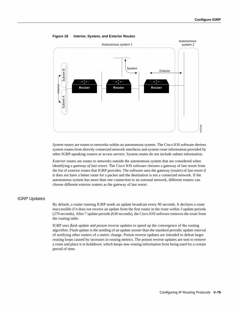
IGRP also advertises three types of routes: interior, system, and exterior, as shown in Figure 18.Interior routes are routes between subnets in the network attached to a router interface. If thenetwork attached to a router is not subnetted, IGRP does not advertise interior routes.
Configure IGRP
Configuring IP Routing Protocols V-79
Figure 18 Interior, System, and Exterior Routes
System routes are routes to networks within an autonomous system. The Cisco IOS software derivessystem routes from directly connected network interfaces and system route information provided byother IGRP-speaking routers or access servers. System routes do not include subnet information.
Exterior routes are routes to networks outside the autonomous system that are considered whenidentifying agateway of last resort. The Cisco IOS software chooses a gateway of last resort fromthe list of exterior routes that IGRP provides. The software uses the gateway (router) of last resort ifit does not have a better route for a packet and the destination is not a connected network. If theautonomous system has more than one connection to an external network, different routers canchoose different exterior routers as the gateway of last resort.
IGRP UpdatesBy default, a router running IGRP sends an update broadcast every 90 seconds. It declares a routeinaccessible if it does not receive an update from the first router in the route within 3 update periods(270 seconds). After 7 update periods (630 seconds), the Cisco IOS software removes the route fromthe routing table.
IGRP usesflash update andpoison reverse updates to speed up the convergence of the routingalgorithm. Flash update is the sending of an update sooner than the standard periodic update intervalof notifying other routers of a metric change. Poison reverse updates are intended to defeat largerrouting loops caused by increases in routing metrics. The poison reverse updates are sent to removea route and place it inholddown, which keeps new routing information from being used for a certainperiod of time.
Router Router Router
System
Sub
net A
Sub
net B
Inte
rior
S10
19a
Exterior
Autonomous system 1Autonomous
system 2
V-80 Network Protocols Configuration Guide, Part 1
Configure IGRP
IGRP Configuration Task ListTo configure IGRP, perform the tasks in the following sections. Creating the IGRP routing processis mandatory; the other tasks described are optional.
• Create the IGRP Routing Process
• Allow Point-to-Point Updates for IGRP
• Define Unequal-Cost Load Balancing
• Control Traffic Distribution
• Adjust the IGRP Metric Weights
• Disable Holddown
• Enforce a Maximum Network Diameter
• Validate Source IP Addresses
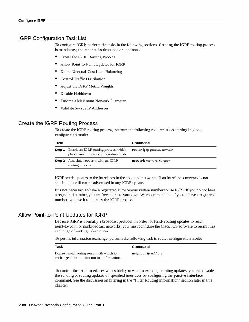
Create the IGRP Routing ProcessTo create the IGRP routing process, perform the following required tasks starting in globalconfiguration mode:
IGRP sends updates to the interfaces in the specified networks. If an interface’s network is notspecified, it will not be advertised in any IGRP update.
It is not necessary to have a registered autonomous system number to use IGRP. If you do not havea registered number, you are free to create your own. We recommend that if you do have a registerednumber, you use it to identify the IGRP process.
Allow Point-to-Point Updates for IGRPBecause IGRP is normally a broadcast protocol, in order for IGRP routing updates to reachpoint-to-point or nonbroadcast networks, you must configure the Cisco IOS software to permit thisexchange of routing information.
To permit information exchange, perform the following task in router configuration mode:
To control the set of interfaces with which you want to exchange routing updates, you can disablethe sending of routing updates on specified interfaces by configuring thepassive-interfacecommand. See the discussion on filtering in the “Filter Routing Information” section later in thischapter.
Task Command
Step 1 Enable an IGRP routing process, whichplaces you in router configuration mode.
router igrp process number
Step 2 Associate networks with an IGRProuting process.
network network-number
Task Command
Define a neighboring router with which toexchange point-to-point routing information.
neighbor ip-address
Configure IGRP
Configuring IP Routing Protocols V-81
Define Unequal-Cost Load BalancingIGRP can simultaneously use an asymmetric set of paths for a given destination. This feature isknown asunequal-cost load balancing. Unequal-cost load balancing allows traffic to be distributedamong multiple (up to four) unequal-cost paths to provide greater overall throughput and reliability.Alternatepath variance (that is, the difference in desirability between the primary and alternatepaths) is used to determine the feasibility of a potential route. An alternate route isfeasible if the nextrouter in the path iscloser to the destination (has a lower metric value) than the current router and ifthe metric for the entire alternate path iswithin the variance. Only paths that are feasible can be usedfor load balancing and included in the routing table. These conditions limit the number of cases inwhich load balancing can occur, but ensure that the dynamics of the network will remain stable.
The following general rules apply to IGRP unequal-cost load balancing:
• IGRP will accept up to four paths for a given destination network.
• The local best metric must be greater than the metric learned from the next router; that is, thenext-hop router must be closer (have a smaller metric value) to the destination than the local bestmetric.
• The alternative path metric must be within the specifiedvariance of the local best metric. Themultiplier times the local best metric for the destination must be greater than or equal to themetric through the next router.
If these conditions are met, the route is deemed feasible and can be added to the routing table.
By default, the amount of variance is set to one (equal-cost load balancing). You can define howmuch worse an alternate path can be before that path is disallowed by performing the following taskin router configuration mode:
Note By using the variance feature, the Cisco IOS software can balance traffic across all feasiblepaths and can immediately converge to a new path if one of the paths should fail.
Control Traffic DistributionBy default, if IGRP or Enhanced IGRP have multiple routes of unequal cost to the same destination,the Cisco IOS software will distribute traffic among the different routes by giving each route a shareof the traffic in inverse proportion to its metric. If you want to have faster convergence to alternateroutes, but you do not want to send traffic across inferior routes in the normal case, you might preferto have no traffic flow along routes with higher metrics.
To control how traffic is distributed among multiple routes of unequal cost, perform the followingtask in router configuration mode:
Task Command
Define the variance associated with a particularpath.
variancemultiplier
Task Command
Distribute traffic proportionately to the ratios ofmetrics, or by the minimum-cost route.
traffic-share { balanced | min}

V-82 Network Protocols Configuration Guide, Part 1
Configure IGRP
Adjust the IGRP Metric WeightsYou have the option of altering the default behavior of IGRP routing and metric computations. Thisallows, for example, tuning system behavior to allow for transmissions via satellite. Although IGRPmetric defaults were carefully selected to provide excellent operation in most networks, you canadjust the IGRP metric. Adjusting IGRP metric weights can dramatically affect networkperformance, however, so ensure that you make all metric adjustments carefully.
To adjust the IGRP metric weights, perform the following task in router configuration mode.Because of the complexity of this task, we recommend that you only perform it with guidance froman experienced system designer.
By default, the IGRP composite metric is a 24-bit quantity that is a sum of the segment delaysand the lowest segment bandwidth (scaled and inverted) for a given route. For a network ofhomogeneous media, this metric reduces to a hop count. For a network of mixed media (FDDI,Ethernet, and serial lines running from 9600 bps to T1 rates), the route with the lowest metric reflectsthe most desirable path to a destination.
Disable HolddownWhen the Cisco IOS software learns that a network is at a greater distance than was previouslyknown, or it learns the network is down, the route to that network is placed in holddown. During theholddown period, the route is advertised, but incoming advertisements about that network from anyrouter other than the one that originally advertised the network’s new metric will be ignored. Thismechanism is often used to help avoid routing loops in the network, but has the effect of increasingthe topology convergence time. To disable holddowns with IGRP, perform the following task inrouter configuration mode. All devices in an IGRP autonomous system must be consistent in theiruse of holddowns.
Enforce a Maximum Network DiameterThe Cisco IOS software enforces a maximum diameter to the IGRP network. Routes whose hopcounts exceed this diameter are not advertised. The default maximum diameter is 100 hops. Themaximum diameter is 255 hops.
To configure the maximum diameter, perform the following task in router configuration mode:
Task Command
Adjust the IGRP metric. metric weights tos k1 k2 k3 k4 k5
Task Command
Disable the IGRP holddown period. no metric holddown
Task Command
Configure the maximum network diameter. metric maximum-hopshops
Configure Enhanced IGRP
Configuring IP Routing Protocols V-83
Validate Source IP AddressesTo disable the default function that validates the source IP addresses of incoming routing updates,perform the following task in router configuration mode:
Configure Enhanced IGRPEnhanced IGRP is an enhanced version of the Interior Gateway Routing Protocol (IGRP) developedby Cisco Systems, Inc. Enhanced IGRP uses the same distance vector algorithm and distanceinformation as IGRP. However, the convergence properties and the operating efficiency of EnhancedIGRP have improved significantly over IGRP.
The convergence technology is based on research conducted at SRI International and employs analgorithm referred to as the Diffusing Update Algorithm (DUAL). This algorithm guaranteesloop-free operation at every instant throughout a route computation and allows all devices involvedin a topology change to synchronize at the same time. Routers or access servers that are not affectedby topology changes are not involved in recomputations. The convergence time with DUAL rivalsthat of any other existing routing protocol.
Cisco’s Enhanced IGRP ImplementationIP Enhanced IGRP provides the following features:
• Automatic redistribution—IP IGRP routes can be automatically redistributed into EnhancedIGRP, and IP Enhanced IGRP routes can be automatically redistributed into IGRP. If desired, youcan turn off redistribution. You can also completely turn off IP Enhanced IGRP and IP IGRP onthe router or on individual interfaces.
• Increased network width—With IP RIP, the largest possible width of your network is 15 hops.When IP Enhanced IGRP is enabled, the largest possible width is 224 hops. Because theEnhanced IGRP metric is large enough to support thousands of hops, the only barrier toexpanding the network is the transport layer hop counter. Cisco works around this problem byincrementing the transport control field only when an IP packet has traversed 15 routers and thenext hop to the destination was learned by way of Enhanced IGRP. When a RIP route is beingused as the next hop to the destination, the transport control field is incremented as usual.
Enhanced IGRP offers the following features:
• Fast convergence—The DUAL algorithm allows routing information to converge as quickly asany currently available routing protocol.
• Partial updates—Enhanced IGRP sends incremental updates when the state of a destinationchanges, instead of sending the entire contents of the routing table. This feature minimizes thebandwidth required for Enhanced IGRP packets.
• Less CPU usage than IGRP—This occurs because full update packets do not have to beprocessed each time they are received.
• Neighbor discovery mechanism—This is a simple hello mechanism used to learn aboutneighboring routers. It is protocol-independent.
• Variable-length subnet masks
Task Command
Disable the checking and validation of the sourceIP address of incoming routing updates.
no validate-update-source
V-84 Network Protocols Configuration Guide, Part 1
Configure Enhanced IGRP
• Arbitrary route summarization
• Scaling. Enhanced IGRP scales to large networks
Enhanced IGRP has four basic components:
• Neighbor discovery/recovery
• Reliable transport protocol
• DUAL finite state machine
• Protocol-dependent modules
Neighbor discovery/recovery is the process that routers use to dynamically learn of other routers ontheir directly attached networks. Routers must also discover when their neighbors becomeunreachable or inoperative. Neighbor discovery/recovery is achieved with low overhead byperiodically sending small hello packets. As long as hello packets are received, the Cisco IOSsoftware can determine that a neighbor is alive and functioning. Once this status is determined, theneighboring routers can exchange routing information.
The reliable transport protocol is responsible for guaranteed, ordered delivery of Enhanced IGRPpackets to all neighbors. It supports intermixed transmission of multicast and unicast packets. SomeEnhanced IGRP packets must be transmitted reliably and others need not be. For efficiency,reliability is provided only when necessary. For example, on a multiaccess network that hasmulticast capabilities (such as Ethernet) it is not necessary to send hellos reliably to all neighborsindividually. Therefore, Enhanced IGRP sends a single multicast hello with an indication in thepacket informing the receivers that the packet need not be acknowledged. Other types of packets(such as updates) require acknowledgment, and this is indicated in the packet. The reliable transporthas a provision to send multicast packets quickly when there are unacknowledged packets pending.Doing so helps ensure that convergence time remains low in the presence of varying speed links.
The DUAL finite state machine embodies the decision process for all route computations. It tracksall routes advertised by all neighbors. DUAL uses the distance information (known as a metric) toselect efficient, loop-free paths. DUAL selects routes to be inserted into a routing table based onfeasible successors. A successor is a neighboring router used for packet forwarding that has aleast-cost path to a destination that is guaranteed not to be part of a routing loop. When there are nofeasible successors but there are neighbors advertising the destination, a recomputation must occur.This is the process whereby a new successor is determined. The amount of time it takes to recomputethe route affects the convergence time. Even though the recomputation is not processor-intensive, itis advantageous to avoid recomputation if it is not necessary. When a topology change occurs,DUAL will test for feasible successors. If there are feasible successors, it will use any it finds in orderto avoid unnecessary recomputation.
The protocol-dependent modules are responsible for network layer protocol-specific tasks. Anexample is the IP Enhanced IGRP module, which is responsible for sending and receiving EnhancedIGRP packets that are encapsulated in IP. It is also responsible for parsing Enhanced IGRP packetsand informing DUAL of the new information received. IP Enhanced IGRP asks DUAL to makerouting decisions, but the results are stored in the IP routing table. Also, IP Enhanced IGRP isresponsible for redistributing routes learned by other IP routing protocols.
Configure Enhanced IGRP
Configuring IP Routing Protocols V-85
Enhanced IGRP Configuration Task ListTo configure IP Enhanced IGRP, complete the tasks in the following sections. At a minimum, youmust enable IP Enhanced IGRP. The remaining tasks are optional.
• Enable IP Enhanced IGRP
• Transition from IGRP to Enhanced IGRP
• Configure IP Enhanced IGRP-Specific Parameters
• Display System and Network Statistics
• Configure Protocol-Independent Parameters
See the “IP Routing Protocol Configuration Examples” at the end of this chapter for configurationexamples.
Enable IP Enhanced IGRPTo create an IP Enhanced IGRP routing process, perform the following tasks:
IP Enhanced IGRP sends updates to the interfaces in the specified networks. If you do not specifyan interface’s network, it will not be advertised in any IP Enhanced IGRP update.
Transition from IGRP to Enhanced IGRPIf you have routers or access servers on your network that are configured for IGRP, and you want tomake a transition to routing Enhanced IGRP, you must designate transition routers that have bothIGRP and Enhanced IGRP configured. In these cases, perform the tasks as noted in the previoussection, “Enable IP Enhanced IGRP,” and also read the section, “Configure IGRP,” earlier in thischapter. You must use the same autonomous system number in order for routes to be redistributedautomatically.
Configure IP Enhanced IGRP-Specific ParametersTo configure IP Enhanced IGRP-specific parameters, perform one or more of the tasks in thefollowing sections:
• Log Enhanced IGRP Neighbor Adjacency Changes
• Configure the Percentage of Link Bandwidth Used by Enhanced IGRP
• Display System and Network Statistics
• Adjust the IP Enhanced IGRP Metric Weights
• Disable Route Summarization
• Configure Summary Aggregate Addresses
Task Command
Step 1 Enable an IP Enhanced IGRP routingprocess in global configuration mode.
router eigrp process-number
Step 2 Associate networks with an IP EnhancedIGRP routing process in routerconfiguration mode.
network network-number
V-86 Network Protocols Configuration Guide, Part 1
Configure Enhanced IGRP
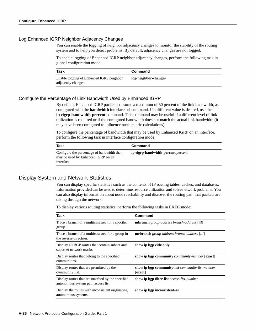
Log Enhanced IGRP Neighbor Adjacency ChangesYou can enable the logging of neighbor adjacency changes to monitor the stability of the routingsystem and to help you detect problems. By default, adjacency changes are not logged.
To enable logging of Enhanced IGRP neighbor adjacency changes, perform the following task inglobal configuration mode:
Configure the Percentage of Link Bandwidth Used by Enhanced IGRPBy default, Enhanced IGRP packets consume a maximum of 50 percent of the link bandwidth, asconfigured with thebandwidth interface subcommand. If a different value is desired, use theip eigrp-bandwidth-percent command. This command may be useful if a different level of linkutilization is required or if the configured bandwidth does not match the actual link bandwidth (itmay have been configured to influence route metric calculations).
To configure the percentage of bandwidth that may be used by Enhanced IGRP on an interface,perform the following task in interface configuration mode:
Display System and Network StatisticsYou can display specific statistics such as the contents of IP routing tables, caches, and databases.Information provided can be used to determine resource utilization and solve network problems. Youcan also display information about node reachability and discover the routing path that packets aretaking through the network.
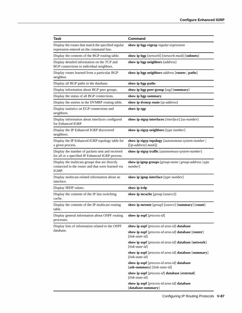
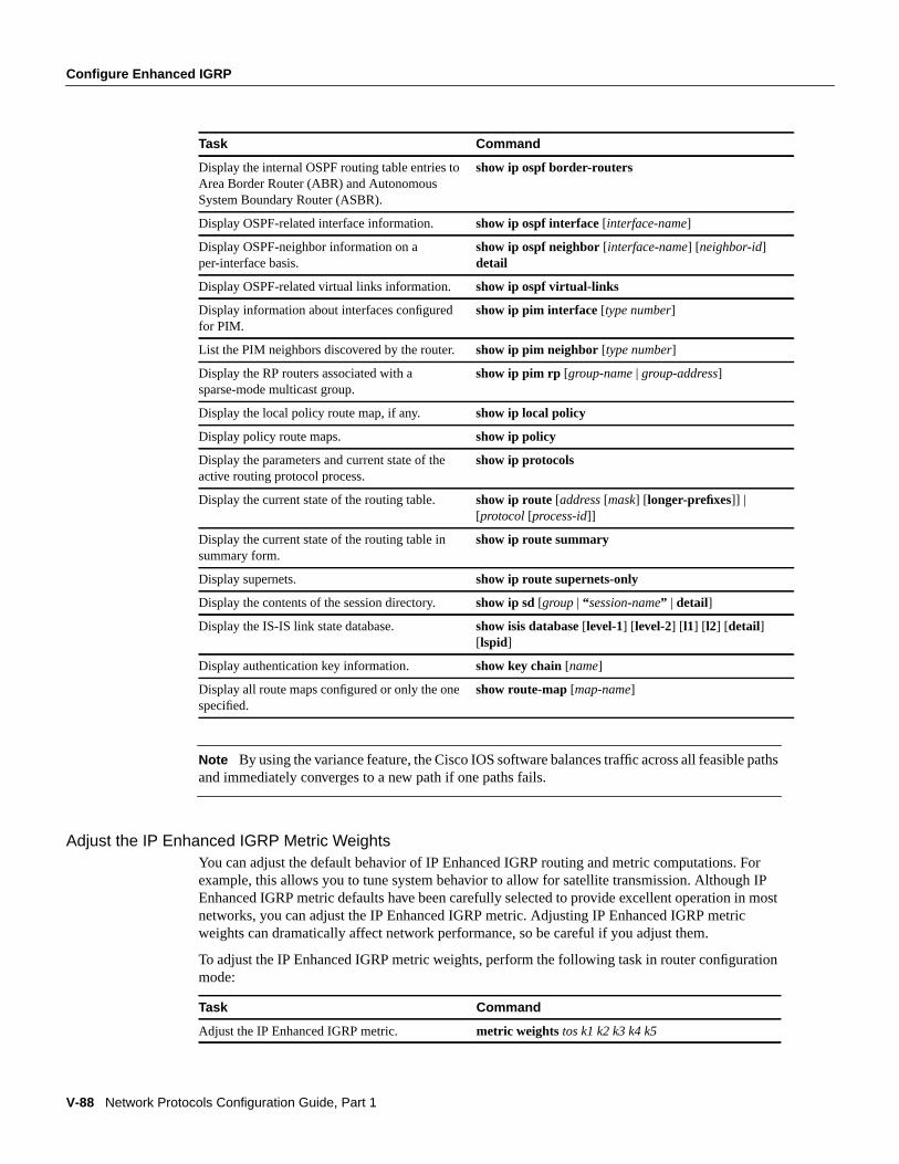
To display various routing statistics, perform the following tasks in EXEC mode:
Task Command
Enable logging of Enhanced IGRP neighboradjacency changes.
log-neighbor-changes
Task Command
Configure the percentage of bandwidth thatmay be used by Enhanced IGRP on aninterface.
ip eigrp-bandwidth-percent percent
Task Command
Trace a branch of a multicast tree for a specificgroup.
mbranch group-address branch-address[ttl]
Trace a branch of a multicast tree for a group inthe reverse direction.
mrbranch group-address branch-address[ttl]
Display all BGP routes that contain subnet andsupernet network masks.
show ip bgp cidr-only
Display routes that belong to the specifiedcommunities.
show ip bgp communitycommunity-number [exact]
Display routes that are permitted by thecommunity list.
show ip bgp community-listcommunity-list-number[exact]
Display routes that are matched by the specifiedautonomous system path access list.
show ip bgp filter-list access-list-number
Display the routes with inconsistent originatingautonomous systems.
show ip bgp inconsistent-as
Configure Enhanced IGRP
Configuring IP Routing Protocols V-87
Display the routes that match the specified regularexpression entered on the command line.
show ip bgp regexp regular-expression
Display the contents of the BGP routing table. show ip bgp[network] [network-mask] [subnets]
Display detailed information on the TCP andBGP connections to individual neighbors.
show ip bgp neighbors[address]
Display routes learned from a particular BGPneighbor.
show ip bgp neighborsaddress [routes | paths]
Display all BGP paths in the database. show ip bgp paths
Display information about BGP peer groups. show ip bgp peer-group [tag] [summary]
Display the status of all BGP connections. show ip bgp summary
Display the entries in the DVMRP routing table.show ip dvmrp route [ip-address]
Display statistics on EGP connections andneighbors.
show ip egp
Display information about interfaces configuredfor Enhanced IGRP
show ip eigrp interfaces [interface] [as-number]
Display the IP Enhanced IGRP discoveredneighbors.
show ip eigrp neighbors[type number]
Display the IP Enhanced IGRP topology table fora given process.
show ip eigrp topology [autonomous-system-number |[[ ip-address] mask]]
Display the number of packets sent and receivedfor all or a specified IP Enhanced IGRP process.
show ip eigrp traffic [autonomous-system-number]
Display the multicast groups that are directlyconnected to the router and that were learned viaIGMP.
show ip igmp groups[group-name |group-address | typenumber]
Display multicast-related information about aninterface.
show ip igmp interface [type number]
Display IRDP values. show ip irdp
Display the contents of the IP fast switchingcache.
show ip mcache [group [source]]
Display the contents of the IP multicast routingtable.
show ip mroute[group] [source] [summary] [count]
Display general information about OSPF routingprocesses.
show ip ospf[process-id]
Display lists of information related to the OSPFdatabase.
show ip ospf[process-id area-id] database
show ip ospf[process-id area-id] database[router ][link-state-id]
show ip ospf[process-id area-id] database[network][link-state-id]
show ip ospf[process-id area-id] database[summary][link-state-id]
show ip ospf[process-id area-id] database[asb-summary] [ link-state-id]
show ip ospf[process-id] database [external][link-state-id]
show ip ospf[process-id area-id] database[database-summary]
Task Command
V-88 Network Protocols Configuration Guide, Part 1
Configure Enhanced IGRP
Note By using the variance feature, the Cisco IOS software balances traffic across all feasible pathsand immediately converges to a new path if one paths fails.
Adjust the IP Enhanced IGRP Metric WeightsYou can adjust the default behavior of IP Enhanced IGRP routing and metric computations. Forexample, this allows you to tune system behavior to allow for satellite transmission. Although IPEnhanced IGRP metric defaults have been carefully selected to provide excellent operation in mostnetworks, you can adjust the IP Enhanced IGRP metric. Adjusting IP Enhanced IGRP metricweights can dramatically affect network performance, so be careful if you adjust them.
To adjust the IP Enhanced IGRP metric weights, perform the following task in router configurationmode:
Display the internal OSPF routing table entries toArea Border Router (ABR) and AutonomousSystem Boundary Router (ASBR).
show ip ospf border-routers
Display OSPF-related interface information. show ip ospf interface [interface-name]
Display OSPF-neighbor information on aper-interface basis.
show ip ospf neighbor [interface-name] [neighbor-id]detail
Display OSPF-related virtual links information. show ip ospf virtual-links
Display information about interfaces configuredfor PIM.
show ip pim interface [type number]
List the PIM neighbors discovered by the router.show ip pim neighbor [type number]
Display the RP routers associated with asparse-mode multicast group.
show ip pim rp [group-name | group-address]
Display the local policy route map, if any. show ip local policy
Display policy route maps. show ip policy
Display the parameters and current state of theactive routing protocol process.
show ip protocols
Display the current state of the routing table. show ip route [address [mask] [ longer-prefixes]] |[protocol[process-id]]
Display the current state of the routing table insummary form.
show ip route summary
Display supernets. show ip route supernets-only
Display the contents of the session directory. show ip sd [group | “ session-name” | detail]
Display the IS-IS link state database. show isis database [level-1] [ level-2] [ l1] [ l2] [detail][lspid]
Display authentication key information. show key chain[name]
Display all route maps configured or only the onespecified.
show route-map[map-name]
Task Command
Adjust the IP Enhanced IGRP metric. metric weights tos k1 k2 k3 k4 k5
Task Command
Configure Enhanced IGRP
Configuring IP Routing Protocols V-89
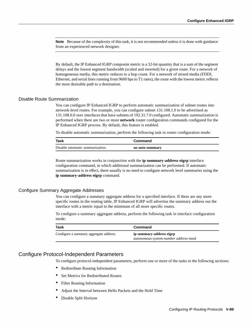
Note Because of the complexity of this task, it is not recommended unless it is done with guidancefrom an experienced network designer.
By default, the IP Enhanced IGRP composite metric is a 32-bit quantity that is a sum of the segmentdelays and the lowest segment bandwidth (scaled and inverted) for a given route. For a network ofhomogeneous media, this metric reduces to a hop count. For a network of mixed media (FDDI,Ethernet, and serial lines running from 9600 bps to T1 rates), the route with the lowest metric reflectsthe most desirable path to a destination.
Disable Route SummarizationYou can configure IP Enhanced IGRP to perform automatic summarization of subnet routes intonetwork-level routes. For example, you can configure subnet 131.108.1.0 to be advertised as131.108.0.0 over interfaces that have subnets of 192.31.7.0 configured. Automatic summarization isperformed when there are two or morenetwork router configuration commands configured for theIP Enhanced IGRP process. By default, this feature is enabled.
To disable automatic summarization, perform the following task in router configuration mode:
Route summarization works in conjunction with theip summary-address eigrp interfaceconfiguration command, in which additional summarization can be performed. If automaticsummarization is in effect, there usually is no need to configure network level summaries using theip summary-address eigrp command.
Configure Summary Aggregate AddressesYou can configure a summary aggregate address for a specified interface. If there are any morespecific routes in the routing table, IP Enhanced IGRP will advertise the summary address out theinterface with a metric equal to the minimum of all more specific routes.
To configure a summary aggregate address, perform the following task in interface configurationmode:
Configure Protocol-Independent ParametersTo configure protocol-independent parameters, perform one or more of the tasks in the following sections:
• Redistribute Routing Information
• Set Metrics for Redistributed Routes
• Filter Routing Information
• Adjust the Interval between Hello Packets and the Hold Time
• Disable Split Horizon
Task Command
Disable automatic summarization. no auto-summary
Task Command
Configure a summary aggregate address. ip summary-address eigrpautonomous-system-number address mask
V-90 Network Protocols Configuration Guide, Part 1
Configure Enhanced IGRP
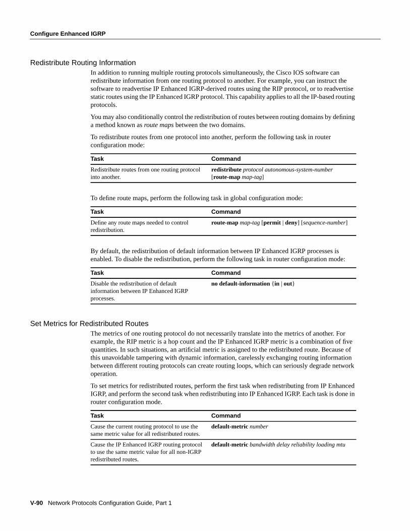
Redistribute Routing InformationIn addition to running multiple routing protocols simultaneously, the Cisco IOS software canredistribute information from one routing protocol to another. For example, you can instruct thesoftware to readvertise IP Enhanced IGRP-derived routes using the RIP protocol, or to readvertisestatic routes using the IP Enhanced IGRP protocol. This capability applies to all the IP-based routingprotocols.
You may also conditionally control the redistribution of routes between routing domains by defininga method known asroute maps between the two domains.
To redistribute routes from one protocol into another, perform the following task in routerconfiguration mode:
To define route maps, perform the following task in global configuration mode:
By default, the redistribution of default information between IP Enhanced IGRP processes isenabled. To disable the redistribution, perform the following task in router configuration mode:
Set Metrics for Redistributed RoutesThe metrics of one routing protocol do not necessarily translate into the metrics of another. Forexample, the RIP metric is a hop count and the IP Enhanced IGRP metric is a combination of fivequantities. In such situations, an artificial metric is assigned to the redistributed route. Because ofthis unavoidable tampering with dynamic information, carelessly exchanging routing informationbetween different routing protocols can create routing loops, which can seriously degrade networkoperation.
To set metrics for redistributed routes, perform the first task when redistributing from IP EnhancedIGRP, and perform the second task when redistributing into IP Enhanced IGRP. Each task is done inrouter configuration mode.
Task Command
Redistribute routes from one routing protocolinto another.
redistribute protocol autonomous-system-number[route-map map-tag]
Task Command
Define any route maps needed to controlredistribution.
route-map map-tag [permit | deny] [sequence-number]
Task Command
Disable the redistribution of defaultinformation between IP Enhanced IGRPprocesses.
no default-information { in | out}
Task Command
Cause the current routing protocol to use thesame metric value for all redistributed routes.
default-metric number
Cause the IP Enhanced IGRP routing protocolto use the same metric value for all non-IGRPredistributed routes.
default-metric bandwidth delay reliability loading mtu

Configure Enhanced IGRP
Configuring IP Routing Protocols V-91
Filter Routing InformationYou can filter routing protocol information by performing the following tasks:
• Suppress the sending of routing updates on a particular interface. Doing so prevents othersystems on an interface from learning about routes dynamically.
• Suppress networks from being advertised in routing updates. Doing so prevents other routersfrom learning a particular interpretation of one or more routes.
• Suppress a routing protocol from both sending and receiving updates on a particular interface.You usually perform this task when a wildcard command has been used to configure the routingprotocol for more interfaces than is desirable.
• Suppress networks listed in updates from being accepted and acted upon by a routing process.Doing so keeps a router from using certain routes.
• Filter on the source of routing information. You perform this task to prioritize routinginformation from different sources, because the accuracy of the routing information can vary.
• Apply an offset to routing metrics. Doing so provides a local mechanism for increasing the valueof routing metrics.
Use the information in the following sections to perform these tasks.
Prevent Routing Updates through an InterfaceTo prevent other routers on a local network from learning about routes dynamically, you can keeprouting update messages from being sent through an interface. This feature applies to all IP-basedrouting protocols except BGP and EGP.
To prevent routing updates through a specified interface, perform the following task in routerconfiguration mode:
Control the Advertising of Routes in Routing UpdatesTo control which routers learn about routes, you can control the advertising of routes in routingupdates. To do this, perform the following task in router configuration mode:
Control the Processing of Routing UpdatesTo control the processing of routes listed in incoming updates, perform the following task in routerconfiguration mode:
Task Command
Suppress the sending of routing updatesthrough an interface.
passive-interfacetype number
Task Command
Control the advertising of routes in routingupdates.
distribute-list access-list-number |name[interface-name| routing-process | autonomous-system-number]
Task Command
Control which incoming route updates areprocesses.
distribute-list access-list-number | namein[interface-name]
V-92 Network Protocols Configuration Guide, Part 1
Configure Enhanced IGRP
Apply Offsets to Routing MetricsTo provide a local mechanism for increasing the value of routing metrics, you can apply an offset torouting metrics. To do so, perform the following task in router configuration mode:
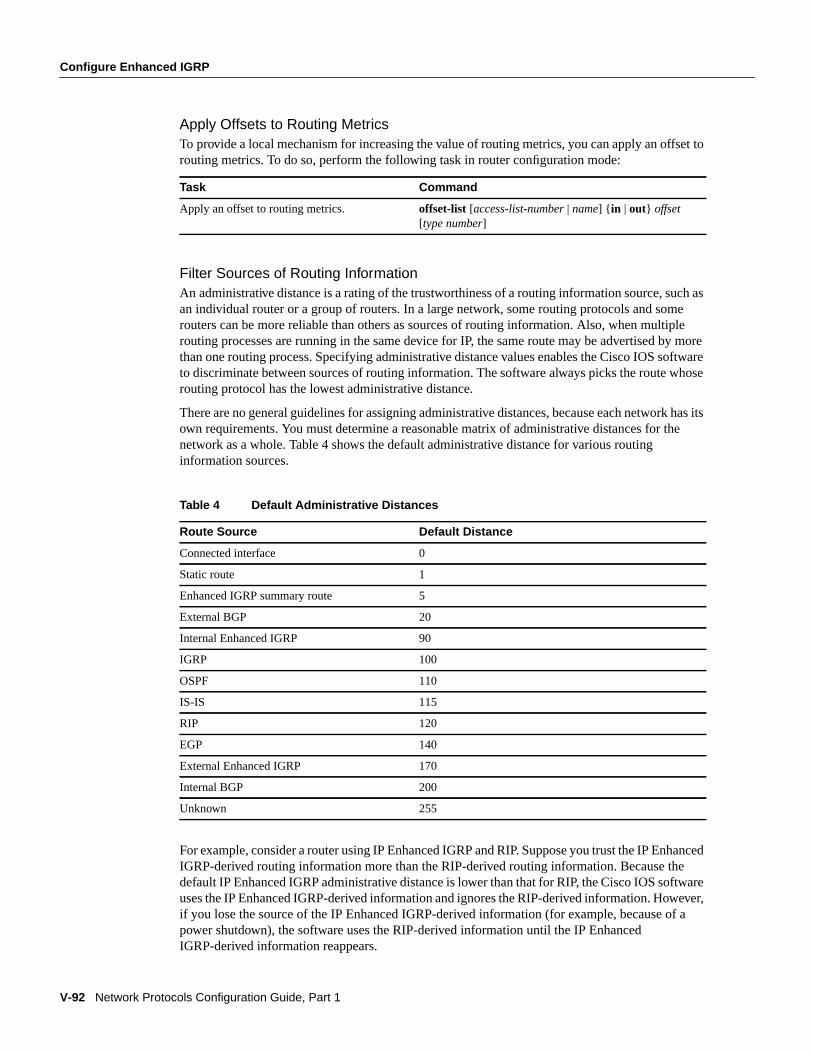
Filter Sources of Routing InformationAn administrative distance is a rating of the trustworthiness of a routing information source, such asan individual router or a group of routers. In a large network, some routing protocols and somerouters can be more reliable than others as sources of routing information. Also, when multiplerouting processes are running in the same device for IP, the same route may be advertised by morethan one routing process. Specifying administrative distance values enables the Cisco IOS softwareto discriminate between sources of routing information. The software always picks the route whoserouting protocol has the lowest administrative distance.
There are no general guidelines for assigning administrative distances, because each network has itsown requirements. You must determine a reasonable matrix of administrative distances for thenetwork as a whole. Table 4 shows the default administrative distance for various routinginformation sources.
For example, consider a router using IP Enhanced IGRP and RIP. Suppose you trust the IP EnhancedIGRP-derived routing information more than the RIP-derived routing information. Because thedefault IP Enhanced IGRP administrative distance is lower than that for RIP, the Cisco IOS softwareuses the IP Enhanced IGRP-derived information and ignores the RIP-derived information. However,if you lose the source of the IP Enhanced IGRP-derived information (for example, because of apower shutdown), the software uses the RIP-derived information until the IP EnhancedIGRP-derived information reappears.
Task Command
Apply an offset to routing metrics. offset-list [access-list-number | name] { in | out} offset[type number]
Table 4 Default Administrative Distances
Route Source Default Distance
Connected interface 0
Static route 1
Enhanced IGRP summary route 5
External BGP 20
Internal Enhanced IGRP 90
IGRP 100
OSPF 110
IS-IS 115
RIP 120
EGP 140
External Enhanced IGRP 170
Internal BGP 200
Unknown 255
Configure Enhanced IGRP
Configuring IP Routing Protocols V-93
Note You can also use administrative distance to rate the routing information from routers runningthe same routing protocol. This application is generally discouraged if you are unfamiliar with thisparticular use of administrative distance, since it can result in inconsistent routing information,including forwarding loops.
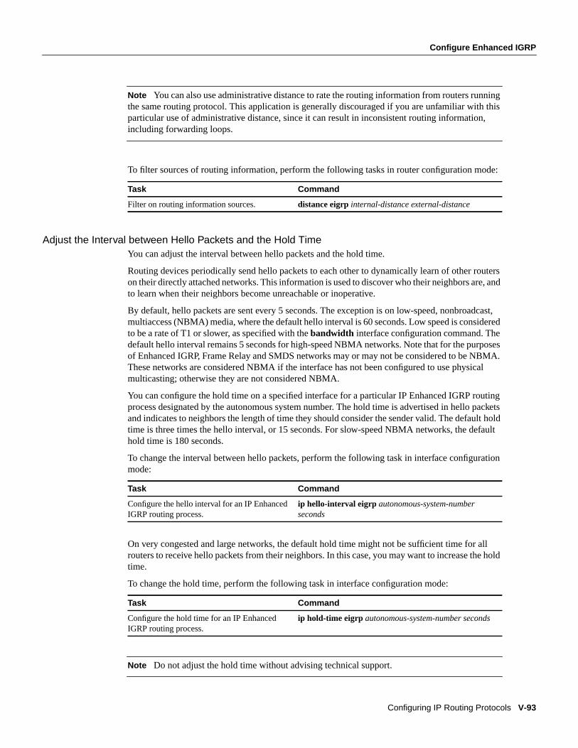
To filter sources of routing information, perform the following tasks in router configuration mode:
Adjust the Interval between Hello Packets and the Hold TimeYou can adjust the interval between hello packets and the hold time.
Routing devices periodically send hello packets to each other to dynamically learn of other routerson their directly attached networks. This information is used to discover who their neighbors are, andto learn when their neighbors become unreachable or inoperative.
By default, hello packets are sent every 5 seconds. The exception is on low-speed, nonbroadcast,multiaccess (NBMA) media, where the default hello interval is 60 seconds. Low speed is consideredto be a rate of T1 or slower, as specified with thebandwidth interface configuration command. Thedefault hello interval remains 5 seconds for high-speed NBMA networks. Note that for the purposesof Enhanced IGRP, Frame Relay and SMDS networks may or may not be considered to be NBMA.These networks are considered NBMA if the interface has not been configured to use physicalmulticasting; otherwise they are not considered NBMA.
You can configure the hold time on a specified interface for a particular IP Enhanced IGRP routingprocess designated by the autonomous system number. The hold time is advertised in hello packetsand indicates to neighbors the length of time they should consider the sender valid. The default holdtime is three times the hello interval, or 15 seconds. For slow-speed NBMA networks, the defaulthold time is 180 seconds.
To change the interval between hello packets, perform the following task in interface configurationmode:
On very congested and large networks, the default hold time might not be sufficient time for allrouters to receive hello packets from their neighbors. In this case, you may want to increase the holdtime.
To change the hold time, perform the following task in interface configuration mode:
Note Do not adjust the hold time without advising technical support.
Task Command
Filter on routing information sources. distance eigrpinternal-distance external-distance
Task Command
Configure the hello interval for an IP EnhancedIGRP routing process.
ip hello-interval eigrp autonomous-system-numberseconds
Task Command
Configure the hold time for an IP EnhancedIGRP routing process.
ip hold-time eigrp autonomous-system-number seconds
V-94 Network Protocols Configuration Guide, Part 1
Configure OSPF
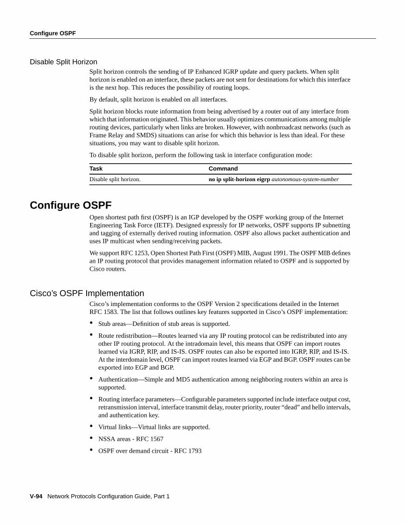
Disable Split HorizonSplit horizon controls the sending of IP Enhanced IGRP update and query packets. When splithorizon is enabled on an interface, these packets are not sent for destinations for which this interfaceis the next hop. This reduces the possibility of routing loops.
By default, split horizon is enabled on all interfaces.
Split horizon blocks route information from being advertised by a router out of any interface fromwhich that information originated. This behavior usually optimizes communications among multiplerouting devices, particularly when links are broken. However, with nonbroadcast networks (such asFrame Relay and SMDS) situations can arise for which this behavior is less than ideal. For thesesituations, you may want to disable split horizon.
To disable split horizon, perform the following task in interface configuration mode:
Configure OSPFOpen shortest path first (OSPF) is an IGP developed by the OSPF working group of the InternetEngineering Task Force (IETF). Designed expressly for IP networks, OSPF supports IP subnettingand tagging of externally derived routing information. OSPF also allows packet authentication anduses IP multicast when sending/receiving packets.
We support RFC 1253, Open Shortest Path First (OSPF) MIB, August 1991. The OSPF MIB definesan IP routing protocol that provides management information related to OSPF and is supported byCisco routers.
Cisco’s OSPF ImplementationCisco’s implementation conforms to the OSPF Version 2 specifications detailed in the InternetRFC 1583. The list that follows outlines key features supported in Cisco’s OSPF implementation:
• Stub areas—Definition of stub areas is supported.
• Route redistribution—Routes learned via any IP routing protocol can be redistributed into anyother IP routing protocol. At the intradomain level, this means that OSPF can import routeslearned via IGRP, RIP, and IS-IS. OSPF routes can also be exported into IGRP, RIP, and IS-IS.At the interdomain level, OSPF can import routes learned via EGP and BGP. OSPF routes can beexported into EGP and BGP.
• Authentication—Simple and MD5 authentication among neighboring routers within an area issupported.
• Routing interface parameters—Configurable parameters supported include interface output cost,retransmission interval, interface transmit delay, router priority, router “dead” and hello intervals,and authentication key.
• Virtual links—Virtual links are supported.
• NSSA areas - RFC 1567
• OSPF over demand circuit - RFC 1793
Task Command
Disable split horizon. no ip split-horizon eigrp autonomous-system-number
Configure OSPF
Configuring IP Routing Protocols V-95
Note To take advantage of the OSPF stub area support,default routing must be used in the stubarea.
OSPF Configuration Task ListOSPF typically requires coordination among many internal routers,area border routers (routersconnected to multiple areas), and autonomous system boundary routers. At a minimum, OSPF-basedrouters or access servers can be configured with all default parameter values, no authentication, andinterfaces assigned to areas. If you intend to customize your environment, you must ensurecoordinated configurations of all routers.
To configure OSPF, complete the tasks in the following sections. Enabling OSPF is mandatory; theother tasks are optional, but might be required for your application.
• Enable OSPF
• Configure OSPF Interface Parameters
• Configure OSPF over Different Physical Networks
• Configure OSPF Area Parameters
• Configure OSPF Not So Stubby Area (NSSA)
• Configure Route Summarization between OSPF Areas
• Configure Route Summarization When Redistributing Routes into OSPF
• Create Virtual Links
• Generate a Default Route
• Configure Lookup of DNS Names
• Force the Router ID Choice with a Loopback Interface
• Disable Default OSPF Metric Calculation Based on Bandwidth
• Configure OSPF on Simplex Ethernet Interfaces
• Configure Route Calculation Timers
• Configure OSPF over On Demand Circuits
In addition, you can specify route redistribution; see the task “Redistribute Routing Information”later in this chapter for information on how to configure route redistribution.
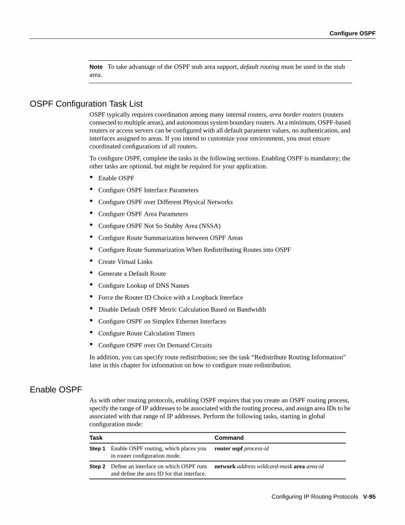
Enable OSPFAs with other routing protocols, enabling OSPF requires that you create an OSPF routing process,specify the range of IP addresses to be associated with the routing process, and assign area IDs to beassociated with that range of IP addresses. Perform the following tasks, starting in globalconfiguration mode:
Task Command
Step 1 Enable OSPF routing, which places youin router configuration mode.
router ospf process-id
Step 2 Define an interface on which OSPF runsand define the area ID for that interface.
network address wildcard-maskareaarea-id
V-96 Network Protocols Configuration Guide, Part 1
Configure OSPF
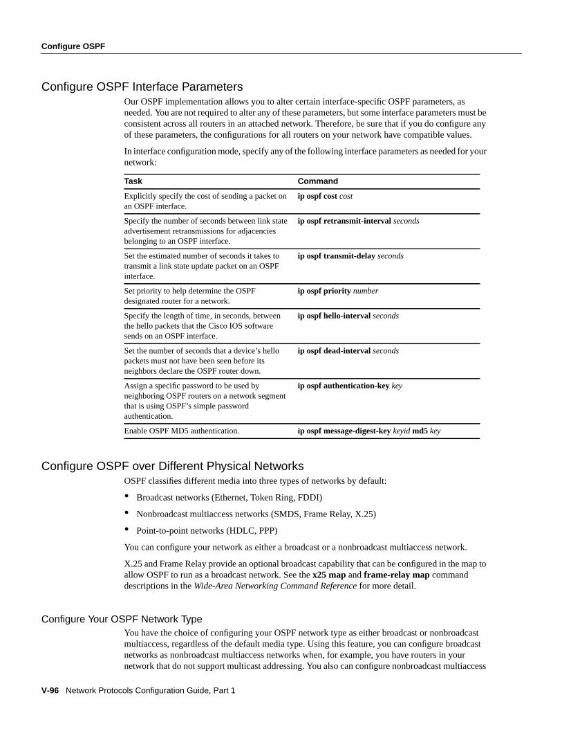
Configure OSPF Interface ParametersOur OSPF implementation allows you to alter certain interface-specific OSPF parameters, asneeded. You are not required to alter any of these parameters, but some interface parameters must beconsistent across all routers in an attached network. Therefore, be sure that if you do configure anyof these parameters, the configurations for all routers on your network have compatible values.
In interface configuration mode, specify any of the following interface parameters as needed for yournetwork:
Configure OSPF over Different Physical NetworksOSPF classifies different media into three types of networks by default:
• Broadcast networks (Ethernet, Token Ring, FDDI)
• Nonbroadcast multiaccess networks (SMDS, Frame Relay, X.25)
• Point-to-point networks (HDLC, PPP)
You can configure your network as either a broadcast or a nonbroadcast multiaccess network.
X.25 and Frame Relay provide an optional broadcast capability that can be configured in the map toallow OSPF to run as a broadcast network. See the x25 map andframe-relay map commanddescriptions in theWide-Area Networking Command Reference for more detail.
Configure Your OSPF Network TypeYou have the choice of configuring your OSPF network type as either broadcast or nonbroadcastmultiaccess, regardless of the default media type. Using this feature, you can configure broadcastnetworks as nonbroadcast multiaccess networks when, for example, you have routers in yournetwork that do not support multicast addressing. You also can configure nonbroadcast multiaccess
Task Command
Explicitly specify the cost of sending a packet onan OSPF interface.
ip ospf costcost
Specify the number of seconds between link stateadvertisement retransmissions for adjacenciesbelonging to an OSPF interface.
ip ospf retransmit-interval seconds
Set the estimated number of seconds it takes totransmit a link state update packet on an OSPFinterface.
ip ospf transmit-delayseconds
Set priority to help determine the OSPFdesignated router for a network.
ip ospf priority number
Specify the length of time, in seconds, betweenthe hello packets that the Cisco IOS softwaresends on an OSPF interface.
ip ospf hello-interval seconds
Set the number of seconds that a device’s hellopackets must not have been seen before itsneighbors declare the OSPF router down.
ip ospf dead-intervalseconds
Assign a specific password to be used byneighboring OSPF routers on a network segmentthat is using OSPF’s simple passwordauthentication.
ip ospf authentication-keykey
Enable OSPF MD5 authentication. ip ospf message-digest-keykeyidmd5 key
Configure OSPF
Configuring IP Routing Protocols V-97
networks (such as X.25, Frame Relay, and SMDS) as broadcast networks. This feature saves youfrom having to configure neighbors, as described in the section “Configure OSPF for NonbroadcastNetworks.”
Configuring nonbroadcast, multiaccess networks as either broadcast or nonbroadcast assumes thatthere are virtual circuits from every router to every router or fully meshed network. This is not truefor some cases, for example, because of cost constraints, or when you have only a partially meshednetwork. In these cases, you can configure the OSPF network type as a point-to-multipoint network.Routing between two routers not directly connected will go through the router that has virtualcircuits to both routers. Note that you must not configure neighbors when using this feature.
An OSPF point-to-multipoint interface is defined as a numbered point-to-point interface having oneor more neighbors. It creates multiple host routes. An OSPF point-to-multipoint network has thefollowing benefits compared to nonbroadcast multiaccess and point-to-point networks:
• Point-to-multipoint is easier to configure because it requires no configuration of neighborcommands, it consumes only one IP subnet, and it requires no designated router election.
• It costs less because it does not require a fully meshed topology.
• It is more reliable because it maintains connectivity in the event of virtual circuit failure.
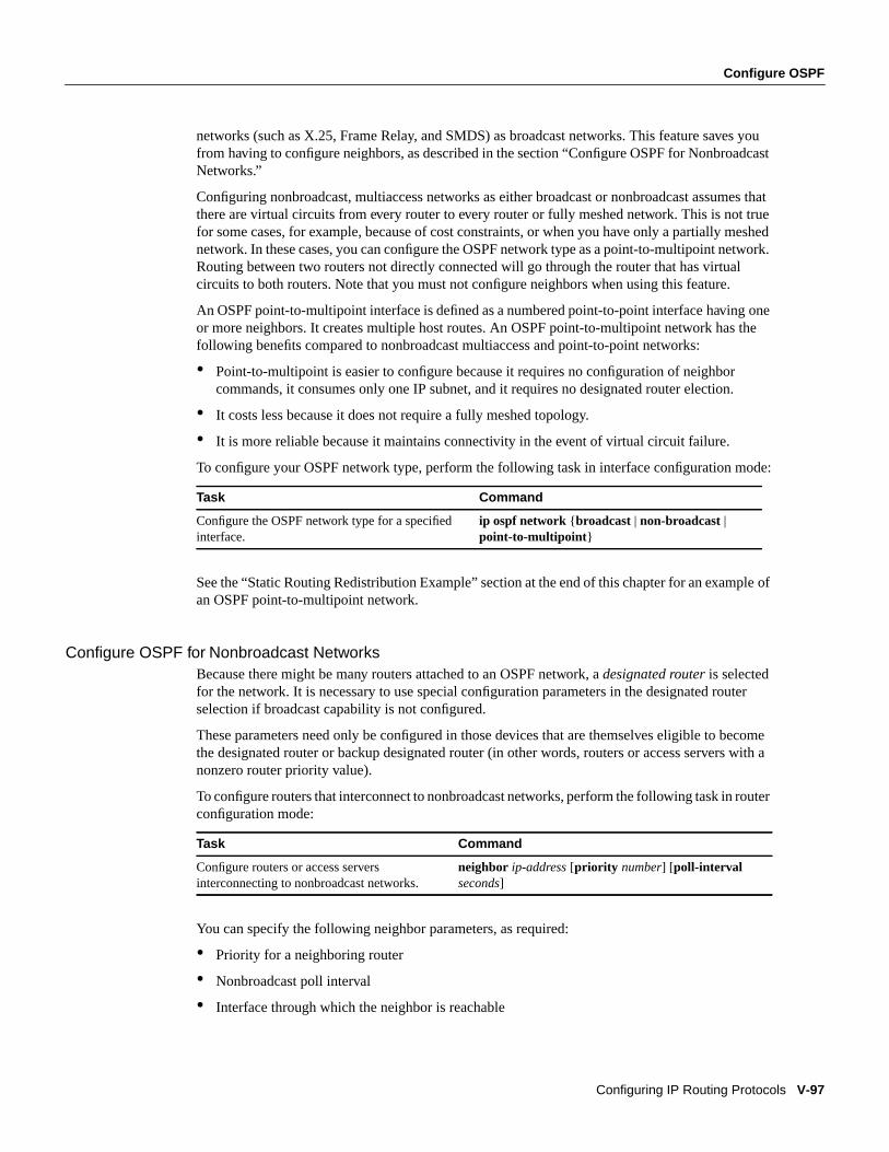
To configure your OSPF network type, perform the following task in interface configuration mode:
See the “Static Routing Redistribution Example” section at the end of this chapter for an example ofan OSPF point-to-multipoint network.
Configure OSPF for Nonbroadcast NetworksBecause there might be many routers attached to an OSPF network, adesignated router is selectedfor the network. It is necessary to use special configuration parameters in the designated routerselection if broadcast capability is not configured.
These parameters need only be configured in those devices that are themselves eligible to becomethe designated router or backup designated router (in other words, routers or access servers with anonzero router priority value).
To configure routers that interconnect to nonbroadcast networks, perform the following task in routerconfiguration mode:
You can specify the following neighbor parameters, as required:
• Priority for a neighboring router
• Nonbroadcast poll interval
• Interface through which the neighbor is reachable
Task Command
Configure the OSPF network type for a specifiedinterface.
ip ospf network {broadcast | non-broadcast |point-to-multipoint }
Task Command
Configure routers or access serversinterconnecting to nonbroadcast networks.
neighbor ip-address[priority number] [poll-intervalseconds]
V-98 Network Protocols Configuration Guide, Part 1
Configure OSPF
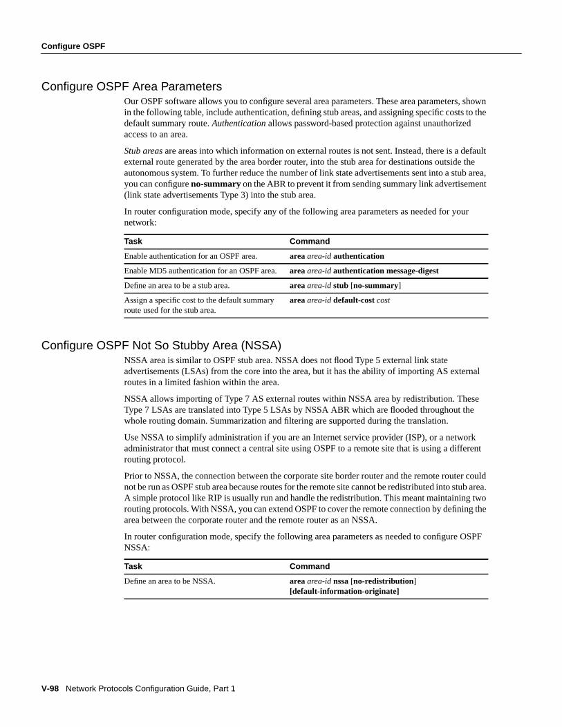
Configure OSPF Area ParametersOur OSPF software allows you to configure several area parameters. These area parameters, shownin the following table, include authentication, defining stub areas, and assigning specific costs to thedefault summary route. Authentication allows password-based protection against unauthorizedaccess to an area.
Stub areas are areas into which information on external routes is not sent. Instead, there is a defaultexternal route generated by the area border router, into the stub area for destinations outside theautonomous system. To further reduce the number of link state advertisements sent into a stub area,you can configureno-summary on the ABR to prevent it from sending summary link advertisement(link state advertisements Type 3) into the stub area.
In router configuration mode, specify any of the following area parameters as needed for yournetwork:
Configure OSPF Not So Stubby Area (NSSA)NSSA area is similar to OSPF stub area. NSSA does not flood Type 5 external link stateadvertisements (LSAs) from the core into the area, but it has the ability of importing AS externalroutes in a limited fashion within the area.
NSSA allows importing of Type 7 AS external routes within NSSA area by redistribution. TheseType 7 LSAs are translated into Type 5 LSAs by NSSA ABR which are flooded throughout thewhole routing domain. Summarization and filtering are supported during the translation.
Use NSSA to simplify administration if you are an Internet service provider (ISP), or a networkadministrator that must connect a central site using OSPF to a remote site that is using a differentrouting protocol.
Prior to NSSA, the connection between the corporate site border router and the remote router couldnot be run as OSPF stub area because routes for the remote site cannot be redistributed into stub area.A simple protocol like RIP is usually run and handle the redistribution. This meant maintaining tworouting protocols. With NSSA, you can extend OSPF to cover the remote connection by defining thearea between the corporate router and the remote router as an NSSA.
In router configuration mode, specify the following area parameters as needed to configure OSPFNSSA:
Task Command
Enable authentication for an OSPF area. areaarea-idauthentication
Enable MD5 authentication for an OSPF area.areaarea-idauthentication message-digest
Define an area to be a stub area. areaarea-idstub [no-summary]
Assign a specific cost to the default summaryroute used for the stub area.
areaarea-iddefault-costcost
Task Command
Define an area to be NSSA. areaarea-id nssa[no-redistribution ][default-information-originate]
Configure OSPF
Configuring IP Routing Protocols V-99
In router configuration mode on the ABR, specify the following command to control summarizationand filtering of Type 7 LSA into Type 5 LSA:
Implementation ConsiderationsEvaluate the following considerations before implementing this feature:
• You can set a Type 7 default route that can be used to reach external destinations. Whenconfigured, the router generates a Type 7 default into the NSSA by the NSSA ABR.
• Every router within the same area must agree that the area is NSSA; otherwise, the routers willnot be able to communicate with each other.
If possible, avoid using explicit redistribution on NSSA ABR because confusion may result overwhich packets are being translated by which router.
Configure Route Summarization between OSPF AreasRoute summarization is the consolidation of advertised addresses. This feature causes a singlesummary route to be advertised to other areas by an ABR. In OSPF, an ABR will advertise networksin one area into another area. If the network numbers in an area are assigned in a way such that theyare contiguous, you can configure the ABR to advertise a summary route that covers all theindividual networks within the area that fall into the specified range.
To specify an address range, perform the following task in router configuration mode:
Configure Route Summarization When Redistributing Routes into OSPFWhen redistributing routes from other protocols into OSPF (as described in the section “ConfigureRouting Protocol-Independent Features” later in this chapter), each route is advertised individuallyin an external link state advertisement (LSA). However, you can configure the Cisco IOS softwareto advertise a single route for all the redistributed routes that are covered by a specified networkaddress and mask. Doing so helps decrease the size of the OSPF link state database.
To have the software advertise one summary route for all redistributed routes covered by a networkaddress and mask, perform the following task in router configuration mode:
Create Virtual LinksIn OSPF, all areas must be connected to a backbone area. If there is a break in backbone continuity,or the backbone is purposefully partitioned, you can establish avirtual link. The two end points of avirtual link are Area Border Routers. The virtual link must be configured in both routers. The
Task Command
(Optional) Control the summarization andfiltering during the translation.
summary addressprefix mask[not advertise] [tag tag]
Task Command
Specify an address range for which a single routewill be advertised.
areaarea-idrangeaddress mask
Task Command
Specify an address and mask that coversredistributed routes, so only one summary route isadvertised.
summary-addressaddress mask
V-100 Network Protocols Configuration Guide, Part 1
Configure OSPF
configuration information in each router consists of the other virtual endpoint (the other ABR), andthe nonbackbone area that the two routers have in common (called thetransit area). Note that virtuallinks cannot be configured through stub areas.
To establish a virtual link, perform the following task in router configuration mode:
To display information about virtual links, use the show ip ospf virtual-links EXEC command. Todisplay the router ID of an OSPF router, use theshow ip ospf EXEC command.
Generate a Default RouteYou can force an autonomous system boundary router to generate a default route into an OSPFrouting domain. Whenever you specifically configure redistribution of routes into an OSPF routingdomain, the router automatically becomes an autonomous system boundary router. However, anautonomous system boundary router does not, by default, generate adefault route into the OSPFrouting domain.
To force the autonomous system boundary router to generate a default route, perform the followingtask in router configuration mode:
See the discussion of redistribution of routes in the “Configure Routing Protocol-IndependentFeatures” section later in this chapter.
Configure Lookup of DNS NamesYou can configure OSPF to look up Domain Naming System (DNS) names for use in all OSPF showcommand displays. This feature makes it easier to identify a router, because it is displayed by namerather than by its router ID or neighbor ID.
To configure DNS name lookup, perform the following task in global configuration mode:
Force the Router ID Choice with a Loopback InterfaceOSPF uses the largest IP address configured on the interfaces as its router ID. If the interfaceassociated with this IP address is ever brought down, or if the address is removed, the OSPF processmust recalculate a new router ID and resend all its routing information out its interfaces.
Task Command
Establish a virtual link. areaarea-idvirtual-link router-id [hello-interval seconds][retransmit-interval seconds] [transmit-delay seconds][dead-interval seconds] [[authentication-keykey] |[message-digest-keykeyidmd5 key]]
Task Command
Force the autonomous system boundary routerto generate a default route into the OSPFrouting domain.
default-information originate [always] [metricmetric-value] [metric-type type-value] [route-mapmap-name]
Task Command
Configure DNS name lookup. ip ospf name-lookup
Configure OSPF
Configuring IP Routing Protocols V-101
If a loopback interface is configured with an IP address, the Cisco IOS software will use this IPaddress as its router ID, even if other interfaces have larger IP addresses. Since loopback interfacesnever go down, greater stability in the routing table is achieved.
OSPF automatically prefers a loopback interface over any other kind, and it chooses the highest IPaddress among all loopback interfaces. If no loopback interfaces are present, the highest IP addressin the router is chosen. You cannot tell OSPF to use any particular interface.
To configure an IP address on a loopback interface, perform the following tasks, starting in globalconfiguration mode:
Disable Default OSPF Metric Calculation Based on BandwidthIn Cisco IOS Release 10.2 and earlier, OSPF assigned default OSPF metrics to interfaces regardlessof the interface bandwidth. It gave both 64K and T1 links the same metric (1562), and thus requiredan explicitip ospf cost command in order to take advantage of the faster link.
In Cisco IOS Release 10.3 and later, by default, OSPF calculates the OSPF metric for an interfaceaccording to the bandwidth of the interface. For example, a 64K link gets a metric of 1562, while aT1 link gets a metric of 64. To disable this feature, perform the following task in router configurationmode:
Configure OSPF on Simplex Ethernet InterfacesBecause simplex interfaces between two devices on an Ethernet represent only one networksegment, for OSPF you must configure the transmitting interface to be a passive interface. Thisprevents OSPF from sending hello packets for the transmitting interface. Both devices are able to seeeach other via the hello packet generated for the receiving interface.
To configure OSPF on simplex Ethernet interfaces, perform the following task in routerconfiguration mode:
1. This command is documented in the “Interface Commands” chapter of the Configuration Fundamentals CommandReference.
2. This command is documented in the “IP Commands” chapter of the Network Protocols Command Reference, Part 1.
Task Command
Step 1 Create a loopback interface, whichplaces you in interface configurationmode.
interface loopback 01
Step 2 Assign an IP address to this interface.ip address address mask2
Task Command
Disable default OSPF metric calculations based oninterface bandwidth, resulting in a fixed defaultmetric assignment.
no ospf auto-cost-determination
Task Command
Suppress the sending of hello packets throughthe specified interface.
passive-interfacetype number
V-102 Network Protocols Configuration Guide, Part 1
Configure OSPF
Configure Route Calculation TimersYou can configure the delay time between when OSPF receives a topology change and when it startsa shortest path first (SPF) calculation. You can also configure the hold time between two consecutiveSPF calculations. To do this, perform the following task in router configuration mode:
Configure OSPF over On Demand CircuitsThe OSPF on demand circuit is an enhancement to the OSPF protocol that allows efficient operationover on demand circuits like ISDN, X.25 SVCs and dial-up lines. This feature supports RFC 1793,Extending OSPF to Support Demand Circuits.
Prior to this feature, OSPF periodic hello and link state advertisements (LSAs) updates would beexchanged between routers that connected the on demand link, even when no changes occurred inthe hello or LSA information.
With this feature, periodic hellos are suppressed and the periodic refreshes of LSAs are not floodedover the demand circuit. These packets bring up the link only when they are exchanged for the firsttime, or when a change occurs in the information they contain. This operation allows the underlyingdatalink layer to be closed when the network topology is stable.
This feature is useful when you want to connect telecommuters or branch offices to an OSPFbackbone at a central site. In this case, OSPF for on demand circuits allows the benefits of OSPFover the entire domain, without excess connection costs. Periodic refreshes of hello updates, LSAupdates, and other protocol overhead are prevented from enabling the on demand circuit when thereis no “real” data to transmit.
Overhead protocols such as hellos and LSAs are transferred over the on demand circuit only uponinitial setup and when they reflect a change in the topology. This means that critical changes to thetopology that require new SPF calculations are transmitted in order to maintain network topologyintegrity. Periodic refreshes that do not include changes, however, are not transmitted across the link.
To configure OSPF for on demand circuits, perform the following tasks:
If the router is part of a point-to-point topology, then only one end of the demand circuit must beconfigured with this command. However, all routers must have this feature loaded.
If the router is part of a point-to-multipoint topology, only the multipoint end must be configuredwith this command.
Implementation ConsiderationsEvaluate the following considerations before implementing this feature:
• Because LSAs that include topology changes are flooded over an on demand circuit, it is advisedto put demand circuits within OSPF stub areas, or within NSSAs to isolate the demand circuitsfrom as many topology changes as possible.
Task Command
Configure route calculation timers. timers spf spf-delay spf-holdtime
Task Command
Step 1 Enable OSPF operation. router ospf process-id
Step 2 Configure OSPF on an on demand circuit.ip ospf demand-circuit
Configure Stub Routing
Configuring IP Routing Protocols V-103
• To take advantage of the on demand circuit functionality within a stub area or NSSA, every routerin the area must have this feature loaded. If this feature is deployed within a regular area, all otherregular areas must also support this feature before the demand circuit functionality can takeeffect. This is because type 5 external LSAs are flooded throughout all areas.
• You do not want to do on a broadcast-based network topology because the overhead protocols(such as hellos and LSAs) cannot be successfully suppressed, which means the link will remain up.
Configure Stub RoutingA stub router can be thought of as a spoke router in a hub-and-spoke network topology, where theonly router to which the spoke is adjacent is the hub router. In such a network topology, the IP routinginformation required to represent this topology is fairly simple. These stub routers commonly havea WAN connection to the hub router, and a small number of LAN network segments (stub networks)are directly connected to the stub router.
These stub networks might consist only of end systems and the stub router, and thus do not requirethe stub router to learn any dynamic IP routing information.The stub routers can then be configuredwith a default route that directs IP traffic to the hub router.
To provide full connectivity, the hub router can be statically configured to know that a particular stubnetwork is reachable via a particular stub router. However, if there are multiple hub routers, manystub networks, or asynchronous connections between hubs and spokes, statically configuring thestub networks on the hub routers becomes a problem.
Stub Routing Task ListOf the following tasks, the first three are required to configure stub routing and the last task isoptional:
• Enable On Demand Routing (ODR)
• Filter ODR Information
• Configure Default Route
• Redistribute ODR Information into the Hub’s Dynamic Routing Protocol
Enable On Demand Routing (ODR)On Demand Routing (ODR) allows you to easily install IP stub networks where the hubsdynamically maintain routes to the stub networks. This is accomplished without requiring theconfiguration of an IP routing protocol on the stubs.
On stub routers that support the ODR feature, the stub router advertises IP prefixes corresponding tothe IP networks configured on all directly connected interfaces. If the interface has multiple logicalIP networks configured (via theip secondary command), only the primary IP network is advertisedthrough ODR. Because ODR advertises IP prefixes and not simply IP network numbers, ODR is ableto carry Variable Length Subnet Mask (VSLM) information.
To enable ODR, perform the following task in global configuration mode:
Task Command
Enable ODR on the hub router. router odr process-id
V-104 Network Protocols Configuration Guide, Part 1
Configure Stub Routing
Once ODR is enabled on a hub router, the hub router begins installing stub network routes in the IPforwarding table. The hub router can additionally be configured to redistribute these routes into anyconfigured dynamic IP routing protocols.
On the stub router, no IP routing protocol must be configured. In fact, from the standpoint of ODR,a router is automatically considered to be a stub when no IP routing protocols have been configured.
The routing information that ODR generates is propagated between routers using Cisco’s CDPprotocol. This means that the operation of ODR is partially controlled by the configuration of CDP.
Using the global configuration commandno cdp run disables the propagation of ODR stub routinginformation entirely. Using the interface configuration commandno cdp enable disables thepropagation of ODR information on a particular interface.
Filter ODR InformationThe hub router will attempt to populate the IP routing table with ODR routes, as they are learneddynamically from stub routers. The IP next hop for these routes is the IP address of the neighboringrouter, as advertised through CDP.
Use IP filtering to limit the network prefixes that the hub router will permit to be learned dynamicallythrough ODR.
To filter ODR information, perform the following task in the router configuration mode:
For example, the following configuration causes the hub router to only accept advertisements for IPprefixes about (or subnets of) the class C network 198.92.110.0.
router odr distribute-list 101 in access-list 101 permit ip any 198.92.110.0 255.255.255.0
Configure Default RouteAlthough no IP routing protocol must be configured on the stub router, it is still necessary toconfigure the default route for IP traffic. You can optionally cause traffic for unknown subsets tofollow the default route.
To configure the default route for IP traffic, perform the following tasks in global configurationmode:
Redistribute ODR Information into the Hub’s Dynamic Routing ProtocolThis task may be performed by using theredistribute router subcommand. The exact syntaxdepends upon the routing protocol into which ODR is being redistributed.
See the “Redistribute Routing Information” section later in this chapter.
Task Command
Filter ODR information on the hub router distribute-list { access-list-number | name} in|out[type number]
Task Command
Configure a default route on the stub router. ip route 0.0.0.0 0.0.0.0interface-name
Cause traffic for unknown subnets of directlyconnected networks to also follow the default route.
ip classless
Configure RIP
Configuring IP Routing Protocols V-105
Reconfigure CDP/ODR TimersBy default, Cisco Discovery Protocol (CDP) sends updates every 60 seconds. This update intervalmay not be frequent enough to provide speedy reconvergence of IP routes on the hub router side ofthe network. A faster reconvergence rate may be necessary if the stub connects to one of several hubrouters via asynchronous interfaces (such as modem lines). ODR expects to receive periodic CDPupdates containing IP prefix information. When ODR fails to receive such updates for routes that ithas installed in the routing table, these ODR routes are first marked invalid, and eventually removedfrom the routing table. (By default, ODR routes are marked invalid after 180 seconds, and areremoved from the routing table after 240 seconds.) These defaults are based upon the default CDPupdate interval. Configuration changes made to either the CDP or ODR timers should be reflectedthrough changes made to both.
To configure CDP/ODR timers, perform the following tasks beginning in global configuration mode:
Other CDP features are described in theConfiguration Fundamentals Configuration Guide, in the“Managing the System” chapter.
Using ODR with Dialer MappingsFor interfaces that specify dialer mappings, CDP packets will make use of dialer map configurationstatements that pertain to the IP protocol. Since CDP packets are always broadcast packets, thesedialer map statements must handle broadcast packets, typically through use of the dialer mapbroadcast keyword. The dialer string interface configuration command may also be used.
On DDR interfaces, certain kinds of packets can be classified as interesting. These interestingpackets can cause a DDR connection to be made, or cause the idle timer of a DDR interface to bereset. For the purposes of DDR classification, CDP packets are considered uninteresting. This is trueeven while CDP is making use of dialer-map statements for IP, where IP packets are classified asinteresting.
Configure RIPThe Routing Information Protocol (RIP) is a relatively old, but still commonly used, IGP created foruse in small, homogeneous networks. This is a classical distance-vector routing protocol. RIP isdocumented in RFC 1058.
RIP uses broadcast User Datagram Protocol (UDP) data packets to exchange routing information.The Cisco IOS software sends routing information updates every 30 seconds; this process is termedadvertising.If a router does not receive an update from another router for 180 seconds or more, itmarks the routes served by the nonupdating router as being unusable. If there is still no update after240 seconds, the router removes all routing table entries for the nonupdating router.
The metric that RIP uses to rate the value of different routes ishop count.The hop count is thenumber of routers that can be traversed in a route. A directly connected network has a metric of zero;an unreachable network has a metric of 16. This small range of metrics makes RIP an unsuitablerouting protocol for large networks.
1. This command is documented in the “System Management Commands” chapter of theConfiguration FundamentalsCommand Reference.
Task Command
Change the rate at which CDP updates are sent. cdp timer seconds1
Change the rate at which ODR routes are expiredfrom the routing table.
router odr
timers odr
V-106 Network Protocols Configuration Guide, Part 1
Configure RIP
If the router has a default network path, RIP advertises a route that links the router to thepseudonetwork 0.0.0.0. The network 0.0.0.0 does not exist; RIP treats 0.0.0.0 as a network toimplement the default routing feature. The Cisco IOS software will advertise the default network ifa default was learned by RIP, or if the router has a gateway of last resort and RIP is configured witha default metric.
RIP sends updates to the interfaces in the specified networks. If an interface’s network is notspecified, it will not be advertised in any RIP update.
Cisco’s implementation of RIP Version 2 supports plain text and MD5 authentication, routesummarization, classless interdomain routing (CIDR), and variable-length subnet masks (VLSMs).
RIP Configuration Task ListTo configure RIP, complete the tasks in the following sections. You must enable RIP. The remainingtasks are optional.
• Enable RIP
• Allow Point-to-Point Updates for RIP
• Specify a RIP Version
• Enable RIP Authentication
• Disable Route Summarization
• Run IGRP and RIP Concurrently
• Disable the Validation of Source IP Addresses
For information about filtering RIP information, see the “Filter Routing Information” section laterin this chapter. For information about RIP Version 2 key management or VLSM, see the “ConfigureRouting Protocol-Independent Features” section later in this chapter.
Enable RIPTo enable RIP, perform the following tasks, starting in global configuration mode:
See the “Key Management Examples” section at the end of this chapter for key managementexamples.
Allow Point-to-Point Updates for RIPBecause RIP is normally a broadcast protocol, in order for RIP routing updates to reachpoint-to-point or nonbroadcast networks, you must configure the Cisco IOS software to permit thisexchange of routing information. To do so, perform the following task in router configuration mode:
Task Command
Step 1 Enable a RIP routing process, whichplaces you in router configuration mode.
router rip
Step 2 Associate a network with a RIP routingprocess.
network network-number
Task Command
Define a neighboring router with which toexchange point-to-point routing information.
neighbor ip-address
Configure RIP
Configuring IP Routing Protocols V-107
To control the set of interfaces with which you want to exchange routing updates, you can disablethe sending of routing updates on specified interfaces by configuring thepassive-interfacecommand. See the discussion on filtering in the “Filter Routing Information” section later in thischapter.
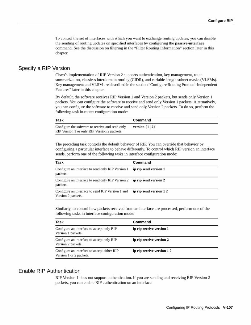
Specify a RIP VersionCisco’s implementation of RIP Version 2 supports authentication, key management, routesummarization, classless interdomain routing (CIDR), and variable-length subnet masks (VLSMs).Key management and VLSM are described in the section “Configure Routing Protocol-IndependentFeatures” later in this chapter.
By default, the software receives RIP Version 1 and Version 2 packets, but sends only Version 1packets. You can configure the software to receive and send only Version 1 packets. Alternatively,you can configure the software to receive and send only Version 2 packets. To do so, perform thefollowing task in router configuration mode:
The preceding task controls the default behavior of RIP. You can override that behavior byconfiguring a particular interface to behave differently. To control which RIP version an interfacesends, perform one of the following tasks in interface configuration mode:
Similarly, to control how packets received from an interface are processed, perform one of thefollowing tasks in interface configuration mode:
Enable RIP AuthenticationRIP Version 1 does not support authentication. If you are sending and receiving RIP Version 2packets, you can enable RIP authentication on an interface.
Task Command
Configure the software to receive and send onlyRIP Version 1 or only RIP Version 2 packets.
version {1 | 2}
Task Command
Configure an interface to send only RIP Version 1packets.
ip rip send version 1
Configure an interface to send only RIP Version 2packets.
ip rip send version 2
Configure an interface to send RIP Version 1 andVersion 2 packets.
ip rip send version 1 2
Task Command
Configure an interface to accept only RIPVersion 1 packets.
ip rip receive version 1
Configure an interface to accept only RIPVersion 2 packets.
ip rip receive version 2
Configure an interface to accept either RIPVersion 1 or 2 packets.
ip rip receive version 1 2
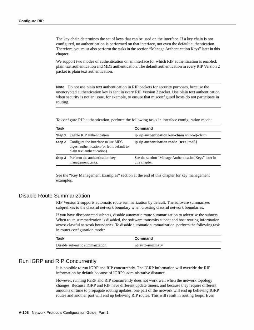
V-108 Network Protocols Configuration Guide, Part 1
Configure RIP
The key chain determines the set of keys that can be used on the interface. If a key chain is notconfigured, no authentication is performed on that interface, not even the default authentication.Therefore, you must also perform the tasks in the section “Manage Authentication Keys” later in thischapter.
We support two modes of authentication on an interface for which RIP authentication is enabled:plain text authentication and MD5 authentication. The default authentication in every RIP Version 2packet is plain text authentication.
Note Do not use plain text authentication in RIP packets for security purposes, because theunencrypted authentication key is sent in every RIP Version 2 packet. Use plain text authenticationwhen security is not an issue, for example, to ensure that misconfigured hosts do not participate inrouting.
To configure RIP authentication, perform the following tasks in interface configuration mode:
See the “Key Management Examples” section at the end of this chapter for key managementexamples.
Disable Route SummarizationRIP Version 2 supports automatic route summarization by default. The software summarizessubprefixes to the classful network boundary when crossing classful network boundaries.
If you have disconnected subnets, disable automatic route summarization to advertise the subnets.When route summarization is disabled, the software transmits subnet and host routing informationacross classful network boundaries. To disable automatic summarization, perform the following taskin router configuration mode:
Run IGRP and RIP ConcurrentlyIt is possible to run IGRP and RIP concurrently. The IGRP information will override the RIPinformation by default because of IGRP’s administrative distance.
However, running IGRP and RIP concurrently does not work well when the network topologychanges. Because IGRP and RIP have different update timers, and because they require differentamounts of time to propagate routing updates, one part of the network will end up believing IGRProutes and another part will end up believing RIP routes. This will result in routing loops. Even
Task Command
Step 1 Enable RIP authentication. ip rip authentication key-chain name-of-chain
Step 2 Configure the interface to use MD5digest authentication (or let it default toplain text authentication).
ip rip authentication mode { text | md5}
Step 3 Perform the authentication keymanagement tasks.
See the section “Manage Authentication Keys” later inthis chapter.
Task Command
Disable automatic summarization. no auto-summary

Configure IS-IS
Configuring IP Routing Protocols V-109
though these loops do not exist for very long, the time to live (TTL) will quickly reach zero, andICMP will send a “TTL exceeded” message. This message will cause most applications to stopattempting network connections.
Disable the Validation of Source IP AddressesBy default, the software validates the source IP address of incoming RIP routing updates. If thatsource address is not valid, the software discards the routing update.
You might want to disable this feature if you have a router that is “off network” and you want toreceive its updates. However, disabling this feature is not recommended under normalcircumstances. To disable the default function that validates the source IP addresses of incomingrouting updates, perform the following task in router configuration mode:
Configure IS-ISIntermediate System-to-Intermediate System (IS-IS) is an International Organization forStandardization (ISO) dynamic routing specification. IS-IS is described in ISO 10589. Cisco’simplementation of IS-IS allows you to configure IS-IS as an IP routing protocol.
IS-IS Configuration Task ListTo configure IS-IS, complete the tasks in the following sections. Only enabling IS-IS is required; theremainder of the tasks are optional, although you might be required to perform them, dependingupon your specific application.
• Enable IS-IS
• Configure IS-IS Interface Parameters
• Configure Miscellaneous IS-IS Parameters
In addition, you can filter routing information (see the “Filter Routing Information” section later inthis chapter for information on how to do this), and specify route redistribution (see the “RedistributeRouting Information” section later in this chapter for information on how to do this).
Enable IS-ISAs with other routing protocols, enabling IS-IS requires that you create an IS-IS routing process andassign it to specific networks. You can specifyonly one IS-IS process per router. Only one IS-ISprocess is allowed whether you run it in integrated mode, ISO CLNS only, or IP only.
Network entity titles (NETs) define the area addresses for the IS-IS area. Multiple NETs per routerare allowed (up to a maximum of three). Refer to the “Configuring ISO CLNS” chapter inNetworkProtocols Configuration Guide, Part 3 for a more detailed discussion of NETs.
Task Command
Disable the validation of the source IP address ofincoming RIP routing updates.
no validate-update-source
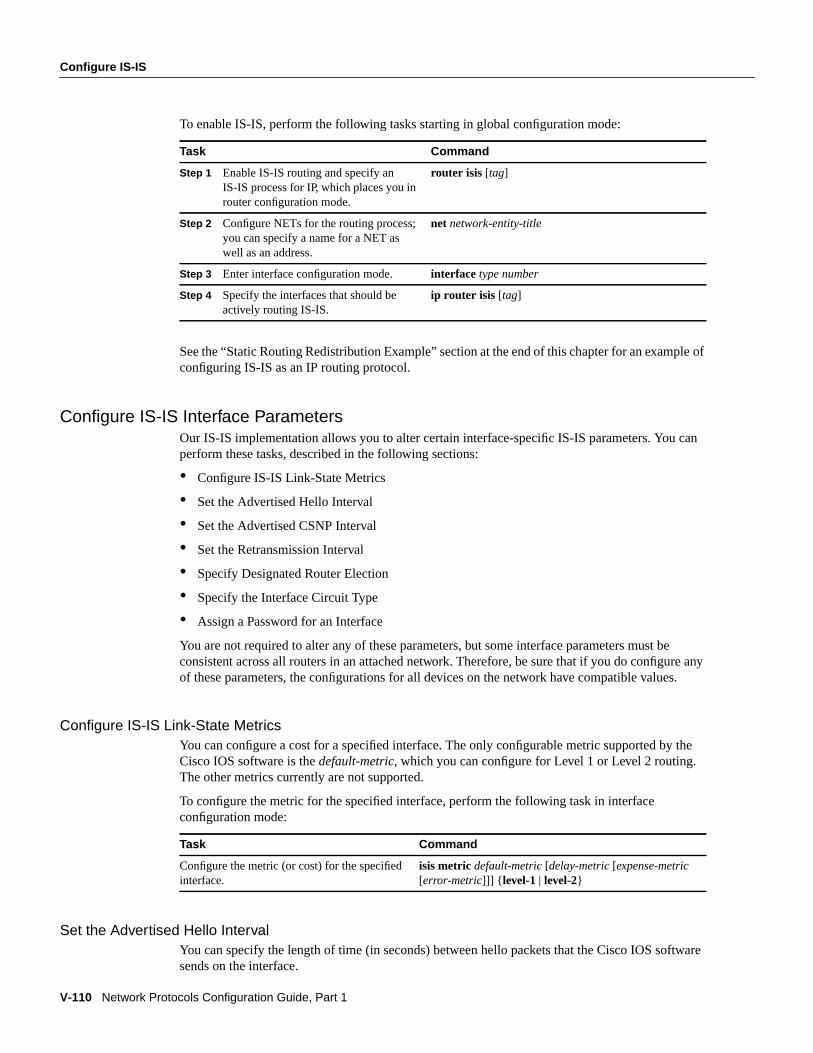
V-110 Network Protocols Configuration Guide, Part 1
Configure IS-IS
To enable IS-IS, perform the following tasks starting in global configuration mode:
See the “Static Routing Redistribution Example” section at the end of this chapter for an example ofconfiguring IS-IS as an IP routing protocol.
Configure IS-IS Interface ParametersOur IS-IS implementation allows you to alter certain interface-specific IS-IS parameters. You canperform these tasks, described in the following sections:
• Configure IS-IS Link-State Metrics
• Set the Advertised Hello Interval
• Set the Advertised CSNP Interval
• Set the Retransmission Interval
• Specify Designated Router Election
• Specify the Interface Circuit Type
• Assign a Password for an Interface
You are not required to alter any of these parameters, but some interface parameters must beconsistent across all routers in an attached network. Therefore, be sure that if you do configure anyof these parameters, the configurations for all devices on the network have compatible values.
Configure IS-IS Link-State MetricsYou can configure a cost for a specified interface. The only configurable metric supported by theCisco IOS software is thedefault-metric, which you can configure for Level 1 or Level 2 routing.The other metrics currently are not supported.
To configure the metric for the specified interface, perform the following task in interfaceconfiguration mode:
Set the Advertised Hello IntervalYou can specify the length of time (in seconds) between hello packets that the Cisco IOS softwaresends on the interface.
Task Command
Step 1 Enable IS-IS routing and specify anIS-IS process for IP, which places you inrouter configuration mode.
router isis [tag]
Step 2 Configure NETs for the routing process;you can specify a name for a NET aswell as an address.
net network-entity-title
Step 3 Enter interface configuration mode. interface type number
Step 4 Specify the interfaces that should beactively routing IS-IS.
ip router isis [tag]
Task Command
Configure the metric (or cost) for the specifiedinterface.
isis metric default-metric[delay-metric[expense-metric[error-metric]]] { level-1 | level-2}
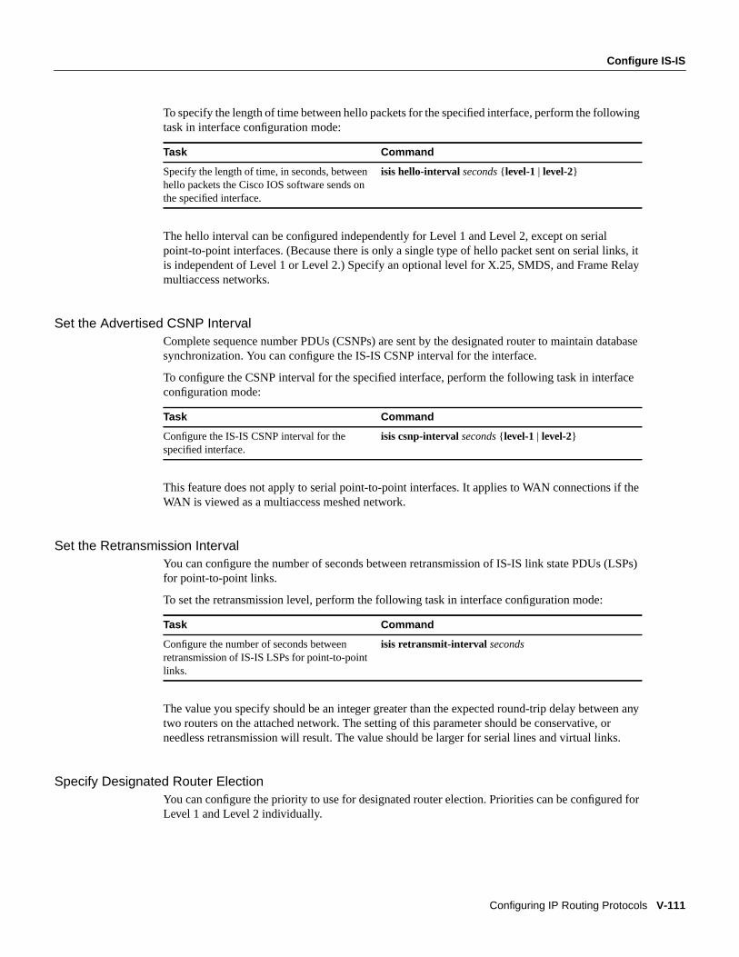
Configure IS-IS
Configuring IP Routing Protocols V-111
To specify the length of time between hello packets for the specified interface, perform the followingtask in interface configuration mode:
The hello interval can be configured independently for Level 1 and Level 2, except on serialpoint-to-point interfaces. (Because there is only a single type of hello packet sent on serial links, itis independent of Level 1 or Level 2.) Specify an optional level for X.25, SMDS, and Frame Relaymultiaccess networks.
Set the Advertised CSNP IntervalComplete sequence number PDUs (CSNPs) are sent by the designated router to maintain databasesynchronization. You can configure the IS-IS CSNP interval for the interface.
To configure the CSNP interval for the specified interface, perform the following task in interfaceconfiguration mode:
This feature does not apply to serial point-to-point interfaces. It applies to WAN connections if theWAN is viewed as a multiaccess meshed network.
Set the Retransmission IntervalYou can configure the number of seconds between retransmission of IS-IS link state PDUs (LSPs)for point-to-point links.
To set the retransmission level, perform the following task in interface configuration mode:
The value you specify should be an integer greater than the expected round-trip delay between anytwo routers on the attached network. The setting of this parameter should be conservative, orneedless retransmission will result. The value should be larger for serial lines and virtual links.
Specify Designated Router ElectionYou can configure the priority to use for designated router election. Priorities can be configured forLevel 1 and Level 2 individually.
Task Command
Specify the length of time, in seconds, betweenhello packets the Cisco IOS software sends onthe specified interface.
isis hello-interval seconds { level-1 | level-2}
Task Command
Configure the IS-IS CSNP interval for thespecified interface.
isis csnp-intervalseconds { level-1 | level-2}
Task Command
Configure the number of seconds betweenretransmission of IS-IS LSPs for point-to-pointlinks.
isis retransmit-interval seconds

V-112 Network Protocols Configuration Guide, Part 1
Configure IS-IS
To specify the designated router election, perform the following task in interface configurationmode:
Specify the Interface Circuit TypeYou can specify adjacency levels on a specified interface. This parameter is also referred to as theinterface circuit type.
To specify the interface circuit type, perform the following task in interface configuration mode:
Assign a Password for an InterfaceYou can assign different passwords for different routing levels. Specifying Level 1 or Level 2configures the password for only Level 1 or Level 2 routing, respectively. If you do not specify alevel, the default is Level 1. By default, authentication is disabled.
To configure a password for the specified level, perform the following task in interface configurationmode:
Configure Miscellaneous IS-IS ParametersYou can configure optional IS-IS parameters as described in the following sections:
• Generate a Default Route
• Specify Router-Level Support
• Configure IS-IS Authentication Passwords
• Summarize Address Ranges
Generate a Default RouteYou can force a default route into an IS-IS routing domain. Whenever you specifically configureredistribution of routes into an IS-IS routing domain, the Cisco IOS software does not, by default,generate adefault route into the IS-IS routing domain. The following feature allows you to force theboundary router do this.
Task Command
Configure the priority to use for designatedrouter election.
isis priority value{ level-1 | level-2}
Task Command
Configure the type of adjacency desired forneighbors on the specified interface (theinterface circuit type).
isis circuit-type { level-1 | level-1-2| level-2-only}
Task Command
Configure the authentication password for aspecified interface.
isis passwordpassword{ level-1 | level-2}
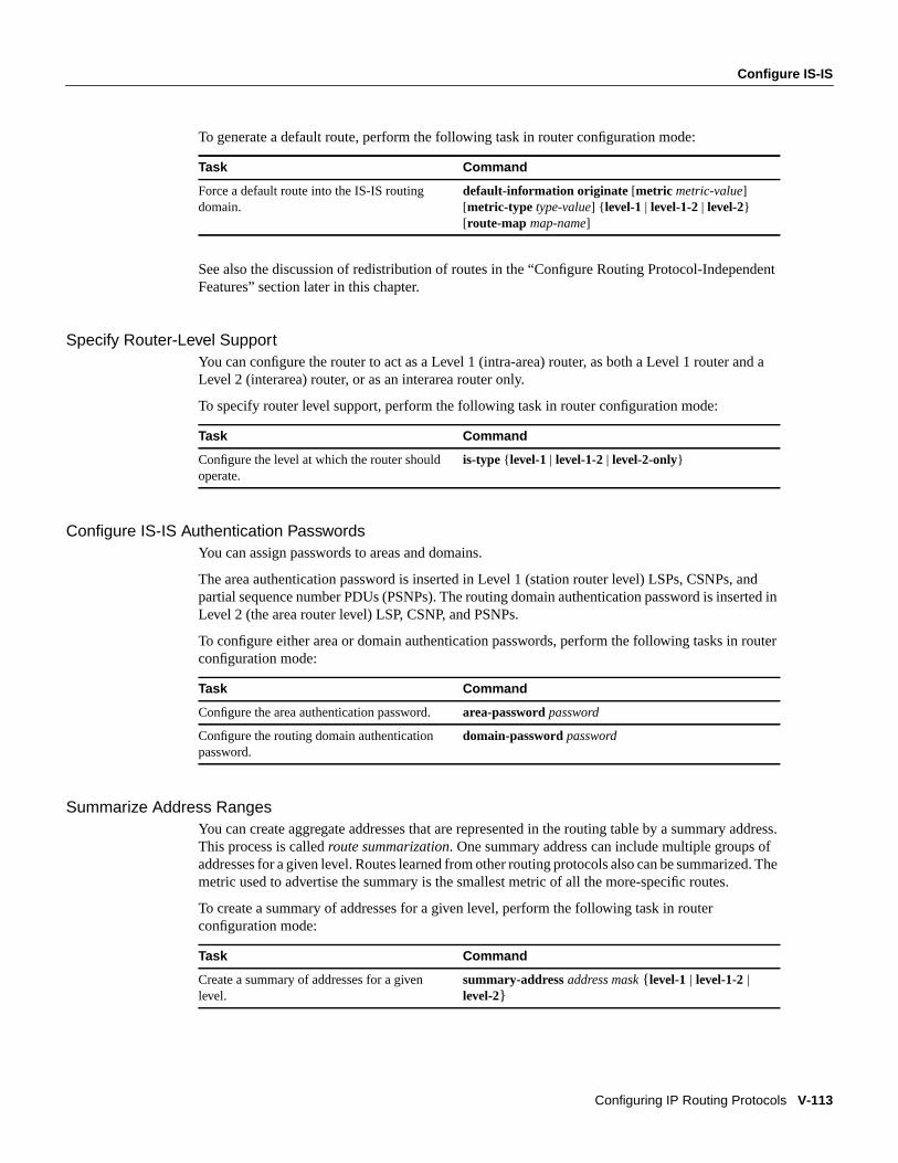
Configure IS-IS
Configuring IP Routing Protocols V-113
To generate a default route, perform the following task in router configuration mode:
See also the discussion of redistribution of routes in the “Configure Routing Protocol-IndependentFeatures” section later in this chapter.
Specify Router-Level SupportYou can configure the router to act as a Level 1 (intra-area) router, as both a Level 1 router and aLevel 2 (interarea) router, or as an interarea router only.
To specify router level support, perform the following task in router configuration mode:
Configure IS-IS Authentication PasswordsYou can assign passwords to areas and domains.
The area authentication password is inserted in Level 1 (station router level) LSPs, CSNPs, andpartial sequence number PDUs (PSNPs). The routing domain authentication password is inserted inLevel 2 (the area router level) LSP, CSNP, and PSNPs.
To configure either area or domain authentication passwords, perform the following tasks in routerconfiguration mode:
Summarize Address RangesYou can create aggregate addresses that are represented in the routing table by a summary address.This process is calledroute summarization. One summary address can include multiple groups ofaddresses for a given level. Routes learned from other routing protocols also can be summarized. Themetric used to advertise the summary is the smallest metric of all the more-specific routes.
To create a summary of addresses for a given level, perform the following task in routerconfiguration mode:
Task Command
Force a default route into the IS-IS routingdomain.
default-information originate [metric metric-value][metric-type type-value] { level-1 | level-1-2| level-2}[route-map map-name]
Task Command
Configure the level at which the router shouldoperate.
is-type { level-1 | level-1-2 | level-2-only}
Task Command
Configure the area authentication password. area-passwordpassword
Configure the routing domain authenticationpassword.
domain-passwordpassword
Task Command
Create a summary of addresses for a givenlevel.
summary-addressaddress mask { level-1 | level-1-2|level-2}
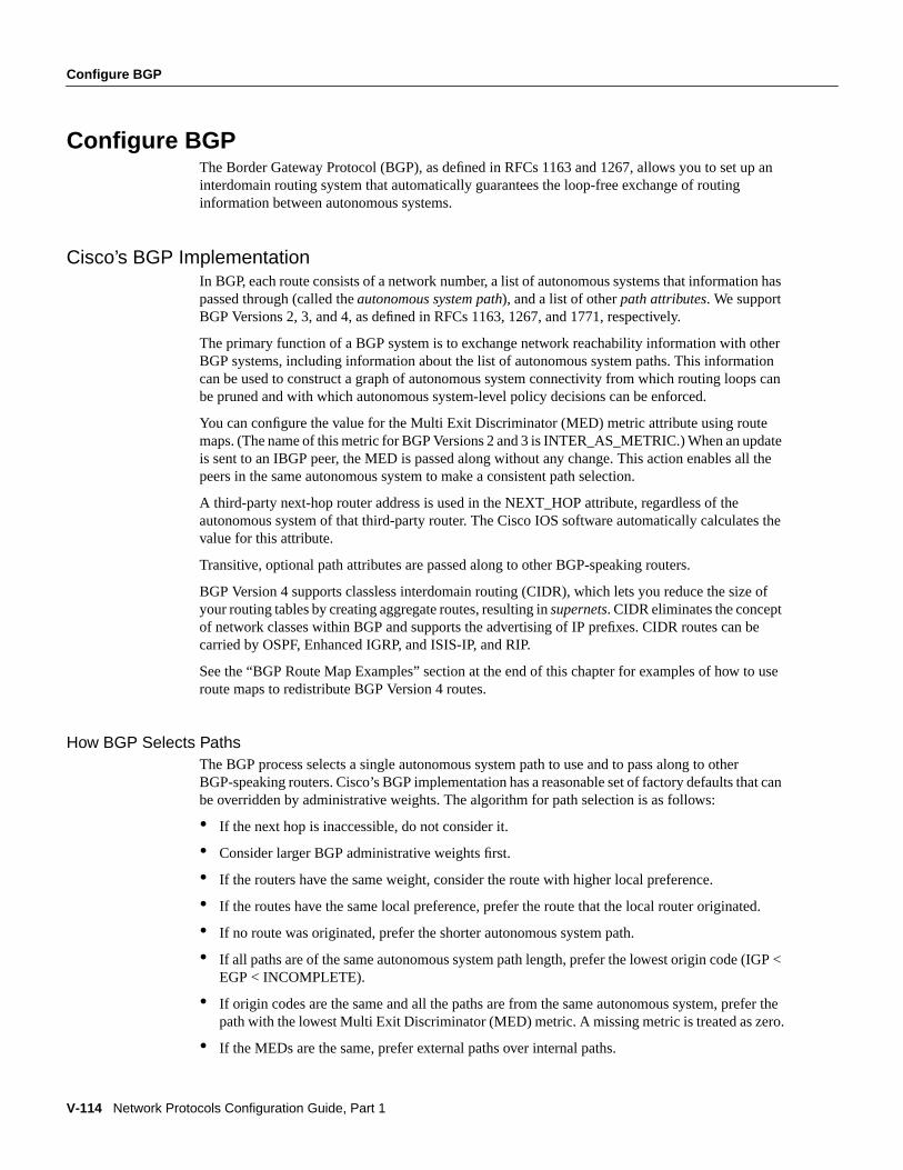
V-114 Network Protocols Configuration Guide, Part 1
Configure BGP
Configure BGPThe Border Gateway Protocol (BGP), as defined in RFCs 1163 and 1267, allows you to set up aninterdomain routing system that automatically guarantees the loop-free exchange of routinginformation between autonomous systems.
Cisco’s BGP ImplementationIn BGP, each route consists of a network number, a list of autonomous systems that information haspassed through (called theautonomous system path), and a list of otherpath attributes. We supportBGP Versions 2, 3, and 4, as defined in RFCs 1163, 1267, and 1771, respectively.
The primary function of a BGP system is to exchange network reachability information with otherBGP systems, including information about the list of autonomous system paths. This informationcan be used to construct a graph of autonomous system connectivity from which routing loops canbe pruned and with which autonomous system-level policy decisions can be enforced.
You can configure the value for the Multi Exit Discriminator (MED) metric attribute using routemaps. (The name of this metric for BGP Versions 2 and 3 is INTER_AS_METRIC.) When an updateis sent to an IBGP peer, the MED is passed along without any change. This action enables all thepeers in the same autonomous system to make a consistent path selection.
A third-party next-hop router address is used in the NEXT_HOP attribute, regardless of theautonomous system of that third-party router. The Cisco IOS software automatically calculates thevalue for this attribute.
Transitive, optional path attributes are passed along to other BGP-speaking routers.
BGP Version 4 supports classless interdomain routing (CIDR), which lets you reduce the size ofyour routing tables by creating aggregate routes, resulting insupernets. CIDR eliminates the conceptof network classes within BGP and supports the advertising of IP prefixes. CIDR routes can becarried by OSPF, Enhanced IGRP, and ISIS-IP, and RIP.
See the “BGP Route Map Examples” section at the end of this chapter for examples of how to useroute maps to redistribute BGP Version 4 routes.
How BGP Selects PathsThe BGP process selects a single autonomous system path to use and to pass along to otherBGP-speaking routers. Cisco’s BGP implementation has a reasonable set of factory defaults that canbe overridden by administrative weights. The algorithm for path selection is as follows:
• If the next hop is inaccessible, do not consider it.
• Consider larger BGP administrative weights first.
• If the routers have the same weight, consider the route with higher local preference.
• If the routes have the same local preference, prefer the route that the local router originated.
• If no route was originated, prefer the shorter autonomous system path.
• If all paths are of the same autonomous system path length, prefer the lowest origin code (IGP <EGP < INCOMPLETE).
• If origin codes are the same and all the paths are from the same autonomous system, prefer thepath with the lowest Multi Exit Discriminator (MED) metric. A missing metric is treated as zero.
• If the MEDs are the same, prefer external paths over internal paths.
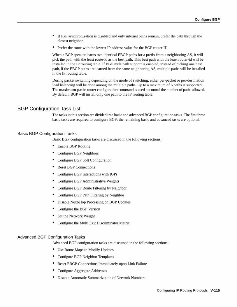
Configure BGP
Configuring IP Routing Protocols V-115
• If IGP synchronization is disabled and only internal paths remain, prefer the path through theclosest neighbor.
• Prefer the route with the lowest IP address value for the BGP router ID.
When a BGP speaker learns two identical EBGP paths for a prefix from a neighboring AS, it willpick the path with the least route-id as the best path. This best path with the least router-id will beinstalled in the IP routing table. If BGP multipath support is enabled, instead of picking one bestpath, if the EBGP paths are learned from the same neighboring AS, multiple paths will be installedin the IP routing table.
During packet switching depending on the mode of switching, either per-packet or per-destinationload balancing will be done among the multiple paths. Up to a maximum of 6 paths is supported.Themaximum-paths router configuration command is used to control the number of paths allowed.By default, BGP will install only one path to the IP routing table.
BGP Configuration Task ListThe tasks in this section are divided into basic and advanced BGP configuration tasks. The first threebasic tasks are required to configure BGP; the remaining basic and advanced tasks are optional.
Basic BGP Configuration TasksBasic BGP configuration tasks are discussed in the following sections:
• Enable BGP Routing
• Configure BGP Neighbors
• Configure BGP Soft Configuration
• Reset BGP Connections
• Configure BGP Interactions with IGPs
• Configure BGP Administrative Weights
• Configure BGP Route Filtering by Neighbor
• Configure BGP Path Filtering by Neighbor
• Disable Next-Hop Processing on BGP Updates
• Configure the BGP Version
• Set the Network Weight
• Configure the Multi Exit Discriminator Metric
Advanced BGP Configuration TasksAdvanced BGP configuration tasks are discussed in the following sections:
• Use Route Maps to Modify Updates
• Configure BGP Neighbor Templates
• Reset EBGP Connections Immediately upon Link Failure
• Configure Aggregate Addresses
• Disable Automatic Summarization of Network Numbers
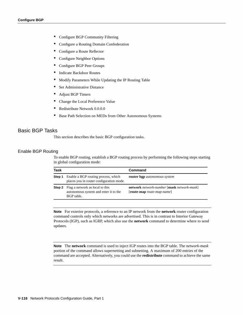
V-116 Network Protocols Configuration Guide, Part 1
Configure BGP
• Configure BGP Community Filtering
• Configure a Routing Domain Confederation
• Configure a Route Reflector
• Configure Neighbor Options
• Configure BGP Peer Groups
• Indicate Backdoor Routes
• Modify Parameters While Updating the IP Routing Table
• Set Administrative Distance
• Adjust BGP Timers
• Change the Local Preference Value
• Redistribute Network 0.0.0.0
• Base Path Selection on MEDs from Other Autonomous Systems
Basic BGP TasksThis section describes the basic BGP configuration tasks.
Enable BGP RoutingTo enable BGP routing, establish a BGP routing process by performing the following steps startingin global configuration mode:
Note For exterior protocols, a reference to an IP network from thenetwork router configurationcommand controls only which networks are advertised. This is in contrast to Interior GatewayProtocols (IGP), such as IGRP, which also use thenetwork command to determine where to sendupdates.
Note Thenetwork command is used to inject IGP routes into the BGP table. Thenetwork-maskportion of the command allows supernetting and subnetting. A maximum of 200 entries of thecommand are accepted. Alternatively, you could use theredistribute command to achieve the sameresult.
Task Command
Step 1 Enable a BGP routing process, whichplaces you in router configuration mode.
router bgp autonomous-system
Step 2 Flag a network as local to thisautonomous system and enter it to theBGP table.
network network-number[mask network-mask][route-map route-map-name]
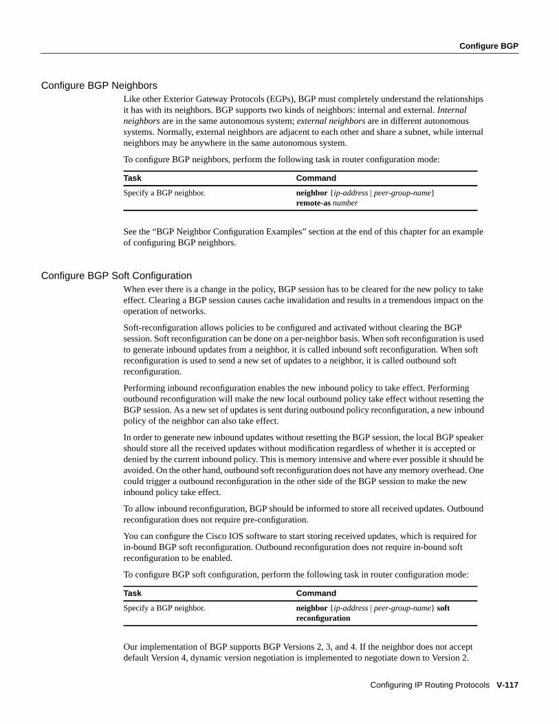
Configure BGP
Configuring IP Routing Protocols V-117
Configure BGP NeighborsLike other Exterior Gateway Protocols (EGPs), BGP must completely understand the relationshipsit has with its neighbors. BGP supports two kinds of neighbors: internal and external.Internalneighbors are in the same autonomous system;external neighbors are in different autonomoussystems. Normally, external neighbors are adjacent to each other and share a subnet, while internalneighbors may be anywhere in the same autonomous system.
To configure BGP neighbors, perform the following task in router configuration mode:
See the “BGP Neighbor Configuration Examples” section at the end of this chapter for an exampleof configuring BGP neighbors.
Configure BGP Soft ConfigurationWhen ever there is a change in the policy, BGP session has to be cleared for the new policy to takeeffect. Clearing a BGP session causes cache invalidation and results in a tremendous impact on theoperation of networks.
Soft-reconfiguration allows policies to be configured and activated without clearing the BGPsession. Soft reconfiguration can be done on a per-neighbor basis. When soft reconfiguration is usedto generate inbound updates from a neighbor, it is called inbound soft reconfiguration. When softreconfiguration is used to send a new set of updates to a neighbor, it is called outbound softreconfiguration.
Performing inbound reconfiguration enables the new inbound policy to take effect. Performingoutbound reconfiguration will make the new local outbound policy take effect without resetting theBGP session. As a new set of updates is sent during outbound policy reconfiguration, a new inboundpolicy of the neighbor can also take effect.
In order to generate new inbound updates without resetting the BGP session, the local BGP speakershould store all the received updates without modification regardless of whether it is accepted ordenied by the current inbound policy. This is memory intensive and where ever possible it should beavoided. On the other hand, outbound soft reconfiguration does not have any memory overhead. Onecould trigger a outbound reconfiguration in the other side of the BGP session to make the newinbound policy take effect.
To allow inbound reconfiguration, BGP should be informed to store all received updates. Outboundreconfiguration does not require pre-configuration.
You can configure the Cisco IOS software to start storing received updates, which is required forin-bound BGP soft reconfiguration. Outbound reconfiguration does not require in-bound softreconfiguration to be enabled.
To configure BGP soft configuration, perform the following task in router configuration mode:
Our implementation of BGP supports BGP Versions 2, 3, and 4. If the neighbor does not acceptdefault Version 4, dynamic version negotiation is implemented to negotiate down to Version 2.
Task Command
Specify a BGP neighbor. neighbor { ip-address| peer-group-name}remote-as number
Task Command
Specify a BGP neighbor. neighbor { ip-address| peer-group-name} softreconfiguration

V-118 Network Protocols Configuration Guide, Part 1
Configure BGP
If you specify a BGP peer group by using thepeer-group-name argument, all members of the peergroup will inherit the characteristic configured with this command.
Reset BGP ConnectionsOnce you have defined two routers to be BGP neighbors, they will form a BGP connection andexchange routing information. If you subsequently change a BGP filter, weight, distance, version, ortimer, or make a similar configuration change, you must reset BGP connections for the configurationchange to take effect. Perform either of the following tasks in EXEC mode to reset BGP connections:
Configure BGP Interactions with IGPsIf your autonomous system will be passing traffic through it from another autonomous system to athird autonomous system, it is very important that your autonomous system be consistent about theroutes that it advertises. For example, if your BGP were to advertise a route before all routers in yournetwork had learned about the route through your IGP, your autonomous system could receive trafficthat some routers cannot yet route. To prevent this from happening, BGP must wait until the IGP haspropagated routing information across your autonomous system. This causes BGP to besynchronized with the IGP. Synchronization is enabled by default.
In some cases, you do not need synchronization. If you will not be passing traffic from a differentautonomous system through your autonomous system, or if all routers in your autonomous systemwill be running BGP, you can disable synchronization. Disabling this feature can allow you to carryfewer routes in your IGP and allow BGP to converge more quickly. To disable synchronization,perform the following task in router configuration mode:
When you disable synchronization, you should also clear BGP sessions using the clear ip bgpcommand.
See the “BGP Path Filtering by Neighbor Example” section at the end of this chapter for an exampleof BGP synchronization.
In general, you will not want to redistribute most BGP routes into your IGP. A common design is toredistribute one or two routes and to make them exterior routes in IGRP, or have your BGP speakergenerate a default route for your autonomous system. When redistributing from BGP into IGP, onlythe routes learned using EBGP get redistributed.
In most circumstances, you also will not want to redistribute your IGP into BGP. Just list thenetworks in your autonomous system withnetwork router configuration commands and yournetworks will be advertised. Networks that are listed this way are referred to aslocal networks andhave a BGP origin attribute of “IGP.” They must appear in the main IP routing table and can haveany source; for example, they can be directly connected or learned via an IGP. The BGP routingprocess periodically scans the main IP routing table to detect the presence or absence of localnetworks, updating the BGP routing table as appropriate.
Task Command
Reset a particular BGP connection. clear ip bgpaddress
Reset all BGP connections. clear ip bgp *
Task Command
Disable synchronization between BGP and an IGP.no synchronization
Configure BGP
Configuring IP Routing Protocols V-119
If you do perform redistribution into BGP, you must be very careful about the routes that can be inyour IGP, especially if the routes were redistributed from BGP into the IGP elsewhere. This createsa situation where BGP is potentially injecting information into the IGP and then sending suchinformation back into BGP, and vice versa.
Networks that are redistributed into BGP from the EGP protocol will be given the BGP originattribute “EGP.” Other networks that are redistributed into BGP will have the BGP origin attributeof “incomplete.” The origin attribute in our implementation is only used in the path selectionprocess.
Configure BGP Administrative WeightsAn administrative weight is a number that you can assign to a path so that you can control the pathselection process. The administrative weight is local to the router. A weight can be a number from 0to 65535. Paths that the Cisco IOS software originates have weight 32768 by default; other pathshave weight 0. If you have particular neighbors that you want to prefer for most of your traffic, youcan assign a higher weight to all routes learned from that neighbor.
Perform the following task in router configuration mode to configure BGP administrative weights:
In addition, you can assign weights based on autonomous system path access lists. A given weightbecomes the weight of the route if the autonomous system path is accepted by the access list. Anynumber of weight filters are allowed.
To assign weights based on autonomous system path access lists, perform the following tasksstarting in global configuration mode:
Configure BGP Route Filtering by NeighborIf you want to restrict the routing information that the Cisco IOS software learns or advertises, youcan filter BGP routing updates to and from particular neighbors. To do this, define an access list andapply it to the updates. Distribute-list filters are applied to network numbers and not autonomoussystem paths.
To filter BGP routing updates, perform the following task in router configuration mode:
Task Command
Specify a weight for all routes from a neighbor.neighbor { ip-address| peer-group-name} weight weight
Task Command
Step 1 Define a BGP-related access list. ip as-path access-listaccess-list-number{ permit |deny} as-regular-expression
Step 2 Enter router configuration mode. router bgp autonomous-system
Step 3 Configure administrative weight on allincoming routes matching anautonomous system path filter.
neighbor ip-address filter-list access-list-numberweightweight
Task Command
Filter BGP routing updates to/from neighborsas specified in an access list.
neighbor { ip-address| peer-group-name} distribute-listaccess-list-number | name{ in | out}
V-120 Network Protocols Configuration Guide, Part 1
Configure BGP
Configure BGP Path Filtering by NeighborIn addition to filtering routing updates based on network numbers, you can specify an access listfilter on both incoming and outbound updates based on the BGP autonomous system paths. Eachfilter is an access list based on regular expressions. To do this, define an autonomous system pathaccess list and apply it to updates to and from particular neighbors. See the “Regular Expressions”appendix in theAccess Services Command Reference for more information on forming regularexpressions.
To configure BGP path filtering, perform the following tasks starting in global configuration mode:
See the “BGP Path Filtering by Neighbor Example” section at the end of this chapter for an exampleof BGP path filtering by neighbor.
Disable Next-Hop Processing on BGP UpdatesYou can configure the Cisco IOS software to disable next-hop processing for BGP updates to aneighbor. This might be useful in nonmeshed networks such as Frame Relay or X.25, where BGPneighbors might not have direct access to all other neighbors on the same IP subnet.
To disable next-hop processing, perform the following task in router configuration mode:
Configuring this command causes the current router to advertise itself as the next hop for thespecified neighbor. Therefore, other BGP neighbors will forward to it packets for that address. Thisis useful in a nonmeshed environment, since you know that a path exists from the present router tothat address. In a fully meshed environment, this is not useful, since it will result in unnecessary extrahops and because there might be a direct access through the fully meshed cloud with fewer hops.
Configure the BGP VersionBy default, BGP sessions begin using BGP Version 4 and negotiating downward to earlier versionsif necessary. To prevent negotiation and force the BGP version used to communicate with a neighbor,perform the following task in router configuration mode:
Task Command
Step 1 Define a BGP-related access list. ip as-path access-listaccess-list-number{ permit |deny} as-regular-expression
Step 2 Enter router configuration mode. router bgp autonomous-system
Step 3 Establish a BGP filter. neighbor { ip-address| peer-group-name} filter-listaccess-list-number{ in | out | weight weight}
Task Command
Disable next-hop processing on BGP updates to aneighbor.
neighbor { ip-address| peer-group-name}next-hop-self
Task Command
Specify the BGP version to use whencommunicating with a neighbor.
neighbor { ip-address| peer-group-name} versionvalue

Configure BGP
Configuring IP Routing Protocols V-121
Set the Network WeightWeight is a parameter that affects the best path selection process. To set the absolute weight for anetwork, perform the following task in router configuration mode:
Configure the Multi Exit Discriminator MetricBGP uses the Multi Exit Discriminator (MED) metric as a hint to external neighbors about preferredpaths. (The name of this metric for BGP Versions 2 and 3 is INTER_AS_METRIC.) You can set theMED of the redistributed routes by performing the following task. All the routes without a MED willalso be set to this value. Perform the following task in router configuration mode:
Alternatively, you can set the MED using theroute-map command. See the “BGP Route MapExamples” section at the end of this chapter for examples of using BGP route maps.
Advanced BGP Configuration TasksThis section contains advanced BGP configuration tasks.
Use Route Maps to Modify UpdatesYou can use a route map on a per-neighbor basis to filter updates and modify various attributes. Aroute map can be applied to either inbound or outbound updates. Only the routes that pass the routemap are sent or accepted in updates.
On both the inbound and the outbound updates, we support matching based on autonomous systempath, community, and network numbers. Autonomous system path matching requires theas-pathaccess-list command, community based matching requires thecommunity-list command andnetwork-based matching requires theip access-list command. Perform the following task in routerconfiguration mode:
See the “BGP Route Map Examples” section at the end of this chapter for BGP route-map examples.
Configure BGP Neighbor TemplatesYou can configure neighbor templates that use a word argument rather than an IP address toconfigure BGP neighbors. During the initiation of a BGP session, the IP address of the neighbor ischecked against the access list, and it must pass the access list to start the BGP session. You mustkeep in mind that the router configured with the template name is in a passive state for theseneighbors, which means it will not initiate sessions; rather it waits until a session is initiated to it,and then verifies based on the criteria previously mentioned.
Task Command
Set the weight for a network. network address weight weight
Task Command
Set a multi exit discriminator. default-metric number
Task Command
Apply a route map to incoming or outgoing routes.neighbor { ip-address | peer-group-name}route-map route-map-name{ in | out}
V-122 Network Protocols Configuration Guide, Part 1
Configure BGP
If you use theneighbor configure-neighbors command, all the neighbors that initiate a session tothe router and pass theneighbor-list are permanently entered into the configuration (NVRAM) uponissuing thewrite memory command. (Note that thewrite memory command has been replaced bythecopy running-config startup-config command.)
Perform the following tasks in router configuration mode to configure BGP neighbor templates:
See the “Using Access Lists to Specify Neighbors” section at the end of this chapter for an exampleof using access lists to specify neighbors.
Reset EBGP Connections Immediately upon Link FailureNormally, when a link between external neighbors goes down, the BGP session will not be resetimmediately. If you want the EBGP session to be reset as soon as an interface goes down, performthe following task in router configuration mode:
Configure Aggregate AddressesClassless interdomain routing (CIDR) enables you to create aggregate routes (orsupernets) tominimize the size of routing tables. You can configure aggregate routes in BGP either byredistributing an aggregate route into BGP or by using the conditional aggregation feature describedin the following task table. An aggregate address will be added to the BGP table if there is at leastone more specific entry in the BGP table.
To create an aggregate address in the routing table, perform one or more of the following tasks inrouter configuration mode:
See the “BGP Aggregate Route Examples” section at the end of this chapter for examples of usingBGP aggregate routes.
Task Command
Support anonymous neighbor peers byconfiguring a neighbor template.
neighbor template-nameneighbor-list[access-list-number | name]
Treat neighbors that have been accepted by atemplate as if they were configured by hand.
neighbor template-nameconfigure-neighbors
Task Command
Automatically reset EBGP sessions. bgp fast-external-fallover
Task Command
Create an aggregate entry in the BGP routingtable.
aggregate-addressaddress mask
Generate an aggregate with AS-SET. aggregate-addressaddress maskas-set
Advertise summary addresses only. aggregate-addressaddress-masksummary-only
Suppress selected, more specific routes. aggregate-addressaddress masksuppress-mapmap-name
Configure BGP
Configuring IP Routing Protocols V-123
Disable Automatic Summarization of Network NumbersIn BGP Version 3, when a subnet is redistributed from an IGP into BGP, only the network route isinjected into the BGP table. By default, this automatic summarization is enabled. To disableautomatic network number summarization, perform the following task in router configuration mode:
Configure BGP Community FilteringBGP supports transit policies via controlled distribution of routing information. The distribution ofrouting information is based on one of the following three values:
• IP address (see the “Configure BGP Route Filtering by Neighbor” section earlier in this chapter).
• The value of the AS_PATH attribute (see the “Configure BGP Path Filtering by Neighbor”section earlier in this chapter).
• The value of the COMMUNITIES attribute (as described in this section).
The COMMUNITIES attribute is a way to group destinations into communities and apply routingdecisions based on the communities. This method simplifies a BGP speaker’s configuration thatcontrols distribution of routing information.
A community is a group of destinations that share some common attribute. Each destination canbelong to multiple communities. Autonomous system administrators can define to whichcommunities a destination belongs. By default, all destinations belong to the general Internetcommunity. The community is carried as the COMMUNITIES attribute.
The COMMUNITIES attribute is an optional, transitive, global attribute in the numerical range from1 to 4,294,967,200. Along with Internet community, there are a few predefined, well-knowncommunities, as follows:
• internet—Advertise this route to the Internet community. All routers belong to it.
• no-export—Do not advertise this route to EBGP peers.
• no-advertise—Do not advertise this route to any peer (internal or external).
Based on the community, you can control which routing information to accept, prefer, or distributeto other neighbors. A BGP speaker can set, append, or modify the community of a route when youlearn, advertise, or redistribute routes. When routes are aggregated, the resulting aggregate has aCOMMUNITIES attribute that contains all communities from all the initial routes.
You can use community lists to create groups of communities to use in a match clause of a routemap. Just like an access list, a series of community lists can be created. Statements are checked untila match is found. As soon as one statement is satisfied, the test is concluded.
To create a community list, perform the following task in global configuration mode:
To set the COMMUNITIES attribute and match clauses based on communities, see thematchcommunity-list andset community commands in the “Redistribute Routing Information” sectionlater in this chapter.
Task Command
Disable automatic network summarization. no auto-summary
Task Command
Create a community list. ip community-list community-list-number{ permit |deny} community-number
V-124 Network Protocols Configuration Guide, Part 1
Configure BGP
By default, no COMMUNITIES attribute is sent to a neighbor. You can specify that theCOMMUNITIES attribute be sent to the neighbor at an IP address by performing the following taskin router configuration mode:
Configure a Routing Domain ConfederationOne way to reduce the IBGP mesh is to divide an autonomous system into multiple autonomoussystems and group them into a single confederation. To the outside world, the confederation lookslike a single autonomous system. Each autonomous system is fully meshed within itself, and has afew connections to other autonomous systems in the same confederation. Even though the peers indifferent autonomous systems have EBGP sessions, they exchange routing information as if theywere IBGP peers. Specifically, the next-hop, MED, and local preference information is preserved.This enables to us to retain a single Interior Gateway Protocol (IGP) for all of the autonomoussystems.
To configure a BGP confederation, you must specify a confederation identifier. To the outside world,the group of autonomous systems will look like a single autonomous system with the confederationidentifier as the autonomous system number. To configure a BGP confederation identifier, performthe following tasks in router configuration mode:
In order to treat the neighbors from other autonomous systems within the confederation as specialEBGP peers, perform the following task in router configuration mode:
See the “BGP Confederation Example” section at the end of this chapter for an exampleconfiguration of several peers in a confederation.
For an alternative way to reduce the IBGP mesh, see the following section, “Configure a RouteReflector,” in this chapter.
Configure a Route ReflectorBGP requires that all of the IBGP speakers be fully meshed. However, this requirement does notscale when there are many IBGP speakers. Instead of configuring a confederation, another way toreduce the IBGP mesh is to configure aroute reflector.
Figure19 illustrates a simple IBGP configuration with three IBGP speakers (Routers A, B, and C).Without route reflectors, when Router A receives a route from an external neighbor, it must advertiseit to both Routers B and C. RoutersB and C do not readvertise the IBGP learned route to other IBGPspeakers because the routers do not pass routes learned from internal neighbors on to other internalneighbors, thus preventing a routing information loop.
Task Command
Specify that the COMMUNITIES attribute be sentto the neighbor at this IP address.
neighbor { ip-address| peer-group-name}send-community
Task Command
Configure a BGP confederation. bgp confederation identifierautonomous-system
Task Command
Specify the autonomous systems that belong to theconfederation.
bgp confederation peersautonomous-system[autonomous-system...]

Configure BGP
Configuring IP Routing Protocols V-125
Figure 19 Three Fully Meshed IBGP Speakers
With route reflectors, all IBGP speakers need not be fully meshed because there is a method to passlearned routes to neighbors. In this model, an internal BGP peer is configured to be a routereflectorresponsible for passing IBGP learned routes to a set of IBGP neighbors. In Figure 20, Router B isconfigured as a route reflector. When the route reflector receives routes advertised from Router A, itadvertises them to Router C, and vice versa. This scheme eliminates the need for the IBGP sessionbetween Routers A and C.
Router Router A
Router C
Router B
S42
17
External BGP
speaker
Routes advertised
Fully meshed autonomous
system
Routes
Routes
Routes not advertised
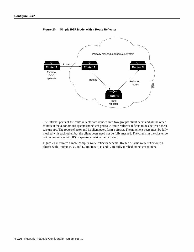
V-126 Network Protocols Configuration Guide, Part 1
Configure BGP
Figure 20 Simple BGP Model with a Route Reflector
The internal peers of the route reflector are divided into two groups: client peers and all the otherrouters in the autonomous system (nonclient peers). A route reflector reflects routes between thesetwo groups. The route reflector and its client peers form acluster. The nonclient peers must be fullymeshed with each other, but the client peers need not be fully meshed. The clients in the cluster donot communicate with IBGP speakers outside their cluster.
Figure 21 illustrates a more complex route reflector scheme. Router A is the route reflector in acluster with Routers B, C, and D. Routers E, F, and G are fully meshed, nonclient routers.
Router A Router A Router C
Router B
S42
19
External BGP
speaker
Partially meshed autonomous system
Route reflector
Reflected routes
Routes
Routes
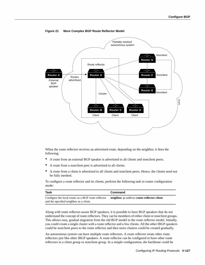
Configure BGP
Configuring IP Routing Protocols V-127
Figure 21 More Complex BGP Route Reflector Model
When the route reflector receives an advertised route, depending on the neighbor, it does thefollowing:
• A route from an external BGP speaker is advertised to all clients and nonclient peers.
• A route from a nonclient peer is advertised to all clients.
• A route from a client is advertised to all clients and nonclient peers. Hence, the clients need notbe fully meshed.
To configure a route reflector and its clients, perform the following task in router configurationmode:
Along with route reflector-aware BGP speakers, it is possible to have BGP speakers that do notunderstand the concept of route reflectors. They can be members of either client or nonclient groups.This allows easy, gradual migration from the old BGP model to the route reflector model. Initially,you could create a single cluster with a route reflector and a few clients. All the other IBGP speakerscould be nonclient peers to the route reflector and then more clusters could be created gradually.
An autonomous system can have multiple route reflectors. A route reflector treats other routereflectors just like other IBGP speakers. A route reflector can be configured to have other routereflectors in a client group or nonclient group. In a simple configuration, the backbone could be
Task Command
Configure the local router as a BGP route reflectorand the specified neighbor as a client.
neighbor ip-addressroute-reflector-client
Router A Router A
Router B Router C Router D
Router E
Router F
Router G
S42
18
External BGP
speaker
Routes advertised
Route reflector
Cluster
Client Client Client
Nonclient
Nonclient
Nonclient
Partially meshed autonomous system

V-128 Network Protocols Configuration Guide, Part 1
Configure BGP
divided into many clusters. Each route reflector would be configured with other route reflectors asnonclient peers (thus, all the route reflectors will be fully meshed). The clients are configured tomaintain IBGP sessions with only the route reflector in their cluster.
Usually a cluster of clients will have a single route reflector. In that case, the cluster is identified bythe router ID of the route reflector. To increase redundancy and avoid a single point of failure, acluster might have more than one route reflector. In this case, all route reflectors in the cluster mustbe configured with the 4-byte cluster ID so that a route reflector can recognize updates from routereflectors in the same cluster. All the route reflectors serving a cluster should be fully meshed and allof them should have identical sets of client and nonclient peers.
If the cluster has more than one route reflector, configure the cluster ID by performing the followingtask in router configuration mode:
Use theshow ip bgp command to display the originator ID and the cluster-list attributes.
By default, the clients of a route reflector are not required to be fully meshed and the routes from aclient are reflected to other clients. However, if the clients are fully meshed, the route reflector doesnot need to reflect routes to clients. To disable client-to-client route reflection, perform the followingtask in router configuration mode:
Note If client-to-client reflection is enabled, the clients of a route reflector cannot be members of apeer group.
As the IBGP learned routes are reflected, it is possible for routing information to loop. The routereflector model has the following mechanisms to avoid routing loops:
• Originator-ID is an optional, nontransitive BGP attribute. This is a 4-byte attributed created by aroute reflector. The attribute carries the router ID of the originator of the route in the localautonomous system. Therefore, if a misconfiguration causes routing information to come backto the originator, the information is ignored.
• Cluster-list is an optional, nontransitive BGP attribute. It is a sequence of cluster IDs that theroute has passed. When a route reflector reflects a route from its clients to nonclient peers, itappends the local cluster ID to the cluster-list. If the cluster-list is empty, it creates a new one.Using this attribute, a route reflector can identify if routing information is looped back to thesame cluster due to misconfiguration. If the local cluster ID is found in the cluster-list, theadvertisement is ignored.
• Usingset clauses in outbound route maps modifies attributes, possibly creating routing loops. Toavoid this,set clauses of outbound route maps are ignored for routes reflected to IBGP peers.
Configure Neighbor OptionsTo provide BGP routing information to a large number of neighbors, you can configure BGP toaccept neighbors based on an access list. If a neighbor attempts to initiate a BGP connection, itsaddress must be accepted by the access list for the connection to be accepted. If you do this, the
Task Command
Configure the cluster ID. bgp cluster-id cluster-id
Task Command
Disable client-to-client route reflection. no bgp client-to-client reflection
Configure BGP
Configuring IP Routing Protocols V-129
router will not attempt to initiate a BGP connection to these neighbors, so the neighbors must beexplicitly configured to initiate the BGP connection. If no access list is specified, all connections areaccepted.
External BGP peers normally must reside on a directly connected network. Sometimes it is useful torelax this restriction in order to test BGP; do so by specifying theneighbor ebgp-multihopcommand.
For internal BGP, you might want to allow your BGP connections to stay up regardless of whichinterface is used to reach a neighbor. To do this, you first configure aloopback interface and assignit an IP address. Next, configure the BGP update source to be the loopback interface. Finally,configure your neighbor to use the address on the loopback interface. Now the IBGP session will beup as long as there is a route, regardless of any interface.
You can set the minimum interval of time between BGP routing updates.
You can invoke MD5 authentication between two BGP peers, meaning that each segment sent on theTCP connection between them is verified. This feature must be configured with the same passwordon both BGP peers; otherwise, the connection between them will not be made. The authenticationfeature uses the MD5 algorithm. Invoking authentication causes the Cisco IOS software to generateand check the MD5 digest of every segment sent on the TCP connection. If authentication is invokedand a segment fails authentication, then a message appears on the console.
Configure any of the following neighbor options in router configuration mode:
Configure BGP Peer GroupsOften, in a BGP speaker, many neighbors are configured with the same update policies (that is, thesame outbound route maps, distribute lists, filter lists, update source, and so on). Neighbors with thesame update policies can be grouped into peer groups to simplify configuration and make updatingmore efficient.
The three steps to configuring a BGP peer group are: creating the peer group, assigning configurationoptions to the peer group, and making neighbors members of the peer group.
To create a BGP peer group, perform the following task in router configuration mode:
After you create a peer group, you configure the peer group withneighbor commands. By default,members of the peer group inherit all the configuration options of the peer group. Members can alsobe configured to override the options that do not affect outbound updates.
Task Command
Specify an access list of BGP neighbors. neighbor any [access-list-number | name]
Allow internal BGP sessions to use anyoperational interface for TCP connections.
neighbor { ip-address| peer-group-name}update-source interface
Allow BGP sessions even when the neighbor isnot on a directly connected segment.
neighbor { ip-address| peer-group-name}ebgp-multihop
Set the minimum interval between sendingBGP routing updates.
neighbor { ip-address| peer-group-name}advertisement-interval seconds
Invoke MD5 authentication on a TCPconnection to a BGP peer.
neighbor { ip-address| peer-group-name} passwordstring
Task Command
Create a BGP peer group. neighbor peer-group-namepeer-group
V-130 Network Protocols Configuration Guide, Part 1
Configure BGP
Peer group members will always inherit the following: remote-as (if configured), version,update-source, out-route-map, out-filter-list, out-dist-list, minimum-advertisement-interval, andnext-hop-self. All the peer group members will inherit changes made to the peer group.
To assign configuration options to the peer group, perform any of the following tasks in routerconfiguration mode:
If a peer group is not configured with a remote-as, the members can be configured with theneighbor ip-address | peer-group-nameremote-as command. This allows you to create peer groupscontaining EBGP neighbors.
Finally, to configure a BGP neighbor to be a member of that BGP peer group, perform the followingtask in router configuration mode, using the same peer group name:
See the “BGP Peer Group Examples” section at the end of this chapter for examples of IBGP andEBGP peer groups.
Task Command
Specify that the COMMUNITIES attribute be sentto the neighbor at this IP address.
neighbor { ip-address| peer-group-name}send-community
Allow internal BGP sessions to use any operationalinterface for TCP connections.
neighbor { ip-address| peer-group-name}update-source interface
Allow BGP sessions, even when the neighbor is noton a directly connected segment.
neighbor { ip-address| peer-group-name}ebgp-multihop
Set the minimum interval between sending BGProuting updates.
neighbor { ip-address| peer-group-name}advertisement-interval seconds
Invoke MD5 authentication on a TCP connection toa BGP peer.
neighbor { ip-address| peer-group-name}passwordstring
Specify a BGP neighbor. neighbor { ip-address| peer-group-name}remote-as number
Specify a weight for all routes from a neighbor. neighbor { ip-address| peer-group-name} weightweight
Filter BGP routing updates to/from neighbors, asspecified in an access list.
neighbor { ip-address| peer-group-name}distribute-list { access-list-number | name} { in |out}
Establish a BGP filter. neighbor { ip-address| peer-group-name}filter-list access-list-number{ in | out | weightweight}
Disable next-hop processing on the BGP updates toa neighbor.
neighbor { ip-address| peer-group-name}next-hop-self
Specify the BGP version to use whencommunicating with a neighbor.
neighbor { ip-address| peer-group-name} versionvalue
Apply a route map to incoming or outgoing routes.neighbor { ip-address | peer-group-name}route-map route-map-name{ in | out}
Task Command
Make a BGP neighbor a member of the peer group.neighbor ip-addresspeer-grouppeer-group-name
Configure BGP
Configuring IP Routing Protocols V-131
Indicate Backdoor RoutesYou can indicate which networks are reachable by using abackdoor route that the border routershould use. A backdoor network is treated as a local network, except that it is not advertised. Toconfigure backdoor routes, perform the following task in router configuration mode:
Modify Parameters While Updating the IP Routing TableBy default, when a BGP route is put into the IP routing table, the MED is converted to an IP routemetric, the BGP next hop is used as the next hop for the IP route, and the tag is not set. However,you can use a route map to perform mapping. To modify metric and tag information when the IProuting table is updated with BGP learned routes, perform the following task in router configurationmode:
Set Administrative DistanceAdministrative distance is a measure of the preference of different routing protocols. BGP uses threedifferent administrative distances: external, internal, and local. Routes learned through external BGPare given the external distance, routes learned with internal BGP are given the internal distance, androutes that are part of this autonomous system are given the local distance. To assign a BGPadministrative distance, perform the following task in router configuration mode:
Changing the administrative distance of BGP routes is considered dangerous and generally is notrecommended. The external distance should be lower than any other dynamic routing protocol, andthe internal and local distances should be higher than any other dynamic routing protocol.
Adjust BGP TimersBGP uses certain timers to control periodic activities such as the sending of keepalive messages, andthe interval after not receiving a keepalive message after which the Cisco IOS software declares apeer dead. You can adjust these timers. When a connection is started, BGP will negotiate the holdtime with the neighbor. The smaller of the two hold times will be chosen. The keepalive timer is thenset based on the negotiated hold time and the configured keepalive time. To adjust BGP timers,perform the following task in router configuration mode:
Task Command
Indicate reachable networks through backdoorroutes.
network address backdoor
Task Command
Apply a route map to routes when updating theIP routing table.
table-map route-map name
Task Command
Assign a BGP administrative distance. distance bgpexternal-distance internal-distancelocal-distance
Task Command
Adjust BGP timers. timers bgp keepalive holdtime
V-132 Network Protocols Configuration Guide, Part 1
Configure EGP
Change the Local Preference ValueYou can define a particular path as more preferable or less preferable than other paths by changingthe default local preference value of 100. To assign a different default local preference value,perform the following task in router configuration mode:
You can use route maps to change the default local preference of specific paths. See the “BGP RouteMap Examples” section at the end of this chapter for examples when used with BGP route maps.
Redistribute Network 0.0.0.0By default, you are not allowed to redistribute network 0.0.0.0. To permit the redistribution ofnetwork 0.0.0.0, perform the following task in router configuration mode:
Base Path Selection on MEDs from Other Autonomous SystemsThe MED is one of the parameters that is considered when selecting the best path among manyalternative paths. The path with a lower MED is preferred over a path with a higher MED.
By default, during the best-path selection process, MED comparison is done only among paths fromthe same autonomous system. You can allow comparison of MEDs among paths regardless of theautonomous system from which the paths are received. To do so, perform the following task in routerconfiguration mode:
Configure EGPThe Exterior Gateway Protocol (EGP), specified in RFC 904, is an older EGP used forcommunicating with certain routers in the Defense Data Network (DDN) that the U.S. Departmentof Defense designates ascore routers. EGP also was used extensively when attaching to the NationalScience Foundation Network (NSFNet) and other large backbone networks.
An exterior router uses EGP to advertise its knowledge of routes to networks within its autonomoussystem. It sends these advertisements to the core routers, which then readvertise their collectedrouting information to the exterior router. A neighbor or peer router is any router with which therouter communicates using EGP.
Task Command
Change the default local preference value. bgp default local-preferencevalue
Task Command
Allow the redistribution of network 0.0.0.0 intoBGP.
default-information originate
Task Command
Allow the comparison of MEDs for paths fromneighbors in different autonomous systems.
bgp always-compare-med
Configure EGP
Configuring IP Routing Protocols V-133
Cisco’s EGP ImplementationCisco’s implementation of EGP supports three primary functions, as specified in RFC 904:
• Routers running EGP establish a set of neighbors, and these neighbors share reachabilityinformation.
• EGP routers poll their neighbors periodically to see if they are “alive.”
• EGP routers send update messages containing information about the reachability of networkswithin their autonomous systems.
EGP Configuration Task ListTo enable EGP routing on your router, complete the tasks in the following sections. The tasks in thefirst two sections are mandatory; the remaining tasks are optional.
• Enable EGP Routing
• Configure EGP Neighbor Relationships
• Adjust EGP Timers
• Configure Third-Party EGP Support
• Configure Backup Routers
• Configure Default Routes
• Define a Central Routing Information Manager (Core Gateway)
Enable EGP RoutingTo enable EGP routing, you must specify an autonomous system number, generate an EGP routingprocess, and indicate the networks for which the EGP process will operate.
To enable EGP routing, perform the following tasks starting in global configuration mode:
Note For exterior gateway protocols, a reference to an IP network from thenetwork routerconfiguration command that is learned by another routing protocol does not require aredistributerouter configuration command. This is in contrast to interior gateway protocols, such as IGRP, whichrequire the use of theredistribute command.
Configure EGP Neighbor RelationshipsA router using EGP cannot dynamically determine its neighbor or peer routers. You must, therefore,provide a list of neighbor routers.
Task Command
Step 1 Specify the autonomous system in whichthe router resides for EGP.
autonomous-systemlocal-as
Step 2 Enable an EGP routing process, whichplaces you in router configuration mode.
router egp remote-as
Step 3 Specify a network to be advertised to theEGP peers of an EGP routing process.
network network-number
V-134 Network Protocols Configuration Guide, Part 1
Configure EGP
To specify an EGP neighbor, perform the following task in router configuration mode:
Adjust EGP TimersThe EGP timers consist of a hello timer and a poll time interval timer. The hello timer determinesthe frequency in seconds with which the Cisco IOS software sends hello messages to its peer. Thepoll time specifies how frequently to exchange updates. Our implementation of EGP allows thesetimers to be adjusted by the user.
To adjust EGP timers, perform the following task in router configuration mode:
Configure Third-Party EGP SupportEGP supports athird-party mechanismin whichEGP tells an EGP peer that another router (the thirdparty) on the shared network is the appropriate router for some set of destinations.
To specify third-party routers in updates, perform the following task in router configuration mode:
See the “Third-Party EGP Support Example” section at the end of this chapter for an example ofconfiguring third-party EGP support.
Configure Backup RoutersYou might want to provide backup in the event of site failure by having a second router (belongingto a different autonomous system) act as a backup to the EGP router (for your autonomous system).To differentiate between the primary and secondary EGP routers, the two routers will advertisenetwork routes with differing EGP distances or metrics. A network with a low metric is generallyfavored over a network with a high metric.
Networks declared as local are always announced with a metric of zero. Networks that areredistributed will be announced with a metric specified by the user. If no metric is specified,redistributed routes will be advertised with a metric of three. All redistributed networks will beadvertised with the same metric. The redistributed networks can be learned from static or dynamicroutes. See the “Redistribute Routing Information” section later in this chapter.
See the “Backup EGP Router Example” section at the end of this chapter for an example ofconfiguring backup EGP routers.
Task Command
Specify an EGP neighbor. neighbor ip-address
Task Command
Adjust EGP timers. timers egphello polltime
Task Command
Specify a third-party through which certaindestinations can be achieved.
neighbor ip-addressthird-party third-party-ip-address[internal | external]
Configure EGP
Configuring IP Routing Protocols V-135
Configure Default RoutesYou also can designate network 0.0.0.0 as a default route. If the next hop for the default route can beadvertised as a third party, it will be included as a third party.
To enable the use of default EGP routes, perform the following task in router configuration mode:
Define a Central Routing Information Manager (Core Gateway)Normally, an EGP process expects to communicate with neighbors from a single autonomoussystem. Because all neighbors are in the same autonomous system, the EGP process assumes thatthese neighbors all have consistent internal information. Therefore, if the EGP process is informedabout a route from one of its neighbors, it will not send it out to other neighbors.
With core EGP, the assumption is that all neighbors are from different autonomous systems, and allhave inconsistent information. In this case, the EGP process distributes routes from one neighbor toall others (but not back to the originator). This allows the EGP process to be a central clearinghousefor information with a single, central manager of routing information (sometimes called acoregateway). To this end, one core gateway process can be configured for each router.
To define a core gateway process, perform the following tasks starting in global configuration mode:
The EGP process defined in this way can act as a peer with any autonomous system, and informationis interchanged freely between autonomous systems.
See the “EGP Core Gateway Example” section at the end of this chapter for an example ofconfiguring an EGP core gateway.
Note Split horizon is performed only on aper-gateway basis (in other words, if an external routerinforms the router about a specific network, and that router is thebest path, the router willnot informthe originating external router about that path). Our routers can also perform per-gateway splithorizon on third-party updates.
Task Command
Configure EGP to generate a default route. default-information originate
Task Command
Step 1 Allow a specific router to act as a peerwith any reachable autonomous system.
router egp 0
Step 2 Define how an EGP process determineswhich neighbors will be treated as peers.or
Allow the specified address to be used asthe next hop in EGP advertisements.
neighbor any [access-list-number | name]
neighbor any third-party ip-address[internal |external]
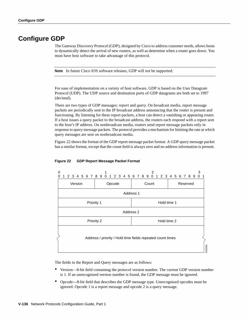
V-136 Network Protocols Configuration Guide, Part 1
Configure GDP
Configure GDPThe Gateway Discovery Protocol (GDP), designed by Cisco to address customer needs, allows hoststo dynamically detect the arrival of new routers, as well as determine when a router goes down. Youmust have host software to take advantage of this protocol.
Note In future Cisco IOS software releases, GDP will not be supported.
For ease of implementation on a variety of host software, GDP is based on the User DatagramProtocol (UDP). The UDP source and destination ports of GDP datagrams are both set to 1997(decimal).
There are two types of GDP messages:report andquery. On broadcast media, report messagepackets are periodically sent to the IP broadcast address announcing that the router is present andfunctioning. By listening for these report packets, a host can detect a vanishing or appearing router.If a host issues a query packet to the broadcast address, the routers each respond with a report sentto the host’s IP address. On nonbroadcast media, routers send report message packets only inresponse to query message packets. The protocol provides a mechanism for limiting the rate at whichquery messages are sent on nonbroadcast media.
Figure22 shows the format of the GDP report message packet format. A GDP query message packethas a similar format, except that the count field is always zero and no address information is present.
Figure 22 GDP Report Message Packet Format
The fields in the Report and Query messages are as follows:
• Version—8-bit field containing the protocol version number. The current GDP version numberis 1. If an unrecognized version number is found, the GDP message must be ignored.
• Opcode—8-bit field that describes the GDP message type. Unrecognized opcodes must beignored. Opcode 1 is a report message and opcode 2 is a query message.
Version Opcode Count Reserved
Address 1
Priority 1 Hold time 1
Address 2
Priority 2 Hold time 2
Address / priority / Hold time fields repeated count times
00 1 2 3 4 5 6 7 8 9 0 1 2 3 4 5 6 7 8 9 0 1 2 3 4 5 6 7 8 9 0 1
1 2 3
S10
29a
Configure IRDP
Configuring IP Routing Protocols V-137
• Count—8-bit field that contains the number of address, priority, and hold time types in thismessage. A query message has a Count field value of zero. A report message has a count fieldvalue of 1 or greater.
• Reserved—8-bit reserved field; it must be set to zero.
• Address—32-bit fields containing the IP address of a router on the local network segment. Thereare no other restrictions on this address. If a host encounters an address that it believes is not onits local network segment, it should ignore that address.
• Priority—16-bit fields that indicate the relative quality of the associated address. The numericallylarger the value in the priority field, the better the address should be considered.
• Hold Time—16-bit fields. On broadcast media, the number of seconds the associated addressshould be used as a router without hearing further report messages regarding that address. Onnonbroadcast media such as X.25, this is the number of seconds the requester should wait beforesending another query message.
Numerous actions can be taken by the host software listening to GDP packets. One possibility is toflush the host’s ARP cache whenever a router appears or disappears. A more complex possibility isto update a host routing table based on the coming and going of routers. The particular course ofaction taken depends on the host software and your network requirements.
To enable GDP routing and other optional GDP tasks as required for your network, perform thefollowing tasks in interface configuration mode:
Configure IRDPLike GDP, the ICMP Router Discovery Protocol (IRDP) allows hosts to locate routers. Whenoperating as a client, router discovery packets are generated. When operating as a host, routerdiscovery packets are received.
The only required task for configuring IRDP routing on a specified interface is to enable IRDPprocessing on an interface. Perform the following task in interface configuration mode:
When you enable IRDP processing, the default parameters will apply. You can optionally change anyof these IRDP parameters. Perform the following tasks in interface configuration mode:
Task Command
Enable GDP processing on an interface. ip gdp
Set the relative quality of the associated address.ip gdp priority number
Set the GDP report period. ip gdp reporttime seconds
Set the length of time the associated addressshould be used as a router without hearing furtherreport messages regarding that address.
ip gdp holdtime seconds
Task Command
Enable IRDP processing on an interface. ip irdp
Task Command
Send IRDP advertisements to the all-systemsmulticast address (224.0.0.1) on a specifiedinterface.
ip irdp multicast
Set the IRDP period for which advertisements arevalid.
ip irdp holdtime seconds
V-138 Network Protocols Configuration Guide, Part 1
Configure Resource Reservation Protocol (RSVP)
The Cisco IOS software can proxy-advertise other machines that use IRDP; however, this is notrecommended because it is possible to advertise nonexistent machines or machines that are down.
Configure Resource Reservation Protocol (RSVP)The Resource Reservation Protocol (RSVP) permits end systems to request Quality of Service(QOS) guarantees from the network. The need for network resource reservations differs as followsfor data traffic versus for real-time traffic:
• Data traffic seldom needs reserved bandwidth since internetworks provide datagram services fordata traffic. This asynchronous packet switching does not need guarantees of service quality.Routers can operate in a first-in, first out (FIFO) manner for data traffic packets. End-to-endcontrols between data traffic senders and receivers help ensure adequate transmission of burstsof information.
• Real-time traffic (that is, voice or video information) experiences problems when operating overdatagram services. Since real-time traffic sends an almost constant flow of information that sendand receive, the network “pipes” must be consistent. Some guarantee must be provided thatservice between real-time hosts will not vary. Routers operating on a FIFO basis riskunrecoverable disruption of the real-time information that is being transmitted.
Data applications (with little need for resource guarantees) frequently demand relatively lowerbandwidth than real-time traffic. The almost constant high bit-rate demands of a video conferenceapplication, and the bursty low bit-rate demands of an interactive data application, share availablenetwork resources.
RSVP prevents the demands of real-time traffic from impairing the bandwidth resources necessaryfor bursty data traffic. To do this, the routers sort and prioritize packets much like a statistical timedivision multiplexor would sort and prioritize several signal sources that shares a single channel.
RSVP mechanisms enable real-time traffic to reserve resources necessary for consistent latency. Avideo conferencing application can use settings in the router to propagate a request for a path withthe required bandwidth and delay for video conferencing destinations. RSVP will check and repeatreservations at regular intervals. By this process, RSVP can adjust and alter the path between RSVPend systems to recover from router changes.
Real-time traffic (unlike data traffic) requires a guaranteed network consistency. Without consistentQOS, real-time traffic faces the following problems:
• Jitter—A slight time or phase movement in a transmission signal can introduce loss ofsynchronization or other errors.
• Insufficient bandwidth—Voice calls use a digital signal level 0 (DS0 at 64Kbps); videoconferencing uses T1/E1 (1.544 Mbs or 2.048 Mbps); and higher-fidelity video uses much more.
Set the IRDP maximum interval betweenadvertisements.
ip irdp maxadvertinterval seconds
Set the IRDP minimum interval betweenadvertisements.
ip irdp minadvertinterval seconds
Set a device’s IRDP preference level. ip irdp preference number
Specify an IRDP address and preference toproxy-advertise.
ip irdp addressaddress[number]
Task Command
Configure Resource Reservation Protocol (RSVP)
Configuring IP Routing Protocols V-139
• Delay variations—If the wait time between when signal elements are sent and when they arrivevaries, the real-time traffic will no longer be synchronized and may fail.
• Information loss—When signal elements drop or arrive too late lost audio causes distortions withnoise or crackle sounds. The lost video causes image blurring, distortions, or blackouts.
RSVP works in conjunction with weighted fair queuing (WFQ). This conjunction of reservationsetting with packet queuing uses two key concepts: end-to-end flows with RSVP and router-to-routerconversations with WFQ.
• RSVP Flow—This is a stream that operates “multidestination simplex,” since data travels acrossit in only one direction (from the origin to the targets). Flows travel from a set of senders to a setof receivers. The flows can be merged or left unmerged, and the method of merging them variesaccording to the attributes of application using the flow.
• WFQ Conversation—This is the traffic for a single transport layer session or network layer flowthat crosses a given interface. This conversation is called from the source and destination address,protocol type, port number, or other attributes in the relevant communications layer.
RSVP allows for hosts to send packets to a subset of all hosts (ormulticasting). RSVP assumes thatresource reservation applies primarily to multicast applications (such as video conferencing).Although the primary target for RSVP is multimedia traffic, a clear interest exists for the reservationof bandwidth for unicast traffic (such as NFS and virtual private network management). Aunicasttransmission involves a host sending packets to a single host.
RSVP Reservation TypesTwo types of multicast flows are a flow that originates from exactly one sender (called adistinctreservation), and a flow that originates from one or more senders (called ashared reservation).RSVP describes these reservations as having certain algorithmic attributes.
An example of a distinct reservation is a video application, in which each sender emits a distinct datastream that requires admission and management in a queue. Such a flow, therefore, requires aseparate reservation per sender on each transmission facility it crosses (such as Ethernet, an HDLCline, a Frame Relay DLCI, or an ATM virtual channel). RSVP refers to this distinct reservation asexplicit, and installs it using a Fixed Filter style of reservation.
Use of RSVP for unicast applications is generally a degenerate case of a distinct flow.
An example of a shared reservation is an audio application, in which each sender also emits a distinctdata stream that requires admission and management in a queue. However, because of the nature ofthe application, a limited number of senders are transmitting data at any given time. Such a flow,therefore, does not require a separate reservation per sender. Instead, a single reservation that can beapplied to any sender within a set, as needed.
RSVP installs a shared reservation using a Wild Card or Shared Explicit style of reservation, withthe difference between the two being determined by the scope of application (which is either wild orexplicit). The Wild Card Filter reserves bandwidth and delay characteristics for any sender, and islimited by the list of source addresses carried in the reservation message. The Shared Explicitreservation style identifies the flows for specific network resources.
V-140 Network Protocols Configuration Guide, Part 1
Configure Resource Reservation Protocol (RSVP)
Planning for RSVP ConfigurationYou must plan carefully to successfully configure and use RSVP on your network. At a minimum,RSVP must reflect your assessment of bandwidth needs on router interfaces. Consider the followingquestions as you plan for RSVP configuration:
• How much bandwidth should RSVP allow per end-user application flow? You must understandthe “feeds and speeds” of your applications. By default, the amount reservable by a single flowcan be the entire reservable bandwidth. You can, however, limit individual reservations to smalleramounts using the single flow bandwidth parameter. This value may not exceed the interfacereservable amount, and no one flow may reserve more than the amount specified.
• How much bandwidth is available for RSVP? By default, 75 percent of the bandwidth availableon an interface is reservable. If you are using a tunnel interface, RSVP can make a reservationfor the tunnel whose bandwidth is the sum of the bandwidths reserved within the tunnel.
• How much bandwidth must be excluded from RSVP so that it can fairly provide the timelyservice required by low-volume data conversations? End-to-end controls for data traffic assumesthat all sessions will behave so as to avoid congestion dynamically. Real-time demands do notfollow this behavior. Determine the bandwidth to set aside so bursty data traffic will not bedeprived as a side effect of the RSVP QOS configuration.
Plan for RSVP before entering the details needed as RSVP configuration parameters.
RSVP Task ListAfter you have planned for your RSVP configuration, continue by entering the Cisco IOS commandsthat will implement your reservation configuration plan. The following sections discuss how toconfigure RSVP. You must enable RSVP on an interface, and enter the senders and receivers into theRSVP database in global configuration mode. The other tasks are optional.
• Enable RSVP on an Interface
• Enter Multicast Addresses
• Set Up Access-List Controls
• Enter Senders in the RSVP Database
• Enter Receivers in the RSVP Database
• Monitor RSVP
Enable RSVP on an InterfaceThe interface configuration commandip rsvp bandwidth enables the use of the RSVP protocol forIP on an interface.
To enable RSVP on an interface, perform the following task in global configuration mode:
You must use theip rsvp bandwidth command because the default is for the protocol to be disabled;this is backward compatible with systems that do not implement RSVP.
Task Command
Enable RSVP for IP on an interface. ip rsvp bandwidth [interface-kbps] [single-flow-kbps]

Configure Resource Reservation Protocol (RSVP)
Configuring IP Routing Protocols V-141
This command starts RSVP and sets the bandwidth and single-flow limits. The default maximumbandwidth is up to 75 percent of the bandwidth available on the interface. By default, the amountreservable by a flow can be up to the entire reservable bandwidth.
On subinterfaces, this applies the more restrictive of the available bandwidths of the physicalinterface and the subinterface. For example, a Frame Relay interface might have a T1 connectornominally capable of 1.536 Mbps, and 64 sub-interfaces on 128 Kbps circuits (64K CIR), with 1200and 100 Kbps, respectively.
Reservations on individual circuits that do not exceed 100 Kbps normally succeed. If, however,reservations have been made on other circuits adding up to 1.2 Mbps, and a reservation is made ona subinterface which itself has enough remaining bandwidth, it will still be refused because thephysical interface lacks supporting bandwidth.
Enter Multicast AddressesIf RSVP neighbors are discovered to be using UDP encapsulation, the router will automaticallygenerate UDP encapsulated messages for consumption by the neighbors. This step is optional.
To enter multicast addresses, perform the following task in global configuration mode:
However, in some cases, a host will not originate such a message until it has first heard from therouter, which it can only do via UDP. You must instruct the router to generate UDP encapsulatedRSVP multicasts whenever it generates an IP encapsulated multicast.
Set Up Access-List ControlsIf no limits are specified, any RSVP neighbor may offer a reservation.
To set up access-list controls, perform the following task in global configuration mode:
If an access list is specified, only neighbors conforming to the access list are accepted. This accesslist is applied to the IP header.
Enter Senders in the RSVP DatabaseThis interface configuration command forces the router to behave as though it is periodicallyreceiving an RSVP PATH message from the sender or previous hop routes containing the indicatedattributes.
Task Command
Enter any multicast addresses necessary if youuse UDP.
ip rsvp udp-multicast [multicast-address]
Task Command
Set up any access-list controls to limit whichrouters may offer reservations.
ip rsvp neighborsaccess-list-number
V-142 Network Protocols Configuration Guide, Part 1
Configure Resource Reservation Protocol (RSVP)
To enter senders in the RSVP database, perform the following task in global configuration mode:
Enter Receivers in the RSVP DatabaseThis interface configuration command forces the router to behave as though it is continuouslyreceiving an RSVP RESV message from the originator containing the indicated attributes.
To enter receivers in the RSVP database, perform the following task in global configuration mode:
Monitor RSVPAfter you configure the RSVP reservations that reflect your network resource policy, you can verifythe resulting RSVP operations.
To verify RSVP operations, perform the following tasks in EXEC mode:
RSVP Implementation ConsiderationsYou should be aware of RSVP implementation considerations as you design your reservationsystem. RSVP does not model all data links likely to be present on the internetwork. RSVP modelsan interface as having a queuing system that completely determines the mix of traffic on theinterface; bandwidth or delay characteristics are only deterministic to the extent that this modelholds.
Unfortunately, data links are often imperfectly modeled this way. Use the following guidelines:
• Serial line interfaces—PPP, HDLC, LAPB, HSSI, and similar serial line interfaces are wellmodeled by RSVP. The device can, therefore, make guarantees on these interfaces. With NBMAinterfaces, these are also the most in need of reservations.
Task Command
Enter the senders in the RSVP database. ip rsvp sendersession-ip-address sender-ip-address[UDP | TCP | ip-protocol] session-dport sender-sportprevious-hop-ip-address previous-hop-interface
Task Command
Enter the receivers in the RSVP database. ip rsvp reservation session-ip-addresssender-ip-address [TCP | UDP | ip-protocol]session-dport sender-sport next-hop-ip-addressnext-hop-interface { ff | se | wf} average-kbps burst-size{ rate | load | delaynumber} [ bandwidth] [burst-size]
Task Command
Display RSVP-related interface information. show ip rsvp interface [interface]
Display RSVP-related filters and bandwidthinformation.
show ip rsvp interface installed [interface]
Display current RSVP neighbors. show ip rsvp neighbor [interface]
Display RSVP sender information. show ip rsvp sender [interface]
Display RSVP request information. show ip rsvp request [interface]
Display RSVP receiver information. show ip rsvp reservation [interface]
Configure IP Multicast Routing
Configuring IP Routing Protocols V-143
• Multiaccess LANs—These data links are not modeled well by RSVP interfaces, because theLAN itself represents a queuing system that is not under the control of the device making theguarantees. The device guarantees what load it will offer, but cannot guarantee what competingloads or timings of loads that neighboring LAN systems will offer. The network administratorcan use admission controls to control how much traffic is placed on the LAN. The networkadministrator, however, should focus on the use of admission in network design in order to useRSVP effectively.
• Public X.25 networks—It is not clear that rate or delay reservations can be usefully made onpublic X.25 networks.
You must use a specialized configuration on Frame Relay and ATM networks.
The following RSVP implementation considerations apply as you design your reservation systemfor a Frame Relay internetwork:
• Reservations are made for an interface or subinterface. If subinterfaces contain more than oneDLC, the bandwidth required and the bandwidth reserved may differ. Therefore, RSVPsubinterfaces of frame relay circuits must contain exactly one DLC to operate correctly.
• In addition, Frame Relay DLCs have rates (CIR) and burst controls (Bc and Be) that may not bereflected in the configuration, and may differ markedly from the interface speed (either addingup to exceed it or being significantly smaller). Therefore, theip rsvp bandwidth interfaceconfiguration command must be entered for both the interface and the subinterface. Bothbandwidths are used as admission criteria.
For example, suppose that a frame relay interface runs at a T1 rate (1.544 Mbps) and supports severalDLCs to remote offices served by 128 and 56 Kbps lines. One must configure the amount of the totalinterface (75 percent of which being 1.158 Mbps) and the amount of each receiving interface(75 percent of which would be 96 and 42 Kbps, respectively) that may be reserved. Admissionsucceeds if and only if enough bandwidth is available on the DLC (the subinterface) and on theaggregate interface.
The following RSVP implementation considerations apply as you design your reservation systemfor an ATM internetwork:
• When ATM is configured, it most likely uses a usable bit rate (UBR) or an available bit rate(ABR) virtual channel (VC) connecting individual routers. With these classes of service, theATM network makes a “best effort” to meet the traffic’s bit-rate requirements, and assumes thatthe end-stations are responsible for information that does not get through the network.
• This ATM service has the capability of opening separate channels for reserved traffic having thenecessary characteristics. RSVP should open these VCs and adjust the cache to make effectiveuse of the VC for this purpose.
Configure IP Multicast RoutingTraditional IP communication allows a host to send packets to a single host (unicast transmission)or to all hosts (broadcast transmission). IP multicast provides a third scheme, allowing a host to sendpackets to a subset of all hosts (group transmission). These hosts are known as group members.
Packets delivered to group members are identified by a single multicast group address. Multicastpackets are delivered to a group using best-effort reliability, just like IP unicast packets.
The multicast environment consists of senders and receivers. Any host, regardless of whether it is amember of a group, can send to a group. However, only the members of a group receive the message.
A multicast address is chosen for the receivers in a multicast group. Senders use that address as thedestination address of a datagram to reach all members of the group.
V-144 Network Protocols Configuration Guide, Part 1
Configure IP Multicast Routing
Membership in a multicast group is dynamic; hosts can join and leave at any time. There is norestriction on the location or number of members in a multicast group. A host can be a member ofmore than one multicast group at a time.
How active a multicast group is and what members it has can vary from group to group and fromtime to time. A multicast group can be active for a long time, or it may be very short-lived.Membership in a group can change constantly. A group that has members may have no activity.
Routers executing a multicast routing protocol, such as Protocol-Independent Multicast (PIM),maintain forwarding tables to forward multicast datagrams. Routers use the Internet GroupManagement Protocol (IGMP) to learn whether members of a group are present on their directlyattached subnets. Hosts join multicast groups by sending IGMP report messages.
Cisco’s Implementation of IP Multicast RoutingThe Cisco IOS software supports three protocols to implement IP multicast routing:
• Internet Group Management Protocol (IGMP) is used between hosts on a LAN and the router(s)on that LAN to track of which multicast groups the hosts are members.
• Protocol-Independent Multicast (PIM) is used between routers so that they can track whichmulticast packets to forward to each other and to their directly connected LANs.
• Distance Vector Multicast Routing Protocol (DVMRP) is the protocol used on the MBONE (themulticast backbone of the Internet. The Cisco IOS software supports PIM-to-DVMRPinteraction.
Internet Group Management Protocol (IGMP)IP hosts use IGMP to report their group membership to directly connected multicast routers. IGMPis an integral part of IP. IGMP is defined in RFC 1112,Host Extensions for IP Multicasting.
IGMP uses group addresses, which are Class D IP addresses. The high-order four bits of a Class Daddress are 1110. This means that host group addresses can be in the range 224.0.0.0 to239.255.255.255. The address 224.0.0.0 is guaranteed not to be assigned to any group. The address224.0.0.1 is assigned to all systems on a subnet. The address 224.0.0.2 is assigned to all routers ona subnet.
Protocol-Independent Multicast (PIM) ProtocolThe PIM protocol maintains the current IP multicast service mode of receiver-initiated membership.It is not dependent on a specific unicast routing protocol.
PIM is defined in the following IETF Internet drafts:
• Protocol Independent Multicast (PIM): Motivation and Architecture
• Protocol Independent Multicast (PIM), Dense Mode Protocol Specification
• Protocol Independent Multicast (PIM), Sparse Mode Protocol Specification
• IGMP Router Extensions for Routing to Dense Multicast Groups
• IGMP Router Extensions for Routing to Sparse Multicast Groups
PIM can operate in two modes: dense mode and sparse mode.
Configure IP Multicast Routing
Configuring IP Routing Protocols V-145
In dense mode, a router assumes that all other routers want to forward multicast packets for a group.If a router receives a multicast packet and has no directly connected members or PIM neighborspresent, a prune message is sent back to the source. Subsequent multicast packets are not flooded tothis router on this pruned branch. PIM builds source-based multicast distribution trees.
In sparse mode, a router assumes that other routers do not want to forward multicast packets for agroup, unless there is an explicit request for the traffic. When hosts join a multicast group, thedirectly connected routers send PIM join messages to the rendezvous point (RP). The RP keeps trackof multicast groups. Hosts that send multicast packets are registered with the RP by that host’sfirst-hop router. The RP then sends joins toward the source. At this point, packets are forwarded ona shared distribution tree. If the multicast traffic from a specific source is sufficient, the receiver’sfirst-hop router may send joins toward the source to build a source-based distribution tree.
Distance Vector Multicast Routing Protocol (DVMRP)DVMRP uses a flood-and-prune approach to multicast packet delivery. It assumes that all otherrouters want to forward multicast packets for a group, like dense-mode PIM. DVMRP isimplemented in the equipment of many vendors and is based on the public domain mrouted program.
The Cisco IOS software supports dynamic discovery of DVMRP routers and can interoperate withthem over traditional media (such as Ethernet and FDDI), or over DVMRP-specific tunnels.
IP Multicast Routing Configuration Task ListTo configure IP multicast routing, perform the required tasks described in the following sections:
• Enable IP Multicast Routing
• Enable PIM on an Interface
You can also perform the optional tasks described in the following sections:
• Configure a Router to Be a Member of a Group
• Modify the IGMP Host-Query Message Interval
• Control Access to IP Multicast Groups
• Modify the PIM Router-Query Message Interval
• Configure the TTL Threshold
• Configure DVMRP Interoperability
• Advertise Network 0.0.0.0 to DVMRP Neighbors
• Configure a DVMRP Tunnel
• Configure an IP Multicast Static Route
• Disable Fast Switching of IP Multicast
• Control the Transmission Rate to a Multicast Group
• Enable PIM Nonbroadcast, Multiaccess (NBMA) Mode
• Enable sd Listener Support
See the “IP Multicast Routing Configuration Examples” section at the end of this chapter forexamples of multicast routing configurations.
V-146 Network Protocols Configuration Guide, Part 1
Configure IP Multicast Routing
Enable IP Multicast RoutingEnabling IP multicast routing allows the Cisco IOS software to forward multicast packets. To enableIP multicast routing on the router, perform the following task in global configuration mode:
Enable PIM on an InterfaceEnabling PIM on an interface also enables IGMP operation on that interface. An interface can beconfigured to be in dense mode or sparse mode. The mode describes how the router populates itsmulticast routing table and how the router forwards multicast packets it receives from its directlyconnected LANs.
In populating the multicast routing table, dense-mode interfaces are always added to the table.Sparse-mode interfaces are added to the table only when periodic join messages are received fromdownstream routers, or when there is a directly connected member on the interface. Whenforwarding from a LAN, sparse-mode operation occurs if there is an RP known for the group. If so,the packets are encapsulated and sent toward the RP. When no RP is known, the packet is flooded ina dense-mode fashion. If the multicast traffic from a specific source is sufficient, the receiver’sfirst-hop router may send joins toward the source to build a source-based distribution tree.
There is no default mode setting. By default, multicast routing is disabled on an interface.
To configure PIM on an interface to be in dense mode, perform the following task in interfaceconfiguration mode:
See the “Configure to Operate in Dense Mode Example” section later in this chapter for an exampleof how to configure a PIM interface in dense mode.
To configure PIM on an interface to be in sparse mode, perform the following task in interfaceconfiguration mode:
See the “Configure to Operate in Sparse Mode Example” section later in this chapter for an exampleof how to configure a PIM interface in sparse mode.
If you configure the Cisco IOS software to operate in sparse mode, you must also choose one or morerouters to be RPs. You do not have to configure the routers to be RPs; they learn this themselves. RPsare used by senders to a multicast group to announce their existence and by receivers of multicastpackets to learn about new senders. The Cisco IOS software can be configured so that packets for asingle multicast group can use one or more RPs.
You must configure the IP address of RPs in leaf routers only. Leaf routers are those routers that aredirectly connected either to a multicast group member or to a sender of multicast messages.
The RP address is used by first-hop routers to send PIM register messages on behalf of a host sendinga packet to the group. The RP address is also used by last-hop routers to send PIM join/prunemessages to the RP to inform it about group membership. The RP does not need to know it is an RP.You must configure the RP address only on first-hop and last-hop routers (leaf routers).
Task Command
Enable IP multicast routing. ip multicast-routing
Task Command
Enable dense-mode PIM on the interface. ip pim dense-mode
Task Command
Enable sparse-mode PIM on the interface. ip pim sparse-mode
Configure IP Multicast Routing
Configuring IP Routing Protocols V-147
A PIM router can be an RP for more than one group. A group can have more than one RP. Theconditions specified by the access list determine for which groups the router is an RP.
To configure the address of the RP, perform the following task in global configuration mode:
Configure a Router to Be a Member of a GroupCisco routers can be configured to be members of a multicast group. This is useful for determiningmulticast reachability in a network. If a device is configured to be a group member and supports theprotocol that is being transmitted to the group, it can respond. An example isping. The device willrespond to ICMP echo request packets addressed to a group, for which it is a member. Anotherexample is the multicast traceroute tools provided in the Cisco IOS software.
To have a router join a multicast group and turn on IGMP, perform the following task in interfaceconfiguration mode:
Modify the IGMP Host-Query Message IntervalMulticast routers send IGMP host-query messages to discover which multicast groups are presenton attached networks. These messages are sent to the all-systems group address of 224.0.0.1 with aTTL of 1.
Multicast routers send host-query messages periodically to refresh their knowledge of membershipspresent on their networks. If, after some number of queries, the Cisco IOS software discovers thatno local hosts are members of a multicast group, the software stops forwarding onto the localnetwork multicast packets from remote origins for that group and sends a prune message upstreamtoward the source.
Multicast routers elect a PIM designated router for the LAN (subnet). This is the router with thehighest IP address. The designated router is responsible for sending IGMP host-query messages toall hosts on the LAN. In sparse mode, the designated router also sends PIM register and PIM joinmessages toward the RP router.
By default, the designated router sends IGMP host-query messages once a minute in order to keepthe IGMP overhead on hosts and networks very low. To modify this interval, perform the followingtask in interface configuration mode:
Control Access to IP Multicast GroupsMulticast routers send IGMP host-query messages to determine which multicast groups havemembers of the router’s attached local networks. The routers then forward to these group membersall packets addressed to the multicast group. You can place a filter on each interface that restricts themulticast groups that hosts on the subnet serviced by the interface can join.
Task Command
Configure the address of a PIM rendezvouspoint (RP).
ip pim rp-address ip-address [access-list-number]
Task Command
Join a multicast group. ip igmp join-group group-address
Task Command
Configure the frequency at which the designatedrouter sends IGMP host-query messages.
ip igmp query-interval seconds
V-148 Network Protocols Configuration Guide, Part 1
Configure IP Multicast Routing
To filter multicast groups allowed on an interface, perform the following task in interfaceconfiguration mode:
Modify the PIM Router-Query Message IntervalRoute-query messages are used to elect a PIM designated router. The designated router isresponsible for sending IGMP host-query messages. By default, multicast routers send PIMrouter-query messages every 30 seconds. To modify this interval, perform the following task ininterface configuration mode:
Configure the TTL ThresholdThe time-to-live (TTL) value controls whether packets are forwarded out of an interface. You specifythe TTL value in hops. Only multicast packets with a TTL greater than the interface TTL thresholdare forwarded on the interface. The default value is 0, which means that all multicast packets areforwarded on the interface. To change the default TTL threshold value, perform the following taskin interface configuration mode:
Configure DVMRP InteroperabilityCisco multicast routers using PIM can interoperate with non-Cisco multicast routers that use theDistance Vector Multicast Routing Protocol (DVMRP).
PIM routers dynamically discover DVMRP multicast routers on attached networks. Once a DVMRPneighbor has been discovered, the router periodically transmits DVMRP report messages advertisingthe unicast sources reachable in the PIM domain. By default, directly connected subnets andnetworks are advertised. The router forwards multicast packets that have been forwarded byDVMRP routers and in turn forwards multicast packets to DVMRP routers.
You can configure what sources are advertised and what metrics are used by using theip dvmrpmetric command. You can also direct all sources learned via a particular unicast routing process tobe advertised into DVMRP.
The mrouted protocol is a public domain implementation of DVMRP. It is necessary to use mroutedversion 3.8 (which implements a nonpruning version of DVMRP). When Cisco routers are directlyconnected to DVMRP routers or interoperate with DVMRP routers over an MBONE tunnel.DVMRP advertisements produced by the Cisco IOS software can cause older versions of mroutedto corrupt their routing tables and those of their neighbors. Any router connected to the MBONEshould have an access-list to limit the number of unicast routes that are advertised via DVMRP.
Task Command
Control the multicast groups that hosts on thesubnet serviced by an interface can join.
ip igmp access-groupaccess-list-number
Task Command
Configure the frequency at which multicastrouters send PIM router-query messages.
ip pim query-interval seconds
Task Command
Configure the TTL threshold of packets beingforwarded out an interface.
ip multicast ttl-threshold ttl
Configure IP Multicast Routing
Configuring IP Routing Protocols V-149
To configure the sources that are advertised and the metrics that are used when transmitting DVMRPreport messages, perform the following task in interface configuration mode:
Responding to MRINFO RequestsThe Cisco IOS software answers mrinfo requests sent by mrouted systems and cisco routers. Thesoftware returns information about neighbors on DVMRP tunnels and all of the router’s interfaces.This information includes the metric, which is always set to 1, the configured TTL threshold, thestatus of the interface, and various flags. Themrinfo command can also be used to query the routeritself as in the following example:
mm1-7kd# mrinfo171.69.214.27 (mm1-7kd.cisco.com) [version cisco 11.1] [flags: PMS]:
171.69.214.27 -> 171.69.214.26 (mm1-r7kb.cisco.com) [1/0/pim/querier] 171.69.214.27 -> 171.69.214.25 (mm1-45a.cisco.com) [1/0/pim/querier] 171.69.214.33 -> 171.69.214.34 (mm1-45c.cisco.com) [1/0/pim] 171.69.214.137 -> 0.0.0.0 [1/0/pim/querier/down/leaf] 171.69.214.203 -> 0.0.0.0 [1/0/pim/querier/down/leaf] 171.69.214.18 -> 171.69.214.20 (mm1-45e.cisco.com) [1/0/pim] 171.69.214.18 -> 171.69.214.19 (mm1-45c.cisco.com) [1/0/pim] 171.69.214.18 -> 171.69.214.17 (mm1-45a.cisco.com) [1/0/pim]
See the “Configure DVMRP Interoperability Examples” section later in this chapter for an exampleof how to configure a PIM router to interoperate with a DVMRP router.
Advertise Network 0.0.0.0 to DVMRP NeighborsThe mrouted protocol is a public domain implementation of DVMRP. If your router is a neighbor toan mrouted version 3.6 machine, you can configure the Cisco IOS software to advertise network0.0.0.0 to the DVMRP neighbor. Do not advertise the DVMRP default into the mbone. You mustspecify whether only route 0.0.0.0 is advertised, or other routes can also be specified.
To advertise network 0.0.0.0 to DVMRP neighbors on an interface, perform the following task ininterface configuration mode:
Configure a DVMRP TunnelThe Cisco IOS software supports DVMRP tunnels to the MBONE. (The MBONE is the multicastbackbone of the Internet.) You can configure a DVMRP tunnel on a router if the other end is runningDVMRP. The software then sends and receives multicast packets over the tunnel. This allows a PIMdomain to connect to the DVMRP router in the case where all routers on the path do not supportmulticast routing. You cannot configure a DVMRP tunnel between two routers.
When a Cisco router runs DVMRP over a tunnel, it advertises sources in DVMRP report messagesmuch as it does on real networks. In addition, DVMRP report messages received are cached by theCisco IOS software and are used as part of its Reverse Path Forwarding (RPF) calculation. Thisallows multicast packets received over the tunnel to be forwarded by the software.
Task Command
Configure the metric associated with a set ofdestinations for DVMRP reports.
ip dvmrp metric metric [list access-list-number][protocol process-id] | [dvmrp ]
Task Command
Advertise network 0.0.0.0 to DVMRP neighbors. ip dvmrp default-information {originate | only}
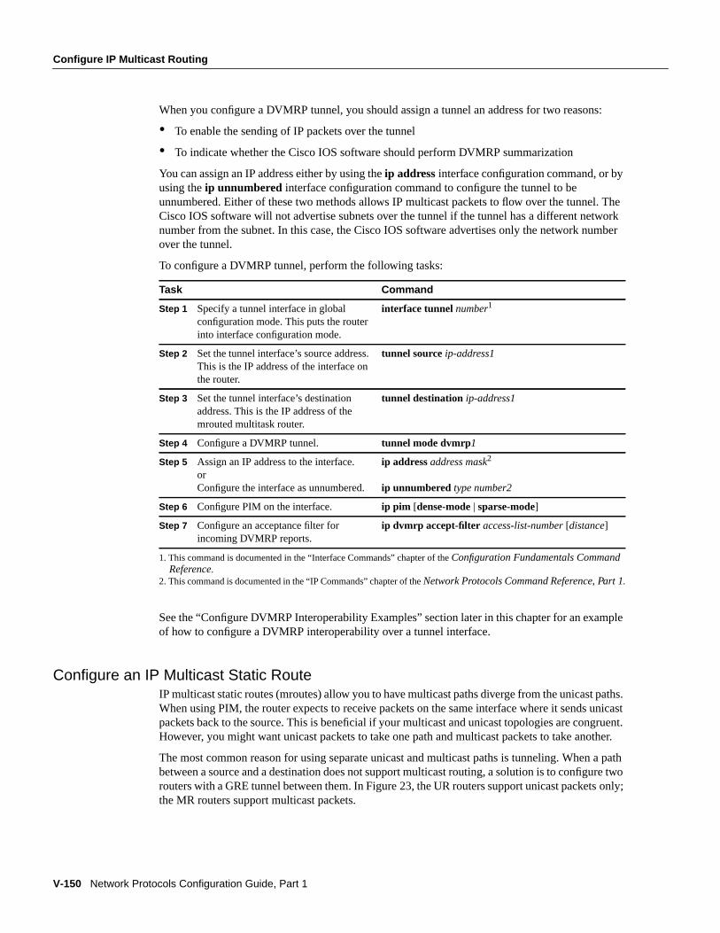
V-150 Network Protocols Configuration Guide, Part 1
Configure IP Multicast Routing
When you configure a DVMRP tunnel, you should assign a tunnel an address for two reasons:
• To enable the sending of IP packets over the tunnel
• To indicate whether the Cisco IOS software should perform DVMRP summarization
You can assign an IP address either by using theip address interface configuration command, or byusing theip unnumbered interface configuration command to configure the tunnel to beunnumbered. Either of these two methods allows IP multicast packets to flow over the tunnel. TheCisco IOS software will not advertise subnets over the tunnel if the tunnel has a different networknumber from the subnet. In this case, the Cisco IOS software advertises only the network numberover the tunnel.
To configure a DVMRP tunnel, perform the following tasks:
See the “Configure DVMRP Interoperability Examples” section later in this chapter for an exampleof how to configure a DVMRP interoperability over a tunnel interface.
Configure an IP Multicast Static RouteIP multicast static routes (mroutes) allow you to have multicast paths diverge from the unicast paths.When using PIM, the router expects to receive packets on the same interface where it sends unicastpackets back to the source. This is beneficial if your multicast and unicast topologies are congruent.However, you might want unicast packets to take one path and multicast packets to take another.
The most common reason for using separate unicast and multicast paths is tunneling. When a pathbetween a source and a destination does not support multicast routing, a solution is to configure tworouters with a GRE tunnel between them. In Figure23, the UR routers support unicast packets only;the MR routers support multicast packets.
1. This command is documented in the “Interface Commands” chapter of theConfiguration Fundamentals CommandReference.
2. This command is documented in the “IP Commands” chapter of the Network Protocols Command Reference, Part 1.
Task Command
Step 1 Specify a tunnel interface in globalconfiguration mode. This puts the routerinto interface configuration mode.
interface tunnel number1
Step 2 Set the tunnel interface’s source address.This is the IP address of the interface onthe router.
tunnel sourceip-address1
Step 3 Set the tunnel interface’s destinationaddress. This is the IP address of themrouted multitask router.
tunnel destination ip-address1
Step 4 Configure a DVMRP tunnel. tunnel mode dvmrp1
Step 5 Assign an IP address to the interface.orConfigure the interface as unnumbered.
ip addressaddress mask2
ip unnumbered type number2
Step 6 Configure PIM on the interface. ip pim [dense-mode | sparse-mode]
Step 7 Configure an acceptance filter forincoming DVMRP reports.
ip dvmrp accept-filter access-list-number[distance]
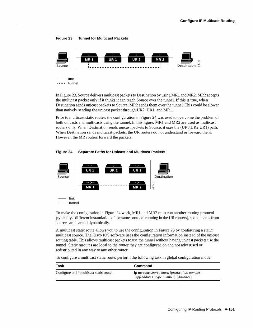
Configure IP Multicast Routing
Configuring IP Routing Protocols V-151
Figure 23 Tunnel for Multicast Packets
In Figure23, Source delivers multicast packets to Destination by using MR1 and MR2. MR2 acceptsthe multicast packet only if it thinks it can reach Source over the tunnel. If this is true, whenDestination sends unicast packets to Source, MR2 sends them over the tunnel. This could be slowerthan natively sending the unicast packet through UR2, UR1, and MR1.
Prior to multicast static routes, the configuration in Figure24 was used to overcome the problem ofboth unicasts and multicasts using the tunnel. In this figure, MR1 and MR2 are used as multicastrouters only. When Destination sends unicast packets to Source, it uses the (UR3,UR2,UR1) path.When Destination sends multicast packets, the UR routers do not understand or forward them.However, the MR routers forward the packets.
Figure 24 Separate Paths for Unicast and Multicast Packets
To make the configuration in Figure 24 work, MR1 and MR2 must run another routing protocol(typically a different instantiation of the same protocol running in the UR routers), so that paths fromsources are learned dynamically.
A multicast static route allows you to use the configuration in Figure 23 by configuring a staticmulticast source. The Cisco IOS software uses the configuration information instead of the unicastrouting table. This allows multicast packets to use the tunnel without having unicast packets use thetunnel. Static mroutes are local to the router they are configured on and not advertised orredistributed in any way to any other router.
To configure a multicast static route, perform the following task in global configuration mode:
Task Command
Configure an IP multicast static route. ip mroute source mask [protocol as-number]{ rpf-address | type number} [ distance]
MR 1 UR 1 UR 2 MR 2
Source Destination
linktunnel
S3
74
0
MR 1
UR 1 UR 2 UR 3
Source Destination
linktunnel
S3
74
1
MR 2
V-152 Network Protocols Configuration Guide, Part 1
Configure IP Multicast Routing
Disable Fast Switching of IP MulticastFast switching of IP multicast packets is enabled by default on all interfaces (including GRE andDVMRP tunnels), with one exception: It is disabled and not supported over X.25 encapsulatedinterfaces.
• If fast switching is disabled on anincoming interface for a multicast routing table entry, thepacket is sent at process level for all interfaces in the outgoing interface list.
• If f ast switching is disabled on anoutgoing interface for a multicast routing table entry, the packetis process-level switched for that interface, but might be fast switched for other interfaces in theoutgoing interface list.
You disable fast switching if you want to log debug messages, because when fast switching isenabled, debug messages are not logged.
To disable fast switching of IP multicast, perform the following task in interface configuration mode:
Control the Transmission Rate to a Multicast GroupBy default, you have no limit as to how fast a sender can transmit packets to a multicast group. Youcan control the rate that the sender from the source list can send to a multicast group in the group listby performing the following task in interface configuration mode:
Enable PIM Nonbroadcast, Multiaccess (NBMA) ModePIM nonbroadcast, multiaccess (NBMA) mode allows the Cisco IOS software to replicate packetsfor each neighbor on the NBMA network. Traditionally, the software replicates multicast andbroadcast packets to all “broadcast” configured neighbors. This might be inefficient when not allneighbors want packets for certain multicast groups. NBMA mode allows you to reduce bandwidthon links leading into the NBMA network, as well as CPU cycles in switches and attached neighbors.
Configure this feature on ATM, Frame Relay, SMDS, PRI ISDN, or X.25 networks only, especiallywhen these media do not have native multicast available. Do not use this feature onmulticast-capable LANs such as Ethernet or FDDI.
We encourage you to use sparse-mode PIM with this feature. Therefore, when each join is receivedfrom NBMA neighbors, PIM stores each neighbor IP address/interface in the outgoing interface listfor the group. When a packet is destined for the group, the software replicates the packet and unicasts(data-link unicasts) it to each neighbor that has joined the group.
To enable PIM nonbroadcast, multicaccess mode on your serial link, perform the following task ininterface configuration mode:
Task Command
Disable fast switching of IP multicast. no ip mroute-cache
Task Command
Control transmission rate to a multicast group. ip multicast rate-limit { in | out} [ group-listaccess-list] [source-listaccess-list] kbps
Task Command
Enable PIM nonbroadcast, multiaccess mode. ip pim nbma-mode
Configure Routing Protocol-Independent Features
Configuring IP Routing Protocols V-153
Consider the following two factors before enabling PIM NBMA mode:
• If the number of neighbors grows, the outgoing interface list will get large. This will cost memoryand replication time.
• If the network (Frame Relay, SMDS, or ATM) supports multicast natively, we encourage you touse it so that replication is performed at optimal points in the network.
Enable sd Listener SupportThe multicast backbone (MBONE) allows efficient, many-to-many communication and is widelyused for multimedia conferencing. To help announce multimedia conference sessions and providethe necessary conference setup information to potential participants, the session directory (sd) toolwas written. A session directory client announcing a conference session periodically multicasts anannouncement packet on a well-known multicast address and port.
To enable session directory listener support, perform the following task in interface configurationmode:
Configure Routing Protocol-Independent FeaturesPrevious sections addressed configurations of specific routing protocols. Complete theprotocol-independent tasks described in the following sections as needed:
• Use Variable-Length Subnet Masks (VLSMs)
• Configure Static Routes
• Specify Default Routes
• Redistribute Routing Information
• Filter Routing Information
• Enable Policy Routing
• Adjust Timers
• Enable or Disable Split Horizon
• Manage Authentication Keys
Use Variable-Length Subnet Masks (VLSMs)Enhanced IGRP, OSPF, RIP Version 2, static routes, and IS-IS support variable-length subnet masks(VLSMs). With VLSMs, you can use different masks for the same network number on differentinterfaces, which allows you to conserve IP addresses and more efficiently use available addressspace. However, using VLSMs also presents address assignment challenges for the networkadministrator and ongoing administrative challenges.
Refer to RFC 1219 for detailed information about VLSMs and how to correctly assign addresses.
Note Consider your decision to use VLSMs carefully. You can easily make mistakes in addressassignments and you will generally find it more difficult to monitor your network using VLSMs.
Task Command
Enable sd listener support. ip sd listen
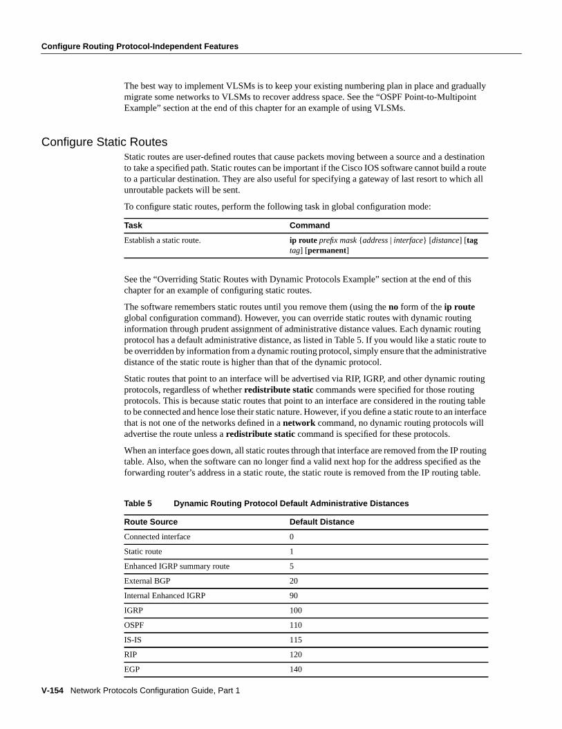
V-154 Network Protocols Configuration Guide, Part 1
Configure Routing Protocol-Independent Features
The best way to implement VLSMs is to keep your existing numbering plan in place and graduallymigrate some networks to VLSMs to recover address space. See the “OSPF Point-to-MultipointExample” section at the end of this chapter for an example of using VLSMs.
Configure Static RoutesStatic routes are user-defined routes that cause packets moving between a source and a destinationto take a specified path. Static routes can be important if the Cisco IOS software cannot build a routeto a particular destination. They are also useful for specifying a gateway of last resort to which allunroutable packets will be sent.
To configure static routes, perform the following task in global configuration mode:
See the “Overriding Static Routes with Dynamic Protocols Example” section at the end of thischapter for an example of configuring static routes.
The software remembers static routes until you remove them (using theno form of theip routeglobal configuration command). However, you can override static routes with dynamic routinginformation through prudent assignment of administrative distance values. Each dynamic routingprotocol has a default administrative distance, as listed in Table5. If you would like a static route tobe overridden by information from a dynamic routing protocol, simply ensure that the administrativedistance of the static route is higher than that of the dynamic protocol.
Static routes that point to an interface will be advertised via RIP, IGRP, and other dynamic routingprotocols, regardless of whetherredistribute static commands were specified for those routingprotocols. This is because static routes that point to an interface are considered in the routing tableto be connected and hence lose their static nature. However, if you define a static route to an interfacethat is not one of the networks defined in anetwork command, no dynamic routing protocols willadvertise the route unless aredistribute static command is specified for these protocols.
When an interface goes down, all static routes through that interface are removed from the IP routingtable. Also, when the software can no longer find a valid next hop for the address specified as theforwarding router’s address in a static route, the static route is removed from the IP routing table.
Task Command
Establish a static route. ip route prefix mask {address | interface} [ distance] [tagtag] [permanent]
Table 5 Dynamic Routing Protocol Default Administrative Distances
Route Source Default Distance
Connected interface 0
Static route 1
Enhanced IGRP summary route 5
External BGP 20
Internal Enhanced IGRP 90
IGRP 100
OSPF 110
IS-IS 115
RIP 120
EGP 140
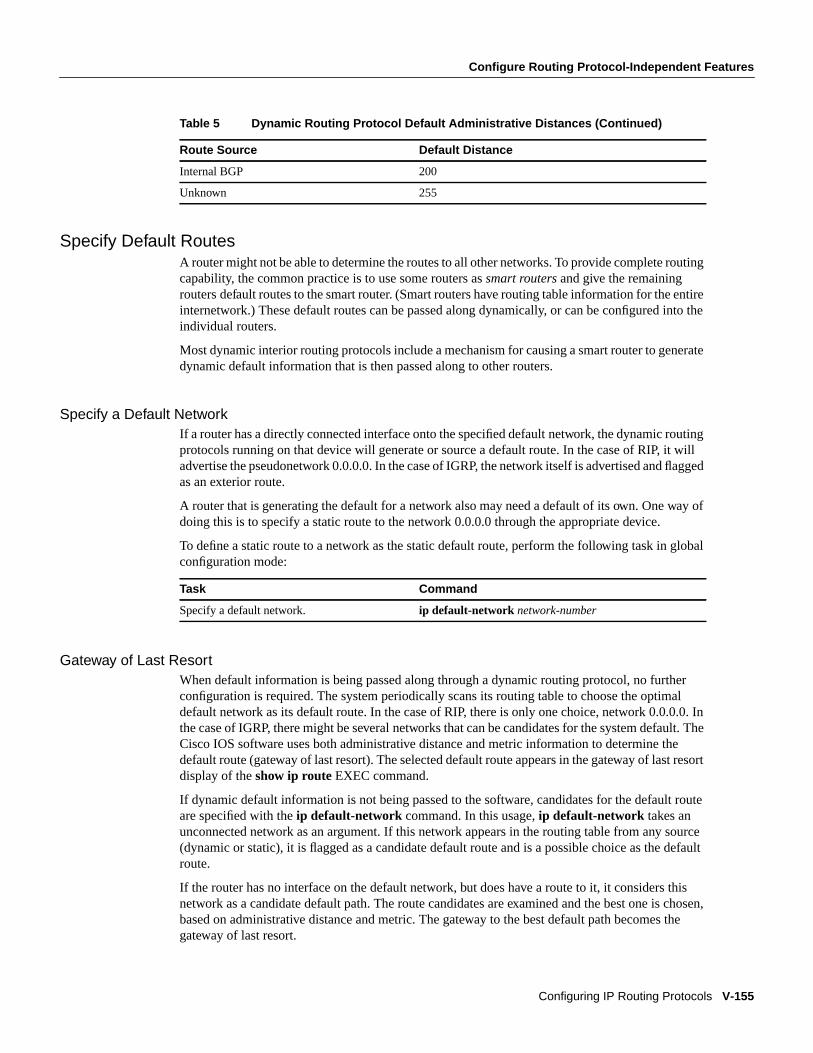
Configure Routing Protocol-Independent Features
Configuring IP Routing Protocols V-155
Specify Default RoutesA router might not be able to determine the routes to all other networks. To provide complete routingcapability, the common practice is to use some routers assmart routers and give the remainingrouters default routes to the smart router. (Smart routers have routing table information for the entireinternetwork.) These default routes can be passed along dynamically, or can be configured into theindividual routers.
Most dynamic interior routing protocols include a mechanism for causing a smart router to generatedynamic default information that is then passed along to other routers.
Specify a Default NetworkIf a router has a directly connected interface onto the specified default network, the dynamic routingprotocols running on that device will generate or source a default route. In the case of RIP, it willadvertise the pseudonetwork 0.0.0.0. In the case of IGRP, the network itself is advertised and flaggedas an exterior route.
A router that is generating the default for a network also may need a default of its own. One way ofdoing this is to specify a static route to the network 0.0.0.0 through the appropriate device.
To define a static route to a network as the static default route, perform the following task in globalconfiguration mode:
Gateway of Last ResortWhen default information is being passed along through a dynamic routing protocol, no furtherconfiguration is required. The system periodically scans its routing table to choose the optimaldefault network as its default route. In the case of RIP, there is only one choice, network 0.0.0.0. Inthe case of IGRP, there might be several networks that can be candidates for the system default. TheCisco IOS software uses both administrative distance and metric information to determine thedefault route (gateway of last resort). The selected default route appears in the gateway of last resortdisplay of theshow ip route EXEC command.
If dynamic default information is not being passed to the software, candidates for the default routeare specified with theip default-network command. In this usage,ip default-network takes anunconnected network as an argument. If this network appears in the routing table from any source(dynamic or static), it is flagged as a candidate default route and is a possible choice as the defaultroute.
If the router has no interface on the default network, but does have a route to it, it considers thisnetwork as a candidate default path. The route candidates are examined and the best one is chosen,based on administrative distance and metric. The gateway to the best default path becomes thegateway of last resort.
Internal BGP 200
Unknown 255
Task Command
Specify a default network. ip default-network network-number
Table 5 Dynamic Routing Protocol Default Administrative Distances (Continued)
Route Source Default Distance
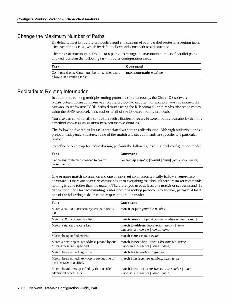
V-156 Network Protocols Configuration Guide, Part 1
Configure Routing Protocol-Independent Features
Change the Maximum Number of PathsBy default, most IP routing protocols install a maximum of four parallel routes in a routing table.The exception is BGP, which by default allows only one path to a destination.
The range of maximum paths is 1 to 6 paths. To change the maximum number of parallel pathsallowed, perform the following task in router configuration mode:
Redistribute Routing InformationIn addition to running multiple routing protocols simultaneously, the Cisco IOS softwareredistributes information from one routing protocol to another. For example, you can instruct thesoftware to readvertise IGRP-derived routes using the RIP protocol, or to readvertise static routesusing the IGRP protocol. This applies to all of the IP-based routing protocols.
You also can conditionally control the redistribution of routes between routing domains by defininga method known asroute maps between the two domains.
The following five tables list tasks associated with route redistribution. Although redistribution is aprotocol-independent feature, some of thematch andset commands are specific to a particularprotocol.
To define a route map for redistribution, perform the following task in global configuration mode:
One or morematch commands and one or moreset commands typically follow aroute-mapcommand. If there are nomatch commands, then everything matches. If there are noset commands,nothing is done (other than the match). Therefore, you need at least onematch orset command. Todefine conditions for redistributing routes from one routing protocol into another, perform at leastone of the following tasks in route-map configuration mode:
Task Command
Configure the maximum number of parallel pathsallowed in a routing table.
maximum-pathsmaximum
Task Command
Define any route maps needed to controlredistribution.
route-map map-tag [permit | deny] [sequence-number]
Task Command
Match a BGP autonomous system path accesslist.
match as-pathpath-list-number
Match a BGP community list. match community-list community-list-number [exact]
Match a standard access list. match ip address{ access-list-number | name...access-list-number | name...name}
Match the specified metric. match metric metric-value
Match a next-hop router address passed by oneof the access lists specified.
match ip next-hop{ access-list-number | name...access-list-number | name...name}
Match the specified tag value. match tag tag-value...tag-value
Match the specified next-hop route out one ofthe interfaces specified.
match interface type number...type number
Match the address specified by the specifiedadvertised access lists.
match ip route-source {access-list-number | name...access-list-number | name...name}
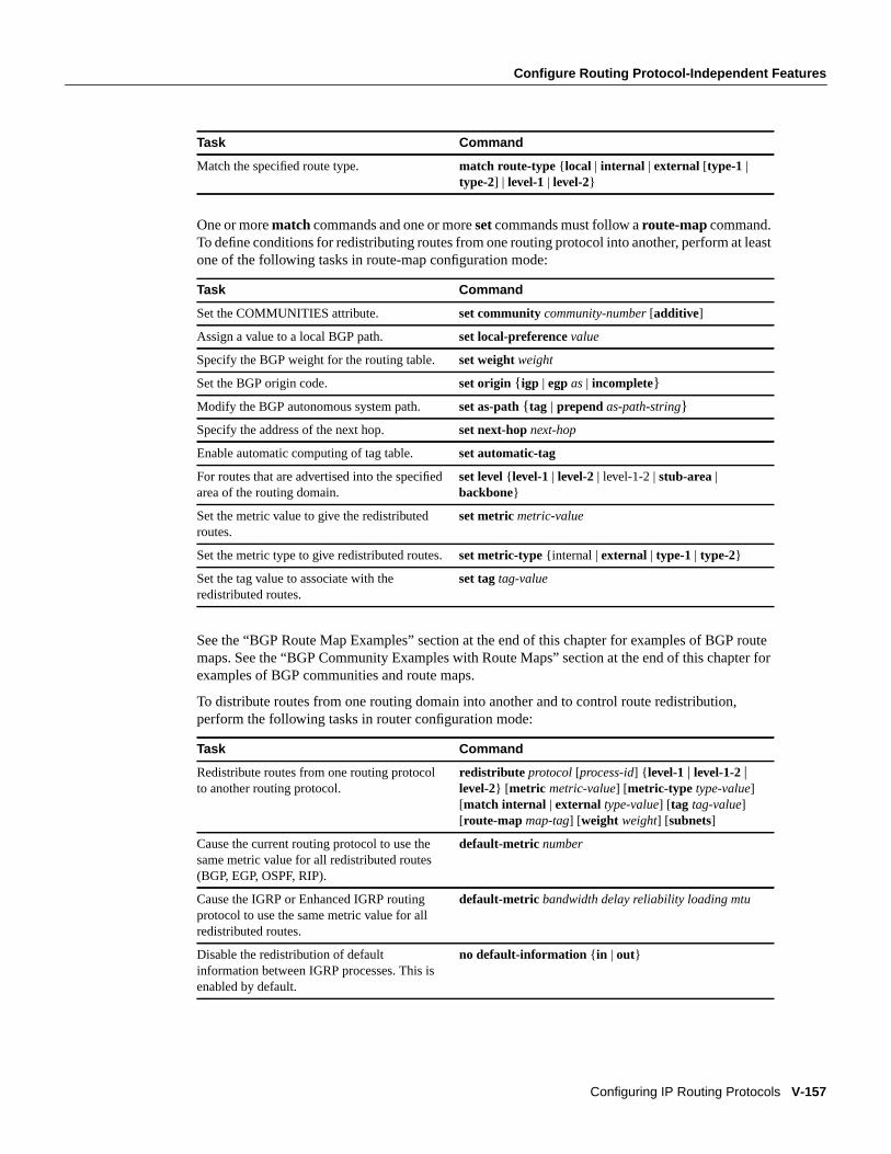
Configure Routing Protocol-Independent Features
Configuring IP Routing Protocols V-157
One or morematch commands and one or moreset commands must follow aroute-mapcommand.To define conditions for redistributing routes from one routing protocol into another, perform at leastone of the following tasks in route-map configuration mode:
See the “BGP Route Map Examples” section at the end of this chapter for examples of BGP routemaps. See the “BGP Community Examples with Route Maps” section at the end of this chapter forexamples of BGP communities and route maps.
To distribute routes from one routing domain into another and to control route redistribution,perform the following tasks in router configuration mode:
Match the specified route type. match route-type { local | internal | external [type-1 |type-2] | level-1 | level-2}
Task Command
Set the COMMUNITIES attribute. set communitycommunity-number [additive]
Assign a value to a local BGP path. set local-preferencevalue
Specify the BGP weight for the routing table. set weightweight
Set the BGP origin code. set origin { igp | egpas | incomplete}
Modify the BGP autonomous system path. set as-path{ tag | prependas-path-string}
Specify the address of the next hop. set next-hop next-hop
Enable automatic computing of tag table. set automatic-tag
For routes that are advertised into the specifiedarea of the routing domain.
set level { level-1 | level-2 | level-1-2 |stub-area |backbone}
Set the metric value to give the redistributedroutes.
set metricmetric-value
Set the metric type to give redistributed routes.set metric-type {internal |external | type-1 | type-2}
Set the tag value to associate with theredistributed routes.
set tagtag-value
Task Command
Redistribute routes from one routing protocolto another routing protocol.
redistribute protocol [process-id] { level-1 | level-1-2|level-2} [ metric metric-value] [metric-type type-value][match internal | external type-value] [tag tag-value][route-map map-tag] [weight weight] [subnets]
Cause the current routing protocol to use thesame metric value for all redistributed routes(BGP, EGP, OSPF, RIP).
default-metric number
Cause the IGRP or Enhanced IGRP routingprotocol to use the same metric value for allredistributed routes.
default-metric bandwidth delay reliability loading mtu
Disable the redistribution of defaultinformation between IGRP processes. This isenabled by default.
no default-information { in | out}
Task Command
V-158 Network Protocols Configuration Guide, Part 1
Configure Routing Protocol-Independent Features
The metrics of one routing protocol do not necessarily translate into the metrics of another. Forexample, the RIP metric is a hop count and the IGRP metric is a combination of five quantities. Insuch situations, an artificial metric is assigned to the redistributed route. Because of this unavoidabletampering with dynamic information, carelessly exchanging routing information between differentrouting protocols can create routing loops, which can seriously degrade network operation.
Supported Metric TranslationsThis section describes supported automatic metric translations between the routing protocols. Thefollowing descriptions assume that you have not defined a default redistribution metric that replacesmetric conversions.
• RIP can automatically redistribute static routes. It assigns static routes a metric of 1 (directlyconnected).
• EGP can automatically redistribute static routes and all dynamically derived routes. EGP assignsthe metric 3 to all static and derived routes.
• BGP does not normally send metrics in its routing updates.
• IGRP can automatically redistribute static routes and information from other IGRP-routedautonomous systems. IGRP assigns static routes a metric that identifies them as directlyconnected. IGRP does not change the metrics of routes derived from IGRP updates from otherautonomous systems.
• Note that any protocol can redistribute other routing protocols if a default metric is in effect.
Filter Routing InformationYou can filter routing protocol information by performing the following tasks:
• Suppress the sending of routing updates on a particular router interface. This is done to preventother systems on an interface from learning about routes dynamically.
• Suppress networks from being advertised in routing updates. This is done to prevent other routersfrom learning a particular device’s interpretation of one or more routes.
• Suppress networks listed in updates from being accepted and acted upon by a routing process.This is done to keep a router from using certain routes.
• Apply an offset to routing metrics. This is done to provide a local mechanism for increasing thevalue of routing metrics.
• Filter on the source of routing information. This is done to prioritize routing information fromdifferent sources, because some pieces of routing information may be more accurate than others.
Note When routes are redistributed between OSPF processes, no OSPF metrics are preserved.
The following sections describe these tasks.
Suppress Routing Updates through an InterfaceTo prevent other routers on a local network from learning about routes dynamically, you can keeprouting update messages from being sent through a router interface. This feature applies to allIP-based routing protocols except BGP and EGP.
Configure Routing Protocol-Independent Features
Configuring IP Routing Protocols V-159
OSPF and IS-IS behaviors are somewhat different. In OSPF, the interface address you specify aspassive appears as a stub network in the OSPF domain. OSPF routing information is neither sent norreceived through the specified router interface. In IS-IS, the specified IP addresses are advertisedwithout actually running IS-IS on those interfaces.
To prevent routing updates through a specified interface, perform the following task in routerconfiguration mode:
See the “Passive Interface Examples” section at the end of this chapter for examples of configuringpassive interfaces.
Suppress Routes from Being Advertised in Routing UpdatesTo prevent other routers from learning one or more routes, you can suppress routes from beingadvertised in routing updates. You cannot specify an interface name in OSPF. When used for OSPF,this feature applies only to external routes.
To suppress routes from being advertised in routing updates, perform the following task in routerconfiguration mode:
Suppress Routes Listed in Updates from Being ProcessedYou might want to avoid processing certain routes listed in incoming updates. This feature does notapply to OSPF or IS-IS. Perform the following task in router configuration mode:
Apply Offsets to Routing MetricsAn offset list is the mechanism for increasing incoming and outgoing metrics to routes learned viaRIP and IGRP. Optionally, you can limit the offset list with either an access list or an interface. Toincrease the value of routing metrics, perform the following task in router configuration mode:
Filter Sources of Routing InformationAn administrative distance is a rating of the trustworthiness of a routing information source, such asan individual router or a group of routers. In a large network, some routing protocols and somerouters can be more reliable than others as sources of routing information. Also, when multiple
Task Command
Suppress the sending of routing updatesthrough the specified interface.
passive-interfacetype number
Task Command
Permit or deny routes from being advertised inrouting updates depending upon the actionlisted in the access list.
distribute-list {access-list-number | name} out[interface-name | routing-process]
Task Command
Suppress routes listed in updates from beingprocessed.
distribute-list {access-list-number | name} in[interface-name]
Task Command
Apply an offset to routing metrics. offset-list [access-list-number | name] { in | out} offset[type number]
V-160 Network Protocols Configuration Guide, Part 1
Configure Routing Protocol-Independent Features
routing processes are running in the same router for IP, it is possible for the same route to beadvertised by more than one routing process. By specifying administrative distance values, youenable the router to intelligently discriminate between sources of routing information. The routerwill always pick the route whose routing protocol has the lowest administrative distance.
To filter sources of routing information, perform the following task in router configuration mode:
For example, consider a router using IGRP and RIP. Suppose you trust the IGRP-derived routinginformation more than the RIP-derived routing information. In this example, because the defaultIGRP administrative distance is lower than the default RIP administrative distance, the router usesthe IGRP-derived information and ignores the RIP-derived information. However, if you lose thesource of the IGRP-derived information (because of a power shutdown in another building, forexample), the router uses the RIP-derived information until the IGRP-derived information reappears.
Note You also can use administrative distance to rate the routing information from routers runningthe same routing protocol. This application is generally discouraged if you are unfamiliar with thisparticular use of administrative distance, because it can result in inconsistent routing information,including forwarding loops.
Assigning administrative distances is a problem unique to each network and is done in response tothe greatest perceived threats to the network. Even when general guidelines exist, the networkmanager must ultimately determine a reasonable matrix of administrative distances for the networkas a whole. Table 5 shows the default administrative distance for various sources of routinginformation.
See the “Administrative Distance Examples” section at the end of this chapter for examples ofsetting administrative distances.
Enable Policy RoutingPolicy routing is a more flexible mechanism for routing packets than destination routing. It is aprocess whereby the router puts packets through a route map before routing them. The route mapdetermines which packets are routed to which router next. You might enable policy routing if youwant certain packets to be routed some way other than the obvious shortest path. Some possibleapplications for policy routing are to provide equal access, protocol-sensitive routing,source-sensitive routing, routing based on interactive versus batch traffic, or routing based ondedicated links.
To enable policy routing, you must identify which route map to use for policy routing and create theroute map. The route map itself specifies the match criteria and the resulting action if all of the matchclauses are met. These steps are described in the following three task tables.
Task Command
Filter on routing information sources. distanceweight [address-mask [access-list-number|name]] [ ip]

Configure Routing Protocol-Independent Features
Configuring IP Routing Protocols V-161
To enable policy routing on an interface, indicate which route map the router should use byperforming the following task in interface configuration mode. All packets arriving on the specifiedinterface will be subject to policy routing. This command disables fast switching of all packetsarriving on this interface.
You must also define the route map to be used for policy routing. Perform the following task in globalconfiguration mode:
The next step is to define the criteria by which packets are examined to see if they will bepolicy-routed. No match clause in the route map indicates all packets. Perform one or more of thefollowing tasks in route-map configuration mode:
The last step is to specify where the packets that pass the match criteria are output. To do so, performone or more of the following tasks in route-map configuration mode:
Theset commands can be used in conjunction with each other. They are evaluated in the order shownin the previous task table. A usable next hop implies an interface. Once the local router finds a nexthop and a usable interface, it routes the packet.
See the “Policy Routing Example” section at the end of this chapter for an example of policy routing.
Task Command
Identify the route map to use for policy routing. ip policy route-map map-tag
Task Command
Define a route map to control where packets areoutput.
route-map map-tag [permit | deny][sequence-number]
Task Command
Match the Level 3 length of the packet. match lengthmin max
Match the destination IP address that is permittedby one or more standard or extended access lists.
match ip address{ access-list-number | name}[...access-list-number | name]
Task Command
Specify the next hop to which to route the packet (itneed not be adjacent).
set ip next-hopip-address [... ip-address]
Specify the output interface for the packet. set interface type number[... type number]
Specify the next hop to which to route the packet, ifthere is no explicit route for this destination.
set ip default next-hopip-address [... ip-address]
Specify the output interface for the packet, if thereis no explicit route for this destination.
set default interface type number[... type number]
V-162 Network Protocols Configuration Guide, Part 1
Configure Routing Protocol-Independent Features
Enable Local Policy RoutingPackets that are generated by the router are not normally policy-routed. To enable local policyrouting for such packets, indicate which route map the router should use by performing the followingtask in global configuration mode. All packets originating on the router will then be subject to localpolicy routing.
Use theshow ip local policy command to display the route map used for local policy routing, if oneexists.
Adjust TimersRouting protocols use a variety of timers that determine such variables as the frequency of routingupdates, the length of time before a route becomes invalid, and other parameters. You can adjustthese timers to tune routing protocol performance to better suit your internetwork needs.
For IGRP and RIP, you can make the following timer adjustments:
• The rate (time in seconds between updates) at which routing updates are sent
• The interval of time (in seconds) after which a route is declared invalid
• The interval (in seconds) during which routing information regarding better paths is suppressed
• The amount of time (in seconds) that must pass before a route is removed from the routing table
• The amount of time for which routing updates will be postponed
EGP and BGP have their owntimers commands, although some EGP timers might be set with thetimers basic command. See the EGP and BGP sections, respectively.
It also is possible to tune the IP routing support in the software to enable faster convergence of thevarious IP routing algorithms, and, hence, quicker fallback to redundant routers. The total effect isto minimize disruptions to end users of the network in situations where quick recovery is essential.
The following two tables list tasks associated with adjusting routing protocol timers and thekeepalive interval.
Perform the following task in router configuration mode:
Perform the following the following task in interface configuration mode:
1. This command is documented in the “Interface Commands” chapter of the Configuration Fundamentals CommandReference.
Task Command
Identify the route map to use for local policyrouting.
ip local policy route-mapmap-tag
Task Command
Adjust routing protocol timers. timers basicupdate invalid holddown flush [sleeptime]
Task Command
Adjust the frequency with which the Cisco IOSsoftware sends messages to itself (Ethernet andToken Ring) or to the other end (HDLC-serialand PPP-serial links) to ensure that a networkinterface is alive for a specified interface.
keepalive[seconds]1
Configure Routing Protocol-Independent Features
Configuring IP Routing Protocols V-163
You can also configure thekeepalive interval, the frequency at which the Cisco IOS software sendsmessages to itself (Ethernet and Token Ring) or to the other end (hdlc-serial, ppp-serial) to ensurethat a network interface is alive. The interval in some previous software versions was 10 seconds; itis now adjustable in one-second increments down to one second. An interface is declared down afterthree update intervals have passed without receiving a keepalive packet.
When adjusting the keepalive timer for a very low-bandwidth serial interface, large packets candelay the smaller keepalive packets long enough to cause the line protocol to go down. You mightneed to experiment to determine the best value.
Enable or Disable Split HorizonNormally, routers that are connected to broadcast-type IP networks and that use distance-vectorrouting protocols employ thesplit horizon mechanism to reduce the possibility of routing loops.Split horizon blocks information about routes from being advertised by a router out of any interfacefrom which that information originated. This behavior usually optimizes communications amongmultiple routers, particularly when links are broken. However, with nonbroadcast networks (such asFrame Relay and SMDS) situations can arise for which this behavior is less than ideal. For thesesituations, you might want to disable split horizon. This applies to IGRP and RIP.
If an interface is configured with secondary IP addresses and split horizon is enabled, updates mightnot be sourced by every secondary address. One routing update is sourced per network numberunless split horizon is disabled.
To enable or disable split horizon, perform the following tasks in interface configuration mode:
Split horizon for Frame Relay and SMDS encapsulation is disabled by default. Split horizon is notdisabled by default for interfaces using any of the X.25 encapsulations. For all other encapsulations,split horizon is enabled by default.
See the “Split Horizon Examples” section at the end of this chapter for examples of using splithorizon.
Note In general, changing the state of the default is not recommended unless you are certain thatyour application requires making a change in order to advertise routes properly. Remember: If splithorizon is disabled on a serial interface (and that interface is attached to a packet-switched network),youmust disable split horizon for all routers in any relevant multicast groups on that network.
Manage Authentication KeysKey management is a method of controlling authentication keys used by routing protocols. RIPVersion 2 is the first protocol that is able to use key management.
Before you manage RIP authentication keys, RIP authentication must be enabled. See the “EnableRIP Authentication” section earlier in this chapter.
Task Command
Enable split horizon. ip split-horizon
Disable split horizon. no ip split-horizon
V-164 Network Protocols Configuration Guide, Part 1
Monitor and Maintain the IP Network
To manage authentication keys, define a key chain, identify the keys that belong to the key chain,and specify how long each key is valid. You can configure multiple keys with lifetimes, and thesoftware will rotate through them. Note that the router must know the time. Refer to the NTP andcalendar commands in the “Managing the System” chapter of theConfiguration FundamentalsConfiguration Guide.
To manage authentication keys, perform the following tasks beginning in global configuration mode:
If authentication is enabled, the software sends a RIP packet forevery active key on the key chain.Therefore, if two keys on the key chain happen to be active based on thesend-lifetime values, thesoftware sends two RIP packets every 30 seconds, one authenticated with each key.
Use theshow key chain command to display key chain information. For examples of keymanagement, see the “Key Management Examples” section at the end of this chapter.
Monitor and Maintain the IP NetworkYou can remove all contents of a particular cache, table, or database. You also can display specificstatistics. The following sections describe each of these tasks.
Clear Caches, Tables, and DatabasesYou can remove all contents of a particular cache, table, or database. Clearing a cache, table, ordatabase can become necessary when the contents of the particular structure have become, or aresuspected to be, invalid.
The following table lists the tasks associated with clearing caches, tables, and databases for IProuting protocols. Perform these tasks in EXEC mode:
Task Command
Identify a key chain. key chainname-of-chain
In key chain configuration mode, identify thekey number.
key number
In key chain key configuration mode, identifythe key string.
key-string text
Specify the time period during which the keycan be received.
accept-lifetimestart-time{ infinite | end-time|duration seconds}
Specify the time period during which the keycan be sent.
send-lifetimestart-time{ infinite | end-time |duration seconds}
Task Command
Clear the IP ARP cache and the fast-switchingcache.
clear arp-cache
Reset a particular BGP connection. clear ip bgpaddress
Reset all BGP connections. clear ip bgp *
Remove all members of a BGP peer group. clear ip bgp peer-grouptag
Delete routes from the DVMRP routing table. clear ip dvmrp route { * | route}
Delete neighbors from the neighbor table. clear ip eigrp neighbors [ip-address | interface]
Delete entries from the IGMP cache. clear ip igmp group [group-name | group-address |interface]
Monitor and Maintain the IP Network
Configuring IP Routing Protocols V-165
Display System and Network StatisticsYou can display specific statistics such as the contents of IP routing tables, caches, and databases.Information provided can be used to determine resource utilization and solve network problems. Youcan also display information about node reachability and discover the routing path your device’spackets are taking through the network.
To display various routing statistics, perform the following tasks in EXEC mode:
Delete entries from the IP multicast routingtable.
clear ip mroute { * | group [source]}
Clear one or more routes from the IP routingtable.
clear ip route {network [mask] | *}
Delete session directory cache entries. clear ip sd [group-address | “ session-name” ]
Task Command
Trace a branch of a multicast tree for a specificgroup.
mbranch group-address branch-address[ttl]
Trace a branch of a multicast tree for a group inthe reverse direction.
mrbranch group-address branch-address[ttl]
Display all BGP routes that contain subnet andsupernet network masks.
show ip bgp cidr-only
Display routes that belong to the specifiedcommunities.
show ip bgp communitycommunity-number [exact]
Display routes that are permitted by thecommunity list.
show ip bgp community-listcommunity-list-number[exact]
Display routes that are matched by the specifiedautonomous system path access list.
show ip bgp filter-list access-list-number
Display the routes with inconsistent originatingautonomous systems.
show ip bgp inconsistent-as
Display the routes that match the specified regularexpression entered on the command line.
show ip bgp regexp regular-expression
Display the contents of the BGP routing table. show ip bgp[network] [network-mask] [subnets]
Display detailed information on the TCP and BGPconnections to individual neighbors.
show ip bgp neighbors[address]
Display routes learned from a particular BGPneighbor.
show ip bgp neighborsaddress [routes | paths]
Display all BGP paths in the database. show ip bgp paths
Display information about BGP peer groups. show ip bgp peer-group [tag] [summary]
Display the status of all BGP connections. show ip bgp summary
Display the entries in the DVMRP routing table. show ip dvmrp route [ip-address]
Display statistics on EGP connections andneighbors.
show ip egp
Display the IP Enhanced IGRP discoveredneighbors.
show ip eigrp neighbors[type number]
Display the IP Enhanced IGRP topology table fora given process.
show ip eigrp topology [autonomous-system-number |[[ ip-address] mask]]
Task Command
V-166 Network Protocols Configuration Guide, Part 1
Monitor and Maintain the IP Network
Display the number of packets sent and receivedfor all or a specified IP Enhanced IGRP process.
show ip eigrp traffic [autonomous-system-number]
Display the multicast groups that are directlyconnected to the router and that were learned viaIGMP.
show ip igmp groups[group-name |group-address | typenumber]
Display multicast-related information about aninterface.
show ip igmp interface [type number]
Display IRDP values. show ip irdp
Display the contents of the IP fast-switchingcache.
show ip mcache [group [source]]
Display the contents of the IP multicast routingtable.
show ip mroute[group] [source] [summary] [count]
Display general information about OSPF routingprocesses.
show ip ospf[process-id]
Display lists of information related to the OSPFdatabase.
show ip ospf[process-id area-id] database
show ip ospf[process-id area-id] database[router ][link-state-id]
show ip ospf[process-id area-id] database[network][link-state-id]
show ip ospf[process-id area-id] database[summary][link-state-id]
show ip ospf[process-id area-id] database[asb-summary] [ link-state-id]
show ip ospf[process-id] database [external][link-state-id]
show ip ospf[process-id area-id] database[database-summary]
Display the internal OSPF routing table entries toArea Border Router (ABR) and AutonomousSystem Boundary Router (ASBR).
show ip ospf border-routers
Display OSPF-related interface information. show ip ospf interface [interface-name]
Display OSPF-neighbor information on aper-interface basis.
show ip ospf neighbor [interface-name] [neighbor-id]detail
Display OSPF-related virtual links information. show ip ospf virtual-links
Display information about interfaces configuredfor PIM.
show ip pim interface [type number]
List the PIM neighbors discovered by the router.show ip pim neighbor [type number]
Display the RP routers associated with asparse-mode multicast group.
show ip pim rp [group-name | group-address]
Display the local policy route map, if any. show ip local policy
Display policy route maps. show ip policy
Display the parameters and current state of theactive routing protocol process.
show ip protocols
Display the current state of the routing table. show ip route [address [mask] [ longer-prefixes]] |[protocol[process-id]]
Task Command
IP Routing Protocol Configuration Examples
Configuring IP Routing Protocols V-167
IP Routing Protocol Configuration ExamplesThe following sections provide IP routing protocol configuration examples:
• Static Routing Redistribution Example
• Key Management Examples
• Static Routing Redistribution Example
• BGP Route Map Examples
• BGP Neighbor Configuration Examples
— Using Access Lists to Specify Neighbors
• BGP Path Filtering by Neighbor Example
• BGP Path Filtering by Neighbor Example
• BGP Aggregate Route Examples
• BGP Confederation Example
• BGP Peer Group Examples
— IBGP Peer Group Example
— EBGP Peer Group Example
• Third-Party EGP Support Example
• Backup EGP Router Example
• EGP Core Gateway Example
• IP Multicast Routing Configuration Examples
— Configure to Operate in Dense Mode Example
— Configure to Operate in Sparse Mode Example
— Configure DVMRP Interoperability Examples
• OSPF Point-to-Multipoint Example
• Overriding Static Routes with Dynamic Protocols Example
• BGP Community Examples with Route Maps
• Passive Interface Examples
Display the current state of the routing table insummary form.
show ip route summary
Display supernets. show ip route supernets-only
Display the contents of the session directory. show ip sd [group | “session-name” | detail]
Display the IS-IS link state database. show isis database [level-1] [ level-2] [ l1] [ l2] [detail][lspid]
Display authentication key information. show key chain[name]
Display all route maps configured or only the onespecified.
show route-map[map-name]
Task Command
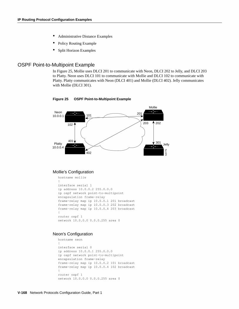
V-168 Network Protocols Configuration Guide, Part 1
IP Routing Protocol Configuration Examples
• Administrative Distance Examples
• Policy Routing Example
• Split Horizon Examples
OSPF Point-to-Multipoint ExampleIn Figure25, Mollie uses DLCI 201 to communicate with Neon, DLCI 202 to Jelly, and DLCI 203to Platty. Neon uses DLCI 101 to communicate with Mollie and DLCI 102 to communicate withPlatty. Platty communicates with Neon (DLCI 401) and Mollie (DLCI 402). Jelly communicateswith Mollie (DLCI 301).
Figure 25 OSPF Point-to-Multipoint Example
Mollie’s Configurationhostname mollie!interface serial 1ip address 10.0.0.2 255.0.0.0ip ospf network point-to-multipointencapsulation frame-relayframe-relay map ip 10.0.0.1 201 broadcastframe-relay map ip 10.0.0.3 202 broadcastframe-relay map ip 10.0.0.4 203 broadcast!router ospf 1network 10.0.0.0 0.0.0.255 area 0
Neon’s Configurationhostname neon!interface serial 0ip address 10.0.0.1 255.0.0.0ip ospf network point-to-multipointencapsulation frame-relayframe-relay map ip 10.0.0.2 101 broadcastframe-relay map ip 10.0.0.4 102 broadcast!router ospf 1network 10.0.0.0 0.0.0.255 area 0
Mollie
Neon 10.0.0.1
Platty 10.0.0.4
Jelly301
202
201
203
101
402
401
102
S37
75
IP Routing Protocol Configuration Examples
Configuring IP Routing Protocols V-169
Platty’s Configurationhostname platty!interface serial 3ip address 10.0.0.4 255.0.0.0ip ospf network point-to-multipointencapsulation frame-relayclockrate 1000000frame-relay map ip 10.0.0.1 401 broadcastframe-relay map ip 10.0.0.2 402 broadcast!router ospf 1network 10.0.0.0 0.0.0.255 area 0
Jelly’s Configurationhostname jelly!interface serial 2ip address 10.0.0.3 255.0.0.0ip ospf network point-to-multipointencapsulation frame-relayclockrate 2000000frame-relay map ip 10.0.0.2 301 broadcast!router ospf 1network 10.0.0.0 0.0.0.255 area 0
Key Management ExamplesThe following example configures a key chain calledtrees. In this example, the software will alwaysaccept and sendwillow as a valid key. The keychestnut will be accepted from 1:30 p.m. to 3:30 p.m.and be sent from 2:00 p.m. to 3:00 p.m. The overlap allows for migration of keys or discrepanciesin the router’s time. Likewise, the keybirch immediately followschestnut, and there is a half hourleeway on each side to handle time-of-day differences.
interface ethernet 0 ip rip authentication key-chain trees ip rip authentication mode md5!router rip network 172.19.0.0 version 2!key chain trees key 1 key-string willow key 2 key-string chestnut accept-lifetime 13:30:00 Jan 25 1996 duration 7200 send-lifetime 14:00:00 Jan 25 1996 duration 3600 key 3 key-string birch accept-lifetime 14:30:00 Jan 25 1996 duration 7200 send-lifetime 15:00:00 Jan 25 1996 duration 3600
The following example configures a key chain calledflintstone.
key chain flintstone key 1 key-string fred key 2
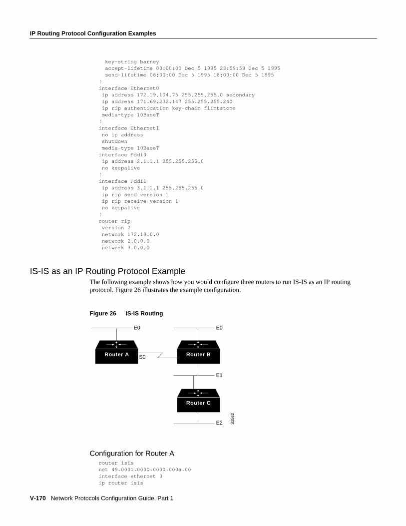
V-170 Network Protocols Configuration Guide, Part 1
IP Routing Protocol Configuration Examples
key-string barney accept-lifetime 00:00:00 Dec 5 1995 23:59:59 Dec 5 1995 send-lifetime 06:00:00 Dec 5 1995 18:00:00 Dec 5 1995!interface Ethernet0 ip address 172.19.104.75 255.255.255.0 secondary ip address 171.69.232.147 255.255.255.240 ip rip authentication key-chain flintstone media-type 10BaseT!interface Ethernet1 no ip address shutdown media-type 10BaseTinterface Fddi0 ip address 2.1.1.1 255.255.255.0 no keepalive!interface Fddi1 ip address 3.1.1.1 255.255.255.0 ip rip send version 1 ip rip receive version 1 no keepalive!router rip version 2 network 172.19.0.0 network 2.0.0.0 network 3.0.0.0
IS-IS as an IP Routing Protocol ExampleThe following example shows how you would configure three routers to run IS-IS as an IP routingprotocol. Figure 26 illustrates the example configuration.
Figure 26 IS-IS Routing
Configuration for Router Arouter isisnet 49.0001.0000.0000.000a.00interface ethernet 0ip router isis
Router A Router B
Router C
E0 E0
E1
E2
S0
S25
82
IP Routing Protocol Configuration Examples
Configuring IP Routing Protocols V-171
interface serial 0ip router isis
Configuration for Router Brouter isisnet 49.0001.0000.0000.000b.00interface ethernet 0ip router isisinterface ethernet 1ip router isisinterface serial 0ip router isis
Configuration for Router Crouter isisnet 49.0001.0000.0000.000c.00interface ethernet 1ip router isisinterface ethernet 2ip router isis
BGP Route Map ExamplesThe following example shows how you can use route maps to modify incoming data from a neighbor.Any route received from 140.222.1.1 that matches the filter parameters set in autonomous systemaccess list 200 will have its weight set to 200 and its local preference set to 250, and it will beaccepted.
router bgp 100!neighbor 140.222.1.1 route-map fix-weight inneighbor 140.222.1.1 remote-as 1!route-map fix-weight permit 10match as-path 200set local-preference 250set weight 200!ip as-path access-list 200 permit ^690$ip as-path access-list 200 permit ^1800
In the following example, route mapfreddy marks all paths originating from autonomous system 690with a Multi Exit Discriminator (MED) metric attribute of 127. The second permit clause is requiredso that routes not matching autonomous system path list 1 will still be sent to neighbor 1.1.1.1.
router bgp 100neighbor 1.1.1.1 route-map freddy out!ip as-path access-list 1 permit ^690_ip as-path access-list 2 permit .*!route-map freddy permit 10match as-path 1set metric 127!route-map freddy permit 20match as-path 2
V-172 Network Protocols Configuration Guide, Part 1
IP Routing Protocol Configuration Examples
The following example shows how you can use route maps to modify incoming data from the IPforwarding table:
router bgp 100redistribute igrp 109 route-map igrp2bgp!route-map igrp2bgpmatch ip address 1set local-preference 25set metric 127set weight 30000set next-hop 192.92.68.24set origin igp!access-list 1 permit 131.108.0.0 0.0.255.255access-list 1 permit 160.89.0.0 0.0.255.255access-list 1 permit 198.112.0.0 0.0.127.255
It is proper behavior to not accept any autonomous system path not matching thematch clause ofthe route map. This means that you will not set the metric and the Cisco IOS software will not acceptthe route. However, you can configure the software to accept autonomous system paths not matchedin thematch clause of the route map command by using multiple maps of the same name, somewithout accompanyingset commands.
route-map fnord permit 10match as-path 1set local-preference 5!route-map fnord permit 20match as-path 2
The following example shows how you can use route maps in a reverse operation to set the route tag(as defined by the BGP/OSPF interaction document, RFC 1403) when exporting routes from BGPinto the main IP routing table:
router bgp 100table-map set_ospf_tag!route-map set_ospf_tagmatch as-path 1set automatic-tag!ip as-path access-list 1 permit .*
In the following example, the route map calledset-as-path is applied to outbound updates to theneighbor 200.69.232.70. The route map will prepend the autonomous system path “100 100” toroutes that pass access list 1. The second part of the route map is to permit the advertisement of otherroutes.
router bgp 100network 171.60.0.0network 172.60.0.0neighbor 200.69.232.70 remote-as 200neighbor 200.69.232.70 route-map set-as-path out!route-map set-as-path 10 permitmatch address 1set as-path prepend 100 100!route-map set-as-path 20 permitmatch address 2!access-list 1 permit 171.60.0.0 0.0.255.255access-list 1 permit 172.60.0.0 0.0.255.255
IP Routing Protocol Configuration Examples
Configuring IP Routing Protocols V-173
!access-list 2 permit 0.0.0.0 255.255.255.255
Inbound route-maps could do prefix-based matching and set various parameters of the update.Inbound prefix matching is available in addition to as-path and community-list matching. In thefollowing example, theset local preference command sets the local preference of the inbound prefix140.10.0.0/16 to 120.
>>!>>router bgp 100>>network 131.108.0.0>>neighbor 131.108.1.1 remote-as 200>>neighbor 131.108.1.1 route-map set-local-pref in !>>route-map set-local-pref permit 10>>match ip address 2>>set local preference 120>>!>>route-map set-local-pref permit 20>>!
>>access-list 2 permit 140.10.0.0 0.0.255.255 access-list 2 deny any
BGP Neighbor Configuration ExamplesIn the following example, a BGP router is assigned to autonomous system 109, and two networksare listed as originating in the autonomous system. Then the addresses of three remote routers (andtheir autonomous systems) are listed. The router being configured will share information aboutnetworks 131.108.0.0 and 192.31.7.0 with the neighbor routers. The first router listed is in a differentautonomous system; the secondneighbor command specifies an internal neighbor (with the sameautonomous system number) at address 131.108.234.2; and the thirdneighbor command specifiesa neighbor on a different autonomous system.
router bgp 109network 131.108.0.0network 192.31.7.0neighbor 131.108.200.1 remote-as 167neighbor 131.108.234.2 remote-as 109neighbor 150.136.64.19 remote-as 99
In Figure 27, Router A is being configured. The internal BGP neighbor is not directly linked toRouter A. External neighbors (in autonomous system 167 and autonomous system 99) must belinked directly to Router A.
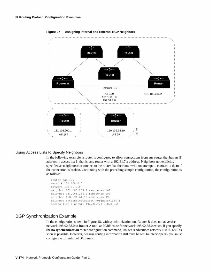
V-174 Network Protocols Configuration Guide, Part 1
IP Routing Protocol Configuration Examples
Figure 27 Assigning Internal and External BGP Neighbors
Using Access Lists to Specify NeighborsIn the following example, a router is configured to allow connections from any router that has an IPaddress in access list 1; that is, any router with a 192.31.7.x address. Neighbors not explicitlyspecified as neighbors can connect to the router, but the router will not attempt to connect to them ifthe connection is broken. Continuing with the preceding sample configuration, the configuration isas follows:
router bgp 109network 131.108.0.0network 192.31.7.0neighbor 131.108.200.1 remote-as 167neighbor 131.108.234.2 remote-as 109neighbor 150.136.64.19 remote-as 99neighbor internal-ethernet neighbor-list 1access-list 1 permit 192.31.7.0 0.0.0.255
BGP Synchronization ExampleIn the configuration shown in Figure 28, with synchronization on, Router B does not advertisenetwork 198.92.68.0 to Router A until an IGRP route for network 198.92.68.0 exists. If you specifytheno synchronization router configuration command, Router B advertises network 198.92.68.0 assoon as possible. However, because routing information still must be sent to interior peers, you mustconfigure a full internal BGP mesh.
Router
Router Router
Router A Router
RouterRouter
Internal BGP
AS 109 131.108.0.0 192.31.7.0
131.108.200.1 150.136.64.19AS 167 AS 99
131.108.234.2
S12
70a
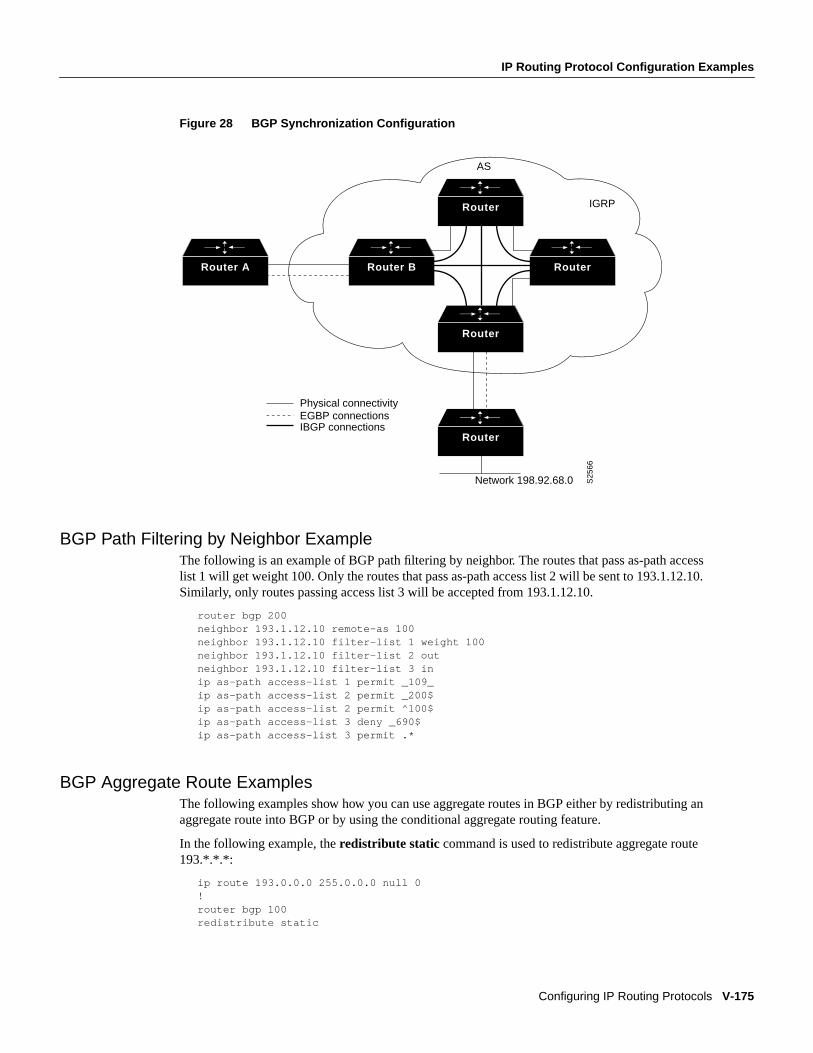
IP Routing Protocol Configuration Examples
Configuring IP Routing Protocols V-175
Figure 28 BGP Synchronization Configuration
BGP Path Filtering by Neighbor ExampleThe following is an example of BGP path filtering by neighbor. The routes that pass as-path accesslist 1 will get weight 100. Only the routes that pass as-path access list 2 will be sent to 193.1.12.10.Similarly, only routes passing access list 3 will be accepted from 193.1.12.10.
router bgp 200neighbor 193.1.12.10 remote-as 100neighbor 193.1.12.10 filter-list 1 weight 100neighbor 193.1.12.10 filter-list 2 outneighbor 193.1.12.10 filter-list 3 inip as-path access-list 1 permit _109_ip as-path access-list 2 permit _200$ip as-path access-list 2 permit ^100$ip as-path access-list 3 deny _690$ip as-path access-list 3 permit .*
BGP Aggregate Route ExamplesThe following examples show how you can use aggregate routes in BGP either by redistributing anaggregate route into BGP or by using the conditional aggregate routing feature.
In the following example, theredistribute static command is used to redistribute aggregate route193.*.*.*:
ip route 193.0.0.0 255.0.0.0 null 0!router bgp 100redistribute static
Router
Router B Router
Router
Router
Router A
Network 198.92.68.0
Physical connectivity
IBGP connectionsEGBP connections
AS
IGRP
S25
66
V-176 Network Protocols Configuration Guide, Part 1
IP Routing Protocol Configuration Examples
The following configuration creates an aggregate entry in the BGP routing table when there is at leastone specific route that falls into the specified range. The aggregate route will be advertised as comingfrom your autonomous system and has the atomic aggregate attribute set to show that informationmight be missing. (By default, atomic aggregate is set unless you use theas-set keyword in theaggregate-addresscommand.)
router bgp 100aggregate-address 193.0.0.0 255.0.0.0
The following example creates an aggregate entry using the same rules as in the previous example,but the path advertised for this route will be an AS_SET consisting of all elements contained in allpaths that are being summarized:
router bgp 100aggregate-address 193.0.0.0 255.0.0.0 as-set
The following example not only creates the aggregate route for 193.*.*.*, but will also suppressadvertisements of more specific routes to all neighbors:
router bgp 100aggregate-address 193.0.0.0 255.0.0.0 summary-only
BGP Confederation ExampleThe following is a sample configuration from several peers in a confederation. The confederationconsists of three internal autonomous systems with autonomous system numbers 6001, 6002, and6003. To the BGP speakers outside the confederation, the confederation looks like a normalautonomous system with autonomous system number 666 (specified via thebgp confederationidentifier command).
In a BGP speaker in autonomous system 6001, thebgp confederation peers command marks thepeers from autonomous systems 6002 and 6003 as special EBGP peers. Hence peers 171.69.232.55and 171.69.232.56 will get the local-preference, next-hop and MED unmodified in the updates. Therouter at 160.69.69.1 is a normal EBGP speaker and the updates received by it from this peer will bejust like a normal EBGP update from a peer in autonomous system 666.
router bgp 6001bgp confederation identified 666bgp confederation peers 6002 6003neighbor 171.69.232.55 remote-as 6002neighbor 171.69.232.56 remote-as 6003neighbor 160.69.69.1 remote-as 777
In a BGP speaker in autonomous system 6002, the peers from autonomous systems 6001 and 6003are configured as special EBGP peers. 170.70.70.1 is a normal IBGP peer and 199.99.99.2 is anormal EBGP peer from autonomous system 700.
router bgp 6002bgp confederation identified 666bgp confederation peers 6001 6003neighbor 170.70.70.1 remote-as 6002neighbor 171.69.232.57 remote-as 6001neighbor 171.69.232.56 remote-as 6003neighbor 199.99.99.2 remote-as 700
In a BGP speaker in autonomous system 6003, the peers from autonomous systems 6001 and 6002are configured as special EBGP peers. 200.200.200.200.200 is a normal EBGP peer fromautonomous system 701.
router bgp 6003bgp confederation identified 666
IP Routing Protocol Configuration Examples
Configuring IP Routing Protocols V-177
bgp confederation peers 6001 6002neighbor 171.69.232.57 remote-as 6001neighbor 171.69.232.55 remote-as 6002neighbor 200.200.200.200 remote-as 701
The following is a part of the configuration from the BGP speaker 200.200.200.205 fromautonomous system 701. Neighbor 171.69.232.56 is configured as a normal EBGP speaker fromautonomous system 666. The internal division of the autonomous system into multiple autonomoussystems is not known to the peers external to the confederation.
router bgp 701neighbor 171.69.232.56 remote-as 666neighbor 200.200.200.205 remote-as 701
BGP Peer Group ExamplesThis section contains an IBGP peer group example and an EBGP peer group example.
IBGP Peer Group ExampleIn the following example, the peer group namedinternal configures the members of the peer groupto be IBGP neighbors. By definition, this is an IBGP peer group because therouter bgp commandand theneighbor remote-as command indicate the same autonomous system (in this case, AS100).All the peer group members use loopback 0 as the update source and useset-med as the outboundroute-map. The example also shows that, except for the neighbor at address 171.69.232.55, all theneighbors have filter-list 2 as the inbound filter list.
router bgp 100neighbor internal peer-groupneighbor internal remote-as 100neighbor internal update-source loopback 0neighbor internal route-map set-med outneighbor internal filter-list 1 outneighbor internal filter-list 2 inneighbor 171.69.232.53 peer-group internalneighbor 171.69.232.54 peer-group internalneighbor 171.69.232.55 peer-group internalneighbor 171.69.232.55 filter-list 3 in
EBGP Peer Group ExampleIn the following example, the peer groupexternal-peers is defined without theneighbor remote-ascommand. This is what makes it an EBGP peer group. Each member of the peer group is configuredwith its respective autonomous system number separately. Thus, the peer group consists of membersfrom autonomous systems 200, 300, and 400. All the peer group members haveset-metric route mapas an outbound route map and filter-list 99 as an outbound filter list. Except for neighbor171.69.232.110, all have 101 as the inbound filter list.
router bgp 100neighbor external-peers peer-groupneighbor external-peers route-map set-metric outneighbor external-peers filter-list 99 outneighbor external-peers filter-list 101 inneighbor 171.69.232.90 remote-as 200neighbor 171.69.232.90 peer-group external-peersneighbor 171.69.232.100 remote-as 300neighbor 171.69.232.100 peer-group external-peersneighbor 171.69.232.110 remote-as 400
V-178 Network Protocols Configuration Guide, Part 1
IP Routing Protocol Configuration Examples
neighbor 171.69.232.110 peer-group external-peersneighbor 171.69.232.110 filter-list 400 in
Third-Party EGP Support ExampleIn the following example configuration, the router is in autonomous system 110 communicating withan EGP neighbor in autonomous system 109 with address 131.108.6.5. Network 131.108.0.0 isadvertised as originating within autonomous system 110. The configuration specifies that tworouters, 131.108.6.99 and 131.108.6.100, should be advertised as third-party sources of routinginformation for those networks that are accessible through those routers. The global configurationcommands also specify that those networks should be flagged as internal to autonomous system 110.
autonomous-system 110router egp 109network 131.108.0.0neighbor 131.108.6.5neighbor 131.108.6.5 third-party 131.108.6.99 internalneighbor 131.108.6.5 third-party 131.108.6.100 internal
Backup EGP Router ExampleThe following example configuration illustrates a router that is in autonomous system 110communicating with an EGP neighbor in autonomous system 109 with address 131.108.6.5.Network 131.108.0.0 is advertised with a distance of 1, and networks learned by RIP are beingadvertised with a distance of 5. Access list 3 filters which RIP-derived networks are allowed inoutgoing EGP updates.
autonomous-system 110router egp 109network 131.108.0.0neighbor 131.108.6.5redistribute ripdefault-metric 5distribute-list 3 out rip
EGP Core Gateway ExampleThe following example illustrates how an EGP core gateway can be configured.
Figure 29 illustrates an environment with three routers (designated C1, C2, and C3) attached to acommon X.25 network. The routers are intended to route information using EGP. With the followingconfiguration (on the router designated Core), C1, C2, and C3 cannot route traffic directly to eachother via the X.25 network:
access-list 1 permit 10.0.0.0 0.255.255.255! global access list assignmentrouter egp 0neighbor any 1
This configuration specifies that an EGP process on any router on network 10.0.0.0 can act as a peerwith the Core router. All traffic in this configuration will flow through the Core router.
Third-party advertisements allow traffic to bypass the Core router and go directly to the router thatadvertised reachability to the Core.
access-list 2 permit 10.0.0.0 0.255.255.255! global access list assignmentrouter egp 0neighbor any 2neighbor any third-party 10.1.1.1
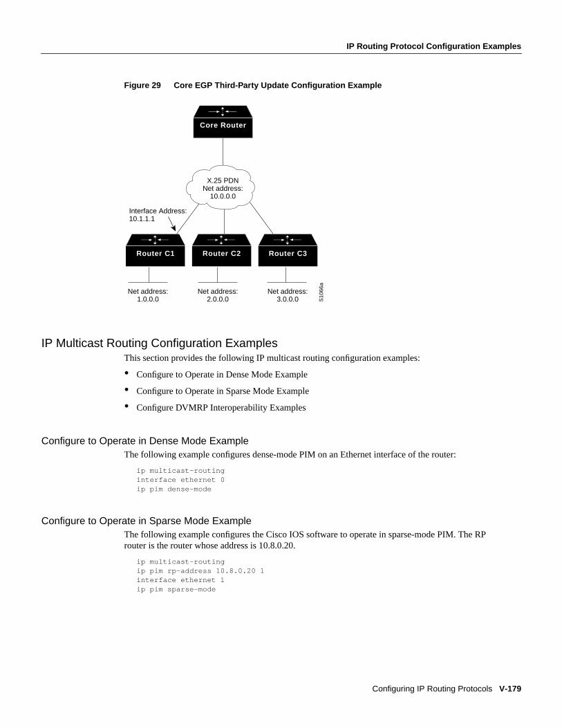
IP Routing Protocol Configuration Examples
Configuring IP Routing Protocols V-179
Figure 29 Core EGP Third-Party Update Configuration Example
IP Multicast Routing Configuration ExamplesThis section provides the following IP multicast routing configuration examples:
• Configure to Operate in Dense Mode Example
• Configure to Operate in Sparse Mode Example
• Configure DVMRP Interoperability Examples
Configure to Operate in Dense Mode ExampleThe following example configures dense-mode PIM on an Ethernet interface of the router:
ip multicast-routinginterface ethernet 0ip pim dense-mode
Configure to Operate in Sparse Mode ExampleThe following example configures the Cisco IOS software to operate in sparse-mode PIM. The RProuter is the router whose address is 10.8.0.20.
ip multicast-routingip pim rp-address 10.8.0.20 1interface ethernet 1ip pim sparse-mode
Router C1
X.25 PDN Net address:
10.0.0.0
Interface Address: 10.1.1.1
Net address: 1.0.0.0
Net address: 2.0.0.0
Net address: 3.0.0.0 S
1066
a
Core Router
Router C2 Router C3
V-180 Network Protocols Configuration Guide, Part 1
IP Routing Protocol Configuration Examples
Configure DVMRP Interoperability ExamplesThe following example configures DVMRP interoperability for configurations when the PIM routerand the DVMRP router are on the same network segment. In this example, access list 1 advertisesthe networks (98.92.35.0, 198.92.36.0, 198.92.37.0, 131.108.0.0, and 150.136.0.0) to the DVMRProuter, and access list 2 is used to prevent all other networks from being advertised(ip dvmrp metric 0 ).
interface ethernet 0ip address 131.119.244.244 255.255.255.0ip pim dense-modeip dvmrp metric 1 list 1ip dvmrp metric 0 list 2
access-list 1 permit 198.92.35.0 0.0.0.255access-list 1 permit 198.92.36.0 0.0.0.255access-list 1 permit 198.92.37.0 0.0.0.255access-list 1 permit 131.108.0.0 0.0.255.255access-list 1 permit 150.136.0.0 0.0.255.255access-list 1 deny 0.0.0.0 255.255.255.255access-list 2 permit 0.0.0.0 255.255.255.255
The following example configures DVMRP interoperability over a tunnel interface:
!ip multicast-routing!interface tunnel 0ip unnumbered ethernet 0ip pim dense-modetunnel source ethernet 0tunnel destination 192.70.92.133tunnel mode dvmrp!interface ethernet 0description Universitat DMZ-ethernetip address 192.76.243.2 255.255.255.0ip pim dense-mode
Variable-Length Subnet Masks ExampleOSPF, static routes, and IS-IS support variable-length subnet masks (VLSMs). With VLSMs, youcan use different masks for the same network number on different interfaces, which allows you toconserve IP addresses and more efficiently use available address space.
In the following example, a 14-bit subnet mask is used, leaving two bits of address space reservedfor serial line host addresses. There is sufficient host address space for two host endpoints on apoint-to-point serial link.
interface ethernet 0ip address 131.107.1.1 255.255.255.0! 8 bits of host address space reserved for ethernets
interface serial 0ip address 131.107.254.1 255.255.255.252! 2 bits of address space reserved for serial lines
! Router is configured for OSPF and assigned AS 107router ospf 107! Specifies network directly connected to the routernetwork 131.107.0.0 0.0.255.255 area 0.0.0.0
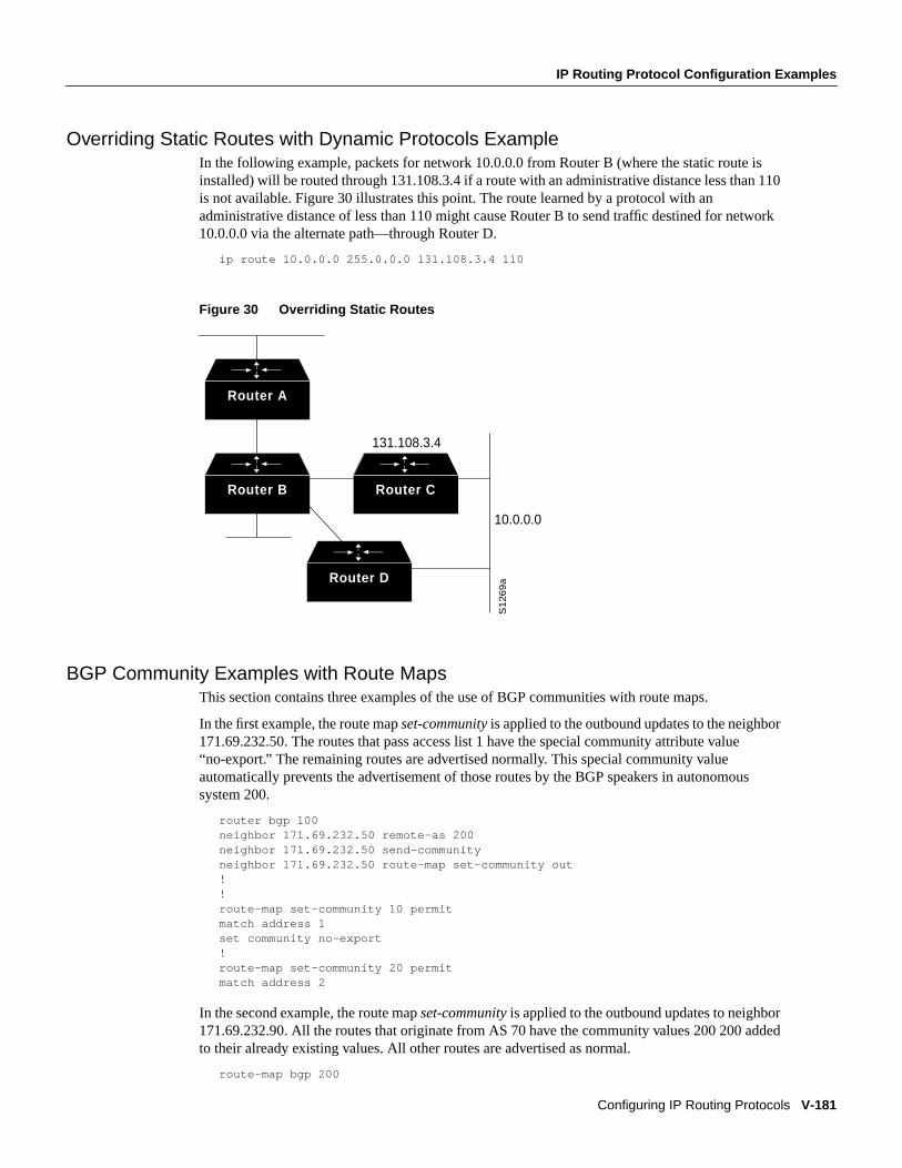
IP Routing Protocol Configuration Examples
Configuring IP Routing Protocols V-181
Overriding Static Routes with Dynamic Protocols ExampleIn the following example, packets for network 10.0.0.0 from Router B (where the static route isinstalled) will be routed through 131.108.3.4 if a route with an administrative distance less than 110is not available. Figure 30 illustrates this point. The route learned by a protocol with anadministrative distance of less than 110 might cause Router B to send traffic destined for network10.0.0.0 via the alternate path—through Router D.
ip route 10.0.0.0 255.0.0.0 131.108.3.4 110
Figure 30 Overriding Static Routes
BGP Community Examples with Route MapsThis section contains three examples of the use of BGP communities with route maps.
In the first example, the route mapset-community is applied to the outbound updates to the neighbor171.69.232.50. The routes that pass access list 1 have the special community attribute value“no-export.” The remaining routes are advertised normally. This special community valueautomatically prevents the advertisement of those routes by the BGP speakers in autonomoussystem 200.
router bgp 100neighbor 171.69.232.50 remote-as 200neighbor 171.69.232.50 send-communityneighbor 171.69.232.50 route-map set-community out!!route-map set-community 10 permitmatch address 1set community no-export!route-map set-community 20 permitmatch address 2
In the second example, the route mapset-community is applied to the outbound updates to neighbor171.69.232.90. All the routes that originate from AS 70 have the community values 200 200 addedto their already existing values. All other routes are advertised as normal.
route-map bgp 200
Router C
Router D
Router B
Router A
131.108.3.4
S1
26
9a
10.0.0.0
V-182 Network Protocols Configuration Guide, Part 1
IP Routing Protocol Configuration Examples
neighbor 171.69.232.90 remote-as 100neighbor 171.69.232.90 send-communityneighbor 171.69.232.90 route-map set-community out!route-map set-community 10 permitmatch as-path 1set community 200 200 additive!route-map set-community 20 permitmatch as-path 2!ip as-path access-list 1 permit 70$ip as-path access-list 2 permit .*
In the third example, community-based matching is used to selectively set MED andlocal-preference for routes from neighbor 171.69.232.55. All the routes that match community list1get the MED set to 8000. This includes any routes that have the communities “100 200 300” or“900 901.” These routes could have other community values also.
All the routes that pass community list 2 get the local preference set to 500. This includes the routesthat have community values 88 or 90. If they belong to any other community, they will not bematched by community list 2.
All the routes that match community list 3 get the local-preference set to 50. Community list3 willmatch all the routes because all the routes are members of the Internet community. Thus, all theremaining routes from neighbor 171.69.232.55 get a local preference 50.
router bgp 200neighbor 171.69.232.55 remote-as 100neighbor 171.69.232.55 route-map filter-on-community in!route-map filter-on-community 10 permitmatch community 1set metric 8000!route-map filter-on-community 20 permitmatch community 2 exact-matchset local-preference 500!route-map filter-on-community 30 permitmatch community 3set local-preference 50!ip community-list 1 permit 100 200 300ip community-list 1 permit 900 901!ip community-list 2 permit 88ip community-list 2 permit 90!ip community-list 3 permit internet
Passive Interface ExamplesThe following example sends IGRP updates to all interfaces on network 131.108.0.0 except interfaceEthernet 1. Figure 31 shows this configuration.
router igrp 109network 131.108.0.0passive-interface ethernet 1
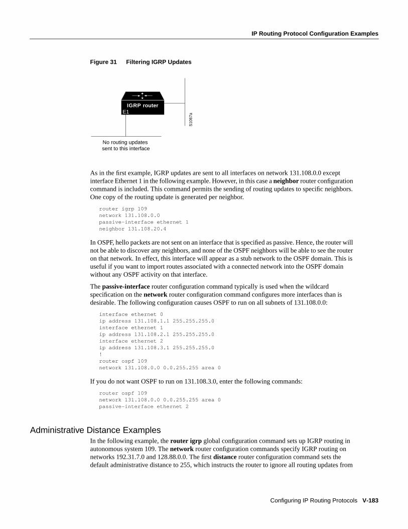
IP Routing Protocol Configuration Examples
Configuring IP Routing Protocols V-183
Figure 31 Filtering IGRP Updates
As in the first example, IGRP updates are sent to all interfaces on network 131.108.0.0 exceptinterface Ethernet 1 in the following example. However, in this case aneighbor router configurationcommand is included. This command permits the sending of routing updates to specific neighbors.One copy of the routing update is generated per neighbor.
router igrp 109network 131.108.0.0passive-interface ethernet 1neighbor 131.108.20.4
In OSPF, hello packets are not sent on an interface that is specified as passive. Hence, the router willnot be able to discover any neighbors, and none of the OSPF neighbors will be able to see the routeron that network. In effect, this interface will appear as a stub network to the OSPF domain. This isuseful if you want to import routes associated with a connected network into the OSPF domainwithout any OSPF activity on that interface.
Thepassive-interface router configuration command typically is used when the wildcardspecification on thenetwork router configuration command configures more interfaces than isdesirable. The following configuration causes OSPF to run on all subnets of 131.108.0.0:
interface ethernet 0ip address 131.108.1.1 255.255.255.0interface ethernet 1ip address 131.108.2.1 255.255.255.0interface ethernet 2ip address 131.108.3.1 255.255.255.0!router ospf 109network 131.108.0.0 0.0.255.255 area 0
If you do not want OSPF to run on 131.108.3.0, enter the following commands:
router ospf 109network 131.108.0.0 0.0.255.255 area 0passive-interface ethernet 2
Administrative Distance ExamplesIn the following example, therouter igrp global configuration command sets up IGRP routing inautonomous system 109. Thenetwork router configuration commands specify IGRP routing onnetworks 192.31.7.0 and 128.88.0.0. The firstdistance router configuration command sets thedefault administrative distance to 255, which instructs the router to ignore all routing updates from
IGRP router
S10
67aE1
No routing updates sent to this interface
V-184 Network Protocols Configuration Guide, Part 1
IP Routing Protocol Configuration Examples
routers for which an explicit distance has not been set. The seconddistance command sets theadministrative distance to 90 for all routers on the Class C network 192.31.7.0. The thirddistancecommand sets the administrative distance to 120 for the router with the address 128.88.1.3.
router igrp 109network 192.31.7.0network 128.88.0.0distance 255distance 90 192.31.7.0 0.0.0.255distance 120 128.88.1.3 0.0.0.0
The following example assigns the router with the address 192.31.7.18 an administrative distance of100, and all other routers on subnet 192.31.7.0 an administrative distance of 200:
distance 100 192.31.7.18 0.0.0.0distance 200 192.31.7.0 0.0.0.255
However, if you reverse the order of these commands, all routers on subnet 192.31.7.0 are assignedan administrative distance of 200, including the router at address 192.31.7.18:
distance 200 192.31.7.0 0.0.0.255distance 100 192.31.7.18 0.0.0.0
Assigning administrative distances is a problem unique to each network and is done in response tothe greatest perceived threats to the connected network. Even when general guidelines exist, thenetwork manager must ultimately determine a reasonable matrix of administrative distances for thenetwork as a whole.
In the following example, the distance value for IP routes learned is 90. Preference is given to theseIP routes rather than routes with the default administrative distance value of 110.
router isisdistance 90 ip
Policy Routing ExampleThe following example provides two sources with equal access to two different service providers.Packets arriving on async interface 1 from the source 1.1.1.1 are sent to the router at 6.6.6.6 if therouter has no explicit route for the packet's destination. Packets arriving from the source 2.2.2.2 aresent to the router at 7.7.7.7 if the router has no explicit route for the packet's destination. All otherpackets for which the router has no explicit route to the destination are discarded.
access-list 1 permit ip 1.1.1.1access-list 2 permit ip 2.2.2.2!interface async 1ip policy route-map equal-access!route-map equal-access permit 10match ip address 1set ip default next-hop 6.6.6.6route-map equal-access permit 20match ip address 2set ip default next-hop 7.7.7.7route-map equal-access permit 30set default interface null0
Split Horizon ExamplesTwo examples of configuring split horizon are provided.
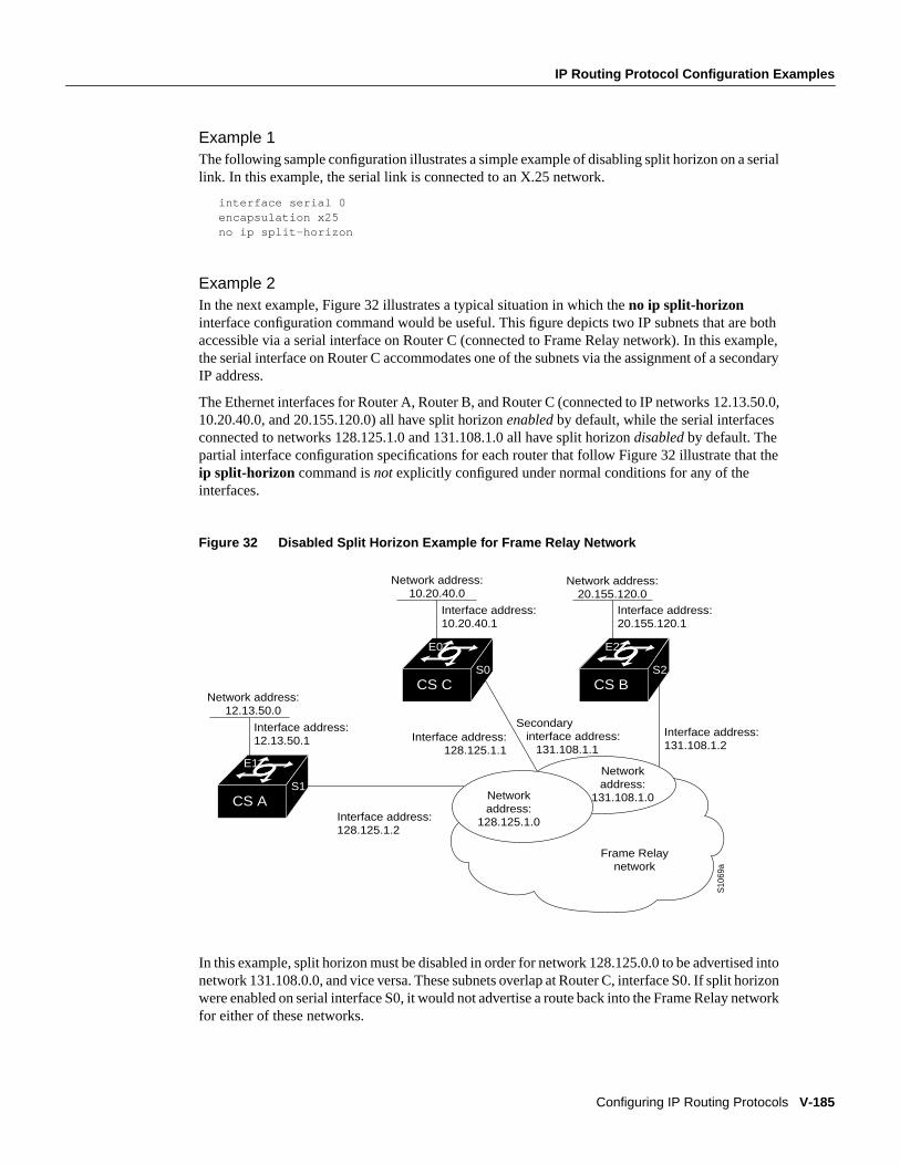
IP Routing Protocol Configuration Examples
Configuring IP Routing Protocols V-185
Example 1The following sample configuration illustrates a simple example of disabling split horizon on a seriallink. In this example, the serial link is connected to an X.25 network.
interface serial 0encapsulation x25no ip split-horizon
Example 2In the next example, Figure 32 illustrates a typical situation in which theno ip split-horizoninterface configuration command would be useful. This figure depicts two IP subnets that are bothaccessible via a serial interface on Router C (connected to Frame Relay network). In this example,the serial interface on Router C accommodates one of the subnets via the assignment of a secondaryIP address.
The Ethernet interfaces for Router A, Router B, and Router C (connected to IP networks 12.13.50.0,10.20.40.0, and 20.155.120.0) all have split horizonenabled by default, while the serial interfacesconnected to networks 128.125.1.0 and 131.108.1.0 all have split horizondisabled by default. Thepartial interface configuration specifications for each router that follow Figure 32 illustrate that theip split-horizon command isnot explicitly configured under normal conditions for any of theinterfaces.
Figure 32 Disabled Split Horizon Example for Frame Relay Network
In this example, split horizon must be disabled in order for network 128.125.0.0 to be advertised intonetwork 131.108.0.0, and vice versa. These subnets overlap at Router C, interface S0. If split horizonwere enabled on serial interface S0, it would not advertise a route back into the Frame Relay networkfor either of these networks.
CS BCS C
CS A
E1
E0
S1
Interface address: 131.108.1.2
Interface address: 128.125.1.2
Secondary interface address: 131.108.1.1
Interface address: 128.125.1.1
S0
E2
S2
Network address: 12.13.50.0
Interface address: 12.13.50.1
Network address: 10.20.40.0
Interface address: 10.20.40.1
Network address: 20.155.120.0
Interface address: 20.155.120.1
S10
69a
Frame Relay network
Network address:
128.125.1.0
Network address:
131.108.1.0
V-186 Network Protocols Configuration Guide, Part 1
IP Routing Protocol Configuration Examples
Configuration for Router Ainterface ethernet 1ip address 12.13.50.1!interface serial 1ip address 128.125.1.2encapsulation frame-relay
Configuration for Router Binterface ethernet 2ip address 20.155.120.1!interface serial 2ip address 131.108.1.2encapsulation frame-relay
Configuration for Router Cinterface ethernet 0ip address 10.20.40.1!interface serial 0ip address 128.124.1.1ip address 131.108.1.1 secondaryencapsulation frame-relay
Static Routing Redistribution ExampleIn the example that follows, three static routes are specified, two of which are to be advertised. Dothis by specifying theredistribute static router configuration command, then specifying an accesslist that allows only those two networks to be passed to the IGRP process. Any redistributed staticroutes should be sourced by a single router to minimize the likelihood of creating a routing loop.
ip route 192.1.2.0 255.255.255.0 192.31.7.65ip route 193.62.5.0 255.255.255.0 192.31.7.65ip route 131.108.0.0 255.255.255.0 192.31.7.65access-list 3 permit 192.1.2.0access-list 3 permit 193.62.5.0!router igrp 109network 192.31.7.0default-metric 10000 100 255 1 1500redistribute staticdistribute-list 3 out static
IGRP Redistribution ExampleEach IGRP routing process can provide routing information to only one autonomous system; theCisco IOS software must run a separate IGRP process and maintain a separate routing database foreach autonomous system it services. However, you can transfer routing information between theserouting databases.
Suppose the router has one IGRP routing process for network 15.0.0.0 in autonomous system 71 andanother for network 192.31.7.0 in autonomous system 109, as the following commands specify:
router igrp 71network 15.0.0.0router igrp 109
IP Routing Protocol Configuration Examples
Configuring IP Routing Protocols V-187
network 192.31.7.0
To transfer a route to 192.31.7.0 into autonomous system 71 (without passing any other informationabout autonomous system 109), use the command in the following example:
router igrp 71redistribute igrp 109distribute-list 3 out igrp 109access-list 3 permit 192.31.7.0
RIP and IGRP Redistribution ExampleConsider a WAN at a university that uses RIP as an interior routing protocol. Assume that theuniversity wants to connect its WAN to a regional network, 128.1.0.0, which uses IGRP as therouting protocol. The goal in this case is to advertise the networks in the university network to therouters on the regional network. The commands for the interconnecting router are listed in theexample that follows:
router igrp 109network 128.1.0.0redistribute ripdefault-metric 10000 100 255 1 1500distribute-list 10 out rip
In this example, therouter global configuration command starts an IGRP routing process. Thenetwork router configuration command specifies that network 128.1.0.0 (the regional network) is toreceive IGRP routing information. Theredistribute router configuration command specifies thatRIP-derived routing information be advertised in the routing updates. Thedefault-metric routerconfiguration command assigns an IGRP metric to all RIP-derived routes.
Thedistribute-list router configuration command instructs the Cisco IOS software to use accesslist 10 (not defined in this example) to limit the entries in each outgoing update. The access listprevents unauthorized advertising of university routes to the regional network.
IP Enhanced IGRP Redistribution ExamplesEach IP Enhanced IGRP routing process provides routing information to only one autonomoussystem. The Cisco IOS software must run a separate IP Enhanced IGRP process and maintain aseparate routing database for each autonomous system it services. However, you can transfer routinginformation between these routing databases.
Suppose the software has one IP Enhanced IGRP routing process for network 15.0.0.0 inautonomous system 71 and another for network 192.31.7.0 in autonomous system 109, as thefollowing commands specify:
router eigrp 71network 15.0.0.0router eigrp 109network 192.31.7.0
To transfer a route from 192.31.7.0 into autonomous system 71 (without passing any otherinformation about autonomous system 109), use the command in the following example:
router eigrp 71redistribute eigrp 109 route-map 109-to-71route-map 109-to-71 permitmatch ip address 3set metric 10000 100 1 255 1500access-list 3 permit 192.31.7.0
V-188 Network Protocols Configuration Guide, Part 1
IP Routing Protocol Configuration Examples
The following example is an alternative way to transfer a route to 192.31.7.0 into autonomoussystem 71. Unlike the previous configuration, this one does not allow you to arbitrarily set the metric.
router eigrp 71redistribute eigrp 109distribute-list 3 out eigrp 109access-list 3 permit 192.31.7.0
RIP and IP Enhanced IGRP Redistribution ExamplesThis sections provides two examples of RIP and IP Enhanced IGRP redistribution, a simple one anda complex one.
Example 1: Simple RedistributionConsider a WAN at a university that uses RIP as an interior routing protocol. Assume that theuniversity wants to connect its WAN to a regional network, 128.1.0.0, which uses IP Enhanced IGRPas the routing protocol. The goal in this case is to advertise the networks in the university networkto the routers on the regional network. The commands for the interconnecting router are listed in theexample that follows:
router eigrp 109network 128.1.0.0redistribute ripdefault-metric 10000 100 255 1 1500distribute-list 10 out rip
In this example, therouter global configuration command starts an IP Enhanced IGRP routingprocess. Thenetwork router configuration command specifies that network 128.1.0.0 (the regionalnetwork) is to send and receive IP Enhanced IGRP routing information. Theredistribute routerconfiguration command specifies that RIP-derived routing information be advertised in the routingupdates. Thedefault-metric router configuration command assigns an IP Enhanced IGRP metric toall RIP-derived routes.
Thedistribute-list router configuration command instructs the Cisco IOS software to use access list10 (not defined in this example) to limit the entries in each outgoing update. The access list preventsunauthorized advertising of university routes to the regional network.
Example 2: Complex RedistributionThe most complex redistribution case is one in whichmutual redistribution is required between anIGP (in this case IP Enhanced IGRP) and BGP.
Suppose that BGP is running on a router somewhere else in autonomous system 1, and that the BGProutes are injected into IP Enhanced IGRP routing process1. You must use filters to ensure that theproper routes are advertised. The example configuration for router R1 illustrates use of access filtersand a distribution list to filter routes advertised to BGP neighbors. This example also illustratesconfiguration commands for redistribution between BGP and IP Enhanced IGRP.
! Configuration for router R1:router bgp 1network 131.108.0.0neighbor 192.5.10.1 remote-as 2neighbor 192.5.10.15 remote-as 1neighbor 192.5.10.24 remote-as 3redistribute eigrp 1distribute-list 1 out eigrp 1!! All networks that should be advertised from R1 are controlled with access lists:
IP Routing Protocol Configuration Examples
Configuring IP Routing Protocols V-189
!access-list 1 permit 131.108.0.0access-list 1 permit 150.136.0.0access-list 1 permit 128.125.0.0!router eigrp 1network 131.108.0.0network 192.5.10.0redistribute bgp 1
OSPF Routing and Route Redistribution ExamplesOSPF typically requires coordination among many internal routers, area border routers, andautonomous system boundary routers. At a minimum, OSPF-based routers can be configured withall default parameter values, with no authentication, and with interfaces assigned to areas.
Three examples follow:
• The first is a simple configuration illustrating basic OSPF commands.
• The second example illustrates a configuration for an internal router, ABR, and ASBRs within asingle, arbitrarily assigned, OSPF autonomous system.
• The third example illustrates a more complex configuration and the application of various toolsavailable for controlling OSPF-based routing environments.
Example 1: Basic OSPF ConfigurationThe following example illustrates a simple OSPF configuration that enables OSPF routing process9000, attaches Ethernet 0 to area 0.0.0.0, and redistributes RIP into OSPF, and OSPF into RIP:
interface ethernet 0ip address 130.93.1.1 255.255.255.0ip ospf cost 1!interface ethernet 1ip address 130.94.1.1 255.255.255.0!router ospf 9000network 130.93.0.0 0.0.255.255 area 0.0.0.0redistribute rip metric 1 subnets!router ripnetwork 130.94.0.0redistribute ospf 9000default-metric 1
Example 2: Another Basic OSPF ConfigurationThe following example illustrates the assignment of four area IDs to four IP address ranges. In theexample, OSPF routing process 109 is initialized, and four OSPF areas are defined: 10.9.50.0, 2, 3,and 0. Areas 10.9.50.0, 2, and 3 mask specific address ranges, while Area 0 enables OSPF forallother networks.
router ospf 109network 131.108.20.0 0.0.0.255 area 10.9.50.0network 131.108.0.0 0.0.255.255 area 2network 131.109.10.0 0.0.0.255 area 3network 0.0.0.0 255.255.255.255 area 0!! Interface Ethernet0 is in area 10.9.50.0:
V-190 Network Protocols Configuration Guide, Part 1
IP Routing Protocol Configuration Examples
interface ethernet 0ip address 131.108.20.5 255.255.255.0!! Interface Ethernet1 is in area 2:interface ethernet 1ip address 131.108.1.5 255.255.255.0!! Interface Ethernet2 is in area 2:interface ethernet 2ip address 131.108.2.5 255.255.255.0!! Interface Ethernet3 is in area 3:interface ethernet 3ip address 131.109.10.5 255.255.255.0!! Interface Ethernet4 is in area 0:interface ethernet 4ip address 131.109.1.1 255.255.255.0!! Interface Ethernet5 is in area 0:interface ethernet 5ip address 10.1.0.1 255.255.0.0
Eachnetwork router configuration command is evaluated sequentially, so the specific order of thesecommands in the configuration is important. The Cisco IOS software sequentially evaluates theaddress/wildcard-mask pair for each interface. See the “IP Routing Protocols Commands” chapterof theNetwork Protocols Command Reference, Part 1for more information.
Consider the firstnetwork command. Area ID 10.9.50.0 is configured for the interface on whichsubnet 131.108.20.0 is located. Assume that a match is determined for interface Ethernet 0. InterfaceEthernet 0 is attached to Area 10.9.50.0 only.
The secondnetwork command is evaluated next. For Area 2, the same process is then applied to allinterfaces (except interface Ethernet 0). Assume that a match is determined for interface Ethernet 1.OSPF is then enabled for that interface and Ethernet 1 is attached to Area 2.
This process of attaching interfaces to OSPF areas continues for allnetwork commands. Note thatthe lastnetwork command in this example is a special case. With this command, all availableinterfaces (not explicitly attached to another area) are attached to Area 0.
Example 3: Internal Router, ABR, and ASBRsThe following example outlines a configuration for several routers within a single OSPF autonomoussystem. Figure 33 provides a general network map that illustrates this example configuration.
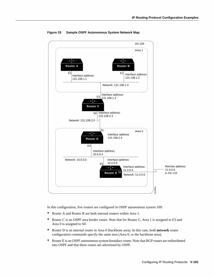
IP Routing Protocol Configuration Examples
Configuring IP Routing Protocols V-191
Figure 33 Sample OSPF Autonomous System Network Map
In this configuration, five routers are configured in OSPF autonomous system 109:
• Router A and Router B are both internal routers within Area 1.
• Router C is an OSPF area border router. Note that for Router C, Area 1 is assigned to E3 andArea 0 is assigned to S0.
• Router D is an internal router in Area 0 (backbone area). In this case, bothnetwork routerconfiguration commands specify the same area (Area 0, or the backbone area).
• Router E is an OSPF autonomous system boundary router. Note that BGP routes are redistributedinto OSPF and that these routes are advertised by OSPF.
Router E
Router D
Router C
Router BRouter A
E1 E2
E3
E5
S2
S1
E4
Interface address: 131.108.1.1
Interface address: 131.108.1.2
Interface address: 131.108.1.3
Network: 131.108.1.0
Network: 131.108.2.0
Network: 10.0.0.0
Interface address: 10.0.0.4
Interface address: 11.0.0.5
Interface address: 10.0.0.5
Network: 11.0.0.0
Remote address: 11.0.0.6 in AS 110
Area 1
Area 0
AS 109
S10
30a
Interface address: 131.108.2.4
S0 Interface address: 131.108.2.3
V-192 Network Protocols Configuration Guide, Part 1
IP Routing Protocol Configuration Examples
Note It is not necessary to include definitions of all areas in an OSPF autonomous system in theconfiguration of all routers in the autonomous system. You must only define thedirectly connectedareas. In the example that follows, routes in Area 0 are learned by the routers in Area 1 (Router Aand Router B) when the area border router (Router C) injects summary link state advertisements(LSAs) into Area 1.
Autonomous system 109 is connected to the outside world via the BGP link to the external peer atIP address 11.0.0.6.
Router A—Internal Routerinterface ethernet 1ip address 131.108.1.1 255.255.255.0
router ospf 109network 131.108.0.0 0.0.255.255 area 1
Router B—Internal Routerinterface ethernet 2ip address 131.108.1.2 255.255.255.0
router ospf 109network 131.108.0.0 0.0.255.255 area 1
Router C—ABRinterface ethernet 3ip address 131.108.1.3 255.255.255.0
interface serial 0ip address 131.108.2.3 255.255.255.0
router ospf 109network 131.108.1.0 0.0.0.255 area 1network 131.108.2.0 0.0.0.255 area 0
Router D—Internal Routerinterface ethernet 4ip address 10.0.0.4 255.0.0.0
interface serial 1ip address 131.108.2.4 255.255.255.0
router ospf 109network 131.108.2.0 0.0.0.255 area 0network 10.0.0.0 0.255.255.255 area 0
Router E—ASBRinterface ethernet 5ip address 10.0.0.5 255.0.0.0
interface serial 2ip address 11.0.0.5 255.0.0.0
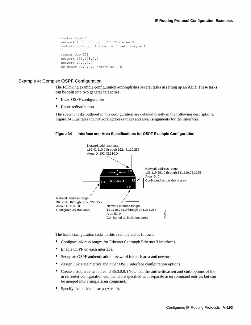
IP Routing Protocol Configuration Examples
Configuring IP Routing Protocols V-193
router ospf 109network 10.0.0.0 0.255.255.255 area 0redistribute bgp 109 metric 1 metric-type 1
router bgp 109network 131.108.0.0network 10.0.0.0neighbor 11.0.0.6 remote-as 110
Example 4: Complex OSPF ConfigurationThe following example configuration accomplishes several tasks in setting up an ABR. These taskscan be split into two general categories:
• Basic OSPF configuration
• Route redistribution
The specific tasks outlined in this configuration are detailed briefly in the following descriptions.Figure 34 illustrates the network address ranges and area assignments for the interfaces.
Figure 34 Interface and Area Specifications for OSPF Example Configuration
The basic configuration tasks in this example are as follows:
• Configure address ranges for Ethernet 0 through Ethernet 3 interfaces.
• Enable OSPF on each interface.
• Set up an OSPF authentication password for each area and network.
• Assign link state metrics and other OSPF interface configuration options.
• Create a stub area with area id 36.0.0.0. (Note that theauthentication andstub options of thearea router configuration command are specified with separatearea command entries, but canbe merged into a singlearea command.)
• Specify the backbone area (Area 0).
Router A
S10
31a
E3 E1
E2
E0
Network address range: 192.42.110.0 through 192.42.110.255 Area ID: 192.42.110.0
Network address range: 36.56.0.0 through 35.56.255.255 Area ID: 36.0.0.0 Configured as stub area
Network address range: 131.119.254.0 through 131.254.255 Area ID: 0 Configured as backbone area
Network address range: 131.119.251.0 through 131.119.251.255 Area ID: 0 Configured as backbone area
V-194 Network Protocols Configuration Guide, Part 1
IP Routing Protocol Configuration Examples
Configuration tasks associated with redistribution are as follows:
• Redistribute IGRP and RIP into OSPF with various options set (includingmetric-type, metric,tag, andsubnet).
• Redistribute IGRP and OSPF into RIP.
The following is an example OSPF configuration:
interface ethernet 0ip address 192.42.110.201 255.255.255.0ip ospf authentication-key abcdefghip ospf cost 10!interface ethernet 1ip address 131.119.251.201 255.255.255.0ip ospf authentication-key ijklmnopip ospf cost 20ip ospf retransmit-interval 10ip ospf transmit-delay 2ip ospf priority 4!interface ethernet 2ip address 131.119.254.201 255.255.255.0ip ospf authentication-key abcdefghip ospf cost 10!interface ethernet 3ip address 36.56.0.201 255.255.0.0ip ospf authentication-key ijklmnopip ospf cost 20ip ospf dead-interval 80
OSPF is on network 131.119.0.0:
router ospf 201network 36.0.0.0 0.255.255.255 area 36.0.0.0network 192.42.110.0 0.0.0.255 area 192.42.110.0network 131.119.0.0 0.0.255.255 area 0area 0 authenticationarea 36.0.0.0 stubarea 36.0.0.0 authenticationarea 36.0.0.0 default-cost 20area 192.42.110.0 authenticationarea 36.0.0.0 range 36.0.0.0 255.0.0.0area 192.42.110.0 range 192.42.110.0 255.255.255.0area 0 range 131.119.251.0 255.255.255.0area 0 range 131.119.254.0 255.255.255.0
redistribute igrp 200 metric-type 2 metric 1 tag 200 subnetsredistribute rip metric-type 2 metric 1 tag 200
IGRP autonomous system 200 is on 131.119.0.0:
router igrp 200network 131.119.0.0!! RIP for 192.42.110!router ripnetwork 192.42.110.0redistribute igrp 200 metric 1redistribute ospf 201 metric 1
IP Routing Protocol Configuration Examples
Configuring IP Routing Protocols V-195
BGP Route Advertisement and Redistribution ExamplesThe following examples illustrate configurations for advertising and redistributing BGP routes. Thefirst example details the configuration for two neighboring routers that run IGRP within theirrespective autonomous systems and that are configured to advertise their respective BGP routesbetween each other. The second example illustrates route redistribution of BGP into IGRP and IGRPinto BGP.
Example 1: Simple BGP Route AdvertisementThis example provides the required configuration for two routers (R1 and R2) that are intended toadvertise BGP routes to each other and to redistribute BGP into IGRP.
Configuration for Router R1! Assumes autonomous system 1 has network number 131.108.0.0router bgp 1network 131.108.0.0neighbor 192.5.10.1 remote-as 2!router igrp 1network 131.108.0.0network 192.5.10.0redistribute bgp 1! Note that IGRP is not redistributed into BGP
Configuration for Router R2router bgp 2network 150.136.0.0neighbor 192.5.10.2 remote-as 1!router igrp 2network 150.136.0.0network 192.5.10.0redistribute bgp 2
Example 2: Mutual Route RedistributionThe most complex redistribution case is one in whichmutual redistribution is required between anIGP (in this case IGRP) and BGP.
Suppose that EGP is running on a router somewhere else in autonomous system 1, and that the EGProutes are injected into IGRP routing process 1. You must filter to ensure that the proper routes areadvertised. The example configuration for router R1 illustrates use of access filters and a distributionlist to filter routes advertised to BGP neighbors. This example also illustrates configurationcommands for redistribution between BGP and IGRP. Only routes learned using the EBGP sessionwith neighbors 192.5.10.1 and 192.5.10.24 are redistributed into IGRP.
Configuration for Router R1router bgp 1network 131.108.0.0neighbor 192.5.10.1 remote-as 2! External peer or neighborneighbor 192.5.10.15 remote-as 1! Same AS; therefore internal neighborneighbor 192.5.10.24 remote-as 3

V-196 Network Protocols Configuration Guide, Part 1
IP Routing Protocol Configuration Examples
! A second External neighborredistribute igrp 1distribute-list 1 out igrp 1!! All networks that should be! advertised from R1 are! controlled with access lists:!access-list 1 permit 131.108.0.0access-list 1 permit 150.136.0.0access-list 1 permit 128.125.0.0!router igrp 1network 131.108.0.0network 192.5.10.0redistribute bgp 1
Default Metric Values Redistribution ExampleThe following example shows a router in autonomous system 109 using both RIP and IGRP. Theexample advertises IGRP-derived routes using the RIP protocol and assigns the IGRP-derived routesa RIP metric of 10.
router ripdefault-metric 10redistribute igrp 109
Route Map ExamplesThe examples in this section illustrate the use of redistribution, with and without route maps.Examples from both the IP and CLNS routing protocols are given.
The following example redistributes all OSPF routes into IGRP:
router igrp 109redistribute ospf 110
The following example redistributes RIP routes with a hop count equal to 1 into OSPF. These routeswill be redistributed into OSPF as external link state advertisements with a metric of 5, metric typeof Type 1, and a tag equal to 1.
router ospf 109redistribute rip route-map rip-to-ospf!route-map rip-to-ospf permitmatch metric 1set metric 5set metric-type type1set tag 1
The following example redistributes OSPF learned routes with tag 7 as a RIP metric of 15:
router ripredistribute ospf 109 route-map 5!route-map 5 permitmatch tag 7set metric 15
IP Routing Protocol Configuration Examples
Configuring IP Routing Protocols V-197
The following example redistributes OSPF intra-area and interarea routes with next-hop routers onserial interface 0 into BGP with an INTER_AS metric of 5:
router bgp 109redistribute ospf 109 route-map 10!route-map 10 permitmatch route-type internalmatch interface serial 0set metric 5
The following example redistributes two types of routes into the integrated IS-IS routing table(supporting both IP and CLNS). The first are OSPF external IP routes with tag 5; these are insertedinto Level 2 IS-IS LSPs with a metric of 5. The second are ISO-IGRP derived CLNS prefix routesthat match CLNS access list 2000. These will be redistributed into IS-IS as Level 2 LSPs with ametric of 30.
router isisredistribute ospf 109 route-map 2redistribute iso-igrp nsfnet route-map 3!route-map 2 permitmatch route-type externalmatch tag 5set metric 5set level level-2!route-map 3 permitmatch address 2000set metric 30
With the following configuration, OSPF external routes with tags 1, 2, 3, and 5 are redistributed intoRIP with metrics of 1, 1, 5, and 5, respectively. The OSPF routes with a tag of 4 are not redistributed.
router ripredistribute ospf 109 route-map 1!route-map 1 permitmatch tag 1 2set metric 1!route-map 1 permitmatch tag 3set metric 5!route-map 1 denymatch tag 4!route map 1 permitmatch tag 5set metric 5
The following configuration sets the condition that if there is an OSPF route to network 140.222.0.0,generate the default network 0.0.0.0 into RIP with a metric of 1:
router ripredistribute ospf 109 route-map default!route-map default permitmatch ip address 1set metric 1!access-list 1 permit 140.222.0.0 0.0.255.255access-list 2 permit 0.0.0.0 0.0.0.0
V-198 Network Protocols Configuration Guide, Part 1
IP Routing Protocol Configuration Examples
Given the following configuration, a RIP learned route for network 160.89.0.0 and an ISO-IGRPlearned route with prefix 49.0001.0002 will be redistributed into an IS-IS Level 2 LSP with a metricof 5:
router isisredistribute rip route-map 1redistribute iso-igrp remote route-map 1!route-map 1 permitmatch ip address 1match clns address 2set metric 5set level level-2!access-list 1 permit 160.89.0.0 0.0.255.255clns filter-set 2 permit 49.0001.0002...
The following configuration example illustrates how a route map is referenced by thedefault-information router configuration command. This is called conditional default origination.OSPF will originate the default route (network 0.0.0.0) with a Type 2 metric of 5 if 140.222.0.0, withnetwork 0.0.0.0 in the routing table.
route-map ospf-default permitmatch ip address 1set metric 5set metric-type type-2!access-list 1 140.222.0.0 0.0.255.255!router ospf 109default-information originate route-map ospf-default
See more route map examples in the sections “BGP Route Map Examples” and “BGP CommunityExamples with Route Maps.”
Route Summarization ExampleThe following example configures route summarization on the interface and also configures theauto-summary feature. This configuration causes IP Enhanced IGRP to summarize network 10.0.0.0out Ethernet interface 0 only. In addition, this example disables auto summarization.
interface Ethernet 0ip summary-address eigrp 1 10.0.0.0 255.0.0.0
!router eigrp 1
network 172.16.0.0no auto-summary
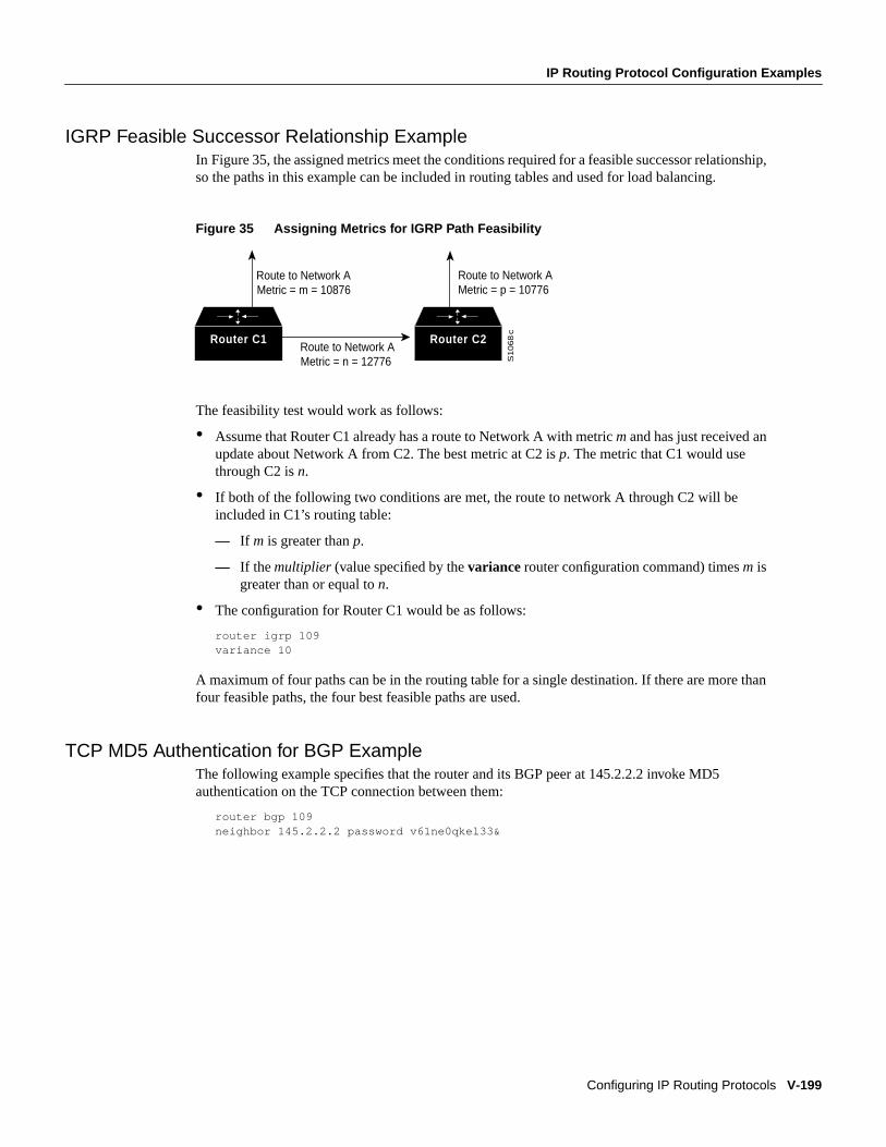
IP Routing Protocol Configuration Examples
Configuring IP Routing Protocols V-199
IGRP Feasible Successor Relationship ExampleIn Figure35, the assigned metrics meet the conditions required for a feasible successor relationship,so the paths in this example can be included in routing tables and used for load balancing.
Figure 35 Assigning Metrics for IGRP Path Feasibility
The feasibility test would work as follows:
• Assume that Router C1 already has a route to Network A with metricm and has just received anupdate about Network A from C2. The best metric at C2 isp. The metric that C1 would usethrough C2 isn.
• If both of the following two conditions are met, the route to network A through C2 will beincluded in C1’s routing table:
— If m is greater thanp.
— If themultiplier (value specified by thevariance router configuration command) timesm isgreater than or equal ton.
• The configuration for Router C1 would be as follows:
router igrp 109variance 10
A maximum of four paths can be in the routing table for a single destination. If there are more thanfour feasible paths, the four best feasible paths are used.
TCP MD5 Authentication for BGP ExampleThe following example specifies that the router and its BGP peer at 145.2.2.2 invoke MD5authentication on the TCP connection between them:
router bgp 109neighbor 145.2.2.2 password v61ne0qkel33&
Router C2Router C1
Route to Network A Metric = m = 10876
Route to Network A Metric = n = 12776
Route to Network A Metric = p = 10776
S1068
c
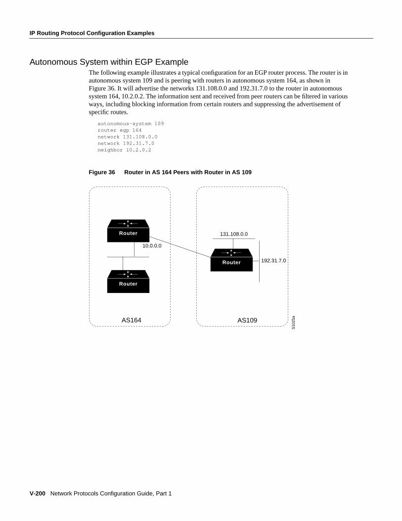
V-200 Network Protocols Configuration Guide, Part 1
IP Routing Protocol Configuration Examples
Autonomous System within EGP ExampleThe following example illustrates a typical configuration for an EGP router process. The router is inautonomous system 109 and is peering with routers in autonomous system 164, as shown inFigure 36. It will advertise the networks 131.108.0.0 and 192.31.7.0 to the router in autonomoussystem 164, 10.2.0.2. The information sent and received from peer routers can be filtered in variousways, including blocking information from certain routers and suppressing the advertisement ofspecific routes.
autonomous-system 109router egp 164network 131.108.0.0network 192.31.7.0neighbor 10.2.0.2
Figure 36 Router in AS 164 Peers with Router in AS 109
Router
Router
Router
S10
25a
AS164 AS109
10.0.0.0
131.108.0.0
192.31.7.0