contura i11 i21
TRANSCRIPT
GB
1
Облицовка Contura 11, Contura 21
Инструкция по сборке и установке
RUS

GB
2
Внимание! Не забудьте связаться с местными органами по согласованию строительной документации до установки камина.
Помните, что владелец дома несет личную ответственность за соблюдение обязательных требований по безопасности и должен иметь разрешение на установку камина, подтвержденное государственным инспектором.
Ваша местная компания, ответственная за чистку труб, также должна быть проинформирована об установке камина, так как установка может повлиять на обычную процедуру чистки труб.
ВНИМАНИЕ! Во время работы некоторые поверхности камина сильно нагреваются и могут привести к ожогам при касании. Будьте также осторожны с теплом, излучаемым через стекло дверцы топки. Размещение горючих материалов ближе безопасной дистанции может привести к пожару. Неправильное разжигание огня может спровоцировать быстрое воспламенение газов, которое может привести к повреждению Вашего имущества и нанесению вреда здоровью.
Декларация соответствия EC
ПроизводительНаименование NIBE AB/NIBE StovesАдрес Box 134, Skulptörvägen 10, SE-285 23 MARKARYDРасположение фабрики Markaryd, Sweden
Продукт, соответствующий данной декларации:Тип продукта Камин на твердом топливеМарка Contura Тип соответствует стандарту EN 13240 annexe ZAОбласть применения Отопление помещенийТопливо ДревесинаСпециальные условия Нет
Маркировка СE C11 C21
Номинальная мощность: 9 кВт 10 кВт
Тип топлива: Древесина Древесина
Температура дымовых газов
на выходе из топки: 265° C 280° C
Эффективность: 81% 81%
Выбросы CO: 0,09% 0,07%
Расстояния до горючих материалов:C 11, C 21 Сзади: огнеупорная стенка, по бокам: 400 мм
Сертифицирован в соответствии с:European standard EN-13240DIN plus Bauart 1Art. 15a B-VGTest report no. C11: RRF 40 09 2080C21: RRF 40 09 2081ГОСТ-Р
Приложения:
• Инструкция по сборке и устанговке, инструкция по эксплуатации
Никлас ГуннарсонГенеральный директор NIBE Brasvärme
RUS
GB
3
УВАЖАЕМЫЙ ВЛАДЕЛЕЦ КАМИНА CONTURA!
Добро пожаловать в семью Contura!
Надеемся, использование Вашего нового камина принесет Вам немало приятных минут.
Мы понимаем, что Вы ожидаете от камина высокого качества и хорошего дизайна. Купив Contura, Вы получили безопасный камин с нестареющим дизайном и длительным сроком эксплуатации. Процесс горения в топке камина Contura экологически безопасен и высокоэффективен.
Пожалуйста, внимательно изучите настоящую инструкцию до того, как начать работу по сборке и установке камина, и отдельную инструкцию по разжиганию огня до того, как разжечь огонь в первый раз. ЭТО ОЧЕНЬ ВАЖНО!
СОДЕРЖАНИЕ
Общая информация 34
Безопасные расстояния 35
Подача воздуха для горения 37
Варианты установки 38
Монтаж облицовки 40
Монтаж модулей для увеличения высоты 49 Стены из горючих материалов и огнеупорный экран
Монтаж модулей для увеличения высоты 53 Стены из негорючих материалов, заднее или верхнее подключениеp
Монтаж модулей для увеличения высоты 56 Стены из негорючих материалов, заднее угловое подключение
Установка дровяных ящиков 60
RUS

GB
4
Общая информацияЭто руководство содержит указания по правильной сборке и установке каминов Сontura 11 and 21. Подробная информация по топкам содержится в отдельной инструкции. Чтобы иметь возможность гарантировать Вам безупречную работу и безопасность камина, мы рекомендуем пригласить для сборки и установки камина специалистов. Наши официальные дилеры могут рекомендовать квалифицированного мастера. Список официальных дилеров Contura можно найти на нашем сайте www.contura.eu/ru.
К камину также прилагается инструкция по эксплуатации. Пожалуйста, внимательно изучите все инструкции и сохраните их для будущего использования.
Топки сертифицированы и могут подключаться к дымоходу, труба которого выдерживает температуру не менее 350°C, внешний диаметр соединения с дымоходом равен Ø200 мм. Для горения необходимо использовать уличный воздух, подробнее см. стр. 37
Панель для защиты полаЕсли пол под камином сделан из горючего материала, необходимо защитить его негорючим материалом (например, натуральный камень, бетон или металл толщиной не менее 0,7 мм). Пол перед дверцей топки также должен быть защищен негорючим материалом на расстоянии не менее 300 мм перед дверцей топки и не менее 100 мм по бокам от дверцы. Стандартные панели для защиты пола из стекла или окрашенного металла производства Contura предлагаются, как дополнительное оборудование.
ДымоходТяга дымохода должна обеспечивать отрицательное давление в минимум 12 Pa. Тяга зависит как от длины и диаметра дымохода, так и от качества его изоляции. Минимальная рекомендованная длина трубы дымохода составляет 3,5 метра. Диаметр трубы должен равняться 200 мм (сечение 300 см2). При подключении через адаптер (дополнительное оборудование) к дымоходу диаметром 150 мм топкой можно будет пользоваться только при закрытой дверце.
Внимательно проверьте изоляцию трубы дымохода на отсутствие утечек воздуха по стыкам и вокруг дымовых заслонок.
Обратите внимание, что тяга уменьшается в дымоходах с острыми изгибами и горизонтальными секциями. Допустимы горизонтальные секции длиной до 1 м, при условии, что длина вертикальной секции будет не менее 5 м.
При конструировании дымохода должна быть предусмотрена возможность легкого доступа к дымовым заслонкам. Начало дымохода должно быть доступно для прочистки.
Стена за каминомЕсли Вы планируете установить Contura 11 / 21 у стены, изготовленной из горючих материалов, нужно защитить ее при помощи огнеупорных материалов или интегрированного защитного экрана (доп. оборудование). Размер огнеупорного экрана должен быть не менее размера облицовки камина. Дополнительную информацию о материалах, подходящих для изготовления огнеупорного экрана, смотрите в отдельной инструкции к топке. Помните, что негорючие также могут требовать дополнительной защиты, например, несущие стены или тонкие негорючие стены с деревянной основой.
БетонПоверхности из бетона по своей природе могут иметь дефекты поверхности. Цемент для доработки дефектов поставляется вместе с камином.
При усадке здания, в котором установлен камин, и из-за того, что бетон сжимается, в течение первых месяцев после установки в затирке между бетонными блоками могут возникнуть трещины. Если это произошло, нужно зачистить затирку и заполнить стыки заново. После высыхания свежей затирки прокрасьте стыки.
Tехническая информация C11 C21Мощность 6-12 кВт 6-12 кВтНоминальная мощность 9 кВт 10 кВтEfficiency 81% 81%
Модель C11C C11A/S Вес (кг) 470 450Ширина (мм) 1050 1050Глубина (мм) 620 620Высота (мм) 1620 1620
Модель C11C, ув. мод. C11A/S, ув. мод. Вес (кг) 575 550Высота (мм) 2305 2305
Модель C21C C21A/S Вес (кг) 495 480Ширина (мм) 950 950Глубина (мм) 620 620Высота (мм) 1755 1755
Модель C21C ув.мод. C21A/S ув.мод. Вес (кг) 585 560Высота (мм) 2305 2305
Внешний диаметр соединения Ø200 мм.Сертифицирован в соответствии с:European standard EN-13240 DIN plus Bauart 1Art. 15a B-VGTest report no. C11: RRF 40 09 2080 C21: RRF 40 09 2081ГОСТ-Р
ФундаментПри установке камина на деревянные перекрытия инженер-строитель должен предварительно оценить, выдержат ли они вес камина. Если общий вес камина превышает 400 кг, обычно требуется укрепление деревянных перекрытий.
Дров.ящик135610620465
Дров.ящик110465620465
RUS
GB
5
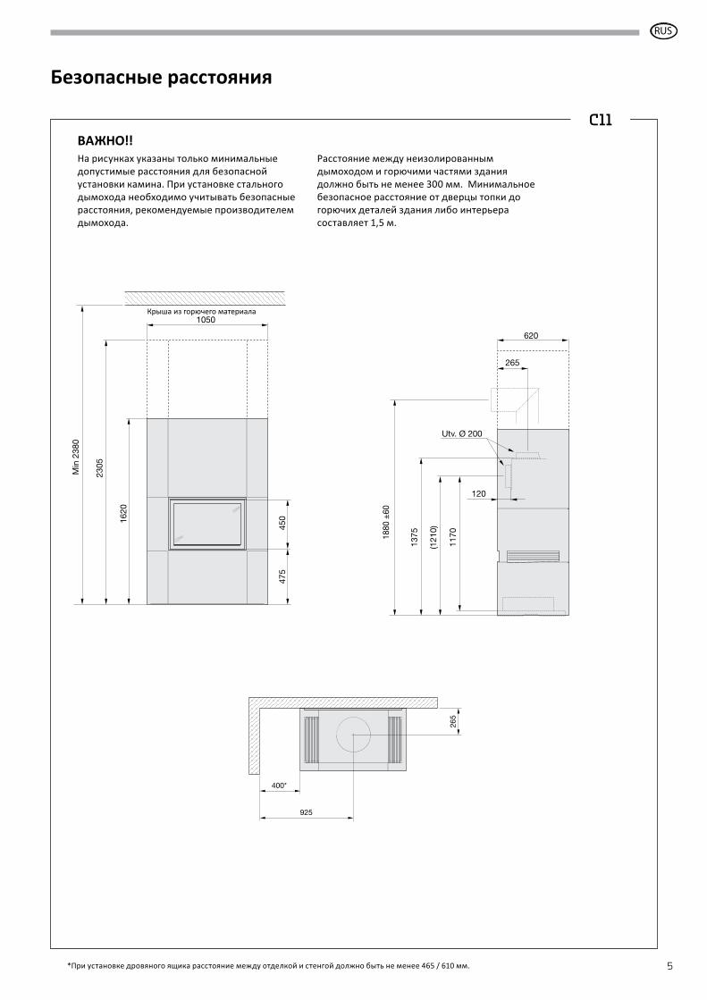
Безопасные расстояния
1620
Min
238
0
2305
475
450
1050Combustible roof
265
120
1375
(121
0)
1170
620
1880
±60
Utv. Ø 200
400*
265
925
*При установке дровяного ящика расстояние между отделкой и стенгой должно быть не менее 465 / 610 мм.
C11
На рисунках указаны только минимальные допустимые расстояния для безопасной установки камина. При установке стального дымохода необходимо учитывать безопасные расстояния, рекомендуемые производителем дымохода.
Расстояние между неизолированным дымоходом и горючими частями здания должно быть не менее 300 мм. Минимальное безопасное расстояние от дверцы топки до горючих деталей здания либо интерьера составляет 1,5 м.
ВАЖНО!!
RUS
Крыша из горючего материала

GB
6
Безопасные расстояния
*При установке дровяного ящика расстояние между отделкой и стенгой должно быть не менее 465 / 610 мм.
C2117
55
2305M
in 2
380
475
670
950
Combustible roof
265
120
1595
1965
±20
(143
0)
620
1390
Utv. Ø 200
400*
265
875
На рисунках указаны только минимальные допустимые расстояния для безопасной установки камина. При установке стального дымохода необходимо учитывать безопасные расстояния, рекомендуемые производителем дымохода.
Расстояние между неизолированным дымоходом и горючими частями здания должно быть не менее 300 мм. Минимальное безопасное расстояние от дверцы топки до горючих деталей здания либо интерьера составляет 1,5 м.
ВАЖНО!!
RUS
Крыша из горючего материала
GB
7
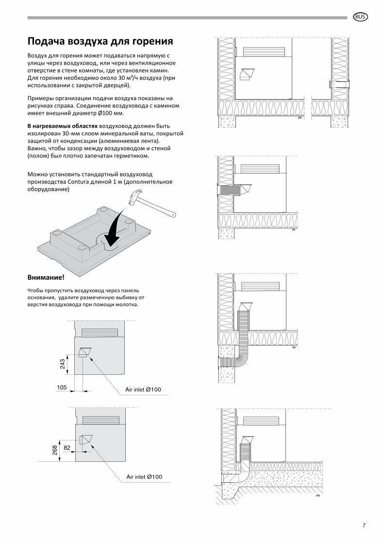
Внимание!
Чтобы пропустить воздуховод через панель основания, удалите размеченную выбивку от верстия воздуховода при помощи молотка.
HK
HK
HK
HK
Подача воздуха для горенияВоздух для горения может подаваться напрямую с улицы через воздуховод, или через вентиляционное отверстие в стене комнаты, где установлен камин. Для горения необходимо около 30 м³/ч воздуха (при использовании с закрытой дверцей).
Примеры организации подачи воздуха показаны на рисунках справа. Соединение воздуховода с камином имеет внешний диаметр Ø100 мм.
В нагреваемых областях воздуховод должен быть изолирован 30-мм слоем минеральной ваты, покрытой защитой от конденсации (алюминиевая лента).Важно, чтобы зазор между воздуховодом и стеной (полом) был плотно запечатан герметиком.
Можно установить стандартный воздуховод производства Contura длиной 1 м (дополнительное оборудование)
268 82
Air inlet Ø100
243
105 Air inlet Ø100
RUS
GB
8
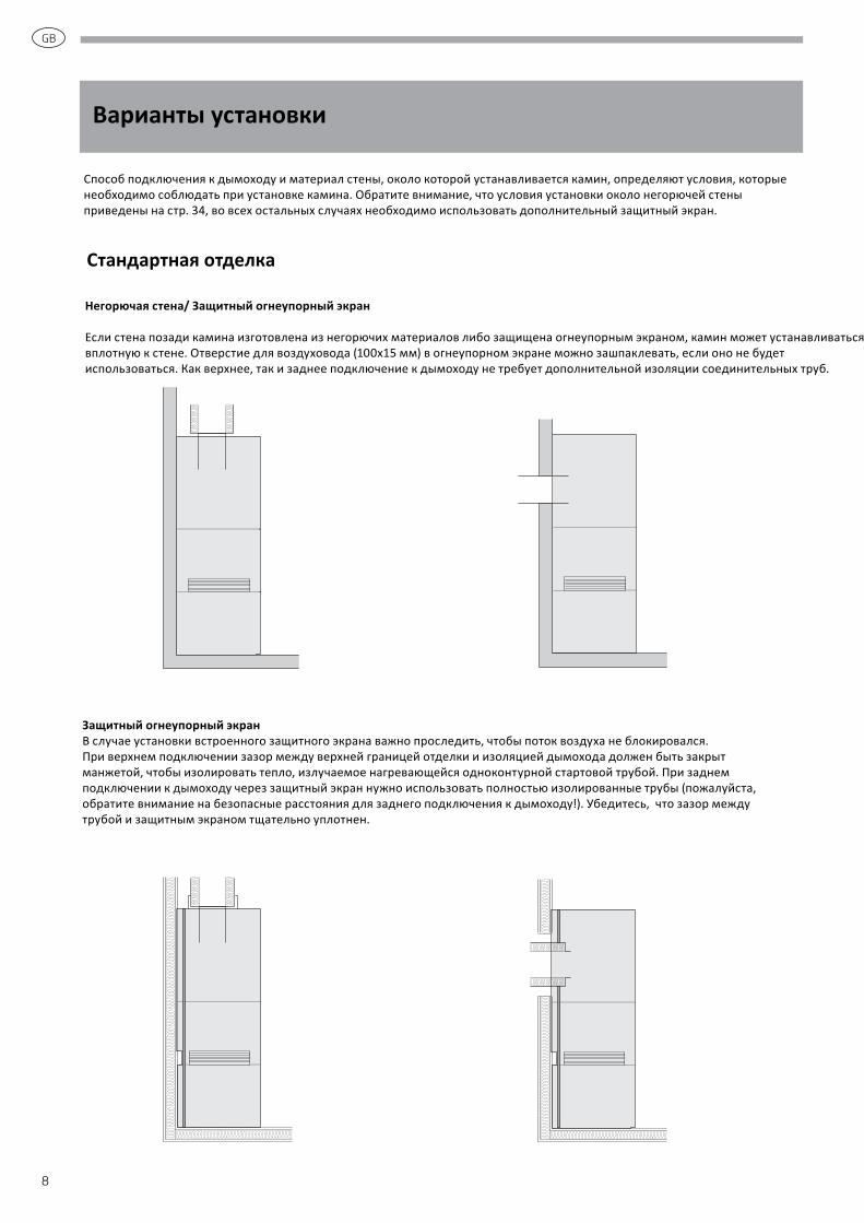
Способ подключения к дымоходу и материал стены, около которой устанавливается камин, определяют условия, которые необходимо соблюдать при установке камина. Обратите внимание, что условия установки около негорючей стены приведены на стр. 34, во всех остальных случаях необходимо использовать дополнительный защитный экран.
Варианты установки
Негорючая стена/ Защитный огнеупорный экран
Если стена позади камина изготовлена из негорючих материалов либо защищена огнеупорным экраном, камин может устанавливаться вплотную к стене. Отверстие для воздуховода (100x15 мм) в огнеупорном экране можно зашпаклевать, если оно не будет использоваться. Как верхнее, так и заднее подключение к дымоходу не требует дополнительной изоляции соединительных труб.
Защитный огнеупорный экранВ случае установки встроенного защитного экрана важно проследить, чтобы поток воздуха не блокировался. При верхнем подключении зазор между верхней границей отделки и изоляцией дымохода должен быть закрыт манжетой, чтобы изолировать тепло, излучаемое нагревающейся одноконтурной стартовой трубой. При заднем подключении к дымоходу через защитный экран нужно использовать полностью изолированные трубы (пожалуйста, обратите внимание на безопасные расстояния для заднего подключения к дымоходу!). Убедитесь, что зазор между трубой и защитным экраном тщательно уплотнен.
Стандартная отделка
GB
9
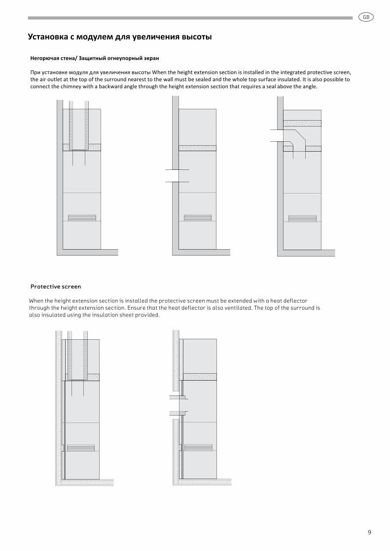
Негорючая стена/ Защитный огнеупорный экран
При установке модуля для увеличения высоты When the height extension section is installed in the integrated protective screen, the air outlet at the top of the surround nearest to the wall must be sealed and the whole top surface insulated. It is also possible to connect the chimney with a backward angle through the height extension section that requires a seal above the angle.
Protective screen
When the height extension section is installed the protective screen must be extended with a heat deflector through the height extension section. Ensure that the heat deflector is also ventilated. The top of the surround is also insulated using the insulation sheet provided.
Установка с модулем для увеличения высоты
GB
10
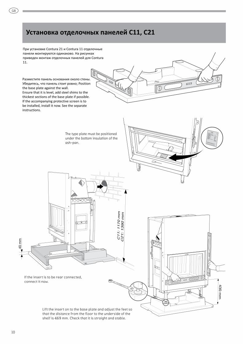
Установка отделочных панелей C11, C21
Разместите панель основания около стены. Убедитесь, что панель стоит ровно; Position the base plate against the wall. Ensure that it is level, add steel shims to the thickest sections of the base plate if possible. If the accompanying protective screen is to be installed, install it now. See the separate instructions.
Lift the insert on to the base plate and adjust the feet so that the distance from the floor to the underside of the shelf is 469 mm. Check that it is straight and stable.
При установке Contura 21 и Contura 11 отделочные панели монтируются одинаково. На рисунках приведен монтаж отделочных панелей для Contura 11.
The type plate must be positioned under the bottom insulation of the ash-pan.
430 m
m40
mm
If the insert is to be rear connected, connect it now.

GB
11
Loosen the screws holding the side panels and remove them. Use the same screws and screw holes to instead screw the hatch frame into place. Check that the bottom corners line up with the shelf.
Hatch frame
Shelf
GB
12
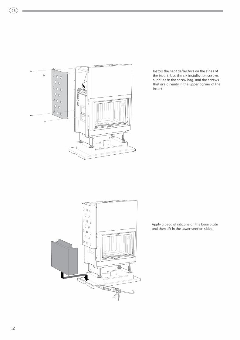
Install the heat deflectors on the sides of the insert. Use the six installation screws supplied in the screw bag, and the screws that are already in the upper corner of the insert.
Apply a bead of silicone on the base plate and then lift in the lower section sides.
GB
13
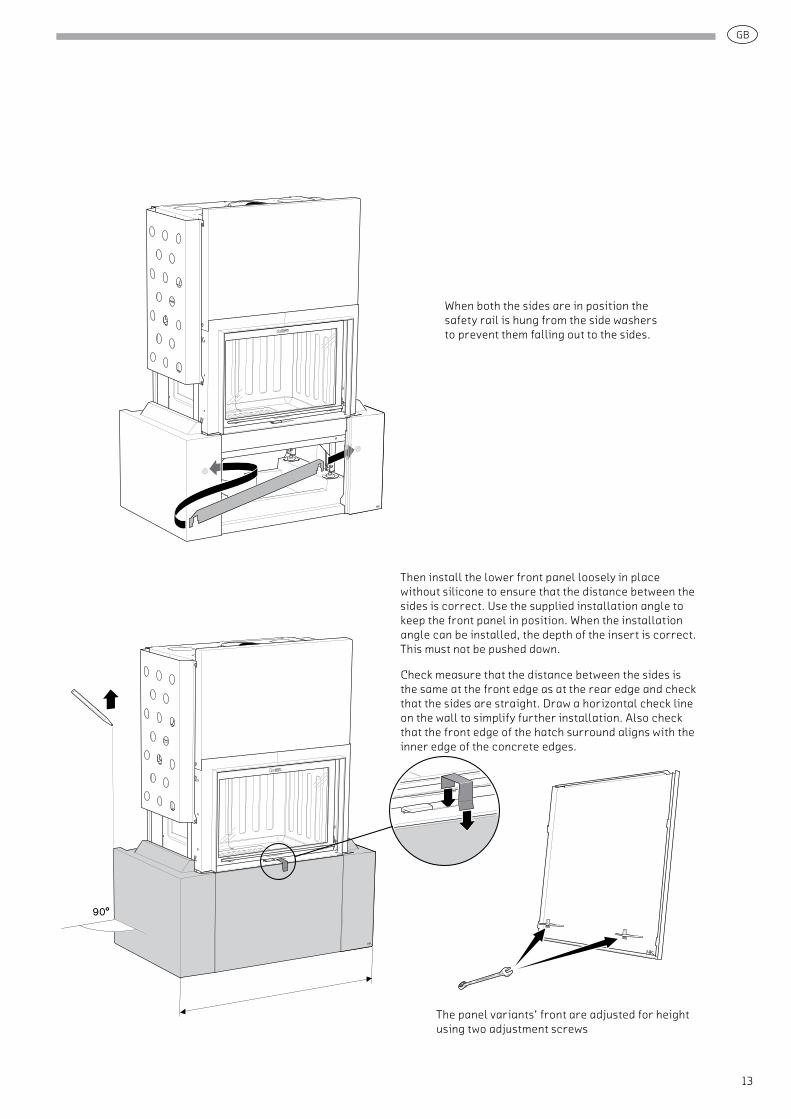
When both the sides are in position the safety rail is hung from the side washers to prevent them falling out to the sides.
Kontrollmått
90°
Then install the lower front panel loosely in place without silicone to ensure that the distance between the sides is correct. Use the supplied installation angle to keep the front panel in position. When the installation angle can be installed, the depth of the insert is correct. This must not be pushed down.
Check measure that the distance between the sides is the same at the front edge as at the rear edge and check that the sides are straight. Draw a horizontal check line on the wall to simplify further installation. Also check that the front edge of the hatch surround aligns with the inner edge of the concrete edges.
The panel variants’ front are adjusted for height using two adjustment screws
GB
14
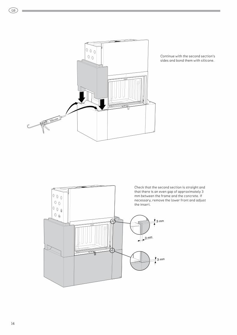
Continue with the second section’s sides and bond them with silicone.
3 mm
3 mm
3 mm
Check that the second section is straight and that there is an even gap of approximately 3 mm between the frame and the concrete. If necessary, remove the lower front and adjust the insert.
GB
15
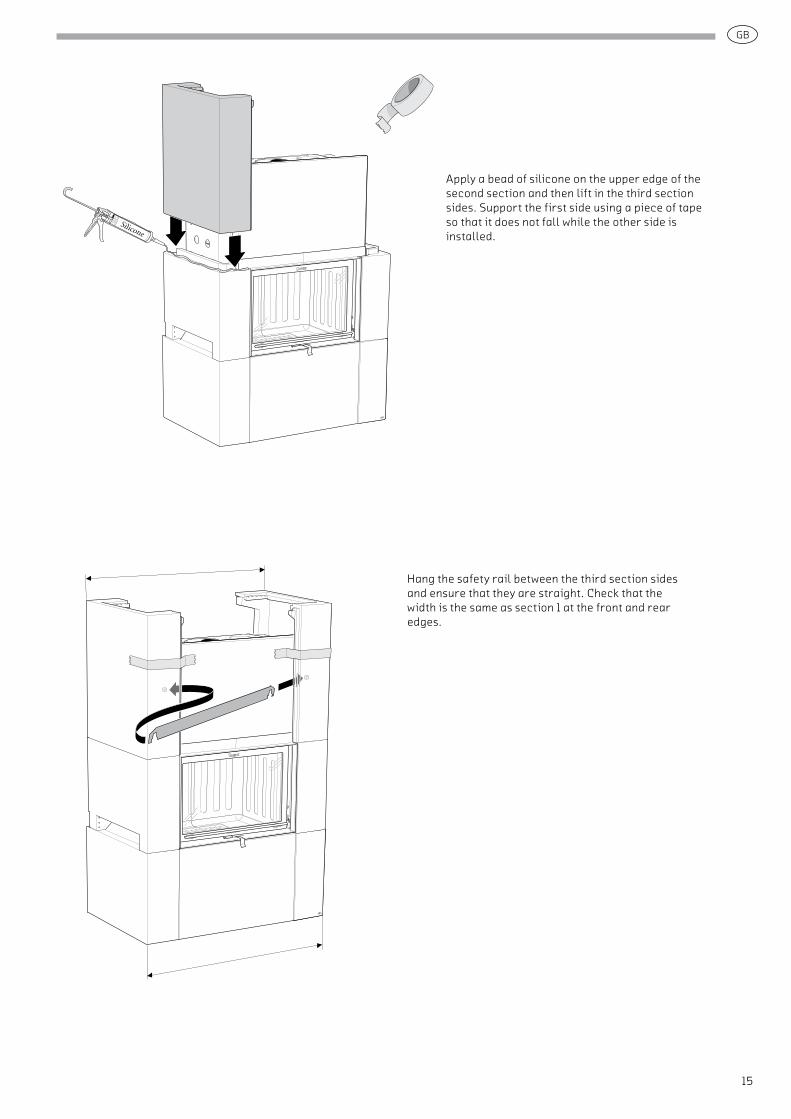
Apply a bead of silicone on the upper edge of the second section and then lift in the third section sides. Support the first side using a piece of tape so that it does not fall while the other side is installed.
Kontrollmått
KontrollmåttHang the safety rail between the third section sides and ensure that they are straight. Check that the width is the same as section 1 at the front and rear edges.

GB
16
Apply silicone beads along the front edge of the sides and bond the upper front.
When top connecting through the top sheet of concrete the knock out in the top disc must be knocked out with a hammer. Secure the top with a few blobs of silicone and press it forward so that it is tight to the front panel.
Bond the lower front with silicone. Use the supplied installation angle to keep the front panel in position while the silicone cures.
GB
17
10
10
VANADIUM
No. 7 CHROME
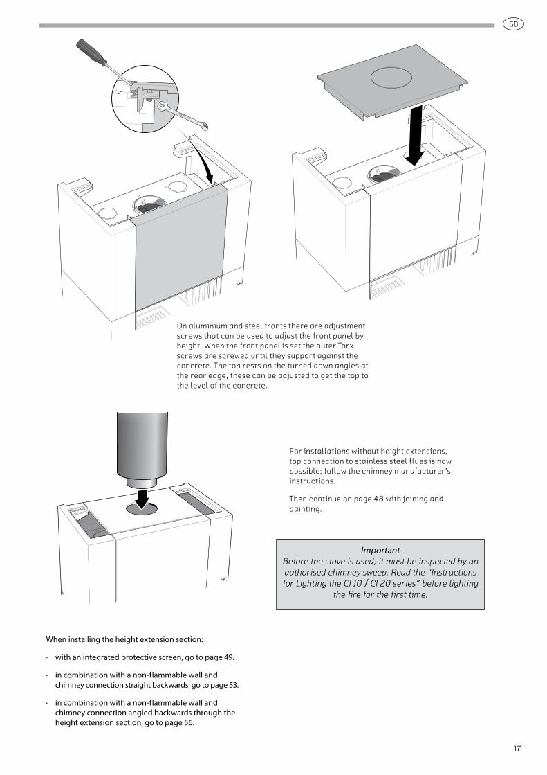
On aluminium and steel fronts there are adjustment screws that can be used to adjust the front panel by height. When the front panel is set the outer Torx screws are screwed until they support against the concrete. The top rests on the turned down angles at the rear edge, these can be adjusted to get the top to the level of the concrete.
When installing the height extension section:
∙ with an integrated protective screen, go to page 49.
∙ in combination with a non-flammable wall and chimney connection straight backwards, go to page 53.
∙ in combination with a non-flammable wall and chimney connection angled backwards through the height extension section, go to page 56.
ImportantBefore the stove is used, it must be inspected by an authorised chimney sweep. Read the “Instructions for Lighting the CI 10 / CI 20 series” before lighting
the fire for the first time.
For installations without height extensions, top connection to stainless steel flues is now possible; follow the chimney manufacturer’s instructions.
Then continue on page 48 with joining and painting.
GB
18
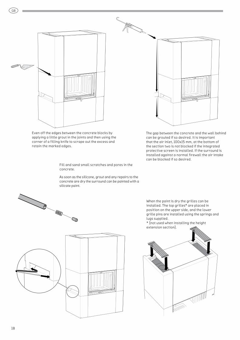
The gap between the concrete and the wall behind can be grouted if so desired. It is important that the air inlet, 100x15 mm, at the bottom of the section two is not blocked if the integrated protective screen is installed. If the surround is installed against a normal firewall the air intake can be blocked if so desired.
When the paint is dry the grilles can be installed. The top grilles* are placed in position on the upper side, and the lower grille pins are installed using the springs and lugs supplied. * (not used when installing the height extension section).
Even off the edges between the concrete blocks by applying a little grout in the joints and then using the corner of a filling knife to scrape out the excess and retain the marked edges.
Fill and sand small scratches and pores in the concrete.
As soon as the silicone, grout and any repairs to the concrete are dry the surround can be painted with a silicate paint.
GB
19
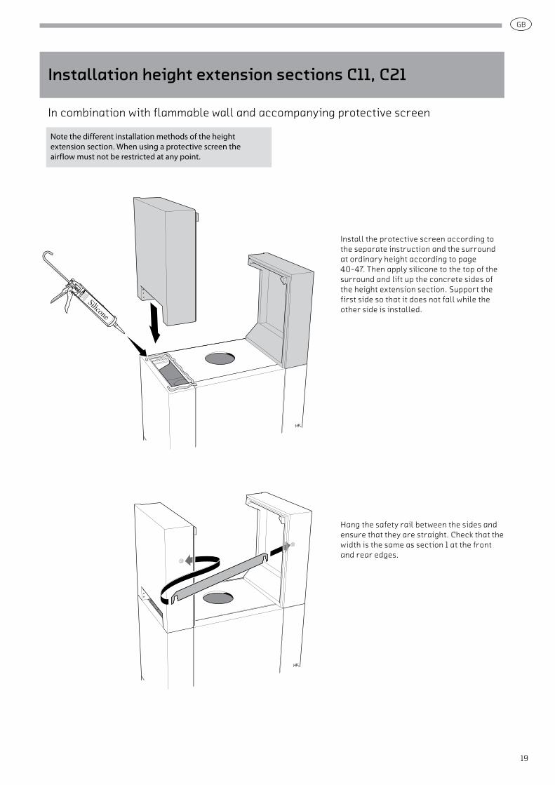
Install the protective screen according to the separate instruction and the surround at ordinary height according to page 40-47. Then apply silicone to the top of the surround and lift up the concrete sides of the height extension section. Support the first side so that it does not fall while the other side is installed.
Hang the safety rail between the sides and ensure that they are straight. Check that the width is the same as section 1 at the front and rear edges.
Note the different installation methods of the height extension section. When using a protective screen the airflow must not be restricted at any point.
Installation height extension sections C11, C21
In combination with flammable wall and accompanying protective screen

GB
20
Install the right half of the heat deflector by inserting sideways and hooking the tabs around the concrete. Note that the heat deflector at the bottom edge must be positioned in front of the protective screen’s heat deflector.
Install the left half of the heat deflector in the same way, and screw the two halves together.
GB
21
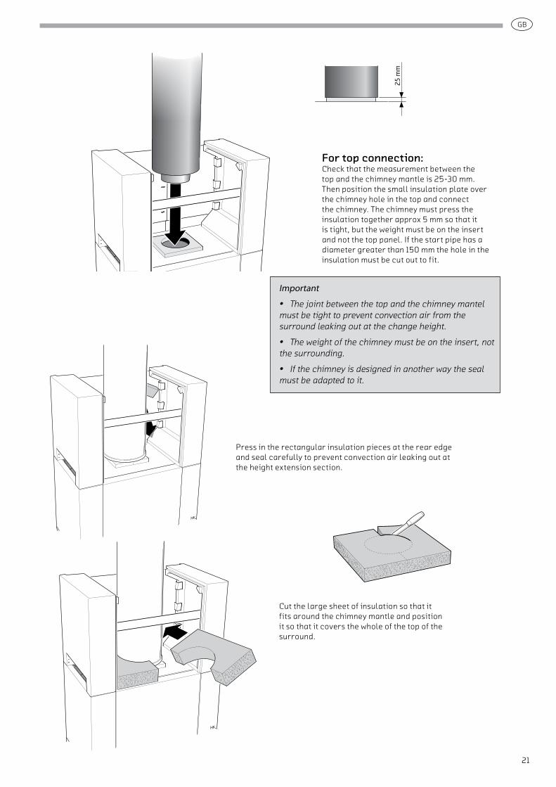
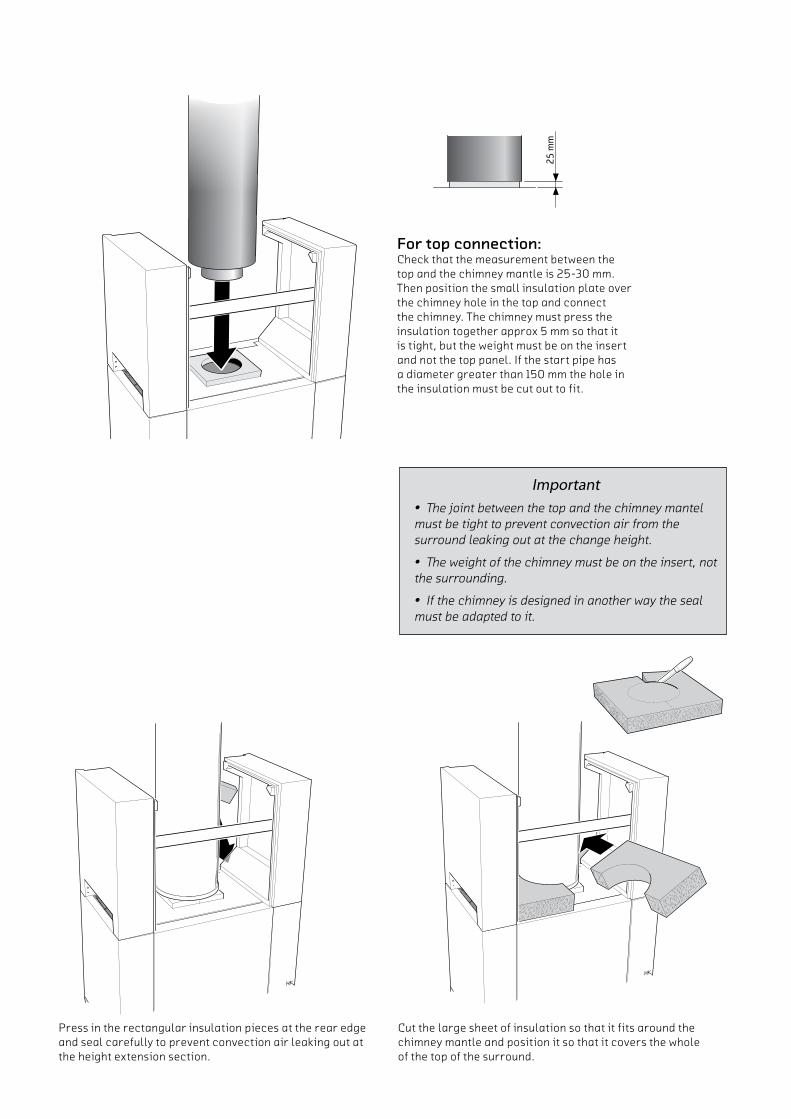
For top connection: Check that the measurement between the top and the chimney mantle is 25-30 mm. Then position the small insulation plate over the chimney hole in the top and connect the chimney. The chimney must press the insulation together approx 5 mm so that it is tight, but the weight must be on the insert and not the top panel. If the start pipe has a diameter greater than 150 mm the hole in the insulation must be cut out to fit.
25 m
m
Important
• The joint between the top and the chimney mantel must be tight to prevent convection air from the surround leaking out at the change height.
• The weight of the chimney must be on the insert, not the surrounding.
• If the chimney is designed in another way the seal must be adapted to it.
Cut the large sheet of insulation so that it fits around the chimney mantle and position it so that it covers the whole of the top of the surround.
Press in the rectangular insulation pieces at the rear edge and seal carefully to prevent convection air leaking out at the height extension section.

GB
22
The sweeping hole in the concrete front is plugged using the concrete plug. Bond it into place using silicone and fill it before painting.
To avoid gaps in the panel lines of the front area, the height extension panel must be hung first without silicone. Adjust the components so that the joints between them look good, use shims where necessary.
Apply silicone along the front edge of the sides and bond the front in position. If necessary, use the adjustment screws to adjust the height of the panel variants.
The surround can now be joined and painted according to page 48, after which the grilles can be put in place.
ImportantBefore the stove is used, it must be inspected by an authorised chimney sweep. Read the “Instructions for Lighting the CI 10 / CI 20 series” before lighting
the fire for the first time.
GB
23
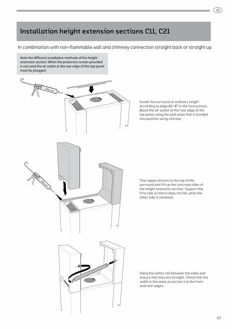
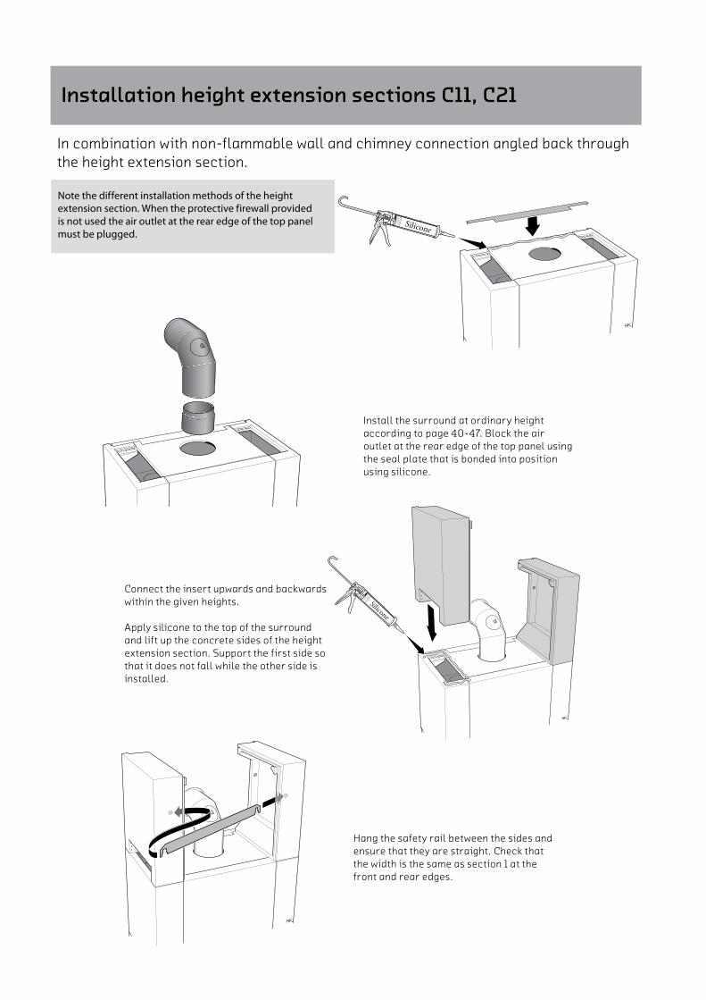
Install the surround at ordinary height according to page 40-47 in the instructions.Block the air outlet at the rear edge of the top panel using the seal plate that is bonded into position using silicone.
Then apply silicone to the top of the surround and lift up the concrete sides of the height extension section. Support the first side so that it does not fall while the other side is installed.
Note the different installation methods of the height extension section. When the protective screen provided is not used the air outlet at the rear edge of the top panel must be plugged.
Installation height extension sections C11, C21
In combination with non-flammable wall and chimney connection straight back or straight up
Hang the safety rail between the sides and ensure that they are straight. Check that the width is the same as section 1 at the front and rear edges.
GB
24
Press in the rectangular insulation pieces at the rear edge and seal carefully to prevent convection air leaking out at the height extension section.
Cut the large sheet of insulation so that it fits around the chimney mantle and position it so that it covers the whole of the top of the surround.
For top connection:Check that the measurement between the top and the chimney mantle is 25-30 mm. Then position the small insulation plate over the chimney hole in the top and connect the chimney. The chimney must press the insulation together approx 5 mm so that it is tight, but the weight must be on the insert and not the top panel. If the start pipe has a diameter greater than 150 mm the hole in the insulation must be cut out to fit.
25 m
m
Important• The joint between the top and the chimney mantel must be tight to prevent convection air from the surround leaking out at the change height.
• The weight of the chimney must be on the insert, not the surrounding.
• If the chimney is designed in another way the seal must be adapted to it.

GB
25
Apply silicone along the front edge of the sides and bond the front in position. If necessary, use the adjustment screws to adjust the height of the panel variants.
To avoid gaps in the panel lines of the front area, the height extension panel must be hung first without silicone. Adjust the components so that the joints between them look good, use shims where necessary.
The sweeping hole in the concrete front is plugged using the concrete plug. Bond it into place using silicone and fill it before painting.
The surround can now be joined and painted according to page 48, after which the grilles can be put in place.
ImportantBefore the stove is used, it must be inspected by an authorised chimney sweep. Read the “Instructions for Lighting the CI 10 / CI 20 series” before lighting
the fire for the first time.
GB
26
Installation height extension sections C11, C21
Note the different installation methods of the height extension section. When the protective firewall provided is not used the air outlet at the rear edge of the top panel must be plugged.
In combination with non-flammable wall and chimney connection angled back through the height extension section.
Install the surround at ordinary height according to page 40-47. Block the air outlet at the rear edge of the top panel using the seal plate that is bonded into position using silicone.
Connect the insert upwards and backwards within the given heights.
Apply silicone to the top of the surround and lift up the concrete sides of the height extension section. Support the first side so that it does not fall while the other side is installed.
Hang the safety rail between the sides and ensure that they are straight. Check that the width is the same as section 1 at the front and rear edges.
GB
27
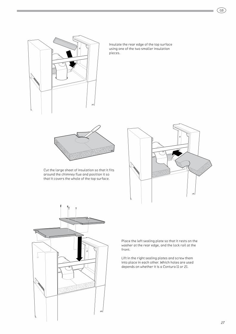
Insulate the rear edge of the top surface using one of the two smaller insulation pieces.
Cut the large sheet of insulation so that it fits around the chimney flue and position it so that it covers the whole of the top surface.
Place the left sealing plate so that it rests on the washer at the rear edge, and the lock rail at the front.
Lift in the right sealing plates and screw them into place in each other. Which holes are used depends on whether it is a Contura 11 or 21.
GB
28
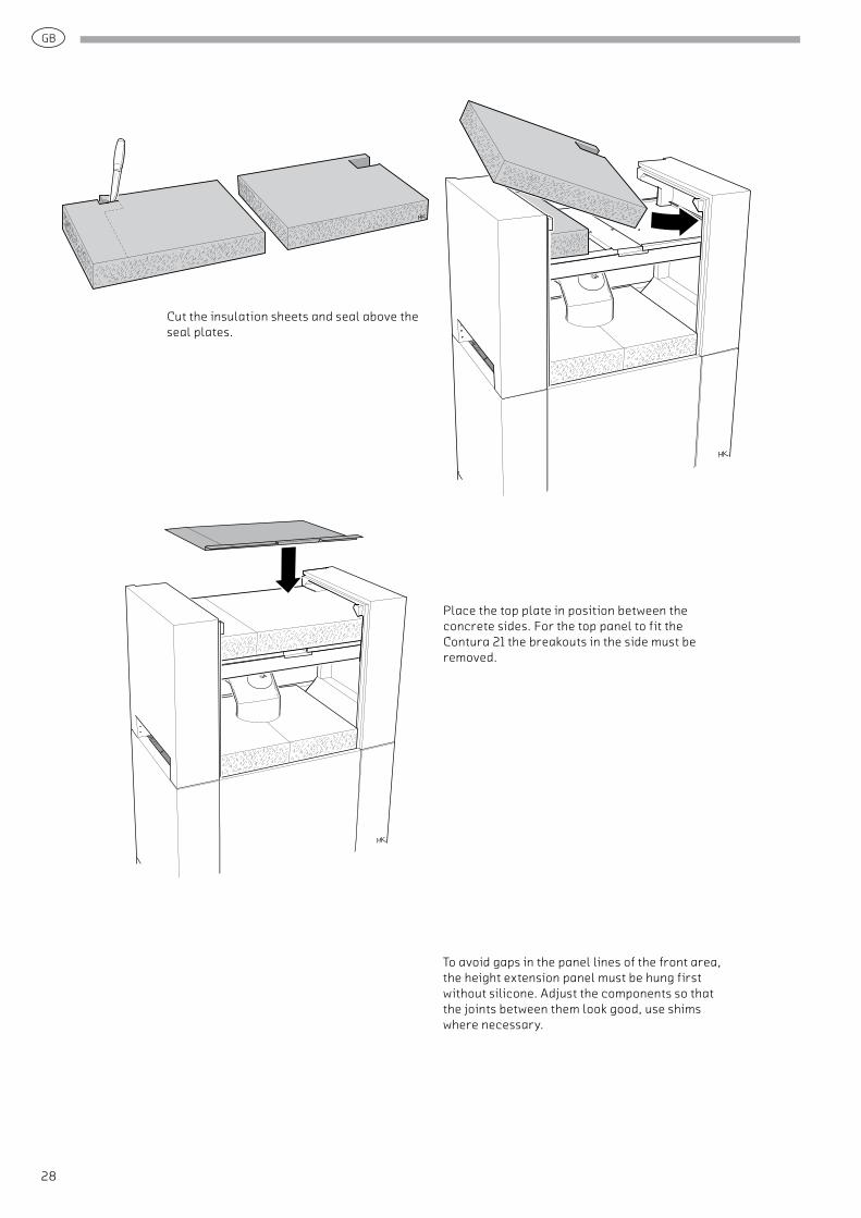
Cut the insulation sheets and seal above the seal plates.
Place the top plate in position between the concrete sides. For the top panel to fit the Contura 21 the breakouts in the side must be removed.
To avoid gaps in the panel lines of the front area, the height extension panel must be hung first without silicone. Adjust the components so that the joints between them look good, use shims where necessary.
GB
29
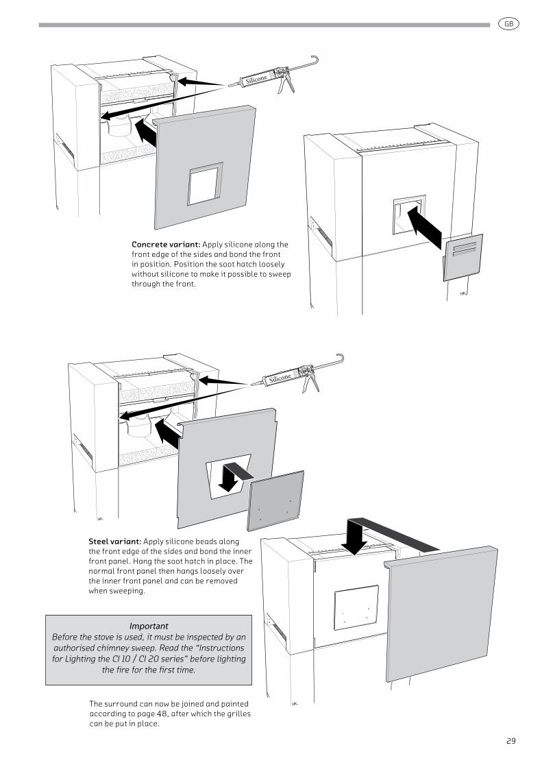
Concrete variant: Apply silicone along the front edge of the sides and bond the front in position. Position the soot hatch loosely without silicone to make it possible to sweep through the front.
Steel variant: Apply silicone beads along the front edge of the sides and bond the inner front panel. Hang the soot hatch in place. The normal front panel then hangs loosely over the inner front panel and can be removed when sweeping.
The surround can now be joined and painted according to page 48, after which the grilles can be put in place.
ImportantBefore the stove is used, it must be inspected by an authorised chimney sweep. Read the “Instructions for Lighting the CI 10 / CI 20 series” before lighting
the fire for the first time.
GB
30
IAV SE-EX 0950-2 811041
NIBE AB/NIBE STOVES · Box 134 · 285 23 Markarydwww.contura.eu
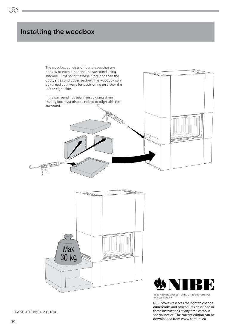
The woodbox consists of four pieces that are bonded to each other and the surround using silicone. First bond the base plate and then the back, sides and upper section. The woodbox can be turned both ways for positioning on either the left or right side.
If the surround has been raised using shims, the log box must also be raised to align with the surround.
Installing the woodbox
NIBE Stoves reserves the right to change dimensions and procedures described in these instructions at any time without special notice. The current edition can be downloaded from www.contura.eu

IAV SE-EX 0950-2 811041
NIBE AB/NIBE STOVES · Box 134 · 285 23 Markarydwww.contura.eu
NIBE Stoves reserves the right to change dimensions and procedures described in these instructions at any time without special notice. The current edition can be downloaded from www.contura.eu