coupler
TRANSCRIPT

OPTICAL MULTIPLEXING AND OPTICAL AMPLIFIERS
The Coupler
The instructor:Hồ Đức Tâm Linh
Hoàng Chung Phạm Gia LươngMai Thị Quý Lệ
Trần Thị Kiều Oanh

Contents:
1. Concept2. Classification3. Application4. Parameter5. Principle of Operation6. Fused Biconical Taper - FBT

1. OPTICAL COUPLER
• An optical coupler is a passive optical component that able to combine or slip stransmission data from optical fiber.
• Couplers are bi-directional, they can carry light in either direction.

2. OPTICAL COUPLER TYPES
• Y Coupler (Tap Coupler).
- Coupler simply divides the signal
into two outputs.• T Coupler
- Fuctions the same as Y coupler.
- Connect multiple terminals on a network.

2. OPTICAL COUPLER TYPES
• Star Coupler. Directional Star Coupler
Mixing optical signals from all inputs and then distribute them among all outputs.
Non-directional Star Coupler
It takes inputs from all fibers and then distribute them among all fibers, both input and output.
Directional star coupler Non-directional star coupler

2. OPTICAL COUPLER TYPES
• Tree Coupler.
- One or two inputs and split it into multiple outputs and backward.
- Tree couplers have been extensively used to split and mix optical signal in CATV, LANs and all other kinds of optical comunication systems.

2. OPTICAL COUPLER TYPES
• WDM Coupler.
- Split two different wavelengths into two outputs.
- WDM couplers are used to separate wavelengths transmitted for different through the same fiber.

• A star coupler 8x8 made by combining 3 dB coupler.
3.Coupler Application

• The power from each input is split equally among all the inputs.
• Tap off a small portion of the light stream for monitoring purposes :… close to 1(0.90 – 0.95)
• Building blocks:ModulatorSwitchesFiltersMultiplexers/ demultiplexers
3.Coupler Application
4. PARAMETER
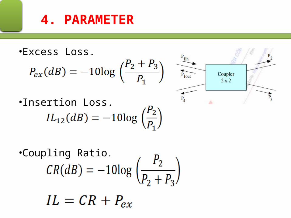
• Excess Loss.
• Insertion Loss.
• Coupling Ratio.

4. PARAMETER
• Uniformity.
• Polariation-dependent Loss.
Loss < 0.15dB.
• Directivity.
• Near – end Crosstalk
4. PARAMETER
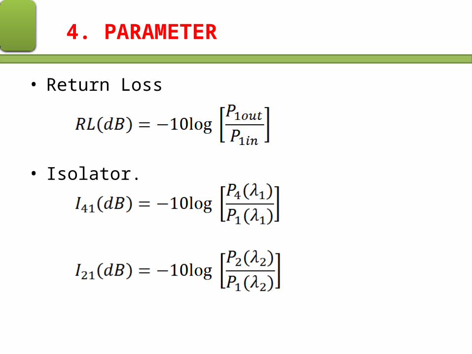
• Return Loss
• Isolator.
5. Principle of Operation
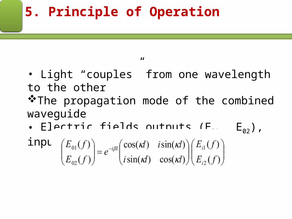
• Light “couples” from one wavelength to the otherThe propagation mode of the combined waveguide• Electric fields outputs (E01 , E02), inputs (E11 , E12):

• When used only one active input:
5. Principle of Operation
• For a 3dB coupler the coupling length must be chosen to satisfy:

6. Fused Biconical Taper
• FBT method is the most common way of manufacturing coupler.
• Fibre twisted, then spot fused under tension to form an elongated “biconical taper structure”.

• For multimode fibre higher order modes (rays with smaller refraction angles)
• Become unguided, leaving the core of Fibre A and coupling into fibre B.
6. Fused Biconical Taper
FBT Multimode Operation

• Process happens because in the tapered section the core diameters are reduced.
• Thus some power from port 1 is transferred gradually over the taper to port 3
• The amount of power is a function of the taper length and the degree of coupling
6. Fused Biconical Taper
FBT Multimode Operation

6. Fused Biconical Taper
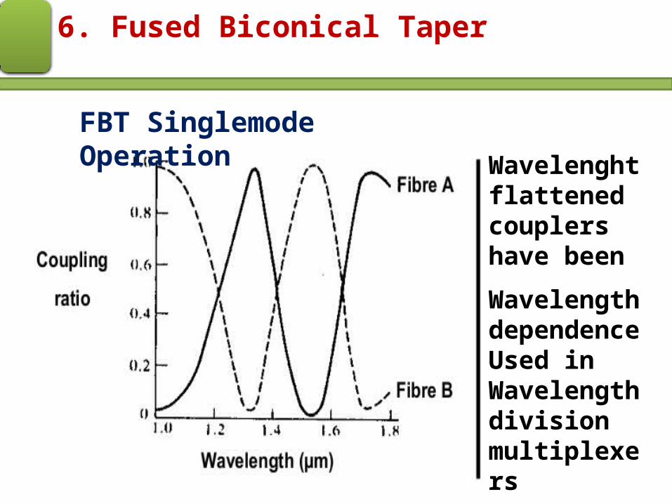
• FBT Singlemode Operation
•In the case of monomode operation there is a complex coherent interaction between the fibres.•Leads to a periodic variation in the splitting ratio with taper length and with wavelength as shown below.•Thus singlemode FBT couplers are naturally wavelength specific.
6. Fused Biconical Taper
Wavelenght flattened couplers have been
Wavelength dependenceUsed in Wavelength division multiplexers
FBT Singlemode Operation