cp planer manual cover
TRANSCRIPT

CP SERIES
COLD PLANERS Operating and Maintenance Manual

1
T A B L E O F C O N T E N T S
1. PRODUCT WARRANTY……………………………………………… 3 2. CHECKLIST Dealer’s File Copy ................................................................... 4 Customer’s File File………………………………………….. 5 3. INTRODUCTION ........................................................................................ 6 4. SPECIFICATIONS ...................................................................................... 7 5. SAFETY ............................................................................................................... 8 5.1 Mandatory Safety Shutdown Procedure ................................................... 9-10 6. OPERATION .................................................................................................... 11 6.1 Forward ...................................................................................................... 11 6.2 Attaching to and detaching from skidsteer loader ..................................... 11 6.3 Preparing to Plane………………………………………………………… 12 6.4 Starting the Cut ........................................................................................... 12 6.5 Advancing the Cut ...................................................................................... 13 6.6 Ending the Cut ............................................................................................ 13 7. DAILY MAINTENANCE ....................................................................... . 14 7.1 Pic Removal and Replacement ................................................................. 15 7.2 Removal .................................................................................................... 15 7.3 Replacement ............................................................................................. 16 7.4 Changing a Drum ..................................................................................... . 17 8. PARTS………………………………………………………………………… . 18 CP Planer Drawings..………………………………………………………. 18-19 CP Planer Parts List………………………………………………………... . 20-21 Danfoss Motor Parts List…..………………………………………………. 22 56996 Bobcat Elec Kit…………………………………………………….... 23 Hydraulic Kits…………………………. ....................................................... . 24-31 Water Kits…………………………………………………………………….. 32-35 Host Kits ……………………………………………………………………. 36-37
Revised 06/01/06

2
3
1. PRODUCT WARRANTY

4
After the Cold Planer has been completely set up and attached to the host machine, inspect the following. Check off each item after the prescribed action is taken. Check that:
♦ No parts of the unit have been damaged in
shipment. Check for things such as dents and loose or missing parts; correct or replace components as required.
♦ All bolts and fasteners are in place and tightly secured.
♦ All grease fittings have been properly lubricated; see lubrication information in this manual.
♦ All decals are in place and securely attached.
♦ The serial number of your unit is recorded in the space provided on this page.
♦ Then, test run the unit while checking that all components are operating correctly.
I acknowledge that the procedures were performed on this unit as outlined above.
—————————————————
DEALERSHIP NAME
—————————————————- DEALER REPRESENTATIVE’S NAME
————————————————
DATE CHECKLIST FILLED OUT
————————————————— SERIAL NUMBER
2. C H E C K L I S T DEALER’S FILE COPY 2.1 PRE-DELIVERY
The following checklist is an important reminder of the valuable information that MUST be passed on to the customer at the time the unit is delivered. Check off each item as you explain it to the customer. ♦ Give the customer his operators manual. Instruct him to be sure to read and com-
pletely understand its contents BEFORE operating the unit.
♦ Explain and review with him the SAFETY information in this manual.
♦ Explain that regular cleaning and lubrication are required for proper operation and long life. Review with him the lubrication information in this manual.
♦ Explain and review with him the service & maintenance information in this manual.
♦ Completely fill out the owner’s registration, including the customer’s signature, and return it to the manufacturer.
I acknowledge that the above points were reviewed with me at the time of delivery. ———————————————————
CUSTOMER’S SIGNATURE
——————————————————— DATE DELIVERED
2.2 DELIVERY

5
After the Cold Planer has been completely set up and attached to the host machine, inspect the following. Check off each item after the prescribed action is taken.
Check that: ♦ No parts of the unit have been damaged in shipment. Check for things such as dents and loose or missing parts; correct or replace components as required. ♦ All bolts and fasteners are in place and tightly secured. ♦ All grease fittings have been properly lubricated; see lubrication information in this manual. ♦ All decals are in place and securely attached. ♦ The serial number of your unit is recorded in the space provided on this page. ♦ Then, test run the unit while checking that all components are operating correctly.
I acknowledge that the procedures were performed on this unit as outlined above.
—————————————————
DEALERSHIP NAME
—————————————————- DEALER REPRESENTATIVE’S NAME
————————————————
DATE CHECKLIST FILLED OUT
————————————————— SERIAL NUMBER
2. C H E C K L I S T CUSTOMER’S FILE COPY
2.1 PRE-DELIVERY
The following checklist is an important reminder of the valuable information that MUST be passed on to the customer at the time the unit is delivered. check off each item as you explain it to the customer. ♦ Give the customer his operator’s manual. Instruct him to be sure to read and com-
pletely understand its contents BEFORE operating the unit.
♦ Explain and review with him the SAFETY information in this manual.
♦ Explain that regular cleaning and lubrication are required for proper operation and long life. Review with him the lubrication information in this manual.
♦ Explain and review with him the service & maintenance information in this manual.
♦ Completely fill out the owner’s registration, including the customer’s signature and return it to the manufacturer.
I acknowledge that the above points were reviewed with me at the time of delivery. ———————————————————
CUSTOMER’S SIGNATURE
——————————————————— DATE DELIVERED
2.2 DELIVERY

6
3. I N T R O D U C T I O N The CP SERIES COLD PLANER was designed as an attachment machine for use on skidsteer loaders. The information contained in this manual refers only to the planer machine. Information regarding the valves used to control oil flow to the planer attachment can be found in the host machines manual.
The information contained within is provided to assist you in preparing, adjusting, maintaining, and servicing your machine. More importantly, this manual provides an operating plan for safe and proper use of your machine. Major points of safe operation are detailed in the safety chapter of this manual. Refer to the table of contents for an outline of this manual.
Modern machinery has become more sophisticated, and with that in mind, you must read and understand the contents of the manual COMPLETELY and become familiar with your new machine before attempting to operate it.
Terms such as “right” and “left” as used in the manual, are as though the reader is sitting in the host machine’s operator seat and facing the planer.
Throughout this manual, information is provided which is set in bold type and introduced by the word NOTE. Be sure to read carefully and comply with the message or directive given. Following this information will improve your operating or maintenance efficiency, help you to avoid costly breakdowns or unnecessary damage, and extend the life of your machine.
The Manufacturer and Society of Automotive Engineers have adopted this SAFETY ALERT SYMBOL to pinpoint characteristics that, if not properly followed, can create a safety hazard. When you see this symbol in this manual or on the unit itself, you are reminded to BE ALERT! YOUR SAFETY IS INVOLVED!
The manufacturer reserves the right to make changes or improvements in the design or construction of any part without the obligation to install such changes on any unit previously delivered.

7
4. S P E C I F I C A T I O N S
CP SERIES
MODEL STANDARD DRUM CP-300...................................................................................................12 Inches (300 mm) CP-400...................................................................................................16 Inches (400 mm) CP-450...................................................................................................18 Inches (450 mm) CP-600...................................................................................................24 Inches (600 mm)
MAXIMUM TILT ANGLE 15 degrees left & right SIDE SHIFT TRAVEL 24 inches (610 mm) WEIGHT* CP300 1200 lbs. (544 kg) CP400 1500 lbs. (680 kg) CP450 1600 lbs. (726 kg) CP600 1700 lbs. (771 kg) * Weights are for fully hydraulic planers equipped for use on skidsteer loaders and are approximate due to optional equipment.

8
5. S A F E T Y BEFORE YOU ATTEMPT TO OPERATE THIS EQUIPMENT, READ AND STUDY THE FOLLOWING SAFETY INFORMATION. IN ADDITION, MAKE SURE THAT EVERY INDIVIDUAL WHO OPERATES OR WORKS WITH THIS EQUIPMENT IS FAMILIAR WITH THESE SAFETY PRECAUTIONS.
The manufacturer always takes the operator and their safety into consideration when designing machinery. Guards are provided on exposed moving parts for the operator’s protection; however, some areas cannot be guarded or shielded in order to assure proper operation. In addition, the operator’s manual and decals on the machine itself warn you of further danger and should be read and observed closely. The SAFETY ALERT SYMBOL above means ATTENTION! BECOME ALERT! YOUR SAFETY IS INVOLVED! It stresses an attitude of “HEADS UP” for safety and can be found throughout this operator’s manual and on the unit itself. REMEMBER: The careful operator is the best operator. Most accidents are caused by human error. Certain precautions must be observed to prevent the possibility of injury or damage. Please read the rules listed below for safe operation BEFORE you operate this equipment. Use of words CAUTION, WARNING, or DANGER herein and on the machine itself signal three degrees of hazard. CAUTION is used for general reminders of good safety practices or to direct attention to unsafe practices. WARNING is used to denote a specific potential hazard. DANGER is used to denote the most serious specific potential hazard.

9
5.1 MANDATORY SAFETY SHUTDOWN
Work of any type on machinery is always more dangerous when the machine is operating. BEFORE cleaning, lubricating, or servicing this unit, the following MANDATORY SAFETY SHUTDOWN PROCEDURE should ALWAYS be followed: 1. Move host machine’s propulsion control to the neutral position and idle engine down.
2. Shut off cold planer.
3. Position cold planer so that it is completely resting on the ground or floor.
4. Engage the host machine’s hand brake.
5. Move the host machine’s throttle to the slow idle position, shut the engine off, and remove the ignition key.
6. Relieve hydraulic pressure by moving the hi-flow and cylinder control levers in both directions. ONLY when you have taken these precautions can you be sure it is safe to proceed. Failure to follow the above procedures could lead to death or serious bodily injury! Some diagrams used herein may show door(s), guard(s), or shield(s) open or removed for illustration purposes ONLY! BE SURE that all door(s), guard(s), and shield(s) are in their proper position(s) and securely attached BEFORE operating the planer! Read and observe ALL safety information and decals on the host machine and cold planer BEFORE operating the unit! In addition, familiarize yourself with ALL of the safety devices and periodically check that they are functioning properly! Refer to the SAFETY chapter of the host machine’s operator manual and observe ALL safety recommendations set forth in that manual! CAREFULLY inspect ALL hydraulic hoses and connections on a routine basis. NEVER use your hand; escaping fluid under pressure can cause serious injury!

10
BE SURE to exercise the MANDATORY SAFETY SHUT DOWN PROCEDURE BEFORE proceeding to do any work on the cold planer! BE SURE the cold planer is properly placed in the “service position” and resting on the ground BEFORE attempting to work on the drum. BEFORE transporting the cold planer, BE SURE to raise the unit completely off the ground and turn it off. When replacing pics, BE SURE to use only a soft or lead headed hammer when inserting the pics into the holders. ALWAYS wear safety glasses with side shields when striking metal against metal! In addition, it is recommended that a softer (non-chipable) material be used to cushion the blow. Failure to heed could result in serious injury to the eyes or other parts of the body! ALWAYS wear proper clothing and covering when working with or on the cold planer! DO NOT attempt to move the cold planer sideways while it is on the ground! DO NOT attempt to work on the planer or host machine with the hydraulics live! BE SURE to relieve the hydraulic pressure by shutting down the engine and moving all control levers BEFORE attempting to disconnect any hoses or BEFORE proceeding to remove the cold planer from the host machine. DO NOT treat the cold planer like a bucket; it can be damaged by contact with solid objects as well as upset the stability of the host machine! DO NOT hit the pics with a steel hammer as this could cause steel chips to fly, causing injury to the eyes or face. REMEMBER! It is the owner’s responsibility to communicate information regarding the safe use and proper operation and maintenance to any user of this machine!

11
6. O P E R A T I O N 6.1 FOREWORD The planer must be attached to a host machine equipped to provide the necessary hydraulics and operational controls. As there are many different host machines available, this manual will only deal with the generic operation of the planer. Anyone attempting to attach and operate the planer must first have the knowledge and skill of operating the host machine’s controls. Information regarding the host machine’s controls and attaching procedure is found in the host machine’s operators manual or from its authorized dealer.
6.2 ATTACHING TO AND DETACHING FROM A SKIDSTEER LOADER
Drive the skidsteer up to the quick attach of the planer and connect up. Exercise the MANDATORY SAFETY SHUTDOWN PROCEDURE before proceeding. After installing hydraulic quick couplers compatible with your skidsteer to the hydraulic hoses of the planer, connect them to the hydraulic outlet as follows: 1. If your skidsteer has five lines i.e. (2 high flow , 2 auxiliary, and 1 case drain): The 3/4” hose attached to the # “2” port of the overrunning valve must be connected to the pressure outlet of the skidsteer’s high flow. The 3/4” hose attached to the # “1” port must be connected to the return outlet. The two 1/4” hoses must be connected to the skidsteer’s auxiliary outlets. The 3/8” case drain line must be connected to the skidsteer’s case drain outlet. 2. If your skidsteer has 3 lines i.e. (2 high flow lines, and 1 case drain): The 3/4” hose attached to the “P” port of the valve must be connected to the pressure outlet of the skidsteer, and the 3/4” hose attached to the “R” port of the valve to the return outlet. The 3/8” case drain line must be attached to the skidsteer’s case drain outlet. 3. On CP 300 and 400 planers on standard flow skidsteer’s without a case drain, connect as per “2” but omit the case drain connection.

12
Determine the required depth of cut, tilt angle of cut, and left to right position of the planer in regard to the host machine. When it is safe to do so, start the host machine’s engine, and ensure that the planer drum is not touching the ground. This is accomplished by rolling the bucket control back. Turn on the planer, and check the drum rotation. The teeth at the bottom of the drum must be moving in the same direction that the planer travels over the material to be planed. If the drum rotates incorrectly, correct the planer installation before attempting to plane. In skidsteer operation, only forward travel should be used. Tilt and Crosslide functions are controlled by the Skid Steers auxiliary controls.
6.3 PREPARING TO PLANE
Check the surface to be planed. The standard drum for each model can be used to mill both asphalt and concrete. If a finer finish is required, drums with more pics are available. Contact Coneqtec/Universal for special drums.
6.4 STARTING THE CUT
Position the planer over the desired starting place. With the planer turned on, the depth gauge at “0” and the host machine’s engine at full rpm, slowly lower the planer to the surface to be planed until the weight of the planer is resting on the planer’s wheels. The CP Planer’s cutting depth is controlled by the skidsteer’s bucket roll. Rolling it forward increases the drum depth, and rolling backward decreases the drum depth. The scale on the left side of the planer cowl in relation to the depth control link shows how deep you are cutting. Roll the bucket control forward until the desired depth is reached. Maximum depth of each cut is determined by the type of material being milled, the weight and hydraulic horsepower of the host machine, and the size planer being used. A general rule of thumb is to start at 3/4” to 1” deep in concrete and 1-1/2” to 2” deep in asphalt. As you increase the cutting depth you will also be automatically applying down pressure on the planer. This is necessary to keep the planer stable during planing. For maximum down pressure the skidsteer’s front wheels should be 1-2” (25-50 mm) off the planing surface. This can be controlled by raising or lowering the boom arms.

13
6.5 ADVANCING THE CUT
Advance the planer in the direction the drum pics are traveling in the cut. If the planer drum stalls, you have been feeding the planer into the cut too fast or cutting too deep. Back out of the cut until the drum restarts, and then advance again. If the planer tends to ride up out of the cut, use the procedure outlined in the paragraph above to keep the planer wheels on the surface to be planed. DO NOT side shift the planer while the drum is in the cut. The drum will not cut in a side to side direction. The depth controls may be actuated while the drum is in the cut.
6.6 ENDING THE CUT
Stop advancing the planer and raise the drum out of the cut by rolling the bucket back. Raise the planer clear out of the pavement, and move to the next cut.
CAUTION: When using cold planers with skidsteer loaders equipped with hi-flow kits, periodic observation must be made of the transmission oil temperature indicator on the skidsteer loader. Hydraulic oil may overheat, depending on ambient temperature and duty cycle of the machine. If indicator comes on or a gauge indicates a temperature in the danger range, shut off cold planer, and allow skidsteer loader to idle until the hydraulic temperature falls below 180°F . Damage to machine may occur if these instructions are not followed.

14
7. D A I L Y M A I N T E N A N C E
CAUTION: NEVER attempt to do any maintenance to the planer while it is running. Exercise the MANDATORY SAFETY SHUTDOWN PROCEDURE BEFORE proceeding.
NOTE: Careful attention to the daily maintenance routines will go a long way toward ensuring efficient planer operation. 1. At the start of each day, lubricate the grease fittings at the end of the carriage arm on each side of the planer housing and the bearing on the right hand side of the drum shaft. Standard shop gun grease will suffice. 2. Check crosslide rods, and tilt plates for lubrication. Clean away any dust or dirt, and apply oil to these areas.
3. Using the correct size wrenches, retighten any loose hardware. 4. Inspect for any loose hydraulic fittings or damaged hoses; retighten or replace as required. 5. At least twice a day check all pics for freedom of rotation and wear. Replace or free up all pics that are not rotating freely, and replace any that are badly worn. Follow the procedure outlined under pic removal and replacement.
WARNING: NEVER use your hands to check for hydraulic leaks. Escaping fluid under pressure can cause serious injury! If injured by escaping fluid, see a doctor at once. If proper medical treatment is NOT administered IMMEDIATELY serious infection or reaction can develop.

15
7.1 PIC REMOVAL AND REPLACEMENT To achieve maximum pic life and optimum performance, the pics will require replacement for the following reasons: 1. They are broken or worn. 2. They are seized in the pic holder and do not rotate freely.
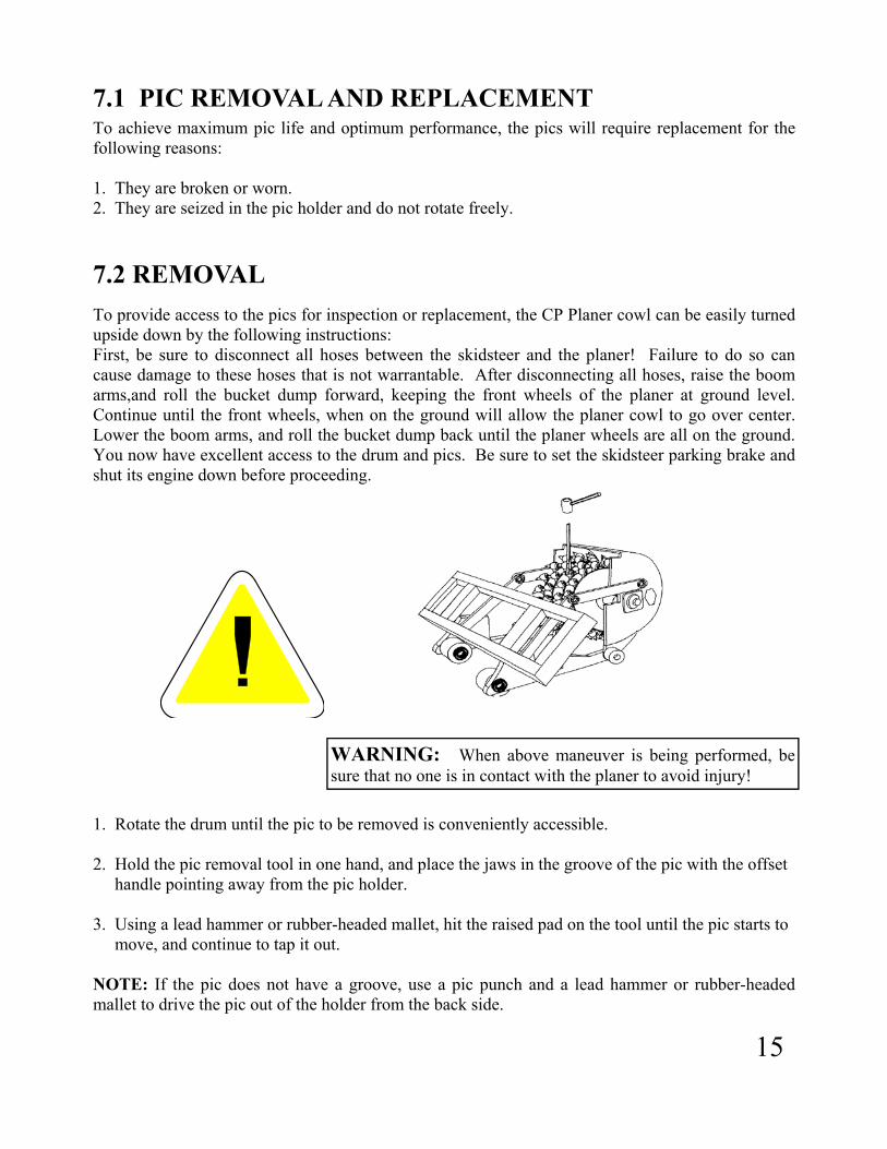
7.2 REMOVAL To provide access to the pics for inspection or replacement, the CP Planer cowl can be easily turned upside down by the following instructions: First, be sure to disconnect all hoses between the skidsteer and the planer! Failure to do so can cause damage to these hoses that is not warrantable. After disconnecting all hoses, raise the boom arms,and roll the bucket dump forward, keeping the front wheels of the planer at ground level. Continue until the front wheels, when on the ground will allow the planer cowl to go over center. Lower the boom arms, and roll the bucket dump back until the planer wheels are all on the ground. You now have excellent access to the drum and pics. Be sure to set the skidsteer parking brake and shut its engine down before proceeding.
WARNING: When above maneuver is being performed, be sure that no one is in contact with the planer to avoid injury!
1. Rotate the drum until the pic to be removed is conveniently accessible. 2. Hold the pic removal tool in one hand, and place the jaws in the groove of the pic with the offset handle pointing away from the pic holder. 3. Using a lead hammer or rubber-headed mallet, hit the raised pad on the tool until the pic starts to move, and continue to tap it out. NOTE: If the pic does not have a groove, use a pic punch and a lead hammer or rubber-headed mallet to drive the pic out of the holder from the back side.
16
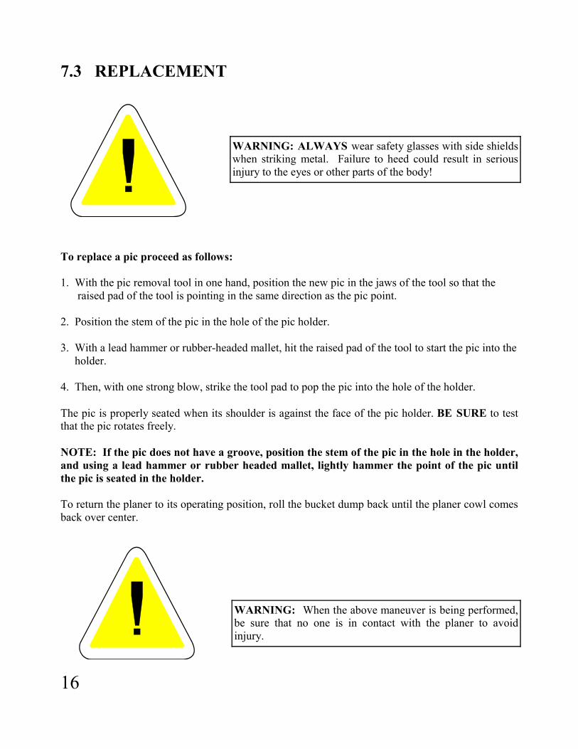
7.3 REPLACEMENT
WARNING: ALWAYS wear safety glasses with side shields when striking metal. Failure to heed could result in serious injury to the eyes or other parts of the body!
To replace a pic proceed as follows: 1. With the pic removal tool in one hand, position the new pic in the jaws of the tool so that the raised pad of the tool is pointing in the same direction as the pic point. 2. Position the stem of the pic in the hole of the pic holder. 3. With a lead hammer or rubber-headed mallet, hit the raised pad of the tool to start the pic into the holder. 4. Then, with one strong blow, strike the tool pad to pop the pic into the hole of the holder. The pic is properly seated when its shoulder is against the face of the pic holder. BE SURE to test that the pic rotates freely. NOTE: If the pic does not have a groove, position the stem of the pic in the hole in the holder, and using a lead hammer or rubber headed mallet, lightly hammer the point of the pic until the pic is seated in the holder. To return the planer to its operating position, roll the bucket dump back until the planer cowl comes back over center.
WARNING: When the above maneuver is being performed, be sure that no one is in contact with the planer to avoid injury.

17
7.4 CHANGING A DRUM
To change a drum, position the planer as described in 6.1.1 pic removal. 1. Support the drum at its center with a proper hoist or lifting device. 2. Remove the four cap screws bolting the motor to the planer. 3. Turn the drum until you find a pipe plug in the shaft approximately four inches from the shaft motor end. Remove this plug, and install the necessary bushing and a grease fitting. Using a hand grease gun, pump grease into the shaft to assist in pushing the motor out of the drum shaft. 4. Loosen the set screws locking the bearing center to the shaft. Remove the four nuts and cap screws retaining the outside bearing to the cowl side; remove the bearing. 5. The drum can now be moved out of the cowl. With some models it may be necessary to disconnect the upper end of the bearing side depth control link to allow the drum to be lifted clear of the planer. If this link is removed, be sure to properly support the cowl to avoid injury. Replacing the drum is a reversal of the above. Prior to installing the motor into the shaft bore, remove the grease fitting and bushing. Clean most of the grease from the bore. Clean and inspect the motor shaft and key, install motor, and replace and torque 5/8” capscrews to 175-200 lb. ft.

18

19

20
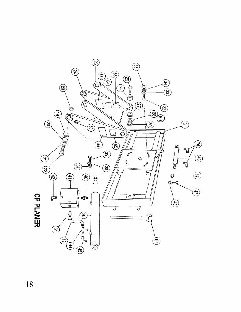
CP PARTS LIST ITEM P/N DESCRIPTION QTY
1 55421 Cowl Assy CP 300 1 1 55423 Cowl Assy CP 400/450 1 1 55424 Cowl Assy CP 600 1 2 55451 Drum Assy CP 300 1 2 55400 Drum Assy CP 400 1 2 55452 Drum Assy CP 450 1 2 55453 Drum Assy CP 600 1 3 55425 Trolley Assy CP 300 1 3 55427 Trolley Assy CP 400/450 1 3 55428 Trolley Assy CP 600 1 4 55073 Motor 400CC 1 4 52708 Motor 500CC 1 4 52588 Motor 630CC 1 4 54329 Motor 800CC 1 5 42013 Wheel 6 6 52596 Wheel Axle Front 2 7 42015 Spacer Wheel 14 8 42014 Bearing Wheel 12 9 13A-0640 Cotter Pin 3 3/16 x 2-1/2” 4 10 42016 Wheel Axle Rear 2 11 50A-1012 5/8-11 x 1-1/2” HHCS 4 12 14A-10 5/8 Lock Washer Motor 4 13 54723 Hose 3/4” x 52” 2 15 54958 Bearing 1 16 50A-1018 5/8-11 x 2-1/4” 4 17 30C-10 5/8-11 Nylock Nut 4 18 52681 Key 1 19 42004 Bushing Carriage Pivot (Up to S/N—) 2 19 55545 Bushing S/N—–& Up 2 20 55546 Pivot Pin Carriage S/N—& Up 2 20 55415 Pivot Pin Carriage 2 21 55406 Washer 1” Carriage Pivot 2 22 50A-1630 1-8 x 3-3/4” HHCS 2 23 30C-16 1-8 Nylock Nut 2 24 55429 Carriage Assy APX 300 1 24 55431 Carriage Assy APX 400/450 1 24 55432 Carriage Assy APX 600 1 25 55417 Link Depth Control 2 26 55418 Spacer Depth Link 4 27 55416 Bushing Depth Link 4 28 55407 Washer 7/8” Depth Link 4 29 50A-1428 7/8-9 x 3-1/2 HHCS 4 30 30C-14 7/8-9 Nylock Nut 4 31 56722 Crosslide Assy Universal 1 32 50A-1024 5/8-11 x 3” HHCS 4 33 52165 Hardened Washer 4 34 52380 Double Lock Washer Tilt 4 35 30C-10 5/8-11 Nylock Nut Tilt 4
21
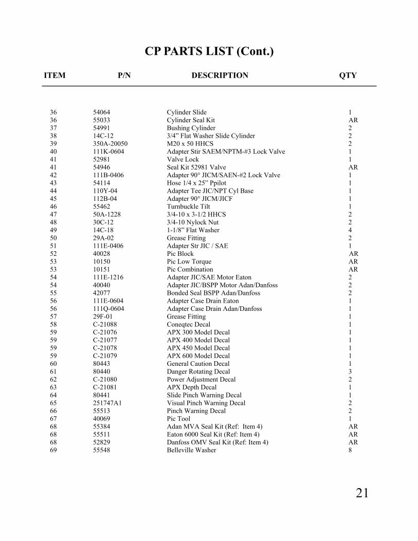
CP PARTS LIST (Cont.) ITEM P/N DESCRIPTION QTY
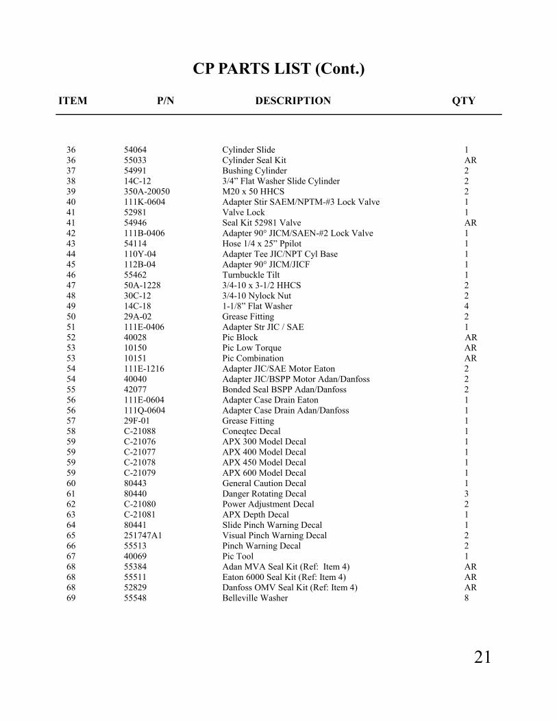
36 54064 Cylinder Slide 1 36 55033 Cylinder Seal Kit AR 37 54991 Bushing Cylinder 2 38 14C-12 3/4” Flat Washer Slide Cylinder 2 39 350A-20050 M20 x 50 HHCS 2 40 111K-0604 Adapter Stir SAEM/NPTM-#3 Lock Valve 1 41 52981 Valve Lock 1 41 54946 Seal Kit 52981 Valve AR 42 111B-0406 Adapter 90° JICM/SAEN-#2 Lock Valve 1 43 54114 Hose 1/4 x 25” Ppilot 1 44 110Y-04 Adapter Tee JIC/NPT Cyl Base 1 45 112B-04 Adapter 90° JICM/JICF 1 46 55462 Turnbuckle Tilt 1 47 50A-1228 3/4-10 x 3-1/2 HHCS 2 48 30C-12 3/4-10 Nylock Nut 2 49 14C-18 1-1/8” Flat Washer 4 50 29A-02 Grease Fitting 2 51 111E-0406 Adapter Str JIC / SAE 1 52 40028 Pic Block AR 53 10150 Pic Low Torque AR 53 10151 Pic Combination AR 54 111E-1216 Adapter JIC/SAE Motor Eaton 2 54 40040 Adapter JIC/BSPP Motor Adan/Danfoss 2 55 42077 Bonded Seal BSPP Adan/Danfoss 2 56 111E-0604 Adapter Case Drain Eaton 1 56 111Q-0604 Adapter Case Drain Adan/Danfoss 1 57 29F-01 Grease Fitting 1 58 C-21088 Coneqtec Decal 1 59 C-21076 APX 300 Model Decal 1 59 C-21077 APX 400 Model Decal 1 59 C-21078 APX 450 Model Decal 1 59 C-21079 APX 600 Model Decal 1 60 80443 General Caution Decal 1 61 80440 Danger Rotating Decal 3 62 C-21080 Power Adjustment Decal 2 63 C-21081 APX Depth Decal 1 64 80441 Slide Pinch Warning Decal 1 65 251747A1 Visual Pinch Warning Decal 2 66 55513 Pinch Warning Decal 2 67 40069 Pic Tool 1 68 55384 Adan MVA Seal Kit (Ref: Item 4) AR 68 55511 Eaton 6000 Seal Kit (Ref: Item 4) AR 68 52829 Danfoss OMV Seal Kit (Ref: Item 4) AR 69 55548 Belleville Washer 8

22
DANFOSS MOTOR OMV PARTS LIST
ITEM P/N DESCRIPTION QTY ITEM P/N DESCRIPTION QTY 1 52676 Screw M8x1x20mm 6 26 52694 Channel Plate 1 NSS 2 52677 Dust Deal Ring 1 28 52695 Disc Valve 1 NSS 3 52678 Front Cover 1 29 52969 Balance Plate 1 NSS 4 52679 Shaft Seal 1 30 52697 Guide Pin 1 NSS 5 52680 O Ring 1 31 52698 O Ring 1 6 52681 Parallel Key 1 32 52699 O Ring 1 7 52682 Shaft Including Bearing 1 33 52700 Spacer 1 8 52683 Conical Seal Ring 1 34 52701 Spring Washer 1 NSS 9 52684 Bearing Housing 1 NSS 36 52702 Valve Housing 1 NSS 10 52685 Drain Plug Including O Ring 1 NSS 37 52703 Ball 2 NSS 13 52687 Cardan Shaft for 52708 500 mtr 1 NSS 38 52704 Springs 2 NSS 13 55333 Cardan Shaft for 52588 630 mtr 1 NSS 39 52705 Washers 2 NSS 13 55334 Cardan Shaft for 54329 800 mtr 1 NSS 40 52706 Plugs 2 NSS 22 52689 O Ring 1 41 52707 Cap Screw OMV500 & 630 4 NSS 23 52690 Gearwheel set for 52588 630mtr 1 NSS 41 55335 Cap Screw for 54329 800mtr 4 NSS 23 52691 Gearwheel set for 52708 500mtr 1 NSS 42 55254 Name Plate OMV 1 NSS 23 55332 Gearwheel set for 54329 800mtr 1 NSS 43 54930 Drive Screw 4 NSS 24 52692 Guide Pin 1 NSS 44 52829 Seal Kit OMV Includes items 1 25 52693 Valve Drive 1 NSS 2,4,5,8,22,31,32 Note: NSS— NOT SERVICED SEPARATELY

23
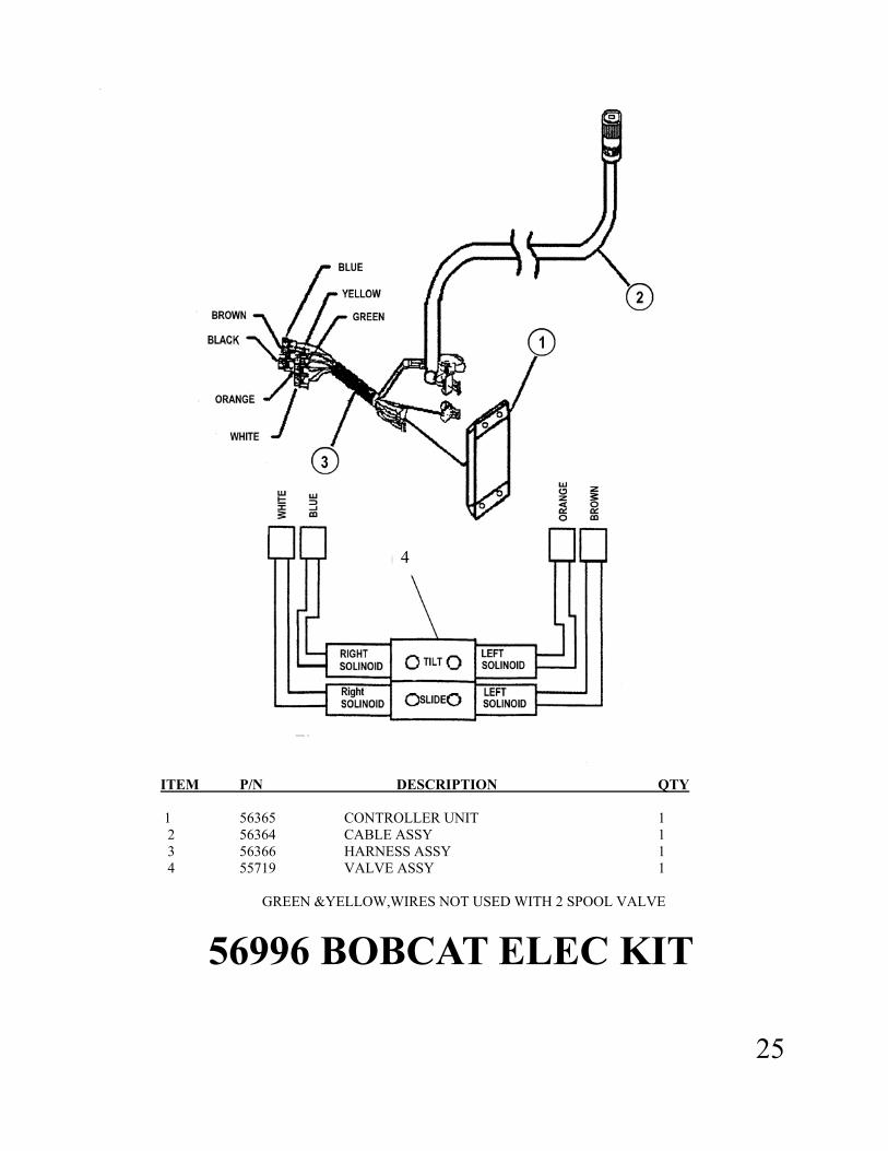
ITEM P/N DESCRIPTION QTY 1 56365 CONTROLLER UNIT 1 2 56364 CABLE ASSY 1 3 56366 HARNESS ASSY 1 4 55719 VALVE ASSY 1
GREEN &YELLOW,WIRES NOT USED WITH 2 SPOOL VALVE
56996 BOBCAT ELEC KIT
4

24

25
55728CP PARKER/SUN HYDRAULIC KIT
ITEM P/N DESCRIPTION QTY 1 55140 Sun Valve Assy Incs 2,3,4 1 2 55232 Valve Priority Flow 1 3 55231 Valve Check PB 1 4 55230 Valve Check 2 5 55719 Valve Parker 2 Spool 1 5 56065 Coil Parker MV5 Valve AR 5 56066 Valve Spool Section AR 6 54066 Tilt Cylinder 1 7 54064 Slide Cylinder 1 8 52981 Lock Valve 1 9 111E-1212 Adapter JIC/SAE 4 10 111B-0404 Adapter JIC/SAE 3 11 40040 Motor Fitting 2 12 42077 Motor Fitting Seal Washer 2 13 111E-0406 Adapter JIC/SAE 2 14 111B-0406 Adapter JIC/SAE 5 15 111K-0604 Adapter SAE/NPT 1 16 110Y-0404 Adapter Tee JIC/SAE 1 17 112B-0404 Adapter 90* JICM/JICF 1 18 111Q-0604 Adapter Str JIC/BSPP 1 19 110G-0404 Adapter 90* JIC/NPT 2 20 54723 Hose 3/4x52” 2 21 54029 Hose 1/4X55” 1 22 54028 Hose 1/4X51” 1 23 54026 Hose 1/4x15” 2 24 54055 Hose 1/4x21” 2 25 55482 Hose 1/4x35” 1 26 54329 Motor Danfoss 800 1 27 See Host Kit 1 28 55033 Seal Kit Hyd. Cyl. AR 29 55277 Seal Kit 55140 Valve AR 30 56052 Seal Kit Parker Valve AR 31 54946 Seal Kit Lock Valve AR 32 52829 Seal Kit Danfoss Mototr AR 32 52677 Dust Seal Only AR 32 52679 Shaft Seal Only AR 32 52680 O’Ring Only AR
26
27
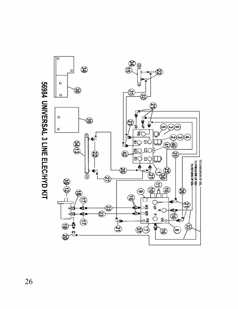
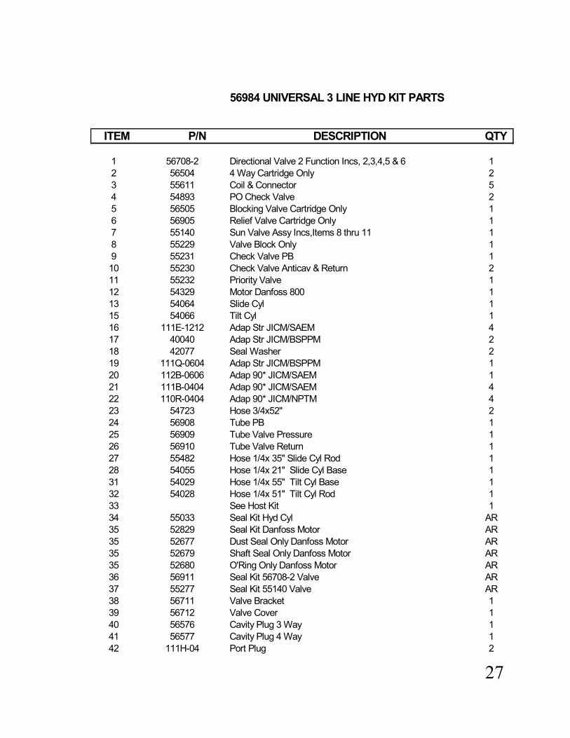
56984 UNIVERSAL 3 LINE HYD KIT PARTS
ITEM P/N DESCRIPTION QTY
1 56708-2 Directional Valve 2 Function Incs, 2,3,4,5 & 6 12 56504 4 Way Cartridge Only 23 55611 Coil & Connector 54 54893 PO Check Valve 25 56505 Blocking Valve Cartridge Only 16 56905 Relief Valve Cartridge Only 17 55140 Sun Valve Assy Incs,Items 8 thru 11 18 55229 Valve Block Only 19 55231 Check Valve PB 110 55230 Check Valve Anticav & Return 211 55232 Priority Valve 112 54329 Motor Danfoss 800 113 54064 Slide Cyl 115 54066 Tilt Cyl 116 111E-1212 Adap Str JICM/SAEM 417 40040 Adap Str JICM/BSPPM 218 42077 Seal Washer 219 111Q-0604 Adap Str JICM/BSPPM 120 112B-0606 Adap 90* JICM/SAEM 121 111B-0404 Adap 90* JICM/SAEM 422 110R-0404 Adap 90* JICM/NPTM 423 54723 Hose 3/4x52" 224 56908 Tube PB 125 56909 Tube Valve Pressure 126 56910 Tube Valve Return 127 55482 Hose 1/4x 35" Slide Cyl Rod 128 54055 Hose 1/4x 21" Slide Cyl Base 131 54029 Hose 1/4x 55" Tilt Cyl Base 132 54028 Hose 1/4x 51" Tilt Cyl Rod 133 See Host Kit 134 55033 Seal Kit Hyd Cyl AR35 52829 Seal Kit Danfoss Motor AR35 52677 Dust Seal Only Danfoss Motor AR35 52679 Shaft Seal Only Danfoss Motor AR35 52680 O'Ring Only Danfoss Motor AR36 56911 Seal Kit 56708-2 Valve AR37 55277 Seal Kit 55140 Valve AR38 56711 Valve Bracket 139 56712 Valve Cover 140 56576 Cavity Plug 3 Way 141 56577 Cavity Plug 4 Way 142 111H-04 Port Plug 2
28

29

30

31
32

33
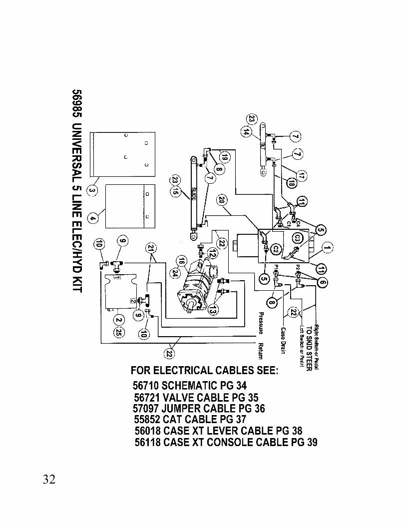
56985 UNIVERSAL 5 LINE ELEC/HYD KIT 2 FUNCTION
ITEM P/N DESCRIPTION QTY
1 56716 Valve 6 Way Shuttle 12 52981 Lock Valve 13 57000 Valve Bracket 14 57001 Valve cover 15 111E-0404 Adapter Str JIC/SAE 46 Orifice Fitting 27 110R-0404 Adap 90* JICM/NPTM 28 112B-0404 Adap 90* JICM/JICF 29 111C-1212 AdapTee JICM/SAEM 210 112B-1212 Adap 90* JICM/JICF 211 112A-0404 Adap 45* JICM/JICF 412 111Q-0604 Adap Str JICM/BSPP 113 40040 Adap Str JICM/BSPP 214 54066 Tilt Cyl 115 54064 Slide Cyl 116 54329 Motor Danfoss 800 117 54029 Hose 1/4x55" 118 54028 Hose 1/4x51" 119 54026 Hose 1/4x15" 120 55482 Hose 1/4x35" 121 54723 Hose 3/4x52" 222 See Host Kit23 55033 Seal Kit Hyd Cyl AR24 52829 Seal Kit Danfoss AR24 52677 Dust Seal Only AR24 52679 Shaft Seal Only AR24 52680 O'Ring Only AR25 54946 Seal Kit 52981 Valve AR

34

35

36

37

38

39

40

41
57002 PARKER 5 LINE HYD KIT PARTS
ITEM P/N DESCRIPTION QTY
1 54728-2 Valve Parker 2 Spool 12 55344 Overrunning Valve 13 52981 Lock Valve 14 57003 Valve Bracket 15 54064 Slide Cyl 16 54066 Tilt Cyl 17 110R-0404 Adap 90* JICM/NPTM 28 111B-0406 Adap 90* JICM/SAEM 29 111E-0406 Adap Str JICM/SAEM 210 111K-0604 Adap Tee JICM/SAEM 111 111C-0406 Adap Tee JICM/SAEM 112 112B-0404 Adap Tee JICFS/SAEM 113 111C-1212 Adap Tee JICM/SAEM 214 112B-1212 Adap 90* JICFS/JICM 215 40040 Adap Str JICM/BSPPM 216 42077 Seal Washer BSPP 217 54329 Motor Danfoss 800 118 54723 Hose 3/4x52" 219 54055 Hose 1/4x 21 120 54026 Hose 1/4x 15 121 55482 Hose 1/4x 35 122 54029 Hose 1/4x 55 123 54028 Hose 1/4x 51 124 See Host Kit 125 55033 Seal Kit Hyd Cyl AR26 52829 Seal Kit Danfoss Motor AR26 52677 Dust Seal Only Danfoss Motor AR26 52679 Shaft Seal Only Danfoss Motor AR26 52680 O'Ring Only Danfoss Motor AR

42

43
54430/54431 WG GRAVITY WATER KITS
ITEM P/N DESCRIPTION QTY
1 54423 Tank 25 Gal (Inc Item 20 11 54621 Tank 55 Gal ( Inc Item 20 12 115A-1208 Nipple Reducing 13 54791 Valve Ball 14 115B-0806 Bushing Reducing 15 55912 Quick Coupler Female 16 55913 Quick Coupler Male 17 106A-0606 Pushlok Fitting 18 54442 Hose 3/8" Pushlok 112" 19 106A-0806 Pushlok Fitting 1
11* 54427 Spray Bar AP/APX/ CP 300 111* 54425 Spray Bar AP/APX/ CP 450 111* 54424 Spray Bar AP/APX/CP 600 111* 55387 Spray Bar AP760/800 111* 55388 Spray Bar AP1000 112 54421 Nozzle as Required AR14 50A-0422 HHCS 1/4-20x 2 3/4 415 56002 Tube Clamp 216 56017 Plate Clamp 218 30C-04 Nut Nylok 1/4-20 419 54443 Tiedown Strap 220 55017 Tank Cap 8" 120 56007 Tank Cap 6" 1
* SPRAY BAR KITS AVAILABLE, KITS INC: SPRAY BAR, NOZZLES & CLAMPS
*AP 300 55875*AP 450 55876*AP 600 55877*AP760/800 55878*AP1000 55879
Assembly Instructions For WG Water Kits
1 Screw valve assembly including Items 2,3,4&5 pg 48 into tank outlet2 Mount tank on top of Skid Steer cab roof using Item 21 tiedowns hooked
into cab sides to secure tank to roof3 Install spray bar tube Item 11 pg 48 to planer using Items 3,15,16 & 17 pg 48 to
secure the spray tube to the planer. Align the nozzles with the holes and have the hose fitting on the left (motor) side of the planer
4 Disregard # 3 if tube is already on the planer5 Push hose onto spray tube fitting and connect quick coupler to coupler on tank6 Fill tank with water and test operation.

44

45
54428/54429 WP WATER KITS
ITEM P/N DESCRIPTION QTY
1 54423 Tank 25 Gal ( inc item 23) 11 54621 Tank 55 Gal (inc item 23) 12 14C-04 Washer Flat 1/4" 123 30C-04 Nut Nylok 1/4-20 64 50A-0408 HHCS 1/4-20 x1" 45 115J-06 Steer EL 3/8" 16 55912 Quick Coupler Female 17 55913 Quick Coupler Male 18 106A-0606 Pushlok Fitting2 29 54442 Hose 3/8" Pushlok 112" 110 106A-0806 Pushlok Fitting 212* 54427 Spray Bar AP/APX/CP 300 112* 54425 Spray Bar AP/APX/CP 450 112* 54424 Spray Bar AP/APX/CP 600 112* 55387 Spray Bar AP760/800 112* 55388 Spray Bar AP1000 113 54421 Nozzle as Required AR15 56002 Clamp 216 50A-0422 HHCS 1/4-20 x 2 3/4" 417 56017 Plate Clamp 218 54441 Hose 3/" Pushlok 24" 119 115B-1208 Bushing Reducing 120 55941 Screen 121 54443 Teidown Strap 222 55942 Wiring Assy Kit( see pgs 44 & 45` 123 55017 Tank Cap 8" 123 56007 Tank Cap 6" 1
Assembly Instructions For WP Water Kits
1 Bolt pump assembly to top of tank at holes provided2 Isnstall 55941 screen Item 20 pg 50 into outlet hole in tank3 Install Items 19,10 & 18 pg 50 between tank outlet and inlet of pump4 Mount tank on top of Skid Steer roof using Item 21 tiedowns hooked into cab sides
to secure tank to cab roof5 Connect female electric plug to a suitable 12 volt source on your Skid Steer. Plug
the connector into it and locate the magnetic box in a convenient location.6 Install the spray tube Item 12 pg 50 to the planer using Items 3,15,16&17to secure
the spray tube to the planer. Align the nozzles with the holes and have the hose fitting on the left (motor) side of the planer.
7 Disregard # 6 if tube assembly is already on the planer8 Push long (112") hose onto tube fitting and connect quick coupler to coupler on pump9 Fill tank with water and test operation.
46
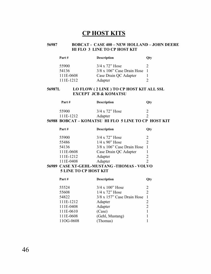
CP HOST KITS
56987 BOBCAT - CASE 400 – NEW HOLLAND – JOHN DEERE
HI FLO 3 LINE TO CP HOST KIT Part # Description Qty 55900 3/4 x 72” Hose 2 54136 3/8 x 106” Case Drain Hose 1 111E-0608 Case Drain QC Adapter 1 111E-1212 Adapter 2 56987L LO FLOW ( 2 LINE ) TO CP HOST KIT ALL SSL EXCEPT JCB & KOMATSU
Part # Description Qty 55900 3/4 x 72” Hose 2 111E-1212 Adapter 2 56988 BOBCAT – KOMATSU HI FLO 5 LINE TO CP HOST KIT Part # Description Qty 55900 3/4 x 72” Hose 2 55486 1/4 x 90” Hose 2 54136 3/8 x 106” Case Drain Hose 1 111E-0608 Case Drain QC Adapter 1 111E-1212 Adapter 2 111E-0408 Adapter 2 56989 CASE XT-GEHL-MUSTANG -THOMAS - VOLVO 5 LINE TO CP HOST KIT Part # Description Qty 55524 3/4 x 100” Hose 2 55608 1/4 x 72” Hose 2 54822 3/8 x 157” Case Drain Hose 1 111E-1212 Adapter 2 111E-0408 Adapter 2 111E-0610 (Case) 1 111E-0608 (Gehl, Mustang) 1 11OG-0608 (Thomas) 1

47
CP HOST KITS (Cont.)
56990 JCB HI FLO 5 LINE TO CP HOST KIT Part # Description Qty 55524 3/4 x 100” Hose 2 55486 1/4 x 90” Hose 2 54822 3/8 x 157” Case Drain Hose 1 40040 Adapter 2
111Q-0406 Adapter 2 111Q-0608 Case Drain QC Adapter 1
56990L JCB LO FLO TO CP HOST KIT Part # Description Qty 55524 3/4 x 100” Hose 2 111Q-1212 Adapter 2

1
T A B L E O F C O N T E N T S
1. PRODUCT WARRANTY……………………………………………… 3 2. CHECKLIST Dealer’s File Copy ................................................................... 4 Customer’s File File………………………………………….. 5 3. INTRODUCTION ........................................................................................ 6 4. SPECIFICATIONS ...................................................................................... 7 5. SAFETY............................................................................................................... 8 5.1 Mandatory Safety Shutdown Procedure................................................... 9-10 6. OPERATION.................................................................................................... 11 6.1 Forward ..................................................................................................... 11 6.2 Attaching to and detaching from skidsteer loader ..................................... 11 6.3 Preparing to Plane………………………………………………………… 12 6.4 Starting the Cut ........................................................................................... 12 6.5 Advancing the Cut...................................................................................... 13 6.6 Ending the Cut ............................................................................................ 13 7. DAILY MAINTENANCE ....................................................................... . 14 7.1 Pic Removal and Replacement ................................................................. 15 7.2 Removal.................................................................................................... 15 7.3 Replacement ............................................................................................. 16 7.4 Changing a Drum ..................................................................................... . 17 8. PARTS…………………………………………………………………………. 18 APX Planer Drawings..………………………………………………………. 18-19 APX Planer Parts List………………………………………………………. 20-21 4-Line Hydraulic Drawing & Parts List……………………………………. 22-23 2-Line Hydraulic Drawing & Parts List ……………………………………. 24-25 4-Line Hydraulic W/Tilt Drawing & Parts List…………………………. .... . 26-27 2-Line Hydraulic W/Tilt Drawing & Parts List…………………………….. . 28-29 Swingaway Arm Drawing & Parts List…………………………………….. . 30 Host Kits……………………………………………………………………. 31-34 Danfoss Motor Parts List……………………………………………………. 35 Revised 05/18/05

2

3
1. PRODUCT WARRANTY

4
After the Cold Planer has been completely set up and attached to the host machine, inspect the following. Check off each item after the prescribed action is taken. Check that:
♦ No parts of the unit have been damaged in
shipment. Check for things such as dents and loose or missing parts; correct or replace components as required.
♦ All bolts and fasteners are in place and tightly secured.
♦ All grease fittings have been properly lubricated; see lubrication information in this manual.
♦ All decals are in place and securely attached.
♦ The serial number of your unit is recorded in the space provided on this page.
♦ Then, test run the unit while checking that all components are operating correctly.
I acknowledge that the procedures were performed on this unit as outlined above.
—————————————————
DEALERSHIP NAME
—————————————————- DEALER REPRESENTATIVE’S NAME
————————————————
DATE CHECKLIST FILLED OUT
————————————————— SERIAL NUMBER
2. C H E C K L I S T DEALER’S FILE COPY 2.1 PRE-DELIVERY
The following checklist is an important reminder of the valuable information that MUST be passed on to the customer at the time the unit is delivered. Check off each item as you explain it to the customer. ♦ Give the customer his operators manual. Instruct him to be sure to read and com-
pletely understand its contents BEFORE operating the unit.
♦ Explain and review with him the SAFETY information in this manual.
♦ Explain that regular cleaning and lubrication are required for proper operation and long life. Review with him the lubrication information in this manual.
♦ Explain and review with him the service & maintenance information in this manual.
♦ Completely fill out the owner’s registration, including the customer’s signature, and return it to the manufacturer.
I acknowledge that the above points were reviewed with me at the time of delivery. ———————————————————
CUSTOMER’S SIGNATURE
——————————————————— DATE DELIVERED
2.2 DELIVERY

5
After the Cold Planer has been completely set up and attached to the host machine, inspect the following. Check off each item after the prescribed action is taken.
Check that: ♦ No parts of the unit have been damaged in shipment. Check for things such as dents and loose or missing parts; correct or replace components as required. ♦ All bolts and fasteners are in place and tightly secured. ♦ All grease fittings have been properly lubricated; see lubrication information in this manual. ♦ All decals are in place and securely attached. ♦ The serial number of your unit is recorded in the space provided on this page. ♦ Then, test run the unit while checking that all components are operating correctly.
I acknowledge that the procedures were performed on this unit as outlined above.
—————————————————
DEALERSHIP NAME
—————————————————- DEALER REPRESENTATIVE’S NAME
————————————————
DATE CHECKLIST FILLED OUT
————————————————— SERIAL NUMBER
2. C H E C K L I S T CUSTOMER’S FILE COPY
2.1 PRE-DELIVERY
The following checklist is an important reminder of the valuable information that MUST be passed on to the customer at the time the unit is delivered. check off each item as you explain it to the customer. ♦ Give the customer his operator’s manual. Instruct him to be sure to read and com-
pletely understand its contents BEFORE operating the unit.
♦ Explain and review with him the SAFETY information in this manual.
♦ Explain that regular cleaning and lubrication are required for proper operation and long life. Review with him the lubrication information in this manual.
♦ Explain and review with him the service & maintenance information in this manual.
♦ Completely fill out the owner’s registration, including the customer’s signature and return it to the manufacturer.
I acknowledge that the above points were reviewed with me at the time of delivery. ———————————————————
CUSTOMER’S SIGNATURE
——————————————————— DATE DELIVERED
2.2 DELIVERY

6
3. I N T R O D U C T I O N The CP SERIES COLD PLANER was designed as an attachment machine for use on skidsteer loaders. The information contained in this manual refers only to the planer machine. Information regarding the valves used to control oil flow to the planer attachment can be found in the host machines manual.
The information contained within is provided to assist you in preparing, adjusting, maintaining, and servicing your machine. More importantly, this manual provides an operating plan for safe and proper use of your machine. Major points of safe operation are detailed in the safety chapter of this manual. Refer to the table of contents for an outline of this manual.
Modern machinery has become more sophisticated, and with that in mind, you must read and understand the contents of the manual COMPLETELY and become familiar with your new machine before attempting to operate it.
Terms such as “right” and “left” as used in the manual, are as though the reader is sitting in the host machine’s operator seat and facing the planer.
Throughout this manual, information is provided which is set in bold type and introduced by the word NOTE. Be sure to read carefully and comply with the message or directive given. Following this information will improve your operating or maintenance efficiency, help you to avoid costly breakdowns or unnecessary damage, and extend the life of your machine.
The Manufacturer and Society of Automotive Engineers have adopted this SAFETY ALERT SYMBOL to pinpoint characteristics that, if not properly followed, can create a safety hazard. When you see this symbol in this manual or on the unit itself, you are reminded to BE ALERT! YOUR SAFETY IS INVOLVED!
The manufacturer reserves the right to make changes or improvements in the design or construction of any part without the obligation to install such changes on any unit previously delivered.

7
4. S P E C I F I C A T I O N S
CP SERIES
MODEL STANDARD DRUM WIDTH CP-300...................................................................................................12 Inches (300 mm) CP-400...................................................................................................16 Inches (400 mm) CP-450...................................................................................................18 Inches (450 mm) CP-600...................................................................................................24 Inches (600 mm)
MAXIMUM TILT ANGLE 15 degrees left & right SIDE SHIFT TRAVEL 24 inches (610 mm) WEIGHT* CP300 1200 lbs. (544 kg) CP400 1500 lbs. (680 kg) CP450 1600 lbs. (726 kg) CP600 1700 lbs. (771 kg) * Weights are for fully hydraulic planers equipped for use on skidsteer loaders and are approximate due to optional equipment.

8
5. S A F E T Y BEFORE YOU ATTEMPT TO OPERATE THIS EQUIPMENT, READ AND STUDY THE FOLLOWING SAFETY INFORMATION. IN ADDITION, MAKE SURE THAT EVERY INDIVIDUAL WHO OPERATES OR WORKS WITH THIS EQUIPMENT IS FAMILIAR WITH THESE SAFETY PRECAUTIONS.
The manufacturer always takes the operator and their safety into consideration when designing machinery. Guards are provided on exposed moving parts for the operator’s protection; however, some areas cannot be guarded or shielded in order to assure proper operation. In addition, the operator’s manual and decals on the machine itself warn you of further danger and should be read and observed closely. The SAFETY ALERT SYMBOL above means ATTENTION! BECOME ALERT! YOUR SAFETY IS INVOLVED! It stresses an attitude of “HEADS UP” for safety and can be found throughout this operator’s manual and on the unit itself. REMEMBER: The careful operator is the best operator. Most accidents are caused by human error. Certain precautions must be observed to prevent the possibility of injury or damage. Please read the rules listed below for safe operation BEFORE you operate this equipment. Use of words CAUTION, WARNING, or DANGER herein and on the machine itself signal three degrees of hazard. CAUTION is used for general reminders of good safety practices or to direct attention to unsafe practices. WARNING is used to denote a specific potential hazard. DANGER is used to denote the most serious specific potential hazard.

9
5.1 MANDATORY SAFETY SHUTDOWN
Work of any type on machinery is always more dangerous when the machine is operating. BEFORE cleaning, lubricating, or servicing this unit, the following MANDATORY SAFETY SHUTDOWN PROCEDURE should ALWAYS be followed: 1. Move host machine’s propulsion control to the neutral position and idle engine down.
2. Shut off cold planer.
3. Position cold planer so that it is completely resting on the ground or floor.
4. Engage the host machine’s hand brake.
5. Move the host machine’s throttle to the slow idle position, shut the engine off, and remove the ignition key.
6. Relieve hydraulic pressure by moving the hi-flow and cylinder control levers in both directions. ONLY when you have taken these precautions can you be sure it is safe to proceed. Failure to follow the above procedures could lead to death or serious bodily injury! Some diagrams used herein may show door(s), guard(s), or shield(s) open or removed for illustration purposes ONLY! BE SURE that all door(s), guard(s), and shield(s) are in their proper position(s) and securely attached BEFORE operating the planer! Read and observe ALL safety information and decals on the host machine and cold planer BEFORE operating the unit! In addition, familiarize yourself with ALL of the safety devices and periodically check that they are functioning properly! Refer to the SAFETY chapter of the host machine’s operator manual and observe ALL safety recommendations set forth in that manual! CAREFULLY inspect ALL hydraulic hoses and connections on a routine basis. NEVER use your hand; escaping fluid under pressure can cause serious injury!

10
BE SURE to exercise the MANDATORY SAFETY SHUT DOWN PROCEDURE BEFORE proceeding to do any work on the cold planer! BE SURE the cold planer is properly placed in the “service position” and resting on the ground BEFORE attempting to work on the drum. BEFORE transporting the cold planer, BE SURE to raise the unit completely off the ground and turn it off. When replacing pics, BE SURE to use only a soft or lead headed hammer when inserting the pics into the holders. ALWAYS wear safety glasses with side shields when striking metal against metal! In addition, it is recommended that a softer (non-chipable) material be used to cushion the blow. Failure to heed could result in serious injury to the eyes or other parts of the body! ALWAYS wear proper clothing and covering when working with or on the cold planer! DO NOT attempt to move the cold planer sideways while it is on the ground! DO NOT attempt to work on the planer or host machine with the hydraulics live! BE SURE to relieve the hydraulic pressure by shutting down the engine and moving all control levers BEFORE attempting to disconnect any hoses or BEFORE proceeding to remove the cold planer from the host machine. DO NOT treat the cold planer like a bucket; it can be damaged by contact with solid objects as well as upset the stability of the host machine! DO NOT hit the pics with a steel hammer as this could cause steel chips to fly, causing injury to the eyes or face. REMEMBER! It is the owner’s responsibility to communicate information regarding the safe use and proper operation and maintenance to any user of this machine!

11
6. O P E R A T I O N 6.1 FOREWORD The planer must be attached to a host machine equipped to provide the necessary hydraulics and operational controls. As there are many different host machines available, this manual will only deal with the generic operation of the planer. Anyone attempting to attach and operate the planer must first have the knowledge and skill of operating the host machine’s controls. Information regarding the host machine’s controls and attaching procedure is found in the host machine’s operators manual or from its authorized dealer.
6.2 ATTACHING TO AND DETACHING FROM A SKIDSTEER LOADER
Drive the skidsteer up to the quick attach of the planer and connect up. Exercise the MANDATORY SAFETY SHUTDOWN PROCEDURE before proceeding. After installing hydraulic quick couplers compatible with your skidsteer to the hydraulic hoses of the planer, connect them to the hydraulic outlet as follows: 1. If your skidsteer has five lines i.e. (2 high flow , 2 auxiliary, and 1 case drain): The 3/4” hose attached to the # “2” port of the overrunning valve must be connected to the pressure outlet of the skidsteer’s high flow. The 3/4” hose attached to the # “1” port must be connected to the return outlet. The two 1/4” hoses must be connected to the skidsteer’s auxiliary outlets. The 3/8” case drain line must be connected to the skidsteer’s case drain outlet. 2. If your skidsteer has 3 lines i.e. (2 high flow lines, and 1 case drain): The 3/4” hose attached to the “P” port of the valve must be connected to the pressure outlet of the skidsteer, and the 3/4” hose attached to the “R” port of the valve to the return outlet. The 3/8” case drain line must be attached to the skidsteer’s case drain outlet. 3. On CP 300 and 400 planers on standard flow skidsteer’s without a case drain, connect as per “2” but omit the case drain connection.

12
Determine the required depth of cut, tilt angle of cut, and left to right position of the planer in regard to the host machine. When it is safe to do so, start the host machine’s engine, and ensure that the planer drum is not touching the ground. This is accomplished by rolling the bucket control back. Turn on the planer, and check the drum rotation. The teeth at the bottom of the drum must be moving in the same direction that the planer travels over the material to be planed. If the drum rotates incorrectly, correct the planer installation before attempting to plane. In skidsteer operation, only forward travel should be used. Tilt and Crosslide functions are controlled by the Skid Steers auxiliary controls.
6.3 PREPARING TO PLANE
Check the surface to be planed. The standard drum for each model can be used to mill both asphalt and concrete. If a finer finish is required, drums with more pics are available. Contact Coneqtec/Universal for special drums.
6.4 STARTING THE CUT
Position the planer over the desired starting place. With the planer turned on, the depth gauge at “0” and the host machine’s engine at full rpm, slowly lower the planer to the surface to be planed until the weight of the planer is resting on the planer’s wheels. The CP Planer’s cutting depth is controlled by the skidsteer’s bucket roll. Rolling it forward increases the drum depth, and rolling backward decreases the drum depth. The scale on the left side of the planer cowl in relation to the depth control link shows how deep you are cutting. Roll the bucket control forward until the desired depth is reached. Maximum depth of each cut is determined by the type of material being milled, the weight and hydraulic horsepower of the host machine, and the size planer being used. A general rule of thumb is to start at 3/4” to 1” deep in concrete and 1-1/2” to 2” deep in asphalt. As you increase the cutting depth you will also be automatically applying down pressure on the planer. This is necessary to keep the planer stable during planing. For maximum down pressure the skidsteer’s front wheels should be 1-2” (25-50 mm) off the planing surface. This can be controlled by raising or lowering the boom arms.
13
6.5 ADVANCING THE CUT
Advance the planer in the direction the drum pics are traveling in the cut. If the planer drum stalls, you have been feeding the planer into the cut too fast or cutting too deep. Back out of the cut until the drum restarts, and then advance again. If the planer tends to ride up out of the cut, use the procedure outlined in the paragraph above to keep the planer wheels on the surface to be planed. DO NOT side shift the planer while the drum is in the cut. The drum will not cut in a side to side direction. The depth controls may be actuated while the drum is in the cut.
6.6 ENDING THE CUT
Stop advancing the planer and raise the drum out of the cut by rolling the bucket back. Raise the planer clear out of the pavement, and move to the next cut.
CAUTION: When using cold planers with skidsteer loaders equipped with hi-flow kits, periodic observation must be made of the transmission oil temperature indicator on the skidsteer loader. Hydraulic oil may overheat, depending on ambient temperature and duty cycle of the machine. If indicator comes on or a gauge indicates a temperature in the danger range, shut off cold planer, and allow skidsteer loader to idle until the hydraulic temperature falls below 180°F . Damage to machine may occur if these instructions are not followed.

14
7. D A I L Y M A I N T E N A N C E
CAUTION: NEVER attempt to do any maintenance to the planer while it is running. Exercise the MANDATORY SAFETY SHUTDOWN PROCEDURE BEFORE proceeding.
NOTE: Careful attention to the daily maintenance routines will go a long way toward ensuring efficient planer operation. 1. At the start of each day, lubricate the grease fittings at the end of the carriage arm on each side of the planer housing and the bearing on the right hand side of the drum shaft. Standard shop gun grease will suffice. 2. Check crosslide rods, and tilt plates for lubrication. Clean away any dust or dirt, and apply oil to these areas.
3. Using the correct size wrenches, retighten any loose hardware. 4. Inspect for any loose hydraulic fittings or damaged hoses; retighten or replace as required. 5. At least twice a day check all pics for freedom of rotation and wear. Replace or free up all pics that are not rotating freely, and replace any that are badly worn. Follow the procedure outlined under pic removal and replacement.
WARNING: NEVER use your hands to check for hydraulic leaks. Escaping fluid under pressure can cause serious injury! If injured by escaping fluid, see a doctor at once. If proper medical treatment is NOT administered IMMEDIATELY serious infection or reaction can develop.
15
7.1 PIC REMOVAL AND REPLACEMENT To achieve maximum pic life and optimum performance, the pics will require replacement for the following reasons: 1. They are broken or worn. 2. They are seized in the pic holder and do not rotate freely.
7.2 REMOVAL To provide access to the pics for inspection or replacement, the CP Planer cowl can be easily turned upside down by the following instructions: First, be sure to disconnect all hoses between the skidsteer and the planer! Failure to do so can cause damage to these hoses that is not warrantable. After disconnecting all hoses, raise the boom arms,and roll the bucket dump forward, keeping the front wheels of the planer at ground level. Continue until the front wheels, when on the ground will allow the planer cowl to go over center. Lower the boom arms, and roll the bucket dump back until the planer wheels are all on the ground. You now have excellent access to the drum and pics. Be sure to set the skidsteer parking brake and shut its engine down before proceeding.
WARNING: When above maneuver is being performed, be sure that no one is in contact with the planer to avoid injury!
1. Rotate the drum until the pic to be removed is conveniently accessible. 2. Hold the pic removal tool in one hand, and place the jaws in the groove of the pic with the offset handle pointing away from the pic holder. 3. Using a lead hammer or rubber-headed mallet, hit the raised pad on the tool until the pic starts to move, and continue to tap it out. NOTE: If the pic does not have a groove, use a pic punch and a lead hammer or rubber-headed mallet to drive the pic out of the holder from the back side.

16
7.3 REPLACEMENT
WARNING: ALWAYS wear safety glasses with side shields when striking metal. Failure to heed could result in serious injury to the eyes or other parts of the body!
To replace a pic proceed as follows: 1. With the pic removal tool in one hand, position the new pic in the jaws of the tool so that the raised pad of the tool is pointing in the same direction as the pic point. 2. Position the stem of the pic in the hole of the pic holder. 3. With a lead hammer or rubber-headed mallet, hit the raised pad of the tool to start the pic into the holder. 4. Then, with one strong blow, strike the tool pad to pop the pic into the hole of the holder. The pic is properly seated when its shoulder is against the face of the pic holder. BE SURE to test that the pic rotates freely. NOTE: If the pic does not have a groove, position the stem of the pic in the hole in the holder, and using a lead hammer or rubber headed mallet, lightly hammer the point of the pic until the pic is seated in the holder. To return the planer to its operating position, roll the bucket dump back until the planer cowl comes back over center.
WARNING: When the above maneuver is being performed, be sure that no one is in contact with the planer to avoid injury.

17
7.4 CHANGING A DRUM
To change a drum, position the planer as described in 6.1.1 pic removal. 1. Support the drum at its center with a proper hoist or lifting device. 2. Remove the four cap screws bolting the motor to the planer. 3. Turn the drum until you find a pipe plug in the shaft approximately four inches from the shaft motor end. Remove this plug, and install the necessary bushing and a grease fitting. Using a hand grease gun, pump grease into the shaft to assist in pushing the motor out of the drum shaft. 4. Loosen the set screws locking the bearing center to the shaft. Remove the four nuts and cap screws retaining the outside bearing to the cowl side; remove the bearing. 5. The drum can now be moved out of the cowl. With some models it may be necessary to disconnect the upper end of the bearing side depth control link to allow the drum to be lifted clear of the planer. If this link is removed, be sure to properly support the cowl to avoid injury. Replacing the drum is a reversal of the above. Prior to installing the motor into the shaft bore, remove the grease fitting and bushing. Clean most of the grease from the bore. Clean and inspect the motor shaft and key, install motor, and replace and torque 5/8” capscrews to 175-200 lb. ft.
18

19

20
CP PARTS LIST ITEM P/N DESCRIPTION QTY
1 55421 Cowl Assy CP 300 1 1 55423 Cowl Assy CP 400/450 1 1 55424 Cowl Assy CP 600 1 2 55451 Drum Assy CP 300 1 2 55400 Drum Assy CP 400 1 2 55452 Drum Assy CP 450 1 2 55453 Drum Assy CP 600 1 3 55425 Trolley Assy CP 300 1 3 55427 Trolley Assy CP 400/450 1 3 55428 Trolley Assy CP 600 1 4 55073 Motor 400CC 1 4 52708 Motor 500CC 1 4 52588 Motor 630CC 1 4 54329 Motor 800CC 1 5 42013 Wheel 6 6 52596 Wheel Axle Front 2 7 42015 Spacer Wheel 14 8 42014 Bearing Wheel 12 9 13A-0640 Cotter Pin 3 3/16 x 2-1/2” 4 10 42016 Wheel Axle Rear 2 11 50A-1012 5/8-11 x 1-1/2” HHCS 4 12 14A-10 5/8 Lock Washer Motor 4 13 54723 Hose 3/4” x 52” 2 15 54958 Bearing 1 16 50A-1018 5/8-11 x 2-1/4” 4 17 30C-10 5/8-11 Nylock Nut 4 18 52681 Key 1 19 42004 Bushing Carriage Pivot (Up to S/N—) 2 19 55545 Bushing S/N—–& Up 2 20 55546 Pivot Pin Carriage S/N—& Up 2 20 55415 Pivot Pin Carriage 2 21 55406 Washer 1” Carriage Pivot 2 22 50A-1630 1-8 x 3-3/4” HHCS 2 23 30C-16 1-8 Nylock Nut 2 24 55429 Carriage Assy APX 300 1 24 55431 Carriage Assy APX 400/450 1 24 55432 Carriage Assy APX 600 1 25 55417 Link Depth Control 2 26 55418 Spacer Depth Link 4 27 55416 Bushing Depth Link 4 28 55407 Washer 7/8” Depth Link 4 29 50A-1428 7/8-9 x 3-1/2 HHCS 4 30 30C-14 7/8-9 Nylock Nut 4 31 54089 Crosslide Assy Universal 1 32 50A-1024 5/8-11 x 3” HHCS 4 33 52165 Hardened Washer 4 34 52380 Double Lock Washer Tilt 4 35 30C-10 5/8-11 Nylock Nut Tilt 4
21
CP PARTS LIST (Cont.) ITEM P/N DESCRIPTION QTY
36 54064 Cylinder Slide 1 36 55033 Cylinder Seal Kit AR 37 54991 Bushing Cylinder 2 38 14C-12 3/4” Flat Washer Slide Cylinder 2 39 350A-20050 M20 x 50 HHCS 2 40 111K-0604 Adapter Stir SAEM/NPTM-#3 Lock Valve 1 41 52981 Valve Lock 1 41 54946 Seal Kit 52981 Valve AR 42 111B-0406 Adapter 90° JICM/SAEN-#2 Lock Valve 1 43 54114 Hose 1/4 x 25” Ppilot 1 44 110Y-04 Adapter Tee JIC/NPT Cyl Base 1 45 112B-04 Adapter 90° JICM/JICF 1 46 55462 Turnbuckle Tilt 1 47 50A-1228 3/4-10 x 3-1/2 HHCS 2 48 30C-12 3/4-10 Nylock Nut 2 49 14C-18 1-1/8” Flat Washer 4 50 29A-02 Grease Fitting 2 51 111E-0406 Adapter Str JIC / SAE 1 52 40028 Pic Block AR 53 10150 Pic Low Torque AR 53 10151 Pic Combination AR 54 111E-1216 Adapter JIC/SAE Motor Eaton 2 54 40040 Adapter JIC/BSPP Motor Adan/Danfoss 2 55 42077 Bonded Seal BSPP Adan/Danfoss 2 56 111E-0604 Adapter Case Drain Eaton 1 56 111Q-0604 Adapter Case Drain Adan/Danfoss 1 57 29F-01 Grease Fitting 1 58 C-21088 Coneqtec Decal 1 59 C-21076 APX 300 Model Decal 1 59 C-21077 APX 400 Model Decal 1 59 C-21078 APX 450 Model Decal 1 59 C-21079 APX 600 Model Decal 1 60 80443 General Caution Decal 1 61 80440 Danger Rotating Decal 3 62 C-21080 Power Adjustment Decal 2 63 C-21081 APX Depth Decal 1 64 80441 Slide Pinch Warning Decal 1 65 251747A1 Visual Pinch Warning Decal 2 66 55513 Pinch Warning Decal 2 67 40069 Pic Tool 1 68 55384 Adan MVA Seal Kit (Ref: Item 4) AR 68 55511 Eaton 6000 Seal Kit (Ref: Item 4) AR 68 52829 Danfoss OMV Seal Kit (Ref: Item 4) AR 69 55548 Belleville Washer 8

22
CP HOST KITS
56987 BOBCAT - CASE 400 – NEW HOLLAND – JOHN DEERE HI FLO 3 LINE TO CP HOST KIT
Part # Description Qty 55900 3/4 x 72” Hose 2 54136 3/8 x 106” Case Drain Hose 1 111E-0608 Case Drain QC Adapter 1 111E-1212 Adapter 2 56987L LO FLOW ( 2 LINE ) TO CP HOST KIT ALL SSL EXCEPT JCB & KOMATSU
Part # Description Qty 55900 3/4 x 72” Hose 2 111E-1212 Adapter 2 56988 BOBCAT – KOMATSU HI FLO 5 LINE TO CP HOST KIT Part # Description Qty 55900 3/4 x 72” Hose 2 55486 1/4 x 90” Hose 2 54136 3/8 x 106” Case Drain Hose 1 111E-0608 Case Drain QC Adapter 1 111E-1212 Adapter 2 111E-0408 Adapter 2 56989 CASE XT-GEHL-MUSTANG -THOMAS - VOLVO 5 LINE TO CP HOST KIT Part # Description Qty 55524 3/4 x 100” Hose 2 55608 1/4 x 72” Hose 2 54822 3/8 x 157” Case Drain Hose 1 111E-1212 Adapter 2 111E-0408 Adapter 2 111E-0610 (Case) 1 111E-0608 (Gehl, Mustang) 1 11OG-0608 (Thomas) 1

23
CP HOST KITS (Cont.)
56990 JCB HI FLO 5 LINE TO CP HOST KIT Part # Description Qty 55524 3/4 x 100” Hose 2 55486 1/4 x 90” Hose 2 54822 3/8 x 157” Case Drain Hose 1 40040 Adapter 2
111Q-0406 Adapter 2 111Q-0608 Case Drain QC Adapter 1
56990L JCB LO FLO TO CP HOST KIT Part # Description Qty 55524 3/4 x 100” Hose 2 111Q-1212 Adapter 2

24
DANFOSS MOTOR OMV PARTS LIST
ITEM P/N DESCRIPTION QTY ITEM P/N DESCRIPTION QTY 1 52676 Screw M8x1x20mm 6 26 52694 Channel Plate 1 NSS 2 52677 Dust Deal Ring 1 28 52695 Disc Valve 1 NSS 3 52678 Front Cover 1 29 52969 Balance Plate 1 NSS 4 52679 Shaft Seal 1 30 52697 Guide Pin 1 NSS 5 52680 O Ring 1 31 52698 O Ring 1 6 52681 Parallel Key 1 32 52699 O Ring 1 7 52682 Shaft Including Bearing 1 33 52700 Spacer 1 8 52683 Conical Seal Ring 1 34 52701 Spring Washer 1 NSS 9 52684 Bearing Housing 1 NSS 36 52702 Valve Housing 1 NSS 10 52685 Drain Plug Including O Ring 1 NSS 37 52703 Ball 2 NSS 13 52687 Cardan Shaft for 52708 500 mtr 1 NSS 38 52704 Springs 2 NSS 13 55333 Cardan Shaft for 52588 630 mtr 1 NSS 39 52705 Washers 2 NSS 13 55334 Cardan Shaft for 54329 800 mtr 1 NSS 40 52706 Plugs 2 NSS 22 52689 O Ring 1 41 52707 Cap Screw OMV500 & 630 4 NSS 23 52690 Gearwheel set for 52588 630mtr 1 NSS 41 55335 Cap Screw for 54329 800mtr 4 NSS 23 52691 Gearwheel set for 52708 500mtr 1 NSS 42 55254 Name Plate OMV 1 NSS 23 55332 Gearwheel set for 54329 800mtr 1 NSS 43 54930 Drive Screw 4 NSS 24 52692 Guide Pin 1 NSS 44 52829 Seal Kit OMV Includes items 1 25 52693 Valve Drive 1 NSS 2,4,5,8,22,31,32 Note: NSS— NOT SERVICED SEPARATELY
25
ITEM P/N DESCRIPTION QTY 1 56365 CONTROLLER UNIT 1 2 56364 CABLE ASSY 1 3 56366 HARNESS ASSY 1 4 55719 VALVE ASSY 1
GREEN &YELLOW,WIRES NOT USED WITH 2 SPOOL VALVE
56996 BOBCAT ELEC KIT
4

26

27
55728CP PARKER/SUN HYDRAULIC KIT
ITEM P/N DESCRIPTION QTY 1 55140 Sun Valve Assy Incs 2,3,4 1 2 55232 Valve Priority Flow 1 3 55231 Valve Check PB 1 4 55230 Valve Check 2 5 55719 Valve Parker 2 Spool 1 5 56065 Coil Parker MV5 Valve AR 5 56066 Valve Spool Section AR 6 54066 Tilt Cylinder 1 7 54064 Slide Cylinder 1 8 52981 Lock Valve 1 9 111E-1212 Adapter JIC/SAE 4 10 111B-0404 Adapter JIC/SAE 3 11 40040 Motor Fitting 2 12 42077 Motor Fitting Seal Washer 2 13 111E-0406 Adapter JIC/SAE 2 14 111B-0406 Adapter JIC/SAE 5 15 111K-0604 Adapter SAE/NPT 1 16 110Y-0404 Adapter Tee JIC/SAE 1 17 112B-0404 Adapter 90* JICM/JICF 1 18 111Q-0604 Adapter Str JIC/BSPP 1 19 110G-0404 Adapter 90* JIC/NPT 2 20 54723 Hose 3/4x52” 2 21 54029 Hose 1/4X55” 1 22 54028 Hose 1/4X51” 1 23 54026 Hose 1/4x15” 2 24 54055 Hose 1/4x21” 2 25 55482 Hose 1/4x35” 1 26 54329 Motor Danfoss 800 1 27 See Host Kit 1 28 55033 Seal Kit Hyd. Cyl. AR 29 55277 Seal Kit 55140 Valve AR 30 56052 Seal Kit Parker Valve AR 31 54946 Seal Kit Lock Valve AR 32 52829 Seal Kit Danfoss Mototr AR 32 52677 Dust Seal Only AR 32 52679 Shaft Seal Only AR 32 52680 O’Ring Only AR

28

29
56984 UNIVERSAL 3 LINE HYD KIT PARTS
ITEM P/N DESCRIPTION QTY 1 56708-2 Directional Valve 2 Function Incs, 2,3,4,5 & 6 1 2 56504 4 Way Cartridge Only 2 3 55611 Coil & Connector 5 4 54893 PO Check Valve 2 5 56505 Blocking Valve Cartridge Only 1 6 56905 Relief Valve Cartridge Only 1 7 54140 Sun Valve Assy Incs,Items 8 thru 11 1 8 55229 Valve Block Only 1 9 55231 Check Valve PB 1
10 55230 Check Valve Anticav & Return 2 11 55232 Priority Valve 1 12 54329 Motor Danfoss 800 1 13 54064 Slide Cyl 1 15 54066 Tilt Cyl 1 16 111E-1212 Adap Str JICM/SAEM 4 17 40040 Adap Str JICM/BSPPM 2 18 42077 Seal Washer 2 19 111Q-0604 Adap Str JICM/BSPPM 1 20 112B-0606 Adap 90* JICM/SAEM 1 21 111B-0404 Adap 90* JICM/SAEM 4 22 110R-0404 Adap 90* JICM/NPTM 4 23 54723 Hose 3/4x52" 2 24 56908 Tube PB 1 25 56909 Tube Valve Pressure 1 26 56910 Tube Valve Return 1 27 Hose 1/4x Slide Cyl Rod 1 28 Hose 1/4x Slide Cyl Base 1 31 Hose 1/4x Tilt Cyl Base 1 32 Hose 1/4x Tilt Cyl Rod 1 33 See Host Kit 1 34 55033 Seal Kit Hyd Cyl AR 35 52829 Seal Kit Danfoss Motor AR 35 52677 Dust Seal Only Danfoss Motor AR 35 52679 Shaft Seal Only Danfoss Motor AR 35 52680 O'Ring Only Danfoss Motor AR 36 56911 Seal Kit 56708-2 Valve AR 37 55277 Seal Kit 55140 Valve AR 38 56711 Valve Bracket 1 39 56712 Valve Cover 1

30

31
56985 UNIVERSAL 5 LINE ELEC/HYD KIT
ITEM P/N DESCRIPTION QTY
1 56716 Valve 6 Way Shuttle 12 52981 Lock Valve 13 57000 Valve Bracket 14 57001 Valve cover 15 111E-0404 Adapter Str JIC/SAE 46 Orifice Fitting 27 110R-0404 Adap 90* JICM/NPTM 28 112B-0404 Adap 90* JICM/JICF 29 111C-1212 AdapTee JICM/SAEM 210 112B-1212 Adap 90* JICM/JICF 211 112A-0404 Adap 45* JICM/JICF 412 111Q-0604 Adap Str JICM/BSPP 113 40040 Adap Str JICM/BSPP 214 54066 Tilt Cyl 115 54064 Slide Cyl 116 54329 Motor Danfoss 800 117 54029 Hose 1/4x55" 118 54028 Hose 1/4x51" 119 54026 Hose 1/4x15" 120 55482 Hose 1/4x35" 121 54723 Hose 3/4x52" 222 See Host Kit23 55033 Seal Kit Hyd Cyl AR24 52829 Seal Kit Danfoss AR24 52677 Dust Seal Only AR24 52679 Shaft Seal Only AR24 52680 O'Ring Only AR25 54946 Seal Kit 52981 Valve AR

32

33
57002 PARKER 5 LINE HYD KIT PARTS
ITEM P/N DESCRIPTION QTY
1 54728-2 Valve Parker 2 Spool 12 55344 Overrunning Valve 13 52981 Lock Valve 14 57003 Valve Bracket 15 54064 Slide Cyl 16 54066 Tilt Cyl 17 110R-0404 Adap 90* JICM/NPTM 28 111B-0406 Adap 90* JICM/SAEM 29 111E-0406 Adap Str JICM/SAEM 210 111K-0604 Adap Tee JICM/SAEM 111 111C-0406 Adap Tee JICM/SAEM 112 112B-0404 Adap Tee JICFS/SAEM 113 111C-1212 Adap Tee JICM/SAEM 214 112B-1212 Adap 90* JICFS/JICM 215 40040 Adap Str JICM/BSPPM 216 42077 Seal Washer BSPP 217 54329 Motor Danfoss 800 118 54723 Hose 3/4x52" 219 54055 Hose 1/4x 21 120 54026 Hose 1/4x 15 121 55482 Hose 1/4x 35 122 54029 Hose 1/4x 55 123 54028 Hose 1/4x 51 124 See Host Kit 125 55033 Seal Kit Hyd Cyl AR26 52829 Seal Kit Danfoss Motor AR26 52677 Dust Seal Only Danfoss Motor AR26 52679 Shaft Seal Only Danfoss Motor AR26 52680 O'Ring Only Danfoss Motor AR

3348 S. Hoover • Wichita, KS 67215 • 316-946-5885
P/N 56992