da100 data acquisition unit user's manual - 横河電機 · user’s manual da100 data...
TRANSCRIPT

User’sManual
DA100Data Acquisition Unit
IM DA100-01E
IM DA100-01E8th Edition

IM DA100-01E 1
ForewordThank you for purchasing the YOKOGAWA DA100 Data Acquisition System (DA100/DS400/DS600).This User’s Manual contains useful information regarding the instrument’s functions andoperating procedures, as well as precautions that should be observed during use. To ensure properuse of the instrument, please read this manual thoroughly before operating it.Keep the manual in a safe place for quick reference whenever a question arises.The following manuals are provided with the instrument in addition to this manual.
Manual Name Manual No.
DA100 Communication Interface IMDA100-11EStandard Software for DA100 IMDP10001-62E
Notes• DARWIN is a system comprising a number of data-acquisition equipment components. In the
course of system growth, new models, software, various input/output modules and optionalfeatures are added to the family to enhance the systems expandability and flexibility. You cancheck the versions of your equipment and software by referring to the style number (Sn) andrelease number (Rn) respectively which are shown on the nameplate of the main unit.When configuring a system, you must confirm that the style number of each component unit andsoftware meets the following requirements:1 the style number of each input/output module must be the same as or lower than that of the
main unit or subunit to which the module is connected.2 the release number of a dedicated software package must be the same or higher than the style
number of the main unit or subunit where the package is installed and where it performscontrol.
Any equipment/software not meeting these requirements might have incompatible areas with yoursystem configuration.In this manual, equipment of style S8 is explained.
• The contents of this manual are subject to change without prior notice as a result of improvementsin the instrument’s performance and functions.
• Every effort has been made in the preparation of this manual to ensure the accuracy of itscontents. However, should you have any questions or find any errors, please contact your nearestYOKOGAWA representative as listed on the back cover of this manual.
• Copying or reproduction of all or any part of the contents of this manual without YOKOGAWA’spermission is strictly prohibited.
TrademarksMicrosoft, MS-DOS, Windows, and Windows NT are either registered trademarks or trademarksof Microsoft Corporation in the United States and/or other countries.IBM is a registered trademark of International Business Machines Corporation.
Revisions1st Edition: January 19962nd Edition: June 19963rd Edition: March 19974th Edition: July 19975th Edition: November 19976th Edition: November 19987th Edition: June 20008th Edition: October 2000
Disk No. RE02
8th Edition: October 2000 (YK)
All Rights Reserved, Copyright © 1996 Yokogawa Electric Corporation

IM DA100-01E2
About the Style NumberProducts with style numbers S6, S7, and S9 are not sold.The following functions are available for DC100 with style number S2:• Computation function (including remote RRJC)The following functions are available for DC100 with style number S3:• RS-422-A/RS-485 communication moduleThe following functions are available for DC100 with style number S4:• Pulse input module• GP-IB moduleThe following functions are available for DC100 with style number S5:• mA-input/power monitor/strain input module• Extension module and extension base• Report functionThe following functions are available for DC100 with style number S8:• Digital input module• Ethernet module/RS-232-C module/RS-422-A/RS-485 module• Measurement of active power and apparent power on ch3 to ch6 for power monitor moduleThe following functions are available for DC100 with style number S10:• Retransmission module

IM DA100-01E 3
Checking the Contents of the Package
Unpack the box and check the contents before operating the instrument. In case the wronginstrument or accessories have been delivered, or if some accessories are not present, or if theyseem abnormal, contact the dealer from which you purchased them. Futhermore, please contact aYokogawa representative to order any of parts as follows.
Main Unit DA100Check that model and suffix code given on the name plate are according to your order.Model and Suffix Codes
Model Suffix Code Description
DA100 ....................... Main Unit DA100
Type -1 .................... Stand-alone model-2 .................... Expandable model-B ................... DU100-11 (Input module) and DT300-21 (Communication module) are
attached-C ................... DU100-21 (Input module) and DT300-21 (Communication module) are
attached-D ................... DU100-31 (Input module) and DT300-21 (Communication module) are
attached
Software 3 ................. Software
Power Supply -1 ............. 100-240VAC-2 ............. 12-28VDC
Power Cord D ......... 3-pin inlet w/UL, CSA cable (Part No. A1006WD)F ......... 3-pin inlet w/VDE cable (Part No. A1004WD)R ......... 3-pin inlet w/SAA cable (Part No. A1024WD)S ......... 3-pin inlet w/BS cable (Part No. A1023WD)W ........ 3-pin inlet with screw conversion terminalY ......... No power cord, 2-pin round-type connector
Option /M1 . ... Optional math function (included remote RJC and event/action functions)/M3 ..... Report fuction
NO. (Instrument Number), Style number (equipment) and Release number(software package)Please quote these numbers when contacting the dealer.
Subunit DS400/DS600Check that model and suffix code given on the name plate are according to your order.Model and Suffix Codes
Model Suffix Code Description
DS400 ....................... 4-module connection subunitDS600 ....................... 6-module connection subunit
Type 00 ................... always 00
Power Supply -1 ............. 100-240VAC-2 ............. 12-28VDC
Power Cord D ......... 3-pin inlet w/UL, CSA cable S .... 3-pin inlet w/BS cableF ......... 3-pin inlet w/VDE cable W ... 3-pin inlet with screw conversion terminalR ......... 3-pin inlet w/SAA cable Y .... No power cord, 2-pin round-type
connector
NO. (Instrument Number) and Style number (equipment)Please quote these numbers when contacting the dealer.

IM DA100-01E4
Input ModulesCheck that model code given on the name plate is according to your order.Model Codes
Model Description
DU100-11 10-channel universal input module, screw type terminalDU100-21 20-channel universal input module, screw type terminalDU100-31 30-channel universal input module, screw type terminal
DU100-12 10-channel universal input module, clamp type terminalDU100-22 20-channel universal input module, clamp type terminalDU100-32 30-channel universal input module, clamp type terminal
DU200-11 10-channel DCV/TC/DI input module, screw type terminalDU200-21 20-channel DCV/TC/DI input module, screw type terminalDU200-31 30-channel DCV/TC/DI input module, screw type terminal
DU200-12 10-channel DCV/TC/DI input module, clamp type terminalDU200-22 20-channel DCV/TC/DI input module, clamp type terminalDU200-32 30-channel DCV/TC/DI input module, clamp type terminalDU300-11 10-channel, mA-input module with screw terminals
DU300-12 10-channel, mA-input module with clamp terminals
DU400-12 Power monitor module for single-phase useDU400-22 Power monitor module for three-phase use
DU500-12 10-channel, strain input module with 120-Ω bridge resistorsDU500-22 10-channel, strain input module with 350-Ω bridge resistorsDU500-32 10-channel, strain input module with NDIS terminals
DU600-11 10-channel, pulse input module with screw terminals
DU700-11 10-channel, digital input module with screw terminals
NO. (Instrument Number)Please quote this instrument number when contacting the dealer.
I/O Terminal ModulesCheck that model code given on the name plate is according to your order.Model Codes
Model Description
DT100-11 DI/DO module, screw type terminal
DT200-11 Alarm output module (4 transfer contacts), screw type terminalDT200-21 Alarm output module (10 make contacts), screw type terminal
DT300-11 GP-IB moduleDT300-21 RS-232C module, D-sub terminalDT300-31 RS-422-A/RS-485 moduleDT300-41 Ethernet module
DT500-11 1-5 V retransmission module, screw type terminalDT500-21 4-20 mA retransmission module, screw type terminal
NO. (Instrument Number) and Style number (equipment)Please quote these numbers when contacting the dealer.
Checking the Contents of the Package

IM DA100-01E 5
Standard Accessories1 power cord(conform your order)
4 User's manuals• IM DA100-01E• IM DA100-11E• IM DP12013-61E
1 3.5" floppy disk
M4 screws (for 1 unit)(4 to fasten the feet, 6 for panel installation)
DC power terminal connector (when power supply code is -2)
1 clamp filter(Part No. A1179MN, when power supply code is -1)
DA100-B, DA100-C, and DA100-D are appended to the following accessories in addition to theabove-mentioned standard accessories by the customer of purchase.
Main Unit Type Name Model Q’ty
DT100-B 10-channel universal input module DU100-11 1RS-232-C module DT300-21 1RS-232-C cable1
DT100-C 20-channel universal input module DU100-21 1RS-232-C module DT300-21 1RS-232-C cable 1
DT100-D 30-channel universal input module DU100-31 1RS-232-C module DT300-21 1RS-232-C cable 1
NoteWhen DA100-B, DA100-C, and DA100-D are used while bought, the system need not be restructured.However, when the position where the module is installed is changed or another module is installed, it isnecessary to restructure the system.
Checking the Contents of the Package

IM DA100-01E6
Optional Accessories
Name Model Description
Extender module DV100-011Extender base DV100-012Extension cable DV200-000 Length: 0.5mExtension cable DV200-001 Length: 1mExtension cable DV200-002 Length: 2mExtension cable DV200-005 Length: 5mExtension cable DV200-010 Length: 10mExtension cable DV200-020 Length: 20mExtension cable DV200-050 Length: 50mExtension cable DV200-100 Length: 100mExtension cable DV200-200 Length: 200mExtension cable DV200-300 Length: 300mExtension cable DV200-400 Length: 400mExtension cable DV200-500 Length: 500m
Shunt resistance DV300-011 10Ω, for screwShunt resistance DV300-012 10Ω, for clampShunt resistance DV300-101 100Ω, for screwShunt resistance DV300-102 100Ω, for clampShunt resistance DV300-251 250Ω, for screwShunt resistance DV300-252 250Ω, for clamp
Rack mount kit DV400-011 ANSI/EIA standard
Strain conversion cable DV450-001
Cable adapter DV250-001 for expanding cables
AC adapter DV500-001 2-pin inlet w/UL, CSA cable for DC100/DA100/DS400/DS600
DV500-002 2-pin inlet w/VDE cable for DC100/DA100/DS400/DS600
DV500-003 2-pin inlet w/SAA cable for DC100/DA100/DS400/DS600
DV500-004 2-pin inlet w/BS cable for DC100/DA100/DS400/DS600
Software
Name Model Description
DAQ Software 32 DP120-13 Same as the standard accessoryDAQ Software 32 Plus DP320-13
Checking the Contents of the Package

IM DA100-01E 7
Safety Precautions
This instrument is an IEC safety class I instrument (provided with terminal for protectivegrounding).The following general safety precautions must be observed during all phases of operation, serviceand repair of this instrument. If this instrument is used in a manner not sepecified in this manual,the protection provided by this instrument may be impaired. Also, YOKOGAWA ElectricCorporation assumes no liability for the customer’s failure to comply with these requirements.
The following symbols are used on this instrument.
To avoid injury, death of personnel ordamage to the instrument, theoperator must refer to an explanationin the User’s Manual or ServiceManual.
Protective grounding terminal.
Alternating current.
ON(power).
OFF(power).
Make sure to comply with the following safety precautions. Not complying mightresult in injury, death of personnel or damage to the instrument.
WARNING
Power SupplyEnsure the source voltage matches the voltage of the power supplybefore turning ON the power.Power Cable and PlugTo prevent an electric shock or fire, be sure to use the power cordsupplied by YOKOGAWA. The main power plug must be plugged in anoutlet with protective grounding terminal. Do not invalidate protection byusing an extension cord without protective grounding.
Protective GroundingMake sure to connect the protective grounding to prevent an electricshock before turning ON the power.Necessity of Protective GroundingNever cut off the internal or external protective grounding wire ordisconnect the wiring of protective grounding terminal. Doing so poses apotential shock hazard.
Defect of Protective Grounding and FuseDo not operate the instrument whenprotective grounding or fuse might bedefective.Do not Operate in an Explosive AtmosphereDo not operate the instrument in the presence of flammable liquids orvapors. Operation of any electrical instrument in such an environmentconstitutes a safety hazard.
Do not Remove any CoversThere are some areas with high voltages. Do not remove any cover if thepower supply is connected. The cover should be removed by qualifiedpersonnel only.External ConnectionTo ground securely, connect the protective grounding before connectingto measurement or control unit.

IM DA100-01E8
How to Use this Manual
This User’s Manual consists of the following four chapters and an Index.
Chapter Title Description
Chapter 1 System configuration Explains the position of the DA100 system withinDARWIN, its configuration, functions, etc..
Chapter 2 Installation and Wiring Explains how to install and wire the DA100.
Chapter 3 Trouble-shooting and Explains how to analyse troubles and what toMaintenance do in case trouble occurs.
Chapter 4 Specifications Explains basic output settings such as the output mode,type, frequency and voltage.
Index Gives the index in alphabetical order.
Conventions Used in this ManualUnitsk ........ means “1000”. Example: 100kHzK ........ means “1024”. Example: 128Kword
Used CharactersAlphanumerics enclosed in double quotation marks usually refer to characters and set values thatappear on the screen and panel.
NoteThe following symbol marks are used to attract the operator’s attention.
Affixed to the DA100/DS400/DS600, indicating that for safety, theoperator should refer to the appropriate User’s Manual. For a list of theUser’s Manuals, refer to page 1.
WARNING Describes precautions that should be observed to prevent the danger ofinjury or death to the user.
CAUTION Describes precautions that should be observed to prevent damage to theDA100/DS400/DS600.
Note Provides information that is important for proper operation of the DA100/DS400/DS600.

IM DA100-01E 9
1
2
3
4
Index
Contents
Foreword ............................................................................................................................................................................. 1
Checking the Contents of the Package ..................................................................................................................... 3
Safety Precautions .............................................................................................................................................................. 7
How to Use this Manual .................................................................................................................................................... 8
Chapter 1 System Configuration1.1 About DARWIN ................................................................................................................................... 1-1
1.2 DA100’s System Configuration ............................................................................................................ 1-2
1.3 Name and Function of Each Part .......................................................................................................... 1-4
1.4 Supportive Software for the DA100 System ...................................................................................... 1-11
Chapter 2 Installation and Wiring2.1 General Precautions for Installation ..................................................................................................... 2-1
2.2 How to Install the DA100 ..................................................................................................................... 2-2
2.3 How to Connect the Input/Output Modules ......................................................................................... 2-4
2.4 Connecting the Interface Cables ........................................................................................................... 2-7
2.5 Connecting the Extension Cables (only for use with the expandable type DA100) .......................... 2-13
2.6 Connecting the Signal Lines ............................................................................................................... 2-14
2.7 Connecting an Extension Module to Extension Bases ....................................................................... 2-23
2.8 Connecting the Power Cord and Turning the Power ON/OFF ........................................................... 2-25
2.9 Countering Noise ................................................................................................................................ 2-29
Chapter 3 Trouble-shooting and Maintenance3.1 Diagnosis .............................................................................................................................................. 3-1
3.2 Error Messages ..................................................................................................................................... 3-3
3.3 Trouble-Shooting .................................................................................................................................. 3-8
3.4 About Maintenance and Calibration ..................................................................................................... 3-9
Chapter 4 Specifications4.1 DA100/ DS400/ DS600 ........................................................................................................................ 4-1
4.2 Universal Input Module and DCV/TC/DI Input Module ..................................................................... 4-9
4.3 Specifications of mA-input Module ................................................................................................... 4-12
4.4 Specifications of Power Monitor Module .......................................................................................... 4-14
4.5 Specifications of Strain Input Module ................................................................................................ 4-18
4.6 Specifications of Pulse Input Module ................................................................................................. 4-20
4.7 Specifications of Digital Input Module .............................................................................................. 4-22
4.8 Alarm Output Module ........................................................................................................................ 4-24
4.9 DI/DO Module .................................................................................................................................... 4-25
4.10 Communication Interface Module ...................................................................................................... 4-26
4.11 Retransmission Module ...................................................................................................................... 4-29
4.12 Specifications of Extension Module and Extension Base .................................................................. 4-30
4.13 Dimensional Drawings ....................................................................................................................... 4-31
Index ................................................................................................................................................................................ Index-1

IM DA100-01E 1-1
1
System
Co
nfig
uratio
n
1.1 About DARWIN
Created from a completely new concept that is based on modular architecture, the group of nextgeneration’s data acquisition systems is called DARWIN (Data Acquistion and RecordingWindows).Today many data acquisition networks are increasingly being linked together. More than everbefore, large volume, high speed, accurate, easy-to-use communication functions are essential inmany disciplines.In a world of measurement and control where the number of measurement points has increasedsharply, the ability to acquire information from a large number of points easily and economicallyis crucial. Interfacing to a personal computer allows simplified utilization of the informationwhile improving quality and efficiency.DARWIN is based on a unique, new concept to meet these needs. The art of measurement isrevolutionized by DARWIN which integrates functions of conventional recording and datalogging.Most existing data acquisition equipment has been the all-in-one type in which the measurementsection and display/recording section are contained in one box. While this simplifies operation onthe one hand, it is difficult to adapt to changes in the measurement environment and also makesexpansion difficult.DARWIN uses a data acquisition engine and remote I/O modules which are completely separatefrom each other. It is an entirely new product line which quickly and flexibly copes with variousrestrictive conditions and changes in specifications.Supported by a personal computer, a whole line-up can be created starting whith the dataacquisitions system DA100 which performs data logging. For example, using a printer as theoutput device, the equipment becomes a hybrid recorder (DR series).
FD
Extension cables(max. length 500m)
Subunit
Personalcomputer
D
CH=001 RANGE=TC TYPE-THybrid Recorder
001
002
003
004
005
006
007
008
009
010
011
012
013
014
015
016
017
018
019
020
021
022
023
024
025
026
027
028
029
030
Input/outputmodules
DR240DR230DA100

IM DA100-01E1-2
1.2 DA100’s System Configuration
The DA100 is a data acquisition unit which allows data logging on a personal computer of smallscale, 10-ch data logging up to 300-ch, multi-point measurements.Measurement data can be analyzed in real-time on the PC, as the DA100 can be controlled usingcommunication interface.There are two types of DA100, the DA100 stand-alone type, and the DA100 expandable type.DA100 Stand-alone typeBeing suitable for small scale data logging between 10 and 40ch, the light-weight main unitallows an easy and quick setting up.DA100 Expandable typeThe expandable type consists of one main unit and by connecting up to six subunits (DA400/DS600), the number of measurement points can be expanded to a maximum of 300ch. Usingdedicated twisted-pair cables between each unit, it is possible to connect up to 500 meters. Sinceeven measurement objects scattered over a wide area can be wired fast and with a minimum ofwiring, a flexible, extensive measurement system can be configured.The input modules to be connected to the DA100 or DA400/DS600 are in units of 10ch and canbe selected from the following, in order to match your measurement conditions.
• Universal Input Module and DCV/TC/DI Input ModuleTemperature, DC voltage, and contact signals can be measured, but cannot be connected to asystem's main unit.
• mA-input ModuleThis module can directly measure DC currents ranging from -20 mA to 20 mA since it containsshunt resistors. It cannot be connected to a system's main unit.
• Power Monitor ModuleThis module can measure the effective voltage, effective current, active power, reactive power,apparent power, frequency, power factor and phase angle for an AC voltage or AC current input.It is available in either a single-phase or three-phase model. This module cannot be connected toa system's main unit.
• Strain Input ModuleThis module can measure strain. It is available in either a model with built-in 120- or 350- Ωbridge resistors or a model with NDIS terminals where bridge resistors are connected externally.The module cannot be connected to a system's main unit.
• Pulse input module (to be released soon)When inputting a TTL signal or contact signal from a revolution counter or flow meter, thenumber of pulses can be counted, computation can be carried out, etc..
• Digital Input ModuleThis module can measured contact signal, but cannot be connected to a system's main unit.
• Communication moduleFor transfer of setting parameters and measurement data by communication interface.
• Alarm output moduleOutputs alarm signals as contact signals.
• DI/DO moduleAllows output of a signal in case of alarm or failure.
• Retransmission moduleThis module deals with data that are measured or computed by the product, or set by a personalcomputer via a communication interface. The modules convert them to 1-5 V analog voltage or 4-20 mA analog current signals for output. The module cannot be connected to the expanablemodel's main unit.
• Extender moduleTo provide power supply to far away input modules.

IM DA100-01E 1-3
1
System
Co
nfig
uratio
n
1.2 DA100’s System Configuration
Connection example
Stand-alone type
POWER
100-240V 50/60Hz 70VA MAX
DATA ACQUITION UNIT
STATUS
CH 1
CH 2
CH 3
CH 4
CH 5
CH 6
CH 7
CH 8
CH 9
CH10
b -/B +/A
CH 1
CH 2
CH 3
CH 4
CH 5
CH 6
CH 7
CH 8
CH 9
CH10
b -/B +/A
CH 1
CH 2
CH 3
CH 4
CH 5
CH 6
CH 7
CH 8
CH 9
CH10
b -/B +/A
CH 1
CH 2
CH 3
CH 4
CH 5
CH 6
CH 7
CH 8
CH 9
CH10
b -/B +/ANO C NC
FAIL
CHART
NO
C
NC
1 2
C3 4
C5 6
C7 8
C9 10
C11 12
REM
NO C NC
NO C NC
ALM
ALM2
1
C
Personalcomputer
DA100Stand-alone type
Communication interface cable
GP-IB module
10ch Universal Input moduleDI/DO module
Expandable type
POWER
100-240V 50/60Hz 55VA MAX
DATA ACQUITION UNIT
STATUS
FAIL
CHART
REM
ALM 1
ALM 2
NO C NC
NO C NC
11 RC 12
9 RC 10
7 RC 8
5 RC 6
3 RC 4
1 RC 2
NO C NC
NO C NC
CH 1
CH 2
CH 3
CH 4
CH 5
CH 6
CH 7
CH 8
CH 9
CH10
b -/B +/A
CH 1
CH 2
CH 3
CH 4
CH 5
CH 6
CH 7
CH 8
CH 9
CH10
b -/B +/A
CH 1
CH 2
CH 3
CH 4
CH 5
CH 6
CH 7
CH 8
CH 9
CH10
b -/B +/A
CH 1
CH 2
CH 3
CH 4
CH 5
CH 6
CH 7
CH 8
CH 9
CH10
b -/B +/A
CH 1
CH 2
CH 3
CH 4
CH 5
CH 6
CH 7
CH 8
CH 9
CH10
b -/B +/A
CH 1
CH 2
CH 3
CH 4
CH 5
CH 6
CH 7
CH 8
CH 9
CH10
b -/B +/A
CH 1
CH 2
CH 3
CH 4
CH 5
CH 6
CH 7
CH 8
CH 9
CH10
b -/B +/A
CH 1
CH 2
CH 3
CH 4
CH 5
CH 6
CH 7
CH 8
CH 9
CH10
b -/B +/A
CH 1
CH 2
CH 3
CH 4
CH 5
CH 6
CH 7
CH 8
CH 9
CH10
b -/B +/A
CH 1
CH 2
CH 3
CH 4
CH 5
CH 6
CH 7
CH 8
CH 9
CH10
b -/B +/A
CH 1
CH 2
CH 3
CH 4
CH 5
CH 6
CH 7
CH 8
CH 9
CH10
b -/B +/A
CH 1
CH 2
CH 3
CH 4
CH 5
CH 6
CH 7
CH 8
CH 9
CH10
b -/B +/A
CH 1
CH 2
CH 3
CH 4
CH 5
CH 6
CH 7
CH 8
CH 9
CH10
b -/B +/A
CH 1
CH 2
CH 3
CH 4
CH 5
CH 6
CH 7
CH 8
CH 9
CH10
b -/B +/A
CH 1
CH 2
CH 3
CH 4
CH 5
CH 6
CH 7
CH 8
CH 9
CH10
b -/B +/A
CH 1
CH 2
CH 3
CH 4
CH 5
CH 6
CH 7
CH 8
CH 9
CH10
b -/B +/A
SUB UNIT
POWER
STATUS
POWER
STATUS
POWER
100-240V 50/60Hz 55VA MAX
STATUS
100-240V 50/60Hz 70VA MAX
SUB UNIT
100-240V 50/60Hz 70VA MAX
SUB UNIT
NO C
ALM1
ALM2
ALM3
ALM4
ALM5
ALM6
ALM7
ALM8
ALM9
ALM10
NO C
ALM1
ALM2
ALM3
ALM4
ALM5
ALM6
ALM7
ALM8
ALM9
ALM10
Personalcomputer
DA100 Expandabletype Main unit
SubunitDS600
SubunitDS600
SubunitDS400
Extension cableCommunication interface cable
DI/DO module Alarm Output module
GP-IB module
10ch Universal Input module
10ch Universal Input module
10ch Universal Input module
Up to 6 subunitscan be connected

IM DA100-01E1-4
1.3 Name and Function of Each Part
DA100 Stand-alone type (DA100-1)
Installationholes
Power switchFunction groundingterminal (below power switch)
Power connector
Feet
Status indicator
Holes for fastening the feet
Screw holes for module installation
Moduleconnector
DA100 Expandable type (DA100-2)
Power connectorPower switch
Feet
Status indicator
Module connector
Installation holesScrew holes for module installation
Holes for fastening the feet
Lid covering the extensioncable connector
Function groundingterminal (below power switch)
Subunit DS400
Power connectorPower switch
Feet
Status indicator
Module connector
Installation holesScrew holes for module installation
Holes for fastening the feet
Lid covering the extensioncable connectorSwitch to set the
unit number
Function groundingterminal (below power switch)

IM DA100-01E 1-5
1
System
Co
nfig
uratio
n
Subunit DS600
Power connectorPower switch
Feet
Status indicator
Module connector
Installationholes
Screw holes formodule installation
Holes for fasteningthe feet
Lid covering the extension cable connector
Switch to setthe unit number
Function groundingterminal (below power switch)
Input modules10-ch Universal input module (DU100-11/DU100-12)
Cover
Screwterminal
DU100-11
Cover
Clampterminal
DU100-12
The 20-ch Universal input modules (DU100-21/DU100-22) and the 30-ch Universal input modules(DU100-31/DU100-31) are similar to the ones shown above.
10-ch DCV/TC/DI input module (DU200-11/DU200-12)
Cover
Screwterminal
DU200-11
Cover
Clampterminal
DU200-12
The 20-ch DCV/TC/DI input modules (DU200-21/DU200-22) and the 30-ch DCV/TC/DI input modules(DU200-31/DU200-31) are similar to the ones shown above.
1.3 Name and Function of Each Part

IM DA100-01E1-6
1.3 Name and Function of Each Part
mA input module (DU300-11/DU300-12)
Cover
Screwterminal
Cover
Clampterminal
Power monitor module (DU400-12/22)
Cover
Wire clip
Clamp terminal
Strain input module (DU500-12/DU500-13/DU500-14)
DU500-14DU500-12/DU500-13
NDI terminal
Gauge method setup switch
Clamp terminalCover

IM DA100-01E 1-7
1
System
Co
nfig
uratio
n
Pulse input module (DU600-11)
Cover
Screw terminal
Digital input module (DU700-11)
Cover
Screwterminal
1.3 Name and Function of Each Part

IM DA100-01E1-8
I/O Terminal ModulesDI/DO module (DT100-11)
Cover
Screw terminal
Alarm output module (DT200-11/DT200-21)
Cover
Screw terminal
DT200-11
Cover
Screw terminal
DT200-21
GP-IB module (DT300-11)
GP-IB connector Switch to set the address
RS-232C module (DT300-21)
RS-232C connector Switches to set communication parameters
1.3 Name and Function of Each Part

IM DA100-01E 1-9
1
System
Co
nfig
uratio
n
RS-422-A/RS-485 module (DT300-31)
ON/OFF switch of built-in terminating resistorLED
Switches to setcommunication parameters
RS-422-A/RS-485 terminal
Ethernet module (DT300-41)
Switch to set mode
Status indicator
10BASE-T port
Retransmission Module1-5 V Retransmission module (DT500-11)
Screw terminal
Cover
4-20 mA Retransmission module (DT500-21)
Cover
Screw terminal
1.3 Name and Function of Each Part

IM DA100-01E1-10
Extender Module/Extender Base
Extender Module (DV100-011)
EXTENDERI/F
I/F
Extension cable connector
Extender Base (DV100-012)
Lid covering the extension
Holes for fastening the feet
Terminator on/off switch
Slot number setup switchInatallationholes
Screw holes formodule installation
Power indicator
Module connector
1.3 Name and Function of Each Part

IM DA100-01E 1-11
1
System
Co
nfig
uratio
n
1.4 Supportive Software for the DA100 System
DAQ Software 32 (standard accessory)This software comprises functions such as setting of measurement conditions, diagnosis,calibration and simple data collection.The following three OS environments are supported.
• Windows 95• Windows 98• Windows NT 4.0
1) Defining the environment
3) Executing DA100 settings
6) Storing the measurement data externally using the data logging software
7) Displaying the data, and converting it to text-data, Excel format or Lotus 1-2-3 format.
2) Gathering DA100 settings
5) Gathering measurement data
4) Storing the set contents
Note• When using the DA100 for the first time, make sure to verify using the software’s diagnosis program that
the DA100 can be properly controlled by the personal computer. This can also be done bycommunication interface.
• Make sure that the total number of following setting changes, including calibrations andrestructuring,does not surpass 100000.Measurement rangeMeasurement intervalA/D integration timeFilter
DAQ Software 32 Plus (special order)Allows the collecting of measurement data over a long period. The following OS environment issupported.
• Windows 95• Windows 98• Windows NT 4.0

IM DA100-01E 2-1
2
Installatio
n an
d W
iring
2.1 General Precautions for Installation
Safety PrecautionsRead the safety precautionsMake sure to have read the safety precautions described on pages 6 and 7 before using theinstrument for the first time.
Do not remove any covers from the instrumentFor internal inspection or adjustment, contact your sales representative or nearest service center.Addresses may be found on the back cover of this manual.
In case of malfunctioningNever continue to use the instrument if there are any symptoms of malfunctioning such as unusualsounds, smell or smoke coming from the instrument. Immediately turn OFF the power and unplugthe power cord. When using an adapter for direct wiring to the power supply, immediately turnOFF the power supply. Also disconnect the power to the equipment under measurement. Contactyour sales representative or nearest service center. Addresses may be found on the back cover ofthis manual.
Power cordNothing should be placed on the power cord; it should also be kept away from any heat sources.When unplugging the power cord from the outlet, never pull the cord itself. Always hold the plugand pull it. If the power cord is damaged, contact your dealer for replacement. Refer to page 2 forthe part number when placing an order.
General Handling PrecautionsNever place anything on top of the instrumentNever place another instrument or any objects containing water on top of the instrument.Otherwise a failure may occur.
When moving the instrumentFirst disconnect the power of the equipment under measurement and disconnect the signal andinterface cables. Then turn the power of this instrument OFF and unplug the power cord.
Ventilation openingsDo not block the ventilation openings in order not to rise the internal temperature.
Electrically charged objectsDon’t bring electrically charged objects near the input terminals. The internal circuitry might bedamaged.
CleaningWhen cleaning the case or any other part of the instrument, first remove the power cord from theconsent (and in case of direct connection, disconnect the power lines). Do not use volatilechemicals since this might result in dis-coloring etc. Always use a dry, soft cloth for cleaning.
When not using the instrument for a long timeWhen the instrument is not being used for an extensive period of time, unplug the power cordfrom the outlet (when using an adapter for direct wiring to the power supply, disconnect thepower cord from the outlet).

IM DA100-01E2-2
2.2 How to Install the DA100
Installation ConditionsThe instrument must be installed in a location where the following conditions are met.
· Ambient temperature: 0 to 50 °CHowever, in case you mount the subunits DS400/DS600 directly to a panel, or mount them in arack, it is possible to use them in a range of –10 to 60 °C.
WARNING
• When the environmental temperature is 50°C or more, the temperatureof the rear panel may rise to more than 70°C. Thus, touching the rearpanel under these circumstances has the danger of sustaining burns.
• To prevent a fire, always use the instrument in a vertical position, anddo not block the upper side of the modules (a space of at least 3cm isnecessary).
· Ambient humidity: 20 to 80%RH for –10 to 40 °C, 10 to 50%RH for 40 to 50 °C, 5 to 30%RH for50 to 60 °C (However, no condensation should be present.)
· Installation location: Room· Installation height: Altitude up to 2,000 m
NoteInternal condensation may occur if the instrument is moved to another place where both the ambienttemperature and humidity are higher, or if the temperature changes rapidly. In case of thermocouple input,this might result in erroneous measurements. In those cases, allow the instrument to achieve equilibriumwith to its new environment for at least one hour before starting operation.
Never install the instrument in any of the following locations:· in direct sunlight or near heat sources;· where an excessive amount of soot, steam, dust or corrosive gases are present;· near strong magnetic field sources;· near high voltage equipment or power lines;· where the level of mechanical vibrations is high;· in an unstable place.
Installation MethodThe data acquisition unit DA100 and the subunit DS400/DS600 can be installed on the floor,directly to a panel, or can be mounted in a rack. Units equipped with screw type terminals shouldonly be used in panel installations.Floor installationSwing the feet which are located under the unit to the front as shown in the figure below, andplace the unit vertically. When there might a possibility of the unit tumbling over after wiring,fasten the feet to the surface using the accessory M4 screws.
Feet
M4 Screws
IM DA100-01E 2-3
2
Installatio
n an
d W
iring
2.2 How to Install the DA100
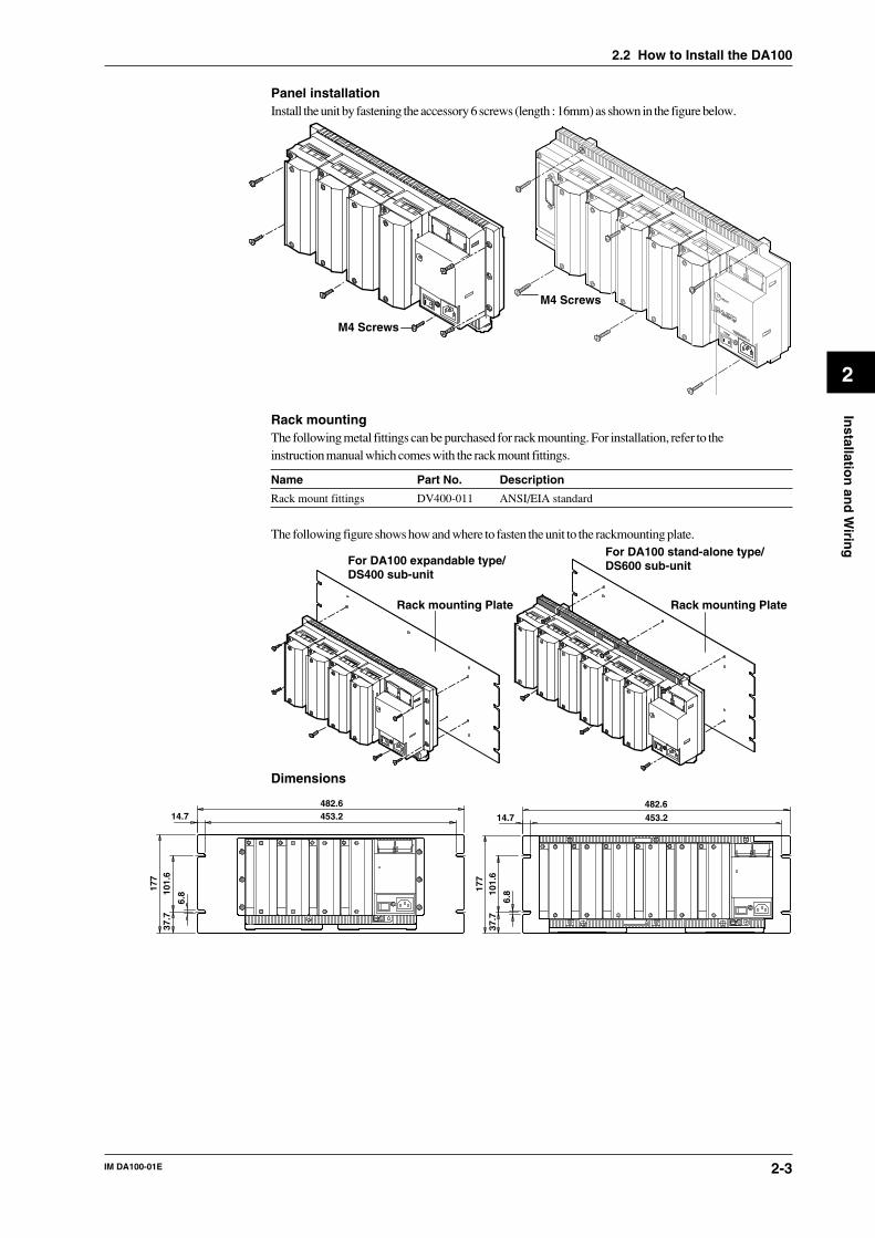
Panel installationInstall the unit by fastening the accessory 6 screws (length : 16mm) as shown in the figure below.
M4 Screws
M4 Screws
Rack mountingThe following metal fittings can be purchased for rack mounting. For installation, refer to theinstruction manual which comes with the rack mount fittings.
Name Part No. Description
Rack mount fittings DV400-011 ANSI/EIA standard
The following figure shows how and where to fasten the unit to the rackmounting plate.
For DA100 expandable type/DS400 sub-unit
Rack mounting Plate Rack mounting Plate
For DA100 stand-alone type/DS600 sub-unit
Dimensions
482.6453.214.7
177
37.7
101.
6
6.8
482.6
453.214.7
177
37.7
101.
6
6.8

IM DA100-01E2-4
2.3 How to Connect the Input/Output Modules
WARNING
When connecting the Input/Output modules, make sure to turn OFF thepower to the DA100/DS400/DS600 to prevent an electric shock or damageto the instrument.
Setting the Unit Number of each Subunit (only for the DA100 Expandable type)When connecting subunits to the DA100 Expandable type, it is necessary to assign a distinctiveunit-number to each subunit. This number can be selected from 0 to 5 (the setting 6 and up willnot be recognized) and is set, as shown in the figure below, by a setting switch (rotary dipswitch).
NoteWhen you connect an input module at the location of the setting switch, the switch can not be operatedanymore. Therefore, make sure you set the switch before connecting any input module there. It isconvenient for confirming unit numbers to write each unit number setting on a dented part located on thetop of DS600 subunit or on the left side of DS400 subunit.
Connecting Method1 Verify that the power to the DA100/DS400/DS600 has been turned OFF.2 Remove the cover of the location where the module will be connected. Do not remove any
cover of locations where no module will be connected.3 Hold the input unit so that the male part of the connector at the back side of the input unit
matches the female part of the receiving connector. Then connect the unit.4 Fasten the input unit by fastening the two accessory M3 screws.
0 1
23
456
78
9
Module connector
Screws to fasten the module
Input module
Switch for setting the unit number
• Switch for setting the unit number (settable from 0 to 5)
Cover

IM DA100-01E 2-5
2
Installatio
n an
d W
iring
Modules Which Can be UsedIn case of the DA100 Stand-alone typeInput module, alarm output module, DI/DO module, extender module, communication interfacemodule, and retransmission module.Number of modules that can be connected: 6 (of which at least one must be a communicationinterface module)
DI/DO module: not more than oneInput module: max. four (up to 40 channels)Input module + alarm output module + DI/DO module + retransmission module: max. five
In case of the DA100 Expandable typeNot more than one DI/DO module can be connected to all units.
• Main unitAlarm output module, DI/DO module, and communication interface module.(Note: The input module and retransmission module cannot be connected.)Number of modules that can be connected: 4 (of which at least one must be a communicationinterface module)
DI/DO module: not more than oneAlarm output module + DI/DO module: max. three
• Subunit DS400/DS600Input module, alarm output module, DI/DO module, extender module, and retransmissionmodule.Number of modules that can be connected: 4 for DS400, 6 for DS600 (up to 300)
DS400: Input module + alarm output module + DI/DO module + retransmission module: max.four
DS600: Input module + alarm output module + DI/DO module + retransmission module: max.six
Note• No alarm output module or DI/DO module can be connected to the right side of an input module, since
the rise in temperature would hinder the measurement accuracy.• When mounting universal and power modules, or DCV/TC/DI and power modules together, keep the two
modules apart at a distance equal to the width of at least two slots. Failure to observe this precautionmay result in the measuring accuracy falling outside the guaranteed range.
• No retransmission module can be connected to the right side of universal input module, DCV/TC/DImodule, since the rise in temperature would hinder the measurement accuracy.
• Verify the type of module by the seal on the top side.
2.3 How to Connect the Input/Output Modules

IM DA100-01E2-6
2.3 How to Connect the Input/Output Modules
Location and Location Number (Channel Number, Alarm Output Number, DI/DONumber)
The location numbers correspond to channel numbers for locations where the input module isconnected, to alarm output numbers for locations where the alarm output module is connected,and to DI/DO numbers for locations where the DI/DO module is connected.
In case of the DA100 Stand-alone typeThe location numbers correspond to the location of each module as shown in the figure below.
Module 0 (Location numbers:001 to 010)Module 1 (Location numbers:011 to 020)
Module 2 (Location numbers:021 to 030)Module 3 (Location numbers:031 to 040)
Module 4 (Location numbers:041 to 050)Module 5 (Location numbers:051 to 060)
In case of the DA100 Expandable typeThe unit number (refer to the previous page, the number of the main unit is fixed at “I”) andlocation numbers correspond to the location of each module as shown in the figure below.
Module 0 (Location numbers:001 to 010)Module 1 (Location numbers:011 to 020)
Module 2 (Location numbers:021 to 030)Module 3 (Location numbers:031 to 040)
Module 4 (Location numbers:041 to 050)Module 5 (Location numbers:051 to 060)
Main unit
Unit No.:0Subunit DS600
Module 0 (Location numbers:101 to 110)Module 1 (Location numbers:111 to 120)
Module 2 (Location numbers:121 to 130)Module 3 (Location numbers:131 to 140)
Unit No.:1Subunit DS400
Input modules or transmission modules cannot be connected.
Module 0 (Location numbers:101 to 110)Module 1 (Location numbers:111 to 120)
Module 2 (Location numbers:121 to 130)Module 3 (Location numbers:131 to 140)
Unit No.:I

IM DA100-01E 2-7
2
Installatio
n an
d W
iring
2.4 Connecting the Interface Cables
This section describes the connection between the communication module of the data acquisitionunit DA100 and a personal computer using a communication interface.
GP-IBThe GP-IB connector of the GP-IB communication module is a 24-pin connector of IEEE St’d488-1978. Only use cables that conform to IEEE St’d 488-1978 as a communication cable.Connection ProcedureConnect the cable as shown in the figure below.
GP-IB module
Ferrite core
Personalcomputer
DA100Ferrite core
Function grounding terminal
CAUTION
When (dis)connecting the GP-IB cable, turn OFF the power of both thepersonal computer and the data acquisition unit DA100. If the power is notturned OFF, malfunctions may occur and the internal circuitry may bedamaged.
• When connecting the cable, take note of the following.· Tighten the screws which fasten the GP-IB connector firmly.· To eliminate noise, we recommend to apply two ferrite cores (as shown above) at both ends of the
cable (e.g. ZCAT 3035-1330 from TDK). Use a shielded interface cable and ground equipmenttogether at one point.
· Although more than one equipment can be connected to a GP-IB system, only onecommunication module can be connected to a single personal computer. To prevent trouble whenusing the accessory software, we recommend not to connect any other equipment with thisDA100 system.
· In case several equipment are connected (although this situation is not recommended), make surethat to each a different address is assigned.
· Use only cables of 2m or less for connections between equipment.
How to Assign an AddressThe address can be assigned easily by turning the rotary dipswitch as shown in the figure below.Any address can be set from “0” to “15”; the characters “A” to “F” on the dipswitch correspond tothe address “10” to “15” respectively.
0123456789
FE
DC B A
0123456789
FE
DC B A
Set-up of the Personal Computer (when using the DAQ software 32 accessory)1 A GP-IB board should be installed in the personal computer. Only the following GP-IB boards
(made by National Instruments Co.) are supported.AT-GPIB
2 Install the accessory software for the GP-IB board (from National Instruments). The devicedriver must be registered as CONFIG.SYS [device=(drive:directory)GPIB.COM].

IM DA100-01E2-8
2.4 Connecting the Interface Cables
· Do not rename the device. A renamed device will not be recognized any longer.· This software supports only the control of board gpib0. Be aware of this when you are working in
multiple GP-IB board environment.· After installation, verify using the accessory diagnosis software program that no errors have
occurred.
RS-232CCommunication SettingsCommunication parameters are set using the three switches located on the RS-232C modules.
1 2 3 4Switch 1
Data lengthBaud rate
1 2 3 4Switch 2
Baud rate
ParityStop bit
1 2 3 4Switch 3
Not usedHandshake format
ONOFF
OFF
OFF
ON
ON
Switch 1 and No.4 of Switch 2
Baudrate dipswitch No.1 No.2 No.3 No.4 (switch 2)
150 OFF OFF OFF OFF300 OFF OFF ON OFF600 OFF ON OFF OFF1200 OFF ON ON OFF2400 ON OFF OFF OFF4800 ON OFF ON OFF9600 ON ON OFF OFF ←initial value19200 ON ON ON OFF38400 OFF OFF OFF ON
Data length dipswitch No.4
7 OFF8 ON ←initial value
Switch 2
Parity dipswitch No.1 No.2
NONE OFF OFFODD OFF ONEVEN ON OFF ←initial value
Stop bit dipswitch No.3
1 OFF ←initial value2 ON
Switch 3
Handshake format dipswitch No.1 No.2 No.3
no handshake OFF OFF OFF ←initial valueXON-DTR* OFF OFF ONXON-RTS* OFF ON OFFCTS-DTR OFF ON ONCTS-RTS ON OFF OFF
* When the baud rate is set to 38400, there is no handshaking.
NoteWhen you are using the accessory software or DAQ software 32 Plus, the settings should be as follows:baud rate 2400 to 38400bps, data length: 8 bit, parity: ODD, stop bit: 1, handshake format: CTS-RTS.

IM DA100-01E 2-9
2
Installatio
n an
d W
iring
2.4 Connecting the Interface Cables
Connecting the RS-232C cableConnect the connector of the RS-232C communication module to a personal computer as follows.The figures below show cases when hardware handshake is carried out. For other connections,refer to the DA100 Communication Interface User’s Manual (IM DA100-11E).
• In case of IBM compatible DOS machineD-Sub 25 pin D-Sub 9-pin
FGSDRD
CSDRER
FGSDRD
CSDRER
PC side Module side
SG SG
RS RS
6
5
4
3
2
1
20
7
6
5
4
3
2
1
20
7
SDRD
CSDRER
SDRD
CSDRER
PC side Module side
SG SG
RS RS
20
7
6
5
4
3
2
4
5
6
8
7
2
3
CAUTION
When (dis)connecting the RS-232C cable, turn OFF the power of both thepersonal computer and the data acquisition unit DA100. If the power is notturned OFF, malfunctions may occur and the internal circuitry may bedamaged.
NoteTo eliminate noise, we recommend to apply ferrite cores to both ends of the interface cable (e.g.ZCAT3035-1330 from TDK). If the noise persists, apply more ferrite cores. Use shielded interface cablesand ground equipment together at one point.
Personalcomputer
DA100Ferrite core
Function groundingterminal

IM DA100-01E2-10
RS-422-A/RS-485
1 2 3 4Switch1
Data lengthBaud rate
ONOFF
1 2 3 4Switch2
four-wire/two-wireStop bitParity
ONOFF
1 2 3 4Switch3
Address (upper)Minimum response time
ONOFF
1 2 3 4Switch4
Address (lower)
ONOFF
Baud rate (No.1 to 3 of Switch1)
Baud rate No.1 No.2 No.3
300 OFF OFF ON600 OFF ON OFF1200 OFF ON ON2400 ON OFF OFF4800 ON OFF ON9600 ON ON OFF ←Default Setting19200 ON ON ON38400 OFF OFF OFF
Data length (No.4 of Switch1)
Data length No.4
7 OFF8 ON ←Default Setting
Parity (No.1 to 2 of Switch2)
Parity No.1 No.2
None OFF OFFODD OFF ONEVEN ON OFF ←Default Setting
Stop bit (No.3 of Switch2)
Stop bit No.3
1 OFF ←Default Setting2 ON
Switch between four-wire/two-wire systems (No.4 of Switch2)
four-wire/two-wire No.4
four-wire OFF ←Default Settingtwo-wire ON
2.4 Connecting the Interface Cables
IM DA100-01E 2-11
2
Installatio
n an
d W
iring
2.4 Connecting the Interface Cables
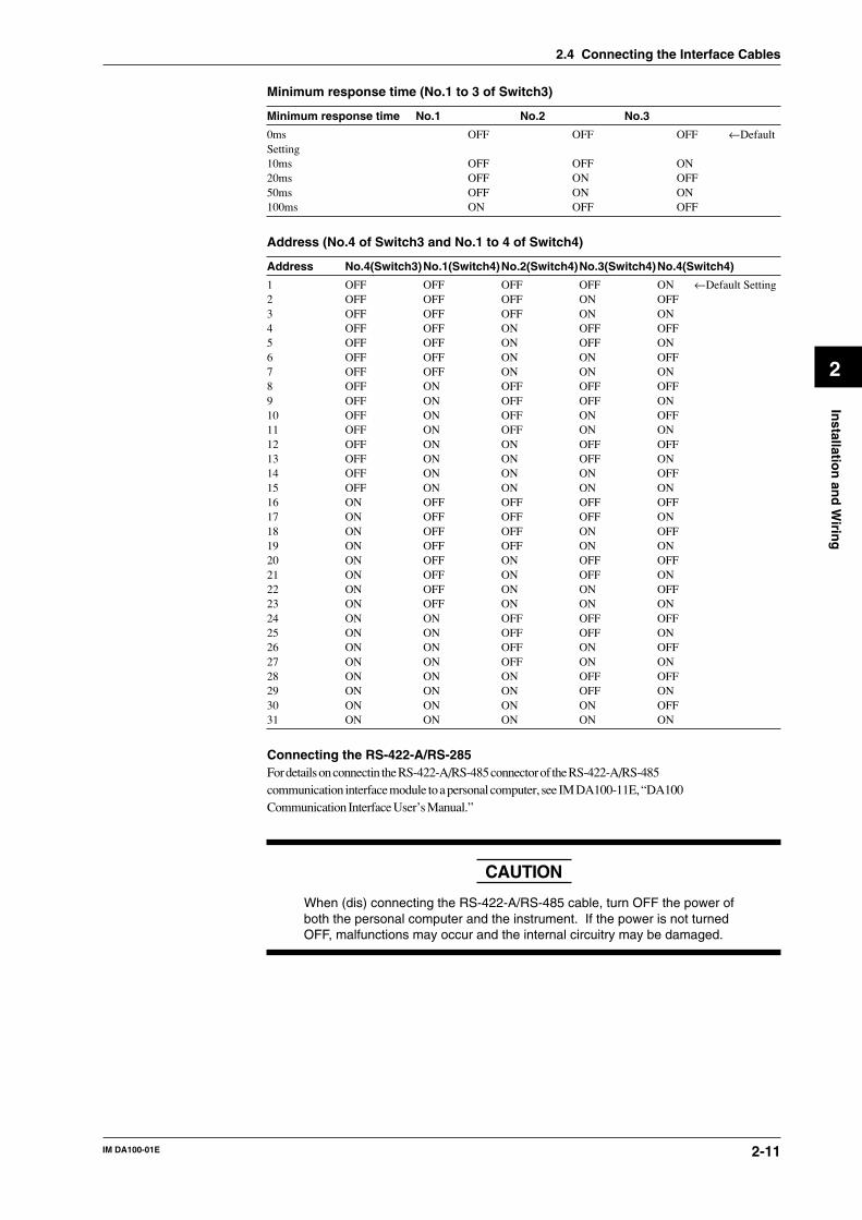
Minimum response time (No.1 to 3 of Switch3)
Minimum response time No.1 No.2 No.3
0ms OFF OFF OFF ←DefaultSetting10ms OFF OFF ON20ms OFF ON OFF50ms OFF ON ON100ms ON OFF OFF
Address (No.4 of Switch3 and No.1 to 4 of Switch4)
Address No.4(Switch3)No.1(Switch4)No.2(Switch4)No.3(Switch4)No.4(Switch4)
1 OFF OFF OFF OFF ON ←Default Setting2 OFF OFF OFF ON OFF3 OFF OFF OFF ON ON4 OFF OFF ON OFF OFF5 OFF OFF ON OFF ON6 OFF OFF ON ON OFF7 OFF OFF ON ON ON8 OFF ON OFF OFF OFF9 OFF ON OFF OFF ON10 OFF ON OFF ON OFF11 OFF ON OFF ON ON12 OFF ON ON OFF OFF13 OFF ON ON OFF ON14 OFF ON ON ON OFF15 OFF ON ON ON ON16 ON OFF OFF OFF OFF17 ON OFF OFF OFF ON18 ON OFF OFF ON OFF19 ON OFF OFF ON ON20 ON OFF ON OFF OFF21 ON OFF ON OFF ON22 ON OFF ON ON OFF23 ON OFF ON ON ON24 ON ON OFF OFF OFF25 ON ON OFF OFF ON26 ON ON OFF ON OFF27 ON ON OFF ON ON28 ON ON ON OFF OFF29 ON ON ON OFF ON30 ON ON ON ON OFF31 ON ON ON ON ON
Connecting the RS-422-A/RS-285For details on connectin the RS-422-A/RS-485 connector of the RS-422-A/RS-485communication interface module to a personal computer, see IM DA100-11E, “DA100Communication Interface User’s Manual.”
CAUTION
When (dis) connecting the RS-422-A/RS-485 cable, turn OFF the power ofboth the personal computer and the instrument. If the power is not turnedOFF, malfunctions may occur and the internal circuitry may be damaged.

IM DA100-01E2-12
2.4 Connecting the Interface Cables
Ethernet
Tx (yellow))
LINK (yellow)
STS1 (green)
STS2 (green)
Status Indicator LED
Dip Switch
1 2 3 4
ON
OFF
10BASE-T Port
Connect the RJ-45 modular jack of the twist pair cable connected to the 10BASE-T network.
You can select the following three modes by setting the dip switch.Configuration mode: A mode in which the IP address, subnet mask, and default gateway are set
for theDA100.Test mode: A mode in which the condition of the physical connection is tested.Communication mode: A mode in which the DA100 is connected to the network to carry out
communication. Use this mode to read in the DA100 measurement datawith the personal computer.
In addition, you can turn ON/OFF the Keepalive function.
Mode Setting
Mode Switch 1 Switch 2
Configuration mode ON OFFTest mode OFF ONCommunication mode OFF OFF ←Default Setting
Do not set both dip switches, 1 and 2, to ON.
Keepalive Setting
Keepalive Switch 3
Enable ON ←Default SettingDisable OFF
Keepalive is a function supported by TCP. It sends packets at constant time intervals andautomatically disconnects when there is no corresponding response. This instrument sendspackets at 30-second time intervals. If a response is not received, it sends 4 more packets at one-second intervals. If a response is still not received, the connection is dropped.
Have dip switch 4 turned OFF.

IM DA100-01E 2-13
2
Installatio
n an
d W
iring
2.5 Connecting the Extension Cables (only for usewith the expandable type DA100)
Extension CablesAny of the following extension cables can be used for connections between the DA100 main unitand subunits or for connections between subunits.
Name Model Description
Extension cable DV200-000 Length: 0.5mExtension cable DV200-001 Length: 1mExtension cable DV200-002 Length: 2mExtension cable DV200-005 Length: 5mExtension cable DV200-010 Length: 10mExtension cable DV200-020 Length: 20mExtension cable DV200-050 Length: 50mExtension cable DV200-100 Length: 100mExtension cable DV200-200 Length: 200mExtension cable DV200-300 Length: 300mExtension cable DV200-400 Length: 400mExtension cable DV200-500 Length: 500m
Connecting ProcedureOpen the lid that covers the connector and insert the plug of the extension cable in the connectoruntil you hear a click. Since both connectors are identical, it makes no difference which connectoryou use. Furthermore, since both plugs of the cable are identical, you may use either end.When pulling the plug from the connector, gently press the peg of the plug and pull it forward.
Lid
PlugExtension cable
Points to Note when Using the Extension Cables· The maximum rated temperature is 60 °C;· Never disconnect the extension cable from the connector by pulling the cable, since this might
damage the signal cable. Always hold the plug.· When wiring the extension cable through a cable duct, or metal pipe or such, protect the peg on
top of the plug by covering it with tape.· Fasten the cables in such a way that no force is being applied to connector or plug.· To prevent the wire from snapping, etc. do no apply a pulling force of 70N or more. Furthermore,
do not bend the cable in a radius of 3 centimeters or less.· For wiring conditions, refer to 2.9 Countering Noise.
NoteWhen several sub-units are connected, and the power is turned off of one of them, the other connected sub-units which are further away from the main unit will not be recognized anymore.

IM DA100-01E2-14
2.6 Connecting the Signal Lines
W WARNING
• To prevent electric shock, always make sure that the power supply isturned OFF before connecting .
• When 30 VAC or 60 VDC and more is applied to the output terminal ofthe alarm output module or the output terminal of the DI/DO module,use double-insulated wires(withstand voltage performance: more than2300 VAC) for those wires which apply 30 VAC or 60 VDC and more.All other wires can be basic-insulated(withstand voltage performance:more than 1350 VAC). Furthermore, use “crimp-on” lugs (for 4-mmscrews) with insulation sleeves for connecting to the screw terminal.Make sure that the crimp-on tool must be one specified by the crimp-onlugs manufacture, and that the crimp-on lugs and tool must be matchedto the wire size. To prevent from electric shock, do not touch theterminal after wiring and make sure to re-apply the cover.
CAUTION
• Do not apply an input voltage exceeding the following levels to eachterminal of the module. Otherwise, the internal circuits may bedamaged.Universal, DCV/TC/DI and digital input modules
Allowable input voltage:2 V DC range or less, RTD, TC and DI (CONT): ±10 V DC6 to 50 V DC range, DI (LEVEL): ±60 V DC
Max. common mode noise voltage: 250 VAC rms (50/60 Hz)mA input module
5 VDCStrain input module
Don’t input voltage to the terminalPluse input module
5 VDCDigital input of DI/DO module
–2 VDC to 7 VDC• The contact capacity of the alarm module and the digital out of the DI/
DO module is as follows:250 VDC/0.1 A (with a resistor load), 250 VAC/2 A (with a resistorload), 30 VDC/2 A (with a resisitor load)
• The overvoltage category of each input module is CAT ll (IEC 1010-1).

IM DA100-01E 2-15
2
Installatio
n an
d W
iring
1 Verify that the power switch of the DA100/DS400/DS600 has been turned OFF.2 Remove the terminal cover. (the figure below shows DU100-11.)
Terminal cover
Screws for fastening the cover
3 Fasten the signal wires to the terminals as shown in the figure below.4 Re-apply the terminal cover and fasten the screws.
Note• Make sure that the equipment connected to the signal in-/output conforms IEC (CSA) 950 or IEC (CSA)
1010. Also, make sure to use cables conform IEC (CSA) standards.• In case you are using an internal RJC in case of thermocouple input, the following considerations are
necessary to stabilize the temperature at the terminals. Always make sure to re-apply the terminal cover;The thermal capacity of the wiring should be small (cross sectional area of less than 0.5mm2); Minimizeoutside temperature fluctuations as much as possible.
• To prevent noise, make sure to ground each unit at the grounding function terminal (below the powerswitch) together at one point.
• Refrain from wiring the input signals parallel. However, if you do, then the following considerations arenecessary. Ground all equipment at the same point; Do not turn the power of other equipment ON/OFFduring operation; Do not use the burnout function.
• If communication is disrupted while outputting the value of the communication input channel from theretransmission module, the retransmission module holds the value that was output immediately before thedisruption occurred.
• After the power is turned ON or the retransmission or input channel settings are changed, it may takeapporoximately twice teh measurement interval (amount of time needed to make two measurements) forthe value of the retransmission to be stabilized.
• When a computation error or a burnout occurs, the output voltage or current will be the “+OVER” levelor the “-OVER” level depending on the Set Up mode settings.
• The maximum time that takes to search out a burnout by using the universal input module or the DCV/TC/DI input module is 2.5 seconds. The values being output during this period from the transmissionoutput module are unstable if a burnout occurs.
2.6 Connecting the Signal Lines

IM DA100-01E2-16
Wiring Input Signal Lines (to Universal and DCV/TC/DI input modules)Terminals
Screw type terminal Clamp type terminal*2
+-
ABb
DC voltage • TC •contact
RTD*1
ABb
Channel1Channel2
Channel10
Channel2
Channel4
Channel1
Channel3
Channel9Channel10
+-
*1 There are no RTDinput terminals onthe DCV/TC/DI inputmodule and digitalinput module.
*2 There is no clamptype terminal fordigital input module.
Wiring Diagram
DC voltage input
Compensation lead
DC current input
Shunt resistorNote:For 4 to 20mA input, shunt resistance value should be 250Ω ±0.1%
10Ω* max./leadwire Three wire resistances should be approx. equal.
*10Ω max. for Pt100Ω and Pt50Ω, 1Ω max. for Cu10Ω.
DC input
RTD inputTC input
DC voltage input/DI input (contact)
b AB
AbB
+
-
+-+-
+
-
+-
2.6 Connecting the Signal Lines

IM DA100-01E 2-17
2
Installatio
n an
d W
iring
Wiring DC-current Input Signal Lines (mA-input Module)Diagrams of Terminal Block and Wiring
Model with Screw Terminals Model with Clamp Terminals+–
+–
Channel1
Channel2
Channel10
Channel1Channel2
Channel3Channel4
Channel9Channel10
DC-current input
+
–
+–
Wiring Strain Input Signal Lines (to Strain Input Module)Please apply the optional DV450-001 strain conversion cable when using a bridge box or straingage without sensor line.
Wiring DiagramsModel with Built-in Bridge ResistorsModel with External Bridge Resistors
CH2
CH3
CH5
CH7
CH9
CH1
CH4
CH6
CH8
CH10
Jumper setup switches
CH1
CH3
CH5
CH7
CH9
CH2
CH4
CH6
CH8
CH10
NDI terminal
Wiring Diagrams• Single-gauge method
ONOFF
No.1No.2No.3No.4No.5
A(+)
B(L)
C(-V)
D(H)
DU500-12/DU500-13Jumper setup switch
DU500-14
E
e
Rg
R
R
R
Rg
No.1ON
No.2ON
No.3ON
No.4OFF
No.5OFF
Rg
R = fixed resistorr = resistance of leadwireRg = resistance of strain gaugee = output voltage developed across bridgeE = voltage imposed across bridge
1 2 3 4
5 6 7 8
2.6 Connecting the Signal Lines

IM DA100-01E2-18
• Single-gauge three-wire methodR R
RRg
r
r
rE
e
R = fixed resistorr = resistance of leadwireRg = resistance of strain gaugee = output voltage developed across bridgeE = voltage imposed across bridge
Jumper setup switchDU500-12/DU500-13 DU500-14
ONOFF
No.1No.2No.3No.4No.5
A(+)
B(L)
C(-V)
D(H)
No.1ON
No.2ON
No.3OFF
No.4ON
No.5OFF
Rg1 2 3 4
5 6 7 8
• Adjacent-side two-gauge method
Jumper setup switchDU500-12/DU500-13 DU500-14
ONOFF
No.1No.2No.3No.4No.5
A(+)
B(L)
C(-V)
D(H)
No.1ON
No.2ON
No.3OFF
No.4OFF
No.5ON
Rg1
Rg2
RR
E
eRg1
Rg2
Rg1
Rg2
R = fixed resistorr = resistance of leadwireRg = resistance of strain gaugee = output voltage developed across bridgeE = voltage imposed across bridge
1 2 3 4
5 6 7 8
Rg2Rg1
• Opposed-side two-gauge method
Jumper setup switchDU500-12/DU500-13 DU500-14
ONOFF
No.1No.2No.3No.4No.5
A(+)
B(L)
C(-V)
D(H)
No.1ON
No.2OFF
No.3ON
No.4OFF
No.5ON
Rg1
Rg2
R
R
Rg2
Rg1
E
e
Rg1
Rg2
R = fixed resistorr = resistance of leadwireRg = resistance of strain gaugee = output voltage developed across bridgeE = voltage imposed across bridge
The 319300 bridge box does not support the opposed-side two gauge method.
2.6 Connecting the Signal Lines

IM DA100-01E 2-19
2
Installatio
n an
d W
iring
• Four-gauge method
Jumper setup switchDU500-12/DU500-13 DU500-14
ONOFF
No.1No.2No.3No.4No.5
A(+)
B(L)
C(-V)
D(H)
No.1OFF
No.2OFF
No.3OFF
No.4OFF
No.5ON
Rg1
Rg2
Rg4
Rg1 Rg2
Rg3
E
e
Rg1, Rg3
Rg2, Rg4
Rg1
Rg3
Rg1
Rg3 Rg4
Rg2
Rg1, Rg2 Rg3, Rg4
Rg3
Rg4
R = fixed resistorr = resistance of leadwireRg = resistance of strain gaugee = output voltage developed across bridgeE = voltage imposed across bridge
1 2 3 4
5 6 7 8
Rg2Rg1
Rg3Rg4
Wiring Pulse Input Signal Lines (to Pulse Input Module)
- + - +
Open collectorTTL open collector
Contact
Channel1Channel2Channel3Channel4
Channel1Channel2Channel3Channel4
Wiring Alarm Output SIgnal Lines (to DI/DO and Alarm output modules)Terminals
NO C NC
Failure output (transfer-contact)
REM
CHART
FAIL
ALM1
ALM2
NO
NO
1
3
5
7
9
11
NO
NO
C
C
C
C
C
C
C
C
C
C
NC
NC
2
4
6
8
10
12
NC
NC
cannot be used
Remote control signal input(12 contact terminals) foronly with math (/M1) option
Terminal arrangement
1
2Alarm output(transfer-contact)
NO C
12
4
NC
3
Alarm output(transfer contact)
Alarm output(transfer contact)
DT200-11DT100-11 NO C
12
10
Alarmoutput(makecontact)
DT200-21
2.6 Connecting the Signal Lines

IM DA100-01E2-20
Connecting the Retransmission Signal Lines (Retransmission Module)Processing of Faulty DataYou cam set the output value that corresponds to abnormal measured balues, computed values,and communication input value using the dip switch of the retransmission module.
Output Type Output Value Switch1 Switch2 Switch3
Approx. 0 V (0.05 V or less) ZERO OFF OFF –or approx. 0 mV (0.15 mA or less)
-5% -OVER ON OFF –(0.8 V or 3.2 mA)
+110% +OVER OFF ON –(5.4 V or 21.6 mA)
Value immediately before Previous value ON ON –the faulty data occurence
Data are processed as faulty data in the following cases:• When the power of the expanded model main unit switches OFF.• When the measurement channel that is retransmitting experiences the following:
The module of the corresponding measurement channel is removed from the unit.The power of the unit to which the corresponding channel is connected is removed.
Terminals
Channel 1
- +
Channel 2Channel 3Channel 4Channel 5Channel 6Channel 7Channel 8Channel 9Channel 10
- +
Channel 1
SW1 SW3
ONOFF
SW2
Channel 2
DT500-11 DT500-21
2.6 Connecting the Signal Lines

IM DA100-01E 2-21
2
Installatio
n an
d W
iring
2.6 Connecting the Signal Lines
Wiring AC Input Signal Lines (Power Monitor Module)
WARNING
• For hazard prevention, ALWAYS provide protective grounding beforeconnecting measuring leadwires.
• When connecting any object being measured, ALWAYS turn off thepower to the object. It is extremely dangerous to connect or disconnectinterconnecting leadwires with the power to the object left on.
• Exercise utmost care to avoid connecting any current-mode circuit to avoltage-input terminal or any voltage-mode circuit to a current-inputterminal. Wrong connection may result in damage to the circuit orequipment being measured or the DA100 recorder itself, as well asbodily injury.
• Fuses are not built into voltage- and current-input terminals. ALWAYSinstall a fuse on the interconnecting leadwire. Use a fuse that will notpermit the voltage or current being measured to exceed the maximumratings of an AC input module.The maximum voltage and current that can continuously be imposed onan AC input module are as follows:Voltage: 250 Vrms; current: 5 Arms
• To avoid electrical shock, ALWAYS attach the terminal cover in placeafter the completion of wiring to the terminals so that the terminalscannot be accidentally touched.
CAUTION
• In wiring, use double-insulated leadwires that have sufficientwithstanding-voltage and current-carrying-capacity margins against thevoltage and current being measured and meet the ratings at which theyare used.
• ALWAYS clamp measuring leadwires with the wire clips to prevent thewires from being disconnected from their terminals. As the measuringleadwires, use wires 0.2 to 2.5 mm2 (AWG14 to 25) thick so they canbe fastened securely with the wire clips.
• The power monitor module is a product belonging to Installation (Over-voltage) Category CAT II.
Diagram of Terminal Block
V1
I1
V1
I1
V2
I2
V3
I3
Wire clip
Single-phase Model Three-phase Model
Wire clip
Wire clip9mm
• Strip 9 mm of insulation off the leadwire.• ALWAYS clamp the leadwire with the wire
clip.• The recommended torque for fastening the
wire clip screw is 0.4 to 0.5 N•m.

IM DA100-01E2-22
Wiring Diagrams• Single-phase Two-wire Configuration
LOADV
±
V
A±A
SOURCE
SOURCE LOAD
FUSE
FUSE
A1
V1
• Single-phase Three-wire Configuration (power monitor modules for three-phaseuse only)
SOURCE
LOAD
V
A
±
±A
V
V
±
VA
±A
1
3
1
3
N
SOURCE LOAD
N
FUSE FUSE
FUSE
A1
V1
A3
V3FUSE
• Three-phase Three-wire Configuration (dual-current/dual-voltage measurement;power monitor modules for three-phase use only)
SOURCE
LOAD
A±A
±
AA
1
3
V±
V
VV
3
1
R
ST
±
SOURCE LOAD
S
T
R
FUSE FUSE
FUSE
A1
V1
A3
V3FUSE
• Three-phase Three-wire Configuration (triple-current/triple-voltagemeasurement; power monitor modules for three-phase use only)
SOURCE
LOAD
A±A
A±A
1
3
R
STV
±
V1
±V
V3
±V
V
2
A±A
2
SOURCE LOAD
S
T
R
FUSE FUSE
FUSE
A1
V1
A2
V2FUSE
FUSE
A3
V3FUSE
• Three-phase Four-wire Configuration (power monitor modules for three-phaseuse only)
SOURCE
LOAD
A±A
A±A
1
3
R
ST
V±
V1
±V
V3
±V
V2
A±A
2
N
LOADSOURCE
SR
TN
A1
V1
A2
V2
A3
V3FUSEFUSEFUSE
FUSEFUSEFUSE
2.6 Connecting the Signal Lines

IM DA100-01E 2-23
2
Installatio
n an
d W
iring
2.7 Connecting an Extension Module to ExtensionBases
Using an extension module and extension bases, you can install input modules at a locationdistant from the sub-unit(s). The module and bases are powered from the sub-unit and, therefore,can be located even in a place where there is no power source nearby.
Installing an Extension Base
WARNING
• For fire prevention, use extension bases in an upright position.Do not cover up the extension base's module (allow a clearance of atleast 3 cm around the module).
Ambient Temperature and HumidityUse an extension base under the following environmental conditions:
• Ambient temperature: -10˚ to 60˚C• Ambient humidity: 20 to 80% RH at -10˚ to 40˚C
10 to 50% RH at 40˚ to 50˚C5 to 30% RH at 50˚ to 60˚CUse the extension base in a condensation-free condition.
NoteCondensation may occur if you move the extension base from an area of low humidity to an area of highhumidity or if any drastic temperature variation takes place. In addition, a measurement error will result ifthe DR recorder is in the thermocouple input mode. In that case, allow at least one hour for the extensionbase to adjust to the ambient atmosphere before using it.
Do not install the extension base where:• it is exposed to direct sunlight or there is a heat source nearby;• soot, steam, dust and/or corrosive gas is relatively abundant;• there is a strong electromagnetic source nearby;• there is high-voltage equipment or a power line nearby;• it is exposed to severe and/or frequent mechanical vibration; or• it is not positioned stably.
Desk-top or Floor InstallationAttach the two supplied shoe plates onto the extension base with two screws (4-mm screws 16mm long, supplied as standard accessories), as shown in the figure on the left below. Then, placethe extension base in an upright position. If the base is liable to fall on its side after wiring, fixthe shoe plates with the four supplied screws (4-mm screws 12 mm long) using the through-holes(for 4-mm screws) of the shoe plates.
Direct Mounting on PanelAccording to the figure on the right below, fix the extension base onto a panel by fastening thefour corners with the supplied screws (4-mm screws 12 mm long).

IM DA100-01E2-24
Connecting Extension Bases to an Extension ModuleVerify that the power of the DS400/DS600 has been turned off before connecting the extensionmodule/extension base.Mount the extension module onto a stand-alone model of the DA main unit or an expandablemodel of the DS sub-unit. Wire the module to the extension base with an extension cable. Youcan wire one extension module to one of these units. In addition, you can wire a maximum ofthree extension bases at the same time to the extension module. It is not possible, however, towire extension bases in such a manner that the total sum of modules already mounted on the mainunit/sub-unit and the extension bases being wired exceeds the maximum number of modules (sixfor the DA100 main unit, four for the DS400 sub-unit and six for the DS600 sub-unit) allowed formounting on the main unit/sub-unit.Either a 10-channel universal input module (DU100-11 or DU100-12) or a 10-channel DCV/TC/DI module (DU200-11 or DU200-12) can be mounted onto each extension base.
CH 1
CH 2
CH 3
CH 4
CH 5
CH 6
CH 7
CH 8
CH 9
CH10
b -/B +/A
CH 1
CH 2
CH 3
CH 4
CH 5
CH 6
CH 7
CH 8
CH 9
CH10
b -/B +/A
CH 1
CH 2
CH 3
CH 4
CH 5
CH 6
CH 7
CH 8
CH 9
CH10
b -/B +/A
CH 1
CH 2
CH 3
CH 4
CH 5
CH 6
CH 7
CH 8
CH 9
CH10
b -/B +/A
POWER
STATUS
100-240V 50/60Hz 70VA MAX
SUB UNIT
EXTENDER I/F
I/F
POWER ADDRESS TERMN
ONOFF
I/F
1
2 3 45
6
7890
CH 1
CH 2
CH 3
CH 4
CH 5
CH 6
CH 7
CH 8
CH 9
CH10
b -/B +/A
POWER ADDRESS TERMN
ONOFF
I/F
1
2 3 45
6
7890
CH 1
CH 2
CH 3
CH 4
CH 5
CH 6
CH 7
CH 8
CH 9
CH10
b -/B +/A
Extension module (DV100-011)
Sub-unit (DS400/600)
Extensioncable
Extension cable
Extension base (DV100-012)
Terminator on/off switchSet this switch to ON for the last extensionbase in the connection.
Slot number setup switchSelect an unused slot number.
Either a 10-channel universal input module (DU100-11 or DU100-12) or a 10-channel DCV/TC/DI module (DU200-11 or DU200-12)
Wiring DistanceThe last extension base in the connection can be located at a maximum distance of 30 m from thesub-unit.
Setting of Terminator On/Off SwitchSet the terminator on/off switch of an extension base to ON for the base that is the last in theconnection. Set these switches of all other extension modules to OFF.
Setting of Slot NumbersSelect an unused slot number for each extension base. This can include, however, a slot numberfor an extension module. The following figure shows how the numbers you set correspond to thepositions of slots and relate to channel numbers.
1
2 3 45
6
7890
1
2 3 45
6
7890
1
2 3 45
6
7890
1
2 3 45
6
7890
1
2 3 45
6
7890
1
2 3 45
6
7890
Setpoint 1X01-X10
Setpoint 2X11-X20
Setpoint 3X21-X30
Setpoint 4X31-X40
Setpoint 5X41-X50
Setpoint 6X51-X60
Setpoints of slot number setup switch on an extension base
Channel numbers, where X is the unit number
2.7 Connecting an Extension Module to Extension Bases

IM DA100-01E 2-25
2
Installatio
n an
d W
iring
2.8 Connecting the Power Cord and Turning thePower ON/OFF
When Using the Accessory Power CordBefore connecting the power supply to the DA100/DS400/DS600, make sure to comply with thefollowing warnings. Failure to do so may cause electric shock or damage to the instrument.
WARNING
• Connect the power cord only after confirming that the voltage of thepower supply matches the rated electric power voltage for thisinstrument.
• Connect the power cord only after confirming that the power switch ofDA100/DS400/DS600 is turned OFF.
• Only use power cords which are supplied with the DA100/DS400/DS600 by YOKOGAWA in order to prevent electric shock or firehazard.
• Always use protective ground to prevent electric shock. Connect theaccessory power cord of the DA100/DS400/DS600 to a power outletwith protective grounding. Do not use the function grounding terminal(below the power switch) as protective grounding.
• Never use an extension cord that does not have protective grounding,otherwise the protection feature will be negated.
Connecting Procedure1 Verify that the power switch of the DA100/DS400/DS600 has been turned OFF.2 Connect the plug of the accessory power cord to the power connector of the DA100/DS400/DS600.3 Plug the other end of the power cord into an AC outlet that meets the following specifications.
The AC outlet must be of a 3-pin type with a protective grounding terminal. Make sure toapply the clamp filter (standard accessory) to the power cord as shown below. This is toeliminate the electric emmission.Rated supply voltage :100 to 240 VACPermitted supply voltage :90 to 250 VACRated supply voltage frequency :50/60 HzMaximum power consumption:
DA100 Stand-alone type (with 6 modules connected):in case of 100VAC input: max. 55VAin case of 240VAC input: max. 70VA
DA100 Expandable type (with 4 modules connected):in case of 100VAC input: max. 45VAin case of 240VAC input: max. 55VA
DS400 Subunit (with 4 modules connected):in case of 100VAC input: max. 45VAin case of 240VAC input: max. 55VA
DS600 Subunit (with 6 modules connected):in case of 100VAC input: max. 55VAin case of 240VAC input: max. 70VA
Power switch Power connector
Status indicator
Power Cord
Clamp filter (Standard Accesory: A1179MN)

IM DA100-01E2-26
When Using an Adapter for Direct Wiring to the Power SupplyBefore connecting the power supply to the DA100/DS400/DS600, make sure to comply with thefollowing warnings. Failure to do so may cause electric shock or damage to the instrument.
WARNING
• Connect the power wires only after confirming that the power supply isOFF to prevent electric shock.
• To prevent fire, use 600V PVC insulated wire (AWG18) for power andground wiring (cross sectional area of 0.83 mm2 or thicker, anti-galvanic corrosion finish, insulation thickness should be more than 0.8mm, insulation resistance ahould be more than 50MΩ Km at 20°C,approved EN60 320 (VDE0625)), or equivalent cables.
• Units equipped with screw type terminals should only be used in panelinstallations. Using such a unit as a floor-installation or rack-mountingis extremely dangerous.
• Before turning ON the power supply, always ground the protectiveground terminal. Do not use the function rounding terminal (below thepower switch) as protective grounding.
• For AC power and ground wiring, use “crimp on” lugs (for 4mm screws)with insulation sleeves. Make sure that the crimp-on tool must be onespecified by the crimp-on lugs manufacture, and that the crimp-on lugs and toolmust be matched to the wire size.
• To prevent electric shock, do not touch the terminals after wiring.
Connecting Procedure1 Verify that the power switch of the DA100/DS400/DS600 has been turned OFF.2 Connect the adapter to the power connector of the DA100/DS400/DS600.3 Fasten the power supply wires and the protective ground wire to the power terminals. Make
sure to apply the clamp filter (standard accessory) to the power wires. This is to eliminate theelectric emmission.
LN
Protective ground wirePower supplywires
Cover
Power supply terminal
Screw for fastening the cover
Switching the Power ON/OFFPressing the “|” side of the power switch results in switching the power ON, while pressing the“O” side results in switching the power OFF.
Note• Before turning the power ON, verify that each unit is installed properly and that the power cord is
connected correctly.• When the power switch is turned ON, but the status indicator doesn’t light up, turn the power off and
verify the following . If even after verification, the indicator doesn’t light up, contact your nearestYokogawa sales representative. Addresses may be found on the back cover of this manual.• Verify if the power cord is connected properly.• Verify if the power supply voltage lies within the range as specified on the previous page.
• When the power switch is turned ON, and the status indicator flashes in 1-second intervals, thecommunication module is not properly connected, and you should verify this. If the status indicatorflashes in other intervals, an internal error has occurred. Turn the power switch OFF and carry out theverification as described above. If no changes appear after after some time after having turned the powerON again, contact your nearest Yokogawa sales representative. Addresses may be found on the backcover of this manual.
• When several sub-units are connected, and the power is turned off/on of one of them, the other connectedsub-units which are further away from the main unit will not be recognized anymore for some time.
2.8 Connecting the Power Cord and Turning the Power ON/OFF

IM DA100-01E 2-27
2
Installatio
n an
d W
iring
DA100/DS400/DS600(when using DC power terminal connecter)This applies only to products with power supply 2 suffix code.
Follow the warnings below to avoid electric shock or damaging the instrument.
WARNING
• Connect the power wires after checking that the power supply is turnedoff to prevent electric shock.
• To prevent fire, use wires with cross sectional area of 0.3mm2(22AWG)or more.
CAUTION
• If you connect the + and - terminals in reverse on the DA100/DS400/DS600, the internal fuse will be blown (You cannot replace the fuse byyourself. The instrument needs servicing in this case). If there is apossibility of reversing the polarity, insert a fuse (rating shown below) inthe wiring. This will lower the chances of blowing the internal fuse.Fuse: 250 V/T2.5 A to T4A (time lag), 20 mm glass tube fuse,
I2t = 12.5 to 32(Recommended: A1350EF (250 V/T2.5 A, I2t=12.5: SCHURTER:FST0034.3121))
Connecting procedure1. Check thst the power switch is turned off.2. Connect the accessory DC power terminal connector (part No. A1105JC) to the power wire
and the DA100/DS400/DS600. Use a power wire with a cross sectional area of 0.3 mm 2
(22AWG) or more.
21
Soldering
- (0 V DC)
+ (10 to 32 V DC)
DA100/DS400/DS600Rated supply voltage: 12 to 28 V DCOperating supply voltage: 10 to 32 V DCPower consumption: About 25 VA max.
• DA100/DS400/DS600: DC power supply model
DC power terminal connector
DC power terminal
2.8 Connecting the Power Cord and Turning the Power ON/OFF

IM DA100-01E2-28
2.8 Connecting the Power Cord and Turning the Power ON/OFF
DA100/DS400/DS600(when using optional AC adapter)This applies only to products with power supply 2 suffix code.
Follow the warnings below to avoid electric shock or damaging the instrument.
WARNING
• Connect the power wires after checking that the power supply is turnedoff to prevent electric shock.
• To prevent electric shock or fire, always use the power cable suppliedby YOKOGAWA.
• Before connecting the power cord, check that the voltage on the supplyside matches with the voltage rating of this recorder.
• When not using the instrument for a long time, unplug the power cordof the AC adapter.
• Only use the AC adapter from YOKOGAWA (Model No.: DV500-00x).• Do not put objects on top of the AC adapter or the power cord. Also,
do not let heat generating objects come in contact with them.• When unplugging the power cord, do not pull on the power cord.
Always hold the plug. If the power cord becomes damaged, contactyour nearest representative listed on the back cover of this manual.
Connecting Procedure1. Check that the power switch is turned OFF.2. Connect the AC adapter to the AC adapter jack on DA100.3. Connect the power cord plug that came with the AC adapter to the power supply connector of
the AC adapter.4. Connect the plug on the other end of the power cord to a power outlet meeting the following
specifications.The power outlet should be a three-pole type with a protective grounding terminal.
Rated power supply voltage: 100 to 240 VACOperating supply voltage range: 90 to 250 VACRated supply voltage frequency: 50/60 HzMaximum power consumption: 90 VAAC adapter rated output voltage: 12 VDCAC adapter maximum rated output current: 2.6 A
Power cord for AC power supply
• DA100/DS400/DS600
DC power supply connector
AC adapter
Power connector for AC power supply
Functional groundingWhen using the AC adapter, noise may be reduced if the functional ground is connected to theearth GND. Use the functional ground terminal as necessary.

IM DA100-01E 2-29
2
Installatio
n an
d W
iring
2.9 Countering Noise
Types and Features of Noise Sources
Commercial Power SupplyIt is necessary to consider both 50 and 60Hz as noise components. It is important to note that apower supply line in which a thyristor or inverter is incorporated functions not only as an “energysurplus line”, but also as a “supply surplus line”.
Thyristor (SCR)A thyristor is used to control power through ON/OFF modulation of commercial power bycontrolling the phase angle.
50Hzor
60Hz
*heaters, etc.
noise
phase angle
Current
Voltage
Thyristor waveform
ThyristorUnit
*Load
When the thyristor turns ON or OFF, a pulse noise is superimposed on commercial power supply,and its pulse width is approximately 1 µs. Accordingly, thyristor noise can be defined as follows.
· thyristor noise = commercial power supply + pulse noise
InverterCommercial power supply is converted to direct current by a rectifier (sometimes the thyristor isused as the rectifier to stabilize direct current) and then modulated by a switching transistor andfinally converted into alternating current at the desired frequency (from tens to hundreds of Hz) todrive a motor, for example. If the load to be driven is a fluorescent lamp, the frequency is tens ofkHz. Accordingly, inverter noise can be defined as follows.Inverter noise = commercial power supply + pulse noise (high density) + variable low frequencynoiseSince the density of pulse noise is high compared to that of a thyristor and in addition, there isvariable frequency noise, it is difficult to consider a countermeasure for inverter noise.
Commercialpower supply Rectifier output DC output Inverter output
Commercialpower supply Rectifier DC filter Inverter Motor
Principle of inverter

IM DA100-01E2-30
Voltage waveform
Current waveform
Voltage/current waveforms of an inverter
RelayA relay is frequently used to amplify alarm and temperature controller outputs. However, since acounter-electromotive force (counter e.m.f.) is produced by coil inductance when the relay isturned off and the e.m.f. becomes noise, care must be taken. Due to chattering at the relay contact,tens to hundreds of kHz noise occurs mainly in bursts. Thus, the noise energy often becomes high.
TransceiverIn large-scale plants, transceivers are often used for communications between the field and thecontrol room. Although W/G of the Japanese Electric Measuring Instruments ManufacturersAssociation recommends to use transceivers covering a wave band of 27MHz, smaller-sizedtransceivers for the 140 or 470MHz wave band are often used.
Noise SimulatorTo test the immunity to pulse noise (mainly thyristor noise), a noise simulator is often used. A testnoise of approximately 1kV for 0.8 µs is used synchronously with the power supply frequency.Since data acquisition equipment is often used for measurements of equipment subjected to thepulse noise test, the influence of noise must be considered.
Propagation of Noise• Noise is propagated in the following three ways.
Conduction: noise is conducted through a power line, input wiring, etc.Electrostatic induction: noise leaks through capacitances between wires and instruments.Electromagnetic induction: a loop in the input line, etc. induces an AC voltage by detecting the
AC magnetic field.In real applications, the above three propagation paths are not independent of each other. Theircombination propagates noise to the equipment and causes problems.
• Examples of noise propagated through each of these paths are given below.Conduction: inverter noise, relay noise, thyristor noise, and noise caused by
surface temperature measurement of a power transistor, etc.Electrostatic induction: commercial power supply noise such as the hum of audio
equipment, relay noise, etc.Electromagnetic induction: magnetic leakage flux from a power transformer or motor, magnetic
field from a high-frequency induction furnace, the rotating magneticfield of a power generator (Cu10 Ω), etc.
The figure on the next page shows the propagation paths using practical examples.
2.9 Countering Noise

IM DA100-01E 2-31
2
Installatio
n an
d W
iring
Power supply
Example of a high-frequencyinduction furnace
Inverter power supply(20 to 3500kW)
Furnace
C
r
i
(0.2k to 10kHz)
Electrostatic induction noise
Hot-line conduction noise
Electro magnetic induction noise
Electrostatic induction noise
Electro magnetic induction noise
Room temperature
Line noise
DA100
Temperatureinside
furnace
* Due to electromagnetic induction, current i flows through the conductor, creating joule heat which heats the furnace. J=i2r
Φ
Power supply Inputs
Basics of Anti-Noise Measures (part 1)Common Mode Noise and Normal Mode Noise
R1
R2 ENM
H
L
Z2 Z1
ECM
Z3 i2 i1
EO
+EONM
Case
Circuit common
Floating amp
Signal sourceresistances Normal mode noise
Signalvoltage E
Common mode noise
Signal component
Normal mode noisecomponent
Output
Common Mode Noise (ECM)Noise generated between the signal source and the ground of a measuring instrument. Since it isapplied to both the H and L input terminals in phase with one another, it is also called in-phasevoltage.
Normal Mode Noise (ENM)This is an unfavorable noise that is superimposed on a signal voltage. Since it is a voltagebetween the H and L terminals, it is also called the line voltage, or since it is a voltage in serieswith the signal voltage, it is sometimes called the series mode voltage.
2.9 Countering Noise

IM DA100-01E2-32
In the figure on the previous page, due to common mode voltage ECM
, noise currents i1 and i
2 flow
through the impedance to grounds Z1 and Z
2 and coupling impedance Z
3, resulting in the
generation of normal mode noise ENM
between input terminals H and L. Like this, common modenoise is converted to normal mode noise. The amp is equipped with a built-in filter and in case ofoutput E
O the normal mode noise will be eliminated. This rate of conversion is called the
common mode rejection ratio and expressed by the following equation.
· Common mode rejection ratio (CMRR)=20LogE O
E C M
(dB)
Since the actual CMRR is expressed using the ratio of an error component output caused bycommon mode noise to common mode noise, it contains the normal mode rejection ratio (NMRR)expressed by the following equation.
· Normal mode rejection ratio (NMRR)=20LogE O
E N M
(dB)
The NMRR is a value that shows the ability to reject the output error (normal mode noisecomponent: E
NM) by normal mode noise. Thus, this is also a very important value which shows
the resistance-to-noise characteristics of the measuring instrument.
Basics of Anti-Noise Measures (part 2)Decreasing and Increasing ImpedanceAs described in the previous section, conversion of common mode noise into normal mode noisecauses an error in the measured output. In other words, prevention of such a conversion is the keyto anti-noise measures. As can be understood from the previous section, it is important to take thefollowing measures to reduce normal mode noise.
· reduce the wiring resistances R1 and R
2, including the resistance of the wires.
· increase the coupling impedance of common mode voltage ECM
.These are called the decrease and increase of impedance as basics of anti-noise measures.In the above discussions, anti-noise measures have been described on the assumption thatcommon mode noise has already been given. In real applications, common mode noise oftenoccurs owing to grounding resistance as shown in the figure below.
Signal source DA100
H
L
One-point grounding
Grounding resistance and ECM
Ground current
In such a case, perform one-point grounding as indicated by the dotted line, as an extremeexample of decreasing impedance, to equalize the potentials of the signal source and the DA100.Rejecting common mode noise in this way is the basics of anti-noise measures.
2.9 Countering Noise

IM DA100-01E 2-33
2
Installatio
n an
d W
iring
Anti-Noise Measures for the DA100Pulse-width modulation (PWM) A/D converterThis instrument employs an in-house developed PWM A/D converter. Its two main features are:
· Superior linearity and stability achieved by the feedback effect;· Excellent noise rejection because of the integral A/D converter.
If the integral time and noise cycle are equal, the shaded portions on the plus and minus sidesbalance each other and the average value becomes zero.
Balance each other
integral value
DC voltage (average value)
Input voltage (instantaneous value)
Normally, an integral time of 20ms (50Hz) or 16.7ms (60Hz) is selected depending on thecommercial power supply frequencies. A 100-ms integral mode is added to the DA100 to achievesuperior noise rejection. However, when using the 100ms setting, the smallest measurementinterval is longer than in case of the 20ms or 16.7ms setting. The integral effect enables the PWMA/D converter to perform the following two functions.
· Rejection of frequency determined by the reciprocal of the integral time and frequencies whichare whole multiples of that frequency;
· First-order lag filter provided with cut-off frequency proportional to the reciprocal of the integraltime.The following table compares the integral times of 16.7ms, 20ms and 100ms.
Integral time Rejection frequency Cut-off frequency Remarks
16.7ms n×60Hz approx. 19Hz for 60Hz20.0ms n×50Hz approx. 16Hz for 50Hz100.0ms n×10Hz approx. 3.2Hz for both 50Hz/60Hz
n=1,2,3...
As shown in the table, the merit of 100.0-ms integration is not only that it applies to both 50 and60Hz, but also that it provides a low cut-off frequency as the first-order lag filter and improvesthe noise rejection ability.The following figure shows the calculation values of the NMRR for three integration times and anexample of actual measurement of the NMRR for a 100-ms integral signal.
• Calculated values of NMRR • Example of actual measurement of
NMRR (100ms)0
-20
-40
-60
-10
-30
-50
-70
5 10 20 50 100 200
Frequency (Hz)
dB
16.7ms20.0ms100ms
Frequency (Hz)
Noise FilterThis instrument is equipped with a low-pass filter (cutoff-frequency of 10Hz (for both 50/60 Hz),50Hz,60Hz) which functions as a way of noise rejection. Also exponential averaging functions asa noise filter.
Anti-Noise Measures: ApplicationsPractical Measures
• Reducing noise itselfThe basics of this practical measures dictates using the instrument in conditions where noise issuppressed as much as possible.
· for power lines: an increase of impedance;Separate the power lines for noise source equipment (inverter, thyristor, etc.) from those for themeasuring instrument.
2.9 Countering Noise

IM DA100-01E2-34
· for input lines: an increase of impedance;Always separate the input line from the noise source lines (power and alarm lines).Step 1 : Install a separator.
Separator
Special class 3 ground(10Ω or less)
Signal*
linesPowerlines
Step 2 : Keep the signal cables at least 15cm above the power lines using a bracket.If the power lines are not shielded, the operating voltage is 220V or less, and the operatingcurrent is 10A or more, the distance between the signal cables and power cords must be60cm or more.
Signal lines*
Powerlines
at least 15 cm
Step 3 : Leave a clearance of at least 15 cm between the signal lines and power lines.If the power lines are not shielded, the operating voltage is 220V or less, and the operatingcurrent is 10A or more, the distance between the signal cables and power cords must be60cm or more.
Signal*lines
Powerlines
at least 15 cm
Step 4 : Lay the signal lines at right angles to the power lines.If the power lines are not shielded, separate the signal lines and power lines where theycross using steel sheeting at least 1.6mm thick.
Signal lines*
Power lines
1.6mm
* Separate analog signal lines and communication cables in the same manner as from powercords.
• When there is influence from a magnetic or electrical field: an increase of impedanceStep 1 : Keep the noise source as far away as possible.
Magnetic field strength H= I
2πr= 2,400
6=400 A/m
Example I=2,400A
r=1mH
The influence of the external magnetic field on the measuring instrument: 400A/m or less.
2.9 Countering Noise

IM DA100-01E 2-35
2
Installatio
n an
d W
iring
Step 2 : Change the position of the noise source.A) Leakage magnetic flux of transformer:
Φ = strong
Φ = weakMove the instrument to a location where the influence from magneticflux is weak.
B) Sparks
strong electromagneticradiation
weak electrogmagneticradiation
Move the instrument to a locationwhere the influence from electro-magnetic radiation is weak.
spark
• Grounding: a decrease of impedanceThe grounding method is the point of common mode noise suppression.
Equipmentunder
measurement(EUM) DA100
ec ec'
EUM DA100 EUM DA100
(if grounding is difficult)
or
The difference in the potential to the ground between EUMand the DA100 may cause a ground current, resulting in noise.
Equalize the potentials to the ground so that the common mode noise becomes zero.
One-point grounding Potential equalization
The basic means to obtain stable measurement is to set the circuit potential with propergrounding. Thus, potential equalization is the means to be adopted only when grounding isimpossible.
2.9 Countering Noise

IM DA100-01E2-36
• Shielded and twisted pair (prevention of electromagnetic coupling): an increase of
impedanceIf it is difficult to keep the noise source away from the measuring instrument due to spacelimitations, the use of a shielded twisted pair is effective.
· electrostatic coupling can be completely cut off by shielding;· for a magnetic field, shielding with a magnetic material (iron, permalloy, etc.) can be employed.
However, there are many restrictions on this use and perfect shielding is impossible. Therefore,use of a twisted pair is preferable.Voltage e
m induced by the coil is proportional to the area of the coil.
=> The smaller the area of the coil becomes, the smaller the noise becomes.
em
Magnetic field Φ
Coil
If the directions of coils 1 and 2 are reversed by twisting, as shown, if the areas of the two coilsare equal, the induced voltages of the coils offset each other and total induced voltage embecomes zero.
em
coil 1 coil 2
The above two principles are combined as a twisted pair.Even though a shielded twisted pair is used, a proper grounding method is still important.
Connectedequipment
Signalsource twisted pair shield
If the signal source is not grounded
connectedequipment
Powersource twisted pair shield
Ground the signal cable shields collectively but separately from the power line ground. If theseparation of grounds is impossible, use the guard terminal.
2.9 Countering Noise

IM DA100-01E 2-37
2
Installatio
n an
d W
iring
· Insertion of noise filter and noise killerIf the influence from noise cannot be eliminated by the methods described before, use noise filteror noise killer.Power line noise rejectionStep 1 : Insert an isolation transformer into the power line.
Increasing impedance to high frequency
with shield, which is grounded
1:1
DA100 (Most of the noise ishigh-frequency noise)
100V AC
Powersupply
Step 2 : Insert a power line noise filter (available on the market)High frequency noise is divided by decreasing impedance to ground through C andincreasing impedance through L.
100V AC
L
C
Powersupply
DA100
Note 1:Ground the noise filter and DA100 in common.Note 2:Since insertion of a noise filter increases the by-pass current (regarded as leakage
current), make sure that the leakage current is within the specified value.· When the noise contains wide frequency components
While one-point grounding is effective at a low frequency, it sometimes forms a loop and has anadverse effect on a high frequency.
Ex: Connecting a power meter and DA100 grounded at one point to an inverter
AC power meter
DA100
Noise source(inverter, etc.)
High-frequency noise
(reverse flow)
One-pointgrounding
AC power meter
DA100
Noise
blocking of reverse flow
Ferrite beads(high impedance at high frequency)
Reverse flow of high-frequency to the DA100 is thus suppressed.
The power meter leaks the high-frequency noise component to theground and that noise flows back to the DA100 side.
Noise source(inverter, etc.)
· Input noise rejectionIf input noise cannot be rejected by means of one-point grounding or 100-ms integration, insertcapacitor or ferrite beads as they are effective in rejecting pulse noise.Step 1 : Connect a capacitor between the L input and ground.
C
H
LDA100 Use a capacitor from a hundred
to thousands of pF which canwithstand high voltages andmust be grounded.
Step 2 : Rejection of pulse noise when grounding is impossible.
CH
LDA100 Use a capacitor from a hundred
to thousands of pF.Ferrite beads
Insert the ferrite beads as necessary.
2.9 Countering Noise

IM DA100-01E2-38
· Relay noise suppression
R
Dc externalpower supply
ContactDiode
connect to the relaycoil terminal (socket)directly.
( )( )
Relaythe relay coil rating must be as low as possible.
<DC relay>• To prevent noise and protect the contact, connect the diode to the relay coil terminal directly.• In addition to the above measure, reduce the rated voltage of the relay circuit as much as possible for higher reliability.• It is necessary to choose a diode that matches the relay. Generally, a diode whose rated rectifying current is at least three times the current flowing through the relay coil must be used. And the rated reverse voltage must be at least three time the operating voltage.
(Note) Across the relay or solenoid coil, a counter-electromotive force is produced by an inductive load. This phenomenon may damage the contact or, as the noise source, cause a malfunctioning of the equipment, and have an unfavorable effect on the entire system.
Surge suppresser circuitconnect to the relay socketterminal directly.( )
C
R
C=0.01 to 1µFMust withstand a voltageof at least three times the operating voltage.R=0.3Re to 1Re
Re=Relay coil's DC resistance
<AC relay>• If a relay contact is connectd to the input of the system components, apply the measure shown in the figure at the right to the relay coil. Otherwise, a counter- electromotive force produced across the coil may be induced on the contact side through the relay's internal coupling or coupling between the lines, and may cause a malfunctioning of the equipment.
· Others (isolation from noise source: for hot line measurement)
(Hot line)Power transistor
(Vcc)
Wrap
At high temperatures
At low temperatures Mylar isolation film
Adhesive copper foil tape
Adhesion
Anti-Noise Measures for PC ConnectionWhen connecting the DA100 to a PC, it is recommended to apply ferrite cores (e.g. ZCAT3035-1303 from TDK) to the interface cable as a noise countering measure. Apply a ferrite core onboth sides of the cable as shown below, when the noise persists, apply more ferrite cores.
Personalcomputer
DA100Ferrite core
Function groundingterminal
2.9 Countering Noise

IM DA100-01E 3-1
3
Tro
ub
le-sho
otin
g an
d M
ainten
ance
3.1 Diagnosis
When using the instrument for the first time, make sure to carry out the following operations toverify that no problems exist relating to the DA100 system configuration. Furthermore, in case itbecomes impossible to set the DA100 or when data acquisition becomes impossible, carry out thefollowing diagnosis.
Points to Verify Before Carrying Out this DiagnosisPower SupplyVerify:
· that the power supply matches the requirements;· that the power supply is properly connected.
Status IndicatorAn internal error has occurred if the status indicator is flashing.Unit/ModulesVerify:
· that the environmental conditions match the requirements;· that all screws are properly fastened;· that the number of connected modules and their locations are conform the specifications. (Refer to
2.3, page 2-4 for more details.)Communication InterfaceVerify:
· that the communication interface cable is properly connected;· that the location of the communication module is correct (as it cannot be connected to a sub-unit);· when using the GP-IB module, verify that the address setting is correct;· when communicating by GP-IB interface, verify that the GP-IB driver has been installed;· when using the RS-232C, RS-422-A/RS-485, ethernet module, verify that the setting parameters
are correct.
Conditions for DiagnosisBefore using the instrument, make sure to carry out the following operations to verify that noproblems exist relating to the DA100 system configuration.When using the DAQ software 321 Start the DAQ software 32.2 Start the self-diagnosis program by clicking the [Diagnosis] icon.3 Carry out the self-diagnosis operations conform the DAQ Software 32 Instruction Manual
(IMDP12013-61E).4 Verify that the displayed units/modules are the same as the ones actually connected and that
there are no errors.Using the Communication Interface without using the DAQ software 321 Send the [CF] command to receive the system acquisition data, conform the Communication
Interface manual IMDA100-11E.2 Using the received results, verify that the displayed units/modules are the same as the ones
actually connected and that there are no errors.

IM DA100-01E3-2
How to Cope with ErrorsWhen Communication Error No. 0801 OccursVerify:
· that the communication format settings of the diagnosis program (such as GP-IB or RS-232C) areconform the actual communication format settings;
· that the interface cables are wired and connected properly;· that the communication settings of the DA100 (address, baud rate) are correct;· that the communication settings of the personal computer are correct.
When Sub-Units do not Appear on the Display (in case of the Expandable type)Verify:
· that the power of the sub-unit is turned ON;· that the extension cables are properly connected;· that the unit number of the sub-unit conforms the setting of the rotary switch;· that after initializing the system no other sub-units have been connected.
When Modules do not Appear on the Display CorrectlyVerify:
· that the configuration of the modules is correct;· that after initializing the system no other modules have been wired.
When Any of the Following Errors Occur
Error Cause ReferenceNo. Page
C0 An input unit which does not match the system configuration has been connected.*1 2-4
C1 The module configuration has been altered after initializing the system -
81 The number of connected modules exceeds the allowable number 2-4, 2-5
82 Erroneous calibration has been carried out 3-5
83 Servicing is required*2 -
*1 Verify that the style number (for hardware) and release number (for software) match the following rules;· module’s style number ≤ main unit’s/sub-unit’s style number.· main unit’s/sub-unit’s style number ≤ software’s release number.
*2 Contact your nearest sales representative; addresses may be found on the back cover of this manual.
3.1 Diagnosis
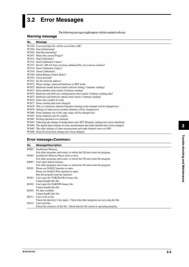
IM DA100-01E 3-3
3
Tro
ub
le-sho
otin
g an
d M
ainten
ance
3.2 Error Messages
The following messages might appear with the standard software.
Warning message
No. Message
W1102 Converted data file will be overwritten. OK?W3304 Start Initiliazeing?W3305 Start Reconstruting?W3451 Delete the current Project?W3315 Stop Calibration?W3316 Send Calibration Values?W3317 60 mV, 200 mV have not been calibrated.Do you want to continue?W3318 Store Calibration Values?W3319 Abort Calibration?W3320 Initial Balance Failed. Retry?W3332 Close network?W3333 Set the network address?W3671 Please change connected hardware to SET mode.W3672 Hardware model doesn't match software setting. Continue sending?W3673 Style numbers don't match. Continue sending?W3674 Hardware and Software configurations don't match. Continue sending data?W3675 Hardware and Software options don't match. Continue sending?W3676 Some data couldn't be read.W3677 Some existing data were changed.W3678 This is a reference channel.Channels refering to this channel will be changed too!W3679 Settings of other power module channels will be changed too!W3680 Some channels out of the copy range will be changed too!W3681 Some channels can't be copied.W3682 Writing operation was changed.W3683 Following the change of temperature unit, SET (Regular) settings have been initialized.W3684 The digital print settings of some measurement and math channels have been changed.W3685 The relay settings of some measurement and math channels were set OFF.W3686 Some Event/Action settings have been changed.
Error message<Common>
No. Message/Description
E0001 Insufficient Memory.Exit other programs and restart, or reboot the OS and restart the program.
E0002 Insufficient Memory.Please close at once.Exit other programs and restart, or reboot the OS and restart the program.
E0003 Can't open shared memory.Exit other programs and restart, or reboot the OS and restart the program.
E0101 Please use DAQ32 launcher to open.Please use DAQ32 Plus launcher to open.Run the program from the launcher.
E0201 Can't open.No YOKOGAWA binary file.Cannot handle this file.
E0202 Can't open.No DARWIN binary file.Cannot handle this file.
E0203 No data available.Cannot handle this file.
E0211 Can't write to file.Check the directory's free space. Check that other programs are not using the file.
E0212 Can't read file.Check the existence of the file. Check that the file system is operating properly.

IM DA100-01E3-4
No. Error/Corrective Action
E0213 Can't open file.Check the existence of the file. Check that the file system is operating properly.
E0214 Insufficient disk capacity.Free disk space.
E0215 No such file.Check the existence of the file.
E0216 Illegal file name.Use a different file name.
E0401 Communication error.The Logger Software cannot communicate while the setup software is communicating.Check that the DARWIN is turned ON, the communication module is being recognized by the DARWIN (DR/DC), and thecable is connected properly.In addition, check the following items according to the communication methods.For GPIBIs the address correct? Is the driver is properly installed? Is the GPIB card manufactured by NI?For EtherIs the address correct? Is the TCP/IP protocol installed in Windows? Is the Ether card properly installed?For RS-232-C, RS-422-A, and RS-485Is the baud rate correct? Is the port (COM1 to COM4) correct? Is the address correct (RS422)? Is the PC's serial portfunctioning? Is the correct type of cable being used?
E0404 Can't load DLL of GPIB.Correctly install the GPIB driver.
Error message<Launcher software>
No. Error/Corrective Action
E3401 Incorrect Password.Enter the correct password.
E3402 Passwords may not be blank.Enter the password.
E3403 Project names may not be blankEnter the project name.
Error message<Logger>
No. Error/Corrective Action
E3001 Incorrect File type or Version!The program will use default settings because the previous settings (such as display settings)could not be loaded.
3.2 Error Messages

IM DA100-01E 3-5
3
Tro
ub
le-sho
otin
g an
d M
ainten
ance
3.2 Error Messages
Error message<Software Configuration>
No. Error/Corrective Action
E3301 Failed to scan.Check that the DARWIN is turned ON, the communication module is being recognized by the DARWIN (DR/DC), and thecable is connected properly.In addition, check the following items according to the communication methods.For GPIBIs the address correct? Is the driver is properly installed? Is the GPIB card manufactured by NI?For EtherIs the address correct? Is the TCP/IP protocol installed in Windows? Is the Ether card properly installed?For RS-232-C, RS-422-A, and RS-485Is the baud rate correct? Is the port (COM1 to COM4) correct? Is the address correct (RS422)? Is the PC's serial portfunctioning? Is the correct type of cable being used?
E3302 Failed to reconstructSee the corrective actions for E3301.
E3303 Failed to initializeSee the corrective actions for E3301.
E3312 Select all ranges that has invalid values.Even though there is a range with an invalid calibration value, that range is not selected. Select the range with the invalidcalibration value and calibrate it.
E3313 Failed to calibrate.Check that the module is connected properly. Check the wiring, rated input, and etc.
E3314 For xxx is invalid.Enter the correct value.
E3331 There is no module. Or there are many modules.Several modules exist when setting up the network. Specify only one module.
E3337 The address is invalid.Properly set the combination of the IP address, subnet mask, and default gateway.
E3338 Can not set the network address.An error occurred while setting the address.
E3339 Modules not found.Set the module's dipswitch and turn DARWIN ON.Check that the cables are connected properly.
Error message<Historical Viewer >
No. Error/Corrective Action
E3101 Data is not exist.Valid data do not exist.
E3102 Channel is not existValid channel does not exist.
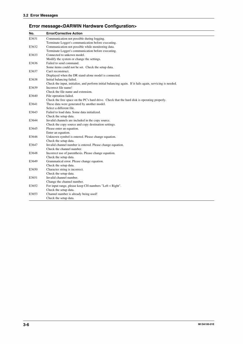
IM DA100-01E3-6
Error message<DARWIN Hardware Configuration>
No. Error/Corrective Action
E3631 Communication not possible during logging.Terminate Logger's communication before executing.
E3632 Communication not possible while monitoring data.Terminate Logger's communication before executing.
E3633 Connected to unkown model.Modify the system or change the settings.
E3636 Failed to send command.Some items could not be set. Check the setup data.
E3637 Can't reconstruct.Displayed when the DR stand-alone model is connected.
E3638 Initial balancing failed.Check the input, initialize, and perform initial balancing again. If it fails again, servicing is needed.
E3639 Incorrect file name!Check the file name and extension.
E3640 File operation failed.Check the free space on the PC's hard drive. Check that the hard disk is operating properly.
E3641 These data were generated by another model.Select a different file.
E3643 Failed to load data. Some data initialized.Check the setup data.
E3644 Invalid channels are included in the copy source.Check the copy source and copy destination settings.
E3645 Please enter an equation.Enter an equation.
E3646 Unknown symbol is entered. Please change equation.Check the setup data.
E3647 Invalid channel number is entered. Please change equation.Check the channel number.
E3648 Incorrect use of parenthesis. Please change equation.Check the setup data.
E3649 Grammatical error. Please change equation.Check the setup data.
E3650 Character string is incorrect.Check the setup data.
E3651 Invalid channel number.Change the channel number.
E3652 For input range, please keep CH numbers "Left < Right".Check the setup data.
E3653 Channel number is already being used!Check the setup data.
3.2 Error Messages
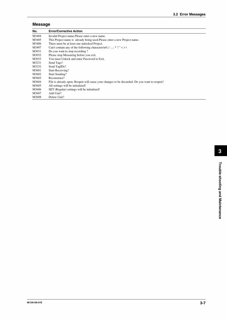
IM DA100-01E 3-7
3
Tro
ub
le-sho
otin
g an
d M
ainten
ance
Message
No. Error/Corrective Action
M3404 Invalid Project name.Please enter a new name.M3405 This Project name is already being used.Please enter a new Project name.M3406 There must be at least one unlocked Project.M3407 Can't contain any of the following characters\n\\ / : , ; * ? " < > |M3031 Do you want to stop recording ?M3032 Please stop Measuring before you exit.M3033 You must Unlock and enter Password to Exit.M3231 Send Tags?M3232 Send TagIDs?M3601 Start Receiving?M3602 Start Sending?M3603 Reconstruct?M3604 File is already open. Reopen will cause your changes to be discarded. Do you want to reopen?M3605 All settings will be initialized!M3606 SET (Regular) settings will be initialized!M3607 Add Unit?M3608 Delete Unit?
3.2 Error Messages

IM DA100-01E3-8
3.3 Trouble-Shooting
• When a message appears on the screen, first refer to the list of error messages described on page3-4.
• When servicing is necessary, contact your nearest sales representative. Addresses may be foundon the back cover of this manual.
Description Cause Action ReferencePage
No power-up; the status The used power supply lies Use the correct power supply. 2-25indicator does not light. outside the permissible range.
The status indicator is The communication module Configure the communication 2-4flashing in 1-second is not configured properly. module properly.intervals.
The status indicator is An internal error occurred. Turn the power OFF and 2-25flashing in an interval ON again.other than 1-second.
Connected sub-units are The power of the corresponding Turn the power ON. 2-25not recognized. sub-unit has been turned OFF.
The extension cables of the Connect the extension cables 2-13corresponding sub-unit are not properly.connected properly.
Connected modules are The corresponding module is not Connect the module properly. 2-4not recognized. properly connected.
Measurement values are The input does not conform Verify the input Chapter 4not correct. specifications. specifications.
The measurement mode is not Select a suitable measurement *1suited for this input. mode.The measurement range/span/scale Select a suitable measurement *1setting is not suited for this input. range/span/scale.Noise interference. Apply anti-noise measures. 2-29Input wiring is not correct. Wire the input properly. 2-15RJC settings are not correct. Enter the correct RJC settings. *1The environmental temperature Make sure the environmental 2-2is outside the specifications. temperature matches the
specifications.
*1 Refer to the User’s Manual for DAQ Software 32.
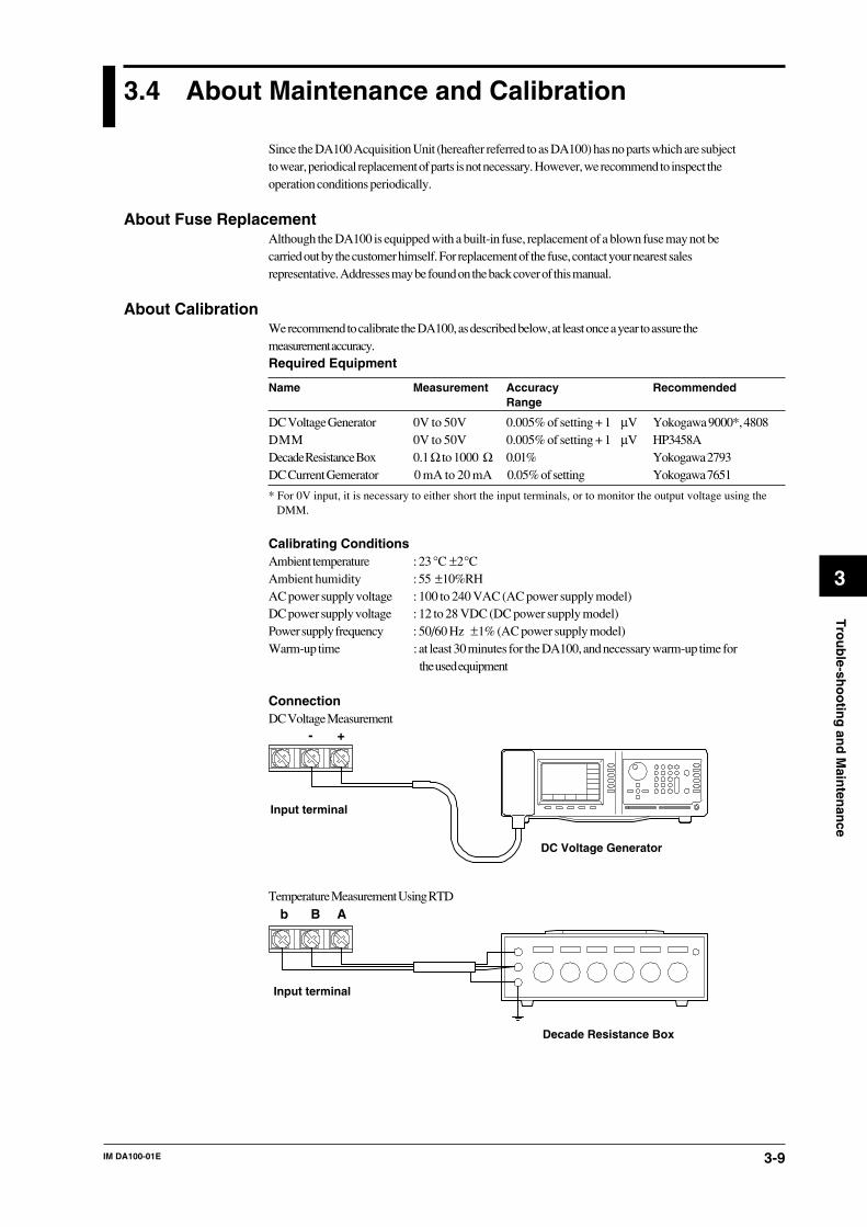
IM DA100-01E 3-9
3
Tro
ub
le-sho
otin
g an
d M
ainten
ance
3.4 About Maintenance and Calibration
Since the DA100 Acquisition Unit (hereafter referred to as DA100) has no parts which are subjectto wear, periodical replacement of parts is not necessary. However, we recommend to inspect theoperation conditions periodically.
About Fuse ReplacementAlthough the DA100 is equipped with a built-in fuse, replacement of a blown fuse may not becarried out by the customer himself. For replacement of the fuse, contact your nearest salesrepresentative. Addresses may be found on the back cover of this manual.
About CalibrationWe recommend to calibrate the DA100, as described below, at least once a year to assure themeasurement accuracy.Required Equipment
Name Measurement Accuracy RecommendedRange
DC Voltage Generator 0V to 50V 0.005% of setting + 1 µV Yokogawa 9000*, 4808DMM 0V to 50V 0.005% of setting + 1 µV HP3458ADecade Resistance Box 0.1Ω to 1000 Ω 0.01% Yokogawa 2793DC Current Gemerator 0 mA to 20 mA 0.05% of setting Yokogawa 7651
* For 0V input, it is necessary to either short the input terminals, or to monitor the output voltage using theDMM.
Calibrating ConditionsAmbient temperature : 23°C ±2°CAmbient humidity : 55 ±10%RHAC power supply voltage : 100 to 240 VAC (AC power supply model)DC power supply voltage : 12 to 28 VDC (DC power supply model)Power supply frequency : 50/60 Hz ±1% (AC power supply model)Warm-up time : at least 30 minutes for the DA100, and necessary warm-up time for
the used equipment
ConnectionDC Voltage Measurement
+-
DC Voltage Generator
Input terminal
Temperature Measurement Using RTDBb A
Decade Resistance Box
Input terminal

IM DA100-01E3-10
Temperature Measurement Using TCDC voltage input for DC voltage measurement substitutes for this.DC Current measurement
Apply the 20mA to channel 3
+–Input terminal
(CH3)
DC Current Generator
Short circuit between “+” and “–” terminal in channel 2+–
Input terminal
(CH2)
Strain measurementWire the strain gauge or the bridge box to the channel 2.
Jumper setting switch
ONOFF
No.1No.2No.3No.4No.5
A(+)
B(L)
C(-V)
D(H)
DU500-12/DU500-13 DU500-14
No.1OFF
No.2OFF
No.3OFF
No.4OFF
No.5ON
1 2 3 4
5 6 7 8
R4R2
R3R1
R2
R4
R3
R1
To R1 to R4, connect resisters with the specifications described below.
Calibration Resisters R1, R2, R3 Resister 4 Accuracy
ZERO 120.000 120.000 ±0.005%, ±0.3ppm/°C
2k SPAN 120.000 119.521 ±0.005%, ±0.3ppm/°C
20k SPAN 120.000 115.294 ±0.005%, ±0.3ppm/°C
200k SPAN 120.000 80.000 ±0.005%, ±0.3ppm/°C
Voltage or Current Output Using Retransmission ModuleWhen clibrating the retransmission module by confirming the output value, connect a DMM (aproduct corresponding to HP3458A) to the terminal to be calibrated.
Calibration Procedure1 Connect the equipment as described above.2 Verify that the calibration conditions are satisfied.3 Start the DAQ Software 32.4 Start the calibration program by clicking the [Calibration] icon.5 Carry out the calibration operations (A/D adjustment) conform the DAQ Software 32 User’s
Manual (IMDP12013-62E).
NoteInstead of operating the DAQ Software 32, calibration can also be carried out by communication interfaceusing the [XZ] command. For details concerning this command, refer to the User’s Manual “DataAcquisition Unit Communication Interface”, IMDA100-11E.
3.4 About Maintenance and Calibration

IM DA100-01E 4-1
4
Sp
ecification
s
4.1 DA100/ DS400/ DS600
Style Number DA100: S8DS400: S8DS600: S8
Available Modules for the DA100 Stand-alone TypeInput modules : universal (DC voltage, TC, RTD, contact), DCV/TC/DI, mA,
Power monitor, Strain, Pulse, DigitalAlarm output modules : 4-ch output (transfer contact) or 10-ch output (make contact);
the number of channels can be increased by adding modules.Communication interface modules : Selectable from GP-IB, RS-232C, RS-422-A/RS-485, and
EthernetDI/DO modules : 2-ch alarm output (transfer contact), 1-ch fail output and 12-
ch remote control input for only with /M1 oputionExtender module
· Number of modules which can be connected : 6 (of which at least one must be a communicationinterface module)
DI/DO module: not more than oneInput module: max. fourInput module + alarm output module + DI/DO module + communication interface module:max. six
Connecting the DA100 Expandable Type SubunitsTypes of subunitsSubunit DS400: four modulesSubunit DS600: six modulesNumber of subunits which can be connectedUp to six units can be connected (either DS400 or DS600)Connection methodUsing dedicated cables
Available Modules for the DA100 Expandable TypeMain unitAlarm output modules : 4-ch output (transfer contact) or 10-ch output (make
contact); the number of channels can be increased by addingmodules.
Communication interface modules : Selectable from GP-IB, RS-232C, RS-422-A/RS-485, andEthernet
DI/DO modules : 2-ch alarm output (transfer contact), 1-ch fail output and 12-ch remote control input for only with /M1 opution
Extender module· Number of modules which can be connected: 4 (of which at least one should be a communication
interface module)Alarm output module + DI/DO module: not more than threeInput module: cannot be connected.
Subunit (DS400/DS600)Input modules : universal (DC voltage, TC, RTD, contact), DCV/TC/DI, mA, Power
monitor, Strain, Pulse, DigitalAlarm output modules : 4-ch output (transfer contact) or 10-ch output (make contact); the
number of channels can be increased by adding modules.DI/DO modules : Alarm 2-ch output (transfer contact) and fail output moduleExtender module
· Number of modules which can be connected to one DS400: 4Input module + alarm output module + DI/DO module: max. four
· Number of modules which can be connected to one DS600: 6Input module + alarm output module + DI/DO module: max. six

IM DA100-01E4-2
4.1 DA100/ DS400/ DS600
ConstructionInstallation methodFloor mounting :Use the feet at the bottom of each unit.Direct panel mounting :Screw the unit directly to the panel at the specified points.DIN rail mounting :Use the dedicated mounting brackets.Rack mounting :Use the dedicated mounting brackets.
Regardless of which installation method you use, be sure to install the units in an uprightposition.
MaterialsSteel, aluminium alloy, plastics.Paint colorSlate grey light (equivalent to Munsell 0.8Y2.5/0.4)Lamp black (equivalent to Munsell 0.1PB4.6/0.2)External dimensionsStand-alone type main unit : approx. 422 (W) x 176 (H) x 100 (D) mmExpandable type main unit : approx. 336 (W) x 165 (H) x 100 (D) mmSubunit DS400 : approx. 336 (W) x 165 (H) x 100 (D) mmSubunit DS600 : approx. 422 (W) x 176 (H) x 100 (D) mmWeightStand-alone type main unit : approx. 1.1kg* (with 4 input modules + 1 alarm output module + 1
communication module installed: approx. 3.5kg)Expandable type main unit : 0.9kg* (with 4 input/output modules installed: approx. 2.5kg)Subunit DS400 : 0.9kg* (with 4 input/output modules installed: approx. 2.5kg)Subunit DS600 : 1.1kg* (with 6 input/output modules installed: approx. 3.5kg)
* represents the weight of each unit without modules installed.
InputMeasurement rangeRefer to 4.2 on page 4-6.Measurement intervalSelectable from 0.5, 1, 2, 3, 4, 5, 6, 10, 12, 15, 20, 30, 60s(with the 10-ch input module, filter: OFF, A/D integration period of 20ms or 16.7ms)stand-alone type : max. 40ch/s (when using the accessory standard software)expandable type : max. 300ch/500ms (when using the accessory standard software)A/D integration periodSelectable from 20ms (50Hz), 16.7ms (60Hz), 100ms (10Hz), or auto.However, AUTO does not function on the stand-alone DC power supply model nor on theextension type using the subunit of the DC power supply model. The factory initialization settingsare set to 20ms (50Hz) for the stand-alone DC power supply model and AUTO for the extensiontype DC power supply model.Number of inputsstand-alone type : up to 40expandable type : up to 300
Alarm Functions (the function of alarm output modules)Number of settingsUp to four settings can be made for each channel.Kinds of alarms: selectable from higher limit, lower limit, difference higher limit, differencelower limit, rising limit of rate of change, falling limit of rate of change.Time interval for the rate of change alarm: Can be set to 1 to 15 times the measurement interval(common to both rising and falling limits)Output modeActivating/de-activating selection, AND/OR mode selection, and output hold/non-holddesignation can be made (common to all channels).Number of alarm output pointsstand-alone type : 2 (in DI/DO modules) to 40 points.expandable type : Up to 30 points can be connected to the DA100 main unit (the number of alarm
points can be increased in module units). By connecting subunits, you canincrease the total number of alarm points (the number of alarm points can beincreased in module units).
Number of alarm output modules that can be connectedstand-alone type : up to three modules can be connected.expandable type : up to 4 modules can be conncected to the DA100 main unit, up to 6 modules
can be connected to one subunit.

IM DA100-01E 4-3
4
Sp
ecification
s
Standard Computation FunctionsComputation functionsDifference between input channels, linear scaling, moving averageScalingranges for which scaling can be set : DC voltage, TC, RTD, contactscaling range : –30000 to +30000Decimal point : can be set freelyMeasurement accuracy for scaling : Measurement accuracy for scaling (digits) = Measurement
accuracy (digits) x Scaling span (digits) / Measurementspan (digits) + 2 digits (numbers below the decimal pointare discarded).
(Example)measurement accuracy when the measured value is 5 V with the following settings: measurementrange: DCV 6 V, measurement span: 1.000 to 5.000 V, and scaling span: 0.000 to 2.000±(0.05 ×5+2)×2000/4000+2= ±3.125, measurement accuracy= ±4digits= ±0.004
Moving averageThe moving average results for between 2 to 64 scans are computed.
Optional Math Function (/M1 option)Computation typesFour arithmetical operations, SQR(square root), ABS(absolute value), LOG(common logarithm),LN(natural logarithm), EXP(exponent), statistical computation*, logical computation (AND, OR,NOT, and XOR), relational computation, exponentiation, previously-measured value reference,hold**, and reset* Statistical computation
CLOG: Computation process of simultaneously measured values within a group (total,maximum, minimum, average, and maximum - minimum)
TLOG: Computation process of a specific channel over time axis (total, maximum, minimum,average, and maximum - minimum)
Statistical computation interval: Set by the event/action function* *Hold
Temporary suspending of computation and temporary hold of the computed result. Duringstatistical computation, resume the computation from the hold point after the hold is released.
Number of channels for computing (Number of channels that can be allocated forcomputational purposes.)Stand-alone type: 30ch maximumExpandable type: 60ch maximumComputation intervalEvery measurement interval (except when the computation becomes too difficult to be processedevery measured interval, in which case an alarm is generated)Significant digits during computation10308
Significant digits of the computed result-9,999,999 to +99,999,999 (Decimal point can be set to have 1 to 4 digits on the right of thedecimal point)Input from communication interfaceDigital value (ASCII numerical array) input from the communication interface can be handled ascomputational dataComputation start/stopCan be controlled by communication commands and event/action function (such as remotecontrol signal, time specified, and alarm status)Other functions included in the math function
Remote RJCInput type: Thermocouple (TC)Accuracy: (Twice the measurement accuracy of the standard thermocouple input) +
(temperature difference between the terminal of the remote terminal section andthermocouple section for measuring the remote terminal temperature)
Thermocouple burnout: not selectableEvent/Action function
Can controll alarm ouput, timer and math executions with the alarm status, timer, etc.
4.1 DA100/ DS400/ DS600

IM DA100-01E4-4
Report Function (feature of the suffix code /M3; available with models with stylenumber 5 or higher)
Report Channels60 channels, from R01 to R60Types of ReportsHourly report: Hourly (every hour) statistical informationDaily report: Statistical information for a day (starting at a specified time)Monthly report: Statistical information for a month (starting at a specified date and time)These types of report making can be turned on or off separately.Output of the Results of Computing for ReportsThe DA100 main unit sends the results to a communication line.Output Formats of the Results of Computing for ReportsHourly report: Standard formatDaily report: Standard format or enhanced format
Standard format: results of computing daily reportsEnhanced format: results of computing daily reports plus results of computing hourly reports*
Monthly report: Standard format or enhanced formatStandard format: results of computing monthly reportsEnhanced format: results of computing monthly reports plus results of computing daily reports*
The enhanced format applies to either daily reports or monthly reports only.*: Either the average, instantaneous value or sum in each computing of a report.Types of Computing for ReportsAVE: Average, maximum and minimum over a preset intervalINST: Instantaneous value at the time of report makingSUM: Sum and cumulative sum over a preset interval
Sum Cumulative Sum
Hourly report Hourly sum Sum over 24 hours (resets at the time to make up a daily report)Daily report Daily sum Sum over a month (resets at the time to make up a monthly report)Monthly report Monthly sum Not applicable
Unit Conversion (SUM only)When inputs over a unit of time are integrated, the unit conversion compensates for anydiscrepancy in the unit of value arising between computed values depending on the measurementinterval applied.INTVL: no conversion; Σ (results of computing)/sec: converted to the sum of input in seconds; Σ (results of computing) × measurement interval/min: converted to the sum of input in minutes; Σ (results of computing) × measurement interval/60/hour: converted to the sum of input in hours; Σ (results of computing) × measurement interval/3600/day: converted to the sum of input in days; Σ (results of computing) × measurement interval/86400Time to Make ReportReference dates: 1st to 28th days of a monthReference times: 00:00 to 23:00Output Ranges of the Results of Computing for ReportsAVE: -9999999 to 99999999 (with the position of the decimal point dependent on themeasurement and computing channels assigned as report channels)INST: -9999999 to 99999999 (with the position of the decimal point dependent on themeasurement and computing channels assigned as report channels)SUM: seven digits for the mantissa and two digits for the exponentProcessing of Faulty DataAVE: Faulty data are excluded from computing. Data of positive and negative overflows,however, are included in the computing of the maximum and minimum.INST: Faulty data are included in computing.SUM: Faulty data are excluded from computing.
4.1 DA100/ DS400/ DS600

IM DA100-01E 4-5
4
Sp
ecification
s
Information on and Process in Case of Power Failure• The DR recorder adds × to the time on a printout provided upon recovery from a power failure.
It does not print the character, however, if it has been more than 12 hours since the powerfailure occurred.
• The DR recorder excludes data occurring during a power failure from its reports.• If the DR recorder recovers from a power failure after the time to make a report, it makes a
report immediately after the recovery.• If a power failure time is longer than 12 hours, the DR recorder stops report making even if the
power is restored.The recorder prints a report (for data acquired up to the power failure), however, immediatelyafter it recovers from the power failure.
Format of Output via CommunicationBinary
4.1 DA100/ DS400/ DS600

IM DA100-01E4-6
Communication Functions (the function of communication modules)GP-IB, RS-232C, RS-422-A/RS-485, Ethernet
Input/Output Functions (the function of DI/DO modules)2 alarm output, 1 fail output and 12 remote control input for only with /M1 option
Power SupplyRated supply voltageAC power supply: 100 to 240 VAC (free supply voltage selection)DC power supply: 12 to 28 VDCAC adapter (optional accessory): 100 to 240 VACPermitted supply voltageAC power supply: 90 to 250 VACDC power supply: 10 to 32 VDCAC adapter (optional accessory): 90 to 250 VACRated supply voltage frequencyAC power supply: 50/60 HzAC adapter (optional accessory): 50/60 HzMaximum power consumption:
· DA100 Stand-alone type (with 6 modules connected):in case of 100VAC input: max. 55VAin case of 240VAC input: max. 70VAin case of DC power supply: max. approx. 25VAin case of AC adapter (100VAC input): max. 55VAin case of AC adapter (240VAC input): max. 70VA
· DA100 Expandable type (with 4 modules connected):in case of 100VAC input: max. 45VAin case of 240VAC input: max. 55VAin case of DC power supply: max. approx. 25VAin case of AC adapter (100VAC input): max. 45VAin case of AC adapter (240VAC input): max. 55VA
· DS400 Subunit (with 4 modules connected):in case of 100VAC input: max. 45VAin case of 240VAC input: max. 55VAin case of DC power supply: max. approx. 25VAin case of AC adapter (100VAC input): max. 45VAin case of AC adapter (240VAC input): max. 55VA
· DS600 Subunit (with 6 modules connected):in case of 100VAC input: max. 55VAin case of 240VAC input: max. 70VAin case of DC power supply: max. approx. 25VAin case of AC adapter (100VAC input): max. 55VAin case of AC adapter (240VAC input): max. 70VAFuse Rating (The fuse may not be replaced by the customer.)Main UnitAC power supplyMaximum rated voltage/current: 250 V/2 A, Type: Time-lag, Standard: IEC/VDEDC power supplyMaximum rated voltage/current: 250 V/6.3 A, Type: Time-lag, Standard: UL/CSASubunitAC power supplyMaximum rated voltage/current: 250 V/2 A, Type: Time-lag, Standard: IEC/VDEDC power supplyMaximum rated voltage/current: 250 V/6.3 A, Type: Time-lag, Standard: UL/CSA
Normal Operation ConditionsSupply voltageAC power supply: 90 to 250 VACDC power supply: 10 to 32 VDCAC adapter (optional accessory): 90 to 250 VACSupply frequency50Hz ±2%, 60Hz ±2%
4.1 DA100/ DS400/ DS600

IM DA100-01E 4-7
4
Sp
ecification
s
Ambient temperature· Stand-alone type main unit/expandable type main unit
when floor-mounted : 0 to 50°Cwhen panel-mounted : 0 to 50°C
· DS400/DS600 Subunitwhen floor-mounted : 0 to 50°Cwhen panel-mounted : –10 to 60°CAmbient humidity20 to 80%RH for –10 to 40°C, 10 to 50%RH for 40 to 50°C, 5 to 30%RH for 50 to 60°C (no condensation)Vibration10 to 60Hz, 0.2m/s2
Shocknot allowedMagnetic field400 A/m max (50/60 Hz)PositionMount the unit left-right horizontally or vertically, as a general rule.Installation locationRoomInstallation heightAltitude up to 2,000 mInstallation category based on IEC 1010-1II*1
Pollution degree based on IEC 1010-12*2
Warm-up timeAt least 30 minutes after power switch-on.*1 Installation category is the specification of the inpuls withstanding voltage which is also called
as overvoltage category.*2 Polution degree is the level of foreign body adhesion such as the solid, liquid, and gas which
decrease the withstanding voltage, 2 means general indoor atmosphere.
Standard PerformanceReference operation conditionstemperature: 23±2°C; humidity: 55 ±10% RH; supply voltage 90 to 250 VAC (AC power supply)/10 to 32 VDC (DC power supply); supply frequency: 50/60 ±1% (AC power supply); warm-uptime: at least 30 minutes; when operating, the system must not adversely affect the operation ofother equipment.
Effect of Operating ConditionsAmbient temperature: variation for a temperature change of 10°C: within ±(0.1% of rdg + 1digit); ±(0.2% of span + 1 digit) for Cu10ΩVoltage variation: within ±1 digit over the range of 90 to 250 VAC (frequency 50/60 Hz, for ACpower supply) /10 to 32 VDC (for DC power supply)External magnetic field: variation with respect to AC (50/60 Hz) and DC magnetic fields of 400A/m: within ± (0.1% of rdg + 10 digits)Except for the power monitor module: within ±15% of rangeSignal source resistance: variation with respect to signal source resistance 1kΩ change(1)voltage
2 V range or below: within ±10µV6 V range or above: within ±0.1% of rdg
(2)thermocouplewithin ±10µV; however it must be within ±100µV when burnout is specified.
(3)RTDvariation with respect to change of 10Ω per wire (when all wires have the same resistancevalue)indication: within ±(0.1% of rdg + 1 digit)variation in indication with respect to a difference of 40 mΩ in the resistance betweenconductors (max, difference between 3 wires): approx. 0.1°C (in case of Pt100)
Mounting positionVariation when the unit is mounted horizontally on a panel: within ±(0.1% of rdg + 1 digit)
VibrationVariation when sinusoidal vibration of acceleration 0.2 m/s2 is applied for two hours in each ofthe 3 axial directions over a frequency range of 10 to 60 Hz: within ±(0.1% of rdg + 1 digit)
4.1 DA100/ DS400/ DS600

IM DA100-01E4-8
Transportation and Storage ConditionsThese refer to the environmental conditions existing during transportation and storage from thetime of shipment from the factory until commencement of use, and also during transportation andstorage in case of temporary non-use. If the environmental conditions are maintained within thespecified range, the unit will not incur permanent damage, and can be returned to a normalworking condition (re-adjustment may be required in some cases.)Ambient temperature–25 to 60 °CHumidity5 to 95% RHVibration10 to 60 Hz 4.9m/s 2 max.Shock392 m/s 2 max (in packed condition)
Other SpecificationsClockWith calendar function; be sure to set when the power is ON.Clock accuracy±100ppmSystem alarmContact output (when DI/DO is connected)Back-up of setting parametersLithium battery back-up (approx. 10 years), excluding clock function (time and date are reset to96/1/1 0:00 each time the power is turned ON.)Insulation resistanceAt least 20M Ω between each terminal and ground (at 500 VDC)Withstand voltage
· Between AC power supply terminal and case of DA100 main unit:1500 VAC (50/60Hz) for one minute
· Between AC power supply terminal and the case of the subunit:1500 VAC (50/60Hz) for one minute
· Between DC power supply terminal and the case of DA100 main unit:1000 VAC (50/60Hz) for one minute
· Between DC power supply terminal and the case of the subunit:1000 VAC (50/60Hz) for one minute
· Between input teminal and case of DA100 main unit:1500 VAC (50/60Hz) for one minute
· Between output teminal and case of DA100 main unit:2300 VAC (50/60Hz) for one minuteEMC Conformity Standards
· Emission EN55011: Class A· Immunity EN50082-2
IEC1000-4-2 Electrostatic Discharge Performance Criteria A*8kV(Air), 4kV(Contact)
IEC1000-4-3 Radiated fields Performance Criteria A*80 to 1000MHz, 10V/m
IEC1000-4-4 Fast Transients Performance Criteria BPower line 2kV, The others 1kV
IEC1000-4-6 Conducted Disturbance Performance Criteria A*0.15 to 80MHz, 10V
* Effect on accuracyUniversal input module and DCV/TC/DI input module±10% of range (except for 50V range)±20% of range (50V range)When the extension module is used±20% of range (except for 50V range)±40% of range (50V range)Strain input module±10% of range (except for 2000 µε range)±50% of range (2000 µε range)Other input module±10% of range
4.1 DA100/ DS400/ DS600

IM DA100-01E 4-9
4
Sp
ecification
s
4.2 Universal Input Module and DCV/TC/DI InputModule
Type, Number of Channels, Terminal Type and Minimum Measurement Interval
0.5s
0.5s
2s
2s
2s
2s
0.5s
0.5s
2s
2s
2s
2s
screw
clamp
screw
clamp
screw
clamp
screw
clamp
screw
clamp
screw
clamp
10ch
10ch
20ch
20ch
30ch
30ch
10ch
10ch
20ch
20ch
30ch
30ch
DU100-11
DU100-12
DU100-21
DU100-22
DU100-31
DU100-32
DU200-11
DU200-12
DU200-21
DU200-22
DU200-31
DU200-32
Kind
Universal
input
module
DCV/TC/DI
input
module
Type Number ofchannels
Terminaltype
Minimum measurementinterval
Style Number S1Input methodfloating unbalanced input, each channel mutually isolated (channel independent)The RTD range has a common potential (terminal b)A/D resolution±20000A/D integration time20ms (50Hz), 16.7ms (60Hz), 100ms (10Hz) or autoHowever, AUTO does not function if the instrument is the stand-alone DC power supply model,or the subunit (DS400/DS600) of the DC power supply model. (Selecting “AUTO” will set theA/D integration time to 20 ms (50 Hz)).Minimum measurement interval
No. of channels/1 module
20ms/16.7ms(50Hz/60Hz)
4s
5s
6s
3s
4s
4s
12s
15s
20s
10
20
30
*: 2s if the power monitor module is installed.
Low-pass filter OFF Low-pass filter ONFilter ON/OFF
A/D integration time
0.5s*
2s
2s
100ms(10Hz)
20ms/16.7ms(50Hz/60Hz)
100ms(10Hz)
Normal operating temperature/humidity–10 to 60°C20 to 80% RH for –10 to 40°C, 10 to 50% RH for 40 to 50°C, 5 to 30% RH for 50 to 60°C (nocondensation)Compensation for the reference junctionSwitchable internally or externally for each channel.Compensation accuracy for the reference junction(measured at 0°C, where the input terminals are balanced)Type R, S, B, W : ±1°CType K, J, E, T, N, L, U : ±0.5°CMaximum allowable input voltage2V DC or lower range, TC, RTD, DI (CONT) : ±10V DC6V DC or greater range, DI (LEVEL) : ±60V DCNormal mode voltagevoltage, TC : 1.2 times the rated range or less (at peak value, including 50 or 60Hz signal
component)RTD : 50 mV or lower (at peak value)Normal mode rejection ratio40dB or greater (50/60Hz ±0.1%)Common mode noise voltage250VAC rms (50/60Hz)Common mode rejection ratio120dB or greater (50/60Hz ±0.1%, 500Ω unbalanced, between the negative measurement terminaland ground)Maximum noise between channels150VAC rms (50/60Hz)

IM DA100-01E4-10
Measurement range and accuracyNote that RTD input is not possible for the DCV/TC/DI input module.Reference operation conditionstemperature: 23 ±2°C; humidity: 55 ±10% RH; supply voltage 90 to 250 VAC (AC power supply)/10 to 32 VDC (DC power supply); supply frequency: 50/60 ±1% (AC power supply); warm-uptime: at least 30 minutes; when operating, the system must not adversely affect the operation ofother equipment.
InputMeasuring(digital display)
DC Voltage
TC(Note that Accuracyof reference junctioncompensation is notconsidered).
RTD
High resolution RTD
Contact
20mV60mV200mV2V6V20V50VR
SBK
EJTLUNWKPvsAu7FePt100(1mA)Pt100(2mA)JPt100(1mA)JPt100(2mA)Pt50(2mA)Ni100(1mA)SAMANi100(1mA)DINNi120(1mA)J263*BCu10 GECu10 L&NCu10 WEEDCu10 BAILEYPt100(1mA)Pt100(2mA)JPt100(1mA)JPt100(2mA)Voltage input
Contact input
-20.000 to 20.000mV-60.00 to 60.00mV-200.00 to 200.00mV-2.0000 to 2.0000V-6.000 to 6.000V-20.000 to 20.000V-50.00 to 50.00V0.0 to 1760.0°C
0.0 to 1760.0°C0.0 to 1820.0°C-200.0 to 1370.0°C
-200.0 to 800.0°C-200.0 to 1100.0°C-200.0 to 400.0°C-200.0 to 900.0°C-200.0 to 400.0°C0.0 to 1300.0°C0.0 to 2315.0°C0.0 to 300.0K-200.0 to 600.0°C-200.0 to 250.0°C-200.0 to 550.0°C-200.0 to 250.0°C-200.0 to 550.0°C-200.0 to 250.0°C
-60.0 to 180.0°C-70.0 to 200.0°C0.0 to 300.0K-200.0 to 300.0°C
-140.00 to 150.00°C-70.00 to 70.00°C-140.00 to 150.00°C-70.00 to 70.00°COff for a voltage of less than 2.4V.On for a voltage of 2.4Vor more.(TTL)On/Off of contact
Type Measurement accuracyMaximumresolution
±(0.05% of rdg + 5digits)±(0.05% of rdg + 2digits)±(0.05% of rdg + 2digits)±(0.05% of rdg + 2digits)±(0.05% of rdg + 2digits)±(0.05% of rdg + 2digits)±(0.05% of rdg + 2digits)±(0.05% of rdg + 1°C)However,R,S:0 to 100°C,±3.7°C100 to 300°C,±1.5°CB:400 to 600°C,±2°C accuracyless than 400°C is not specified.±(0.05% of rdg +0.7°C)However,K attains an accuracy of±(0.05% of rdg. +1°C) within the range between -200 to -100°C.±(0.05% of rdg +0.5°C)However,J and L attain an accuracy of±(0.05% of rdg. +0.7°C) within the range between -200 to -100°C.
±(0.05% of rdg. +0.7°C) ±(0.05% of rdg. +1°C) ±(0.05% of rdg. +0.7K) ±(0.05% of rdg. +0.3°C)
±(0.05% of rdg. +0.3°C) ±(0.05% of rdg. +0.3°C)
±(0.05% of rdg. +0.3°C)
±(0.05% of rdg. +0.3K) ±(0.2% of rdg. +0.7°C)
±(0.05% of rdg. +0.3°C) ±(0.05% of rdg. +0.3°C) ±(0.05% of rdg. +0.3°C) ±(0.05% of rdg. +0.3°C) Off for a voltage of less than 2.4V.
On for a voltage of 2.4V or more.(TTL)On/Off of contact
Measurement range1µV10µV10µV100µV1mV1mV10mV
0.1°C
0.1K
0.1°C
0.1K
0.1°C
0.01°C
*1
*1
*1
*1
*1
*1
*1
*2
*2
*3
*4
*5
*5
*5
*5
*5
*6
*6
*7
*8
*8
*8
*8
*5
*5
*5
*5
*1 : R,S,B,K,E,J,T:ANSI,IEC 584,DIN IEC 584,JIS C 1602-1981*2 : L:Fe-CuNi,DIN43710,U:Cu-CuNi,DIN 43710*3 : N:Nicrosil-Nisil,IEC 584,DIN IEC 584*4 : W:W·5%RE-W·26%Re (Hoskins Mfg Co)*5 : Pt50:JIS C 1604-1981,JIS C 1606-1986 Pt100:JIS C 1604-1989,JIS C 1606-1989,IEC 751,DIN IEC 751 JPt100:JIS C 1604-1981,JIS C 1606-1989
*6 : SAMA/DIN*7 : McGRAW EDISON COMPANY*8 : ranges to which accuracy applies: Cu10 GE:-84.4 to 170.0°C, Cu10 L&N:-75.0 to 150.0°C, Cu10 WEED:-20.0 to 250.0°C, Cu10 BAILEY:-20.0 to 250.0°C
Noise rejectionrejection by integration type A/D, lowpass filter, or moving averaging.Cut-off frequency50/60/10HzInput resistanceMin. 10MΩ at 2V DC or lower, thermocouple rangeApprox. 1M Ω at 6V DC or higher.
4.2 Universal Input Module and DCV/TC/DI Input Module

IM DA100-01E 4-11
4
Sp
ecification
s
Insulation resistanceMin. 20MΩ at 500V DC between the input terminal and ground.Input bias currentmax. 10nADielectric strengthBetween input terminals : 1000V AC (50/60Hz) for one minuteBetween an input terminal and ground : 1500V AC (50/60Hz) for one minuteInput source resistanceDCV, TC : 2kΩ or lowerRTD : 10 Ω or lower per line (Pt100 Ω)
5 Ω or lower per line (Pt50 Ω) 1 Ω or lower per line (Cu10 Ω)
Temperature coefficientzero : 0.01% of range/ °Cfull span : 0.01% of range/ °C (0.02% of span/ °C for Cu10 Ω)Thermocouple burnoutDetected in a thermocouple range (On/Off) enabled, current of 4 µA, detectable pulse width ofapprox. 5ms2 kΩ or lower is considered “normal”100 k Ω or greater is considered “disconnected”Detection interval for thermocouple burnout2.5 sec. in a measurement period of 0.5 sec.2 sec. in a measurement period of 2 sec.Detection timing for thermocouple burnoutThe burnout condition is detected at each measurement interval. However, with a 10ch universalinput module connected and a measurement interval of 0.5sec, the minimum interval of theburnout detection becomes 2.5 sec.Power consumptionIncluded in the main unit or the subunit to which the module is to be installed.External dimensions and weight
Weight(kg)0.50.51.01.01.51.50.50.51.01.01.51.5
External dimensions(W)x(H)x(D) mmapprox.57x137x88approx.57x137x88approx.114x137x88approx.114x137x88approx.171x137x88approx.171x137x88approx.57x137x88approx.57x137x88approx.114x137x88approx.114x137x88approx.171x137x88approx.171x137x88
TypeDU100-11DU100-12DU100-21DU100-22DU100-31DU100-32DU200-11DU200-12DU200-21DU200-22DU200-31DU200-32
4.2 Universal Input Module and DCV/TC/DI Input Module

IM DA100-01E4-12
4.3 Specifications of mA-input Module
Style Number: S5Model Code, Number of Input Channels, Terminal Configuration and ShortestMeasurement Interval
Model Code Number of Channels Terminal Configuration Shortest Measurement Interval
DU300-11 10 Screw 0.5 sDU300-12 10 Clamp 0.5 s
Method of InputNon-balanced floating input with isolation between channels (separated channels)Resolution of A/D Conversion±20000Integral Time of A/D ConversionManual or automatic selection between 20 ms (50 Hz), 16.7 ms (60 Hz) and 100 ms (10 Hz)However, AUTO does not function if the instrument is the stand-alone DC power supply model,or the subunit (DS400/DS600) of the DC power supply model. (Selecting “AUTO” will set theA/D integration time to 20 ms (50 Hz)).Shortest Measurement Interval and Cutoff FrequencyWhen the lowpass filter is turned off:
Cutoff frequency: 50/60 Hz 10 HzShortest measurement interval: 0.5 s* 4 s*: 2s if the power monitor module is installed
When the lowpass filter is turned on:Cutoff frequency: 50/60 Hz 10 HzShortest measurement interval: 3 s 12 s
Withstanding VoltageAcross channels: 100 VA C, 1 minAcross output terminals and ground: 1,500 V AC, 1 min (excluding DU500-14)Normal Operating Temperature/Humidity Range-10˚ to 60˚C20 to 80% RH for an ambient temperature range of -10˚ to 50˚C; 10 to 50% RH for 40˚ to 50˚C; 5to 30% RH for 50˚ to 60˚C (non-condensing)Maximum Input Voltage5 V DCMaximum Normal-mode Noise Current24 mA (peak value, including 50- and 60-Hz signal components)Equivalent voltage of 2.4 VNormal Mode Rejection Ratio (Equivalent Voltage)40 dB minimum (50/60 Hz ±0.1%)Maximum Common Mode Noise Voltage250 V ACrms (50/60 Hz)Common Mode Rejection Ratio (Equivalent Voltage)120 dB minimum (50/60 Hz ±0.1%)Maximum Noise Across Channels150 V ACrms (50/60 Hz)Measuring Range/AccuracyMeasured under the following standards of operating conditions:Reference operation conditionstemperature: 23 ±2°C; humidity: 55 ±10% RH; supply voltage 90 to 250 VAC (AC power supply)/10 to 32 VDC (DC power supply); supply frequency: 50/60 ±1% (AC power supply); warm-uptime: at least 30 minutes; when operating, the system must not adversely affect the operation ofother equipment.
Measuring Range Measuring Accuracy MaximumResolution
-20.000 to 20.000 mA ±(0.25% of rdg. + 5 digits) 1 µA

IM DA100-01E 4-13
4
Sp
ecification
s
FilterLowpass filter or use of moving averageCutoff frequencies of lowpass filter: 50/60 Hz and 10 Hz and frequencies of their respectiveintegral multiplesInput Resistance100 ΩInsulation ResistanceAcross input terminals and ground: 20 M Ω minimum (500 V DC)Temperature CoefficientZero: 0.0125% of range/˚CSpan: 0.0125% of range/˚CPower ConsumptionIncluded in the value of a system's installed main unit or sub-unitDimensionsApproximately 57 (W) × 137 (H) × 88 (D) (mm)WeightApproximately 0.5 kgInstallation Category (Overvoltage Category)CAT II (IEC1010)
4.3 Specifications of mA-input Module

IM DA100-01E4-14
4.4 Specifications of Power Monitor Module
Style Number: S5Model Code, Use (Input Channels), Terminal Configuration and ShortestMeasurement Interval
Model Code Use (Input Channels) Terminal ShortestConfiguration Measurement Interval
DU400-12 Single-phase Clamp* 2 s(one channel each for voltage and current)
DU400-22 Three-phase Clamp*, ** 2 s(three channels each for voltage and current)
*: Two-terminal pressure clamping**: Not usable as an equivalent to three modules of single-phase use
Method of InputTransformer-isolated input, with isolation between channels (separated channels)Method of Measurement and ComputingDigital multiplicationMeasuring RangesVoltage: 25 or 250 VrmsCurrent: 0.5 or 5 AIn three-phase measurement or single-phase three-wire measurement, the current/voltage rangesare identical between the respective phases or lines (the current/voltage ranges are set in commonbetween the respective channels).Measured Frequency Range45 to 65 HzWiring MethodsDU400-12: Single-phase two-wireDU400-22: Single-phase two-wire, single-phase three-wire, three-phase three-wire (dual-voltage,dual-current), three-phase three-wire (triple-voltage, triple-current) and three-phase four-wireMeasured Data ItemsFor each module, a maximum of six data items can be selected from the effective voltage,effective current, active power, apparent power, reactive power, frequency, power factor andphase angle. The selected data items can then be assigned to channel numbers xx1 to xx6 to showthem on the display as well as record them. Restrictions apply to the combination of selectabledata items, however, depending on the method of input wiring.Conditions of Measurement• Measuring range for current and voltage inputs10% of the measuring range < current and voltage inputs ≤ 100% of the measuring range• V1 range is monitored in frequency measurement• All measurements are done relative to the frequency on a channel for V1 and, therefore, theresults of measurements are not guaranteed if the V1 input is out of the range noted above.• If the input apparent power falls below 10% of the span, the DR recorder cannot measure thephase and power factor (negative overflow).• A maximum of two scans' worth of data become invalid immediately after a change has beenmade to the measuring range and/or wiring.

IM DA100-01E 4-15
4
Sp
ecification
s
Measuring Accuracy and ResolutionReference operation conditionstemperature: 23 ±2°C; humidity: 55 ±10% RH; supply voltage 90 to 250 VAC (AC power supply)/10 to 32 VDC (DC power supply); supply frequency: 50/60 ±1% (AC power supply); warm-uptime: at least 30 minutes; when operating, the system must not adversely affect the operation ofother equipment.
Measured Data Item Measuring Accuracy Resolution
Effective voltage ± (0.5% of SPAN) 0.01 Vrms (for 25-V range), 0.1 Vrms (for 250-V range)
Effective current ± (0.5% of SPAN) 0.0001 Arms (for 0.5-A range), 0.001 Arms (for 5-A range)
Active power ± (1% of SPAN) φ = 0 0.01 W (for 12.5-W, 25-W and 37.5-W spans)± (2.5% of SPAN) 0 <| φ |≤ 30 0.1 W (for 125-W, 250-W and 375-W spans)± (5% of SPAN) 30 <| φ |≤ 80 1 W (for 1,250-W, 2,500-W and 3,750-W spans)
Apparent power ± (1% of SPAN) 0 ≤| φ |≤ 80 0.01 VA (for 12.5-VA, 25-VA and 37.5-VA spans)0.1 VA (for 125-VA, 250-VA and 375-VA spans)1 VA (for 1,250-VA, 2,500-VA and 3,750-VA spans)
Reactive power ± (5% of SPAN) 0 ≤| φ |< 60 0.01 Var (for 12.5-Var, 25-Var and 37.5-Var spans)± (2.5% of SPAN) 60 ≤| φ |≤ 80 0.1 Var (for 125-Var, 250-Var and 375-Var spans)
1 Var (for 1,250-Var, 2,500-Var and 3,750-Var spans)
Frequency ±0.1Hz 0.01Hz
Power factor ± (2% of SPAN) 0 ≤| φ |≤ 80 0.01
Phase angle ±5deg 0 ≤| φ |≤ 80 0.1deg
Measuring Ranges
Measured Data Item 25 V-0.5A 25 V-5 A 250 V-0.5 A 250 V-5 A
Effective voltage 0.00 to 25.00 V rms 0.00 to 25.00 V rms 0.0 to 250.0 V rms 0.0 to 250.0 V rmsVi (i = 1, 2, 3, 13, 0)
Effective current 0.0000 to 0.5000 A rms 0.000 to 5.000 A rms 0.0000 to 0.5000 A rms 0.000 to 5.000 A rmsIi (i = 1, 2, 3, 13, 0)
Active power –12.50 to 12.50 W –125.0 to 125.0 W –125.0 to 125.0 W –1250 to 1250 WP1, P2, P3
Active power –25.00 to 25.00 W –250.0 to 250.0 W –250.0 to 250.0 W –2500 to 2500 WP13
Active power –37.50 to 37.50 W –375.0 to 375.0 W –375.0 to 375.0 W –3750 to 3750 WP0
Apparent power 0.00 to 12.50 VA 0.0 to 125.0 VA 0.0 to 125.0 VA 0 to 1250 VAVA1, VA2, VA3
Apparent power 0.00 to 25.00 VA 0.0 to 250.0 VA 0.0 to 250.0 VA 0 to 2500 VAVA13
Apparent power 0.00 to 37.50 VA 0.0 to 375.0 VA 0.0 to 375.0 VA 0 to 3750 VAVA0
Reactive power 0.00 to 12.50 Var 0.0 to 125.0 Var 0.0 to 125.0 Var 0 to 1250 VarVar1, Var2, Var3
Reactive power 0.00 to 25.00 Var 0.0 to 250.0 Var 0.0 to 250.0 Var 0 to 2500 VarVar13
Reactive power 0.00 to 37.50 Var 0.0 to 375.0 Var 0.0 to 375.0 Var 0 to 3750 VarVar0
Power factor –1.00 to 1.00 –1.00 to 1.00 –1.00 to 1.00 –1.00 to 1.00PFi (i = 1, 2, 3, 13, 0)
Phase –80.0 to 80.0 deg –80.0 to 80.0 deg –80.0 to 80.0 deg –80.0 to 80.0 degPHi (i = 1, 2, 3, 13, 0)
Frequency 45.00 to 65.00 Hz 45.00 to 65.00 Hz 45.00 to 65.00 Hz 45.00 to 65.00 HzFREQ
4.4 Specifications of Power Monitor Module

IM DA100-01E4-16
Ranges of Indication
Measured Data Item 25 V-0.5A 25 V-5 A 250 V-0.5 A 250 V-5 A
Effective voltage 0.00 to 26.25 V rms 0.00 to 26.25 V rms 0.0 to 262.5 V rms 0.0 to 262.5 V rmsVi (i = 1, 2, 3, 13, 0)
Effective current 0.0000 to 0.5250 A rms 0.000 to 5.250 A rms 0.0000 to 0.5250 A rms 0.000 to 5.250 A rmsIi (i = 1, 2, 3, 13, 0)
Active power –13.75 to 13.75 W –137.5 to 137.5 W –137.5 to 137.5 W –1375 to 1375 WP1, P2, P3
Active power –27.50 to 27.50 W –275.0 to 275.0 W –275.0 to 275.0 W –2750 to 2750 WP13
Active power –41.25 to 41.25 W –412.5 to 412.5 W –412.5 to 412.5 W –4125 to 4125 WP0
Apparent power 0.00 to 13.75 VA 0.0 to 137.5 VA 0.0 to 137.5 VA 0 to 1375 VAVA1, VA2, VA3
Apparent power 0.00 to 27.50 VA 0.0 to 275.0 VA 0.0 to 275.0 VA 0 to 2750 VAVA13
Apparent power 0.00 to 41.25 VA 0.0 to 412.5 VA 0.0 to 412.5 VA 0 to 4125 VAVA0
Reactive power 0.00 to 13.75 Var 0.0 to 137.5 Var 0.0 to 137.5 Var 0 to 1375 VarVar1, Var2, Var3
Reactive power 0.00 to 27.50 Var 0.0 to 275.0 Var 0.0 to 275.0 Var 0 to 2750 VarVar13
Reactive power 0.00 to 41.25 Var 0.0 to 412.5 Var 0.0 to 412.5 Var 0 to 4125 VarVar0
Power factor –1.00 to 1.00 –1.00 to 1.00 –1.00 to 1.00 –1.00 to 1.00PFi (i = 1, 2, 3, 13, 0)
Phase –89.0 to 89.0 deg –89.0 to 89.0 deg –89.0 to 89.0 deg –89.0 to 89.0 degPHi (i = 1, 2, 3, 13, 0)
Frequency 41.00 to 69.00 Hz 41.00 to 69.00 Hz 41.00 to 69.00 Hz 41.00 to 69.00 HzFREQ
Output Data Items of Each Wiring Method
Output Data Item Single-phase Single-phase Three-phase Three-phase Three-phaseTwo-wire Three-wire Three-wire Three-wire Four-wire
(Dual-voltage, (Triple-voltage,Dual-current) Triple-current)
Effective voltage V V1 V1, V3 V1, V3 V1, V2, V3 V1, V2, V3V13: (V1+V3)/2 V13: (V1+V3)/2 V13: (V1+V3)/2 V0: (V1+V2+V3)/3
V0: (V1+V2+V3)/3
Effective current I I1 I1, I3 I1, I3 I1, I2, I3 I1, I2, I3I13: (I1+I3)/2 I13: (I1+I3)/2 I13: (I1+I3)/2 I0: (I1+I2+I3)/3
I0: (I1+I2+I3)/3
Active power W P1 P1, P3 P1, P3 P1, P2, P3 P1, P2, P3P13: P1+P3 P13: P1+P3 P13: P1+P3 P0: P1+I2+P3
Apparent power VA VA1 VA1, VA3 VA1, VA3 VA1, VA2, VA3 VA1, VA2, VA3VA13: VA1+VA3 VA13: VA1+VA3 VA13: VA1+VA3 VA0: VA1+VA2+VA3
Reactive power Var Var1 Var1, Var3 Var1, Var3 Var1, Var2, Var3 Var1, Var2, Var3Var13: Var1+Var3 Var13: Var1+Var3 Var13: Var1+VA3 Var0: Var1+Var2+Var3
Frequency FREQ FREQ FREQ FREQ FREQ FREQ
Power factor PF PF1 PF1, PF3 PF1, PF3 PF1, PF2, PF3 PF1, PF2, PF3PF13 PF13 PF13 PF13
Phase angle PH PH1 PH1, PH3 PH1, PH3 PH1, PH2, PH3 PH1, PH2, PH3PH13 PH13 PH13 PH13
4.4 Specifications of Power Monitor Module

IM DA100-01E 4-17
4
Sp
ecification
s
Continuously Applicable Maximum Voltage and CurrentVoltage: 250 VrmsCurrent: 5 ArmsCrest Factor3 maximum (600 Vpeak)Maximum Common Mode Voltage250 VrmsCommon Mode Voltage Rejection Ratio (Voltage and Current Ranges)0.02% of span (when 250 V 45 to 65 Hz is imposed)Input ResistanceVoltage input: 300 k Ω minimum for AC voltagesCurrent input: 1 Ω maximum for AC currentsFilterMoving averageWattage CalculationUse of /M1 computing functionInsulation ResistanceAcross output terminals and ground: 20 M Ω minimumWithstanding VoltageAcross output terminals and ground: 2,300 V AC (50/60 Hz), 1 minNormal Operating Temperature/Humidity Ranges0˚ to 50˚C20 to 80% RH for an ambient temperature range of 0˚ to 40˚C; 10 to 50% RH for 40˚ to 50˚C(non-condensing)Power ConsumptionIncluded in the value of a system's installed main unit or sub-unitDimensionsApproximately 57 (W) × 137 (H) × 99 (D) (mm)WeightApproximately 0.5 kgInstallation Category (Overvoltage Category)CAT II (IEC1010)
4.4 Specifications of Power Monitor Module

IM DA100-01E4-18
4.5 Specifications of Strain Input Module
Style Number: S5Model Code, Number of Input Channels, Terminal Configuration, ShortestMeasurement Interval and Values of Built-in Resistors
Model Code Number of Input Terminal Shortest Measurement Built-inChannels Configuration Interval Resistor
DU500-12 10* Clamp 0.5 s 120 ΩDU500-13 10* Clamp 0.5 s 350 ΩDU500-14 10* NDIS** 0.5 s External
*: Requires the space of two slots.**: Recommended by the Japanese Nondestructive Inspection Association
Method of InputNon-balanced floating input, with isolation between channels (separated channels)Resolution of A/D ConversionEquivalent to reading on 20000 full scaleIntegral Time of A/D ConversionManual or automatic selection between 20 ms (50 Hz), 16.7 ms (60 Hz) and 100 ms (10 Hz)However, AUTO does not function if the instrument is the stand-alone DC power supply model,or the subunit (DS400/DS600) of the DC power supply model. (Selecting “AUTO” will set theA/D integration time to 20 ms (50 Hz)).Types of InputSignals from strain gauge or strain-gauge sensorConnection MethodsSingle-gauge, opposed-side two-gauge, adjacent-side two-gauge or four-gauge configuration(Configured with built-in DIP switches for DU500-12 and DU500-13)Applicable Gauge Resistance100 to 1,000 ΩThe DU500-12 and DU500-13 modules contain 120- Ω and 350- Ω resistors, respectively.Bridge VoltageFixed to 2 V DC ( ±5% accuracy with a correction function)Gauges2.00 (with scaling capability)BalancingAutomaticRange of BalancingEquivalent to ±10,000 µε (for single-gauge method)Measuring Ranges and AccuraciesReference operation conditionstemperature: 23 ±2°C; humidity: 55 ±10% RH; supply voltage 90 to 250 VAC (AC power supply)/10 to 32 VDC (DC power supply); supply frequency: 50/60 ±1% (AC power supply); warm-uptime: at least 30 minutes; when operating, the system must not adversely affect the operation ofother equipment.
Gauge Method Measuring Range AccuracyResolution
Single-gauge –2000 to 2000 µε 0.5% of Range 0.1 µε–20000 to 20000 µε 0.3% of Range 1 µε–200000 to 200000 µε 0.3% of Range 10 µε
Two-gauge –1000 to 1000 µε 0.5% of Range 0.1 µε10000 to 10000 µε 0.3% of Range 1 µε–100000 to 100000 µε 0.3% of Range 10 µε
Four-gauge –500 to 500 µε 0.5% of Range 0.1 µε–5000 to 5000 µε 0.3% of Range 1 µε–50000 to 50000 µε 0.3% of Range 10 µε
The Accuracies and Resolutions of the DU500-12 and DU500-13 models, do not include the influence of theinternal-and contact-resistance of the jumper setup switch.

IM DA100-01E 4-19
4
Sp
ecification
s
Accuracy of Bridge Resistors±0.01%, ±5 ppm/˚C (excludes contact resistance of the jumper setup switch)Contact Resistance of the Jumper Setup Switch100 m Ω maximumInput Resistance10 MΩ minimumFilterThird-order sinc filter, moving-averageWithstanding VoltageAcross channels: 50 V DCAcross output terminals and ground: 1,500 V AC, 1 min (excluding DU500-14)Normal Operating Temperature/Humidity Range0˚ to 50˚C20 to 80% RH for an ambient temperature range of 0˚ to 40˚C; 10 to 50% RH for 40˚ to 50˚C(non-condensing)Power ConsumptionIncluded in the value of a system's installed main unit or sub-unitDimensionsDU500-12/DU500-13: Approximately 114.3 (W) × 137 (H) × 88 (D) (mm)DU500-14: Approximately 114.3 (W) × 137 (H) × 77 (D) (mm)WeightApproximately 1 kgInstallation Category (Overvoltage Category)CAT II (IEC1010)AccessoryBridge box: 319300 (120 Ω)
4.5 Specifications of Strain Input Module

IM DA100-01E4-20
4.6 Specifications of Pulse Input Module
Style Number: S5Model Code, Number of Input Channels, Terminal Configuration and ShortestMeasurement Interval
Model Code Number of Channels Terminal Configuration Shortest MeasurementInterval
DU600-11 10 Screw 0.5 s*
*: The interval between data updates is fixed to one second.
Method of InputPotential with reference to the shared voltage of the COMMON line within the same moduleTypes of InputVoltage-free contact or open collector (TTL or transistor)Measurement ModesRATE (instantaneous count mode): Outputs the prescaled value of the count of pulses imposedover the last one-second interval of measurement.GATE (instantaneous turn-on time mode): Outputs the prescaled values of the contact's turn-on(make) and turn-off (break) times (on = 1; off = 0) over the last one-second interval ofmeasurement.Note
The computing function (computational expression: TLOG.PSUM (XXX)) should be used whenintegrating an every-second count or turn-on time (maximum count/turn-on time: 99999999).
Input Range0 to 6,000 pulses, or 0 to 10 pulses (if the filter is on) for voltage-free input.Ratio of make at input: 35 to 65% at the maximum frequency (ratio of make = closed-contacttime/(closed-contact time + open-contact time) × 100)Minimum input pulse width: 60 µs (whether the contact is closed or open)Measuring AccuraciesReference operation conditionstemperature: 23 ±2°C; humidity: 55 ±10% RH; supply voltage 90 to 250 VAC (AC power supply)/10 to 32 VDC (DC power supply); supply frequency: 50/60 ±1% (AC power supply); warm-uptime: at least 30 minutes; when operating, the system must not adversely affect the operation ofother equipment.Count: ±1 pulse (for integration, ±(1 scan + 1 second) at the start of measurement and ±(1 scan +1.5 seconds) at the end of measurement)Turn-on time: ±100-ppm accuracy for judgment of one-second-interval sampling; for integration,±(1 second + 1 scan) at the start of measurement and ±(100 ppm of rdg. + 1.5 seconds + 1 scan) atthe end of measurementModule-to-module error: ±(3 seconds + 1 pulse) for count and ±(200 ppm + 3 seconds) for turn-on timeNote
It takes a maximum of 2 seconds for normal measured values to be output when the power is turned on,when the measurement mode is changed or when the setting for turning on/off the filter is changed. TheDR recorder indicates a value representative of “no data” ( on the display, or 8005H for thebinary format or a faulty data value for the ASCII format in the case of output to the communication line)until the normal measured values are output.
FilterRemoves chatter of up to 5 ms (can be turned on or off on a channel basis).Input Signal LevelsOpen contact: 200 Ω maximumClosed contact: 100 k Ω minimumNormal Operating Temperature/Humidity Range0˚ to 50˚C20 to 80% RH for an ambient temperature range of 0˚ to 40˚C or 10 to 50% RH for 40˚ to 50˚C(non-condensing)Normal Operating Magnetic-field Strength400 A/m maximum

IM DA100-01E 4-21
4
Sp
ecification
s
Maximum Input Voltage5 V DCSignal Source Ratings15 V DC, 30 mA minimumInsulation ResistanceAcross input terminals and ground: 100 M Ω minimum (500 V DC)Withstanding VoltageAcross output terminals and ground: 500 V DC, 1 min (no channel-to-channel isolation)Power ConsumptionIncluded in the value of a system's installed main unit or sub-unitDimensionsApproximately 57 (W) × 137 (H) × 68 (D) (mm)WeightApproximately 0.3 kgInstallation Category (Overvoltage Category)CAT II (IEC1010)
4.6 Specifications of Pulse Input Module

IM DA100-01E4-22
4.7 Specifications of Digital Input ModuleStyle Number: S8Model, Number of Channels, Terminal Type and Minimum Measurement Interval
Model Number of Channels Terminal Type Minimum Measurement Interval
DU700-11 10 Screw 05s
Input methodFloating unbalanced input, each channel mutually isolated (channel independent)A/D resolution±20000A/D integration time20 ms (50 Hz), 16.7 ms (60 Hz), 100 ms (10 Hz) or auto(Except, auto switch does not function on the stand-alone DC power supply model or the subunit(DS400/DS600) of a DC power supply model.)Minimum measurement intervalLow-pass filter OFF
Cut-off frequency 50/60Hz 10Hz
Minimum measurement interval 05 s 4 s
Low-pass filter ON
Cut-off frequency 50/60Hz 10Hz
Minimum measurement interval 3 s 12 s
Normal operating temperature/humidity20 to 80% RH for –10 to 40°C, 10 to 50% RH for 40 to 50°C, 5 to 30% RH for 50 to 60°C (nocondensation)Magnetic field400A/m max (50/60Hz)Maximum allowable input voltageCONT (Contact input) : ±10 V DCLEVEL (Voltage input) : ±60 V DCCommon mode noise voltage250 V AC rms (50/60 Hz)Maximum noise between channels150 V AC rms (50/60 Hz)ActionAt normal operating temperature/humidityVoltage input (LEVEL) : Off for a voltage of less than 24V.
ON for a voltage 2.4 V or more.Contact input (CONT) : On/Off of contact.**: Contact resistance ON ; 2 k Ω or less, OFF ; 100 k Ω or moreNoise rejectionRejection by integration type A/D, lowpass filterCut-off frequency50/60/10HzInput resistanceCONT : Min. 10 M ΩLEVEL : Approx. 1 M ΩInsulation resistanceMin. 20 MΩ at 500 V DC between the input terminal and ground.Dielectric strengthBetween input terminals : 1000 V AC (50/60 Hz) for one minuteBetween an input terminal and ground : 1500 V AC (50/60 Hz) for one minuteInput source resistanceLEVEL : 2 kΩ or lowerPower consumptionIncluded in the main unit or the subunit to which the module is to be installed.

IM DA100-01E 4-23
4
Sp
ecification
s
DimensionsApproximately 57(W) x 137(H) x 68(D) (mm)Weight0.5 kgInstallation Category (Overvoltage Category)CAT II (IEC 1010)
4.7 Specifications of Digital Input Module

IM DA100-01E4-24
4.8 Alarm Output Module
Type, Number of outputs, Contact mode, Terminal type
Contact mode
Transfer contact (NO-C-NC)
Make contact (NO-C)
screw
screw
Terminal typeType Number of outputs
DT200-11
DT200-21
4
10
Style Number S1Normal operating temperature/humidity0 to 50 °C20 to 80% RH for 0 to 40 °C, 10 to 50% RH for 40 to 50 °C (no condensation)Output updating rateevery measurement intervalContact modeMake contact : normal open/common contact typeTransfer contact : normal open/common/normal close typeActivate/de-activateswitchableHold/non-holdswitchableReflash alarmup to 6 contacts can be specified.Contact capacity250V DC/0.1A (with a resistor load)250V AC/2A (with a resistor load)30V DC/2A (with a resistor load)Dielectric strengthBetween the output terminal and ground: 2300V AC (50/60Hz) for one minute.Power consumptionIncluded in the main unit or the subunit to which the module is to be installed.External dimensions and weight
Weight(kg)0.30.35
External dimensions(W)x(H)x(D) mmapprox.57x137x67.9approx.57x137x67.9
TypeDT200-11DT200-21

IM DA100-01E 4-25
4
Sp
ecification
s
4.9 DI/DO Module
General SpecificationsStyle Number S1Terminal typescrewNormal operating temperature/humidity0 to 50 °C20 to 80% RH for 0 to 40 °C, 10 to 50% RH for 40 to 50 °C (no condensation)Power consumptionIncluded in the main unit or the subunit to which the module is to be installed.Dielectric strengthBetween the output terminal and ground: 2300V AC (50/60Hz) for one minute.External dimensionsApprox. 57 (W) x 137 (H) x 67.9 (D) mmWeight0.35kg
DO: Alarm outputOutput update rateevery measurement intervalContact modeTransfer contact (NO-C-NC)Activate/de-activateswitchableHold/non-holdswitchableReflash alarmcan be setContact capacity250V DC/0.1A (with a resistor load)250V AC/2A (with a resistor load)30V DC/2A (with a resistor load)
DO: Failure outputFunctionsThe output terminal for a failure becomes de-activated when an error is detected in the system ofthe DA100 main unit or the DA/DR subunit which is connected to the module.Contact modeTransfer contact (NO-C-NC)Activate/de-activatenot switchableContact capacity250V DC/0.1A (with a resistor load)250V AC/2A (with a resistor load)30V DC/2A (with a resistor load)
DI: Remote contol funtion (can be used with the oputional math function)FunctionThe alarm status, timer and math executions can be controlled by contact input.InputNo voltage contact, open-collector driven by a TTL or transistorRated input voltage: 0 to 5 V DC (input impedance: 4.7k Ω, 5V DC pull up)Maximum input voltage: –2 to 7 V DCInput conditions
ON voltage: 0.5V max. (30 mA DC)Leakage current at OFF state: 0.25 mA max.
Duration of input signal: one second or longer (input signal detection interval: approx. 0.5 s)

IM DA100-01E4-26
4.10 Communication Interface Module
TypeDescription
GP-IB
RS-232C
RS-422-A/RS485
Ethernet
Type
DT300-11
DT300-21
DT300-31
DT300-41
General SpecificationsPower consumptionIncluded in the main unit or the subunit to which the module is to be installed.Normal operating temperature/humidity0 to 50 °C20 to 80% RH for 0 to 40 °C, 10 to 50% RH for 40 to 50 °C (no condensation)
GP-IB ModuleStyle Number S4Electrical and mechanical specificationsconform to IEEE Standard 488-1978CodeISO (ASCII) codeAddress0 to 15Functions
· Talker functionsaddressable: Output of measurement values (ASCII, binary); output of setting parameters (ASCII)
· Listener functionsSetting of measurement conditions, control sof starting and stopping measurement, specifyingcauses of interrupts (excluding setting and control of power on/off)Causes of interruptsSyntax error, completion of A/D conversion and data acquisiton error (occurs only when usingoptional math function)External dimensionsApprox. 57 (W) × 137 (H) × 53.8 (D) mmWeight0.25kg
RS-232-C ModuleStyle Number S8Electrical and mechanical specificationsconform to standard EIA RS-232CConnection methodpoint-to-pointCommunication methodhalf-duplexSynchronization modeSynchronous mode (synchronized by a start and a stop bit)Baud rate150, 300, 600, 1200, 2400, 4800, 9600, 19200, 38400 bpsStart bitFixed at 1 bitData length7 or 8 bits, selectableParitySelectable from even, odd, or noneStop bit1 or 2, selectable

IM DA100-01E 4-27
4
Sp
ecification
s
Transfer distancemax. 15 mConnectorD-sub 25pinHandshakinghardware : transmission and reception control by ‘DTR’’ ‘RTS’, ‘CTS’ signal enabled.Software : transmission control by ‘XON’ and ‘XOFF’ enabled.Capacity of receiving buffer200 bytesEscape sequencefor reception onlyFunctions
· Talker functionsOutput of measurement data (ASCII, binary) and setting parameters (ASCII)
· Listener functionsSetting of measurement conditions, control of measurement start and stop (excluding the settingand control of power on/off), specifying causes of ‘ESC S’ (output of a status byte)Contents of ‘status’Syntax error, completion of A/D conversion and data acquisiton error (occurs only when usingoptional math function)External dimensionsApprox. 57 (W) × 137 (H) × 53.8 (D) mmWeight0.25kg
RS-422-A/RS-485 ModuleStyle Number: S8Electrical and Mechanical SpecificationsCompatible with EIA RS-422-A and EIA RS-485Connection1 : n multi-drop (n = 16 for RS-422-A; 31 for RS-485)CommunicationHalf-duplexSynchronizationStart-stop (by means of start and stop bits)Baud RatesSelected from 300, 600, 1200, 2400, 4800, 9600, 19200, 38400 bpsStart BitFixed to one bitData LengthSelected from 7 and 8 bitsParitySelected from Even, Odd and NoneStop BitsSelected from 1 and 2 bitsConnectorSix-line, screw-terminal (with 4-mm screws)Minimum Response TimeSelected from 0, 10, 20, 50 and 100 msLength of Receive Buffer250 bytesEscape SequenceTrigger, status call, open, closeElectrical CharacteristicsSDA, SDB, RDA, RDB and SG lines, where the signal-line terminal is functionally isolated fromthe module's internal circuitry.
4.10 Communication Interface Module

IM DA100-01E4-28
Communication Distance1.2 km maximumTerminating ResistorBuilt-in (120 Ω, 1 W), selected with a slide switchDimensionsApproximately 57 (W) × 137 (H) × 68.2 (D) (mm)WeightApproximately 0.3 kg
EthernetStyle number : S8Electrical and Mechanical specificationsConforms to IEEE802.3 (Frames are not supported.)Communication methodEthernetTransmission specifications10BASE-T (CSMA/CD, 10Mbps, Baseband)Transmission speed10 MbpsProtocolsTCP, IP, UDP, ARP, ICMPMaximum number of connections4Input dataASCIISupporting RS-232-C commandsOutput dataASCII, BinaryExternal dimensionsApprox 57(W) ×137(H) × 57(D) (mm)Weight0.3 kg
4.10 Communication Interface Module

IM DA100-01E 4-29
4
Sp
ecification
s
4.11 Retransmission Module
Style number: S10Model code, number of output points, output signal, output range, terminal type
Model Number of Output Points Output Signal Output Range Terminal Type
DT500-11 10ch 1 to 5 VDC 0.8 to 5.4 VDC screwDT500-21 2ch 4 to 20 mADC 3.2 to 21.6 mADC screw
Load resistanceDT500-11: 10 k Ω or more DT500-21: 600 Ω or lessLoad capacitance0.22 mF or lessLoad Inductance100 mH or lessOutput accuracy (under reference operation conditions)* * *±0.2% of SpanCalibration periodOne yearTemperature coefficient0.01% of Span/ °CHighest resolutionDT500-11: 12 bit (approx. 1.43 mV) DT500-21: 12 bit (approx. 5.86 mA)Normal operating temperature/humidity0 to 50 °C20 to 80%RH for 0 to 40 °C and 10 to 50%RH for 40 to 50 °C (no condensation)Update interval of output valuesSame as the measurement intervalHowever, depending on the number of modules that are connected, the specified computationalexpression, and the condition of the external storage medium, the output value may not beupdated at the measurement interval.Output during SKIPDT500-11; 0.05 V or lessDT500-21; 0.15 mA or lessOutput filterFirst order low pass filter in 10 levels (time constant in the range 4 ms to 3 s) can be applied to theoutput value with respect to the changes in the measured data, computed data, and thecommunication input value.Insulation resistanceAcross output terminals and ground: 20 M Ω or more (500 VDC)Withstand voltageAcross output terminals and ground: 500 VDC for 1 minuteAcross channelsDT500-11: No insulation across channels (COM shared)DT500-21: Insulation across channels (500 VDC, 1 minute)Power consumptionIncluded in the value of the main unit or sub-unit.DimensionsApproximately 57(W) ×137(H) ×68(D) mmWeightDT500-11: Approximately 0.35 kgDT500-21: Approximately 0.3 kgInstallation category (overvoltage category)CAT II (IEC1010)

IM DA100-01E4-30
4.12 Specifications of Extension Module andExtension Base
Model CodesExtension module: DV100-011Extension base: DV100-012Units to Which Extension Modules Are ConnectedDA100 (stand-alone model), DS400/DS600 (for expandable model of DA100)Input Modules Connectable to an Extension BaseUniversal input modules: DU100-11 or DU100-12, 10 channelsDCV/TC/DI input modules: DU200-11 or DU200-12, 10 channelsMaximum Mountable Number of Extension ModulesOne each on a sub-unitMaximum Connectable Number of Extension BasesUp to three to each extension module. It is not possible, however, to wire extension bases in sucha manner that the total number of modules already mounted on the sub-unit and the extensionbases being wired exceeds the maximum number of modules allowed for mounting on the sub-unit.Overall Length of Wiring30 m maximum(The maximum overall length of cable measured from the extension module to the farthestextension base)Normal Operating Temperature/Humidity Range-10˚ to 60˚C20 to 80% RH for an ambient temperature range of -10˚ to 40˚C; 10 to 50% RH for 40˚ to 50˚C; 5to 30% RH for 50˚ to 60˚C (non-condensing)Insulation ResistanceDepends on the input module installed.Withstanding VoltageDepends on the input module installed.Power ConsumptionIncluded in the value of a system's installed main unit or sub-unitDimensionsExtension module: Approximately 57 (W) × 137 (H) × 49.5 (D) (mm)Extension base: Approximately 114.8 (W) × 152.7 (H) × 43.7 (D) (mm) (without shoe plates)
Approximately 114.8 (W) × 171.5 (H) × 143.3 (D) (mm) (with shoe plates)WeightExtension module: approximately 176 gExtension base: approximately 345 g

IM DA100-01E 4-31
4
Sp
ecification
s
4.13 Dimensional Drawings
DA100 Stand-alone type / Subunit DS600Unit:mm
156
168
20
100422
145
2216255
176
115
369
20
DA100 Expandable type / Subunit DS400
165
40
100336
145
223208
5050
115
290
20
If not specified, the tolerance is ±3%. However, in cases of less than 10mm, the tolerance is±0.3mm.

IM DA100-01E4-32
10ch Universal input module / 10ch DCV/TC/DI input module / Digital input moduleUnit:mm
137
88
57
20ch Universal input module / 20ch DCV/TC/DI input module
114.3
137
88
30ch Universal input module / 30ch DCV/TC/DI input module
171.6
137
88
If not specified, the tolerance is ±3%. However, in cases of less than 10mm, the tolerance is±0.3mm.
4.13 Dimensional Drawings

IM DA100-01E 4-33
4
Sp
ecification
s
mA-input Moduleunit : mm
57
8868
137
Power Monitor Module
5799
78
137
Strain Input Module (with built-in bridge resistors)
114.3 6888
137
Unless otherwise specified, the dimensional tolerance is ±3% (though ±0.3% for fractions smallerthan 10 mm).
4.13 Dimensional Drawings

IM DA100-01E4-34
Strain Input Module (with NDI terminals)unit : mm
114.3 5777
137
Pulse Input Module
57
6848
137
Digital Input Module
137.
4
88
57
Unless otherwise specified, the dimensional tolerance is ±3% (though ±0.3% for fractions smallerthan 10 mm).
4.13 Dimensional Drawings

IM DA100-01E 4-35
4
Sp
ecification
s
DI/DO Module / Alarm output moduleUnit:mm
137
68
57
GP-IB Module
137
54
57
RS-232C Module
137
54
57
If not specified, the tolerance is ±3%. However, in cases of less than 10mm, the tolerance is±0.3mm.
4.13 Dimensional Drawings

IM DA100-01E4-36
4.13 Dimensional Drawings
RS-422-A/RS-485 ModuleUnit:mm
57
69
137
Ethernet Module
57
35.756.7
136.
7
57
35.756.7
136.
7
If not specified, the tolerance is ±3%. However, in cases of less than 10mm, the tolerance is±0.3mm.
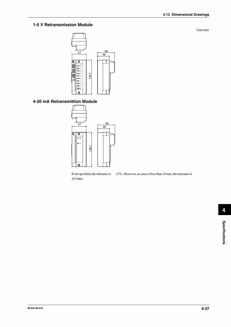
IM DA100-01E 4-37
4
Sp
ecification
s
4.13 Dimensional Drawings
1-5 V Retransmission ModuleUnit:mm
57 6948
136.
7
4-20 mA Retransmittion Module
57 6948
136.
7
If not specified, the tolerance is ±3%. However, in cases of less than 10 mm, the torerance is±0.3mm.

IM DA100-01E4-38
4.13 Dimensional Drawings
Extension ModuleUnit:mm
5749.5
28.5
137
EXTENDER I/F
I/F
Extension Base
89.812.5
114.884 43.7
4833.4 φ5-4
φ5-4
15.4
3217
1.5
8.1
10.7
152.
7
113.
314
3.3
20
Unless otherwise specified, the dimensional tolerance is ±3% (though ±0.3% for fractions smallerthan 10 mm).

IM DA100-01E Index-1
Index
Ind
ex
Index
A
AC adapter ................................................................................ 6, 2-28accessories ......................................................................................... 5accuracy ........................................................................................ Ch.4address setting (GP-IB) .................................................................. 2-7alarm output module .................................................. 4, 1-2, 1-8, 2-19alarm output relay number ............................................................. 2-6alarm output signal wiring ............................................................ 2-19
B
baud rate ................................................................................ 2-8, 2-10
C
calibration ....................................................................................... 3-9caution ............................................................................................... 8channel number .............................................................................. 2-6communication interface cable ....................................................... 2-7communication interface module ............................................... 4, 1-2communication settings (for RS-232C) .......................................... 2-8connecting
input modules ........................................................................ 2-12power cord ............................................................................. 2-21subunits .................................................................................. 2-11
countering noise ........................................................................... 2-29
D
DARWIN ........................................................................................ 1-1data length ............................................................................. 2-8, 2-10DAQ software 32 .......................................................................... 1-11DC power terminal connector .................................................. 4, 2-27DCV/TC/DI input module ......................................... 4, 1-2, 1-5, 2-16DI/DO module ........................................................... 4, 1-2, 1-8, 2-19DI/DO number ................................................................................ 2-5diagnosis ......................................................................................... 3-1digital input module ................................................. 4, 1-7, 2-16, 4-21dimensional drawings ................................................................... 4-31DS400/600 .................................................................................. 3, 1-4DT100/200/300 .......................................................................... 4, 1-8DU100/200 ................................................................................. 4, 1-5DV200/300 ........................................................................................ 5DV400 ........................................................................................ 5, 2-3
E
error messages ................................................................................ 3-3ethernet ............................................................................ 4, 1-10, 2-12expandable type ................................................................... 3, 1-3, 1-4extension cables ........................................................................ 5, 2-13external dimensions ...................................................................... 4-30
F
floppy disc ......................................................................................... 5fuse ............................................................................................... 2-27
G
GP-IB module ...................................................................... 4, 1-8, 2-7
H
handshake format ........................................................................... 2-8
I
I/O terminal module ................................................................... 4, 1-8input modules ............................................................ 4, 1-5, 2-4, 2-16installation ...................................................................................... 2-2instrument number ............................................................................. 3
M
mA input module ....................................................... 4, 1-2, 1-6, 2-16main unit .............................................................................. 3, 1-3, 1-4model codes
I/O terminal modules .................................................................. 4input modules ............................................................................. 4main unit ..................................................................................... 3optional accessories .................................................................... 6software ...................................................................................... 6standard accessories ................................................................... 5subunit ........................................................................................ 3
N
noise .............................................................................................. 2-29
P
parity ...................................................................................... 2-8, 2-10power
connector ............................................................ 2-25, 2-27, 2-28cord ........................................................................... 3, 2-25, 2-28switch .................................................................................... 2-25voltage ................................................................................... 2-25
power consumption ...................................................................... 2-25power monitor module .............................................. 4, 1-2, 1-6, 2-21pulse input module .................................................... 4, 1-2, 1-7, 2-19
R
rack mounting ............................................................................. 5, 2-3retransmission module ........................................ 4, 1-2, 1-9, 2-4, 4-29RS-232C module ................................................................. 4, 1-8, 2-8RS-422-A/RS-485 module ................................................ 4, 1-9, 2-10
S
shunt resistance .................................................................................. 5signal wiring ................................................................................. 2-14stand-alone type ................................................................... 3, 1-3, 1-4standard software ............................................................................... 4stop bit ............................................................................................ 2-8strain input module .................................................... 4, 1-2, 1-6, 2-17style number .................................................................................. 1, 2subunit ................................................................................. 3, 1-3, 1-4suffix codes ........................................................................................ 3

IM DA100-01EIndex-2
T
trouble-shooting .............................................................................. 3-8
U
universal input module .............................................. 4, 1-2, 1-5, 2-16
W
warnings ............................................................................................ 8wiring diagrams ............................................................... 2-16 to 2-22
Index