daikin-p - 185504.selcdn.ru
TRANSCRIPT

TR07-07
(2008.01.00000)NK
本 社 大阪市北区中崎西2丁目4番12号 梅田センタービル郵便番号 530-8323 電話 大 阪(06)6373-1201 (大 代 表)
東京支社 東京都港区港南2-18-1 JR品川イーストビル10階郵便番号 108-0075 電話 東 京(03)6716-0420
Head Office. Umeda Center Bldg., 4-12, Nakazaki-Nishi 2-chome, Kita-ku, Osaka, 530-8323 Japan.
Tel: 06-6373-4338
Fax: 03-6373-7297
Tokyo Office. JR Shinagawa East Bldg., 10F 18-1, Konan 2-chome, Minato-ku Tokyo, 108-0075 Japan.
Tel: 03-6716-0420
Fax: 03-6716-0230
ダイキン海上コンテナ冷凍装置Marine type Container Refrigeration Unit
TR07-07
LXE10E-A32ALXE10E-A32B
サービスガイド・パーツリスト
Service Manual・Parts List
オプション機能編・Optional Functions
web-LXE10E-A32A,B_表1-4.qxd 08.1.24 4:50 PM ページ 1
https://daikin-p.ru
1
Covered Models
Regarding the features and operation of the unit, the service guide
describes the items which are different from those of the service manual
TR01-09C.
NO. ItemDifferent points from service manual
(Maintenance and Repair)
1 Suction thermometer check port Fitted
2 Ventilator: potential mater Fitted
3 Minutely cut plate (gutter) Fitted
01-14_LXE10E-A32A,B_SG.qx 08.1.24 10:15 AM ページ 1
https://daikin-p.ru

2
CONTENTS3.5.1 Specifications .......................................3-36
3.5.2 Function................................................3-36
3.5.3 Battery check
(When using optional recargeable battery) ...3-36
3.5.4 Battery replacement
(Rechargeable battery) ............................3-37
3.6 Information interchange with personal computer...3-38
3.6.1 Data logging .........................................3-39
3.6.2 Software configuration..........................3-40
3.7 Inspection procedure for the electronic
controller .....................................................3-42
3.8 Controller replacement and the initial setting...3-43
3.8.1 Controller replacement .........................3-43
3.8.2 Compatibility of controller DECOSⅢd with
Ⅲc and Ⅲb ..........................................3-44
3.8.3 LXE10E-1, LXE10E-A & LXE10D Initial
setting procedure
(for spare controller of DECOSⅢd,
DECOSⅢc & DECOSⅢb) ...................3-46
3.8.4 LXE10E-1 & LXE10E-A Initial setting table
into spare controller DECOSⅢd ..........3-47
3.8.5 LXE10E-A Initial setting table into spare
controller DECOSⅢc ...........................3-48
3.8.6 LXE10D Initial setting table into spare
controller DECOSⅢb ...........................3-49
3.9 PTI (Pre-Trip Inspection) and periodic inspection ...3-50
3.9.1 Inspection item .....................................3-51
3.9.2 Automatic PTI (Pre-Trip Inspection) .....3-54
3.9.2.1 PTI selection mode........................3-55
3.9.2.2 Short PTI (S.PTI) ...........................3-56
3.9.2.3 Full PTI (F.PTI) ..............................3-57
3.9.2.4 Alarm list during PTI
(Pre-Trip Inspection)......................3-58
3.9.2.5 Manual check (M.CHECK) ............3-59
3.10 Chartless function .....................................3-61
3.10.1 Chart indication function.....................3-61
3.10.2 P code (Pull down time indication) .....3-63
3.10.3 Chartless code display function..........3-64
3.10.3.1 List of chartless code...................3-64
3.10.3.2 H-code.........................................3-65
3.10.3.3 d-code: ........................................3-67
3.11 Communication modem ............................3-68
4. SERVICE AND MAINTENANCE........................4-1
4.1 Maintenance service .....................................4-1
4.1.1 Collection of refrigerant ..........................4-1
4.1.2 Gauge manifold ......................................4-1
4.1.3 Automatic pump down............................4-3
4.1.4 Refrigerant recovery and charge............4-5
4.2 Main components and maintenance .............4-8
4.2.1 Scroll compressor...................................4-8
4.2.2 Fan and fan motor ................................4-12
4.2.3 PT and CT board (EC9756) .................4-13
4.2.4 Electronic expansion valve...................4-15
SAFETY PRECAUTIONS
• Danger .................................................................3
• Warning................................................................4
• Caution.................................................................5
1. INTRODUCTION.................................................1-1
1.1 Operation range ............................................1-1
1.2 Basic names of components .........................1-1
1.3 Basic operation of refrigeration unit ..............1-2
1.3.1 Starting operation ...................................1-2
1.3.2 Checking during operation .....................1-3
1.3.3 Procedure after operation.......................1-3
1.3.4 Adjust the ventilation ..............................1-4
2. GENERAL DESCRIPTION.................................2-1
2.1 Main specifications........................................2-1
2.2 Names of components ..................................2-2
2.2.1 Outside ...................................................2-2
2.2.2 Inside......................................................2-5
2.2.3 Control box .............................................2-7
2.3 Set point of functional parts and protection
devices.........................................................2-12
2.4 Operating pressure and running current .....2-13
2.5 Operation modes and control......................2-17
2.5.1 Frozen mode ........................................2-18
2.5.2 Chilled and partial frozen mode............2-20
2.5.3 Defrosting mode ...................................2-22
2.5.4 Dehumidification (Optional) ..................2-25
2.5.5 Common control ...................................2-26
3. ELECTRONIC CONTROLLER...........................3-1
3.1 Function table................................................3-1
3.2 Basic operation of electronic controller .........3-3
3.2.1 Control panel ..........................................3-3
3.3 Operation procedure .....................................3-6
3.3.1 Operation procedure flow chart ..............3-6
3.3.2 Mode operation procedure .....................3-9
1. Current (Operation state) indication mode ...3-9
2. Operation setting mode ........................3-10
3. Battery mode ........................................3-11
4. Mode operation ....................................3-12
5. LED display light-OFF mode ................3-14
6. Sensor indication mode........................3-15
7. Temperature record scroll mode ..........3-18
8. Alarm record scroll mode .....................3-21
9. PTI record scroll mode .........................3-23
3.3.3 Setting flow chart..................................3-24
10. Optional function setting mode...........3-26
11. Basic function setting mode ...............3-27
12. Optional condition setting mode .........3-29
13. Input data mode .................................3-31
14. Controller software download mode...3-32
3.4 Alarm display and back-up function ............3-33
3.4.1 Alarm list...............................................3-33
3.4.2 Back-up operation at sensor malfunction...3-34
3.5 Back up Battery...........................................3-36
*Diffirences from standard model service manual (TR01-09C) are marked with ☆
☆
☆
☆
☆
☆
☆
☆
☆
☆
01-14_LXE10E-A32A,B_SG.qx 08.1.24 10:15 AM ページ 2
https://daikin-p.ru

3
☆
CONTENTS
7.10 Piping diagram ............................................7-5
7.11 Electric wiring pilot lamps and monitoring
circuit...........................................................7-6
7.12 Fuse protection table...................................7-7
7.13 Schematic wiring diagram (Connector type
terminal board and rechargeable battery) ...7-9
7.14 Stereoscopic wiring diagram (Connector type
terminal board and rechargeable battery) ...7-10
7.15 Schematic wiring diagram (Connector type terminal
board, temperature recorder and dry battery). ..7-11
7.16 Stereoscopic wiring diagram (Connector type terminal
board, temperature recorder and dry battery) .....7-12
7.17 Schematic wiring diagram (Screwed cramp
type terminal board, temperature recorder and
dry battery) ................................................7-13
7.18 Stereoscopic wiring diagram (Screwed cramp
type terminal board, temperature recorder and
dry battery) ................................................7-14
8. OPTIONAL FUNCTIONS MANUAL...................8-1
8.1 Electronic temperature recorder....................8-2
8.1.1 Standard type .........................................8-2
8.1.2 Rechargeable battery type .....................8-4
8.2 Electronic controller.......................................8-5
8.2.1 Special operation 1.................................8-5
8.2.2 Special operation 2.................................8-9
8.2.3 Special operation 3...............................8-22
8.2.4 Special controller setting .....................8-26
8.2.5 Setting temperature and operation mode
(with Partial frozen mode).........................8-30
8.2.6 Defrost interval .....................................8-31
8.2.7 G-SET operation 1 ...............................8-32
8.2.8 G-SET operation 2 .................................8-32
8.2.9 Valve mode ..........................................8-33
8.2.10 Dehumidification control .....................8-35
8.2.11 Manual check selection mode.............8-39
8.2.12 F.PTI specification ...............................8-40
8.2.13 Rechargeable battery...........................8-42
8.3 Control box..................................................8-43
8.3.1 Installation of personal computer receptacle
and spare fuse in the control box .........8-43
8.3.2 Cable clamp bracket 1..........................8-44
8.3.3 Cable clamp bracket 2..........................8-45
8.4 USDA transportation.....................................8-46
8.4.1 Type of USDA sensor/receptacle .........8-46
8.4.2 Initial setting .........................................8-46
8.4.3 USDA sensor calibration ......................8-46
8.4.4 USDA transportation requirement ........8-46
8.4.5 USDA report required by USDA local officer...8-46
8.5 TransFRESH................................................8-48
8.6 Special service port ......................................8-50
8.6.1 Collection of refrigerant ........................8-50
8.6.2 Attaching and removing of manifold gauge...8-50
8.7 Pressure gauge............................................8-52
9. OPTION FOR LXE10E-A32A,32B .....................9-1
9.1 Ventilation opening detector(FA Sensor) ......9-1
4.2.5 Suction modulation valve .....................4-16
4.2.6 Drier......................................................4-17
4.2.7 Solenoid valve ......................................4-18
4.2.8 Discharge pressure regulating valve ....4-19
4.2.9 Check valve..........................................4-19
4.2.10 High-pressure switch (HPS) ...............4-20
4.2.11 Low pressure transducer (LPT)..........4-20
4.2.12 High pressure transducer (HPT) ........4-21
4.2.13 Air-cooled condenser and evaporator ...4-21
4.2.14 Fusible plug ........................................4-21
4.2.15 Liquid/moisture indicator ....................4-22
4.2.16 Evacuation and dehydrating...............4-23
5. OPTIONAL DEVICES.........................................5-1
5.1 Electronic temperature recorder....................5-1
5.1.1 Standard type .........................................5-1
5.1.2 Rechargeable battery type .....................5-3
5.2 USDA transportation .....................................5-4
5.2.1 Type of USDA sensor/receptacle ...........5-4
5.2.2 Initial setting ...........................................5-4
5.2.3 USDA sensor calibration ........................5-4
5.2.4 USDA transportation requirement ..........5-4
5.2.5 USDA report required by USDA local
officer......................................................5-4
5.3 TransFRESH.................................................5-6
6. TROUBLESHOOTING........................................6-1
6.1 Refrigeration system and electrical system...6-1
6.2 Alarm codes on electronic controller ...........6-13
6.3 Troubleshooting for automatic PTI (J-code)...6-17
6.4 Diagnosis based on the recording chart......6-19
6.5 Emergency operation ..................................6-22
6.5.1 Emergency operation of controller .......6-22
6.5.2 Short circuit operation of controller.......6-23
6.5.3 Opening adjustment of electronic
expansion valve....................................6-25
6.5.4 Opening adjustment of suction modulation
valve: ....................................................6-26
6.5.5 Automatic Back up for supply/ return air
temperature sensors ............................6-27
7. APPENDIX..........................................................7-1
7.1 Standard tightening torques for bolts ............7-1
7.2 Standard tightening torque for flare nut.........7-1
7.3 Resistance of motor coil and solenoid valve coil ...7-1
7.4 Standard tightening torque for electronic
expansion valve coil(EV)...............................7-1
7.5 HFC134a, temperature-vapor pressure
characteristics table ......................................7-2
7.6 Temperature conversion table and temperature sensor
(SS/RS/DSS/DRS/RSS/RRS/EIS/EOS/SGS/AMBS)
characteristics table.............................................7-3
7.7 Temperature conversion table and temperature
sensor (DCHS) characteristics table..................7-4
7.8 High pressure transducer characteristics table ..7-4
7.9 Low pressure transducer characteristics table...7-4
☆
01-14_LXE10E-A32A,B_SG.qx 08.1.24 10:15 AM ページ 3
https://daikin-p.ru

4
CAUTIONKeep the ventilation closed during
transportation of the frozen cargo.
1.3.4 Adjust the ventilationAdjust the opening of the lower or upper
ventilator according to the cargo.
When the ventilation amount is 80 m3/h or more,
use the upper ventilator to adjust the amount.
When the amount is not more than 80 m3/h, use
the lower ventilator cover for the adjustment.
Air inletVentilation cover
Handle
Air outlet
Air inlet
Air outlet
Upper ventilator (80~250m3/h)
When ventilation is not required (frozen mode),
set the handle to "CLOSE".
When ventilation is required (chilled mode),
slide the handle upward.
※Adjust the ventilation as desired according to
the cargo.
Air inlet
Ventilation cover
Handle
Air outlet
"CLOSE" "OPEN"
When ventilation is not
required (frozen mode),
set the handle to
"CLOSE".
When ventilation is
required (chilled
mode), slide the
handle upward.
Lower ventilator (0~80m3/h)
※ By pressing the key on the operation panel, the ventilation amount will be displayed.
1-4
01-14_LXE10E-A32A,B_SG.qx 08.1.24 10:15 AM ページ 4
https://daikin-p.ru

53-1
3. ELECTRONIC CONTROLLER
3.1 Function table
●DECOS 3d (Daikin Electronic Controller Operation System)
(Note) [PC]: Functions using personal computer
No. Function division Function DECOS3d
1 Control function • Temperature control ✓• Defrosting control ✓• Humidity control Optional
2 Initial setting • With/without optional equipment (USDA, humidity) and horse power selection ✓• Chartless function setting ✓
3 Setting • Temperature ✓• Defrosting interval ✓• Humidity ✓• [PC] --- Header information set of data logger ✓
4 Indication • Operating mode (compressor running, defrosting, ✓(Display panel) in-range temperature, dehumidifying)
• Alarm ✓• Return air temperature/set point temperature ✓• Supply air temperature/set point temperature ✓• Defrosting interval ✓• Inside humidity/set point humidity Optional• Ambient temperature ✓• High pressure ✓• Low pressure ✓• Power supply voltage ✓• Total operating current ✓• Compressor operating current• Evaporator inlet temperature ✓• Evaporator outlet temperature ✓• Discharge gas temperature ✓• Compressor suction gas temperature ✓• Suction modulating valve opening ✓• Electronic expansion valve opening ✓• Return air temperature (during PTI only) ✓• Supply air temperature (during PTI only) ✓• Pulp temperature (USDA #1, #2, #3) Optional• Cargo temperature Optional
• Fresh air quantity Optional
5 Self-diagnosis and • Sensor Return air temperature sensor ✓automatic back-up Supply air temperature sensor ✓
Ambient temperature sensor ✓High pressure sensor ✓Low pressure sensor ✓Voltage sensor ✓Current sensor ✓Evaporator inlet temperature sensor ✓Evaporator outlet temperature sensor ✓Discharge gas temperature sensor ✓Compressor suction gas temperature sensor ✓Humidity sensor OptionalPulp temperature sensor OptionalCargo temperature sensor OptionalData recorder sensor Optional
• High pressure switch ✓• Solenoid valve/hot gas modulating valve (leakage check) ✓• Long defrosting ✓• Over-voltage ✓
01-14_LXE10E-A32A,B_SG.qx 08.1.24 10:15 AM ページ 5
https://daikin-p.ru

6 3-4
SET
S
DOWN
ENTER/ESC
SELECT
CHART
●UP key
To select the item to be set in
the selected mode.
●DOWN key
To select the item to be set in
the selected mode.
●ENTER/ESCAPE key
To determine the setting values
or displayed contents in the
selected mode.
CHART key (DISPLAY SELECT key)
If CHARTLESS Function is "ON",
this key is effective.
To display logged temperature
data in a simple graphic chart on
the LCD, press this key when the
display reads "set point
temperature" or other data. When
this is pressed once again, the
display returns to "set point
temperature" or other data again.
OVERSP + 5˚C
UNDERSP – 5˚C
IN RANGE
–12 –10 –8 –6 –4 –2
–6 –5 –4 –3 –2 –1
UNITON/OFF
MODE
M
●UNIT ON/OFF key
To start or to stop the unit
operation.
The controller has a memory
function.
If the power supply is cut off
suddenly while the unit is on,
and the power supply is then
turned on again, the unit
automatically starts the
operation without pressing this
key again. If the power supply is
cut off while the unit is off, the
unit does not start the operation
unless this key is pressed.
●MODE key
To carry out the following
control
q Generator set (=Power
corsumption control)
w Automatic pump down
e Dehumidification set
r Test set
●SET key
When the power supply is ON:
q Change operation mode from
the CURRENT INDICATION
MODE to the OPERATION
SETTING MODE.
w Select the item to be set in
the operation setting mode.
When the power supply is OFF:
q To change operation modes
from the POWER OFF
MODE to the BATTERY
OPERATION MODE.
●SELECT key
Fresh air quantity (FA) can be
displayed.
UP
SELECT
Function of operation key
LCD
01-14_LXE10E-A32A,B_SG.qx 08.1.24 10:15 AM ページ 6
https://daikin-p.ru

73-7
Check on settings and operation conditions
※1. Current indication mode (indication of operation conditions)
Page 3-9
Indicates the unit operation conditions. ●Supply air temperature (SS)
●Return air temperature (RS)
●Defrost interval
●Alarm
●Setting point humidity and humidity (OPTION)
※2. Operation setting mode
Page 3-10Settings for cargo transportation ●Temperature settings
●Defrost interval settings
●Humidity settings (optional)
※3. Battery mode (settings for operation conditions by using the battery)
Page 3-11
Setting can be executed when
commercial power supply is not available.
●Temperature display
●Humidity settings
●Defrost interval settings
●Unit ON/OFF setting
※4. Mode operation
Page 3-12
q G-Set : The maximum power consumption can be set in case of
operation by generation.
w Automatic pump down : The pump down can be executed automatically.
e Mode Operation : Dehumidification mode can be set.
Test mode can be set.
●Fresh air quantity (FA) display
●Temperature settings
※5. LED display off mode
Page 3-14LED display section on the controller can
be turned off.
●LED lights off
01-14_LXE10E-A32A,B_SG.qx 08.1.24 10:15 AM ページ 7
https://daikin-p.ru
8 3-8
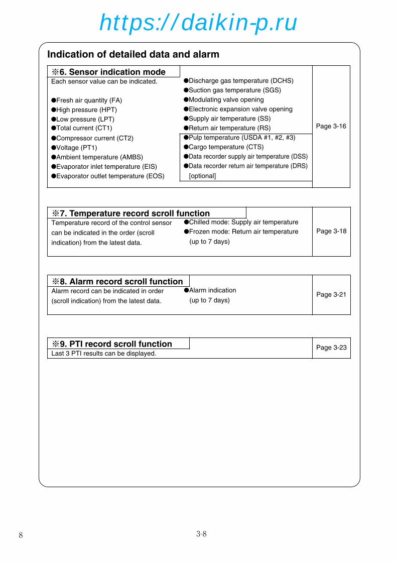
※9. PTI record scroll function Page 3-23Last 3 PTI results can be displayed.
Indication of detailed data and alarm
●Return air temperature (RS)
●Pulp temperature (USDA #1, #2, #3)
●Cargo temperature (CTS)
●Data recorder supply air temperature (DSS)
●Data recorder return air temperature (DRS)
※6. Sensor indication mode
Page 3-16
Each sensor value can be indicated. ●Discharge gas temperature (DCHS)
●Suction gas temperature (SGS)
●Modulating valve opening
●Electronic expansion valve opening
●Supply air temperature (SS)
●High pressure (HPT)
●Low pressure (LPT)
●Total current (CT1)
●Compressor current (CT2)
●Voltage (PT1)
●Ambient temperature (AMBS)
●Evaporator inlet temperature (EIS)
※7. Temperature record scroll function
Page 3-18
Temperature record of the control sensor
can be indicated in the order (scroll
indication) from the latest data.
●Chilled mode: Supply air temperature
●Frozen mode: Return air temperature
(up to 7 days)
※8. Alarm record scroll function
Page 3-21Alarm record can be indicated in order
(scroll indication) from the latest data.
●Alarm indication
(up to 7 days)
●Evaporator outlet temperature (EOS) [optional]
●Fresh air quantity (FA)
01-14_LXE10E-A32A,B_SG.qx 08.1.24 10:15 AM ページ 8
https://daikin-p.ru

9
6. SENSOR INDICATION MODE
Each sensor value, the suction modulating valve (SMV) opening, the electronic expansion valve (EV)opening and the fresh air quantity (FA) can be checked. The following items are displayed:High pressure (HPT), low pressure (LPT), voltage (PT1), total current (CT1), compressor current (CT2),ambient temperature (AMBS), evaporator inlet temperature (EIS), evaporator outlet temperature (EOS),discharge gas temperature (DCHS), suction gas temperature (SGS), suction modulating valve opening,electronic expansion valve opening, supply air temperature (SS) (during PTI only), return airtemperature (RS) (during PTI only), pulp temperature (USDA#1, UADA#2, USDA#3) (optional), cargotemperature (CTS) (optional), supply air temperature for data recorder (DSS) (optional), return airtemperature for data recorder (DRS) (optional).
<Mode selection procedure>
3-15
<Operation procedure>
Whenever the or key is pressed, the display changes.
LED: The control temperature is displayed.
LCD: Fresh air quantity is displayed.
The display reads: "FA".
(In m3/h)
LED: The control temperature is displayed.
LCD: The value of high pressure transducer is displayed.
The display reads: "HPT ".
(In kPa.)
LED: The control temperature is displayed.
LCD: The value of the low pressure transducer is displayed.
The display reads: "LPT ".
(In kPa.)
LED: The control temperature is displayed.
LCD: The value of voltage is displayed.
The display reads: " PT V".
(In Volts.)
LED: The control temperature is displayed.
LCD: The value of total running current is displayed.
The display reads: " CT A".
(In Ampere.)
1
1
All indication
Lights on
(for 3 sec.)
Starting
Preparation
(for 18 sec.)
※ 1
Current
indication
(Operation state) ※ 6 Sensor Indication
HIGH PRESSURETRANSDUCER
(HPT)
LOW PRESSURETRANSDUCER
(LPT)
CURRENTSENSOR-1
(CT1)
VOLTAGE SENSOR(PT)
FRESH AIRQUANTITY
(FA)
01-14_LXE10E-A32A,B_SG.qx 08.1.24 10:15 AM ページ 9
https://daikin-p.ru

10 3-24
I/O ON
I/O
Power OFF
Unit OFF
All lights on
(for 3 sec.)
Preparation
(for 18 sec.)
CASE1
Circuit Breaker ON
Circuit Breaker OFF
after setting change
( OFF when no setting changed)
When Circuit Breaker is not turned OFF after setting change
for 3 sec. for 3 sec. for 3 sec. for 3 sec.
※ 10
Optional
Function
Setting
※ 11
Basic
Function
Setting
※ 12
Optional
Condition
Setting
※ 13
Input
Data
PTI
for 3 sec.for 3 sec.
USDA: AU (4 or 3 or OFF)
S
dHU: OFF (or ON)
DECOS3: d (C or B or A)
S
Log. Interval: 60 (or 15 or 30 or 120)
S
REC SEN: ON (or OFF)
S
OC-SET: Sing (or Dual)
S
HP: 10 (or 5)
S
DISP: OFF (or ON)
S
COMP: 100 (or 33)
S
REHEAT: ON (or OFF)
S
FA SEN: L (or H or OFF)
Container I.D
S
Controller
Time
Chartls: ON (or OFF)
S
USDA 1/2: 2 (or 1)
S
H001~H006
S
d-1**~d-2* S
C/F : F (or C)
CASE3 (Refer to clause 3.8.3)
CASE2
3.3.3 Setting flow chart
This configuration setting flow shall be utilized, when
CASE 1) USDA transportation setting is required (※10 Optional Function Setting)
CASE 2) Container ID shall to be subjected to change from another container for emergency use.
(※13 Container ID & Time Setting)
CASE 3) Controller is replaced to new one. (All setting in ※10~※13 (page 3-25) shall be set.)
NOTE 1 : All initial settings are pre-set, when the unit is delivered.
(The initial setting for LXE10E-1 are underlined figures.)
2 : In CASE 3), the settings of "CHARTLS" and "USdA 1/2" shall be changed from default
(Default of spare controller : CHARTLS=Off, UsdA=1) to set for LXE10E-A32A, A32B as
below underlined.
3 : In order to complete the setting change, CIRCUIT BREAKER shall be turned off
01-14_LXE10E-A32A,B_SG.qx 08.1.24 10:15 AM ページ 10
https://daikin-p.ru

113-28
LED DISPLAYLIGHT-OFF SETTING
INPUT POWERSETTING
HORSEPOWERSETTING
S
S
S
S
S
DEHUMIDIFICATIONCOIL ON/OFFSETTING
COMPRESSORUNLOADINGSYSTEM SETTING
VENTILATOR OPENING DETECTOR FUNCTION SETTING
S
S
To set the power input:
Select "Sing" or "dUAL" on the LED when the LCD displays "OC-SET" .
Whenever the or key is pressed, the indication of "Sing" or "dUAL" is
changed. Press the key to determine the setting.
For the unit, select "Sing", and press key to determine the setting.
To set the horse power setting:
Select "5" or "10" on the LED when the LCD displays "HP" (Horse power).
Whenever the or key is pressed, the indication of "5" or "10" is
changed. Press the key to determine the setting.
To set the "panel (LED) lighting off" function ON/OFF:
Select "ON" (provided) or "OFF" (not provided) on the LED when the LCD
displays "dISP" .
Whenever the or key is pressed, the indication of "ON" or "OFF" is
changed. Press the key to determine the setting.
Note: When the 0/CHART key is pressed twice when the "panel (LED) lighting
off" function is ON, the lights on the LED panel are turned off.
To set the compressor unloading system:
Select "33 (provided)" or "100 (not provided)" on the LED when the LCD
displays "COMP".
Whenever the or key is pressed, the indication of "33" or "100" is changed.
Note: This "33" setting is applicable for LXE10D type only.
To set the dehumidification coil ON/OFF:
Select "ON (provided)" or "OFF (not provided)" on the LED when the LCD
displays "REHEAT".
Whenever the or key is pressed, the indication of "ON" or "OFF" is
changed. Press the key to determine the setting
Select "H (Upper)", L (Lower)" or "OFF (not provided)" on the LED when the
LCD displays "FA SEN".
Whenever the or key is pressed, the indication of "H", "L" or "OFF" is
changed. Press the key to determine the setting.
01-14_LXE10E-A32A,B_SG.qx 08.1.24 10:15 AM ページ 11
https://daikin-p.ru

12 3-46
Circ
uit B
reak
er :
ON
Uni
t Sw
itch
: ON
Circ
uit B
reak
er :
OF
F
Circ
uit B
reak
er :
ON
Uni
t Sw
itch
:
OF
F
Uni
t Sw
itch
:
ON
INIT
IAL
SE
TT
ING
for
4 M
OD
ES
S
S
SS
CH
AR
TLS
: O
N (
OF
F)
H
001 : 3
H
005 : 3 d
3 : 1
H
002 : 2 H
006 : 3 d-1
: 1
H
003 : 2 d : 1
d-2
: 1
H
004 : 2 d
2 : 1
※10
Opt
iona
l Fun
ctio
n S
ettin
g M
ode
※11
Bas
ic F
unct
ion
Set
ting
Mod
e※
12 O
ptio
nal C
ondi
tion
Set
ting
Mod
e※
13 I
nput
Dat
a M
ode
TR
IPS
TA
RT
SE
TT
ING
OP
ER
AT
ION
CO
ND
ITIO
NS
ET
TIN
G A
larm
F30
1: N
on s
ettin
g of
[Con
trol
Tem
pera
ture
]E
303:
Non
set
ting
of [C
ontr
ol H
umid
ity] (
optio
n)E
305:
Non
set
ting
of [D
efro
st In
terv
al]
Ope
ratio
n
S
i.d.-
C
Four
alp
habets
Settin
g
i.d-n
Sev
en n
umer
ic v
alue
set
ting
I.d
Settin
g
Date
Settin
g
Tim
e S
ettin
g
Conta
iner
I.D
Settin
g
Contr
olle
r T
ime S
ettin
g
S S S
All
Indi
catio
n lig
hts
ON
(fo
r 3
seco
nds)
Set
ting
enab
led
mod
e (f
or 1
8 se
cond
s)
※6
. P
TI s
elec
tion
mod
e (f
or T
rip S
tart
Set
ting)
OP
ER
AT
ION
:Manual action
:Sele
ct key
:S k
ey
:Ente
r key
:Contr
olle
r opera
tion
Blu
e la
be
l
DE
CO
SⅢ
d
S SS S S S
S SU
SD
A S
enso
r 1/
2 S
elec
tion
: 2 (
1)
S S S
SS S S
SS S
C/F
: F
( C
)
Key O
pera
tion
1.
Un
de
rlin
ed
fig
ure
s s
ho
w "
Fa
cto
ry s
et"
in
th
is m
od
el. O
the
r ch
oic
es a
re d
escrib
ed
in
(
).
If
the
re is n
ot
sp
ecify s
pe
cia
l in
str
uctio
n,
se
t a
ll fig
ure
s t
o "
Fa
cto
ry s
et"
.
2.
Wh
en
ch
an
gin
g t
he
se
tup
, a
lte
r th
e s
etu
p w
ith
th
e “△
” o
r “▽
” ke
y,
an
d f
ix it
with
th
e “
EN
TE
R”
ke
y.
Th
en
, d
ea
ctiva
te t
he
circu
it b
rea
ke
r.3
. If
th
e c
on
tro
ller
is r
ep
lace
d w
ith
sp
are
pa
rts,
ch
eck t
he
mo
de
l n
am
e f
irst,
an
d s
et
up
all
the
ite
ms in
acco
rda
nce
with
th
e in
itia
l se
tup
ta
ble
.
S
All
Indi
catio
n lig
hts
ON
(fo
r 3
seco
nds)
Set
ting
enab
led
mod
e (f
or 1
8 se
cond
s)
All
Indi
catio
n lig
hts
ON
(fo
r 3
seco
nds)
Set
ting
enab
led
mod
e (f
or 1
8 se
cond
s)
Con
trol
ler
: d (
C o
r B
or
A)
Logg
ing
Inte
rval
: 60
(15,
30
or 1
20)
Dat
a R
ecor
der
Sen
sor
: ON
(O
FF
)
Inpu
t Pow
er :
Sin
g (d
UA
L)
Hor
se P
ower
: 10
(5)
LED
dis
play
ligh
t-of
f : O
FF
(O
N)
Com
p/U
nloa
d se
tting
: 10
0 (3
3)
Reh
eat c
oil s
ettin
g : O
N (
OF
F)
FA
SE
N :
H (
L or
OF
F)
pres
s an
d ho
ld fo
r 3
seco
nds
pres
s an
d ho
ld fo
r 3
seco
nds
pres
s an
d ho
ld fo
r 3
seco
nds
Pre
ss a
nd h
old
for
3 se
cond
s (
with
in 1
8 se
cond
s)
Uni
t Sw
itch
: OF
F
Uni
t Sw
itch
: ON
Con
trol
Tem
pera
ture
Set
ting
Con
trol H
umid
ity S
ettin
g (o
ptio
n)
Def
rost
Inte
rval
Set
ting
※2
Ope
ratio
n se
tting
mod
e
USD
A, C
argo
Tem
p, S
enso
r :
AU (4
or 3
or O
FF)
Deh
umid
ifica
tion
Con
trol
:
OF
F*1 (
ON
)
1. S
elec
t「M
anua
l Che
ck」
with
or
Key
an
d de
term
ine
it w
ith
K
ey.
2. S
elec
t Trip
Sta
rt「
TS
H」
with
or
Key
an
d se
t it b
y pr
essi
ng th
e E
nter
Key
for
3 se
cond
s.
3.8
.3 In
itia
l sett
ing
pro
ced
ure
(fo
r sp
are
con
tro
ller
of
DE
CO
SⅢ
d)
01-14_LXE10E-A32A,B_SG.qx 08.1.24 10:15 AM ページ 12
https://daikin-p.ru

133-60
MANUAL CHECK SELECTION MODE
The LED displays the values of following items:
Compressor operating time, Evaporator fan motor high-speed running current, Evaporator fan motor
low-speed running current, Condenser fan motor running current, Battery life, Horse power, Elapsed
time after trip start, Evaporator fan motor running time, Condenser fan motor running time, and
Controller software version.
To display the compressor operating time:
Press the key when the LCD shows "CC ✕10H".
The operating time is [the value shown on the LED] ✕10 hours.
Pushing the key for 3 seconds sets compressor operating time to 0
(hour).
To display the current value of the evaporator fan motor high-speed:
Press the key when the LCD shows "EFH A", then the LED displays
the current value. (Unit: Ampere)
To display the current value of the evaporator fan motor low-speed:
Press the key when the LCD shows "EFL A", then the LED displays
the current value. (Unit: Ampere)
To display the current value of the condenser fan motor running current:
Press the key when the LCD shows "CF A", then the LED displays the
current value. (Unit: Ampere)
To display the elapsed time after trip start:
Press the key when the LCD shows "TS H", then the LED displays the
elapsed time. (Unit: Hours).
When the key is pressed and hold for 3 seconds while the elapsed time is
displayed the TRIP START is set, and the elapsed time display is reset to "0"
(hour).
To display the evaporator fan motor-1 operating time:
Press the key when the LCD shows "EF1 ✕10H".
The operating time is [the value displayed on the LED] ✕10 hours.
When the key is pressed and hold for 3 seconds while the evaporator fan
motor-1 operating time is displayed, the evaporator fan motor-1 operating
time is reset to "0" (hour).
("EF1" stands for the right hand side fan motor looking from the inside of the container.)
To display the evaporator fan motor-2 operating time:
Press the key when the LCD shows "EF2 ✕10H".
The operating time is [the value displayed on the LED] ✕10 hours.
If the key is pressed and hold for 3 seconds while the evaporator fan
motor-2 operating time is displayed, the evaporator fan motor-2 operating
time is reset to "0" (hour).
"EF2" stands for the left hand side fan motor looking from the inside of the container.
To display the condenser fan motor operating time:
Press the key when the LCD shows "CF ✕10H".
The operating time is [the value displayed on the LED] ✕10 hours.
If the key is pressed and hold for 3 seconds while the condenser fan motor operatingtime is displayed, the condenser fan motor operating time is reset to "0" (hour).
To display the controller software version:
Press the key when the LCD shows "SOFTVER".
The value on the LED is the software version.
FA ZERO-POINT ADJUSTMENT
Used to make automatic zero-point adjustment of ventilation amount.
Pressing the key while the "FA CAL" is displayed on the LCD will display
the current value of ventilation port sliding amount. Pressing and holding the
key for a period of 3 seconds while the sliding amount is displayed on the
LCD, the sliding amount will be reset to "0".
COMPRESSOROPERATINGTIME
EVAPORATOR FANMOTOR HIGH-SPEEDRUNNING CURRENT
EVAPORATOR FANMOTOR LOW-SPEEDRUNNING CURRENT
EVAPORATORFAN MOTOR-1OPERATING TIME
CONDENSER FANMOTOR RUNNNINGCURRENT
ELAPSED TIMEAFTER TRIPSTART
FA 0 POINTADJUSTMENT
CONTROLLERSOFTWAREVERSION
EVAPORATOR FANMOTOR-2OPERATING TIME
CONDENSER FANMOTOROPERATING TIME
01-14_LXE10E-A32A,B_SG.qx 08.1.24 10:15 AM ページ 13
https://daikin-p.ru

14
01-14_LXE10E-A32A,B_SG.qx 08.1.24 10:15 AM ページ 14
https://daikin-p.ru

7-9
7.13 Schematic wiring diagram
15
15-16_LXE10E-A32A,B_SG.qx 08.1.24 10:25 AM ページ 15
https://daikin-p.ru

7-10
board
7.14 Stereoscopic wiring diagram
16
Notes for wiring
U L 1 0 1 5 A W G 1 0 ( 5 . 5 m m ) :
U L 1 0 1 5 A W G 1 6 ( 1 . 2 5 m m ) :
-C-
line between terminals represents the jumper wire.
line represents the line in the box.(1)Note:
U L 1 0 1 5 A W G 1 2 ( 3 . 5 m m ) :
line represents the optional specification.
U L 1 0 1 5 A W G 1 4 ( 2 . 0 m m ) :
2
2
2
2
The terminal numbers and applicable cables in eachunit are as shown below.
(2)
-A--B-
line represents the external unit or junction cable.
BLK: Black, BLU: Blue, GRY: GreyBRN: Brown, RED: Red, YLW: Yel lowWHT: White, GRN: Green
Line color(3)
(6) At the two tightening positions of round crimp terminals with M3.5 insulating sleeve (FN type) or tightening positions of round crimp terminal (FN type) with M3.5 insulating sleeve and the round crimp terminals (FN type) with M4 insulating sleeve,tighten with torques ranging from 11.2 to 13.8 kg.cm. (from 1.1 to 1.3 N.m).(7) Prevent any contact of the wiring with the TrC coil.(8) The strong wiring must be separate from the weak wiring by 25 mm or more.(9) Wiring inside the machine should be laid in accordance with GAH010-Z unless otherwise specified.(10) The colors in parentheses indicate distinction colors.
M3.5 screwThe larger size wire must be placed under the smaller one.
M3.5 round crimp terminal (FN type)(back-to-back)
(4) Sequence chart of this diagram accords with the table.(5) When tightening the two round terminals, tighten as shown below. When tightening the two terminals whose wire sizes are different, the larger size wire must be placed under the smaller size one.
15-16_LXE10E-A32A,B_SG.qx 08.1.24 10:25 AM ページ 16
https://daikin-p.ru

179-1
9.1 Ventilation opening detector
(FA sensor) FA sensor
Control box
Connector
Ventilation cover
Condenser fan
● Type: 5ZZ2157This sensor has a main unit (i.e., wire winderblock and position meter) and wire block. Thewire tip is connected to the ventilation cover,which detects the opening degree of theventilation port.
(1) Replacement procedure
q Disconnect the lead wire (with connectorconnected) in the control box.
w Remove the screw clamping the ventilationcover and the wire tip together.
e Remove the screw fixing the main unit to thecasing, and replace the one-piece sensor unittogether with the wire.
Note)Be sure to replace the one-piece sensor unittogether with the wire.
r After the replacement, seal the position meterfixing screw block on the sensor main unitwith silicone sealant.
● For the maintenance of the air-cooledcondenser, remove the fan grille, fan guideand temperature recorder box. For themaintenance of the evaporator, remove therear panel of the evaporator.
4.2.17 Air-cooled condenser and evaporatorThis finned coil is compact and has uniformheat exchanging performance and high heatexchanging efficiency due to the adoption ofcorrugated fins.
● Washing of air-cooled condenserCarefully flush the air-cooled condenser withfresh water after trip, although this type ofcondenser employs thick fins andelectrodeposition coating for high corrosionresistance.
Air cooled condenser
Evaporator
17-18_LXE10E-A32A,B_SG.qx 08.1.21 19:48 ページ 17
https://daikin-p.ru

18
17-18_LXE10E-A32A,B_SG.qx 08.1.21 19:48 ページ 18
https://daikin-p.ru

19
掲載機種このサービスガイドは本ユニットの特長及び取扱いについてサービスガイド(サービス編 TR01-08B)と異なる事項のみ掲載しております。
NO. 項 目1 吸入温度計挿入口2 換気口:ポテンションメーター3 小切り板(雨トイ)
有
有
有
サービスガイド(サービス編)と異なる点
19-32_LXE10E-A32A,B_SG.qx 08.1.21 4:44 PM ページ 19
https://daikin-p.ru

20
目 次3.5.3 バッテリチェック………………………3-36
3.5.4 バッテリ交換(充電式電池)…………3-37
3.6 パソコンとの情報交換………………………3-38
3.6.1 データロギング…………………………3-39
3.6.2 パソコンソフトの構成…………………3-40
3.7 コントローラの点検方法……………………3-42
3.8 コントローラの交換および初期設定………3-43
3.8.1 コントローラの交換……………………3-43
3.8.2 コントローラDECOSⅢdとⅢc & Ⅲbとの互換性 ………………………3-44
3.8.3 LXE10E-1,LXE10E-A & LXE10D スペアーコントローラ
DECOSⅢd,DECOSⅢc & DECOSⅢb交換時のイニシャル設定手順…3-46
3.8.4 LXE10E-1 & LXE10E-A スペアーコントローラDECOSⅢdの初期設定表…3-47
3.8.5 LXE10E-A スペアーコントローラDECOSⅢcの初期設定表…3-48
3.8.6 LXE10D スペアーコントローラDECOSⅢbのイニシャル設定表 …3-49
3.9 PTI(使用前点検)と定期点検 ……………3-50
3.9.1 点検項目…………………………………3-51
3.9.2 自動PTI …………………………………3-54
3.9.2.1 PTI選択モード ……………………3-55
3.9.2.2 S.PTI ………………………………3-56
3.9.2.3 F.PTI ………………………………3-57
3.9.2.4 PTI(使用前点検)中のアラーム一覧 …3-58
3.9.2.5 M.CHECK …………………………3-59
3.10 チャートレス機能 …………………………3-61
3.10.1 チャート表示機能 ……………………3-61
3.10.2 Pコード(プルダウンタイム表示)……3-63
3.10.3 チャートレスコード …………………3-64
3.10.3.1 チャートレスコード一覧 ………3-64
3.10.3.2 H-コード …………………………3-65
3.10.3.3 d-コード …………………………3-67
3.11 通信モデム …………………………………3-68
4.サービスとメンテナンス …………………………4-1
4.1 サービスの方法 ………………………………4-1
4.1.1 冷媒の回収 ………………………………4-1
4.1.2 ゲージマニホールドの取付け、取外し …4-1
4.1.3 自動ポンプダウン ………………………4-3
4.1.4 冷媒の回収および充填 …………………4-5
4.2 主要機器とメンテナンス ……………………4-8
4.2.1 スクロール圧縮機 ………………………4-8
4.2.2 ファンおよび電動機……………………4-12
4.2.3 PT/CTボード(EC9756) ………………4-13
4.2.4 電子膨張弁………………………………4-15
4.2.5 吸入比例弁………………………………4-16
4.2.6 ドライヤ…………………………………4-17
4.2.7 電磁弁……………………………………4-18
4.2.8 吐出圧力調整弁…………………………4-19
4.2.9 逆止弁……………………………………4-19
4.2.10 高圧圧力開閉器(HPS)………………4-20
4.2.11 低圧圧力センサ(LPT)………………4-20
4.2.12 高圧圧力センサ(HPT)………………4-21
4.2.13 空冷凝縮器、蒸発器 …………………4-21
4.2.14 可溶栓 …………………………………4-21
4.2.15 リキッド/モイスチャーインジケータ …4-22
4.2.16 真空乾燥 ………………………………4-23
取扱上の注意
・危険…………………………………………………4
・警告…………………………………………………5
・注意…………………………………………………7
1. 概要 …………………………………………………1-1
1.1 運転範囲 ………………………………………1-1
1.2 各部の名称 ……………………………………1-1
1.3 運転操作 ………………………………………1-2
1.3.1 運転準備と操作 …………………………1-2
1.3.2 運転中の点検 ……………………………1-3
1.3.3 停止後の処置 ……………………………1-3
1.3.4 ベンチレータの開閉 ……………………1-4
2.製品データ …………………………………………2-1
2.1 主仕様 …………………………………………2-1
2.2 部品名称 ………………………………………2-2
2.2.1 庫外側 ……………………………………2-2
2.2.2 庫内側 ……………………………………2-5
2.2.3 コントロールボックス …………………2-7
2.3 機能部品・保護装置の設定値………………2-12
2.4 運転圧力と電流値……………………………2-13
2.5 運転モードと制御……………………………2-17
2.5.1 フローズン運転…………………………2-18
2.5.2 チルド、パーシャルフローズン運転…2-20
2.5.3 デフロスト運転…………………………2-22
2.5.4 除湿制御運転(オプション)…………2-25
2.5.5 共通制御…………………………………2-26
3.電子式コントローラ ………………………………3-1
3.1 機能 ……………………………………………3-1
3.2 電子式コントローラの基本操作 ……………3-3
3.2.1 コントロールパネル ……………………3-3
3.3 操作方法 ………………………………………3-6
3.3.1 操作方法フローチャート ………………3-6
3.3.2 各表示モード操作方法 …………………3-9
1.カレント(運転状態)表示モード …………3-9
2.運転設定モード …………………………3-10
3.電池モード ………………………………3-11
4.モード運転 ………………………………3-12
5.表示(LED部)消灯モード…………………3-14
6.センサ表示モード ………………………3-15
7.温度記録スクロールモード ……………3-18
8.アラーム記録スクロールモード ………3-21
9.PTIレコードスクロールモード…………3-23
3.3.3 設定フローチャート……………………3-24
10.オプション機能設定モード……………3-26
11.基本機能設定モード……………………3-27
12.オプション条件機能設定モード………3-29
13.インプットデータモード………………3-31
14.コントローラソフトダウンロードモード…3-32
3.4 アラーム表示とバックアップ機能…………3-33
3.4.1 アラーム一覧表…………………………3-33
3.4.2 センサ異常時のバックアップ運転……3-34
3.5 バックアップ用電池…………………………3-36
3.5.1 仕様………………………………………3-36
3.5.2 機能………………………………………3-36
☆が付いている項目は、標準サービスガイド(TR 01-08B)と内容が異なることを示しています。
☆
☆
☆
☆
☆
☆
☆
☆
☆
19-32_LXE10E-A32A,B_SG.qx 08.1.21 4:44 PM ページ 20
https://daikin-p.ru

21
目 次8.2.8 ジーセット運転2 ………………………8-32
8.2.9 バルブモード……………………………8-33
8.2.10 除湿制御 ………………………………8-35
8.2.11 マニュアルチェック選択モード ……8-39
8.2.12 F.PTI仕様………………………………8-40
8.2.13 リチャージャブルバッテリ …………8-42
8.3 コントロールボックス………………………8-43
8.3.1 パソコンレセプタクル、
予備ヒューズのコントロールボックス内装備………8-43
8.3.2 ケーブルクランプ金具1 ………………8-44
8.3.3 ケーブルクランプ金具2 ………………8-45
8.4 USDA低温処理輸送 …………………………8-46
8.4.1 USDAセンサ、レセプタクルの型式…8-46
8.4.2 初期設定…………………………………8-46
8.4.3 USDAセンサカリブレーション………8-46
8.4.4 USDA低温処理輸送要件………………8-46
8.4.5 USDA事務所要求の書類作成…………8-46
8.5 TransFRESH…………………………………8-48
8.6 特殊サービスポート…………………………8-50
8.6.1 冷媒の回収………………………………8-50
8.6.2 ゲージマニホールドの取付け、取外し …8-50
8.7 圧力計…………………………………………8-52
9. LXE10E-A32A, A32Bオプション …………9-1
9.1 換気口開度検知器(FAセンサ)……………9-1
5. オプション…………………………………………5-1
5.1 電子式温度記録計 ……………………………5-1
5.1.1 標準型 ……………………………………5-1
5.1.2 リチャージャブルバッテリ型 …………5-3
5.2 USDA低温処理輸送 …………………………5-4
5.2.1 USDAセンサ、レセプタクルの型式……5-4
5.2.2 初期設定 …………………………………5-4
5.2.3 USDAセンサカリブレーション…………5-4
5.2.4 USDA低温処理輸送要件…………………5-4
5.2.5 USDA事務所要求の書類作成……………5-4
5.3 TransFRESH …………………………………5-6
6.故障診断 ……………………………………………6-1
6.1 冷媒システム・電気システム ………………6-1
6.2 アラームコードの診断………………………6-13
6.3 自動PTIのトラブルシューティング(Jコード)…6-17
6.4 記録紙による診断……………………………6-19
6.5 緊急運転の方法………………………………6-22
6.5.1 コントローラの緊急運転………………6-22
6.5.2 コントローラの短絡運転………………6-23
6.5.3 電子膨張弁の緊急運転…………………6-25
6.5.4 吸入比例弁の緊急運転方法……………6-26
6.5.5 吹出センサ・吸込センサ緊急運転……6-27
7.付図 …………………………………………………7-1
7.1 ボルトの標準締付トルク ……………………7-1
7.2 フレヤナットの標準締付トルク ……………7-1
7.3 モータコイル及び電磁弁コイルの抵抗値 ……7-1
7.4 電子膨張弁コイルの標準締付トルク(EVコイル)……7-1
7.5 HFC134a、温度一蒸気圧特性表 ……………7-2
7.6 温度換算表と温度センサ(SS/RS/DSS/DRS/RSS/RRS/EIS/EOS/SGS
/AMBS)特性表 ………………………………………7-3
7.7 温度換算表と温度センサ(DCHS)特性表……7-4
7.8 高圧圧力センサ特性表 ………………………7-4
7.9 低圧圧力センサ特性表 ………………………7-4
7.10 配管系統図……………………………………7-5
7.11 電気配線………………………………………7-6
7.12 ヒューズ保護対象表…………………………7-7
7.13 シーケンス(コネクタ型ターミナルボード+充電式バッテリ) ………7-9
7.14 実体配線図(コネクタ型ターミナルボード+充電式バッテリ)………7-10
7.15 シーケンス(コネクタ型ターミナルボード+温度記録計+ドライバッテリ)………7-11
7.16 実体配線図(コネクタ型ターミナルボード+温度記録計+ドライバッテリ)………7-12
7.17 シーケンス(丸型圧着端子型ターミナルボード+温度記録計+ドライバッテリ) ……7-13
7.18 実体配線図(丸型圧着端子型ターミナルボード+温度記録計+ドライバッテリ) ……7-14
8.補足版マニュアル …………………………………8-1
8.1 電子式温度記録計 ……………………………8-2
8.1.1 標準型 ……………………………………8-2
8.1.2 リチャージャブルバッテリ型 …………8-4
8.2 コントローラ関連 ……………………………8-5
8.2.1 標準と異なる操作1………………………8-5
8.2.2 標準と異なる操作2………………………8-9
8.2.3 標準と異なる操作3 ……………………8-22
8.2.4 標準と異なるコントローラ設定………8-26
8.2.5 設定温度と運転モード(パーシャルフローズンモード付)…………8-30
8.2.6 デフロストインターバル………………8-31
8.2.7 ジーセット運転1 ………………………8-32
☆
☆
19-32_LXE10E-A32A,B_SG.qx 08.1.21 4:44 PM ページ 21
https://daikin-p.ru

22
注意冷凍カーゴの場合は必ず CLOSE にしてください。
1.3.4 ベンチレータの開閉
カーゴに応じて上部、下部換気口の開度を調節します。換気量が 80m3/h 以上の場合は上部換気口で換気量を調整し、80m3/h 以下の場合は下部換気口で調整します。
上部換気口(80~250m3/h)換気が不要な場合(フローズン運転時)ハンドルを下にスライドさせ、CLOSE の位置にします。
換気が必要な場合(チルド運転時)ハンドルを上へスライドさせます。※カーゴに応じ、換気必要量を調節してください。
1-4
吸込口
吹出口
ベンチレーターカバー
ハンドル 吸込口
吹出口
“CLOSE” “OPEN”
"CLOSE" "OPEN"
ベンチレーター カバー
ハンドル
吸込口
吹出口
換気が不要な場合(フローズン運転時)ハンドルを下にスライドさせ、CLOSE の位置にします。
換気が必要な場合(チルド運転時)ハンドルを上へスライドさせます。
下部換気口(0~80m3/h)
※換気量は操作パネルの キーを押すと表示されます。
19-32_LXE10E-A32A,B_SG.qx 08.1.21 4:44 PM ページ 22
https://daikin-p.ru

233-1
3. 電子式コントローラ3.1機能●DECOS Ⅲd (Daikin Electronic Container Operation System)
注)[PC]:パソコン接続による機能を示すNo. 機能分類 機 能 DECOSⅢd
1 制御機能 ・温度制御 ✓・デフロスト制御 ✓・湿度制御 オプション
2 初期設定 ・オプション有無(USDA、湿度)及び馬力切換等 ✓・チャートレス機能設定 ✓
3 設定 ・温度 ✓・デフロストインターバル ✓・湿度 ✓・[PC]…データロガーのヘッダ情報セット ✓
4 表示 ・運転モード ✓(表示パネル) (圧縮機運転/デフロスト/適正温度/除湿)
・アラーム ✓・吸込空気温度/設定温度 ✓・吹出空気温度/設定温度 ✓・デフロストインターバル ✓・庫内湿度/設定湿度 オプション・外気温度 ✓・高圧圧力 ✓・低圧圧力 ✓・電源電圧 ✓・総合運転電流 ✓・圧縮機運転電流 ✓・蒸発器入口管温度 ✓・蒸発器出口管温度 ✓・吐出ガス温度 ✓・圧縮機吸入ガス温度 ✓・吸入比例弁開度 ✓・電子膨張弁開度 ✓・吸込空気温度(PTI時のみ) ✓・吹出空気温度(PTI時のみ) ✓・果芯温度(USDA # 1 ,# 2 ,# 3 ) オプション・カーゴ温度 オプション・換気量 オプション
5 自己診断・ ・センサ 吸込空気温度センサ ✓自動バックアップ 吹出空気温度センサ ✓
外気温度センサ ✓高圧圧力センサ ✓低圧圧力センサ ✓電圧センサ ✓電流センサ ✓蒸発器入口管温度センサ ✓蒸発器出口管温度センサ ✓吐出ガス温度センサ ✓圧縮機吸入ガス温度センサ ✓湿度センサ オプション芯温センサ オプションカーゴ温度センサ オプションデータレコーダセンサ オプション
・高圧圧力開閉器 ✓・電磁弁/ホットガス比例制御弁(漏れチェック) ✓・長時間デフロスト ✓・過電圧 ✓
19-32_LXE10E-A32A,B_SG.qx 08.1.21 4:44 PM ページ 23
https://daikin-p.ru

243-4
UP
SET
S
DOWN
ENTER/ESC
SELECT
CHART
SELECT
●アップキー
表示する項目を移行する時等
に使用します。
●ダウンキー
表示する項目を移行する時等
に使用します。
●エンター/エスケープキー
設定又は、表示する内容を決
定する時に使用します。
チャートキー(ディスプレイセ
レクトキー)
設定温度等を表示して、この
キーを押すと記録温度データ
の簡易グラフを LCD 画面に表
示します。再度このキーを押
すと、設定温度等に戻ります。
UNITON/OFF
MODE
M
●ユニットオン/オフキー
ユニットの運転/停止を行いま
す。
コントローラは、電源を切っ
た時のユニットオン/オフの
状態を記憶しています。ユニ
ットオンのまま電源を切った
場合は、次に電源を入れると
ユニットオンしなくても自動
的に運転を開始します。ユニ
ットオフで電源を切った場合
はユニットオンしなければ運
転を開始しません。
●モードキー
下記制御を行います。
①ジェネレータ設定(=消費
電力低減制御)
②自動ポンプダウン
③除湿設定
④テストモード設定
●セットキー
電源 ON の場合:
①カレント表示モードから運
転設定モードに移行します。
②運転設定モードで設定項目
間を移行します。
電源 OFF の場合:
①電源OFFモードから電池モ
ードに移行します。
●セレクトキー
換気量(FA)を表示させる事
ができます。
操作キーの機能
OVERSP + 5˚C
UNDERSP – 5˚C
IN RANGE
–12 –10 –8 –6 –4 –2
–6 –5 –4 –3 –2 –1
LCD
19-32_LXE10E-A32A,B_SG.qx 08.1.21 4:44 PM ページ 24
https://daikin-p.ru

253-7
設定・運転状態の確認
※1. カレント表示モード(運転状態表示)
P 3-9
ユニットの運転状態を表示します。 ●吹出空気温度(SS)●吸込空気温度(RS)●デフロストインターバル●アラーム●設定湿度と湿度(オプション)
※2. 運転設定モード
P 3-10カーゴ輸送のための各種設定をします。 ●温度設定●デフロストインターバル●湿度設定(オプション)
※3. 電池モード(バッテリによる運転条件設定)
P 3-11
電源がない場合でも設定ができます。 ●温度表示●換気量(FA)表示
●ユニットのON/OFF
●デフロストインターバル
※4. モード運転
P 3-12①Gセット運転 :発電機で運転する場合の最大消費電力を設定します。②自動ポンプダウン:コントローラ操作によりポンプダウンは自動で行われます。③モード運転 :除湿モードが設定できます。(オプション)
テストモードが設定できます。
●温度設定●湿度設定
※5. 表示(LED)消灯モード
P 3-14コントローラの表示部のLED部を消灯させておくことができます。
●LEDの消灯
19-32_LXE10E-A32A,B_SG.qx 08.1.21 4:44 PM ページ 25
https://daikin-p.ru

263-8
詳細データアラームの表示
●吸入空気温度(RS)●芯温(USDA#1, #2, #3)●カーゴ温度(CTS)●データレコーダ用吹出空気温度(DSS)●データレコーダ用吸込空気温度(DRS)
※6. センサ表示モード
P 3-16
各センサの値を表示させます。 ●吐出ガス温度(DCHS)●吸入ガス温度(SGS)●比例制御弁開度●電子膨張弁開度●吹出空気温度(SS)
●高圧圧力(HPT)●低圧圧力(LPT)●総合電流(CT1)
●圧縮機電流(CT2)●電圧(PT1)●庫外空気温度(AMBS)●蒸発器入口温度(EIS)●蒸発器出口温度(EOS) [オプション]
●換気量(FA)
※7. 温度記録スクロールモード
P 3-18制御センサの記録を最新データから順番に(スクロール)表示します。
●チルド:吹出温度●パーシャルフローズン:吸込温度
(最大7日分)●フローズン:吸込温度
※8. アラーム記録スクロールモード
P 3-21アラームの記録を最新のデータから順番に(スクロール)表示します。
●アラームの表示(最大7日分)
最後の3回のPTIの結果を表示します。※9. PTI選択モード
P 3-23
19-32_LXE10E-A32A,B_SG.qx 08.1.21 4:44 PM ページ 26
https://daikin-p.ru

273-15
6. センサ表示モード
各センサ値と、吸入制御比例弁(SMV)、電子膨張弁(EV)の開度及び換気量(FA)を確認できます。次の項目を表示します。高圧圧力(HPT)、低圧圧力(LPT)、電圧(PT1)、総合電流(CT1)、圧縮機電流(CT2)、庫外空気温度(AMBS)、蒸発器入口温度(EIS)、蒸発器出口温度(EOS)、吐出ガス温度(DCHS)、吸入ガス温度(SGS)吸入比例制御弁開度、電子膨張弁開度、吹出空気温度(SS)(PTI時のみ)、吸込空気温度(RS)(PTI時のみ)、果芯温度(USDA#1、USDA#2、USDA#3)(オプション)、カーゴ温度(CTS)(オプション)、データレコーダ用吹出空気温度(DSS)(オプション)、データレコーダ用吸込空気温度(DRS)(オプション)
<表示モードの移行方法>
表示全点灯3秒
始動準備18秒
※ 1
カレント表示(運転状態表示)
※ 6 センサ表示
5分間無操作
<操作方法>キーまたは、 キーを押すごとに表示が変わります。
LED :制御温度を表示します。LCD :換気量を表示します。
『FA 』と表示します。(単位はm3/hです。)
LED :制御温度を表示します。LCD :高圧圧力センサ値を表示します。
『HPT 』と表示します。(単位はKpaです。)
LED :制御温度を表示します。LCD :低圧圧力センサ値を表示します。
『LPT 』と表示します。(単位はKpaです。)
LED :制御温度を表示します。LCD :電圧値を表示します。
『 PT V』と表示します。(単位はVです。)
LED :制御温度を表示します。LCD :総合運転電流値を表示します。
『 CT A』と表示します。(単位はAです。)
1
1
高圧圧力 センサ (HPT)
低圧圧力 センサ (LPT)
電流センサ 1 (CT1)
電圧センサ (PT)
換気量 (FA)
19-32_LXE10E-A32A,B_SG.qx 08.1.21 4:44 PM ページ 27
https://daikin-p.ru

283-24
I/O ON
I/O
電源OFF
ユニットOFF
全点灯3秒
始動準備18秒
サーキットブレーカON
設定終了後サッキットブレーカをOFF
(設定を変更しなかった場合は をOFF)
初期設定途中でブレーカをOFFせず、ユニットOFFし、再度ユニット
ONした場合、初期設定画面に戻ります。
3秒 3秒間 3秒間 3秒間
ケース 2ケース 1
ケース 3(3.8.3項参照)
※ 10
オプション 機能設定
※ 11
基本機能 設定
※ 12
オプション 条件設定
※ 13
インプット データ
PTI
3秒間
USDA: OFF (or 3 or 4)
S
dHU: OFF (or ON)
DECOS3: d (C or B or A)
S
Log. Interval: 60 (or 15 or 30 or 120)
S
REC SEN: ON (or OFF)
S
OC-SET: Sing (or Dual)
S
HP: 10 (or 5)
S
DISP: OFF (or ON)
S
COMP: 100 (or 33)
S
REHEAT: ON (or OFF)
S
FA SEN: H (or L or OFF)
コンテナID
S
コントローラ カレンダ
CHARTLS: OFF (or ON)
S
USDA 1/2: 2 (or 1)
S
H001~H006
S
d-1**~d-2** S
C/F : C (or F)
3.3.3 設定フローチャート下図の設定を使用するのは下記の場合です。ケース1)USDA低温処理輸送設定が必要な場合。(※10. オプション機能設定)ケース2)緊急にコンテナIDを他のIDから変更する場合。(※13. コンテナIDとカレンダ設定)ケース3)コントローラを新しく交換した場合。(※P.3-25の※10~13の全設定の設定が必要)
注1)本ユニットが配送された時にはすべての初期設定は完了しています。注2)ケース3の場合“CHARTLS”と“USdA 1/2”は初期設定(補用コントローラの初期設定は:
CHARTLS=Off,USdA=1)から下記のLXE10E-A32A,A32Bの下線部へ変更して下さい。注3)設定変更が終了したらサーキットブレーカを一旦切ってください。
(LXE10E-A32A,A32Bの初期設定は下線(_)部です。)
19-32_LXE10E-A32A,B_SG.qx 08.1.21 4:44 PM ページ 28
https://daikin-p.ru

293-28
表示(LED部)消灯 機能有/無設定
電源入力設定
馬力設定
S
S
S
S
S
S
圧縮機 アンロードシステム
設定
除湿コイル 有/無設定
S
換気量検知 機能設定
電源入力の設定を行うときは、LCD画面に「OC-SET」と表示しているときに、LED画面に表示された「Slng」、「dUAL」から選択します。
「Slng」、「dUAL」は キーまたは、 キーを押すごとに表示が変わります。
確定するときは、 キーを押します。
本ユニットは「Slng」を選択して、 キーを押し確定します。
馬力の設定を行うときは、LCD画面に「HP」(Horse Power)と表示しているときに、LED画面に表示された「 5 」、「10」から選択します。
「 5 」、「10」は キーまたは、 キーを押すごとに表示が変わります。
確定するときは、 キーを押します。
表示(LED部)消灯機能有/無の設定を行うときは、LCD画面に「dISP」と表示しているときに、LED画面に表示された「ON(消灯機能有」、「OFF(消灯機能無)」から選択します。
「ON(消灯機能有)」、「OFF(消灯機能無)」は キーまたは、 キーを押す
ごとに表示が変わります。確定するときは、 キーを押します。
注:この設定を「ON(消灯機能有)」にし、 キーを 2 回押すことにより、コントローラの表示部のLED部を消灯させることが可能です。
圧縮機アンロードシステムの設定を行うときは、LCD画面に「COMP」と表示しているときに、LED画面に表示された「33
(アンロードシステム有)」、「100(アンロードシステム無)」から選択します。「 33 」、「100」は キーまたは、 キーを押すごとに表示が変わります。
注:この「33」設定はLXE10D型のみ適用します。
除湿コイル有/無の設定を行うときは、LCD画面に「REHEAT」と表示しているときに、LED画面に表示された「ON
(除湿コイル有)」、「OFF(除湿コイル無)」から選択します。「ON」、「OFF」は キーまたは、 キーを押すごとに表示が変わります。
確定するときには、 キーを押します。
換気量検知機能の設定を行うときは、LCD画面に「FA SEN」と表示しているときに、LED画面に表示された「H
(上部)」と「L(下部)」あるいは「OFF(使用しない)」から選択します。「H」、「L」、「OFF」は キーまたは、 キーを押すごとに表示が変わります。
確定する時は、 キーを押します。
0/CHART
19-32_LXE10E-A32A,B_SG.qx 08.1.21 4:44 PM ページ 29
https://daikin-p.ru

303-46
3秒押し
サーキットブレーカ
:ON
ユニットスイッチ
:ON
ユニットスイッチ
:OF
F
ユニットスイッチ
:ON
サーキット
ブレーカ
OF
F
サーキット
ブレーカ
ON
ユニット
スイッチ
OF
F
ユニット
スイッチ
ON
4モード
イニシャル
設定
US
DAカーゴ
: OF
FO
FF
(AU
, 3 ,
4) 除湿制御
dHU
: OF
F (o
rO
N)
S3秒間
押し
DE
CO
SⅢ
:d
( C
,B,A
)
Log
.Int :
60 (
or 1
20,3
0,15
)
RE
C S
EN
: ON
(OF
F)
OC
-SE
T :
Sin
g (d
UA
L)
H
P :
10 (
5)
DIS
P: O
FF
(O
N )
CO
MP
: 100
(33
)
RE
HE
AT
: ON
(O
FF
)
FA
SE
N: H
(L,
OF
F)
S
SS
CH
AR
TLS
: O
FF
(ON
)
US
DA
1/2
: 2
(1)
H
001
: 3
H00
5 :
3
d3
: 1
H
002
: 2
H
006
: 3
d-
1 :
1
H
003
: 2
d
: 1
d-2
: 1
H
004
: 2
d2 :
1
3秒間押し
※10
.オプション機能モード
※11
. 基本機能設定モード
※12
. オプション条件設定ード
※13
.インプットデータモード
トリップ
スタート
設定
運転条件設定
18秒経過
1.△
or ▽キーで「M
anua
l Che
ck」 を選択し
エンターキーで確定してください。
2..△
or ▽キーで
「T
S H」 を選択し、エンターキーを
3秒間押して
"0"に設定してください。
LED全点灯(
3秒間)
コントローラ作動準備(
18秒間)
アラーム
F30
1:「制御温度」の設定無し
E30
3:「制御湿度」の設定無し
E30
5:「デフロストインターバル」設定
無し
運転
S
※2.
運転条件の設定
i.d.-
C
4ヶのアルファベット設定
i.d-n
7ヶの数値設定
I.d 設定
年月日の設定
時分の設定
I.dの設定
(コンテナ
I.D
)
コントローラ時刻設定
S
「制御温度」の設定
「制御湿度」の設定
(オプション)
「デフロストインターバル」
設定 S S
L
ED全点灯(
3秒間)
コントローラ作動準備(
18秒間)
L
ED全点灯(
3秒間)
コントローラ作動準備(
18秒間)
※6.
PT
I 選択モード
(トリップスタートの設定
)
キー操作
1. アンダーラインのついた設定値は”工場設定値”です。特別の指示の無い限りすべての設定値を”工場設定値”に設定してください。
2
. コントローラを補用部品と交換した時は最初に機種名を確認し、そして初期設定表に従ってすべての項目を
設定してください。
3. 設定変更をする場合は
△ o
r ▽キーで設定を変更し、
EN
TE
Rキーで確定した後、サーキットブレーカを
OF
Fして下さい。
運転
:マニュアル動作
:Sel
ect キー
:S キー
:Ent
er キー
S:コントローラ動作
3秒間
押し
青ラベル
DE
CO
SⅢ
d
S SS S S S
S S S S S
SS S S
SS S
C/F
: C
( F
)
3.8
.3 イニシャル設定&操作要領(電子コントローラ交換時)
19-32_LXE10E-A32A,B_SG.qx 08.1.21 4:44 PM ページ 30
https://daikin-p.ru

313-60
マニュアルチェック選択モード
次の各項目の値をLEDに表示します。圧縮機運転時間、蒸発器ファン高速運転電流、蒸発器ファン低速運転電流、凝縮器ファン運転電流、電池寿命(年月)、馬力表示、トリップスタートからの経過時間、庫内ファン運転時間、庫外ファン運転時間、コントローラソフトバージョン。
圧縮機運転時間を表示するときは、LCD画面に「CC ×10H」と表示しているときに キーを押します。運転時間は、LED画面に表示された値×10時間です。キーを連続 3 秒間押すことで圧縮機運転時間を 0(時間)にします。
蒸発器ファン高速運転時の電流値を表示するときは、LCD画面に「EFH A」と表示しているときに キーを押します。LED画面に電流値を表示します。(単位:A)
蒸発器ファン低速運転時の電流値を表示するときは、LCD画面に「EFL A」と表示しているときに キーを押します。LED画面に電流値を表示します。(単位:A)
凝縮器ファン運転時の電流値を表示するときは、LCD画面に「CF A」と表示しているときに キーを押します。LED画面に電流値を表示します。(単位:A)
トリップスタートからの経過時間を表示するときは、LCD画面に「TS H」と表示しているときに キーを押すとLED画面に経過時間を表示します。(単位:時間)なお、トリップスタートからの経過時間を表示中に、 キーを連続 3 秒間押し続けるとトリップスタートとなり経過時間は 0(時間)にリセットされます。
庫内ファン 1 運転時間を表示するときは、LCD画面に「EF1 ×10H」と表示しているときに キーを押します。運転時間は、LED画面に表示された値×10時間です。なお、庫内ファン 1 運転時間を表示中に、 キーを連続 3 秒間押し続けると庫内ファン 1 運転時間は 0(時間)にリセットします。(「EF1」とは、庫内側から見て右側のファンモータです。)
庫内ファン 2 運転時間を表示するときは、LCD画面に「EF2 ×10H」と表示しているときに キーを押します。運転時間は、LED画面に表示された値×10時間です。なお、庫内ファン 2 運転時間を表示中に、 キーを連続 3 秒間押し続けると庫内ファン 2 運転時間は 0(時間)にリセットされます。(「EF2」とは、庫内側から見て左側のファンモータです。)
庫外ファン運転時間を表示するときは、LCD画面に「CF ×10H」と表示しているときに キーを押します。運転時間は、LED画面に表示された値×10時間です。なお、庫外ファン運転時間を表示中に、 キーを連続 3 秒間押し続けると庫外ファン運転時間は 0(時間)にリセットします。
コントローラソフトバージョンを表示するときは、LCD画面に「SOFTVER」と表示しているときに キーを押します。LED画面にコントローラのソフトバージョンを表示します。
換気量のゼロ点を自動調整する。LCDに“FA CAL”を表示している時に キーを押すと換気口カバーのスライド量の現在値を表示します。スライド量表示中に キーを 3 秒間押し続けるとスライド量が 0にリセットされます。
圧縮機 運転時間
蒸発器ファン 高速運転電流
蒸発器ファン 低速運転電流
庫内ファン 1 運転時間
凝縮器ファン 運転電流
トリップスタート からの経過時間
庫内ファン 2 運転時間
庫外ファン 運転時間
換気量0点 調整
コントローラ ソフトバージョン
表示
19-32_LXE10E-A32A,B_SG.qx 08.1.21 4:44 PM ページ 31
https://daikin-p.ru

32
19-32_LXE10E-A32A,B_SG.qx 08.1.21 4:44 PM ページ 32
https://daikin-p.ru
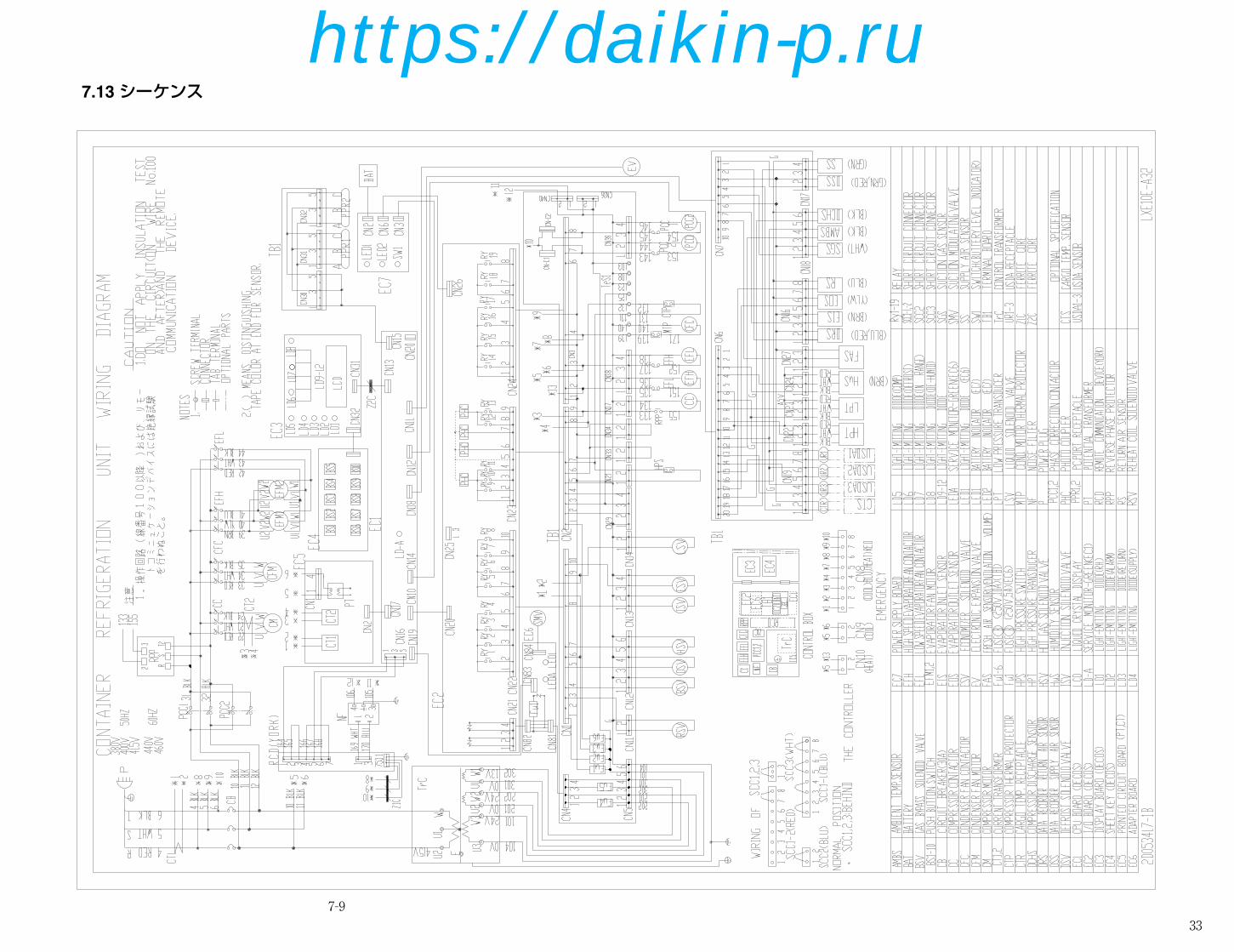
7-9
7.13 シーケンス
33
33-34_LXE10E-A32A,B_SG.qx 08.1.23 6:53 PM ページ 33
https://daikin-p.ru
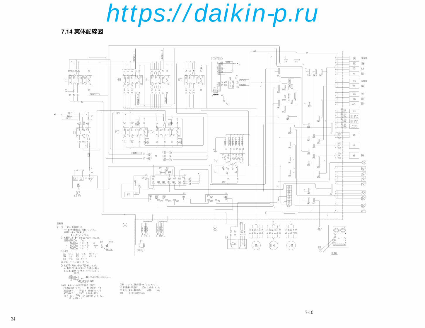
7-10
7.14 実体配線図
34
33-34_LXE10E-A32A,B_SG.qx 08.1.23 6:53 PM ページ 34
https://daikin-p.ru

359-1
9.1 換気口開度検知器(FAセンサ)
Connector
換気口カバー
コントロールボックス FAセンサ 凝縮器ファン
●型式 5ZZ2157
本体(ワイヤ巻き取り部とポジショメータ)とワイヤー部分で構成されています。ワイヤーの先端が換気口カバーに締結されており、換気口の開度を検知します。
(1) 交換方法①コントロールボックス内でリード線(コネクタ接続)を取り外します。
②換気口カバーとワイヤー先端を締結しているネジを取り外します。
③ケーシングに本体を取付けているネジを外し、ワイヤーを含めてセンサ一体を交換します。注)必ずワイヤーを含めた一体で交換をして下さい。
④交換後センサ本体のポジショメータ取付ネジ部をシリコンシーラントでシールします。
●メンテナンスについては、空冷凝縮器はファングリル、ファンガイド、レコーダボックスを、蒸発器は庫内パネルを取外して行ないます。
空冷凝縮器
蒸発器
4.2.17 空冷凝縮器、蒸発器特殊波形フィンを採用した小形で熱交換のむらのない、高熱交換効率のクロスフィンコイルを使用しています。●空冷凝縮器の洗浄空冷凝縮器は耐食性強化のため、厚肉フィン、電着塗装を行っていますが、使用後は、塩分が多量に付着するので、清水で洗浄してください。
35-36_LXE10E-A32A,B_SG.qx 08.1.21 4:52 PM ページ 35
https://daikin-p.ru

36
35-36_LXE10E-A32A,B_SG.qx 08.1.21 4:52 PM ページ 36
https://daikin-p.ru

37
ORDERING INSTRUCTIONS
The parts list contains the parts of the DAIKIN Marine Type Container Refrigeration Units. Please read the following items before using the list.1. When ordering the parts, be sure to specify the model No., the name of part and the type
of part. When ordering the parts for which no parts NO. is shown in the PARTS NO.column, be sure to describe DWG.NO..
2. The list shows the parts only for replacement or repairing at the job site. Certain partsrequire a production lead time or are supplied as a set, so please contact with the nearestDAIKIN PARTS CENTRE.
3. Index symbols;Meaning of the ranking A,B and C are as follows;A. The most important spare parts
1. The parts whose malfunction cause fatal damage to the unit.2. The parts with high risk of malfunction.3. The parts that are worn out after an extended service period.
B. The important spare parts next to A, but the risk of malfunction is not so high.C. The parts with low risk of malfunction, but recommendable to stock to cope with
damage during handling of container box and long delivery time, etc.The parts without A, B and C mark is the parts whose necessity is not so high undernormal operation.
パーツリスト使用上の注意
このパーツリストはダイキン海上コンテナ冷凍装置の部品を集録してあります。パーツリスト使用にあたっては、必ず次の注意事項をご一読の上使用していただくようお願いいたします。
1.部品のご注文の際は機種名、部品番号、および部品名、形式を必ずご指定ください。なお、部品番号欄が空白になっている部品は、図面番号で指示願います。
2.掲載部品の範囲は、あくまでも現地にて分解修理できるところまで記載しております。一部部品につき納期のかかるものおよびセット単位となるものもありますので、お近くのダイキンパーツセンター又はサービスステーションに相談願います。
3.INDEXの説明INDEXのA、B、Cの意味は下記の通りです。A. 最も重要な部品1.故障した場合に最も重大な損害を与えると思われる部品2.故障の確率が高いと思われる部品3.長期の使用で摩耗して使用できなくなる部品B. 故障発生の確率は高くはないが、Aについで重要な部品C. 故障発生の確率は低いが、コンテナボックスの運搬中の事故や、部品の納期が長期になると思われる等の理由で、在庫をお勧めする部品
A,B,Cマークの無い部品は、通常の運転では必要性は高くない部品です。
37-49_LXE10E-A32A,B.Qx 08.1.24 2:36 PM ページ 37
https://daikin-p.ru

38
Denomination of Model Name
L X E E
NOMINAL HORSE POWER 5 : 510 : 10
CONDENSER COOLING TYPE NIL : AIR and WATER COOLED TYPE A : AIR COOLED TYPE
OPTION NUMBER
機種名について
L X E E
称呼馬力 5 : 5 10 : 10
凝縮器冷却方式 なし:空水冷兼用形 A :空冷専用形
オプション番号
Note) "R" GIVEN AFTER OPTION NUMBER STANDS FOR "REVISION"
AND IT IS GIVEN FOR THE UNIT WHICH IS SPECIALLY
MODIFIED.
注)オプション番号の後に R がつく機種は、改造機で、特別な仕様が加えられていることを意味します。
37-49_LXE10E-A32A,B.Qx 08.1.24 2:36 PM ページ 38
https://daikin-p.ru

39
C O N T E N T S
目 次
Page
A. Parts related with the unit(outside)………………………………………………………………………40庫外関連部品
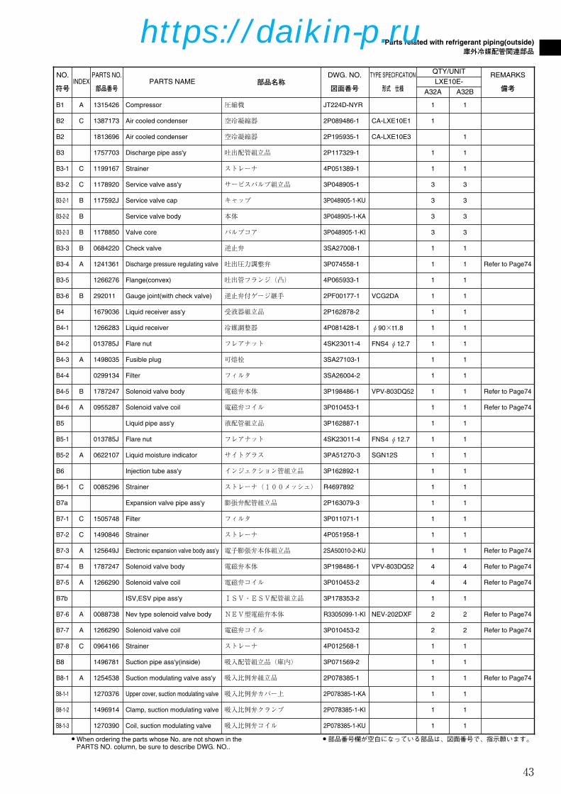
B. Parts related with refrigerant piping(outside) …………………………………………………………42庫外冷媒配管関連部品
C. Parts related with the unit(inside) ………………………………………………………………………46庫内関連部品
D. Parts related with refrigerant piping(inside) …………………………………………………………48庫内冷媒配管関連部品
E. Other parts(Pipe clamp, sealing and insulation material etc.) …………………………………………50その他部品(配管固定具、シール材、防熱材等)
F. Control box …………………………………………………………………………………………………58コントローラボックス
G. Parts related with name plate ……………………………………………………………………………62銘板関連
I. Parts related with option 1 – USDA………………………………………………………………………64オプション関連部品1 - USDA関連
J. Parts related with option 2 – MODEM …………………………………………………………………66オプション関連部品2 - モデム
K. Parts related with option 3 – Others ……………………………………………………………………68オプション関連部品3 - その他
1. Indoor fan guard 庫内ファンガード2. Evaporator coil 蒸発器コイル組立品
L. List of size for standard pipe clamp ……………………………………………………………………70配管固定具サイズ表
1. Resin clamp 樹脂バンド2. Tube clamp 管止金3. Cushion rubber for pipe clamp 管止金用緩衝ゴム
M.Note for ordering spare parts ……………………………………………………………………………72部品発注の際の注意事項
1. Parts recommended to be ordered together with packing, gasket, sealing material and name plate発注の際にパッキングやシール材、銘板等の同時発注を推奨する部品
2. Order for motorized valve, solenoid valve and pressure regulating valve電動弁・電磁弁・圧力調整弁の発注
3. Order for pressure transducer 圧力センサーの発注4. Order for temperature sensor 温度センサーの発注
N. Measuring and adjusting tools …………………………………………………………………………77測定調整用工具
1. Tools for emergency operation 緊急運転用工具2. Personal computer cable (for DCCS) パソコンケーブル(DCCS用)
37-49_LXE10E-A32A,B.Qx 08.1.24 2:36 PM ページ 39
https://daikin-p.ru

40
Parts related with the unit(outside)
庫外関連部品
A20
A19A30
A18
A7
A13
A36
A17
A9A8
E13
A1
A35A31
A32
A33A34
A14
A16
A2
A3
A15 (Refer to 73Page)
E55
A11
A10
A12
A5 A6
A4 (Refer to 72Page)
A19
A21
A21
A22
A20
37-49_LXE10E-A32A,B.Qx 08.1.24 2:36 PM ページ 40
https://daikin-p.ru

41
Parts related with the unit(outside)
庫外関連部品
NO.
符号INDEX
PARTS NO.
部品番号PARTS NAME 部品名称
DWG. NO.
図面番号
TYPE SPECIFICATION
形式 仕様
QTY/UNITREMARKS
備考
A1 1448270 Power plug 電源プラグ 3P109727-1
A2 A 0954936 Condenser fan motor 凝縮器電動機 3P005566-1
A3 B 0980618 Fan Brade(outside) プロペラファン(庫外側) 2P004956-1 P44H11S
A4 C 1612576 Access panel(FRP) サービス扉組立品 1P006678-5 Refer to Page72
A5 1266207 Cushion material(access panel) クッション材(サービス扉) 3P033608-1 Refer to Page72
A6 1196113 Sealing material(access panel) シール材(サービス扉) 3P001640-2 Refer to Page72
A7 1326705 Wire clamp 電線止め金 4P090422-1
A7 1779734 Wire clamp 電線止め金 4P090422-2
A8 C 1266199 Drain hose ドレンホース 3P011299-1 For trap type
A9 537320 Hose band ホースバンド R4716528-3
A10 1266137 Fan guide stay ass'y(outside) ファンガイドステー組立品(庫外側) 3P027891-1
A10 1813689 Fan guide stay(center) ファンガイドステー(中央) 3P007593-1
A11 1588356 Fan guide(outside) ファンガイド(庫外側) 1P050906-6
A12 C 1588349 Discharge grill 吹出グリル 1PA53427-6
A13 1369663 Mounting plate 2, cable storage ケーブル収納部取付板2 4P006981-2
A14 1564660 Cabel holding sheet metal ケーブル収納部板金(圧縮機前板:有/無共用) 3P128458-1
A15 1739286 Front plate(CA) 前板(CA) 2P173133-1 Refer to Page73
A16 1600504 C,BOX Front plate コントロールボックス前板(左) 2P093861-5
A17 1661338 Fixing plate 外板取付板(1) 3P170539-1
A21 1775446 Wing bolt 蝶ボルト 4P048681-2
A35 1267084 Gasket, resin bolt パッキン樹脂ボルト用 4PA63573-1
A36 1679416 Front panel(right) 前板(右) 3P173348-1
E55 1267077 Packing for prevention of vibration CA前板ビビリ防止パッキン 4P050050-1
A18 1661321 Fixing plate 外板取付板(2) 3P170535-1
A19 B 1847365 Ventilation cover 換気口蓋 3P134985-1 Refer to Page73
A22 0275145 Plain washer(Woods round type) 平座金(木材用丸) 4SK07006-6 M6
A30 1496820 Protection cover(2) 温度計挿入口保護カバー(2) 4P085921-2
A31 1266238 Hexagon head bolt PC六角ボルト R4290921-125 M12X25
A32 1386930 Latch(victor chain) 掛金(ビクターチェーン) 4P063801-1
A33 1775453 Tapping screw タッピンネジ 4SK05064-10
A34 844012S Plain washer 平座金 4SK07005-3 M3SUS
1 1
1 1
1 1
2 2
2 2
2 2
1
1
1 1
1 1
1
1
1 1
1 1
1 1
1 1
1 1
1 1
1 1
1 1
1 1
4 4
21 21
1 1
2 2
2 2
2 2
23 23
2 2
1
2 2
LXE10E-
A32A A32B
A20 1266221 Sealing material(ventilator) シール材(換気口) 4P016185-1 2 2 Refer to Page73
A36 1787456 Front panel(right) RESIN 前板(右)<樹脂> 2P175878-1 1
E13 1266788 Resin clamp 樹脂バンド NE41015-12 MILK WHITE 6 6
37-49_LXE10E-A32A,B.Qx 08.1.24 2:36 PM ページ 41
https://daikin-p.ru

42
Parts related with refrigerant piping(outside)
庫外冷媒配管関連部品
B21B12
A
A
B12
View A-A
B11詳細(Detail of B11)B23
B26B11
Discharge pipe
Feeler bulb inserting pipe
Feeler bulb
B13詳細(Detail of B13)
B13
B23Suction pipe
Feeler bulb inserting pipe
Feelerbulb
LSV
SMV
DPR
B2
B8-1-1
B8-1-2
B8-1-3B8-1-5
B8-1-4
B3-2-2
B3-2
B3-2-1
B3-2-3
B19
B16
B11
B15
B3-6
B3-5
B24
B14B1
B25
B9-2
B9
B3-3
B13
B3
B6
B8B5
B8-1
B3-4 B4-4
B4
B9-1-2
B9-1-1
B9-1
B9-1-3
B3-2-2
B3-2-1
B3-2
B3-2-3
B4-3
B4-1
B4-6B4-5
B5-2
B5-1B10
B4-2B3-1
B6-1
DSVRSV
HSV
ESVISV
BSV
EV
B7a
B7b
B7-1
B7-6
B7-7B7-4
B7-5
B7-2
B7-8
B7-3
B20
B12詳細(Detail of B12)
B12
37-49_LXE10E-A32A,B.Qx 08.1.24 2:36 PM ページ 42
https://daikin-p.ru
43
Parts related with refrigerant piping(outside)
庫外冷媒配管関連部品
● When ordering the parts whose No. are not shown in thePARTS NO. column, be sure to describe DWG. NO..
● 部品番号欄が空白になっている部品は、図面番号で、指示願います。
NO.
符号INDEX
PARTS NO.
部品番号PARTS NAME 部品名称
DWG. NO.
図面番号
TYPE SPECIFICATION
形式 仕様
QTY/UNITREMARKS
備考
B1 A 1315426 Compressor 圧縮機 JT224D-NYR
B2 C 1387173 Air cooled condenser 空冷凝縮器 2P089486-1 CA-LXE10E1
B2 1813696 Air cooled condenser 空冷凝縮器 2P195935-1 CA-LXE10E3
B3 1757703 Discharge pipe ass'y 吐出配管組立品 2P117329-1
B3-1 C 1199167 Strainer ストレーナ 4P051389-1
B3-2 C 1178920 Service valve ass'y サービスバルブ組立品 3P048905-1
B3-2-1 B 117592J Service valve cap キャップ 3P048905-1-KU
B3-2-2 B Service valve body 本体 3P048905-1-KA
B3-2-3 B 1178850 Valve core バルブコア 3P048905-1-KI
B3-3 B 0684220 Check valve 逆止弁 3SA27008-1
B3-4 A 1241361 Discharge pressure regulating valve 吐出圧力調整弁 3P074558-1 Refer to Page74
B3-5 1266276 Flange(convex) 吐出管フランジ(凸) 4P065933-1
B3-6 B 292011 Gauge joint(with check valve) 逆止弁付ゲージ継手 2PF00177-1 VCG2DA
B4 1679036 Liquid receiver ass'y 受液器組立品 2P162878-2
B4-1 1266283 Liquid receiver 冷媒調整器 4P081428-1 φ90×t1.8
B4-2 013785J Flare nut フレアナット 4SK23011-4 FNS4 φ12.7
B4-3 A 1498035 Fusible plug 可熔栓 3SA27103-1
B4-4 0299134 Filter フィルタ 3SA26004-2
B4-5 B 1787247 Solenoid valve body 電磁弁本体 3P198486-1 VPV-803DQ52 Refer to Page74
B5-2 A 0622107 Liquid moisture indicator サイトグラス 3PA51270-3 SGN12S
B7-4 B 1787247 Solenoid valve body 電磁弁本体 3P198486-1 VPV-803DQ52 Refer to Page74
B7-5 A 1266290 Solenoid valve coil 電磁弁コイル 3P010453-2 Refer to Page74
B7-7 A 1266290 Solenoid valve coil 電磁弁コイル 3P010453-2 Refer to Page74
B4-6 A 0955287 Solenoid valve coil 電磁弁コイル 3P010453-1 Refer to Page74
B5 Liquid pipe ass'y 液配管組立品 3P162887-1
B6 Injection tube ass'y インジェクション管組立品 3P162892-1
B6-1 C 0085296 Strainer ストレーナ(100メッシュ) R4697892
B7a Expansion valve pipe ass'y 膨張弁配管組立品 2P163079-3
B7-1 C 1505748 Filter フィルタ 3P011071-1
B7-2 C 1490846 Strainer ストレーナ 4P051958-1
B7-3 A 125649J Electronic expansion valve body ass'y 電子膨張弁本体組立品 2SA50010-2-KU Refer to Page74
B7-8 C 0964166 Strainer ストレーナ 4P012568-1
B8-1-1 1270376 Upper cover, suction modulating valve 吸入比例弁カバー上 2P078385-1-KA
B8-1-3 1270390 Coil, suction modulating valve 吸入比例弁コイル 2P078385-1-KU
1 1
1
1
1 1
1 1
3 3
3 3
3 3
3 3
1 1
1 1
1 1
1 1
1 1
1 1
1 1
1 1
1 1
1 1
1 1
1 1
1 1
1 1
1 1
1 1
1 1
1 1
1 1
4 4
4 4
2 2
1 1
1 1
1 1
LXE10E-
A32A A32B
B5-1 013785J Flare nut フレアナット 4SK23011-4 FNS4 φ12.7 1 1
B7b ISV,ESV pipe ass'y ISV・ESV配管組立品 3P178353-2 1 1
B7-6 A 0088738 Nev type solenoid valve body NEV型電磁弁本体 R3305099-1-KI NEV-202DXF 2 2 Refer to Page74
B8 1496781 Suction pipe ass'y(inside) 吸入配管組立品(庫内) 3P071569-2 1 1
B8-1 A 1254538 Suction modulating valve ass'y 吸入比例弁組立品 2P078385-1 1 1 Refer to Page74
B8-1-2 1496914 Clamp, suction modulating valve 吸入比例弁クランプ 2P078385-1-KI 1 1
37-49_LXE10E-A32A,B.Qx 08.1.24 2:36 PM ページ 43
https://daikin-p.ru

44
Parts related with refrigerant piping(outside)
庫外冷媒配管関連部品
NO.
符号INDEX
PARTS NO.
部品番号PARTS NAME 部品名称
DWG. NO.
図面番号
TYPE SPECIFICATION
形式 仕様
QTY/UNIT
B8-1-4 1270408 Body, suction modulating valve 吸入比例弁弁本体 2P078385-1-KE 1
B8-1-5 1270415 Cover band, suction modulating valve 吸入比例弁カバーバンド 2P078385-1-KO 2
B9 Suction pipe ass'y(outside) 吸入配管組立品(庫外) 3P162880-1 1
B9-1 C 1178937 Service valve ass'y サービスバルブ組立品 3P048907-1 2
B9-1-1 B 1178867 Valve core バルブコア 3P048907-1-KI 2
B9-1-2 B 1637498 Service valve body 本体 3P048907-1-KA 2
B9-1-3 B 117591J Service valve cap キャップ 3P048907-1-KU 2
B9-2 1266315 Square flange 角フランジ 4PA61542-1 1
B10 A 1241385 Drier ass'y ドライヤ組立品 3P069859-1 1
B11 A 098332J Sensor, discharge pipe temperature(DCHS) 吐出管用センサ(DCHS) 3SA48009-10 1
B12 A 0798321 Sensor, ambient air temperature(AMBS) 外気温度センサ(AMBS) 3PA61769-6 ST9503-6(NIL) 1
B13 A 098333J Sensor, comp suction pipe temperature(SGS) 圧縮機吸込配管温度用センサ(SGS) 3PA61769-9 ST9503-9(white) 1
B14 1266322 Cable(comressor) ケーブル(圧縮機) 3P063458-1 1
B15 A 1587942 Low pressure transducer(LPT) 低圧圧力センサ(LPT) 3P141601-1 NSK-BD010F-070 1
B16 A 1587959 High pressure transducer(HPT) 高圧圧力センサ(HPT) 3P141602-1 NSK-BD030F-070 1
B19 A 1241378 High pressure switch 高圧圧力開閉器 3P071506-1 1
B20 A 138143J Electronic expansion valve coil 電子膨張弁コイル 2P010454-2 1
B21 1605244 Therminal fixing plate, Resin サーミスタ固定具(樹脂) 3P124175-1 3
B23 0423968 Mounting spring,thermistor サーミスタ取付バネ 4PA38890-1 3
B24 A 0132192 Flange packing, compressor discharge 圧縮機吐出側フランジパッキン 4SK20053-4 1
B25 A 0395032 Flange packing, compressor suction 圧縮機吸入側フランジパッキン R4221042-1 1
B26 1267147 Thermal insulation tube 断熱筒(吸入弁庫外側) 4P073602-1 1
1
2
1
2
2
2
2
1
1
1
1
1
1
1
1
1
1
3
3
1
1
1
LXE10E-
A32A
● When ordering the parts whose No. are not shown in thePARTS NO. column, be sure to describe DWG. NO..
● 部品番号欄が空白になっている部品は、図面番号で、指示願います。
A32B
Refer to Page76
Refer to Page76
Refer to Page76
Refer to Page75
Refer to Page75
Refer to Page74
37-49_LXE10E-A32A,B.Qx 08.1.24 2:36 PM ページ 44
https://daikin-p.ru

45
Parts related with refrigerant piping(outside)
庫外冷媒配管関連部品
NO.
符号INDEX
PARTS NO.
部品番号PARTS NAME 部品名称
DWG. NO.
図面番号
TYPE SPECIFICATION
形式 仕様
QTY/UNIT
LXE10E-
A32A
REMARKS
備考A32B
37-49_LXE10E-A32A,B.Qx 08.1.24 2:36 PM ページ 45
https://daikin-p.ru
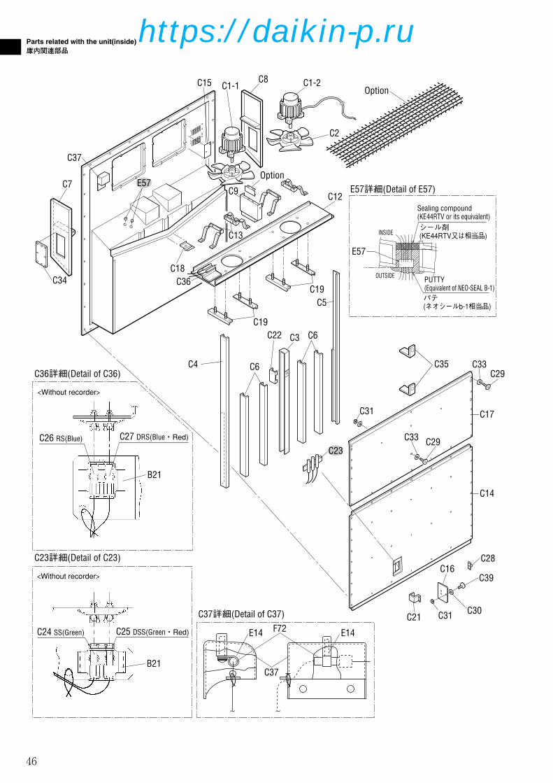
46
Parts related with the unit(inside)
庫内関連部品
C36詳細(Detail of C36)
C23詳細(Detail of C23)
C25 DSS(Green・Red)C24 SS(Green)
<Without recorder>
<Without recorder>
C37詳細(Detail of C37)
C27 DRS(Blue・Red)C26 RS(Blue)
E14
C37
C7
C34 C36C18
C13
C37
C15 C1-1C8 C1-2
C2
Option
C12
Option
C3C22 C6
C6
C5
C4
C19
C19
B21
B21
C9
E14F72
E57詳細(Detail of E57)
PUTTY(Equivalent of NEO-SEAL B-1)
Sealing compound(KE44RTV or its equivalent)
E57
INSIDE
OUTSIDE
シール剤(KE44RTV又は相当品)
パテ(ネオシールb-1相当品)
E57
C23
C31
C29C33
C17
C14
C33 C29
C16
C21 C31
C35
C30
C28
C39
37-49_LXE10E-A32A,B.Qx 08.1.24 2:36 PM ページ 46
https://daikin-p.ru

47
Parts related with the unit(inside)
庫内関連部品
NO.
符号INDEX
PARTS NO.
部品番号PARTS NAME 部品名称
DWG. NO.
図面番号
TYPE SPECIFICATION
形式 仕様
QTY/UNIT
C1-1 A 0955340 Three phase AC fan motor 三相交流ファン電動機 3PA07524-5 SPRK91A-42 1
C1-2 A 0955333 Three phase AC fan motor 三相交流ファン電動機 3PA07524-4 SPRK91A-42 1
C2 B 0777519 Fan brade(inside) プロペラファン(庫内側) P32P11F 2
C3 1686584 Center stay 中央ステー(裏板SUS 0.8t仕様) 3P164565-1 1
C4 1686577 Side stay サイドステー(1)(裏板SUS t0.8仕様) 3P164449-1 1
C5 1701159 Side stay(2) サイドステー(2)(裏板SUS t0.8仕様) 3P164450-1 1
C6 1686591 Rear stay 背面ステー(型材・裏板SUSt0.8仕様) 3P165208-1 4
C7 1700930 Casing frame, evaporator 蒸発器枠(1)ファンカバーSUS t0.8仕様 2P164446-1 1
C8 1700947 Casing frame, evaporator 蒸発器枠(2)ファンカバー t0.8SUS仕様 2P164446-2 1
C9 1726569 Fan guide fixing plate ファンガイド固定板(ファンカバーSUSt0.8 3P165414-1 1
C12 1667088 Fan guide ass'y ファンガイド組立品(レヒート・樹脂製サーミスタ) 3P166890-3 1
C13 1667172 Set plate, fan motor 電動機取付脚 3P171676-1 4
C14 1686197 Rear plate(lower) 裏板(下)(裏板SUS t0.8仕様) 2P163839-2 1
C15 1496990 Shield plate 遮蔽板 4P123922-1 1
C16 1686926 Supply sensor inspection door サプライセンサ点検蓋(裏板SUS t0.8仕様) 4P166062-1 1
C17 1686205 Rear plate(upper) 裏板(上)(裏板SUS t0.8仕様) 2P163840-2 1
C18 1266485 Partition plate(drain outlet) 仕切板(ドレン出口) 4P011317-1 1
C19 1135978 Reinforce plate, fan motor 補強板(ファン電動機台) 4P011316-1 4
C21 1135125 Hinge 蝶番 3P043374-1 1
C26 A 1713354 Sensor(RS) センサー(RS) 3PA61769-18 1
C35 1496976 Rear plate(middle) fixture 裏板(中)固定具 4P105391-1 2
C37 1667280 RH sensor mounting plate RHセンサ固定板 4P164832-1 1
C39 860011 Speed bolt スピードボルト(M6) 4P048680-1 1
C22 1686919 Support plate 支柱補強柱(裏板SUS t0.8仕様) 4P165649-1 1
C24 A 1713330 Sensor(SS) センサー(SS) 3PA61769-16 1
C25 A 1713347 Sensor(DSS) センサー(DSS) 3PA61769-17 1
C27 A 1713361 Sensor(DRS) センサー(DRS) 3PA61769-19 1
C28 860015 Universal nut 自在ナット R4713188-1 1
C29 1685170 Pan head screw ナベ小ネジM5SUS(±穴付) 4P167690-1 20
C30 860005 Washer, speed bolt スピードボルト用座金 R4713334 3
C31 840002 Drop out prevention washer 脱落防止座金 R4718607-6 3
C33 1685187 Washer 木材座金M5用(φ20) 4P170127-5 21
C34 1380848 Cover カバー 3P090387-1 1
B21 1605244 Therminal fixing plate, Resin サーミスタ固定具(樹脂) 3P124175-1 3
E14 0508162 Resin clamp 樹脂バンド NE41015-3 1
E57 1267091 Wiring protection bush 配線保護ブッシュ 4P023920-1 BLACK 2
F72 A 1780284 Humidy sensor(HUS) 湿度センサー 3PA61738-3 RHU-650B-D2 1
1
1
2
1
1
1
4
1
1
1
1
4
1
1
1
1
1
4
1
1
1
1
1
1
1
20
3
3
21
1
2
1
1
3
1
2
1
LXE10E-
A32A
REMARKS
備考A32B
Refer to Page76
Refer to Page76
Refer to Page76
Refer to Page76
C23 1605466 Mounting plate サプライセンサ取付板 4P144433-1 1 1
37-49_LXE10E-A32A,B.Qx 08.1.24 2:36 PM ページ 47
https://daikin-p.ru
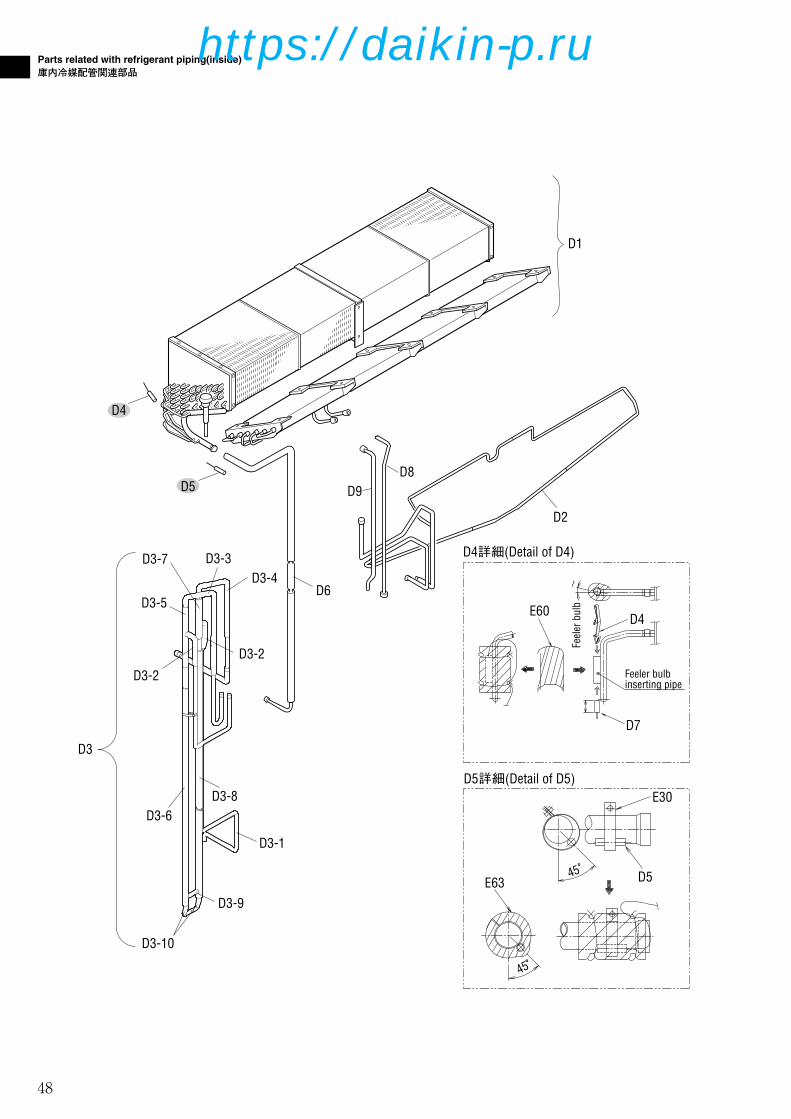
48
Parts related with refrigerant piping(inside)
庫内冷媒配管関連部品
D6
D4詳細(Detail of D4)
D5詳細(Detail of D5)
45°
45°E63 D5
E30
~
E60
D7
D4
Feel
er b
ulb
Feeler bulbinserting pipe
D3-10
D3-6
D3-2
D3-2
D1
D3-4D3-3
D2
D8D9
D3-5
D3-7
D3
D3-9
D3-1
D3-8
D4
D5
37-49_LXE10E-A32A,B.Qx 08.1.24 2:36 PM ページ 48
https://daikin-p.ru

49
Parts related with refrigerant piping(inside)
庫内冷媒配管関連部品
NO.
符号INDEX
PARTS NO.
部品番号PARTS NAME 部品名称
DWG. NO.
図面番号
TYPE SPECIFICATION
形式 仕様
QTY/UNIT
D1 C 1683927 Evaporator ass'y 蒸発器組立品 2P163797-1 CRB-LXE10E9
D1 1787470 Evaporator ass'y 蒸発器組立品 2P195931-1 CRB-LXE10E15 1
D2 1683934 ass'y for pipe of drain pan ドレンパン配管組立品(レヒート) 2P167639-2 1
D3 1683941 Heat exchanger ass'y with insulation 熱交換器防露筒組立品 3P167421-2 1
D3-1 1863475 Dowble tube heat exchanger ass'y 二重管式熱交換器組立品 2P167001-2 1
D3-2 1549762 Insulation tube, gas pipe(1) ガス配管(1)防露筒 3P114518-1 2
D3-3 1683958 Insulation tube, liquid pipe(1) 液配管(1)防露筒 3P167441-1 1
D3-4 1683965 Insulation tube, liquid pipe(2) 液配管(2)防露筒 3P167441-2 1
D3-5 1380918 Thermal insulation tube 断熱筒(熱交外管) 4P103439-1 1
D3-6 1380925 Thermal insulation tube 断熱筒(熱交外管) 4P103439-2 1
D3-7 1380932 Thermal insulation tube 断熱筒(熱交外管) 4P103439-3 1
D3-8 1380949 Thermal insulation tube 断熱筒(熱交外管) 4P103439-4 1
D3-9 1549971 Thermal insulation, gas pipe(3) ガス配管(3)防露筒 3P114518-4 1
D3-10 1549988 Thermal insulation, liquid pipe(3) 液配管(3)防露筒 4P110520-2 2
D4 A 156282J Senser(EIS) センサー(EIS) 3P012118-2 1
D5 A 156283J Senser(EOS) センサー(EOS) 3PA61769-15 1
D6 1266308 Filter フィルタ 3P032328-1 1
D7 0423968 Mounting spring,thermistor サーミスタ取付バネ 4PA38890-1 3
D8 1713967 Reheat coil inlet pipe レヒートコイル入口管(塗装無)MSL 3P158828-2 1
E63 1267154 Insulation tube, evaporater header 蒸発器ヘッダー防露筒 4P073525-1 1
D9 1713974 Reheat coil outlet pipe レヒートコイル出口管(塗装無)MSL 3P158829-2 1
E30 537320 Hose band ホースバンド R4716528-3 1
E60 1267293 Thermal insulation tube 断熱筒配管緩衝材 4P011309-4 2
1
1
1
1
2
1
1
1
1
1
1
1
2
1
1
1
3
1
1
1
2
1
LXE10E-
A32A
REMARKS
備考A32B
Refer to Page76
Refer to Page76
37-49_LXE10E-A32A,B.Qx 08.1.24 2:36 PM ページ 49
https://daikin-p.ru

50
Other parts(Pipe clamp, sealing and insulation material etc.)
その他部品(配管固定具、シール材、防熱材等)
E断面(Section of E)
B詳細(Detail of B)
Tie wrap
Wires
C詳細(Detail of C)
E91
E60
E11E13
B
EE
C
E83
E82
E79
E83
Condenser coil
E87
E86E87
50-57_LXE10E-A32A,B.Qx 08.1.24 11:59 AM ページ 50
https://daikin-p.ru

51
Other parts(Pipe clamp, sealing and insulation material etc.)
その他部品(配管固定具、シール材、防熱材等)
E32
E8
E7
E33
E34
E2
※(L = XX mm)と表記のものは、緩衝ゴム(E35)の長さです。(配管のサイズに合わせて切って使用ください。)※(L = XX mm) indicates the length of cushion rubber E35.(Cut to suit pipe size.)
矢視A/B(View A/B)
E29
E90
E90
E90
E78
E16E16
矢視D(View D)
受液機器部詳細(Receive part detail)
ドライヤー部詳細(Dryer part detail)
圧力センサー配管部詳細(Pressure tranducer detail)
E25(L=65mm)
E6(L=90mm)
E1
E17
E7/8
E10
E31(L=40mm)
E22E22
E6
E84
B
A
E5
E4
E88
E61
E21(L=60mm)
E89
E26
E22
RSV
50-57_LXE10E-A32A,B.Qx 08.1.24 11:59 AM ページ 51
https://daikin-p.ru
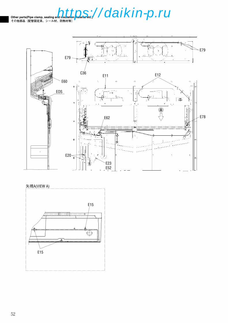
52
Other parts(Pipe clamp, sealing and insulation material etc.)
その他部品(配管固定具、シール材、防熱材等)
EOS
E60
矢視A(VIEW A)
E15
E15
C36E11 E12
A
E23E52
E20
E78E62
E79
E79
50-57_LXE10E-A32A,B.Qx 08.1.24 11:59 AM ページ 52
https://daikin-p.ru
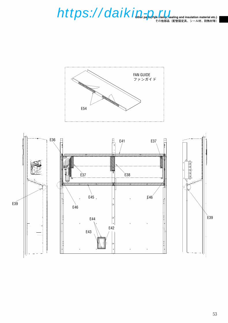
53
Other parts(Pipe clamp, sealing and insulation material etc.)
その他部品(配管固定具、シール材、防熱材等)
FAN GUIDEファンガイド
E43
E44
E45
E37
E46
E46
E38
E37E41
E54
E42
E36
E39
E39
50-57_LXE10E-A32A,B.Qx 08.1.24 11:59 AM ページ 53
https://daikin-p.ru

54
Other parts(Pipe clamp, sealing and insulation material etc.)
その他部品(配管固定具、シール材、防熱材等)
E40
E69
E75
E70
E40
E63
E76
E64
E67
E66
E65
E93
E77
E61
E78
E72
50-57_LXE10E-A32A,B.Qx 08.1.24 11:59 AM ページ 54
https://daikin-p.ru

55
Other parts(Pipe clamp, sealing and insulation material etc.)
その他部品(配管固定具、シール材、防熱材等)
NO.
符号INDEX
PARTS NO.
部品番号PARTS NAME 部品名称
DWG. NO.
図面番号
TYPE SPECIFICATION
形式 仕様
QTY/UNIT
E1 1266694 Set plate, discharge pipe 吐出配管取付板 4P079462-1
E1 1779727 Set plate, discharge pipe 吐出配管取付板 4P079462-2 1
E2 1266702 Fixture plate, receiver レシーバー固定具 4P011318-2 t1.5
E2 1779710 Fixture plate, receiver レシーバー固定具 4P011318-3 1
E4 1683972 Pipe fixing plate 配管取付板組立品(MSL) 4P158750-1 1
E5 1726608 Mounting plate 電磁弁取付板 4P172423-1 1
E6 1592425 Tube clamp 管止め金 NE31016-58 3
E7 1266764 Fitting band, dryer ドライヤー取付バンド 4PA51194-1
E7 1779804 Fitting band, dryer 取付バンド(ドライヤー) 4PA51194-2 1
E8 1266771 Set plate, dryer 取付板(ドライヤ) 4P076788-1 t2.0
E8 1787487 Set plate, dryer 取付板(ドライヤ) 4P076788-2 1
E10 1222764 Resin clamp 樹脂バンド NE41015-9 MILK WHITE 1
E11 0944528 Resin clamp 樹脂バンド NE41015-7 MILK WHITE 2
E12 0142492 Resin clamp 樹脂バンド NE41015-10 MILK WHITE 2
E13 1266788 Resin clamp 樹脂バンド NE41015-12 MILK WHITE 6
E14 0508162 Resin clamp 樹脂バンド NE41015-3 1
E15 0782775 Tube clamp 管止め金 NE31016-51 5
E16 1584215 Nylon coating tube clamp ナイロンコーティング管止め金 4P143802-51 8
E22 1584239 Nylon coating tube holder ナイロンコーティング管止め金 4P143802-71 4
E31 1380970 Hot gas tube clamp ホットガス管止め金 4PA43040-1 1
E32 1266889 Cushion rubber, pipe clamp 緩衝ゴム(管止用) 4P064896-1 t2.0 1
E33 1266896 Seal packing シールパッキン 4P011314-1 1
E38 1266942 Packing(for evaporator) パッキン(蒸発器) 4P063465-2 1
E41 1386954 Packing, fan guide ファンガイドパッキン 3P090183-1 1
E17 1584208 Nylon coating tube clamp ナイロンコーティング管止め金 4P143802-52 1
E20 1386992 Duble tube heat exch<tube hol 二重管熱交管止め金 4P103281-56 2
E21 0016290 Tube clamp 管止め金 NE31016-56 1
E23 1266827 Fixing plate, filter フィルタ固定具 4P071794-1 t1.5 1
E24 1386985 Tube clamp, double tube heat exch 二重管熱交管止め金 4P103281-51 1
E25 1266841 Tube clamp 管止め金(2) 4P005817-2 1
E26 1584215 Nylon coating tube clamp ナイロンコーティング管止め金 4P143802-51 2
E27 1266858 Tube clamp 管止め金 NE31016-59 1
E29 1584246 Nylon coating tube clamp ナイロンコーティング管止め金 4P143802-59 1
E30 537320 Hose band ホースバンド R4716528-3 1
E34 1270446 Dryer cushion rubber ドライヤ緩衝ゴム 4PA53083-2 1
E35 1584253 Cushion rubber 緩衝ゴム NE41013-3-300 1
E36 1386947 Sealing material, evaporator frame 蒸発器受枠(1)シール材 4P090149-1 1
E37 1266935 Packing(for evaporator) パッキン(蒸発器) 4P063465-1 2
1
1
1
1
3
1
1
1
2
2
6
1
5
8
1
2
1
4
1
1
1
2
1
1
1
1
1
1
1
1
1
2
1
1
LXE10E-
A32A
E39 1381036 Packing パッキン 4P095033-1 2 2
REMARKS
備考A32B
Page 51
Page 51
Page 51
Page 51
Page 51
Page 51
Page 51
Page 51
Page 51
Page 51
Page 51
Page 51
Page 50,52
Page 52
Page 50
Page 47
Page 52
Page 51
Page 51
Page 52
Page 51
Page 51
Page 52
Page 51
Page 51
Page 51
Page 49
Page 51
Page 51
Page 51
Page 51
Page 53
Page 53
Page 53
Page 53
Page 53
E40 1862124 Support 支柱 4P050539-1 2 2 Page 54
50-57_LXE10E-A32A,B.Qx 08.1.24 11:59 AM ページ 55
https://daikin-p.ru

56
Other parts(Pipe clamp, sealing and insulation material etc.)
その他部品(配管固定具、シール材、防熱材等)
NO.
符号INDEX
PARTS NO.
部品番号PARTS NAME 部品名称
DWG. NO.
図面番号
TYPE SPECIFICATION
形式 仕様
QTY/UNIT
E45 1267008 Sealing packing シールパッキン 3P011293-1 1
E46 1605422 Side stay packing サイドステーパッキン 4P095033-2 2
E52 1584260 Cushion rubber 緩衝ゴム NE41013-4-230
E54 1267060 Packing for prevention of air bypass バイパス防止用パッキン 4P011733-1 2
E57 1267091 Wiring protection bush 配線保護ブッシュ 4P023920-1 BLACK 2
E61 1683989 Insulation tube EV outlet pipe 膨張弁出口配管防露筒(P&O) 4P170252-1 1
E62 1267123 Thermal insulation tube piping 断熱筒配管緩衝材 4P011309-1 3
E63 1267154 Insulation tube, evaporater header 蒸発器ヘッダー防露筒 4P073525-1 1
E64 1267161 Cushion material suction pipe(1) 吸入配管緩衝材(1) 3P073468-1 1
E65 1267178 Cushion material suction pipe(2) 吸入配管緩衝材(2) 3P073468-2 1
E66 1267224 Cushion material suction pipe(3) 吸入配管緩衝材(3) 3P073468-3 1
E67 1584378 Suction pipe 吸入配管断熱材 4P140007-1 1
E69 1267255 Thermal insulation tube 断熱筒(吸入弁庫外側) 4P081186-1 1
E70 1267262 Thermal insulation tube 断熱筒(圧縮機根元吸入弁) 4P081187-1 1
E72 1267286 Thermal insulation tube 断熱筒配管緩衝材 4P011309-3 1
E75 1448371 Suction solenoid valve insulator 吸入比例弁防熱材(1) 2P079441-1 1
E78 1278921 Heat protection tie wrap 耐熱用タイラップ 4SA90202-1 5
E89 1656165 Mounting plate, solenoid valve 液電磁弁・サプライセンサ固定板(カバー有) 4P165877-1
E89 1779741 Mounting plate 液電磁弁・サプライセンサ固定板(カバー有) 4P165877-2 1
E90 1381012 Protection rubber 保護ゴム 4PA43128-1 6
E76 1267325 Thermal insulation tube(drain outlet) 断熱筒(ドレン入口管防露筒) 4P067126-1 1
E77 1485921 Thermal insulation tube 熱交入口管防露筒 4P117089-1 1
E79 0024640 Rubber bush ゴムブッシュ R3713279-3 5
E82 1267370 Rubber bush ゴムブッシュ R3713279-2 2
E83 1267387 U-packing UP字形パッキン NA40014-4-500 L=500 1
E84 B 1605509 Heat shrinkable tube 熱収縮チューブ 4P151322-1 2
E86 B 1270453 Heat shrinkable tube 熱収縮チューブ 4P075241-1 1
E87 B 1497070 Thermal insulation tape, no-dry 不乾性形断熱テープ 3SA90101-3-KA 3
E88 1667297 LSV cover 液電磁弁カバー 4P164903-1 1
E91 1448388 Suction flange 吸入フランジシール材 4P083248-1 1
E93 1381029 Thermal insulation tube レヒートコイル出入口連絡配管防露筒 4P102857-1 2
1
2
1
2
2
1
3
1
1
1
1
1
1
1
1
1
1
1
5
5
2
1
2
1
3
1
1
7
1
2
LXE10E-
A32A
E55 1267077 Packing for prevention of vibration CA前板ビビリ防止パッキン 4P050050-1 2 2
E60 1267293 Thermal insulation tube 断熱筒配管緩衝材 4P011309-4 2 2
REMARKS
備考A32B
Page 53
Page 53
Page 52
Page 53
Page 41
Page 47
Page 50,52
Page 51,54
Page 52
Page 54
Page 54
Page 54
Page 54
Page 54
Page 54
Page 54
Page 54
Page 54
Page 54
Page 54
Page 51,52,54
Page 50,52
Page 50
Page 50
Page 51
Page 50
Page 50
Page 51
Page 51
Page 51
Page 51
Page 50
Page 54
E42 1624290 Supply sensor sealing シール材(1) 4P154324-1 2 2 Page 53
E43 1624290 Supply sensor sealing シール材(1) 4P154324-1 2 2 Page 53
E44 1624308 Supply sensor sealing シール材(2) 4P154324-2 2 2 Page 53
50-57_LXE10E-A32A,B.Qx 08.1.24 11:59 AM ページ 56
https://daikin-p.ru

57
Other parts(Pipe clamp, sealing and insulation material etc.)
その他部品(配管固定具、シール材、防熱材等)
NO.
符号INDEX
PARTS NO.
部品番号PARTS NAME 部品名称
DWG. NO.
図面番号
TYPE SPECIFICATION
形式 仕様
QTY/UNIT
LXE10E-
A32A
REMARKS
備考A32B
50-57_LXE10E-A32A,B.Qx 08.1.24 11:59 AM ページ 57
https://daikin-p.ru

58
F7-1
F7-9 F13
F7-3
F16-1
F75
F16-2
F7-8
F7-4F7-7
F61F7-5
F7-6
F7-2
F18
F30
F27
F23F73
F24
F22
F58F17
F25
F59 F33
F46
F76
F57
F39
F7
Control box
コントローラボックス
58-80_LXE10E-A32A,B.Qx 08.1.24 2:39 PM ページ 58
https://daikin-p.ru

59
Control box
コントローラボックス
F34-1
F34-7
F20
F34 F34-3
F34-2
F34-4
F28
F71
F6
F32
F3
F42F62
F72
F74
F48
F36
F64F63
F67
F29
F26
F34-8-1
F34-8
F34-11 F34-5
F34-6F34-12 F34-13
F34-14
F34-10
F31-1
F34-9
F31
F38
F37
F35
F40
F49F50
F39
F41
F3
F78F70-2 F77
F70-1
F77-1F77-2
58-80_LXE10E-A32A,B.Qx 08.1.24 2:39 PM ページ 59
https://daikin-p.ru

60
Control box
コントローラボックス
NO.
符号INDEX
PARTS NO.
部品番号PARTS NAME 部品名称
DWG. NO.
図面番号
TYPE SPECIFICATION
形式 仕様
QTY/UNIT
F3 C 1136407 Hinge(control/box cover) 平蝶番(コントロールボックス蓋) 4P021346-1 2
F6 1796289 C.BOX welding ass'y コントロールボックス組立品(樹脂) 2P197567-1 1
F7 1739301 Control box cover ass'y コントロールボックス蓋組立品 2P171706-6 1
F7-1 C 1136407 Hinge(control/box cover) 平蝶番(コントロールボックス蓋) 4P021346-1 2
F7-2 1136414 Patch plate nut 当板ナット 4P044898-2 2
F7-3 1267875 Roller ワンタッチ金具用ローラ 3P054321-1 1
F7-4 1739318 Control box cover welding ass'y コントロールボックス蓋溶接組立品 3P172570-1 1
F7-5 1796265 Operation display cover 操作表示カバー(2) 3P078251-2 1
F7-6 A 1010815 Display board 表示基板 2P010368-2 1
F7-7 1497188 Rubber gasket パッキン(コントロールボックス蓋) 4P111693-1 1
F7-8 A 1295553 Control panel(with sheet key) コントロールパネル(シートキー付) 3P085319-1 1
F7-9 1128949 Packing パッキン(樹脂パネル) 3P030317-1 1
F13 1136539 Clamp クランプ金具 4P015574-2 3
F16-1 0907062 Seal washer シール座金(ボンテッド座金) 4PA21941-5 10
F16-2 1267488 Pan head machine screw アプセット小ネジ 4P067677-1 M5X16 10
F17 1739325 Set plate 機器取付板 2P165714-1 1
F18 1739332 Blind plate ブレーカ取付板 1P173093-1 1
F20 1630916 PC port fixing plate 樹脂製パソコンポート固定具(PPR5・無) 2P154325-4 1
F25 C 1562796 Low frequency transformer 低周波変圧器 3P139293-1 1
F32 1739349 Mounting plate humidity sensor 湿度センサ取付板 4P168053-1 1
F33 A 1787230 Reverse phase protector 逆相保護装置(RPP) 3P198363-1 346-440V 1
F34 1775477 Controller assemblies コントローラ組立品 3P172236-7 1
F34-6 1099957 Support color, PCB プリント基板サポートカラー MI49531-13 14
F34-8 A 1250783 PC board for suction modulating valve プリント基板組立品(吸入制御弁用) 3P065441-1 EC0058 1
F22 A 119893J Magnetic contactor(for Fans) 電磁接触器(ファン用) 3P055568-1 24V PAK-6J31C 3
F23 A 124149J Magnetic contactor(Phase correction contactor) 相順切換電磁接触器(PCC) 3P071508-3 24V RSK-35J 1
F24 A 119891J Magnetic contactor(Compressor) 電磁接触器(圧縮機) 3P055566-1 24V PAK35J-S536 1
F26 C 1381113 PC port connector パソコンポートコネクタ 3P073218-1 1
F27 A 1381120 Earth leakage circuit breaker 漏電遮断器 3P093326-1 1
F28 C 1141144 Contactor, receptacle コンタクタ 3P010806-1 HD10 6
F29 1381137 PC port connector ass'y パソコンポートカバー組立品 3P010743-2 1
F30 A 0954633 PT/CT board PT/CTボード 2P010906-3 1
F31 A 1679137 Terminal strip boaed 端子台基板 2P174377-1 1
F31-1 A 003065J Fuse, controller 制御用ヒューズ 4SA42006-4 250V 10A 6
F34-1 A 1642553 PCB ass'y プリント基板組立品 2P161091-2 1
F34-2 A 1775484 PCB ass'y プリント基板組立品 2P010367-3 EC0630 1
F34-3 1739363 Bottom plate(sheet metal) コントローラ底板 2P168028-1 1
F34-4 B 1739370 Controller cover 蓋(コントローラ) 2P168029-1 1
F34-5 1099940 Support bushing, PCB プリント基板サポートブッシュ MI49531-11 14
2
1
1
2
2
1
1
1
1
1
1
1
3
10
10
1
1
1
3
1
1
1
1
1
6
1
1
1
6
1
1
1
1
1
1
1
14
14
1
LXE10E-
A32A
F34-7 1267572 Rubber transistor 放熱用ゴムトランジスタ 4P005330-1 2 2
REMARKS
備考A32B
Refer to Page72
58-80_LXE10E-A32A,B.Qx 12.12.7 1:59 PM ページ 60
https://daikin-p.ru

61
Control box
コントローラボックス
NO.
符号INDEX
PARTS NO.
部品番号PARTS NAME 部品名称
DWG. NO.
図面番号
TYPE SPECIFICATION
形式 仕様
QTY/UNIT
F34-8-1 A 044543J Fuse, control 制御用ヒューズ 4SA42006-3 250V 5A 1
F34-9 1267596 Locking wire saddle ロッキングワイヤサドル 4P015570-2 LWS 3
F34-10 1267604 Flat cable clamp フラットケーブルクランプスナップタイプ 4P015573-1 1
F34-12 1267611 Speed bolt スピードボルト(M6) 4P048680-3 M6X20(S) 1
F34-13 860005 Washer, speed bolt スピードボルト用座金 R4713334 1
F35 1267628 Wire(wire ground) 電線(電線グランド) 4P067662-1 1
F36 1267635 Wire(wire ground) 電線(電線グランド) 4P067663-1 2
F37 1635346 Wire ground, flexible tube 樹脂製フレキシブル管用グランド 4P157387-1 2
F38 1635353 Flexible tube(resin) 樹脂製フレキシブル管 4P157410-1 2
F39 1267666 Quick fastener クイックファスナー 4P064642-1 2
F40 1861859 Universal nut 自在ナット 4P197298-1 1
F41 1743216 Wire ground,flexible tube 樹脂製フレキシブル管用コネクタ 4P010926-7 1
F42 833302 Nylon nut ナイロンナット R4716460-1 M4 4
F46 380401 Locking card spacer ロッキングカードスペーサー R3428091-2 4
F48 1739387 Packing for control box front plate パッキン(コントロールボックス前板(左)) 4P172580-1 1
F50 1136539 Clamp クランプ金具 4P015574-2 1
F57 1739394 Breaker plate 1 ブレ-カ取付板(1) 3P168052-1 1
F58 1739495 Mounting plate, elect components 電装品取付板(2) 4P064227-2 1
F63 1295630 Lever ワンタッチ金具 4P085171-1 1
F75 1780309 Bushing ワンタッチ金具ローラ用ブッシュ 4P171668-2 1
F76 1780316 Mounting plate, RPP 逆相保護装置取付板 4P168038-1 t1.0 1
F77 A 1733466 Battery charger ass'y 充電・残ボルトメータ組立品 3P171534-3 1
F59 1739402 Breaker plate 2 ブレ-カ取付板(2) 3P168051-1 1
F61 1295623 Fixtture(instruction ring) 固定具(インストラクションリング) 4P064698-1 Wire diameter 1
F62 1381175 Circuit board spacer サーキットボードスペーサ 4P000347-1 4
F64 1295647 Fixing plate for lever ワンタッチ金具取付板 4P085164-1 1
F67 833301 Nylon nut ナイロンナット R4716460-3 M6 11
F70-1 A 1684449 Chargeble battery PCB ass'y 充電器P板組立品 2P174898-1 1
F71 1381221 Wire harness 平行ピン(ドイチェ製シールピン) 3P040139-1 2
F72 A 1780284 Humidy sensor(HUS) 湿度センサー 3PA61738-3 RHU-650B-D2 1
F73 B 0954640 Noise filter ノイズフィルタ 2PA51273-1 ZCB2206-11 1
F74 1780291 Protection plate 保護板(YORK製モデム) 4P176030-1 1
F77-1 1780323 Mounting plate 充電・残ボルトメータ取付板 4P172284-2 1
F77-2 1684463 Spacer スペーサ 4P171495-1 4
F78 B 1679430 Battery 電池 3P174899-1 1
1
3
1
1
1
1
2
2
2
2
1
1
4
4
1
1
1
1
1
1
4
1
1
11
1
2
1
1
1
1
1
1
1
4
1
LXE10E-
A32A
F70-2 1733473 Mounting plate リチャージャブルバッテリーホルダー組立品(2) 4P175166-2 1 1
F34-14 840002 Drop out prevention washer 脱落防止座金 R4718607-6 2 2
REMARKS
備考A32B
F34-11 1750663 Ferrite core filter フェライトコアフィルタ 4EA76013-5 1 1
F49 1136539 Clamp クランプ金具 4P015574-2 1 1
58-80_LXE10E-A32A,B.Qx 08.1.24 2:39 PM ページ 61
https://daikin-p.ru

62
Parts related with name plate
銘板関連
58-80_LXE10E-A32A,B.Qx 08.1.24 2:39 PM ページ 62
https://daikin-p.ru
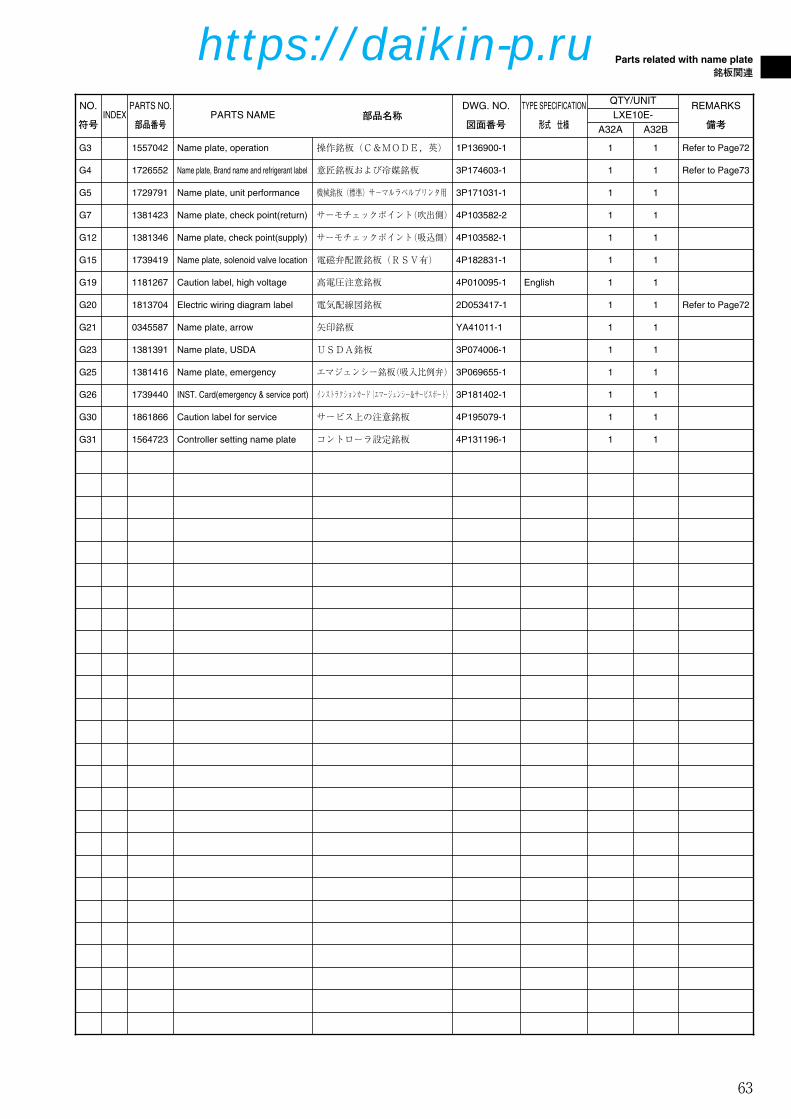
63
Parts related with name plate
銘板関連
NO.
符号INDEX
PARTS NO.
部品番号PARTS NAME 部品名称
DWG. NO.
図面番号
TYPE SPECIFICATION
形式 仕様
QTY/UNIT
G3 1557042 Name plate, operation 操作銘板(C&MODE,英) 1P136900-1 1
G5 1729791 Name plate, unit performance 機械銘板(標準)サ-マルラベルプリンタ用 3P171031-1 1
G7 1381423 Name plate, check point(return) サーモチェックポイント(吹出側) 4P103582-2 1
G15 1739419 Name plate, solenoid valve location 電磁弁配置銘板(RSV有) 4P182831-1 1
G19 1181267 Caution label, high voltage 高電圧注意銘板 4P010095-1 English 1
G20 1813704 Electric wiring diagram label 電気配線図銘板 2D053417-1 1
G21 0345587 Name plate, arrow 矢印銘板 YA41011-1 1
G23 1381391 Name plate, USDA USDA銘板 3P074006-1 1
G25 1381416 Name plate, emergency エマジェンシー銘板(吸入比例弁) 3P069655-1 1
G26 1739440 INST. Card(emergency & service port) インストラクションカード(エマージェンシー&サービスポート) 3P181402-1 1
G31 1564723 Controller setting name plate コントローラ設定銘板 4P131196-1 1
1
1
1
1
1
1
1
1
1
1
1
LXE10E-
A32A
G4 1726552 Name plate, Brand name and refrigerant label 意匠銘板および冷媒銘板 3P174603-1 1 1
REMARKS
備考A32B
Refer to Page72
Refer to Page73
Refer to Page72
G12 1381346 Name plate, check point(supply) サーモチェックポイント(吸込側) 4P103582-1 1 1
G30 1861866 Caution label for service サービス上の注意銘板 4P195079-1 1 1
58-80_LXE10E-A32A,B.Qx 08.1.24 2:39 PM ページ 63
https://daikin-p.ru

64
Parts related with option 1 – USDA
オプション関連部品1 – USDA関連
I1
I9
I3
I3
I3
I4
I4
I4
I3
I4
I6 I5
I7
I8
58-80_LXE10E-A32A,B.Qx 08.1.24 2:39 PM ページ 64
https://daikin-p.ru

65
Parts related with option 1 – USDA
オプション関連部品1 – USDA関連
NO.
符号INDEX
PARTS NO.
部品番号PARTS NAME 部品名称
DWG. NO.
図面番号
TYPE SPECIFICATION
形式 仕様
QTY/UNIT
I1 1622580 Mounting plate ass'y, receptacle USDA取付板(樹脂) 2P146266-1 1
I3 C 0991531 PC port connector パソコンポートコネクタ 3P010803-1 4
I4 1267541 Cover ass'y, PC port パソコンポートカバー組立品 3P010743-1 4
I5 C 1381113 PC port connector パソコンポートコネクタ 3P073218-1 1
I6 1381137 PC port connector ass'y パソコンポートカバー組立品 3P010743-2 1
I7 C 1141144 Contactor, receptacle コンタクタ 3P010806-1 HD10 8
I8 1381221 Wire harness 平行ピン(ドイチェ製シールピン) 3P040139-1 6
I9 1622597 USDA Receptacle cover USDAレセプタクルカバー 3P146268-1 1
1
4
4
1
1
8
6
1
LXE10E-
A32A
REMARKS
備考A32B
58-80_LXE10E-A32A,B.Qx 08.1.24 2:40 PM ページ 65
https://daikin-p.ru
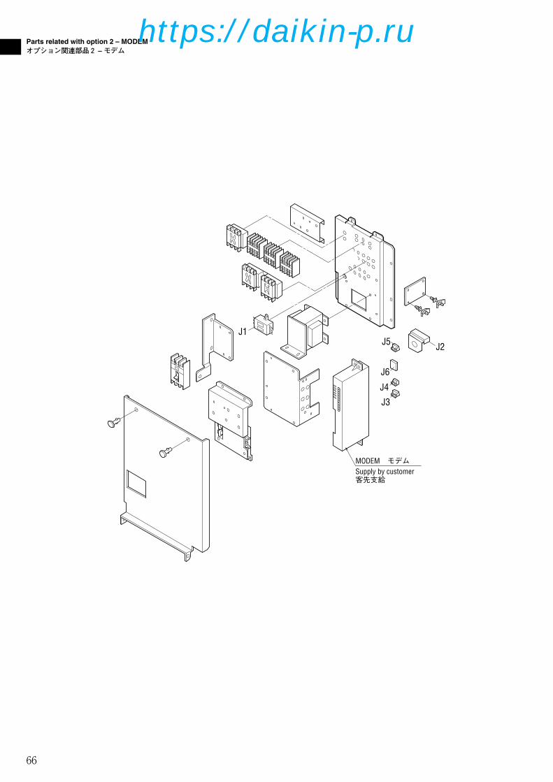
66
Parts related with option 2 – MODEM
オプション関連部品2 –モデム
MODEM モデムSupply by customer 客先支給
J1
J2J5
J6
J4
J3
58-80_LXE10E-A32A,B.Qx 08.1.24 2:40 PM ページ 66
https://daikin-p.ru

67
Parts related with option 2 – MODEM
オプション関連部品2 –モデム
NO.
符号INDEX
PARTS NO.
部品番号PARTS NAME 部品名称
DWG. NO.
図面番号
TYPE SPECIFICATION
形式 仕様
QTY/UNIT
J1 B 0954640 Noise filter ノイズフィルタ 2PA51273-1 ZCB2206-11 1
J3 1267736 Connector for MODEM モデム用コネクタ 3P012038-3 BLA3 1
J4 1267743 Connector for MODEM モデム用コネクタ 3P010371-7 1
J5 1267750 Connector for MODEM モデム用コネクタ 3P012038-7 BLA7 1
J6 0468839 Noise filter(for modem) ノイズフィルター(モデム用) 3EA76001-1 1
1
1
1
1
1
LXE10E-
A32A
REMARKS
備考A32B
J2 1780291 Protection plate 保護板(YORK製モデム) 4P176030-1 1 1
58-80_LXE10E-A32A,B.Qx 08.1.24 2:40 PM ページ 67
https://daikin-p.ru

68
Parts related with option 3 – Others
オプション関連部品3 –その他
K2
K1
1.Indoor fan guard1.庫内ファンガード
2.Evaporator coil2.蒸発器コイル組立品
K6
58-80_LXE10E-A32A,B.Qx 08.1.24 2:40 PM ページ 68
https://daikin-p.ru

69
Parts related with option 3 – Others
オプション関連部品3 –その他
NO.
符号INDEX
PARTS NO.
部品番号PARTS NAME 部品名称
DWG. NO.
図面番号
TYPE SPECIFICATION
形式 仕様
QTY/UNIT
K1 1686212 Inside fan cover 庫内ファンカバー(裏板SUS t0.8仕様) 2P165209-2 1
K6 C 1683927 Evaporator ass'y 蒸発器組立品 2P163797-1 CRB-LXE10E9
K6 C 1787470 Evaporator ass'y 蒸発器組立品 2P195931-1 CRB-LXE10E15 1
1
1
LXE10E-
A32A
REMARKS
備考A32B
58-80_LXE10E-A32A,B.Qx 08.1.24 2:40 PM ページ 69
https://daikin-p.ru

70
List of size for standard pipe clamp
配管固定具サイズ表
1.Resin clamp1.樹脂バンド
H
(外穴)
(OUTER HOLE)
C
φ
D±1.0
H
(内穴)(外穴)
(INNER HOLE)(OUTER HOLE) φD±
1.0
C
H(INTERMEDIATE HOLE)
(内穴)(中穴)(外穴) (INNER HOLE) (OUTER HOLE)
φD±1.0
C
NO.
符号
PARTS NO.
部品番号PARTS NAME 部品名称
DWG NO.
図面番号
SIZE サイズ QTY
D C H A32A
E10 1222764 Resin clamp 樹脂バンド NE41015-9 26.9 27.8 7.9 1
E11 0944528 Resin clamp 樹脂バンド NE41015-7 19.8 24.6 7.9 2
LXE10E-
E13 1266788 Resin clamp 樹脂バンド NE41015-12 39.4 34.2 9.5 6
E14 0508162 RESIN CLAMP 樹脂バンド NE41015-3 8.4 16.7 4.8 1
E12 0142492 Resin clamp 樹脂バンド NE41015-10 29.2 29.4 7.9 2
A32B
1
2
2
6
1
58-80_LXE10E-A32A,B.Qx 08.1.24 2:40 PM ページ 70
https://daikin-p.ru

71
List of size for standard pipe clamp
配管固定具サイズ表
2.Tube clamp2.管止金
NO.
符号
PARTS NO.
部品番号PARTS NAME 部品名称
DWG NO.
図面番号
REMARKS
備考
E35 1584253 Cushion rubber 管止金用緩衝ゴム NE41013-3-300
Cut to suit pipe size.
配管サイズに合わせて切って使用のこと
22
L=300
H
φD
7
C
15
2-φ5.5穴
QTY/UNIT
1
3.Cushion rubber for pipe clamp3.管止金用緩衝ゴム
LXE10E-
A32A
NO.
符号
PARTS NO.
部品番号PARTS NAME 部品名称
DWG NO.
図面番号
SIZE サイズ
D C H
E6 1592425 Tube clamp 管止め金 NE31016-58 24 27 5
E15 0782775 Tube clamp 管止め金 NE31016-51 10 20 3
E29 1584246 Nylon coating tube clamp ナイロンコーティング管止め金 4P143802-59 26 28 5
E16 1584215 Nylon coating tube clamp ナイロンコーティング管止め金 4P143802-51 10 20 3
E17 1584208 Nylon coating tube clamp ナイロンコーティング管止め金 4P143802-52 12 21 3
3
5
8
1
E21 0016290 Tube clamp 管止め金 NE31016-56 20 25 5 1
E22 1584239 Nylon coating tube holder ナイロンコーティング管止め金 4P143802-71 6.4 20 1 4
E26 1584215 Nylon coating tube clamp ナイロンコーティング管止め金 4P143802-51 10 20 3 2
E27 1266858 Tube clamp 管止め金 NE31016-59 26 28 5 1
1
A32B
QTY/UNIT
LXE10E-
A32A
3
5
8
1
1
4
2
1
1
A32B
1
58-80_LXE10E-A32A,B.Qx 08.1.24 2:40 PM ページ 71
https://daikin-p.ru

72
Notes for ordering spare parts
部品発注の際の注意事項
1.Parts recommended to be ordered together with packing,gasket, sealing material and name plate
1.発注の際にパッキングやシール材、銘板等の同時発注を推奨する部品
For ordering following spare parts, we recommend that you order the followingpacking, gasket, sealing material and name plate together at the same time.上記のサービス扉やボックスカバーを発注の際には、下記のパッキングを同時に発注することをおすすめします。
(1)Service door(1)サービス扉
※Rubber gasket, sheet key is attacked to control box cover ass'y.
※ゴムガスケットとシートキーはコントロールボックス組立品に付属しています。
NO.
符号
PARTS NO.
部品番号PARTS NAME 部品名称
A6 1196113Sealing material
(access panel)
シール材(サービス扉)
DWG NO.
図面番号
A4 1612576 Access panel (FRP) サービス扉組立品 1P006678-5
3P001640-2
A4A5
A62
A5 1266207Cushion material
(access panel)
クッション材(サービス扉)
3P033608-1 2
2
NO.
符号
PARTS NO.
部品番号PARTS NAME 部品名称
DWG NO.
図面番号
G20 1813704Electric wiring
diagram label電気配線図銘板 2D053417-1 1
G3 1557042Name plate,
operation
操作銘板(C&MODE,英)
1P136900-1 1
A32B
A32B
QTY/UNIT
LXE10E-
QTY/UNIT
LXE10E-
F7 1739301C.BOX cover
ass'y
コントロールボックス蓋組立品
2P171706-6 1
A32A
2
2
2
A32A
1
1
1
(2)Control box cover(2)コントロールボックスカバー
F7
G3
G20
58-80_LXE10E-A32A,B.Qx 08.1.24 2:40 PM ページ 72
https://daikin-p.ru

73
Notes for ordering spare parts
部品発注の際の注意事項
A19
A20
A15
G4R134a
(5)Front plate (CA)(5)前板(CA)
NO.
符号
PARTS NO.
部品番号PARTS NAME 部品名称
DWG NO.
図面番号A32B
QTY/UNIT
LXE10E-
A15 1739286 Front plate (CA) 前板(CA) 2P173133-1 1
G4 1726552
Name plate,
Brand name and
refrigerant label
意匠銘板および冷媒銘板
3P174603-1 1
NO.
符号
PARTS NO.
部品番号PARTS NAME 部品名称
A19 1847365 Ventilation cover 換気口蓋
DWG NO.
図面番号
3P134985-1
A20 1266221Sealing material
(access panel)シール材(換気口) 4P016185-1
1 1
2 2
A32A A32B
QTY/UNIT
LXE10E-
(4)Ventilation cover(4)換気口蓋
A32A
1
1
58-80_LXE10E-A32A,B.Qx 08.1.24 2:40 PM ページ 73
https://daikin-p.ru
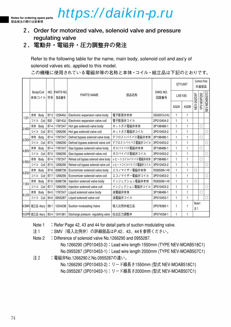
74
Notes for ordering spare parts
部品発注の際の注意事項
2.Order for motorized valve, solenoid valve and pressureregulating valve
2.電動弁・電磁弁・圧力調整弁の発注
Refer to the following table for the name, main body, solenoid coil and ass'y ofsolenoid valves etc. applied to this model.この機種に使用されている電磁弁等の名称と本体・コイル・組立品は下記のとおりです。
Note 1 :Refer Page 42, 43 and 44 for detail parts of suction modulating valve.注1 :SMV(吸入比例弁)の詳細部品はP.42、43、44を参照ください。Note 2 :Difference of solenoid valve No.1266290 and 0955287.
No.1266290 (3P010453-2):Lead wire length 1550mm (TYPE NEV-MOAB518C1)No.0955287 (3P010453-1):Lead wire length 2000mm (TYPE NEV-MOAB507C1)
注2 :電磁弁No.1266290とNo.0955287の違い。No.1266290 (3P010453-2):リード線長さ1550mm (型式 NEV-MOAB518C1)No.0955287 (3P010453-1):リード線長さ2000mm (型式 NEV-MOAB507C1)
Body/Coil
本体/コイルPARTS NAME 部品名称
1.EV本体 Body Electronic expansion valve body 電子膨張弁本体
コイル Coil Electronic expansion valve coil 電子膨張弁コイル
コイル Coil Hot gas solenoid valve coil ホットガス電磁弁コイル
NO.
符号
PARTS NO.
部品番号
B7-3 125649J
B20 138143J
B7-5 1266290
コイル Coil B7-5 1266290 Defrost bypass solenoid valve coil デフロストバイパス電磁弁コイル
コイル Coil B7-5 1266290 Reheat coil bypass solenoid valve coil レヒートコイルバイパス電磁弁コイル
6.ESV本体 Body B7-6 0088738 Economizer solenoid valve body エコノマイザー電磁弁本体
コイル Coil B7-7 1266290 Economizer solenoid valve coil エコノマイザー電磁弁コイル
7.ISV本体 Body B7-6 0088738 Injection solenoid valve body インジェクション電磁弁本体
コイル Coil B7-7 1266290 Injection solenoid valve coil インジェクション電磁弁コイル
10.DPR 組立品 Ass'y B3-4 1241361 Discharge pressure regulating valve 吐出圧力調整弁
DWG NO.
図面番号
2SA50010-2-KU
2P010454-2
3P010453-2
3P010453-2
3P010453-2
R3305099-1-KI ○
3P010453-2
R3305099-1-KI ○
3P010453-2
3P074558-1
コイル Coil B4-6 0955287 Liquid solenoid valve coil 液電磁弁コイル 3P010453-1
9.SMV 組立品 Ass'y B8-1 1254538 Suction modulating Valve 吸入比例弁組立品 2P078385-1
NE
V-2
02D
XF
コイル Coil B7-5 1266290 Gas bypass solenoid valve coil ガスバイパス電磁弁コイル 3P010453-2
B7-4 1787247 Hot gas solenoid valve body ホットガス電磁弁本体 3P198486-1
B7-4 1787247 Defrost bypass solenoid valve body デフロストバイパス電磁弁本体 3P198486-1
B7-4 1787247 Gas bypass solenoid valve body ガスバイパス電磁弁本体 3P198486-1
B7-4 1787247 Reheat coil bypass solenoid valve body レヒートコイルバイパス電磁弁本体 3P198486-1
B4-5 1787247 Liquid solenoid valve body 液電磁弁本体 3P198486-1
VP
V-8
03P
Q50
○
○
○
○
○
NE
V-M
OA
B50
7C1
○
○
○
○
○
○
○
A32B
1
1
1
1
1
1
1
1
1
1
1
1
1
1
1
1
1
1
2.HSV本体 Body
3.DSV本体 Body
4.BSV本体 Body
5.RSV本体 Body
8.LSV本体 Body
QTY/UNIT
LXE10E-
Common Parts
共通部品
Note1
注1
A32A
1
1
1
1
1
1
1
1
1
1
1
1
1
1
1
1
1
1
58-80_LXE10E-A32A,B.Qx 08.1.24 2:40 PM ページ 74
https://daikin-p.ru

75
Notes for ordering spare parts
部品発注の際の注意事項
3.Order for pressure trasducer3.圧力センサーの発注
Refer to the following table for the pressure transducer applied to this model.For ordering pressure transducer, we recommend that you order the following bestshrinkable tube together at the same time.この機種に使用している圧力センサーは下記の通りです。圧力センサー発注の際は、下記の熱収縮チューブを同時に発注することをおすすめします。
NO.
符号
PARTS NO.
部品番号PARTS NAME 部品名称
REMARKS
備考
E84 1605509 Heat shrinkable tube 熱収縮チューブ
Must be applied
when replacing
above sensors.
上記圧力センサー交換時使用の事。
DWG NO.
図面番号
4P151322-1
B16 1587959 High pressure transducer (HPT) 高圧圧力センサ(HPT) 3P141602-1
TYPE
形式
NSK-BD030F-0701
2
B15 1587942 Low pressure transducer (LPT) 低圧圧力センサ(LPT) 3P141601-1 1 NSK-BD010F-070
A32B
QTY/UNITLXE10E-
A32A
1
1
2
58-80_LXE10E-A32A,B.Qx 08.1.24 2:40 PM ページ 75
https://daikin-p.ru
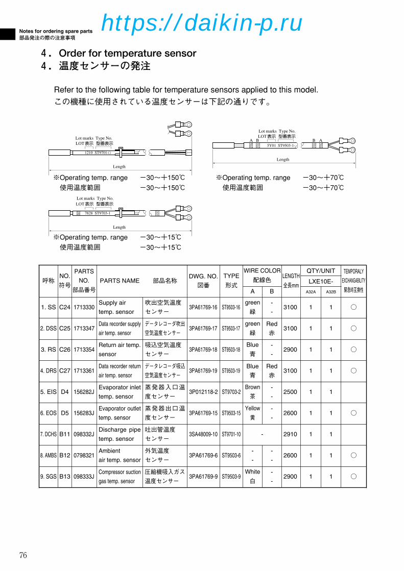
76
Notes for ordering spare parts
部品発注の際の注意事項
4.Order for temperature sensor4.温度センサーの発注
Refer to the following table for temperature sensors applied to this model.この機種に使用されている温度センサーは下記の通りです。
1210 ST9701-
Length
LOT表示 型番表示 Type No.Lot marks
5Y01 ST9503-1-ABA B
LOT
Length
表示 型番表示 Type No.Lot marks
7828 ST9703-1
Length
LOT表示 型番表示 Type No.Lot marks
※Operating temp. range ー30~+15℃使用温度範囲 ー30~+15℃
※Operating temp. range ー30~+150℃使用温度範囲 ー30~+150℃
※Operating temp. range ー30~+70℃使用温度範囲 ー30~+70℃
NO.
符号
PARTS
NO.
部品番号
PARTS NAME 部品名称
TEMPORALY
EXCHANGABILITY
緊急時互換性呼称
DWG. NO.
図番
TYPE
形式
WIRE COLOR
配線色LENGTH
全長mmA B
1. SS C24 1713330Supply air
temp. sensor
吹出空気温度センサー
3PA61769-16 ST9503-16green
緑
-
-3100 ○
2. DSS C25 1713347Data recorder supply
air temp. sensor
データレコーダ吹出空気温度センサー
3PA61769-17 ST9503-17green
緑Red
赤3100 ○
3. RS C26 1713354Return air temp.
sensor
吸込空気温度センサー
3PA61769-18 ST9503-18Blue
青
-
-2900 ○
4. DRS C27 1713361Data recorder return
air temp. sensor
データレコーダ吸込空気温度センサー
3PA61769-19 ST9503-19Blue
青Red
赤3100 ○
7. DCHS B11 098332JDischarge pipe
temp. sensor
吐出管温度センサー
3SA48009-10 ST9701-10 - 2910
8. AMBS B12 0798321Ambient
air temp. sensor
外気温度センサー
3PA61769-6 ST9503-6-
-
-
-2600 ○
9. SGS B13 098333JCompressor suction
gas temp. sensor
圧縮機吸入ガス温度センサー
3PA61769-9 ST9503-9White
白
-
-2900 ○
5. EIS D4 156282JEvaporator inlet
temp. sensor
蒸発器入口温度センサー
3P012118-2 ST9703-2Brown
茶
-
-2500
6. EOS D5 156283JEvaporator outlet
temp. sensor
蒸発器出口温度センサー
3PA61769-15 ST9503-15Yellow
黄2600 ○
-
-
A32B
1
1
1
1
1
1
1
1
1
QTY/UNIT
LXE10E-
A32A
1
1
1
1
1
1
1
1
1
58-80_LXE10E-A32A,B.Qx 08.1.24 2:40 PM ページ 76
https://daikin-p.ru

77
Measuring and adjusting tools
測定調整用工具
1.Tools for emergency operation1.緊急運転用工具
(See Service Manual for application.)(使用方法はサービスマニュアルを参照ください。)
NO.
符号
PARTS NO.
部品番号PARTS NAME 部品名称
ILLUSTLATION
姿図
- 1270530E m e r g e n c y
magnet
エマージェンシーマグネット
- 1080263Emergency coil
cap
エマージェンシーコイルキャップ
DWG NO.
図面番号
USE
用途
3P017370-1
For electronic
expansion
valve
電子膨張弁用
2P078385-2
Suction
modulating
valve
吸入比例弁用
UPSIDE
→OPEN
DOWNSIDE
58-80_LXE10E-A32A,B.Qx 08.1.24 2:40 PM ページ 77
https://daikin-p.ru
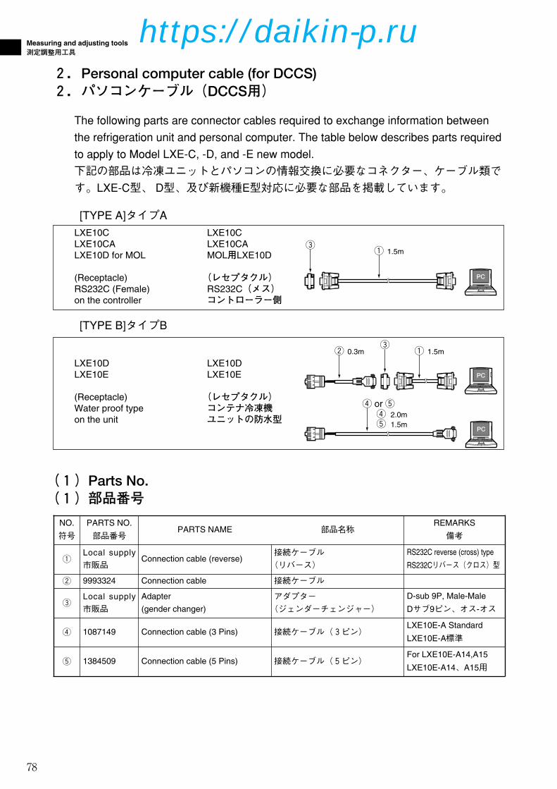
78
Measuring and adjusting tools
測定調整用工具
2.Personal computer cable (for DCCS)2.パソコンケーブル(DCCS用)
The following parts are connector cables required to exchange information betweenthe refrigeration unit and personal computer. The table below describes parts requiredto apply to Model LXE-C, -D, and -E new model.下記の部品は冷凍ユニットとパソコンの情報交換に必要なコネクター、ケーブル類です。LXE-C型、 D型、及び新機種E型対応に必要な部品を掲載しています。
[TYPE A]タイプALXE10C LXE10C
LXE10CA LXE10CALXE10D for MOL MOL用LXE10D
(Receptacle) (レセプタクル)RS232C (Female) RS232C(メス)on the controller コントローラー側
[TYPE B]タイプB
LXE10D LXE10DLXE10E LXE10E
(Receptacle) (レセプタクル)Water proof type コンテナ冷凍機on the unit ユニットの防水型
(1)Parts No.(1)部品番号
w 0.3m q 1.5me
r or tr 2.0m
t 1.5m
eq 1.5m
NO.
符号
PARTS NO.
部品番号PARTS NAME 部品名称
REMARKS
備考
5 1384509 Connection cable (5 Pins) 接続ケーブル(5ピン)For LXE10E-A14,A15
LXE10E-A14、A15用
1Local supply
市販品Connection cable (reverse)
接続ケーブル(リバース)
RS232C reverse (cross) type
RS232Cリバース(クロス)型
2 9993324 Connection cable 接続ケーブル
3Local supply
市販品
Adapter
(gender changer)
アダプター(ジェンダーチェンジャー)
D-sub 9P, Male-Male
Dサブ9ピン、オス-オス
4 1087149 Connection cable (3 Pins) 接続ケーブル(3ピン)LXE10E-A Standard
LXE10E-A標準
58-80_LXE10E-A32A,B.Qx 08.1.24 2:40 PM ページ 78
https://daikin-p.ru

79
Measuring and adjusting tools
測定調整用工具
NO.
符号
Illustlation
姿図
Internal Wiring
内部配線
1
2
5
12345678
Frame
フレーム Frame
フレーム
12345678
RS232CFemaleメス
RS232CFemaleメス
123456789
ABC
Daikinmade
ダイキン製
RS232CFemaleメス
Red
White
Black
Red 赤
White 白 Black 黒
ABCDE
12345678
Daikinmade
ダイキン製
RS232CFemaleメス
Frame
フレーム
4
Red 赤
White 白 Black 黒
ABC
12345678
Daikinmade
ダイキン製
RS232CFemaleメス
Frame
フレーム
3
58-80_LXE10E-A32A,B.Qx 08.1.24 2:40 PM ページ 79
https://daikin-p.ru

MEMO
58-80_LXE10E-A32A,B.Qx 08.1.24 2:40 PM ページ 80
https://daikin-p.ru
TR07-07
(2008.01.00000)NK
本 社 大阪市北区中崎西2丁目4番12号 梅田センタービル郵便番号 530-8323 電話 大 阪(06)6373-1201 (大 代 表)
東京支社 東京都港区港南2-18-1 JR品川イーストビル10階郵便番号 108-0075 電話 東 京(03)6716-0420
Head Office. Umeda Center Bldg., 4-12, Nakazaki-Nishi 2-chome, Kita-ku, Osaka, 530-8323 Japan.
Tel: 06-6373-4338
Fax: 03-6373-7297
Tokyo Office. JR Shinagawa East Bldg., 10F 18-1, Konan 2-chome, Minato-ku Tokyo, 108-0075 Japan.
Tel: 03-6716-0420
Fax: 03-6716-0230
ダイキン海上コンテナ冷凍装置Marine type Container Refrigeration Unit
TR07-07
LXE10E-A32ALXE10E-A32B
サービスガイド・パーツリスト
Service Manual・Parts List
オプション機能編・Optional Functions
web-LXE10E-A32A,B_表1-4.qxd 08.1.24 4:50 PM ページ 1
https://daikin-p.ru