datasheet - img.motortong.com · 05/03/2017 · buy this product at rgb automatyka buy
TRANSCRIPT
RGB ELEKTRONIKA AGACIAK CIACIEKSPÓŁKA JAWNA Jana Dlugosza 2-6 Street51-162 WrocławPoland
[email protected] +48 71 325 15 05
www.rgbautomatyka.pl
www.rgbelektronika.pl
DATASHEET
www.rgbautomatyka.plwww.rgbelektronika.pl
OTHER SYMBOLS:
1FT6064-1AH71-4AH1
1FT60641AH714AH1, 1FT60641AH71 4AH1, 1FT60641AH71-4AH1, 1FT6064 1AH714AH1, 1FT6064 1AH714AH1, 1FT6064 1AH71-4AH1, 1FT6064-1AH714AH1, 1FT6064-1AH71 4AH1, 1FT6064-1AH71-4AH1
SIEMENS

YOUR PARTNER IN MAINTENANCE
At our premises in Wrocław, we have a fully equipped servicing facility. Here we perform all the repair works and test each later sold unit. Our trained employees, equipped with a wide variety of tools and having several testing stands at their disposal, are a guarantee of the highest quality service.
OUR SERVICES
ENCODERS
SERVO DRIVERS
LINEAR ENCODERS
SERVO AMPLIFIERS
CNC MACHINES
MOTORS
POWER SUPPLIERS
OPERATOR PANELS
CNC CONTROLS
INDUSTRIAL COMPUTERS
PLC SYSTEMS
Repair this product with RGB ELEKTRONIKA ORDER A DIAGNOSIS
Buy this product at RGB AUTOMATYKA BUY


Foreword
Motor Description 1
Electrical Connections 2
Technical Data and Speed-Torque Diagrams
3
Motor Components (Options) 4
Dimension Drawings 5
Appendix A
SINAMICS
1FT6 Synchronous Motors
Configuration Manual
(PFT6), Edition 12.2004 6SN1197-0AD12-0BP0
Safety Guidelines
This manual contains notices you have to observe in order to ensure your personal safety, as well as to prevent damage to property. The notices referring to your personal safety are highlighted in the manual by a safety alert symbol, notices referring to property damage only have no safety alert symbol. These notices shown below are graded according to the degree of danger.
Danger
indicates that death or severe personal injury will result if proper precautions are not taken.
Warning
indicates that death or severe personal injury may result if proper precautions are not taken.
Caution
with a safety alert symbol, indicates that minor personal injury can result if proper precautions are not taken.
Caution
without a safety alert symbol, indicates that property damage can result if proper precautions are not taken.
Notice
indicates that an unintended result or situation can occur if the corresponding information is not taken into account.
If more than one degree of danger is present, the warning notice representing the highest degree of danger will be used. A notice warning of injury to persons with a safety alert symbol may also include a warning relating to property damage.
Qualified Personnel The device/system may only be set up and used in conjunction with this documentation. Commissioning and operation of a device/system may only be performed by qualified personnel. Within the context of the safety notes in this documentation qualified persons are defined as persons who are authorized to commission, ground and label devices, systems and circuits in accordance with established safety practices and standards.
Prescribed Usage Note the following:
Warning
This device may only be used for the applications described in the catalog or the technical description and only in connection with devices or components from other manufacturers which have been approved or recommended by Siemens. Correct, reliable operation of the product requires proper transport, storage, positioning and assembly as well as careful operation and maintenance.
Trademarks All names identified by ® are registered trademarks of the Siemens AG. The remaining trademarks in this publication may be trademarks whose use by third parties for their own purposes could violate the rights of the owner.
Copyright Siemens AG 2004. All rights reserved. The distribution and duplication of this document or the utilization and transmission of its contents are not permitted without express written permission. Offenders will be liable for damages. All rights, including rights created by patent grant or registration of a utility model or design, are reserved.
Disclaimer of Liability We have reviewed the contents of this publication to ensure consistency with the hardware and software described. Since variance cannot be precluded entirely, we cannot guarantee full consistency. However, the information in this publication is reviewed regularly and any necessary corrections are included in subsequent editions.
Siemens AG Automation and Drives Postfach 4848, 90327 Nuremberg, Germany
Siemens AG 2005 Technical data subject to change
Siemens Aktiengesellschaft 6SN1197-0AD12-0BP0
Designation of the documentation
Printing history
Brief details of this edition and previous editions are listed below.
The status of each edition is shown by the code in the ”Remarks” column.
Status code in the ”Remarks” column:
A New documentation
B Unrevised reprint with new Order No.
C Revised edition with new status
If factual changes have been made on the page since the last edition, this is indicated by a new edition coding in the header on
that page.
Edition Order No. for 1FT6 Remarks
12.04 6SN1197-0AD12-0BP0 A
Trademarks
SINAMICS®, SIMOTION®, SIMATIC®, SIMATIC HMI®, SIMATIC NET®, SIROTEC®, SINUMERIK®, SIMODRIVE®, SIMOVERT
MASTERDRIVES® and MOTION-CONNECT® are registered trademarks of Siemens AG. Other names in this publication might
be trademarks whose use by a third party for his own purposes may violate the rights of the registered holder.
Further information is available on the Internet under:
http://www.siemens.com/motioncontrol
This publication was produced with SIPS+
© Siemens AG 2004. All rights reserved. The control system may support functions that are not described in
this documentation. However, no claim can be made regarding the
availability of these functions when the equipment is first supplied or
in the event of servicing.
We have checked that the contents of this document correspond to
the hardware and software described. Nonetheless, differences might
exist and therefore we cannot guarantee that they are completely identical.
The information given in this publication is reviewed at regular intervals
and any corrections that might be necessary are made in the subsequent
printings. Suggestions for improvement are also welcome.
We reserve the right to make technical changes.
Order No. 6SN1197-0AD07-0BP2
Printed in the Federal Republic of Germany
Siemens–Aktiengesellschaft

Foreword Information on the documentation
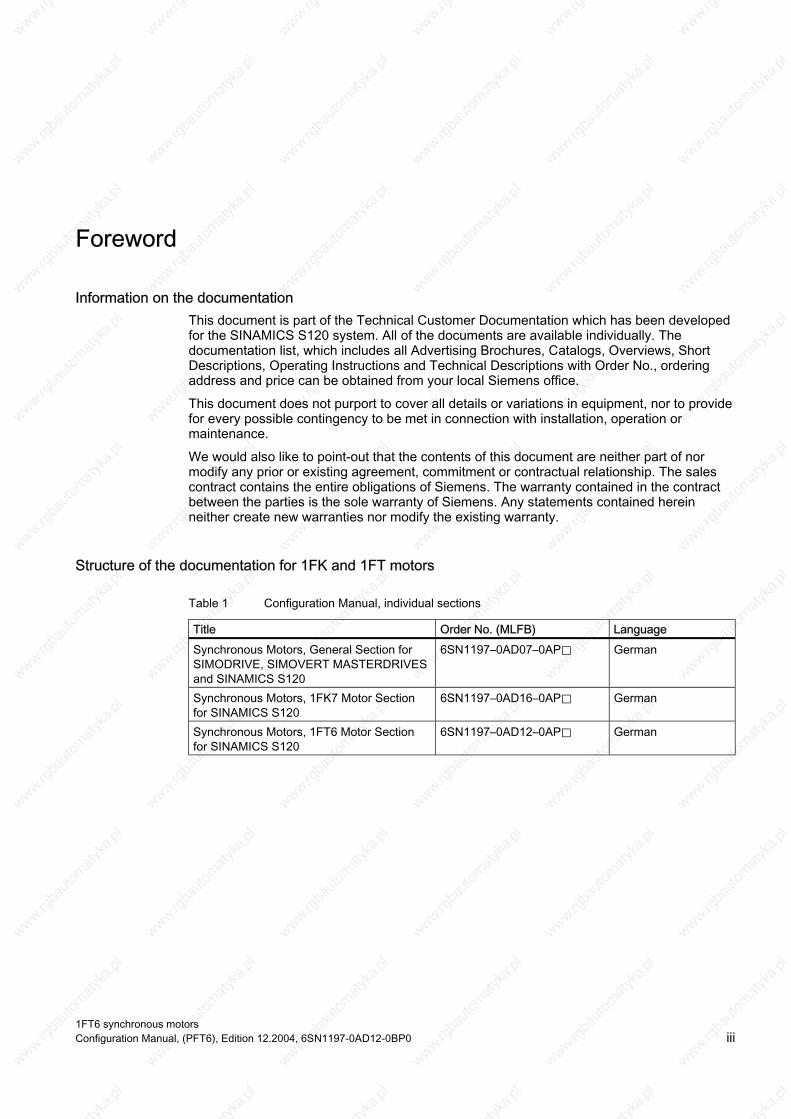
This document is part of the Technical Customer Documentation which has been developed for the SINAMICS S120 system. All of the documents are available individually. The documentation list, which includes all Advertising Brochures, Catalogs, Overviews, Short Descriptions, Operating Instructions and Technical Descriptions with Order No., ordering address and price can be obtained from your local Siemens office.
This document does not purport to cover all details or variations in equipment, nor to provide for every possible contingency to be met in connection with installation, operation or maintenance.
We would also like to point-out that the contents of this document are neither part of nor modify any prior or existing agreement, commitment or contractual relationship. The sales contract contains the entire obligations of Siemens. The warranty contained in the contract between the parties is the sole warranty of Siemens. Any statements contained herein neither create new warranties nor modify the existing warranty.
Structure of the documentation for 1FK and 1FT motors
Table 1 Configuration Manual, individual sections
Title Order No. (MLFB) Language Synchronous Motors, General Section for SIMODRIVE, SIMOVERT MASTERDRIVES and SINAMICS S120
6SN1197–0AD07–0AP⃞ German
Synchronous Motors, 1FK7 Motor Section for SINAMICS S120
6SN1197–0AD16–0AP⃞ German
Synchronous Motors, 1FT6 Motor Section for SINAMICS S120
6SN1197–0AD12–0AP⃞ German
1FT6 synchronous motors Configuration Manual, (PFT6), Edition 12.2004, 6SN1197-0AD12-0BP0 iii
Foreword
Hotline If you have any questions, please contact the following Hotline:
A&D Technical Support Phone: +49 (180) 5050–222 Fax: +49 (180) 5050–223 http://www.siemens.de/automation/support-request
If you have any questions regarding the documentation (suggestions, corrections) then please send a fax to the following number:
+49 (9131) 98–2176
Fax form: Refer to the response sheet at the end of the document
1FT6 synchronous motors iv Configuration Manual, (PFT6), Edition 12.2004, 6SN1197-0AD12-0BP0

Foreword
Danger and warning information
Danger
Start-up/commissioning is absolutely prohibited until it has been completely ensured that the machine, in which the components described here are to be installed, is in full compliance with the specifications of Directive 98/37/EC.
SINAMICS devices and synchronous motors may only be commissioned by suitably qualified personnel.
This personnel must carefully observe the technical customer documentation associated with this product and be knowledgeable about and carefully observe the danger and warning information.
Operational electrical equipment and motors have parts and components which are at hazardous voltage levels.
When the machine or system is operated, hazardous axis movements can occur.
All of the work carried-out on the electrical machine or system must be carried-out with it in a no-voltage condition.
SINAMICS drive units are designed for operation on low-ohmic, grounded line supply systems (TN line supply systems).
Warning
The successful and safe operation of this equipment and motors is dependent on professional transport, storage, installation and mounting as well as careful operator control, service and maintenance.
For special versions of the drive units and motors, information and data in the catalogs and quotations additionally apply.
In addition to the danger and warning information/instructions in the technical customer documentation supplied, the applicable domestic, local and plant-specific regulations and requirements must be carefully taken into account.
1FT6 synchronous motors Configuration Manual, (PFT6), Edition 12.2004, 6SN1197-0AD12-0BP0 v

Foreword
Caution
The motors can have surface temperatures of over +100° C.
This is the reason that temperature-sensitive components, e.g. cables or electronic components may neither be in contact nor be attached to the motor.
When connecting-up cables, please observe that they – are not damaged – are not subject to tensile stress – cannot be touched by rotating components.
Caution
The DRIVE-CLiQ interface contains motor and encoder-specific data as well as an electronic rating plate. This is the reason that this Sensor Module may only be operated on the original motor - and may not be mounted onto other motors or replaced by a sensor module from other motors.
The DRIVE-CLiQ interface has direct contact to components that can be damaged/destroyed by electrostatic discharge (ESDS). Neither hands nor tools that could be electrostatically charged may come into contact with the connections.
Caution
SINAMICS drive units with synchronous motors are subject, as part of the routine test, to a voltage test in accordance with EN 50178. While the electrical equipment of industrial machines is being subject to a voltage test in accordance with EN60204-1, Section 19.4, all SINAMICS drive unit connections must be disconnected/withdrawn in order to avoid damaging the SINAMICS drive units.
Motors should be connected-up according to the circuit diagram provided. It is not permissible to directly connect the motors to the three-phase line supply. Motors will be destroyed if they are connected directly to the three-phase line supply.
Note
SINAMICS units with synchronous motors fulfill, when operational and in dry operating rooms, the Low-Voltage Directive 73/23/EEC.
SINAMICS units with synchronous motors fulfill, in the configuration specified in the associated EC Declaration of Conformity, the EMC Directive 89/336/EEC.
1FT6 synchronous motors vi Configuration Manual, (PFT6), Edition 12.2004, 6SN1197-0AD12-0BP0

Foreword
ESDS instructions
Caution
An electrostatic-sensitive device (ESDS) is an individual component, integrated circuit, or module that can be damaged by electrostatic fields or discharges.
ESDS regulations for handling boards and equipment:
When handling components that can be destroyed by electrostatic discharge, it must be ensured that personnel, the workstation and packaging are well grounded!
Personnel in ESD zones with conductive floors may only touch electronic components if they are – grounded through an ESDS bracelet and – wearing ESDS shoes or ESDS shoe grounding strips.
Electronic boards may only be touched when absolutely necessary.
Electronic boards may not be brought into contact with plastics and articles of clothing manufactured from man-made fibers.
Electronic boards may only be placed on conductive surfaces (table with ESDS surface, conductive ESDS foam rubber, ESDS packing bag, ESDS transport containers).
Electronic boards may not be brought close to data terminals, monitors or television sets. Minimum clearance to screens > 10 cm).
Measurements may only be carried-out on electronic boards and modules if – the measuring instrument is grounded (e.g. via a protective conductor) or – before making measurements with a potential-free measuring device, the measuring head is briefly discharged (e.g. by touching an unpainted blank piece of metal on the control cabinet).
Standards, regulations The appropriate standards, regulations are directly assigned to the functional requirements.
1FT6 synchronous motors Configuration Manual, (PFT6), Edition 12.2004, 6SN1197-0AD12-0BP0 vii

Foreword
1FT6 synchronous motors viii Configuration Manual, (PFT6), Edition 12.2004, 6SN1197-0AD12-0BP0
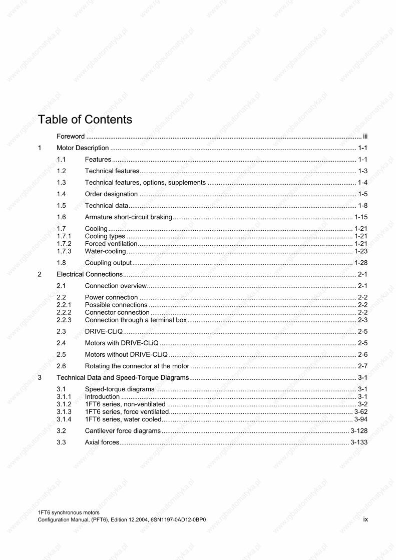
Table of Contents Foreword ...................................................................................................................................................... iii
1 Motor Description ...................................................................................................................................... 1-1
1.1 Features ..................................................................................................................................... 1-1
1.2 Technical features...................................................................................................................... 1-3
1.3 Technical features, options, supplements ................................................................................. 1-4
1.4 Order designation ...................................................................................................................... 1-5
1.5 Technical data............................................................................................................................ 1-8
1.6 Armature short-circuit braking.................................................................................................. 1-15
1.7 Cooling ..................................................................................................................................... 1-21 1.7.1 Cooling types ........................................................................................................................... 1-21 1.7.2 Forced ventilation..................................................................................................................... 1-21 1.7.3 Water-cooling........................................................................................................................... 1-23
1.8 Coupling output........................................................................................................................ 1-28
2 Electrical Connections............................................................................................................................... 2-1
2.1 Connection overview.................................................................................................................. 2-1
2.2 Power connection ...................................................................................................................... 2-2 2.2.1 Possible connections ................................................................................................................. 2-2 2.2.2 Connector connection ................................................................................................................ 2-2 2.2.3 Connection through a terminal box............................................................................................ 2-3
2.3 DRIVE-CLiQ............................................................................................................................... 2-5
2.4 Motors with DRIVE-CLiQ ........................................................................................................... 2-5
2.5 Motors without DRIVE-CLiQ ...................................................................................................... 2-6
2.6 Rotating the connector at the motor .......................................................................................... 2-7
3 Technical Data and Speed-Torque Diagrams........................................................................................... 3-1
3.1 Speed-torque diagrams ............................................................................................................. 3-1 3.1.1 Introduction ................................................................................................................................ 3-1 3.1.2 1FT6 series, non-ventilated ....................................................................................................... 3-2 3.1.3 1FT6 series, force ventilated.................................................................................................... 3-62 3.1.4 1FT6 series, water cooled........................................................................................................ 3-94
3.2 Cantilever force diagrams ...................................................................................................... 3-128
3.3 Axial forces............................................................................................................................. 3-133
1FT6 synchronous motors Configuration Manual, (PFT6), Edition 12.2004, 6SN1197-0AD12-0BP0 ix

Table of Contents
4 Motor Components (Options) .................................................................................................................... 4-1
4.1 Thermal motor protection ........................................................................................................... 4-1
4.2 Encoders .................................................................................................................................... 4-3 4.2.1 Encoder overview....................................................................................................................... 4-3 4.3 Motors with DRIVE-CLiQ ........................................................................................................... 4-4 4.4 Motors without DRIVE-CLiQ ...................................................................................................... 4-5 4.4.1 Incremental encoders................................................................................................................. 4-5 4.4.2 Absolute value encoders............................................................................................................ 4-7 4.4.3 Resolvers ................................................................................................................................. 4-10
4.5 Holding brake (option).............................................................................................................. 4-12
4.6 Gearbox (option) ...................................................................................................................... 4-13 4.6.1 Introduction .............................................................................................................................. 4-13 4.6.2 Planetary gearbox 1-stage....................................................................................................... 4-13 4.6.3 Planetary gearbox 2-stage....................................................................................................... 4-18
5 Dimension Drawings.................................................................................................................................. 5-1
5.1 Introduction ................................................................................................................................ 5-1
5.2 1FT6 with DRIVE-CLiQ.............................................................................................................. 5-2 5.2.1 Non-ventilated 1FT6 motors....................................................................................................... 5-2 5.2.2 Force-ventilated 1FT6 motors.................................................................................................. 5-10 5.2.3 Water-cooled 1FT6 motors ...................................................................................................... 5-13
5.3 1FT6 without DRIVE-CLiQ....................................................................................................... 5-18 5.3.1 Non-ventilated 1FT6 motors..................................................................................................... 5-18 5.3.2 Force-ventilated 1FT6 motors.................................................................................................. 5-28 5.3.3 Water-cooled 1FT6 motors ...................................................................................................... 5-34
A Appendix....................................................................................................................................................A-1
A.1 References.................................................................................................................................A-1
Index
1FT6 synchronous motors x Configuration Manual, (PFT6), Edition 12.2004, 6SN1197-0AD12-0BP0
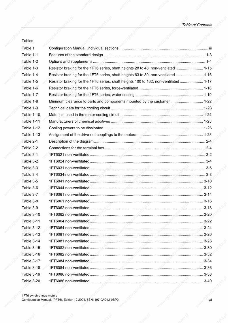
Table of Contents
Tables
Table 1 Configuration Manual, individual sections .................................................................................... iii Table 1-1 Features of the standard design ................................................................................................ 1-3 Table 1-2 Options and supplements .......................................................................................................... 1-4 Table 1-3 Resistor braking for the 1FT6 series, shaft heights 28 to 48, non-ventilated .......................... 1-15 Table 1-4 Resistor braking for the 1FT6 series, shaft heights 63 to 80, non-ventilated .......................... 1-16 Table 1-5 Resistor braking for the 1FT6 series, shaft heights 100 to 132, non-ventilated ...................... 1-17 Table 1-6 Resistor braking for the 1FT6 series, force-ventilated............................................................. 1-18 Table 1-7 Resistor braking for the 1FT6 series, water cooling ................................................................ 1-19 Table 1-8 Minimum clearance to parts and components mounted by the customer ............................... 1-22 Table 1-9 Technical data for the cooling circuit ....................................................................................... 1-23 Table 1-10 Materials used in the motor cooling circuit............................................................................... 1-24 Table 1-11 Manufacturers of chemical additives ....................................................................................... 1-25 Table 1-12 Cooling powers to be dissipated.............................................................................................. 1-26 Table 1-13 Assignment of the drive-out couplings to the motors............................................................... 1-28 Table 2-1 Description of the diagram......................................................................................................... 2-4 Table 2-2 Connections for the terminal box ............................................................................................... 2-4 Table 3-1 1FT6021 non-ventilated ............................................................................................................. 3-2 Table 3-2 1FT6024 non-ventilated ............................................................................................................. 3-4 Table 3-3 1FT6031 non-ventilated ............................................................................................................. 3-6 Table 3-4 1FT6034 non-ventilated ............................................................................................................. 3-8 Table 3-5 1FT6041 non-ventilated ........................................................................................................... 3-10 Table 3-6 1FT6044 non-ventilated ........................................................................................................... 3-12 Table 3-7 1FT6061 non-ventilated ........................................................................................................... 3-14 Table 3-8 1FT6061 non-ventilated ........................................................................................................... 3-16 Table 3-9 1FT6062 non-ventilated ........................................................................................................... 3-18 Table 3-10 1FT6062 non-ventilated ........................................................................................................... 3-20 Table 3-11 1FT6064 non-ventilated ........................................................................................................... 3-22 Table 3-12 1FT6064 non-ventilated ........................................................................................................... 3-24 Table 3-13 1FT6081 non-ventilated ........................................................................................................... 3-26 Table 3-14 1FT6081 non-ventilated ........................................................................................................... 3-28 Table 3-15 1FT6082 non-ventilated ........................................................................................................... 3-30 Table 3-16 1FT6082 non-ventilated ........................................................................................................... 3-32 Table 3-17 1FT6084 non-ventilated ........................................................................................................... 3-34 Table 3-18 1FT6084 non-ventilated ........................................................................................................... 3-36 Table 3-19 1FT6086 non-ventilated ........................................................................................................... 3-38 Table 3-20 1FT6086 non-ventilated ........................................................................................................... 3-40
1FT6 synchronous motors Configuration Manual, (PFT6), Edition 12.2004, 6SN1197-0AD12-0BP0 xi
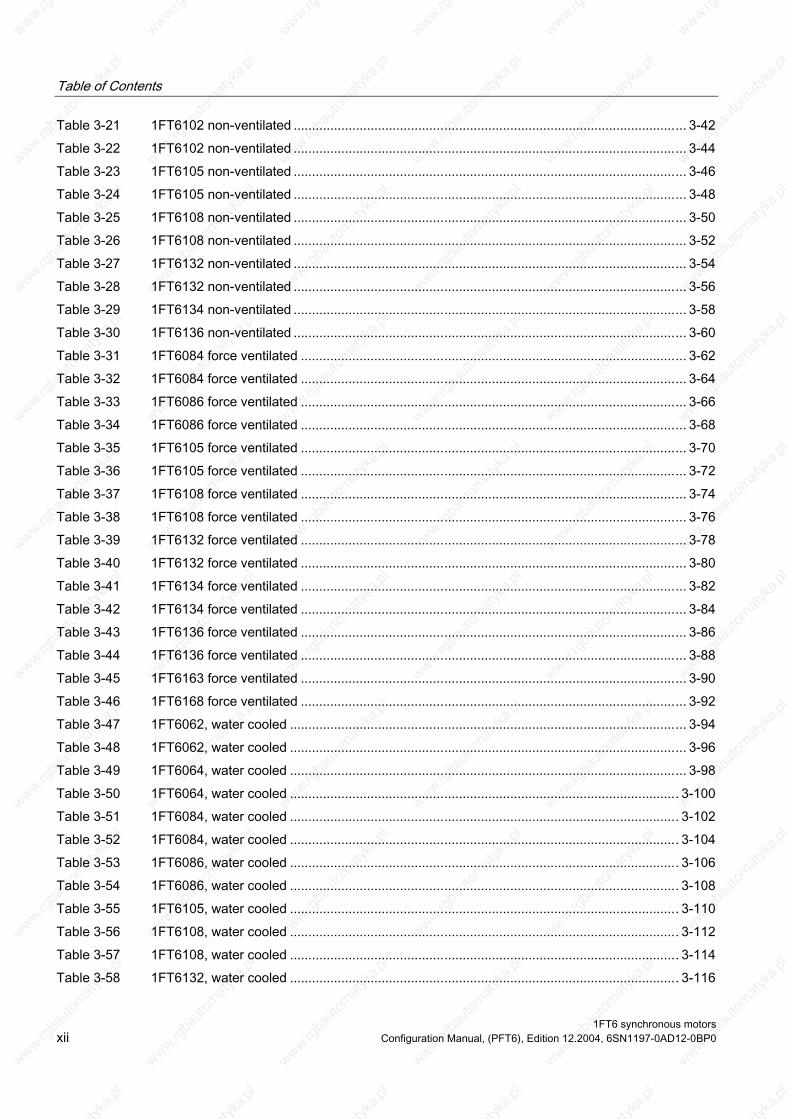
Table of Contents
Table 3-21 1FT6102 non-ventilated ........................................................................................................... 3-42 Table 3-22 1FT6102 non-ventilated ........................................................................................................... 3-44 Table 3-23 1FT6105 non-ventilated ........................................................................................................... 3-46 Table 3-24 1FT6105 non-ventilated ........................................................................................................... 3-48 Table 3-25 1FT6108 non-ventilated ........................................................................................................... 3-50 Table 3-26 1FT6108 non-ventilated ........................................................................................................... 3-52 Table 3-27 1FT6132 non-ventilated ........................................................................................................... 3-54 Table 3-28 1FT6132 non-ventilated ........................................................................................................... 3-56 Table 3-29 1FT6134 non-ventilated ........................................................................................................... 3-58 Table 3-30 1FT6136 non-ventilated ........................................................................................................... 3-60 Table 3-31 1FT6084 force ventilated ......................................................................................................... 3-62 Table 3-32 1FT6084 force ventilated ......................................................................................................... 3-64 Table 3-33 1FT6086 force ventilated ......................................................................................................... 3-66 Table 3-34 1FT6086 force ventilated ......................................................................................................... 3-68 Table 3-35 1FT6105 force ventilated ......................................................................................................... 3-70 Table 3-36 1FT6105 force ventilated ......................................................................................................... 3-72 Table 3-37 1FT6108 force ventilated ......................................................................................................... 3-74 Table 3-38 1FT6108 force ventilated ......................................................................................................... 3-76 Table 3-39 1FT6132 force ventilated ......................................................................................................... 3-78 Table 3-40 1FT6132 force ventilated ......................................................................................................... 3-80 Table 3-41 1FT6134 force ventilated ......................................................................................................... 3-82 Table 3-42 1FT6134 force ventilated ......................................................................................................... 3-84 Table 3-43 1FT6136 force ventilated ......................................................................................................... 3-86 Table 3-44 1FT6136 force ventilated ......................................................................................................... 3-88 Table 3-45 1FT6163 force ventilated ......................................................................................................... 3-90 Table 3-46 1FT6168 force ventilated ......................................................................................................... 3-92 Table 3-47 1FT6062, water cooled ............................................................................................................ 3-94 Table 3-48 1FT6062, water cooled ............................................................................................................ 3-96 Table 3-49 1FT6064, water cooled ............................................................................................................ 3-98 Table 3-50 1FT6064, water cooled .......................................................................................................... 3-100 Table 3-51 1FT6084, water cooled .......................................................................................................... 3-102 Table 3-52 1FT6084, water cooled .......................................................................................................... 3-104 Table 3-53 1FT6086, water cooled .......................................................................................................... 3-106 Table 3-54 1FT6086, water cooled .......................................................................................................... 3-108 Table 3-55 1FT6105, water cooled .......................................................................................................... 3-110 Table 3-56 1FT6108, water cooled .......................................................................................................... 3-112 Table 3-57 1FT6108, water cooled .......................................................................................................... 3-114 Table 3-58 1FT6132, water cooled .......................................................................................................... 3-116
1FT6 synchronous motors xii Configuration Manual, (PFT6), Edition 12.2004, 6SN1197-0AD12-0BP0
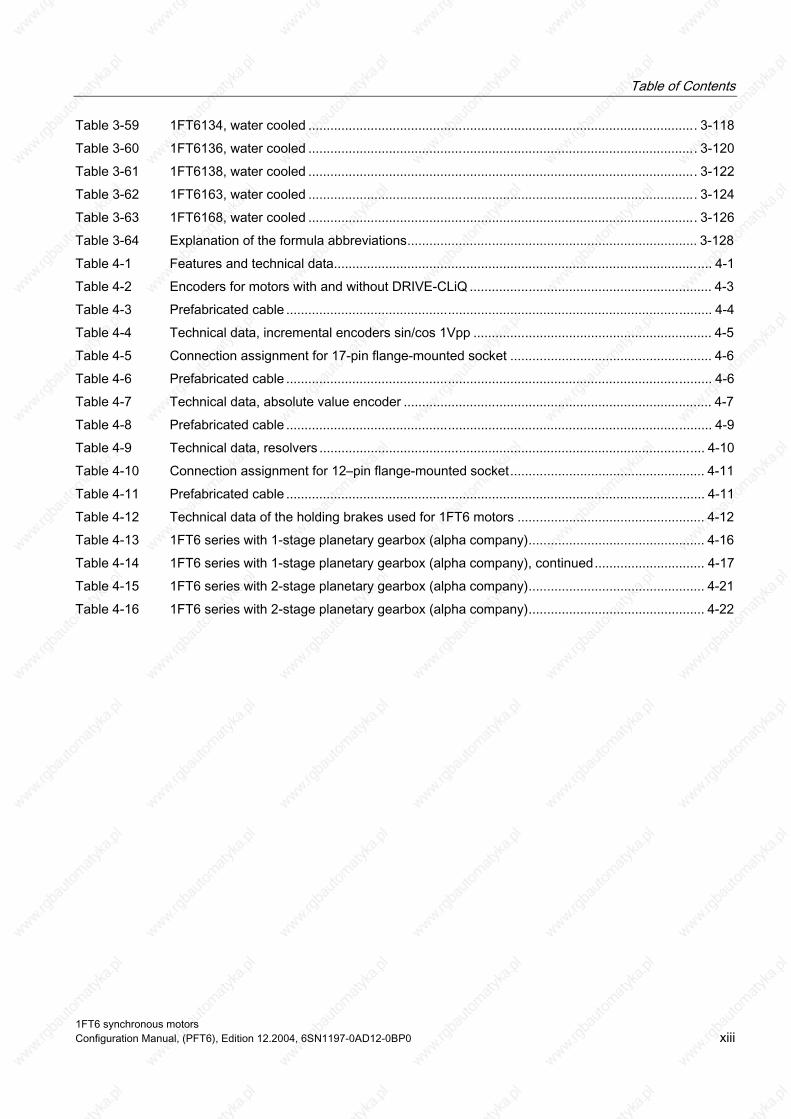
Table of Contents
Table 3-59 1FT6134, water cooled .......................................................................................................... 3-118 Table 3-60 1FT6136, water cooled .......................................................................................................... 3-120 Table 3-61 1FT6138, water cooled .......................................................................................................... 3-122 Table 3-62 1FT6163, water cooled .......................................................................................................... 3-124 Table 3-63 1FT6168, water cooled .......................................................................................................... 3-126 Table 3-64 Explanation of the formula abbreviations............................................................................... 3-128 Table 4-1 Features and technical data....................................................................................................... 4-1 Table 4-2 Encoders for motors with and without DRIVE-CLiQ .................................................................. 4-3 Table 4-3 Prefabricated cable .................................................................................................................... 4-4 Table 4-4 Technical data, incremental encoders sin/cos 1Vpp ................................................................. 4-5 Table 4-5 Connection assignment for 17-pin flange-mounted socket ....................................................... 4-6 Table 4-6 Prefabricated cable .................................................................................................................... 4-6 Table 4-7 Technical data, absolute value encoder .................................................................................... 4-7 Table 4-8 Prefabricated cable .................................................................................................................... 4-9 Table 4-9 Technical data, resolvers ......................................................................................................... 4-10 Table 4-10 Connection assignment for 12–pin flange-mounted socket..................................................... 4-11 Table 4-11 Prefabricated cable .................................................................................................................. 4-11 Table 4-12 Technical data of the holding brakes used for 1FT6 motors ................................................... 4-12 Table 4-13 1FT6 series with 1-stage planetary gearbox (alpha company)................................................ 4-16 Table 4-14 1FT6 series with 1-stage planetary gearbox (alpha company), continued.............................. 4-17 Table 4-15 1FT6 series with 2-stage planetary gearbox (alpha company)................................................ 4-21 Table 4-16 1FT6 series with 2-stage planetary gearbox (alpha company)................................................ 4-22
1FT6 synchronous motors Configuration Manual, (PFT6), Edition 12.2004, 6SN1197-0AD12-0BP0 xiii

Table of Contents
1FT6 synchronous motors xiv Configuration Manual, (PFT6), Edition 12.2004, 6SN1197-0AD12-0BP0
Motor Description 1 1.1 Features
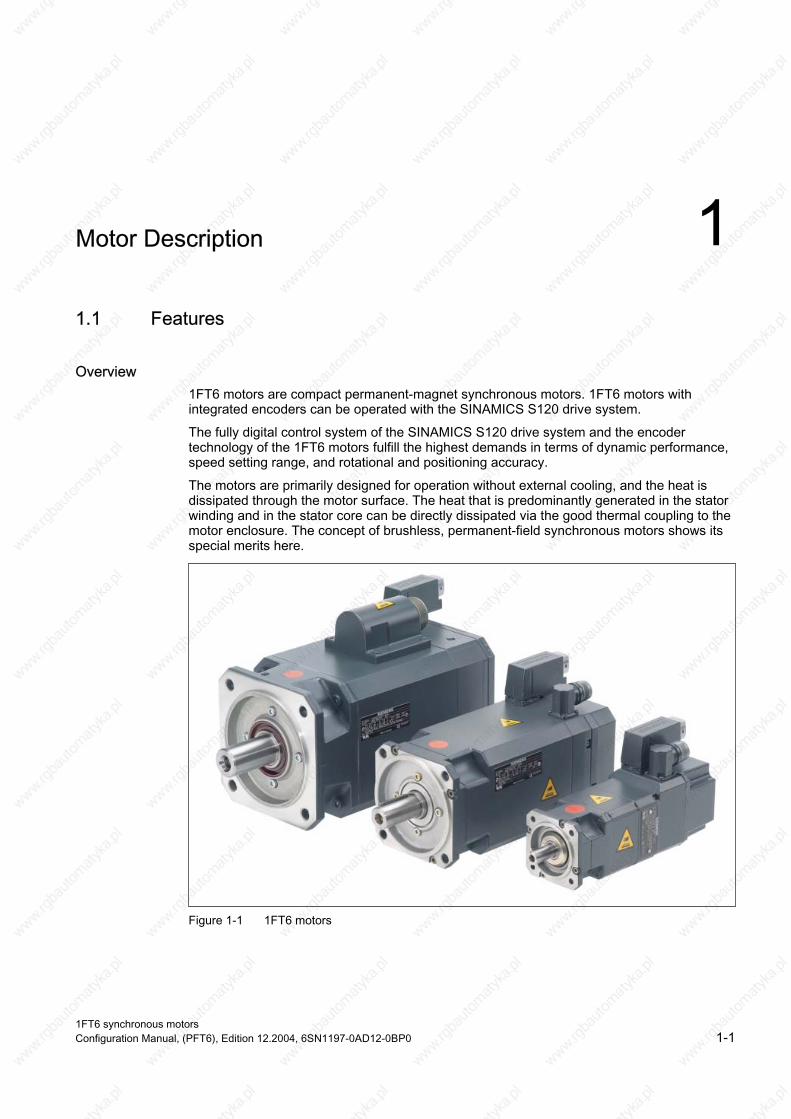
Overview 1FT6 motors are compact permanent-magnet synchronous motors. 1FT6 motors with integrated encoders can be operated with the SINAMICS S120 drive system.
The fully digital control system of the SINAMICS S120 drive system and the encoder technology of the 1FT6 motors fulfill the highest demands in terms of dynamic performance, speed setting range, and rotational and positioning accuracy.
The motors are primarily designed for operation without external cooling, and the heat is dissipated through the motor surface. The heat that is predominantly generated in the stator winding and in the stator core can be directly dissipated via the good thermal coupling to the
special merits here. motor enclosure. The concept of brushless, permanent-field synchronous motors shows its
Figure 1-1 1FT6 motors
1FT6 synchronous motors Configuration Manual, (PFT6), Edition 12.2004, 6SN1197-0AD12-0BP0 1-1

Motor Description 1.1 Features
Benefits • Optimum surface quality of the workpiece due to high rotational accuracy (sinusoidal
current injection)
• Short non-productive idle times due to high dynamic performance
• Power and signal connections for use in very dirty environments
• Simple installation due to reduced cabling requirements
• Can absorb high cantilever forces
Application • High-performance machine tools
• Machines with high requirements in terms of dynamic performance and precision
Standards, regulations The appropriate standards, regulations are directly assigned to the functional requirements.
1FT6 synchronous motors 1-2 Configuration Manual, (PFT6), Edition 12.2004, 6SN1197-0AD12-0BP0

Motor Description 1.2 Technical features
1.2 Technical features
Table 1-1 Features of the standard design
Technical features Version Motor type Permanent-magnet synchronous motor Type of construction (acc. to EN60034–7; IEC 60034–7)
IM B5 (IM V1, IM V3) for SH 28 to 132 IM B35 (IM V15, IM V36) for 132 to 160 (options, refer to the table)
Degree of protection 4) (acc. to EN60034–5; IEC 60034–5)
IP64; core types IP65 (options, refer to the table)
Cooling (acc. to EN60034–6; IEC 60034–6)
Non-ventilated 2) Force-ventilated 2)3) Water-cooled
Thermal motor protection (acc. to EN 60034-11; IEC 60034-11)
KTY84 temperature sensor in the stator winding
Shaft end (acc. to DIN 748-3; IEC 60072-1)
Cylindrical; without keyway and without fitted key tolerance field k6 (option, refer to the table)
Radial eccentricity, concentricity and axial eccentricity (acc. to DIN 42955; IEC 60072-1)
Tolerance N (normal)
Vibration severity (acc. to EN 60034-14; IEC 60034-14)
Grade N (normal) (options, refer to the table)
Max. sound pressure level (acc. to DIN EN ISO 1680) + 3 dB
SH 28 to 48: approx. 55 dB(A) SH 63 to 100: approx. 70 dB(A)
ooled): approx. 70 dB(A) SH 132 to 160 (force-ventilated): approx. 74 dB(A)
N. Bearings Roller bearings with permanent grease lubrication (lubrication over the
bearing lifetime) bearing lifetime 20000 h SH 36, 48: Locating bearings on the NDE
Winding insulation (acc. to EN 60034–1; IEC 60034–1)
Temperature class F for a winding temperature rise of ΔT = 100 K at an ambient temperature of 40 °C.
Installation altitude (acc. to EN and IEC 60034–1)
≤ 1000 m above sea level, otherwise power-de-rating factor 2) 2000 m factor 0.94 2500 m factor 0.9
Magnetic material Magnetic material Electrical connection The power is connected either through a terminal box or connector
Encoder signals through connectors Speed encoder, integrated Optical encoders:
• Incremental encoders sin/cos 1Vpp (I–2048) • Absolute value encoder EnDat (A-2048 and A–512) 1) • Resolver, two-pole/multi-pole For more detailed information, refer to the Chapter Encoders.
Rating plate A second rating plate is provided for all motors
options, refer to the Table)
SH 132 to 160 (non-ventilated or water-c
The specified values apply to all shaft heights up to speed n
SH 28, 63 to 160: Locating bearing on the DE
Footnotes, refer to the next page
1FT6 synchronous motors Configuration Manual, (PFT6), Edition 12.2004, 6SN1197-0AD12-0BP0 1-3

Motor Description 1.3 Technical features, options, supplements
1.3 Technical features, options, supplements
Table 1-2 Options and supplements
Technical feature Version Type of construction (acc. to EN60034–7; IEC 60034–7)
IM B14 for SH 63 to 100
Degree of protection 4) (acc. to EN 60034–5; IEC 60034–5)
IP65, IP67, IP68 Information: SH 28 is only available in degree of protection IP64 or IP67. IP67 and IP68 with sealing air connection. Force-ventilated motors, only available in degree of protection IP64 and IP65 (fan IP54).
Shaft end (acc. to EN and IEC 60034–14)
Cylindrical; with keyway and fitted key; Tolerance field k6
Radial eccentricity, concentricity and axial eccentricity (acc. to DIN 42955; IEC 60072-1)
Tolerance R (reduced)
Vibration severity (acc. to EN 60034-14; IEC 60034-14)
Grade R
Mounted/integrated components Mounted planetary gear for SH 28 to 132 (geared motors only available with vibration severity grade N)
Cable outlet for terminal boxes Outlet direction can be selected in steps of 90°
H=half key balancing
1)When using an absolute value encoder and non-ventilated or forced ventilation, the rated torque is reduced by 10 % (refer to the Table, Technical data) 2) Power de-rating for temperatures > 40 °C and/or installation altitudes > 1000 m, refer to the Configuration Manual "General Section for Synchronous Motors" 3) Forced ventilation cannot be used in the presence of flammable, corrosive, electrically conductive or explosive dust. 4) For motors with degree of protection IP67 and IP68, since 01/2001, an M5 inner thread is provided in the cover on the NDE. This allows compressed air to be connected. The pressure in the motor should be within the range from 0.05 to 0.1 bar. The compressed air must be dry and clean. For instance, the DA300 compressed air service unit from the Heidenhain company can be used.
ave a pre-filter that filters-out any foreign bodies above 3 μm.
lter element, a fine filter is required that filters-out foreign bodies above 0.01 μm.
For 1FT6 motors without optical encoders, it is sufficient to h
For 1FT6 motors with optical encoder, in addition to the pre-fi
1FT6 synchronous motors 1-4 Configuration Manual, (PFT6), Edition 12.2004, 6SN1197-0AD12-0BP0

Motor Description 1.4 Order designation
1.4 Order designation
Order designation (standard types), SH 28 to SH 132 (non-ventilated, forced-ventilated and water-cooled)
. .. – .. .–. . . ..
1) Only for SH 63, 80, 100 2) Not for force ventilated motors 3) For 1FT6062 - only in conjunction with a water connection, either at the side or below 4) Water connection is only possible at the righthand side (code –ZQ20) or lefthand side (-ZQ21) or at the bottom (-ZQ22).
ill be supplied with a water connection at the top. 5) Without code –ZQ2⃞, the motor w
1FT6 synchronous motors Configuration Manual, (PFT6), Edition 12.2004, 6SN1197-0AD12-0BP0 1-5
Motor Description 1.4 Order designation
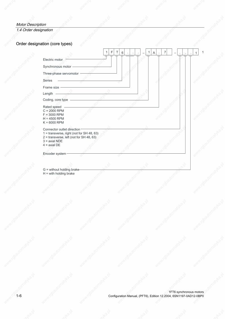
Order designation (core types)
– . ..–. . .
1FT6 synchronous motors 1-6 Configuration Manual, (PFT6), Edition 12.2004, 6SN1197-0AD12-0BP0
Motor Description 1.4 Order designation
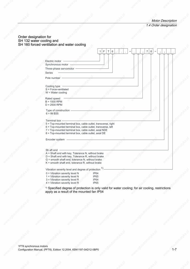
Order designation for SH 132 water cooling and SH 160 forced ventilation and water cooling
–– . ..
1) Specified degree of protection is only valid for water cooling; for air cooling, restrictions apply as a result of the mounted fan IP54
1FT6 synchronous motors Configuration Manual, (PFT6), Edition 12.2004, 6SN1197-0AD12-0BP0 1-7
Motor Description 1.5 Technical data
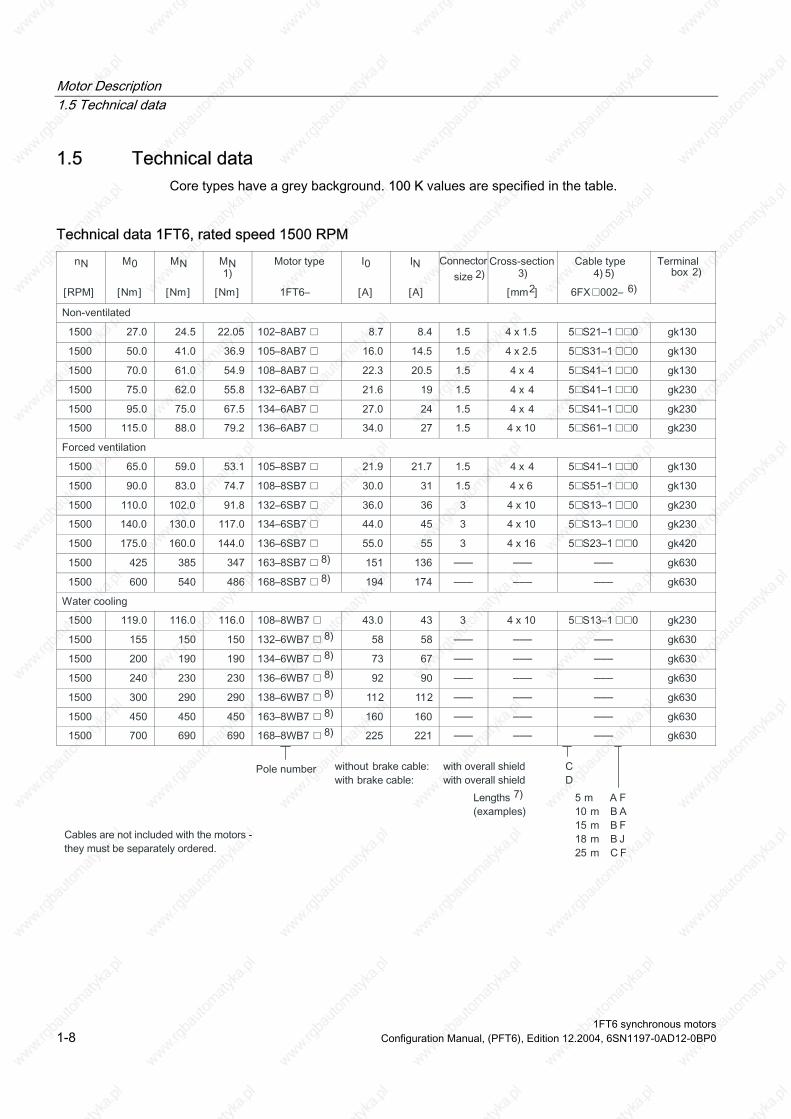
1.5 Technical data Core types have a grey background. 100 K values are specified in the table.
Technical data 1FT6, rated speed 1500 RPM
––– ––– –––
––– ––– –––
––– ––– –––
––– ––– –––
––– ––– –––
––– ––– –––
––– ––– –––
––– ––– –––
1FT6 synchronous motors 1-8 Configuration Manual, (PFT6), Edition 12.2004, 6SN1197-0AD12-0BP0

Motor Description 1.5 Technical data
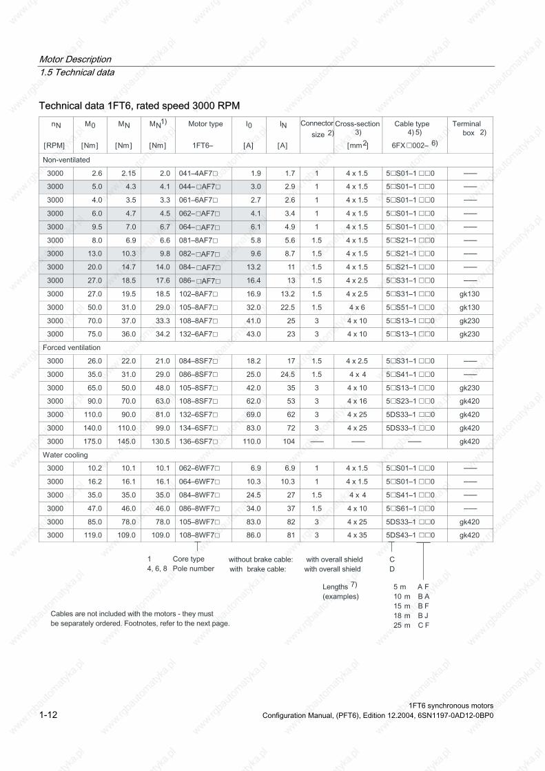
1) With absolute value encoder (due to the max. temperature of the encoder) 2) Power connector and terminal box mutually exclude one another 3) Motor with terminal boxes, max. cross-section that can be connected, refer to the Table "Connections for terminal boxes"
ends on the size of the selected power module (refer to the Configuration Manual, Drive Converters) 5) Motor with terminal boxes, power and signals cables, refer to Catalog, Chapter "Connection system MOTION-CONNECT”
6FX5002 = MOTION-CONNECT 500; TION-CONNECT”
7) Cables can be supplied in integer lengths of precisely 1 meter; Length code, refer to the Configuration Manual "General Part for Synchronous Motors" 8) For 1FT613⃞ motors, the maximum current and the rated current of the converter must be carefully observed. 1FT616⃞ motors can only be operated with SIMOVERT MASTERDRIVES MC drive converters.
4) The electrical shock hazard protection of the power cables dep
6) 6FX8002 = MOTION-CONNECT 800;
Technical data, refer to Catalog, Chapter “Connection system MO
1FT6 synchronous motors Configuration Manual, (PFT6), Edition 12.2004, 6SN1197-0AD12-0BP0 1-9
Motor Description 1.5 Technical data
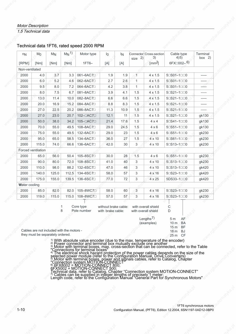
Technical data 1FT6, rated speed 2000 RPM
1
7
7
0
7
7
7
7
7
7
7 1
4
7
7
7
1 7
7
7
1 7 0
1
W
1 1 1
AFJF
-
–––
–––
–––
–––
–––
–––
–––
1) With absolute value encoder (due to the max. temperature of the encoder) 2) Power connector and terminal box mutually exclude one another 3) Motor with terminal boxes, max. cross-section that can be connected, refer to the Table "Connections for terminal boxes"
ends on the size of the selected power module (refer to the Configuration Manual, Drive Converters) 5) Motor with terminal boxes, power and signals cables, refer to Catalog, Chapter "Connection system MOTION-CONNECT” 6FX5002 = MOTION-CONNECT 500;
TION-CONNECT” 7) Cables can be supplied in integer lengths of precisely 1 meter; Length code, refer to the Configuration Manual "General Part for Synchronous Motors"
4) The electrical shock hazard protection of the power cables dep
6) 6FX8002 = MOTION-CONNECT 800; Technical data, refer to Catalog, Chapter “Connection system MO
1FT6 synchronous motors 1-10 Configuration Manual, (PFT6), Edition 12.2004, 6SN1197-0AD12-0BP0
Motor Description 1.5 Technical data
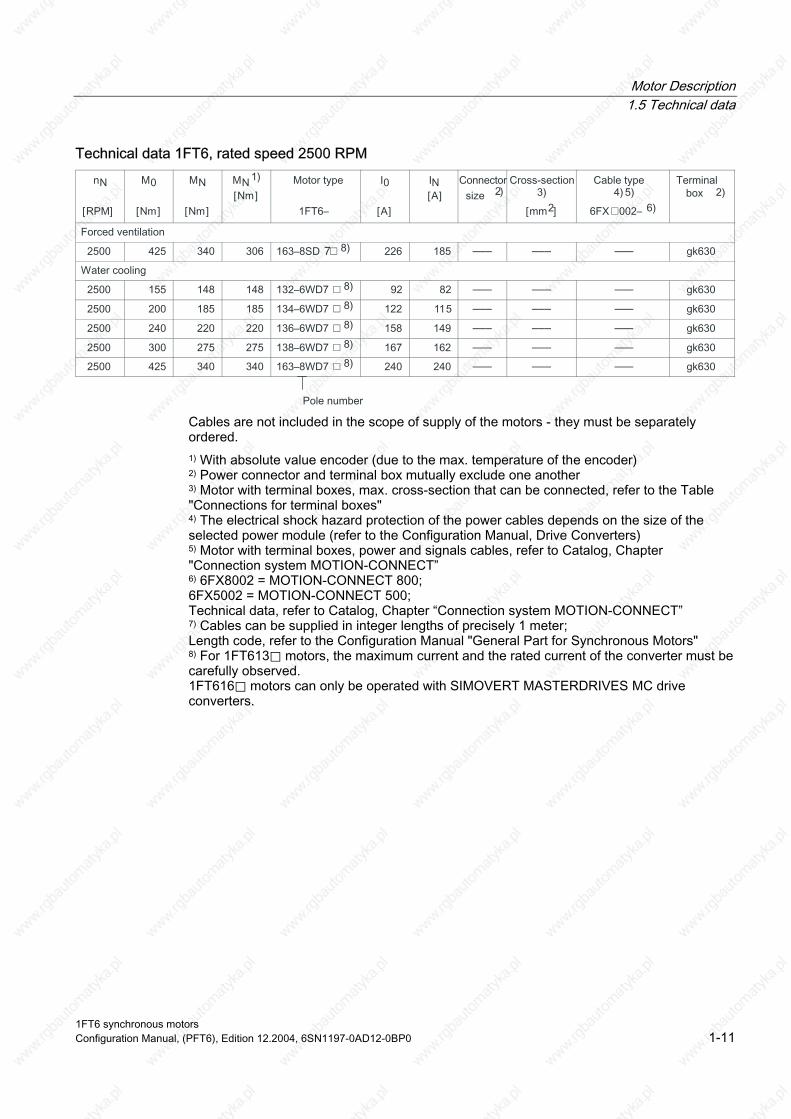
Technical data 1FT6, rated speed 2500 RPM
7 ––– ––– –––
––– ––– –––
––– ––– –––
––– ––– –––
––– ––– –––
––– ––– –––
Cables are not included in the scope of supply of the motors - they must be separately ordered. 1) With absolute value encoder (due to the max. temperature of the encoder) 2) Power connector and terminal box mutually exclude one another 3) Motor with terminal boxes, max. cross-section that can be connected, refer to the Table "Connections for terminal boxes"
ends on the size of the selected power module (refer to the Configuration Manual, Drive Converters) 5) Motor with terminal boxes, power and signals cables, refer to Catalog, Chapter "Connection system MOTION-CONNECT”
6FX5002 = MOTION-CONNECT 500; TION-CONNECT”
7) Cables can be supplied in integer lengths of precisely 1 meter; Length code, refer to the Configuration Manual "General Part for Synchronous Motors" 8) For 1FT613⃞ motors, the maximum current and the rated current of the converter must be carefully observed. 1FT616⃞ motors can only be operated with SIMOVERT MASTERDRIVES MC drive converters.
4) The electrical shock hazard protection of the power cables dep
6) 6FX8002 = MOTION-CONNECT 800;
Technical data, refer to Catalog, Chapter “Connection system MO
1FT6 synchronous motors Configuration Manual, (PFT6), Edition 12.2004, 6SN1197-0AD12-0BP0 1-11
Motor Description 1.5 Technical data
Technical data 1FT6, rated speed 3000 RPM
–––
–––
–––
–––
–––
–––
–––
–––
–––
–––
–––
––– ––– –––
–––
–––
–––
–––
1FT6 synchronous motors 1-12 Configuration Manual, (PFT6), Edition 12.2004, 6SN1197-0AD12-0BP0
Motor Description 1.5 Technical data
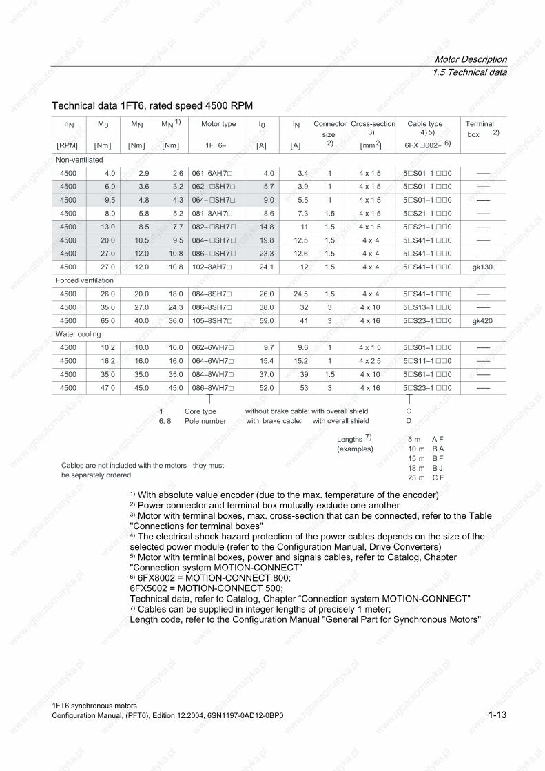
Technical data 1FT6, rated speed 4500 RPM
–––
–––
–––
–––
–––
–––
–––
–––
–––
–––
–––
–––
–––
1) With absolute value encoder (due to the max. temperature of the encoder) 2) Power connector and terminal box mutually exclude one another 3) Motor with terminal boxes, max. cross-section that can be connected, refer to the Table "Connections for terminal boxes"
ends on the size of the selected power module (refer to the Configuration Manual, Drive Converters) 5) Motor with terminal boxes, power and signals cables, refer to Catalog, Chapter "Connection system MOTION-CONNECT”
6FX5002 = MOTION-CONNECT 500; TION-CONNECT”
7) Cables can be supplied in integer lengths of precisely 1 meter; Length code, refer to the Configuration Manual "General Part for Synchronous Motors"
4) The electrical shock hazard protection of the power cables dep
6) 6FX8002 = MOTION-CONNECT 800;
Technical data, refer to Catalog, Chapter “Connection system MO
1FT6 synchronous motors Configuration Manual, (PFT6), Edition 12.2004, 6SN1197-0AD12-0BP0 1-13
Motor Description 1.5 Technical data
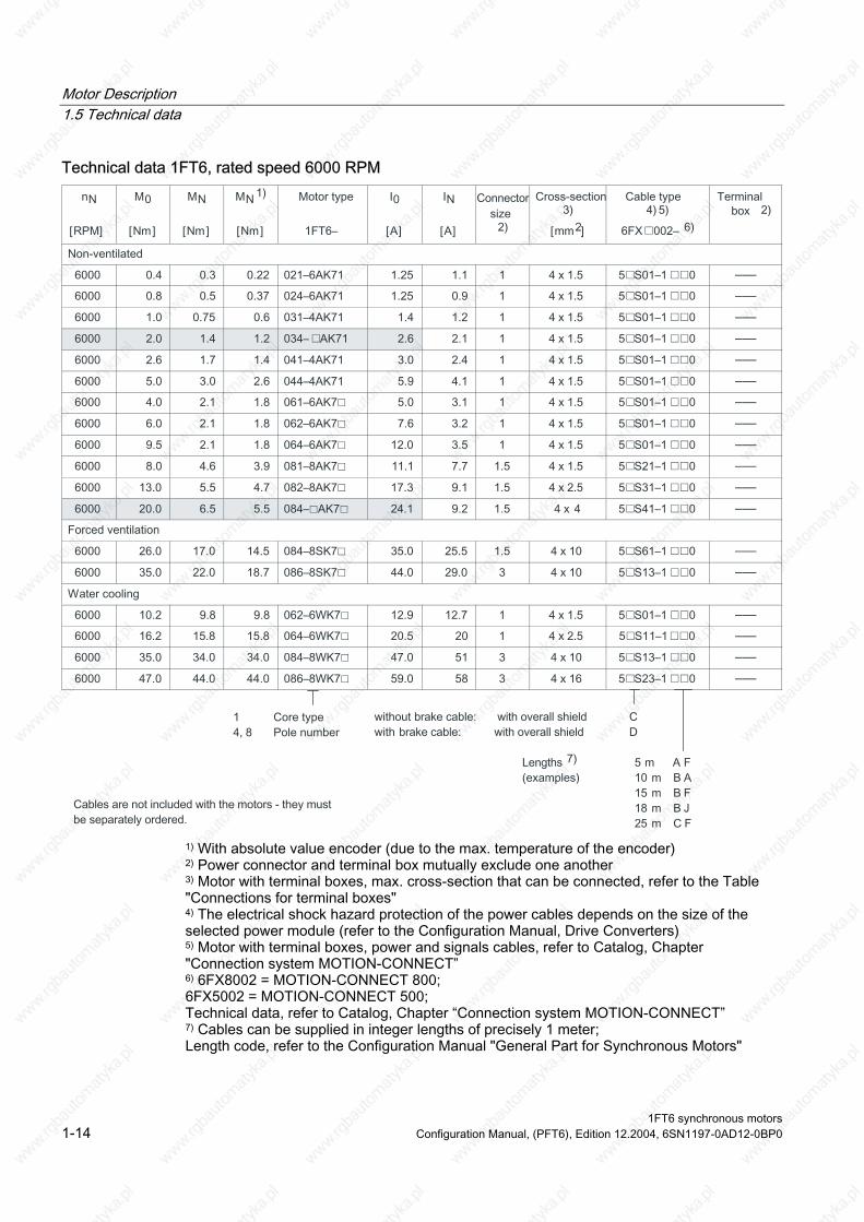
Technical data 1FT6, rated speed 6000 RPM
–––
–––
–––
–––
–––
–––
–––
–––
–––
–––
–––
–––
–––
–––
–––
–––
–––
–––
1) With absolute value encoder (due to the max. temperature of the encoder) 2) Power connector and terminal box mutually exclude one another 3) Motor with terminal boxes, max. cross-section that can be connected, refer to the Table "Connections for terminal boxes"
ends on the size of the selected power module (refer to the Configuration Manual, Drive Converters) 5) Motor with terminal boxes, power and signals cables, refer to Catalog, Chapter "Connection system MOTION-CONNECT”
6FX5002 = MOTION-CONNECT 500; TION-CONNECT”
7) Cables can be supplied in integer lengths of precisely 1 meter; Length code, refer to the Configuration Manual "General Part for Synchronous Motors"
4) The electrical shock hazard protection of the power cables dep
6) 6FX8002 = MOTION-CONNECT 800;
Technical data, refer to Catalog, Chapter “Connection system MO
1FT6 synchronous motors 1-14 Configuration Manual, (PFT6), Edition 12.2004, 6SN1197-0AD12-0BP0
Motor Description 1.6 Armature short-circuit braking
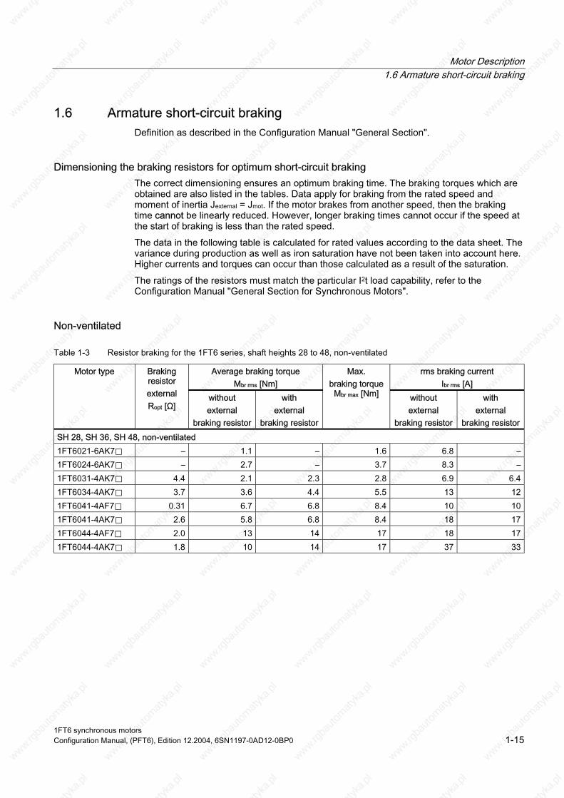
1.6 Armature short-circuit braking Definition as described in the Configuration Manual "General Section".
Dimensioning the braking resistors for optimum short-circuit braking The correct dimensioning ensures an optimum braking time. The braking torques which are obtained are also listed in the tables. Data apply for braking from the rated speed and moment of inertia Jexternal = Jmot. If the motor brakes from another speed, then the braking time cannot be linearly reduced. However, longer braking times cannot occur if the speed at the start of braking is less than the rated speed.
The data in the following table is calculated for rated values according to the data sheet. The variance during production as well as iron saturation have not been taken into account here. Higher currents and torques can occur than those calculated as a result of the saturation.
The ratings of the resistors must match the particular I2t load capability, refer to the Configuration Manual "General Section for Synchronous Motors".
Non-ventilated
Table 1-3 Resistor braking for the 1FT6 series, shaft heights 28 to 48, non-ventilated
Average braking torque Mbr rms [Nm]
rms braking current Ibr rms [A]
Motor type Braking resistor external Ropt [Ω]
without external
braking resistor
with external
braking resistor
Max. braking torque Mbr max [Nm] without
external braking resistor
with external
braking resistor SH 28, SH 36, SH 48, non-ventilated 1FT6021-6AK7⃞ – 1.1 – 1.6 6.8 – 1FT6024-6AK7⃞ – 2.7 – 3.7 8.3 – 1FT6031-4AK7⃞ 4.4 2.1 2.3 2.8 6.9 6.4 1FT6034-4AK7⃞ 3.7 3.6 4.4 5.5 13 12 1FT6041-4AF7⃞ 0.31 6.7 6.8 8.4 10 10 1FT6041-4AK7⃞ 2.6 5.8 6.8 8.4 18 17 1FT6044-4AF7⃞ 2.0 13 14 17 18 17 1FT6044-4AK7⃞ 1.8 10 14 17 37 33
1FT6 synchronous motors Configuration Manual, (PFT6), Edition 12.2004, 6SN1197-0AD12-0BP0 1-15
Motor Description 1.6 Armature short-circuit braking
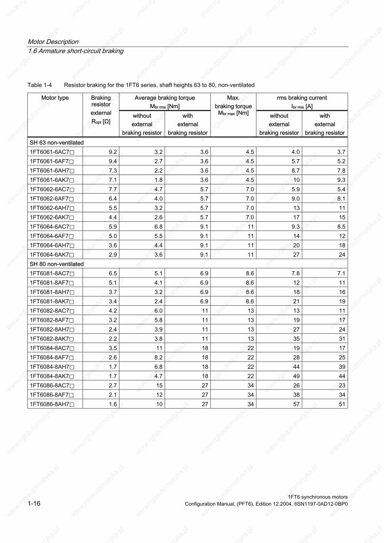
Table 1-4 Resistor braking for the 1FT6 series, shaft heights 63 to 80, non-ventilated
Average braking torque Mbr rms [Nm]
rms braking current Ibr rms [A]
Motor type Braking resistor external Ropt [Ω]
without external
braking resistor
with external
braking resistor
Max. braking torque Mbr max [Nm] without
external braking resistor
with external
braking resistor SH 63 non-ventilated 1FT6061-6AC7⃞ 9.2 3.2 3.6 4.5 4.0 3.7 1FT6061-6AF7⃞ 9.4 2.7 3.6 4.5 5.7 5.2 1FT6061-6AH7⃞ 7.3 2.2 3.6 4.5 8.7 7.8 1FT6061-6AK7⃞ 7.1 1.8 3.6 4.5 10 9.3 1FT6062-6AC7⃞ 7.7 4.7 5.7 7.0 5.9 5.4 1FT6062-6AF7⃞ 6.4 4.0 5.7 7.0 9.0 8.1 1FT6062-6AH7⃞ 5.5 3.2 5.7 7.0 13 11 1FT6062-6AK7⃞ 4.4 2.6 5.7 7.0 17 15 1FT6064-6AC7⃞ 5.9 6.8 9.1 11 9.3 8.5 1FT6064-6AF7⃞ 5.0 5.5 9.1 11 14 12 1FT6064-6AH7⃞ 3.6 4.4 9.1 11 20 18 1FT6064-6AK7⃞ 2.9 3.6 9.1 11 27 24 SH 80 non-ventilated 1FT6081-8AC7⃞ 6.5 5.1 6.9 8.6 7.8 7.1 1FT6081-8AF7⃞ 5.1 4.1 6.9 8.6 12 11 1FT6081-8AH7⃞ 3.7 3.2 6.9 8.6 18 16 1FT6081-8AK7⃞ 3.4 2.4 6.9 8.6 21 19 1FT6082-8AC7⃞ 4.2 6.0 11 13 13 11 1FT6082-8AF7⃞ 3.2 5.8 11 13 19 17 1FT6082-8AH7⃞ 2.4 3.9 11 13 27 24 1FT6082-8AK7⃞ 2.2 3.8 11 13 35 31 1FT6084-8AC7⃞ 3.5 11 18 22 19 17 1FT6084-8AF7⃞ 2.6 8.2 18 22 28 25 1FT6084-8AH7⃞ 1.7 6.8 18 22 44 39 1FT6084-8AK7⃞ 1.7 4.7 18 22 49 44 1FT6086-8AC7⃞ 2.7 15 27 34 26 23 1FT6086-8AF7⃞ 2.1 12 27 34 38 34 1FT6086-8AH7⃞ 1.6 10 27 34 57 51
1FT6 synchronous motors 1-16 Configuration Manual, (PFT6), Edition 12.2004, 6SN1197-0AD12-0BP0

Motor Description 1.6 Armature short-circuit braking
Table 1-5 Resistor braking for the 1FT6 series, shaft heights 100 to 132, non-ventilated
Average braking torque Mbr rms [Nm]
rms braking current Ibr rms [A]
Motor type Braking re-
sistor external Ropt [Ω]
without external
braking resistor
with external
braking resistor
Max. braking torque Mbr max [Nm] without
external braking resistor
with external
braking resistor SH 100 non-ventilated 1FT6102-8AB7⃞ 3.9 13 24 30 18 16 1FT6102-8AC7⃞ 2.8 11 24 30 25 23 1FT6102-8AF7⃞ 2.3 8.1 24 30 35 31 1FT6102-8AH7⃞ 1.7 6.5 24 30 51 46 1FT6105-8AB7⃞ 2.2 21 43 54 33 29 1FT6105-8AC7⃞ 1.7 17 43 54 44 39 1FT6105-8AF7⃞ 1.2 13 43 54 65 58 1FT6108-8AB7⃞ 1.4 32 71 88 53 47 1FT6108-8AC7⃞ 1.2 26 71 88 68 61 1FT6108-8AF7⃞ 0.9 21 71 88 99 89 SH 132 non-ventilated 1FT6132-6AB7⃞ 1.0 1) 37 83 105 56 50 1FT6132-6AC7⃞ 1.2 1) 32 83 105 75 67 1FT6132-6AF7⃞ 0.8 1) 23 83 105 110 100 1FT6134-6AB7⃞ 1.2 1) 47 110 140 72 65 1FT6134-6AC7⃞ 0.9 1) 40 110 140 99 89 1FT6136-6AB7⃞ 0.9 1) 55 130 170 91 82 1FT6136-6AC7⃞ 0.8 1) 45 130 170 115 105
1) When utilized to M0 (100 K), a braking resistor must be used in order to prevent partial de-magnetization. When utilized to M0 (60 K), the additional braking resistor is not required.
1FT6 synchronous motors Configuration Manual, (PFT6), Edition 12.2004, 6SN1197-0AD12-0BP0 1-17
Motor Description 1.6 Armature short-circuit braking
Forced cooling
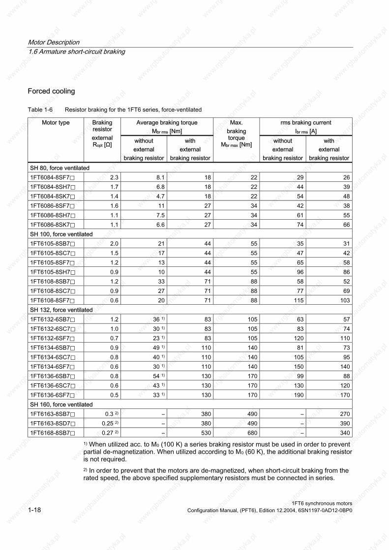
Table 1-6 Resistor braking for the 1FT6 series, force-ventilated
Average braking torque Mbr rms [Nm]
rms braking current Ibr rms [A]
Motor type Braking resistor external Ropt [Ω] without
external braking resistor
with external
braking resistor
Max. braking torque
Mbr max [Nm] without external
braking resistor
with external
braking resistor SH 80, force ventilated 1FT6084-8SF7⃞ 2.3 8.1 18 22 29 26 1FT6084-8SH7⃞ 1.7 6.8 18 22 44 39 1FT6084-8SK7⃞ 1.4 4.7 18 22 54 48 1FT6086-8SF7⃞ 1.6 11 27 34 42 38 1FT6086-8SH7⃞ 1.1 7.5 27 34 61 55 1FT6086-8SK7⃞ 1.1 6.6 27 34 74 66 SH 100, force ventilated 1FT6105-8SB7⃞ 2.0 21 44 55 35 31 1FT6105-8SC7⃞ 1.5 17 44 55 47 42 1FT6105-8SF7⃞ 1.2 13 44 55 65 58 1FT6105-8SH7⃞ 0.9 10 44 55 96 86 1FT6108-8SB7⃞ 1.2 33 71 88 58 52 1FT6108-8SC7⃞ 0.9 27 71 88 77 69 1FT6108-8SF7⃞ 0.6 20 71 88 115 103 SH 132, force ventilated 1FT6132-6SB7⃞ 1.2 36 1) 83 105 63 57 1FT6132-6SC7⃞ 1.0 30 1) 83 105 83 74 1FT6132-6SF7⃞ 0.7 23 1) 83 105 120 110 1FT6134-6SB7⃞ 0.9 49 1) 110 140 81 73 1FT6134-6SC7⃞ 0.8 40 1) 110 140 105 95 1FT6134-6SF7⃞ 0.6 30 1) 110 140 150 140 1FT6136-6SB7⃞ 0.8 54 1) 130 170 99 88 1FT6136-6SC7⃞ 0.6 43 1) 130 170 130 120 1FT6136-6SF7⃞ 0.5 33 1) 130 170 190 170 SH 160, force ventilated 1FT6163-8SB7⃞ 0.3 2) – 380 490 – 270 1FT6163-8SD7⃞ 0.25 2) – 380 490 – 390 1FT6168-8SB7⃞ 0.27 2) – 530 680 – 340
1) When utilized acc. to M0 (100 K) a series braking resistor must be used in order to prevent partial de-magnetization. When utilized according to M0 (60 K), the additional braking resistor is not required. 2) In order to prevent that the motors are de-magnetized, when short-circuit braking from the rated speed, the above specified supplementary resistors must be connected in series.
1FT6 synchronous motors 1-18 Configuration Manual, (PFT6), Edition 12.2004, 6SN1197-0AD12-0BP0
Motor Description 1.6 Armature short-circuit braking
Water-cooling
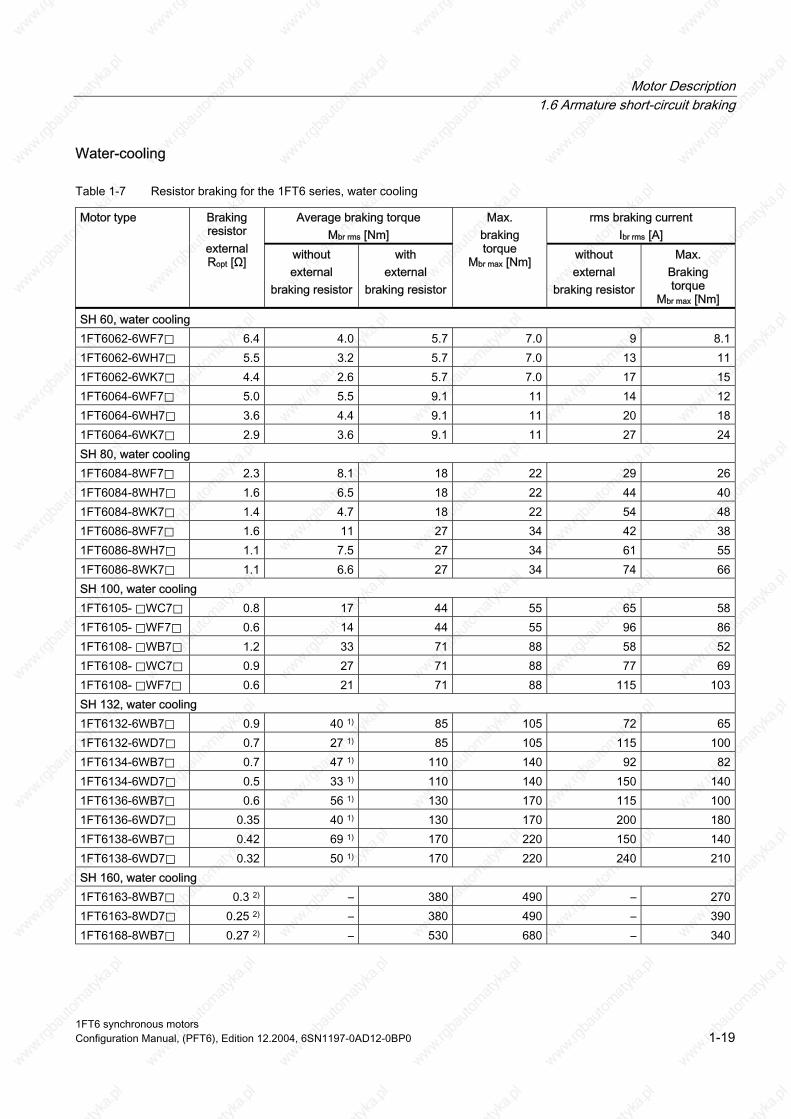
Table 1-7 Resistor braking for the 1FT6 series, water cooling
Average braking torque Mbr rms [Nm]
rms braking current Ibr rms [A]
Motor type Braking resistor external Ropt [Ω] without
external braking resistor
with external
braking resistor
Max. braking torque
Mbr max [Nm] without external
braking resistor
Max. Braking torque
Mbr max [Nm] SH 60, water cooling 1FT6062-6WF7⃞ 6.4 4.0 5.7 7.0 9 8.1 1FT6062-6WH7⃞ 5.5 3.2 5.7 7.0 13 11 1FT6062-6WK7⃞ 4.4 2.6 5.7 7.0 17 15 1FT6064-6WF7⃞ 5.0 5.5 9.1 11 14 12 1FT6064-6WH7⃞ 3.6 4.4 9.1 11 20 18 1FT6064-6WK7⃞ 2.9 3.6 9.1 11 27 24 SH 80, water cooling 1FT6084-8WF7⃞ 2.3 8.1 18 22 29 26 1FT6084-8WH7⃞ 1.6 6.5 18 22 44 40 1FT6084-8WK7⃞ 1.4 4.7 18 22 54 48 1FT6086-8WF7⃞ 1.6 11 27 34 42 38 1FT6086-8WH7⃞ 1.1 7.5 27 34 61 55 1FT6086-8WK7⃞ 1.1 6.6 27 34 74 66 SH 100, water cooling 1FT6105- ⃞WC7⃞ 0.8 17 44 55 65 58 1FT6105- ⃞WF7⃞ 0.6 14 44 55 96 86 1FT6108- ⃞WB7⃞ 1.2 33 71 88 58 52 1FT6108- ⃞WC7⃞ 0.9 27 71 88 77 69 1FT6108- ⃞WF7⃞ 0.6 21 71 88 115 103 SH 132, water cooling 1FT6132-6WB7⃞ 0.9 40 1) 85 105 72 65 1FT6132-6WD7⃞ 0.7 27 1) 85 105 115 100 1FT6134-6WB7⃞ 0.7 47 1) 110 140 92 82 1FT6134-6WD7⃞ 0.5 33 1) 110 140 150 140 1FT6136-6WB7⃞ 0.6 56 1) 130 170 115 100 1FT6136-6WD7⃞ 0.35 40 1) 130 170 200 180 1FT6138-6WB7⃞ 0.42 69 1) 170 220 150 140 1FT6138-6WD7⃞ 0.32 50 1) 170 220 240 210 SH 160, water cooling 1FT6163-8WB7⃞ 0.3 2) – 380 490 – 270 1FT6163-8WD7⃞ 0.25 2) – 380 490 – 390 1FT6168-8WB7⃞ 0.27 2) – 530 680 – 340
1FT6 synchronous motors Configuration Manual, (PFT6), Edition 12.2004, 6SN1197-0AD12-0BP0 1-19

Motor Description 1.6 Armature short-circuit braking
1) When utilized acc. to M0 (100 K) a series braking resistor must be used in order to prevent partial de-magnetization. When utilized according to M0 (60 K), the additional braking resistor is not required. 2) It is absolutely prohibited to short-circuit the winding when using smaller supplementary resistors than those specified. When braking from the rated speed, the resistors listed prevent partial de-magnetization of the rotor.
1FT6 synchronous motors 1-20 Configuration Manual, (PFT6), Edition 12.2004, 6SN1197-0AD12-0BP0

Motor Description 1.7 Cooling
1.7 Cooling
1.7.1 Cooling types The different cooling types are defined in the Configuration Manual "General Section for Synchronous Motors"..
1.7.2 Forced ventilation Degree of protection IP54 (acc. to EN 60529).
e Degrees of protection IP64, IP65, IP67 and IP68 are not possibl
The hot discharged air may not be drawn-in again.
Caution
Forced ventilation cannot be used in the presence of flammable, corrosive, electrically conductive or explosive dust.
Forced ventilation, SH 80 and SH 100 Air flow direction from NDE to DE.
yield by approx. 20 %. If the air flow direction is reversed, this reduces the torque
Mechanical changes to the motor with respect to non-ventilated versions:
• The power connector is about 12 mm higher.
• A sheet metal envelope is located over the motor frame from the non-drive end side. The axial fan is mounted in this sheet metal envelope. There is a cut-out in the sheet metal envelope at the connector positions. This means that the motor is only partially cooled by the air flow (three-sided ventilation).
• The motor dimensions can be taken from the dimension drawings.
Connection: Connector, Size 1, Order No.: 6FX2003–0CA10 Supply voltage: 1-ph. 230/260 V AC, 50/60 Hz Maximum current: 0.3 A
Connector assignment for fan connections SH 80 and SH 100: L1
N
1
24
56
1FT6 synchronous motors Configuration Manual, (PFT6), Edition 12.2004, 6SN1197-0AD12-0BP0 1-21

Motor Description 1.7 Cooling
Forced ventilation, SH 132 Air flow direction from DE to NDE
profile using a mounted radial fan. The air is blown through the enclosure corners of the extruded
Connection: via terminal box Supply voltage: 3-ph. 400/480 V AC, 50/60 Hz Maximum current: 0.4 A
Forced ventilation, SH 160 Air flow direction from DE to NDE
rofile using a mounted radial fan. The air is blow through the enclosure corners of the extruded p
Connection: via terminal box Supply voltage: 3-ph. 400/480 V AC, 50/60 Hz Maximum current: 0.8 A
Minimum clearance between parts and components mounted by the customer and the air discharge opening
The following minimum clearance must be maintained between parts and components mounted by the customer and the air discharge opening:
Table 1-8 Minimum clearance to parts and components mounted by the customer
Shaft height [mm] Minimum clearance [mm]
80 20 100 30 132 60 160 80
1FT6 synchronous motors 1-22 Configuration Manual, (PFT6), Edition 12.2004, 6SN1197-0AD12-0BP0

Motor Description 1.7 Cooling
1.7.3 Water-cooling The power loss generated by the motor is dissipated using a water cooling system. The machinery construction company must connect-up a cooling system (e.g. heat exchanger). The rated motor torques, specified in the motor data sheets apply for water-cooled operation and a water intake temperature of < 30 °C.
Notice
If the motor is operated without water cooling, then the rated motor torque is reduced as a function of the heat losses which can be dissipated by convection and radiation. In this case, the data for non-ventilated operation apply.
Note
It is not possible to retrofit a motor for water cooling.
The cooling medium must be pre-cleaned and filtered in order to prevent the cooling circuit from becoming blocked. The maximum permissible particle size after filtering is 100 mm.
Cooling circuit
Notice
If current is flowing through the motor, then the cooling circuit must be activated.
Table 1-9 Technical data for the cooling circuit
Motor type Water flow rate [l] Max. permissible pressure [bar]
Flow rate [l/min]
1FT6062 0.2 2.5 5 1FT6064 0.26 2.5 5 1FT6082 0.4 2.5 5 1FT6084 0.5 2.5 5 1FT6086 0.6 2.5 5 1FT6105 1.1 2.5 5 1FT6108 1.5 2.5 5 1FT6132 2.1 6.0 8 1FT6134 2.4 6.0 8 1FT6136 2.7 6.0 8 1FT6138 3.1 6.0 8 1FT6163 4.7 6.0 10 1FT6168 5.7 6.0 10
Pressure drop, intake/return: < 0.1 bar
1FT6 synchronous motors Configuration Manual, (PFT6), Edition 12.2004, 6SN1197-0AD12-0BP0 1-23

Motor Description 1.7 Cooling
Materials used in the cooling circuits The anti-corrosion additives used should be harmonized with the cooling system manufacturer - i.e. the materials of the motor cooler and the materials of the fittings and cooling medium hoses listed in the Table.
Table 1-10 Materials used in the motor cooling circuit
Motor type Bearing end shield Enclosure Sealing agent Connecting plate 1FT606⃞ 1FT608⃞ 1FT610⃞
Aluminum
Aluminum
Terostat
Stainless steel
1FT613⃞ 1FT616⃞
Gray cast iron Aluminum Terostat –––
Cooling medium and anti-corrosion protection
Notice
It is not permissible that ice forms in the cooling circuit, neither in operation nor during storage.
The checking and change intervals for the cooling medium should be harmonized with the companies supplying the anti-corrosion agent and the cooling system.
We recommend that an anti-corrosion agent is added to water as cooling-medium (e.g. Antifrogen N from the Hoechst Company or Tyfocor from Tyforop Chemie GmbH, refer to the Table below).
Observe the specifications of the anti-corrosion agent manufacturer regarding the ratio of water to anti-corrosion agent.
For Tyfocor, the ratio of 75 % water and 25 % anti-corrosion agent should not be exceeded.
When using another cooling medium (e.g. oil, cooling-lubricating medium) de-rating may be required in order that the thermal motor limit is not exceeded. The de-rating can be determined using the following data:
Specific density: ρ [kg/m3] Specific thermal capacitance: cp [J/(kg K)] Intake temperature: tv [°C] Flow quantity: v [l/min]
The enquiry must be sent to the manufacturer's plant (Hotline).
The motor power still does not have to be reduced for oil-water mixtures with less than 10 %.
1FT6 synchronous motors 1-24 Configuration Manual, (PFT6), Edition 12.2004, 6SN1197-0AD12-0BP0
Motor Description 1.7 Cooling
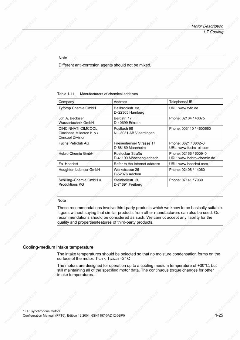
Note
Different anti-corrosion agents should not be mixed.
Table 1-11 Manufacturers of chemical additives
Company Address Telephone/URL
Tyforop Chemie GmbH Hellbrookstr. 5a, D–22305 Hamburg
URL: www.tyfo.de
Joh.A. Beckiser Bergstr. 17 D-40699 Erkrath
Phone: 02104 / 40075
CINCINNATI CIMCOOL Cincinnati Milacron b. v./ Cimcool Division
Postfach 98 NL–3031 AB Vlaardingen
Phone: 003110 / 4600660
Fuchs Petrolub AG Friesenheimer Strasse 17 D-68169 Mannheim
Phone: 0621 / 3802–0 URL: www.fuchs–oil.com
Hebro Chemie GmbH Rostocker Straße D-41199 Mönchengladbach
Phone: 02166 / 6009–0 URL: www.hebro–chemie.de
Fa. Hoechst Refer to the Internet address URL: www.hoechst.com Houghton Lubricor GmbH Werkstrasse 26
D-52076 Aachen Phone: 02408 / 14060
Schilling–Chemie GmbH u. Produktions KG
Steinbeißstr. 20 D-71691 Freiberg
Phone: 07141 / 7030
Note
These recommendations involve third-party products which we know to be basically suitable. It goes without saying that similar products from other manufacturers can also be used. Our recommendations should be considered as such. We cannot accept any liability for the quality and properties/features of third-party products.
Wassertechnik GmbH
Cooling-medium intake temperature The intake temperatures should be selected so that no moisture condensation forms on the surface of the motor: Tcool ≤ Tambient –2° C
The motors are designed for operation up to a cooling medium temperature of +30°C, but still maintaining all of the specified motor data. The continuous torque changes for other intake temperatures.
1FT6 synchronous motors Configuration Manual, (PFT6), Edition 12.2004, 6SN1197-0AD12-0BP0 1-25

Motor Description 1.7 Cooling
Cooling powers to be dissipated The values specified in Table refer to a cooling-medium temperature of 30 °C and maximum speed in S1 duty.
Table 1-12 Cooling powers to be dissipated
Motor type Cooling powers to be dissipated [W]
1FT6062–6WF7⃞ 600 1FT6062–6WH7⃞ 650 1FT6062–6WK7⃞ 700 1FT6064–6WF7⃞ 800 1FT6064–6WH7⃞ 850 1FT6064–6WK7⃞ 900 1FT6084–8WF7⃞ 1500 1FT6084–8WH7⃞ 1900 1FT6084–8WK7⃞ 2200 1FT6086–8WF7⃞ 1800 1FT6086–8WH7⃞ 2000 1FT6086–8WK7⃞ 2400 1FT6105–8WC7⃞ 2000 1FT6105–8WF7⃞ 2100 1FT6108–8WB7⃞ 1900 1FT6108–8WC7⃞ 2100 1FT6108–8WF7⃞ 2100 1FT6132–6WB7⃞ 2600 1FT6132–6WD7⃞ 2700 1FT6134–6WB7⃞ 2700 1FT6134–6WD7⃞ 3100 1FT6136–6WB7⃞ 3300 1FT6136–6WD7⃞ 3600 1FT6138–6WB7⃞ 3600 1FT6138–6WD7⃞ 4000 1FT6163–8WB7⃞ 4500 1FT6163–8WD7⃞ 6000 1FT6168–8WB7⃞ 7500
1FT6 synchronous motors 1-26 Configuration Manual, (PFT6), Edition 12.2004, 6SN1197-0AD12-0BP0

Motor Description 1.7 Cooling
Cooling system A cooling system (i.e. heat exchanger) must be used in order to guarantee a cooling medium intake temperature of +30°C. It is possible to operate several motors from a single cooling system. The cooling system is not included in the scope of supply.
Cooling system manufacturer, refer to the Catalog.
The cooling power is calculated from the sum of the power losses of the connected motors. The power of the pump and the distribution to different cooling circuits should be engineered corresponding to the specified flow and the pressure losses of the individual cooling circuits.
If one pump is used with distribution to several cooling circuits, then it may be necessary to use a flow controller.
1FT6 synchronous motors Configuration Manual, (PFT6), Edition 12.2004, 6SN1197-0AD12-0BP0 1-27
Motor Description 1.8 Coupling output
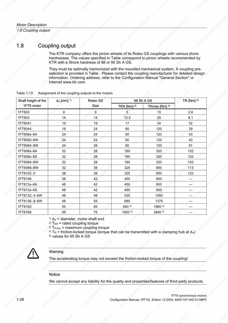
1.8 Coupling output The KTR company offers the pinion wheels of its Rotex GS couplings with various shore hardnesses. The values specified in Table correspond to pinion wheels recommended by KTR with a Shore hardness of 98 or 95 Sh A GS.
They must be optimally harmonized with the mounted mechanical system. A coupling pre-selection is provided in Table . Please contact the coupling manufacturer for detailed design information. Ordering address, refer to the Configuration Manual "General Section" or Internet www.ktr.com.
Table 1-13 Assignment of the coupling outputs to the motors
98 Sh A GS Shaft height of the 1FT6 motor
dw [mm] 1) Rotex GS Size TKN [Nm] 2) TKmax [Nm] 3)
TR [Nm] 4)
1FT602 9 9 5 10 2.6 1FT603 14 14 12.5 25 8.1 1FT6041 19 19 17 34 32 1FT6044 19 24 60 120 39 1FT606x–6A 24 24 60 120 43 1FT6062–6W 24 24 60 120 43 1FT6064–6W 24 28 60 120 91 1FT608x–8A 32 28 160 320 102 1FT608x–8S 32 28 160 320 102 1FT6084–8W 32 28 160 320 102 1FT6086–8W 32 38 325 650 113 1FT6102..5 38 38 325 650 122 1FT6108 38 42 450 900 –– 1FT613x–6A 48 42 450 900 –– 1FT613x–6S 48 42 450 900 –– 1FT6132..4–6W 48 48 525 1050 –– 1FT6136..8–6W 48 55 685 1370 –– 1FT6163 55 65 940 5) 1880 5) –– 1FT6168 55 75 1920 5) 3840 5) ––
1) dw = diameter, motor shaft end 2) TKN = rated coupling torque 3) TKmax = maximum coupling torque 4) TR = friction-locked torque (torque that can be transmitted with a clamping hub at dw) 5) values for 95 Sh A GS
Warning
The accelerating torque may not exceed the friction-locked torque of the coupling!
Notice
We cannot accept any liability for the quality and properties/features of third-party products.
1FT6 synchronous motors 1-28 Configuration Manual, (PFT6), Edition 12.2004, 6SN1197-0AD12-0BP0

Electrical Connections 2 2.1 Connection overview
Figure 2-1 Connection overview SINAMICS S120
1FT6 synchronous motors Configuration Manual, (PFT6), Edition 12.2004, 6SN1197-0AD12-0BP0 2-1

Electrical Connections 2.2 Power connection
2.2 Power connection
2.2.1 Possible connections
Warning
The motors are not designed to be connected directly to the line supply.
Connection via power connector or terminal box Certain motor types can either be connected via power connectors or via terminal boxes.
Several motors types can only be connected through a power connector.
2.2.2 Connector connection
Connection assignment, power connector at the motor
Figure 2-2 Power connection
1FT6 synchronous motors 2-2 Configuration Manual, (PFT6), Edition 12.2004, 6SN1197-0AD12-0BP0
Electrical Connections 2.2 Power connection
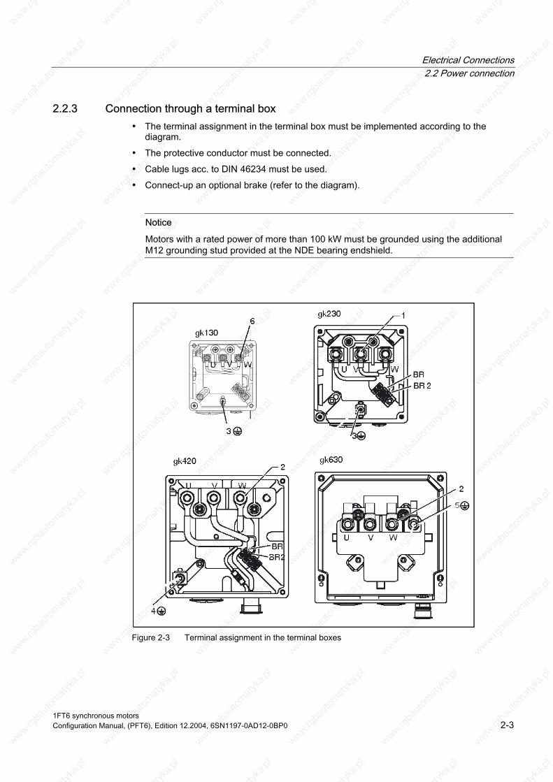
2.2.3 Connection through a terminal box • The terminal assignment in the terminal box must be implemented according to the
diagram.
• The protective conductor must be connected.
• Cable lugs acc. to DIN 46234 must be used.
• Connect-up an optional brake (refer to the diagram).
Notice
Motors with a rated power of more than 100 kW must be grounded using the additional M12 grounding stud provided at the NDE bearing endshield.
Figure 2-3 Terminal assignment in the terminal boxes
1FT6 synchronous motors Configuration Manual, (PFT6), Edition 12.2004, 6SN1197-0AD12-0BP0 2-3

Electrical Connections 2.2 Power connection
Table 2-1 Description of the diagram
No. Description No. Description 1 M5 connecting studs 5 M10 grounding studs 2 M10 connecting studs 6 M4 connecting studs 3 M4 grounding stud BR Brake connection 4 M6 grounding stud
Table 2-2 Connections for the terminal box
Terminal box type
Cable gland Max. outer cable
diameter 3) [mm]
Max. current
[A]1)
Power connection
Max. cross-section
per phase
Ground connection
Brake connection 2)
gk130 1 x Pg29 30 36 3 x M4 1 x 6 mm2 M4 1.5 mm2 gk230 1 x Pg29 30 66 3 x M5 1 x 16 mm2 M4 1.5 mm2 gk420 1 x Pg36 37 104 4 x M10 1 x 35 mm2 M6 1.5 mm2 gk630 2 x M32 x 1.5 25 112 3 x M10 2 x 16 mm2 M10 ––– gk630 2 x M40 x 1.5 32 176 3 x M10 2 x 35 mm2 M10 ––– gk630 2 x M50 x 1.5 41 209 3 x M10 2 x 50 mm2 M10 –––
1) Data acc. to DIN EN 60204-1 (routing type C, ambient temperature 40° C) 2) BR/BR2 (terminal strip, only for versions with brake) 3) Dependent on the seal used
1FT6 synchronous motors 2-4 Configuration Manual, (PFT6), Edition 12.2004, 6SN1197-0AD12-0BP0
Electrical Connections 2.3 DRIVE-CLiQ
2.3 DRIVE-CLiQ The encoder system can only be connected to SINAMICS S120 via DRIVE-CLiQ.
The DRIVE-CLiQ interface is either established through the sensor module at the motor (motors with DRIVE-CLiQ) or in the cabinet using sensor module, cabinet-mounted (for motors without DRIVE-CLiQ).
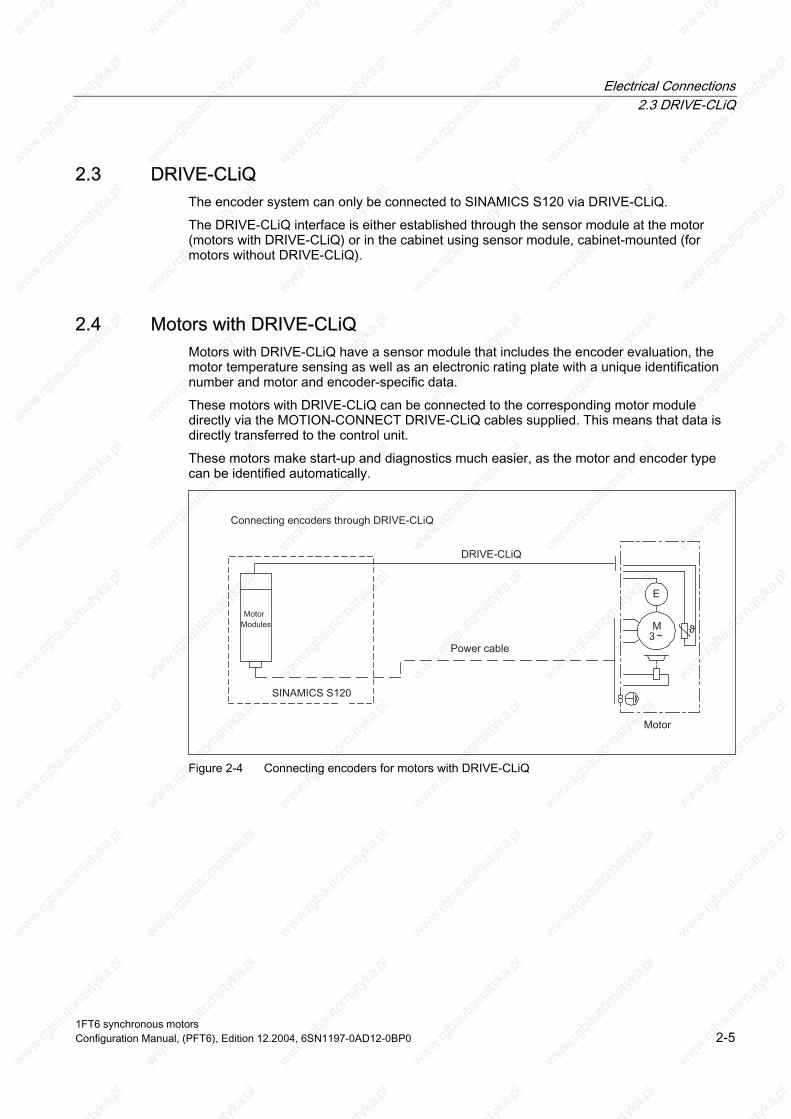
2.4 Motors with DRIVE-CLiQ Motors with DRIVE-CLiQ have a sensor module that includes the encoder evaluation, the motor temperature sensing as well as an electronic rating plate with a unique identification number and motor and encoder-specific data.
These motors with DRIVE-CLiQ can be connected to the corresponding motor module directly via the MOTION-CONNECT DRIVE-CLiQ cables supplied. This means that data is directly transferred to the control unit.
These motors make start-up and diagnostics much easier, as the motor and encoder type can be identified automatically.
Figure 2-4 Connecting encoders for motors with DRIVE-CLiQ
1FT6 synchronous motors Configuration Manual, (PFT6), Edition 12.2004, 6SN1197-0AD12-0BP0 2-5

Electrical Connections 2.5 Motors without DRIVE-CLiQ
2.5 Motors without DRIVE-CLiQ When fed from SINAMICS S120, motors without DRIVE-CLiQ require a sensor module, cabinet-mounted. The sensor modules evaluate the signals from the connected motor sensors or external sensors and convert them to DRIVE-CLiQ. In conjunction with motor encoders, the motor temperature can also be evaluated using sensor modules. Additional information is provided in the SINAMICS Equipment Manual.
Figure 2-5 Connecting encoders without DRIVE-CLiQ
1FT6 synchronous motors 2-6 Configuration Manual, (PFT6), Edition 12.2004, 6SN1197-0AD12-0BP0

Electrical Connections 2.6 Rotating the connector at the motor
2.6 Rotating the connector at the motor
Rotating the connector at the motor The DRIVE-CLiQ interface can be rotated but the amount of rotation is limited.
Notice
The permissible range of rotation may not be exceeded. Do not exceed max. turning torques of 8 Nm.
ay only be rotated a max. of 10x up to its end stop. The connector should be rotated using a mating connector attached at the connector thread. Connecting cables must be secured against tensile stress and bending. The motors connectors must be secured so that they cannot be rotated any further. It is not permissible to subject connectors to a continuous force.
In order to guarantee the degree of protection, the connector m
Figure 2-6 Connectors can be rotated
1FT6 synchronous motors Configuration Manual, (PFT6), Edition 12.2004, 6SN1197-0AD12-0BP0 2-7

Electrical Connections 2.6 Rotating the connector at the motor
1FT6 synchronous motors 2-8 Configuration Manual, (PFT6), Edition 12.2004, 6SN1197-0AD12-0BP0
Technical Data and Speed-Torque Diagrams 3 3.1 Speed-torque diagrams
3.1.1 Introduction
Note
Refer to the Configuration Manual "General Section for Synchronous Motors" for a description of how the voltage limiting characteristics are shifted.
The specified thermal S3 limit characteristics are referred to ΔT = 100 K for 1 min cycle duration for SH 28
10 min cycle duration for SH 36, 48, 63, 80, 100, 132, 160
1FT6 synchronous motors Configuration Manual, (PFT6), Edition 12.2004, 6SN1197-0AD12-0BP0 3-1

Technical Data and Speed-Torque Diagrams 3.1 Speed-torque diagrams
3.1.2 1FT6 series, non-ventilated
Table 3-1 1FT6021 non-ventilated
1FT6021 Technical data Code Units -6AK71 Engineering data Rated speed No. of poles Rated torque (100K) Rated current (100K) Stall torque (60K) Stall torque (100K) Stall current (60K) Stall current (100K) Moment of inertia (with brake) Moment of inertia (without brake)
nN 2p MN(100K) IN (100K) M0 (60K) M0 (100K) I0 (60K) I0 (100K) Jmot Jmot
RPM Nm A Nm Nm A A 10–4 kgm2 10–4 kgm2
6000 6 0.3 1.1 0.33 0.40 1.0 1.25 0.28 0.21
Optimum operating point Optimum speed Optimum power
nopt Popt
RPM kW
6000 0.19
Limiting data Max. permissible speed (mech.) Max. torque Max. current
nmax Mmax Imax
RPM Nm A
12000 1.5 5
Physical constants Torque constant Voltage constant
Rotating field inductance Electrical time constant Shaft torsional stiffness Mechanical time constant
Weight with brake Weight without brake
kT kE Rph LD Tel ct Tmech Tth m m
Nm/A V/1000 RPM Ohm mH ms Nm/rad ms min kg kg
0.32 20.5 7.2 4 0.56 3000 4.4 15 1.4 1.2
Winding resistance at 20° C
Thermal time constant
1FT6 synchronous motors 3-2 Configuration Manual, (PFT6), Edition 12.2004, 6SN1197-0AD12-0BP0

Technical Data and Speed-Torque Diagrams 3.1 Speed-torque diagrams
Figure 3-1 Speed-torque diagram 1FT6021-6AK71
[a] SINAMICS S120 SMART LINE, VDC link=540V (DC), Vmot=380Vrms [b] SINAMICS S120 ACTIVE LINE, VDC link=600V (DC), Vmot=425Vrms
1FT6 synchronous motors Configuration Manual, (PFT6), Edition 12.2004, 6SN1197-0AD12-0BP0 3-3

Technical Data and Speed-Torque Diagrams 3.1 Speed-torque diagrams
Table 3-2 1FT6024 non-ventilated
1FT6024 Technical data Code Units -6AK71 Engineering data Rated speed No. of poles Rated torque (100K) Rated current (100K) Stall torque (60K) Stall torque (100K) Stall current (60K) Stall current (100K) Moment of inertia (with brake) Moment of inertia (without brake)
nN 2p MN(100K) IN (100K) M0 (60K) M0 (100K) I0 (60K) I0 (100K) Jmot Jmot
RPM Nm A Nm Nm A A 10–4 kgm2 10–4 kgm2
6000 6 0.5 0.9 0.66 0.8 1.0 1.25 0.41 0.34
Optimum operating point Optimum speed Optimum power
nopt Popt
RPM kW
6000 0.31
Limiting data Max. permissible speed (mech.) Max. torque Max. current
nmax Mmax Imax
RPM Nm A
12000 3.15 5
Physical constants Torque constant Voltage constant
Rotating field inductance Electrical time constant Shaft torsional stiffness Mechanical time constant
Weight with brake Weight without brake
kT kE Rph LD Tel ct Tmech Tth m m
Nm/A V/1000 RPM Ohm mH ms Nm/rad ms min kg kg
0.63 41 10.9 7 0.64 3000 2.8 15 2.3 2.1
Winding resistance at 20° C
Thermal time constant
1FT6 synchronous motors 3-4 Configuration Manual, (PFT6), Edition 12.2004, 6SN1197-0AD12-0BP0

Technical Data and Speed-Torque Diagrams 3.1 Speed-torque diagrams
Figure 3-2 Speed-torque diagram 1FT6024-6AK71
[a] SINAMICS S120 SMART LINE, VDC link=540V (DC), Vmot=380Vrms [b] SINAMICS S120 ACTIVE LINE, VDC link=600V (DC), Vmot=425Vrms
1FT6 synchronous motors Configuration Manual, (PFT6), Edition 12.2004, 6SN1197-0AD12-0BP0 3-5

Technical Data and Speed-Torque Diagrams 3.1 Speed-torque diagrams
Table 3-3 1FT6031 non-ventilated
1FT6031 Technical data Code Units -4AK71 Engineering data Rated speed No. of poles Rated torque (100K) Rated current (100K) Stall torque (60K) Stall torque (100K) Stall current (60K) Stall current (100K) Moment of inertia (with brake) Moment of inertia (without brake)
nN 2p MN(100K) IN (100K) M0 (60K) M0 (100K) I0 (60K) I0 (100K) Jmot Jmot
RPM Nm A Nm Nm A A 10–4 kgm2 10–4 kgm2
6000 4 0.75 1.2 0.83 1.0 1.1 1.4 0.77 0.65
Optimum operating point Optimum speed Optimum power
nopt Popt
RPM kW
6000 0.47
Limiting data Max. permissible speed (mech.) Max. torque Max. current
nmax Mmax Imax
RPM Nm A
9700 4 5.8
Physical constants Torque constant Voltage constant
Rotating field inductance Electrical time constant Shaft torsional stiffness Mechanical time constant
Weight with brake Weight without brake
kT kE Rph LD Tel ct Tmech Tth m m
Nm/A V/1000 RPM Ohm mH ms Nm/rad ms min kg kg
0.72 47 6.9 18 2.6 7500 2.6 20 3.5 3.1
Winding resistance at 20° C
Thermal time constant
[a] SINAMICS S120 SMART LINE, VDC link=540V (DC), Vmot=380Vrms [b] SINAMICS S120 ACTIVE LINE, VDC link=600V (DC), Vmot=425Vrms
1FT6 synchronous motors 3-6 Configuration Manual, (PFT6), Edition 12.2004, 6SN1197-0AD12-0BP0

Technical Data and Speed-Torque Diagrams 3.1 Speed-torque diagrams
Figure 3-3 Speed-torque diagram 1FT6031-4AK71
1FT6 synchronous motors Configuration Manual, (PFT6), Edition 12.2004, 6SN1197-0AD12-0BP0 3-7
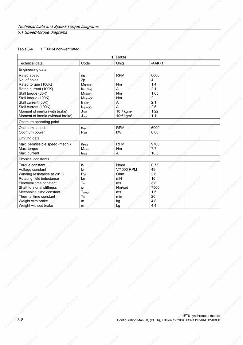
Technical Data and Speed-Torque Diagrams 3.1 Speed-torque diagrams
Table 3-4 1FT6034 non-ventilated
1FT6034 Technical data Code Units -4AK71 Engineering data Rated speed No. of poles Rated torque (100K) Rated current (100K) Stall torque (60K) Stall torque (100K) Stall current (60K) Stall current (100K) Moment of inertia (with brake) Moment of inertia (without brake)
nN 2p MN(100K) IN (100K) M0 (60K) M0 (100K) I0 (60K) I0 (100K) Jmot Jmot
RPM Nm A Nm Nm A A 10–4 kgm2 10–4 kgm2
6000 4 1.4 2.1 1.65 2 2.1 2.6 1.22 1.1
Optimum operating point Optimum speed Optimum power
nopt Popt
RPM kW
6000 0.88
Limiting data Max. permissible speed (mech.) Max. torque Max. current
nmax Mmax Imax
RPM Nm A
9700 7.7 10.5
Physical constants Torque constant Voltage constant
Rotating field inductance Electrical time constant Shaft torsional stiffness Mechanical time constant
Weight with brake Weight without brake
kT kE Rph LD Tel ct Tmech Tth m m
Nm/A V/1000 RPM Ohm mH ms Nm/rad ms min kg kg
0.75 49 2.6 10 3.8 7500 1.5 20 4.8 4.4
Winding resistance at 20° C
Thermal time constant
1FT6 synchronous motors 3-8 Configuration Manual, (PFT6), Edition 12.2004, 6SN1197-0AD12-0BP0

Technical Data and Speed-Torque Diagrams 3.1 Speed-torque diagrams
Figure 3-4 Speed-torque diagram 1FT6034
[a] SINAMICS S120 SMART LINE, VDC link=540V (DC), Vmot=380Vrms [b] SINAMICS S120 ACTIVE LINE, VDC link=600V (DC), Vmot=425Vrms
1FT6 synchronous motors Configuration Manual, (PFT6), Edition 12.2004, 6SN1197-0AD12-0BP0 3-9

Technical Data and Speed-Torque Diagrams 3.1 Speed-torque diagrams
Table 3-5 1FT6041 non-ventilated
1FT6041 Technical data Code Units -4AF71 -4AK71 Engineering data Rated speed No. of poles Rated torque (100K) Rated current (100K) Stall torque (60K) Stall torque (100K) Stall current (60K) Stall current (100K) Moment of inertia (with brake) Moment of inertia (without brake)
nN 2p MN(100K) IN (100K) M0 (60K) M0 (100K) I0 (60K) I0 (100K) Jmot Jmot
RPM Nm A Nm Nm A A 10–4 kgm2 10–4 kgm2
3000 4 2.15 1.7 2.15 2.6 1.5 1.9 3.98 2.9
6000 4 1.7 2.4 2.15 2.6 2.5 3.0 3.98 2.9
Optimum operating point Optimum speed Optimum power
nopt Popt
RPM kW
3000 0.68
6000 1.07
Limiting data Max. permissible speed (mech.) Max. torque Max. current
nmax Mmax Imax
RPM Nm A
7700 10 7.7
7700 10 12.8
Physical constants Torque constant Voltage constant
Rotating field inductance Electrical time constant Shaft torsional stiffness Mechanical time constant
Weight with brake Weight without brake
kT kE Rph LD Tel ct Tmech Tth m m
Nm/A V/1000 RPM Ohm mH ms Nm/rad ms min kg kg
1.38 90 6.6 22 3.3 14000 3 30 7.8 6.6
0.83 54 2.37 8 3.4 14000 3 30 7.8 6.6
Winding resistance at 20° C
Thermal time constant
1FT6 synchronous motors 3-10 Configuration Manual, (PFT6), Edition 12.2004, 6SN1197-0AD12-0BP0

Technical Data and Speed-Torque Diagrams 3.1 Speed-torque diagrams
Figure 3-5 Speed-torque diagram 1FT6041-4AF71
Figure 3-6 Speed-torque diagram 1FT6041-4AK71
[a] SINAMICS S120 SMART LINE, VDC link=540V (DC), Vmot=380Vrms [b] SINAMICS S120 ACTIVE LINE, VDC link=600V (DC), Vmot=425Vrms
1FT6 synchronous motors Configuration Manual, (PFT6), Edition 12.2004, 6SN1197-0AD12-0BP0 3-11

Technical Data and Speed-Torque Diagrams 3.1 Speed-torque diagrams
Table 3-6 1FT6044 non-ventilated
1FT6044 Technical data Code Units -⃞AF71 -4AK71 Engineering data Rated speed No. of poles Rated torque (100K) Rated current (100K) Stall torque (60K) Stall torque (100K) Stall current (60K) Stall current (100K) Moment of inertia (with brake) Moment of inertia (without brake)
nN 2p MN(100K) IN (100K) M0 (60K) M0 (100K) I0 (60K) I0 (100K) Jmot Jmot
RPM Nm A Nm Nm A A 10–4 kgm2 10–4 kgm2
3000 4 4.3 2.9 4.2 5.0 2.4 3.0 6.18 5.1
6000 4 3.0 4.1 4.2 5.0 4.8 5.9 6.18 5.1
Optimum operating point Optimum speed Optimum power
nopt Popt
RPM kW
3000 1.35
6000 1.88
Limiting data Max. permissible speed (mech.) Max. torque Max. current
nmax Mmax Imax
RPM Nm A
7700 18 11
7700 18 22
Physical constants Torque constant Voltage constant
Rotating field inductance Electrical time constant Shaft torsional stiffness Mechanical time constant
Weight with brake Weight without brake
kT kE Rph LD Tel ct Tmech Tth m m
Nm/A V/1000 RPM Ohm mH ms Nm/rad ms min kg kg
1.68 109 3.05 16 5.2 11000 1.7 30 9.5 8.3
0.85 55 0.78 4.1 5.3 11000 1.7 30 9.5 8.3
Winding resistance at 20° C
Thermal time constant
1FT6 synchronous motors 3-12 Configuration Manual, (PFT6), Edition 12.2004, 6SN1197-0AD12-0BP0

Technical Data and Speed-Torque Diagrams 3.1 Speed-torque diagrams
Figure 3-7 Speed-torque diagram 1FT6044-⃞AF71
Figure 3-8 Speed-torque diagram 1FT6044-4AK71
[a] SINAMICS S120 SMART LINE, VDC link=540V (DC), Vmot=380Vrms [b] SINAMICS S120 ACTIVE LINE, VDC link=600V (DC), Vmot=425Vrms
1FT6 synchronous motors Configuration Manual, (PFT6), Edition 12.2004, 6SN1197-0AD12-0BP0 3-13

Technical Data and Speed-Torque Diagrams 3.1 Speed-torque diagrams
Table 3-7 1FT6061 non-ventilated
1FT6061 Technical data Code Units -6AC7⃞ -6AF7⃞ Engineering data Rated speed No. of poles Rated torque (100K) Rated current (100K) Stall torque (60K) Stall torque (100K) Stall current (60K) Stall current (100K) Moment of inertia (with brake) Moment of inertia (without brake)
nN 2p MN(100K) IN (100K) M0 (60K) M0 (100K) I0 (60K) I0 (100K) Jmot Jmot
RPM Nm A Nm Nm A A 10–4 kgm2 10–4 kgm2
2000 6 3.7 1.9 3.3 4.0 1.6 1.9 9.3 6
3000 6 3.5 2.6 3.3 4.0 2.2 2.7 9.3 6
Optimum operating point Optimum speed Optimum power
nopt Popt
RPM kW
2000 0.77
3000 1.1
Limiting data Max. permissible speed (mech.) Max. torque Max. current
nmax Mmax Imax
RPM Nm A
9100 16 14
Physical constants Torque constant Voltage constant
Rotating field inductance Electrical time constant Shaft torsional stiffness Mechanical time constant
Weight with brake Weight without brake
kT kE Rph LD Tel ct Tmech Tth m m
Nm/A V/1000 RPM Ohm mH ms Nm/rad ms min kg kg
2.07 132 9.3 59 6.3 34000 3.9 20 9.5 8
1.48 94 4.71 30 6.4 34000 3.9 20 9.5 8
9100 16 10
Winding resistance at 20° C
Thermal time constant
1FT6 synchronous motors 3-14 Configuration Manual, (PFT6), Edition 12.2004, 6SN1197-0AD12-0BP0

Technical Data and Speed-Torque Diagrams 3.1 Speed-torque diagrams
Figure 3-9 Speed-torque diagram 1FT6061-6AC7⃞
Figure 3-10 Speed-torque diagram 1FT6061-6AF7⃞
[a] SINAMICS S120 SMART LINE, VDC link=540V (DC), Vmot=380Vrms [b] SINAMICS S120 ACTIVE LINE, VDC link=600V (DC), Vmot=425Vrms
1FT6 synchronous motors Configuration Manual, (PFT6), Edition 12.2004, 6SN1197-0AD12-0BP0 3-15

Technical Data and Speed-Torque Diagrams 3.1 Speed-torque diagrams
Table 3-8 1FT6061 non-ventilated
1FT6061 Technical data Code Units -6AH7⃞ -6AK7⃞ Engineering data Rated speed No. of poles Rated torque (100K) Rated current (100K) Stall torque (60K) Stall torque (100K) Stall current (60K) Stall current (100K) Moment of inertia (with brake) Moment of inertia (without brake)
nN 2p MN(100K) IN (100K) M0 (60K) M0 (100K) I0 (60K) I0 (100K) Jmot Jmot
RPM Nm A Nm Nm A A 10–4 kgm2 10–4 kgm2
4500 6 2.9 3.4 3.3 4 3.3 4 9.3 6
6000 6 2.1 3.1 3.3 4 4 5 9.3 6
Optimum operating point Optimum speed Optimum power
nopt Popt
RPM kW
4500 1.37
5000 1.38
Limiting data Max. permissible speed (mech.) Max. torque Max. current
nmax Mmax Imax
RPM Nm A
9100 16 21
9100 16 26
Physical constants Torque constant Voltage constant
Rotating field inductance Electrical time constant Shaft torsional stiffness Mechanical time constant
Weight with brake Weight without brake
kT kE Rph LD Tel ct Tmech Tth m m
Nm/A V/1000 RPM Ohm mH ms Nm/rad ms min kg kg
0.99 63 2.1 13.3 6.3 34000 3.9 20 9.5 8
0.80 51 1.42 9 6.3 34000 4.0 20 9.5 8
Winding resistance at 20° C
Thermal time constant
1FT6 synchronous motors 3-16 Configuration Manual, (PFT6), Edition 12.2004, 6SN1197-0AD12-0BP0

Technical Data and Speed-Torque Diagrams 3.1 Speed-torque diagrams
Figure 3-11 Speed-torque diagram 1FT6061-6AH7
Figure 3-12 Speed-torque diagram 1FT6061-6AK7
[a] SINAMICS S120 SMART LINE, VDC link=540V (DC), Vmot=380Vrms [b] SINAMICS S120 ACTIVE LINE, VDC link=600V (DC), Vmot=425Vrms
1FT6 synchronous motors Configuration Manual, (PFT6), Edition 12.2004, 6SN1197-0AD12-0BP0 3-17
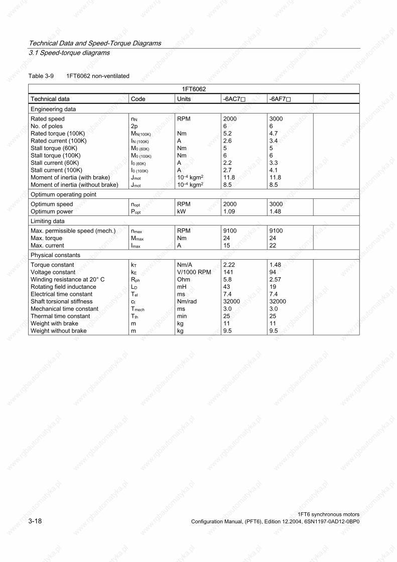
Technical Data and Speed-Torque Diagrams 3.1 Speed-torque diagrams
Table 3-9 1FT6062 non-ventilated
1FT6062 Technical data Code Units -6AC7⃞ -6AF7⃞ Engineering data Rated speed No. of poles Rated torque (100K) Rated current (100K) Stall torque (60K) Stall torque (100K) Stall current (60K) Stall current (100K) Moment of inertia (with brake) Moment of inertia (without brake)
nN 2p MN(100K) IN (100K) M0 (60K) M0 (100K) I0 (60K) I0 (100K) Jmot Jmot
RPM Nm A Nm Nm A A 10–4 kgm2 10–4 kgm2
2000 6 5.2 2.6 5 6 2.2 2.7 11.8 8.5
3000 6 4.7 3.4 5 6 3.3 4.1 11.8 8.5
Optimum operating point Optimum speed Optimum power
nopt Popt
RPM kW
2000 1.09
3000 1.48
Limiting data Max. permissible speed (mech.) Max. torque Max. current
nmax Mmax Imax
RPM Nm A
9100 24 15
9100 24 22
Physical constants Torque constant Voltage constant
Rotating field inductance Electrical time constant Shaft torsional stiffness Mechanical time constant
Weight with brake Weight without brake
kT kE Rph LD Tel ct Tmech Tth m m
Nm/A V/1000 RPM Ohm mH ms Nm/rad ms min kg kg
2.22 141 5.8 43 7.4 32000 3.0 25 11 9.5
1.48 94 2.57 19 7.4 32000 3.0 25 11 9.5
Winding resistance at 20° C
Thermal time constant
1FT6 synchronous motors 3-18 Configuration Manual, (PFT6), Edition 12.2004, 6SN1197-0AD12-0BP0

Technical Data and Speed-Torque Diagrams 3.1 Speed-torque diagrams
Figure 3-13 Speed-torque diagram 1FT6062-6AC7
Figure 3-14 Speed-torque diagram 1FT6062-6AF7
[a] SINAMICS S120 SMART LINE, VDC link=540V (DC), Vmot=380Vrms [b] SINAMICS S120 ACTIVE LINE, VDC link=600V (DC), Vmot=425Vrms
1FT6 synchronous motors Configuration Manual, (PFT6), Edition 12.2004, 6SN1197-0AD12-0BP0 3-19

Technical Data and Speed-Torque Diagrams 3.1 Speed-torque diagrams
Table 3-10 1FT6062 non-ventilated
1FT6062 Technical data Code Units -6AH7⃞ -6AK7⃞ Engineering data Rated speed No. of poles Rated torque (100K) Rated current (100K) Stall torque (60K) Stall torque (100K) Stall current (60K) Stall current (100K) Moment of inertia (with brake) Moment of inertia (without brake)
nN 2p MN(100K) IN (100K) M0 (60K) M0 (100K) I0 (60K) I0 (100K) Jmot Jmot
RPM Nm A Nm Nm A A 10–4 kgm2 10–4 kgm2
4500 6 3.6 3.9 5 6 4.7 5.7 11.8 8.5
6000 6 2.1 3.2 5 6 6.2 7.6 11.8 8.5
Optimum operating point Optimum speed Optimum power
nopt Popt
RPM kW
4500 1.70
4500 1.70
Limiting data Max. permissible speed (mech.) Max. torque Max. current
nmax Mmax Imax
RPM Nm A
9100 24 31
9100 24 41
Physical constants Torque constant Voltage constant
Rotating field inductance Electrical time constant Shaft torsional stiffness Mechanical time constant
Weight with brake Weight without brake
kT kE Rph LD Tel ct Tmech Tth m m
Nm/A V/1000 RPM Ohm mH ms Nm/rad ms min kg kg
1.05 67 1.31 9.7 7.4 32000 3.0 25 11 9.5
0.79 50 0.74 5.5 7.4 32000 3.0 25 11 9.5
Winding resistance at 20° C
Thermal time constant
1FT6 synchronous motors 3-20 Configuration Manual, (PFT6), Edition 12.2004, 6SN1197-0AD12-0BP0

Technical Data and Speed-Torque Diagrams 3.1 Speed-torque diagrams
Figure 3-15 Speed-torque diagram 1FT6062-6AH7⃞
Figure 3-16 Speed-torque diagram 1FT6062-6AK7⃞
[a] SINAMICS S120 SMART LINE, VDC link=540V (DC), Vmot=380Vrms [b] SINAMICS S120 ACTIVE LINE, VDC link=600V (DC), Vmot=425Vrms
1FT6 synchronous motors Configuration Manual, (PFT6), Edition 12.2004, 6SN1197-0AD12-0BP0 3-21

Technical Data and Speed-Torque Diagrams 3.1 Speed-torque diagrams
Table 3-11 1FT6064 non-ventilated
1FT6064 Technical data Code Units -6AC7⃞ -6AF7⃞ Engineering data Rated speed No. of poles Rated torque (100K) Rated current (100K) Stall torque (60K) Stall torque (100K) Stall current (60K) Stall current (100K) Moment of inertia (with brake) Moment of inertia (without brake)
nN 2p MN(100K) IN (100K) M0 (60K) M0 (100K) I0 (60K) I0 (100K) Jmot Jmot
RPM Nm A Nm Nm A A 10–4 kgm2 10–4 kgm2
2000 6 8.0 3.8 7.9 9.5 3.4 4.2 16.3 13
3000 6 7.0 4.9 7.9 9.5 4.9 6.1 16.3 13
Optimum operating point Optimum speed Optimum power
nopt Popt
RPM kW
2000 1.68
3000 2.20
Limiting data Max. permissible speed (mech.) Max. torque Max. current
nmax Mmax Imax
RPM Nm A
9100 38 23
9100 38 33
Physical constants Torque constant Voltage constant
Rotating field inductance Electrical time constant Shaft torsional stiffness Mechanical time constant
Weight with brake Weight without brake
kT kE Rph LD Tel ct Tmech Tth m m
Nm/A V/1000 RPM Ohm mH ms Nm/rad ms min kg kg
2.26 144 2.93 28 9.6 27000 2.2 30 13 12.5
1.57 100 1.40 13.5 9.6 27000 2.2 30 13 12.5
Winding resistance at 20° C
Thermal time constant
1FT6 synchronous motors 3-22 Configuration Manual, (PFT6), Edition 12.2004, 6SN1197-0AD12-0BP0

Technical Data and Speed-Torque Diagrams 3.1 Speed-torque diagrams
Figure 3-17 Speed-torque diagram 1FT6064-6AC7⃞
Figure 3-18 Speed-torque diagram 1FT6064-6AF7⃞
[a] SINAMICS S120 SMART LINE, VDC link=540V (DC), Vmot=380Vrms [b] SINAMICS S120 ACTIVE LINE, VDC link=600V (DC), Vmot=425Vrms
1FT6 synchronous motors Configuration Manual, (PFT6), Edition 12.2004, 6SN1197-0AD12-0BP0 3-23

Technical Data and Speed-Torque Diagrams 3.1 Speed-torque diagrams
Table 3-12 1FT6064 non-ventilated
1FT6064 Technical data Code Units -6AH7⃞ -6AK7⃞ Engineering data Rated speed No. of poles Rated torque (100K) Rated current (100K) Stall torque (60K) Stall torque (100K) Stall current (60K) Stall current (100K) Moment of inertia (with brake) Moment of inertia (without brake)
nN 2p MN(100K) IN (100K) M0 (60K) M0 (100K) I0 (60K) I0 (100K) Jmot Jmot
RPM Nm A Nm Nm A A 10–4 kgm2 10–4 kgm2
4500 6 4.8 5.5 7.9 9.5 7.3 9.0 16.3 13
6000 6 2.1 3.5 7.9 9.5 9.8 12.0 16.3 13
Optimum operating point Optimum speed Optimum power
nopt Popt
RPM kW
4500 2.26
4500 2.26
Limiting data Max. permissible speed (mech.) Max. torque Max. current
nmax Mmax Imax
RPM Nm A
9100 38 49
9100 38 66
Physical constants Torque constant Voltage constant
Rotating field inductance Electrical time constant Shaft torsional stiffness Mechanical time constant
Weight with brake Weight without brake
kT kE Rph LD Tel ct Tmech Tth m m
Nm/A V/1000 RPM Ohm mH ms Nm/rad ms min kg kg
1.05 67 0.63 6 9.5 27000 2.2 30 13 12.5
0.79 50 0.35 3.4 9.7 27000 2.2 30 13 12.5
Winding resistance at 20° C
Thermal time constant
1FT6 synchronous motors 3-24 Configuration Manual, (PFT6), Edition 12.2004, 6SN1197-0AD12-0BP0

Technical Data and Speed-Torque Diagrams 3.1 Speed-torque diagrams
Figure 3-19 Speed-torque diagram 1FT6064-6AH7⃞
Figure 3-20 Speed-torque diagram 1FT6064-6AK7⃞
[a] SINAMICS S120 SMART LINE, VDC link=540V (DC), Vmot=380Vrms [b] SINAMICS S120 ACTIVE LINE, VDC link=600V (DC), Vmot=425Vrms
1FT6 synchronous motors Configuration Manual, (PFT6), Edition 12.2004, 6SN1197-0AD12-0BP0 3-25
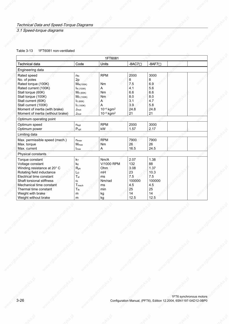
Technical Data and Speed-Torque Diagrams 3.1 Speed-torque diagrams
Table 3-13 1FT6081 non-ventilated
1FT6081 Technical data Code Units -8AC7⃞ -8AF7⃞ Engineering data Rated speed No. of poles Rated torque (100K) Rated current (100K) Stall torque (60K) Stall torque (100K) Stall current (60K) Stall current (100K) Moment of inertia (with brake) Moment of inertia (without brake)
nN 2p MN(100K) IN (100K) M0 (60K) M0 (100K) I0 (60K) I0 (100K) Jmot Jmot
RPM Nm A Nm Nm A A 10–4 kgm2 10–4 kgm2
2000 8 7.5 4.1 6.6 8.0 3.1 3.9 24.8 21
3000 8 6.9 5.6 6.6 8.0 4.7 5.8 24.8 21
Optimum operating point Optimum speed Optimum power
nopt Popt
RPM kW
2000 1.57
3000 2.17
Limiting data Max. permissible speed (mech.) Max. torque Max. current
nmax Mmax Imax
RPM Nm A
7900 26 16.5
7900 26 24.5
Physical constants Torque constant Voltage constant
Rotating field inductance Electrical time constant Shaft torsional stiffness Mechanical time constant
Weight with brake Weight without brake
kT kE Rph LD Tel ct Tmech Tth m m
Nm/A V/1000 RPM Ohm mH ms Nm/rad ms min kg kg
2.07 132 3.08 23 7.5 100000 4.5 25 14 12.5
1.38 88 1.37 10.3 7.5 100000 4.5 25 14 12.5
Winding resistance at 20° C
Thermal time constant
1FT6 synchronous motors 3-26 Configuration Manual, (PFT6), Edition 12.2004, 6SN1197-0AD12-0BP0

Technical Data and Speed-Torque Diagrams 3.1 Speed-torque diagrams
Figure 3-21 Speed-torque diagram 1FT6081-8AC7⃞
Figure 3-22 Speed-torque diagram 1FT6081-8AF7⃞
[a] SINAMICS S120 SMART LINE, VDC link=540V (DC), Vmot=380Vrms [b] SINAMICS S120 ACTIVE LINE, VDC link=600V (DC), Vmot=425Vrms
1FT6 synchronous motors Configuration Manual, (PFT6), Edition 12.2004, 6SN1197-0AD12-0BP0 3-27

Technical Data and Speed-Torque Diagrams 3.1 Speed-torque diagrams
Table 3-14 1FT6081 non-ventilated
1FT6081 Technical data Code Units -8AH7⃞ -8AK7⃞ Engineering data Rated speed No. of poles Rated torque (100K) Rated current (100K) Stall torque (60K) Stall torque (100K) Stall current (60K) Stall current (100K) Moment of inertia (with brake) Moment of inertia (without brake)
nN 2p MN(100K) IN (100K) M0 (60K) M0 (100K) I0 (60K) I0 (100K) Jmot Jmot
RPM Nm A Nm Nm A A 10–4 kgm2 10–4 kgm2
4500 8 5.8 7.3 6.6 8.0 7.0 8.6 24.8 21
6000 8 4.6 7.7 6.6 8.0 8.9 11.1 24.8 21
Optimum operating point Optimum speed Optimum power
nopt Popt
RPM kW
4500 2.73
6000 2.89
Limiting data Max. permissible speed (mech.) Max. torque Max. current
nmax Mmax Imax
RPM Nm A
7900 26 37
7900 26 46
Physical constants Torque constant Voltage constant
Rotating field inductance Electrical time constant Shaft torsional stiffness Mechanical time constant
Weight with brake Weight without brake
kT kE Rph LD Tel ct Tmech Tth m m
Nm/A V/1000 RPM Ohm mH ms Nm/rad ms min kg kg
0.93 59 0.61 4.6 7.5 100000 4.4 25 14 12.5
0.72 46 0.38 3 7.9 100000 4.6 25 14 12.5
Winding resistance at 20° C
Thermal time constant
1FT6 synchronous motors 3-28 Configuration Manual, (PFT6), Edition 12.2004, 6SN1197-0AD12-0BP0

Technical Data and Speed-Torque Diagrams 3.1 Speed-torque diagrams
Figure 3-23 Speed-torque diagram 1FT6081-8AH7⃞
Figure 3-24 Speed-torque diagram 1FT6081-8AK7⃞
[a] SINAMICS S120 SMART LINE, VDC link=540V (DC), Vmot=380Vrms [b] SINAMICS S120 ACTIVE LINE, VDC link=600V (DC), Vmot=425Vrms
1FT6 synchronous motors Configuration Manual, (PFT6), Edition 12.2004, 6SN1197-0AD12-0BP0 3-29

Technical Data and Speed-Torque Diagrams 3.1 Speed-torque diagrams
Table 3-15 1FT6082 non-ventilated
1FT6082 Technical data Code Units -8AC7⃞ -⃞AF7⃞ Engineering data Rated speed No. of poles Rated torque (100K) Rated current (100K) Stall torque (60K) Stall torque (100K) Stall current (60K) Stall current (100K) Moment of inertia (with brake) Moment of inertia (without brake)
nN 2p MN(100K) IN (100K) M0 (60K) M0 (100K) I0 (60K) I0 (100K) Jmot Jmot
RPM Nm A Nm Nm A A 10–4 kgm2 10–4 kgm2
2000 8 11.4 6.6 10.8 13 5.4 6.6 33.8 30
3000 8 10.3 8.7 10.8 13 7.8 9.6 33.8 30
Optimum operating point Optimum speed Optimum power
nopt Popt
RPM kW
2000 2.39
3000 3.24
Limiting data Max. permissible speed (mech.) Max. torque Max. current
nmax Mmax Imax
RPM Nm A
7900 42 28
7900 42 41
Physical constants Torque constant Voltage constant
Rotating field inductance Electrical time constant Shaft torsional stiffness Mechanical time constant
Weight with brake Weight without brake
kT kE Rph LD Tel ct Tmech Tth m m
Nm/A V/1000 RPM Ohm mH ms Nm/rad ms min kg kg
1.96 125 1.48 13.6 9.2 90000 3.5 30 16.5 15
1.35 86 0.69 6.2 9.0 90000 3.4 30 16.5 15
Winding resistance at 20° C
Thermal time constant
1FT6 synchronous motors 3-30 Configuration Manual, (PFT6), Edition 12.2004, 6SN1197-0AD12-0BP0

Technical Data and Speed-Torque Diagrams 3.1 Speed-torque diagrams
Figure 3-25 Speed-torque diagram 1FT6082-8AC7⃞
Figure 3-26 Speed-torque diagram 1FT6082-8AF7⃞
[a] SINAMICS S120 SMART LINE, VDC link=540V (DC), Vmot=380Vrms [b] SINAMICS S120 ACTIVE LINE, VDC link=600V (DC), Vmot=425Vrms
1FT6 synchronous motors Configuration Manual, (PFT6), Edition 12.2004, 6SN1197-0AD12-0BP0 3-31

Technical Data and Speed-Torque Diagrams 3.1 Speed-torque diagrams
Table 3-16 1FT6082 non-ventilated
1FT6082 Technical data Code Units -8AH7⃞ -8AK7⃞ Engineering data Rated speed No. of poles Rated torque (100K) Rated current (100K) Stall torque (60K) Stall torque (100K) Stall current (60K) Stall current (100K) Moment of inertia (with brake) Moment of inertia (without brake)
nN 2p MN(100K) IN (100K) M0 (60K) M0 (100K) I0 (60K) I0 (100K) Jmot Jmot
RPM Nm A Nm Nm A A 10–4 kgm2 10–4 kgm2
4500 8 8.5 11 10.8 13 12.0 14.8 33.8 30
6000 8 5.5 9.1 10.8 13.0 14.0 17.3 33.8 30
Optimum operating point Optimum speed Optimum power
nopt Popt
RPM kW
4500 4.01
4500 4.01
Limiting data Max. permissible speed (mech.) Max. torque Max. current
nmax Mmax Imax
RPM Nm A
7900 42 60
7900 42 73
Physical constants Torque constant Voltage constant
Rotating field inductance Electrical time constant Shaft torsional stiffness Mechanical time constant
Weight with brake Weight without brake
kT kE Rph LD Tel ct Tmech Tth m m
Nm/A V/1000 RPM Ohm mH ms Nm/rad ms min kg kg
0.88 56 0.30 2.9 9.7 90000 3.5 30 16.5 15
0.75 48 0.21 1.9 9.0 90000 3.4 30 16.5 15
Winding resistance at 20° C
Thermal time constant
1FT6 synchronous motors 3-32 Configuration Manual, (PFT6), Edition 12.2004, 6SN1197-0AD12-0BP0
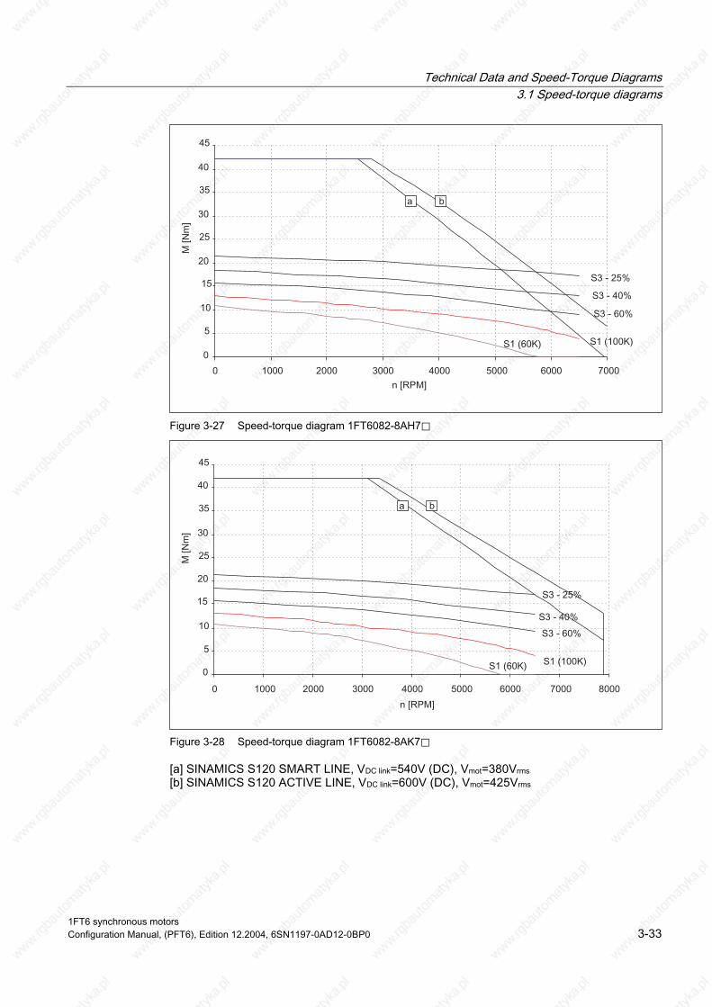
Technical Data and Speed-Torque Diagrams 3.1 Speed-torque diagrams
Figure 3-27 Speed-torque diagram 1FT6082-8AH7⃞
Figure 3-28 Speed-torque diagram 1FT6082-8AK7⃞
[a] SINAMICS S120 SMART LINE, VDC link=540V (DC), Vmot=380Vrms [b] SINAMICS S120 ACTIVE LINE, VDC link=600V (DC), Vmot=425Vrms
1FT6 synchronous motors Configuration Manual, (PFT6), Edition 12.2004, 6SN1197-0AD12-0BP0 3-33

Technical Data and Speed-Torque Diagrams 3.1 Speed-torque diagrams
Table 3-17 1FT6084 non-ventilated
1FT6084 Technical data Code Units -8AC7⃞ -⃞AF7⃞ Engineering data Rated speed No. of poles Rated torque (100K) Rated current (100K) Stall torque (60K) Stall torque (100K) Stall current (60K) Stall current (100K) Moment of inertia (with brake) Moment of inertia (without brake)
nN 2p MN(100K) IN (100K) M0 (60K) M0 (100K) I0 (60K) I0 (100K) Jmot Jmot
RPM Nm A Nm Nm A A 10–4 kgm2 10–4 kgm2
2000 8 16.9 8.3 16.6 20 7.2 8.8 61.1 48
3000 8 14.7 11 16.6 20 10.7 13.2 61.1 48
Optimum operating point Optimum speed Optimum power
nopt Popt
RPM kW
2000 3.54
3000 4.62
Limiting data Max. permissible speed (mech.) Max. torque Max. current
nmax Mmax Imax
RPM Nm A
7900 65 38
7900 65 56
Physical constants Torque constant Voltage constant
Rotating field inductance Electrical time constant Shaft torsional stiffness Mechanical time constant
Weight with brake Weight without brake
kT kE Rph LD Tel ct Tmech Tth m m
Nm/A V/1000 RPM Ohm mH ms Nm/rad ms min kg kg
2.26 144 0.91 10.4 11.4 76000 2.6 35 24 20.5
1.52 97 0.41 4.8 11.7 76000 2.6 35 24 20.5
Winding resistance at 20° C
Thermal time constant
1FT6 synchronous motors 3-34 Configuration Manual, (PFT6), Edition 12.2004, 6SN1197-0AD12-0BP0
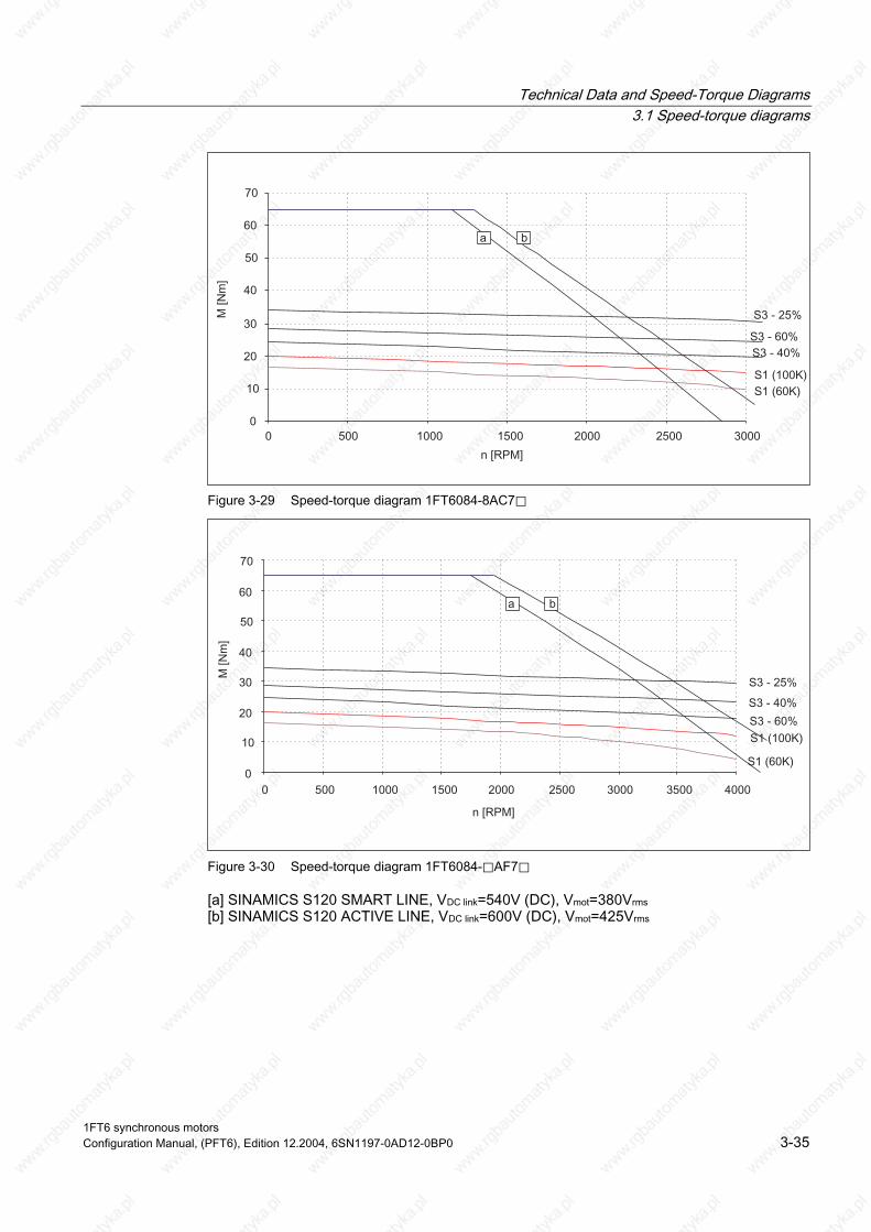
Technical Data and Speed-Torque Diagrams 3.1 Speed-torque diagrams
Figure 3-29 Speed-torque diagram 1FT6084-8AC7⃞
Figure 3-30 Speed-torque diagram 1FT6084-⃞AF7⃞
[a] SINAMICS S120 SMART LINE, VDC link=540V (DC), Vmot=380Vrms [b] SINAMICS S120 ACTIVE LINE, VDC link=600V (DC), Vmot=425Vrms
1FT6 synchronous motors Configuration Manual, (PFT6), Edition 12.2004, 6SN1197-0AD12-0BP0 3-35

Technical Data and Speed-Torque Diagrams 3.1 Speed-torque diagrams
Table 3-18 1FT6084 non-ventilated
1FT6084 Technical data Code Units -⃞AH7⃞ -⃞AK7⃞ Engineering data Rated speed No. of poles Rated torque (100K) Rated current (100K) Stall torque (60K) Stall torque (100K) Stall current (60K) Stall current (100K) Moment of inertia (with brake) Moment of inertia (without brake)
nN 2p MN(100K) IN (100K) M0 (60K) M0 (100K) I0 (60K) I0 (100K) Jmot Jmot
RPM Nm A Nm Nm A A 10–4 kgm2 10–4 kgm2
4500 8 10.5 12.5 16.6 20 16.2 19.8 61.1 48
6000 8 6.5 9.2 16.6 20 19.5 24.1 61.1 48
Optimum operating point Optimum speed Optimum power
nopt Popt
RPM kW
4000 5.03
4000 5.03
Limiting data Max. permissible speed (mech.) Max. torque Max. current
nmax Mmax Imax
RPM Nm A
7900 65 86
7900 65 100
Physical constants Torque constant Voltage constant
Rotating field inductance Electrical time constant Shaft torsional stiffness Mechanical time constant
Weight with brake Weight without brake
kT kE Rph LD Tel ct Tmech Tth m m
Nm/A V/1000 RPM Ohm mH ms Nm/rad ms min kg kg
1.01 64 0.18 2 11.1 76000 2.5 35 24 20.5
0.83 53 0.12 1.5 12.5 76000 2.5 35 24 20.5
Winding resistance at 20° C
Thermal time constant
1FT6 synchronous motors 3-36 Configuration Manual, (PFT6), Edition 12.2004, 6SN1197-0AD12-0BP0

Technical Data and Speed-Torque Diagrams 3.1 Speed-torque diagrams
Figure 3-31 Speed-torque diagram 1FT6084-⃞AH7⃞
Figure 3-32 Speed-torque diagram 1FT6084-⃞AK7⃞
[a] SINAMICS S120 SMART LINE, VDC link=540V (DC), Vmot=380Vrms [b] SINAMICS S120 ACTIVE LINE, VDC link=600V (DC), Vmot=425Vrms
1FT6 synchronous motors Configuration Manual, (PFT6), Edition 12.2004, 6SN1197-0AD12-0BP0 3-37

Technical Data and Speed-Torque Diagrams 3.1 Speed-torque diagrams
Table 3-19 1FT6086 non-ventilated
1FT6086 Technical data Code Units -8AC7⃞ Engineering data Rated speed No. of poles Rated torque (100K) Rated current (100K) Stall torque (60K) Stall torque (100K) Stall current (60K) Stall current (100K) Moment of inertia (with brake) Moment of inertia (without brake)
nN 2p MN(100K) IN (100K) M0 (60K) M0 (100K) I0 (60K) I0 (100K) Jmot Jmot
RPM Nm A Nm Nm A A 10–4 kgm2 10–4 kgm2
2000 8 22.5 10.9 22.4 27 9.2 11.3 79.6 66.5
Optimum operating point Optimum speed Optimum power
nopt Popt
RPM kW
2000 4.71
Limiting data Max. permissible speed (mech.) Max. torque Max. current
nmax Mmax Imax
RPM Nm A
7900 90 48
Physical constants Torque constant Voltage constant
Rotating field inductance Electrical time constant Shaft torsional stiffness Mechanical time constant
Weight with brake Weight without brake
kT kE Rph LD Tel ct Tmech Tth m m
Nm/A V/1000 RPM Ohm mH ms Nm/rad ms min kg kg
2.39 152 0.65 8 12.3 65000 2.3 45 29 25.5
Winding resistance at 20° C
Thermal time constant
1FT6 synchronous motors 3-38 Configuration Manual, (PFT6), Edition 12.2004, 6SN1197-0AD12-0BP0

Technical Data and Speed-Torque Diagrams 3.1 Speed-torque diagrams
Figure 3-33 Speed-torque diagram 1FT6086-8AC7⃞
[a] SINAMICS S120 SMART LINE, VDC link=540V (DC), Vmot=380Vrms [b] SINAMICS S120 ACTIVE LINE, VDC link=600V (DC), Vmot=425Vrms
1FT6 synchronous motors Configuration Manual, (PFT6), Edition 12.2004, 6SN1197-0AD12-0BP0 3-39

Technical Data and Speed-Torque Diagrams 3.1 Speed-torque diagrams
Table 3-20 1FT6086 non-ventilated
1FT6086 Technical data Code Units -⃞AF7⃞ -⃞AH7⃞ Engineering data Rated speed No. of poles Rated torque (100K) Rated current (100K) Stall torque (60K) Stall torque (100K) Stall current (60K) Stall current (100K) Moment of inertia (with brake) Moment of inertia (without brake)
nN 2p MN(100K) IN (100K) M0 (60K) M0 (100K) I0 (60K) I0 (100K) Jmot Jmot
RPM Nm A Nm Nm A A 10–4 kgm2 10–4 kgm2
3000 8 18.5 13 22.4 27 13.3 16.4 79.6 66.5
4500 8 12 12.6 22.4 27 18.9 23.3 79.6 66.5
Optimum operating point Optimum speed Optimum power
nopt Popt
RPM kW
3000 5.81
3000 5.81
Limiting data Max. permissible speed (mech.) Max. torque Max. current
nmax Mmax Imax
RPM Nm A
7900 90 71
7900 90 102
Physical constants Torque constant Voltage constant
Rotating field inductance Electrical time constant Shaft torsional stiffness Mechanical time constant
Weight with brake Weight without brake
kT kE Rph LD Tel ct Tmech Tth m m
Nm/A V/1000 RPM Ohm mH ms Nm/rad ms min kg kg
1.65 105 0.31 3.8 12.3 65000 2.3 45 29 25.5
1.16 74 0.15 1.8 12 65000 2.2 45 29 25.5
Winding resistance at 20° C
Thermal time constant
1FT6 synchronous motors 3-40 Configuration Manual, (PFT6), Edition 12.2004, 6SN1197-0AD12-0BP0
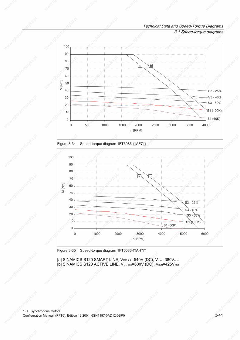
Technical Data and Speed-Torque Diagrams 3.1 Speed-torque diagrams
Figure 3-34 Speed-torque diagram 1FT6086-⃞AF7⃞
Figure 3-35 Speed-torque diagram 1FT6086-⃞AH7⃞
[a] SINAMICS S120 SMART LINE, VDC link=540V (DC), Vmot=380Vrms [b] SINAMICS S120 ACTIVE LINE, VDC link=600V (DC), Vmot=425Vrms
1FT6 synchronous motors Configuration Manual, (PFT6), Edition 12.2004, 6SN1197-0AD12-0BP0 3-41

Technical Data and Speed-Torque Diagrams 3.1 Speed-torque diagrams
Table 3-21 1FT6102 non-ventilated
1FT6102 Technical data Code Units -8AB7⃞ -⃞AC7⃞ Engineering data Rated speed No. of poles Rated torque (100K) Rated current (100K) Stall torque (60K) Stall torque (100K) Stall current (60K) Stall current (100K) Moment of inertia (with brake) Moment of inertia (without brake)
nN 2p MN(100K) IN (100K) M0 (60K) M0 (100K) I0 (60K) I0 (100K) Jmot Jmot
RPM Nm A Nm Nm A A 10–4 kgm2 10–4 kgm2
1500 8 24.5 8.4 22.4 27 7.0 8.7 130 99
2000 8 23 11 22.4 27 9.8 12.1 130 99
Optimum operating point Optimum speed Optimum power
nopt Popt
RPM kW
1500 3.85
2000 4.82
Limiting data Max. permissible speed (mech.) Max. torque Max. current
nmax Mmax Imax
RPM Nm A
5600 80 42
5600 80 59
Physical constants Torque constant Voltage constant
Rotating field inductance Electrical time constant Shaft torsional stiffness Mechanical time constant
Weight with brake Weight without brake
kT kE Rph LD Tel ct Tmech Tth m m
Nm/A V/1000 RPM Ohm mH ms Nm/rad ms min kg kg
3.11 198 0.82 15.1 18 137000 2.5 40 32 27.5
2.23 142 0.42 7.7 18 137000 2.5 40 32 27.5
Winding resistance at 20° C
Thermal time constant
1FT6 synchronous motors 3-42 Configuration Manual, (PFT6), Edition 12.2004, 6SN1197-0AD12-0BP0
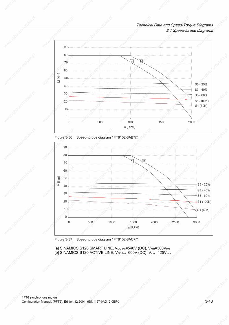
Technical Data and Speed-Torque Diagrams 3.1 Speed-torque diagrams
Figure 3-36 Speed-torque diagram 1FT6102-8AB7⃞
Figure 3-37 Speed-torque diagram 1FT6102-8AC7⃞
[a] SINAMICS S120 SMART LINE, VDC link=540V (DC), Vmot=380Vrms [b] SINAMICS S120 ACTIVE LINE, VDC link=600V (DC), Vmot=425Vrms
1FT6 synchronous motors Configuration Manual, (PFT6), Edition 12.2004, 6SN1197-0AD12-0BP0 3-43

Technical Data and Speed-Torque Diagrams 3.1 Speed-torque diagrams
Table 3-22 1FT6102 non-ventilated
1FT6102 Technical data Code Units -8AF7⃞ -8AH7⃞ Engineering data Rated speed No. of poles Rated torque (100K) Rated current (100K) Stall torque (60K) Stall torque (100K) Stall current (60K) Stall current (100K) Moment of inertia (with brake) Moment of inertia (without brake)
nN 2p MN(100K) IN (100K) M0 (60K) M0 (100K) I0 (60K) I0 (100K) Jmot Jmot
RPM Nm A Nm Nm A A 10–4 kgm2 10–4 kgm2
3000 8 19.5 13.2 22.4 27 13.7 16.9 130 99
4500 8 12 12 22.4 27 19.7 24.1 130 99
Optimum operating point Optimum speed Optimum power
nopt Popt
RPM kW
3000 6.13
3000 6.13
Limiting data Max. permissible speed (mech.) Max. torque Max. current
nmax Mmax Imax
RPM Nm A
5600 80 82
5600 80 118
Physical constants Torque constant Voltage constant
Rotating field inductance Electrical time constant Shaft torsional stiffness Mechanical time constant
Weight with brake Weight without brake
kT kE Rph LD Tel ct Tmech Tth m m
Nm/A V/1000 RPM Ohm mH ms Nm/rad ms min kg kg
1.60 102 0.22 4 18 137000 2.6 40 32 27.5
1.12 71 0.11 1.9 17 137000 2.6 40 32 27.5
Winding resistance at 20° C
Thermal time constant
1FT6 synchronous motors 3-44 Configuration Manual, (PFT6), Edition 12.2004, 6SN1197-0AD12-0BP0

Technical Data and Speed-Torque Diagrams 3.1 Speed-torque diagrams
Figure 3-38 Speed-torque diagram 1FT6102-8AF7⃞
Figure 3-39 Speed-torque diagram 1FT6102-8AH7⃞
[a] SINAMICS S120 SMART LINE, VDC link=540V (DC), Vmot=380Vrms [b] SINAMICS S120 ACTIVE LINE, VDC link=600V (DC), Vmot=425Vrms
1FT6 synchronous motors Configuration Manual, (PFT6), Edition 12.2004, 6SN1197-0AD12-0BP0 3-45
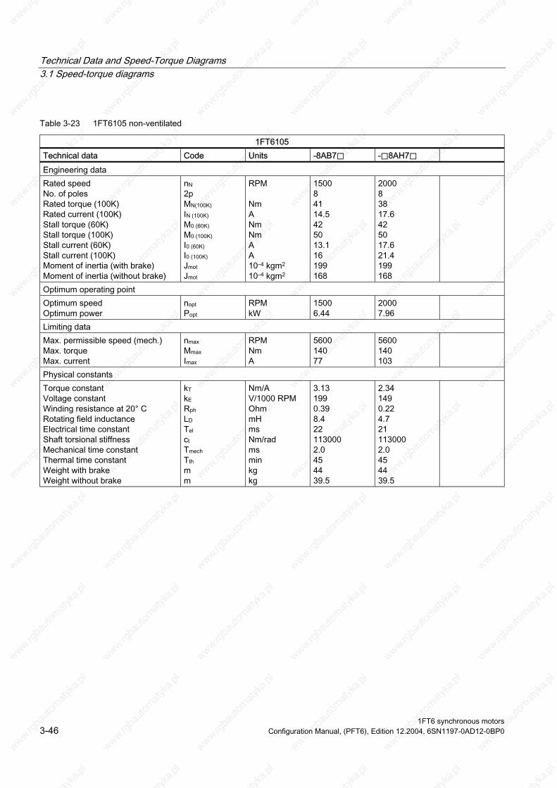
Technical Data and Speed-Torque Diagrams 3.1 Speed-torque diagrams
Table 3-23 1FT6105 non-ventilated
1FT6105 Technical data Code Units -8AB7⃞ -⃞8AH7⃞ Engineering data Rated speed No. of poles Rated torque (100K) Rated current (100K) Stall torque (60K) Stall torque (100K) Stall current (60K) Stall current (100K) Moment of inertia (with brake) Moment of inertia (without brake)
nN 2p MN(100K) IN (100K) M0 (60K) M0 (100K) I0 (60K) I0 (100K) Jmot Jmot
RPM Nm A Nm Nm A A 10–4 kgm2 10–4 kgm2
1500 8 41 14.5 42 50 13.1 16 199 168
2000 8 38 17.6 42 50 17.6 21.4 199 168
Optimum operating point Optimum speed Optimum power
nopt Popt
RPM kW
1500 6.44
2000 7.96
Limiting data Max. permissible speed (mech.) Max. torque Max. current
nmax Mmax Imax
RPM Nm A
5600 140 77
5600 140 103
Physical constants Torque constant Voltage constant
Rotating field inductance Electrical time constant Shaft torsional stiffness Mechanical time constant
Weight with brake Weight without brake
kT kE Rph LD Tel ct Tmech Tth m m
Nm/A V/1000 RPM Ohm mH ms Nm/rad ms min kg kg
3.13 199 0.39 8.4 22 113000 2.0 45 44 39.5
2.34 149 0.22 4.7 21 113000 2.0 45 44 39.5
Winding resistance at 20° C
Thermal time constant
1FT6 synchronous motors 3-46 Configuration Manual, (PFT6), Edition 12.2004, 6SN1197-0AD12-0BP0
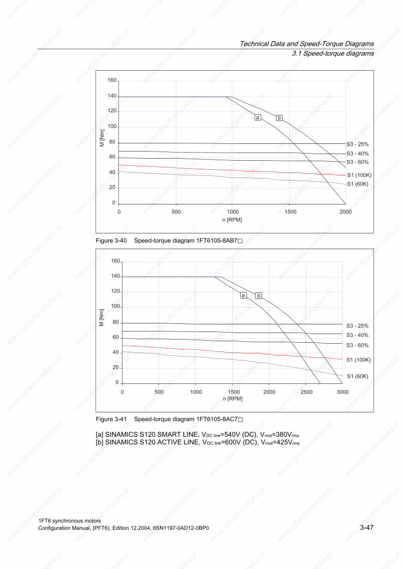
Technical Data and Speed-Torque Diagrams 3.1 Speed-torque diagrams
Figure 3-40 Speed-torque diagram 1FT6105-8AB7⃞
Figure 3-41 Speed-torque diagram 1FT6105-8AC7⃞
[a] SINAMICS S120 SMART LINE, VDC link=540V (DC), Vmot=380Vrms [b] SINAMICS S120 ACTIVE LINE, VDC link=600V (DC), Vmot=425Vrms
1FT6 synchronous motors Configuration Manual, (PFT6), Edition 12.2004, 6SN1197-0AD12-0BP0 3-47

Technical Data and Speed-Torque Diagrams 3.1 Speed-torque diagrams
Table 3-24 1FT6105 non-ventilated
1FT6105 Technical data Code Units -8AF7⃞ Engineering data Rated speed No. of poles Rated torque (100K) Rated current (100K) Stall torque (60K) Stall torque (100K) Stall current (60K) Stall current (100K) Moment of inertia (with brake) Moment of inertia (without brake)
nN 2p MN(100K) IN (100K) M0 (60K) M0 (100K) I0 (60K) I0 (100K) Jmot Jmot
RPM Nm A Nm Nm A A 10–4 kgm2 10–4 kgm2
3000 8 31 22.5 42 50 26 32 199 168
Optimum operating point Optimum speed Optimum power
nopt Popt
RPM kW
3000 9.74
Limiting data Max. permissible speed (mech.) Max. torque Max. current
nmax Mmax Imax
RPM Nm A
5600 140 155
Physical constants Torque constant Voltage constant
Rotating field inductance Electrical time constant Shaft torsional stiffness Mechanical time constant
Weight with brake Weight without brake
kT kE Rph LD Tel ct Tmech Tth m m
Nm/A V/1000 RPM Ohm mH ms Nm/rad ms min kg kg
1.56 99 0.098 2.1 21 113000 2.0 45 44 39.5
Winding resistance at 20° C
Thermal time constant
1FT6 synchronous motors 3-48 Configuration Manual, (PFT6), Edition 12.2004, 6SN1197-0AD12-0BP0
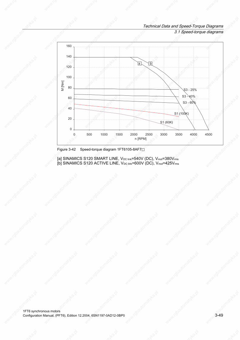
Technical Data and Speed-Torque Diagrams 3.1 Speed-torque diagrams
Figure 3-42 Speed-torque diagram 1FT6105-8AF7⃞
[a] SINAMICS S120 SMART LINE, VDC link=540V (DC), Vmot=380Vrms [b] SINAMICS S120 ACTIVE LINE, VDC link=600V (DC), Vmot=425Vrms
1FT6 synchronous motors Configuration Manual, (PFT6), Edition 12.2004, 6SN1197-0AD12-0BP0 3-49

Technical Data and Speed-Torque Diagrams 3.1 Speed-torque diagrams
Table 3-25 1FT6108 non-ventilated
1FT6108 Technical data Code Units -8AB7⃞ -8AC7⃞ Engineering data Rated speed No. of poles Rated torque (100K) Rated current (100K) Stall torque (60K) Stall torque (100K) Stall current (60K) Stall current (100K) Moment of inertia (with brake) Moment of inertia (without brake)
nN 2p MN(100K) IN (100K) M0 (60K) M0 (100K) I0 (60K) I0 (100K) Jmot Jmot
RPM Nm A Nm Nm A A 10–4 kgm2 10–4 kgm2
1500 8 61 20.5 58 70 18.1 22.3 291 260
2000 8 55 24.5 58 70 23.5 29 291 260
Optimum operating point Optimum speed Optimum power
nopt Popt
RPM kW
1500 9.58
2000 11.5
Limiting data Max. permissible speed (mech.) Max. torque Max. current
nmax Mmax Imax
RPM Nm A
5600 220 107
5600 220 139
Physical constants Torque constant Voltage constant
Rotating field inductance Electrical time constant Shaft torsional stiffness Mechanical time constant
Weight with brake Weight without brake
kT kE Rph LD Tel ct Tmech Tth m m
Nm/A V/1000 RPM Ohm mH ms Nm/rad ms min kg kg
3.14 200 0.22 5.2 24 92000 1.7 55 60 55.5
2.42 154 0.13 3.1 24 92000 1.7 55 60 55.5
Winding resistance at 20° C
Thermal time constant
1FT6 synchronous motors 3-50 Configuration Manual, (PFT6), Edition 12.2004, 6SN1197-0AD12-0BP0

Technical Data and Speed-Torque Diagrams 3.1 Speed-torque diagrams
Figure 3-43 Speed-torque diagram 1FT6108-8AB7⃞
Figure 3-44 Speed-torque diagram 1FT6108-8AC7⃞
[a] SINAMICS S120 SMART LINE, VDC link=540V (DC), Vmot=380Vrms [b] SINAMICS S120 ACTIVE LINE, VDC link=600V (DC), Vmot=425Vrms
1FT6 synchronous motors Configuration Manual, (PFT6), Edition 12.2004, 6SN1197-0AD12-0BP0 3-51

Technical Data and Speed-Torque Diagrams 3.1 Speed-torque diagrams
Table 3-26 1FT6108 non-ventilated
1FT6108 Technical data Code Units -8AF7⃞ Engineering data Rated speed No. of poles Rated torque (100K) Rated current (100K) Stall torque (60K) Stall torque (100K) Stall current (60K) Stall current (100K) Moment of inertia (with brake) Moment of inertia (without brake)
nN 2p MN(100K) IN (100K) M0 (60K) M0 (100K) I0 (60K) I0 (100K) Jmot Jmot
RPM Nm A Nm Nm A A 10–4 kgm2 10–4 kgm2
3000 8 37 25 58 70 33 41 291 260
Optimum operating point Optimum speed Optimum power
nopt Popt
RPM kW
2500 12.0
Limiting data Max. permissible speed (mech.) Max. torque Max. current
nmax Mmax Imax
RPM Nm A
5600 220 198
Physical constants Torque constant Voltage constant
Rotating field inductance Electrical time constant Shaft torsional stiffness Mechanical time constant
Weight with brake Weight without brake
kT kE Rph LD Tel ct Tmech Tth m m
Nm/A V/1000 RPM Ohm mH ms Nm/rad ms min kg kg
1.70 108 0.065 1.5 23 92000 1.8 55 60 55.5
Winding resistance at 20° C
Thermal time constant
1FT6 synchronous motors 3-52 Configuration Manual, (PFT6), Edition 12.2004, 6SN1197-0AD12-0BP0

Technical Data and Speed-Torque Diagrams 3.1 Speed-torque diagrams
Figure 3-45 Speed-torque diagram 1FT6108-8AF7⃞
[a] SINAMICS S120 SMART LINE, VDC link=540V (DC), Vmot=380Vrms [b] SINAMICS S120 ACTIVE LINE, VDC link=600V (DC), Vmot=425Vrms
1FT6 synchronous motors Configuration Manual, (PFT6), Edition 12.2004, 6SN1197-0AD12-0BP0 3-53

Technical Data and Speed-Torque Diagrams 3.1 Speed-torque diagrams
Table 3-27 1FT6132 non-ventilated
1FT6132 Technical data Code Units -6AB71 -6AC71 Engineering data Rated speed No. of poles Rated torque (100K) Rated current (100K) Stall torque (60K) Stall torque (100K) Stall current (60K) Stall current (100K) Moment of inertia (with brake) Moment of inertia (without brake)
nN 2p MN(100K) IN (100K) M0 (60K) M0 (100K) I0 (60K) I0 (100K) Jmot Jmot
RPM Nm A Nm Nm A A 10–4 kgm2 10–4 kgm2
1500 6 62 19 62 75 17.4 21.6 508 430
2000 6 55 23 62 75 23.1 29 508 430
Optimum operating point Optimum speed Optimum power
nopt Popt
RPM kW
1500 9.74
2000 11.5
Limiting data Max. permissible speed (mech.) Max. torque Max. current
nmax Mmax Imax
RPM Nm A
3600 248 96
3600 248 128
Physical constants Torque constant Voltage constant
Rotating field inductance Electrical time constant Shaft torsional stiffness Mechanical time constant
Weight with brake Weight without brake
kT kE Rph LD Tel ct Tmech Tth m m
Nm/A V/1000 RPM Ohm mH ms Nm/rad ms min kg kg
3.48 224 0.23 7.4 37 258000 2.4 65 95 85.0
2.61 168 0.13 4.15 36 258000 2.5 65 95 85.0
Winding resistance at 20° C
Thermal time constant
1FT6 synchronous motors 3-54 Configuration Manual, (PFT6), Edition 12.2004, 6SN1197-0AD12-0BP0
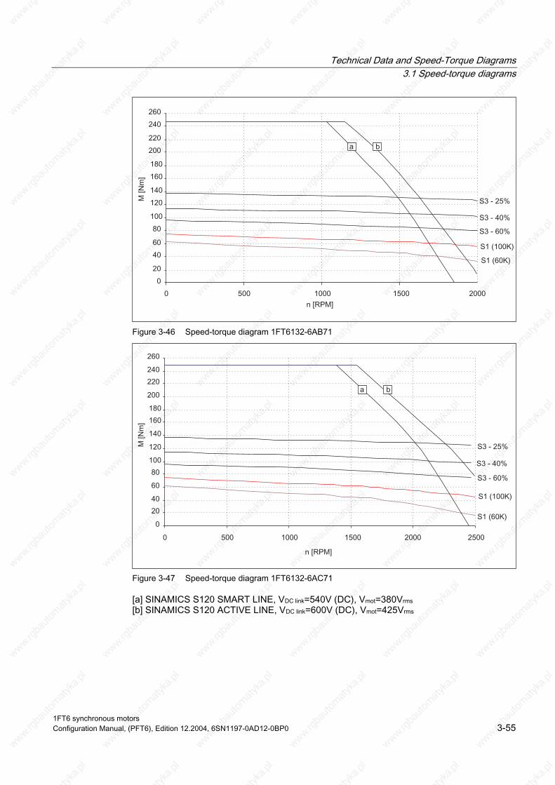
Technical Data and Speed-Torque Diagrams 3.1 Speed-torque diagrams
Figure 3-46 Speed-torque diagram 1FT6132-6AB71
Figure 3-47 Speed-torque diagram 1FT6132-6AC71
[a] SINAMICS S120 SMART LINE, VDC link=540V (DC), Vmot=380Vrms [b] SINAMICS S120 ACTIVE LINE, VDC link=600V (DC), Vmot=425Vrms
1FT6 synchronous motors Configuration Manual, (PFT6), Edition 12.2004, 6SN1197-0AD12-0BP0 3-55
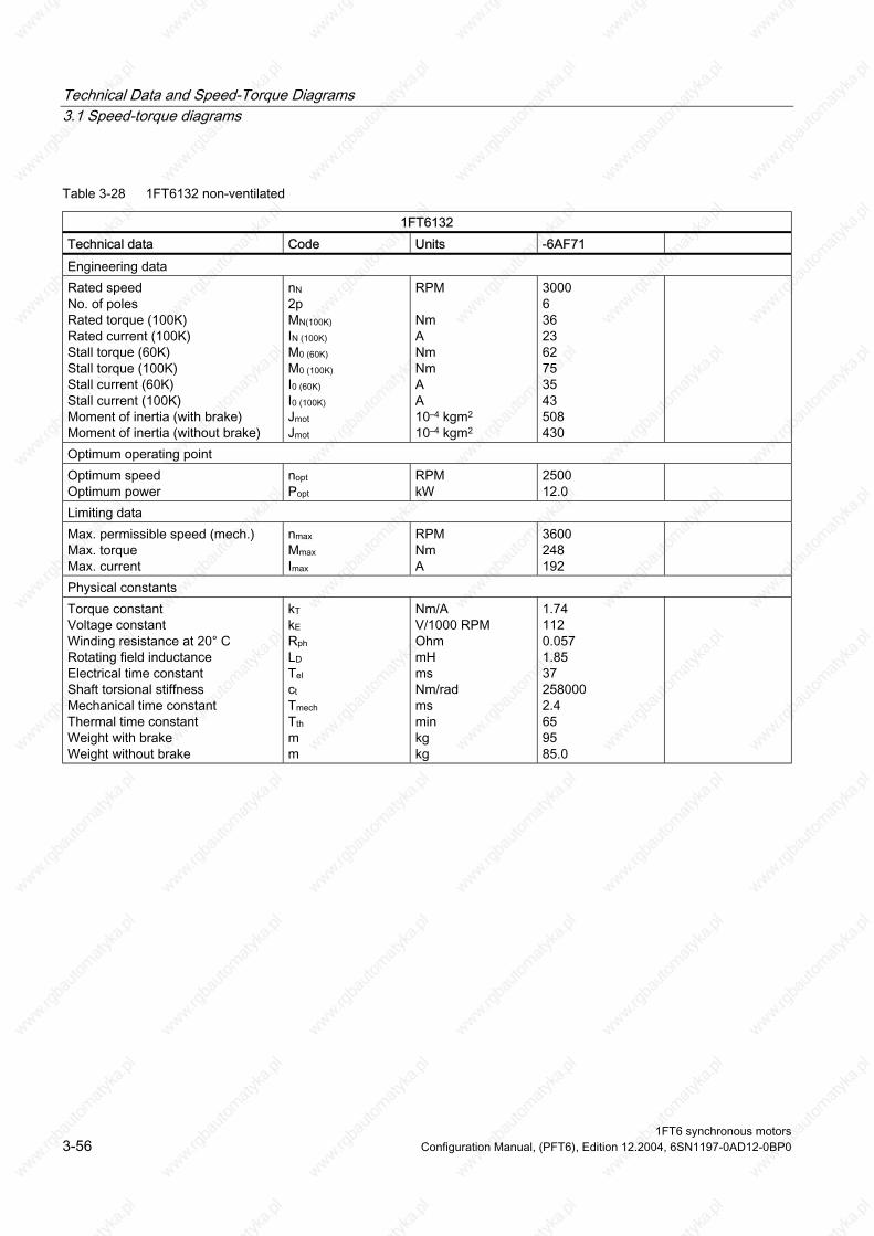
Technical Data and Speed-Torque Diagrams 3.1 Speed-torque diagrams
Table 3-28 1FT6132 non-ventilated
1FT6132 Technical data Code Units -6AF71 Engineering data Rated speed No. of poles Rated torque (100K) Rated current (100K) Stall torque (60K) Stall torque (100K) Stall current (60K) Stall current (100K) Moment of inertia (with brake) Moment of inertia (without brake)
nN 2p MN(100K) IN (100K) M0 (60K) M0 (100K) I0 (60K) I0 (100K) Jmot Jmot
RPM Nm A Nm Nm A A 10–4 kgm2 10–4 kgm2
3000 6 36 23 62 75 35 43 508 430
Optimum operating point Optimum speed Optimum power
nopt Popt
RPM kW
2500 12.0
Limiting data Max. permissible speed (mech.) Max. torque Max. current
nmax Mmax Imax
RPM Nm A
3600 248 192
Physical constants Torque constant Voltage constant
Rotating field inductance Electrical time constant Shaft torsional stiffness Mechanical time constant
Weight with brake Weight without brake
kT kE Rph LD Tel ct Tmech Tth m m
Nm/A V/1000 RPM Ohm mH ms Nm/rad ms min kg kg
1.74 112 0.057 1.85 37 258000 2.4 65 95 85.0
Winding resistance at 20° C
Thermal time constant
1FT6 synchronous motors 3-56 Configuration Manual, (PFT6), Edition 12.2004, 6SN1197-0AD12-0BP0
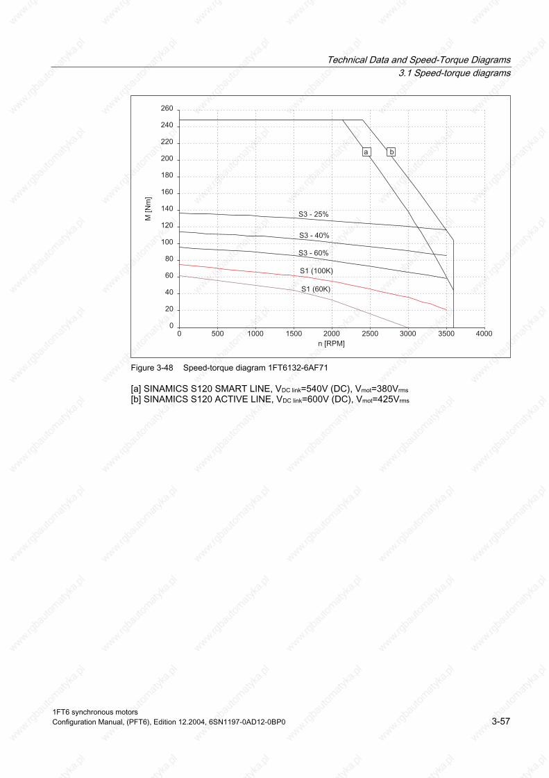
Technical Data and Speed-Torque Diagrams 3.1 Speed-torque diagrams
Figure 3-48 Speed-torque diagram 1FT6132-6AF71
[a] SINAMICS S120 SMART LINE, VDC link=540V (DC), Vmot=380Vrms [b] SINAMICS S120 ACTIVE LINE, VDC link=600V (DC), Vmot=425Vrms
1FT6 synchronous motors Configuration Manual, (PFT6), Edition 12.2004, 6SN1197-0AD12-0BP0 3-57

Technical Data and Speed-Torque Diagrams 3.1 Speed-torque diagrams
Table 3-29 1FT6134 non-ventilated
1FT6134 Technical data Code Units -6AB71 -6AC71 Engineering data Rated speed No. of poles Rated torque (100K) Rated current (100K) Stall torque (60K) Stall torque (100K) Stall current (60K) Stall current (100K) Moment of inertia (with brake) Moment of inertia (without brake)
nN 2p MN(100K) IN (100K) M0 (60K) M0 (100K) I0 (60K) I0 (100K) Jmot Jmot
RPM Nm A Nm Nm A A 10–4 kgm2 10–4 kgm2
1500 6 75 24 79 95 21.7 27 625 547
2000 6 65 27 79 95 30 36 625 547
Optimum operating point Optimum speed Optimum power
nopt Popt
RPM kW
1500 11.8
2000 13.6
Limiting data Max. permissible speed (mech.) Max. torque Max. current
nmax Mmax Imax
RPM Nm A
3600 316 125
3600 316 170
Physical constants Torque constant Voltage constant
Rotating field inductance Electrical time constant Shaft torsional stiffness Mechanical time constant
Weight with brake Weight without brake
kT kE Rph LD Tel ct Tmech Tth m m
Nm/A V/1000 RPM Ohm mH ms Nm/rad ms min kg kg
3.54 228 0.17 5.8 34 234000 2.2 70 110 100
2.61 168 0.094 3.1 33 234000 2.3 70 110 100
Winding resistance at 20° C
Thermal time constant
1FT6 synchronous motors 3-58 Configuration Manual, (PFT6), Edition 12.2004, 6SN1197-0AD12-0BP0

Technical Data and Speed-Torque Diagrams 3.1 Speed-torque diagrams
Figure 3-49 Speed-torque diagram 1FT6134-6AB71
Figure 3-50 Speed-torque diagram 1FT6134-6AC71
[a] SINAMICS S120 SMART LINE, VDC link=540V (DC), Vmot=380Vrms [b] SINAMICS S120 ACTIVE LINE, VDC link=600V (DC), Vmot=425Vrms
1FT6 synchronous motors Configuration Manual, (PFT6), Edition 12.2004, 6SN1197-0AD12-0BP0 3-59

Technical Data and Speed-Torque Diagrams 3.1 Speed-torque diagrams
Table 3-30 1FT6136 non-ventilated
1FT6136 Technical data Code Units -6AB71 -6AC7⃞ Engineering data Rated speed No. of poles Rated torque (100K) Rated current (100K) Stall torque (60K) Stall torque (100K) Stall current (60K) Stall current (100K) Moment of inertia (with brake) Moment of inertia (without brake)
nN 2p MN(100K) IN (100K) M0 (60K) M0 (100K) I0 (60K) I0 (100K) Jmot Jmot
RPM Nm A Nm Nm A A 10–4 kgm2 10–4 kgm2
1500 6 88 27 95 115 27 34 742 664
2000 6 74 30 95 115 34 42 742 664
Optimum operating point Optimum speed Optimum power
nopt Popt
RPM kW
1500 13.8
2000 15.5
Limiting data Max. permissible speed (mech.) Max. torque Max. current
nmax Mmax Imax
RPM Nm A
3600 380 146
3600 380 183
Physical constants Torque constant Voltage constant
Rotating field inductance Electrical time constant Shaft torsional stiffness Mechanical time constant
Weight with brake Weight without brake
kT kE Rph LD Tel ct Tmech Tth m m
Nm/A V/1000 RPM Ohm mH ms Nm/rad ms min kg kg
3.40 219 0.12 4.4 41 214000 2.1 75 125 117
2.72 175 0.075 2.8 41 214000 2.0 75 125 117
Winding resistance at 20° C
Thermal time constant
1FT6 synchronous motors 3-60 Configuration Manual, (PFT6), Edition 12.2004, 6SN1197-0AD12-0BP0

Technical Data and Speed-Torque Diagrams 3.1 Speed-torque diagrams
Figure 3-51 Speed-torque diagram 1FT6136-6AB71
Figure 3-52 Speed-torque diagram 1FT6136-6AC7⃞
[a] SINAMICS S120 SMART LINE, VDC link=540V (DC), Vmot=380Vrms [b] SINAMICS S120 ACTIVE LINE, VDC link=600V (DC), Vmot=425Vrms
1FT6 synchronous motors Configuration Manual, (PFT6), Edition 12.2004, 6SN1197-0AD12-0BP0 3-61

Technical Data and Speed-Torque Diagrams 3.1 Speed-torque diagrams
3.1.3 1FT6 series, force ventilated
Table 3-31 1FT6084 force ventilated
1FT6084 Technical data Code Units -8SF7⃞ Engineering data Rated speed No. of poles Rated torque (100K) Rated current (100K) Stall torque (60K) Stall torque (100K) Stall current (60K) Stall current (100K) Moment of inertia (with brake) Moment of inertia (without brake)
nN 2p MN(100K) IN (100K) M0 (60K) M0 (100K) I0 (60K) I0 (100K) Jmot Jmot
RPM Nm A Nm Nm A A 10–4 kgm2 10–4 kgm2
3000 8 22.0 17.0 21.6 26.0 14.8 18.2 61.1 48.0
Optimum operating point Optimum speed Optimum power
Nopt Popt
RPM kW
3000 6.91
Limiting data Max. permissible speed (mech.) Max. torque Max. current
Nmax Mmax Imax
RPM Nm A
7900 65 59
Physical constants Torque constant Voltage constant
Rotating field inductance Electrical time constant Shaft torsional stiffness Mechanical time constant
Weight with brake Weight without brake
kt kE Rph LD Tel ct Tmech Tth m m
Nm/A V/1000 RPM Ohm mH ms Nm/rad ms min kg kg
1.43 91 0.37 4.3 11.6 76000 2.6 15 28.5 25.0
Winding resistance at 20° C
Thermal time constant
1FT6 synchronous motors 3-62 Configuration Manual, (PFT6), Edition 12.2004, 6SN1197-0AD12-0BP0
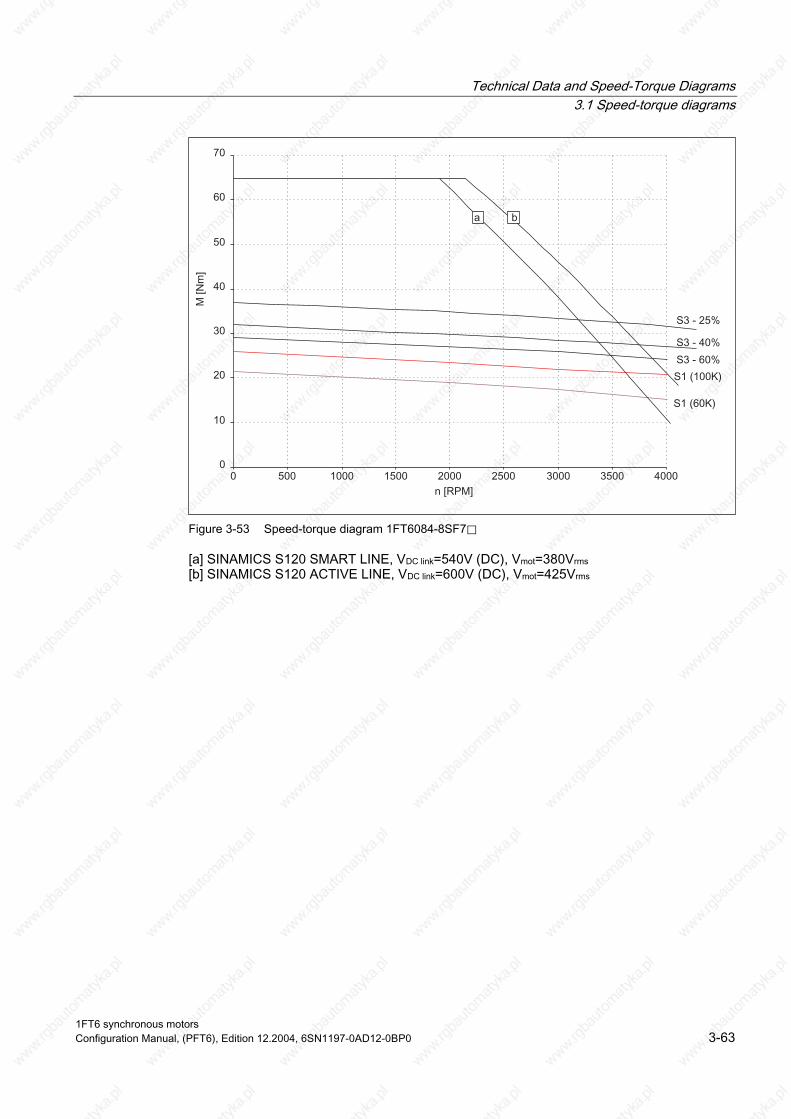
Technical Data and Speed-Torque Diagrams 3.1 Speed-torque diagrams
Figure 3-53 Speed-torque diagram 1FT6084-8SF7⃞
[a] SINAMICS S120 SMART LINE, VDC link=540V (DC), Vmot=380Vrms [b] SINAMICS S120 ACTIVE LINE, VDC link=600V (DC), Vmot=425Vrms
1FT6 synchronous motors Configuration Manual, (PFT6), Edition 12.2004, 6SN1197-0AD12-0BP0 3-63

Technical Data and Speed-Torque Diagrams 3.1 Speed-torque diagrams
Table 3-32 1FT6084 force ventilated
1FT6084 Technical data Code Units -8SH7⃞ -8SK7⃞ Engineering data Rated speed No. of poles Rated torque (100K) Rated current (100K) Stall torque (60K) Stall torque (100K) Stall current (60K) Stall current (100K) Moment of inertia (with brake) Moment of inertia (without brake)
nN 2p MN(100K) IN (100K) M0 (60K) M0 (100K) I0 (60K) I0 (100K) Jmot Jmot
RPM Nm A Nm Nm A A 10–4 kgm2 10–4 kgm2
4500 8 20.0 24.5 21.6 26.0 21.0 26.0 61.1 48.0
6000 8 17.0 25.5 21.6 26.0 29.0 35.0 61.1 48.0
Optimum operating point Optimum speed Optimum power
Nopt Popt
RPM kW
4500 9.42
6000 10.68
Limiting data Max. permissible speed (mech.) Max. torque Max. current
Nmax Mmax Imax
RPM Nm A
7900 65 86
7900 65 112
Physical constants Torque constant Voltage constant
Rotating field inductance Electrical time constant Shaft torsional stiffness Mechanical time constant
Weight with brake Weight without brake
kt kE Rph LD Tel ct Tmech Tth m m
Nm/A V/1000 RPM Ohm mH ms Nm/rad ms min kg kg
1.01 64 0.18 2.0 11.1 76000 2.5 15 28.5 25.0
0.74 47 0.1 1.2 12.0 76000 2.6 15 28.5 25.0
Winding resistance at 20° C
Thermal time constant
1FT6 synchronous motors 3-64 Configuration Manual, (PFT6), Edition 12.2004, 6SN1197-0AD12-0BP0

Technical Data and Speed-Torque Diagrams 3.1 Speed-torque diagrams
Figure 3-54 Speed-torque diagram 1FT6084-8SH7⃞
Figure 3-55 Speed-torque diagram 1FT6084-8SK7⃞
[a] SINAMICS S120 SMART LINE, VDC link=540V (DC), Vmot=380Vrms [b] SINAMICS S120 ACTIVE LINE, VDC link=600V (DC), Vmot=425Vrms
1FT6 synchronous motors Configuration Manual, (PFT6), Edition 12.2004, 6SN1197-0AD12-0BP0 3-65

Technical Data and Speed-Torque Diagrams 3.1 Speed-torque diagrams
Table 3-33 1FT6086 force ventilated
1FT6086 Technical data Code Units -8SF7⃞ Engineering data Rated speed No. of poles Rated torque (100K) Rated current (100K) Stall torque (60K) Stall torque (100K) Stall current (60K) Stall current (100K) Moment of inertia (with brake) Moment of inertia (without brake)
nN 2p MN(100K) IN (100K) M0 (60K) M0 (100K) I0 (60K) I0 (100K) Jmot Jmot
RPM Nm A Nm Nm A A 10–4 kgm2 10–4 kgm2
3000 8 31.0 24.5 29.0 35.0 20.3 25.0 79.6 66.5
Optimum operating point Optimum speed Optimum power
Nopt Popt
RPM kW
3000 9.74
Limiting data Max. permissible speed (mech.) Max. torque Max. current
Nmax Mmax Imax
RPM Nm A
7900 90 80
Physical constants Torque constant Voltage constant
Rotating field inductance Electrical time constant Shaft torsional stiffness Mechanical time constant
Weight with brake Weight without brake
kt kE Rph LD Tel ct Tmech Tth m m
Nm/A V/1000 RPM Ohm mH ms Nm/rad ms min kg kg
1.40 89 0.23 2.9 12.6 65000 2.3 15 33.5 30.0
Winding resistance at 20° C
Thermal time constant
1FT6 synchronous motors 3-66 Configuration Manual, (PFT6), Edition 12.2004, 6SN1197-0AD12-0BP0

Technical Data and Speed-Torque Diagrams 3.1 Speed-torque diagrams
Figure 3-56 Speed-torque diagram 1FT6086-8SF7⃞
[a] SINAMICS S120 SMART LINE, VDC link=540V (DC), Vmot=380Vrms [b] SINAMICS S120 ACTIVE LINE, VDC link=600V (DC), Vmot=425Vrms
1FT6 synchronous motors Configuration Manual, (PFT6), Edition 12.2004, 6SN1197-0AD12-0BP0 3-67
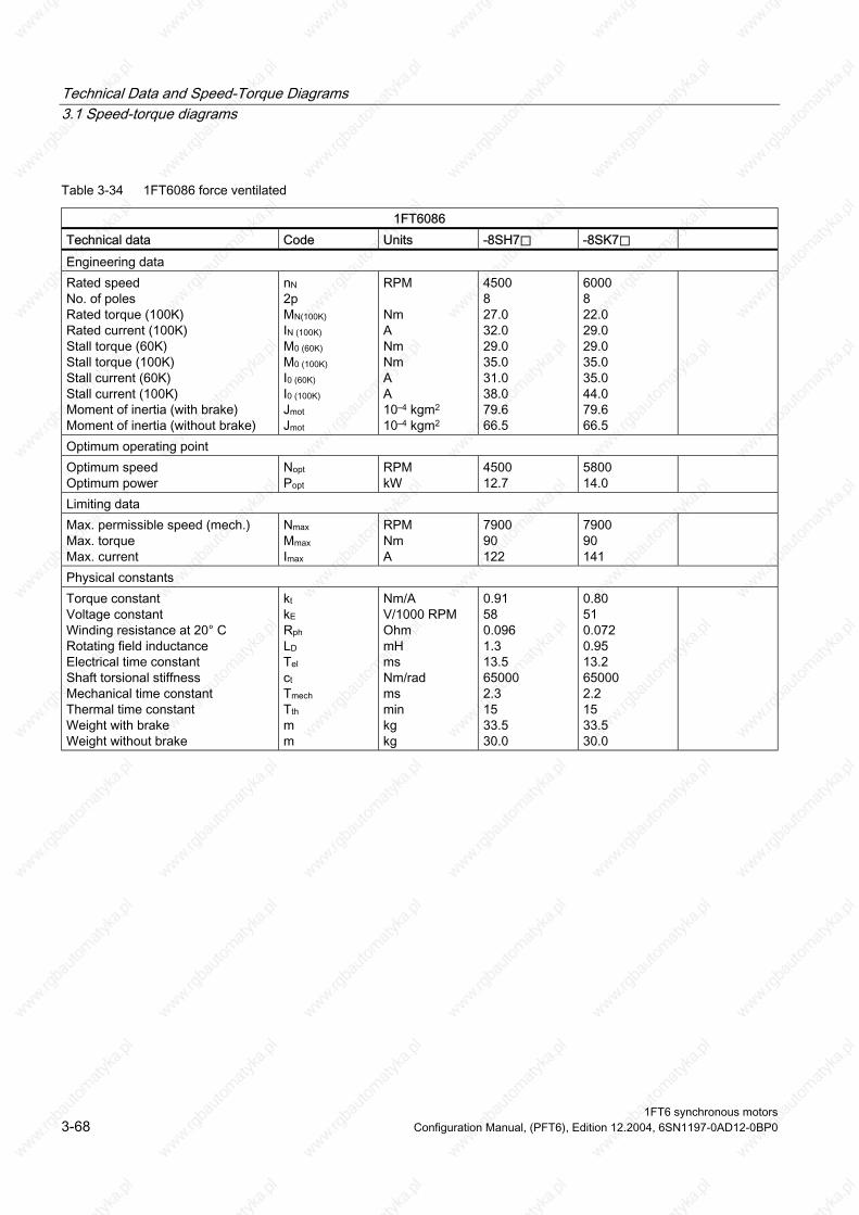
Technical Data and Speed-Torque Diagrams 3.1 Speed-torque diagrams
Table 3-34 1FT6086 force ventilated
1FT6086 Technical data Code Units -8SH7⃞ -8SK7⃞ Engineering data Rated speed No. of poles Rated torque (100K) Rated current (100K) Stall torque (60K) Stall torque (100K) Stall current (60K) Stall current (100K) Moment of inertia (with brake) Moment of inertia (without brake)
nN 2p MN(100K) IN (100K) M0 (60K) M0 (100K) I0 (60K) I0 (100K) Jmot Jmot
RPM Nm A Nm Nm A A 10–4 kgm2 10–4 kgm2
4500 8 27.0 32.0 29.0 35.0 31.0 38.0 79.6 66.5
6000 8 22.0 29.0 29.0 35.0 35.0 44.0 79.6 66.5
Optimum operating point Optimum speed Optimum power
Nopt Popt
RPM kW
4500 12.7
5800 14.0
Limiting data Max. permissible speed (mech.) Max. torque Max. current
Nmax Mmax Imax
RPM Nm A
7900 90 122
7900 90 141
Physical constants Torque constant Voltage constant
Rotating field inductance Electrical time constant Shaft torsional stiffness Mechanical time constant
Weight with brake Weight without brake
kt kE Rph LD Tel ct Tmech Tth m m
Nm/A V/1000 RPM Ohm mH ms Nm/rad ms min kg kg
0.91 58 0.096 1.3 13.5 65000 2.3 15 33.5 30.0
0.80 51 0.072 0.95 13.2 65000 2.2 15 33.5 30.0
Winding resistance at 20° C
Thermal time constant
1FT6 synchronous motors 3-68 Configuration Manual, (PFT6), Edition 12.2004, 6SN1197-0AD12-0BP0
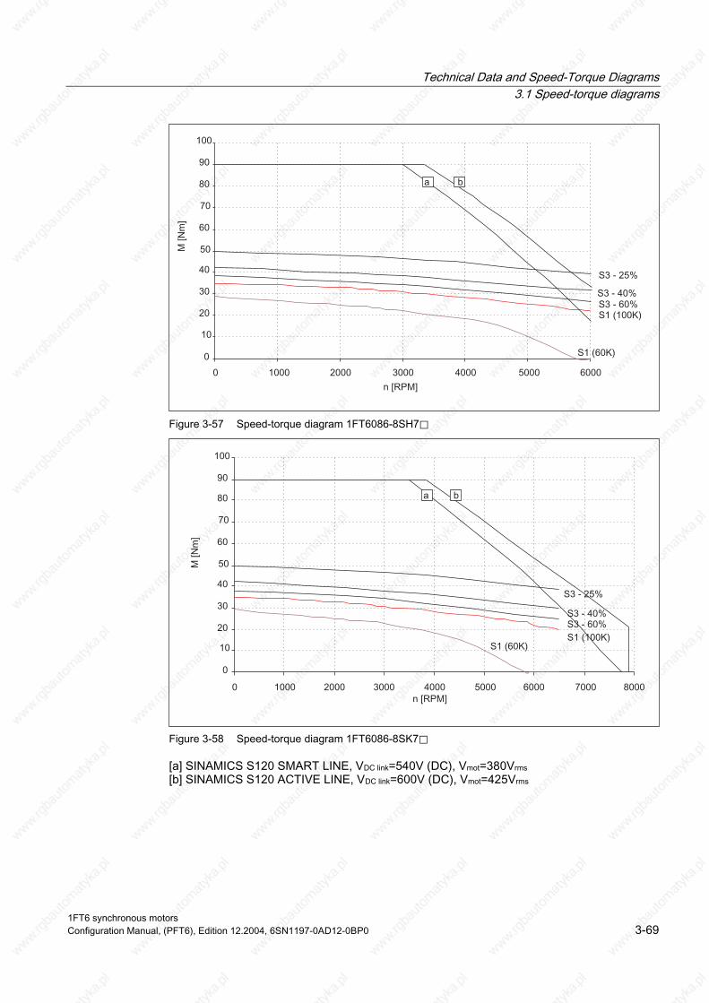
Technical Data and Speed-Torque Diagrams 3.1 Speed-torque diagrams
Figure 3-57 Speed-torque diagram 1FT6086-8SH7⃞
Figure 3-58 Speed-torque diagram 1FT6086-8SK7⃞
[a] SINAMICS S120 SMART LINE, VDC link=540V (DC), Vmot=380Vrms [b] SINAMICS S120 ACTIVE LINE, VDC link=600V (DC), Vmot=425Vrms
1FT6 synchronous motors Configuration Manual, (PFT6), Edition 12.2004, 6SN1197-0AD12-0BP0 3-69

Technical Data and Speed-Torque Diagrams 3.1 Speed-torque diagrams
Table 3-35 1FT6105 force ventilated
1FT6105 Technical data Code Units -8SB7⃞ -8SC7⃞ Engineering data Rated speed No. of poles Rated torque (100K) Rated current (100K) Stall torque (60K) Stall torque (100K) Stall current (60K) Stall current (100K) Moment of inertia (with brake) Moment of inertia (without brake)
nN 2p MN(100K) IN (100K) M0 (60K) M0 (100K) I0 (60K) I0 (100K) Jmot Jmot
RPM Nm A Nm Nm A A 10–4 kgm2 10–4 kgm2
1500 8 59.0 21.7 54.0 65.0 17.8 21.9 199 168
2000 8 56.0 28.0 54.0 65.0 24.2 30.0 199 168
Optimum operating point Optimum speed Optimum power
Nopt Popt
RPM kW
1500 9.27
2000 11.73
Limiting data Max. permissible speed (mech.) Max. torque Max. current
Nmax Mmax Imax
RPM Nm A
5600 140 81
5600 140 110
Physical constants Torque constant Voltage constant
Rotating field inductance Electrical time constant Shaft torsional stiffness Mechanical time constant
Weight with brake Weight without brake
kt kE Rph LD Tel ct Tmech Tth m m
Nm/A V/1000 RPM Ohm mH ms Nm/rad ms min kg kg
2.97 189 0.35 7.5 21.0 113000 2.0 20 50 45.5
2.18 139 0.19 4.1 22.0 113000 2.0 20 50 45.5
Winding resistance at 20° C
Thermal time constant
1FT6 synchronous motors 3-70 Configuration Manual, (PFT6), Edition 12.2004, 6SN1197-0AD12-0BP0
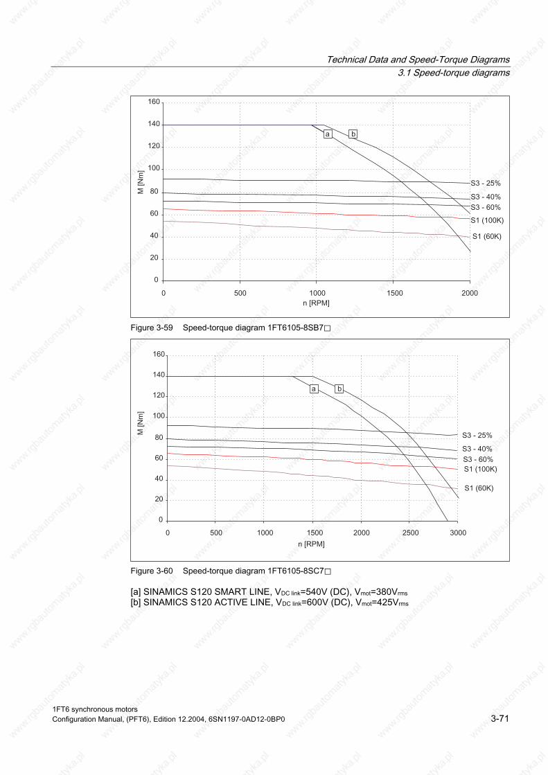
Technical Data and Speed-Torque Diagrams 3.1 Speed-torque diagrams
Figure 3-59 Speed-torque diagram 1FT6105-8SB7⃞
Figure 3-60 Speed-torque diagram 1FT6105-8SC7⃞
[a] SINAMICS S120 SMART LINE, VDC link=540V (DC), Vmot=380Vrms [b] SINAMICS S120 ACTIVE LINE, VDC link=600V (DC), Vmot=425Vrms
1FT6 synchronous motors Configuration Manual, (PFT6), Edition 12.2004, 6SN1197-0AD12-0BP0 3-71

Technical Data and Speed-Torque Diagrams 3.1 Speed-torque diagrams
Table 3-36 1FT6105 force ventilated
1FT6105 Technical data Code Units -8SF7⃞ -8SH7⃞ Engineering data Rated speed No. of poles Rated torque (100K) Rated current (100K) Stall torque (60K) Stall torque (100K) Stall current (60K) Stall current (100K) Moment of inertia (with brake) Moment of inertia (without brake)
nN 2p MN(100K) IN (100K) M0 (60K) M0 (100K) I0 (60K) I0 (100K) Jmot Jmot
RPM Nm A Nm Nm A A 10–4 kgm2 10–4 kgm2
3000 8 50.0 35.0 54.0 65.0 34.0 42.0 199 168
4500 8 40.0 41.0 54.0 65.0 48.0 59.0 199 168
Optimum operating point Optimum speed Optimum power
Nopt Popt
RPM kW
3000 15.7
4500 18.8
Limiting data Max. permissible speed (mech.) Max. torque Max. current
Nmax Mmax Imax
RPM Nm A
5600 140 155
5600 140 221
Physical constants Torque constant Voltage constant
Rotating field inductance Electrical time constant Shaft torsional stiffness Mechanical time constant
Weight with brake Weight without brake
kt kE Rph LD Tel ct Tmech Tth m m
Nm/A V/1000 RPM Ohm mH ms Nm/rad ms min kg kg
1.56 99 0.098 2.1 21.0 113000 2.0 20 50 45.5
1.10 70 0.048 1.0 21.0 113000 2.0 20 50 45.5
Winding resistance at 20° C
Thermal time constant
1FT6 synchronous motors 3-72 Configuration Manual, (PFT6), Edition 12.2004, 6SN1197-0AD12-0BP0

Technical Data and Speed-Torque Diagrams 3.1 Speed-torque diagrams
Figure 3-61 Speed-torque diagram 1FT6105-8SF7⃞
Figure 3-62 Speed-torque diagram 1FT6105-8SH7⃞
[a] SINAMICS S120 SMART LINE, VDC link=540V (DC), Vmot=380Vrms [b] SINAMICS S120 ACTIVE LINE, VDC link=600V (DC), Vmot=425Vrms
1FT6 synchronous motors Configuration Manual, (PFT6), Edition 12.2004, 6SN1197-0AD12-0BP0 3-73

Technical Data and Speed-Torque Diagrams 3.1 Speed-torque diagrams
Table 3-37 1FT6108 force ventilated
1FT6108 Technical data Code Units -8SB7⃞ -8SC7⃞ Engineering data Rated speed No. of poles Rated torque (100K) Rated current (100K) Stall torque (60K) Stall torque (100K) Stall current (60K) Stall current (100K) Moment of inertia (with brake) Moment of inertia (without brake)
nN 2p MN(100K) IN (100K) M0 (60K) M0 (100K) I0 (60K) I0 (100K) Jmot Jmot
RPM Nm A Nm Nm A A 10–4 kgm2 10–4 kgm2
1500 8 83 31 75 90 25 31 291 260
2000 8 80 40 75 90 34 41 291 260
Optimum operating point Optimum speed Optimum power
Nopt Popt
RPM kW
1500 13.0
2000 16.8
Limiting data Max. permissible speed (mech.) Max. torque Max. current
Nmax Mmax Imax
RPM Nm A
5600 220 116
5600 220 154
Physical constants Torque constant Voltage constant
Rotating field inductance Electrical time constant Shaft torsional stiffness Mechanical time constant
Weight with brake Weight without brake
kt kE Rph LD Tel ct Tmech Tth m m
Nm/A V/1000 RPM Ohm mH ms Nm/rad ms min kg kg
2.91 195 0.19 4.4 23.0 92000 1.8 20 66 61.5
2.18 139 0.11 2.5 23.0 92000 1.8 20 66 61.5
Winding resistance at 20° C
Thermal time constant
1FT6 synchronous motors 3-74 Configuration Manual, (PFT6), Edition 12.2004, 6SN1197-0AD12-0BP0
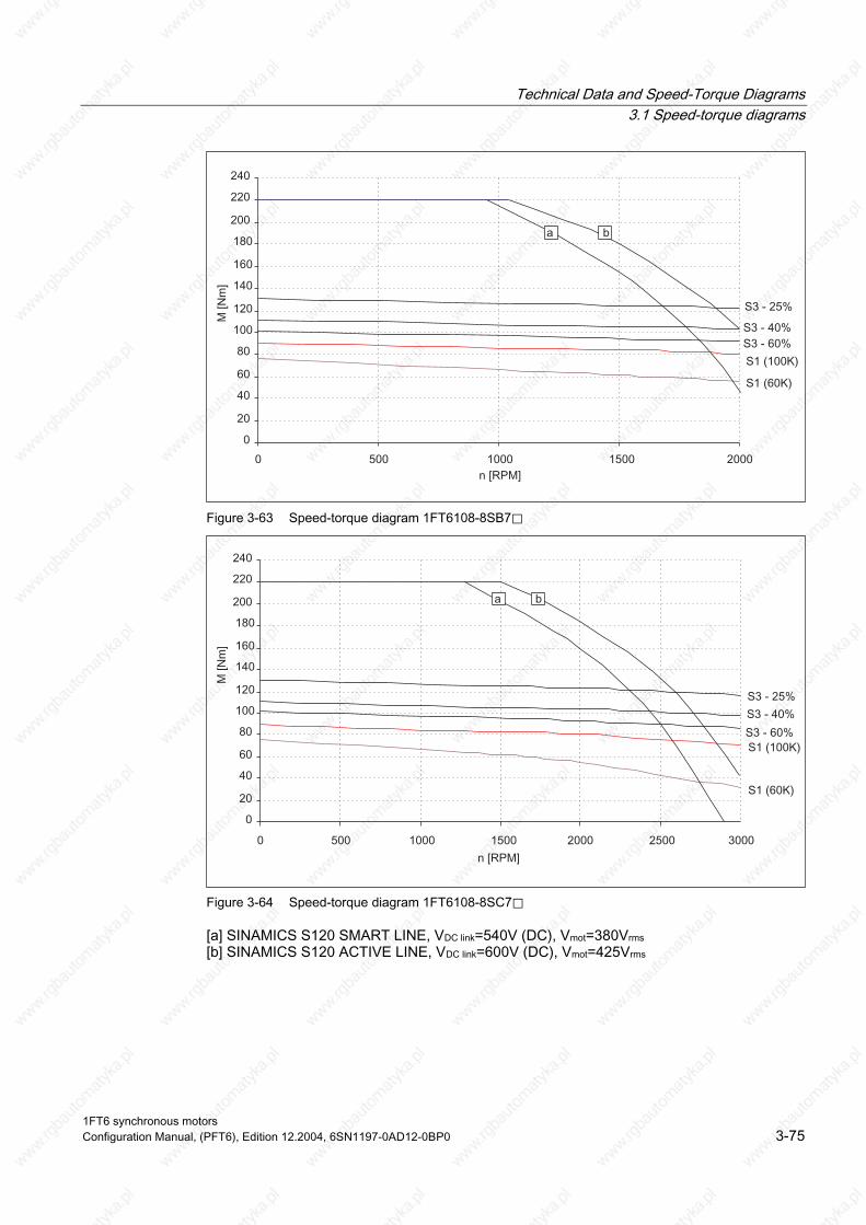
Technical Data and Speed-Torque Diagrams 3.1 Speed-torque diagrams
Figure 3-63 Speed-torque diagram 1FT6108-8SB7⃞
Figure 3-64 Speed-torque diagram 1FT6108-8SC7⃞
[a] SINAMICS S120 SMART LINE, VDC link=540V (DC), Vmot=380Vrms [b] SINAMICS S120 ACTIVE LINE, VDC link=600V (DC), Vmot=425Vrms
1FT6 synchronous motors Configuration Manual, (PFT6), Edition 12.2004, 6SN1197-0AD12-0BP0 3-75

Technical Data and Speed-Torque Diagrams 3.1 Speed-torque diagrams
Table 3-38 1FT6108 force ventilated
1FT6108 Technical data Code Units -8SF7⃞ Engineering data Rated speed No. of poles Rated torque (100K) Rated current (100K) Stall torque (60K) Stall torque (100K) Stall current (60K) Stall current (100K) Moment of inertia (with brake) Moment of inertia (without brake)
nN 2p MN(100K) IN (100K) M0 (60K) M0 (100K) I0 (60K) I0 (100K) Jmot Jmot
RPM Nm A Nm Nm A A 10–4 kgm2 10–4 kgm2
3000 8 70 53 75 90 51 62 291 260
Optimum operating point Optimum speed Optimum power
Nopt Popt
RPM kW
3000 22.0
Limiting data Max. permissible speed (mech.) Max. torque Max. current
Nmax Mmax Imax
RPM Nm A
5600 220 231
Physical constants Torque constant Voltage constant
Rotating field inductance Electrical time constant Shaft torsional stiffness Mechanical time constant
Weight with brake Weight without brake
kt kE Rph LD Tel ct Tmech Tth m m
Nm/A V/1000 RPM Ohm mH ms Nm/rad ms min kg kg
1.45 92 0.048 1.1 23.0 92000 1.8 20 66 61.5
Winding resistance at 20° C
Thermal time constant
1FT6 synchronous motors 3-76 Configuration Manual, (PFT6), Edition 12.2004, 6SN1197-0AD12-0BP0
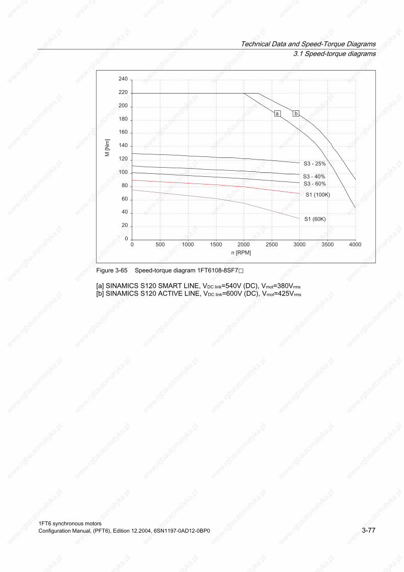
Technical Data and Speed-Torque Diagrams 3.1 Speed-torque diagrams
Figure 3-65 Speed-torque diagram 1FT6108-8SF7⃞
[a] SINAMICS S120 SMART LINE, VDC link=540V (DC), Vmot=380Vrms [b] SINAMICS S120 ACTIVE LINE, VDC link=600V (DC), Vmot=425Vrms
1FT6 synchronous motors Configuration Manual, (PFT6), Edition 12.2004, 6SN1197-0AD12-0BP0 3-77

Technical Data and Speed-Torque Diagrams 3.1 Speed-torque diagrams
Table 3-39 1FT6132 force ventilated
1FT6132 Technical data Code Units -6SB71 -6SC71 Engineering data Rated speed No. of poles Rated torque (100K) Rated current (100K) Stall torque (60K) Stall torque (100K) Stall current (60K) Stall current (100K) Moment of inertia (with brake) Moment of inertia (without brake)
nN 2p MN(100K) IN (100K) M0 (60K) M0 (100K) I0 (60K) I0 (100K) Jmot Jmot
RPM Nm A Nm Nm A A 10–4 kgm2 10–4 kgm2
1500 6 102 36 91 110 29 36 508 430
2000 6 98 46 91 110 38 47 508 430
Optimum operating point Optimum speed Optimum power
Nopt Popt
RPM kW
1500 16.0
2000 20.5
Limiting data Max. permissible speed (mech.) Max. torque Max. current
Nmax Mmax Imax
RPM Nm A
3600 248 108
3600 248 144
Physical constants Torque constant Voltage constant
Rotating field inductance Electrical time constant Shaft torsional stiffness Mechanical time constant
Weight with brake Weight without brake
kt kE Rph LD Tel ct Tmech Tth m m
Nm/A V/1000 RPM Ohm mH ms Nm/rad ms min kg kg
3.05 196 0.17 5.7 38 258000 2.4 25 101 91
2.32 149 0.10 3.3 37 258000 2.4 25 101 91
Winding resistance at 20° C
Thermal time constant
1FT6 synchronous motors 3-78 Configuration Manual, (PFT6), Edition 12.2004, 6SN1197-0AD12-0BP0

Technical Data and Speed-Torque Diagrams 3.1 Speed-torque diagrams
Figure 3-66 Speed-torque diagram 1FT6132-6SB71
Figure 3-67 Speed-torque diagram 1FT6132-6SC71
[a] SINAMICS S120 SMART LINE, VDC link=540V (DC), Vmot=380Vrms [b] SINAMICS S120 ACTIVE LINE, VDC link=600V (DC), Vmot=425Vrms
1FT6 synchronous motors Configuration Manual, (PFT6), Edition 12.2004, 6SN1197-0AD12-0BP0 3-79

Technical Data and Speed-Torque Diagrams 3.1 Speed-torque diagrams
Table 3-40 1FT6132 force ventilated
1FT6132 Technical data Code Units -6SF71 Engineering data Rated speed No. of poles Rated torque (100K) Rated current (100K) Stall torque (60K) Stall torque (100K) Stall current (60K) Stall current (100K) Moment of inertia (with brake) Moment of inertia (without brake)
nN 2p MN(100K) IN (100K) M0 (60K) M0 (100K) I0 (60K) I0 (100K) Jmot Jmot
RPM Nm A Nm Nm A A 10–4 kgm2 10–4 kgm2
3000 6 90 62 91 110 55 69 508 430
Optimum operating point Optimum speed Optimum power
Nopt Popt
RPM kW
3000 28.3
Limiting data Max. permissible speed (mech.) Max. torque Max. current
Nmax Mmax Imax
RPM Nm A
3600 248 209
Physical constants Torque constant Voltage constant
Rotating field inductance Electrical time constant Shaft torsional stiffness Mechanical time constant
Weight with brake Weight without brake
kt kE Rph LD Tel ct Tmech Tth m m
Nm/A V/1000 RPM Ohm mH ms Nm/rad ms min kg kg
1.6 103 0.048 1.55 37 258000 2.4 25 101 91
Winding resistance at 20° C
Thermal time constant
1FT6 synchronous motors 3-80 Configuration Manual, (PFT6), Edition 12.2004, 6SN1197-0AD12-0BP0
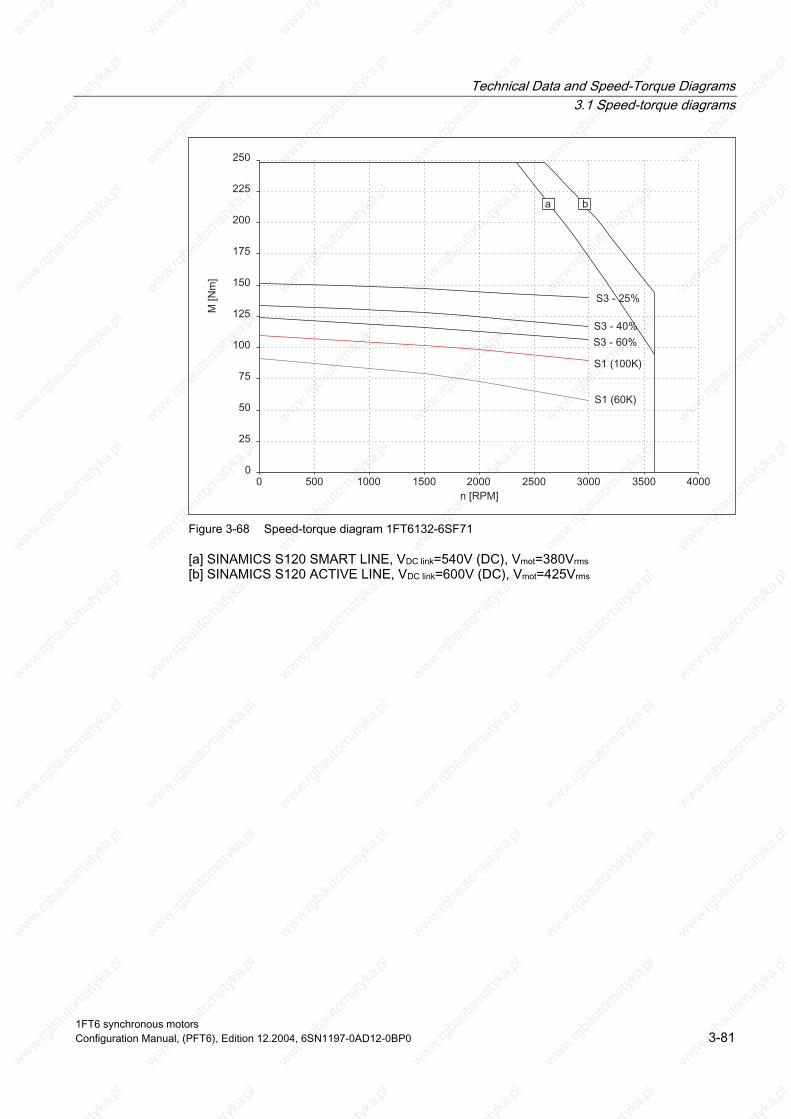
Technical Data and Speed-Torque Diagrams 3.1 Speed-torque diagrams
Figure 3-68 Speed-torque diagram 1FT6132-6SF71
[a] SINAMICS S120 SMART LINE, VDC link=540V (DC), Vmot=380Vrms [b] SINAMICS S120 ACTIVE LINE, VDC link=600V (DC), Vmot=425Vrms
1FT6 synchronous motors Configuration Manual, (PFT6), Edition 12.2004, 6SN1197-0AD12-0BP0 3-81

Technical Data and Speed-Torque Diagrams 3.1 Speed-torque diagrams
Table 3-41 1FT6134 force ventilated
1FT6134 Technical data Code Units -6SB71 -6SC71 Engineering data Rated speed No. of poles Rated torque (100K) Rated current (100K) Stall torque (60K) Stall torque (100K) Stall current (60K) Stall current (100K) Moment of inertia (with brake) Moment of inertia (without brake)
nN 2p MN(100K) IN (100K) M0 (60K) M0 (100K) I0 (60K) I0 (100K) Jmot Jmot
RPM Nm A Nm Nm A A 10–4 kgm2 10–4 kgm2
1500 6 130 45 116 140 36 44 625 547
2000 6 125 57 116 140 47 58 625 547
Optimum operating point Optimum speed Optimum power
nopt Popt
RPM kW
1500 20.4
2000 26.2
Limiting data Max. permissible speed (mech.) Max. torque Max. current
nmax Mmax Imax
RPM Nm A
3600 316 140
3600 316 182
Physical constants Torque constant Voltage constant
Rotating field inductance Electrical time constant Shaft torsional stiffness Mechanical time constant
Weight with brake Weight without brake
kT kE Rph LD Tel ct Tmech Tth m m
Nm/A V/1000 RPM Ohm mH ms Nm/rad ms min kg kg
3.17 204 0.14 4.6 33 234000 2.3 25 116 106
2.43 156 0.081 2.7 33 234000 2.3 25 116 106
Winding resistance at 20° C
Thermal time constant
1FT6 synchronous motors 3-82 Configuration Manual, (PFT6), Edition 12.2004, 6SN1197-0AD12-0BP0

Technical Data and Speed-Torque Diagrams 3.1 Speed-torque diagrams
Figure 3-69 Speed-torque diagram 1FT6134-6SB71
Figure 3-70 Speed-torque diagram 1FT6134-6SC71
[a] SINAMICS S120 SMART LINE, VDC link=540V (DC), Vmot=380Vrms [b] SINAMICS S120 ACTIVE LINE, VDC link=600V (DC), Vmot=425Vrms
1FT6 synchronous motors Configuration Manual, (PFT6), Edition 12.2004, 6SN1197-0AD12-0BP0 3-83

Technical Data and Speed-Torque Diagrams 3.1 Speed-torque diagrams
Table 3-42 1FT6134 force ventilated
1FT6134 Technical data Code Units -6SF71 Engineering data Rated speed No. of poles Rated torque (100K) Rated current (100K) Stall torque (60K) Stall torque (100K) Stall current (60K) Stall current (100K) Moment of inertia (with brake) Moment of inertia (without brake)
nN 2p MN(100K) IN (100K) M0 (60K) M0 (100K) I0 (60K) I0 (100K) Jmot Jmot
RPM Nm A Nm Nm A A 10–4 kgm2 10–4 kgm2
3000 6 110 72 116 140 67 83 625 547
Optimum operating point Optimum speed Optimum power
nopt Popt
RPM kW
3000 35
Limiting data Max. permissible speed (mech.) Max. torque Max. current
nmax Mmax Imax
RPM Nm A
3600 316 264
Physical constants Torque constant Voltage constant
Rotating field inductance Electrical time constant Shaft torsional stiffness Mechanical time constant
Weight with brake Weight without brake
kT kE Rph LD Tel ct Tmech Tth m m
Nm/A V/1000 RPM Ohm mH ms Nm/rad ms min kg kg
1.68 108 0.039 1.3 33 234000 2.3 25 116 106
Winding resistance at 20° C
Thermal time constant
1FT6 synchronous motors 3-84 Configuration Manual, (PFT6), Edition 12.2004, 6SN1197-0AD12-0BP0
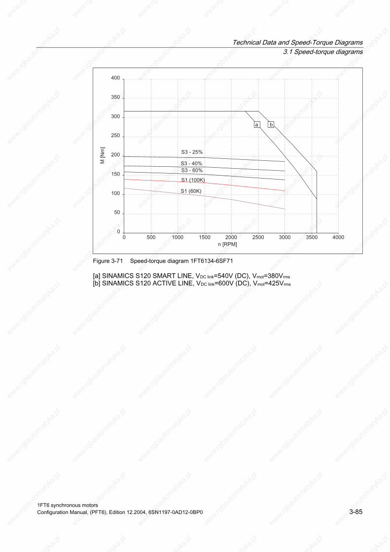
Technical Data and Speed-Torque Diagrams 3.1 Speed-torque diagrams
Figure 3-71 Speed-torque diagram 1FT6134-6SF71
[a] SINAMICS S120 SMART LINE, VDC link=540V (DC), Vmot=380Vrms [b] SINAMICS S120 ACTIVE LINE, VDC link=600V (DC), Vmot=425Vrms
1FT6 synchronous motors Configuration Manual, (PFT6), Edition 12.2004, 6SN1197-0AD12-0BP0 3-85

Technical Data and Speed-Torque Diagrams 3.1 Speed-torque diagrams
Table 3-43 1FT6136 force ventilated
1FT6136 Technical data Code Units -6SB71 -6SC71 Engineering data Rated speed No. of poles Rated torque (100K) Rated current (100K) Stall torque (60K) Stall torque (100K) Stall current (60K) Stall current (100K) Moment of inertia (with brake) Moment of inertia (without brake)
nN 2p MN(100K) IN (100K) M0 (60K) M0 (100K) I0 (60K) I0 (100K) Jmot Jmot
RPM Nm A Nm Nm A A 10–4 kgm2 10–4 kgm2
1500 6 160 55 145 175 45 55 742 664
2000 6 155 72 145 175 62 77 742 664
Optimum operating point Optimum speed Optimum power
nopt Popt
RPM kW
1500 25
2000 32
Limiting data Max. permissible speed (mech.) Max. torque Max. current
nmax Mmax Imax
RPM Nm A
3600 380 156
3600 380 219
Physical constants Torque constant Voltage constant
Rotating field inductance Electrical time constant Shaft torsional stiffness Mechanical time constant
Weight with brake Weight without brake
kT kE Rph LD Tel ct Tmech Tth m m
Nm/A V/1000 RPM Ohm mH ms Nm/rad ms min kg kg
3.17 204 0.1 3.8 43 214000 2.0 25 131 123
2.27 146 0.052 2.0 42 214000 2.0 25 131 123
Winding resistance at 20° C
Thermal time constant
1FT6 synchronous motors 3-86 Configuration Manual, (PFT6), Edition 12.2004, 6SN1197-0AD12-0BP0
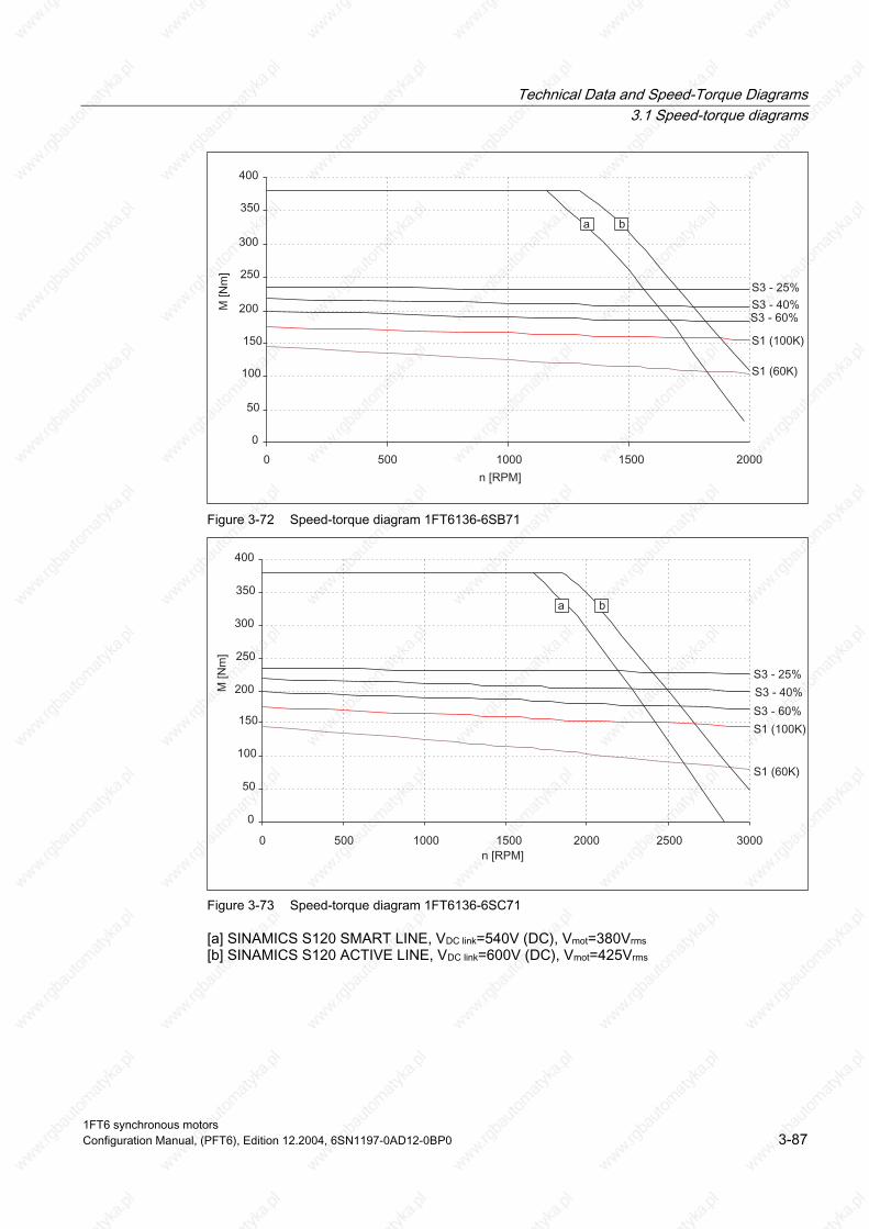
Technical Data and Speed-Torque Diagrams 3.1 Speed-torque diagrams
Figure 3-72 Speed-torque diagram 1FT6136-6SB71
Figure 3-73 Speed-torque diagram 1FT6136-6SC71
[a] SINAMICS S120 SMART LINE, VDC link=540V (DC), Vmot=380Vrms [b] SINAMICS S120 ACTIVE LINE, VDC link=600V (DC), Vmot=425Vrms
1FT6 synchronous motors Configuration Manual, (PFT6), Edition 12.2004, 6SN1197-0AD12-0BP0 3-87

Technical Data and Speed-Torque Diagrams 3.1 Speed-torque diagrams
Table 3-44 1FT6136 force ventilated
1FT6136 Technical data Code Units -6SF71 Engineering data Rated speed No. of poles Rated torque (100K) Rated current (100K) Stall torque (60K) Stall torque (100K) Stall current (60K) Stall current (100K) Moment of inertia (with brake) Moment of inertia (without brake)
nN 2p MN(100K) IN (100K) M0 (60K) M0 (100K) I0 (60K) I0 (100K) Jmot Jmot
RPM Nm A Nm Nm A A 10–4 kgm2 10–4 kgm2
3000 6 145 104 145 175 89 110 742 664
Optimum operating point Optimum speed Optimum power
nopt Popt
RPM kW
3000 46
Limiting data Max. permissible speed (mech.) Max. torque Max. current
nmax Mmax Imax
RPM Nm A
3600 380 313
Physical constants Torque constant Voltage constant
Rotating field inductance Electrical time constant Shaft torsional stiffness Mechanical time constant
Weight with brake Weight without brake
kT kE Rph LD Tel ct Tmech Tth m m
Nm/A V/1000 RPM Ohm mH ms Nm/rad ms min kg kg
1.59 102 0.025 0.96 44 214000 2.0 25 131 123
Winding resistance at 20° C
Thermal time constant
1FT6 synchronous motors 3-88 Configuration Manual, (PFT6), Edition 12.2004, 6SN1197-0AD12-0BP0
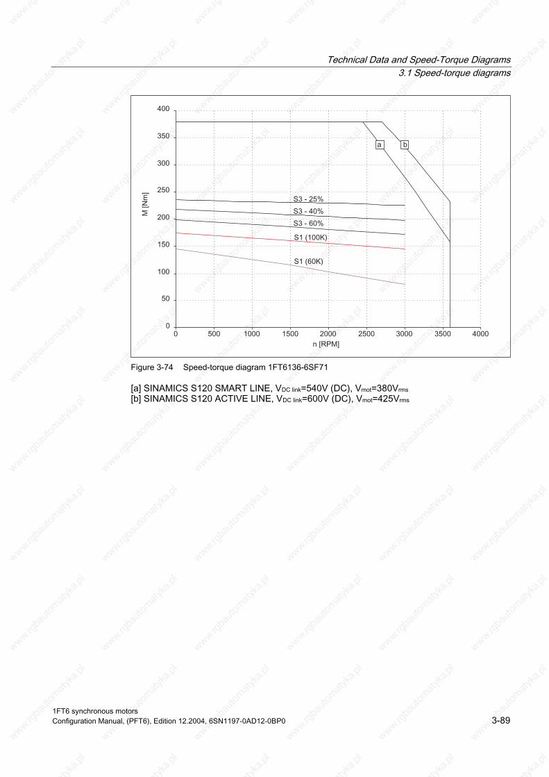
Technical Data and Speed-Torque Diagrams 3.1 Speed-torque diagrams
Figure 3-74 Speed-torque diagram 1FT6136-6SF71
[a] SINAMICS S120 SMART LINE, VDC link=540V (DC), Vmot=380Vrms [b] SINAMICS S120 ACTIVE LINE, VDC link=600V (DC), Vmot=425Vrms
1FT6 synchronous motors Configuration Manual, (PFT6), Edition 12.2004, 6SN1197-0AD12-0BP0 3-89

Technical Data and Speed-Torque Diagrams 3.1 Speed-torque diagrams
Table 3-45 1FT6163 force ventilated
1FT6163 Technical data Code Units -8SB7 -8SD7 Engineering data Rated speed No. of poles Rated torque (100K) Rated current (100K) Stall torque (60K) Stall torque (100K)1) Stall current (60K) Stall current (100K) Moment of inertia (with brake) Moment of inertia (without brake)
nN 2p MN(100K) IN (100K) M0 (60K) M0 (100K) I0 (60K) I0 (100K) Jmot Jmot
RPM Nm A Nm Nm A A 10–4 kgm2 10–4 kgm2
1500 8 385 136 360 425 124 151 –– 2300
2500 8 340 185 360 425 186 226 –– 2300
Optimum operating point Optimum speed Optimum power
nopt Popt
RPM kW
1500 60.5
2500 89.0
Limiting data Max. permissible speed (mech.) Max. torque Max. current 1)
nmax Mmax Imax
RPM Nm A
3100 900 372
3100 900 558
Physical constants Torque constant Voltage constant
Rotating field inductance Electrical time constant Shaft torsional stiffness Mechanical time constant
Weight with brake Weight without brake
kT kE Rph LD Tel ct Tmech Tth m m
Nm/A V/1000 RPM Ohm mH ms Nm/rad ms min kg kg
2.81 186 0.026 0.81 31 472100 2.3 25 –– 170
1.88 124 0.012 0.36 30 472100 2.3 25 –– 170
Winding resistance at 20° C
Thermal time constant
1) Observe the maximum and rated current of the drive converter
1FT6 synchronous motors 3-90 Configuration Manual, (PFT6), Edition 12.2004, 6SN1197-0AD12-0BP0
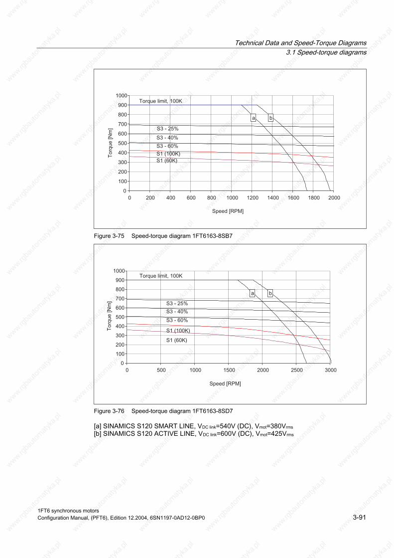
Technical Data and Speed-Torque Diagrams 3.1 Speed-torque diagrams
Figure 3-75 Speed-torque diagram 1FT6163-8SB7
Figure 3-76 Speed-torque diagram 1FT6163-8SD7
[a] SINAMICS S120 SMART LINE, VDC link=540V (DC), Vmot=380Vrms [b] SINAMICS S120 ACTIVE LINE, VDC link=600V (DC), Vmot=425Vrms
1FT6 synchronous motors Configuration Manual, (PFT6), Edition 12.2004, 6SN1197-0AD12-0BP0 3-91

Technical Data and Speed-Torque Diagrams 3.1 Speed-torque diagrams
Table 3-46 1FT6168 force ventilated
1FT6168 Technical data Code Units -8SB7 Engineering data Rated speed No. of poles Rated torque (100K) Rated current (100K) Stall torque (60K) Stall torque (100K) Stall current (60K) Stall current (100K) Moment of inertia (with brake) Moment of inertia (without brake)
nN 2p MN(100K) IN (100K) M0 (60K) M0 (100K) I0 (60K) I0 (100K) Jmot Jmot
RPM Nm A Nm Nm A A 10–4 kgm2 10–4 kgm2
1500 8 540 174 510 600 165 194 –– 3100
Optimum operating point Optimum speed Optimum power
nopt Popt
RPM kW
1500 85
Limiting data Max. permissible speed (mech.) Max. torque Max. current 1)
nmax Mmax Imax
RPM Nm A
3100 1200 479
Physical constants Torque constant Voltage constant
Rotating field inductance Electrical time constant Shaft torsional stiffness Mechanical time constant
Weight with brake Weight without brake
kT kE Rph LD Tel ct Tmech Tth m m
Nm/A V/1000 RPM Ohm mH ms Nm/rad ms min kg kg
3.09 203 0.02 0.69 35 431600 1.9 25 –– 210
Winding resistance at 20° C
Thermal time constant
1) Observe the maximum and rated current of the drive converter
1FT6 synchronous motors 3-92 Configuration Manual, (PFT6), Edition 12.2004, 6SN1197-0AD12-0BP0
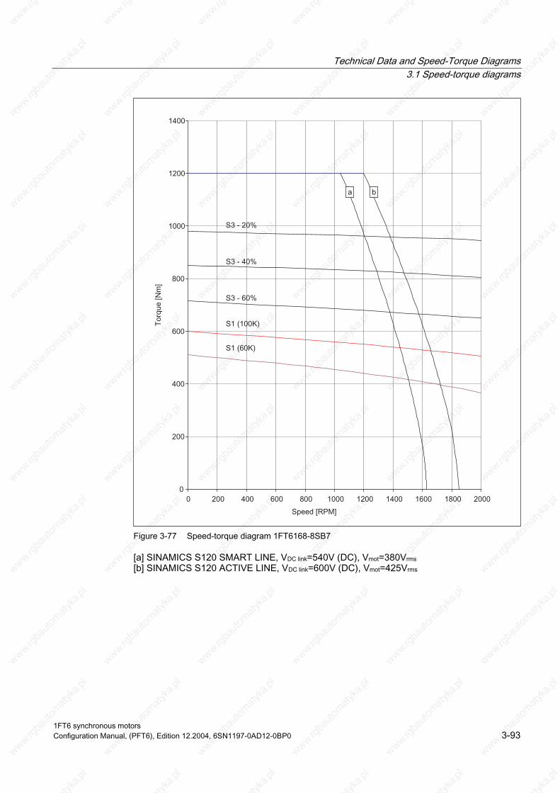
Technical Data and Speed-Torque Diagrams 3.1 Speed-torque diagrams
Figure 3-77 Speed-torque diagram 1FT6168-8SB7
[a] SINAMICS S120 SMART LINE, VDC link=540V (DC), Vmot=380Vrms [b] SINAMICS S120 ACTIVE LINE, VDC link=600V (DC), Vmot=425Vrms
1FT6 synchronous motors Configuration Manual, (PFT6), Edition 12.2004, 6SN1197-0AD12-0BP0 3-93

Technical Data and Speed-Torque Diagrams 3.1 Speed-torque diagrams
3.1.4 1FT6 series, water cooled
Table 3-47 1FT6062, water cooled
1FT6062 Technical data Code Unit -6WF7⃞ Engineering data Rated speed Pole number Rated torque (100K) Rated current (100K) Stall torque (60K) Stall torque (100K) Stall current (60K) Stall current (100K) Moment of inertia (with brake) Moment of inertia (without brake)
nN 2p MN(100K) IN (100K) M0 (60K) M0 (100K) I0 (60K) I0 (100K) Jmot Jmot
RPM Nm A Nm Nm A A 10–4 kgm2 10–4 kgm2
3000 6 10.1 6.9 8.5 10.2 5.6 6.9 11.8 8.5
Optimum operating point Optimum speed Optimum power
nopt Popt
RPM kW
3000 3.19
Limiting data Max. permissible speed (mech.) Max. torque Max. current
nmax Mmax Imax
RPM Nm A
9100 24 22
Physical constants Torque constant Voltage constant
Rotating field inductance Electrical time time constant Shaft torsional stiffness Mechanical time constant
Weight with brake Weight without brake
kT kE Rph LD Tel ct Tmech Tth m m
Nm/A V/1000 RPM Ohm mH ms Nm/rad ms min kg kg
1.48 94 2.57 19 7.4 32000 3.0 1.5 11 9.5
Winding resistance at 20° C
Thermal time constant
1FT6 synchronous motors 3-94 Configuration Manual, (PFT6), Edition 12.2004, 6SN1197-0AD12-0BP0
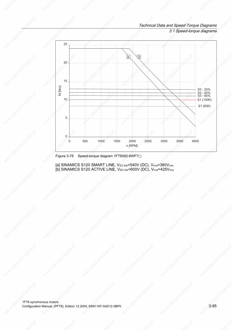
Technical Data and Speed-Torque Diagrams 3.1 Speed-torque diagrams
Figure 3-78 Speed-torque diagram 1FT6062-6WF7⃞
[a] SINAMICS S120 SMART LINE, VDC link=540V (DC), Vmot=380Vrms [b] SINAMICS S120 ACTIVE LINE, VDC link=600V (DC), Vmot=425Vrms
1FT6 synchronous motors Configuration Manual, (PFT6), Edition 12.2004, 6SN1197-0AD12-0BP0 3-95

Technical Data and Speed-Torque Diagrams 3.1 Speed-torque diagrams
Table 3-48 1FT6062, water cooled
1FT6062 Technical data Code Unit -6WH7⃞ -6WK7⃞ Engineering data Rated speed Pole number Rated torque (100K) Rated current (100K) Stall torque (60K) Stall torque (100K) Stall current (60K) Stall current (100K) Moment of inertia (with brake) Moment of inertia (without brake)
nN 2p MN(100K) IN (100K) M0 (60K) M0 (100K) I0 (60K) I0 (100K) Jmot Jmot
RPM Nm A Nm Nm A A 10–4 kgm2 10–4 kgm2
4500 6 10 9.6 8.5 10.2 7.9 9.7 11.8 8.5
6000 6 9.8 12.7 8.5 10.2 10.6 12.9 11.8 8.5
Optimum operating point Optimum speed Optimum power
nopt Popt
RPM kW
4500 4.71
6000 6.16
Limiting data Max. permissible speed (mech.) Max. torque Max. current
nmax Mmax Imax
RPM Nm A
9100 24 31
9100 24 41
Physical constants Torque constant Voltage constant
Rotating field inductance Electrical time time constant Shaft torsional stiffness Mechanical time constant
Weight with brake Weight without brake
kT kE Rph LD Tel ct Tmech Tth m m
Nm/A V/1000 RPM Ohm mH ms Nm/rad ms min kg kg
1.05 67 1.31 9.7 7.4 32000 3.0 1.5 11 9.5
0.79 50 0.74 5.5 7.4 32000 3.0 1.5 11 9.5
Winding resistance at 20° C
Thermal time constant
1FT6 synchronous motors 3-96 Configuration Manual, (PFT6), Edition 12.2004, 6SN1197-0AD12-0BP0

Technical Data and Speed-Torque Diagrams 3.1 Speed-torque diagrams
Figure 3-79 Speed-torque diagram 1FT6062-6WH7⃞
Figure 3-80 Speed-torque diagram 1FT6062-6WK7⃞
[a] SINAMICS S120 SMART LINE, VDC link=540V (DC), Vmot=380Vrms [b] SINAMICS S120 ACTIVE LINE, VDC link=600V (DC), Vmot=425Vrms
1FT6 synchronous motors Configuration Manual, (PFT6), Edition 12.2004, 6SN1197-0AD12-0BP0 3-97

Technical Data and Speed-Torque Diagrams 3.1 Speed-torque diagrams
Table 3-49 1FT6064, water cooled
1FT6064 Technical data Code Unit -6WF7⃞ Engineering data Rated speed Pole number Rated torque (100K) Rated current (100K) Stall torque (60K) Stall torque (100K) Stall current (60K) Stall current (100K) Moment of inertia (with brake) Moment of inertia (without brake)
nN 2p MN(100K) IN (100K) M0 (60K) M0 (100K) I0 (60K) I0 (100K) Jmot Jmot
RPM Nm A Nm Nm A A 10–4 kgm2 10–4 kgm2
3000 6 16.1 10.3 13.4 16.2 8.4 10.3 16.3 13
Optimum operating point Optimum speed Optimum power
nopt Popt
RPM kW
3000 5.06
Limiting data Max. permissible speed (mech.) Max. torque Max. current
nmax Mmax Imax
RPM Nm A
9100 38 33
Physical constants Torque constant Voltage constant
Rotating field inductance Electrical time time constant Shaft torsional stiffness Mechanical time constant
Weight with brake Weight without brake
kT kE Rph LD Tel ct Tmech Tth m m
Nm/A V/1000 RPM Ohm mH ms Nm/rad ms min kg kg
1.57 100 1.40 13.5 9.6 27000 2.2 1.5 13 12.5
Winding resistance at 20° C
Thermal time constant
1FT6 synchronous motors 3-98 Configuration Manual, (PFT6), Edition 12.2004, 6SN1197-0AD12-0BP0

Technical Data and Speed-Torque Diagrams 3.1 Speed-torque diagrams
Figure 3-81 Speed-torque diagram 1FT6064-6WF7⃞
[a] SINAMICS S120 SMART LINE, VDC link=540V (DC), Vmot=380Vrms [b] SINAMICS S120 ACTIVE LINE, VDC link=600V (DC), Vmot=425Vrms
1FT6 synchronous motors Configuration Manual, (PFT6), Edition 12.2004, 6SN1197-0AD12-0BP0 3-99

Technical Data and Speed-Torque Diagrams 3.1 Speed-torque diagrams
Table 3-50 1FT6064, water cooled
1FT6064 Technical data Code Unit -6WH7⃞ -6WK7⃞ Engineering data Rated speed Pole number Rated torque (100K) Rated current (100K) Stall torque (60K) Stall torque (100K) Stall current (60K) Stall current (100K) Moment of inertia (with brake) Moment of inertia (without brake)
nN 2p MN(100K) IN (100K) M0 (60K) M0 (100K) I0 (60K) I0 (100K) Jmot Jmot
RPM Nm A Nm Nm A A 10–4 kgm2 10–4 kgm2
4500 6 16 15.2 13.4 16.2 12.5 15.4 16.3 13
6000 6 15.8 20 13.4 16.2 16.7 20.5 16.3 13
Optimum operating point Optimum speed Optimum power
nopt Popt
RPM kW
4500 7.54
6000 9.93
Limiting data Max. permissible speed (mech.) Max. torque Max. current
nmax Mmax Imax
RPM Nm A
9100 38 49
9100 38 66
Physical constants Torque constant Voltage constant
Rotating field inductance Electrical time time constant Shaft torsional stiffness Mechanical time constant
Weight with brake Weight without brake
kT kE Rph LD Tel ct Tmech Tth m m
Nm/A V/1000 RPM Ohm mH ms Nm/rad ms min kg kg
1.05 67 0.63 6 9.5 27000 2.2 1.5 13 12.5
0.79 50 0.35 3.4 9.7 27000 2.2 1.5 13 12.5
Winding resistance at 20° C
Thermal time constant
1FT6 synchronous motors 3-100 Configuration Manual, (PFT6), Edition 12.2004, 6SN1197-0AD12-0BP0

Technical Data and Speed-Torque Diagrams 3.1 Speed-torque diagrams
Figure 3-82 Speed-torque diagram 1FT6064-6WH7⃞
Figure 3-83 Speed-torque diagram 1FT6064-6WK7⃞
[a] SINAMICS S120 SMART LINE, VDC link=540V (DC), Vmot=380Vrms [b] SINAMICS S120 ACTIVE LINE, VDC link=600V (DC), Vmot=425Vrms
1FT6 synchronous motors Configuration Manual, (PFT6), Edition 12.2004, 6SN1197-0AD12-0BP0 3-101

Technical Data and Speed-Torque Diagrams 3.1 Speed-torque diagrams
Table 3-51 1FT6084, water cooled
1FT6084 Technical data Code Unit -8WF7⃞ Engineering data Rated speed Pole number Rated torque (100K) Rated current (100K) Stall torque (60K) Stall torque (100K) Stall current (60K) Stall current (100K) Moment of inertia (with brake) Moment of inertia (without brake)
nN 2p MN(100K) IN (100K) M0 (60K) M0 (100K) I0 (60K) I0 (100K) Jmot Jmot
RPM Nm A Nm Nm A A 10–4 kgm2 10–4 kgm2
3000 8 35 27 29 35 19.9 24.5 61.1 48
Optimum operating point Optimum speed Optimum power
nopt Popt
RPM kW
3000 11.0
Limiting data Max. permissible speed (mech.) Max. torque Max. current
nmax Mmax Imax
RPM Nm A
7900 65 59
Physical constants Torque constant Voltage constant
Rotating field inductance Electrical time time constant Shaft torsional stiffness Mechanical time constant
Weight with brake Weight without brake
kT kE Rph LD Tel ct Tmech Tth m m
Nm/A V/1000 RPM Ohm mH ms Nm/rad ms min kg kg
1.43 91 0.37 4.3 11.6 76000 2.6 1.5 24.5 21
Winding resistance at 20° C
Thermal time constant
1FT6 synchronous motors 3-102 Configuration Manual, (PFT6), Edition 12.2004, 6SN1197-0AD12-0BP0

Technical Data and Speed-Torque Diagrams 3.1 Speed-torque diagrams
Figure 3-84 Speed-torque diagram 1FT6084-8WF7⃞
[a] SINAMICS S120 SMART LINE, VDC link=540V (DC), Vmot=380Vrms [b] SINAMICS S120 ACTIVE LINE, VDC link=600V (DC), Vmot=425Vrms
1FT6 synchronous motors Configuration Manual, (PFT6), Edition 12.2004, 6SN1197-0AD12-0BP0 3-103

Technical Data and Speed-Torque Diagrams 3.1 Speed-torque diagrams
Table 3-52 1FT6084, water cooled
1FT6084 Technical data Code Unit -8WH7⃞ -8WK7⃞ Engineering data Rated speed Pole number Rated torque (100K) Rated current (100K) Stall torque (60K) Stall torque (100K) Stall current (60K) Stall current (100K) Moment of inertia (with brake) Moment of inertia (without brake)
nN 2p MN(100K) IN (100K) M0 (60K) M0 (100K) I0 (60K) I0 (100K) Jmot Jmot
RPM Nm A Nm Nm A A 10–4 kgm2 10–4 kgm2
4500 8 35 39 29 35 30 37 61.1 48
6000 8 34 51 29 35 38 47 61.1 48
Optimum operating point Optimum speed Optimum power
nopt Popt
RPM kW
4500 16.5
6000 21.4
Limiting data Max. permissible speed (mech.) Max. torque Max. current
nmax Mmax Imax
RPM Nm A
7900 65 90
7900 65 112
Physical constants Torque constant Voltage constant
Rotating field inductance Electrical time time constant Shaft torsional stiffness Mechanical time constant
Weight with brake Weight without brake
kT kE Rph LD Tel ct Tmech Tth m m
Nm/A V/1000 RPM Ohm mH ms Nm/rad ms min kg kg
0.96 61 0.17 1.9 11.2 76000 2.7 1.5 24 21
0.74 47 0.1 1.2 12.0 76000 2.6 1.5 26 21
Winding resistance at 20° C
Thermal time constant
1FT6 synchronous motors 3-104 Configuration Manual, (PFT6), Edition 12.2004, 6SN1197-0AD12-0BP0

Technical Data and Speed-Torque Diagrams 3.1 Speed-torque diagrams
Figure 3-85 Speed-torque diagram 1FT6084-8WH71
Figure 3-86 Speed-torque diagram 1FT6084-8WK71
[a] SINAMICS S120 SMART LINE, VDC link=540V (DC), Vmot=380Vrms [b] SINAMICS S120 ACTIVE LINE, VDC link=600V (DC), Vmot=425Vrms
1FT6 synchronous motors Configuration Manual, (PFT6), Edition 12.2004, 6SN1197-0AD12-0BP0 3-105
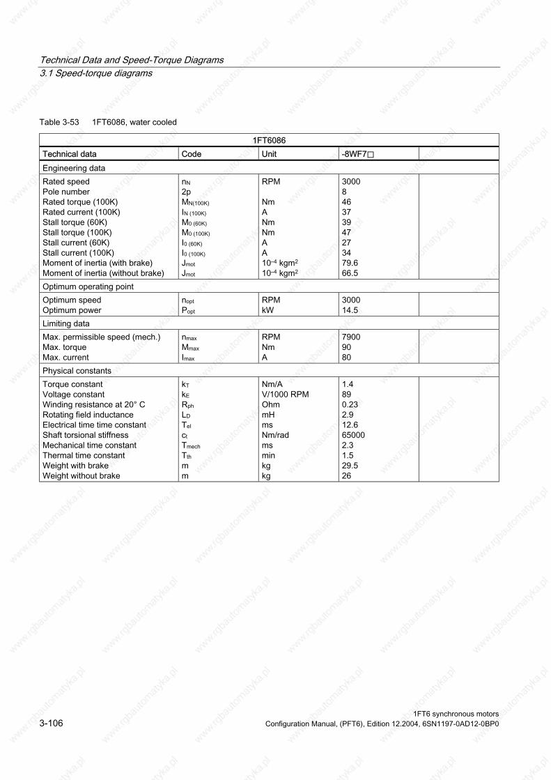
Technical Data and Speed-Torque Diagrams 3.1 Speed-torque diagrams
Table 3-53 1FT6086, water cooled
1FT6086 Technical data Code Unit -8WF7⃞ Engineering data Rated speed Pole number Rated torque (100K) Rated current (100K) Stall torque (60K) Stall torque (100K) Stall current (60K) Stall current (100K) Moment of inertia (with brake) Moment of inertia (without brake)
nN 2p MN(100K) IN (100K) M0 (60K) M0 (100K) I0 (60K) I0 (100K) Jmot Jmot
RPM Nm A Nm Nm A A 10–4 kgm2 10–4 kgm2
3000 8 46 37 39 47 27 34 79.6 66.5
Optimum operating point Optimum speed Optimum power
nopt Popt
RPM kW
3000 14.5
Limiting data Max. permissible speed (mech.) Max. torque Max. current
nmax Mmax Imax
RPM Nm A
7900 90 80
Physical constants Torque constant Voltage constant
Rotating field inductance Electrical time time constant Shaft torsional stiffness Mechanical time constant
Weight with brake Weight without brake
kT kE Rph LD Tel ct Tmech Tth m m
Nm/A V/1000 RPM Ohm mH ms Nm/rad ms min kg kg
1.4 89 0.23 2.9 12.6 65000 2.3 1.5 29.5 26
Winding resistance at 20° C
Thermal time constant
1FT6 synchronous motors 3-106 Configuration Manual, (PFT6), Edition 12.2004, 6SN1197-0AD12-0BP0
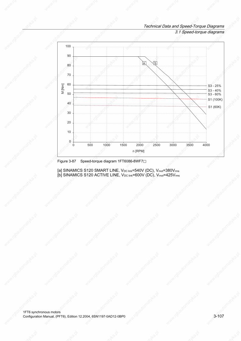
Technical Data and Speed-Torque Diagrams 3.1 Speed-torque diagrams
Figure 3-87 Speed-torque diagram 1FT6086-8WF7⃞
[a] SINAMICS S120 SMART LINE, VDC link=540V (DC), Vmot=380Vrms [b] SINAMICS S120 ACTIVE LINE, VDC link=600V (DC), Vmot=425Vrms
1FT6 synchronous motors Configuration Manual, (PFT6), Edition 12.2004, 6SN1197-0AD12-0BP0 3-107

Technical Data and Speed-Torque Diagrams 3.1 Speed-torque diagrams
Table 3-54 1FT6086, water cooled
1FT6086 Technical data Code Unit -8WH7⃞ -8WK7⃞ Engineering data Rated speed Pole number Rated torque (100K) Rated current (100K) Stall torque (60K) Stall torque (100K) Stall current (60K) Stall current (100K) Moment of inertia (with brake) Moment of inertia (without brake)
nN 2p MN(100K) IN (100K) M0 (60K) M0 (100K) I0 (60K) I0 (100K) Jmot Jmot
RPM Nm A Nm Nm A A 10–4 kgm2 10–4 kgm2
4500 1) 8 45 1) 53 1) 39 47 42 52.0 79.6 66.5
6000 8 44 58 39 47 48 59 79.6 66.5
Optimum operating point Optimum speed Optimum power
nopt Popt
RPM kW
4500 21.2
6000 27.6
Limiting data Max. permissible speed (mech.) Max. torque Max. current
nmax Mmax Imax
RPM Nm A
7900 90 122
7900 90 141
Physical constants Torque constant Voltage constant
Rotating field inductance Electrical time time constant Shaft torsional stiffness Mechanical time constant
Weight with brake Weight without brake
kT kE Rph LD Tel ct Tmech Tth m m
Nm/A V/1000 RPM Ohm mH ms Nm/rad ms min kg kg
0.91 58 0.096 1.3 13.5 65000 2.3 1.5 29.5 26
0.80 51 0.072 0.95 13.2 65000 2.2 1.5 29.5 26
Winding resistance at 20° C
Thermal time constant
1FT6 synchronous motors 3-108 Configuration Manual, (PFT6), Edition 12.2004, 6SN1197-0AD12-0BP0

Technical Data and Speed-Torque Diagrams 3.1 Speed-torque diagrams
Figure 3-88 Speed-torque diagram 1FT6086-8WH7⃞
Figure 3-89 Speed-torque diagram 1FT6086-8WK7⃞
[a] SINAMICS S120 SMART LINE, VDC link=540V (DC), Vmot=380Vrms [b] SINAMICS S120 ACTIVE LINE, VDC link=600V (DC), Vmot=425Vrms
1FT6 synchronous motors Configuration Manual, (PFT6), Edition 12.2004, 6SN1197-0AD12-0BP0 3-109

Technical Data and Speed-Torque Diagrams 3.1 Speed-torque diagrams
Table 3-55 1FT6105, water cooled
1FT6105 Technical data Code Unit -8WC7⃞ -8WF7⃞ Engineering data Rated speed Pole number Rated torque (100K) Rated current (100K) Stall torque (60K) Stall torque (100K) Stall current (60K) Stall current (100K) Moment of inertia (with brake) Moment of inertia (without brake)
nN 2p MN(100K) IN (100K) M0 (60K) M0 (100K) I0 (60K) I0 (100K) Jmot Jmot
RPM Nm A Nm Nm A A 10–4 kgm2 10–4 kgm2
2000 8 82 60 70 85 47 58 199 168
3000 8 78 82 70 85 67 83 199 168
Optimum operating point Optimum speed Optimum power
nopt Popt
RPM kW
2000 17.2
3000 24.5
Limiting data Max. permissible speed (mech.) Max. torque Max. current
nmax Mmax Imax
RPM Nm A
5600 140 155
5600 140 221
Physical constants Torque constant Voltage constant
Rotating field inductance Electrical time time constant Shaft torsional stiffness Mechanical time constant
Weight with brake Weight without brake
kT kE Rph LD Tel ct Tmech Tth m m
Nm/A V/1000 RPM Ohm mH ms Nm/rad ms min kg kg
1.45 99 0.098 2.1 21 113000 2.3 1.5 50 45.5
1.02 70 0.048 1.0 21 113000 2.3 1.5 50 45.5
Winding resistance at 20° C
Thermal time constant
1FT6 synchronous motors 3-110 Configuration Manual, (PFT6), Edition 12.2004, 6SN1197-0AD12-0BP0

Technical Data and Speed-Torque Diagrams 3.1 Speed-torque diagrams
Figure 3-90 Speed-torque diagram 1FT6105-8WC7⃞
Figure 3-91 Speed-torque diagram 1FT6105-8WF7⃞
[a] SINAMICS S120 SMART LINE, VDC link=540V (DC), Vmot=380Vrms [b] SINAMICS S120 ACTIVE LINE, VDC link=600V (DC), Vmot=425Vrms
1FT6 synchronous motors Configuration Manual, (PFT6), Edition 12.2004, 6SN1197-0AD12-0BP0 3-111

Technical Data and Speed-Torque Diagrams 3.1 Speed-torque diagrams
Table 3-56 1FT6108, water cooled
1FT6108 Technical data Code Unit -8WB7 -8WC7 Engineering data Rated speed Pole number Rated torque (100K) Rated current (100K) Stall torque (60K) Stall torque (100K) Stall current (60K) Stall current (100K) Moment of inertia (with brake) Moment of inertia (without brake)
nN 2p MN(100K) IN (100K) M0 (60K) M0 (100K) I0 (60K) I0 (100K) Jmot Jmot
RPM Nm A Nm Nm A A 10–4 kgm2 10–4 kgm2
1500 8 116 43 98 119 35 43 291 260
2000 8 115 57 98 119 46 57 291 260
Optimum operating point Optimum speed Optimum power
nopt Popt
RPM kW
1500 18.2
2000 24.1
Limiting data Max. permissible speed (mech.) Max. torque Max. current
nmax Mmax Imax
RPM Nm A
5600 220 116
5600 220 154
Physical constants Torque constant Voltage constant
Rotating field inductance Electrical time time constant Shaft torsional stiffness Mechanical time constant
Weight with brake Weight without brake
kT kE Rph LD Tel ct Tmech Tth m m
Nm/A V/1000 RPM Ohm mH ms Nm/rad ms min kg kg
2.76 185 0.19 4.4 23 92000 1.9 1.5 66 61.5
2.07 139 0.11 2.5 23 92000 2.0 1.5 66 61.5
Winding resistance at 20° C
Thermal time constant
1FT6 synchronous motors 3-112 Configuration Manual, (PFT6), Edition 12.2004, 6SN1197-0AD12-0BP0

Technical Data and Speed-Torque Diagrams 3.1 Speed-torque diagrams
Figure 3-92 Speed-torque diagram 1FT6108-8WB7⃞
Figure 3-93 Speed-torque diagram 1FT6108-8WC7⃞
[a] SINAMICS S120 SMART LINE, VDC link=540V (DC), Vmot=380Vrms [b] SINAMICS S120 ACTIVE LINE, VDC link=600V (DC), Vmot=425Vrms
1FT6 synchronous motors Configuration Manual, (PFT6), Edition 12.2004, 6SN1197-0AD12-0BP0 3-113

Technical Data and Speed-Torque Diagrams 3.1 Speed-torque diagrams
Table 3-57 1FT6108, water cooled
1FT6108 Technical data Code Unit -8WF7⃞ Configuring data Rated speed Pole number Rated torque (100K) Rated current (100K) Stall torque (60K) Stall torque (100K) Stall current (60K) Stall current (100K) Moment of inertia (with brake) Moment of inertia (without brake)
nN 2p MN(100K) IN (100K) M0 (60K) M0 (100K) I0 (60K) I0 (100K) Jmot Jmot
RPM Nm A Nm Nm A A 10–4 kgm2 10–4 kgm2
3000 8 109 81 98 119 70 86 291 260
Optimum operating point Optimum speed Optimum power
nopt Popt
RPM kW
3000 34
Limiting data Max. permissible speed (mech.) Max. torque Max. current
nmax Mmax Imax
RPM Nm A
5600 220 231
Physical constants Torque constant Voltage constant
Rotating field inductance Electrical time time constant Shaft torsional stiffness Mechanical time constant
Weight with brake Weight without brake
Winding resistance at 20° C
Thermal time constant
kT kE Rph LD Tel ct Tmech Tth m m
Nm/A V/1000 RPM Ohm mH ms Nm/rad ms min kg kg
1.38 92 0.048 1.1 23 92000 2.0 1.5 66 61.5
1FT6 synchronous motors 3-114 Configuration Manual, (PFT6), Edition 12.2004, 6SN1197-0AD12-0BP0

Technical Data and Speed-Torque Diagrams 3.1 Speed-torque diagrams
Figure 3-94 Speed-torque diagram 1FT6108-8WF7⃞
[a] SINAMICS S120 SMART LINE, VDC link=540V (DC), Vmot=380Vrms [b] SINAMICS S120 ACTIVE LINE, VDC link=600V (DC), Vmot=425Vrms
1FT6 synchronous motors Configuration Manual, (PFT6), Edition 12.2004, 6SN1197-0AD12-0BP0 3-115

Technical Data and Speed-Torque Diagrams 3.1 Speed-torque diagrams
Table 3-58 1FT6132, water cooled
1FT6132 Technical data Code Unit -6WB7⃞ -6WD7⃞ Configuring data Rated speed Pole number Rated torque (100K) Rated current (100K) Stall torque (60K) Stall torque (100K) Stall current (60K) Stall current (100K) Moment of inertia (with brake) Moment of inertia (without brake)
nN 2p MN(100K) IN (100K) M0 (60K) M0 (100K) I0 (60K) I0 (100K) Jmot Jmot
RPM Nm A Nm Nm A A 10–4 kgm2 10–4 kgm2
1500 6 150 58 120 155 45 58 –– 430
2500 6 148 82 120 155 71 92 –– 430
Optimum operating point Optimum speed Optimum power
RPM kW
1500 23.6
2500 35.3
Limiting data Max. permissible speed (mech.) Max. torque Max. current
nmax Mmax Imax
RPM Nm A
3600 250 124.5
3600 250 197
Physical constants Torque constant Voltage constant
Rotating field inductance Electrical time time constant Shaft torsional stiffness Mechanical time constant
Weight with brake Weight without brake
kT kE Rph LD Tel ct Tmech Tth m m
Nm/A V/1000 RPM Ohm mH ms Nm/rad ms min kg kg
2.67 177 0.15 4.5 30 262300 2.7 6 –– 90
1.68 112 0.057 1.8 32 262300 2.6 6 –– 90
nopt Popt
Winding resistance at 20° C
Thermal time constant
1FT6 synchronous motors 3-116 Configuration Manual, (PFT6), Edition 12.2004, 6SN1197-0AD12-0BP0
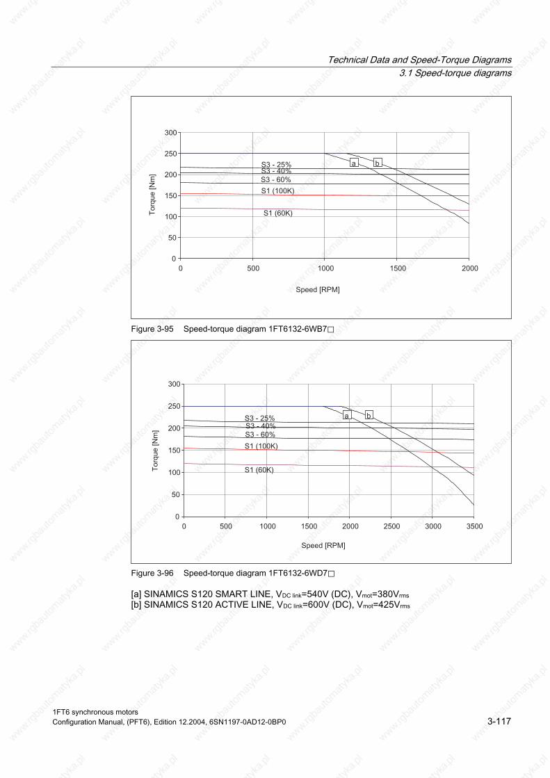
Technical Data and Speed-Torque Diagrams 3.1 Speed-torque diagrams
Figure 3-95 Speed-torque diagram 1FT6132-6WB7⃞
Figure 3-96 Speed-torque diagram 1FT6132-6WD7⃞
[a] SINAMICS S120 SMART LINE, VDC link=540V (DC), Vmot=380Vrms [b] SINAMICS S120 ACTIVE LINE, VDC link=600V (DC), Vmot=425Vrms
1FT6 synchronous motors Configuration Manual, (PFT6), Edition 12.2004, 6SN1197-0AD12-0BP0 3-117

Technical Data and Speed-Torque Diagrams 3.1 Speed-torque diagrams
Table 3-59 1FT6134, water cooled
1FT6134 Technical data Code Unit -6WB7⃞ -6WD7⃞ Configuring data Rated speed Pole number Rated torque (100K) Rated current (100K) Stall torque (60K) Stall torque (100K) Stall current (60K) Stall current (100K) Moment of inertia (with brake) Moment of inertia (without brake)
nN 2p MN(100K) IN (100K) M0 (60K) M0 (100K) I0 (60K) I0 (100K) Jmot Jmot
RPM Nm A Nm Nm A A 10–4 kgm2 10–4 kgm2
1500 6 185 67 155 200 57 73 –– 547
2500 6 185 115 155 200 95 122 –– 547
Optimum operating point Optimum speed Optimum power
nopt Popt
RPM kW
1500 29
2500 48.4
Limiting data Max. permissible speed (mech.) Max. torque Max. current
nmax Mmax Imax
RPM Nm A
3600 320 158
3600 320 263
Physical constants Torque constant Voltage constant
Rotating field inductance Electrical time time constant Shaft torsional stiffness Mechanical time constant
Weight with brake Weight without brake
kT kE Rph LD Tel ct Tmech Tth m m
Nm/A V/1000 RPM Ohm mH ms Nm/rad ms min kg kg
2.74 180 0.105 3.6 34 237500 2.3 6 –– 103
1.64 108 0.038 1.3 34 237500 2.3 6 –– 103
Winding resistance at 20° C
Thermal time constant
1FT6 synchronous motors 3-118 Configuration Manual, (PFT6), Edition 12.2004, 6SN1197-0AD12-0BP0

Technical Data and Speed-Torque Diagrams 3.1 Speed-torque diagrams
Figure 3-97 Speed-torque diagram 1FT6134-6WB7⃞
Figure 3-98 Speed-torque diagram 1FT6134-6WD7⃞
[a] SINAMICS S120 SMART LINE, VDC link=540V (DC), Vmot=380Vrms [b] SINAMICS S120 ACTIVE LINE, VDC link=600V (DC), Vmot=425Vrms
1FT6 synchronous motors Configuration Manual, (PFT6), Edition 12.2004, 6SN1197-0AD12-0BP0 3-119

Technical Data and Speed-Torque Diagrams 3.1 Speed-torque diagrams
Table 3-60 1FT6136, water cooled
1FT6136 Technical data Code Unit -6WB7⃞ -6WD7⃞ Configuring data Rated speed Pole number Rated torque (100K) Rated current (100K) Stall torque (60K) Stall torque (100K) Stall current (60K) Stall current (100K) Moment of inertia (with brake) Moment of inertia (without brake)
nN 2p MN(100K) IN (100K) M0 (60K) M0 (100K) I0 (60K) I0 (100K) Jmot Jmot
RPM Nm A Nm Nm A A 10–4 kgm2 10–4 kgm2
1500 6 230 90 200 240 75 92 –– 664
2500 6 220 149 200 240 129 158 –– 664
Optimum operating point Optimum speed Optimum power
nopt Popt
RPM kW
1500 36.1
2500 57.6
Limiting data Max. permissible speed (mech.) Max. torque Max. current 1)
nmax Mmax Imax
RPM Nm A
3600 390 198
3600 390 339
Physical constants Torque constant Voltage constant
Rotating field inductance Electrical time time constant Shaft torsional stiffness Mechanical time constant
Weight with brake Weight without brake
kT kE Rph LD Tel ct Tmech Tth m m
Nm/A V/1000 RPM Ohm mH ms Nm/rad ms min kg kg
2.61 176 0.077 2.8 36 217000 2.3 6 –– 120
1.52 103 0.026 0.95 37 217000 2.2 6 –– 120
Winding resistance at 20° C
Thermal time constant
1) Observe the maximum and rated current of the drive converter
1FT6 synchronous motors 3-120 Configuration Manual, (PFT6), Edition 12.2004, 6SN1197-0AD12-0BP0

Technical Data and Speed-Torque Diagrams 3.1 Speed-torque diagrams
Figure 3-99 Speed-torque diagram 1FT6136-6WB7⃞
Figure 3-100 Speed-torque diagram 1FT6136-6WD7⃞
[a] SINAMICS S120 SMART LINE, VDC link=540V (DC), Vmot=380Vrms [b] SINAMICS S120 ACTIVE LINE, VDC link=600V (DC), Vmot=425Vrms
1FT6 synchronous motors Configuration Manual, (PFT6), Edition 12.2004, 6SN1197-0AD12-0BP0 3-121

Technical Data and Speed-Torque Diagrams 3.1 Speed-torque diagrams
Table 3-61 1FT6138, water cooled
1FT6138 Technical data Code Unit -6WB7⃞ -6WD7⃞ Configuring data Rated speed Pole number Rated torque (100K) Rated current (100K) Stall torque (60K) Stall torque (100K) Stall current (60K) Stall current (100K) Moment of inertia (with brake) Moment of inertia (without brake)
nN 2p MN(100K) IN (100K) M0 (60K) M0 (100K) I0 (60K) I0 (100K) Jmot Jmot
RPM Nm A Nm Nm A A 10–4 kgm2 10–4 kgm2
1500 6 290 112 232 300 87 112 –– 845
2500 6 275 162 232 300 129 167 –– 845
Optimum operating point Optimum speed Optimum power
nopt Popt
RPM kW
1500 45.5
2500 72
Limiting data Max. permissible speed (mech.) Max. torque Max. current 1)
nmax Mmax Imax
RPM Nm A
3600 500 263
3600 500 395
Physical constants Torque constant Voltage constant
Rotating field inductance Electrical time time constant Shaft torsional stiffness Mechanical time constant
Weight with brake Weight without brake
kT kE Rph LD Tel ct Tmech Tth m m
Nm/A V/1000 RPM Ohm mH ms Nm/rad ms min kg kg
2.68 168 0.052 2 38 192000 1.8 6 –– 137
1.80 112 0.023 0.87 38 192000 1.8 6 –– 137
Winding resistance at 20° C
Thermal time constant
1) Observe the maximum and rated current of the drive converter
1FT6 synchronous motors 3-122 Configuration Manual, (PFT6), Edition 12.2004, 6SN1197-0AD12-0BP0
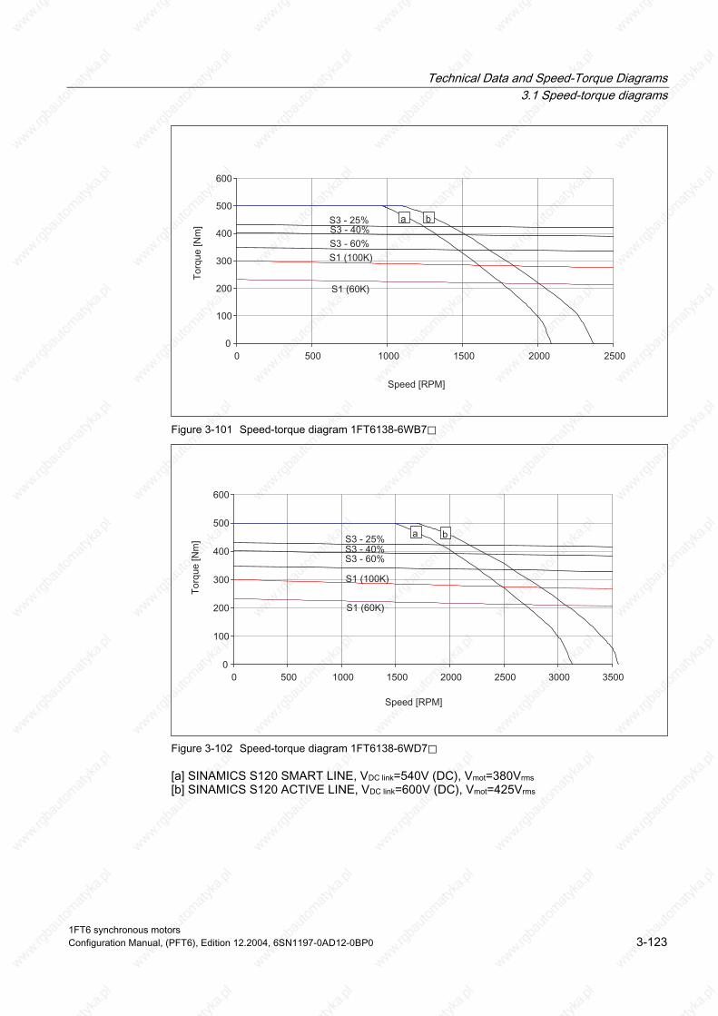
Technical Data and Speed-Torque Diagrams 3.1 Speed-torque diagrams
Figure 3-101 Speed-torque diagram 1FT6138-6WB7⃞
Figure 3-102 Speed-torque diagram 1FT6138-6WD7⃞
[a] SINAMICS S120 SMART LINE, VDC link=540V (DC), Vmot=380Vrms [b] SINAMICS S120 ACTIVE LINE, VDC link=600V (DC), Vmot=425Vrms
1FT6 synchronous motors Configuration Manual, (PFT6), Edition 12.2004, 6SN1197-0AD12-0BP0 3-123
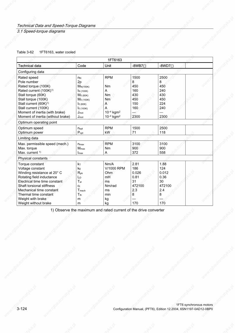
Technical Data and Speed-Torque Diagrams 3.1 Speed-torque diagrams
Table 3-62 1FT6163, water cooled
1FT6163 Technical data Code Unit -8WB7⃞ -8WD7⃞ Configuring data Rated speed Pole number Rated torque (100K) Rated current (100K)1) Stall torque (60K) Stall torque (100K)
Stall current (100K) Moment of inertia (with brake) Moment of inertia (without brake)
nN 2p MN(100K) IN (100K) M0 (60K) M0 (100K) I0 (60K) I0 (100K) Jmot Jmot
RPM Nm A Nm Nm A A 10–4 kgm2 10–4 kgm2
1500 8 450 160 430 450 150 160 –– 2300
2500 8 450 240 430 450 224 240 –– 2300
Optimum operating point Optimum speed Optimum power
nopt Popt
RPM kW
1500 71
2500 118
Limiting data Max. permissible speed (mech.) Max. torque Max. current 1)
nmax Mmax Imax
RPM Nm A
3100 900 372
3100 900 558
Physical constants Torque constant Voltage constant
Rotating field inductance Electrical time time constant Shaft torsional stiffness Mechanical time constant
Weight with brake Weight without brake
kT kE Rph LD Tel ct Tmech Tth m m
Nm/A V/1000 RPM Ohm mH ms Nm/rad ms min kg kg
2.81 186 0.026 0.81 31 472100 2.3 8 –– 170
1.88 124 0.012 0.36 30 472100 2.4 8 –– 170
Stall current (60K)1)
Winding resistance at 20° C
Thermal time constant
1) Observe the maximum and rated current of the drive converter
1FT6 synchronous motors 3-124 Configuration Manual, (PFT6), Edition 12.2004, 6SN1197-0AD12-0BP0

Technical Data and Speed-Torque Diagrams 3.1 Speed-torque diagrams
Figure 3-103 Speed-torque diagram 1FT6163-8WB7⃞
Figure 3-104 Speed-torque diagram 1FT6163-8WD7⃞
[a] SINAMICS S120 SMART LINE, VDC link=540V (DC), Vmot=380Vrms [b] SINAMICS S120 ACTIVE LINE, VDC link=600V (DC), Vmot=425Vrms
1FT6 synchronous motors Configuration Manual, (PFT6), Edition 12.2004, 6SN1197-0AD12-0BP0 3-125

Technical Data and Speed-Torque Diagrams 3.1 Speed-torque diagrams
Table 3-63 1FT6168, water cooled
1FT6168 Technical data Code Unit -8WB7⃞ Configuring data Rated speed Pole number Rated torque (100K) Rated current (100K)1) Stall torque (60K) Stall torque (100K) Stall current (60K) Stall current (100K) Moment of inertia (with brake) Moment of inertia (without brake)
nN 2p MN(100K) IN (100K) M0 (60K) M0 (100K) I0 (60K) I0 (100K) Jmot Jmot
RPM Nm A Nm Nm A A 10–4 kgm2 10–4 kgm2
1500 8 690 221 600 700 193 225 –– 3100
Optimum operating point Optimum speed Optimum power
nopt Popt
RPM kW
1500 108
Limiting data Max. permissible speed (mech.) Max. torque Max. current 1)
nmax Mmax Imax
RPM Nm A
3100 1200 479
Physical constants Torque constant Voltage constant
Rotating field inductance Electrical time time constant Shaft torsional stiffness Mechanical time constant
Weight with brake Weight without brake
kT kE Rph LD Tel ct Tmech Tth m m
Nm/A V/1000 RPM Ohm mH ms Nm/rad ms min kg kg
3.11 203 0.02 0.69 35 431600 1.9 8 –– 210
Winding resistance at 20° C
Thermal time constant
1) Observe the maximum and rated current of the drive converter
1FT6 synchronous motors 3-126 Configuration Manual, (PFT6), Edition 12.2004, 6SN1197-0AD12-0BP0

Technical Data and Speed-Torque Diagrams 3.1 Speed-torque diagrams
Figure 3-105 Speed-torque diagram 1FT6168-8WB7⃞
[a] SINAMICS S120 SMART LINE, VDC link=540V (DC), Vmot=380Vrms [b] SINAMICS S120 ACTIVE LINE, VDC link=600V (DC), Vmot=425Vrms
1FT6 synchronous motors Configuration Manual, (PFT6), Edition 12.2004, 6SN1197-0AD12-0BP0 3-127
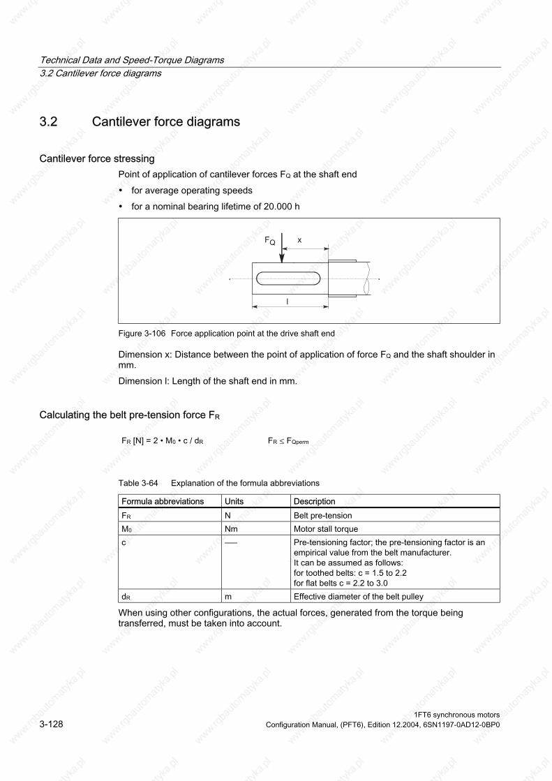
Technical Data and Speed-Torque Diagrams 3.2 Cantilever force diagrams
3.2 Cantilever force diagrams
Cantilever force stressing Point of application of cantilever forces FQ at the shaft end
• for average operating speeds
• for a nominal bearing lifetime of 20.000 h
Figure 3-106 Force application point at the drive shaft end
Dimension x: Distance between the point of application of force FQ and the shaft shoulder in mm.
Dimension l: Length of the shaft end in mm.
Calculating the belt pre-tension force FR
FR [N] = 2 • M0 • c / dR FR ≤ FQperm
Table 3-64 Explanation of the formula abbreviations
Formula abbreviations Units Description N Belt pre-tension
M0 Nm Motor stall torque c ––– Pre-tensioning factor; the pre-tensioning factor is an
empirical value from the belt manufacturer. It can be assumed as follows: for toothed belts: c = 1.5 to 2.2 for flat belts c = 2.2 to 3.0
dR m Effective diameter of the belt pulley
FR
When using other configurations, the actual forces, generated from the torque being transferred, must be taken into account.
1FT6 synchronous motors 3-128 Configuration Manual, (PFT6), Edition 12.2004, 6SN1197-0AD12-0BP0
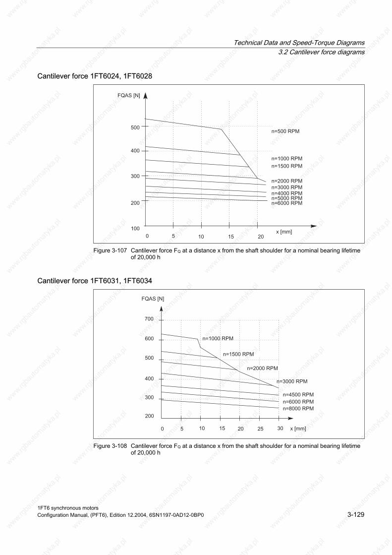
Technical Data and Speed-Torque Diagrams 3.2 Cantilever force diagrams
Cantilever force 1FT6024, 1FT6028
Figure 3-107 Cantilever force FQ at a distance x from the shaft shoulder for a nominal bearing lifetime
of 20,000 h
Cantilever force 1FT6031, 1FT6034
Figure 3-108 Cantilever force FQ at a distance x from the shaft shoulder for a nominal bearing lifetime
of 20,000 h
1FT6 synchronous motors Configuration Manual, (PFT6), Edition 12.2004, 6SN1197-0AD12-0BP0 3-129

Technical Data and Speed-Torque Diagrams 3.2 Cantilever force diagrams
Cantilever force 1FT6041, 1FT6044
Figure 3-109 Cantilever force FQ at a distance x from the shaft shoulder for a nominal bearing lifetime
of 20,000 h
Cantilever force 1FT6061, 1FT6062, 1FT6064
Figure 3-110 Cantilever force FQ at a distance x from the shaft shoulder for a nominal bearing lifetime
of 20,000 h
1FT6 synchronous motors 3-130 Configuration Manual, (PFT6), Edition 12.2004, 6SN1197-0AD12-0BP0
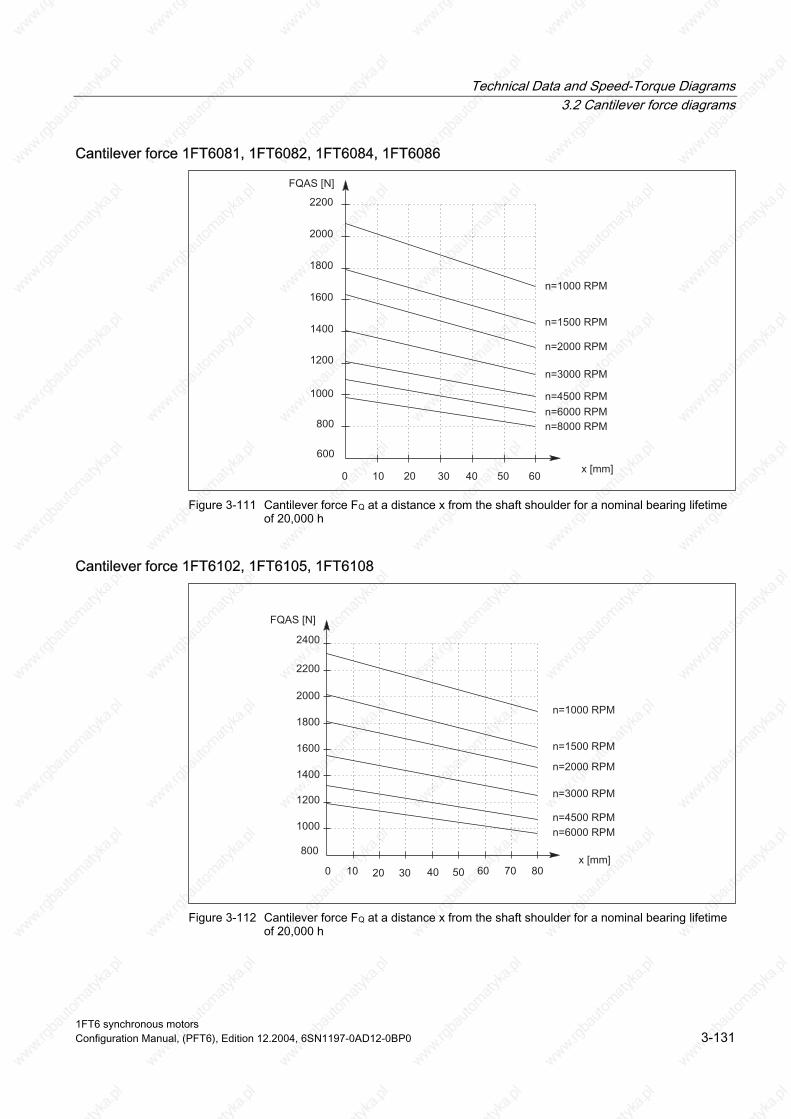
Technical Data and Speed-Torque Diagrams 3.2 Cantilever force diagrams
Cantilever force 1FT6081, 1FT6082, 1FT6084, 1FT6086
Figure 3-111 Cantilever force FQ at a distance x from the shaft shoulder for a nominal bearing lifetime
of 20,000 h
Cantilever force 1FT6102, 1FT6105, 1FT6108
Figure 3-112 Cantilever force FQ at a distance x from the shaft shoulder for a nominal bearing lifetime
of 20,000 h
1FT6 synchronous motors Configuration Manual, (PFT6), Edition 12.2004, 6SN1197-0AD12-0BP0 3-131

Technical Data and Speed-Torque Diagrams 3.2 Cantilever force diagrams
Cantilever force 1FT6132, 1FT6134, 1FT6136, 1FT6138
Figure 3-113 Cantilever force FQ at a distance x from the shaft shoulder for a nominal bearing lifetime
of 20,000 h
Cantilever force 1FT6163, 1FT6168
Figure 3-114 Cantilever force FQ at a distance x from the shaft shoulder for a nominal bearing lifetime
of 20,000 h
1FT6 synchronous motors 3-132 Configuration Manual, (PFT6), Edition 12.2004, 6SN1197-0AD12-0BP0

Technical Data and Speed-Torque Diagrams 3.3 Axial forces
3.3 Axial forces
Axial force stressing
Warning
Motors with integrated holding brake cannot be subject to axial forces!
When using, for example, helical toothed wheels as drive element, in addition to the radial force, there is also an axial force on the motor bearings. For axial forces, the spring-loading of the bearings can be overcome so that the rotor moves corresponding to the axial bearing play present (up to 0.2 mm).
The permissible axial force can be approximately calculated using the following formula:
FA = 0.35 • FQ
1FT6 synchronous motors Configuration Manual, (PFT6), Edition 12.2004, 6SN1197-0AD12-0BP0 3-133
Technical Data and Speed-Torque Diagrams 3.3 Axial forces
1FT6 synchronous motors 3-134 Configuration Manual, (PFT6), Edition 12.2004, 6SN1197-0AD12-0BP0

4 Motor Components (Options)
4.1 Thermal motor protection A temperature-dependent resistor is integrated as temperature sensor to monitor the motor temperature.
Table 4-1 Features and technical data
Type KTY 84 (PTC thermistor) Resistance when cold (20°C) approx. 580 Ohm Resistance when hot (100°C) approx. 1000 Ohm
via signal cable Response temperature Pre-warning at 120 °C ± 5 °C
Alarm/trip at 155 °C ± 5 °C
Connecting
The resistance of the KTY 84 thermistor changes proportionally to the winding temperature change.
The temperature signal is sensed and evaluated in the drive converter whose closed-loop control takes into account the temperature characteristic of the motor resistances.
When a fault occurs, an appropriate message is output at the drive converter. When the motor temperature increases, a message "Alarm motor overtemperature" is output; this must be externally evaluated. If this signal is not observed, the drive converter shuts down with the appropriate fault message when the motor limiting temperature or the shutdown temperature is exceeded.
Warning
If the user carries-out an additional high-voltage test, then the ends of the temperature sensor cables must be short-circuited before the test is carried-out!
If the test voltage is connected to a temperature sensor terminal, then it will be destroyed.
The polarity must be carefully observed.
The temperature sensor is designed so that the DIN/EN requirement for "protective separation" is fulfilled.
1FT6 synchronous motors Configuration Manual, (PFT6), Edition 12.2004, 6SN1197-0AD12-0BP0 4-1
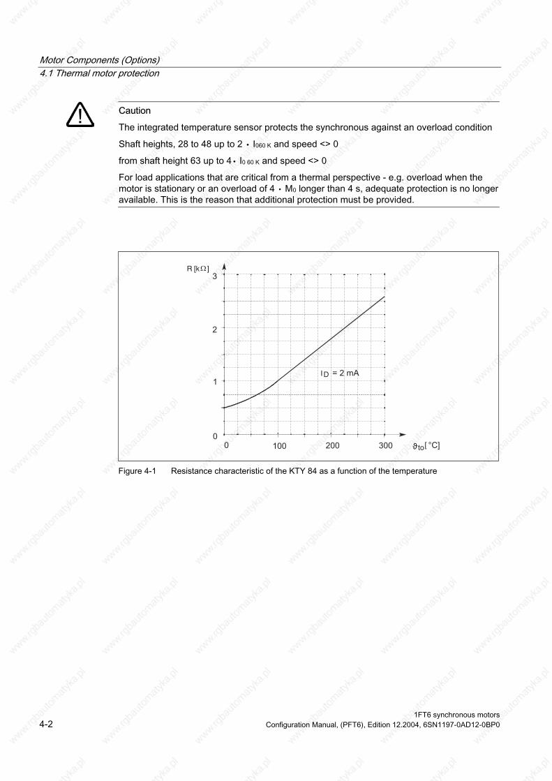
Motor Components (Options) 4.1 Thermal motor protection
Caution
The integrated temperature sensor protects the synchronous against an overload condition
For load applications that are critical from a thermal perspective - e.g. overload when the motor is stationary or an overload of 4 ∙ M0 longer than 4 s, adequate protection is no longer available. This is the reason that additional protection must be provided.
Shaft heights, 28 to 48 up to 2 ∙ I060 K and speed <> 0
from shaft height 63 up to 4∙ I0 60 K and speed <> 0
[
I
R [kΩ
Figure 4-1 Resistance characteristic of the KTY 84 as a function of the temperature
1FT6 synchronous motors 4-2 Configuration Manual, (PFT6), Edition 12.2004, 6SN1197-0AD12-0BP0

Motor Components (Options) 4.2 Encoders
4.2 Encoders
4.2.1 Encoder overview The encoder is selected with the appropriate letters in the motor Order No. (MLFB) at the 14th position.
Note
The letter code at the 14th position of the Order No. (MLFB) is different for motors with and without DRIVE-CLiQ.
Table 4-2 Encoders for motors with and without DRIVE-CLiQ
Motor types Incremental encoders
sin/cos 1 Vpp (for low shaft
heights) (I–2048)
Incremental encoders
sin/cos 1 Vpp (I–2048)
Absolute value encoders
EnDat (A–2048)
Absolute value encoders
EnDat (A-512)
Resolvers 2-pole/
multi-pole
Order No. (MLFB) 14th position for motors with DRIVE-CLiQ
D D F L U / P
Order No. (MLFB) 14th position for motors without DRIVE-CLiQ
A A E H S / T
1FT6 02⃞ X X X X X X
1FT6 04⃞ X X X 1FT6 06⃞ X X X 1FT6 08⃞ X X X 1FT6 10⃞ X X X 1FT6 13⃞ X X X 1FT6 16⃞ X X X
Notice
When the encoder is replaced, the position of the encoder system with respect to the motor EMF must be adjusted. Only qualified personnel may replace an encoder.
1FT6 03⃞
1FT6 synchronous motors Configuration Manual, (PFT6), Edition 12.2004, 6SN1197-0AD12-0BP0 4-3
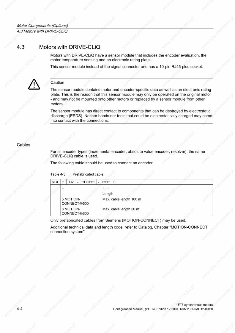
Motor Components (Options) 4.3 Motors with DRIVE-CLiQ
4.3 Motors with DRIVE-CLiQ Motors with DRIVE-CLiQ have a sensor module that includes the encoder evaluation, the motor temperature sensing and an electronic rating plate.
This sensor module instead of the signal connector and has a 10-pin RJ45-plus socket.
Caution
The sensor module contains motor and encoder-specific data as well as an electronic rating plate. This is the reason that this sensor module may only be operated on the original motor - and may not be mounted onto other motors or replaced by a sensor module from other motors.
The sensor module has direct contact to components that can be destroyed by electrostatic discharge (ESDS). Neither hands nor tools that could be electrostatically charged may come into contact with the connections.
Cables For all encoder types (incremental encoder, absolute value encoder, resolver), the same DRIVE-CLiQ cable is used.
The following cable should be used to connect an encoder:
Table 4-3 Prefabricated cable
6FX 002 - DC - 0
↓ ↓ 5 MOTION-CONNECT500 8 MOTION-CONNECT800
↓↓↓ Length Max. cable length 100 m Max. cable length 50 m
Only prefabricated cables from Siemens (MOTION-CONNECT) may be used.
Additional technical data and length code, refer to Catalog, Chapter "MOTION-CONNECT connection system"
1FT6 synchronous motors 4-4 Configuration Manual, (PFT6), Edition 12.2004, 6SN1197-0AD12-0BP0
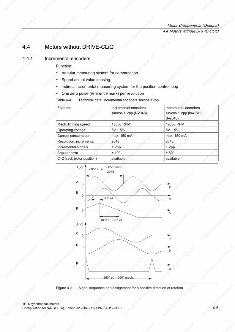
Motor Components (Options) 4.4 Motors without DRIVE-CLiQ
4.4 Motors without DRIVE-CLiQ
Features
4.4.1 Incremental encoders Function:
• Angular measuring system for commutation
• Speed actual value sensing
• Indirect incremental measuring system for the position control loop
• One zero pulse (reference mark) per revolution Table 4-4 Technical data, incremental encoders sin/cos 1Vpp
Incremental encoders sin/cos 1 Vpp (I–2048)
Incremental encoders sin/cos 1 Vpp (low SH) (I–2048)
Mech. limiting speed 15000 RPM 12000 RPM Operating voltage 5V ± 5% 5V ± 5% Current consumption max. 150 mA max. 150 mA Resolution, incremental 2048 2048 Incremental signals 1 Vpp 1 Vpp Angular error ± 40" ± 80" C–D track (rotor position) available available
Figure 4-2 Signal sequence and assignment for a positive direction of rotation
1FT6 synchronous motors Configuration Manual, (PFT6), Edition 12.2004, 6SN1197-0AD12-0BP0 4-5
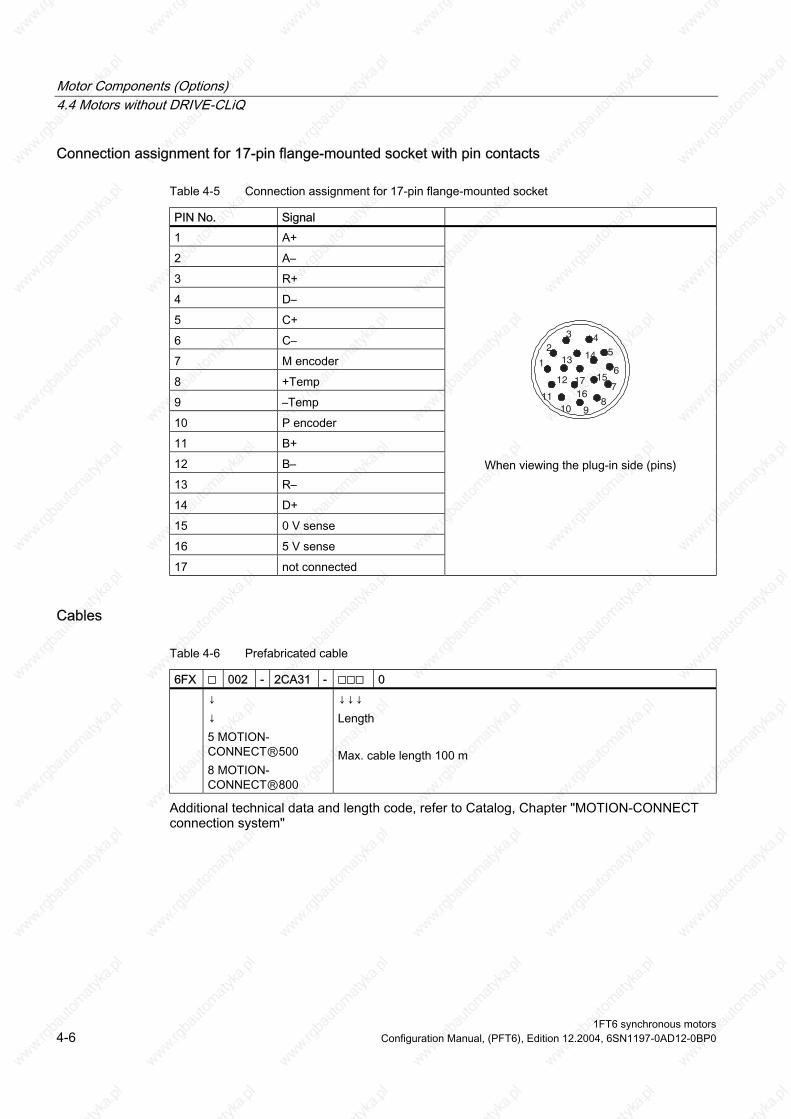
Motor Components (Options) 4.4 Motors without DRIVE-CLiQ
Connection assignment for 17-pin flange-mounted socket with pin contacts
Table 4-5 Connection assignment for 17-pin flange-mounted socket
PIN No. Signal 1 A+
2 A–
3 R+
4 D–
5 C+
6 C–
7 M encoder
8 +Temp
9 –Temp
10 P encoder
11 B+
12 B–
13 R–
14 D+
0 V sense
16 5 V sense
17 not connected
45
6
7
8910
11
1
23
14
17 15
1612
13
When viewing the plug-in side (pins)
15
Cables
Table 4-6 Prefabricated cable
6FX 002 - 2CA31 - 0 ↓
↓ 5 MOTION-CONNECT500 8 MOTION-CONNECT800
↓↓↓ Length Max. cable length 100 m
Additional technical data and length code, refer to Catalog, Chapter "MOTION-CONNECT connection system"
1FT6 synchronous motors 4-6 Configuration Manual, (PFT6), Edition 12.2004, 6SN1197-0AD12-0BP0

Motor Components (Options) 4.4 Motors without DRIVE-CLiQ
4.4.2 Absolute value encoders Function:
• Angular measuring system to impress current
• Speed actual value sensing
• Absolute measuring system for the position control loop
Table 4-7 Technical data, absolute value encoder
Features Absolute value encoders EnDat (A–2048)
Absolute value encoders EnDat (A–512)
Mech. limiting speed 12000 RPM 12000 RPM Operating voltage 5V ± 5% 5V ± 5% Current consumption max. 300 mA max. 200 mA Resolution, incremental (periods per revolution) 2048 512 Resolution, absolute (coded revolutions) 4096 4096 Incremental signals 1 Vpp 1 Vpp Serial absolute position interface EnDat EnDat Angular error ± 40" ± 80"
Note
As a result of the reduced maximum operating temperature of absolute value encoders with respect to incremental encoders, the thermally permissible rated motor torque is reduced by 10%.
1FT6 synchronous motors Configuration Manual, (PFT6), Edition 12.2004, 6SN1197-0AD12-0BP0 4-7
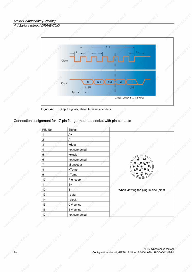
Motor Components (Options) 4.4 Motors without DRIVE-CLiQ
Figure 4-3 Output signals, absolute value encoders
Connection assignment for 17-pin flange-mounted socket with pin contacts
PIN No. Signal 1 A+
2 A–
3 +data
4 not connected
5 +clock
6 not connected
7 M encoder
8 +Temp
9 –Temp
10 P encoder
11 B+
12 B–
–data
14 –clock
15 0 V sense
16 5 V sense
17 not connected
45
6
7
8910
11
1
23
14
17 15
1612
13
When viewing the plug-in side (pins) 13
1FT6 synchronous motors 4-8 Configuration Manual, (PFT6), Edition 12.2004, 6SN1197-0AD12-0BP0

Motor Components (Options) 4.4 Motors without DRIVE-CLiQ
Cables
Table 4-8 Prefabricated cable
6FX 002 - 2EQ10 - 0 ↓
↓ 5 MOTION-CONNECT500 8 MOTION-CONNECT800
↓↓↓ Length Max. cable length 100 m
For other technical data and length code, refer to Catalog, Chapter "MOTION-CONNECT connection system"
1FT6 synchronous motors Configuration Manual, (PFT6), Edition 12.2004, 6SN1197-0AD12-0BP0 4-9
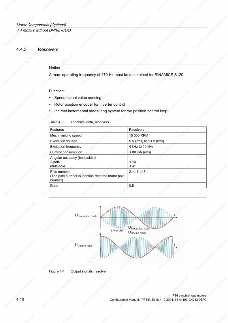
Motor Components (Options) 4.4 Motors without DRIVE-CLiQ
4.4.3 Resolvers
Notice
A max. operating frequency of 470 Hz must be maintained for SINAMICS S120.
Function:
• Speed actual value sensing
• Rotor position encoder for inverter control
• Indirect incremental measuring system for the position control loop
Table 4-9 Technical data, resolvers
Features Resolvers Mech. limiting speed 15 000 RPM Excitation voltage 5 V (rms) to 13 V (rms) Excitation frequency 4 kHz to 10 kHz Current consumption < 80 mA (rms) Angular accuracy (bandwidth) 2-pole multi-pole
< 14' < 4'
Pole number al with the motor pole
number)
2, 4, 6 or 8
Ratio 0.5
(The pole number is identic
Figure 4-4 Output signals, resolver
1FT6 synchronous motors 4-10 Configuration Manual, (PFT6), Edition 12.2004, 6SN1197-0AD12-0BP0

Motor Components (Options) 4.4 Motors without DRIVE-CLiQ
Connection assignment for 12–pin flange-mounted socket with pin contacts
Table 4-10 Connection assignment for 12–pin flange-mounted socket
PIN No. Signal 1 S2
2 S4
3 not connected
4 not connected
5 not connected
6 not connected
7 R2/R3
8 +Temp
9 –Temp
10 R1
11 S1
12 S3
2
1
10 12
1163
9 8
7
4 5
When viewing the plug-in side (pins)
Cables
Table 4-11 Prefabricated cable
6FX 002 - 2CF02 - 0
↓ ↓ 5 MOTION-CONNECT500 8 MOTION-CONNECT800
↓↓↓ Length 2-pole resolver: Max. cable length 50 m Multi-pole resolver: Max. cable length 130 m
Additional technical data and length code, refer to Catalog, Chapter "MOTION-CONNECT connection system"
1FT6 synchronous motors Configuration Manual, (PFT6), Edition 12.2004, 6SN1197-0AD12-0BP0 4-11
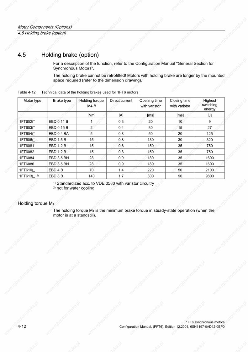
Motor Components (Options) 4.5 Holding brake (option)
4.5 Holding brake (option) For a description of the function, refer to the Configuration Manual "General Section for Synchronous Motors".
The holding brake cannot be retrofitted! Motors with holding brake are longer by the mounted space required (refer to the dimension drawing).
Table 4-12 Technical data of the holding brakes used for 1FT6 motors
Motor type Brake type Holding torque M4 1)
Direct current Opening time with varistor
Closing time with varistor
Highest switching energy
[Nm] [A] [ms] [ms] [J] 1FT602⃞ EBD 0.11 B 1 0.3 20 10 9 1FT603⃞ EBD 0.15 B 2 0.4 30 15 27 1FT604⃞ EBD 0.4 BA 5 0.8 50 20 125 1FT606⃞ EBD 1.5 B 15 0.8 130 30 320 1FT6081 EBD 1.2 B 15 0.8 150 35 750 1FT6082 EBD 1.2 B 15 0.8 150 35 750 1FT6084 EBD 3.5 BN 28 0.9 180 35 1600 1FT6086 EBD 3.5 BN 28 0.9 180 35 1600 1FT610⃞ EBD 4 B 70 1.4 220 50 2100 1FT613⃞ 2) EBD 8 B 140 1.7 300 90 9800
1) Standardized acc. to VDE 0580 with varistor circuitry 2) not for water cooling
Holding torque M4 The holding torque M4 is the minimum brake torque in steady-state operation (when the motor is at a standstill).
1FT6 synchronous motors 4-12 Configuration Manual, (PFT6), Edition 12.2004, 6SN1197-0AD12-0BP0
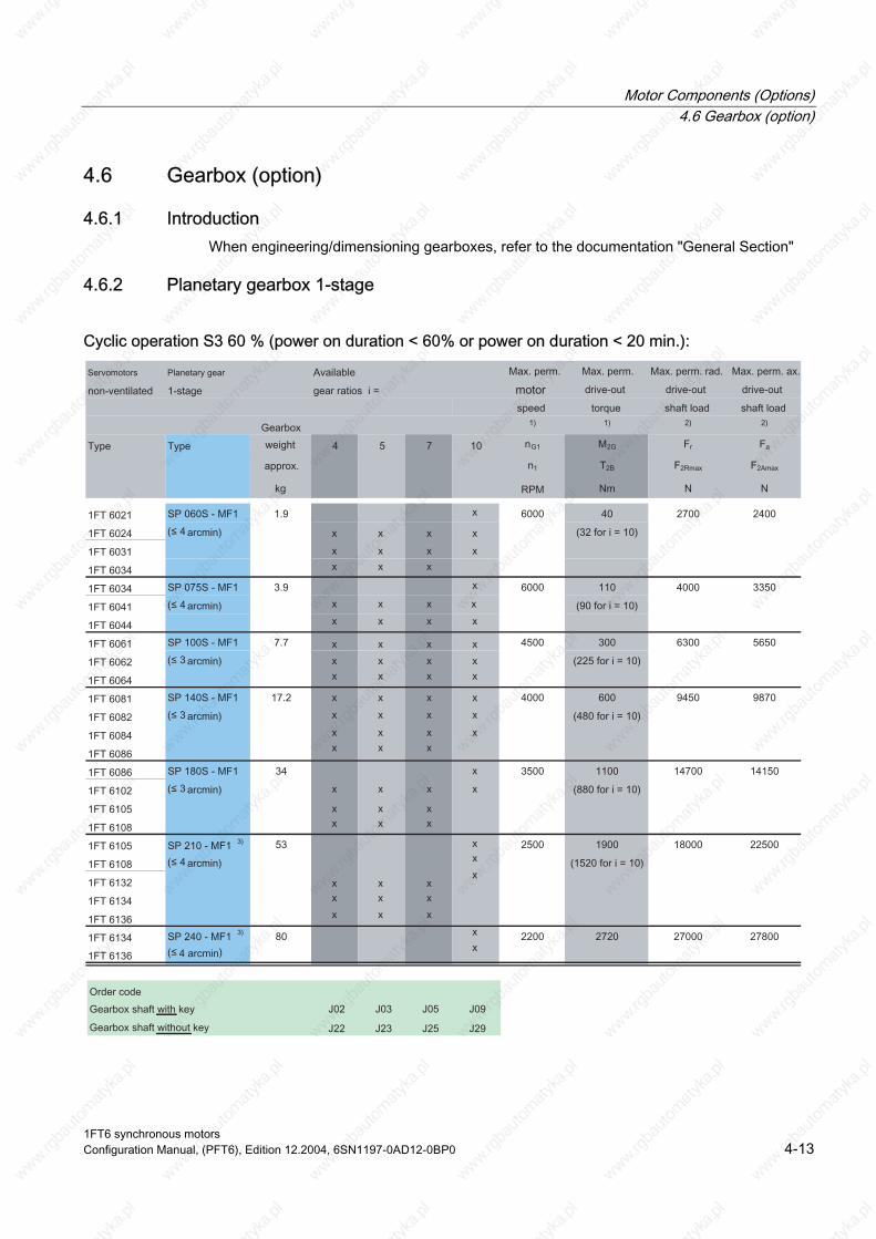
Motor Components (Options) 4.6 Gearbox (option)
4.6 Gearbox (option)
4.6.1 Introduction When engineering/dimensioning gearboxes, refer to the documentation "General Section"
4.6.2 Planetary gearbox 1-stage
Cyclic operation S3 60 % (power on duration < 60% or power on duration < 20 min.):
1FT6 synchronous motors Configuration Manual, (PFT6), Edition 12.2004, 6SN1197-0AD12-0BP0 4-13
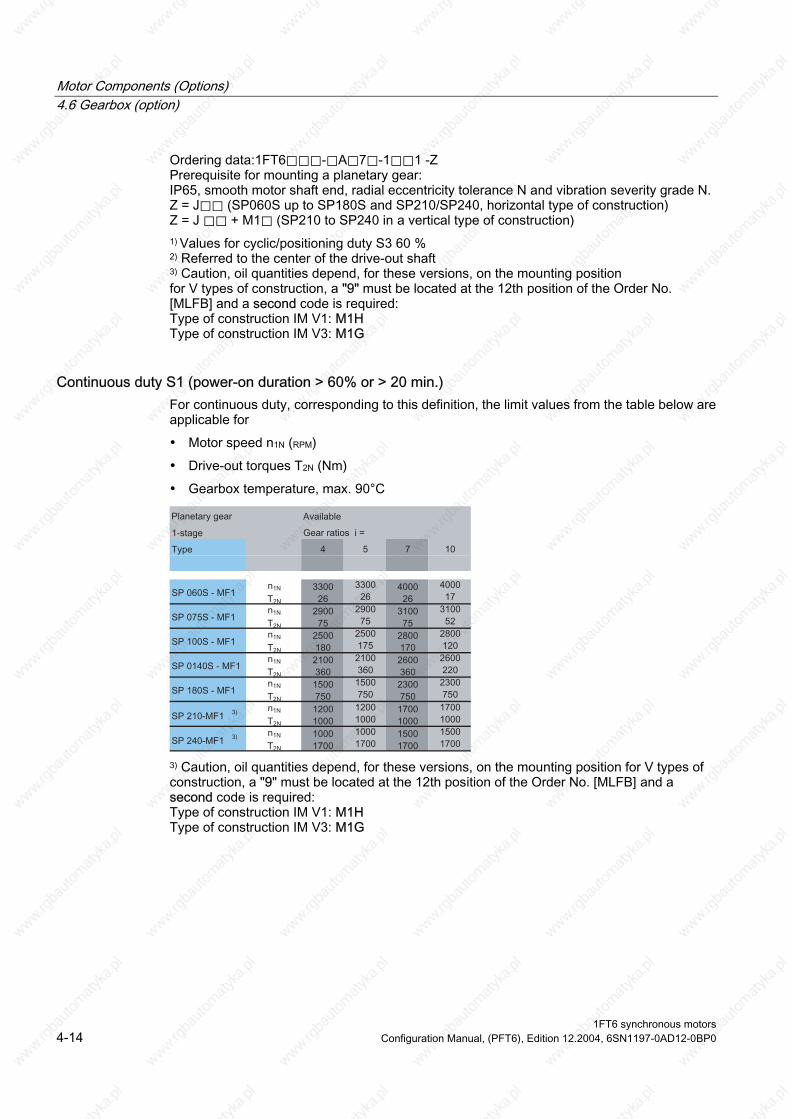
Motor Components (Options) 4.6 Gearbox (option)
Ordering data:1FT6⃞⃞⃞-⃞A⃞7⃞-1⃞⃞1 -Z Prerequisite for mounting a planetary gear: IP65, smooth motor shaft end, radial eccentricity tolerance N and vibration severity grade N. Z = J⃞⃞ (SP060S up to SP180S and SP210/SP240, horizontal type of construction) Z = J ⃞⃞ + M1⃞ (SP210 to SP240 in a vertical type of construction) 1) Values for cyclic/positioning duty S3 60 % 2) Referred to the center of the drive-out shaft 3) Caution, oil quantities depend, for these versions, on the mounting position for V types of construction, a "9" must be located at the 12th position of the Order No. [MLFB] and a second code is required:
Type of construction IM V3: M1G Type of construction IM V1: M1H
Continuous duty S1 (power-on duration > 60% or > 20 min.) For continuous duty, corresponding to this definition, the limit values from the table below are applicable for
• Motor speed n1N (RPM)
• Drive-out torques T2N (Nm)
• Gearbox temperature, max. 90°C
3) Caution, oil quantities depend, for these versions, on the mounting position for V types of construction, a "9" must be located at the 12th position of the Order No. [MLFB] and a second code is required: Type of construction IM V1: M1H Type of construction IM V3: M1G
1FT6 synchronous motors 4-14 Configuration Manual, (PFT6), Edition 12.2004, 6SN1197-0AD12-0BP0
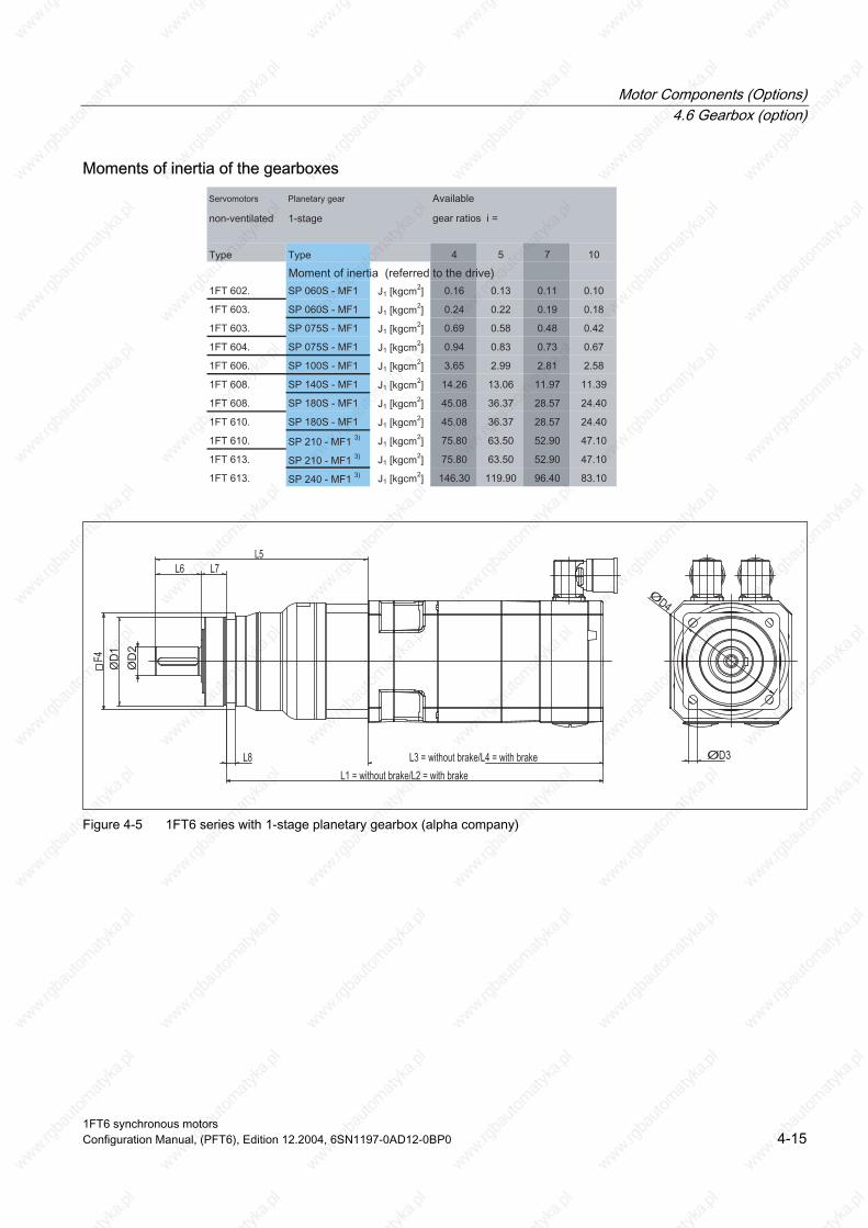
Motor Components (Options) 4.6 Gearbox (option)
Moments of inertia of the gearboxes
Figure 4-5 1FT6 series with 1-stage planetary gearbox (alpha company)
1FT6 synchronous motors Configuration Manual, (PFT6), Edition 12.2004, 6SN1197-0AD12-0BP0 4-15
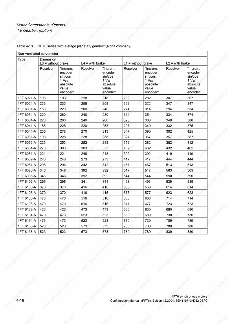
Motor Components (Options) 4.6 Gearbox (option)
Table 4-13 1FT6 series with 1-stage planetary gearbox (alpha company)
Non-ventilated servomotor Dimension
L4 = with brake L1 = without brake
L2 = with brake
Type
Resolver "Increm. encoder sin/cos 1 Vpp absolute value encoder"
Resolver "Increm. encoder sin/cos 1 Vpp absolute value encoder"
Resolver "Increm. encoder sin/cos 1 Vpp absolute value encoder"
Resolver "Increm. encoder sin/cos 1 Vpp absolute value encoder"
1FT 6021-A 193 193 218 218 282 282 307 307 1FT 6024-A 233 233 258 258 322 322 347 347 1FT 6031-A 180 220 200 240 274 314 294 334 1FT 6034-A 220 260 240 280 314 354 334 374 1FT 6034-A 220 260 240 280 328 368 348 388 1FT 6041-A 185 228 220 263 297 340 332 375 1FT 6044-A 235 278 270 313 347 390 382 425 1FT 6061-A 198 228 228 258 327 357 357 387 1FT 6062-A 223 253 253 283 352 382 382 412 1FT 6064-A 273 303 303 333 402 432 432 462 1FT 6081-A 221 221 248 248 392 392 419 419 1FT 6082-A 246 246 273 273 417 417 444 444 1FT 6084-A 296 296 342 342 467 467 513 513 1FT 6086-A 346 346 392 392 517 517 563 563 1FT 6086-A 346 346 392 392 544 544 590 590 1FT 6102-A 295 295 341 341 493 493 539 539 1FT 6105-A 370 370 416 416 568 568 614 614
370 370 416 416 577 577 623 1FT 6108-A 470 470 516 516 668 668 714 714 1FT 6108-A 470 470 516 516 677 677 723 723 1FT 6132-A 423 423 473 473 630 630 680 680 1FT 6134-A 473 473 523 523 680 680 730 730
473 473 523 523 739 739 789 789 1FT 6136-A 523 523 573 573 730 730 780 780 1FT 6136-A 523 523 573 573 789 789 839 839
L3 = without brake
1FT 6105-A 623
1FT 6134-A
1FT6 synchronous motors 4-16 Configuration Manual, (PFT6), Edition 12.2004, 6SN1197-0AD12-0BP0
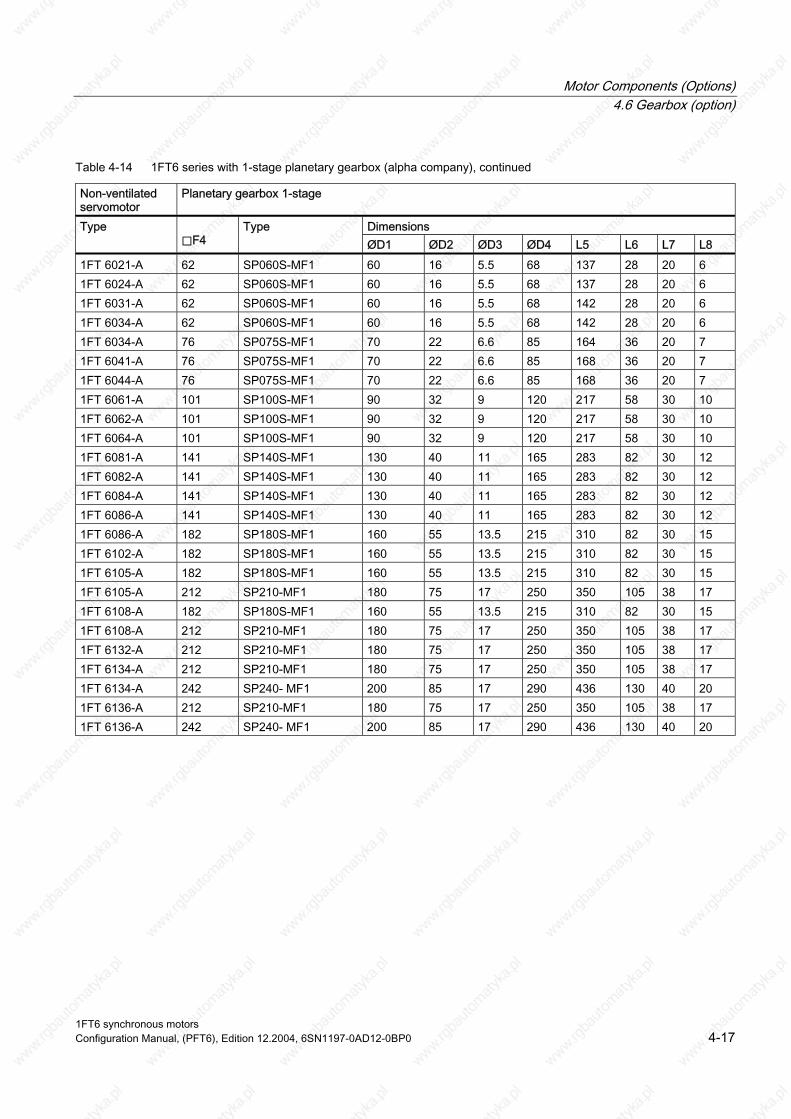
Motor Components (Options) 4.6 Gearbox (option)
Table 4-14 1FT6 series with 1-stage planetary gearbox (alpha company), continued
Non-ventilated servomotor
Planetary gearbox 1-stage
Dimensions Type ⃞F4
Type ØD1 ØD2 ØD3 ØD4 L5 L6 L7 L8
1FT 6021-A 62 SP060S-MF1 60 16 5.5 68 137 28 20 6 1FT 6024-A 62 SP060S-MF1 60 16 5.5 68 137 28 20 6 1FT 6031-A 62 SP060S-MF1 60 16 5.5 68 142 28 20 6 1FT 6034-A 62 SP060S-MF1 60 16 5.5 68 142 28 20 6 1FT 6034-A 76 SP075S-MF1 70 22 6.6 85 164 36 20 7 1FT 6041-A 76 SP075S-MF1 70 22 6.6 85 168 36 20 7 1FT 6044-A 76 SP075S-MF1 70 22 6.6 85 168 36 20 7 1FT 6061-A 101 SP100S-MF1 90 32 9 120 217 58 30 10 1FT 6062-A 101 SP100S-MF1 90 32 9 120 217 58 30 10 1FT 6064-A 101 SP100S-MF1 90 32 9 120 217 58 30 10 1FT 6081-A 141 SP140S-MF1 130 165 40 11 283 82 30 12
141 SP140S-MF1 130 40 11 165 283 30 1FT 6084-A 141 SP140S-MF1 130 40 11 165 283 82 30 12
141 SP140S-MF1 130 40 11 283 82 30 12 1FT 6086-A 182 SP180S-MF1 160 55 13.5 215 310 82 30 15
182 SP180S-MF1 160 55 13.5 215 310 82 30 15 1FT 6105-A 182 SP180S-MF1 160 55 13.5 215 310 82 30 15 1FT 6105-A 212 SP210-MF1 180 75 17 250 350 105 38 17 1FT 6108-A 182 SP180S-MF1 160 55 13.5 215 310 82 30 15 1FT 6108-A 212 SP210-MF1 180 75 17 250 350 105 38 17 1FT 6132-A 212 SP210-MF1 180 75 17 250 350 105 38 17 1FT 6134-A 212 SP210-MF1 180 75 17 250 350 105 38 17 1FT 6134-A 242 SP240- MF1 130 200 85 17 290 436 40 20 1FT 6136-A 212 SP210-MF1 180 75 17 105 250 350 38 17 1FT 6136-A 242 SP240- MF1 200 85 17 290 436 130 40 20
1FT 6082-A 82 12
1FT 6086-A 165
1FT 6102-A
1FT6 synchronous motors Configuration Manual, (PFT6), Edition 12.2004, 6SN1197-0AD12-0BP0 4-17
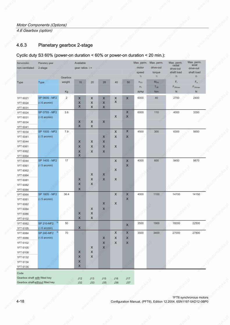
Motor Components (Options) 4.6 Gearbox (option)
4.6.3 Planetary gearbox 2-stage
Cyclic duty S3 60% (power-on duration < 60% or power-on duration < 20 min.):
1FT6 synchronous motors 4-18 Configuration Manual, (PFT6), Edition 12.2004, 6SN1197-0AD12-0BP0

Motor Components (Options) 4.6 Gearbox (option)
1) Values for cyclic/positioning duty S3 60 % 2) referred to the center of the drive-out shaft 3) refer to footnote 3 on the next page
Ordering data: 1FT6⃞⃞⃞-⃞A⃞7⃞-1⃞⃞1-Z Prerequisites for mounting a planetary gearbox:
on severity grade N. Z = J ⃞⃞ (SP060S to SP180S and SP210/SP240 in a horizontal type of construction) Z = J ⃞⃞ + M1⃞ (SP210 to SP240 in a vertical type of construction)
IP65, smooth motor shaft end, radial eccentricity N and vibrati
• Motor speed n1N (RPM)
Continuous duty S1 (power-on duration > 60% or > 20 min.): For continuous operation, corresponding to the definition, the limit values from the table below apply for:
• Drive-out torques T2N (Nm)
• Max. gearbox temperature, 90°C
3) Caution For these versions, the amount of oil depends on the mounting position - for types of construction a "9" should be set at the 12th position of the Order No. (MLFB) and a second code is required: Type of construction IM V1: M1H Type of construction IM V3: M1G
1FT6 synchronous motors Configuration Manual, (PFT6), Edition 12.2004, 6SN1197-0AD12-0BP0 4-19
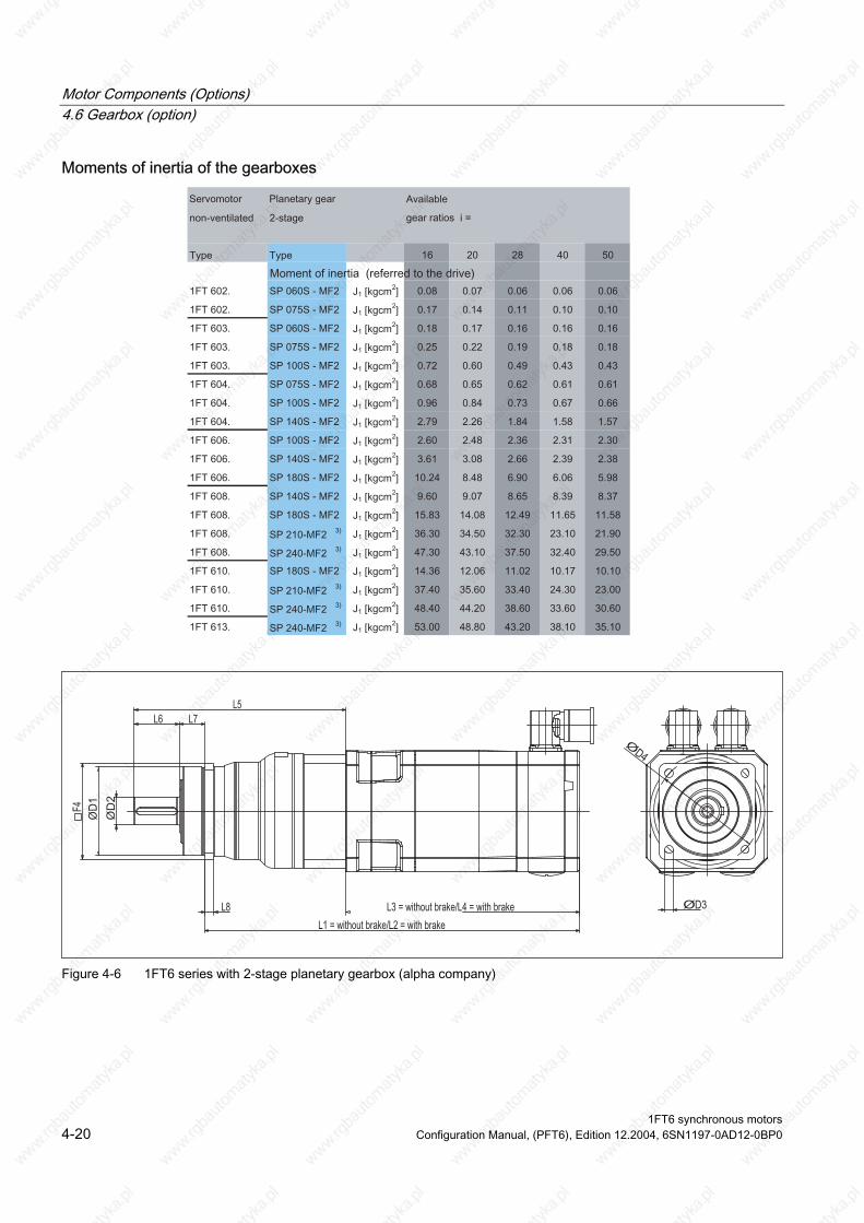
Motor Components (Options) 4.6 Gearbox (option)
Moments of inertia of the gearboxes
Figure 4-6 1FT6 series with 2-stage planetary gearbox (alpha company)
1FT6 synchronous motors 4-20 Configuration Manual, (PFT6), Edition 12.2004, 6SN1197-0AD12-0BP0

Motor Components (Options) 4.6 Gearbox (option)
Table 4-15 1FT6 series with 2-stage planetary gearbox (alpha company)
Servomotor, non-ventilated Dimensions L3 = without brake
L4 = with brake
L1 = without brake L2 = with brake Type
Resolver "Increm. encoder sin/cos 1 Vpp absolute value
"Increm. encoder sin/cos 1 Vpp absolute value encoder"
Resolvers
encoder"
Resolvers "Increm. encoder sin/cos 1 Vpp absolute value
Resolvers
encoder"
"Increm. encoder sin/cos 1 Vpp absolute value encoder"
1FT 6021-A 193 193 218 218 301 301 326 326 1FT 6021-A 193 193 218 218 312 312 337 337 1FT 6024-A 233 233 258 258 341 341 366 366 1FT 6024-A 233 233 258 258 352 352 377 377 1FT 6024-A 233 233 258 258 375 375 400 400 1FT 6031-A 180 220 200 240 296 336 316 356 1FT 6031-A 180 220 200 240 303 343 323 363 1FT 6031-A 180 220 200 240 322 362 342 382 1FT 6034-A 220 260 240 383 280 343 363 403 1FT 6034-A 220 260 240 280 362 402 382 422 1FT 6034-A 220 260 240 280 406 446 426 466 1FT 6041-A 185 228 220 263 321 364 356 399 1FT 6041-A 185 228 220 263 331 374 366 409 1FT 6041-A 185 228 220 263 371 414 406 449 1FT 6044-A 235 278 270 313 381 424 416 459 1FT 6044-A 235 278 270 313 421 464 456 499 1FT 6044-A 235 278 270 313 469 512 504 547 1FT 6061-A 198 228 228 258 362 392 392 422 1FT 6061-A 198 228 228 258 391 421 421 451 1FT 6061-A 198 228 228 258 432 462 462 492 1FT 6062-A 223 253 253 283 387 417 417 447 1FT 6062-A 223 253 253 283 416 446 446 476 1FT 6064-A 273 303 303 333 437 467 467 497 1FT 6064-A 273 303 303 333 466 496 496 526 1FT 6064-A 273 303 303 333 507 537 537 567 1FT 6081-A 221 221 248 248 441 441 468 468 1FT 6081-A 221 491 491 221 248 248 464 464 1FT 6081-A 221 221 248 248 475 475 502 502 1FT 6082-A 246 246 273 273 466 466 493 493 1FT 6082-A 246 246 273 273 489 489 516 516 1FT 6082-A 246 246 273 273 500 500 527 527 1FT 6084-A 296 296 342 342 516 516 562 562
296 296 342 342 539 585 585 1FT 6084-A 296 296 342 342 580 580 626 626 1FT 6084-A 539
1FT6 synchronous motors Configuration Manual, (PFT6), Edition 12.2004, 6SN1197-0AD12-0BP0 4-21
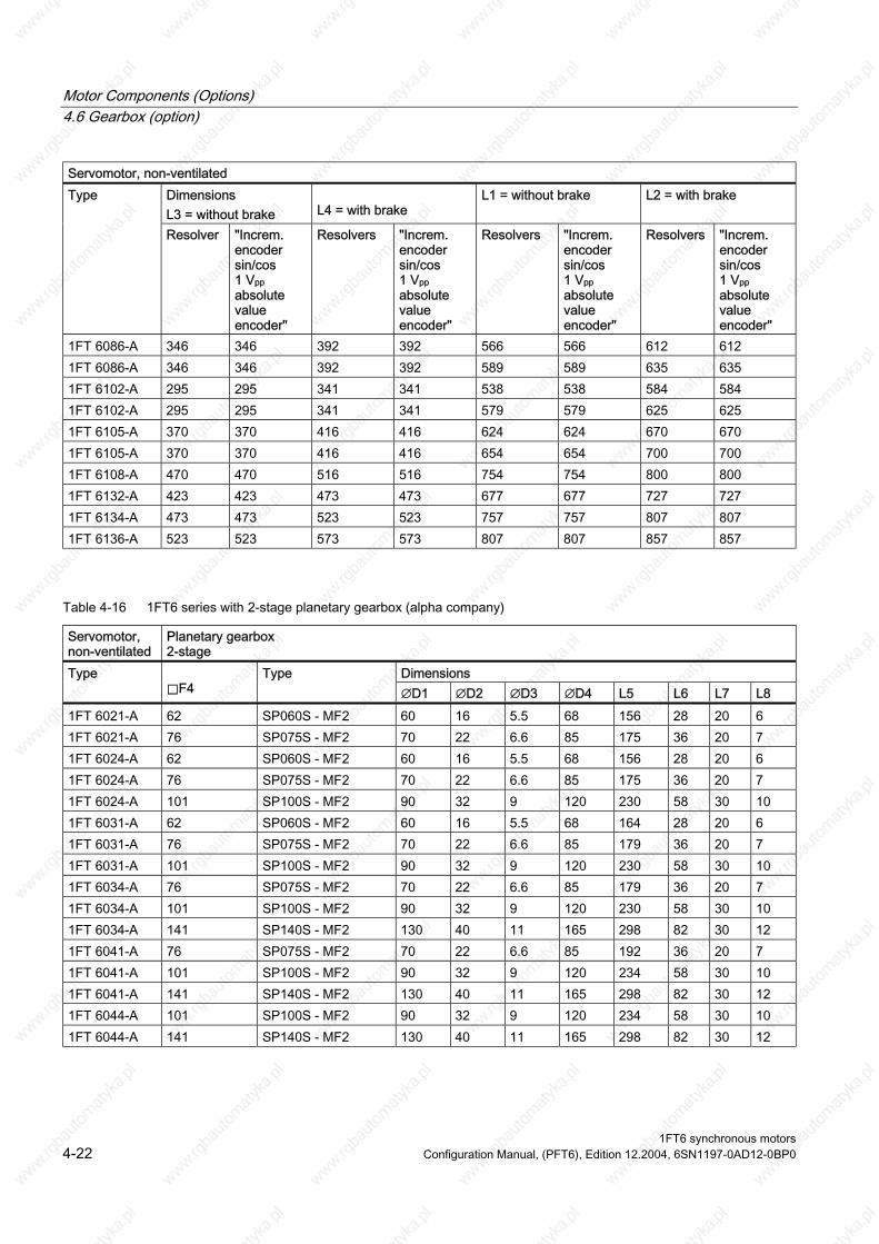
Motor Components (Options) 4.6 Gearbox (option)
Servomotor, non-ventilated Dimensions L3 = without brake
L4 = with brake
L1 = without brake L2 = with brake Type
Resolver "Increm. encoder sin/cos 1 Vpp absolute value encoder"
Resolvers "Increm. encoder sin/cos 1 Vpp absolute value encoder"
Resolvers "Increm. encoder sin/cos 1 Vpp absolute value encoder"
Resolvers "Increm. encoder sin/cos 1 Vpp absolute value encoder"
1FT 6086-A 346 346 392 392 566 566 612 612 1FT 6086-A 346 346 392 392 589 589 635 635 1FT 6102-A 295 295 341 341 538 538 584 584 1FT 6102-A 295 295 341 341 579 579 625 625 1FT 6105-A 370 370 416 416 624 624 670 670 1FT 6105-A 370 370 416 416 654 654 700 700 1FT 6108-A 470 470 516 516 754 754 800 800
423 473 473 677 677 727 473 473 523 523 757 807 807
1FT 6136-A 523 523 573 573 807 807 857 857
1FT 6132-A 423 727 1FT 6134-A 757
Table 4-16 1FT6 series with 2-stage planetary gearbox (alpha company)
Servomotor, non-ventilated
Planetary gearbox
Type ⃞F4
Type ∅D1 ∅D2 ∅D3 ∅D4 L5 L7 L6 L8
1FT 6021-A 62 SP060S - MF2 60 16 5.5 68 156 28 20 6 1FT 6021-A 76 SP075S - MF2 70 22 6.6 85 175 36 20 7 1FT 6024-A 62 SP060S - MF2 60 16 5.5 68 156 28 20 6 1FT 6024-A 76 SP075S - MF2 70 22 6.6 85 175 36 20 7 1FT 6024-A 101 SP100S - MF2 90 32 9 120 230 58 30 10 1FT 6031-A 62 SP060S - MF2 60 16 5.5 68 164 28 20 6 1FT 6031-A 76 SP075S - MF2 70 22 6.6 85 179 36 20 7 1FT 6031-A 101 SP100S - MF2 90 32 9 120 230 58 30 10 1FT 6034-A 76 SP075S - MF2 70 22 6.6 85 179 36 20 7 1FT 6034-A 101 SP100S - MF2 90 32 9 120 230 58 30 10 1FT 6034-A 141 SP140S - MF2 130 40 11 165 298 82 30 12 1FT 6041-A 76 SP075S - MF2 70 22 6.6 85 192 36 20 7 1FT 6041-A 101 SP100S - MF2 90 32 9 120 234 58 30 10 1FT 6041-A 141 SP140S - MF2 130 40 11 165 298 82 30 12 1FT 6044-A 101 SP100S - MF2 90 32 9 120 58 234 30 10 1FT 6044-A 141 SP140S - MF2 130 11 40 165 298 82 30 12
2-stage Dimensions
1FT6 synchronous motors 4-22 Configuration Manual, (PFT6), Edition 12.2004, 6SN1197-0AD12-0BP0

Motor Components (Options) 4.6 Gearbox (option)
Servomotor, non-ventilated
Planetary gearbox 2-stage
Dimensions Type ⃞F4
Type ∅D1 ∅D2 ∅D3 ∅D4 L5 L6 L7 L8
1FT 6044-A 182 SP180S - MF2 160 55 13.5 215 346 82 30 15 1FT 6061-A 101 SP100S - MF2 90 32 9 120 252 58 30 10 1FT 6061-A 141 SP140S - MF2 130 40 11 165 305 82 30 12 1FT 6061-A 182 SP180S - MF2 160 55 13.5 215 346 82 30 15 1FT 6062-A 101 SP100S - MF2 90 32 9 120 252 58 30 10 1FT 6062-A 141 SP140S - MF2 130 40 11 165 305 82 12 1FT 6064-A 101 SP100S - MF2 90 32 9 120 252 58 30 10 1FT 6064-A 141 SP140S - MF2 130 40 11 165 305 82 30 12 1FT 6064-A 182 SP180S - MF2 160 55 13.5 215 346 82 30 15 1FT 6081-A 141 SP140S - MF2 130 40 11 165 332 82 30 12 1FT 6081-A 182 SP180S - MF2 160 55 13.5 215 355 82 30 15 1FT 6081-A 121 SP210 - MF2 180 75 17 250 397 105 38 17 1FT 6082-A 141 SP140S - MF2 130 40 11 165 332 82 30 12 1FT 6082-A 182 SP180S - MF2 160 55 13.5 215 355 82 30 15 1FT 6082-A 121 SP210 - MF2 180 75 17 250 397 105 38 17 1FT 6084-A 141 SP140S - MF2 130 40 11 165 332 82 30 12 1FT 6084-A 182 SP180S - MF2 160 55 13.5 215 82 355 30 15 1FT 6084-A 242 SP240 - MF2 200 85 17 290 454 130 40 20 1FT 6086-A 141 SP140S - MF2 130 40 11 165 332 82 30 12 1FT 6086-A 182 SP180S - MF2 160 55 13.5 215 355 82 30 15 1FT 6102-A 182 SP180S - MF2 160 55 13.5 215 355 82 30 15 1FT 6102-A 242 SP240 - MF2 200 85 17 290 454 130 40 20 1FT 6105-A 212 SP210 - MF2 180 75 17 250 397 105 38 17 1FT 6105-A 242 SP240 - MF2 200 85 17 290 454 130 40 20 1FT 6108-A 242 SP240 - MF2 200 85 17 290 454 130 40 20 1FT 6132-A 212 SP210 - MF2 180 75 17 250 397 105 38 170 1FT 6134-A 242 SP240 - MF2 200 85 17 290 454 130 40 20 1FT 6136-A 242 SP240 - MF2 200 85 17 290 454 130 40 20
30
1FT6 synchronous motors Configuration Manual, (PFT6), Edition 12.2004, 6SN1197-0AD12-0BP0 4-23

Motor Components (Options) 4.6 Gearbox (option)
1FT6 synchronous motors 4-24 Configuration Manual, (PFT6), Edition 12.2004, 6SN1197-0AD12-0BP0

5 Dimension Drawings
5.1 Introduction
Note
Siemens AG reserves the right to change the dimensions of the motors as part of mechanical design improvements without prior notice. This means that dimensions drawings can go out-of-date. Up-to-date dimension drawings can be requested at no charge from your local SIEMENS sales department.
1FT6 synchronous motors Configuration Manual, (PFT6), Edition 12.2004, 6SN1197-0AD12-0BP0 5-1
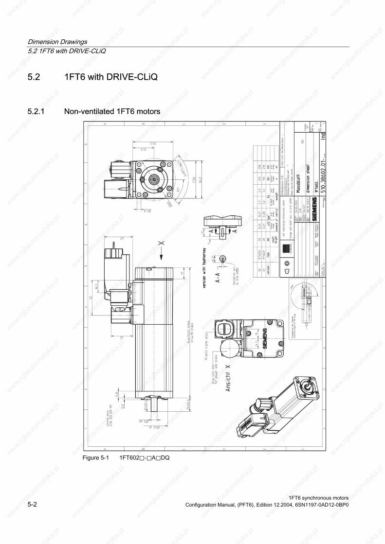
Dimension Drawings 5.2 1FT6 with DRIVE-CLiQ
5.2 1FT6 with DRIVE-CLiQ
5.2.1 Non-ventilated 1FT6 motors
Figure 5-1 1FT602⃞-⃞A⃞DQ
1FT6 synchronous motors 5-2 Configuration Manual, (PFT6), Edition 12.2004, 6SN1197-0AD12-0BP0

Dimension Drawings 5.2 1FT6 with DRIVE-CLiQ
Figure 5-2 1FT603⃞-⃞A⃞DQ
1FT6 synchronous motors Configuration Manual, (PFT6), Edition 12.2004, 6SN1197-0AD12-0BP0 5-3
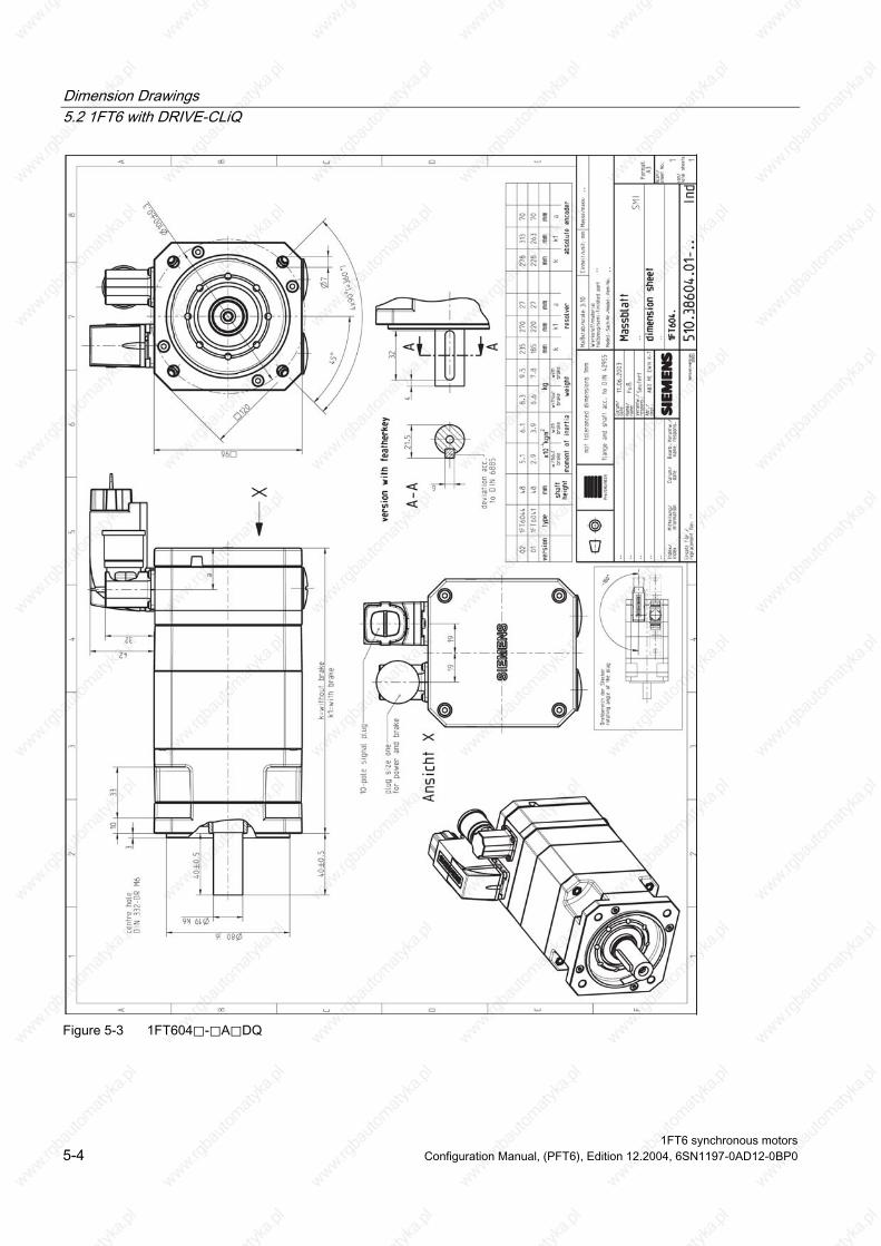
Dimension Drawings 5.2 1FT6 with DRIVE-CLiQ
Figure 5-3 1FT604⃞-⃞A⃞DQ
1FT6 synchronous motors 5-4 Configuration Manual, (PFT6), Edition 12.2004, 6SN1197-0AD12-0BP0
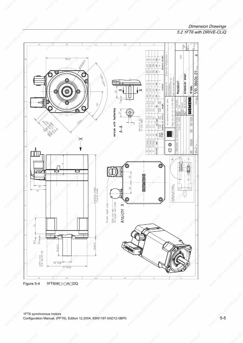
Dimension Drawings 5.2 1FT6 with DRIVE-CLiQ
Figure 5-4 1FT606⃞-⃞A⃞DQ
1FT6 synchronous motors Configuration Manual, (PFT6), Edition 12.2004, 6SN1197-0AD12-0BP0 5-5

Dimension Drawings 5.2 1FT6 with DRIVE-CLiQ
Figure 5-5 1FT608⃞-⃞A⃞DQ
1FT6 synchronous motors 5-6 Configuration Manual, (PFT6), Edition 12.2004, 6SN1197-0AD12-0BP0

Dimension Drawings 5.2 1FT6 with DRIVE-CLiQ
Figure 5-6 1FT610⃞-⃞A⃞plug⃞DQ
1FT6 synchronous motors Configuration Manual, (PFT6), Edition 12.2004, 6SN1197-0AD12-0BP0 5-7

Dimension Drawings 5.2 1FT6 with DRIVE-CLiQ
Figure 5-7 1FT613⃞-⃞A⃞plug⃞DQ
1FT6 synchronous motors 5-8 Configuration Manual, (PFT6), Edition 12.2004, 6SN1197-0AD12-0BP0

Dimension Drawings 5.2 1FT6 with DRIVE-CLiQ
Figure 5-8 1FT616x-8Sx76-5xxx_DQ
1FT6 synchronous motors Configuration Manual, (PFT6), Edition 12.2004, 6SN1197-0AD12-0BP0 5-9

Dimension Drawings 5.2 1FT6 with DRIVE-CLiQ
5.2.2 Force-ventilated 1FT6 motors
Figure 5-9 1FT608⃞-⃞S⃞DQ
1FT6 synchronous motors 5-10 Configuration Manual, (PFT6), Edition 12.2004, 6SN1197-0AD12-0BP0

Dimension Drawings 5.2 1FT6 with DRIVE-CLiQ
Figure 5-10 1FT610⃞-⃞S⃞plug⃞DQ
1FT6 synchronous motors Configuration Manual, (PFT6), Edition 12.2004, 6SN1197-0AD12-0BP0 5-11

Dimension Drawings 5.2 1FT6 with DRIVE-CLiQ
Figure 5-11 1FT613⃞-⃞S⃞plug⃞DQ
1FT6 synchronous motors 5-12 Configuration Manual, (PFT6), Edition 12.2004, 6SN1197-0AD12-0BP0
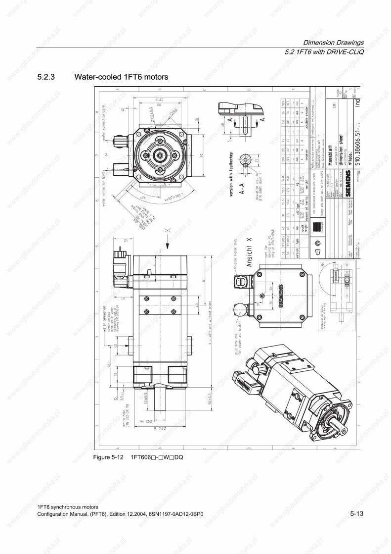
Dimension Drawings 5.2 1FT6 with DRIVE-CLiQ
5.2.3 Water-cooled 1FT6 motors
Figure 5-12 1FT606⃞-⃞W⃞DQ
1FT6 synchronous motors Configuration Manual, (PFT6), Edition 12.2004, 6SN1197-0AD12-0BP0 5-13
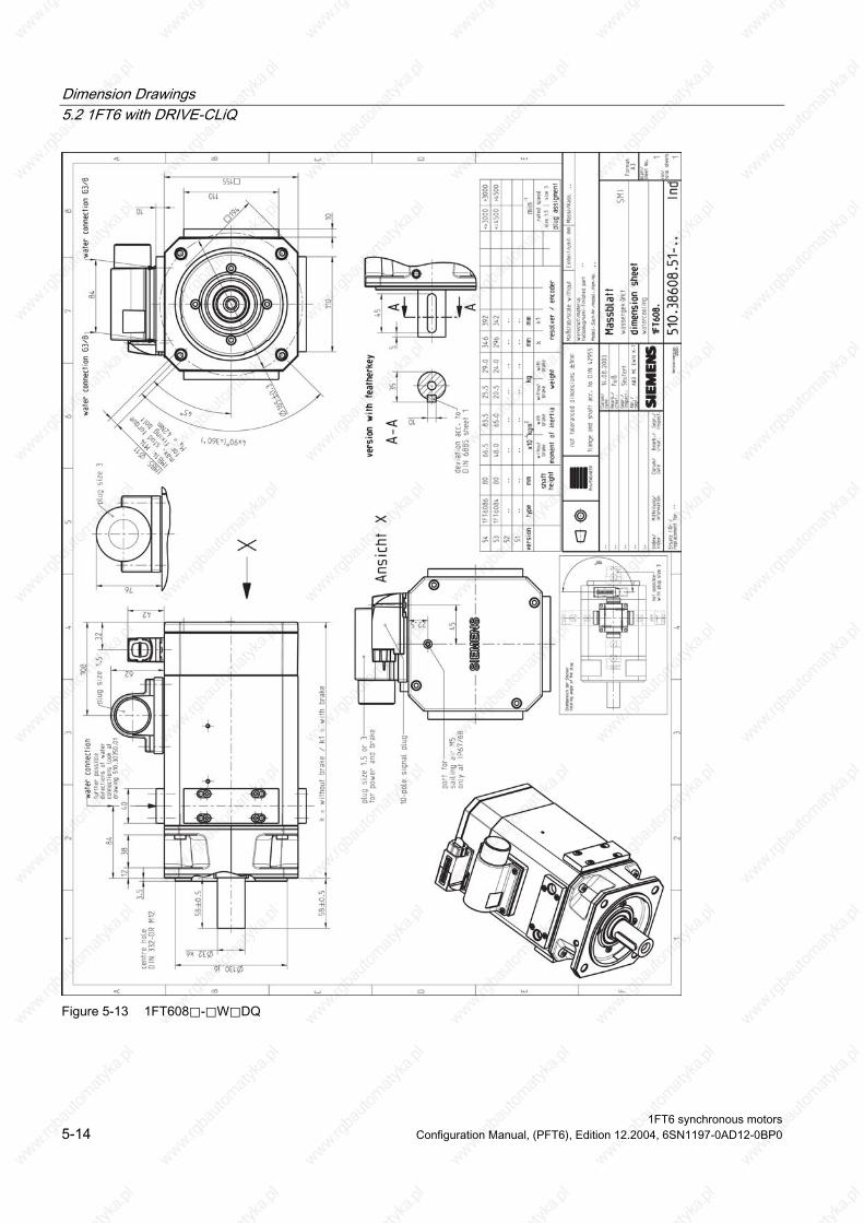
Dimension Drawings 5.2 1FT6 with DRIVE-CLiQ
Figure 5-13 1FT608⃞-⃞W⃞DQ
1FT6 synchronous motors 5-14 Configuration Manual, (PFT6), Edition 12.2004, 6SN1197-0AD12-0BP0
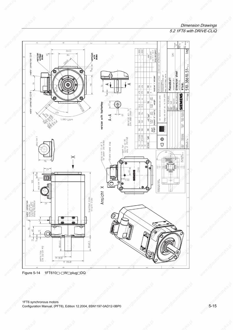
Dimension Drawings 5.2 1FT6 with DRIVE-CLiQ
Figure 5-14 1FT610⃞-⃞W⃞plug⃞DQ
1FT6 synchronous motors Configuration Manual, (PFT6), Edition 12.2004, 6SN1197-0AD12-0BP0 5-15
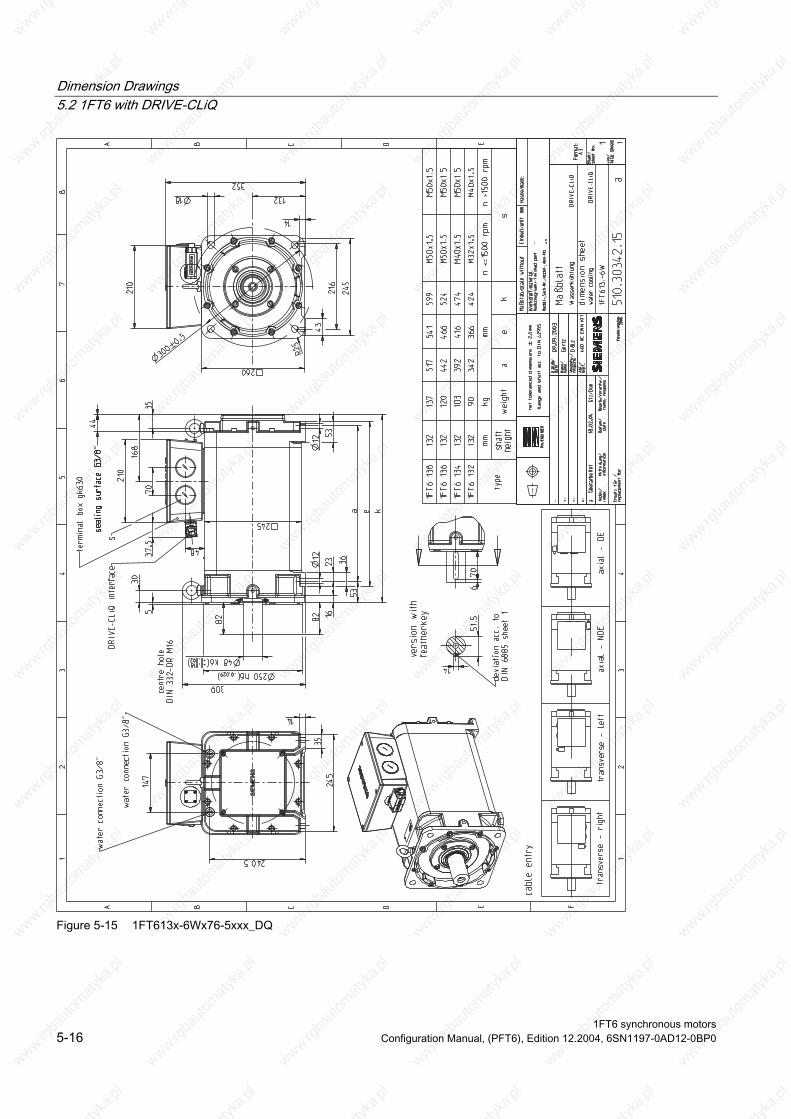
Dimension Drawings 5.2 1FT6 with DRIVE-CLiQ
Figure 5-15 1FT613x-6Wx76-5xxx_DQ
1FT6 synchronous motors 5-16 Configuration Manual, (PFT6), Edition 12.2004, 6SN1197-0AD12-0BP0

Dimension Drawings 5.2 1FT6 with DRIVE-CLiQ
Figure 5-16 1FT616x-8Wx76-5xxx_DQ
1FT6 synchronous motors Configuration Manual, (PFT6), Edition 12.2004, 6SN1197-0AD12-0BP0 5-17
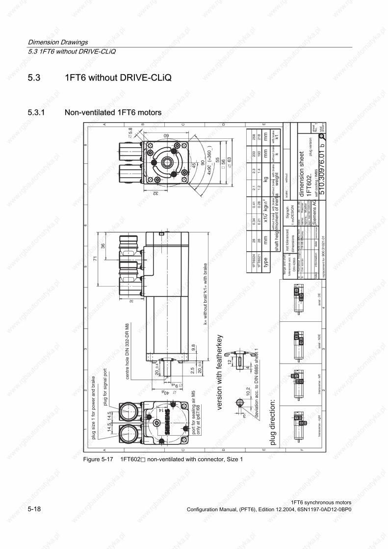
Dimension Drawings 5.3 1FT6 without DRIVE-CLiQ
5.3 1FT6 without DRIVE-CLiQ
5.3.1 Non-ventilated 1FT6 motors
with
out
self
cool
ing
/ IM
B5
plug
ver
sion
with
out b
rake
with
bra
ke
193
233
28 28
0.34
0.21
0.41
0.28
2.1
1.2
2.3
1.4
mm k1
flang
e an
d sh
aft
tole
ranc
es a
cc. t
o
DIN
429
55
not t
oler
ance
d
dim
ensi
ons
+1
mm
900.
3102
1.01
plug
dire
ctio
n:
tran
sver
se -
rig
httr
ansv
erse
- le
ftax
ial -
ND
Eax
ial -
DE
aK
orre
ktur
Trö
gh.m
om.
29.0
3.00
Ki/T
sch
b
port
for
seal
ing
air
M5
bÒ
.M. 5
0073
019
.08.
03M
G/M
J
only
at i
p67/
6890
_
4x90
_(=
360 _
)
56
14.5
14.5
14
36
71
45_ 55
10.2
3
2.5
9.8
20+0,
4
4
12
20+0,
5
9k6
40j6
63
5.8
60
32
k= w
ithou
t bra
ke / k1
= w
ith b
rake
32
vers
ion
with
feat
herk
ey
devi
atio
n ac
c. to
DIN
688
5 sh
eet 1
DE
SIG
N
Sig
raph
1FT
602.
tota
lsh
eets
shee
tN
o.
EDCBA
43
2
87
65
43
2
FEDCA
1
11S
iem
ens
AG
repl
acem
ent f
or:
Kie
ûner
30.1
1.99
dept
.: A
&D
MC
EW
N K
T2
repo
ns.:
nam
e:da
te:
nam
e/re
spon
s.da
tein
form
atio
nin
dex
scal
e:
dim
ensi
on s
heet
1FT
6021
1FT
6024
218
258
Mue
ller
510.
3097
6.01
cent
re h
ole
DIN
332
-DR
M8
plug
siz
e 1
for
pow
er a
nd b
rake
plug
for
sign
al p
ort
type
mm
x10
kgm
kgm
m
shaf
t hei
ght m
omen
t of i
nert
iaw
eigh
tw
ithou
t bra
kew
ith b
rake
with
out b
rake
with
bra
kek
-42
0
Figure 5-17 1FT602⃞ non-ventilated with connector, Size 1
1FT6 synchronous motors 5-18 Configuration Manual, (PFT6), Edition 12.2004, 6SN1197-0AD12-0BP0
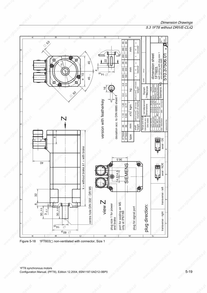
Dimension Drawings 5.3 1FT6 without DRIVE-CLiQ
bM
aû96
in92
geö
.22
.12.
94S
cc
Ste
cker
bild
l. be
r.02
.06.
99W
d/K
e
a
40
4
22
14k6
14k6
30+0
.5
3-0
.1
8
30+0
.5
60j6
32
72
92
75+0.
3
k =
with
out b
rake
/ k1
= w
ith b
rake
14.5
14.5
45_
45_
16
5
devi
atio
n ac
c. to
DIN
688
5 sh
eet 1
self
cool
ing
with
plu
g si
ze 1
with
/with
out b
rake
IMB
5
1FT
6031
1FT
6034
36360.
651.
100.
771.
223.
14.
43.
54.
818
022
020
024
02929
220
260
240
280
6969
vers
ion
with
feat
herk
ey
cent
re h
ole
DIN
332
- D
R M
5
Z
view
Zpl
ug s
ize
1 fo
r po
wer
plug
for
sign
al p
ort
scal
e:w
ithou
t
SIE
ME
NS
heig
ht
aM
aûe
geön
dert
11.1
1.93
Sc
1
A B C D E F
23
45
67
8
12
34
A B C D E
shee
t-N
r.
tota
lsh
eets
inde
xin
form
atio
nda
tena
me/
resp
ons.
date
:na
me:
resp
ons.
:de
pt.:A
&D
MC
EW
N K
T2
1.06
.93
Bau
mei
ster
repl
acem
ent f
or:
Sie
men
s A
G
dim
ensi
on s
heet
510.
3750
6.01
1 1
1FT
603.
Sig
raph
DE
SIG
N
e
Mue
ller
shaf
tm
omen
t of i
nert
ia
plug
dire
ctio
n:
tran
sver
se -
rig
httr
ansv
erse
- le
ftax
ial -
ND
Eax
ial -
DE
flang
e an
d sh
aft
tole
ranc
es a
cc. t
oD
IN 4
2955
not t
oler
ance
ddi
men
sion
s+1
mm
dM
aûe
geön
dert
.Fu
û/K
e22
.03.
00
port
for
seal
ing
air
M5
eÒ
.M. 5
0073
019
.08.
03M
G/M
J
with
out b
rake
with
bra
ke
wei
ght
with
out b
rake
with
bra
ke
reso
lver
enco
der
mm
x10
kgm
-42
kgm
mm
mty
pe
kk1
ak
k1a
and
brak
e
only
at I
P67
/68
36.5
5.5 0
Figure 5-18 1FT603⃞ non-ventilated with connector, Size 1
1FT6 synchronous motors Configuration Manual, (PFT6), Edition 12.2004, 6SN1197-0AD12-0BP0 5-19

Dimension Drawings 5.3 1FT6 without DRIVE-CLiQ
aS
teck
er b
ildl.
ber.
02.0
6.99
Wd/
Ke
bM
aûko
rrek
tur
29.0
9.99
S‰
/Se
port
for
seal
ing
air
M5
cÒ
.M. 5
0073
019
.08.
03M
G/M
J
and
brak
e
only
at I
P67
/68
38
heig
htsh
aft
mom
ent o
f ine
rtia
with
out b
rake
with
bra
ke
wei
ght
with
out b
rake
with
bra
ke
reso
lver
enco
der
mm
x10
kgm
-42
kgm
mm
mty
pe
kk1
ak
k1a
c
1
4
32
19k6
100
+0.
3
96
12045
_45
_
2424
1033
3-0
.1
40+0
.5
40+0
.5
19k6
80j6
k =
with
out b
rake
/ k1
= w
ith b
rake
a
32
21.5
6
devi
atio
n ac
c. to
DIN
688
5 sh
eet 1
with
/with
out b
rake
IMB
5
1FT
6041
1FT
6044
48 485.
12.
96.
13.
98.
36.
69.
57.
823
518
527
022
026 26
278
228
313
263
69 69
vers
ion
with
feat
herk
ey
Z
view
Z
cent
re h
ole
DIN
332
- D
R M
6
plug
for
sign
al p
ort
plug
siz
e 1
for
pow
er
scal
e:w
ithou
t
SIE
ME
NS
1
A B C D E F
23
45
67
8
12
34
A B C D E
shee
tN
o.
tota
lsh
eets
inde
xin
form
atio
nda
tena
me/
resp
ons.da
te:
nam
e:re
spon
s.:
dept
.: A
&D
MC
EW
N K
T2
2.06
.93
Bau
mei
ster
repl
acem
ent f
or:
Sie
men
s A
Gdim
ensi
on s
heet
self
cool
ing
with
plu
g si
ze 1
510.
3750
7.01
1 1
1FT
604.
Sig
raph
DE
SIG
N
c
Mue
ller
plug
dire
ctio
n:
tran
sver
se -
rig
httr
ansv
erse
- le
ftax
ial -
ND
Eax
ial -
DE
flang
e an
d sh
aft
tole
ranc
es a
cc. t
oD
IN 4
2955
not t
oler
ance
ddi
men
sion
s+1
mm
IMB5:
7
IMB14
:M6
max.
stud
torq
ue
M
=9
Nm
A
Figure 5-19 1FT604⃞ non-ventilated with connector, Size 1
1FT6 synchronous motors 5-20 Configuration Manual, (PFT6), Edition 12.2004, 6SN1197-0AD12-0BP0

Dimension Drawings 5.3 1FT6 without DRIVE-CLiQ
aS
teck
er b
ildl.
ber.
02.0
6.99
Wd/
Ke
port
for
seal
ing
air
M5
cÒ
.M. 5
0073
019
.08.
03M
G/M
J
283
and
brak
e
only
at I
P67
/68
18
bFu
û/Ts
chA
nzug
smom
. hin
zu17
.01.
00
0
heig
htsh
aft
mom
ent o
f ine
rtia
with
out b
rake
with
bra
ke
wei
ght
with
out b
rake
with
bra
ke
reso
lver
enco
der
mm
x10
kgm
-42
kgm
mm
mty
pek
k1a
kk1
a
k =
with
out b
rake
/ k1
= w
ith b
rake
3.5
-0.110
44
540
50+0,
5
24k6
110j6
50+
0,5
116
a
3030
45_
45_
24k6
32
146
130
+0.
3
27
8
devi
atio
n ac
c. to
DIN
688
5 sh
eet 1
cent
re h
ole
DIN
332
-DR
M8
vers
ion
with
feat
herk
ey
plug
dire
ctio
n:
self
cool
ing
with
plu
g si
ze 1
with
/with
out b
rake
IMB
5 (
IMB
14)
1FT
6061
1FT
6062
1FT
6064
63 63 63 6
.0 8
.513
.015
.511
.0 8
.5
12.5
9.5
8.0
9.5
11.0
14.0
273
223
198
303
253
228
26 26 26
303
253
228
258
333
56 56 56
tran
sver
se -
rig
httr
ansv
erse
- le
ftax
ial -
ND
Eax
ial -
DE
Z
view
Zpl
ug s
ize
1 fo
r po
wer
plug
for
sign
al p
ort
with
out
SIE
ME
NS
scal
e:
1
A B C D E F
23
45
67
8
12
34
A B C D E
shee
tN
o.
tota
lsh
eets
inde
xin
form
atio
nda
tena
me/
resp
ons.da
te:
nam
e:re
spon
s.:
dept
.: A
&D
MC
EW
N K
T2
1.06
.93
Bau
mei
ster
repl
acem
ent f
or:
Sie
men
s A
G
dim
ensi
on s
heet
510.
3750
8.01
1 1
1FT
606.
Sig
raph
DE
SIG
N
c
Mue
ller
flang
e an
d sh
aft
tole
ranc
es a
cc. t
oD
IN 4
2955
not t
oler
ance
ddi
men
sion
s+1
mm
IMB5:
9
IMB14
:M8
max
.stu
dto
rque
forfix
ing
bolt
MA
=24
Nm
Figure 5-20 1FT606⃞ non-ventilated with connector, Size 1
1FT6 synchronous motors Configuration Manual, (PFT6), Edition 12.2004, 6SN1197-0AD12-0BP0 5-21

Dimension Drawings 5.3 1FT6 without DRIVE-CLiQ
Figure 5-21 1FT608⃞ non-ventilated with connector, Size 1.5
1FT6 synchronous motors 5-22 Configuration Manual, (PFT6), Edition 12.2004, 6SN1197-0AD12-0BP0
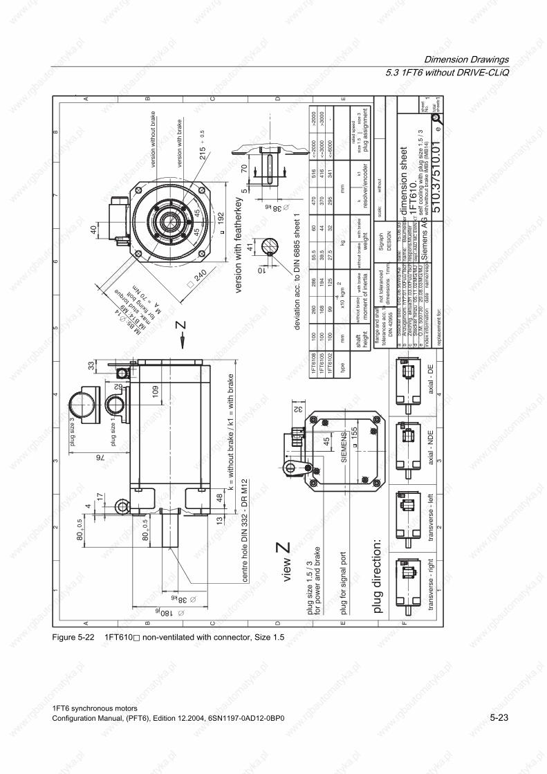
Dimension Drawings 5.3 1FT6 without DRIVE-CLiQ
aS
teck
er b
ildl.
ber. 02
.06.
99W
d/K
e
cZ
eich
ng. a
ktua
lis.
31.0
3.00
Fuû/
Tsch
plug
siz
e 1.
5
dS
teck
er h
inzu
05.1
1.02
MG
/MJ
plug
siz
e 1.
5 / 3
for
pow
er a
nd b
rake
eÒ
.M. 5
0073
020
.08.
03M
G/M
J
plug
ass
ignm
ent
size
1.5
size
3ra
ted
spee
d
<=
6000
<=
3000
<=
2000
>20
00
>30
00
-
33
76
62
32
192
155
80+0
.5
109
13
k =
with
out b
rake
/ k1
= w
ith b
rake
45
1740
240
45_
45_
38k6
180j6
4
48
80+0
.5
570
38k6
215
+0.
5
41
10
devi
atio
n ac
c. to
DIN
688
5 sh
eet 1
cent
re h
ole
DIN
332
- D
R M
12
self
cool
ing
with
plu
g si
ze 1
.5 /
3w
ith/w
ithou
t bra
ke IM
B5
(IM
B14
)
1FT
6102
1FT
6105
1FT
6108
100
100
100
260
168
99
286
194
125
55.5
39.5
27.5
60 44 32
470
370
295
516
416
341
vers
ion
with
feat
herk
ey
Z
plug
for
sign
al p
ort
view
Z
SIE
ME
NS
vers
ion
with
bra
ke
vers
ion
with
out b
rake
1
A B C D E F
23
45
67
8
12
34
A B C D E
shee
tN
o.
tota
lsh
eets
scal
e:w
ithou
t
inde
xin
form
atio
nda
tena
me/
resp
ons.
date
:na
me:
resp
ons.
:de
pt.:A
&D
MC
EW
N K
T2
15.0
6.93
Bau
mei
ster
repl
acem
ent f
or:
Sie
men
s A
G
dim
ensi
on s
heet
510.
3751
0.01
1 1
1FT
610.
Sig
raph
DE
SIG
N
e
Mue
ller
plug
dire
ctio
n:
tran
sver
se -
rig
httr
ansv
erse
- le
ftax
ial -
ND
Eax
ial -
DE
flang
e an
d sh
aft
tole
ranc
es a
cc. t
oD
IN 4
2955
not t
oler
ance
ddi
men
sion
s+
1mm
bFu
û/Ts
chA
nzug
smom
. hin
zu17
.01.
00
plug
siz
e 3
heig
htsh
aft
mom
ent o
f ine
rtia
with
out b
rake
with
bra
ke
wei
ght
with
out b
rake
with
bra
ke
reso
lver
/enc
oder
mm
x10
kgm
-42
kgm
mty
pe
kk1
0IM
B5:14
IMB14:M
9
max.
stud
torq
ue
forfix
ing
bolt
MA=
70Nm
Figure 5-22 1FT610⃞ non-ventilated with connector, Size 1.5
1FT6 synchronous motors Configuration Manual, (PFT6), Edition 12.2004, 6SN1197-0AD12-0BP0 5-23
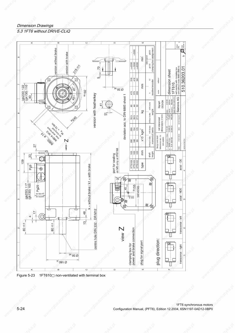
Dimension Drawings 5.3 1FT6 without DRIVE-CLiQ
Figure 5-23 1FT610⃞ non-ventilated with terminal box
1FT6 synchronous motors 5-24 Configuration Manual, (PFT6), Edition 12.2004, 6SN1197-0AD12-0BP0

Dimension Drawings 5.3 1FT6 without DRIVE-CLiQ
Figure 5-24 1FT613⃞ non-ventilated with connector, Size 1.5/3
1FT6 synchronous motors Configuration Manual, (PFT6), Edition 12.2004, 6SN1197-0AD12-0BP0 5-25

Dimension Drawings 5.3 1FT6 without DRIVE-CLiQ
Figure 5-25 1FT613⃞ non-ventilated with terminal box
1FT6 synchronous motors 5-26 Configuration Manual, (PFT6), Edition 12.2004, 6SN1197-0AD12-0BP0
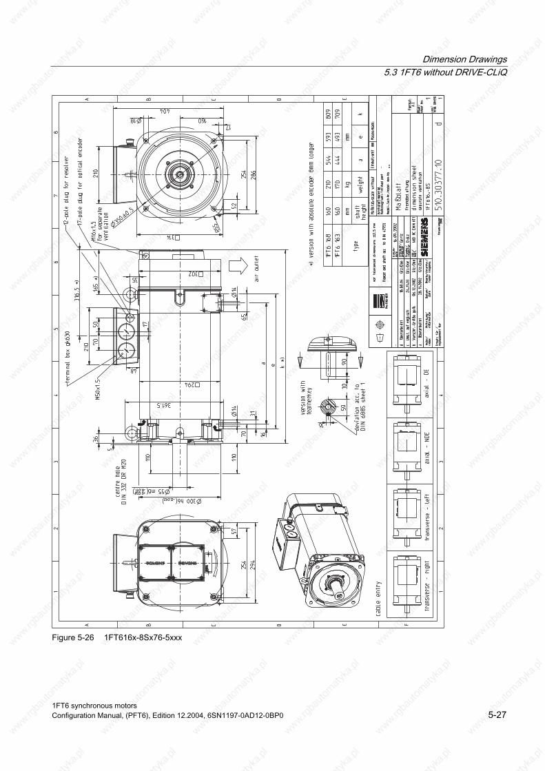
Dimension Drawings 5.3 1FT6 without DRIVE-CLiQ
Figure 5-26 1FT616x-8Sx76-5xxx
1FT6 synchronous motors Configuration Manual, (PFT6), Edition 12.2004, 6SN1197-0AD12-0BP0 5-27

Dimension Drawings 5.3 1FT6 without DRIVE-CLiQ
5.3.2 Force-ventilated 1FT6 motors
min
-1
plug
ass
ignm
ent
rate
d sp
eed
size
1.5
size
3
-an
d br
ake
3.5
1232k6
58+
0.5
58+
0.5
130j6
93
155
194
45
35
10
185
343
2
k =
with
out b
rake
/ k1
= w
ith b
rake
175
140
32
4213
521
1
45
545
32k6
38
165
+0.
3
154
devi
atio
n ac
c. to
DIN
688
5 sh
eet 1
plug
for
fan
port
cent
re h
ole
DIN
332
- D
R M
12
plug
siz
e 1.
5 fo
r po
wer
with
/with
out b
rake
IMB
5 (
IMB
14)
1FT
6084
1FT
6086
80 8066
.548
.083
.565
.030 25
33.5
28.5
449
399
495
445
vers
ion
with
feat
herk
ey
Z
view
Z
plug
for
sign
al p
ort
air
entr
y
dÒ
.M. 5
0073
018
.08.
03M
G/M
J
<=
3000
<=
6000
>30
00
plug
siz
e 1.
5
plug
siz
e 3
1
A B C D E F
23
45
67
8
12
34
A B C D E
shee
tN
o.
tota
lsh
eet
scal
e:w
ithou
t
inde
xin
form
atio
nda
tena
me/
resp
ons.
date
:na
me:
resp
ons.
:de
pt.:
A&
D M
C E
WN
KT
2
25.0
3.93
Bal
ling
repl
acem
ent f
or:
Sie
men
s A
G
dim
ensi
on s
heet
forc
ed v
entil
ated
with
plu
g si
ze 1
.5/3
510.
3743
0.01
1 1
1FT
608.
Sig
raph
DE
SIG
N
d
Mue
ller
flang
e an
d sh
aft
tole
ranc
es a
cc. t
oD
IN 4
2955
plug
dire
ctio
n:
tran
sver
se -
rig
httr
ansv
erse
- le
ftax
ial -
ND
Eax
ial -
DE
not t
oler
ance
ddi
men
sion
s+1m
m
cFu
û/Ts
chA
nzug
smom
. hin
zu 17.
01.0
0
heig
htsh
aft
mom
ent o
f ine
rtia
with
out b
rake
with
bra
ke
wei
ght
with
out b
rake
with
bra
ke
reso
lver
/enc
oder
mm
x10
kgm
-42
kgm
mty
pek
k1
0
IMB5:
11
IMB14:M
10
max
.stud
torq
ue
forfix
ing
bolt
MA
=42
Nm
Figure 5-27 1FT608⃞ force-ventilated with connector, Size 1.5/3
1FT6 synchronous motors 5-28 Configuration Manual, (PFT6), Edition 12.2004, 6SN1197-0AD12-0BP0

Dimension Drawings 5.3 1FT6 without DRIVE-CLiQ
1500
dTa
belle
geö
nder
t12
.05.
03K
e/M
J
rate
d sp
eed
size
1.5
size
3
-1
eÒ
.M. 5
0073
019
.08.
03M
G/M
J
for
pow
er a
nd b
rake
brak
e
brak
e
1348
38k6
80+
0.5
480
+0.5
180j6
241
1k
= w
ithou
t bra
ke / k
1 =
with
bra
ke
42
136
212
17
41
10
40
24019
222
1
111212
32
158
45
90
455
70
38k6
215 +
0.5
172
devi
atio
n ac
c. to
DIN
688
5 sh
eet 1
cent
re h
ole
DIN
332
-DR
M12
with
/with
out b
rake
IM
B5
(IM
B14
)
vers
ion
with
vers
ion
with
out
vers
ion
with
feat
hter
key
1FT
6105
1FT
6108
100
100
260
168
194
286
61.5
45.5
506657
347
361
951
9
Z
view
Z
plug
siz
e 1.
5
plug
for
sign
al p
ort
plug
for
fan
port
air
entr
y
<=
200
0>
200
0>
150
0
plug
siz
e 3
plug
siz
e 1.
5
1
A B C D E F
23
45
67
8
12
34
A B C D E
shee
tN
o.
tota
lsh
eets
scal
e:w
ithou
t
inde
xin
form
atio
nda
tena
me/
resp
ons.
date
:na
me:
resp
ons.
:de
pt.:A
&D
MC
EW
N K
T2
25.0
3.93
Bal
ling
repl
acem
ent f
or:
Sie
men
s A
G
dim
ensi
on s
heet
forc
ed v
entil
ated
with
plu
g si
ze 1
.5/3
510.
3743
1.01
1 1
1FT
610.
Sig
raph
DE
SIG
N
e
Mue
ller
flang
e an
d sh
aft
tole
ranc
es a
cc. t
oD
IN 4
2955
plug
dire
ctio
n:
tran
sver
se-r
ight
tran
sver
se-le
ftax
ial-N
DE
axia
l-DE
not t
oler
ance
ddi
men
sion
s+1m
m
cFu
û/Ts
chA
nzug
smom
. hin
zu 17.
01.0
0
heig
htsh
aft
mom
ent o
f ine
rtia
with
out b
rake
with
bra
ke
wei
ght
with
out b
rake
with
bra
ke
reso
lver
/enc
oder
plug
ass
ignm
ent
mm
x10
kgm
-42
kgm
mm
inty
pe
kk1
0
IMB5:
14
(IMB14
:M12
)
max
.stu
dto
rque
forfix
ing
bolt
MA
=70
Nm
Figure 5-28 1FT610⃞ force-ventilated with connector, Size 1.5/3
1FT6 synchronous motors Configuration Manual, (PFT6), Edition 12.2004, 6SN1197-0AD12-0BP0 5-29

Dimension Drawings 5.3 1FT6 without DRIVE-CLiQ
Figure 5-29 1FT610⃞ force-ventilated with terminal box
1FT6 synchronous motors 5-30 Configuration Manual, (PFT6), Edition 12.2004, 6SN1197-0AD12-0BP0
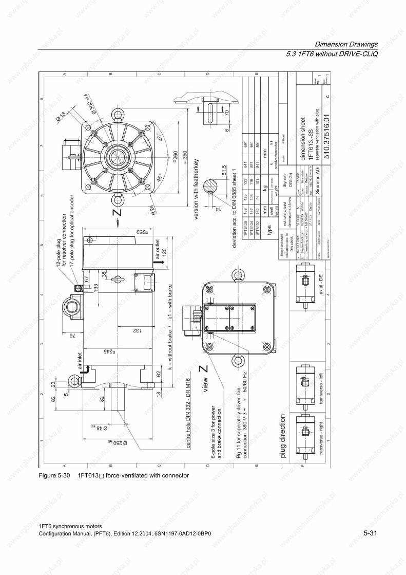
Dimension Drawings 5.3 1FT6 without DRIVE-CLiQ
Figure 5-30 1FT613⃞ force-ventilated with connector
1FT6 synchronous motors Configuration Manual, (PFT6), Edition 12.2004, 6SN1197-0AD12-0BP0 5-31

Dimension Drawings 5.3 1FT6 without DRIVE-CLiQ
Figure 5-31 1FT613⃞ force-ventilated with terminal box
1FT6 synchronous motors 5-32 Configuration Manual, (PFT6), Edition 12.2004, 6SN1197-0AD12-0BP0
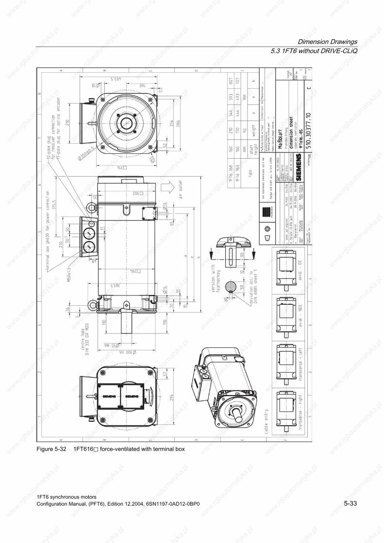
Dimension Drawings 5.3 1FT6 without DRIVE-CLiQ
Figure 5-32 1FT616⃞ force-ventilated with terminal box
1FT6 synchronous motors Configuration Manual, (PFT6), Edition 12.2004, 6SN1197-0AD12-0BP0 5-33
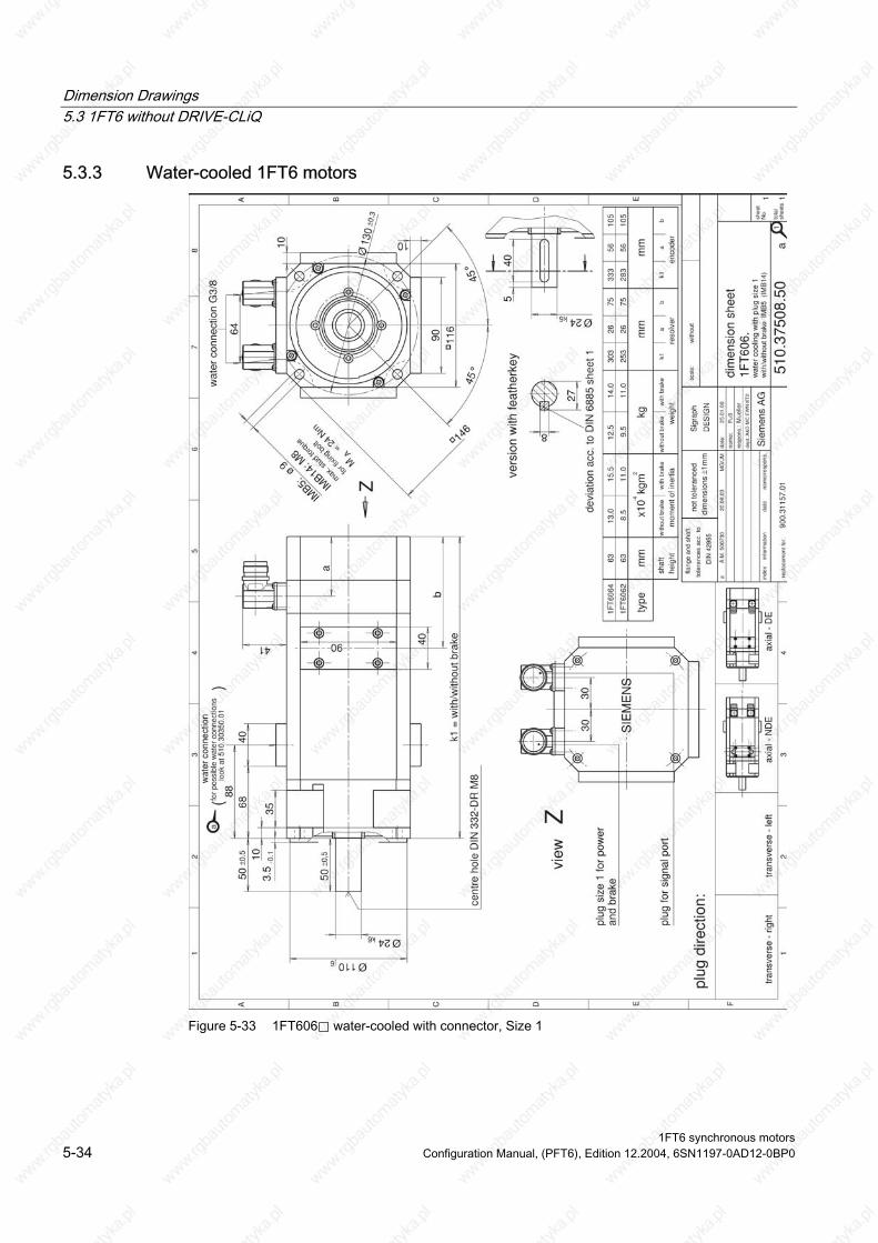
Dimension Drawings 5.3 1FT6 without DRIVE-CLiQ
5.3.3 Water-cooled 1FT6 motors
Figure 5-33 1FT606⃞ water-cooled with connector, Size 1
1FT6 synchronous motors 5-34 Configuration Manual, (PFT6), Edition 12.2004, 6SN1197-0AD12-0BP0
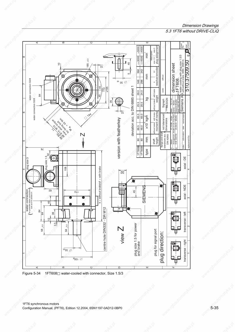
Dimension Drawings 5.3 1FT6 without DRIVE-CLiQ
eS
tand
27.1
0.98
Ki/S
e
plug
siz
e 3
plug
siz
e 1.
5
gÒ
.M. 5
0073
020
.08.
03M
G/M
J
plug
ass
ignm
ent
size
1.5
size
3
rate
d sp
eed
<=
4500
<=
3000
>30
00>
4500
min-1
wat
er c
onne
ctio
nfo
r po
ssib
le w
ater
con
nect
ions
()
40
110
10 10
64
110
84
76
84
194
35
10
455
32k6
32
wat
er c
onne
ctio
n G
3/8wat
er c
onne
ctio
n G
3/8
look
at 5
10.3
0350
.01
devi
atio
n ac
c. to
DIN
688
5 sh
eet 1
45
155
62
32
108
k =
with
out b
rake
/ k1
= w
ith b
rake
58+0
,5
32k6
130j6
3.5
12
38
58+0,
5
45_
45_
165
+0.3
Z
view
Z
cent
re h
ole
DIN
332
- D
R M
12
with
/with
out b
rake
IM
B5
(IM
B14
)
scal
e:w
ithou
t
1FT
6084
1FT
6086
80 8066
.548
.083
.565
.025
.520
.529
.024
.034
629
639
234
2
vers
ion
with
feat
herk
ey
plug
for
sign
al p
ort
plug
siz
e 1.
5 fo
r po
wer
and
brak
e
SIE
ME
NS
1
A B C D E F
23
45
67
8
12
34
A B C D E
shee
tN
o.
tota
lsh
eets
inde
xin
form
atio
nda
tena
me/
resp
ons.da
te:
nam
e:re
spon
s.:
dept
.:A&
D M
C E
WN
KT
2
13.1
1.97
repl
acem
ent f
or:
Sie
men
s A
G
dim
ensi
on s
heet
wat
er c
oolin
g w
ith p
lug
size
1.5
/3
510.
3750
9.50
1 1
1FT
608.
Sig
raph
DE
SIG
N
g
Mue
ller
plug
dire
ctio
n:
tran
sver
se -
rig
httr
ansv
erse
- le
ftax
ial -
ND
E
flang
e an
d sh
aft
tole
ranc
es a
cc. t
oD
IN 4
2955
not t
oler
ance
ddi
men
sion
s+1
mm
axia
l - D
E
fFu
û/Ts
chA
nzug
smom
. hin
zu 17.
01.0
0
heig
htsh
aft
mom
ent o
f ine
rtia
with
out b
rake
with
bra
ke
wei
ght
with
out b
rake
with
bra
ke
reso
lver
/enc
oder
mm
x10
kgm
-42
kgm
mty
pe
kk1
0
IMB5:
11
IMB14
:M10
max
.stu
dto
rque
forfix
ing
bolt
MA
=42
Nm
Figure 5-34 1FT608⃞ water-cooled with connector, Size 1.5/3
1FT6 synchronous motors Configuration Manual, (PFT6), Edition 12.2004, 6SN1197-0AD12-0BP0 5-35
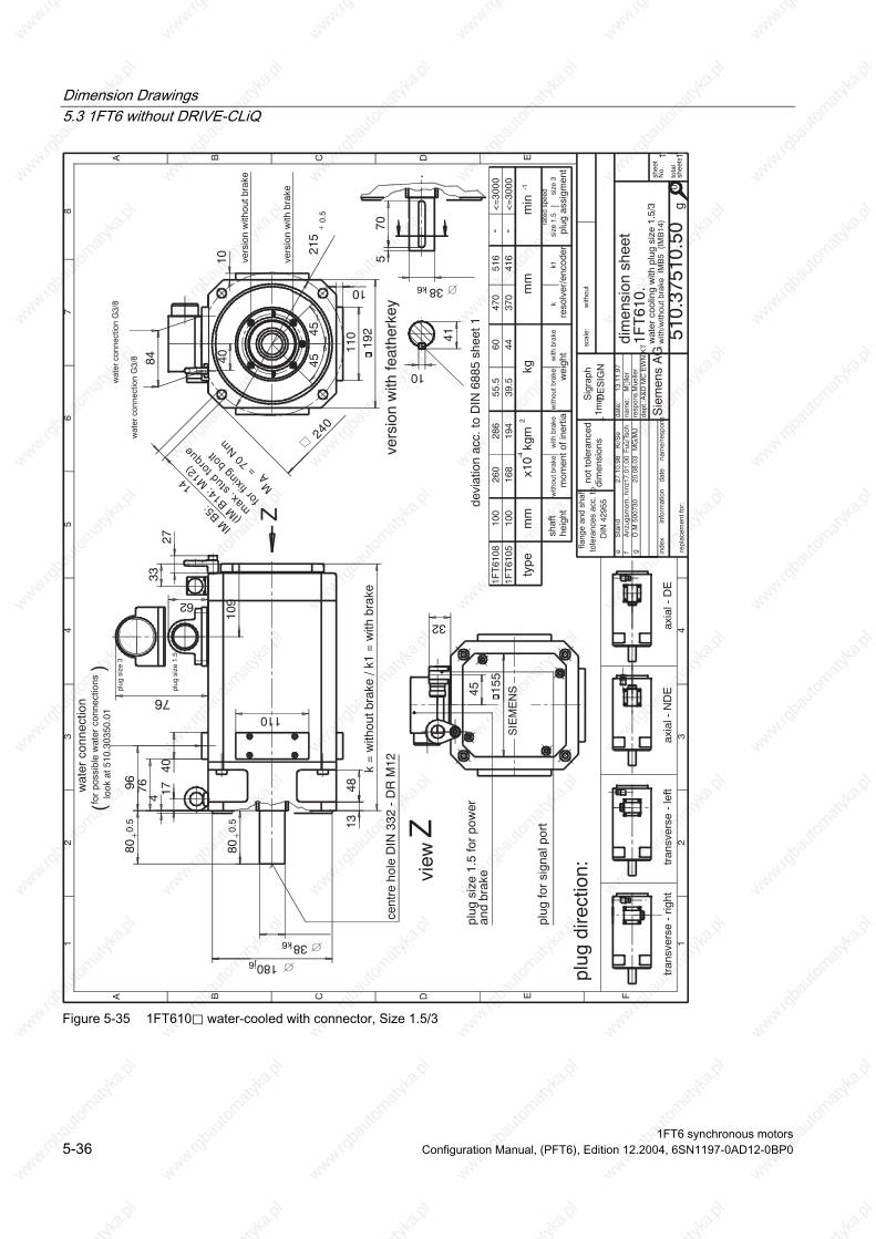
Dimension Drawings 5.3 1FT6 without DRIVE-CLiQ
eS
tand
27.1
0.98
Ki/S
e
plug
siz
e 3
plug
siz
e 1.
5
and
brak
e
gÒ
.M 5
0073
020
.08.
03M
G/M
J
1FT
6108
100
260
286
55.5
6047
051
6
plug
ass
igm
ent
size
1.5
size
3ra
ted
spee
d
<=
3000
<=
3000
min
-1-4
--
wat
er c
onne
ctio
nfo
r po
ssib
le w
ater
con
nect
ions
()
76
40
110
10
110
10
84
76
96
32
wat
er c
onne
ctio
n G
3/8
wat
er c
onne
ctio
n G
3/8
look
at 5
10.3
0350
.01
192
155
2733
80+0.
5
109
13k
= w
ithou
t bra
ke /
k1 =
with
bra
ke62
45
17
40
240
45_
45_
38k6
180j6
4
48
80+0.
5
570
38k6
215
+0.
5
41
10
devi
atio
n ac
c. to
DIN
688
5 sh
eet 1
cent
re h
ole
DIN
332
- D
R M
12
wat
er c
oolin
g w
ith p
lug
size
1.5
/3w
ith/w
ithou
t bra
ke I
MB
5 (
IMB
14)
1FT
6105
100
168
194
39.5
4437
041
6
vers
ion
with
feat
herk
ey
Z
plug
for
sign
al p
ort
plug
siz
e 1.
5 fo
r po
wer
view
Z
SIE
ME
NS
vers
ion
with
bra
ke
vers
ion
with
out b
rake
1
A B C D E F
23
45
67
8
12
34
A B C D E
shee
tN
o.
tota
lsh
eets
scal
e:w
ithou
t
inde
xin
form
atio
nda
tena
me/
resp
ons.da
te:
nam
e:re
spon
s.:
dept
.:A&
D M
C E
WN
KT
2
13.1
1.97
repl
acem
ent f
or:
Sie
men
s A
G
dim
ensi
on s
heet
510.
3751
0.50
1 1
1FT
610.
Sig
raph
DE
SIG
N
g
Mue
ller
plug
dire
ctio
n:
tran
sver
se -
rig
httr
ansv
erse
- le
ftax
ial -
ND
E
flang
e an
d sh
aft
tole
ranc
es a
cc. t
oD
IN 4
2955
not t
oler
ance
ddi
men
sion
s+1
mm
axia
l - D
E
fFu
û/Ts
chA
nzug
smom
. hin
zu 17.
01.0
0
heig
htsh
aft
mom
ent o
f ine
rtia
with
out b
rake
with
bra
ke
wei
ght
with
out b
rake
with
bra
ke
reso
lver
/enc
oder
mm
x10
kgm
2kg
mm
type
kk1
0
IMB5:
14
(IMB14:
M12)
max
.stu
dto
rque
forfix
ing
bolt
M
=70
Nm
A
Figure 5-35 1FT610⃞ water-cooled with connector, Size 1.5/3
1FT6 synchronous motors 5-36 Configuration Manual, (PFT6), Edition 12.2004, 6SN1197-0AD12-0BP0
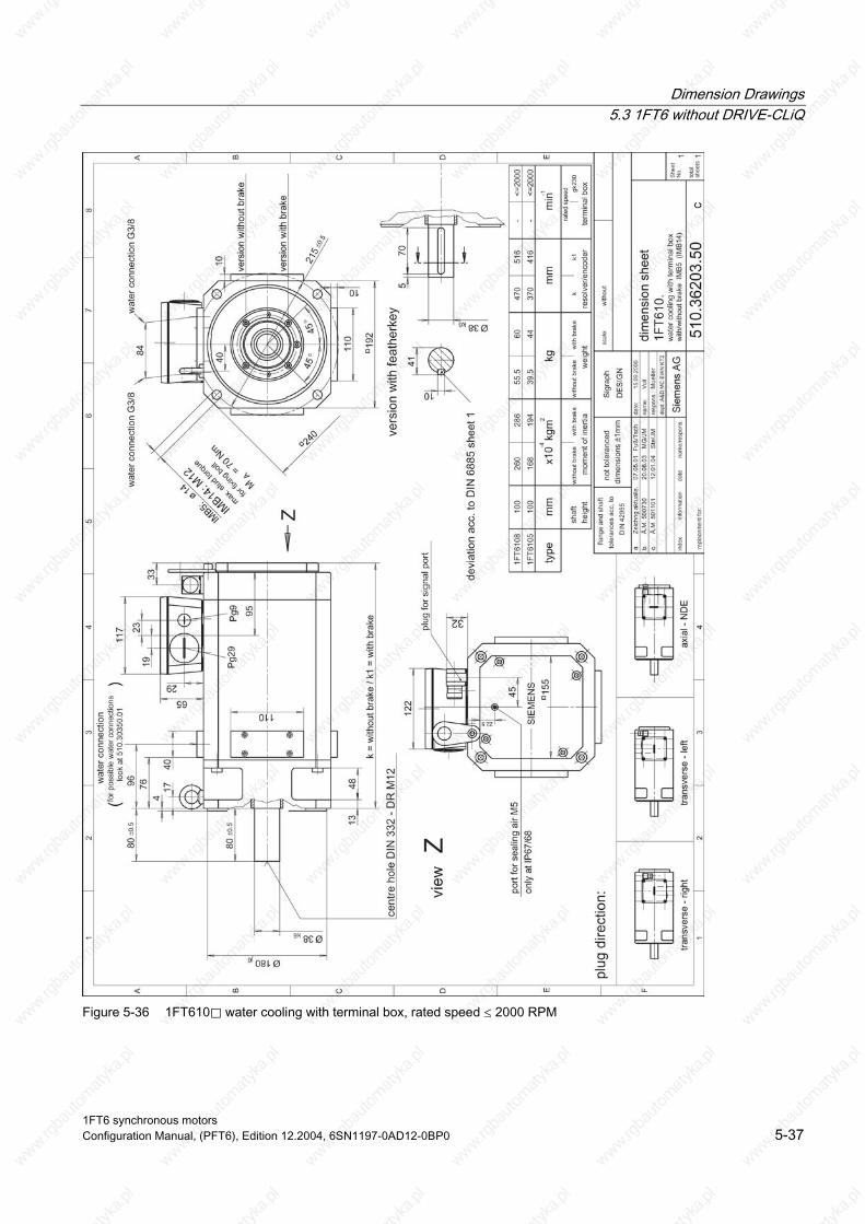
Dimension Drawings 5.3 1FT6 without DRIVE-CLiQ
Figure 5-36 1FT610⃞ water cooling with terminal box, rated speed ≤ 2000 RPM
1FT6 synchronous motors Configuration Manual, (PFT6), Edition 12.2004, 6SN1197-0AD12-0BP0 5-37
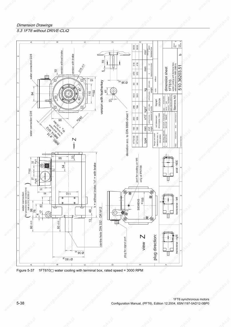
Dimension Drawings 5.3 1FT6 without DRIVE-CLiQ
Figure 5-37 1FT610⃞ water cooling with terminal box, rated speed = 3000 RPM
1FT6 synchronous motors 5-38 Configuration Manual, (PFT6), Edition 12.2004, 6SN1197-0AD12-0BP0
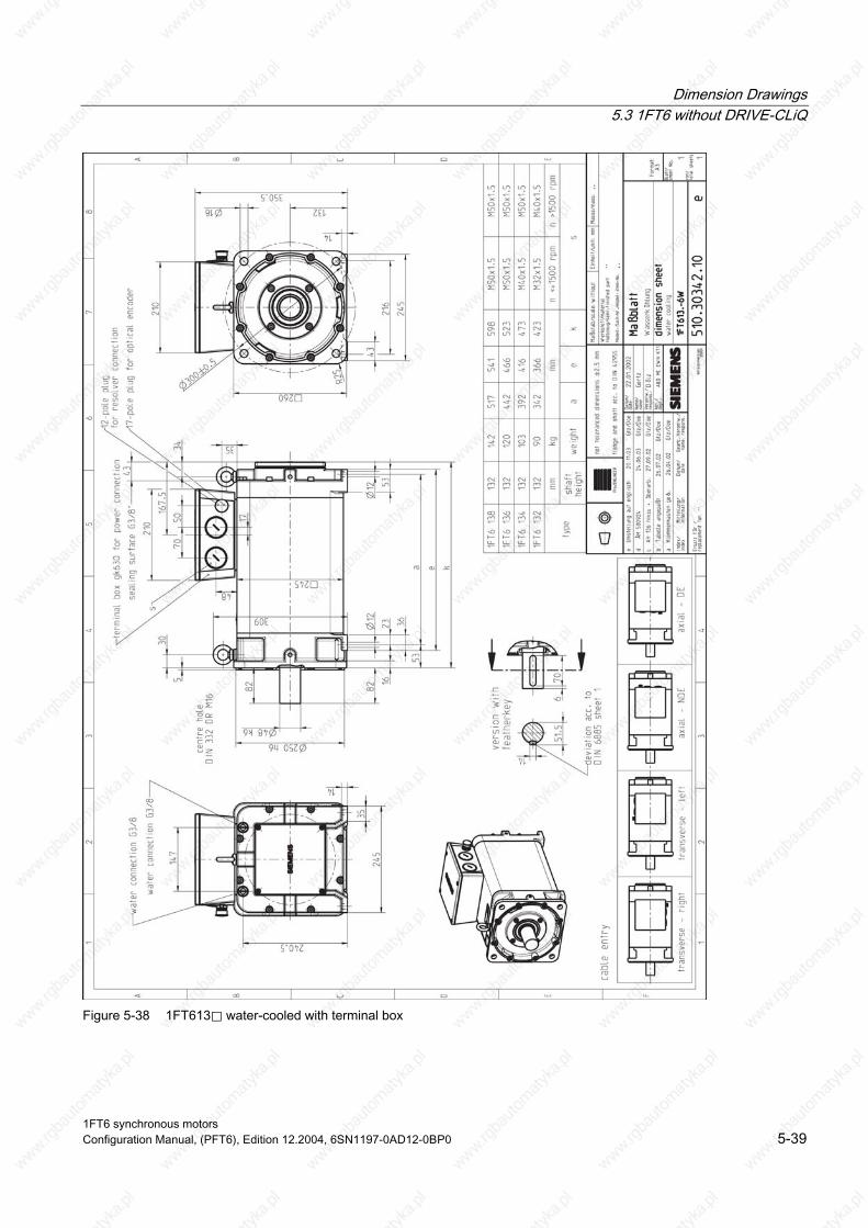
Dimension Drawings 5.3 1FT6 without DRIVE-CLiQ
Figure 5-38 1FT613⃞ water-cooled with terminal box
1FT6 synchronous motors Configuration Manual, (PFT6), Edition 12.2004, 6SN1197-0AD12-0BP0 5-39

Dimension Drawings 5.3 1FT6 without DRIVE-CLiQ
Figure 5-39 1FT613x-6Wx76-5xxx
1FT6 synchronous motors 5-40 Configuration Manual, (PFT6), Edition 12.2004, 6SN1197-0AD12-0BP0

Dimension Drawings 5.3 1FT6 without DRIVE-CLiQ
Figure 5-40 1FT616⃞ water-cooled with terminal box
1FT6 synchronous motors Configuration Manual, (PFT6), Edition 12.2004, 6SN1197-0AD12-0BP0 5-41

Dimension Drawings 5.3 1FT6 without DRIVE-CLiQ
Figure 5-41 1FT616x-8Wx76-5xxx
1FT6 synchronous motors 5-42 Configuration Manual, (PFT6), Edition 12.2004, 6SN1197-0AD12-0BP0

Dimension Drawings 5.3 1FT6 without DRIVE-CLiQ
1FT
606.
Q20
Q21
Q22
Q20
Q21
Q22
1FT
608.
/610
.
of th
e w
ater
con
nect
ions
= W
ater
con
nect
ion
kom
pl. ü
bera
rbei
tet
e
(rig
ht s
ide)
(left
side
)(o
ppos
ite s
ide)
(rig
ht s
ide)
(left
side
)(o
ppos
ite s
ide)
aO
ptio
nen
erw
eite
rtM
G/M
J10
.10.
2002
Plu
g di
rect
ion
driv
e en
d an
d w
ater
conn
ectio
n fr
om to
p si
de is
not
pos
sibl
e
for
1FT
6062
. Ple
ase
sele
ct o
ne o
f the
optio
ns Q
20, Q
21 o
r Q
22 in
stea
d.
1FT
6062
b c d
kom
pl. ü
bera
rbei
tet
Kor
rekt
ur
Kor
rekt
ur
02.0
9.20
04
06.0
8.20
04
12.0
8.20
04
30.0
8.20
04
Re/
Re
Re/
Re
Fuß
/Re
Re/
Re
e e
1
A B C D E F
23
45
67
8
12
34
A B C D E
shee
tN
o.
tota
lsh
eets
scal
ew
ithou
t
Inde
xM
ittei
lung
Dat
umB
earb
./Gep
r.
date
:
nam
e:
resp
ons.
:
A&
D M
C E
WN
K-T
25.0
1.20
02
Fuß
Sie
men
s A
G
Ove
rvie
w o
f the
pos
sibl
e di
rect
ions
510.
3035
0.01
1 1
1FT
6.
Sig
raph
DE
SIG
N
Rei
man
n
Figure 5-42 1FT6_cooling connections
1FT6 synchronous motors Configuration Manual, (PFT6), Edition 12.2004, 6SN1197-0AD12-0BP0 5-43

Dimension Drawings 5.3 1FT6 without DRIVE-CLiQ
1FT6 synchronous motors 5-44 Configuration Manual, (PFT6), Edition 12.2004, 6SN1197-0AD12-0BP0
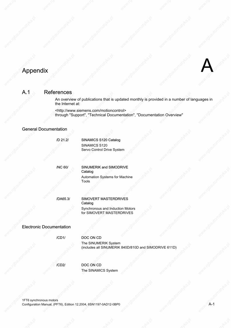
A Appendix
A.1 References An overview of publications that is updated monthly is provided in a number of languages in the Internet at:
<http://www.siemens.com/motioncontrol> erview" through "Support", "Technical Documentation", "Documentation Ov
SINAMICS S120 Servo Control Drive System
SINUMERIK and SIMODRIVE Catalog
General Documentation
/D 21.2/ SINAMICS S120 Catalog
/NC 60/
Automation Systems for Machine Tools
/DA65.3/ SIMOVERT MASTERDRIVES
Synchronous and Induction Motors for SIMOVERT MASTERDRIVES
Catalog
Electronic Documentation
/CD1/ DOC ON CD The SINUMERIK System
MODRIVE 611D) (includes all SINUMERIK 840D/810D and SI
/CD2/ DOC ON CD The SINAMICS System
1FT6 synchronous motors Configuration Manual, (PFT6), Edition 12.2004, 6SN1197-0AD12-0BP0 A-1

Appendix A.1 References
Manufacturer/Service Documentation
/PJAL/ Configuration Manual, Synchronous Motors SINAMICS S120, SIMODRIVE 611, SIMOVERT MASTERDRIVES
Synchronous Motors, General Section
/PFK7S/ Configuration Manual, Synchronous Motors SINAMICS S120
1FK7 Synchronous Motors
/PFT6S/ Configuration Manual, Synchronous Motors SINAMICS S120
1FT6 Synchronous Motors
/PMH2/ Installation Manual, Hollow Shaft Measuring System SINAMICS S120, SIMODRIVE 611, SIMOVERT MASTERDRIVES,
SIMAG H2 Hollow-Shaft Measuring System
/PFK7/ Configuration Manual, Synchronous Motors SIMODRIVE 611, SIMOVERT MASTERDRIVES
1FK7 Synchronous Motors
/PFT6/ Configuration Manual, Synchronous Motors SIMODRIVE 611, SIMOVERT MASTERDRIVES
1FT6 Synchronous Motors
/PFK6/ Configuration Manual, Synchronous Motors SIMODRIVE 611, SIMOVERT MASTERDRIVES
1FK6 Synchronous Motors
/PFS6/ Configuration Manual, Synchronous Motors SIMOVERT MASTERDRIVES
1FS6 Synchronous Motors, Explosion-Protected
/PFU/ Configuration Manual, Synchronous Motors SINAMICS S120, SIMOVERT MASTERDRIVES, MICROMASTER
SIEMOSYN Synchronous Motors 1FU8
1FT6 synchronous motors A-2 Configuration Manual, (PFT6), Edition 12.2004, 6SN1197-0AD12-0BP0

Appendix A.1 References
/ASAL/ Configuration Manual, Induction Motors SIMODRIVE 611, SIMOVERT MASTERDRIVES
Induction Motors, General Section
/APH2/ Configuration Manual, Induction Motors SIMODRIVE 611
1PH2 Induction Motors
/APH4/ Configuration Manual, Induction Motors SIMODRIVE 611
1PH4 Induction Motors
/APH7S/ Configuration Manual, Induction Motors SIMODRIVE 611
1PH7 Induction Motors
/PPM/ Configuration Manual, Hollow Shaft Motors SIMODRIVE 611
Hollow Shaft Motors for Main Spindle Drives 1PM6 and 1PM4
SIMODRIVE 611 Synchronous Motors for Main Spindle Drives 1FE1 Synchronous Build-in Motors
/PJFE/ Configuration Manual, Synchronous Build-in Motors
/PJTM/ Configuration Manual, Build-in Torque Motors SIMODRIVE 611
W6 Build-in Torque Motors 1F
/PJLM/ Configuration Manual, Linear Motors SIMODRIVE 611
N3 Linear Motors 1FN1 and 1F
1FT6 synchronous motors Configuration Manual, (PFT6), Edition 12.2004, 6SN1197-0AD12-0BP0 A-3

Appendix A.1 References
/PMS/ Configuration Manual, ECO Motor Spindle SIMODRIVE 611
ECO Motor Spindle 2SP1
/APL6/ Configuration Manual, Induction Motors SIMOVERT MASTERDRIVES
Induction Motors 1PL6
SIMOVERT MASTERDRIVES VC/MC Induction Motors 1PH7
SIMOVERT MASTERDRIVES
/APH7M/ Configuration Manual, Induction Motors
/PKTM/ Configuration Manual, Complete Torque Motors
Complete Torque Motors 1FW3
1FT6 synchronous motors A-4 Configuration Manual, (PFT6), Edition 12.2004, 6SN1197-0AD12-0BP0

Index A H Absolute value encoders, 4-7 Holding brake, 4-12 Additive, 1-25 Hotline, iv Armature short-circuit braking, 1-15 Axial force stressing, 3-133
B
I Incremental encoders, 4-5 Interfaces, 2-1
Order designation
Brake resistors, 1-15
O C Options, 1-4 Cantilever force diagrams, 3-128
Core types, 1-6 Cantilever force stressing, 3-128 Standard types, 1-5 Characteristics, 3-1
Connector assignment Brake, 2-2 Encoder, 2-2 Power, 2-2
R Resistance characteristic, 4-2 Cooling, 1-21 Resistor braking, 1-15 Cooling medium, 1-24 Force ventilated, 1-18 Cooling powers to be dissipated, 1-26 Non-ventilated, 1-15 Coupling output, 1-28 Water cooling, 1-19 Resolvers, 4-10
D S Danger and warning information, v
Dimension drawings, 5-1 Speed-torque diagrams Force ventilated, 3-62
T
nN 1500 RPM, 1-8
Non-ventilated, 3-2 E Water cooling, 3-94 Standard engineering, 1-1 Encoders, 4-3
ESDS instructions, vii
G Technical data Gearbox
nN 2000 RPM, 1-10 1-stage, 4-13 nN 2500 RPM, 1-11 2-stage, 4-18 nN 3000 RPM, 1-12
1FT6 synchronous motors Configuration Manual, (PFT6), Edition 12.2004, 6SN1197-0AD12-0BP0 Index-1

Index
nN 4500 RPM, 1-13 nN 6000 RPM, 1-14
Technical features, 1-3 Temperature sensor, KTY 84, 4-1 Thermal motor protection, 4-1
1FT6 synchronous motors Index-2 Configuration Manual, (PFT6), Edition 12.2004, 6SN1197-0AD12-0BP0

Suggestions
Corrections
To
SIEMENS AG
A&D MC BMS
Postfach 3180
D-91050 Erlangen
Tel.: +49 (0) 180 / 5050 - 222 (Service Support)
Fax: +49 (0) 9131 / 98 – 2176 (Documentation)
email: [email protected]
For Publication/Manual:
Synchronous Motors
1FT6
Manufacturer/Service Documentation
Configuration Manual
Order No.: 6SN1197-0AD12-0BP0
Edition: 12.2004
From
Name
Company/Department
Address
Postal code: Town:
Telephone: /
Telefax: /
If you come across any printing errors in this
document, please let us know using this form.
We would also be grateful for any suggestions and
recommendations for improvement.
Suggestions and/or corrections