dc axial fans - ebm-papst - world market leader for … · 2014-11 26 range of fans ebm-papst...
TRANSCRIPT
DC axial fan overview 27DC axial fans / DC diagonal fans 31
DC axial fans
25
2014
-11
Info
rmat
ion
DC a
xial
fans
DC fa
ns -
spe
cial
sAC
max
x / G
reen
Tech
EC
-Com
pact
fans
AC a
xial
fans
Acce
ssor
ies
Repr
esen
tativ
esDC
cen
trifu
gal f
ans
AC c
entr
ifuga
l fan
s
26
2014
-11
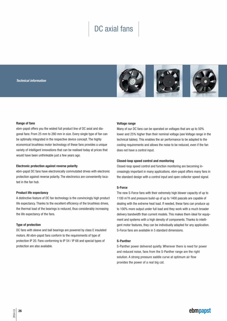
Range of fans
ebm-papst offers you the widest full product line of DC axial and dia-
gonal fans: From 25 mm to 280 mm in size. Every single type of fan can
be optimally integrated in the respective device concept. The highly
economical brushless motor technology of these fans provides a unique
variety of intelligent innovations that can be realised today at prices that
would have been unthinkable just a few years ago.
Electronic protection against reverse polarity
ebm-papst DC fans have electronically commutated drives with electronic
protection against reverse polarity. The electronics are conveniently loca-
ted in the fan hub.
Product life expectancy
A distinctive feature of DC fan technology is the convincingly high product
life expectancy. Thanks to the excellent efficiency of the brushless drives,
the thermal load of the bear ings is reduced, thus con siderably increasing
the life expectancy of the fans.
Type of protection
DC fans with sleeve and ball bearings are powered by class E insulated
motors. All ebm-papst fans conform to the requirements of type of
protection IP 20. Fans conforming to IP 54 / IP 68 and special types of
protection are also avail able.
Voltage range
Many of our DC fans can be operated on voltages that are up to 50%
lower and 25% higher than their nominal voltage (see Voltage range in the
technical tables). This enables the air performance to be adapted to the
cooling requirements and allows the noise to be reduced, even if the fan
does not have a control input.
Closed-loop speed control and monitoring
Closed-loop speed control and function monitoring are becoming in-
creasingly important in many applications. ebm-papst offers many fans in
the standard design with a control input and open collector speed signal.
S-Force
The new S-Force fans with their extremely high blower capacity of up to
1100 m3/h and pressure build-up of up to 1400 pascals are capable of
dealing with the extreme heat load. If needed, these fans can produce up
to 100% more output under full load and they work with a much broader
delivery bandwidth than current models. This makes them ideal for equip-
ment and systems with a high density of components. Thanks to intelli-
gent motor features, they can be individually adapted for any application.
S-Force fans are available in 5 standard dimensions.
S-Panther
S-Panther power delivered quietly. Wherever there is need for power
and reduced noise, fans from the S-Panther range are the right
solution. A strong pressure saddle curve at optimum air flow
provides the power of a real big cat.
Technical information
DC axial fans

27
2014
-11
Dim
ensi
ons
Serie
s
Air f
low
Page
mm m3/h
c 25 x 8 250 2,3...4,6 31
c 40 x 10 400 F 6...9 32
c 40 x 20 400 10...13,5 33
c 40 x 28 420 J 24...38 34
c 50 x 15 500 F 11...20 35
c 60 x 15 600 F 19...33 36
c 60 x 25 620 21...67 37
c 60 x 25 630 40...44 38
c 60 x 25 600 N 21...56 39
c 60 x 25 600 N VARIOFAN 16...41 40
c 60 x 32 600 J 70...82 41
c 70 x 15 700 F 28...44 42
c 80 x 25 8450 32...117 43
c 80 x 25 8400 N 33...79 44
c 80 x 25 8400 N VARIOFAN 20...58 45
c 80 x 32 8300 32...80 46
c 80 x 38 8200 J 132...222 47
c 92 x 25 3400 N 61...102 48
c 92 x 25 3400 N VARIOFAN 44...84 49
c 92 x 32 3300 56...107 50
c 92 x 32 3300 N 56...133 51
c 92 x 38 3200 J 130...280 52
c 92 x 38 3250 J 145...270 53
c 119 x 25 4400 F 94...170 54
c 119 x 25 4400 FN 200...225 55
c 119 x 32 4300 95...204 56
c 119 x 32 4300 VARIOFAN 65...170 57
Subject to alternations
10
m3/h
40 50 60 70 80 9020 30 100 400 500 600 700 800 900200 300 1000 2000 3000
10 40 50 60 70 80 9020 30 100 400 500 600 700 800 900 1000200 300 2000 3000
NEW
NEW
NEW
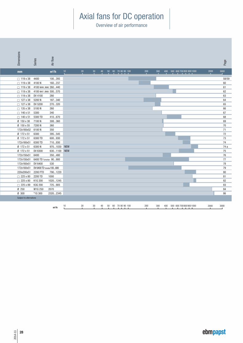
Axial fans for DC operationOverview of air performance In
form
atio
nDC
axi
al fa
nsDC
fans
- s
peci
als
ACm
axx
/ Gre
enTe
ch
EC-C
ompa
ct fa
nsAC
axi
al fa
nsAc
cess
orie
sRe
pres
enta
tives
DC c
entr
ifuga
l fan
sAC
cen
trifu
gal f
ans
28
2014
-11
Axial fans for DC operationOverview of air performance
Dim
ensi
ons
Serie
s
Air f
low
Page
mm m3/h
c 119 x 38 4400 100...285 58/59
c 119 x 38 4100 N 160...237 60
c 119 x 38 4100 NHH..NH6 260...440 61
c 119 x 38 4100 NH7..NH8 500...570 62
c 119 x 38 DV 4100 280 63
c 127 x 38 5200 N 187...340 64
c 127 x 38 DV 5200 270...320 65
c 135 x 38 5100 N 260 66
c 140 x 51 5300 340 67
c 140 x 51 5300 TD 410...670 68
Ø 150 x 38 7100 N 308...360 69
Ø 150 x 55 7200 N 360 70
172x160x52 6100 N 350 71
Ø 172 x 51 6300 395...545 72
Ø 172 x 51 6300 TD 600...930 73
172x160x51 6300 TD 710...930 74
Ø 172 x 51 6300 N 970...1030 74 a
Ø 172 x 51 DV 6300 630...1100 75
172x150x51 6400 350...480 76
172x150x51 6400 TD Turbofan 90...900 77
172x160x51 DV 6400 530 78
172x160x51 DV 6400 TD Turbofan100...680 79
220x200x51 2200 FTD 790...1220 80
c 225 x 80 2200 TD 1000 81
c 225 x 80 K1G 200 1020...1245 82
c 225 x 89 K3G 200 725...905 83
Ø 250 W1G 250 2070 84
Ø 300 *1G 300 2320...2345 86
Subject to alternations
10
m3/h
40 50 60 70 80 9020 30 100 400 500 600 700 800 900200 300 1000 2000 3000
10 40 50 60 70 80 9020 30 100 400 500 600 700 800 900 1000200 300 2000 3000
NEW
NEW
29
2014
-11
Axial fans
Series mm OPTIONAL P.
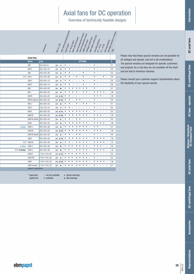
250 25 x 25 x 8 yes • – – – – – – – • – – – – 31
400 F 40 x 40 x 10 yes • • – – – – – – • – – – – 32
400 40 x 40 x 20 yes • • – – – • – – • – – – – 33
NEW 420 J 40 x 40 x 28 yes • • – • – • – – • – – • – 34
500 F 50 x 50 x 15 yes • • – – – • – – • – – – – 35
600 F 60 x 60 x 15 yes • • – – – • – – • – – – – 36
620 60 x 60 x 25 yes • • • • • • • – • – – – – 37
630 60 x 60 x 25 yes • • • • – • • – • • • • – 38
600 N 60 x 60 x 25 yes / • • – – – – – – • • • – – 39
600 N VARIOFAN 60 x 60 x 25 yes / • • – • • – – – • – – – – 40
600 J 60 x 60 x 32 yes • • – • – • • – • – – – – 41
700 F 70 x 70 x 15 yes • • – – – – – – • – – – – 42
8450 80 x 80 x 25 yes / • • • • • • • – • – – – – 43
8400 N 80 x 80 x 25 yes / • • • • • • • – • • • – – 44
8400 N VARIOFAN 80 x 80 x 25 yes • • – • • – – – • – – – – 45
8300 80 x 80 x 32 yes • • • • • • • – • • • • – 46
8200 J 80 x 80 x 38 yes • • • • • • • – • • – – – 47
3400 N 92 x 92 x 25 yes / • • • • • • • – • • • – – 48
3400 N VARIOFAN 92 x 92 x 25 yes • • – • • – – – • – – – – 49
3300 92 x 92 x 32 yes / • • • • • • • – • • • • – 50
NEW 3300 N 92 x 92 x 38 yes • • – • • • • – • • • • – 51
3200 J 92 x 92 x 38 yes • • • • • • • – • • • – – 52
NEW 3250 J 92 x 92 x 38 yes • • – • • • • – • • • • – 53
4400 F 119 x 119 x 25 yes / • • • • • • • – • – – – – 54
4400 FN 119 x 119 x 25 yes • • • • • • • – • – – – – 55
4300 119 x 119 x 32 yes / • • • • • • • – • • • • – 56
4300 VARIOFAN 119 x 119 x 32 yes • • • • • • • – • – – – – 57
Subject to alternations
Sint
ec s
leev
e be
arin
gs/b
all b
earin
gs
Page
VDE,
UL,
CSA
Dim
ensio
ns
Spee
d sig
nal
Go /
No-g
o al
arm
Alar
m w
ith li
mit
spee
dEx
tern
al te
mpe
ratu
re s
enso
r
Inte
rnal
tem
pera
ture
sen
sor
PWM
con
trol i
nput
An
alog
ue c
ontro
l inp
ut
Hum
idity
pro
tect
ion
IP >
= IP
54
Salt
fog
prot
ectio
nRe
vers
ible
dire
ctio
n of
rota
tion
IP >
= IP
68
Sleeve bearings Ball bearings
– not yet available • available
* approvals-applied for
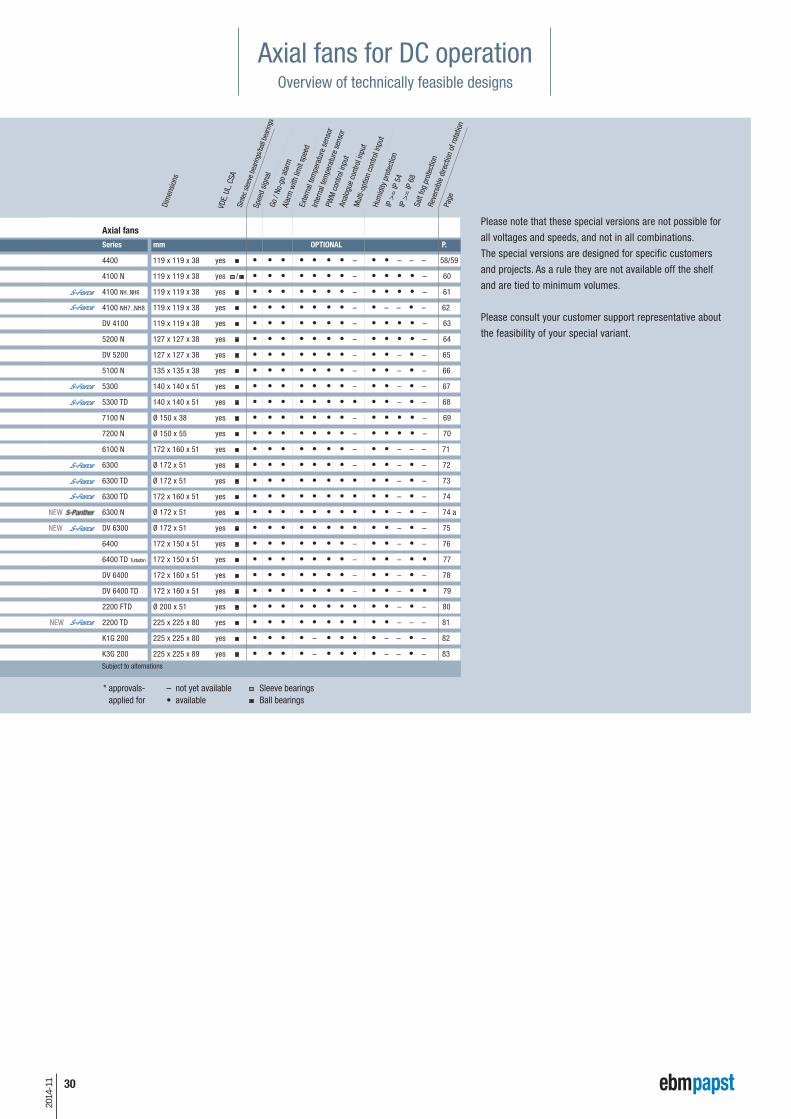
Please note that these special versions are not possible for
all voltages and speeds, and not in all combinations.
The special versions are designed for specific customers
and projects. As a rule they are not available off the shelf
and are tied to minimum volumes.
Please consult your customer support representative about
the feasibility of your special variant.
Mul
ti-op
tion
cont
rol i
nput
Axial fans for DC operationOverview of technically feasible designs In
form
atio
nDC
axi
al fa
nsDC
fans
- s
peci
als
ACm
axx
/ Gre
enTe
ch
EC-C
ompa
ct fa
nsAC
axi
al fa
nsAc
cess
orie
sRe
pres
enta
tives
DC c
entr
ifuga
l fan
sAC
cen
trifu
gal f
ans
Axial fans
Series mm OPTIONAL P.
4400 119 x 119 x 38 yes • • • • • • • – • • – – – 58/59
4100 N 119 x 119 x 38 yes / • • • • • • • – • • • • – 60
4100 NH..NH6 119 x 119 x 38 yes • • • • • • • – • • • • – 61
4100 NH7..NH8 119 x 119 x 38 yes • • • • • • • – • – – • – 62
DV 4100 119 x 119 x 38 yes • • • • • • • – • • • • – 63
5200 N 127 x 127 x 38 yes • • • • • • • – • • • • – 64
DV 5200 127 x 127 x 38 yes • • • • • • • – • • – • – 65
5100 N 135 x 135 x 38 yes • • • • • • • – • • – • – 66
5300 140 x 140 x 51 yes • • • • • • • – • • – • – 67
5300 TD 140 x 140 x 51 yes • • • • • • • • • • – • – 68
7100 N Ø 150 x 38 yes • • • • • • • – • • • • – 69
7200 N Ø 150 x 55 yes • • • • • • • – • • • • – 70
6100 N 172 x 160 x 51 yes • • • • • • • – • • – – – 71
6300 Ø 172 x 51 yes • • • • • • • – • • – • – 72
6300 TD Ø 172 x 51 yes • • • • • • • • • • – • – 73
6300 TD 172 x 160 x 51 yes • • • • • • • • • • – • – 74
NEW 6300 N Ø 172 x 51 yes • • • • • • • • • • – • – 74 a
NEW DV 6300 Ø 172 x 51 yes • • • • • • • • • • – • – 75
6400 172 x 150 x 51 yes • • • • • • • – • • – • – 76
6400 TD Turbofan 172 x 150 x 51 yes • • • • • • • – • • – • • 77
DV 6400 172 x 160 x 51 yes • • • • • • • – • • – • – 78
DV 6400 TD 172 x 160 x 51 yes • • • • • • • – • • – • • 79
2200 FTD Ø 200 x 51 yes • • • • • • • • • • – • – 80
NEW 2200 TD 225 x 225 x 80 yes • • • • • • • • • • – – – 81
K1G 200 225 x 225 x 80 yes • • • • – • • • • – – • – 82
K3G 200 225 x 225 x 89 yes • • • • – • • • • – – • – 83
Subject to alternations
30
2014
-11
VDE,
UL,
CSA
Please note that these special versions are not possible for
all voltages and speeds, and not in all combinations.
The special versions are designed for specific customers
and projects. As a rule they are not available off the shelf
and are tied to minimum volumes.
Please consult your customer support representative about
the feasibility of your special variant.
Axial fans for DC operationOverview of technically feasible designs
Sleeve bearings Ball bearings
– not yet available • available
* approvals-applied for
Dim
ensio
ns
Sint
ec s
leev
e be
arin
gs/b
all b
earin
gs
Page
Spee
d sig
nal
Go /
No-g
o al
arm
Alar
m w
ith li
mit
spee
dEx
tern
al te
mpe
ratu
re s
enso
r
Inte
rnal
tem
pera
ture
sen
sor
PWM
con
trol i
nput
An
alog
ue c
ontro
l inp
ut
Hum
idity
pro
tect
ion
IP >
= IP
54
Salt
fog
prot
ectio
nRe
vers
ible
dire
ctio
n of
rota
tion
IP >
= IP
68
Mul
ti-op
tion
cont
rol i
nput
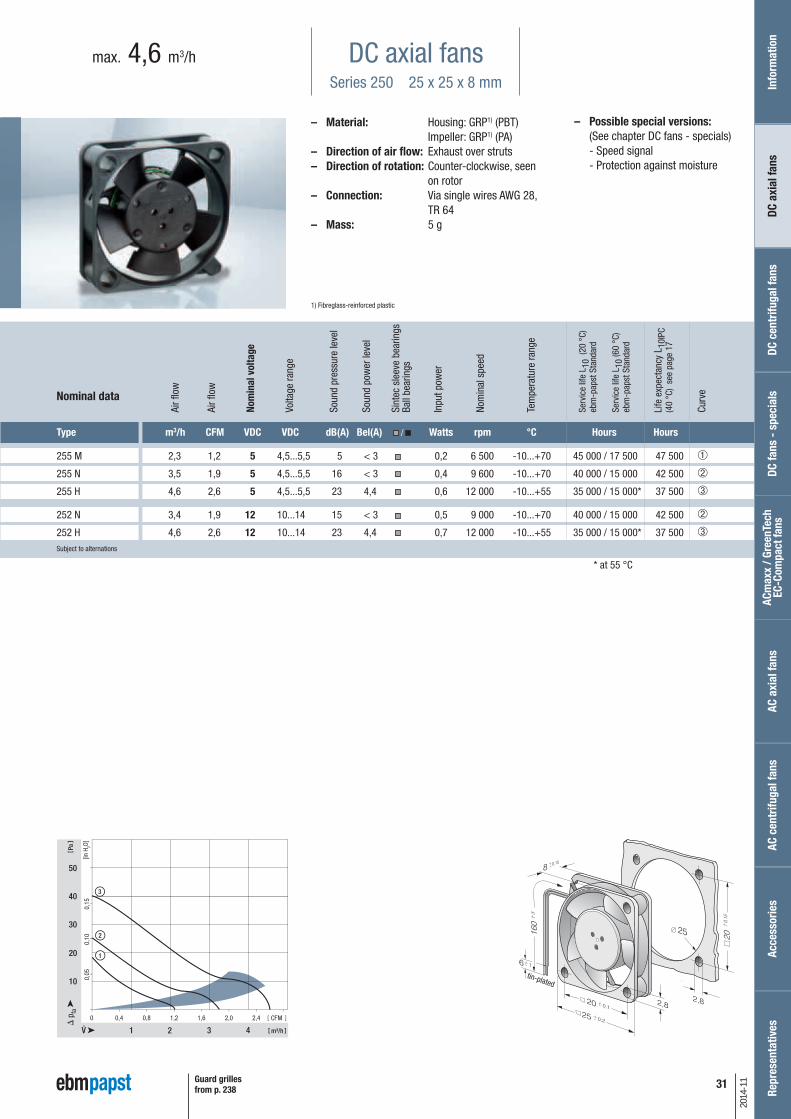
– Possible special versions:(See chapter DC fans - specials)
- Speed signal - Protection against moisture
DC axial fansSeries 250 25 x 25 x 8 mm
max. 4,6 m3/h
– Material: Housing: GRP1) (PBT) Impeller: GRP1) (PA)
– Direction of air flow: Exhaust over struts – Direction of rotation: Counter-clockwise, seen
on rotor– Connection: Via single wires AWG 28,
TR 64– Mass: 5 g
1) Fibreglass-reinforced plastic
1 2
10
20
3 4 m³/h
2
1
3
30
40
50
0 0,4 0,8 1,2 1,6 2,0 2,4
0,15
0,10
0,05
Pa
CFM
[in H
2O]
Type m3/h CFM VDC VDC dB(A) Bel(A) / Watts rpm °C Hours Hours
255 M 2,3 1,2 5 4,5...5,5 5 < 3 0,2 6 500 -10...+70 45 000 / 17 500 47 500 ➀
255 N 3,5 1,9 5 4,5...5,5 16 < 3 0,4 9 600 -10...+70 40 000 / 15 000 42 500 ➁
255 H 4,6 2,6 5 4,5...5,5 23 4,4 0,6 12 000 -10...+55 35 000 / 15 000* 37 500 ➂
252 N 3,4 1,9 12 10...14 15 < 3 0,5 9 000 -10...+70 40 000 / 15 000 42 500 ➁
252 H 4,6 2,6 12 10...14 23 4,4 0,7 12 000 -10...+55 35 000 / 15 000* 37 500 ➂Subject to alternations
Nom
inal
vol
tage
Air f
low
Air f
low
Volta
ge ra
nge
Soun
d pr
essu
re le
vel
Soun
d po
wer
leve
l
Sint
ec s
leev
e be
arin
gsBa
ll be
arin
gs
Inpu
t pow
er
Nom
inal
spe
ed
Tem
pera
ture
rang
e
Serv
ice
life
L 10
(20
°C)
ebm
-pap
st S
tand
ard
Serv
ice
life
L 10
(60
°C)
ebm
-pap
st S
tand
ard
Life
exp
ecta
ncy
L 10I
PC(4
0 °C
) se
e pa
ge 1
7
Curv
e
31Guard grillesfrom p. 238
2014
-11
Nominal data
* at 55 °C
tin-plated
Info
rmat
ion
DC a
xial
fans
DC fa
ns -
spe
cial
sAC
max
x / G
reen
Tech
EC
-Com
pact
fans
AC a
xial
fans
Acce
ssor
ies
Repr
esen
tativ
esDC
cen
trifu
gal f
ans
AC c
entr
ifuga
l fan
s

32
2014
-11
– Possible special versions:(See chapter DC fans - specials)
- Speed signal - Go / No-go alarm - Protection against moisture
DC axial fansSeries 400 F 40 x 40 x 10 mm
max. 9 m3/h
Type m3/h CFM VDC VDC dB(A) Bel(A) / Watts rpm °C Hours Hours
405 F 8 4,7 5 4,5...5,5 22,1 4,4 0,7 5 400 -20...+70 45 000 / 17 500 47 500 ➁
405 FH 9 5,3 5 4,5...5,5 26,0 4,6 0,9 6 000 -20...+70 45 000 / 17 500 47 500 ➂
412 FM 6 3,5 12 10...14 17,0 3,8 0,5 4 300 -20...+70 45 000 / 17 500 47 500 ➀
412 F 8 4,7 12 10...14 22,1 4,4 0,7 5 400 -20...+70 45 000 / 17 500 47 500 ➁
412 FH 9 5,3 12 10...14 26,0 4,6 0,8 6 000 -20...+70 45 000 / 17 500 47 500 ➂
414 F 8 4,7 24 20...28 22,1 4,4 0,8 5 400 -20...+70 45 000 / 17 500 47 500 ➁
414 FH 9 5,3 24 21,6...26,4 26,0 4,4 0,9 6 000 -20...+70 45 000 / 17 500 47 500 ➂
412 FM-074 6 3,5 12 10...14 17,0 3,8 0,4 4 300 -20...+85 45 000 / 17 500 47 500 ➀
412 F-130 8 4,7 12 10...14 22,1 4,4 0,6 5 400 -20...+85 45 000 / 17 500 47 500 ➁
412 FH-132 9 5,3 12 10...14 26,0 4,6 0,8 6 000 -20...+85 45 000 / 17 500 47 500 ➂Subject to alternations
– Material: Housing: GRP1) (PBT) Impeller: GRP1) (PA)
– Direction of air flow: Exhaust over struts – Direction of rotation: Counter-clockwise, seen
on rotor– Connection: Via single wires AWG 28,
TR 64– Highlights: Some models are suitable
for use at high ambient temperatures
– Mass: 17 g
1) Fibreglass-reinforced plastic
0 1 2 3 4 5
2 4
10
20
6 8
30
1
2
15
25
5
3
0,10
0,08
0,06
0,04
0,02
m³/h
Pa
CFM
[in H
2O]
Model with temperature range up to +85 °C.
tin-plated
Guard grillesfrom p. 238
Nom
inal
vol
tage
Air f
low
Air f
low
Volta
ge ra
nge
Soun
d pr
essu
re le
vel
Soun
d po
wer
leve
l
Sint
ec s
leev
e be
arin
gsBa
ll be
arin
gs
Inpu
t pow
er
Nom
inal
spe
ed
Tem
pera
ture
rang
e
Serv
ice
life
L 10
(20
°C)
ebm
-pap
st S
tand
ard
Serv
ice
life
L 10
(60
°C)
ebm
-pap
st S
tand
ard
Life
exp
ecta
ncy
L 10I
PC(4
0 °C
) se
e pa
ge 1
7
Curv
eNominal data

33
2014
-11
– Possible special versions:(See chapter DC fans - specials)
- Speed signal - Go / No-go alarm - PWM control input - Protection against moisture
DC axial fansSeries 400 40 x 40 x 20 mm
max. 13,5 m3/h
– Material: Housing: GRP1) (PBT) Impeller: GRP1) (PA)
– Direction of air flow: Exhaust over struts – Direction of rotation: Counter-clockwise, seen
on rotor– Connection: Via single wires AWG 28,
TR 64– Highlights: Some models are suitable
for use at high ambient temperatures
– Mass: 27 g
1) Fibreglass-reinforced plastic
0 1 2 3 4 5 6 7
2 4
10
30
20
6 8 10
401
2
50
0,15
0,10
0,05
m³/h
Pa
CFM
[in H
2O]
Type m3/h CFM VDC VDC dB(A) Bel(A) / Watts rpm °C Hours Hours
405 10,0 5,9 5 4,5...5,5 18 3,8 0,9 6 000 -20...+70 50 000 / 20 000 52 500 ➀
412 10,0 5,9 12 10...14 18 3,8 0,8 6 000 -20...+70 50 000 / 20 000 52 500 ➀
412 H 13,5 7,9 12 10...14 29 4,7 1,6 8 100 -20...+60 45 000 / 17 500 47 500 ➁
414 10,0 5,9 24 20...28 18 3,8 1,0 6 000 -20...+70 50 000 / 20 000 52 500 ➀
414 H 13,5 7,9 24 20...26,5 29 4,7 1,7 8 100 -20...+60 45 000 / 17 500 47 500 ➁
412-099 10,0 5,9 12 10...14 18 3,8 0,8 6 000 -20...+85 50 000 / 20 000 52 500 ➀Subject to alternations
Model with temperature range up to +85 °C.
tin-plated
Guard grillesfrom p. 238
Info
rmat
ion
DC a
xial
fans
DC fa
ns -
spe
cial
sAC
max
x / G
reen
Tech
EC
-Com
pact
fans
AC a
xial
fans
Acce
ssor
ies
Repr
esen
tativ
esDC
cen
trifu
gal f
ans
AC c
entr
ifuga
l fan
s
Nom
inal
vol
tage
Air f
low
Air f
low
Volta
ge ra
nge
Soun
d pr
essu
re le
vel
Soun
d po
wer
leve
l
Sint
ec s
leev
e be
arin
gsBa
ll be
arin
gs
Inpu
t pow
er
Nom
inal
spe
ed
Tem
pera
ture
rang
e
Serv
ice
life
L 10
(20
°C)
ebm
-pap
st S
tand
ard
Serv
ice
life
L 10
(60
°C)
ebm
-pap
st S
tand
ard
Life
exp
ecta
ncy
L 10I
PC(4
0 °C
) se
e pa
ge 1
7
Curv
eNominal data
34
2014
-11
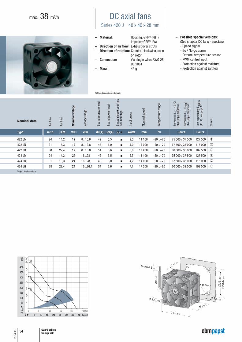
– Possible special versions:(See chapter DC fans - specials)
- Speed signal - Go / No-go alarm - External temperature sensor - PWM control input - Protection against moisture - Protection against salt fog
DC axial fansSeries 420 J 40 x 40 x 28 mm
max. 38 m3/h
Type m3/h CFM VDC VDC dB(A) Bel(A) / Watts rpm °C Hours Hours
422 JM 24 14,2 12 8...13,8 42 5,5 2,5 11 100 -20...+70 75 000 / 37 500 127 500 ➀
422 JN 31 18,3 12 8...13,8 48 6,0 4,0 14 000 -20...+70 67 500 / 35 000 115 000 ➁
422 JH 38 22,4 12 8...13,8 54 6,6 6,8 17 200 -20...+70 60 000 / 30 000 102 500 ➂
424 JM 24 14,2 24 16...28 42 5,5 2,7 11 100 -20...+70 75 000 / 37 500 127 500 ➀
424 JN 31 18,3 24 16...28 48 6,0 4,2 14 000 -20...+70 67 500 / 35 000 115 000 ➁
424 JH 38 22,4 24 16...26,4 54 6,6 7,1 17 200 -20...+65 60 000 / 32 500 102 500 ➂Subject to alternations
– Material: Housing: GRP1) (PBT) Impeller: GRP1) (PA)
– Direction of air flow: Exhaust over struts – Direction of rotation: Counter-clockwise, seen
on rotor– Connection: Via single wires AWG 28,
UL 1061– Mass: 45 g
1) Fibreglass-reinforced plastic
Ø 42,5 ± 0,3
0
5 10
50
100
150
200
250
m³/h
Pa
CFM
[in H
2O]
0,5
1,0
1,5
5 10 15
15 20 25
20
300
0,2
0,75
1,25
30 35 40
350
400
2
1
3
tin-plated
Guard grillesfrom p. 238
Nominal data
Nom
inal
vol
tage
Air f
low
Air f
low
Volta
ge ra
nge
Soun
d pr
essu
re le
vel
Soun
d po
wer
leve
l
Sint
ec s
leev
e be
arin
gsBa
ll be
arin
gs
Inpu
t pow
er
Nom
inal
spe
ed
Tem
pera
ture
rang
e
Serv
ice
life
L 10
(40
°C)
ebm
-pap
st S
tand
ard
Serv
ice
life
L 10
(Tm
ax)
ebm
-pap
st S
tand
ard
Life
exp
ecta
ncy
L 10I
PC(4
0 °C
) se
e pa
ge 1
7
Curv
e

35
2014
-11
– Possible special versions:(See chapter DC fans - specials)
- Speed signal - Go / No-go alarm - PWM control input - Protection against moisture
DC axial fansSeries 500 F 50 x 50 x 15 mm
max. 20 m3/h
– Material: Housing: GRP1) (PBT) Impeller: GRP1) (PA)
– Direction of air flow: Exhaust over struts – Direction of rotation: Counter-clockwise, seen
on rotor– Connection: Via single wires AWG 28,
TR 64– Highlights: Some models are suitable
for use at high ambient temperatures
– Mass: 27 g
1) Fibreglass-reinforced plastic
0 2 4 6 8 10
5
10
30
20
10
2
15
25
15
5
0,10
0,08
0,06
0,04
0,02
1
m³/h
Pa
CFM
[in H
2O]
Nominal data
Type m3/h CFM VDC VDC dB(A) Bel(A) / Watts rpm °C Hours Hours
512 F 20 11,8 12 10,8...13,2 30 4,5 0,8 5 000 -20...+70 50 000 / 20 000 52 500 ➁
514 F 20 11,8 24 21,6...26,4 30 4,5 0,9 5 000 -20...+70 50 000 / 20 000 52 500 ➁
512 FL-547 11 6,5 12 10,2...13,8 18 3,7 0,4 3 000 -20...+85 50 000 / 20 000 52 500 ➀
512 F-532 20 11,8 12 10,8...13,2 30 4,5 0,9 5 000 -20...+85 50 000 / 20 000 52 500 ➁Subject to alternations
Model with temperature range up to +85 °C.
tin-plated
Guard grillesfrom p. 238
Info
rmat
ion
DC a
xial
fans
DC fa
ns -
spe
cial
sAC
max
x / G
reen
Tech
EC
-Com
pact
fans
AC a
xial
fans
Acce
ssor
ies
Repr
esen
tativ
esDC
cen
trifu
gal f
ans
AC c
entr
ifuga
l fan
s
Nom
inal
vol
tage
Air f
low
Air f
low
Volta
ge ra
nge
Soun
d pr
essu
re le
vel
Soun
d po
wer
leve
l
Sint
ec s
leev
e be
arin
gsBa
ll be
arin
gs
Inpu
t pow
er
Nom
inal
spe
ed
Tem
pera
ture
rang
e
Serv
ice
life
L 10
(20
°C)
ebm
-pap
st S
tand
ard
Serv
ice
life
L 10
(60
°C)
ebm
-pap
st S
tand
ard
Life
exp
ecta
ncy
L 10I
PC(4
0 °C
) se
e pa
ge 1
7
Curv
e

36
2014
-11
– Possible special versions:(See chapter DC fans - specials)
- Speed signal - Go / No-go alarm - PWM control input - Protection against moisture
DC axial fansSeries 600 F 60 x 60 x 15 mm
max. 33 m3/h
Nominal data
Type m3/h CFM VDC VDC dB(A) Bel(A) / Watts rpm °C Hours Hours
605 F 29 17,1 5 4,5...5,2 27 4,4 1,1 4 000 -20...+50 50 000 / 20 000 52 500 ➁
612 FL 19 11,2 12 11,5...13,2 16 3,6 0,4 2 650 -20...+70 50 000 / 20 000 52 500 ➀
612 F 29 17,1 12 10,8...13,2 27 4,4 1,0 3 900 -20...+70 50 000 / 20 000 52 500 ➁
612 FH 33 19,4 12 10,0...13,2 31 4,8 1,5 4 500 -20...+60 45 000 / 17 500 47 500 ➂
614 F 29 17,1 24 21,6...26,4 27 4,4 1,1 3 900 -20...+70 50 000 / 20 000 52 500 ➁
614 F/39 H-691 33 19,4 24 16...28 31 4,8 1,4 4 500 -20...+60 45 000 / 17 500 47 500 ➂
612 FL-680 19 11,2 12 11,5...14 16 3,6 0,5 2 650 -20...+85 50 000 / 20 000 52 500 ➀
612 F-637 29 17,1 12 10,8...12,6 27 4,4 1,0 3 900 -20...+80 50 000 / 20 000 52 500 ➁Subject to alternations
– Material: Housing: GRP1) (PBT) Impeller: GRP1) (PA)
– Direction of air flow: Exhaust over struts – Direction of rotation: Counter-clockwise, seen
on rotor– Connection: Via single wires AWG 28,
TR 64– Highlights: Some models are suitable
for use at high ambient temperatures
– Mass: 30 g
1) Fibreglass-reinforced plastic
0 3 6 9 12 15 18
5
5
10
1
2
15 20
10
3
25
15
20
25
0,08
0,06
0,04
0,02
m³/h
Pa
CFM
[in H
2O]
Model with temperature range up to +80 / 85 °C.
tin-plated
Guard grillesfrom p. 238
Nom
inal
vol
tage
Air f
low
Air f
low
Volta
ge ra
nge
Soun
d pr
essu
re le
vel
Soun
d po
wer
leve
l
Sint
ec s
leev
e be
arin
gsBa
ll be
arin
gs
Inpu
t pow
er
Nom
inal
spe
ed
Tem
pera
ture
rang
e
Serv
ice
life
L 10
(20
°C)
ebm
-pap
st S
tand
ard
Serv
ice
life
L 10
(60
°C)
ebm
-pap
st S
tand
ard
Life
exp
ecta
ncy
L 10I
PC(4
0 °C
) se
e pa
ge 1
7
Curv
e

37
2014
-11
– Possible special versions:(See chapter DC fans - specials)
- Speed signal - Go / No-go alarm - Alarm with limit speed - External temperature sensor - Internal temperature sensor - PWM control input - Analogue control input - Protection against moisture
DC axial fansSeries 620 60 x 60 x 25 mm
max. 67 m3/h
– Material: Housing: GRP1) (PBT) Impeller: GRP1) (PA)
– Direction of air flow: Exhaust over struts – Direction of rotation: Clockwise, seen on rotor– Connection: Via single wires AWG 22,
TR 64– Highlights: Very low-noise motor– Mass: 85 g
1) Fibreglass-reinforced plastic
0 10 20 30
0,4
0,6
0,2
6
35
70
140
105
175
10 20 30 40 50 60 m³/h
Pa
CFM
[in H
2O]
1
2
3
4
5
Nominal data
Type m3/h CFM VDC VDC dB(A) Bel(A) / Watts rpm °C Hours Hours
622 L 21 12,4 12 8...15 20 3,7 0,5 3 200 -20...+85 80 000 / 20 000 135 000 ➀
622 M 30 17,7 12 8...15 29 4,3 1,0 4 550 -20...+75 77 500 / 30 000 127 500 ➁
622 N 40 23,5 12 8...15 35 4,7 1,9 6 100 -20...+70 72 500 / 35 000 117 500 ➂
622 H 46 27,1 12 8...15 39 5,1 2,3 6 850 -20...+70 70 000 / 35 000 117 500 ➃
622 HH 56 33,0 12 8...15 43 5,6 3,5 8 200 -20...+70 65 000 / 32 500 110 000 ➄
622/2 H3P 67 39,4 12 8...13,2 48 5,9 8,0 9 700 -20...+60 52 500 / 32 500 87 500 ➅
624 L 21 12,4 24 18...28 20 3,7 1,0 3 200 -20...+70 80 000 / 40 000 135 000 ➀
624 M 30 17,7 24 12...28 29 4,3 1,5 4 550 -20...+70 77 500 / 37 500 130 000 ➁
624 N 40 23,5 24 12...28 35 4,7 2,2 6 100 -20...+70 72 500 / 35 000 117 500 ➂
624 H 46 27,1 24 18...28 39 5,1 2,4 6 850 -20...+70 70 000 / 35 000 117 500 ➃
624 HH 56 33,0 24 18...28 43 5,6 3,6 8 200 -20...+70 65 000 / 32 500 110 000 ➄
624/2 H3P 67 39,4 24 18...28 48 5,9 7,0 9 700 -20...+60 52 500 / 32 500 87 500 ➅
628 HH 56 33,0 48 36...60 43 5,6 4,2 8 200 -20...+70 65 000 / 32 500 110 000 ➄ Subject to alternations
tin-plated
Guard grillesfrom p. 238
Info
rmat
ion
DC a
xial
fans
DC fa
ns -
spe
cial
sAC
max
x / G
reen
Tech
EC
-Com
pact
fans
AC a
xial
fans
Acce
ssor
ies
Repr
esen
tativ
esDC
cen
trifu
gal f
ans
AC c
entr
ifuga
l fan
s
Nom
inal
vol
tage
Air f
low
Air f
low
Volta
ge ra
nge
Soun
d pr
essu
re le
vel
Soun
d po
wer
leve
l
Sint
ec s
leev
e be
arin
gsBa
ll be
arin
gs
Inpu
t pow
er
Nom
inal
spe
ed
Tem
pera
ture
rang
e
Serv
ice
life
L 10
(40
°C)
ebm
-pap
st S
tand
ard
Serv
ice
life
L 10
(Tm
ax)
ebm
-pap
st S
tand
ard
Life
exp
ecta
ncy
L 10I
PC(4
0 °C
) se
e pa
ge 1
7
Curv
e
38
2014
-11
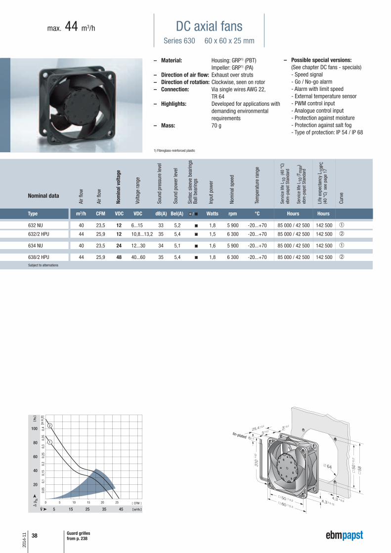
– Possible special versions:(See chapter DC fans - specials)
- Speed signal - Go / No-go alarm - Alarm with limit speed - External temperature sensor - PWM control input - Analogue control input - Protection against moisture - Protection against salt fog - Type of protection: IP 54 / IP 68
DC axial fansSeries 630 60 x 60 x 25 mm
max. 44 m3/h
Nominal data
Type m3/h CFM VDC VDC dB(A) Bel(A) / Watts rpm °C Hours Hours
632 NU 40 23,5 12 6...15 33 5,2 1,8 5 900 -20...+70 85 000 / 42 500 142 500 ➀
632/2 HPU 44 25,9 12 10,8...13,2 35 5,4 1,5 6 300 -20...+70 85 000 / 42 500 142 500 ➁
634 NU 40 23,5 24 12...30 34 5,1 1,6 5 900 -20...+70 85 000 / 42 500 142 500 ➀
638/2 HPU 44 25,9 48 40...60 35 5,4 1,8 6 300 -20...+70 85 000 / 42 500 142 500 ➁Subject to alternations
– Material: Housing: GRP1) (PBT) Impeller: GRP1) (PA)
– Direction of air flow: Exhaust over struts – Direction of rotation: Clockwise, seen on rotor– Connection: Via single wires AWG 22,
TR 64– Highlights: Developed for applications with
demanding environmental requirements
– Mass: 70 g
1) Fibreglass-reinforced plastic
tin-plated
Guard grillesfrom p. 238
Nom
inal
vol
tage
Air f
low
Air f
low
Volta
ge ra
nge
Soun
d pr
essu
re le
vel
Soun
d po
wer
leve
l
Sint
ec s
leev
e be
arin
gsBa
ll be
arin
gs
Inpu
t pow
er
Nom
inal
spe
ed
Tem
pera
ture
rang
e
Serv
ice
life
L 10
(40
°C)
ebm
-pap
st S
tand
ard
Serv
ice
life
L 10
(Tm
ax)
ebm
-pap
st S
tand
ard
Life
exp
ecta
ncy
L 10I
PC(4
0 °C
) se
e pa
ge 1
7
Curv
e

39
2014
-11
– Possible special versions:(See chapter DC fans - specials)
- Speed signal - Go / No-go alarm - Protection against moisture - Type of protection: IP 54 / IP 68
DC axial fansSeries 600 N 60 x 60 x 25 mm
max. 56 m3/h
– Material: Housing: GRP1) (PBT) Impeller: GRP1) (PA)
– Direction of air flow: Exhaust over struts – Direction of rotation: Clockwise, seen on rotor– Connection: Via single wires AWG 22,
TR 64– Highlights: Some models are suitable
for use at high ambient temperatures until 85 °C
– Mass: 66 g
1) Fibreglass-reinforced plastic
0 5 10 15 20 25 30
10 20
20
60
80
100
30 40 50
1
2
340
4
5
6
0,3
0,2
0,1
m³/h
Pa
CFM
[in H
2O]
Nominal data
Type m3/h CFM VDC VDC dB(A) Bel(A) / Watts rpm °C Hours Hours
612 NGLE 21 12,4 12 8...15 16 3,6 0,6 2 500 -20...+85 80 000 / 27 500 135 000 ➀
612 NLE 21 12,4 12 8...15 16 3,6 0,4 2 500 -20...+85 80 000 / 27 500 135 000 ➀
612 NGMLE 25 14,7 12 8...15 19 3,9 0,7 3 000 -20...+80 80 000 / 32 500 135 000 ➁
612 NMLE 25 14,7 12 8...15 19 3,9 0,4 3 000 -20...+85 80 000 / 27 500 135 000 ➁
612 NGME 35 20,6 12 8...15 28 4,6 1,2 4 100 -20...+75 80 000 / 35 000 135 000 ➂
612 NME 35 20,6 12 8...15 28 4,6 0,8 4 100 -20...+75 80 000 / 35 000 135 000 ➂
612 NN 42 24,7 12 8...15 35 5,0 1,5 5 100 -20...+70 70 000 / 35 000 117 500 ➃
612 NH 43 25,3 12 8...15 37 5,3 1,8 5 600 -20...+70 70 000 / 35 000 117 500 ➄
612 NHH-118 56 33,0 12 8...15 41 5,7 2,9 6 800 -20...+70 60 000 / 30 000 102 500 ➅
614 NGL 21 12,4 24 18...28 16 3,6 1,0 2 500 -20...+70 80 000 / 40 000 135 000 ➀
614 NL 21 12,4 24 18...28 16 3,6 0,8 2 500 -20...+70 80 000 / 40 000 135 000 ➀
614 NGML 25 14,7 24 18...28 19 3,9 1,2 3 000 -20...+70 80 000 / 40 000 135 000 ➁
614 NML 25 14,7 24 18...28 19 3,9 1,0 3 000 -20...+70 80 000 / 40 000 135 000 ➁
614 NGM 35 20,6 24 18...28 28 4,6 1,7 4 100 -20...+70 80 000 / 40 000 135 000 ➂
614 NM 35 20,6 24 18...28 28 4,6 1,3 4 100 -20...+70 80 000 / 40 000 135 000 ➂
614 NN 42 24,7 24 18...28 35 5,0 1,8 5 100 -20...+70 70 000 / 35 000 117 500 ➃
614 NH 43 25,3 24 18...26 37 5,3 2,1 5 600 -20...+70 70 000 / 35 000 117 500 ➄
614 NHH 56 33,0 24 18...26 41 5,7 2,9 6 850 -20...+70 60 000 / 30 000 102 500 ➅
614 NHH-119 56 33,0 24 18...28 41 5,7 2,9 6 850 -20...+70 60 000 / 30 000 102 500 ➅
618 NM 35 20,6 48 36...56 28 4,6 1,9 4 100 -20...+70 80 000 / 40 000 135 000 ➂
618 NN 42 24,7 48 36...56 35 5,0 2,1 5 100 -20...+65 70 000 / 40 000 117 500 ➃
tin-plated
Guard grillesfrom p. 238
Info
rmat
ion
DC a
xial
fans
DC fa
ns -
spe
cial
sAC
max
x / G
reen
Tech
EC
-Com
pact
fans
AC a
xial
fans
Acce
ssor
ies
Repr
esen
tativ
esDC
cen
trifu
gal f
ans
AC c
entr
ifuga
l fan
s
Nom
inal
vol
tage
Air f
low
Air f
low
Volta
ge ra
nge
Soun
d pr
essu
re le
vel
Soun
d po
wer
leve
l
Sint
ec s
leev
e be
arin
gsBa
ll be
arin
gs
Inpu
t pow
er
Nom
inal
spe
ed
Tem
pera
ture
rang
e
Serv
ice
life
L 10
(40
°C)
ebm
-pap
st S
tand
ard
Serv
ice
life
L 10
(Tm
ax)
ebm
-pap
st S
tand
ard
Life
exp
ecta
ncy
L 10I
PC(4
0 °C
) se
e pa
ge 1
7
Curv
e

40
2014
-11
– Possible special versions:(See chapter DC fans - specials)
- Speed signal - Go / No-go alarm - External temperature sensor - Internal temperature sensor - Protection against moisture
DC axial fansSeries 600 N VARIOFAN 60 x 60 x 25 mm
max. 41 m3/h
Type m3/h CFM VDC VDC dB(A) Bel(A) / Watts rpm °C Hours Hours
612 NGMI 18 10,6
12 8...12,6 14 3,5 1,3 2 150
-20...+65 80 000 / 45 000 135 000 ➀
35 20,6 28 4,6 1,7 4 100 ➁
612 NMI 16 9,4
12
8...12,6 16 3,6 1,0 2 400
-20...+65 80 000 / 45 000 135 000 ➂
35 20,6 28 4,6 1,4 4 100 ➃
612 NGNI 23 13,5
12
8...12,6 18 3,8 1,7 2 900
-20...+65 70 000 / 40 000 117 500 ➄
41 24,1 35 5,0 2,4 5 100 ➅
612 NNI 23 13,5
12
8...12,6 18 3,8 1,2 2 900
-20...+65 70 000 / 40 000 117 500 ➄
41 24,1 35 5,0 1,5 5 100 ➅
612 NGNV 23 13,5
12
8...12,6 18 3,8 1,7 2 900
-20...+65 70 000 / 40 000 117 500 ➄
41 24,1 35 5,0 2,4 5 100 ➅Subject to alternations
– Material: Housing: GRP1) (PBT) Impeller: GRP1) (PA)
– Direction of air flow: Exhaust over struts – Direction of rotation: Clockwise, seen on rotor– Connection: Via single wires AWG 22,
TR 64– Highlights: Automatic speed adjustment
with temperature sensor– Mass: 66 g
1) Fibreglass-reinforced plastic
Nominal data
0 3 6 9 12 15 18
10 20
20
10
30
40
15 25 30
2
5
1
30°C 55°C
612 NGMI
0,15
0,10
0,05
m³/h
Pa
CFM
[in H
2O]
0 3 6 9 12 15 18
10 20
20
10
30
40
15 25 30
4
5
3
30°C 55°C
612 NMI
0,10
0,15
0,05
m³/h
Pa
CFM
[in H
2O]
0 4 8 12 16 20
10 20
20
40
30
6
5
30°C 55°C
60
0,20
0,25
0,15
0,10
0,05
612 NGNI612 NNI612 NGNV
m³/h
Pa
CFM
[in H
2O]
30°C
55°C
30°C
55°C
30°C
55°C
30°C
55°C
30°C
55°C
The temperature sensor for con-trolling the motor speed is not in-cluded in delivery.Temperature sensor LZ 370 seeaccessories.
Temperature sensor (NTC-resistor)for controlling the motor speed ispositioned directly in the air flow.
V-Types I-Types
tin-plated
Guard grillesfrom p. 238
Nom
inal
vol
tage
Air f
low
Air f
low
Volta
ge ra
nge
Soun
d pr
essu
re le
vel
Soun
d po
wer
leve
l
Sint
ec s
leev
e be
arin
gsBa
ll be
arin
gs
Inpu
t pow
er
Nom
inal
spe
ed
Tem
pera
ture
rang
e
Serv
ice
life
L 10
(40
°C)
ebm
-pap
st S
tand
ard
Serv
ice
life
L 10
(Tm
ax)
ebm
-pap
st S
tand
ard
Life
exp
ecta
ncy
L 10I
PC(4
0 °C
) se
e pa
ge 1
7
Curv
e

41
2014
-11
– Possible special versions:(See chapter DC fans - specials)
- Speed signal - Go / No-go alarm - Alarm with limit speed - External temperature sensor - PWM control input - Analogue control input - Protection against moisture
DC axial fansSeries 600 J 60 x 60 x 32 mm
max. 82 m3/h
– Material: Housing: GRP1) (PBT) Impeller: GRP1) (PA)
– Direction of air flow: Exhaust over struts – Direction of rotation: Clockwise, seen on rotor– Connection: Via single wires AWG 24,
TR 64– Mass: 100 g
1) Fibreglass-reinforced plastic
Type m3/h CFM VDC VDC dB(A) Bel(A) / Watts rpm °C Hours Hours
612 JH 70 41,1 12 7...13,6 53 6,4 7,7 11 700 -20...+70 57 500 / 27 500 97 500 ➀
614 JH 70 41,1 24 14...26,4 53 6,4 7,7 11 700 -20...+70 57 500 / 27 500 97 500 ➀
618 JH 70 41,1 48 36...56 53 6,4 7,7 11 700 -20...+70 57 500 / 27 500 97 500 ➀
614 J/2 HHP 82 48,3 24 18...30 62 7,6 14,6 15 000 -20...+75 65 000 / 25 000 110 000 ➁
618 J/2 HHP 82 48,3 48 38...58 62 7,6 14,6 15 000 -20...+75 65 000 / 25 000 110 000 ➁Subject to alternations
Nominal data
Rear view of types 614 J/2HHP and 618 J/2HHP
Fan types with streamer and integrated guard grille.
tin-plated
Guard grillesfrom p. 238
Info
rmat
ion
DC a
xial
fans
DC fa
ns -
spe
cial
sAC
max
x / G
reen
Tech
EC
-Com
pact
fans
AC a
xial
fans
Acce
ssor
ies
Repr
esen
tativ
esDC
cen
trifu
gal f
ans
AC c
entr
ifuga
l fan
s
Nom
inal
vol
tage
Air f
low
Air f
low
Volta
ge ra
nge
Soun
d pr
essu
re le
vel
Soun
d po
wer
leve
l
Sint
ec s
leev
e be
arin
gsBa
ll be
arin
gs
Inpu
t pow
er
Nom
inal
spe
ed
Tem
pera
ture
rang
e
Serv
ice
life
L 10
(40
°C)
ebm
-pap
st S
tand
ard
Serv
ice
life
L 10
(Tm
ax)
ebm
-pap
st S
tand
ard
Life
exp
ecta
ncy
L 10I
PC(4
0 °C
) se
e pa
ge 1
7
Curv
e

42
2014
-11
– Possible special versions:(See chapter DC fans - specials)
- Speed signal - Go / No-go alarm - Protection against moisture
DC axial fansSeries 700 F 70 x 70 x 15 mm
max. 44 m3/h
Type m3/h CFM VDC VDC dB(A) Bel(A) / Watts rpm °C Hours Hours
712 F/2L-005* 28 16,5 12 8...13,8 25 4,7 0,6 3 300 -20...+70 60 000 / 30 000 102 500 ➀
712 F/2M-006* 36 21,2 12 8...13,8 32 5,0 1,1 4 300 -20...+70 60 000 / 30 000 102 500 ➁
712 F 44 25,9 12 8...13,8 38 5,3 1,7 5 300 -20...+70 60 000 / 30 000 102 500 ➂
714 F 44 25,9 24 18...28 38 5,3 1,5 5 300 -20...+70 60 000 / 30 000 102 500 ➂Subject to alternations
0 4 8 12 16 20 24
10 20
10
20
40
50
60
30 40
1
2
3
30
0,20
0,15
0,10
0,05
m³/h
Pa
CFM
[in H
2O]
Nominal data
*Version with 3-pin Molex plug housing 22-01-2035 Molex Contacts 08-50-0113
tin-plated
Guard grillesfrom p. 238
Nom
inal
vol
tage
Air f
low
Air f
low
Volta
ge ra
nge
Soun
d pr
essu
re le
vel
Soun
d po
wer
leve
l
Sint
ec s
leev
e be
arin
gsBa
ll be
arin
gs
Inpu
t pow
er
Nom
inal
spe
ed
Tem
pera
ture
rang
e
Serv
ice
life
L 10
(40
°C)
ebm
-pap
st S
tand
ard
Serv
ice
life
L 10
(Tm
ax)
ebm
-pap
st S
tand
ard
Life
exp
ecta
ncy
L 10I
PC(4
0 °C
) se
e pa
ge 1
7
Curv
e
– Material: Housing: GRP1) (PBT) Impeller: GRP1) (PA)
– Direction of air flow: Exhaust over struts – Direction of rotation: Counter-clockwise, seen
on rotor– Connection: Via single wires AWG 24 to
AWG 28, TR 64– Mass: 53 g
1) Fibreglass-reinforced plastic

43
2014
-11
– Possible special versions:(See chapter DC fans - specials)
- Speed signal - Go / No-go alarm - Alarm with limit speed - External temperature sensor - Internal temperature sensor - PWM control input - Analogue control input - Protection against moisture
DC axial fansSeries 8450 80 x 80 x 25 mm
max. 117 m3/h
– Material: Housing: GRP1) (PBT) Impeller: GRP1) (PA)
– Direction of air flow: Exhaust over struts – Direction of rotation: Counter-clockwise, seen
on rotor– Connection: Via single wires AWG 24,
TR 64– Highlights: Very low-noise motor– Mass: 105 g
1) Fibreglass-reinforced plastic
Type m3/h CFM VDC VDC dB(A) Bel(A) / Watts rpm °C Hours Hours
8452 GL 32 18,8 12 8...15 14 3,3 0,4 1 700 -20...75 80 000 / 35 000 135 000 ➀
8452 GM 58 34,1 12 8...15 32 4,7 1,3 3 100 -20...75 80 000 / 35 000 135 000 ➁
8452 GN 68 40,0 12 8...15 36 5,0 1,8 3 600 -20...70 70 000 / 35 000 117 500 ➂
8452/2 GHP 75 44,1 12 10,8...13,2 38 5,3 2,5 4 000 -20...70 70 000 / 35 000 117 500 ➃
8452/2 GHHP 83 48,8 12 10,8...13,2 42 5,5 3,5 4 400 -20...60 65 000 / 40 000 110 000 ➄
8452/2 H4P 117 68,8 12 8...15 50 6,4 6,8 6 200 -20...70 60 000 / 30 000 102 500 ➅
8454/2 H4P 117 68,8 24 20,0...26,4 50 6,4 6,8 6 200 -20...70 60 000 / 30 000 102 500 ➅ Subject to alternations
Nominal data
Models with 25 kHz PWM control and speed signal to 4-wire specification (see page 175).
Models with 1-30 kHz PWM control and speed signal.
tin-plated
Guard grillesfrom p. 238
Info
rmat
ion
DC a
xial
fans
DC fa
ns -
spe
cial
sAC
max
x / G
reen
Tech
EC
-Com
pact
fans
AC a
xial
fans
Acce
ssor
ies
Repr
esen
tativ
esDC
cen
trifu
gal f
ans
AC c
entr
ifuga
l fan
s
Nom
inal
vol
tage
Air f
low
Air f
low
Volta
ge ra
nge
Soun
d pr
essu
re le
vel
Soun
d po
wer
leve
l
Sint
ec s
leev
e be
arin
gsBa
ll be
arin
gs
Inpu
t pow
er
Nom
inal
spe
ed
Tem
pera
ture
rang
e
Serv
ice
life
L 10
(40
°C)
ebm
-pap
st S
tand
ard
Serv
ice
life
L 10
(Tm
ax)
ebm
-pap
st S
tand
ard
Life
exp
ecta
ncy
L 10I
PC(4
0 °C
) se
e pa
ge 1
7
Curv
e
44
2014
-11
– Possible special versions:(See chapter DC fans - specials)
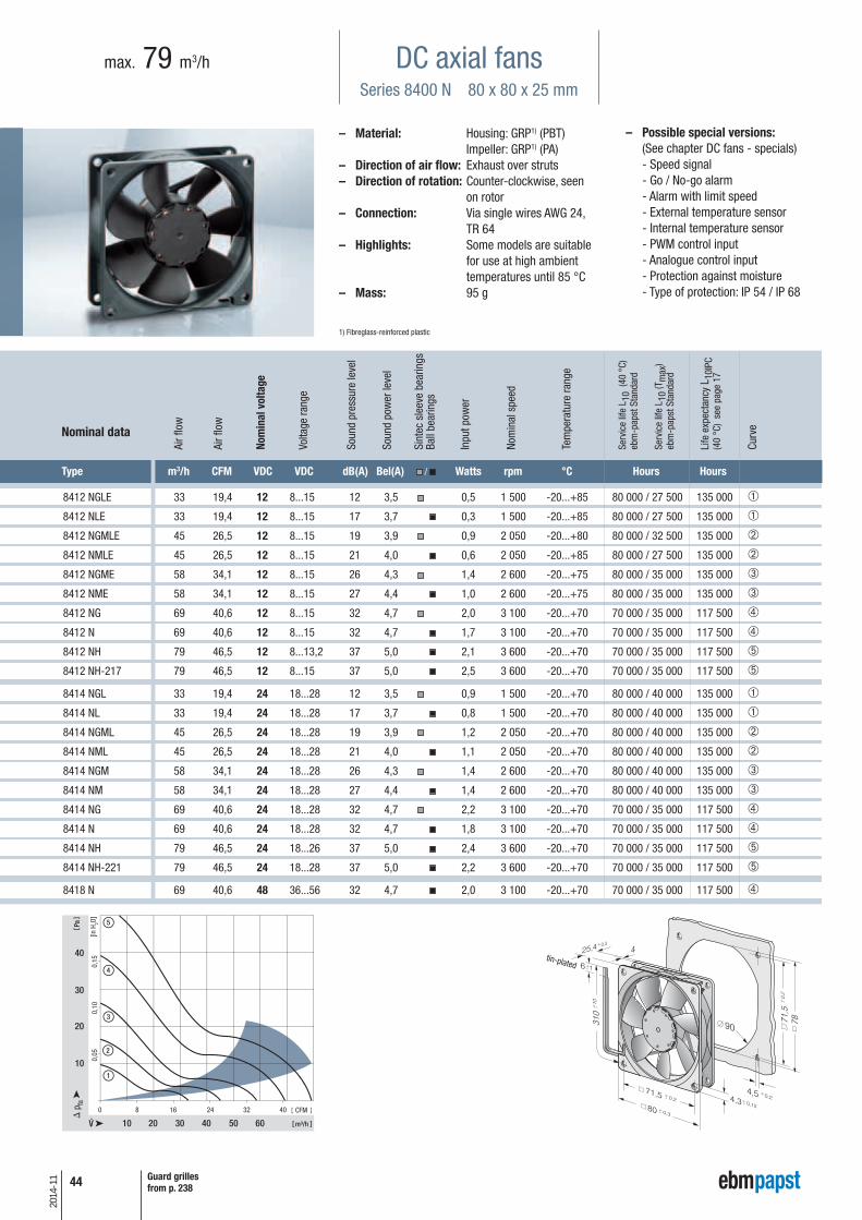
- Speed signal - Go / No-go alarm - Alarm with limit speed - External temperature sensor - Internal temperature sensor - PWM control input - Analogue control input - Protection against moisture - Type of protection: IP 54 / IP 68
DC axial fansSeries 8400 N 80 x 80 x 25 mm
max. 79 m3/h
Type m3/h CFM VDC VDC dB(A) Bel(A) / Watts rpm °C Hours Hours
8412 NGLE 33 19,4 12 8...15 12 3,5 0,5 1 500 -20...+85 80 000 / 27 500 135 000 ➀
8412 NLE 33 19,4 12 8...15 17 3,7 0,3 1 500 -20...+85 80 000 / 27 500 135 000 ➀
8412 NGMLE 45 26,5 12 8...15 19 3,9 0,9 2 050 -20...+80 80 000 / 32 500 135 000 ➁
8412 NMLE 45 26,5 12 8...15 21 4,0 0,6 2 050 -20...+85 80 000 / 27 500 135 000 ➁
8412 NGME 58 34,1 12 8...15 26 4,3 1,4 2 600 -20...+75 80 000 / 35 000 135 000 ➂
8412 NME 58 34,1 12 8...15 27 4,4 1,0 2 600 -20...+75 80 000 / 35 000 135 000 ➂
8412 NG 69 40,6 12 8...15 32 4,7 2,0 3 100 -20...+70 70 000 / 35 000 117 500 ➃
8412 N 69 40,6 12 8...15 32 4,7 1,7 3 100 -20...+70 70 000 / 35 000 117 500 ➃
8412 NH 79 46,5 12 8...13,2 37 5,0 2,1 3 600 -20...+70 70 000 / 35 000 117 500 ➄
8412 NH-217 79 46,5 12 8...15 37 5,0 2,5 3 600 -20...+70 70 000 / 35 000 117 500 ➄
8414 NGL 33 19,4 24 18...28 12 3,5 0,9 1 500 -20...+70 80 000 / 40 000 135 000 ➀
8414 NL 33 19,4 24 18...28 17 3,7 0,8 1 500 -20...+70 80 000 / 40 000 135 000 ➀
8414 NGML 45 26,5 24 18...28 19 3,9 1,2 2 050 -20...+70 80 000 / 40 000 135 000 ➁
8414 NML 45 26,5 24 18...28 21 4,0 1,1 2 050 -20...+70 80 000 / 40 000 135 000 ➁
8414 NGM 58 34,1 24 18...28 26 4,3 1,4 2 600 -20...+70 80 000 / 40 000 135 000 ➂
8414 NM 58 34,1 24 18...28 27 4,4 1,4 2 600 -20...+70 80 000 / 40 000 135 000 ➂
8414 NG 69 40,6 24 18...28 32 4,7 2,2 3 100 -20...+70 70 000 / 35 000 117 500 ➃
8414 N 69 40,6 24 18...28 32 4,7 1,8 3 100 -20...+70 70 000 / 35 000 117 500 ➃
8414 NH 79 46,5 24 18...26 37 5,0 2,4 3 600 -20...+70 70 000 / 35 000 117 500 ➄
8414 NH-221 79 46,5 24 18...28 37 5,0 2,2 3 600 -20...+70 70 000 / 35 000 117 500 ➄
8418 N 69 40,6 48 36...56 32 4,7 2,0 3 100 -20...+70 70 000 / 35 000 117 500 ➃
– Material: Housing: GRP1) (PBT) Impeller: GRP1) (PA)
– Direction of air flow: Exhaust over struts – Direction of rotation: Counter-clockwise, seen
on rotor– Connection: Via single wires AWG 24,
TR 64– Highlights: Some models are suitable
for use at high ambient temperatures until 85 °C
– Mass: 95 g
1) Fibreglass-reinforced plastic
0 8 16 24 32 40
10 20
10
30
40
30 40
1
2
320
5
50 60
4
0,10
0,15
0,05
m³/h
Pa
CFM
[in H
2O]
Nominal data
tin-plated
Guard grillesfrom p. 238
Nom
inal
vol
tage
Air f
low
Air f
low
Volta
ge ra
nge
Soun
d pr
essu
re le
vel
Soun
d po
wer
leve
l
Sint
ec s
leev
e be
arin
gsBa
ll be
arin
gs
Inpu
t pow
er
Nom
inal
spe
ed
Tem
pera
ture
rang
e
Serv
ice
life
L 10
(40
°C)
ebm
-pap
st S
tand
ard
Serv
ice
life
L 10
(Tm
ax)
ebm
-pap
st S
tand
ard
Life
exp
ecta
ncy
L 10I
PC(4
0 °C
) se
e pa
ge 1
7
Curv
e

45
2014
-11
– Possible special versions:(See chapter DC fans - specials)
- Speed signal - Go / No-go alarm - External temperature sensor - Internal temperature sensor - Protection against moisture
DC axial fansSeries 8400 N VARIOFAN 80 x 80 x 25 mm
max. 58 m3/h
– Material: Housing: GRP1) (PBT) Impeller: GRP1) (PA)
– Direction of air flow: Exhaust over struts – Direction of rotation: Counter-clockwise, seen
on rotor– Connection: Via single wires AWG 24,
TR 64– Highlights: Automatic speed adjustment
with temperature sensor– Mass: 95 g
1) Fibreglass-reinforced plastic
Type m3/h CFM VDC VDC dB(A) Bel(A) / Watts rpm °C Hours Hours
8412 NGLV 20 11,8
12
10...14 < 10 < 3 0,9 900
-20...+65
80 000 / 45 000 135 000 ➀
33 19,4 12 3,5 1,1 1 500 ➁
8412 NGMLV 27 15,9
12
8...14 < 10 3,0 1,1 1 200
-20...+65
80 000 / 45 000 135 000 ➂
45 26,6 19 3,9 1,5 2 050 ➃
8412 NGMI 35 20,6
12
8...14 < 13 3,5 1,4 1 600
-20...+65
80 000 / 45 000 135 000 ➄
58 34,1 26 4,3 2,0 2 600 ➅Subject to alternations
Nominal data
30°C
50°C
30°C
50°C
30°C
50°C
0 4 8 12 16 20
10 20
2,5
5
30
2
1
30°C 50°C
8412 NGLV
7,5 0,03
0,02
0,01
m³/h
Pa
CFM
[in H
2O]
0 5 10 15 20 25
10 20
5
30
4
3
30°C 50°C
8412 NGMLV
10
15
40
0,06
0,04
0,02
m³/h
Pa
CFM
[in H
2O]
0 5 10 15 20 25 30
10 20
5
30
6
30°C 50°C
15
20
40
10
25
50
5
0,08
0,06
0,04
0,02
8412 NGMV8412 NGMI
m³/h
Pa
CFM
[in H
2O]
The temperature sensor for con-trolling the motor speed is not in-cluded in delivery. Temperature sensor LZ 370 seeaccessories.
Temperature sensor (NTC-resistor)for controlling the motor speed ispositioned directly in the air flow.
V-Types I-Types
tin-plated
Guard grillesfrom p. 238
Info
rmat
ion
DC a
xial
fans
DC fa
ns -
spe
cial
sAC
max
x / G
reen
Tech
EC
-Com
pact
fans
AC a
xial
fans
Acce
ssor
ies
Repr
esen
tativ
esDC
cen
trifu
gal f
ans
AC c
entr
ifuga
l fan
s
Nom
inal
vol
tage
Air f
low
Air f
low
Volta
ge ra
nge
Soun
d pr
essu
re le
vel
Soun
d po
wer
leve
l
Sint
ec s
leev
e be
arin
gsBa
ll be
arin
gs
Inpu
t pow
er
Nom
inal
spe
ed
Tem
pera
ture
rang
e
Serv
ice
life
L 10
(40
°C)
ebm
-pap
st S
tand
ard
Serv
ice
life
L 10
(Tm
ax)
ebm
-pap
st S
tand
ard
Life
exp
ecta
ncy
L 10I
PC(4
0 °C
) se
e pa
ge 1
7
Curv
e

46
2014
-11
– Possible special versions:(See chapter DC fans - specials)
- Speed signal - Go / No-go alarm - Alarm with limit speed - External temperature sensor - Internal temperature sensor - PWM control input - Analogue control input - Protection against moisture - Protection against fog - Type of protection: IP 54 / IP 68
DC axial fansSeries 8300 80 x 80 x 32 mm
max. 80 m3/h
Type m3/h CFM VDC VDC dB(A) Bel(A) / Watts rpm °C Hours Hours
8312 L 32 18,8 12 6...15 24 4,0 1,2 2 000 -20...+75 80 000 / 32 500 135 000 ➀
8312 M 48 28,3 12 6...15 34 5,0 2,2 3 000 -20...+75 70 000 / 27 500 117 500 ➁
8312 54 31,8 12 6...15 36 5,2 2,6 3 300 -20...+75 70 000 / 27 500 117 500 ➂
8312 HL 67 39,4 12 6...15 43 5,8 4,0 4 200 -20...+75 62 500 / 25 000 105 000 ➃
8312 H 80 47,1 12 6...12,6 48 6,2 6,4 5 000 -20...+60 55 000 / 35 000 92 500 ➄
8314 L 32 18,8 24 12...31,5 24 4,0 1,0 2 000 -20...+75 80 000 / 32 500 135 000 ➀
8314 M 48 28,3 24 12...31,5 34 5,0 2,3 3 000 -20...+75 70 000 / 27 500 117 500 ➁
8314 54 31,8 24 12...31,5 36 5,2 2,7 3 300 -20...+75 70 000 / 27 500 117 500 ➂
8314 HL 67 39,4 24 12...31,5 43 5,8 4,3 4 200 -20...+75 62 500 / 25 000 105 000 ➃
8314 H 80 47,1 24 12...28 48 6,2 6,0 5 000 -20...+75 55 000 / 22 500 92 500 ➄
8318 54 31,8 48 36...60 36 5,2 3,0 3 300 -20...+75 70 000 / 27 500 117 500 ➂
8318 HL 67 39,4 48 36...60 43 5,8 4,2 4 200 -20...+75 62 500 / 25 000 105 000 ➃
8318 H 80 47,1 48 36...60 48 6,2 6,2 5 000 -20...+65 55 000 / 30 000 92 500 ➄Subject to alternations
– Material: Housing: GRP1) (PBT) Impeller: GRP1) (PA)
– Direction of air flow: Exhaust over struts – Direction of rotation: Clockwise, seen on rotor– Connection: Via single wires AWG 22,
TR 64– Mass: 170 g
1) Fibreglass-reinforced plastic
0 8 16 24 32 40
10 20
20
60
80
30 40
1
2
3
40
5
50 60
4
100
120
0,4
0,3
0,2
0,1
m³/h
Pa
CFM
[in H
2O]
Nominal data
Rotor protrusion max. 0,4 mm.
tin-plated
Guard grillesfrom p. 238
Nom
inal
vol
tage
Air f
low
Air f
low
Volta
ge ra
nge
Soun
d pr
essu
re le
vel
Soun
d po
wer
leve
l
Sint
ec s
leev
e be
arin
gsBa
ll be
arin
gs
Inpu
t pow
er
Nom
inal
spe
ed
Tem
pera
ture
rang
e
Serv
ice
life
L 10
(40
°C)
ebm
-pap
st S
tand
ard
Serv
ice
life
L 10
(Tm
ax)
ebm
-pap
st S
tand
ard
Life
exp
ecta
ncy
L 10I
PC(4
0 °C
) se
e pa
ge 1
7
Curv
e

47
2014
-11
– Possible special versions:(See chapter DC fans - specials)
- Speed signal - Go / No-go alarm - Alarm with limit speed - External temperature sensor - Internal temperature sensor - PWM control input - Analogue control input - Protection against moisture - Type of protection: IP 54 / IP 68
DC axial fansSeries 8200 J 80 x 80 x 38 mm
max. 222 m3/h
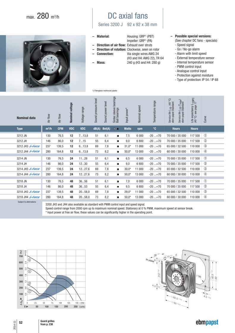
– Material: Housing: GRP1) (PBT) Impeller: GRP1) (PA)
– Direction of air flow: Exhaust over struts – Direction of rotation: Counter-clockwise, seen
on rotor– Connection: Via single wires AWG 24
(H3 and H4: AWG 22), TR 64– Mass: 160 g (H3 and H4: 200 g)
1) Fibreglass-reinforced plastic
250
50
100
200
100
500
600
50 75
300
400
150
3
100 125
200
1,2
1,6
2,0
0,8
0,4
2
1
m³/h
Pa
CFM
[in H
2O]
Type m3/h CFM VDC VDC dB(A) Bel(A) / Watts rpm °C Hours Hours
8212 JN 132 78 12 7...13,8 55 6,6 10 8400 -20...+70 62 500 / 32 500 105 000 ➀
8212 JH3 190 112 12 6...13,8 66 7,3 26* 12 000 -20...+70 55 000 / 27 500 92 500 ➁
8212 JH4 222 131 12 6...13,8 71 7,8 39* 14 000 -20...+70 50 000 / 25 000 85 000 ➂
8214 JN 132 78 24 18...26,4 55 6,6 11 8400 -20...+70 62 500 / 32 500 105 000 ➀
8214 JH3 190 112 24 12...27,6 66 7,3 26* 12 000 -20...+70 55 000 / 27 500 92 500 ➁
8214 JH4 222 131 24 12...27,6 71 7,8 38* 14 000 -20...+70 50 000 / 25 000 85 000 ➂
8218 JN 132 78 48 36...53 55 6,6 11 8400 -20...+70 62 500 / 32 500 105 000 ➀
8218 JH3 190 112 48 36...53 66 7,3 25* 12 000 -20...+70 55 000 / 27 500 92 500 ➁
8218 JH4 222 131 48 20...58 71 7,8 36* 14 000 -20...+70 50 000 / 25 000 85 000 ➂ Subject to alternations
Nominal data
8200 JH3 and JH4 also available as standard with PWM control input and speed signal.Speed control range from 2000 rpm up to maximum nominal speed. Stationary at 0 % PWM, maximum speed at sensor break.* Input power at free air flow, these values can be significantly higher in the operating point.
tin-plated
Guard grillesfrom p. 238
Info
rmat
ion
DC a
xial
fans
DC fa
ns -
spe
cial
sAC
max
x / G
reen
Tech
EC
-Com
pact
fans
AC a
xial
fans
Acce
ssor
ies
Repr
esen
tativ
esDC
cen
trifu
gal f
ans
AC c
entr
ifuga
l fan
s
Nom
inal
vol
tage
Air f
low
Air f
low
Volta
ge ra
nge
Soun
d pr
essu
re le
vel
Soun
d po
wer
leve
l
Sint
ec s
leev
e be
arin
gsBa
ll be
arin
gs
Inpu
t pow
er*
Nom
inal
spe
ed
Tem
pera
ture
rang
e
Serv
ice
life
L 10
(40
°C)
ebm
-pap
st S
tand
ard
Serv
ice
life
L 10
(Tm
ax)
ebm
-pap
st S
tand
ard
Life
exp
ecta
ncy
L 10I
PC(4
0 °C
) se
e pa
ge 1
7
Curv
e

48
2014
-11
– Possible special versions:(See chapter DC fans - specials)
- Speed signal - Go / No-go alarm - Alarm with limit speed - External temperature sensor - Internal temperature sensor - PWM control input - Analogue control input - Protection against moisture - Type of protection: IP 54 / IP 68
DC axial fansSeries 3400 N 92 x 92 x 25 mm
max. 102 m3/h
Type m3/h CFM VDC VDC dB(A) Bel(A) / Watts rpm °C Hours Hours
3412 NGLE 61 35,9 12 8...15 23 4,0 1,1 1 950 -20...+80 80 000 / 22 500 135 000 ➀ 3412 NLE 61 35,9 12 8...15 23 4,0 0,8 1 950 -20...+85 80 000 / 17 500 135 000 ➀3412 NGME 72 42,4 12 8...15 28 4,3 1,6 2 300 -20...+75 75 000 / 27 500 127 500 ➁ 3412 NME 72 42,4 12 8...15 28 4,3 1,1 2 300 -20...+75 75 000 / 27 500 127 500 ➁3412 NG 84 49,4 12 8...15 32 4,7 1,9 2 700 -20...+70 70 000 / 35 000 117 500 ➂3412 N 84 49,4 12 8...15 32 4,7 1,7 2 700 -20...+70 70 000 / 35 000 117 500 ➂3412 NGH 94 55,3 12 8...15 36 5,0 2,3 3 000 -20...+70 70 000 / 35 000 117 500 ➃3412 NH 94 55,3 12 8...15 36 5,0 2,1 3 000 -20...+70 70 000 / 35 000 117 500 ➃3412 NGHH 102 60,0 12 8...13,2 39 5,1 3,2 3 250 -20...+60 70 000 / 45 000 127 500 ➄3412 NHH 102 60,0 12 8...13,2 39 5,1 2,9 3 250 -20...+60 70 000 / 45 000 127 500 ➄3412 NHH-379 102 60,0 12 8...15 39 5,1 2,7 3 250 -20...+70 70 000 / 35 000 117 500 ➄
3414 NGL 61 35,9 24 18...28 23 4,0 1,4 1 950 -20...+70 80 000 / 40 000 135 000 ➀3414 NL 61 35,9 24 18...28 23 4,0 1,1 1 950 -20...+70 80 000 / 40 000 135 000 ➀3414 NGM 72 42,4 24 18...28 28 4,3 1,7 2 300 -20...+70 75 000 / 37 500 127 500 ➁3414 NM 72 42,4 24 18...28 28 4,3 1,4 2 300 -20...+70 75 000 / 37 500 127 500 ➁3414 NG 84 49,4 24 18...28 32 4,7 2,5 2 700 -20...+70 70 000 / 35 000 117 500 ➂3414 N 84 49,4 24 18...28 32 4,7 2,1 2 700 -20...+70 70 000 / 35 000 117 500 ➂3414 NGH 94 55,3 24 18...26 36 5,0 3,0 3 000 -20...+70 70 000 / 35 000 117 500 ➃3414 NH 94 55,3 24 18...26 36 5,0 2,3 3 000 -20...+70 70 000 / 35 000 117 500 ➃ 3414 NGHH 102 60,0 24 18...26 39 5,1 3,2 3 250 -20...+70 70 000 / 35 000 117 500 ➄3414 NGHH-389 102 60,0 24 18...28 39 5,1 3,2 3 250 -20...+70 70 000 / 35 000 117 500 ➄3414 NHH 102 60,0 24 18...26 39 5,1 3,1 3 250 -20...+70 70 000 / 35 000 117 500 ➄3414 NHH-386 102 60,0 24 18...28 39 5,1 3,2 3 250 -20...+70 70 000 / 35 000 117 500 ➄
3418 N 84 49,4 48 36...56 32 4,7 2,4 2 700 -20...+70 70 000 / 35 000 117 500 ➂
– Material: Housing: GRP1) (PBT) Impeller: GRP1) (PA)
– Direction of air flow: Exhaust over struts – Direction of rotation: Counter-clockwise, seen
on rotor– Connection: Via single wires AWG 24,
TR 64– Mass: 100 g
1) Fibreglass-reinforced plastic
0 10 20 30 40 50
20
20
10
30
40
1
2
3
40
5
8060
4
0,10
0,15
0,05
m³/h
Pa
CFM
[in H
2O]
Nominal data
Other 48 VDC models on request.
tin-plated
Guard grillesfrom p. 238
Nom
inal
vol
tage
Air f
low
Air f
low
Volta
ge ra
nge
Soun
d pr
essu
re le
vel
Soun
d po
wer
leve
l
Sint
ec s
leev
e be
arin
gsBa
ll be
arin
gs
Inpu
t pow
er
Nom
inal
spe
ed
Tem
pera
ture
rang
e
Serv
ice
life
L 10
(40
°C)
ebm
-pap
st S
tand
ard
Serv
ice
life
L 10
(Tm
ax)
ebm
-pap
st S
tand
ard
Life
exp
ecta
ncy
L 10I
PC(4
0 °C
) se
e pa
ge 1
7
Curv
e

49
2014
-11
– Possible special versions:(See chapter DC fans - specials)
- Speed signal - Go / No-go alarm - External temperature sensor - Internal temperature sensor - Protection against moisture
DC axial fansSeries 3400 N VARIOFAN 92 x 92 x 25 mm
max. 84 m3/h
– Material: Housing: GRP1) (PBT) Impeller: GRP1) (PA)
– Direction of air flow: Exhaust over struts – Direction of rotation: Counter-clockwise, seen
on rotor– Connection: Via single wires AWG 24,
TR 64– Highlights: Automatic speed adjustment
with temperature sensor– Mass: 100 g
1) Fibreglass-reinforced plastic
0 8 16 24 32 40
10 20
5
30
30°C 50°C
3412 NGV
15
20
40
10
50
3
60
4
70
25
0,08
0,06
0,04
0,02
m³/h
Pa
CFM
[in H
2O]
0 8 16 24 32 40
10 20
5
30
30°C 50°C
3412 NGMV
15
20
40
10
50
1
60
2
0,08
0,06
0,04
0,02
m³/h
Pa
CFM
[in H
2O]
Type m3/h CFM VDC VDC dB(A) Bel(A) / Watts rpm °C Hours Hours
3412 NGMV 44 25,9
12 8...14 14 3,5 1,5 1 400
-20...+65 75 000 / 42 500 127 500 ➀
72 42,4 28 4,3 2,0 2 300 ➁
3412 NGV 50 29,4
12 8...12,6 16 3,7 1,6 1 600
-20...+65 75 000 / 42 500 127 500 ➂
84 49,4 32 4,7 2,5 2 700 ➃Subject to alternations
Nominal data
30°C
50°C
30°C
50°C
The temperature sensor for con-trolling the motor speed is not in-cluded in delivery.Temperature sensor LZ 370 seeaccessories.
tin-plated
Guard grillesfrom p. 238
Info
rmat
ion
DC a
xial
fans
DC fa
ns -
spe
cial
sAC
max
x / G
reen
Tech
EC
-Com
pact
fans
AC a
xial
fans
Acce
ssor
ies
Repr
esen
tativ
esDC
cen
trifu
gal f
ans
AC c
entr
ifuga
l fan
s
Nom
inal
vol
tage
Air f
low
Air f
low
Volta
ge ra
nge
Soun
d pr
essu
re le
vel
Soun
d po
wer
leve
l
Sint
ec s
leev
e be
arin
gsBa
ll be
arin
gs
Inpu
t pow
er
Nom
inal
spe
ed
Tem
pera
ture
rang
e
Serv
ice
life
L 10
(40
°C)
ebm
-pap
st S
tand
ard
Serv
ice
life
L 10
(Tm
ax)
ebm
-pap
st S
tand
ard
Life
exp
ecta
ncy
L 10I
PC(4
0 °C
) se
e pa
ge 1
7
Curv
e
50
2014
-11
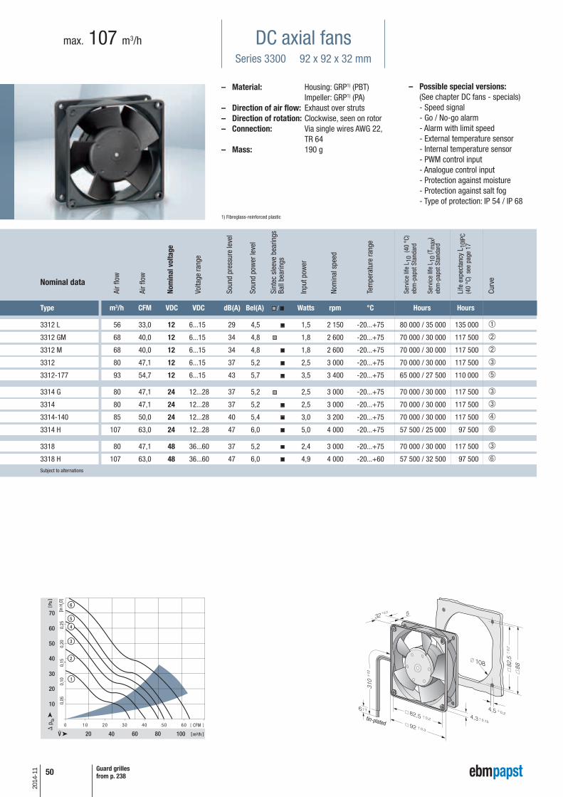
– Possible special versions:(See chapter DC fans - specials)
- Speed signal - Go / No-go alarm - Alarm with limit speed - External temperature sensor - Internal temperature sensor - PWM control input - Analogue control input - Protection against moisture - Protection against salt fog - Type of protection: IP 54 / IP 68
DC axial fansSeries 3300 92 x 92 x 32 mm
max. 107 m3/h
Type m3/h CFM VDC VDC dB(A) Bel(A) / Watts rpm °C Hours Hours
3312 L 56 33,0 12 6...15 29 4,5 1,5 2 150 -20...+75 80 000 / 35 000 135 000 ➀
3312 GM 68 40,0 12 6...15 34 4,8 1,8 2 600 -20...+75 70 000 / 30 000 117 500 ➁
3312 M 68 40,0 12 6...15 34 4,8 1,8 2 600 -20...+75 70 000 / 30 000 117 500 ➁
3312 80 47,1 12 6...15 37 5,2 2,5 3 000 -20...+75 70 000 / 30 000 117 500 ➂
3312-177 93 54,7 12 6...15 43 5,7 3,5 3 400 -20...+75 65 000 / 27 500 110 000 ➄
3314 G 80 47,1 24 12...28 37 5,2 2,5 3 000 -20...+75 70 000 / 30 000 117 500 ➂
3314 80 47,1 24 12...28 37 5,2 2,5 3 000 -20...+75 70 000 / 30 000 117 500 ➂
3314-140 85 50,0 24 12...28 40 5,4 3,0 3 200 -20...+75 70 000 / 30 000 117 500 ➃
3314 H 107 63,0 24 12...28 47 6,0 5,0 4 000 -20...+75 57 500 / 25 000 97 500 ➅
3318 80 47,1 48 36...60 37 5,2 2,4 3 000 -20...+75 70 000 / 30 000 117 500 ➂
3318 H 107 63,0 48 36...60 47 6,0 4,9 4 000 -20...+60 57 500 / 32 500 97 500 ➅Subject to alternations
– Material: Housing: GRP1) (PBT) Impeller: GRP1) (PA)
– Direction of air flow: Exhaust over struts – Direction of rotation: Clockwise, seen on rotor– Connection: Via single wires AWG 22,
TR 64– Mass: 190 g
1) Fibreglass-reinforced plastic
0 10 20 30 40 50 60
20 40
20
40
30
60 80 100
60
1
2
10
50
70
3
5
6
4
0,15
0,10
0,05
0,20
0,25
m³/h
Pa
CFM
[in H
2O]
Nominal data
tin-plated
Guard grillesfrom p. 238
Nom
inal
vol
tage
Air f
low
Air f
low
Volta
ge ra
nge
Soun
d pr
essu
re le
vel
Soun
d po
wer
leve
l
Sint
ec s
leev
e be
arin
gsBa
ll be
arin
gs
Inpu
t pow
er
Nom
inal
spe
ed
Tem
pera
ture
rang
e
Serv
ice
life
L 10
(40
°C)
ebm
-pap
st S
tand
ard
Serv
ice
life
L 10
(Tm
ax)
ebm
-pap
st S
tand
ard
Life
exp
ecta
ncy
L 10I
PC(4
0 °C
) se
e pa
ge 1
7
Curv
e
51
2014
-11
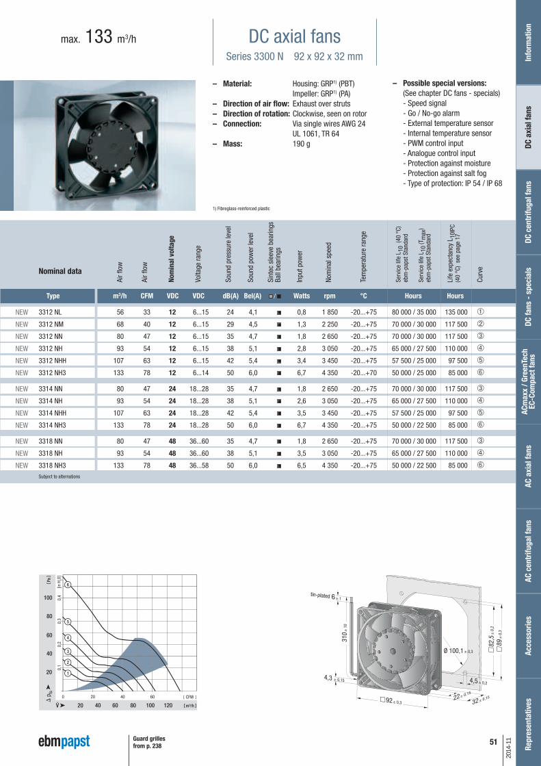
– Possible special versions:(See chapter DC fans - specials)
- Speed signal - Go / No-go alarm - External temperature sensor - Internal temperature sensor - PWM control input - Analogue control input - Protection against moisture - Protection against salt fog - Type of protection: IP 54 / IP 68
DC axial fansSeries 3300 N 92 x 92 x 32 mm
max. 133 m3/h
– Material: Housing: GRP1) (PBT) Impeller: GRP1) (PA)
– Direction of air flow: Exhaust over struts – Direction of rotation: Clockwise, seen on rotor– Connection: Via single wires AWG 24
UL 1061, TR 64– Mass: 190 g
1) Fibreglass-reinforced plastic
Ø 100,1 ± 0,3
0
20 40
20
40
60
80
100
m³/h
Pa
CFM
[in H
2O]
0,1
0,2
0,3
0,4
20 40 60
60 80 100 120
4
6
5
3
2
1
Type m3/h CFM VDC VDC dB(A) Bel(A) / Watts rpm °C Hours Hours
3312 NL 56 33 12 6...15 24 4,1 0,8 1 850 -20...+75 80 000 / 35 000 135 000 ➀
3312 NM 68 40 12 6...15 29 4,5 1,3 2 250 -20...+75 70 000 / 30 000 117 500 ➁
3312 NN 80 47 12 6...15 35 4,7 1,8 2 650 -20...+75 70 000 / 30 000 117 500 ➂
3312 NH 93 54 12 6...15 38 5,1 2,8 3 050 -20...+75 65 000 / 27 500 110 000 ➃
3312 NHH 107 63 12 6...15 42 5,4 3,4 3 450 -20...+75 57 500 / 25 000 97 500 ➄
3312 NH3 133 78 12 6...14 50 6,0 6,7 4 350 -20...+70 50 000 / 25 000 85 000 ➅
3314 NN 80 47 24 18...28 35 4,7 1,8 2 650 -20...+75 70 000 / 30 000 117 500 ➂
3314 NH 93 54 24 18...28 38 5,1 2,6 3 050 -20...+75 65 000 / 27 500 110 000 ➃
3314 NHH 107 63 24 18...28 42 5,4 3,5 3 450 -20...+75 57 500 / 25 000 97 500 ➄
3314 NH3 133 78 24 18...28 50 6,0 6,7 4 350 -20...+75 50 000 / 22 500 85 000 ➅
3318 NN 80 47 48 36...60 35 4,7 1,8 2 650 -20...+75 70 000 / 30 000 117 500 ➂
3318 NH 93 54 48 36...60 38 5,1 3,5 3 050 -20...+75 65 000 / 27 500 110 000 ➃
3318 NH3 133 78 48 36...58 50 6,0 6,5 4 350 -20...+75 50 000 / 22 500 85 000 ➅Subject to alternations
Nominal data
tin-plated
Guard grillesfrom p. 238
Info
rmat
ion
DC a
xial
fans
DC fa
ns -
spe
cial
sAC
max
x / G
reen
Tech
EC
-Com
pact
fans
AC a
xial
fans
Acce
ssor
ies
Repr
esen
tativ
esDC
cen
trifu
gal f
ans
AC c
entr
ifuga
l fan
s
Nom
inal
vol
tage
Air f
low
Air f
low
Volta
ge ra
nge
Soun
d pr
essu
re le
vel
Soun
d po
wer
leve
l
Sint
ec s
leev
e be
arin
gsBa
ll be
arin
gs
Inpu
t pow
er
Nom
inal
spe
ed
Tem
pera
ture
rang
e
Serv
ice
life
L 10
(40
°C)
ebm
-pap
st S
tand
ard
Serv
ice
life
L 10
(Tm
ax)
ebm
-pap
st S
tand
ard
Life
exp
ecta
ncy
L 10I
PC(4
0 °C
) se
e pa
ge 1
7
Curv
e
NEW
NEW
NEW
NEW
NEW
NEW
NEW
NEW
NEW
NEW
NEW
NEW
NEW
52
2014
-11
– Possible special versions:(See chapter DC fans - specials)
- Speed signal - Go / No-go alarm - Alarm with limit speed - External temperature sensor - Internal temperature sensor - PWM control input - Analogue control input - Protection against moisture - Type of protection: IP 54 / IP 68
DC axial fansSeries 3200 J 92 x 92 x 38 mm
max. 280 m3/h
Type m3/h CFM VDC VDC dB(A) Bel(A) / Watts rpm °C Hours Hours
3212 JN 130 76,5 12 7...13,8 51 6,1 7,5 6 000 -20 ...+70 70 000 / 35 000 117 500 ➀
3212 JH 146 86,0 12 7...15 55 6,4 9,0 6 800 -20 ...+70 70 000 / 35 000 117 500 ➁
3212 JH3 237 139,5 12 6...13,8 69 7,8 31,0* 11 000 -20 ...+70 65 000 / 32 500 110 000 ➂
3212 JH4 280 164,8 12 6...13,8 73 8,2 50,0* 13 000 -20 ...+70 60 000 / 30 000 110 000 ➃
3214 JN 130 76,5 24 11...28 51 6,1 6,5 6 000 -20 ...+70 70 000 / 35 000 117 500 ➀
3214 JH 146 86,0 24 12...30 55 6,4 9,0 6 800 -20 ...+70 70 000 / 35 000 117 500 ➁
3214 JH3 237 139,5 24 12...27,6 69 7,8 30,0* 11 000 -20 ...+70 65 000 / 32 500 110 000 ➂
3214 JH4 280 164,8 24 12...27,6 73 8,2 50,0* 13 000 -20 ...+70 60 000 / 30 000 110 000 ➃
3218 JN 130 76,5 48 36...56 51 6,1 7,0 6 000 -20 ...+70 70 000 / 35 000 117 500 ➀
3218 JH 146 86,0 48 36...53 55 6,4 9,5 6 800 -20 ...+70 70 000 / 35 000 117 500 ➁
3218 JH3 237 139,5 48 20...58,0 69 7,8 29,0* 11 000 -20 ...+70 65 000 / 32 500 110 000 ➂
3218 JH4 280 164,8 48 20...58,0 73 8,2 50,0* 13 000 -20 ...+70 60 000 / 30 000 110 000 ➃Subject to alternations
– Material: Housing: GRP1) (PBT) Impeller: GRP1) (PA)
– Direction of air flow: Exhaust over struts – Direction of rotation: Clockwise, seen on rotor– Connection: Via single wires AWG 24
(H3 and H4: AWG 22), TR 64– Mass: 240 g (H3 and H4: 280 g)
1) Fibreglass-reinforced plastic
Nominal data
3200 JH3 and JH4 also available as standard with PWM control input and speed signal.Speed control range from 2000 rpm up to maximum nominal speed. Stationary at 0 % PWM, maximum speed at sensor break.* Input power at free air flow, these values can be significantly higher in the operating point.
tin-plated
Guard grillesfrom p. 238
Nom
inal
vol
tage
Air f
low
Air f
low
Volta
ge ra
nge
Soun
d pr
essu
re le
vel
Soun
d po
wer
leve
l
Sint
ec s
leev
e be
arin
gsBa
ll be
arin
gs
Inpu
t pow
er*
Nom
inal
spe
ed
Tem
pera
ture
rang
e
Serv
ice
life
L 10
(40
°C)
ebm
-pap
st S
tand
ard
Serv
ice
life
L 10
(Tm
ax)
ebm
-pap
st S
tand
ard
Life
exp
ecta
ncy
L 10I
PC(4
0 °C
) se
e pa
ge 1
7
Curv
e

3252 J/2 H3P 270 158 12 7...13,2 64 7,6 35,0 7 450 -20...+70 85 000 / 42 500 142 500 ➂
3254 J/2 H3P 270 158 24 14...26,4 64 7,6 35,0 7 450 -20...+70 85 000 / 42 500 142 500 ➂
3258 J/2 HP** 145 85 48 36...56,0 46 5,8 5,3 4 100 -20...+70 100 000 / 50 000 170 000 ➀
3258 J/2 HHP 235 138 48 36...56,0 59 7,0 24,3 6 650 -20...+70 90 000 / 45 000 152 500 ➁
3258 J/2 H3P 270 158 48 36...56,0 64 7,6 33,6 7 450 -20...+70 85 000 / 42 500 142 500 ➂Subject to alternations
* Input power at free air flow, these values can be significantly higher in the operating point.** On request
NEW
NEW
NEW
NEW
NEW
53
2014
-11
– Possible special versions:(See chapter DC fans - specials)
- Speed signal - Go / No-go alarm - External temperature sensor - Internal temperature sensor - PWM control input - Analogue control input - Protection against moisture - Protection against salt fog - Type of protection: IP 54 / IP 68
DC axial fansSeries 3250 J 92 x 92 x 38 mm
max. 270 m3/h
– Material: Housing: GRP1) (PBT) Impeller: GRP1) (PA)
– Direction of air flow: Exhaust over struts – Direction of rotation: Clockwise, seen on rotor– Connection: Via single wires AWG 22,
TR 64– Mass: 240 g
1) Fibreglass-reinforced plastic
Type m3/h CFM VDC VDC dB(A) Bel(A) / Watts rpm °C Hours Hours
Nominal data
tin-plated
Guard grillesfrom p. 238
Info
rmat
ion
DC a
xial
fans
DC fa
ns -
spe
cial
sAC
max
x / G
reen
Tech
EC
-Com
pact
fans
AC a
xial
fans
Acce
ssor
ies
Repr
esen
tativ
esDC
cen
trifu
gal f
ans
AC c
entr
ifuga
l fan
s
Nom
inal
vol
tage
Air f
low
Air f
low
Volta
ge ra
nge
Soun
d pr
essu
re le
vel
Soun
d po
wer
leve
l
Sint
ec s
leev
e be
arin
gsBa
ll be
arin
gs
Inpu
t pow
er*
Nom
inal
spe
ed
Tem
pera
ture
rang
e
Serv
ice
life
L 10
(40
°C)
ebm
-pap
st S
tand
ard
Serv
ice
life
L 10
(Tm
ax)
ebm
-pap
st S
tand
ard
Life
exp
ecta
ncy
L 10I
PC(4
0 °C
) se
e pa
ge 1
7
Curv
e

54
2014
-11
– Possible special versions:(See chapter DC fans - specials)
- Speed signal - Go / No-go alarm - Alarm with limit speed - External temperature sensor - Internal temperature sensor - PWM control input - Analogue control input - Protection against moisture
DC axial fansSeries 4400 F 119 x 119 x 25 mm
max. 170 m3/h
Type m3/h CFM VDC VDC dB(A) Bel(A) / Watts rpm °C Hours Hours
4412 FGL 94 55 12 7...14 26 3,9 1,3 1 600 -20...+75 80 000 / 35 000 135 000 ➀
4412 FGML 114 67 12 7...12,6 32 4,3 2,0 1 950 -20...+75 75 000 / 32 500 127 500 ➁
4412 FML 114 67 12 7...12,6 32 4,3 2,0 1 950 -20...+75 75 000 / 32 500 127 500 ➁
4412 FGM 140 82 12 7...12,6 38 4,8 3,2 2 400 -20...+75 70 000 / 30 000 117 500 ➂
4412 FM 140 82 12 7...12,6 38 4,8 3,2 2 400 -20...+75 70 000 / 30 000 117 500 ➂
4412 FG 170 100 12 8...12,6 43 5,3 5,3 2 900 -20...+60 60 000 / 37 500 102 500 ➃
4412 F 170 100 12 8...12,6 43 5,3 5,3 2 900 -20...+60 60 000 / 37 500 102 500 ➃
4414 FL 94 55 24 18...28 26 3,9 1,2 1 600 -20...+75 80 000 / 35 000 135 000 ➀
4414 FM 140 82 24 12...28 38 4,8 3,1 2 400 -20...+75 70 000 / 30 000 117 500 ➂
4414 FG 170 100 24 12...28 43 5,3 5,0 2 900 -20...+60 60 000 / 37 500 102 500 ➃
4414 F 170 100 24 12...28 43 5,3 5,0 2 900 -20...+60 60 000 / 37 500 102 500 ➃
4418 FG 170 100 48 28...53 43 5,3 5,4 2 900 -20...+60 60 000 / 37 500 102 500 ➃
4418 F 170 100 48 28...53 43 5,3 5,4 2 900 -20...+60 60 000 / 37 500 102 500 ➃Subject to alternations
– Material: Housing: GRP1) (PBT) Impeller: GRP1) (PA)
– Direction of air flow: Exhaust over struts – Direction of rotation: Counter-clockwise, seen
on rotor– Connection: Via single wires AWG 24,
TR 64– Highlights: Ball bearings and plain
bearings available– Mass: 175 g
1) Fibreglass-reinforced plastic
0 15 30 45 60 75 90
25 50
20
40
30
75 100 125
1
2
10
50
3
4
0,15
0,10
0,05
m³/h
Pa
CFM
[in H
2O]
Nominal data
Available on request:Fan housing with moulded-in spacers. For mounting over both flanges.
tin-plated
Guard grillesfrom p. 238
Nom
inal
vol
tage
Air f
low
Air f
low
Volta
ge ra
nge
Soun
d pr
essu
re le
vel
Soun
d po
wer
leve
l
Sint
ec s
leev
e be
arin
gsBa
ll be
arin
gs
Inpu
t pow
er
Nom
inal
spe
ed
Tem
pera
ture
rang
e
Serv
ice
life
L 10
(40
°C)
ebm
-pap
st S
tand
ard
Serv
ice
life
L 10
(Tm
ax)
ebm
-pap
st S
tand
ard
Life
exp
ecta
ncy
L 10I
PC(4
0 °C
) se
e pa
ge 1
7
Curv
e

55
2014
-11
– Possible special versions:(See chapter DC fans - specials)
- Speed signal - Go / No-go alarm - Alarm with limit speed - External temperature sensor - Internal temperature sensor - PWM control input - Analogue control input - Protection against moisture
DC axial fansSeries 4400 FN 119 x 119 x 25 mm
max. 225 m3/h
– Material: Housing: GRP1) (PBT) Impeller: GRP1) (PA)
– Direction of air flow: Exhaust over struts – Direction of rotation: Counter-clockwise, seen
on rotor– Connection: Via single wires AWG 22,
TR 64– Mass: 240 g
1) Fibreglass-reinforced plastic
20 40 60 80 100 1200
50 100
50
75
25
150
150
175
125
200
100
1
2
m³/h
Pa
CFM
0,1
0,3
0,4
0,5
0,6
0,2
[in H
2O]
Type m3/h CFM VDC VDC dB(A) Bel(A) / Watts rpm °C Hours Hours
4412 FNH 225 132 12 9...13,2 55 6,7 12 5 400 -20...+70 60 000 / 30 000 102 500 ➁
4414 FNN 200 118 24 14...28 52 6,5 8,3 4 850 -20...+70 60 000 / 30 000 102 500 ➀
4414 FNH 225 132 24 18...26,4 55 6,7 12 5 400 -20...+70 60 000 / 30 000 102 500 ➁
4418 FNH 225 132 48 36...53 55 6,7 12 5 400 -20...+70 60 000 / 30 000 102 500 ➁Subject to alternations
Nominal data
tin-plated
Guard grillesfrom p. 238
Info
rmat
ion
DC a
xial
fans
DC fa
ns -
spe
cial
sAC
max
x / G
reen
Tech
EC
-Com
pact
fans
AC a
xial
fans
Acce
ssor
ies
Repr
esen
tativ
esDC
cen
trifu
gal f
ans
AC c
entr
ifuga
l fan
s
Nom
inal
vol
tage
Air f
low
Air f
low
Volta
ge ra
nge
Soun
d pr
essu
re le
vel
Soun
d po
wer
leve
l
Sint
ec s
leev
e be
arin
gsBa
ll be
arin
gs
Inpu
t pow
er
Nom
inal
spe
ed
Tem
pera
ture
rang
e
Serv
ice
life
L 10
(40
°C)
ebm
-pap
st S
tand
ard
Serv
ice
life
L 10
(Tm
ax)
ebm
-pap
st S
tand
ard
Life
exp
ecta
ncy
L 10I
PC(4
0 °C
) se
e pa
ge 1
7
Curv
e

56
2014
-11
– Possible special versions:(See chapter DC fans - specials)
- Speed signal - Go / No-go alarm - Alarm with limit speed - External temperature sensor - Internal temperature sensor - PWM control input - Analogue control input - Protection against moisture - Protection against salt fog - Type of protection: IP 54 / IP 68
DC axial fansSeries 4300 119 x 119 x 32 mm
max. 204 m3/h
Type m3/h CFM VDC VDC dB(A) Bel(A) / Watts rpm °C Hours Hours
4312 GL 95 56 12 6...15 30 4,3 1,2 1 550 -20...+75 80 000 / 35 000 135 000 ➀
4312 L 95 56 12 6...15 30 4,3 1,2 1 550 -20...+75 80 000 / 35 000 135 000 ➀
4312 GM 140 82 12 6...15 39 5,3 3,1 2 300 -20...+75 70 000 / 30 000 117 500 ➁
4312 M 140 82 12 6...15 39 5,3 3,1 2 300 -20...+75 70 000 / 30 000 117 500 ➁
4312 G 170 100 12 6...15 45 5,8 5,0 2 800 -20...+70 62 500 / 30 000 105 000 ➂
4312 170 100 12 6...15 45 5,8 5,0 2 800 -20...+70 62 500 / 30 000 105 000 ➂
4312-179 204 120 12 6...13,2 51 6,4 9,4 3 400 -20...+65 47 500 / 27 500 80 000 ➄
4314 L 95 56 24 12...28 30 4,3 1,2 1 550 -20...+75 80 000 / 35 000 135 000 ➀
4314 M 140 82 24 12...28 39 5,3 2,8 2 300 -20...+75 70 000 / 30 000 117 500 ➁
4314 G 170 100 24 12...28 45 5,8 4,7 2 800 -20...+75 62 500 / 27 500 105 000 ➂
4314 170 100 24 12...28 45 5,8 5,0 2 800 -20...+75 62 500 / 27 500 105 000 ➂
4314-147 180 106 24 12...28 47 6,1 4,7 3 000 -20...+75 57 500 / 25 000 80 000 ➃
4314-180 204 120 24 12...26 51 6,4 8,5 3 400 -20...+70 45 000 / 22 500 75 000 ➄
4318 M 140 82 48 36...56 39 5,3 3,6 2 300 -20...+75 70 000 / 30 000 117 500 ➁
4318 170 100 48 36...53 45 5,8 5,1 2 800 -20...+75 62 500 / 27 500 105 000 ➂Subject to alternations
– Material: Housing: GRP1) (PBT) Impeller: GRP1) (PA)
– Direction of air flow: Exhaust over struts – Direction of rotation: Clockwise, seen on rotor– Connection: Via single wires AWG 22,
TR 64– Highlights: Ball bearings and plain
bearings available– Mass: 220 g
1) Fibreglass-reinforced plastic
0 15 30 45 60 75 90
25 50
20
40
75 100 125
60
150
80
1
2
3
4
5
0,3
0,2
0,1
m³/h
Pa
CFM
[in H
2O]
Nominal data
Rotor protrusion max. 0.4 mm.
tin-plated
Guard grillesfrom p. 238
Nom
inal
vol
tage
Air f
low
Air f
low
Volta
ge ra
nge
Soun
d pr
essu
re le
vel
Soun
d po
wer
leve
l
Sint
ec s
leev
e be
arin
gsBa
ll be
arin
gs
Inpu
t pow
er
Nom
inal
spe
ed
Tem
pera
ture
rang
e
Serv
ice
life
L 10
(40
°C)
ebm
-pap
st S
tand
ard
Serv
ice
life
L 10
(Tm
ax)
ebm
-pap
st S
tand
ard
Life
exp
ecta
ncy
L 10I
PC(4
0 °C
) se
e pa
ge 1
7
Curv
e

57
2014
-11
– Possible special versions:(See chapter DC fans - specials)
- Speed signal - Go / No-go alarm - Alarm with limit speed - External temperature sensor - Internal temperature sensor - PWM control input - Analogue control input - Protection against moisture
DC axial fansSeries 4300 VARIOFAN 119 x 119 x 32 mm
max. 170 m3/h
– Material: Housing: GRP1) (PBT) Impeller: GRP1) (PA)
– Direction of air flow: Exhaust over struts – Direction of rotation: Clockwise, seen on rotor– Connection: Via single wires AWG 22,
TR 64– Highlights: Speed automatically adjusted
to cooling requirement– Mass: 220 g
1) Fibreglass-reinforced plastic
0 15 30 45 60 75 90
25 50
20
40
30
75 100 125
10
50
60
4
3
50°C2530°C
°C /
4312 T4314 V
0,20
0,15
0,10
0,05
m³/h
Pa
CFM
[in H
2O]
Type m3/h CFM VDC VDC dB(A) Bel(A) / Watts rpm °C Hours Hours
4312 MT 65 38
12 8...15 25 3,9 1,1 1 100
-20...+65 70 000 / 40 000 117 500 ➀
138 81 39 5,3 3,3 2 300 ➁
4312 T 85 50
12 8...13,2 29 4,2 1,7 1 400
-20...+65 65 000 / 35 000 110 000 ➂
170 100 45 5,8 5,0 2 800 ➃
4314 T 85 50
24 18...32 29 4,2 1,6 1 400
-20...+65 65 000 / 35 000 110 000 ➂
170 100 45 5,8 4,8 2 800 ➃Subject to alternations
Nominal data
0 10 20 30 40 50 60 70
20 40
10
30
20
60 80 100
40
4312 MV
25°C 50°C
1
2
0,10
0,15
0,05
m³/h
Pa
CFM
[in H
2O]
The temperature sensor for controlling the motor speed is not included in delivery.Temperature sensor LZ 370 see accessories.
Rotor protrusion max. 0.4 mm.
25°C
50°C
25°C
50°C
30°C
50°C
tin-plated
Guard grillesfrom p. 238
Info
rmat
ion
DC a
xial
fans
DC fa
ns -
spe
cial
sAC
max
x / G
reen
Tech
EC
-Com
pact
fans
AC a
xial
fans
Acce
ssor
ies
Repr
esen
tativ
esDC
cen
trifu
gal f
ans
AC c
entr
ifuga
l fan
s
Nom
inal
vol
tage
Air f
low
Air f
low
Volta
ge ra
nge
Soun
d pr
essu
re le
vel
Soun
d po
wer
leve
l
Sint
ec s
leev
e be
arin
gsBa
ll be
arin
gs
Inpu
t pow
er
Nom
inal
spe
ed
Tem
pera
ture
rang
e
Serv
ice
life
L 10
(40
°C)
ebm
-pap
st S
tand
ard
Serv
ice
life
L 10
(Tm
ax)
ebm
-pap
st S
tand
ard
Life
exp
ecta
ncy
L 10I
PC(4
0 °C
) se
e pa
ge 1
7
Curv
e
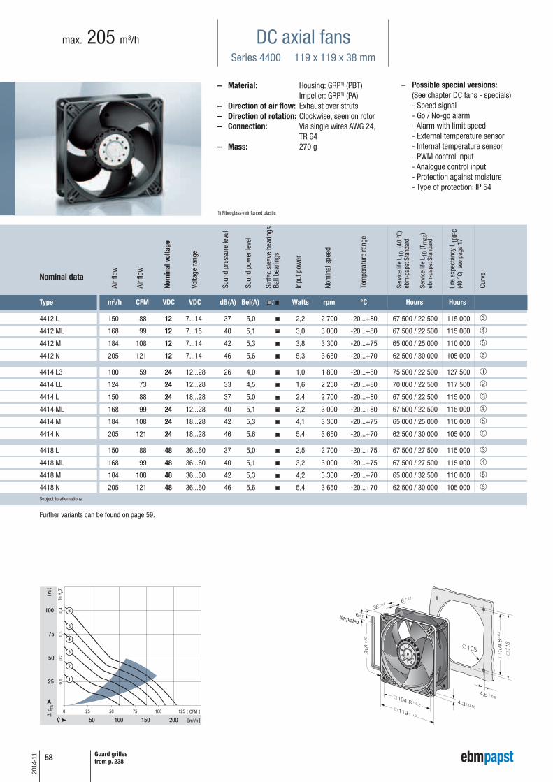
58
2014
-11
– Possible special versions:(See chapter DC fans - specials)
- Speed signal - Go / No-go alarm - Alarm with limit speed - External temperature sensor - Internal temperature sensor - PWM control input - Analogue control input - Protection against moisture - Type of protection: IP 54
DC axial fansSeries 4400 119 x 119 x 38 mm
max. 205 m3/h
Type m3/h CFM VDC VDC dB(A) Bel(A) / Watts rpm °C Hours Hours
4412 L 150 88 12 7...14 37 5,0 2,2 2 700 -20...+80 67 500 / 22 500 115 000 ➂
4412 ML 168 99 12 7...15 40 5,1 3,0 3 000 -20...+80 67 500 / 22 500 115 000 ➃
4412 M 184 108 12 7...14 42 5,3 3,8 3 300 -20...+75 65 000 / 25 000 110 000 ➄
4412 N 205 121 12 7...14 46 5,6 5,3 3 650 -20...+70 62 500 / 30 000 105 000 ➅
4414 L3 100 59 24 12...28 26 4,0 1,0 1 800 -20...+80 75 500 / 22 500 127 500 ➀
4414 LL 124 73 24 12...28 33 4,5 1,6 2 250 -20...+80 70 000 / 22 500 117 500 ➁
4414 L 150 88 24 18...28 37 5,0 2,4 2 700 -20...+80 67 500 / 22 500 115 000 ➂
4414 ML 168 99 24 12...28 40 5,1 3,2 3 000 -20...+80 67 500 / 22 500 115 000 ➃
4414 M 184 108 24 18...28 42 5,3 4,1 3 300 -20...+75 65 000 / 25 000 110 000 ➄
4414 N 205 121 24 18...28 46 5,6 5,4 3 650 -20...+70 62 500 / 30 000 105 000 ➅
4418 L 150 88 48 36...60 37 5,0 2,5 2 700 -20...+75 67 500 / 27 500 115 000 ➂
4418 ML 168 99 48 36...60 40 5,1 3,2 3 000 -20...+75 67 500 / 27 500 115 000 ➃
4418 M 184 108 48 36...60 42 5,3 4,2 3 300 -20...+70 65 000 / 32 500 110 000 ➄
4418 N 205 121 48 36...60 46 5,6 5,4 3 650 -20...+70 62 500 / 30 000 105 000 ➅Subject to alternations
– Material: Housing: GRP1) (PBT) Impeller: GRP1) (PA)
– Direction of air flow: Exhaust over struts – Direction of rotation: Clockwise, seen on rotor– Connection: Via single wires AWG 24,
TR 64– Mass: 270 g
1) Fibreglass-reinforced plastic
Nominal data
tin-plated
Guard grillesfrom p. 238
Further variants can be found on page 59.
Nom
inal
vol
tage
Air f
low
Air f
low
Volta
ge ra
nge
Soun
d pr
essu
re le
vel
Soun
d po
wer
leve
l
Sint
ec s
leev
e be
arin
gsBa
ll be
arin
gs
Inpu
t pow
er
Nom
inal
spe
ed
Tem
pera
ture
rang
e
Serv
ice
life
L 10
(40
°C)
ebm
-pap
st S
tand
ard
Serv
ice
life
L 10
(Tm
ax)
ebm
-pap
st S
tand
ard
Life
exp
ecta
ncy
L 10I
PC(4
0 °C
) se
e pa
ge 1
7
Curv
e

59
2014
-11
– Possible special versions:(See chapter DC fans - specials)
- Speed signal - Go / No-go alarm - Alarm with limit speed - External temperature sensor - Internal temperature sensor - PWM control input - Analogue control input - Protection against moisture - Type of protection: IP 54
DC axial fansSeries 4400 119 x 119 x 38 mm
max. 285 m3/h
– Material: Housing: GRP1) (PBT) Impeller: GRP1) (PA)
– Direction of air flow: Exhaust over struts – Direction of rotation: Clockwise, seen on rotor– Connection: Via single wires AWG 24,
TR 64– Mass: 270 g
1) Fibreglass-reinforced plastic
Type m3/h CFM VDC VDC dB(A) Bel(A) / Watts rpm °C Hours Hours
4412 H 240 141 12 7...14 50 6,0 8,6 4 300 -20...+70 57 500 / 27 500 92 500 ➀
4412/2 HHP 285 168 12 7...14,5 55 6,4 13,0 5 000 -20...+70 50 000 / 25 000 85 000 ➁
4414 H 240 141 24 18...28 50 6,0 8,6 4 300 -20...+70 57 500 / 27 500 92 500 ➀
4414 HH 285 165 24 16...28 55 6,4 14,0 5 000 -20...+70 50 000 / 25 000 85 000 ➁
4414/2 HHP 285 168 24 18...28 55 6,4 12,0 5 000 -20...+70 50 000 / 25 000 85 000 ➁
4418 H 240 141 48 36...60 50 6,0 8,6 4 300 -20...+70 57 500 / 27 500 92 500 ➀
4418/2 HHP 285 168 48 36...60 55 6,4 13,0 5 000 -20...+70 50 000 / 25 000 85 000 ➁Subject to alternations
Nominal data
tin-plated
Guard grillesfrom p. 238
Info
rmat
ion
DC a
xial
fans
DC fa
ns -
spe
cial
sAC
max
x / G
reen
Tech
EC
-Com
pact
fans
AC a
xial
fans
Acce
ssor
ies
Repr
esen
tativ
esDC
cen
trifu
gal f
ans
AC c
entr
ifuga
l fan
s
Nom
inal
vol
tage
Air f
low
Air f
low
Volta
ge ra
nge
Soun
d pr
essu
re le
vel
Soun
d po
wer
leve
l
Sint
ec s
leev
e be
arin
gsBa
ll be
arin
gs
Inpu
t pow
er
Nom
inal
spe
ed
Tem
pera
ture
rang
e
Serv
ice
life
L 10
(40
°C)
ebm
-pap
st S
tand
ard
Serv
ice
life
L 10
(Tm
ax)
ebm
-pap
st S
tand
ard
Life
exp
ecta
ncy
L 10I
PC(4
0 °C
) se
e pa
ge 1
7
Curv
e

60
2014
-11
– Possible special versions:(See chapter DC fans - specials)
- Speed signal - Go / No-go alarm - Alarm with limit speed - External temperature sensor - Internal temperature sensor - PWM control input - Analogue control input - Protection against moisture - Protection against salt fog - Type of protection: IP 54 / IP 68
DC axial fansSeries 4100 N 119 x 119 x 38 mm
max. 237 m3/h
Type m3/h CFM VDC VDC dB(A) Bel(A) / Watts rpm °C Hours Hours
4182 NGX 160 94 12 6...15 44 5,3 3,7 2 800 -20...+75 85 000 / 37 500 142 500 ➀
4182 NX 180 106 12 6...15 49 5,7 4,9 3 200 -30...+75 85 000 / 37 500 142 500 ➁
4182 NXH 237 140 12 7...14 57 6,5 11,0 4 400 -30...+55 70 000 / 50 000 117 500 ➂
4184 NGX 160 94 24 12...31,5 44 5,3 3,3 2 800 -20...+75 85 000 / 37 500 142 500 ➀
4184 NXM 160 94 24 12...31,5 44 5,3 3,2 2 800 -30...+75 85 000 / 37 500 142 500 ➀
4184 NX 180 106 24 12...31,5 49 5,7 4,9 3 200 -30...+70 85 000 / 42 500 142 500 ➁
4184 NXH 237 140 24 12...28 57 6,5 11,0 4 400 -30...+70 70 000 / 35 000 117 500 ➂
4188 NGX 160 94 48 36...60 44 5,3 3,6 2 800 -20...+75 85 000 / 37 500 142 500 ➀
4188 NXM 160 94 48 36...60 44 5,3 3,5 2 800 -30...+75 85 000 / 37 500 142 500 ➀Subject to alternations
– Material: Housing: Die-cast aluminium Impeller: GRP1) (PA)
– Direction of air flow: Intake over struts – Direction of rotation: Clockwise, seen on rotor– Connection: On flat connectors, 2.8 x 0.5 mm
Also available with wires as an option
– Highlights: Housing with grounding lug for screw M4 x 8 (Torx)
– Mass: 390 g
1) Fibreglass-reinforced plastic
0 20 40 60 80 100 120
40 80
40
80
60
120 160 200
120
1
2
20
100
1403
0,5
0,4
0,3
0,2
0,1
m³/h
Pa
CFM
[in H
2O]
Nominal data
Guard grillesfrom p. 238
Connection cablesfrom p. 251
Nom
inal
vol
tage
Air f
low
Air f
low
Volta
ge ra
nge
Soun
d pr
essu
re le
vel
Soun
d po
wer
leve
l
Sint
ec s
leev
e be
arin
gsBa
ll be
arin
gs
Inpu
t pow
er
Nom
inal
spe
ed
Tem
pera
ture
rang
e
Serv
ice
life
L 10
(40
°C)
ebm
-pap
st S
tand
ard
Serv
ice
life
L 10
(Tm
ax)
ebm
-pap
st S
tand
ard
Life
exp
ecta
ncy
L 10I
PC(4
0 °C
) se
e pa
ge 1
7
Curv
e

61
2014
-11
– Possible special versions:(See chapter DC fans - specials)
- Speed signal - Go / No-go alarm - Alarm with limit speed - External temperature sensor - Internal temperature sensor - PWM control input - Analogue control input - Protection against moisture - Protection against salt fog - Type of protection: IP 54 / IP 68
DC axial fansSeries 4100 N High Performance 119 x 119 x 38 mm
max. 440 m3/h
– Material: Housing: Die-cast aluminium Impeller: GRP1) (PA)
– Direction of air flow: Intake over struts – Direction of rotation: Clockwise, seen on rotor– Connection: Via single wires AWG 22 UL
1007, TR 64– Highlights: Housing with grounding lug for
screw M4 x 8 (Torx)– Mass: 390 g
1) Fibreglass-reinforced plastic
Type m3/h CFM VDC VDC dB(A) Bel(A) / Watts rpm °C Hours Hours
4112 NHH 260 153 12 9...15 60 6,8 13,3 5 000 -20...+65 70 000 / 55 000 117 500 ➀
4112 NH3 310 182 12 9...15 65 7,2 21,6 6 000 -20...+65 65 000 / 37 500 110 000 ➁
4112 NH4 355 209 12 9...14 67 7,4 32,0 6 800 -20...+65 62 500 / 35 000 105 000 ➂
4114 NHH 260 153 24 16...30 60 6,8 12,4 5 000 -20...+65 70 000 / 52 500 117 500 ➀
4114 NH3 310 182 24 16...30 65 7,2 19,5 6 000 -20...+65 65 000 / 37 500 110 000 ➁
4114 NH4 355 209 24 16...30 67 7,4 30,0 6 800 -20...+65 62 500 / 35 000 105 000 ➂
4114 NH5 390 230 24 16...30 70 7,6 45,0* 7 500 -20...+65 62 500 / 35 000 105 000 ➃
4114 NH6 440 259 24 16...30 73 8,1 65,0* 8 400 -20...+65 60 000 / 32 500 102 500 ➄
4118 NHH 260 153 48 36...60 60 6,8 12,0 5 000 -20...+65 70 000 / 52 500 117 500 ➀
4118 NH3 310 182 48 36...60 65 7,2 20,0 6 000 -20...+65 65 000 / 37 500 110 000 ➁
4118 NH4 355 209 48 36...60 67 7,4 28,0 6 800 -20...+65 62 500 / 35 000 105 000 ➂
4118 NH5 390 230 48 36...60 70 7,6 45,0* 7 500 -20...+65 62 500 / 35 000 105 000 ➃
4118 NH6 440 259 48 36...60 73 8,1 62,0* 8 400 -20...+65 60 000 / 32 500 102 500 ➄Subject to alternations
Nominal data
* Input power at free air flow, these values can be significantly higher in the operating point.
* Input power - in operation
Fan type optimum operating range (W)
4114 NH5 55
4114 NH6 95
4118 NH5 55
4118 NH6 95
tin-plated
Guard grillesfrom p. 238
Info
rmat
ion
DC a
xial
fans
DC fa
ns -
spe
cial
sAC
max
x / G
reen
Tech
EC
-Com
pact
fans
AC a
xial
fans
Acce
ssor
ies
Repr
esen
tativ
esDC
cen
trifu
gal f
ans
AC c
entr
ifuga
l fan
s
Nom
inal
vol
tage
Air f
low
Air f
low
Volta
ge ra
nge
Soun
d pr
essu
re le
vel
Soun
d po
wer
leve
l
Sint
ec s
leev
e be
arin
gsBa
ll be
arin
gs
Inpu
t pow
er*
Nom
inal
spe
ed
Tem
pera
ture
rang
e
Serv
ice
life
L 10
(40
°C)
ebm
-pap
st S
tand
ard
Serv
ice
life
L 10
(Tm
ax)
ebm
-pap
st S
tand
ard
Life
exp
ecta
ncy
L 10I
PC(4
0 °C
) se
e pa
ge 1
7
Curv
e

62
2014
-11
– Possible special versions:(See chapter DC fans - specials)
- Speed signal - Go / No-go alarm - Alarm with limit speed - External temperature sensor - Internal temperature sensor - PWM control input - Analogue control input - Protection against moisture - Protection against salt fog
DC axial fansSeries 4100 N High Performance 119 x 119 x 38 mm
max. 570 m3/h
Type m3/h CFM VDC VDC dB(A) Bel(A) / Watts rpm °C Hours Hours
4114 N/2 H7P 500 294 24 16...30 76 8,5 90 9 500 -20...+75 57 500 / 25 000 97 500 ➀
4114 N/2 H8P 570 336 24 16...30 78 8,9 120 11 000 -20...+75 55 000 / 22 500 92 500 ➁
4118 N/2 H7P 500 294 48 36...60* 76 8,5 90 9 500 -20...+75 57 500 / 25 000 97 500 ➀
4118 N/2 H8P 570 336 48 36...60* 78 8,9 120 11 000 -20...+75 55 000 / 22 500 92 500 ➁Subject to alternations
– Material: Housing: Die-cast aluminium Impeller: GRP1) (PA)
– Direction of air flow: Intake over struts – Direction of rotation: Clockwise, seen on rotor– Connection: Via single wires AWG 18, 20 or AWG 22, TR 64, speed signal
and control input AWG 22– Highlights: 3-phase fan drive with very smooth running and high
efficiency Housing with grounding lug for screw M4 x 8 (Torx)
– Mass: 425 g1) Fibreglass-reinforced plastic
0 50 100 150 200 250 300
100 200
200
300 400 500
400
600
1000
1200
800 3,2
2,4
1,6
0,8
4,0
1
2
m³/h
Pa
CFM
[in H
2O]
Nominal data
* 36...72 VDC on request.
Speed control range from 500 rpm up to maximum nominal speed. Stationary at 0 % PWM,maximum speed at sensor break.To attain the specified service life, an external capacitor must be wired between the plus and minus strands.Please note the wiring suggestion on page 16.** Input power at free air flow, these values can be significantly higher in the operating point.
tin-plated
Guard grillesfrom p. 238
** Input power - in operation
Fan type optimum operating range (W)
4114 NH7P 100
4114 NH8P 160
4118 NH7P 100
4118 NH8P 160
Nom
inal
vol
tage
Air f
low
Air f
low
Volta
ge ra
nge
Soun
d pr
essu
re le
vel
Soun
d po
wer
leve
l
Sint
ec s
leev
e be
arin
gsBa
ll be
arin
gs
Inpu
t pow
er**
Nom
inal
spe
ed
Tem
pera
ture
rang
e
Serv
ice
life
L 10
(40
°C)
ebm
-pap
st S
tand
ard
Serv
ice
life
L 10
(Tm
ax)
ebm
-pap
st S
tand
ard
Life
exp
ecta
ncy
L 10I
PC(4
0 °C
) se
e pa
ge 1
7
Curv
e
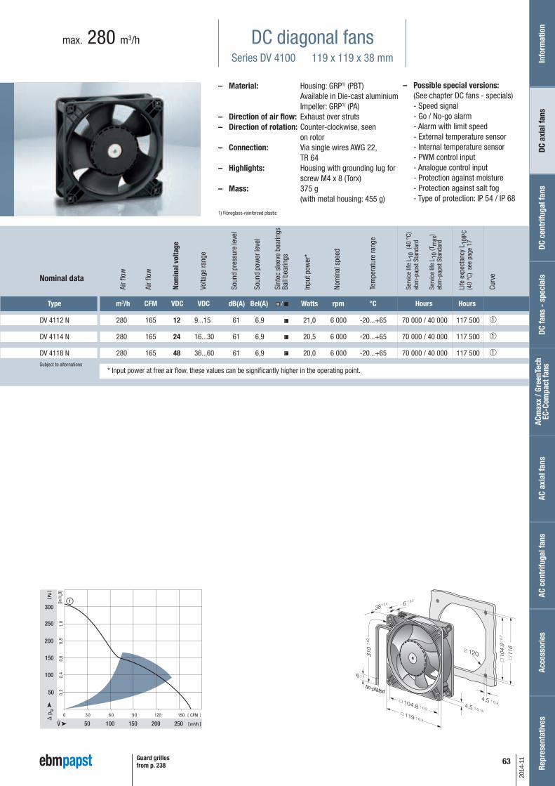
63
2014
-11
– Possible special versions:(See chapter DC fans - specials)
- Speed signal - Go / No-go alarm - Alarm with limit speed - External temperature sensor - Internal temperature sensor - PWM control input - Analogue control input - Protection against moisture - Protection against salt fog - Type of protection: IP 54 / IP 68
DC diagonal fansSeries DV 4100 119 x 119 x 38 mm
max. 280 m3/h
– Material: Housing: GRP1) (PBT) Available in Die-cast aluminium Impeller: GRP1) (PA)
– Direction of air flow: Exhaust over struts – Direction of rotation: Counter-clockwise, seen
on rotor– Connection: Via single wires AWG 22,
TR 64– Highlights: Housing with grounding lug for
screw M4 x 8 (Torx)– Mass: 375 g
(with metal housing: 455 g)
1) Fibreglass-reinforced plastic
0 30 60 90 120 150
50 100
50
150
150
200
250
300
200
100
250
1
1,0
0,8
0,6
0,4
0,2
m³/h
Pa
CFM
[in H
2O]
Type m3/h CFM VDC VDC dB(A) Bel(A) / Watts rpm °C Hours Hours
DV 4112 N 280 165 12 9...15 61 6,9 21,0 6 000 -20...+65 70 000 / 40 000 117 500 ➀
DV 4114 N 280 165 24 16...30 61 6,9 20,5 6 000 -20...+65 70 000 / 40 000 117 500 ➀
DV 4118 N 280 165 48 36...60 61 6,9 20,0 6 000 -20...+65 70 000 / 40 000 117 500 ➀Subject to alternations
Nominal data
tin-plated
Guard grillesfrom p. 238
* Input power at free air flow, these values can be significantly higher in the operating point.
Info
rmat
ion
DC a
xial
fans
DC fa
ns -
spe
cial
sAC
max
x / G
reen
Tech
EC
-Com
pact
fans
AC a
xial
fans
Acce
ssor
ies
Repr
esen
tativ
esDC
cen
trifu
gal f
ans
AC c
entr
ifuga
l fan
s
Nom
inal
vol
tage
Air f
low
Air f
low
Volta
ge ra
nge
Soun
d pr
essu
re le
vel
Soun
d po
wer
leve
l
Sint
ec s
leev
e be
arin
gsBa
ll be
arin
gs
Inpu
t pow
er*
Nom
inal
spe
ed
Tem
pera
ture
rang
e
Serv
ice
life
L 10
(40
°C)
ebm
-pap
st S
tand
ard
Serv
ice
life
L 10
(Tm
ax)
ebm
-pap
st S
tand
ard
Life
exp
ecta
ncy
L 10I
PC(4
0 °C
) se
e pa
ge 1
7
Curv
e

64
2014
-11
– Possible special versions:(See chapter DC fans - specials)
- Speed signal - Go / No-go alarm - Alarm with limit speed - External temperature sensor - Internal temperature sensor - PWM control input - Analogue control input - Protection against moisture - Protection against salt fog - Type of protection: IP 54 / IP 68
DC axial fansSeries 5200 N 127 x 127 x 38 mm
max. 340 m3/h
Type m3/h CFM VDC VDC dB(A) Bel(A) / Watts rpm °C Hours Hours
5212 NM 187 110 12 7...14,5 43 5,3 4,1 2 750 -20...+75 62 500 / 27 500 105 000 ➀
5212 NN 216 127 12 7...14 46 5,6 6,2 3 150 -20...+70 57 500 / 25 000 97 500 ➁
5212 NH 252 148 12 7...14 51 6,0 9,8 3 650 -20...+70 45 000 / 22 500 75 000 ➂
5212 NHH* 340 200 12 9...15 58 6,6 19,0 4 900 -20...+65 45 000 / 25 000 75 000 ➃
5214 NM 187 110 24 12...28 43 5,3 4,6 2 750 -20...+75 62 500 / 27 500 105 000 ➀
5214 NN 216 127 24 12...28 46 5,6 6,0 3 150 -20...+75 57 500 / 25 000 97 500 ➁
5214 NH 252 148 24 12...28 51 6,0 9,8 3 650 -20...+70 45 000 / 22 500 75 000 ➂
5214 NHH* 340 200 24 16...30 58 6,6 17,5 4 900 -20...+65 45 000 / 25 000 75 000 ➃
5218 NM 187 110 48 36...56 43 5,3 4,5 2 750 -20...+75 62 500 / 27 500 105 000 ➀
5218 NN 216 127 48 36...56 46 5,6 6,2 3 150 -20...+70 57 500 / 32 500 97 500 ➁
5218 NH 252 148 48 36...56 51 6,0 9,6 3 650 -20...+55 45 000 / 32 500 75 000 ➂
5218 NHH* 340 200 48 36...60 58 6,6 18,0 4 900 -20...+65 45 000 / 25 000 75 000 ➃Subject to alternations
– Material: Housing: GRP1) (PBT) Impeller: GRP1) (PA)
– Direction of air flow: Exhaust over struts – Direction of rotation: Counter-clockwise, seen
on rotor– Connection: Via single wires AWG 22,
TR 64– Mass: 310 g
1) Fibreglass-reinforced plastic
0 40 80 120 160 200
100
50
100
150
200
200
300
1
3
4
2
0,8
0,6
0,4
0,2
m³/h
Pa
CFM
[in H
2O]
Nominal data
*Models NHH: Fan housingwith moulded-in spacers.
tin-plated
Guard grillesfrom p. 238
** Input power at free air flow, these values can be significantly higher in the operating point.
Nom
inal
vol
tage
Air f
low
Air f
low
Volta
ge ra
nge
Soun
d pr
essu
re le
vel
Soun
d po
wer
leve
l
Sint
ec s
leev
e be
arin
gsBa
ll be
arin
gs
Inpu
t pow
er**
Nom
inal
spe
ed
Tem
pera
ture
rang
e
Serv
ice
life
L 10
(40
°C)
ebm
-pap
st S
tand
ard
Serv
ice
life
L 10
(Tm
ax)
ebm
-pap
st S
tand
ard
Life
exp
ecta
ncy
L 10I
PC(4
0 °C
) se
e pa
ge 1
7
Curv
e
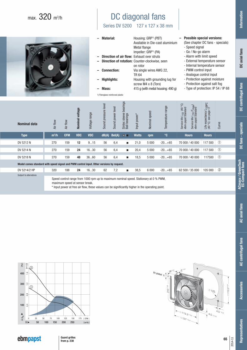
65
2014
-11
– Possible special versions:(See chapter DC fans - specials)
- Speed signal - Go / No-go alarm - Alarm with limit speed - External temperature sensor - Internal temperature sensor - PWM control input - Analogue control input - Protection against moisture - Protection against salt fog - Type of protection: IP 54 / IP 68
DC diagonal fansSeries DV 5200 127 x 127 x 38 mm
max. 320 m3/h
– Material: Housing: GRP1) (PBT) Available in Die-cast aluminium Metal flange Impeller: GRP1) (PA)
– Direction of air flow: Exhaust over struts – Direction of rotation: Counter-clockwise, seen
on rotor– Connection: Via single wires AWG 22,
TR 64– Highlights: Housing with grounding lug for
screw M4 x 8 (Torx)– Mass: 415 g (with metal housing: 490 g)
1) Fibreglass-reinforced plastic
25 50 75 100 125 150 1750
50 100 150
300
400
200
100
200
250
2
1
1,2
1,6
0,8
0,4
m³/h
Pa
CFM
[in H
2O]
Type m3/h CFM VDC VDC dB(A) Bel(A) / Watts rpm °C Hours Hours
DV 5212 N 270 159 12 9...15 56 6,4 21,0 5 000 -20...+65 70 000 / 40 000 117 500 ➀
DV 5214 N 270 159 24 16...30 56 6,4 20,4 5 000 -20...+65 70 000 / 40 000 117 500 ➀
DV 5218 N 270 159 48 36...60 56 6,4 18,5 5 000 -20...+65 70 000 / 40 000 117500 ➀
DV 5214/2 HP 320 188 24 16...30 62 7,2 38,5 6 000 -20...+65 62 500 / 35 000 105 000 ➁Subject to alternations
Nominal data
Model comes standard with speed signal and PWM control input. Other versions by request.
Speed control range from 1000 rpm up to maximum nominal speed. Stationary at 0 % PWM,maximum speed at sensor break.* Input power at free air flow, these values can be significantly higher in the operating point.
tin-plated
Guard grillesfrom p. 238
Info
rmat
ion
DC a
xial
fans
DC fa
ns -
spe
cial
sAC
max
x / G
reen
Tech
EC
-Com
pact
fans
AC a
xial
fans
Acce
ssor
ies
Repr
esen
tativ
esDC
cen
trifu
gal f
ans
AC c
entr
ifuga
l fan
s
Nom
inal
vol
tage
Air f
low
Air f
low
Volta
ge ra
nge
Soun
d pr
essu
re le
vel
Soun
d po
wer
leve
l
Sint
ec s
leev
e be
arin
gsBa
ll be
arin
gs
Inpu
t pow
er*
Nom
inal
spe
ed
Tem
pera
ture
rang
e
Serv
ice
life
L 10
(40
°C)
ebm
-pap
st S
tand
ard
Serv
ice
life
L 10
(Tm
ax)
ebm
-pap
st S
tand
ard
Life
exp
ecta
ncy
L 10I
PC(4
0 °C
) se
e pa
ge 1
7
Curv
e
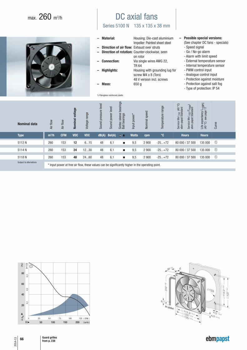
66
2014
-11
– Possible special versions:(See chapter DC fans - specials)
- Speed signal - Go / No-go alarm - Alarm with limit speed - External temperature sensor - Internal temperature sensor - PWM control input - Analogue control input - Protection against moisture - Protection against salt fog - Type of protection: IP 54
DC axial fansSeries 5100 N 135 x 135 x 38 mm
max. 260 m3/h
Type m3/h CFM VDC VDC dB(A) Bel(A) / Watts rpm °C Hours Hours
5112 N 260 153 12 6...15 48 6,1 9,5 2 900 -25...+72 80 000 / 37 500 135 000 ➀
5114 N 260 153 24 12...30 48 6,1 9,5 2 900 -25...+72 80 000 / 37 500 135 000 ➀
5118 N 260 153 48 24...60 48 6,1 9,5 2 900 -25...+72 80 000 / 37 500 135 000 ➀Subject to alternations
– Material: Housing: Die-cast aluminium Impeller: Painted sheet steel
– Direction of air flow: Exhaust over struts – Direction of rotation: Counter-clockwise, seen
on rotor– Connection: Via single wires AWG 22,
TR 64– Highlights: Housing with grounding lug for
screw M4 x 8 (Torx) 48 V version incl. screws
– Mass: 650 g
1) Fibreglass-reinforced plastic
0 25 50 75 100 125
50
80
20
100
1
150 200
60
40
0,3
0,2
0,1
m³/h
Pa
CFM
[in H
2O]
Nominal data
tin-plated
Guard grillesfrom p. 238
* Input power at free air flow, these values can be significantly higher in the operating point.
Nom
inal
vol
tage
Air f
low
Air f
low
Volta
ge ra
nge
Soun
d pr
essu
re le
vel
Soun
d po
wer
leve
l
Sint
ec s
leev
e be
arin
gsBa
ll be
arin
gs
Inpu
t pow
er*
Nom
inal
spe
ed
Tem
pera
ture
rang
e
Serv
ice
life
L 10
(40
°C)
ebm
-pap
st S
tand
ard
Serv
ice
life
L 10
(Tm
ax)
ebm
-pap
st S
tand
ard
Life
exp
ecta
ncy
L 10I
PC(4
0 °C
) se
e pa
ge 1
7
Curv
e
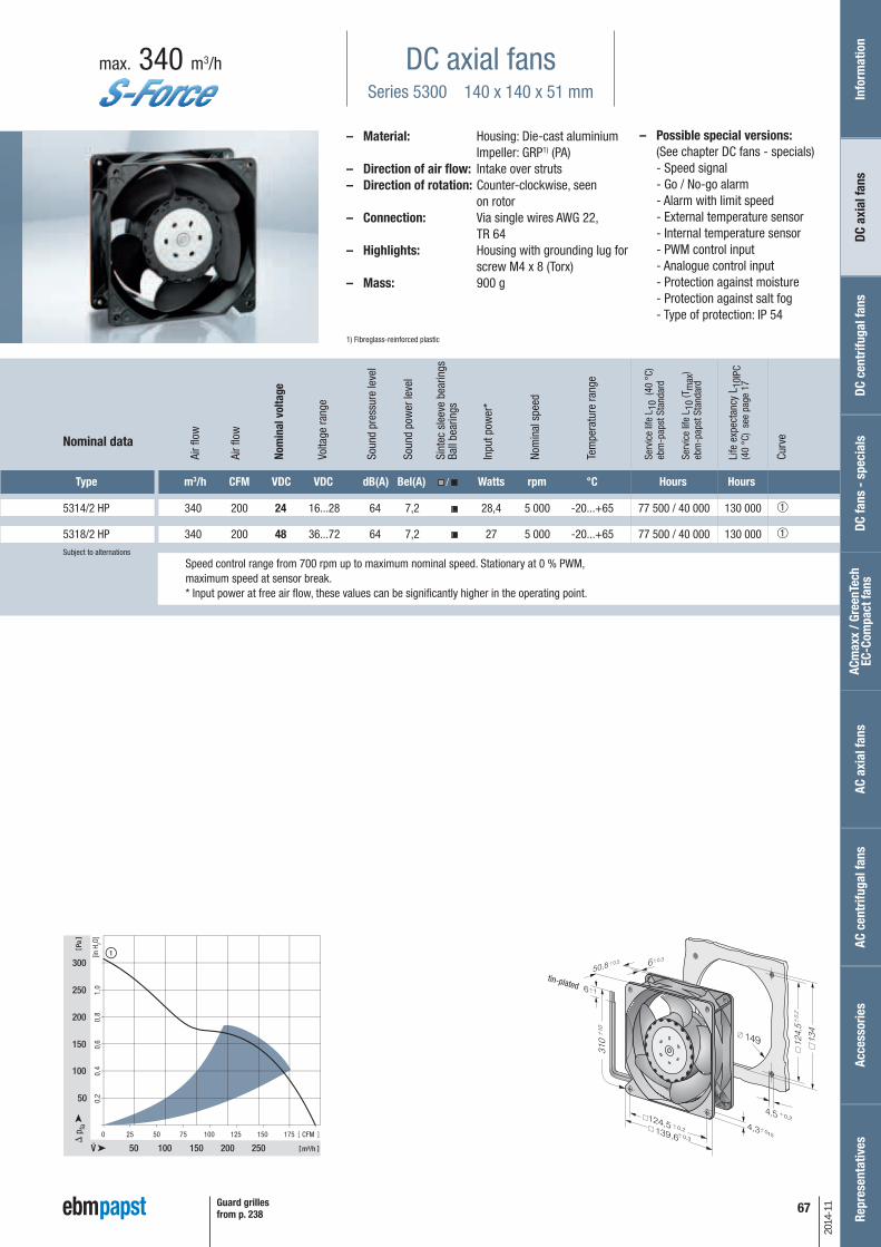
67
2014
-11
– Possible special versions:(See chapter DC fans - specials)
- Speed signal - Go / No-go alarm - Alarm with limit speed - External temperature sensor - Internal temperature sensor - PWM control input - Analogue control input - Protection against moisture - Protection against salt fog - Type of protection: IP 54
DC axial fansSeries 5300 140 x 140 x 51 mm
max. 340 m3/h
– Material: Housing: Die-cast aluminium Impeller: GRP1) (PA)
– Direction of air flow: Intake over struts – Direction of rotation: Counter-clockwise, seen
on rotor– Connection: Via single wires AWG 22,
TR 64– Highlights: Housing with grounding lug for
screw M4 x 8 (Torx)– Mass: 900 g
1) Fibreglass-reinforced plastic
25 50 75 100 125 150 1750
50 100
50
150
200
150
100
200 250
250
3001
0,6
0,8
1,0
0,4
0,2
m³/h
Pa
CFM
[in H
2O]
Type m3/h CFM VDC VDC dB(A) Bel(A) / Watts rpm °C Hours Hours
5314/2 HP 340 200 24 16...28 64 7,2 28,4 5 000 -20...+65 77 500 / 40 000 130 000 ➀
5318/2 HP 340 200 48 36...72 64 7,2 27 5 000 -20...+65 77 500 / 40 000 130 000 ➀Subject to alternations
Nominal data
Speed control range from 700 rpm up to maximum nominal speed. Stationary at 0 % PWM,maximum speed at sensor break.* Input power at free air flow, these values can be significantly higher in the operating point.
tin-plated
Guard grillesfrom p. 238
Info
rmat
ion
DC a
xial
fans
DC fa
ns -
spe
cial
sAC
max
x / G
reen
Tech
EC
-Com
pact
fans
AC a
xial
fans
Acce
ssor
ies
Repr
esen
tativ
esDC
cen
trifu
gal f
ans
AC c
entr
ifuga
l fan
s
Nom
inal
vol
tage
Air f
low
Air f
low
Volta
ge ra
nge
Soun
d pr
essu
re le
vel
Soun
d po
wer
leve
l
Sint
ec s
leev
e be
arin
gsBa
ll be
arin
gs
Inpu
t pow
er*
Nom
inal
spe
ed
Tem
pera
ture
rang
e
Serv
ice
life
L 10
(40
°C)
ebm
-pap
st S
tand
ard
Serv
ice
life
L 10
(Tm
ax)
ebm
-pap
st S
tand
ard
Life
exp
ecta
ncy
L 10I
PC(4
0 °C
) se
e pa
ge 1
7
Curv
e

68
2014
-11
– Possible special versions:(See chapter DC fans - specials)
- Speed signal - Go / No-go alarm - Alarm with limit speed - External temperature sensor - Internal temperature sensor - PWM control input - Analogue control input - Multi-option control input - Protection against moisture - Protection against salt fog - Type of protection: IP 54 / IP 68
DC axial fansSeries 5300 TD 140 x 140 x 51 mm
max. 670 m3/h
Type m3/h CFM VDC VDC dB(A) Bel(A) / Watts rpm °C Hours Hours
5312/2 TDHP 410 241 12 8...16 70 7,7 43 6 000 -20...+70 70 000 / 35 000 117 500 ➀
5314/2 TDHP 410 241 24 16...36 70 7,7 42 6 000 -20...+70 70 000 / 35 000 117 500 ➀
5314/2 TDHHP 490 288 24 16...36 75 8,1 67 7 000 -20...+70 62 500 / 30 000 105 000 ➁
5318/2 TDHP 410 241 48 36...72 70 7,7 42 6 000 -20...+70 70 000 / 35 000 117 500 ➀
5318/2 TDHHP 490 288 48 36...72 75 8,1 66 7 000 -20...+70 62 500 / 30 000 105 000 ➁
5318/2 TDH4P 670 394 48 36...72 79 8,8 149 9 200 -20...+65 57 500 / 32 500 97 500 ➂Subject to alternations
– Material: Housing: Die-cast aluminium Impeller: GRP1) (PA)
– Direction of air flow: Intake over struts – Direction of rotation: Counter-clockwise, seen
on rotor– Connection: Via single wires AWG 20 and
AWG 22, TR 64– Highlights: 3-phase fan drive with very
smooth running and high efficiency
– Mass: 900 g
1) Fibreglass-reinforced plastic
500 100 250
100 200
200
600
800
300 400
400
500 600
1000
1200
3,2
2,4
1,6
0,8
4,0
150 200 300 350 400
1
2
3
m³/h
Pa
CFM
[in H
2O]
Nominal data
Speed control range from 1000 rpm up to maximum nominal speed. Stationary at 0 % PWM,maximum speed at sensor break.* Input power at free air flow, these values can be significantly higher in the operating point.
tin-plated
Guard grillesfrom p. 238
Nom
inal
vol
tage
Air f
low
Air f
low
Volta
ge ra
nge
Soun
d pr
essu
re le
vel
Soun
d po
wer
leve
l
Sint
ec s
leev
e be
arin
gsBa
ll be
arin
gs
Inpu
t pow
er*
Nom
inal
spe
ed
Tem
pera
ture
rang
e
Serv
ice
life
L 10
(40
°C)
ebm
-pap
st S
tand
ard
Serv
ice
life
L 10
(Tm
ax)
ebm
-pap
st S
tand
ard
Life
exp
ecta
ncy
L 10I
PC(4
0 °C
) se
e pa
ge 1
7
Curv
e
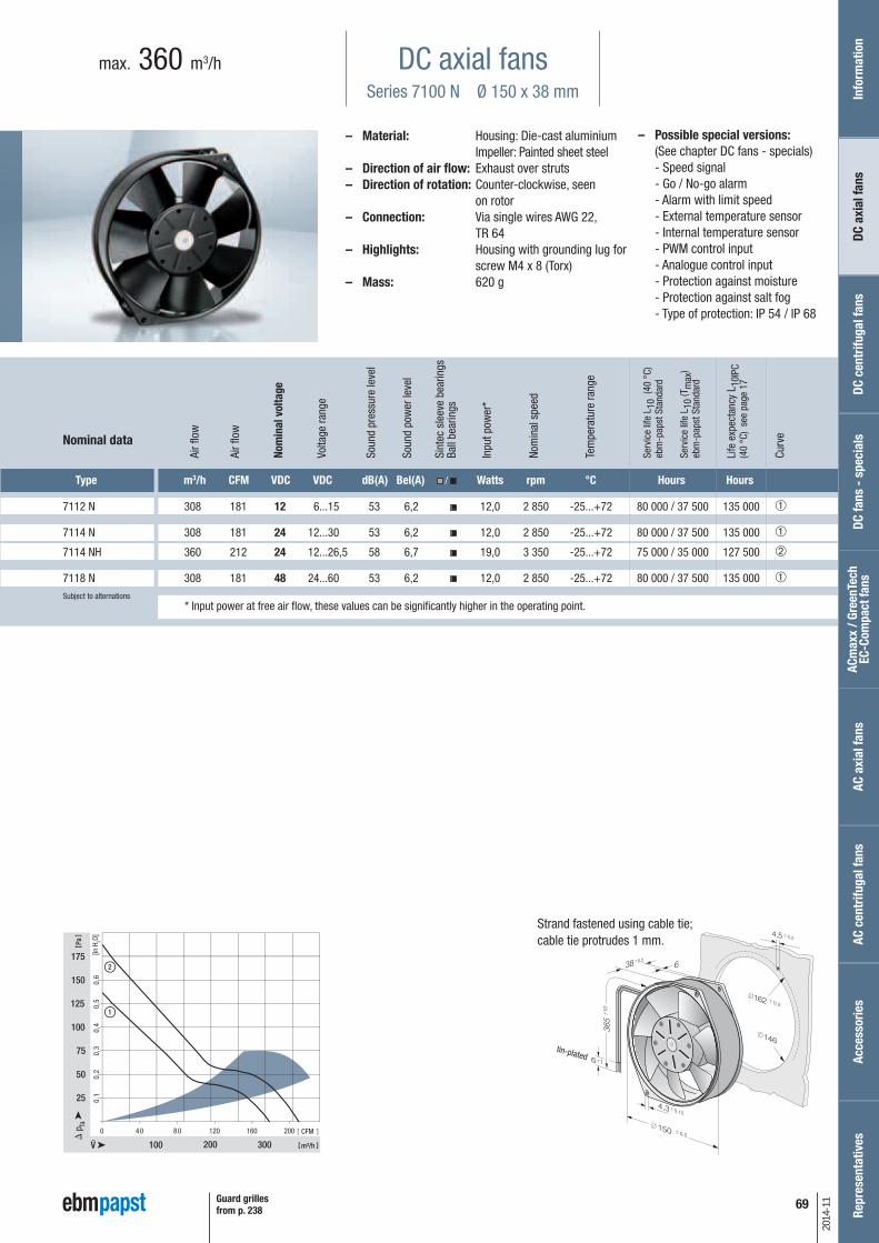
69
2014
-11
– Possible special versions:(See chapter DC fans - specials)
- Speed signal - Go / No-go alarm - Alarm with limit speed - External temperature sensor - Internal temperature sensor - PWM control input - Analogue control input - Protection against moisture - Protection against salt fog - Type of protection: IP 54 / IP 68
DC axial fansSeries 7100 N Ø 150 x 38 mm
max. 360 m3/h
– Material: Housing: Die-cast aluminium Impeller: Painted sheet steel
– Direction of air flow: Exhaust over struts – Direction of rotation: Counter-clockwise, seen
on rotor– Connection: Via single wires AWG 22,
TR 64– Highlights: Housing with grounding lug for
screw M4 x 8 (Torx)– Mass: 620 g
Type m3/h CFM VDC VDC dB(A) Bel(A) / Watts rpm °C Hours Hours
7112 N 308 181 12 6...15 53 6,2 12,0 2 850 -25...+72 80 000 / 37 500 135 000 ➀
7114 N 308 181 24 12...30 53 6,2 12,0 2 850 -25...+72 80 000 / 37 500 135 000 ➀
7114 NH 360 212 24 12...26,5 58 6,7 19,0 3 350 -25...+72 75 000 / 35 000 127 500 ➁
7118 N 308 181 48 24...60 53 6,2 12,0 2 850 -25...+72 80 000 / 37 500 135 000 ➀Subject to alternations
Nominal data
Strand fastened using cable tie;cable tie protrudes 1 mm.
tin-plated
Guard grillesfrom p. 238
* Input power at free air flow, these values can be significantly higher in the operating point.
Info
rmat
ion
DC a
xial
fans
DC fa
ns -
spe
cial
sAC
max
x / G
reen
Tech
EC
-Com
pact
fans
AC a
xial
fans
Acce
ssor
ies
Repr
esen
tativ
esDC
cen
trifu
gal f
ans
AC c
entr
ifuga
l fan
s
Nom
inal
vol
tage
Air f
low
Air f
low
Volta
ge ra
nge
Soun
d pr
essu
re le
vel
Soun
d po
wer
leve
l
Sint
ec s
leev
e be
arin
gsBa
ll be
arin
gs
Inpu
t pow
er*
Nom
inal
spe
ed
Tem
pera
ture
rang
e
Serv
ice
life
L 10
(40
°C)
ebm
-pap
st S
tand
ard
Serv
ice
life
L 10
(Tm
ax)
ebm
-pap
st S
tand
ard
Life
exp
ecta
ncy
L 10I
PC(4
0 °C
) se
e pa
ge 1
7
Curv
e

70
2014
-11
– Possible special versions:(See chapter DC fans - specials)
- Speed signal - Go / No-go alarm - Alarm with limit speed - External temperature sensor - Internal temperature sensor - PWM control input - Analogue control input - Protection against moisture - Protection against salt fog - Type of protection: IP 54 / IP 68
DC axial fansSeries 7200 N Ø 150 x 55 mm
max. 360 m3/h
Type m3/h CFM VDC VDC dB(A) Bel(A) / Watts rpm °C Hours Hours
7212 N 360 212 12 6...15 53 6,2 12,0 3 050 -25...+72 80 000 / 37 500 135 000 ➀
7214 N 360 212 24 12...30 53 6,2 12,0 3 050 -25...+72 80 000 / 37 500 135 000 ➀
7218 N 360 212 48 24...60 53 6,2 12,0 3 050 -25...+72 80 000 / 37 500 135 000 ➀Subject to alternations
– Material: Housing: Die-cast aluminium Impeller: GRP1) (PA)
– Direction of air flow: Exhaust over struts – Direction of rotation: Counter-clockwise, seen
on rotor– Connection: Via single wires AWG 22,
TR 64– Highlights: Housing with grounding lug for
screw M4 x 8 (Torx)– Mass: 725 g
1) Fibreglass-reinforced plastic
0 40 80 120 160 200
100
25
50
75
200
100
125
300
1
0,4
0,3
0,2
0,1
m³/h
Pa
CFM
[in H
2O]
Nominal data
tin-plated
Guard grillesfrom p. 238
* Input power at free air flow, these values can be significantly higher in the operating point.
Nom
inal
vol
tage
Air f
low
Air f
low
Volta
ge ra
nge
Soun
d pr
essu
re le
vel
Soun
d po
wer
leve
l
Sint
ec s
leev
e be
arin
gsBa
ll be
arin
gs
Inpu
t pow
er*
Nom
inal
spe
ed
Tem
pera
ture
rang
e
Serv
ice
life
L 10
(40
°C)
ebm
-pap
st S
tand
ard
Serv
ice
life
L 10
(Tm
ax)
ebm
-pap
st S
tand
ard
Life
exp
ecta
ncy
L 10I
PC(4
0 °C
) se
e pa
ge 1
7
Curv
e

71
2014
-11
– Possible special versions:(See chapter DC fans - specials)
- Speed signal - Go / No-go alarm - Alarm with limit speed - External temperature sensor - Internal temperature sensor - PWM control input - Analogue control input - Protection against moisture - Type of protection: IP 54
DC axial fansSeries 6100 N 172 x 160 x 52 mm
max. 350 m3/h
– Material: Housing: GRP1) (PBT) Impeller: GRP1) (PA)
– Direction of air flow: Exhaust over struts – Direction of rotation: Counter-clockwise, seen
on rotor– Connection: Via single wires AWG 22,
TR 64– Highlights: Light and compact plastic
housing– Mass: 610 g
1) Fibreglass-reinforced plastic
100
25
50
75
200
100
125
150
300
0 40 80 120 160 200
0,5
0,4
0,3
0,2
0,1
m³/h
Pa
CFM
[in H
2O]
1
Type m3/h CFM VDC VDC dB(A) Bel(A) / Watts rpm °C Hours Hours
6112 NM 350 206 12 8...15 49 5,9 11 2 850 -20...+70 80 000 / 40 000 135 000 ➀
6114 NM 350 206 24 12...32 49 5,9 11 2 850 -20...+70 80 000 / 40 000 135 000 ➀Subject to alternations
Nominal data
8,2 deep
tin-plated
Guard grillesfrom p. 238
* Input power at free air flow, these values can be significantly higher in the operating point.
Info
rmat
ion
DC a
xial
fans
DC fa
ns -
spe
cial
sAC
max
x / G
reen
Tech
EC
-Com
pact
fans
AC a
xial
fans
Acce
ssor
ies
Repr
esen
tativ
esDC
cen
trifu
gal f
ans
AC c
entr
ifuga
l fan
s
Nom
inal
vol
tage
Air f
low
Air f
low
Volta
ge ra
nge
Soun
d pr
essu
re le
vel
Soun
d po
wer
leve
l
Sint
ec s
leev
e be
arin
gsBa
ll be
arin
gs
Inpu
t pow
er*
Nom
inal
spe
ed
Tem
pera
ture
rang
e
Serv
ice
life
L 10
(40
°C)
ebm
-pap
st S
tand
ard
Serv
ice
life
L 10
(Tm
ax)
ebm
-pap
st S
tand
ard
Life
exp
ecta
ncy
L 10I
PC(4
0 °C
) se
e pa
ge 1
7
Curv
e
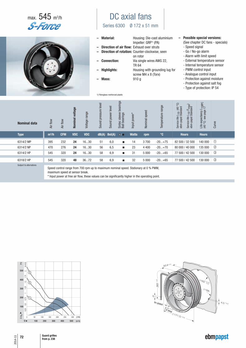
72
2014
-11
– Possible special versions:(See chapter DC fans - specials)
- Speed signal - Go / No-go alarm - Alarm with limit speed - External temperature sensor - Internal temperature sensor - PWM control input - Analogue control input - Protection against moisture - Protection against salt fog - Type of protection: IP 54
DC axial fansSeries 6300 Ø 172 x 51 mm
max. 545 m3/h
Type m3/h CFM VDC VDC dB(A) Bel(A) / Watts rpm °C Hours Hours
6314/2 MP 395 232 24 16...30 51 6,0 14 3 700 -20...+75 82 500 / 32 500 140 000 ➀
6314/2 NP 470 276 24 16...30 56 6,5 23 4 400 -20...+70 80 000 / 40 000 135 000 ➁
6314/2 HP 545 320 24 16...30 58 6,9 31 5 000 -20...+65 77 500 / 42 500 130 000 ➂
6318/2 HP 545 320 48 36...72 58 6,9 32 5 000 -20...+65 77 500 / 42 500 130 000 ➂Subject to alternations
– Material: Housing: Die-cast aluminium Impeller: GRP1) (PA)
– Direction of air flow: Exhaust over struts – Direction of rotation: Counter-clockwise, seen
on rotor– Connection: Via single wires AWG 22,
TR 64– Highlights: Housing with grounding lug for
screw M4 x 8 (Torx)– Mass: 910 g
1) Fibreglass-reinforced plastic
100 200 300 400 500
0 [CFM]
[Pa]
100
200
300
400
500
[in H
2O]
[m3/h]
0,5
0,25
0,75
1,25
1,75
11,
52
50 100 150 200 250 300
3
2
1
Nominal data
7,6 deep
Speed control range from 700 rpm up to maximum nominal speed. Stationary at 0 % PWM,maximum speed at sensor break.* Input power at free air flow, these values can be significantly higher in the operating point.
tin-plated
Guard grillesfrom p. 238
Nom
inal
vol
tage
Air f
low
Air f
low
Volta
ge ra
nge
Soun
d pr
essu
re le
vel
Soun
d po
wer
leve
l
Sint
ec s
leev
e be
arin
gsBa
ll be
arin
gs
Inpu
t pow
er*
Nom
inal
spe
ed
Tem
pera
ture
rang
e
Serv
ice
life
L 10
(40
°C)
ebm
-pap
st S
tand
ard
Serv
ice
life
L 10
(Tm
ax)
ebm
-pap
st S
tand
ard
Life
exp
ecta
ncy
L 10I
PC(4
0 °C
) se
e pa
ge 1
7
Curv
e

73
2014
-11
– Possible special versions:(See chapter DC fans - specials)
- Speed signal - Go / No-go alarm - Alarm with limit speed - External temperature sensor - Internal temperature sensor - PWM control input - Analogue control input - Multi-option control input - Protection against moisture - Protection against salt fog - Type of protection: IP 54
DC axial fansSeries 6300 TD Ø 172 x 51 mm
max. 930 m3/h
– Material: Housing: Die-cast aluminium Impeller: GRP1) (PA)
– Direction of air flow: Exhaust over struts – Direction of rotation: Counter-clockwise, seen
on rotor– Connection: Via single wires AWG 18, 20
or AWG 22, TR 64, speed signal and control input AWG 22
– Highlights: 3-phase fan drive with very smooth running and high efficiency. Housing with groun- ding lug for screw M4 x 8 (Torx)
– Mass: 910 g1) Fibreglass-reinforced plastic
Type m3/h CFM VDC VDC dB(A) Bel(A) / Watts rpm °C Hours Hours
6312/2 TDHP 600 353 12 8...16 60 7,3 40 5 500 -20...+70 75 000 / 37 500 127 500 ➁
6314/2 TDHP-298 600 353 24 16...30 60 7,3 42 5 500 -20...+65 75 000 / 42 500 127 500 ➀
6314/2 TDHP 600 353 24 16...36 60 7,3 40 5 500 -20...+75 75 000 / 30 000 127 500 ➁
6314/2 TDHHP 710 418 24 16...36 69 7,9 67 7 000 -20...+75 62 500 / 25 000 105 000 ➂
6314/2 TDH4P 930 545 24 16...36 75 8,4 150 9 200 -20...+75 52 500 / 20 000 87 500 ➄
6318/2 TDHP-299 600 353 48 36...60 60 7,3 42 5 500 -20...+65 75 000 / 42 500 127 500 ➀
6318/2 TDHP 600 353 48 36...72 60 7,3 40 5 500 -20...+75 75 000 / 30 000 127 500 ➁
6318/2 TDHHP 710 418 48 36...72 69 7,9 67 7 000 -20...+75 62 500 / 25 000 105 000 ➂
6318/2 TDH4P 930 545 48 36...72 75 8,4 150 9 200 -20...+75 52 500 / 20 000 87 500 ➃ Subject to alternations
Nominal data
7,6 deep
Speed control range from 1000 rpm up to maximum nominal speed. Stationary at 0 % PWM,maximum speed at sensor break.* Input power at free air flow, these values can be significantly higher in the operating point.
* Input power - in operation
Fan type optimum operating range (W)
6318/2 TDHHP 115
6318/2 TDH4P 270
NEW
NEW
NEW
tin-plated
Guard grillesfrom p. 238
Info
rmat
ion
DC a
xial
fans
DC fa
ns -
spe
cial
sAC
max
x / G
reen
Tech
EC
-Com
pact
fans
AC a
xial
fans
Acce
ssor
ies
Repr
esen
tativ
esDC
cen
trifu
gal f
ans
AC c
entr
ifuga
l fan
s
Nom
inal
vol
tage
Air f
low
Air f
low
Volta
ge ra
nge
Soun
d pr
essu
re le
vel
Soun
d po
wer
leve
l
Sint
ec s
leev
e be
arin
gsBa
ll be
arin
gs
Inpu
t pow
er*
Nom
inal
spe
ed
Tem
pera
ture
rang
e
Serv
ice
life
L 10
(40
°C)
ebm
-pap
st S
tand
ard
Serv
ice
life
L 10
(Tm
ax)
ebm
-pap
st S
tand
ard
Life
exp
ecta
ncy
L 10I
PC(4
0 °C
) se
e pa
ge 1
7
Curv
e

74
2014
-11
– Possible special versions:(See chapter DC fans - specials)
- Speed signal - Go / No-go alarm - Alarm with limit speed - External temperature sensor - Internal temperature sensor - PWM control input - Analogue control input - Multi-option control input - Protection against moisture - Protection against salt fog - Type of protection: IP 54
DC axial fansSeries 6300 TD 172 x 160 x 51 mm
max. 930 m3/h
Type m3/h CFM VDC VDC dB(A) Bel(A) / Watts rpm °C Hours Hours
6314/2 TDHHP-015 710 418 24 16...36 69 7,9 67 7 000 -20...+75 62 500 / 25 000 105 000 ➀
6318/2 TDH4P-007 930 546 48 36...72 75 8,4 150 9 200 -20...+75 52 500 / 20 000 87 500 ➁Subject to alternations
– Material: Housing: Die-cast aluminium Impeller: GRP1) (PA)
– Direction of air flow: Exhaust over struts – Direction of rotation: Counter-clockwise, seen
on rotor– Connection: Via single wires AWG 18, 20
or AWG 22, TR 64, speed signal and control input AWG 22
– Highlights: 3-phase fan drive with very smooth running and high efficiency. Housing with groun- ding lug for screw M4 x 8 (Torx)
– Mass: 910 g1) Fibreglass-reinforced plastic
0 100 200 300 400 500 600
200 400 600 800 1000
2,4
1,6
0,8
3,2
200
400
600
800
1000
1
2
m³/h
Pa
CFM
[in H
2O]
Nominal data
7,6 deep
Speed control range from 1000 rpm up to maximum nominal speed. Stationary at 0 % PWM,maximum speed at sensor break.* Input power at free air flow, these values can be significantly higher in the operating point.
tin-plated
Guard grillesfrom p. 238
Nom
inal
vol
tage
Air f
low
Air f
low
Volta
ge ra
nge
Soun
d pr
essu
re le
vel
Soun
d po
wer
leve
l
Sint
ec s
leev
e be
arin
gsBa
ll be
arin
gs
Inpu
t pow
er*
Nom
inal
spe
ed
Tem
pera
ture
rang
e
Serv
ice
life
L 10
(40
°C)
ebm
-pap
st S
tand
ard
Serv
ice
life
L 10
(Tm
ax)
ebm
-pap
st S
tand
ard
Life
exp
ecta
ncy
L 10I
PC(4
0 °C
) se
e pa
ge 1
7
Curv
e

– Possible special versions:(See chapter DC-fans - specials)
- Speed signal - Go / No-go alarm - Alarm with limit speed - External temperature sensor - Internal temperature sensor - PWM control input (Standard) - Analogue control input - Multi-option control input - Protection against moisture - Protection against salt spray fog - Protection class: IP 54
max. 1030 m3/h
– Material: Housing: Die-cast aluminium Impeller: GRP 1) (PA)
– Direction of air flow: Exhaust over struts– Direction of rotation: Counter-clockwise, seen on rotor– Connection: AWG 18, 20 UL 1007, TR 64, speed signal and control input AWG 22, UL 1007, TR 64– Highlights: 3-phase fan drive with very smooth running and hight efficiency. Housing with groun-
ding lug for screw M4 x 8 (Torx)– Mass: 850 g1) Glass fibre reinforced plastic
Ø 162+0,15-0,3
Ø 166
162Ø
+0,15162
166Ø
-0,3
100 200 300 400 5000
200 400
200
600
800
1000
600 800
400
0,5
1,0
1,5
2,0
2,5
m³/h
Pa
CFM
[in H
2O]
1000
600
3,0
3,5
4,0 2
1
Type m3/h CFM VDC VDC dB(A) Bel(A) / Watt min-1 °C hours hours
6314 N/2 TDHHP 970 571 24 16…36 - 8,3 135 7200 -20…+70 62.500 / 32.500 105.000 ➀
6318 N/2 TDH3P 1030 606 48 36…72 83 8,4 152 7500 -20…+70 60.000 / 30.000 102.500 ➁
Nominal data
Speed control range from 1000 RPM up to maximum nominal speed. Stationary at 0 % PWM, maximum speed at sensor break.* Input power at free air flow, these values can be significantly higher in the operating point.
NEU
NEU
tin-plated
Subject to alternations
74 a
2014
-11 Guard grilles
from p. 238
DC axial fansSeries 6300 N Ø 172 x 51 mm
Nom
inal
vol
tage
Air f
low
Air f
low
Volta
ge ra
nge
Soun
d pr
essu
re le
vel
Soun
d po
wer
leve
l
Sint
ec s
leev
e be
arin
gsBa
ll be
arin
gs
Inpu
t pow
er*
Nom
inal
spe
ed
Tem
pera
ture
rang
e
Serv
ice
life
L 10
(40
°C)
ebm
-pap
st S
tand
ard
Serv
ice
life
L10
(Tm
ax)
ebm
-pap
st S
tand
ard
Life
exp
ecta
ncy
L 10I
PC(4
0 °C
)
Curv
e
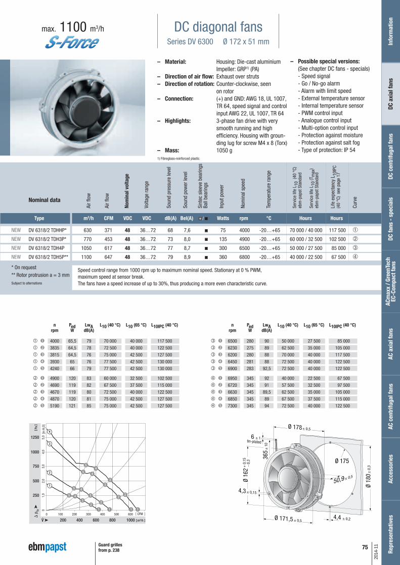
75
2014
-11
– Possible special versions:(See chapter DC fans - specials)
- Speed signal - Go / No-go alarm - Alarm with limit speed - External temperature sensor - Internal temperature sensor - PWM control input - Analogue control input - Multi-option control input - Protection against moisture - Protection against salt fog - Type of protection: IP 54
DC diagonal fansSeries DV 6300 Ø 172 x 51 mm
max. 1100 m3/h
– Material: Housing: Die-cast aluminium Impeller: GRP1) (PA)
– Direction of air flow: Exhaust over struts – Direction of rotation: Counter-clockwise, seen
on rotor– Connection: (+) and GND: AWG 18, UL 1007,
TR 64, speed signal and control input AWG 22, UL 1007, TR 64
– Highlights: 3-phase fan drive with very smooth running and high efficiency. Housing with groun- ding lug for screw M4 x 8 (Torx)
– Mass: 1050 g1) Fibreglass-reinforced plastic
Type m3/h CFM VDC VDC dB(A) Bel(A) / Watts rpm °C Hours Hours
DV 6318/2 TDHHP* 630 371 48 36…72 68 7,6 75 4000 -20…+65 70 000 / 40 000 117 500 ➀
DV 6318/2 TDH3P* 770 453 48 36…72 73 8,0 135 4900 -20…+65 60 000 / 32 500 102 500 ➁
DV 6318/2 TDH4P 1050 617 48 36…72 77 8,7 300 6500 -20…+65 50 000 / 27 500 85 000 ➂
DV 6318/2 TDH5P** 1100 647 48 36…72 79 8,9 360 6800 -20…+65 40 000 / 22 500 67 500 ➃
Nominal data
Speed control range from 1000 rpm up to maximum nominal speed. Stationary at 0 % PWM,maximum speed at sensor break.The fans have a speed increase of up to 30%, thus producing a more even characteristic curve.
NEW
NEW
NEW
NEW
n Ped LwA L10 (40 °C) L10 (65 °C) L10IPC (40 °C) rpm W dB(A)
4000 65,5 79 70 000 40 000 117 500
3835 64,5 78 72 500 40 000 122 500
3815 64,5 76 75 000 42 500 127 500
3930 65 76 77 500 42 500 130 000 4240 66 79 77 500 42 500 130 000
4900 120 83 60 000 32 500 102 500
4690 119 82 67 500 37 500 115 000
4670 119 80 72 500 40 000 122 500
4870 120 81 75 000 42 500 127 500
5190 121 85 75 000 42 500 127 500
tin-plated
Guard grillesfrom p. 238
* On request** Rotor protrusion a = 3 mmSubject to alternations
n Ped LwA L10 (40 °C) L10 (65 °C) L10IPC (40 °C) rpm W dB(A)
6500 280 90 50 000 27 500 85 000
6230 275 89 62 500 35 000 105 000
6200 280 88 70 000 40 000 117 500
6450 281 88 72 500 40 000 122 500
6900 283 92,5 72 500 40 000 122 500
6950 345 92 40 000 22 500 67 500
6720 345 91 57 500 32 500 97 500
6630 345 89,5 62 500 35 000 105 000
6850 345 89 67 500 37 500 115 000
7300 345 94 72 500 40 000 122 500
Info
rmat
ion
DC a
xial
fans
DC fa
ns -
spe
cial
sAC
max
x / G
reen
Tech
EC
-Com
pact
fans
AC a
xial
fans
Acce
ssor
ies
Repr
esen
tativ
esDC
cen
trifu
gal f
ans
AC c
entr
ifuga
l fan
s
Nom
inal
vol
tage
Air f
low
Air f
low
Volta
ge ra
nge
Soun
d pr
essu
re le
vel
Soun
d po
wer
leve
l
Sint
ec s
leev
e be
arin
gsBa
ll be
arin
gs
Inpu
t pow
er
Nom
inal
spe
ed
Tem
pera
ture
rang
e
Serv
ice
life
L 10
(40
°C)
ebm
-pap
st S
tand
ard
Serv
ice
life
L 10
(Tm
ax)
ebm
-pap
st S
tand
ard
Life
exp
ecta
ncy
L 10I
PC(4
0 °C
) se
e pa
ge 1
7
Curv
e
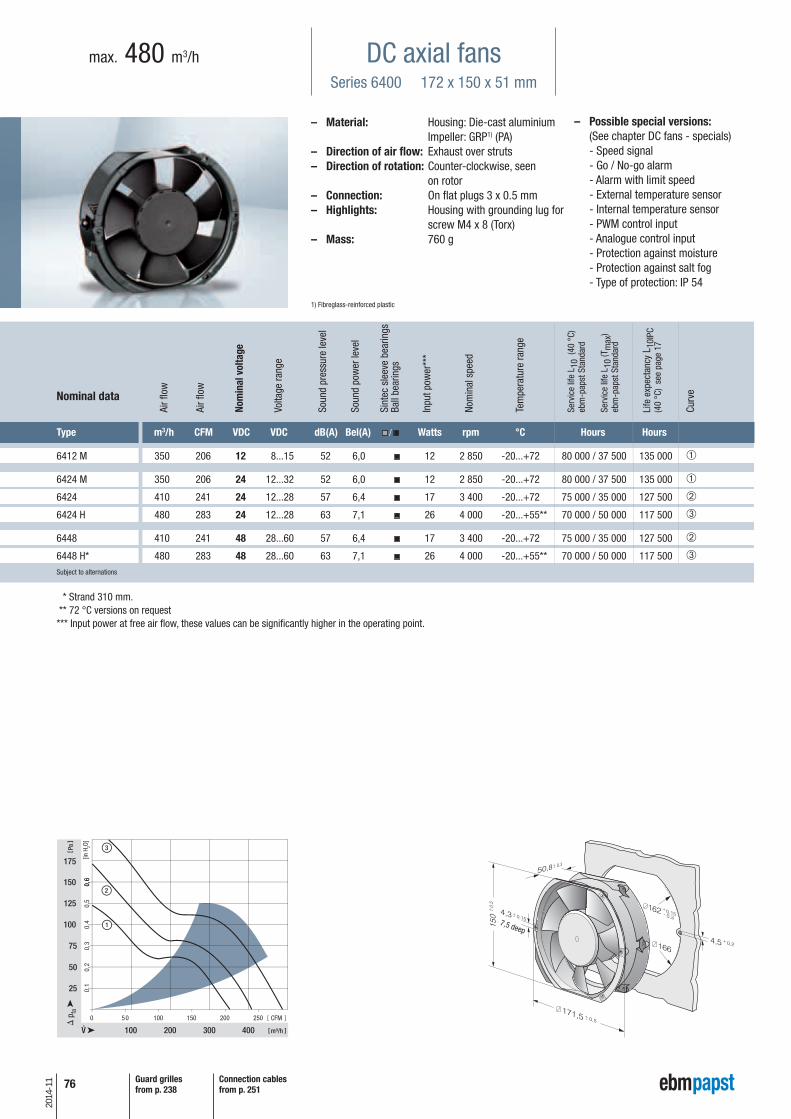
76
2014
-11
– Possible special versions:(See chapter DC fans - specials)
- Speed signal - Go / No-go alarm - Alarm with limit speed - External temperature sensor - Internal temperature sensor - PWM control input - Analogue control input - Protection against moisture - Protection against salt fog - Type of protection: IP 54
DC axial fansSeries 6400 172 x 150 x 51 mm
max. 480 m3/h
Type m3/h CFM VDC VDC dB(A) Bel(A) / Watts rpm °C Hours Hours
6412 M 350 206 12 8...15 52 6,0 12 2 850 -20...+72 80 000 / 37 500 135 000 ➀
6424 M 350 206 24 12...32 52 6,0 12 2 850 -20...+72 80 000 / 37 500 135 000 ➀
6424 410 241 24 12...28 57 6,4 17 3 400 -20...+72 75 000 / 35 000 127 500 ➁
6424 H 480 283 24 12...28 63 7,1 26 4 000 -20...+55** 70 000 / 50 000 117 500 ➂
6448 410 241 48 28...60 57 6,4 17 3 400 -20...+72 75 000 / 35 000 127 500 ➁
6448 H* 480 283 48 28...60 63 7,1 26 4 000 -20...+55** 70 000 / 50 000 117 500 ➂Subject to alternations
– Material: Housing: Die-cast aluminium Impeller: GRP1) (PA)
– Direction of air flow: Exhaust over struts – Direction of rotation: Counter-clockwise, seen
on rotor– Connection: On flat plugs 3 x 0.5 mm– Highlights: Housing with grounding lug for
screw M4 x 8 (Torx)– Mass: 760 g
1) Fibreglass-reinforced plastic
0 50 100 150 200 250
100 200
25
50
100
125
150
175
300 400
1
2
3
75
0,5
0,6
0,6
0,4
0,3
0,2
0,1
m³/h
Pa
CFM
[in H
2O]
Nominal data
7,5 deep
* Strand 310 mm.** 72 °C versions on request*** Input power at free air flow, these values can be significantly higher in the operating point.
Guard grillesfrom p. 238
Connection cablesfrom p. 251
Nom
inal
vol
tage
Air f
low
Air f
low
Volta
ge ra
nge
Soun
d pr
essu
re le
vel
Soun
d po
wer
leve
l
Sint
ec s
leev
e be
arin
gsBa
ll be
arin
gs
Inpu
t pow
er**
*
Nom
inal
spe
ed
Tem
pera
ture
rang
e
Serv
ice
life
L 10
(40
°C)
ebm
-pap
st S
tand
ard
Serv
ice
life
L 10
(Tm
ax)
ebm
-pap
st S
tand
ard
Life
exp
ecta
ncy
L 10I
PC(4
0 °C
) se
e pa
ge 1
7
Curv
e

77
2014
-11
– Possible special versions:(See chapter DC fans - specials)
- Speed signal - Go / No-go alarm - Alarm with limit speed - External temperature sensor - Internal temperature sensor - PWM control input - Analogue control input - Protection against moisture - Protection against salt fog - Type of protection: IP 54 - Reversible direction of rotation
DC axial fansSeries 6400 TD TURBOFAN 172 x 150 x 51 mm
max. 900 m3/h
– Material: Housing: Die-cast aluminium Impeller: GRP1) (PA)
– Direction of air flow: Exhaust over struts – Direction of rotation: Counter-clockwise, seen
on rotor– Connection: Via single wires AWG 18, 20
or AWG 22, TR 64, speed signal and control input AWG 22
– Highlights: 3-phase fan drive with very smooth running and high efficiency. Housing with groun- ding lug for screw M4 x 8 (Torx)
– Mass: 760 g1) Fibreglass-reinforced plastic
Type m3/h CFM VDC VDC dB(A) Bel(A) / Watts rpm °C Hours Hours
6424 TD... 90 53
24
16...28 18 — 2 800
-20...+60 70 000 / 45 000 117 500 ➀
600 353 65 7,4
50 5 100 ➁
6448 TD... 90 53
48
40...55* 18 — 2 800
-20...+60 70 000 / 45 000 117 500 ➀
600 353 65 7,4
50 5 100 ➁
6448 TDHH... 90 53
48
36...72 18 — 2 800
-20...+60 70 000 / 45 000 117 500 ➀
900 530 78 8,6
163 7500 ➂Subject to alternations
Nominal data
min
max
min
max
min
max
Models 6424 TD..., 6448 TD... and 6448 TDHH... are available in customer-specific, custom-developed variants only. The data specified here is technically feasible benchmark values. The fans can be specially adapted to your application with signaloutputs and control inputs. For details of the technical possibilities, refer to the chapters on the sensor signal, alarm signal and control inputs beginning on page 161.** Input power at free air flow, these values can be significantly higher in the operating point.
* Variants with an extended voltage range available to deliver on request.
(7,5 deep)
tin-plated
Guard grillesfrom p. 238
Info
rmat
ion
DC a
xial
fans
DC fa
ns -
spe
cial
sAC
max
x / G
reen
Tech
EC
-Com
pact
fans
AC a
xial
fans
Acce
ssor
ies
Repr
esen
tativ
esDC
cen
trifu
gal f
ans
AC c
entr
ifuga
l fan
s
Nom
inal
vol
tage
Air f
low
Air f
low
Volta
ge ra
nge
Soun
d pr
essu
re le
vel
Soun
d po
wer
leve
l
Sint
ec s
leev
e be
arin
gsBa
ll be
arin
gs
Inpu
t pow
er**
Nom
inal
spe
ed
Tem
pera
ture
rang
e
Serv
ice
life
L 10
(40
°C)
ebm
-pap
st S
tand
ard
Serv
ice
life
L 10
(Tm
ax)
ebm
-pap
st S
tand
ard
Life
exp
ecta
ncy
L 10I
PC(4
0 °C
) se
e pa
ge 1
7
Curv
e
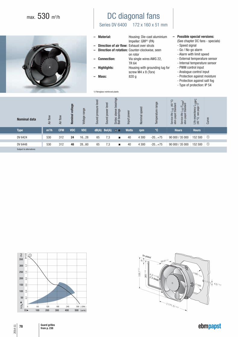
78
2014
-11
– Possible special versions:(See chapter DC fans - specials)
- Speed signal - Go / No-go alarm - Alarm with limit speed - External temperature sensor - Internal temperature sensor - PWM control input - Analogue control input - Protection against moisture - Protection against salt fog - Type of protection: IP 54
DC diagonal fansSeries DV 6400 172 x 160 x 51 mm
max. 530 m3/h
Type m3/h CFM VDC VDC dB(A) Bel(A) / Watts rpm °C Hours Hours
DV 6424 530 312 24 16...28 65 7,3 40 4 300 -20...+75 90 000 / 35 000 152 500 ➀
DV 6448 530 312 48 28...60 65 7,3 40 4 300 -20...+75 90 000 / 35 000 152 500 ➀Subject to alternations
– Material: Housing: Die-cast aluminium Impeller: GRP1) (PA)
– Direction of air flow: Exhaust over struts – Direction of rotation: Counter-clockwise, seen
on rotor– Connection: Via single wires AWG 22,
TR 64– Highlights: Housing with grounding lug for
screw M4 x 8 (Torx)– Mass: 820 g
1) Fibreglass-reinforced plastic
0 60 120 180 240 300
100 200
50
300
150
200
250
300
350
400
100
500
1
1,2
1,0
0,8
0,6
0,4
0,2
m³/h
Pa
CFM
[in H
2O]
Nominal data
(7,5 deep)
tin-plated
Guard grillesfrom p. 238
Nom
inal
vol
tage
Air f
low
Air f
low
Volta
ge ra
nge
Soun
d pr
essu
re le
vel
Soun
d po
wer
leve
l
Sint
ec s
leev
e be
arin
gsBa
ll be
arin
gs
Inpu
t pow
er
Nom
inal
spe
ed
Tem
pera
ture
rang
e
Serv
ice
life
L 10
(40
°C)
ebm
-pap
st S
tand
ard
Serv
ice
life
L 10
(Tm
ax)
ebm
-pap
st S
tand
ard
Life
exp
ecta
ncy
L 10I
PC(4
0 °C
) se
e pa
ge 1
7
Curv
e

79
2014
-11
– Possible special versions:(See chapter DC fans - specials)
- Speed signal - Go / No-go alarm - Alarm with limit speed - External temperature sensor - Internal temperature sensor - PWM control input - Analogue control input - Protection against moisture - Protection against salt fog - Type of protection: IP 54 - Reversible direction of rotation
DC diagonal fansSeries DV 6400 TD TURBOFAN 172 x 160 x 51 mm
max. 680 m3/h
– Material: Housing: Die-cast aluminium Impeller: GRP1) (PA)
– Direction of air flow: Exhaust over struts – Direction of rotation: Counter-clockwise, seen
on rotor– Connection: Via single wires AWG 22,
TR 64– Highlights: 3-phase fan drive with very
smooth running and high efficiency. Housing with groun- ding lug for screw M4 x 8 (Torx)
– Mass: 820 g
1) Fibreglass-reinforced plastic
Type m3/h CFM VDC VDC dB(A) Bel(A) / Watts rpm °C Hours Hours
DV 6424 TD 680 400 24 16...28 71 7,9 91 5 500 -20...+60 65 000 / 40 000 110 000 ➁
DV 6424 TD... 100 59
24
16...28 29 — 2 800
-20...+60 65 000 / 40 000 110 000 ➀
680 400 71 7,9
91 5 500 ➁
DV 6448 TD... 100 59
48
40...55 29 — 2 800
-20...+60 65 000 / 40 000 110 000 ➀
680 400 71 7,9
86 5 500 ➁Subject to alternations
Nominal data
(7,5 deep)
min
max
min
max
Models DV 6424 TD... and DV 6448 TD... are available in customer-specific, custom-developed variants only. The data specified here is technically feasible benchmark values. The fans can be specially adapted to your application with signaloutputs and control inputs. For details of the technical possibilities, refer to the chapters on the sensor signal, alarm signal and control inputs beginning on page 161.* Input power at free air flow, these values can be significantly higher in the operating point.
tin-plated
Guard grillesfrom p. 238
Info
rmat
ion
DC a
xial
fans
DC fa
ns -
spe
cial
sAC
max
x / G
reen
Tech
EC
-Com
pact
fans
AC a
xial
fans
Acce
ssor
ies
Repr
esen
tativ
esDC
cen
trifu
gal f
ans
AC c
entr
ifuga
l fan
s
Nom
inal
vol
tage
Air f
low
Air f
low
Volta
ge ra
nge
Soun
d pr
essu
re le
vel
Soun
d po
wer
leve
l
Sint
ec s
leev
e be
arin
gsBa
ll be
arin
gs
Inpu
t pow
er*
Nom
inal
spe
ed
Tem
pera
ture
rang
e
Serv
ice
life
L 10
(40
°C)
ebm
-pap
st S
tand
ard
Serv
ice
life
L 10
(Tm
ax)
ebm
-pap
st S
tand
ard
Life
exp
ecta
ncy
L 10I
PC(4
0 °C
) se
e pa
ge 1
7
Curv
e

80
2014
-11
– Possible special versions:(See chapter DC fans - specials)
- Speed signal - Go / No-go alarm - Alarm with limit speed - External temperature sensor - Internal temperature sensor - PWM control input - Analogue control input - Multi-option control input - Protection against moisture - Protection against salt fog - Type of protection: IP 54
DC axial fansSeries 2200 FTD 220 x 200 x 51 mm
max. 1220 m3/h
Type m3/h CFM VDC VDC dB(A) Bel(A) / Watts rpm °C Hours Hours
2214 F/2 TDHO 790 465 24 16...30 62 7,1 35 4250 -20...+75 90 000 / 42 500 152 500 ➀
2214 F/2 TDHHO 940 553 24 16...36 66 7,4 48 5000 -20...+70 85 000 / 42 500 142 500 ➁
2218 F/2 TDHO 790 465 48 36...57 62 7,1 35 4250 -20...+75 90 000 / 42 500 152 500 ➀
2218 F/2 TDHHO 940 553 48 36...72 66 7,4 48 5000 -20...+70 85 000 / 42 500 142 500 ➁
2218 F/2 TDH4P 1220 718 48 36...72 72 8,2 103 6500 -20...+65 70 000 / 40 000 117 500 ➂Subject to alternations
– Material: Housing: Die-cast aluminium Impeller: GRP1) (PA)
– Direction of air flow: Exhaust over struts – Direction of rotation: Counter-clockwise, seen
on rotor– Connection: Via single wires AWG 18, 20
or AWG 22, TR 64, speed signal and control input AWG 22
– Highlights: 3-phase fan drive with very smooth running and high efficiency. Housing with groun- ding lug for screw M4 x 8 (Torx)
– Mass: 1000 g1) Fibreglass-reinforced plastic
1000 200 300 400
400200 600
200
600
800
800 1000 m³/h
Pa
400
CFM
1,5
2,0
2,5
1,0
0,5
[in H
2O]
3,0
3,5
0
500 600
3
2
1
Nominal data
7,6 deep
Speed control range from 1000 rpm up to maximum nominal speed. Stationary at 0 % PWM / 0 V,Type O: stationary at sensor break; Type P: maximum speed at sensor break.* Input power at free air flow, these values can be significantly higher in the operating point.
tin-plated
Guard grillesfrom p. 238
Nom
inal
vol
tage
Air f
low
Air f
low
Volta
ge ra
nge
Soun
d pr
essu
re le
vel
Soun
d po
wer
leve
l
Sint
ec s
leev
e be
arin
gsBa
ll be
arin
gs
Inpu
t pow
er*
Nom
inal
spe
ed
Tem
pera
ture
rang
e
Serv
ice
life
L 10
(40
°C)
ebm
-pap
st S
tand
ard
Serv
ice
life
L 10
(Tm
ax)
ebm
-pap
st S
tand
ard
Life
exp
ecta
ncy
L 10I
PC(4
0 °C
) se
e pa
ge 1
7
Curv
e

81
2014
-11
– Possible special versions:(See chapter DC fans - specials)
- Speed signal - Go / No-go alarm - Alarm with limit speed - External temperature sensor - Internal temperature sensor - PWM control input - Analogue control input - Multi-option control input - Protection against moisture - Type of protection: IP 54
DC axial fansSeries 2200 TD 225 x 225 x 80 mm
max. 1000 m3/h
– Material: Wall ring: Die-cast aluminium Impeller: GRP1) (PA)
– Direction of air flow: Exhaust over struts – Direction of rotation: Counter-clockwise, seen
on rotor– Connection: With terminal strip– Highlights: 3-phase fan drive with very
smooth running Fully integrated electronic commutation
– Mass: 2,1 kg
1) Fibreglass-reinforced plastic
Type m3/h CFM VDC VDC dB(A) Bel(A) / Watts rpm °C Hours Hours
2214/2 TDO 1000 588 24 16...30 59 6,8 50 3 000 -20...+60 80 000 / 50 000 135 000 ➀
2218/2 TDO 1000 588 48 36...57 59 6,8 50 3 000 -20...+60 80 000 / 50 000 135 000 ➀Subject to alternations
Nominal data
Guard grillesfrom p. 238
* Input power at free air flow, these values can be significantly higher in the operating point.
Info
rmat
ion
DC a
xial
fans
DC fa
ns -
spe
cial
sAC
max
x / G
reen
Tech
EC
-Com
pact
fans
AC a
xial
fans
Acce
ssor
ies
Repr
esen
tativ
esDC
cen
trifu
gal f
ans
AC c
entr
ifuga
l fan
s
Nom
inal
vol
tage
Air f
low
Air f
low
Volta
ge ra
nge
Soun
d pr
essu
re le
vel
Soun
d po
wer
leve
l
Sint
ec s
leev
e be
arin
gsBa
ll be
arin
gs
Inpu
t pow
er*
Nom
inal
spe
ed
Tem
pera
ture
rang
e
Serv
ice
life
L 10
(40
°C)
ebm
-pap
st S
tand
ard
Serv
ice
life
L 10
(Tm
ax)
ebm
-pap
st S
tand
ard
Life
exp
ecta
ncy
L 10I
PC(4
0 °C
) se
e pa
ge 1
7
Curv
e
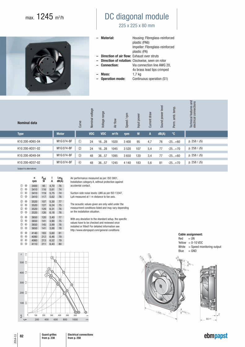
82
2014
-11
DC diagonal module225 x 225 x 80 mm
max. 1245 m3/h
– Material: Housing: Fibreglass-reinforced plastic (PA6) Impeller: Fibreglass-reinforced plastic (PA)
– Direction of air flow: Exhaust over struts – Direction of rotation: Clockwise, seen on rotor– Connection: Via connection line AWG 20,
4x brass lead tips crimped– Mass: 1,7 kg– Operation mode: Continuous operation (S1)
+- 0,5
276
288
80
6
+1
Cable assignment:Red = UNYellow = 0-10 VDCWhite = Speed monitoring outputBlue = GND
n Ped I LwA rpm W A dB(A)
3400 95 4,70 76 3410 116 5,61 74 3410 119 5,75 74 3410 117 5,62 76
3520 107 5,30 77 3520 127 6,24 75 3520 129 6,31 76 3520 126 6,18 76
3650 120 3,40 77 3650 141 3,90 75 3650 145 3,99 76 3650 141 3,88 78
4140 183 5,60 81 4090 212 6,46 79 4060 213 6,52 79 4110 211 6,43 80
Air performance measured as per: ISO 5801,Installation category A, without protection againstaccidental contact.
Suction-side noise levels: LWA as per ISO 13347,LpA measured at 1 m distance to fan axis.
The acoustic values given are only valid under themeasurment conditions listed and may vary dependingon the installation situation.
With any deviation to the standard setup, the specificvalues have to be checked and reviewed onceinstalled or fitted! For detailed information seehttp://www.ebmpapst.com/general conditions
Guard grillesfrom p. 238
Electrical connectionsfrom p. 258
p. 258 / J5)
Nominal data
Type Motor
K1G 200-AD65-04 M1G 074-BF
Tech
nica
l fea
ture
s an
del
ectri
cal c
onne
ctio
ns
VDC VDC m3/h rpm W A dB(A) °C
➀ 24 16...28 1020 3 400 95 4,7 76 -25...+60
p. 258 / J5)K1G 200-AD31-02 M1G 074-BF ➁ 24 16...28 1045 3 520 107 5,4 77 -25...+70
p. 258 / J5)K1G 200-AD49-04 M1G 074-BF ➂ 48 36...57 1095 3 650 120 3,4 77 -25...+60
p. 258 / J5)K1G 200-AD37-02 M1G 074-BF ➃ 48 36...57 1245 4 140 183 5,6 81 -25...+70
Curv
e
Nom
inal
vol
tage
Volta
ge ra
nge
Air f
low
Spee
d / r
pm
Inpu
t pow
er
Curr
ent d
raw
Soun
d po
wer
leve
l
Perm
. am
b. te
mp.
Subject to alternations

p. 258 / J5)
83
2014
-11
DC diagonal module225 x 225 x 89 mm
max. 905 m3/h
– Material: Housing: Fibreglass-reinforced plastic (PA6) Impeller: Fibreglass-reinforced plastic (PA)
– Direction of air flow: Exhaust over struts – Direction of rotation: Clockwise, seen on rotor– Connection: Via connection line AWG 16,
4x brass lead tips crimped– Mass: 2,2 kg– Operation mode: Continuous operation (S1)
+- 0,5
276
288
89
6
+1
Cable assignment:Red = UNYellow = 0-10 VDCWhite = Speed monitoring outputBlue = GND
Guard grillesfrom p. 238
Electrical connectionsfrom p. 258
Air performance measured as per: ISO 5801,Installation category A, without protection againstaccidental contact.
Suction-side noise levels: LWA as per ISO 13347,LpA measured at 1 m distance to fan axis.
The acoustic values given are only valid under themeasurment conditions listed and may vary dependingon the installation situation.
With any deviation to the standard setup, the specificvalues have to be checked and reviewed onceinstalled or fitted! For detailed information seehttp://www.ebmpapst.com/general conditions
* current measured at nominal voltage
n Ped I LwA rpm W A dB(A)
4120 170 7,0* 80 4025 180 7,52* 77 4005 187 7,80* 76 4045 187 7,78* 78
4830 275 11,5* 84 4720 294 12,24* 81 4685 299 12,48* 80 4715 295 12,30* 83
4890 280 5,9* 85 4795 300 6,27* 81 4755 307 6,41* 80 4780 304 6,35* 82
5470 400 8,4* 88 5365 426 8,89* 85 5310 438 9,17* 83 5355 431 9,01* 87
Nominal data
Type Motor
K3G 200-BD46-04 M3G 074-CF
Tech
nica
l fea
ture
s an
del
ectri
cal c
onne
ctio
ns
VDC VDC m3/h rpm W A dB(A) °C
➀ 24 16...28 725 4120 170 7,0 80 -25...+60
p. 258 / J5)K3G 200-BD44-02 M3G 074-CF ➁ 24 16...28 805 4830 275 11,5 84 -25...+60
p. 258 / J5)K3G 200-BD64-04 M3G 074-CF ➂ 48 36...57 900 4890 280 5,9 85 -25...+60
p. 258 / J5)K3G 200-BDA8-02 M3G 074-CF ➃ 48 36...57 905 5470 400 8,4 88 -25...+60
Curv
e
Nom
inal
vol
tage
Volta
ge ra
nge
Air f
low
Spee
d / r
pm
Inpu
t pow
er
Curr
ent d
raw
Soun
d po
wer
leve
l
Perm
. am
b. te
mp.
Subject to alternations
Info
rmat
ion
DC a
xial
fans
DC fa
ns -
spe
cial
sAC
max
x / G
reen
Tech
EC
-Com
pact
fans
AC a
xial
fans
Acce
ssor
ies
Repr
esen
tativ
esDC
cen
trifu
gal f
ans
AC c
entr
ifuga
l fan
s
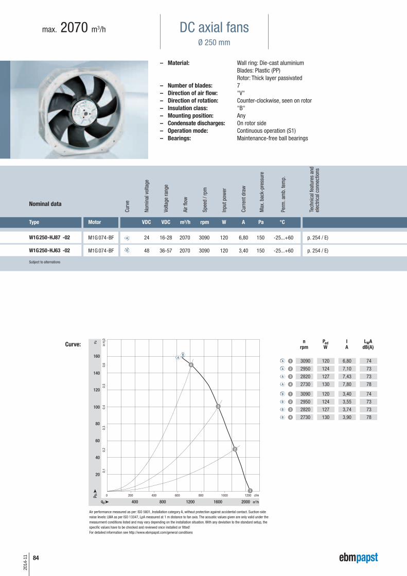
84
2014
-11
– Material: Wall ring: Die-cast aluminium Blades: Plastic (PP) Rotor: Thick layer passivated
– Number of blades: 7– Direction of air flow: "V"– Direction of rotation: Counter-clockwise, seen on rotor– Insulation class: "B"– Mounting position: Any– Condensate discharges: On rotor side– Operation mode: Continuous operation (S1)– Bearings: Maintenance-free ball bearings
400 800 200016001200
0
40
80
0,4
20
0,2
100
60
0,6
0,3
0,1
0,5
12001000800600400200 cfm
qV
p fs
Pa
in H
2O
m3/h
3
4
1
2
120
140
160 A1
2
3
4
1
2
3
4
3090
2950
2820
2730
3090
2950
2820
2730
120
124
127
130
120
124
127
130
6,80
7,10
7,43
7,80
3,40
3,55
3,74
3,90
A
A
A
A
B
B
B
B
74
73
73
78
74
73
73
78
B
nrpm
PedW
IA
LWAdB(A)
Air performance measured as per: ISO 5801, Installation category A, without protection against accidental contact. Suction-sidenoise levels: LWA as per ISO 13347, LpA measured at 1 m distance to fan axis. The acoustic values given are only valid under themeasurment conditions listed and may vary depending on the installation situation. With any deviation to the standard setup, thespecific values have to be checked and reviewed once installed or fitted!For detailed information see http://www.ebmpapst.com/general conditions
Curve:
Nominal data
Type Motor
M1G 074-BF
Subject to alternations
Tech
nica
l fea
ture
s an
del
ectri
cal c
onne
ctio
ns
VDC VDC m3/h rpm W A Pa °C
24 16-28 2070 3090 120 6,80 150 -25...+60
48 36-57 2070 3090 120 3,40 150 -25...+60
Curv
e
Nom
inal
vol
tage
Volta
ge ra
nge
Air f
low
Spee
d / r
pm
Inpu
t pow
er
Curr
ent d
raw
Perm
. am
b. te
mp.
A
BM1G 074-BF
p. 254 / E)
p. 254 / E)
Max
. bac
k-pr
essu
re
W1G250-HJ87 -02
W1G250-HJ63 -02
max. 2070 m3/h DC axial fansØ 250 mm
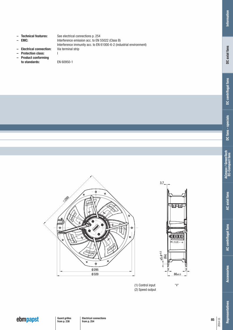
85
2014
-11
– Technical features: See electrical connections p. 254– EMC: Interference emission acc. to EN 55022 (Class B)
Interference immunity acc. to EN 61000-6-2 (industrial environment)– Electrical connection: Via terminal strip– Protection class: I– Product conforming
to standards: EN 60950-1
80295 7
5.4
(8x)
3207
280
3.7
Ø Ø
Ø +
0.2
±0.3
PE (1) (2) - +
"V"
Guard grillesfrom p. 238
Electrical connectionsfrom p. 254
(1) Control input(2) Speed output
Info
rmat
ion
DC a
xial
fans
DC fa
ns -
spe
cial
sAC
max
x / G
reen
Tech
EC
-Com
pact
fans
AC a
xial
fans
Acce
ssor
ies
Repr
esen
tativ
esDC
cen
trifu
gal f
ans
AC c
entr
ifuga
l fan
s
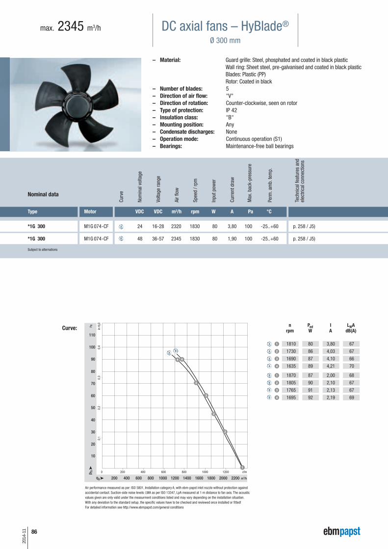
86
2014
-11
– Material: Guard grille: Steel, phosphated and coated in black plasticWall ring: Sheet steel, pre-galvanised and coated in black plasticBlades: Plastic (PP)Rotor: Coated in black
– Number of blades: 5– Direction of air flow: "V"– Direction of rotation: Counter-clockwise, seen on rotor– Type of protection: IP 42– Insulation class: "B"– Mounting position: Any– Condensate discharges: None– Operation mode: Continuous operation (S1)– Bearings: Maintenance-free ball bearings
200 400 600 1200 14001000 1800 2000 22001600800
0
70
90
0,2
60
0,1
0,4
80
30
50
20
10
40
0,3
1000 1200800600400200 cfm
qV
p fs
Pa
in H
2O
m3/h
3
44
2
3
1
2
100
110
A
1
2
3
4
1
2
3
4
1810
1730
1690
1635
1870
1805
1765
1695
80
86
87
89
87
90
91
92
3,80
4,03
4,10
4,21
2,00
2,10
2,13
2,19
A
A
A
A
B
B
B
B
67
67
66
70
68
67
67
69
B
nrpm
PedW
IA
LWAdB(A)
Air performance measured as per: ISO 5801, Installation category A, with ebm-papst inlet nozzle without protection againstaccidental contact. Suction-side noise levels: LWA as per ISO 13347, LpA measured at 1 m distance to fan axis. The acousticvalues given are only valid under the measurment conditions listed and may vary depending on the installation situation.With any deviation to the standard setup, the specific values have to be checked and reviewed once installed or fitted!For detailed information see http://www.ebmpapst.com/general conditions
Curve:
Nominal data
Type Motor
*1G 300 M1G 074-CF
Subject to alternations
VDC VDC m3/h rpm W A Pa °C
24 16-28 2320 1830 80 3,80 100 -25..+60
48 36-57 2345 1830 80 1,90 100 -25..+60
A
B*1G 300 M1G 074-CF
p. 258 / J5)
p. 258 / J5)
DC axial fans – HyBlade®
Ø 300 mm
max. 2345 m3/h
Tech
nica
l fea
ture
s an
del
ectri
cal c
onne
ctio
ns
Curv
e
Nom
inal
vol
tage
Volta
ge ra
nge
Air f
low
Spee
d / r
pm
Inpu
t pow
er
Curr
ent d
raw
Perm
. am
b. te
mp.
Max
. bac
k-pr
essu
re

kg
2,8
3,1
87
2014
-11
685
+20
450
Ø58
M4 (4x)7957.5
Ø300
75
45°
90°Ø9
2
31
±10
±0.15
±5±3
±1
"V"
Depth of screw max. 6 mm
– Technical features: See electrical connections p. 258– EMC: Interference emission acc. to EN 55022 (Class B)
Interference immunity acc. to EN 61000-6-2 (industrial environment)– Cable exit: lateral– Product conforming
to standards: EN 60950-1– Approvals: GOST, CSA C22.2 Nr. 77, UL 1004-1
15°60° (6x)
Ø9 (6x)Ø380
Ø397
8011
Ø326
4.3
Ø360
Ø300
57.2
Ø329
.6
4.529
25
±5
±1
±3
Connection line PVC AWG 20,4 x lead tips crimped
A1G 300
W1G 300 S1G 300
Dire
ctio
n of
air
flow
"V"
"V"
"V"
With full roundnozzle
"V" "V"Withoutattachments
With guard grillefor short nozzle kg
1,8
Mas
s w
ithou
tat
tach
men
ts
A1G 300-AC19 -54 W1G 300-DC19 -54 S1G 300-AC19 -54
A1G 300-AC33 -54 W1G 300-DC33 -54 S1G 300-AC33 -541,8
kg
3,8
Mas
s w
ith fu
llro
und
nozz
le
3,8
Mas
s w
ith g
uard
gril
lefo
r sho
rt no
zzle
Guard grillesfrom p. 238
Electrical connectionsfrom p. 258
Info
rmat
ion
DC a
xial
fans
DC fa
ns -
spe
cial
sAC
max
x / G
reen
Tech
EC
-Com
pact
fans
AC a
xial
fans
Acce
ssor
ies
Repr
esen
tativ
esDC
cen
trifu
gal f
ans
AC c
entr
ifuga
l fan
s

88
2014
-11