dedicated short-range communication … short-range communication system arib std-t75 arib...
TRANSCRIPT

Association of Radio Industries and Businesses (ARIB)
VERSION 1.0
ARIB STD-T75
DEDICATED SHORT-RANGECOMMUNICATION SYSTEM
ARIB STD-T75
ARIB STANDARD
Version 1.0 September 9th 2001


General Notes to the English translation of ARIB Standardsand Technical Reports
1. The copyright of this document is ascribed to the Association of Radio Industries and Businesses (ARIB).
2. All rights reserved. No part of this document may be reproduced, stored in are retrieval system, or transmitted, in any form or by any means, without the prior written permission of ARIB.
3. The ARIB Standards and ARIB Technical Reports are usually written in Japanese and approved by the ARIB Standard Assembly. This document is a translation into English of the approved document for the purpose of convenience of users. If there are any discrepancies in the content, expressions, etc., between the Japanese original and this translated document, the Japanese original shall prevail.
4. The establishment, revision and abolishment of ARIB Standards and Technical Reports are approved at the ARIB Standard Assembly, which meets several times a year. Approved ARIB Standards and Technical Reports, in their original language, are made publicly available in hard copy, CDs or through web posting, generally in about one month after the date of approval. The original document of this translation may have been further revised and therefore users are encouraged to check the latest version at an appropriate page under the following URL:
http://www.arib.or.jp/english/index.html 5. The original “DEDICATED SHORT-RANGE COMMUNICATION(DSRC) SYSTEM
(ARIB STD-T75)” is written in Japanese and has been approved by the 39th Standard Assembly Meeting (September 6, 2001).
6. The note about IPR (Industrial Property Rights) in the FOREWORD of the standard applies to the use of Essential IPR for the ARIB Standard in Japan. If the ARIB Standard is adopted outside Japan, Essential IPR will be treated in accordance with policies stated by each IPR owner. The IPR owners are, however, expected to apply the rules of the preface of the “Guidelines for Treatment of Industrial Property Rights in connection with the ARIB Standard” (September 5, 1995, approved by the 1st Standard Assembly Meeting). In the preface of the Guidelines, it is stated that it is “desirable that the Essential IPR which relates to any or all parts of the contents of the ARIB Standard should be used free of charge by anyone and that it would not block the use of such Essential IPR in any other country where such an ARIB Standard is adopted.”


ARIB STD-T75
FOREWORD The Association of Radio Industries and Businesses (ARIB) has been investigating and summarizing the basic technical requirements for establishing standards. These will appear in the form of standards and specifications governing the use of radio transmission facilities and equipment. The standards are being developed based on the participation of and discussions with, the various radio equipment manufacturers, operators and users. The standards and specifications contained herein will serve as guidelines for developing standards for private use based on the publicly established technical standards in Japan. Their purpose is to enable effective use of radio frequencies by avoiding interference among users, conflicts among the standards of individual operators, and so forth, so that all parties involved, including radio equipment manufacturers, users and others will be able to ensure the quality and compatibility of radio facilities and equipment. These standards are being established principally for “DEDICATED SHORT-RANGE COMMUNICATION (DSRC)”. In order to ensure fairness and openness among all par-ties involved, during drafting stages, we invite radio equipment manufacturers, operators and users both domestically and overseas to participate openly in the activities of the Standard Assembly so as to develop standards with the total agreement of all parties involved. The scope of application of these standards covers the minimum requirements for communications. They are designed to serve as practical guidelines for operators in developing original specifications and systems that fall within the scope of the standards. We hope that the standards will aid all parties involved, including radio equipment manufacturers, operators, users, and others in the development of an excellent radio telecommunication system. NOTE :Although this ARIB Standard contains no specific reference to any Essential
Industrial Property Right relating thereto, the holder of such Essential Industrial Property Right states that "YYY" is the holder of the Industrial Property Right "XXX" covering this ARIB Standard and to grant a non-exclusive and non-discriminatory license to the use of such right "XXX" on reasonable terms and conditions to anyone using this ARIB Standard. However this does not apply to anyone who uses this ARIB Standard and also owns and lays claim to any other Essential Industrial Property Right whose scope is included in any or all parts of the contents of the provisions of this ARIB Standard.

ARIB STD-T75
List of Essential Industrial Property Right
Patent Holder Name of Patent Registration No. /Application No. Remarks
A method of communication and a communication apparatus
2000-223857 Hitachi, Ltd.
A method of communication and a communication apparatus
2001-114761
ARIB STD-T75
i
CONTENTS Chapter 1 General.......................................................................................................................1 1.1 Overview ..............................................................................................................................1 1.2 Scope of application .............................................................................................................1 1.3 Scope of standardization ......................................................................................................2 Chapter 2 System Overview.......................................................................................................3 2.1 Configuration of the system .................................................................................................3 2.1.1 Base Station (RSU) .......................................................................................................3 2.1.2 Mobile Station (OBE) ...................................................................................................3 2.1.3 Test Equipment..............................................................................................................3 2.2 Definition of the interface ....................................................................................................4 2.3 Basic functions of the system ...............................................................................................5 2.3.1 System requirements .....................................................................................................5 2.3.1.1 Basic functions .......................................................................................................5 2.3.2 Services provided by the system ...................................................................................6 2.3.2.1 Service features ......................................................................................................6 2.3.2.2 Service types...........................................................................................................6 2.4 Access method......................................................................................................................8 2.4.1 Type of transmission .....................................................................................................8 2.4.2 Radio channel control....................................................................................................9 2.5 Basic rules for protocol ......................................................................................................10 2.5.1 Model for protocol.......................................................................................................10 2.5.1.1 Features of Layer 1 ...............................................................................................11 2.5.1.2 Features of Layer 2 ...............................................................................................11 2.5.1.3 Features of Layer 7 ...............................................................................................12 2.5.2 Communication Service ..............................................................................................12 2.5.3 Numbering plan (Link address)...................................................................................14 2.5.4 Other related rules .......................................................................................................14 2.6 Type of secured communication.........................................................................................14 Chapter 3 Technical Requirements for Radio Facilities...........................................................15 3.1 Overview ............................................................................................................................15 3.2 General conditions..............................................................................................................15 3.2.1 Radio frequency bands ................................................................................................15

ARIB STD-T75
ii
3.2.2 Carrier frequency spacing............................................................................................15 3.2.3 Transmit-receive frequency separation........................................................................15 3.2.4 Operating method and multiple access........................................................................15 3.2.5 Access method.............................................................................................................15 3.2.6 Number of multiplexed circuits...................................................................................15 3.2.7 Data transmission method ...........................................................................................15 3.2.8 Modulation method .....................................................................................................15 3.2.9 Modulation signal........................................................................................................16 3.2.10 Access control method ..............................................................................................16 3.2.11 Frame length and slot length .....................................................................................16 3.2.12 Wireless call number(call sign) .................................................................................16 3.2.13 One cabinet................................................................................................................16 3.2.14 Security measures ......................................................................................................16 3.2.15 Countermeasures against electromagnetic interference.............................................16 3.3 Conditions for modulation method ....................................................................................17 3.3.1 Modulation method .....................................................................................................17 3.3.1.1 ASK......................................................................................................................17
3.3.1.1.1 Modulation method .......................................................................................17 3.3.1.1.2 Data coding method.......................................................................................17 3.3.1.1.3 Transmission bit rate .....................................................................................18 3.3.1.2 π/4 shift QPSK .....................................................................................................19
3.3.1.2.1 Modulation method .......................................................................................19 3.3.1.2.2 Differential coding.........................................................................................19 3.3.1.2.3 Base band regulation .....................................................................................20 3.3.1.2.4 Method of orthogonal modulation.................................................................21 3.3.1.2.5 Transmitting spectrum...................................................................................21 3.3.1.2.6 Transmission bit rate .....................................................................................21 3.4 Conditions relating to transmitter and receiver ..................................................................22 3.4.1 Carrier frequencies and carrier numbers .....................................................................22 3.4.2 Transmission characteristics........................................................................................22 3.4.2.1 Transmit power.....................................................................................................22 3.4.2.2 Mobile station maximum e.i.r.p. ..........................................................................23 3.4.2.3 Transmission of wireless call number(call sign) ..................................................24 3.4.2.4 Adjacent channel leakage power ..........................................................................24 3.4.2.5 Eye pattern............................................................................................................24 3.4.2.6 Burst transmission transient response time ..........................................................25

ARIB STD-T75
iii
3.4.2.7 Leakage power during carrier off period ..............................................................26 3.4.2.8 Transmission spurious..........................................................................................26 3.4.2.9 Occupied bandwidth.............................................................................................27 3.4.2.10 Frequency tolerance............................................................................................27 3.4.2.11 Modulation index, Modulation accuracy............................................................27 3.4.2.11.1 Modulation index(ASK)..............................................................................27 3.4.2.11.2 Modulation accuracy(QPSK) ......................................................................28 3.4.2.12 Cabinet radiation ................................................................................................28 3.4.2.13 Allowable deviation of absolute signal transmission time.................................28 3.4.3 Reception characteristics .............................................................................................29 3.4.3.1 Frequency tolerance of local oscillator.................................................................29 3.4.3.2 Reception sensitivity ............................................................................................30 3.4.3.3 Bit error rate performance ....................................................................................31 3.4.3.4 Receiver bandwidth..............................................................................................31 3.4.3.5 Power limits within communication zone............................................................31 3.4.3.6 Adjacent signal selectivity....................................................................................32 3.4.3.7 Intermodulation performance ...............................................................................32 3.4.3.8 Spurious response rejection ratio .........................................................................33 3.4.3.9 Strength of secondary radio emissions .................................................................33 3.4.3.10 Cabinet radiation ................................................................................................33 3.4.4 Antenna .......................................................................................................................34 3.4.4.1 Classification of antenna ......................................................................................34 3.4.4.2 Gain of antenna ....................................................................................................39 3.4.4.3 Polarization...........................................................................................................39 3.5 Test equipment ...................................................................................................................40 3.5.1 Maximum e.i.r.p of test equipment .............................................................................40 Chapter 4 Communication Control System..............................................................................41 4.1 Overview ............................................................................................................................41 4.1.1 Outline of Relationship between Layers, Layer Managements and System Management ...........................................................................................41 4.2 Layer1 Standards ................................................................................................................43 4.2.1 Overview .....................................................................................................................43 4.2.2 Mobile Station types and base station types................................................................43 4.2.2.1 Mobile Station Types ...........................................................................................43 4.2.2.2 Base Station Types ...............................................................................................43
ARIB STD-T75
iv
4.2.2.3 Test equipment .....................................................................................................43 4.2.3 Service Characteristics ................................................................................................43 4.2.3.1 Outline ................................................................................................................43 4.2.3.2 Service Access points ...........................................................................................43 4.2.3.3 Service provided by layer 1 ..................................................................................44 4.2.3.3.1 Facilities of transmission...............................................................................44 4.2.3.3.2 Channel Activate / Deactivate .......................................................................44 4.2.3.3.3 Maintaining the radio link .............................................................................44 4.2.3.3.4 Maintenance and state indication ..................................................................44 4.2.4 Communication (TDMA) Frame ...............................................................................44 4.2.4.1 The structure of the communication (TDMA) Frame ..........................................44 4.2.4.1.1 Half-duplex Frame Format ............................................................................45 4.2.4.1.2 Full-Duplex Mode Frame Format .................................................................46 4.2.4.2 Channel types and the relationship between slot types ........................................47 4.2.4.2.1 Frame Control Message Slot (FCMS) .........................................................47 4.2.4.2.1.1 Preamble (PR) ........................................................................................49 4.2.4.2.1.2 Unique Word (UW1)..............................................................................49 4.2.4.2.1.3 Transmission Channel Control Field (SIG)............................................49 4.2.4.2.1.4 Fixed Equipment ID (FID) .....................................................................54 4.2.4.2.1.5 Frame Structure Identifier (FSI) .............................................................54 4.2.4.2.1.6 Release Timer Information field (RLT) .................................................56 4.2.4.2.1.7 Service Application Information field (SC) ...........................................57 4.2.4.2.1.8 Slot Control Identifier (SCI)...................................................................59 4.2.4.2.1.8.1 Control Information Identifier of SCI field (CI)..............................60 4.2.4.2.1.8.2 Link Address Field (LID) ..............................................................63 4.2.4.2.1.9 Cyclic Redundancy Error Check Sequence (CRC) ..............................65 4.2.4.2.2 Message Data Slot (MDS).............................................................................65 4.2.4.2.2.1 Message Data Channel (MDC) ..............................................................66 4.2.4.2.2.1.1 Preamble (PR) .................................................................................68 4.2.4.2.2.1.2 Unique Word (UW2,UW2B) ..........................................................69 4.2.4.2.2.1.3 MAC control field (MAC) ..............................................................69 4.2.4.2.2.1.4 Cyclic Redundancy Error Check Sequence (CRC) .......................70 4.2.4.2.2.2 ACK channel (ACKC) ...........................................................................70 4.2.4.2.2.2.1 Preamble (PR) .................................................................................71 4.2.4.2.2.2.2 Unique Word (UW2,UW2A) ..........................................................72 4.2.4.2.2.2.3 Acknowledgment Identifier (AI) .....................................................72
ARIB STD-T75
v
4.2.4.2.2.2.4 Cyclic Redundancy Error Check Sequence (CRC) .......................72 4.2.4.2.3 Activation Slot (ACTS) ...............................................................................73 4.2.4.2.3.1 Activation Channel (ACTC) ..................................................................73 4.2.4.2.3.1.1 Preamble (PR) .................................................................................74 4.2.4.2.3.1.2 Unique word (UW2,UW2A) ...........................................................75 4.2.4.2.3.1.3 Fixed Equipment ID (FID) ..............................................................75 4.2.4.2.3.1.4 Link Address Field (LID) ................................................................75 4.2.4.2.3.1.5 Link Request Information Field (LRI) ............................................75 4.2.4.2.3.1.6 Cyclic Redundancy Error Check Sequence (CRC) .........................77 4.2.4.2.4 Wireless Call Number slot (WCNS) .............................................................77 4.2.4.3 Frame Check Sequence ........................................................................................78 4.2.4.4 Forward Error Correction(FEC) ...........................................................................78 4.2.5 Bit Order......................................................................................................................79 4.2.6 Scramble System .........................................................................................................79 4.2.6.1 Simple encryption scramble .................................................................................80 4.2.6.1.1 Encryption Key..............................................................................................80 4.2.6.1.2 Encryption Scramble System.........................................................................81 4.2.6.2 Data scramble .......................................................................................................81 4.2.6.2.1 Data scramble system ....................................................................................81 4.2.6.2.2 Relationship between Data Scramble, Encryption Scramble and
Error Check Code (CRC), Forward Error Correction Code (BCH) ............82 4.2.6.2.3 Sequence of CRC Calculation, FEC Calculation (BCH) and
simple encryption and Data Scramble .........................................................82 4.2.6.2.4 Range of CRC Calculation, FEC Calculation (BCH),
simple encryption scramble, and Data Scramble.........................................82 4.2.6.2.4.1 Scope of application and processing procedure in the MDC .................82
4.2.6.2.4.2 Scope of application and processing procedure in the FCMC ...............84 4.2.6.2.4.3 Scope of application and processing procedure in the ACTC ................84 4.2.6.2.4.4 Scope of application and processing procedure in the ACKC ...............85
4.2.7 Guard time...................................................................................................................86 4.2.8 Channel selection procedures on the mobile station ...................................................88 4.2.8.1 Channel selection procedure.................................................................................88 4.2.8.2 Channel change procedures ..................................................................................89 4.2.8.3 Channel selection procedure in overlapping radio communication zones by the mobile station .........................................................................................90 4.2.9 Channel selection time of mobile station ....................................................................91

ARIB STD-T75
vi
4.2.10 Transmission / Reception Switching time.................................................................92 4.2.11 Wake-up processing of the mobile station ................................................................92 4.2.12 Maximum start-up time of the mobile station...........................................................93 4.2.13 Test Equipment..........................................................................................................93 4.2.13.1 Conditions for slot transmission.........................................................................93 4.2.13.2 Avoidance of interference and suspension of transmission ...............................94 4.2.13.3 Wireless call number slot (WCNS) transmission...............................................95 4.2.14 Layer1 Management service interface.......................................................................95 4.2.14.1 Overview of Interactions ....................................................................................95 4.2.14.2 Service specification...........................................................................................96 4.2.14.2.1 PLME-GET.request.....................................................................................96 4.2.14.2.2 PLME-GET.confirm....................................................................................96 4.2.14.2.3 PLME-SET.request .....................................................................................97 4.2.14.2.4 PLME-SET.confirm ....................................................................................97 4.3 Layer 2 Standards ...............................................................................................................99 4.3.1 Outline of the layer 2 ...................................................................................................99 4.3.1.1 Overview ..............................................................................................................99 4.3.1.2 Overview of Services ...........................................................................................99 4.3.1.2.1 MAC Sublayer...............................................................................................99 4.3.1.2.2 LLC Sublayer ..............................................................................................100 4.3.1.3 Protocol Data Unit..............................................................................................100 4.3.1.3.1 Protocol Data Unit.......................................................................................100 4.3.1.3.2 Relationship between Frame Format and Physical Channel .......................101 4.3.2 Link Address (LID) ...................................................................................................102 4.3.2.1 Restraint of link address usage ...........................................................................103 4.3.2.2 Service access point (SAP).................................................................................103 4.3.3 Medium Access Control (MAC) Sublayer ................................................................104 4.3.3.1 Overview of MAC Sublayer...............................................................................104 4.3.3.2 Specification for Interface Service of MAC Sublayer........................................104 4.3.3.2.1 MAC Data Service ......................................................................................104 4.3.3.2.1.1 Overview of Interactions ......................................................................104 4.3.3.2.1.2 Service Specification............................................................................104 4.3.3.2.1.2.1 MA-UNITDATA.request ..............................................................105 4.3.3.2.1.2.2 MA-UNITDATA. Indication.........................................................106 4.3.3.2.2 MAC Management Service Interface ..........................................................107 4.3.3.2.2.1 Overview of Interactions ......................................................................107
ARIB STD-T75
vii
4.3.3.2.2.2 Service specification.............................................................................108 4.3.3.2.2.2.1 MLME-GET.request .....................................................................110 4.3.3.2.2.2.2 MLME-GET.confirm ....................................................................110 4.3.3.2.2.2.3 MLME-SET.request ......................................................................111 4.3.3.2.2.2.4 MLME-SET.confirm.....................................................................111 4.3.3.2.2.2.5 MLME-SCAN.request...................................................................112 4.3.3.2.2.2.6 MLME-SCAN.confirm .................................................................112 4.3.3.2.2.2.7 MLME-ASSOCAITE.request .......................................................113 4.3.3.2.2.2.8 MLME-ASSOCIATE.confirm ......................................................113 4.3.3.2.2.2.9 MLME-ASSOCAITE.indication...................................................114 4.3.3.2.2.2.10 MLME-RLT.request....................................................................114 4.3.3.2.2.2.11 MLME-RLT.confirm...................................................................115 4.3.3.3 Field Format of Protocol Data Unit (PDU) ........................................................115 4.3.3.3.1 Field Format of Protocol Data Unit.............................................................115 4.3.3.3.2 PDU Elements of MAC Sublayer................................................................116 4.3.3.3.2.1 Format of MAC control field ...............................................................116 4.3.3.3.2.2 Field Format of LPDU..........................................................................117 4.3.3.3.2.3 Bit Order...............................................................................................117 4.3.3.3.2.4 Transparency ........................................................................................117 4.3.3.3.2.5 Invalidity of MPDU..............................................................................118 4.3.3.4 MAC Elements of Procedures ............................................................................118 4.3.3.4.1 FCMC variables ..........................................................................................118 4.3.3.4.2 Assignment request variables (ASGN) .......................................................119 4.3.3.4.3 Transmission sequence state variable (TSQ, TSQ2)...................................119 4.3.3.4.4 Receive sequence state variable (RSQ).......................................................119 4.3.3.4.5 Retry counters of the base station (NFR1, NFR2, NFR1max, and NFR2max)...............................................120 4.3.3.4.6 Retry counter of the mobile station (NMR, NMRmax) ..............................120 4.3.3.4.7 Link request counter (NRQ, NRQmax).......................................................120 4.3.3.4.8 Re-link Entry request restriction Counter (NRT)........................................121 4.3.3.4.9 Base station connection variable (NUMLINK, MAXLINK) ......................121 4.3.3.4.10 Base station assignment variable (ASL, ASLmax) ...................................121 4.3.3.4.11 WCNC transmission counter (WTC, WTCmax) ......................................121 4.3.3.4.12 Slot assignment state variable (SLT_STATUS)........................................122 4.3.3.4.13 Transmission state variables (TR_STATUS, NUMQ, FQBUSY, MQBUSY) .....................................122

ARIB STD-T75
viii
4.3.3.4.14 Maximum transmission size variable (MSIZE) ........................................122 4.3.3.4.15 Management Information Base (MIB) ......................................................123 4.3.3.5 Procedures for the MAC Sublayer......................................................................123 4.3.3.5.1 Frame Management .....................................................................................123 4.3.3.5.1.1 Frame Management of the base station ................................................123 4.3.3.5.1.1.1 Generation of Frames ....................................................................123 4.3.3.5.1.1.2 Transmission/Reception Procedures .............................................124 4.3.3.5.1.1.3 Association ....................................................................................125 4.3.3.5.1.1.3.1 Reception of Association Request..........................................125 4.3.3.5.1.1.3.2 Assignment for Normal MDSs...............................................125 4.3.3.5.1.1.3.3 Priority MDS Assignment Procedures ...................................127 4.3.3.5.1.1.3.4 Termination of Assignment of MDS......................................128 4.3.3.5.1.1.4 Traffic flow control .......................................................................128 4.3.3.5.1.1.5 Management of the transmission state ..........................................129 4.3.3.5.1.1.6 ACTS and WCNS assignment procedures ....................................129 4.3.3.5.1.1.7 Assignment of Idle channel MDS .................................................130 4.3.3.5.1.2 Frame Management of the mobile station ............................................130 4.3.3.5.1.2.1 Regeneration of Frames.................................................................130 4.3.3.5.1.2.2 Transmission/Reception Procedures .............................................132 4.3.3.5.1.2.3 Normal Association.......................................................................132 4.3.3.5.1.2.4 Association request with Priority ..................................................134 4.3.3.5.1.2.5 Management of transmission state ................................................134 4.3.3.5.2 Procedures for Transfer PDUs.....................................................................135 4.3.3.5.2.1 Transfer Procedures at the base station ................................................135 4.3.3.5.2.1.1 MAC Data Service Procedures......................................................135 4.3.3.5.2.1.2 MAC Transfer Control Procedures ...............................................137 4.3.3.5.2.1.2.1 Transmission Control .............................................................137 4.3.3.5.2.1.2.2 Reception control ...................................................................139 4.3.3.5.2.1.3 Transmission/Reception procedures..............................................141 4.3.3.5.2.1.3.1 Transmission ..........................................................................141 4.3.3.5.2.1.3.2 Reception................................................................................142 4.3.3.5.2.2 Transfer Procedures at the mobile station ............................................143 4.3.3.5.2.2.1 MAC Data Service Procedures......................................................143 4.3.3.5.2.2.2 MAC Transfer Control Procedures ...............................................144 4.3.3.5.2.2.2.1 Transmission Control .............................................................144 4.3.3.5.2.2.2.2 Reception Control...................................................................146
ARIB STD-T75
ix
4.3.3.5.2.2.3 Transmission/Reception procedure ...............................................148 4.3.3.5.2.2.3.1 Transmission ..........................................................................148 4.3.3.5.2.2.3.2 Reception................................................................................149 4.3.4 Logical Link Control (LLC) Sublayer .......................................................................149 4.3.4.1 LLC Sublayer Service Specification ..................................................................151 4.3.4.1.1 Overview of Interaction...............................................................................151 4.3.4.1.2 Detailed Service Specification ....................................................................153 4.3.4.1.2.1 DL-UNITDATA request ......................................................................154 4.3.4.1.2.2 DL-UNITDATA.indication..................................................................155 4.3.4.1.2.3 DL-DATA-ACK.request ......................................................................156 4.3.4.1.2.4 DL-DATA-ACK.indication..................................................................156 4.3.4.1.2.5 DL-DATA-ACK-STATUS indication .................................................157 4.3.4.1.2.6 DL-REPLY.request ..............................................................................158 4.3.4.1.2.7 DL-REPLY.indication..........................................................................158 4.3.4.1.2.8 DL-REPLY-STATUS.indication .........................................................159 4.3.4.1.2.9 DL-REPLY-UPDATE.request .............................................................159 4.3.4.1.2.10 DL-REPLY-UPDATE-STATUS.indication ......................................160 4.3.4.2 LLC PDU Structure............................................................................................161 4.3.4.2.1 LPDU format ...............................................................................................161 4.3.4.2.2 Elements of the LLC PDU ..........................................................................161 4.3.4.2.2.1 Address Field........................................................................................161 4.3.4.2.2.2 Command/Response.............................................................................162 4.3.4.2.2.3 LLC Control Field ................................................................................162 4.3.4.2.2.4 Information field...................................................................................162 4.3.4.2.2.5 Bit order................................................................................................162 4.3.4.2.2.6 Invalid LPDU .......................................................................................162 4.3.4.3 Types of LLC Procedure ....................................................................................163 4.3.4.4 Elements of LLC Procedures..............................................................................164 4.3.4.4.1 Format of Control Field...............................................................................164 4.3.4.4.2 Control Field Parameters.............................................................................165 4.3.4.4.2.1 Type 3 Operation Parameters ...............................................................165 4.3.4.4.3 Commands and Responses ..........................................................................165 4.3.4.4.3.1 Commands of Type 1 Operation ..........................................................166 4.3.4.4.3.2 Type 3 Operation Commands and Responses ......................................167 4.3.4.4.3.3 Type 3 operation Response information field ......................................168 4.3.4.5 LLC Description of the Procedures ....................................................................170

ARIB STD-T75
x
4.3.4.5.1 Procedures for Addressing ..........................................................................170 4.3.4.5.1.1 Type 1 Procedures ................................................................................170 4.3.4.5.1.2 Type 3 Procedures ................................................................................170 4.3.4.5.2 Procedures of the use of P/F bit...................................................................170 4.3.4.5.2.1 Type 1 Procedures ................................................................................170 4.3.4.5.2.2 Type 3 Procedures ................................................................................170 4.3.4.5.3 Procedures for Logic Data Link Set-up .......................................................171 4.3.4.5.4 Procedures for Information Transfer ...........................................................171 4.3.4.5.4.1 Type 1 Procedures ................................................................................171 4.3.4.5.4.2 Type 3 Procedures ................................................................................171 4.3.4.5.4.2.1 Transmission of ACn commands ..................................................171 4.3.4.5.4.2.2 Receiving of ACn Commands.......................................................172 4.3.4.5.4.2.2.1 Non-duplicate ACn Command...............................................173 4.3.4.5.4.2.2.2 Duplicated ACn Command ....................................................173 4.3.4.5.4.3 Receiving ACn response ......................................................................174 4.3.4.5.4.4 Receiving Acknowledgment ................................................................174 4.3.4.5.5 List of logical Data Link Parameters ...........................................................175 4.3.4.5.5.1 Maximum Number of Octets in a PDU (N10) .....................................175 4.3.4.5.5.2 Minimum Number of Octets in a PDU ................................................175 4.3.4.5.5.3 Maximum Number of Transmission (N11)..........................................175 4.3.4.5.5.4 Acknowledgment Time , N13 ..............................................................175 4.3.4.5.6 Detailed description of procedures..............................................................176 4.3.4.5.6.1 Type 1 Component ...............................................................................176 4.3.4.5.6.1.1 State Description ...........................................................................177 4.3.4.5.6.1.2 Event Description ..........................................................................177 4.3.4.5.6.1.3 Action Description ........................................................................177 4.3.4.5.6.2 Type 3 Receiver Component Overview ...............................................178 4.3.4.5.6.2.1 State Description ...........................................................................178 4.3.4.5.6.2.2 Functions description ....................................................................178 4.3.4.5.6.2.3 Event Description ..........................................................................181 4.3.4.5.6.2.4 Action Description ........................................................................182 4.3.4.5.6.3 Type 3 Sender Component ...................................................................184 4.3.4.5.6.3.1 State Description ...........................................................................186 4.3.4.5.6.3.2 Event description...........................................................................186 4.3.4.5.6.3.3 Action description .........................................................................187 4.4 Layer 7 standards..............................................................................................................191
ARIB STD-T75
xi
4.4.1 Scope .........................................................................................................................191 4.4.1.1 Out line of services.............................................................................................191 4.4.1.2 Structure .............................................................................................................191 4.4.1.3 Definition of Function ........................................................................................193 4.4.1.3.1 Term ............................................................................................................193 4.4.1.3.2 Data units in the data transfer services ........................................................196 4.4.2 Kernel Elements ........................................................................................................196 4.4.2.1 Transfer-KE (Transfer-service-provider) ...........................................................196 4.4.2.1.1 Function.......................................................................................................196 4.4.2.1.2 Outline of Services ......................................................................................197 4.4.2.1.3 Protocol .......................................................................................................197 4.4.2.2 Initialization-KE (Initialization-service-provider : I-KE) ..................................199 4.4.2.2.1 Function.......................................................................................................199 4.4.2.2.2 Outline of Services ......................................................................................199 4.4.2.3 Broadcast-KE (Broadcast-service-provider : B-KE) ..........................................199 4.4.2.3.1 Function.......................................................................................................199 4.4.2.3.2 Outline of Services ......................................................................................199 4.4.3 Layer 7 service interface...............................................................................................199 4.4.3.1 Scope ..................................................................................................................199 4.4.3.2 List of service primitives ....................................................................................200 4.4.3.3 Relationship of primitives ..................................................................................200 4.4.3.4 Service specification...........................................................................................202 4.4.3.4.1 Get primitives ..............................................................................................202 4.4.3.4.2 SET primitives.............................................................................................202 4.4.3.4.3 ACTION primitives.....................................................................................203 4.4.3.4.4 EVENT-REPORT primitives ......................................................................203 4.4.3.4.5 RegisterApplicationRSU(Beacon) primitive...............................................204 4.4.3.4.6 RegisterApplicationOBU(Vehicle) primitive..............................................204 4.4.3.4.7 DeregisterApplication primitive..................................................................204 4.4.3.4.8 NotifyApplicationRSU(Beacon) primitive..................................................205 4.4.3.4.9 NotifyApplicationOBU(Vehicle) primitive.................................................205 4.4.3.4.10 End(Ready)Application primitive .............................................................205 4.4.3.4.11 BroadcastData primitive............................................................................206 4.4.3.4.12 GetBroadcastData primitives.....................................................................206 4.4.3.4.13 NotifyApplicationOBU_Release primitives..............................................206 4.4.3.5 Parameters ..........................................................................................................207
ARIB STD-T75
xii
4.4.4 Layer Management ....................................................................................................220 4.4.4.1 Scope ..................................................................................................................220 4.4.4.2 Function..............................................................................................................220 4.4.4.2.1 Application management.............................................................................220 4.4.4.2.2 Communication control information management......................................221 4.4.4.3 Communication Profiles.....................................................................................222 4.4.4.4 Layer 7 management service interface specification..........................................223 4.4.4.4.1 Overview of Interactions .............................................................................223 4.4.4.4.2 Management service interface specification................................................223 4.4.4.4.2.1 ALME-GET.request .............................................................................224 4.4.4.4.2.2 ALME-GET.confirm ............................................................................224 4.4.4.4.2.3 ALME-SET.request..............................................................................225 4.4.4.4.2.4 ALME-SET.confirm.............................................................................225 4.4.4.5 Relation with the MLME (layer 2 management entity)......................................226 4.4.5 Association (Initialization) Procedures .....................................................................226 4.4.5.1 Normal Association (Initialization) Procedures .................................................227 4.4.5.1.1 Scope ...........................................................................................................227 4.4.5.1.2 Procedures (Sequence) ................................................................................227 4.4.5.1.2.1 Normal Association (Initialization) Procedures
on the mobile station .........................................................................228 4.4.5.1.2.1.1 Search of Communication zone ....................................................228 4.4.5.1.2.1.2 Association request........................................................................228 4.4.5.1.2.1.3 Normal Association (Initialization) confirm response ..................229 4.4.5.1.2.2 Normal Association (Initialization) Procedures on the base station .............................................................................230 4.4.5.1.2.2.1 Association response .....................................................................230 4.4.5.1.2.2.2 Normal Association (Initialization) confirm .................................231 4.4.5.1.3 Initialization Internal Service Primitives.....................................................232 4.4.5.2 Simplified Association Procedures ....................................................................232 4.4.5.2.1 Scope ...........................................................................................................232 4.4.5.2.2 Procedures (Sequence) ................................................................................233 4.4.5.3 Association Release procedures .........................................................................233 4.4.5.3.1 Scope ...........................................................................................................233 4.4.5.3.2 Procedures (Sequence) ................................................................................234 4.4.5.4 Association procedures for linked communication zones ..................................235 4.4.5.4.1 Scope ...........................................................................................................235
ARIB STD-T75
xiii
4.4.5.4.2 Procedures (Sequence) ................................................................................235 4.4.5.5 Association procedures with Release timer........................................................237 4.4.5.6 Management of the connection state of application (s)......................................241 4.4.6 Communication procedures for applications.............................................................243 4.4.6.1 Broadcast transfer service...................................................................................243 4.4.6.1.1 Scope ...........................................................................................................243 4.4.6.1.2 Procedures (Sequence) ................................................................................243 4.4.6.2 Procedures for Point-to-Point Data Transfer......................................................245 4.4.6.2.1 Scope ...........................................................................................................245 4.4.6.2.2 Procedures (Sequence) ................................................................................245 4.4.6.3 Procedures for Data Transfer with Priority ........................................................246 4.4.6.4 Encoding/Decoding ............................................................................................246 4.4.6.5 Concatenation/Deconcatenation .........................................................................247 4.4.6.5.1 Scope ...........................................................................................................247 4.4.6.5.2 Conditions for Concatenation......................................................................247 4.4.6.5.3 PDU header .................................................................................................248 4.4.6.5.3.1 PDU indicator.......................................................................................249 4.4.6.5.3.2 PDU number.........................................................................................249 4.4.6.5.3.3 PDU counter .........................................................................................249 4.4.6.5.3.4 PDU counter extension indicator .........................................................249 4.5 Systems Management .......................................................................................................251 4.5.1 Introduction ...............................................................................................................251 4.5.1.1 Systems Management Model .............................................................................251 4.5.1.2 Scope ..................................................................................................................252 4.5.2 Service Interface of Systems Management................................................................252 4.5.2.1 Outline of Services .............................................................................................252 4.5.2.2 Management Notification Service......................................................................253 4.5.2.2.1 SME_EVENTREPORT.request..................................................................253 4.5.2.2.2 SME_EVENTREPORT.indication .............................................................254 4.5.2.2.3 SME_EVENTREPORT.response ...............................................................255 4.5.2.2.4 SME_EVENTREPORT.confirm.................................................................255 4.5.2.3 Management Operation Service .........................................................................256 4.5.2.3.1 SME_GET.request ......................................................................................257 4.5.2.3.2 SME_GET.indication ..................................................................................257 4.5.2.3.3 SME_GET.response ....................................................................................257 4.5.2.3.4 SME_GET.confirm .....................................................................................258

ARIB STD-T75
xiv
4.5.2.3.5 SME_SET.request .......................................................................................259 4.5.2.3.6 SME_SET.indication...................................................................................259 4.5.2.3.7 SME_SET.response.....................................................................................260 4.5.2.3.8 SME_SET.confirm......................................................................................260 4.5.2.3.9 SME_RESET.request ..................................................................................261 4.5.2.3.10 SME_RESET.indication ...........................................................................261 4.5.2.3.11 SME_RESET.response..............................................................................261 4.5.2.3.12 SME_RESET.confirm...............................................................................262 4.5.3 System Management Procedure ................................................................................262 4.5.3.1 Report of Event ..................................................................................................262 4.5.3.2 Retrieval of Management Information ...............................................................263 4.5.3.3 Modification of Management Information .........................................................264 4.5.3.4 Initialization of Management Information .........................................................265 4.5.4 Independent Management Operation of Agent..........................................................266 4.5.4.1 Failure Detection of Mobile Station...................................................................266 Chapter 5 Measurement Methods...........................................................................................267 5.1 Transmission system ........................................................................................................267 5.1.1 Frequency tolerance...................................................................................................268 5.1.2 Transmission spurious...............................................................................................269 5.1.3 Occupied bandwidth..................................................................................................269 5.1.4 Transmit power..........................................................................................................270 5.1.5 Leakage power during carrier off period ...................................................................271 5.1.6 Burst transmission transient response time ...............................................................271 5.1.7 Modulation index, Modulation accuracy...................................................................272 5.1.7.1 Modulation index(ASK Modulation) .................................................................272 5.1.7.2 Modulation accuracy(π/4 shift QPSK Modulation) ..................................................273 5.1.8 Adjacent channel leakage power ...............................................................................275 5.1.9 Cabinet radiation .......................................................................................................275 5.1.10 Modulation signal rate tolerance .............................................................................276 5.1.11 Deviation of absolute signal transmission time.......................................................277 5.1.12 Eye pattern...............................................................................................................278 5.2 Reception system..............................................................................................................279 5.2.1 Reception sensitivity .................................................................................................280 5.2.2 Adjacent signal selectivity.........................................................................................281 5.2.3 Spurious response rejection ratio ..............................................................................281
ARIB STD-T75
xv
5.2.4 Cabinet radiation .......................................................................................................282 5.2.5 Channel selection time of mobile station ..................................................................282 5.2.6 Strength of secondary radio emission........................................................................282 5.3 Measurement methods without attaching connectors.......................................................282 5.3.1 Transmission system .................................................................................................283 5.3.1.1 Frequency tolerance............................................................................................283 5.3.1.2 Transmission spurious........................................................................................284 5.3.1.3 Occupied bandwidth...........................................................................................284 5.3.1.4 Transmit power...................................................................................................284 5.3.1.5 Leakage power during carrier off period ..........................................................285 5.3.1.6 Burst transmission transient response time ........................................................285 5.3.1.7 Modulation index ...............................................................................................285 5.3.1.8 Adjacent channel leakage power ........................................................................285 5.3.1.9 Cabinet radiation ................................................................................................285 5.3.1.10 Modulation signal rate tolerance ......................................................................285 5.3.1.11 Deviation of absolute signal transmission time................................................285 5.3.1.12 Eye pattern........................................................................................................285 5.3.2 Reception system.......................................................................................................286 5.3.2.1 Reception sensitivity (measuring in test sight)................................................286 5.3.2.2 Reception sensitivity (measuring with RF combiner) .....................................287 5.3.2.3 Adjacent signal selectivity..................................................................................287 5.3.2.4 Spurious response...............................................................................................287 5.3.2.5 Cabinet radiation ................................................................................................288 5.3.2.6 Channel selection time of mobile station ...........................................................288 5.3.2.7 Strength of secondary radio emission.................................................................288 5.4 Test equipment .................................................................................................................289 5.4.1 Carrier sense function
(Measurement methods of with attaching connectors) .............................................289 5.4.2 Carrier sense function
(Measurement methods of without attaching connectors) ........................................290 Chapter 6 Definitions and Abbreviations ...............................................................................293 6.1 Definitions ........................................................................................................................293 6.2 Abbreviations ...................................................................................................................302 6.3 Variables...........................................................................................................................306 6.3.1 Variables in the layer 1..............................................................................................306

ARIB STD-T75
xvi
6.3.2 Variables in the layer 2..............................................................................................306 Annex A. Protocol parameters ...............................................................................................309 Annex B Communication Environment .................................................................................324 Annex C WCNC (Call sign) format .......................................................................................334 Annex D Encryption Key .......................................................................................................337 Annex E Frequency Selecting Procedures..............................................................................338 Annex F Layer 2 (MAC) SDL diagram..................................................................................341 Annex G Layer 7 SDL diagram..............................................................................................387 Annex H Data Structures........................................................................................................413 Annex I DSRC Application Entity ID....................................................................................419 Annex J Protocol Version Identifier.......................................................................................424 Annex K Emergency Reporting from mobile station.............................................................425 Annex L Unique Word............................................................................................................427 Annex M Fixed Equipment ID (FID) .....................................................................................427 Annex N Private Link Address...............................................................................................428 Annex O Multicast Link Address...........................................................................................429 Annex P Communication Profiles..........................................................................................430 Annex Q Installation and operation standard for Radio station that communicates
with the RF equipment of mobile station for the test ..........................................441 Annex R Change the data transmission speed........................................................................442

ARIB STD-T75
- 1 -
Chapter 1 General 1.1 Overview
This standard specifies the radio communication interface between a Land Mobile Station and a Base Station for the Dedicated Short Range Communication system (written as “sys-tem” hereunder in this document).
The system shall be in accord with Article 49-26 (including related notifications ) of Japa-nese Radio Facility Regulations when the system is used in Japan.
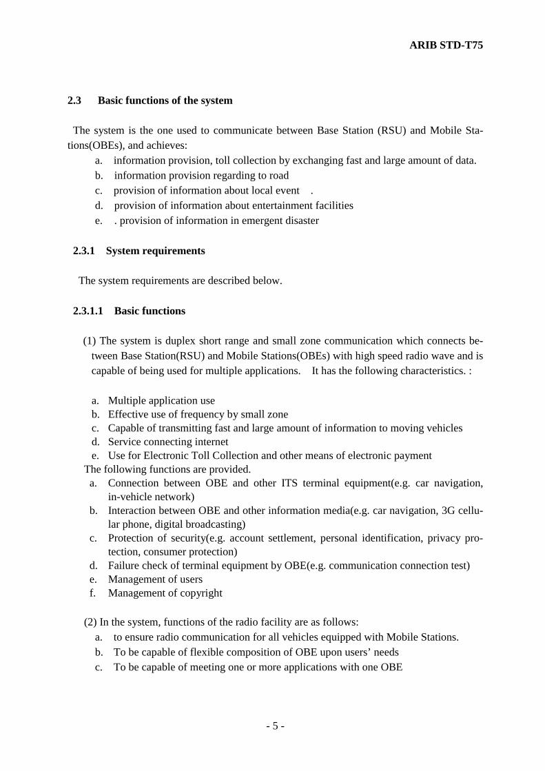
Mobile stations and the radio station for testing communication to the mobile stations shall be in accord with Article 4-3 of the Japanese Radio Act and Article 6-4-7 of the Enforcement Regulations. 1.2 Scope of application The system consists of a Road Side Unit (RSU) installed on road side (termed "Base Sta-tion") and On-Board Equipment (OBE) (termed "Land Mobile Station" or abbreviated "Mobile Station") ,and Equipment for testing the mobile station (termed “Station for Testing” or abbreviated “Test Equipment ” . This standard specifies the radio communication interface as indicated in Fig. 1.1.
Land Mobile Station(s) Base Station to Application Equipment
(On-Board Equipment) (Road Side Unit)
Reference point
Land Mobile Station(s) Test Equipment to Application Equipment
(On-Board Equipment) (Road Side Unit)
Reference point
Fig. 1.1 Configuration of the system
ARIB STD-T75
- 2 -
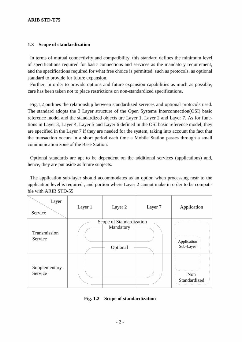
1.3 Scope of standardization In terms of mutual connectivity and compatibility, this standard defines the minimum level of specifications required for basic connections and services as the mandatory requirement, and the specifications required for what free choice is permitted, such as protocols, as optional standard to provide for future expansion. Further, in order to provide options and future expansion capabilities as much as possible, care has been taken not to place restrictions on non-standardized specifications. Fig.1.2 outlines the relationship between standardized services and optional protocols used. The standard adopts the 3 Layer structure of the Open Systems Interconnection(OSI) basic reference model and the standardized objects are Layer 1, Layer 2 and Layer 7. As for func-tions in Layer 3, Layer 4, Layer 5 and Layer 6 defined in the OSI basic reference model, they are specified in the Layer 7 if they are needed for the system, taking into account the fact that the transaction occurs in a short period each time a Mobile Station passes through a small communication zone of the Base Station. Optional standards are apt to be dependent on the additional services (applications) and, hence, they are put aside as future subjects. The application sub-layer should accommodates as an option when processing near to the application level is required , and portion where Layer 2 cannot make in order to be compati-ble with ARIB STD-55
Fig. 1.2 Scope of standardization
SupplementaryService
TransmissionService
Layer 1 Layer 2 Layer 7 ApplicationLayer
Service
Optional
Scope of StandardizationMandatory
NonStandardized
ApplicationSub-Layer

ARIB STD-T75
- 3 -
Chapter 2 System Overview
2.1 Configuration of the system The system consists of a Road Side Unit (RSU) installed at the road side (termed "Base Sta-tion" hereunder) and On-Board Equipment (OBE) installed in the vehicle (termed "Mobile Station"). 2.1.1 Base Station (RSU) Base Station performs land mobile radio communication with Mobile Station(s). The Base Station is composed of radio equipment with antenna(e), a transmitter and receiver, a control unit and a display unit. Depending on the radio communication range, Base Station is classified as follows. Class 1: radio communication range is below 10 m Class 2: radio communication range exceeds 10 m, but within 30 m 2.1.2 Mobile Station (OBE) Mobile Station performs land mobile radio communication with Base Station. The Mobile Station consists of radio equipment with antenna(e), a transmitter and receiver, and optional equipment such as an IC card, a control unit and a display unit. 2.1.3 Test Equipment Test Equipment performs radio communication for testing with Mobile Station. The Test equipment consists of radio equipment with antenna(e), a transmitter and receiver, control unit, and display unit.
ARIB STD-T75
- 4 -
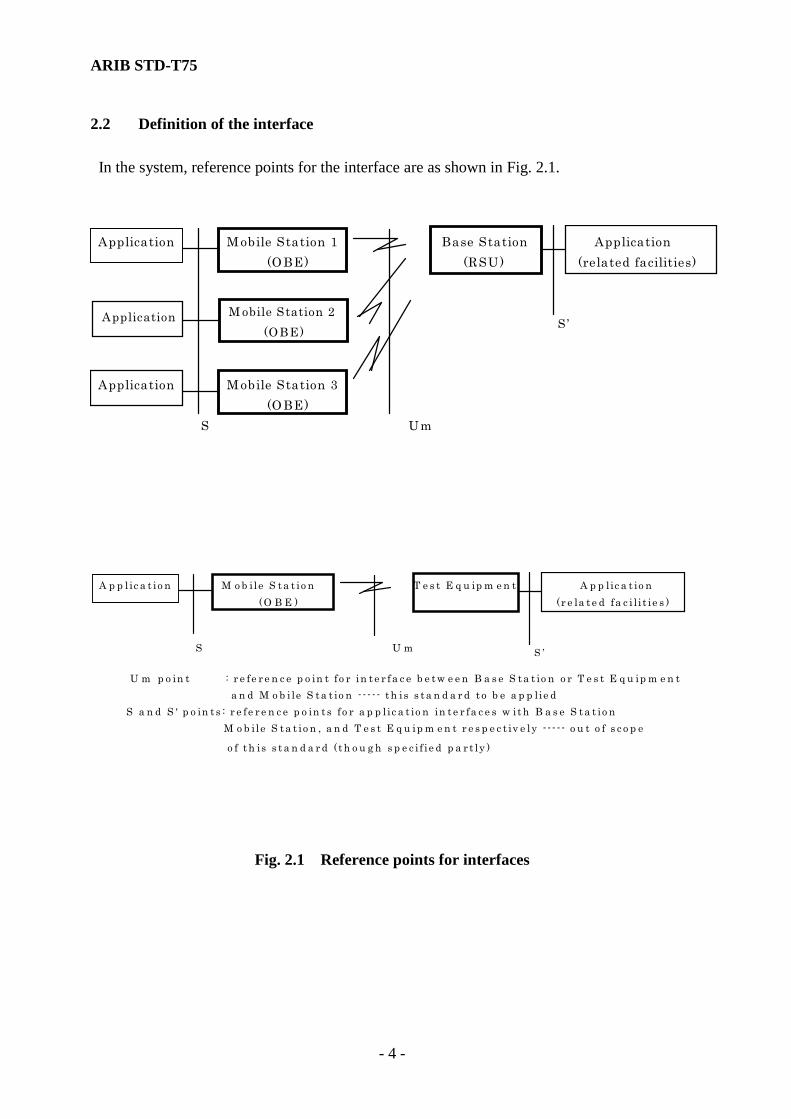
2.2 Definition of the interface In the system, reference points for the interface are as shown in Fig. 2.1.
M obile Station 2 (OBE)
Application
Application M obile Station 1 Base Station Application (OBE) (RSU) (related facilities)
Application M obile Station 3 (OBE) S Um
S ’
A p p l ic a t io n M o b ile S t a t io n T e s t E q u ip m e n t A p p lic a t io n (O B E ) ( r e la t e d fa c i l i t ie s )
S U m
U m p o in t : r e fe r e n c e p o in t fo r in t e r fa c e b e t w e e n B a s e S t a t io n o r T e s t E q u ip m e n ta n d M o b i le S t a t io n - - - - - t h is s t a n d a r d t o b e a p p lie d
S a n d S ' p o in t s : r e fe r e n c e p o in t s fo r a p p li c a t io n in t e r fa c e s w it h B a s e S t a t io nM o b ile S t a t io n , a n d T e s t E q u ip m e n t r e s p e c t iv e ly - - - - - o u t o f s c o p e
o f t h is s t a n d a r d ( t h o u g h s p e c i f ie d p a r t ly )
S ’
Fig. 2.1 Reference points for interfaces
ARIB STD-T75
- 5 -
2.3 Basic functions of the system The system is the one used to communicate between Base Station (RSU) and Mobile Sta-tions(OBEs), and achieves: a. information provision, toll collection by exchanging fast and large amount of data. b. information provision regarding to road c. provision of information about local event .
d. provision of information about entertainment facilities e. . provision of information in emergent disaster
2.3.1 System requirements The system requirements are described below. 2.3.1.1 Basic functions (1) The system is duplex short range and small zone communication which connects be-
tween Base Station(RSU) and Mobile Stations(OBEs) with high speed radio wave and is capable of being used for multiple applications. It has the following characteristics. :
a. Multiple application use b. Effective use of frequency by small zone c. Capable of transmitting fast and large amount of information to moving vehicles d. Service connecting internet e. Use for Electronic Toll Collection and other means of electronic payment
The following functions are provided. a. Connection between OBE and other ITS terminal equipment(e.g. car navigation,
in-vehicle network) b. Interaction between OBE and other information media(e.g. car navigation, 3G cellu-
lar phone, digital broadcasting) c. Protection of security(e.g. account settlement, personal identification, privacy pro-
tection, consumer protection) d. Failure check of terminal equipment by OBE(e.g. communication connection test) e. Management of users f. Management of copyright
(2) In the system, functions of the radio facility are as follows:
a. to ensure radio communication for all vehicles equipped with Mobile Stations. b. To be capable of flexible composition of OBE upon users’ needs c. To be capable of meeting one or more applications with one OBE

ARIB STD-T75
- 6 -
d. To be capable of communicating with vehicles running 0 to up to 180km/h. The information volume can be limited based upon the size of communication zone and vehicle speed.
e. To be capable of composing flexible communication zones within the range of 30m x 30m
f. To be capable of setting the size of communication zone as a service provider wants
g. To be capable of having various functions such as electronic payment according to a user’s and service provider’s needs
2.3.2 Services provided by the system 2.3.2.1 Service features
The services provided by the system have the attributes listed in Table 2.1 below.
Table 2.1 Service attributes
Service attributes Service items Information transfer capability unrestricted digital information Information transfer rate 1024 kbps or 4096 kbps Communication configuration point-to-point, point-to-multipoint
2.3.2.2 Service types (1) Bearer services The following functions provided by this service are assumed
a. Account settlement of electronic payment b. Internet (IP) connection c. Information provision (road & traffic information, various local information d. Reservation (public transportation, local facilities, car ferry) e. Information search f. Facility management (parking management, check in & out of specific area) g. Freight management (CVO, container probe)
The followings are ETC services as examples of transmission service through communication
channel. a. Exchange of the information about the toll collection: It is an exchange of needed

ARIB STD-T75
- 7 -
information about toll collection, and the reading /writing of the information are per-formed through the radio facility (lane based antenna) installed at the toll gate.
b. Transmission of the guiding information about the lanes: It is an information transmission in order to guide vehicles equipped with OBE to the dedicated lane and to achieve a smooth operation of traffic lanes. The information is transmitted by the radio equipment (approach antenna) installed ahead of the toll gate.
c. Notification of the route information: It is transmission of information about driven routes, necessary for writing on the through lanes. The information is read/written by radio equipment on the lane (Navigation antenna).
Refer to Fig. 2.2 and Fig. 2.3.
Mixed lanes
(existing)
Lane based antenna
Navigation antenna
To read/write
information
To read/write route
information in passing
Approach antenna
To guide vehicles
equipped with OBE to
the dedicated lane
Dedicated lane
Fig. 2.2 Example of DSRC service (ETC system)
ARIB STD-T75
- 8 -
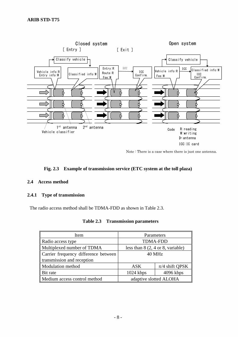
Route:R
Fee:W
1st antennaVehicle classifier
Vehicle info:REntry info:W Classified info:W
ICC Confirm.
R:reading W:writing
:antenna
Code
ICC
Closed system [ Entry ]
[ Exit ]
Open system
Classify vehicle
Entry:R
Classify vehicle
ICCVehicle info:R
Fee:W
Classified info:W
ICC Confirm.
2nd antenna
ICC:IC card
Note : There is a case where there is just one antenna.
Fig. 2.3 Example of transmission service (ETC system at the toll plaza)
2.4 Access method 2.4.1 Type of transmission The radio access method shall be TDMA-FDD as shown in Table 2.3. Table 2.3 Transmission parameters
Item Parameters Radio access type TDMA-FDD Multiplexed number of TDMA less than 8 (2, 4 or 8, variable) Carrier frequency difference between transmission and reception
40 MHz
Modulation method ASK π/4 shift QPSK Bit rate 1024 kbps 4096 kbps Medium access control method adaptive slotted ALOHA

ARIB STD-T75
- 9 -
2.4.2 Radio channel control The basic procedure for communication control shall be synchronous, adaptive slotted ALOHA which is suited to point-to-point, short time, two-way communication between a Mobile Stations and a Base Station. It is a full-duplex communication, which uses different transmission channels (frequencies) for uplink and downlink, respectively. In this standard, a communication control type which also allows half-duplex communication is specified. Fig. 2.4.2-1 and Fig. 2.4.2-2 show examples of communication. Mobile Stations and a Base Sta-tion establish the two-way communication in the communication zone. Fig. 2.4.2-1 shows a communication frame of the half-duplex and the communication with two Mobile Stations.
RSU
OBE-A
OBE-B
(Communication Zone)
FCMS2
MDS1
MDS2 ACTS
ACTC
FCMS1
MDS
MDS/ WCNS
ACTS
Structure of elementary frame
MDS
MDS3
Fig. 2.4.2-1 Example of communication (Example of the half-duplex communication)
A communication frame consists of a frame control message slot (FCMS) which performs an allocation of slots, message data slots (MDS) for data transmission, activation slot (ACTS) for the association (link connection) to Base Station, and a wireless call number slot (WCNS) which transmits wireless ID code (Call sign). The field length of each slot is 100 octets, con-stant. Fig. 2.4.2-2 shows an example of the frame structure, including 7 MDSs and a ACTS during the full-duplex communication mode in Base Station. Different transmission channels (fre-quencies) are used for up and down links, respectively and the data slot portion (MDS) are multiplexed. In the example in the figure, 4 OBE's (A, B, C, D) exchange the MDS's within the same frame during the data communication. And the figure shows an example of data exchange in up and downlink channels by using
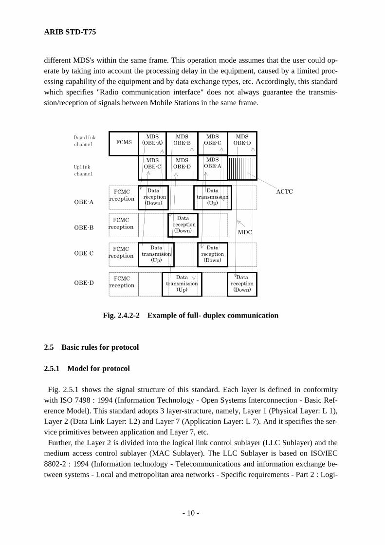
ARIB STD-T75
- 10 -
different MDS's within the same frame. This operation mode assumes that the user could op-erate by taking into account the processing delay in the equipment, caused by a limited proc-essing capability of the equipment and by data exchange types, etc. Accordingly, this standard which specifies "Radio communication interface" does not always guarantee the transmis-sion/reception of signals between Mobile Stations in the same frame.
MDS OBE-B
MDS (OBE-A)
MDS OBE-C
FCMS
Downlink
channel
Uplink
channel
MDS OBE-D
ACTC Data reception
(Down)
Data transmission
(Up)
Data reception
(Down)
Data transmision
(Up)
Data reception(Down)
Data transmission
(Up)
Data reception(Down)
MDS OBE-C
FCMC reception
FCMC reception
FCMC reception
FCMC reception
MDS OBE-D
OBE-A
OBE-B
OBE-C
OBE-D
MDS OBE-A
MDC
Fig. 2.4.2-2 Example of full- duplex communication 2.5 Basic rules for protocol 2.5.1 Model for protocol Fig. 2.5.1 shows the signal structure of this standard. Each layer is defined in conformity with ISO 7498 : 1994 (Information Technology - Open Systems Interconnection - Basic Ref-erence Model). This standard adopts 3 layer-structure, namely, Layer 1 (Physical Layer: L 1), Layer 2 (Data Link Layer: L2) and Layer 7 (Application Layer: L 7). And it specifies the ser-vice primitives between application and Layer 7, etc. Further, the Layer 2 is divided into the logical link control sublayer (LLC Sublayer) and the medium access control sublayer (MAC Sublayer). The LLC Sublayer is based on ISO/IEC 8802-2 : 1994 (Information technology - Telecommunications and information exchange be-tween systems - Local and metropolitan area networks - Specific requirements - Part 2 : Logi-

ARIB STD-T75
- 11 -
cal link control), and some parameters are modified to adapt to this standard. MAC Sublayer, Layer Management Entity (LME) and System Management Entity (SME) of the Layer 1 are specified. They exchange and manage service primitives of each layer in order to work smoothly as a whole radio system.
LLC
MAC
LMELayer 2
(Data link)
SME
system
manage
ment
entity
PMD-SAP
MAC-SAP
LLC-SAP
LME
SME
system
manage
ment
entity
LLC
MAC
Layer 1
PMD-SAP
MAC-SAP
LLC-SAP
Layer 7APDU
LPDU
PHY PDU
LSDU
LPHY SDU
LSDU
Layer 1
Application ApplicationADU
Service primitive + ASDU Service primitive + ASDU
Scope of thisstandard
APDU:Application Protocol Data UnitLPDU:Link Layer Protocol Data UnitLSDU:Link Layer Service Data UnitSAP :Service Access PointPHY PDU:Physical Layer Protocol Data Unit
LPHY SDU
Layer 7
Fig. 2.5.1 Signal structure 2.5.1.1 Features of Layer 1 Layer 1 provides the radio communication media and performs a separation and configura-tion of data following Layer 2 or the system management entity. Further to that, Layer 2 or the system management entity conducts construction and separation of physical slot by adding the preamble and the unique word, etc. 2.5.1.2 Features of Layer 2 LLC Sublayer supports 2 types of communication services (Type 1 operation : Unacknow-ledged connectionless-mode services, Type 3 operation : acknowledged connectionless-mode
ARIB STD-T75
- 12 -
services). MAC Sublayer supports the following service contents in order to perform commu-nication management of radio channels.
(1) Association (link connection) (2) Slot (Frame) control (3) Slot-by- slot data separation and processing (4) Control of request for partial resend in MAC Sub Layer level (5) Simplified security communication (scramble)
2.5.1.3 Features of Layer 7 Layer 7 provides the application with communication control tools. It provides the services to the application, and transmits and receives data via LLC sublayer in Layer 2. It can provide the services to more than one application (so-called multi-application). It conducts association process and application management through a linkage with Layer 2. 2.5.2 Communication Service It is divided into two phases, i.e., the association phase and the communication phase. (By taking the example of Fig. 2.4.2-1, an operation example is shown in Fig. 2.5.2 for reference.) (1) Association phase It is a phase where Mobile Station registers to Base Station (entry). It is generally di-
vided into the phase of link channel establishment and the phase of service establishment. a. The phase of link channel establishment Mobile Station (OBE) receives FCMC to which communication control infor-
mation about frame configuration, etc. sent from RSU are added, and, if needed, interprets the communication control information including protocol types.
ⅰ. Mobile Station (OBE) judges the contents of FCMC (Frame Control Message
Slot), chooses an ACTC (Activation channel) in ACTS randomly, adds the link address, transfers the ACTC (Activation channel) to Base Station (RSU) and performs a request for association.
ⅱ. In the following frame, Base Station (RSU) allocates a link address and a data
slot to a Mobile Station, and transmits after adding information. Mobile Station receives a correct FCMS added with a proper link address, and by interpreting the information the phase of link channel establishment is completed.

ARIB STD-T75
- 13 -
After this, normally it proceeds to the phase of service establishment. There is a simplified association (connection) process by which the communication phase is commenced directly and, hence, omitting the phase of service (application) estab-lishment. The operation of the normal phase of service establishment is described hereunder.
b. The phase of Service (Application) establishment This phase establishes applications selectively, and it shall be decided that Mo-
bile Station performs the communication with which Base Station (RSU) and by which application.
ⅰ. By adding to a Beacon Service Table (BST) and using a message data slot
(MDS), Base Station (RSU) transmits parameters of applications, which are available from Base Station (RSU) by using message data slot (MDS).
ⅱ. Mobile Station (OBE) transmits the response, corresponding to the application
in the BST, to Base Station (RSU) by using MDS as a vehicle service table (VST), establishes the application for communication and proceeds to the com-munication phase.
(2) Communication phase The Base Station allocates a communication slot (MDS) in the uplink or downlink
to a requesting unit or plural groups of Mobile Stations and performs data exchange. After sending Ack/Nack by using an Ack channel (ACKC) within the same slot, re-quest for resend control is performed either when Nack is received or Ack/Nack is not received in a limited period of time.

ARIB STD-T75
- 14 -
RSU OBE-BOBE-AFCMS1communication profile
ACTCOBE LID(link address)
FCMS1
ACTS
FCMS2
MDS1
MDS2
FCMS2OBE LID(link address),Slot allocation
MDS3 : DownlinkTransmit data in allocated slot (BST)
ACK transmission
ACK transmission
MDS1 : UplinkTransmit data in allocated slot
Direction offrame transfer
MDS3
Fig. 2.5.2 Example of communication transaction
2.5.3 Numbering plan (Link address) It is assumed that Link addresses for communication and the numbers of each type of equipment are different. In order to protect communication privacy, an address with a length of 4 octets, chosen by Mobile Station at random, is to be used as the link address. This ad-dress is commonly used as an ID number of SAP (Service Access Point) of Layer 1, Layer 2 and Layer 7 of Base Station and Mobile Station. The details are defined in the subclause 4.2.4.2.1.8.2. 2.5.4 Other related rules The SDL* diagrams indicate typical functional states and flows, and a flow which differs from them is also acceptable if it results in equivalent functions. * SDL : Functional Specification and Description Language specified in ITU-T Z-series rec-
ommendations. 2.6 Type of secured communication A simplified type of security communication is standardized.
ARIB STD-T75
- 15 -
Chapter 3 Technical Requirements for Radio Facilities 3.1 Overview This chapter specifies the technical requirements for radio facilities and equipment. 3.2 General conditions The radio facilities and equipment shall include carrier frequency oscillator(s). 3.2.1 Radio frequency bands The radio frequency bands to be used shall be 5.8 GHz bands. 3.2.2 Carrier frequency spacing The carrier frequency spacing shall be 5 MHz. 3.2.3 Transmit-receive frequency separation The transmit-receive frequency separation shall be 40 MHz. 3.2.4 Operating method and multiple access The operating method shall be one-way operation, semi-duplex operation, or duplex operation. The multiple access shall be TDMA (time division multiple access). 3.2.5 Access method The access method shall be TDMA-FDD (frequency division duplex). 3.2.6 Number of multiplexed circuits The maximum number of multiplexed circuits on a TDMA channel shall be eight. 3.2.7 Data transmission method The data transmission method shall be one-way, half duplex, or full duplex for base stations, one-way, or half duplex for mobile stations. 3.2.8 Modulation method The modulation method shall be an ASK (amplitude shift keying) or π/4 shift QPSK. The roll-off rate is applied to only π/4 shift QPSK and 100% transmission.

ARIB STD-T75
- 16 -
3.2.9 Modulation signal In case of ASK, the bit rate shall be 1024 kbps and the modulation signal rate after coding shall be 2048 kbaud. In the case of π/4 shift QPSK, the bit rate shall be 4096 kbps and the modulation signal rate 2048 kbps. The data coding method shall be a split phase code in ASK, and NRZ code in π/4 shift QPSK. The accuracy of the bit rate shall be ±100×10-6 or less. 3.2.10 Access control method The access control method shall be an adaptive slotted ALOHA method. 3.2.11 Frame length and slot length The frame length shall be 9 slots or less including FCMS (frame control message slot). The slot length shall be 100 octets (800 bits constant) on the basis of bit rate 1024 kbps in case of ASK modulation. 3.2.12 Wireless call number (call sign) The wireless call number (call sign) memory in mobile stations or test equipment shall be able to store and transmit the wireless call number (call sign) which is managed by the organiza-tion approved by the Minister of Public Management, Home Affairs, Posts and Telecommu-nications. 3.2.13 One cabinet The radio facilities and equipment, except the following equipment and power supplies, shall be installed inside one cabinet. The cabinet shall not be easily opened.
a. Antenna(s) b. Displays for showing operational conditions of transmitter or receiver. c. Additional equipment for data processing and the similar equipment to this. d. Signal processing equipment, which is not easily removed from the one cabinet above
mentioned. 3.2.14 Security measures The radio facilities and equipment should be designed taking into consideration the authenti-cation and the scrambles (as specified in detail in chapter 4) to avoid a false charge or unfair use. 3.2.15 Countermeasures against electromagnetic interference Vehicle-mounted mobile stations should be designed to prevent mutual electromagnetic in-

ARIB STD-T75
- 17 -
terference between the mobile stations and electrical equipment for automobiles. 3.3 Conditions for modulation method 3.3.1 Modulation method The modulation method shall be ASK (amplitude shift keying) or π/4 shift QPSK.. 3.3.1.1 ASK 3.3.1.1.1 Modulation method Fig. 3.1 shows a schematic diagram which specifies the modulation method in this standard of ASK. (Informative)
Binary data encoding low pass filter
(modulation signal)
Carrier ASK
(modulated signal)
Fig. 3.1 Schematic diagram of ASK modulation circuit
3.3.1.1.2 Data coding method The data coding method shall be the split phase code (manchester code) method for both base stations and mobile stations. Data bit “1” : The RF signal is sent in the first half of the bit duration and the RF signal is not
sent in the latter half. Data bit “0” : The RF signal is not sent in the first half of the bit duration and the RF signal is
sent in the latter half.

ARIB STD-T75
- 18 -
carrier on
carrier off
data 0 1 1 0
(Example : transmission data is 0110)
Fig. 3.1.1 Split phase code
3.3.1.1.3 Transmission bit rate Transmission bit rate shall be 1024.000kbps

ARIB STD-T75
- 19 -
3.3.1.2 π/4 shift QPSK 3.3.1.2.1 Modulation method Fig.3.3.1.2.1 shows a schematic diagram which specifies the modulation method of π/4 shift QPSK. (Informative)
Fig.3.3.1.2.1 π/4 Shift QPSK modulation circuit 3.3.1.2.2 Differential coding
The serial signal is converted to the symbol of (Xk, Yk) by the serial/parallel converter, and converted to SP signal (Ik, Qk) by the differential coding unit. The conversion from the serial signal to (Xk, Yk) (Binary/quadrature convert) is made as follows, and the equa-tion from (Xk, Yk) to (Ik, Qk) shall be in Equation3.3-1 and Table 3.3.1.
Binary data series ………….an-1 , an , an+1,………….. Symbol series (an , an+1)
Xk , Yk Ik = Ik-1cos{ ΔΦ(Xk,Yk)}- Qk-1sin{ΔΦ(Xk,Yk)}
Serial/parallel Convert
Differential coding
low pass filter
H(F)
low pass filter
H(F)
π/2
cos(ωct)
-sin(ωct)
ωc an
Yk
Xk
Ik
Qk
S(t)
i(t)
q(t)

ARIB STD-T75
- 20 -
Qk = Ik-1sin{ ΔΦ(Xk,Yk)}+ Qk-1cos{ ΔΦ(Xk,Yk)} ….(3.3-1) Table 3.3.1 differential coding rule
Xk Yk ΔΦ 1 1 0 1 0 0 1 0
-3π/4 3π/4 π/4 -π/4
(2)The signal space diagram shall be in Fig3.3.1.2.2.
Fig.3.3.1.2.2 The signal space diagram of π/4 shift QPSK 3.3.1.2.3 Base band regulation (1) The base band regulation shall be expressed by Nyquist bandwidth H(f) in Equation
3.3-2 1 0 ≤ | f | < (1-α) / 2T
| H(f) | = cos2 [ (T/4α)( 2π| f | -π (1-α) / T )] ( 1-α) / 2T ≤ | f | < ( 1+α) / 2T 0 ( 1+α) / 2T ≤ | f |
where, T = ×10-3 sec …..(3.3-2)
(2) Roll off rate
10 11
01 00
1 2048
I
Q
ARIB STD-T75
- 21 -
The cosine roll off rate shall be 1.0. ( transmission; 100%)
(3) The phase characteristics of H(f) shall be linear. 3.3.1.2.4 Method of orthogonal modulation S(t) in Fig.3.3.1.2.1 shall be withdrawn by the following equation. S(t) = Re [{i( t ) + j * q ( t ) }exp( jωc t)] = i( t ) cos(ωc t) - q( t ) sin(ωc t)
…..(3.3-3) where, I(t) = F –1[H ( f ) * F { Ik ( t ) } ] q(t) = F –1[H ( f ) * F { Qk ( t ) } ]
…..(3.3-4) F(X) , F -1 (x) show Fourier transformation , reverse Fourier transformation of X , x. Ik(t) , Qk(t) show the continuous impulse function which owns energy proportional to the square of each amplitude of Ik , Qk. 3.3.1.2.5 Transmitting spectrum See 3.4.2.4 3.3.1.2.6 Transmission bit rate Transmission bit rate shall be 4096.000kbps

ARIB STD-T75
- 22 -
3.4 Conditions relating to transmitter and receiver 3.4.1 Carrier frequencies and carrier numbers The relationship between carrier frequencies and carrier numbers is listed in Table 3.1.(*1)
Table 3.1 Relationship between carrier frequencies and carrier numbers
Carrier number Carrier fre-quency(MHz) application remarks
D7 5,775.000 Downlink D6 5,780.000 Downlink D5 5,785.000 Downlink D4 5,790.000 Downlink D1 5,795.000 Downlink (*2) D3 5,800.000 Downlink D2 5,805.000 Downlink (*2) U7 5,815.000 Uplink U6 5,820.000 Uplink U5 5,825.000 Uplink U4 5,830.000 Uplink U1 5,835.000 Uplink (*2) U3 5,840.000 Uplink U2 5,845.000 Uplink (*2)
(*1) : Carrier number Di and Ui shall be in pairs.
A pair of carrier numbers D1 and U1 corresponds to A mode, and a pair of D2 and U2 corresponds to B mode. Refer to subclause 4.2.4.2.1.3 (3). Downlink : Transmission from base station or test equipment to mobile stations. Uplink : Transmission from mobile stations to base station or test equipment.
(*2) : D1,D2,U1,U2 are used in ETC. 3.4.2 Transmission characteristics 3.4.2.1 Transmit power (1) Definition
a. Facilities and equipment having antenna connector : Power fed to antenna. b. Facilities and equipment in which antenna is installed : Antenna radiation power
measured at the test site or measured using a RF coupler which is calibrated at the test site.
Note) The transmit power of ASK shall be expressed in the peak envelope power and the power of QPSK shall be expressed in the average power of the burst.
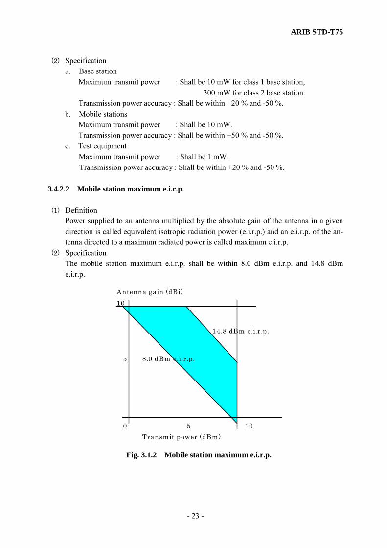
ARIB STD-T75
- 23 -
(2) Specification a. Base station Maximum transmit power : Shall be 10 mW for class 1 base station, 300 mW for class 2 base station. Transmission power accuracy : Shall be within +20 % and -50 %. b. Mobile stations Maximum transmit power : Shall be 10 mW. Transmission power accuracy : Shall be within +50 % and -50 %. c. Test equipment
Maximum transmit power : Shall be 1 mW. Transmission power accuracy : Shall be within +20 % and -50 %. 3.4.2.2 Mobile station maximum e.i.r.p. (1) Definition Power supplied to an antenna multiplied by the absolute gain of the antenna in a given
direction is called equivalent isotropic radiation power (e.i.r.p.) and an e.i.r.p. of the an-tenna directed to a maximum radiated power is called maximum e.i.r.p.
(2) Specification The mobile station maximum e.i.r.p. shall be within 8.0 dBm e.i.r.p. and 14.8 dBm
e.i.r.p.
10
8.0 dBm e.i.r.p.
0
5
Antenna gain (dBi)
14.8 dBm e.i.r.p.
105Transmit power (dBm)
Fig. 3.1.2 Mobile station maximum e.i.r.p.

ARIB STD-T75
- 24 -
3.4.2.3 Transmission of wireless call number (call sign) The wireless call number is specified in Appendix C. Refer to subclause 3.2.1. 3.4.2.4 Adjacent channel leakage power (1) Definition The adjacent channel leakage power shall be defined as the ratio to the power (peak en-
velope power in ASK, average power of the burst in QPSK refer to subclause 3.4.2.1) that is radiated within a bandwidth of ±2200 kHz, of which center frequency is sepa-rated by 5 MHz (adjacent) and 10 MHz (adjacent-adjacent) from the subject carrier fre-quency when the subject carrier is modulated with the reference coded test signal at the same bit rate as that of transmission bit rate.
(2) Specification The adjacent channel leakage power shall be –30dB or less (adjacent) and -40 dB or less
(adjacent-adjacent) for base station, mobile stations, and test equipment. 3.4.2.5 Eye pattern (1) Definition Free decision distance in width and height of a digital signal. An ideal digital signal has a
decision height of 100 % which is equal to the difference of high level and low level. Eye pattern (amplitude) = 2B/(A+B).
where, A : max. amplitude, B : min. amplitude. Eye pattern (time) = 2B’/(A’+B’). where, A’ : max. zero-cross time width, B’ : min. zero-cross time width. (2) Specification a: The eye pattern (amplitude) shall be 80 % or more in ASK. b: The eye pattern (time) shall be 80 % or more in ASK. The eye pattern is not specified for π/4 shift QPSK.

ARIB STD-T75
- 25 -
A B
B’
A’
Fig. 3.2 Eye pattern
3.4.2.6 Burst transmission transient response time (1) Definition The burst transmission transient response time for both base station and mobile stations
shall be defined by the duration of a burst signal modulated by the digital bit stream; to fall off from the average power over the transmit burst to LP or to rise from LP to the average power over the transmit burst.
Where, LP is the specification for leakage power during carrier off period (refer to Sec-tion 3.4.2.7).
(2) Specification
a. Time characteristics : 2|ΔTabs| + Tbst < 15.625 µS Where, ΔTabs : Refer to subclause 3.4.2.13 Tbst : Burst transmission transient response time. b. The leakage power during carrier off period shall meet the specification of sub-
clause 3.4.2.7.
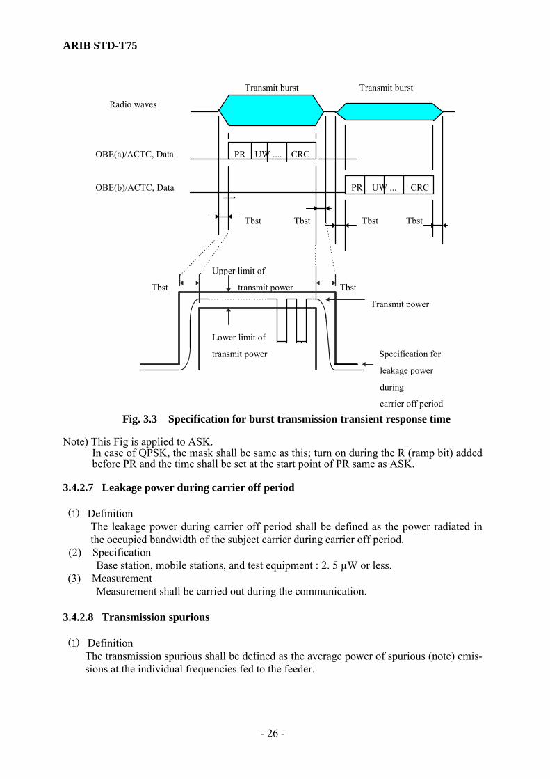
ARIB STD-T75
- 26 -
Transmit burst Transmit burst
Radio waves
OBE(a)/ACTC, Data PR UW .... CRC
OBE(b)/ACTC, Data PR UW ... CRC
Tbst Tbst Tbst Tbst
Upper limit of
Tbst transmit power Tbst
Transmit power
Lower limit of
transmit power Specification for
leakage power
during
carrier off period Fig. 3.3 Specification for burst transmission transient response time
Note) This Fig is applied to ASK.
In case of QPSK, the mask shall be same as this; turn on during the R (ramp bit) added before PR and the time shall be set at the start point of PR same as ASK.
3.4.2.7 Leakage power during carrier off period (1) Definition
The leakage power during carrier off period shall be defined as the power radiated in the occupied bandwidth of the subject carrier during carrier off period.
(2) Specification Base station, mobile stations, and test equipment : 2. 5 µW or less. (3) Measurement
Measurement shall be carried out during the communication. 3.4.2.8 Transmission spurious (1) Definition
The transmission spurious shall be defined as the average power of spurious (note) emis-sions at the individual frequencies fed to the feeder.

ARIB STD-T75
- 27 -
Note : Spurious emissions refer to radio wave emissions on a frequency or frequencies which
are outside the necessary bandwidth and the level of which may be reduced without af-fecting the corresponding transmission of information. Spurious emissions include har-monic emissions at frequencies above and below the fundamental frequency, parasitic emissions, intermodulation products and frequency conversion products, but exclude emissions at frequencies immediately outside the necessary bandwidth which result from the modulation process for transmission of information.
(2) Specification The transmission spurious shall be 25 µW or less for both base station and mobile sta-
tions. (3) Measurement
Measurement shall be carried out during the communication. 3.4.2.9 Occupied bandwidth (1) Definition
The occupied bandwidth shall be defined as the width of a frequency band such that, be-low the lower and above the upper frequency limits, the mean power emitted are each equal to 0.5 % of the total mean power of a given emission.
(2) Specification The occupied bandwidth shall be 4.4 MHz or less for both base station and mobile sta-
tions. The transmit cosine roll off, roll off rate shall be 1.0 in case of QPSK.
3.4.2.10 Frequency tolerance (1) Definition
The frequency tolerance shall be defined as the maximum permissible departure by the center frequency of the frequency band occupied by an emission from the assigned fre-quency. The frequency tolerance is expressed in parts per 106.
(2) Specification ASK Base station : ± 20 ×10-6 or less. Mobile stations : ± 50 × 10-6 or less. QPSK Base station : ± 5 × 10⁻⁶ or less. Mobile stations : ± 20 × 10-6 or less. Test equipment shall be ± 5 x 10⁻⁶ or less for both ASK and QPSK.
3.4.2.11 Modulation index, Modulation accuracy 3.4.2.11.1 Modulation index (ASK) (1) Definition
The modulation index shall be defined as the size of the variation of the modulation pa-
ARIB STD-T75
- 28 -
rameter (frequency, amplitude, phase) caused by the modulation signal (data signal). It is expressed as follows in ASK.
Modulation index = (Vmax-Vmin) / (Vmax+Vmin). Where, Vmax : Crest of amplitude waveform after detection by diode. Vmin : Bottom of amplitude waveform after detection by diode. (2) Specification
The modulation index shall be within 0.75 and 1.0 for base station, mobile stations, and test equipment.
3.4.2.11.2 Modulation accuracy (QPSK) (1) Definition
The modulation accuracy shall be the effective value of vector error at signal point. (2)Specification The modulation accuracy for base station, mobile station, and test equipment shall be 12.5% or less. 3.4.2.12 Cabinet radiation
Cabinet radiation shall be 2.5 µW or less for base station, mobile station, and test equip-ment. 3.4.2.13 Allowable deviation of absolute signal transmission time (1) Definition
The allowable deviation of absolute signal transmission time shall be defined as the de-viation of time after the start of base station control signal FCMC (Frame Control Mes-sage Channel) transmission until the end of each slot reception from the reference time.
Refer to Fig. 3.4.

ARIB STD-T75
- 29 -
(2) Specification 2|ΔTabs| + Tbst < 15.625 µS. ΔTabs < 5 µS. Where, ΔTabs : Deviation of absolute signal transmission time. Tbst : Burst transmission transient response time. Refer to subclause 3.4.2.6.
Base station Mobile station
Starting point
for time control FCMC delay in
in base station mobile station
FCMC “CRC ok” :
Transmission delay Check Starting point
Tabs in base station SCI(m) for time control in mobile station
MDS Determination of number
Tabs and position of MDS,ACTC
Tabs Transmission delay
in mobile station
ACTC
ACTC Reception delay
in base station
time time
Tabs : Absolute signal transmission time Fig. 3.4 Examples of absolute signal transmission time
3.4.3 Reception characteristics 3.4.3.1 Frequency tolerance of local oscillator (1) Definition
The frequency tolerance of the local oscillator shall be defined by the maximum toler-ance of the oscillator frequency.
(2) Specification The frequency tolerance of the local oscillator is not specified in this standard.
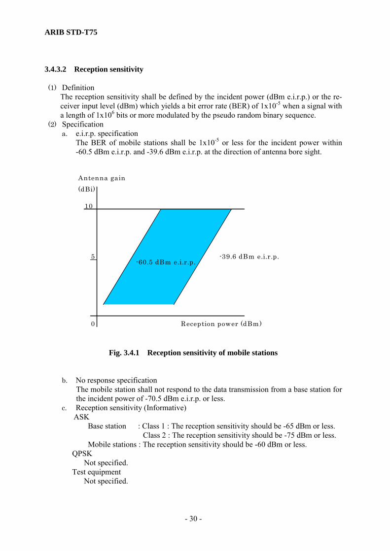
ARIB STD-T75
- 30 -
3.4.3.2 Reception sensitivity (1) Definition
The reception sensitivity shall be defined by the incident power (dBm e.i.r.p.) or the re-ceiver input level (dBm) which yields a bit error rate (BER) of 1x10⁻⁵ when a signal with a length of 1x106 bits or more modulated by the pseudo random binary sequence.
(2) Specification a. e.i.r.p. specification The BER of mobile stations shall be 1x10⁻⁵ or less for the incident power within
-60.5 dBm e.i.r.p. and -39.6 dBm e.i.r.p. at the direction of antenna bore sight.
0
5
Antenna gain (dBi)
10
-39.6 dBm e.i.r.p.
Reception power (dBm)
-60.5 dBm e.i.r.p.
Fig. 3.4.1 Reception sensitivity of mobile stations
b. No response specification The mobile station shall not respond to the data transmission from a base station for
the incident power of -70.5 dBm e.i.r.p. or less. c. Reception sensitivity (Informative) ASK
Base station : Class 1 : The reception sensitivity should be -65 dBm or less. Class 2 : The reception sensitivity should be -75 dBm or less. Mobile stations : The reception sensitivity should be -60 dBm or less. QPSK Not specified. Test equipment Not specified.

ARIB STD-T75
- 31 -
(3) Definition of specified reception sensitivity The specified reception sensitivity shall be defined as follows. ASK
Base station : Class 1 : The specified reception sensitivity shall be -65 dBm. Class 2 : The specified reception sensitivity shall be -75 dBm. Mobile stations : The specified reception sensitivity shall be -60 dBm. QPSK Not specified. However, it is recommended the sensitivity of Class 1 Base sta-
tion be –65dBm, Class 2 station be –75dBm, and Mobile station be –65dBm. Test equipment Not specified 3.4.3.3 Bit error rate performance (1) Definition The bit error rate performance shall be defined by the bit error rate measured with a sig-
nal modulated by a pseudo random binary sequence at the specified reception sensitiv-ity.
(2) Specification The bit error rate performance is not specified in this standard. (3) Informative The bit error rate performance should be 1x10⁻⁵ or less.
3.4.3.4 Receiver bandwidth (1) Definition The receiver bandwidth shall be defined as the 3 dB bandwidth of the receiver. (2) Specification The receiver bandwidth is not specified in this standard.
3.4.3.5 Power limits within communication zone (1) Definition
The power limits within communication zone shall be defined by the minimum and maximum values of incident power in front of the antenna. These two values also specify the dynamic range of the receiver. Power values are measured without any additional losses due to rain or misalignment.
(2) Specification ASK Base station : For the receiver of class 1 base station :
The minimum incident power shall be -58 dBm e.i.r.p. The maximum incident power shall be -46 dBm e.i.r.p.
For the receiver of class 2 base station : The minimum incident power shall be -72 dBm e.i.r.p. The maximum incident power shall be -48 dBm e.i.r.p.
ARIB STD-T75
- 32 -
Mobile stations : For the receiver of mobile station responding to class 1 base station : The minimum incident power shall be -54 dBm e.i.r.p. The maximum incident power shall be -41 dBm e.i.r.p.
For the receiver of mobile station responding to class 2 base station : The minimum incident power shall be -56 dBm e.i.r.p. The maximum incident power shall be -40 dBm e.i.r.p.
QPSK Not specified. 3.4.3.6 Adjacent signal selectivity (1) Definition
The adjacent signal selectivity shall be defined as the level ratio of the interfering signal to the desired signal, specified by the following statement:
The level of desired signal shall be set to +3 dB higher than the level of the specified re-ception sensitivity* . The level of interfering signal shall be the one yielding a bit error rate of 1x10⁻⁵ on the desired signal. The interference signal shall be detuned by F Hz and modulated by a pseudo random binary sequence.
(* Refer to Section 3.4.3.2 (3) for the specified reception sensitivity) (2) Specification
The adjacent signal selectivity shall meet the following requirements for both base sta-tion and mobile stations.
Base station Class 1
F = 10 MHz off : 15 dB or higher. F = 30 MHz off : 20 dB or higher. F = 50 MHz off : 20 dB or higher. Class2 F = 10 MHz off : 20 dB or higher. F = 30 MHz off : 20 dB or higher. F = 50 MHz off : 20 dB or higher
mobile stations and test equipment F = 10 MHz off : 15 dB or higher. F = 30 MHz off : 20 dB or higher. F = 50 MHz off : 20 dB or higher
3.4.3.7 Intermodulation performance (1) Definition
The intermodulation performance shall be defined as the level ratio of the either of the two interfering signals to the desired signal.
(2) Specification The intermodulation performance is not specified in this standard.

ARIB STD-T75
- 33 -
3.4.3.8 Spurious response rejection ratio (1) Definition
The spurious response rejection ratio shall be defined as the level ratio of the interfering signal to the desired signal, specified by the following statement:
The level of desired signal shall be set to +3 dB higher than the level of the specified re-ception sensitivity* . The level of interfering signal shall be the one yielding a bit error rate of 1x10⁻⁵ on the desired signal. The interference signal shall be detuned inside or outside the 5.8 GHz ISM band and modulated by a pseudo random binary sequence.
(* Refer to subclause 3.4.3.2 (3) for the specified reception sensitivity.) Where, Inside the 5.8 GHz ISM band : 5.725 - 5.875 GHz. (2) Specification
a. Base station : For the receiver of class 1 base station:
Inside the 5.8 GHz ISM band : The spurious response rejection ratio shall be 2328 dB or more.
Outside the 5.8 GHz ISM band : The spurious response rejection ratio shall be 16 dB or more.
For the receiver of class 2 base station;(Informative) Inside the 5.8 GHz ISM band : The spurious response rejection ratio shall be
30 dB or more. Outside the 5.8 GHz ISM band : The spurious response rejection ratio shall be
26 dB or more. b. Mobile stations : (Informative)
Inside the 5.8 GHz ISM band : The spurious response rejection ratio shall be 24 dB or more.
Outside the 5.8 GHz ISM band : The spurious response rejection ratio shall be 18 dB or more.
Note : Image response is excepted. c. Test equipment
Not specified. 3.4.3.9 Strength of secondary radio emissions (1) Definition
The strength of secondary radio emissions shall be defined as the strength of radio waves emitted from the antenna terminal when the stations are in the receive mode.
(2) Specification The strength of secondary radio emissions shall be 2.5µW or less for base station, mo-
bile station, and test equipment. 3.4.3.10 Cabinet radiation The cabinet radiation from the receiver is not specified in this standard.

ARIB STD-T75
- 34 -
3.4.4 Antenna 3.4.4.1 Classification of antenna [Informative] (1) The classification of antenna is shown in Table 3.3.
Table 3.3 Classification of antenna (Example of ETC) Class Application
Type 1 • Lane based antenna • Shall be connected to class 1 base station
Type 2 • Navigation antenna ( Wide-area ) • Shall be connected to class 2 base station
Type 3 • Navigation antenna • Shall be connected to class 2 base station
Type 4 • Approach antenna • Shall be connected to class 2 base station
Mobile antenna • Shall be connected to mobile station (2) Installation condition of antenna (Informative) Type 1 - 4 antennae are installed on a gantry or a single pole on the roadside. Each antenna beam is directed downward to a predetermined communication zone. Typical installation heights of antennae are as follows above the road surface.
Type 1 antenna : 5 m Type 2 and type 3 antennas : 6 m Type 4 antenna : 10 m
The mobile antenna is installed to a forward section inside or outside a vehicle and its beam is directed upward to receive the radio waves from or transmit to type 1 - 4 anten-nas.
The installation height of the mobile antenna is about 1 to 2 m above the road surface and different depending on the vehicle type.
(1) Communication zone (Informative) a. Communication zone of type 1 antenna
Examples of communication zone of type 1 antenna are shown in Fig. 3.5 and Fig. 3.6. The communication zone is about 4m in length along the road, about 3m in width and 1m in height above the road surface. The figures on the lane width etc. are the representative value in Fig. 3.5 and Fig. 3.6 (this is the same as Fig. 3.7 through Fig. 3.9).
b. Communication zone of type 2 antenna An example of communication zone of type 2 antenna is shown in Fig. 3.7.
c. Communication zone of type 3 antenna An example of communication zone of type 3 antenna is shown in Fig. 3.8.
d. Communication zone of type 4 antenna

ARIB STD-T75
- 35 -
An example of communication zone of type 4 antenna is shown in Fig. 3.9.
Adjacent lane
Traveling
direction
Antenna
5m
19°
Island
1.7mAbout 4m
1m
45°Communication zone
Island
3m
1.75m
Fig. 3.5 Example of communication zone - Type 1 antenna

ARIB STD-T75
- 36 -
6m
1m
5m
Travelingdirection
Antenna
23°45°
Adjacent lane
Communication zone
Island
1.7m
About 4m
Fig. 3.6 Example of communication zone - Type 1 antenna

ARIB STD-T75
- 37 -
1m
14m
39°
35 ° Comm. zone
Antenna
6m 3.5m
10m
15.7m
Fig. 3.7 Example of communication zone - Type 2 antenna
11.73m
22m
5.96m
31.3 °
31.3°
19° Comm. zone
Antenna
10m
18m
1m
29.2m 10.8m
Fig. 3.8 Example of communication zone - Type 3 antenna

ARIB STD-T75
- 38 -
1m
30m
31° Comm. zone
Antenna
8.5m
30m
2m
10m 33.2m 9.2m
Fig. 3.9 Example of communication zone - Type 4 antenna
ARIB STD-T75
- 39 -
3.4.4.2 Gain of antenna (1) Definition
The gain of antenna shall be defined as the ratio, usually expressed in decibels, of the power required at the input of a loss-free reference antenna to the power supplied to the input of the given antenna to produce, in a given direction, the same field strength or the same power flux-density at the same distance. When not specified otherwise, the gain refers to the direction of maximum radiation. The gain may be considered for a specified polarization.
The absolute gain shall be defined as the gain when the reference antenna is an isotropic antenna isolated in space.
(2) Specification a. Base station : The antenna which is connected to the base station shall have the
absolute gain of 20 dBi or less. b. Mobile stations : The antenna which is connected to the mobile station shall have
the absolute gain of 10 dBi or less. c. Test equipment: The antenna which is connected to the test equipment shall have
the absolute gain of 10 dBi or less. 3.4.4.3 Polarization (1) Definition
The right-hand (clockwise) polarized wave shall be defined as the elliptically- or circu-larly-polarized wave, in which the electric field vector, observed in any fixed plane, normal to the direction of propagation, whilst looking in the direction of propagation, rotates with time in a right-hand or clockwise direction.
The left-hand (anticlockwise) polarized wave shall be defined, by the same way, as the rotation in a left-hand or anticlockwise direction.
(2) Specification The polarization shall be the right-hand circular for both base station and mobile stations.

ARIB STD-T75
- 40 -
3.5 Test equipment 3.5.1 Maximum e.i.r.p of test equipment
(1) Definition Power supplied to an antenna multiplied by the absolute gain of the antenna in a given
direction is called equivalent isotropic radiation power (e.i.r.p.) and an e.i.r.p. of the an-tenna directed to a maximum radiated power is called maximum e.i.r.p.
(2)Specification The test equipment maximum e.i.r.p. shall be 5.0 dBm e.i.r.p. or less. It shall be the
lowest value required for testing.

ARIB STD-T75
- 41 -
Chapter 4 Communication Control System 4.1 Overview This chapter specifies the communication control system of the radio interface utilized for the radio communication system. Hereafter, the radio interface is specified regarding the protocol model described in chapter 2. 4.1.1 Outline of Relationship between Layers, Layer Managements and System Management Fig. 4.1.1 indicates an OSI reference model of this radio communication system. An entity of each layer provides data transmission service for a higher layer. Each layer management entity has an inherent management information base (MIB) providing access service to the higher layer management entities or the system management entity. Furthermore, the layer 2 management entity provides services for the association control. The system management entity provides services for management information service users. The layer 2 management entity has the MIB in the MAC sublayer and does not have any MIB in the LLC sub layer (Parameters utilized for the LLC sublayer is specified by the MIB in the MAC sublayer management.). Moreover, either a layer 1 or a layer 7 management entity is not specified. Each MIB is the virtual information data base consisted of variables or parameters utilized for elements of procedures of the each layer. Access to the same layer MIB is executed as direct reference and access to another layer MIB is executed as indirect reference using service primitives provided by each layer. Service primitives and details of MIB for each layer and layer management entity are definitely specified in the layer standards.

ARIB STD-T75
- 42 -
Application Kernel Service User
Layer 1
Layer 7
Layer 2
GETSETACTION
GETSETAction
DL-UNITDATA
RegisterApplicationReadyApplication
SystemManagement
T-KE
LLC MACManagement
MLME_GETMLME_SETMLME_SCANMLME_ASSOCIATEMLME_RLT
MLME_GETMLME_SET
SME_GETSME_SETSME_RESETSME_EVENTREPORT
PLME_GETPLME_SET
I-KE
PLME_GETPLME_SET
ALME_GETALME_SETL7 MIB
MAC MIB
L1 MIB
SM MIB
B-KE
GetBroadcastDataBroadcastData
GET
MAC
Fig. 4.1.1 Outline of Relationship between Layers, Layer Managements and System Management

ARIB STD-T75
- 43 -
4.2 Layer 1 Standards 4.2.1 Overview This subclause specifies the physical portion of the radio communication system, including the structure of the frame, the structure of slots, the assignment of slots, different channel types, the structure of channels and the structure of signals, etc. 4.2.2 Mobile Station types and base station types 4.2.2.1 Mobile Station Types Not specified. 4.2.2.2 Base Station Types Depending on the maximum transmit power (defined in subclause 3.4.2.1), two classes of the base station are specified. 4.2.2.3 Test equipment Not specified. 4.2.3 Service Characteristics 4.2.3.1 Outline The layer 1 provides services for the layer 2 and the system management entity and in turn, receives services from layer 2 and the system management entity. The layer 1 has the inherent management information base (physical management information data base; L1 MIB). 4.2.3.2 Service Access points Service access points that exist between the layer 1 and the layer 2 and interface with transmission service are defined as units of link addresses.

ARIB STD-T75
- 44 -
4.2.3.3 Services provided by the layer 1 4.2.3.3.1 Facilities of transmission The layer 1 provides the transmission function using the frame control channel (FCMC) and message data channels (MDC), time function and synchronization function for the association and the data transmission. 4.2.3.3.2 Channel Activate / Deactivate The layer 1 provides signal transmission functions and procedures turning the frame control channel, message data channels and activation channels Activate / Deactivate controlled from applications (terminals). 4.2.3.3.3 Maintaining the radio link The layer 1 provides the functions and procedures for maintaining the radio link (Channel signal level measurement etc.). 4.2.3.3.4 Maintenance and state indication The layer 1 provides signal transmission functions, procedures and the layer 1 functions required for maintenance functions. The layer 1 also provides indication functions of the state of the layer 1 to the layer management entity and/or system management entity. 4.2.4 Communication (TDMA) Frame 4.2.4.1 The structure of the communication (TDMA) Frame Transmission frame shall comprise a set of variable sub-slots; a frame control message slot (FCMS), message data slot (s) (MDS (s)), or Wireless Call Number slot (WCNS) having wireless call number channel (WCNC; call sign) or activation slot (s) (ACTS (s)). The time length of the entire slot including FCMS shall be equal and 100 octets on the basis of the bit rate of 1024kbps (400 octets on the basis of the bit rate of 4096kbps). Furthermore, the communication profile and the frame structure are multiplexed by the control information multiplexed on FCMS, and the details are defined in subclause 4.2.4.1.
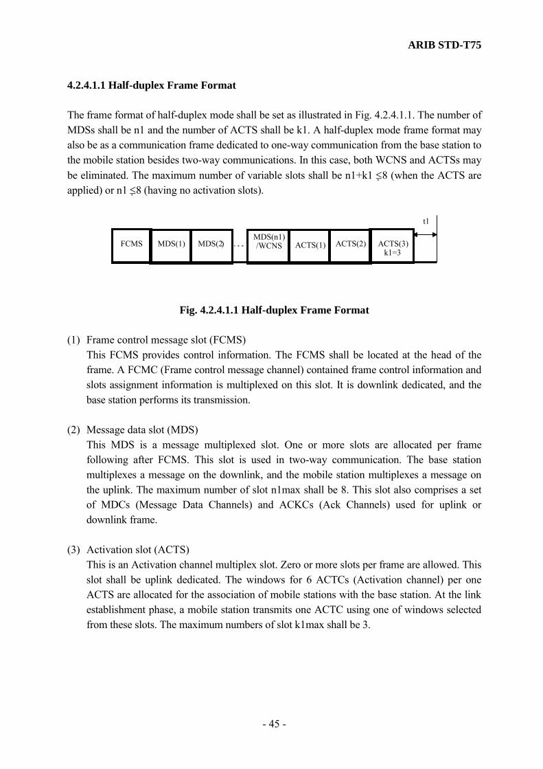
ARIB STD-T75
- 45 -
4.2.4.1.1 Half-duplex Frame Format The frame format of half-duplex mode shall be set as illustrated in Fig. 4.2.4.1.1. The number of MDSs shall be n1 and the number of ACTS shall be k1. A half-duplex mode frame format may also be as a communication frame dedicated to one-way communication from the base station to the mobile station besides two-way communications. In this case, both WCNS and ACTSs may be eliminated. The maximum number of variable slots shall be n1+k1 ≤8 (when the ACTS are applied) or n1 ≤8 (having no activation slots).
t1
MDS(n1)/WCNSMDS(2)MDS(1)FCMS ACTS(2)ACTS(1) ACTS(3)
k1=3
Fig. 4.2.4.1.1 Half-duplex Frame Format
(1) Frame control message slot (FCMS) This FCMS provides control information. The FCMS shall be located at the head of the
frame. A FCMC (Frame control message channel) contained frame control information and slots assignment information is multiplexed on this slot. It is downlink dedicated, and the base station performs its transmission.
(2) Message data slot (MDS) This MDS is a message multiplexed slot. One or more slots are allocated per frame
following after FCMS. This slot is used in two-way communication. The base station multiplexes a message on the downlink, and the mobile station multiplexes a message on the uplink. The maximum number of slot n1max shall be 8. This slot also comprises a set of MDCs (Message Data Channels) and ACKCs (Ack Channels) used for uplink or downlink frame.
(3) Activation slot (ACTS) This is an Activation channel multiplex slot. Zero or more slots per frame are allowed. This
slot shall be uplink dedicated. The windows for 6 ACTCs (Activation channel) per one ACTS are allocated for the association of mobile stations with the base station. At the link establishment phase, a mobile station transmits one ACTC using one of windows selected from these slots. The maximum numbers of slot k1max shall be 3.

ARIB STD-T75
- 46 -
(4) Wireless call number slot (WCNS) The WCNC is multiplexed on this slot. The WCNC contains the peculiar number (call sign) of the mobile station. This slot shall be uplink dedicated, and a mobile station transmits a WCNC on the indication from the base station using the assigned WCNS. In the test equipment, this slot is used as WCNC assigned to the down link. And the test equipment transmits a WCNC on the indication in this slot.
4.2.4.1.2 Full-duplex Mode Frame Format The frame format of full-duplex mode shall be set as illustrated in Fig. 4.2.4.1.2. The frame consists of n2 of MDS and k2 of ACTS with its length variable. A part of message data slot of the uplink is also used as ACTS (Activation slot). The interpreting of attributes of the slot is made by the control information that is multiplexed on the FCMC, and the details are defined in subclause 4.2.4.2.1.5 and 4.2.4.2.1.8. The maximum number of slots, which are variable, in the full-duplex communication frame format shall be n2+k2 ≤ 4.
t1
MDS(3) MDS(n2)MDS(2)
MDS(2)/WCNS
MDS(1)
MDS(1)
FCMS
MDS(n2)//ACTS(k2)
MDS(3)/ /ACTS(1)Up
Link
Down Link
Fig. 4.2.4.1.1 Full-duplex (RSE) Frame Format
(1) Frame control message slot (FCMS) This FCMS provides control information. The FCMS shall be located at the head of the
frame. A FCMC (Frame control message channel) contained frame control information and slots assignment information is multiplexed on this slot. It is downlink dedicated, and the base station performs its transmission.
(2) Message data slot (MDS) This MDS is a message multiplex slot. One or more slots are allocated per frame following
after FCMS. This slot is used in two-way communication. This slot also comprises a set of MDCs (Message Data Channels) and ACKCs (Ack Channels) used for uplink or downlink frame. The base station multiplexes a message on the downlink, and the mobile station multiplexes a message on the uplink. The maximum number of slots n2max shall be 4.

ARIB STD-T75
- 47 -
(3) Activation slot (ACTS) This is an Activation channel multiplex slot. Zero or more slots per frame are allowed. This
slot shall be uplink dedicated. The windows for 6 ACTCs (Activation channel) per one ACTS are allocated for the association of mobile stations with the base station. At the link establishment phase, a mobile station transmits one ACTC using one of windows selected from these slots. The maximum locatable number of slot k2max shall be 3.
(4) Wireless call number slot (WCNS)
The WCNC is multiplexed on this slot. The WCNC contains the peculiar number (call sign) of the mobile station. This slot shall be uplink dedicated, and a mobile station transmits an inherent WCNC on the indication from the base station using the assigned WCNS. In the test equipment, this slot is used as WCNC assigned to the down link. And the test equipment transmits a WCNC on the indication in this slot.
4.2.4.2 Channel types and the relationship between slot types Channel types and the relation with the slot are shown in Fig. 4.2.4.2. The detail of each channel is specified in the following subclause.
FCMS FCMC (Frame Control Message Channel) : down link
MDS MDC (Message Data Channel) : up link, down link
ACKC (Ack Channel) : up link, down link
ACTS ACTC (Activation Channel) : up link
WCNS WCNC (Wireless Call Number Channel) : up link, down link
Fig 4.2.4.2 Configuration of the layer 1 channels and slots
4.2.4.2.1 Frame Control Message Slot (FCMS) The subfield format within an FCMS shall be set as illustrated in Fig. 4.2.4.2.1-1 and Fig. 4.2.4.2.1-2. FCMS contains the FCMC which has frame control information and slot assignment information and, it is transmitted from the base station. The FCMC shall consist of the following subfields: two octets of an information field SIG (Signaling) for the layer 1, one octet of an identification number subfield FID (Fixed Equipment ID) of the base station, one octet of a frame structure information field FSI (Frame Structure identifier), one octet of a

ARIB STD-T75
- 48 -
release timer information field RLT (Release Timer Information field), 7 octets of a service application information field SC (Service Code) of the base station, and a slot control information field SCI (Slot Control Identifier) for allocation of communication slots. The SCI shall consist of one octet of the control information subfield CI (Control Information) and four octets of a link address subfield LID (Link address). The number of assigned slots following after the FCMS (m) shall be defined in the FSI field. Therefore, the number of valid SCIs (n) is equal to m (mmax is equal to n1max) in the half-duplex mode. In the case of full duplex mode, the number of valid SCIs (n) is equal to 2m (nmax is equal to 2mmax). The mobile station can distinguish of the number of slots by interpreting the FSI field. The details of the FSI field are defined in subclause 4.2.4.2.1.5. Two octets (ASK system) or sixteen octets (π/4 shift QPSK system) of a preamble signal PR, four octets of a unique word signal UW1 and two octets of an error check sequence field CRC shall be added to these signals. Guard time t0 and t2 shall be set before and after the FCMC. Furthermore, in the case of π/4 shift QPSK system, the ramp bit (R) of 1 octet length ( 4 symbols) shall be added before a preamble signal PR.
PR SIG FIDUW1 CI(1)
LID(1) CRC t2
FCMC
SCI(1)
28 2
100
41 124 241 17
FSI SC CI(8)
LID(8)
SCI(8)
2 1
(octet)
1
RLTt0
Fig 4.2.4.2.1-1 FCMS format (ASK system)
FSI PR SIG FI
D
UW1 CI(1)
LID(1) CRC t2
FCMC
SCI(1)
111 16
400
4 1 214 4 2 4 1 1 7
SC
CI (8)
LID(8)
SCI(8)
2 1
(Octet)
1
RLTt0
R
1
Fig 4.2.4.2.1-2 FCMS format (π/4 shift QPSK system)
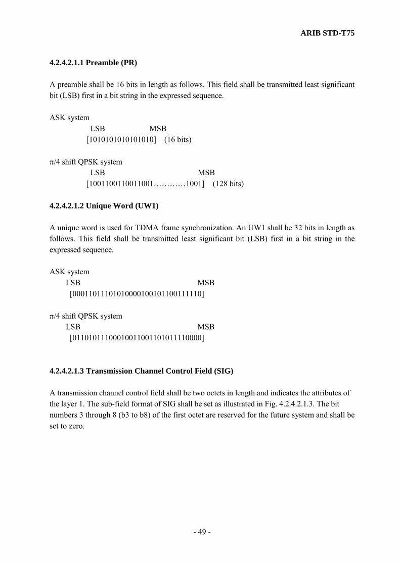
ARIB STD-T75
- 49 -
4.2.4.2.1.1 Preamble (PR) A preamble shall be 16 bits in length as follows. This field shall be transmitted least significant bit (LSB) first in a bit string in the expressed sequence. ASK system LSB MSB [1010101010101010] (16 bits) π/4 shift QPSK system LSB MSB [1001100110011001…………1001] (128 bits) 4.2.4.2.1.2 Unique Word (UW1) A unique word is used for TDMA frame synchronization. An UW1 shall be 32 bits in length as follows. This field shall be transmitted least significant bit (LSB) first in a bit string in the expressed sequence. ASK system LSB MSB [00011011101010000100101100111110] π/4 shift QPSK system LSB MSB [01101011100010011001101011110000] 4.2.4.2.1.3 Transmission Channel Control Field (SIG) A transmission channel control field shall be two octets in length and indicates the attributes of the layer 1. The sub-field format of SIG shall be set as illustrated in Fig. 4.2.4.2.1.3. The bit numbers 3 through 8 (b3 to b8) of the first octet are reserved for the future system and shall be set to zero.
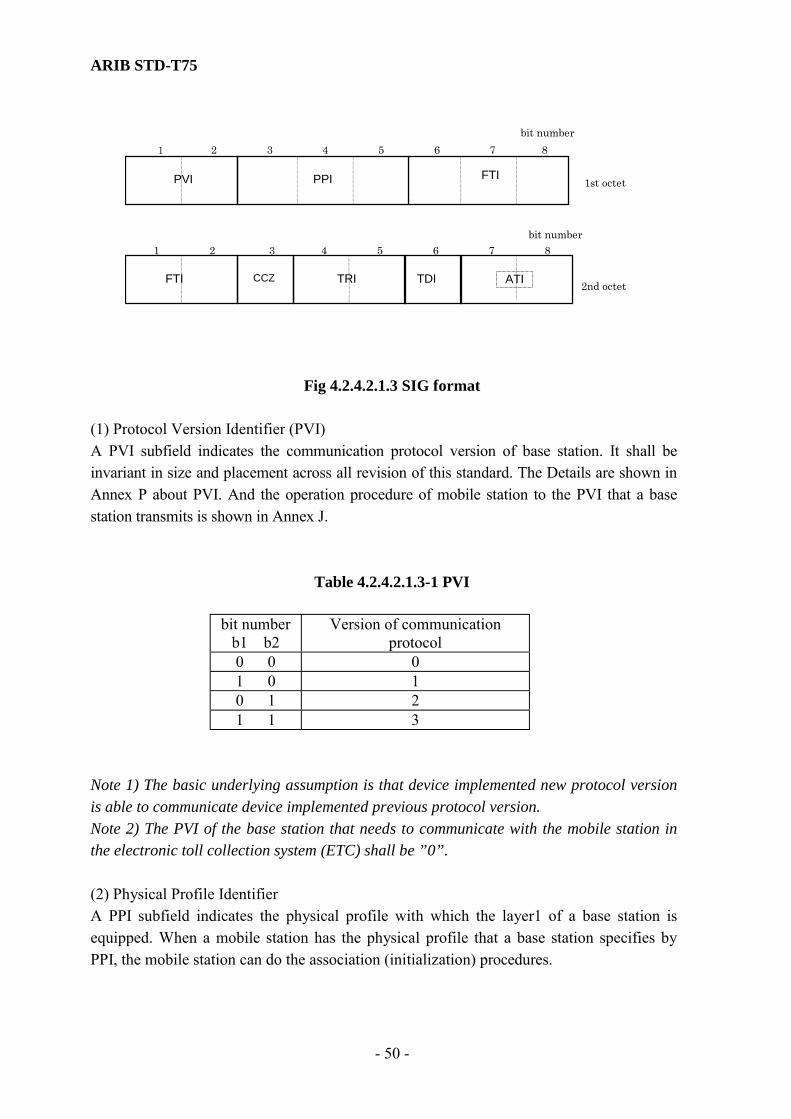
ARIB STD-T75
- 50 -
TDI ATIFTI CCZ
1 2 3 4 5 6 7 8bit number
1st octet
2nd octet
87654 3 2 1 bit number
PVI
TRI
FTIPPI
Fig 4.2.4.2.1.3 SIG format
(1) Protocol Version Identifier (PVI) A PVI subfield indicates the communication protocol version of base station. It shall be invariant in size and placement across all revision of this standard. The Details are shown in Annex P about PVI. And the operation procedure of mobile station to the PVI that a base station transmits is shown in Annex J.
Table 4.2.4.2.1.3-1 PVI
bit number b1 b2
Version of communication protocol
0 0 0 1 0 1 0 1 2 1 1 3
Note 1) The basic underlying assumption is that device implemented new protocol version is able to communicate device implemented previous protocol version. Note 2) The PVI of the base station that needs to communicate with the mobile station in the electronic toll collection system (ETC) shall be ”0”. (2) Physical Profile Identifier A PPI subfield indicates the physical profile with which the layer1 of a base station is equipped. When a mobile station has the physical profile that a base station specifies by PPI, the mobile station can do the association (initialization) procedures.

ARIB STD-T75
- 51 -
A base station and a mobile station shall perform communication by the physical profile specified by PPI. This is effective between the communication transaction end including the association (initialization) procedures of layer7. Set up the physical profile of PPI in consideration of the compatibility of the communication profile to which the physical profile belongs. The Details are shown in Annex P about PPI.
Table 4.2.4.2.1.3-2 PPI
bit number b3 b4 b5
Value of Physical Profile Identifier
0 0 0 0 1 0 0 1 0 1 0 2 1 1 0 3 0 0 1 Reserved 1 0 1 Reserved 0 1 1 Reserved 1 1 1 Reserved
(3) Operation mode (Frequency Type) Identifier (FTI) A FTI subfield indicates the Frequency Type of the base station. The FTI subfield of 1st octet (b6, b7, b8) and the FTI subfield of 2nd octet (b1, b2) shall be set as shown in Table 4.2.4.2.1.3-3. Others codes are reserved for the future system. Note) Refer to Table 3.1 in subclause 3.4.1.

ARIB STD-T75
- 52 -
Table 4.2.4.2.1.3-3 FTI (Operation Mode)
Radio Frequency Bit number b6 b7 b7 b1 b2 (1st octet) (2nd octet)
Down link Up link
Remarks
0 0 0 0 0 5795MHz 5835MHz ex. Electronic Toll
Collection 0 0 0 1 1 5805MHz 5845MHz ex. Electronic
Toll Collection
0 0 0 0 1 5800MHz 5840MHz 0 0 1 1 0 5775MHz 5815MHz 0 1 0 1 0 5780MHz 5820MHz 0 1 1 1 0 5785MHz 5825MHz 1 0 0 1 0 5790MHz 5830MHz
(4) Continuous Communication Zone (CCZ) This bit number 3 (b3) in 2nd octet indicates the allocation of different base stations (different FIDs) in the traveling direction. In the case where these base stations are linked to each other in any way, the CCZ may be set to “1”. If it indicates usual stand-alone type communication zone, the CCZ shall be set to “0”. In the case where a TRI is “01” or “10” (TRI is not equal “00” or “11”), it is specific to exceptional communication zone and expects particular processing in the layer 2. This exceptional communication zone is specified with subclause 4.2.4.2.1.3(4) (5) Transmitter / Receiver Identifier (TRI) A Transmitter/Receiver Identifier (TRI) is the identifier for the distinction between base stations allocated in the traveling direction of the continuous communication zone. The subfield of TRI shall be set as shown in Table 4.2.4.2.1.3-4. In the case where the TRI is “00”, the definition of the CCZ=”1” shall be ignored. The code “11” is reserved for future systems. In the case where the TRI is “10” or “01”and of CCZ= “1”, the transmitter / receiver are defined by TRI.

ARIB STD-T75
- 53 -
Table 4.2.4.2.1.3-4 TRI
Bit number b4 b5
Description
0 0 stand alone 1 0 Front(first) transmitter/receiver in the traveling direction 0 1 Rear(2nd) transmitter/receiver in the traveling direction 1 1 Reserved
In the case of CCZ= “0”, TRI=“01” or “10”: One base station has two transmitter / receivers (antennas) located in the traveling direction and performs transmission / reception frames in communication zone of each transmitter / receiver (antenna). If the frame is a transmission / reception frame from a transmitter / receiver that is located relatively in the front compared to another transmitter/receiver in the traveling direction, the TRI shall be set to “10”. If a transmission / reception frame with a transmitter / receiver that is located relatively in the rear compared to another transmitter/receiver in the traveling direction, the TRI shall be set to “01”. The codes “01” and “10” should be used as a pair of codes. In the case of the TDI=“1”, it indicates the communication frame is transmitted or received from each transmitter/receiver (base station) in time division. Note 1) The underlying assumption is that two transmitter/receivers designated TRI=“01” or “10” are allocated close to each other and a chain of application transactions is performed while a mobile station communicates with the transmitter / receiver (antennas) passing the each communication zone in sequence. In the case of CCZ=“1”, TRI=”01” or “10”: Two different base stations are allocated in the traveling direction and they each perform communication transactions in the communication zones by themselves. If the frame with a base station (transmitter / receiver) is located relatively in the front compared to another base station (transmitter / receiver) in the traveling direction, the TRI shall be set to “10”. If the frame with a base station (transmitter / receiver) is located relatively in the rear compared to another the base station (transmitter / receiver) in the traveling direction, the TRI shall be set to “01”. The codes of “01” and “10” should be used as a pair of codes. In the case of the TDI= “1”, it indicates the communication frame is transmitted or received from each base station in time division. Note 2) The underlying assumption is that different base stations defined TRI=“01” or “10” are allocated close to each other. And a chain of application transaction is performed while a mobile station is provided one application from the first base station, hereafter provided

ARIB STD-T75
- 54 -
another application from the 2nd base station passing the each communication zone in sequence. Note 3) Relation between the CCZ and the TDI and communication environment is indicated in Annex B for reference only. (6) Time Division Identifier (TDI) The bit number 6 (b6) is a Time Division Identifier (TDI). This identifier indicates whether or not the base stations transmit / receive of frames in time division. When communication transaction is performed in time division, the TDI shall be set to “1”. When communication transaction is not performed in time division, the TDI shall be set to “0”. (7) Area type identifier (ATI) This subfield indicates the type of communication area (zone) (transmission output power) of the base station. If it indicates a small area communication zone, the ATI subfield (b7, b8) shall be set to “00”. If it indicates a wide area communication zone, the ATI shall be set to “11” as shown in Table 4.2.4.2.1.3-5. When ATI is set to "10", it specifies employment with a test equipment. Others codes are reserved for future systems.
Table 4.2.4.2.1.3-5 ATI Communication Area Modes
Bit number b7 b8
Description
0 0 Class 1 (Small area zone) 1 1 Class 2 (Wide area zone) 1 0 Test equipment Others Reserved
4.2.4.2.1.4 Fixed Equipment ID (FID) The length of the fixed equipment ID shall be one octet. The FID number shall be generated by modulus 256. The establishment of the FID is outside of the scope of this standard. The FID is indicated in Annex M for reference only. 4.2.4.2.1.5 Frame Structure Identifier (FSI) The subfield format of a Frame Structure Identifier (FSI) shall be set as illustrated in Fig. 4.2.4.2.1.5. The bit numbers 5 through 8 (b5-b8) are reserved for future systems and shall be
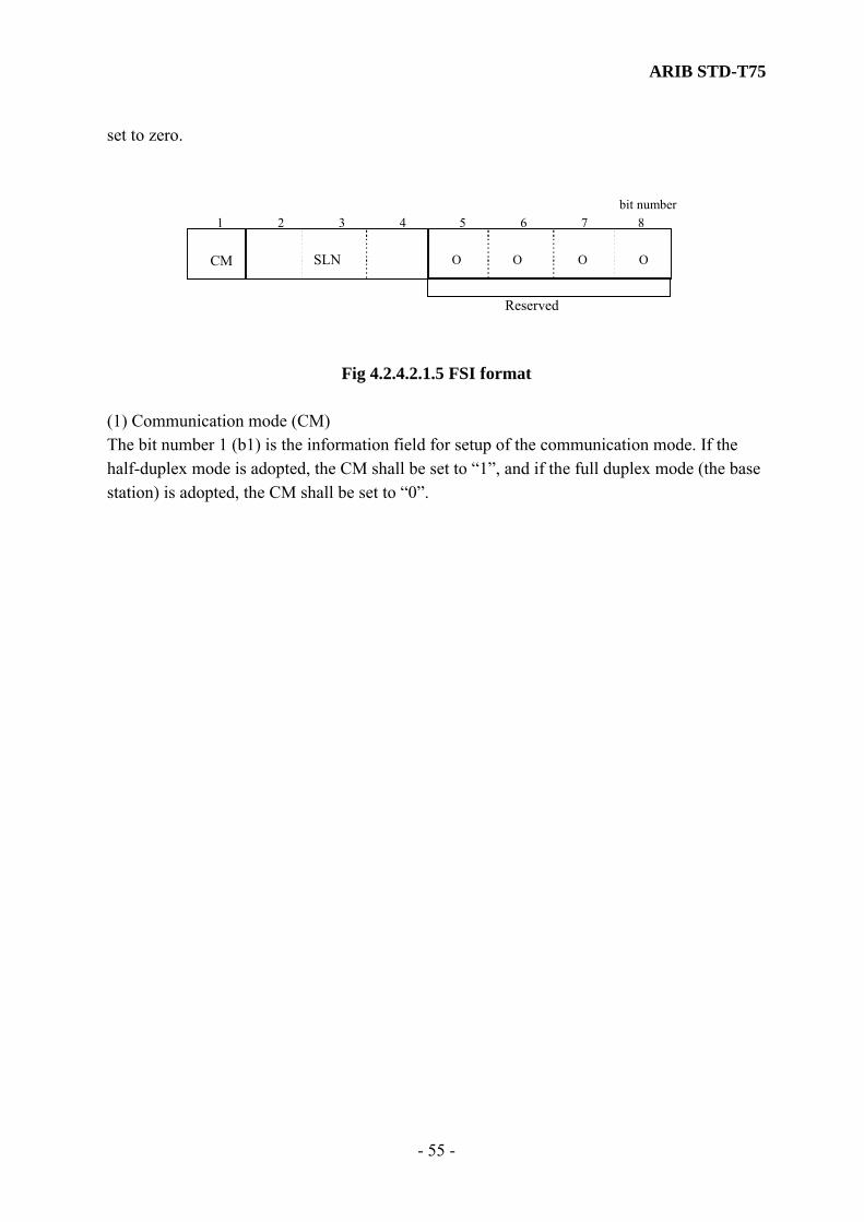
ARIB STD-T75
- 55 -
set to zero.
Reserved
1 2 3 4 5 6 7 8bit number
CM SLN O O OO
Fig 4.2.4.2.1.5 FSI format
(1) Communication mode (CM) The bit number 1 (b1) is the information field for setup of the communication mode. If the half-duplex mode is adopted, the CM shall be set to “1”, and if the full duplex mode (the base station) is adopted, the CM shall be set to “0”.
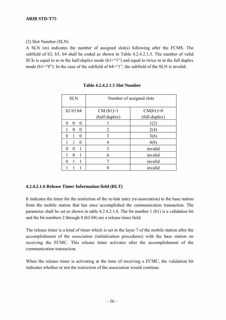
ARIB STD-T75
- 56 -
(2) Slot Number (SLN) A SLN (m) indicates the number of assigned slot(s) following after the FCMS. The subfield of b2, b3, b4 shall be coded as shown in Table 4.2.4.2.1.5. The number of valid SCIs is equal to m in the half-duplex mode (b1=“1”) and equal to twice m in the full duplex mode (b1=“0”). In the case of the subfield of b4=“1”, the subfield of the SLN is invalid.
Table 4.2.4.2.1.5 Slot Number
SLN
Number of assigned slots
b2 b3 b4 CM (b1)=1 (half-duplex)
CM(b1)=0 (full-duplex)
0 0 0 1 1(2) 1 0 0 2 2(4) 0 1 0 3 3(6) 1 1 0 4 4(8) 0 0 1 5 invalid 1 0 1 6 invalid 0 1 1 7 invalid 1 1 1 8 invalid
4.2.4.2.1.6 Release Timer Information field (RLT) It indicates the timer for the restriction of the re-link entry (re-association) to the base station from the mobile station that has once accomplished the communication transaction. The parameter shall be set as shown in table 4.2.4.2.1.6. The bit number 1 (b1) is a validation bit and the bit numbers 2 through 8 (b2-b8) are a release timer field. The release timer is a kind of timer which is set in the layer 7 of the mobile station after the accomplishment of the association (initialization procedures) with the base station on receiving the FCMC. This release timer activates after the accomplishment of the communication transaction. When the release timer is activating at the time of receiving a FCMC, the validation bit indicates whether or not the restriction of the association would continue.
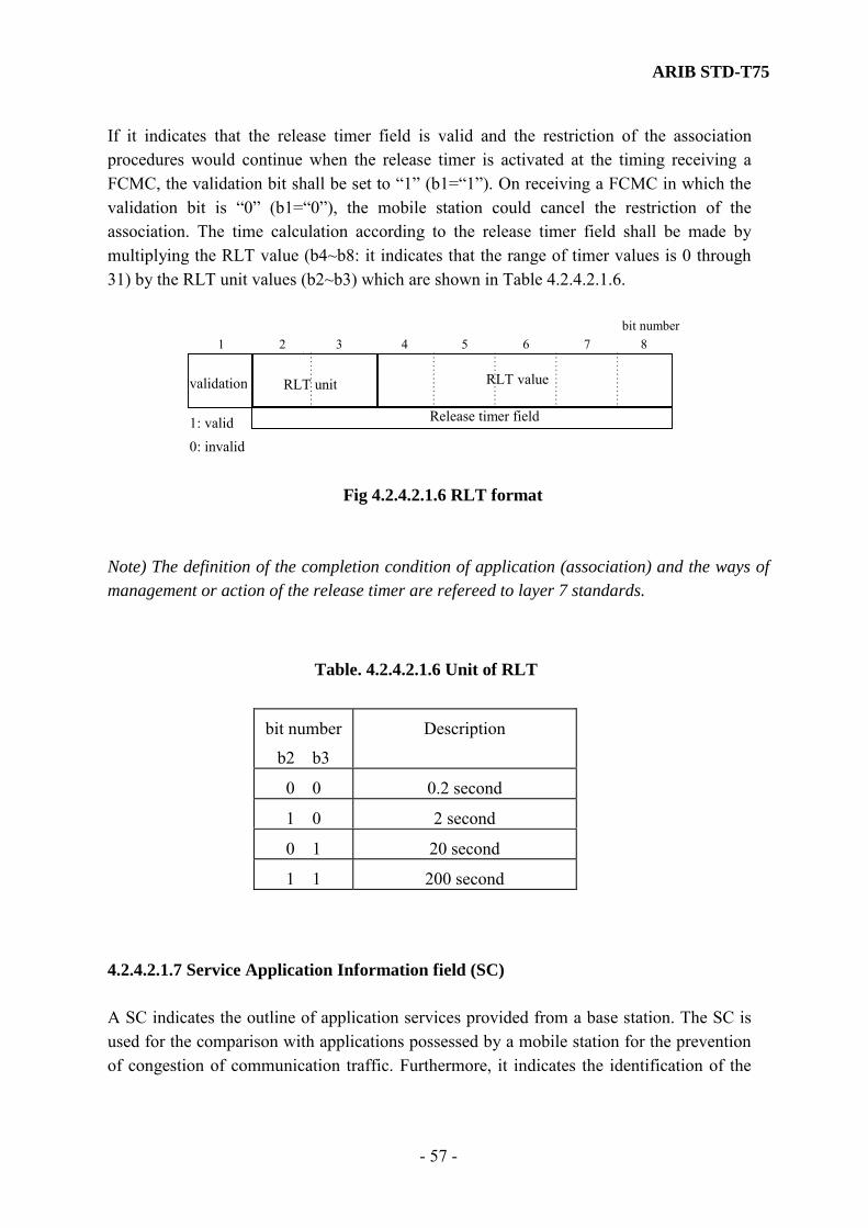
ARIB STD-T75
- 57 -
If it indicates that the release timer field is valid and the restriction of the association procedures would continue when the release timer is activated at the timing receiving a FCMC, the validation bit shall be set to “1” (b1=“1”). On receiving a FCMC in which the validation bit is “0” (b1=“0”), the mobile station could cancel the restriction of the association. The time calculation according to the release timer field shall be made by multiplying the RLT value (b4~b8: it indicates that the range of timer values is 0 through 31) by the RLT unit values (b2~b3) which are shown in Table 4.2.4.2.1.6.
Release timer field
1 2 3 4 5 6 7 8bit number
validation RLT unit
1: valid0: invalid
RLT value
Fig 4.2.4.2.1.6 RLT format
Note) The definition of the completion condition of application (association) and the ways of management or action of the release timer are refereed to layer 7 standards.
4.2.4.2.1.7 Service Application Information field (SC) A SC indicates the outline of application services provided from a base station. The SC is used for the comparison with applications possessed by a mobile station for the prevention of congestion of communication traffic. Furthermore, it indicates the identification of the
Table. 4.2.4.2.1.6 Unit of RLT
bit number
b2 b3
Description
0 0 0.2 second
1 0 2 second
0 1 20 second
1 1 200 second

ARIB STD-T75
- 58 -
association procedures (a normal association (initialization) procedures or a simplified association (initialization) procedures) in the layer 7. The field format shall consist of 1 octet of the initialization mode identifier field (IMI) and 6 octets of the application identifier field (API) as shown in Fig. 4.2.4.2.1.7.1(a). If it indicates that the layer 7 of the base station provides a normal association (initialization) procedures, the IMI bit (b1 of the first octet) shall be set to “0”. If it indicates that the layer 7 of the base station provides a simplified association (initialization) procedures, the IMI (b1 of first octet) shall be set to “1” as shown in Fig. 4.2.4.2.1.7.1(b).
IMI
7octets
octet number1 2 3 4 5 6 7
API
IMI
87654321
0:normal procedure1:simplfied procedure
Reserved
(a) Subfield format of SC
0 00 0 0 0 0
(b) Subfield format of IMI
bit number
Fig. 4.2.4.2.1.7.1 SC Format (1)
For reference, the example of the construction of the SC field is shown in Fig. 4.2.4.2.1.7.2 This figure shows the configuration of the SC in both cases of a normal association (initialization) procedures and a simplified association (initialization) procedures. Hence, APIs are application identifiers specified by applications and EIDs are element identifiers specified according to an AID. Either an AID field or an EID field has the length of 7 bits. The first bit of each EID or AID is an extender. In the case where a following octet is valid, the extender is set to “0”. In the case where a following octet is invalid, the extender is set to “1”. However, EIDs are not definitely specified in general, when the simplified association (initialization) procedures is adopted, it assumes that a specified EID is defined common in a base station and mobile stations that have the function of this procedures. In the case where there is no matched application between the base station and the mobile station, the association procedure is not performed so as to prevent congestion of communication traffic.

ARIB STD-T75
- 59 -
Note 1) Definition of the AIDs and EIDs used for API are indicated in Annex I. Note2) When the AID is stored in API field, the bit field by the side of MSB should be used. And the bit by the side of other LSB should be set as “0”. When the AID is a 5bits definition, numbers 4-8 (b4-b8) should be used. And the numbers 2 and 3 (b2, b3) should be set to “0”. In addition, the bit number 1 (b1) is an extension. Note3) When the AID is not set up by the test communication etc., the bit numbers 2 and 3 of API of SC should be set to “11”. The AID value of the octet set up like this is invalid. Therefore, the processing should not be performed to a receive side. In this case, it is recommend that the value of the octet is set to “FF” (the AID is invalid and there is no AID to continue.)
IMI
LSB MSB
octet number1 2 3 4 5 6 7
Extender
7654321
0: continued1: not continued
Application Identifier(AID, EID)
(a) Field format of the SC in the normal association (initialization) mode
AID(1)00--00
reserved
(c) Field format of API
00--00AID(2) AID(3) AID(4)
APIreserved
IMI
octet number1 2 3 4 5 6 7
(b) Field format of the SC in the simplified association (initialization)
mode
AID(1)00--00
reserved00--00
EID(2) reservedAttribute
Information00--00
reserved
Fig. 4.2.4.2.1.7.2 SC Format (2) 4.2.4.2.1.8 Slot Control Identifier (SCI) A SCI shall consist of one octet of the control information subfield CI as slot assignment information and 4 octets of the link address subfield LID. If the communication mode is the half-duplex mode, the slots, which follow FCMS, shall
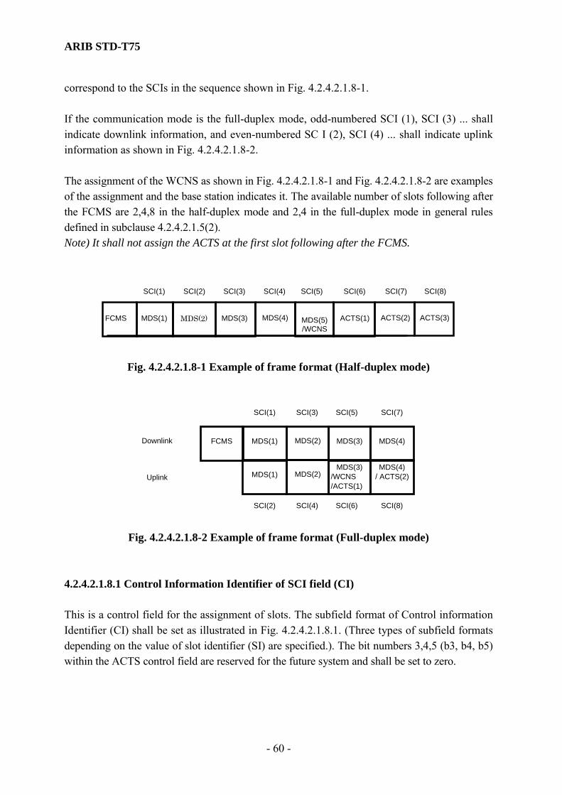
ARIB STD-T75
- 60 -
correspond to the SCIs in the sequence shown in Fig. 4.2.4.2.1.8-1. If the communication mode is the full-duplex mode, odd-numbered SCI (1), SCI (3) ... shall indicate downlink information, and even-numbered SC I (2), SCI (4) ... shall indicate uplink information as shown in Fig. 4.2.4.2.1.8-2. The assignment of the WCNS as shown in Fig. 4.2.4.2.1.8-1 and Fig. 4.2.4.2.1.8-2 are examples of the assignment and the base station indicates it. The available number of slots following after the FCMS are 2,4,8 in the half-duplex mode and 2,4 in the full-duplex mode in general rules defined in subclause 4.2.4.2.1.5(2). Note) It shall not assign the ACTS at the first slot following after the FCMS.
MDS(4)MDS(3)MDS(2)
SCI(6) SCI(7)SCI(4)SCI(3) SCI(5)SCI(2)SCI(1)
MDS(1)FCMS ACTS(2)ACTS(1)MDS(5)/WCNS
ACTS(3)
SCI(8)
Fig. 4.2.4.2.1.8-1 Example of frame format (Half-duplex mode)
MDS(2)MDS(1)FCMS
SCI(7)SCI(3)SCI(1) SCI(5)
MDS(4)MDS(3)
MDS(2)MDS(1)MDS(4)
/ ACTS(2)MDS(3)
/WCNS/ACTS(1)
SCI(8)SCI(4)SCI(2) SCI(6)
Uplink
Downlink
Fig. 4.2.4.2.1.8-2 Example of frame format (Full-duplex mode)
4.2.4.2.1.8.1 Control Information Identifier of SCI field (CI) This is a control field for the assignment of slots. The subfield format of Control information Identifier (CI) shall be set as illustrated in Fig. 4.2.4.2.1.8.1. (Three types of subfield formats depending on the value of slot identifier (SI) are specified.). The bit numbers 3,4,5 (b3, b4, b5) within the ACTS control field are reserved for the future system and shall be set to zero.
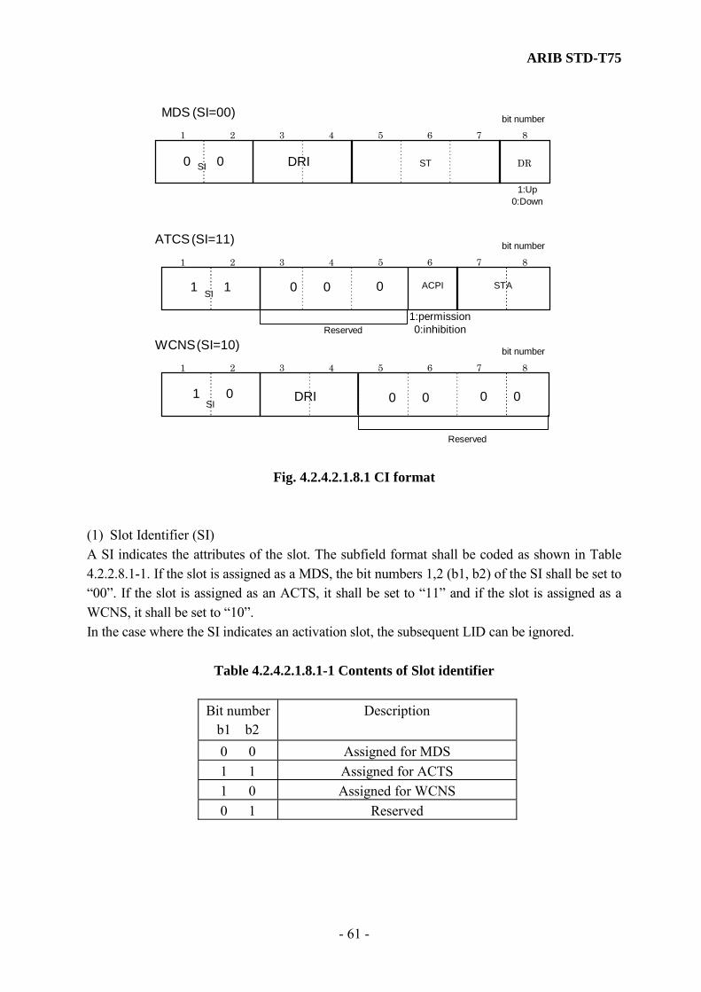
ARIB STD-T75
- 61 -
1: Up 0: Down
SI ST DR
SIACPI STA
ATCS (SI=11)
MDS (SI=00)
1:permission 0:inhibitionReserved
1 2 3 4 5 6 7 8 bit number
1 2 3 4 5 6 7 8 bit number
SI
WCNS (SI=10)
1 2 3 4 5 6 7 8 bit number
Reserved
1 0
1 1
0 0 DRI
0 0 0
DRI 0 0 0 0
Fig. 4.2.4.2.1.8.1 CI format
(1) Slot Identifier (SI) A SI indicates the attributes of the slot. The subfield format shall be coded as shown in Table 4.2.2.8.1-1. If the slot is assigned as a MDS, the bit numbers 1,2 (b1, b2) of the SI shall be set to “00”. If the slot is assigned as an ACTS, it shall be set to “11” and if the slot is assigned as a WCNS, it shall be set to “10”. In the case where the SI indicates an activation slot, the subsequent LID can be ignored.
Table 4.2.4.2.1.8.1-1 Contents of Slot identifier
Bit number b1 b2
Description
0 0 Assigned for MDS 1 1 Assigned for ACTS 1 0 Assigned for WCNS 0 1 Reserved
ARIB STD-T75
- 62 -
(2) Data Rate Identifier (DRI) A DRI indicates the signal transmission speed that discriminates the data transmission speed of MDC and WCNC. This subfield format shall be coded as shown in Table 4.2.4.2.1.8.1-2. In the case of ASK system of bit rate 1024kbps, the bit numbers 3 and 4 should be set to “00”. In case of π/4 shift QPSK system of bit rate 4096kbps, those bits shall be set to “11”. And in case of others, it is the reservation of the future for system extension. When two or more MDCs of the same link address are assigned within the same frame, all MDCs should be the same signal transmission speed (bit rate). (3) Status of data field (ST) The bit numbers 5,6,7 (b5, b6, b7) shall be coded as shown in Table 4.2.4.2.1.8.1-2. The ST indicates the contents of the MDC. If it indicates that the MDC is a normal data channel, the bit numbers 5,6,7 (b5, b6, b7) of the ST shall be set to “111”. If it indicates that the MDC is an empty data channel, it shall be set to “011”. If it indicates that the MDC is an idle signal channel, it shall be set to “100”, and if it indicates that the MDC is a data channel assigned with priority, it shall be set to “000”. For the idle signal channel, all of the LPDU fields of the MDC shall take the value of “0”. For the non-data channel, the LID of the SCI and the data of corresponding MDC are invalid.
Table 4.2.4.2.1.8.1-2 ST
Bit number
b5 b6 b7 Description
1 1 1 Normal data channel 0 1 1 empty data channel 1 0 1 Reserved 0 0 1 Reserved 1 1 0 Reserved 0 1 0 Reserved 1 0 0 Idle signal channel 0 0 0 Data channel assigned with
priority Note) Refer to (5) in subclause 4.3.3.5.2.2.2.1 for the control procedure of a mobile station when ST specifies an idol channel.

ARIB STD-T75
- 63 -
(4) Direction (DR) A DR bit indicates the direction of transmission of the MDC. If the transmission is made in the uplink direction (from the mobile station to the base station), the DR shall be set to “1”, and if transmission is made in the downlink direction (from the base station to the mobile station), the DR shall be set to “0”. (5) Activation possibility identifier (ACPI) An ACPI bit is information field of ACTS transmission operation. If the base station allows mobile stations to make an attempt to associate with the base station communication link by transmitting an ACTC, the ACPI shall be set to “1”. If the transmission of the ACTC is inhibited, the ACPI shall be set to “0”. This indication shall be set to the same value over ACTSs within one frame.
Table 4.2.4.2.1.8.1-3 STA
Bit numberb7 b8
Activation probability
0 0 100 - 50% 1 0 Less than 50 - 25% 0 1 Less than 25 - 12.5% 1 1 less than 12.5%
(6) State of acceptance of ACTCs (STA) The subfield of STA (b7, b8) broadcasts the activation (acceptance) state of the ACTC at the base station. It prevents deadlocking of the traffic caused by excessive associations (link entries). Table 4.2.4.2.1.8.1-3 indicates the relationship between the STA and the activation (acceptance of ACTCs) probability at the base station. It indicates that the smaller the value of start probability, the larger the traffic. This indication shall be set to the same value over ACTSs within one frame. 4.2.4.2.1.8.2 Link Address Field (LID) Link address LID is available in three types. (1) A private link address for the point to point two-way communication between a mobile
station and a base station.

ARIB STD-T75
- 64 -
(2) A broadcast link address for the transmission of data, etc., in broadcast type from a base station to plural mobile stations.
(3) A multicast (group) link address for the transmission/reception of data, etc., from a base station to plural groups of mobile stations.
This LID shall be a link address that is common to the base station and the mobile station, and the same link address shall be used in the layer 1, layer 2 (the MAC sublayer and the LLC sublayer) and the layer 7 for identification of the service access points. The same LID shall be used while the communication is continuously performed. Establishment of numbers to LIDs is described in subclause 4.3.2. The subfield format of LID shall be set as illustrated in Fig. 4.2.4.2.1.8.2. The bit number 1 (b1) of each octet shall use an extender. When the first bit of octet is “0”, the subsequent octet shall be an extension of the address field. An octet having the address field “1” in the bit number 1 (b1) shall terminate. However, since the SCI is defined in fixed length of five octets, LID is of fixed length of four octets (32 bits). Therefore, the first bit (b1) of the 2nd and 3rd octet is always “0”. Where the first octet only is valid (first bit (b1) of first octet is “1”), the other octets cannot be deleted. All subfield of the other octets shall be set “0” in this case.
LSB
Extender
1 2 3 4 5 6 7 8bit number
1st octet
0 2nd octet
Link address field
Link address field
1 2 3 4 5 6 7 8bit number
0 3rd octet
Link address field
1 2 3 4 5 6 7 8bit number
Extender4th octet
Link address field
1 2 3 4 5 6 7 8bit number
7MSB
Fig. 4.2.4.2.1.8.2 LID format

ARIB STD-T75
- 65 -
The 1st octet address of eight “1” bits (“11111111”) shall be reserved as the broadcast link address. All single octet addresses except for the broadcast link address (“1xxx xxxx”) shall be reserved for the multicast (group) link address. Note 1) A private link address shall be used the 28 bits of bit No. 2 - 8 of four octets and the first bit (b1) of 4th octet shall be set to “1”.Moreover, the generation method of a private link address is specified in Annex N. Note 2) Allocation of multicast (group) link addresses are outside of the scope of this standard. Moreover, they are specified in Annex O. 4.2.4.2.1.9 Cyclic Redundancy Error Check Sequence (CRC) A 16-bits CRC code is used for data check sequence for error detection purposes. The contents of the FCMC field excluding the PR and the UW1 field shall be contained in the calculation of the FCMC field. The generator polynomial shall be as follows.
Generator polynomial: X16+X12 + X 5+1 4.2.4.2.2 Message Data Slot (MDS) A format of MDS according to the contents of Data Rate Identifier (DRI) specified to Table 4.2.4.2.1.8.1-2 is shown in Fig 4.2.4.2.2-1 and Fig 4.2.4.2.2-2. The MDS shall consist of the following subfield format: a message data channel (MDC) for data transmission and an acknowledgment channel (ACKC) that indicates the transmission originating station whether or not the received the MDC was correct. The guard times t3 and t4 shall set before and after the ACKC.
AIUW2PR MAC LPDU t4UW2 PRCRC CRCt3
MDC ACKC
2 1122 2 65 Octet
100
2 22 91
Fig. 4.2.4.2.2-1 MDS format (in case of ASK system (1024kbps))

ARIB STD-T75
- 66 -
AIUW2APR (MAC)
(2)
(LPDU)
(193)
t4 UW2B PR(CRC)
(2)
CRC
t3
MDC ACKC
16 12 Octet
400
16 2 2 43 1
R
1
R
244.25
73.75
Data scramble range *1
BCH coding range
Data scramble range
*1: shows the data length of MPDU.
Fig. 4.2.4.2.2-2 MDS format (in case of π/4 shift QPSK system (4096kbps))
4.2.4.2.2.1 Message Data Channel (MDC) (1) ASK system The subfield format within the message data channel (MDC) shall be set as illustrated in Fig. 4.2.4.2.2.1-1. The MDC shall contain an LPDU of 65 octets, a MAC control field (MAC) of two octets and a preamble signal PR, a unique word signal UW2 and a CRC code. Each length of field is 2 octets. The LPDU, which is delivered from the LLC sublayer, should be have been aligned in octet units, and unaligned data shall be discarded. The LPDU having a length of over 65 octets shall be fragmented into 65-octet units in the MAC sublayer, and will be transmitted using plural frames. In the case where the data length is less than 65 octets, zeros shall be added in the MAC sublayer up to 65 octets, and the data is a unit of 65 octets. Furthermore, the data scrambling (simple encryption system) showed in subclause 4.2.6 should be adapted to the LPDU and CRC. The LPDU has an LLC control field and an LSDU (link service data unit). The format of the LLC control field is specified in detail in subclause 4.3.4.4.1. The PR, the UW2 and the CRC code that each length of field is 2 octets are further added to these signals, and transmission is made in the physical medium channel in the layer 1. In the case of where an LPDU is fragmented, the LLC field is only contained in the first MSDU.

ARIB STD-T75
- 67 -
PR UW2 LLC
LPDU
LSDU CRC
2 2 2 2 1 64
MAC
Octet
Data Scramble (Simple encryption system) range
control
Fig. 4.2.4.2.2.1-1 MDC format (ASK system) (2) π/4 shift QPSK system The subfield format within the message data channel (MDC) shall be set as illustrated in Fig. 4.2.4.2.2.1-2. The MDC shall contain a LPDU of 193 octets, a MAC control field (MAC) of two octets, a ramp bit, and a preamble signal PR of 16 octets, a unique word signal UW2B of 2 octets and a CRC code of 2 octets. The encryption scramble (simple encryption system in subclause 4.2.6) process shall be preformed to a LPDU and a CRC field. Then, BCH error correction processing shall be performed to a MAC and the encryption scramble (simple encryption system) field. Furthermore, the data scramble (subclause 4.2.6 prescribes) processing shall be performed to this “244 octets + 2 bits” field. This processing procedure is shown in Fig 4.2.4.2.2.1-2. The LPDU, which is delivered from the LLC sublayer, should be have been aligned in octet units, and unaligned data shall be discarded. The LPDU having a length of over 193 octets shall be fragmented into 193 octet units in the MAC sublayer, and will be transmitted using plural frames. In the case where the data length is less than 193 octets, zeros shall be added in the MAC sublayer up to 193 octets, and the data is a unit of 193 octets. Furthermore, the data scrambling (simple encryption system) showed in subclause 4.2.6 should be adapted to the LPDU and CRC. The LPDU has an LLC control field and an LSDU (link service data unit). The format of the LLC control field is specified in detail in subclause 4.3.4.4.1. The ramp bit of 1 octet, the PR of 16 octets, the UW2B of 2 octets and the CRC code of 2 octets are further added to these signals, and transmission is made in the physical medium channel in the layer 1. In the case of where an LPDU is fragmented, the LLC field is only contained in the first MSDU.

ARIB STD-T75
- 68 -
MAC LSDU CRCLLC
MAC LSDULLC
control
MAC LSDU CRC
LLC
Divided into 31block (51bits )
FilllBits
PR UW2B
12 bits BCH is added to each block
2 1 1922 (Octet)
5 bits ”01001”
244 octets + 2 bits R,PR and UW are added
16 2
Tail Bit 1bit ”0”
Data scramble range
“0011 1101 0100 1100”
1
R
LPDU
control
control
Data scramble (simple encryption system)
Fig. 4.2.4.2.2.1-2 MDC format (π/4 shift QPSK system) 4.2.4.2.2.1.1 Preamble (PR) (1) ASK system A preamble shall be 16 bits in length as follows. This field shall be transmitted least significant bit (LSB) first in a bit string in the expressed sequence. LSB MSB [1010101010101010] (2) π/4 shift QPSK system A preamble shall be 128 bits in length as follows. This field shall be transmitted least significant bit (LSB) first in a bit string in the expressed sequence.
LSB MSB [10011001……1001]
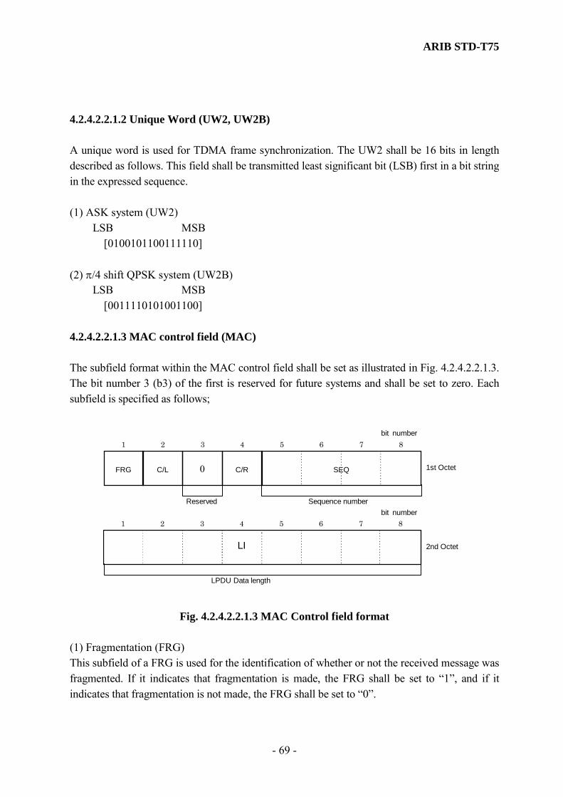
ARIB STD-T75
- 69 -
4.2.4.2.2.1.2 Unique Word (UW2, UW2B) A unique word is used for TDMA frame synchronization. The UW2 shall be 16 bits in length described as follows. This field shall be transmitted least significant bit (LSB) first in a bit string in the expressed sequence. (1) ASK system (UW2) LSB MSB [0100101100111110] (2) π/4 shift QPSK system (UW2B) LSB MSB [0011110101001100] 4.2.4.2.2.1.3 MAC control field (MAC) The subfield format within the MAC control field shall be set as illustrated in Fig. 4.2.4.2.2.1.3. The bit number 3 (b3) of the first is reserved for future systems and shall be set to zero. Each subfield is specified as follows;
Reserved Sequence number
SEQC/R0 C/LFRG
1 2 3 4 5 6 7 8 bit number
LPDU Data length
2nd Octet
1st Octet
LI
1 2 3 4 5 6 7 8 bit number
Fig. 4.2.4.2.2.1.3 MAC Control field format
(1) Fragmentation (FRG) This subfield of a FRG is used for the identification of whether or not the received message was fragmented. If it indicates that fragmentation is made, the FRG shall be set to “1”, and if it indicates that fragmentation is not made, the FRG shall be set to “0”.

ARIB STD-T75
- 70 -
(2) Continuous/Last (C/L) A C/L bit is used for identification of whether or not a message is continued after the received message. If it indicates that the MDC to be transmitted continuously occurs, the C/L shall be set to “1”, and if it indicates that the corresponding MDC is the last MDC, the C/L shall be set to “0”. If the data (LPDU) transmission is performed using one MDC, it shall be set to “0”. (3) Command/Response (C/R) The bit number 4 (b4) of the 1st octet is command/response identifier of an LPDU. Where the LPDU is a command LPDU, the b4 shall be set to “0” and where the LPDU is a response LPDU, the b4 shall be set to “1” (4) Sequence Number (SEQ) The bit numbers 5 through 8 (b5, b6, b7, b8) of the 1st octet shall indicate the sequence number that indicates fragmented data transmission sequence. The sequence number SEQ shall be created by modulus 16. This SEQ is used to prevent receipt of the duplicated message and also make the fragmentation / de-fragmentation of data in the MAC sublayer. The least significant bit shall be b5. (5) Length indicator information field of LPDU (LI) The subfield of LI shall indicate valid data length of LPDU. The unit of L1 shall be octet. 4.2.4.2.2.1.4 Cyclic Redundancy Error Check Sequence (CRC) A 16-bit CRC code shall be used for data check sequence for error detection purposes. The contents of the MDC field excluding a PR and an UW2 field shall be contained in the calculation of MDC field. The generator polynomial shall be as follows.
Generator polynomial: X16+X12 + X 5+1
4.2.4.2.2.2 ACK channel (ACKC) (1) ASK system The sub-field format within an ACKC shall be set as illustrated in Fig. 4.2.4.2.2.2-1 It is an acknowledgment subfield AI of one octet only. A preamble signal PR of two octets, a unique word signal, an UW2 of two octets and a CRC code of two octets shall be added to these signals, and transmission is made in the physical medium channel of the layer 1.

ARIB STD-T75
- 71 -
PR UW2 AI CRC
2 2 1 2 (Octet)
Fig. 4.2.4.2.2.2-1 ACKC format (ASK system) (2) π/4 shift QPSK system The sub-field format within an ACKC shall be set as illustrated in Fig. 4.2.4.2.2.2-2. It is an acknowledgment subfield AI of one octet only. A ramp bit R of one octet, a preamble signal PR of 16 octets, a unique word signal, an UW2A of two octets and a CRC code of two octets shall be added to these signals, and transmission is made in the physical medium channel of the layer 1.The data scramble system which it specifies in subclause 4.2.6 shall be applied to AI and CRC.
PR UW2A AI CRC
16 2 1 2 (Octet)
R
1
Datascramble range
Fig. 4.2.4.2.2.2-2 ACKC format (π/4 shift QPSK system)
4.2.4.2.2.2.1 Preamble (PR) (1) ASK system A preamble shall be 16 bits in length as follows. This field shall be transmitted least significant bit (LSB) first in a bit string in the expressed sequence. LSB MSB [1010101010101010] (2) π/4 shift QPSK system A preamble shall be 128 bits in length as follows. This field shall be transmitted least significant bit (LSB) first in a bit string in the expressed sequence. LSB MSB [10011001……1001]

ARIB STD-T75
- 72 -
4.2.4.2.2.2.2 Unique Word (UW2,UW2A) An unique word is used for TDMA frame synchronization. An UW2 shall be 16 bits in length as follows. This field shall be transmitted least significant bit (LSB) first in a bit string in the expressed sequence. (1) ASK system LSB MSB [0100101100111110] (2) π/4 shift QPSK system LSB MSB [1110000101001001] 4.2.4.2.2.2.3 Acknowledgment Identifier (AI) The subfield format within an acknowledgment identifier (AI) shall be set as illustrated in Fig. 4.2.4.2.2.2.3. The bit numbers 1 through 7 (b1-b7) are reserved for future system improvement and shall be set to “0”. If an Ack signal that indicates that data was correct, the AK shall be set to “1”. If a Nack signal that indicates that data was not correct, the AK shall be set to “0”.
AK
1:ACK0:NACKReserved
1 2 3 4 5 6 7 8bitnumber
0 0 0 0 0 0 0
Fig. 4.2.4.2.2.2.3 AI format
4.2.4.2.2.2.4 Cyclic Redundancy Error Check Sequence (CRC) A 16-bit CRC code shall be used for data check sequence for error detection purposes. The contents of the ACKC field excluding a PR and an UW2 field shall be contained in the calculation of ACKC field. The generator polynomial shall be as follows.
Generator polynomial: X16+X12 + X 5+1
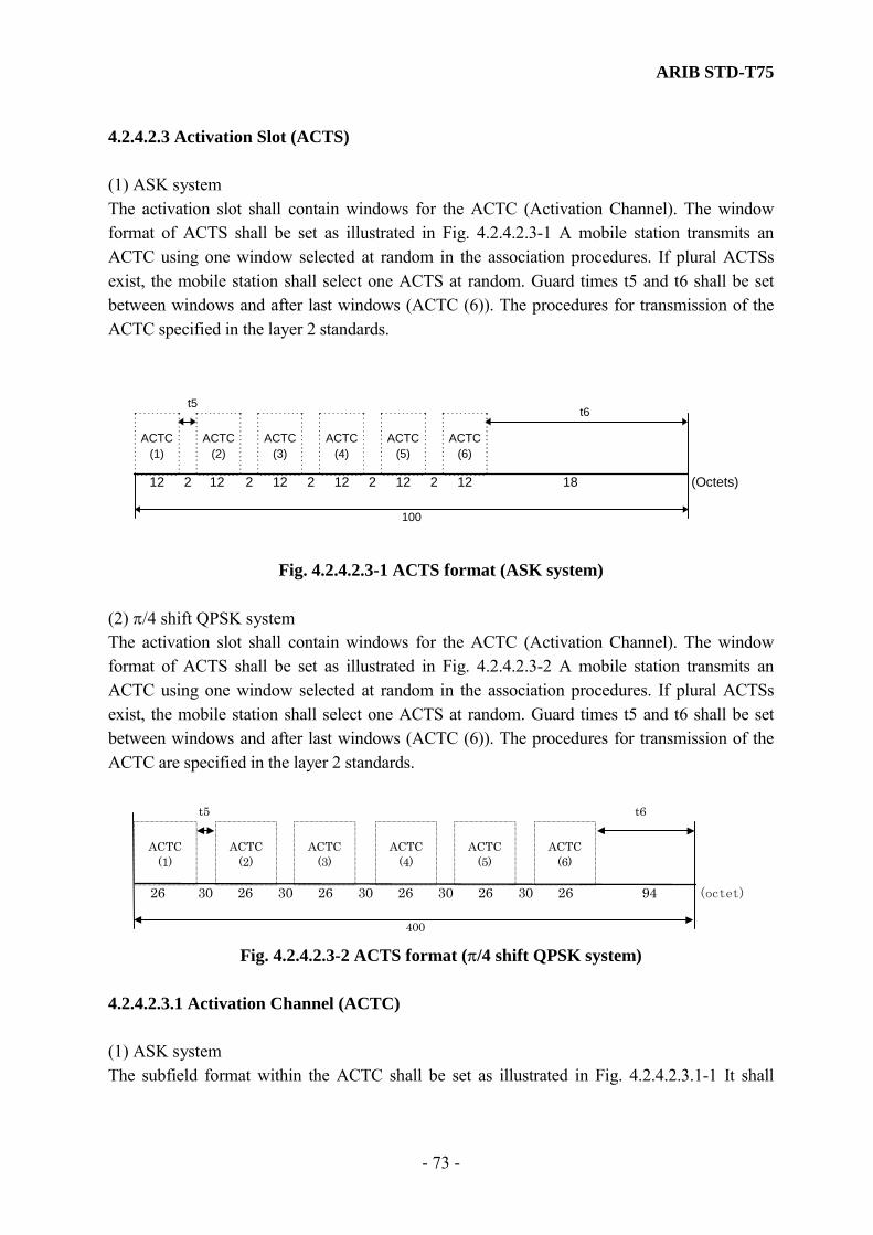
ARIB STD-T75
- 73 -
4.2.4.2.3 Activation Slot (ACTS) (1) ASK system The activation slot shall contain windows for the ACTC (Activation Channel). The window format of ACTS shall be set as illustrated in Fig. 4.2.4.2.3-1 A mobile station transmits an ACTC using one window selected at random in the association procedures. If plural ACTSs exist, the mobile station shall select one ACTS at random. Guard times t5 and t6 shall be set between windows and after last windows (ACTC (6)). The procedures for transmission of the ACTC specified in the layer 2 standards.
100
t5
ACTC(1)
12 2
ACTC(2)
ACTC(3)
ACTC(4)
ACTC(5)
(Octets)12 2 12 2 12 2 12 2
ACTC(6)
12
t6
18
Fig. 4.2.4.2.3-1 ACTS format (ASK system) (2) π/4 shift QPSK system The activation slot shall contain windows for the ACTC (Activation Channel). The window format of ACTS shall be set as illustrated in Fig. 4.2.4.2.3-2 A mobile station transmits an ACTC using one window selected at random in the association procedures. If plural ACTSs exist, the mobile station shall select one ACTS at random. Guard times t5 and t6 shall be set between windows and after last windows (ACTC (6)). The procedures for transmission of the ACTC are specified in the layer 2 standards.
400
t5
ACTC (1)
26 30 (octet)26 30 26 30 26 30 26 30 26 94
t6
ACTC(2)
ACTC
(4)
ACTC
(5)
ACTC
(3)
ACTC
(6)
Fig. 4.2.4.2.3-2 ACTS format (π/4 shift QPSK system)
4.2.4.2.3.1 Activation Channel (ACTC) (1) ASK system The subfield format within the ACTC shall be set as illustrated in Fig. 4.2.4.2.3.1-1 It shall

ARIB STD-T75
- 74 -
consist of the following subfields: a link request (association request) subfield LRI for the ACTC (one octet in length), a link address of four octets and identification number FID of the base station. A preamble signal PR (two octets in length), an unique word signal UW2 (two octets in length) and a error check signal CRC code (two octets in length) are further added to these signals, and transmission is made in the layer 1.
PR
422 21 1
UW2 FID LID LRI CRC
(Octets)
Fig. 4.2.4.2.3.1-1 ACTC Format (ASK system)
(2) π/4 shift QPSK system The subfield format within the ACTC shall be set as illustrated in Fig. 4.2.4.2.3.1-2 It shall consist of the following subfields: a link request (association request) subfield LRI for the ACTC (one octet in length), a link address of four octets and identification number FID of the base station. A ramp bit(one octet in length), a preamble signal PR (16 octets in length), an unique word signal UW2A (two octets in length) and a error check signal CRC code (two octets in length) are further added to these signals, and transmission is made in the layer 1. The data scramble system which it specifies in subclause 4.2.6 shall be applied to FID, LID, LRI and CRC.
PR
4 2 2 16 1 1
UW2A FID LID LRI CRC
(octet)
1
R
Data scramble renge
Fig. 4.2.4.2.3.1-2 ACTC Format (π/4 shift QPSK system)
4.2.4.2.3.1.1 Preamble (PR) (1) ASK system A preamble shall be 16 bits in length described below. This field shall be transmitted least significant bit (LSB) first in a bit string in the expressed sequence. LSB MSB [1010101010101010]

ARIB STD-T75
- 75 -
(2) π/4 shift QPSK system A preamble shall be 128 bits in length described below. This field shall be transmitted least significant bit (LSB) first in a bit string in the expressed sequence. LSB MSB [10011001……..1001] 4.2.4.2.3.1.2 Unique word (UW2, UW2A) A unique word is used for TDMA frame synchronization. An UW2 shall be 16 bits in length as follows. This field shall be transmitted least significant bit (LSB) first in a bit string in the expressed sequence. (1) ASK system (UW2) LSB MSB [0100101100111110] (2) π/4 shift QPSK system (UW2A) LSB MSB [1110000101001001] 4.2.4.2.3.1.3 Fixed Equipment ID (FID) The length of a FID shall be one octet in length. The FID contained within the FCMS transmitted from the base station is multiplexed as it is. 4.2.4.2.3.1.4 Link Address Field (LID) The link address LID is a private link address for making point to point two-way communication between the mobile station and the base station. The sub-field format of LID shall be as illustrated in Fig. 4.2.4.2.1.8.2. The private link address shall use the 28 bits of bit number 2 through 8 of four octets. The bit number 1 (b1) of 1st octet shall be set to “0” and the bit number 1 (b1) of 4 the octet shall be set to “1”.
4.2.4.2.3.1.5 Link Request Information field (LRI) A link request (association request) information field LRI is used for link request (association request) from the mobile station. The LRI shall be set as illustrated in Fig. 4.2.4.2.3.1.5. The bit number 1 (b1) is the identifier whether or not the association request of the MDS assignment with priority is made. If the mobile station requests association with priority, it shall be set to “1”. If the mobile station requests association without priority, it shall be set to “0”.
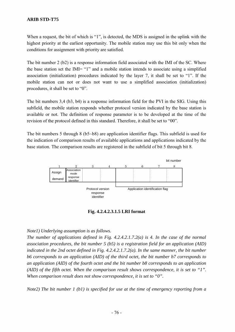
ARIB STD-T75
- 76 -
When a request, the bit of which is “1”, is detected, the MDS is assigned in the uplink with the highest priority at the earliest opportunity. The mobile station may use this bit only when the conditions for assignment with priority are satisfied. The bit number 2 (b2) is a response information field associated with the IMI of the SC. Where the base station set the IMI= “1” and a mobile station intends to associate using a simplified association (initialization) procedures indicated by the layer 7, it shall be set to “1”. If the mobile station can not or does not want to use a simplified association (initialization) procedures, it shall be set to “0”. The bit numbers 3,4 (b3, b4) is a response information field for the PVI in the SIG. Using this subfield, the mobile station responds whether protocol version indicated by the base station is available or not. The definition of response parameter is to be developed at the time of the revision of the protocol defined in this standard. Therefore, it shall be set to “00”. The bit numbers 5 through 8 (b5~b8) are application identifier flags. This subfield is used for the indication of comparison results of available applications and applications indicated by the base station. The comparison results are registered in the subfield of bit 5 through bit 8.
Assign
demand
Application identification flag
1 2 3 4 5 6 7 8bit number
Associationmode
responseidentifier
Protocol versionresponseidentifier
Fig. 4.2.4.2.3.1.5 LRI format
Note1) Underlying assumption is as follows. The number of applications defined in Fig. 4.2.4.2.1.7.2(a) is 4. In the case of the normal association procedures, the bit number 5 (b5) is a registration field for an application (AID) indicated in the 2nd octet defined in Fig. 4.2.4.2.1.7.2(a). In the same manner, the bit number b6 corresponds to an application (AID) of the third octet, the bit number b7 corresponds to an application (AID) of the fourth octet and the bit number b8 corresponds to an application (AID) of the fifth octet. When the comparison result shows correspondence, it is set to “1”. When comparison result does not show correspondence, it is set to “0”. Note2) The bit number 1 (b1) is specified for use at the time of emergency reporting from a

ARIB STD-T75
- 77 -
mobile station to a base station. The conditions for assignment with priority are to be defined elsewhere, but it is outside of the scope of this standard. 4.2.4.2.3.1.6 Cyclic Redundancy Error Check Sequence (CRC) A 16-bits CRC code shall be used for data check sequence for error detection purposes. The contents of the ACTC field excluding PR and UW2 field shall be contained in the calculation of ACTC field. The generator polynomial shall be as follows.
Generator polynomial: X16+X12 + X 5+1
4.2.4.2.4 Wireless Call Number slot (WCNS) The sub-field format of the WCNS (Call sign) of the mobile station and test equipment shall be set as illustrated in Fig. 4.2.4.2.4-1(ASK system) and Fig 4.2.4.2.4-2(π/4 shift QPSK system). This WCNS contains a window for a WCNC (wireless call number channel). A wireless call number is an approval number granted from the government certification office as an inherent wireless mobile terminal. WCNC shall transmit using specified window according to indication from the base station. Guard times t7 and t8 shall be set before and after the window. The format of WCNC (Call sign) shall conform to Annex C.
50
100
t8t7
(Octet)
WCNC
25 25
Fig. 4.2.4.2.4-1 WCNS format (ASK system)
400
WCNC
50 100
t7 t8
250
(octet)
Fig. 4.2.4.2.4-2 WCNS format (π/4 shift QPSK system)
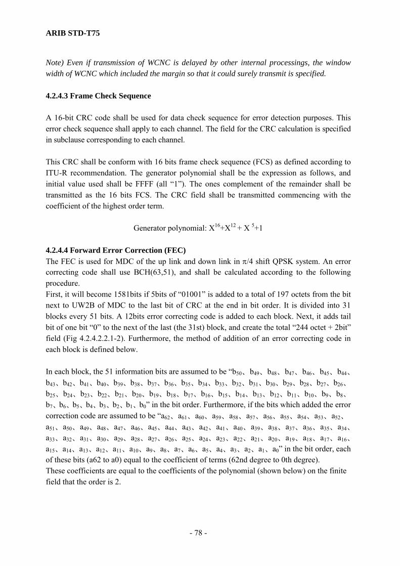
ARIB STD-T75
- 78 -
Note) Even if transmission of WCNC is delayed by other internal processings, the window width of WCNC which included the margin so that it could surely transmit is specified. 4.2.4.3 Frame Check Sequence A 16-bit CRC code shall be used for data check sequence for error detection purposes. This error check sequence shall apply to each channel. The field for the CRC calculation is specified in subclause corresponding to each channel. This CRC shall be conform with 16 bits frame check sequence (FCS) as defined according to ITU-R recommendation. The generator polynomial shall be the expression as follows, and initial value used shall be FFFF (all “1”). The ones complement of the remainder shall be transmitted as the 16 bits FCS. The CRC field shall be transmitted commencing with the coefficient of the highest order term.
Generator polynomial: X16+X12 + X 5+1
4.2.4.4 Forward Error Correction (FEC) The FEC is used for MDC of the up link and down link in π/4 shift QPSK system. An error correcting code shall use BCH(63,51), and shall be calculated according to the following procedure. First, it will become 1581bits if 5bits of “01001” is added to a total of 197 octets from the bit next to UW2B of MDC to the last bit of CRC at the end in bit order. It is divided into 31 blocks every 51 bits. A 12bits error correcting code is added to each block. Next, it adds tail bit of one bit “0” to the next of the last (the 31st) block, and create the total “244 octet + 2bit” field (Fig 4.2.4.2.2.1-2). Furthermore, the method of addition of an error correcting code in each block is defined below. In each block, the 51 information bits are assumed to be “b50、b49、b48、b47、b46、b45、b44、
b43、b42、b41、b40、b39、b38、b37、b36、b35、b34、b33、b32、b31、b30、b29、b28、b27、b26、
b25、b24、b23、b22、b21、b20、b19、b18、b17、b16、b15、b14、b13、b12、b11、b10、b9、b8、
b7、b6、b5、b4、b3、b2、b1、b0” in the bit order. Furthermore, if the bits which added the error correction code are assumed to be “a62、a61、a60、a59、a58、a57、a56、a55、a54、a53、a52、
a51、a50、a49、a48、a47、a46、a45、a44、a43、a42、a41、a40、a39、a38、a37、a36、a35、a34、
a33、a32、a31、a30、a29、a28、a27、a26、a25、a24、a23、a22、a21、a20、a19、a18、a17、a16、
a15、a14、a13、a12、a11、a10、a9、a8、a7、a6、a5、a4、a3、a2、a1、a0” in the bit order, each of these bits (a62 to a0) equal to the coefficient of terms (62nd degree to 0th degree). These coefficients are equal to the coefficients of the polynomial (shown below) on the finite field that the order is 2.

ARIB STD-T75
- 79 -
50
X12・(ΣbiXi)+R(X) i=0 .
Here, the R(X) is defined as the remainder polynomial when dividing
50
X12・(ΣbiXi) by (X12+X10+X8+X5+X4+X3+1). i=0
And the 11th order to the 0th coefficient of R (X) expresses a11 to a0 of the added 12-bit error correction code. 4.2.5 Bit Order Each sub-field shall be transmitted least significant bit (LSB) first, i.e. low order bit first (the first bit of transmitted data has a weight of 20). However, the protocol data unit consisting of MDC’s MAC control field and LPDU is defined in subclause 4.3. 4.2.6 Scramble System This standard specifies this communication system using a simple encryption system (encryption scramble system) with an encryption key delivery in the layer 2 as means for the privacy protection and countermeasures against the radio interception at the minimum level. Moreover, apart from the encryption scramble system for the simple encryption described above, the data scramble system for the code balance maintenance at the time of radio transmission of π/4 shift QPSK system is defined separately. Fig. 4.2.6 shows an outline of the data scramble system .
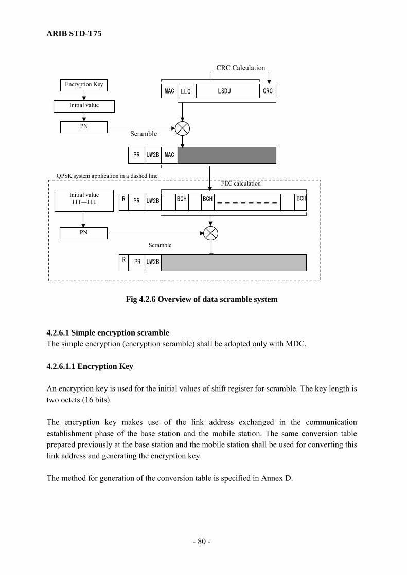
ARIB STD-T75
- 80 -
Encryption Key
PN
CRCMAC LLC LSDU
PR UW2B MAC
Initial value
CRC Calculation
Scramble
PN
FEC calculation
PR UW2B Initial value 111---111
Scramble
BCH
PR UW2B
QPSK system application in a dashed line
BCHR
R
BCH
Fig 4.2.6 Overview of data scramble system 4.2.6.1 Simple encryption scramble The simple encryption (encryption scramble) shall be adopted only with MDC. 4.2.6.1.1 Encryption Key An encryption key is used for the initial values of shift register for scramble. The key length is two octets (16 bits). The encryption key makes use of the link address exchanged in the communication establishment phase of the base station and the mobile station. The same conversion table prepared previously at the base station and the mobile station shall be used for converting this link address and generating the encryption key. The method for generation of the conversion table is specified in Annex D.
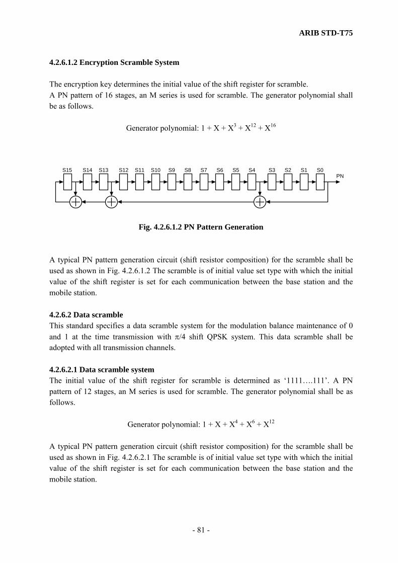
ARIB STD-T75
- 81 -
4.2.6.1.2 Encryption Scramble System The encryption key determines the initial value of the shift register for scramble. A PN pattern of 16 stages, an M series is used for scramble. The generator polynomial shall be as follows.
Generator polynomial: 1 + X + X3 + X12 + X16
PNS0S1S2S3S4S5S6S7S8S9S10S11S12S13S14S15
Fig. 4.2.6.1.2 PN Pattern Generation A typical PN pattern generation circuit (shift resistor composition) for the scramble shall be used as shown in Fig. 4.2.6.1.2 The scramble is of initial value set type with which the initial value of the shift register is set for each communication between the base station and the mobile station. 4.2.6.2 Data scramble This standard specifies a data scramble system for the modulation balance maintenance of 0 and 1 at the time transmission with π/4 shift QPSK system. This data scramble shall be adopted with all transmission channels. 4.2.6.2.1 Data scramble system The initial value of the shift register for scramble is determined as ‘1111….111’. A PN pattern of 12 stages, an M series is used for scramble. The generator polynomial shall be as follows.
Generator polynomial: 1 + X + X4 + X6 + X12
A typical PN pattern generation circuit (shift resistor composition) for the scramble shall be used as shown in Fig. 4.2.6.2.1 The scramble is of initial value set type with which the initial value of the shift register is set for each communication between the base station and the mobile station.
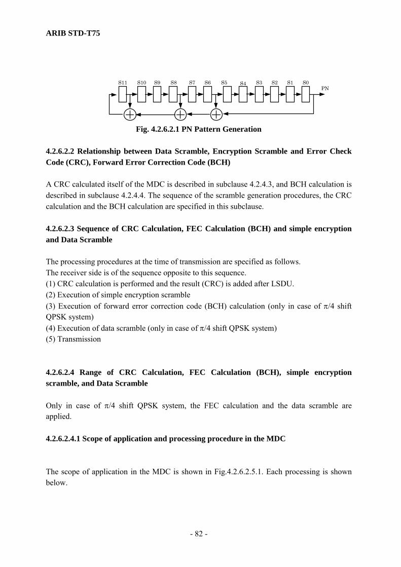
ARIB STD-T75
- 82 -
Fig. 4.2.6.2.1 PN Pattern Generation
4.2.6.2.2 Relationship between Data Scramble, Encryption Scramble and Error Check Code (CRC), Forward Error Correction Code (BCH) A CRC calculated itself of the MDC is described in subclause 4.2.4.3, and BCH calculation is described in subclause 4.2.4.4. The sequence of the scramble generation procedures, the CRC calculation and the BCH calculation are specified in this subclause. 4.2.6.2.3 Sequence of CRC Calculation, FEC Calculation (BCH) and simple encryption and Data Scramble The processing procedures at the time of transmission are specified as follows. The receiver side is of the sequence opposite to this sequence. (1) CRC calculation is performed and the result (CRC) is added after LSDU. (2) Execution of simple encryption scramble (3) Execution of forward error correction code (BCH) calculation (only in case of π/4 shift QPSK system) (4) Execution of data scramble (only in case of π/4 shift QPSK system) (5) Transmission 4.2.6.2.4 Range of CRC Calculation, FEC Calculation (BCH), simple encryption scramble, and Data Scramble Only in case of π/4 shift QPSK system, the FEC calculation and the data scramble are applied. 4.2.6.2.4.1 Scope of application and processing procedure in the MDC The scope of application in the MDC is shown in Fig.4.2.6.2.5.1. Each processing is shown below.
PN S0 S1 S2S3S4S5S6S7S8S9 S10 S11
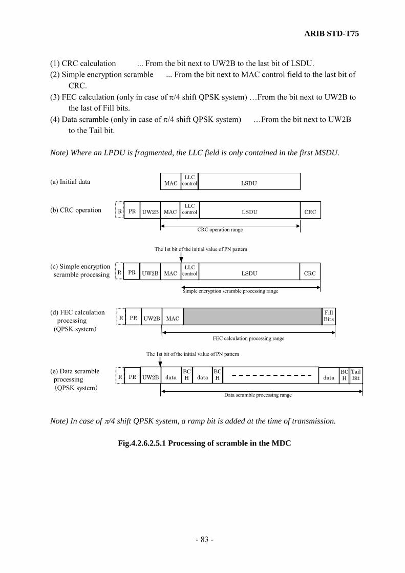
ARIB STD-T75
- 83 -
(1) CRC calculation ... From the bit next to UW2B to the last bit of LSDU. (2) Simple encryption scramble ... From the bit next to MAC control field to the last bit of
CRC. (3) FEC calculation (only in case of π/4 shift QPSK system) …From the bit next to UW2B to
the last of Fill bits. (4) Data scramble (only in case of π/4 shift QPSK system) …From the bit next to UW2B
to the Tail bit. Note) Where an LPDU is fragmented, the LLC field is only contained in the first MSDU.
MAC
UW2B LLC
control LSDU CRC MAC
CRC operation range
LLCcontrol LSDU
The 1st bit of the initial value of PN pattern
(b) CRC operation
Simple encryption scramble processing range
(c) Simple encryption scramble processing
(a) Initial data
UW2B LLC
control LSDU CRC MAC
(d) FEC calculation processing
(QPSK system) FEC calculation processing range
UW2B
(e) Data scramble processing (QPSK system)
Data scramble processing range
UW2B BCH data
Fill Bits
TailBit
BCHdata
BCHdata
MAC
PR R
PR R
PR R
PR R
The 1st bit of the initial value of PN pattern
Note) In case of π/4 shift QPSK system, a ramp bit is added at the time of transmission.
Fig.4.2.6.2.5.1 Processing of scramble in the MDC
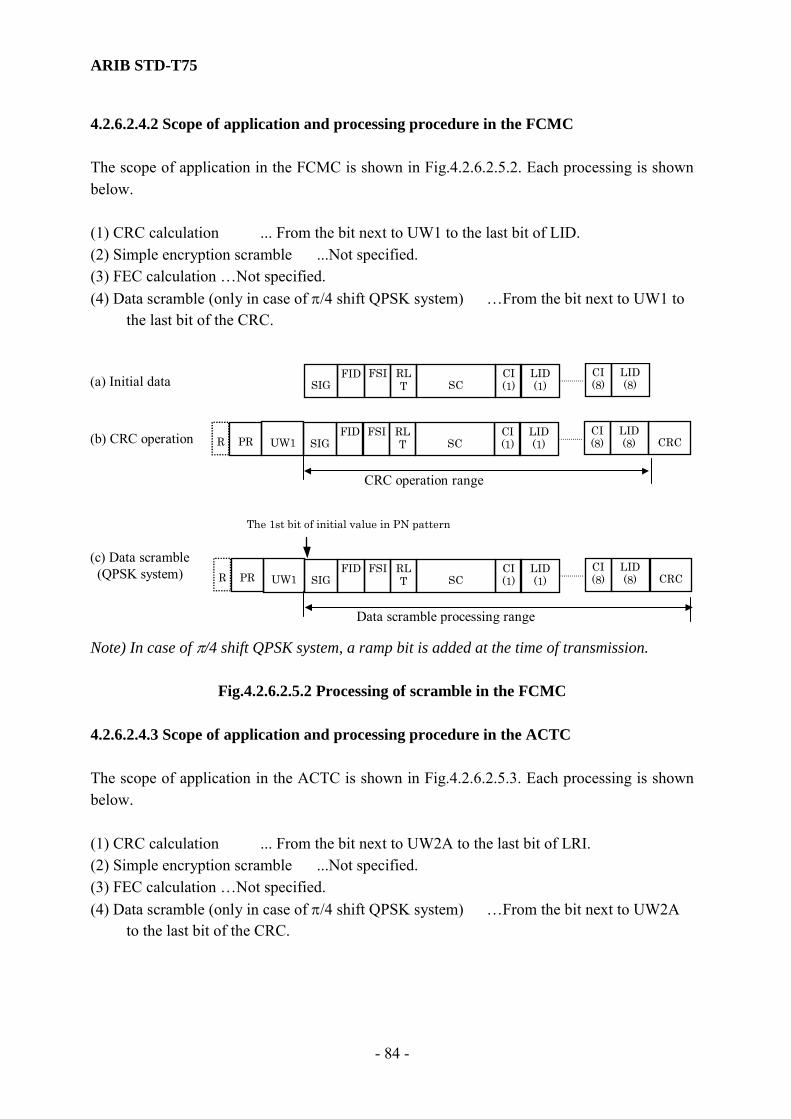
ARIB STD-T75
- 84 -
4.2.6.2.4.2 Scope of application and processing procedure in the FCMC The scope of application in the FCMC is shown in Fig.4.2.6.2.5.2. Each processing is shown below. (1) CRC calculation ... From the bit next to UW1 to the last bit of LID. (2) Simple encryption scramble ...Not specified. (3) FEC calculation …Not specified. (4) Data scramble (only in case of π/4 shift QPSK system) …From the bit next to UW1 to
the last bit of the CRC.
CRC operation range
(b) CRC operation
(a) Initial data
(c) Data scramble (QPSK system)
Data scramble processing range
The 1st bit of initial value in PN pattern
SIGFID
SC FSI RL
TCI(1)
CI (8)
LID(1)
LID (8)
UW1 CRCSIGFID
SC FSI RL
TCI(1)
CI (8)
LID(1)
LID (8)
UW1 CRCSIGFID
SC FSI RL
TCI(1)
CI (8)
LID(1)
LID (8)
PR R
PR R
Note) In case of π/4 shift QPSK system, a ramp bit is added at the time of transmission.
Fig.4.2.6.2.5.2 Processing of scramble in the FCMC 4.2.6.2.4.3 Scope of application and processing procedure in the ACTC The scope of application in the ACTC is shown in Fig.4.2.6.2.5.3. Each processing is shown below. (1) CRC calculation ... From the bit next to UW2A to the last bit of LRI. (2) Simple encryption scramble ...Not specified. (3) FEC calculation …Not specified. (4) Data scramble (only in case of π/4 shift QPSK system) …From the bit next to UW2A
to the last bit of the CRC.

ARIB STD-T75
- 85 -
UW2A CRC
CRC operation range
FIDLID
LRI
(b) CRC operation
(a) Initial Data
(c) Data scramble processing
FIDLID
LRI
UW2A CRCFIDLID
LRI
Data scramble processing range
PRR
PRR
Note) In case of π/4 shift QPSK system, a ramp bit is added at the time of transmission.
Fig.4.2.6.2.5.3 Processing of scramble in the ACTC 4.2.6.2.4.4 Scope of application and processing procedure in the ACKC The scope of application in the ACKC is shown in Fig.4.2.6.2.5.4. Each processing is shown below. (1) CRC calculation ...All the bits of the AI.. (2) Simple encryption scramble ...Not specified. (3) FEC calculation …Not specified. (4) Data scramble (only in case of π/4 shift QPSK system) …From the bit next to UW2A
to the last bit of the CRC.
UW2A CRC
CRC operation range
AI
(b) CRC operation
(a) Initial data
(c) Data scramble processing
UW2A CRC
Data scramble processing range
AI
AI
PRR
PRR
Note) In case of π/4 shift QPSK system, a ramp bit is added at the time of transmission.
Fig.4.2.6.2.5.4 Processing of scramble in the ACKC
ARIB STD-T75
- 86 -
4.2.7 Guard time The guard times of the basic frame or channels shall be set as shown in Table 4.2.7 by octet length. In case of time conversion in ASK system, guard time is the calculation of the multiplied of the indicated units by 7.8125 μs. And in case of time conversion in π/4 shift QPSK system, guard time is the calculation of the multiplied of the indicated units by 1.9531 μs. These values shall be adapted conformable to the following specifications. (1) Accuracy of the modulation signal rate (subclause 3.2.9) (2) Burst transmission transient response time (subclause 3.4.2.6) (3) Allowable deviation of absolute signal transmission time (subclause 3.4.2.13) (4) Transmission / reception switching time (subclause 4.2.10)

ARIB STD-T75
- 87 -
Table 4.2.7 Guard Time of Basic System
Note) The ramp bit R in the π/4 shift QPSK system is not contained in this time conversion table.
Parameter
ASK system
Set time
(octets)
π/4 shift QPSK
system
Set time
(octets)
Remarks
t0 28 112 See subclause
4.2.4.2.1
t1 0 0 See subclause
4.2.4.1
t2 12 214 See subclause
4.2.4.2.1
t3 11 73.75 See subclause
4.2.4.2.2
t4 9 43 See subclause
4.2.4.2.2
t5 2 30 See subclause
4.2.4.2.3
t6 18 94 See subclause
4.2.4.2.3
t7 25 100 See subclause
4.2.4.2.4
t8 25 250 See subclause
4.2.4.2.4
ARIB STD-T75
- 88 -
4.2.8 Channel selection procedures on the mobile station 4.2.8.1 Channel selection procedure (1) Definition This is the procedures when a mobile station selects one correct frequency channel from specified plural channels on receiving the radio signal and from a base station in a defined radio communication zone. (2) Setting priority channels It is recommended that priority channels be set in order to reduce time for frequency channel selection. When a mobile station implements an application for electronic toll collection (ETC) systems, it shall assign two channels for ETC systems to the first priority channels and give higher priority to these channels in frequency channel selection. Regarding applications other than ETC systems, a mobile station can assign a specific channel to the second priority channel and give higher priority to this channel in frequency channel selection, so that the time for frequency channel selection will be reduced. (3) Recommend procedures Base station: Previously, one frequency transmission channel shall be preset. Mobile station: On receiving the FCMC signal with signal level higher than the specified level, the FCMC may execute error detection procedures using CRC field. (On receiving different frequency channel signals simultaneously, it is desired that the mobile station determines, which signal level is higher, if possible.) Where it does not show an error in corresponding FCMC, the mobile station may set one radio frequency channel according to FTI within the corresponding FCMC. (4) Procedures of the mobile station (a) It is desired that the mobile station select one radio frequency channel after error checking if plural FCMCs are received continuously. Firstly, after the FCMC has selected correctly, the mobile station sets one radio frequency channel according to FTI within the corresponding FCMC. Secondly, using following FCMC, the mobile station transmits an ACTC. Adopting this procedures, it is the same as executing error detection procedures of FCMC twice. (b) Ways of setting radio frequency channel in the mobile station
1) High-speed frequency switching through all frequencies (e.g. high-speed frequency

ARIB STD-T75
- 89 -
switching of a local oscillator, etc.) 2) Frequency channel selection using priority channels Here are some examples of frequency channel selection method:
i) The priority channels are given higher priority in frequency scan; the other channels are scanned less frequently. ii) Among priority channels, the first priority channel is given the highest priority in frequency scan. The second priority channel is scanned less frequently than the first priority channel, and the other channels are scanned even less frequently.
3) Presetting data concerning the next base station to transact, based on the data concerning the previous transaction (e.g. In lane-based systems, data concerning transaction with the first antenna can be used for transaction with the second antenna. This allows a mobile station to skip the frequency selection procedure for the second antenna.) 4) Other way
(c) Setting window of the mobile station. Considering the mobile station which cannot previously know a period of transmission of FCMC from the base station, in the case of adopting a searching signals way, it may be suitable for the mobile station to use a window (time slot) for the channel selection procedures. 4.2.8.2 Channel change procedures [Informative] (1) Definition This is the procedure to be followed when a mobile station changes the current frequency channel to a different one within the same radio communication zone based on the frequency data obtained from the base station. This is also the procedure to be followed when a mobile station selects a frequency channel to use in the next radio communication zone and changes to it based on the frequency data obtained from the base station or by other means. (2) Procedures - Procedure of the base station The base station shall conduct any one of the following operations: a. Sets a specific value as a FCMC parameter. (Refer to Note 4 of Section 3 in Annex B.) b. Transmits frequency data in an application data format by wireless communication. c. Other - Procedure of the mobile station The mobile station shall conduct any one of the following operations: a. Recognizes a specific value as a FCMC parameter and sets a frequency channel. (Refer
to Note 4 of Section 3 in Annex B.)

ARIB STD-T75
- 90 -
b. Recognizes frequency data transmitted in an application data format by wireless communication and sets a frequency channel.
c. Recognizes frequency data obtained by other means and sets a frequency channel. d. Other (3) Setting a frequency channel by the mobile station
a. The mobile station shall determine whether the obtained frequency data is the one concerning frequency channel change within the current radio communication zone or the one concerning frequency channel change in the next radio communication zone.
b. If the data is concerning frequency channel change in the next radio communication zone, the mobile station shall stop the normal frequency channel selection procedure and set a specific frequency channel using the systems management interface from the application after it has completed the communication at the frequency of the current radio communication zone or detected departure from the current radio communication zone.
c. If the data is concerning frequency channel change within the current radio communication zone, the mobile station shall stop the normal frequency channel selection procedure and set a specific frequency channel using the systems management interface from the application.
d. As soon as communication at a changed frequency channel has been completed, the mobile station shall return to the normal frequency channel selection procedure. Note) The procedures for transmission of frequency data in an application data format by wireless communication and setting a frequency channel by the mobile station are detailed in Annex E.
(4) Frequency data transmitted in an application data format by wireless communication Although the details of frequency data are governed by this standard, it is desirable that attribute IDs and the like be defined in a way that they will be applicable to multiple applications. 4.2.8.3 Channel selection procedure in overlapping radio communication zones by the mobile station (1) Definition This is the procedure for the mobile station to receive radio signals from the base station and select a frequency channel for use in wireless communication in overlapping radio communication zones. (2) Channel selection procedure in overlapping communication zones The mobile station shall use the normal frequency channel selection procedure in overlapping
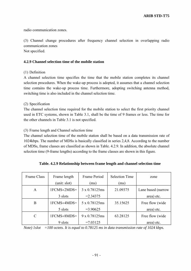
ARIB STD-T75
- 91 -
radio communication zones. (3) Channel change procedures after frequency channel selection in overlapping radio communication zones Not specified. 4.2.9 Channel selection time of the mobile station (1) Definition A channel selection time specifies the time that the mobile station completes its channel selection procedures. When the wake-up process is adopted, it assumes that a channel selection time contains the wake-up process time. Furthermore, adopting switching antenna method, switching time is also included in the channel selection time. (2) Specification The channel selection time required for the mobile station to select the first priority channel used in ETC systems, shown in Table 3.1, shall be the time of 9 frames or less. The time for the other channels in Table 3.1 is not specified. (3) Frame length and Channel selection time The channel selection time of the mobile station shall be based on a data transmission rate of 1024kbps. The number of MDSs is basically classified in series 2,4,8. According to the number of MDSs, frame classes are classified as shown in Table. 4.2.9. In addition, the absolute channel selection time (9-frame lengths) according to the frame classes are shown in this figure.
Table. 4.2.9 Relationship between frame length and channel selection time
Frame Class Frame length
(unit: slot)
Frame Period
(ms)
Selection Time
(ms)
zone
A 1FCMS+2MDS=
3 slots
3 x 0.78125ms
=2.34375
21.09375 Lane based (narrow
area) etc.
B 1FCMS+4MDS=
5 slots
5 x 0.78125ms
=3.90625
35.15625 Free flow (wide
area) etc.
C 1FCMS+8MDS=
9 slots
9 x 0.78125ms
=7.03125
63.28125 Free flow (wide
area) etc. Note) 1slot =100 octets. It is equal to 0.78125 ms in data transmission rate of 1024 kbps.

ARIB STD-T75
- 92 -
4.2.10 Transmission / Reception Switching time (1) Definition A transmission / reception switching time specifies the transient time that the mobile station moves its state from reception state to transmission state or from transmission state to reception state. This specification does not apply to the base station, since the base station may operate in full-duplex mode. The burst transient time may be contained in this transmission / reception switching time. (2) Specifications 1) The time taken for the mobile station to switch time from reception state to transmission
state shall be less than 64 μs. Note) A channel selection time shall not be included in this transmission / reception switching time. 2) The time taken for the mobile station to switch from transmission state to reception state
shall be less than 64 μs. (3) Description A transmission / reception switching time shall contain the data processing time in the layer 1 and the layer 2. The layer 7 or applications (service user) may elapse more time than specified time in this subclause, since the data could not process smoothly by any reason. The layer 2 management entity has a timer (maximum number of frames) for the rapid re-association, when the communication transaction fails. After elapse of this timer, the communication transaction would be cancelled. If the cancellation is not desired, the mobile station may need temporal data transmission including any idle message. 4.2.11 Wake-up processing of the mobile station (1) Definition This processing specifies that the mobile station is able to communicate in a defined radio communication zone, or the transient of the mobile station move state from a standby state (sleep mode state) to an operation state. The latter standby state is the function of an energy management to avoid wasting the battery energy in the mobile station.

ARIB STD-T75
- 93 -
(2) Specification 1) The wake-up process shall apply to the normal type of data transaction. 2) The mobile station may not adopt the Wake-up process. 4.2.12 Maximum start-up time of the mobile station (1) Definition A maximum start-up time is the time for the mobile station to complete the wake-up process, after receiving the minimum length of downlink data (message) which enables the trigger of transition. (2) Specifications Maximum start-up time of the mobile station shall be less than 5 ms. 4.2.13 Test Equipment 4.2.13.1 Conditions for slot transmission (1) Definition The communication system specified in this standard uses a wireless communication system in which the base station (test equipment) manages transmission of the wireless communication slot of the mobile station. This standard defines the conditions for slot transmission under which the test equipment can transmit slots (frame control message channels, etc.) to prevent the test equipment from interfering the base station and the mobile station. (2) Scope These specifications apply to the test equipment. (3) Specifications 1) Within 3 seconds prior to the start of communication, carrier sense shall be conducted for the time of 10 frames or more by unit of the maximum frame length described as frame class in Table 4.2.9. Unless the test equipment detects a carrier which equals or exceeds a specified carrier sense level, it shall be able to start slot transmission. Note that the carrier sense shall be conducted at a specified carrier sense frequency. 2) Carrier sense level The test equipment shall measure the carrier sense level using an antenna for carrier sense that is specified separately. In carrier sense, the equipment shall be capable of detect a carrier

ARIB STD-T75
- 94 -
which is equal to or below the carrier sense level shown in Table 3.4.5 in front of the carrier sense antenna. If it detects a carrier which equals or exceeds this carrier sense level, it shall not be able to start slot transmission. Reference: The method of detection is to conduct average detection for the time of less than half a frame control message channel (FCMC).
Table. 3.4.5 Carrier sense level
Carrier frequency Carrier sense level Cannel for radio wave emission -78 dBm e.i.r.p
Cannel adjacent to the above channel -78 dBm e.i.r.p
3) Carrier sense frequency The carrier sense frequency indicates a frequency of a channel at which the test equipment emits radio waves after the completion of carrier sense and a frequency of a channel adjacent to the said frequency. 4) Antenna for carrier sense When the transceiver antenna of the test equipment is used in carrier sense instead of the antenna dedicated to carrier sense, the differences in the following points must be considered: - Difference in position - Difference in gain - Difference in polarization - Difference in directivity 4.2.13.2 Avoidance of interference and suspension of transmission (1) Definition This is the operation for the test equipment to suspend transmission in order to avoid interference when interference is detected (by carrier sense, etc.). (2) Scope These specifications apply to the test equipment. (3) Specifications a) Continuous communication time When communication is conducted continuously, the continuous time length shall be the minimum of the tested item. Carrier senses shall be included during the time and the time interval between carrier senses specified in Subclause 3.4.5 shall be as short as possible.
ARIB STD-T75
- 95 -
b) Time interval before resuming communication When a carrier that equals or exceeds the carrier sense level specified in Subclause 3.4.5.a is detected, the test equipment shall suspend slot (frame) transmission. In such a case, when communication (slot transmission) is resumed at the same channel frequency, there shall be at least a 10-second time interval after the suspension of slot transmission. Then, a carrier sense operation specified in Subclause 3.4.5.a shall be resumed. c) Suspension of transmission When a carrier is detected that equals or exceeds the carrier sense level specified in Subclause 3.4.5.a, the test equipment shall suspend slot (frame) transmission immediately. 4.2.13.3 Wireless call number slot (WCNS) transmission When the test equipment transmits a wireless call number channel (WCNC), it shall do so by assigning a downlink WCNS in such a way that there will be no influence on testing. The method of WCNS assignment is not specified in this standard. 4.2.14 Layer 1 Management service interface. 4.2.14.1 Overview of Interactions The layer 1 management entity (PLME) provides the following primitives to a MAC sublayer management entity in the layer 2 or a system management entity (SME). PLME-GET.request PLME-GET.confirm PLME-SET.request PLME-SET.confirm The management information specific to the layer 1 is represented as a layer 1 (Physical Medium Layer) Management Information Base (MIB). The PLME-GET.request primitive is passed to the layer 1 management entity (PLME) to request from the user entity (the SME or the MAC sublayer management entity (MLME)) to get the value of the MIB attribute. The PLME-GET.confirm is passed from the PLME to convey the results of the previous action associated with the PLME-GET.request primitive. The PLME-SET.request primitive is passed to the PLME to request that the user-entity (the SME or the MLME) set the value of the MIB attribute. The PLME-SET.confirm is passed from the PLME to convey the results of the previous action associated with the PLME-SET.request primitives. Details of the variable definition of the MIB are shown in Annex A.

ARIB STD-T75
- 96 -
4.2.14.2 Service specification
This subclause describes in detail the primitives and parameters associated with the service specified in subclause 4.2.13.1. The parameters are abstractly described, and specified in view of the necessity for the receive entity. A specific implementation is not constrained in the method of making this information available. Figure 4.2.13.2. shows the logical relationship of primitives.
PLME_GET.request
PLME_GET.confirm
PLME SET.requestPLME_SET.confirm
Fig.4.2.13.2 Time-sequence diagram
4.2.14.2.1 PLME-GET.request (1) Function This primitive is to request for the MIB access service. (2) Semantics of Service Primitive The primitive parameters shall be as follows: PLME-GET.request (MIB-attribute) The MIB-attribute parameter is specific to the attribute of the MIB. (3) When Generated This primitive is generated by the SME or the MLME to request for getting the MIB attribute of the PLME and is passed to the PLME. 4.2.14.2.2 PLME-GET.confirm (1) Function This primitive is to report the results of the action associated with the PLME-GET.request.

ARIB STD-T75
- 97 -
(2) Semantics of Service Primitive The primitive parameters shall be as follows: PLME-GET.confirm (status, MIB-attribute, MIB-attribute-value) The status parameter indicates the success or the failure of the MIB-attribute reading requests. The MIB-attribute parameter is specific to the attribute provided by the PLME-GET.request. The MIB-attribute-value is specific to the value of the attribute itself. Note 1) If a type of invalid attribute is specified, the status will indicate the failure. Note 2) If the status indicates the failure, the MIB-attribute-value will not assure validity. (3) When Generated This primitive is generated by the PLME to report the results of the previous action provided by the PLME-GET.request primitives and is passed to the SME or the MLME. 4.2.14.2.3 PLME-SET.request (1) Function This primitive is to request for the MIB access service. (2) Semantics of Service Primitive The primitive parameters shall be as follows: PLME-SET.request (MIB-attribute, MIB-attribute-value) The MIB-attribute parameter specifies the attribute of the MIB. The MIB-attribute-value is specific to the value. (3) When Generated This primitive is generated by the SME or the MLME to request for writing the MIB attribute of the PLME and is passed to the PLME. 4.2.14.2.4 PLME-SET.confirm (1) Function This primitive is to report the results of the action associated with the PLME-SET.request. (2) Semantics of Service Primitive The primitive parameters shall be as follows:

ARIB STD-T75
- 98 -
PLME-SET.confirm (status, MIB-attribute) The status parameter indicates the success or the failure of the setting MIB-attribute request provided by PLME-SET.request. The MIB-attribute parameter is specific to the attribute provided by PLME-SET.request. Note) If a type of invalid attribute is specified, the status will indicate failure. (3) When Generated This primitive is generated by the PLME to report the results of the previous action provided by the PLME-SET.request primitives and is passed to the SME or the MLME.
ARIB STD-T75
- 99 -
4.3 Layer 2 Standards 4.3.1 Outline of the layer 2 4.3.1.1 Overview The layer 2 has the same meaning as the data link layer. The layer 2 is further divided into two distinct layers, the logical link control sublayer (LLC sublayer) and medium access control sublayer (MAC sublayer). The LLC sublayer performs data exchange between LLC sublayers and provides its service for the layer 7. The MAC sublayer also performs data transmission between MAC sublayers using the bit transmission function of the layer 1 (physical layer). The MAC sublayer manages the bit order data reception/transmission using physical medium channel cooperating with the MAC sublayer management entity (MLME). The MAC subalayer also performs the association (data link connection) cooperating with the functions of the layer1, the layer7 and the system management entity (SME). This subclause specifies frame structure, elements for procedures and procedures for performing the above operations. 4.3.1.2 Overview of Services The layer 2 standard is divided in two parts, the MAC sublayer and the LLC subalyer. Each sublayer is specified as below. 4.3.1.2.1 MAC Sublayer The MAC sublayer is responsible for controlling the physical medium by the MAC entity. The contents of the service are as follows. (1) Association Associates with the base station from the mobile station. (2) Frame control Manages frames such as slot assignment. (3) Fragmentation Fragment a LPDU in MSDUs and defragment MSDUs. (4) MAC level acknowledgment Actions regarding error control of the transmission MPDU in MAC sublayer.
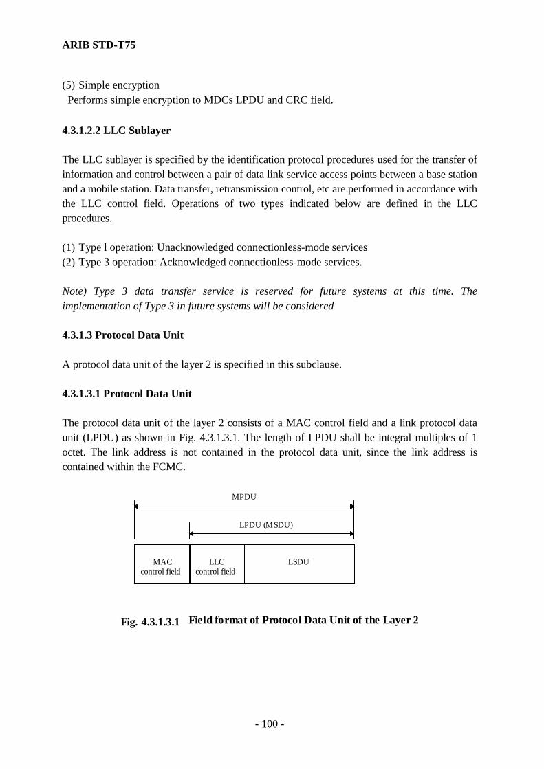
ARIB STD-T75
- 100 -
(5) Simple encryption Performs simple encryption to MDCs LPDU and CRC field. 4.3.1.2.2 LLC Sublayer The LLC sublayer is specified by the identification protocol procedures used for the transfer of information and control between a pair of data link service access points between a base station and a mobile station. Data transfer, retransmission control, etc are performed in accordance with the LLC control field. Operations of two types indicated below are defined in the LLC procedures. (1) Type l operation: Unacknowledged connectionless-mode services (2) Type 3 operation: Acknowledged connectionless-mode services. Note) Type 3 data transfer service is reserved for future systems at this time. The implementation of Type 3 in future systems will be considered 4.3.1.3 Protocol Data Unit A protocol data unit of the layer 2 is specified in this subclause. 4.3.1.3.1 Protocol Data Unit The protocol data unit of the layer 2 consists of a MAC control field and a link protocol data unit (LPDU) as shown in Fig. 4.3.1.3.1. The length of LPDU shall be integral multiples of 1 octet. The link address is not contained in the protocol data unit, since the link address is contained within the FCMC.
LSDUMACcontrol field
Fig. 4.3.1.3.1 Field format of Protocol Data Unit of the Layer 2
LLCcontrol field
MPDU
LPDU (MSDU)

ARIB STD-T75
- 101 -
4.3.1.3.2 Relationship between Frame Format and Physical channel The relationship between the protocol data unit of the layer 2 and frame format of the layer 1 is shown in Fig. 4.3.1.3.2. The protocol data unit of the layer 2 is multiplexed at the position of the MDC in the MDS, with the PR, UW2 and CRC added to it, at the time of delivery to the layer 1. In the case of the downlink transmission from a base station to a mobile station, the base station registers the link address received from the mobile station at the SCI of the FCMC. The protocol data units of the layer 2 contained the data from the service access point indicated by this link address is previously multiplexed by the procedures stated at the MDS that corresponds to the position of the SCI, and is transmitted to the mobile station. The mobile station compares the link address used at the time of association request with the link address contained in the SCI of the FCMC. When the SCI contained the same address is detected; the data is received from the MDS of the corresponding position, and passes the data to the service access point indicated by the link address, which was held by it. In the case of the uplink transmission from the mobile station to the base station, the base station registers the link address received from the mobile station at the SCI of the FCMC. The mobile station compares the link address used at the time of link request with the address contained in the SCI of the FCMC and identifies the position of the MDS. The protocol data unit of the layer 2 contained the data from the service access point indicated by this link address is multiplexed at the identified MDS by the procedures described. The base station receives the data from the MDS which corresponds to the SCI, at which link address was registered, and passes the data to the service access point indicated by this link address. Where the LPDU from the LLC sublayer exceeds 65 octets (or 193 octets in QPSK), sequence numbers are added to plural MDSs by LPDUs of 65-octet units (or 193-octet units in QPSK), and thus data is transmitted fragmented. The MAC sublayer that received the data performs linking processing of these data and then passes the data to the LLC sublayer. The details of these procedures are specified in subclause 4.3.3.4 and 4.3.3.5.
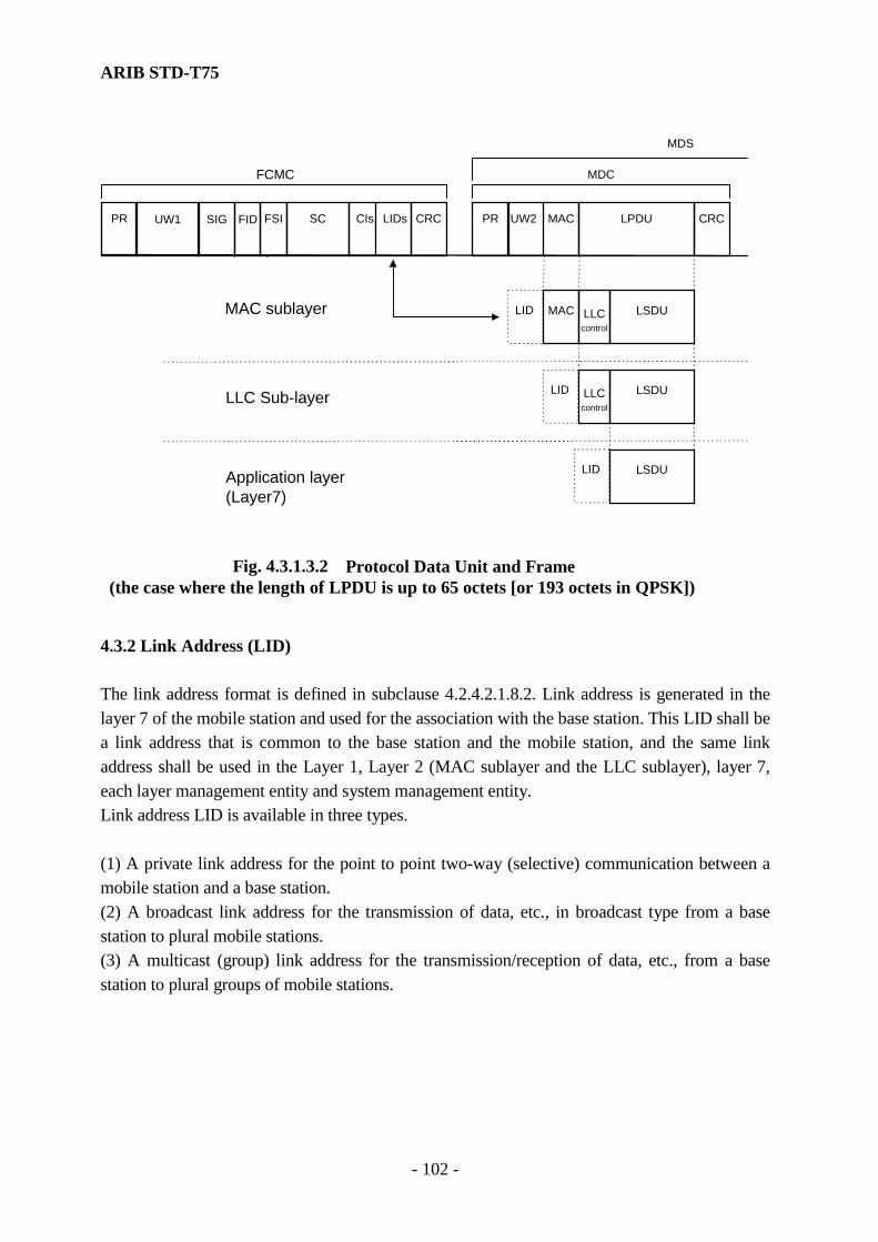
ARIB STD-T75
- 102 -
PRPR UW2UW1 SIG FSI SC CRC
LLC Sub-l ayer
CIs
FCMC
MDS
MDC
Fig. 4.3.1.3.2 Protocol Data Unit and Frame (the case where the length of LPDU is up to 65 octets [or 193 octets in QPSK])
LPDU
MAC sublayer
FID MACLIDs
Application layer (Layer7)
LLCcontrol
LSDU MAC
LID
LID
LID
CRC
LLCcontrol
LSDU
LSDU
4.3.2 Link Address (LID) The link address format is defined in subclause 4.2.4.2.1.8.2. Link address is generated in the layer 7 of the mobile station and used for the association with the base station. This LID shall be a link address that is common to the base station and the mobile station, and the same link address shall be used in the Layer 1, Layer 2 (MAC sublayer and the LLC sublayer), layer 7, each layer management entity and system management entity. Link address LID is available in three types. (1) A private link address for the point to point two-way (selective) communication between a mobile station and a base station. (2) A broadcast link address for the transmission of data, etc., in broadcast type from a base station to plural mobile stations. (3) A multicast (group) link address for the transmission/reception of data, etc., from a base station to plural groups of mobile stations.

ARIB STD-T75
- 103 -
4.3.2.1 Restraint of link address usage An overview of link addresses is shown in Fig. 4.3.2.1. At the point to point communication, the private link address shall be used. The mobile station should at least be capable of dealing with private link address and broadcast link address. Depending on the type of the mobile station, the multicast (group) link addresses are available. The mobile station should use the private link address at the time of uplink transmission to the base station. The same LID shall be used while the communication is continuously executing.
SAP SAPSAP SAP SAP SAP SAP
BaseStation
Broadcast link address
Private link address
Private link address
MobileStations
Fig. 4.3.2.1 Overview of Link Addresses 4.3.2.2 Service access point (SAP) (1) The mobile station shall use a new private link address to associate with the communication link of the base station. This private link address shall be a random address to secure the discrimination among mobile stations. (2) The base station shall accept the association (data link connection) request from the mobile station, and when it is able to associate with the base station (communication link), it newly opens a service access point (SAP) by the link address reported by an ACTC. The broadcast link address for the broadcast link and the multicast (group) link address for group link shall be indicated by the base station.

ARIB STD-T75
- 104 -
4.3.3 Medium Access Control (MAC) Sublayer 4.3.3.1 Overview of MAC Sublayer The MAC sublayer is responsible for controlling the use of layer 1 (physical medium channel) by the MAC sublayer entity residing in a base station and a MAC sublayer entity of a mobile station. This subclause specifies the MAC sublayer operations. The medium access control is unbalanced. The base station always controls access to physical medium channels, granting access to the physical medium to either, including the mobile station, and the principal functions of the MAC sublayer are as follows. (1) Generation of communication frame (2) Establishment of association (data link connection) (3) Transmission/reception of PDU and acknowledgment (4) Addition and inspection of CRC (5) Simple encryption/decryption (Scramble/descramble) (6) MAC level acknowledgment 4.3.3.2 Specification for Interface Service of MAC Sublayer 4.3.3.2.1 MAC Data Service 4.3.3.2.1.1 Overview of Interactions The MAC sublayer provides the following primitives to the LLC sublayer. MA-UNITDATA.request MA-UNITDATA.indication MA-UNITDATA.request is passed to the MAC sublayer from the LLC sublayer to request transmission of MSDU. MA-UNITDATA.indication is passed to the LLC sublayer from the MAC sublayer to indicate arrival of MSDU. 4.3.3.2.1.2 Service Specification This subclause describes in detail the primitives and parameters associated to the service specified in subclause 4.3.3.2.1.1. The parameters (excluding "link_address") are described in an abstract way, and the information required on the receiver entity is specified. A specific implementation is not constrained in the method of making this information available.

ARIB STD-T75
- 105 -
The “link_address” parameter provides SAPs of the own stations of the MAC sublayer and the LLC sublayer and also SAPs of the remote mobile station. The “link_address” parameter has the format defined in subclause 4.2.4.2.1.8.2. The “data” parameter may be provided by actually passing the MSDU, by passing a pointer, or by other means. The “data” parameter permits use of null characters. Figure 4.3.3.2.1.2 shows the logical relationship of primitives.
MA_UNIDATA.request
MA_UNIDATA.indication
Fig.4.3.3.2.1.2 Time sequence diagram 4.3.3.2.1.2.1 MA-UNITDATA.request (1) Function This primitive shall be passed from the LLC sublayer to the MAC sublayer to request that an LPDU be transmitted of the MAC service data unit (MSDU). (2) Semantics of Service Primitive The primitive shall provide parameters as follows: In the MAC sublayer of a mobile station MA-UNITDATA.request (link_address, data, cr) The link_address parameter of the mobile station shall be a private link address. The data parameter specifies the MSDU transmitted by the MAC entity. A cr parameter specifies the C/R identifier defined in the LLC sublayer and it shall be set to the same value of the bit number 4 (b4) within the MAC control field. In the MAC sublayer of a base station MA-UNITDATA.request (link_address, data, response_request, cr) The link_address parameter of the base station may be the private, multicast (group) link and broadcast link addresses. The data parameter specifies the MSDU transmitted by the MAC
ARIB STD-T75
- 106 -
entity. The response_request (RR) indicates that the MAC assigns a MDS in immediate frame. A cr parameter specifies the C/R identifier defined in the LLC sublayer and it shall be set to the same value of the bit number 4 (b4) within the MAC control field.
Note) The parameters of response_request are specified as follows.
(a) The response_request of the base station set to “0” shall indicate that the base station only transmits an MSDU, which is simultaneously passed from the LLC, to the mobile station as indicated by the link_address. If the PDU is Type 1 and the response_request is set to “0” at the layer 7, the LLC shall set the same value.
(b) The response_request of the base station set to “1” shall indicate that the base station transmits an MSDU, which is simultaneously passed from the LLC, to the mobile station as indicated by the link_address. Hereafter, the base station assigns the uplink MDS with the same link_address. If the PDU is Type 1 and the response_request is set to “1” at the layer 7, the LLC shall set the same value.
(c) The response_request of the base station set to “2” shall indicate that the MAC sublayer assigns the uplink MDS with the same link_address. The MSDU shall be discarded. If the PDU is Type 1 and the response_request is set to “2” at the layer 7, the LLC shall set the same value.
(d) The response_request of the base station set to “3” shall indicate that the base station transmits an MSDU, which is simultaneously passed from the LLC, to the mobile station as indicated by the link_address. Hereafter, the base station assigns the uplink MDS with the same link_address
In the case of passing the Type 3 Command PDU to the MAC sublayer, the LLC shall set this value.
(e) The response_request of the base station set to “4” shall indicate that the base station assigns the downlink MDS with the same link_address. In the case of passing the Type 3 Response PDU to the MAC sublayer, the LLC shall set this value.
(3) When Generated This primitive is passed to the MAC entity from an LLC entity to request to transmit data. 4.3.3.2.1.2.2 MA-UNITDATA. indication (1) Function This primitive shall be passed from the MAC sublayer to the LLC sublayer to indicate the successful reception of a valid LPDU.
ARIB STD-T75
- 107 -
(2) Semantics of Service Primitive The primitive shall provide parameters as follows: MA-UNITDATA indication (link_address, data, cr) The link_address parameter of the mobile station shall be a private link address. The link_address parameters of the base station are private, multicast (group) link and broadcast link addresses. The data parameter specifies the MSDU received by the MAC entity. A cr parameter specifies the C/R identifier defined in the LLC sublayer and it shall be set to the same value of the bit number 4 (b4) within the MAC control field. (3) When Generated The MA-UNITDATA primitive is passed from a MAC entity to an LLC entity to indicate that a data has arrived at the MAC entity. 4.3.3.2.2 MAC Management Service Interface 4.3.3.2.2.1 Overview of Interactions The MAC sublayer layer management entity (MLME) provides the following primitives to a layer 7 or a system management entity (SME). (1) MIB access service The primitives associated with the MIB access service are as follows. MLME-GET.request MLME-GET.confirm MLME-SET.request MLME-SET.confirm The MLME-GET.request primitive is passed to the MLME to request that the user-entity (the SME or the layer 7) is able to get the value of the MIB attributes that are stored in a Management Information Base (MIB) of the MLME. The MLME-GET.confirm is passed from the MLME to convey the results of the previous action associated with the MLME-GET.request primitive. The MLME-SET.request primitive is passed to the MLME to request that the user-entity (the SME or the layer 7) is able to set the value of the MIB attribute. The MLME-SET.confirm is passed from the MLME to convey the results of the previous action associated with the MLME-SET.request primitives.
ARIB STD-T75
- 108 -
(2) Association service The primitives related with the association service are as follows.
MLME-SCAN.request MLME-SACN.confirm MLME-ASSOCIATE.request MLME- ASSOCIATE.confirm MLME- ASSOCIATE.indication MLME-RLT.request MLME-RLT.confirm The MLME-SCAN.request primitive is passed from the layer 7 of a mobile station to request the detection of a communication zone (the detection of the physical medium channel). The MLME-SCAN.confirm is passed to the layer 7 of a mobile station to report the detection of communication zone. The MLME-ASSOCIATE.request primitive is passed from the layer 7 of the mobile station to the MLME to demand an association with a base station. The ASSOCIATE.confirm primitive is passed from the layer 7 of a mobile station to the MLME to convey the results of the previous association with the MLME- ASSOCIATE.request primitive. The MLME- ASSOCIATE.indication is passed from the MLME of the base station to the layer 7 of the base station to indicate the acceptance of an association request from the mobile station. The MLME-RLT.request primitive is passed from the layer 7 of the mobile station to the MLME to request the detection of an invalid state within a release timer information field (RLT information field). The MLME-RLT.confirm primitive is passed from the MLME of the mobile station to the layer 7 to report the invalid state of the validation bit within a release timer information field (RLT). 4.3.3.2.2.2 Service Specification This subclause describes in detail the primitives and parameters associated with services specified in subclause 4.3.3.1. The parameters are abstractly described, and specified in view of the necessity for the receive entity. A specific implementation is not constrained in the method of making this information available. Figure 4.3.3.2.2.2-1 and Figure 4.3.3.2.2.2-2 shows the logical relationship of primitives.
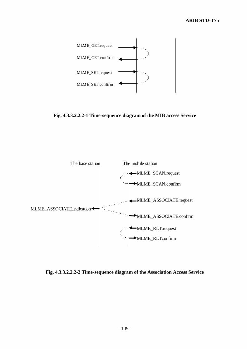
ARIB STD-T75
- 109 -
MLME_GET.request
MLME_GET.confirm
MLME_SET.request
MLME_SET.confirm
Fig. 4.3.3.2.2.2-1 Time-sequence diagram of the MIB access Service
The base station The mobile station
MLME_SCAN.request
MLME_RLT.request
MLME_ASSOCIATE.request
MLME_ASSOCIATE.indicationMLME_ASSOCIATE.confirm
MLME_SCAN.confirm
MLME_RLTconfirm
Fig. 4.3.3.2.2.2-2 Time-sequence diagram of the Association Access Service
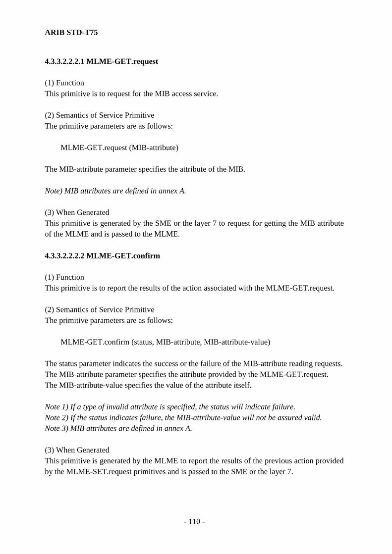
ARIB STD-T75
- 110 -
4.3.3.2.2.2.1 MLME-GET.request (1) Function This primitive is to request for the MIB access service. (2) Semantics of Service Primitive The primitive parameters are as follows: MLME-GET.request (MIB-attribute) The MIB-attribute parameter specifies the attribute of the MIB. Note) MIB attributes are defined in annex A. (3) When Generated This primitive is generated by the SME or the layer 7 to request for getting the MIB attribute of the MLME and is passed to the MLME. 4.3.3.2.2.2.2 MLME-GET.confirm (1) Function This primitive is to report the results of the action associated with the MLME-GET.request. (2) Semantics of Service Primitive The primitive parameters are as follows: MLME-GET.confirm (status, MIB-attribute, MIB-attribute-value) The status parameter indicates the success or the failure of the MIB-attribute reading requests. The MIB-attribute parameter specifies the attribute provided by the MLME-GET.request. The MIB-attribute-value specifies the value of the attribute itself. Note 1) If a type of invalid attribute is specified, the status will indicate failure. Note 2) If the status indicates failure, the MIB-attribute-value will not be assured valid. Note 3) MIB attributes are defined in annex A. (3) When Generated This primitive is generated by the MLME to report the results of the previous action provided by the MLME-SET.request primitives and is passed to the SME or the layer 7.
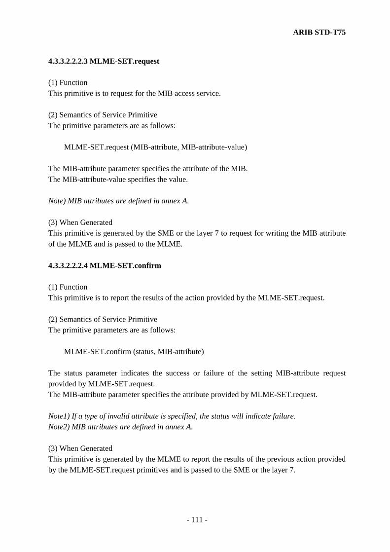
ARIB STD-T75
- 111 -
4.3.3.2.2.2.3 MLME-SET.request (1) Function This primitive is to request for the MIB access service. (2) Semantics of Service Primitive The primitive parameters are as follows: MLME-SET.request (MIB-attribute, MIB-attribute-value) The MIB-attribute parameter specifies the attribute of the MIB. The MIB-attribute-value specifies the value. Note) MIB attributes are defined in annex A. (3) When Generated This primitive is generated by the SME or the layer 7 to request for writing the MIB attribute of the MLME and is passed to the MLME. 4.3.3.2.2.2.4 MLME-SET.confirm (1) Function This primitive is to report the results of the action provided by the MLME-SET.request. (2) Semantics of Service Primitive The primitive parameters are as follows: MLME-SET.confirm (status, MIB-attribute) The status parameter indicates the success or failure of the setting MIB-attribute request provided by MLME-SET.request. The MIB-attribute parameter specifies the attribute provided by MLME-SET.request. Note1) If a type of invalid attribute is specified, the status will indicate failure. Note2) MIB attributes are defined in annex A. (3) When Generated This primitive is generated by the MLME to report the results of the previous action provided by the MLME-SET.request primitives and is passed to the SME or the layer 7.

ARIB STD-T75
- 112 -
4.3.3.2.2.2.5 MLME-SCAN.request (1) Function This primitive is to request for the association service in the mobile station. (2) Semantics of Service Primitive The primitive parameter has none. MLME-SCAN.request () (3) When Generated The layer 7 generates this primitive to request for the detection of the communication zone. Note) this primitive is only used on the mobile station side. 4.3.3.2.2.2.6 MLME-SCAN.confirm (1) Function This primitive is to report the results of the action associated with the MLME-SCAN.request. (2) Semantics of Service Primitive The primitive parameters are as follows: MLME-SCAN.confirm (service-code, release-time, ccz-status, tri-status) The service-code parameter specifies the value of the service application information (SC) field contained within the FCMC. The release-time parameter specifies the value of the release timer information (RLT) field contained within the FCMC. The ccz-status parameter specifies the identifier of the continuous communication zone (CCZ) subfield in the SIG within the FCMC. The tri-status parameter specifies the value of the Transmitter / Receiver Identifier subfield (TRI) in the FSI within the FCMC. (3) When Generated This primitive is generated by the MLME to report the detection of the communication zone provided by the MLME-SCAN.request and is passed to the layer 7. Note) this primitive is only used on the mobile station side.

ARIB STD-T75
- 113 -
4.3.3.2.2.2.7 MLME-ASSOCIAITE.request (1) Function This primitive is to request for the association service in the mobile station. (2) Semantics of Service Primitive The primitive parameters are as follows: MLME-ASSOCIATE.request (link-address, initialization-mode, application-id, priority) The link-address parameter specifies the private link address. The initialization-mode parameter specifies whether the simplified association (initialization) procedure is available in the mobile station. If it is available, the initialization-mode parameter shall be set to “1” and if it is not, its parameter shall be set to “0”. This parameter is the same value of the IMI within the link request information field (LRI). The application-id parameter specifies the application identification flag within LRI for multiplexing on the ACTC. The priority parameter specifies the assign demand field within the LRI for multiplexing on the ACTC. If the mobile station intends to demand the association request without priority, the priority parameter shall be set to “0” and if the mobile station demand the association request with priority, it shall be set to “1”. The protocol_ver parameter specifies the protocol version response identifier that is multiplexed into the link request data field LRI of the activation channel ACTC, which is available to the mobile station. (3) When Generated The layer 7 to demand the association with the base station and be passed to the MLME generates this primitive. Note) this primitive is only used on the mobile station side. 4.3.3.2.2.2.8 MLME-ASSOCIATE.confirm (1) Function This primitive is to report the results of the action provided the ASSOCIATE.request. (2) Semantics of Service Primitive The primitive parameter is as follows: MLME- ASSOCIATE.confirm (status)
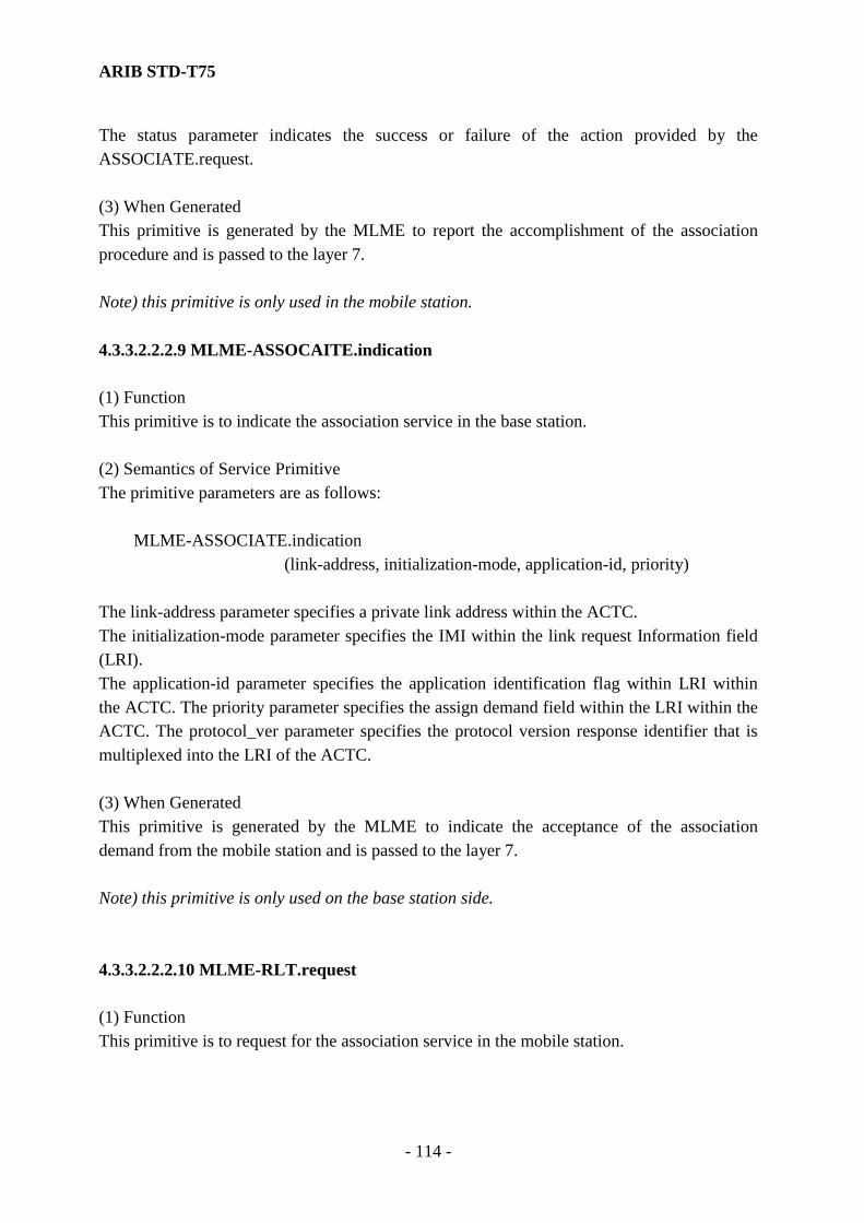
ARIB STD-T75
- 114 -
The status parameter indicates the success or failure of the action provided by the ASSOCIATE.request. (3) When Generated This primitive is generated by the MLME to report the accomplishment of the association procedure and is passed to the layer 7. Note) this primitive is only used in the mobile station. 4.3.3.2.2.2.9 MLME-ASSOCAITE.indication (1) Function This primitive is to indicate the association service in the base station. (2) Semantics of Service Primitive The primitive parameters are as follows: MLME-ASSOCIATE.indication (link-address, initialization-mode, application-id, priority) The link-address parameter specifies a private link address within the ACTC. The initialization-mode parameter specifies the IMI within the link request Information field (LRI). The application-id parameter specifies the application identification flag within LRI within the ACTC. The priority parameter specifies the assign demand field within the LRI within the ACTC. The protocol_ver parameter specifies the protocol version response identifier that is multiplexed into the LRI of the ACTC. (3) When Generated This primitive is generated by the MLME to indicate the acceptance of the association demand from the mobile station and is passed to the layer 7. Note) this primitive is only used on the base station side. 4.3.3.2.2.2.10 MLME-RLT.request (1) Function This primitive is to request for the association service in the mobile station.

ARIB STD-T75
- 115 -
(2) Semantics of Service Primitive The primitive parameter has none. MLME-RLT.request () (3) When Generated This primitive is generated by the layer 7 to detect the invalid state within a release timer information field (RLT) and is passed to the MLME. 4.3.3.2.2.2.11 MLME-RLT.confirm (1) Function This primitive is to report the results of the action associated with the MLME-RLT.request. (2) Semantics of Service Primitive The primitive parameters are as follows: MLME-RLT.confirm (service_code, release_time, ccz_status, tri_status) The service_code parameter specifies the value of the service code (SC) field contained within the FCMC. The release-time parameter specifies the value of the release timer information (RLT) field contained within the FCMC. The ccz-status parameter specifies the identifier of the continuous communication zone (CCZ) subfield within the SIG contained within the FCMC. The tri-status parameter specifies the value of the Transmitter / Receiver Identifier subfield within the FSI contained within the FCMC. (3) When Generated This primitive is generated by the MLME to report the detection of the invalid status of the validation bit of RLT and be passed to the layer 7. Note) this primitive is only used on the mobile station side. 4.3.3.3 Field Format of Protocol Data Unit (PDU) 4.3.3.3.1 Field Format of Protocol Data Unit The PDU of the MAC sublayer shall consist of a MAC control field and a link protocol control data unit (LPDU) as shown in Fig. 4.3.3.3.1-1 and Fig. 4.3.3.3.1-2. As the link address is contained in FCMC, it is not attached in the PDU. The LPDU length is different between ASK modulation and QPSK modulation.
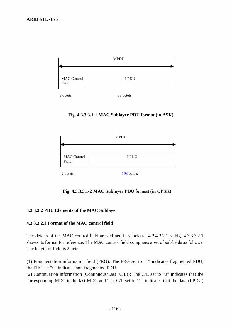
ARIB STD-T75
- 116 -
MAC Control Field
LPDU
MPDU
2 octets 65 octets
Fig. 4.3.3.3.1-1 MAC Sublayer PDU format (in ASK)
MAC Control Field
LPDU
MPDU
2 octets 193 octets
Fig. 4.3.3.3.1-2 MAC Sublayer PDU format (in QPSK)
4.3.3.3.2 PDU Elements of the MAC Sublayer 4.3.3.3.2.1 Format of the MAC control field The details of the MAC control field are defined in subclause 4.2.4.2.2.1.3. Fig. 4.3.3.3.2.1 shows its format for reference. The MAC control field comprises a set of subfields as follows. The length of field is 2 octets. (1) Fragmentation information field (FRG): The FRG set to “1” indicates fragmented PDU, the FRG set “0” indicates non-fragmented PDU. (2) Continuation information (Continuous/Last (C/L)): The C/L set to “0” indicates that the corresponding MDC is the last MDC and The C/L set to “1” indicates that the data (LPDU)

ARIB STD-T75
- 117 -
transmission is performed using one MDC or last MDC. (3) Command/Response (C/R): This field value is set according to the LLC control field of an LPDU. (4) Sequence number (SEQ): The sequence number of fragmented MPDUs. The sequence number is generated by modulus 16. (5) Length indicator of LPDU (LI): The valid data length of LPDU. Its length is 2 octets.
Sequence number
C/RC/L FRG
1 2 3 4 5 6 7 8bit number
LPDU data length
2nd octet
1st octet
LI
1 2 3 4 5 6 7 8
Reserved
SEQ
bit number
Fig. 4.3.3.3.2.1 Field Format of MAC control field 4.3.3.3.2.2 Field Format of LPDU The LDPU is 65 octets in ASK and 193 octets in QPSK. The LPDU shall consist of 65 octets. The LPDU is defined by encoding described in clause 4.3.4.2. 4.3.3.3.2.3 Bit Order Each sub-field shall be transmitted least significant bit (LSB) first, i.e. low order bit first (the first bit of transmitted data has a weight of 20.) Furthermore, a LPDU is transmitted in the bit sequence received from the LLC sublayer and is delivered to the LLC sublayer in the received bit sequence. 4.3.3.3.2.4 Transparency (1) ASK modulation A LPDU having a length of over 65 octets is fragmented multiple of 65-octet units in the MAC sublayer, and is transmitted using multiple frames (MDSs). Where the data length is less than 65 octets (including the case where it occurred as a result of fragmentation), zeros (“0”) shall be

ARIB STD-T75
- 118 -
inserted in the MAC sublayer up to 65 octets, and the data be unit of 65 octets. The information of fragmentation shall be multiplexed on the MAC control field, and be added to each fragmented data. The fragmented data is defragmented according to the information within the MAC control field. When the data length is less than 65 octets, the data is taken out in the length that is indicated in the second octet of the MAC control field, and inserted zeros (“0”) shall be removed. (2) QPSK modulation A LPDU having a length of over 193 octets is fragmented multiple of 193-octet units in the MAC sublayer, and is transmitted using multiple frames (MDSs). Where the data length is less than 193 octets (including the case where it occurred as a result of fragmentation), zeros (“0”) shall be inserted in the MAC sublayer up to 193 octets, and the data be unit of 193 octets. The information of fragmentation shall be multiplexed on the MAC control field, and be added to each fragmented data. The fragmented data is defragmented according to the information within the MAC control field. When the data length is less than 193 octets, the data is taken out in the length that is indicated in the second octet of the MAC control field, and inserted zeros (“0”) shall be removed. 4.3.3.3.2.5 Invalidity of MPDU The MAC sub-layer shall inspect all received MPDUs to access their validity. An invalid MPDU shall be defined as one that meets at least one of the following conditions: (a) The length of MPDU is not 67 octets in ASK or not 197 octets in QPSK. (b) The FRG of the MAC control field is “0” and the C/L is “1”. (c) The LI of the MAC control field is “0” (null of the LLC control field) or it is 66
octets or more in ASK or 194 octets or more in QPSK. (d) The link address of the MPDU received by the base station is a broadcast link address. If the frame received is invalid MPDU, it shall be discarded. 4.3.3.4 MAC Elements of Procedures 4.3.3.4.1 FCMC variables This variable manages the frame structure information comprised a set of SIG, FID, FSI, RLT and SCI. The information according to FCMC variable is transmitted using an FCMC. Detail of FCMC variable refers to subclause 4.2.

ARIB STD-T75
- 119 -
4.3.3.4.2 Assignment request variables (ASGN) A variable ASGN for slot assignment request has a form of a structure, and its members consist of an address variable ASGN.LID, a transmission direction variable ASGN.DIR, a response state variable ASGN.RS and a priority variable ASGN.PR. The ASGN.LID stores the link address assigned to the LID of the SCI. The ASGN.DIR field has “1” and “0” state; and “1” shall be set in the case of uplink transmission, and “0” shall be set in the case of the downlink transmission. The ASGN.RS field has “1” or “0” state; and “1” shall be set in the transmission with response, and “0” shall be set in the transmission without response. The ASGN.PR field has “1” or “0” state; and “1” shall be set where the assignment with priority is requested, and “0” shall be set where the normal assignment is requested. These variables are used on the base station side and shall be generated each time slot assignment is generated. 4.3.3.4.3 Transmission sequence state variable (TSQ, TSQ2) The MAC sublayer shall be able to maintain a set of transmit sequence state variables TSQ and TSQ2 for each unique SAP which is identified as the destination address with the transmission of an MPDU and shall manage values stored in the sequence number field (SEQ) of the MAC control field. This variable shall take on the values of 0 thorough 7 and shall be incremented by modulo 8 at the time of receiving the MSDU from the service access point (SAP). When a new private link address is established, the TSQ shall be generated and set at initial value “7” at the same time. TSQ2 shall have an array in a structural format, of which elements consist of a redundancy check state variable TSQ2.DUP and a transmission acknowledgement state variable TSQ2.ACK. TSQ2.DUP shall be generated by modulo 2. TSQ2.ACK shall store the result of receiving acknowledgement. TSQ2 shall be generated at the time of establishment of a new SAP. When it is generated, all elements of TSQ2.DUP shall be set to “0” and TSQ2.ACK shall be initialized into Ack. TSQ2 shall consist of 8 elements. 4.3.3.4.4 Receive sequence state variable (RSQ) The MAC sublayer shall be able to maintain one receive sequence state variable RSQ for each unique SAP which is identified as the destination address with the transmission of an MPDU. This variable shall be an array that stores the value of the most significant bit in the SEQ
ARIB STD-T75
- 120 -
within the MAC control field of the MPDU, which is received at an associated link address. (The most significant bit indicates Bit 8 of the 1st octet in the Mac control field, as shown in Fig. 4.3.3.3.2.1). RSQ shall consist of 8 elements. The least significant 3 bits in the SEQ shall indicate the storage location of the most significant bit in the SEQ. The variable insures the MAC sublayer to detect the reception of duplicated MPDU. When a new private link address is established, the RSQ shall be generated with its all elements set to an initial value “1”. 4.3.3.4.5 Retry counters of the base station (NFR1, NFR2, NFR1max, and NFR2max) These counters are used to set the number of times of retransmission of MDC in the MAC sublayer on the base station side. A NFR1 is used at the time of the downlink data transmission, and shall be initialized at the time of the first transmission. The NFR1 shall be incremented when the MPDU was transmitted from the base station to the mobile station and an Ack was not received with an ACKC of the corresponding slot. A NFR2 is used at the time of the uplink data transmission, and shall be initialized at the time of the first transmission. The NFR2 shall be incremented each time when the base station did not correctly receive the MPDU from the mobile station and a Nack was returned. This is the same function as that of the retry counter of the mobile station. It is used for the base station to watch the state of retrying from the mobile station. The NFR1 and the NFR2 exists by the number of slots assigned as the MDS. The NFR1max and the NFR2max represent maximum counter values. 4.3.3.4.6 Retry counter of the mobile station (NMR, NMRmax) A NMR is used to set the number of times of retransmission of the MDC at the MAC sublayer level on the mobile station side. The NMR is used at the time of the uplink data transmission, and shall be initialized at the time of the first transmission. The NMR shall be incremented when the MPDU was transmitted from the mobile station to the base station and the Ack was not received with the ACKC of the corresponding slot. A NMRmax represents the maximum number of times of the retransmission. 4.3.3.4.7 Link request counter (NRQ, NRQmax) This counter (NRQ) is used on the mobile station side. This counter counts the number of times of transmission of the ACTC. The NRQ field shall be set to “1” at the time of first transmission.
ARIB STD-T75
- 121 -
The NRQ field shall be incremented each time ACTC is transmitted, until a link address is set at the SCI in the FCMC. The NRQ shall be created when ACTC transmission conditions are satisfied, and shall be deleted at the time of the accomplishment of the association. NRQmax represents the maximum number of times of transmission. 4.3.3.4.8 Re-link Entry request restriction Counter (NRT) This counter is used that sets the standby time until a re-association (re-link entry) request is made, where the MDS is not assigned for own private link address, on the mobile station side. The NRT shall be set at the initial value after transmission of the ACTS, and shall be decrement “1” at the time when FCMC is detected. The initial value shall be set according to the STA field in the SCI. The NRT shall be created when ACTC transmission conditions are satisfied, and shall be deleted at the time of the accomplishment of the association. 4.3.3.4.9 Base station connection variables (NUMLINK, MAXLINK) The NUMLINK shall be the current number what the base station has accomplished the association with mobile stations. The MAXLINK shall be the maximum number of the NUMLINK that indicates available number of addresses holding for communication. Comparing the NUMLINK and the MAXLINK, it is able to judge the traffic congestion or the possibility of reception of ACTCs. The number of the NUMLINK shall be incremented by “1” each time the layer 7 has accepted an association request and be decremented by “1” each time the layer 7 has released a communication link. Using services provided by the MLME makes revision of the number of the NUMLINK. 4.3.3.4.10 Base station assignment variable (ASL, ASLmax) The ASL is the number of ACTSs per frame, which the base station could assign. The number of the ASL is 1 through ASLmax. This variable is used on the base station side. The ASLmax shall be the maximum available number of assignment slots per frame. 4.3.3.4.11 WCNC transmission counter (WTC, WTCmax) The WTC is the counter that counts the number of transmission the WCNC. The WTC shall be set to initial value “0” when the mobile station enter the newly communication zone. The WTC

ARIB STD-T75
- 122 -
shall be incremented by “1” when of the transmission of the WCNC has been accomplished. The initial value is “0”. The WTCmax is the maximum number of transmissions. 4.3.3.4.12 Slot assignment state variable (SLT_STATUS) The SLT_STATUS indicates the state of the slot assignment on the base station side. When there are non-processing ASGN variables, the SLT_STATUS indicates the admission of the transmission immediately (in_time). When there is ASGN variable waiting for processing, the SLT_STATUS indicates the restriction of the transmission immediately (out_time). Using this variable, the layer 7 performs the data transmission procedures by layer management services provided by the MLME. 4.3.3.4.13 Transmission state variables (TR_STATUS, NUMQ, FQBUSY, MQBUSY) The TR_STATUS is a variable, which indicates the state of the waiting for transmission. The NUMQ is a variable, which indicates the number of the MPDUs that are waiting for transmission. The FQBUSY is threshold value for the judgment of the base station transmission state. The MQBUSY is threshold value for the judgment of the mobile station transmission state. On the base station side, when the NUMQ, which indicates the number of the MPDUs that are waiting for transmission, is larger than the FQBUSY, the TR_STATUS shall indicate the busy state, and if it is smaller than the FQBUSY, it shall indicate the idle state. On the mobile station side, when the NUMQ, which indicates the number of the MPDUs that are waiting for transmission, is larger than the MQBUSY, the TR_STATUS shall indicate the busy state, and if it is smaller than the MQBUSY, it shall indicate the idle state. Using these variables, the layer 7 performs the data transmission procedures by layer management services provided by the MLME. 4.3.3.4.14 Maximum transmission size variable (MSIZE) MSIZE is a variable indicating the maximum data length that can be transferred via MDC1 channel. The base station shall set the following value in accordance with its own profile. The

ARIB STD-T75
- 123 -
mobile station shall set the value according to the profile (signal transmission rate) specified by the base station. The value of MSIZE shall be 65 octets in ASK and 193 octets in QPSK. 4.3.3.4.15 Management Information Base (MIB) A MIB is the database constructed for management of layer consisting of variables which determine frame structure such as the FCMC information, control variables, etc. The layer management entity of the MAC sublayer only allows access this MIB directly. Furthermore, another layer management entity allows access to the MIB indirectly using services between layer management entities. PR, UW1, UW2 (UW2, UW2A, UW2B), CRC specified in the FCMC and the ACTC are not registered in the MIB since they are added at the time of transfer to Layer 1. The details about the MIB are specified in Annex A. 4.3.3.5 Procedures for the MAC Sublayer The procedures for the MAC sublayer are described as divided into the base station and the mobile station. The state machine that corresponds to these procedures is appended to Annex F for reference. 4.3.3.5.1 Frame Management 4.3.3.5.1.1 Frame Management of the base station On the base station side, using MIB access services, the frame structure that corresponds to the operation configuration shall be registered in the MIB (management information base) constructed for the layer management entity previously. 4.3.3.5.1.1.1 Generation of Frames (1) Generation of the FCMS The parameters of the control field consisting of the SIG, FID, FSI, RLT,SC and SCI are defined as variables in the MIB. The FCMC shall be generated according to the time base of the frame, with reference made to this information. (2) Generation of the MDS A MDS is the slot which the SI (b1, b2) of the SCI defined in the MIB is “00”. Reading the

ARIB STD-T75
- 124 -
information of the SI in time series according to the transmission sequence of SCIs in slot units, in the case of the half-duplex mode it shall indicate the slot position of generation of the MDS. In the case of the full-duplex mode (the base station), the slot positions of MDSs of downlink and uplink are indicated by sequentially reading odd-numbered SCIs and even-numbered SCIs. Furthermore, referencing the DR control field simultaneously controls the transmission and the reception. (3) Generation of the ACTS (link request slot) An activation slot (ACTS) is a slot referenced in which the SI (b1, b2) of the SCI defined in the MIB is “11”. The position of generation of the link request slot shall be indicated by reference information of the SI in time series according to the transmission sequence of SCIs in slot units, in the case of the half-duplex mode. In the case of the full duplex mode, the positions of the ACTS are indicated by sequentially reading SCIs of even numbers. The slot indicated as the link request slot is dedicated to uplink. (4) Generation of the WCNS A WCNS is a slot referenced in which the SI (b1, b2) of the SCI defined in the MIB is “10”. The position of generation of the WCNS (Call sign) shall be indicated by reference information of the SI in time series according to the transmission sequence of SCIs in slot units, in the case of the half-duplex mode. In the case of the full duplex mode, the position of WCNS is indicated by sequentially reading SCIs of even numbers. The slot indicated as WCNS is dedicated to uplink. 4.3.3.5.1.1.2 Transmission/Reception Procedures (1) Transmission of the FCMC The PR and UW1 are added to the first of the FCMC, which is generated according to the time base of the frame. Furthermore, the 16-bits CRC calculated from the data field except the PR and UW1 is added to the end of the FCMC, before being delivered to the layer 1.
(2) Reception of the ACTC A comparison shall be made between a unique remainder value and a result, which is calculated, from the serial incoming bits of the data, except the PR and UW2, passed from the layer 1 to the position of the ACTC of the slot indicated by the information of the MIB. Where it shows equality, portions of the FID, LID and LRI shall be taken out and be passed to the procedure of association, which is described in detail in subclause 4.3.3.5.1.1.3. Where it shows inequality, the corresponding ACTC shall be discarded, and portions of the FID, LID and LRI shall not transfer to the association procedures.
ARIB STD-T75
- 125 -
Note) the CRC procedure is specified in compliance with ITU-R recommendations. However, another procedure may be adopted if it could check errors correctly. (3) Reception of WCNC The reception of the WCNC is not specified. 4.3.3.5.1.1.3 Association 4.3.3.5.1.1.3.1 Reception of Association Request The base station shall receive ACTCs and process these, when the ACPI bits of the SCI in all ACTSs are set to “1”. Where the LID of the received ACTC is not a private link address, the corresponding ACTC is ignored. The corresponding ACTC is ignored also where the priority assignment bit of the ACTC is “0” (association request without priority) and valid flag is not set in the LRI (application identification flags). Valid ACTCs are processed in the reception sequence procedures. Where the current connection variable NUMLINK set in the MIB does not exceed the maximum connection variable MAXLINK when an ACTC has been received, the base station shall generate MLME-ASSOCIATE.indication primitive. Hereafter, it shall report the layer 7 reception of ACTC and it is regarded as reception of an association request (acceptance of an ACTC or link request) from a newly arrived mobile station. However, when the priority assignment bit of the ACTC is set to “1” (association request with priority), an association request shall be received unless all of MDSs are assigned priority assignment (slot in which the ST of the SCI is not “000” exists) and the MLME-ASSOCAITE.indication shall be generated. Note) The layer 7 judges whether or not the association request passed from the layer 2 accepts. 4.3.3.5.1.1.3.2 Assignment for Normal MDSs Where data transmission request occurs, the assignment request variable ASGN for requesting slot assignment shall be generated.

ARIB STD-T75
- 126 -
(1) Generation of Assignment Request If an LPDU is received from the LLC sublayer of the base station, its link address shall be set in ASGN.LID field and the ASGN. PR field shall be set to “0” (normal type of assignment). Other parameters are specified as follows. (a) Where the response-request parameter within the MA-UNITDATA.request passed from the LLC sublayer is “0” or “4”, the ASGN.RS field shall be set to “0” (without response) and the ASGN.RS field shall be set to “0” (downlink). (b) Where the response-request parameter within the MA-UNITDATA.request passed from the LLC sublayer is “1” or “3”, the ASGN.RS field shall be set to “1” (with response) and the ASGN.RS field shall be set to “0” (downlink). (c) Where the response-request parameter within the MA-UNITDATA.request passed from the LLC sublayer is “2”, the ASGN.RS field shall be set to “0” (without response) and the ASGN.RS field shall be set to “1” (uplink). Note) Refer to subclause 4.3.3.2.1.2.1 for parameters of MA-UNITDATA.request.
(2) Assignment Procedures Assignment procedures of the MDS shall be performed each time the generation of the ASGN is detected. In the MDS assignment procedures, if ASGN.DR is “0” (downlink transmission), an assigned downlink slot (a slot whose ST bit of the SCI is “111” and DR bit is “0”) shall be searched to check the presence of a slot whose LID of the SCI is the same as that of ASGN.LID. If a slot with the same LID is identified, it shall be determined whether the assigned MPDU or the MPDU to be assigned to the concerned slot has already been applied with the fragmentation procedure (refer to Subclause 4.3.3.5.2.1.2.1). Then, if the fragmentation procedure has been applied, the assignment procedure of the concerned ASGN shall be suspended. Whereas, if there is no slot with the same LID of the SCI, or there is such a slot to which the fragmentation procedure is not applied, the assignment procedure of the concerned ASGN shall be conducted. When ASGN.DR is “1” (uplink transmission), an assigned uplink slot (a slot whose ST bit of the SCI is “111” and DR bit is “1”) is searched to check the presence of a slot whose LID of the SCI is the same as that of ASGN.LID. If a slot with the same LID is identified, the assignment procedure of the concerned ASGN shall be suspended. Whereas, if there is no slot with the same LID of the SCI, the assignment procedure of the concerned ASGN shall be conducted. Slots able to be assigned are MDSs that the SCI indicate as empty channels or set as a WCNC. When an unassigned SCI (ST (b5, b6, b7) is “011”) exists, the assignment procedures is performed in the following manner.
ARIB STD-T75
- 127 -
The ASGN.LID shall be set to the LID of the SCI defined in the MIB. Furthermore, the ASGN.DIR shall be set to the DR bit of the SCI, and ST bit of the SCI shall be set to “111” (normal data channel). Assignment procedure of the ASGN, the ASGN.PR of which was set at “0”, is kept holding where all the SCIs have been assigned or during FCMS transmission period. After the accomplishment of the assignment of MDSs, the ASGN shall be deleted if the ASGN.RS is “0”. Furthermore, it shall be not deleted when the ASGN.RS is “1”, but the ASGN.DIR shall be replaced by its complement value, and it is regarded as a new assignment request variable. In the half duplex-mode, an MDS for the uplink transmission shall be assigned in the same slot. In the full duplex-mode, it shall set the ASGN.RS to “0” and it is regarded as a newly assigned request variable and it shall find an available slot for assignment. In this case, the slot searching procedure should assign in respect with maintaining slot distance of 1 slot in length from corresponding downlink slot. 4.3.3.5.1.1.3.3 Priority MDS Assignment Procedures (1) Generation of Assignment Request Where the priority assignment bit of the ACTC is “1” (association request with priority), the ASGN shall be generated in the following manner. The link address transmitted by the ACTC shall be set to the ASGN.LID, and the ASGN.DIR shall be set to “1” (uplink transmission), and the ASGN.RS shall be set to “0” (without response), and the ASGN.PR shall be set to “1” (priority assignment). (2) Assignment procedure If the ASGN.PR of which was set at “1”, the ASGN shall be set the ASGN.LID at the LID of the SCI, set the ASGN.DIR at the DR bit of the SCI and set “000” (data channel with priority assignment) at the ST bit for assignment. The procedure of assignment shall be performed in the following manner. (a) If there is any ASGN, assignment of, which was kept suspended, the assignment shall be made with precedence over such an ASGN. (b) Where no allocable slot was found, the SCI of a slot which is not possessed by priority assignment (the ST bit of the SCI is not “000”) shall be saved and made the assignment. The saved SCI shall be returned with priority when an empty slot becomes available.

ARIB STD-T75
- 128 -
Assignment procedure with priority should be accomplished in the frame in which ASGN has been generated. ASGN shall be deleted after accomplishment of assignment of MDS. 4.3.3.5.1.1.3.4 Termination of Assignment of MDS The assignment shall terminate under the following conditions. (1) The link address is a multicast (group) or broadcast address. The C/L bit of the MAC control field of MPDU for transmission is “0”. (2) I the case of that the link address is a private address. (a) The C/L bit of the MAC control field of MPDU for reception is “0” and the Ack was received in the received ACKC, or the NFR1 exceeded the NFR1max. (b) The C/L bit of the MAC control field of an MPDU for transmission is “0” and the Ack is
transmitted in the ACKC, or NFR2 exceeded NFR2max. The subfield of the ST bit field (b5, b6, b7) shall be set to “011” (empty data channel) after the accomplishment of the assignment. At this time, the LID of the subject SCI shall not change. 4.3.3.5.1.1.4 Traffic flow control (1) Flow control parameter setting Traffic control information, state of acceptance of ACTCs (STA) and activation possibility identifier (ACPI), that are multiplexed on an FCMC, are specified using the connection variables (NUMLINK, MAXLINK). The STA shall have 4 level threshold values in the range of “0” through MAXLINK. The STA shall decide by comparing with these threshold values and the current NUMLINK. However, these threshold values are not defined in these standards, since it is a matter of implementation. If the current NUMLINK is less than MAXLINK, it shall set the ACPI to “1”. If the current NUMLINK is the same of MAXLINK, the processing ability has reached its limit. Hereafter, the ACPI shall be set to “0” (inhibition of transmission of an ACTC) for avoidance of traffic congestion. Note 1) refer to subclause 4.3.3.4.8 for connection variables. Note 2) Threshold values for determining the STA are shown in annex A for reference. Note 3) if plural ACTSs are assigned in the same frame, the STA value or the ACPI value of each slot shall be set to the same value.

ARIB STD-T75
- 129 -
(1) The assignment number of ACTSs The assignment number of ACTSs (ASLN) per one frame is from “0“ to ASLNmax at will, according to the state of connection variable. The ASLN should be determined as the following manner. Threshold values have some levels in the range of “0” through MAXLINK and the assignment number of ACTSs is determined by comparing with these threshold values and the current NUMLINK. However, these threshold values are not defined in this standard, since it is a matter of implementation. Note) the assignment of ACTSs is performed according to the procedure specified in subclause 4.3.3.5.1.1.6. 4.3.3.5.1.1.5 Management of the trasmission state The MAC sublayer shall manage the state of transmission for supporting the efficiently transmission procedures in the layer 7. For that, the MAC sublayer of the base station shall manage the slot assignment state variable (SLT_STATUS) and the transmission request state variable (TR_STATUS). Note) refer to subclause 4.3.3.4.11 for the SLT_STATUS and refer to subclause 4.3.3.4.12 for the TR_STATUS. 4.3.3.5.1.1.6 ACTS and WCNS assignment procedures The assignment of ACTCs and WCNSs should be performed during a certain period (from the head of FCMS to the end of the SC of the FCMC), since the assignment procedure for MDSs is prohibited during this period. (1) Assignment of ACTSs The ACTSs, with numbers previously determined according to the traffic flow control procedures defined in subclause 4.3.3.5.1.1.4, are assigned for slots that the SCI indicates as empty channel MDSs (the SI (b1, b2) is “ 00” and the ST (b5, b6, b7) is “011”). The slot searching for the empty channel MDSs should be made over SCI fields in due order from the end of SCIs (from a field corresponded to the end of the frame). If an empty channel MDS is available, the SI of SCI of corresponding slot shall set to “11”, hereafter, the ACTS shall be assigned.
ARIB STD-T75
- 130 -
If there is assignment for ACTSs in remainder slots, the assignment of subject slots shall be reset. This reset shall set the SCI corresponding slot to an empty channel MDS. In this case, the LID of the subject SCI shall set to a broadcast link address and it shall set the DR to “1” (uplink). (With this, it is able to avoid the assignment for a WCNS.) Note) the number of assigned ACTSs may be less than the ASLN. (2) Assignment of WCNSs The WCNS assignment shall be available for slots that the SCI indicates an empty channel MDS and the LID of it is a private link address. Since the identification of a mobile station for the WCNC is made by using the LID within the empty channel MDS. If an empty channel MDS is available, the SI (b1, b2) of corresponding slot′s SCI shall be set to “10”, hereafter, the WCNS shall be assigned. 4.3.3.5.1.1.7 Assignment of Idle channel MDS The assignment of an idle channel MDS shall be performed for a slot that indicates an empty channel MDS or a WCNS. Its procedure is not defined in this standard. 4.3.3.5.1.2 Frame Management of the mobile station The mobile station registers the frame structure information transmitted from the base station at the MIB constructed of the MLME, to maintain the compatibility with communication parameters of the base station. 4.3.3.5.1.2.1 Regeneration of Frames (1) Judgment of the communication zone and regeneration of the FCMC information On the receiving the MLME_SCAN.request primitive passed from the layer 7, the MLME of the mobile station shall performs the judgment procedures for a type of communication zone and a frequency type (FTI) of physical medium channel. This judgment procedures is specified in subclause 4.2.8. After accomplishment of the judgment procedures for communication zone, where the FCMC is acknowledged as a valid frame by the inspection of CRC field, the FCMC information (SIG, FID, FSI, RLT and SC) shall be registered at the MIB. After the registration of these variables, the MLME shall generate MLME-SCAN.confirm primitives of which the parameters are set from the MIB and pass this primitive to the layer 7.
ARIB STD-T75
- 131 -
After registration at the MIB, the MLME shall generate the MLME_SCAN.confirm primitive, which is consisted of a set of parameters defined according to that registration information, and pass it to the layer 7. The information that has been registered once at the MIB shall not be revised until MLME-SCAN.request primitive is passed from the layer 7. (When the layer 7 moves to the state of association (initialization) waiting procedures), it shall pass the MLME-SCAN.request primitive to release the inhibiting state for revision of the MIB information. The subfield of SCI in FCMC shall not adopted these procedure defined above. Where the FCMC is acknowledged as a valid frame by the inspection of the CRC field and the FID of corresponding FCMC is the same FID that is previously registered at the MIB, the subfields of SCI shall be registered at the MIB one by one. (2) Generation of the MDS A valid MDS of the mobile station shall be a slot referenced as follows. The SI bit of the SCI is “00”, and the ST bit (b5, b6, b7) is not “011” (empty data channel), and the address indicated by LID is a private link address which has passed from the layer 7 to the MLME, link address broadcast or multicast (group) link address. Reading out of the MIB the LIDs of the SCI, in which the SI (b1, b2) is “00” and the ST bit (b5, b6, b7) is not “011”, in slot units corresponding with the SCI transmission sequence, the MDS positions shall be indicated by comparing them with that addresses in the case of half-duplex mode. In the case of full-duplex mode, the positions of MDSs of downlink and uplink shall be indicated by sequentially reading odd-numbered SCIs and even-numbered SCIs and by comparing them with those addresses. Furthermore, reading the DR bit simultaneously shall control transmission and reception. (3) Generation of the ACTS An ACTS shall be a slot referenced in which the SI bit of the SCI registered in the MIB is “11”. The positions of assignment of link request slots shall be indicated by reading the information of the SI bit (b1, b2) in time series corresponding with the SCI transmission sequence in slot units, in the case of half-duplex mode. In the case of full-duplex mode, the positions shall be indicated by sequentially reading even-numbered SCIs. The slots indicated as link request slots should be dedicated to transmission.

ARIB STD-T75
- 132 -
(4) Generation of the WCNS (Call sign) A WCNS is a slot referenced in which the SI (b1, b2) of the SCI registered at the MIB is “10”. The position of generation of the WCNS shall be indicated by referencing the information of the SI in time series corresponding with the transmission sequence of SCIs in slot units, in the case of the half-duplex mode. In the case of the full duplex mode, the position of WCNS is indicated by sequentially reading SCIs of even numbers. 4.3.3.5.1.2.2 Transmission/Reception Procedures (1) Reception of FCM
The mobile station shall interpret slot positions from FCMS beginning at UW1 of FCMC, and reproduces the time base of the frame. A comparison shall be made between a unique remainder value and a result which is calculated from the serial incoming bits of the data, except the PR and UW1, passed from the layer 1 to the position of the FCMS indicated by the time base of the frame.
The FCMC shall transfer to the layer management if the comparison shows equality. If the comparison shows inequality, the corresponding frame is regarded as an invalid frame and shall be not processed. (2) Transmission of ACTC PR and UW2 shall add FID, LID and LRI generated according to an association (initialization) request specified in subclause 4.3.3.5.1.2.3 at the head. Furthermore, the 16 bits CRC calculated from data codes except PR and UW2 shall be added to the end and delivery is made to the layer 1. (3) Transmission of WCNC (Call sign) Where a WCNS indicated by its own link address is assigned, it shall inspect whether the current WTC value is less than the WTCmax registered at the MIB or not. If it is less than the WTCmax, the WCNC shall be generated in the format (refer to annex C) in compliance with the registered information at the MIB in the position of the WCNC window, which is specified in subclause 4.2.4.2.4. This WCNC is delivered to the layer 1 as it is. If the current WTC exceeds the WTCmax, it shall be not made the WCNC transmission. The value of WTC shall be incremented by “1” each time of a WCNC transmission. 4.3.3.5.1.2.3 Normal Association The normal association (initialization) procedure is performed when the MLME has received the MLME-ASSOCIATE.request primitive and the priority parameter indicated the normal association procedure.
ARIB STD-T75
- 133 -
(1) The generation of the MLME-ASSOCIATE.request On the generating the MLME-ASSOCIATE.request primitive, the layer 7 of a mobile station shall meet the following conditions, (a) The layer 7 has received the MLME-SCAN.confirm primitive from the MLME. (b) One of applications registered in the layer 7 is available for an application notified from the base station using the SC field. (2) FID field The FID specifies the value of the MIB, which has been registered after the justification procedures of the communication zone. (3) LID field The MLME shall use a private link address within the MLME-ASSOCIATE.request primitive passed from the layer 7 for the association request. If it is a private link address, the MLME shall register it the LID field for the ACTC of the MIB. If it is a broadcast address or multicast address, the MLME shall not register it and ignore the MLME-ASSOCIATE.request primitive. (4) Link request information (LRI) field The LRI parameter shall use the parameter contained within the MLME-ASSOCIATE.request primitive passed from the layer 7. This parameter shall be registered in the LRI field within the ACTC of the MIB and the ACTC shall be transmitted using this LRI parameter. The initialization_mode parameter within the MLME_ASSOCIATE.request primitives shall correspond to the IMI (the initialization mode identifier). The application-id parameter shall correspond to the API (the application identifier). The protocol version identifier (PV I) specifies the value previously registered in the MIB. (5) Transmission of ACTC The transfer of an ACTC is allowed using one of ACTSs that are referenced where the SI bit (b1, b2) of the SCI registered in the MIB is “11”. However, if one of ACTSs in the same fame set the ACPI “ 0 “, the transmission of the ACTC shall be suspended. One ACTC could be transmitted using an arbitrary position (window) out of ACTC positions (windows) illustrated in Fig. 4.2.4. This position shall be selected at random for each transmission. On receiving the MLME-ASSOCIATE.request primitive, link request counter NRQ and re-link entry request constraint counter NRT shall be generated, and the NRQ shall be set at
ARIB STD-T75
- 134 -
initial value “1” at this time. The NRQ shall be incremented by “1” and the NRT shall be set at the initial value after accomplishment of transfer of the ACTC. (The NRT shall be decremented by “1” at the time when the FCMS is indicated.) Where a transmitted link address was detected out of SCI in the next frame or subsequent of the ACTC transfer frame, the transmission of the ACTC shall terminate. At the same time, the NRQ and the NRT shall be deleted and the MLME_ASSOCIATE.confirm primitive with status parameter indicating “success” shall be generated and be passed to the layer 7. Where a transmitted link address was not detected out of SCI in the next frame or subsequent of the ACTC transfer frame, an ACTC shall be transferred again at the time when the value of NRQ becomes “0”. Transmission of ACTC shall be stopped when NRQ exceeds NRQmax as a result of retransmission and the MLME_ASSOCIATE.confirm primitive with status parameter “ failure” shall be created and be passed to the layer 7. The initial value of the NRT shall be determined according to the traffic flow control information set at the STA of the FCMC. Note) the conditions for the determination of the NRT value are shown in annex A for reference. 4.3.3.5.1.2.4 Association request with Priority Only when the priority parameter of the MLME-ASSOCIATE.request primitive passed from the layer 7 is “1”, which means demanding the MDS assignment with priority, the priority assignment bit of the ACTC may be set to “1”. In this case, if the communication is in progress, the communication should be quickly interrupted and the ACTC should be transmitted. The transmitting operation is performed for each frame until the MDS is assigned. (The initial value of the NRT is “1”.) Furthermore, repeating transmission operation shall not be constrained by the NRQmax. Note) The condition for the priority assignment, further definition is required elsewhere. However, it is outside of the scope of this standard. 4.3.3.5.1.2.5 Management of transmission state Giving support to the efficient transmission procedure in the Layer 7, the MAC sublayer should manage the transmission state. On the mobile station side the MAC sublayer should manage transmission state variables.
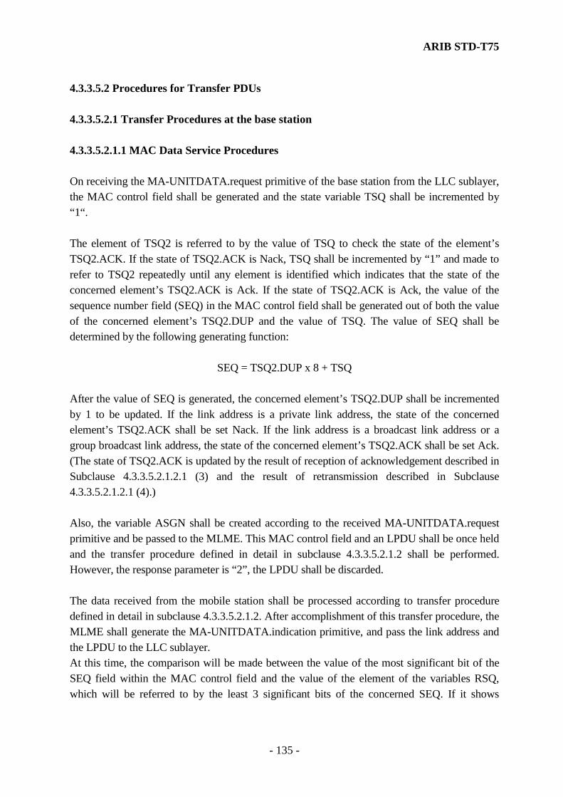
ARIB STD-T75
- 135 -
4.3.3.5.2 Procedures for Transfer PDUs 4.3.3.5.2.1 Transfer Procedures at the base station 4.3.3.5.2.1.1 MAC Data Service Procedures On receiving the MA-UNITDATA.request primitive of the base station from the LLC sublayer, the MAC control field shall be generated and the state variable TSQ shall be incremented by “1“. The element of TSQ2 is referred to by the value of TSQ to check the state of the element’s TSQ2.ACK. If the state of TSQ2.ACK is Nack, TSQ shall be incremented by “1” and made to refer to TSQ2 repeatedly until any element is identified which indicates that the state of the concerned element’s TSQ2.ACK is Ack. If the state of TSQ2.ACK is Ack, the value of the sequence number field (SEQ) in the MAC control field shall be generated out of both the value of the concerned element’s TSQ2.DUP and the value of TSQ. The value of SEQ shall be determined by the following generating function:
SEQ = TSQ2.DUP x 8 + TSQ After the value of SEQ is generated, the concerned element’s TSQ2.DUP shall be incremented by 1 to be updated. If the link address is a private link address, the state of the concerned element’s TSQ2.ACK shall be set Nack. If the link address is a broadcast link address or a group broadcast link address, the state of the concerned element’s TSQ2.ACK shall be set Ack. (The state of TSQ2.ACK is updated by the result of reception of acknowledgement described in Subclause 4.3.3.5.2.1.2.1 (3) and the result of retransmission described in Subclause 4.3.3.5.2.1.2.1 (4).) Also, the variable ASGN shall be created according to the received MA-UNITDATA.request primitive and be passed to the MLME. This MAC control field and an LPDU shall be once held and the transfer procedure defined in detail in subclause 4.3.3.5.2.1.2 shall be performed. However, the response parameter is “2”, the LPDU shall be discarded. The data received from the mobile station shall be processed according to transfer procedure defined in detail in subclause 4.3.3.5.2.1.2. After accomplishment of this transfer procedure, the MLME shall generate the MA-UNITDATA.indication primitive, and pass the link address and the LPDU to the LLC sublayer. At this time, the comparison will be made between the value of the most significant bit of the SEQ field within the MAC control field and the value of the element of the variables RSQ, which will be referred to by the least 3 significant bits of the concerned SEQ. If it shows

ARIB STD-T75
- 136 -
equality, the corresponding LPDU shall not pass to the LLC sublayer and be discarded, since the LPDU is duplicated. After the comparison of the RSQ and the TSQ values has completed, the most significant bit of the concerned SEQ shall be stored in the element of the RSQ to be referred to by the least 3 significant bits of the concerned SEQ for a duplication inspection next time. If a duplicated reception is identified, a slot for uplink transmission shall be reassigned to the concerned mobile station. This is just as in the case of receiving a MA-UNITDATA request primitive in which the parameter “response_request” is set to “2” from the base station. Note1) The inspection of the continuance, defined in subclause 4.3.3.5.2.1.2, for the sequence number SEQ within the receiving PDU passed after the accomplishment of the transfer procedures shall not be performed. Note2) The relationship between the TSQ, the RSQ, and MAC control subfields is shown table 4.3.3.5.2.1.1 for reference.
Table. 4.3.3.5.2.1.1 The relationship between the TSQ, the RSQ, and MAC control subfields
Frame Numbers
1 2 3 4 5 6 7 8 9 10 11 12
TSQ (transmission side)
0 1 2 3 4 5 6 7 8
TSQ2.DUP (transmission side)
0 0 0 0 0 0 0 0 1
FRG 0 0 1 1 1 0 0 1 1 0 0 0 C/L 0 0 1 1 0 0 0 1 0 0 0 0 SEQ 0 1 2 3 4 3 4 5 6 6 7 8 SEQ (reception side) comparison with the RSQ
0 1 2 3 4 5 6 7 8
Fragmentation within frames. Fragmentation within frames.
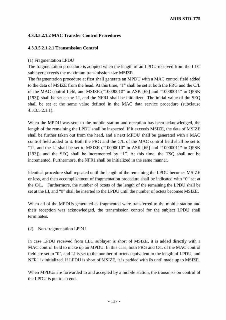
ARIB STD-T75
- 137 -
4.3.3.5.2.1.2 MAC Transfer Control Procedures 4.3.3.5.2.1.2.1 Transmission Control (1) Fragmentation LPDU The fragmentation procedure is adopted when the length of an LPDU received from the LLC sublayer exceeds the maximum transmission size MSIZE. The fragmentation procedure at first shall generate an MPDU with a MAC control field added to the data of MSIZE from the head. At this time, “1” shall be set at both the FRG and the C/L of the MAC control field, and MSIZE (“10000010” in ASK [65] and “10000011” in QPSK [193]) shall be set at the LI, and the NFR1 shall be initialized. The initial value of the SEQ shall be set at the same value defined in the MAC data service procedure (subclause 4.3.3.5.2.1.1). When the MPDU was sent to the mobile station and reception has been acknowledged, the length of the remaining the LPDU shall be inspected. If it exceeds MSIZE, the data of MSIZE shall be further taken out from the head, and a next MPDU shall be generated with a MAC control field added to it. Both the FRG and the C/L of the MAC control field shall be set to “1”, and the LI shall be set to MSIZE (“10000010” in ASK [65] and “10000011” in QPSK [193]), and the SEQ shall be incremented by “1”. At this time, the TSQ shall not be incremented. Furthermore, the NFR1 shall be initialized in the same manner. Identical procedure shall repeated until the length of the remaining the LPDU becomes MSIZE or less, and then accomplishment of fragmentation procedure shall be indicated with “0” set at the C/L. Furthermore, the number of octets of the length of the remaining the LPDU shall be set at the LI, and “0” shall be inserted to the LPDU until the number of octets becomes MSIZE. When all of the MPDUs generated as fragmented were transferred to the mobile station and their reception was acknowledged, the transmission control for the subject LPDU shall terminates. (2) Non-fragmentation LPDU In case LPDU received from LLC sublayer is short of MSIZE, it is added directly with a MAC control field to make up an MPDU. In this case, both FRG and C/L of the MAC control field are set to "0", and LI is set to the number of octets equivalent to the length of LPDU, and NFR1 is initialized. If LPDU is short of MSIZE, it is padded with 0s until made up to MSIZE. When MPDUs are forwarded to and accepted by a mobile station, the transmission control of the LPDU is put to an end.

ARIB STD-T75
- 138 -
(3) Reception of an acknowledgement When the MPDU generated by the procedure mentioned above was sent, it should wait for reception of the ACKC during the certain period indicated by a transfer slot. If the AI was not obtained from the ACKC during this period or if the Nack was received at the AI, the NFR1 shall be incremented and the retransmission procedure indicated below shall be executed. Where the Ack was received at the AI, transfer of the subject MPDU shall terminate, and the subject MPDU shall be discarded. In this case, the element of the transmission state variable, TSQ2, is looked up using the three least significant bits of the sequence number field (SEQ) of the MAC control field for the MPDU, and the status of the transmission confirmation state variable, TSQ2.ACK, which is one of the members of its element, is turned Ack. Provided that if the MPDU in question has been fragmented as aforesaid, the processing is carried out for the sequence number affixed to the first of the segments into which the MPDU is fragmented. The status will be changed when the Ack for the last fragment has been received. This acknowledgement transmission procedure shall only be applied to the transmission of MPDU indicated by a private link address, and not to the transmission of MPDU indicated by multi-group or broadcast link addresses. (4) Retransmission Retransmission procedure is performed when the transfer slot of the MPDU could not receive the Ack at the AI obtained from the ACKC (the AI was not obtained from the ACKC or the Nack was received at the AI) during a certain period indicated by a transfer slot. Where the Ack could not be received, the MPDU shall not be discarded, but be retransmitted by the slot assigned to the next frame, and it shall wait for reception of the AI of that slot. Retransmission procedure shall be repeated until the Ack is received or until the NFR1 exceeds the NFR1max. The LPDU shall be discarded when the NFR1max is exceeded. In this case, the element of the transmission state variable, TSQ2, is looked up using the three

ARIB STD-T75
- 139 -
least significant bits of the sequence number field (SEQ) of the MAC control field for the MPDU, and the status of the transmission confirmation state variable, TSQ2.ACK, which is one of the members of its element, is turned Ack. Provided that if the MPDU in question has been fragmented as aforesaid, the processing is carried out for the sequence number affixed to the first of the fragments into which the MPDU is split. The status will be changed when the Ack for the last fragment has been received. This retransmission procedure shall only be applied to the transmission of MPDUs indicated by a private link address, and not to the transmission of MPDU indicated by multi-group or broadcast link addresses. (5) Generation of Idle channel signal If the MLME detects an MDS that it is an idle channel with the downlink, it shall generate an MPDU of which LPDU fields are all "0". In this case, FRG ,C/Land C/R of the MAC control field shall both be set to all "0"; LI shall be set to the MSIZE value ("10000010" (65) in ASK system or "10000011"(193) in the π/4-shift QPSK system); and NFR1 shall be initialized. If there are MPDUs waiting for transmission or LPDUs in process, the generation of the idle channel signal shall not destroy the contents of these MPDUs and LPDUs. 4.3.3.5.2.1.2.2 Reception control (1) Reception of MPDU If the ST of the SCI identifies a normal data channel or a data channel assigned with priority, the MPDU to be transferred by the uplink MDS shall be accepted, and the MLME shall execute the acknowledgement transmission procedures and the defragmentation procedures specified below. If the ST of the SCI identifies another type of channel (an idle signal channel, a empty data channel etc.), the MPDU to be transferred by the uplink MDS shall be discarded, and the MLME shall terminate the reception control procedures. (2) Transmission of acknowledgement When the reception of the MPDU is indicated, the NFR2 shall be initialized, and the AI shall be transferred by that reception slot. At this time, where the MPDU was correctly received, it
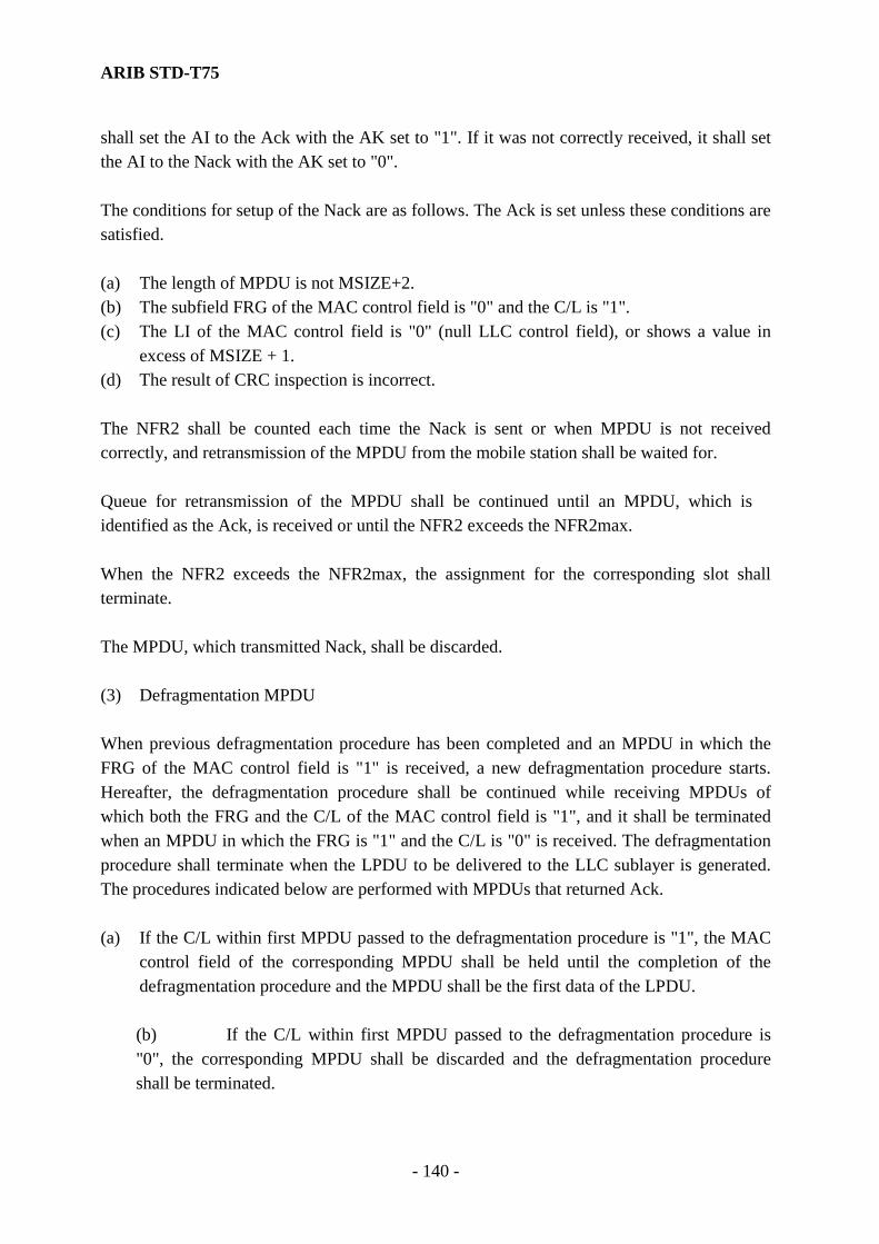
ARIB STD-T75
- 140 -
shall set the AI to the Ack with the AK set to "1". If it was not correctly received, it shall set the AI to the Nack with the AK set to "0". The conditions for setup of the Nack are as follows. The Ack is set unless these conditions are satisfied. (a) The length of MPDU is not MSIZE+2. (b) The subfield FRG of the MAC control field is "0" and the C/L is "1". (c) The LI of the MAC control field is "0" (null LLC control field), or shows a value in
excess of MSIZE + 1. (d) The result of CRC inspection is incorrect. The NFR2 shall be counted each time the Nack is sent or when MPDU is not received correctly, and retransmission of the MPDU from the mobile station shall be waited for. Queue for retransmission of the MPDU shall be continued until an MPDU, which is identified as the Ack, is received or until the NFR2 exceeds the NFR2max. When the NFR2 exceeds the NFR2max, the assignment for the corresponding slot shall terminate. The MPDU, which transmitted Nack, shall be discarded. (3) Defragmentation MPDU When previous defragmentation procedure has been completed and an MPDU in which the FRG of the MAC control field is "1" is received, a new defragmentation procedure starts. Hereafter, the defragmentation procedure shall be continued while receiving MPDUs of which both the FRG and the C/L of the MAC control field is "1", and it shall be terminated when an MPDU in which the FRG is "1" and the C/L is "0" is received. The defragmentation procedure shall terminate when the LPDU to be delivered to the LLC sublayer is generated. The procedures indicated below are performed with MPDUs that returned Ack. (a) If the C/L within first MPDU passed to the defragmentation procedure is "1", the MAC
control field of the corresponding MPDU shall be held until the completion of the defragmentation procedure and the MPDU shall be the first data of the LPDU.
(b) If the C/L within first MPDU passed to the defragmentation procedure is "0", the corresponding MPDU shall be discarded and the defragmentation procedure shall be terminated.

ARIB STD-T75
- 141 -
(c) If the increment of the SEQ is "1" (the SEQ is continuous, but change from "1111" to
"0000" is included), data of the length indicated by the LI shall be taken out from the beginning of the MSDU, and shall be defragmented sequentially.
(d) If the increment of the SEQ is "0" (the MPDU was duplicated), the corresponding
MPDU shall be discarded. (e) If the increment of the SEQ is not "1" or "0" (The SEQ is not continuous; but change
from "1111" to "0000" is excluded), the MPDUs received thereafter and defragmented data of up to this time shall be discarded. After deleting the last MPDU (the FRG was "1" and the C/L was "0"), it shall be regarded as the completion of the defragmentation procedure.
(f) After the completion of the defragmentation of MPDUs and the generation of a valid
LPDU, it shall be regarded as the termination of the defragmentation procedure, the LPDU with the MAC control field which has been held shall pass to the MAC data service procedure specified in subclause 4.3.3.5.2.2.1.
The receive control procedures shall terminate after the completion of this defragmentation procedure.
(4) Non-defragmentation MPDU On receiving an MPDU, both FRG and C/L of the MAC control field of which is "0", is indicated, the defragmentation procedure shall not be executed. But data of the length indicated by LI shall be taken out from the beginning of the MSDU, and LPDU to be passed to the LLC sublayer shall be generated and reception control procedures shall terminate. 4.3.3.5.2.1.3 Transmission/Reception procedures 4.3.3.5.2.1.3.1 Transmission (1) Transmission of MDC The MPDU generated by transmission control is preceded by a ramp bit (for π/4 shift QPSK system only), preamble and unique word in accordance with the modulation system, and is followed by a 16-bit CRC figured out from the data codes other than ramp bit (for π/4 shift QPSK system only), preamble and unique word. Then, the range from the header of LPDU just after the MAC control field to the end of CRC is scrambled by the key generated from

ARIB STD-T75
- 142 -
LID (see 4.2.6 for details). The scrambled result is multiplexed to the MDC position in the slot indicated by the MIB information and transferred to layer-1. (2) Transmission of ACKC The AI generated by transmission control is preceded by a ramp bit (for π/4 shift QPSK system only), preamble and unique word in accordance with the modulation system, and is followed by a 16-bit CRC figured out from the data codes other than ramp bit (for π/4 shift QPSK system only), preamble and unique word. Finally, it is multiplied to the ACKC position in the slot indicated by the MIB information, and is delivered to layer-1. 4.3.3.5.2.1.3.2 Reception (1) Reception of MDC The key generated from the LID shall descramble the data passed from the layer 1 at the position of the MDC of the slot indicated by the information of the MIB. The range of data for descrambling (details are defined in subclause 4.2.6) shall be from the beginning of the LPDU field to the end of CRC. A 16-bits CRC shall be calculated from the descrambled data codes other than ramp bit (for π/4 shift QPSK system only), preamble (PR) and unique word (UW2), and shall be compared with a reference value. If the comparison shows equality, the corresponding MPDU shall be taken out and be passed to the reception control procedures specified previously. (2) Reception of ACKC The signal transferred from layer-1 to the ACKC position in the slot indicated by the MIB information is subjected to 16-bit CRC calculation based on data codes other than ramp bit (for the π/4 shift QPSK system only), preamble and unique word and compared with a reference value. If the comparison shows equality, the AI shall be taken out and be passed to the reception control procedures. If the comparison shows inequality, the corresponding ACKC shall be discarded, and the AI shall not be passed to the reception control.
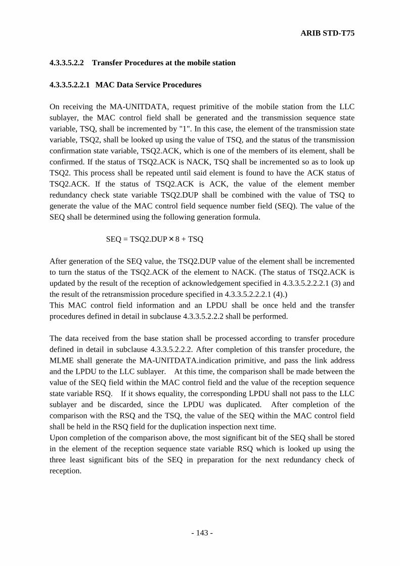
ARIB STD-T75
- 143 -
4.3.3.5.2.2 Transfer Procedures at the mobile station 4.3.3.5.2.2.1 MAC Data Service Procedures On receiving the MA-UNITDATA, request primitive of the mobile station from the LLC sublayer, the MAC control field shall be generated and the transmission sequence state variable, TSQ, shall be incremented by "1". In this case, the element of the transmission state variable, TSQ2, shall be looked up using the value of TSQ, and the status of the transmission confirmation state variable, TSQ2.ACK, which is one of the members of its element, shall be confirmed. If the status of TSQ2.ACK is NACK, TSQ shall be incremented so as to look up TSQ2. This process shall be repeated until said element is found to have the ACK status of TSQ2.ACK. If the status of TSQ2.ACK is ACK, the value of the element member redundancy check state variable TSQ2.DUP shall be combined with the value of TSQ to generate the value of the MAC control field sequence number field (SEQ). The value of the SEQ shall be determined using the following generation formula.
SEQ = TSQ2.DUP×8 + TSQ After generation of the SEQ value, the TSQ2.DUP value of the element shall be incremented to turn the status of the TSQ2.ACK of the element to NACK. (The status of TSQ2.ACK is updated by the result of the reception of acknowledgement specified in 4.3.3.5.2.2.2.1 (3) and the result of the retransmission procedure specified in 4.3.3.5.2.2.2.1 (4).) This MAC control field information and an LPDU shall be once held and the transfer procedures defined in detail in subclause 4.3.3.5.2.2.2 shall be performed. The data received from the base station shall be processed according to transfer procedure defined in detail in subclause 4.3.3.5.2.2.2. After completion of this transfer procedure, the MLME shall generate the MA-UNITDATA.indication primitive, and pass the link address and the LPDU to the LLC sublayer. At this time, the comparison shall be made between the value of the SEQ field within the MAC control field and the value of the reception sequence state variable RSQ. If it shows equality, the corresponding LPDU shall not pass to the LLC sublayer and be discarded, since the LPDU was duplicated. After completion of the comparison with the RSQ and the TSQ, the value of the SEQ within the MAC control field shall be held in the RSQ field for the duplication inspection next time. Upon completion of the comparison above, the most significant bit of the SEQ shall be stored in the element of the reception sequence state variable RSQ which is looked up using the three least significant bits of the SEQ in preparation for the next redundancy check of reception.

ARIB STD-T75
- 144 -
(Note 1) The SEQ continuity check of the received data passed after completion of the transfer procedure specified in subclause 4.3.3.5.2.2.2 shall not be performed.
(Note 2) The relationship between the TSQ, the RSQ, and MAC control subfields is shown in
Figure 4.3.3.5.2.1.1 for reference. 4.3.3.5.2.2.2 MAC Transfer Control Procedures 4.3.3.5.2.2.2.1 Transmission Control (1) Fragmentation LPDU In case the length of LPDU received from LLC sublayer is in excess of the maximum transfer size variable, MSIZE, it must be fragmented. For the purpose of fragmentation, The MSIZE data taken from the leading end shall be added with a MAC control field to form an MPDU. In this case, FRG and C/L of the MAC control field shall both be set to "1"; LI shall be set to the MSIZE value ("10000010" (65) in ASK system or "10000011"(193) in the π/4-shift QPSK system); and NFR1 shall be initialized. The initial value of the SEQ shall be set at the same value as defined in the MAC data service procedure (subclause 4.3.3.5.2.2.1). When the MPDU was sent to the base station and reception has been acknowledged, the length of the remaining LPDU shall be inspected. If it exceeds MSIZE, the data of MSIZE shall be further taken off from the beginning, and an MPDU shall be generated with a MAC control field added to it. In this case, FRG and C/L of the MAC control field shall both be set to "1"; LI shall be set to the MSIZE value ("10000010" (65) in ASK system or "10000011"(193) in the π/4-shift QPSK system); SEQ shall be incremented; TSQ shall not be incremented; and NMR shall be initialized. The process shall be repeated until the remaining part of LPDU becomes smaller than MSIZE. When the remaining part gets smaller than MSIZE, C/L shall be set to "0" to signify the end of fragmentation. The number of octets equivalent to the remaining length of LPDU shall be set to LI, and LPDU shall be padded with 0s until MSIZE is reached. When all of the MPDUs generated as fragmented were transferred to the base station and their reception was acknowledged, the transmission control for the LPDU shall terminate. (2) Non-fragmentation LPDU In case LPDU received from LLC sublayer is short of MSIZE, it shall be added directly with
ARIB STD-T75
- 145 -
a MAC control field to make up an MPDU. In this case, both of the FRG and the C/L of the MAC control field shall be set to "0", the number of octets of its length shall be set at the LI, and the NMR shall be initialized. If LPDU is short of MSIZE, it shall be padded with 0s until an MSIZE is reached. When the MPDU was sent to the mobile station and its reception was acknowledged, the transmission control for the LPDU shall terminate. (3) Reception of acknowledgement When the MPDUs prepared in the above process are transmitted, the system shall wait for ACKC while the transfer slots for MPDUs are on display. If the AI was not obtained from the ACKC during this period or if the Nack was received at the AI, the NMR shall be incremented and the retransmission procedure indicated below shall be executed. Where the Ack was received at the AI, transfer of the MPDU shall terminate, and the MPDU shall be discarded. In this case, the element of the transmission state variable, TSQ2, shall be looked up using the three least significant bits of the sequence number field (SEQ) of the MAC control field for the MPDU, and the status of the transmission confirmation state variable, TSQ2.ACK, which is one of the members of its element, shall be turned Ack. Provided that if the MPDU in question has been fragmented as aforesaid, the processing shall be carried out for the sequence number affixed to the first of the segments into which the MPDU is fragmented. The status will be changed when the Ack for the last segment has been received. (4) Retransmission Retransmission procedure shall be performed when the transfer slot of the MPDU could not receive the Ack at the AI obtained from the ACKC (the AI was not obtained from the ACKC or the Nack was received at the AI) while the transfer slot for MPDU is displayed. Where the Ack could not be received, the subject MPDU shall not be discarded, but be retransmitted by the slot assigned to the next frame, and it shall wait for reception of the AI in the corresponding slot. Retransmission procedure shall be repeated until the Ack is received or until the NMR exceeds the NMRmax.
ARIB STD-T75
- 146 -
When NMRmax is exceeded, the LPDU shall be dicarded, and the re-transmission procedures shall be terminated. In case the version of the protocol selected for communication with the base station is "0", the retransmission shall be terminated if an MPDU is received from the base station while the retransmission is in progress. In this case, the element of the transmission state variable, TSQ2, shall be looked up using the three least significant bits of the sequence number field (SEQ) of the MAC control field for the MPDU, and the status of the transmission confirmation state variable, TSQ2.ACK, which is one of the members of its element, shall be turned Ack. Provided that if the MPDU in question has been fragmented as aforesaid, the processing shall be carried out for the sequence number affixed to the first of the segments into which the MPDU is fragmented. The status shall be changed when the Ack for the last segment has been received. (5) Generation of idle channel signal If the MLME detects an MDS indicating that it is an idle channel with the uplink, it shall generate an MPDU in which LPDU fields are all "0". In this case, FRG , C/L and C/R of the MAC control field shall both be set to "0"; LI shall be set to the MSIZE value ("10000010" (65) in ASK system or "10000011"(193) in the π/4-shift QPSK system). If there are MPDUs waiting for transmission or LPDUs in process, the generation of the idle channel signal shall not destroy the contents of these MPDUs and LPDUs. 4.3.3.5.2.2.2.2 Reception control (1) Reception of MPDU If the ST of the SCI has identified normal data channel or a data channel assigned with priority, the MPDU to be transferred by the downlink MDS shall be accepted, and the MLME shall execute the acknowledgement transmission procedure and the defragmentation procedure specified below. If the ST of the SCI has identified another type of channel (an idle signal channel, an empty data channel etc.), the MPDU to be transferred by the downlink MDS shall be discarded, and the MLME shall terminate the reception control procedures. (2) Acknowledgement transmission When the reception of the MPDU is indicated, the AI shall be sent within the ACKC in the

ARIB STD-T75
- 147 -
reception slot. If the MPDU was correctly received, it shall set the AI to the Ack with the AK set to "1". If it was not correctly received, the AI shall be set to the Nack with the AK set to "0". The conditions that set the Nack are as follows. The Ack shall be set unless these conditions are satisfied. (a) The length of MPDU is not equal to MSIZE+2. (b) In the MAC control field, FRG is "0", whereas C/L is "1". (c) In the MAC control field, LI is "0" (i.e., absence of LLC control field), or shows a value
in excess of MSIZE+1. (d) CRC check result is not correct. The MPDU that has dispatched NACK is discarded. This acknowledgement transmission procedure shall only be applied to a private link address, not to multi-group or broadcast link addresses. (3) Defragmentation MPDU When the previous defragmentation procedure has been completed and an MPDU in which the FRG of the MAC control field is "1" is received, a new defragmentation procedure starts. Hereafter, the defragmentation procedure shall be continued while receiving MPDUs of which the both of the FRG and the C/L of the MAC control field is "1", and it shall be terminated when an MPDU in which the FRG is "1" and the C/L is "0" is received. The defragmentation procedure shall terminate when the LPDU to be delivered to the LLC sublayer is generated. The procedures indicated below shall be performed with respect to the MPDUs that returned Ack. (a) If the C/L within the first MPDU passed to the defragmentation procedure is "1", the
MAC control field of the corresponding MPDU shall be held until the completion of the defragmentation procedure and the MPDU shall be the first data of the LPDU.
(b) If the C/L within the first MPDU passed to the defragmentation procedure is "0", that
MPDU shall be discarded and the defragmentation procedure shall terminate. (c) If the increment of the SEQ is "1" (the SEQ is continuous, but change from "1111" to
"0000" is included), data of the length indicated by the LI shall be taken out from the beginning of the MSDU, and shall be defragmented sequentially.
ARIB STD-T75
- 148 -
(d) If the increment of the SEQ is "0" (the MPDU was duplicated), the corresponding MPDU shall be discarded.
(e) If the increment of the SEQ is not "1" or "0" (The SEQ is not continuous; but change
from "1111" to "0000" is excluded), the MPDUs received thereafter and the data defragmented theretofore shall be discarded. After deleting the last MPDU (the FRG was "1" and the C/L was "0"), it shall be regarded as the completion of the defragmentation procedures.
(f) After the completion of the defragmentation of MPDUs and the generation of a valid
LPDU, it shall be regarded as the termination of the defragmentation procedure, and the LPDU together with the MAC control field which has been held shall pass to the MAC data service procedure specified in subclause 4.3.3.5.2.2.1.
The reception control procedure shall terminate after the completion of this defragmentation procedures. (4) Non-defragmentation MPDU In case the MPDU having returned an Ack is indicated in which MAC control field has its FRG and C/L set to "0", the defragmentation procedure shall not be executed. But data of the length indicated by LI shall be taken out from the beginning of the MSDU, an LPDU to be passed to the LLC sublayer shall be generated and reception control procedures shall terminate. 4.3.3.5.2.2.3 Transmission/Reception procedure In this transmission/reception procedures, the source address of the base station shall be identified as the FID by way of the SCI registration procedure specified in subclause 4.3.3.5.1.2.1(1). 4.3.3.5.2.2.3.1 Transmission (1) Transmission of MDC The MPDU generated by transmission control shall be preceded by a ramp bit (for π/4 shift QPSK system only), preamble and unique word in accordance with the modulation system, and shall be followed by a 16-bit CRC figured out from the data codes other than ramp bit (for π/4 shift QPSK system only), preamble and unique word. Then, the range from the header of LPDU just after the MAC control field to the end of CRC shall be scrambled by the

ARIB STD-T75
- 149 -
key generated from LID (see 4.2.6 for details). The scrambled result shall be multiplexed to the MDC position in the slot indicated by the MIB information and shall be passed to layer-1. (2) Transmission of ACKC The AI generated by transmission control is preceded by a ramp bit (for π/4 shift QPSK system only), preamble and unique word in accordance with the modulation system, and is followed by a 16-bit CRC figured out from the data codes other than ramp bit (for π/4 shift QPSK system only), preamble and unique word. Finally, it shall be multiplied to the ACKC position in the slot indicated by the MIB information, and is delivered to layer-1. 4.3.3.5.2.2.3.2 Reception (1) Reception of MDC The data passed from the layer-1 at the position of the MDC of the slot indicated by the information of the MIB shall be de-scrambled by the key generated from the LID. The range of data for descrambling (details are defined in subclause 4.2.6) shall be from the beginning of the LPDU field to the end of CRC. A 16-bits CRC shall be calculated from the descrambled data less the preamble (PR) and unique word (UW2), and shall be compared with a reference value. If the comparison shows equality, the corresponding MPDU shall be taken out and be passed to the reception control procedure specified previously. (2) Reception of ACKC The signal transferred from layer-1 to the ACKC position in the slot indicated by the MIB information shall be subjected to 16-bit CRC calculation based on data codes other than ramp bit (for the π/4 shift QPSK system only), preamble and unique word and shall be compared with a reference value. If the comparison shows equality, the AI shall be taken out and be passed to the reception control procedure. If the comparison shows inequality, the corresponding ACKC shall be discarded, and the AI shall not be passed to the reception control procedure. 4.3.4 Logical Link Control (LLC) Sublayer The LLC generates command PDU and response PDU for transmission and interprets received command PDUs and response PDUs.

ARIB STD-T75
- 150 -
LLC provides the following functions. (1) Initialization of PDU transmit/receive. (2) Control of data flow. (3) Interpretation of received command PDUs and generation of appropriate response PDUs. (4) Action regarding error control and error recovery functions in LLC sublayer. The LLC sublayer provides a description of the peer-to-peer protocol procedures that are defined for the transfer of information and control between a pair of data link service access points (LSAPs) in this radio communication system environment. For a broad range of DSRC applications, two types of data link control operation are contained. (See subclause 4.3.4.3) The first (referred to as Type 1) of operation provides unacknowledged connectionless-mode service across the data link with a minimum protocol. This type of operation may be useful when the layer-7 or applications provide any error recovery and sequencing service so that these do not need replicating in the layer-2. In addition, this type of operation may prove useful in applications where it is not essential to acknowledge the delivery of the data link layer (layer-2) data unit. The second (referred to as Type 3) of operation provides an acknowledged connection-less mode data unit exchange service, which permits a station to both transmit data and request the return of the data at the same time. Although exchange service is connectionless, in-sequence data transfer is guaranteed by the initiating station. (Note 1) Definition of this LLC sublayer is based on ISO/IEC 8802-2:1994 (Information
technology -- Telecommunication and information exchange between systems -- Local and metropolitan area networks - Specific requirements -- Part 2: Logical link control).
(Note 2) Type 3 data transfer service is reserved for future systems at this time. The
implementation of Type 3 in future systems will be considered. Type 2 is not adopted because of an unwanted overhead for connection and disconnection in the real-time environment of this radio communication system.
ARIB STD-T75
- 151 -
4.3.4.1 LLC Sublayer Service Specification This subclause specifies the services required of the LLC sublayer by the superordinate entities for the purpose of packet exchange between the layer-7 entities using LLC sublayer. The service is described in an abstract way and does not imply any particular implementation or any exposed interface. Two forms of service are provided.
(a) Unacknowledged connectionless-mode service (b) Acknowledged connection-less mode service
(1) Unacknowledged connection-mode service The data transfer service that provides the means by which data link user entities can exchange link service data units (LSDUs) without the establishment of data link level connection on an unacknowledged base. The data transfer can be point-to-point, multicast (group cast), or broadcast. (2) Acknowledged connectionless-mode service The Acknowledged connection-less mode data unit exchange service provides the means by which data link user entities can exchange link service data units (LSDUs) which are acknowledged at the LLC sublayer, without establishment of data link connection. The service provides a means by which a layer-7 at one station can transmit a data unit to another station, request a previously prepared data unit from another station, or exchange data unit from another station. The data unit transfer is point-to-point. 4.3.4.1.1 Overview of Interaction (1) Unacknowledged connectionless-mode service (a) Data unit transmission service
The primitives associated with unacknowledged connectionless mode data transfer are: DL-UNITDATA.request DL-UNITDATA.indication

ARIB STD-T75
- 152 -
The DL-UNITDATA.request primitive is passed from the layer-7 to the LLC sublayer to request that an LSDU be transmitted using unacknowledged connectionless-mode procedures. A DL-UNITDATA.indication primitive is passed from the LLC sublayer to the layer-7 to indicate arrival of an LSDU. (2) Acknowledged connectionless-mode service (a) Acknowledged connectionless-mode data unit transmission service
The primitives associated with the acknowledged connectionless-mode data unit transmission service are:
DL-DATA-ACK. request DL-DATA-ACK. indication DL-DATA-ACK-STATUS.indication The DL-DATA-ACK.request primitive is passed from the layer-7 to the LLC sublayer to request that an LSDU be transmitted to a remote LLC using acknowledged connectionless-mode data transmission procedures. The DL-DATA-ACK.indication primitive is passed from to the layer-7 the LLC sublayer to indicate the arrival of a common PDU except in the case where this PDU is used only for resynchronization. The DL-DATA-ACK-STATUS.indication is passed from the LLC sublayer to the layer-7 to convey the results of previous associated DL-DATA-ACK.request primitive. (b) Data unit exchange service The primitives associated with the acknowledged connectionless-mode data unit exchange services are: DL-REPLY.request DL-REPLY.indication DL-REPLY-STATUS.indication The DL-DATA-REPLY.request primitive is passed from the layer-7 to the LLC sublayer to request that an LSDU be returned from a remote station or that LSDUs be exchanged between stations using acknowledged connectionless-mode data unit exchange procedures.
ARIB STD-T75
- 153 -
The DL-DATA-REPLY.indication primitive is passed from the LLC sublayer to the layer-7 to indicate the arrival of a common PDU. The DL-DATA-REPLY-STATUS.indication is passed from the LLC sublayer to the layer-7 to convey the results (success/failure and reply data) of previous associated DL-REPLY.request primitive. (c) Reply data unit preparation service The primitives associated with reply data unit preparation are: DL-REPLY-UPDATE.request DL-REPLY-UPDATE-STATUS.indication The DL-REPLY-UPDATE.request primitive is passed from the layer-7 to the LLC sublayer to request that an LSDU to be held by LLC and transmitted at later time when requested to do so by some other station. The DL-DATA-REPLY-UPDATE-STATUS.indication is passed from the LLC sublayer to the layer-7 to convey the results of previous associated DL-REPLY-UPDATE.request primitive. 4.3.4.1.2 Detailed Service Specification This subclause describes in detail the primitives and parameters associated with the identified services (specified in 4.3.4.1.1). The parameters (except "link addresses") are defined in abstract sense. The parameters specify the information that must be available to the receiving end. No restraint shall be imposed upon the implementation method of providing this information. The link_address parameter identifies remote SAP and remote SAP of both MAC and the LLC. The link_address parameter shall have the format defined in subclause 4.2.4.2.1.8.2. The data parameter may be provided by actually passing the data link service data unit by passing a pointer or other means. The parameter may be null. The status parameter indicates success or failure of a previous associated request. (Note) Different from ISO/IEC 8802-2:1994, MAC and LLC shall have one common
address. Possible logical sequences of successful data unit transmission are illustrated in Fig. 4.3.4.1.2. (Primitive types that occur earlier in time and connected by dotted lines in the diagrams are the logical antecedents of subsequent primitive types.)
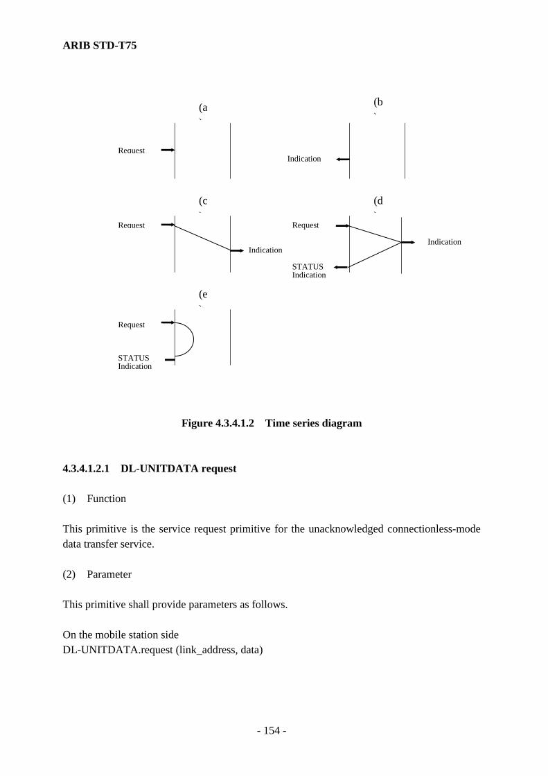
ARIB STD-T75
- 154 -
Figure 4.3.4.1.2 Time series diagram
4.3.4.1.2.1 DL-UNITDATA request (1) Function This primitive is the service request primitive for the unacknowledged connectionless-mode data transfer service. (2) Parameter This primitive shall provide parameters as follows. On the mobile station side DL-UNITDATA.request (link_address, data)
(a)
(b)
(c)
(d)
(e)
Request
Request
Request
Request
Indication
Indication
STATUS Indication
STATUS Indication
Indication
ARIB STD-T75
- 155 -
The link_address parameter of the mobile station shall be a private link address. The data parameter specifies the LSDU to be transmitted by the data link entity. On the base station side DL-UNITDATA.request (link_address, data, response_request) The link_address parameter of the base station may be the private, multicast (groupcast) link and broadcast link addresses. The data parameter specifies the MSDU to be transmitted by the data link entity. The response_request parameter is passed to the MAC sublayer directly. (Note) The parameters of response_request are specified as follows. The response_request
set to "1" indicates that the MAC sublayer only transmits data, which is simultaneously passed from the LLC, to the mobile station as indicated by link_address.
The response_request set to "2" indicates that the MAC sublayer assigns the uplink MDS with the same link_address. In this case, data is discarded by the MAC sublayer. The response_request set to "0" indicates that the MAC sublayer assigns the uplink MDS with the same link_address. At that time, the MAC sublayer discards the corresponding data. the MAC sublayer transmits data, which is simultaneously passed from the LLC, to the mobile station as indicated by link_address.
(3) When generated This primitive is passed from the layer-7 to the LLC sublayer to request that an LSDU be transmitted to one or more remote LSAP(s) using unacknowledged connectionless-mode procedures. 4.3.4.1.2.2 DL-UNITDATA.indication (1) Function This primitive is a service indication primitive for the unacknowledged connectionless-mode data transfer service. (2) Parameter This primitive shall provide parameters as follows.

ARIB STD-T75
- 156 -
DL-UNITDATA.indication (link_address, data) The link_address parameter of the base station shall specify a private link address. The link_address parameter of the mobile station shall specify a private link address, multi (group) link and broadcast link addresses. The data parameter shall specify the LSDU that is to be transferred by the data link entity. (3) When generated This primitive is passed from the LLC sublayer to the layer-7 to indicate arrival of LSDU from a specified remote station entity. 4.3.4.1.2.3 DL-DATA-ACK.request (1) Function This primitive is a service request primitive for the acknowledged connectionless-mode data unit transfer service. (2) Parameter This primitive shall provide parameters as follows. DL-DATA-ACK.request (link_address, data) The link_address parameter indicates a private link address. The data parameter specifies the LSDU to be transferred by the data link entity. (3) When generated This primitive is passed from the layer-7 to the LLC sublayer to request that an LSDU be transmitted to remote LSAP using acknowledged connectionless-mode data unit transfer procedures. 4.3.4.1.2.4 DL-DATA-ACK.indication (1) Function This primitive is the service request primitive for the acknowledged connectionless-mode data unit transmission service.
ARIB STD-T75
- 157 -
(2) Parameter This primitive shall provide parameters as follows. DL-DATA-ACK.indication (link_address, data) The link_address parameter specifies a private link address. The data parameter specifies the LSDU to be transferred by the data link entity. (3) When generated This primitive is passed from the LLC sublayer to the layer-7 to indicate arrival of non-null, nonduplicate LSDU from a specified remote station entity. 4.3.4.1.2.5 DL-DATA-ACK-STATUS indication (1) Function This primitive is a status indication primitive for the acknowledged connectionless-mode data unit transfer service. (2) Parameter This primitive shall provide parameters as follows. DL-DATA-ACK-STATUS.indication (link_address, status) The link_address parameter specifies a private link address. The status parameter indicates success or failure of the previous associated acknowledged connectionless-mode data unit transfer request. (3) When generated This primitive is passed from the LLC sublayer to the layer-7 to indicate success or failure of the previous associated acknowledged connectionless-mode data unit transfer request.

ARIB STD-T75
- 158 -
4.3.4.1.2.6 DL-REPLY.request (1) Function This primitive is the service request primitive for the acknowledged connectionless-mode data unit exchange service. This primitive can be used to request a previously prepared data unit from another station, or to exchange data unit with another station. (2) Parameter This primitive shall provide parameters as follows. DL-REPLY.request (link_address, data) The link_address parameter shall specify a private link address. The data parameter specifies the LSDU transferred by the data link entity. (3) When generated This primitive is passed from the layer-7 to the LLC sublayer to exchange an LSDU with a remote station or to obtain an LSDU prepared at a remote station. (Note) The primitive can be passed with a null (having zero length) data parameter for the
purpose of requesting data only (without transmitting data). 4.3.4.1.2.7 DL-REPLY.indication (1) Function This primitive is a service indication primitive for the acknowledged connectionless-mode data unit exchange service. (2) Parameter This primitive shall provide parameters as follows. DL-REPLY.indication (link_address, data) The link_address parameter indicates a private link address. The data parameter specifies the LSDU to be transferred by the data link entity.

ARIB STD-T75
- 159 -
(3) When generated This primitive is passed from the LLC sublayer to the layer-7 to indicate either a successful acquisition of an LSDU from a remote station entity or exchange of LSDUs with a remote station entity. The transfer of previously prepared LSDU to the requesting station shall not destroy the original copy of LSDU. Subsequent requests for data by any station shall cause the transfer of the same LSDU, until the DL-REPLY-UPDATE.request primitive is used to replace the LSDU with new information. 4.3.4.1.2.8 DL-REPLY-STATUS.indication (1) Function This primitive is a service status indication primitive for the acknowledged connectionless-mode data unit exchange service. (2) Parameter This primitive shall provide parameters as follows. DL-REPLY-STATUS.indication (link_address, data, status) The link_address parameter indicates a private link address. The status parameter indicates the success or failure of the previously associated acknowledged connectionless-mode data unit exchange request. (3) When generated This primitive is passed from the LLC sublayer to the layer-7 entity to indicate the success or failure of previous associated acknowledged connectionless-mode data unit exchange request and to pass data available. 4.3.4.1.2.9 DL-REPLY-UPDATE.request (1) Function This primitive is a service request primitive for response data unit preparation service.
ARIB STD-T75
- 160 -
(2) Parameter This primitive shall provide parameters as follows. DL-REPLY-UPDATE.request (link_address, data) The link_address parameter indicates a private link address. The data parameter specifies the LSDU held by the data link entity at the request of the response data unit preparation request. (3) When generated This primitive is passed from the layer-7 to the LLC sublayer to request that an LSDU be associated with a local SAP and held by LLC for future access. Once LSDU has been associated with a local SAP, that LSDU shall be transferred to the other stations using acknowledged connectionless-mode response PDU as often as requested by other stations (without need for additional DL-REPLY-UPDATE.request primitives from the layer-7). A subsequent DL-REPLY-UPDATE.request primitives from the layer-7 for the specified SAP serves to replace the currently associated LSDU with a new LSDU. 4.3.4.1.2.10 DL-REPLY-UPDATE-STATUS.indication (1) Function This primitive is a service confirmation primitive for the reply data unit preparation service. (2) Parameter This primitive shall provide parameters as follows. DL-REPLY-UPDATE-STATUS.indication (link_address, status) The link_address parameter shall specify a private link address. The status parameter indicates success or failure of the previous associated data unit preparation request.

ARIB STD-T75
- 161 -
(3) When generated This primitive is passed from the LLC sublayer to the layer-7 to indicate success or failure of the previous associated data unit preparation request. The effect on reception of this primitive by the layer-7 is unspecified. If the status is successful, this primitive indicates that the LLC sublayer has associated LSDU with a local SAP. 4.3.4.2 LLC PDU Structure This subclause defines in detail the LPDU structure. It defines the relative positions of the various components of the PDU. 4.3.4.2.1 LPDU format All LLC PDUs shall conform to the format shown in Fig. 4.3.4.2.1.
Control field Information field 8 bit 8×M bit
(Note 1) Control=Control field: Refer to subclause 4.3.4.4.1 (Note 2) M=Number of octets: an integer value equal to or greater than "0" (Upper bound of
M depends on media access methodology used.)
Fig. 4.3.4.2.1 LLC PDU Format 4.3.4.2.2 Elements of the LLC PDU 4.3.4.2.2.1 Address Field The link address is used for the MAC sublayer and LLC sublayer and is therefore not contained in the LPDU. The link address of downlink shall make a clear distinction between one (private) SAP or more (multi (group) link, broadcast link) SAP(s) for which the LLC information field is intended and the SAP from which the data transfer was initiated. The link address of uplink shall make a clear distinction between the specific (private) SAP for which the LLC
ARIB STD-T75
- 162 -
information field is intended and the SAP from which the LLC information field was initiated. The format of a link address is defined in subclause 4.2.4.2.1.8.2. A link address shall be generated as described in subclause 4.3.2. 4.3.4.2.2.2 Command/Response The Command/Response bit shall be located at bit 4 (b4) in the MAC control field. If this bit is "0", it shall indicate that the LPDU is a command. If this bit is "1", it shall indicate that the LPDU is a response. 4.3.4.2.2.3 LLC Control Field The control field shall consist of one octet that shall be used to designate commands and responses. The contents of these fields shall be described in subclause 4.3.4.4. 4.3.4.2.2.4 Information field An information field shall consist of a multiple (including zero) of octets. 4.3.4.2.2.5 Bit order Command and Response shall be delivered to / received from the MAC sublayer with the least significant bit first (i.e., the first bit of an octet that is delivered / received shall have the weight of 20.). This information field shall be delivered to the MAC sublayer in the same bit order as received from the layer-7. The information field shall be delivered to the layer-7 in the same bit order as received from the MAC sublayer. 4.3.4.2.2.6 Invalid LPDU Invalid LPDU shall be ignored. An invalid LPDU shall be defined as one that meets at least one of following conditions: (1) LPDU judged by the MAC sublayer or the layer-1 entity to be invalid. (2) LPDU whose length is not a multiple of octets. (3) LPDU whose length is 0 (no control field). (4) LPDU that has no valid command or response control field specified in this standard.
ARIB STD-T75
- 163 -
(5) LPDU which contains a Type 3 command or response control field, and whose link address is multi (group) link address or a broadcast link address.
(6) LPDU which contains a Type 3 response control field, but contains no ACn response status subfield in its information field.
4.3.4.3 Types of LLC Procedure LLC defines two types of operation for data communication between service access points (SAPs). (1) Type 1 operation With Type 1 operation, PDUs shall be exchanged between LLCs without the need for the establishment of data link connection. In the LLC sublayer these PDUs shall not be acknowledged, nor shall there be any flow control or error recovery in the Type 1 procedures. (2) Type 3 operation With Type 3 operation, PDUs shall be exchanged between LLC entities without the need for the establishment of data link connection. In the LLC sublayer, PDUs that may or may not bear information shall be acknowledged. The acknowledgment function shall be completed by destination LLC returning to those LLCs a specific response in a separate PDU that contains status information and may or may not bear user information. In the normal operation, each command PDU in Type 3 operation shall receive an acknowledgment PDU, and though the source LLC may transmit a Type 3 command for recovery purposes, it shall not transmit a new Type 3 command PDU while waiting for acknowledgment of a previous PDU with the same link address. The LLC entity shall not accept a new request primitive from the layer-7 until receipt of the preceding "request" primitive LSDU has been acknowledged by the remote LLC entity. This restriction is necessary to allow higher layers to perform recovery operation before resuming normal data transmission in case LLC is unsuccessful in transmitting a PDU (even after retransmission). The mechanism alternating LLC control field code in successive PDUs provides a one-bit sequence number functionality which allows the LLC receiving a command PDU to differentiate between a new and second copy of a previously received PDU. Further, the LLC receiving an acknowledgment PDU can insure that acknowledgment refers to the last transmit information PDU. A previously received acknowledgment that incurred excessive delay is thus ignored.

ARIB STD-T75
- 164 -
The Type 3 operation defines the status information that must be maintained at the stations involved in the information exchange. Each station shall maintain for each SAP, a one-bit sequence number for transmitting and another for receiving. Therefore, the mobile station has to maintain one pair of transmit / receive sequence numbers, if using Type 3 operation. The base station has to maintain, for each mobile station using Type 3 operation in the communication zone, one pair of transmit / receive sequence numbers. Type 3 operation shall only be used in a point to point (private) communication. 4.3.4.4 Elements of LLC Procedures This sabclause specifies the elements of the LLC procedures for code-independent data communication using LPDU structure (see subclause 4.3.4.2). 4.3.4.4.1 Format of Control Field The format defined for the control field is illustrated in Fig. 4.3.4.4.1.
1 2 3 4 5 6 7 8
1 1 M M P/F M M M
M : Modifier function bit P/F : Poll bit (P bit) - command LPDU transmission Final bit (F bit)- response LPDU transmission "1" = Poll/Final The two least significant bits are set to "1".
Fig. 4.3.4.4.1 LPDU Control Field The PDU shall be used to provide data link control functions and information transfer. The PDUs shall contain a P/F bit set in accordance to subclause 4.3.4.5.2.

ARIB STD-T75
- 165 -
4.3.4.4.2 Control Field Parameters 4.3.4.4.2.1 Type 3 Operation Parameters (1) Transmit sequence state variable V (SI) The LLC shall be able to maintain one transmit sequence state variable V (SI) for each unique SAP used for transmitting Type 3 command. This variable shall assume a value of 0 and 1 and shall be set equal to the bit eight of the LLC control field code used for the last Type 3 response PDU received with the link address. The V (SI) variable permits the LLC to insure that received acknowledgment applies to the currently transmission and allows the receiver to detect duplicate frames. The V (SI) shall be created with establishment of a new private link address. (2) Receive sequence state variable V (RI) The LLC shall be able to maintain one receive sequence state variable V (RI) for each unique SAP associated with received Type 3 command PDUs. This variable contains the complement of the bit eight of AC0 or AC1 LLC control field code of the last received Type 3 command PDU with the associated link address. The V (RI) variable allows the LLC to differentiate between a Type 3 received for the first time, and a received PDU which is retransmission of previously received PDU. The V (RI) shall be created with establishment of a new private link address. (3) Reception status state variable V (RB) The LLC shall be able to maintain one reception status state variable V (RB) for each unique SAP associated with received Type 3 command PDUs. This variable contains an indication of success or failure of the reception of the information field from the last received Type 3 command with the associated link address. The V (RB) variable insures that the response to the duplicate command PDU contains the same reception status code as the response to the original command PDU. The reception status state variable V (RB) shall be changed if the last reception was successful, but previous not. 4.3.4.4.3 Commands and Responses This subclause defines the commands and associated responses. Subclause 4.3.4.4.3.1 and 4.3.4.4.3.2 contain definition of the set of commands and response (listed below) for each the control fields format for Type 1 and Type 3 operation, respectively.

ARIB STD-T75
- 166 -
The C/R bit located in bit four of the MAC control field, is used to make a clear distinction between command and response. Table 4.3.4.4.3 shows the command and response. Table 4.3.4.4.3 Commands and Responses of Type 1 Operation and Type 3 Operation
Command Response UI - Unnumbered Information AC0 - Acknowledged Connectionless Information, Seq. 0
AC1 - Acknowledged Connectionless Acknowledge, Seq. 1
AC1 - Acknowledged Connectionless Information, Seq. 1
AC0 - Acknowledged Connectionless Acknowledge, Seq. 0
4.3.4.4.3.1 Commands of Type 1 Operation The LLC control field of the PDU command for Type 1 operation is illustrated in Fig. 4.3.4.4.3.1.
1 2 3 4 5 6 7 8
1 1 0 0 P 0 0 0 UI command
Fig. 4.3.4.4.3.1 Type 1 Operation Command, Control Field Bit assignment
(1) Unnumbered Information (UI) command On the downlink, the UI command PDU shall be used to transmit information to one or more Mobile station SAP(s) (private, multi (group), broadcast link addresses). On the uplink, the UI command PDU shall be used to transmit information to the base station SAP (private link address). The use of UI command PDU does not depend on the existence of the data link connection between the destination and source LLCs, and its use will not affect the V (SI) or V (RI) variables of Type 3 operation. There is no LLC response PDU to the UI command PDU. The data contained in an UI command PDU may be lost if logical data link exception (e.g. a transmission error or the busy state of the destination) occurs during the transmitting of the command PDU.
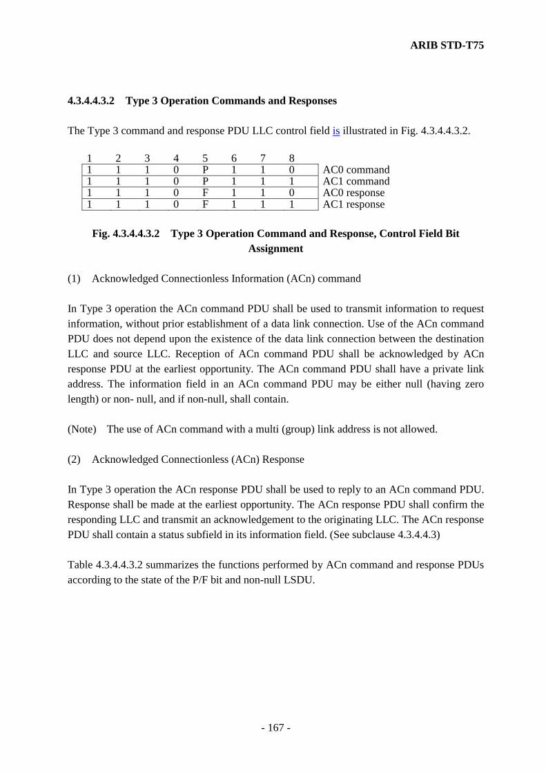
ARIB STD-T75
- 167 -
4.3.4.4.3.2 Type 3 Operation Commands and Responses The Type 3 command and response PDU LLC control field is illustrated in Fig. 4.3.4.4.3.2.
1 2 3 4 5 6 7 8 1 1 1 0 P 1 1 0 AC0 command 1 1 1 0 P 1 1 1 AC1 command 1 1 1 0 F 1 1 0 AC0 response 1 1 1 0 F 1 1 1 AC1 response
Fig. 4.3.4.4.3.2 Type 3 Operation Command and Response, Control Field Bit
Assignment (1) Acknowledged Connectionless Information (ACn) command In Type 3 operation the ACn command PDU shall be used to transmit information to request information, without prior establishment of a data link connection. Use of the ACn command PDU does not depend upon the existence of the data link connection between the destination LLC and source LLC. Reception of ACn command PDU shall be acknowledged by ACn response PDU at the earliest opportunity. The ACn command PDU shall have a private link address. The information field in an ACn command PDU may be either null (having zero length) or non- null, and if non-null, shall contain. (Note) The use of ACn command with a multi (group) link address is not allowed. (2) Acknowledged Connectionless (ACn) Response In Type 3 operation the ACn response PDU shall be used to reply to an ACn command PDU. Response shall be made at the earliest opportunity. The ACn response PDU shall confirm the responding LLC and transmit an acknowledgement to the originating LLC. The ACn response PDU shall contain a status subfield in its information field. (See subclause 4.3.4.4.3) Table 4.3.4.4.3.2 summarizes the functions performed by ACn command and response PDUs according to the state of the P/F bit and non-null LSDU.

ARIB STD-T75
- 168 -
Table 4.3.4.4.3.2 Summary of ACn Command and Response PDU Functionality Command:
P LSDU Function 0 null Resynchronization 0 non-null Transmitting data 1 null Requesting data 1 non-null Exchanging data
Response:
F LSDU Function 0 null Acknowledgment of resynchronization or Acknowledgment of
received data 0 non-null (not allowed) 1 null Acknowledgment, request data unavailable 1 non-null Acknowledgment with request data
4.3.4.4.3.3 Type 3 Operation Response information field Every ACn response PDU shall contain a status subfield in its information field. The remainder of the information field may be either null or non-null, and if non-null shall contain a link service data as shown in Fig. 4.3.4.4.3.3.
← ACn Response information field → Status sub-field
(1 octet) LSDU sub-field (0 or more octet)
Control C C C C R R R R Link Service Data Unit
1 2 3 4 5 6 7 8
Fig. 4.3.4.4.3.3 ACn Response PDU Information Field The code returned by CCCC part of the status subfield indicates success or failure of information transfer in the command PDU (from initiating LLC to responding LLC). Possible values of CCCC are given in Table 4.3.4.4.3.3-1.
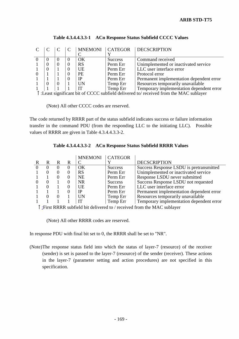
ARIB STD-T75
- 169 -
Table 4.3.4.4.3.3-1 ACn Response Status Subfield CCCC Values
C C C C MNEMONIC
CATEGORY
DECSCRIPTION
0 0 0 0 OK Success Command received 1 0 0 0 RS Perm Err Unimplemented or inactivated service 1 0 1 0 UE Perm Err LLC user interface error 0 1 1 0 PE Perm Err Protocol error 1 1 1 0 IP Perm Err Permanent implementation dependent error1 0 0 1 UN Temp Err Resources temporarily unavailable 1 1 1 1 IT Temp Err Temporary implementation dependent error↑:Least significant bit of CCCC subfield delivered to/ received from the MAC sublayer
(Note) All other CCCC codes are reserved.
The code returned by RRRR part of the status subfield indicates success or failure information transfer in the command PDU (from the responding LLC to the initiating LLC). Possible values of RRRR are given in Table 4.3.4.4.3.3-2.
Table 4.3.4.4.3.3-2 ACn Response Status Subfield RRRR Values
R R R R MNEMONIC
CATEGORY DECSCRIPTION
0 0 0 0 OK Success Success Response LSDU is pretransmitted 1 0 0 0 RS Perm Err Unimplemented or inactivated service 1 1 0 0 NE Perm Err Response LSDU never submitted 0 0 1 0 NR Success Success Response LSDU not requested 1 0 1 0 UE Perm Err LLC user interface error 1 1 1 0 IP Perm Err Permanent implementation dependent error 1 0 0 1 UN Temp Err Resources temporarily unavailable 1 1 1 1 IT Temp Err Temporary implementation dependent error
↑:First RRRR subfield bit delivered to / received from the MAC sublayer
(Note) All other RRRR codes are reserved. In response PDU with final bit set to 0, the RRRR shall be set to "NR". (Note) The response status field into which the status of layer-7 (resource) of the receiver
(sender) is set is passed to the layer-7 (resource) of the sender (receiver). These actions in the layer-7 (parameter setting and action procedures) are not specified in this specification.
ARIB STD-T75
- 170 -
4.3.4.5 LLC Description of the Procedures 4.3.4.5.1 Procedures for Addressing The address field of the frame shall be used to indicate the link address of PDU. 4.3.4.5.1.1 Type 1 Procedures Private link addressing shall be supported by the mobile station on uplink and by the base station in downlink. Private, multicast (group) and broadcast link addressing shall be supported in downlink. 4.3.4.5.1.2 Type 3 Procedures Link addresses shall be private. The mobile station shall be able to handle one pair of transmitting and receiving access points with private link address. The base station shall be able to handle one pair of transmitting and receiving access points with private link address, for each mobile station in the communication zone at one time. 4.3.4.5.2 Procedures of the use of P/F bit 4.3.4.5.2.1 Type 1 Procedures An UI command PDU shall only transmitted with P bit set to "0". If a UI command PDU is received with the P bit set to "1", the LLC sublayer shall optionally discard it or pass it to the layer-7 with an identifying flag showing that the P bit was set to "1". Since a UI PDU shall not be transmitted as a response PDU, procedure regarding the use of the F bit does not apply. 4.3.4.5.2.2 Type 3 Procedures The LLC sublayer shall set P bit in an ACn command PDU to "0" if the command PDU is not a request for the remote LLC to return an LSDU in its acknowledgment. Thus the P bit is set to "0" when data is to be passed only from the transmitting station to receiving station. LLC shall set P bit in an ACn command PDU to "1" if the command PDU is a request for the remote LLC to return an LSDU in its acknowledgment. If it is only necessary to request data from the responding LLC to the transmitting LLC, a null information field may be placed in the command PDU. When transmitting an ACn response PDU, the LLC sublayer sets the F bit equal to the P bit in the received ACn command PDU and includes a non-null LSDU
ARIB STD-T75
- 171 -
subfield only if F bit is a "1". 4.3.4.5.3 Procedures for Logic Data Link Set-up The transmit sequence state variable V (SI), receive sequence state variable V (RI) and reception status state variable V (RB) shall be generated and deleted together with the generation and deletion of corresponding SAP. The transmit sequence state variable V (SI) shall be set to a "0" at the time of the generation. (Note) No sequence number resynchronization is defined since it is assumed that status
variables are not deleted (due to power down, reset or the like) in one communication zone.
4.3.4.5.4 Procedures for Information Transfer 4.3.4.5.4.1 Type 1 Procedures Information transfer shall be completed by transmitting the UI command PDU with the P bit set to "0". If the P bit is set to "1", the transmitting UI PDUs or as response PDUs is prohibited. The C/R bits in the MAC control field is used to identify that command is contained in PDU. Reception of the UI command PDU shall not be acknowledged by the layer-2 LLC procedures. (Note) Since the reception of an UI command PDU is not acknowledged by the layer-2 LLC
procedures, the UI command PDU may be lost if the LLC trouble occurs during the transmitting of the command PDU.
4.3.4.5.4.2 Type 3 Procedures 4.3.4.5.4.2.1 Transmission of ACn commands Information transfer from an initiating LLC to a responding PDU shall be completed by the transmitting of an ACn command. It shall be possible to transmit such a command PDU at any time, to any receiving LLC provided the transmitting LLC is not currently awaiting an ACn response PDU from that LLC for the same local service access points. Upon being passed a DL-DATA-ACK.request primitive from the layer-7, the LLC shall transmit an ACn command PDU containing the specified LSDU with the P bit in the ACn command PDU set to "0".

ARIB STD-T75
- 172 -
Upon being passed a DL-REPLAY.request primitive from the layer-7, the LLC shall transmit an ACn command PDU containing the specified LSDU with the P bit in the ACn command PDU set to "1". When an ACn command PDU is constructed the value of V (SI) shall be used to select the LLC control field code of the PDU. When V (SI) is "0", the code of the LLC control field code shall be AC0, and when V (SI) is "1", the LLC control field code shall be AC1. When the LLC transmits a command PDU, it shall start an acknowledgment timer for the transmission and increment an internal transmission count variable. If no ACn response PDU is received before the acknowledgment timer expires, the transmitting LLC shall retransmit the ACn command, increment the internal transmission count variable, and reset and restart the acknowledgment timer. If an ACn response PDU is not still received, the retransmitting procedures shall be repeated until the value of the internal transmission count variable is found to equal the value of the logical link parameter N11 (see 4.3.4.5.5.3), at which time an unsuccessful status shall be reported to the layer-7. The acknowledgment timer and internal transmission count variable shall be maintained separately for each Type 3 information exchange between a pair of transmitting and receiving LLCs. Type 3 information exchange shall not interfere with any Type 1 operation. The maximum value for the acknowledgment timer is N13. The maximum value for the acknowledgment timer is N11. 4.3.4.5.4.2.2 Receiving ACn Commands Upon receipt of an ACn command, the LLC shall compare the V (SI) received status variable with the bit eight of the LLC control field of the received PDU ("0" in AC0, "1" in AC1) from that SAP. If the comparison shows equality, the received PDU is recognized to be a non-duplicate, otherwise, the received PDU is recognized to be a duplicate of most recently received ACn command PDU.

ARIB STD-T75
- 173 -
4.3.4.5.4.2.2.1 Non-duplicate ACn Command If the received LPDU is valid, not null, the P bit is "0", the LSDU shall be passed to the layer-7 in a DL-DATA-ACK.indication primitive. 2If the P bit is "1" and the requested reply LSDU can be accessed, the DL-REPLY.indication primitive shall be passed to the layer-7. If the LSDU is non-null, it shall be passed in the indication primitive. If the P bit is "1", the requested reply LSDU can not be accessed and the received LSDU was non null, the received LSDU shall be passed to the layer-7 in the DL-DATA-ACK.indication primitive. The state variable V (RI) of the SAP associated with the received command PDU shall be set equal to the complement of the bit eight of the LLC control field in the received PDU. LLC shall acknowledge the receipt of a non-duplicate ACn command PDU by transmitting to the originator of an ACn response PDU having the bit eight of the LLC control field set to the (new) value of V (RI). If the P bit in the received command PDU is "0", the response PDU shall be transmitted with the F bit set to "0" and with only a status subfield in the information field. If the P bit of the received command PDU is "1", the response PDU shall be transmitted with the F bit set to "1", and with the information field including the LSDU previously associated with the SAP, if it was available. 4.3.4.5.4.2.2.2 Duplicated ACn Command The LLC procedures for reception of a duplicate ACn command PDU are the same as those for the non-duplicate PDU with the following exceptions. The V (RI) and V (RB) status variable are not affected by reception of a duplicate command PDU. The DL-DATA-ACK.indication primitive is not issued, regardless of the P bit in the command PDU. If an LSDU is received in a command PDU, it is discarded.
ARIB STD-T75
- 174 -
4.3.4.5.4.3 Transmission of Acn response AC0 response PDU shall be transmitted only upon the reception of an AC1 command. ACn response PDU shall be transmitted only upon the reception of an AC0 command. The response shall be transmitted to the transmitter of the associated command PDU. The status subfield in the response PDU shall indicate whether or not resources were available to successfully receive the information field in the associated command PDU and, in the case of the F bit equal to "1", whether or not an LSDU was available for return in the response PDU. The status code in the CCCC portion of the status subfield of an ACn response PDU is set according to the reception status stored previously in the appropriate V (RB) state variable. 4.3.4.5.4.4 Receiving Acknowledgment After transmitting an ACn command PDU to some remote LLC, the transmitting LLC shall expect to receive an acknowledgment in the form of ACn PDU from the LLC to which the command PDU was transmitted. An AC0 command shall receive AC1 acknowledgment and vice versa. Upon receiving such a response PDU, the LLC shall compare bit eight of the LLC control field code in the response PDU with the current value of transmit sequence state variable V (SI). If comparison shows inequality, the response is considered valid and the LLC shall stop the acknowledgment timer associated with the transmission for which the acknowledgment was received, and reset the internal transmission count to "0". The V (SI) state variable shall be complemented. The LLC shall pass a DL-DATA-ACK-STATUS.indication primitive or a DL-REPLAY-STATUS.indication primitive to the layer-7, depending on which request primitive is being confirmed. In the case that response data was returned in the ACn response PDU, the LSDU shall be passed to the layer-7. The LLC shall pass the status to the layer-7 based on the status subfield in the response PDU. If the comparison of the bit eight of the code of the LLC control field in the response PDU
ARIB STD-T75
- 175 -
with the current value of transmit sequence state variable V (SI) shows equality, the ACn response PDU shall be considered invalid. The LLC shall take no further action, and shall continue to expect to receive a valid ACn response PDU. The acknowledgment timer (maximum value is N13) shall not be affected. 4.3.4.5.5 List of logical Data Link Parameters 4.3.4.5.5.1 Maximum Number of Octets in a PDU (N10) N10 is a logical link parameter that denotes the maximum number of octets in a PDU. 4.3.4.5.5.2 Minimum Number of Octets in a PDU A minimum length of a valid command PDU shall contain the control field. Thus, the minimum number of octets in a valid command PDU shall be 1. The minimum length of a valid response PDU shall contain the control field and a status subfield in that order. Thus, the minimum number of octets in a valid response PDU shall be 2. 4.3.4.5.5.3 Maximum Number of Transmission (N11) N11 is a logical link parameter that indicates the maximum number of times of ACn command PDU transmitted by LLC trying to complete successful information exchange. Normally, N11 is set large enough to overcome the loss of a PDU due to link error condition. The value of N11 may be set to 1 so that LLC does not itself request a PDU to the MAC sublayer, but retransmission may be initiated by the layer-7. 4.3.4.5.5.4 Acknowledgment Time, N13 The acknowledgment time is a logical link parameter that determines the period of the acknowledgment timers, and as such shall define the time interval during which the LLC shall expect to receive an ACn response PDU from specific a LLC from which the LLC is awaiting a response PDU. The acknowledgment time shall take into account any delay-introduced time by the MAC sublayer and whether the timer is started at the beginning or the end of the transmission of ACn command PDU by the LLC. The proper operation of the procedures shall require that the acknowledgment time shall be greater than the normal time between the transmission of an ACn command PDU and the reception of the corresponding ACn response PDU.

ARIB STD-T75
- 176 -
The specific MAC defines the unit of acknowledgment time. The value may be different for the base station and a mobile station, and therefore two parameters values are defined N13FE for a base station and N13ME for a mobile station are defined. 4.3.4.5.6 Detailed description of procedures This subclause contains a precise description of the LLC procedures. The LLC operations is described using following three types of components: (1) Type 1 Component This component is responsible for transmitting a Type 1 commands upon request of the layer-7 and for processing Type 1 commands as they are received from the MAC sublayer and putting it forward to the layer-7. (2) Type 3 receiver Component This component is responsible for processing Type 3 commands as they are received from the MAC sublayer, and returning Type 3 responses to the originators of the commands. At the base station LLC is separate Type 3 Receiver Component for each private link address (for each mobile station in the communication zone). At mobile station LLCs there is only one Type 3 Receiver Component at one time. (3) Type 3 Sender Component This component is responsible for transmitting Type 3 commands upon request of the layer-7, and for the processing of Type 3 responses when they are received from the MAC sublayer. At the base station LLC is potentially a separate Type 3 Sender Component for each private link address (for each mobile station in the communication zone). At mobile station LLCs there is only one Type 3 Sender Component at one time. The operation of the component is described using a state machine description. 4.3.4.5.6.1 Type 1 Component The Type 1 component handles all LLC Type 1 PDU traffic for particular link address in the LLC. An UI PDU is transmitted to one or more (downlink only) remote SAPs in response to a user request, to transmit a service data unit. The Type 1 Component shall process Type 1 LPDUs addressed for a particular link address.

ARIB STD-T75
- 177 -
Table 4.3.4.5.6.1 is showing the Type 1 Component state transition table.
Table 4.3.4.5.6.1 Type 1 Component State Transition Table
Current status Event Action(s) Next state RECEIVE_UI UNIDATA_indication
() READY Activated status
UNIDATA_REQUEST
TRANSMIT_UI READY
4.3.4.5.6.1.1 State Description (1) READY This is the only state. SAP is capable of receiving and transmitting Type 1 command PDU. 4.3.4.5.6.1.2 Event Description (1) RECEIVE_UI The MAC sublayer has passed to LLC an MA-UNITDATA.indication primitive including UI command PDU. (2) UNITDATA_REQUEST The layer-7 has passed a DL-UNITDATA.request primitive to the LLC. 4.3.4.5.6.1.3 Action Description (1) UNITDATA_INDICATION Pass to the layer-7 a DL-UNITDATA.indication primitive containing an LSDU equal to the information field from the associated received command PDU. (2) TRANSMIT_UI Transmit an MA-UNITDATA.request primitive including UI command PDU to the MAC sublayer.

ARIB STD-T75
- 178 -
4.3.4.5.6.2 Type 3 Receiver Component Overview The Type 3 Receiver Component is responsible for receiving ACn commands from the remote LLCs and returning the appropriate ACn response. There is one Type 3 Receiver Component for each private link address associated with received Type 3 command PDUs and this component has only one state. All state information is contained in the state variables. All operations at the responding LLC necessary for the handling of a single transaction are terminated at one time interval. Each Receiver Component uses its own V (RI) state variable and V (RB) state variable when checking for a duplicate command PDU and when checking of the status of a previous reception. At a mobile station there shall be one receiver component communicating with Type 3 operation. At a base station there shall be as many receiver components as mobile stations communicating with Type 3 operation in the communication zone. Table 4.3.4.5.6.2 is showing Type 3 Receiver Component state transition table. 4.3.4.5.6.2.1 State Description (1) READY LLC is capable of receiving and acknowledging Type 3 PDUs. 4.3.4.5.6.2.2 Functions description The following function return values are used both for qualifying and for supplying values used in action. (1) RECEIVE STATUS() Returns an indication of the success or failure of processing of the information field of the received command PDU. (It is assumed, however, that the LLC header was successfully received any time a DL-UNITDATA.indication primitive is passed to the LLC.) The possible returned values are:
ARIB STD-T75
- 179 -
OK Information field successfully processed. UN Resources temporarily unavailable for information field. RS Reception of information is unimplemented or inactivated. UE Hardware failure prevents information passage from user. IT Temporary implementation dependent error. IP Permanent implementation dependent error.
(2) ACCESS() Return an indication of whether or not an LSDU associated with remote LLC specified in received command PDU is available for inclusion in a response PDU. The possible returned values are as follows.
OK LSDU exists and it can be accessed quickly enough to include it in the response PDU.
UN Resources temporarily unavailable to access the LSDU. RS The return of LSDU is unimplemented or inactivated. NE Response LSDU was never submitted by user. UE Hardware failure prevents information passage from user. IT Temporary implementation dependent error. IP Permanent implementation dependent error.
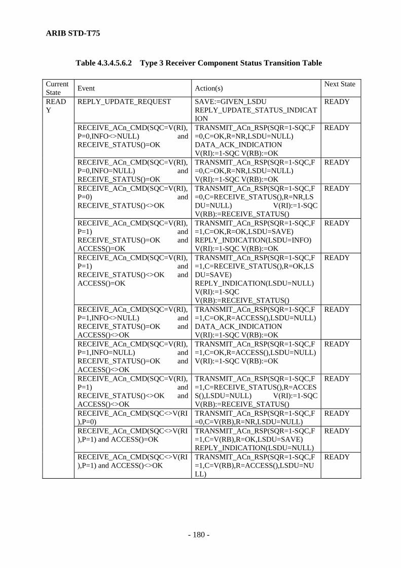
ARIB STD-T75
- 180 -
Table 4.3.4.5.6.2 Type 3 Receiver Component Status Transition Table Current State Event Action(s) Next State
REPLY_UPDATE_REQUEST SAVE:=GIVEN_LSDU REPLY_UPDATE_STATUS_INDICATION
READY
RECEIVE_ACn_CMD(SQC=V(RI),P=0,INFO<>NULL) and RECEIVE_STATUS()=OK
TRANSMIT_ACn_RSP(SQR=1-SQC,F=0,C=OK,R=NR,LSDU=NULL) DATA_ACK_INDICATION V(RI):=1-SQC V(RB):=OK
READY
RECEIVE_ACn_CMD(SQC=V(RI),P=0,INFO=NULL) and RECEIVE_STATUS()=OK
TRANSMIT_ACn_RSP(SQR=1-SQC,F=0,C=OK,R=NR,LSDU=NULL) V(RI):=1-SQC V(RB):=OK
READY
RECEIVE_ACn_CMD(SQC=V(RI),P=0) and RECEIVE_STATUS()<>OK
TRANSMIT_ACn_RSP(SQR=1-SQC,F=0,C=RECEIVE_STATUS(),R=NR,LSDU=NULL) V(RI):=1-SQC V(RB):=RECEIVE_STATUS()
READY
RECEIVE_ACn_CMD(SQC=V(RI),P=1) and RECEIVE_STATUS()=OK and ACCESS()=OK
TRANSMIT_ACn_RSP(SQR=1-SQC,F=1,C=OK,R=OK,LSDU=SAVE) REPLY_INDICATION(LSDU=INFO) V(RI):=1-SQC V(RB):=OK
READY
RECEIVE_ACn_CMD(SQC=V(RI),P=1) and RECEIVE_STATUS()<>OK and ACCESS()=OK
TRANSMIT_ACn_RSP(SQR=1-SQC,F=1,C=RECEIVE_STATUS(),R=OK,LSDU=SAVE) REPLY_INDICATION(LSDU=NULL) V(RI):=1-SQC V(RB):=RECEIVE_STATUS()
READY
RECEIVE_ACn_CMD(SQC=V(RI),P=1,INFO<>NULL) and RECEIVE_STATUS()=OK and ACCESS()<>OK
TRANSMIT_ACn_RSP(SQR=1-SQC,F=1,C=OK,R=ACCESS(),LSDU=NULL) DATA_ACK_INDICATION V(RI):=1-SQC V(RB):=OK
READY
RECEIVE_ACn_CMD(SQC=V(RI),P=1,INFO=NULL) and RECEIVE_STATUS()=OK and ACCESS()<>OK
TRANSMIT_ACn_RSP(SQR=1-SQC,F=1,C=OK,R=ACCESS(),LSDU=NULL) V(RI):=1-SQC V(RB):=OK
READY
RECEIVE_ACn_CMD(SQC=V(RI),P=1) and RECEIVE_STATUS()<>OK and ACCESS()<>OK
TRANSMIT_ACn_RSP(SQR=1-SQC,F=1,C=RECEIVE_STATUS(),R=ACCESS(),LSDU=NULL) V(RI):=1-SQC V(RB):=RECEIVE_STATUS()
READY
RECEIVE_ACn_CMD(SQC<>V(RI),P=0)
TRANSMIT_ACn_RSP(SQR=1-SQC,F=0,C=V(RB),R=NR,LSDU=NULL)
READY
RECEIVE_ACn_CMD(SQC<>V(RI),P=1) and ACCESS()=OK
TRANSMIT_ACn_RSP(SQR=1-SQC,F=1,C=V(RB),R=OK,LSDU=SAVE) REPLY_INDICATION(LSDU=NULL)
READY
READY
RECEIVE_ACn_CMD(SQC<>V(RI),P=1) and ACCESS()<>OK
TRANSMIT_ACn_RSP(SQR=1-SQC,F=1,C=V(RB),R=ACCESS(),LSDU=NULL)
READY

ARIB STD-T75
- 181 -
4.3.4.5.6.2.3 Event Description (1) REPLY-UPDATE_REQUEST The layer-7 has passed a DL-REPLY-UPDATE.request primitive to LLC. (2) RECEIVE_ACn_CMD(SQC,P,INFO) The MAC sublayer has passed to LLC an MA-UNITDATA.indication primitive including AC0 or AC1 command PDU, where the command sequence bit SQC (bit eight of LLC control field) is "0" for AC0 command or "1" for AC1 command. The following parameter values exists for this action: SQC=V (RI) Either the command sequence bit is equal to the V (RI) state variable for this
Receiver Component, or that a state variable does not exist. SQC<>V(RI) There exists V (RI) state variable for this Receiver Component and the
command sequence bit is not equal to this state variable. P=0 The P bit is "0" in the command. P=1 The P bit is "1" in the command. INFO=NULL The information field of the command is null (of zero length). INFO<>NULL The information field of the command is not null. In the state transition table, some of the events are qualified by the following conditions. The event is recognized only when the condition is true. (3) RECEIVE_STATUS()=OK The information field in the received command PDU was successfully received or can be passed to the user. (4) RECEIVE_STATUS()<>OK The information field in the received command PDU was not successfully received or cannot be passed to the user. (5) ACCESS()=OK A response LSDU associated with the SAP does exist and it can be accessed quickly enough to include it in the response PDU.

ARIB STD-T75
- 182 -
(6) ACCESS<>OK Either a response LSDU associated with the SAP does not exist or the LSDU does exist but it cannot be accessed quickly enough to include it in the response PDU. 4.3.4.5.6.2.4 Action Description (1) SAVE:=GIVEN_LSDU The LSDU is given in the associated DL-REPLY-UPDATE.request primitive held in readiness for transmission by being placed in the abstract location, SAVE. The SAVE location used is specifically associated with the SAP given in the primitive and the new LSDU replaces any previously held for that SAP. (2) TRANSMIT_ACn_RSP(SQR,F,C,R,LSDU) Pass an MA-UNITDATA.request primitive to the MAC sublayer including an AC0 or AC1 response PDU. The following parameter values exists for this action: SQR=1-SQC The response sequence bit (bit eight of LLC control field code) is set to
the complement of the sequence bit from the received command. F=0 The F bit of the response is set to "0". F=1 The F bit of the response is set to "1". C=OK The CCCC portion of the status subfield is set to OK code (successful
reception). C=RECEIVE_STATUS()
The CCCC portion of the status subfield is set to the value returned by the RECEIVE_STATUS function.
C=V(RB) The CCCC portion of the status subfield is set equal to the V (RB) state variable associated with the link address of the received command PDU.
R=NR The RRRR portion of the status subfield is set to NR code. (Response
data not requested.) R=OK The RRRR portion of the status subfield is set to OK code. (Response
data included.)

ARIB STD-T75
- 183 -
R=ACCESS() The RRRR portion of the status subfield is set to the value returned from the ACCESS function.
LSDU=NULL The LSDU subfield of the response is null (having zero length). LSDU=SAVE The LSDU subfield of the response contains the LSDU held in readiness
the SAVE location for this SAP. (Note) at the base station, the medium for the response of the mobile station shall be assigned
immediate upon connection to the ACn command. (3) DATA_ACK_INDICATION Pass the layer-7 a DL-DATA-ACK.indication primitive including an LSDU equal to the information field of associated received command PDU. (4) REPLY_INDICATION(LSDU) Pass to the layer-7 a DL-REPLY.indication primitive. The following parameter values exists for this action: LSDU=INFO The user is passed an LSDU equal to the information field from associated
received command PDU. (This field may be null.) LSDU=NULL The user is passed a null LSDU. (5) REPLY_UPDATE_STATUS_INDICATION Pass the layer-7 a DL-REPLY-UPDATE-STATUS.indication primitive. (6) V(RI):=1-SQC The V (RI) state variable for this Receiver Component is set to the complement of the sequence bit (bit eight of LLC control field code) in the received command PDU. (7) V(RB):=OK The V (RB) state variable for this Receiver Component is set to the "OK" code (successful reception).

ARIB STD-T75
- 184 -
(8) V(RB):=RECEIVE_STATUS() The V (RB) state variable for this Receiver Component is set to the value returned by the RECEIVE_STATUS function. 4.3.4.5.6.3 Type 3 Sender Component The Type 3 Sender Component is responsible for transmitting ACn command PDUs to a remote LLC. The Sender Component also receives response PDUs and retransmits the command PDUs if no response is received. Type 3 protocol allows one outstanding (not yet acknowledged) command PDU for each private SAP. Each Transmitter uses its own V (SI) state variable when selecting the LLC control field code for a new transmission and when checking for valid response LLC control field code. There shall be one Sender Component at each mobile station, communicating with Type 3 operation. There shall be as many receiver components as mobile station, communicating with Type 3 operation, in the communication zone. Each Sender Component has three states. In the IDLE state, it is capable of processing the request from the layer-7 to transmit a new command PDU. In the WAIT_A and WAIT_R states, the component is only capable of receiving a response from the remote LLC, or of timing out and performing a retransmission. The WAIT_A state is used when the expected response is data less acknowledgment. The WAIT_R state is used when the expected response is a data bearing reply. Table 4.3.4.5.6.3 shows Type 3 Sender Component state transition table.
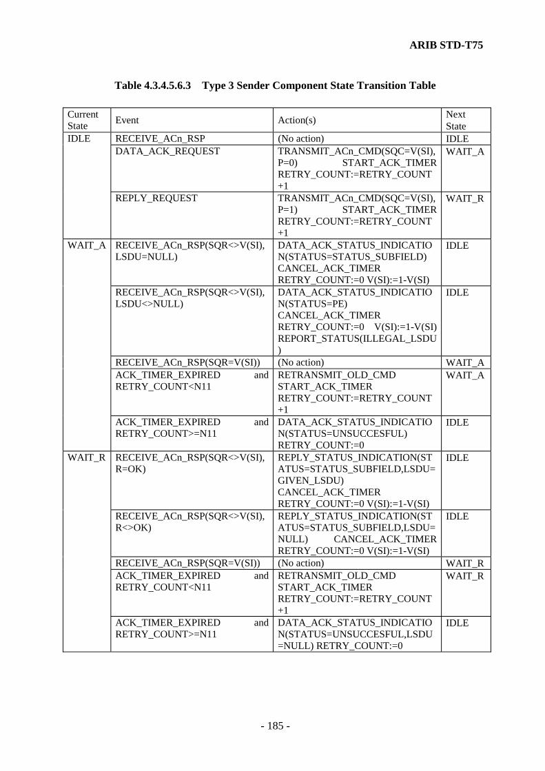
ARIB STD-T75
- 185 -
Table 4.3.4.5.6.3 Type 3 Sender Component State Transition Table Current State Event Action(s) Next
State RECEIVE_ACn_RSP (No action) IDLE DATA_ACK_REQUEST TRANSMIT_ACn_CMD(SQC=V(SI),
P=0) START_ACK_TIMER RETRY_COUNT:=RETRY_COUNT+1
WAIT_AIDLE
REPLY_REQUEST TRANSMIT_ACn_CMD(SQC=V(SI),P=1) START_ACK_TIMER RETRY_COUNT:=RETRY_COUNT+1
WAIT_R
RECEIVE_ACn_RSP(SQR<>V(SI),LSDU=NULL)
DATA_ACK_STATUS_INDICATION(STATUS=STATUS_SUBFIELD) CANCEL_ACK_TIMER RETRY_COUNT:=0 V(SI):=1-V(SI)
IDLE
RECEIVE_ACn_RSP(SQR<>V(SI),LSDU<>NULL)
DATA_ACK_STATUS_INDICATION(STATUS=PE) CANCEL_ACK_TIMER RETRY_COUNT:=0 V(SI):=1-V(SI) REPORT_STATUS(ILLEGAL_LSDU)
IDLE
RECEIVE_ACn_RSP(SQR=V(SI)) (No action) WAIT_AACK_TIMER_EXPIRED and RETRY_COUNT<N11
RETRANSMIT_OLD_CMD START_ACK_TIMER RETRY_COUNT:=RETRY_COUNT+1
WAIT_A
WAIT_A
ACK_TIMER_EXPIRED and RETRY_COUNT>=N11
DATA_ACK_STATUS_INDICATION(STATUS=UNSUCCESFUL) RETRY_COUNT:=0
IDLE
RECEIVE_ACn_RSP(SQR<>V(SI),R=OK)
REPLY_STATUS_INDICATION(STATUS=STATUS_SUBFIELD,LSDU=GIVEN_LSDU) CANCEL_ACK_TIMER RETRY_COUNT:=0 V(SI):=1-V(SI)
IDLE
RECEIVE_ACn_RSP(SQR<>V(SI),R<>OK)
REPLY_STATUS_INDICATION(STATUS=STATUS_SUBFIELD,LSDU=NULL) CANCEL_ACK_TIMER RETRY_COUNT:=0 V(SI):=1-V(SI)
IDLE
RECEIVE_ACn_RSP(SQR=V(SI)) (No action) WAIT_RACK_TIMER_EXPIRED and RETRY_COUNT<N11
RETRANSMIT_OLD_CMD START_ACK_TIMER RETRY_COUNT:=RETRY_COUNT+1
WAIT_R
WAIT_R
ACK_TIMER_EXPIRED and RETRY_COUNT>=N11
DATA_ACK_STATUS_INDICATION(STATUS=UNSUCCESFUL,LSDU=NULL) RETRY_COUNT:=0
IDLE
ARIB STD-T75
- 186 -
4.3.4.5.6.3.1 State Description (1) IDLE In this state, LLC is capable of executing a request from the layer-7 to transmit a Type 3 command PDU. (2) WAIT_A In this state, LLC is waiting for an acknowledgment previously transmitted Type 3 command PDU that was invoked by a DL-DATA-ACK.request primitive. (3) WAIT_R In this state, LLC is waiting for an acknowledgment previously transmitted Type 3 command PDU that was invoked by a DL-REPLY.request primitive. 4.3.4.5.6.3.2 Event description (1) DATA_ACK_REQUEST The layer-7 has passed a DL-DATA-ACK.request primitive to the LLC. (2) REPLY_REQUEST The layer-7 has passed a DL-REPLY.request primitive to the LLC. (3) RECEIVE_ACn_RSP(SQR,R,LSDU) The MAC sublayer has passed to LLC an MA-UNITDATA.indication primitive including the AC0 or AC1 response of which contains PDU, where the response sequence bit SQR (bit eight of the LLC control field) is 0 for an AC0 response or 1 for an AC1 response. The following parameter values exist for this action. SQR=V(SI) The response sequence bit is equal to the V (SI) status variable for this
Sender Component. SQR<>V(SI) The response sequence bit is not equal to the V (SI) status variable for this
Sender Component. R=OK The RRRR portion of the status subfield of the received response PDU
shows OK status. (Indicating that LSDU is included.)

ARIB STD-T75
- 187 -
R<>OK The RRRR portion of the status subfield of the received response PDU shows a status other than OK. (Indicating that an LSDU is not included.)
LSDU=NULL The LSDU subfield of the response is null (having zero length). LSDU<>NULL The LSDU subfield of the response is not null. (4) ACK_TIMER_EXPIRED The acknowledgment timer associated with this Sender Component (i.e., timer for a specific private link address) has terminated. In the state transmission table, some events are qualified by the following conditions. The event is recognized only when the condition is true. (5) RETRY_COUNT<N11 The retry count for this Sender Component is less than the logical link parameter N11. (6) RETRY_COUNT>=N11 The retry counts for this Sender Component is greater than or equal to the logical link parameter N11. 4.3.4.5.6.3.3 Action Description (1) TRANSMIT_ACn_CMD(SQC,P) Pass an MA-UNITDATA request primitive including an AC0 or AC1 command PDU to the MAC sublayer. The following parameter values exist for this action. SQC=V(SI) The command sequence bit (8th bit of LLC control field) is made equal to
the status variable V (SI) for this Receiver Component. If no status variable V (SI) exists, it is generated by value "0". Otherwise, the current value is used.
P=0 The P bit of the response is set to "0". P=1 The P bit of the response is set to "1". (2) RETRANSMIT_OLD_CMD Pass an MA-DATA.request primitive including the ACn command PDU most recently

ARIB STD-T75
- 188 -
transmitted by this Sender Component to the MAC sublayer. (3) START_ACK_TIMER Start the acknowledgment timer for this Sender Component. (4) CANCEL_ACK_TIMER Cancel the acknowledgment timer for this Sender Component. (5) DATA_ACK_STATUS_INDICATION(STATUS) Pass to the layer-7 a DL_DATA_ACK_STATUS.indication primitive. The following parameter values exist for this action. STATUS=UNSUCCESSFUL This status parameter is set to indicate failure receive an
acknowledgment. STATUS=STATUS_SUBFIELD This status parameter is set according to the status
returned by the received response PDU. (6) REPLY_STATUS_INDICATION(STATUS,LSDU) Pass to the layer-7 a DL-REPLY-STATUS.indication primitive. The following parameter values exist for this action. STATUS=UNSUCCESSFUL This status parameter is set to indicate failure to receive an
acknowledgment. STATUS=STATUS_SUBFIELD The status parameter is set according to the status returned
in the received response PDU. STATUS=PE This status parameter is set at PE status (protocol error). LSDU=NULL The data parameter is null. LSDU=GIVEN_LSDU The data parameter contains the LSDU given in the
associated MA-DATA.indication primitive.
ARIB STD-T75
- 189 -
(7) V(SI):=1-V(SI) Complement of V (SI) state variable for this Sender Component (8) RETRY_COUNT:=0 Set the retry counter for this Sender Component to "0". (9) RETRY_COUNT:=RETRY_COUNT+1 Increment the retry counter for this Sender Component. (10) REPORT_STATUS(ILLEGAL_LSDU) Report to layer management that an LSDU was received in violation of the Type3 LLC protocol.

ARIB STD-T75
- 190 -
Empty page

ARIB STD-T75
- 191 -
4.4 Layer 7 standards 4.4.1 Scope This subclause specifies the architecture and service items. Furthermore, considering the layer 7 structure, the application service elements that are constructed by the application protocol data unit (APDU), the application service data unit (ASDU) and operations relating to the ASDU are also specified. The operation specified regarding the ASDU is performed by the invocation from service primitives (SP). Services for applications provided by the layer 7 have a wide range, from simple service to complex, and are able to perform the process simultaneously for multiple applications by selecting necessary elements. 4.4.1.1 Outline of services The purpose of the layer 7 is to provide communication tools for the application whilst the scope of the application oriented working groups is to build the application using the tools provided by the layer 7. These tools consist of elements that can be used by application processes. The following subjects are covered by this standard:
(1) The layer 7 structure and framework. (2) Services to enable data transfer and remote operations. (3) Common encoding rules to translate data in local syntax with an abstract syntax defined
by ASN.1 (Abstract Syntax Notation One) into transfer syntax and vice versa. (4) Communication negotiation and association (initialization) procedures. (5) Broadcast service support. (6) Communication system management support including communication profile
handling.
Note) Although, this standard does not cover application multiplexing procedure, fragmentation procedure, concatenation and chaining procedure, etc. , shall specify and explain the requirements on the layer 7 operation. 4.4.1 .2 Structure The layer 7 shall consist of the layer 7 Kernel Element(s) (KE(s)). The layer 7 may consist of additional Application Service Elements. The services are provided service users by means of service primitives. These services are realized by means of protocols.

ARIB STD-T75
- 192 -
The fig. 4.4.1.2.1 shows the layer 7 structure for the basic data transfer service. This kernel element for the data transfer service is the transfer kernel element (T-KE). The layer 7 also shall composed of the initialization kernel element (I-KE) for the initialization (association) control and the broadcast pool kernel element (B-KE) for the broadcast services. The fig. 4.4.1.2.2 shows the entire layer 7 structure that is constructed by 3-kernel element.
Layer 2
Kernel-Service-Provider=LLC-Service-User Figure 4.4.1.2.1 The layer 7 Structure (data transfer service)
B-KernelService
B-KernelService
I-Kernel-Service
I-Kernel-Service
T-Kernel-Service
T-Kernel-Service
Broadcast-ProtocolB-KEB-KE
Initialization - Protocol
I-KEI-KE
T-KET-KETransfer-Protocol
LLC-ServiceLLC-Service
LLC LLC
Figure 4.4.1.2.2 the layer 7 kernel Structure
Application-Protocol ASE ASE
Kernel-Service-User ASE ASE
Layer 7
Kernel-ProtocolKernel-Service
LLC-Service
KE KE
LLC LLC

ARIB STD-T75
- 193 -
The layer 7 kernel provides the minimum set of services realized by the kernel elements needed to support several applications in parallel. This requires the means for dialogue initialization (association) control, offered by the Initialization KE (I-KE), cyclic broadcast transmission, offered by the Broadcast pool KE (B-KE), and generic transfer of data structures, offered by the Transfer-KE (T-KE). To permit simultaneous independent access to these elements from the user elements, the requirements on elements that may access the layer 7 kernel are defined. The layer 7-kernel elements always exist as single instances and are allocated outside the application processes, whereas several instances of these elements that access the kernel may exist in the application processes. The outline of function of each KE is described below. (1) Transfer Kernel Element (T-KE) T-KE shall transfer information between two peer service users and shall abstract from the realization of this transfer. The T-KE is responsible for the transfer of an APDU to the peer entity. It includes the needed, but extremely reduced, functionality from the Network Layer (the layer 3) to the Presentation Layer (the layer 6). These are (de-) coding to transfer syntax, and (de-) Multiplexing with priority handling. (2) Initialization Kernel Element (I-KE) The I-KE is responsible for the association (initialization) of the communication on the level of the layer 7. (3) Broadcast Kernel Element (B-KE) The B-KE is responsible for the collection, broadcast and retrieval of data for multiple applications and/or multiple mobile stations. The KE of the layer 7 shall consist of at least two Kernel Elements, the T-KE, and the I-KE or the B-KE. The Kernel may consist in addition of a B-KE or an I-KE.
4.4.1.3 Definition of Function The functionalities, architectures and terminologies of the layer 7 are defined in this subclause. 4.4.1.3.1 Term (1) Application The User who uses the service provided by DSRC communication protocol stack.
ARIB STD-T75
- 194 -
(2) Attributes Elements may have attributes. An attribute has an associated value, which can exhibit structure; i.e. it can consist of a set or sequence of sequence of data elements. Note) The value of an attribute is observed or modified by sending a request to an element to read (GET) or write (SET) the value. (3) Attribute identifier An identifier used to distinguish an attribute of an element from all other attributes. (4) Beacon Service Table (BST) The BST is the data structure which showed service which the base station provides, and is sent from the base station. On the base station side the I-KE collects application identifiers, etc. relevant for the communication. The application identifiers are stored in the BST as a priority list defining the order in which applications are served. The reception of the BST on the mobile station side is the initiator of each data transfer from applications on mobile station side. The mobile station's I-KE evaluates a received BST and indicates the availability (including parameter) of services to the corresponding application and application service elements. (5) Broadcast Pool File, cyclically broadcast from the base station to the mobile stations. Records may be independent by inserted from several service users. (6) Chaining A function performed by the transfer kernel element (T-KE) to concatenate multiple application protocol data units (APDUs) or APDU fragment into one ASDU and to process simultaneously. It is called Chaining to perform multiple application operation (data transfer) in one APDU using one Chain (Chain : Consists of the concatenated multiple T-APDU fragments with the fixed sequentiality in the same PDU number) . (7) Concatenation A function performed by the transfer kernel element (T-KE) to concatenate multiple application protocol data units (APDUs) or divided APDU into one application service data unit (ASDU). (8) Element An application element with data and function became the set, and abstract expression of the resource required for data processing and data communications. (9) Element Identifier (EID) An identifier used to distinguish the element within the mobile station.

ARIB STD-T75
- 195 -
(10) Encoding A function performed by the transfer-service-provider that transfers the data from a special local syntax into transfer syntax common for all communication systems (with the same applications on them). The peer transfer-service-provider decodes this data from transfer syntax into its own local syntax. The common abstract description of this data is the abstract syntax (defined by means ASN.1 [ISO 8824]). The common rules for the encoding and decoding are the Packed Encoding Rules (PER [ISO 8825-2]). (11) Fragmentation A function performed by the transfer kernel element (T-KE) to divide encoded PDU into T-APDU. (12) Head of the line Queuing discipline (also: strict priority queuing or fixed priority queuing), a number of queues are served in priority order, i.e. a lower priority queue is served if all higher priority queues are empty, each queue is served in First-Come-First-Served order, and each customer goes to the head of the line of the customers of lower priorities but behind all customers of equal or higher priority. (13) Management The layer management is the part of the layer 7 that supports the communication system management. This management consists of providing the layer 7, the layer 2 or the layer 1 in both entities with values for the communication parameters and the collection and distribution of other information necessary for controlling the communication system. (14) Operation An operation is the means to access a functionality or information of an element or to change its state. (15) Profile Information about capabilities and/or settings in the different layers and/or application processes. A profile is identified by an INTEGER. (16) Time The initialization kernel element (I-KE) shall interpret Time as the number of seconds up from the 1/1/1970 00:00. (17) Vehicle Service Table (VST) The VST is the answer of the I-KE inside the mobile station (vehicle) on the BST. It contains

ARIB STD-T75
- 196 -
the identifiers of all application present in the BST and registered in the mobile station (vehicle) and the profile used for further communication. 4.4.1.3.2 Data units in the data transfer services Data units in the data transfer services in the layer 7 are defined as below. (1) Application Data Unit (ADU) Data unit specified in an application and transferred between two application entities. (2) Application Protocol Data Unit (APDU) Data Units exchanged between peer application service elements. (3) Application Service Data Unit (ASDU) Data associated to a SP invocation of an application service element. (4) LLC Protocol Data Unit (LPDU) Data Unit transmitted between two LLC protocol instances. (5) LLC Service Data Unit (LSDU) Vertically transmitted data unit between the layer 7 and the LLC. (6) Transfer Application Protocol Data Unit (T-APDU) Data Unit of APDU transferred between transfer kernel elements (T-KEs) 4.4.2 Kernel Elements The functionalities of each kernel of the layer 7 are specified in detail. 4.4.2.1 Transfer-KE (Transfer-service-provider) 4.4.2.1.1 Function The T-KE shall transfer information between two service users by translating a defined service primitive(s) to T-APDU and shall provide its function.

ARIB STD-T75
- 197 -
4.4.2.1.2 Outline of Services The T-KE shall offer its services by means of service primitives defined as follows.
(1) GET (2) SET (3) ACTION (4) EVENT-REPORT (5) INITIALIZATION
4.4.2.1.3 Protocol The transfer protocol shall consist of the following sequence of steps.
(1) Translate SDU to PDU (2) Encoding of PDU (3) Octet alignment (4) Multiplexing, Concatenation, and Access to LLC (5) Demultiplexing and Deconcatenation (6) Removing of inserted bits (7) Decoding of PDU (8) Translate PDU to SDU and Distribution to addressee
The sequence of these functionalities is shown in fig. 4.4.2.1.

ARIB STD-T75
- 198 -
T-ASDUT-ASDU
SAPSAP
Demultiplexer(also Deconcatenation)
Multiplexer(also Concatenation)
encoded PDU
PDU
PDUPDU
LLC-SDULLC-SDU
T-APDU T-APDU
DecoderEncoder
Octet Aligner Encoded PDU
DealignmentDeletion inserted bits
LLC-SAP LLC-SAP
Figure 4.4.2.1 Functionalities of the T-KE
ARIB STD-T75
- 199 -
4.4.2.2 Initialization-KE (Initialization-service-provider: I-KE) 4.4.2.2.1 Function The I-KE shall realize the initialization of the communication between a mobile station and a base station by exchanging information concerning profiles or applications with its peer entity. It shall inform the applications inside the mobile station about the presence of a peer application inside the base station. It shall handle the LID of the mobile station. 4.4.2.2.2 Outline of Services The I-KE shall provide the following services to other elements (Initialization-service-users) as follows. (1) RegisterApplicationRSU(Beacon) (2) RegisterApplicationOBU(Vehicle) (3) DeregisterApplication (4) NotifyApplicationRSU(Beacon) (5) NotifyApplicationOBU(Vehicle) (6) End(Ready)Application 4.4.2.3 Broadcast-KE (Broadcast-service-provider: B-KE) 4.4.2.3.1 Function The B-KE shall realize the collection, broadcast and distribution of information for different applications in the mobile station and the base station by exchanging the Broadcast Pool. 4.4.2.3.2 Outline of Services The B-KE shall provide the following services to other elements (Broadcast-service-users). (1) BroadcastData (2) GetBroadcastData 4.4.3 Layer 7 service interface 4.4.3.1 Scope The communication between the layer 7 and service users (applications) using service primitives provided by the layer 7.
ARIB STD-T75
- 200 -
4.4.3.2 List of service primitives The name of the primitive is specific to the operation that should be performed. A Service primitive defined in this standard is shown in Table. 4.4.3.1. 4.4.3.3 Relationship of primitives In this standard, primitives are 4 generic types as follows. The relationship between the layer 7 and application entity and their associated peer protocol entities is shown in Fig. 4.4.3.3. These service primitives are abstraction in that they specify only the service provided rather than means by which the service is provided. This definition of services is independent of any particular interface implementation. (1) request The request primitive is passed from the application (kernel service user) to the layer 7 to request that a service be initiated. (2) indication The indication primitive is passed from the layer 7 to the application (kernel service user) to indicate a service from the peer application (peer kernel service user). (3) response The response primitive is passed from the application (kernel service user) to the layer 7 to response for a service from the peer application (peer kernel service user) invoked by an indication primitive. (4) confirm The confirm primitive is passed from the layer 7 to the application (kernel service user) to convey the results of one or more associated previous service request(s).

ARIB STD-T75
- 201 -
Table. 4.4.3.1. Service primitives Primitives request indication response confirm Notice
GET √ √ √ √ T-KE SET √ √ √ √ T-KE ACTION √ √ √ √ T-KE EVENT-REPORT √ √ √ √ T-KE RegisterApplicationRSU(Beacon) I-KE RegisterApplicationOBU(Vehicle) I-KE DeregisterApplication I-KE NotifyApplicationRSU(Beacon) I-KE NotifyApplicationOBU(Vehicle) I-KE End(Ready)Application I-KE BroadcastData √ B-KE GetBroadcastData √ √ B-KE
AP request indication confirm response
Fig. 4.4.3.3 Relationship between primitives and entities
Application Application
The layer 7 The layer 7
ARIB STD-T75
- 202 -
4.4.3.4 Service specification 4.4.3.4.1 Get primitives (1) Function and When Generated The invocation of the GET service by an application (kernel service user) shall result in the retrieval of information from a peer application (kernel service user) on the base station / mobile station side. The service shall only be requested in a confirmed mode, and a reply is expected. (2) Format These primitives shall provide parameters as follows.
GET.request ([IID], LID, Chaining, EID, [Access Credentials], [AttrIdList], Flow Control) GET.indication ([IID], LID, Chaining, EID, [Access Credentials], [AttrIdList], Flow Control) GET.response ([IID], LID, Chaining, EID, Flow Control, [AttrList], [Ret]) GET.confirm ([IID], LID, Chaining, EID, [Flow Control], [AttrList], [Ret])
Note) parameter “xx” within the [xx] is optional. This note shall apply to the following definitions. 4.4.3.4.2 SET primitives (1) Function and When Generated The invocation of the SET service by an application (kernel service user) shall result in the modification of information by a peer application (kernel service user) on the base station / the mobile station side. The service may be requested in a confirmed or non-confirmed mode. In the confirmed mode a reply is expected. (2) Format These primitives shall provide parameters as follows.
SET.request ([IID], LID, Chaining, EID, [Access Credentials], AttrList, Mode, Flow Control)
SET.indication ([IID], LID, Chaining, EID, [Access Credentials], AttrList, Mode, Flow Control)
SET.response ([IID], LID, Chaining, EID, Flow Control, [Ret]) SET.confirm ([IID], LID, Chaining, EID, [Flow Control], [Ret])

ARIB STD-T75
- 203 -
4.4.3.4.3 ACTION primitives (1) Function and When Generated The invocation of the ACTION service by an application (kernel service user) shall result in the performance of an action by a peer application (kernel service user) on the base station / the mobile station side. The service may be requested in a confirmed or non-confirmed mode. In the confirmed mode a reply is expected. (2) Format These primitives shall provide parameters as follows.
ACTION.request ([IID], LID, Chaining, EID, Action Type, [Access Credentials], [Action Parameter], Mode, Flow Control) ACTION.indication ([IID], LID, Chaining, EID, Action Type, [Access Credentials],
[Action Parameter], Mode, Flow Control) ACTION.response ([IID], LID, Chaining, EID, Flow Control,
[Response Parameter], [Ret]) ACTION.confirm ([IID], LID, Chaining, EID, [Flow Control],
[Response Parameter], [Ret]) 4.4.3.4.4 EVENT-REPORT primitives (1) Function and When Generated The invocation of the EVENT-REPORT service by an application (kernel service user) shall result in the report of an event about an element to a peer application (kernel service user) on the base station / the mobile station side. The service may be requested in a confirmed or non-confirmed mode. In the confirmed mode a reply is expected. (2) Format These primitives shall provide parameters as follows.
EVENT-REPORT.request ([IID], LID, Chaining, EID, Event Type, [Access Credentials], [Event Parameter], Mode, Flow Control) EVENT-REPORT.indication ([IID], LID, Chaining, EID, Event Type,
[Access Credentials], [Event Parameter], Mode, Flow Control) EVENT-REPORT.response ([IID], LID, Chaining, EID, Flow Control, [Ret]) EVENT-REPORT.confirm ([IID], LID, Chaining, EID, [Flow Control], [Ret])

ARIB STD-T75
- 204 -
4.4.3.4.5 RegisterApplicationRSU(Beacon) primitive (1) Function and When Generated The invocation of the RegisterApplicationRSU(Beacon) service to by an application (kernel service user) on the base station side shall result in the registration of the application to the application list of I-KE. Note) Refer to the parameter of Profiles for Annex P. (2) Format These primitives shall provide parameters as follows.
RegisterApplicationRSU(Beacon) (AID, Mandatory, Priority, [EID], [Profiles],
[Parameter]) 4.4.3.4.6 RegisterApplicationOBU(Vehicle) primitive (1) Function and When Generated The invocation of the RegisterApplicationOBU(Vehicle) service by an application (kernel service user) on the mobile station side shall result in the registration of the application to the application list of I-KE. (2) Format This primitive shall provide parameters as follows.
RegisterApplicationOBU(Vehicle) (AID, Priority, EID, [Profiles], [Parameter]) Note) Refer to the parameter of Profiles for Annex P. 4.4.3.4.7 DeregisterApplication primitive (1) Function and When Generated The invocation of the DeregisterApplication service by an application (kernel service user) on the base station / the mobile station side shall result in the deregistration of the associated entry in an application list. In addition, if DeregisterApplication is invoked from the corresponding application in the state managed by only its application, it shall release the association (link) at the time.
ARIB STD-T75
- 205 -
(2) Format This primitive shall provide parameters as follows.
DeregisterApplication (AID, [EID])
4.4.3.4.8 NotifyApplicationRSU(Beacon) primitive (1) Function and When Generated The invocation of the NotifyApplicationRSU(Beacon) by the I-KE in the layer 7 shall result in the notification of the application (kernel service user) on the base station about the presence of a potential communication application and the LID of the associated mobile station. (2) Format This primitive shall have the following format.
NotifyApplicationRSU (Priority, [EID], LID, [Parameter], obe Configuration)
Note) The obeConfiguration parameter of NotifyApplicationRSU(Beacon) to the simplified association (initialization) procedures specified with subclause 4.4.5.2 is considering as empty. 4.4.3.4.9 NotifyApplicationOBU(Vehicle) primitive (1) Function and When Generated The invocation of the NotifyApplicationOBU(Vehicle) by the I-KE in the layer 7 shall result in the notification of the application (kernel service user) on the mobile station side about the presence of a potential communication application and the LID generated by the mobile station. (2) Format This primitive shall provide parameters as follows.
NotifyApplicationOBU (RSU(Beacon), Priority, [EID], LID, [Parameter])
4.4.3.4.10 End(Ready)Application primitive (1) Function and When Generated The invocation of the End(Ready)Application service by the application (kernel service user) shall result in the notification of the I-KE that the LID is not longer needed for this application. In addition, if End(Ready)Application is invoked from the corresponding application in the state managed by only its application, it shall release the association (link) at the time.

ARIB STD-T75
- 206 -
(2) Format This primitive shall have the following format.
End(Ready)Application (EID, LID, [Norm_end]) Note) Norm_end is an option, has a meaning only the mobile station and is not necessary to use it on the base station. 4.4.3.4.11 BroadcastData primitive (1) Function and When Generated The invocation of the BroadcastData service by the application (kernel service user) on the base station side shall result in the broadcast of information to other Broadcast applications on the mobile station side or in the update of this information. (2) Format This primitive shall provide parameters as follows.
BroadcastData.request (File) 4.4.3.4.12 GetBroadcastData primitives (1) Function and When Generated The invocation of the GetBroadcastData-service by a Broadcast application shall result in the retrieval of the broadcasted data. (2) Format These primitives shall provide parameters as follows.
GetBroadcastData.request (Name, EID) GetBroadcastData.confirm (File)
4.4.3.4.13 NotifyApplicationOBU_Release primitives (1) Function and When Generated The invocation of the NotifyApplicationOBU_Release service by the application (kernel service user) shall result in the notification to the layer 7 from the application that the application received the release by the EVENT_REPORT.request from the base station.
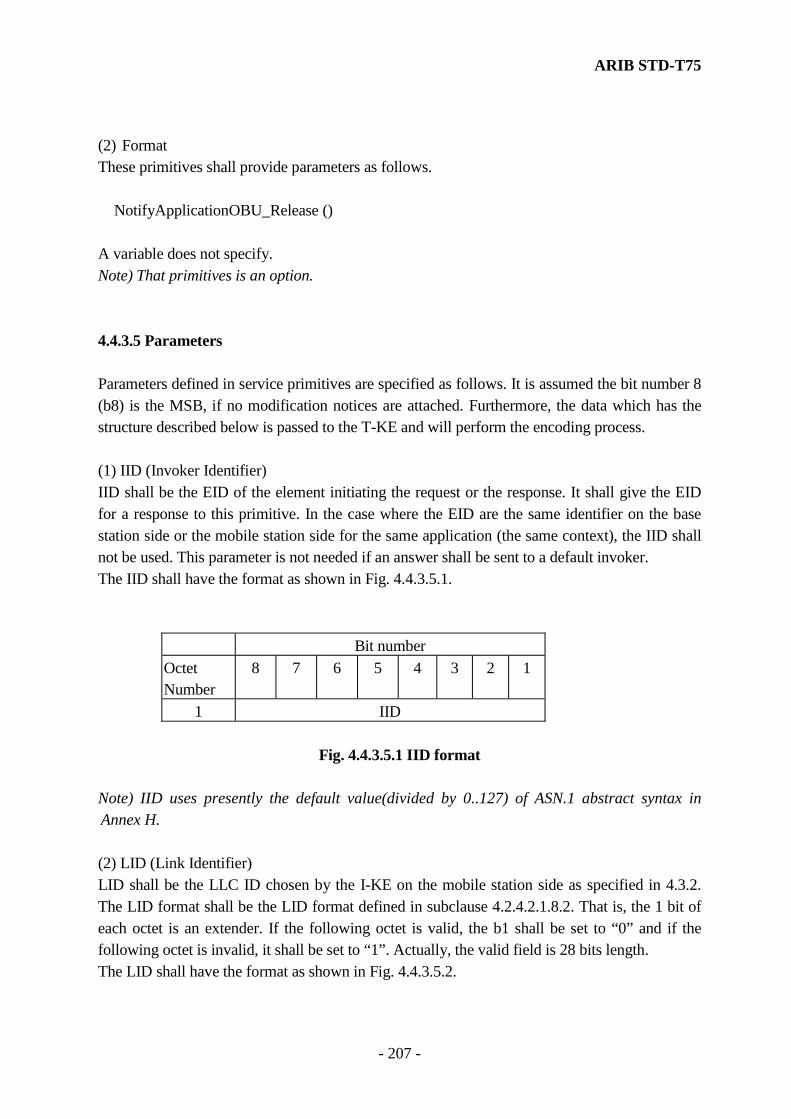
ARIB STD-T75
- 207 -
(2) Format These primitives shall provide parameters as follows.
NotifyApplicationOBU_Release () A variable does not specify. Note) That primitives is an option. 4.4.3.5 Parameters Parameters defined in service primitives are specified as follows. It is assumed the bit number 8 (b8) is the MSB, if no modification notices are attached. Furthermore, the data which has the structure described below is passed to the T-KE and will perform the encoding process. (1) IID (Invoker Identifier) IID shall be the EID of the element initiating the request or the response. It shall give the EID for a response to this primitive. In the case where the EID are the same identifier on the base station side or the mobile station side for the same application (the same context), the IID shall not be used. This parameter is not needed if an answer shall be sent to a default invoker. The IID shall have the format as shown in Fig. 4.4.3.5.1.
Bit number Octet Number
8 7 6 5 4 3 2 1
1 IID
Fig. 4.4.3.5.1 IID format Note) IID uses presently the default value(divided by 0..127) of ASN.1 abstract syntax in Annex H. (2) LID (Link Identifier) LID shall be the LLC ID chosen by the I-KE on the mobile station side as specified in 4.3.2. The LID format shall be the LID format defined in subclause 4.2.4.2.1.8.2. That is, the 1 bit of each octet is an extender. If the following octet is valid, the b1 shall be set to “0” and if the following octet is invalid, it shall be set to “1”. Actually, the valid field is 28 bits length. The LID shall have the format as shown in Fig. 4.4.3.5.2.
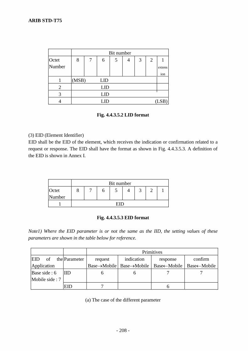
ARIB STD-T75
- 208 -
Bit number Octet Number
8 7 6 5 4 3 2 1 extens
ion
1 (MSB) LID 2 LID 3 LID 4 LID (LSB)
Fig. 4.4.3.5.2 LID format
(3) EID (Element Identifier) EID shall be the EID of the element, which receives the indication or confirmation related to a request or response. The EID shall have the format as shown in Fig. 4.4.3.5.3. A definition of the EID is shown in Annex I.
Bit number Octet Number
8 7 6 5 4 3 2 1
1 EID
Fig. 4.4.3.5.3 EID format
Note1) Where the EID parameter is or not the same as the IID, the setting values of these parameters are shown in the table below for reference.
Primitives EID of the Application
Parameter request Base→Mobile
indication Base→Mobile
response Base←Mobile
confirm Base←Mobile
Base side : 6 Mobile side : 7
IID 6 6 7 7
EID 7 6
(a) The case of the different parameter
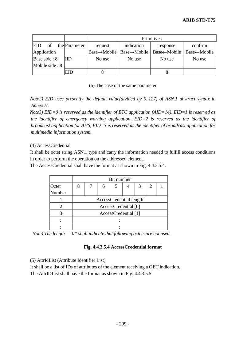
ARIB STD-T75
- 209 -
Primitives EID of the Application
Parameter request Base→Mobile
indication Base→Mobile
response Base←Mobile
confirm Base←Mobile
Base side : 8 Mobile side : 8
IID No use No use No use No use
EID 8 8
(b) The case of the same parameter Note2) EID uses presently the default value(divided by 0..127) of ASN.1 abstract syntax in Annex H. Note3) EID=0 is reserved as the identifier of ETC application (AID=14), EID=1 is reserved as the identifier of emergency warning application, EID=2 is reserved as the identifier of broadcast application for AHS, EID=3 is reserved as the identifier of broadcast application for multimedia information system. (4) AccessCredential It shall be octet string ASN.1 type and carry the information needed to fulfill access conditions in order to perform the operation on the addressed element. The AccessCredential shall have the format as shown in Fig. 4.4.3.5.4.
Bit number Octet Number
8 7 6 5 4 3 2 1
1 AccessCredential length 2 AccessCredential [0] 3 AccessCredential [1] : : : :
Note) The length =“0” shall indicate that following octets are not used.
Fig. 4.4.3.5.4 AccessCredential format (5) AttrIdList (Attribute Identifier List) It shall be a list of IDs of attributes of the element receiving a GET.indication. The AttrIDList shall have the format as shown in Fig. 4.4.3.5.5.

ARIB STD-T75
- 210 -
Bit number Octet Number
8 7 6 5 4 3 2 1
1 AttrIdList count 2 AttrIdList [0] 3 AttrIdList [1] : : : :
Note) The count =“0” shall indicate that following octets are not used.
Fig. 4.4.3.5.5 AttrIdList format (6) Flow Control Flow Control shall be a parameter that represents the behavior of the underlying communication service to LLC service primitives. The Flow Control parameter shall have the format and value as shown in Fig. 4.4.3.5.6.
Bit number Octet Number
8 7 6 5 4 3 2 1
1 Flow Control
Flow Control parameter
LLC service
1 DL-UNITDATA.request without response request 2 DL-UNITDATA.request with response request 3 DL-UNITDATA.indication 4 DL-DATA-ACK.request 5 DL-DATA-ACK.indication 6 DL-DATA-ACK-STATUS.indication 7 DL-PERLY.request 8 DL-PERLY.indication 9 DL-PERLY-STATUS.indication 10 DL-REPLY-UPDATE.request 11 DL-REPLY-UPDATE-STATUS.indication 12 DL-UNITDATA.request wait response request
Fig. 4.4.3.5.6 Flow Control parameters

ARIB STD-T75
- 211 -
(7) AttrList (Attribute List) It shall be a sequence of attribute values of one element sent by the SET.request, the SET.indication or the GET.response or GET.confirm. The AttrList shall have the format as shown in Fig. 4.4.3.5.7. However, the structure of attribute value is not defined in this standard.
Bit number Octet Number
8 7 6 5 4 3 2 1
1 Attribute count 2 attributeId (Attribute [0]) 3 : :
attributevalue (Attribute [0]) :
: Attribute [1] : Attribute [2] : : : :
Note) The Attribute count =“0” shall indicate that following octets are not used.
Fig. 4.4.3.5.7 AttrList format (8) Ret (Return Code) It shall be a special return code issued by an element as an answer to a service indication. The Ret shall have the format and be coded as shown in Fig. 4.4.3.5.8.
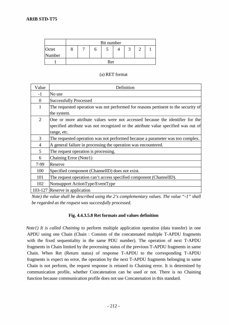
ARIB STD-T75
- 212 -
Bit number Octet Number
8 7 6 5 4 3 2 1
1 Ret
(a) RET format
Value Definition -1 No use 0 Successfully Processed 1 The requested operation was not performed for reasons pertinent to the security of
the system. 2 One or more attribute values were not accessed because the identifier for the
specified attribute was not recognized or the attribute value specified was out of range, etc.
3 The requested operation was not performed because a parameter was too complex.4 A general failure in processing the operation was encountered. 5 The request operation is processing. 6 Chaining Error (Note1)
7-99 Reserve 100 Specified component (ChannelID) does not exist. 101 The request operation can’t access specified component (ChannelID). 102 Nonsupport ActionType/EventType
103-127 Reserve in application Note) the value shall be described using the 2’s complementary values. The value “-1” shall
be regarded as the request was successfully processed.
Fig. 4.4.3.5.8 Ret formats and values definition Note1) It is called Chaining to perform multiple application operation (data transfer) in one APDU using one Chain (Chain : Consists of the concatenated multiple T-APDU fragments with the fixed sequentiality in the same PDU number). The operation of next T-APDU fragments in Chain limited by the processing status of the previous T-APDU fragments in same Chain. When Ret (Return status) of response T-APDU to the corresponding T-APDU fragments is expect no error, the operation by the next T-APDU fragments belonging to same Chain is not perform, the request response is retuned to Chaining error. It is determined by communication profile, whether Concatenation can be used or not. There is no Chaining function because communication profile does not use Concatenation in this standard.
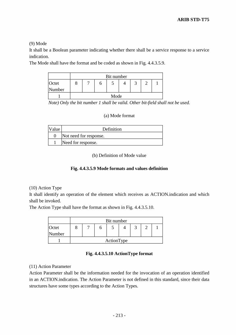
ARIB STD-T75
- 213 -
(9) Mode It shall be a Boolean parameter indicating whether there shall be a service response to a service indication. The Mode shall have the format and be coded as shown in Fig. 4.4.3.5.9.
Bit number Octet Number
8 7 6 5 4 3 2 1
1 Mode Note) Only the bit number 1 shall be valid. Other bit-field shall not be used.
(a) Mode format
Value Definition
0 Not need for response. 1 Need for response.
(b) Definition of Mode value
Fig. 4.4.3.5.9 Mode formats and values definition
(10) Action Type It shall identify an operation of the element which receives as ACTION.indication and which shall be invoked. The Action Type shall have the format as shown in Fig. 4.4.3.5.10.
Bit number Octet Number
8 7 6 5 4 3 2 1
1 ActionType
Fig. 4.4.3.5.10 ActionType format
(11) Action Parameter Action Parameter shall be the information needed for the invocation of an operation identified in an ACTION.indication. The Action Parameter is not defined in this standard, since their data structures have some types according to the Action Types.

ARIB STD-T75
- 214 -
(12) Response Parameter It may be information resulting from the execution of the operation invoked by ACTION.indication. The Response Parameters are not defined in this standard, since their data structures have some types according to the Action Types. (13) Event Type It shall identify the message that shall be delivered to an element that receives an EVENT-REPORT.indication. The Event Type shall have the format and be coded as shown in Fig. 4.4.3.5.11.
Bit number Octet Number
8 7 6 5 4 3 2 1
1 EventType
(a) EventType format
Value Definition 0 The release of the association (link)
Note) Values of 1, 2 and 3 are reserved for future systems.
(b) Definition of EventType value
Fig. 4.4.3.5.11 EventType format and value definition
(14) Event Parameter It shall be the additional information needed for the message sent via an EVENT-REPORT.request or EVENT-REPORT.indication, respectively. The Event Parameter is not defined, since the Event Type is defined only for the release and the Event Parameter for this release does not exist. (15) AID It shall be the Application Entity ID of the Initialization service user (application). The AID values are defined in annex I. The AID shall have the format as shown in Fig. 4.4.3.5.12.

ARIB STD-T75
- 215 -
Bit number Octet Number
8 7 6 5 4 3 2 1
1 AID
Fig. 4.4.3.5.12 AID format Note) AID uses presently the default value(divided by 0..31) of ASN.1 abstract syntax in Annex H. (16) Mandatory It shall be the BOOLEAN status of the Initialization service user (application). It shall be true if the Initialization service user (application) is a mandatory application and false if the Initialization service user (application) is a non-mandatory application. The Mandatory shall have the format and be coded as shown in Fig. 4.4.3.5.13.
Bit number Octet Number
8 7 6 5 4 3 2 1
1 Mandatory Note) Only the bit number 1 shall be valid. Other bit-field shall not be used.
(a) Mandatory format
Value Definition
0 Non-mandatory 1 Mandatory
(b) Definition of Mandatory values
Fig. 4.4.3.5.13 Mandatory formats and values definition
(17) Priority It shall be the priority of the Initialization service user (application) in relation to the other Initialization service user (application). A small INTEGER shall represent a high priority, a high INTEGER shall represent a low priority. The Priority shall have the format as shown in Fig. 4.4.3.5.14.
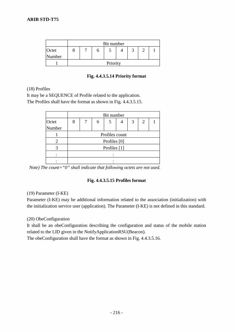
ARIB STD-T75
- 216 -
Bit number Octet Number
8 7 6 5 4 3 2 1
1 Priority
Fig. 4.4.3.5.14 Priority format
(18) Profiles It may be a SEQUENCE of Profile related to the application. The Profiles shall have the format as shown in Fig. 4.4.3.5.15.
Bit number Octet Number
8 7 6 5 4 3 2 1
1 Profiles count 2 Profiles [0] 3 Profiles [1] : : : :
Note) The count=“0” shall indicate that following octets are not used.
Fig. 4.4.3.5.15 Profiles format (19) Parameter (I-KE) Parameter (I-KE) may be additional information related to the association (initialization) with the initialization service user (application). The Parameter (I-KE) is not defined in this standard. (20) ObeConfiguration It shall be an obeConfiguration describing the configuration and status of the mobile station related to the LID given in the NotifyApplicationRSU(Beacon). The obeConfiguration shall have the format as shown in Fig. 4.4.3.5.16.
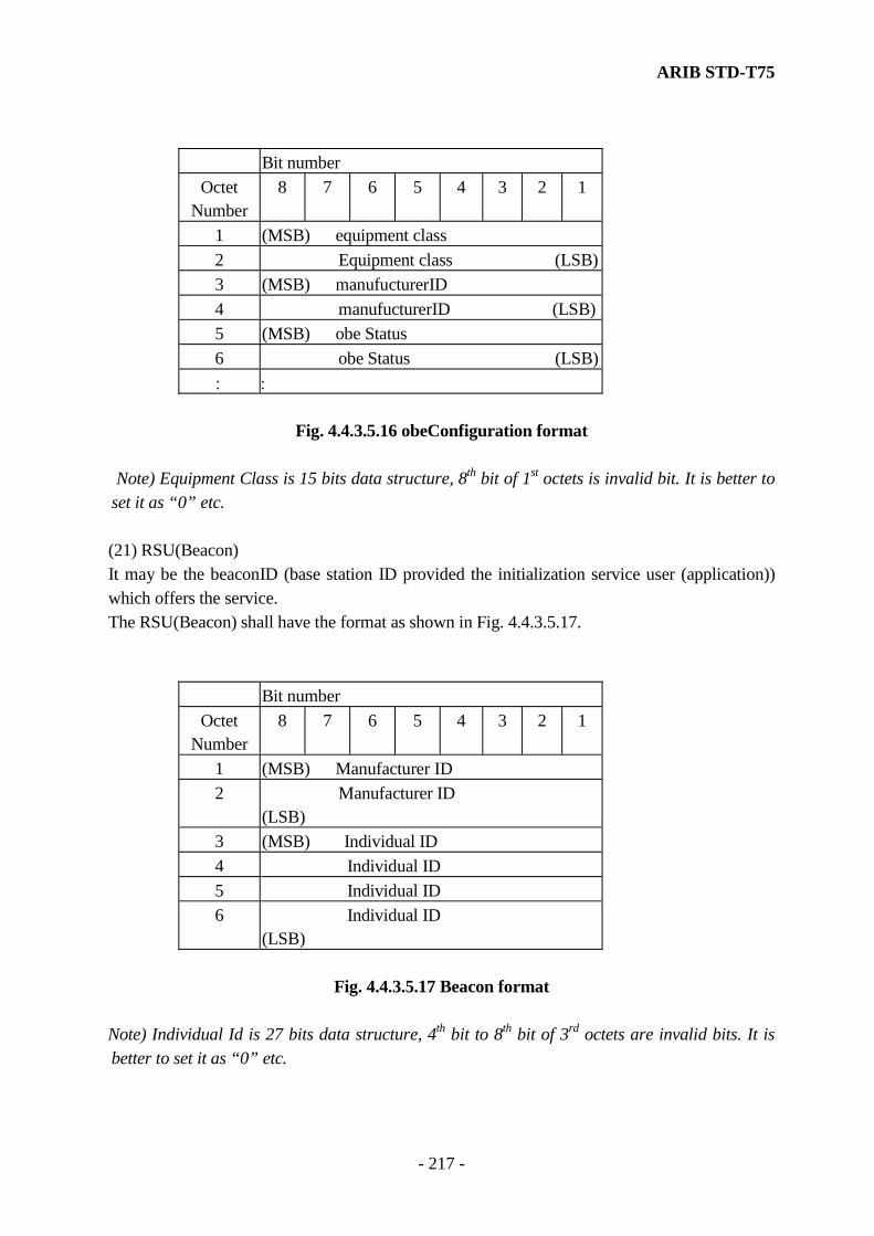
ARIB STD-T75
- 217 -
Bit number
Octet Number
8 7 6 5 4 3 2 1
1 (MSB) equipment class 2 Equipment class (LSB)3 (MSB) manufucturerID 4 manufucturerID (LSB)5 (MSB) obe Status 6 obe Status (LSB): :
Fig. 4.4.3.5.16 obeConfiguration format
Note) Equipment Class is 15 bits data structure, 8th bit of 1st octets is invalid bit. It is better to
set it as “0” etc. (21) RSU(Beacon) It may be the beaconID (base station ID provided the initialization service user (application)) which offers the service. The RSU(Beacon) shall have the format as shown in Fig. 4.4.3.5.17.
Bit number Octet
Number 8 7 6 5 4 3 2 1
1 (MSB) Manufacturer ID 2 Manufacturer ID
(LSB) 3 (MSB) Individual ID 4 Individual ID 5 Individual ID 6 Individual ID
(LSB)
Fig. 4.4.3.5.17 Beacon format Note) Individual Id is 27 bits data structure, 4th bit to 8th bit of 3rd octets are invalid bits. It is better to set it as “0” etc.
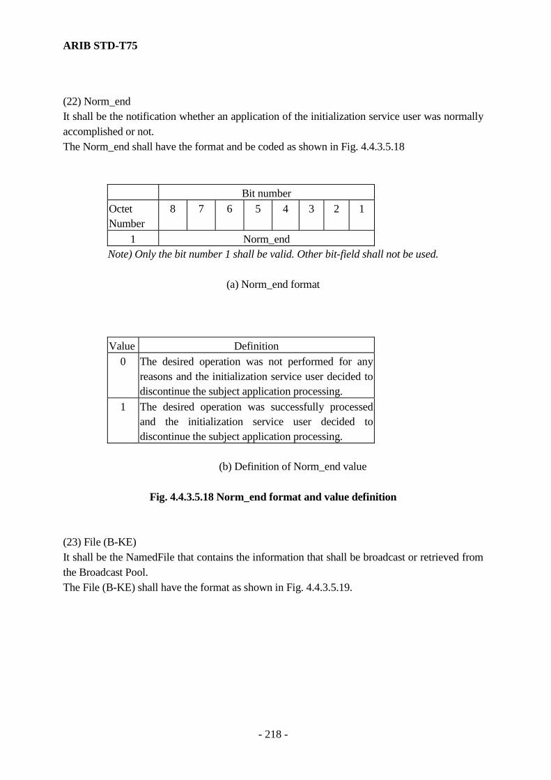
ARIB STD-T75
- 218 -
(22) Norm_end It shall be the notification whether an application of the initialization service user was normally accomplished or not. The Norm_end shall have the format and be coded as shown in Fig. 4.4.3.5.18
Bit number Octet Number
8 7 6 5 4 3 2 1
1 Norm_end Note) Only the bit number 1 shall be valid. Other bit-field shall not be used.
(a) Norm_end format
Value Definition 0 The desired operation was not performed for any
reasons and the initialization service user decided to discontinue the subject application processing.
1 The desired operation was successfully processed and the initialization service user decided to discontinue the subject application processing.
(b) Definition of Norm_end value
Fig. 4.4.3.5.18 Norm_end format and value definition
(23) File (B-KE) It shall be the NamedFile that contains the information that shall be broadcast or retrieved from the Broadcast Pool. The File (B-KE) shall have the format as shown in Fig. 4.4.3.5.19.

ARIB STD-T75
- 219 -
Bit number
Octet Number
8 7 6 5 4 3 2 1
1 ase ID 2 file ID 3 Record count 4 Record value length--Record[0] 5 Record value [0] --Record[0] : Record value [1] --Record[0] : : : : --Record[0] : Record [1] : Record [2] : :
Note) The Record count=“0” shall indicate that following octets are not used.
Fig. 4.4.3.5.19 File (B-KE) format
(24) Name (B-KE) It shall be the FileName of the file that shall be retrieved from the Broadcast Pool. The Name (B-KE) shall have the format as shown in Fig. 4.4.3.5.20.
Bit number Octet Number
8 7 6 5 4 3 2 1
1 ase ID 2 file ID
Fig. 4.4.3.5.20 Name (B-KE) format

ARIB STD-T75
- 220 -
4.4.4 Layer Management 4.4.4.1 Scope This layer 7 management entity (ALME: application layer management entity) consists of providing the layer 7 and the layer 2 in both entities with values for the communication parameters and communication control information necessary for communication and administration of the communication system. The communication control information and service interface to access to that information are defined for the layer 7 management entity. But, the functionalities of the layer 7 management entity are not specified in detail, since the function of the layer 7 management entity can be realized by the I-KE of the layer 7. The communication parameters and the communication control information are registered at the MIB of the layer 7 management entity (I-KE). The MIB information of the layer 7 management entity is defined in detail in annex A. 4.4.4.2 Function The layer 7 management entity shall have the following information, at least. (1) Application (the initialization service user) information. (2) The communication control information 4.4.4.2.1 Application management The layer 7 management entity shall manage the application information in order to provide service for the initialization service user (application) on the base station / the mobile station. The application information for each the initialization service user (application) shall be registered each time the RegisterApplicationRSU(Beacon)/ RegisterApplicationOBU(Vehicle) is received, and the corresponding application information shall be de-registered each time the DeregisterApplication is received. It may use the application management list for the registration. The application management list is shown in Table. 4.4.4.2.1 for reference.
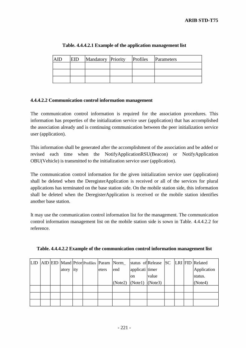
ARIB STD-T75
- 221 -
Table. 4.4.4.2.1 Example of the application management list
AID EID Mandatory Priority Profiles Parameters
4.4.4.2.2 Communication control information management The communication control information is required for the association procedures. This information has properties of the initialization service user (application) that has accomplished the association already and is continuing communication between the peer initialization service user (application). This information shall be generated after the accomplishment of the association and be added or revised each time when the NotifyApplicationRSU(Beacon) or NotifyApplication OBU(Vehicle) is transmitted to the initialization service user (application). The communication control information for the given initialization service user (application) shall be deleted when the DeregisterApplication is received or all of the services for plural applications has terminated on the base station side. On the mobile station side, this information shall be deleted when the DeregisterApplication is received or the mobile station identifies another base station. It may use the communication control information list for the management. The communication control information management list on the mobile station side is sown in Table. 4.4.4.2.2 for reference.
Table. 4.4.4.2.2 Example of the communication control information management list LID AID EID Mand
atory Priority
Profiles Parameters
Norm_ end (Note2)
status of application (Note1)
Release timer value (Note3)
SC LRI FID Related Application status. (Note4)

ARIB STD-T75
- 222 -
Where LID: Link address AID, EID: identifier of application M: Mandatory Priority: priority for applications requested by service users. Profiles: the layer 7 profiles. Parameter: the layer 7 parameters required for management SC: the comparison results with application identifiers of the base station provided by the layer 2 within the FCMC and the application identifiers that has registered at the layer 7 management entity (I-KE). LRI: Initialization (association) mode identifier. (Either normal type of association or simplified association procedure is implemented.) FID: the base station identifier on the layer 2 Note1) Status of application performance is described in subclause 4.4.5.6. Note2) Whether or not an application of the initialization service user was normally accomplished. It assumed the value of the Norm_end is substituted its field. Note3) the timer that constrains the re-association processes after releasing the association (link) on the mobile station side. Note4) underlying assumption is as follows. The linked two communication zones are constructed and each base station provides multiple applications for each zone. It may be that a related application accomplished an application transaction provided by 1st base station (1st communication zone) and another application transaction by 2nd base station (2nd communication zone). In that case, the mobile station needs to identify application which base station was provided. It may be usually identified as the 1st base station in the stand-alone communication zone. 4.4.4.3 Communication Profiles General Communication System Profiles shall represent characteristics of the communication partners. These characteristics shall be the same or compatible for two communicating partners. Two classes of characteristics shall be distinguished as follows. (1) Settable characteristics These characteristics shall be parameters of the system that may be set to a special value in general in each system. They shall be distinguished between characteristics where the wrong setting will lead to communication errors or will disable the communication between the partners and characteristics where the wrong setting will not lead to a communication error or will not disable the communication between the partners.
ARIB STD-T75
- 223 -
(2) Abilities These characteristics shall be abilities of the systems that are present or not. If one communication partner uses this ability the other partner shall also have this ability to be able to understand the incoming data. Refer to the communication profiles in this standard for Annex P. 4.4.4.4 Layer 7 management service interface specification 4.4.4.4.1 Overview of Interactions The layer 7 management entity (ALME) provides the following primitives to a system management entity (SME) or a MAC sublayer management entity (MLME). The primitives associated with the MIB access service are as follows. ALME-GET.request ALME-GET.confirm ALME-SET.request ALME-SET.confirm The ALME-GET.request primitive is passed to the ALME to request that the user-entity (the SME or the MLME) is able to get the value of the MIB attributes that are stored in a Management Information Base (MIB) of the ALME. The ALME-GET.confirm is passed from the user-entity (the SME or the MLME) to convey the results of the previous action associated with the ALME-GET.request primitive. The ALME-SET.request primitive is passed to the ALME to request that the user-entity (the SME or the MLME) is able to set the value of the MIB attribute. The ALME-SET.confirm is passed from the ALME to convey the results of the previous action associated with the ALME-SET.request primitives. 4.4.4.4.2 Management service interface specification The layer 7 management entity (ALME) provides the services to a system management entity (SME). The management information specific to the layer 7 represented as the layer 7 Management Information Base (MIB). This subclause describes in detail the primitives and parameters associated with the service specified in subclause 4.4.4.4.1. The parameters are abstractly described, and specified in view

ARIB STD-T75
- 224 -
of the necessity for the receive entity. A specific implementation is not constrained in the method of making this information available. Fig. 4.4.4.4 shows the logical relationship of primitives.
ALME_GET.request
ALME_GET.confirm
ALME_SET.request
ALME_SET.confirm
.
Fig.4.4.4.4 Time-sequence diagram of the MIB access service
4.4.4.4.2.1 ALME-GET.request (1) Function This primitive is to request for the layer 7 MIB access service. (2) Semantics of Service Primitive This primitive shall provide parameter as follows. ALME-GET.request (MIB-attribute) The MIB-attribute parameter is specific to the attribute of the MIB. (3) When Generated This primitive is generated by the SME to request for getting the MIB attribute of the ALME and is passed to the ALME. 4.4.4.4.2.2 ALME-GET.confirm (1) Function This primitive is to report the results of the action associated with the ALME-GET.request. (2) Semantics of Service Primitive This primitive shall provide parameters as follows. ALME-GET.confirm (status, MIB-attribute, MIB-attribute-value)

ARIB STD-T75
- 225 -
The status parameter indicates the success or failure of the MIB-attribute reading requests. The MIB-attribute parameter is specific to the attribute provided by the ALME-GET.request. The MIB-attribute-value is specific to the value of the attribute itself. Note 1) If a type of invalid attribute is set, the status will indicate the failure. Note 2) If the status indicates the failure, the MIB-attribute-value will not assure of the validity. (3) When Generated This primitive is generated by the ALME to report the results of the previous action provided by the ALME-GET.request primitives and is passed to the SME. 4.4.4.4.2.3 ALME-SET.request (1) Function This primitive is to request for the MIB access service. (2) Semantics of Service Primitive This primitive shall provide parameters as follows. ALME-SET.request (MIB-attribute, MIB-attribute-value) The MIB-attribute parameter specifies the attribute of the MIB. The MIB-attribute-value is specific to the value provided by the ALME-SET.request. (3) When Generated This primitive is generated by the SME to request for writing the MIB attribute of the ALME and is passed to the ALME. 4.4.4.4.2.4 ALME-SET.confirm (1) Function This primitive is to report the results of the action provided by the MLME-SET.request. (2) Semantics of Service Primitive This primitive shall provide parameters as follows. ALME-SET.confirm (status, MIB-attribute)

ARIB STD-T75
- 226 -
The status parameter indicates the success or failure of the setting MIB-attribute request provided by ALME-SET.request. The MIB-attribute parameter is specific to the attribute provided by ALME-SET.request. Note) If a type of invalid attribute is set, the status will indicates the failure. (3) When Generated This primitive is generated by the ALME to report the results of the previous action provided by the ALME-SET.request primitives and is passed to the SME. 4.4.4.5 Relation with the MLME (layer 2 management entity) The layer 7 uses the MLME_GET / MLME_SET primitives of the MLME (layer 2 management entity) for getting or setting variables, that are the connection variable NUMLINK, the slot assignment state variable SLT_STATUS and the transmission state variable TR_STATUS. (1) Connection variable NUMLINK The number of the NUMLINK is incremented “1” when the layer 7 accepts the association (initialization) request, and be decrement “1” when the layer 7 releases the association accepted and registered previously. (2) Slot assignment state variable SLT_STATUS / transmission state variable TR_STATUS Before the transmission request for an LPDU, the layer 7 reads the SLT_STATUS and the TR_STATUS. If the state of the SLT_STATUS shows “out_time” or the state of the TR_STATUS shows busy, the layer 7 move to the state of the waiting the transmission. 4.4.5 Association (Initialization) Procedures This subclause describes in detail association (Initialization) procedures in DSRC system. The SDL figure related to this procedure is attached to Annex G. Note) When the T-KE transfers BST, the LLC service primitives use DL-UNITDATA.req with response request (Flowcontrol=2). When the T-KE transfers VST, the LLC service primitives use DL-UNITDATA.req without response request (Flowcontrol=1).
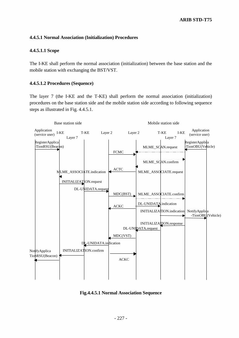
ARIB STD-T75
- 227 -
4.4.5.1 Normal Association (Initialization) Procedures 4.4.5.1.1 Scope The I-KE shall perform the normal association (initialization) between the base station and the mobile station with exchanging the BST/VST. 4.4.5.1.2 Procedures (Sequence) The layer 7 (the I-KE and the T-KE) shall perform the normal association (initialization) procedures on the base station side and the mobile station side according to following sequence steps as illustrated in Fig. 4.4.5.1.
RegisterApplica - TionRSU(Beacon) MLME_SCAN.request
FCMC
MLME_SCAN.confirm
MLME_ASSOCIATE.request ACTC
MLME_ASSOCIATE.indication
INITIALIZATION.request
DL-UNIDATA.request MDC(BST) MLME_ASSOCIATE.confirm
DL-UNIDATA.indication ACKC
INITIALIZATION.indication NotifyApplica - TionOBU(Vehicle)
INITIALIZATION.response DL-UNIDATA.request
Layer 7 Layer 7 Layer 2I- KE T-KE
Base station side Mobile station side
T-KE I-KE Layer 2Application
( service user)Application ( service user)
MDC(VST)
DL-UNIDATA.indication
INITIALIZATION.confirm NotifyApplica - TionRSU(Beacon)
RegisterApplica- TionOBU(Vehicle)
ACKC
Fig.4.4.5.1 Normal Association Sequence
ARIB STD-T75
- 228 -
4.4.5.1.2.1 Normal Association (Initialization) Procedures on the mobile station 4.4.5.1.2.1.1 Search of Communication zone The I-KE on the mobile station uses MLME_SCAN.request primitives provided by the layer 2 management entity to search communication zone provided by the base station. The invocation of MLME_SCAN.request primitives shall be provided as follows. (1) The mobile station is activated and can communicate. (2) Not fulfill Association request in subclause 4.4.5.1.2.1.2. (3) Not fulfill Normal Association confirm response in subclause 4.4.5.1.2.1.3. (4) Accords to Association release in subclause 4.4.5.3. If the I-KE on the mobile station issues MLME_SCAN.request primitives to Layer 2 management entity, it waits for MLME_SCAN.comfirm primitives which is informed from Layer 2 management entity. 4.4.5.1.2.1.2 Association request If The I-KE on the mobile station receives MLME_SCAN.comfirm primitives which is informed from layer 2 management entity and the parameter passed by its primitives is effective, it performs the processing of association request. Association request uses MLME_ASSOCIATE.request primitives provided by layer 2 management entity. The invocation of MLME_ASSOCIATE.request primitives shall be provided as follows. (1) There is an available AID in service_code parameter passed by MLME_SCAN.confirm primitives. (2) When ccz_status passed by MLME_SCAN.confirm primitives will indicate concatenated communication zone and connection sequence of the corresponding mobile station accords to configuration information of transceiver which is indicated tri_status parameter. The parameter passed to layer 2 management entity by MLME_SCAN.confirm primitives specifies as follows. 1) link_address : The link_address parameter is specific to private link address of
self managed by I-KE on the mobile station 2) initialization_mode : The initialization_mode parameter is specific to the value
according to the communication profile of self

ARIB STD-T75
- 229 -
3) application_id : The application_id parameter is specific to the value for register into application identifier flag of LRI in subclause 4.2.4.2.3.1.5.
Its value is generated by result of service_code parameter passed by MLME_SCAN.cofirm primitives.
4) priority : The priority parameter is specific to the value of normal assignment.
If the I-KE on the mobile station issues MLME_ASSOCIATE.request primitives to Layer 2 management entity, it waits for MLME_ASSOCIATE.comfirm primitives which is informed from Layer 2 management entity. 4.4.5.1.2.1.3 Normal Association (Initialization) confirm response If the I-KE on the mobile station receives MLME_ASSOCIATE.confirm primitives which is informed from layer 2 management entity and the status parameter passed by the its primitives indicates success, it performs the processing of confirm response. The processing of Association (Initialization) confirm response checks the BST registered into the InitializationPramaeter of INITIALIZATION.indication after reception of MLME_ASSOCIATE.confirm primitives and responds to the base station using INITIALIZATION.response. The invocation of Association (Initialization) response primitives shall be provided as follows. (1) There is an available AID in the mobile station of self, reference to mandApplications and nonmandApplications in the BST. (2) When the profile specified by AID chosen in (1) is compared with profile or profileList in the BST and the station of self has communication profile which accord to the condition shown in Annex P. Note) The action of avoidance when INITIALIZATION.indicate can not receive is not specified as requirements for mounting The Initialization parameter specifies as follows. 1) profile : The profile parameter is specific to the value for the
condition in shown Annex P. 2) application : The AID List accord to above-mentioned invocation condition.
The application parameter is specific to information registered by its application using RegisterApplicationOBU(Vehicle).

ARIB STD-T75
- 230 -
3) obeConfiguration : The obeConfiguration parameter is specific to information according to data structure of self station.
If The I-KE on the mobile station responds to the base station using InitializationParameter primitives, it informs Association (Link) to application in self station accord to the above-mentioned invocation condition using NotifyApplicationOBU(Vehicle). If I-KE informs NotifyApplicationOBU(Vehicle), The InitializationParameter specifies as follows. 1) RSU(Beacon) : The RSU(Beacon) parameter is specific to rSU provided by the BST. 2) Priority : The Priority parameter is specific to the position from the head of the
corresponding application in the BST in mandatory application, it is specific to the value which applied the priority when application registered and the number of mandatory application in application list in non-mandatory application.
3) EID : If the I-KE on the mobile station received the EID by the BST, the EID parameter is specific to its EID. If not received, not use.
4) LID : The LID parameter is specific to LID of self. 5) Parameter : If there are parameters received by the BST, the Parameter parameter is
specific to its parameter. If not parameters, not use. 4.4.5.1.2.2 Normal Association (Initialization) Procedures on the base station 4.4.5.1.2.2.1 Association response If the I-KE of the base station receives MLME_ASSOCIATE.indication primitives which is informed from the layer 2 management and the parameter passed by the corresponding primitives is effective, it shall perform the response processing of association. The association response uses INITIALIZATION.request primitives. The invocation of association (Initialization) request primitives shall be provided as follows. (1) The link_address parameter passed by the MLME_ASSOCIATE.indication primitives is private link address, does not overlap link address of the mobile station which connected by self station. (2) The application provided by the self station was registered the application_id parameter passed by the MLME_ASSOCIATE.indication. (3) The priority parameter passed by MLME_ASSOCIATE.indication primitives indicates normal assignment. Note) Refer to Annex N for processing of link address overlap.
ARIB STD-T75
- 231 -
The InitializationParameter is specified to BST. The parameter of BST specifies as follows. 1) rSU : identifier of the base station 2) time : time information 3) profile : The value defined by Annex P. 4) mandApplication : The mandatory application list provided by the base station. The
mandApplication parameter is specific to information which is registered by the corresponding application using RegisterApplicationRSU(Beacon).
5) nonmandApplication : The nonmandatory application list provided by the base station.The mandApplication parameter is specific to information which is registered by the corresponding application using RegisterApplicationRSU(Beacon).
6) profileList : The value defined by Annex P. When the I-KE of the base station issues INITIALAZATION.request primitives, it waits for INITIALZATION.confirm after NUMLINK I is incremented “1”. Note) The action of avoidance when INITIALIZATION.confirm primitives can not receive is not specified as requirements for mounting. After avoidance, NUMLINK is decremented “1”. 4.4.5.1.2.2.2 Normal Association (Initialization) confirm If the I-KE of the base station receives INITIALAZATION.confirm primitives, it is specified to the profile according to VST which was registered to parameter of the corresponding primitives. The I-KE of the base station generates association information and performs association (Link) management to the application specified in VST of the corresponding mobile station, it shall perform association (Link) notify to the corresponding application in self using NotifyApplicationRSU(Beacon) primitives. If the I-KE of the base station notifies NotifyApplicationRSU(Beacon), the parameter of the corresponding primitives specifies as follows. 1) Priority : The Priority parameter is specific to the position from the head of
the concerned application in the BST in mandatory application, it is specific to the value which applied the number of the mandatory application and the position of the corresponding application in application list in nonmadatory application.
2) EID : If the I-KE of the base station received EID by the VST, the EID parameter is specific to its EID. If not received, not use.

ARIB STD-T75
- 232 -
3) LID : The LID parameter is specific to LID which received in INITIALIZATION.confirm.
4) Parameter : If there are parameters received by the VST, the Parameter parameter is specific to its parameter. If not parameters, not use.
5) obeConfiguration : The obeConfiguration parameter is specific to obeConfiguration which received in VST.
4.4.5.1.3 Initialization Internal Service Primitives (1) Scope The initialization internal services for the I-KE shall be provided by the T-KE regarding to the normal initialization (association) procedure. These services are used for setting the information (the contents of the BST/VST) needed for initialization (association) to the I-KE. A specific implementation is not constrained in the method of making this information available. (2) Format The Initialization Internal Service Primitive shall provide parameters as follows. INITIALIZATION.request ([LID], Initialization Parameter] INITIALIZATION.indication ([LID], Initialization Parameter] INITIALIZATION.response (LID, Initialization Parameter] INITIALIZATION.confirm (LID, Initialization Parameter] (3) Initialization Parameter The Initialization Parameter specifies the BST in the case of the INITIALIZATION.request / the INITIALIZATION.indication. The Initialization Parameter specifies the VST in the case of the INITIALIZATION.response / INITIALIZATION.confirm. The data structure of BST/VST is shown in Annex H. Note) NotifyApplicationRSU(Beacon) issues each application of application list in VST as a unit. NotifyApplicationOBU(Vehicle) issues each application of application list in BST as a unit. 4.4.5.2 Simplified Association Procedures 4.4.5.2.1 Scope The simplified association procedures may be used with omitting the exchange of the BST/VST.
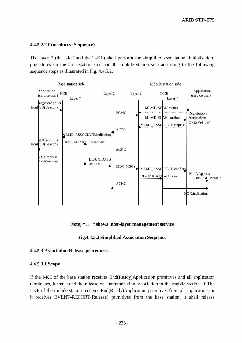
ARIB STD-T75
- 233 -
4.4.5.2.2 Procedures (Sequence) The layer 7 (the I-KE and the T-KE) shall perform the simplified association (initialization) procedures on the base station side and the mobile station side according to the following sequence steps as illustrated in Fig. 4.4.5.2.
RegisterApplica - TionRSU(Beacon) MLME_SCAN.reques
FCMCMLME_SCAN.confirm
MLME_ASSOCIATE.request ACTC
MLME_ASSOCIATE.indication
INITIALIZATION.request
DL-UNIDATA .request
MDC(MSG)MLME_ASSOCIATE.confirm
DL-UNIDATA.indication
ACKC
NotifyApplica - TionOBU(Vehicle)
Layer 7 Layer 7 Layer 2I- KE
Base station side Mobile station side
T-KE Layer 2Application
( service user)Application ( service user)
NotifyApplica - TionRSU(Beacon)
XXX.indication
XXX.request (1st Message)
ACKC
RegistrationApplicationOBU(Vehicle)
Note) “ … “ shows inter-layer management service
Fig.4.4.5.2 Simplified Association Sequence
4.4.5.3 Association Release procedures 4.4.5.3.1 Scope If the I-KE of the base station receives End(Ready)Application primitives and all application terminates, it shall send the release of communication association to the mobile station. If The I-KE of the mobile station receives End(Ready)Application primitives from all application, or it receives EVENT-REPORT(Release) primitives from the base station, it shall release
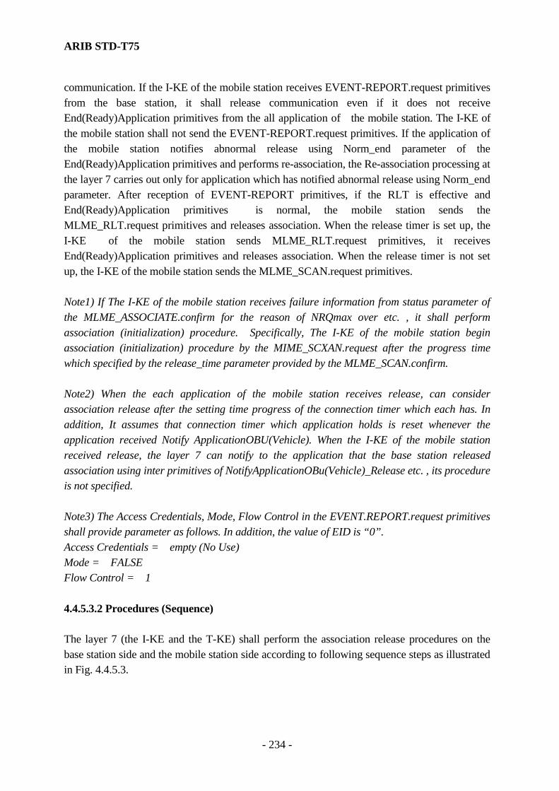
ARIB STD-T75
- 234 -
communication. If the I-KE of the mobile station receives EVENT-REPORT.request primitives from the base station, it shall release communication even if it does not receive End(Ready)Application primitives from the all application of the mobile station. The I-KE of the mobile station shall not send the EVENT-REPORT.request primitives. If the application of the mobile station notifies abnormal release using Norm_end parameter of the End(Ready)Application primitives and performs re-association, the Re-association processing at the layer 7 carries out only for application which has notified abnormal release using Norm_end parameter. After reception of EVENT-REPORT primitives, if the RLT is effective and End(Ready)Application primitives is normal, the mobile station sends the MLME_RLT.request primitives and releases association. When the release timer is set up, the I-KE of the mobile station sends MLME_RLT.request primitives, it receives End(Ready)Application primitives and releases association. When the release timer is not set up, the I-KE of the mobile station sends the MLME_SCAN.request primitives. Note1) If The I-KE of the mobile station receives failure information from status parameter of the MLME_ASSOCIATE.confirm for the reason of NRQmax over etc. , it shall perform association (initialization) procedure. Specifically, The I-KE of the mobile station begin association (initialization) procedure by the MIME_SCXAN.request after the progress time which specified by the release_time parameter provided by the MLME_SCAN.confirm. Note2) When the each application of the mobile station receives release, can consider association release after the setting time progress of the connection timer which each has. In addition, It assumes that connection timer which application holds is reset whenever the application received Notify ApplicationOBU(Vehicle). When the I-KE of the mobile station received release, the layer 7 can notify to the application that the base station released association using inter primitives of NotifyApplicationOBu(Vehicle)_Release etc. , its procedure is not specified. Note3) The Access Credentials, Mode, Flow Control in the EVENT.REPORT.request primitives shall provide parameter as follows. In addition, the value of EID is “0”. Access Credentials = empty (No Use) Mode = FALSE Flow Control = 1 4.4.5.3.2 Procedures (Sequence) The layer 7 (the I-KE and the T-KE) shall perform the association release procedures on the base station side and the mobile station side according to following sequence steps as illustrated in Fig. 4.4.5.3.

ARIB STD-T75
- 235 -
End(Ready)Application
DL-UNIDATA.request MDC(Release)
DL-UNIDATA.indication
ACKC
Layer 7 Layer 7 Layer 2I-KE
Base station side Mobile station
T- KE Layer 2Application
( service user)Application ( service user)
Note) “ …“ shows inter layer management service
EVENT- REPORT.request
EVENT-REPORT. indication
MLME-SCAN.request
End(Ready)Application
Fig.4.4.5.3 Association Release Sequence 4.4.5.4 Association procedures for linked communication zones. 4.4.5.4.1 Scope The linked two communication zones are constructed in series in the traveling direction, and each base station provides plural applications for each zone. It may be that a related application accomplished through a communication transaction provided by the 1st base station (the 1st communication zone), and another communication transaction by 2nd base station (the 2nd communication zone) in order. In that case, the mobile station shall perform the association procedures after entering each communication zone, respectively. When the mobile station enters the 2nd communication zone (the 2nd base station) after the accomplishment of the association with the 1st base station (the 1st communication zone), the I-KE of the mobile station shall not associate with the same 1st base station. When the I-KE received the MLME_SCAN.confirm from the MLME, it shall not perform the association procedures for such the 1st base station. 4.4.5.4.2 Procedures (Sequence) The layer 7 (the I-KE and the T-KE) shall perform the association procedures for linked communication zones on the base station side and the mobile station side according to following sequence steps as illustrated in Fig. 4.4.5.4.
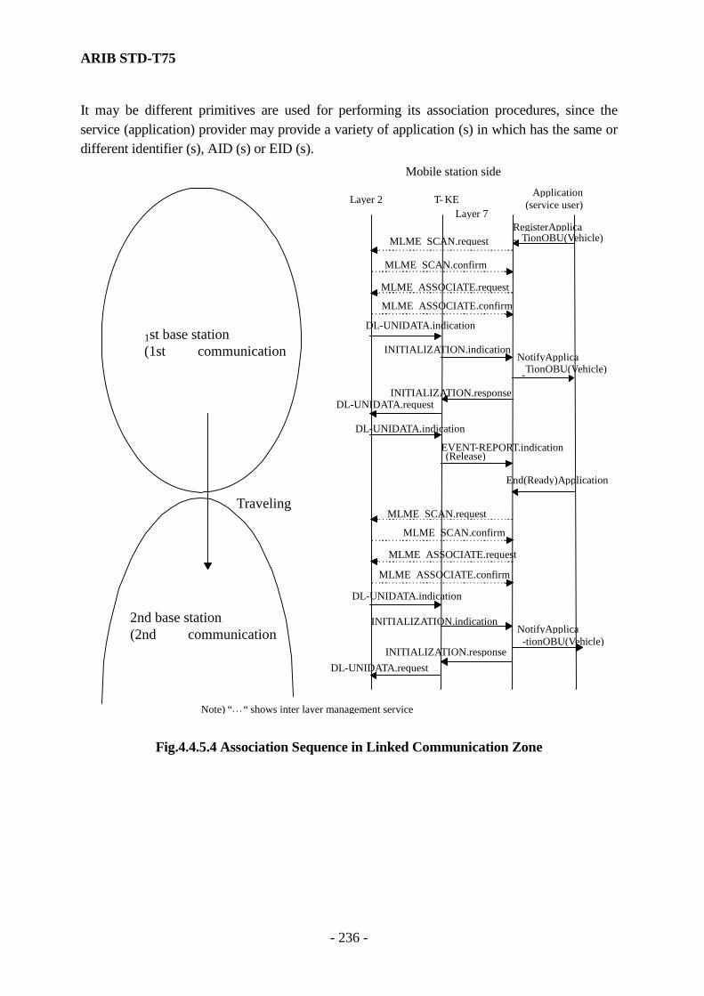
ARIB STD-T75
- 236 -
It may be different primitives are used for performing its association procedures, since the service (application) provider may provide a variety of application (s) in which has the same or different identifier (s), AID (s) or EID (s).
MLME SCAN.request
MLME SCAN.confirm
MLME ASSOCIATE.request MLME ASSOCIATE.confirm
DL-UNIDATA.indication
INITIALIZATION.indication NotifyApplica - TionOBU(Vehicle)
INITIALIZATION.response DL-UNIDATA.request
Layer 7
Mobile station side
T- KE Layer 2 Application( service user)
1 st base station (1st communication
Note) “ … “ shows inter layer management service
RegisterApplica- TionOBU(Vehicle)
DL-UNIDATA.indication
EVENT-REPORT.indication (Release)
End(Ready)Application
MLME SCAN.request
MLME SCAN.confirm MLME ASSOCIATE.request
MLME ASSOCIATE.confirm DL-UNIDATA.indication
INITIALIZATION.indication
INITIALIZATION.response DL-UNIDATA.request
NotifyApplica -tionOBU(Vehicle)
2nd base station (2nd communication
Traveling
Fig.4.4.5.4 Association Sequence in Linked Communication Zone

ARIB STD-T75
- 237 -
4.4.5.5 Association procedures with Release timer When all of the applications that are registered have been normally accomplished their application transactions by receiving EndApplication primitives, the release timer (t10) shall be set in order to constrain the re-association with the same base station on the mobile station side during a certain period. However, when there is at least one application, which has notified the abnormal accomplishment state by the EndApplication, it shall not be set in order to re-associate immediately. Furthermore, when the different applications related on the application level are provided in the linked communication zones and the association release procedures with the 1st base station have been accomplished, it shall perform the association procedures with the 2nd base station whether or not the release timer is set. When the release timer is operating, the mobile station recognizes the base station, which indicates the invalid release timer field, it shall perform the association procedures with corresponding base station. If the release timer is set, it shall be performed the association procedures according to following sequence steps as illustrated in Fig. 4.4.5.5.1. If the release timer is not set, it shall perform the re-association procedures according to following sequence steps as illustrated in Fig. 4.4.5.5.2. If the mobile station identifies the release timer is invalid, it shall perform the re-association procedures according to following sequence steps as illustrated in Fig. 4.4.5.5.3
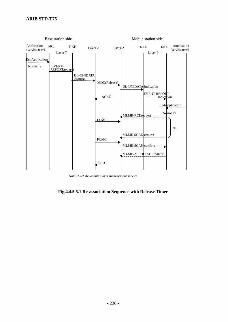
ARIB STD-T75
- 238 -
EndApplication Normally
DL-UNIDATA.request
MDC(Release)DL-UNIDATA.indication
ACKC
Layer 7 Layer 7Layer 2I-KE T-KE
Base station side Mobile station side
Layer 2 Application( service user)
Application ( service user)
Note) “ … “ shows inter layer management service
EVENT- REPORT.request
EVENT-REPORT. indication
MLME-RLT.request
EndApplication
Normally
FCMC
MLME-SCAN.request
t10
FCMC
MLME-SCAN.confirm
MLME-ASSOCIATE.request
ACTC
I-KE T-KE
Fig.4.4.5.5.1 Re-association Sequence with Release Timer
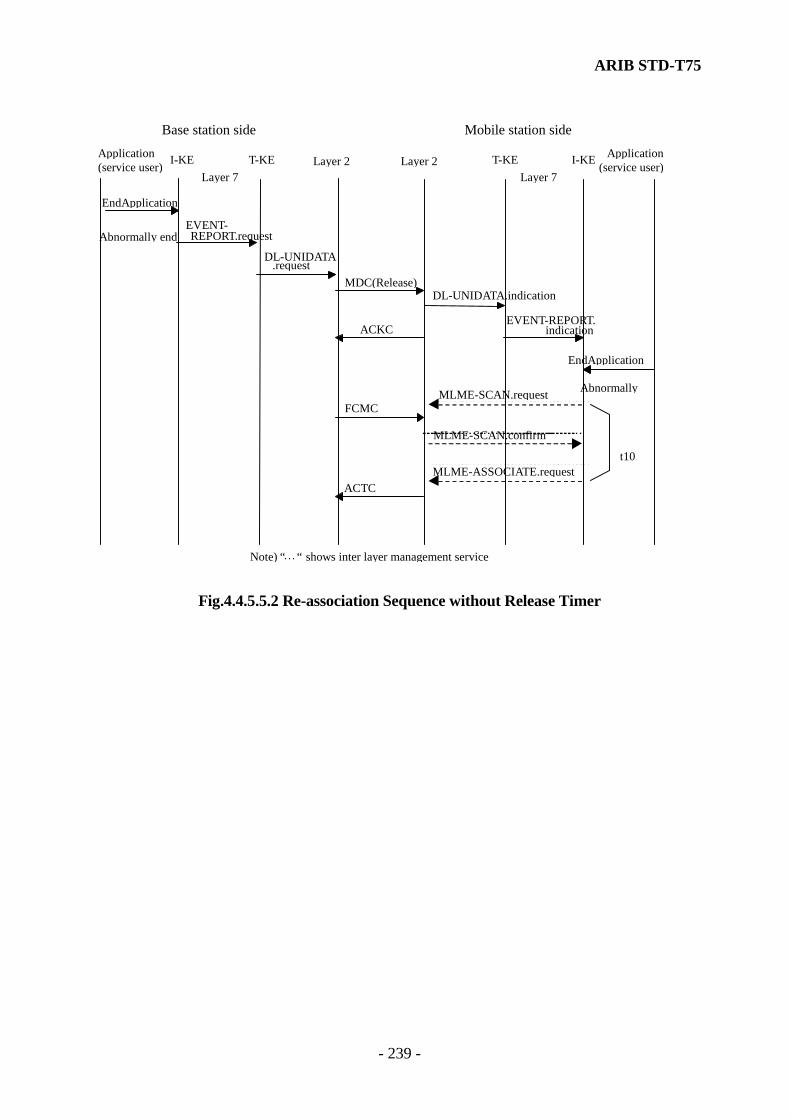
ARIB STD-T75
- 239 -
EndApplication
Abnormally end DL-UNIDATA
.request MDC(Release)
DL-UNIDATA.indication
ACKC
Layer 7 Layer 7Layer 2
Base station side Mobile station side
Layer 2Application
( service user)Application ( service user)
Note) “ … “ shows inter layer management service
EVENT- REPORT.request
EVENT-REPORT. indication
EndApplication
Abnormally MLME-SCAN.requestFCMC
MLME-SCAN.confirm
MLME-ASSOCIATE.request ACTC
t10
I-KE T-KE I-KE T-KE
Fig.4.4.5.5.2 Re-association Sequence without Release Timer

ARIB STD-T75
- 240 -
EndApplication
Normally
DL-UNIDATA.request
MDC(Release)DL-UNIDATA.indication
ACKC
Layer 7 Layer 7Layer 2
Base station side Mobile station side
Layer 2 Application( service user)
Application ( service user)
Note) “ … “ shows inter layer management service
EVENT- REPORT.request
EVENT-REPORT. indication
MLME-RLT.request
EndApplication
Normally FCMC
MLME-RLT.confirm(RLT is invalid)
t10
MLME-ASSOCIATE.request
ACTC
I-KE T-KE I-KE T-KE
Fig.4.4.5.3 Re-association Sequence with invalid Release Timer value

ARIB STD-T75
- 241 -
4.4.5.6 Management of the connection state of application (s) The management for the current operating state of application (s) shall be performed not to communicate with the same application on the base station side and the mobile station side. When the layer 7 (the I-KE and the T-KE) sends NotifyApplicationOBU(Vehicle) to an application (kernel service user), it shall be regarded the subject application is operating. When End(Ready)Application from the subject application (kernel service user) is received, it shall move its state to the accomplishment of the service. The example of procedures (sequence) is shown in Fig. 4.4.5.6.1.
DL-UNIDATA.indication
INITIALIZATION.indication NotifyAppOBU-
INITIALIZATION.response
MLME-SCAN.request
Layer 7T- KE I-KELayer 2 Application
(service user)Status of
Application (service user)
Performing Application Transaction
DL-UNIDATA. indication EVENT-REPORT. indication
EndApp
Accomplished Application Transaction
DL-UNIDATA. request
Fig.4.4.5.6.1 Management of Application-Status Sequence
However, in this communication environment, when the communication transaction for the application confirmed previously on the base station and the mobile station side has not yet started, or a long time has elapsed after previous application transaction, the mobile station may be out of the communication zone. (The base station may lose the peer application (service user).) In above case, when the application (service user) would like to maintain service between the peer application, the layer 7 may not receive the End(Ready)Application and the association is maintained for long time as shown in Fig. 4.4.5.6.2.

ARIB STD-T75
- 242 -
Therefore, considering the above conditions, it is required that the application has a connection (maintenance) timer and the maximum time maintained the service (connection time). If it is over this maximum time, the application (service user) should disconnect. Note) Synchronizing the operation starting time for the connection (maintenance) timers on the base station side and the mobile station side, it may be able to re-associate immediately. In case plural applications are performed, when some of them accomplish abnormally (the status of each application is notified by Norm_end parameter of EndApplication), re-association procedure shall be applied to only abnormal-ended applications.
DL-UNIDATA.indication
INITIALIZATION.indication NotifyAppOBU
INITIALIZATION.responseDL-UNIDATA.request
Layer 7T- KE I-KE Layer 2
Application(service user)
Status ofApplication
(service user)
Performing Application Transaction
Fig.4.4.5.6.2 Management of Application-Status Sequence (2)

ARIB STD-T75
- 243 -
4.4.6 Communication procedures for applications Annex G shows SDL diagrams for these procedures. 4.4.6.1 Broadcast transfer service 4.4.6.1.1 Scope On the base station, the B-KE may cyclically send the data stored in the Broadcast Pool to the mobile stations using BroadcastData primitive provided by the I-KE and the SET.request primitives provided by the T-KE. Its interval period of the broadcasting service is t11. On base station side, the B-KE should store the received data in the Broadcast Pool, and it should realize the collection and distribution of information for different applications in the mobile station exchanging the GetBroadcastData.request and the GetBroadcastData.confirm provide by the B-KE. 4.4.6.1.2 Procedures (Sequence) The layer 7 may perform the broadcast data transfer procedures on the base station side and the mobile station side according to following sequence steps as illustrated in Fig. 4.4.6.1.

ARIB STD-T75
- 244 -
BradcastData. request
DL-UNIDATA.request MDC
DL-UNIDATA.indication
Layer 7 Layer 7Layer 2B- KE T-KE
Base station side Mobile station side
T- KE B-KE Layer 2Application
( service user)Application ( service user)
SET.request
SET. indication
GetBradcast Data.request
GetBradcast Data.confirm BP
BP
DL-UNIDATA.request MDC DL-UNIDATA.
indication
SET.request
SET. indication
t11
Fig.4.4.6.1 Broadcast Data Transfer Sequence
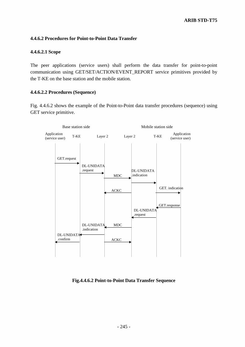
ARIB STD-T75
- 245 -
4.4.6.2 Procedures for Point-to-Point Data Transfer 4.4.6.2.1 Scope The peer applications (service users) shall perform the data transfer for point-to-point communication using GET/SET/ACTION/EVENT_REPORT service primitives provided by the T-KE on the base station and the mobile station. 4.4.6.2.2 Procedures (Sequence) Fig. 4.4.6.2 shows the example of the Point-to-Point data transfer procedures (sequence) using GET service primitive.
DL-UNIDATA.request
MDCDL-UNIDATA.indication
ACKC
Layer 2T-KE
Base station side Mobile station side
T-KELayer 2Application
(service user)Application(service user)
GET.request
GET. indication
GET.responseDL-UNIDATA.request
MDC
ACKC
DL-UNIDATA.indication
DL-UNIDATA.confirm
Fig.4.4.6.2 Point-to-Point Data Transfer Sequence
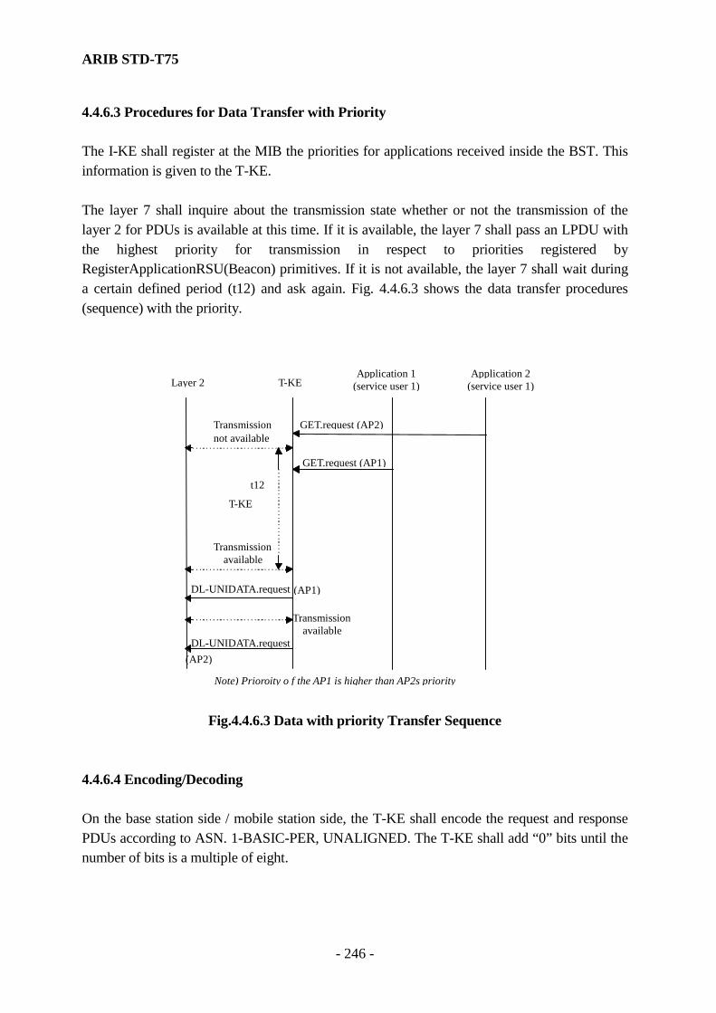
ARIB STD-T75
- 246 -
4.4.6.3 Procedures for Data Transfer with Priority The I-KE shall register at the MIB the priorities for applications received inside the BST. This information is given to the T-KE. The layer 7 shall inquire about the transmission state whether or not the transmission of the layer 2 for PDUs is available at this time. If it is available, the layer 7 shall pass an LPDU with the highest priority for transmission in respect to priorities registered by RegisterApplicationRSU(Beacon) primitives. If it is not available, the layer 7 shall wait during a certain defined period (t12) and ask again. Fig. 4.4.6.3 shows the data transfer procedures (sequence) with the priority.
DL-UNIDATA.request (AP1)
T-KELayer 2 Application 1(service user 1)
Application 2 (service user 1)
GET.request (AP2)
GET.request (AP1)
Transmission not available
Transmission available
T-KE
Transmissionavailable
DL-UNIDATA.request (AP2)
Note) Prioroity o f the AP1 is higher than AP2s priority
t12
Fig.4.4.6.3 Data with priority Transfer Sequence 4.4.6.4 Encoding/Decoding On the base station side / mobile station side, the T-KE shall encode the request and response PDUs according to ASN. 1-BASIC-PER, UNALIGNED. The T-KE shall add “0” bits until the number of bits is a multiple of eight.
ARIB STD-T75
- 247 -
The T-KE shall decode the PDU. If more than 7 trailing bits are received and if not more than 7 bits in sequence have the value “0”, these “0” bits are removed as bits inserted to achieve an octet alignment. Definition of ASN.1 datatypes may import modules from application (service user). However, the functionalities of importing procedures for ASN.1 modules from applications are not used in this standard at this time. The parameters required the definition of ASN.1 decoding / encoding rule on the application (service user) side, the datatypes shall be OCTET STRING type, in the following parameters. The service interface and procedures for importing ASN.1 modules from applications is the subject of further ongoing study and resolution. (see annex H). (1) ACTION service ……………ActionParameter, ResponseParameter (2) EVENT_REPORT service …EventParameter (3) ApplicationList………………parameter (4) Attribute …………………… AttributeValue Note) APDU shall be encoded or decoded from the most significant bit (MSB) of each octet. 4.4.6.5 Concatenation/Deconcatenation 4.4.6.5.1 Scope Plural (two) consecutive APDU fragments may be mapped on one LPDU. APDU header for each APDU shall be added at the beginning, since the peer layer 7 (destination) may be easily de-concatenated the concatenated APDU. However, if the concatenation is not made, a PDU header, demanded at minimum shall be added to an APDU. 4.4.6.5.2 Conditions for Concatenation The concatenation shall be only permitted under following three conditions; 1) In the case of concatenation of two APDUs, the LIDs are the same and the length of one
concatenated LPDU is less than the maximum LPDU length. 2) When the waiting state for the layer 2 transmission has occurred, the current state is the ready state.
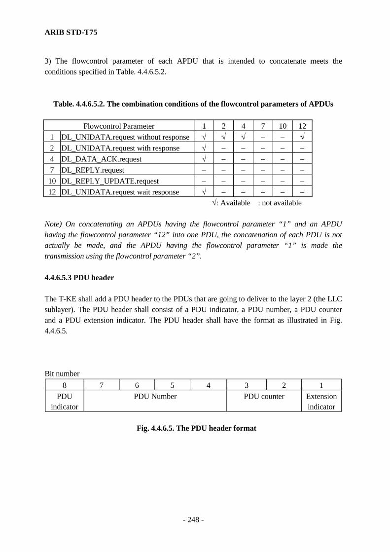
ARIB STD-T75
- 248 -
3) The flowcontrol parameter of each APDU that is intended to concatenate meets the conditions specified in Table. 4.4.6.5.2.
Table. 4.4.6.5.2. The combination conditions of the flowcontrol parameters of APDUs
Flowcontrol Parameter 1 2 4 7 10 12 1 DL_UNIDATA.request without response √ √ √ − − √ 2 DL_UNIDATA.request with response √ − − − − − 4 DL_DATA_ACK.request √ − − − − − 7 DL_REPLY.request − − − − − − 10 DL_REPLY_UPDATE.request − − − − − − 12 DL_UNIDATA.request wait response √ − − − − −
√: Available : not available
Note) On concatenating an APDUs having the flowcontrol parameter “1” and an APDU having the flowcontrol parameter “12” into one PDU, the concatenation of each PDU is not actually be made, and the APDU having the flowcontrol parameter “1” is made the transmission using the flowcontrol parameter “2”. 4.4.6.5.3 PDU header The T-KE shall add a PDU header to the PDUs that are going to deliver to the layer 2 (the LLC sublayer). The PDU header shall consist of a PDU indicator, a PDU number, a PDU counter and a PDU extension indicator. The PDU header shall have the format as illustrated in Fig. 4.4.6.5. Bit number
8 7 6 5 4 3 2 1 PDU
indicator PDU Number PDU counter Extension
indicator
Fig. 4.4.6.5. The PDU header format
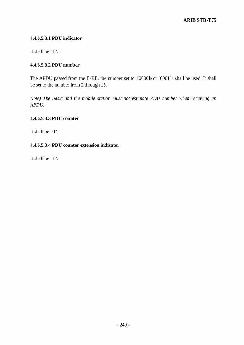
ARIB STD-T75
- 249 -
4.4.6.5.3.1 PDU indicator It shall be “1”. 4.4.6.5.3.2 PDU number The APDU passed from the B-KE, the number set to, [0000]B or [0001]B shall be used. It shall be set to the number from 2 through 15. Note) The basic and the mobile station must not estimate PDU number when receiving an APDU. 4.4.6.5.3.3 PDU counter It shall be “0”. 4.4.6.5.3.4 PDU counter extension indicator It shall be “1”.

ARIB STD-T75
- 250 -
Empty page
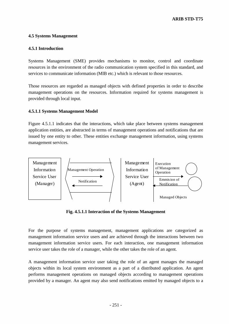
ARIB STD-T75
- 251 -
4.5 Systems Management 4.5.1 Introduction Systems Management (SME) provides mechanisms to monitor, control and coordinate resources in the environment of the radio communication system specified in this standard, and services to communicate information (MIB etc.) which is relevant to those resources. Those resources are regarded as managed objects with defined properties in order to describe management operations on the resources. Information required for systems management is provided through local input. 4.5.1.1 Systems Management Model Figure 4.5.1.1 indicates that the interactions, which take place between systems management application entities, are abstracted in terms of management operations and notifications that are issued by one entity to other. These entities exchange management information, using systems management services.
ManagementInformationService User
(Manager)
ManagementInformationService User
(Agent)
Management Operation
Notification
Executionof ManagementOperation
Emmis ion ofNotification
Managed Objects
Fig. 4.5.1.1 Interaction of the Systems Management
For the purpose of systems management, management applications are categorized as management information service users and are achieved through the interactions between two management information service users. For each interaction, one management information service user takes the role of a manager, while the other takes the role of an agent. A management information service user taking the role of an agent manages the managed objects within its local system environment as a part of a distributed application. An agent performs management operations on managed objects according to management operations provided by a manager. An agent may also send notifications emitted by managed objects to a

ARIB STD-T75
- 252 -
manager. Management information services user taking the role of a manager issues management operations and receives notifications. The concept of a manager is not limited only to applications participating in systems management. Other applications that need to access to management information may use management information services. 4.5.1.2 Scope Systems management specified in this standard is applicable to the systems management processes in the local systems environment. This standard specifies management information services taking place between two management information service users (one taking the manager role, the other the agent role). The implementation matters on how to provide the services specified in this standard are out of the scope of this standard. Details of the management application are out of this standard. Therefore, the management operation by a manager which is dependent on the contents of the management application, the semantics of the information or commands exchanged by the services and the managed objects defined in the aspect of management are not subject to standardization. Note) The radio communication system architecture in this standard does not include the management operation in which the information is exchanged on a remote management entity. The management operation, which does not need the management information exchange with a manager, is defined as a part of the function of an agent in this standard. The content of those management operations is specified in this standard. 4.5.2 Service Interface of Systems Management 4.5.2.1 Outline of Services Management information services are used between management information service users of the peer application process to exchange information and commands for systems management. Information transfer services are categorized into the following two services.

ARIB STD-T75
- 253 -
(1) Management notification service (2) Management operation service Note) Management information service provider is defined as the abstracted concept for the entire entity, providing the management information services to the management information service user in the local system environment. 4.5.2.2 Management Notification Service Definition of the notification and the resulting behavior of the communication entity depend on the specification of the managed object which generates the notification, and are excluded in the scope of management information services. However, some notifications are often used for the system management. The service (SME_EVENTREPORT service) applicable to the information transfer for those notification are therefore defined. A management information service user (agent) to report the event invokes SME_EVENTREPORT service on the managed object to a peer management information service user (manager). This service is applicable to both the confirmed-service mode (requiring response) and non-confirmed-service mode (requiring no response). Figure 4.5.2.2 shows the logical relationship of each primitive.
SME-EVENTREPORT.indicationSME-EVENTREPORT.request
SME-EVENTREPORT.response
SME-EVENTREPORT.confirm
Fig. 4.5.2.2 Time Sequence Diagrams of the Management Notification Service
4.5.2.2.1 SME_EVENTREPORT.request (1) Function This primitive is the service request primitive for the management notification service.

ARIB STD-T75
- 254 -
(2) Semantics of Service Primitive This primitive shall provide the following parameters. SME_EVENTREPORT.request (Mode, event_type, event_time, event_parameter) The mode parameter shall indicate the mode required for the operation. The value for this parameter shall indicate either confirmed-service mode or non-confirmed-service mode. The event_type parameter shall specify the type of the event to be reported. The event_time parameter shall indicate the time when the event occurred. This parameter is optional. The event_parameter parameter shall indicate the information relevant to the event. This parameter is optional. (3) When Generated The agent to report the confirmed event to the manager generates this primitive. This primitive is passed from the agent to the management information service provider. 4.5.2.2.2 SME_EVENTREPORT.indication (1) Function This primitive is the service indication primitive for the management notification service. (2) Semantics of Service Primitive This primitive shall provide the following parameters. SME_EVENTREPORT.indication (Mode, event_type, event_time, event_parameter) The mode parameter shall indicate the mode required for the operation. The value for this parameter shall indicate either confirmed-service mode or non-confirmed-service mode. The event_type parameter shall specify the type of the event to be reported. The event_time parameter shall indicate the time when the event occurred. This parameter is optional. The event_parameter parameter shall indicate the information relevant to the event. This parameter is optional. (3) When Generated This primitive is passed from the management information service provider to the manager to report the arrival of the SME_EVENTREPORT.request.

ARIB STD-T75
- 255 -
4.5.2.2.3 SME_EVENTREPORT.response (1) Function This primitive is the service response primitive for the management notification service. (2) Semantics of Service Primitive This primitive shall provide the following parameters. SME_EVENTREPORT.response (event_type, response_time, response_parameter, status) The event_type parameter shall indicate the type of the event reported by the corresponding SME_EVENTREPORT.indication. The response_time parameter shall indicate the time of the response. This parameter is optional. The response_parameter parameter shall indicate the response information for the report of the event. This parameter is optional. The status parameter shall indicate the status of the operation. This parameter includes error codes of the operation for the reported event. This parameter is optional. (3) When Generated The manager generates this primitive when the mode parameter of the previous associated SME_EVENTREPORT.indication indicates the confirmed-service mode. This primitive is passed from the manager to the management information service provider. 4.5.2.2.4 SME_EVENTREPORT.confirm (1) Function This primitive is the confirmation service primitive for the management notification service. (2) Semantics of Service Primitive This primitive shall provide the following parameters. SME_EVENTREPORT.confirm (event_type, response_time, response_parameter, status) The event_type parameter shall indicate the type of the event. The response is identified to be the response for the reported event by this parameter. The response_time parameter shall indicate the time of the response. This parameter is optional. The response_parameter parameter shall indicate the response information for the report of the event. This parameter is optional.

ARIB STD-T75
- 256 -
The status parameter shall indicate the status of the operation. This parameter includes error codes for the operation of the manager. This parameter is optional. (3) When Generated This primitive is passed from the management information service provider to the agent to indicate the arrival of the SME_EVENTREPORT.response. 4.5.2.3 Management Operation Service Management operation services are categorized as follows. (1) SME_GET service (2) SME_SET service (3) SME_RESET service A manager to request an agent to retrieve the management information invokes SME_GET service. This service is applicable only to the confirmed-service mode and requires response. A manager to request an agent to modify the management information invokes SME_SET service. This service is applicable both to the confirmed-service mode and non-confirmed-service mode. Response is required in case of confirmed-service mode. A manager to request an agent to initialize the management information invokes SME_RESET service. This service is applicable only to the confirmed-service mode and requires response. Figure 4.5.2.3 shows the logical relationship of each primitive.
SME-GET.request
SME-GET. confirm SME-GET.response
SME-GET.indication
SME-SET.request
SME-SET. confirm SME-SET.response
SME-SET.indication
SME-RESET.request
SME-RESET. confirm SME-RESET.response
SME-RESET.indication
Fig. 4.5.2.3 Time Sequence Diagrams of the Management Operation Service

ARIB STD-T75
- 257 -
4.5.2.3.1 SME_GET.request (1) Function This primitive is the service request primitive for the management operation service. (2) Semantics of Service Primitive This primitive shall provide the following parameters. SME_GET.request (layer_id, MIB_attribute) The layer_id parameter shall specify the identifier of the layer to be retrieved. The MIB_attribute parameter shall indicate the name of the variables in the MIBs defined for each layer. (3) When Generated The manager to require the agent to retrieve the management information generates this primitive. This primitive is passed from the manager to the management information provider. 4.5.2.3.2 SME_GET.indication (1) Function This primitive is the service indication primitive for the management operation service. (2) Semantics of Service Primitive This primitive shall provide the following parameters. SME_GET.indication (layer_id, MIB_attribute) The layer_id parameter shall specify the identifier of the layer to be retrieved. The MIB_attribute parameter shall indicate the name of the variables in the MIB to be retrieved. (3) When Generated This primitive is passed from the management information service provider to the agent to indicate the arrival of the SME_GET.request. 4.5.2.3.3 SME_GET.response (1) Function This primitive is the service response primitive for the management operation service.

ARIB STD-T75
- 258 -
(2) Semantics of Service Primitive This primitive shall provide the following parameters. SME_GET.response (status, MIB_attribute, MIB_attribute_value) The status parameter shall indicate the results of the retrieval of the variables taken place on receipt of SME_GET.indication. Either success or failure is applicable to the value of this parameter. The MIB_attribute parameter shall indicate the name of the variables designated by SME_GET.indication. The MIB_attribute_value parameter shall indicate the value for those variables. NOTE) when the status parameter indicates failure, the MIB_attribute_value shall be null. (3) When Generated This primitive is generated by the agent to report the result of the retrieval, carried out by receiving the SME_GET.indication, to the manager. This primitive is passed from the agent to the management information provider. 4.5.2.3.4 SME_GET.confirm (1) Function This primitive is the confirmation service primitive for the management operation service. (2) Semantics of Service Primitive This primitive shall provide the following parameters. SME_GET.confirm (status, MIB_attribute, MIB_attribute_value) The status parameter shall indicate whether the results of the retrieval are success or failure. The MIB_attribute parameter shall indicate the name of the variables designated by SME_GET.indication. The response is identified by this parameter to be corresponding to the required operation. The MIB_attribute_value parameter shall indicate the value for those variables. (3) When Generated This primitive is passed from the management information service provider to the manager to report the arrival of the SME_GET.response.
ARIB STD-T75
- 259 -
4.5.2.3.5 SME_SET.request (1) Function This primitive is the service request primitive for the management operation service. (2) Semantics of Service Primitive This primitive shall provide the following parameters. SME_SET.request (mode, layer_id, MIB_attribute, MIB_attribute_value) The mode parameter specifies the required mode for the operation. The possible value for this parameter is either confirmed-service mode or non-confirmed-service mode. The layer_id parameter shall specify the identifier of the layer to be modified. The MIB_attribute parameter shall indicate the name of the variables in MIBs defined for each layer. The MIB_attribute_value parameter shall indicate the value for the variables to be modified. (3) When Generated The manager to require the agent to modify the management information generates this primitive. This primitive is passed from the manager to the management information provider. 4.5.2.3.6 SME_SET.indication (1) Function This primitive is the service indication primitive for the management operation service. (2) Semantics of Service Primitive This primitive shall provide the following parameters. SME_SET.indication (mode, layer_id, MIB_attribute, MIB_attribute_value) The mode parameter specifies the required mode for the operation. The possible value for this parameter is either confirmed-service mode or non-confirmed-service mode. The layer_id parameter shall specify the identifier of the layer to be modified. The MIB_attribute parameter shall indicate the name of the variables in the MIB to be modified. The MIB_attribute_value parameter shall indicate the value for the variables to be modified.
ARIB STD-T75
- 260 -
(3) When Generated This primitive is passed from the management information provider to the agent to indicate the arrival of SME_SET.request. 4.5.2.3.7 SME_SET.response (1) Function This primitive is the service response primitive for the management operation service. (2) Semantics of Service Primitive This primitive shall provide the following parameters. SME_SET.response (status, MIB_attribute) The status parameter shall indicate the results of the modification of the variables taken place on receipt of SME_SET.indication. Either success or failure is applicable to this parameter. The MIB_attribute parameter shall indicate the name of the variables designated by SME_SET.indication. The response is identified by this parameter to be corresponding to the required operation. (3) When Generated The agent generates this primitive when the mode parameter of the previous associated SME_SET.indication indicates the confirmed-service mode. This primitive is passed from the agent to the management information service provider. 4.5.2.3.8 SME_SET.confirm (1) Function This primitive is the confirmation sevice primitive for the management operation service. (2) Semantics of Service Primitive This primitive shall provide the following parameters. SME_SET.confirm (status, MIB_attribute) The status parameter shall indicate whether the result of the modification is success or failure. The MIB_attribute parameter shall indicate the name of the variables designated by the SME_GET.indication. The response is identified by this parameter to be corresponding to the required operation.

ARIB STD-T75
- 261 -
(3) When Generated This primitive is passed from the management information service provider to the manager to report the arrival of the SME_SET.response. 4.5.2.3.9 SME_RESET.request (1) Function This primitive is the service request primitive for the management operation service. (2) Semantics of Service Primitive This primitive shall provide no parameters. SME_RESET.request ( ) (3) When Generated The manager to require the agent to initialize the management information generates this primitive. This primitive is passed from the manager to the management information service provider. 4.5.2.3.10 SME_RESET.indication (1) Function This primitive is the service indication primitive for the management operation service. (2) Semantics of Service Primitive This primitive shall provide no parameters. SME_RESET.indication ( ) (3) When Generated This primitive is passed from the management information serviceprovider to the agent to indicate the arrival of the SME_RESET.request. 4.5.2.3.11 SME_RESET.response (1) Function This primitive is the service response primitive for the management operation service. (2) Semantics of Service Primitive This primitive shall provide the following parameter.

ARIB STD-T75
- 262 -
SME_RESET.response (status) The status parameter shall indicate the result of the initialization of the management information taken place on receipt of the SME_RESET.indication. Either success or failure is applicable to this parameter. (3) When Generated This primitive is generated by the agent to report the result of the initialization of the management information, taken place on receipt of the SME_RESET.indication, to the manager. This primitive is passed from the agent to the management information service provider. 4.5.2.3.12 SME_RESET.confirm (1) Function This primitive is the confirmation service primitive for the management operation service. (2) Semantics of Service Primitive This primitive shall provide the following parameter. SME_RESET.confirm (status) The status parameter shall indicate the result of the initialization of the management information taken place on receipt of the SME_RESET.indication. Either success or failure is applicable to this parameter. (3) When Generated This primitive is passed from the management information service provider to the manager to report the arrival of the SME_RESET.response. 4.5.3 System Management Procedure 4.5.3.1 Report of Event An agent issues a SME_EVENTREPORT request primitive to a management information service provider to report an event to a manager. On receipt of the primitive the management information provider shall issue a SME_EVENTREPORT indication primitive to the manager.
ARIB STD-T75
- 263 -
In the confirmed-service mode, the manager shall issue a SME_EVENTREPORT response primitive to the management information service provider to report the result whether the SME_EVENTREPORT request primitive was accepted or not. In the confirmed-service mode, the management information service provider shall issue a SME_EVENTREPORT confirm primitive to the agent. 4.5.3.2 Retrieval of Management Information A manager issues a SME_GET request primitive to a management information service provider to require an agent to retrieve the values of variables in the MIB. On receipt of the primitive the management information service provider shall issue a SME_GET indication primitive to the agent. If the agent is not capable of carrying out the operation, the agent shall issue a SME_GET response primitive containing the status parameter of failure to the management information service provider. If the agent is capable of carrying out the operation, the agent shall identify the designated layer according to the layer_id parameter, and issue a XX_GET request primitive (either ALME, MLME or PLME is applicable to XX) to the layer management entity supported by the designated layer to request the retrieval of the values. The values are derived from the XX_GET confirm primitive of the layer management entity. On receipt of the XX_GET confirm primitive containing status parameter of success, the agent shall issue a SME_GET response primitive with the MIB_attribute_value parameter of the retrieved value and the status parameter of success to the management information service provider. On receipt of the XX_GET confirm primitive containing status parameter of failure, the agent shall issue a SME_GET response primitive with the status parameter of failure to the management information service provider. If the layer_id is not defined, the agent shall derive the values of variables from the MIB that the agent is allowed to access directly. On successful retrieval of the values, the agent shall issue a SME_GET response primitive containing status parameter of success to the management information service provider. On unsuccessful retrieval of the values, the agent shall issue a SME_GET response primitive containing status parameter of failure to the management information service provider.

ARIB STD-T75
- 264 -
On receipt of the SME_GET response primitive from the agent, the management information service provider shall issue a SME_GET confirm primitive to the manager and thus complete the operation of the management information retrieval. 4.5.3.3 Modification of Management Information A manager issues a SME_SET request primitive to a management information service provider to require an agent to modify the values of variables in the MIB. On receipt of the primitive the management information service provider shall issue a SME_SET indication primitive to the agent. If the agent is not capable of carrying out the operation, the agent shall issue a SME_SET response primitive containing the status parameter of failure to the management information service provider. If the agent is capable of carrying out the operation, the agent shall identify the designated layer according to the layer_id parameter, and issue a XX_SET request primitive (either ALME, MLME or PLME is applicable to XX) to the layer management entity supported by the designated layer to request the modification of the values. On receipt of the XX_SET confirm primitive containing the status parameter of success, the agent shall issue a SME_SET response primitive with the status parameter of success to the management information service provider. On receipt of the XX_SET confirm primitive containing the status parameter of failure, the agent shall issue a SME_SET response primitive with the status parameter of failure to the management information service provider. If the layer_id is not defined, the agent shall modify the values of variables from the MIB that the agent is allowed to access directly. On successful modification of the values, the agent shall issue a SME_GET response primitive containing the status parameter of success to the management information service provider. On unsuccessful modification of the values, the agent shall issue a SME_SET response primitive containing the status parameter of failure to the management information service provider. On receipt of the SME_SET response primitive from the agent, the management information service provider shall issue a SME_SET confirm primitive to the manager and thus complete the operation of the management information modification.

ARIB STD-T75
- 265 -
4.5.3.4 Initialization of Management Information A manager issues a SME_RESET request primitive to a management information service provider to require an agent to initialize the values of variables in the MIB. On receipt of the primitive the management information service provider shall issue a SME_RESET indication primitive to the agent. If the agent is not capable of carrying out the operation, the agent shall issue a SME_RESET response primitive containing the status parameter of failure to the management information service provider. If the agent is capable of carrying out the operation, the agent shall derive the initial values for each MIB of the respective layers from the MIB under its own control, and shall issue XX_RESET request primitives (either ALME, MLME or PLME is applicable to XX) for each layer to request each layer management entity to modify the values respectively. If all the received XX_RESET confirm primitives from those layers contain the status parameter of success, the agent shall issue a SME_RESET response primitive with the status parameter of success to the management information service provider. If at least one of the received XX_RESET confirm primitives contain the status parameter of failure, the agent shall issue a SME_RESET response primitive with status parameter of failure to the management information service provider. On receipt of the SME_RESET response primitive from the agent, the management information service provider shall issue a SME_RESET confirm primitive to the manager and thus complete the operation of the management information initialization.
ARIB STD-T75
- 266 -
4.5.4 Independent Management Operation of Agent 4.5.4.1 Failure Detection of Mobile Station An agent shall maintain a timer (failure detection timer) which is independent of the other functions. The agent shall periodically initialize the failure detection timer in order not to make it expired. On detection of the expiration of the failure detection timer, the agent shall regard the mobile station to have failed, and shall carry out the necessary operation at least to prevent the erroneous transmission. The maximum value of the failure detection timer shall be t9 sec.
ARIB STD-T75
- 267 -
Chapter 5 Measurement Methods In subcaluse 5.1 Transmission system and subcalause 5.2 reception system, the measurement methods are presented for transceiver with attaching connectors to antenna and pattern generator. For transceiver without attaching connectors, the measurement methods are given in subclause 5.3. The attaching connectors to antenna should have enough return loss to measure with measurement test sets. 5.1 Transmission system Detailed explanations on measurement methods are given subclauses 5.1.1 through 5.1.12. For a subclause in which more than one measurement method is described, any method can be used as long as the measurement accuracy is maintained. The following subclauses are common for all the measurement methods. (a) The standard encoding test signal used for modulation shall be pseudo noise random test signal. The generator polynomial shall be: 1 14 15+ +X X (b) In the case of ASK modulation, definition for inner burst section shall be at least 73 octets ranging from the beginning of the symbol immediately after ramp up to the end of the symbol immediately before ramp down. In the case of π/4 shift QPSK modulation, it shall be at least 270(TBD) octets ranging from the beginning of the symbol immediately after ramp up to the end of the symbol immediately before ramp down. (C) In the case of ASK modulation, definition of outer burst section shall be at least 94 symbols from the end of the symbol immediately before ramp down minus 3 symbols to the beginning of the symbol immediately after ramp up of the next slot minus 3 symbols. In the case of π/4 shift QPSK modulation, it shall be at least 186(TBD) symbols from the end of the symbol immediately before ramp down minus 3 symbols to the beginning of the symbol immediately after ramp up of the next slot minus 3 symbols.

ARIB STD-T75
- 268 -
5.1.1 Frequency tolerance (1) Measuring system diagram
Pattern
Generator UUTArtificial load
(attenuator)
Frequency
meter
(2) Conditions for measuring instrument a. A frequency counter shall be used as the frequency meter. (3) Conditions for unit under test (UUT) and measuring procedures a. Test frequency should be set for transmission. Output signal of pattern generator shall be the standard encoding test signals. UUT shall be set continuously transmitting mode. b. When fixed pattern test signals for modulation is used by test mode UUT the offset by test signals may be rectified. c. When a transmitter can output non-modulated carrier waves and features a circuitry system in which the center of modulation spectrum becomes the carrier frequency, non-modulated can be applied. (4) Other methods In the case of radio equipment using a circuitry in which the frequency accuracy of the reference oscillator becomes the transmit output frequency accuracy, measurement can be done directly with the reference oscillator output frequency.
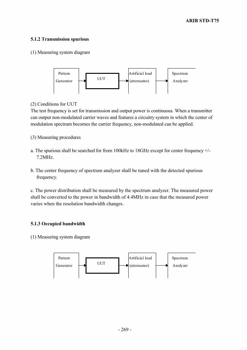
ARIB STD-T75
- 269 -
5.1.2 Transmission spurious (1) Measuring system diagram
Pattern
Generator UUTArtificial load
(attenuator)
Spectrum
Analyzer
(2) Conditions for UUT The test frequency is set for transmission and output power is continuous. When a transmitter can output non-modulated carrier waves and features a circuitry system in which the center of modulation spectrum becomes the carrier frequency, non-modulated can be applied.
(3) Measuring procedures a. The spurious shall be searched for from 100kHz to 18GHz except for center frequency +/-
7.2MHz. b. The center frequency of spectrum analyzer shall be tuned with the detected spurious
frequency.
c. The power distribution shall be measured by the spectrum analyzer. The measured power shall be converted to the power in bandwidth of 4.4MHz in case that the measured power varies when the resolution bandwidth changes. 5.1.3 Occupied bandwidth (1) Measuring system diagram
Pattern
Generator UUTArtificial load
(attenuator)
Spectrum
Analyzer

ARIB STD-T75
- 270 -
(2) Conditions for unit under test (UUT) and measuring procedures a. Test frequency should set for transmission. Output signal of pattern generator shall be the standard encoding test signals. UUT should set to continuously transmitting mode. b. The frequency sweeping range of spectrum analyzer should about 2 to 3.5 times the occupied bandwidth standard. 5.1.4 Transmit power (1) Measuring system diagram
Pattern
Generator UUTArtificial load
(attenuator)
Power
meter
(2) Condition for measuring instrument The power shall be measured in the positive peak mode for ASK modulation. The positive peak mode or the effective power mode shall be applied for π/4 shift QPSK modulation. (3) Conditions for unit under test (UUT) a. Test frequency should set for transmission.
Output signal of pattern generator shall be the standard encoding test signals. UUT shall set continuously transmitting mode.
b. When a transmitter can output non-modulated carrier waves and features a circuitry system in
which the center of modulation spectrum becomes the carrier frequency, non-modulated can be applied.
(4) Definition of transmitting power The transmitting power of ASK modulation is defined peak power. In case of 50% mark the transmitting power equal to measuring power plus 3dB. When the transmitter output non-modulated carrier the transmitting power equal to measuring power. In case of π/4 shift QPSK modulation, the transmitting power is defined as the average power during the burst cycle. The transmitting power is equal to the measuring power when the power is measured in the continuous non-modulated wave.
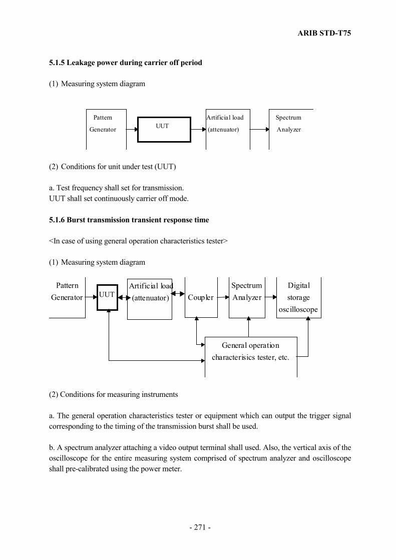
ARIB STD-T75
- 271 -
5.1.5 Leakage power during carrier off period (1) Measuring system diagram
Pattern
Generator UUTArtificial load
(attenuator)
Spectrum
Analyzer
(2) Conditions for unit under test (UUT) a. Test frequency shall set for transmission. UUT shall set continuously carrier off mode. 5.1.6 Burst transmission transient response time <In case of using general operation characteristics tester> (1) Measuring system diagram
PatternGenerator UUT
Artificial load(attenuator)
SpectrumAnalyzerCoupler
Digitalstorage
oscilloscope
General operationcharacterisics tester, etc.
(2) Conditions for measuring instruments a. The general operation characteristics tester or equipment which can output the trigger signal corresponding to the timing of the transmission burst shall be used. b. A spectrum analyzer attaching a video output terminal shall used. Also, the vertical axis of the oscilloscope for the entire measuring system comprised of spectrum analyzer and oscilloscope shall pre-calibrated using the power meter.

ARIB STD-T75
- 272 -
(3) Conditions for unit under test (UUT) a. Test frequency shall set for transmission. UUT shall be set to the mode of normal operation. <In case of direct detecting modulated signal> (1) Measuring system diagram
PatternGenerator UUT
Artificial load(attenuator) Detector
Digitalstorage
oscilloscope
(2) Conditions for measuring instruments The output signal of pattern generators to be set as shown below: All “0” or all “1” or recurring pattern of “01”. (3) Conditions for unit under test (UUT) a. Test frequency shall be set for transmission. 5.1.7 Modulation index, Modulation accuracy 5.1.7.1 Modulation index (ASK Modulation) (1) Measuring system diagram
PatternGenerator UUT
Artificial load(attenuator)
Modulationaccuracy meter
orDetector andoscillosccope
(2) Conditions for measuring instruments The modulation accuracy meter shall have a reception roll-off filter function and be capable of measuring the difference of effective value between the ideal signal and the signal that is actually transmitted.
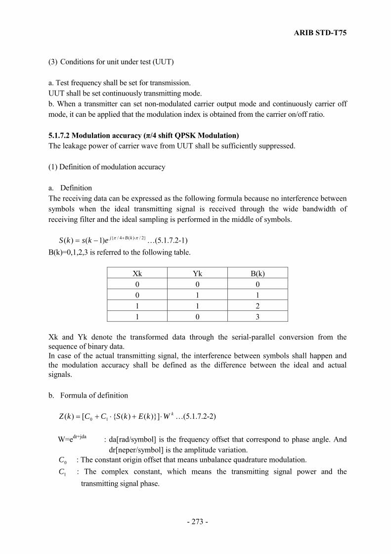
ARIB STD-T75
- 273 -
(3) Conditions for unit under test (UUT) a. Test frequency shall be set for transmission. UUT shall be set continuously transmitting mode. b. When a transmitter can set non-modulated carrier output mode and continuously carrier off mode, it can be applied that the modulation index is obtained from the carrier on/off ratio. 5.1.7.2 Modulation accuracy (π/4 shift QPSK Modulation) The leakage power of carrier wave from UUT shall be sufficiently suppressed. (1) Definition of modulation accuracy a. Definition The receiving data can be expressed as the following formula because no interference between symbols when the ideal transmitting signal is received through the wide bandwidth of receiving filter and the ideal sampling is performed in the middle of symbols.
}2/)(4/{)1()( ππ ⋅+−= kBjekskS …(5.1.7.2-1) B(k)=0,1,2,3 is referred to the following table.
Xk Yk B(k) 0 0 0 0 1 1 1 1 2 1 0 3
Xk and Yk denote the transformed data through the serial-parallel conversion from the sequence of binary data. In case of the actual transmitting signal, the interference between symbols shall happen and the modulation accuracy shall be defined as the difference between the ideal and actual signals. b. Formula of definition
kWkEkSCCkZ ⋅+⋅+= )}]()({[)( 10 …(5.1.7.2-2) W=edr+jda : da[rad/symbol] is the frequency offset that correspond to phase angle. And
dr[neper/symbol] is the amplitude variation. 0C : The constant origin offset that means unbalance quadrature modulation.
1C : The complex constant, which means the transmitting signal power and the transmitting signal phase.

ARIB STD-T75
- 274 -
E(k) : the residual vector error of Sample S(k). The sum of square of vector error can be expressed as follows.
∑∑=
−
=
−−⋅=MAX
MINk
kMAX
MINkkSCCWkZkE
2
102 )(]/})([{)( …(5.1.7.2-3)
C0, C1 and W shall be selected as the above sum shall be minimized, and the vector error for each symbol shall be calculated through C0, C1 and W. The sampling timing of receiving symbols shall also be optimized as the vector error shall be minimized. MIN and MAX of slots can be given as follows.
MIN=1 :Vector after ramp up. MAX=1049 :Vector before ramp up.
The efficient value of vector error can be calculated as the square root of ∑ 1049/)( 2kE , and shall be defined as the modulation accuracy. (2) Measuring system diagram Pattern
Generator UUT Artificial load(attenuator)
Modulationaccuracy meter
(3) Conditions for measuring instruments Measuring equipment for modulation accuracy shall provide the receiving filter with sufficient wide bandwidth and the difference of vector error between the ideal and actual transmitting signals. (4) Conditions for unit under test (UUT) UUT shall be set in the transmitting frequency. (5) measuring procedure a. Measure the vector error between the ideal and actual transmitting signals. b. Sum the square of vector error for each sampling point and calculate the square root of the
sum divided by the number of phase discrimination point within the slot (1049).
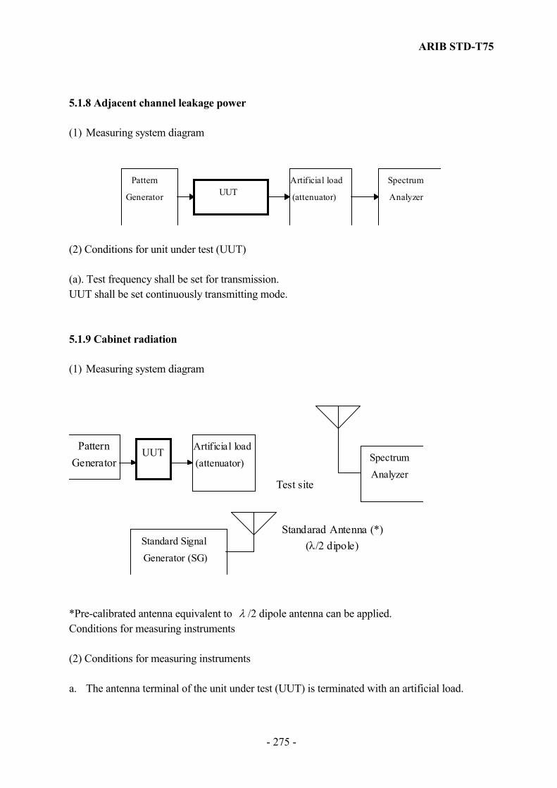
ARIB STD-T75
- 275 -
5.1.8 Adjacent channel leakage power (1) Measuring system diagram
Pattern
Generator UUTArtificial load
(attenuator)
Spectrum
Analyzer
(2) Conditions for unit under test (UUT) (a). Test frequency shall be set for transmission. UUT shall be set continuously transmitting mode. 5.1.9 Cabinet radiation (1) Measuring system diagram
PatternGenerator
UUT Artificial load(attenuator) Spectrum
AnalyzerTest site
Standard SignalGenerator (SG)
Standarad Antenna (*)(λ/2 dipole)
*Pre-calibrated antenna equivalent to λ /2 dipole antenna can be applied. Conditions for measuring instruments (2) Conditions for measuring instruments a. The antenna terminal of the unit under test (UUT) is terminated with an artificial load.

ARIB STD-T75
- 276 -
b. Measurement is done in the open site or anechoic chamber at distance of 3m with directional
antenna for measurement. It is better to suppress the reflected ground wave to avoid trouble due to complication of height pattern. Therefore, it is better to cover the floor in the middle of measurement with absorbing materials.
c. If one side of the UUT exceeds 60 cm the distance of measurement shall be greater than 5
times the distance. If the measuring frequency is less than 100 MHz,measurment is done in the 30 m test site.
d. In case that the RF coupler is applied, the coupler shall be calibrated for every measuring
frequency in the open site using the same type of equipment. λ /2 dipole antenna shall be applied as the standard antenna.
(3) Conditions for unit under test (UUT) a. Test frequency shall be set for transmission. 5.1.10 Modulation signal rate tolerance (1) Measuring system diagram
Frequency
counter UUTArtificial load
(attenuator)
(2) Conditions for measuring instruments The measuring accuracy of the frequency meter should be over one digit larger than the permissible deviation of the applicable frequency. (3) Conditions for unit under test (UUT) a. Test frequency shall be set for transmission. UUT shall be set continuously transmitting mode.

ARIB STD-T75
- 277 -
5.1.11 Deviation of absolute signal transmission time <In case of using general operation characteristics tester> (1) Measuring system diagram
PatternGenerator UUT
Artificial load(attenuator)
SpectrumAnalyzer
Coupler
Digitalstorage
oscilloscope
General operationcharacterisics tester, etc.
(2) Conditions for measuring instruments a. The general operation characteristic tester shall feature the base station function to establish connection to the unit under test (UUT). b. The general operation characteristics tester shall be capable of yielding the difference between the tester’s transmission timing and UUT’s transmission timing. c. The general operation characteristics tester which can output the trigger signal corresponding to the timing of the transmission burst shall be used. d. A spectrum analyzer attaching a video output terminal shall be used. (3) Conditions for unit under test (UUT) UUT shall be set to the normal operation. a. Test frequency shall be set for transmission. (4) Other methods Direct measurement of transmitting and receiving digital data in UUT and general operation characteristic tester is also applicable. This measurement shall be conducted by the digital oscilloscope or the logic analyzer. <In case of direct detecting modulated signal>

ARIB STD-T75
- 278 -
(1) Measuring system diagram
Pattern
Generator UUTArtificial load(attenuator) Detector
Digitalstorage
oscilloscope
(2) Conditions for measuring instruments The output signal of pattern generators to be set as shown below: All “0” or all “1” or recurring pattern of “01”. (3) Conditions for unit under test (UUT) a. Test frequency shall be set for transmission. 5.1.12 Eye pattern (Only ASK modulation is applied) (1) Measuring system diagram
PatternGenerator UUT
Artificial load(attenuator)
orFrequencyconverter
DetectorDigitalstorage
oscilloscope
(2) Conditions for unit under test (UUT) a. Test frequency shall be set for transmission. UUT shall be set continuously transmitting mode. (3) Other method The characteristics obtained from the measuring the envelope of the UUT output signal can be applied directly without detector.
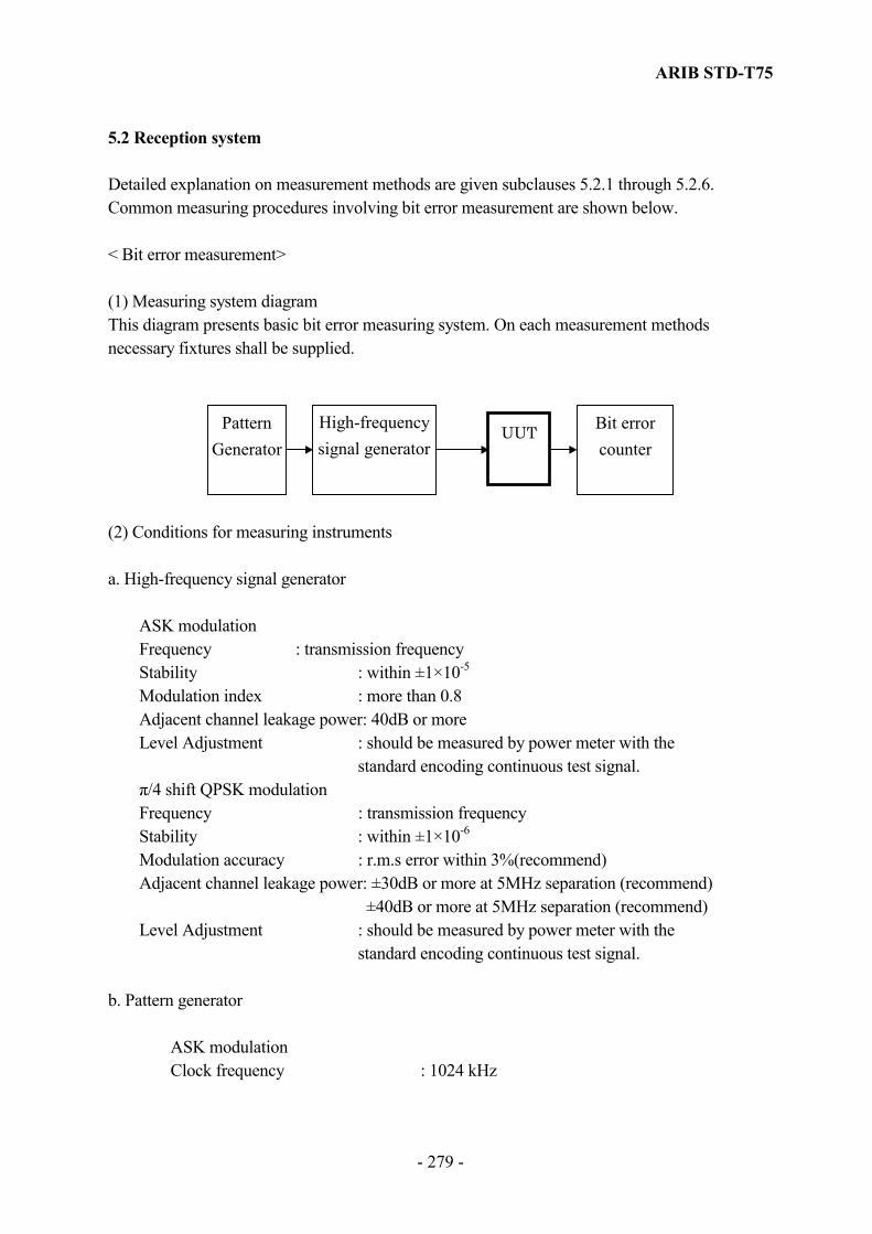
ARIB STD-T75
- 279 -
5.2 Reception system Detailed explanation on measurement methods are given subclauses 5.2.1 through 5.2.6. Common measuring procedures involving bit error measurement are shown below. < Bit error measurement> (1) Measuring system diagram This diagram presents basic bit error measuring system. On each measurement methods necessary fixtures shall be supplied.
PatternGenerator
UUT Bit errorcounter
High-frequencysignal generator
(2) Conditions for measuring instruments a. High-frequency signal generator
ASK modulation Frequency : transmission frequency Stability : within ±1×10⁻⁵
Modulation index : more than 0.8 Adjacent channel leakage power: 40dB or more Level Adjustment : should be measured by power meter with the standard encoding continuous test signal. π/4 shift QPSK modulation Frequency : transmission frequency Stability : within ±1×10⁻⁶
Modulation accuracy : r.m.s error within 3%(recommend) Adjacent channel leakage power: ±30dB or more at 5MHz separation (recommend) ±40dB or more at 5MHz separation (recommend) Level Adjustment : should be measured by power meter with the standard encoding continuous test signal.
b. Pattern generator ASK modulation Clock frequency : 1024 kHz

ARIB STD-T75
- 280 -
Clock accuracy : within ±1×10⁻⁶
π/4 shift QPSK modulation Clock frequency : 2048 kHz Clock accuracy : within ±5×10⁻⁶
(3) Conditions for unit under test (UUT) a. The UUT shall be set to the frequency for reception. b. The mobile station shall be set to the mode of only receiving. (Note) Error rate can also be obtained by accumulating the number of errors within the slot data. Number of slot data shall exceed 106 bits. 5.2.1 Reception sensitivity Measuring system diagram
PatternGenerator
UUT Bit errorcounter
High-frequencysignal generator
Matching/distribution
circuitor
attenuator
Powermeter
(2) Conditions for measuring instruments and for UUT Refer to < Bit error measurement>.

ARIB STD-T75
- 281 -
5.2.2 Adjacent signal selectivity (1) Measuring system diagram
PatternGenerator
-1
UUT Bit errorcounter
High-frequencysignal generator
-1
Matching/Couplerdistribution
circuit
Powermeter
PatternGenerator
-2
High-frequencysignal generator
-2
(2) Conditions for measuring instruments and for UUT Refer to < Bit error measurement>. (3) Pattern generator-2 the generator polynomial of pattern generator-2 can be different from the polynomial of the pattern generator-1. 5.2.3 Spurious response rejection ratio (1) Measuring system diagram
PatternGenerator
-1
UUT Bit errorcounter
High-frequencysignal generator
-1
Matching/Couplerdistribution
circuit
Powermeter
High-frequencysignal generator
-2
(2) Conditions for measuring instruments and for UUT Refer to < Bit error measurement>.

ARIB STD-T75
- 282 -
5.2.4 Cabinet radiation (Informative) The UUT shall be set to the frequency for reception. The other conditions and the measurement procedures are the same as subclause 5.1.9. 5.2.5 Channel selection time of mobile station (Informative) (1) Measuring system diagram
UUTArtificial load(attenuator)
Digitalstorage
oscilloscope
General operationcharacterisics tester, etc.
(2) Conditions for measuring instruments and for UUT Refer to < Bit error measurement>. 5.2.6 Strength of secondary radio emission (Informative) The UUT shall be set to the frequency for reception. The other conditions and the measurement procedures are the same as subclause 5.1.5. 5.3 Measurement methods of without attaching connectors The UUT (transceiver) without connectors to antenna or to pattern generator should be tested following manner and referred the measurements diagram below. The UUT should have a facility to mesure by establishing connection to the general operation characteristic tester and be changed the specific parameters by the commands from the tester. It can be applied that the commands are received directly from the tester through cables.

ARIB STD-T75
- 283 -
5.3.1 Transmission system 5.3.1.1 Frequency tolerance (1) Measuring system diagram
UUT
Artificial load(attenuator)
General operationcharacterisics tester, etc.
Coupler Frequencycounter
RF combiner
(2) Conditions for measuring instruments a. The reception level of UUT shall be set enough power to demodulate without errors. And the output power of the general operation characteristic tester shall be set small power to ignore the leakage of the coupler to the frequency counter. b. When a transmitter can output non-modulated carrier waves and features a circuitry system in which the center of modulation spectrum becomes the carrier frequency, non- modulated can be applied and the frequency counter can be directly connected to the RF combiner. (3) Conditions for UUT a. Test frequency shall be set for transmission. UUT shall be set to continuously transmitting mode. b. When a transmitter can output non-modulated carrier waves non-modulated can be applied.

ARIB STD-T75
- 284 -
(4) Coding signals Bellow are the coding signals: The internal signal of UUT The received signal from the general operation characteristic tester through RF combiner. The received signal from the general operation characteristic tester through cable. 5.3.1.2 Transmission spurious (1) Measurement procedures This measurement is done in the test site the same as the measurement of cabinet emission. The conditions for instruments or for UUT are the same as subclause 5.1.2 and the test coding signal is same subclause 5.3.1.1 (4). (2) Result calculation Equivalent radiation power = (above measurement power) / (relative gain of test antenna) Relative gain = (maximum gain of the test antenna) / gain of (standard dipole antenna)*
*1.64 5.3.1.3 Occupied bandwidth The conditions for instruments or for UUT are same subclause 5.1.3 and the test coding signal is the same as subclause 5.3.1.1. 5.3.1.4 Transmit power (1) Measurement procedures This measurement shall done in the test site as same as the measurement of cabinet emission. The conditions for instruments or for UUT are same subclause 5.1.4 and the test coding signal is same subclause 5.3.1.1 (4). (2) Result calculation Equivalent radiation power = (above measurement power) / (relative gain of test antenna) Relative gain = (maximum gain of the test antenna) / gain of (standard dipole antenna)*
*1.64

ARIB STD-T75
- 285 -
5.3.1.5 Leakage power during carrier off period The conditions for instruments or for UUT are the same as subclause 5.1.5 and the test coding signal is the same as subclause 5.3.1.1. (4). 5.3.1.6 Burst transmission transient response time The conditions for instruments or for UUT are same subclause 5.1.6 and the test coding signal is same subclause 5.3.1.1. 5.3.1.7 Modulation index The conditions for instruments or for UUT are same subclause 5.1.7 and the test coding signal is the same as subclause 5.3.1.1. 5.3.1.8 Adjacent channel leakage power The conditions for instruments or for UUT are the same as subclause 5.1.8 and the test coding signal is the same as subclause 5.3.1.1. 5.3.1.9 Cabinet radiation This measurement is same as subclause 5.1.3.2 Transmission spurious and the test coding signal is same subclause 5.3.1.1. 5.3.1.10 Modulation signal rate tolerance The conditions for instruments or for UUT are the same as subclause 5.1.10 and the test coding signal is the same as subclause 5.3.1.1. 5.3.1.11 Deviation of absolute signal transmission time The conditions for instruments or for UUT are the same as subclause 5.1.10 and the test coding signal is the same as subclause 5.3.1.1. 5.3.1.12 Eye pattern The conditions for instruments or for UUT are same subclause 5.1.12 and the test coding is same subclause 5.3.1.1.

ARIB STD-T75
- 286 -
5.3.2 Reception system 5.3.2.1 Reception sensitivity (measuring in test site) (1) Measuring system diagram
UUT
General operationcharacterisics tester, etc.
Selectivelevel meter
Bit errorcounter
Pattern Generatorand
RF signal generator
or
Standardreceiver
*B
*A
(2) The conditions for instruments or for UUT a. The conditions of test site are the same as subclause 5.1.9 “Cabinet radiation”. b. The set *A should be able to measure the received power at the position of UUT. The antenna *A shall be 1/2 dipole antenna or standard antenna with right-hand circular polarization. c. The set *B should accord with the tester of subclause 5.1.2 d. The standard receiver should be able to receive the signal from UUT and output demodulated data in accordance with subclause 5.1.2 to the bit error counter. The standard receiver should be placed at about 3m from the UUT and an about 4.2m from the antenna *B in order to receive the signal from UUT without errors and not to interfere the measurement. e. When UUT is able to output the demodulated data from attached connectors, the bit error counter can be applied to connect directly to UUT. (3) Conditions for unit under test (UUT) a. The UUT shall be set to the frequency for reception.

ARIB STD-T75
- 287 -
5.3.2.2 Reception sensitivity (measuring with RF combiner)
(1) Measuring system diagram
(2) The conditions for instruments a. The RF combiner shall be corrected at each transmission frequency in test site the same as measuring “ cabinet radiation “ assuming that the effect to UTT is negligible. b. The reception level of standard receiver from UUT shall be set to enough power to receive without errors. And the output power of the general operation characteristic tester shall be set small power to ignore the leakage of the coupler to the standard receiver. (3) Conditions for unit under test (UUT) a. The UUT shall be set to the frequency for reception. 5.3.2.3 Adjacent signal selectivity The conditions for instruments or for UUT are the same as subclause 5.2.2 using RF combiner. 5.3.2.4 Spurious response (1) Measuring in test site a. The test site and receiving power are same as subclause 5.3.2.1 “Reception sensitivity”. b. The test circuit for combining the undesired signal with the desired signal is the same as the circuit in subclause 5.2.2. The undesired signal shall be set to the specific level, which meets the ratio to the desired signal is equal to the defined value in spurious response specification.
UUT
Artificial load (attenuator)
Coupler Standard receiver
(attenuato
Bit error counter
(attenuato
General operation Characteristics tester,
etc.
RF combiner

ARIB STD-T75
- 288 -
(2) Measuring with RF combiner a. The RF combiner and receiving power are same as subclause 5.3.2.1 “Reception sensitivity”. b. The test circuit for combining the undesired signal with the desired signal is the same as the circuit in subclause 5.2.2. The undesired signal shall be set to the specific level, which meets the ratio to the desired signal is equal to the defined value in spurious response specification.
5.3.2.5 Cabinet radiation This measurement is the same as subclause 5.1.3.2 “Transmission spurious”. 5.3.2.6 Channel selection time of mobile station (1) Measuring system diagram
UUT
Artificial load(attenuator)
General operationcharacterisics tester, etc.
Coupler Standardreceiver
RF combiner
Bit errorcounter
(2) Conditions for measuring instruments and for UUT Refer to < Bit error measurement>. 5.3.2.7 Strength of secondary radio emission The UUT shall be set to the frequency for reception. The other conditions and the measurement procedures are the same as subclause 5.3.1.5.

ARIB STD-T75
- 289 -
5.4 Test equipment
5.4.1 Carrier sense function (Measurement methods of with attaching connectors) (1) Measuring system diagram
(2) Conditions for measuring instruments
a. The general operation characteristic tester shall feature the following functions.
It can select a frame class (A,B and C at Table. 4.2.9), and can output trigger timings of
transmitting Frame Control Message Slot of selected frame class to pattern generator and
high-frequency signal generator.
b. Signal generator
Refer to < Bit error measurement>.
c. High-frequency signal generator output signals modulated by Pattern generator signals to
communication control slot at channel selected by General operation characteristics tester.
Refer to < Bit error measurement> about others.
d. Time constant of Power meter shall be enough long to display exact effective value of power.
(3) Conditions for unit under test(UUT)
The UUT shall be set to the frequency for testing.
Pattern Generator
High-frequency Signal generator
Matching/Coupler Distribution circuit
Or attenuator
Power meter
UUT General operation
characteristics tester,etc

ARIB STD-T75
- 290 -
(4) Measuring procedures
a. The Power meter shall be corrected to measure –78 dBm e.i.r.p. exactly considering the period
of frame time and the period of communication control slot time.
b. Channel of General operation characteristics tester shall be set the frequency for testing.
c. Start UUT, then Conform to transmit no slots at all.
d. The Power meter shall be corrected to measure –78 dBm e.i.r.p. exactly considering the period
of frame time and the period of communication control slot time.
e. Channel of General operation characteristics tester shall be set the adjacent frequency for
testing.
f. Start UUT,then Conform to transmit no slots at all.
g. When there are two channel as the adjacent frequency for testing ,repeat d,e and f for the
remaining frequency .
5.4.2 Carrier sense function (Measurement methods of without attaching connectors)
(1) Measuring in test site
a. The condition of test site are the same subclause 5.3.2.1 “Reception sensitivity”. The Power
meter shall be set to enough input level to measure on behalf of regulated sensitivity, then
measure the same method.
b. The constitution of measurement is that UUT and Test equipment are able to face, UUT
can receive commands of measurement by air interface to perform measurement.

ARIB STD-T75
- 291 -
c. It is to measure as the method of with attaching connectors.
Note) Refer to subclause 5.3 “The measurement methods of without attaching connector”
(2)Measuring with RF combiner
a.The condition of RF combiner are the same subclause 5.3.2.1 “Reception sensitivity”.
b. UUT shall be set in RF combiner, the connector of RF combiner is used as antenna
connectors, then it is to measure as the method of with attaching connectors.

ARIB STD-T75
- 292 -
Empty page

ARIB STD-T75
- 293 -
Chapter 6 Definitions and Abbreviations 6.1 Definitions
[Activation slot (ACTS)] Communication slot for multiple activation channels (ACTC) for remote mobile station to
enter the communication link of base station. [Association] Service to register the remote mobile station link address to the communication link of the
base station to permit communication between base station and remote mobile station. It has the same meaning as the initialization.
[Application service data unit (ASDU)]
Data associated with a Service Primitive invocation of an Application Service Element in the layer 7.
[Application data unit (ADU)]
Data unit specified in an application and transferred between two application entities. [Application protocol data unit (APDU)]
Data unit exchanged between peer Application Service Elements.
[Application Service Element (ASE)] A part of an Application Entity response. The layer 7 that provides a communication environment capability, using underlying LLC services where appropriate. The Application Service Elements describe the encapsulation of data structures by offering a well-defined set of Service
[Attributes]
This is defined in the layer 7. An Attribute has an associated value, which can exhibit structure. The value of an Attribute can determine or reflect the behavior of the element. The value of an Attribute is observed or modified by sending a request to an element to read (GET) or write (SET) the value. Operations on Attributes are defined to be performed upon the Element that contains the Attributes and not directly upon the Attributes.

ARIB STD-T75
- 294 -
[Base station] Fixed communication equipment on the roadside. Provides one or more down channels and
one or more up channels. Performs communication with plural mobile stations. It has the same meaning as the roadside unit (RSU) or the beacon.
[Beacon Service Table (BST)]
A BST is generated in the layer 7 of the base station. On the layer 7 of the base station, the I-KE collects application identifiers, initial data, and protocol layer parameter relevant for the communication. The application identifiers are stored in the BST as a priority list defining the order in which applications are served. The base station transmits the BST. The reception of the BST on the mobile station side is the initiator of each data transfer from applications on mobile station side. The vehicle's I-KE evaluates a received BST and indicates the availability (including parameter) of services to the corresponding Application and Application Service Elements.
[Broadcast Kernel Element (B-KE)]
The B-KE of the layer 7 is responsible for the collection, broadcast and retrieval of data for plural applications and/or plural mobile stations.
[Broadcast link address] The pre-defined SAP used as a broadcast (all parties) address. It can never be the address of a
single SAP on the layer 2. [Broadcast Pool]
This is defined in the layer 7. File, cyclically broadcast from the base station to the mobile stations. Records may be independent inserted from several Service Users.
[Coding]
A function performed by the Transfer Kernel Element, which transfers the data from a special local syntax (related to the local hardware) into transfer syntax common for all communication systems (with the same applications on them). The peer Transfer-service-provider decodes this data from transfer syntax into its own local syntax. The common abstract description of this data is the abstract syntax notice 1 (ASN.1).
[Command] An instruction in data communications. It is represented in the control field of a LPDU and
transmitted by an LLC. It causes the addressed LLC(s) to perform a specific data link control function.

ARIB STD-T75
- 295 -
[Concatenation] A function performed by the Transfer Kernel Element of the layer 7 to map multiple Application Layer Protocol Data Units or the layer 7 Fragments into one layer 2 Logical Service Data Unit.
[Data link] An assembly of two or more terminal installations and the interconnecting communications
channel operating according to a particular method that permits information to be exchanged between the remote layer 2 entities.
[Down link] Communication channel on which the base stations transmits its information to mobile
stations. [Element]
Application Service Element or User Element, Elements in the layer 7 are abstractions of data processing and data communication resources. These elements represent the parts of the communication system building up response. using the layer 7 functions.
[Element Identifier]
The registered name of a layer 7 (Application Layer) Kernel Service User which is unambiguous in each piece of equipment and the same for the same Element in each Communication System.
[Entity]
An active element within a system. [Fragmentation]
A function performed by the Transfer Kernel Element of the layer 7 to map one Transfer-SDU on plural LSDU . A function performed by MAC sub layer of the layer 2 to map one LSDU on plural MPDU.
[Frame control message Slot (FCMS)] Frame control information field for the communication profile and information such as data
slot, for making communication with base station.

ARIB STD-T75
- 296 -
[Grand Mobile station] A mobile communication facility capable of receiving information from the base stations on
the downlink, also capable of transmitting information on the uplink. This is abbreviated to Mobile station. It is the same meaning of the on-board equipment.
[Head of Line]
Queuing discipline (also: strict priority queuing or fixed priority queuing), a number of queues are served in priority order, each queue is served in First-Come-First-Serve order.
[Identifier]
This is defined in the layer 7. The unique IDs of equipment. The term identifier is used in a different concept from the term element identifier.
[Initialization Kernel Element (I-KE)]
This is functional entity of the layer 7. The I-KE is responsible for the initialization of the communication on the level of the Layer 7.
[Initialization] Service to register the remote mobile station link address to the communication link of the
base station to permit communication between base station and remote mobile station. It has the same meaning as the association.
[Layer 1(L1)] The conceptual layer of transmitting or receiving signals through physical medium channel.
This layer provides service for the layer 2. It is the same meaning of the physical layer.
[Layer 2 (L2)] The conceptual layer of control or processing logic existing in the hierarchical structure of a
station that is responsible for maintaining control of the data link. This layer provides service for the layer 7. It has the same meaning as the data link layer.
[Layer 7 (L7)]
The layer 7 contains all functions, which imply communication between a base station and a mobile station not already performed by lower layers. These include functions performed by programs as well as functions performed by human beings.
This layer provides service for applications. It has the same meaning as the application layer.

ARIB STD-T75
- 297 -
[Layer management entity (LME)] Management entity determined for each layer for facilitating control of the entire system,
which is not specified by services of each layer (the layer 1, the layer 2 (MAC sublayer and LLC sublayer) and the layer 7).
[Layer7Management] This is a part of communication system management in layer 7. This Management provides parameters to layer 1,2 and 7 by entity ,and has a function which
provides and collects information to control communication system.
[Link address] Service access point address at the beginning of an LPDU, which identifies the SAP,
designated to receive PDU and the SAP transmitting the PDU.
[Link service data unit (LSDU)] Data unit exchanged between LLC sublayer and layer 7. [LLC Protocol Data Unit (LPDU)]
Data Unit exchanged between two LLC protocols instances.
[Logical link control (LLC)] A part of communication facility that supports the logical link control function of one or
more logical links. The LLC generates command PDUs for transmission, and interprets received command PDUs and response PDUs.
LLC provides the following functions. (1) Initialization of transmission/reception of PDU (2) Control of data flow (3) Interpretation of received command PDUs and generation of appropriate response PDUs. (4) Actions regarding error control and its recovery function in LLC sublayer [LLC control field] The first control field of LPDU. The content of the control field is interpreted as following by
the link address of the received destination LLC(s), (1) As a command, instructing the performance of function specified by the source LLC. (2) As response, replying the source LLC .
ARIB STD-T75
- 298 -
[MAC control field] The portion of the frame that holds the control information fields that permits MAC sublayer to perform suitable control.
[MAC protocol data unit (MPDU)] Data unit exchanged between MAC sublayers.
[MAC service data unit (MSDU)] Data unit exchanged between LLC sublayer and MAC sublayer.
[Manager] Management information service user that can issues management operations and receives notifications in interaction of the systems management.
[Managed object] A side of the resource management in the OSI environment managed via system
management process.
[Management Information Provider] The concept of a whole entity provides the management information to Management
Information Service Users.
[Management Information Base] A conceptual memory of information database in the OSI environment.
[Management Information Service] Services are provided by Application Service User Elements specified in the system
management entity. [Management Information Service User] Users of the Management Information Services provided by Management Information
Provider. [Medium access control (MAC)] The part of a data station that supports the medium access control functions that resides just
below the LLC sublayer. The MAC procedures include framing/deframing data units, and acquiring the right to use underlying physical medium.
ARIB STD-T75
- 299 -
[Message data slot (MDS)] Communication slot for data transmission/reception in a communication frame.
[Mobile station] A mobile communication facility capable of receiving information from the base stations on
the downlink, also capable of transmitting information on the uplink. It is the same meaning of the on-board equipment.
[Multicast (group) link address] A destination address assigned to a collection (group) of SAPs to facilitate their being
addressed collectively.
[Multiplexing]
A function within the Transfer Kernel Element of the layer 7 by which one LLC-SAP is used to support more than one Transfer-service-user.
[Notification] At the layer 7, Elements may be defined to emit notifications when some internal or external
event occurs .This is specific to the means that emit them. At system management, This is defined as the information of event that occur in a particular management object.
[Octet] A bit-oriented element that consists of eight contiguous binary bits.
[On-board equipment (OBE or OBU)] On-board equipment capable of receiving information from the base stations on the
downlink, also capable of transmitting information on the uplink. It has the same meaning as the mobile station.
[Private link address] Used as an address to perform point-to-point communication between the base station. The
remote mobile station creates this.
[Profile]
Information about transmission capabilities and settings in the different communication layers and Application Processes. A profile is identified by an INTEGER.
ARIB STD-T75
- 300 -
[Protocol data unit (PDU)] Data unit exchanged between same level protocol layer. [Response] .Response to data communication. Set in control field of LPDU , and transmitted by LLC. A
specific data link control is performed by LLC specifying address [Road side equipment (RSU)] Fixed communication equipment on the roadside. Provides one or more down channels and
one or more up channels. Performs communication with plural mobile stations. It has the same meaning as the base station.
[Service]
Functions provided to next upper layer.
[Service Primitive (SP)]
An abstract implementation of independent interaction between a Service User and a Service Provider.
[Service Provider]
An application Service Element or a communication Layer provides a special capability to Application Elements or a User Element by means of Service Primitives.
[Service User]
An application Service Element or a User Element which makes use of a service of a Service Provider.
[System management Application Entity] An application entity which executes the function of the system management. [System management entity (SME)] System management layer that functions in coordination with the layer management entity
that is determined for each layer for facilitating controlling of the entire system, which is not specified by services of the layer 1, the layer 2 or the layer 7.
[System Management Service] Group of service primitives named for providing services in system management entity.
ARIB STD-T75
- 301 -
[System Management Operation] Operation for executing the system management to managed objects.
[Transfer Kernel Element (T-KE)]
The T-KE of the layer 7 is responsible to transfer an APDU to the peer group entity. It includes the needed functions between the network layer and the presentation Layer. These functions are (de-) coding to transfer syntax, Fragmentation/Concatenation, and (de-) Multiplexing with priority handling.
[Up link] Communication channel on which the mobile station transmits its information to the base
station. [User Element]
A part of the application process in the layer 7 which uses application service elements needed to execute the communication demanded by the application process.
[Vehicle Service Table (VST)]
The VST is the answer to the BST from I-KE in the layer 7 of the mobile station . It contains the identifiers of all application present in the BST and registered in the mobile station and the profile used in communication after sending VST.
ARIB STD-T75
- 302 -
6.2 Abbreviations
[A] ACPI : Activation Possibility Identifier Ack : Acknowledged ACKC : Ack Channel ACnC/R : Acknowledge command/response
ACTC : Activation Channel ACTS : Activation Slot ADU : Application Data Unit AI : Acknowledgement Information field AID : Application Element Identifier AP : Application Process API : Application Identifier APDU : Application Protocol Data Unit ASDU : Application Service Data Unit ASE : Application Service Element ASK : Amplitude Shift Keying ASN.1 : Abstract Syntax Notation One ATI : Area Type Identifier
[B] BER : Bit Error Rate BP : Broadcast Pool B-KE : Broadcast Kernel Element BST : Beacon Service Table
[C] CCZ : Continuous Communication Zone identifier CEN : European Committee for Standardization CI : Control Information subfield of SCI CM : Communication Mode identifier CRC : Cyclic Redundancy Check C/L : Continued/Last C/R : Command/Response CW : Continuous Wave
[D] DRI : Data transmission Rate Identifier
ARIB STD-T75
- 303 -
DSRC : Dedicated Short-range Communication DR : Direction Identifier
[E] EID : Element Identifier E.I.R.P(e.i.r.p) : Equivalent Isotropic Radiation Power
[F] FCMS : Frame Control Message Slot FCMC : Frame Control Message Channel FDMA : Frequency Division Multiple Access FID : Fixed Equipment ID FRG : Fragmentation FSI : Frame Structure Information field FTI : Frequency Type Identifier
[G]
[H]
[I] ID : Identifier IID : Invoker Identifier IMI : Initialization Mode Identifier ITU : International Telecommunication Union ITU-R : ITU-Radio Communication Bureau I-KE : Initialization Kernel Element ISO : International Organization for Standardization
[J]
[K]
[L] L1 : Physical Medium Laye (Layer 1) L2 : Data Link Layer (Layer 2) L7 : Application Layer (Layer 7) LI : Length indicator information field of LPDU LID : Link Address
ARIB STD-T75
- 304 -
LLC : Logical Link Control LME : Layer Management Entity LPDU : Link Protocol Data Unit LRI : Link Request Information field LSAP : LLC Service Access Point LSB : Least Significant Bit LSDU : LLC Service Data Unit
[M] MAC : Medium Access Control mand. : Mandatory MDC : Message Data Channel MDS : Message Data Slot MIB : Management Information Base MPDU : MAC Protocol Data Unit MSB : Most Significant Bit MSDU : MAC Service Data Unit
[N] Nack : Not acknowledged non-mand : Non Mandatory
[O] OBE : On-Board Equipment ( Mobile station) OSI : Open Systems Interconnection
[P] PDU : Protocol Data Unit PHY : Physical Layer (Layer 1) PR : Preamble PN : Pseudo random Noise PPI : Physical layer Profile Identifier PVI : Protocol Version Information field req/ind : request/indication resp/conf : response/confirm
[Q] QPSK : Quadrature Phase Shift Keying
ARIB STD-T75
- 305 -
[R] RF : Radio Frequency RLT : Release Timer information field RSU : Road Side Unit (base station)
[S] SAP : Service Access Point SC : Service Code SCI : Slot Control Information field SEQ : Sequence Number SI : Slot Identifier SIG : Signaling Channel information field SLN : Slot Number Information field SME : System Management Entity SP : Service Primitive STA : Status of receiving ACTC
[T] TDMA : Time Division Multiple Access TDI : Time Division Identifier T-KE : Transfer Kernel Element TRI : Transmitter/Receiver Identifier [U] UI : Unnumbered Information UW : Unique Word
[V] VST : Vehicle Service Table
[W] WCNC : Wireless Call Number Channel (Call sign) WCNS : Wireless Call Number Slot

ARIB STD-T75
- 306 -
6.3 Variables 6.3.1 Variables in the layer 1 k1, k1max : Number of ACTSs (activation slots) in half-duplex mode k2, k2max : Number of ACTSs (activation slots) in full-duplex mode n1, n1max : Number of MDSs (message data slots) in half-duplex mode n2, n2max : Number of MDSs (message data slots) in full-duplex mode m : Number of slots allocated following FCMS. m is the number of valid SCI (slot control identifier) field in half-duplex mode and 2m is in full-
duplex mode.
6.3.2 Variables in the layer 2 (1) MAC sublayer ASL, ASLmax : Base station ACTS assignment variable ASGN : Group of assignment variable to request slots of base station. ASGN.LID : Assignment link address variable ASGN.DIR : Assignment direction variable ASGN.RS : Assignment response sate variable ASGN.PR : Assignment priority variable FQBUSY : Base station threshold value for transmission queue state variable NFR1, NFR1max: Retry counter of base station (downlink MDS allocation) NFR2, NFR2max: Retry counter of base station (uplink MDS allocation) NMR, NMRmax : Retry counter of mobile station (uplink MDS transmission) NRQ, NRQmax : Link request counter of a mobile station NRT : Re-link entry restriction counter NUMLINK : Base station connection variable NUMQ : Number of a transmission queue MAXLINK : Base station link connection maximum number variable MQBUSY : Mobile station threshold value for a transmission queue state variable MSIZE : Maximum transmission LLC data size number RSQ : Reception sequence state variable SLT_STATUS : Slot assignment state variable TR_STATUS : Transmission request state variable TSQ : Transmission sequence state variable TSQ2.DUP : Duplication inspection state variable TSQ2.ACK : Delivery confirmation state variable WTC, WTCmax : Number of a mobile station WCNC transmission

ARIB STD-T75
- 307 -
(2) LLC sublayer V (RI) : receive state variable (LLC) V (SI) : transmit state variable (LLC) V (RB) : Reception status state variable (LLC) N10 : Maximum number of octets of a LPDU (LLC) N11 : Maximum number of transmission (LLC) N13 : Acknowledgment time (LLC)

ARIB STD-T75
- 308 -
Empty page

ANNEX

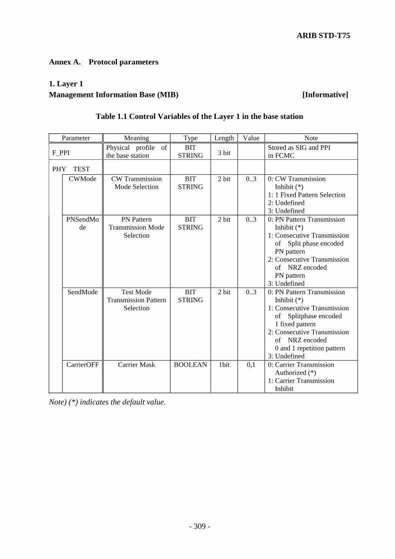
ARIB STD-T75
- 309 -
Annex A. Protocol parameters 1. Layer 1 Management Information Base (MIB) [Informative]
Table 1.1 Control Variables of the Layer 1 in the base station
Parameter Meaning Type Length Value Note
F_PPI Physical profile of the base station
BIT STRING 3 bit
Stored as SIG and PPI in FCMC
PHY TEST
CWMode CW Transmission
Mode Selection BIT
STRING 2 bit 0..3 0: CW Transmission
Inhibit (*) 1: 1 Fixed Pattern Selection 2: Undefined 3: Undefined
PNSendMo
de PN Pattern
Transmission Mode Selection
BIT STRING
2 bit 0..3 0: PN Pattern Transmission Inhibit (*) 1: Consecutive Transmission of Split phase encoded PN pattern 2: Consecutive Transmission
of NRZ encoded PN pattern
3: Undefined
SendMode Test Mode
Transmission Pattern Selection
BIT STRING
2 bit 0..3 0: PN Pattern Transmission Inhibit (*) 1: Consecutive Transmission of Splitphase encoded 1 fixed pattern 2: Consecutive Transmission of NRZ encoded 0 and 1 repetition pattern 3: Undefined
CarrierOFF Carrier Mask BOOLEAN 1bit 0,1 0: Carrier Transmission
Authorized (*) 1: Carrier Transmission
Inhibit
Note) (*) indicates the default value.
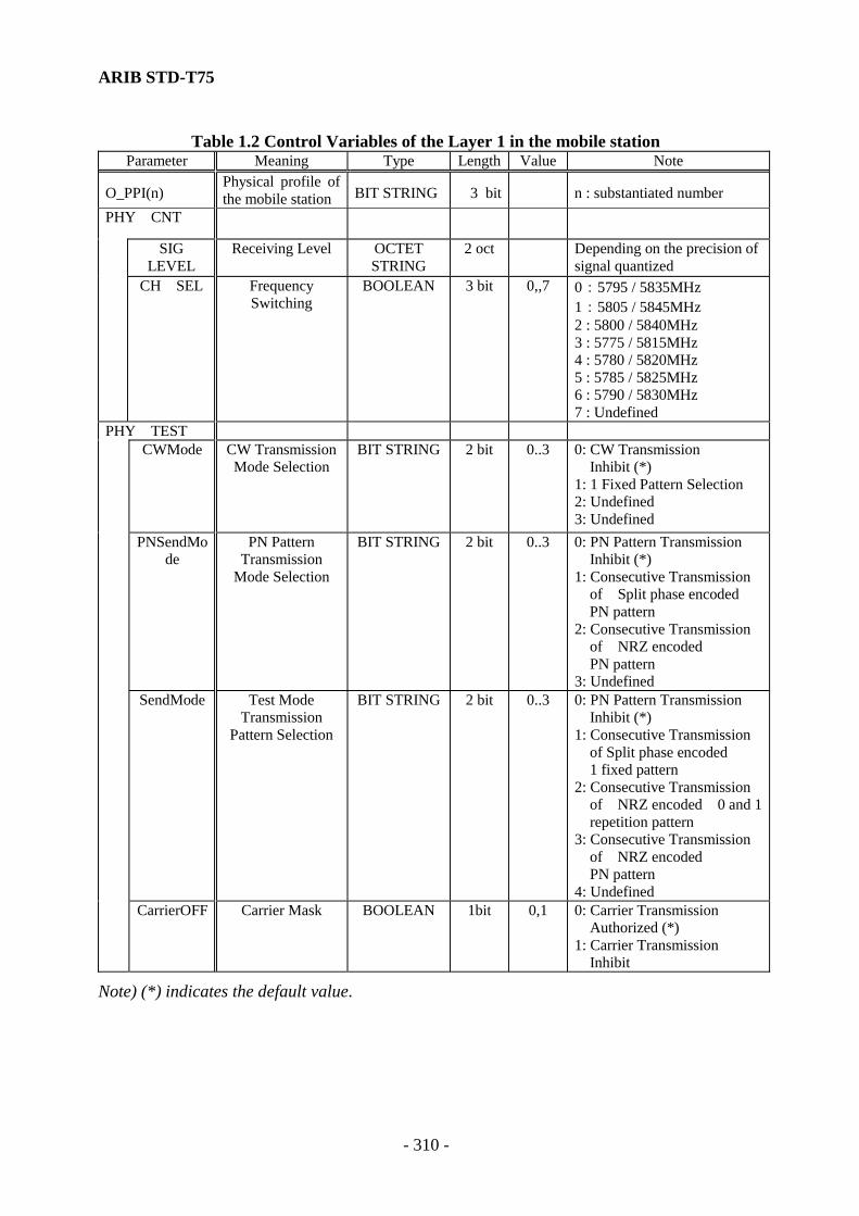
ARIB STD-T75
- 310 -
Table 1.2 Control Variables of the Layer 1 in the mobile station Parameter Meaning Type Length Value Note
O_PPI(n) Physical profile of the mobile station BIT STRING 3 bit n : substantiated number
PHY CNT
SIG
LEVEL Receiving Level OCTET
STRING 2 oct Depending on the precision of
signal quantized
CH SEL Frequency
Switching BOOLEAN 3 bit 0,,7 0:5795 / 5835MHz
1:5805 / 5845MHz 2 : 5800 / 5840MHz 3 : 5775 / 5815MHz 4 : 5780 / 5820MHz 5 : 5785 / 5825MHz 6 : 5790 / 5830MHz 7 : Undefined
PHY TEST
CWMode CW Transmission
Mode Selection BIT STRING 2 bit 0..3 0: CW Transmission
Inhibit (*) 1: 1 Fixed Pattern Selection 2: Undefined 3: Undefined
PNSendMo
de PN Pattern
Transmission Mode Selection
BIT STRING 2 bit 0..3 0: PN Pattern Transmission Inhibit (*) 1: Consecutive Transmission of Split phase encoded PN pattern 2: Consecutive Transmission
of NRZ encoded PN pattern
3: Undefined
SendMode Test Mode
Transmission Pattern Selection
BIT STRING
2 bit 0..3 0: PN Pattern Transmission Inhibit (*) 1: Consecutive Transmission of Split phase encoded 1 fixed pattern 2: Consecutive Transmission of NRZ encoded 0 and 1 repetition pattern 3: Consecutive Transmission of NRZ encoded
PN pattern 4: Undefined
CarrierOFF Carrier Mask BOOLEAN 1bit 0,1 0: Carrier Transmission
Authorized (*) 1: Carrier Transmission
Inhibit
Note) (*) indicates the default value.

ARIB STD-T75
- 311 -
2. Layer 2 2.1 Value of Timer Counter used in MAC sublayer (see subclause 4.3.3.4) (1) Maximum value of Retry Counter in the base station (downlink MDC) (NFR1max) NFR1max shall be 127at maximum. (2) Maximum value of Retry Counter in the base station (uplink MDC) (NFR2max) NFR2max shall be 127at maximum. (3) Maximum value of Retry Counter in the mobile station (uplink MDC) (NMRmax) NMRmax shall be 127 at maximum. (4) Maximum value of Link Request Counter in the mobile station (NRQmax) NRQmax shall be 127 at maximum. (5)Re-link Entry Request Constraint Counter (NRT) [Informative] According to the Status of State of acceptance of ACTCs (STA) as shown in Table 4.2.4.2.1.8.1-4, the value shall be as shown in Table 2.1-1.
Table 2.1-1 Values of Re-link Request Constraint Counter
STA subfield b7 b8
Status of Receiving ACTC
NRT
0 0 100 ~50% RT1 ( = 1) 1 0 ~25% RT2 ( = 2) 0 1 ~12.5% RT3 ( = 4) 1 1 ~0% RT4 ( = 4)
State of acceptance of ACTCs (6) Value of Receiving ACTC (TRA) [Informative] State of acceptance of ACTCs(STA), shown in Table 4.2.4.2.1.8.1-4, shall be specified as shown in Table 2.1-2 according to the Value of Receiving ACTC.
Table 2.1-2 Values of receiving ACTC (TRA) STA subfield
b7 b8 Status of
Receiving ACTC
TRA ( = MAXLINK- NUMLINK )
0 0 100 ~50% SLI ( = MAXLINK) 1 0 ~25% SL2 ( = MAXLINK/2) 0 1 ~12.5% SL3( = MAXLINK/4) 1 1 ~0% SL4 ( = MAXLINK/8)
ARIB STD-T75
- 312 -
(7) The maximum number of the base station connection variable(MAXLINK) [Informative] MAXLINK shall be greater than the number of slots available as MDSs. (8) The maximum number of the base station ACTC assignment variable (ASLNmax) ASLNmax shall be less than 3 at maximum. (9) The maximum number of the mobile station WCNC transmission counter (WTCmax) WTCmax shall be 2. (10) Threshold value of the base station transmission status (FQBUSY) [Informative] The FQBUSY shall be 90% of the queue capacity for transmission. (11) Threshold value of the mobile station transmission status (MQBUSY) [Informative] The MQBUSY shall be 90% of the queue capacity for transmission.
2.2 Timer, Counter and Field Length used in the LLC sublayer (See subclause 4.3.4.5.5) (1) Maximum number of Octets in a PDU in the LLC sublayer (N10) The maximum number for N10 is not defined in this standard. (2) Minimum number of octets in a PDU in the LLC sublayer. Minimum number of octets in a Command PDU shall be 1 octet. Minimum number of octets in a Response PDU shall be 2 octets. (3) Maximum Number of Transmissions by the LLC sublayer (N11). N11 shall be 127 at maximum. (4) Response (acknowledgement) time in the LLC sublayer of the base station (N13FE) N13FE is the time corresponding to 1 frame. (5) Response (acknowledgement) time of the LLC sublayer of the mobile station (N13ME) N13ME is the time corresponding to 1 frame.

ARIB STD-T75
- 313 -
2.3 Management Information Base (MIB) [Informative]
Table2.3-1 Variables of Frame Control Message Channel (FCMC)
Parameter Meaning Type Length Value Note
FCMC
SIG
PVI Protocol Version Information field
BIT STRING 2 bit 0..3
PPI Physical Profile Identifier BIT
STRING 3 bit
FTI Frequency Type Identifier BIT STRING 2 bit
CCZ Continuous Communication Zone Identifier
BIT STRING 1 bit
TRI Transmitter / Receiver Identifier
BIT STRING 2 bit
TDI Time Division Identifier BIT STRING 1 bit
ATI Area Type Identifier BIT STRING 2 bit
FID Fixed Equipment ID OCTET STRING 1 bit
FSI
CM Communication Mode Identifier
BIT STRING 1 bit
SLN Slot Number Information Field
BIT STRING 3 bit
RLT
VALID
Release Timer Validation Identifier
BIT STRING 1 bit
VALUE Release Time Value BIT
STRING 7 bit
SC Service Code OCTET STRING 7 oct
SCI(n) n = 1..8
CI Control Information Subfield
OCTET STRING 1 oct
See Table2.3.-2, Table2.3.-3 and Table2.3.-4
LID Link Address Field OCTET
STRING 4 oct
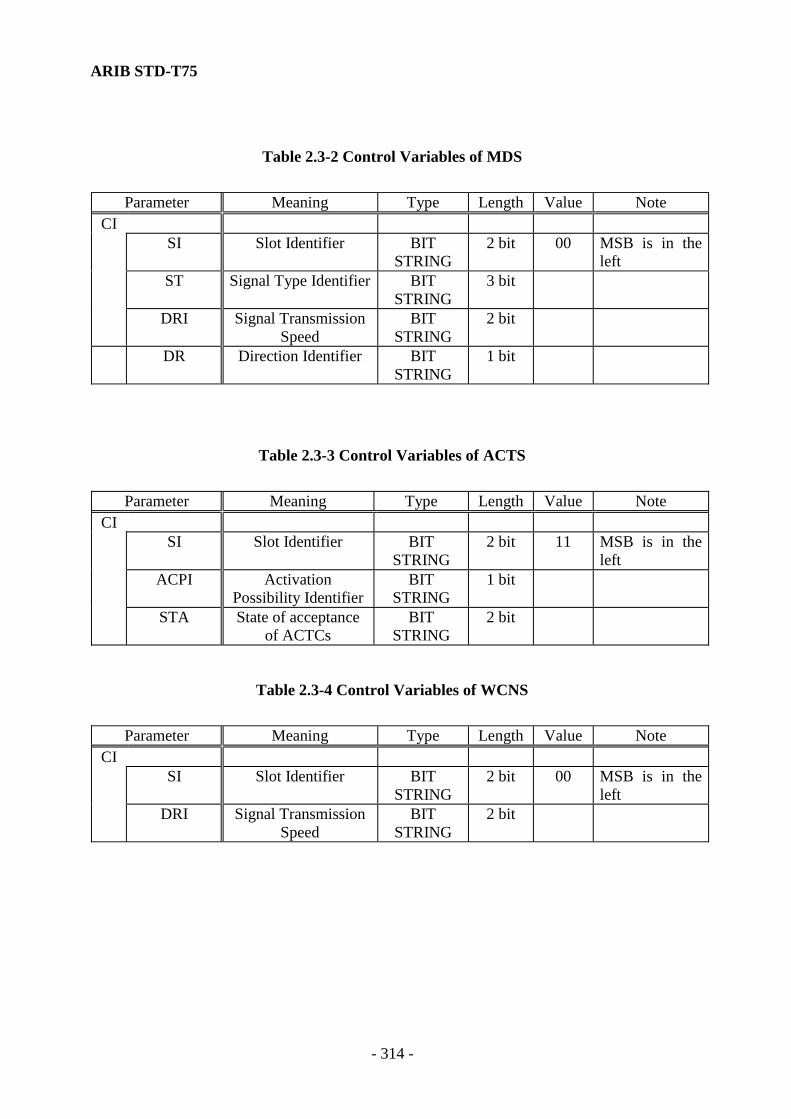
ARIB STD-T75
- 314 -
Table 2.3-2 Control Variables of MDS
Parameter Meaning Type Length Value Note
CI SI Slot Identifier BIT
STRING 2 bit 00 MSB is in the
left ST Signal Type Identifier BIT
STRING 3 bit
DRI Signal Transmission Speed
BIT STRING
2 bit
DR Direction Identifier BIT STRING
1 bit
Table 2.3-3 Control Variables of ACTS
Parameter Meaning Type Length Value Note
CI SI Slot Identifier BIT
STRING 2 bit 11 MSB is in the
left ACPI Activation
Possibility IdentifierBIT
STRING 1 bit
STA State of acceptance of ACTCs
BIT STRING
2 bit
Table 2.3-4 Control Variables of WCNS
Parameter Meaning Type Length Value Note CI SI Slot Identifier BIT
STRING 2 bit 00 MSB is in the
left DRI Signal Transmission
Speed BIT
STRING 2 bit

ARIB STD-T75
- 315 -
Table2.3-5 (1) Variables of the MAC sublayer in the base station Parameter Meaning Type Length Value Note
FMAC_PVI Protocol Version of the base station
BIT STRING 2bit Stored as SIG,PVI in FCMC
ASGN
LID Link Address Field OCTET STRING 4 oct DIR Direction BIT STRING 1 bit 1: Uplink
0: Downlink RS Response BIT STRING 1 bit 1: Response
0: No Response PR Priority BIT STRING 1 bit 1: Priority Assignment
0: Normal Assignment FMAC_CNT
MAXLINK Maximum Number of Link
Connections
INTEGER 1 oct 0..127
NUMLINK Current Number of Link Connections
INTEGER 1 oct 0..127
ASLNmax Number of ACTS Location
INTEGER 1 oct 0..3
FQBUSY Threshold value of Transmission State
INTEGER 1 oct 0..127
SL1 Threshold value of Transmission State
INTEGER 1 oct SL1 < SL2
SL2 Threshold value of Transmission State
INTEGER 1 oct SL2 > SL3
SL3 Threshold value of Transmission State
INTEGER 1 oct SL3 > SL4
SL4 Threshold value of Transmission State
INTEGER 1 oct
NFR1max Maximum value of Retry Counter in
Base Station (BS)
INTEGER 1 oct 0..127 Downlink
NFR2max Maximum value of Mobile Station
Retry Counter in Base Station
INTEGER 1 oct 0..127 Uplink
FMAC_ STATUS ASLN Number of ACTS
Location INTEGER 1 oct 0. .
ASLNmax
NUMQ Status value of Transmission
Queue
INTEGER 1 oct 0..127 1: busy 0: idle
TR_STATUS Transmission State Variable
BOOLEAN 1 bit 1: out time 0: in time
SLT_STATUS
State Variable of Slot Assignment
BOOLEAN 1 bit n = 1..8
FMAC_RETRY(n) n = 1..8 NFR1 Retry Counter in
Base Station (BS) INTEGER 1 oct 0..127 Downlink
NFR2 Mobile Station Retry Counter in
Base Station
INTEGER 1 oct 0..127 Uplink

ARIB STD-T75
- 316 -
Table2.3-5 (2) Variables of the MAC sublayer in the base station Parameter Meaning Type Length Value Note
FMAC_SEQ(m) m = 1…MAXLINK TSQ State Variable
of Transmit Sequence
INTEGER 1 oct 0..7
TSQ2(n) N=0..7
TSQ2(n).DUP
Duplication inspection state
variable
BOOLEAN 1 bit 0,1
TSQ2.ACK
Delivery confirmation state variable
BOOLEAN 1 bit 0,1 0: Nack 1: Ack
RSQ(n) State Variable of Receiving Sequence
BOOLEAN 1 bit 0,1 N= 0..7
FMAC_TEST
ACK_MASK
Mask Variable of ACKC
Transmission Process
BOOLEAN 1 bit 0,1 0:Transmission admitted (*)1:Transmission inhibit
RETRY_MASK
Mask Variable of Retry Process
BOOLEAN 1 bit 0,1 0:Retry process admitted (*)1:Retry process prohibit
CRC_MASK
Mask Variable of CRC
BOOLEAN 1 bit 0,1 0: CRC effective (*) 1: CRC invalid ( Does not
destroy receiving data) CRC_ERR(
n) Number of CRC
Errors INTEGER 2 oct 0..32767 Accumulation value of CRC
Errors on each slot. When it overflows, -1 shall be set and further accumulation shall be prohibited. n = 1..8
Note) (*) indicates the default value.

ARIB STD-T75
- 317 -
Table2.3-6 Variables of LLC sublayer in the base station
Parameter Meaning Type Length Value Note
FLLC_CNT N10 Maximum Value of
Octets in an LPDU INTEGER 2 oct 1 octet / bit
N11 Maximum Number of Transmissions
INTEGER 1 oct 0..127
N13FE Response Time INTEGER 2 oct FLLC_STATUS(m)
m = 1.. MAXLINK
V(SI) Transmit State Sequence Variable
BOOLEAN 1 bit 0,1
V(RI) Receive State Sequence Variable
BOOLEAN 1 bit 0,1
V(RB) Reception Status State Variable
OCTET STRING
1 oct
Table2.3-7 (1) Variables of MAC sublayer in the mobile station
Parameter Meaning Type Length Value Note OMAC_PVI(n) Protocol version of
the mobile station BIT
STRING 2 bit n: number of
substance ACTC
FID Fixed Equipment ID OCTET STRING
1 oct
LID Link Address OCTET STRING
4 oct
LRI Link Request Information Field
OCTET STRING
1 oct See Table 2.3.-8
OMAC_CNT IDNR ID Number BIT
STRING 63 bit See Annex C
NRQmax Maximum Number of Link Requests
INTEGER 1 oct 0..127
RT1 Limiting Cycle of Link Request
INTEGER 1 oct 1frame / bit RT1 < RT2
RT2 Limiting Cycle of Link Request
INTEGER 1 oct 1frame / bit RT2 < RT3
RT3 Limiting Cycle of Link Request
INTEGER 1 oct 1frame / bit RT3 < RT4

ARIB STD-T75
- 318 -
Table2.3-7 (2) Variables of MAC sublayer in the mobile station Parameter Meaning Type Length Value Note
OMAC_CNT RT4 Limiting Cycle of Link
Request INTEGER 1 oct 1 frame / bit
MQBUSY Threshold value of Transmission State
INTEGER 1 oct 0..127
NMRmax Maximum Number of Retries INTEGER 1 oct 0..127 WTCmax Maximum Number of
WCNC Transmissions INTEGER 1 oct 2
OMAC_STATUS NRQ Maximum Number of Link
Requests INTEGER 1 oct 0..127
NRT Limiting Counter of RetryLink Request
INTEGER 1 oct 0..127
NMR Number of Retries INTEGER 1 oct 0..127 NUMQ Status Value of Transmission
Queue INTEGER 1 oct 0..127
TR _STATUS Transmission State Variable BOOLEAN 1 bit 1: busy, 0 : idle TSQ Transmit State Sequence
Variable INTEGER 1 oct 0..7
TSQ2(n) n= 0..7 TSQ2.DUP Duplication inspection state
variable BOOLEAN 1 bit 0,1
TSQ2.ACK Delivery confirmation state variable
BOOLEAN 1 bit 0,1 0:Nack 1:Ack
RSQ(n) State Variable of Receiving Sequence
BOOLEAN 1 bit 0,1 n= 0..7
WTC Number of WCNC Transmissions
INTEGER 1 oct 0..3
OMAC_TEST ACK_MASK Mask Variable of ACKC
Transmission Process BOOLEAN 1 bit 0,1 0 :Transmission
admitted (*) 1 :Transmission
inhibit RETRY_MASK Mask Variable of Retry
Process BOOLEAN 1 bit 0,1 0 : Retry process
admitted (*) 1 : Retry process
inhibit CRC_MASK Mask Variable of CRC BOOLEAN 1 bit 0,1 0 : CRC effective (*)
1 : CRC invalid ( No receiving data
destroyed ) CRC_ERR Number of CRC Errors INTEGER 2 oct 0..32767 Accumulation value
of CRC Errors on each slot. When it overflows, -1 shall be set and further accumulation shall be inhibited. n = 1..8
Note) (*) indicates the default value.

ARIB STD-T75
- 319 -
Table2.3-8 Variables of Link Request Information
Parameter Meaning Type Length Value Note
LRI PR ID Information of
Priority Assignment BIT
STRING 1 bit
INIT ID Information of Initialization Mode
BIT STRING
1 bit
RES PVI Protocol Version Response
BIT STRING
2 bit
RES AID ID Information of Application
BIT STRING
4 bit
Table2.3.9 Variables of LLC sublayer in On Board Equipment
Parameter Meaning Type Length Value Note OLLC CNT
N10 Maximum Value of Octets in an LPDU
INTEGER 2 oct 1 octet / bit
N11 Maximum Number of Transmissions
INTEGER 1 oct 0..127
N13ME Response Time INTEGER 2 oct OLLC STATUS
V(SI) Transmit State Sequence Variable
BOOLEAN 1 bit 0,1
V(RI) Receive State Sequence Variable
BOOLEAN 1 bit 0,1
V(RB) Reception Status State Variable
OCTET STRING
1 oct
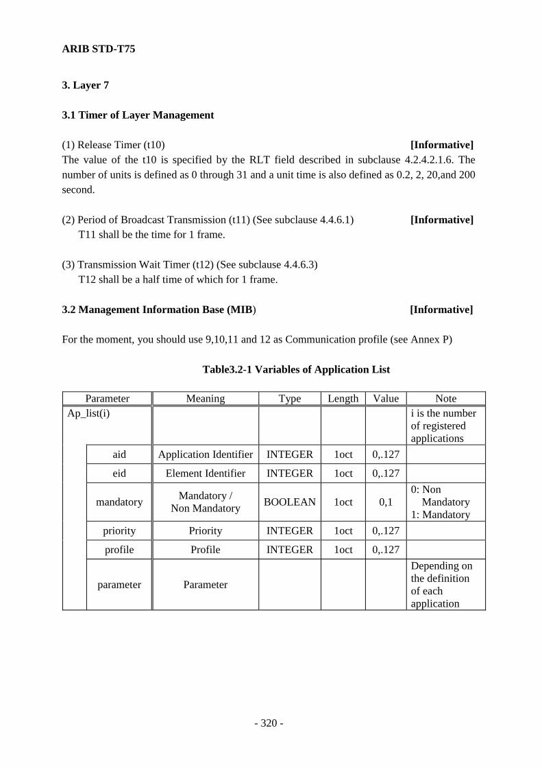
ARIB STD-T75
- 320 -
3. Layer 7 3.1 Timer of Layer Management (1) Release Timer (t10) [Informative] The value of the t10 is specified by the RLT field described in subclause 4.2.4.2.1.6. The number of units is defined as 0 through 31 and a unit time is also defined as 0.2, 2, 20,and 200 second. (2) Period of Broadcast Transmission (t11) (See subclause 4.4.6.1) [Informative] T11 shall be the time for 1 frame. (3) Transmission Wait Timer (t12) (See subclause 4.4.6.3) T12 shall be a half time of which for 1 frame. 3.2 Management Information Base (MIB) [Informative] For the moment, you should use 9,10,11 and 12 as Communication profile (see Annex P)
Table3.2-1 Variables of Application List
Parameter Meaning Type Length Value Note Ap_list(i)
i is the number of registered applications
aid Application Identifier INTEGER 1oct 0,.127
eid Element Identifier INTEGER 1oct 0,.127
mandatory Mandatory / Non Mandatory BOOLEAN 1oct 0,1
0: Non Mandatory
1: Mandatory
priority Priority INTEGER 1oct 0,.127
profile Profile INTEGER 1oct 0,.127
parameter Parameter
Depending on the definition of each application
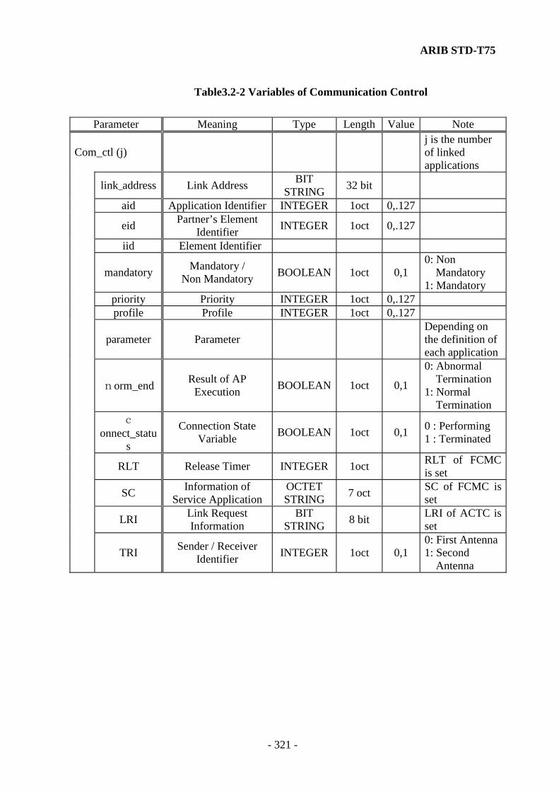
ARIB STD-T75
- 321 -
Table3.2-2 Variables of Communication Control
Parameter Meaning Type Length Value Note
Com_ctl (j) j is the number of linked applications
link_address Link Address BIT STRING 32 bit
aid Application Identifier INTEGER 1oct 0,.127
eid Partner’s Element Identifier INTEGER 1oct 0,.127
iid Element Identifier
mandatory Mandatory / Non Mandatory BOOLEAN 1oct 0,1
0: Non Mandatory 1: Mandatory
priority Priority INTEGER 1oct 0,.127 profile Profile INTEGER 1oct 0,.127
parameter Parameter Depending on the definition of each application
norm_end Result of AP Execution BOOLEAN 1oct 0,1
0: Abnormal Termination
1: Normal Termination
c
onnect_status
Connection State Variable BOOLEAN 1oct 0,1 0 : Performing
1 : Terminated
RLT Release Timer INTEGER 1oct RLT of FCMC is set
SC Information of Service Application
OCTET STRING 7 oct SC of FCMC is
set
LRI Link Request Information
BIT STRING 8 bit LRI of ACTC is
set
TRI Sender / Receiver Identifier INTEGER 1oct 0,1
0: First Antenna1: Second
Antenna

ARIB STD-T75
- 322 -
Table3.2-3 Proprietary Information of the base station
Parameter Meaning Type Length Value Note
Beacon man_id Manufacturer ID INTEGER 2oct 0,.65535 ind_id Device ID INTEGER 4oct 0,...
BEACON_CNT
t11 Period of Broadcast Transmission INTEGER 1oct 0,.127 Used by B-KE
t12 Transmission Waiting Timer INTEGER 1oct 0,.127 Used by T-KE
profile Communication Profile INTEGER 1oct 0,.127 9,10,11,12
time Current Time INTEGER 5oct 0,...
Table3.2-4 Proprietary Information of the mobile station
Parameter Meaning Type Length Value Note obe_conf
eq_class Equipment Class INTEGER 2oct 0,.32767 man_id Manufacturer ID INTEGER 2oct 0,.65535 obe_status Mobile station Status INTEGER 2oct 0,.65535
OBE CNT
t12 Transmission Waiting Timer INTEGER 1oct 0,.127 Used by T-KE
profile Communication Profile INTEGER 1oct 0,.127 9,10,11,12
time Current Time INTEGER 5oct 0,... Option

ARIB STD-T75
- 323 -
4. System Management 4.1 Failure Detection Timer of the mobile station The t9, maximum value of Failure Detection Timer, shall be greater than 60 seconds. 4.2 Management Information Base (MIB) [Informative] The agent manages the variables to be used in Procedure element of the function assigned to System Management. It is added according to the contents of Application for Management. The agent also manages such variable as a Management Variable of each layer, which is not able to set the value autonomously (i.e. the set value is unknown) and requires to be preserved.
Table4.2-1 Management Variables of the base station
Parameter Meaning Type Length Value Note
FCMC FCMC Variable See Annex A, Table 2.3.-1
FMAC_CNT Control Variable of
MAC sublayer in the base station
See Annex A, Table 2.3.-5
FLLC_CNT Control Variable of LLC sublayer in the
base station See Annex A,
Table 2.3.-6
beacon Proprietary Information of The base station See Annex A,
Table 3.3.-3
BEACON_CNT Proprietary Information of the base station See Annex A,
Table 3.2.-3
Table4.2-2 Management Variables of the mobile station
Parameter Meaning Type Length Value Note
OMAC_CNT Control Variable of
MAC sublayer in the mobile station
See Annex A,
Table 2.3.-7
OLLC_CNT Control Variable of LLC sublayer in the
mobile station See Annex A,
Table 2.3.-9
obe_conf Proprietary Information of the mobile station See Annex A,
Table 3.2.-4
OBE_CNT Proprietary Information of the mobile station See Annex A,
Table 3.2.-4 t9 Failure Detection Timer INTEGER 1 oct 0..60 1 second / bit

ARIB STD-T75
- 324 -
Annex B. Communication Environment [Informative] This annex describes the communication environment assumed in the standards of the layer 2 and the layer 7.
1. Basic Classifications of Communication Environment The following shows the basic classifications of communication environment. AP and the FID represent an application (communication service user) and an identifier of BS (Base Station), respectively.
(1) Classification A: Presence of Overlapping Communication Areas Separate (Sep.) : Each BS has its own Communication area separately. Overlap (Ovr.) : Communication areas of plural BS are overlapped. (2) Classification B: Communication Links when plural BSs exist (location of BSs) Normal: BSs are not in the closest positions to each other (some communication areas may be overlapped). Real Time: Plural BSs are very close each other. (including when both separated and overlapped communication areas may exist. “Very close” means here that plural BSs are located so close that mobile stations mistakes to associate with next true BS, because plural BSs are using Release Timer to prevent to associate for a certain period after end communication. For example, an Mobile Station moves between different communication areas of BSs in less than a few seconds. However, even when the communication areas of BSs exist closely, but both communication areas are wide and the association prevented by the Release Timer causes no trouble. These cases are not included . ) (3) Classification C: Classification of the Communication Transactions (Applications) performed in each BSs when plural BSs exist. Same Application(AP Same): The same contents of communication (i.e. the contents of communication frame) are performed in plural BSs. The same FID is used in the BSs. Parallel Application(AP Parallel): The different contents of communication are performed with the same transaction in plural BSs, so the multi-transaction is not necessary. The different FIDs are used in the BSs when they exist closely. The number of BSs is not defined. Generally, BSs are located transversely. Independent Application (Ap ind.): The transactions are performed in plural BSs independently. The different FIDs are used in the BSs when they exist closely. The numbers of BSs are not defined.
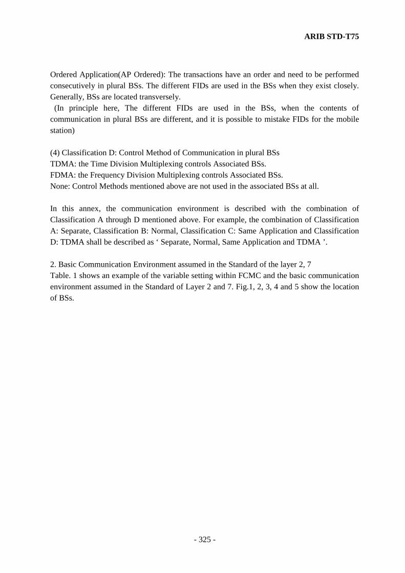
ARIB STD-T75
- 325 -
Ordered Application(AP Ordered): The transactions have an order and need to be performed consecutively in plural BSs. The different FIDs are used in the BSs when they exist closely. Generally, BSs are located transversely. (In principle here, The different FIDs are used in the BSs, when the contents of communication in plural BSs are different, and it is possible to mistake FIDs for the mobile station) (4) Classification D: Control Method of Communication in plural BSs TDMA: the Time Division Multiplexing controls Associated BSs. FDMA: the Frequency Division Multiplexing controls Associated BSs. None: Control Methods mentioned above are not used in the associated BSs at all. In this annex, the communication environment is described with the combination of Classification A through D mentioned above. For example, the combination of Classification A: Separate, Classification B: Normal, Classification C: Same Application and Classification D: TDMA shall be described as ‘ Separate, Normal, Same Application and TDMA ’. 2. Basic Communication Environment assumed in the Standard of the layer 2, 7 Table. 1 shows an example of the variable setting within FCMC and the basic communication environment assumed in the Standard of Layer 2 and 7. Fig.1, 2, 3, 4 and 5 show the location of BSs.

ARIB STD-T75
- 326 -
Table.1 (1) Examples of Variables Setting within FCMC and Basic Communication Environment assumed in the Standard of the layer 2 and the layer 7
Case No.
A Zone
Location
B Communic
ation Link
C AP
Environment
D Communication Control
BS Location
CCZ TRI TDI FID Association
Note
1 Sep. Normal AP Same Fig.3 0 xx 0 Same possible 2 BSs arranged in Traveling Direction (*1)
2 Sep. Normal AP Parallel
Fig.1 0 00 0 Dif-feren
t
possible Arranged transversely ( Adjacent BSs )
3 Sep. Normal AP Inde- pendent
Fig.1,3,4
0 00 0 Dif-feren
t
possible Arranged normally
4 Sep. Normal AP Ordered
Fig.3,4
0 00 0 Dif-feren
t
possible Depending on the Application
5 Sep. Real Time AP Same TDM Fig.3 0 xx 1 Same possible 2 BSs arranged in Traveling Direction (*1)
6 Sep. Real Time AP Same FDM Fig.3 0 xx 0 Same Not assumed
2 BSs arranged in Traveling Direction (*2)
7 Sep. Real Time AP Same None Fig.3 0 xx 0 Same Partly limited
2 BSs arranged in Traveling Direction (*2)
8 Sep. Real Time AP Parallel
Fig.1 0 00 0 Dif-feren
t
possible Same as Case 2 ( No meaning of Real Time )
9 Sep. Real Time AP Inde- pendent
TDM Fig.3 1 xx 1 Dif-feren
t
possible 2 BSs arranged in Traveling Direction (*3)
( Frequency Selection Process can be omitted )
10 Sep. Real Time AP Inde- pendent
FDM None
Fig.3 1 xx 1 Dif-feren
t
Partly limited
2 BSs arranged in Traveling Direction (*4) (Frequency Selection Process can not be omitted)
11 Sep. Real Time AP Ordered
TDM Fig.3 1 xx 1 Dif-feren
t
possible 2 BSs arranged in Traveling Direction (*3) (Frequency Selection Process can be omitted)
12 Sep. Real Time AP Ordered
FDM None
Fig.3 1 xx 0 Dif-feren
t
Partly limited
2 BSs arranged in Traveling Direction (*4) (Frequency Selection Process can not be omitted)
13 Ovr. Normal AP Same TDM Fig.2,5
0 xx 1 Same possible Same Application overlapped (*5)

ARIB STD-T75
- 327 -
Table.1 (2) Examples of Variables Setting within FCMC and Basic Communication Environment assumed in the Standard of the layer 2 and the layer 7
Case No.
A Zone Loca-
tion
B Commu- nication
Link
C AP
Environ- ment
D Commu- nication Control
BS Loca-tion
CCZ TRI TDI FID Associ- ation
Note
14 Ovr. Normal AP Parallel
TDM Fig.2 0 00 1 Dif-feren
t
possible Same Application overlapped
15 Ovr. Normal AP Inde- pendent
TDM Fig. 2,5
0 00 1 Dif-feren
t
possible Different Applications overlapped
16 Ovr. Normal AP Ordered
TDM Fig.5 0 00 1 Dif-feren
t
possible Ordered Applications overlapped
17 Ovr. Real Time
AP Same TDM Fig. 2,5
0 xx 1 Same possible Same Application overlapped (*5)
18 Ovr. Real Time
AP Parallel
TDM Fig.2 0 00 1 Dif-feren
t
possible Same as Case 14 ( No meaning of Real Time )
19 Ovr. Real Time
AP Inde- pendent
TDM Fig.5 1 xx 1 Dif-feren
t
possible 2 BSs arranged in Traveling Direction (*3) (Frequency Selection Process can be omitted)
20 Ovr. Real Time
AP Ordered
TDM Fig.5 1 xx 1 Dif-feren
t
possible 2 BSs arranged in Traveling Direction (*3) (Frequency Selection Process can be omitted)
21 Ovr. Norma - FDM None
Fig.6 0 xx 0 Dif-feren
t
Not assumed
Not assumed at this stage
22 Ovr. Real Time
AP Inde- pendent
FDM Fig.60 xx 0
Dif-feren
t
possible Assumed adaptation of plural Qos
23 Ovr. Real Time
AP Same AP
Parallel AP
Ordered
FDM Fig.60 xx 0
Dif-feren
t
Not assumed
Not assumed at this stage
24 Ovr. - - None Fig. 2,5,6
- - - - Not assumed
Not assumed at this stage
Notes) (*1) If Transmitter / Receiver Identifier (TRI) is not used, the configuration of more than 3 components is feasible. (*2) If Transmitter / Receiver Identifier (TRI) is not used, the configuration of more than 3 components is feasible. However, the linkage is difficult when the frequency is different.

ARIB STD-T75
- 328 -
(*3) Due to the problem of association, the configuration of more than 3 components in traveling direction is not feasible. (*4) The association is feasible but the Frequency Selection Process can not be omitted. (*5) If Transmitter / Receiver Identifier (TRI) is not used, the configuration of more than 3 BS components is feasible. (*6) In this table, x indicates that any possible case can be applied. (*7) In this table, except for the case clearly defined, the detailed problems of interference between BSs and the transmission time of applications are not considered.

ARIB STD-T75
- 329 -
Traveling Direction Traveling Direction
Fig.1 BSs arranged transversely Fig.2 BSs arranged transversely
Their communication zone
Traveling Direction Traveling Direction
Fig.3 BSs arranged in Traveling Direction
Fig.4 BSs arranged in Traveling Direction
Traveling Direction
Fig.5 BSs arranged in Traveling Direction
Their communication zone overlapped Fig.6 BS communication zone
contained in another zone
(including 2communication zones are
same shape and overlapped)
Traveling Direction
Fig.7 Communication zones of BSs overlapped and arranged at regular intervals
(Combination of the communication zone showed in Fig.2 and Fig.3)

ARIB STD-T75
- 330 -
3. Combined Communication Environment There are so many combinations of the Communication Environment described in the preceding paragraph. For a typical but complex example, the case that BSs with their communication areas overlapped and transversely located, sequentially communicate in the traveling direction (Fig.7) can be assumed. Only this case is considered in this paragraph. The case that BSs with their communication environment overlapped transversely and perform the same contents of transaction, is described as “Overlap, Normal, AP same or AP Parallel and TDMA” according to the Classification shown in the preceding paragraph. And the case that BS sequentially communicate in the traveling direction can be described as “ Separate, x, AP Ordered and x”. These cases can be described in Table 2.
Table. 2 Adaptation to Combination of Communication Environment
Transverse
Arrangement Traveling Direction
Arrangement
Case Zone Link
AP Environ-ment
Con-trol
Area LinkAP
Environ-ment
Con-trol
Adapta-tion
Note
No.1 BS CCZ,TRI,TDI( *5 )
No.2 BSCCZ,TR
I, TDI( *5
) 1 Ovr.
Nor-m
al AP
Same TDM
Separate
Normal
AP ordere
d
X Possible Association in traveling
direction is Feasible
0,00,X 0,00,X
2 Ovr.
Nor-mal
AP Same
TDM
Separate
Real Time
AP ordere
d
TDM
Possible Two BSs in traveling
direction (*1)
1,01,1 1,10,1
3 Ovr.
Nor-mal
AP Same
TDM
Separate
Real Time
AP ordere
d
FDM
None
Partly limited
(*3)
Two BSs in traveling
direction (*2)
1,01,0 1,10,0
4 Ovr.
Nor-mal
AP Paralle
l
TDM
Separate
Normal
AP ordere
d
X Possible Association in traveling
direction is Feasible
0,00,X 0,00,X
5 Ovr.
Nor-mal
AP Paralle
l
TDM
Separate
Real Time
AP ordere
d
TDM
Possible Two BSs in traveling
direction (*1)
1,01,1 1,10,1
6 Ovr.
Nor-mal
AP Paralle
l
TDM
Separate
Real Time
AP ordere
d
FDM
None
Partly limited
(*3)
Two BSs in traveling
direction (*2)
1,01,0 1,10,0
Notes) (*1) There is no BS recognition for Transverse Arrangement. And Frequency Selection Process can be omitted. In the case that the association is feasible, The number of BSs in the traveling direction is up to 2.

ARIB STD-T75
- 331 -
(*2) There is no BS recognition for Transverse Arrangement. Frequency Selection Process can not be omitted unless the BSs arranged in traveling direction use the same frequency. In the case that the association is feasible, the number of BSs in the traveling direction is up to 2. (*3) It means that the BS can be adapted, in the case that the time of Frequency Selection causes no problem.
(*4) After the termination of Frequency Selection Process (Not only the termination of normal transmission) between an MS and No.1 BS (CCZ=1) using Time Division (TDI= 1), Frequency Selection Process between the MS and No.2 BS can be simplify. Although it is assumed that a layer of higher order than Layer 2 might request Frequency Selection Process in the various communication environment (for example, locking of Frequency Selection Process for a fixed period of time to perform the next association promptly, in the case of normal / abnormal termination of transmission and so on), The adoption of these procedure is entrusted the manufacturer’s discretion.
(*5) In this case, it is assumed that the FIDs of BSs are different.
4. Overlapped Communication Environment (1) Overlapped communication zone It is necessary to consider influences of overlapped communication zones about the connecting with mobile stations and the performing applications in the case described as Paragraph 1 that communication zones of plural base stations are overlapped. in Table 1 of Paragraph 1, these are classified as case No 13 through 24 . The connection between mobile stations and base stations in overlapped communication zones is related to the relative position of communication zones and the Traveling Direction of mobile stations. That is , as Case No 16 and so on, it is assumed occasionally that mobile stations connect the closer base station, their application perform and end continuously, then connect the next base station. In this case, the association of the performed application by the closer base station and the performed application by the next base station depends on the procedure of application. (The Case No16 is ordered application.) The other side, as Case No 14, it is necessary to consider the accidental nature on time axis about which base stations are selected when a mobile station enter overlapped communication zones (TDMA) at the same time. It is necessary to pay attention to above restrictions in particular , when applications of each communication zones. In Case No 24 described in Table 1 of Paragraph 1, described as Base station Communication

ARIB STD-T75
- 332 -
zones and other base station communication zones are overlapped and different frequency communication zones in same areas are overlapped. In Fid 5 and 6, it is assumed occasionally that depending on how to overlap for both communication zones, connecting to the closer base station and performing the application and end ,then connecting to the next base station. But How to connect depends on Frequency Selection Process of the mobile station mainly when almost same size communication zones described at Fig 2 and 6. Frequency Selection Process is described in Annex E of this standard, according to above points , it is described focusing the association overlapped communication zones. (2) Frequency Selection Process in overlapped communication zone a. Frequency Selection Process In overlapped communication zones, it is possible to perform a combination with others and a normal application described as Frequency Selection Process in Annex E. As other procedures, for example, the first procedure is that the mobile station select a channel by detecting AID information, etc in FCMC after scanning each frequency. The Second procedure is that the mobile station focus next frequency group expected by adapting the information of application or setting the priority of frequency selection (including priority channel). The third procedure is that the mobile station manages the priority of frequency selection cyclic by storing the sequence of receive frequency. The fourth procedure is that the mobile station select by comparing both level in zones of base stations. However, above and other procedures depend on the application or the installation, normal frequency selection process shall be use as precondition, other procedures are out of scope in this standard. b. Channel changeover If it is possible for a mobile station to change the frequency channel to the other base station in succession to a transaction with one base station within an overlapped communication zone, a processing procedure in which instructions such as frequency data to be handed over are transmitted from the base station to the mobile station during a transaction based on an application, can be considered. This procedure, however, depends on applications and installation. Therefore, it is not specified in the DSRC protocol stack within the scope of this standard.
ARIB STD-T75
- 333 -
c. Priority channel Designation of the base station frequency is, of course, outside the scope of this standard, but it is desirable to apply a priority channel when forming an overlapped communication zone if it is effective in frequency selection for a mobile station. d. Number of frequency channels This standard assumes that an overlapped communication zone is comprised of two communication zones that use one different frequency channel, forming an FDMA environment with two frequencies in total.

ARIB STD-T75
- 334 -
Annex C. WCNC (Call sign) format (Equipment: No. 9, Article 9 - 4, enforcement: No. 2, Article 6 - 2, Notification No)
1. The configuration of the Wireless Call Number Channel (WCNC; Call sign) shall comply with the following specification. Each mobile station and test equipment shall have a unique identification number (IDNR). When a WCNS slot (uplink) is assigned, the mobile station shall immediately send the WCNC shown below within the WCNC transmission window in an appropriate slot shown in Figs. 4.2.4.2.4-1 and 4.2.4.2.4-2. The number of transmission times in one transaction is specified by WTCmax (see section 4.3.3.5.1.2.2.). When a WCNS slot (downlink) is assigned, the test equipment shall send the WCNC shown below within the WCNC transmission window in an appropriate slot shown in Figs. 4.2.4.2.4-1 and 4.2.4.2.4-2. The specified WCNC format is shown in Fig. 1.1.1 (ASK system) and Fig. 1.1.2 (π/4 shift QPSK system) below. It consists of the ramp bit (R: π/4 shift QPSK system only), preamble (PR) signal, unique word (UW3), and ID number (IDNR). Details of the format are described in the following. When using the π/4 shift QPSK system, data scrambling shall be performed for the ID number (IDNR) as specified in Section 4.2.6.2. Note) the Link Address for WCNS assignment assumes that the mobile station uses a unique Link Address. The group broadcasting address [120] shall be used for the test equipment.
PR UW3
Fig.1.1.1 WCNC Format(ASK system)
IDNR
104 31 63 (bits)
198
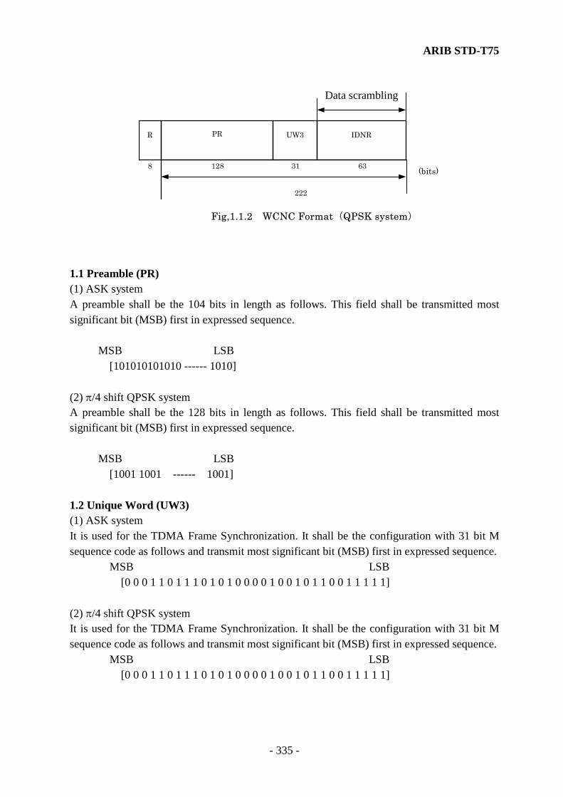
ARIB STD-T75
- 335 -
1.1 Preamble (PR) (1) ASK system A preamble shall be the 104 bits in length as follows. This field shall be transmitted most significant bit (MSB) first in expressed sequence. MSB LSB [101010101010 ------ 1010] (2) π/4 shift QPSK system A preamble shall be the 128 bits in length as follows. This field shall be transmitted most significant bit (MSB) first in expressed sequence. MSB LSB [1001 1001 ------ 1001] 1.2 Unique Word (UW3) (1) ASK system It is used for the TDMA Frame Synchronization. It shall be the configuration with 31 bit M sequence code as follows and transmit most significant bit (MSB) first in expressed sequence. MSB LSB [0 0 0 1 1 0 1 1 1 0 1 0 1 0 0 0 0 1 0 0 1 0 1 1 0 0 1 1 1 1 1] (2) π/4 shift QPSK system It is used for the TDMA Frame Synchronization. It shall be the configuration with 31 bit M sequence code as follows and transmit most significant bit (MSB) first in expressed sequence. MSB LSB [0 0 0 1 1 0 1 1 1 0 1 0 1 0 0 0 0 1 0 0 1 0 1 1 0 0 1 1 1 1 1]
PR UW3
Fig,1.1.2 WCNC Format(QPSK system)
IDNR
128 31 63 (bits)
222
R
8
Data scrambling

ARIB STD-T75
- 336 -
1.3 ID Number (IDNR) The IDNR consists of ID name and Error Correcting Code. The configuration shall be as follows: [a62, a61, a60, a59, a58, a57, a56, a55, a54, a53, a52, a51, a50, a49, a48, a47, a46, a45, a44, a43, a42, a41, a40, a39, a38,
a37, a36, a35, a34, a33, a32, a31, a30, a29, a28, a27, a26, a25, a24, a23, a22, a21, a20, a19, a18, a17, a16, a15, a14,
a13, a12, a10, a9, a8, a7, a6, a5, a4, a3, a2, a1, a0 ] From a62 through a0 , they shall be the factors of the following polynomial’s term from the 62 nd through the 0 th on the finite field which has the order of 2.
50
X12 * (Σ bi Xi) + R (X)
i =0
Where from b0 through b47, they shall be corresponded to each digit from 1st through the 48th of ID name, which is converted from number of 12 digits into binary numeral according to Table 1.1 and from b48 through b50, they shall be zeros. In addition, R (X) shall be a residue polynomial when
50
X12 * (Σ bi Xi) is divided by (X12 + X10 + X8 + X5 + X4 + X3 + 1).
i =0
Table 1.1 Conversion Table of ID name into Binary Numeral
Number of ID name
1 2 3 4 5 6 7 8 9 0
Binary Numeral
0011 0100 0101 0110 0111 1000 1001 1010 1011 1100
Note) An IDNR shall be transmitted in the specified order from the coefficient of the 62nd
term.

ARIB STD-T75
- 337 -
Annex D. Encryption Key Encryption Key is used for an initial value of a shift register for scramble and the key length is 2 octets (16 bits). Encryption Key is generated according to the link address (LID) provided by association procedures between the base station and the mobile station. It shall be translated LID using the same translation table, which is previously prepared in the base station or the mobile station. Generation of the translation table shall comply with the following: (1) It shall be used the portion of 2 octets on LSB side of the LID shown in Fig. 4.2.4.2.1.8.2 (including the extender). Specifically, S0 in Fig. 4.2.6.2.1 corresponds to bit 1 of the first octet, and S15 corresponds to bit 8 of the second octet. (Between S0 and S15, correspond sequentially) (2) If the LID is a Private Link Address, the bit is shifted “1” to “0” or “0” to “1”, and used as a Encryption Key (3) Encryption Key of Broadcast Address shall be “0000 0000 0000 0000”. (4) The encryption key of group broadcast address shall be "0000 0000 0000 0000"

ARIB STD-T75
- 338 -
Annex E. Frequency Selection Procedures [Informative] 1. Frequency Selection Procedures Frequency Selection Procedures is shown for reference. A FCMC reception is regarded a reception time of a FCMC which is identified correct ones by the CRC inspection. Fk_FID list is used for logging of FID received by the array structure.
Frequency Selecting Process
Fkcount←0
Fk_FID list initializingk←1
Frequency Fk set
Timer set
FCMC received ?
Is FID inFk_FID list ?
Registration in Fk_FID list
Fk_count←Fk_count+1
Fk_count > Established value
Time out ?
1
1
Reception level≧Threshold value
Frequency Fk determined
End
yes
no
yes
no
yes
no
yes
no
no
yes
(k=1 --- n) n: Number of channel scanning
k←k +1

ARIB STD-T75
- 339 -
2. Frequency Supervisory Procedures Frequency Supervisory Procedures is shown in the following figure. This supervisory procedures is not necessarily to be an independent function module.
Frequency Selecting process
Frequency Determined flag ON
FCMC continuously received?
Frequency Determined flag OFF
Frequency Resettinginstruction?
Frequency Determined flag ON
Reception level ≧Threshold value
FCMC continuously received?
yes
no
yes
no
yes
no
no
yes
Frequency Resettinginstruction?
yes
no
Frequency Supervisory Process
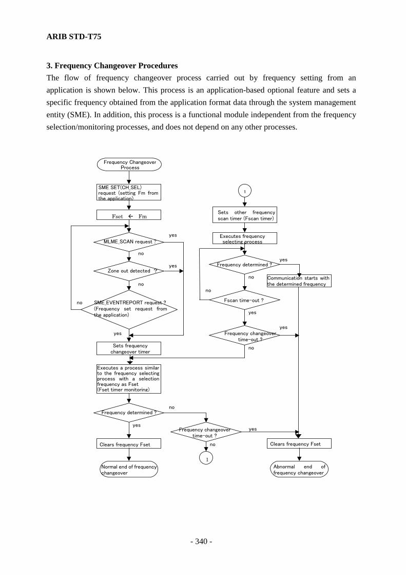
ARIB STD-T75
- 340 -
3. Frequency Changeover Procedures The flow of frequency changeover process carried out by frequency setting from an application is shown below. This process is an application-based optional feature and sets a specific frequency obtained from the application format data through the system management entity (SME). In addition, this process is a functional module independent from the frequency selection/monitoring processes, and does not depend on any other processes.
Frequency ChangeoverProcess
Sets frequencychangeover timer
Zone out detected ?
MLME_SCAN request ?
Clears frequency Fset
yes
no
no
no
no
no
yes
yes
yes
yes
Normal end of frequencychangeover
1
Frequency changeovertime-out ?
Abnormal end offrequency changeover
Frequency changeovertime-out ?
yes
no
Communication starts withthe determined frequency
Frequency determined ?
Fscan time-out ?
no
yes
no
1
Sets other frequencyscan timer (Fscan timer)
yes
Clears frequency Fset
SME_EVENTREPORT request ?(Frequency set request fromthe application)
Executes a process similarto the frequency selectingprocess with a selectionfrequency as Fset(Fset timer monitoring)
Frequency determined ?
Executes frequencyselecting process
SME_SET(CH_SEL)request (setting Fm fromthe application)
Fset Fm
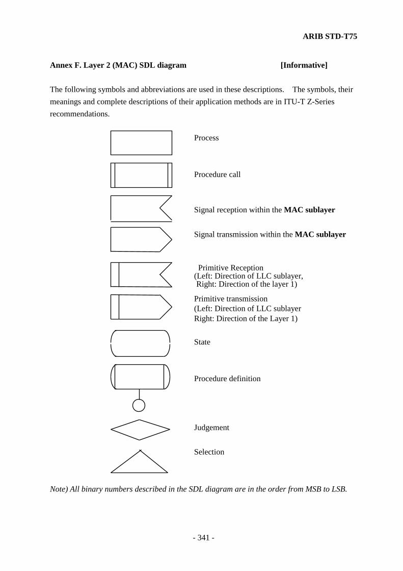
ARIB STD-T75
- 341 -
Annex F. Layer 2 (MAC) SDL diagram [Informative] The following symbols and abbreviations are used in these descriptions. The symbols, their meanings and complete descriptions of their application methods are in ITU-T Z-Series recommendations. Process Procedure call Signal reception within the MAC sublayer Signal transmission within the MAC sublayer Primitive Reception (Left: Direction of LLC sublayer, Right: Direction of the layer 1)
Primitive transmission (Left: Direction of LLC sublayer Right: Direction of the Layer 1) State Procedure definition Judgement Selection Note) All binary numbers described in the SDL diagram are in the order from MSB to LSB.

ARIB STD-T75
- 342 -
1. SDL Diagram of MAC Sub-Layer Only SDL diagram of the MAC sublayer is described in this chapter. The LLC sublayer is described in the state transition list. 1.1 Overview of State Machines MAC operation is described in six communication state machines. They operate simultaneously. If there are differences between terms used in this subclause and previous subclauses, those in previous subclauses take precedence. Fig. F-1 shows the relation between those state machines. In the figure, a bold arrow line shows a transfer path for data frames and fragments and also for control signals and status data. A slim arrow line is used for transfer of control signals and status data only. (1)MAC Data Service State Machine Provides LLC sublayer with the MAC data service interface. (2)MAC Management Service State Machine Provides MAC sublayer management entity (MACLME) or system management entity (SME) with the MAC management service interface. (3)MAC Control State Machine Provides adjustment function to transfer frames and fragments via Layer 1. Provides data segmentation/desegmentation. (4)MAC Management State Machine Provides MAC management functions such as synchronizing management and association. Bears major responsibility for maintenance and management of the MAC MIB (Management Information Base). (5)Transmission State Machine Transfers frames for transmission at the physical channel of Layer 1 and performs CRC generation. (6)Reception State Machine Checks validity, CRC and double reception of receive frames from Layer 1.
Note) The description in this appendix does not take the π/4 shift QPSK system into consideration except for the PDU’s maximum transfer size (MSIZE). To carry out the π/4 shift QPSK system processing, it is necessary to add the processing procedure (data scrambling/decoding and error correction encoding/decoding shown in Section 4.2.4) specified for Layer 1.

ARIB STD-T75
- 343 -
Scrambling described in this appendix is a simplified encryption scrambling specified in Section 4.2.6.1. In case of the π/4 shift QPSK system, UW2 used in attached figures F-9, F-12 (RMRV2), F-34 (OMTR2), and F-37 (OMRV3) shall be replaced with UW2B, and likewise, UW2 in F-10, F-12 (RMRV4), F-34 (OMTR3), F-35, and F-37 (OMRV4) with UW2A.
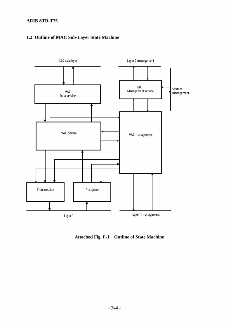
ARIB STD-T75
- 344 -
1.2 Outline of MAC Sub-Layer State Machine
MACData service
MACManagement service
MAC management
Transmission Reception
LLC sub-layer
Systemmanagement
Layer 1 managementLayer 1
Layer 7 management
MAC control
Attached Fig. F-1 Outline of State Machine
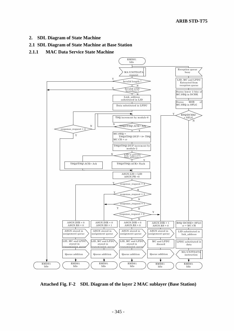
ARIB STD-T75
- 345 -
2. SDL Diagram of State Machine 2.1 SDL Diagram of State Machine at Base Station 2.1.1 MAC Data Service State Machine
MA-UNITDATArequest
MA-UNITDATAinstruction
Invalid length ?
TSQ2(TSQ).ACK= Ack
Reception queuebusy
RMDS1Idle
LID substituted inlink_address
LID, MC and LPDUExtracted fromreception queue
LPDU substituted indata
N
N
N
Y
Y
Y
RMDS1Idle
RMDS1Idle
ASGN.LID = LIDASGN.PR =0
Data substituted in LPDU
MC.SEQ = TSQ2(TSQ).DUP×8+ TSQ
MC.CR = cr
RSQ (DCHK)= SFLGcr = MC.CR
TSQ increment by modulo-8
Link_addresssubstituted in LID
Invalid octetboundary ?
N
Y
TSQ2(TSQ).DUP increment bymodulo-2
TSQ2(TSQ).ACK= Nack
Stores lower 3 bits ofMC.SEQ in DCHK
Stores MSB ofMC.SEQ in SFLG
RSQ(DCHK)= SFLG
N
N
N
N
YY
Y
Y
ASGN.DIR = 0ASGN.RS = 0
RMDS1Idle
LID, MC and LPDUstored in
transmission queue
ASGN stored inassignment queue
Queue addition
response_request = 3
response_request = 2
MC and LPDUdiscard
ASGN.DIR = 1ASGN.RS = 0
RMDS1Idle
ASGN stored inassignment queue
Queue addition
ASGN.DIR = 0ASGN.RS = 1
RMDS1Idle
LID, MC and LPDUstored in
transmission queue
ASGN stored inassignment queue
Queue addition
response_request = 4
ASGN.DIR = 0ASGN.RS = 0
RMDS1Idle
ASGN stored inassignment queue
Queue addition
response_request = 1
LID, MC and LPDUstored in
transmission queue
LID is privatelink address ?
Y
N
TSQ2(TSQ).ACK= Ack
N
Y
response_request = 2
Attached Fig. F-2 SDL Diagram of the layer 2 MAC sublayer (Base Station)

ARIB STD-T75
- 346 -
2.1.2 MAC Control State Machine
RMC2Message fragmentation
Reception slot assign instructionTransmission slot assign instruction
LPDU(n)discarded
LID is not private linkaddressLID is private link
address
Resend times forreception upper limit over
NACKtransmission
NACK received/ACK notreceived
Assembling completedAssembling continued
ACK transmission
Resend times for transmission upper limit over
ACK received
RMC7Message assembling
RMC6ACK processing
RMC4ACK waiting
RMC3Message transmission
RMC5Message search
RMC1Idle
Attached Fig. F-3 Outline of MAC Control State Machine (Base Station)
RMC2Message
fragmentation
RMC1Idle
Extraction fromtransmission queue
LPDU(n) = LPDUMC(n)=MCLID(n) = LIDFRG(n)=OFF
Slot n assign
RMC5Message search
ASGN(n).DIR = ‘0’
N
N
Y
Y
DEFRG=OFF
Resend counter forreception initializing
NFR2(n) = 0
Queue subtraction
Transmission queueBusy ?
RMC1Idle
Attached Fig. F-4 SDL Diagram of the layer 2 MAC sublayer (Base Station)

ARIB STD-T75
- 347 -
RMC2Message
fragmentation
MC(n).FRG = 0 MC(n).CL = 0 MC(n).LI =Length of LPDU(n)
MC(n).FRG = 1 MC(n).CL = 1 MC(n).LI = MSIZE
IncrementsMC(n).SEQ by
modulo 16
Stores lower 3 bitsof MC(n).SEQ inDCHK(n)
Inserts zero up toMSIZE octets
Extracts MSIZEoctets from head ofLPDU(n), and storesit in MSDU(n)
MSDU(n) =LPDU(n)
LPDU(n)is discarded ?
N
N N
N
N
N
Y
Y
Y
Y
Y
Y
LPDU(n ) > MSIZE octets
MC(n).LI < MSIZE
FRG(n) =OFF ?
LPDU(n ) > MSIZE octets
MC(n).FRG = 1 MC(n).CL = 0 MC(n).LI =length ofresidual LPDU(n)
MC(n).FRG = 1 MC(n).CL = 1 MC(n).LI = MSIZE
Inserts zero up toMSIZE octets
Extracts MSIZEoctets from head ofresidual LPDU(n),and stores it inMSDU(n)
Extracts residualLPDU(n), and storesit in MSDU(n)
MC(n).LI < MSIZE
RMC3Message
Transmission
MC(n).CL = ’0’
Discards LPDU(n)
RMC3Message
Transmission
N
Y Transmits releaseindication of ready
state of slotnumber n
RMC1Idle
Initializes NFR1(n)NFR1(n) = 0
FRG(n) =OFF
FRG(n) =ON
Note : MSIZE (Maximum transmission size) is
- 65 for ASK system - 193 for QPSK system
Attached Fig. F-5 SDL Diagram of the layer 2 MAC sublayer (Base Station)

ARIB STD-T75
- 348 -
Receives AI(n)
AI(n).AK = ‘1’
RMC3Message
Transmission
RMC4Waiting
Acknowledgement
N
N Y
Y
Time for slotassignment expires
RMC2Message
Fragmentation
NFR1(n) = NFR1(n)+1
NFR1(n) >NFR1max
RMC3Message
Transmission
N
Y
NFR1(n)= NFR1(n)+1
NFR1(n) >NFR1max Discards
LID(n),MC(n)LPDU(n)
DiscardsLID(n),MC(n)
LPDU(n)
Transmits releaseindication of slot n
RMC1Idle
Transmits releaseindication of slot n
RMC1Idles
RMC3Message
Transmission
Indicatestransmission slot
and receives TSLT
TSLT.LID =LID(n)
RMC2Message
Fragmentation
Transmits MPDU
RMC4Waiting
Acknowledgement
N
N
N
Y
Y
Y
LID(n) is private link
address
Generates MPDU fromMAC control field
MC(n) and MSDU(n)
Generates MPDUfrom MSDU (all 0) and
MAC control field(length = MSIZE
octets withoutfragment)
Transmits MPDU
TSLT.CI.ST =‘001’
RMC3Message
Transmission
Note : MSIZE (Maximum transmission size) is
- 65 for ASK system - 193 for QPSK system
RMC3Message
Transmission
MC(n).CL = ’0’
TSQ2(DCHK).ACK= Ack
TSQ2(DCHK).ACK= Ack
TSQ2(DCHK).ACK= Ack
Y
N
Attached Fig. F-6 SDL Diagram of the layer 2 MAC sublayer (Base Station)

ARIB STD-T75
- 349 -
N
N
N
Y
Y
Y
RMC7Message assembling
AI transfer
Resend counter forreception initializing
NFR2(n) = 0
MC(n).FRG = 0and
MC(n).CL= 1
Is MPDUMSIZE+2 octets
or more ?
AI(n).AK = 1
RMC6ACK processing
MPDU stored in MACcontrol fields
(MC(n)/MSDU(n))
MPDU reception CRC error reception Assigned slot periodpassed
N
Y
AI transfer
NFR2(n)>NFR2max
RMC1Idle
NFR2(n)= NFR2(n)+1
Transmission of slotn release instruction
LID(n) discard
AI(n).AK = 0
RMC5Message search
RMC5Message search
Reception slotinstruction
RSLT reception
RSLT.LID =LID(n)
RMC5Message search
RMC6ACK processing
N
N
Y
YRSLT.CI.ST =
‘001’
Note : MSIZE (Maximum transmission size) is
- 65 for ASK system - 193 for QPSK system
MC(n).LI = 0or
MC(n).LI > MSIZE
Attached Fig. F-7 SDL Diagram of the layer 2 MAC sublayer (Base Station)

ARIB STD-T75
- 350 -
N
N
N
N
N
N
N
Y
Y
Y
Y
Y
Y
Y
RMC7Message assembling
Increment ofMC(n).SEQ=1?
RMC1Idle
LID(n) discard LID(n) discardLID(n) discard
Transmission of slotn release instruction
RMC1Idle
RMC5Message search
Increment ofMC(n).SEQ=0?
DEFRG=OFFand
MC(n).CL=1
Processing interruptionflag ON
Processing interruptionflag OFF
LPDU(n) initializing LPDU(n) initializing
MC(n).FRG=1
MSDU with a lengthindicated by MC(n).LI
extracted from MSDU(n)then stored in LPDU(n)
MSDU with a lengthindicated by MC(n).LI
extracted from MSDU(n)then concatenated to
LPDU(n)
MSDU with a lengthindicated by MC(n).LI
extracted from MSDU(n)then concatenated to
LPDU(n)
MC(n).CL=0
Transmission of slotn release instruction
MCData, LPDU(n)and LID(n) stored in
reception queue
MC(n), LPDU(n) andLID(n) stored inreception queue
MC(n) stored in MCData
DEFRG = ON
DEFRG = OFF DEFRG = OFF
Is processinginterruption flag
OFF?
DEFRG=ON
RMC5Message search
RMC1Idle
Transmission of slotn release instruction
Attached Fig. F-8 SDL Diagram of the layer 2 MAC sublayer (Base Station)
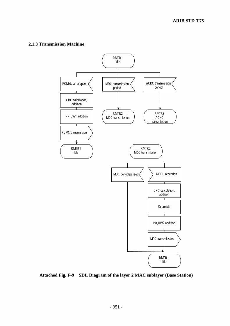
ARIB STD-T75
- 351 -
2.1.3 Transmission Machine
ACKC transmissionperiod
RMTR2MDC transmission
RMTR3ACKC
transmission
RMTR1Idle
PR,UW1 addition
CRC calculation,addition
FCMC transmission
Scramble
CRC calculation,addition
MDC transmission
RMTR1Idle
PR,UW2 addition
FCM data reception
RMTR2MDC transmission
MPDU receptionMDC period passed
MDC transmissionperiod
RMTR1Idle
Attached Fig. F-9 SDL Diagram of the layer 2 MAC sublayer (Base Station)

ARIB STD-T75
- 352 -
CRC calculation,addition
PR,UW2 addition
ACKC transmission
RMTR1Idle
RMTR3ACKC
transmission
AI receptionACKC periodpassed
Attached Fig. F-10 SDL Diagram of the layer 2 MAC sublayer (Base Station)
2.1.4 Reception State Machine
MDC receptionperiod
RMRV2MDC reception
ACTC receptionperiod
RMRV3ACKC reception
RMRV4ACTC reception
ACKC receptionperiod
RMRV1Idle
Attached Fig. F-11 SDL Diagram of the layer 2 MAC sublayer (Base Station)
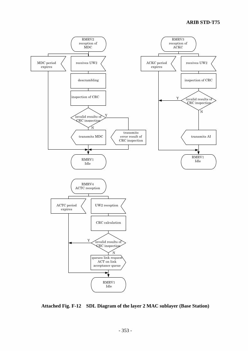
ARIB STD-T75
- 353 -
RMRV1Idle
inspection of CRC
transmits AI
RMRV1Idle
RMRV2reception of
MDC
RMRV3reception of
ACKC
receives UW2ACKC periodexpires
descrambling
inspection of CRC
transmits MDC
receives UW2MDC periodexpires
invalid results ofCRC inspection
invalid results ofCRC inspection
transmitserror result of
CRC inspection
N
YN
Y
RMRV1Idle
RMRV4ACTC reception
CRC calculation
UW2 receptionACTC periodexpires
invalid results ofCRC inspection
N
Y
queues link requestACT on link
acceptance queue
Attached Fig. F-12 SDL Diagram of the layer 2 MAC sublayer (Base Station)

ARIB STD-T75
- 354 -
2.1.5 MAC Management State Machine
RMM3Slot assign
NUMLINK update
Link acceptancedisabled
Slot control time
Link acceptancequeue busy
Slot release instruction
Assignment queue busy
RMM4Slot release
RMM2Link acceptance
RMM6Frame generation
Slot n instruction
MDS transmission time MDS reception time
RMM1Idle
RMM5Congestion
control
RMM10Reception slot
generation
RMM9Reception MDSdata generation
RMM8Transmission MDS
data generation
Slot n instructionRMM7
Transmission slotgeneration
RMM11Slot control
Attached Fig. F-13 SDL Diagram of the layer 2 MAC sublayer (Base Station)
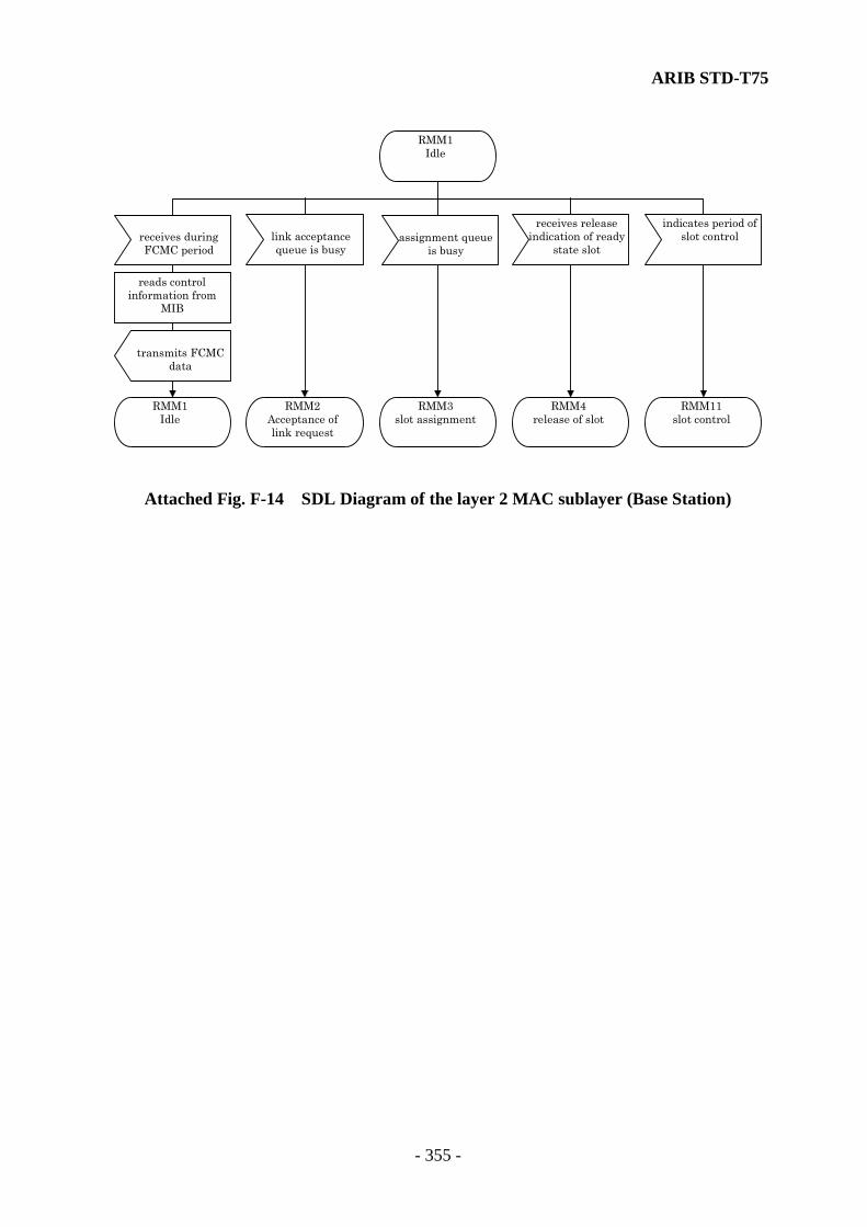
ARIB STD-T75
- 355 -
RMM3slot assignment
RMM1Idle
link acceptancequeue is busy
assignment queueis busy
RMM2Acceptance oflink request
receives releaseindication of ready
state slot
RMM4release of slot
receives duringFCMC period
transmits FCMCdata
reads controlinformation from
MIB
RMM1Idle
indicates period ofslot control
RMM11slot control
Attached Fig. F-14 SDL Diagram of the layer 2 MAC sublayer (Base Station)
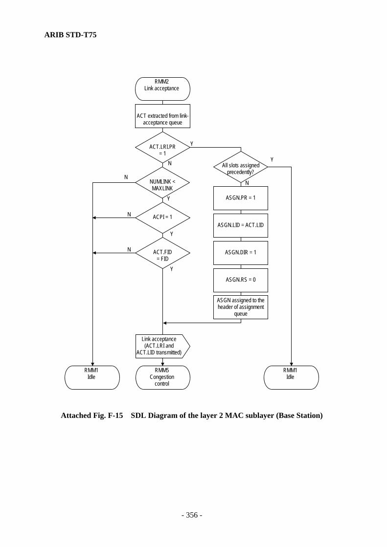
ARIB STD-T75
- 356 -
RMM1Idle
ASGN.RS = 0
ASGN.DIR = 1
ASGN.LID = ACT.LID
ASGN.PR = 1
ACT extracted from link-acceptance queue
N
N
N
N
N
Y
Y
Y
Y
Y
RMM2Link acceptance
ACT.FID= FID
ACT.LRI.PR= 1
ASGN assigned to theheader of assignment
queue
Link acceptance(ACT.LRI and
ACT.LID transmitted)
RMM5Congestion
control
NUMLINK <MAXLINK
ACPI = 1
All slots assignedprecedently?
RMM1Idle
Attached Fig. F-15 SDL Diagram of the layer 2 MAC sublayer (Base Station)
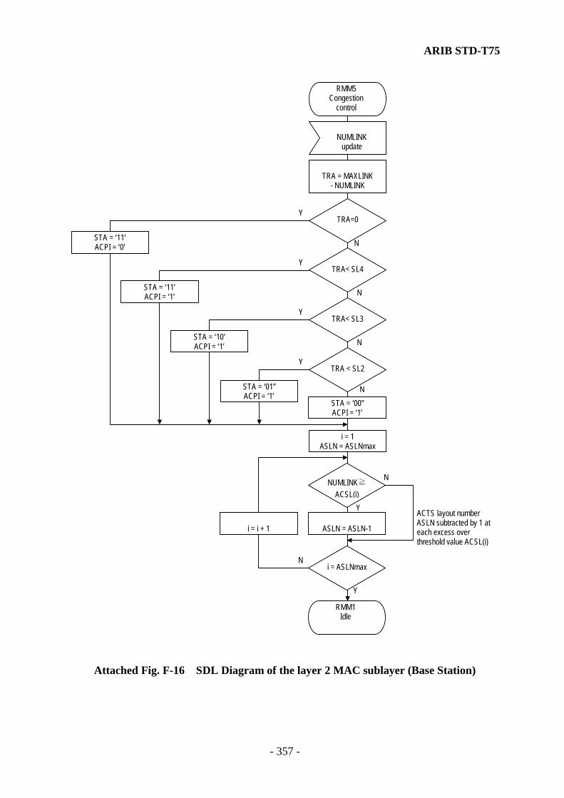
ARIB STD-T75
- 357 -
TRA = MAXLINK- NUMLINK
STA = ‘01”ACPI = ‘1’
STA = ‘00”ACPI = ‘1’
STA = ‘10’ACPI = ‘1’
STA = ‘11’ACPI = ‘0’
STA = ‘11’ACPI = ‘1’
RMM5Congestion
control
NUMLINKupdate
TRA=0
TRA< SL4
TRA< SL3
TRA < SL2
N
N
N
N
Y
Y
Y
Y
ASLN = ASLN-1i = i + 1
i = 1ASLN = ASLNmax
NUMLINK≧ACSL(i)
i = ASLNmax
ACTS layout numberASLN subtracted by 1 ateach excess overthreshold value ACSL(i)
N
N
Y
Y
RMM1Idle
Attached Fig. F-16 SDL Diagram of the layer 2 MAC sublayer (Base Station)

ARIB STD-T75
- 358 -
RMM3Slot assign
n-th WCNS detected
n-th null slot detected
n-th normallyassigned slotdetected
i = 1
RMM1Idle
ASGN(n) = ASGN
SCI(n).LID=ASGN.LID
SCI(n).CI.ST= ‘111’SCI(n).CI.DR =
ASGN.DIR
ASGN extracted fromassignment queue
SCI(i).CI.SI. = ‘00’and SCI(i).CI.ST = ‘110’
i = i+1
Slot n assign
N
N
NN N
N
N
Y
Y
Y
Half-duplexFSI.CM =1
Full-duplexFSI.CM =0
Y
Y
Y
Y
FCMS time ?ASGN.PR=1
ASGN(n).PR=0
i = FSI.SLN
i = 1
i = i+1
ASGN(n) stored insaving queue
SCI(n).LID=ASGN.LID
SCI(n).CI.ST= ‘111’SCI(n).CI.DR = ‘1’
i = FSI.SLN
Communication modeFSI.CM
3
RMM1Idle
ASGN(n) = ASGN
Slot n assign
N
YSlot n time ?
SCI(i).CI.SI.= ‘01’
ASGN.DR = 0and SCI(i).CI.ST = ‘111’
and SCI(i).CI.DR = 0and ASGN.LID=SCI(i).LID
Has the MPDU assigned orto be assigned been
segmented ?
Y
RMM1Idle
ASGN.DR = 1and SCI(i).CI.ST = ‘111’
and SCI(i).CI.DR = 1and ASGN.LID=SCI(i).LID
N
N
Y
Y
N
Reloads ASGN in theassignment queue andholds transmission /reception of anappropriate MPDUuntil the next frame orlater
i = FSI.SLN
i = 1
i = i+1
N
Y
Attached Fig. F-17 SDL Diagram of the layer 2 MAC sublayer (Base Station)

ARIB STD-T75
- 359 -
n-th normally assignedslot detected
n-th null slot detected
n-th WCNS detected
RMM1Idle
ASGN(n) = ASGNASGN(n) = ASGN
SCI(n).LID=ASGN.LID
SCI(n).CI.ST= ‘111’
SCI(i).CI.SI. = ‘00’and SCI(i).CI.ST = ‘110’
i = i+1
i = slot_position
Slot nassign
N
N
N N
N
N
N
NN
N
Y
Y
Y
Y
Y
Y
Y
Y
Y
Y
FCMS time
SCI(n).CI.DR=ASGN.DIR
ASGN.PR=1
ASGN(n).PR=0
i = FSI.SLN
i = 1
i = i+1
RMM1Idle
ASGN(n) stored insaving queue
SCI(n).LID=ASGN.LID
SCI(n).CI.ST= ‘111’’
Slot nassign
i = FSI.SLN
3
N
YSlot n time
ASGN.DIR = 0
i = 1
i = 1SCI(i).CI.SI. = ‘01’
i = 1
ASGN.DR = 0and SCI(i).CI.ST = ‘111’
and SCI(i).CI.DR = 0and ASGN.LID=SCI(i).LID
Has the MPDU assignedor to be assigned been
segmented ?
YASGN.DR = 1
and SCI(i).CI.ST = ‘111’and SCI(i).CI.DR = 1
and ASGN.LID=SCI(i).LID
N
N
Y
Y
N
i = FSI.SLN
i = i+1
N
SCI(n).CI.DR=ASGN.DIR
RMM1Idle
Y
Reloads ASGN in theassignment queue andholds transmission /reception of anappropriate MPDUuntil the next frame orlater
Attached Fig. F-18 SDL Diagram of the layer 2 MAC sublayer (Base Station)
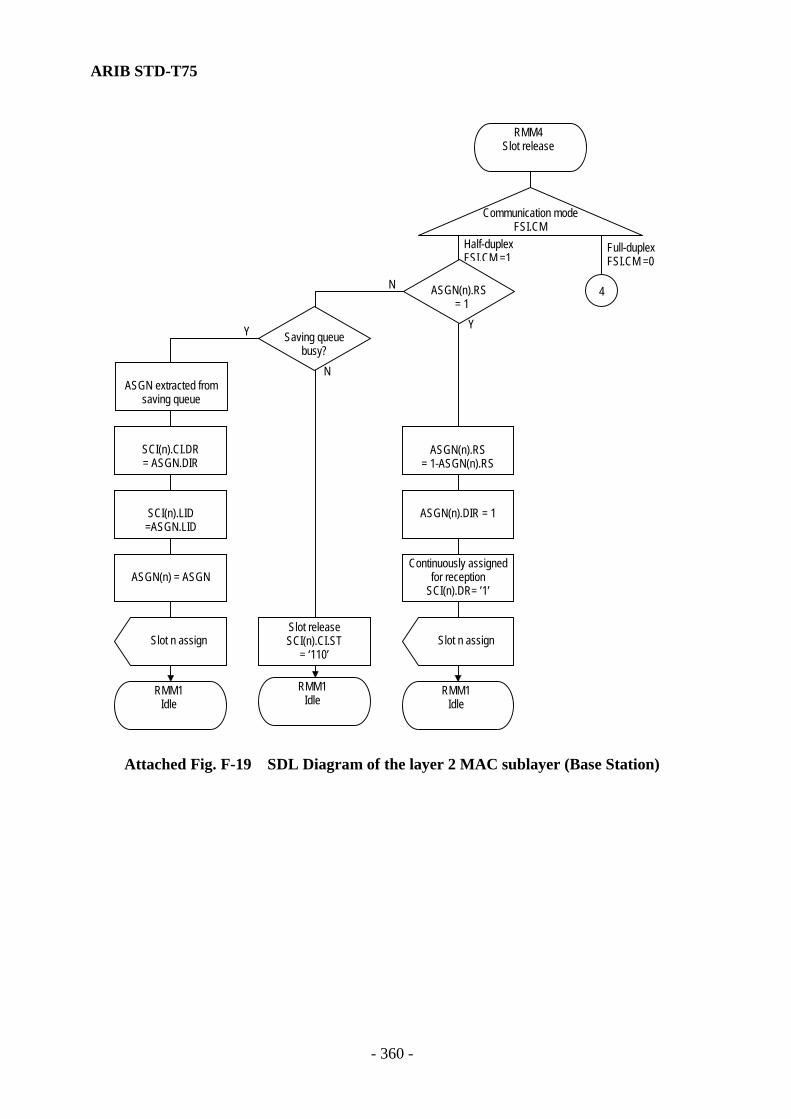
ARIB STD-T75
- 360 -
Continuously assignedfor reception
SCI(n).DR= ’1’
ASGN extracted fromsaving queue
ASGN(n).DIR = 1
ASGN(n).RS= 1-ASGN(n).RS
Slot releaseSCI(n).CI.ST
= ‘110’
RMM4Slot release
ASGN(n).RS = 1
N
N
Y
RMM1Idle
Y
Slot n assign
Half-duplexFSI.CM =1
RMM1Idle
Communication modeFSI.CM
Saving queuebusy?
ASGN(n) = ASGN
SCI(n).LID=ASGN.LID
SCI(n).CI.DR= ASGN.DIR
Slot n assign
RMM1Idle
Full-duplexFSI.CM =0
4
Attached Fig. F-19 SDL Diagram of the layer 2 MAC sublayer (Base Station)

ARIB STD-T75
- 361 -
ASGN(n)discard
ASGN(n) assigned tothe header of saving
queue
Slot releaseSCI(n).CI.ST
= ‘110’
RMM1Idle
ASGN(n).DIR = 1
slot_position = n+1
ASGN(n).RS= 1-ASGN(n).RS
ASGN(n).RS = 1
N
Y
4
ASGN extracted fromsaving queue
N
N
Y
Y
RMM1Idle
Saving queuebusy?
ASGN(n) = ASGN
SCI(n).LID=ASGN.LID
ASGN returned tosaving queue
SCI(n).CI.DR= ASGN.DIR
Slot n assign
SCI(n).CI.DR=ASGN.DIR
Attached Fig. F-20 SDL Diagram of the layer 2 MAC sublayer (Base Station)

ARIB STD-T75
- 362 -
Y
RMM11Slot control
Release slotSCI(i).CI.SI. = ‘00’SCI(i).CI.ST = ‘110’SCI(i).CI.DR = ‘1’SCI(i).LID = Broadcast
i = i - jk = k + 1
i = i - jk = k + 1
Assigns ACTSSCI(i).CI.SI = ‘11’SCI(i).CI.STA=STASCI(i).CI.ACPI=ACPI
Assigns WCNSSCI(i).CI.SI = ‘01’
N
N
N
N
N
N
N
N
Y
Y
Y
Y
Y
Y
Y
Y
SCI(i).CI.SI. = ‘00’and
SCI(i).CI.ST = ‘110’
k > ASLN
SCI(i).CI.SI= ‘11’
ASLN = 0 or
ASLNmax=0
RMM1Idle
i = j
k = 1i = FSI.SLN
j = 1j = 2
N
Y
Half-duplexFSI.CM =1
SCI(i).CI.SI. = ‘00’and
SCI(i).CI.ST = ‘110’
i = FSI.SLN
SCI(i).LID is privatelink address
k > FSI.SLN
q= FSI.SLN(j=1) orq=2*FSI.SLN(j=2)
SCI(i).LID = SCI(q).LID
q = i
q = q + 1
q = 1
N
N
Yi = i + j
N
Attached Fig. F-21 SDL Diagram of the layer 2 MAC sublayer (Base Station)
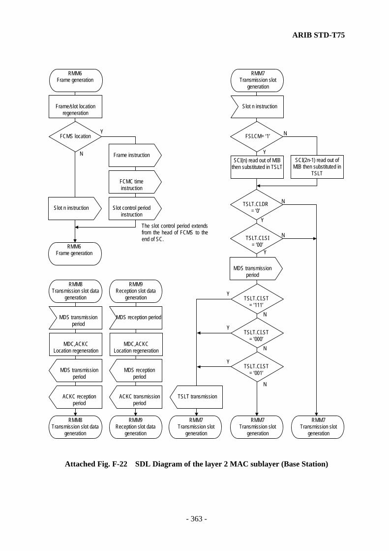
ARIB STD-T75
- 363 -
SCI(2n-1) read out ofMIB then substituted in
TSLT
SCI(n) read out of MIBthen substituted in TSLT
TSLT.CI.SI= ‘00’
N
N
N
N
N
N
Y
Y
Y
Y
Y
Y
TSLT transmission
TSLT.CI.ST= ‘111’
TSLT.CI.ST= ‘000’
TSLT.CI.DR= ‘0’
TSLT.CI.ST= ‘001’
MDS transmissionperiod
FSI.CM= ‘1’
Slot n instruction
RMM7Transmission slot
generation
RMM7Transmission slot
generation
RMM7Transmission slot
generation
RMM7Transmission slot
generation
RMM6Frame generation
Frame/slot locationregeneration
Slot n instruction
Frame instruction
RMM6Frame generation
FCMS location
The slot control period extendsfrom the head of FCMS to theend of SC.
N
Y
RMM8Transmission slot data
generation
MDC,ACKCLocation regeneration
ACKC receptionperiod
MDS transmissionperiod
RMM8Transmission slot data
generation
MDS transmissionperiod
RMM9Reception slot data
generation
MDC,ACKCLocation regeneration
ACKC transmissionperiod
MDS receptionperiod
RMM9Reception slot data
generation
MDS reception period
FCMC timeinstruction
Slot control periodinstruction
Attached Fig. F-22 SDL Diagram of the layer 2 MAC sublayer (Base Station)

ARIB STD-T75
- 364 -
ACTS receptiontperiod
WCNS receptionperiod
N
Y
Y RSLT.CI.SI= ‘11’
RSLT.CI.SI= ‘01’
RMM10Reception slot
generation
SCI(2n) read out ofMIB then substituted in
RSLT
SCI(n) read out ofMIB then substituted in
RSLT
RSLT.CI.SI= ‘00’
N
N
N
N
N
N
Y
Y
Y
Y
Y
Y
RSLT transmission
RSLT.CI.ST= ‘111’
RSLT.CI.ST= ‘000’
RSLT.CI.DR= ‘1’
RSLT.CI.ST= ‘001’
MDS rec. period
FSI.CM= ‘1’
Slot n instruction
RMM10Reception slot
generation
RMM10Reception slot
generation
RMM10Reception slot
generation
RMM10Reception slot
generation
RMM10Reception slot
generation
N
Attached Fig. F-23 SDL Diagram of the layer 2 MAC sublayer (Base Station)

ARIB STD-T75
- 365 -
2.1.6 MAC Management Service State Machine
RMMS1Idle
Link acceptance(ACT.LRI and
ACT.LID received)MLME_SET
request
Send state variable setTR_STATUS = busy
NUMQ = NUMQ+1
A value obtained from avariable specified by
MIB_attribute
A value set to a variablespecified by
MIB_attribute
NUMLINK specified byMIB_attribute?
MLME_SETconfirm
NUMLINKupdate
MLME_GETrequest
MLME_GETconfirm
RMMS1Idle
RMMS1Idle
RMMS1Idle
N N
N
YY
Y
Queue addition
NUMQ ≧ FQBUSY
RMMS1Idle
Queue subtraction
Slot assignment statevariable set
SLT_STATUS = in_time
Slot assignment statevariable set
SLT_STATUS =out_time
Send state variable setTR_STATUS = idle
NUMQ = NUMQ-1
NUMQ < FQBUSY
RMMS1Idle
Assignment queuebusy
Assignment queuenull
RMMS1Idle
RMMS1Idle
MLME_ASSOCIATEinstruction
Attached Fig. F-24 SDL Diagram of Layer 2 MAC Sublayer (Base Station)

ARIB STD-T75
- 366 -
2.2 MAC Control Procedures at Mobile Stations 2.2.1 MAC Data Service State Machine
MA-UNITDATArequest
MA-UNITDATAinstruction
Invalid length ?
Invalid octetboundary ?
Busy received fromreception queue
OMDS1Idle
OMDS1Idle
LID substituted inlink_address
LPDU substitutedin data
RSQ(DCHK) = SFLG
MC.SEQ =TSQ2(TSQ).DUP×8
+TSQMC.CR = cr
TSQ increment bymodulo-8
Data substituted inLPDU
link_addresssubstituted in LID
LID and LPDUextracted from
reception queue
N
N
N
Y
Y
Y
OMDS1Idle
OMDS1Idle
LID, MC andLPDU stored in
transmission queue
Queue addition
RSQ(DCHK)=SFLG
OMDS1Idle
TSQ2(TSQ).ACK= Ack
N
Y
TSQ2(TSQ).DUPincrement by modulo-
2
TSQ2(TSQ).ACK= Nack
Stores lower 3 bits ofMC.SEQ in DCHK
Stores MSB ofMC.SEQ in SFLG
LID is privatelink address ?
cr = MC.CR
N
Y
Attached Fig. F-25 SDL Diagram of Layer 2 MAC Sublayer (Mobile Station)
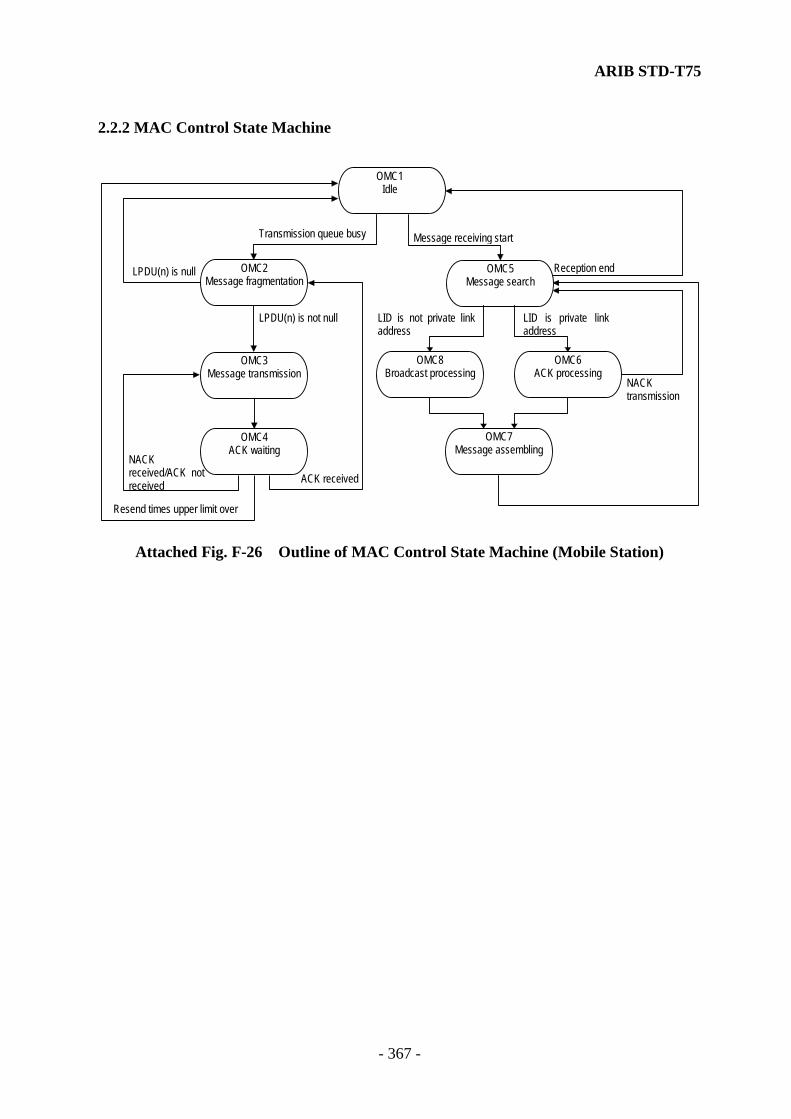
ARIB STD-T75
- 367 -
2.2.2 MAC Control State Machine
OMC2Message fragmentation
Message receiving start
Reception end
Transmission queue busy
LPDU(n) is null
LPDU(n) is not null
NACKtransmission
LID is private linkaddress
LID is not private linkaddress
NACKreceived/ACK notreceived
Resend times upper limit over
ACK received
OMC7Message assembling
OMC6ACK processing
OMC4ACK waiting
OMC3Message transmission
OMC5Message search
OMC1Idle
OMC8Broadcast processing
Attached Fig. F-26 Outline of MAC Control State Machine (Mobile Station)
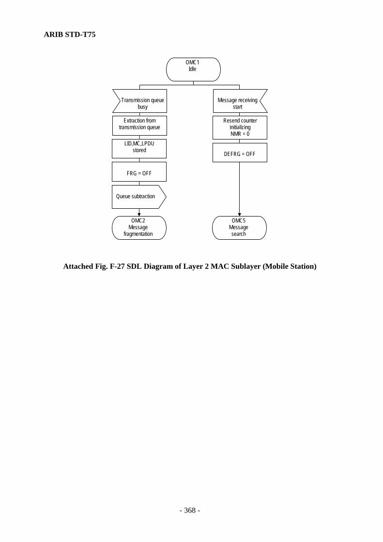
ARIB STD-T75
- 368 -
OMC2Message
fragmentation
OMC5Messagesearch
DEFRG = OFF
FRG = OFF
LID,MC,LPDUstored
Extraction fromtransmission queue
Transmission queuebusy
OMC1Idle
Message receivingstart
Resend counterinitializingNMR = 0
Queue subtraction
Attached Fig. F-27 SDL Diagram of Layer 2 MAC Sublayer (Mobile Station)

ARIB STD-T75
- 369 -
OMC2Message
fragmentation
MC.FRG = 0 MC.CL = 0 MC(n).LI
= Length of LPDU
MC.FRG = 1 MC.CL = 1MC.LI = MSIZE
MC.SEQ incrementby modulo-16
0 insertion up toMSIZE octet
FRG = OFFFRG = ON
MSDU =LPDU
LPDUdiscarded?
N
N N
N
N
N
Y
Y
Y
Y
Y
Y
LPDU >MSIZE octets?
MC.LI < MSIZE
FRG=OFF
LPDU >MSIZE octets?
MC.FRG = 1 MC.CL = 0MC.LI = Length of
residual LPDU
MC.FRG = 1 MC.CL = 1MC.LI = MSIZE
0 insertion up toMSIZE octet
MSIZE octetsextracted from theresidual LPDU thenstored in MSDU
Residual LPDUextracted then
stored in MSDU
MC.LI< MSIZE
OMC3Message transmission
MC.CL = ’0’
LPDU discard
OMC3Message transmission
N
Y
Resend counterinitializingNMR = 0
OMC1Idle
Note : MSIZE (Maximum transmission size) is
- 65 for ASK system - 193 for QPSK system
Stores lower 3 bits ofMS.SEQ in DCHK
Store lower 3 bits ofMS.SEQ in DCHK
MSIZE octetsextracted from theheader of LPDU thenstored in MSDU
Attached Fig. F-28 SDL Diagram of Layer 2 MAC Sublayer (Mobile Station)
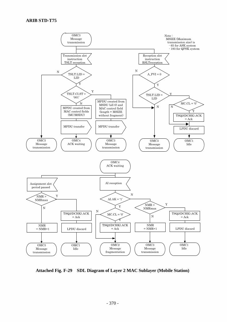
ARIB STD-T75
- 370 -
OMC3Message
transmission
Transmission slotinstruction
TSLT reception
TSLT.LID =LID
OMC3Message
transmission
MPDU transfer
OMC4ACK waiting
N
YY
Y
NN
MPDU created fromMAC control fields
(MC/MSDU)
TSLT.CI.ST =‘001’
MPDU transfer
MPDU created fromMSDU (all 0) andMAC control field(length = MSIZE
without fragment)
OMC3Message
transmission
AI reception
AI.AK = ‘1’
OMC3Message
transmission
OMC4ACK waiting
N
N Y
Y
Assignment slotperiod passed
OMC2Message
fragmentation
NMR = NMR+1
NMR >NMRmax
N
Y
NMR= NMR+1LPDU discard
LPDU discard
LPDU discard
OMC1Idle
OMC3Message
transmission
OMC1Idle
Reception slotinstruction
RSLTreception
TSLT.LID =LID
OMC1Idle
OMC3Message
transmission
TSQ2(DCHK).ACK= Ack
NMR >NMRmax
TSQ2(DCHK).ACK= Ack
TSQ2(DCHK).ACK= Ack
MC.CL = ‘0’
Y
N
Y
A_PVI = 0
TSQ2(DCHK).ACK= Ack
MC.CL = ‘0’
YN N
Note : MSIZE (Maximum transmission size) is
- 65 for ASK system - 193 for QPSK system
Attached Fig. F-29 SDL Diagram of Layer 2 MAC Sublayer (Mobile Station)

ARIB STD-T75
- 371 -
OMC5Message search
Reception slotinstructionRSLT reception
RSLT.LID =LID
OMC5Broadcast processing
OMC6ACK processing
N
N
N
N
Y
Y
Y
YLink request flag
ON?
Reception confirm
Reception end
OMC1Idle
N
Y
Is RSLT.LIDbroadcast address?
LID valid?
OMC5Message search
RSLT.CI.ST= ’001’
Attached Fig. F-30 SDL Diagram of Layer 2 MAC Sublayer (Mobile Station)

ARIB STD-T75
- 372 -
N
N
N
Y
Y
Y
OMC7Message assembling
AI transfer
MC.LI=0 orMC.LI>MSIZE
MC.FRG=0 and
MC.CL=1
Is MPDU MSIZE+2octets or more?
AI.AK = 1
OMC6ACK processing
MPDU stored in MACcontrol fields(MC/MSDU)
MPDU reception CRC error reception Assignment slotperiod passed
AI transfer
AI.AK = 0
OMC5Message search
OMC5Message search
Attached Fig. F-31 SDL Diagram of Layer 2 MAC Sublayer (Mobile Station)
Note : MSIZE (Maximum transmission size) is
- 65 for ASK system - 193 for QPSK system

ARIB STD-T75
- 373 -
N
N
N
Y
Y
Y
OMC7Message assembling
MC.LI=0 orMC.LI>MSIZE
MC.FRG=0 and
MC.CL=1
OMC8Broadcast processing
MPDU stored in MACcontrol fields(MC/MSDU)
MPDU reception CRC error reception
OMC5Message search
Assignment slotperiod passed
OMC5Message search
OMC5Message search
Is MPDU MSIZE+2octets or more?
Attached Fig. F-32 SDL Diagram of Layer 2 MAC Sublayer (Mobile Station)
Note : MSIZE (Maximum transmission size) is
- 65 for ASK system - 193 for QPSK system

ARIB STD-T75
- 374 -
OMC7
Message assembling
OMC5Message search
OMC5Message search
OMC5Message search
OMC5Message search
N
N
N
N
N
N
N
Y
Y
Y
Y
Y
Y
Y
Increment ofMC(n).SEQ=1?
Increment ofMC(n).SEQ=0?
DEFRG=OFFand
MC(n).CL=1
Processing interruptionflag ON
Processing interruptionflag OFF
LPDU(n) initializing LPDU(n) initializing
MC(n).FRG=1
MSDU with a lengthindicated by MC(n).LI
extracted from MSDU(n)then stored in LPDU(n)
MSDU with a lengthindicated by MC(n).LI
extracted from MSDU(n)then concatenated to
LPDU(n)
MSDU with a lengthindicated by MC(n).LI
extracted from MSDU(n)then concatenated to
LPDU(n)
MC(n).CL=0
MCData, LPDU(n)and LID(n) stored in
reception queue
MC(n), LPDU(n) andLID(n) stored inreception queue
MC(n) stored in MCData
DEFRG = ON
DEFRG = OFF DEFRG = OFF
Processinginterruption flag
OFF?
DEFRG=ON
OMC5Message search
Attached Fig. F-33 SDL Diagram of Layer 2 MAC Sublayer (Mobile Station)

ARIB STD-T75
- 375 -
2.2.3 Transmission State Machine
MDC transmissionperiod
OMTR1Idle
OMTR2MDC
transmission
ACTS period
OMTR3ACKC
transmission
OMTR4ACTC
transmission
ACKC transmissionperiod
WCNS period
OMTR5WCNC
transmission
Scramble
CRC calculation,addition
CRC calculation,addition
MDC transmission
OMTR1Idle
PR,UW2 additionPR,UW2 addition
ACKC transmission
OMTR1Idle
OMTR2MDC
transmission
OMTR3ACKC
transmission
MPDU reception AI receptionACKC periodpassed
MDC period passed
Attached Fig. F-34 SDL Diagram of Layer 2 MAC Sublayer (Mobile Station)
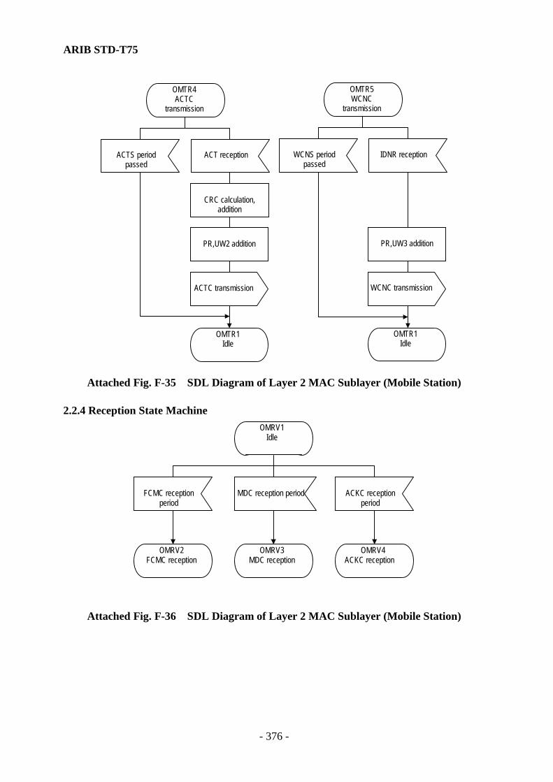
ARIB STD-T75
- 376 -
CRC calculation,addition
ACTC transmission
OMTR1Idle
PR,UW3 additionPR,UW2 addition
WCNC transmission
OMTR1Idle
OMTR4ACTC
transmission
OMTR5WCNC
transmission
ACT reception IDNR receptionWCNS periodpassed
ACTS periodpassed
Attached Fig. F-35 SDL Diagram of Layer 2 MAC Sublayer (Mobile Station)
2.2.4 Reception State Machine OMRV1
Idle
ACKC receptionperiod
OMRV3MDC reception
OMRV4ACKC reception
MDC reception periodFCMC receptionperiod
OMRV2FCMC reception
Attached Fig. F-36 SDL Diagram of Layer 2 MAC Sublayer (Mobile Station)

ARIB STD-T75
- 377 -
OMRV2FCMC
reception
UW1 reception
CRC check
FCM transfer
N
YCRC checkincorrect?
OMRV2FCMCreception
FCMCperiod passed
OMRV1Idle
CRC check
AI transfer
OMRV1Idle
OMRV4ACKC
reception
Scramble release
CRC check
MDCtransmission
CRC checkincorrect?
CRC checkincorrect?
CRC errortransmission
N
YN
Y
UW2 receptionACKC period
passedMDC period
passed UW2 reception
OMRV3MDC reception
Attached Fig. F-37 SDL Diagram of Layer 2 MAC Sublayer (Mobile Station)
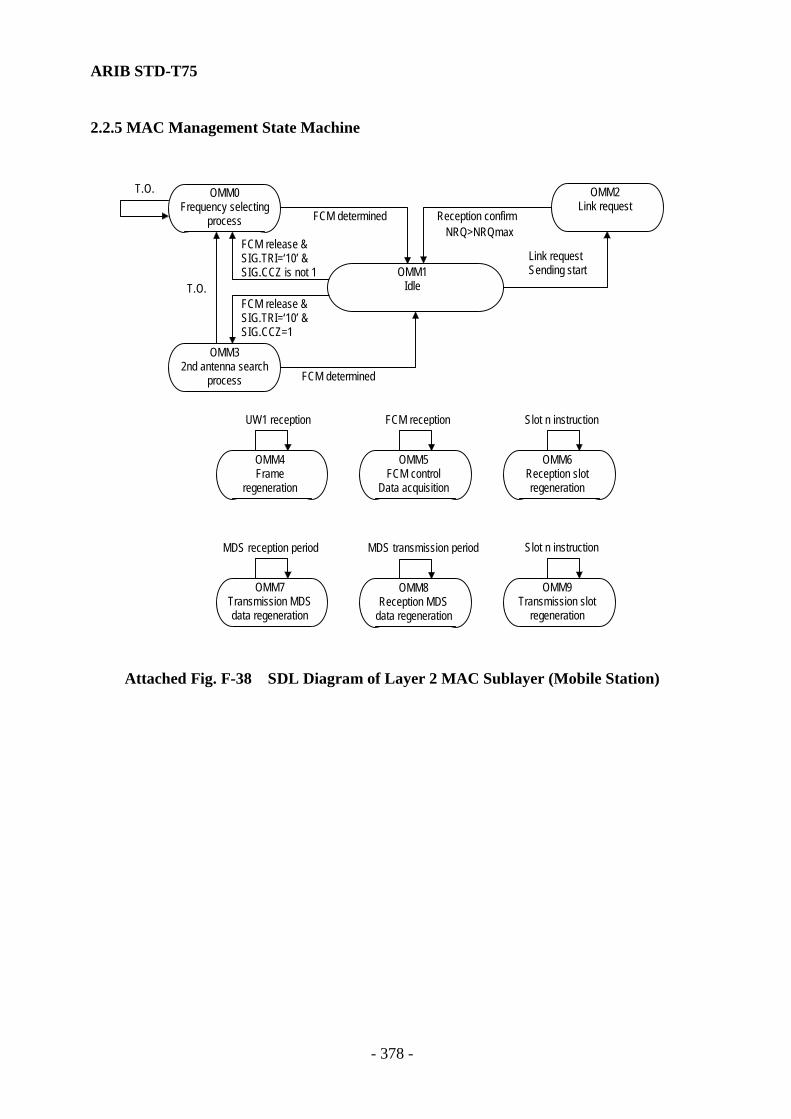
ARIB STD-T75
- 378 -
2.2.5 MAC Management State Machine
OMM0
Frequency selectingprocess
NRQ>NRQmax
T.O.
T.O.
FCM determined Reception confirm
Link requestSending start
FCM reception
FCM determined
FCM release &SIG.TRI=‘10’ &SIG.CCZ=1
FCM release &SIG.TRI=‘10’ &SIG.CCZ is not 1
OMM32nd antenna search
process
OMM2Link request
OMM7Transmission MDSdata regeneration
Slot n instruction
MDS transmission periodMDS reception period
OMM1Idle
UW1 reception
OMM4Frame
regeneration
OMM5FCM control
Data acquisition
OMM8Reception MDS
data regeneration
OMM6Reception slotregeneration
Slot n instruction
OMM9Transmission slot
regeneration
Attached Fig. F-38 SDL Diagram of Layer 2 MAC Sublayer (Mobile Station)

ARIB STD-T75
- 379 -
OMM1Idle
Link request sendingstart
OMM2Link request
Transmission channellocation calculated
Link request flag ON
NRQ = 1NRT = 0
LRI and LID obtainedfrom MIB and link
request ACT created
LRI.PR = 1
NRQmax=Emergency_value
NMR = NMRmax
Transmission queue,MSDU and LPDU
discard
NRQmax = Default
N
Y
FCM release
SIG.TRI= ’10’and
SIG.CCZ = 1
N
Y
OMM0Frequency selecting
process
OMM32nd antenna
search process
Message receivingstart
FCM detection
OMM1Idle
Link connection
Attached Fig. F-39 SDL Diagram of Layer 2 MAC Sublayer (Mobile Station)

ARIB STD-T75
- 380 -
OMM2Link request
NRQ = NRQ + 1
Link request flag OFF
Transmission channellocation calculated
Transmission locationtiming processing
NRT = NRT-1
ACTSperiod
Frame instructionON
Reception confirm
NRQ >NRQmax
ACT transfer
OMM2Link request
NRT = 0
OMM2Link request
OMM1Idle
N
NN
N
N
Y
YY
Y
Y
Link request flagON?
Link request failure
Link requestsuccess
NRT = RT4 ’
NRT = RT3
NRT = RT2
NRT = RT1
STA = ‘00’
STA = ‘01’
STA = ‘10’
N
N
N
Y
Y
YOMM1Idle
ACT trans missionprohibit flag ON?
NRT=0
OMM2Link request
Attached Fig. F-40 SDL Diagram of Layer 2 MAC Sublayer (Mobile Station)
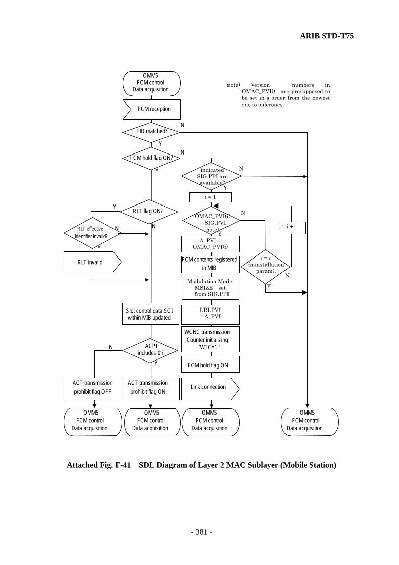
ARIB STD-T75
- 381 -
FCM hold flag ON
FCM contents registeredin MIB
WCNC transmissionCounter initializing
‘WTC=1 ’
Slot control data SCIwithin MIB updated
N
N N
Y
Y
Y
Y
NFID matched?
FCM reception
OMM5 FCM control
Data acquisition
N
Y
FCM hold flag ON?
ACT trans mission prohibit flag OFF
ACT trans missionprohibit flag ON
Link connection
ACPI includes ‘ 0 ’ ?
OMM5 FCM control
Data acquisition
OMM5FCM control
Data acquisition
OMM5 FCM control
Data acquisition
OMM5 FCM control
Data acquisition
RLT effective identifier invalid?
RLT invalid
RLT flag ON?
Modulation Mode,MSIZE set
from SIG.PPI
indicated SIG.PPI are available?
N
N
Y
i = 1
i = i +1
Y
N
A_PVI = OMAC_PVI(i)
i = n (n:installation
param).
OMAC_PVI(i) =SIG.PVI
note)
LRI.PVI = A_PVI
Y
note) Version numbers in OMAC_PVI() are presupposed to be set in s order from the newest one to olderones.
Attached Fig. F-41 SDL Diagram of Layer 2 MAC Sublayer (Mobile Station)

ARIB STD-T75
- 382 -
SCI(2n-1) read out ofMIB then substituted in
RSLT
SCI(n) read out ofMIB then substituted in
RSLT
RSLT.CI.SI= ‘00’
N
N
N
N
N
N
Y
Y
Y
Y
Y
Y
RSLTtransmission
RSLT.CI.ST= ‘111’
RSLT.CI.ST= ‘000’
RSLT.CI.DR= ‘0’
RSLT.CI.ST= ‘001’
MDS receptionperiod
FSI.CM= ‘1’
Slot n instruction
OMM6Reception slotregeneration
OMM6Reception slotregeneration
OMM6Reception slotregeneration
OMM6Reception slotregeneration
MDC,ACKCLocation regeneration
ACKC receptionperiod
MDC transmissionperiod
MDS transmissionperiod
MDC,ACKCLocation regeneration
ACKC transmissionperiod
MDC receptionperiod
MDS reception period
OMM4Frame
regeneration
Frame/slot locationregeneration
Slot n instruction
Frame instruction
OMM4Frame
regeneration
UW1 reception
FCMC periodinstruction
OMM8Reception MDS
data regeneration
OMM7Transmission MDSdata regeneration
OMM8Reception MDS data
regeneration
OMM7Transmission MDSdata regeneration
Attached Fig. F-42 SDL Diagram of Layer 2 MAC Sublayer (Mobile Station)
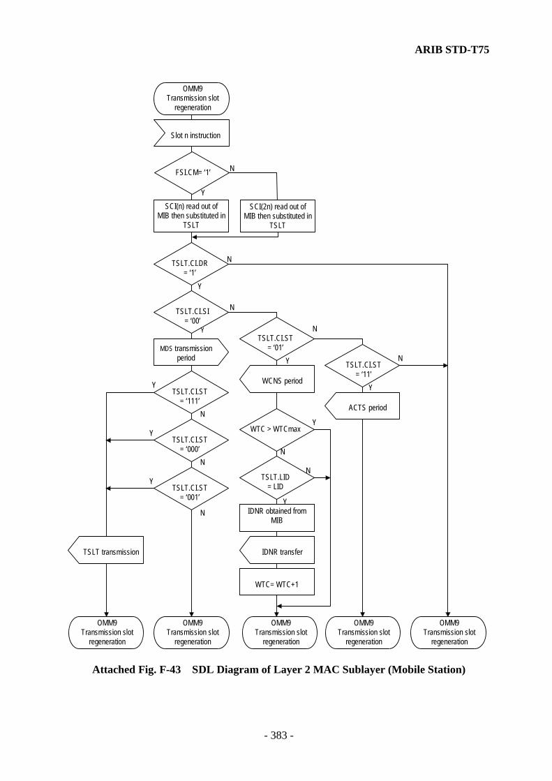
ARIB STD-T75
- 383 -
SCI(2n) read out ofMIB then substituted in
TSLT
SCI(n) read out ofMIB then substituted in
TSLT
TSLT.CI.SI= ‘00’
N
N
N
N
N
N
Y
Y
Y
Y
Y
Y
TSLT transmission
TSLT.CI.ST= ‘111’
TSLT.CI.ST= ‘000’
TSLT.CI.DR= ‘1’
TSLT.CI.ST= ‘001’
MDS transmissionperiod
FSI.CM= ‘1’
Slot n instruction
OMM9Transmission slot
regeneration
OMM9Transmission slot
regeneration
OMM9Transmission slot
regeneration
OMM9Transmission slot
regeneration
OMM9Transmission slot
regeneration
OMM9Transmission slot
regeneration
WCNS period
Y
NTSLT.CI.ST
= ‘01’
ACTS period
Y
NTSLT.CI.ST
= ‘11’
TSLT.LID= LID
WTC= WTC+1
IDNR obtained fromMIB
IDNR transfer
N
Y
YWTC > WTCmax
N
Attached Fig. F-43 SDL Diagram of Layer 2 MAC Sublayer (Mobile Station)
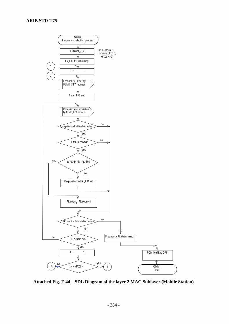
ARIB STD-T75
- 384 -
k ← 1
12 k > MAXCH yesno
OMM0 Freq uency selecting process
Fkcount ← 0
Fk_FID list initializing
Timer TFS set
FCMC received?
Is FID in Fk _FID list?
Registration in Fk _FID list
Fk count ← Fk count+1
Fk count > Established value
TFS time out?
1
Reception level ≥Threshold value
Frequency Fk determined
FCM hold flag OFF
OMM1Idle
yes
no
yes
no
yes
no
yes
no
no
yes
Frequency Fk set by PLME_SET request
Rec eption level acquisition by PLME_GET request
2 k ← 1
k= 1..MAXCH (in case of ETC, MAXCH=2)
Attached Fig. F-44 SDL Diagram of the layer 2 MAC Sublayer (Mobile Station)
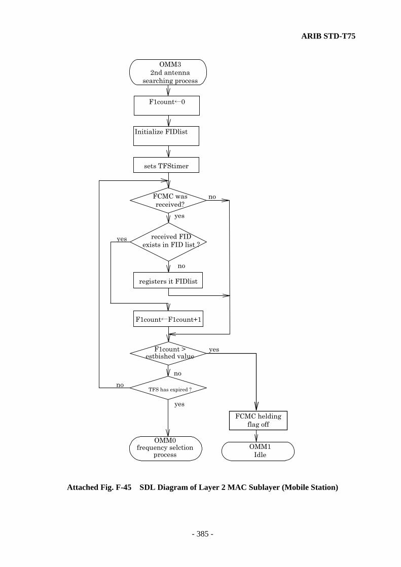
ARIB STD-T75
- 385 -
OMM3 2nd antenna
searching process
F1count←0
Initialize FIDlist
sets TFStimer
FCMC was received?
received FID exists in FID list ?
registers it FIDlist
F1count←F1count+1
F1count > estbished value
TFS has expired ?
FCMC helding flag off
OMM1 Idle
yes
no
yes
no
yes
nono
yes
OMM0frequency selction
process
Attached Fig. F-45 SDL Diagram of Layer 2 MAC Sublayer (Mobile Station)

ARIB STD-T75
- 386 -
2.2.6 MAC Management State Machine OMMS1
Idle
Link requestsending start
MLME_SETrequest
LIDdiscard
FCM hold flagOFF
LIDdiscard
SIG, CCZ, SIG, TRI, SCand RLT obtained from
MIB
SIG, CCZ, SIG, TRI, SCand RLT obtained from
MIB
Parameter set inMIB
Status setFailed
Status setSucceeded
A value obtained from avariable specified by
MIB_attribute
A value set to a variablespecified byMIB_attribute
MLME_SETconfirm
MLME_GETrequest
MLME_GETconfirm
OMMS1Idle
OMMS1Idle
OMMS1Idle
MLME_ASSOCIATErequest
FCM detection
OMMS1Idle
MLME_SCANrequest
MLME_SCANconfirm
OMMS1Idle
FCMrelease
Link requestsuccess
Link requestfailure
MLME_ASSOCIATEconfirm
MLME_ASSOCIATEconfirm
OMMS1Idle
OMMS1Idle
Send state variable setTR_STATUS = busy
NUMQ = NUMQ+1
N N
YY
Queue addition
NUMQ ≥ MQBUSY
OMMS1Idle
Queue subtraction
Send state variable setTR_STATUS = idle
NUMQ = NUMQ-1
NUMQ < MQBUS
OMMS1Idle
RLT flag OFFRLT flag ON
MLME_RLTrequest
OMMS1Idle
RLTinvalid
MLME_RLTconfirm
OMMS1Idle
Attached Fig. F-46 SDL Diagram of Layer 2 MAC Sublayer (Mobile Station)
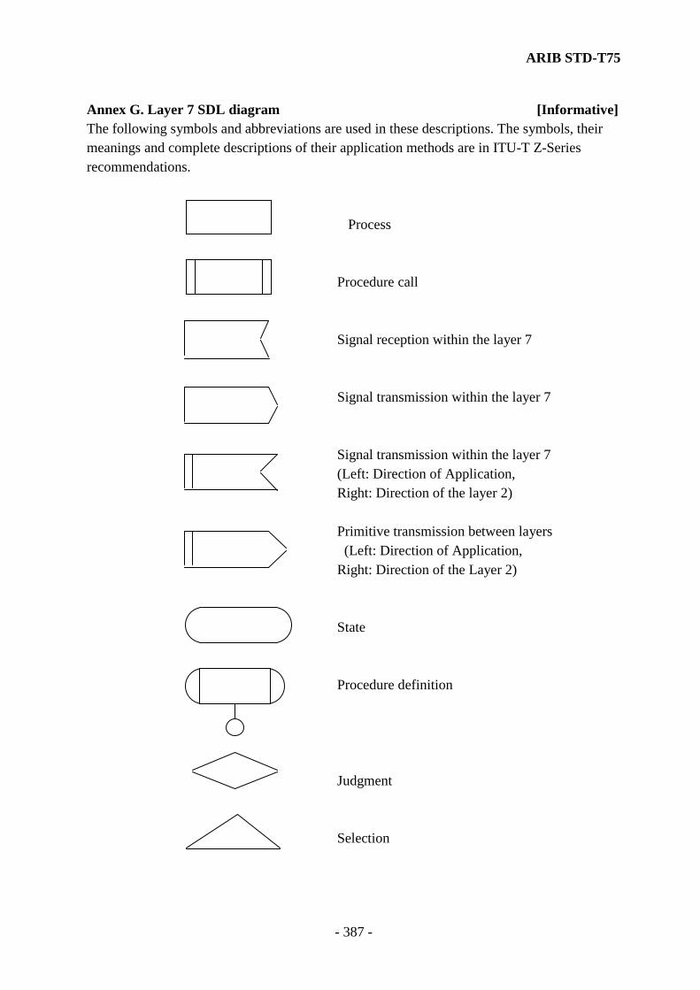
ARIB STD-T75
- 387 -
Annex G. Layer 7 SDL diagram [Informative] The following symbols and abbreviations are used in these descriptions. The symbols, their meanings and complete descriptions of their application methods are in ITU-T Z-Series recommendations.
Process Procedure call Signal reception within the layer 7
Signal transmission within the layer 7
Signal transmission within the layer 7 (Left: Direction of Application, Right: Direction of the layer 2) Primitive transmission between layers
(Left: Direction of Application, Right: Direction of the Layer 2) State Procedure definition Judgment Selection
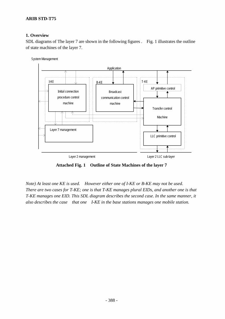
ARIB STD-T75
- 388 -
1. Overview SDL diagrams of The layer 7 are shown in the following figures . Fig. 1 illustrates the outline of state machines of the layer 7.
System Management
Application
Initial connectionprocedure control
machine
Broadcastcommunication control
machine
AP primitive control
Transfer control
Machine
LLC primitive control
Layer 7 management
Layer 2 management Layer 2 LLC sub-layer
I-KE B-KE T-KE
Attached Fig. 1 Outline of State Machines of the layer 7
Note) At least one KE is used. However either one of I-KE or B-KE may not be used. There are two cases for T-KE; one is that T-KE manages plural EIDs, and another one is that T-KE manages one EID. This SDL diagram describes the second case. In the same manner, it also describes the case that one I-KE in the base stations manages one mobile station.
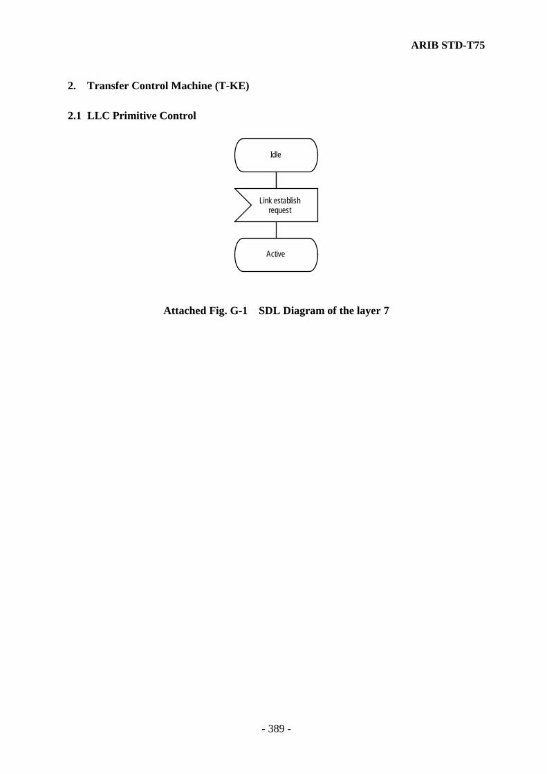
ARIB STD-T75
- 389 -
2. Transfer Control Machine (T-KE) 2.1 LLC Primitive Control
Idle
Link establishrequest
Active
Attached Fig. G-1 SDL Diagram of the layer 7
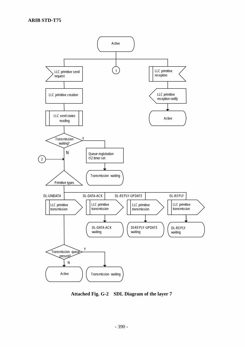
ARIB STD-T75
- 390 -
Active
LLC primitive sendrequest
LLC primitive creation
LLC send statesreading
Transmissionwaiting?
Y
N2
Queue registrationt12 timer set
Transmission waiting
Primitive types
LLC primitivetransmission
LLC primitivetransmission
LLC primitivetransmission
LLC primitivetransmission
DL-DATA-ACKwaiting
DI-REPLY-UPDATEwaiting
DL-REPLYwaiting
Transmission queuepresent?
LLC primitivereception
LLC primitivereception notify
Active
Active Transmission waiting
Y
N
DL-UNIDATA DL-DATA-ACK DL-REPLY-UPDATE DL-REPLY
1
Attached Fig. G-2 SDL Diagram of the layer 7

ARIB STD-T75
- 391 -
DL-DATA-ACKwaiting
LLC primitivereception
LLC primitive sendrequest
Primitive types
LLC primitive creationQueue registration
Others
LLC primitivereception notify
DL-DATA-ACKwaiting
Transmissionqueue present?
Transmission waiting Active
N
Y
1
DL-DATA-ACK-STATUS. ind
Attached Fig. G-3 SDL Diagram of the layer 7

ARIB STD-T75
- 392 -
DL-REPLY-UPDATEwaiting
LLC primitivereception
LLC primitive sendrequest
Primitive typesLLC primitive creationQueue registration
Others
LLC primitivereception notify
DL-REPLY-UPDATEwaiting
Transmissionqueue present?
Transmission waiting Active
N
Y
DL-REPLY-UPDATE- STATUS. ind
1
Attached Fig. G-4 SDL Diagram of the layer 7
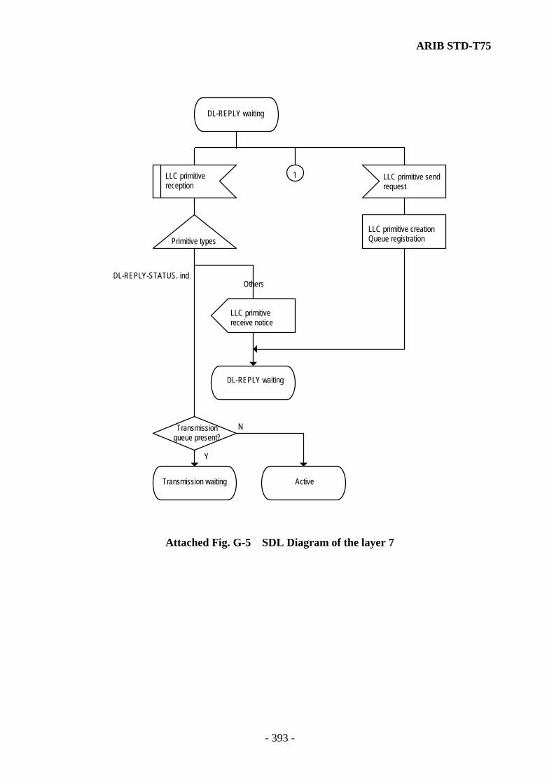
ARIB STD-T75
- 393 -
DL-REPLY waiting
LLC primitivereception
LLC primitive sendrequest
Primitive typesLLC primitive creationQueue registration
Others
LLC primitivereceive notice
DL-REPLY waiting
Transmissionqueue present?
Transmission waiting Active
N
Y
DL-REPLY-STATUS. ind
1
Attached Fig. G-5 SDL Diagram of the layer 7

ARIB STD-T75
- 394 -
Transmission waiting
Timer set in-process?
t12 time out
LLC transmissionStatus reading
Transmissionwaiting?
Priority extractionfrom queue
Concatenation
Link disconnectrequest
Waiting queue discard
t12 timer reset
Idle
Y
N
Y
N
t12 timer set
Trans. waiting
2
1
Transmission waiting
Attached Fig. G-6 SDL Diagram of the layer 7
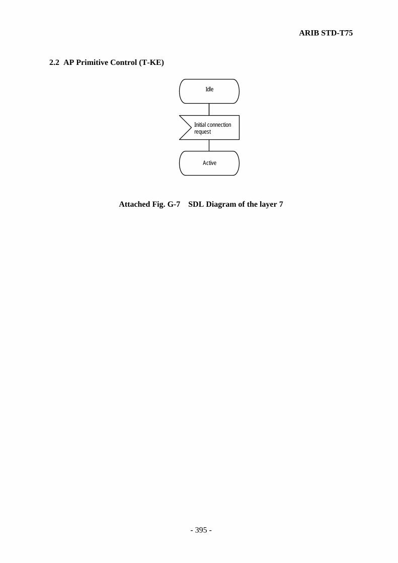
ARIB STD-T75
- 395 -
2.2 AP Primitive Control (T-KE)
Idle
Active
Initial connectionrequest
Attached Fig. G-7 SDL Diagram of the layer 7

ARIB STD-T75
- 396 -
Active
Disconnect request AP primitivereception
AP primitive sendrequest
Idle Format check AP primitivetransmission
AP primitivereception notify
Is primitive ind?
Is primitiverequest?
GET.ind or Modetruth?
GET.req or Modetruth?
response waiting
confirm waitingActive
Active
Y
N
N
Y
N
N
Y
Y
Attached Fig. G-8 SDL Diagram of the layer 7

ARIB STD-T75
- 397 -
Confirm waiting
Disconnect request AP primitivereception
AP primitive sendrequest
Idle AP primitivereception notify
AP primitivetransmission
Confirm waitingPrimitives
correspond?
Is primitives confirmed?
Active Confirm waiting
N
Y
N
Y
Attached Fig. G-9 SDL Diagram of the layer 7

ARIB STD-T75
- 398 -
Response waiting
Disconnect request AP primitivereception
AP primitive sendrequest
Idle AP primitivetransmission Format check
Response waiting AP primitivereception notify
Primitivecorrespond ?
Is primitive response?
Active Response waiting
N
Y
N
Y
Attached Fig. G-10 SDL Diagram of the layer 7

ARIB STD-T75
- 399 -
2.3 Transfer Control (T-KE)
Idle
Initial connectionrequest
Active
Attached Fig. G-11 SDL Diagram of the layer 7
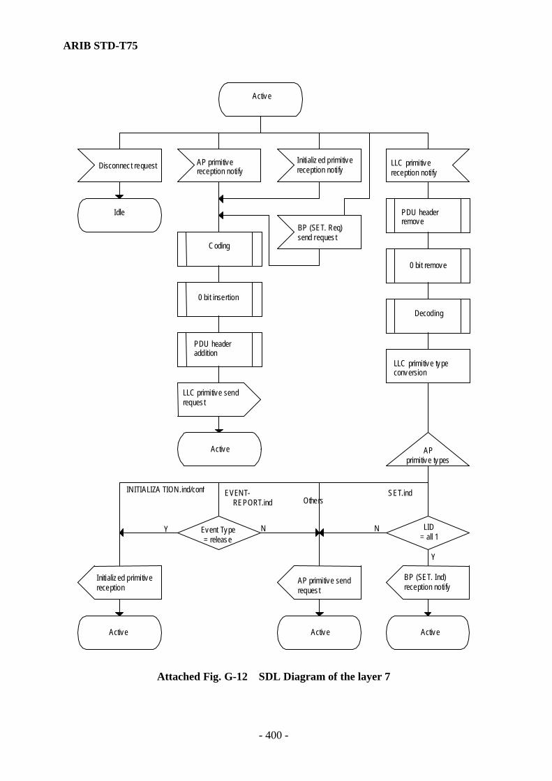
ARIB STD-T75
- 400 -
Active
Disconnect request AP primitivereception notify
Initialized primitivereception notify
LLC primitivereception notify
Idle
Coding
BP (SET. Req)send request
PDU headerremove
0 bit insertion
PDU headeraddition
LLC primitive sendrequest
Active
0 bit remove
Decoding
LLC primitive typeconversion
APprimitive types
Others
Initialized primitivereception
BP (SET. Ind)reception notify
Active Active Active
AP primitive sendrequest
Event Type= release
LID= all 1
INITIALIZA TION.ind/conf EVENT-REPORT.ind
SET.ind
Y N N
Y
Attached Fig. G-12 SDL Diagram of the layer 7

ARIB STD-T75
- 401 -
3. Broadcast Communication Control Machine (B-KE) 3.1 Broadcast Communication Control
Idle
Initial connectionrequest
t11 timer set
RSU
Active
N
Y
Attached Fig. G-13 SDL Diagram of the layer 7

ARIB STD-T75
- 402 -
Active
t11 time out BP (SET.ind)reception notify
AP primitivereception
BP send request(SET.req) generation
BP regis tration/updatePrimitive types
BP (SET.req)send request
Active
t11 timer set
Active BP reading
GetBroadcastData.cnf creation
AP primitivetransmission
Active
BP registration/update
Active
GetBraodcastData.req BroadcastData.req
Attached Fig. G-14 SDL Diagram of the layer 7
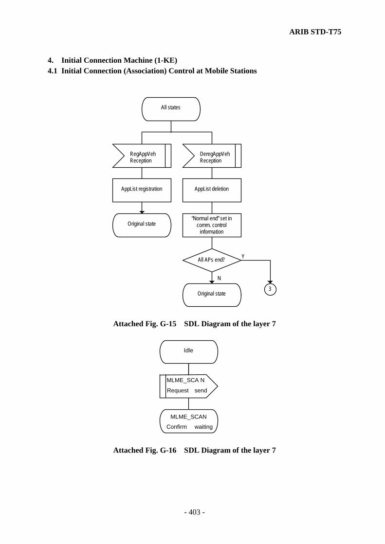
ARIB STD-T75
- 403 -
4. Initial Connection Machine (1-KE) 4.1 Initial Connection (Association) Control at Mobile Stations
All states
RegAppVehReception
DeregAppVehReception
AppList registration AppList deletion
Original state“Normal end” set in
comm. controlinformation
All APs end?
Original state3
Y
N
Attached Fig. G-15 SDL Diagram of the layer 7
Idle
MLME_SCA N
Request send
MLME_SCAN
Confirm waiting
Attached Fig. G-16 SDL Diagram of the layer 7
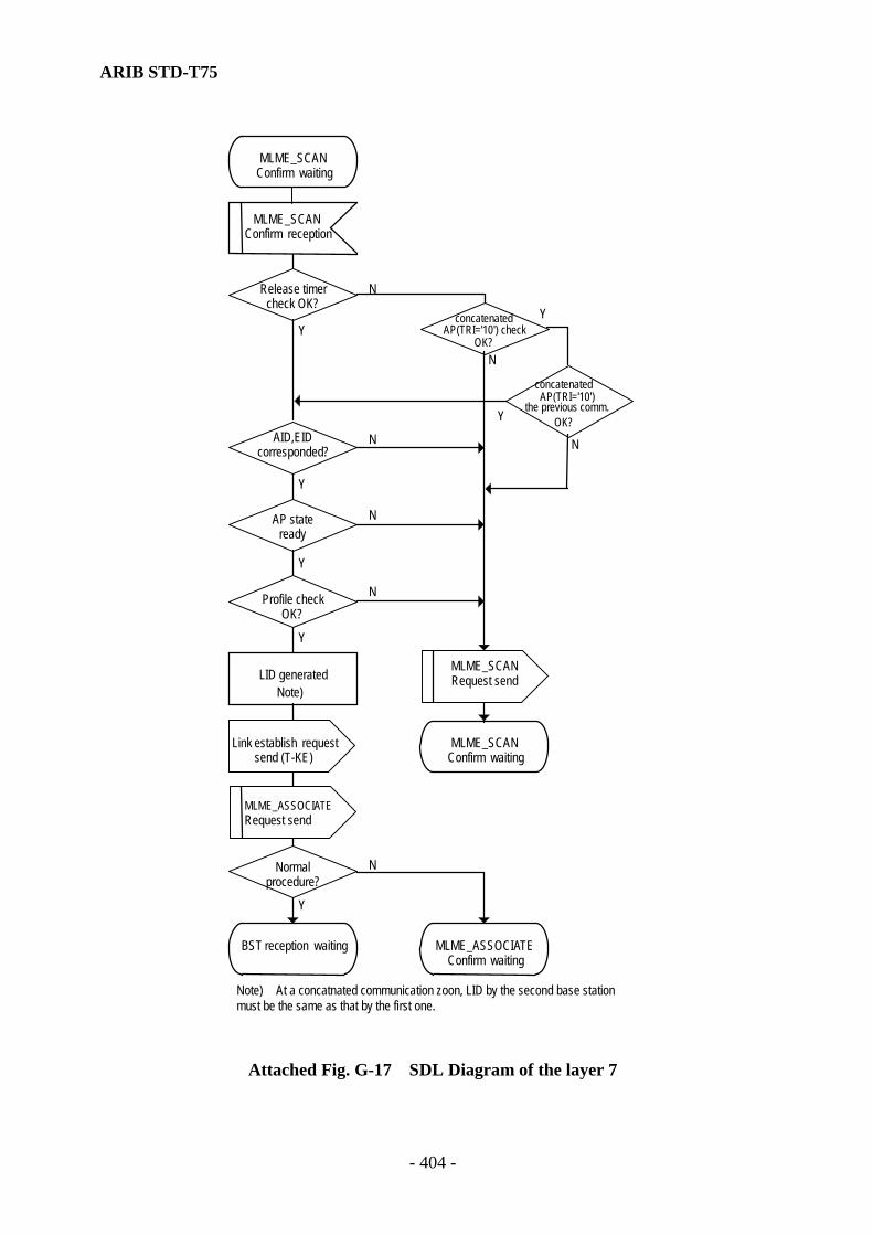
ARIB STD-T75
- 404 -
MLME_SCAN Confirm waiting
MLME_SCAN Confirm reception
Release timer check OK?
concatenated
OK?
AID,EID corresponded?
AP state ready
Profile check OK?
LID generated
Link establish request send (T-KE)
MLME_SCANConfirm waiting
MLME_ASSOCIATE Request send
Normal procedure?
BST rec eption waiting MLME_ASSOCIATEConfirm waiting
Y
Y
Y
Y
YY
N
N
N
N
N
N
Y
N
concatenated
OK?
AP(TRI='10') check
AP(TRI='10')the previous comm.
Note)
Note) At a concatnated communication zoon, LID by the second base station must be the same as that by the first one.
MLME_SCANRequest send
Attached Fig. G-17 SDL Diagram of the layer 7
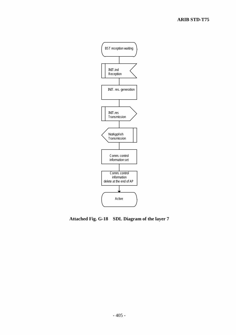
ARIB STD-T75
- 405 -
BST reception waiting
INIT.indReception
INIT. res. generation
INIT.resTransmission
NotAppVehTransmission
Comm. controlinformation set
Comm. controlinformation
delete at the end of AP
Active
Attached Fig. G-18 SDL Diagram of the layer 7
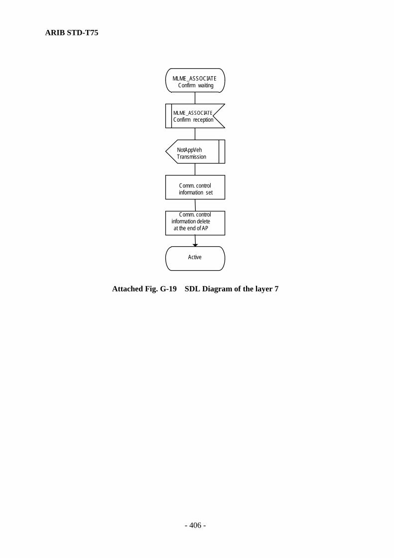
ARIB STD-T75
- 406 -
MLME_ASSOCIATEConfirm waiting
MLME_ASSOCIATEConfirm reception
NotAppVehTransmission
Comm. controlinformation set
Comm. controlinformation deleteat the end of AP
Active
Attached Fig. G-19 SDL Diagram of the layer 7
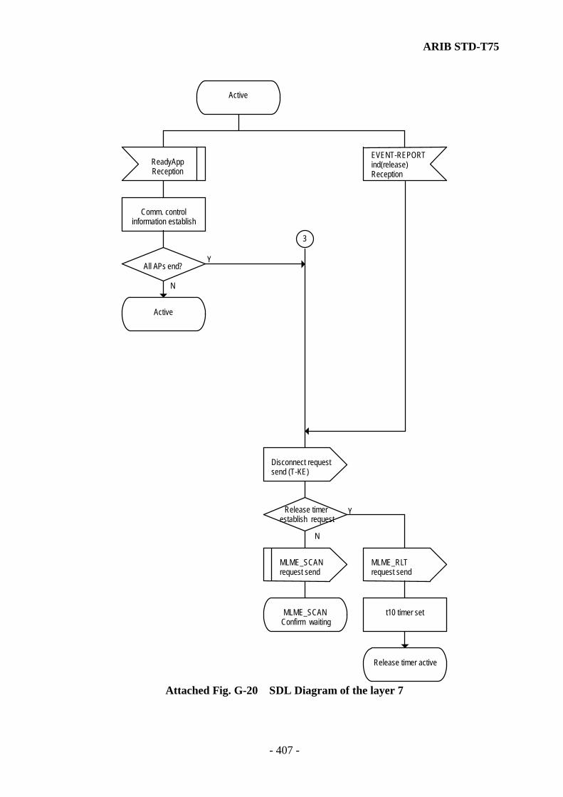
ARIB STD-T75
- 407 -
Active
ReadyApp Reception
Comm. control information establish
All A Ps end?
Active
EVENT-REPORT ind(release) Reception
Disconnect requestsend (T-KE)
Release timerestablish request
3
MLME_SCANrequest send
MLME_SCANConfirm waiting
MLME_RLT request send
t10 timer set
Release timer active
Y
N
Y
N
Attached Fig. G-20 SDL Diagram of the layer 7
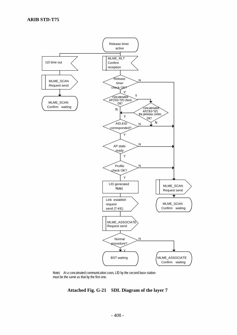
ARIB STD-T75
- 408 -
MLME_SCAN Request send
AP stateready
Profilecheck OK?
MLME_SCAN Request send
Link establishrequestsend (T-KE)
MLME_SCAN Confirm waiting
MLME_ASSOCIATE Request send
Normalprocedure?
BST waiting MLME_ASSOCIATE Confirm waiting
MLME_SCAN Confirm waiting
Y
Y
N
Y
N
Y
N
concatenated
OK?
Y
N
YN
AP(TRI='10') check
concatenated
OK?
AP(TRI='10')the previous comm.
Note) At a concatnated communication zoon, LID by the second base station must be the same as that by the first one.
Release timer active
t10 time out MLME_RLTConfirmreception
LID generated Note)
AID,EIDcorresponded?
Y
N
Releasetimer
check OK?
N
Attached Fig. G-21 SDL Diagram of the layer 7
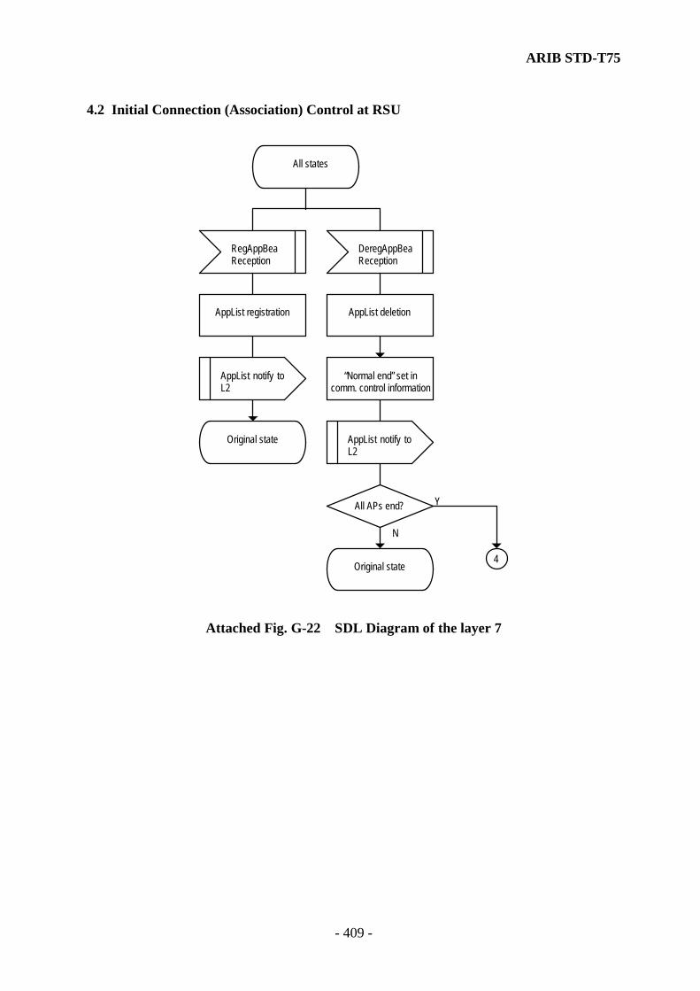
ARIB STD-T75
- 409 -
4.2 Initial Connection (Association) Control at RSU
All states
RegAppBeaReception
DeregAppBeaReception
AppList registration AppList deletion
AppList notify toL2
“Normal end” set in comm. control information
Original state AppList notify toL2
All APs end?
Original state4
Y
N
Attached Fig. G-22 SDL Diagram of the layer 7

ARIB STD-T75
- 410 -
Idle
MLME_ASSOCIATEIndication reception
Number of connection linksadded (L2 management)
Initial connectionrequest send (T-KE)
Normalprocedure?
INIT.req creation Comm. controlinformation establish
INIT.req send request
NotAppBeaTransmission
Comm. controlinformation establish
Active
VST receive waiting
N
Y
Attached Fig. G-23 SDL Diagram of the layer 7

ARIB STD-T75
- 411 -
VST reception waiting
ReadyAppReception
Comm. controlinformation establish
All APs end?
VST reception waiting
INIT.confReception
NotAppBeaTransmission
Comm. controlinformation establish
Active4
Y
N
Attached Fig. G-24 SDL Diagram of the layer 7
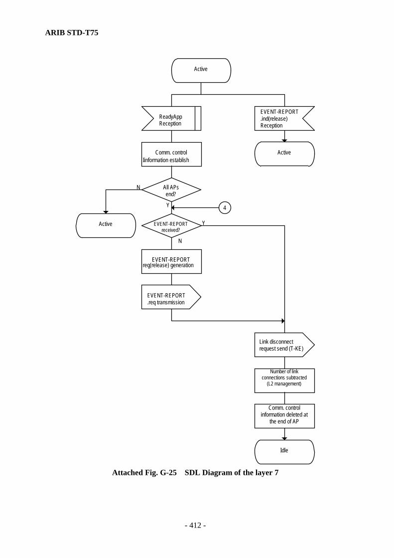
ARIB STD-T75
- 412 -
Active
ReadyAppReception
EVENT-REPORT.ind(release)Reception
Comm. controlIinformation establish
Active
All APsend?
Active EVENT-REPORTreceived?
4
EVENT-REPORT.req(release) generation
EVENT-REPORT.req transmission
Link disconnectrequest send (T-KE)
Idle
N
Y
Y
N
Comm. controlinformation deleted at
the end of AP
Number of linkconnections subtracted
(L2 management)
Attached Fig. G-25 SDL Diagram of the layer 7

ARIB STD-T75
- 413 -
Annex H. Data Structures This annex specifies the data structures in the Layer 7. 1. Use of modules The T-KE shall use a DSRCData and a DSRCtransfer module. Note1) IMPORT resp.EXPORT mechanism is standardized in[ISO 8824-1]. Note2) Parameters (aid.etc.,) presented in the abstract structure of ASN.1 sentences will be
bounded within regulated values or default one. Then, the transmission data length shall be 1Octet-length including of a extension bit, preamble bits and so on.
1.1 ASN.1 modules DSRCData DEFINITIONS::= BEGIN IMPORTS ContainerJ.y FROM ApplicationJ --this line shall be given for each application
-- which defines data of type container, J and y -- shall be replaced by an unambiguous suffix;
RecordJ.y FROM ApplicationJ -- this line shall be given for each application -- which defines data of type record, J and y -- shall be replaced by an unambiguous suffix;
-- EXPORTS everything; Action-Request::= SEQUENCE{ mode BOOLEAN, eid Dsrc-EID, actionType ActionType, accessCredentials OCTET STRING (SIZE (0..127,…)) OPTIONAL, actionParameter Container OPTIONAL, iid Dsrc-EID OPTIONAL } Action-Response::= SEQUENCE{ fill BIT STRING (SIZE(1)), eid Dsrc-EID, iid Dsrc-EID OPTIONAL, responseParameter Container OPTIONAL, ret ReturnStatus OPTIONAL } ActionType ::= INTEGER(0..127,..) ApplicationContextMark ::= Container -- OCTET STRING (SIZE(0..127,...))
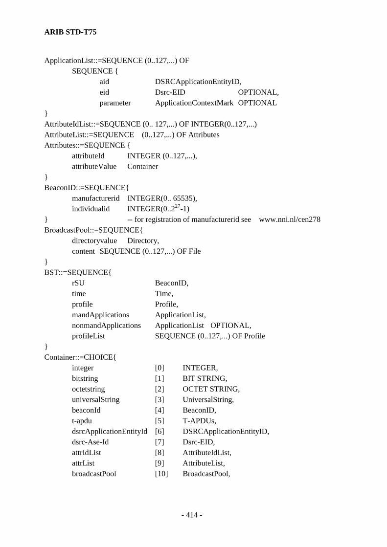
ARIB STD-T75
- 414 -
ApplicationList::=SEQUENCE (0..127,...) OF SEQUENCE { aid DSRCApplicationEntityID, eid Dsrc-EID OPTIONAL, parameter ApplicationContextMark OPTIONAL } AttributeIdList::=SEQUENCE (0.. 127,...) OF INTEGER(0..127,...) AttributeList::=SEQUENCE (0..127,...) OF Attributes Attributes::=SEQUENCE { attributeId INTEGER (0..127,...), attributeValue Container } BeaconID::=SEQUENCE{ manufacturerid INTEGER(0.. 65535), individualid INTEGER(0..227-1) } -- for registration of manufacturerid see www.nni.nl/cen278 BroadcastPool::=SEQUENCE{ directoryvalue Directory, content SEQUENCE (0..127,...) OF File } BST::=SEQUENCE{ rSU BeaconID, time Time, profile Profile, mandApplications ApplicationList, nonmandApplications ApplicationList OPTIONAL, profileList SEQUENCE (0..127,...) OF Profile } Container::=CHOICE{
integer [0] INTEGER, bitstring [1] BIT STRING, octetstring [2] OCTET STRING, universalString [3] UniversalString, beaconId [4] BeaconID, t-apdu [5] T-APDUs, dsrcApplicationEntityId [6] DSRCApplicationEntityID, dsrc-Ase-Id [7] Dsrc-EID, attrIdList [8] AttributeIdList, attrList [9] AttributeList, broadcastPool [10] BroadcastPool,
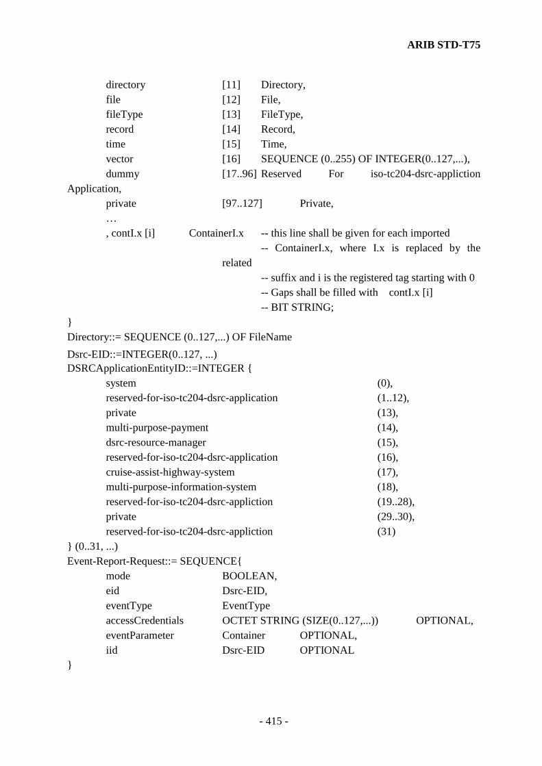
ARIB STD-T75
- 415 -
directory [11] Directory, file [12] File, fileType [13] FileType, record [14] Record, time [15] Time, vector [16] SEQUENCE (0..255) OF INTEGER(0..127,...), dummy [17..96] Reserved For iso-tc204-dsrc-appliction
Application, private [97..127] Private, … , contI.x [i] ContainerI.x -- this line shall be given for each imported
-- ContainerI.x, where I.x is replaced by the related
-- suffix and i is the registered tag starting with 0 -- Gaps shall be filled with contI.x [i]
-- BIT STRING; } Directory::= SEQUENCE (0..127,...) OF FileName Dsrc-EID::=INTEGER(0..127, ...) DSRCApplicationEntityID::=INTEGER { system (0), reserved-for-iso-tc204-dsrc-application (1..12), private (13), multi-purpose-payment (14), dsrc-resource-manager (15), reserved-for-iso-tc204-dsrc-application (16), cruise-assist-highway-system (17), multi-purpose-information-system (18), reserved-for-iso-tc204-dsrc-appliction (19..28), private (29..30), reserved-for-iso-tc204-dsrc-appliction (31) } (0..31, ...) Event-Report-Request::= SEQUENCE{ mode BOOLEAN, eid Dsrc-EID, eventType EventType accessCredentials OCTET STRING (SIZE(0..127,...)) OPTIONAL, eventParameter Container OPTIONAL, iid Dsrc-EID OPTIONAL }

ARIB STD-T75
- 416 -
Event-Report-Response::= SEQUENCE{ fill BIT STRING (SIZE(2)), eid Dsrc-EID, iid Dsrc-EID OPTIONAL, ret ReturnStatus OPTIONAL } EventType::=INTEGER{ release (0) } (0..127, ...) File::=SEQUENCE(0..127,...) OF Record FileName::=SEQUENCE{ aseID Dsrc-EID, fileID INTEGER(0..127,...) } Get-Request::=SEQUENCE{ fill BIT STRING (SIZE(1)), eid Dsrc-EID, accessCredentials OCTET STRING (SIZE(0..127,...)) OPTIONAL, iid Dsrc-EID OPTIONAL, attrIdList AttributeIdList OPTIONAL } Get-Response::=SEQUENCE{ fill BIT STRING (SIZE(1)), eid Dsrc-EID, iid Dsrc-EID OPTIONAL, attributelist AttributeList OPTIONAL, ret ReturnStatus OPTIONAL } Initialisation-Request::= BST Initialisation-Response::= VST NamedFile::=SEQUENCE{ name FileName, file File } ObeConfiguration::=SEQUENCE{ equipmentClass INTEGER(0..32767), manufacturerID INTEGER(0..65535), obeStatus INTEGER(0..65535) OPTIONAL } Profile::= INTEGER{
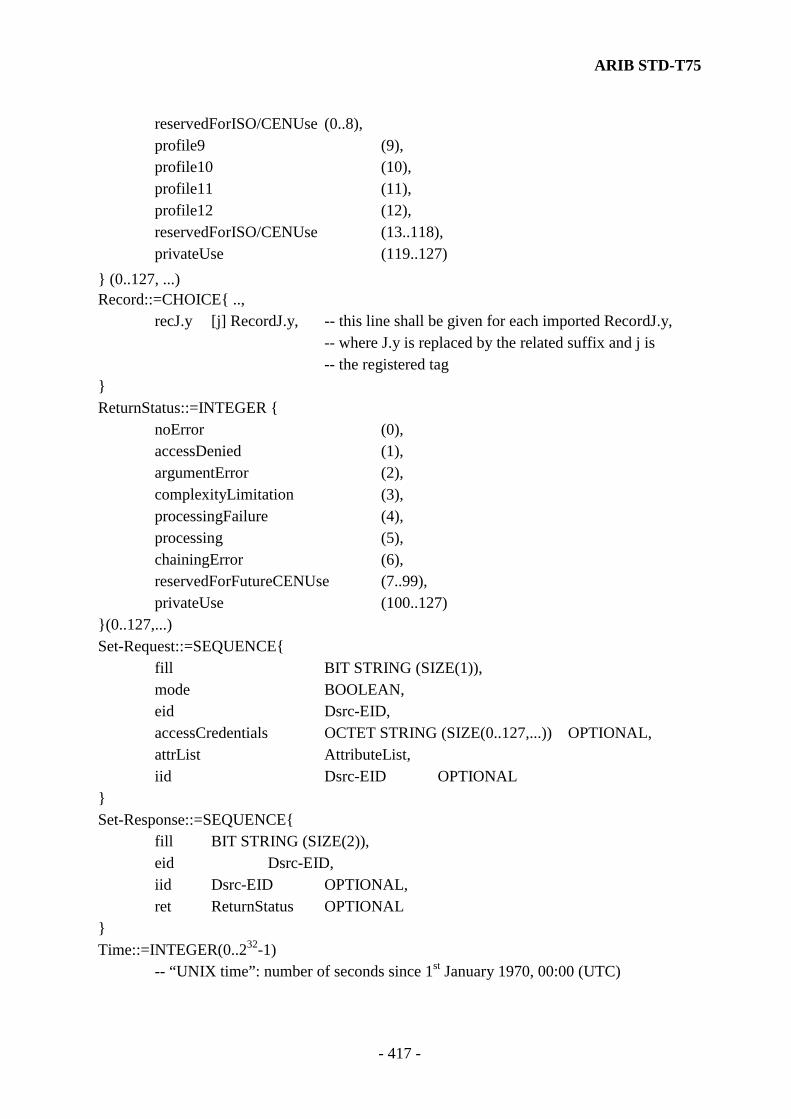
ARIB STD-T75
- 417 -
reservedForISO/CENUse (0..8), profile9 (9), profile10 (10), profile11 (11), profile12 (12), reservedForISO/CENUse (13..118),
privateUse (119..127) } (0..127, ...) Record::=CHOICE{ .., recJ.y [j] RecordJ.y, -- this line shall be given for each imported RecordJ.y,
-- where J.y is replaced by the related suffix and j is -- the registered tag
} ReturnStatus::=INTEGER { noError (0), accessDenied (1), argumentError (2), complexityLimitation (3), processingFailure (4), processing (5), chainingError (6), reservedForFutureCENUse (7..99),
privateUse (100..127) }(0..127,...) Set-Request::=SEQUENCE{ fill BIT STRING (SIZE(1)), mode BOOLEAN, eid Dsrc-EID, accessCredentials OCTET STRING (SIZE(0..127,...)) OPTIONAL, attrList AttributeList, iid Dsrc-EID OPTIONAL } Set-Response::=SEQUENCE{ fill BIT STRING (SIZE(2)), eid Dsrc-EID, iid Dsrc-EID OPTIONAL, ret ReturnStatus OPTIONAL } Time::=INTEGER(0..232-1)
-- “UNIX time”: number of seconds since 1st January 1970, 00:00 (UTC)

ARIB STD-T75
- 418 -
T-APDUs::= CHOICE{ action.request [0] Action-Request, action.response [1] Action-Response, event-report.request [2] Event-Report-Request, event-report.response [3] Event-Report-Response, set.request [4] Set-Request, set.response [5] Set-Response, get.request [6] Get-Request, get.response [7] Get-Response, initialisation.request [8] Initialisation-Request, initialisation.response [9] Initialisation-Response } VST::=SEQUENCE{ fill BIT STRING (SIZE(4)),
profile Profile, applications ApplicationList, obeConfiguration ObeConfiguration } END DSRCtransferData DEFINITIONS::= BEGIN IMPORTS T-APDUs FROM DSRCData -- EXPORTS everything; Message::= T-APDUs -- Message is transferred over the DSRC link; END

ARIB STD-T75
- 419 -
Annex I. DSRC Application Entity ID 1 AID AID defined in the layer 2 and DSRC Application Layer is used as DSRCApplication identifier. In this standard DSRCApplication identifier shall be set to 0, 14, 17 or 18. AID of 0, 1, 14, 15, 17, 18, 29 and 30 are already defined and the other AIDs are reserved as shown in Table 1.
Table 1 Classifications of AID (DSRCApplication Entity ID)
AID Application Note 0 System 1 Application compliant with ISO Technical
Report 14906
2~13 Reserved for ISO-DSRC Application 14 Multi-purpose Fee Collection System Application
compliant with this standard
15 DSRC Resource Manager North America 16 Reserved for ISO-DSRC Application 17 Cruise-Assist System Application
compliant with this standard
18 Multi purpose Information System Application compliant with this
standard 19~28 Reserved for ISO-DSRC Application 29, 30 DSRC Test System Application
31 Reserved for ISO-DSRC Application Note) It depends on a system operator which of classification the application belongs to and the definition of the classification is outside of the scope of this standard. 1.1 Classification of AID [Informative] The example of the classification of AID defined by this standard is as follows. AID=0 : system(Testing etc) AID=14 : Applications that perform fee collection services mainly. Applied for
Electric Toll Collection systems of toll ways. AID=17 : Applications that mainly service the cruise-assist information on the road
and need the real time processing.

ARIB STD-T75
- 420 -
AID=18 : Applications that is carried out mainly the information services and secondary fee collection services. Applied for the application except Electric Toll Collection systems (ETC) of toll ways and the cruise-assist information systems.
2 EID 2.1 Definition of EID Although EID is an identifier to identify the elements that compose the application, EID is defined as relative address. Consequently, EID shall be used with the information of the element definition (ContextMark) which identifies the element. The application shall identify the elements of the other station by means of ContextMark and accesses to the element using the corresponding EID. The contents of an EID with ContextMark shall be exchanged between a base station and a mobile station by means of the association procedures. ContextMark shall be stored in parameters of RegisterApplicationRSU(Beacon)-service of the base station and parameter of RegisterApplicationOBU(Vehicle)-service of the mobile station. The details of contents, size and so on for ContextMark are outside of the scope of this standard. 2.2 EID Establishment (1) The number of EID shall be set not to be overlapped within each station. The EID of 0 is reserved for ETC application (AID=14) and the EID of 1 is reserved for the emergency call application. EID of 2 is reserved for broadcast application(AID=17) of cruise-assist information systems and EID of 3 is reserved for broadcast application(AID=18) of multi purpose information systems. (2) If the application has plural elements (i.e. plural EID respond to an AID), ContextMark shall be given to each EID. (3) If the application consists of a single element (i.e. an EID respond to an AID) and the information of the element is known, ContextMark can be omitted. (4) If the application of a base station consists of a single element, EID can be omitted. (5) Even if the application of a mobile station consists of a single element, EID can not be omitted. (Note1) IID shall be used in the case of a base station consists of a element. The example of it
is shown in 4.4.3.5(3). (Note2) EID of 127 shall b used for testing of the group broadcasting.

ARIB STD-T75
- 421 -
2.3 Examples of EIDs use [Informative] Examples of EIDs use are shown as follows. (1) Association procedures and data exchange procedures Examples of EIDs use are shown in Fig. 2.3-1, Fig 2.3-2, and Fig 2.3-3.
Fig 2.3-1 Example of RegisterApplication-service
Application(AID=14)
Context3 Data list
Context4 Data list
Context5 Data list
Layer7
Mobile stationBase station
Layer7
Application(AID=14)
Program
Program
EID=4 Context1
Data
EID=5 Context2データ
EID=9 Context3 データ
Program
I-KE
T-KE
T-KE
I-KE
Program
RegApp {aid=14,eid=4,Context1}
RegApp {aid=14,eid=9,Context3}
RegApp {aid=14,eid=5,Context2}
RegApp {aid=14 }

ARIB STD-T75
- 422 -
Fig 2.3-2 Example of Association procedures (Exchange of BST, VST)
Fig 2.3-3 Example of Data Exchange procedures
Application(AID=14)
Context3 Data list
Context4Data list
Context5 Data list
②GET.res {LID,eid=9, Attrib. List …}
①GET.req {LID,eid=9, Attrib.ID List …}
Layer7 Layer7
Application(AID=14)
Program
Program
EID=4 Context1
Data
EID=5 Context2
Data
EID=9 Context3
Data
Program
I-KE
T-KE
T-KE
I-KE
Program
Base station Mobile Staion
Application(AID=14)
Context3 Data list
Context4 Data list
Context5 Data list
Layer7 Layer7
Application(AID=14)
Prpgram
Program
EID=4 Context1
Data
EID=5 Context2
Data
EID=9 Context3
Data
Program
T-KE
T-KE
Program
③VST { LID, App.{aid=14,eid=4,Context1} App.{aid=14,eid=5,Context2} App.{aid=14,eid=9,Context3} …}
⑤Select Context3 {eid=9}
②NotifyApp .{…}
④NotifyApp .{eid,…}
①BST{aid=14}
I-KE
I-KE
Base station Mobile station
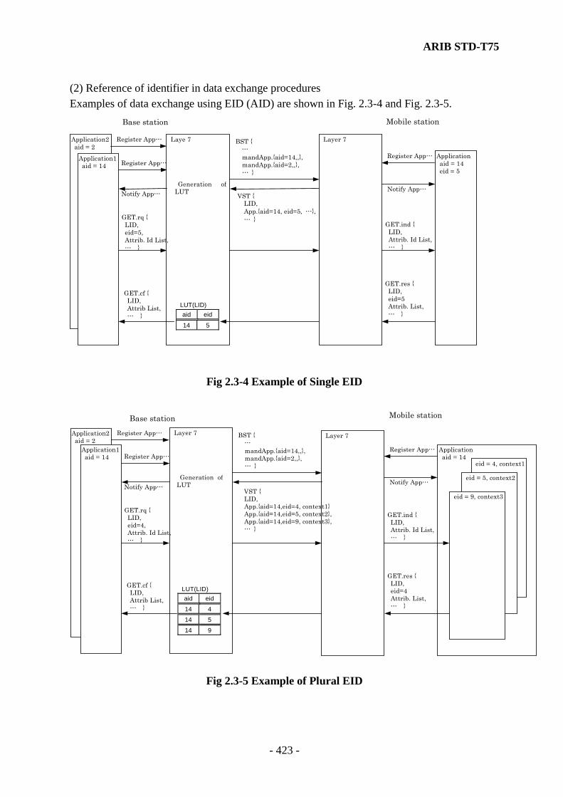
ARIB STD-T75
- 423 -
(2) Reference of identifier in data exchange procedures Examples of data exchange using EID (AID) are shown in Fig. 2.3-4 and Fig. 2.3-5.
LUT(LID) aid eid
14 5
Laye 7 Layer 7
Generation ofLUT
Mobile station Base station
GET.cf { LID, Attrib List, … }
GET.rq { LID, eid=5, Attrib. Id List, … }
GET.res { LID, eid=5 Attrib. List, … }
GET.ind { LID, Attrib. Id List, … }
Register App…
Register App…
Notify App… Notify App…
Register App…
BST { …
mandApp.{aid=14,,}, mandApp.{aid=2,,},… }
VST { LID, App.{aid=14, eid=5, …},… }
Application2 aid = 2
Application aid = 14 eid = 5
Application1 aid = 14
Fig 2.3-4 Example of Single EID
Fig 2.3-5 Example of Plural EID
LUT(LID) aid eid
14 4
14 5
14 9
Application aid = 14 eid = 4, context1
Layer 7 Layer 7
Generation of LUT
Mobile station Base station
GET.cf { LID, Attrib List, … }
GET.rq { LID, eid=4, Attrib. Id List, … }
GET.res { LID, eid=4 Attrib. List, … }
GET.ind { LID, Attrib. Id List, … }
Register App…
Register App…
Notify App… Notify App…
Register App…
BST { …
mandApp.{aid=14,,}, mandApp.{aid=2,,},… }
VST { LID, App.{aid=14,eid=4, context1} App.{aid=14,eid=5, context2}, App.{aid=14,eid=9, context3}, … }
Application2 aid = 2 Application1
aid = 14
eid = 5, context2
eid = 9, context3

ARIB STD-T75
- 424 -
Annex J. Protocol Version Identifier [Informative] 1. Summary A Protocol Version Identifier (PVI) shall be used to select the communication protocol applied for Layer 2 from association procedure of Layer 7 to termination of transaction. This selection of protocol shall be done by PVI that is exchanged in the association procedure of Layer 2 and the communication shall be done by selecting the newest version protocol among some versions of protocol which is available on Base station and Mobile stations. The setting the PVI of Base station shall be done by the condition that not only the newest version but the old version protocol are supported on Base station and Mobile station. Therefore, the newest version protocol among the implemented protocols shall be set up on Base station. The bigger number of PVI shall be recognized as the newest version. The details of each version is shown by Annex P. In the case of revision of protocol version, the following conditions should be considered. (1) The BS and MS have benefit of the improvement of communication facilities by adopting the newest version of protocol. (2) The BS or MS is able to communicate using the previous version of protocol. (3) The distinction of protocol version between the BS and the MS is made in the association procedures (link entry procedures) prior to the communication. 2. Procedures in Mobile Station Basic underlying assumption of the association procedure using the PVI code is as follows: The followings shall be referred as the pertinent details. 4.2.4.2.1.3 Transmission Channel Control Field (SIG) (1) Protocol Version Identifier (PVI) 4.2.4.2.3.1 Activation Channel (ACTC) 4.2.4.2.3.1.5 Link Request Information field (LRI) (1) An MS interprets the PVI code within FCMC from BS. (2) In the case where the PVI code of FCMC is the same PVI code in the MS, the MS transmits an ACTC, which set the same code to FCMC’s code in a PVI response field and starts the association procedure. (3) If the all PVI codes in the MS are older than the PVI code within FCMC, the MS transmits an ACTC in which a PVI response field sets the newest version code and then starts the association procedures. (4) If the all PVI codes in the MS are newer than the PVI code within FCMC, the MS does not start the association procedures.
ARIB STD-T75
- 425 -
Annex K. Emergency reporting from the mobile station [Informative] The request of the assignment with priority from an MS (Mobile Station) is assumed to apply to the emergency reporting that let a BS (Base Station) know an emergency at the MS. The procedures of the emergency reporting are explained as follows. An example of a connection sequence is shown in Fig. 1. (1) Procedures in MS
(a) In the case where the emergency reporting is needed (this judgment is outside of the scope of this standard), an MS shall notify the I-KE of the layer 7 by means of RegisterApplicationOBU(Vehicle).
(b) The I-KE shall interpret AID as the emergency reporting and shall indicate the association request of the assignment with priority (the assign demand bit of LRI is “1”) to the layer 2 by way of the layer management.
(c) At the same time the I-KE shall notify the emergency reporting application to NotifyApplicationVehicle () and shall start the emergency reporting application.
(d) The emergency reporting application shall transmit the data of EID=1 immediately after starting.
(e) The transmitted data shall be held until the uplink slot is assigned in the layer 2 by way of the T-KE.
(f) When the uplink slot assignment is detected, the layer 2 shall transmit the data to be held and shall do the emergency reporting.
(2) Procedures in BS
(a) When the layer 2 accepts the association request of the assignment with priority (the assign demand bit of LRI is "1"), Data Link Layer shall assign an uplink slot with priority and shall notify the I-KE of the layer 7 by way of the layer management.
(b) The I-KE shall interpret the assign demand bit of LRI and shall start the emergency reporting application by means of NotifyApplicationRSU(Beacon). EID shall generate the value arranged beforehand (EID=1) at the I-KE of the layer 7.
(c) The emergency reporting application shall be kept waiting for a reception of the datum after starting.
(3) Attention Even in the case where the association has been already completed and another application is under communication, the data of the emergency reporting must be transferred with priority. The layer 7 transmits the data based on the rank of the priority but there is a possibility of being late to transfer when there are the data that stagnate to be re-transmitted in the layer 2.

ARIB STD-T75
- 426 -
Application for Emergency T-KE Layer2
Application (Emergency)Transaction
I-KE
MobileStation I-KE T-KE
EventType=Release
EID,LID
AID,EID
Layer2
RegisterApplication RSU
RegisterApplicationOBU
DL-UNITDATA .req
EVENT-REPORT.ind
ACTC(LRI,LID)
Uplink Slot Assignment
AID,EID LRI,LID
LRI,LID LID,EID
EID,LID EventType=Release
LID
DL-UNITDATA.ind
MDS(EID,---)
LID,EID, DATA
Notify Application OBU
Notify ApplicationRSU
EVENTREPORT .ind
DL-UNITDATA .ind
EVENTREPORT .req
ReadyApplication EVENT-REPORT.req DL-UNITDATA.req
Base Station Application forEmergency
Fig. 1 Example of Connection Sequence of the Emergency Reporting

ARIB STD-T75
- 427 -
Annex L. Unique Word A unique word is used for TDMA frame synchronization. The unique words are defined in sub-clause 4.2.4 in this protocol version (Ver. 0;PVI=0). The definition is shown again in Table 1. Even if a standard version changes, the length of field must be the same, but use of another types of unique words are not restricted.
Table 1 Unique Word defined by the protocol version 0 Applied method Symbol Usage Bit assignment
UW1 FCMC LSB MSB 0001 1011 1010 1000 0100 1011 0011 1110 32bits in length and shall be transmitted least significant bit (LSB) first in a bit string
ASK
UW2 MDC,ACTC& ACKC
LSB MSB 0100 1011 0011 1110 16bits in length and shall be transmitted least significant bit (LSB) first in a bit string
UW1 FCMC LSB MSB 0110 1011 1000 1001 1001 1010 1111 0000 32bits in length and shall be transmitted least significant bit (LSB) first in a bit string
UW2A ACTC & ACKC
LSB MSB 1110 0001 0100 1001 16bits in length and shall be transmitted least significant bit (LSB) first in a bit string
π/4 shift QPSK
UW2B MDC LSB MSB 0011 1101 0100 1100 16bits in length and shall be transmitted least significant bit (LSB) first in a bit string
NOTE) The unique word of WCNC is shown in Annex C. Annex M. Fixed Equipment ID (FID) [Informative] The fixed equipment ID (FID) is an ID number of a base station used in association between a base station and a mobile station. This FID is not supposed to be given the same number in the next communication zone. To number base stations is outside of the scope of this standard, but the numbering regulation is to be considered by the system operator. The FID [11111111] shall not be permitted for the time being.
ARIB STD-T75
- 428 -
Annex N. Private Link Address (1) When generated In principle, a mobile station shall generate a new random number as a private link address when the operation starts and shall hold the value until the operation is finished. Note 1) the start of an operation is defined as a time when the mobile station comes into operation by means of a user's turning on its power. Basically, the end of an operation is defined as a time when the mobile station stops by means of a user's turning off the power. As well, it is assumed that a link address is generated when the mobile station is turn on. But, it is permitted that a link address is generated when each communication is started under the guarantee of random link address. However, the same link address using for the first base station shall be used for the second base station in the continuous communication zone. And the previous link address shall be used when the second association procedure is carried out to the same base station after the termination of communication (independently of Good or No good). It is not necessary that the private link address of a mobile station equal to the private link address using the previous base stations in the case that a mobile station is carried out the association procedure (link connection) with new base station except the tow base stations, which set up the continuous communication zone defined as DSRC protocol stuck. As well, after the complete link connection, the same private link address shall be used until the termination of communication with same base station (independently of Good or No good) if changing the frequency and transmission speed is occurred. (2) Generation Algorithm Link addresses are not supposed to be overlapped between mobile stations within the same communication zone at the same time. Therefore the generation algorithm which has the low probability of generating the duplicate link addresses between mobile stations shall be adopted in consideration of not only the randomness of a link address within a mobile station but also the randomness between mobile stations. NOTE) The generation algorithm of link address is not defined especially. But the random characteristic of link address shall be fully considered. (3) Handling procedure of Base Station with Duplicate LIDs A base station shall consider the duplicate of LIDs in some probability. The examination of the duplication of LIDs and the procedure are defined as follows and are applied to layer 7.
(a) A base station shall examine the duplication of LIDs after receiving the association request from mobile stations.

ARIB STD-T75
- 429 -
(b) In the case where the duplicate LIDs are detected, a base station shall immediately transmit the release using the LID and shall release the connection with a mobile station that has the duplicate LID.
Annex O. Multicast Link Address [Informative] A multicast link address that is a SAP of a link is defined and supposed to do a communication service to both this system operator and the specific user (a mobile station). For the numbering of a multicast link address, the items of operation including the registration, administration and so on is outside of the scope of this standard and is defined separately. For the numbering scheme, it is desirable to define plural number groups separately for system, private and application. The multicast link addresses of 120-126 are defined for testing of private use for a time. The other number is defined separately including the items of operation mentioned above. NOTE) The link address of 120 shall be used for the transmission of Wireless Call Number Channel (WCNC) of test equipment.
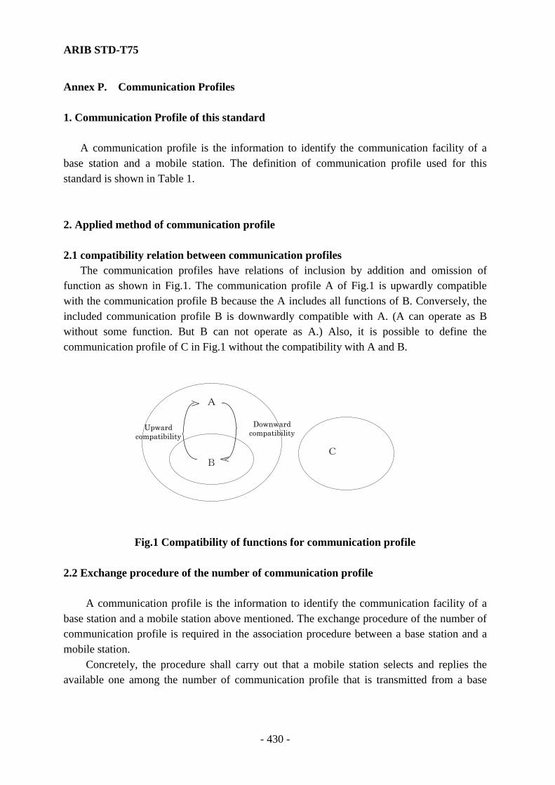
ARIB STD-T75
- 430 -
Annex P. Communication Profiles 1. Communication Profile of this standard A communication profile is the information to identify the communication facility of a base station and a mobile station. The definition of communication profile used for this standard is shown in Table 1. 2. Applied method of communication profile 2.1 compatibility relation between communication profiles The communication profiles have relations of inclusion by addition and omission of function as shown in Fig.1. The communication profile A of Fig.1 is upwardly compatible with the communication profile B because the A includes all functions of B. Conversely, the included communication profile B is downwardly compatible with A. (A can operate as B without some function. But B can not operate as A.) Also, it is possible to define the communication profile of C in Fig.1 without the compatibility with A and B.
Fig.1 Compatibility of functions for communication profile
2.2 Exchange procedure of the number of communication profile A communication profile is the information to identify the communication facility of a base station and a mobile station above mentioned. The exchange procedure of the number of communication profile is required in the association procedure between a base station and a mobile station. Concretely, the procedure shall carry out that a mobile station selects and replies the available one among the number of communication profile that is transmitted from a base
A
B C
Upward compatibility
Downward compatibility

ARIB STD-T75
- 431 -
station. The following is the summary of the exchange procedure of communication profile by BST and VST. The communication profile is used for the application registration by ResisterApplicationRSU(Beacon)/OBU(Vehicle) of Layer 7 and the association procedure. The treatment of communication profile is as follows for each case.
Table 1-a Number of communication profile and functions of each layer (Note1) Communication
Profile 9
(Note2) 10 11 12
T-KE ASN.1 Coding M M M M ASN.1 Decoding M M M M Octet allayment M M M M Delete the insert bits M M M M Concatenation/Chaining -- -- -- -- Fragmentation -- -- -- -- Multiplexing -- -- -- -- Fragmented header Fixed one octet M M M M Primitive GET M M M M SET M M M M ACTION M M M M EVENT-REPORT M M M M INITIALISATION M M M M I-KE Nominal Association procedure M M M M Simple Association procedure -- -- -- -- Primitive RegisterApplicationRSU(Beacon) M M M M RegisterApplicationOBU(Vehicle) M M M M DeregisterApplication M M M M NotifyApplicationRSU(Beacon) M M M M NotifyApplicationOBU(Vehicle) M M M M EndApplication
(ReadyApplication) M M M M
B-KE Primitive BroadcastData -- -- -- --
Layer7
GetBroadcastData -- -- -- -- Layer2
Protocol Version Identifier Number(refer to Table 1-c)
0 1 1 1
Layer1 Physical Profile Identifier Number (refer to Table 1-b)
0 1 2 3
(NOTE1) Symbols in Table are follows. M: Mandatory --: Not implement function (NOTE2) The communication profile number 9 is compatible with the communication profile
number 9(Layer 7 profile 4) of “ELECTRONIC TOLL COLLECTION SYSTEM (ARIB STD-T55)”. The same communication profile number is used commonly.
The communication profiles of 10,11,12 are defined in this standard.

ARIB STD-T75
- 432 -
Table 1-b Physical Profile Identifier (PPI)
Profile Number 0 1 2 3 4-7
FCMC/ACTC ASK ASK ASK QPSK Reserved Modulation
MDC /ACKC ASK ASK QPSK QPSK Reserved
FCMC/ACTC 1024kbps 1024kbps 1024kbps 4096kbps Reserved Transmission
speed MDC /ACKC 1024kbps 1024kbps 4096kbps 4096kbps Reserved
Occupied bandwidth 4.4MHz/10MHz 4.4MHz 4.4MHz 4.4MHz Reserved
Channel allocation 2 7 7 7 Reserved
Table 1-c Protocol Version (NOTE3) Protocol Version Identifier Number 0 1 2 3
DL-UNITDATA.request without response request
M M Reserved Reserved
DL-UNITDATA.request with response request
M M Reserved Reserved
DL-UNITDATA.indication M M Reserved Reserved
Type 1
Procedures DL-UNITDATA.request wait response request
M M Reserved Reserved
DL-DATA-ACK.request -- -- Reserved Reserved
DL-DATA-ACK.indication -- -- Reserved Reserved
DL-REPLY.request -- -- Reserved Reserved
DL-REPLY-STATUS.indication
-- -- Reserved Reserved
DL-REPLY-UPDATE.request
-- -- Reserved Reserved
LLC
Sublaye
r
Type 3
Procedures
DL-REPLY-UPDATES-STATUS.indication
-- -- Reserved Reserved
MAC
sublayer
Break of retransmission procedure by receiving the down link data (refer to 4.3.3.5.2.2.2.1 (4) retransimission)
M -- Reserved Reserved
(NOTE3) Symbols in Table are follows. M: Applied --: Not Applied (1) Registration of Application (a) Application sets the available communication profile number to the parameter profile
of RegisterApplicationRSU(Beacon)/OBU(vehicle) and sends to Layer 7. (b) Layer 7 compares the parameter profile with own communication profile and registers
the communication profile number to be able to use by itself to the profiles of application list in Layer 7.
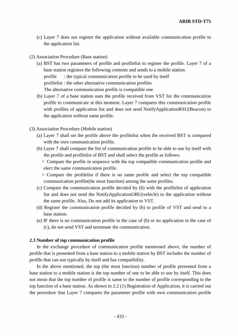
ARIB STD-T75
- 433 -
(c) Layer 7 does not register the application without available communication profile to the application list.
(2) Association Procedure (Base station) (a) BST has two parameters of profile and profilelist to register the profile. Layer 7 of a
base station registers the following contents and sends to a mobile station. profile : the typical communication profile to be used by itself profilelist : the other alternative communication profiles The alternative communication profile is compatible one. (b) Layer 7 of a base station uses the profile received from VST for the communication
profile to communicate at this moment. Layer 7 compares this communication profile with profiles of application list and does not send NotifyApplicationRSU(Beacon) to the application without same profile.
(3) Association Procedure (Mobile station) (a) Layer 7 shall set the profile above the profilelist when the received BST is compared
with the own communication profile. (b) Layer 7 shall compare the list of communication profile to be able to use by itself with
the profile and profilelist of BST and shall select the profile as follows. ☼ Compare the profile in sequence with the top compatible communication profile and
elect the same communication profile. ☼ Compare the profilelist if there is no same profile and select the top compatible
communication profile(the most function) among the same profiles. (c) Compare the communication profile decided by (b) with the profilelist of application
list and does not send the NotifyApplicationOBU(vehicle) to the application without the same profile. Also, Do not add its application to VST.
(d) Register the communication profile decided by (b) to profile of VST and send to a base station.
(e) IF there is no communication profile in the case of (b) or no application in the case of (c), do not send VST and terminate the communication.
2.3 Number of top communication profile In the exchange procedure of communication profile mentioned above, the number of profile that is presented from a base station to a mobile station by BST includes the number of profile that can use typically by itself and has compatibility. In the above mentioned, the top (the most function) number of profile presented from a base station to a mobile station is the top number of one to be able to use by itself. This does not mean that the top number of profile is same to the number of profile corresponding to the top function of a base station. As shown in 2.2 (1) Registration of Application, it is carried out the procedure that Layer 7 compares the parameter profile with own communication profile

ARIB STD-T75
- 434 -
and registers the communication profile number to be able to use by itself to the profiles of application list in Layer 7 after Application sets the available communication profile number to the parameter profile of RegisterApplicationRSU(Beacon) and sends to Layer 7. That is to say, the top communication profile to be able to use by itself of a base station means as the top communication profile supported by a base station among the communication profile required by application. For example of Fig.1, the communication profile A is not included although a base station can support A in the case that communication profile B is included and A is not included. It is same for a mobile station. It is impossible to select the available communication profile over the profiles registered from applications regardless of the function of a mobile station. 2.4 Compatibility of communication profile The previous Fig.1 shows that the relation of inclusion between the function of a base station and mobile station corresponds to the communication profile. That is not described the compatibility of communication profile indicated the number of communication profile. The same communication profile shall be used for communication between a base station and mobile station. For example of Fig.1, the communication profile A of a mobile station is required if the communication profile of a base station is A. In the same way, the communication profile B of a mobile station is required if the communication profile of a base station is B. This is required to avoid the problem by discordance. Because there is a possibility that the function not implemented at one side is used at the another side if the communication profile of a base station is upward A and the one of a mobile station is downward B or the one of a base station is downward B and the one of a mobile station is upward A. For the correct communication, the procedure that upward side narrows down the function and changes to the other communication profiles is considered regardless of the number of communication profile exchanged mutually between a base station and mobile station. But that procedure is not considered in this standard. 2.5 Registration of the communication profile by application In case that one application registers the communication profile by RegistrationApplicationRSU(Beacon)/OBU(Vehicle) primitive, generally the registration of the same communication profile is expected at a base station and mobile station. But in case that the plural communication profiles are noticed from application, there is a possibility that the deferent one is registered according to the composition of a base station and mobile station. For example of Fig.1, it is considered that application has communication profile A and B in profile, while a base station can use the communication profile A, B and a mobile station can use only B. In this case, it is possible that a mobile station can select B by to notice not only A but also B at a base station as shown in 2.2 Exchange procedure of the
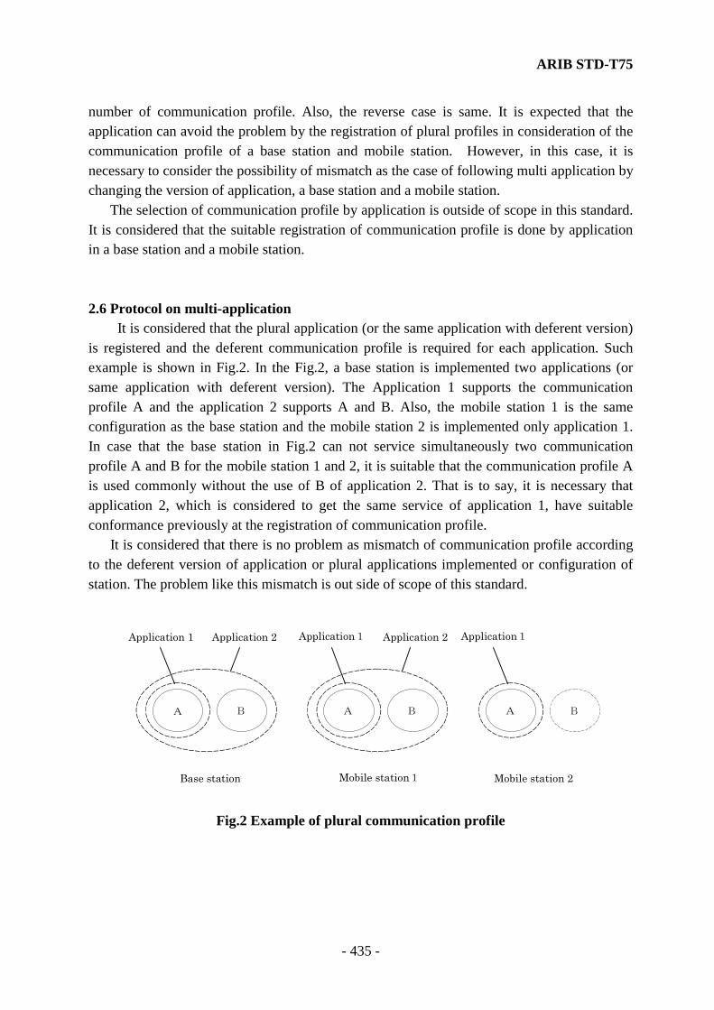
ARIB STD-T75
- 435 -
number of communication profile. Also, the reverse case is same. It is expected that the application can avoid the problem by the registration of plural profiles in consideration of the communication profile of a base station and mobile station. However, in this case, it is necessary to consider the possibility of mismatch as the case of following multi application by changing the version of application, a base station and a mobile station. The selection of communication profile by application is outside of scope in this standard. It is considered that the suitable registration of communication profile is done by application in a base station and a mobile station. 2.6 Protocol on multi-application It is considered that the plural application (or the same application with deferent version) is registered and the deferent communication profile is required for each application. Such example is shown in Fig.2. In the Fig.2, a base station is implemented two applications (or same application with deferent version). The Application 1 supports the communication profile A and the application 2 supports A and B. Also, the mobile station 1 is the same configuration as the base station and the mobile station 2 is implemented only application 1. In case that the base station in Fig.2 can not service simultaneously two communication profile A and B for the mobile station 1 and 2, it is suitable that the communication profile A is used commonly without the use of B of application 2. That is to say, it is necessary that application 2, which is considered to get the same service of application 1, have suitable conformance previously at the registration of communication profile. It is considered that there is no problem as mismatch of communication profile according to the deferent version of application or plural applications implemented or configuration of station. The problem like this mismatch is out side of scope of this standard.
A B
Base station
Application 1 Application 2
A B
Mobile station1
Application1 Application 2
A B
Mobile station 2
Application1
Fig.2 Example of plural communication profile
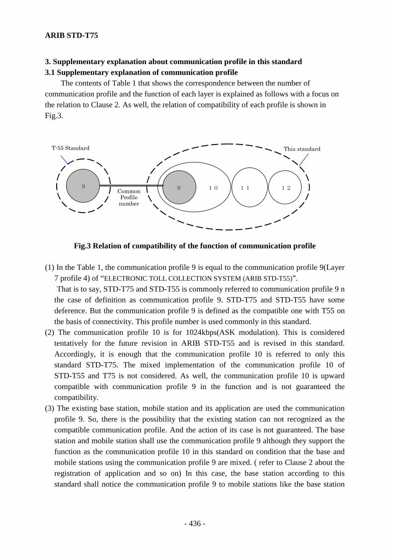
ARIB STD-T75
- 436 -
3. Supplementary explanation about communication profile in this standard 3.1 Supplementary explanation of communication profile The contents of Table 1 that shows the correspondence between the number of communication profile and the function of each layer is explained as follows with a focus on the relation to Clause 2. As well, the relation of compatibility of each profile is shown in Fig.3.
T-55 Standard This standard
12 10 1199 Common Profile number
Fig.3 Relation of compatibility of the function of communication profile
(1) In the Table 1, the communication profile 9 is equal to the communication profile 9(Layer
7 profile 4) of “ELECTRONIC TOLL COLLECTION SYSTEM (ARIB STD-T55)”. That is to say, STD-T75 and STD-T55 is commonly referred to communication profile 9 n
the case of definition as communication profile 9. STD-T75 and STD-T55 have some deference. But the communication profile 9 is defined as the compatible one with T55 on the basis of connectivity. This profile number is used commonly in this standard.
(2) The communication profile 10 is for 1024kbps(ASK modulation). This is considered tentatively for the future revision in ARIB STD-T55 and is revised in this standard. Accordingly, it is enough that the communication profile 10 is referred to only this standard STD-T75. The mixed implementation of the communication profile 10 of STD-T55 and T75 is not considered. As well, the communication profile 10 is upward compatible with communication profile 9 in the function and is not guaranteed the compatibility.
(3) The existing base station, mobile station and its application are used the communication profile 9. So, there is the possibility that the existing station can not recognized as the compatible communication profile. And the action of its case is not guaranteed. The base station and mobile station shall use the communication profile 9 although they support the function as the communication profile 10 in this standard on condition that the base and mobile stations using the communication profile 9 are mixed. ( refer to Clause 2 about the registration of application and so on) In this case, the base station according to this standard shall notice the communication profile 9 to mobile stations like the base station
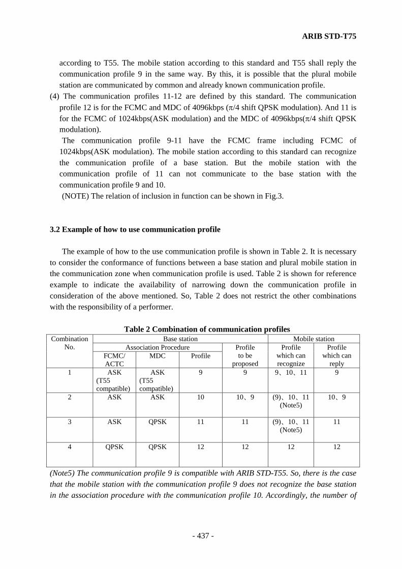
ARIB STD-T75
- 437 -
according to T55. The mobile station according to this standard and T55 shall reply the communication profile 9 in the same way. By this, it is possible that the plural mobile station are communicated by common and already known communication profile.
(4) The communication profiles 11-12 are defined by this standard. The communication profile 12 is for the FCMC and MDC of 4096kbps (π/4 shift QPSK modulation). And 11 is for the FCMC of 1024kbps(ASK modulation) and the MDC of 4096kbps(π/4 shift QPSK modulation).
The communication profile 9-11 have the FCMC frame including FCMC of 1024kbps(ASK modulation). The mobile station according to this standard can recognize the communication profile of a base station. But the mobile station with the communication profile of 11 can not communicate to the base station with the communication profile 9 and 10.
(NOTE) The relation of inclusion in function can be shown in Fig.3. 3.2 Example of how to use communication profile The example of how to the use communication profile is shown in Table 2. It is necessary to consider the conformance of functions between a base station and plural mobile station in the communication zone when communication profile is used. Table 2 is shown for reference example to indicate the availability of narrowing down the communication profile in consideration of the above mentioned. So, Table 2 does not restrict the other combinations with the responsibility of a performer.
Table 2 Combination of communication profiles Base station Mobile station
Association Procedure Combination
No. FCMC/ ACTC
MDC Profile Profile to be
proposed
Profile which can recognize
Profile which can
reply 1
ASK (T55 compatible)
ASK (T55 compatible)
9 9 9、10、11
9
2
ASK ASK 10 10、9 (9)、10、11 (Note5)
10、9
3
ASK QPSK 11 11 (9)、10、11 (Note5)
11
4
QPSK QPSK 12 12 12
12
(Note5) The communication profile 9 is compatible with ARIB STD-T55. So, there is the case that the mobile station with the communication profile 9 does not recognize the base station in the association procedure with the communication profile 10. Accordingly, the number of

ARIB STD-T75
- 438 -
communication profile must be the combination No.1 of 9 in case that a base station must communicate to the mobile station with ARIB STD-T55 (ELECTRONIC TOLL COLLECTION SYSTEM). (1) Combination 1 In this case, the number of communication profile that a base station can propose is only 9 in the communication zone of the base station with communication profile of 9. And a mobile station replies the same communication profile of 9. This gives the communication compatible to T55. It is possible that also the mobile station with communication profile of 10 can recognize the one of the base station by the association procedure to it. (2) Combination 2 In this case, the number of communication profile that a base station can propose is 10 and 9 in the communication zone of the base station with communication profile of 10. And the mobile station that can reply is the one with communication profile of 10 and 9(reply 10) and with only 9(reply 9). (3) Combination 3 In this case, the number of communication profile that a base station can propose is only 11 in the communication zone of the base station with communication profile of 11. And the mobile station replies the same communication profile of 11. This gives the communication of QPSK by this standard. (NOTE6) (NOTE6) It is considered at “ANNEX.R Change of transmission speed” that the upward
compatible communication profile is added to the one of 9,10 and 11. The number of communication profile that a base station can propose is this
upward compatible one in addition to 10, 9 and 11 under the consideration to the upward compatibility of ANNEX. R. And the reply of a mobile station is described in it.
In case that a base station always gives the communication zone with the upward compatible profile and a mobile station replies that one, a base station shall give the communication that is able to change the transmission speed. Also, a base station shall give the communication by ASK for the mobile station that reply the communication profile of 10.
But, it shall be the condition that a base station can service the plural communication profiles.
(4) Combination 4 In this case, the number of communication profile that a base station can propose is only 12 in the communication zone of the base station with communication profile of 12. And
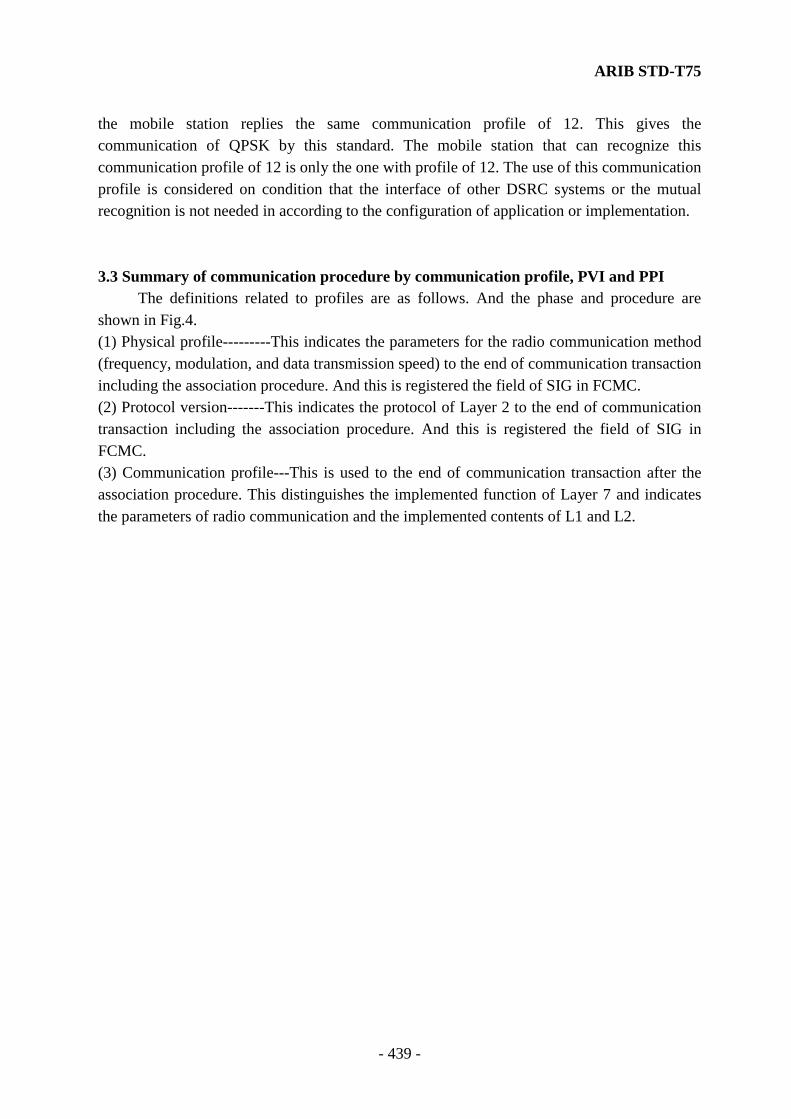
ARIB STD-T75
- 439 -
the mobile station replies the same communication profile of 12. This gives the communication of QPSK by this standard. The mobile station that can recognize this communication profile of 12 is only the one with profile of 12. The use of this communication profile is considered on condition that the interface of other DSRC systems or the mutual recognition is not needed in according to the configuration of application or implementation. 3.3 Summary of communication procedure by communication profile, PVI and PPI The definitions related to profiles are as follows. And the phase and procedure are shown in Fig.4. (1) Physical profile---------This indicates the parameters for the radio communication method (frequency, modulation, and data transmission speed) to the end of communication transaction including the association procedure. And this is registered the field of SIG in FCMC. (2) Protocol version-------This indicates the protocol of Layer 2 to the end of communication transaction including the association procedure. And this is registered the field of SIG in FCMC. (3) Communication profile---This is used to the end of communication transaction after the association procedure. This distinguishes the implemented function of Layer 7 and indicates the parameters of radio communication and the implemented contents of L1 and L2.
ARIB STD-T75
- 440 -
Base station
Layer2 Layer7
Mobile station
Layer2
FCMC
Layer7
MLME_SCAN request
・ MIB registration ・ Decide modulation from
PPI and set MSIZE ・ Decide and set PVI
MLME_SCAN confirm
MLME_ASSOCIATE requestACTC
MLME_ASSOCIATE indication
INITIALIZATION request MDC(BST)MLME_ASSOCIATE
confirm
INITIALIZATION indication
INITIALIZATION confirm INITIALIZATION responseMDC(VST)
Select the
communication
profile
Notify the
communication profile
Both decision about PPI/PVI are OK
Notify PVI
Decide the protocolof Layer 2
Decide theassociation of L7
Store the decision of PVI
Decide the protocol of Layer 2
Fig.4 Summary of communication procedure
ARIB STD-T75
- 441 -
ANNEX Q. Installation and operation standard for Radio station that communicates with the RF equipment of mobile station for the test
The radio station that communicates with the RF equipment of mobile station for the test (hereafter "test equipment") is defined the standard because it gives interference or disturbance to other communications by installation or operation of it. a. Strongly inhibit the test equipment from being used for the purpose except the test of
mobile station b. Do not use the test equipment on the condition of turning the boresight direction
(direction of radiation) of antenna, which is described on the test equipment, to the direction of mobile station under not testing
c. Do not use the test equipment on the condition of turning the boresight direction (direction of radiation) of antenna, which is described on the test equipment, to the direction of base station
d. Do not use the test equipment on the condition of turning the boresight direction (direction of radiation) of antenna, which is described on the test equipment, to the direction of human, animals and other electrical equipments.
e. Use the test equipment at the position that is over 6meters distance from a road in optical length. If the attenuation equivalent to this distance is given, it is permitted to use one within 6meteres. Or, it is not applied in case that there are no vehicles or mobile stations on a road obviously
f. If there are some mobile stations to be not tested around there, disconnect power from such mobile stations as much as possible

ARIB STD-T75
- 442 -
ANNEX R. Change the data transmission speed [Informative] Two data transmission speeds are defined in this standard. It is possible that a mobile station can change (NOTE1) the data transmission speed by the request of application. The communication profiles considered this are defined in annex P. It is possible to use this function on condition that the compatibility is maintained in the particular group of base station and mobile stations although the detail is not defined. The following is the informative considerations for the change of data transmission speed in this standard. (NOTE1) The mobile station shall have both the data transmission functions
(1Mbps(ASK) and 4Mbps(QPSK)) and select the data transmission speed for MDC, ACKC and WCNC according to the communication profile informed from a base station.
1. Communication considered (1) The following four communication frame formats are defined with the relation of
communication profile. (a) The data transmission speed including FCMC and MDC is 1Mbps(ASK).
(communication profile of 9 and 10) (b) The data transmission speed of FCMC is 1Mbps(ASK) and the one of MDC is
4Mbps(QPSK). (communication profile of 11) (c) The data transmission speed of FCMC and MDC is 4Mbps(QPSK). (communication
profile of 12) (d) The data transmission speed of FCMC is 1Mbps(ASK) and the one of MDC is
selectable(1Mbps(ASK) and 4Mbps(QPSK)) . This is upward compatible with the communication profile defined by (a) and (b).
(2) The mutual confirmation is done in association procedure in case that the both data transmission function (1Mbps(ASK) and 4Mbps(QPSK)) is given in a base and mobile stations and the selecting the data transmission speed between a base and mobile station.
(3) Whether a base station allows plural mobile stations with different data transmission speed in the same communication zone or not is depend on the capacity (configuration) of a base station.
2. Basic principle that has to be considered in the change of data transmission speed (1) Do not allow the change of data transmission speed after the end of association between a
base and mobile station. (restrict to the point-to-point communication and not applied to the multicast (all and group) communication.

ARIB STD-T75
- 443 -
(2) The data transmission speed of association (FCMC and ACTC) and communication management (FCMC) shall be 1Mbps(ASK). (initial set up)
(3) All such MDCs shall be applied the same data transmission speed in case that plural MDCs assignment are occurred for the same mobile station (same LID) in the same frame.
3. Association procedure Recommended Practice 1: The confirmation is carried out by informing the applied communication profile to Profile
and profilelist of BST of base station and the possible (requiring) one to profile of VST of mobile station.
It is considered that the selection of such data transmission speed is done at the registration of communication profile in Layer 7 on mobile station. (It is considered that a mobile station has more than one communication profile.)
For applying this recommended practice 1, it is necessary that the following functions are implemented on condition that the compatibility between a base station and a mobile station is secured
(1) The function for the confirmation for the reply from a mobile station which is indicated that the selecting is done or not in association procedure.
This means the method of confirmation by a base station to the requirement of data transmission speed selecting from a mobile station and the default procedure.
For example, this means the rule whether a base station confirms by setting the modulation information to DRI of FCMC or not and whether ASK is selected or not when no response and so on.
(2) The function for deciding the modulation of MDC by managing each LID on a base station
On the protocol stuck of DSRC, there is not the function for management of LID in Layer1 and Layer 2. So, the interface rules to be used the data transmission speed changing function at sending procedure by applications (the procedure to indicate the data transmission speed when PDUs are transferred between Layer 7 and Layer 2 ) are required.
Also, at receiving procedure, the procedure to notify previously the data transmission speed to Layer 2 and Layer 7 by communication profile is required.
Further, the communication profile is registered in the communication management list on a base station and mobile station. So, it is required that not only the rules for interface primitive between Layer 7 and Layer Management Entity but also the parameters for MIB of Layer 2 and Layer 7 like communication profile and so on are added.
ARIB STD-T75
- 444 -
Recommended Practice 2: The confirmation is carried out by setting and informing the data transmission identifier
defined by communication profile to SC field of FCMC on base station and selecting and informing the identifier to ACTC on mobile station.
For applying this recommended practice 1, it is necessary that the following functions are implemented on condition that the compatibility between a base station and a mobile station is secured.
(1) The function for the confirmation for the reply from a mobile station which is indicated that the selecting is done or not in association procedure.
The review of ACTC field definition is required because ACTC is used for the confirmation by a base station to the reply of selecting data transmission speed from a mobile station. For example, the changing the meaning of application identifier in LRI field of ACTC (i.e. if there is the same AID between a base station and a mobile station, the parameters of communication are decided by BST/VST and ACTC to be sent from a mobile station is considered the reply of data transmission speed selecting) is required. This discrimination of protocol is required to be distinguished by Protocol Version Identifier and so on.
(2) Algorithm for selecting the data transmission speed on Layer 1 The algorithm for selecting the data transmission speed is required to a mobile
station. Such methods are considered as the decision refer to the received radio level or selecting the higher data transmission speed that a base station proposes and a mobile station can use.
On the protocol stuck of DSRC, there is not the function for management of LID in Layer1 and Layer 2. So, the interface rules to be used the data transmission speed changing function at sending procedure by applications (the procedure to indicate the data transmission speed when PDUs are transferred between Layer 7 and Layer 2) are required.
Further, it is required that not only the rules for interface primitive between Layer 7 and Layer Management Entity but also the parameters for MIB of Layer 2 and Layer 7 like communication profile and so on are added.

DEDICATED SHORT-RANGECOMMUNICATION SYSTEM
ARIB STANDARD
ARIB STD-T75 VERSION 1.0
Version 1.0 September 2001
Published byAssociation of Radio Industries and Businesses
Nittochi Bldg. 11F1-4-1 Kasumigaseki, Chiyoda-ku, Tokyo 100-0013, Japan
TEL 81-3-5510-8590FAX 81-3-3592-1103
Printed in JapanAll rights reserved