deimos bt a 400 deimos bt a 600 - minikon.si za podporo/bft/deimos-bt-a400... · istruzioni d uso e...
TRANSCRIPT

ISTR
UZ
ION
I D’U
SO E
DI I
NST
ALL
AZ
ION
EIN
STA
LLA
TIO
N A
ND
USE
R’S
MA
NU
AL
INST
RU
CTI
ON
S D
’UTI
LISA
TIO
N E
T D
’INST
ALL
ATI
ON
INST
ALL
ATI
ON
S-U
ND
GEB
RA
UC
HSA
NLE
ITU
NG
INST
RU
CC
ION
ES D
E U
SO Y
DE
INST
ALA
CIO
NIN
STA
LLA
TIEV
OO
RSC
HR
IFTE
N
ATTUATORE PER CANCELLI SCORREVOLI A CREMAGLIERA ACTUATOR FOR RACK SLIDING GATES ACTIONNEUR POUR PORTAILS COULISSANTS A CREMAILLERE ANTRIEB FÜR ZAHNSTANGEN-SCHIEBETORE SERVOMOTOR PARA CANCELAS CORREDERAS DE CREMALLERA ACTUATOR VOOR SCHUIFHEKKEN MET TANDHEUGEL
Attenzione! Leggere attentamente le “Avvertenze” all’interno! Caution! Read “Warnings” inside carefully! Attention! Veuillez lire attentivement les Avertissements qui se trouvent à l’intérieur!Achtung! Bitte lesen Sie aufmerksam die „Hinweise“ im Inneren! ¡Atención¡ Leer atentamente las “Advertencias” en el interior! Let op! Lees de “Waarschuwingen” aan de binnenkant zorgvuldig!
D81
1972
001
00_0
6 1
1-12
-15
DEI
MO
S B
T A
400
DEI
MO
S B
T A
600
BT

INSTALLAZIONE VELOCE-QUICK INSTALLATION-INSTALLATION RAPIDESCHNELLINSTALLATION-INSTALACIÓN RÁPIDA - SNELLE INSTALLATIE
2x0.75mm2
3x1.5mm2
RG58
3x1.5mm 2
3x1.5mm 2
5x0,75mm2
2x1.5mm2
Predisposizione fissaggio motore, Preparation for motor mounting,
Aménagement fixation moteur, Vorbereitung Motorbefestigung,
Disposición fijación del motor, Voorbereiding bevestiging motor.
17mm + “X”
“X”=Cremagliera (FIG J), Rack (FIG J),
Crémaillère (FIG J), Zahnstange (FIG J),
Cremallera (FIG J), Tandheugel (FIG J)
Montaggio motore,
Mounting the motor,
Montage moteur,Montage Motor,
Montaje del motor,
Montage motor.
Montaggio accessori trasmissione, Mounting drive accessories,Montage accessoires transmission, Montage Antriebszubehör,Montaje de accesorios transmisión, Montage accessoires overbrenging.
Y + 50 mm
> 10mm
> 25mm
60-70mm
A
D
B
E
E1
PREDISPOSIZIONE TUBI, TUBE ARRANGEMENT,PRÉDISPOSITION DES TUYAUX, VORBEREITUNG DER LEITUNGEN,DISPOSICIÓN DE TUBOS, VOORBEREIDING LEIDINGEN.
1
2
C
3A 3B
43
Y
Fissaggio staffe finecorsa (dx e sx), Fastening limit switch brackets (RH/LH),
Fixation étriers fin de course (drt et gch), Befestigung Bügel Anschläge (rechts und links),
Fijación abrazaderas final de carrera (der. e izq.),
Bevestiging stangen aanslag (rechts en links).
F
2 - DEIMOS BT A 400 - DEIMOS BT A 600
D81
1972
001
00_0
6
ITALIA
NO
EN
GLIS
HFR
AN
ÇA
ISD
EU
TS
CH
ES
PAÑ
OL
NED
ERLAN
DS
G
Y#
AN
T
SH
IEL
D
AntennaAntenneAntena
Antenne
++
+
Tasti programmazione,Programming keys,touches de programmation, Programmierungstasten, botones de programacion, Toetsen programmeur.
F3 1,25A T
F1
Connettore �necorsaLimit switch connectorConnecteur de �n de courseSteckverbindung EndschalterConector �nal de carrera Connector eindaanslag
ERR
SET
RAD
IO
24V -24V +
24 VSafe+
COM
START
OPEN
NO
NO
Alimentazione accessoriAccessories power supplyAlimentation des accessoiresStromversorgung ZubehörAlimentación accesoriosVoeding accessoires
Comandi / CommandsCommandes/BedienelementeMandos/ Commando's
PHOT
STOP
COM
FAULT 1
BAR
FAULT 2
NC
NC
NC SicurezzeSafety devicesSécuritésSicherheitsvorrichtungenDispositivos de seguridadVeiligheden
Alimentazione / Power supplyAlimentation / StromversorgungAlimentación /VoedingL
N
22
0-2
30
V ~ *
M1+
-Motore / Motor / moteurMotor /Eindaanslag/Encoder
Lampeggiante / Blinker / ClignotantWarnblinkleuchte / Bombilla / Knipperlicht
+ REF SWE
SWC
SWO
10
LN
11
20
21
41
42
43
50
51
52
60
61
62
70
71
72
73
74
75
S1 S2 S3
FAULT2
FAULT1
PHOT
STOP
OPEN
START
BAR
H
JP3
24
V
Collegamento di 1 coppia di fotocellule non veri�cate, Connection of 1 pair of non-tested photocells, Connexion 1 paire photocellules no véri�ées, Anschluss von einem Paar nicht überprüften Fotozellen, Conexión de 1 par fotocélulas no comprobadas, Aansluiting van 1 paar fotocellen anders dan “trusted device”.
2
1TX1 2
1RX1
45
3
50 51 70 72
24V
!24V~
220-230V~*
DIP3=OFF
POWER
SWO
SWC
START+ +
S3 S3 X1X1
START STOP
F1 DEIMOS BT A 400 DEIMOS BT A 600
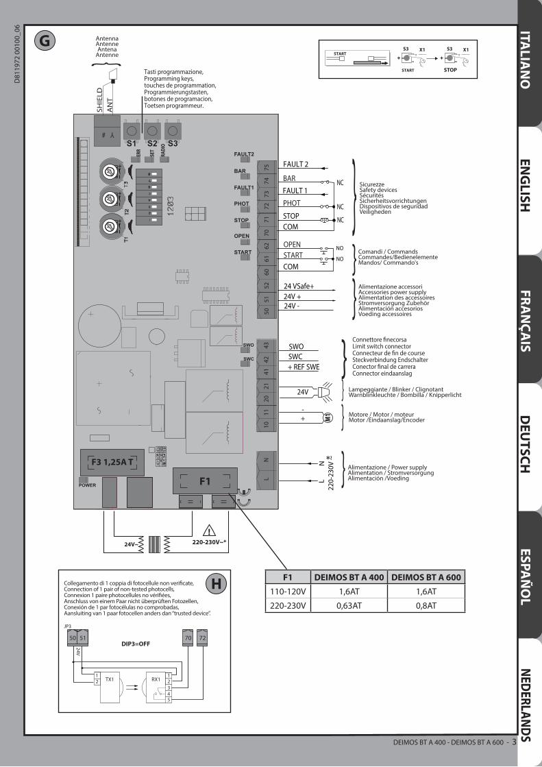
110-120V 1,6AT 1,6AT
220-230V 0,63AT 0,8AT
DEIMOS BT A 400 - DEIMOS BT A 600 - 3
D81
1972
001
00_0
6
J
I
I1
1
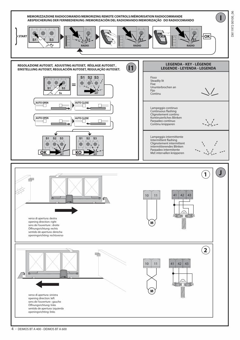
verso di apertura: destraopening direction: rightsens de l’ouverture : droiteÖ�nungsrichtung: rechtssentido de apertura: derechaopeningsrichting: rechtsverso
2
verso di apertura: sinistraopening direction: leftsens de l’ouverture : gaucheÖ�nungsrichtung: linkssentido de apertura: izquierdaopeningsrichting: links
START OKS1 S1 S1
MEMORIZZAZIONE RADIOCOMANDO/MEMORIZING REMOTE CONTROLS/MÉMORISATION RADIOCOMMANDEABSPEICHERUNG DER FERNBEDIENUNG /MEMORIZACIÓN DEL RADIOMANDO/MEMORIZAÇÃO DO RADIOCOMANDO
x1
S1 S2 S3
RADIO RADIO RADIO
FissoSteadily litFixeUnunterbrochen anFijoContinu
Lampeggio continuoContinuous �ashingClignotement continuKontinuierliches BlinkenParpadeo continuoContinu knipperen
Lampeggio intermittenteIntermittent �ashingClignotement intermittentintermittierendes BlinkenParpadeo intermitenteMet intervallen knipperen
LEGENDA - KEY - LÉGENDELEGENDE - LEYENDA - LEGENDA
=
AUTO OPEN AUTO CLOSE
AUTO OPEN AUTO CLOSE
5s
S1 S2 S3
S2S1 S3
SET
S2S1 S3
SET
S2S1 S3
SETOK KO
REGOLAZIONE AUTOSET, ADJUSTING AUTOSET, RÉGLAGE AUTOSET , EINSTELLUNG AUTOSET, REGULACIÓN AUTOSET, REGULAÇÃO AUTOSET.
10 11
M
10 11
M
41 4342
41 4342
4 - DEIMOS BT A 400 - DEIMOS BT A 600
D81
1972
001
00_0
6
CP
X= 37
30
12
CVZ
28
60
X= 33
30
8
CVZ-S
6
X= 40
NO OK
N1
39
50
255
120
135
164
287
K L
M N
PP1
50
>25
>100
17
2m
m
O
Q
S
Q1
Q3
Q2
DEIMOS BT A 400 - DEIMOS BT A 600 - 5
D81
1972
001
00_0
6
R50 51 52 70 71 72 73 74 75
24V -
24V +
24 VSafe+
CO
M
PHO
T
BAR
STOP
FAU
LT 1
FAU
LT 2
NC
NC
NC
PHOT
12
1234
5
51TX1 RX1
12
1234
5
5250 TX1 RX1
12
12345
TX1 RX1
12
12345
TX2 RX2
12
1234
5
TX1 RX1
12
1234
5
TX1 RX1
12
12345
TX1 RX1
12
12345
TX2 RX2
1 PHOT / 1 PHOT CL
1 PHOT / 1 PHOT CL
2 PHOT / 2 PHOT CL
BAR 8K2
50
5250
5250
5150
5150
5150
5150
70
72
70
7273
70
70
72
73
BAR
Bar 1123456
Bar 112345
Bar 212345
Bar 1123456
6
6
Bar 1123456
Bar 112345
Bar 212345
Bar 1123456
6
6
BAR 8K2
1 BAR
1 BAR
2 BAR
51
5150
5150
5150
52
52
52
74
70
74
7075
7470
5150
7075
7074 8,2Kohm 5%
SAFETY EDGE SAFETY EDGE
DIP
2 O
FF
DIP
4 O
FFD
IP4
ON
DIP
2 O
N
DIP
3 O
FFD
IP3
ON
6 - DEIMOS BT A 400 - DEIMOS BT A 600
D81
1972
001
00_0
6
INSTALLER WARNINGS
Anything that is not explicitly provided for in the installation ma-nual is not allowed. The operator’s proper operation can only be guaranteed if the information given is complied with. The Firm shall not be answerable for damage caused by failure to comply with the instructions featured herein.While we will not alter the product’s essential features, the Firm reserves the right, at any time, to make those changes deemed opportune to improve the product from a technical, design or commercial point of view, and will not be required to update this publication accordingly.
WARNING! Important safety instructions. Carefully read and comply with all the warnings and instructions that come with the product as incorrect installation can cause injury to people and animals and damage to property. The warnings and instructions give important information regarding safety, installation, use and maintenance. Keep hold of instructions so that you can attach them to the technical ile and keep them handy for future reference.
GENERAL SAFETYThis product has been designed and built solely for the purpose indicated herein. Uses other than those indicated herein might cause damage to the product and create a hazard.- The units making up the machine and its installation must meet the requirements of the following European Directives, where applicable: 2004/108/EC, 2006/95/EC, 2006/42/EC, 89/106/EC, 99/05/EC and later amendments. For all countries outside the EEC, it is advisable to comply with the standards mentioned, in ad-dition to any national standards in force, to achieve a good level of safety.
- The Manufacturer of this product (hereinafter referred to as the “Firm”) disclaims all responsibility resulting from improper use or any use other than that for which the product has been designed, as indicated herein, as well as for failure to apply Good Practice in the construction of entry systems (doors, gates, etc.) and for deformation that could occur during use.
- Installation must be carried out by qualiied personnel (professional installer, according to EN 12635), in compliance with Good Practice and current code.
- Before installing the product, make all structural changes required to produce safety gaps and to provide protection from or isolate all crushing, shearing and dragging hazard areas and danger zones in general in accordance with the provisions of standards EN 12604 and 12453 or any local installation standards. Check that the existing structure meets the necessary strength and stability requirements.
- Before commencing installation, check the product for damage.- The Firm is not responsible for failure to apply Good Practice in the construction and maintenance of the doors, gates, etc. to be motorized, or for deformation that might occur during use.
- Make sure the stated temperature range is compatible with the site in which the automated system is due to be installed.
- Do not install this product in an explosive atmosphere: the presence of lammable fumes or gas constitutes a serious safety hazard.
- Disconnect the electricity supply before performing any work on the system. Also disconnect bufer batteries, if any are connected.
- Before connecting the power supply, make sure the product’s ratings match the mains ratings and that a suitable residual current circuit breaker and overcurrent protection device have been installed upline from the electrical system. Have the automated system’s mains power supply itted with a switch or omnipolar thermal-magnetic circuit breaker with a contact separation that provide full disconnection under overvoltage category III conditions.
- Make sure that upline from the mains power supply there is a residual current circuit breaker that trips at no more than 0.03A as well as any other equipment required by code.
- Make sure the earth system has been installed correctly: earth all the metal parts belonging to the entry system (doors, gates, etc.) and all parts of the system featuring an earth terminal.
- Installation must be carried out using safety devices and controls that meet standards EN 12978 and EN 12453.
- Impact forces can be reduced by using deformable edges.- In the event impact forces exceed the values laid down by the relevant standards, apply electro-sensitive or pressure-sensitive devices.
- Apply all safety devices (photocells, safety edges, etc.) required to keep the area free of impact, crushing, dragging and shearing hazards. Bear in mind the standards and directives in force, Good Practice criteria, intended use, the instal-lation environment, the operating logic of the system and forces generated by the automated system.
- Apply all signs required by current code to identify hazardous areas (residual risks). All installations must be visibly identiied in compliance with the provisions of standard EN 13241-1.
- Once installation is complete, apply a nameplate featuring the door/gate’s data.- This product cannot be installed on leaves incorporating doors (unless the motor can be activated only when the door is closed).
- If the automated system is installed at a height of less than 2.5 m or is accessible, the electrical and mechanical parts must be suitably protected.
- For roller shutter automation only 1) The motor’s moving parts must be installed at a height greater than 2.5 m above the loor or other surface from which they may be reached.
2) The gearmotor must be installed in a segregated and suitably protected space so that it cannot be reached without the aid of tools.
- Install any ixed controls in a position where they will not cause a hazard, away from moving parts. More speciically, hold-to-run controls must be positioned within direct sight of the part being controlled and, unless they are key operated, must be installed at a height of at least 1.5 m and in a place where they cannot be reached by the public.
- Apply at least one warning light (lashing light) in a visible position, and also attach a Warning sign to the structure.
- Attach a label near the operating device, in a permanent fashion, with informa-tion on how to operate the automated system’s manual release.
- Make sure that, during operation, mechanical risks are avoided or relevant protective measures taken and, more speciically, that nothing can be banged, crushed, caught or cut between the part being operated and surrounding parts.
- Once installation is complete, make sure the motor automation settings are correct and that the safety and release systems are working properly.
- Only use original spare parts for any maintenance or repair work. The Firm dis-claims all responsibility for the correct operation and safety of the automated system if parts from other manufacturers are used.
- Do not make any modiications to the automated system’s components unless explicitly authorized by the Firm.
- Instruct the system’s user on what residual risks may be encountered, on the control systems that have been applied and on how to open the system manu-ally in an emergency. give the user guide to the end user.
- Dispose of packaging materials (plastic, cardboard, polystyrene, etc.) in accord-ance with the provisions of the laws in force. Keep nylon bags and polystyrene out of reach of children.
WIRINGWARNING! For connection to the mains power supply, use: a multicore cable with a cross-sectional area of at least 5x1.5mm2 or 4x1.5mm2 when dealing with three-phase power supplies or 3x1.5mm2 for single-phase supplies (by way of example, type H05 VV-F cable can be used with a cross-sectional area of 4x1.5mm2). To con-nect auxiliary equipment, use wires with a cross-sectional area of at least 0.5 mm2.- Only use pushbuttons with a capacity of 10A-250V or more.- Wires must be secured with additional fastening near the terminals (for example,
using cable clamps) in order to keep live parts well separated from safety extra low voltage parts.
- During installation, the power cable must be stripped to allow the earth wire to be connected to the relevant terminal, while leaving the live wires as short as possible. The earth wire must be the last to be pulled taut in the event the cable’s fastening device comes loose.
WARNING! safety extra low voltage wires must be kept physically separate from low voltage wires.Only qualiied personnel (professional installer) should be allowed to access live parts.
CHECKING THE AUTOMATED SYSTEM AND MAINTENANCEBefore the automated system is inally put into operation, and during maintenance work, perform the following checks meticulously:- Make sure all components are fastened securely.- Check starting and stopping operations in the case of manual control.- Check the logic for normal or personalized operation.- For sliding gates only: check that the rack and pinion mesh correctly with 2 mm of play along the full length of the rack; keep the track the gate slides on clean and free of debris at all times.
- For sliding gates and doors only: make sure the gate’s running track is straight and horizontal and that the wheels are strong enough to take the weight of the gate.
- For cantilever sliding gates only: make sure there is no dipping or swinging during operation.
- For swing gates only: make sure the leaves’ axis of rotation is perfectly vertical.-For barriers only: before opening the door, the spring must be decompressed (vertical boom).
- Check that all safety devices (photocells, safety edges, etc.) are working properly and that the anti-crush safety device is set correctly, making sure that the force of impact measured at the points provided for by standard EN 12445 is lower than the value laid down by standard EN 12453.
- Impact forces can be reduced by using deformable edges.- Make sure that the emergency operation works, where this feature is provided.- Check opening and closing operations with the control devices applied.- Check that electrical connections and cabling are intact, making extra sure that insulating sheaths and cable glands are undamaged.
- While performing maintenance, clean the photocells’ optics.- When the automated system is out of service for any length of time, activate the emergency release (see “EMERGENCY OPERATION” section) so that the operated part is made idle, thus allowing the gate to be opened and closed manually.
- If the power cord is damaged, it must be replaced by the manufacturer or their technical assistance department or other such qualiied person to avoid any risk .
- If “D” type devices are installed (as deined by EN12453), connect in unveriied mode, foresee mandatory maintenance at least every six months
- The maintenance described above must be repeated at least once yearly or at shorter intervals where site or installation conditions make this necessary.
WARNING! Remember that the drive is designed to make the gate/door easier to use and will not solve problems as a result of defective or poorly performed installation or lack of maintenance
SCRAPPING Materials must be disposed of in accordance with the regulations in
force. Do not throw away your discarded equipment or used batteries with household waste. You are responsible for taking all your waste electrical and electronic equipment to a suitable recycling centre.
DISMANTLINGIf the automated system is being dismantled in order to be reassembled at another site, you are required to:- Cut of the power and disconnect the whole electrical system.- Remove the actuator from the base it is mounted on.- Remove all the installation’s components.- See to the replacement of any components that cannot be removed or happen to be damaged.
DECLARATIONS OF CONFORMITY CAN BE FOUND AT http://www.bft-automation.com/CE INSTRUCTIONS FOR USE AND ASSEMBLY CAN BE FOUND IN THE DOWN-LOAD SECTION.
AVVERTENZE PER L’INSTALLATORE D811766_1312 - DEIMOS BT A 400 - DEIMOS BT A 600
D81
1972
001
00_0
6
EN
GLIS
HINSTALLATION MANUAL
1) GENERAL INFORMATIONThe DEIMOS BT A actuator is highly versatile in terms of installation options due to the extremely low position of the pinion, the actuator’s compact nature and the height and depth adjustment features it ofers. The adjustable electronic torque limiter provides anti-crush safety. Manual emergency operation is extremely easy to perform using just a release lever.Stopping at end of travel is controlled by electromechanical microswitches.The HAMAL control panel comes with standard factory settings. Any change must be set by means of the TRIMMER and DIP SWITCH settings.
Its main features are: - Control of 1 low-voltage motor- Obstacle detection- Separate inputs for safety devices- Built-in radio receiver rolling code with transmitter cloning.The board has a terminal strip of the removable kind to make maintenance or replacement easier. It comes with a series of prewired jumpers to make the installer’s job on site easier. The jumpers concern terminals: 70-71, 70-72, 70-74. If the above-mentioned terminals are being used, remove the relevant jumpers.
TESTINGThe HAMAL panel controls (checks) the start relays and safety devices (photocells) before performing each opening and closing cycle. If there is a malfunction, make sure that the connected devices are working properly and check the wiring.
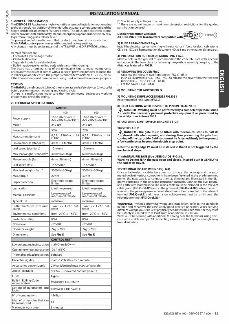
2) TECHNICAL SPECIFICATIONS
MOTOR
400 600
Power supply 110-120V 50/60Hz 220-230V 50/60 Hz(*)
110-120V 50/60Hz 220-230V 50/60 Hz(*)
Motor 24V 24V
Power input 50W 70W
Max. current demand 0,5A (230V~) - 1A (110V~)
0,5A (230V~) - 1A (110V~)
Pinion module (standard) 4mm (14 teeth) 4mm (14 teeth)
Leaf speed (standard) 12m/min 12m/min
Max. leaf weight - standard** 4000N (≈400kg) 6000N (≈600kg)
Pinion module (fast) 4mm (18 teeth) 4mm (18 teeth)
Leaf speed (fast) 15.5m/min 15.5m/min
Max. leaf weight - fast** 3000N (≈300kg) 3600N (≈360kg)
Max. torque 20Nm 30Nm
Impact reaction Electronic torque limiter
Electronic torque limiter
Lubrication Lifetime greased Lifetime greased
Manual operation Lever-operated mechanical release
Lever-operated mechanical release
Type of use intensive intensive
Buffer batteries (optional extras)
Two 12V 1.2Ah bat-teries
Two 12V 1.2Ah bat-teries
Environmental conditions from -20°C to +55°C from -20°C to +55°C
Protection rating IP24 IP24
Noise level <70dBA <70dBA
Operator weight 7kg (≈70N) 7kg (≈70N)
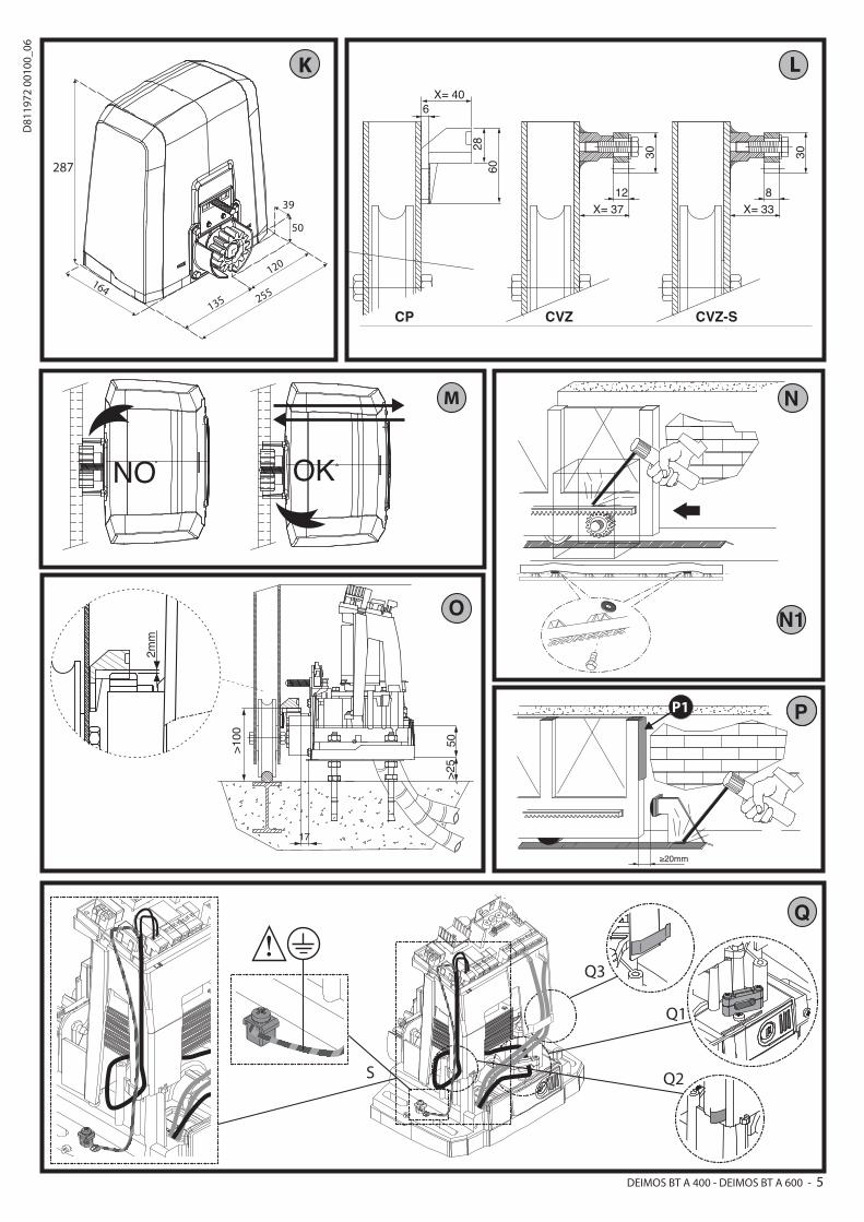
Dimensions See Fig. K See Fig. K
CONTROL UNIT
Low voltage/mains insulation > 2MOhm 500V
Operating temperature range -20 / +55°C
Thermal overload protection Software
Dielectric rigidity mains/LV 3750V~ for 1 minute
Accessories power supply 24V (demand max. 0,2A) 24V safe
AUX 0 - BLINKER NO 24V powered contact (max.1A)
Fuses Fig. G
Built-in Rolling-Code radio-receiver frequency 433.92MHz
Setting of parameters and logics TRIMMER + DIP SWITCH
N° of combinations 4 billion
Max. n° of remotes that can be memorized 63
Maximum work time 3 minutes
(*) Special supply voltages to order.** There are no minimum or maximum dimension restrictions for the guided part that can be used
Usable transmitter versions:All ROLLING CODE transmitters compatible with .
3) TUBE ARRANGEMENT Fig.AInstall the electrical system referring to the standards in force for electrical systems CEI 64-8, IEC 364, harmonization document HD 384 and other national standards.
4) PREPARATION FOR MOTOR MOUNTING FIG.BMake a hole in the ground to accommodate the concrete pad, with anchors embedded in the base plate for fastening the gearbox assembly, keeping to the distances featured in FIG.B.
5) REMOVING THE COVER Fig.C• Unscrewtherelevanttwofrontscrews(FIG.C-rif.1)• Pushasillustrated(FIG.C-rif.2-rif.3)toreleasethecoverfromthetworear
blocks (FIG.C - rif.3A e FIG.C - rif.3B).• Liftthecover(FIG.C-rif.4).
6) MOUNTING THE MOTOR FIG.D
7) MOUNTING DRIVE ACCESSORIES FIG.E-E1Recommended rack types (FIG.L)
8) RACK CENTRING WITH RESPECT TO PINION FIG.M-N1-ODANGER - Welding must be performed by a competent person issued with the necessary personal protective equipment as prescribed by
the safety rules in force FIG.L.
9) FASTENING LIMIT SWITCH BRACKETS FIG.F
10) STOPS FIG.PDANGER - The gate must be itted with mechanical stops to halt its travel both when opening and closing, thus preventing the gate from
coming of the top guide. Said stops must be fastened irmly to the ground, a few centimetres beyond the electric stop point.
Note: the safety edge P1 must be installed so that it is not triggered by the mechanical stops.
11) MANUAL RELEASE (See USER GUIDE -FIG.3-).Warning Do not JERK the gate open and closed, instead push it GENTLY to the end of its travel.
12) TERMINAL BOARD WIRING Fig. G-QOnce suitable electric cables have been run through the raceways and the auto-mated device’s various components have been fastened at the predetermined points, the next step is to connect them as directed and illustrated in the dia-grams contained in the relevant instruction manuals. Connect the live, neutral and earth wire (compulsory).The mains cable must be clamped in the relevant cable gland (FIG.Q-ref.Q1) and in the grommet (FIG.Q-ref.Q2), while the earth wire with the yellow/green-coloured sheath must be connected in the relevant terminal (FIG.Q-ref.S) and the extra low voltage wires must be run through the relevant grommet (FIG.Q ref.Q3). WARNINGS - When performing wiring and installation, refer to the standards in force and, whatever the case, apply good practice principles. Wires carrying diferent voltages must be kept physically separate from each other, or they must be suitably insulated with at least 1mm of additional insulation. Wires must be secured with additional fastening near the terminals, using devi-ces such as cable clamps. All connecting cables must be kept far enough away from dissipaters.
DEIMOS BT A 400 - DEIMOS BT A 600 - 13
D81
1972
001
00_0
6
INSTALLATION MANUAL
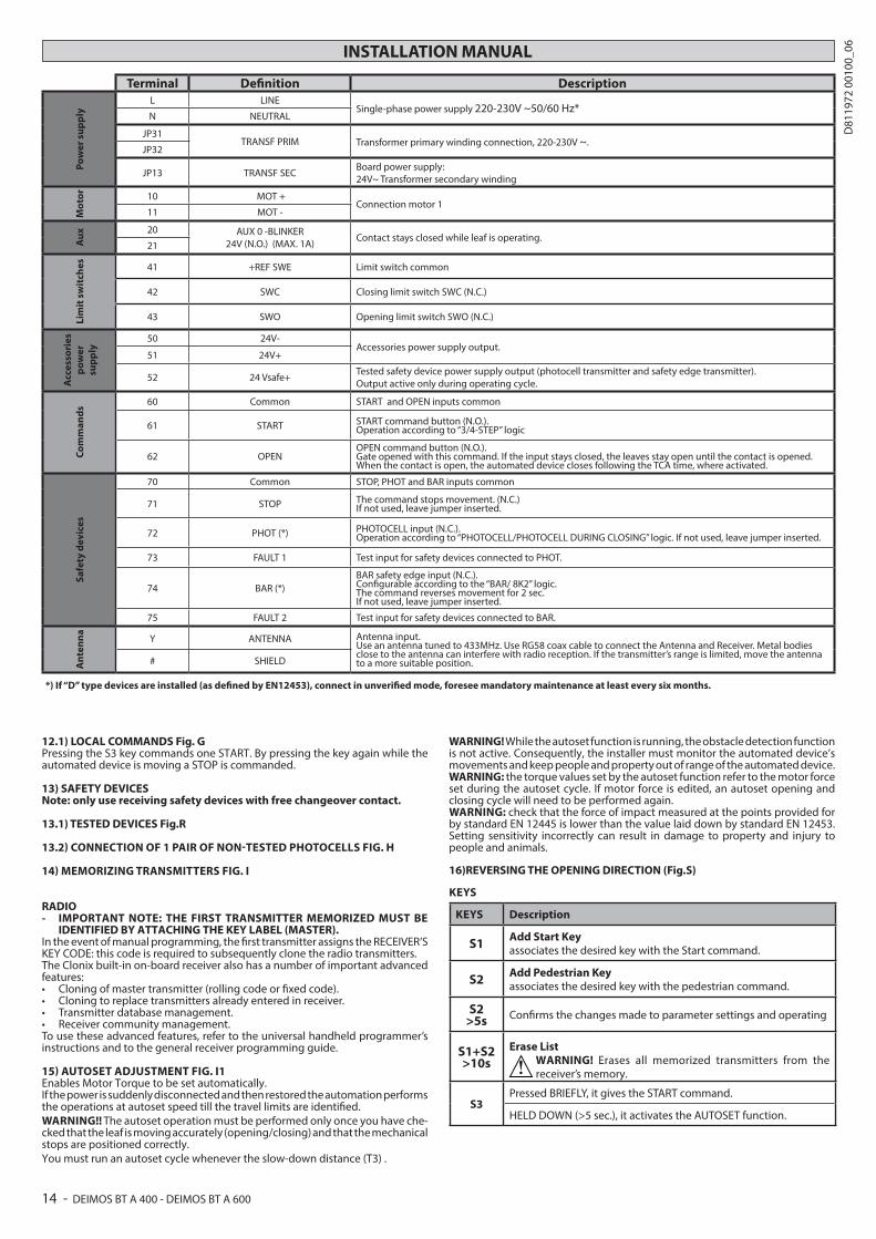
Terminal Deinition DescriptionP
ow
er s
up
ply
L LINESingle-phase power supply 220-230V ~50/60 Hz*
N NEUTRAL
JP31TRANSF PRIM Transformer primary winding connection, 220-230V ~.
JP32
JP13 TRANSF SECBoard power supply: 24V~ Transformer secondary winding
Mo
tor
10 MOT +Connection motor 1
11 MOT -
Au
x 20 AUX 0 -BLINKER 24V (N.O.) (MAX. 1A)
Contact stays closed while leaf is operating.21
Lim
it s
wit
ches 41 +REF SWE Limit switch common
42 SWC Closing limit switch SWC (N.C.)
43 SWO Opening limit switch SWO (N.C.)
Acc
esso
ries
po
wer
su
pp
ly
50 24V-Accessories power supply output.
51 24V+
52 24 Vsafe+Tested safety device power supply output (photocell transmitter and safety edge transmitter). Output active only during operating cycle.
Co
mm
and
s
60 Common START and OPEN inputs common
61 START START command button (N.O.).Operation according to “3/4-STEP” logic
62 OPENOPEN command button (N.O.).Gate opened with this command. If the input stays closed, the leaves stay open until the contact is opened. When the contact is open, the automated device closes following the TCA time, where activated.
Saf
ety
dev
ices
70 Common STOP, PHOT and BAR inputs common
71 STOP The command stops movement. (N.C.) If not used, leave jumper inserted.
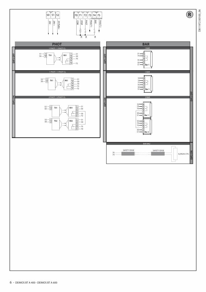
72 PHOT (*) PHOTOCELL input (N.C.).Operation according to “PHOTOCELL/PHOTOCELL DURING CLOSING” logic. If not used, leave jumper inserted.
73 FAULT 1 Test input for safety devices connected to PHOT.
74 BAR (*)BAR safety edge input (N.C.).Conigurable according to the “BAR/ 8K2” logic.The command reverses movement for 2 sec.If not used, leave jumper inserted.
75 FAULT 2 Test input for safety devices connected to BAR.
An
ten
na
Y ANTENNA Antenna input. Use an antenna tuned to 433MHz. Use RG58 coax cable to connect the Antenna and Receiver. Metal bodies close to the antenna can interfere with radio reception. If the transmitter’s range is limited, move the antenna to a more suitable position.# SHIELD
*) If “D” type devices are installed (as deined by EN12453), connect in unveriied mode, foresee mandatory maintenance at least every six months.
12.1) LOCAL COMMANDS Fig. G Pressing the S3 key commands one START. By pressing the key again while the automated device is moving a STOP is commanded.
13) SAFETY DEVICESNote: only use receiving safety devices with free changeover contact.
13.1) TESTED DEVICES Fig.R
13.2) CONNECTION OF 1 PAIR OF NON-TESTED PHOTOCELLS FIG. H
14) MEMORIZING TRANSMITTERS FIG. I
RADIO- IMPORTANT NOTE: THE FIRST TRANSMITTER MEMORIZED MUST BE
IDENTIFIED BY ATTACHING THE KEY LABEL (MASTER).In the event of manual programming, the irst transmitter assigns the RECEIVER’S KEY CODE: this code is required to subsequently clone the radio transmitters.The Clonix built-in on-board receiver also has a number of important advanced features:• Cloningofmastertransmitter(rollingcodeorixedcode).• Cloningtoreplacetransmittersalreadyenteredinreceiver.• Transmitterdatabasemanagement.• Receivercommunitymanagement.To use these advanced features, refer to the universal handheld programmer’s instructions and to the general receiver programming guide.
15) AUTOSET ADJUSTMENT FIG. I1Enables Motor Torque to be set automatically.If the power is suddenly disconnected and then restored the automation performs the operations at autoset speed till the travel limits are identiied. WARNING!! The autoset operation must be performed only once you have che-cked that the leaf is moving accurately (opening/closing) and that the mechanical stops are positioned correctly. You must run an autoset cycle whenever the slow-down distance (T3) .
WARNING! While the autoset function is running, the obstacle detection function is not active. Consequently, the installer must monitor the automated device’s movements and keep people and property out of range of the automated device.WARNING: the torque values set by the autoset function refer to the motor force set during the autoset cycle. If motor force is edited, an autoset opening and closing cycle will need to be performed again.WARNING: check that the force of impact measured at the points provided for by standard EN 12445 is lower than the value laid down by standard EN 12453.Setting sensitivity incorrectly can result in damage to property and injury to people and animals.
16)REVERSING THE OPENING DIRECTION (Fig.S)
KEYS
KEYS Description
S1Add Start Keyassociates the desired key with the Start command.
S2Add Pedestrian Keyassociates the desired key with the pedestrian command.
S2>5s Conirms the changes made to parameter settings and operating
S1+S2>10s
Erase ListWARNING! Erases all memorized transmitters from the receiver’s memory.
S3Pressed BRIEFLY, it gives the START command.
HELD DOWN (>5 sec.), it activates the AUTOSET function.
14 - DEIMOS BT A 400 - DEIMOS BT A 600
D81
1972
001
00_0
6

EN
GLIS
HINSTALLATION MANUAL
TABLE “A” - PARAMETERS
TRIMMER Parameter+
min.+
max.
Description
T1 Automatic closing time [s] 0 120 Waiting time before automatic closing.
NOTE: Set to 0 if not used.
T2 Leaf force [%] 10 90
Force exerted by leaf/leaves.This is the percentage of force delivered, beyond the force stored during the autoset cycle (and subsequently updated), before an obstacle alarm is generated.
WARNING: It afects impact force directly: make sure that current safety requirements are met with the set value (*). Install anti-crush safety devices where necessary.
T3 Slow-down distance [%] 5 50 Set opening slow-down speed as a percentage of total travel. This distance is travelled at low speed.
NOTE: When this parameter is edited, a new Autoset cycle must be run to conirm it.
(*) In the European Union, apply standard EN 12453 for force limitations, and standard EN 12445 for measuring method.
TABLE “B” - LOGICS
DIP Logic Default Cross out setting used Description
1 Transmitter programming ON
ON
Enables wireless memorizing of transmitters:1- Press in sequence the hidden key and normal key (T1-T2-T3-T4) of a transmitter that has already been memorized in standard mode via the radio menu.2- Press within 10 sec. the hidden key and normal key (T1-T2-T3-T4) of a transmitter to be memorized.The receiver exits programming mode after 10 sec.: you can use this time to enter other new transmitters.This mode does not require access to the control panel.IMPORTANT: Enables the automatic addition of new transmitters, clones and replays.
OFFDisables wireless memorizing of transmitters and automatic addition of clones.Transmitters are memorized only using the relevant Radio menu or automatically with replays.IMPORTANT: Disables the automatic addition of new transmitters and clones
2 BAR / 8K2 OFFON Input conigured as Bar 8k2. Input for resistive edge 8K2.
The command reverses movement for 2 sec.
OFF Input conigured as Bar, safety edge.The command reverses movement for 2 sec.
3 Photocell input check OFF
ON Enable safety check on the PHOT input
OFF Safety check on PHOT input not enabled
4 Edge input check OFFON Enable safety check on the BAR input
OFF Safety check on BAR input not enabled
5 Photocells during closing OFF
ON In the event beam is broken, photocell operation is disabled during opening. During closing, movement is reversed immediately.
OFFWhen beam is broken, photocells are active during both opening and clo-sing. When beam is broken during closing, movement is reversed only once the photocell is cleared.
6 Fast closing OFFON Closes 3 seconds after the photocells are cleared before waiting for the set TCA to elapse.
OFF Logic not enabled
7 Block pulses during opening OFF
ON The start pulse has no efect during opening.
OFF The start pulse has efect during opening.
8 3-step logic OFF
ON Switches to 3-step logic; during closing, start reverses movement. 3 step 4 step
CLOSEDopens
opens
DURING CLOSING stop
OPEN closes closes
DURING OPENING stop + TCA
stop + TCA
AFTER STOP opens opens
OFF Switches to 4-step logic.
DEIMOS BT A 400 - DEIMOS BT A 600 - 15
D81
1972
001
00_0
6
INSTALLATION MANUAL
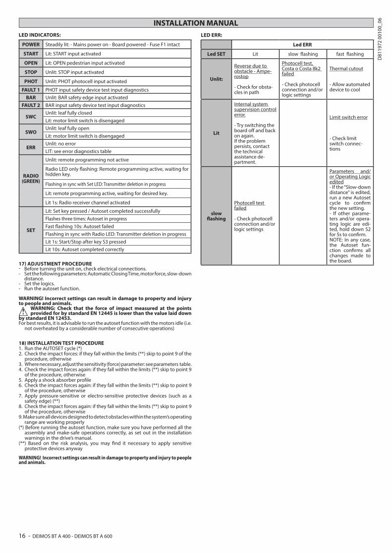
LED INDICATORS:
POWER Steadily lit: - Mains power on - Board powered - Fuse F1 intact
START Lit: START input activated
OPEN Lit: OPEN pedestrian input activated
STOP Unlit: STOP input activated
PHOT Unlit: PHOT photocell input activated
FAULT 1 PHOT input safety device test input diagnostics
BAR Unlit: BAR safety edge input activated
FAULT 2 BAR input safety device test input diagnostics
SWCUnlit: leaf fully closed
Lit: motor limit switch is disengaged
SWOUnlit: leaf fully open
Lit: motor limit switch is disengaged
ERRUnlit: no error
LIT: see error diagnostics table
RADIO(GREEN)
Unlit: remote programming not active
Radio LED only lashing: Remote programming active, waiting for hidden key.
Flashing in sync with Set LED: Transmitter deletion in progress
Lit: remote programming active, waiting for desired key.
Lit 1s: Radio receiver channel activated
SET
Lit: Set key pressed / Autoset completed successfully
Flashes three times: Autoset in progress
Fast lashing 10s: Autoset failed
Flashing in sync with Radio LED: Transmitter deletion in progress
Lit 1s: Start/Stop after key S3 pressed
Lit 10s: Autoset completed correctly
17) ADJUSTMENT PROCEDURE- Before turning the unit on, check electrical connections.- Set the following parameters: Automatic Closing Time, motor force, slow-down
distance.- Set the logics.- Run the autoset function.
WARNING! Incorrect settings can result in damage to property and injury to people and animals.
WARNING: Check that the force of impact measured at the points provided for by standard EN 12445 is lower than the value laid down
by standard EN 12453.For best results, it is advisable to run the autoset function with the motors idle (i.e.
not overheated by a considerable number of consecutive operations)
18) INSTALLATION TEST PROCEDURE1. Run the AUTOSET cycle (*)2. Check the impact forces: if they fall within the limits (**) skip to point 9 of the
procedure, otherwise3. Where necessary, adjust the sensitivity (force) parameter: see parameters table. 4. Check the impact forces again: if they fall within the limits (**) skip to point 9
of the procedure, otherwise5. Apply a shock absorber proile6. Check the impact forces again: if they fall within the limits (**) skip to point 9
of the procedure, otherwise7. Apply pressure-sensitive or electro-sensitive protective devices (such as a
safety edge) (**)8. Check the impact forces again: if they fall within the limits (**) skip to point 9
of the procedure, otherwise9. Make sure all devices designed to detect obstacles within the system’s operating
range are working properly(*) Before running the autoset function, make sure you have performed all the
assembly and make-safe operations correctly, as set out in the installation warnings in the drive’s manual.
(**) Based on the risk analysis, you may ind it necessary to apply sensitive protective devices anyway
WARNING! Incorrect settings can result in damage to property and injury to people and animals.
LED ERR:
Led ERR
Led SET Lit slow lashing fast lashing
Unlit:
Reverse due to obstacle - Ampe-rostop - Check for obsta-cles in path
Photocell test, Costa o Costa 8k2 failed - Check photocell connection and/or logic settings
Thermal cutout
- Allow automated device to cool
Lit
Internal system supervision control error. - Try switching the board of and back on again.If the problem persists, contact the technicalassistance de-partment.
Limit switch error
- Check limit switch connec-tions
slow lashing
Photocell test failed - Check photocell connection and/or logic settings
Parameters and/or Operating Logic edited- If the “Slow-down distance” is edited, run a new Autoset cycle to conirm the new setting.- If other parame-ters and/or opera-ting logic are edi-ted, hold down S2 for 5s to conirm.NOTE: In any case, the Autoset fun-ction conirms all changes made to the board.
16 - DEIMOS BT A 400 - DEIMOS BT A 600
D81
1972
001
00_0
6
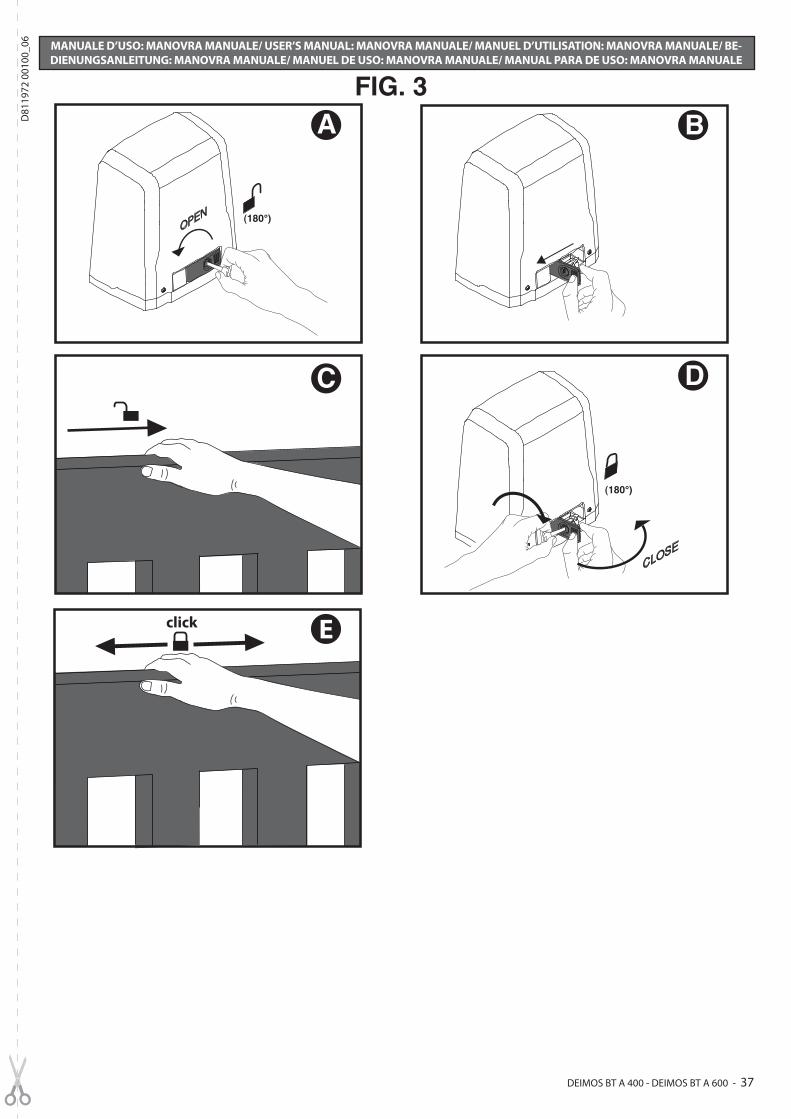
FIG. 3
C
B
Eclick
D
CLOSE
(180°)
(180°)
A
OPEN
MANUALE D’USO: MANOVRA MANUALE/ USER’S MANUAL: MANOVRA MANUALE/ MANUEL D’UTILISATION: MANOVRA MANUALE/ BE-DIENUNGSANLEITUNG: MANOVRA MANUALE/ MANUEL DE USO: MANOVRA MANUALE/ MANUAL PARA DE USO: MANOVRA MANUALE
DEIMOS BT A 400 - DEIMOS BT A 600 - 37
D81
1972
001
00_0
6