design of offshore pipelines on erodible seabed - · pdf filedesign of offshore pipelines on...
TRANSCRIPT

Design of Offshore Pipelines on Erodible Seabed
Winthrop Professor Liang Cheng
School of Civil, Environmental and Mining Engineering The University of Western Australia
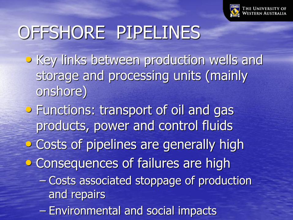
OFFSHORE PIPELINES
• Key links between production wells and storage and processing units (mainly onshore)
• Functions: transport of oil and gas products, power and control fluids
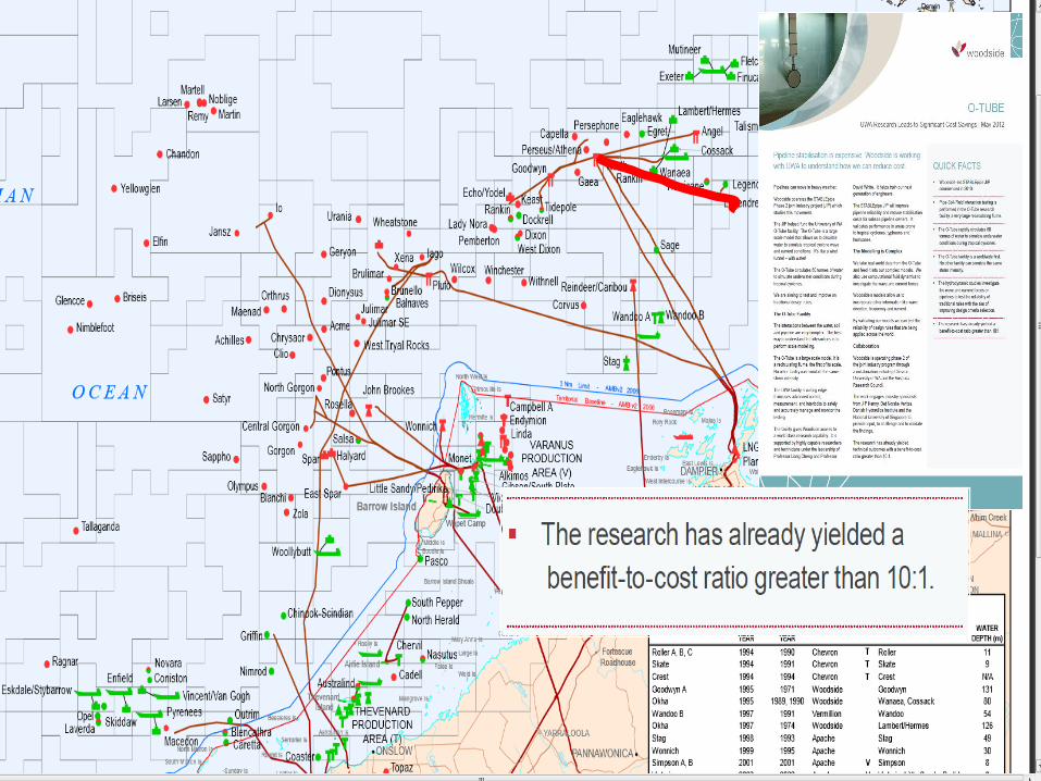
• Costs of pipelines are generally high
• Consequences of failures are high
– Costs associated stoppage of production and repairs
– Environmental and social impacts
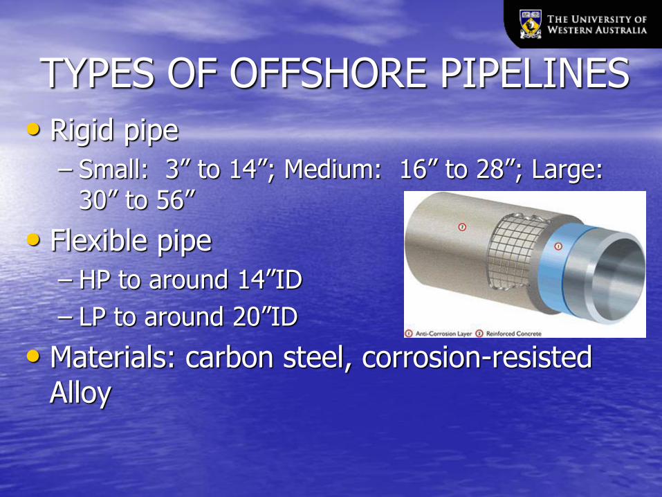
TYPES OF OFFSHORE PIPELINES
• Rigid pipe
– Small: 3” to 14”; Medium: 16” to 28”; Large: 30” to 56”
• Flexible pipe
– HP to around 14”ID
– LP to around 20”ID
• Materials: carbon steel, corrosion-resisted Alloy
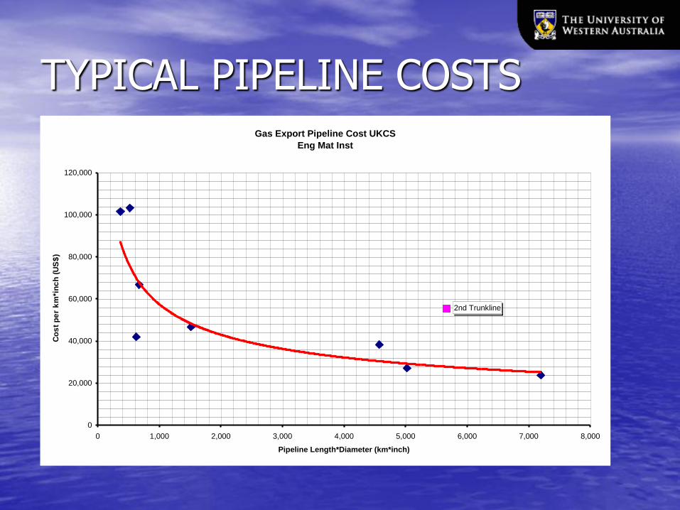
TYPICAL PIPELINE COSTS
Gas Export Pipeline Cost UKCS
Eng Mat Inst
2nd Trunkline
0
20,000
40,000
60,000
80,000
100,000
120,000
0 1,000 2,000 3,000 4,000 5,000 6,000 7,000 8,000
Pipeline Length*Diameter (km*inch)
Co
st
pe
r k
m*i
nc
h (
US
$)

COSTS FOR PIPELINES
Materials Materials & Fabrication& Fabrication
30%30%
Management Management
& Engineering& Engineering
10%10%
StabilisationStabilisation
30%30%
InstallationInstallation
(excluding Stabilisation)(excluding Stabilisation)
30%30% Materials Materials & Fabrication& Fabrication
30%30%
Management Management
& Engineering& Engineering
10%10%
StabilisationStabilisation
30%30%
InstallationInstallation
(excluding Stabilisation)(excluding Stabilisation)
30%30%
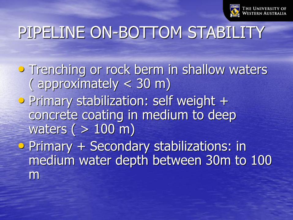
PIPELINE ON-BOTTOM STABILITY
• Trenching or rock berm in shallow waters ( approximately < 30 m)
• Primary stabilization: self weight + concrete coating in medium to deep waters ( > 100 m)
• Primary + Secondary stabilizations: in medium water depth between 30m to 100 m
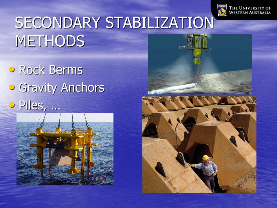
SECONDARY STABILIZATION METHODS
• Rock Berms
• Gravity Anchors
• Piles, …
PIPELINE DESIGN CHALLENGES
• Corrosion – pipeline integrity
– Anti-corrosion coating and metal cladding
• Flow assurance – steady productions
– Liquid plugging, hydrates, wax, …
• On-bottom stability – present topic
– Resist extreme hydrodynamic forces
– Very expensive

PIPELINE STABILITY DESIGN
• Design requirement: pipeline be stable under extreme environmental conditions
– Absolute stability methods
• Pipeline movements not allowed
• Often conservative, leading to high costs
– Dynamic stability methods
• Pipeline movements are allowed
• Considers seabed resistance changes
• Structure integrity needs to be checked
FLAWS IN CURRENT DESIGN METHODS
• Calculations of wave forces are too conservative – Velocity reduction in wave boundary layers in
force calculations are not considered
• Sediment transport processes ignored – Use static seabed profiles
• Reality: seabed profiles around the pipe significantly modified before storm peaks arrive
– Hydrodynamic loads
– Soil resistance
– Use of a slice of pipeline is not acceptable
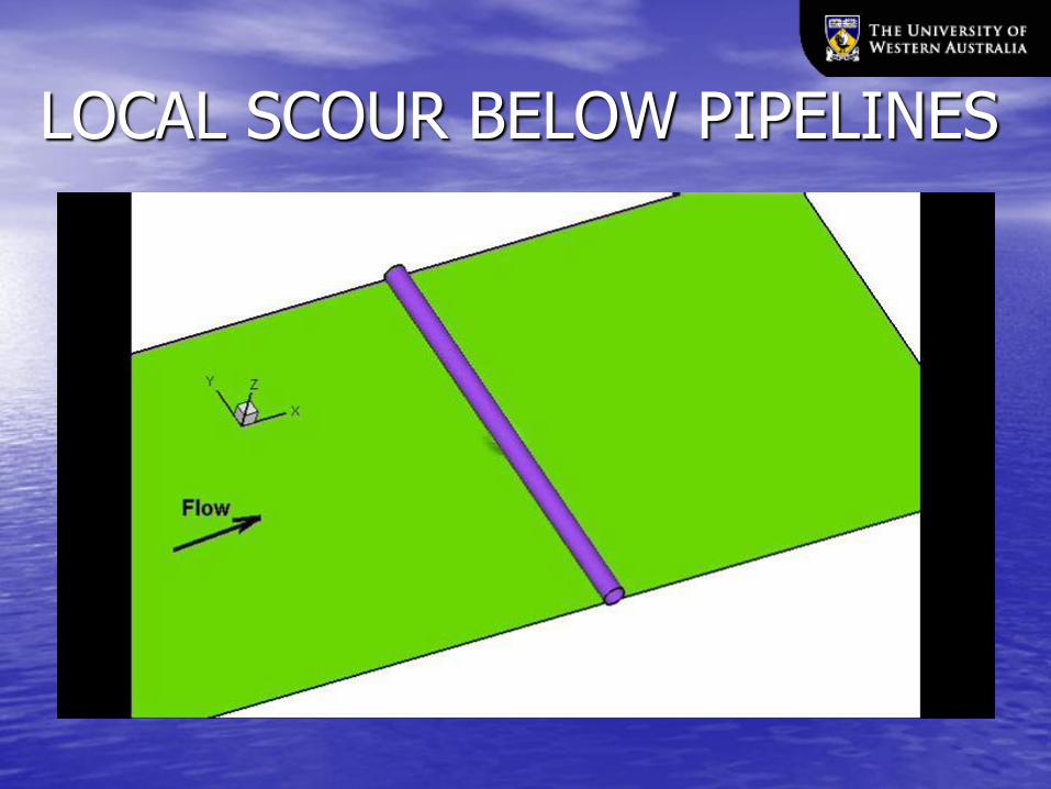
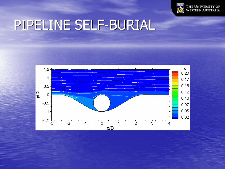
Effects of Sediment Transport
• Movement of sandy seabed sediments modifies seabed profiles around pipelines
• Local scour occurs if wave orbital velocity exceeds a critical value
• Local scour can cause pipeline self-burial into the seabed, improving pipeline stability
– Hydrodynamic forces decreases
– Soil resistance increases Dalian University of Technology
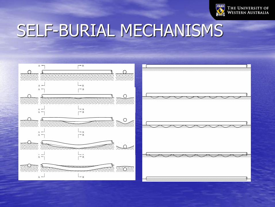
SELF-BURIAL MECHANISMS
School of Civil and Resource
Engineering
B
B
A
A
B
B
A
A
B
B
A
A
B
B
A
A
B
B
A
A

FIELD EXPERIENCES
• Significant self-burial on sandy seabed
– 80%-100% burial for 60%-80% of the lengths of existing small diameter pipelines
School of Civil and Resource Engineering
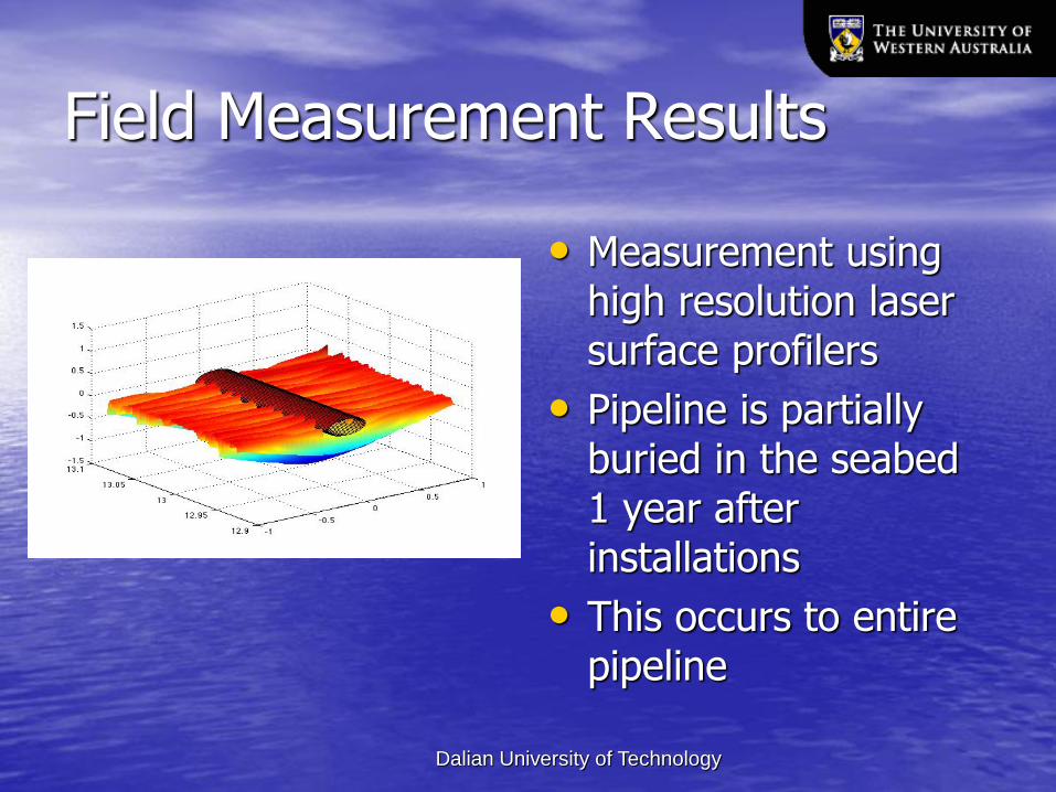
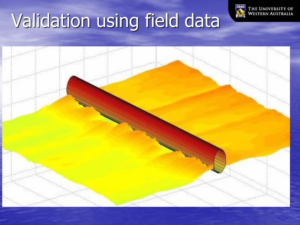
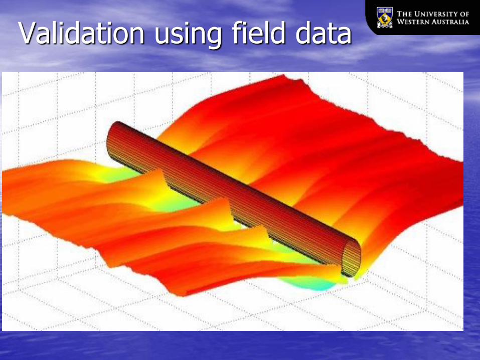
Field Measurement Results
• Measurement using high resolution laser surface profilers
• Pipeline is partially buried in the seabed 1 year after installations
• This occurs to entire pipeline
Dalian University of Technology
WAY FORWARD
• Conduct more research
– Quantify the effect of wave boundary layers on hydrodynamic forces on pipelines
– Develop robust and reliable methodology that can take into account the effect of sediment transport on pipeline stability
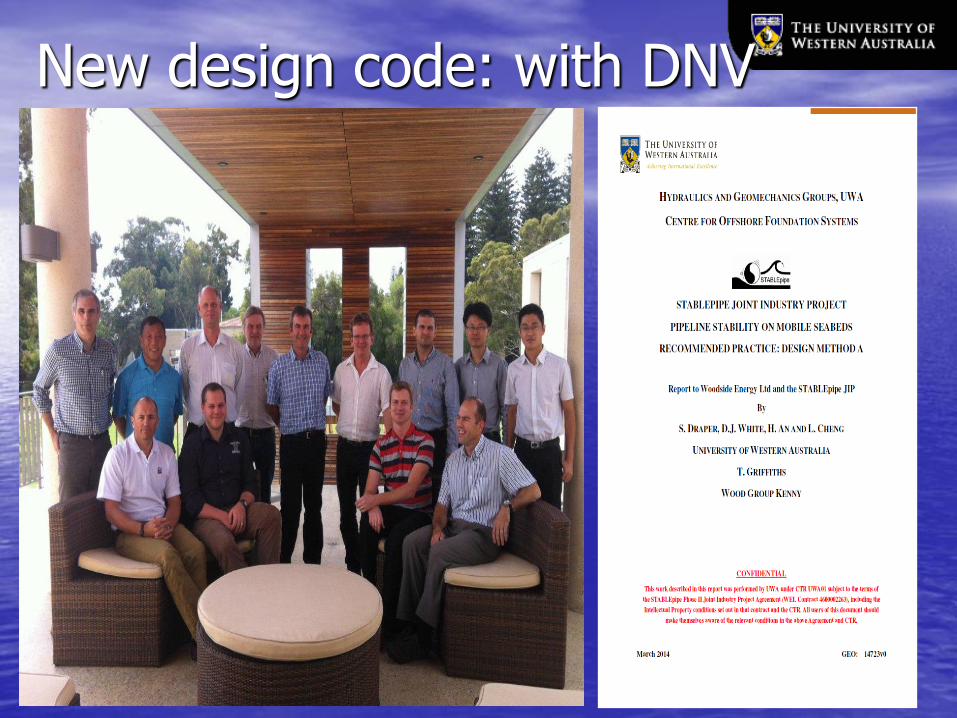
• Joint Industry Project: StablePIPE JIP
– Aims: develop new design guidelines
– Sponsored by two industry partners
– Involved University and engineering companies
Research Aims and Methods
• Develop a new design method to consider the effect of pipeline self-burial on the stability of pipelines
• Method: Experimental investigation
– Quantify the effects of sediment transport and wave boundary layers on pipeline stability
– Simulate dynamic response of pipelines under extreme environmental conditions
Dalian University of Technology

OUTCOMES
• A new research facility is established
– A large scale recirculating flume
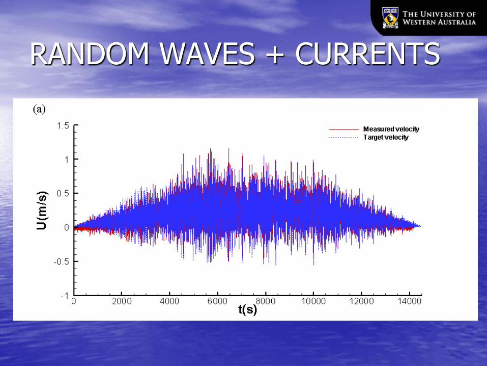
• Able to generate prototype random storm velocity time series up to 2.8m/s with a period of 13s.
• Simulate flow/pipeline/seabed interactions near prototype conditions to overcome scaling difficulties
• Completed a number of research projects
• Developed a new pipeline stability design guideline.
NEW FACILITY
• Functions
– Conduct pipeline stability testing at large scales to reduce scaling effects;
• 1:1 scale for small diameter pipelines (<8 inch)
• 1:5 scale for large diameter pipelines (<40 inch)
– Simulate flow conditions induced by cyclonic storms
• Oscillatory flow up to 2.8 m/s with a peak period of 13 seconds
• Steady currents up to 3.0 m/s
• Combined random storm time series.
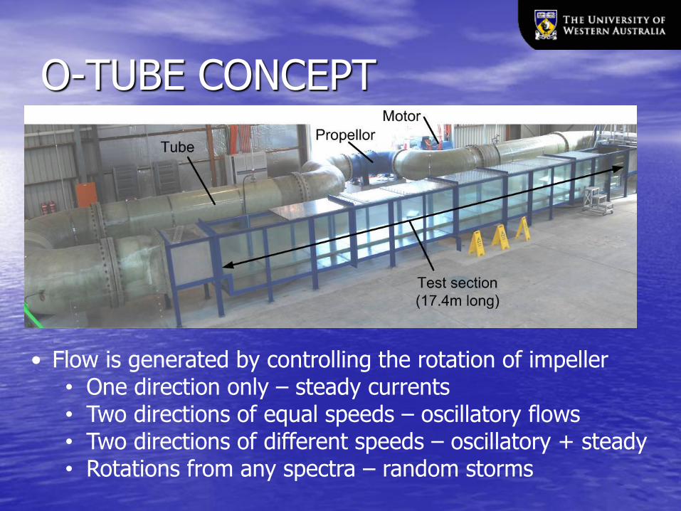
O-TUBE CONCEPT
• Flow is generated by controlling the rotation of impeller • One direction only – steady currents • Two directions of equal speeds – oscillatory flows • Two directions of different speeds – oscillatory + steady • Rotations from any spectra – random storms
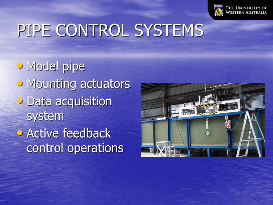
PIPE CONTROL SYSTEMS
• Model pipe
• Mounting actuators
• Data acquisition system
• Active feedback control operations
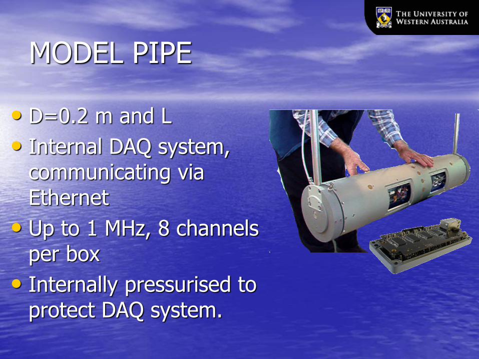
MODEL PIPE
• D=0.2 m and L
• Internal DAQ system, communicating via Ethernet
• Up to 1 MHz, 8 channels per box
• Internally pressurised to protect DAQ system.

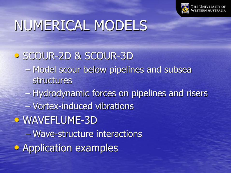
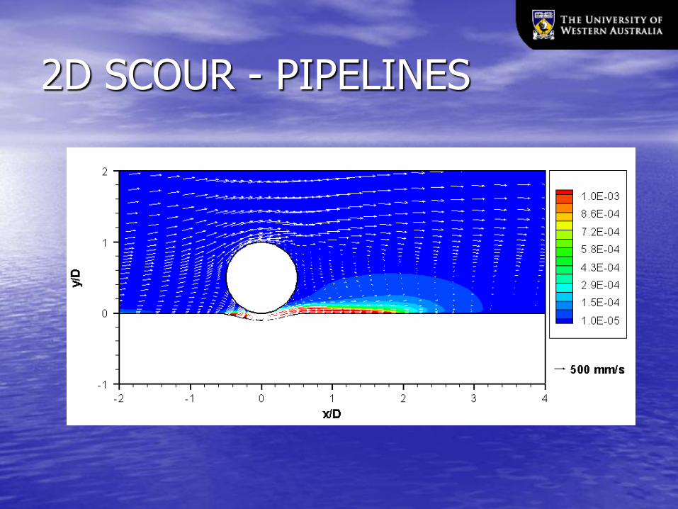
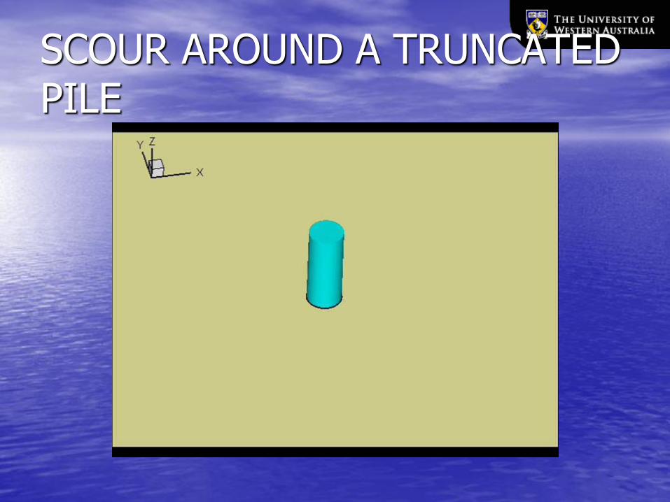
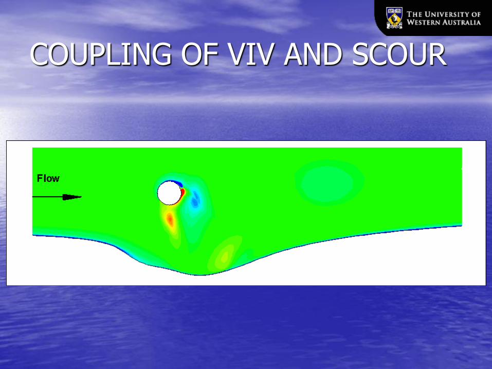
NUMERICAL MODELS
• SCOUR-2D & SCOUR-3D
– Model scour below pipelines and subsea structures
– Hydrodynamic forces on pipelines and risers
– Vortex-induced vibrations
• WAVEFLUME-3D
– Wave-structure interactions
• Application examples


RESEARCH IMPACTS
SUMMARY
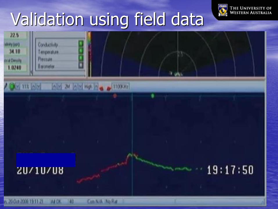
• A new pipeline stability design methodology has been developed and validated against both laboratory tests and field data
• The new design method is being applied to a number of real engineering projects
• More research efforts are needed to improve the design method.