desktop 4th generation intel and intel - intel: แท็บเล็ต, … · desktop 4th...
TRANSCRIPT
Desktop 4th Generation Intel® Core™
Processor Family, Desktop Intel®Pentium® Processor Family, DesktopIntel® Celeron® Processor Family,and Intel® Xeon® Processor E3-1200v3 Product FamilyThermal Mechanical Design Guidelines (TMDG)
December 2013
Order No.: 328900-003
INFORMATION IN THIS DOCUMENT IS PROVIDED IN CONNECTION WITH INTEL PRODUCTS. NO LICENSE, EXPRESS OR IMPLIED, BY ESTOPPEL OROTHERWISE, TO ANY INTELLECTUAL PROPERTY RIGHTS IS GRANTED BY THIS DOCUMENT. EXCEPT AS PROVIDED IN INTEL'S TERMS ANDCONDITIONS OF SALE FOR SUCH PRODUCTS, INTEL ASSUMES NO LIABILITY WHATSOEVER AND INTEL DISCLAIMS ANY EXPRESS OR IMPLIEDWARRANTY, RELATING TO SALE AND/OR USE OF INTEL PRODUCTS INCLUDING LIABILITY OR WARRANTIES RELATING TO FITNESS FOR APARTICULAR PURPOSE, MERCHANTABILITY, OR INFRINGEMENT OF ANY PATENT, COPYRIGHT OR OTHER INTELLECTUAL PROPERTY RIGHT.
A "Mission Critical Application" is any application in which failure of the Intel Product could result, directly or indirectly, in personal injury or death.SHOULD YOU PURCHASE OR USE INTEL'S PRODUCTS FOR ANY SUCH MISSION CRITICAL APPLICATION, YOU SHALL INDEMNIFY AND HOLD INTEL ANDITS SUBSIDIARIES, SUBCONTRACTORS AND AFFILIATES, AND THE DIRECTORS, OFFICERS, AND EMPLOYEES OF EACH, HARMLESS AGAINST ALLCLAIMS COSTS, DAMAGES, AND EXPENSES AND REASONABLE ATTORNEYS' FEES ARISING OUT OF, DIRECTLY OR INDIRECTLY, ANY CLAIM OFPRODUCT LIABILITY, PERSONAL INJURY, OR DEATH ARISING IN ANY WAY OUT OF SUCH MISSION CRITICAL APPLICATION, WHETHER OR NOT INTELOR ITS SUBCONTRACTOR WAS NEGLIGENT IN THE DESIGN, MANUFACTURE, OR WARNING OF THE INTEL PRODUCT OR ANY OF ITS PARTS.
Intel may make changes to specifications and product descriptions at any time, without notice. Designers must not rely on the absence orcharacteristics of any features or instructions marked "reserved" or "undefined". Intel reserves these for future definition and shall have noresponsibility whatsoever for conflicts or incompatibilities arising from future changes to them. The information here is subject to change withoutnotice. Do not finalize a design with this information.
The products described in this document may contain design defects or errors known as errata which may cause the product to deviate from publishedspecifications. Current characterized errata are available on request.
Contact your local Intel sales office or your distributor to obtain the latest specifications and before placing your product order.
Copies of documents which have an order number and are referenced in this document, or other Intel literature, may be obtained by calling1-800-548-4725, or go to: http://www.intel.com/design/literature.htm
This document contains information on products in the design phase of development.
Code Names are only for use by Intel to identify products, platforms, programs, services, etc. ("products") in development by Intel that have not beenmade commercially available to the public, i.e., announced, launched or shipped. They are never to be used as "commercial" names for products. Also,they are not intended to function as trademarks.
Intel, Intel Core, Xeon, Pentium, and the Intel logo are trademarks of Intel Corporation in the U.S. and/or other countries.
*Other names and brands may be claimed as the property of others.
Copyright © 2013, Intel Corporation. All rights reserved.
Desktop 4th Generation Intel® Core™ Processor Family, Desktop Intel® Pentium® Processor Family, Desktop Intel® Celeron®
Processor Family, and Intel® Xeon® Processor E3-1200 v3 Product FamilyThermal Mechanical Design Guidelines (TMDG) December 20132 Order No.: 328900-003
Contents
1.0 Introduction................................................................................................................. 71.1 Key Changes..........................................................................................................81.2 Related Documents................................................................................................91.3 Definition of Terms................................................................................................. 9
2.0 Platform Environment Control Interface (PECI)..........................................................122.1 Fan Speed Control with Digital Thermal Sensor (DTS)................................................12
3.0 Thermal Solution Design Process................................................................................ 133.1 Boundary Condition Definition................................................................................ 133.2 Thermal Design and Modeling.................................................................................133.3 Thermal Solution Validation....................................................................................14
4.0 Digital Thermal Sensor Design Guidance.....................................................................164.1 Sensor Based Thermal Specification........................................................................ 164.2 Fan Speed Control (FSC) Guidance..........................................................................174.3 Legacy Fan Speed Control......................................................................................184.4 Fan Speed Control Scheme with Digital Thermal Sensor 1.1........................................184.5 Fan Speed Control Scheme with Digital Thermal Sensor 2.0........................................19
5.0 Advanced Technology eXtended (ATX) Reference Thermal Solution........................... 225.1 Heatsink Thermal Solution..................................................................................... 225.2 Geometric Envelope for the Intel® Reference ATX Thermal Mechanical Design...............235.3 Reference Design Components................................................................................245.4 Mechanical Interface to the Reference Attach Mechanism........................................... 275.5 Heatsink Mass and Center of Gravity....................................................................... 295.6 Thermal Interface Material..................................................................................... 295.7 Heat Pipe Thermal Considerations........................................................................... 29
6.0 Thermal Solution Quality and Reliability Requirements...............................................306.1 Reference Heatsink Thermal Verification.................................................................. 306.2 Mechanical Environmental Testing...........................................................................306.3 Material and Recycling Requirements.......................................................................31
7.0 Boxed Processor Specifications...................................................................................337.1 Mechanical Specifications.......................................................................................347.2 Electrical Requirements......................................................................................... 367.3 Thermal Specifications...........................................................................................38
Appendix A Component Suppliers..................................................................................... 42
Contents—Processor
Desktop 4th Generation Intel® Core™ Processor Family, Desktop Intel® Pentium® Processor Family, Desktop Intel® Celeron®
Processor Family, and Intel® Xeon® Processor E3-1200 v3 Product FamilyDecember 2013 Thermal Mechanical Design Guidelines (TMDG)Order No.: 328900-003 3
Figures1 Keying and Pin Out Array Comparison.......................................................................... 82 Thermal Solution Performance versus Fan Speed......................................................... 153 PCG 2013D Thermal Profile.......................................................................................174 Example Fan PWM Profile using Legacy FSC................................................................ 185 DTS 1.1 Definition Points..........................................................................................196 DTS 2.0 Thermal Specification...................................................................................207 Diagram of DTS 2.0 implementation...........................................................................218 ATX Heatsink Reference Design Assembly................................................................... 239 ATX KOZ 3-D Model Primary (Top) Side......................................................................2410 RCBFH Extrusion .................................................................................................... 2511 Clip for Existing Solutions to straddle LGA1150 Socket..................................................2612 Core...................................................................................................................... 2613 Clip Core and Extrusion Assembly.............................................................................. 2714 Critical Parameters for Interface to the Reference Clip.................................................. 2815 Critical Core Dimensions...........................................................................................2816 1150 TTV Die Size and Orientation.............................................................................2917 Mechanical Representation of the Boxed Processor Thermal Solution.............................. 3418 Space Requirements for the Boxed Processor (side view).............................................. 3519 Space Requirements for the Boxed Processor (top view)............................................... 3520 Space Requirements for the Boxed Processor (overall view).......................................... 3621 Boxed Processor Fan Heatsink Power Cable Connector Description................................. 3722 Baseboard Power Header Placement Relative to Processor Socket.................................. 3823 Boxed Processor Fan Heatsink Airspace Keep-Out Requirements (top view)..................... 3924 Boxed Processor Fan Heatsink Airspace Keep-Out Requirements (side view)....................3925 Boxed Processor Fan Heatsink Set Points.................................................................... 40
Processor—Figures
Desktop 4th Generation Intel® Core™ Processor Family, Desktop Intel® Pentium® Processor Family, Desktop Intel® Celeron®
Processor Family, and Intel® Xeon® Processor E3-1200 v3 Product FamilyThermal Mechanical Design Guidelines (TMDG) December 20134 Order No.: 328900-003
Tables1 Related Documents .................................................................................................. 92 Terms and Descriptions..............................................................................................93 Fan Speed Control (FSC) Scheme Comparison.............................................................174 Reference Thermal Solutions.....................................................................................225 Use Conditions (Board Level).................................................................................... 306 Fan Heatsink Power and Signal Specifications..............................................................377 Fan Heatsink Power and Signal Specifications..............................................................418 Reference Heatsink..................................................................................................429 Reference Heatsink Components................................................................................4210 Supplier Contact Information.................................................................................... 42
Tables—Processor
Desktop 4th Generation Intel® Core™ Processor Family, Desktop Intel® Pentium® Processor Family, Desktop Intel® Celeron®
Processor Family, and Intel® Xeon® Processor E3-1200 v3 Product FamilyDecember 2013 Thermal Mechanical Design Guidelines (TMDG)Order No.: 328900-003 5
Revision History
Revison Number Description Revision Date
001 • Initial release June 2013
002 • Added Desktop Intel® Pentium® processor family September2013
003 • Added Desktop Intel® Celeron® processor family December 2013
Processor—Revision History
Desktop 4th Generation Intel® Core™ Processor Family, Desktop Intel® Pentium® Processor Family, Desktop Intel® Celeron®
Processor Family, and Intel® Xeon® Processor E3-1200 v3 Product FamilyThermal Mechanical Design Guidelines (TMDG) December 20136 Order No.: 328900-003
1.0 Introduction
This document contains thermal and mechanical design guidance for the Desktop 4thGeneration Intel® Core™ processor family, Desktop Intel® Pentium® processor family,Desktop Intel® Celeron® processor family, and Intel® Xeon® processor E3-1200 v3product family.
The components described in this document include:
• Thermal and mechanical design guidance for:
— Desktop 4th Generation Intel® Core™ processor family with 4 cores andintegrated graphics
— Desktop 4th Generation Intel® Core™ processor family with 2 cores andintegrated graphics
— Desktop Intel® Pentium® processor family with 4 cores and integratedgraphics
— Desktop Intel® Pentium® processor family with 2 cores and integratedgraphics
— Desktop Intel® Celeron® processor family with 4 cores and integrated graphics
— Desktop Intel® Celeron® processor family with 2 cores and integrated graphics
— Intel® Xeon® processor E3-1200 v3 product family with 4 cores and integratedgraphics
— Intel® Xeon® processor E3-1200 v3 product family with 2 cores and integratedgraphics
• A reference design thermal solution (heatsink) for the processors and associatedretention hardware.
The processor has four SKUs. When required for clarity, this document will use:
• Desktop 4th Generation Intel® Core™ processor (PCG 2013D)
• Desktop 4th Generation Intel® Core™ processor (PCG 2013C)
• Desktop 4th Generation Intel® Core™ processor (PCG 2013B)
• Desktop 4th Generation Intel® Core™ processor (PCG 2013A)
• Desktop Intel® Pentium® processor (PCG 2013D)
• Desktop Intel® Pentium® processor (PCG 2013C)
• Desktop Intel® Pentium® processor (PCG 2013B)
• Desktop Intel® Pentium® processor (PCG 2013A)
• Desktop Intel® Celeron® processor (PCG 2013D)
• Desktop Intel® Celeron® processor (PCG 2013B)
• Desktop Intel® Celeron® processor (PCG 2013B)
• Desktop Intel® Celeron® processor (PCG 2013A)
Introduction—Processor
Desktop 4th Generation Intel® Core™ Processor Family, Desktop Intel® Pentium® Processor Family, Desktop Intel® Celeron®
Processor Family, and Intel® Xeon® Processor E3-1200 v3 Product FamilyDecember 2013 Thermal Mechanical Design Guidelines (TMDG)Order No.: 328900-003 7
• Intel® Xeon® processor E3-1200 v3 product family (PCG 2013D)
• Intel® Xeon® processor E3-1200 v3 product family (PCG 2013C)
• Intel® Xeon® processor E3-1200 v3 product family (PCG 2013B)
• Intel® Xeon® processor E3-1200 v3 product family (PCG 2013A)
Note: When the information is applicable to all products this document will use “processor”or “processors” to simplify the document.
Key Changes
The processors introduce thermal and mechanical changes that will be highlighted inthis document and related documentation identified in Related Documents on page9:
• A new fan speed control implementation scheme is introduced, DTS 2.0.
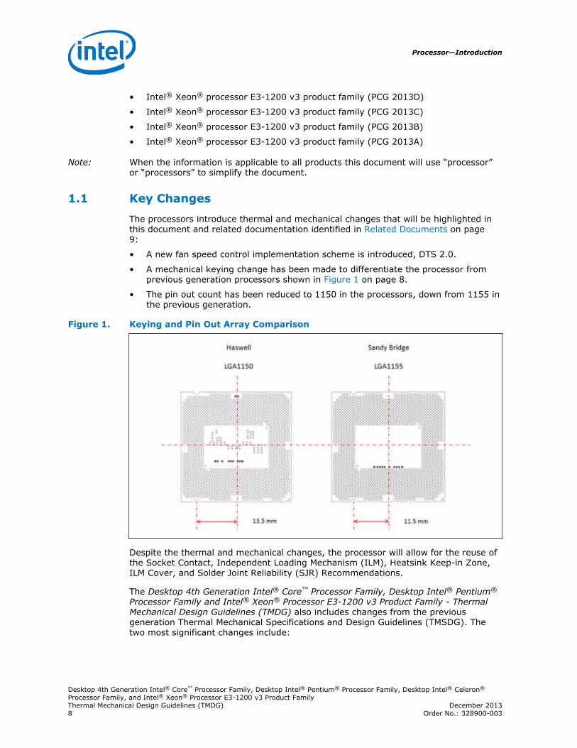
• A mechanical keying change has been made to differentiate the processor fromprevious generation processors shown in Figure 1 on page 8.
• The pin out count has been reduced to 1150 in the processors, down from 1155 inthe previous generation.
Figure 1. Keying and Pin Out Array Comparison
Despite the thermal and mechanical changes, the processor will allow for the reuse ofthe Socket Contact, Independent Loading Mechanism (ILM), Heatsink Keep-in Zone,ILM Cover, and Solder Joint Reliability (SJR) Recommendations.
The Desktop 4th Generation Intel® Core™ Processor Family, Desktop Intel® Pentium®
Processor Family and Intel® Xeon® Processor E3-1200 v3 Product Family - ThermalMechanical Design Guidelines (TMDG) also includes changes from the previousgeneration Thermal Mechanical Specifications and Design Guidelines (TMSDG). Thetwo most significant changes include:
1.1
Processor—Introduction
Desktop 4th Generation Intel® Core™ Processor Family, Desktop Intel® Pentium® Processor Family, Desktop Intel® Celeron®
Processor Family, and Intel® Xeon® Processor E3-1200 v3 Product FamilyThermal Mechanical Design Guidelines (TMDG) December 20138 Order No.: 328900-003
1. The Thermal Specifications chapter has been relocated to documents Desktop 4thGeneration Intel® Core™ Processor Family, Intel® Pentium® Processor Family, andIntel® Celeron® Processor Family Datasheet - Volume 1 of 2 and Intel® Xeon®
Processor E3-1200 v3 Product Family Datasheet - Volume 1 of 2.
2. The LGA1150 Socket Application Guide will now contain the chapters discussingthe Socket, the Independent Loading mechanism (ILM), their respective Electrical,Mechanical, and Environmental Specifications, and related Appendices.
Note: Refer to Related Documents on page 9 for details on acquiring these documents.
Related Documents
Material and concepts available in the following documents may be beneficial whenreading this document.
Table 1. Related Documents
Title Document Number /Location
Desktop 4th Generation Intel® Core™ Processor Family, Intel® Pentium®
Processor Family, and Intel® Celeron® Processor Family Datasheet - Volume 1 of2
328897
Desktop 4th Generation Intel® Core™ Processor Family, Intel® Pentium®
Processor Family, and Intel® Celeron® Processor Family Datasheet - Volume 2 of2
328898
Intel® Xeon® Processor E3-1200 v3 Product Family Datasheet - Volume 1 of 2 328907
Intel® Xeon® Processor E3-1200 v3 Product Family Datasheet - Volume 2 of 2 329000
Intel® Xeon® Processor E3-1200 v3 Product Family Specification Update 328908
LGA1150 Socket Application Guide 328999
Thermally Advantaged Chassis (TAC) http://www.formfactors.org/
4-Wire Pulse Width Modulation (PWM) Controlled Fans http://www.formfactors.org/
Various system thermal design suggestions http://www.formfactors.org/
Definition of Terms
Table 2. Terms and Descriptions
Term Description
ATX Advanced Technology eXtended is a motherboard form factor specification developed byIntel in 1995.
Bypass Bypass is the area between a passive heatsink and any object that can act to form a duct.For this example, it can be expressed as a dimension away from the outside dimension ofthe fins to the nearest surface.
CAG Chassis Air Guide
CTE Coefficient of Thermal Expansion. The relative rate a material expands during a thermalevent.
continued...
1.2
1.3
Introduction—Processor
Desktop 4th Generation Intel® Core™ Processor Family, Desktop Intel® Pentium® Processor Family, Desktop Intel® Celeron®
Processor Family, and Intel® Xeon® Processor E3-1200 v3 Product FamilyDecember 2013 Thermal Mechanical Design Guidelines (TMDG)Order No.: 328900-003 9
Term Description
DTS Digital Thermal Sensor reports a relative die temperature as an offset from TCC activationtemperature.
FSC Fan Speed Control
IHS Integrated Heat Spreader: a component of the processor package used to enhance thethermal performance of the package. Component thermal solutions interface with theprocessor at the IHS surface.
ILM Independent Loading Mechanism provides the force needed to seat the 1150-LGA landpackage onto the socket contacts.
MD Metal Defined pad is one where a pad is individually etched into the PCB with a minimumwidth trace exiting it.
PCG Platform Compatibility Guide (PCG) (previously known as FMB) provides a design target formeeting all planned processor frequency requirements.
PCH Platform Controller Hub. The PCH is connected to the processor using the Direct MediaInterface (DMI) and Intel Flexible Display Interface (Intel FDI).
LGA1150socket
The processor mates with the system board through this surface mount, 1150-land socket.
PECI The Platform Environment Control Interface (PECI) is a one-wire interface that provides acommunication channel between Intel processor and chipset components to externalmonitoring devices.
PWM Pulse Width Modulation
Ψ ca Case-to-ambient thermal characterization parameter (psi). A measure of thermal solutionperformance using total package power. Defined as (TCASE – TLA ) / Total Package Power.The heat source should always be specified for Y measurements.
Ψ CS Case-to-sink thermal characterization parameter. A measure of thermal interface materialperformance using total package power. Defined as (TCASE – TS ) / Total Package Power.
Ψ sa Sink-to-ambient thermal characterization parameter. A measure of heatsink thermalperformance using total package power. Defined as (TS – TLA ) / Total Package Power.
SMD The Solder Mask Defined pad is typically a pad in a flood plane where the solder maskopening defines the pad size for soldering to the component to the printed circuit board.
TCASE or T C The case temperature of the processor, measured at the geometric center of the top-side ofthe TTV IHS.
TCASE_MAX The maximum case temperature as specified in a component specification.
TAC Thermal Advantaged Chassis
TCC Thermal Control Circuit: Thermal monitor uses the TCC to reduce the die temperature byusing clock modulation and/or operating frequency and input voltage adjustment when thedie temperature is very near its operating limits.
TCONTROL TCONTROL is a static value that is below the TCC activation temperature and used as atrigger point for fan speed control. When DTS > TCONTROL, the processor must comply tothe TTV thermal profile.
TDP Thermal Design Power: Thermal solution should be designed to dissipate this target powerlevel. TDP is not the maximum power that the processor can dissipate.
ThermalMonitor
A power reduction feature designed to decrease temperature after the processor hasreached its maximum operating temperature.
ThermalProfile
Line that defines case temperature specification of the TTV at a given power level.
TIM Thermal Interface Material: The thermally conductive compound between the heatsink andthe processor case. This material fills the air gaps and voids, and enhances the transfer ofthe heat from the processor case to the heatsink.
continued...
Processor—Introduction
Desktop 4th Generation Intel® Core™ Processor Family, Desktop Intel® Pentium® Processor Family, Desktop Intel® Celeron®
Processor Family, and Intel® Xeon® Processor E3-1200 v3 Product FamilyThermal Mechanical Design Guidelines (TMDG) December 201310 Order No.: 328900-003
Term Description
TTV Thermal Test Vehicle. A mechanically equivalent package that contains a resistive heater inthe die to evaluate thermal solutions.
TLA The measured ambient temperature locally surrounding the processor. The ambienttemperature should be measured just upstream of a passive heatsink or at the fan inlet foran active heatsink.
TSA The system ambient air temperature external to a system chassis. This temperature isusually measured at the chassis air inlets.
Introduction—Processor
Desktop 4th Generation Intel® Core™ Processor Family, Desktop Intel® Pentium® Processor Family, Desktop Intel® Celeron®
Processor Family, and Intel® Xeon® Processor E3-1200 v3 Product FamilyDecember 2013 Thermal Mechanical Design Guidelines (TMDG)Order No.: 328900-003 11
2.0 Platform Environment Control Interface (PECI)
PECI uses a single wire for self-clocking and data transfer. The bus requires noadditional control lines. The physical layer is a self-clocked one-wire bus that beginseach bit with a driven, rising edge from an idle level near zero volts. The duration ofthe signal driven high depends on whether the bit value is a logic ‘0’ or logic ‘1’. PECIalso includes variable data transfer rate established with every message. In this way,it is highly flexible even though underlying logic is simple.
The interface design was optimized for interfacing to Intel processors in both singleprocessor and multiple processor environments. The single wire interface provides lowboard routing overhead for the multiple load connections in the congested routingarea near the processor and chipset components. Bus speed, error checking, and lowprotocol overhead provides adequate link bandwidth and reliability to transfer criticaldevice operating conditions and configuration information.
The PECI bus offers:
• A wide speed range from 2 Kbps to 2 Mbps
• CRC check byte used to efficiently and atomically confirm accurate data delivery
• Synchronization at the beginning of every message minimizes device timingaccuracy requirements
For temperature monitoring and fan speed control management purpose, the PECI 3.0commands that are commonly implemented includes Ping(), GetDIB(), GetTemp(),TCONTROL and TjMAX(TCC) read. The TCONTROL and TCC read command can beimplemented by utilizing the RdPkgConfig() command.
Fan Speed Control with Digital Thermal Sensor (DTS)
Processor fan speed control is managed by comparing DTS temperature data againstthe processor-specific value stored in the static variable, TCONTROL. When the DTStemperature data is less than TCONTROL, the fan speed control algorithm can reduce thespeed of the thermal solution fan. This remains the same as with the previousguidance for fan speed control. Refer to Volume 1 of the processor Datasheet (seeRelated Documents section) for guidance where the DTS temperature data exceedsTCONTROL.
The DTS temperature data is delivered over PECI, in response to a GetTemp()command, and reported as a relative value to TCC activation target. The temperaturedata reported over PECI is always a negative value and represents a delta below theonset of thermal control circuit (TCC) activation, as indicated by the PROCHOT#signal. Therefore, as the temperature approaches TCC activation, the valueapproaches zero degrees.
2.1
Processor—Platform Environment Control Interface (PECI)
Desktop 4th Generation Intel® Core™ Processor Family, Desktop Intel® Pentium® Processor Family, Desktop Intel® Celeron®
Processor Family, and Intel® Xeon® Processor E3-1200 v3 Product FamilyThermal Mechanical Design Guidelines (TMDG) December 201312 Order No.: 328900-003
3.0 Thermal Solution Design Process
Thermal solution design guidance for the processors is the same as with previousgeneration desktop processors. The initial design needs to take into account the targetmarket and overall product requirements for the system. This can be broken downinto several steps:
• Boundary Condition Definition on page 13
• Thermal Design and Modeling on page 13
• Thermal Solution Validation on page 14
Boundary Condition Definition
Using the knowledge of the system boundary conditions – such as, inlet airtemperature, acoustic requirements, cost, design for manufacturing, package andsocket mechanical specifications and chassis environmental test limits – the designercan make informed thermal solution design decisions.
For the PCG 2013D and PCG 2013C, the thermal boundary conditions for an ATX towersystem are as follows:
• TEXTERNAL = 35 °C. This is typical of a maximum system operating environment orroom temperature
• TRISE = 5 °C. This is typical of a chassis compliant to CAG 1.1 or TAC 2.0
• TAMBIENT = 40 °C (TAMBIENT = TEXTERNAL + TRISE)
Based on the system boundary conditions the designer can select a TAMBIENT and ΨCAto use in thermal modeling. The assumption of a TAMBIENT has a significant impact onthe required ΨCA needed to meet TTV TCASE _ MAX at TDP. A system that can deliver alower assumed TAMBIENT can use a design with a higher ΨCA, which can have a lowercost.
If the assumed TAMBIENT is inappropriate for the intended system environment, thethermal solution performance may not be sufficient to meet the product requirements.The results may be excessive noise from fans having to operate at a speed higherthan intended. In the worst case this can lead to performance loss with excessiveactivation of the Thermal Control Circuit (TCC).
Thermal Design and Modeling
Based on the boundary conditions, the designer can now make the design selection ofthe thermal solution components. The major components that can be mixed are thefan, fin geometry, heat pipe or air cooled solid core design. There are cost andacoustic trade-offs the customer can make.
To aide in the design process, Intel provides Thermal Test Vehicle (TTV) thermalmodels. Consult your Intel Field Sales Engineer for these tools.
3.1
3.2
Thermal Solution Design Process—Processor
Desktop 4th Generation Intel® Core™ Processor Family, Desktop Intel® Pentium® Processor Family, Desktop Intel® Celeron®
Processor Family, and Intel® Xeon® Processor E3-1200 v3 Product FamilyDecember 2013 Thermal Mechanical Design Guidelines (TMDG)Order No.: 328900-003 13
Thermal Solution Validation
Test for Compliance to the TTV Thermal Profile
This step is the same as previously suggested for prior products. The thermal solutionis mounted on a test fixture with the TTV and tested at the following conditions:
• TTV is powered to the TDP condition
• Thermal solution fan is operating at full speed
• TAMBIENT is at the boundary condition from Boundary Condition Definition on page13
The following data points are collected: TTV power, TTV TCASE and TAMBIENT. These areused to calculate ΨCA which is defined as:
ΨCA = (TTV TCASE – TAMBIENT) / TTV Power
ΨCA must be lower than the specification listed in the specifications provided inVolume 1 of the processor Datasheet (see Related Documents section) for a givenprocessor power and TAMBIENT.
This testing is best conducted on a bench to eliminate as many variables as possiblewhen assessing the thermal solution performance. The boundary condition analysis asdescribed in Boundary Condition Definition on page 13 should help in making thebench test simpler to perform.
Thermal Solution Characterization for Fan Speed Control
The final step in thermal solution validation is to establish the thermal solutionperformance, ΨCA and acoustics as a function of fan speed. This data is necessary toallow the fan speed control algorithm developer to program the device. It also isneeded to assess the expected acoustic impact of the processor thermal solution inthe system.
For the characterization of a fan, data should be taken over the full operation range.As an example, data was collected at several points of operation to fit a curve for theRCBF7-1156 (DHA-A) which has an operation range from 900 to 3150 RPM shown in Figure 2 on page 15. Taking data at 6 evenly distributed fan speeds over theoperating range provides enough data to establish an equation. By using the equationfrom the curve fit a complete set of required fan speeds as a function of ΨCA can bedeveloped.
The fan speed control device may modulate the thermal solution fan speed (RPM) byone of two methods. The first and preferred is pulse width modulation (PWM) signalcompliant to the 4-Wire Pulse Width Modulation (PWM) Controlled Fans specification.The alternative is varying the input voltage to the fan. As a result, the characterizationdata needs to also correlate the RPM to PWM or voltage to the thermal solution fan.The fan speed algorithm developer needs to associate the output command from thefan speed control device with the required thermal solution performance. Regardlessof which control method is used, the term RPM will be used to indicate required fanspeed in the rest of this document.
Note: When selecting a thermal solution from a thermal vendor, the characterization datashould be requested directly from them as a part of their thermal solution collateral.
3.3
Processor—Thermal Solution Design Process
Desktop 4th Generation Intel® Core™ Processor Family, Desktop Intel® Pentium® Processor Family, Desktop Intel® Celeron®
Processor Family, and Intel® Xeon® Processor E3-1200 v3 Product FamilyThermal Mechanical Design Guidelines (TMDG) December 201314 Order No.: 328900-003
Figure 2. Thermal Solution Performance versus Fan Speed
Note: This data is from the evaluation of the validation of the RCBF7-1156 (DHA-A)reference processor thermal solution.
Thermal Solution Design Process—Processor
Desktop 4th Generation Intel® Core™ Processor Family, Desktop Intel® Pentium® Processor Family, Desktop Intel® Celeron®
Processor Family, and Intel® Xeon® Processor E3-1200 v3 Product FamilyDecember 2013 Thermal Mechanical Design Guidelines (TMDG)Order No.: 328900-003 15
4.0 Digital Thermal Sensor Design Guidance
The Digital Thermal Sensor Design Guide presents opportunities for the systemdesigner to optimize the acoustics and simplify thermal validation. The digital thermalsensor design guidance uses the Digital Thermal Sensor information accessed usingthe PECI interface. The digital thermal sensor guidance assumes that the thermalsolution meets the thermal solution requirements outlined in Thermal Solution DesignProcess on page 13.
Note: A new fan speed control implementation scheme is introduced for the processoridentified as DTS 2.0. Please refer to Fan Speed Control Scheme with Digital ThermalSensor 2.0 on page 19 for details.
Sensor Based Thermal Specification
The sensor based thermal specification consists of two parts. The first is a thermalprofile that defines the maximum TTV TCASE as a function of TTV power dissipation.The thermal profile defines the boundary conditions for validation of the thermalsolution.
The second part is a defined thermal solution performance (ΨCA) as a function of theDTS value as reported over the PECI bus when DTS is greater than TCONTROL. Thisdefines the operational limits for the processor using the TTV validated thermalsolution.
TTV Thermal Profile
For the sensor based specification, the only reference made to a case temperaturemeasurement is on the TTV. Functional thermal validation will not require the user toapply a thermocouple to the processor package or measure processor power.
Note: All functional compliance testing will be based on fan speed response to the reportedDTS values above TCONTROL. As a result, no conversion of the TTV TCASE to processorTCASE will be necessary.
A knowledge of the system boundary conditions is necessary to perform the heatsinkvalidation. More detail on defining the boundary conditions is provided in BoundaryCondition Definition on page 13. The TTV is placed in the socket and powered to therecommended value to simulate the TDP condition.
4.1
Processor—Digital Thermal Sensor Design Guidance
Desktop 4th Generation Intel® Core™ Processor Family, Desktop Intel® Pentium® Processor Family, Desktop Intel® Celeron®
Processor Family, and Intel® Xeon® Processor E3-1200 v3 Product FamilyThermal Mechanical Design Guidelines (TMDG) December 201316 Order No.: 328900-003
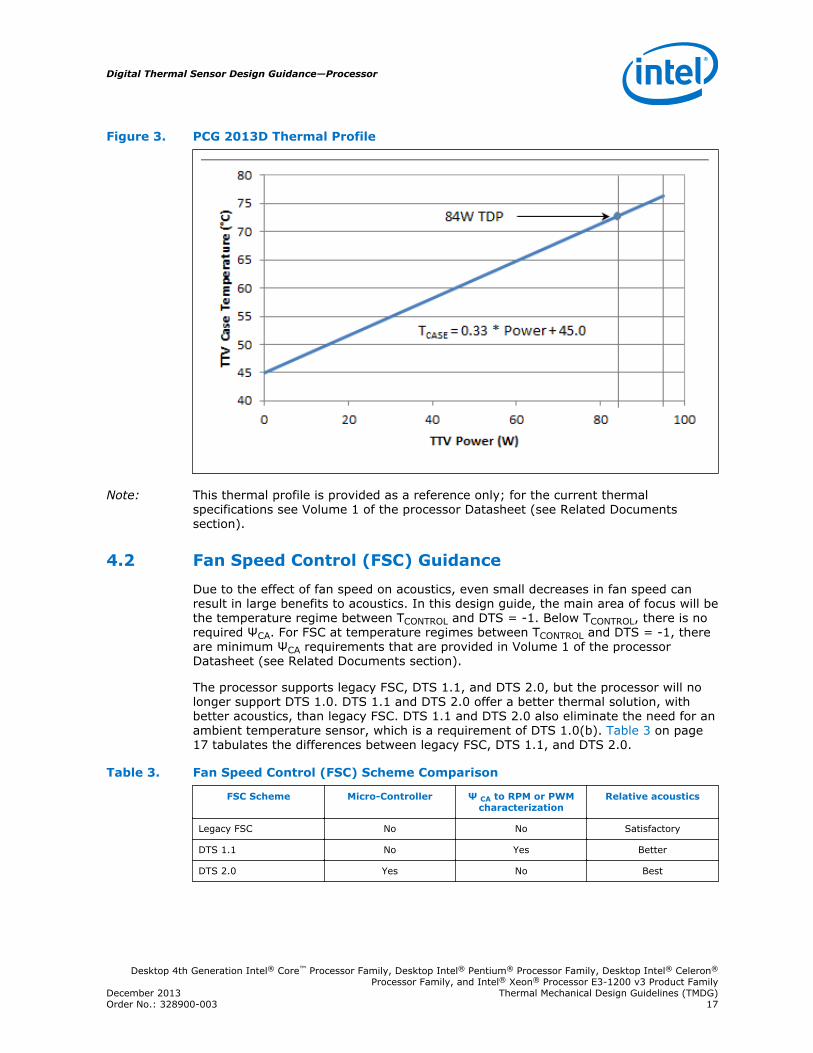
Figure 3. PCG 2013D Thermal Profile
Note: This thermal profile is provided as a reference only; for the current thermalspecifications see Volume 1 of the processor Datasheet (see Related Documentssection).
Fan Speed Control (FSC) Guidance
Due to the effect of fan speed on acoustics, even small decreases in fan speed canresult in large benefits to acoustics. In this design guide, the main area of focus will bethe temperature regime between TCONTROL and DTS = -1. Below TCONTROL, there is norequired ΨCA. For FSC at temperature regimes between TCONTROL and DTS = -1, thereare minimum ΨCA requirements that are provided in Volume 1 of the processorDatasheet (see Related Documents section).
The processor supports legacy FSC, DTS 1.1, and DTS 2.0, but the processor will nolonger support DTS 1.0. DTS 1.1 and DTS 2.0 offer a better thermal solution, withbetter acoustics, than legacy FSC. DTS 1.1 and DTS 2.0 also eliminate the need for anambient temperature sensor, which is a requirement of DTS 1.0(b). Table 3 on page17 tabulates the differences between legacy FSC, DTS 1.1, and DTS 2.0.
Table 3. Fan Speed Control (FSC) Scheme Comparison
FSC Scheme Micro-Controller Ψ CA to RPM or PWMcharacterization
Relative acoustics
Legacy FSC No No Satisfactory
DTS 1.1 No Yes Better
DTS 2.0 Yes No Best
4.2
Digital Thermal Sensor Design Guidance—Processor
Desktop 4th Generation Intel® Core™ Processor Family, Desktop Intel® Pentium® Processor Family, Desktop Intel® Celeron®
Processor Family, and Intel® Xeon® Processor E3-1200 v3 Product FamilyDecember 2013 Thermal Mechanical Design Guidelines (TMDG)Order No.: 328900-003 17
Legacy Fan Speed Control
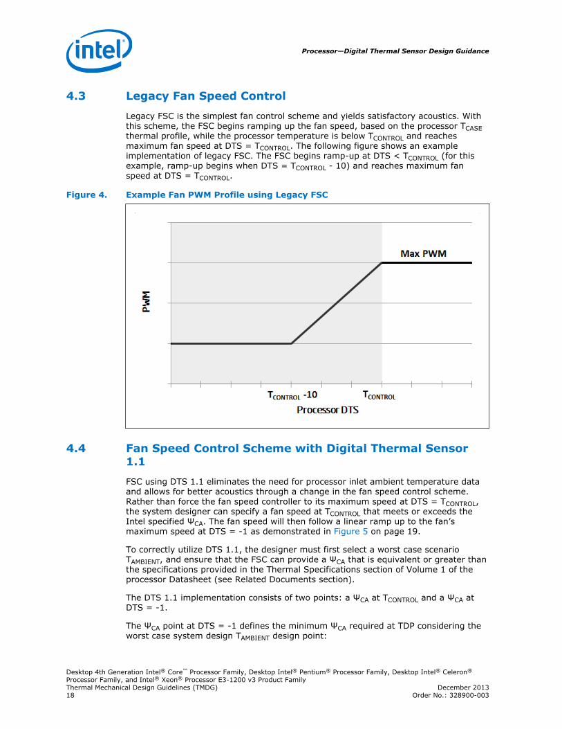
Legacy FSC is the simplest fan control scheme and yields satisfactory acoustics. Withthis scheme, the FSC begins ramping up the fan speed, based on the processor TCASEthermal profile, while the processor temperature is below TCONTROL and reachesmaximum fan speed at DTS = TCONTROL. The following figure shows an exampleimplementation of legacy FSC. The FSC begins ramp-up at DTS < TCONTROL (for thisexample, ramp-up begins when DTS = TCONTROL - 10) and reaches maximum fanspeed at DTS = TCONTROL.
Figure 4. Example Fan PWM Profile using Legacy FSC
Fan Speed Control Scheme with Digital Thermal Sensor1.1
FSC using DTS 1.1 eliminates the need for processor inlet ambient temperature dataand allows for better acoustics through a change in the fan speed control scheme.Rather than force the fan speed controller to its maximum speed at DTS = TCONTROL,the system designer can specify a fan speed at TCONTROL that meets or exceeds theIntel specified ΨCA. The fan speed will then follow a linear ramp up to the fan’smaximum speed at DTS = -1 as demonstrated in Figure 5 on page 19.
To correctly utilize DTS 1.1, the designer must first select a worst case scenarioTAMBIENT, and ensure that the FSC can provide a ΨCA that is equivalent or greater thanthe specifications provided in the Thermal Specifications section of Volume 1 of theprocessor Datasheet (see Related Documents section).
The DTS 1.1 implementation consists of two points: a ΨCA at TCONTROL and a ΨCA atDTS = -1.
The ΨCA point at DTS = -1 defines the minimum ΨCA required at TDP considering theworst case system design TAMBIENT design point:
4.3
4.4
Processor—Digital Thermal Sensor Design Guidance
Desktop 4th Generation Intel® Core™ Processor Family, Desktop Intel® Pentium® Processor Family, Desktop Intel® Celeron®
Processor Family, and Intel® Xeon® Processor E3-1200 v3 Product FamilyThermal Mechanical Design Guidelines (TMDG) December 201318 Order No.: 328900-003
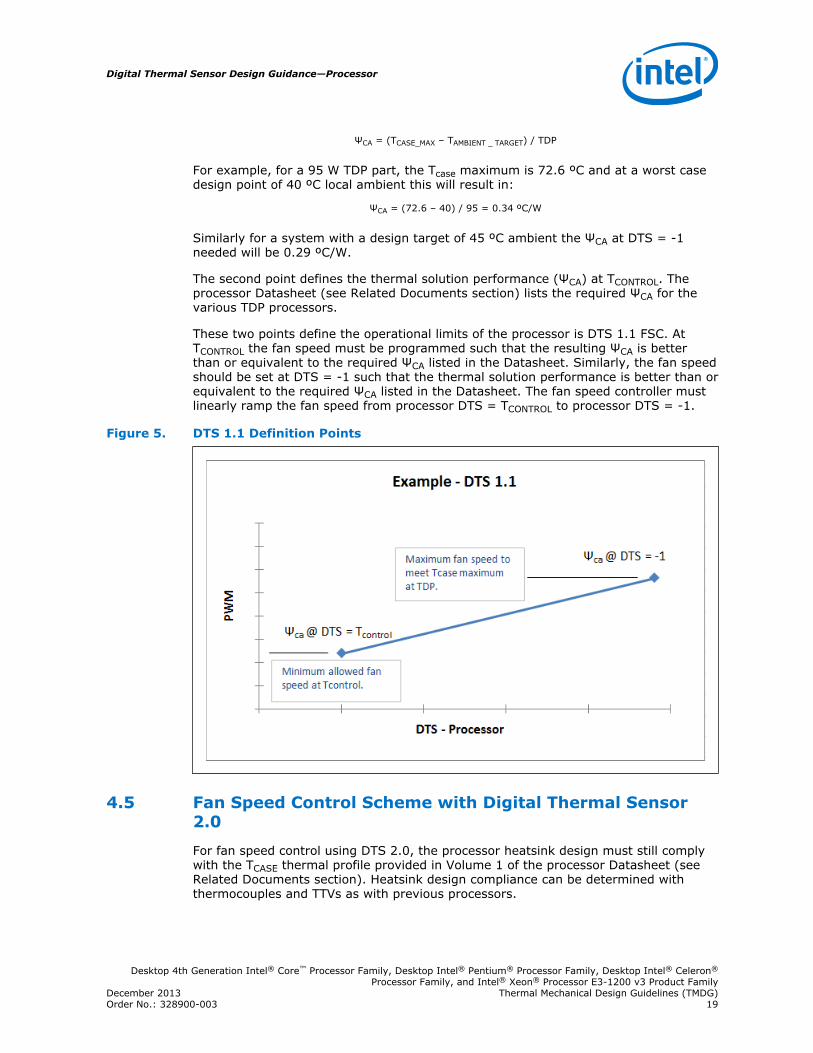
ΨCA = (TCASE_MAX – TAMBIENT _ TARGET) / TDP
For example, for a 95 W TDP part, the Tcase maximum is 72.6 ºC and at a worst casedesign point of 40 ºC local ambient this will result in:
ΨCA = (72.6 – 40) / 95 = 0.34 ºC/W
Similarly for a system with a design target of 45 ºC ambient the ΨCA at DTS = -1needed will be 0.29 ºC/W.
The second point defines the thermal solution performance (ΨCA) at TCONTROL. Theprocessor Datasheet (see Related Documents section) lists the required ΨCA for thevarious TDP processors.
These two points define the operational limits of the processor is DTS 1.1 FSC. AtTCONTROL the fan speed must be programmed such that the resulting ΨCA is betterthan or equivalent to the required ΨCA listed in the Datasheet. Similarly, the fan speedshould be set at DTS = -1 such that the thermal solution performance is better than orequivalent to the required ΨCA listed in the Datasheet. The fan speed controller mustlinearly ramp the fan speed from processor DTS = TCONTROL to processor DTS = -1.
Figure 5. DTS 1.1 Definition Points
Fan Speed Control Scheme with Digital Thermal Sensor2.0
For fan speed control using DTS 2.0, the processor heatsink design must still complywith the TCASE thermal profile provided in Volume 1 of the processor Datasheet (seeRelated Documents section). Heatsink design compliance can be determined withthermocouples and TTVs as with previous processors.
4.5
Digital Thermal Sensor Design Guidance—Processor
Desktop 4th Generation Intel® Core™ Processor Family, Desktop Intel® Pentium® Processor Family, Desktop Intel® Celeron®
Processor Family, and Intel® Xeon® Processor E3-1200 v3 Product FamilyDecember 2013 Thermal Mechanical Design Guidelines (TMDG)Order No.: 328900-003 19
Thermal Margin
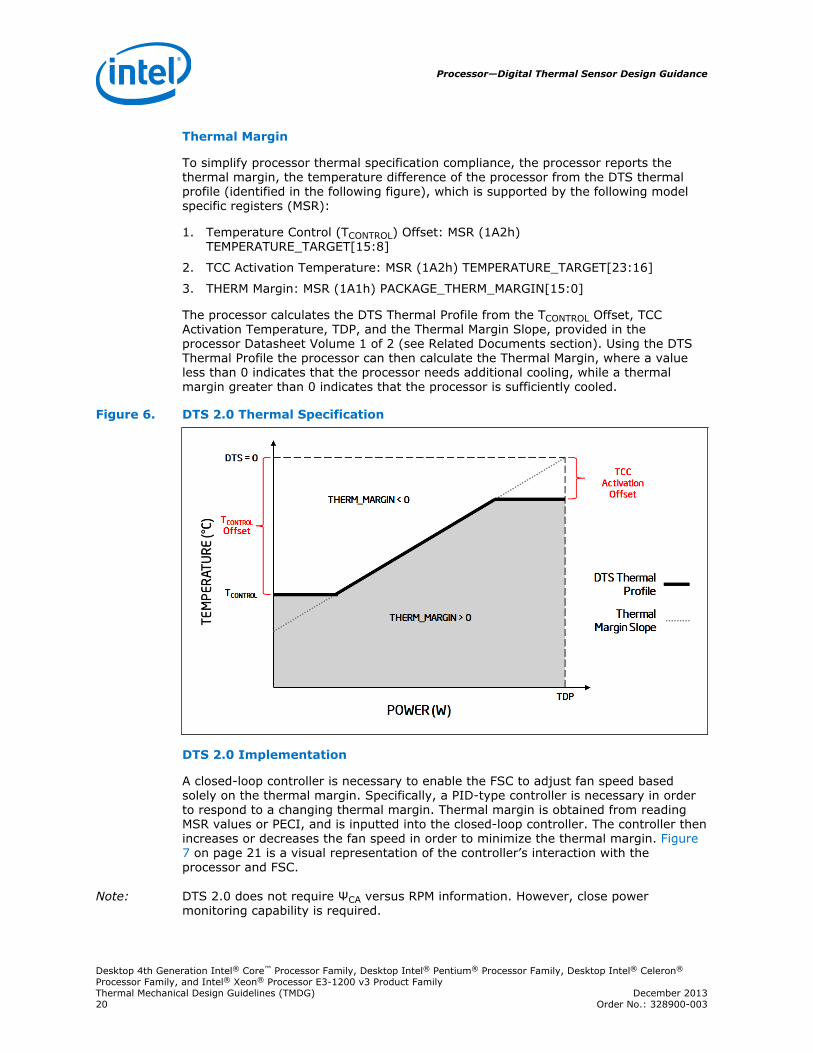
To simplify processor thermal specification compliance, the processor reports thethermal margin, the temperature difference of the processor from the DTS thermalprofile (identified in the following figure), which is supported by the following modelspecific registers (MSR):
1. Temperature Control (TCONTROL) Offset: MSR (1A2h)TEMPERATURE_TARGET[15:8]
2. TCC Activation Temperature: MSR (1A2h) TEMPERATURE_TARGET[23:16]
3. THERM Margin: MSR (1A1h) PACKAGE_THERM_MARGIN[15:0]
The processor calculates the DTS Thermal Profile from the TCONTROL Offset, TCCActivation Temperature, TDP, and the Thermal Margin Slope, provided in theprocessor Datasheet Volume 1 of 2 (see Related Documents section). Using the DTSThermal Profile the processor can then calculate the Thermal Margin, where a valueless than 0 indicates that the processor needs additional cooling, while a thermalmargin greater than 0 indicates that the processor is sufficiently cooled.
Figure 6. DTS 2.0 Thermal Specification
DTS 2.0 Implementation
A closed-loop controller is necessary to enable the FSC to adjust fan speed basedsolely on the thermal margin. Specifically, a PID-type controller is necessary in orderto respond to a changing thermal margin. Thermal margin is obtained from readingMSR values or PECI, and is inputted into the closed-loop controller. The controller thenincreases or decreases the fan speed in order to minimize the thermal margin. Figure7 on page 21 is a visual representation of the controller’s interaction with theprocessor and FSC.
Note: DTS 2.0 does not require ΨCA versus RPM information. However, close powermonitoring capability is required.
Processor—Digital Thermal Sensor Design Guidance
Desktop 4th Generation Intel® Core™ Processor Family, Desktop Intel® Pentium® Processor Family, Desktop Intel® Celeron®
Processor Family, and Intel® Xeon® Processor E3-1200 v3 Product FamilyThermal Mechanical Design Guidelines (TMDG) December 201320 Order No.: 328900-003
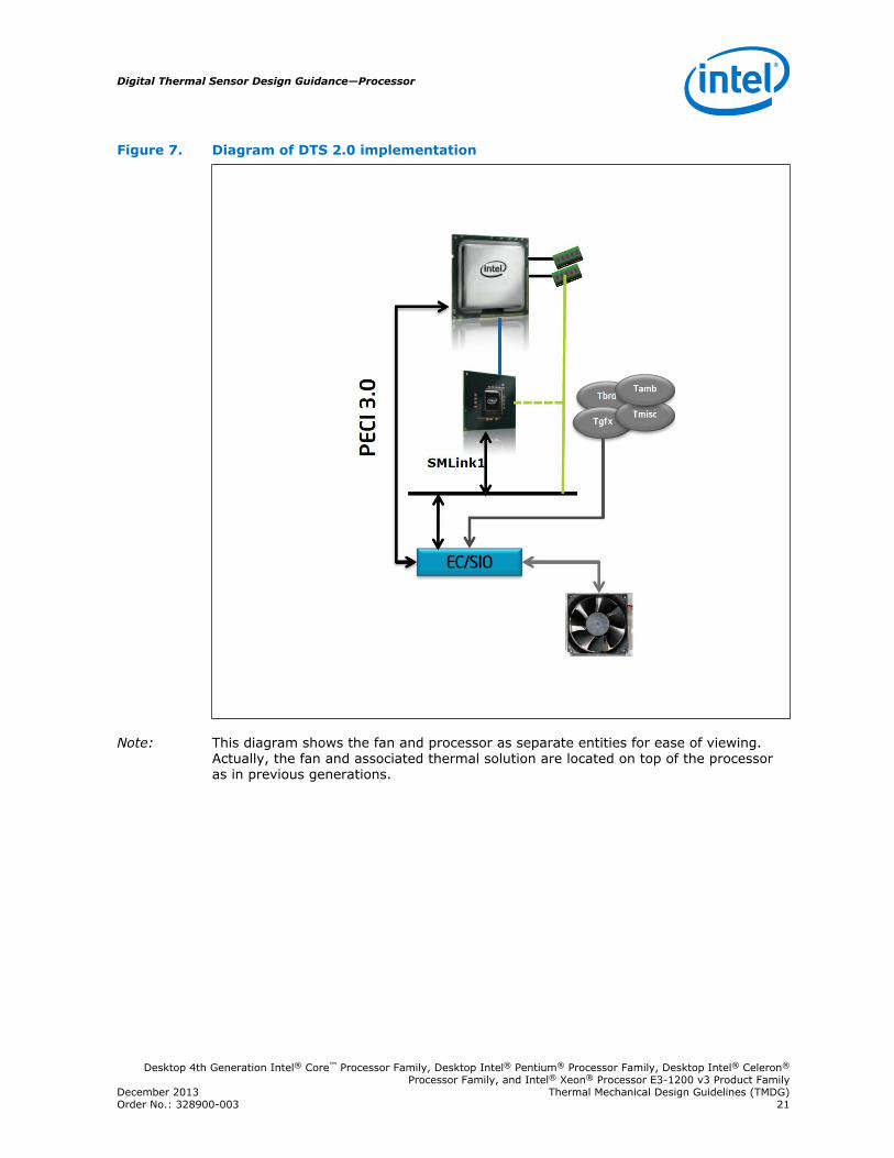
Figure 7. Diagram of DTS 2.0 implementation
Note: This diagram shows the fan and processor as separate entities for ease of viewing.Actually, the fan and associated thermal solution are located on top of the processoras in previous generations.
Digital Thermal Sensor Design Guidance—Processor
Desktop 4th Generation Intel® Core™ Processor Family, Desktop Intel® Pentium® Processor Family, Desktop Intel® Celeron®
Processor Family, and Intel® Xeon® Processor E3-1200 v3 Product FamilyDecember 2013 Thermal Mechanical Design Guidelines (TMDG)Order No.: 328900-003 21
5.0 Advanced Technology eXtended (ATX) ReferenceThermal Solution
Note: The reference thermal mechanical solution information shown in this documentrepresents the current state of the data and may be subject to modification. Theinformation represents design targets, not commitments by Intel.
The design strategy is to use the design concepts from the prior Intel® Radial CurvedBifurcated Fin Heatsink Reference Design (Intel® RCBFH Reference Design) designedoriginally for the Intel® Pentium® 4 processors.
This chapter describes the overall requirements for the ATX heatsink referencethermal solution supporting the processors including critical-to-function dimensions,operating environment, and validation criteria.
Heatsink Thermal Solution
The reference thermal solutions are active fan solutions, same to the prior designs forthe Desktop 2nd and 3rd Generation Intel® Core™ processor families, Desktop Intel®Pentium® and Desktop Intel® Celeron® processor families, and Intel® Xeon®
processor E3-1200 v3 product family. There are three designs being enabled thatsupport the Desktop 4th Generation Intel® Core™, Desktop Intel® Pentium®, DesktopIntel® Celeron® processor families, and Intel® Xeon® processor E3-1200 v3 productfamily. The first is called RCFH7-1156 (DHA-A) that is a universal design (PCG2013D). The second is called the RCFH6-1156 (DHA-B) (PCG 2013C, PCG 2013B, andPCG 2013A). The third is called the DHA-D (PCG 2013B and PCG 2013A).
Table 4. Reference Thermal Solutions
Thermal Solution Name PCG
RCFH7-1156 (DHA-A) 2011D
RCFH6-1156 (DHA-B) 2011C
DHA-D 2011A & 2011B
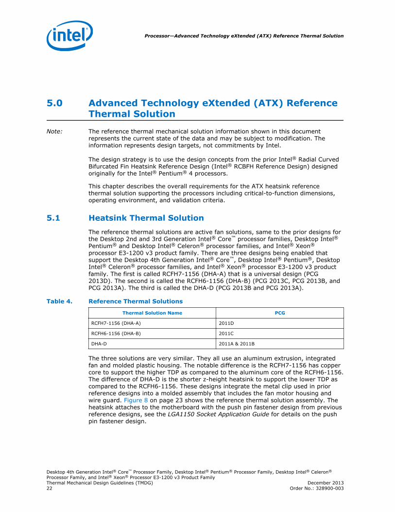
The three solutions are very similar. They all use an aluminum extrusion, integratedfan and molded plastic housing. The notable difference is the RCFH7-1156 has coppercore to support the higher TDP as compared to the aluminum core of the RCFH6-1156.The difference of DHA-D is the shorter z-height heatsink to support the lower TDP ascompared to the RCFH6-1156. These designs integrate the metal clip used in priorreference designs into a molded assembly that includes the fan motor housing andwire guard. Figure 8 on page 23 shows the reference thermal solution assembly. Theheatsink attaches to the motherboard with the push pin fastener design from previousreference designs, see the LGA1150 Socket Application Guide for details on the pushpin fastener design.
5.1
Processor—Advanced Technology eXtended (ATX) Reference Thermal Solution
Desktop 4th Generation Intel® Core™ Processor Family, Desktop Intel® Pentium® Processor Family, Desktop Intel® Celeron®
Processor Family, and Intel® Xeon® Processor E3-1200 v3 Product FamilyThermal Mechanical Design Guidelines (TMDG) December 201322 Order No.: 328900-003
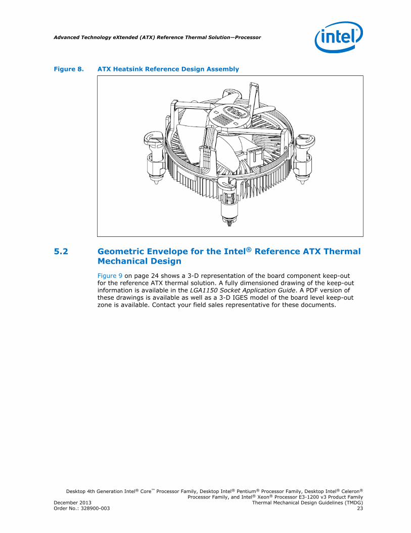
Figure 8. ATX Heatsink Reference Design Assembly
Geometric Envelope for the Intel® Reference ATX ThermalMechanical Design
Figure 9 on page 24 shows a 3-D representation of the board component keep-outfor the reference ATX thermal solution. A fully dimensioned drawing of the keep-outinformation is available in the LGA1150 Socket Application Guide. A PDF version ofthese drawings is available as well as a 3-D IGES model of the board level keep-outzone is available. Contact your field sales representative for these documents.
5.2
Advanced Technology eXtended (ATX) Reference Thermal Solution—Processor
Desktop 4th Generation Intel® Core™ Processor Family, Desktop Intel® Pentium® Processor Family, Desktop Intel® Celeron®
Processor Family, and Intel® Xeon® Processor E3-1200 v3 Product FamilyDecember 2013 Thermal Mechanical Design Guidelines (TMDG)Order No.: 328900-003 23
Figure 9. ATX KOZ 3-D Model Primary (Top) Side
Note: All Maximum Component Heights are post reflow / assembly.
Note: The maximum height of the reference thermal solution (see Figure 9 on page 24)above the motherboard is 46.00 mm [1.81 inches], and is compliant with themotherboard primary side height constraints defined in the ATX Specification and themicroATX Motherboard Interface Specification found at http://www.formfactors.org.
The reference solution requires a chassis obstruction height of at least 81.30 mm[3.20 inches], measured from the top of the motherboard. This allows for appropriatefan inlet airflow to ensure fan performance, and therefore overall cooling solutionperformance. This is compliant with the recommendations found in both ATXSpecification and microATX Motherboard Interface Specification documents.
Reference Design Components
Extrusion
The aluminum extrusion design is similar to what is shown in Figure 10 on page 25.To facilitate reuse of the core design, the center cylinder ID and wall thickness are thesame as RCBFH3.
5.3
Processor—Advanced Technology eXtended (ATX) Reference Thermal Solution
Desktop 4th Generation Intel® Core™ Processor Family, Desktop Intel® Pentium® Processor Family, Desktop Intel® Celeron®
Processor Family, and Intel® Xeon® Processor E3-1200 v3 Product FamilyThermal Mechanical Design Guidelines (TMDG) December 201324 Order No.: 328900-003
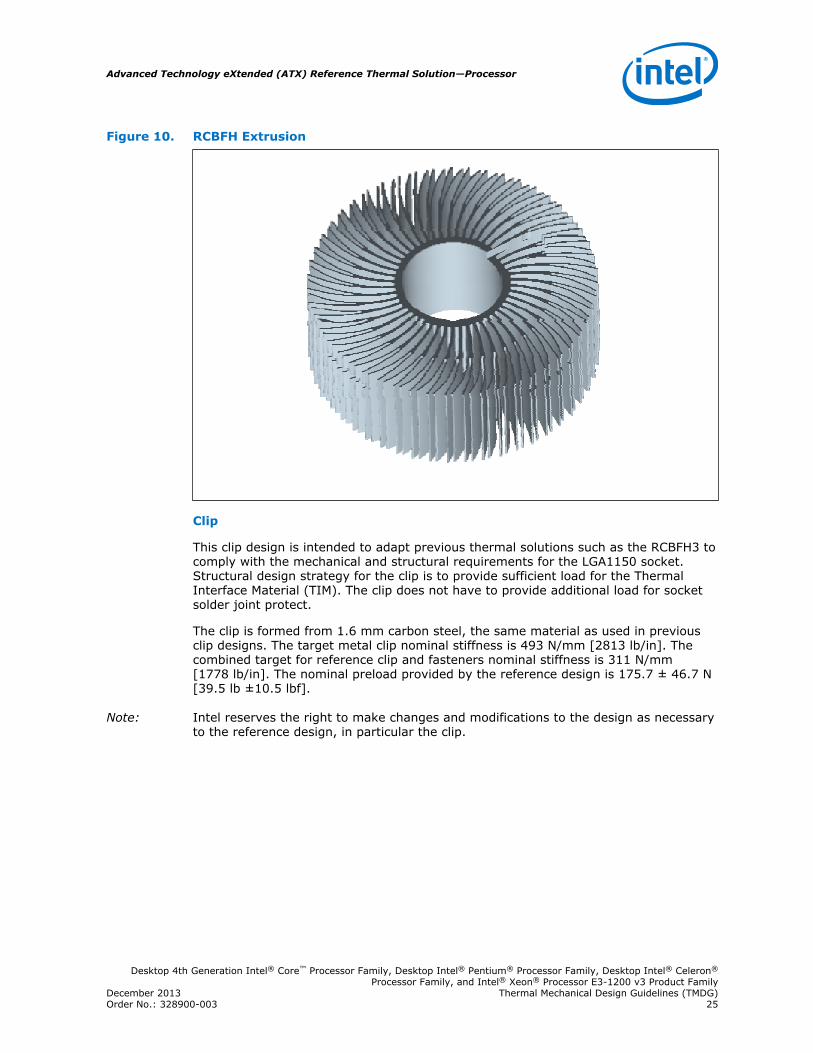
Figure 10. RCBFH Extrusion
Clip
This clip design is intended to adapt previous thermal solutions such as the RCBFH3 tocomply with the mechanical and structural requirements for the LGA1150 socket.Structural design strategy for the clip is to provide sufficient load for the ThermalInterface Material (TIM). The clip does not have to provide additional load for socketsolder joint protect.
The clip is formed from 1.6 mm carbon steel, the same material as used in previousclip designs. The target metal clip nominal stiffness is 493 N/mm [2813 lb/in]. Thecombined target for reference clip and fasteners nominal stiffness is 311 N/mm[1778 lb/in]. The nominal preload provided by the reference design is 175.7 ± 46.7 N[39.5 lb ±10.5 lbf].
Note: Intel reserves the right to make changes and modifications to the design as necessaryto the reference design, in particular the clip.
Advanced Technology eXtended (ATX) Reference Thermal Solution—Processor
Desktop 4th Generation Intel® Core™ Processor Family, Desktop Intel® Pentium® Processor Family, Desktop Intel® Celeron®
Processor Family, and Intel® Xeon® Processor E3-1200 v3 Product FamilyDecember 2013 Thermal Mechanical Design Guidelines (TMDG)Order No.: 328900-003 25
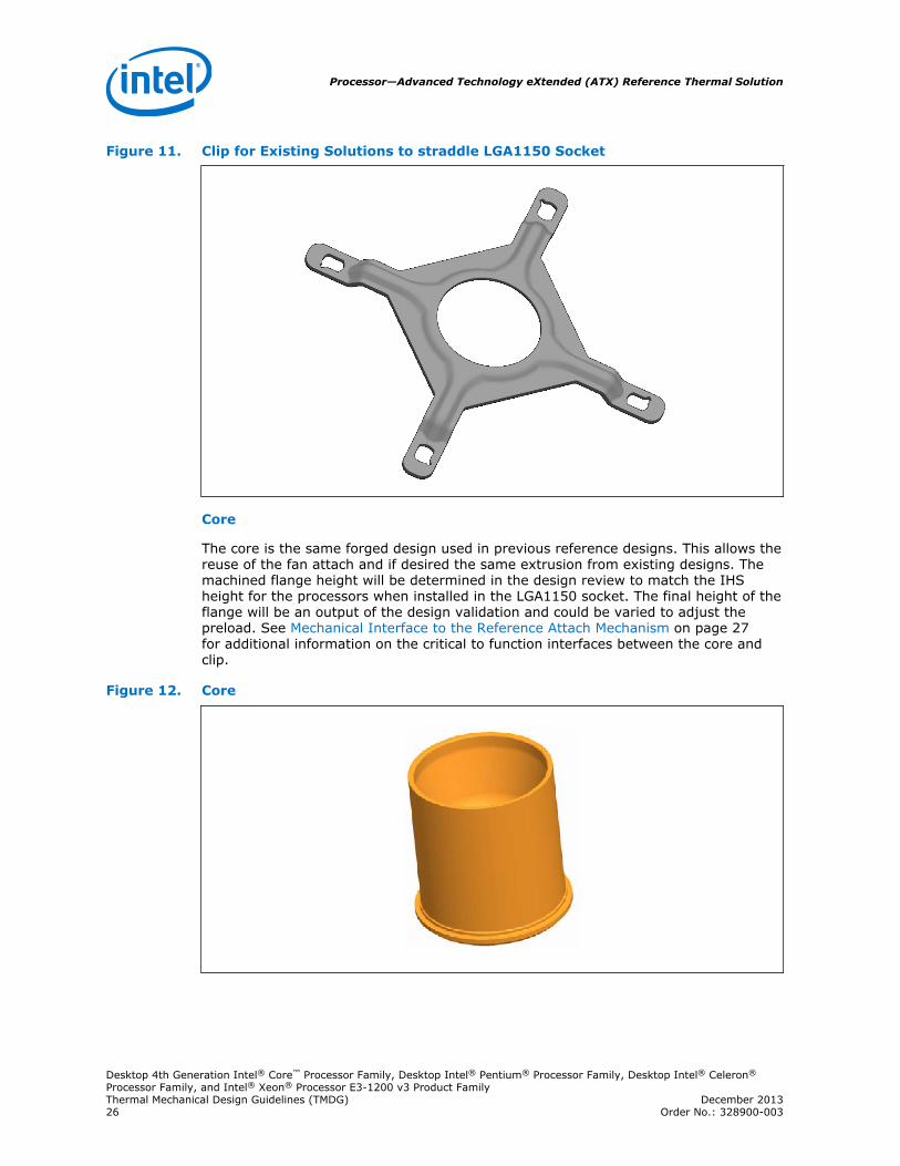
Figure 11. Clip for Existing Solutions to straddle LGA1150 Socket
Core
The core is the same forged design used in previous reference designs. This allows thereuse of the fan attach and if desired the same extrusion from existing designs. Themachined flange height will be determined in the design review to match the IHSheight for the processors when installed in the LGA1150 socket. The final height of theflange will be an output of the design validation and could be varied to adjust thepreload. See Mechanical Interface to the Reference Attach Mechanism on page 27for additional information on the critical to function interfaces between the core andclip.
Figure 12. Core
Processor—Advanced Technology eXtended (ATX) Reference Thermal Solution
Desktop 4th Generation Intel® Core™ Processor Family, Desktop Intel® Pentium® Processor Family, Desktop Intel® Celeron®
Processor Family, and Intel® Xeon® Processor E3-1200 v3 Product FamilyThermal Mechanical Design Guidelines (TMDG) December 201326 Order No.: 328900-003
Mechanical Interface to the Reference Attach Mechanism
The attach mechanism component from the Intel Reference Design can be used byother 3rd party cooling solutions. The attach mechanism consists of:
• A metal attach clip that interfaces with the heatsink core.
• Four plastic fasteners.
Note: See the LGA1150 Socket Application Guide for detailed clip and plastic fastenerdrawings.
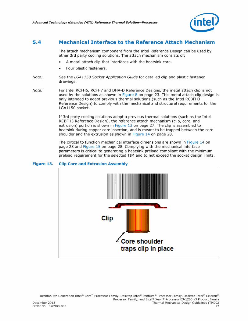
Note: For Intel RCFH6, RCFH7 and DHA-D Reference Designs, the metal attach clip is notused by the solutions as shown in Figure 8 on page 23. This metal attach clip design isonly intended to adapt previous thermal solutions (such as the Intel RCBFH3Reference Design) to comply with the mechanical and structural requirements for theLGA1150 socket.
If 3rd party cooling solutions adopt a previous thermal solutions (such as the IntelRCBFH3 Reference Design), the reference attach mechanism (clip, core, andextrusion) portion is shown in Figure 13 on page 27. The clip is assembled toheatsink during copper core insertion, and is meant to be trapped between the coreshoulder and the extrusion as shown in Figure 14 on page 28.
The critical to function mechanical interface dimensions are shown in Figure 14 onpage 28 and Figure 15 on page 28. Complying with the mechanical interfaceparameters is critical to generating a heatsink preload compliant with the minimumpreload requirement for the selected TIM and to not exceed the socket design limits.
Figure 13. Clip Core and Extrusion Assembly
5.4
Advanced Technology eXtended (ATX) Reference Thermal Solution—Processor
Desktop 4th Generation Intel® Core™ Processor Family, Desktop Intel® Pentium® Processor Family, Desktop Intel® Celeron®
Processor Family, and Intel® Xeon® Processor E3-1200 v3 Product FamilyDecember 2013 Thermal Mechanical Design Guidelines (TMDG)Order No.: 328900-003 27
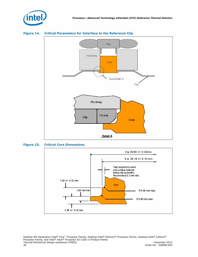
Figure 14. Critical Parameters for Interface to the Reference Clip
Figure 15. Critical Core Dimensions
Processor—Advanced Technology eXtended (ATX) Reference Thermal Solution
Desktop 4th Generation Intel® Core™ Processor Family, Desktop Intel® Pentium® Processor Family, Desktop Intel® Celeron®
Processor Family, and Intel® Xeon® Processor E3-1200 v3 Product FamilyThermal Mechanical Design Guidelines (TMDG) December 201328 Order No.: 328900-003
Heatsink Mass and Center of Gravity
• Total mass including plastic fan housing and fasteners <500 g.
• Assembly center of gravity ≤ 25.4 mm, measured from the top of the IHS.
Thermal Interface Material
A thermal interface material (TIM) provides conductivity between the IHS andheatsink. The designs use Dow Corning TC-1996. The TIM application is 0.14 g, whichwill be a nominal 20 mm diameter (~0.79 inches).
Heat Pipe Thermal Considerations
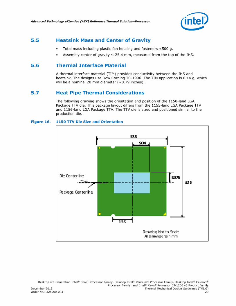
The following drawing shows the orientation and position of the 1150-land LGAPackage TTV die. This package layout differs from the 1155-land LGA Package TTVand 1156-land LGA Package TTV. The TTV die is sized and positioned similar to theproduction die.
Figure 16. 1150 TTV Die Size and Orientation
5.5
5.6
5.7
Advanced Technology eXtended (ATX) Reference Thermal Solution—Processor
Desktop 4th Generation Intel® Core™ Processor Family, Desktop Intel® Pentium® Processor Family, Desktop Intel® Celeron®
Processor Family, and Intel® Xeon® Processor E3-1200 v3 Product FamilyDecember 2013 Thermal Mechanical Design Guidelines (TMDG)Order No.: 328900-003 29
6.0 Thermal Solution Quality and ReliabilityRequirements
Reference Heatsink Thermal Verification
Each motherboard, heatsink and attach combination may vary the mechanical loadingof the component. Based on the end user environment, the user should define theappropriate reliability test criteria and carefully evaluate the completed assembly priorto use in high volume. The Intel reference thermal solution will be evaluated to theboundary conditions provided in Volume 1 of the processor Datasheet (see RelatedDocuments section).
The test results, for a number of samples, are reported in terms of a worst-case mean+ 3s value for thermal characterization parameter using the TTV.
Mechanical Environmental Testing
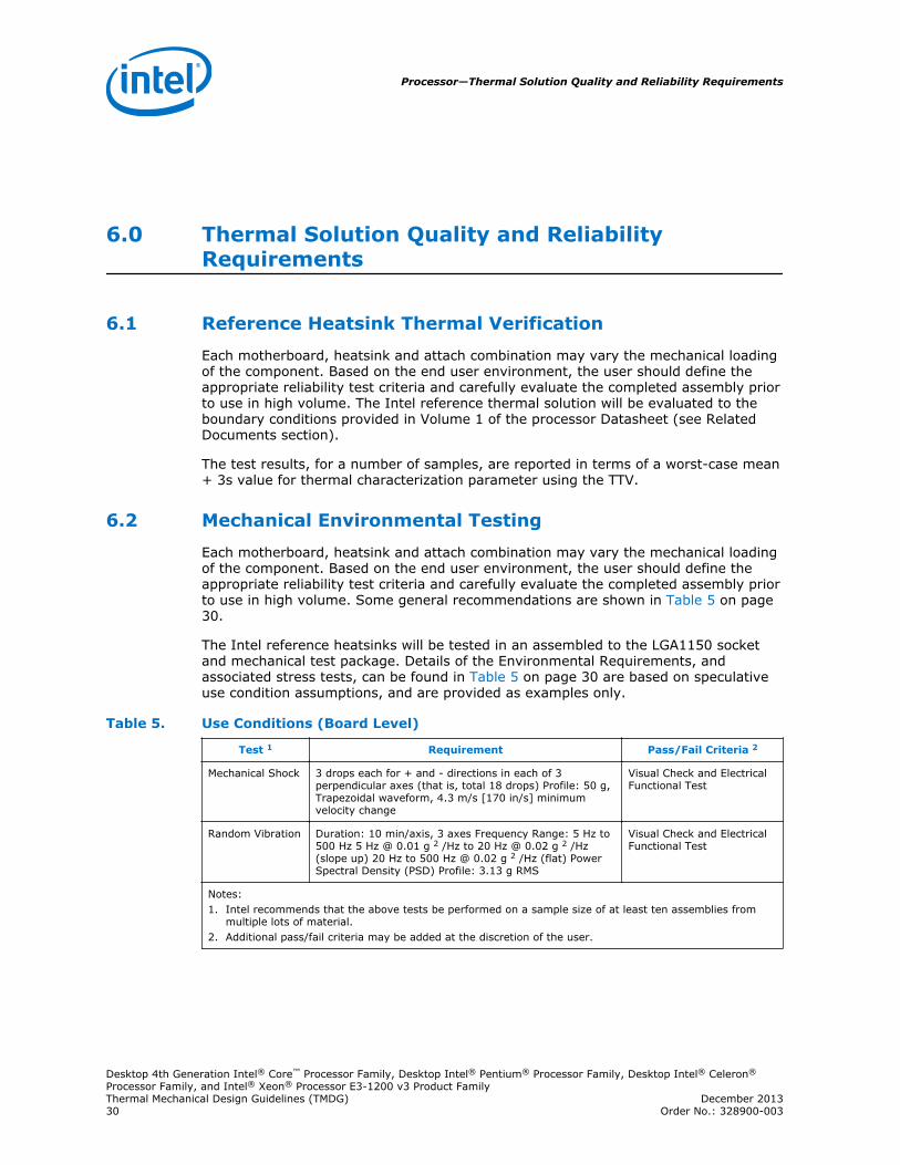
Each motherboard, heatsink and attach combination may vary the mechanical loadingof the component. Based on the end user environment, the user should define theappropriate reliability test criteria and carefully evaluate the completed assembly priorto use in high volume. Some general recommendations are shown in Table 5 on page30.
The Intel reference heatsinks will be tested in an assembled to the LGA1150 socketand mechanical test package. Details of the Environmental Requirements, andassociated stress tests, can be found in Table 5 on page 30 are based on speculativeuse condition assumptions, and are provided as examples only.
Table 5. Use Conditions (Board Level)
Test 1 Requirement Pass/Fail Criteria 2
Mechanical Shock 3 drops each for + and - directions in each of 3perpendicular axes (that is, total 18 drops) Profile: 50 g,Trapezoidal waveform, 4.3 m/s [170 in/s] minimumvelocity change
Visual Check and ElectricalFunctional Test
Random Vibration Duration: 10 min/axis, 3 axes Frequency Range: 5 Hz to500 Hz 5 Hz @ 0.01 g 2 /Hz to 20 Hz @ 0.02 g 2 /Hz(slope up) 20 Hz to 500 Hz @ 0.02 g 2 /Hz (flat) PowerSpectral Density (PSD) Profile: 3.13 g RMS
Visual Check and ElectricalFunctional Test
Notes:1. Intel recommends that the above tests be performed on a sample size of at least ten assemblies from
multiple lots of material.2. Additional pass/fail criteria may be added at the discretion of the user.
6.1
6.2
Processor—Thermal Solution Quality and Reliability Requirements
Desktop 4th Generation Intel® Core™ Processor Family, Desktop Intel® Pentium® Processor Family, Desktop Intel® Celeron®
Processor Family, and Intel® Xeon® Processor E3-1200 v3 Product FamilyThermal Mechanical Design Guidelines (TMDG) December 201330 Order No.: 328900-003
Recommended Test Sequence
Each test sequence should start with components (that is, baseboard, heatsinkassembly, and so on) that have not been previously submitted to any reliabilitytesting.
Prior to the mechanical shock & vibration test, the units under test should bepreconditioned for 72 hours at 45 ºC. The purpose is to account for load relaxationduring burn-in stage.
The test sequence should always start with a visual inspection after assembly, andBIOS/Processor/memory test. The stress test should be then followed by a visualinspection and then BIOS/Processor/memory test.
Post-Test Pass Criteria
The post-test pass criteria are:
1. No significant physical damage to the heatsink and retention hardware.
2. Heatsink remains seated and its bottom remains mated flatly against the IHSsurface. No visible gap between the heatsink base and processor IHS. No visibletilt of the heatsink with respect to the retention hardware.
3. No signs of physical damage on baseboard surface due to impact of heatsink.
4. No visible physical damage to the processor package.
5. Successful BIOS/Processor/memory test of post-test samples.
6. Thermal compliance testing to demonstrate that the case temperaturespecification can be met.
Recommended BIOS/Processor/Memory Test Procedures
This test is to ensure proper operation of the product before and after environmentalstresses, with the thermal mechanical enabling components assembled. The test shallbe conducted on a fully operational baseboard that has not been exposed to anybattery of tests prior to the test being considered.
Testing setup should include the following components, properly assembled and/orconnected:
• Appropriate system baseboard.
• Processor and memory.
• All enabling components, including socket and thermal solution parts.
The pass criterion is that the system under test shall successfully complete thechecking of BIOS, basic processor functions and memory, without any errors. Intel PCDiags is an example of software that can be utilized for this test.
Material and Recycling Requirements
Material shall be resistant to fungal growth. Examples of non-resistant materialsinclude cellulose materials, animal and vegetable-based adhesives, grease, oils, andmany hydrocarbons. Synthetic materials such as PVC formulations, certainpolyurethane compositions (such as, polyester and some polyethers), plastics which
6.3
Thermal Solution Quality and Reliability Requirements—Processor
Desktop 4th Generation Intel® Core™ Processor Family, Desktop Intel® Pentium® Processor Family, Desktop Intel® Celeron®
Processor Family, and Intel® Xeon® Processor E3-1200 v3 Product FamilyDecember 2013 Thermal Mechanical Design Guidelines (TMDG)Order No.: 328900-003 31
contain organic fillers of laminating materials, paints, and varnishes also aresusceptible to fungal growth. If materials are not fungal growth resistant, then MIL-STD-810E, Method 508.4 must be performed to determine material performance.
Material used shall not have deformation or degradation in a temperature life test.
Any plastic component exceeding 25 grams should be recyclable per the EuropeanBlue Angel recycling standards.
The following definitions apply to the use of the terms lead-free, Pb-free, and RoHScompliant.
Lead-free and Pb-free: Lead has not been intentionally added, but lead may stillexist as an impurity below 1000 ppm.
RoHS compliant: Lead and other materials banned in RoHS Directive are either (1)below all applicable substance thresholds as proposed by the EU or (2) an approved/pending exemption applies.
Note: RoHS implementation details are not fully defined and may change.
Processor—Thermal Solution Quality and Reliability Requirements
Desktop 4th Generation Intel® Core™ Processor Family, Desktop Intel® Pentium® Processor Family, Desktop Intel® Celeron®
Processor Family, and Intel® Xeon® Processor E3-1200 v3 Product FamilyThermal Mechanical Design Guidelines (TMDG) December 201332 Order No.: 328900-003
7.0 Boxed Processor Specifications
The processors will also be offered as Intel boxed processors. Intel boxed processorsare intended for system integrators who build systems from baseboards and standardcomponents. The boxed processor will be supplied with a thermal solution. Thischapter documents baseboard and system requirements for the thermal solution thatwill be supplied with the boxed processor. This chapter is particularly important forOEMs that manufacture baseboards for system integrators.
Note: Unless otherwise noted, all figures in this chapter are dimensioned in millimeters andinches [in brackets]. Figure 17 on page 34 shows a mechanical representation of aboxed processor.
Note: The thermal solution that is supplied with the boxed processor will be halogen freecompliant.
Note: Drawings in this chapter reflect only the specifications on the Intel boxed processorproduct. These dimensions should not be used as a generic keep-out zone for allcooling solutions. It is the system designers’ responsibility to consider theirproprietary cooling solution when designing to the required keep-out zone on theirsystem platforms and chassis. Refer to the LGA1150 Socket Application Guide forfurther guidance on keep-in and keep-out zones.
Boxed Processor Specifications—Processor
Desktop 4th Generation Intel® Core™ Processor Family, Desktop Intel® Pentium® Processor Family, Desktop Intel® Celeron®
Processor Family, and Intel® Xeon® Processor E3-1200 v3 Product FamilyDecember 2013 Thermal Mechanical Design Guidelines (TMDG)Order No.: 328900-003 33
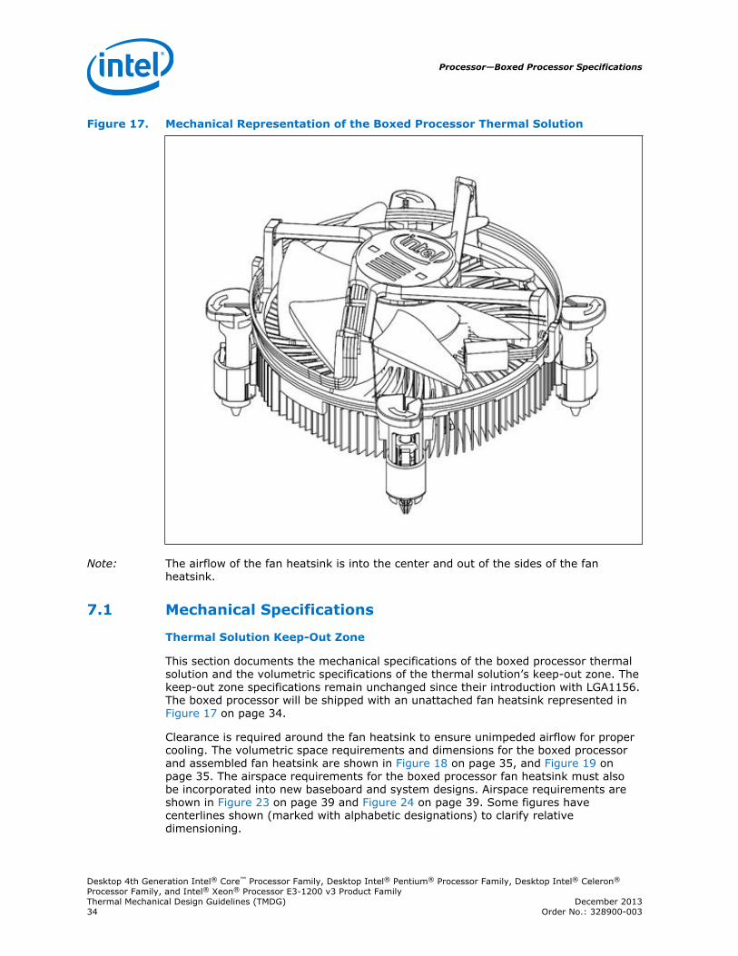
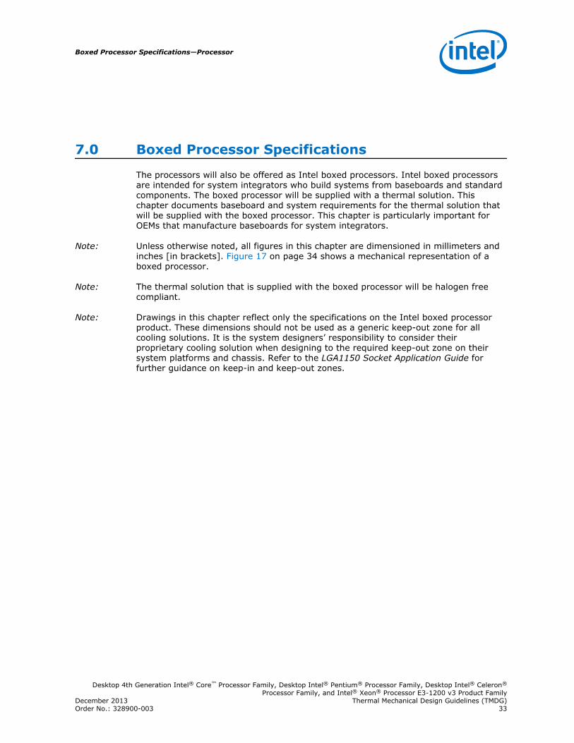
Figure 17. Mechanical Representation of the Boxed Processor Thermal Solution
Note: The airflow of the fan heatsink is into the center and out of the sides of the fanheatsink.
Mechanical Specifications
Thermal Solution Keep-Out Zone
This section documents the mechanical specifications of the boxed processor thermalsolution and the volumetric specifications of the thermal solution’s keep-out zone. Thekeep-out zone specifications remain unchanged since their introduction with LGA1156.The boxed processor will be shipped with an unattached fan heatsink represented in Figure 17 on page 34.
Clearance is required around the fan heatsink to ensure unimpeded airflow for propercooling. The volumetric space requirements and dimensions for the boxed processorand assembled fan heatsink are shown in Figure 18 on page 35, and Figure 19 onpage 35. The airspace requirements for the boxed processor fan heatsink must alsobe incorporated into new baseboard and system designs. Airspace requirements areshown in Figure 23 on page 39 and Figure 24 on page 39. Some figures havecenterlines shown (marked with alphabetic designations) to clarify relativedimensioning.
7.1
Processor—Boxed Processor Specifications
Desktop 4th Generation Intel® Core™ Processor Family, Desktop Intel® Pentium® Processor Family, Desktop Intel® Celeron®
Processor Family, and Intel® Xeon® Processor E3-1200 v3 Product FamilyThermal Mechanical Design Guidelines (TMDG) December 201334 Order No.: 328900-003
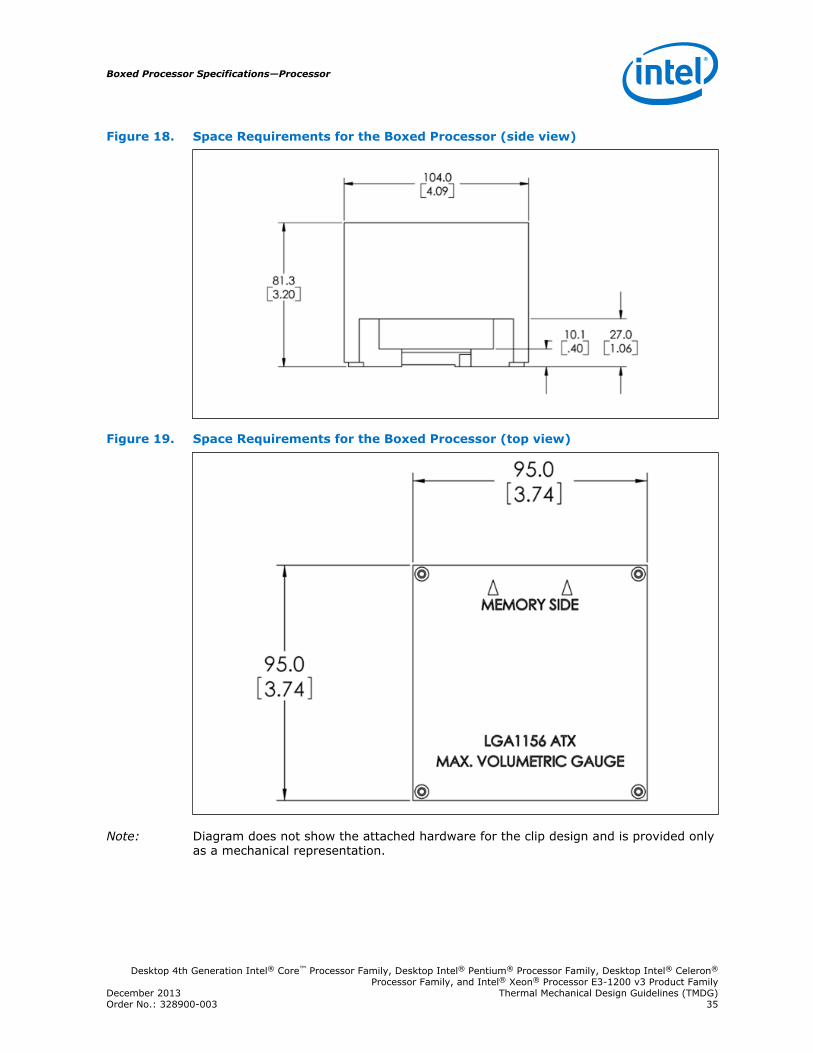
Figure 18. Space Requirements for the Boxed Processor (side view)
Figure 19. Space Requirements for the Boxed Processor (top view)
Note: Diagram does not show the attached hardware for the clip design and is provided onlyas a mechanical representation.
Boxed Processor Specifications—Processor
Desktop 4th Generation Intel® Core™ Processor Family, Desktop Intel® Pentium® Processor Family, Desktop Intel® Celeron®
Processor Family, and Intel® Xeon® Processor E3-1200 v3 Product FamilyDecember 2013 Thermal Mechanical Design Guidelines (TMDG)Order No.: 328900-003 35
Figure 20. Space Requirements for the Boxed Processor (overall view)
Boxed Processor Fan Heatsink Weight
The boxed processor fan heatsink will not weigh more than 450 grams.
Boxed Processor Retention Mechanism and Heatsink Attach Clip Assembly
The boxed processor thermal solution requires a heatsink attach clip assembly, tosecure the processor and fan heatsink in the baseboard socket. The boxed processorwill ship with the heatsink attach clip assembly.
Electrical Requirements
Fan Heatsink Power Supply
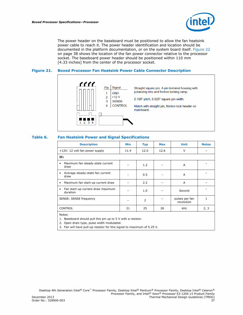
The boxed processor's fan heatsink requires a +12 V power supply. A fan power cablewill be shipped with the boxed processor to draw power from a power header on thebaseboard. The power cable connector and pinout are shown in Figure 21 on page37. Baseboards must provide a matched power header to support the boxedprocessor. Table 6 on page 37 contains specifications for the input and outputsignals at the fan heatsink connector.
The fan heatsink outputs a SENSE signal, which is an open-collector output that pulsesat a rate of 2 pulses per fan revolution. A baseboard pull-up resistor provides VOH tomatch the system board-mounted fan speed monitor requirements, if applicable. Useof the SENSE signal is optional. If the SENSE signal is not used, pin 3 of the connectorshould be tied to GND.
The fan heatsink receives a PWM signal from the motherboard from the 4th pin of theconnector labeled as CONTROL.
The boxed processor's fan heatsink requires a constant +12 V supplied to pin 2 anddoes not support variable voltage control or 3-pin PWM control.
7.2
Processor—Boxed Processor Specifications
Desktop 4th Generation Intel® Core™ Processor Family, Desktop Intel® Pentium® Processor Family, Desktop Intel® Celeron®
Processor Family, and Intel® Xeon® Processor E3-1200 v3 Product FamilyThermal Mechanical Design Guidelines (TMDG) December 201336 Order No.: 328900-003
The power header on the baseboard must be positioned to allow the fan heatsinkpower cable to reach it. The power header identification and location should bedocumented in the platform documentation, or on the system board itself. Figure 22on page 38 shows the location of the fan power connector relative to the processorsocket. The baseboard power header should be positioned within 110 mm[4.33 inches] from the center of the processor socket.
Figure 21. Boxed Processor Fan Heatsink Power Cable Connector Description
Table 6. Fan Heatsink Power and Signal Specifications
Description Min Typ Max Unit Notes
+12V: 12 volt fan power supply 11.4 12.0 12.6 V –
IC:
• Maximum fan steady-state currentdraw – 1.2 – A –
• Average steady-state fan currentdraw – 0.5 – A –
• Maximum fan start-up current draw – 2.2 – A –
• Fan start-up current draw maximumduration – 1.0 – Second –
SENSE: SENSE frequency – 2 – pulses per fanrevolution
1
CONTROL 21 25 28 kHz 2, 3
Notes:1. Baseboard should pull this pin up to 5 V with a resistor.2. Open drain type, pulse width modulated.3. Fan will have pull-up resistor for this signal to maximum of 5.25 V.
Boxed Processor Specifications—Processor
Desktop 4th Generation Intel® Core™ Processor Family, Desktop Intel® Pentium® Processor Family, Desktop Intel® Celeron®
Processor Family, and Intel® Xeon® Processor E3-1200 v3 Product FamilyDecember 2013 Thermal Mechanical Design Guidelines (TMDG)Order No.: 328900-003 37
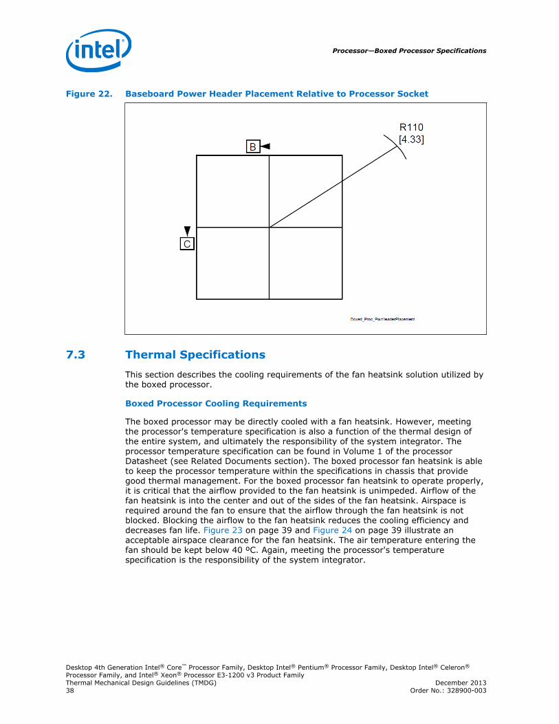
Figure 22. Baseboard Power Header Placement Relative to Processor Socket
Thermal Specifications
This section describes the cooling requirements of the fan heatsink solution utilized bythe boxed processor.
Boxed Processor Cooling Requirements
The boxed processor may be directly cooled with a fan heatsink. However, meetingthe processor's temperature specification is also a function of the thermal design ofthe entire system, and ultimately the responsibility of the system integrator. Theprocessor temperature specification can be found in Volume 1 of the processorDatasheet (see Related Documents section). The boxed processor fan heatsink is ableto keep the processor temperature within the specifications in chassis that providegood thermal management. For the boxed processor fan heatsink to operate properly,it is critical that the airflow provided to the fan heatsink is unimpeded. Airflow of thefan heatsink is into the center and out of the sides of the fan heatsink. Airspace isrequired around the fan to ensure that the airflow through the fan heatsink is notblocked. Blocking the airflow to the fan heatsink reduces the cooling efficiency anddecreases fan life. Figure 23 on page 39 and Figure 24 on page 39 illustrate anacceptable airspace clearance for the fan heatsink. The air temperature entering thefan should be kept below 40 ºC. Again, meeting the processor's temperaturespecification is the responsibility of the system integrator.
7.3
Processor—Boxed Processor Specifications
Desktop 4th Generation Intel® Core™ Processor Family, Desktop Intel® Pentium® Processor Family, Desktop Intel® Celeron®
Processor Family, and Intel® Xeon® Processor E3-1200 v3 Product FamilyThermal Mechanical Design Guidelines (TMDG) December 201338 Order No.: 328900-003
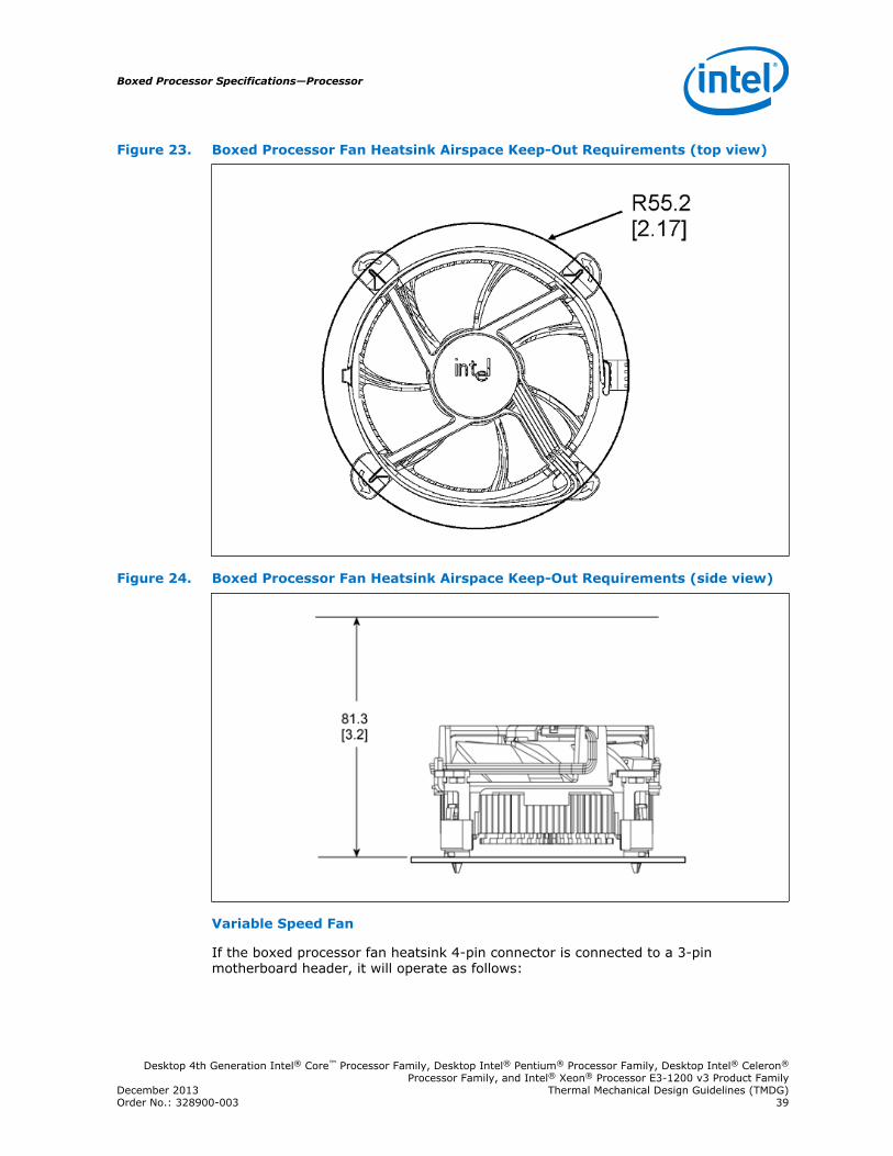
Figure 23. Boxed Processor Fan Heatsink Airspace Keep-Out Requirements (top view)
Figure 24. Boxed Processor Fan Heatsink Airspace Keep-Out Requirements (side view)
Variable Speed Fan
If the boxed processor fan heatsink 4-pin connector is connected to a 3-pinmotherboard header, it will operate as follows:
Boxed Processor Specifications—Processor
Desktop 4th Generation Intel® Core™ Processor Family, Desktop Intel® Pentium® Processor Family, Desktop Intel® Celeron®
Processor Family, and Intel® Xeon® Processor E3-1200 v3 Product FamilyDecember 2013 Thermal Mechanical Design Guidelines (TMDG)Order No.: 328900-003 39
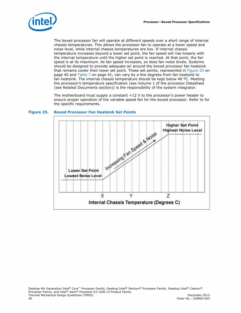
The boxed processor fan will operate at different speeds over a short range of internalchassis temperatures. This allows the processor fan to operate at a lower speed andnoise level, while internal chassis temperatures are low. If internal chassistemperature increases beyond a lower set point, the fan speed will rise linearly withthe internal temperature until the higher set point is reached. At that point, the fanspeed is at its maximum. As fan speed increases, so does fan noise levels. Systemsshould be designed to provide adequate air around the boxed processor fan heatsinkthat remains cooler then lower set point. These set points, represented in Figure 25 onpage 40 and Table 7 on page 41, can vary by a few degrees from fan heatsink tofan heatsink. The internal chassis temperature should be kept below 40 ºC. Meetingthe processor's temperature specification (see Volume 1 of the processor Datasheet(see Related Documents section)) is the responsibility of the system integrator.
The motherboard must supply a constant +12 V to the processor's power header toensure proper operation of the variable speed fan for the boxed processor. Refer to forthe specific requirements.
Figure 25. Boxed Processor Fan Heatsink Set Points
Processor—Boxed Processor Specifications
Desktop 4th Generation Intel® Core™ Processor Family, Desktop Intel® Pentium® Processor Family, Desktop Intel® Celeron®
Processor Family, and Intel® Xeon® Processor E3-1200 v3 Product FamilyThermal Mechanical Design Guidelines (TMDG) December 201340 Order No.: 328900-003
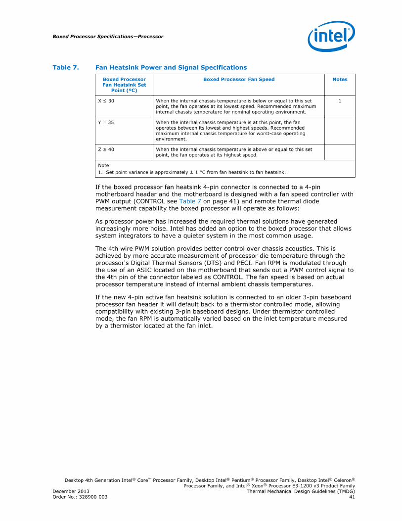
Table 7. Fan Heatsink Power and Signal Specifications
Boxed ProcessorFan Heatsink Set
Point (ºC)
Boxed Processor Fan Speed Notes
X ≤ 30 When the internal chassis temperature is below or equal to this setpoint, the fan operates at its lowest speed. Recommended maximuminternal chassis temperature for nominal operating environment.
1
Y = 35 When the internal chassis temperature is at this point, the fanoperates between its lowest and highest speeds. Recommendedmaximum internal chassis temperature for worst-case operatingenvironment.
Z ≥ 40 When the internal chassis temperature is above or equal to this setpoint, the fan operates at its highest speed.
Note:1. Set point variance is approximately ± 1 °C from fan heatsink to fan heatsink.
If the boxed processor fan heatsink 4-pin connector is connected to a 4-pinmotherboard header and the motherboard is designed with a fan speed controller withPWM output (CONTROL see Table 7 on page 41) and remote thermal diodemeasurement capability the boxed processor will operate as follows:
As processor power has increased the required thermal solutions have generatedincreasingly more noise. Intel has added an option to the boxed processor that allowssystem integrators to have a quieter system in the most common usage.
The 4th wire PWM solution provides better control over chassis acoustics. This isachieved by more accurate measurement of processor die temperature through theprocessor's Digital Thermal Sensors (DTS) and PECI. Fan RPM is modulated throughthe use of an ASIC located on the motherboard that sends out a PWM control signal tothe 4th pin of the connector labeled as CONTROL. The fan speed is based on actualprocessor temperature instead of internal ambient chassis temperatures.
If the new 4-pin active fan heatsink solution is connected to an older 3-pin baseboardprocessor fan header it will default back to a thermistor controlled mode, allowingcompatibility with existing 3-pin baseboard designs. Under thermistor controlledmode, the fan RPM is automatically varied based on the inlet temperature measuredby a thermistor located at the fan inlet.
Boxed Processor Specifications—Processor
Desktop 4th Generation Intel® Core™ Processor Family, Desktop Intel® Pentium® Processor Family, Desktop Intel® Celeron®
Processor Family, and Intel® Xeon® Processor E3-1200 v3 Product FamilyDecember 2013 Thermal Mechanical Design Guidelines (TMDG)Order No.: 328900-003 41
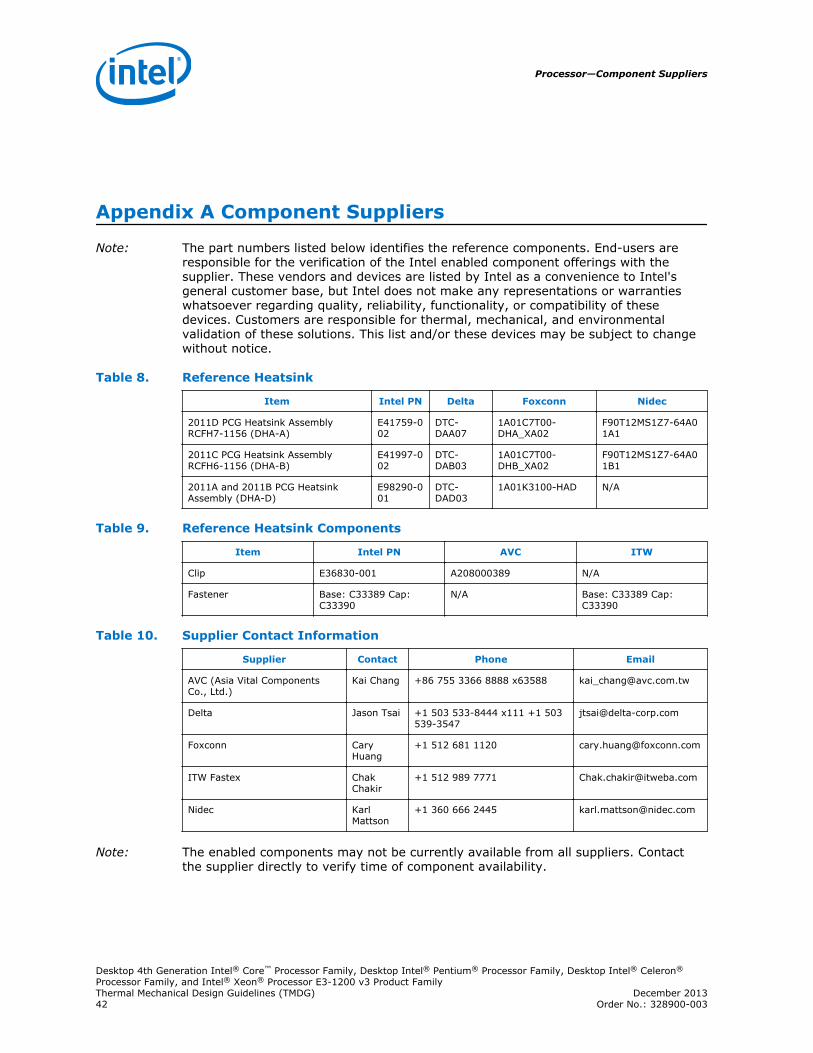
Appendix A Component Suppliers
Note: The part numbers listed below identifies the reference components. End-users areresponsible for the verification of the Intel enabled component offerings with thesupplier. These vendors and devices are listed by Intel as a convenience to Intel'sgeneral customer base, but Intel does not make any representations or warrantieswhatsoever regarding quality, reliability, functionality, or compatibility of thesedevices. Customers are responsible for thermal, mechanical, and environmentalvalidation of these solutions. This list and/or these devices may be subject to changewithout notice.
Table 8. Reference Heatsink
Item Intel PN Delta Foxconn Nidec
2011D PCG Heatsink AssemblyRCFH7-1156 (DHA-A)
E41759-002
DTC-DAA07
1A01C7T00-DHA_XA02
F90T12MS1Z7-64A01A1
2011C PCG Heatsink AssemblyRCFH6-1156 (DHA-B)
E41997-002
DTC-DAB03
1A01C7T00-DHB_XA02
F90T12MS1Z7-64A01B1
2011A and 2011B PCG HeatsinkAssembly (DHA-D)
E98290-001
DTC-DAD03
1A01K3100-HAD N/A
Table 9. Reference Heatsink Components
Item Intel PN AVC ITW
Clip E36830-001 A208000389 N/A
Fastener Base: C33389 Cap:C33390
N/A Base: C33389 Cap:C33390
Table 10. Supplier Contact Information
Supplier Contact Phone Email
AVC (Asia Vital ComponentsCo., Ltd.)
Kai Chang +86 755 3366 8888 x63588 [email protected]
Delta Jason Tsai +1 503 533-8444 x111 +1 503539-3547
Foxconn CaryHuang
+1 512 681 1120 [email protected]
ITW Fastex ChakChakir
+1 512 989 7771 [email protected]
Nidec KarlMattson
+1 360 666 2445 [email protected]
Note: The enabled components may not be currently available from all suppliers. Contactthe supplier directly to verify time of component availability.
Processor—Component Suppliers
Desktop 4th Generation Intel® Core™ Processor Family, Desktop Intel® Pentium® Processor Family, Desktop Intel® Celeron®
Processor Family, and Intel® Xeon® Processor E3-1200 v3 Product FamilyThermal Mechanical Design Guidelines (TMDG) December 201342 Order No.: 328900-003