dessambles rokr e2
TRANSCRIPT
8/7/2019 Dessambles Rokr E2
http://slidepdf.com/reader/full/dessambles-rokr-e2 1/52
Level 1 and 2 Service Manual6809497A99-
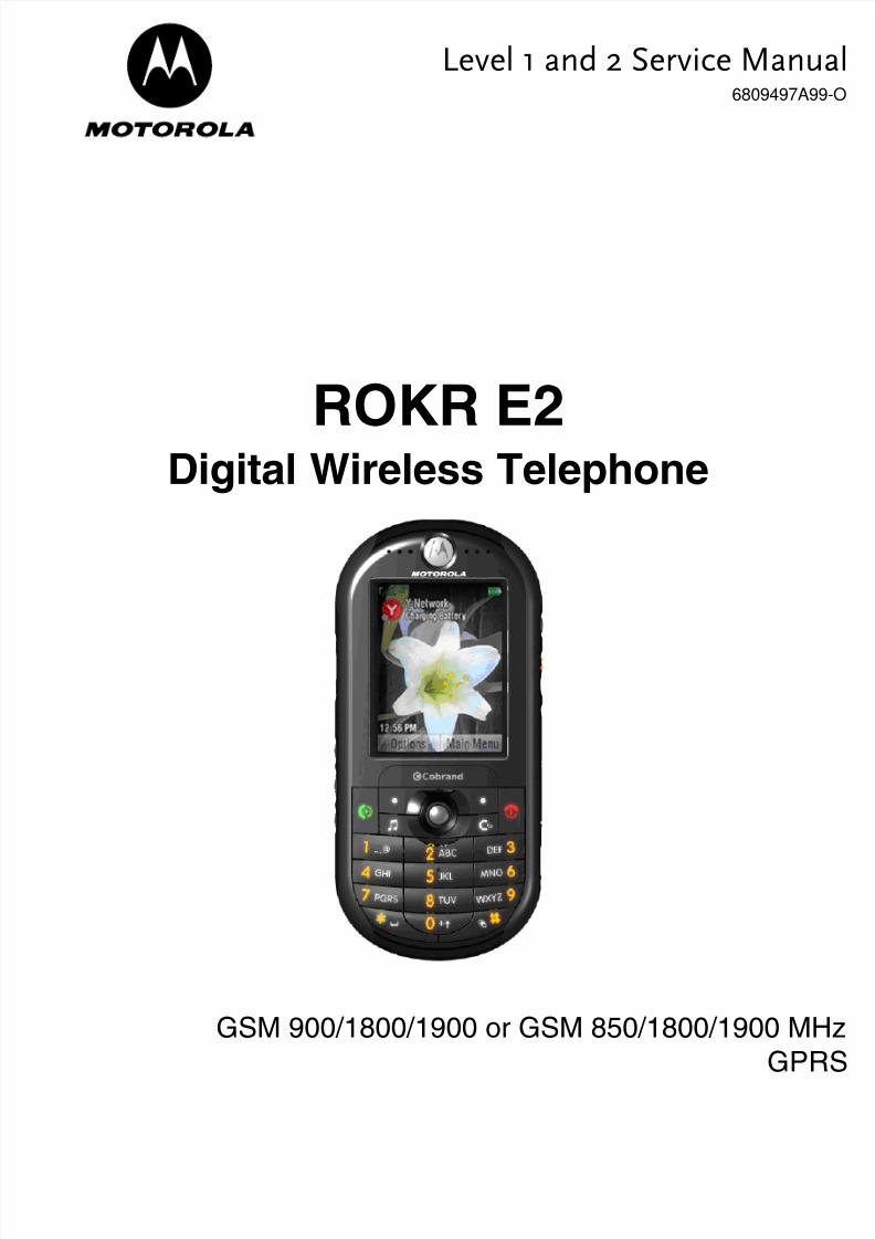
ROKR E2Digital Wireless Telephone
GSM 900/1800/1900 or GSM 850/1800/1900 MHzGPR

8/7/2019 Dessambles Rokr E2
http://slidepdf.com/reader/full/dessambles-rokr-e2 2/52

8/7/2019 Dessambles Rokr E2
http://slidepdf.com/reader/full/dessambles-rokr-e2 3/52
6809497A99-O March 27, 2006 3
Level 1 and 2 Service Manual Contents
ContentsContents . . . . . . . . . . . . . . . . . . . . . . . . . . . . . . . . . . . . . . . . . . . . . . . . . . . . . . . . . . . . . . . . . . . . . . . . . . . . . . . . . 3Introduction . . . . . . . . . . . . . . . . . . . . . . . . . . . . . . . . . . . . . . . . . . . . . . . . . . . . . . . . . . . . . . . . . . . . . . . . . . . . . . 5
Product Identification . . . . . . . . . . . . . . . . . . . . . . . . . . . . . . . . . . . . . . . . . . . . . . . . . . . . . . . . . . . . . . . . 5Product Names . . . . . . . . . . . . . . . . . . . . . . . . . . . . . . . . . . . . . . . . . . . . . . . . . . . . . . . . . . . . . . . . . . . . . 5Product Changes . . . . . . . . . . . . . . . . . . . . . . . . . . . . . . . . . . . . . . . . . . . . . . . . . . . . . . . . . . . . . . . . . . . . 5Regulatory Agency Compliance . . . . . . . . . . . . . . . . . . . . . . . . . . . . . . . . . . . . . . . . . . . . . . . . . . . . . . . . 5Computer Program Copyrights . . . . . . . . . . . . . . . . . . . . . . . . . . . . . . . . . . . . . . . . . . . . . . . . . . . . . . . . 6
About This Service Manual . . . . . . . . . . . . . . . . . . . . . . . . . . . . . . . . . . . . . . . . . . . . . . . . . . . . . . . . . . . 6Warranty Service Policy . . . . . . . . . . . . . . . . . . . . . . . . . . . . . . . . . . . . . . . . . . . . . . . . . . . . . . . . . . . . . . 7Parts Replacement . . . . . . . . . . . . . . . . . . . . . . . . . . . . . . . . . . . . . . . . . . . . . . . . . . . . . . . . . . . . . . . . . . 8
Specifications . . . . . . . . . . . . . . . . . . . . . . . . . . . . . . . . . . . . . . . . . . . . . . . . . . . . . . . . . . . . . . . . . . . . . . . . . . . 9Product Overview . . . . . . . . . . . . . . . . . . . . . . . . . . . . . . . . . . . . . . . . . . . . . . . . . . . . . . . . . . . . . . . . . . . . . . . . 11
Features . . . . . . . . . . . . . . . . . . . . . . . . . . . . . . . . . . . . . . . . . . . . . . . . . . . . . . . . . . . . . . . . . . . . . . . . . . 11General Operation . . . . . . . . . . . . . . . . . . . . . . . . . . . . . . . . . . . . . . . . . . . . . . . . . . . . . . . . . . . . . . . . . . . . . . . . 14
Controls, Indicators, and Input/Output (I/O) Connectors . . . . . . . . . . . . . . . . . . . . . . . . . . . . . . . . . . 14
Battery Information . . . . . . . . . . . . . . . . . . . . . . . . . . . . . . . . . . . . . . . . . . . . . . . . . . . . . . . . . . . . . . . . 17Operation . . . . . . . . . . . . . . . . . . . . . . . . . . . . . . . . . . . . . . . . . . . . . . . . . . . . . . . . . . . . . . . . . . . . . . . . . 21Tools and Test Equipment . . . . . . . . . . . . . . . . . . . . . . . . . . . . . . . . . . . . . . . . . . . . . . . . . . . . . . . . . . . . . . . . . 23Disassembly . . . . . . . . . . . . . . . . . . . . . . . . . . . . . . . . . . . . . . . . . . . . . . . . . . . . . . . . . . . . . . . . . . . . . . . . . . . . . 24
Removing and Replacing the SD (Secure Digital) Card . . . . . . . . . . . . . . . . . . . . . . . . . . . . . . . . . . . . 24Removing and Replacing the Battery Cover . . . . . . . . . . . . . . . . . . . . . . . . . . . . . . . . . . . . . . . . . . . . . 26Removing and Replacing the Battery . . . . . . . . . . . . . . . . . . . . . . . . . . . . . . . . . . . . . . . . . . . . . . . . . . 27Removing and Replacing the Subscriber Identity Module (SIM) . . . . . . . . . . . . . . . . . . . . . . . . . . . . . 28Removing the Side Bands . . . . . . . . . . . . . . . . . . . . . . . . . . . . . . . . . . . . . . . . . . . . . . . . . . . . . . . . . . . . 29Removing and Replacing the Rear Housing . . . . . . . . . . . . . . . . . . . . . . . . . . . . . . . . . . . . . . . . . . . . . 30Removing and Replacing the Camera Module . . . . . . . . . . . . . . . . . . . . . . . . . . . . . . . . . . . . . . . . . . . 32Removing and Replacing the Transceiver PC Board Assembly . . . . . . . . . . . . . . . . . . . . . . . . . . . . . . 33Removing and Replacing the Keypad Assembly . . . . . . . . . . . . . . . . . . . . . . . . . . . . . . . . . . . . . . . . . . 34
Removing and Replacing the Display Module Assembly . . . . . . . . . . . . . . . . . . . . . . . . . . . . . . . . . . . 36Removing the Keypad Switch PC Board . . . . . . . . . . . . . . . . . . . . . . . . . . . . . . . . . . . . . . . . . . . . . . . . 37
Subscriber Identity Module (SIM) and Identification Label . . . . . . . . . . . . . . . . . . . . . . . . . . . . . . . . . . . . . . . 39SIM . . . . . . . . . . . . . . . . . . . . . . . . . . . . . . . . . . . . . . . . . . . . . . . . . . . . . . . . . . . . . . . . . . . . . . . . . . . . . 39Identification . . . . . . . . . . . . . . . . . . . . . . . . . . . . . . . . . . . . . . . . . . . . . . . . . . . . . . . . . . . . . . . . . . . . . . 39
Troubleshooting . . . . . . . . . . . . . . . . . . . . . . . . . . . . . . . . . . . . . . . . . . . . . . . . . . . . . . . . . . . . . . . . . . . . . . . . . 41Manual Test Mode . . . . . . . . . . . . . . . . . . . . . . . . . . . . . . . . . . . . . . . . . . . . . . . . . . . . . . . . . . . . . . . . . 41Troubleshooting Chart . . . . . . . . . . . . . . . . . . . . . . . . . . . . . . . . . . . . . . . . . . . . . . . . . . . . . . . . . . . . . . 43Programming: Software Upgrade and Flexing . . . . . . . . . . . . . . . . . . . . . . . . . . . . . . . . . . . . . . . . . . . 44
Part Numbers . . . . . . . . . . . . . . . . . . . . . . . . . . . . . . . . . . . . . . . . . . . . . . . . . . . . . . . . . . . . . . . . . . . . . . . . . . . . 44Exploded View Diagram . . . . . . . . . . . . . . . . . . . . . . . . . . . . . . . . . . . . . . . . . . . . . . . . . . . . . . . . . . . . . 45Exploded View Parts List . . . . . . . . . . . . . . . . . . . . . . . . . . . . . . . . . . . . . . . . . . . . . . . . . . . . . . . . . . . 46
Accessories . . . . . . . . . . . . . . . . . . . . . . . . . . . . . . . . . . . . . . . . . . . . . . . . . . . . . . . . . . . . . . . . . . . . . . . . 46
1 and 2ROKR E2
6809497A99-O
Contents
8/7/2019 Dessambles Rokr E2
http://slidepdf.com/reader/full/dessambles-rokr-e2 4/52
4 March 27, 2006 6809497A99-O
Contents ROKR E2

8/7/2019 Dessambles Rokr E2
http://slidepdf.com/reader/full/dessambles-rokr-e2 5/52
6809497A99-O March 27, 2006 5
Level 1 and 2 Service Manual Introduction
IntroductionMotorola ® Inc. maintains a worldwide organization that is dedicated to provideresponsive, full-service customer support. Motorola products are serviced by an
international network of company-operated product care centers as well asauthorized independent service firms.
Available on a contract basis, Motorola Inc. offers comprehensive maintenance andinstallation programs which enable customers to meet requirements for reliable,continuous communications.
To learn more about the wide range of Motorola service programs, contact your localMotorola products representative or the nearest Customer Service Manager.
Product IdentificationMotorola products are identified by the model number on the housing. Use the entiremodel number when inquiring about the product. Numbers are also assigned tochassis and kits. Use these numbers when requesting information or orderingreplacement parts.
Product NamesProduct names are listed on the front cover. Product names are subject to changewithout notice. Some product names, as well as some frequency bands, are availableonly in certain markets.
Product ChangesWhen electrical, mechanical or production changes are incorporated into Motorolaproducts, a revision letter is assigned to the chassis or kit affected, for example;
-A, -B, or -C, and so on.The chassis or kit number, complete with revision number is imprinted duringproduction. The revision letter is an integral part of the chassis or kit number andis also listed on schematic diagrams and printed circuit board layouts.
Regulatory Agency ComplianceThis device complies with Part 15 of the FCC Rules. Operation is subject to thefollowing conditions:• This device may not cause any harmful interference, and• this device must accept interference received, including interference that may
cause undesired operation.
This class B device also complies with all requirements of the CanadianInterference-Causing Equipment Regulations (ICES-003).
Cet appareil numérique de la classe B respecte toutes les exigences du Règlementsur le matériel brouilleur du Canada.
1 and 2ROKR E2
6809497A99-O

8/7/2019 Dessambles Rokr E2
http://slidepdf.com/reader/full/dessambles-rokr-e2 6/52
6 March 27, 2006 6809497A99-O
Introduction ROKR E2
Computer Program CopyrightsThe Motorola products described in this manual may include Motorola computerprograms stored in semiconductor memories or other media that are copyrightedwith all rights reserved worldwide to Motorola. Laws in the United States and othercountries preserve for Motorola, Inc. certain exclusive rights to the copyrightedcomputer programs, including the exclusive right to copy, reproduce, modify,decompile, disassemble, and reverse-engineer the Motorola computer programs inany manner or form without Motorola's prior written consent. Furthermore, thepurchase of Motorola products shall not be deemed to grant either directly or byimplication, estoppel, or otherwise, any license or rights under the copyrights,patents, or patent applications of Motorola, except for a nonexclusive license to usethe Motorola product and the Motorola computer programs with the Motorolaproduct.
About This Service ManualUsing this service manual and the suggestions contained in it assures properinstallation, operation, and maintenance of E2 telephones. Refer questions aboutthis manual to the nearest Customer Service Manager.
AudienceThis document aids service personnel in testing and repairing E2 telephones.Service personnel should be familiar with electronic assembly, testing, andtroubleshooting methods, and with the operation and use of associated testequipment.
Use of this document assures proper installation, operation, and maintenance of Motorola products and equipment. It contains all service information required forthe equipment described and is current as of the printing date.
ScopeThe scope of this document is to provide the reader with basic information relatingto E2 telephones, and also to provide procedures and processes for repairing theunits at Level 1 and 2 service centers including:• Unit swap out• Repairing of mechanical faults• Basic modular troubleshooting• Testing and verification of unit functionality• Initiate warranty claims and send faulty modules to Level 3 or 4 repair
centers.

8/7/2019 Dessambles Rokr E2
http://slidepdf.com/reader/full/dessambles-rokr-e2 7/52
6809497A99-O March 27, 2006 7
Level 1 and 2 Service Manual Introduction
ConventionsSpecial characters and typefaces, listed and described below, are used in thispublication to emphasize certain types of information.
Warranty Service PolicyThe product will be sold with the standard 12 months warranty terms andconditions. Accidental damage, misuse, and extended warranties offered byretailers are not supported under warranty. Non warranty repairs are available atagreed fixed repair prices.
Out of Box Failure PolicyThe standard out of box failure criteria applies. Customer units that fail very earlyon after the date of sale, are to be returned to Manufacturing for root cause analysis,to guard against epidemic criteria. Manufacturing to bear the costs of early lifefailure.
Product SupportCustomer’s original units will be repaired but not refurbished as standard.
Appointed Motorola Service Hubs will perform warranty and non-warranty fieldservice for level 2 (assemblies) and level 3 (limited PCB component). The MotorolaHigh Technology Centers will perform level 4 (full component) repairs.
Customer SupportCustomer support is available through dedicated Call Centers and in-country helpdesks. Product Service training should be arranged through the local MotorolaSupport Center.
➧ Note: Emphasizes additional information pertinent to the subjectmatter.
G Caution: Emphasizes information about actions which may result in equipment damage.
E Warning: Emphasizes information about actions which may resultin personal injury.
MKeys to be pressed are represented graphically. For example, instead of “Press
the Menu Key”, you will see “Press M ”.
Information from a screen is shown in text as similar as possible to what
appears in the display. For example, ALERTS or ALERTS or ALERTS .
Information that you need to type is printed in boldface type

8/7/2019 Dessambles Rokr E2
http://slidepdf.com/reader/full/dessambles-rokr-e2 8/52
8 March 27, 2006 6809497A99-O
Introduction ROKR E2
Parts ReplacementWhen ordering replacement parts or equipment, include the Motorola part numberand description used in the service manual or supplement.
When ordering crystals or channel elements, specify the Motorola part number,description, crystal frequency, and operating frequency desired.
When the Motorola part number of a component is not known, use the product modelnumber or other related major assembly along with a description of the relatedmajor assembly and of the component in question.
In the U.S.A., to contact Motorola, Inc. on your TTY, call: 800-793-7834
Accessories and Aftermarket Division (AAD)Order replacement parts, test equipment, and manuals from AAD.
U.S.A. Outside U.S.A.Phone: 800-422-4210 Phone: 847-538-8023
FAX: 800-622-6210 FAX: 847-576-3023
Website: http://businessonline.motorola.com
EMEA
Phone: +49 461 803 1404
Website: http://emeaonline.motorola.com
Asia
Phone: +65 648 62995Website: http://asiaonline.motorola.com

8/7/2019 Dessambles Rokr E2
http://slidepdf.com/reader/full/dessambles-rokr-e2 9/52
6809497A99-O March 27, 2006 9
Level 1 and 2 Service Manual Specifications
SpecificationsGeneral Function Specification
Frequency Range GSM 850 824-849 MHz Tx869-894 MHz Rx
Frequency Range GSM 900 880-915 MHz Tx (with EGSM)925-960 MHZ Rx
Frequency Range DCS 1800 1710-1785 MHz Tx1805-1880 MHz Rx
Frequency Range PCS 1900 1850-1910 MHz Tx1930-1990 MHz Rx
Channel Spacing 200 kHz
Channels 174 EGSM, 374 DCS, 374 PCS, 124 GSM850 carriers with 8 channels per carrier
Modulation GMSK at BT = 0.3Transmitter Phase Accuracy 5 Degrees RMS, 20 Degrees peakDuplex Spacing 45 MHz GSM, 95 MHz DCS, 80 MHz PCSFrequency Stability ± 0.10 ppm of the downlink frequency (Rx)
Operating Voltage+3.0V dc to +4.2V dc (cell)+4.4V dc to +6.6V dc (external charger jackwith 2.4 K ohm resistor)
Average Transmit Current 300 mA maxAverage Stand-by Current 4.0 mA max (DRX2), 2.0 mA max (DRX9)
Dimensions 49.8 mm x 106 mm x 17 mm(1.96 inches x 4.17 inches x 0.66 inches)
Size (Volume) 80 cc (4.8 in 3)Weight 100 g (3.52 oz) with cellTemperature Range -10° C to +55° C (+15° F to +130° F)Battery Life, 880 mAh Li Ion Battery Talk time 205 - 240 minutes
Standby time 144 - 216 hoursAll talk and standby times are approximateand depend on network configuration,signal strength, and features selected.Standby times are quoted as a range fromDRX=2 to DRX=9. Talk times are quotedas a range from DTX off to DTX on.
Transmitter Specification
RF Power Output33 dBm nominal GSM 85033 dBm nominal GSM 90030 dBm nominal GSM 180030 dBm nominal PCS 1900
Output Impedance 50 ohms nominal
Spurious Emissions -36 dBm from 0.1 to 1 GHz,
-30 dBm from 1 to 4 GHz
Receiver Specification
Receive Sensitivity-106 dBm GSM 850,-106 dBm GSM 900,-104 dBm GSM 1800,-104 dBm PCS 1900
RX bit error rate (100k bits) Type II < 2%Channel Hop Time 500 microseconds

8/7/2019 Dessambles Rokr E2
http://slidepdf.com/reader/full/dessambles-rokr-e2 10/52
10 March 27, 2006 6809497A99-O
Specifications ROKR E2
Time to Camp Approximately 5-10 seconds
Speech Coding Function Specification
Speech Coding Type Regular pulse excitation / linear predictive codingwith long term prediction (RPE LPC with LTP)
Bit Rate 13.0 kbpsFrame Duration 20 msBlock Length 260 bitsClasses Class 1 bits = 182 bits; Class 2 bits = 78 bitsBit Rate with FEC Encoding 22.8 kbps
Receiver Specification
8/7/2019 Dessambles Rokr E2
http://slidepdf.com/reader/full/dessambles-rokr-e2 11/52
6809497A99-O March 27, 2006 11
Level 1 and 2 Service Manual Product Overview
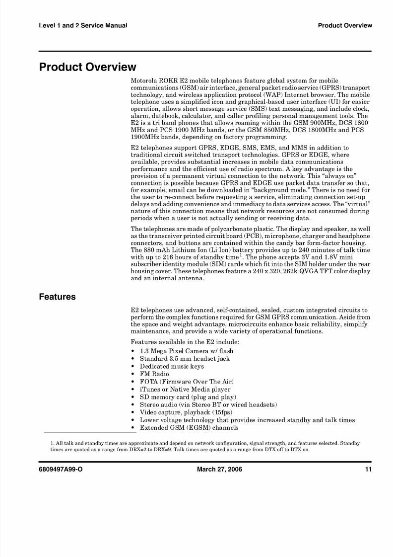
Product OverviewMotorola ROKR E2 mobile telephones feature global system for mobilecommunications (GSM) air interface, general packet radio service (GPRS) transport
technology, and wireless application protocol (WAP) Internet browser. The mobiletelephone uses a simplified icon and graphical-based user interface (UI) for easieroperation, allows short message service (SMS) text messaging, and include clock,alarm, datebook, calculator, and caller profiling personal management tools. TheE2 is a tri band phones that allows roaming within the GSM 900MHz, DCS 1800MHz and PCS 1900 MHz bands, or the GSM 850MHz, DCS 1800MHz and PCS1900MHz bands, depending on factory programming.
E2 telephones support GPRS, EDGE, SMS, EMS, and MMS in addition totraditional circuit switched transport technologies. GPRS or EDGE, whereavailable, provides substantial increases in mobile data communicationsperformance and the efficient use of radio spectrum. A key advantage is theprovision of a permanent virtual connection to the network. This “always on”connection is possible because GPRS and EDGE use packet data transfer so that,for example, email can be downloaded in “background mode.” There is no need forthe user to re-connect before requesting a service, eliminating connection set-updelays and adding convenience and immediacy to data services access. The “virtual”nature of this connection means that network resources are not consumed duringperiods when a user is not actually sending or receiving data.
The telephones are made of polycarbonate plastic. The display and speaker, as wellas the transceiver printed circuit board (PCB), microphone, charger and headphoneconnectors, and buttons are contained within the candy bar form-factor housing.The 880 mAh Lithium Ion (Li Ion) battery provides up to 240 minutes of talk timewith up to 216 hours of standby time 1. The phone accepts 3V and 1.8V minisubscriber identity module (SIM) cards which fit into the SIM holder under the rearhousing cover. These telephones feature a 240 x 320, 262k QVGA TFT color displayand an internal antenna.
FeaturesE2 telephones use advanced, self-contained, sealed, custom integrated circuits toperform the complex functions required for GSM GPRS communication. Aside fromthe space and weight advantage, microcircuits enhance basic reliability, simplifymaintenance, and provide a wide variety of operational functions.
Features available in the E2 include:• 1.3 Mega Pixel Camera w/ flash• Standard 3.5 mm headset jack• Dedicated music keys• FM Radio• FOTA (Firmware Over The Air)
• iTunes or Native Media player• SD memory card (plug and play)• Stereo audio (via Stereo BT or wired headsets)• Video capture, playback (15fps)• Lower voltage technology that provides increased standby and talk times• Extended GSM (EGSM) channels
1. All talk and standby times are approximate and depend on network configuration, signal strength, and features selected. Standbytimes are quoted as a range from DRX=2 to DRX=9. Talk times are quoted as a range from DTX off to DTX on.

8/7/2019 Dessambles Rokr E2
http://slidepdf.com/reader/full/dessambles-rokr-e2 12/52
8/7/2019 Dessambles Rokr E2
http://slidepdf.com/reader/full/dessambles-rokr-e2 13/52
6809497A99-O March 27, 2006 13
Level 1 and 2 Service Manual Product Overview
Simplified Text EntryiTAP™ predictive text entry. Press a key to generate a character and a dynamicdictionary uses this to build and display a set of word or name options. The iTAP™feature may not be available on the phone in all languages.
Caller Line IdentificationUpon receipt of a call, the calling party’s phone number is compared to the phonebook. If the number matches a phone book entry, that name will be displayed. If there is no phone book entry, the incoming phone number will be displayed. In theevent that no caller identification information is available, an incoming call messageis displayed.
SIM Toolkit ™ - Class 2SIM Application Toolkit is a value-added service delivery mechanism that allowsGSM operators to customize the services they offer their customers, from theoccasional user who requests sports news and traffic alerts, to a high call timebusiness user who receives stock alerts and checks flight times. Operators can nowcreate their own value-added services menu quickly and easily in the phone. Thecustomized menu will appear as the first menu and may be updated over-the-airwith new services when customers request them.
Network Based Chat MessagingThe chat messaging feature provides a constant WAP connection through GPRS tocarrier, service center, or factory flexed WAP site. The specific site can also beentered by the user. Chat messaging is a carrier option.
Personal Information ManagementThe E2 telephone contains a built in calendar with date book reminders andphonebook that can be synchronized easily to a computer.
➧ If the user receives a call while in browser mode, the browser will pause and allowthe user to resume after completing the call.
➧User must subscribe to a caller line identification service through their service
provider.
8/7/2019 Dessambles Rokr E2
http://slidepdf.com/reader/full/dessambles-rokr-e2 14/52
14 March 27, 2006 6809497A99-O
General Operation ROKR E2
General Operation
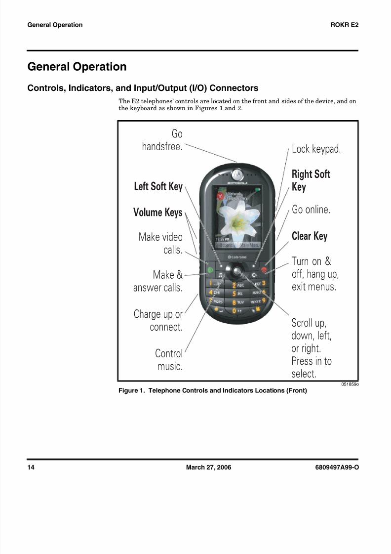
Controls, Indicators, and Input/Output (I/O) ConnectorsThe E2 telephones’ controls are located on the front and sides of the device, and onthe keyboard as shown in Figures 1 and 2.
051859o
Figure 1. Telephone Controls and Indicators Locations (Front)
Scroll up,down, left,or right.Press in toselect.
Right SoftKey
Clear Key
Turn on &off, hang up,
exit menus.
Left Soft Key
Volume Keys
Charge up orconnect.
Go online.
Controlmusic.
Lock keypad.Go
handsfree.
Make &
answer calls.
Make videocalls.

8/7/2019 Dessambles Rokr E2
http://slidepdf.com/reader/full/dessambles-rokr-e2 15/52
6809497A99-O March 27, 2006 15
Level 1 and 2 Service Manual General Operation
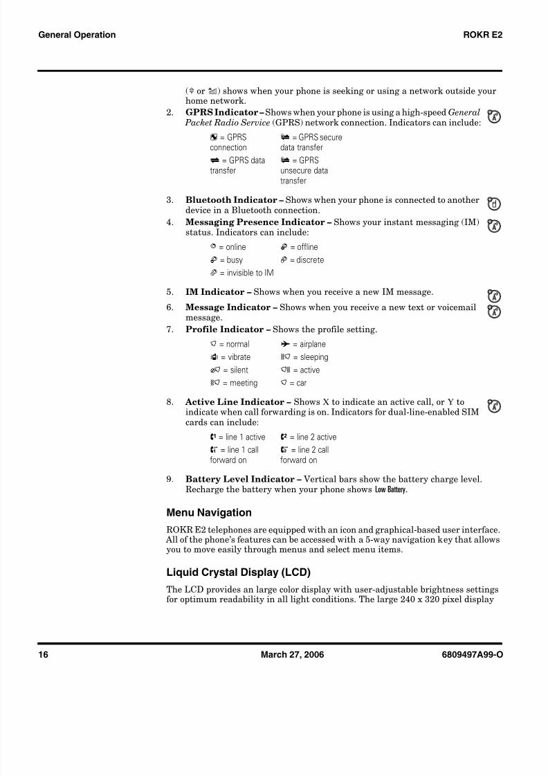
Indicators, in the form of icons, are displayed on the LCD (see Figure 3).
1. Signal Strength/Airplane Mode Indicator – Vertical bars show thestrength of the network connection. You can’t make or receive calls when theno signal indicator 0 or airplane mode indicator A shows. The roam indicator
051864
Figure 2. Telephone Controls and Indicators Locations (Sides)
051866
Figure 3. Main Screen Icon Display
Left Side Right Side
Volume Keys
Camera Key
Keypad LockKey
MemoryCard Door
EMUConnector
MusicControl Keys
Options Main Menu
3. Bluetooth
1. SignalStrength/ AirplaneMode
2. GPRS
6. Message 7. Location 8. Profile
5. IM4. Messaging
Presence
9. ActiveLine
10.BatteryLevel
Service Provider 10:15 am
8/7/2019 Dessambles Rokr E2
http://slidepdf.com/reader/full/dessambles-rokr-e2 16/52
16 March 27, 2006 6809497A99-O
General Operation ROKR E2
(1 or 2 ) shows when your phone is seeking or using a network outside yourhome network.
2. GPRS Indicator – Shows when your phone is using a high-speed General Packet Radio Service (GPRS) network connection. Indicators can include:
3. Bluetooth Indicator – Shows when your phone is connected to anotherdevice in a Bluetooth connection.
4. Messaging Presence Indicator – Shows your instant messaging (IM)status. Indicators can include:
5. IM Indicator – Shows when you receive a new IM message.
6. Message Indicator – Shows when you receive a new text or voicemailmessage.
7. Profile Indicator – Shows the profile setting.
8. Active Line Indicator – Shows X to indicate an active call, or Y toindicate when call forwarding is on. Indicators for dual-line-enabled SIMcards can include:
9. Battery Level Indicator – Vertical bars show the battery charge level.Recharge the battery when your phone shows Low Battery.
Menu NavigationROKR E2 telephones are equipped with an icon and graphical-based user interface.
All of the phone’s features can be accessed with a 5-way navigation key that allowsyou to move easily through menus and select menu items.
Liquid Crystal Display (LCD)The LCD provides an large color display with user-adjustable brightness settingsfor optimum readability in all light conditions. The large 240 x 320 pixel display
> = GPRSconnection
8 = GPRS securedata transfer
< = GPRS datatransfer
9 = GPRSunsecure datatransfer
B = online E = offlineC = busy F = discrete
D = invisible to IM
) = normal A = airplaneS = vibrate ( = sleepingO = silent N = active( = meeting ) = car
V = line 1 active W = line 2 activeZ = line 1 callforward on
a = line 2 callforward on

8/7/2019 Dessambles Rokr E2
http://slidepdf.com/reader/full/dessambles-rokr-e2 17/52
6809497A99-O March 27, 2006 17
Level 1 and 2 Service Manual General Operation
provides room for entering text, viewing graphics, tapping icons, and systemprompts.
Figures 4 shows the Idle Screen display.
Battery Information
Battery Charge IndicatorThe telephone displays a battery charge indicator icon in the idle screen to indicatethe battery charge level. The gauge shows four levels: 100%, 66%, 33%, and LowBattery.
Battery RemovalRemoving the battery causes the device to immediately shut down and any pendingwork (partially entered phone book entries or outgoing messages, for example) islost.
➧
Whether a phone displays all indicators depends on the programming and servicesto which the user subscribes.
051865
Figure 4. Main Screen Display
E All batteries can cause property damage and/or bodily injury such as burns if aconductive material such as jewelry, keys, or beaded chains touch exposed terminals.The conductive material may complete an electrical circuit (short circuit) andbecome quite hot. Exercise care in handling any charged battery, particularly when
placing it inside a pocket, purse, or other container with metal objects.
G If the battery is removed while receiving a message, the message will be lost.
➧ To ensure proper memory retention, turn the phone OFF before removing thebattery.
Options Main Menu
Service Provider 10:15 am
Contacts
Recent Calls
Left Soft KeyLabel
Web Access
Messages
Right SoftKey Label
8/7/2019 Dessambles Rokr E2
http://slidepdf.com/reader/full/dessambles-rokr-e2 18/52
18 March 27, 2006 6809497A99-O
General Operation ROKR E2
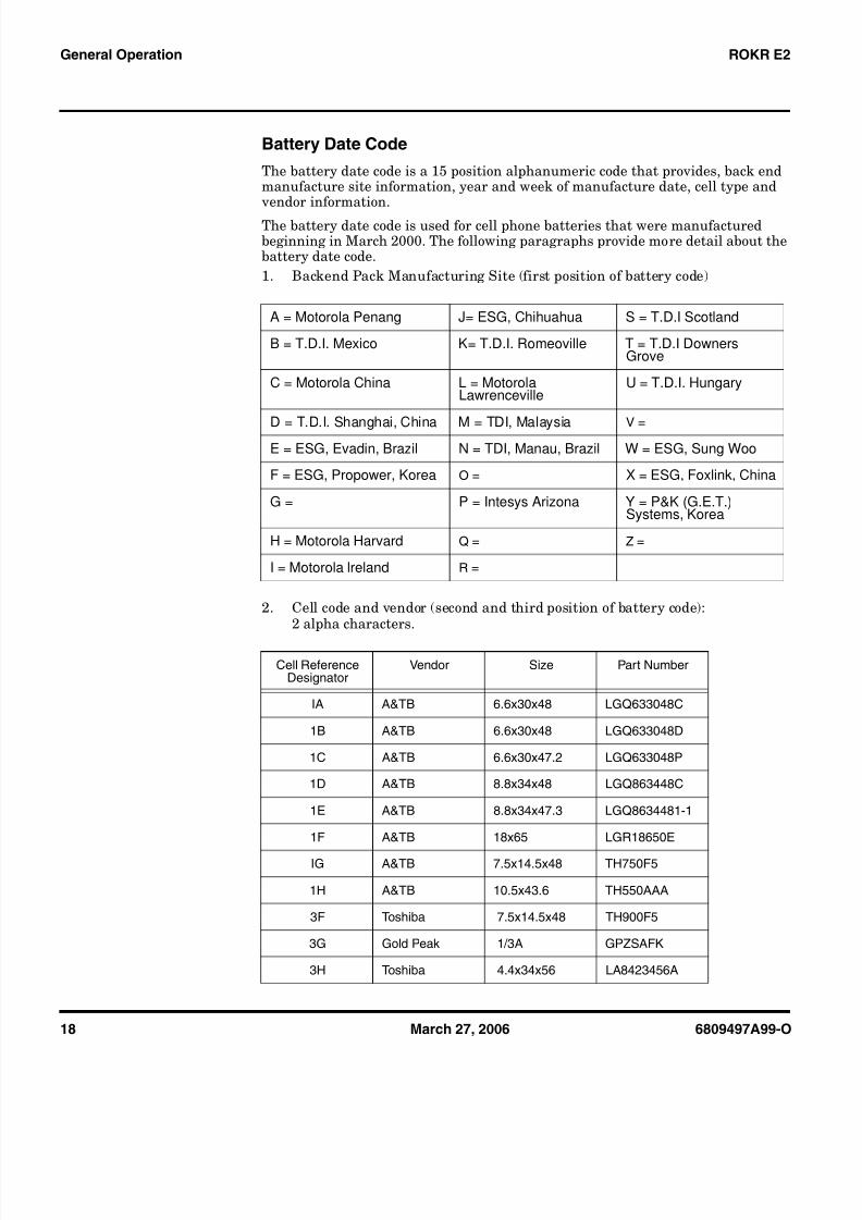
Battery Date CodeThe battery date code is a 15 position alphanumeric code that provides, back endmanufacture site information, year and week of manufacture date, cell type and
vendor information.
The battery date code is used for cell phone batteries that were manufacturedbeginning in March 2000. The following paragraphs provide more detail about thebattery date code.1. Backend Pack Manufacturing Site (first position of battery code)
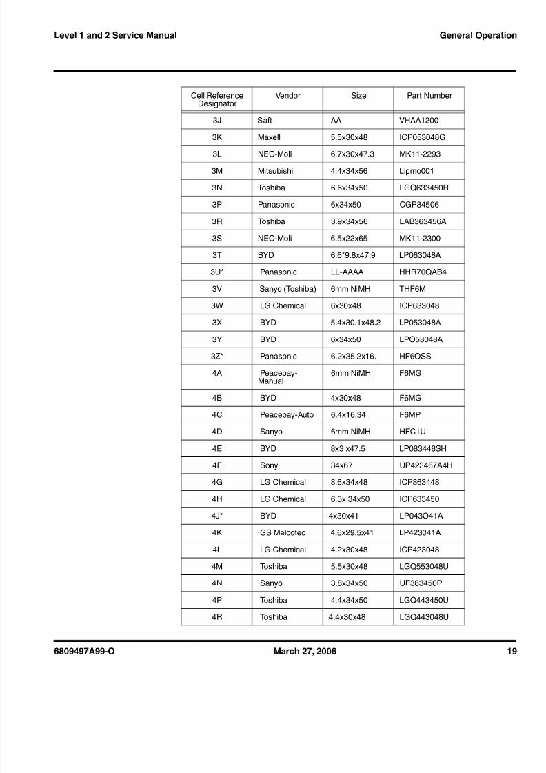
2. Cell code and vendor (second and third position of battery code):2 alpha characters.
A = Motorola Penang J= ESG, Chihuahua S = T.D.I Scotland
B = T.D.I. Mexico K= T.D.I. Romeoville T = T.D.I DownersGrove
C = Motorola China L = MotorolaLawrenceville
U = T.D.I. Hungary
D = T.D.I. Shanghai, China M = TDI, Malaysia V =E = ESG, Evadin, Brazil N = TDI, Manau, Brazil W = ESG, Sung Woo
F = ESG, Propower, Korea O = X = ESG, Foxlink, China
G = P = Intesys Arizona Y = P&K (G.E.T.)Systems, Korea
H = Motorola Harvard Q = Z =
I = Motorola lreland R =
Cell ReferenceDesignator
Vendor Size Part Number
IA A&TB 6.6x30x48 LGQ633048C
1B A&TB 6.6x30x48 LGQ633048D
1C A&TB 6.6x30x47.2 LGQ633048P
1D A&TB 8.8x34x48 LGQ863448C
1E A&TB 8.8x34x47.3 LGQ8634481-1
1F A&TB 18x65 LGR18650E
IG A&TB 7.5x14.5x48 TH750F5
1H A&TB 10.5x43.6 TH550AAA
3F Toshiba 7.5x14.5x48 TH900F5
3G Gold Peak 1/3A GPZSAFK
3H Toshiba 4.4x34x56 LA8423456A
8/7/2019 Dessambles Rokr E2
http://slidepdf.com/reader/full/dessambles-rokr-e2 19/52
6809497A99-O March 27, 2006 19
Level 1 and 2 Service Manual General Operation
3J Saft AA VHAA1200
3K Maxell 5.5x30x48 ICP053048G
3L NEC-Moli 6.7x30x47.3 MK11-2293
3M Mitsubishi 4.4x34x56 Lipmo001
3N Toshiba 6.6x34x50 LGQ633450R
3P Panasonic 6x34x50 CGP34506
3R Toshiba 3.9x34x56 LAB363456A
3S NEC-Moli 6.5x22x65 MK11-2300
3T BYD 6.6*9.8x47.9 LP063048A
3U* Panasonic LL-AAAA HHR70QAB4
3V Sanyo (Toshiba) 6mm NiMH THF6M
3W LG Chemical 6x30x48 ICP633048
3X BYD 5.4x30.1x48.2 LP053048A
3Y BYD 6x34x50 LPO53048A
3Z* Panasonic 6.2x35.2x16. HF6OSS
4A Peacebay-Manual
6mm NiMH F6MG
4B BYD 4x30x48 F6MG
4C Peacebay-Auto 6.4x16.34 F6MP
4D Sanyo 6mm NiMH HFC1U
4E BYD 8x3 x47.5 LP083448SH
4F Sony 34x67 UP423467A4H
4G LG Chemical 8.6x34x48 ICP863448
4H LG Chemical 6.3x 34x50 ICP633450
4J* BYD 4x30x41 LP043O41A
4K GS Melcotec 4.6x29.5x41 LP423041A
4L LG Chemical 4.2x30x48 ICP423048
4M Toshiba 5.5x30x48 LGQ553048U
4N Sanyo 3.8x34x50 UF383450P
4P Toshiba 4.4x34x50 LGQ443450U
4R Toshiba 4.4x30x48 LGQ443048U
Cell ReferenceDesignator
Vendor Size Part Number

8/7/2019 Dessambles Rokr E2
http://slidepdf.com/reader/full/dessambles-rokr-e2 20/52
20 March 27, 2006 6809497A99-O
General Operation ROKR E2
3. Cell date code (fourth fifth and sixth position of battery code) consisting of characters as stated on cell pack by cell manufacturer. If a 3 digit code is notused, place a period in the sixth position.
4. Line and shift manufactured (optional) (seventh and eighth positions of batterycode)
5. Year of battery manufacture (ninth position of battery code)
6. Week of manufacture (tenth and eleventh positions of battery code).
7. Front end corepack manufacturing site (twelfth position of battery code (seestep 1)).
Example of a battery date code: A1V90311JCCC...
position 1 = A = Motorola Penang.t (Backend Pack)position 2 & 3 = 1V = Panasonic, AAA, HHR55B2position 4, 5 & 6 = 903 = cell date code (from manufacturer)position 7 & 8 = 11 = (TBD by supplier.Example: Line one of the first shift.)position 9 = J = 1999 = Year of battery pack manufactureposition 10 & 11 = CC = week twenty two. (backend pack)position 12 = C = Motorola, China. (Frontend Core Pack)position 13, 14 & 15 = placeholders (...) to indicate pack has not been relabeled.
4S Lishen 06x30x48 LP0601AE
4T Panasonic AAAALL HHR70QAB4
1990 = A 1997 = H 2004 = O 2011 = V
1991 = B 1998 = I 2005 = P 2012 = W
1992 = C 1999 = J 2006 = Q 2013 = X
1993 = D 2000 = K 2007 = R 2014 = Y
1994 = E 2001 = L 2008 = S 2015 = Z
1995 = F 2002 = M 2009 = T
1996 = G 2003 = N 2010 = U
A=0 C=2 E=4 G=6 I=8
B=1 D=3 F=5 H=7 J=9
Cell ReferenceDesignator
Vendor Size Part Number
8/7/2019 Dessambles Rokr E2
http://slidepdf.com/reader/full/dessambles-rokr-e2 21/52
6809497A99-O March 27, 2006 21
Level 1 and 2 Service Manual General Operation
8. Batteries sold in China have a 16 character date code:
Example: YYYYMMDDABCXXXX
Where YYYYMMDD is the actual battery manufacturing date
A is the line numberB is the shift number (A,C is day shift; B, D is night shift)C is a serial number from A to Z
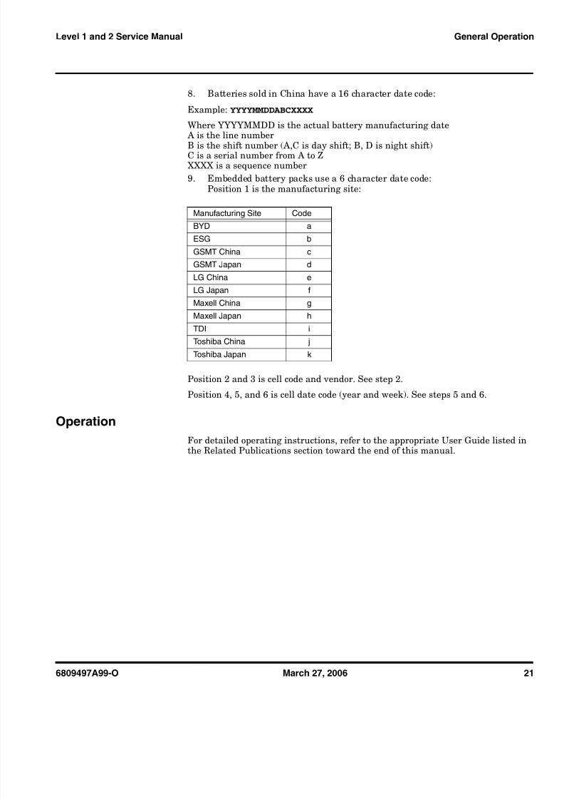
XXXX is a sequence number9. Embedded battery packs use a 6 character date code:
Position 1 is the manufacturing site:
Position 2 and 3 is cell code and vendor. See step 2.
Position 4, 5, and 6 is cell date code (year and week). See steps 5 and 6.
OperationFor detailed operating instructions, refer to the appropriate User Guide listed inthe Related Publications section toward the end of this manual.
Manufacturing Site Code
BYD a
ESG b
GSMT China cGSMT Japan d
LG China eLG Japan f
Maxell China g
Maxell Japan h
TDI iToshiba China j
Toshiba Japan k

8/7/2019 Dessambles Rokr E2
http://slidepdf.com/reader/full/dessambles-rokr-e2 22/52
22 March 27, 2006 6809497A99-O
General Operation ROKR E2

8/7/2019 Dessambles Rokr E2
http://slidepdf.com/reader/full/dessambles-rokr-e2 23/52
6809497A99-O March 27, 2006 23
Level 1 and 2 Service Manual Tools and Test Equipment
Tools and Test EquipmentTable 1 list the tools and test equipment used on E2 telephones. Use either thelisted items or equivalents.
Table 1. General Test Equipment and Tools
MotorolaPart Number 1 Description Application
See Table 5 Charger Used to charge battery and to power phone
0180386A82
Antistatic Mat Kit (includes 66-80387A95 antistaticmat, 66-80334B36 ground cord, and 42-80385A59wrist band)
Provides protection from damage to phone causedby electrostatic discharge (ESD)
8102430Z04 GSM / DCS / PCS Test SIM Used to enable manual test mode
6680388B67 Disassembly tool, plastic with flat and pointedends (manual opening tool) Used during assembly/disassembly of phone
6680388B01 Tweezers, plastic Used during assembly/disassembly
RSX4043-A Torque Driver Used to remove and replace screws
—Torque Driver Bit T-6 Plus, Apex 440-6IP Torx Plusor equivalent Used with torque driver
HP34401A 2 Digital Multimeter Used to measure battery voltage
1. To order in North America, contact Motorola Aftermarket and Accessories Division (AAD) by phone at (800) 422-4210 orFAX (800) 622-6210; Internationally, AAD can be reached by calling (847) 538-8023 or faxing (847) 576-3023.2. Not available from Motorola. To order, contact Hewlett Packard at (800) 452-4844.
1 and 2E2
6809497A99-O

8/7/2019 Dessambles Rokr E2
http://slidepdf.com/reader/full/dessambles-rokr-e2 24/52
24 March 27, 2006 6809497A99-O
Disassembly E2
DisassemblyThis section describes h ow to disassemble a E2 telephone. Tools and equipmentused are listed in Table 1, preceding.
Removing and Replacing the SD (Secure Digital) Card1. Ensure the phone is turned off.
2. Open the memory card door to see if a memory card is installed.
G Many of the integrated devices used in this equipment are vulnerable to damage from electrostatic discharge (ESD). Ensure adequate static protection is in placewhen handling, shipping, and servicing the internal components of this equipment.
G Avoid stressing the plastic in any way to avoid damage to either the plastic orinternal components.
051882o
Figure 5. Opening the Memory Card Door
Memory carddoor

8/7/2019 Dessambles Rokr E2
http://slidepdf.com/reader/full/dessambles-rokr-e2 25/52
6809497A99-O March 27, 2006 25
Level 1 and 2 Service Manual Disassembly
3. If an SD card is present, first, push the SD Card inward to unlock it (seeFigure 6),
4. Pull the SD card out of the phone (see Figure 6).
5. To replace, slide the SD card all the way into the opening near the navigationkey. Ensure the notched end of the SD card faces the phone and the metalcontacts face downward.
051883
Figure 6. Unlocking the SD Card
051884
Figure 7. Removing the SD Card
SD Card
SD Card

8/7/2019 Dessambles Rokr E2
http://slidepdf.com/reader/full/dessambles-rokr-e2 26/52
26 March 27, 2006 6809497A99-O
Disassembly E2
Removing and Replacing the Battery Cover1. Ensure the phone is turned off.2. Remove the SD card if present.3. Press down on the battery cover latch on the back of the phone and slide it the
direction of the arrow and then lift the battery cover away from the phone (seeFigure 8).
4. To replace, align the battery cover to the back of the phone.5. Gently press the battery cover into position onto the phone until the battery
cover snaps into place.6. Reinstall the SD card if present.
051869o
Figure 8. Removing the Battery Cover
battery latch
battery cover

8/7/2019 Dessambles Rokr E2
http://slidepdf.com/reader/full/dessambles-rokr-e2 27/52
6809497A99-O March 27, 2006 27
Level 1 and 2 Service Manual Disassembly
Removing and Replacing the BatteryBattery date codes are explained in the Battery Date Code section on page 17
Before handling the battery, please observe the battery cautions listed below.
1. Remove the SD Card, and battery cover, as described in the procedures.2. Lift the end of the battery near the battery latch (use the disassembly tool if
needed) as shown in Figure 5.3. Lift the bottom end of the battery near the SD card slot out of the battery
compartment as shown in Figure 5.
4. To replace, insert the top end of the battery into the battery compartment withcontacts facing downward as shown in Figure 5B.
5. Press the top of the battery into the battery compartment.6. Replace the battery cover as described in the procedures.
G Do not handle batteries with wet or sweaty hands. Do not short the positive or negative terminals Non conductive tweezers or grasping tools are to be used for battery connectormanipulation, assembly, and disassembly.
051870
Figure 9. Removing and Replacing the Battery
EThere is a danger of explosion if the Lithium ion battery is replaced incorrectly.
Replace only with the same type of battery or equivalent as recommended by thebattery manufacturer. Dispose of used batteries according to the manufacturer’sinstructions.
BatteryDisassembly tool

8/7/2019 Dessambles Rokr E2
http://slidepdf.com/reader/full/dessambles-rokr-e2 28/52
28 March 27, 2006 6809497A99-O
Disassembly E2
Removing and Replacing the Subscriber Identity Module (SIM)1. Remove the SD card, battery cover, and battery as described in the procedures.2. Remove the SIM from the phone by sliding it in the direction indicated as shown
in Figure 10 .
3. To replace, carefully slide the SIM into position into the SIM holder.4. Observe the notched corner when inserting the SIM.5. Replace the battery and the battery cover as described in the procedures.
051871o
Figure 10. Removing the SIM
SIM
8/7/2019 Dessambles Rokr E2
http://slidepdf.com/reader/full/dessambles-rokr-e2 29/52
6809497A99-O March 27, 2006 29
Level 1 and 2 Service Manual Disassembly
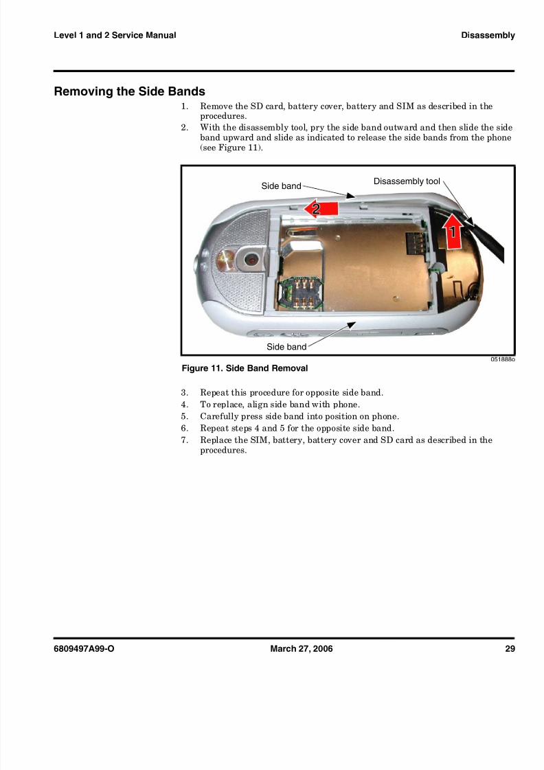
Removing the Side Bands1. Remove the SD card, battery cover, battery and SIM as described in the
procedures.2. With the disassembly tool, pry the side band outward and then slide the side
band upward and slide as indicated to release the side bands from the phone(see Figure 11 ).
3. Repeat this procedure for opposite side band.
4. To replace, align side band with phone.5. Carefully press side band into position on phone.6. Repeat steps 4 and 5 for the opposite side band.7. Replace the SIM, battery, battery cover and SD card as described in the
procedures.
051888
Figure 11. Side Band Removal
Side band
Side band
Disassembly tool
1
2
8/7/2019 Dessambles Rokr E2
http://slidepdf.com/reader/full/dessambles-rokr-e2 30/52
30 March 27, 2006 6809497A99-O
Disassembly E2
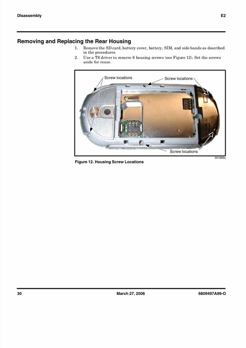
Removing and Replacing the Rear Housing1. Remove the SD card, battery cover, battery, SIM, and side bands as described
in the procedures.2. Use a T6 driver to remove 6 housing screws (see Figure 12 ). Set the screws
aside for reuse.
051889o
Figure 12. Housing Screw Locations
Screw locationsScrew locations
Screw locations
8/7/2019 Dessambles Rokr E2
http://slidepdf.com/reader/full/dessambles-rokr-e2 31/52
6809497A99-O March 27, 2006 31
Level 1 and 2 Service Manual Disassembly
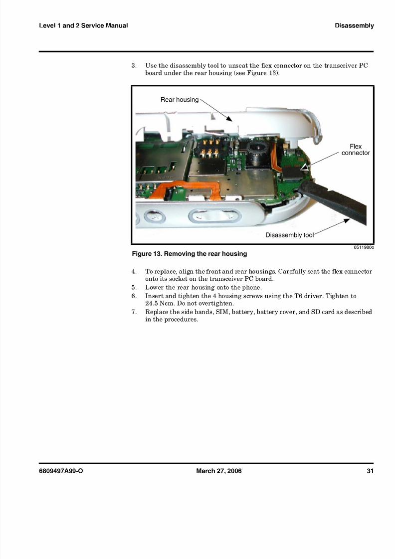
3. Use the disassembly tool to unseat the flex connector on the transceiver PCboard under the rear housing (see Figure 13 ).
4. To replace, align the front and rear housings. Carefully seat the flex connectoronto its socket on the transceiver PC board.
5. Lower the rear housing onto the phone.6. Insert and tighten the 4 housing screws using the T6 driver. Tighten to
24.5 Ncm. Do not overtighten.7. Replace the side bands, SIM, battery, battery cover, and SD card as described
in the procedures.
0511980
Figure 13. Removing the rear housing
Flexconnector
Disassembly tool
Rear housing

8/7/2019 Dessambles Rokr E2
http://slidepdf.com/reader/full/dessambles-rokr-e2 32/52
32 March 27, 2006 6809497A99-O
Disassembly E2
Removing and Replacing the Camera Module1. Remove the SD card, battery cover, battery, SIM, side bands, rear housing, as
described in the procedures.
2. Use the disassembly tool to unseat the camera module connector from it’ssocket on the transceiver board.
3. Lift the camera module off of the transceiver board (see Figure 14 ).
4. To replace, align the camera module and connector to the socket on thetransceiver PC board.
5. Press the camera connector gently until seated in it’s socket. Be careful not todamage the camera flex.
6. Replace the rear housing, side bands, SIM, battery, battery cover, and SD cardas described in the procedures.
G This product contains static-sensitive devices. Use anti-static handling proceduresto prevent electrostatic discharge (ESD) and component damage.
051981o
Figure 14. Removing the Camera Module
Camera module
Camera module connector
Transceiver PC board
Disassembly tool

8/7/2019 Dessambles Rokr E2
http://slidepdf.com/reader/full/dessambles-rokr-e2 33/52
6809497A99-O March 27, 2006 33
Level 1 and 2 Service Manual Disassembly
Removing and Replacing the Transceiver PC Board Assembly1. Remove the SD card, battery cover, battery, SIM, side bands, rear housing, as
described in the procedures.2. Carefully lift one side of the transceiver PC board out of the front housing.3. Carefully use the disassembly tool to disconnect the display module flex
connector from the transceiver PC board (see Figure 15 ).
4. Carefully lift the transceiver PC board out of the front housing.5. To replace, align the transceiver PC board assembly to the rear housing and
then lower the transceiver PC board assembly onto the rear housing.6. Replace the rear housing, side bands, SIM, battery, battery cover, and SD card
as described in the procedures.
051982
Figure 15. Removing the Transceiver PC Board Assembly
Flex connector
Transceiver PC board
Front housing

8/7/2019 Dessambles Rokr E2
http://slidepdf.com/reader/full/dessambles-rokr-e2 34/52
34 March 27, 2006 6809497A99-O
Disassembly E2
Removing and Replacing the Keypad Assembly1. Remove the SD card, battery cover, battery, SIM, side bands, rear housing,
and transceiver PC board assembly as described in the procedures.2. Beginning underneath the front housing, use the plastic disassembly tool to
push the keypad upward out of the front housing.3. Lift the keypad assembly away from the front housing as shown in Figure 16 .
4. To replace, turn the front housing over so that the display lens is facing up.
051987o
Figure 16. Removing the Keypad Assembly
Keypad
Disassemblytool
Front housing
Display module

8/7/2019 Dessambles Rokr E2
http://slidepdf.com/reader/full/dessambles-rokr-e2 35/52
6809497A99-O March 27, 2006 35
Level 1 and 2 Service Manual Disassembly
5. Insert the straight edge of the keypad between the display lens and the displaymodule (see Figure 17 ).
6. Insert the rest of the keypad into the front housing. Use the keypad alignmentholes to correctly align the keypad with the front housing.
7. Replace the transceiver PC board, rear housing, side bands, SIM, stylus,battery, battery cover, and SD card as described in the procedures.
051992
Figure 17. Installing the Keypad Assembly
Ke ad
Display lens

8/7/2019 Dessambles Rokr E2
http://slidepdf.com/reader/full/dessambles-rokr-e2 36/52
36 March 27, 2006 6809497A99-O
Disassembly E2
Removing and Replacing the Display Module Assembly1. Remove the SD card, battery cover, battery, SIM, side bands, rear housing,
transceiver PC board assembly, and keypad assembly as described in theprocedures.
2. Use the disassembly tool to lift the bottom edge of the display module assemblyaway from the front housing.
3. Carefully lift the transceiver PC board assembly out of the front housing.
4. To replace, align the transceiver PC board assembly to the rear housing andthen lower the transceiver PC board assembly onto the rear housing.
5. Replace the keypad assembly, transceiver PC board assembly, rear housing,side bands, SIM, battery, battery cover, and SD card as described in theprocedures.
051993o
Figure 18. Removing the Display Module Assembly
Front Housing
Display module
8/7/2019 Dessambles Rokr E2
http://slidepdf.com/reader/full/dessambles-rokr-e2 37/52
6809497A99-O March 27, 2006 37
Level 1 and 2 Service Manual Disassembly
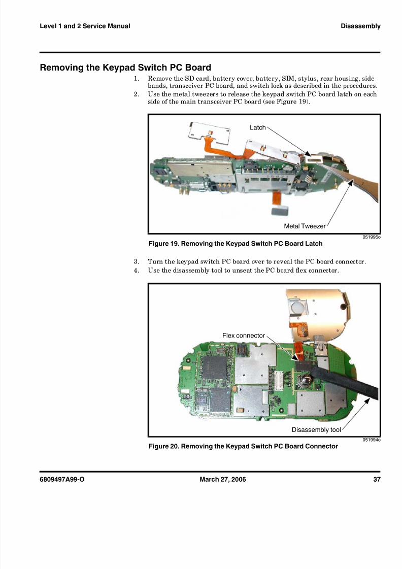
Removing the Keypad Switch PC Board1. Remove the SD card, battery cover, battery, SIM, stylus, rear housing, side
bands, transceiver PC board, and switch lock as described in the procedures.2. Use the metal tweezers to release the keypad switch PC board latch on each
side of the main transceiver PC board (see Figure 19 ).
3. Turn the keypad switch PC board over to reveal the PC board connector.4. Use the disassembly tool to unseat the PC board flex connector.
051995
Figure 19. Removing the Keypad Switch PC Board Latch
051994
Figure 20. Removing the Keypad Switch PC Board Connector
Latch
Metal Tweezer
Flex connector
Disassembly tool

8/7/2019 Dessambles Rokr E2
http://slidepdf.com/reader/full/dessambles-rokr-e2 38/52
38 March 27, 2006 6809497A99-O
Disassembly E2
5. Lift the keypad switch PC board away from the transceiver PC board.6. To replace, align the keypad switch flex connector to its socket on the trans-
ceiver PC board.7. Gently press the keypad switch flex connector into position until the connector
is properly seated in its socket.8. Turn the keypad switch PC board over so that the keypad switch is aligned to
the transceiver PC board.9. Engage the metal latch on one side of the keypad switch PC board to the
transceiver PC board.10. Engage the metal latch on the other edge of the keypad switch PC board to
secure the keypad switch PC board to the transceiver PC board.11. Replace the display module assembly, keypad assembly, transceiver PC board
assembly, rear housing, side bands, SIM, battery, battery cover, and SD cardas described in the procedures.

8/7/2019 Dessambles Rokr E2
http://slidepdf.com/reader/full/dessambles-rokr-e2 39/52
6809497A99-O March 27, 2006 39
Level 1 and 2 Service Manual Subscriber Identity Module (SIM) and IdentificationLabel
Subscriber Identity Module (SIM) and Identification Label
SIM A SIM is required to access the existing local GSM network, or remote networkswhen traveling (if a roaming agreement has been made with the provider).
The SIM card contains:• All the data necessary to access GSM services• The ability to store user information such as phone numbers• All information required by the network provider to provide access to the
network
IdentificationEach Motorola GSM phone is labeled with a variety of identifying numbers. Thefollowing information describes the current identifying labels.
Mechanical Serial Number (MSN)The MSN is an individual unit identity number and remains with the unit through-out its life.
The MSN can be used to log and track a phone on Motorola's Service CenterDatabase.
The MSN is divided into 4 sections as shown in Figure 21 .
000807
Figure 21. MSN label breakdown
MSN 10 Digits
3 Digits 1 Digit 2 Digits 4 Digits
APC DC DC SNR
Account Product Codei.e. StarTAC Phone130
Distribution Centeri.e. Easter Inch
Date Code: Year andMonth of Shipment
Unit's individual serialnumberTM
8/7/2019 Dessambles Rokr E2
http://slidepdf.com/reader/full/dessambles-rokr-e2 40/52
40 March 27, 2006 6809497A99-O
Subscriber Identity Module (SIM) and Identification Label E2
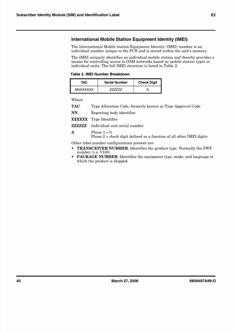
International Mobile Station Equipment Identity (IMEI)The International Mobile station Equipment Identity (IMEI) number is anindividual number unique to the PCB and is stored within the unit's memory.
The IMEI uniquely identifies an individual mobile station and thereby provides ameans for controlling access to GSM networks based on mobile station types orindividual units. The full IMEI structure is listed in Table 2.
Where
TAC Type Allocation Code, formerly known as Type Approval Code
NN Reporting body identifier
XXXXXX Type Identifier
ZZZZZZ Individual unit serial number
A Phase 1 = 0.Phase 2 = check digit defined as a function of all other IMEI digits
Other label number configurations present are:• TRANSCEIVER NUMBER : Identifies the product type. Normally the SWF
number. (i .e. V100).• PACKAGE NUMBER : Identifies the equipment type, mode, and language in
which the product is shipped.
Table 2. IMEI Number Breakdown
TAC Serial Number Check Digit
NNXXXXXX ZZZZZZ A

8/7/2019 Dessambles Rokr E2
http://slidepdf.com/reader/full/dessambles-rokr-e2 41/52
6809497A99-O March 27, 2006 41
Level 1 and 2 Service Manual Troubleshooting
Troubleshooting
Manual Test ModeMotorola E2 telephones are equipped with a manual test mode capability. Thisallows service personnel to verify functionality and perform fault isolation byentering keypad commands.
To enter the manual test command mode, a GSM / DCS test SIM must be used.1. Turn the phone OFF.2. Remove the battery as described in the procedures.3. Remove the customer’s SIM card from the phone as described in the
procedures.4. Insert the test SIM into the SIM slot.5. Replace the battery as described in the procedures.6. Turn the phone ON.
7. In the idle screen, press and hold the # key to enter test mode. The test modescreen appears.
8. Select Suspendand then enter individual test parameters.9. Scroll up-and-down using the navigation key to select the specific function to
be tested.
060107o
Figure 22. Test Mode Screen

8/7/2019 Dessambles Rokr E2
http://slidepdf.com/reader/full/dessambles-rokr-e2 42/52
42 March 27, 2006 6809497A99-O
Troubleshooting E2
10. Press the left soft key ( a ) to begin the test.
060108o
Figure 23. Test Parameters
Left Soft Key

8/7/2019 Dessambles Rokr E2
http://slidepdf.com/reader/full/dessambles-rokr-e2 43/52
6809497A99-O March 27, 2006 43
Level 1 and 2 Service Manual Troubleshooting
Troubleshooting Chart
Table 3. Level 1 and 2 Troubleshooting Chart
Symptom Probable Cause Verification And Remedy
1. Telephone will not turn on or stay on. a) Battery either discharged ordefective.
Measure the voltage at TP_BATT+ with batteryattached. If voltage is below 3.0V, attach acharger to the phone and ensure that the phoneis charging. If the phone does not charge,change the battery and repeat the measurementcharging procedure. If the phone still does notturn on, proceed to b).
b) Transceiver board defective.Replace the faulty board with a known goodtransceiver board. If the phone powers up afterreplacement, reassemble the phone with a newtransceiver board. Verify that the fault is fixed.
2. Telephone exhibits poor reception orerratic operation such as calls frequentlydropping or weak or distorted audio.
a) Speaker/antenna assemblydefective
Check connection between the speaker/antennaassembly and the transceiver board. If thecontact is intermittent visually, replace with aknown good speaker/antenna assembly. If thefault is still present, proceed to b.
b) Transceiver board defective.Replace with a known good transceiver board(refer to 1b). Verify that the fault has beencleared with the new transceiver board andreassemble the unit.
3. No display. a) Connections between transceiverand display faulty.
Check connections between transceiver boardand display. If display still does not come up,proceed to b.
b) Display module defective.Replace with a known good display module.Verify that the fault has been cleared with thenew display module and reassemble the unit.
4. Incoming call alert transducer audiodistorted or volume is too low. a) Faulty antenna/speaker assembly.
Replace the antenna/speaker assembly with aknown good antenna/speaker assembly. If theproblem goes away, replace with a new antenna/ speaker assembly. Else proceed to b.
b) Transceiver board defectiveReplace with a known good transceiver board(refer to 1b). Verify that the fault has beencleared with a new transceiver board.
5. Telephone transmit audio is weak.(usually indicated by called partiescomplaining of difficulty in hearing voice).
a) Microphone defective. Replace the microphone as described in theprocedures. If fault is not cleared, proceed to b.
b) Transceiver board defective.Replace the transceiver board (refer to 1b).Verify that the fault has been cleared andreassemble the unit with the new transceiverboard.
6. Receive audio from earpiece speaker isweak or distorted.
a) Contacts between earpiecespeaker and transceiver board faulty.
Replace the earpiece speaker with a knowngood one. Reassemble with a new front housingif the fault goes away. If the fault is still present,proceed to b.
b) Transceiver board defective.Replace the transceiver board (refer to 1b).Verify that the fault has been cleared andreassemble the unit with the new transceiverboard.

8/7/2019 Dessambles Rokr E2
http://slidepdf.com/reader/full/dessambles-rokr-e2 44/52
44 March 27, 2006 6809497A99-O
Part Numbers E2
Programming: Software Upgrade and FlexingContact your local technical support engineer for information about equipment andprocedures for flashing and flexing.
Part Numbers
7. Telephone will not recognize or acceptSIM card. a) SIM card defective.
Check the SIM card contacts for dirt. Clean ifnecessary, and check if fault has been cleared.If the contacts are clean, insert a known goodSIM card into the telephone. Power up the unitand confirm that the card has been accepted. Ifthe fault goes away, replace the defective SIMcard. If the SIM card is not at fault, proceed to b.
b) Transceiver board defective.Replace the transceiver board (refer to 1b).Verify that the fault has been cleared andreassemble the phone with the new transceiverboard.
8. Vibrator feature not functioning. a) Vibrator/Camera flash/Speakerassembly.
Replace the Vibrator/ Camera Flash /Speakerassembly, placed in the back housing with agood known assembly. Verify that the fault hasbeen cleared and reassemble the unit with theVibrator/Camera flash/Speaker assembly. If theVibrator/Camera flash/Speaker assembly is notat fault, proceed to b.
b) Transceiver board defective.Replace the transceiver board (refer to 1b).Verify that the fault has been cleared andreassemble the phone with the new transceiverboard.
9. No or weak audio when using headset. a) Headset plug not pushed in fully. Ensure the headset plug is fully seated in the jack.
b) Faulty jack on transceiver board.Replace the transceiver board with a knowngood transceiver board (refer to 1b). Verify thatthe fault has been cleared and reassemble theunit with the new transceiver board.
10. Camera feature not functioning. a) Camera module defective.
1. Replace camera module with a good knowncamera module. Verify that the fault has beencleared and reassemble the phone with the newcamera module. If the camera module is not atfault, proceed to b.
b) Transceiver board defective.Replace the transceiver board (refer to 1b).Verify that the fault has been cleared andreassemble the phone with the new transceiverboard.
11. No camera flash. a) Vibrator/Camera flash/Speakerassembly defective
Replace the Vibrator/ Camera Flash /Speakerassembly, placed in the back housing with agood known assembly. Verify that the fault hasbeen cleared and reassemble the unit with theVibrator/Camera flash/Speaker assembly. If theVibrator/Camera flash/Speaker assembly is notat fault, proceed to b.
b) Transceiver board defective.Replace the transceiver board (refer to 1b).Verify that the fault has been cleared andreassemble the phone with the new transceiverboard.
Table 3. Level 1 and 2 Troubleshooting Chart (Continued)Symptom Probable Cause Verification And Remedy

8/7/2019 Dessambles Rokr E2
http://slidepdf.com/reader/full/dessambles-rokr-e2 45/52
6809497A99-O March 27, 2006 45
Level 1 and 2 Service Manual Part Numbers
The following section provides a reference for the parts associated withE2 telephones.
Exploded View Diagram
051890o
Figure 24. Exploded View Diagram
12 3
45
67
98
100
111
122
166
133
144
155

8/7/2019 Dessambles Rokr E2
http://slidepdf.com/reader/full/dessambles-rokr-e2 46/52
46 March 27, 2006 6809497A99-O
Part Numbers E2
Exploded View Parts List
For information on ordering parts please contact EMEA at +49 461 803 1404.
Accessories
Table 4. Exploded View Parts List
Item
Number
Motorola Part
NumberDescription
1 Rear housing assembly2 Bluetooth antenna3 Acoustic booth4 1.3M camera module5 Joystick6 Transceiver PCBA7 Side bands8 0309315B35 Screws (6X)9 Front housing assembly
10 Side keys11 Keypad12 Display module
13Keypad holder
14 PF4 Series battery15 Battery door assembly16 Internal antenna
EThere is a danger of explosion if the Lithium ion battery pack is replaced incorrectly.
Replace only with the same type of battery or equivalent as recommended by thebattery manufacturer. Dispose of used batteries according to the manufacturer’sinstructions.
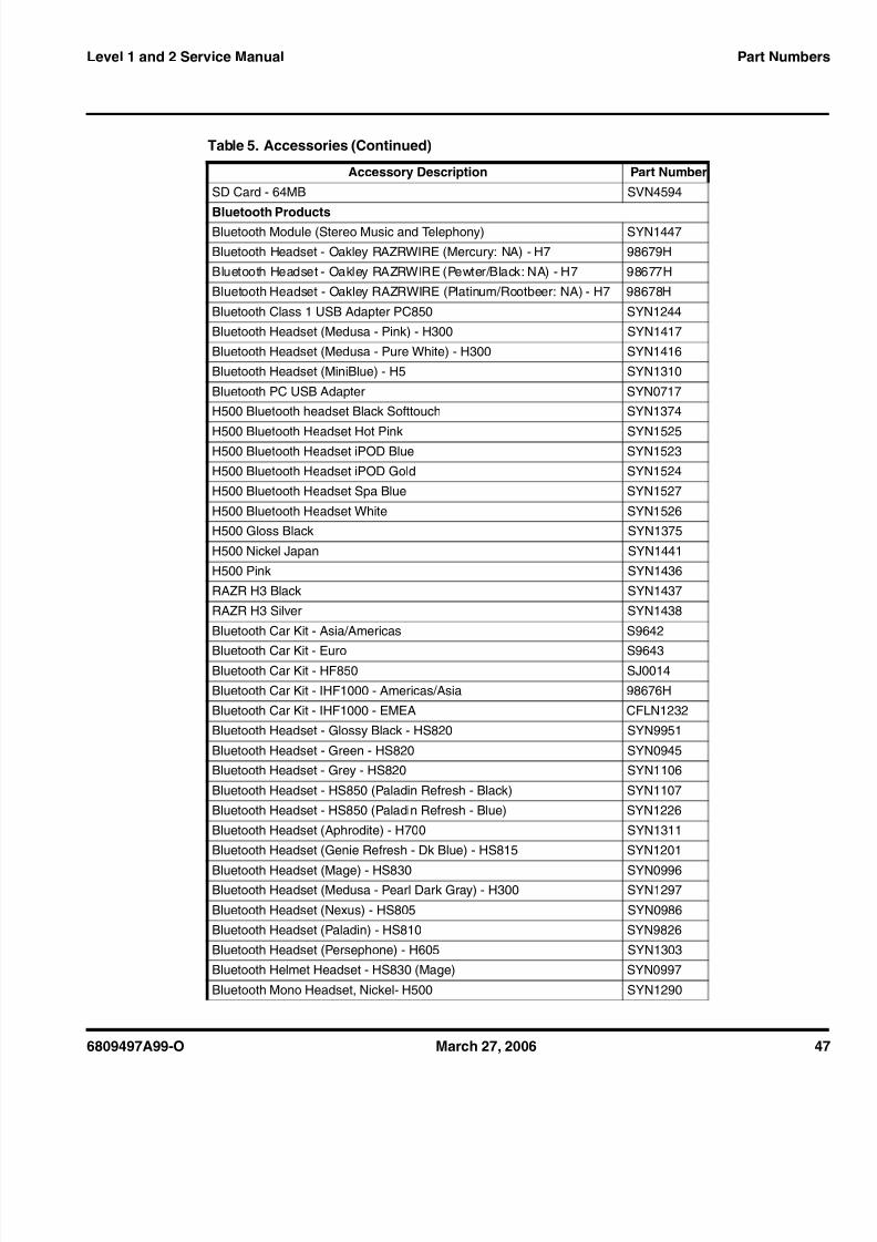
Table 5. Accessories
Accessory Description Part NumberAudio & Connectivity
1 GB micro SD card & Mot SD adapter syn1406
128MB micro SD card & Mot SD adapter SYN1403
256MB micro SD card & Mot SD adapter SYN1404
32MB micro SD card & Mot SD adapter SYN1401
512MB micro SD card & Mot SD adapter SYN140564MB micro SD card & Mot SD adapter SYN1402
Data Cable Mini USB/USB/Serial SKN6371
Headset Stereo 3.5mm SYN1302
Mobile Phone Tools Region-specific
SD Card - 128MB SVN4595
SD Card - 32MB SVN4593
8/7/2019 Dessambles Rokr E2
http://slidepdf.com/reader/full/dessambles-rokr-e2 47/52
6809497A99-O March 27, 2006 47
Level 1 and 2 Service Manual Part Numbers
SD Card - 64MB SVN4594
Bluetooth ProductsBluetooth Module (Stereo Music and Telephony) SYN1447
Bluetooth Headset - Oakley RAZRWIRE (Mercury: NA) - H7 98679H
Bluetooth Headset - Oakley RAZRWIRE (Pewter/Black: NA) - H7 98677H
Bluetooth Headset - Oakley RAZRWIRE (Platinum/Rootbeer: NA) - H7 98678H
Bluetooth Class 1 USB Adapter PC850 SYN1244
Bluetooth Headset (Medusa - Pink) - H300 SYN1417
Bluetooth Headset (Medusa - Pure White) - H300 SYN1416
Bluetooth Headset (MiniBlue) - H5 SYN1310
Bluetooth PC USB Adapter SYN0717H500 Bluetooth headset Black Softtouch SYN1374
H500 Bluetooth Headset Hot Pink SYN1525H500 Bluetooth Headset iPOD Blue SYN1523
H500 Bluetooth Headset iPOD Gold SYN1524
H500 Bluetooth Headset Spa Blue SYN1527
H500 Bluetooth Headset White SYN1526H500 Gloss Black SYN1375
H500 Nickel Japan SYN1441
H500 Pink SYN1436
RAZR H3 Black SYN1437
RAZR H3 Silver SYN1438
Bluetooth Car Kit - Asia/Americas S9642
Bluetooth Car Kit - Euro S9643Bluetooth Car Kit - HF850 SJ0014
Bluetooth Car Kit - IHF1000 - Americas/Asia 98676H
Bluetooth Car Kit - IHF1000 - EMEA CFLN1232
Bluetooth Headset - Glossy Black - HS820 SYN9951
Bluetooth Headset - Green - HS820 SYN0945Bluetooth Headset - Grey - HS820 SYN1106
Bluetooth Headset - HS850 (Paladin Refresh - Black) SYN1107
Bluetooth Headset - HS850 (Paladin Refresh - Blue) SYN1226
Bluetooth Headset (Aphrodite) - H700 SYN1311
Bluetooth Headset (Genie Refresh - Dk Blue) - HS815 SYN1201
Bluetooth Headset (Mage) - HS830 SYN0996Bluetooth Headset (Medusa - Pearl Dark Gray) - H300 SYN1297
Bluetooth Headset (Nexus) - HS805 SYN0986
Bluetooth Headset (Paladin) - HS810 SYN9826
Bluetooth Headset (Persephone) - H605 SYN1303
Bluetooth Helmet Headset - HS830 (Mage) SYN0997
Bluetooth Mono Headset, Nickel- H500 SYN1290
Table 5. Accessories (Continued)
Accessory Description Part Number

8/7/2019 Dessambles Rokr E2
http://slidepdf.com/reader/full/dessambles-rokr-e2 48/52
48 March 27, 2006 6809497A99-O
Part Numbers E2
Bluetooth Speaker (Quadrant Refresh) - HF820 SYN0736C
Bluetooth Stereo Headset HT820 (Neptune) SYN0948Bluetooth Stereo Transceiver DC800 (Triton) SYN1001
In vehicle Solutions
Self Install Car Kit Universal - Mandarin - Smart Drive+ SYN0888
Self Install Car Kit Universal - Smar t Car Kit - Smar t Drive SYN0890
Smart Cable EMU - Motorola SYN1003
Vehicle Power Adapter EMU - VC700 SYN0847
Power Solutions
Battery BT50 (PF4 Ltd) Li-Ion 880 mAh SNN5771
Battery-Only-Charger for PF batteries, US/Euro plug SYN1488ABattery-Only-Charger for PF batteries, PRC plug SYN1489A
Battery-Only-Charger for PF batteries, Taiwan plug SYN1490ABattery-Only-Charger for PF batteries, Hong Kong plug SYN1491A
Travel Charger EMU Mid-Rate Switcher - Argentina SPN5192
Travel Charger EMU Mid-Rate Switcher - Australia SPN5193
Travel Charger EMU Mid-Rate Switcher - BRAZIL SPN5187Travel Charger EMU Mid-Rate Switcher - EURO SPN5189
Travel Charger EMU Mid-Rate Switcher - INDIA SPN5194
Travel Charger EMU Mid-Rate Switcher - MEXICO SPN5186
Travel Charger EMU Mid-Rate Switcher - PRC SPN5188
Travel Charger EMU Mid-Rate Switcher - TWN SPN5216
Travel Charger EMU Mid-Rate Switcher - UK/HK SPN5190
Travel Charger EMU Mid-Rate Switcher - US ENG SPN5185Travel Charger EMU Rapid Switcher - Argentina SPN5197
Travel Charger EMU Rapid Switcher - BRAZIL SPN5196
Travel Charger EMU Rapid Switcher - HK SPN5199
Travel Charger EMU Rapid Switcher - MEXICO SPN5200
Travel Charger EMU Rapid Switcher - PRC SPN5198Travel Charger EMU Rapid Switcher - US SPN5202
Travel Charger EMU Rapid TWN SPN5270
Table 5. Accessories (Continued)
Accessory Description Part Number
8/7/2019 Dessambles Rokr E2
http://slidepdf.com/reader/full/dessambles-rokr-e2 49/52
6809497A99-O March 27, 2006 Index-1
Level 1 and 2 Service Manual Index
Aactive line indicator 16airplane mode indicator 15antenna, removing and replacing 27
Bbattery
charge indicator 17function 17
battery cover, removing and replacing 26battery indicator 16battery, removing and replacing 27Bluetooth indicator 16
Ccall forward indicator 16caller ID 13camera module, removing and replacing 32Canadian Interference-Causing Equipment regulations 5changes
product 5copyrights
computer software 6
Ddisassembly 24display module assembly, removing and replacing 36
Eendo housing, removing and replacing 30exploded view diagram 45exploded view parts list 46
FFCC rules 5features
caller ID 13chat messaging 13SIM Toolkit 13
text entry 13voice recognition 12
Wireless Access Protocol (WAP) 12front endo housing, removing and replacing 36
GGPRS indicator 16
Hhousing cover rear, removing and replacing 30
Iidentificationinternational mobile station equipment identity 40mechanical serial number 39product 5
identification, labels 39IM indicators 16IMEI 40in-call indicator 16Introduction 5
Kkeypad switch PC board, removing and replacing 37keypad, removing and replacing 34
LLCD 16liquid crystal display (LCD) 16Low Battery message 16
Mmanual test mode 41message indicator 16microphone, removing and replacing 32, 39
MSN 39
Nnames
product 5
Ooperation 14
battery 17controls, indicators, and I/O connectors 14LCD 16menu navigation 16
overview, product 11
Ppart numbers
accessories 46parts
exploded view diagram 45
1 and 2IndexROKR E2
6809497A99-O

8/7/2019 Dessambles Rokr E2
http://slidepdf.com/reader/full/dessambles-rokr-e2 50/52
Index-2 March 27, 2006 6809497A99-O
Index ROKR E2
exploded view parts list 46replacement parts 44
productchanges 5
identification 5names 5product overview 11
features 11profile indicator 16
RRear Housing, removing and replacing 30regulatory agency compliance 5removing
antenna 27battery 17, 27
battery cover 26camera module 32
display module assembly 36endo housing 30front endo housing 36keypad 34keypad switch PC board 37microphone 32, 39Rear Housing 30rear housing cover 30SD (Secure Digital) Card 24Side Bands 29SIM 28
transceiver board 32, 39Transceiver PC Board Assembly 33
replacement partsordering 8
replacingantenna 27battery 27battery cover 26camera module 32display module assembly 36endo housing 30front endo housing 36keypad 34keypad switch PC board 37microphone 32, 39Rear Housing 30rear housing cover 30SD (Secure Digital) Card 24Side Bands 29SIM 28transceiver board 32, 39
Transceiver PC Board Assembly 33
SSD (Secure Digital) Card, removing and replacing 24serial number
mechanical 39service manual
about 6audience 6conventions 7scope 6
service policy 7customer support 7out of box failure 7product support 7
shut down
upon battery removal 17Side Bands, removing and replacing 29
signal strength indicator 15SIM Toolkit 13SIM, description 39SIM, removing and replacing 28specifications 9subscriber identity module (SIM) 39support
customer 7product 7
Ttest equipment 23text entry 13tools, disassembly 23transceiver board, removing and replacing 32, 39Transceiver PC Board Assembly, removing and replacing
33troubleshooting 41
manual test mode 41troubleshooting chart 43
Vvoice recognition 12
WWAP (Wireless Access Protocol) 12warranty service 7

8/7/2019 Dessambles Rokr E2
http://slidepdf.com/reader/full/dessambles-rokr-e2 51/52
8/7/2019 Dessambles Rokr E2
http://slidepdf.com/reader/full/dessambles-rokr-e2 52/52
MOTOROLA, the Stylized M Logo, and all other trademarks indicated as such herein are trademarks of Motorola, Inc. ® Reg. U.S. Pat. & Tm. Off.
© 2006 Motorola, Inc.All rights reserved.
Personal Communications Sector,789 International Parkway.
Sunrise, FL 33325-8292