development and characterization of poly(lactic …
TRANSCRIPT
DEVELOPMENT AND CHARACTERIZATION OF POLY(LACTIC ACID)/FISH GELATINE ELECTROSPUN MEMBRANES FOR PERIPHERAL NERVE REGENERATION
MARIANA BRANCO MARINHEIRO FERREIRA DE SOUSA DISSERTAÇÃO DE MESTRADO APRESENTADA À FACULDADE DE ENGENHARIA DA UNIVERSIDADE DO PORTO EM ENGENHARIA BIOMÉDICA
M 2016
Faculdade de Engenharia da Universidade do Porto
Development and characterization of poly(lactic acid)/fish gelatine electrospun membranes for
peripheral nerve regeneration
Mariana Branco Marinheiro Ferreira de Sousa
Master in Biomedical Engineering
Supervisor: Prof. José Domingos Santos
Co-Supervisor: Prof. Vitor Sencadas
September, 2016

Mariana Branco Marinheiro Ferreira de Sousa, 2016
i
Abstract
Injuries to the peripheral nervous system are a major cause for permanent disabilities with a strong
effect on a diminished quality of life. The neurological sequels left by this kind of injuries result in a
diminished daily live activity as well as loss of work capabilities. Peripheral nerve injuries are the
principal cause of disorders with devastating impact on quality of life of patients and affects a large
part of the population over the world. Therefore, this has a socioeconomic impact. For those reasons,
the surgery to repair the damage to the peripheral nerve is urgently needed as well as a medical
challenge.
In recent years, various surgical techniques have been carried out to aid the regeneration and
repair of damage in peripheral nerves. However, the functional recovery is usually incomplete. Thus,
a promising alternative is to use natural and synthetic neural scaffolds in which tubular nerve guidance
conduits (NGC) is the basic structure. Guidance channels provide a microenvironment and mechanical
support, directing the axonal growth from the proximal to the distal nerve stumps. In addition, they
are designed and fabricated to increase the number, speed and length of the regenerating nerves.
A very important factor for the fabrication of NGC is the biomaterials selection. Synthetic and
natural polymers, such as poly(lactic acid) (PLA) and fish gelatine (GE), have received great attention
and have been widely used in tissue engineering because their properties can be tailored and are
inexpensive.
In addition to the material selection, fabrication methods are also critical for designing neural
scaffolds. Electrospinning allows the production of nanofibrous scaffolds that offer optimal surface
properties for cell attachment, proliferation and differentiation because they can potentially mimic
the structure of natural extracellular matrix (ECM).
In this context, this work aimed the production of biomaterials that promote the peripheral nerve
regeneration. In this way, electrospun membranes of PLA blended with fish gelatine were developed
at five different weight ratios. Additionally, the potential of these membranes for peripheral nerve
regeneration was characterized in terms of their physicochemical properties. In order to characterize
the biological properties of the membranes produced, in vitro cytotoxicity assays were performed.
These assays revealed that the electrospun membranes are biocompatible and the PG11 membranes
was proven to be a good substrate for fibroblast adhesion and proliferation compared to pure PLA and
GE, since their morphology and structure was improved.
Keywords: Electrospinning, fish gelatine, poly(lactic acid), peripheral nerve regeneration, tissue
engineering.

ii
iii
Resumo
As lesões do sistema nervoso periférico são uma das principais causas de incapacidade permanente e
têm um impacto negativo na qualidade de vida dos pacientes. As sequelas neurológicas deixadas por
este tipo de lesões comprometem as atividades do dia-a-dia, bem como as capacidades de trabalho.
Estas lesões são a principal causa de doenças com impacto devastador na qualidade de vida dos
pacientes, afetando uma grande parte da população no mundo inteiro. Desta forma, têm um elevado
impacto sócio-económico. Por estas razões, a correção cirúrgica de lesões nos nervos periféricos
representa uma necessidade médica urgente, bem como um grande desafio clínico.
Nos últimos anos, têm sido realizadas várias técnicas cirúrgicas para reparar e regenerar os nervos
periféricos. No entanto, a recuperação funcional, normalmente, é incompleta. Assim, uma alternativa
promissora é a utilização de tubos-guia, sintéticos e/ou naturais. Estes tubos-guia proporcionam um
microambiente, suporte mecânico e direcionam o crescimento axonal. Além disso, são implementados
para aumentar o número, a velocidade e o comprimento da regeneração nervosa.
Um fator muito importante para a fabricação dos tubos-guia é a seleção dos biomateriais.
Polímeros sintéticos e naturais, como o ácido poli-lático (PLA) e gelatina de peixe (GE), têm sido
amplamente utilizados na área de engenharia de tecidos devido à possibilidade de adaptação das suas
propriedades e o seu custo.
Além da seleção dos biomateriais, a escolha do método de processamento também é um fator
crítico na conceção de tubos-guia. A técnica de electrospinning permite a produção de scaffolds
nanofibrosos que apresentam ótimas propriedades superficiais para a adesão, proliferação e
diferenciação celular, uma vez que permitem imitar a estrutura natural da matriz extracelular.
Neste contexto, este trabalho pretende produzir biomateriais que promovam a regeneração do
nervo periférico. Desta forma, desenvolveu-se as membranas de PLA com gelatina de peixe através
da técnica de electrospinning, em cinco rácios diferentes. Além disso, o potencial destas membranas
para a sua utilização na regeneração do nervo periférico foi caracterizado em termos das suas
propriedades físico-químicas. As propriedades biológicas das membranas desenvolvidas foram
caracterizadas através de ensaios de citotoxicidade in vitro. Estes estudos revelaram que as
membranas produzidas pela técnica de electrospinning são biocompatíveis e, as membranas PG11
provaram ser um substrato adequado para promover a adesão e proliferação de fibroblastos, em
comparação com o uso individual das membranas de PLA e GE, uma vez que a sua morfologia e
estrutura foi melhorada.
Palavras-chave: Electrospinning, gelatina de peixe, ácido poli-láctico, regeneração do nervo
periférico, engenharia de tecidos.

iv
v
Acknowledgments
Começo por agradecer aos meus orientadores, Professor José Domingos Santos e Professor Vitor
Sencadas, por me terem dado a oportunidade de realizar este trabalho. Agradeço também a
disponibilidade, orientação e as correções pertinentes essenciais para aumentar a qualidade deste
trabalho.
Gostaria também de deixar um agradecimento à Professora Maria Helena Fernandes por me
proporcionar os meios para a realização dos ensaios in vitro e à Liliana que me ajudou com todos os
procedimentos laboratoriais.
Agradeço também às minhas amigas e ao João que sempre me ajudaram, pelos conselhos e
paciência. Um especial obrigada à Raquel por saber sempre o que me dizer nos momentos mais
difíceis.
Por último, um obrigada à minha família, em especial à minha mãe e às minhas irmãs que sempre
me apoiaram e incentivaram durante o meu percurso académico.

vi
vii
Contents
List of Figures ..................................................................................... ix
List of Tables ...................................................................................... xi
Abbreviations ................................................................................... xiii
Chapter 1 ........................................................................................... 1
Introduction ........................................................................................ 1
1.1 - Motivation and Context ............................................................................... 1
1.2 - Objectives ............................................................................................... 3
1.3 - Document Structure ................................................................................... 3
Chapter 2 ........................................................................................... 5
Literature Review ................................................................................. 5
2.1 - Classification of Nervous System .................................................................... 5
2.2 - Cellular components of the PNS ..................................................................... 5
2.3 - Peripheral Nerve Anatomy ........................................................................... 6
2.4 - Peripheral Nerve Injuries ............................................................................. 7
2.4.1 – Types of Injuries ..................................................................................... 7
2.4.2 – Wallerian Degeneration ............................................................................. 9
2.5 - Treatments of Peripheral Nerve Injuries ........................................................ 10
2.6 - Tissue Engineering Nerve Grafts .................................................................. 10
2.6.1 - Requirements of an ideal scaffold .............................................................. 11
2.6.1.1 – Biocompatibility ................................................................................. 12
2.6.1.2 – Biodegradability ................................................................................. 12
2.6.1.3 – Permeability ..................................................................................... 12
2.6.1.4 – Biomechanical Properties ..................................................................... 13
2.6.1.5 – Surface Properties .............................................................................. 13
2.6.2 – Neural Scaffold Material .......................................................................... 14
2.6.2.1 – Synthetic Materials ............................................................................. 14
2.6.2.1.1 – Poly(Lactic Acid) ............................................................................. 15
2.6.2.2 – Natural Materials................................................................................ 16
2.6.2.2.1 – Fish Gelatine .................................................................................. 16
viii
2.6.3 – Methods for nanofiber processing ............................................................... 17
2.6.3.1 – Electrospinning .................................................................................. 18
Chapter 3 ......................................................................................... 21
Materials and Methods.......................................................................... 21
3.1 – Materials .............................................................................................. 21
3.2 – Electrospinning ....................................................................................... 21
3.3 – Cross-linking .......................................................................................... 22
3.4 – Materials Characterization ......................................................................... 22
3.4.1 – Scanning electron microscopy (SEM) ........................................................... 22
3.4.2 – Diameter measurements ......................................................................... 22
3.4.3 – Determination of the degree of cross-linking ............................................... 23
3.4.4 – Contact angle measurements ................................................................... 23
3.4.5 – Swelling and water retention capacity ....................................................... 23
3.4.6 – Thermogravimetric analysis ..................................................................... 24
3.4.7 – Differential scanning calorimetry .............................................................. 24
3.4.8 – Fourier transform infrared spectroscopy ..................................................... 24
3.5 – Cell culture procedure .............................................................................. 24
3.6 – Cell viability and proliferation .................................................................... 24
3.7 – Statistical analysis ................................................................................... 25
Chapter 4 ......................................................................................... 27
Results and Discussion.......................................................................... 27
4.1 – Morphology of the electrospun membranes ..................................................... 27
4.2 – Degree of cross-linking ............................................................................. 30
4.3 – Contact angle measurements ...................................................................... 31
4.4 – Swelling Degree ...................................................................................... 32
4.5 – Thermal behaviour .................................................................................. 33
4.6 – Infrared spectra ...................................................................................... 36
4.7 – Cell viability and proliferation .................................................................... 38
Chapter 5 ......................................................................................... 41
Conclusions and Future Work ................................................................. 41
5.1 – Conclusions ........................................................................................... 41
5.2 – Future Work .......................................................................................... 42
References........................................................................................ 43
Appendix A ....................................................................................... 49
ix
List of Figures
2.1 Peripheral motor neuron with its structural features: cell body and axon extension surrounded
by myelin sheath produced by Schwann cells (Adapted from [21]). ............................................. 6
2.2 Cross-sectional anatomy of peripheral nerve [2]. ............................................................................. 7
2.3 Schematic representation of the five grades of nerve injury according to Sunderland’s
classification: (1) Sunderland grade I, (2) Sunderland grade II, (3) Sunderland grade III, (4)
Sunderland grade IV, (5) Sunderland grade V [8]. ........................................................................... 8
2.4 Degeneration and regeneration after peripheral injury [26]. ........................................................ 9
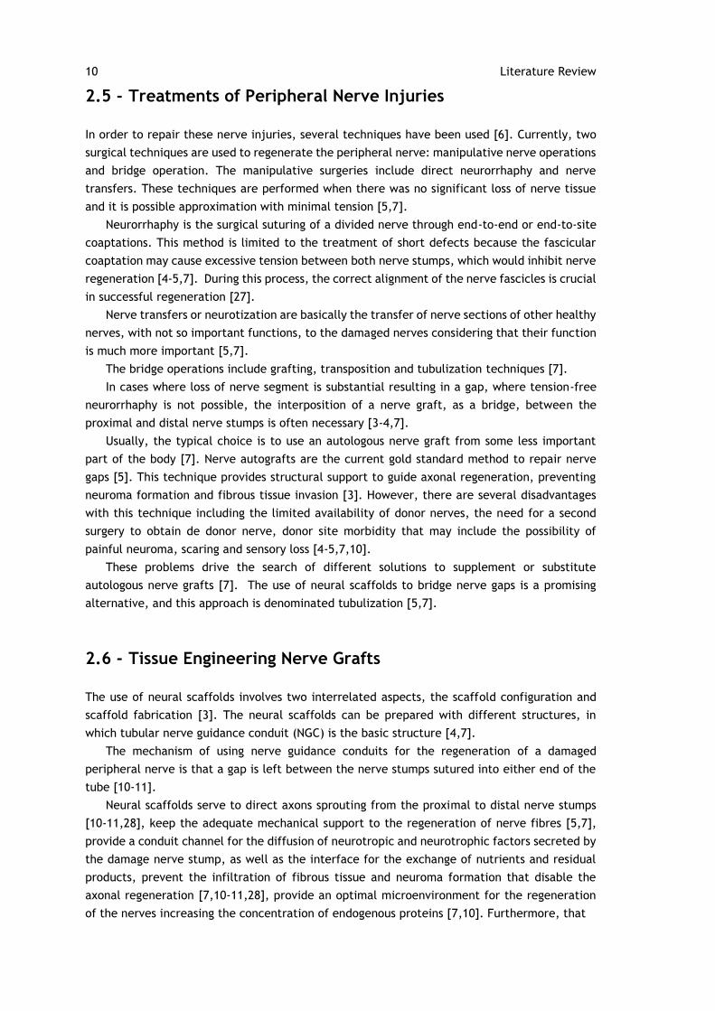
2.5 The structure of nerve guidance conduits showing the sequence of events that occur in
peripheral nerve regeneration [27]. ............................................................................................... 11
2.6 The stereoisomers of lactic acid: L-Lactic Acid and D-Lactic Acid [35]. ..................................... 15
2.7 Structure of poly(lactic acid) and its degradation product, lactic acid [6]. ................................ 15
2.8 Schematic diagram of the basic experimental electrospinning setup [59]. ................................ 19
4.1 SEM morphologies of the electrospun polymeric nanofibers; (A) PLA, (B) PG31, (C) PG31 cross-
linked, (D) PG11, (E) PG11 cross-linked, (F) PG13, (G) PG13 cross-linked, (H) GE and (I) GE cross-
linked. ................................................................................................................................................ 28
4.2 Evolution of fibre mean diameter for electrospun fibres samples before and after cross-linking;
bars represent means ± SD. ............................................................................................................. 29
4.3 Optical absorbance of the gelatine powder and the PLA/gelatine membranes. ........................ 30
4.4 Degree of cross-linking for gelatine and PLA/GE electrospun membranes. ................................ 31
4.5 Evolution of water contact angles for electrospun fibres membranes. Values are mean ± SD. 32
4.6 Equilibrium swelling ratio of PLA/gelatine electrospun membranes with different blending
compositions. .................................................................................................................................... 32
4.7 a) TGA data for pure PLA and GE samples, as well as for the PLA-GE and b) DTG curves for the
obtained scaffolds. ........................................................................................................................... 33
4.8 DSC thermograms for electrospun fibres samples. ........................................................................ 35
4.9 FT-IR spectra for the pure PLA, pure gelatine and the PLA:GE blend membranes. ................... 36
4.10 Resazurin viability of fibroblast cells after 1, 4, 7 and 14 days of being seeded. “PLA” cells
seeded in PLA membranes; “PG31” cells seeded in PG31 membranes; “PG11” cells seeded in
PG11 membranes; “PG13” cells seeded in PG13 membranes; “GE” cells seeded in gelatine
x
membranes. Each result is presented as the mean ± SD of four replicates. Statistical analysis
was performed using two-way ANOVA with Dunnet’s post hoc test being the significant
differences when compares to control for each day (* p<0.05). ................................................. 38
A.1 Calibration curve of BSA protein used to determine the amount of free amino groups in the
sample to calculate the degree of cross-linking. .......................................................................... 49
xi
List of Tables
2.1 Classification of nerve injury [2,8,19,24,25]. .......................................................8
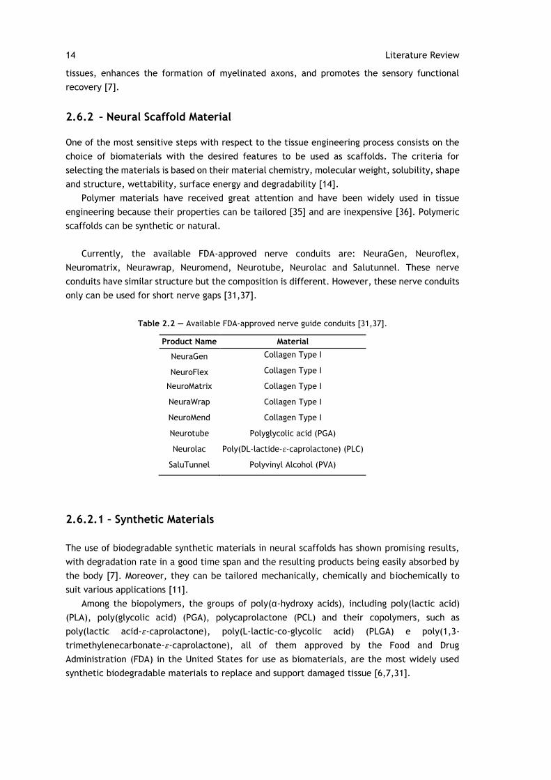
2.2 Available FDA-approved nerve guide conduits [31,37]. ......................................... 14
3.1 Description of membranes developed according to the weight ratio of PLA and gelatine.22
4.1 Infrared bands associated with different phases of PLA (Adapted from [13]). ............. 37
4.2 FT-IR spectra characteristics of fish gelatine. .................................................... 37

xiii
Abbreviations
BSA Bovine serum albumin
CBB Coomassie Brilliant Blue G
CNS Central Nervous System
DHT Dehydrothermal
DNA Deoxyribonucleic acids
DSC Differential scanning calorimetry
DTG Derivative thermogravimetric
ECM Extracellular Matrix
FBS Fetal bovine serum
FDA Food and Drug Administration
FT-IR Fourier transform infrared
GA Glutaraldehyde
GE Gelatine
HFIP Hexafluoro-2-propanol
NGC Nerve Guidance Conduits
NHS N-hydrocysuccinimide
PBS Phosphate buffered saline
PCL Poycaprolactone
PGA Poly(glycolic acid)
PLA Poly(lactic acid)
PDLA Poly(D-lactic acid)
PDLLA Poly(D,L-lactic acid)
PLLA Poly(L-lactic acid)
PLGA Poly(L-lactic-co-glycolic acid)
PNS Peripheral Nervous System
ROP Ring-opening polymerization
SD Standard deviation
SEM Scanning electron microscopy
Tcc Cold-crystallization temperature
Tg Glass transition temperature
Tm Melting temperature
TGA Thermogravimetric analysis
UV Ultraviolet
WCA Water angle contact
XCL Cross-linking degree

xiv
1
Chapter 1
Introduction
1.1 - Motivation and Context
Injuries to the peripheral nervous system (PNS) are a major cause for permanent disabilities
with a strong effect on a diminished quality of life. The neurological sequels left by this kind
of injuries result in a diminished daily live activity as well as loss of work capabilities.
Peripheral nerve injuries are the principal cause of disorders with devastating impact on
quality of life of patients. Neurological sequels caused by this kind of injuries compromise the
daily activities and work skills. Therefore, this has a socioeconomic impact. The main symptoms
of these injuries result in motor and sensory functions loss, which result in complete paralysis
of the affected limbs or the development of neuropathic pain [1-5]. PNS injuries are classified
according to its origin in traumatic, non-traumatic and surgical.
Traumatic peripheral nerve injuries result from collisions, motor vehicle accidents,
gunshots wounds, fractures or lacerations. Non-traumatic injuries are attributed to nerve
compression and adhesion. Surgical nerve injuries result from procedures to remove prostate
tumours [6]. This kind of injuries affects a large part of the population over the world. It is
estimated that about 2.8% of trauma patients, many of whom acquire life-long disability, are
affected by peripheral nerve injuries. In Europe, over 300,000 cases of peripheral nerve injury
occur annually [7] and 200,000 people in the United States suffer from peripheral nerve injury
caused by trauma and medical disorders [5]. That is the main reason why the surgery to repair
the damage to the peripheral nerve is urgently needed as well as a medical challenge [7].
Experimental work has been done that reveals the existence of neurobiological activity
crucial to the regeneration of the peripheral nerve and target reinnervation [1]. Unlike what
happens in the central nervous system (CNS), the peripheral nervous system has an intrinsic
ability for repair and regeneration under proper conditions [3, 7]. This is mainly due to
differences in response to injury of glial cells. The Schwann cells, glial cells of the PNS, convert
to a regenerative phenotype thereby promoting the formation of a basal lamina and providing
abundant cues to trigger neuronal regenerative response [3].
However, the capacity for regeneration depends on many factors including the time
elapsed, type of injury, patient’s age and in particular to the proximity of the injury to the
nerve cell body [3,5].
2 Introduction
In fact, there is an acceptable period of approximately 12-18 months for muscles
reinnervation to occur in order to achieve functional recovery before irreversible motor end
plate degeneration follows [2,8]. The axonal regeneration rate, in humans, is slow around 1-2
mm/day. Thus, for severe injuries may take many months to heal [2].
In recent years, various surgical techniques have been carried out to aid the regeneration
and repair of damage in peripheral nerves [7]. However, the functional recovery is usually
incomplete [1,4,9]. The combination of slow axonal regeneration, structural changes in muscle
targets and an increasingly less supportive stromal environment for regeneration all contribute
to an incomplete recovery [2].
Thus, a promising alternative is to use natural and synthetic neural scaffolds in which
tubular nerve guidance conduits (NGC) is the basic structure. This approach is denominated
tubulization. The mechanism of using a nerve guide for the regeneration of a damaged
peripheral nerve is that a gap is left between the nerve stumps sutured into either end of the
tube. Guidance channels provide a microenvironment and mechanical support, directing the
axonal growth from the proximal to the distal nerve stumps, while neuroma formation and
ingrowth of fibrous tissue into the nerve gap is prevented [5, 9, 10-11]. In addition, they are
designed and fabricated to increase the number, speed and length of the regenerating nerves
[5].
A very important factor for the fabrication of NGC is the biomaterials selection [7,11]. That
is the main reason why different types of biologic and artificial grafts have been developed and
investigated in their regeneration capacity and functional recovery [7, 12]. Natural biomaterials
are extremely useful in tissue engineering, especially in nerve regeneration, because they
stimulate adhesion, migration, growth and proliferation of cells and have good biocompatibility
[4]. Synthetic materials constitute another class of promising biomaterials due to their
physiochemical and biological properties that can be specifically tailored to match different
application requirements, rate degradation in a good time span, and the degradation products
are easily absorbed by the body [7,10].
The structure of neural scaffold is an important factor that determines the effectiveness of
the scaffold for peripheral nerve regeneration. The neural scaffold can be manufactured in its
basic structure, i.e., the tubular NGC with a single hollow lumen. However, modifications have
been developed to create a more complex structure, where the NGC lumen has an intricate
internal architecture, where physical fillers are introduced into the lumen NGC. To enhance
peripheral nerve regeneration, fibres were successfully used as intraluminal fillers [5,7].
In addition to the material selection, fabrication methods are also critical for designing
neural scaffolds [6]. Nanofibers can be produced by diverse manufacturing methods, such as
drawing, electrospinning, phase separation, self-assembly, template synthesis and wet spinning
[13-15]. However, electrospinning has proven to be an excellent method for the synthesis of
thin fibres to build three-dimensional tissue engineering scaffolds [6,13]. Nanofibers scaffolds
served as suitable environment for cell attachment, proliferation and differentiation because
they can potentially mimic the structure of natural extracellular matrix (ECM) [6, 14,16-17].
1.2 - Objectives 3
1.2 - Objectives
This study will focus on the development and characterization of fibrous membranes, produced
through the electrospinning technique, of poly(lactic acid) (PLA) blended with fish gelatine
(GE). The potential of these membranes for peripheral nerve regeneration will be characterized
in terms of their physical, chemical and mechanical properties and biological performance. This
study intends to assess membranes cytotoxicity and verify if they are responsible for
accelerating axonal regeneration process in order to promote the reinnervation and improve
the functional recovery.
1.3 - Document Structure
The report is divided in 5 chapters. The motivation and objectives have already been described
in this first chapter. In Chapter 2, the contextualization of key aspects is presented, particularly
the classification and anatomy of nervous system, types of injuries, the current treatments of
peripheral nerve injuries. Chapter 3 is relative to the materials and methods and Chapter 4 to
the obtained experimental results and its discussion. Finally, Chapter 5 summarizes the main
conclusions of this research and discusses future work.

5
Chapter 2
Literature Review
In this chapter is presented the contextualization of the principal biological aspects relevant
for this report. Initially, the classification and anatomy of nervous system will be presented.
Additionally, the types of injuries will be described, followed by the events that occur after
these injuries. Finally, the current treatments of peripheral nerve injuries will be explained,
with particularly focus on nerve grafts and the production techniques of these grafts.
2.1 - Classification of Nervous System
The nervous system is structurally divided into the central nervous system (CNS) and peripheral
nervous system (PNS). The CNS consists of the brain and the spinal cord. The PNS includes all
the nervous tissue outside the CNS, such as sensory receptors, nerves, ganglia, and plexuses.
Neurons in the PNS are classified according to the direction in which the neuron conducts the
nervous impulse. Sensory or afferent nerves transmit electrical signals, known as action
potentials, from the sensory receptors to the CNS and motor or efferent nerves conduct
electrical signals from the CNS to effector tissues, such as muscles and glands. Motor neurons
are also divided as somatic and automatic [2,10,18].
2.2 - Cellular components of the PNS
The two types of cells that comprise the nervous system are neurons and neuroglia or glial cells.
Neuroglia are non-neural cells that support and protect neurons. The glial cells of the PNS
are Schwann cells and satellite cells [18]. Schwann cells forms a myelin sheath at regular
intervals that allow faster and more intense propagation of signals along the axon. In addition,
Schwann cells have an important role in maintaining normal nerve function and in mediating
nerve repair following injury. The myelin sheath is not continuous but is interrupted. These
interruptions are the nodes of Ranvier, which initiate and propagate action potentials [18-20].
The basal lamina that surrounds the Schwann cells and the associated axon is produced by the
6 Literature Review
Schwann cells. Extracellular matrix molecules in the basal lamina, such as laminin and collagen,
regulate the formation, architecture and function of myelin [20].
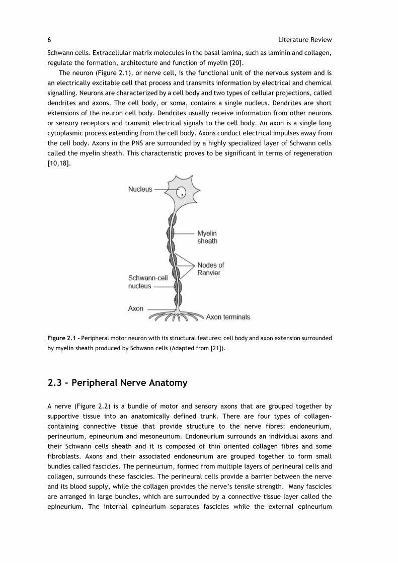
The neuron (Figure 2.1), or nerve cell, is the functional unit of the nervous system and is
an electrically excitable cell that process and transmits information by electrical and chemical
signalling. Neurons are characterized by a cell body and two types of cellular projections, called
dendrites and axons. The cell body, or soma, contains a single nucleus. Dendrites are short
extensions of the neuron cell body. Dendrites usually receive information from other neurons
or sensory receptors and transmit electrical signals to the cell body. An axon is a single long
cytoplasmic process extending from the cell body. Axons conduct electrical impulses away from
the cell body. Axons in the PNS are surrounded by a highly specialized layer of Schwann cells
called the myelin sheath. This characteristic proves to be significant in terms of regeneration
[10,18].
Figure 2.1 - Peripheral motor neuron with its structural features: cell body and axon extension surrounded
by myelin sheath produced by Schwann cells (Adapted from [21]).
2.3 - Peripheral Nerve Anatomy
A nerve (Figure 2.2) is a bundle of motor and sensory axons that are grouped together by
supportive tissue into an anatomically defined trunk. There are four types of collagen-
containing connective tissue that provide structure to the nerve fibres: endoneurium,
perineurium, epineurium and mesoneurium. Endoneurium surrounds an individual axons and
their Schwann cells sheath and it is composed of thin oriented collagen fibres and some
fibroblasts. Axons and their associated endoneurium are grouped together to form small
bundles called fascicles. The perineurium, formed from multiple layers of perineural cells and
collagen, surrounds these fascicles. The perineural cells provide a barrier between the nerve
and its blood supply, while the collagen provides the nerve’s tensile strength. Many fascicles
are arranged in large bundles, which are surrounded by a connective tissue layer called the
epineurium. The internal epineurium separates fascicles while the external epineurium
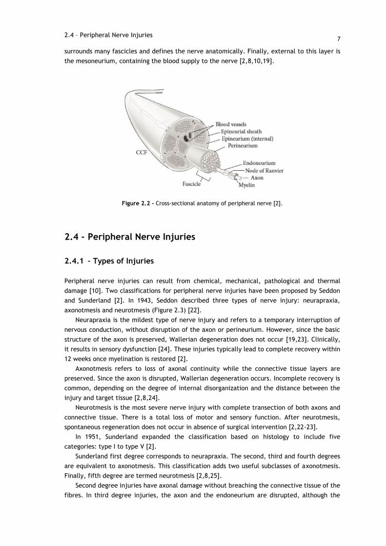
7
surrounds many fascicles and defines the nerve anatomically. Finally, external to this layer is
the mesoneurium, containing the blood supply to the nerve [2,8,10,19].
Figure 2.2 - Cross-sectional anatomy of peripheral nerve [2].
2.4 - Peripheral Nerve Injuries
2.4.1 – Types of Injuries
Peripheral nerve injuries can result from chemical, mechanical, pathological and thermal
damage [10]. Two classifications for peripheral nerve injuries have been proposed by Seddon
and Sunderland [2]. In 1943, Seddon described three types of nerve injury: neurapraxia,
axonotmesis and neurotmesis (Figure 2.3) [22].
Neurapraxia is the mildest type of nerve injury and refers to a temporary interruption of
nervous conduction, without disruption of the axon or perineurium. However, since the basic
structure of the axon is preserved, Wallerian degeneration does not occur [19,23]. Clinically,
it results in sensory dysfunction [24]. These injuries typically lead to complete recovery within
12 weeks once myelination is restored [2].
Axonotmesis refers to loss of axonal continuity while the connective tissue layers are
preserved. Since the axon is disrupted, Wallerian degeneration occurs. Incomplete recovery is
common, depending on the degree of internal disorganization and the distance between the
injury and target tissue [2,8,24].
Neurotmesis is the most severe nerve injury with complete transection of both axons and
connective tissue. There is a total loss of motor and sensory function. After neurotmesis,
spontaneous regeneration does not occur in absence of surgical intervention [2,22-23].
In 1951, Sunderland expanded the classification based on histology to include five
categories: type I to type V [2].
Sunderland first degree corresponds to neurapraxia. The second, third and fourth degrees
are equivalent to axonotmesis. This classification adds two useful subclasses of axonotmesis.
Finally, fifth degree are termed neurotmesis [2,8,25].
Second degree injuries have axonal damage without breaching the connective tissue of the
fibres. In third degree injuries, the axon and the endoneurium are disrupted, although the
2.4 – Peripheral Nerve Injuries
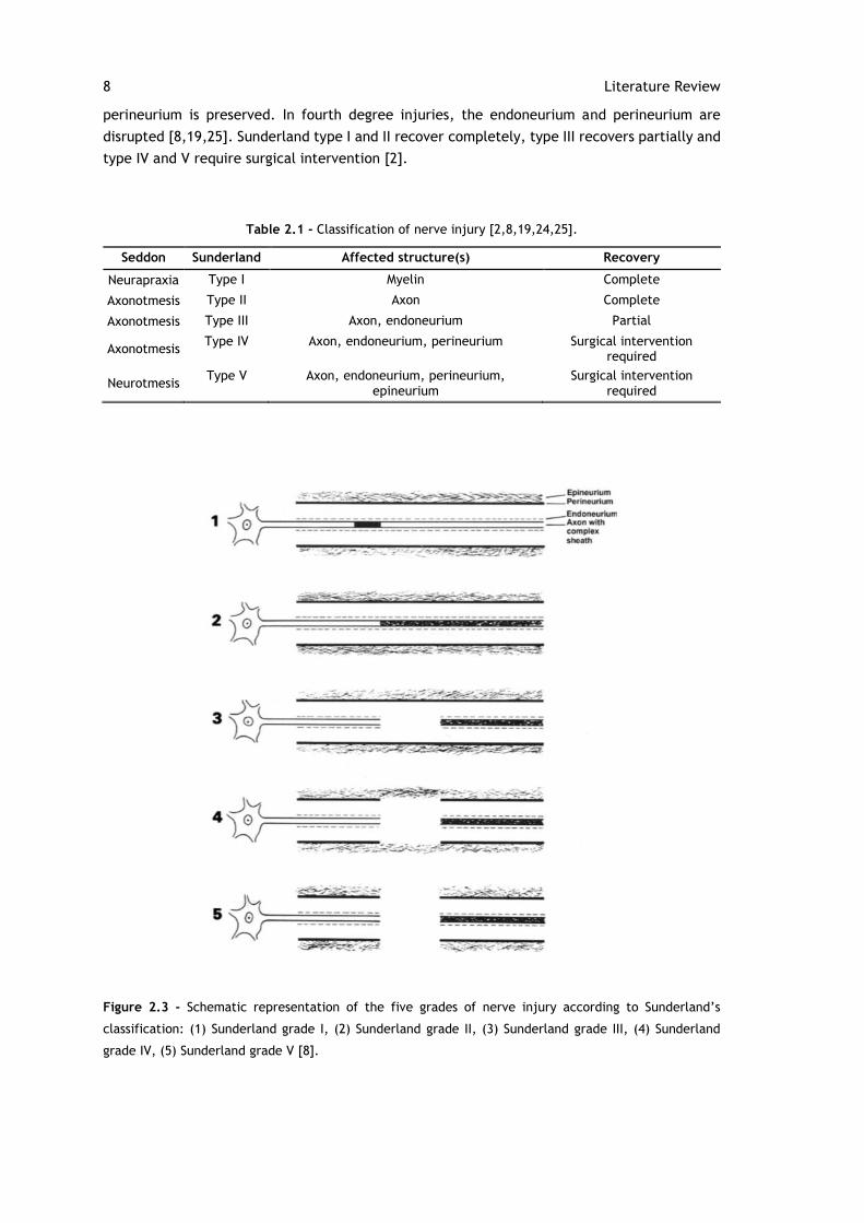
8 Literature Review
perineurium is preserved. In fourth degree injuries, the endoneurium and perineurium are
disrupted [8,19,25]. Sunderland type I and II recover completely, type III recovers partially and
type IV and V require surgical intervention [2].
Table 2.1 - Classification of nerve injury [2,8,19,24,25].
Seddon Sunderland Affected structure(s) Recovery
Neurapraxia Type I Myelin Complete
Axonotmesis Type II Axon Complete
Axonotmesis Type III Axon, endoneurium Partial
Axonotmesis Type IV Axon, endoneurium, perineurium Surgical intervention
required
Neurotmesis Type V Axon, endoneurium, perineurium,
epineurium Surgical intervention
required
Figure 2.3 - Schematic representation of the five grades of nerve injury according to Sunderland’s
classification: (1) Sunderland grade I, (2) Sunderland grade II, (3) Sunderland grade III, (4) Sunderland
grade IV, (5) Sunderland grade V [8].
9
2.4.2 – Wallerian Degeneration
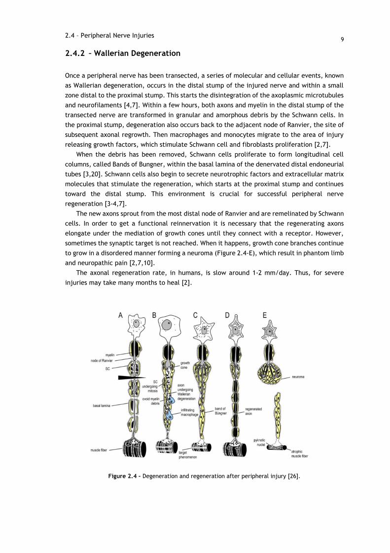
Once a peripheral nerve has been transected, a series of molecular and cellular events, known
as Wallerian degeneration, occurs in the distal stump of the injured nerve and within a small
zone distal to the proximal stump. This starts the disintegration of the axoplasmic microtubules
and neurofilaments [4,7]. Within a few hours, both axons and myelin in the distal stump of the
transected nerve are transformed in granular and amorphous debris by the Schwann cells. In
the proximal stump, degeneration also occurs back to the adjacent node of Ranvier, the site of
subsequent axonal regrowth. Then macrophages and monocytes migrate to the area of injury
releasing growth factors, which stimulate Schwann cell and fibroblasts proliferation [2,7].
When the debris has been removed, Schwann cells proliferate to form longitudinal cell
columns, called Bands of Bungner, within the basal lamina of the denervated distal endoneurial
tubes [3,20]. Schwann cells also begin to secrete neurotrophic factors and extracellular matrix
molecules that stimulate the regeneration, which starts at the proximal stump and continues
toward the distal stump. This environment is crucial for successful peripheral nerve
regeneration [3-4,7].
The new axons sprout from the most distal node of Ranvier and are remelinated by Schwann
cells. In order to get a functional reinnervation it is necessary that the regenerating axons
elongate under the mediation of growth cones until they connect with a receptor. However,
sometimes the synaptic target is not reached. When it happens, growth cone branches continue
to grow in a disordered manner forming a neuroma (Figure 2.4-E), which result in phantom limb
and neuropathic pain [2,7,10].
The axonal regeneration rate, in humans, is slow around 1-2 mm/day. Thus, for severe
injuries may take many months to heal [2].
Figure 2.4 – Degeneration and regeneration after peripheral injury [26].
2.4 – Peripheral Nerve Injuries
10 Literature Review
2.5 - Treatments of Peripheral Nerve Injuries
In order to repair these nerve injuries, several techniques have been used [6]. Currently, two
surgical techniques are used to regenerate the peripheral nerve: manipulative nerve operations
and bridge operation. The manipulative surgeries include direct neurorrhaphy and nerve
transfers. These techniques are performed when there was no significant loss of nerve tissue
and it is possible approximation with minimal tension [5,7].
Neurorrhaphy is the surgical suturing of a divided nerve through end-to-end or end-to-site
coaptations. This method is limited to the treatment of short defects because the fascicular
coaptation may cause excessive tension between both nerve stumps, which would inhibit nerve
regeneration [4-5,7]. During this process, the correct alignment of the nerve fascicles is crucial
in successful regeneration [27].
Nerve transfers or neurotization are basically the transfer of nerve sections of other healthy
nerves, with not so important functions, to the damaged nerves considering that their function
is much more important [5,7].
The bridge operations include grafting, transposition and tubulization techniques [7].
In cases where loss of nerve segment is substantial resulting in a gap, where tension-free
neurorrhaphy is not possible, the interposition of a nerve graft, as a bridge, between the
proximal and distal nerve stumps is often necessary [3-4,7].
Usually, the typical choice is to use an autologous nerve graft from some less important
part of the body [7]. Nerve autografts are the current gold standard method to repair nerve
gaps [5]. This technique provides structural support to guide axonal regeneration, preventing
neuroma formation and fibrous tissue invasion [3]. However, there are several disadvantages
with this technique including the limited availability of donor nerves, the need for a second
surgery to obtain de donor nerve, donor site morbidity that may include the possibility of
painful neuroma, scaring and sensory loss [4-5,7,10].
These problems drive the search of different solutions to supplement or substitute
autologous nerve grafts [7]. The use of neural scaffolds to bridge nerve gaps is a promising
alternative, and this approach is denominated tubulization [5,7].
2.6 - Tissue Engineering Nerve Grafts
The use of neural scaffolds involves two interrelated aspects, the scaffold configuration and
scaffold fabrication [3]. The neural scaffolds can be prepared with different structures, in
which tubular nerve guidance conduit (NGC) is the basic structure [4,7].
The mechanism of using nerve guidance conduits for the regeneration of a damaged
peripheral nerve is that a gap is left between the nerve stumps sutured into either end of the
tube [10-11].
Neural scaffolds serve to direct axons sprouting from the proximal to distal nerve stumps
[10-11,28], keep the adequate mechanical support to the regeneration of nerve fibres [5,7],
provide a conduit channel for the diffusion of neurotropic and neurotrophic factors secreted by
the damage nerve stump, as well as the interface for the exchange of nutrients and residual
products, prevent the infiltration of fibrous tissue and neuroma formation that disable the
axonal regeneration [7,10-11,28], provide an optimal microenvironment for the regeneration
of the nerves increasing the concentration of endogenous proteins [7,10]. Furthermore, that
11
they must be easy to produce, sterilize and implant in the body with microsurgical techniques
[7].
In addition, they are designed and fabricated to stimulate the regeneration process actively
increasing the number, speed and length of regenerating nerves [5,10].
Figure 2.5 - The structure of nerve guidance conduits showing the sequence of events that occur in
peripheral nerve regeneration [27].
Thus, in addition to the requirements listed above, other important properties must be
considered.
2.6.1 - Requirements of an ideal scaffold
The properties determined by the scaffold material and its structure, are the most important
to satisfy many physical and biologic requirements of each scaffold, along with
biocompatibility, biodegradability, permeability, biomechanical and surface properties [7,29].
2.6 – Tissue Engineering Nerve Grafts
12 Literature Review
2.6.1.1 – Biocompatibility
The first criteria to be taken into consideration is the biocompatibility and function without
interrupting other physiological process. The scaffold must be able to work as a substrate that
supports the appropriate cellular behaviours, such as promotion of molecular and mechanical
signalling systems to help nerve regeneration [7,14]. The cells should adhere and migrate to
the surface and eventually proliferate before a new matrix is formed [15,30]. In addition, after
implantation, the scaffold must not promote or initiate any undesirable effects on neural cells
and tissues or eliciting any undesirable local or systemic responses in the neural scaffold, in
order to avoid the rejection of the scaffold by the body [7,14]. The biocompatibility of the
scaffolds is affected by the polymer synthesis, scaffold processing and sterilization conditions
[14].
The biocompatibility of neural scaffolds can be measured from three different aspects:
blood and mechanical compatibility and histocompatibility. In order to have a good blood
biocompatibility it is required that the scaffold in contact with the blood does not induce
hemolysis, destroy blood components, or lead to coagulation and thrombus formation.
Histocompatibility means that the scaffold has no toxic side effects on the surrounding tissue,
while the last ones do not induce corrosive effects or immune rejection of the scaffold. Finally,
mechanical compatibility refers to the matching of mechanical properties between the scaffold
and nerve tissue [7].
2.6.1.2 – Biodegradability
Biodegradability is a very important property that has a very special task on the tissue
regeneration. The scaffold should be able to degenerate or be resorbed in vivo allowing the
body to replace the scaffold with its own cells. In fact, scaffolds are not made to be used as
replacements but as support for a new cell structure [10,12,30]. Scaffold degradation occur
through physical, chemical or biological processes that are mediated by biological agents, such
as enzymes in tissue remodelling [14]. The degradation products must be non-toxic and be
expelled from the body with any interference with any other organs [30].
During nerve regeneration, neural scaffolds must be able to cope with some mechanical
stress from neighbouring tissues and maintain at least a slight elasticity and bendability without
collapse or losing their shape [7]. On the other hand, the degradation rate should be tuned to
match the regeneration rate of the nerve [7,14].
The scaffold biodegradation rate depends on the properties of the polymer, including the
chemical structure, the wettability, morphology, glass transition temperatures and the
molecular weight [14].
2.6.1.3 – Permeability
A neural scaffold must have the adequate permeability to allow the nutrients, gas and
metabolic waste exchange, including the exchange of fluids between the regeneration
environment and surrounding tissues, through pores in the conduit wall [7,31].
Also, permeability may be needed for the viability of supportive cells [32], since the porous
structure provide a large surface area that will allow cell ingrowth, uniform cell distribution,
13
and facilitate the revascularization of the neural guidance conduit [14]. However, pore size is
also a very important issue because the pores should be small enough to prevent fibrous scar
tissue invasion [9]. It is also important for the formation of the fibrin matrix during the first
period of nerve regeneration [7,31-32].
There are different fabrication techniques through which neural scaffolds can be made
permeable, such as cutting holes into the wall, rolling of meshes, fibre spinning, adding pore-
formation agent or injection-molding followed by solvent evaporation. In addition, the
hydrophilic property of the scaffold material it is a critical factor and is responsible for the
permeability of the neural scaffold [7,32].
2.6.1.4 – Biomechanical Properties
Mechanical strength is one of the properties that must be analysed. The scaffold should have
proper mechanical properties to encourage the rapid regeneration of the tissue [14] and
maintain a stable support structure for nerve regeneration [9]. Scaffolds must have Young
modulus close to the tissues where it will be implanted, in order to resist in vivo physiological
loads during nerve regeneration. To meet this basic requirements, the biomedical parameters
of native peripheral nerves have been determined. It is accepted that Young’s modulus of
peripheral nerves in the longitudinal direction is 0.50 MPa and the ultimate load of human ulnar
or median nerve is 65-155 and 72-220 N, respectively [7]. In other words, the tube should be
able to resist compression, but be flexible enough to prevent mechanical irritation [33]. Thus,
a balance should be found between flexibility and rigidity, because if the scaffolds is too rigid
some dislocation can result but if is too flexible, the axonal regeneration can be failed [4,7].
In order to control the mechanical strength of nerve guidance conduits, several approaches
have been taken such as cross-linking, coil-reinforcement and tuning the material composition.
In addition, the degree of cross-linking also offers a mechanism to tune the degradation rate of
the nerve conduits [28].
2.6.1.5 – Surface Properties
Surface properties, including chemical and topographical characteristics, are important in the
interaction between the scaffold and nerve cells because the scaffold surface is the initial site
of interaction with the surrounding cells and tissue [7]. The longitudinally oriented surface
texture is thought to mimic the endoneurial tubules naturally found in nerves, which has been
shown to influence directional outgrowth of axons and uniform alignment of Schwann cells in
vitro, and improved nerve regeneration in vivo [7,28].
The incorporation of physical fillers in the lumen to form an internal matrix was the more
important modification to the basic structure of neural scaffolds because the matrices attempt
to increase the bioactivity of NGC and prevent their collapse [28].
Scaffolds with a high internal surface-area-to-volume ratio is essential in order to
accommodate the number of cells required to replace or restore tissue functions [14]. The use
of nanofibrous scaffolds offer optimal surface properties because these scaffolds mimic the
topography of natural ECM and provide a high surface area for cell attachment and growth and
topographic signals favourable for directing cellular functions [34]. In addition, the introduction
of fibres into the NGC lumen also increase the overall cross-section area of regenerated nerve
2.6 – Tissue Engineering Nerve Grafts
14 Literature Review
tissues, enhances the formation of myelinated axons, and promotes the sensory functional
recovery [7].
2.6.2 – Neural Scaffold Material
One of the most sensitive steps with respect to the tissue engineering process consists on the
choice of biomaterials with the desired features to be used as scaffolds. The criteria for
selecting the materials is based on their material chemistry, molecular weight, solubility, shape
and structure, wettability, surface energy and degradability [14].
Polymer materials have received great attention and have been widely used in tissue
engineering because their properties can be tailored [35] and are inexpensive [36]. Polymeric
scaffolds can be synthetic or natural.
Currently, the available FDA-approved nerve conduits are: NeuraGen, Neuroflex,
Neuromatrix, Neurawrap, Neuromend, Neurotube, Neurolac and Salutunnel. These nerve
conduits have similar structure but the composition is different. However, these nerve conduits
only can be used for short nerve gaps [31,37].
Table 2.2 — Available FDA-approved nerve guide conduits [31,37].
Product Name Material
NeuraGen Collagen Type I
NeuroFlex Collagen Type I
NeuroMatrix Collagen Type I
NeuraWrap Collagen Type I
NeuroMend Collagen Type I
Neurotube Polyglycolic acid (PGA)
Neurolac Poly(DL-lactide-휀-caprolactone) (PLC)
SaluTunnel Polyvinyl Alcohol (PVA)
2.6.2.1 – Synthetic Materials
The use of biodegradable synthetic materials in neural scaffolds has shown promising results,
with degradation rate in a good time span and the resulting products being easily absorbed by
the body [7]. Moreover, they can be tailored mechanically, chemically and biochemically to
suit various applications [11].
Among the biopolymers, the groups of poly(α-hydroxy acids), including poly(lactic acid)
(PLA), poly(glycolic acid) (PGA), polycaprolactone (PCL) and their copolymers, such as
poly(lactic acid-휀-caprolactone), poly(L-lactic-co-glycolic acid) (PLGA) e poly(1,3-
trimethylenecarbonate-휀-caprolactone), all of them approved by the Food and Drug
Administration (FDA) in the United States for use as biomaterials, are the most widely used
synthetic biodegradable materials to replace and support damaged tissue [6,7,31].
15
2.6.2.1.1 – Poly(Lactic Acid)
PLA is known to be one of the most commonly used biomaterials [12], due to its four attractive
advantages, such as renewability, biocompatibility and processability and mechanical
properties [35,38]. PLA is obtained by the processing and polymerization of lactic acid monomer
(2-hydroxypropionic acid) [39] and is derived from renewable and degradable sources such as
corn, rice and sugar cane [40]. Currently, the polymerization processes used to prepare PLA
are direct polycondensation and ring-opening polymerization (ROP) [39].
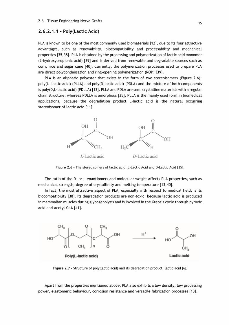
PLA is an aliphatic polyester that exists in the form of two stereoisomers (Figure 2.6):
poly(L- lactic acid) (PLLA) and poly(D-lactic acid) (PDLA) and the mixture of both components
is poly(D,L-lactic acid) (PDLLA) [13]. PLLA and PDLA are semi crystalline materials with a regular
chain structure, whereas PDLLA is amorphous [35]. PLLA is the mainly used form in biomedical
applications, because the degradation product L-lactic acid is the natural occurring
stereoisomer of lactic acid [11].
Figure 2.6 - The stereoisomers of lactic acid: L-Lactic Acid and D-Lactic Acid [35].
The ratio of the D- or L-enantiomers and molecular weight affects PLA properties, such as
mechanical strength, degree of crystallinity and melting temperature [13,40].
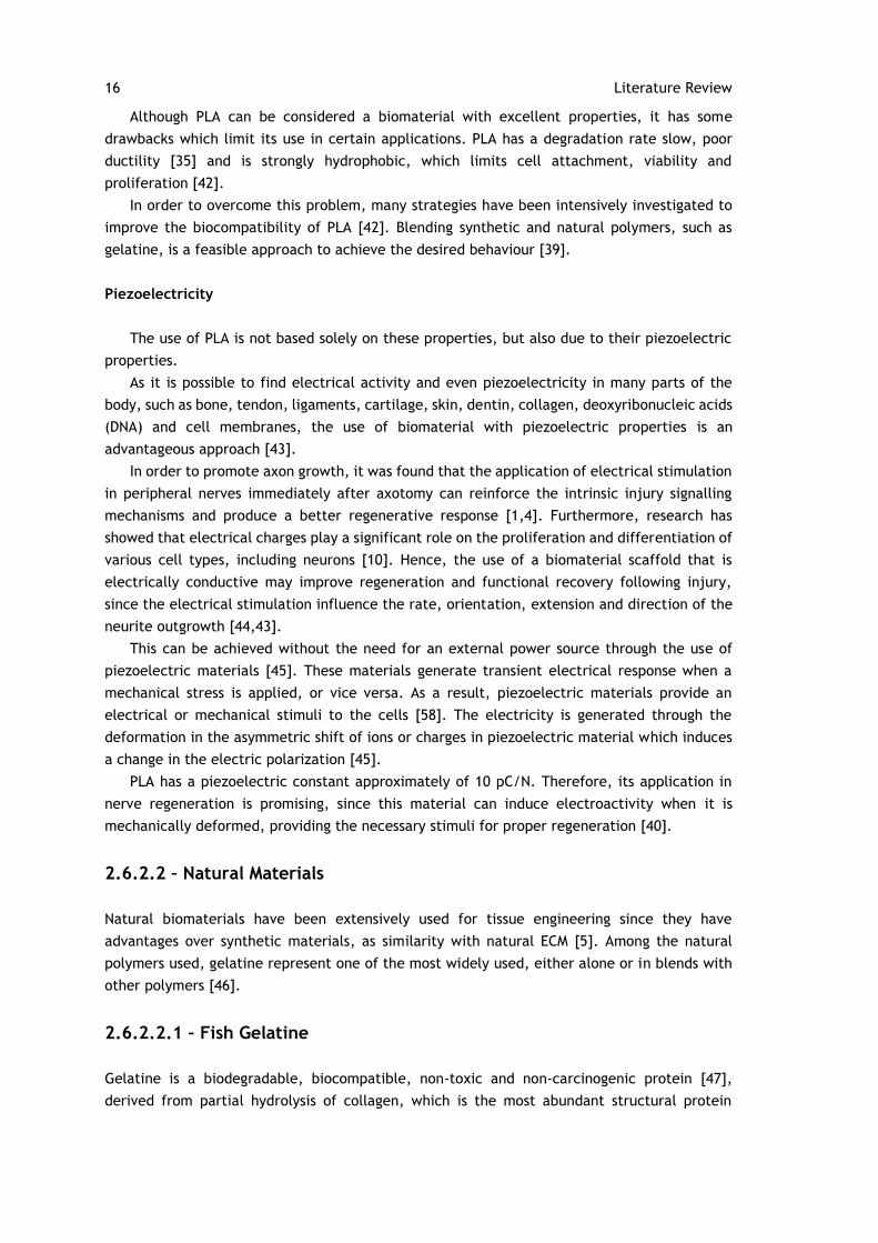
In fact, the most attractive aspect of PLA, especially with respect to medical field, is its
biocompatibility [38]. Its degradation products are non-toxic, because lactic acid is produced
in mammalian muscles during glycogenolysis and is involved in the Krebs’s cycle through pyruvic
acid and Acetyl-CoA [41].
Figure 2.7 - Structure of poly(lactic acid) and its degradation product, lactic acid [6].
Apart from the properties mentioned above, PLA also exhibits a low density, low processing
power, elastomeric behaviour, corrosion resistance and versatile fabrication processes [13].
2.6 – Tissue Engineering Nerve Grafts
16 Literature Review
Although PLA can be considered a biomaterial with excellent properties, it has some
drawbacks which limit its use in certain applications. PLA has a degradation rate slow, poor
ductility [35] and is strongly hydrophobic, which limits cell attachment, viability and
proliferation [42].
In order to overcome this problem, many strategies have been intensively investigated to
improve the biocompatibility of PLA [42]. Blending synthetic and natural polymers, such as
gelatine, is a feasible approach to achieve the desired behaviour [39].
Piezoelectricity
The use of PLA is not based solely on these properties, but also due to their piezoelectric
properties.
As it is possible to find electrical activity and even piezoelectricity in many parts of the
body, such as bone, tendon, ligaments, cartilage, skin, dentin, collagen, deoxyribonucleic acids
(DNA) and cell membranes, the use of biomaterial with piezoelectric properties is an
advantageous approach [43].
In order to promote axon growth, it was found that the application of electrical stimulation
in peripheral nerves immediately after axotomy can reinforce the intrinsic injury signalling
mechanisms and produce a better regenerative response [1,4]. Furthermore, research has
showed that electrical charges play a significant role on the proliferation and differentiation of
various cell types, including neurons [10]. Hence, the use of a biomaterial scaffold that is
electrically conductive may improve regeneration and functional recovery following injury,
since the electrical stimulation influence the rate, orientation, extension and direction of the
neurite outgrowth [44,43].
This can be achieved without the need for an external power source through the use of
piezoelectric materials [45]. These materials generate transient electrical response when a
mechanical stress is applied, or vice versa. As a result, piezoelectric materials provide an
electrical or mechanical stimuli to the cells [58]. The electricity is generated through the
deformation in the asymmetric shift of ions or charges in piezoelectric material which induces
a change in the electric polarization [45].
PLA has a piezoelectric constant approximately of 10 pC/N. Therefore, its application in
nerve regeneration is promising, since this material can induce electroactivity when it is
mechanically deformed, providing the necessary stimuli for proper regeneration [40].
2.6.2.2 – Natural Materials
Natural biomaterials have been extensively used for tissue engineering since they have
advantages over synthetic materials, as similarity with natural ECM [5]. Among the natural
polymers used, gelatine represent one of the most widely used, either alone or in blends with
other polymers [46].
2.6.2.2.1 – Fish Gelatine
Gelatine is a biodegradable, biocompatible, non-toxic and non-carcinogenic protein [47],
derived from partial hydrolysis of collagen, which is the most abundant structural protein
17
contained in animal bones, skin, tendons and cartilage [46] and one of the most important
constituents of ECMs [48].
Gelatine is derived from mammalian sources, such as porcine and bovine, and fish.
However, fish gelatine has gained great interest in compassion with mammalian due to public
health reasons, such as the transmission of bovine spongiform encephalopathy or other
diseases, and religious interdictions to the consumption of certain animal sources [46,49].
Due to its biological origin, gelatine is a very good material for tissue engineering
application once it promotes cell differentiation, proliferation and adhesion [50].
However, the poor mechanical properties and water solubility have restricted the
application of gelatine as scaffold [48]. In order to overcome the quickly dissolution in aqueous
environments, but also the weak mechanical properties, cross-linking of gelatine is necessary
[46]. This can be achieved either using physical methods, such as dehydrothermal (DHT)
treatment and ultraviolet or gamma irradiation, or chemical methods [47] which typically use
chemicals agents like aldehydes, which interact with the functional groups of proteins [51].
Several chemical substances have been applied to cross-link gelatine, such as glutaraldehyde
(GA), genipin and EDC/N-hydrocysuccinimide (NHS) [47]. Amongst the cross-linking agents, GA
is the most widely used because it reacts rapidly with amine groups in gelatine [49] and its
vapour phase is efficient and fast in stabilizing collagenous materials [46]. The reaction occurs
between the free amine groups of lysine or hydroxylysine amino acid residues in the gelatine
polypeptide chains and the aldehyde groups of GA to produce imine linkages [46]. However, if
released into the host due to biodegradation, GA is toxic, and poses a risk for biocompatibility
[52]. The risk of cytotoxicity can be reduced by decreasing the concentration of GA solutions
or through treatment to remove unreacted GA left in the material after the cross-linking
treatment [53].
The introduction of gelatine in PLA matrices is expected to improve the hydrophilicity and
cellular affinity. On the other hand, the poor mechanical properties of the gelatine will also be
improved due to the introduction of PLA [14]. For those reasons, blending natural and synthetic
polymers is a viable approach to circumvent the limitations of each material. It allows the
manufacturing of new biomaterials with good cell adhesion and mechanical properties for tissue
engineering applications [48].
2.6.3 – Methods for nanofiber processing
As mentioned before, an array of biomaterial-based fillers with different physical forms, such
as fibres, are included into the single hollow lumen of the NGC to promote attachment,
proliferation, migration of Schwann cells and, hence, enhance peripheral nerve regeneration.
Furthermore, the biopolymer properties are also determined by the fabrication technique [7].
Nanofibers can be produced by a number of techniques such as drawing, electrospinning,
phase separation, self-assembly, template synthesis and wet spinning [36].
Nanofibers have been fabricated through drawing process. In this simple technique,
nanofibers were fabricated directly when a micropipette with a diameter with few micrometres
was placed in a polymer solution and moved up forming a thin filament which is then solidified
to form a nanofiber. However, this technique only allows the production of a single fibre at
one time, i.e., has a low productivity [36,54].
2.6 – Tissue Engineering Nerve Grafts
18 Literature Review
Nanofibers can be fabricated using templates using templates. The major drawback of
template synthesis technique is the limitation on fibre dimensions and arrangement [54].
Phase separation has been used to create porous polymers membranes. The main
mechanism of this technique is the separation of phases due to physical incompatibility. This
fabrication procedure involves the dissolution of polymer, polymer gelation, solvent extraction,
freezing and free-drying [36,54]. Phase separation is a relatively simple procedure that does
not require many specialized equipment. It is also easy to achieve batch-to-batch consistency,
and mechanical properties of the matrix can be tailored by varying polymer concentrations.
However, this technique is specific to certain polymers [15].
Self-assembly involves the molecule organization and arrangement into patterns or stables
structures through non-covalent forces, such as hydrogen bonding, hydrophobic forces, and
electrostatic reactions. This technique generally creates small nanofibers, similar with the
natural ECM scale. Despite these characteristics, this technique involves a complex procedure
that is limited to specific polymer configurations [15,36,54].
2.6.3.1 – Electrospinning
Electrospinning has proved to be one of the best methods for the synthesis of thin fibres in the
order of few nanometres with small pores and large surface areas, ease of functionalisation
purposes and superior mechanical properties, for a varied range of polymeric solutions [13,55].
Moreover, this technique allows the production of nanofibrous scaffolds that can mimic the
structure of the fibres in natural extracellular matrix [55] at the nanometre scale (3-5000 nm)
[56]. The native ECM of human tissues and organs provide support to cells and it is composed
of a network of micro- and nano-scaled protein and glycosaminoglycan fibres [56]. Due to the
similar architecture of the native ECM, electrospun nanofibers have been used in biomedical
application, such as nerve, cartilage, bone and heart regeneration [40].
Another attractive characteristic of electrospinning process is a simple and inexpensive
setup. When used in its simplest form, the setup (Figure 2.8) consists of a pipette or a syringe
filled with polymer solution, a high voltage power supply and a grounded conductive collector
[57].
During the electrospinning process, a high voltage (5-15 kV) is applied between a grounded
collector and a positively charged needle capillary filled with a polymer solution [56]. When
charges within the polymer solution reach a critical amount, i.e., the electrostatic charges
overcome the surface tension of the polymer solution, a polymer jet is created and, then, it is
distorted into a conical shape, resulting in the formation of the Taylor cone [36,58]. As the jet
is charged electrically, the jet is subjected to a stretching process. The continuously elongation
and the solvent evaporation leads to formation of an extreme thin polymer fibres [56]. The
electrospinning jet moves to the region with less potential, which generally is a grounded
collector, where are deposited. In the end, the fibres are collected from the collector as a web
of fibres [36].
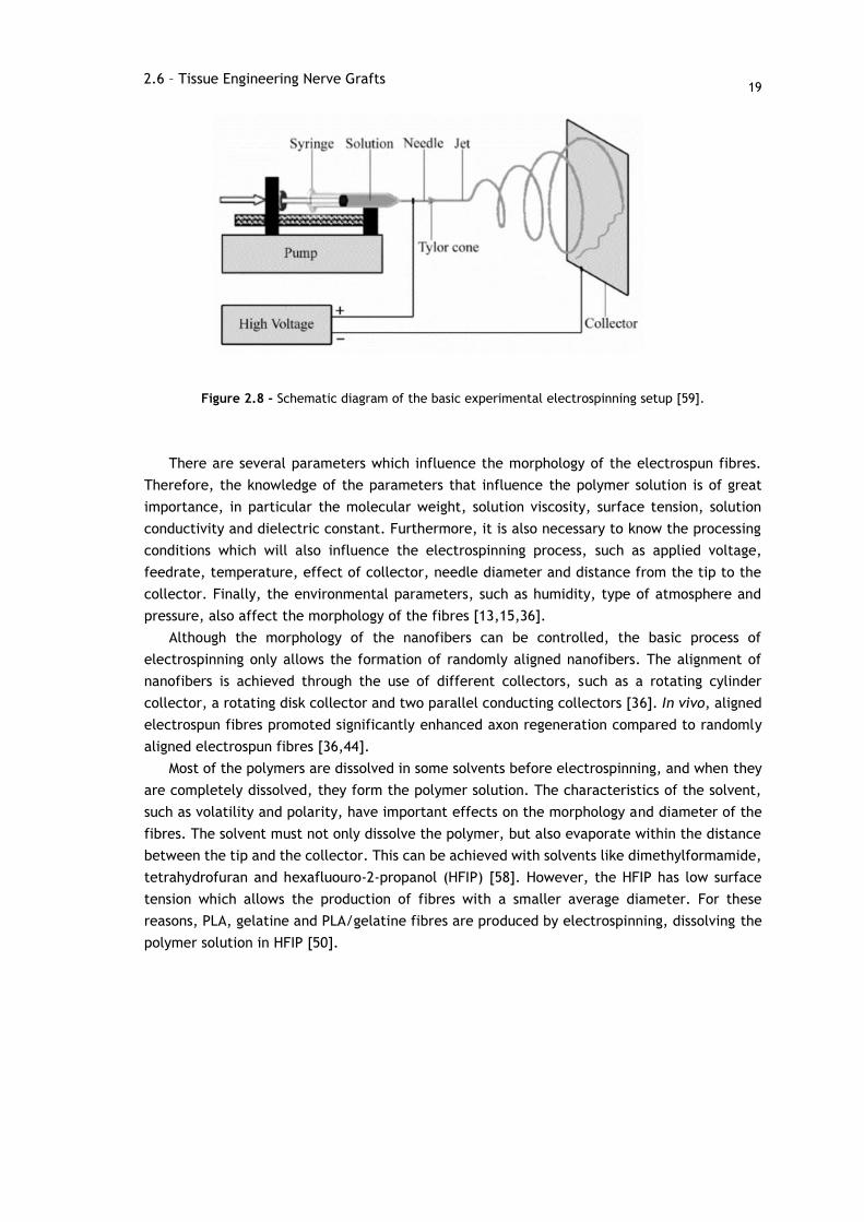
19
Figure 2.8 - Schematic diagram of the basic experimental electrospinning setup [59].
There are several parameters which influence the morphology of the electrospun fibres.
Therefore, the knowledge of the parameters that influence the polymer solution is of great
importance, in particular the molecular weight, solution viscosity, surface tension, solution
conductivity and dielectric constant. Furthermore, it is also necessary to know the processing
conditions which will also influence the electrospinning process, such as applied voltage,
feedrate, temperature, effect of collector, needle diameter and distance from the tip to the
collector. Finally, the environmental parameters, such as humidity, type of atmosphere and
pressure, also affect the morphology of the fibres [13,15,36].
Although the morphology of the nanofibers can be controlled, the basic process of
electrospinning only allows the formation of randomly aligned nanofibers. The alignment of
nanofibers is achieved through the use of different collectors, such as a rotating cylinder
collector, a rotating disk collector and two parallel conducting collectors [36]. In vivo, aligned
electrospun fibres promoted significantly enhanced axon regeneration compared to randomly
aligned electrospun fibres [36,44].
Most of the polymers are dissolved in some solvents before electrospinning, and when they
are completely dissolved, they form the polymer solution. The characteristics of the solvent,
such as volatility and polarity, have important effects on the morphology and diameter of the
fibres. The solvent must not only dissolve the polymer, but also evaporate within the distance
between the tip and the collector. This can be achieved with solvents like dimethylformamide,
tetrahydrofuran and hexafluouro-2-propanol (HFIP) [58]. However, the HFIP has low surface
tension which allows the production of fibres with a smaller average diameter. For these
reasons, PLA, gelatine and PLA/gelatine fibres are produced by electrospinning, dissolving the
polymer solution in HFIP [50].
2.6 – Tissue Engineering Nerve Grafts

21
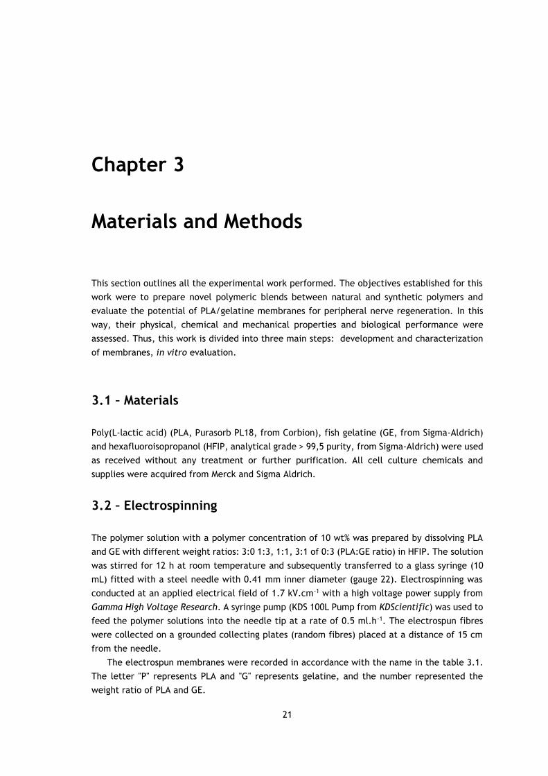
Chapter 3
Materials and Methods
This section outlines all the experimental work performed. The objectives established for this
work were to prepare novel polymeric blends between natural and synthetic polymers and
evaluate the potential of PLA/gelatine membranes for peripheral nerve regeneration. In this
way, their physical, chemical and mechanical properties and biological performance were
assessed. Thus, this work is divided into three main steps: development and characterization
of membranes, in vitro evaluation.
3.1 – Materials
Poly(L-lactic acid) (PLA, Purasorb PL18, from Corbion), fish gelatine (GE, from Sigma-Aldrich)
and hexafluoroisopropanol (HFIP, analytical grade > 99,5 purity, from Sigma-Aldrich) were used
as received without any treatment or further purification. All cell culture chemicals and
supplies were acquired from Merck and Sigma Aldrich.
3.2 – Electrospinning
The polymer solution with a polymer concentration of 10 wt% was prepared by dissolving PLA
and GE with different weight ratios: 3:0 1:3, 1:1, 3:1 of 0:3 (PLA:GE ratio) in HFIP. The solution
was stirred for 12 h at room temperature and subsequently transferred to a glass syringe (10
mL) fitted with a steel needle with 0.41 mm inner diameter (gauge 22). Electrospinning was
conducted at an applied electrical field of 1.7 kV.cm-1 with a high voltage power supply from
Gamma High Voltage Research. A syringe pump (KDS 100L Pump from KDScientific) was used to
feed the polymer solutions into the needle tip at a rate of 0.5 ml.h-1. The electrospun fibres
were collected on a grounded collecting plates (random fibres) placed at a distance of 15 cm
from the needle.
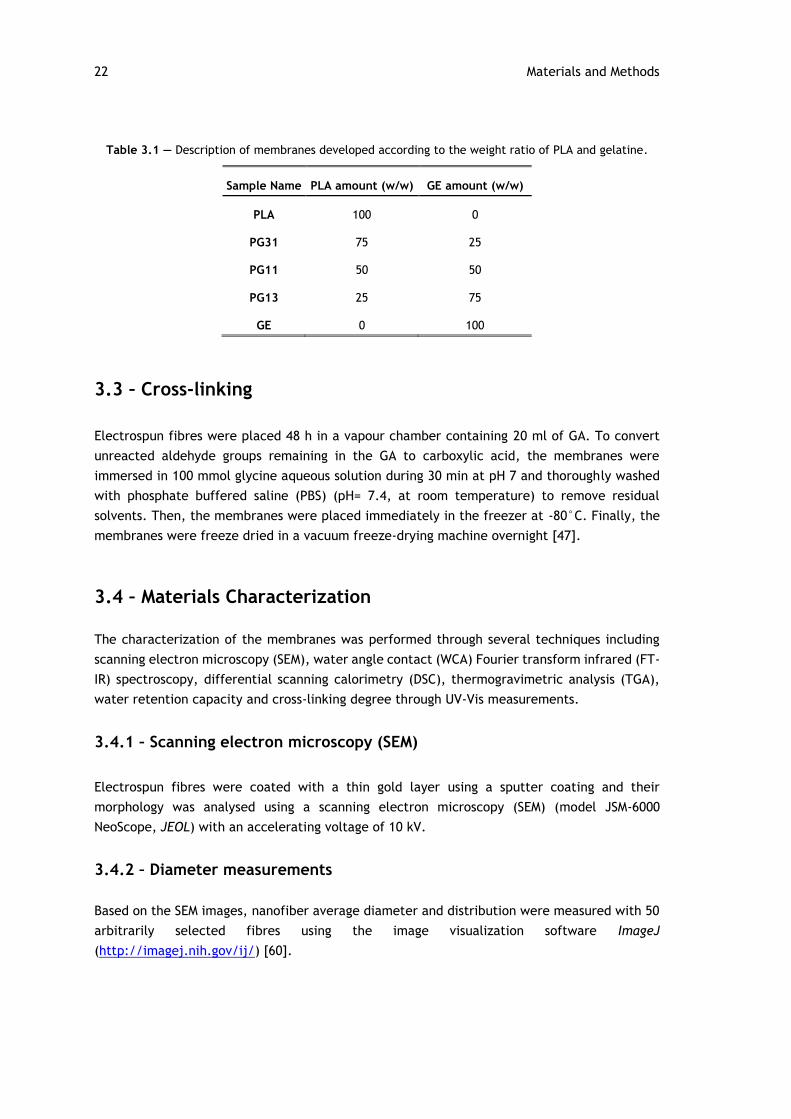
The electrospun membranes were recorded in accordance with the name in the table 3.1.
The letter "P" represents PLA and "G" represents gelatine, and the number represented the
weight ratio of PLA and GE.
22 Materials and Methods
Table 3.1 — Description of membranes developed according to the weight ratio of PLA and gelatine.
Sample Name PLA amount (w/w) GE amount (w/w)
PLA 100 0
PG31 75 25
PG11 50 50
PG13 25 75
GE 0 100
3.3 – Cross-linking
Electrospun fibres were placed 48 h in a vapour chamber containing 20 ml of GA. To convert
unreacted aldehyde groups remaining in the GA to carboxylic acid, the membranes were
immersed in 100 mmol glycine aqueous solution during 30 min at pH 7 and thoroughly washed
with phosphate buffered saline (PBS) (pH= 7.4, at room temperature) to remove residual
solvents. Then, the membranes were placed immediately in the freezer at -80°C. Finally, the
membranes were freeze dried in a vacuum freeze-drying machine overnight [47].
3.4 – Materials Characterization
The characterization of the membranes was performed through several techniques including
scanning electron microscopy (SEM), water angle contact (WCA) Fourier transform infrared (FT-
IR) spectroscopy, differential scanning calorimetry (DSC), thermogravimetric analysis (TGA),
water retention capacity and cross-linking degree through UV-Vis measurements.
3.4.1 – Scanning electron microscopy (SEM)
Electrospun fibres were coated with a thin gold layer using a sputter coating and their
morphology was analysed using a scanning electron microscopy (SEM) (model JSM-6000
NeoScope, JEOL) with an accelerating voltage of 10 kV.
3.4.2 – Diameter measurements
Based on the SEM images, nanofiber average diameter and distribution were measured with 50
arbitrarily selected fibres using the image visualization software ImageJ
(http://imagej.nih.gov/ij/) [60].
23
3.4.3 – Determination of the degree of cross-linking
The degree of cross-linking of fish gelatine electrospun fibres was determined through UV-Vis
measurements using a protein quantification kit (Protein Quantification Kit-Rapid, Sigma-
Aldrich) that is based on Coomassie Brilliant Blue G (CBB), which reacts with free amino groups
(NH2) remaining in the membranes after cross-linking and stains blue under acidic conditions.
At first, the samples were weighted to obtain 1 mg of gelatine in all samples. Then, 150 µL of
CBB solution was added to all the samples and the absorbance of the solution was measured for
the spectral range 400-620 nm at 1 nm resolution with an ELISA reader (Synergy HT, Biotek).
The optical absorbance of the gelatine powder was also measured. The amount of free amino
groups in the sample test is proportional to the absorbance of the solution and was determined
by comparison to a standard curve of BSA vs absorbance.
The degree of cross-linking was then calculated (XCL) according to equation nº 3.1, where
“free” is the mole fraction of free NH2 in the non-crosslinked samples and “fixed” is the mole
fraction of free NH2 remaining in the cross-linked samples [61].
𝑋𝐶𝐿 =𝑁𝐻𝑁 𝑟𝑒𝑎𝑐𝑡𝑖𝑣𝑒 𝑎𝑚𝑖𝑛𝑒𝑓𝑖𝑥𝑒𝑑
𝑁𝐻𝑁 𝑟𝑒𝑎𝑐𝑡𝑖𝑣𝑒 𝑎𝑚𝑖𝑛𝑒𝑓𝑟𝑒𝑒
3.4.4 – Contact angle measurements
Water contact angle measurements (WCA, sessile drop in dynamic mode) were performed at
room temperature in a Data Physics OCA20 device using ultrapure water as test liquid. The
contact angles were measured by depositing water drops (3 µL) on sample surfaces and analysed
with SCA20 software. At least 5 measurements were performed in each sample and in different
membrane locations and the average contact angle was taken as the result for each sample.
3.4.5 – Swelling and water retention capacity
The swelling ratio denotes the water absorption percentage of the nanofibrous membranes at
equilibrium. The capacities of water absorption were tested by immersing the electrospun
fibres in deionized water at room temperature. The samples were then removed and placed
between two pieces of tissue paper to remove excess of water. Water retention capacity was
determined with the increase in the weight of the fibres through the equation nº 3.2, where W
is the weight of the sample after submersion for a certain period of time and Wd is the weight
of the sample in its dry state before submersion [62].
𝑆𝑤𝑒𝑙𝑙𝑖𝑛𝑔 𝑑𝑒𝑔𝑟𝑒𝑒 (%) =𝑊 − 𝑊𝑑
𝑊𝑑
×100%
(3.1)
(3.2)
3.4 – Materials Characterization
24 Materials and Methods
3.4.6 – Thermogravimetric analysis
Thermal degradation kinetics of the samples was characterized by thermogravimetric analysis
(TGA) in a Q500 apparatus from TAinstruments at heating rate of 20 °C.min-1. All measurements
were performed under a nitrogen atmosphere. Differential thermal curves were obtained from
TGA curves by plotting a graph between derivate weight % and temperature.
3.4.7 – Differential scanning calorimetry
The thermal behaviour of the electrospun fibre mats were analysed by differential scanning
calorimetry measurements (DSC) with a Mettler-Toledo DSC 823e apparatus. The samples were
cut into small pieces from the middle region of the electrospun membranes and placed into 30
µl aluminium pans and heated between 30 and 200 °C at a heating rate of 10 °C.min-1. All
experiments were performed under a nitrogen purge. The glass transition temperature (Tg),
cold-crystallization temperature (Tcc) and melting temperature (Tm) of the electrospun mats
samples were evaluated.
3.4.8 – Fourier transform infrared spectroscopy
Infrared measurements (FT-IR) were performed at room temperature in a Shimadzu IRAffinity-
1S apparatus in ATR mode from 4000 to 600 cm-1. FT-IR spectra were collected after 32 scans
with a resolution of 2 cm-1.
3.5 – Cell culture procedure
To evaluate cell behaviour in the presence of the scaffolds, human fibroblasts were used for
this experiment. Fibroblast cells were cultured in alpha minimum essential medium (α-MEM)
supplemented with 10% (v/v) fetal bovine serum (FBS), 1% (v/v) fungizone and 1% (v/v)
penicillin-streptomycin incubated at 37°C, in a humidified atmosphere of 95% air and 5% CO2.
The medium was changed every 3-4 days and sub-cultured once they reached 70-80%
confluence. Detachment of adherent cells was achieved by a 10 min incubation with trypsin
0.05% in 0.25% EDTA solution, at 37°C. For cell culture, circular membranes with 13 mm
diameter were previously sterilized in both sides by UV radiation for 30 min.
3.6 – Cell viability and proliferation
To evaluate the cytotoxicity, membrane samples were held at the bottom of the 24-well culture
plate with Teflon inserts. Then, fibroblasts (passage 8) were seeded on the membranes at a
cell density of 2x10⁴ cells/well. Wells containing cells seeded without materials (n=3) and wells
containing only culture medium with material (n=1) were used as controls.
Cell viability and proliferation of fibroblast cells on the membranes was estimated by the
Resazurin cell viability assay, at days 1, 3, 7 and 14. Briefly, the medium was removed from
25
the wells and replaced by a mixture of 500 µL of culture medium and resazurin solution (10%),
in the dark. The samples were incubated at 37 °C, in a humidified atmosphere of 95% air and
5% CO2, for 3h. The redox activity within the cytosol of the viable cells was assessed through
the reduction of the Resazurin, a blue compound, into resorufin, which is red in colour [63].
Following, 100 µL of the solution was transferred to a 96-well plate to read the fluorescence
on an ELISA reader (Synergy HT, Bioteck) at 530 nm excitation wavelength and 590 nm emission
wavelength. The experiment was performed in triplicate for each group.
3.7 – Statistical analysis
All quantitative results were expressed as mean ± standard deviation (SD) of at least three
replicates. Statistical differences were determined by performing two-way ANOVA analysis
followed by Dunnett’s multiple comparisons test using GraphPad, Prism Software (V.7).
Differences were taken to be statistically significant when compared to control for each day
for P values < 0.05.
3.7 – Statistical analysis

27
Chapter 4
Results and Discussion
One of the main concerns regarding the tissue engineering process consists on the choice of
biomaterials with the desired features to be used as scaffolds [64]. Good biocompatibility and
sufficient mechanical strength are basic requirements for membranes in nerve regeneration
[65]. When a single polymer does not have the properties desired for tissue engineering, a blend
of polymers may be employed to achieve the desired geometrical, mechanical and
biodegradation properties [15]. The electrospinning technique allows the ability to produce
nanofibers of a polymeric blend. Electrospun nanofibers have been proven to be a promising
scaffold in the field of tissue engineering [61] due to their dimension which are able to mimic
the natural extracellular matrix, which play an essential role in structural integrity and
mechanical robustness of the tissue construct. The electrospun nanofibrous membranes of
PLA/GE meet the requirements by taking advantages of both material properties. GE is a
natural component of the extracellular matrix that can provide a suitable ground for cell
adhesion, proliferation and differentiation [66], whereas PLA provides good mechanical
properties because of its slow degradation rate [38].
The selection of an appropriate solvent is essential to determine the rheological properties
and the morphology of nanofibers [67]. In this work, PLA, fish gelatine and PLA blended with
fish gelatine were electrospun into nanofibers using hexafluoroisopropanol (HFIP) as the
solvent. The characteristics of the solvent, such as volatility and polarity, have important
effects on the diameter and morphology of the fibres. The low surface tension of the HFIP
allows the production of fibres with a smaller average diameter [50], which is known to be
more desirable to mimic the structure of the natural extracellular matrix [55]. In addition, the
use of HFIP gives more uniform and bead-free fibres [68].
4.1 – Morphology of the electrospun membranes
The morphology and structure of the membranes were observed using SEM. SEM is a powerful
tool for characterizing the size, shape and structure of materials due to its ability to resolve
nanometre scale features [69]. This is an important technique to characterize biomaterials
topography that are known to influence the cell response [58].
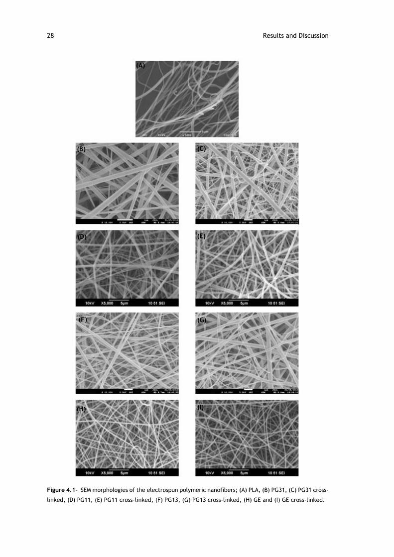
28 Results and Discussion
Figure 4.1- SEM morphologies of the electrospun polymeric nanofibers; (A) PLA, (B) PG31, (C) PG31 cross-
linked, (D) PG11, (E) PG11 cross-linked, (F) PG13, (G) PG13 cross-linked, (H) GE and (I) GE cross-linked.
(A)
(B) (C)
(D) (E)
(F) (G)
(H) (I)
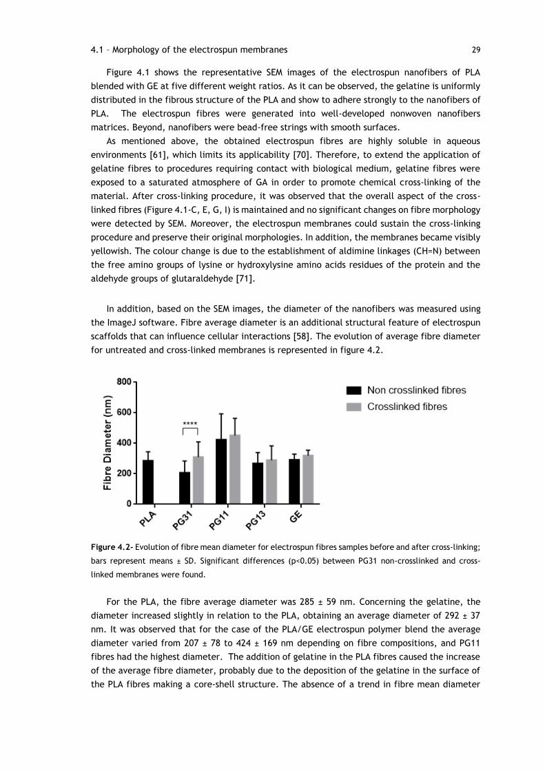
29
Figure 4.1 shows the representative SEM images of the electrospun nanofibers of PLA
blended with GE at five different weight ratios. As it can be observed, the gelatine is uniformly
distributed in the fibrous structure of the PLA and show to adhere strongly to the nanofibers of
PLA. The electrospun fibres were generated into well-developed nonwoven nanofibers
matrices. Beyond, nanofibers were bead-free strings with smooth surfaces.
As mentioned above, the obtained electrospun fibres are highly soluble in aqueous
environments [61], which limits its applicability [70]. Therefore, to extend the application of
gelatine fibres to procedures requiring contact with biological medium, gelatine fibres were
exposed to a saturated atmosphere of GA in order to promote chemical cross-linking of the
material. After cross-linking procedure, it was observed that the overall aspect of the cross-
linked fibres (Figure 4.1-C, E, G, I) is maintained and no significant changes on fibre morphology
were detected by SEM. Moreover, the electrospun membranes could sustain the cross-linking
procedure and preserve their original morphologies. In addition, the membranes became visibly
yellowish. The colour change is due to the establishment of aldimine linkages (CH=N) between
the free amino groups of lysine or hydroxylysine amino acids residues of the protein and the
aldehyde groups of glutaraldehyde [71].
In addition, based on the SEM images, the diameter of the nanofibers was measured using
the ImageJ software. Fibre average diameter is an additional structural feature of electrospun
scaffolds that can influence cellular interactions [58]. The evolution of average fibre diameter
for untreated and cross-linked membranes is represented in figure 4.2.
Figure 4.2- Evolution of fibre mean diameter for electrospun fibres samples before and after cross-linking;
bars represent means ± SD. Significant differences (p<0.05) between PG31 non-crosslinked and cross-
linked membranes were found.
For the PLA, the fibre average diameter was 285 ± 59 nm. Concerning the gelatine, the
diameter increased slightly in relation to the PLA, obtaining an average diameter of 292 ± 37
nm. It was observed that for the case of the PLA/GE electrospun polymer blend the average
diameter varied from 207 ± 78 to 424 ± 169 nm depending on fibre compositions, and PG11
fibres had the highest diameter. The addition of gelatine in the PLA fibres caused the increase
of the average fibre diameter, probably due to the deposition of the gelatine in the surface of
the PLA fibres making a core-shell structure. The absence of a trend in fibre mean diameter
4.1 – Morphology of the electrospun membranes
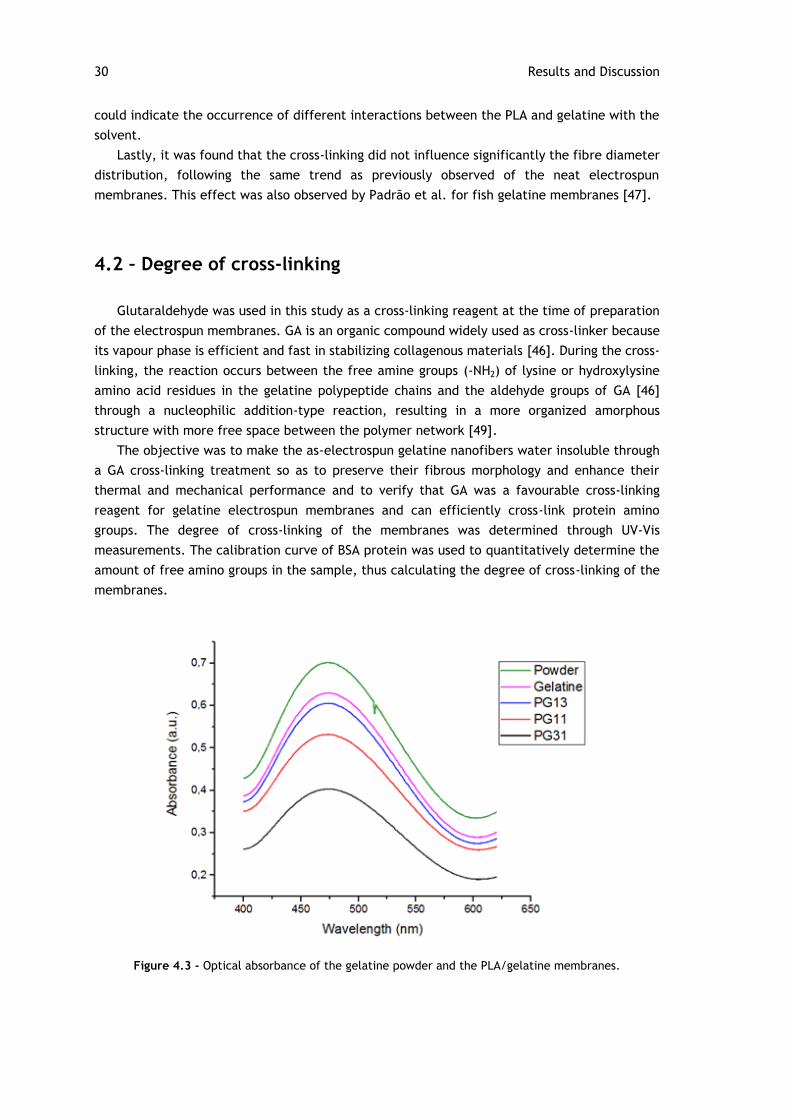
30 Results and Discussion
could indicate the occurrence of different interactions between the PLA and gelatine with the
solvent.
Lastly, it was found that the cross-linking did not influence significantly the fibre diameter
distribution, following the same trend as previously observed of the neat electrospun
membranes. This effect was also observed by Padrão et al. for fish gelatine membranes [47].
4.2 – Degree of cross-linking
Glutaraldehyde was used in this study as a cross-linking reagent at the time of preparation
of the electrospun membranes. GA is an organic compound widely used as cross-linker because
its vapour phase is efficient and fast in stabilizing collagenous materials [46]. During the cross-
linking, the reaction occurs between the free amine groups (-NH2) of lysine or hydroxylysine
amino acid residues in the gelatine polypeptide chains and the aldehyde groups of GA [46]
through a nucleophilic addition-type reaction, resulting in a more organized amorphous
structure with more free space between the polymer network [49].
The objective was to make the as-electrospun gelatine nanofibers water insoluble through
a GA cross-linking treatment so as to preserve their fibrous morphology and enhance their
thermal and mechanical performance and to verify that GA was a favourable cross-linking
reagent for gelatine electrospun membranes and can efficiently cross-link protein amino
groups. The degree of cross-linking of the membranes was determined through UV-Vis
measurements. The calibration curve of BSA protein was used to quantitatively determine the
amount of free amino groups in the sample, thus calculating the degree of cross-linking of the
membranes.
Figure 4.3 - Optical absorbance of the gelatine powder and the PLA/gelatine membranes.

31
In figure 4.3, it is represented the absorption spectrum of the gelatine powder (non-
crosslinked raw material) and the cross-linked membranes. As it can be observed, the optical
absorbance for the membranes is lower than the gelatine powder, which suggest that GA
worked as a cross-linking agent.
Figure 4.4 - Degree of cross-linking for gelatine and PLA/GE electrospun membranes.
The results showed a degree of cross-linking ranging from 54 to 86%. So, GA is a favourable
cross-linking agent for gelatine electrospun membranes, as it can be efficiently cross-link
protein amino groups.
4.3 – Contact angle measurements
Surface wettability is one of the most important parameters affecting the biological response,
since wettability affects protein adsorption and cell adhesion [72]. The wettability of the
membranes was evaluated by measuring the water contact angle (WCA).
Figure 4.5 shows that PLA membranes have a strong hydrophobic behaviour with WCA of
136 ± 1°. Once gelatine is reported as superhydrophilic material [73], it was expected a lower
contact angle for PLA/GE membranes compared to PLA membranes. In fact, a decrease of WCA
was observed after the incorporation of GE. However, PL31 membranes shows a hydrophobic
behaviour with WCA of 134 ± 1°, despite the incorporation of GE. The fact that WCA of PG31
and PLA membranes was identical, indicate the embedment of GE component in the continuous
PLA phase [17]. On the other hand, a significant difference between PG31 membranes and
PG11 and PG13 membranes is observed. PG11, PG13 and GE membranes shows a hydrophilic
behaviour with WCA of 0°. The PG13 membranes were suggested having a reverse
microstructure to PG31 membranes that PLA component was separated and embedded in the
continuous GE phase, for it containing more amount of GE component [17]. These results
suggested that different structures had formed in fibres with different ratios of PLA and GE.
4.3 – Contact angle measurements
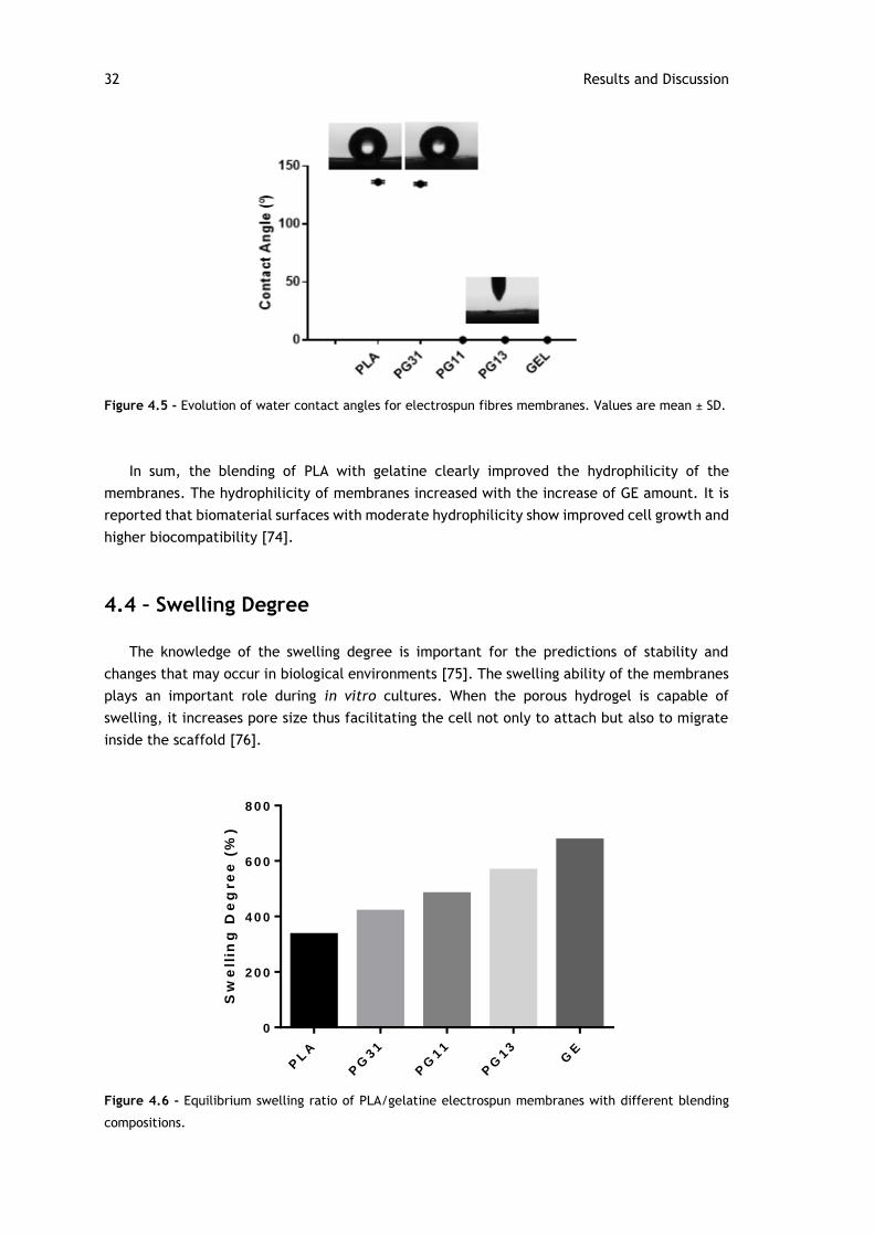
32 Results and Discussion
Figure 4.5 - Evolution of water contact angles for electrospun fibres membranes. Values are mean ± SD.
In sum, the blending of PLA with gelatine clearly improved the hydrophilicity of the
membranes. The hydrophilicity of membranes increased with the increase of GE amount. It is
reported that biomaterial surfaces with moderate hydrophilicity show improved cell growth and
higher biocompatibility [74].
4.4 – Swelling Degree
The knowledge of the swelling degree is important for the predictions of stability and
changes that may occur in biological environments [75]. The swelling ability of the membranes
plays an important role during in vitro cultures. When the porous hydrogel is capable of
swelling, it increases pore size thus facilitating the cell not only to attach but also to migrate
inside the scaffold [76].
Sw
ell
ing
De
gre
e (
%)
PL
A
PG
31
PG
11
PG
13
GE
0
2 0 0
4 0 0
6 0 0
8 0 0
Figure 4.6 - Equilibrium swelling ratio of PLA/gelatine electrospun membranes with different blending
compositions.
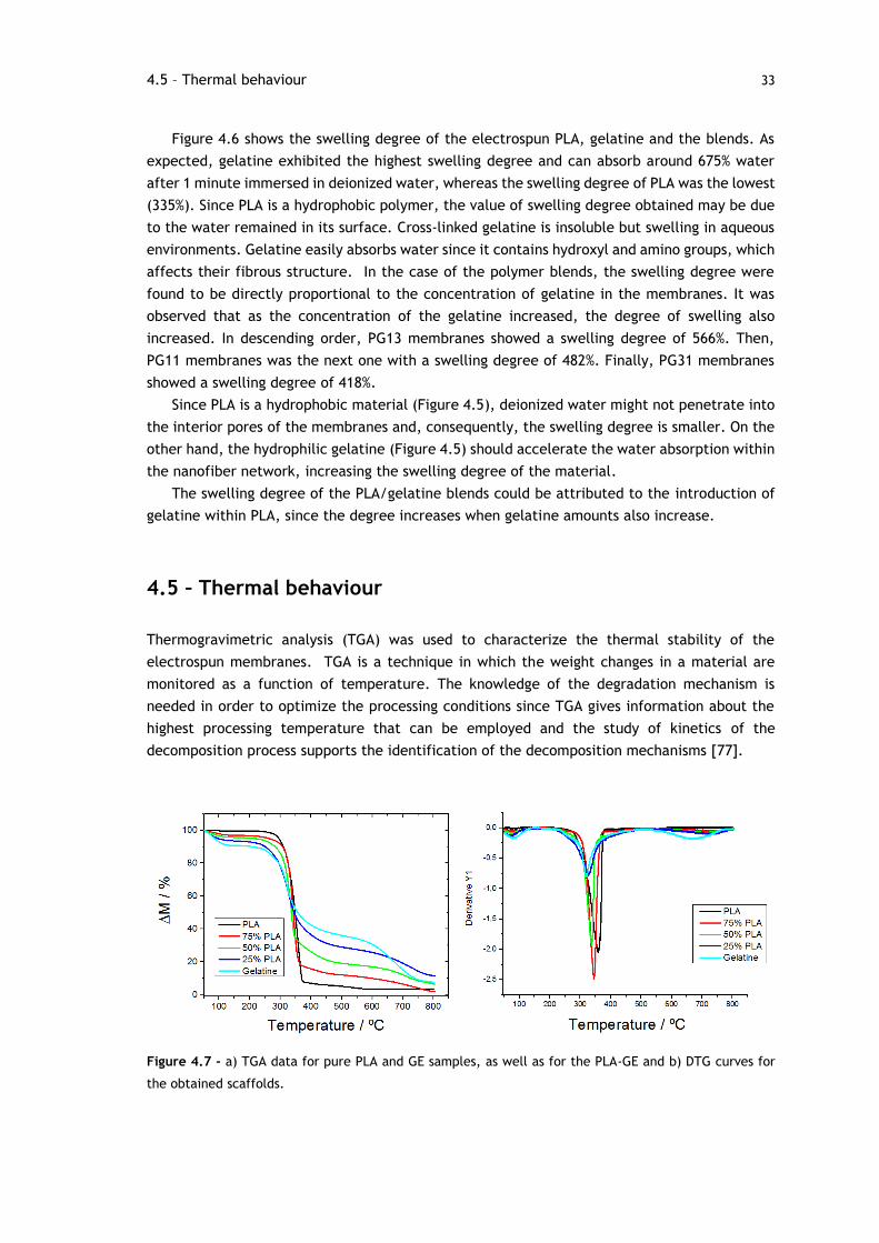
33
Figure 4.6 shows the swelling degree of the electrospun PLA, gelatine and the blends. As
expected, gelatine exhibited the highest swelling degree and can absorb around 675% water
after 1 minute immersed in deionized water, whereas the swelling degree of PLA was the lowest
(335%). Since PLA is a hydrophobic polymer, the value of swelling degree obtained may be due
to the water remained in its surface. Cross-linked gelatine is insoluble but swelling in aqueous
environments. Gelatine easily absorbs water since it contains hydroxyl and amino groups, which
affects their fibrous structure. In the case of the polymer blends, the swelling degree were
found to be directly proportional to the concentration of gelatine in the membranes. It was
observed that as the concentration of the gelatine increased, the degree of swelling also
increased. In descending order, PG13 membranes showed a swelling degree of 566%. Then,
PG11 membranes was the next one with a swelling degree of 482%. Finally, PG31 membranes
showed a swelling degree of 418%.
Since PLA is a hydrophobic material (Figure 4.5), deionized water might not penetrate into
the interior pores of the membranes and, consequently, the swelling degree is smaller. On the
other hand, the hydrophilic gelatine (Figure 4.5) should accelerate the water absorption within
the nanofiber network, increasing the swelling degree of the material.
The swelling degree of the PLA/gelatine blends could be attributed to the introduction of
gelatine within PLA, since the degree increases when gelatine amounts also increase.
4.5 – Thermal behaviour
Thermogravimetric analysis (TGA) was used to characterize the thermal stability of the
electrospun membranes. TGA is a technique in which the weight changes in a material are
monitored as a function of temperature. The knowledge of the degradation mechanism is
needed in order to optimize the processing conditions since TGA gives information about the
highest processing temperature that can be employed and the study of kinetics of the
decomposition process supports the identification of the decomposition mechanisms [77].
Figure 4.7 - a) TGA data for pure PLA and GE samples, as well as for the PLA-GE and b) DTG curves for
the obtained scaffolds.
4.5 – Thermal behaviour
34 Results and Discussion
Figure 4.7-a) shows the thermo-gravimetric analysis for PLLA, gelatine and blends. For the
pure PLA, as expected, one single degradation process was observed which starts from around
260°C and almost completed at 390°C, which could be attributed to the chain scission of ester
linkages [62].
Thermal degradation of gelatine occurs in three different stages. The first stage has been
found at temperatures between 50°C and 120°C, which is related to the loss of absorbed and
bound water due to the handling of the sample at room conditions without any special care.
After its initial weight loss, gelatine was found to be quite stable until the temperature reached
230 ºC. The second stage occurred between 230°C and 450°C and gelatine sample exhibited a
large drop in weight due to the protein degradation and peptide bond rupture. Lastly, the third
stage was found between 450°C and 750°C, which corresponds to the thermal decomposition
of the gelatine networks [47,78].
Different from gelatine, the hydrophobic polymers did not undergo any degradation
between 40 and 100 ºC, indicating the absence of water molecules [61].
In the case of the polymer blends, it was observed in TGA curves of all blend polymers an
initial decrease in weight due to moisture loss from the gelatine portion. Then, the blends
showed a large decrease in weight at approximately the same temperature as that pure PLA.
However, the blends degrade more slowly than PLA due to the presence of gelatine [69]. The
blend samples had degradation temperatures between those of pure PLA and gelatine.
The derivative curves of weight loss for PLA, gelatine and PLA/gelatine blends are shown in
figure 4.7- b). Each peak represents the Tmax which corresponds to the maximum degradation
rate at particular temperature [47]. In derivative thermogravimetric (DTG) analysis, gelatine
and PG13 membranes both exhibit two peaks. Gelatine shows the maximum degradation rate
at 83°C and 321°C, while PG13 membranes at 79°C and 326°C. PLA, PG13 and PG11 membranes
show only one single peak of fast thermal degradation at 358°C in PLA, 344°C in PG31
membranes and 337°C in PG11 membranes.
According to Lewandowska, when the measured lower Tmax of one component shifts to the
higher Tmax of another component then it shows some interactions between polymer
components in the blend [79] and, consequently, an improved thermal stability could be
achieved for the component with a lower Tmax [80]. In this work, in the blend polymers, lower
Tmax of gelatine has shifted to the higher Tmax of PLA that indicates some interactions between
PLA and gelatine in the blend polymers.
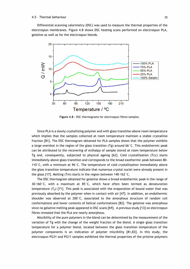
35
Differential scanning calorimetry (DSC) was used to measure the thermal properties of the
electrospun membranes. Figure 4.8 shows DSC heating scans performed on electrospun PLA,
gelatine as well as for the electrospun blends.
Figure 4.8 - DSC thermograms for electrospun fibres samples.
Since PLA is a slowly crystallizing polymer and with glass transition above room temperature
which implies that the samples collected at room temperature maintain a stable crystalline
fraction [81]. The DSC thermogram obtained for PLA samples shows that the polymer exhibits
a large overshot in the region of the glass transition (Tg) around 66°C. This endothermic peak
can be attributed to the recovering of enthalpy of sample stored at room temperature below
Tg and, consequently, subjected to physical ageing [62]. Cold crystallization (Tcc) starts
immediately above glass transition and corresponds to the broad exothermic peak between 80-
110°C, with a minimum at 96°C. The temperature of cold crystallization immediately above
the glass transition temperature indicate that numerous crystal nuclei were already present in
the glass [17]. Melting (Tm) starts in the region between 140-162°C.
The DSC thermogram obtained for gelatine shows a broad endothermic peak in the range of
30-160°C, with a maximum at 85°C, which have often been termed as denaturation
temperature (TD) [71]. This peak is associated with the evaporation of bound water that was
previously absorbed by the polymer when in contact with air [47]. In addition, an endothermic
shoulder was observed at 200°C, associated to the amorphous structure of random coil
conformations and lower contents of helical conformations [82]. The gelatine was amorphous
since no gelatine melting peak appeared in DSC scans [69]. A previous study [13] on electrospun
fibres revealed that the PLA are nearly amorphous.
Miscibility of the pure polymers in the blend can be determined by the measurement of the
variation of Tg with the change of the weight fraction of the blend. A single glass transition
temperature for a polymer blend, located between the glass transition temperature of the
polymer components is an indication of polymer miscibility [81,83]. In this study, the
electrospun PG31 and PG11 samples exhibited the thermal properties of the pristine polymers
4.5 – Thermal behaviour
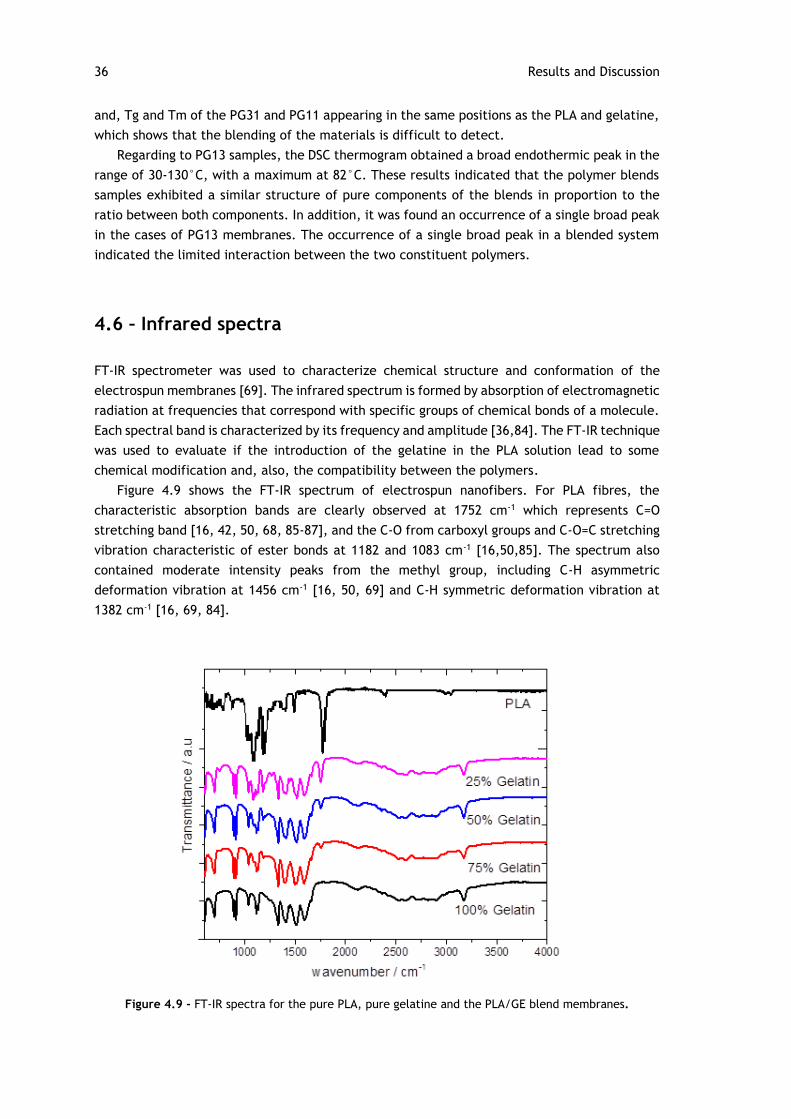
36 Results and Discussion
and, Tg and Tm of the PG31 and PG11 appearing in the same positions as the PLA and gelatine,
which shows that the blending of the materials is difficult to detect.
Regarding to PG13 samples, the DSC thermogram obtained a broad endothermic peak in the
range of 30-130°C, with a maximum at 82°C. These results indicated that the polymer blends
samples exhibited a similar structure of pure components of the blends in proportion to the
ratio between both components. In addition, it was found an occurrence of a single broad peak
in the cases of PG13 membranes. The occurrence of a single broad peak in a blended system
indicated the limited interaction between the two constituent polymers.
4.6 – Infrared spectra
FT-IR spectrometer was used to characterize chemical structure and conformation of the
electrospun membranes [69]. The infrared spectrum is formed by absorption of electromagnetic
radiation at frequencies that correspond with specific groups of chemical bonds of a molecule.
Each spectral band is characterized by its frequency and amplitude [36,84]. The FT-IR technique
was used to evaluate if the introduction of the gelatine in the PLA solution lead to some
chemical modification and, also, the compatibility between the polymers.
Figure 4.9 shows the FT-IR spectrum of electrospun nanofibers. For PLA fibres, the
characteristic absorption bands are clearly observed at 1752 cm-1 which represents C=O
stretching band [16, 42, 50, 68, 85-87], and the C-O from carboxyl groups and C-O=C stretching
vibration characteristic of ester bonds at 1182 and 1083 cm-1 [16,50,85]. The spectrum also
contained moderate intensity peaks from the methyl group, including C-H asymmetric
deformation vibration at 1456 cm-1 [16, 50, 69] and C-H symmetric deformation vibration at
1382 cm-1 [16, 69, 84].
Figure 4.9 - FT-IR spectra for the pure PLA, pure gelatine and the PLA/GE blend membranes.
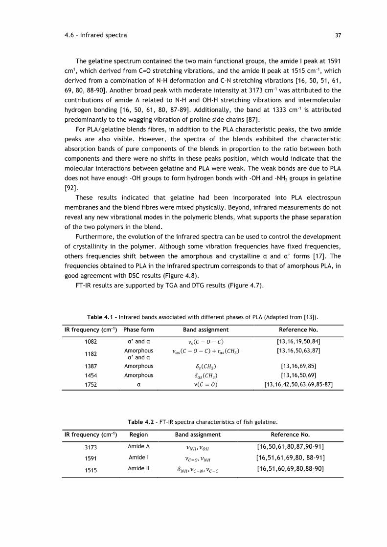
37
The gelatine spectrum contained the two main functional groups, the amide I peak at 1591
cm1, which derived from C=O stretching vibrations, and the amide II peak at 1515 cm-1, which
derived from a combination of N-H deformation and C-N stretching vibrations [16, 50, 51, 61,
69, 80, 88-90]. Another broad peak with moderate intensity at 3173 cm-1 was attributed to the
contributions of amide A related to N-H and OH-H stretching vibrations and intermolecular
hydrogen bonding [16, 50, 61, 80, 87-89]. Additionally, the band at 1333 cm-1 is attributed
predominantly to the wagging vibration of proline side chains [87].
For PLA/gelatine blends fibres, in addition to the PLA characteristic peaks, the two amide
peaks are also visible. However, the spectra of the blends exhibited the characteristic
absorption bands of pure components of the blends in proportion to the ratio between both
components and there were no shifts in these peaks position, which would indicate that the
molecular interactions between gelatine and PLA were weak. The weak bonds are due to PLA
does not have enough -OH groups to form hydrogen bonds with -OH and -NH2 groups in gelatine
[92].
These results indicated that gelatine had been incorporated into PLA electrospun
membranes and the blend fibres were mixed physically. Beyond, infrared measurements do not
reveal any new vibrational modes in the polymeric blends, what supports the phase separation
of the two polymers in the blend.
Furthermore, the evolution of the infrared spectra can be used to control the development
of crystallinity in the polymer. Although some vibration frequencies have fixed frequencies,
others frequencies shift between the amorphous and crystalline α and α’ forms [17]. The
frequencies obtained to PLA in the infrared spectrum corresponds to that of amorphous PLA, in
good agreement with DSC results (Figure 4.8).
FT-IR results are supported by TGA and DTG results (Figure 4.7).
Table 4.1 - Infrared bands associated with different phases of PLA (Adapted from [13]).
IR frequency (cm-1) Phase form Band assignment Reference No.
1082 α’ and α 𝜈𝑠(𝐶 − 𝑂 − 𝐶) [13,16,19,50,84]
1182 Amorphous α’ and α
𝜈𝑎𝑠(𝐶 − 𝑂 − 𝐶) + 𝑟𝑎𝑠(𝐶𝐻3) [13,16,50,63,87]
1387 Amorphous 𝛿𝑠(𝐶𝐻3) [13,16,69,85]
1454 Amorphous 𝛿𝑎𝑠(𝐶𝐻3) [13,16,50,69]
1752 α ν(𝐶 = 𝑂) [13,16,42,50,63,69,85-87]
Table 4.2 - FT-IR spectra characteristics of fish gelatine.
IR frequency (cm-1) Region Band assignment Reference No.
3173 Amide A 𝜈𝑁𝐻 , 𝜈𝑂𝐻 [16,50,61,80,87,90-91]
1591 Amide I 𝜈𝐶=𝑂 , 𝜈𝑁𝐻 [16,51,61,69,80, 88-91]
1515 Amide II 𝛿𝑁𝐻, 𝜈𝐶−𝑁 , 𝜈𝐶−𝐶 [16,51,60,69,80,88-90]
4.6 – Infrared spectra
38 Results and Discussion
4.7 – Cell viability and proliferation
The cytocompatibility of PLA, gelatine and blend membranes was characterized through in
vitro studies. Cytocompatibility is necessary in cell-scaffold interaction, since cell adhesion,
proliferation and spreading on scaffold contribute crucially tissue regeneration [50]. Sample
morphology play an important role in regulating cellular behaviour and cell attachment. A series
of biological reactions, such as nutrient supply, initial protein binding and cell adhesion should
be favorably affected by the nanofibrous structure [16]. Furthermore, to achieve this goals we
used PLA blended with gelatine to improve the hydrophilicity of the membranes.
To asses the behaviour of cells seeded over the electrospun membranes, we analysed
adhesion and proliferation of fibroblasts cells that were cultured for 14 days over the developed
membranes. Fibroblast are intrinsic constituents of all three major compartments, such as
epineurium, perineurium and endoneurium [93]. After a peripheral nerve injury, Schwann cells
initiate proliferation and migration and participate actively with accumulated fibroblasts at the
injury site establishing a guidance channel, called Bands of Bunger, crucial for peripheral nerve
regeneration [94].
Figure 4.10 - Resazurin viability of fibroblast cells after 1, 4, 7 and 14 days of being seeded. “PLA” cells
seeded in PLA membranes; “PG31” cells seeded in PG31 membranes; “PG11” cells seeded in PG11
membranes; “PG13” cells seeded in PG13 membranes; “GE” cells seeded in gelatine membranes. Each
result is presented as the mean ± SD of four replicates. Statistical analysis was performed using two-way
ANOVA with Dunnet’s post hoc test being the significant differences when compares to control for each
day (* p<0.05).
39
Although the hydrophobic interaction between PLA and GE could prevent the complete
dissolution of GE from the composite, cross-linking treatment was still necessary before the
PLA/GE electrospun membrane were used for cell culture. In this study, cell culture
experiments were carried out on electrospun membranes cross-linked with GA. However,
although the cross-linking treatment improved the water-resistant ability and thermal-
mechanical properties of electrospun gelatine membranes, an adverse effect is that such
treatment could be cytotoxic to cellular growth during in vitro and in vivo experiments [95].
Thus, it is necessary a treatment with an efficient removal of unreacted GA left in the material
after the cross-linking treatment. After the glycine treatment, it was found that fibre
morphology of gelatine membranes could not be preserved. The membrane loses their fibrous
structure and became a polymeric film.
The redox activity of viable cells after 1, 4, 7 and 14 days in culture is shown in figure 4.10
by the resazurin cell viability assay. In this study, it was verified that cell adhesion and
proliferation of fibroblasts cells is different in the membranes with different weight ratios of
PLA and gelatine.
In the first 24 hours, cell adhesion and proliferation was noticed in wells where cell were
in contact with materials and in the control. The metabolic activity of fibroblast cells culture
in the electrospun membranes is similar when compared to the control. After 4 days of culture
is observed a slight inhibition in metabolic activity of cells cultured in the PG13 and PG11
membranes when compared to the day 1. Cells continued to proliferate in wells in contact with
PLA, PG31 and gelatine membranes. After 7 days of cell culture, it is observed an increase on
cell proliferation in all membranes compared to the day 4. At this time point, cell metabolic
activity is similar for all the membranes, however lower than that obtained in control. After 14
days, cells seeded in the presence of PG13 and gelatine membranes showed that in both cases
cell viability decreased and cells in wells containing PG31 membranes presented the lowest
proliferation. As previously mentioned, gelatine membrane loses their fibrous structure and
became a polymeric film. The cellular responses to the substrate with nanolevel morphology
are understood to be very different. The differences obtained between electrospun membranes
and polymeric films were due to the higher porosity of the electrospun membranes [48]. Since
gelatine films had lower porosity and the porous structure provide a large surface area that will
allow cell ingrowth, the lower cell viability may be related to porosity.
Additionally, there is a remarkable increase in cell proliferation on the PG11 membranes
after 14 days of culture when compared to the other membranes and probably this behaviour
is related to the fibre diameter. S.J. Eichhorn et al. [96] determined that an increase in fibre
diameter resulted in an increase in mean pore radius. Larger pores may be required for ingrowth
of the cells into the nanofibrous network. In this study, PG11 electrospun membranes had the
highest diameter (Figure 4.2), which should facilitate better penetration of cells into the
membrane, leading to the difference of cell viability compared with other blended membranes
(PG13 and PG31 membranes).
The PG11 electrospun membranes was proven to be a good substrate for cell culture
compared to pure PLA and GE, since their morphology was improved. In fact, the PLA
modification with gelatine could improve the viability and attachment of fibroblasts. This
finding suggest that the PLA/GE blend should have better potential for use in the tissue
regeneration.
4.7 – Cell viability and proliferation

41
Chapter 5
Conclusions and Future Work
5.1 – Conclusions
Peripheral nerve repair is one of the most difficult problems in the field of neuroscience.
Currently, the gold standard for peripheral nerve injury repair is surgical implantation of
autologous nerve grafts. However, there are several disadvantages associated with this
technique. These problems drive the search of different solution to substitute autologous nerve
grafts [97]. The use of NGC is a promising alternative to traditional techniques [98]. Nerve
regeneration can be improved by increasing the surface area for cell growth into the nerve
conduit. This can be achieved using electrospun nanofibers that provide a large surface area
and a number of pores similar to a natural ECM, which is favourable to cell adhesion and
proliferation [99].
In this context, this dissertation thesis describes a method using biomaterials to enhance
peripheral nerve regeneration. To accomplish this, the development of electrospun membranes
as well as their characterization were achieved. Due to the hydrophobic properties of the PLA,
the blending of these with natural polymers, such fish gelatine, which possess better biological
properties was tried. PLA/GE blends with different weight ratios were successfully electrospun
from the solution of polymers in a common solvent (HFIP). The gelatine has been incorporated
into PLA membranes and the blend fibres were mixed physically. In order to improve stability
in aqueous environments, chemical cross-linking with GA was performed for 48h, and it was
found that the cross-linking treatment does not influence the fibre morphology. In addition, it
was found that the nanofibrous membranes were properly cross-linked. The average fibre
diameter obtained were in the range of 207-452 nm, found to be more desirable to mimic the
natural extracellular matrix (50-500 nm) [100]. The introduction of gelatine within PLA
significantly improved the hydrophilic property of the nanofibers. In fact, the blending process
leads to a decrease on polymer wettability and creates superhydrophilic membranes when
higher gelatine amounts are added to the solution. In the electrospun membranes a swelling
phase was observed, which can be important for cell survival.
After the development and characterization of PLA/GE was achieved, the biological
response was addressed. Appropriate cytocompatibility is the foremost concern when a
biomaterial is used for tissue regeneration purpose. From the evaluation of the in vitro results,
42 Conclusions and Future Work
it appears that PG11 membranes offer the best conditions for fibroblast cell adhesion and
proliferation. PG11 membranes could support fibroblast growth and proliferation, which
suggested that the membranes had good cytocompatibility, whereas cells cultures on the PG31
and PG13 membranes had low viability.
These results suggest that the blend polymers PG13 and PG31 do not possesses the ideal
properties for a good cellular adhesion and proliferation, thus being their use impractical in
the tissue regeneration field. On the other hand, from the structural and biological analysis,
the PG11 membranes seem to be suitable and in some way ideal to promote the nerve
regeneration, since their properties were considerably improved after modification. In this
experimental work was developed a simple but efficient modification enhancing the potential
application of electrospun membranes in the field of peripheral nerve regeneration.
5.2 – Future Work
These tests indicate that the incorporation of gelatine in PLA membranes has the potential to
enhance cell adhesion and proliferation but further research is necessary to better characterize
the membranes and its biological functions. Optimization of the glycine treatment of the
membranes should be performed to maintain the membrane morphology. Furthermore, a future
work will be important to evaluate mechanical properties of the membranes.
The other issue to improve material cellular behaviour is to cross-link the gelatine with
more biocompatible crosslinking agents such EDC/NHS or genipin.
While fibroblasts cells represent a suitable model to evaluate the cytotoxicity of the
membranes, these cells do not represent the behaviour of Schwann cells. Since the proliferation
of these cells is crucial for successful peripheral nerve regeneration, further viability tests
should be performed using Schwann cells for comparison.
Finally, each developed biomaterial should be evaluated in vivo through the use of animal
models. The rat model provides a realistic and useful model of damage for the study of
peripheral nerve regeneration. Nerve guidance conduits should be constructed and implanted
to evaluate its potential in peripheral nerve regeneration. Essential parameters such as
inflammation, cellular proliferation and differentiation, functional testing must be
investigated.
43
References
[1] P. A. S. Armada-da-Silva, C. Pereira, S. Amado, A. Luís and A.C. Maurício, “Activity-Based
Strategies in the Rehabilitation of Peripheral Nerve Injuries”, Intech, pp. 52-66, 2014.
[2] D. Grinsell and C.P. Keating, “Peripheral Nerve Reconstruction after Injury: A Review of
Clinical and Experimental Therapies”, Hindawi, pp. 1-13, 2014.
[3] A. Faroni, S. A. Mobasseri, P. J, Kingham and A. J. Reid, “Peripheral Nerve Regeneration:
Experimental Strategies and Future Perspectives”, Advanced Drug Delivery Reviews, pp.
160-167, 2014.
[4] X. Gu, F, Ding and D. F. Williams, “Neural tissue engineering options for peripheral nerve
regeneration”, Biomaterials, pp. 6143-6156, 2014.
[5] V. Carriel, M. Alaminos, I. Garzón, A. Campos and M. Cornelissen, “Tissue engineering of
the peripheral nervous system”, Expert Review Neurother, pp.301-318, 2014.
[6] A. Atala, R. Lanza, J. A. Thomson and R. M. Nerem, “Foundations of Regenerative
Medicine”, Academic Press, 1st edition, pp. 672-683, 2010.
[7] X. Gu, F. Ding, Y. Yang and J. Liu, “Construction of tissue engineered nerve grafts and their
application in peripheral nerve regeneration”, Progress in Neurobiology, pp. 204-230, 2011.
[8] W. W. Campbell, “Evaluation of peripheral nerve injury”, European Journal of Pain
Supplements, pp. 37-40, 2009.
[9] Y. Shirosaki, S. Hayakawa, A. Osaka, M. A. Lopes, J. D. Santos, S. Geuna and A. C Mauricio,
“Challenges for Nerve Repair using Chitosan-Siloxane Hybrid Porous Scaffolds”, Hindawi,
pp. 1-7, 2014.
[10] C.W. Patrick, A. G. Mikos and L. V. McIntire, “Frontiers in Tissue Enginerring”, Pergamon,
1st edition, pp. 514-535, 1998.
[11] D. Shi, “Biomaterials and Tissue Engineering”, Spinger, 1st edition, pp. 195-234, 2004;
[12] Y. Shirosaki, K. Tsuru, S. Hayakawa, A. Osaka, M. A. Lopes, J. D. Santos and M. H.
Fernandes, “In vitro cytocompatibility of MG63 cells on chitosan-organosiloxane hybrid
membranes”, Biomaterials, pp. 485-493, 2005.
[13] C. Ribeiro, V. Sencadas, C. M Costa, J. L. G. Ribelles and S. Lanceros-Méndez, “Tailoring
the morphology and crystallinity of poly(L-lactide acid) electrospun membranes”, Science
and Technology of Advanced Materials, pp. 1-9, 2011.
[14] B. Dhandayuthapani, Y. Yoshida, T. Maekawa and D. S. Kumar, “Polymeric Scaffolds in
Tissue Engineering Applications: A Review”, Hindawi, pp. 1-19, 2011.
[15] C. P. Barnes, S. A. Sell, E. D. Boland, D. G. Simpson and G. L. Bowlin, “Nanofiber
technology: Designing the next generation of tissue engineering scaffolds”, Advanced Drug
Delivery Reviews, pp. 1413-1433, 2007.
44 References
[16] HW. Kim, HS. Yu and HH Lee, “Nanofibrous matrices of poly(lactic acid) and gelatin
polymeric blends for the improvement of cellular responses”, Wiley Periodicals, pp. 25-32,
2007.
[17] X. Yang, Q Xu, N. Yan, G. Sui, Q. Cai and X. Deng, “Structure and wettability relationship
of coelectrospun poly(L-lactic acid)/gelatin composite fibrous mats”, Polymers Advanced
Technologies, pp. 2222-2230, 2011.
[18] “Seeley’s Anatomy and Physiology”, 10th edition.
[19] J. Ryu, C. F. Beimesch, T. J. Lalli, “Peripheral Nerve Repair”, Orthopedics and trauma,
pp. 174-180, 2011.
[20] M. Richner, M. Ulrichsen, S. L. Elmegaard, R. Dieu, L. T. Pallesen and C. B. Vaegter,
“Peripheral Nerve Injury Modulates Neurotrophin Signaling in the Peripheral and Central
Nervous System”, Mol Neurobiol, pp. 945-970, 2014.
[21] C. A. Health and Gregory E. Rutkowski, “The development of bioartificial nerve grafts for
peripheral-nerve regeneration”, Tibitech, pp. 163-168,1998.
[22] H. J. Seddon, “A classification of nerve injuries”, British Medical Journal, pp. 237-239,
1942.
[23] Y. Kaya and L. Sarikeioghu, “Sir Herbert Seddon (1903-1977) and his classification scheme
for peripheral nerve injury”, Childs Nervous System, pp. 177-180, 2015.
[24] A. Chhabra, S. Ahalawat and G. Andreseik, “Peripheral nerve injury grading simplified on
MR neurography: As referenced to Seddon and Sunderland classifications”, The Indian
Journal of Radiology and Imaging, pp. 217-224, 2014.
[25] A. Osbourne, “Peripheral Nerve Injuury and Repair”, Reviews: Surgery, pp. 29-35, 2007.
[26] R. Deumens, A. Bozkurt, M. F. Meek, M. A. E. Marcus, E. A.J. Joosten, J. Weis and G. A.
Brook, “Repairing injured peripheral nerves: Bridging the gap”, Progress in Neurobiology,
pp. 245-276, 2010.
[27] C. V. Blitterswijk, “Tissue Engineering”, Academic Press, 1st Edition, pp., 2008.
[28] K. S. Straley, C. W. P. Foo and C. Heilshorn, “Biomaterial Design Strategies for the
Treatment of Spinal Cord Injuries”, Journal of Neurotrauma, pp. 1-19, 2010.
[29] G. R.D. Evans, “Peripheral Nerve Injury: A Review and Approach to Tissue Engineered
Constructs”, The Anatomical Record, pp. 396-404, 2001.
[30] F. J. O’Brien, “Biomaterials and Scaffolds for Tissue Engineering”, MaterialsToday, pp. 88-
95, 2011.
[31] S. Kehoe, X.F. Zhang and D. Boyd, “FDA approved guidance conduits and wraps for
peripheral nerve injury: A review of materials and efficacy”, Injury, pp. 553-572, 2012.
[32] G.C.W. Ruiter, M.J.A. Melessy, M. J. Yaszemski, A.J. Windebank and R. J. Spinner,
“Designing ideal conduits for peripheral nerve repair”, Neurosurgical focus, pp. 1-50, 2009.
[33] S. Ichihara, Y. Inada, T. Nakamura, “Artificial nerve tubes and their application for repairo
f peripheral nerve injury: an update of current concepts”, Injury, pp. 29-39, 2008.
[34] X. Jiang, S. H. Lim, HQ. Mao, S. Y. Chew, “Current applications and future perpectives of
artificial nerve conduits”, Experimental Neurology, pp. 86-101, 2010.
[35] L. Xiao, B. Wang, G. Yang and M. Gauthier, “Poly(Lactic Acid)-Based Biomaterials:
Synthesis, Modification and Applications”, Intechop, pp. 247- 282, 2012.
[36] S. Ramakrishna, K. Fujihara, WE. Teo, TC. Lim and Z. Ma, “An Introductiom to
Electrospinning and Nanofibers”, World Scientific, 2005.
[37] D. Arslantunali, T. Dursun and V. Hasirci, “Peripheral nerve conduits: technology update”,
Medical Devices, pp. 405-424, 2014.
45
[38] R. M. Rasal, A. V. Janorkar and D. E. Hirt, “Poly(lactic Acid) modifications”, Progress in
Polymer Science, pp. 338-356, 2010.
[39] A.J.R. Lasprilla, G.A.R. Martinez, B.H. Lunelli, A.L. Jardini and R.M. Filho, “Poly-lactic
acid synthesis for application in biomedical devides- A review”, pp.321-328, 2012.
[40] V. Sencadas, C. Ribeiro, A. Heredia, I.K. Bdikin, A.L. Kholkin, S. Lanceros-Mendez, “Local
piezoelectric activity of single poly(L-lactic acid) (PLLA) microfoibers”, Applied Physics A,
pp. 51-55, 2012.
[41] B. Gupta, N. Revagade, J. Hilbron, “Poly(lactic acid) fiber: An overview”, Progress in
Polymer Science, pp. 455-482, 2007.
[42] G.S. Nyanhongo, R.D. Rodríguez, E.N. Prasetyo, C. Caparrós, C. Ribeiro, V. Sencadas and
S. Lanceros-Mendez, E.H. Acero, and G.M. Guebitz, “Bioactive albumin functionalized
polylactic acid membranes for improved biocompatibility”, Reactive and Funcional
Polymers, pp. 1399-1404, 2013.
[43] C. Ribeiro, V. Sencadas, D.M. Correia and S. Lanceros-Mendez, “Piezoelectric polymers as
biomaterials for tissue engineering applications”, Colloids and Surfaces B: Biointerfaces,
pp. 46-55, 2015.
[44] L.M. Marquardt and S.E. Sakiyama-Elbert, “Engineering peripheral nerve repair”, Current
opinion in Biotechnology, pp. 887-892, 2013.
[45] A.H. Rajabi, M. Jaffe and T.L. Arinzeh, “Piezoelectric materials for tissue regeneration: A
review”, Acta Biomaterialia, pp. 12-33, 2015.
[46] S.R. Gomes, G. Rodrigues, G.G. Martins, C.M.R. Henriques and J.C. Silva, “In vitro
evaluation of crosslinked electrospun fish gelatin scaffolds”, Materials Science and
Engineering C, pp. 1219-1227, 2013.
[47] D.M. Correia, J. Padrão, L.R. Rodrigues, F. Dourado, S. Lanceros-Mendez and V. Sencadas,
“Thermal and hydrolytic degradation of electrospun fish gelatin membranes”, Polymer
Testing, pp. 995-1000, 2013.
[48] A. Kejing, L. Haiying, G. Shidong, D.N.T. Kumar and W. Qingqing, “Preparation of fish
gelatin and fish gelatin/poly(L-Lactide) nanofibers by electrospinning”, International
Journal of Biologiocal Macromolecules, pp. 380-388, 2010.
[49] J. Padrão, J.P. Silva, L. R. Rodrigues, F. Dourado, S. Lanceros-Méndez and V. Sencadas,
“Modifying Fish Gelatin Electrospun Membranes for Biomedical Applications: Cross-Linking
and Swelling Behavior”, Soft Materials, pp. 247-252, 2014.
[50] E. Hoveizi, M. Nabiuni, K. Parivar, S. Rajabi-Zeleti and S. Tavakol, “Functionalisation and
surface modification of electrospun polylactic acid for tissue engineering”, Cell Biology
International, pp. 41-49, 2014.
[51] A. Etxabide, M. Urdanpilleta, P. Guerreiro and K. Caba, “Effects of cross-linking in
nanostructure and physicochemical properties of fish gelatins for bio-applications”,
Reactive and Functional Polymers, pp. 55-62, 2015.
[52] S. Panzavolta, M. Gioffre, M.L. Focarete, C. Gualandi, L. Foroni and A. Bigi, “Electrospun
gelatina nanofibers: Optimization of genipin cross-linking to preserve fiber morphology
after exposure to water”, Acta Biomaterialia, pp. 1702-1709, 2011.
[53] J. Ratanavaraporn, R. Rangkupan, H. Jeeratawatchai, S. Kanokpanont and S.
Damrongsakkul, “Influences of physical and chemical crosslinking techniques on
electrospun type A and B gelatin fiber mats”, International Journal of Biological
Macromolecules, pp. 431-438, 2010.
46 References
[54] V. Beachley, X. Wen, “Polymer nanofibrous structures: Fabrication, biofunctionalization
and cell interactions”, Progress in polymer science, pp. 868-892, 2010.
[55] S. Agarwal, J.H Wendorff and A. Greiner, “Use of electrospinning technique for biomedical
applications”, Polymer, pp. 5603-5621, 2008.
[56] D. Kai, S.S. Liow, X.J. Loh, “Biodegradable polymers for electrospinning: Towards
biomedical applications”, Materials Science and Engineering C, pp. 659-670, 2014.
[57] A. Baji, YW. Mai, SC. Wong, M. Abtahi and P. Chen, “Electrospinning of polymer nanofibers:
Effects on oriented morphology, structures and tensile properties”, Composites Science and
Technology, pp. 703-718, 2010.
[58] R.J. Wade and J.A. Burdick, “Advances in nanofibrous scaffolds for biomedical
applicartions: From electrospinning to self-assembly”, NanoToday, pp. 722-742, 2014.
[59] M. Ziabari, V. Mottaghitalab and A.K. Haghi, “Application of direct tracking method for
measuring electrospun nanofiber diameter”, Brazilian Journal of Chemical Engineering,
pp. 53-62, 2009.
[60] C. A. Schneider, W. S. Rasband and K. W. Eliceiri, “NIH Image to ImageJ: 25 years of image
analysis”, Nature Methods, pp. 671-675, 2012.
[61] J. Padrão, R. Machado, M. Casal, S. Lanceros-Méndez, L.R. Rodrigues, F. Dourado and V.
Sencadas, “Antibacterial performance of bovine lactoferrin-fish gelatine electrospun
membranes”, International Journal of Biological Macromolecules, pp. 608-614, 2015.
[62] N. Nagiah, R. Johnson, R. Anderson, W. Elliott and W. Tan, “Highly compliant vascular
grafts with gelatin-sheathed coaxially structured nanofibers”, Langmuir, pp. 1-10, 2015.
[63] T. A. M. Valente, D. M. Silva, P. S. Gomes, M. H. Fernandes, J. D. Santos and V. Sencadas,
“Effect of sterilization methods on electrospun poly(lactic acid) (PLA) fibre alignment for
biomedical applications”, ACS Applied Materials and Interfaces, pp. 1-26, 2016.
[64] T. Nie, L. Xue, M. Ge, H. Ma and J. Zhang, “Fabrication of poly(L-lactic acid) tissue
engineering scaffolds with precisely controlled gradient structure”, Materials Letters, pp.
25-28, 2016.
[65] A. Subramanian, U. M. Krishnan and S. Sethuraman, “Development of biomaterial scaffold
for nerve tissue engineering: Biomaterial mediated neural regeneration”, Journal of
Biomedical Science, pp. 1-11,2009.
[66] H. Duan, B. Feng, X. Guo, J. Wang, L. Zhao, G. Zhou, W. Liu, Y. Cao and W. J. Zhang,
“Engineering of epidermis skin grafts using electrospun nanofibrous
gelatin/polycaprolactone membranes”, International Journal of nanomedicine, pp. 2077-
2084, 2013.
[67] R. Casasola, N.L. Thomas, A. Trybana and S. Georgiadou, “Electrospun poly lactic acid
(PLA) fibres: Effect of different solvent system on fibre morphology and diameter”,
Polymer, pp. 4728-4737, 2014.
[68] J. Kucinska-Lipka, I. Gubanska, H. Janik and M. Sienkiewicz, “Fabrication of polyurethane
and polyurethane based composite fibres by the electrospinning technique for soft tissue
engineering of cardiovascular system”, Materials Science and Engineering C, pp. 166-176,
2015.
[69] BS. Chiou, H. Jafri, R. Avena-Bustillos, K.S. Gregorski, P.J. Bechtel, S.H. Imam, G.M. Glenn
and W.J. Orts, “Properties of electrospun Pollock gelatin/poly(vinyl alcohol) and Pollock
gelatin/poly(lactic acid) fibers”, International Journal of Biological Macromolecules, pp.
214-220, 2013.
47
[70] A. Laha, S. Yadav, S. Majumdar and C. S. Sharma, “In-vitro release study of hydrophobic
drug using electrospun cross-linked gelatin nanofibers”, Biochemical Engineering Journal,
pp. 481-488, 2016.
[71] Y. Z. Zhang, J. Venugopal, Z. M. Huang, C. T. Lim and S. Ramakrishna, “Crosslinking of the
electrospun gelatin nanofibers”, Polymer, pp. 2911-2017, 2006.
[72] C. Ribeiro, J.A. Panadero, V. Sencadas, S. Lanceros-Méndez, M.N. Tamanõ, D. Moratal, M.
Salmerón-Sánchez and J.L.G. Ribelles, “Fibronectin absorption and cell response on
electroactive poly(vinylidene fluoride) films”, Biomed. Mater., pp. 1-10, 2012.
[73] J. Zhu, F. Yang, F. He, X. Tian, S. Tang and X. Chen, “A tubular gelatin scaffold capable
of the time-dependent controlled release of epidermal growth factor and motimycin C”,
Colloids and Surfaces B: Biointerfaces, pp. 416-424, 2015.
[74] C. Ribeiro, S. Moreira, V. Correia, V. Sencadas, J. G. Rocha, F. M. Gama, J. L. Goméz
Ribelles and S. Lanceros-Mendez, “Enhanced proliferation of pre-osteoblastic cells by
dynamic piezoelectric stimulation”, RSC Advances, pp. 11504-11509, 2012.
[75] S. F. Hosseini, Z. Javidi and M. Rezaei, “Efficient barrier properties of multi-layer films
based on poly(lactic acid) and fish gelatine”, International Journal of Biological
Macromolecules, pp. 1205-1214, 2016.
[76] J. Araujo, J. Padrão, J. P. Silva, F. Dourado, D. M. Correia, G. Botelho, J. L. Gomez
Ribelles, S. Lanceros-Méndez and V. Sencadas, “Processing and characterization of α-
elastin electrospun membranes”, Applied Physics A: Materials Science and Processing, pp.
1291-1298, 2014.
[77] V. Sencadas, C. M. Costa, G. Botelho, C. Caparrós, C. Ribeiro, J. L. Gómez-Ribelles and S.
Lanceros-Mendez, “Thermal properties of electrospun poly(lactic acid) membranes”,
Journal of Macromolecular Science, Part B: Physics, pp. 411-424, 2012.
[78] S. Gautam, C. Chou, A. K. Dinda, P. D. Potdar and N. C. Mishra, “Surface modification of
nanofibrous polycaprolactone/gelatin composite scaffold by collagen type I grafting for skin
tissue engineering”, Materials Science and Engineering C, pp. 402-409, 2014.
[79] K. Lewandowska, “Miscibility and thermal stability of poly(vinyl alcohol)/chitosan
mixtures”, Thermochimica Acta, pp. 42-48, 2009.
[80] S. Gautam, A. K. Dinda and N. C. Mishra, “Fabrication and characterization of PCL/gelatin
composite nanofibrous scaffold for tissue engineering applications by electrospinning
method”, Materials Science and Engineering C, pp. 1228-1235, 2013.
[81] C. Ribeiro, V. Sencadas, C. Caparros, J. L. Gómez Ribelles and S. Lanceros-Méndez,
“Fabrication of Poly(lactic acid)-Poly(ethylene oxide) electrospun membranes with
controlled micro to nanofiber sizes”, Journal of Nanoscience and Nanotechnology, pp.
6746-6753, 2012.
[82] C. S. Ki, D. H. Baek, K. D. Gang, K. H. Lee, I. C. Um and Y. H. Park, “Characterization of
gelatin nanofiber prepared from gelatin-formic acid solution”, Polymer, pp. 5094-5102,
2005.
[83] A. Wagner, V. Poursorkhabi, A. K. Mohanty and M. Misra, “Analysis of porous electrospun
fibers from Poly(L-lactic acid)/Poly(3-hydroxybutyrate-co-3-hydroxyvalerate) blends”, ACS
Sustainable Chemistry and Engineering, pp. 1976-1982, 2014.
[84] D. Duydu, T. Baykal, I. Açikgoz and K. Yildiz, “Fourier transform infrared (FT-IR)
spectroscopy for biological studies”, G.U. Journal of Science, pp. 117-121, 2009.
48 References
[85] R. Al-Itry, K. Lamnawar and A. Maazouz, “Improvement of thermal stability, rheological
and mechanical properties of PLA, PBAT and their blends by reactive extrusion with
functionalized epoxy”, Polymer Degradation and Stability, pp. 1898-1914, 2012.
[86] CS. Wu and HT. Liao, “A new biodegradable blends prepared from polylactide and
hyaluronic acid”, Polymer, pp. 1017-10026, 2005.
[87] W. H. Hoidy, M. B. Ahmad, E. A. J. Al-Mulla and N. A. B. Ibrahim, “Preparation and
Characterization of Polylactic Acid/Polycaprolactone Clay Nanocomposites”, Journal of
Applied Sciences, pp. 97-106, 2010.
[88] M. J. Hossan, M. A. Gafur, M. R. Kadir and M. M. Karim, “Preparation and characterization
of gelatin-hydroxyapatite composite for bone tissue engineering”, International Journal of
Engineering and Technology, pp. 1-9, 2014.
[89] C. S. Ki, D. H. Baek, K. D. Gang, K. H. Lee, I. C. Um and Y. H. Park, “Characterization of
gelatin nanofiber prepared from gelatin-formic acid solution”, Polymer, pp- 5094-5102,
2005.
[90] H. Staroszczyk, K. sztuka, J. Wolska, A. Wojtasz-Pajak and I. Kolodziejska, “Interactions
of fish gelatin and chitosan in uncrosslinked and crosslinked with EDC films: FT-IR study”,
Spectrochimica Acta Part A: Molecular and Biomolecular Spectroscopy, pp. 707-712, 2014.
[91] S. F. Hosseini, M. Rezaei, M. Zandi and F. F. Ghavi, “Preparation and functional properties
of fish gelatin-chitosan blend edible films”, Food Chemestry, pp. 1490-1495, 2013.
[92] A. Kejing, L. Haiying, G. Shidong, D.N.T. Kumar and W. Qingqing, “Preparation of fish
gelatin and fish gelatin/poly(L-lactide) nanofibers by electrospinning”, International
Journal of Biological Macromolecules, pp. 380-388, 2010.
[93] L. Dreesmann, R. Mittnacht, M. Lietz and B. Schlosshauer, “Nerve fibroblasts impact on
Schwann cell behavior”, European Journal of Cell Biology, pp. 285-300, 2009.
[94] N. Niapour, A. Niapour, H.S. Milan, M. Amani, H. Salehi, N. Najafzadeh and M.R. Gholami,
“All trans retinoic acid modulates peripheral nerve fibroblasts viability and apoptosis”,
Tissue and Cell, pp. 61-65, 2015.
[95] Q. Li, X. Wang, X. Lou, H. Yuan, H. Tu and B. Li, “Genipin-crosslinked electrospun chitosan
nanofibers: Determination of crosslinking conditions and evaluation of cytocompatibility”,
Carbohydrate Polymers, pp. 166-174, 2015.
[96] S.J. Eichhorn and W. Sampson, “Statistical geometry of pores and statistics of porous
nanofibrous assemblies”, Journal of the Royal Society Interface, pp. 309-318, 2005.
[97] P.M. Jenkins, M.R. Laughter, D.J. Lee, Y.M. Lee, C.R. Freed and D. Park, “A nerve guidance
conduit with topographic and biochemical cues: potential application using human neural
stem cells”, NanoScale Research Letters, pp. 10:264, 2015.
[98] YL. Wang, XM. Gu and YM. Yang, “Electrospun and woven silk fibroin/poly(lactic-coglycolic
acid) nerve guidance conduits for reparing peripheral nerve injury”, Neural Regeneration
Research, pp. 1635-1642, 2015.
[99] S.Y. Park, C.S. Ki, Y.H. Park, K.G. Lee, S.W. Kang, H.Y. Kweon and H.J. Kim, “Functional
recovery guided by an electrospun silk fibroin conduit after sciatic nerve injury in rats”,
Journal of Tissue Engineering and Regenerative Medicine, pp. 66-76, 2015.
[100] I. O. Smith, X. H. Liu, L. A. Smith and P.X. Ma, “Nanostructured polymer scaffolds for
tissue engineering and regenerative medicine”, WIREs Nanomedicine and
Nanobiotechnology, pp. 226-236, 2009.
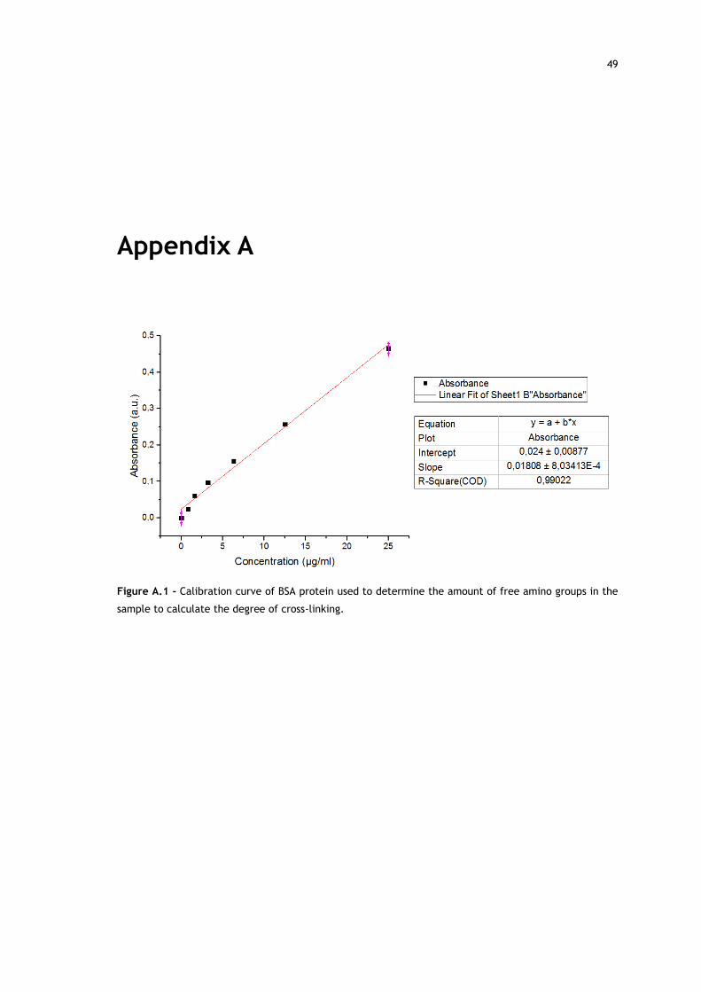
49
Appendix A
Figure A.1 - Calibration curve of BSA protein used to determine the amount of free amino groups in the
sample to calculate the degree of cross-linking.