development of a linear micro-inductosyn sensor
TRANSCRIPT
2830 IEEE TRANSACTIONS ON MAGNETICS, VOL. 42, NO. 10, OCTOBER 2006
Development of a Linear Micro-Inductosyn SensorD. Dinulovic1, D. Hermann1, J. Fluegge2, and H. H. Gatzen1
Institute for Microtechnology, 30823 Garbsen, GermanyPhysikalisch-Technische Bundesanstalt, D-38116, Braunschweig, Germany
This paper describes the development of an inductive microposition measuring system based on the “Inductosyn” principle and itsfabrication using thin-film technology. By integrating a soft magnetic flux guide, the coupling between excitation and sensing coils wasincreased. The system consists of two principle components: a stationary planar meander coil and two planar meander coils positionedon a slider. The sensor device was simulated by applying the finite-element method. Thin-film processes were used to fabricate an induc-tive microposition measuring system. Initial measurements show an induced voltage of 9 mV at an excitation current of 40 mA and afrequency of 5 MHz.
Index Terms—Electroplating, Inductosyn, MEMS, permalloy, positioning sensor, SU-8.
I. INTRODUCTION
THE “Inductosyn” is a multipole electromagnetic sensordevice used as position measurement system. The Induc-
tosyn sensor belongs to the group of encoder type positioningsensors [1]. Due to its simple design, easy installation, insen-sitivity to the influence of the working environment, and highprecision, these sensors are widely used in many of industrialapplication and robotic systems [2], [3].
The aim of our investigation was the development of aninductive microposition measuring system based on the Induc-tosyn principle and its fabrication using thin-film technology.Generally, inductive measuring systems in thin-film technologyfeature a large degree of integration, miniaturization, andlow-manufacturing costs [4], [5]. In order to use an Inductosynsensor in permanent, increasingly precise technical applications(e.g., positioning during microassembly, position measurementfor microactuators, etc.), sensor miniaturization is necessary.Such a miniaturization not only improves the sensor integrationcapabilities and lowers fabrication costs due to batch pro-cessing, but also increases the sensor accuracy and resolutioninto the submicron range. The accuracy of a standard Induc-tosyn sensor with a period of 2 mm is 2.5 m. The aim of ourdevelopment was to decrease the period to as little as 50 mand ultimately to achieve an accuracy of 500 nm or below. Themain challenge of such a miniaturization is the loss of sensorsignals. However, such a reduction of the sensor signals due tothe miniaturization can be compensated by the integration ofsoft magnetic poles and flux guides around the meander sensingcoils of Inductosyn sensor. Therefore, the coupling betweenexcitation and sensing coils increases considerably.
II. DESIGN AND SIMULATION
Fig. 1 depicts a classic Inductosyn sensor. It consists of threecoil systems. One forms the magnetic scale which is positionedon the stationary part of the system (stator) and is facilitatedby a planar meander coil. The sensing part of the system (trav-eler) is positioned on a slider. It consists of two planar meander
Digital Object Identifier 10.1109/TMAG.2006.879141
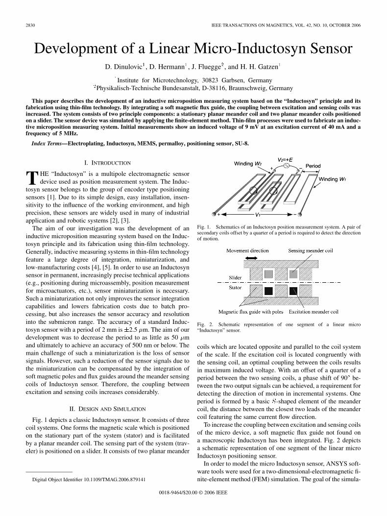
Fig. 1. Schematics of an Inductosyn position measurement system. A pair ofsecondary coils offset by a quarter of a period is required to detect the directionof motion.
Fig. 2. Schematic representation of one segment of a linear micro“Inductosyn” sensor.
coils which are located opposite and parallel to the coil systemof the scale. If the excitation coil is located congruently withthe sensing coil, an optimal coupling between the coils resultsin maximum induced voltage. With an offset of a quarter of aperiod between the two sensing coils, a phase shift of 90 be-tween the two output signals can be achieved, a requirement fordetecting the direction of motion in incremental systems. Oneperiod is formed by a basic -shaped element of the meandercoil, the distance between the closest two leads of the meandercoil featuring the same current flow direction.
To increase the coupling between excitation and sensing coilsof the micro device, a soft magnetic flux guide not found ona macroscopic Inductosyn has been integrated. Fig. 2 depictsa schematic representation of one segment of the linear microInductosyn positioning sensor.
In order to model the micro Inductosyn sensor, ANSYS soft-ware tools were used for a two-dimensional-electromagnetic fi-nite-element method (FEM) simulation. The goal of the simula-
0018-9464/$20.00 © 2006 IEEE
DINULOVIC et al.: DEVELOPMENT OF A LINEAR MICRO-INDUCTOSYN SENSOR 2831
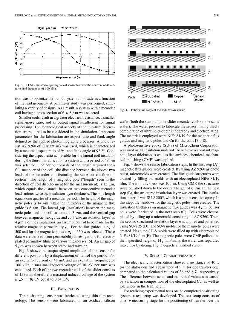
Fig. 3. FEM simulated output signals of sensor for excitation current of 48 mAturns and frequency of 100 kHz.
tion was to optimize the output system amplitude as a functionof the lead geometry. A parameter study was performed, simu-lating a variety of designs. As a result, a system with a meandercoil having a cross section of 6 8 m was selected.
Smaller coils result in a greater electrical resistance, a smallersignal-noise ratio, and an output signal insufficient for signalprocessing. The technological aspects of the thin-film fabrica-tion are required to be considered in the simulation. Importantparameters for the fabrication are aspect ratio and flank angledefined by the applied photolithography processes. A photo re-sist AZ 9260 of Clariant AG was used, which is characterizedby a maximal aspect ratio of 9:1 and flank angle of 92.2 . Con-sidering the aspect ratio achievable for the lateral coil insulatorduring the thin-film fabrication, a system with a period of 48 mwas selected. One period consists of the length required for afull meander of the coil (the distance between the closest twoleads of the meander coil featuring the same current flow di-rection). The length of a magnetic pole (“length” seen in thedirection of coil displacement for the measurement) is 12 m,which equals the distance between two consecutive meanderleads minus twice the insulation layer thickness. The pole lengthequals one quarter of a meander period. The height of the mag-netic poles is 14 m, while the thickness of the magnetic fluxguide is 6 m. The lateral gap (insulation) between the mag-netic poles and the coil structure is 3 m, and the vertical gapbetween magnetic flux guide and coil (also an isolation layer) is4 m. For the simulations, an assumption had to be made for therelative magnetic permeability . For the flux guides, a of500 and for the magnetic poles a of 350 was selected. Thesedata were derived from permeability investigations for electro-plated permalloy films of various thicknesses [6]. An air gap of5 m was chosen between stator and traveler.
Fig. 3 shows the output signal amplitude of the sensor fordifferent positions by a displacement of half of the period. Foran excitation current of 48 mA and an excitation frequency of100 kHz, a maximal induced voltage of 36 V per turn wascalculated. Each of the two meander coils of the slider consistsof 15 turns; therefore, a maximal induced voltage of the systemis V equal to 0.54 mV.
III. FABRICATION
The positioning sensor was fabricated using thin-film tech-nology. The sensors were fabricated on an oxidized silicon
Fig. 4. Fabrication steps of the Inductosyn sensor.
wafer (both the stator and the slider meander coils on the samewafer). The wafer process to fabricate the sensor mainly used acombination of ultraviolet-depth lithography and electroplating.The materials employed were NiFe 81/19 for the magnetic fluxguides and magnetic poles and Cu for the coils [7], [8].
A photosensitive epoxy (SU-8) of MicroChem Corporationwas used as an insulation material. To achieve a constant mag-netic layer thickness as well as flat surfaces, chemical–mechan-ical polishing (CMP) was applied.
Fig. 4 shows the sensor fabrication steps. In the first step (A),magnetic flux guides were created. By using AZ 9260 as photoresist, micromolds were created. The flux guide structures werecreated by filling the molds with an electroplated NiFe 81/19film. The film thickness was 10 m. Using CMP, the structureswere polished down to the desired height of 6 m. In the nextstep (B), the structured insulation layer was created. The insula-tion material was SU-8 2005, which is a photosensitive epoxy. Inthis step, the windows for the magnetic poles were created. Theinsulation thickness on magnetic flux guides was 4 m. Sensorcoils were fabricated in the next step (C). Coils were electro-plated by filling up a micromold consisting of AZ 9260. Then,the second structured insulation layer was applied and patternedusing SU-8 25 (D). The SU-8 molds for the magnetic poles werecreated. Next, the SU-8 molds were filled up with electroplatedNiFe 81/19 film (E). The magnetic poles were CMP polished totheir specified height of 14 m. Finally, the wafer was separatedinto chips by dicing. Fig. 5 depicts a finished stator.
IV. SENSOR CHARACTERIZATION
The electrical characterization showed a resistance of 40for the stator coil and a resistance of 9 for one traveler coil,compared to the calculated values of 36 and 6 , respectively.The difference between actual and theoretical values was causedby variation in composition of the electroplated Cu, as well astolerances in the lead height.
For realizing experimental tests on the completed positioningsystem, a test setup was developed. The test setup consists ofan – measuring stage for the positioning of traveler over the

2832 IEEE TRANSACTIONS ON MAGNETICS, VOL. 42, NO. 10, OCTOBER 2006
Fig. 5. Stator meander coil with flux guides of the micro-Inductosyn.
Fig. 6. Micro-Inductosyn output signal.
stator and of a piezoelectric nanopositioning stage (Type HeraP-625.1CD by Physik Instrumente) for simulation of the move-ment. The nanopositioning stage allows a travel range of 500
m. The traveler was mounted on the – measurement plat-form stage and the stator on the nanopositioning stage.
The – platform enabled the precise positioning of the trav-eler above the stator. The nanopositioning stage provided pre-cise motion of the stator for measurement. In the test setup, thetraveler remained stationary, while the stator was moved.
Since no amplifiers or signal processing systems were usedfor the first measurements, the induced voltage was increasedby applying an excitation current of 40 mA at a frequency of5 MHz. This greater excitation resulted in maximal inducedvoltage amplitude of 9 mV. The theoretical value of inducedvoltage for the same excitation condition is about 25 mV. Fig. 6depicts a measured output signals of sensor. One meander coil
of slider in the measured position with nearly maximal couplinggenerates a signal with maximal amplitude of about 9 mV. In thesame position, a second coil has a zero-crossing.
V. CONCLUSION AND OUTLOOK
The work performed demonstrates that the Inductosyn prin-ciple can be transformed into the micro measurement range.The meander coil, which is the basic element of an Inductosyn,can be substantially reduced in size by applying thin-film tech-nology. This miniaturization improves considerably the reso-lution of the system. To maintain sufficient signal levels, animproved coupling through additional highly permeable fluxguides proved to be necessary.
A measurement test setup for a sensor performance evalu-ation will be developed. For an optimal measurement system,the two 90 phase shifted output signals must be demodulatedand interpolated. Two dual phase lock-in amplifiers will per-form the demodulation to minimize distortions. For good signalstrength and small time constants required for use in dynamiccontrol systems supply frequencies in the megahertz range arenecessary.
ACKNOWLEDGMENT
This work was supported by a grant from the German Re-search Foundation (DFG).
REFERENCES
[1] M. Mizoguchi, T. Matsukawa, K. Takeuchi, and T. Fukuda, “Coherentdetection circuit for high precision encoders,” in Proc. 2000 Int. Symp.Micromechatron. Human Sci., Oct. 2000, pp. 113–118.
[2] C. Li and R. X. Gao, “Error compensation techniques for a linear induc-tosyn displacement measurement system,” in Instrum. Measurm. Tech.Conf. IMTC/95 Proc. IEEE Integrating Intell. Instrum. Control , Apr.1995, p. 364.
[3] D. Chunyang and Y. Guijie, “Error analysis and compensation for in-ductosyn-based position measuring system,” Conf. Rec. 38th IAS Annu.Meeting Industry Appl. Conf., vol. 1, pp. 6–10, Oct. 2003.
[4] P. Kejik, C. Kluser, R. Bischofberger, and R. S. Popovic, “A low-costinductive proximity sensor for industrial applications,” Sens. ActuatorsA, vol. 110, pp. 93–97, 2004.
[5] D. Dinulovic and H. H. Gatzen, “Microfabricated inductive linear micropositioning sensor,” Proc. IEEE Sensors, vol. 3, pp. 1399–1402, 2004.
[6] M. C. Wurz, D. Dinulovic, and H. H. Gatzen, “Investigation of the per-meability on electroplated and sputtered permalloy,” in 206th MeetingElectrochem. Soc. Meeting Abstracts, vol. L2, Honolulu, HI, 2004, p.1175.
[7] H. H. Gatzen, “Magnetic materials in thin-film sensors and actuators,” in206th Meeting Electrochem. Society, Meeting Abstracts, vol. L2, Hon-olulu, HI, 2004, p. 1168.
[8] T. Kohlmeier, V. Seidemann, S. Buettgenbach, and H. H. Gatzen, “Aninvestigation on technologies to fabricate microcoils for miniaturizedactuator systems,” in Microsystem Technology. Berlin, Germany:Springer–Verlag, 2004, vol. 10, pp. 175–185.
Manuscript received March 13, 2006 (e-mail: [email protected]).