direct drive straight arm turntable
TRANSCRIPT

OPERATIONS MANUALBEDIENUNGSHANDBUCHMANUAL DEL OPERADORMANUEL D’INSTRUCTIONS
DIRECT DRIVE STRAIGHT ARM TURNTABLEPLATTENSPIELER MIT DIREKTANTRIEB UND GERADEM TONARMGIRADISCOS DE BRAZO RECTO TRACCIÓN DIRECTAPLATINE VINYLE AVEC ENTRAÎNEMENT DIRECT ET BRAS DROIT
CAUTION: This product satisfies FCC regulations when shielded cables and connectors are used to connect the unit to other equipment. To prevent electromagnetic interference with electric appliances such as radios and televisions, use shielded cables and connectors for connections.
The exclamation point within an equilateral triangle is intended to alert the user to the presenceof important operating and maintenance (servicing) instructions in the literature accompanying the appliance.
The lightning flash with arrowhead symbol, within an equilateral triangle, is intended to alert the user to the presence of uninsulated “dangerous voltage” within the product’s enclosure thatmay be of sufficient magnitude to constitute a risk of electric shock to persons.
READ INSTRUCTIONS: All the safety and operating instructions should be read before the product is operated.
RETAIN INSTRUCTIONS: The safety and operating instructions should be retained for future reference.
HEED WARNINGS: All warnings on the product and in the operating instructions should be adhered to.
FOLLOW INSTRUCTIONS: All operating and use instructions should be followed.
CLEANING: The product should be cleaned only with a polishing cloth or a soft dry cloth. Never clean with furniture wax, benzine, insecticides or other volatile liquidssince they may corrode the cabinet.
ATTACHMENTS: Do not use attachments not recommended by the product manufacturer as they may cause hazards.
WATER AND MOISTURE: Do not use this product near water, for example, near a bathtub, wash bowl, kitchen sink, or laundry tub; in a wet basement; or near a swimming pool; and the like.
ACCESSORIES: Do not place this product on an unstable cart, stand, tripod, bracket, or table. The product may fall, causing serious injury to a child or adult, and serious damage to the product. Use only with a cart, stand, tripod, bracket, or table recommended by the manufacturer, or sold with the product. Any mounting of theproduct should follow the manufacturer’s instructions, and should use a mountingaccessory recommended by the manufacturer.
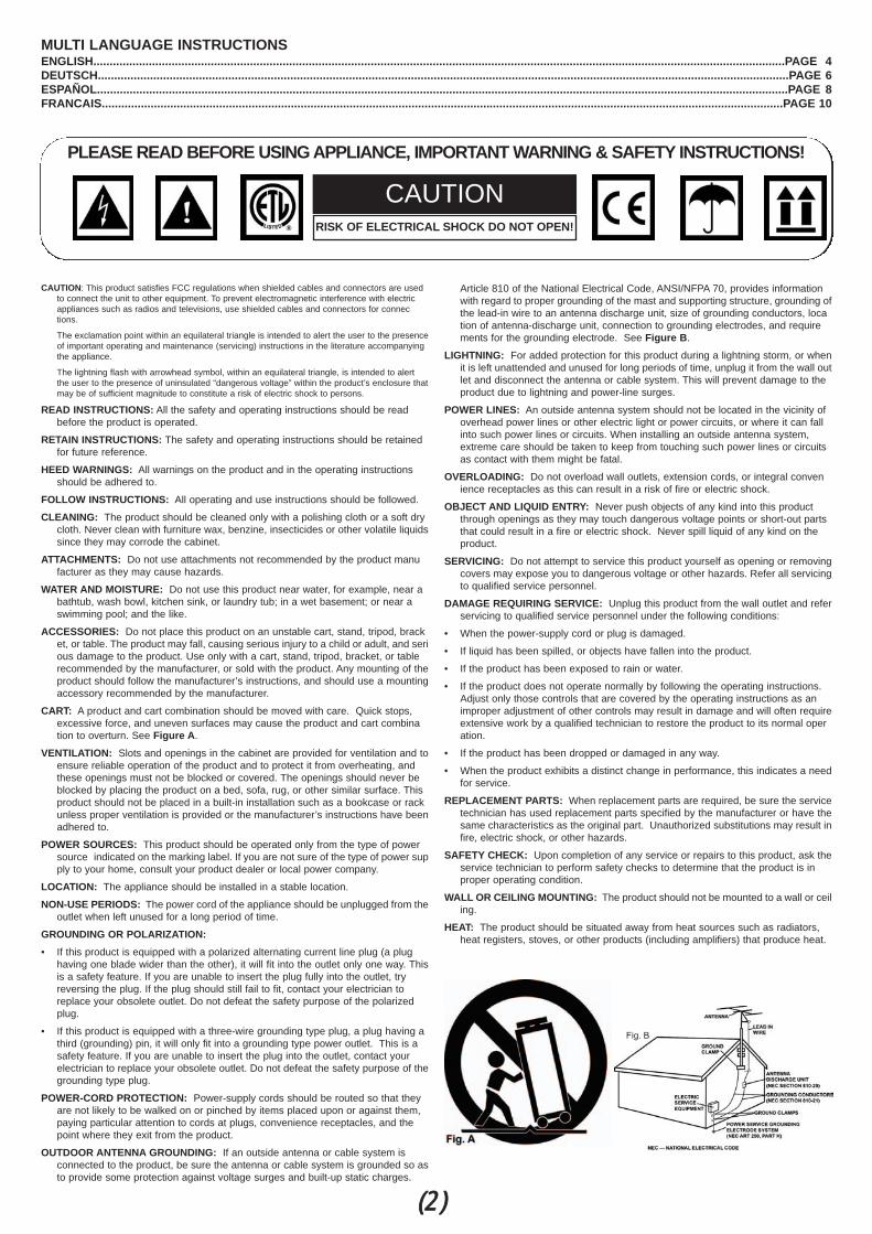
CART: A product and cart combination should be moved with care. Quick stops, excessive force, and uneven surfaces may cause the product and cart combination to overturn. See Figure A.
VENTILATION: Slots and openings in the cabinet are provided for ventilation and toensure reliable operation of the product and to protect it from overheating, and these openings must not be blocked or covered. The openings should never be blocked by placing the product on a bed, sofa, rug, or other similar surface. This product should not be placed in a built-in installation such as a bookcase or rack unless proper ventilation is provided or the manufacturer’s instructions have beenadhered to.
POWER SOURCES: This product should be operated only from the type of power source indicated on the marking label. If you are not sure of the type of power supply to your home, consult your product dealer or local power company.
LOCATION: The appliance should be installed in a stable location.
NON-USE PERIODS: The power cord of the appliance should be unplugged from theoutlet when left unused for a long period of time.
GROUNDING OR POLARIZATION:• If this product is equipped with a polarized alternating current line plug (a plug
having one blade wider than the other), it will fit into the outlet only one way. Thisis a safety feature. If you are unable to insert the plug fully into the outlet, try reversing the plug. If the plug should still fail to fit, contact your electrician to replace your obsolete outlet. Do not defeat the safety purpose of the polarized plug.
• If this product is equipped with a three-wire grounding type plug, a plug having a third (grounding) pin, it will only fit into a grounding type power outlet. This is a safety feature. If you are unable to insert the plug into the outlet, contact your electrician to replace your obsolete outlet. Do not defeat the safety purpose of thegrounding type plug.
POWER-CORD PROTECTION: Power-supply cords should be routed so that they are not likely to be walked on or pinched by items placed upon or against them, paying particular attention to cords at plugs, convenience receptacles, and the point where they exit from the product.
OUTDOOR ANTENNA GROUNDING: If an outside antenna or cable system is connected to the product, be sure the antenna or cable system is grounded so asto provide some protection against voltage surges and built-up static charges.
Article 810 of the National Electrical Code, ANSI/NFPA 70, provides information with regard to proper grounding of the mast and supporting structure, grounding ofthe lead-in wire to an antenna discharge unit, size of grounding conductors, location of antenna-discharge unit, connection to grounding electrodes, and requirements for the grounding electrode. See Figure B.
LIGHTNING: For added protection for this product during a lightning storm, or whenit is left unattended and unused for long periods of time, unplug it from the wall outlet and disconnect the antenna or cable system. This will prevent damage to the product due to lightning and power-line surges.
POWER LINES: An outside antenna system should not be located in the vicinity of overhead power lines or other electric light or power circuits, or where it can fall into such power lines or circuits. When installing an outside antenna system, extreme care should be taken to keep from touching such power lines or circuits as contact with them might be fatal.
OVERLOADING: Do not overload wall outlets, extension cords, or integral convenience receptacles as this can result in a risk of fire or electric shock.
OBJECT AND LIQUID ENTRY: Never push objects of any kind into this product through openings as they may touch dangerous voltage points or short-out parts that could result in a fire or electric shock. Never spill liquid of any kind on the product.
SERVICING: Do not attempt to service this product yourself as opening or removingcovers may expose you to dangerous voltage or other hazards. Refer all servicingto qualified service personnel.
DAMAGE REQUIRING SERVICE: Unplug this product from the wall outlet and referservicing to qualified service personnel under the following conditions:
• When the power-supply cord or plug is damaged.
• If liquid has been spilled, or objects have fallen into the product.
• If the product has been exposed to rain or water.
• If the product does not operate normally by following the operating instructions. Adjust only those controls that are covered by the operating instructions as an improper adjustment of other controls may result in damage and will often requireextensive work by a qualified technician to restore the product to its normal operation.
• If the product has been dropped or damaged in any way.
• When the product exhibits a distinct change in performance, this indicates a needfor service.
REPLACEMENT PARTS: When replacement parts are required, be sure the servicetechnician has used replacement parts specified by the manufacturer or have thesame characteristics as the original part. Unauthorized substitutions may result infire, electric shock, or other hazards.
SAFETY CHECK: Upon completion of any service or repairs to this product, ask theservice technician to perform safety checks to determine that the product is in proper operating condition.
WALL OR CEILING MOUNTING: The product should not be mounted to a wall or ceiling.
HEAT: The product should be situated away from heat sources such as radiators, heat registers, stoves, or other products (including amplifiers) that produce heat.
MULTI LANGUAGE INSTRUCTIONSENGLISH....................................................................................................................................................................................................................PAGE 4DEUTSCH....................................................................................................................................................................................................................PAGE 6ESPAÑOL....................................................................................................................................................................................................................PAGE 8FRANCAIS.................................................................................................................................................................................................................PAGE 10
PLEASE READ BEFORE USING APPLIANCE, IMPORTANT WARNING & SAFETY INSTRUCTIONS!
RISK OF ELECTRICAL SHOCK DO NOT OPEN!
CAUTION
(2)
TT-002MKII
(3)
INTRODUCTION:Congratulations on purchasing a Gemini TT-02 MKIIturntable. This state of the art turntable includes the lat-est features. Prior to use, we suggest that you carefullyread all the instructions.
FEATURES• +/-10% Variable pitch slider• Solid aluminum platter• Straight tonearm for superior tracking• Fully adjustable counter weight & anti-skating con
trols• Dual speed RPM (33/45)• LED Illuminated soft touch start/stop & RPM but
tons• Removable head shell• CN-1000 cartridge & felt slipmat included• RCA & ground cables
PRECAUTIONS:1. Read all operating instructions before using this equip-ment.
2. The apparatus should not be exposed to dripping orsplashing, and no objects filled with liquids such as vasesshould be placed on the apparatus.
3. To reduce the risk of electrical shock, do not open theunit. THERE ARE NO USER REPLACEABLE PARTSINSIDE. Please contact the Gemini Service Departmentor your authorized dealer to speak to a qualified servicetechnician.
4. Tone Arm bearings are factory set and sealed. Anyattempt at adjustment will void the warranty.
5. Be sure that all AC power is OFF while making connec-tions.
6. Cables should be low capacitance, shielded and ofproper length. Make sure that all plugs and jacks are tightand properly connected.
7. Always, begin with the audio level faders/volume con-trols set at minimum and the speaker volume control(s)set to OFF. Wait 8 to 10 seconds prior to turning up thespeaker volume to prevent the transient “POP” that couldresult in speaker/crossover damage.
8. DO NOT EXPOSE THIS UNIT TO RAIN OR MOIS-TURE.
9. DO NOT USE ANY SPRAY CLEANER OR LUBRI-CANT ON ANY CONTROLS OR SWITCHES.
PARTS CHECKLIST:Please make sure the following parts are included withyour TT-02 MKII:Turntable unit...................................................................1Turntable platter...............................................................1Slipmat.............................................................................1Counterweight..................................................................1Headshell with cartridge..................................................1
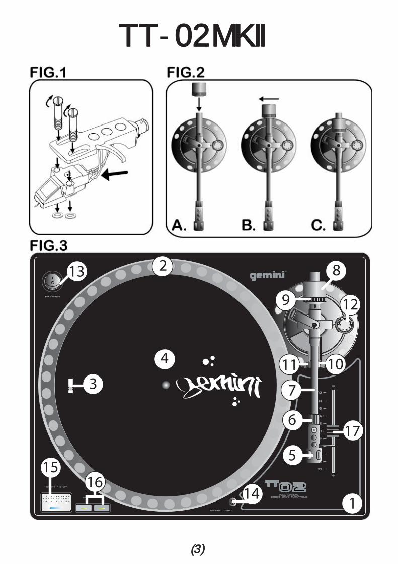
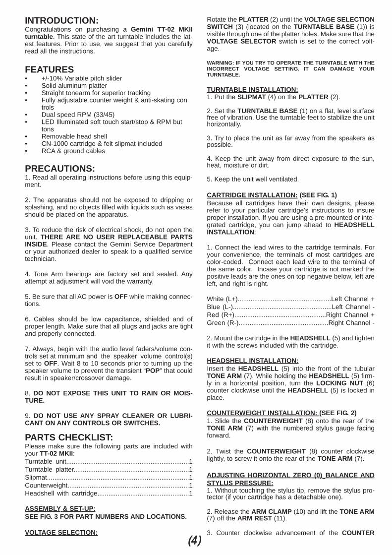
ASSEMBLY & SET-UP:SEE FIG. 3 FOR PART NUMBERS AND LOCATIONS.
VOLTAGE SELECTION:
Rotate the PLATTER (2) until the VOLTAGE SELECTIONSWITCH (3) (located on the TURNTABLE BASE (1)) isvisible through one of the platter holes. Make sure that theVOLTAGE SELECTOR switch is set to the correct volt-age.
WARNING: IF YOU TRY TO OPERATE THE TURNTABLE WITH THEINCORRECT VOLTAGE SETTING, IT CAN DAMAGE YOURTURNTABLE.
TURNTABLE INSTALLATION:1. Put the SLIPMAT (4) on the PLATTER (2).
2. Set the TURNTABLE BASE (1) on a flat, level surfacefree of vibration. Use the turntable feet to stabilize the unithorizontally.
3. Try to place the unit as far away from the speakers aspossible.
4. Keep the unit away from direct exposure to the sun,heat, moisture or dirt.
5. Keep the unit well ventilated.
CARTRIDGE INSTALLATION: (SEE FIG. 1)Because all cartridges have their own designs, pleaserefer to your particular cartridge’s instructions to insureproper installation. If you are using a pre-mounted or inte-grated cartridge, you can jump ahead to HEADSHELLINSTALLATION:
1. Connect the lead wires to the cartridge terminals. Foryour convenience, the terminals of most cartridges arecolor-coded. Connect each lead wire to the terminal ofthe same color. Incase your cartridge is not marked thepositive leads are the ones on top negative below, left areleft, and right is right.
White (L+)...................................................Left Channel +Blue (L-)......................................................Left Channel -Red (R+)..................................................Right Channel +Green (R-).................................................Right Channel -
2. Mount the cartridge in the HEADSHELL (5) and tightenit with the screws included with the cartridge.
HEADSHELL INSTALLATION:Insert the HEADSHELL (5) into the front of the tubularTONE ARM (7). While holding the HEADSHELL (5) firm-ly in a horizontal position, turn the LOCKING NUT (6)counter clockwise until the HEADSHELL (5) is locked inplace.
COUNTERWEIGHT INSTALLATION: (SEE FIG. 2)1. Slide the COUNTERWEIGHT (8) onto the rear of theTONE ARM (7) with the numbered stylus gauge facingforward.
2. Twist the COUNTERWEIGHT (8) counter clockwiselightly, to screw it onto the rear of the TONE ARM (7).
ADJUSTING HORIZONTAL ZERO (0) BALANCE ANDSTYLUS PRESSURE:1. Without touching the stylus tip, remove the stylus pro-tector (if your cartridge has a detachable one).
2. Release the ARM CLAMP (10) and lift the TONE ARM(7) off the ARM REST (11).
3. Counter clockwise advancement of the COUNTER(44)
WEIGHT (8) will cause the cartridge side of the TONEARM (7) to be lowered; turning it clockwise will cause theopposite. Turn the COUNTERWEIGHT (8) clockwise orcounter clockwise as needed until the TONE ARM (7) isbalanced horizontally. You can easily tell this by watchingfor the point where the TONE ARM (7) “floats” freely.
4. Place TONE ARM (7) on ARM REST (11) and lock it inplace with the ARM CLAMP (10).
5. With the TONE ARM (7) locked on the ARM REST (11),hold the COUNTERWEIGHT (8) steady with one handwhile rotating the STYLUS PRESSURE RING (9) until thenumeral “0” on the ring aligns with the center line on theTONE ARM (7) rear shaft. The horizontal zero (0) balanceshould be completed.
6. Re-float the TONE ARM (7) to ensure horizontal zero(0) balance. If zero balance has not been maintained,repeat counterweight steps 3 - 5.
7. After adjusting the horizontal zero (0) balance, turn thebalanced COUNTERWEIGHT (8) counter clockwise untilthe cartridge manufacturer’s recommend stylus pressureappears on the STYLUS PRESSURE RING (9) where itmeets the center line of the TONE ARM (7) rear shaft.
ADJUSTING THE ANTI-SKATING CONTROL:Set the ANTI-SKATING CONTROL (12) to the samevalue as the stylus pressure.
NOTE: IF YOUR TURNTABLE CAME WITH A CN-1000 CARTRIDGE,IT HAS A RECOMMENDED TRACKING FORCE OF 3.0 GRAMS ANDCAN HAVE RANGE FROM 2.5-3.5 GRAMS.
CONNECTIONS:1. Plug the AC power plug into an appropriate outlet.
2. See Table A for proper connection of the output RCAplugs and ground connector. Make sure that all the plugsare firmly plugged into the appropriate jacks (phonoinputs).NOTE: TO REDUCE HUM, MAKE SURE THE GROUND LUG IS FIRM-LY CONNECTED TO THE GROUND SCREW.TABLE A:
OPERATING INSTRUCTIONS:BASIC OPERATION:1. Place a record on the SLIPMAT (4) which sits on thePLATTER (2).
2. Select the desired speed by depressing the 33 or 45SPEED SELECTOR (16) button.
3. Turn the POWER (13) switch to the “ON” position, atwhich point the TARGET LIGHT (14) will light up, TAR-GET LIGHTS (14) are an optional accessory available atyour local retailer.
4. Remove the stylus protector (if applicable to your car-tridge).
5. Release the ARM CLAMP (10) found on the ARMREST (11).
6. Push the START/STOP (15) button. The turntablePLATTER (2) will start to spin.
7. Carefully position the TONE ARM (7) over the desiredposition over the record. Lower the TONE ARM (7) slow-ly, while letting go of the TONE ARM (7) over the recordwhere you want to play.
8. When play is over, raise the TONE ARM (7), move itonto the ARM REST (11), and secure it with the ARMCLAMP (10).
9. You now have the option of turning off the power byturning the POWER (13) switch to the “OFF” position, orstopping the PLATTER (2) by pushing the START/STOP(15) button.
INTERRUPTING PLAY:1. Pushing the START/STOP (15) button will cause therecord to stop exactly when the START/STOP (15) buttonis pressed while playing.
2. Press the START/STOP (15) button again to start play-back with a short DELAY effect.
ADJUSTING THE PITCH CONTROL:1. The TT-02 MKII is equipped with a PITCH CONTROL(17). When the PITCH CONTROL is in the center posi-tion, the speed will be 33 or 45 depending on whichSPEED SELECTOR (16) button is pushed.
2. When the PITCH CONTROL (17) is positioned off cen-ter, the pitch can vary ±10% depending on the position ofthe PITCH CONTROL (17).
SPECIFICATIONS:TURNTABLE SECTION:
Type.......................................Direct Drive Manual TurntableDrive Method.......................................................Direct DriveMotor......................................................................DC MotorSpeed........................................................33 1/3 or 45 RPMWow and Flutter............................Less than 0.25% WRMS*
*THIS RATING REFERS TO THE TURNTABLE ASSEMBLY ANDPLATTER ONLY AND EXCLUDES EFFECTS OF RECORDS, CAR-TRIDGES OR TONEARMS.
TONEARM SECTION:Type.............................Statically Balanced Straight TonearmHeadshell Weight...........................................................5.6 g
GENERAL:Power Supply.........................AC 115 V~60 Hz/230 V~50 HzPower Consumption......................................................15 WDimensions.............................................17.75" x 5.75” x 14" ............................................................(450 x 136 x 352 mm)Weight.........................................................12.5 lbs. (5.7 kg)
SPECIFICATIONS ARE SUBJECT TO CHANGE WITHOUT NOTICE.THE WEIGHT AND DIMENSIONS SHOWN ARE APPROXIMATE.
(5)
OUTPUT CONNECTORS MIXER OR RECIEVERL (WHITE) PHONO L CHANNELR (RED) PHONO R CHANNEL
GND (SPADE LUG) GND SCREW

EINLEITUNG:Wir gratulieren Ihnen zum Kauf eines Gemini TT-02 MKIIPlattenspielers. Dieses hochentwickelte erstklassigeGerät enthält die neuesten Leistungsmerkmale. VorAnwendung dieses Plattenspielers bitte alle Anweisungensorgfältig durchlesen.
LEISTUNGSMERKMALE• Pitchbereich +/- 10% • Stabiler Aluminium Plattenteller• Gerader Tonarm für bestes Abtastverhalten• Tonarmgewicht und Antiskating einstellbar• Zwei Geschwindigkeiten (33/45Upm)• Soft-touch-Taster für Start/Stop und
Drehzahlumschaltung mit LED• Abnehmbares Head shell mit ½”- Normanschluß• Inklusive CN-1000 Tonabnehmersystem & Filz-
Slipmat • Cinchkabel mit Erdungsleitung
VORSICHTSMANAHMEN1. Vor Anwendung dieses Geräts bitten alleAnweisungensorgfältig durchlesen.
2. Das Gerät vor Tropfen und Spritzern schützen, und esdürfen keine mit Flüssigkeit gefüllte Behälter wie Vasendarauf gestellt werden.
3. Das Gerät nicht öffnen, um das Risiko elektrischenSchocks zu mindern. ES ENTHÄLT KEINE VOMANWENDER ERSETZBAREN TEILE. Die Wartung darfnur von befähigten Wartungstechnikern durchgeführt wer-den.
4. Die Tonarmlager sind werkseingestellt und abgedichtet.Jegliche Änderungsversuche machen die Garantieungültig.
5. Darauf achten, da beim Anschlu dieWechseltromleistung abgeschaltet ist.
6. Nur kapazitätsarme, abgeschirmte Kabelvorschriftsmäiger Länge benutzen. Darauf achten, da alleStecker und Buchsen fest angeschraubt und richtigangeschlossen sind.
7. Zu Beginn müssen die Tonpegelüberblender undLautstärkenregler auf Mindeststärke eingestellt und der(die) Lautstärkenregler in OFF-Position geschaltet sein.Vor dem Lauterstellen 8 bis 10 Sekunden warten, umden durch Einschwingung erzeugten Schroteffekt zu ver-meiden, welches zu Lautsprecher- undFrequenzweichenschaden führen könnte.
8. DIESES GERÄT NICHT REGEN ODERFEUCHTIGKEIT AUSSETZEN.
9. AN DEN REGLERN ODER SCHALTERN KEINSPRAY-REINIGUNGSMITTEL ODER SCHMIERMITTELBENUTZEN.
TEILE-CHECKLIST:Plattenspieler...................................................................1Plattenteller......................................................................1Plattentellerauflage..........................................................1Balancegewicht...............................................................1Tonkopf............................................................................1
ZUSAMMENBAU UND ANORDNUNG:HINWEIS: SIEHE ABBILDUNG 3 FüR TEILENUMMERN UND POSI-TIONEN.
SPANNUNGSAUSWAHL:Den PLATTENTELLER - PLATTER (2) rotieren bis denSPANNUNGSWAHLER - VOLTAGE SELECTOR (3)
(befindet sich auf dem PLATTENSPIELERCHASSIS -TURNTABLE BASE (1)) sichtbar ist durch ein Loch desPlattentellers. Den VOLTAGE SELECTOR (3) auf der richtigen Spannung setzen.WARNUNG: LASSEN SIE DEN PLATTER (2) ROTIEREN MIT EINERFALSCHEN SPANNUNGSEINSTELLUNG, DANN KANN DERPLATTENSPIELER SICH BESCHÄDIGEN.
EINBAU DES PLATTENSPIELERS:1. Den PLATTENTELLERAUFLAGE - SLIPMAT (4) aufden PLATTENTELLER - PLATTER (2) legen.
2. Setzen Sie das PLATTENSPIELERCHASSIS -TURNTABLE BASE (1) auf eine flache, ebene Flächeohne Vibration. Es mit den Plattentellerfüßen horizontallagefest machen.
3. Das Gerät so weit wie möglich von den Lautsprechernentfernt aufstellen.
4. Das Gerät von direktem Sonnenlicht, Wärme,Feuchtigkeit oder Schmutz fernhalten.
5. Das Gerät in gut belüfteter Umgebung aufstellen.
EINBAU DES TONABNEHMERS: (SIEHE ABBILDUNG 1)Weil alle Tonabnehmer individuell ausgeführt sind, siehejeweilige Anweisungen für Tonabnehmer, um richtigenEinbau sicherzustellen:
1. Die Zuleitungsdrähte an den Tonabnehmerklemmenanschlieen. Um den Anschlu zu erleichtern, sind die meis-ten Tonabnehmerklemmen farbkodiert. DieZuleitungsdrähte an den Klemmen der jeweiligenFarbkennzeichnung anschlieen.
Weiß (L+)....................................................linker Kanal +Blau (L-)...................................................linker Kanal -Rot (R+)....................................................rechter Kanal +Grün (R-)...................................................rechter Kanal -
2. Den Tonabnehmer in den TONKOPF - HEADSHELL(5) einbauen und mit den dem Tonabnehmer beigefügtenSchrauben befestigen.
EINBAU DES TONKOPFES:Den TONKOPF - HEADSHELL (5) in der Vorderseite desröhrenförmigen TONARMS - TONE ARM (7) einfügen.Beim Halten des TONKOPFES (5) in horizontaler Positiondie SICHERUNGSMUTTER - LOCKING NUT (10) gegenden Uhrzeigersinn drehen, bis der TONKOPF (5) ein-rastet.
EINBAU DES BALANCEGEWICHTS: (SIEHE ABBILDUNG 2)1. Das BALANCEGEWICHT - COUNTERWEIGHT (8)auf den hinteren Teil des TONARMS - TONE ARM (7)Schieben, wobei die numerierte Nadeldicke nach vornegerichtet sein muss.
2. Das COUNTERWEIGHT (8) gering imGegenuhrzeigersinn ziehen, um es auf den hinteren Teildes TONARMS - TONE ARM (7) zu schrauben.
HORIZONTALER NULLPUNKTABGLEICH UND REG-ULIERUNG DES AUFLAGEDRUCKS:1. Ohne die Nadelspitze zu berühren, entfernen Sie denNadelschutz (falls Ihr Tonabnehmer einen abnehmbarenNadelschutz hat).
(6)
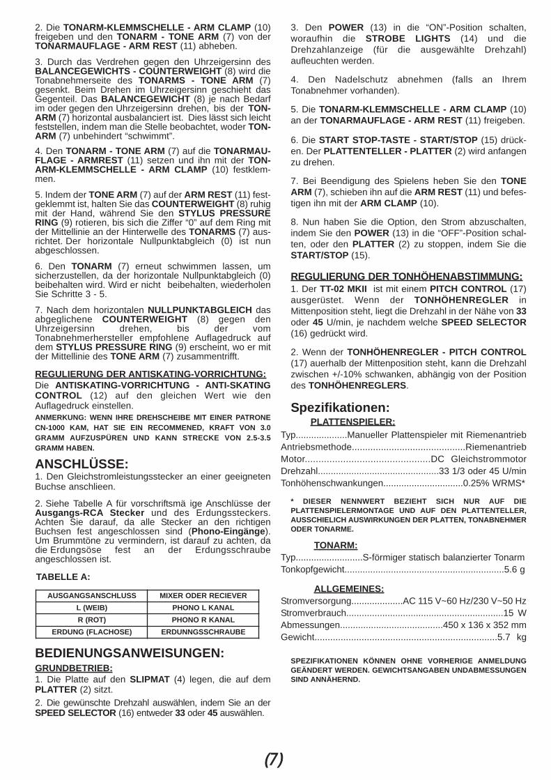
2. Die TONARM-KLEMMSCHELLE - ARM CLAMP (10)freigeben und den TONARM - TONE ARM (7) von derTONARMAUFLAGE - ARM REST (11) abheben.
3. Durch das Verdrehen gegen den Uhrzeigersinn desBALANCEGEWICHTS - COUNTERWEIGHT (8) wird dieTonabnehmerseite des TONARMS - TONE ARM (7)gesenkt. Beim Drehen im Uhrzeigersinn geschieht dasGegenteil. Das BALANCEGEWICHT (8) je nach Bedarfim oder gegen den Uhrzeigersinn drehen, bis der TON-ARM (7) horizontal ausbalanciert ist. Dies lässt sich leichtfeststellen, indem man die Stelle beobachtet, woder TON-ARM (7) unbehindert “schwimmt”.4. Den TONARM - TONE ARM (7) auf die TONARMAU-FLAGE - ARMREST (11) setzen und ihn mit der TON-ARM-KLEMMSCHELLE - ARM CLAMP (10) festklem-men.
5. Indem der TONE ARM (7) auf der ARM REST (11) fest-geklemmt ist, halten Sie das COUNTERWEIGHT (8) ruhigmit der Hand, während Sie den STYLUS PRESSURERING (9) rotieren, bis sich die Ziffer “0” auf dem Ring mitder Mittellinie an der Hinterwelle des TONARMS (7) aus-richtet. Der horizontale Nullpunktabgleich (0) ist nunabgeschlossen.
6. Den TONARM (7) erneut schwimmen lassen, umsicherzustellen, da der horizontale Nullpunktabgleich (0)beibehalten wird. Wird er nicht beibehalten, wiederholenSie Schritte 3 - 5.
7. Nach dem horizontalen NULLPUNKTABGLEICH dasabgeglichene COUNTERWEIGHT (8) gegen denUhrzeigersinn drehen, bis der vomTonabnehmerhersteller empfohlene Auflagedruck aufdem STYLUS PRESSURE RING (9) erscheint, wo er mitder Mittellinie des TONE ARM (7) zusammentrifft.
REGULIERUNG DER ANTISKATING-VORRICHTUNG:Die ANTISKATING-VORRICHTUNG - ANTI-SKATINGCONTROL (12) auf den gleichen Wert wie denAuflagedruck einstellen.ANMERKUNG: WENN IHRE DREHSCHEIBE MIT EINER PATRONECN-1000 KAM, HAT SIE EIN RECOMMENED, KRAFT VON 3.0GRAMM AUFZUSPÜREN UND KANN STRECKE VON 2.5-3.5GRAMM HABEN.
ANSCHLÜSSE:1. Den Gleichstromleistungsstecker an einer geeignetenBuchse anschlieen.
2. Siehe Tabelle A für vorschriftsmä ige Anschlüsse derAusgangs-RCA Stecker und des Erdungssteckers.Achten Sie darauf, da alle Stecker an den richtigenBuchsen fest angeschlossen sind (Phono-Eingänge).Um Brummtöne zu vermindern, ist darauf zu achten, dadie Erdungsöse fest an der Erdungsschraubeangeschlossen ist.
TABELLE A:
BEDIENUNGSANWEISUNGEN:GRUNDBETRIEB:1. Die Platte auf den SLIPMAT (4) legen, die auf demPLATTER (2) sitzt.2. Die gewünschte Drehzahl auswählen, indem Sie an derSPEED SELECTOR (16) entweder 33 oder 45 auswählen.
3. Den POWER (13) in die “ON”-Position schalten,woraufhin die STROBE LIGHTS (14) und dieDrehzahlanzeige (für die ausgewählte Drehzahl)aufleuchten werden.
4. Den Nadelschutz abnehmen (falls an IhremTonabnehmer vorhanden).
5. Die TONARM-KLEMMSCHELLE - ARM CLAMP (10)an der TONARMAUFLAGE - ARM REST (11) freigeben.
6. Die START STOP-TASTE - START/STOP (15) drück-en. Der PLATTENTELLER - PLATTER (2) wird anfangenzu drehen.
7. Bei Beendigung des Spielens heben Sie den TONEARM (7), schieben ihn auf die ARM REST (11) und befes-tigen ihn mit der ARM CLAMP (10).
8. Nun haben Sie die Option, den Strom abzuschalten,indem Sie den POWER (13) in die “OFF”-Position schal-ten, oder den PLATTER (2) zu stoppen, indem Sie dieSTART/STOP (15).
REGULIERUNG DER TONHÖHENABSTIMMUNG:1. Der TT-02 MKII ist mit einem PITCH CONTROL (17)ausgerüstet. Wenn der TONHÖHENREGLER inMittenposition steht, liegt die Drehzahl in der Nähe von 33oder 45 U/min, je nachdem welche SPEED SELECTOR(16) gedrückt wird.
2. Wenn der TONHÖHENREGLER - PITCH CONTROL(17) auerhalb der Mittenposition steht, kann die Drehzahlzwischen +/-10% schwanken, abhängig von der Positiondes TONHÖHENREGLERS.
Spezifikationen:PLATTENSPIELER:
Typ....................Manueller Plattenspieler mit RiemenantriebAntriebsmethode...........................................RiemenantriebMotor..............................................DC GleichstrommotorDrehzahl...............................................33 1/3 oder 45 U/minTonhöhenschwankungen...............................0.25% WRMS*
* DIESER NENNWERT BEZIEHT SICH NUR AUF DIEPLATTENSPIELERMONTAGE UND AUF DEN PLATTENTELLER,AUSSCHIELICH AUSWIRKUNGEN DER PLATTEN, TONABNEHMERODER TONARME.
TONARM:Typ..........................S-förmiger statisch balanzierter TonarmTonkopfgewicht..............................................................5.6 g
ALLGEMEINES:Stromversorgung....................AC 115 V~60 Hz/230 V~50 HzStromverbrauch.............................................................15 WAbmessungen........................................450 x 136 x 352 mmGewicht......................................................................5.7 kg
SPEZIFIKATIONEN KÖNNEN OHNE VORHERIGE ANMELDUNGGEÄNDERT WERDEN. GEWICHTSANGABEN UNDABMESSUNGENSIND ANNÄHERND.
(77)
AUSGANGSANSCHLUSS MIXER ODER RECIEVERL (WEIB) PHONO L KANALR (ROT) PHONO R KANAL
ERDUNG (FLACHOSE) ERDUNNGSSCHRAUBE
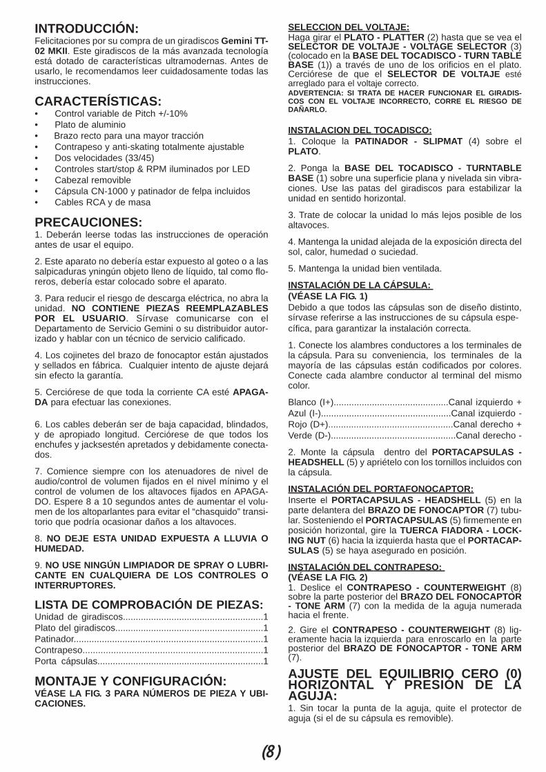
INTRODUCCIÓN:Felicitaciones por su compra de un giradiscos Gemini TT-02 MKII. Este giradiscos de la más avanzada tecnologíaestá dotado de características ultramodernas. Antes deusarlo, le recomendamos leer cuidadosamente todas lasinstrucciones.
CARACTERÍSTICAS:• Control variable de Pitch +/-10%• Plato de aluminio• Brazo recto para una mayor tracción• Contrapeso y anti-skating totalmente ajustable• Dos velocidades (33/45)• Controles start/stop & RPM iluminados por LED• Cabezal removible• Cápsula CN-1000 y patinador de felpa incluidos• Cables RCA y de masa
PRECAUCIONES:1. Deberán leerse todas las instrucciones de operaciónantes de usar el equipo.
2. Este aparato no debería estar expuesto al goteo o a lassalpicaduras yningún objeto lleno de líquido, tal como flo-reros, debería estar colocado sobre el aparato.
3. Para reducir el riesgo de descarga eléctrica, no abra launidad. NO CONTIENE PIEZAS REEMPLAZABLESPOR EL USUARIO. Sírvase comunicarse con elDepartamento de Servicio Gemini o su distribuidor autor-izado y hablar con un técnico de servicio calificado.
4. Los cojinetes del brazo de fonocaptor están ajustadosy sellados en fábrica. Cualquier intento de ajuste dejarásin efecto la garantía.
5. Cerciórese de que toda la corriente CA esté APAGA-DA para efectuar las conexiones.
6. Los cables deberán ser de baja capacidad, blindados,y de apropiado longitud. Cerciórese de que todos losenchufes y jacksestén apretados y debidamente conecta-dos.
7. Comience siempre con los atenuadores de nivel deaudio/control de volumen fijados en el nivel mínimo y elcontrol de volumen de los altavoces fijados en APAGA-DO. Espere 8 a 10 segundos antes de aumentar el volu-men de los altoparlantes para evitar el “chasquido” transi-torio que podría ocasionar daños a los altavoces.
8. NO DEJE ESTA UNIDAD EXPUESTA A LLUVIA OHUMEDAD.
9. NO USE NINGÚN LIMPIADOR DE SPRAY O LUBRI-CANTE EN CUALQUIERA DE LOS CONTROLES OINTERRUPTORES.
LISTA DE COMPROBACIÓN DE PIEZAS:Unidad de giradiscos.......................................................1Plato del giradiscos..........................................................1Patinador..........................................................................1Contrapeso......................................................................1Porta cápsulas.................................................................1
MONTAJE Y CONFIGURACIÓN:VÉASE LA FIG. 3 PARA NÚMEROS DE PIEZA Y UBI-CACIONES.
SELECCION DEL VOLTAJE:Haga girar el PLATO - PLATTER (2) hasta que se vea elSELECTOR DE VOLTAJE - VOLTAGE SELECTOR (3)(colocado en la BASE DEL TOCADISCO - TURN TABLEBASE (1)) a través de uno de los orificios en el plato.Cerciórese de que el SELECTOR DE VOLTAJE estéarreglado para el voltaje correcto.ADVERTENCIA: SI TRATA DE HACER FUNCIONAR EL GIRADIS-COS CON EL VOLTAJE INCORRECTO, CORRE EL RIESGO DEDAÑARLO.
INSTALACION DEL TOCADISCO:1. Coloque la PATINADOR - SLIPMAT (4) sobre elPLATO.
2. Ponga la BASE DEL TOCADISCO - TURNTABLEBASE (1) sobre una superficie plana y nivelada sin vibra-ciones. Use las patas del giradiscos para estabilizar launidad en sentido horizontal.
3. Trate de colocar la unidad lo más lejos posible de losaltavoces.
4. Mantenga la unidad alejada de la exposición directa delsol, calor, humedad o suciedad.
5. Mantenga la unidad bien ventilada.
INSTALACIÓN DE LA CÁPSULA: (VÉASE LA FIG. 1)Debido a que todos las cápsulas son de diseño distinto,sírvase referirse a las instrucciones de su cápsula espe-cífica, para garantizar la instalación correcta.
1. Conecte los alambres conductores a los terminales dela cápsula. Para su conveniencia, los terminales de lamayoría de las cápsulas están codificados por colores.Conecte cada alambre conductor al terminal del mismocolor.
Blanco (I+).............................................Canal izquierdo +Azul (I-)...................................................Canal izquierdo -Rojo (D+).................................................Canal derecho +Verde (D-).................................................Canal derecho -
2. Monte la cápsula dentro del PORTACAPSULAS -HEADSHELL (5) y apriételo con los tornillos incluidos conla cápsula.
INSTALACIÓN DEL PORTAFONOCAPTOR:Inserte el PORTACAPSULAS - HEADSHELL (5) en laparte delantera del BRAZO DE FONOCAPTOR (7) tubu-lar. Sosteniendo el PORTACAPSULAS (5) firmemente enposición horizontal, gire la TUERCA FIADORA - LOCK-ING NUT (6) hacia la izquierda hasta que el PORTACAP-SULAS (5) se haya asegurado en posición.
INSTALACIÓN DEL CONTRAPESO: (VÉASE LA FIG. 2)1. Deslice el CONTRAPESO - COUNTERWEIGHT (8)sobre la parte posterior del BRAZO DEL FONOCAPTOR- TONE ARM (7) con la medida de la aguja numeradahacia el frente.2. Gire el CONTRAPESO - COUNTERWEIGHT (8) lig-eramente hacia la izquierda para enroscarlo en la parteposterior del BRAZO DE FONOCAPTOR - TONE ARM(7).
AJUSTE DEL EQUILIBRIO CERO (0)HORIZONTAL Y PRESIÓN DE LAAGUJA:1. Sin tocar la punta de la aguja, quite el protector deaguja (si el de su cápsula es removible).
(8)
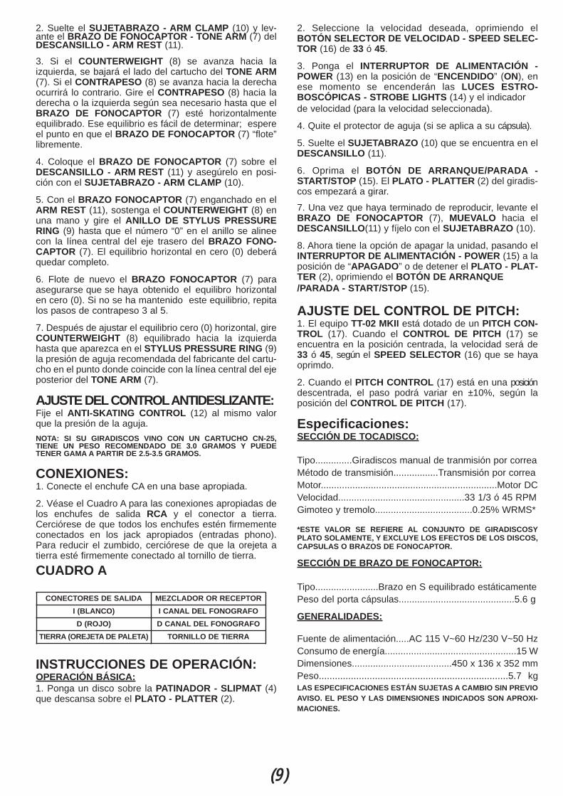
2. Suelte el SUJETABRAZO - ARM CLAMP (10) y lev-ante el BRAZO DE FONOCAPTOR - TONE ARM (7) delDESCANSILLO - ARM REST (11).
3. Si el COUNTERWEIGHT (8) se avanza hacia laizquierda, se bajará el lado del cartucho del TONE ARM(7). Si el CONTRAPESO (8) se avanza hacia la derechaocurrirá lo contrario. Gire el CONTRAPESO (8) hacia laderecha o la izquierda según sea necesario hasta que elBRAZO DE FONOCAPTOR (7) esté horizontalmenteequilibrado. Ese equilibrio es fácil de determinar; espereel punto en que el BRAZO DE FONOCAPTOR (7) “flote”libremente.
4. Coloque el BRAZO DE FONOCAPTOR (7) sobre elDESCANSILLO - ARM REST (11) y asegúrelo en posi-ción con el SUJETABRAZO - ARM CLAMP (10).
5. Con el BRAZO FONOCAPTOR (7) enganchado en elARM REST (11), sostenga el COUNTERWEIGHT (8) enuna mano y gire el ANILLO DE STYLUS PRESSURERING (9) hasta que el número “0” en el anillo se alineecon la línea central del eje trasero del BRAZO FONO-CAPTOR (7). El equilibrio horizontal en cero (0) deberáquedar completo.
6. Flote de nuevo el BRAZO FONOCAPTOR (7) paraasegurarse que se haya obtenido el equilibro horizontalen cero (0). Si no se ha mantenido este equilibrio, repitalos pasos de contrapeso 3 al 5.
7. Después de ajustar el equilibrio cero (0) horizontal, gireCOUNTERWEIGHT (8) equilibrado hacia la izquierdahasta que aparezca en el STYLUS PRESSURE RING (9)la presión de aguja recomendada del fabricante del cartu-cho en el punto donde coincide con la línea central del ejeposterior del TONE ARM (7).
AJUSTE DELCONTROLANTIDESLIZANTE:Fije el ANTI-SKATING CONTROL (12) al mismo valorque la presión de la aguja.NOTA: SI SU GIRADISCOS VINO CON UN CARTUCHO CN-25,TIENE UN PESO RECOMENDADO DE 3.0 GRAMOS Y PUEDETENER GAMA A PARTIR DE 2.5-3.5 GRAMOS.
CONEXIONES:1. Conecte el enchufe CA en una base apropiada.
2. Véase el Cuadro A para las conexiones apropiadas delos enchufes de salida RCA y el conector a tierra.Cerciórese de que todos los enchufes estén firmementeconectados en los jack apropiados (entradas phono).Para reducir el zumbido, cerciórese de que la orejeta atierra esté firmemente conectado al tornillo de tierra.
CUADRO A
INSTRUCCIONES DE OPERACIÓN:OPERACIÓN BÁSICA:1. Ponga un disco sobre la PATINADOR - SLIPMAT (4)que descansa sobre el PLATO - PLATTER (2).
2. Seleccione la velocidad deseada, oprimiendo elBOTÓN SELECTOR DE VELOCIDAD - SPEED SELEC-TOR (16) de 33 ó 45.
3. Ponga el INTERRUPTOR DE ALIMENTACIÓN -POWER (13) en la posición de “ENCENDIDO” (ON), enese momento se encenderán las LUCES ESTRO-BOSCÓPICAS - STROBE LIGHTS (14) y el indicadorde velocidad (para la velocidad seleccionada).
4. Quite el protector de aguja (si se aplica a su cápsula).
5. Suelte el SUJETABRAZO (10) que se encuentra en elDESCANSILLO (11).
6. Oprima el BOTÓN DE ARRANQUE/PARADA -START/STOP (15). El PLATO - PLATTER (2) del giradis-cos empezará a girar.
7. Una vez que haya terminado de reproducir, levante elBRAZO DE FONOCAPTOR (7), MUEVALO hacia elDESCANSILLO(11) y fíjelo con el SUJETABRAZO (10).
8. Ahora tiene la opción de apagar la unidad, pasando elINTERRUPTOR DE ALIMENTACIÓN - POWER (15) a laposición de “APAGADO” o de detener el PLATO - PLAT-TER (2), oprimiendo el BOTÓN DE ARRANQUE/PARADA - START/STOP (15).
AJUSTE DEL CONTROL DE PITCH:1. El equipo TT-02 MKII está dotado de un PITCH CON-TROL (17). Cuando el CONTROL DE PITCH (17) seencuentra en la posición centrada, la velocidad será de33 ó 45, según el SPEED SELECTOR (16) que se hayaoprimdo.
2. Cuando el PITCH CONTROL (17) está en una posicióndescentrada, el paso podrá variar en ±10%, según laposición del CONTROL DE PITCH (17).
Especificaciones:SECCIÓN DE TOCADISCO:
Tipo..............Giradiscos manual de tranmisión por correaMétodo de transmisión.................Transmisión por correaMotor...................................................................Motor DCVelocidad................................................33 1/3 ó 45 RPMGimoteo y tremolo.....................................0.25% WRMS*
*ESTE VALOR SE REFIERE AL CONJUNTO DE GIRADISCOSYPLATO SOLAMENTE, Y EXCLUYE LOS EFECTOS DE LOS DISCOS,CAPSULAS O BRAZOS DE FONOCAPTOR.
SECCIÓN DE BRAZO DE FONOCAPTOR:
Tipo........................Brazo en S equilibrado estáticamentePeso del porta cápsulas............................................5.6 g
GENERALIDADES:
Fuente de alimentación.....AC 115 V~60 Hz/230 V~50 HzConsumo de energía..................................................15 WDimensiones......................................450 x 136 x 352 mmPeso.......................................................................5.7 kgLAS ESPECIFICACIONES ESTÁN SUJETAS A CAMBIO SIN PREVIOAVISO. EL PESO Y LAS DIMENSIONES INDICADOS SON APROXI-MACIONES.
(9)
CONECTORES DE SALIDA MEZCLADOR OR RECEPTORI (BLANCO) I CANAL DEL FONOGRAFOD (ROJO) D CANAL DEL FONOGRAFO
TIERRA (OREJETA DE PALETA) TORNILLO DE TIERRA
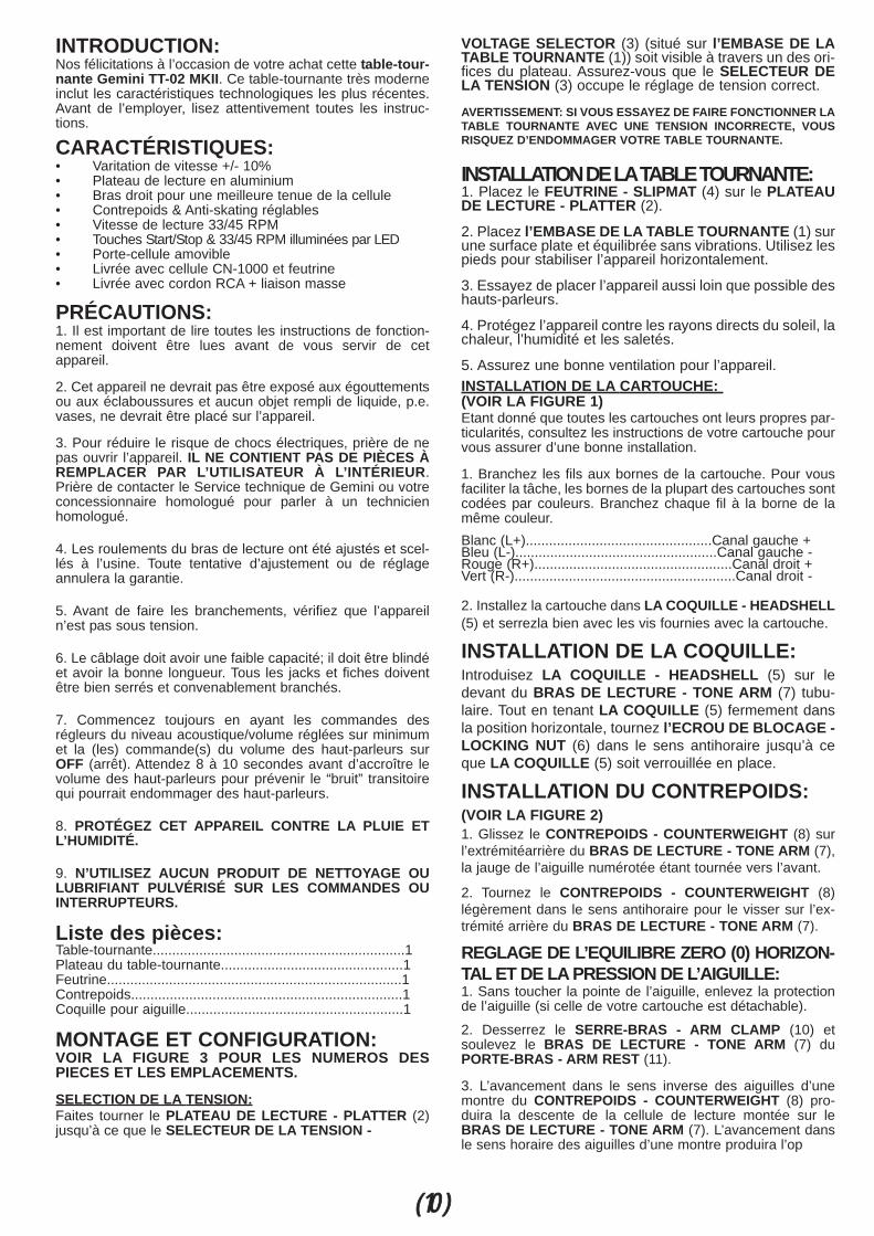
INTRODUCTION:Nos félicitations à l’occasion de votre achat cette table-tour-nante Gemini TT-02 MKII. Ce table-tournante très moderneinclut les caractéristiques technologiques les plus récentes.Avant de l’employer, lisez attentivement toutes les instruc-tions.
CARACTÉRISTIQUES:• Varitation de vitesse +/- 10%• Plateau de lecture en aluminium• Bras droit pour une meilleure tenue de la cellule• Contrepoids & Anti-skating réglables• Vitesse de lecture 33/45 RPM• Touches Start/Stop & 33/45 RPM illuminées par LED• Porte-cellule amovible• Livrée avec cellule CN-1000 et feutrine• Livrée avec cordon RCA + liaison masse
PRÉCAUTIONS:1. Il est important de lire toutes les instructions de fonction-nement doivent être lues avant de vous servir de cetappareil.
2. Cet appareil ne devrait pas être exposé aux égouttementsou aux éclaboussures et aucun objet rempli de liquide, p.e.vases, ne devrait être placé sur l’appareil.
3. Pour réduire le risque de chocs électriques, prière de nepas ouvrir l’appareil. IL NE CONTIENT PAS DE PIÈCES ÀREMPLACER PAR L’UTILISATEUR À L’INTÉRIEUR.Prière de contacter le Service technique de Gemini ou votreconcessionnaire homologué pour parler à un technicienhomologué.
4. Les roulements du bras de lecture ont été ajustés et scel-lés à l’usine. Toute tentative d’ajustement ou de réglageannulera la garantie.
5. Avant de faire les branchements, vérifiez que l’appareiln’est pas sous tension.
6. Le câblage doit avoir une faible capacité; il doit être blindéet avoir la bonne longueur. Tous les jacks et fiches doiventêtre bien serrés et convenablement branchés.
7. Commencez toujours en ayant les commandes desrégleurs du niveau acoustique/volume réglées sur minimumet la (les) commande(s) du volume des haut-parleurs surOFF (arrêt). Attendez 8 à 10 secondes avant d’accroître levolume des haut-parleurs pour prévenir le “bruit” transitoirequi pourrait endommager des haut-parleurs.
8. PROTÉGEZ CET APPAREIL CONTRE LA PLUIE ETL’HUMIDITÉ.
9. N’UTILISEZ AUCUN PRODUIT DE NETTOYAGE OULUBRIFIANT PULVÉRISÉ SUR LES COMMANDES OUINTERRUPTEURS.
Liste des pièces:Table-tournante.................................................................1Plateau du table-tournante...............................................1Feutrine............................................................................1Contrepoids......................................................................1Coquille pour aiguille........................................................1
MONTAGE ET CONFIGURATION:VOIR LA FIGURE 3 POUR LES NUMEROS DESPIECES ET LES EMPLACEMENTS.
SELECTION DE LA TENSION:Faites tourner le PLATEAU DE LECTURE - PLATTER (2)jusqu’à ce que le SELECTEUR DE LA TENSION -
VOLTAGE SELECTOR (3) (situé sur l’EMBASE DE LATABLE TOURNANTE (1)) soit visible à travers un des ori-fices du plateau. Assurez-vous que le SELECTEUR DELA TENSION (3) occupe le réglage de tension correct.
AVERTISSEMENT: SI VOUS ESSAYEZ DE FAIRE FONCTIONNER LATABLE TOURNANTE AVEC UNE TENSION INCORRECTE, VOUSRISQUEZ D’ENDOMMAGER VOTRE TABLE TOURNANTE.
INSTALLATION DE LATABLE TOURNANTE:1. Placez le FEUTRINE - SLIPMAT (4) sur le PLATEAUDE LECTURE - PLATTER (2).
2. Placez l’EMBASE DE LA TABLE TOURNANTE (1) surune surface plate et équilibrée sans vibrations. Utilisez lespieds pour stabiliser l’appareil horizontalement.
3. Essayez de placer l’appareil aussi loin que possible deshauts-parleurs.
4. Protégez l’appareil contre les rayons directs du soleil, lachaleur, l’humidité et les saletés.
5. Assurez une bonne ventilation pour l’appareil.INSTALLATION DE LA CARTOUCHE: (VOIR LA FIGURE 1)Etant donné que toutes les cartouches ont leurs propres par-ticularités, consultez les instructions de votre cartouche pourvous assurer d’une bonne installation.
1. Branchez les fils aux bornes de la cartouche. Pour vousfaciliter la tâche, les bornes de la plupart des cartouches sontcodées par couleurs. Branchez chaque fil à la borne de lamême couleur.Blanc (L+)................................................Canal gauche +Bleu (L-)....................................................Canal gauche -Rouge (R+)...................................................Canal droit +Vert (R-).........................................................Canal droit -
2. Installez la cartouche dans LA COQUILLE - HEADSHELL(5) et serrezla bien avec les vis fournies avec la cartouche.
INSTALLATION DE LA COQUILLE:Introduisez LA COQUILLE - HEADSHELL (5) sur ledevant du BRAS DE LECTURE - TONE ARM (7) tubu-laire. Tout en tenant LA COQUILLE (5) fermement dansla position horizontale, tournez l’ECROU DE BLOCAGE -LOCKING NUT (6) dans le sens antihoraire jusqu’à ceque LA COQUILLE (5) soit verrouillée en place.
INSTALLATION DU CONTREPOIDS: (VOIR LA FIGURE 2)1. Glissez le CONTREPOIDS - COUNTERWEIGHT (8) surl’extrémitéarrière du BRAS DE LECTURE - TONE ARM (7),la jauge de l’aiguille numérotée étant tournée vers l’avant.
2. Tournez le CONTREPOIDS - COUNTERWEIGHT (8)légèrement dans le sens antihoraire pour le visser sur l’ex-trémité arrière du BRAS DE LECTURE - TONE ARM (7).
REGLAGE DE L’EQUILIBRE ZERO (0) HORIZON-TAL ET DE LA PRESSION DE L’AIGUILLE:1. Sans toucher la pointe de l’aiguille, enlevez la protectionde l’aiguille (si celle de votre cartouche est détachable).
2. Desserrez le SERRE-BRAS - ARM CLAMP (10) etsoulevez le BRAS DE LECTURE - TONE ARM (7) duPORTE-BRAS - ARM REST (11).
3. L’avancement dans le sens inverse des aiguilles d’unemontre du CONTREPOIDS - COUNTERWEIGHT (8) pro-duira la descente de la cellule de lecture montée sur leBRAS DE LECTURE - TONE ARM (7). L’avancement dansle sens horaire des aiguilles d’une montre produira l’op
(10)

posé. Tournez le CONTREPOIDS (8) dans le sens horaire oudans le sens inverse des aiguilles d’une mon tre selon lebesoin, jusqu’à ce que le BRAS DE LECTURE (7) soit équili-bré horizontalement. Ce moment seproduit, et vous le verrezfacilement, lorsque le BRAS DE LECTURE (7) “flotte” libre-ment.4. Placez le BRAS DE LECTURE - TONE ARM (7) sur lePORTE-BRAS - ARM REST (11) bloquez-le en place avec leSERRE-BRAS - ARM CLAMP (10).
5. Le BRAS DE LECTURE - TONE ARM (7) étant verrouillésur le PORTEBRAS - ARM REST (11), stabilisez le CON-TREPOIDS - COUNTERWEIGHT (8) avec une main tout entournant l’ANNEAU DE PRESSION DE L’AIGUILLE - STY-LUS PRESSURE RING (9) jusqu’à ce que le numéro “0” surl’anneau s’aligne avec la ligne médiane sur l’arbre arrière duBRAS DE LECTURE (7). L’équilibre zéro horizontal (0)devrait être complété.
6. Faites flotter le BRAS DE LECTURE (7) de nouveau pourvous assurer de l’équilibre zéro horizontal (0). Si l’équilibrezéro n’est pas maintenu, répétez les étapes 3-5 du CON-TREPOIDS (8).
7. Après le réglage de l’équilibre zéro (0) horizontal, tournezle CONTREPOIDS - COUNTERWEIGHT (8) équilibré dansle sens inverse des aguilles d’une montre jusqu’à ce que lapression de l’aiguille recommandée par le fabricant de la cel-lule de lecture apparaisse sur la BAGUE DE PRESSION DEL’AIGUILLE - STYLUS PRESSURE RING (9) là où elle ren-contre la ligne médiane de l’arbre arrière du BRAS DE LEC-TURE - TONE ARM (7).
REGLAGE DE LACOMMANDE ANTI-DERAPAGE:Mettez la COMMANDE ANTI-DERAPAGE - ANTI-SKATINGCONTROL (12) à la même valeur que celle de la pression del’aiguille.
NOTE: SI VOTRE PLATEAU TOURNE-DISQUES VENAIT AVEC UNECARTOUCHE CN-1000, ELLE A UN RECOMMENED DÉPISTER LAFORCE DE 3.0 GRAMMES ET PEUT AVOIR LA GAMME DE 2.5-3.5GRAMMES.
CONNEXIONS:1. Branchez la fiche à courant alternatif à une priseadéquate.
2. Voir la Table A pour les connexions correctes des fichesRCA de sortie et du connecteur de mise à la terre. Assurez-vous que toutes les fiches sont solidement raccordées dansles jacks corrects (entrées phono). Pour réduire le ronron-nement, assurez-vous que l’oreille de mise à la terre sebranche solidement à la vis de mise à la terre.
TABLEAU A
MODE D’EMPLOI:FONCTIONNEMENT DE BASE:1. Placez un disque sur le SLIPMAT (4) se trouvant sur lePLATTER (2).
2. Choisissez la vitesse désirée en appuyant sur le SPEEDSELECTOR (16) de 33 ou de 45.
3. Mettez l’INTERRUPTEUR DE MISE SOUS TENSION -POWER (13) sur la position “ON” (Sous tension); à cemoment, les LUMIERES STROBOSCOPIQUES - STROBELIGHTS (14) et l’indicateur de vitesse (pour la vitessechoisie) s’allumeront.
4. Enlevez la protection de l’aiguille (si elle fait partie de votrecartouche).
5. Libérez le ARM CLAMP (10) qui se trouve sur le ARMREST (11).
6. Appuyez sur le START/STOP (15). Le PLATTER (2) dutable-tournante commencera à tourner.
7. Une fois l’enregistrement terminé, soulevez le TONE ARM(7), guidez-levers le ARM REST (11) et bloquez-le à l’aide duARM CLAMP (10).
8. Maintenant, vous avez le choix de mettre l’appareil horstension en tournant POWER (13) sur la position “OFF” (horstension) ou d’arrêter le PLATTER (2) en appuyant sur leSTART/STOP (15).
REGLAGE DE LA COMMANDE DE LAHAUTEUR TONALE:1. L’appareil TT-02 MKII est muni d’une COMMANDE DELA HAUTEUR TONALE - PITCH CONTROL (17).Lorsque cette COMMANDE DE LA HAUTEUR TONALEoccupe la position centrale, la vitesse s’approchera de 33ou de 45 t/mn en fonction du SPEED SELECTOR (16)pressé.
2. Si la COMMANDE DE LA HAUTEUR TONALE -PITCH CONTROL (17) n’occupe pas la position centrale,la hauteur tonale peut varier de +/-10% en fonction de laposition occupée par cette PITCH CONTROL (17).
SPECIFICATIONS:PARTIE DU TABLE-TOURNANTE:
Type....Table-tournante manuel à transmission par courroieMéthode de transmission.............Transmission par courroieMoteur..................................................................Moteur DCVitesse.......................................................33 1/3 ou 45 t/mnPleurage et scintillement...............................0.25% WRMS*
*CETTE VALEUR NE CORRESPOND QU’AU TOURNE-DISQUE ETAU PLATEAU, À L’EXCLUSION DES EFFETS PRODUITS PAR LESDISQUES, LES CARTOUCHES OU LES BRAS DE LECTURES.
PARTIE DU BRAS DE LECTURE:Type....................................Bras en S à équilibrage statiquePoids de la coquille........................................................5.6 g
GENERALITES:Alimentation électrique...........AC 115 V~60 Hz/230 V~50 HzConsommation...............................................................15 WDimensions............................................450 x 136 x 352 mmPoids..........................................................................5.7 kg
LES SPÉCIFICATIONS PEUVENT CHANGER SANS PRÉAVIS. LEPOIDS ET LES DIMENSIONS INDIQUÉS SONT APPROXIMATIFS.
(11)
CONNECTUERS DE SORTIE MELANGUER OU RECEPTEUR
L (BLANC) L CANALE PHONO
R (ROUGE) R CANAL PHONO
MASSE (OEILLET) VIS DE MISE A LA MASSE

(12)
NOTES

(13)
NOTES

50Hz Speed check gaugeCarefully punch a hole in the center of this disc,Operate turntable at 0% without quartz lock.Place turntable close to any florescent lighting source. The outer ring should appear still at 33 rpm.The inner ring should appear still at 45rpm.

60Hz Speed check gaugeCarefully punch a hole in the center of this disc,Operate turntable at 0% without quartz lock.Place turntable close to any florescent lighting source. The outer ring should appear still at 33 rpm.The inner ring should appear still at 45rpm.

Worldwide Headquarters • 120 Clover Place, Edison, NJ 08837 • USATel: (732) 738-9003 • Fax: (732) 738-9006
France • Gemini France (GSL) • 1, Allee d’Effiat, Parc de l’evénement, 91160 Longjumeau, FranceTél: + 33 1 69 79 97 70 • Fax: + 33 1 69 79 97 80
Germany • Gemini Sound Products GmbH • Liebigstr. 16, Haus B - 3.0G, 85757 Karlsfeld, GermanyTel: 08131 - 39171-0 • Fax: 08131 - 39171-9
UK • Gemini Sound Products • Unit C4 Hazleton Industrial Estate, P08 9JU Waterlooville , UKTel: 087 087 00880 • Fax: 087 087 00990
Spain • Gemini Sound Products S.A. • Rosello, 516, 08026 Barcelona, Spain, Tel: 349-3435-0814 • Fax: 3493-347-6961
___________________________________________________© Gemini Sound Products Corp. 2004 All Rights Reserved.
IN THE USA: IF YOU EXPERIENCE PROBLEMS WITHTHIS UNIT, CALL 1-732-738-9003 FOR
GEMINI CUSTOMER SERVICE. DO NOT ATTEMPT TORETURN THIS EQUIPMENT TO YOUR DEALER.
Parts of the design of this product may be protected by worldwide patents.Information in this manual is subject to change without notice and does notrepresent a commitment on the part of the vendor. Gemini Sound ProductsCorp. shall not be liable for any loss or damage whatsoever arising from theuse of information or any error contained in this manual. No part of this man-ual may be reproduced, stored in a retrieval system or transmitted, in anyform or by any means, electronic, electrical, mechanical, optical, chemical,including photocopying and recording, for any purpose without the expresswritten permission of Gemini Sound Products Corp. It is recommended thatall maintenance and service on this product is performed by Gemini SoundProducts Corp. or its authorized agents. Gemini Sound Products Corp. willnot accept liability for loss or damage caused by maintenance or repair per-formed by unauthorized personnel.