Download - 7-Prevost FRA.pdf
Diagnosis of Winding Faults with Frequency Response Analysis in Power Transformers Conference on Electrical Power Equipment Diagnostics Bali, Indonesia Thomas Prevost
Theory
© OMICRON Page 2
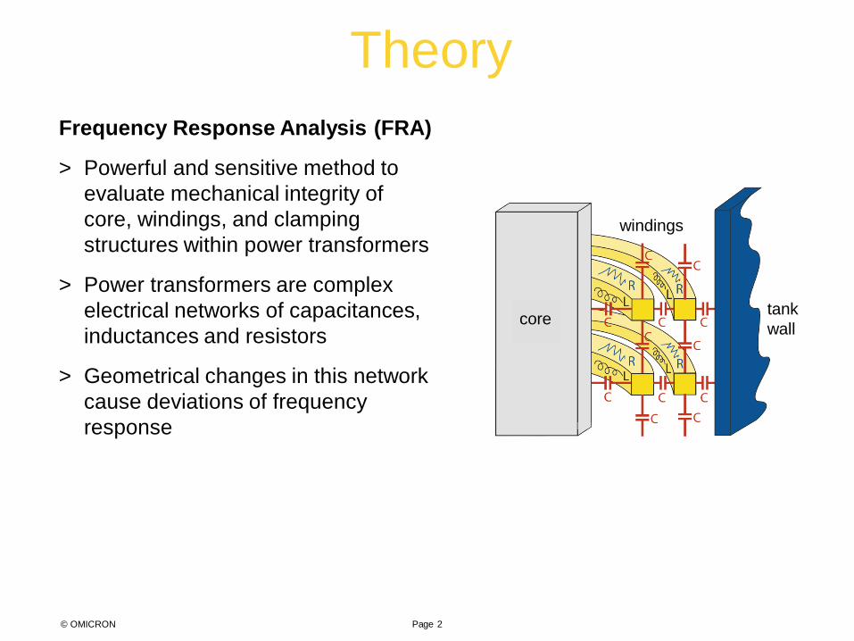
Frequency Response Analysis (FRA)
> Powerful and sensitive method to evaluate mechanical integrity of core, windings, and clamping structures within power transformers
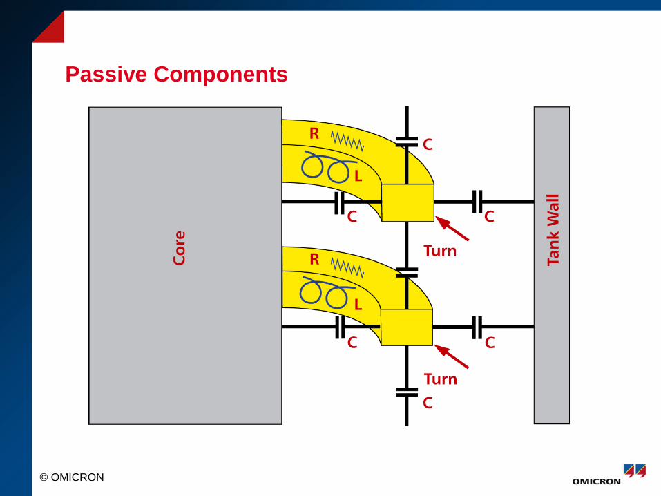
> Power transformers are complex electrical networks of capacitances, inductances and resistors
> Geometrical changes in this network cause deviations of frequency response
tank wall
windings
core
Theory
Page 3 © OMICRON
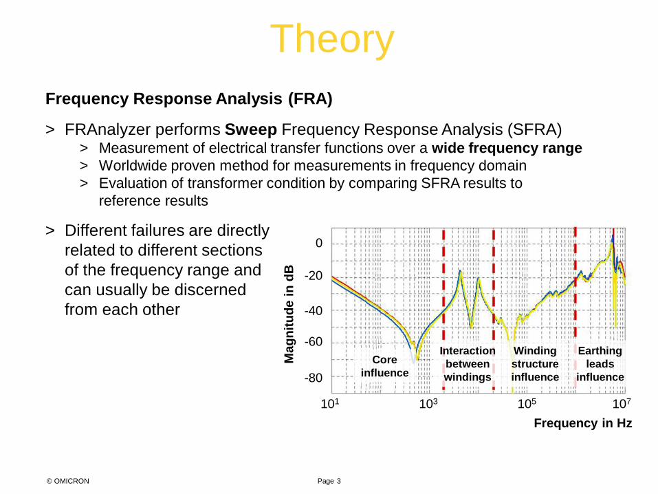
Frequency Response Analysis (FRA)
> FRAnalyzer performs Sweep Frequency Response Analysis (SFRA) > Measurement of electrical transfer functions over a wide frequency range > Worldwide proven method for measurements in frequency domain > Evaluation of transformer condition by comparing SFRA results to
reference results
> Different failures are directly related to different sections of the frequency range and can usually be discerned from each other
Mag
nitu
de in
dB
Frequency in Hz
0
-20
-40
-60
-80
101 103 105 107
Core influence
Interaction between windings
Winding structure influence
Earthing leads
influence
Theory
© OMICRON Page 4
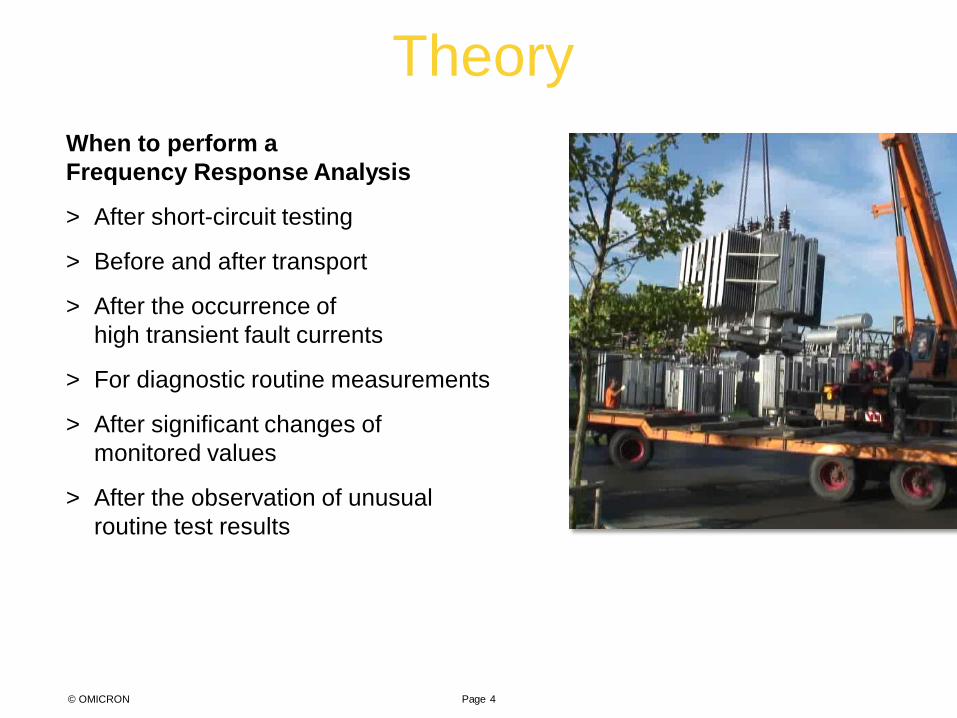
When to perform a Frequency Response Analysis
> After short-circuit testing
> Before and after transport
> After the occurrence of high transient fault currents
> For diagnostic routine measurements
> After significant changes of monitored values
> After the observation of unusual routine test results
Methods
Page 5 © OMICRON
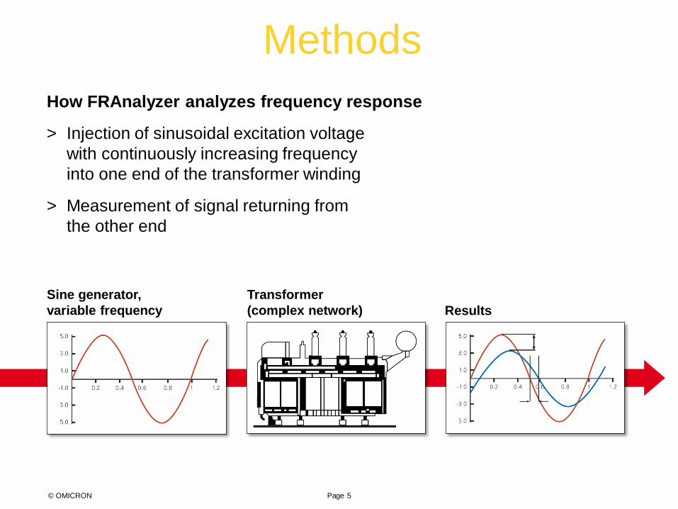
How FRAnalyzer analyzes frequency response
> Injection of sinusoidal excitation voltage with continuously increasing frequency into one end of the transformer winding
> Measurement of signal returning from the other end
Results Sine generator, variable frequency
Transformer (complex network)

Methods
Page 6 © OMICRON
How FRAnalyzer analyzes frequency response
> Comparison of signals generates unique frequency response which can be compared to reference data
> Deviations indicate geometrical and/or electrical changes within the transformer
> No additional data processing required due to direct measurement in the frequency domain
Results
Phase
Amplitude
© OMICRON
What is SFRA?
• Powerful and sensitive tool to assess the mechanical and electrical integrity of power transformers active part
• Measurement of the transfer function over a wide frequency range
© OMICRON
SFRA Discussion Outline
1. Basic SFRA Theory, History, and Evolution 2. SFRA Measurement Characteristics 3. Failure Modes 4. Test Procedures 5. Analysis of Results 6. Case Sudies
© OMICRON
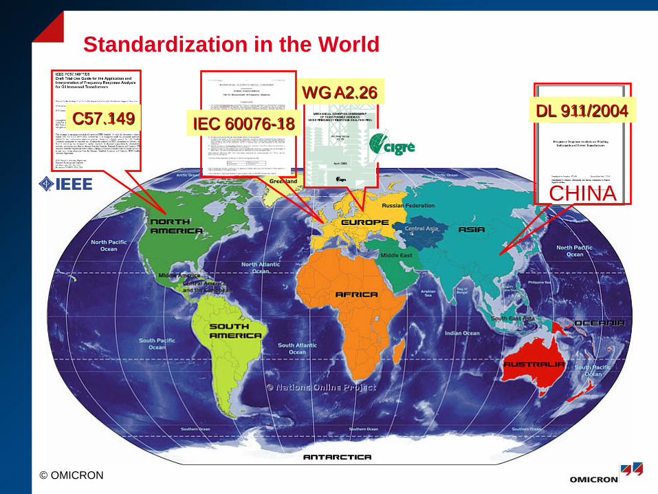
Standardization in the World
CHINA
DL 911/2004 C57.149 WG A2.26
IEC 60076-18
© OMICRON
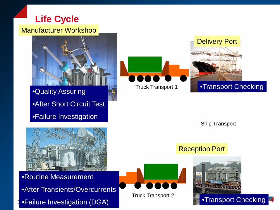
Life Cycle
Delivery Port
Reception Port
Manufacturer Workshop
•Quality Assuring
•After Short Circuit Test
•Failure Investigation
•Transport Checking
•Transport Checking
•Routine Measurement
•After Transients/Overcurrents
•Failure Investigation (DGA)
Truck Transport 1
Truck Transport 2
Ship Transport
© OMICRON
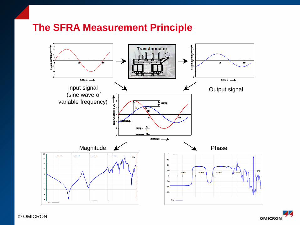
The SFRA Measurement Principle
Input signal (sine wave of
variable frequency)
Output signal
Phase Magnitude
© OMICRON
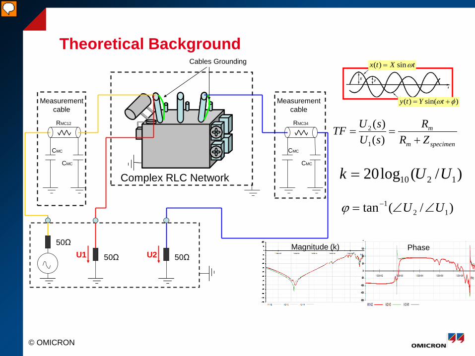
Theoretical Background
Measurementcable
Measurementcable
CMC
CMC
CMC
CMC
RMC12 RMC34
Complex RLC Network
U1
Cables Grounding
50Ω U2 50Ω
50Ω
)sin()( φω += tYty
tXtx ωsin)( =
)/(log20 1210 UUk =
)/(tan 121 UU ∠∠= −ϕ
Magnitude (k) Phase
specimenm
m
ZRR
sUsUTF
+==
)()(
1
2
© OMICRON
Passive Components
© OMICRON
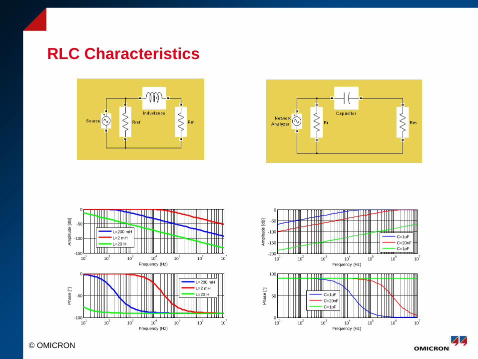
RLC Characteristics
101
102
103
104
105
106
107
-150
-100
-50
0
Frequency (Hz)
Am
plitu
de [d
B]
101
102
103
104
105
106
107
-100
-50
0
Frequency (Hz)
Pha
se [°
]
L=200 mHL=2 mHL=20 H
L=200 mHL=2 mHL=20 H
101
102
103
104
105
106
107
-200
-150
-100
-50
0
Frequency (Hz)A
mpl
itude
[dB
]
C=1uFC=20nFC=1pF
101
102
103
104
105
106
107
0
50
100
Frequency (Hz)
Pha
se [°
]
C=1uFC=20nFC=1pF
© OMICRON
Failure Mode Identified with SFRA 1. Radial “Hoop Buckling” Deformation of Winding
2. Axial Winding Elongation “Telescoping”
3. Overall- Bulk & Localized Movement
4. Core Defects
5. Contact Resistance
6. Winding Turn-to-Turn Short Circuit
7. Open Circuited Winding
• Residual Magnetization
• Oil Status (With or Without)
• Grounding
© OMICRON
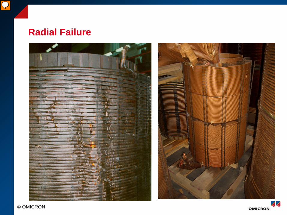
Radial Failure
© OMICRON
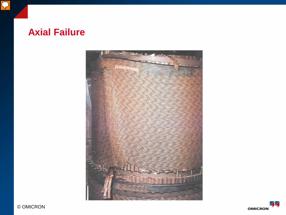
Axial Failure
© OMICRON
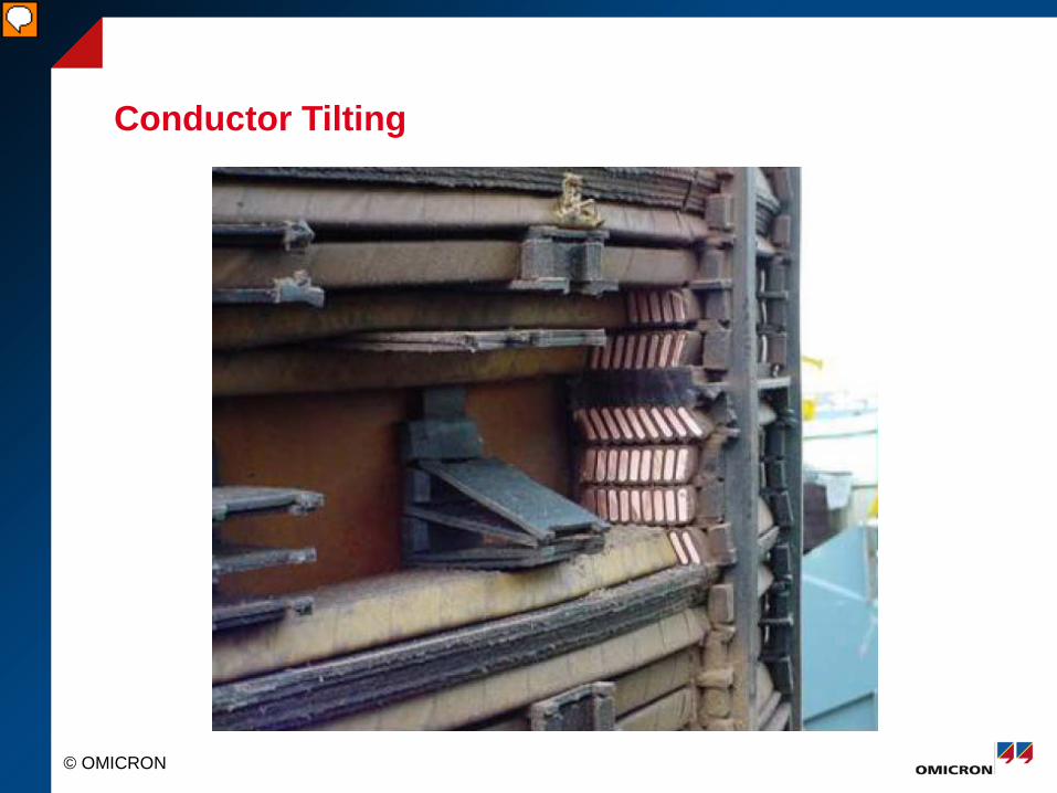
Conductor Tilting
© OMICRON
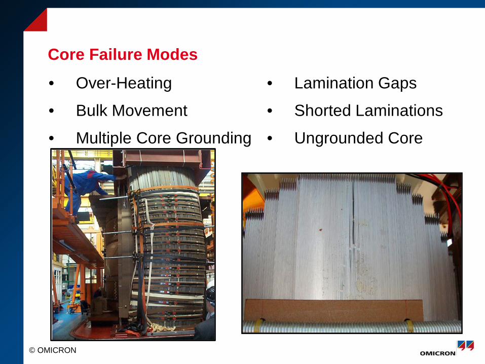
Core Failure Modes
• Over-Heating
• Bulk Movement
• Multiple Core Grounding
• Lamination Gaps
• Shorted Laminations
• Ungrounded Core
© OMICRON
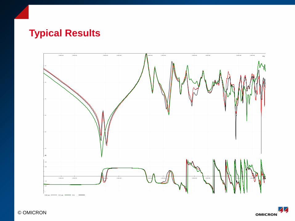
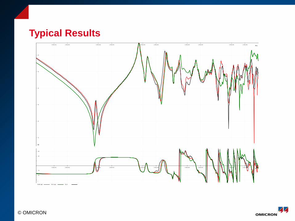
Typical Results
f/Hz5.000e+001 1.000e+002 5.000e+002 1.000e+003 5.000e+003 1.000e+004 5.000e+004 1.000e+005 5.000e+005 1.000e+006
dB
-70
-60
-50
-40
-30
-20
N W sec N V sec N U
f/Hz5.000e+001 1.000e+002 5.000e+002 1.000e+003 5.000e+003 1.000e+004 5.000e+004 1.000e+005 5.000e+005 1.000e+006
°
-100
-50
100
150
© OMICRON
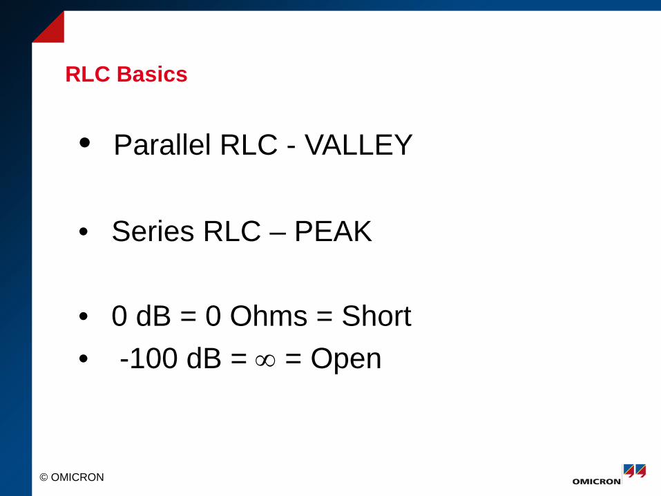
RLC Basics
• Parallel RLC - VALLEY
• Series RLC – PEAK
• 0 dB = 0 Ohms = Short • -100 dB = ∞ = Open
© OMICRON
Typical Results f/Hz
5.000e+001 1.000e+002 5.000e+002 1.000e+003 5.000e+003 1.000e+004 5.000e+004 1.000e+005 5.000e+005 1.000e+006
dB
-70
-60
-50
-40
-30
-20
N W sec N V sec N U
f/Hz5.000e+001 1.000e+002 5.000e+002 1.000e+003 5.000e+003 1.000e+004 5.000e+004 1.000e+005 5.000e+005 1.000e+006
°
-100
-50
100
150
© OMICRON
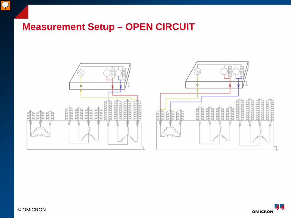
Measurement Setup – OPEN CIRCUIT
© OMICRON
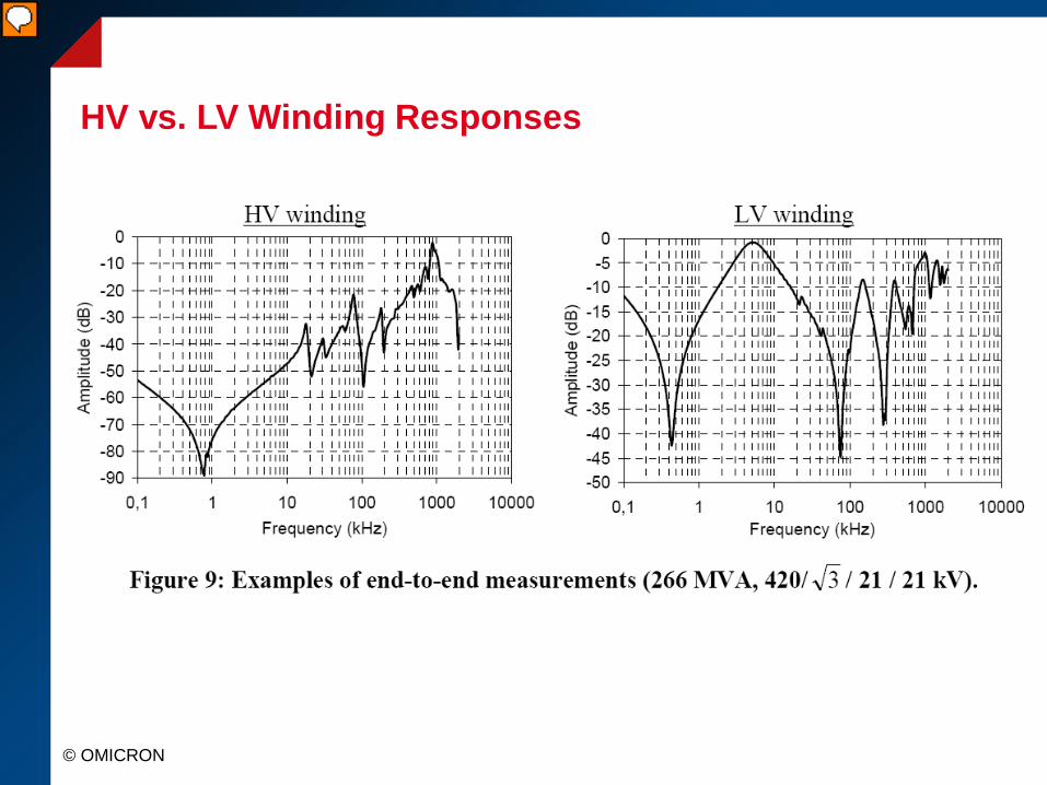
HV vs. LV Winding Responses
© OMICRON
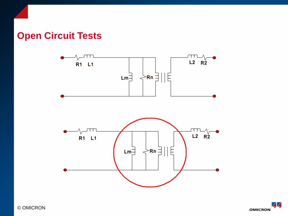
Open Circuit Tests
© OMICRON
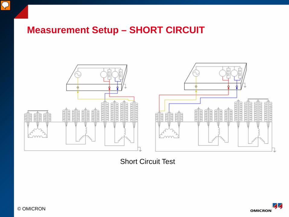
Measurement Setup – SHORT CIRCUIT
Short Circuit Test
© OMICRON
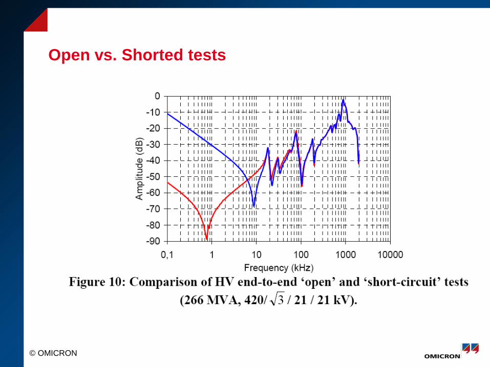
Open vs. Shorted tests
© OMICRON
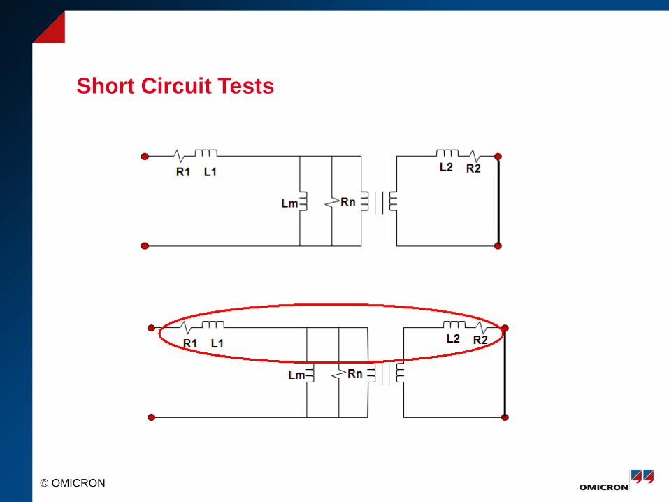
Short Circuit Tests
© OMICRON
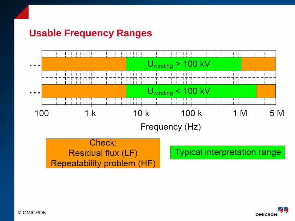
Usable Frequency Ranges

© OMICRON
Transformer Types
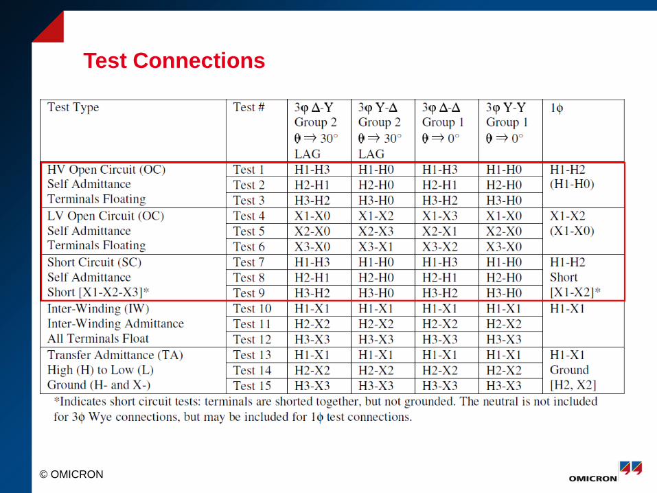
• 2 Winding (H, X) 3-H OC 3-X OC 3-HX SC
• 3 Winding (H, X, Y) 3-H OC 3-X OC 3-Y OC 3-HX SC 3-HY SC
• Auto Transformer (Series, Common, Tert) 3-H Series OC 3-X Common OC 3-Y Tert OC 3-HX SC 3-HY SC
© OMICRON
Test Connections
© OMICRON
Test Recommendations (IEEE)
• LTC Extreme Raise
• DETC as Found
• Open Circuit Test
• Short Circuit Test
© OMICRON
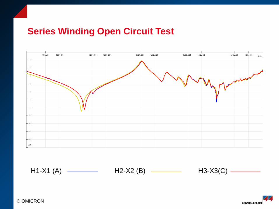
Series Winding Open Circuit Test
H1-X1 (A) H2-X2 (B) H3-X3(C)
© OMICRON
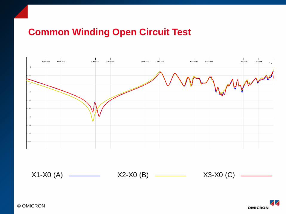
Common Winding Open Circuit Test
X1-X0 (A) X2-X0 (B) X3-X0 (C)
© OMICRON
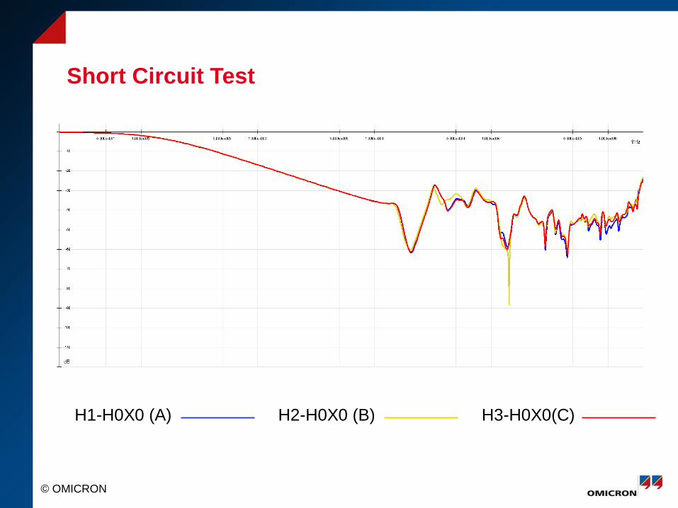
Short Circuit Test
H1-H0X0 (A) H2-H0X0 (B) H3-H0X0(C)

© OMICRON
Overview of B Phase
H1-X2 (B) X2-X0 (B) H2-H0X0 (B)
© OMICRON
Analysis Strategies
1. Baseline 2. Similar Unit
3. Phase Comparison
© OMICRON
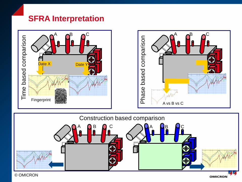
SFRA Interpretation
Fingerprint
Date X Date Y
Tim
e ba
sed
com
paris
on
Pha
se b
ased
com
paris
on
f/Hz1.000e+002 5.000e+002 1.000e+003 5.000e+003 1.000e+004 5.000e+004 1.000e+005 5.000e+005 1.000e+006
dB
-80
-70
-60
-50
-40
-30
-20
-10
f/Hz1.000e+002 5.000e+002 1.000e+003 5.000e+003 1.000e+004 5.000e+004 1.000e+005 5.000e+005 1.000e+006
dB
-80
-70
-60
-50
-40
-30
-20
-10
f/Hz1.000e+002 5.000e+002 1.000e+003 5.000e+003 1.000e+004 5.000e+004 1.000e+005 5.000e+005 1.000e+006
dB
-80
-70
-60
-50
-40
-30
-20
-10
A B C A B C
f/Hz1.000e+002 5.000e+002 1.000e+003 5.000e+003 1.000e+004 5.000e+004 1.000e+005 5.000e+005 1.000e+006
dB
-80
-70
-60
-50
-40
-30
-20
-10
A vs B vs C
A B C A B C
f/Hz1.000e+002 5.000e+002 1.000e+003 5.000e+003 1.000e+004 5.000e+004 1.000e+005 5.000e+005 1.000e+006
dB
-80
-70
-60
-50
-40
-30
-20
-10
f/Hz1.000e+002 5.000e+002 1.000e+003 5.000e+003 1.000e+004 5.000e+004 1.000e+005 5.000e+005 1.000e+006
dB
-80
-70
-60
-50
-40
-30
-20
-10
Construction based comparison
© OMICRON
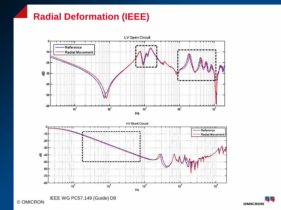
Radial Deformation (IEEE)
IEEE WG PC57.149 (Guide) D8
© OMICRON
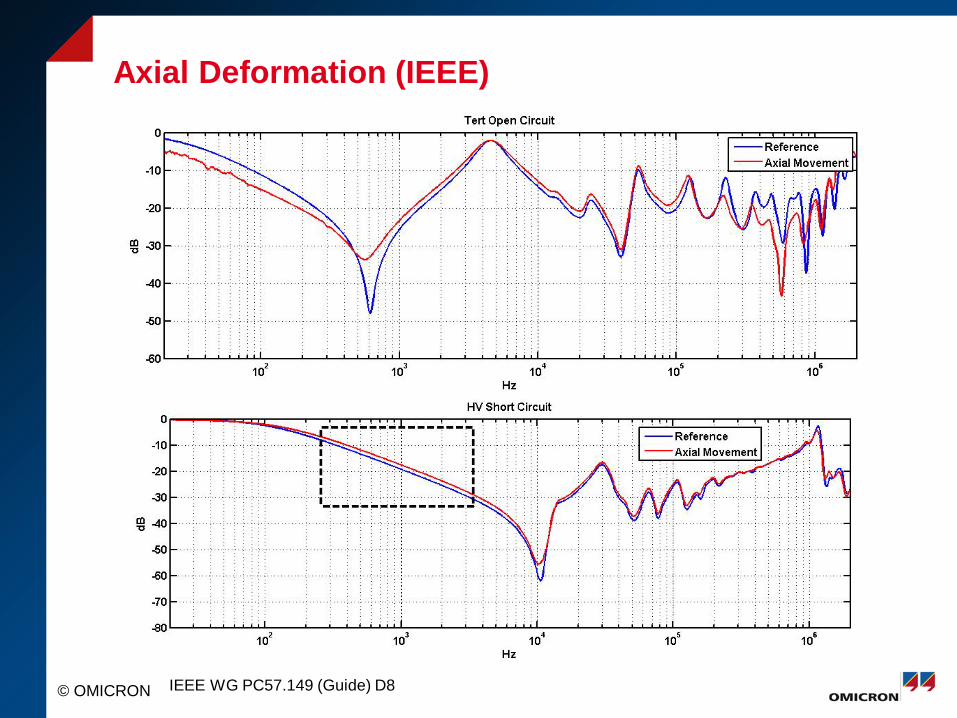
Axial Deformation (IEEE)
IEEE WG PC57.149 (Guide) D8
© OMICRON
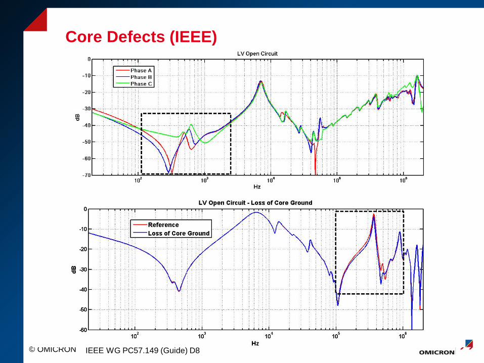
Core Defects (IEEE)
IEEE WG PC57.149 (Guide) D8
© OMICRON
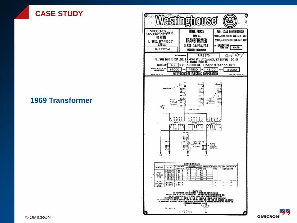
1969 Transformer
CASE STUDY
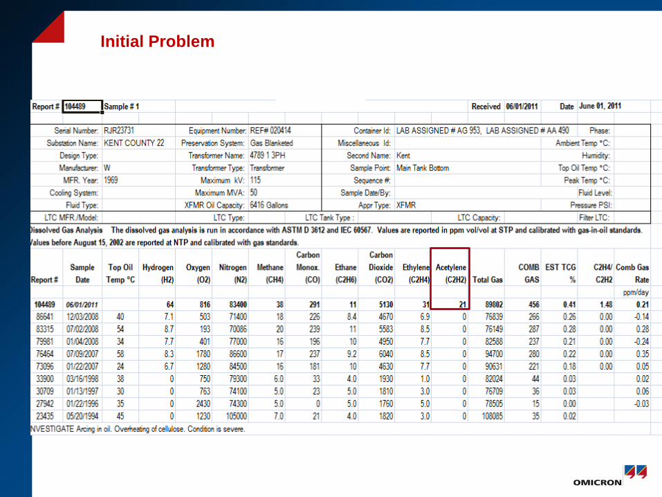
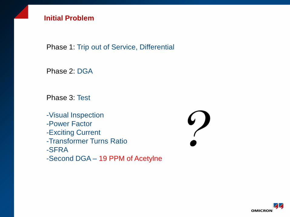
Initial Problem
Phase 1: Trip out of Service, Differential
Phase 2: DGA
Initial Problem
Phase 1: Trip out of Service, Differential
Phase 2: DGA
Phase 3: Test -Visual Inspection -Power Factor -Exciting Current -Transformer Turns Ratio -SFRA -Second DGA – 19 PPM of Acetylne
Phase 4: Reviewed SFRA data
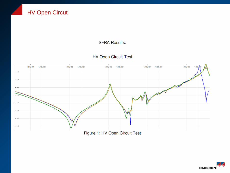
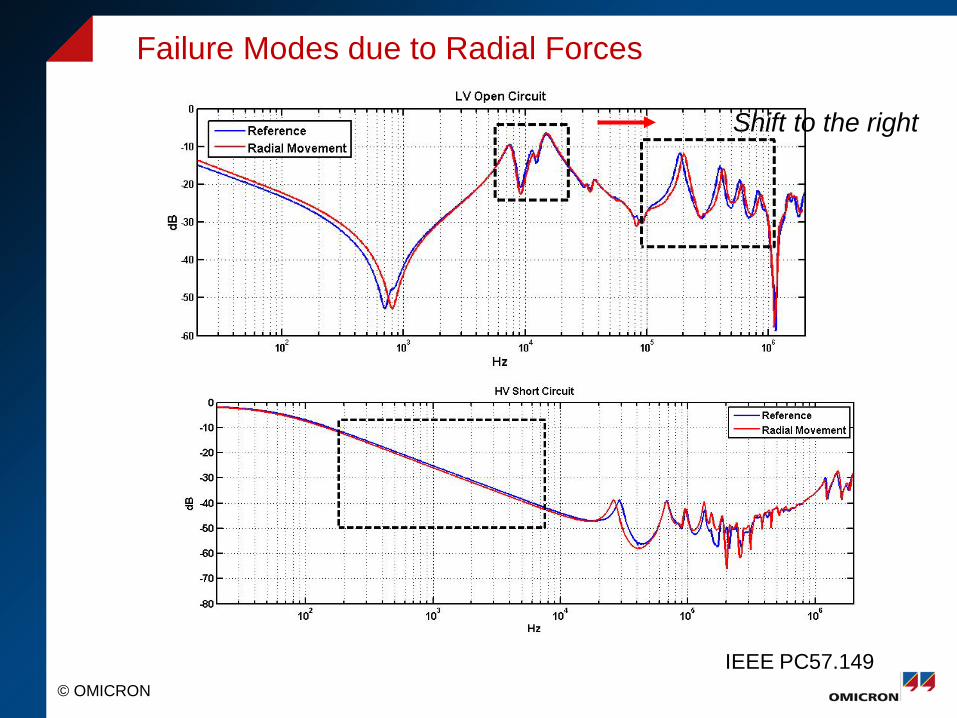
HV Open Circut
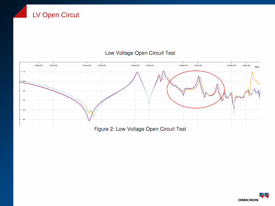
LV Open Circut
© OMICRON
Failure Modes due to Radial Forces
IEEE PC57.149
Shift to the right
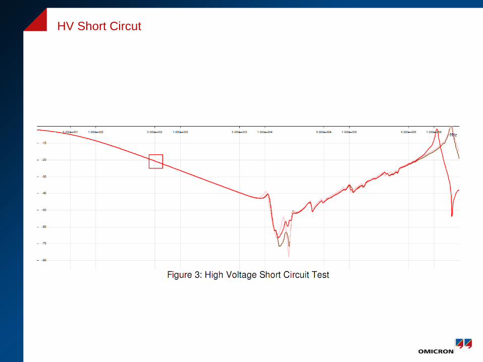
HV Short Circut
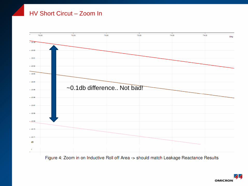
HV Short Circut – Zoom In
~0.1db difference.. Not bad!
Phase 4: Reviewed SFRA data
Phase 6: Perform Addition Test -Leakage Reactance +FRSL -Winding Resistance
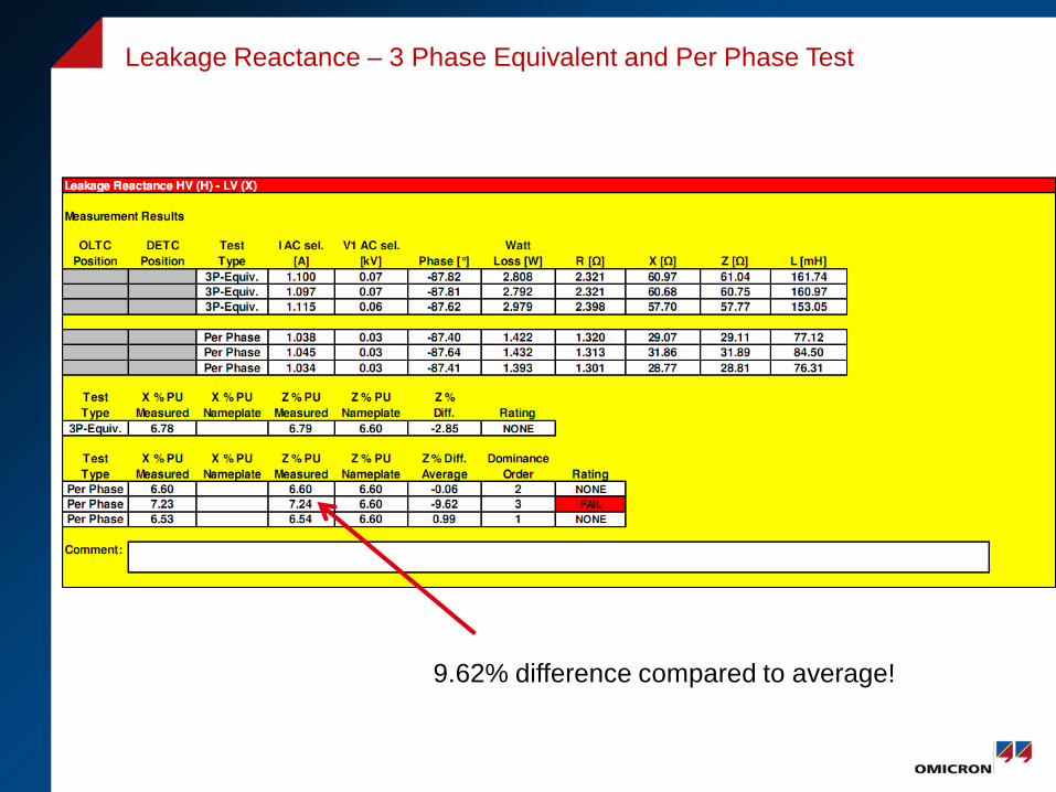
Leakage Reactance – 3 Phase Equivalent and Per Phase Test
9.62% difference compared to average!
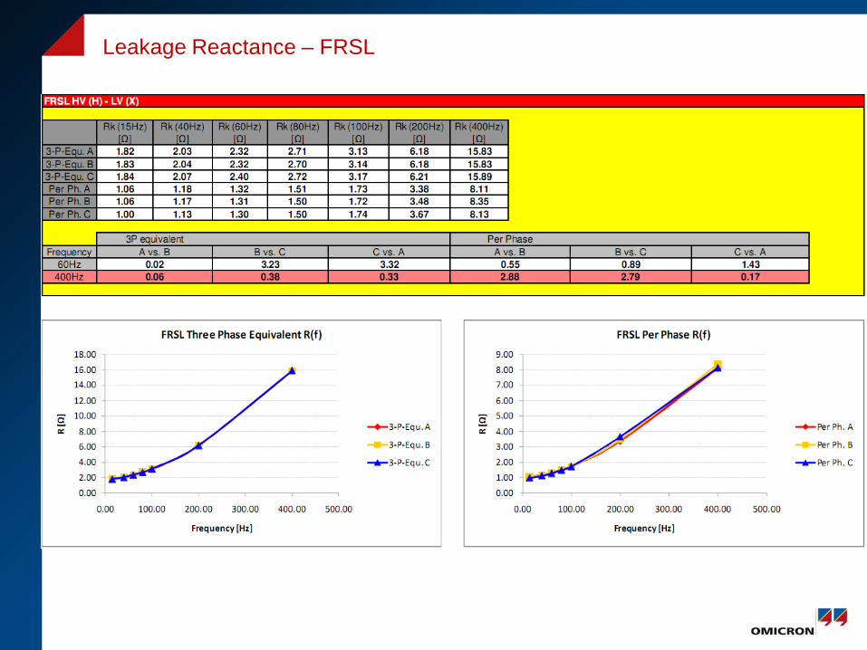
Leakage Reactance – FRSL
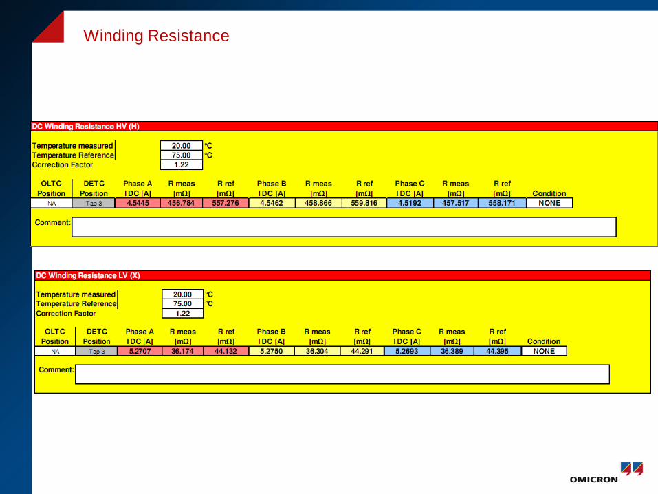
Winding Resistance
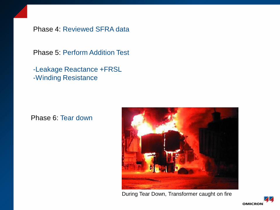
Phase 4: Reviewed SFRA data
Phase 5: Perform Addition Test -Leakage Reactance +FRSL -Winding Resistance
Phase 6: Tear down
During Tear Down, Transformer caught on fire
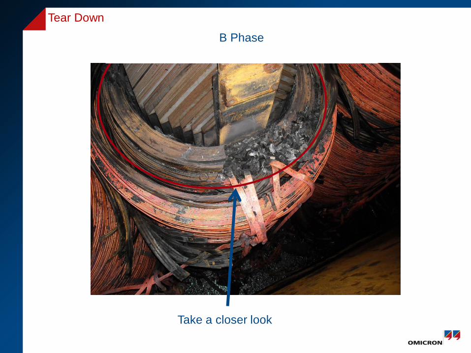
Tear Down
B Phase
Take a closer look
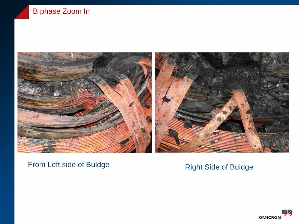
From Left side of Buldge
B phase Zoom In
Right Side of Buldge
© OMICRON
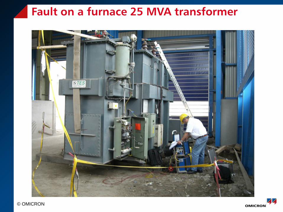
Fault on a furnace 25 MVA transformer
© OMICRON
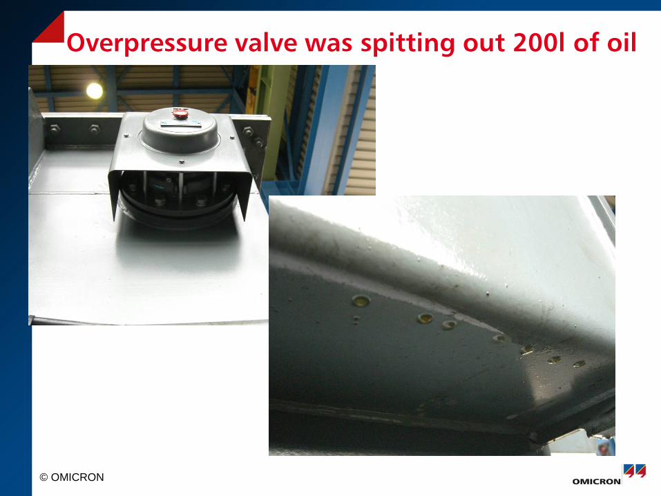
Overpressure valve was spitting out 200l of oil
© OMICRON
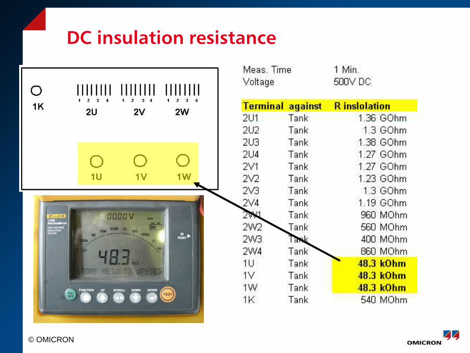
DC insulation resistance
© OMICRON
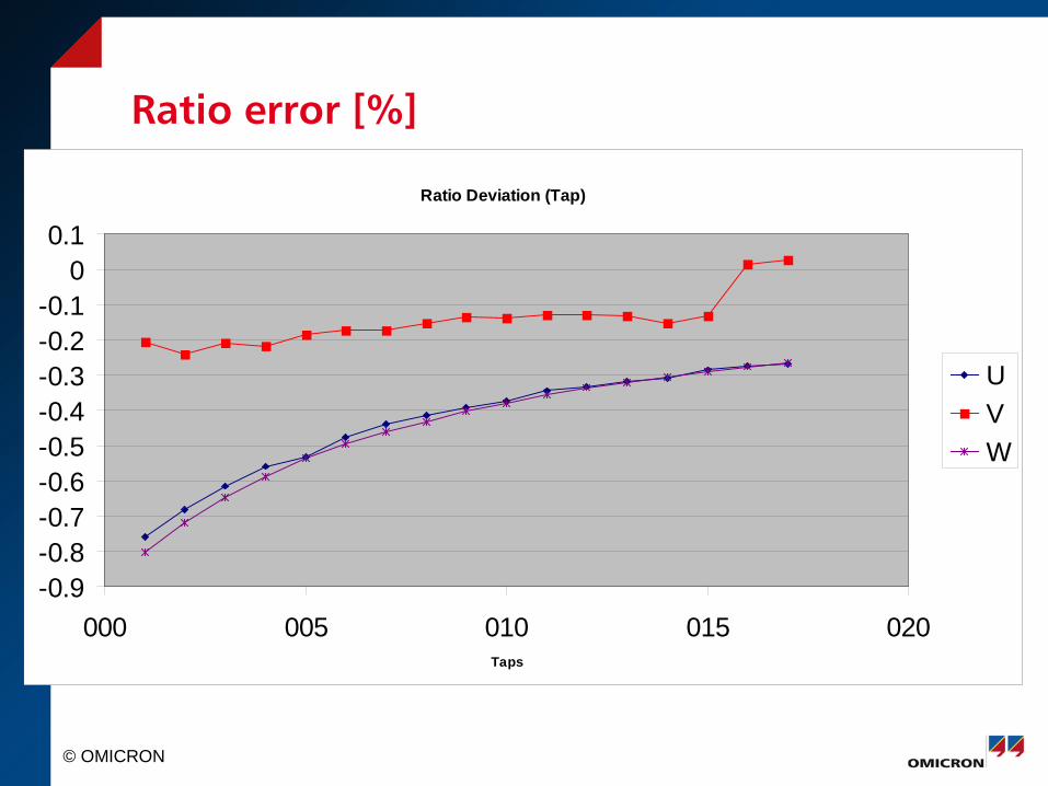
Ratio error [%]
Ratio Deviation (Tap)
-0.9-0.8-0.7-0.6-0.5-0.4-0.3-0.2-0.1
00.1
000 005 010 015 020Taps
UVW
© OMICRON
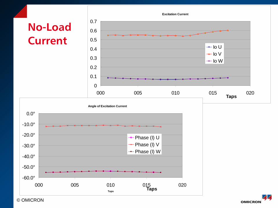
No-Load Current
Excitation Current
0
0.1
0.2
0.3
0.4
0.5
0.6
0.7
000 005 010 015 020Taps
Io UIo VIo W
Angle of Excitation Current
-60.0°
-50.0°
-40.0°
-30.0°
-20.0°
-10.0°
0.0°
000 005 010 015 020Taps
Phase (I) UPhase (I) VPhase (I) W
Taps
Taps
© OMICRON
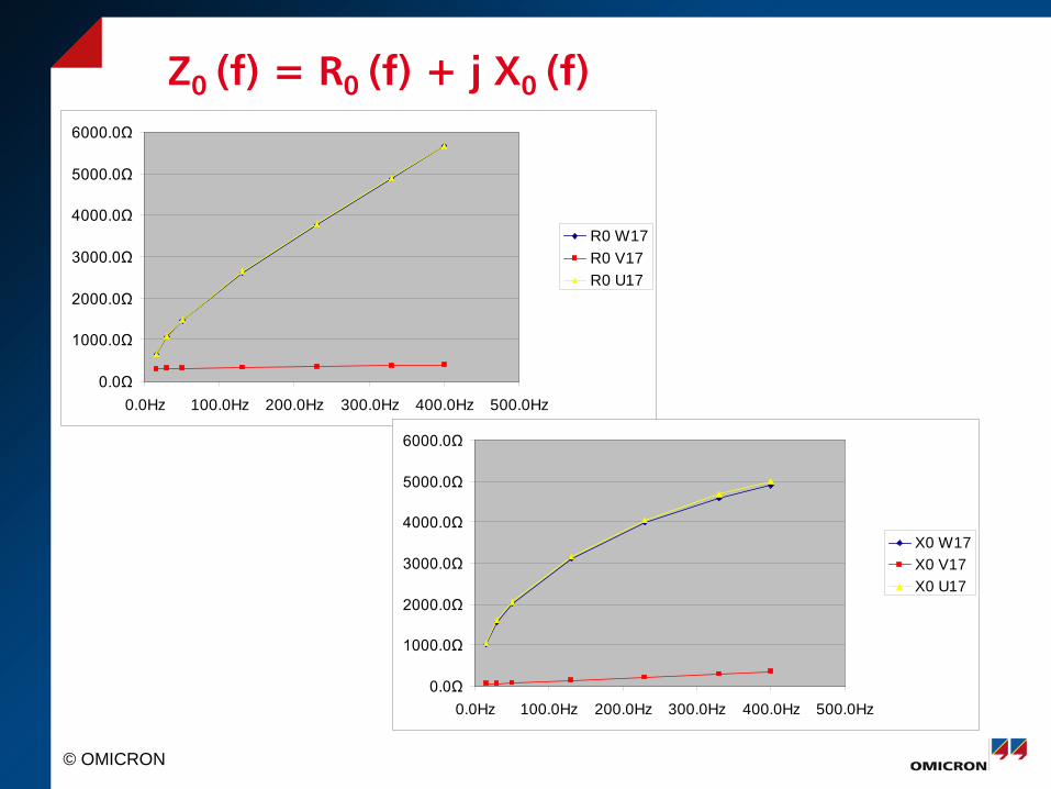
Z0 (f) = R0 (f) + j X0 (f)
0.0Ω
1000.0Ω
2000.0Ω
3000.0Ω
4000.0Ω
5000.0Ω
6000.0Ω
0.0Hz 100.0Hz 200.0Hz 300.0Hz 400.0Hz 500.0Hz
R0 W17R0 V17R0 U17
0.0Ω
1000.0Ω
2000.0Ω
3000.0Ω
4000.0Ω
5000.0Ω
6000.0Ω
0.0Hz 100.0Hz 200.0Hz 300.0Hz 400.0Hz 500.0Hz
X0 W17X0 V17X0 U17

© OMICRON
FRA (log view)
© OMICRON
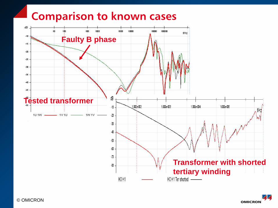
Comparison to known cases
Tested transformer
Faulty B phase
Transformer with shorted tertiary winding
© OMICRON
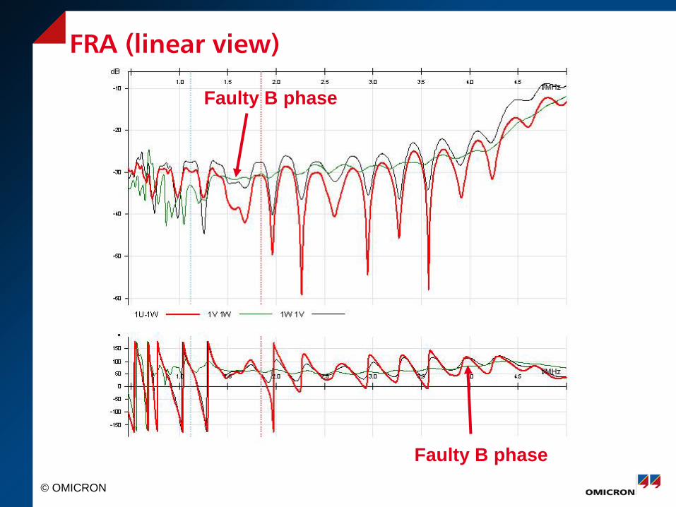
FRA (linear view)
Faulty B phase
Faulty B phase
© OMICRON
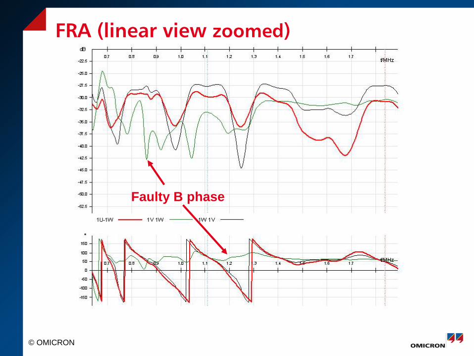
FRA (linear view zoomed)
Faulty B phase
© OMICRON
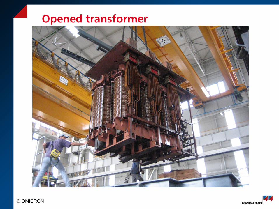
Opened transformer
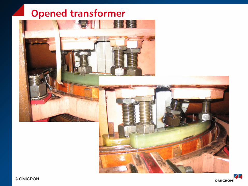
© OMICRON
Opened transformer
© OMICRON
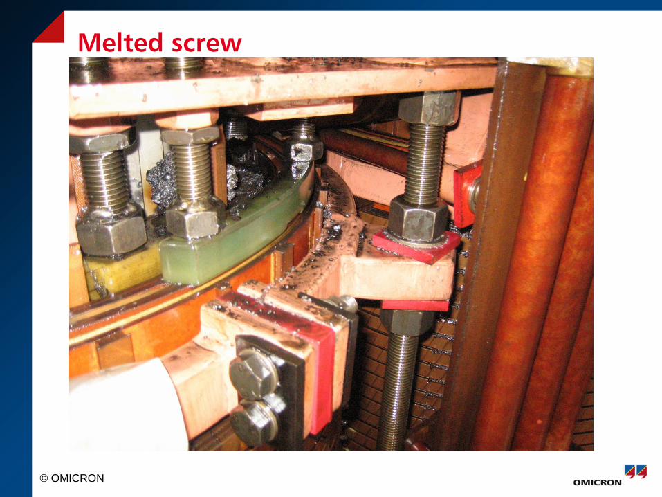
Melted screw
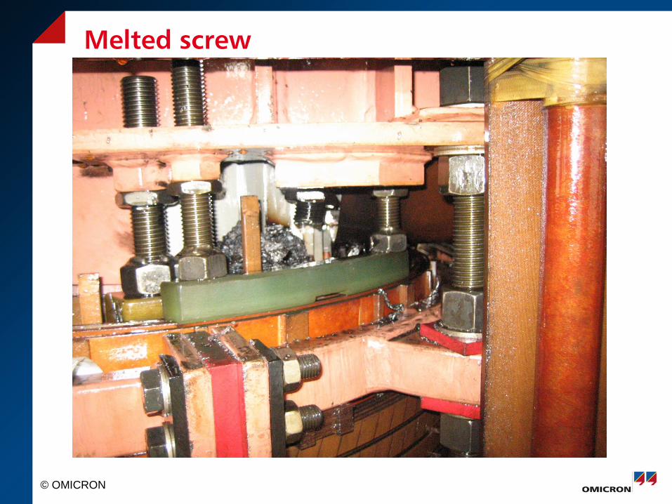
© OMICRON
Melted screw

© OMICRON
Melted Steel with copper marks
© OMICRON
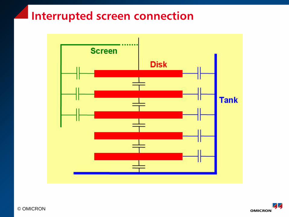
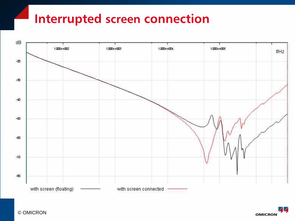
Interrupted screen connection
© OMICRON
Interrupted screen connection
© OMICRON
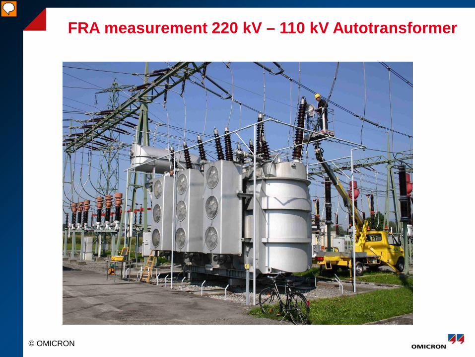
FRA measurement 220 kV – 110 kV Autotransformer
© OMICRON
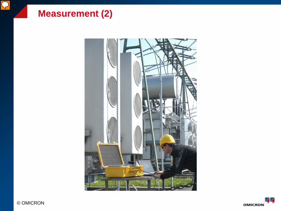
Measurement (2)
© OMICRON
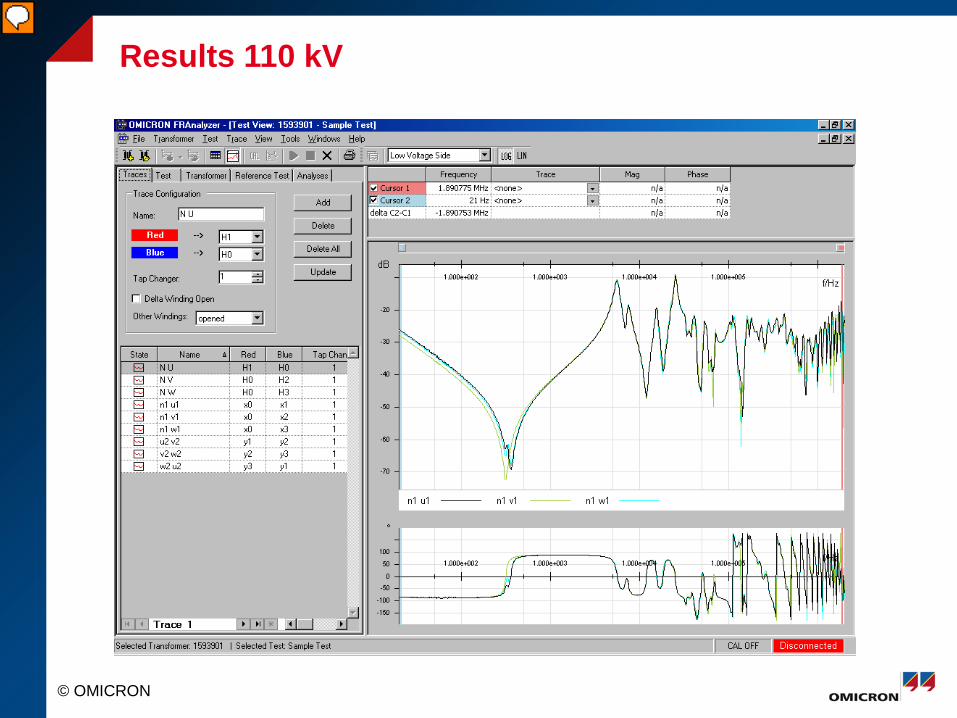
Results 110 kV
© OMICRON
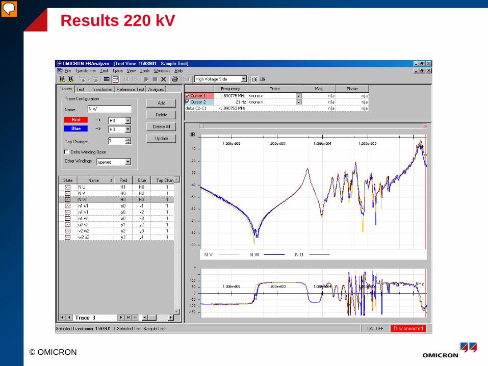
Results 220 kV
© OMICRON
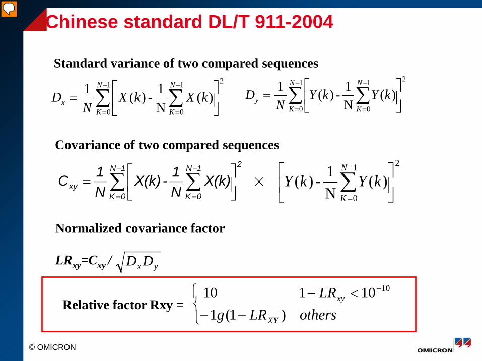
Chinese standard DL/T 911-2004
Standard variance of two compared sequences 21
0
1
0)(
N1-)(1 ∑ ∑
−
=
−
=
=
N
K
N
Kx kXkX
ND
21
0
1
0)(
N1-)(1 ∑ ∑
−
=
−
=
=
N
K
N
Ky kYkY
ND
Covariance of two compared sequences 21N
0K
1N
0Kxy X(k)
N1-X(k)
N1C ∑ ∑
−
=
−
=
= ×
21
0)(
N1-)(
∑−
=
N
KkYkY
Normalized covariance factor LRxy=Cxy / yx DD
Relative factor Rxy =
−−<− −
othersLRgLR
XY
xy
)1(110110 10
© OMICRON
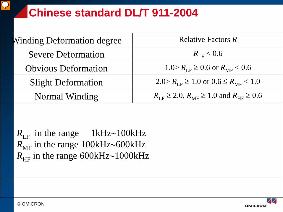
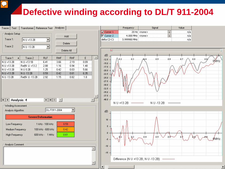
Chinese standard DL/T 911-2004
Winding Deformation degree Relative Factors R
Severe Deformation RLF < 0.6
Obvious Deformation 1.0> RLF ≥ 0.6 or RMF < 0.6
Slight Deformation 2.0> RLF ≥ 1.0 or 0.6 ≤ RMF < 1.0
Normal Winding RLF ≥ 2.0, RMF ≥ 1.0 and RHF ≥ 0.6
RLF in the range 1kHz∼100kHz RMF in the range 100kHz∼600kHz RHF in the range 600kHz∼1000kHz
© OMICRON
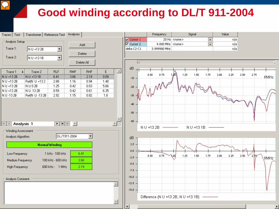
Good winding according to DL/T 911-2004
© OMICRON
Defective winding according to DL/T 911-2004

Thank You for Your Attention


