
Levante Sistemas de Automatización y Control S.L.
Catálogos
www.lsa-control.com
Distribuidor oficial Bosch Rexroth, Indramat, Bosch y Aventics.
LSA Control S.L. - Bosch Rexroth Sales PartnerRonda Narciso Monturiol y Estarriol, 7-9Edificio TecnoParQ Planta 1ª Derecha, Oficina 14(Parque Tecnológico de Paterna)46980 Paterna (Valencia)Telf. (+34) 960 62 43 01 [email protected] www.lsa-control.com www.boschrexroth.es

DIAX04Drive With Servo Function
Parameter Description: SSE 03VRS
DOK-DIAX04-SSE-03VRS**-PA01-EN-P
mannesmannRexroth
engineering
IndramatRexroth
7=78)1���
DIAX 04
HDS HDD
SSE-03VRS
Read and follow "Safety
Instructions for Electrical Drives"
manual,
DOK-GENERL-DRIVE******-SVS...
DANGE
High V oltage.
Danger of electrical shock.Do not touch electrical connec tions
for
5 minutes after switching power
LSA Control S.L. www.lsa-control.com [email protected] (+34) 960 62 43 01
About this Documentation DIAX04 SSE-03VRS
DOK-DIAX04-SSE-03VRS**-PA01-EN-P
DIAX04
Drive With Servo Function
Parameter Description: SSE 03VRS
DOK-DIAX04-SSE-03VRS**-PA01-EN-P
• Box 61-03V-EN
• Based on: SSE 03VRS
• 120-0800-B306-01/EN
The following documentation describes the parameters of the firmwareFWA-DIAX04-SSE-03VRS.
This documentation serves:
• for parameterization of the drive controller
Description ReleaseDate
Notes
DOK-DIAX04-SSE-03VRS **-PA01-DE-P 10.99 First edition
1999 Rexroth Indramat GmbH
Copying this document, giving it to others and the use or communicationof the contents thereof without express authority, are forbidden. Offendersare liable for the payment of damages. All rights are reserved in the eventof the grant of a patent or the registration of a utility model or design (DIN34-1).
All rights are reserved with respect to the content of this documentationand the availability of the product.
Rexroth Indramat GmbHBgm.-Dr.-Nebel-Str. 2 • D-97816 Lohr a. Main
Telephone 09352/40-0 • Tx 689421 • Fax 09352/40-4885
http://www.rexroth.com/indramat
Dept. ECD (sf/hp)
This document has been printed on chlorine-free bleached paper..
Title
Type of Documentation
Document Typecode
Internal File Reference
Purpose of Documentation
Record of Revisions
Copyright
Validity
Published by
Note
LSA Control S.L. www.lsa-control.com [email protected] (+34) 960 62 43 01

DIAX04 SSE-03VRS About this Documentation
DOK-DIAX04-SSE-03VRS**-PA01-EN-P
Summary of Documentation - Box
Order designation:DOK-DIAX04-SSE-03VRS**-FK01-EN-P
Order designation:DOK-DIAX04-SSE-03VRS**-PA01-EN-P
Order designation:DOK-DIAX04-SSE-03VRS**-WA01-EN-P
Order designation:DOK-DIAX04-SSE-03VRS**-FV01-EN-P
Order designation:DOK-DIAX04-SSE-03VRS**-IF01-EN-P
2 8 2 8 0 1
FK
2 8 2 8 0 1
PA
2 8 2 8 0 1
WA
2 8 2 8 0 1
FV
2 8 2 8 0 1
IF
Functional Description:
Description of all implemented Functionbased on SERCOS-Parameters
Parameter Description:
A description of all parametersused in the firmware
Troubleshooting Guide:
-Explanation of the diagnostic states-How to proceed when eliminating faults
Firmware Version Notes:
Description of new and changed functionsin terms of the derivatives:
-FWA-DIAX04-SSE02VRS-MS
Drive Configuration: -Determining the motor type-Choosing the motor – motor feedback combination-Choosing the desired function of the drive control device
Order designationDOK-DIAX04-SSE-03VRS**-6101-EN-P
part number: 282411Version: 01Win3.1 andWin95&NT
(6-:),)04
CD: DRIVEHELP
Collection of Windows help systems whichcontain documents on firmware derivatives
Order designation:DOK-GENERL-DRIVEHELP**-GExx-MS-D0600
LSA Control S.L. www.lsa-control.com [email protected] (+34) 960 62 43 01

About this Documentation DIAX04 SSE-03VRS
DOK-DIAX04-SSE-03VRS**-PA01-EN-P
Notes
LSA Control S.L. www.lsa-control.com [email protected] (+34) 960 62 43 01

DIAX04 SSE-03VRS Contents I
DOK-DIAX04-SSE-03VRS**-PA01-EN-P
Contents
1 General Information ............................................................................................ 1-1
Using This Manual.............................................................................................................................. 1-1
Definitions........................................................................................................................................... 1-2
2 Standard Parameters .......................................................................................... 2-1
2.1 S-0-0001, NC Cycle time (TNcyc)........................................................................................................ 2-1
S-0-0002, SERCOS Cycle time (Tscyc)............................................................................................. 2-1
S-0-0003, Minimum AT transmit starting time (T1min) ...................................................................... 2-2
S-0-0004, Transmit/receive transition time (TATMT)......................................................................... 2-2
S-0-0005, Minimum feedback acquisition time(T4min)...................................................................... 2-3
S-0-0006, AT Transmission starting time (T1) ................................................................................... 2-3
S-0-0007, Feedback acquisition starting time (T4) ............................................................................ 2-4
S-0-0008, Command valid time (T3) .................................................................................................. 2-4
S-0-0009, Beginning address in master data telegram ..................................................................... 2-5
S-0-0010, Length of master data telegram ........................................................................................ 2-5
S-0-0011, Class 1 diagnostics ........................................................................................................... 2-6
S-0-0012, Class 2 diagnostics ........................................................................................................... 2-7
S-0-0013, Class 3 diagnostics ........................................................................................................... 2-8
S-0-0014, Interface status.................................................................................................................. 2-9
S-0-0015, Telegram type parameter ................................................................................................ 2-10
S-0-0016, Custom amplifier telegram configuration list ................................................................... 2-11
S-0-0017, IDN-list of all operation data............................................................................................ 2-11
S-0-0018, IDN-list of operation data for CP2 ................................................................................... 2-12
S-0-0019, IDN-list of operation data for CP3 ................................................................................... 2-12
S-0-0021, IDN-list of invalid op. data for comm. Ph. 2..................................................................... 2-13
S-0-0022, IDN-list of invalid op. data for comm. Ph. 3..................................................................... 2-13
S-0-0024, Config. list of the master data telegram .......................................................................... 2-14
S-0-0025, IDN-list of all procedure commands ................................................................................ 2-14
S-0-0026, Configuration list signal status word................................................................................ 2-15
S-0-0028, MST error counter ........................................................................................................... 2-15
S-0-0029, MDT error counter ........................................................................................................... 2-16
S-0-0030, Manufacturer version....................................................................................................... 2-16
S-0-0032, Primary mode of operation .............................................................................................. 2-17
S-0-0033, Secondary operation mode 1 .......................................................................................... 2-18
S-0-0034, Secondary operation mode 2 .......................................................................................... 2-19
S-0-0035, Secondary operation mode 3 .......................................................................................... 2-19
S-0-0036, Velocity command value ................................................................................................. 2-20
S-0-0037, Additive velocity command value .................................................................................... 2-21
LSA Control S.L. www.lsa-control.com [email protected] (+34) 960 62 43 01

II Contents DIAX04 SSE-03VRS
DOK-DIAX04-SSE-03VRS**-PA01-EN-P
S-0-0040, Velocity feedback value................................................................................................... 2-21
S-0-0041, Homing velocity ............................................................................................................... 2-22
S-0-0042, Homing acceleration........................................................................................................ 2-22
S-0-0043, Velocity polarity parameter.............................................................................................. 2-23
S-0-0044, Velocity data scaling type................................................................................................ 2-24
S-0-0045, Velocity data scaling factor.............................................................................................. 2-25
S-0-0046, Velocity data scaling exponent........................................................................................ 2-25
S-0-0047, Position command value ................................................................................................. 2-25
S-0-0049, Positive position limit value ............................................................................................. 2-26
S-0-0050, Negative position limit value............................................................................................ 2-27
S-0-0051, Position feedback 1 value ............................................................................................... 2-27
S-0-0052, Reference distance 1 ...................................................................................................... 2-28
S-0-0053, Position feedback 2 value ............................................................................................... 2-29
S-0-0054, Reference distance 2 ...................................................................................................... 2-29
S-0-0055, Position polarities ............................................................................................................ 2-30
S-0-0057, Position window............................................................................................................... 2-31
S-0-0058, Reversal clearance.......................................................................................................... 2-32
S-0-0076, Position data scaling type................................................................................................ 2-33
S-0-0077, Linear position data scaling factor................................................................................... 2-34
S-0-0078, Linear position data scaling exponent............................................................................. 2-35
S-0-0079, Rotational position resolution .......................................................................................... 2-36
S-0-0080, Torque/Force command.................................................................................................. 2-36
S-0-0084, Torque/Force feedback value.......................................................................................... 2-37
S-0-0085, Torque/Force polarity parameter..................................................................................... 2-37
S-0-0086, Torque/Force data scaling type....................................................................................... 2-38
S-0-0088, Receive to receive recovery time (TMTSG).................................................................... 2-39
S-0-0089, MDT Transmit starting time (T2) ..................................................................................... 2-39
S-0-0090, Command value transmit time (TMTSG) ........................................................................ 2-40
S-0-0091, Bipolar velocity limit value ............................................................................................... 2-40
S-0-0092, Bipolar torque/force limit value........................................................................................ 2-41
S-0-0093, Torque/force data scaling factor...................................................................................... 2-41
S-0-0094, Torque/force data scaling exponent................................................................................ 2-42
S-0-0095, Diagnostic message........................................................................................................ 2-42
S-0-0096, Slave arrangement (SLKN) ............................................................................................. 2-43
S-0-0097, Mask class 2 diagnostic .................................................................................................. 2-43
S-0-0098, Mask class 3 diagnostic .................................................................................................. 2-44
S-0-0099, C500 Reset class 1 diagnostic........................................................................................ 2-44
S-0-0100, Velocity loop proportional gain ........................................................................................ 2-45
S-0-0101, Velocity loop integral action time..................................................................................... 2-45
S-0-0103, Modulo value ................................................................................................................... 2-46
S-0-0104, Position loop Kv-factor .................................................................................................... 2-47
S-0-0106, Current loop proportional gain 1...................................................................................... 2-47
S-0-0107, Current loop integral action time 1 .................................................................................. 2-48
S-0-0108, Feedrate override ............................................................................................................ 2-48
S-0-0109, Motor peak current .......................................................................................................... 2-49
S-0-0110, Amplifier peak current ..................................................................................................... 2-50
LSA Control S.L. www.lsa-control.com [email protected] (+34) 960 62 43 01

DIAX04 SSE-03VRS Contents III
DOK-DIAX04-SSE-03VRS**-PA01-EN-P
S-0-0111, Motor current at standstill ................................................................................................ 2-50
S-0-0112, Amplifier nominal current................................................................................................. 2-51
S-0-0113, Maximum motor speed ( nmax) ......................................................................................... 2-51
S-0-0115, Position feedback 2 type ................................................................................................. 2-52
S-0-0116, Feedback 1 Resolution.................................................................................................... 2-52
S-0-0117, Feedback 2 Resolution.................................................................................................... 2-53
S-0-0121, Input revolutions of load gear .......................................................................................... 2-53
S-0-0122, Output revolutions of load gear ....................................................................................... 2-54
S-0-0123, Feed constant.................................................................................................................. 2-54
S-0-0124, Standstill window............................................................................................................. 2-55
S-0-0125, Velocity threshold nx ....................................................................................................... 2-56
S-0-0127, C100 Communication phase 3 transition check.............................................................. 2-56
S-0-0128, C200 Communication phase 4 transition check.............................................................. 2-57
S-0-0130, Probe value 1 positive edge............................................................................................ 2-59
S-0-0131, Probe value 1 negative edge........................................................................................... 2-59
S-0-0132, Probe value 2 positive edge............................................................................................ 2-60
S-0-0133, Probe value 2 negative edge........................................................................................... 2-60
S-0-0134, Master control word......................................................................................................... 2-61
S-0-0135, Drive status word............................................................................................................. 2-61
S-0-0138, Bipolar acceleration limit value........................................................................................ 2-62
S-0-0139, D700 Command Parking axis.......................................................................................... 2-62
S-0-0140, Controller type ................................................................................................................. 2-63
S-0-0141, Motor type........................................................................................................................ 2-64
S-0-0142, Application type ............................................................................................................... 2-64
S-0-0143, System interface version ................................................................................................. 2-65
S-0-0144, Signal status word ........................................................................................................... 2-65
S-0-0147, Homing parameter........................................................................................................... 2-66
S-0-0148, C600 Drive controlled homing procedure command....................................................... 2-67
S-0-0149, D400 Positive stop drive procedure command ............................................................... 2-68
S-0-0150, Reference offset 1 ........................................................................................................... 2-68
S-0-0151, Reference offset 2 ........................................................................................................... 2-69
S-0-0155, Friction compensation ..................................................................................................... 2-69
S-0-0157, Velocity window............................................................................................................... 2-70
S-0-0159, Monitoring window........................................................................................................... 2-70
S-0-0160, Acceleration data scaling type......................................................................................... 2-71
S-0-0161, Acceleration data scaling factor ...................................................................................... 2-72
S-0-0162, Acceleration data scaling exponent ................................................................................ 2-73
S-0-0165, Distance coded reference offset 1 .................................................................................. 2-73
S-0-0166, Distance coded reference offset 2 .................................................................................. 2-74
S-0-0169, Probe control parameter.................................................................................................. 2-74
S-0-0170, Probing cycle procedure command................................................................................. 2-76
S-0-0173, Marker position A ............................................................................................................ 2-77
S-0-0177, Absolute distance 1 ......................................................................................................... 2-77
S-0-0178, Absolute distance 2 ......................................................................................................... 2-78
S-0-0182, Manufacturer class 3 diagnostics.................................................................................... 2-78
S-0-0185, Length of the configurable data record in the AT............................................................ 2-79
LSA Control S.L. www.lsa-control.com [email protected] (+34) 960 62 43 01

IV Contents DIAX04 SSE-03VRS
DOK-DIAX04-SSE-03VRS**-PA01-EN-P
S-0-0186, Length of the configurable data record in the MDT......................................................... 2-80
S-0-0187, List of configurable data in the AT................................................................................... 2-80
S-0-0188, List of configurable data in the MDT ............................................................................... 2-81
S-0-0189, Following error................................................................................................................. 2-82
S-0-0191, D600 Cancel reference point procedure command ........................................................ 2-82
S-0-0192, IDN-list of backup operation data.................................................................................... 2-83
S-0-0193, Positioning Jerk ............................................................................................................... 2-84
S-0-0201, Motor warning temperature ............................................................................................. 2-84
S-0-0204, Motor shutdown temperature .......................................................................................... 2-85
S-0-0256, Multiplication 1................................................................................................................. 2-85
S-0-0257, Multiplication 2................................................................................................................. 2-86
S-0-0258, Target position................................................................................................................. 2-86
S-0-0259, Positioning Velocity ......................................................................................................... 2-87
S-0-0260, Positioning Acceleration .................................................................................................. 2-87
S-0-0262, C700 Command basic load............................................................................................. 2-88
S-0-0265, Language selection ......................................................................................................... 2-88
S-0-0267, Password......................................................................................................................... 2-89
S-0-0269, Parameter buffer mode ................................................................................................... 2-89
S-0-0277, Position feedback 1 type ................................................................................................. 2-90
S-0-0278, Maximum travel range..................................................................................................... 2-91
S-0-0292, List of all operating modes .............................................................................................. 2-92
S-0-0298, Reference cam shift ........................................................................................................ 2-92
S-0-0299, Home switch offset .......................................................................................................... 2-93
S-0-0301, Allocation of real-time control Bit 1.................................................................................. 2-94
S-0-0303, Allocation of real-time control Bit 2.................................................................................. 2-94
S-0-0305, Allocation of real-time status Bit 1................................................................................... 2-95
S-0-0307, Allocation of real-time status Bit 2................................................................................... 2-95
S-0-0328, Assign list signal status word .......................................................................................... 2-96
S-0-0347, Speed deviation............................................................................................................... 2-96
S-0-0348, Acceleration feedforward gain......................................................................................... 2-97
S-0-0349, Jerk limit bipolar .............................................................................................................. 2-98
S-0-0359, Positioning Deceleration.................................................................................................. 2-98
S-0-0360, MDT Data container A..................................................................................................... 2-99
S-0-0364, AT Data container A ........................................................................................................ 2-99
S-0-0368, Addressing for data container A.................................................................................... 2-100
S-0-0370, Configuration list for MDT data container...................................................................... 2-101
S-0-0371, Configuration list for the AT data container................................................................... 2-101
S-0-0375, List of diagnostic numbers ............................................................................................ 2-102
S-0-0378, Encoder 1, absolute range ............................................................................................ 2-102
S-0-0379, Encoder 2, absolute range ............................................................................................ 2-103
S-0-0382, Intermediate bus power................................................................................................. 2-103
S-0-0383, Motor temperature......................................................................................................... 2-104
S-0-0390, Diagnostic message number......................................................................................... 2-104
S-0-0391, Monitoring window feedback 2...................................................................................... 2-105
S-0-0393, Command value mode .................................................................................................. 2-105
S-0-0400, Home switch.................................................................................................................. 2-106
LSA Control S.L. www.lsa-control.com [email protected] (+34) 960 62 43 01

DIAX04 SSE-03VRS Contents V
DOK-DIAX04-SSE-03VRS**-PA01-EN-P
S-0-0401, Probe 1 .......................................................................................................................... 2-106
S-0-0402, Probe 2 .......................................................................................................................... 2-107
S-0-0403, Position feedback value status...................................................................................... 2-108
S-0-0405, Probe 1 enable .............................................................................................................. 2-109
S-0-0406, Probe 2 enable .............................................................................................................. 2-109
S-0-0409, Probe 1 positive latched................................................................................................ 2-110
S-0-0410, Probe 1 negative latched............................................................................................... 2-111
S-0-0411, Probe 2 positive latched................................................................................................ 2-112
S-0-0412, Probe 2 negative latched............................................................................................... 2-112
S-7-0100, Velocity loop proportional gain ...................................................................................... 2-113
S-7-0101, Velocity loop integral action time................................................................................... 2-114
S-7-0104, Position loop Kv-factor .................................................................................................. 2-114
S-7-0106, Current loop proportional gain 1.................................................................................... 2-115
S-7-0107, Current loop integral action time 1 ................................................................................ 2-115
S-7-0109, Motor peak current ........................................................................................................ 2-116
S-7-0111, Motor current at standstill .............................................................................................. 2-116
S-7-0113, Maximum motor speed (nmax)........................................................................................ 2-117
S-7-0116, Feedback 1 Resolution.................................................................................................. 2-117
S-7-0117, Feedback 2 Resolution.................................................................................................. 2-118
S-7-0141, Motor type...................................................................................................................... 2-118
S-7-0177, Absolute distance 1 ....................................................................................................... 2-119
S-7-0178, Absolute distance 2 ....................................................................................................... 2-119
3 Product Specific Parameters.............................................................................. 3-1
P-0-0004, Velocity loop smoothing time constant.............................................................................. 3-1
P-0-0005, Language selection ........................................................................................................... 3-1
P-0-0008, Activation E-Stop function ................................................................................................. 3-2
P-0-0009, Error message number...................................................................................................... 3-3
P-0-0010, Excessive position command value .................................................................................. 3-3
P-0-0011, Last valid position command value ................................................................................... 3-4
P-0-0012, C300 Command ’Set absolute measurement’................................................................... 3-5
P-0-0014, D500 Command determine marker position ..................................................................... 3-6
P-0-0015, Memory address................................................................................................................ 3-6
P-0-0016, Content of memory address.............................................................................................. 3-7
P-0-0018, Number of pole pairs/pole pair distance............................................................................ 3-7
P-0-0019, Position start value ............................................................................................................ 3-8
P-0-0021, List of scope data 1 ........................................................................................................... 3-8
P-0-0022, List of scope data 2 ........................................................................................................... 3-9
P-0-0023, Signal select scope channel 1........................................................................................... 3-9
P-0-0024, Signal select scope channel 2......................................................................................... 3-10
P-0-0025, Trigger source ................................................................................................................. 3-11
P-0-0026, Trigger signal selection ................................................................................................... 3-12
P-0-0027, Trigger level for position data.......................................................................................... 3-13
P-0-0028, Trigger level for velocity data .......................................................................................... 3-13
P-0-0029, Trigger level for torque/force data ................................................................................... 3-14
P-0-0030, Trigger edge .................................................................................................................... 3-14
LSA Control S.L. www.lsa-control.com [email protected] (+34) 960 62 43 01
VI Contents DIAX04 SSE-03VRS
DOK-DIAX04-SSE-03VRS**-PA01-EN-P
P-0-0031, Timebase......................................................................................................................... 3-15
P-0-0032, Size of memory ............................................................................................................... 3-15
P-0-0033, Number of samples after trigger...................................................................................... 3-16
P-0-0035, Delay from trigger to start................................................................................................ 3-16
P-0-0036, Trigger control word ........................................................................................................ 3-17
P-0-0037, Trigger status word.......................................................................................................... 3-18
P-0-0051, Torque/force constant ..................................................................................................... 3-18
P-0-0074, Feedback 1 type.............................................................................................................. 3-19
P-0-0075, Feedback 2 type.............................................................................................................. 3-20
P-0-0081, Parallel I/O output 1......................................................................................................... 3-21
P-0-0082, Parallel I/O input 1........................................................................................................... 3-21
P-0-0090, Travel limit parameter...................................................................................................... 3-22
P-0-0096, Distance to move in error situation.................................................................................. 3-22
P-0-0097, Absolute encoder monitoring window ............................................................................. 3-23
P-0-0098, Max. model deviation ...................................................................................................... 3-24
P-0-0099, Position command smoothing time constant................................................................... 3-25
P-0-0109, Torque/force peak limit.................................................................................................... 3-25
P-0-0117, NC reaction on error........................................................................................................ 3-26
P-0-0118, Power off on error............................................................................................................ 3-26
P-0-0119, Best possible deceleration .............................................................................................. 3-28
P-0-0121, Velocity mix factor feedback 1 & 2 .................................................................................. 3-29
P-0-0126, Maximum braking time .................................................................................................... 3-29
P-0-0127, Overload warning ............................................................................................................ 3-30
P-0-0139, Analog output 1 ............................................................................................................... 3-30
P-0-0140, Analog output 2 ............................................................................................................... 3-31
P-0-0141, Thermal drive load........................................................................................................... 3-31
P-0-0145, Expanded trigger level..................................................................................................... 3-32
P-0-0146, Expanded trigger address ............................................................................................... 3-32
P-0-0147, Expanded signal K1 address .......................................................................................... 3-33
P-0-0148, Expanded signal K2 address .......................................................................................... 3-34
P-0-0149, List of selectable signals for oscilloscope function.......................................................... 3-34
P-0-0150, Number of valid samples for oscilloscope function ......................................................... 3-35
P-0-0153, Optimal distance home switch - reference mark............................................................. 3-35
P-0-0170, Parallel I/O output 4......................................................................................................... 3-36
P-0-0171, Parallel I/O input 4........................................................................................................... 3-37
P-0-0176, Torque/Force command smoothing time constant.......................................................... 3-37
P-0-0177, Absolute encoder buffer 1 ............................................................................................... 3-37
P-0-0178, Absolute encoder buffer 2 ............................................................................................... 3-38
P-0-0180, Rejection frequency velocity loop.................................................................................... 3-38
P-0-0181, Rejection bandwidth velocity loop ................................................................................... 3-39
P-0-0185, Function of encoder 2...................................................................................................... 3-40
P-0-0187, Position command processing mode .............................................................................. 3-40
P-0-0190, Operating hours control section ...................................................................................... 3-41
P-0-0191, Operating hours power section ....................................................................................... 3-42
P-0-0192, Error recorder, diagnosis number ................................................................................... 3-42
P-0-0193, Error recorder, operating hours control section............................................................... 3-43
LSA Control S.L. www.lsa-control.com [email protected] (+34) 960 62 43 01

DIAX04 SSE-03VRS Contents VII
DOK-DIAX04-SSE-03VRS**-PA01-EN-P
P-0-0194, List of present plug-in modules ....................................................................................... 3-44
P-0-0200, Signal select probe 1....................................................................................................... 3-44
P-0-0201, Signal select probe 2....................................................................................................... 3-45
P-0-0202, Difference probe values 1 ............................................................................................... 3-45
P-0-0203, Difference probe values 2 ............................................................................................... 3-46
P-0-0222, State of Travel range limit inputs..................................................................................... 3-46
P-0-0223, Status Input E-Stop function............................................................................................ 3-47
P-0-0247, Version of safety functions .............................................................................................. 3-47
P-0-0248, Checksum over scaled data, drive .................................................................................. 3-48
P-0-0249, Activation of the safety functions..................................................................................... 3-48
P-0-0250, Safety input signals of the drive ...................................................................................... 3-49
P-0-0251, Safety output signals of the drive .................................................................................... 3-50
P-0-0252, State of safety function, drive.......................................................................................... 3-52
P-0-0253, Max. speed 1 for safety function, drive ........................................................................... 3-53
P-0-0254, Upper position limit 1 for safety function, drive ............................................................... 3-53
P-0-0255, Lower position limit 1 for safety function, drive ............................................................... 3-54
P-0-0256, Max. speed 2 for safety function, drive ........................................................................... 3-54
P-0-0257, Upper position limit 2 for safety function, drive ............................................................... 3-55
P-0-0258, Lower position limit 2 for safety function, drive ............................................................... 3-55
P-0-0259, Upper position limit for position switch 1, drive ............................................................... 3-55
P-0-0260, Lower position limit for position switch 1, drive ............................................................... 3-56
P-0-0261, Upper position limit for position switch 2, drive ............................................................... 3-56
P-0-0262, Lower position limit for position switch 2, drive ............................................................... 3-56
P-0-0263, Upper position limit for position switch 3, drive ............................................................... 3-57
P-0-0264, Lower position limit for position switch 3, drive ............................................................... 3-57
P-0-0265, Upper position limit for position switch 4, drive ............................................................... 3-57
P-0-0266, Lower position limit for position switch 4, drive ............................................................... 3-58
P-0-0267, Pos. monitoring window for safe stop operation, drive ................................................... 3-58
P-0-0268, Reference position for safe homing, drive....................................................................... 3-58
P-0-0269, Selection safety functions, drive...................................................................................... 3-59
P-0-0270, Changeover time for safety function, drive...................................................................... 3-60
P-0-0271, Time interval for forced dynamization, drive ................................................................... 3-60
P-0-0272, C000 Command Check reference................................................................................... 3-61
P-0-0273, Monitored actual position, drive ...................................................................................... 3-61
P-0-0274, Preset forced dynamization............................................................................................. 3-62
P-0-0275, Acknowledge forced dynamization.................................................................................. 3-62
P-0-0276, State of safety function, control ....................................................................................... 3-62
P-0-0277, Max. speed 1 for safety function, control ........................................................................ 3-63
P-0-0278, Upper position limit 1 for safety function, control ............................................................ 3-63
P-0-0279, Lower position limit 1 for safety function, control ............................................................ 3-64
P-0-0280, Max. speed 2 for safety function, control ........................................................................ 3-64
P-0-0281, Upper position limit 2 for safety function, control ............................................................ 3-65
P-0-0282, Lower position limit 2 for safety function, control ............................................................ 3-65
P-0-0283, Upper position limit for position switch 1, control ............................................................ 3-65
P-0-0284, Lower position limit for position switch 1, control ............................................................ 3-66
P-0-0285, Upper position limit for position switch 2, control ............................................................ 3-66
LSA Control S.L. www.lsa-control.com [email protected] (+34) 960 62 43 01

VIII Contents DIAX04 SSE-03VRS
DOK-DIAX04-SSE-03VRS**-PA01-EN-P
P-0-0286, Lower position limit for position switch 2, control ............................................................ 3-67
P-0-0287, Upper position limit for position switch 3, control ............................................................ 3-67
P-0-0288, Lower position limit for position switch 3, control ............................................................ 3-67
P-0-0289, Upper position limit for position switch 4, control ............................................................ 3-68
P-0-0290, Lower position limit for position switch 4, control ............................................................ 3-68
P-0-0291, Pos. monitoring window for safe stop operation, control ................................................ 3-68
P-0-0292, Reference position for safe homing, control.................................................................... 3-69
P-0-0293, Selection safety functions, control................................................................................... 3-69
P-0-0294, Changeover time for safety functions, control................................................................. 3-70
P-0-0295, Time interval for forced dynamization, control ................................................................ 3-70
P-0-0296, Monitored actual position, control ................................................................................... 3-70
P-0-0297, Checksum over scaled data, control ............................................................................... 3-71
P-0-0400, Pos. corr., external correction value................................................................................ 3-71
P-0-0401, Pos. corr., active correction value ................................................................................... 3-72
P-0-0408, Pos. corr., prec. corr. start position ................................................................................. 3-72
P-0-0409, Pos. corr., correction table for prec. corr......................................................................... 3-73
P-0-0410, Pos. corr., support point distance for prec. corr. ............................................................. 3-74
P-0-0420, Analog output 1 signal selection ..................................................................................... 3-74
P-0-0421, Analog output 1, expanded signal selection.................................................................... 3-75
P-0-0422, Analog output 1, scaling per 10V full scale ..................................................................... 3-77
P-0-0423, Analog output 2, signal selection .................................................................................... 3-77
P-0-0424, Analog output 2, expanded signal selection.................................................................... 3-78
P-0-0425, Analog output 2, scaling per 10V full scale ..................................................................... 3-80
P-0-0426, Analog outputs, IDN list of assignable parameters ......................................................... 3-80
P-0-0508, Commutation offset ......................................................................................................... 3-81
P-0-0509, Slot angle......................................................................................................................... 3-81
P-0-0510, Moment of inertia of the rotor .......................................................................................... 3-82
P-0-0511, Brake current................................................................................................................... 3-82
P-0-0518, Amplifier nominal current 2.............................................................................................. 3-83
P-0-0519, Amplifier peak current 2 .................................................................................................. 3-83
P-0-0523, Commutation, probe value .............................................................................................. 3-84
P-0-0524, D300 Commutation adjustment command...................................................................... 3-84
P-0-0525, Type of motor brake ........................................................................................................ 3-85
P-0-0526, Brake control delay.......................................................................................................... 3-85
P-0-0530, Slip increase.................................................................................................................... 3-86
P-0-0531, Stall current factor ........................................................................................................... 3-87
P-0-0532, Premagnetization factor .................................................................................................. 3-87
P-0-0533, Flux loop prop. gain......................................................................................................... 3-88
P-0-0534, Flux loop integral action time .......................................................................................... 3-88
P-0-0535, Motor voltage at no load.................................................................................................. 3-88
P-0-0536, Motor voltage max........................................................................................................... 3-89
P-0-0537, S1-Kink-speed................................................................................................................. 3-89
P-0-0538, Motor function parameter 1 ............................................................................................. 3-90
P-0-0542, B100 Command Release motor holding brake ............................................................... 3-91
P-0-0560, Commutation adjustment current .................................................................................... 3-91
P-0-0562, Commutation adjustment periodic time........................................................................... 3-92
LSA Control S.L. www.lsa-control.com [email protected] (+34) 960 62 43 01
DIAX04 SSE-03VRS Contents IX
DOK-DIAX04-SSE-03VRS**-PA01-EN-P
P-0-0640, Cooling type..................................................................................................................... 3-92
P-0-1201, Velocity control, deceleration ramp 1 .............................................................................. 3-93
P-0-1222, Velocity command filter ................................................................................................... 3-94
P-0-4000, Current-zero-trim phase U............................................................................................... 3-94
P-0-4001, Current-zero-trim phase V............................................................................................... 3-95
P-0-4002, Current-amplify-trim phase U .......................................................................................... 3-95
P-0-4003, Current-amplify-trim phase V .......................................................................................... 3-95
P-0-4004, Magnetizing current......................................................................................................... 3-96
P-0-4011, Switching frequency ........................................................................................................ 3-96
P-0-4012, Slip factor......................................................................................................................... 3-97
P-0-4014, Motor type........................................................................................................................ 3-97
P-0-4015, Intermediate DC bus voltage........................................................................................... 3-98
P-0-4035, Trim-current..................................................................................................................... 3-98
P-0-4045, Active permanent current ................................................................................................ 3-98
P-0-4046, Active peak current.......................................................................................................... 3-99
P-0-4047, Motor inductance........................................................................................................... 3-100
P-0-4094, C800 Command Base-parameter load ......................................................................... 3-100
P-7-0004, Velocity loop smoothing time constant.......................................................................... 3-101
P-7-0018, Number of pole pairs/pole pair distance........................................................................ 3-101
P-7-0051, Torque/force constant ................................................................................................... 3-102
P-7-0508, Commutation offset ....................................................................................................... 3-102
P-7-0509, Slot angle....................................................................................................................... 3-102
P-7-0510, Moment of inertia of the rotor ........................................................................................ 3-103
P-7-0511, Brake current................................................................................................................. 3-103
P-7-0513, Feedback type 1............................................................................................................ 3-104
P-7-0517, Feedback type 2............................................................................................................ 3-104
P-7-4014, Motor type...................................................................................................................... 3-104
P-7-4028, Impulse wire feedback - offset ...................................................................................... 3-105
P-7-4029, Impulse wire feedback - PIC counter value................................................................... 3-105
P-7-4047, Motor inductance........................................................................................................... 3-106
4 Index ..................................................................................................................... 4-1
5 Kundenbetreuungsstellen - Sales & Service Facilities .................................... 5-1
LSA Control S.L. www.lsa-control.com [email protected] (+34) 960 62 43 01
X Contents DIAX04 SSE-03VRS
DOK-DIAX04-SSE-03VRS**-PA01-EN-P
Notes
LSA Control S.L. www.lsa-control.com [email protected] (+34) 960 62 43 01
DIAX04 SSE-03VRS General Information 1-1
DOK-DIAX04-SSE-03VRS**-PA01-EN-P
1 General Information
Using This ManualAll standard and product specific parameters are listed in this chapter in anumerically ascending order.
This chapter supplements the functional description and represents acomplete description of all parameters used in the firmware.
The description of the individual parameters is divided into twosubsections.
1) General descriptionThis section contains the feature or meaning of the parameter and tipsfor setting parameters.
2) Description of attributes
The characteristic values or features listed here help to classify theparameter. They are necessary for a complete description of theparameter. However, they are not required to get a general idea of themeaning of the parameter.
LSA Control S.L. www.lsa-control.com [email protected] (+34) 960 62 43 01

1-2 General Information DIAX04 SSE-03VRS
DOK-DIAX04-SSE-03VRS**-PA01-EN-P
DefinitionsThe following abbreviations are used:
Data length:
2-byte - the data length for the operating data is 2 bytes.
4-byte - the data length for the operating data is 4 bytes.
1-byte variable - this is a variable-length list of operating data and thelength of a data unit in this list is 1 byte.
2-byte variable - this is a variable-length list of operating data and thelength of a data unit in this list is 2 bytes.
4-byte variable - this is a variable-length list of operating data and thelength of a data unit in this list is 4 bytes.
Format:
BIN - the display format for the operating data should be binary.
HEX - the display format for the operating data should be hexadecimal.
DEC_OV - The display format for the operating data should be decimalwithout a sign.
DEC_MV - The display format for the operating data should be decimalwith a sign.
ASCII - the operating data is an ASCII string.
IDN - the operating data is an ID number (IDN).
Editability:
No - the operating data cannot be edited.
P2 - The operating data can only be edited in communications phase 2.
P23 - The operating data can only be edited in communications phases 2and 3.
P234 - The operating data can be edited in any communications phase.
P3 - The operating data can only be edited in communications phase 3.
P4 - The operating data can only be edited in communications phase 4.
Memory:
fixed - the operating data is programmed in the drive (fixed value).
no - The operating data is not buffered in the drive; the value is undefinedafter the drive controller is switched on.
Param. EE - The operating data is buffered in E²prom of theprogramming module (HSM).
Ampl. EE - The operating data is buffered in E²prom of the drivecontroller.
Feedb. EE - The operating data is buffered in the E²prom of the motorfeedback data memory (only in MHD- and MKD motors).
LSA Control S.L. www.lsa-control.com [email protected] (+34) 960 62 43 01

DIAX04 SSE-03VRS General Information 1-3
DOK-DIAX04-SSE-03VRS**-PA01-EN-P
Validity check:
no - the operating data is not checked for validity.
Phase2 - the operating data is checked in the "Communications phase 3transition check" command.
Phase3 - the operating data is checked in the "Communications phase 4transition check" command.
Extreme value check:
no - the operating data is not checked for its extreme values when it iswritten to.
yes - the operating data is checked for its extreme values when it iswritten to.
Combination check:
no - the operating data is not checked (bitwise) for a valid combinationwith other parameter values when it is written to.
yes - The operating data is checked (bitwise) for a valid combination withother parameter values when it is written to.
Cyc. transmittable:
no - The operating data cannot be configured as cyclical data in themaster data telegram or in the drive telegram.
AT - The operating data can be configured as cyclical data in the drivetelegram.
MDT - The operating data can be configured as cyclical data in themaster data telegram.
Default Value:
The default value indicates the value of the parameter loaded into fixedmemory with the current version of firmware installed on the drivefollowing the PL program load command and prior to user edits or loadingsaved parameter files.
LSA Control S.L. www.lsa-control.com [email protected] (+34) 960 62 43 01

1-4 General Information DIAX04 SSE-03VRS
DOK-DIAX04-SSE-03VRS**-PA01-EN-P
Notes
LSA Control S.L. www.lsa-control.com [email protected] (+34) 960 62 43 01
DIAX04 SSE-03VRS Standard Parameters 2-1
DOK-DIAX04-SSE-03VRS**-PA01-EN-P
2 Standard Parameters
2.1 S-0-0001, NC Cycle time (TNcyc)
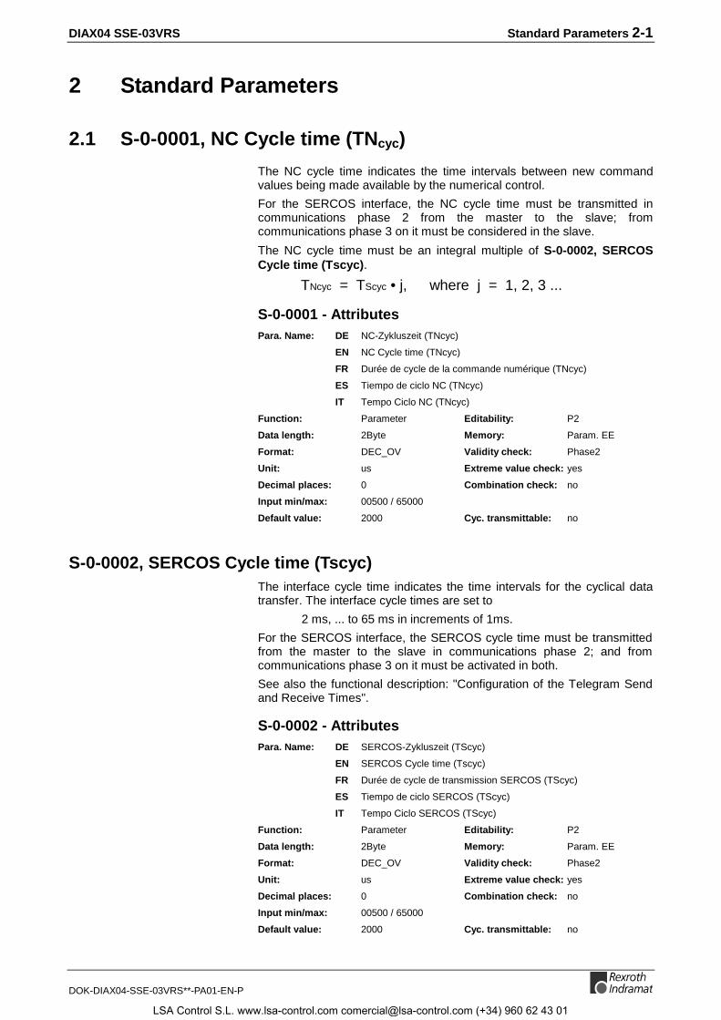
The NC cycle time indicates the time intervals between new commandvalues being made available by the numerical control.
For the SERCOS interface, the NC cycle time must be transmitted incommunications phase 2 from the master to the slave; fromcommunications phase 3 on it must be considered in the slave.
The NC cycle time must be an integral multiple of S-0-0002, SERCOSCycle time (Tscyc).
TNcyc = TScyc • j, where j = 1, 2, 3 ...
S-0-0001 - AttributesPara. Name: DE NC-Zykluszeit (TNcyc)
EN NC Cycle time (TNcyc)
FR Durée de cycle de la commande numérique (TNcyc)
ES Tiempo de ciclo NC (TNcyc)
IT Tempo Ciclo NC (TNcyc)
Function: Parameter Editability: P2
Data length: 2Byte Memory: Param. EE
Format: DEC_OV Validity check: Phase2
Unit: us Extreme value check: yes
Decimal places: 0 Combination check: no
Input min/max: 00500 / 65000
Default value: 2000 Cyc. transmittable: no
S-0-0002, SERCOS Cycle time (Tscyc)The interface cycle time indicates the time intervals for the cyclical datatransfer. The interface cycle times are set to
2 ms, ... to 65 ms in increments of 1ms.
For the SERCOS interface, the SERCOS cycle time must be transmittedfrom the master to the slave in communications phase 2; and fromcommunications phase 3 on it must be activated in both.
See also the functional description: "Configuration of the Telegram Sendand Receive Times".
S-0-0002 - AttributesPara. Name: DE SERCOS-Zykluszeit (TScyc)
EN SERCOS Cycle time (Tscyc)
FR Durée de cycle de transmission SERCOS (TScyc)
ES Tiempo de ciclo SERCOS (TScyc)
IT Tempo Ciclo SERCOS (TScyc)
Function: Parameter Editability: P2
Data length: 2Byte Memory: Param. EE
Format: DEC_OV Validity check: Phase2
Unit: us Extreme value check: yes
Decimal places: 0 Combination check: no
Input min/max: 00500 / 65000
Default value: 2000 Cyc. transmittable: no
LSA Control S.L. www.lsa-control.com [email protected] (+34) 960 62 43 01

2-2 Standard Parameters DIAX04 SSE-03VRS
DOK-DIAX04-SSE-03VRS**-PA01-EN-P
S-0-0003, Minimum AT transmit starting time (T1min)The slave uses this parameter value to indicate the minimum timerequirement between the end of the received master synchronizationtelegram and the transmission of the drive telegram.
The time T1min is read in communications phase 2 by the master tocalculate the time to send the drive telegram T1 S-0-0006, ATTransmission starting time (T1).
See also the functional description: "Configuration of the Telegram Sendand Receive Times".
S-0-0003 - AttributesPara. Name: DE Sende-Reaktionszeit AT (T1min)
EN Minimum AT transmit starting time (T1min)
FR Temps de réaction à l'émission AT (T1min)
ES Tiempo de reacción de emision AT (T1min)
IT Tempo di Partenza Trasmissione mini. AT (T1min)
Function: Parameter Editability: no
Data length: 2Byte Memory: no
Format: DEC_OV Validity check: no
Unit: us Extreme value check: no
Decimal places: 0 Combination check: no
Input min/max: --- / ---
Default value: 400 Cyc. transmittable: no
S-0-0004, Transmit/receive transition time (TATMT)This parameter indicates the time required for the slave to switch toreception of the master data telegram after sending its drive telegram.
The transmission/reception transition time is read in communicationsphase 2 by the master to calculate the time to send the master datatelegram T2 S-0-0089, MDT Transmit starting time (T2).
See also the functional description: "Configuration of the Telegram Sendand Receive Times".
S-0-0004 - AttributesPara. Name: DE Umschaltzeit Senden-Empfangen (TATMT)
EN Transmit/receive transition time (TATMT)
FR Temps de transition entre transmission et réception (TATMT)
ES Tiempo de conmutación emisión-recepción (TATMT)
IT Tempo di Transizione Trasmis./Ricez. (TATMT)
Function: Parameter Editability: no
Data length: 2Byte Memory: no
Format: DEC_OV Validity check: no
Unit: us Extreme value check: no
Decimal places: 0 Combination check: no
Input min/max: --- / ---
Default value: --- Cyc. transmittable: no
LSA Control S.L. www.lsa-control.com [email protected] (+34) 960 62 43 01

DIAX04 SSE-03VRS Standard Parameters 2-3
DOK-DIAX04-SSE-03VRS**-PA01-EN-P
S-0-0005, Minimum feedback acquisition time(T4min)This is the minimum time requirement between feedback-valueacquisition and the end of the master synchronization telegram. Thisvalue is indicated by the drive in such a manner that the current feedbackvalues can be transmitted to the numerical control in the next drivetelegram.
For the SERCOS interface, the master reads this value incommunications phase 2 to set the acquisition starting time of thefeedback values T4 S-0-0007, Feedback acquisition starting time (T4)for all drives.
See also the functional description: "Configuration of the Telegram Sendand Receive Times".
S-0-0005 - AttributesPara. Name: DE Mindestzeit Istwerterfassung(T4min)
EN Minimum feedback acquisition time(T4min)
FR Temps mini. d'acquisition des données retour (T4min)
ES Tiempo mínimo registro de valor real (T4min)
IT Tempo di Acquisizione Feedback minimo (T4min)
Function: Parameter Editability: no
Data length: 2Byte Memory: no
Format: DEC_OV Validity check: no
Unit: us Extreme value check: no
Decimal places: 0 Combination check: no
Input min/max: --- / ---
Default value: --- Cyc. transmittable: no
S-0-0006, AT Transmission starting time (T1)The transmission starting time determines when the slave must send itsdrive telegram in communications phases 3 and 4, after the end of themaster synchronization telegram.
This parameter is transmitted from the master to the slave incommunications phase 2 and is active from communications phase 3 on.
The transmission time drive telegram must be set equal to or greater thanthe transmission reaction time S-0-0003, Minimum AT transmit startingtime (T1min).
The following must apply: T1min ≤ T1
See also the functional description: "Configuration of the Telegram Sendand Receive Times".
S-0-0006 - AttributesPara. Name: DE Sendezeitpunkt Antriebs-Telegramm (T1)
EN AT Transmission starting time (T1)
FR Temps de départ de transmission de l'AT (T1)
ES Punto temporal de emision telegrama de accionamiento (T1)
IT Tempo di Partenza Trasmissione AT (T1)
LSA Control S.L. www.lsa-control.com [email protected] (+34) 960 62 43 01
2-4 Standard Parameters DIAX04 SSE-03VRS
DOK-DIAX04-SSE-03VRS**-PA01-EN-P
Function: Parameter Editability: P2
Data length: 2Byte Memory: Param. EE
Format: DEC_OV Validity check: Phase2
Unit: us Extreme value check: yes
Decimal places: 0 Combination check: no
Input min/max: 00012 / 65000
Default value: 400 Cyc. transmittable: no
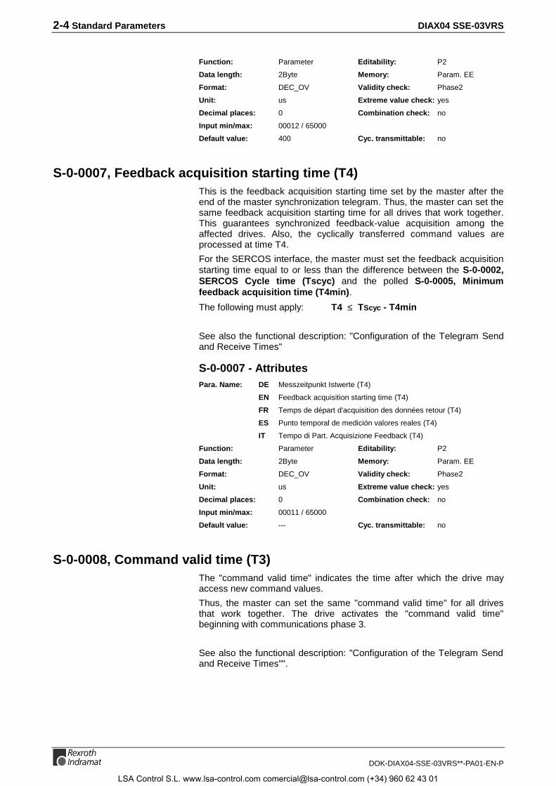
S-0-0007, Feedback acquisition starting time (T4)This is the feedback acquisition starting time set by the master after theend of the master synchronization telegram. Thus, the master can set thesame feedback acquisition starting time for all drives that work together.This guarantees synchronized feedback-value acquisition among theaffected drives. Also, the cyclically transferred command values areprocessed at time T4.
For the SERCOS interface, the master must set the feedback acquisitionstarting time equal to or less than the difference between the S-0-0002,SERCOS Cycle time (Tscyc) and the polled S-0-0005, Minimumfeedback acquisition time (T4min).
The following must apply: T4 ≤ TScyc - T4min
See also the functional description: "Configuration of the Telegram Sendand Receive Times"
S-0-0007 - AttributesPara. Name: DE Messzeitpunkt Istwerte (T4)
EN Feedback acquisition starting time (T4)
FR Temps de départ d'acquisition des données retour (T4)
ES Punto temporal de medición valores reales (T4)
IT Tempo di Part. Acquisizione Feedback (T4)
Function: Parameter Editability: P2
Data length: 2Byte Memory: Param. EE
Format: DEC_OV Validity check: Phase2
Unit: us Extreme value check: yes
Decimal places: 0 Combination check: no
Input min/max: 00011 / 65000
Default value: --- Cyc. transmittable: no
S-0-0008, Command valid time (T3)The "command valid time" indicates the time after which the drive mayaccess new command values.
Thus, the master can set the same "command valid time" for all drivesthat work together. The drive activates the "command valid time"beginning with communications phase 3.
See also the functional description: "Configuration of the Telegram Sendand Receive Times"".
LSA Control S.L. www.lsa-control.com [email protected] (+34) 960 62 43 01

DIAX04 SSE-03VRS Standard Parameters 2-5
DOK-DIAX04-SSE-03VRS**-PA01-EN-P
S-0-0008 - AttributesPara. Name: DE Zeitpunkt für Sollwert gültig (T3)
EN Command valid time (T3)
FR Temps pour consigne valide (T3)
ES Punto temporal para valor nominal valido (T3)
IT Tempo di Comando Valido (T3)
Function: Parameter Editability: P2
Data length: 2Byte Memory: Param. EE
Format: DEC_OV Validity check: Phase2
Unit: us Extreme value check: yes
Decimal places: 0 Combination check: no
Input min/max: 00000 / 65000
Default value: --- Cyc. transmittable: no
S-0-0009, Beginning address in master data telegramThis parameter displays the start address of a drive’s data record in theMaster Data Telegram, expressed as a byte position. It begins with 1 forthe first data byte after the address field in the MDT.
The start address of the drive’s data record in the MDT is transmitted toeach drive by the master in communications phase 2. The address isactivated beginning with communications phase 3.
See also the functional description: "Configuration of the Telegram Sendand Receive Times".
S-0-0009 - AttributesPara. Name: DE Anfangsadresse im Master-Daten-Telegramm
EN Beginning address in master data telegram
FR Adresse de départ dans le MDT
ES Dirección inicial en telegrama de datos maestro
IT Indirizzo iniziale del Telegramma Dati Master
Function: Parameter Editability: P2
Data length: 2Byte Memory: Param. EE
Format: DEC_OV Validity check: Phase2
Unit: -- Extreme value check: yes
Decimal places: 0 Combination check: no
Input min/max: 00001 / 65531
Default value: 1 Cyc. transmittable: no
S-0-0010, Length of master data telegramThe length of the Master Data Telegram, expressed in bytes, contains thedata records of all the drives. The MDT length is transmitted by themaster to all drives in communications phase 2. It is activated by themaster and slave beginning with communications phase 3.
See also the functional description: "Configuration of the Telegram Sendand Receive Times".
LSA Control S.L. www.lsa-control.com [email protected] (+34) 960 62 43 01

2-6 Standard Parameters DIAX04 SSE-03VRS
DOK-DIAX04-SSE-03VRS**-PA01-EN-P
S-0-0010 - AttributesPara. Name: DE Länge Master-Daten-Telegramm
EN Length of master data telegram
FR Longueur du MDT
ES Longitud telegrama de datos maestro
IT Lunghezza del Telegramma Dati Master
Function: Parameter Editability: P2
Data length: 2Byte Memory: Param. EE
Format: DEC_OV Validity check: Phase2
Unit: Byte Extreme value check: yes
Decimal places: 0 Combination check: no
Input min/max: 00004 / 65534
Default value: 4 Cyc. transmittable: no
S-0-0011, Class 1 diagnosticsFunction: Drive lock
A Class 1 diagnostic error situation discovered by the drive leads to
• the drive’s error response, as described in the functional descriptionunder "Error".
• setting the static error bits to 1 for Class 1 (S-0-0135, Drive statusword)
The drive resets the error bit back to 0 only if
• there are no errors pending in C1D
• and command S-0-0099, C500 Reset C1D has been started.
Parameter structure:
Bit 4: Control voltage error
Bit 5: Feedback error
Bit 1: Amplifier over-temperature shutdown
Bit 2: Motor over-temperature shutdown(see also S-0-0204)
Bit 9: Under-voltage error
Bit 11: Excessive control deviation
Bit 12: Communication error
Bit 13: Position limit has been exceeded
Bit 15: Manufacturer-specific error
Fig. 2-1:: S-0-0011, Class 1 diagnostics
See also the functional description: "S-0-0011, Class 1 Diagnostics".
S-0-0011 - AttributesPara. Name: DE Zustandsklasse 1
EN Class 1 diagnostics
FR Diagnostic de classe 1 (C1D)
ES Diagnosticos clase 1
IT Diagnostica Classe 1
LSA Control S.L. www.lsa-control.com [email protected] (+34) 960 62 43 01
DIAX04 SSE-03VRS Standard Parameters 2-7
DOK-DIAX04-SSE-03VRS**-PA01-EN-P
Function: Parameter Editability: no
Data length: 2Byte Memory: no
Format: BIN Validity check: no
Unit: -- Extreme value check: no
Decimal places: 0 Combination check: no
Input min/max: --- / ---
Default value: --- Cyc. transmittable: no
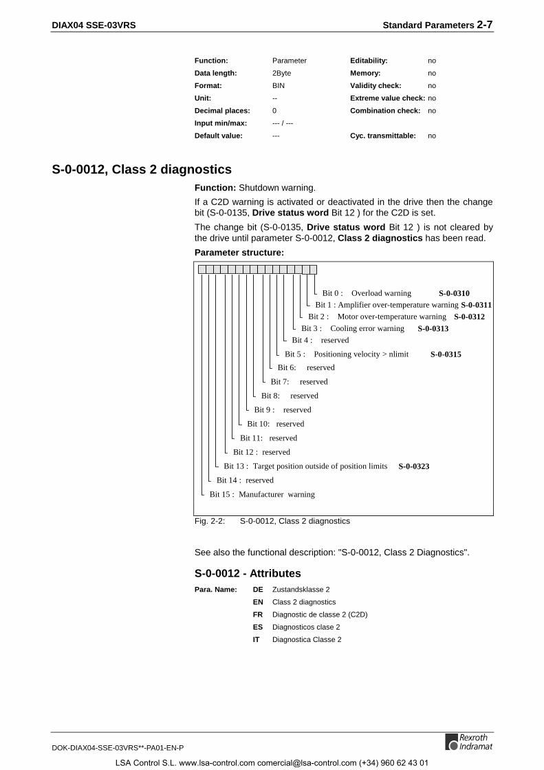
S-0-0012, Class 2 diagnosticsFunction: Shutdown warning.
If a C2D warning is activated or deactivated in the drive then the changebit (S-0-0135, Drive status word Bit 12 ) for the C2D is set.
The change bit (S-0-0135, Drive status word Bit 12 ) is not cleared bythe drive until parameter S-0-0012, Class 2 diagnostics has been read.
Parameter structure:
Bit 4 : reserved
Bit 5 : Positioning velocity > nlimit S-0-0315
Bit 1 : Amplifier over-temperature warning S-0-0311Bit 2 : Motor over-temperature warning S-0-0312
Bit 9 : reserved
Bit 11: reserved
Bit 12 : reserved
Bit 13 : Target position outside of position limits S-0-0323
Bit 15 : Manufacturer warning
Bit 0 : Overload warning S-0-0310
Bit 14 : reserved
Bit 10: reserved
Bit 8: reserved
Bit 7: reserved
Bit 6: reserved
Bit 3 : Cooling error warning S-0-0313
Fig. 2-2: S-0-0012, Class 2 diagnostics
See also the functional description: "S-0-0012, Class 2 Diagnostics".
S-0-0012 - AttributesPara. Name: DE Zustandsklasse 2
EN Class 2 diagnostics
FR Diagnostic de classe 2 (C2D)
ES Diagnosticos clase 2
IT Diagnostica Classe 2
LSA Control S.L. www.lsa-control.com [email protected] (+34) 960 62 43 01
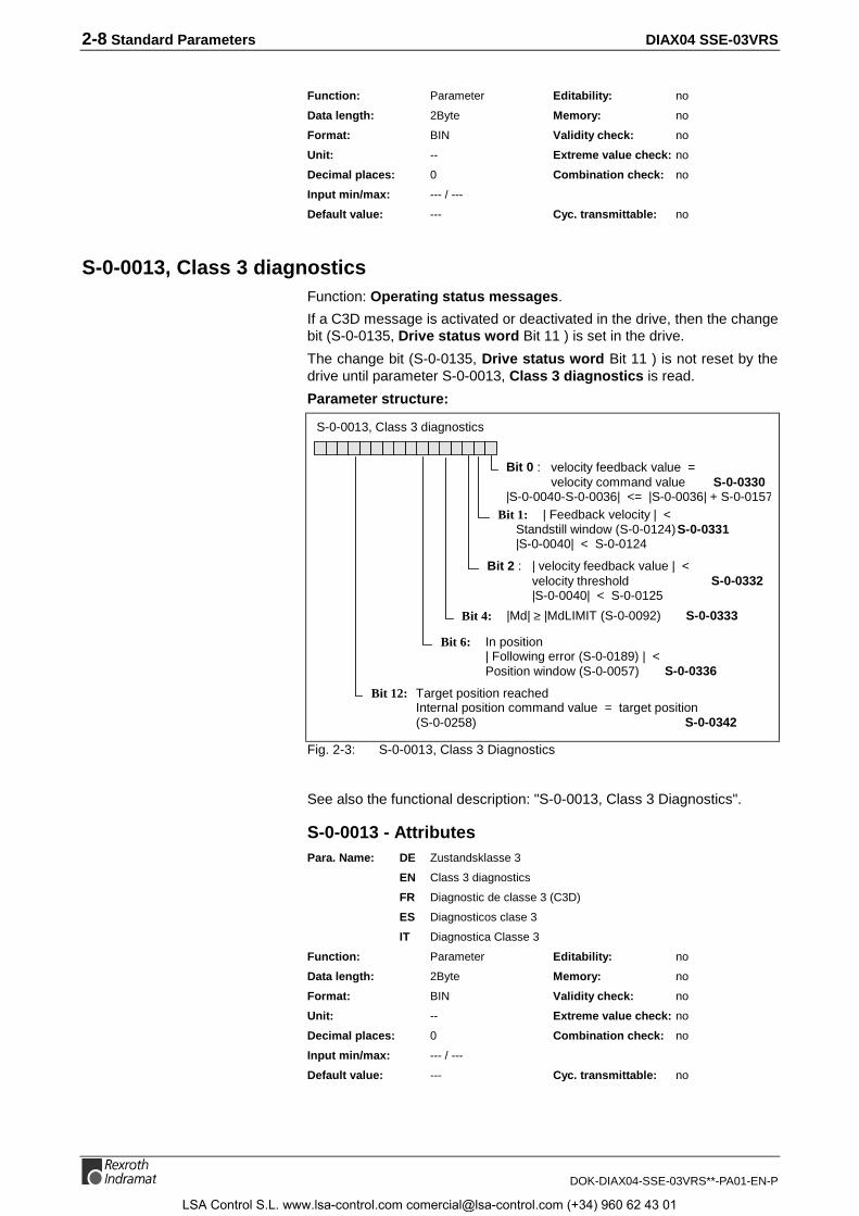
2-8 Standard Parameters DIAX04 SSE-03VRS
DOK-DIAX04-SSE-03VRS**-PA01-EN-P
Function: Parameter Editability: no
Data length: 2Byte Memory: no
Format: BIN Validity check: no
Unit: -- Extreme value check: no
Decimal places: 0 Combination check: no
Input min/max: --- / ---
Default value: --- Cyc. transmittable: no
S-0-0013, Class 3 diagnosticsFunction: Operating status messages.
If a C3D message is activated or deactivated in the drive, then the changebit (S-0-0135, Drive status word Bit 11 ) is set in the drive.
The change bit (S-0-0135, Drive status word Bit 11 ) is not reset by thedrive until parameter S-0-0013, Class 3 diagnostics is read.
Parameter structure:
S-0-0013, Class 3 diagnostics
Bit 1: | Feedback velocity | <Standstill window (S-0-0124)S-0-0331|S-0-0040| < S-0-0124
Bit 12: Target position reachedInternal position command value = target position(S-0-0258) S-0-0342
Bit 6: In position| Following error (S-0-0189) | <Position window (S-0-0057) S-0-0336
Bit 4: |Md| ≥ |MdLIMIT (S-0-0092) S-0-0333
Bit 2 : | velocity feedback value | < velocity threshold S-0-0332
|S-0-0040| < S-0-0125
Bit 0 : velocity feedback value =velocity command value S-0-0330
|S-0-0040-S-0-0036| <= |S-0-0036| + S-0-0157
Fig. 2-3: S-0-0013, Class 3 Diagnostics
See also the functional description: "S-0-0013, Class 3 Diagnostics".
S-0-0013 - AttributesPara. Name: DE Zustandsklasse 3
EN Class 3 diagnostics
FR Diagnostic de classe 3 (C3D)
ES Diagnosticos clase 3
IT Diagnostica Classe 3
Function: Parameter Editability: no
Data length: 2Byte Memory: no
Format: BIN Validity check: no
Unit: -- Extreme value check: no
Decimal places: 0 Combination check: no
Input min/max: --- / ---
Default value: --- Cyc. transmittable: no
LSA Control S.L. www.lsa-control.com [email protected] (+34) 960 62 43 01

DIAX04 SSE-03VRS Standard Parameters 2-9
DOK-DIAX04-SSE-03VRS**-PA01-EN-P
S-0-0014, Interface statusIn the three least significant bits ( 0, 1, 2 ), the current communicationphase can be requested:
0010b: the drive is in parameterization mode
0100b: the drive is in operation mode
If an interface error is pending, then
• one of the bits 4-15 in S-0-0014, Interface status is set(Bit in 4 .. 15 = 1 => error pending)
• and Bit 12 is set in S-0-0011, Class 1 diagnostics.
The communications error bits are not cleared by the drive until
• the relevant interface error is no longer pending
• and command S-0-0099, C500 Reset class 1 diagnostic is started.
Parameter structure:
Bit 4 : Double MDT failure
Bit 5 : Invalid phase (phase > 4)
Bits 0-2: Communication phase
Bit 9 : reserved
Bit 11: reserved
Bit 12 : reserved
Bit 13 : reserved
Bit 15 : reserved
Bit 14 : reserved
Bit 10: reserved
Bit 8: Phase switching without ready message
Bit 7: Error while switching to lower phase(not to phase 0)
Bit 6: Error while switching to higher phase(order)
Bit 3 : not supported
Fig. 2-4: S-0-0014, Interface status
See also the functional description: "Diagnostic of the interface Status".
S-0-0014 - AttributesPara. Name: DE Schnittstellen-Status
EN Interface status
FR Etat d’interface
ES Estado de interfaces
IT Stato Interfaccia
LSA Control S.L. www.lsa-control.com [email protected] (+34) 960 62 43 01

2-10 Standard Parameters DIAX04 SSE-03VRS
DOK-DIAX04-SSE-03VRS**-PA01-EN-P
Function: Parameter Editability: no
Data length: 2Byte Memory: no
Format: BIN Validity check: no
Unit: -- Extreme value check: no
Decimal places: 0 Combination check: no
Input min/max: --- / ---
Default value: --- Cyc. transmittable: no
S-0-0015, Telegram type parameterIn this parameter, you can choose between priority telegrams and theconfigured telegram.
The telegram type that is selected will be activated in the master andslave only from communications phase 3 on.
Parameter structure:
Bit 0 - 2: Priority-telegram-selection,resp. configured telegramselection
Bit 3 0 : Position-feedback 1 (Motor feedback)1 : Position-feedback-2 (external)
Fig. 2-5: S-0-0015, Telegram type parameter
Note: Only the bits indicated here are supported by the software.
Telegrams:
Bit0-2: MDT: AT:
0 PT 0 No cyclical data No cyclical data
1 PT 1 DF1: S-0-0080 Torque command No cyclical data
2 PT 2 DF1: S-0-0036, Velocity command value DF1: S-0-0040 Velocity feedback value
3 PT 3 DF1: S-0-0036, Velocity command value DF1: S-0-0051/S-0-0053 Position feedbackvalue 1
4 PT 4 DF1: S-0-0047, Position command value DF1: S-0-0051/S-0-0053 Position feedbackvalue 1
5 PT 5 DF1: S-0-0047, Position command valueDF2: S-0-0036, Velocity command value
DF1: S-0-0051/S-0-0053 Position feedbackvalue 1DF2: S-0-0040 Velocity feedback value
6 PT 6 DF1: S-0-0036, Velocity command value No cyclical data
7 Configurable telegramFig. 2-6: Supported bits
where PT : Priority telegram
DF1/2: Data field 1/2
See also the functional description: "Configuration of Telegram Contents"
LSA Control S.L. www.lsa-control.com [email protected] (+34) 960 62 43 01
DIAX04 SSE-03VRS Standard Parameters 2-11
DOK-DIAX04-SSE-03VRS**-PA01-EN-P
S-0-0015 - AttributesPara. Name: DE Telegrammarten-Parameter
EN Telegram type parameter
FR Paramètre de type de télégramme
ES Parámetros de tipo de telegrama
IT Parametri Tipo Telegramma
Function: Parameter Editability: P2
Data length: 2Byte Memory: Param. EE
Format: BIN Validity check: Phase2
Unit: -- Extreme value check: yes
Decimal places: 0 Combination check: no
Input min/max: 0x0000 / ---
Default value: 0 Cyc. transmittable: no
S-0-0016, Custom amplifier telegram configuration listIf a configured telegram is set in S-0-0015, Telegram type parameter,then this list will be used for application-specific configuration of the datarecord in the AT.
The list can contain only operating data that are listed in the parameter S-0-0187, List of configurable data in the AT.
See also the functional description: "Configuration of Telegram Contents"
S-0-0016 - AttributesPara. Name: DE Konfig.-Liste Antriebs-Telegramm
EN Custom amplifier telegram configuration list
FR Liste de configuration d'AT
ES Telegrama de accionamiento lista de config.
IT Configurazione personalizzata Telegramma
Function: Parameter Editability: P2
Data length: 2Byte var. Memory: Param. EE
Format: IDN Validity check: Phase2
Unit: -- Extreme value check: no
Decimal places: 0 Combination check: no
Input min/max: --- / ---
Default value: leer Cyc. transmittable: no
S-0-0017, IDN-list of all operation dataThe ID numbers for all parameters with operation data available in thedrive are accessible in this IDN list.
See also the functional description: "Parameter"
S-0-0017 - AttributesPara. Name: DE IDN-Liste aller Betriebsdaten
EN IDN-list of all operation data
FR Liste des IDN de toutes les données d'exploitation
ES Lista IDN de todos los datos de servicio
IT Lista IDN di tutti i Dati operativi
LSA Control S.L. www.lsa-control.com [email protected] (+34) 960 62 43 01

2-12 Standard Parameters DIAX04 SSE-03VRS
DOK-DIAX04-SSE-03VRS**-PA01-EN-P
Function: Parameter Editability: no
Data length: 2Byte var. Memory: no
Format: IDN Validity check: no
Unit: -- Extreme value check: no
Decimal places: 0 Combination check: no
Input min/max: --- / ---
Default value: --- Cyc. transmittable: no
S-0-0018, IDN-list of operation data for CP2The IDN-list contains the ident-numbers of all parameters that the drivechecks in the transition command for phase 3. Only when the data of thelisted ident-numbers are correct can the transmission command becompleted and the transition to communications phase 3 allowed.
See also the functional description: "IDN List of Parameters"
S-0-0018 - AttributesPara. Name: DE IDN-Liste Betriebsdaten Kommunikationsphase 2
EN IDN-list of operation data for CP2
FR Liste IDN des données d'exploitation relatives à CP2
ES Lista IDN datos de servicio fase de comunicación 2
IT Lista IDN di tutti i Dati per fase di comm. 2
Function: Parameter Editability: no
Data length: 2Byte var. Memory: no
Format: IDN Validity check: no
Unit: -- Extreme value check: no
Decimal places: 0 Combination check: no
Input min/max: - / -
Default value: --- Cyc. transmittable: no
S-0-0019, IDN-list of operation data for CP3The IDN-list contains the ident-numbers of all parameters that the drivechecks in the transition command for phase 4. Only when the data of thelisted ident-numbers are correct can the transmission command becompleted and the transition to communications phase 4 allowed.
See also the functional description: "IDN List of Parameters"
S-0-0019 - AttributesPara. Name: DE IDN-Liste Betriebsdaten Kommunikationsphase 3
EN IDN-list of operation data for CP3
FR Liste IDN des données d'exploitation relatives à CP3
ES Lista IDN datos de servicio fase de comunicación 3
IT Lista IDN di tutti i Dati per fase di comm. 3
Function: Parameter Editability: no
Data length: 2Byte var. Memory: no
Format: IDN Validity check: no
Unit: -- Extreme value check: no
Decimal places: 0 Combination check: no
Input min/max: - / -
Default value: --- Cyc. transmittable: no
LSA Control S.L. www.lsa-control.com [email protected] (+34) 960 62 43 01

DIAX04 SSE-03VRS Standard Parameters 2-13
DOK-DIAX04-SSE-03VRS**-PA01-EN-P
S-0-0021, IDN-list of invalid op. data for comm. Ph. 2Before the drive executes a switch from phase 2 to phase 3, it mustcomplete the corresponding command S-0-0127, C100 Communicationphase 3 transition check that allows it to check if the communicationsparameters are complete and accurate.
If the drive identifies one or more IDNs as invalid, it will write the operatingdata that is still needed or is invalid to this ID No. list. This will bedisplayed to the drive by command error diagnostic message C101Invalid communication parameter (S-0-0021).
See also the functional description: "IDN List of Parameters"
S-0-0021 - AttributesPara. Name: DE IDN-Liste ungültige Betriebsdaten Phase 2
EN IDN-list of invalid op. data for comm. Ph. 2
FR Liste des IDN-données d'exploitation invalides phase 2
ES Lista IDN de datos de servicio no validos fase 2
IT Lista IDN dei Dati oper. invalidi per Comm. in Fase 2
Function: Parameter Editability: no
Data length: 2Byte var. Memory: no
Format: IDN Validity check: no
Unit: -- Extreme value check: no
Decimal places: 0 Combination check: no
Input min/max: --- / ---
Default value: --- Cyc. transmittable: no
S-0-0022, IDN-list of invalid op. data for comm. Ph. 3Before the drive executes a switch from phase 3 to phase 4, it mustcomplete the corresponding command S-0-0128, C200 Communicationphase 4 transition check that allows it to check parameters for thefollowing conditions:
• Validity of the parameter
• The parameter value is found within the valid input range.
• Compatibility with other parameters.
If the result of a parameter check is negative, this operating data will beentered in the ID No. (IDN) list.
The drive then responds to the transition command with thecommunications error diagnostic messages
• C201 Invalid Parameter(s) (->S-0-0022) or
• C202 Parameter limit error (->S-0-0022) or
• C203 Parameter calculation error (->S-0-0022)
See also the functional description: "IDN List of Parameters"
S-0-0022 - AttributesPara. Name: DE IDN-Liste ungültige Betriebsdaten Phase 3
EN IDN-list of invalid op. data for comm. Ph. 3
FR IDN-Liste données d'exploitation invalides phase 3
ES Lista IDN de datos de servicio no validos fase 3
IT Lista IDN dei Dati oper. invalidi per Comm. in Fase 3
LSA Control S.L. www.lsa-control.com [email protected] (+34) 960 62 43 01

2-14 Standard Parameters DIAX04 SSE-03VRS
DOK-DIAX04-SSE-03VRS**-PA01-EN-P
Function: Parameter Editability: no
Data length: 2Byte var. Memory: no
Format: IDN Validity check: no
Unit: -- Extreme value check: no
Decimal places: 0 Combination check: no
Input min/max: --- / ---
Default value: --- Cyc. transmittable: no
S-0-0024, Config. list of the master data telegramIf the configured telegram is set in S-0-0015, Telegram type parameter,then the configurable data record in the MDT will be configuredapplication-specifically using this list.
The list can contain only operating data that are listed in the parameterS-0-0188, List of configurable data in the MDT.
See also the functional description: "Configuration of Telegram Contents"
S-0-0024 - AttributesPara. Name: DE Konfig.-Liste Master-Daten-Telegramm
EN Config. list of the master data telegram
FR Liste de configuration du MDT
ES Lista de configuración del MDT
IT Lista Config. del Telegramma Dati Master
Function: Parameter Editability: P2
Data length: 2Byte var. Memory: Param. EE
Format: IDN Validity check: Phase2
Unit: -- Extreme value check: no
Decimal places: 0 Combination check: no
Input min/max: --- / ---
Default value: leer Cyc. transmittable: no
S-0-0025, IDN-list of all procedure commandsThe data of the IDN-list contains the ident-numbers of all commands inthe drive controller.
See also the functional description: "Commands"
S-0-0025 - AttributesPara. Name: DE IDN-Liste aller Kommandos
EN IDN-list of all procedure commands
FR Liste des IDN de toutes les commandes
ES Lista IDN de todos los comandos
IT Lista IDN di tutti i Comandi
Function: Parameter Editability: no
Data length: 2Byte var. Memory: no
Format: IDN Validity check: no
Unit: -- Extreme value check: no
Decimal places: 0 Combination check: no
Input min/max: - / -
Default value: --- Cyc. transmittable: no
LSA Control S.L. www.lsa-control.com [email protected] (+34) 960 62 43 01
DIAX04 SSE-03VRS Standard Parameters 2-15
DOK-DIAX04-SSE-03VRS**-PA01-EN-P
S-0-0026, Configuration list signal status wordThe data of this parameters contains the ident-numbers of the signals orbits which the signal status word (S-0-0144) contains.
The order of the ident-numbers in the configuration list determines the bitsequence, beginning with the LSB in the signal status word.
That means, the first ident-number in S-0-0026 defines the bit 0, thesecond ident-number in S-0-0026 defines bit 1 in the parameter S-0-0144,Signal status word, and so on.
Note: The signal status word is used in fieldbus drives for theinternal communications between the two microcontrollers(exception: P-0-4048 = FFFFh).
See also the functional description: "Configurable Signal Status Word"
S-0-0026 - AttributesPara. Name: DE Konfigurations-Liste Signal-Statuswort
EN Configuration list signal status word
FR Liste de configuration pour mot d'état de signal
ES Lista de configuración palabra de estado de señal
IT Lista di Configurazione Parole di Stato Segnali
Function: Parameter Editability: P234
Data length: 2Byte var. Memory: Param. EE
Format: IDN Validity check: P3-4
Unit: -- Extreme value check: no
Decimal places: 0 Combination check: no
Input min/max: -- / --
Default value: 0 Cyc. transmittable: no
S-0-0028, MST error counterThe MST error count counts all invalid Master Synchronization Telegramsin communications phases 3 and 4.
If two MSTs fail in direct succession, then error F401 Double MST errorshutdown will be generated and the operation will return to phase 0.
The MST error count has a limit stop at (2^16) - 1. This means that duringa highly distorted transfer the MST Error count will show the value 65535after a long time.
See also the functional description: "Error Count for Telegram Interrupts".
S-0-0028 - AttributesPara. Name: DE Fehlerzähler MST
EN MST error counter
FR Compteur de MST erronés
ES Contador de errores MST
IT Contatore errori MST
Function: Parameter Editability: no
Data length: 2Byte Memory: no
Format: DEC_0V Validity check: no
Unit: -- Extreme value check: no
Decimal places: 0 Combination check: no
Input min/max: --- / ---
Default value: --- Cyc. transmittable: no
LSA Control S.L. www.lsa-control.com [email protected] (+34) 960 62 43 01
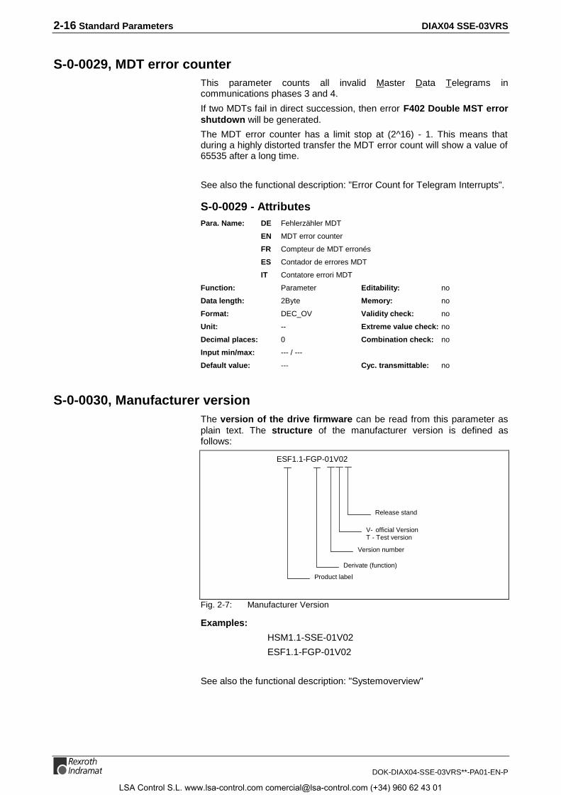
2-16 Standard Parameters DIAX04 SSE-03VRS
DOK-DIAX04-SSE-03VRS**-PA01-EN-P
S-0-0029, MDT error counterThis parameter counts all invalid Master Data Telegrams incommunications phases 3 and 4.
If two MDTs fail in direct succession, then error F402 Double MST errorshutdown will be generated.
The MDT error counter has a limit stop at (2^16) - 1. This means thatduring a highly distorted transfer the MDT error count will show a value of65535 after a long time.
See also the functional description: "Error Count for Telegram Interrupts".
S-0-0029 - AttributesPara. Name: DE Fehlerzähler MDT
EN MDT error counter
FR Compteur de MDT erronés
ES Contador de errores MDT
IT Contatore errori MDT
Function: Parameter Editability: no
Data length: 2Byte Memory: no
Format: DEC_OV Validity check: no
Unit: -- Extreme value check: no
Decimal places: 0 Combination check: no
Input min/max: --- / ---
Default value: --- Cyc. transmittable: no
S-0-0030, Manufacturer versionThe version of the drive firmware can be read from this parameter asplain text. The structure of the manufacturer version is defined asfollows:
ESF1.1-FGP-01V02
Release stand
V- official VersionT - Test version
Version number
Derivate (function)
Product label
Fig. 2-7: Manufacturer Version
Examples:
HSM1.1-SSE-01V02
ESF1.1-FGP-01V02
See also the functional description: "Systemoverview"
LSA Control S.L. www.lsa-control.com [email protected] (+34) 960 62 43 01
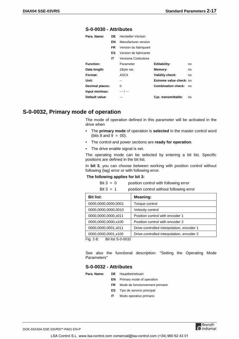
DIAX04 SSE-03VRS Standard Parameters 2-17
DOK-DIAX04-SSE-03VRS**-PA01-EN-P
S-0-0030 - AttributesPara. Name: DE Hersteller-Version
EN Manufacturer version
FR Version du fabriquant
ES Version de fabricante
IT Versione Costruttore
Function: Parameter Editability: no
Data length: 1Byte var. Memory: no
Format: ASCII Validity check: no
Unit: -- Extreme value check: no
Decimal places: 0 Combination check: no
Input min/max: --- / ---
Default value: --- Cyc. transmittable: no
S-0-0032, Primary mode of operationThe mode of operation defined in this parameter will be activated in thedrive when
• The primary mode of operation is selected in the master control word(bits 8 and 9 = 00).
• The control and power sections are ready for operation.
• The drive enable signal is set.
The operating mode can be selected by entering a bit list. Specificpositions are defined in the bit list.
In bit 3, you can choose between working with position control withoutfollowing (lag) error or with following error.
The following applies for bit 3:
Bit 3 = 0 position control with following error
Bit 3 = 1 position control without following error
Bit list: Meaning:
0000,0000,0000,0001 Torque control
0000,0000,0000,0010 Velocity control
0000,0000,0000,x011 Position control with encoder 1
0000,0000,0000,x100 Position control with encoder 2
0000,0000,0001,x011 Drive-controlled interpolation, encoder 1
0000,0000,0001,x100 Drive-controlled interpolation, encoder 2Fig. 2-8: Bit list S-0-0032
See also the functional description: "Setting the Operating ModeParameters"
S-0-0032 - AttributesPara. Name: DE Hauptbetriebsart
EN Primary mode of operation
FR Mode de fonctionnement primaire
ES Tipo de servicio principal
IT Modo operativo primario
LSA Control S.L. www.lsa-control.com [email protected] (+34) 960 62 43 01

2-18 Standard Parameters DIAX04 SSE-03VRS
DOK-DIAX04-SSE-03VRS**-PA01-EN-P
Function: Parameter Editability: P23
Data length: 2Byte Memory: Param. EE
Format: BIN Validity check: Phase3
Unit: -- Extreme value check: no
Decimal places: 0 Combination check: yes
Input min/max: --- / ---
Default value: 10 Cyc. transmittable: no
S-0-0033, Secondary operation mode 1The mode of operation defined in this parameter will be activated in thedrive if:
• The secondary operation mode 1 is selected in the master controlword (bits 8 and 9 = "01")
• The control and power sections are ready for operation.
• The drive enable signal is set.
The operating mode can be selected by entering a bit list. Specificpositions are defined in the bit list.
In bit 3, you can choose between working with position control withoutfollowing (lag) error or with following error.
The following applies:
Bit 3 = 0 position control with following error
Bit 3 = 1 position control without following error
Bit list: Meaning:
0000,0000,0000,0001 Torque control
0000,0000,0000,0010 Velocity control
0000,0000,0000,x011 Position control with encoder 1
0000,0000,0000,x100 Position control with encoder 2
0000,0000,0001,x011 Drive-controlled interpolation, encoder 1
0000,0000,0001,x100 Drive-controlled interpolation, encoder 2Fig. 2-9: Bit list S-0-0033
See also the functional description: "Setting the Operating ModeParameters"
S-0-0033 - AttributesPara. Name: DE Nebenbetriebsart 1
EN Secondary operation mode 1
FR Mode de fonctionnement secondaire 1
ES Tipo de servicio secundario 1
IT Modo operativo secondario 1
Function: Parameter Editability: P23
Data length: 2Byte Memory: Param. EE
Format: BIN Validity check: Phase3
Unit: -- Extreme value check: no
Decimal places: 0 Combination check: yes
Input min/max: --- / ---
Default value: 10 Cyc. transmittable: no
LSA Control S.L. www.lsa-control.com [email protected] (+34) 960 62 43 01
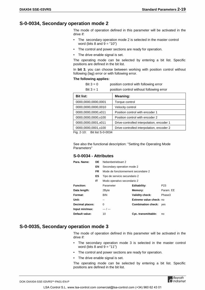
DIAX04 SSE-03VRS Standard Parameters 2-19
DOK-DIAX04-SSE-03VRS**-PA01-EN-P
S-0-0034, Secondary operation mode 2The mode of operation defined in this parameter will be activated in thedrive if:
• The secondary operation mode 2 is selected in the master controlword (bits 8 and 9 = "10")
• The control and power sections are ready for operation.
• The drive enable signal is set.
The operating mode can be selected by entering a bit list. Specificpositions are defined in the bit list.
In bit 3, you can choose between working with position control withoutfollowing (lag) error or with following error.
The following applies:
Bit 3 = 0 position control with following error
Bit 3 = 1 position control without following error
Bit list: Meaning:
0000,0000,0000,0001 Torque control
0000,0000,0000,0010 Velocity control
0000,0000,0000,x011 Position control with encoder 1
0000,0000,0000,x100 Position control with encoder 2
0000,0000,0001,x011 Drive-controlled interpolation, encoder 1
0000,0000,0001,x100 Drive-controlled interpolation, encoder 2Fig. 2-10: Bit list S-0-0034
See also the functional description: "Setting the Operating ModeParameters"
S-0-0034 - AttributesPara. Name: DE Nebenbetriebsart 2
EN Secondary operation mode 2
FR Mode de fonctionnement secondaire 2
ES Tipo de servicio secundario 2
IT Modo operativo secondario 2
Function: Parameter Editability: P23
Data length: 2Byte Memory: Param. EE
Format: BIN Validity check: Phase3
Unit: -- Extreme value check: no
Decimal places: 0 Combination check: yes
Input min/max: --- / ---
Default value: 10 Cyc. transmittable: no
S-0-0035, Secondary operation mode 3The mode of operation defined in this parameter will be activated in thedrive if:
• The secondary operation mode 3 is selected in the master controlword (bits 8 and 9 = "11")
• The control and power sections are ready for operation.
• The drive enable signal is set.
The operating mode can be selected by entering a bit list. Specificpositions are defined in the bit list.
LSA Control S.L. www.lsa-control.com [email protected] (+34) 960 62 43 01
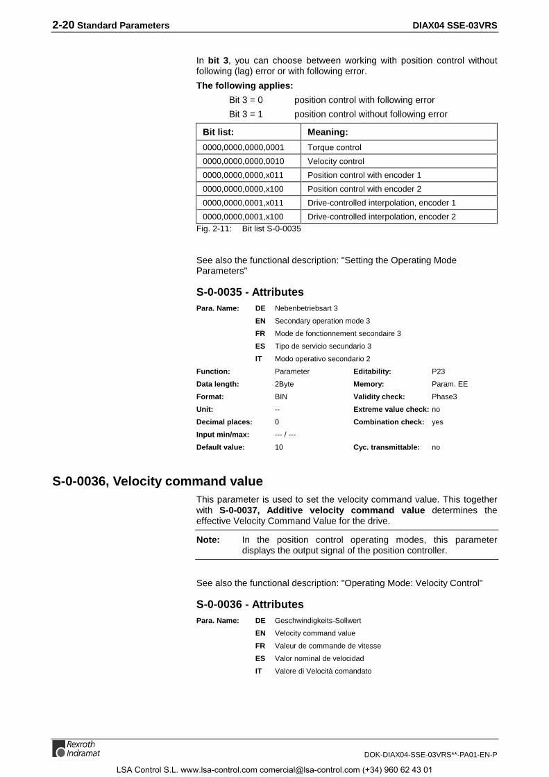
2-20 Standard Parameters DIAX04 SSE-03VRS
DOK-DIAX04-SSE-03VRS**-PA01-EN-P
In bit 3, you can choose between working with position control withoutfollowing (lag) error or with following error.
The following applies:
Bit 3 = 0 position control with following error
Bit 3 = 1 position control without following error
Bit list: Meaning:
0000,0000,0000,0001 Torque control
0000,0000,0000,0010 Velocity control
0000,0000,0000,x011 Position control with encoder 1
0000,0000,0000,x100 Position control with encoder 2
0000,0000,0001,x011 Drive-controlled interpolation, encoder 1
0000,0000,0001,x100 Drive-controlled interpolation, encoder 2Fig. 2-11: Bit list S-0-0035
See also the functional description: "Setting the Operating ModeParameters"
S-0-0035 - AttributesPara. Name: DE Nebenbetriebsart 3
EN Secondary operation mode 3
FR Mode de fonctionnement secondaire 3
ES Tipo de servicio secundario 3
IT Modo operativo secondario 2
Function: Parameter Editability: P23
Data length: 2Byte Memory: Param. EE
Format: BIN Validity check: Phase3
Unit: -- Extreme value check: no
Decimal places: 0 Combination check: yes
Input min/max: --- / ---
Default value: 10 Cyc. transmittable: no
S-0-0036, Velocity command valueThis parameter is used to set the velocity command value. This togetherwith S-0-0037, Additive velocity command value determines theeffective Velocity Command Value for the drive.
Note: In the position control operating modes, this parameterdisplays the output signal of the position controller.
See also the functional description: "Operating Mode: Velocity Control"
S-0-0036 - AttributesPara. Name: DE Geschwindigkeits-Sollwert
EN Velocity command value
FR Valeur de commande de vitesse
ES Valor nominal de velocidad
IT Valore di Velocità comandato
LSA Control S.L. www.lsa-control.com [email protected] (+34) 960 62 43 01

DIAX04 SSE-03VRS Standard Parameters 2-21
DOK-DIAX04-SSE-03VRS**-PA01-EN-P
Function: Parameter Editability: P234
Data length: 4Byte Memory: no
Format: DEC_MV Validity check: no
Unit: S-0-0044 Extreme value check: yes
Decimal places: S-0-0045/S-0-0046 Combination check: no
Input min/max: -000060000.0 / 0000060000.0
Default value: --- Cyc. transmittable: MDT
S-0-0037, Additive velocity command valueThe additive velocity command value is added to the S-0-0036, Velocitycommand value in the drive.
See also the functional description: "Operating Mode: Velocity Control"
S-0-0037 - AttributesPara. Name: DE Geschwindigkeits-Sollwert additiv
EN Additive velocity command value
FR Valeur de commande de vitesse supplémentaire
ES Valor nominal adicional de velocidad
IT Comando di Velocità addizzionale
Function: Parameter Editability: P234
Data length: 4Byte Memory: no
Format: DEC_MV Validity check: no
Unit: S-0-0044 Extreme value check: yes
Decimal places: S-0-0045/S-0-0046 Combination check: no
Input min/max: -000060000.0 / 0000060000.0
Default value: --- Cyc. transmittable: MDT
S-0-0040, Velocity feedback valueThe velocity feedback value can be transferred from the drive controldevice to the control system either cyclically or via the service channel.
Bit 7 in the parameter P-0-0538, Motor function parameter 1 canactivate a filter for the velocity feedback value.
see also functional description "Preparations for Setting the VelocityController"
S-0-0040 - AttributesPara. Name: DE Geschwindigkeits-Istwert
EN Velocity feedback value
FR Valeur de retour de vitesse
ES Valor real de velocidad
IT Feedback di Velocità
Function: Parameter Editability: no
Data length: 4Byte Memory: no
Format: DEC_MV Validity check: no
Unit: S-0-0044 Extreme value check: no
Decimal places: S-0-0045/S-0-0046 Combination check: no
Input min/max: --- / ---
Default value: --- Cyc. transmittable: AT
LSA Control S.L. www.lsa-control.com [email protected] (+34) 960 62 43 01
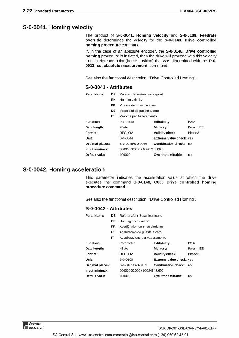
2-22 Standard Parameters DIAX04 SSE-03VRS
DOK-DIAX04-SSE-03VRS**-PA01-EN-P
S-0-0041, Homing velocityThe product of S-0-0041, Homing velocity and S-0-0108, Feedrateoverride determines the velocity for the S-0-0148, Drive controlledhoming procedure command.
If, in the case of an absolute encoder, the S-0-0148, Drive controlledhoming procedure is initiated, then the drive will proceed with this velocityto the reference point (home position) that was determined with the P-0-0012; set absolute measurement, command.
See also the functional description: "Drive-Controlled Homing".
S-0-0041 - AttributesPara. Name: DE Referenzfahr-Geschwindigkeit
EN Homing velocity
FR Vitesse de prise d’origine
ES Velocidad de puesta a cero
IT Velocità per Azzeramento
Function: Parameter Editability: P234
Data length: 4Byte Memory: Param. EE
Format: DEC_OV Validity check: Phase3
Unit: S-0-0044 Extreme value check: yes
Decimal places: S-0-0045/S-0-0046 Combination check: no
Input min/max: 0000000000.0 / 0030720000.0
Default value: 100000 Cyc. transmittable: no
S-0-0042, Homing accelerationThis parameter indicates the acceleration value at which the driveexecutes the command S-0-0148, C600 Drive controlled homingprocedure command.
See also the functional description: "Drive-Controlled Homing".
S-0-0042 - AttributesPara. Name: DE Referenzfahr-Beschleunigung
EN Homing acceleration
FR Accélération de prise d'origine
ES Aceleración de puesta a cero
IT Accellerazione per Azzeramento
Function: Parameter Editability: P234
Data length: 4Byte Memory: Param. EE
Format: DEC_OV Validity check: Phase3
Unit: S-0-0160 Extreme value check: yes
Decimal places: S-0-0161/S-0-0162 Combination check: no
Input min/max: 00000000.000 / 00024543.692
Default value: 100000 Cyc. transmittable: no
LSA Control S.L. www.lsa-control.com [email protected] (+34) 960 62 43 01

DIAX04 SSE-03VRS Standard Parameters 2-23
DOK-DIAX04-SSE-03VRS**-PA01-EN-P
S-0-0043, Velocity polarity parameterThis parameter is used to switch the polarity of the velocity data in relationto the application.
Polarities are switched externally, at the input and output of a controlsystem rather than inside the system.
The following applies to rotary motors:
Clockwise rotation when facing the motor shaft is the rule for a positivevelocity command value and a positive polarity.
The following applies to linear motors:
The positive direction is used when the primary is moving toward thelinear motor power cable side.
Parameter structure:
Bit 0: Velocity command value 0: positive polarity 1: negative polarity
Bit 2: Velocity feedback value 0: positive polarity 1: negative polarity
Bit 1: Velocity command value, additive 0: positive polarity 1: negative polarity
Fig. 2-12: S-0-0043, Velocity polarity parameter
Note: The bits 1 and 2 are copies of bit 0. Only changes of bit 0 havean effect. Different settings of the single bits are not possible!
See also the functional description: "Command Polarities and ActualValue Polarities".
S-0-0043 - AttributesPara. Name: DE Geschwindigkeits-Polaritäten-Parameter
EN Velocity polarity parameter
FR Paramètre de polarité de vitesse
ES Parámetros de polaridad de velocidad
IT Parametro Direzione Velocità
Function: Parameter Editability: P23
Data length: 2Byte Memory: Param. EE
Format: BIN Validity check: Phase3
Unit: -- Extreme value check: yes
Decimal places: 0 Combination check: no
Input min/max: 0x0000 / ---
Default value: 0 Cyc. transmittable: no
LSA Control S.L. www.lsa-control.com [email protected] (+34) 960 62 43 01

2-24 Standard Parameters DIAX04 SSE-03VRS
DOK-DIAX04-SSE-03VRS**-PA01-EN-P
S-0-0044, Velocity data scaling typeVarious scaling types can be defined for the velocity data in the drive.
Examples: RPM → rotary
mm/min → linear
Structure of the parameter:
Bit 4 : Unit of measure for linear scaling0 : meter [m]1 : inch [in]
Unit of measure for rotary scaling0 : revolution1 : reserved
Bit 5 : Unit of time0 : minute [min]1 : second [sec]
Bit 15 - 7: reserved
Bit 6: Data reference0 : to the motor shaft1 : to the load
Bit 3 :0 : preferred scaling1 : parameter scaling
Bit 2 - 0: Scaling type0 0 0: unscaled0 0 1: linear scaling0 1 0: rotary scaling
Fig. 2-13: S-0-0044, Velocity Data Scaling Type
In bit 3 it is possible to select between preferred and parameter scaling.
Preferred scaling:
The following parameters are predefined in this case and cannot bechanged:
• S-0-0045, scaling factor for velocity data
• S-0-0046, scaling exponents for velocity data
Scaling with parameter scaling means that the above parameter must beset.
(See section: "Preferred / parameter scaling")
See also functional description: "Velocity Data Display Format"
S-0-0044 - AttributesPara. Name: DE Wichtungsart für Geschwindigkeitsdaten
EN Velocity data scaling type
FR Type de calibrage pour données de vitesse
ES Tipo de escala de datos de velocidad
IT Tipo di Scala per Dati di Velocità
Function: Parameter Editability: P23
Data length: 2Byte Memory: Param. EE
Format: BIN Validity check: Phase3
Unit: -- Extreme value check: no
Decimal places: 0 Combination check: yes
Input min/max: --- / ---
Default value: 1000010 Cyc. transmittable: no
LSA Control S.L. www.lsa-control.com [email protected] (+34) 960 62 43 01

DIAX04 SSE-03VRS Standard Parameters 2-25
DOK-DIAX04-SSE-03VRS**-PA01-EN-P
S-0-0045, Velocity data scaling factorThis parameter defines the scaling factor for all velocity data in the drive.
If preferred scaling is set with S-0-0044, Velocity data scaling type, thisparameter will be set to 1.
See also the functional description: "Velocity Data Display Format"
S-0-0045 - AttributesPara. Name: DE Wichtungs-Faktor für Geschwindigkeitsdaten
EN Velocity data scaling factor
FR Facteur de calibrage pour données de vitesse
ES Factor de escala para datos de velocidad
IT Fattore di Scala per Dati Velocità
Function: Parameter Editability: P23
Data length: 2Byte Memory: Param. EE
Format: DEC_OV Validity check: Phase3
Unit: -- Extreme value check: no
Decimal places: 0 Combination check: no
Input min/max: --- / ---
Default value: 1 Cyc. transmittable: no
S-0-0046, Velocity data scaling exponentThe scaling exponent for all velocity data in the drive is determined in thisparameter.
See also functional description: "Velocity Data Display Format".
S-0-0046 - AttributesPara. Name: DE Wichtungs-Exponent für Geschwindigkeitsdaten
EN Velocity data scaling exponent
FR Exposant de calibrage pour données de vitesse
ES Exponente de escala para datos de velocidad
IT Esponente per Dati Velocità
Function: Parameter Editability: P23
Data length: 2Byte Memory: Param. EE
Format: DEC_MV Validity check: Phase3
Unit: -- Extreme value check: no
Decimal places: 0 Combination check: no
Input min/max: -00032 / 000032
Default value: -4 Cyc. transmittable: no
S-0-0047, Position command valueIn the position control operation mode, this parameter is transferredfrom the control system to the drive every NC cycle time. In otheroperating modes, with the velocity loop closed in the drive, the activeposition command value of the position controller is displayed here. Thenthe position command is generated in the drive, depending on the activeoperation mode.
See also the functional description: "Operating Mode: Position Control".
LSA Control S.L. www.lsa-control.com [email protected] (+34) 960 62 43 01

2-26 Standard Parameters DIAX04 SSE-03VRS
DOK-DIAX04-SSE-03VRS**-PA01-EN-P
S-0-0047 - AttributesPara. Name: DE Lage-Sollwert
EN Position command value
FR Valeur de commande de position
ES Valor nominal de posición
IT Valore di Posizione comandato
Function: Parameter Editability: P234
Data length: 4Byte Memory: no
Format: DEC_MV Validity check: no
Unit: S-0-0076 Extreme value check: yes
Decimal places: S-0-0077/S-0-0078 Combination check: no
Input min/max: -214748.3648 / 0214748.3647
Default value: --- Cyc. transmittable: MDT
S-0-0049, Positive position limit valueThe positive position limit value describes the maximum extent of travel inthe positive direction.
The position limit values can be switched off using bit 4 in S-0-0055,Position polarity parameter.
The monitor for the position limit is active when:
• the encoder chosen in S-0-0147, Homing parameter is homed or
• a second encoder is present and homed.
If a Target position, S-0-0258 beyond the positive position limit value isset for the drive, then the drive sets warning bit 13 in S-0-0012, Class 2diagnostic and generates the warning E253 Target position out oftravel range.
If the positive position limit value is exceeded, the drive sets error bit 13 inS-0-0011, Class 1 diagnostic.
See also the functional description: "Axis Limit Values".
S-0-0049 - AttributesPara. Name: DE Lage-Grenzwert positiv
EN Positive position limit value
FR Limite de position positive
ES Valor limite de posición positivo
IT Limite positivo di Posizione
Function: Parameter Editability: P234
Data length: 4Byte Memory: Param. EE
Format: DEC_MV Validity check: Phase3
Unit: S-0-0076 Extreme value check: yes
Decimal places: S-0-0077/S-0-0078 Combination check: no
Input min/max: -214748.3648 / 0214748.3647
Default value: 1000000 Cyc. transmittable: no
Activation
Warning
LSA Control S.L. www.lsa-control.com [email protected] (+34) 960 62 43 01
DIAX04 SSE-03VRS Standard Parameters 2-27
DOK-DIAX04-SSE-03VRS**-PA01-EN-P
S-0-0050, Negative position limit valueThe negative position limit value describes the maximum extent of travelin the negative direction.
The position limit values can be switched off using bit 4 in S-0-0055,Position polarity parameter.
The monitor for the position limit is active when:
• the encoder chosen in S-0-0147, Homing parameter is homed or
• a second encoder is present and homed.
If a target position beyond the negative position limit value is set for thedrive, then the drive sets warning bit 13 in S-0-0012, Class 2 diagnosticand generates the warning E253 Target position out of travel range.
If the negative position limit value is exceeded, the drive will set error bit13 in S-0-0011, Class 1 diagnostics.
See also the functional description: "Axis Limit Values".
S-0-0050 - AttributesPara. Name: DE Lage-Grenzwert negativ
EN Negative position limit value
FR Limite de position négative
ES Valor limite de posición negativo
IT Limite negativo di Posizione
Function: Parameter Editability: P234
Data length: 4Byte Memory: Param. EE
Format: DEC_MV Validity check: Phase3
Unit: S-0-0076 Extreme value check: yes
Decimal places: S-0-0077/S-0-0078 Combination check: no
Input min/max: -214748.3648 / 0214748.3647
Default value: -1000000 Cyc. transmittable: no
S-0-0051, Position feedback 1 valuePosition feedback value 1 represents the current position of the motorencoder. The initialization of the position feedback happens during theexecution of S-0-0128, C200 Communication phase 4 transitioncheck; that means, the feedback positions are only initialized aftersuccessful execution of the command.
If an absolute encoder is present, the value in S-0-0051, PositionFeedback 1 Value then shows the absolute position referred to themachine’s zero-point, provided that during the initial startup the commandP-0-0012, C300 Command ’Set absolute measurement’ has beenexecuted once.
Otherwise, the initialization value depends on whether the parameter P-0-0019, Position start value has been written to during the phaseprogression or whether the motor feedback is an absolute encoder.
See also the functional description: "Setting the Measurement System".
Activation
Warning
LSA Control S.L. www.lsa-control.com [email protected] (+34) 960 62 43 01

2-28 Standard Parameters DIAX04 SSE-03VRS
DOK-DIAX04-SSE-03VRS**-PA01-EN-P
S-0-0051 - AttributesPara. Name: DE Lage-Istwert Geber 1
EN Position feedback 1 value
FR Valeur de retour de position codeur 1
ES Valor real de posición 1
IT Valore di Posizione di Feedback 1
Function: Parameter Editability: no
Data length: 4Byte Memory: no
Format: DEC_MV Validity check: no
Unit: S-0-0076 Extreme value check: no
Decimal places: S-0-0077/S-0-0078 Combination check: no
Input min/max: --- / ---
Default value: --- Cyc. transmittable: AT
S-0-0052, Reference distance 1This parameter displays the distance between the machine zero-point andthe homing point for the motor measurement system (Position feedbackvalue 1). The parameter is used for the execution of the commandsS-0-0148, C600 Drive controlled homing procedure command and P-0-0012, C300 Command ’Set absolute measurement’.
During the command S-0-0148, C600 Drive controlled homingprocedure command, the distance between the homing point and themachine zero-point is written there. If homing is done with run to thehoming point, the drive goes to the homing point, and S-0-0051, Positionfeedback 1 value contains the value of S-0-0052, Reference distance 1.
For the command P-0-0012, C300 Command ’Set absolutemeasurement’, the desired value for S-0-0051, Position feedback 1value is written there. After successful execution of ‘Setting absolutemeasurement’, S-0-0051, Position feedback 1 value shows the value ofS-0-0052, Reference distance 1.
See also the functional description: "Drive-Controlled Homing".
S-0-0052 - AttributesPara. Name: DE Referenzmaß 1
EN Reference distance 1
FR Distance de référence 1
ES Medida de referencia valor de posición 1
IT Distanza di Riferimento 1
Function: Parameter Editability: P234
Data length: 4Byte Memory: Param. EE
Format: DEC_MV Validity check: Phase3
Unit: S-0-0076 Extreme value check: yes
Decimal places: S-0-0077/S-0-0078 Combination check: no
Input min/max: -214748.3648 / 0214748.3647
Default value: 0 Cyc. transmittable: no
LSA Control S.L. www.lsa-control.com [email protected] (+34) 960 62 43 01
DIAX04 SSE-03VRS Standard Parameters 2-29
DOK-DIAX04-SSE-03VRS**-PA01-EN-P
S-0-0053, Position feedback 2 valuePosition feedback value 2 represents the current position of the optionalexternal encoder. The initialization of the position feedback happensduring the execution of S-0-0128, C200 Communication phase 4transition check; that means, the feedback positions are only initializedafter successful execution of the command.
If an absolute optional encoder is present, the value in S-0-0053,Position Feedback Value 2 then shows the absolute position referred tothe machine’s zero-point, provided that during the first setup thecommand P-0-0012, C300 Command ’Set absolute measurement’ hasbeen executed once.
Otherwise, the initialization value depends on whether the parameter P-0-0019, Position start value has been written to during the phaseprogression or whether an existing optional feedback is an absoluteencoder.
See also the functional description: "Setting the Measurement System".
S-0-0053 - AttributesPara. Name: DE Lage-Istwert Geber 2
EN Position feedback 2 value
FR Valeur de retour de position codeur 2
ES Valor real de posición 2
IT Valore di Posizione di Feedback 2
Function: Parameter Editability: no
Data length: 4Byte Memory: no
Format: DEC_MV Validity check: no
Unit: S-0-0076 Extreme value check: no
Decimal places: S-0-0077/S-0-0078 Combination check: no
Input min/max: --- / ---
Default value: --- Cyc. transmittable: AT
S-0-0054, Reference distance 2This parameter displays the distance between the machine zero-point andthe homing point for the external measuring system (Position feedbackvalue 2). The parameter is used for the execution of the commandsS-0-0148, C600 Drive controlled homing procedure command and P-0-0012, C300 Command ’Set absolute measurement’.
During the command S-0-0148, C600 Drive controlled homingprocedure command, the distance between the homing point and themachine zero-point is written there. If homing is done with run to thehoming point, the drive goes to the homing point, and S-0-0053, Positionfeedback 2 value contains the value of S-0-0054, Reference distance 2.
For the command P-0-0012, C300 Command ’Set absolutemeasurement’, the desired value for S-0-0053, Position feedback 2value is written there. After successful execution of ‘Setting absolutemeasurement’, S-0-0053, Position feedback 2 value shows the value ofS-0-0054, Reference distance 2.
See also the functional description: " Drive-Controlled Homing".
LSA Control S.L. www.lsa-control.com [email protected] (+34) 960 62 43 01

2-30 Standard Parameters DIAX04 SSE-03VRS
DOK-DIAX04-SSE-03VRS**-PA01-EN-P
S-0-0054 - AttributesPara. Name: DE Referenzmaß 2
EN Reference distance 2
FR Distance de référence 2
ES Medida de referencia valor de posición 2
IT Distanza di Riferimento 2
Function: Parameter Editability: P234
Data length: 4Byte Memory: Param. EE
Format: DEC_MV Validity check: Phase3
Unit: S-0-0076 Extreme value check: yes
Decimal places: S-0-0077/S-0-0078 Combination check: no
Input min/max: -214748.3648 / 0214748.3647
Default value: 0 Cyc. transmittable: no
S-0-0055, Position polaritiesThis parameter can be used to invert the polarities of the given positiondata. These polarities are switched outside of the control system (i.e., atthe input and output of the control system).
Note: The polarity of the position must be determined during the firstsetup of an axis before establishing a zero reference for themeasurement systems, because changing the polarity resultsin different position values.
Note the following in reference to rotary motors:
"Motor-clockwise rotation" means the motor shaft turns in a clockwisedirection (facing the motor shaft) if the position command value differenceand the polarity are both positive.
The following applies to linear motors:
The positive direction is used when the primary is moving toward thelinear motor power cable side
Bit 4 is used to activate or deactivate software position limits.
Parameter structure:
Bit 4 : Position limits0 : not active1 : active
Bit 0 : Position feedback value0: positive polarity1: negative polarity
Bit 1 : Position feedback value additive0: positive polarity1: negative polarity
Bit 2 : Position command value 10: positive polarity1: negative polarity
Bit 3 : Position command value 20: positive polarity1: negative polarity
Fig. 2-14: S-0-0055, Position polarity parameter
LSA Control S.L. www.lsa-control.com [email protected] (+34) 960 62 43 01

DIAX04 SSE-03VRS Standard Parameters 2-31
DOK-DIAX04-SSE-03VRS**-PA01-EN-P
Note: - Only the bits indicated here are supported by the software.- If bit 0 is changed by the control system, bits 1 - 3 will also beset to the value of bit 0 by the drive!
See also the functional description: "Command Polarities and ActualValue Polarities".
S-0-0055 - AttributesPara. Name: DE Lage-Polaritäten
EN Position polarities
FR Polarités de position
ES Polaridades de posición
IT Direzioni di Posizionamento
Function: Parameter Editability: P23
Data length: 2Byte Memory: Param. EE
Format: BIN Validity check: Phase3
Unit: -- Extreme value check: yes
Decimal places: 0 Combination check: no
Input min/max: 0x0000 / ---
Default value: 0 Cyc. transmittable: no
S-0-0057, Position windowThe parameter S-0-0057, Position window, is used for the followingfunctions:
• Status In Position,|following error (S-0-0189)| < Position window (S-0-0057)
→ bit 6 in S-0-0013, Class 3 Diagnostics
• Status ITP,|Target pos. -.pos. feedback value | < Position window (S-0-0057)
&&|following error | < Position window &&|act. speed | < Standstill window (S-0-0124)
→ bit 6 in S-0-0182, Manufacturer class 3 diagnostics
• Status In_Target_Position,|Target pos. - pos. feedback value | < Position window (S-0-0057)
→ Bit 10 in S-0-0182, Manufacturer class 3 diagnostics
• Status message End Position reached
(|Target position - position feedback value | < S-0-0057, pos. window) &end of following block sequence reached.
• During the execution of the command S-0-0148, C600 Drivecontrolled homing procedure command, the drive reportscompletion of the command, when the internal command generatorhas reached its target value and the difference between this value andthe position feedback value is smaller than the position window.
• As a hysteresis window for the position limits. I.e., when the drive hasgone beyond the limit, the travel range is additionally limited by theposition window.
• For the spindle positioning command to show that the spindle is inposition.
See also the functional description: "S-0-0182, Manufacturer Class 3Diagnostics".
LSA Control S.L. www.lsa-control.com [email protected] (+34) 960 62 43 01

2-32 Standard Parameters DIAX04 SSE-03VRS
DOK-DIAX04-SSE-03VRS**-PA01-EN-P
S-0-0057 - AttributesPara. Name: DE Positionierfenster
EN Position window
FR Fenêtre de positionnement
ES Ventana de posicionamiento
IT Finestra di Posizionamento
Function: Parameter Editability: P234
Data length: 4Byte Memory: Param. EE
Format: DEC_MV Validity check: Phase3
Unit: S-0-0076 Extreme value check: yes
Decimal places: S-0-0077/S-0-0078 Combination check: no
Input min/max: 0000000.0000 / 0214748.3647
Default value: 1111101000 Cyc. transmittable: no
S-0-0058, Reversal clearanceThe reversal clearance describes the amount of slack between the driveand the load when direction is changed, in respect to the position data.
The processing depends on the following data :
• S-0-0124, Standstill window,
• S-0-0036, Velocity command value, built by the position controllerwhen it’s active.
The following applies :
S-0-0058, Reversal clearance
Velocity commandPosition commandvalue error
Correction value for actualposition
S-0-0124, Standstill window
Fig. 2-15: Processing of the reversal clearance
Play between the toothsurfaces causes slack inthe transmission ofrotational motion
Mb5001d2.fh5
Fig. 2-16: Graphic representation of the motion play, or slack when direction ischanged
See also the functional description: "Axis Error Correction".
LSA Control S.L. www.lsa-control.com [email protected] (+34) 960 62 43 01

DIAX04 SSE-03VRS Standard Parameters 2-33
DOK-DIAX04-SSE-03VRS**-PA01-EN-P
S-0-0058 - AttributesPara. Name: DE Umkehrspiel
EN Reversal clearance
FR Débattement inverse
ES Juego de inversion
IT Inversione Liberazione
Function: Parameter Editability: P234
Data length: 4Byte Memory: Param. EE
Format: DEC_MV Validity check: Phase 3
Unit: S-0-0076 Extreme value check: yes
Decimal places: S-0-0077/S-0-0078 Combination check: no
Input min/max: 0000000.0000 / 0214748.3647
Default value: 0 Cyc. transmittable: no
S-0-0076, Position data scaling typeThe position data scaling type determines in which format the positiondata is communicated between the drive and the control or MMI. Whenposition parameters (e.g. S-0-0051, Position feedback 1 value) areread, the drive displays them with the selected scaling. The scalingselection is usually pre-set by the control.
The following settings can be made:
Structure of the parameter:
Bit 4: Unit of measure for linear scaling0: meter [m]1: inch [in]Unit of measure for rotary scaling0: degree angles1: reserved
Bit 5: reserved
Bit 7: Processing format0: absolute1: modulo
Bit 6: Data reference0: to the motor shaft1: to the load
Bit 3 :0: preferred scaling1: parameter scaling
Bit 2 - 0: Scaling type0 0 0: unscaled0 0 1: linear scaling0 1 0: rotary scaling
Bit 15 - 8: reserved
Fig. 2-17: S-0-0076, Position data scaling type
In bit 3 the selection between preferred and parameter scaling can be set.
LSA Control S.L. www.lsa-control.com [email protected] (+34) 960 62 43 01

2-34 Standard Parameters DIAX04 SSE-03VRS
DOK-DIAX04-SSE-03VRS**-PA01-EN-P
Preferred scaling:
The following parameters are predefined and cannot be changed:
• S-0-0077, Linear position data scaling factor,
• S-0-0078, Linear position data scaling exponent
• S-0-0079, Rotational position resolution
Parameter scaling means that these parameters must be set for scaling(see section: preferred / parameter scaling).
Note: Only the bits mentioned here are supported by the firmware.1) See also S-0-0045, Scaling factor for velocity data.2) See also the example S-0-0077, Scaling of position data.
See also the functional description: "Display Format of Position Data".
S-0-0076 - AttributesPara. Name: DE Wichtungsart für Lagedaten
EN Position data scaling type
FR Type de calibrage pour données de position
ES Tipo de escala para datos de posición
IT Tipo di Scala per Dati Posizionamento
Function: Parameter Editability: P23
Data length: 2Byte Memory: Param. EE
Format: BIN Validity check: Phase3
Unit: -- Extreme value check: no
Decimal places: 0 Combination check: yes
Input min/max: --- / ---
Default value: 1000010 Cyc. transmittable: no
S-0-0077, Linear position data scaling factorWhen linear scaling is selected, the parameter S-0-0077, Linear positiondata scaling factor together with S-0-0078, Linear position datascaling exponent and the selection of the physical unit m (meters) orinch in S-0-0076, determine in which unit the present position parametersin the drive are displayed,.
If "preferred scaling“ is chosen in S-0-0076, Position data scaling type(bit 3 = 0), the values in S-0-0077 and S-0-0078 are set by the drive.
If "parameter scaling“ is chosen in S-0-0076, Position data scalingtype (bit 3 = 1), the settings in S-0-0077 and S-0-0078 are used.
Example for the display of position data for linear scaling:
- Physical position of the motor feedback equals 0.12 m (meter).
A) Selected scaling = linear preferred scaling (S-0-0077 = 1,S-0-0078 = -7). This gives for S-0-0051, Position feedback 1 value avalue of 1200000 with unit meters and 7 places after the decimal.
B) Selected scaling = linear parameter scaling (S-0-0077 = 3,S-0-0078 = -7). This gives for S-0-0051, Position feedback 1 value avalue of 400000 with unit meters and 7 places after the decimal.
See also the functional description: "Display Format of Position Data".
LSA Control S.L. www.lsa-control.com [email protected] (+34) 960 62 43 01

DIAX04 SSE-03VRS Standard Parameters 2-35
DOK-DIAX04-SSE-03VRS**-PA01-EN-P
S-0-0077 - AttributesPara. Name: DE Wichtungs-Faktor transl. Lagedaten
EN Linear position data scaling factor
FR Facteur de calibrage pour données de posit. lin.
ES Factor de escala datos de posición lineales
IT Fattore di Scala per Posizionamenti lineare
Function: Parameter Editability: P23
Data length: 2Byte Memory: Param. EE
Format: DEC_OV Validity check: Phase3
Unit: -- Extreme value check: no
Decimal places: 0 Combination check: no
Input min/max: --- / ---
Default value: 1 Cyc. transmittable: no
S-0-0078, Linear position data scaling exponentWhen linear scaling is selected, the parameter S-0-0078, Linear positiondata scaling exponent together with S-0-0077, Linear position datascaling factor and the selection of the physical unit m (meters) or inch inS-0-0076, determine in which unit the present position parameters in thedrive are displayed,.
If "preferred scaling“ is chosen in S-0-0076, Position data scaling type(bit 3 = 0), the values in S-0-0077 and S-0-0078 are set by the drive.
If "parameter scaling“ is chosen in S-0-0076, Position data scalingtype (bit 3 = 1), the settings in S-0-0077 and S-0-0078 are used.
Example for the display of position data for linear scaling:
- Physical position of the motor feedback equals 0.12 m (meter).
A) Selected scaling = linear preferred scaling (S-0-0077 = 1,S-0-0078 = -7). This gives for S-0-0051, Position feedback 1 value avalue of 1200000with unit meters and 7 places after the decimal.
B) Selected scaling = linear parameter scaling (S-0-0077 = 1,S-0-0078 = -6). This gives for S-0-0051, Position feedback 1 value avalue of 120000 with unit meters and 6 places after the decimal.
See also the functional description: "Display Format of Position Data".
S-0-0078 - AttributesPara. Name: DE Wichtungs-Exponent transl. Lagedaten
EN Linear position data scaling exponent
FR Exposant de calibrage pour données de posit. lin.
ES Exponente de escala datos de posición lineales
IT Esponente per Dati Posizionamento lineare
Function: Parameter Editability: P23
Data length: 2Byte Memory: Param. EE
Format: DEC_MV Validity check: Phase3
Unit: -- Extreme value check: no
Decimal places: 0 Combination check: no
Input min/max: --- / ---
Default value: -7 Cyc. transmittable: no
LSA Control S.L. www.lsa-control.com [email protected] (+34) 960 62 43 01

2-36 Standard Parameters DIAX04 SSE-03VRS
DOK-DIAX04-SSE-03VRS**-PA01-EN-P
S-0-0079, Rotational position resolutionIf rotary position scaling is selected, the LSB valence for all position datawill be set in this parameter. The valence of the LSB in the drive’s positiondata results in
LSB valence = 1 Revolution
Rotational position resolution
where bit 6 of S-0-0076, Position data scaling type selects whether theLSB valence refers to one motor revolution or one load revolution.
If you work with preferred rotary scaling, the value in S-0-0079, Rotationalposition resolution is fixed at 3 600 000. Thus, the LSB bit of all rotaryposition data is fixed at 0.0001 degrees of angle.
See also the functional description: "Display Format of Position Data".
S-0-0079 - AttributesPara. Name: DE Rotations-Lageauflösung
EN Rotational position resolution
FR Résolution de position rotationnelle
ES Resolución de posición de rotación
IT Risoluzione per Posizionamenti circolari
Function: Parameter Editability: P23
Data length: 4Byte Memory: Param. EE
Format: DEC_OV Validity check: Phase3
Unit: -- Extreme value check: yes
Decimal places: 0 Combination check: no
Input min/max: 0000000001 / 4294967295
Default value: 3600000 Cyc. transmittable: no
S-0-0080, Torque/Force commandThe torque command values are transferred by the control system to thedrive when in torque control mode.
If the velocity controller is active, the torque required for thecorresponding velocity can be derived from this parameter.
The evaluation depends upon the scaling of torque and force data and onparameter P-0-0640, cooling type. At present, only the percentage-based scaling is supported.
The data corresponds to the current command value in respect to themotor current at standstill (S-0-0111) * cooling type factor.
100 % = Motor continuous standstill torque * cooling typefactor.
The value can be converted to a torque or force value by multiplying thecommand current by the torque/force constant (P-0-0051).
See also functional description: "Operating Mode: Torque Control".
S-0-0080 - AttributesPara. Name: DE Drehmoment/Kraft-Sollwert
EN Torque/Force command
FR Valeur de commande de couple/force
ES Valor nominal de par de giro/fuerza
IT Comando Coppia/Forza
LSA Control S.L. www.lsa-control.com [email protected] (+34) 960 62 43 01
DIAX04 SSE-03VRS Standard Parameters 2-37
DOK-DIAX04-SSE-03VRS**-PA01-EN-P
Function: Parameter Editability: P234
Data length: 2Byte Memory: no
Format: DEC_MV Validity check: no
Unit: S-0-0086 Extreme value check: yes
Decimal places: S-0-0086 Combination check: no
Input min/max: -0099.6 / 00099.6
Default value: --- Cyc. transmittable: no
S-0-0084, Torque/Force feedback valueThe current torque/force feedback value can be derived from thisparameter.
The shown value depends on the torque/force scaling as well asparameter P-0-0640, Cooling type. At present, only the percentage-basedscaling is supported.
The data corresponds to the measured feedback current, where 100% isequal to the motor current at standstill, S-0-0111 * cooling type factor.
The value can be converted to a torque or force value by multiplying thecommand current by the torque/force constant P-0-0051.
S-0-0084 - AttributesPara. Name: DE Drehmoment/Kraft-Istwert
EN Torque/Force feedback value
FR Valeur de retour de couple/force
ES Par de giro/valor de retroalimentación de fuerza
IT Valore di Feedback Coppia/Forza
Function: Parameter Editability: no
Data length: 2Byte Memory: no
Format: DEC_MV Validity check: no
Unit: S-0-0086 Extreme value check: no
Decimal places: S-0-0086 Combination check: no
Input min/max: -0099.6 / 00099.6
Default value: --- Cyc. transmittable: AT
S-0-0085, Torque/Force polarity parameterThe polarities for the given torque data as related to the application canbe switched in this parameter.
Polarities are switched externally, at the input and output of a controlsystem rather than inside the system.
The following applies to rotary (turning) motors:
The motor will turn in a clockwise direction (facing the motor shaft) with apositive torque command value and positive polarity.
The following applies to linear motors:
The positive direction is used when the primary is moving toward thelinear motor power cable side.
LSA Control S.L. www.lsa-control.com [email protected] (+34) 960 62 43 01

2-38 Standard Parameters DIAX04 SSE-03VRS
DOK-DIAX04-SSE-03VRS**-PA01-EN-P
Structure of the parameter:
Bit 0 : Torque command value0: positive polarity1: negative polarity
Bit 1 : Torque command value additive0: positive polarity1: negative polarity
Bit 2 : Torque feedback value0: positive polarity1: negative polarity
Fig. 2-18: S-0-0085, Torque/force polarity parameter
Note: If bit 0 of the control system is changed, then bits 1 - 2 of thedrive will also be set to the value in bit 0.
See also the functional description: "Command Polarities and ActualValue Polarities".
S-0-0085 - AttributesPara. Name: DE Drehmoment/Kraft-Polaritäten-Parameter
EN Torque/Force polarity parameter
FR Paramètre de polarité de couple/force
ES Par de giro/fuerza parámetro de polaridad
IT Polarità Coppia/Forza
Function: Parameter Editability: P23
Data length: 2Byte Memory: Param. EE
Format: BIN Validity check: Phase3
Unit: -- Extreme value check: yes
Decimal places: 0 Combination check: no
Input min/max: 0x0000 / ---
Default value: 0 Cyc. transmittable: no
S-0-0086, Torque/Force data scaling typeAt present, only the percentage scaling for torque/force data is supported.
The following applies:
100 % = S-0-0111, Motor current at standstill
See also the functional description: "Adjustable Scaling for Position,Velocity, and Acceleration Data".
S-0-0086 - AttributesPara. Name: DE Wichtungsart für Drehmoment/Kraftdaten
EN Torque/Force data scaling type
FR Type de calibrage pour données de couple/force
ES Par de giro/fuerza tipo de escala de datos
IT Tipo di Scala per Dati Coppia/Forza
LSA Control S.L. www.lsa-control.com [email protected] (+34) 960 62 43 01

DIAX04 SSE-03VRS Standard Parameters 2-39
DOK-DIAX04-SSE-03VRS**-PA01-EN-P
Function: Parameter Editability: P23
Data length: 2Byte Memory: Param. EE
Format: BIN Validity check: Phase3
Unit: -- Extreme value check: no
Decimal places: 0 Combination check: yes
Input min/max: --- / ---
Default value: 0 Cyc. transmittable: no
S-0-0088, Receive to receive recovery time (TMTSG)This parameter defines the time needed for the slave to switch toreadiness for the next master synchronization telegram after receiving amaster data telegram.
The parameter is read by the control system in phase 2 to calculate thetime slot parameters.
See also the functional description: "Configuration of the Telegram Sendand Receive Times"
S-0-0088 - AttributesPara. Name: DE TMTSY Erholzeit Empfangen-Empfangen
EN Receive to receive recovery time (TMTSG)
FR Temps de récupération entre deux réceptions (TMTSY)
ES TMTSY Tiempo de recuperación recepción-recepción
IT Tempo di Recupero Ricettore a Ricettore (TMTSG)
Function: Parameter Editability: no
Data length: 2Byte Memory: no
Format: DEC_OV Validity check: no
Unit: us Extreme value check: no
Decimal places: 0 Combination check: no
Input min/max: --- / ---
Default value: --- Cyc. transmittable: no
S-0-0089, MDT Transmit starting time (T2)This is the transmit starting time for the master data telegram after theend of a master synchronization telegram. The value is transferred fromthe master to the slave in communications phase 2 and is activated inphase 3.
See also the functional description: "Configuration of the Telegram Sendand Receive Times"
S-0-0089 - AttributesPara. Name: DE T2 Sendezeitpunkt MDT
EN MDT Transmit starting time (T2)
FR Temps du départ de transmission du MDT (T2)
ES T2 Punto temporal de emision MDT
IT MDT Tempo Partenza Trasmissione (T2)
LSA Control S.L. www.lsa-control.com [email protected] (+34) 960 62 43 01
2-40 Standard Parameters DIAX04 SSE-03VRS
DOK-DIAX04-SSE-03VRS**-PA01-EN-P
Function: Parameter Editability: P2
Data length: 2Byte Memory: Param. EE
Format: DEC_OV Validity check: Phase2
Unit: us Extreme value check: yes
Decimal places: 0 Combination check: no
Input min/max: 00000 / 65000
Default value: 1500 Cyc. transmittable: no
S-0-0090, Command value transmit time (TMTSG)This is the time required by the slave to prepare the command values forthe drive after reception of the master data telegram.
See also the functional description: "Configuration of the Telegram Sendand Receive Times"
S-0-0090 - AttributesPara. Name: DE TMTSG Kopierzeit Sollwerte
EN Command value transmit time (TMTSG)
FR TMTSG Temps de recopie de consigne
ES TMTSG Tiempo de copia valores nominales
IT Tempo di Trasmissione Valore comandato (TMTSG)
Function: Parameter Editability: no
Data length: 2Byte Memory: no
Format: DEC_OV Validity check: no
Unit: us Extreme value check: no
Decimal places: 0 Combination check: no
Input min/max: --- / ---
Default value: --- Cyc. transmittable: no
S-0-0091, Bipolar velocity limit valueThe "bipolar velocity limit value" describes the maximum permissiblevelocity, symmetrical in both directions. The max. input value isdetermined by the S-0-0113, Maximum motor speed ( nmax).
The entered value generates the maximum value for all other speedparameters.
See also the functional description: "Limiting Velocity"
S-0-0091 - AttributesPara. Name: DE Geschwindigkeits-Grenzwert bipolar
EN Bipolar velocity limit value
FR Limite de vitesse bipolaire
ES Valor limite de velocidad bipolar
IT Valore di Velocità Limite
Function: Parameter Editability: P234
Data length: 4Byte Memory: Param. EE
Format: DEC_OV Validity check: Phase3
Unit: S-0-0044 Extreme value check: yes
Decimal places: S-0-0045/S-0-0046 Combination check: no
Input min/max: 0000000000.0 / 0000006010.0
Default value: 1000000 Cyc. transmittable: MDT
LSA Control S.L. www.lsa-control.com [email protected] (+34) 960 62 43 01

DIAX04 SSE-03VRS Standard Parameters 2-41
DOK-DIAX04-SSE-03VRS**-PA01-EN-P
S-0-0092, Bipolar torque/force limit valueThis parameter describes the maximum torque symmetrically permitted inboth directions ( accelerating, braking ).
The evaluation refers to the percentage of the motor current at standstill:
100 % = Motor current at standstill * cooling type factor
Note: The maximum torque is also influenced by• P-0-0006, Overload factor• P-0-4011, Switching frequency
See also functional description: "Torque Limit".
See also parameter description: "P-0-0640, Cooling type".
S-0-0092 - AttributesPara. Name: DE Drehmoment/Kraft-Grenzwert bipolar
EN Bipolar torque/force limit value
FR Limite de couple/force bipolaire
ES Valor limite par de giro/fuerza bipolar
IT Valore di Coppia/Forza Limite
Function: Parameter Editability: P234
Data length: 2Byte Memory: Param. EE
Format: DEC_MV Validity check: Phase3
Unit: S-0-0086 Extreme value check: yes
Decimal places: S-0-0086 Combination check: no
Input min/max: 0000.0 / 0099.6
Default value: 4000 Cyc. transmittable: MDT
S-0-0093, Torque/force data scaling factorThe scaling factor for all torque/force data in the drive is set in thisparameter.
The parameter has no meaning at the present time, because onlypercentage scaling can be set for torque and force data. Therefore, onlythe value 1 is suitable.
See also the functional description: "Adjustable Scaling for Position,Velocity, and Acceleration Data".
S-0-0093 - AttributesPara. Name: DE Wichtungs-Faktor für Drehmoment/Kraftdaten
EN Torque/force data scaling factor
FR Facteur de calibrage pour données de couple/force
ES Factor de escala para datos par de giro/fuerza
IT Fattore di Scala per Dati Coppia/Forza
Function: Parameter Editability: P23
Data length: 2Byte Memory: Param. EE
Format: DEC_OV Validity check: Phase3
Unit: -- Extreme value check: no
Decimal places: 0 Combination check: no
Input min/max: --- / ---
Default value: 1 Cyc. transmittable: no
LSA Control S.L. www.lsa-control.com [email protected] (+34) 960 62 43 01

2-42 Standard Parameters DIAX04 SSE-03VRS
DOK-DIAX04-SSE-03VRS**-PA01-EN-P
S-0-0094, Torque/force data scaling exponentThe scaling exponent for all torque/force data in the drive is set in thisparameter.
The parameter has no meaning at the present time, because onlypercentage scaling can be set for torque and force data.
See also the functional description: "Adjustable Scaling for Position,Velocity, and Acceleration Data".
S-0-0094 - AttributesPara. Name: DE Wichtungs-Exponent für Drehmoment/Kraftdaten
EN Torque/force data scaling exponent
FR Exposant de calibrage pour données de couple/force
ES Exponente de escala para datos de par de giro/fuerza
IT Esponente per Dati Coppia/Forza
Function: Parameter Editability: P23
Data length: 2Byte Memory: Param. EE
Format: DEC_MV Validity check: Phase3
Unit: -- Extreme value check: no
Decimal places: 0 Combination check: no
Input min/max: --- / ---
Default value: -1 Cyc. transmittable: no
S-0-0095, Diagnostic messageThe operating status for the drive that is relevant at the moment can beread in text form in this parameter.
The respective diagnostic message number from S-0-0390, DiagnosticMessage Number will appear in front of this parameter.
Example: "A010 Drive Halt"
See also the functional description: "Diagnostic Messages"
S-0-0095 - AttributesPara. Name: DE Diagnose
EN Diagnostic message
FR Message de diagnostic
ES Diagnostico
IT Messaggio di Diagnosi
Function: Parameter Editability: no
Data length: 1Byte var. Memory: no
Format: ASCII Validity check: no
Unit: -- Extreme value check: no
Decimal places: 0 Combination check: no
Input min/max: --- / ---
Default value: --- Cyc. transmittable: no
LSA Control S.L. www.lsa-control.com [email protected] (+34) 960 62 43 01
DIAX04 SSE-03VRS Standard Parameters 2-43
DOK-DIAX04-SSE-03VRS**-PA01-EN-P
S-0-0096, Slave arrangement (SLKN)For SERCOS: During initialization, the master must know which drivesare available under which slave numbers in order to execute an optimalautomatic time slot calculation.
The master uses this information to detect the address of the connectedslave.
Example for address 3:
Contents S-0-0096 03 03
See also the functional description: "Setting the Drive Address of theSERCOS Interface"
S-0-0096 - AttributesPara. Name: DE Slavekennung (SLKN)
EN Slave arrangement (SLKN)
FR Reconnaissance d’esclave (SLKN)
ES Disposición de esclavo (SLKN)
IT Preparazione Slave (SLKN)
Function: Parameter Editability: no
Data length: 2Byte Memory: no
Format: HEX Validity check: no
Unit: -- Extreme value check: no
Decimal places: 0 Combination check: no
Input min/max: --- / ---
Default value: --- Cyc. transmittable: no
S-0-0097, Mask class 2 diagnosticThis Parameter can mask out pre-warnings in the S-0-0012, Class 2diagnostics concerning their effect on
• the change bit in the drive status
When changes are made to the masked pre-warnings, the Class 2diagnostic change bit will not be set in the drive status.
Note: A warning bit masked by this parameter will still be shown inparameter S-0-0012, Class 2 diagnostic, but will not lead to achange in the drive status word.
Class 2 and 3 Diagnostic Change Bits in the Drive Status Word".
S-0-0097 - AttributesPara. Name: DE Maske Zustandsklasse 2
EN Mask class 2 diagnostic
FR Diagnostic de classe 2, masque
ES Máscara diagnostico clase 2
IT Maschera Diagnosi Classe 2
LSA Control S.L. www.lsa-control.com [email protected] (+34) 960 62 43 01

2-44 Standard Parameters DIAX04 SSE-03VRS
DOK-DIAX04-SSE-03VRS**-PA01-EN-P
Function: Parameter Editability: P234
Data length: 2Byte Memory: Param. EE
Format: BIN Validity check: Phase3
Unit: -- Extreme value check: no
Decimal places: 0 Combination check: no
Input min/max: --- / ---
Default value: 0 Cyc. transmittable: no
S-0-0098, Mask class 3 diagnosticThis mask can cancel pre-warnings in the S-0-0013, Class 3 diagnosticsconcerning their effect on
• the change bit in the S-0-0135, drive status
When changes are made to the masked early warnings, the Class 3diagnostic change bit will be set in the S-0-0135, Drive status.
Note: A warning canceled by this mask will only be shown in theS-0-0013, Class 3 diagnostic.
Class 2 and 3 Diagnostic Change Bits in the Drive Status Word".
S-0-0098 - AttributesPara. Name: DE Maske Zustandsklasse 3
EN Mask class 3 diagnostic
FR Diagnostic de classe 3, masque
ES Máscara diagnostico clase 3
IT Maschera Diagnosi Classe 3
Function: Parameter Editability: P234
Data length: 2Byte Memory: Param. EE
Format: BIN Validity check: Phase3
Unit: -- Extreme value check: no
Decimal places: 0 Combination check: no
Input min/max: --- / ---
Default value: 0 Cyc. transmittable: no
S-0-0099, C500 Reset class 1 diagnosticCommand to reset errors, after the cause has been cleared.
This command can be started with
• the S1 key on the drive controller or
• by writing to the parameter S-0-0099, C5 Reset class 1 diagnostic
When starting the command via the parameter S-0-0099, all errors in thedrive are cleared, and the drive will switch to the "ready for operation"status if no further error remains.
If the command is started with the S1 key, only one error is deleted at atime. If the drive has stored several errors (up to 4 errors), the diagnosticmessage that corresponds to each error will appear sequentially everytime the S1 key is pressed again.
See also the function description: "Clearing Errors".
LSA Control S.L. www.lsa-control.com [email protected] (+34) 960 62 43 01
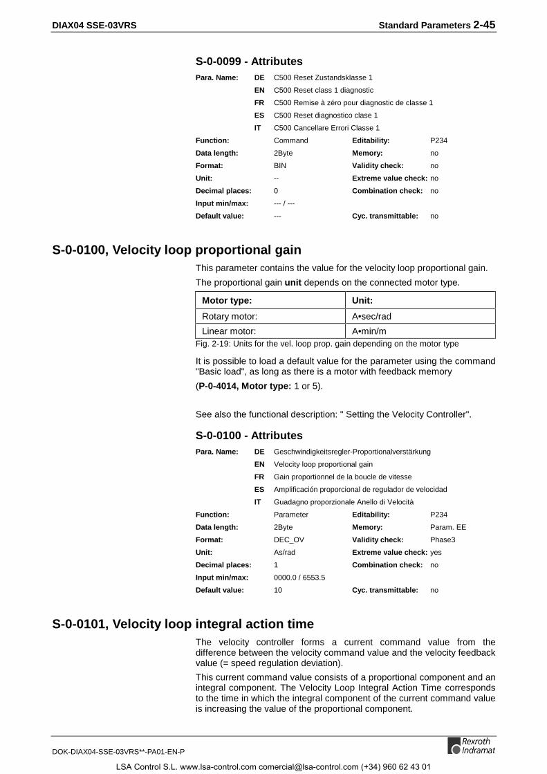
DIAX04 SSE-03VRS Standard Parameters 2-45
DOK-DIAX04-SSE-03VRS**-PA01-EN-P
S-0-0099 - AttributesPara. Name: DE C500 Reset Zustandsklasse 1
EN C500 Reset class 1 diagnostic
FR C500 Remise à zéro pour diagnostic de classe 1
ES C500 Reset diagnostico clase 1
IT C500 Cancellare Errori Classe 1
Function: Command Editability: P234
Data length: 2Byte Memory: no
Format: BIN Validity check: no
Unit: -- Extreme value check: no
Decimal places: 0 Combination check: no
Input min/max: --- / ---
Default value: --- Cyc. transmittable: no
S-0-0100, Velocity loop proportional gainThis parameter contains the value for the velocity loop proportional gain.
The proportional gain unit depends on the connected motor type.
Motor type: Unit:
Rotary motor: A•sec/rad
Linear motor: A•min/mFig. 2-19: Units for the vel. loop prop. gain depending on the motor type
It is possible to load a default value for the parameter using the command"Basic load", as long as there is a motor with feedback memory
(P-0-4014, Motor type: 1 or 5).
See also the functional description: " Setting the Velocity Controller".
S-0-0100 - AttributesPara. Name: DE Geschwindigkeitsregler-Proportionalverstärkung
EN Velocity loop proportional gain
FR Gain proportionnel de la boucle de vitesse
ES Amplificación proporcional de regulador de velocidad
IT Guadagno proporzionale Anello di Velocità
Function: Parameter Editability: P234
Data length: 2Byte Memory: Param. EE
Format: DEC_OV Validity check: Phase3
Unit: As/rad Extreme value check: yes
Decimal places: 1 Combination check: no
Input min/max: 0000.0 / 6553.5
Default value: 10 Cyc. transmittable: no
S-0-0101, Velocity loop integral action timeThe velocity controller forms a current command value from thedifference between the velocity command value and the velocity feedbackvalue (= speed regulation deviation).
This current command value consists of a proportional component and anintegral component. The Velocity Loop Integral Action Time correspondsto the time in which the integral component of the current command valueis increasing the value of the proportional component.
LSA Control S.L. www.lsa-control.com [email protected] (+34) 960 62 43 01
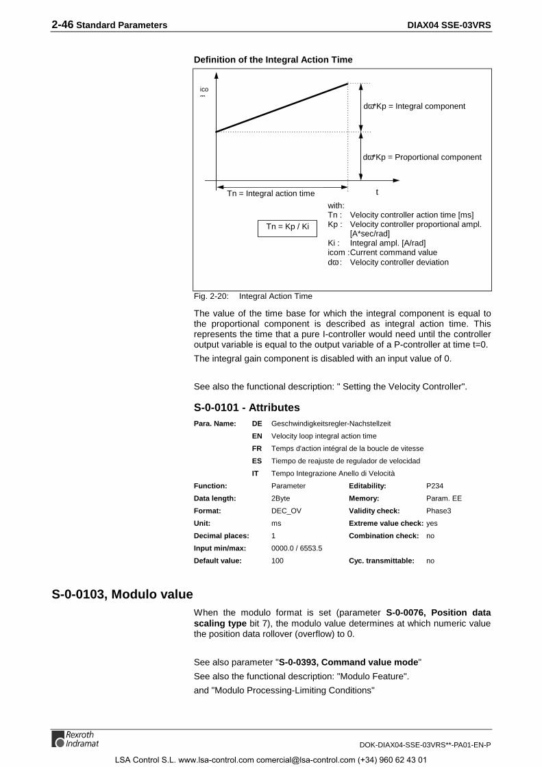
2-46 Standard Parameters DIAX04 SSE-03VRS
DOK-DIAX04-SSE-03VRS**-PA01-EN-P
Definition of the Integral Action Time
icom
tTn = Integral action time
dω*Kp = Proportional component
dω*Kp = Integral component
Tn = Kp / Ki
with:Tn : Velocity controller action time [ms]Kp : Velocity controller proportional ampl.
[A*sec/rad]Ki : Integral ampl. [A/rad]icom :Current command valuedω : Velocity controller deviation
Fig. 2-20: Integral Action Time
The value of the time base for which the integral component is equal tothe proportional component is described as integral action time. Thisrepresents the time that a pure I-controller would need until the controlleroutput variable is equal to the output variable of a P-controller at time t=0.
The integral gain component is disabled with an input value of 0.
See also the functional description: " Setting the Velocity Controller".
S-0-0101 - AttributesPara. Name: DE Geschwindigkeitsregler-Nachstellzeit
EN Velocity loop integral action time
FR Temps d'action intégral de la boucle de vitesse
ES Tiempo de reajuste de regulador de velocidad
IT Tempo Integrazione Anello di Velocità
Function: Parameter Editability: P234
Data length: 2Byte Memory: Param. EE
Format: DEC_OV Validity check: Phase3
Unit: ms Extreme value check: yes
Decimal places: 1 Combination check: no
Input min/max: 0000.0 / 6553.5
Default value: 100 Cyc. transmittable: no
S-0-0103, Modulo valueWhen the modulo format is set (parameter S-0-0076, Position datascaling type bit 7), the modulo value determines at which numeric valuethe position data rollover (overflow) to 0.
See also parameter "S-0-0393, Command value mode"
See also the functional description: "Modulo Feature".
and "Modulo Processing-Limiting Conditions"
LSA Control S.L. www.lsa-control.com [email protected] (+34) 960 62 43 01

DIAX04 SSE-03VRS Standard Parameters 2-47
DOK-DIAX04-SSE-03VRS**-PA01-EN-P
S-0-0103 - AttributesPara. Name: DE Modulowert
EN Modulo value
FR Valeur modulo
ES Valor de modulo
IT Valore Modulo
Function: Parameter Editability: P23
Data length: 4Byte Memory: Param. EE
Format: DEC_MV Validity check: Phase3
Unit: S-0-0076 Extreme value check: yes
Decimal places: S-0-0077/S-0-0078 Combination check: no
Input min/max: 1.0000 / 0214748.3647
Default value: 3600000 Cyc. transmittable: no
S-0-0104, Position loop Kv-factorThis parameter contains the value for the proportional gain of the positioncontroller.
It is possible to load a default value for the controller parameters using thecommand "Basic load".
Motors with feedback memory e.g. MKD, have appropriate values for allcontroller settings in their feedback. These are loaded after the initialconnection (display UL) or with the command "Basic load“.
See also the functional description: " Setting the position controller".
S-0-0104 - AttributesPara. Name: DE Lageregler Kv-Faktor
EN Position loop Kv-factor
FR Gain proportionnel de la boucle de position, Kv
ES Regulador de posición factor Kv
IT Fattore Kv Anello di Posizione
Function: Parameter Editability: P234
Data length: 2Byte Memory: Param. EE
Format: DEC_OV Validity check: Phase3
Unit: 1000/min Extreme value check: yes
Decimal places: 2 Combination check: no
Input min/max: 000.00 / 655.35
Default value: 100 Cyc. transmittable: no
S-0-0106, Current loop proportional gain 1The current controller proportional gain is fixed for every motor-drivecombination. It depends on the type of the motor and may not bechanged. It is loaded from the motor feedback after the initial connection(display UL) or using the command "Basic load".
Note: The values of the current controller set at the factory shouldnot be altered!
See also function description: " Setting the Current Controller".
LSA Control S.L. www.lsa-control.com [email protected] (+34) 960 62 43 01

2-48 Standard Parameters DIAX04 SSE-03VRS
DOK-DIAX04-SSE-03VRS**-PA01-EN-P
S-0-0106 - AttributesPara. Name: DE Stromregler-Proportionalverstärkung 1
EN Current loop proportional gain 1
FR Gain proportionnel de la boucle de courant 1
ES Amplificación proporcional 1 regulador de corriente
IT Guadagno proporzionale 1 Regolatore di Corrente
Function: Parameter Editability: P234
Data length: 4Byte Memory: Param. EE
Format: DEC_OV Validity check: Phase3
Unit: V/A Extreme value check: yes
Decimal places: 2 Combination check: no
Input min/max: 000.00 / 655.35
Default value: 100 Cyc. transmittable: no
S-0-0107, Current loop integral action time 1The current loop integral action time is fixed for every motor-drivecombination. It depends on the type of the motor. The factory setting maynot be changed.
The basic setup for all controllers is loaded after the initial connection(display UL) or with the command "Basic load“. For motors withoutfeedback memory, you can take the value from the motor’s data sheet.
See also function description: " Setting the Current Controller".
S-0-0107 - AttributesPara. Name: DE Stromregler-Nachstellzeit 1
EN Current loop integral action time 1
FR Temps d'action intégral de la boucle de courant 1
ES Tiempo de reajuste de regulador de corriente 1
IT Tempo Integrazione 1 Anello di Corrente
Function: Parameter Editability: P234
Data length: 2Byte Memory: Param. EE
Format: DEC_OV Validity check: Phase3
Unit: ms Extreme value check: yes
Decimal places: 1 Combination check: no
Input min/max: 0000.0 / 6553.5
Default value: 100 Cyc. transmittable: no
S-0-0108, Feedrate overrideThe feedrate override acts on drive controlled operation modes andmotion commands, like
• S-0-0148, C600 Drive controlled homing procedure command
• operating modes Drive internal interpolation
• Jogging operation
• automatic control loop setting
Note: The versions have not implemented all operating modes andcommands at the same time.
The feedrate override has a multiplying effect on the parameters
LSA Control S.L. www.lsa-control.com [email protected] (+34) 960 62 43 01

DIAX04 SSE-03VRS Standard Parameters 2-49
DOK-DIAX04-SSE-03VRS**-PA01-EN-P
• S-0-0041, Homing velocity
• S-0-0259, Positioning velocity
• Positioning block velocities
• Jog velocity
Note: In devices with analog interface, an analog input can beconfigured for the feedrate override, see also the projectmanual.
See also the functional description: " Drive-Controlled Homing".
S-0-0108 - AttributesPara. Name: DE Feedrate-Override
EN Feedrate override
FR Atténuateur d'avance
ES Override de alimentación
IT Riduzione Velocità Avanzamento
Function: Parameter Editability: P4
Data length: 2Byte Memory: no
Format: DEC_OV Validity check: no
Unit: % Extreme value check: no
Decimal places: 2 Combination check: no
Input min/max: 000.00 / 655.35
Default value: --- Cyc. transmittable: no
S-0-0109, Motor peak currentSpecifies the maximum current which may flow through the motor for ashort period without damaging it.
Note: If the motor’s peak current is less than the amplifier’s peakcurrent, the maximum output current will be automaticallylimited to the motor’s peak current.
This value is stored in the motor feedback for MHD, MKD and MKEmotors and will be uploaded from there when the amplifier is turned on forthe first time. For other motor types, the value must be taken from thedata sheet.
See also the functional description: "Current Limit".
S-0-0109 - AttributesPara. Name: DE Spitzenstrom Motor
EN Motor peak current
FR Courant crête du moteur
ES Corriente punta de motor
IT Corrente di Picco Motore
Function: Parameter Editability: P23
Data length: 4Byte Memory: Param. EE
Format: DEC_OV Validity check: Phase3
Unit: A Extreme value check: yes
Decimal places: 3 Combination check: no
Input min/max: 0000000.001 / 0000500.000
Default value: 1 Cyc. transmittable: no
LSA Control S.L. www.lsa-control.com [email protected] (+34) 960 62 43 01

2-50 Standard Parameters DIAX04 SSE-03VRS
DOK-DIAX04-SSE-03VRS**-PA01-EN-P
S-0-0110, Amplifier peak currentPeak current available from the drive controller. The value will be set bythe drive itself. This current is only available for short duration’s.
See also the functional description: "Current Limit".
S-0-0110 - AttributesPara. Name: DE Spitzenstrom Verstärker
EN Amplifier peak current
FR Courant crête du variateur
ES Corriente punta amplificador
IT Corrente di Picco Azionamento
Function: Parameter Editability: no
Data length: 4Byte Memory: Verst. EE
Format: DEC_OV Validity check: Phase3
Unit: A Extreme value check: yes
Decimal places: 3 Combination check: no
Input min/max: 0000000.001 / 0000500.000
Default value: --- Cyc. transmittable: no
S-0-0111, Motor current at standstillThe motor current at standstill is the current from which the motorcontinuously generates the standstill torque according to the motor datasheet.
This value is stored in motor feedback for MHD, MKD and MKE motorsand will be loaded from there when the drive controller is turned on for thefirst time. For other types of motors, this value must be taken from thedata sheet.
100% Force/Torque value corresponds to
Motor current at standstill S-0-0111 x Factor for cooling type x Torqueconstant
Note: All torque/force data refer to this motor current at standstill =100 % .
See also the functional description: "Motor Feedback-Data Memory"
S-0-0111 - AttributesPara. Name: DE Stillstandsstrom Motor
EN Motor current at standstill
FR Courant du moteur à l'arrêt
ES Corriente de parada motor
IT Corrente Motore con Asse fermo
Function: Parameter Editability: P23
Data length: 4Byte Memory: Param. EE
Format: DEC_OV Validity check: Phase3
Unit: A Extreme value check: yes
Decimal places: 3 Combination check: no
Input min/max: 0000000.001 / 0000500.000
Default value: 1 Cyc. transmittable: no
LSA Control S.L. www.lsa-control.com [email protected] (+34) 960 62 43 01
DIAX04 SSE-03VRS Standard Parameters 2-51
DOK-DIAX04-SSE-03VRS**-PA01-EN-P
S-0-0112, Amplifier nominal currentAllowable continuous current output for the drive controller. The value willbe set by the drive itself.
See also the functional description: "Current Limit"
S-0-0112 - AttributesPara. Name: DE Nennstrom Verstärker
EN Amplifier nominal current
FR Courant nominal variateur
ES Corriente nominal amplificador
IT Corrente nominale Azionamento
Function: Parameter Editability: no
Data length: 4Byte Memory: Verst. EE
Format: DEC_OV Validity check: Phase3
Unit: A Extreme value check: yes
Decimal places: 3 Combination check: no
Input min/max: 0000000.001 / 0000500.000
Default value: --- Cyc. transmittable: no
S-0-0113, Maximum motor speed ( nmax)The maximum velocity for the motor cannot be exceeded. It also limits theS-0-0091, Bipolar velocity limit parameter.
This value is stored in the motor feedback of MHD, MKD and MKE motorsand will be loaded from there when the drive controller is turned on for thefirst time. For other motor types, the value must be taken from the datasheet.
In torque regulation, if the maximum motor speed is exceeded by morethan 12.5%, the drive will be switched into a torque free state and theerror message F879 Velocity limit S-0-0091 exceeded will result.
See also the functional description: "Limiting Velocity".
S-0-0113 - AttributesPara. Name: DE Maximal-Geschwindigkeit des Motors
EN Maximum motor speed (nmax)
FR Vitesse maximale du moteur
ES Velocidad máxima del motor
IT Velocità massima Motore (nmax)
Function: Parameter Editability: P23
Data length: 4Byte Memory: Param. EE
Format: DEC_OV Validity check: Phase3
Unit: S-0-0044 Extreme value check: yes
Decimal places: S-0-0045/S-0-0046 Combination check: no
Input min/max: 000000.0000 / 214738.3647
Default value: 1000000 Cyc. transmittable: no
LSA Control S.L. www.lsa-control.com [email protected] (+34) 960 62 43 01

2-52 Standard Parameters DIAX04 SSE-03VRS
DOK-DIAX04-SSE-03VRS**-PA01-EN-P
S-0-0115, Position feedback 2 typeEssential characteristics of the optional encoder (position encoder 2) areestablished is this parameter.
Parameter structure:
Bit 0: Feedback type0: rotary1: linear
Bit 1: Distance coded measuring system0: no distance coded referencemarkers1: distance coded reference markersS-0-0165, S-0-0166
Bit 3: Direction of movement0: not inverted1: inverted
Bits 7 + 6: Absolute readoutx 0: No absolute readout possible.
(Bit 7 irrelevant)0 1: Absolute readout possible and active,
encoder is treated as absolute.1 1: Absolute readout possible, but not active.
Fig. 2-21: S-0-0115, Position feedback 2 type parameter
Remark:
Bit 6 is set by the drive.
See also the functional description: "Other Optional Encoder Characteristics".
S-0-0115 - AttributesPara. Name: DE Lagegeberart 2
EN Position feedback 2 type
FR Type codeur 2
ES Tipo de encoder de posición 2
IT Tipo di Feedback di Posizione 2
Function: Parameter Editability: P23
Data length: 2Byte Memory: Param. EE
Format: BIN Validity check: Phase3
Unit: -- Extreme value check: no
Decimal places: 0 Combination check: no
Input min/max: --- / ---
Default value: 0 Cyc. transmittable: no
S-0-0116, Feedback 1 ResolutionDepending on parameter P-0-4014, Motor type (rotary or linear motors),the resolution of the motor encoder is indicated by S-0-0116, Resolutionof motor feedback.
This value contains the number of lines or cycles per motor revolution forrotary motors, or the segment spacing per mm for linear motors. Formotors with resolver feedback, the number of the resolver pole pairs isstored here.
See also the functional description: "Motor Encoder Resolution".
LSA Control S.L. www.lsa-control.com [email protected] (+34) 960 62 43 01

DIAX04 SSE-03VRS Standard Parameters 2-53
DOK-DIAX04-SSE-03VRS**-PA01-EN-P
S-0-0116 - AttributesPara. Name: DE Geber 1 Auflösung
EN Feedback 1 Resolution
FR Résolution codeur 1
ES Resolución encoder 1
IT Risoluzione Feedback 1
Function: Parameter Editability: P23
Data length: 4Byte Memory: Param. EE
Format: DEC_OV Validity check: Phase3
Unit: Cycles/Rev Extreme value check: no
Decimal places: 0 Combination check: no
Input min/max: --- / ---
Default value: 256 Cyc. transmittable: no
S-0-0117, Feedback 2 ResolutionThe resolution of the optional encoder contains the cycles per externalencoder revolution for rotational encoders. For linear optional encoders,the segment spacing is given, in mm.
See also the functional description: "Optional Encoder Resolution".
S-0-0117 - AttributesPara. Name: DE Geber 2 Auflösung
EN Feedback 2 Resolution
FR Résolution codeur 2
ES Resolución encoder 2
IT Risoluzione Feedback 2
Function: Parameter Editability: P23
Data length: 4Byte Memory: Param. EE
Format: DEC_OV Validity check: Phase3
Unit: Cycles/Rev Extreme value check: no
Decimal places: 0 Combination check: no
Input min/max: --- / ---
Default value: 256 Cyc. transmittable: no
S-0-0121, Input revolutions of load gearA mechanical gear is often employed between the motor and the load.
The gear ratio is defined by:
S-0-0122, Output Revolutions of load Gear
S-0-0121, Input Revolutions of load Gear
Fig. 2-22: Gear Ratio
Example:
5 motor rotations result in 2 output gear rotations.
⇒ S-0-0121 : 5
S-0-0122 : 2
See also function description: "Transmission Ratio" and "ModuloProcessing-Limiting Conditions".
LSA Control S.L. www.lsa-control.com [email protected] (+34) 960 62 43 01
2-54 Standard Parameters DIAX04 SSE-03VRS
DOK-DIAX04-SSE-03VRS**-PA01-EN-P
S-0-0121 - AttributesPara. Name: DE Lastgetriebe-Eingangsumdrehungen
EN Input revolutions of load gear
FR Nombre de tours d'entrée d'engrenages de charge
ES Giros de entrada de engranaje de carga
IT N di Giri in Ingresso al Riduttore
Function: Parameter Editability: P23
Data length: 4Byte Memory: Param. EE
Format: DEC_OV Validity check: Phase3
Unit: Rev Extreme value check: yes
Decimal places: 0 Combination check: no
Input min/max: 0000000001 / 4294967295
Default value: 1 Cyc. transmittable: no
S-0-0122, Output revolutions of load gearA mechanical gear is often employed between the motor and the load.
The gear ratio is defined by:
S-0-0122, Output Revolutions of load Gear
S-0-0121, Input Revolutions of load Gear
Fig. 2-23: Gear Ratio
Example:
5 motor rotations result in 2 output gear rotations.
⇒ S-0-0121 : 5
S-0-0122 : 2
See also function description: "Transmission Ratio" and "ModuloProcessing-Limiting Conditions".
S-0-0122 - AttributesPara. Name: DE Lastgetriebe-Ausgangsumdrehungen
EN Output revolutions of load gear
FR Nombre de tours de sortie d'engrenages de charge
ES Giros de salida de engranaje de carga
IT N di Giri in Uscita del Riduttore
Function: Parameter Editability: P23
Data length: 4Byte Memory: Param. EE
Format: DEC_OV Validity check: Phase3
Unit: Rev Extreme value check: yes
Decimal places: 0 Combination check: no
Input min/max: 0000000001 / 4294967295
Default value: 1 Cyc. transmittable: no
S-0-0123, Feed constantThis parameter describes the conversion from rotary to linear motion. It isdefined as the linear displacement of the load during one revolution of thegear drive shaft.
LSA Control S.L. www.lsa-control.com [email protected] (+34) 960 62 43 01

DIAX04 SSE-03VRS Standard Parameters 2-55
DOK-DIAX04-SSE-03VRS**-PA01-EN-P
Characteristic value:
Ball screw: Rack and pinion:
Feed constant = pitch of screw(typical value 10.00 mm)
Feed constant =effective pitch diameter of the pinion • π =effective circumference of the pinion
Fig. 2-24: Characteristic values of the feed constant
Note: The unit is dependent on bit 4 in S-0-0076, Position datascaling type.
Note that: S-0-0076 bit 4 = 0 → mm/rev
S-0-0076 bit 4 = 1 → inch/rev
See also the functional description: "Feed Constant".
S-0-0123 - AttributesPara. Name: DE Vorschubkonstante
EN Feed constant
FR Constante d’avance
ES Constante de avance
IT Costante di Avanzamento
Function: Parameter Editability: P23
Data length: 4Byte Memory: Param. EE
Format: DEC_OV Validity check: Phase3
Unit: S-0-0076 Extreme value check: no
Decimal places: 5 Combination check: no
Input min/max: --- / ---
Default value: 100000 Cyc. transmittable: no
S-0-0124, Standstill windowThe motors is considered at standstill when the velocity feedback value,(S-0-0040) is below the parameterized threshold level in S-0-0125.
Bit 1 of the S-0-0013, Class 3 diagnostics is set during standstill.
The standstill window also works:
• if termination or interruption of a drive control command isacknowledged when the drive is at a standstill
• with drive-controlled homing, the feedback and command values arenot switched until the drive is at a standstill
• When switching operating modes, if the velocity feedback value issmaller than the standstill window, then the command valueprocessing is initialized with velocity = 0.
See also the functional description: "S-0-0182, Manufacturer Class 3Diagnostics"
S-0-0124 - AttributesPara. Name: DE Stillstandsfenster
EN Standstill window
FR Fenêtre d'arrêt
ES Ventana de parada
IT Finestra di monitorizzazione Asse fermo
LSA Control S.L. www.lsa-control.com [email protected] (+34) 960 62 43 01
2-56 Standard Parameters DIAX04 SSE-03VRS
DOK-DIAX04-SSE-03VRS**-PA01-EN-P
Function: Parameter Editability: P234
Data length: 4Byte Memory: Param. EE
Format: DEC_MV Validity check: Phase3
Unit: S-0-0044 Extreme value check: yes
Decimal places: S-0-0045/S-0-0046 Combination check: no
Input min/max: 0000000000.0 / 0000060000.0
Default value: 100000 Cyc. transmittable: no
S-0-0125, Velocity threshold nxIf the S-0-0040, Velocity feedback value falls below the value of theparameter S-0-0125, Velocity threshold nx, the drive sets the messagenactual< nx (Bit 2 in S-0-0013, Class 3 Diagnostics).
See also the functional description: "S-0-0013, Class 3 Diagnostics".
S-0-0125 - AttributesPara. Name: DE Geschwindigkeits-Schwelle nx
EN Velocity threshold nx
FR Seuil de vitesse nx
ES Umbral de velocidad nx
IT Finestra di Controllo Velocità
Function: Parameter Editability: P234
Data length: 4Byte Memory: Param. EE
Format: DEC_OV Validity check: Phase3
Unit: S-0-0044 Extreme value check: yes
Decimal places: S-0-0045/S-0-0046 Combination check: no
Input min/max: 0 / S-0-0044
Default value: 10000000 Cyc. transmittable: no
S-0-0127, C100 Communication phase 3 transition checkThe command "S-0-0127, 67C100 Communication phase 3 transitioncheck is used to switch form the parameter mode to the operating mode.
If invalid parameters are present, then
• the drive completes the command with an error message
• and the invalid parameters are entered in parameter S-0-0021, IDN listof invalid operating data phase 2!
Note: The execution of the command with an inactive ( P-0-4086 =xx1b ) command communications (SERCOS or fieldbus) stillallows a transition to phase 3.
This makes it possible, using commands
• S-0-0127, C100 communications phase 3 transition check
• S-0-0128, C200 communications phase 4 transition check
to switch (with inactive command communications ( P-0-4086 = xx1b ))from Parameterization into operating mode.
See also Function description: "Position Command Value Monitoring".
LSA Control S.L. www.lsa-control.com [email protected] (+34) 960 62 43 01

DIAX04 SSE-03VRS Standard Parameters 2-57
DOK-DIAX04-SSE-03VRS**-PA01-EN-P
S-0-0127 - AttributesPara. Name: DE C100 Umschaltvorbereitung auf Komm.-Phase 3
EN C100 Communication phase 3 transition check
FR C100 Préparation transition phase de comm. 3
ES C100 Comprobación de conmutación a fase 3
IT C100 Check Transizione Fase di Comunicazione 3
Function: Command Editability: P2
Data length: 2Byte Memory: no
Format: BIN Validity check: no
Unit: -- Extreme value check: no
Decimal places: 0 Combination check: no
Input min/max: --- / ---
Default value: --- Cyc. transmittable: no
S-0-0128, C200 Communication phase 4 transition checkWhen the S-0-0128, C200 Communication phase 4 transition checkcommand is executed , all parameters will be checked for validity and limitvalue violations.
• If any invalid parameters or any limit values have been violated, thedrive would end the command with an error message
• and the invalid parameter entered in parameter S-0-0022, IDN list ofinvalid operating data phase 3!
The execution of the command with an inactive ( P-0-4086 = xx1b )command communication (SERCOS or fieldbus) still allows atransition to phase 4.
this means it is possible, using commands
• S-0-0127, C100 Communication phase 3 transition check
• S-0-0128, C200 Communication phase 4 transition check
to switch from parameterization into operating mode with an inactivecommand communications ( P-0-4086 = xx1b ).
See also Function description: "Position Command Value Monitoring".
S-0-0128 - AttributePara. Name: DE C200 Umschaltvorbereitung auf Komm.-Phase 4
EN C200 Communication phase 4 transition check
FR C200 Préparation transition phase de comm. 4
ES C200 comprobación de conmutación a fase 4
IT C200 Check Transizione Fase di Comunicazione 4
Function: Kommando Editability: P3
Data length: 2Byte Memory: nein
Format: BIN Validity check: nein
Unit: -- Extreme value check.:nein
Decimal places: 0 Combination check: nein
Input min/max: --- / ---
Default value: --- Cyc. transmittable: nein
LSA Control S.L. www.lsa-control.com [email protected] (+34) 960 62 43 01

2-58 Standard Parameters DIAX04 SSE-03VRS
DOK-DIAX04-SSE-03VRS**-PA01-EN-P
Notes
LSA Control S.L. www.lsa-control.com [email protected] (+34) 960 62 43 01

DIAX04 SSE-03VRS Standard Parameters 2-59
DOK-DIAX04-SSE-03VRS**-PA01-EN-P
S-0-0130, Probe value 1 positive edgeThe drive uses the positive edge of the input signal from S-0-0401, Probe1 , to store the instantaneous value of the selected signal in thisparameter.
The signal to be measured is determined by parameters P-0-0200,Signal select probe 1 and S-0-0169, Probe control parameter.
See also the functional description: "Probe Input Feature".
S-0-0130 - AttributesPara. Name: DE Messwert 1 positiv
EN Probe value 1 positive edge
FR Mesure sonde 1 front montant
ES Valor de medición 1 positivo
IT Misura Valore con Probe 1 positivo
Function: Parameter Editability: no
Data length: 4Byte Memory: no
Format: DEC_MV Validity check: no
Unit: S-0-0076/P-0-0200 Extreme value check: no
Decimal places: S-0-0076/P-0-0200 Combination check: no
Input min/max: --- / ---
Default value: --- Cyc. transmittable: AT
S-0-0131, Probe value 1 negative edgeThe drive uses the negative edge of the input signal from S-0-0401,Probe 1, to store the instantaneous value of the selected signal in thisparameter.
The signal to be measured is determined by parameters P-0-0200,Signal select probe 1 and S-0-0169, Probe control parameter.
See also the functional description: "Probe Input Feature".
S-0-0131 - AttributesPara. Name: DE Messwert 1 negativ
EN Probe value 1 negative edge
FR Mesure sonde 1 front descendant
ES Valor de medición 1 negativo
IT Misura Valore con Probe 1 negativo
Function: Parameter Editability: no
Data length: 4Byte Memory: no
Format: DEC_MV Validity check: no
Unit: S-0-0076/P-0-0200 Extreme value check: no
Decimal places: S-0-0076/P-0-0200 Combination check: no
Input min/max: --- / ---
Default value: --- Cyc. transmittable: AT
LSA Control S.L. www.lsa-control.com [email protected] (+34) 960 62 43 01

2-60 Standard Parameters DIAX04 SSE-03VRS
DOK-DIAX04-SSE-03VRS**-PA01-EN-P
S-0-0132, Probe value 2 positive edgeThe drive uses the positive edge of the input signal from S-0-0402, Probe2, to store the instantaneous value of the selected signal in thisparameter.
The signal to be measured is determined by parameters P-0-0201,Signal select probe 2 and S-0-0169, Probe control parameter.
See also the functional description: "Probe Input Feature".
S-0-0132 - AttributesPara. Name: DE Messwert 2 positiv
EN Probe value 2 positive edge
FR Mesure sonde 2 front montant
ES Valor de medición 2 positivo
IT Misura Valore con Probe 2 positivo
Function: Parameter Editability: -
Data length: 4Byte Memory: no
Format: DEC_MV Validity check: no
Unit: S-0-0076/P-0-0201 Extreme value check: no
Decimal places: S-0-0076/P-0-0201 Combination check: no
Input min/max: --- / ---
Default value: --- Cyc. transmittable: AT
S-0-0133, Probe value 2 negative edgeThe drive uses the negative edge of the input signal from S-0-0402,Probe 2, to store the instantaneous value of the selected signal in thisparameter.
The signal to be measured is determined by parameters P-0-0201,Signal select probe 2 and S-0-0169, Probe control parameter.
See also the functional description: "Probe Input Feature".
S-0-0133 - AttributesPara. Name: DE Messwert 2 negativ
EN Probe value 2 negative edge
FR Mesure sonde 2 front descendant
ES Valor de medición 2 negativo
IT Misura Valore con Probe 2 negativo
Function: Parameter Editability: no
Data length: 4Byte Memory: no
Format: DEC_MV Validity check: no
Unit: S-0-0076/P-0-0201 Extreme value check: no
Decimal places: S-0-0076/P-0-0201 Combination check: no
Input min/max: --- / ---
Default value: --- Cyc. transmittable: AT
LSA Control S.L. www.lsa-control.com [email protected] (+34) 960 62 43 01

DIAX04 SSE-03VRS Standard Parameters 2-61
DOK-DIAX04-SSE-03VRS**-PA01-EN-P
S-0-0134, Master control wordIf a bus interface is present (SERCOS-Interface, Profibus-DP, Interbus,CAN, ...), the master control word is transmitted cyclically from the master(control) to the drive. It defines important control information like
• drive enable
• /drive halt
• Selection of the operation mode
The exact composition is explained in the functional description of therespective bus interface.
If there is no bus interface, the information of the master control word isgiven by digital inputs. In any case, the parameter S-0-0134, Mastercontrol word is only for diagnostic purposes.
See also the functional description: "Master Control Word".
S-0-0134 - AttributesPara. Name: DE Master-Steuerwort
EN Master control word
FR Mot de contrôle maître
ES Palabra de mando maestro
IT Parole di Controllo Master
Function: Parameter Editability: no
Data length: 2Byte Memory: no
Format: BIN Validity check: no
Unit: -- Extreme value check: no
Decimal places: 0 Combination check: no
Input min/max: --- / ---
Default value: --- Cyc. transmittable: no
S-0-0135, Drive status wordIf a bus interface is present (SERCOS-Interface, Profibus-DP, Interbus,CAN, ...), the drive status word is transmitted cyclically from the slave(drive) to the control. It defines important status information like
• class 1 errors, drive lock
• operation readiness
• active actual operation mode
The exact composition is described in the functional description of therespective bus interface. In any case, the parameter S-0-0135, Drivestatus word is only for diagnostic purposes.
See also the functional description: "Drive Status Word".
S-0-0135 - AttributesPara. Name: DE Antriebs-Status
EN Drive status word
FR Etat entraînement
ES Estado de accionamiento
IT Parole di Stato Azionamento
LSA Control S.L. www.lsa-control.com [email protected] (+34) 960 62 43 01

2-62 Standard Parameters DIAX04 SSE-03VRS
DOK-DIAX04-SSE-03VRS**-PA01-EN-P
Function: Parameter Editability: no
Data length: 2Byte Memory: no
Format: BIN Validity check: no
Unit: -- Extreme value check: no
Decimal places: 0 Combination check: no
Input min/max: --- / ---
Default value: --- Cyc. transmittable: no
S-0-0138, Bipolar acceleration limit valueThe Bipolar acceleration limit value describes the maximum permissibleacceleration, symmetrical in both directions (acceleration anddeceleration).
The drive decelerates at this deceleration to the velocity = 0 when thefunction "Drive stop" is executed, if the previously active operation modewas without drive internal command generation.
Operation modes without drive internal command generation are
• Position control
• Angular synchronization
• Stepper motor operation
and others.
See also the functional description: "Drive Halt".
S-0-0138 - AttributesPara. Name: DE Beschleunigung bipolar
EN Bipolar acceleration limit value
FR Accélération bipolaire
ES Aceleración bipolar
IT Valore di Accellerazione Limite
Function: Parameter Editability: P234
Data length: 4Byte Memory: Param. EE
Format: DEC_MV Validity check: Phase3
Unit: S-0-0160 Extreme value check: yes
Decimal places: S-0-0161/S-0-0162 Combination check: no
Input min/max: 00000000.000 / 00024543.692
Default value: 100000 Cyc. transmittable: no
S-0-0139, D700 Command Parking axisSetting and enabling the command Parking Axis switches off all themonitoring functions related to the measurement system.
This affects position control, feedback monitoring and the monitoring ofthe position window (S-0-0057).
When the command is active, the drive does not report any errors of class1 diagnostics.
The Position feedback value status (S-0-0403) is cleared by the drive.
The command is acknowledged positive, when the mentioned monitorsare switched off.
Clearing the command switches all the mentioned monitors on again. Torefer the position feedback values to the reference point again, the drivemust go to the reference again.
LSA Control S.L. www.lsa-control.com [email protected] (+34) 960 62 43 01

DIAX04 SSE-03VRS Standard Parameters 2-63
DOK-DIAX04-SSE-03VRS**-PA01-EN-P
Structure of the parameter:
Bit 0 : Command in the drive0: clear1: set
Bit 1 : Command execution0: suspended1: execute
Fig. 2-25:: S-0-0139, D700 Command Parking axis
See also the functional description: "Command Parking Axis".
S-0-0139 - AttributesPara. Name: DE D700 Kommando Parkende Achse
EN D700 Command Parking axis
FR D700 Commande stationnement axe
ES D700 Comando eje estacionada
IT D700 Comando Stazionamento Asse
Function: Command Editability: P2
Data length: 2Byte Memory: no
Format: BIN Validity check: no
Unit: -- Extreme value check: no
Decimal places: 0 Combination check: no
Input min/max: - / -
Default value: --- Cyc. transmittable: no
S-0-0140, Controller typeThe device type of the manufacturer can be found in text form in theoperating data for the controller type.
Examples:
HDS02.1-W100-D
DKC01.1-040-7
See also the functional description: "Drive Controllers".
S-0-0140 - AttributesPara. Name: DE Regelgerätetyp
EN Controller type
FR Type de variateur
ES Tipo de regulador
IT Tipo Azionamento
Function: Parameter Editability: no
Data length: 1Byte var. Memory: Verst. EE
Format: ASCII Validity check: Phase3
Unit: -- Extreme value check: no
Decimal places: 0 Combination check: no
Input min/max: --- / ---
Default value: --- Cyc. transmittable: no
LSA Control S.L. www.lsa-control.com [email protected] (+34) 960 62 43 01

2-64 Standard Parameters DIAX04 SSE-03VRS
DOK-DIAX04-SSE-03VRS**-PA01-EN-P
S-0-0141, Motor typeHere is the motor type of the connected motor in text form.
The contents of the parameter is overwritten when „Loading base values“(possible with MHD, MKD and MKE motors ) with parameter S-7-0141.
The diagnoses „F208 UL motor type has changed“ is based on acomparison between S-0-0141 and S-7-0141.
With motors without feedback data memory it is necessary to enter themotor type.
Example:
MKD 071B-061-KP1-BN
MKE 096B-047-GG0-KN
See also the functional description: "Systemoverview".
S-0-0141 - AttributesPara. Name: DE Motor-Typ
EN Motor type
FR Type de moteur
ES Tipo de motor
IT Tipo Motore
Function: Parameter Editability: P23
Data length: 1Byte var. Memory: Param. EE
Format: ASCII Validity check: Phase3
Unit: -- Extreme value check: no
Decimal places: 0 Combination check: no
Input min/max: --- / ---
Default value: Defaut Motor Cyc. transmittable: no
S-0-0142, Application typeA descriptive name text for the drive can be stored in this parameter (e.g.,swivel axis ). It has no functional significance.
See also the functional description: "Systemoverview"
S-0-0142 - AttributesPara. Name: DE Anwendungsart
EN Application type
FR Type d’application
ES Tipo de aplicación
IT Tipo applicazione
Function: Parameter Editability: P234
Data length: 1Byte var. Memory: Param. EE
Format: ASCII Validity check: no
Unit: -- Extreme value check: no
Decimal places: 0 Combination check: no
Input min/max: --- / ---
Default value: Default Cyc. transmittable: no
LSA Control S.L. www.lsa-control.com [email protected] (+34) 960 62 43 01
DIAX04 SSE-03VRS Standard Parameters 2-65
DOK-DIAX04-SSE-03VRS**-PA01-EN-P
S-0-0143, System interface versionThe version of the SERCOS interface specifications is found in theoperating data.
Current valid settings:
V V 01.01: V 01.02:
SERCOS specificationGerman 01.00:
SERCOSEnglish specification
SERCOS updateGerman/English
Version 5/90 Version 4/91 Version 9/91Fig. 2-26: S-0-0143, Version of the SERCOS interface specification
See also the functional description: "Overview of SERCOSCommunication".
S-0-0143 - AttributesPara. Name: DE Sercos Interface Version
EN System interface version
FR Version d’interface SERCOS
ES Version de Interface Sercos
IT Versione del Interfaccia Sercos
Function: Parameter Editability: no
Data length: 1Byte var. Memory: no
Format: ASCII Validity check: no
Unit: -- Extreme value check: no
Decimal places: 0 Combination check: no
Input min/max: --- / ---
Default value: --- Cyc. transmittable: no
S-0-0144, Signal status wordWith the help of the signal status word, real time signals can betransferred from the drive to the Control.
To do so, the signal status word must be configured as cyclic data in theDrive Telegram.
The bits in the signal status word can be defined freely with theparameters S-0-0026, Configuration list signal status word and S-0-0328, Config. list for signal status word, bit number.
With a parallel interface, bits 0 to 9 are illustrated directly on the digitaloutputs. Thus various parameters can be allocated to the digital outputs.
See also the functional description: "Configurable Signal Status Word"
S-0-0144 - AttributesPara. Name: DE Signal-Statuswort
EN Signal status word
FR Mot d'état de signal
ES Palabra de estado de señal
IT Parole di Stato Segnali
LSA Control S.L. www.lsa-control.com [email protected] (+34) 960 62 43 01

2-66 Standard Parameters DIAX04 SSE-03VRS
DOK-DIAX04-SSE-03VRS**-PA01-EN-P
Function: Parameter Editability: no
Data length: 2Byte Memory: no
Format: BIN Validity check: no
Unit: -- Extreme value check: no
Decimal places: 0 Combination check: no
Input min/max: - / -
Default value: --- Cyc. transmittable: AT
S-0-0147, Homing parameterThe processes for the S-0-0148, Drive controlled homing procedure, inrelation to the machine layout, NC and drive installation are set in thisparameter.
Structure of the parameter:
Bit 0: Start direction0: positive = clockwise with view
towards motor shaft1: negative = counter-clockwise with view
towards motor shaft
Bit 3: Feedback selectionHoming
0: with motor feedback (feedback 1)1: with external feedback (feedback 2)
Bit 6: Reference mark evaluationThe Reference mark is
0: detected.1: not detected.
Bit 5: Home switch evaluationThe home switch is
0: detected.1: not detected.
Bit 8,7: Stop/positioning/run path0 0: once the reference switch or reference marker
have been overtravelled the drive stops andswitches into the coordinate system
0 1: after the reference swtich or marker have beenovertravelled, the drive positions at thereference point and switches into the coordinatesystem
1 0: drive always runs path that is needed tooverrun two sequential reference markers andthen switches into coordinate system(only with distance-coded reference marks !)
1 1: Not allowed!
S-0-0147, Homing parameter
Fig. 2-27: Structure of parameter S-0-0147, Homing parameter
Note: In addition, for DIAX drives, bit 5 activates the monitoring ofthe external 24V.
See also the functional description: "Drive-Controlled Homing".
LSA Control S.L. www.lsa-control.com [email protected] (+34) 960 62 43 01

DIAX04 SSE-03VRS Standard Parameters 2-67
DOK-DIAX04-SSE-03VRS**-PA01-EN-P
S-0-0147 - AttributesPara. Name: DE Referenzfahr-Parameter
EN Homing parameter
FR Paramètre de prise d'origine
ES Parámetro de puesta a cero
IT Parametro Azzeramento
Function: Parameter Editability: P234
Data length: 2Byte Memory: Param. EE
Format: BIN Validity check: Phase3
Unit: -- Extreme value check: no
Decimal places: 0 Combination check: yes
Input min/max: --- / ---
Default value: 100000 Cyc. transmittable: no
S-0-0148, C600 Drive controlled homing procedure commandWhen this command is set and enabled, the drive switches automaticallyinto internal position control and accelerates using the S-0-0041,Homing acceleration to the S-0-0042, Homing velocity as long as it isin operating status AF. Bit 0 in S-0-0403, Position feedback valuestatus will be deleted at first. As long as the command is active, changesin the cyclic position command values will be ignored.
The process for the homing procedure can be specified with S-0-0147,Homing parameter. After the command has been properly executed(drive is at standstill and position feedback value is related to the homingposition), the drive sets bit 0 in parameter S-0-0403, Position feedbackvalue status.
The parameter "Position feedback value status“ reflects the signal"In_Reference“.
See also the functional description: "Drive-Controlled Homing"
S-0-0148 - AttributesPara. Name: DE C600 Kommando Antriebsgeführtes Referenzieren
EN C600 Drive controlled homing procedure command
FR C600 Commande prise origine pilotée par entraînement
ES C600 Comando puesta a cero por accionamiento
IT C600 Asse controllato durante la Procedura di Azzer.
Function: Command Editability: P4
Data length: 2Byte Memory: no
Format: BIN Validity check: no
Unit: -- Extreme value check: no
Decimal places: 0 Combination check: no
Input min/max: --- / ---
Default value: --- Cyc. transmittable: no
LSA Control S.L. www.lsa-control.com [email protected] (+34) 960 62 43 01

2-68 Standard Parameters DIAX04 SSE-03VRS
DOK-DIAX04-SSE-03VRS**-PA01-EN-P
S-0-0149, D400 Positive stop drive procedure commandWhen this command is set and enabled, all controller monitoring whichwould otherwise result in an class 1 diagnostic error message when thedrive is blocked by a positive stop will be turned off.
Parameter structure:
Bit 0 : Command in drive0: clear1: set
Bit 1 : Execution ofcommand
0: suspended1: execute
Fig. 2-28: S-0-0149, D400 Positive stop drive procedure command
See also the functional description: "Positive stop drive procedure".
S-0-0149 - AttributesPara. Name: DE D400 Kommando Fahren auf Festanschlag
EN D400 Positive stop drive procedure command
FR D400 Commande déplacement contre obstacle fixe
ES D400 Comando Desplazamiento a tope
IT D400 Comando Movimento contro un Ostacolo fisso
Function: Command Editability: P4
Data length: 2Byte Memory: no
Format: BIN Validity check: no
Unit: -- Extreme value check: no
Decimal places: 0 Combination check: no
Input min/max: --- / ---
Default value: --- Cyc. transmittable: no
S-0-0150, Reference offset 1This parameter describes the distance between the position encoderhome reference marker 1 and S-0-0052, Reference distance 1.
The parameter makes it possible to shift the reference point in relation tothe reference marker to be detected. If bit 7 in S-0-0147, Homingparameter is set to 1, then, during execution of the command S-0-0148,C600 Drive controlled homing procedure command, the drive goes tothe reference point shifted from the reference mark by the value S-0-0150, Reference Offset 1.
See also the functional description: " Drive-Controlled Homing".
S-0-0150 - AttributesPara. Name: DE Referenzmaß Offset 1
EN Reference offset 1
FR Décalage d'origine 1
ES Medición de referencia offset 1
IT Azzeramento Offset 1 (Feedback Motore)
LSA Control S.L. www.lsa-control.com [email protected] (+34) 960 62 43 01

DIAX04 SSE-03VRS Standard Parameters 2-69
DOK-DIAX04-SSE-03VRS**-PA01-EN-P
Function: Parameter Editability: P234
Data length: 4Byte Memory: Param. EE
Format: DEC_MV Validity check: Phase3
Unit: S-0-0076 Extreme value check: yes
Decimal places: S-0-0077/S-0-0078 Combination check: no
Input min/max: -214748.3648 / 0214748.3647
Default value: 0 Cyc. transmittable: no
S-0-0151, Reference offset 2This parameter describes the distance between the position encoderhome reference marker 2 and S-0-0054, Reference distance 2.
The parameter makes it possible to shift the reference point in relation tothe reference marker to be detected. If bit 7 in S-0-0147, Homingparameter is set to 1, then, during execution of the command S-0-0148,C600 Drive controlled homing procedure command, the drive goes tothe reference point shifted from the reference mark by the value S-0-0151, Reference offset 2.
See also the functional description: " Drive-Controlled Homing"
S-0-0151 - AttributesPara. Name: DE Referenzmaß Offset 2
EN Reference offset 2
FR Décalage d'origine 2
ES Medición de referencia offset 2
IT Azzeramento Offset 2 (Feedback esterno)
Function: Parameter Editability: P234
Data length: 4Byte Memory: Param. EE
Format: DEC_MV Validity check: Phase3
Unit: S-0-0076 Extreme value check: yes
Decimal places: S-0-0077/S-0-0078 Combination check: no
Input min/max: -214748.3648 / 0214748.3647
Default value: 0 Cyc. transmittable: no
S-0-0155, Friction compensationThe friction compensation is added into the torque/force command value.The sign (+/-) of the compensation value is determined by the sign of thevelocity command value. A change in the sign only takes place at valuesoutside of what has been set in S-0-0124, Standstill window.
By programming the friction compensation, it is possible to compensatefor static friction during acceleration from standstill and change ofdirection.
See also the functional description: " Setting the Frictional Torque Compensation".
S-0-0155 - AttributesPara. Name: DE Reibungs-Kompensation
EN Friction compensation
FR Compensation de frottement
ES Compensación de rozamiento
IT Compensazione per Frizzione
LSA Control S.L. www.lsa-control.com [email protected] (+34) 960 62 43 01

2-70 Standard Parameters DIAX04 SSE-03VRS
DOK-DIAX04-SSE-03VRS**-PA01-EN-P
Function: Parameter Editability: P234
Data length: 2Byte Memory: Param. EE
Format: DEC_OV Validity check: Phase3
Unit: % Extreme value check: yes
Decimal places: 1 Combination check: no
Input min/max: 0000.0 / 0099.6
Default value: 0 Cyc. transmittable: no
S-0-0157, Velocity windowThe Velocity window refers to the absolute value of the S-0-0036,Velocity Command Value.
If the velocity feedback value, in comparison with the velocity commandvalue, is within the calculated velocity window, then the drive sets the bit 0in S-0-0013, Class 3 diagnostics (Message ’n_actual = n_command’).
See also the functional description: "S-0-0013, Class 3 Diagnostics"
S-0-0157 - AttributesPara. Name: DE Geschwindigkeits-Fenster
EN Velocity window
FR Fenêtre de vitesse
ES Ventana de velocidad
IT Finestra Velocità
Function: Parameter Editability: P234
Data length: 4Byte Memory: Param. EE
Format: DEC_OV Validity check: Phase3
Unit: S-0-0044 Extreme value check: yes
Decimal places: S-0-0045/S-0-0046 Combination check: no
Input min/max: 0 / S-0-0044
Default value: 1000000 Cyc. transmittable: no
S-0-0159, Monitoring windowWhen an operating mode with internal position control is activated in thedrive, the position loop is monitored. Therefore, a model value for theactual position is calculated and compared with the real actual position.
The maximum tolerated deviation between the measured and calculatedposition feedback value is set with the help of the parameter S-0-0159,Monitoring window. If the position deviation exceeds the monitoringwindow, then the drive sets the error F228 Excessive deviation in theclass 1 diagnostics.
The greatest deviation that occurs will always be stored in parameter P-0-0098, Max. model deviation.
See also the functional description: " Position Control Loop Monitoring"
S-0-0159 - AttributesPara. Name: DE Überwachungsfenster
EN Monitoring window
FR Fenêtre de contrôle
ES Ventana de control
IT Finestra di Monitoraggio
LSA Control S.L. www.lsa-control.com [email protected] (+34) 960 62 43 01
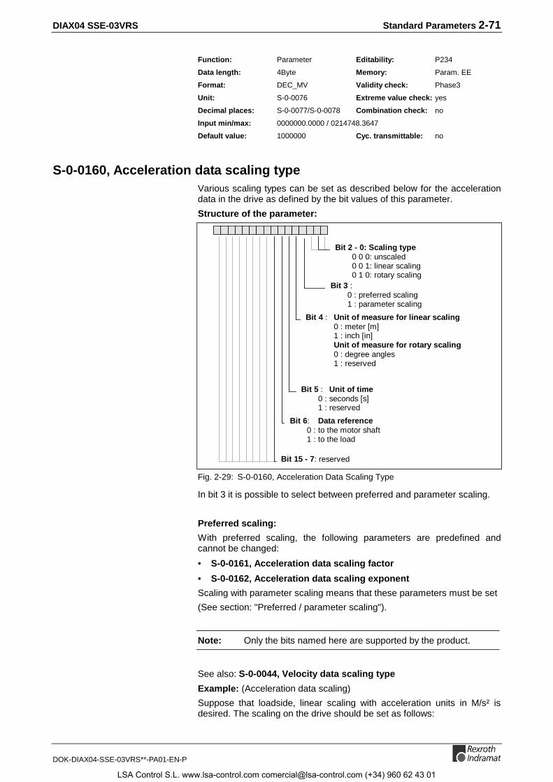
DIAX04 SSE-03VRS Standard Parameters 2-71
DOK-DIAX04-SSE-03VRS**-PA01-EN-P
Function: Parameter Editability: P234
Data length: 4Byte Memory: Param. EE
Format: DEC_MV Validity check: Phase3
Unit: S-0-0076 Extreme value check: yes
Decimal places: S-0-0077/S-0-0078 Combination check: no
Input min/max: 0000000.0000 / 0214748.3647
Default value: 1000000 Cyc. transmittable: no
S-0-0160, Acceleration data scaling typeVarious scaling types can be set as described below for the accelerationdata in the drive as defined by the bit values of this parameter.
Structure of the parameter:
Bit 4 : Unit of measure for linear scaling0 : meter [m]1 : inch [in]Unit of measure for rotary scaling0 : degree angles1 : reserved
Bit 5 : Unit of time0 : seconds [s]1 : reserved
Bit 15 - 7: reserved
Bit 6: Data reference0 : to the motor shaft1 : to the load
Bit 3 :0 : preferred scaling1 : parameter scaling
Bit 2 - 0: Scaling type0 0 0: unscaled0 0 1: linear scaling0 1 0: rotary scaling
Fig. 2-29: S-0-0160, Acceleration Data Scaling Type
In bit 3 it is possible to select between preferred and parameter scaling.
Preferred scaling:
With preferred scaling, the following parameters are predefined andcannot be changed:
• S-0-0161, Acceleration data scaling factor
• S-0-0162, Acceleration data scaling exponent
Scaling with parameter scaling means that these parameters must be set
(See section: "Preferred / parameter scaling").
Note: Only the bits named here are supported by the product.
See also: S-0-0044, Velocity data scaling type
Example: (Acceleration data scaling)
Suppose that loadside, linear scaling with acceleration units in M/s² isdesired. The scaling on the drive should be set as follows:
LSA Control S.L. www.lsa-control.com [email protected] (+34) 960 62 43 01
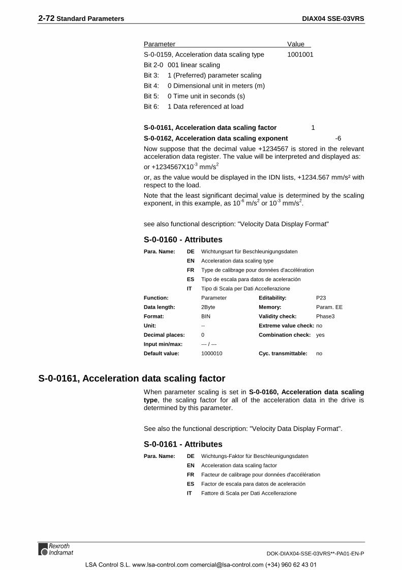
2-72 Standard Parameters DIAX04 SSE-03VRS
DOK-DIAX04-SSE-03VRS**-PA01-EN-P
Parameter Value
S-0-0159, Acceleration data scaling type 1001001
Bit 2-0 001 linear scaling
Bit 3: 1 (Preferred) parameter scaling
Bit 4: 0 Dimensional unit in meters (m)
Bit 5: 0 Time unit in seconds (s)
Bit 6: 1 Data referenced at load
S-0-0161, Acceleration data scaling factor 1
S-0-0162, Acceleration data scaling exponent -6
Now suppose that the decimal value +1234567 is stored in the relevantacceleration data register. The value will be interpreted and displayed as:
or +1234567X10-3 mm/s2
or, as the value would be displayed in the IDN lists, +1234.567 mm/s² withrespect to the load.
Note that the least significant decimal value is determined by the scalingexponent, in this example, as 10-6 m/s2 or 10-3 mm/s2.
see also functional description: "Velocity Data Display Format"
S-0-0160 - AttributesPara. Name: DE Wichtungsart für Beschleunigungsdaten
EN Acceleration data scaling type
FR Type de calibrage pour données d'accélération
ES Tipo de escala para datos de aceleración
IT Tipo di Scala per Dati Accellerazione
Function: Parameter Editability: P23
Data length: 2Byte Memory: Param. EE
Format: BIN Validity check: Phase3
Unit: -- Extreme value check: no
Decimal places: 0 Combination check: yes
Input min/max: --- / ---
Default value: 1000010 Cyc. transmittable: no
S-0-0161, Acceleration data scaling factorWhen parameter scaling is set in S-0-0160, Acceleration data scalingtype, the scaling factor for all of the acceleration data in the drive isdetermined by this parameter.
See also the functional description: "Velocity Data Display Format".
S-0-0161 - AttributesPara. Name: DE Wichtungs-Faktor für Beschleunigungsdaten
EN Acceleration data scaling factor
FR Facteur de calibrage pour données d'accélération
ES Factor de escala para datos de aceleración
IT Fattore di Scala per Dati Accellerazione
LSA Control S.L. www.lsa-control.com [email protected] (+34) 960 62 43 01

DIAX04 SSE-03VRS Standard Parameters 2-73
DOK-DIAX04-SSE-03VRS**-PA01-EN-P
Function: Parameter Editability: P23
Data length: 2Byte Memory: Param. EE
Format: DEC_OV Validity check: Phase3
Unit: -- Extreme value check: no
Decimal places: 0 Combination check: no
Input min/max: --- / ---
Default value: 1 Cyc. transmittable: no
S-0-0162, Acceleration data scaling exponentIf parameter scaling is set in S-0-0160, Acceleration data scaling typethe scaling exponent with sign for all acceleration data in the drive isdetermined in this parameter.
See also the functional description: "Velocity Data Display Format".
S-0-0162 - AttributesPara. Name: DE Wichtungs-Exponent für Beschleunigungsdaten
EN Acceleration data scaling exponent
FR Exposant de calibrage pour données d'accélération
ES Exponente de escala para datos de aceleración
IT Esponente per Dati Accellerazione
Function: Parameter Editability: P23
Data length: 2Byte Memory: Param. EE
Format: DEC_MV Validity check: Phase3
Unit: -- Extreme value check: no
Decimal places: 0 Combination check: no
Input min/max: --- / ---
Default value: 100000 Cyc. transmittable: no
S-0-0165, Distance coded reference offset 1With the help of this parameter, the greater distance between tworeference markers is programmed, if a measurement system withdistance coded reference markers is used.
See also the functional description: " Drive-Controlled Homing"
S-0-0165 - AttributesPara. Name: DE Abstandskodiertes Referenzmaß 1
EN Distance coded reference offset 1
FR Marques de référence de distance codée 1
ES Marcas de referencia de distancia codificada 1
Function: Parameter Editability: P23
Data length: 4Byte Memory: Param. EE
Format: DEC_OV Validity check: Phase3
Unit: Periods Extreme value check: no
Decimal places: 0 Combination check: no
Input min/max: - / -
Default value: 1001 Cyc. transmittable: no
LSA Control S.L. www.lsa-control.com [email protected] (+34) 960 62 43 01

2-74 Standard Parameters DIAX04 SSE-03VRS
DOK-DIAX04-SSE-03VRS**-PA01-EN-P
S-0-0166, Distance coded reference offset 2With the help of this parameter, the smaller distance between tworeference markers is programmed, if a measurement system withdistance coded reference markers is used.
See also the functional description: "Drive-Controlled Homing"
S-0-0166 - AttributesPara. Name: DE Abstandskodiertes Referenzmaß 2
EN Distance coded reference offset 2
FR Marques de référence de distance codée 2
ES Marcas de referencia de distancia codificada 2
Function: Parameter Editability: P23
Data length: 4Byte Memory: Param. EE
Format: DEC_OV Validity check: Phase3
Unit: Periods Extreme value check: no
Decimal places: 0 Combination check: no
Input min/max: - / -
Default value: 100 Cyc. transmittable: no
S-0-0169, Probe control parameterThis parameter is used to specify whether one or both of the probe inputs"probe 1" (DSS: X12-E4) and "probe 2" (DSS: X12-E5) are activated, andwhich edge (positive/negative) should trigger the probe data acquisition.
LSA Control S.L. www.lsa-control.com [email protected] (+34) 960 62 43 01
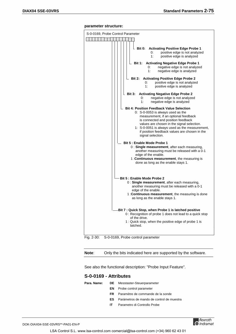
DIAX04 SSE-03VRS Standard Parameters 2-75
DOK-DIAX04-SSE-03VRS**-PA01-EN-P
parameter structure:
S-0-0169, Probe Control Parameter
Bit 0: Activating Positive Edge Probe 1 0: positive edge is not analyzed 1: positive edge is analyzed
Bit 1: Activating Negative Edge Probe 1 0: negative edge is not analyzed 1: negative edge is analyzed
Bit 2: Activating Positive Edge Probe 2 0: positive edge is not analyzed 1: positive edge is analyzed
Bit 3: Activating Negative Edge Probe 2 0: negative edge is not analyzed 1: negative edge is analyzed
Bit 4: Position Feedback Value Selection0: S-0-0053 is always used as the
measurement, if an optional feedbackis connected and position feedbackvalues are chosen in the signal selection.
1: S-0-0051 is always used as the measurement,if position feedback values are chosen in thesignal selection.
Bit 5 : Enable Mode Probe 10 : Single measurement, after each measuring,
another measuring must be released with a 0-1edge of the enable.
1 :Continuous measurement, the measuring isdone as long as the enable stays 1.
Bit 5 : Enable Mode Probe 20 : Single measurement, after each measuring,
another measuring must be released with a 0-1edge of the enable.
1 :Continuous measurement, the measuring is doneas long as the enable stays 1.
Bit 7 : Quick Stop, when Probe 1 is latched positive0 : Recognition of probe 1 does not lead to a quick stop
of the drive.1 : Quick stop, when the positive edge of probe 1 is
latched.
Fig. 2-30: S-0-0169, Probe control parameter
Note: Only the bits indicated here are supported by the software.
See also the functional description: "Probe Input Feature".
S-0-0169 - AttributesPara. Name: DE Messtaster-Steuerparameter
EN Probe control parameter
FR Paramètre de commande de la sonde
ES Parámetros de mando de control de muestra
IT Parametro di Controllo Probe
LSA Control S.L. www.lsa-control.com [email protected] (+34) 960 62 43 01

2-76 Standard Parameters DIAX04 SSE-03VRS
DOK-DIAX04-SSE-03VRS**-PA01-EN-P
Function: Parameter Editability: P234
Data length: 2Byte Memory: Param. EE
Format: BIN Validity check: Phase3
Unit: -- Extreme value check: no
Decimal places: 0 Combination check: yes
Input min/max: --- / ---
Default value: 0 Cyc. transmittable: no
S-0-0170, Probing cycle procedure commandBy setting and enabling the command "probing cycle procedure," the drivereacts to the following:
• S-0-0405, Probe 1 enable / S-0-0406, Probe 2 enable and
• S-0-0401, Probe 1, / S-0-0402, Probe 2.
as is programmed in S-0-0169, Probe control parameter.
The NC can perform multiple measurements while this command isactive. If the NC no longer wants new measurements, it clears thecommand.
Parameter structure:
Bit 0: Command in drive 0: clear 1: set
Bit 1: Command execution 0: interrupt 1: execute
Fig. 2-31: S-0-0170, Probing cycle procedure command
Note: if bit 0is set then the monitoring of the external 24V isactivated.
See also the functional description: "Probe Input Feature".
S-0-0170 - AttributesPara. Name: DE Kommando Messtasterzyklus
EN Probing cycle procedure command
FR Commande cycle mesure de sonde
ES Comando ciclo de teclas de medición
IT Comando per Procedura di Probe
Function: Parameter Editability: P4
Data length: 2Byte Memory: no
Format: BIN Validity check: no
Unit: -- Extreme value check: yes
Decimal places: 0 Combination check: no
Input min/max: --- / ---
Default value: --- Cyc. transmittable: no
LSA Control S.L. www.lsa-control.com [email protected] (+34) 960 62 43 01

DIAX04 SSE-03VRS Standard Parameters 2-77
DOK-DIAX04-SSE-03VRS**-PA01-EN-P
S-0-0173, Marker position ADuring the drive controlled homing with an incremental measuringsystem, the position of the reference marker (zero pulse) is stored in thisparameter. This position feedback value still refers to the "old“ coordinatesystem (before switching the coordinate system with the homingprocedure).
Furthermore, the recognition of the reference mark can be activated bythe command P-0-0014, D500 Command determine marker position.Then, as soon as the next reference pulse comes from the feedback, theappropriate position value is stored in this parameter, and the commandgets a positive acknowledge.
See also the functional description: "Command - detect marker position"
S-0-0173 - AttributesPara. Name: DE Markerposition A
EN Marker position A
FR Position du marqueur A
ES Posición de marcador A
IT Posizione Marca A
Function: Parameter Editability: no
Data length: 4Byte Memory: no
Format: DEC_MV Validity check: no
Unit: S-0-0076 Extreme value check: no
Decimal places: S-0-0077/S-0-0078 Combination check: no
Input min/max: S-0-0076 / S-0-0076
Default value: --- Cyc. transmittable: AT
S-0-0177, Absolute distance 1This parameter is used for the homing procedure of a distance codedmotor feedback. It describes the offset between the zero point of themotor feedback (position of the 1st reference marker of the motorencoder) and the machine’s zero-point.
Determining the right value for this parameter can be done in 2 steps.First, write the value 0 into S-0-0177 and proceed with the command S-0-0148, C600 Drive controlled homing procedure command. Theposition feedback value 1 in S-0-0051 then shows the actual position inreference to the motor feedback’s zero point.
Then, when you jog the axis to the machine’s zero point, input the valueof S-0-0051 indicated there into S-0-0177 with inverted sign (+ ↔ -). Afteranother homing, the value in S-0-0051 displays the position in referenceto the machine’s zero point.
See also the functional description: " Drive-Controlled Homing"
S-0-0177 - AttributesPara. Name: DE Absolutmaß-Offset 1
EN Absolute distance 1
FR Décalage absolu 1
ES Distancia absoluta 1
IT Offset 1 per Dimensionamenti assoluti (Feedback Motore)
LSA Control S.L. www.lsa-control.com [email protected] (+34) 960 62 43 01

2-78 Standard Parameters DIAX04 SSE-03VRS
DOK-DIAX04-SSE-03VRS**-PA01-EN-P
Function: Parameter Editability: P234
Data length: 4Byte Memory: Param. EE
Format: DEC_MV Validity check: Phase3
Unit: S-0-0076 Extreme value check: yes
Decimal places: S-0-0077/S-0-0078 Combination check: no
Input min/max: -214748.3648 / 0214748.3647
Default value: 0 Cyc. transmittable: no
S-0-0178, Absolute distance 2This parameter is used for the homing procedure of a distance codedexternal feedback. It describes the offset between the zero point of theoptional feedback (position of the 1st reference marker) and themachine’s zero-point.
Determining the right value for this parameter can be done in 2 steps.First, write the value 0 into S-0-0178 and proceed the command S-0-0148, C600 Drive controlled homing procedure command. Theposition feedback value 2 in S-0-0053 then shows the actual position inreference to the external feedback’s zero point.
Then, when you jog the axis to the machine’s zero point, input the valueof S-0-0053 indicated there into S-0-0178 with inverted sign (+ ↔ -). Afteranother homing, the value in S-0-0053 displays the position in referenceto the machine’s zero point.
See also the functional description: "Drive-Controlled Homing"
S-0-0178 - AttributesPara. Name: DE Absolutmaß-Offset 2
EN Absolute distance 2
FR Décalage absolu 2
ES Distancia absoluta 2
IT Offset 2 per Dimensionamenti assoluti (Feedback esterno)
Function: Parameter Editability: P234
Data length: 4Byte Memory: Param. EE
Format: DEC_MV Validity check: Phase3
Unit: S-0-0076 Extreme value check: yes
Decimal places: S-0-0077/S-0-0078 Combination check: no
Input min/max: -214748.3648 / 0214748.3647
Default value: 0 Cyc. transmittable: no
S-0-0182, Manufacturer class 3 diagnosticsVarious messages regarding the operating status are stored here every8ms. If the status of a message changes, this will not be signaled by achange bit.
LSA Control S.L. www.lsa-control.com [email protected] (+34) 960 62 43 01
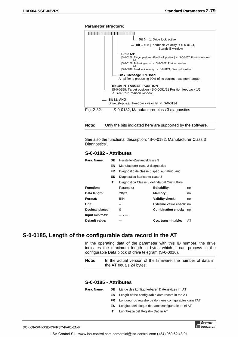
DIAX04 SSE-03VRS Standard Parameters 2-79
DOK-DIAX04-SSE-03VRS**-PA01-EN-P
Parameter structure:
Bit 0 = 1: Drive lock active
Bit 6: IZP|S-0-0258, Target position - Feedback position| < S-0-0057, Position window
&&|S-0-0189, Following error| < S-0-0057, Position window
&&|S-0-0040, Feedback velocity| < S-0-0124, Standstill window
Bit 11: AHQDrive_stop && |Feedback velocity| < S-0-0124
Bit 1 = 1: |Feedback Velocity| < S-0-0124,Standstill window
Bit 7: Message 90% loadAmplifier is producing 90% of its current maximum torque.
Bit 10: IN_TARGET_POSITION|S-0-0258, Target position - S-0-0051/51 Position feedback 1/2|< S-0-0057 Position window
Fig. 2-32: S-0-0182, Manufacturer class 3 diagnostics
Note: Only the bits indicated here are supported by the software.
See also the functional description: "S-0-0182, Manufacturer Class 3Diagnostics".
S-0-0182 - AttributesPara. Name: DE Hersteller-Zustandsklasse 3
EN Manufacturer class 3 diagnostics
FR Diagnostic de classe 3 spéc. au fabriquant
ES Diagnostico fabricante clase 3
IT Diagnostica Classe 3 definita dal Costruttore
Function: Parameter Editability: no
Data length: 2Byte Memory: no
Format: BIN Validity check: no
Unit: -- Extreme value check: no
Decimal places: 0 Combination check: no
Input min/max: --- / ---
Default value: --- Cyc. transmittable: AT
S-0-0185, Length of the configurable data record in the ATIn the operating data of the parameter with this ID number, the driveindicates the maximum length in bytes which it can process in theconfigurable Data block of drive telegram (S-0-0016).
Note: In the actual version of the firmware, the number of data inthe AT equals 24 bytes.
S-0-0185 - AttributesPara. Name: DE Länge des konfigurierbaren Datensatzes im AT
EN Length of the configurable data record in the AT
FR Longueur du registre de données configurables dans l'AT
ES Longitud del bloque de datos configurable en el AT
IT Lunghezza del Registro Dati in AT
LSA Control S.L. www.lsa-control.com [email protected] (+34) 960 62 43 01

2-80 Standard Parameters DIAX04 SSE-03VRS
DOK-DIAX04-SSE-03VRS**-PA01-EN-P
Function: Parameter Editability: no
Data length: 2Byte Memory: no
Format: DEC_OV Validity check: no
Unit: Byte Extreme value check: no
Decimal places: 0 Combination check: no
Input min/max: --- / ---
Default value: --- Cyc. transmittable: no
S-0-0186, Length of the configurable data record in the MDTIn the operating data of the parameter with this ID number, the driveindicates the maximum length in bytes which it can process in theconfigurable data record of the master data telegram (S-0-0024).
Note: In the actual version of the firmware, the number of data inthe MDT equals 32 bytes.
See also the functional description: "Configuration of Telegram Contents".
S-0-0186 - AttributesPara. Name: DE Länge des konfigurierbaren Datensatzes im MDT
EN Length of the configurable data record in the MDT
FR Longueur du registre de données configurables dans le MDT
ES Longitud del bloque de datos configurable en el MDT
IT Lunghezza del Registro Dati in MDT
Function: Parameter Editability: no
Data length: 2Byte Memory: no
Format: DEC_OV Validity check: no
Unit: Byte Extreme value check: no
Decimal places: 0 Combination check: no
Input min/max: --- / ---
Default value: --- Cyc. transmittable: no
S-0-0187, List of configurable data in the ATThis list contains the ID numbers of the operating data which can beconfigured in the drive telegram (AT).
• S-0-0040, Velocity feedback value
• S-0-0051, Position feedback value 1 (motor feedback)
• S-0-0053, Position feedback value 2 (ext. feedback)
• S-0-0084, Torque/Force feedback value
• S-0-0130, Probe value 1 positive edge
• S-0-0131, Probe value 1 negative edge
• S-0-0132, Probe value 2 positive edge
• S-0-0133, Probe value 2 negative edge
• S-0-0182, Manufacturer class 3 diagnostics
• S-0-0189, Following error
• P-0-0082, Parallel I/O input 1
• P-0-0111, Parallel I/O input 2
LSA Control S.L. www.lsa-control.com [email protected] (+34) 960 62 43 01
DIAX04 SSE-03VRS Standard Parameters 2-81
DOK-DIAX04-SSE-03VRS**-PA01-EN-P
• P-0-0113, Parallel I/O input 3
• P-0-0171, Parallel I/O input 4
• P-0-0173, Parallel I/O input 5
• P-0-0175, Parallel I/O input 6
• P-0-0202, Difference probe values 1
• P-0-0203, Difference probe values 2
• P-0-0210, Analog input 1
• P-0-0211, Analog input 2
See also the functional description: "Configuration of Telegram Contents".
S-0-0187 - AttributesPara. Name: DE Liste der konfigurierbaren Daten im AT
EN List of configurable data in the AT
FR Liste des IDN de données configurables dans l'AT
ES Lista de los datos configurables en el AT
IT Lista dei Dati configurabili in AT
Function: Parameter Editability: no
Data length: 2Byte var. Memory: no
Format: IDN Validity check: no
Unit: -- Extreme value check: no
Decimal places: 0 Combination check: no
Input min/max: --- / ---
Default value: --- Cyc. transmittable: no
S-0-0188, List of configurable data in the MDTThis list contains the ID numbers of the operating data which can beconfigured in the Master Data Telegram.
• S-0-0036, Velocity command value
• S-0-0037, Additive velocity command value
• S-0-0047, Position command value
• S-0-0080, Torque/force command
• S-0-0091, Bipolar velocity limit value
• S-0-0092, Bipolar torque/force limit value
• S-0-0138, Bipolar acceleration limit value
• S-0-0193, Positioning Jerk
• S-0-0258, Target position
• S-0-0259, Positioning Velocity
• S-0-0260, Positioning Acceleration
• S-0-0349, Jerk limit bipolar
• P-0-0081, Parallel I/O output 1
• P-0-0110, Parallel I/O output 2
• P-0-0112, Parallel I/O output 3
• P-0-0170, Parallel I/O output 4
• P-0-0172, Parallel I/O output 5
LSA Control S.L. www.lsa-control.com [email protected] (+34) 960 62 43 01
2-82 Standard Parameters DIAX04 SSE-03VRS
DOK-DIAX04-SSE-03VRS**-PA01-EN-P
• P-0-0174, Parallel I/O output 6
• P-0-0400, Pos. corr., external correction value
• P-0-0405, Pos. corr., actual temperature, position independent
See also the functional description: "Configuration of Telegram Contents".
S-0-0188 - AttributesPara. Name: DE Liste der konfigurierbaren Daten im MDT
EN List of configurable data in the MDT
FR Liste des IDN de données configurables dans le MDT
ES Lista de los datos configurables en el MDT
IT Lista dei Dati configurabili in MDT
Function: Parameter Editability: no
Data length: 2Byte var. Memory: no
Format: IDN Validity check: no
Unit: -- Extreme value check: no
Decimal places: 0 Combination check: no
Input min/max: --- / ---
Default value: --- Cyc. transmittable: no
S-0-0189, Following errorTo this parameter, the drive writes the current difference between theposition command and the feedback position value (S-0-0051, Positionfeedback 1 value or S-0-0053, Position feedback 2 value ).
See also the functional description: "Determining the Position ControllerSetting".
S-0-0189 - AttributesPara. Name: DE Schleppabstand
EN Following error
FR Ecart de poursuite
ES Error de seguimiento
IT Errore di Inseguimento
Function: Parameter Editability: no
Data length: 4Byte Memory: no
Format: DEC_OV Validity check: no
Unit: S-0-0076 Extreme value check: no
Decimal places: S-0-0077/S-0-0078 Combination check: no
Input min/max: --- / ---
Default value: --- Cyc. transmittable: AT
S-0-0191, D600 Cancel reference point procedure commandSetting and enabling the command Cancel reference point clears thereference of the encoder defined by S-0-0147, Homing Parameter. Theposition status (bit 0 in S-0-0403) is cleared as well.
The command is correctly completed in the drive, when the bit "Positionfeedback value status“ has been set to 0 and the position value of theactive feedback no longer refers to the machine’s zero point (= no longerreferenced).
LSA Control S.L. www.lsa-control.com [email protected] (+34) 960 62 43 01

DIAX04 SSE-03VRS Standard Parameters 2-83
DOK-DIAX04-SSE-03VRS**-PA01-EN-P
Parameter structure:
Bit 0 : Command in the drive0: cancel1: set
Bit 1 : Command execution0: suspend1: execute
Fig. 2-33: S-0-0191, D600 Cancel reference point procedure command
See also the functional description: " Drive-Controlled Homing"
S-0-0191 - AttributesPara. Name: DE D600 Kommando Referenzbezug löschen
EN D600 Cancel reference point procedure command
FR D600 Commande Annullation de l'origine
ES D600 Comando Borrar referencia
IT D600 Comando Anullazione Azzeramento
Function: Command Editability: P234
Data length: 2Byte Memory: no
Format: BIN Validity check: no
Unit: -- Extreme value check: no
Decimal places: 0 Combination check: no
Input min/max: - / -
Default value: --- Cyc. transmittable: no
S-0-0192, IDN-list of backup operation dataThe ID numbers for all operating data that must be loaded in the drive forproper operation are kept in this IDN list. Generally these are theparameters which are stored in the programming module.
The control system should use this IDN list to create a backup copy ofthe drive parameters.
If a customer password has been activated with the parameter S-0-0267,Password, all parameters contained in S-0-0192, IDN List of backupoperation data are write protected.
See also the functional description: "IDN List of Parameters".
S-0-0192 - AttributesPara. Name: DE IDN-Liste der zu sichernden Betriebsdaten
EN IDN-list of backup operation data
FR Liste des IDN des données d'exploitation de sauvegarde
ES Lista IDN de los datos de servicio de seguridad
IT Lista IDN dei Dati operativi salvati
Function: Parameter Editability: no
Data length: 2Byte var. Memory: no
Format: IDN Validity check: no
Unit: -- Extreme value check: no
Decimal places: 0 Combination check: no
Input min/max: --- / ---
Default value: --- Cyc. transmittable: no
LSA Control S.L. www.lsa-control.com [email protected] (+34) 960 62 43 01

2-84 Standard Parameters DIAX04 SSE-03VRS
DOK-DIAX04-SSE-03VRS**-PA01-EN-P
S-0-0193, Positioning JerkThe positioning jerk limits the acceleration change per time in theoperating modes with
• Drive internal interpolation and
• Relative drive internal interpolation.
• Jog mode
Note: With the value 0, the jerk filter is off.
See also the functional description: "Functional Principle Drive InternalInterpolation"
S-0-0193 - AttributesPara. Name: DE Positionier-Ruck
EN Positioning Jerk
FR Jerk de positionnement
ES Posicionamiento agitación
IT Jerk per Posizionamento
Function: Parameter Editability: P234
Data length: 4Byte Memory: Param. EE
Format: DEC_OV Validity check: Phase3
Unit: S-0-0160 Extreme value check: yes
Decimal places: S-0-0161/S-0-0162 Combination check: no
Input min/max: 0000000.000 / 4000000.000
Default value: 0 Cyc. transmittable: MDT
S-0-0201, Motor warning temperatureIf the motor temperature exceeds the motor warning temperature, thenthe motor warning high temperature bit will be set by the drive inS-0-0012, Class 2 diagnostics.
This parameter will be set by the drive at 145° for MHD, MKD and MKEmotors.
See also the functional description: "Temperature Monitoring".
S-0-0201 - AttributesPara. Name: DE Motor-Warntemperatur
EN Motor warning temperature
FR Température de préalerte du moteur
ES Temperatura de aviso de motor
IT Preallarme Temperatura Motore
Function: Parameter Editability: P23
Data length: 2Byte Memory: Param. EE
Format: DEC_MV Validity check: Phase3
Unit: C Extreme value check: yes
Decimal places: 1 Combination check: no
Input min/max: 0045.0 / 0155.0
Default value: 1400 Cyc. transmittable: no
LSA Control S.L. www.lsa-control.com [email protected] (+34) 960 62 43 01

DIAX04 SSE-03VRS Standard Parameters 2-85
DOK-DIAX04-SSE-03VRS**-PA01-EN-P
S-0-0204, Motor shutdown temperatureIf the motor temperature exceeds the motor shutdown temperature, thenthe motor overtemperature bit in S-0-0011, Class 1 diagnostics will beset by the drive and the error F219 Motor overtemp. shutdown will begenerated.
In MHD, MKD and MKE motors, the drive sets this parameter at 155°.
See also the functional description: "Temperature Monitoring".
S-0-0204 - AttributesPara. Name: DE Motor-Abschalttemperatur
EN Motor shutdown temperature
FR Température d'arrêt du moteur
ES Temperatura de desconexion de motor
IT Spegnimento per Sovratemp. Motore
Function: Parameter Editability: P23
Data length: 2Byte Memory: Param. EE
Format: DEC_MV Validity check: Phase3
Unit: C Extreme value check: yes
Decimal places: 1 Combination check: no
Input min/max: 0145.0 / 0155.0
Default value: 1500 Cyc. transmittable: no
S-0-0256, Multiplication 1The parameter S-0-0256, Multiplication 1 determines, with which factorthe signals of the motor feedback are multiplied in the drive.
The internal resolution for the motor encoder in the drive is calculated asfollows:
S-0-0116 Resolution of motor feedback x S-0-0256 Multiplication 1
The multiplication 1 depends on the parameters S-0-0278, Maximumtravel range and S-0-0116, Resolution of motor feedback. If there isan optional encoder, the S-0-0257, Multiplication 2 is taken into accountas well.
See also the functional description: "Setting the drive-internal positiondata format"
S-0-0256 - AttributesPara. Name: DE Vervielfachung 1
EN Multiplication 1
FR Multiplication 1
ES Multiplicación 1
IT Multiplicazione 1
Function: Parameter Editability: no
Data length: 4Byte Memory: no
Format: DEC_OV Validity check: no
Unit: -- Extreme value check: no
Decimal places: 1 Combination check: no
Input min/max: --- / ---
Default value: --- Cyc. transmittable: no
LSA Control S.L. www.lsa-control.com [email protected] (+34) 960 62 43 01

2-86 Standard Parameters DIAX04 SSE-03VRS
DOK-DIAX04-SSE-03VRS**-PA01-EN-P
S-0-0257, Multiplication 2The parameter S-0-0257, Multiplication 2 determines with which factorthe signals of the optional feedback are multiplied in the drive.
The internal resolution for the optional encoder in the drive is calculatedas follows:
S-0-0117 Resolution of optional feedback x S-0-0257 Multiplication 2
The multiplication 2 depends on the parameters S-0-0278, Maximumtravel range and S-0-0117, Resolution of optional feedback.
See also the functional description: "Setting the drive-internal positiondata format"
S-0-0257 - AttributesPara. Name: DE Vervielfachung 2
EN Multiplication 2
FR Multiplication 2
ES Multiplicación 2
IT Multiplicazione 2
Function: Parameter Editability: no
Data length: 4Byte Memory: no
Format: DEC_OV Validity check: no
Unit: -- Extreme value check: no
Decimal places: 1 Combination check: no
Input min/max: --- / ---
Default value: --- Cyc. transmittable: no
S-0-0258, Target positionThe target position is assigned to the drive as a command value by thecontroller in the operating modes with drive-controlled interpolation. Thedrive moves to the target position taking into account S-0-0259,Positioning Velocity, S-0-0260, Positioning Acceleration and S-0-0193, Positioning Jerk
See also the functional description: "Functional Principle Drive InternalInterpolation"
S-0-0258 - AttributesPara. Name: DE Zielposition
EN Target position
FR Position à atteindre
ES Posición objeto
IT Posizione da raggiungere
Function: Parameter Editability: P234
Data length: 4Byte Memory: no
Format: DEC_MV Validity check: no
Unit: S-0-0076 Extreme value check: yes
Decimal places: S-0-0077/S-0-0078 Combination check: no
Input min/max: -214748.3648 / 0214748.3647
Default value: --- Cyc. transmittable: MDT
LSA Control S.L. www.lsa-control.com [email protected] (+34) 960 62 43 01
DIAX04 SSE-03VRS Standard Parameters 2-87
DOK-DIAX04-SSE-03VRS**-PA01-EN-P
S-0-0259, Positioning VelocityThe Positioning Velocity is used in the operating mode "Drive-controlledinterpolation" to reach the S-0-0258, Target position.
See also the functional description: "Functional Principle Drive InternalInterpolation"
S-0-0259 - AttributesPara. Name: DE Positionier-Geschwindigkeit
EN Positioning Velocity
FR Vitesse de positionnement
ES Velocidad de posicionamiento
IT Velocità di Posizionamento
Function: Parameter Editability: P234
Data length: 4Byte Memory: Param. EE
Format: DEC_OV Validity check: Phase3
Unit: S-0-0044 Extreme value check: yes
Decimal places: S-0-0045/S-0-0046 Combination check: no
Input min/max: 0000000000.0 / 0030720000.0
Default value: 100000 Cyc. transmittable: MDT
S-0-0260, Positioning AccelerationThe Positioning acceleration is used in the operating mode "Drive-controlled interpolation" to accelerate to the S-0-0259, PositioningVelocity.
See also the functional description: "Functional principle Drive InternalInterpolation"
S-0-0260 - AttributesPara. Name: DE Positionier-Beschleunigung
EN Positioning Acceleration
FR Accélération de positionnement
ES Aceleración de posicionamiento
IT Accellerazione di Posizionamento
Function: Parameter Editability: P234
Data length: 4Byte Memory: Param. EE
Format: DEC_OV Validity check: Phase3
Unit: S-0-0160 Extreme value check: yes
Decimal places: S-0-0161/S-0-0162 Combination check: no
Input min/max: 00000000.000 / 00024543.692
Default value: 100000 Cyc. transmittable: MDT
LSA Control S.L. www.lsa-control.com [email protected] (+34) 960 62 43 01
2-88 Standard Parameters DIAX04 SSE-03VRS
DOK-DIAX04-SSE-03VRS**-PA01-EN-P
S-0-0262, C700 Command basic loadWhen this command is set and enabled, the default parameters in themotor feedback for current, velocity and position control loop settings willbe loaded and activated. These default parameters are not optimized forthe specific application. They establish a stable control loop status.
ATTENTION
When this command is executed, parameters thathave already been optimized may be overwritten.
See also Function description: "Load Default Feature"
S-0-0262 - AttributesPara. Name: DE C700 Kommando Urladen
EN C700 Command basic load
FR C700 Commande chargement initial
ES C700 Comando carga base
IT C700 Comando Caricamento Base
Function: Command Editability: P234
Data length: 2Byte Memory: no
Format: BIN Validity check: no
Unit: -- Extreme value check: no
Decimal places: 0 Combination check: no
Input min/max: --- / ---
Default value: --- Cyc. transmittable: no
S-0-0265, Language selectionAll parameter names, units and diagnostic warning messages within thedrive controller are stored in several languages. This parameterdetermines the output language for the text.
• 0: German
• 1: English
• 2: French
• 3: Spanish
• 4: Italian
See also the functional description: "Language Selection".
S-0-0265 - AttributesPara. Name: DE Sprach-Umschaltung
EN Language selection
FR Sélection de langue
ES Cambio de idioma
IT Selezione di Lingua
LSA Control S.L. www.lsa-control.com [email protected] (+34) 960 62 43 01

DIAX04 SSE-03VRS Standard Parameters 2-89
DOK-DIAX04-SSE-03VRS**-PA01-EN-P
Function: Parameter Editability: P234
Data length: 2Byte Memory: Param. EE
Format: DEC_OV Validity check: Phase3
Unit: -- Extreme value check: yes
Decimal places: 0 Combination check: no
Input min/max: 00000 / 00001
Default value: 0 Cyc. transmittable: no
S-0-0267, PasswordRexroth Indramat reserves the right of having a master password.
The password "007" is set at the factory. This password permits writeaccess to the parameters.
Moreover, the parameter can unlock service capabilities.
See also the functional description: "Password".
S-0-0267 - AttributesPara. Name: DE Passwort
EN Password
FR Mot de passe
ES Contraseña
IT Parole Chiave
Function: Parameter Editability: P234
Data length: 1Byte var. Memory: no
Format: ASCII Validity check: no
Decimal places: 0 Combination check: no
Input min/max: --- / ---
Default value: --- Cyc. transmittable: no
S-0-0269, Parameter buffer modeThe Parameter buffer mode is used to determine whether the datatransmitted through the service channel (or serial interface) will be storedtemporarily (in RAM) or permanently.
1: Data will not be stored permanently. (Data is volatile.)
0: Data will be stored permanently. (Data is resident.)
After the control voltage supply has been switched on, the drive willinitialize bit 0 to 0. To activate temporary storage mode, bit 0 must beforced to 1 after switching on.
Note: For applications that write cylic or frequent updates tobuffered parameters: Parameter buffer mode = 1 (temporary)should be activated by the initialization procedure in themachine control. This mode ensures that the write cycle life ofthe EEPROM is not exceeded. Must be re-programmed aftercomplete power shut down.
See also the functional description: "Data Storage"
LSA Control S.L. www.lsa-control.com [email protected] (+34) 960 62 43 01

2-90 Standard Parameters DIAX04 SSE-03VRS
DOK-DIAX04-SSE-03VRS**-PA01-EN-P
S-0-0269 - AttributesPara. Name: DE Speicherungsmodus
EN Parameter buffer mode
FR Mode d’enregistrement
ES Modo de buffer
IT Buffer Modo Parametri
Function: Parameter Editability: P234
Data length: 2Byte Memory: no
Format: DEC_OV Validity check: no
Unit: -- Extreme value check: yes
Decimal places: 0 Combination check: no
Input min/max: 00000 / 00001
Default value: --- Cyc. transmittable: no
S-0-0277, Position feedback 1 typeThis parameter is used to determine the significant properties of theencoder 1.
Parameter structure:
Bit 0: Feedback type0: rotary1: linear
Bit 1: Distance coded measuring system0: no distance coded referencemarkers1: distance coded reference markersS-0-0165, S-0-0166
Bit 3: Direction ofmovement
0: not inverted1: inverted
Bits 7 + 6: Absolute readoutx 0: No absolute readout possible.
(Bit 7 irrelevant)0 1: Absolute readout possible and active,
encoder is treated as absolute.1 1: Absolute readout possible, but not active.
Fig. 2-34: S-0-0277, Position feedback 1 type parameter
Remark:
• If the motor has a motor feedback memory (MHD, MKD or MKE) thenbits 0,1 and 3 are set to “0”.
• If the motor is a linear motor, then bit 0 is set to "1“.
• Depending on the absolute encoder range and the maximum travelrange or modulo value, bit 6 is set to the correct value.
Note: Only the bits indicated here are supported by the software.
See also the functional description: "Other Motor Encoder Characteristics"
LSA Control S.L. www.lsa-control.com [email protected] (+34) 960 62 43 01
DIAX04 SSE-03VRS Standard Parameters 2-91
DOK-DIAX04-SSE-03VRS**-PA01-EN-P
S-0-0277 - AttributesPara. Name: DE Lagegeberart 1
EN Position feedback 1 type
FR Type codeur 1
ES Tipo de encoder de posición 1
IT Tipo di Feedback Posizione 1
Function: Parameter Editability: P23
Data length: 2Byte Memory: Param. EE
Format: BIN Validity check: Phase3
Unit: -- Extreme value check: no
Decimal places: 0 Combination check: yes
Input min/max: --- / ---
Default value: 0 Cyc. transmittable: no
S-0-0278, Maximum travel rangeThe parameter S-0-0278, Maximum travel range defines the maximumpossible mechanical move of the machine. Depending on the selectedscaling, modulo or absolute format (see also S-0-0076, Position datascaling type), the input is unipolar (positive only) or bipolar (with sign).
The parameter S-0-0278, Maximum travel range affects the parametersS-0-0256, Multiplication 1 and S-0-0257, Multiplication 2 and thereforethe internal position resolution in the drive.
Moreover, the limits for velocity and acceleration of the drive internalposition command generator are influenced by the maximum travel range.Among others, the max. input values for S-0-0259, Positioning Velocityand S-0-0260, Positioning Acceleration depend on the value in S-0-0278 !
Note: The greater the parameterized maximum travel range, thesmaller is the multiplication and the drive internal positionresolution and the higher are the limits of the acceleration andvelocity data.
Additionally, the parameter S-0-0278, Maximum travel range affects thebit 6 "Absolute readout possible“ in the respective parameter S-0-0277,Position feedback 1 type or S-0-0115, Position feedback 2 type. If theparameterized maximum travel range is greater than half the absolutenumerical range of the used encoder, then the bit 6 for "Absolute readoutpossible“ is reset to 0. The converse is also true. Bit 6 is set to “1” as soonas a travel range less than half the absolute numerical range of theencoder is recognized.
See also the functional description: "Setting the drive-internal positiondata format"
S-0-0278 - AttributesPara. Name: DE Maximaler Verfahrbereich
EN Maximum travel range
FR Champs de déplacement maxi.
ES Campo máximo de desplazamiento
IT Campo di Movimento mass.
LSA Control S.L. www.lsa-control.com [email protected] (+34) 960 62 43 01

2-92 Standard Parameters DIAX04 SSE-03VRS
DOK-DIAX04-SSE-03VRS**-PA01-EN-P
Function: Parameter Editability: P23
Data length: 4Byte Memory: Param. EE
Format: DEC_MV Validity check: Phase3
Unit: S-0-0076 Extreme value check: no
Decimal places: S-0-0077/S-0-0078 Combination check: no
Input min/max: 0000000.0000 / 0214748.3647
Default value: 2147483647 Cyc. transmittable: no
S-0-0292, List of all operating modesIn this list, all operation modes are named, which the drive supports. Theoperation modes are listed by their codings (binary values), as they areinput in the parameters S-0-0032..35 (primary and secondary operationmodes).
See also the functional description: "Possible Operating Modes".
S-0-0292 - AttributesPara. Name: DE Liste der unterstützten Betriebsarten
EN List of all operating modes
FR Liste de tous les modes de fonctionnement
ES Lista de todos los modos de operación
IT Lista di tutti i Modi operativi
Function: Parameter Editability: no
Data length: 2Byte var. Memory: no
Format: HEX Validity check: no
Unit: -- Extreme value check: no
Decimal places: 0 Combination check: no
Input min/max: -- / --
Default value: --- Cyc. transmittable: no
S-0-0298, Reference cam shiftFor the drive controlled homing, if there is more than one referencemarker in the travel range of the axis during homing, it is necessary toevaluate a reference switch. In this case, the 0->1 rising edge of the zeroswitch specifies the relevant reference marker.
To do this, the distance between zero switch and reference marker maynot be below a certain value, because otherwise the reference marker isambiguous. Therefore, the drive monitors the distance. If the distance isoutside the allowed range, the command S-0-0148, C600 Drivecontrolled homing procedure command ends up with the error C602Distance zero switch - reference marker wrong.
In this case, this parameter shows the distance, by which the zero switchmust be shifted, to get the optimal distance. You can either
• input the value in the parameter S-0-0299, Home switch offset toshift the active zero switch (virtually) referred to the real one, or
• shift the zero switch mechanically by the value displayed in S-0-0298.
If the distance between zero switch and reference marker is within theallowed range, then S-0-0298, Reference cam shift by.. displays a 0.
LSA Control S.L. www.lsa-control.com [email protected] (+34) 960 62 43 01
DIAX04 SSE-03VRS Standard Parameters 2-93
DOK-DIAX04-SSE-03VRS**-PA01-EN-P
See also the functional description: " Drive-Controlled Homing"
S-0-0298 - AttributesPara. Name: DE Verschiebung des Referenznockens
EN Reference cam shift
FR Décalage de la came d'origine
ES Desplazamiento de la leva de origen
IT Posizione Camma di Azzeramento
Function: Parameter Editability: no
Data length: 4Byte Memory: no
Format: DEC_MV Validity check: no
Unit: S-0-0076 Extreme value check: no
Decimal places: S-0-0077/S-0-0078 Combination check: no
Input min/max: -214748.3648 / 0214748.3647
Default value: --- Cyc. transmittable: no
S-0-0299, Home switch offsetFor the drive controlled homing, if there is more than one referencemarker in the travel range of the axis during homing, it is necessary toevaluate a reference switch. In this case, the 0->1 rising edge of the zeroswitch specifies the relevant reference marker.
To do this, the distance between zero switch and reference marker maynot be below a certain value, because otherwise the reference marker isambiguous. Therefore, the drive monitors the distance. If the distance isoutside the allowed range, the command S-0-0148, C600 Drivecontrolled homing procedure command ends up with the error C602Distance zero switch - reference marker wrong.
In this case, the parameter S-0-0298, Reference cam shift shows thedistance, by which the zero switch must be shifted, to get the optimaldistance.
You can either
• input the value in the parameter S-0-0299, Home switch offset toshift the active zero switch (virtually) referred to the real one, or
• shift the zero switch mechanically by the value displayed in S-0-0298.
If the distance between zero switch and reference marker is good, thenS-0-0298, Reference cam shift by.. displays a 0.
See also the functional description: " Drive-Controlled Homing"
S-0-0299 - AttributesPara. Name: DE Referenzschalter-Offset
EN Home switch offset
FR Décalage contact origine
ES Offset de interruptor de referencia
IT Offset FC di Zero
Function: Parameter Editability: P234
Data length: 4Byte Memory: Param. EE
Format: DEC_MV Validity check: Phase3
Unit: S-0-0076 Extreme value check: yes
Decimal places: S-0-0077/S-0-0078 Combination check: no
Input min/max: -214748.3648 / 0214748.3647
Default value: --- Cyc. transmittable: no
LSA Control S.L. www.lsa-control.com [email protected] (+34) 960 62 43 01

2-94 Standard Parameters DIAX04 SSE-03VRS
DOK-DIAX04-SSE-03VRS**-PA01-EN-P
S-0-0301, Allocation of real-time control Bit 1In order to assign a signal to the real-time control bit 1, the ID number ofthe signal is written to the operating data of the assignment for the real-time control bit 1.
If such an assignment is made, the assigned signal (bit 0) will be controlled bythe real-time control bit 1 (=component of the master control word).
If the selected IDN is not available, the drive responds with the servicechannel error message "IDN not available"
If the programmed IDN is available but is not editable in phase 4, then thedrive responds with the error message "Data not correct"
See also the functional description: "Real-Time Control and Status Bits".
S-0-0301 - AttributesPara. Name: DE Zuweisung Echtzeitsteuerbit 1
EN Allocation of real-time control Bit 1
FR Allocation bit contrôle temps réel 1
ES Asignación bit de mando tiempo real 1
IT Allocazione del Real Time Control Bit 1
Function: Parameter Editability: P234
Data length: 2Byte Memory: Param. EE
Format: DEC_OV Validity check: Phase3
Unit: -- Extreme value check: no
Decimal places: 0 Combination check: no
Input min/max: 00000 / 65535
Default value: 0 Cyc. transmittable: no
S-0-0303, Allocation of real-time control Bit 2In order to assign a signal the real-time control bit 2, the ID number of thesignal is written to the operating data of the assignment for the real-timecontrol bit 2.
If such an assignment is made, the assigned signal (bit 0) will becontrolled by the real-time control bit 2 ( = component of the mastercontrol word).
See also the functional description: "Real-Time Control and Status Bits".
S-0-0303 - AttributesPara. Name: DE Zuweisung Echtzeitsteuerbit 2
EN Allocation of real-time control Bit 2
FR Allocation bit contrôle temps réel 2
ES Asignación bit de mando tiempo real 2
IT Allocazione del Real Time Control Bit 2
Function: Parameter Editability: P234
Data length: 2Byte Memory: Param. EE
Format: DEC_OV Validity check: Phase3
Unit: -- Extreme value check: no
Decimal places: 0 Combination check: no
Input min/max: 00000 / 65535
Default value: 0 Cyc. transmittable: no
LSA Control S.L. www.lsa-control.com [email protected] (+34) 960 62 43 01
DIAX04 SSE-03VRS Standard Parameters 2-95
DOK-DIAX04-SSE-03VRS**-PA01-EN-P
S-0-0305, Allocation of real-time status Bit 1In order to assign a signal to the real-time status bit 1, the ID number ofthe signal is written to the operating data of the assignment for the real-time status bit 1.
If such an assignment is made, the assigned signal (bit 0) thereafterappears in the real-time status bit 1 ( = component of the drive statusword).
If the programmed IDN is not available, the drive responds with theservice channel error message "IDN not available".
see also the functional description: "Real-Time Control and Status Bits".
S-0-0305 - AttributesPara. Name: DE Zuweisung Echtzeitstatusbit 1
EN Allocation of real-time status Bit 1
FR Allocation bit état temps réel 1
ES Asignación bit de estado tiempo real 1
IT Allocazione del Real Time Status Bit 1
Function: Parameter Editability: P234
Data length: 2Byte Memory: Param. EE
Format: DEC_OV Validity check: Phase3
Unit: -- Extreme value check: no
Decimal places: 0 Combination check: no
Input min/max: 00000 / 65535
Default value: 0 Cyc. transmittable: no
S-0-0307, Allocation of real-time status Bit 2In order to assign a signal to the real-time status bit 2, the ID number ofthe signal is written to the operating data of the assignment for the real-time status bit 2.
If such an assignment is made, the assigned signal (bit 0) thereafterappears in the real-time status bit 2 (component of the drive status word).
See also the functional description: "Real-Time Control and Status Bits".
S-0-0307 - AttributesPara. Name: DE Zuweisung Echtzeitstatusbit 2
EN Allocation of real-time status Bit 2
FR Allocation bit état temps réel 2
ES Asignación bit de estado tiempo real 2
IT Allocazione del Real Time Status Bit 2
Function: Parameter Editability: P234
Data length: 2Byte Memory: Param. EE
Format: DEC_OV Validity check: Phase3
Unit: -- Extreme value check: no
Decimal places: 0 Combination check: no
Input min/max: 00000 / 65535
Default value: 0 Cyc. transmittable: no
LSA Control S.L. www.lsa-control.com [email protected] (+34) 960 62 43 01

2-96 Standard Parameters DIAX04 SSE-03VRS
DOK-DIAX04-SSE-03VRS**-PA01-EN-P
S-0-0328, Assign list signal status wordThe signal status word (S-0-0144) is configured with the parametersS-0-0026, Configuration list signal status word and S-0-0328, Assignlist signal status word. These parameters have variable length with dataelements of 16 bits. In the parameter S-0-0026, Configuration list signalstatus word, the ident number of the parameters is set, which containsthe original bit (source). The parameter S-0-0328, Assign list signalstatus word determines which bit in the data is copied into the signalstatus word.
The position in the respective configuration list determines, to whichposition in the signal status word the chosen bit is copied.
See also the functional description: "Configurable Signal Status Word".
S-0-0328 - AttributesPara. Name: DE Zuweisungsliste Signal-Statuswort
EN Assign list signal status word
FR Liste d’assignations pour mot de statut des signaux
ES Lista de assignaciones palabra de estado de señal
IT Lista di Assignazioni Parole di Stato Segnali
Function: Parameter Editability: P234
Data length: 2Byte var. Memory: Param. EE
Format: DEC_OV Validity check: P3-4
Unit: -- Extreme value check: no
Decimal places: 0 Combination check: no
Input min/max: - / -
Default value: 0 Cyc. transmittable: no
S-0-0347, Speed deviationParameter S-0-0347 indicates the difference between the velocitycommand value and the velocity feedback value in the velocity controller.
Vfeed
Vcomm
S-0-0347
Fig. 2-35: : S-0-0347, Speed deviation
See also the functional description: "Velocity Controller".
S-0-0347 - AttributesPara. Name: DE Geschwindigkeits-Regelabweichung
EN Speed deviation
FR Ecart de vitesse
ES Desviación de velocidad
IT E.I. di Velocità
LSA Control S.L. www.lsa-control.com [email protected] (+34) 960 62 43 01
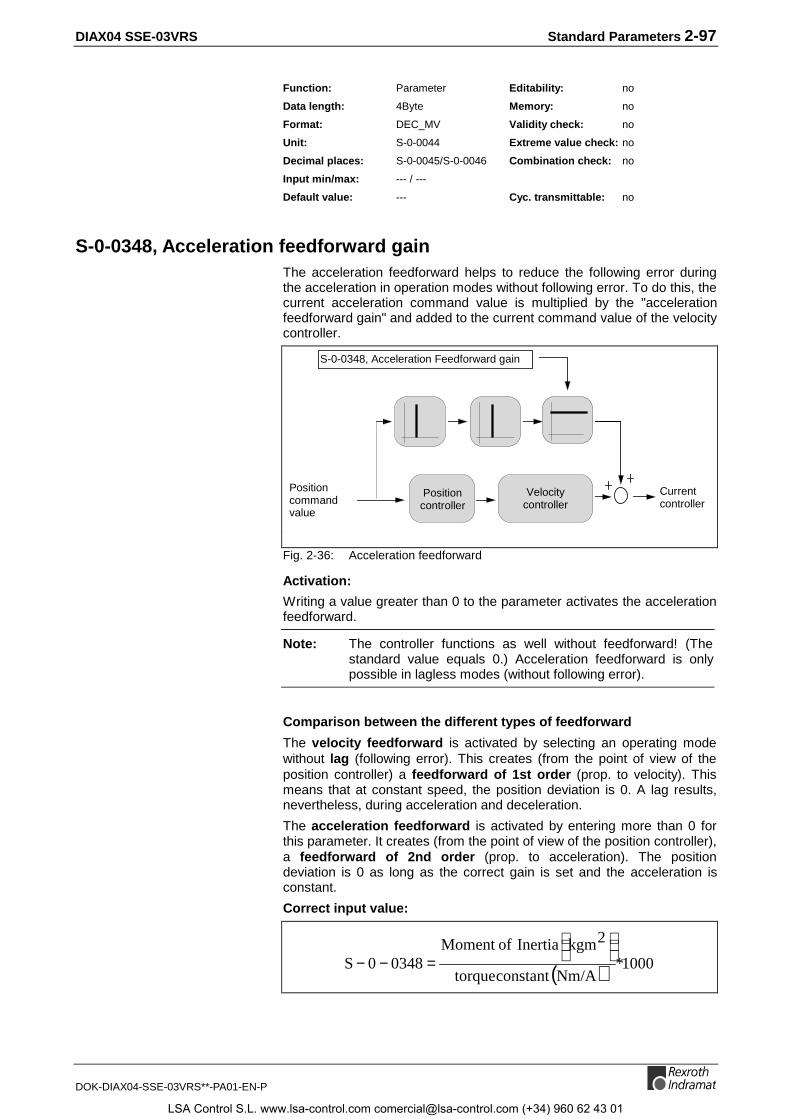
DIAX04 SSE-03VRS Standard Parameters 2-97
DOK-DIAX04-SSE-03VRS**-PA01-EN-P
Function: Parameter Editability: no
Data length: 4Byte Memory: no
Format: DEC_MV Validity check: no
Unit: S-0-0044 Extreme value check: no
Decimal places: S-0-0045/S-0-0046 Combination check: no
Input min/max: --- / ---
Default value: --- Cyc. transmittable: no
S-0-0348, Acceleration feedforward gainThe acceleration feedforward helps to reduce the following error duringthe acceleration in operation modes without following error. To do this, thecurrent acceleration command value is multiplied by the "accelerationfeedforward gain" and added to the current command value of the velocitycontroller.
Positioncommandvalue
Currentcontroller
S-0-0348, Acceleration Feedforward gain
Positioncontroller
Velocitycontroller
Fig. 2-36: Acceleration feedforward
Activation:
Writing a value greater than 0 to the parameter activates the accelerationfeedforward.
Note: The controller functions as well without feedforward! (Thestandard value equals 0.) Acceleration feedforward is onlypossible in lagless modes (without following error).
Comparison between the different types of feedforward
The velocity feedforward is activated by selecting an operating modewithout lag (following error). This creates (from the point of view of theposition controller) a feedforward of 1st order (prop. to velocity). Thismeans that at constant speed, the position deviation is 0. A lag results,nevertheless, during acceleration and deceleration.
The acceleration feedforward is activated by entering more than 0 forthis parameter. It creates (from the point of view of the position controller),a feedforward of 2nd order (prop. to acceleration). The positiondeviation is 0 as long as the correct gain is set and the acceleration isconstant.
Correct input value:
( ) 1000*Nm/Aconstanttorque
2kgmInertia ofMoment 03480S
=−−
LSA Control S.L. www.lsa-control.com [email protected] (+34) 960 62 43 01

2-98 Standard Parameters DIAX04 SSE-03VRS
DOK-DIAX04-SSE-03VRS**-PA01-EN-P
The moment of inertia is the total sum of the rotor and the reflected loadinertia.
The factor 1000 is needed for unit mA.Fig. 2-37: Acceleration feedforward prop. Gain
See also the functional description: " Setting the Acceleration FeedForward"
S-0-0348 - AttributesPara. Name: DE Verstärkung Beschleunigungsvorsteuerung
EN Acceleration feedforward gain
FR Anticipation d'accélération, gain
ES Ajuste mando adelante de aceleración
IT Guadagno Accellerazione
Function: Parameter Editability: P234
Data length: 2Byte Memory: Param. EE
Format: DEC_OV Validity check: Phase3
Unit: mA/(rad/s²) Extreme value check: yes
Decimal places: 1 Combination check: no
Input min/max: 0000.0 / 6553.5
Default value: 0 Cyc. transmittable: no
S-0-0349, Jerk limit bipolarThe Jerk limit bipolar limits the acceleration change per time during "DriveHalt"
See also the functional description: " Drive Halt"
S-0-0349 - AttributesPara. Name: DE Ruck-Grenzwert bipolar
EN Jerk limit bipolar
FR Limite de Jerk bipolaire
ES Límite sacudida bipolar
IT Limite di Jerk bipol.
Function: Parameter Editability: P234
Data length: 4Byte Memory: Param. EE
Format: DEC_OV Validity check: Phase3
Unit: S-0-0160 Extreme value check: yes
Decimal places: 1 Combination check: no
Input min/max: 0000000.000 / 4000000.000
Default value: 0 Cyc. transmittable: MDT
S-0-0359, Positioning Decelerationno function
S-0-0359 - AttributesPara. Name: DE Positionier-Verzögerung
EN Positioning Deceleration
FR Décélération de positionnement
IT Decellerazione Posizionamento
LSA Control S.L. www.lsa-control.com [email protected] (+34) 960 62 43 01
DIAX04 SSE-03VRS Standard Parameters 2-99
DOK-DIAX04-SSE-03VRS**-PA01-EN-P
Function: Parameter Editability: P234
Data length: 4Byte Memory: Param.-E²prom
Format: DEC_OV Validity check: P3-4
Unit: S-0-0160 Extreme value check: yes
Decimal places: S-0-0161, S-0-0162 Combination check: no
Input min/max: 0 / 1
Default value: 0 Cyc. transmittable: no
S-0-0360, MDT Data container AIn the parameter S-0-0360, MDT Data container A, the master transfersthe data of the target parameter which has been addressed via the"Addressing for data container A" parameters (S-0-0368 with S-0-0371).
If a target parameter with 2 byte data is addressed, only the low word ofS-0-0360, MDT Data container A is used.
To be able to use the data container, you must enter the parameterS-0-0360 into the list of cyclical data in parameter S-0-0024 during phase 2.
Note: The parameter S-0-0360 is not writeable via theasynchronous data channel.
See also the functional description: "Multiplex Channel".
S-0-0360 - AttributesPara. Name: DE MDT-Datencontainer A
EN MDT Data container A
FR Récipient de dates A pour MDT
ES Contenedor de datos A para MDT
IT Contenitore di Dati A per MDT
Function: Parameter Editability: P234
Data length: 4Byte Memory: no
Format: DEC_OV Validity check: no
Unit: -- Extreme value check: no
Decimal places: 0 Combination check: no
Input min/max: 0 / 2147483647
Default value: - Cyc. transmittable: MDT
S-0-0364, AT Data container AIn the parameter S-0-0364, AT Data container A, the drive copies thedata of the source parameter which has been addressed via the"Addressing for data container A" (S-0-0368 with S-0-0371).
If a source parameter with 2 byte data is addressed, only the low word iscopied into S-0-0364, AT Data container A.
To be able to use the data container, you must enter the parameterS-0-0364 into the list of cyclical data in parameter S-0-0016 during phase2.
Note: The parameter S-0-0364 is not writeable via theasynchronous data channel.
See also the functional description: "Multiplex Channel".
LSA Control S.L. www.lsa-control.com [email protected] (+34) 960 62 43 01

2-100 Standard Parameters DIAX04 SSE-03VRS
DOK-DIAX04-SSE-03VRS**-PA01-EN-P
S-0-0364 - AttributesPara. Name: DE AT-Datencontainer A
EN AT Data container A
FR Récipient de dates A pour AT
ES Contenedor de datos A para AT
IT Contenitore di Dati A per AT
Function: Parameter Editability: P234
Data length: 4Byte Memory: no
Format: DEC_OV Validity check: no
Unit: -- Extreme value check: no
Decimal places: - Combination check: no
Input min/max: 0 / 2147483647
Default value: - Cyc. transmittable: AT
S-0-0368, Addressing for data container AThe parameter S-0-0368, Addressing for data container A contains theindices for the access to the two parameter lists S-0-0370, Configurationlist MDT data container and S-0-0371, Configuration list AT-datacontainer. The content of the two data containers S-0-0360 and S-0-0364 is defined here.
Only the bits 0..7 (for MDT) and 8..15 (for AT) are used for theaddressing; the other bits are truncated.
Note: If an index greater than the number of elements in therespective list is set, the warning E4/08 Invalid AddressingMDT-data container A or, respectively, E4/09, InvalidAddressing AT-data container A is generated.
Note: The parameter S-0-0368, Addressing data container A canbe configured in the Master data telegram (MDT), or written tovia the asynchronous data channel or another interface, asneeded.
See also the functional description: "Multiplex Channel".
S-0-0368 - AttributesPara. Name: DE Adressierung Daten-Container A
EN Addressing for data container A
FR Index pour récipient de dates A
ES Dirección para contenedor de datos A
IT Indirizzo per Contenitore di Dati A
Function: Parameter Editability: P234
Data length: 2Byte Memory: no
Format: HEX Validity check: -
Unit: -- Extreme value check: yes
Decimal places: 0 Combination check: no
Input min/max: 0 / 32767
Default value: - Cyc. transmittable: MDT
LSA Control S.L. www.lsa-control.com [email protected] (+34) 960 62 43 01

DIAX04 SSE-03VRS Standard Parameters 2-101
DOK-DIAX04-SSE-03VRS**-PA01-EN-P
S-0-0370, Configuration list for MDT data containerIn the parameter S-0-0370, Configuration list MDT-data container,those ident numbers (IDN) are entered, which are transferred, dependingfrom the index in S-0-0368, Addressing for data container A, low byte,in the S-0-0360, MDT Data container A. Writing to S-0-0370 is onlypossible in communication phase 2.
In this procedure, the following checks are done :
• Check, whether the input IDN exists; if not, the async. channel errormessage "0x1001, Ident number nonexistent“ is generated.
• Check, whether the input IDN is present in the parameter S-0-0188,IDN list of configurable data in the MDT; if not, the async. channelerror message "0x7008, data not correct“ is generated.
Note: A maximum of 32 ident numbers is configurable in S-0-0370.
See also the functional description: "Multiplex Channel"
S-0-0370 - AttributesPara. Name: DE Konfigurationsliste MDT-Daten-Container
EN Configuration list for MDT data container
FR Liste de config. pour récipient de dates MDT
ES Lista de config. para contenedor de datos MDT
IT Config. per Recipiente di Dati MDT
Function: Parameter Editability: P234
Data length: 2Byte var. Memory: Param.-E²prom
Format: IDN Validity check: -
Unit: -- Extreme value check: -
Decimal places: 0 Combination check: -
Input min/max: 0 / -
Default value: - Cyc. transmittable: no
S-0-0371, Configuration list for the AT data containerIn the parameter S-0-0371, Configuration list AT-data container, thoseident numbers (IDN) are entered, which are transferred, depending fromthe index in S-0-0368, Addressing for data container A, high byte, inthe S-0-0364, AT Data container A. Writing to S-0-0371 is only possiblein communication phase 2.
In this procedure, the following checks are done :
• Check, whether the input IDN exists; if not, the async. channel errormessage "0x1001, Ident number nonexistent“ is generated.
• Check, whether the input IDN is present in the parameter S-0-0187,IDN list of configurable data in the AT; if not, the async. channelerror message "0x7008, data not correct“ is generated.
Note: A maximum of 32 ident numbers is configurable in S-0-0371.
See also the functional description: "Multiplex Channel"
LSA Control S.L. www.lsa-control.com [email protected] (+34) 960 62 43 01

2-102 Standard Parameters DIAX04 SSE-03VRS
DOK-DIAX04-SSE-03VRS**-PA01-EN-P
S-0-0371 - AttributesPara. Name: DE Konfigurationsliste AT-Daten-Container
EN Configuration list for the AT data container
FR Liste de config. pour le récipient de dates AT
ES Lista de config. para contenedor de datos AT
IT Config. per il Recipiente di Dati AT
Function: Parameter Editability: P234
Data length: 2Byte var. Memory: Param.-E²prom
Format: IDN Validity check: -
Unit: -- Extreme value check: -
Decimal places: 0 Combination check: -
Input min/max: - / -
Default value: - Cyc. transmittable: no
S-0-0375, List of diagnostic numbersThe drive enters every change of the parameter S-0-0390 Diagnosticnumber in this list. The list is organized as a circular buffer; there is placefor 50 numbers. When the list is read, the 1st element of the parametershows the last displayed diagnostic number.
See also the functional description: "List of diagnostic numbers"
S-0-0375 - AttributesPara. Name: DE Liste Diagnosenummern
EN List of diagnostic numbers
FR Liste des numéros de diagnostic
ES Lista de numeros de diagnostico
IT Lista di Numeri Diagnosi
Function: Parameter Editability: no
Data length: 2Byte var. Memory: no
Format: HEX Validity check: no
Unit: -- Extreme value check: no
Decimal places: 0 Combination check: no
Input min/max: - / -
Default value: - Cyc. transmittable: no
S-0-0378, Encoder 1, absolute rangeParameter S-0-0378 Absolute encoder 1, range defines the range inwhich the encoder selected in P-0-0074, Feedback type 1 can generatethe position information absolutely.
See also functional description: "Absolute encoder range and absoluteencoder evaluation"
S-0-0378 - AttributesPara. Name: DE Absolutbereich Geber 1
EN Encoder 1, absolute range
FR Codeur absolu 1, champs
ES Encoder absoluto 1, campo
IT Encoder assoluto 1, campo
LSA Control S.L. www.lsa-control.com [email protected] (+34) 960 62 43 01
DIAX04 SSE-03VRS Standard Parameters 2-103
DOK-DIAX04-SSE-03VRS**-PA01-EN-P
Function: Parameter Editability: no
Data length: 4Byte Memory: no
Format: DEC_OV Validity check: no
Unit: S-0-0076 Extreme value check: no
Decimal places: S-0-0077/S-0-0078 Combination check: no
Input min/max: --- / ---
Default value: --- Cyc. transmittable: no
S-0-0379, Encoder 2, absolute rangeParameter S-0-0379, Absolute encoder 2, range defines the range inwhich the encoder selected in P-0-0075, Feedback type 2 can generatethe position information absolutely.
See also functional description: "Absolute encoder range and absoluteencoder evaluation"
S-0-0379 - AttributesPara. Name: DE Absolutbereich Geber 2
EN Encoder 2, absolute range
FR Codeur absolu 2, champs
ES Encoder absoluto 2, campo
IT Encoder assoluto 2, campo
Function: Parameter Editability: no
Data length: 4Byte Memory: no
Format: DEC_OV Validity check: no
Unit: S-0-0076 Extreme value check: no
Decimal places: S-0-0077/S-0-0078 Combination check: no
Input min/max: --- / ---
Default value: --- Cyc. transmittable: no
S-0-0382, Intermediate bus powerDisplay of the DC-bus power in kW.
S-0-0382 - AttributesPara. Name: DE Zwischenkreisleistung
EN Intermediate bus power
FR Puissance circuit interméd.
ES Potencia de circuito intermedio
IT Potenza sul Bus DC
Function: Parameter Editability: no
Data length: 4Byte Memory: no
Format: DEC_MV Validity check: no
Unit: KW Extreme value check: no
Decimal places: 3 Combination check: no
Input min/max: --- / ---
Default value: --- Cyc. transmittable: AT
LSA Control S.L. www.lsa-control.com [email protected] (+34) 960 62 43 01

2-104 Standard Parameters DIAX04 SSE-03VRS
DOK-DIAX04-SSE-03VRS**-PA01-EN-P
S-0-0383, Motor temperatureThis parameter contains the measured motor temperature.
Remark:
For all Rexroth Indramat motors except 2AD motors, a PTC resistor isused as the temperature sensor .
As the temperature curve in this case shows a considerable tolerance andin higher temperature ranges a considerable progression, the value in S-0-0383, Motor temperature is not usable for these motor types.
See also the functional description: "Temperature Monitoring".
S-0-0383 - AttributesPara. Name: DE Motor-Temperatur
EN Motor temperature
FR Température moteur
ES Temperatura de motor
IT Temperatura Motore
Function: Parameter Editability: no
Data length: 2Byte Memory: no
Format: DEC_MV Validity check: no
Unit: C Extreme value check: no
Decimal places: 1 Combination check: no
Input min/max: --- / ---
Default value: --- Cyc. transmittable: no
S-0-0390, Diagnostic message numberIn the parameter Diagnostic message number, the same number isstored as can be seen in the seven segment display. This makes itpossible for the control to generate its own diagnostics according to thediagnostic message number (for example in languages which are notstored as diagnostics in the drive).
Example:
Diagnostic Message: "F822 Motor encoder failure: signal too small" inparameter S-0-0095
Seven Segment Display: changing "F8" <=> "22"
Diagnostic message number: "F822(hex)" in parameter S-0-0390
See also the functional description: "Diagnostic Message Number"
S-0-0390 - AttributesPara. Name: DE Diagnose-Nummer
EN Diagnostic message number
FR Numéro message diagnostique
ES Numero de diagnostico
IT Numero Messaggio Diagnosi
Function: Parameter Editability: no
Data length: 2Byte Memory: no
Format: HEX Validity check: no
Unit: -- Extreme value check: no
Decimal places: 0 Combination check: no
Input min/max: --- / ---
Default value: --- Cyc. transmittable: no
LSA Control S.L. www.lsa-control.com [email protected] (+34) 960 62 43 01
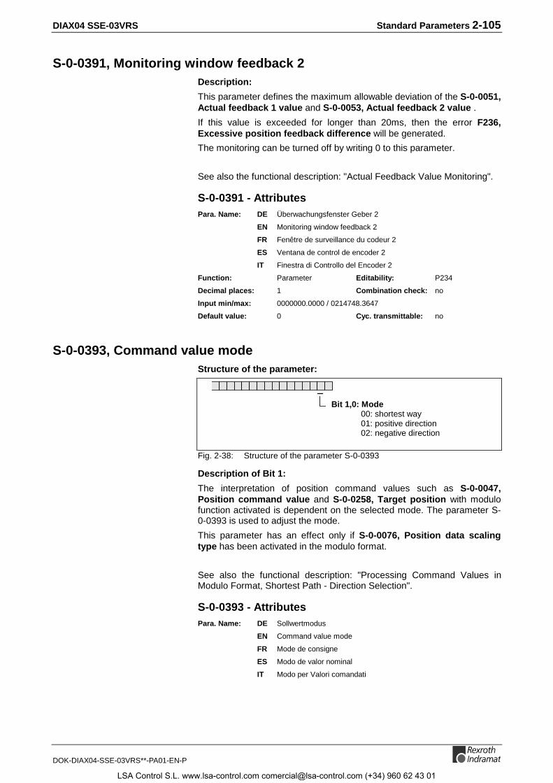
DIAX04 SSE-03VRS Standard Parameters 2-105
DOK-DIAX04-SSE-03VRS**-PA01-EN-P
S-0-0391, Monitoring window feedback 2Description:
This parameter defines the maximum allowable deviation of the S-0-0051,Actual feedback 1 value and S-0-0053, Actual feedback 2 value .
If this value is exceeded for longer than 20ms, then the error F236,Excessive position feedback difference will be generated.
The monitoring can be turned off by writing 0 to this parameter.
See also the functional description: "Actual Feedback Value Monitoring".
S-0-0391 - AttributesPara. Name: DE Überwachungsfenster Geber 2
EN Monitoring window feedback 2
FR Fenêtre de surveillance du codeur 2
ES Ventana de control de encoder 2
IT Finestra di Controllo del Encoder 2
Function: Parameter Editability: P234
Decimal places: 1 Combination check: no
Input min/max: 0000000.0000 / 0214748.3647
Default value: 0 Cyc. transmittable: no
S-0-0393, Command value modeStructure of the parameter:
Bit 1,0: Mode00: shortest way01: positive direction02: negative direction
Fig. 2-38: Structure of the parameter S-0-0393
Description of Bit 1:
The interpretation of position command values such as S-0-0047,Position command value and S-0-0258, Target position with modulofunction activated is dependent on the selected mode. The parameter S-0-0393 is used to adjust the mode.
This parameter has an effect only if S-0-0076, Position data scalingtype has been activated in the modulo format.
See also the functional description: "Processing Command Values inModulo Format, Shortest Path - Direction Selection".
S-0-0393 - AttributesPara. Name: DE Sollwertmodus
EN Command value mode
FR Mode de consigne
ES Modo de valor nominal
IT Modo per Valori comandati
LSA Control S.L. www.lsa-control.com [email protected] (+34) 960 62 43 01
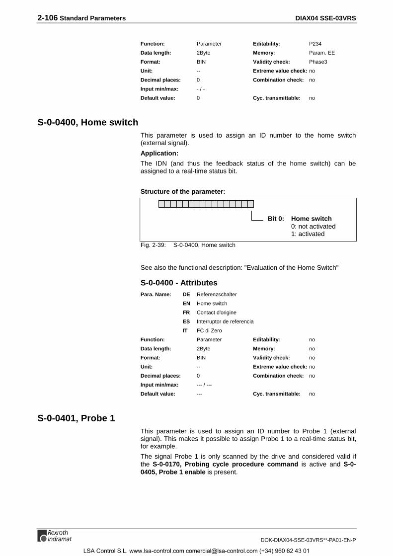
2-106 Standard Parameters DIAX04 SSE-03VRS
DOK-DIAX04-SSE-03VRS**-PA01-EN-P
Function: Parameter Editability: P234
Data length: 2Byte Memory: Param. EE
Format: BIN Validity check: Phase3
Unit: -- Extreme value check: no
Decimal places: 0 Combination check: no
Input min/max: - / -
Default value: 0 Cyc. transmittable: no
S-0-0400, Home switchThis parameter is used to assign an ID number to the home switch(external signal).
Application:
The IDN (and thus the feedback status of the home switch) can beassigned to a real-time status bit.
Structure of the parameter:
Bit 0: Home switch0: not activated1: activated
Fig. 2-39: S-0-0400, Home switch
See also the functional description: "Evaluation of the Home Switch"
S-0-0400 - AttributesPara. Name: DE Referenzschalter
EN Home switch
FR Contact d’origine
ES Interruptor de referencia
IT FC di Zero
Function: Parameter Editability: no
Data length: 2Byte Memory: no
Format: BIN Validity check: no
Unit: -- Extreme value check: no
Decimal places: 0 Combination check: no
Input min/max: --- / ---
Default value: --- Cyc. transmittable: no
S-0-0401, Probe 1This parameter is used to assign an ID number to Probe 1 (externalsignal). This makes it possible to assign Probe 1 to a real-time status bit,for example.
The signal Probe 1 is only scanned by the drive and considered valid ifthe S-0-0170, Probing cycle procedure command is active and S-0-0405, Probe 1 enable is present.
LSA Control S.L. www.lsa-control.com [email protected] (+34) 960 62 43 01

DIAX04 SSE-03VRS Standard Parameters 2-107
DOK-DIAX04-SSE-03VRS**-PA01-EN-P
Parameter structure:
Bit 0: Probe 0: not activated 1: activated
Fig. 2-40: S-0-0401, Probe 1
See also the functional description: "Probe Input Feature".
S-0-0401 - AttributesPara. Name: DE Messtaster 1
EN Probe 1
FR Sonde 1
ES Teclas de medición 1
IT Probe 1
Function: Parameter Editability: no
Data length: 2Byte Memory: no
Format: BIN Validity check: no
Unit: -- Extreme value check: no
Decimal places: 0 Combination check: no
Input min/max: --- / ---
Default value: --- Cyc. transmittable: no
S-0-0402, Probe 2This parameter is used to assign an ID number to Probe 2 (externalsignal). This makes it possible to assign Probe 2 to a real-time status bit,for example.
The signal Probe 2 is only scanned by the drive and considered valid ifthe S-0-0170, Probing cycle procedure command is active and S-0-0406, Probe 2 enable is present.
Parameter structure:
Bit 0 : Probe0: not activated1: activated
Fig. 2-41: S-0-0402, Probe 2
See also the functional description: "Probe Input Feature".
S-0-0402 - AttributesPara. Name: DE Messtaster 2
EN Probe 2
FR Sonde 2
ES Teclas de medición 2
IT Probe 2
LSA Control S.L. www.lsa-control.com [email protected] (+34) 960 62 43 01

2-108 Standard Parameters DIAX04 SSE-03VRS
DOK-DIAX04-SSE-03VRS**-PA01-EN-P
Function: Parameter Editability: no
Data length: 2Byte Memory: no
Format: BIN Validity check: no
Unit: -- Extreme value check: no
Decimal places: 0 Combination check: no
Input min/max: --- / ---
Default value: --- Cyc. transmittable: no
S-0-0403, Position feedback value statusBit 0 of this parameter will be set high when the position feedback value,as determined by bit 3 (motor or external feedback) of S-0-0147, Homingparameter, is fixed in reference to the machine’s zero point.
When the drive performs the commands S-0-0148, C600 Drivecontrolled homing procedure or P-0-0012, C300 Command ’Setabsolute measurement’, the bit will be reset when they are started andthen set to 1 again once the command has been successfully completed.
The bit for position feedback value status corresponds to the output signal"In reference".
In drives with Sercos interface, the position feedback value status can beassigned to a real-time status bit and thus be continuously communicatedto the NC in the drive status word
(see S-0-0305, Allocation of real-time status bit 1).
Structure of the parameter:
Bit 0 : Position feedback values0: are relative.1: are in reference to the machine’s
zero point.
Bit 0 : Position feedback values0: are relative.1: are in reference to the machine’s
zero point.
Bit 1 : Status motor feedback0: position feedback value is relativ1: referenced
Bit 2 : status feedback 20: position feedback value is relativ1: referenced
Fig. 2-42: S-0-0403, Position feedback value status
See also the functional description: " Drive-Controlled Homing".
S-0-0403 - AttributesPara. Name: DE Status Lageistwerte
EN Position feedback value status
FR Etat de la valeur de retour de position
ES Estado valores reales de posición
IT Stato del Feedback di Posizione
Function: Parameter Editability: no
Data length: 2Byte Memory: no
Format: BIN Validity check: no
Unit: -- Extreme value check: no
Decimal places: 0 Combination check: no
Input min/max: --- / ---
Default value: --- Cyc. transmittable: no
LSA Control S.L. www.lsa-control.com [email protected] (+34) 960 62 43 01
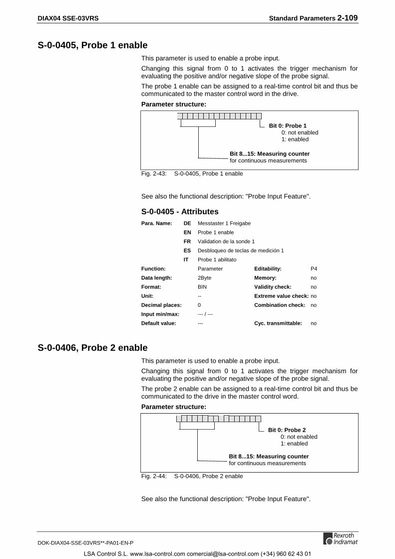
DIAX04 SSE-03VRS Standard Parameters 2-109
DOK-DIAX04-SSE-03VRS**-PA01-EN-P
S-0-0405, Probe 1 enableThis parameter is used to enable a probe input.
Changing this signal from 0 to 1 activates the trigger mechanism forevaluating the positive and/or negative slope of the probe signal.
The probe 1 enable can be assigned to a real-time control bit and thus becommunicated to the master control word in the drive.
Parameter structure:
Bit 0: Probe 10: not enabled1: enabled
Bit 8...15: Measuring counterfor continuous measurements
Fig. 2-43: S-0-0405, Probe 1 enable
See also the functional description: "Probe Input Feature".
S-0-0405 - AttributesPara. Name: DE Messtaster 1 Freigabe
EN Probe 1 enable
FR Validation de la sonde 1
ES Desbloqueo de teclas de medición 1
IT Probe 1 abilitato
Function: Parameter Editability: P4
Data length: 2Byte Memory: no
Format: BIN Validity check: no
Unit: -- Extreme value check: no
Decimal places: 0 Combination check: no
Input min/max: --- / ---
Default value: --- Cyc. transmittable: no
S-0-0406, Probe 2 enableThis parameter is used to enable a probe input.
Changing this signal from 0 to 1 activates the trigger mechanism forevaluating the positive and/or negative slope of the probe signal.
The probe 2 enable can be assigned to a real-time control bit and thus becommunicated to the drive in the master control word.
Parameter structure:
Bit 0: Probe 20: not enabled1: enabled
Bit 8...15: Measuring counterfor continuous measurements
Fig. 2-44: S-0-0406, Probe 2 enable
See also the functional description: "Probe Input Feature".
LSA Control S.L. www.lsa-control.com [email protected] (+34) 960 62 43 01
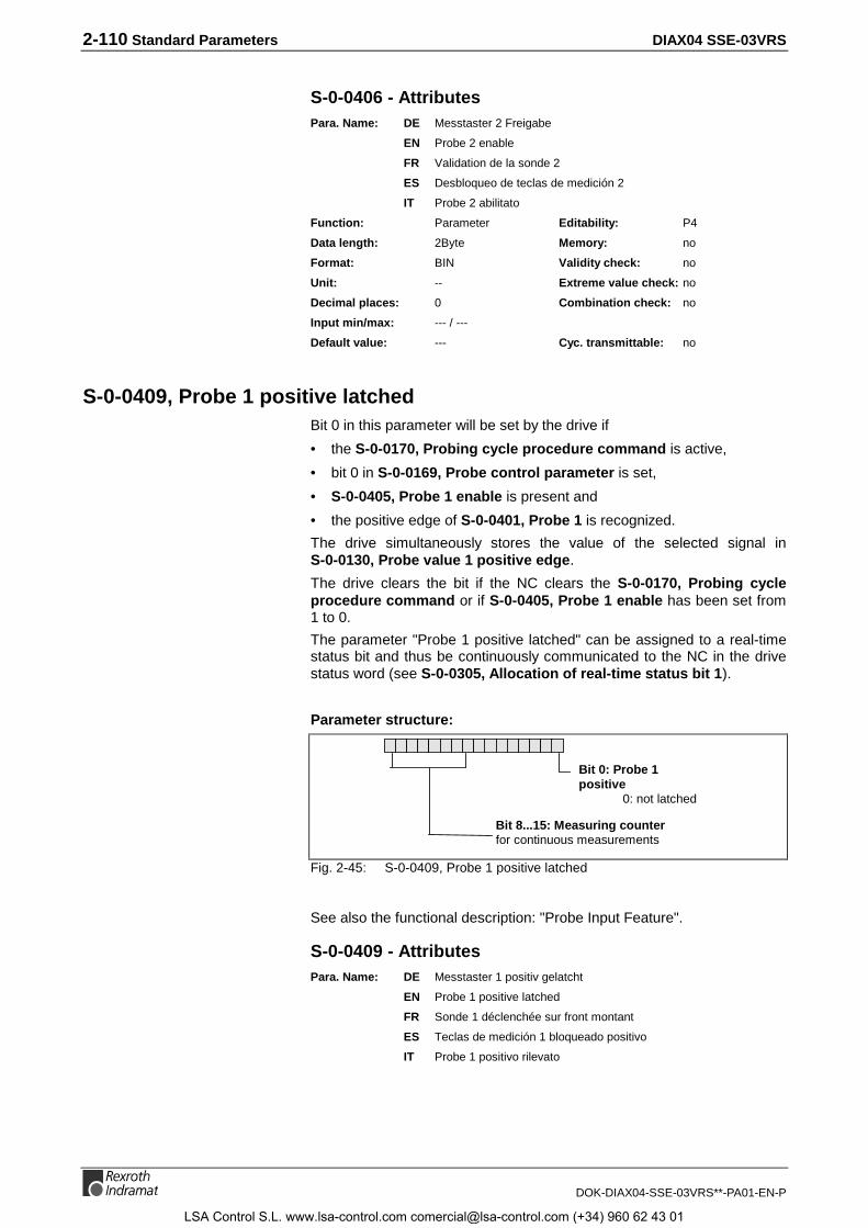
2-110 Standard Parameters DIAX04 SSE-03VRS
DOK-DIAX04-SSE-03VRS**-PA01-EN-P
S-0-0406 - AttributesPara. Name: DE Messtaster 2 Freigabe
EN Probe 2 enable
FR Validation de la sonde 2
ES Desbloqueo de teclas de medición 2
IT Probe 2 abilitato
Function: Parameter Editability: P4
Data length: 2Byte Memory: no
Format: BIN Validity check: no
Unit: -- Extreme value check: no
Decimal places: 0 Combination check: no
Input min/max: --- / ---
Default value: --- Cyc. transmittable: no
S-0-0409, Probe 1 positive latchedBit 0 in this parameter will be set by the drive if
• the S-0-0170, Probing cycle procedure command is active,
• bit 0 in S-0-0169, Probe control parameter is set,
• S-0-0405, Probe 1 enable is present and
• the positive edge of S-0-0401, Probe 1 is recognized.
The drive simultaneously stores the value of the selected signal inS-0-0130, Probe value 1 positive edge.
The drive clears the bit if the NC clears the S-0-0170, Probing cycleprocedure command or if S-0-0405, Probe 1 enable has been set from1 to 0.
The parameter "Probe 1 positive latched" can be assigned to a real-timestatus bit and thus be continuously communicated to the NC in the drivestatus word (see S-0-0305, Allocation of real-time status bit 1).
Parameter structure:
Bit 0: Probe 1positive
0: not latched
Bit 8...15: Measuring counterfor continuous measurements
Fig. 2-45: S-0-0409, Probe 1 positive latched
See also the functional description: "Probe Input Feature".
S-0-0409 - AttributesPara. Name: DE Messtaster 1 positiv gelatcht
EN Probe 1 positive latched
FR Sonde 1 déclenchée sur front montant
ES Teclas de medición 1 bloqueado positivo
IT Probe 1 positivo rilevato
LSA Control S.L. www.lsa-control.com [email protected] (+34) 960 62 43 01

DIAX04 SSE-03VRS Standard Parameters 2-111
DOK-DIAX04-SSE-03VRS**-PA01-EN-P
Function: Parameter Editability: no
Data length: 2Byte Memory: no
Format: BIN Validity check: no
Unit: -- Extreme value check: no
Decimal places: 0 Combination check: no
Input min/max: --- / ---
Default value: --- Cyc. transmittable: no
S-0-0410, Probe 1 negative latchedBit 0 in this parameter will be set by the drive if
• the S-0-0170, Probing cycle procedure command is active,
• bit 1 in S-0-0169, Probe control parameter is set,
• S-0-0405, Probe 1 enable is present and
• the negative edge of S-0-0401, Probe 1 is recognized.
The drive simultaneously stores the value of the selected signal in S-0-0131, Probe value 1 negative edge.
The drive clears the bit if the NC clears the S-0-0170, Probing cycleprocedure command or if S-0-0405, Probe 1 enable has been set from1 to 0.
The parameter "probe 1 negative latched" can be assigned to a real-timestatus bit and thus be continuously communicated to the NC in the drivestatus word (see S-0-0305, Allocation of real-time status bit 1).
Parameter structure:
Bit 0: Probe 1 negative0: not latched1: latched
Bit 8...15: Measuring counterfor continuous measurements
Fig. 2-46: S-0-0410, Probe 1 negative latched
See also the functional description: "Probe Input Feature"
S-0-0410 - AttributesPara. Name: DE Messtaster 1 negativ gelatcht
EN Probe 1 negative latched
FR Sonde 1 déclenchée sur front descendant
ES Teclas de medición 1 bloqueado negativo
IT Probe 1 negativo rilevato
Function: Parameter Editability: no
Data length: 2Byte Memory: no
Format: BIN Validity check: no
Unit: -- Extreme value check: no
Decimal places: 0 Combination check: no
Input min/max: --- / ---
Default value: --- Cyc. transmittable: no
LSA Control S.L. www.lsa-control.com [email protected] (+34) 960 62 43 01
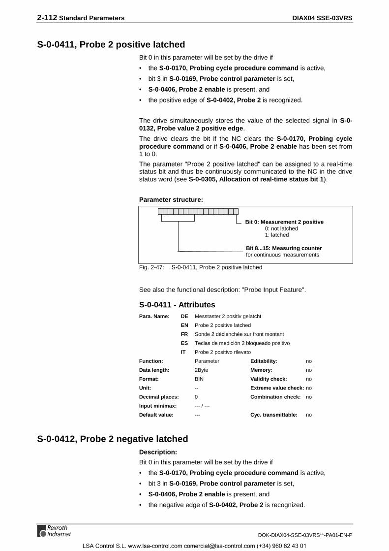
2-112 Standard Parameters DIAX04 SSE-03VRS
DOK-DIAX04-SSE-03VRS**-PA01-EN-P
S-0-0411, Probe 2 positive latchedBit 0 in this parameter will be set by the drive if
• the S-0-0170, Probing cycle procedure command is active,
• bit 3 in S-0-0169, Probe control parameter is set,
• S-0-0406, Probe 2 enable is present, and
• the positive edge of S-0-0402, Probe 2 is recognized.
The drive simultaneously stores the value of the selected signal in S-0-0132, Probe value 2 positive edge.
The drive clears the bit if the NC clears the S-0-0170, Probing cycleprocedure command or if S-0-0406, Probe 2 enable has been set from1 to 0.
The parameter "Probe 2 positive latched" can be assigned to a real-timestatus bit and thus be continuously communicated to the NC in the drivestatus word (see S-0-0305, Allocation of real-time status bit 1).
Parameter structure:
Bit 0: Measurement 2 positive0: not latched1: latched
Bit 8...15: Measuring counterfor continuous measurements
Fig. 2-47: S-0-0411, Probe 2 positive latched
See also the functional description: "Probe Input Feature".
S-0-0411 - AttributesPara. Name: DE Messtaster 2 positiv gelatcht
EN Probe 2 positive latched
FR Sonde 2 déclenchée sur front montant
ES Teclas de medición 2 bloqueado positivo
IT Probe 2 positivo rilevato
Function: Parameter Editability: no
Data length: 2Byte Memory: no
Format: BIN Validity check: no
Unit: -- Extreme value check: no
Decimal places: 0 Combination check: no
Input min/max: --- / ---
Default value: --- Cyc. transmittable: no
S-0-0412, Probe 2 negative latchedDescription:
Bit 0 in this parameter will be set by the drive if
• the S-0-0170, Probing cycle procedure command is active,
• bit 3 in S-0-0169, Probe control parameter is set,
• S-0-0406, Probe 2 enable is present, and
• the negative edge of S-0-0402, Probe 2 is recognized.
LSA Control S.L. www.lsa-control.com [email protected] (+34) 960 62 43 01
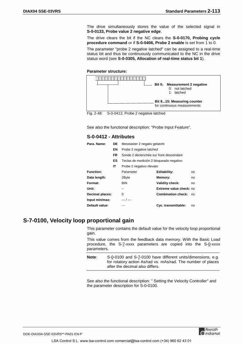
DIAX04 SSE-03VRS Standard Parameters 2-113
DOK-DIAX04-SSE-03VRS**-PA01-EN-P
The drive simultaneously stores the value of the selected signal inS-0-0133, Probe value 2 negative edge.
The drive clears the bit if the NC clears the S-0-0170, Probing cycleprocedure command or if S-0-0406, Probe 2 enable is set from 1 to 0.
The parameter "probe 2 negative latched" can be assigned to a real-timestatus bit and thus be continuously communicated to the NC in the drivestatus word (see S-0-0305, Allocation of real-time status bit 1).
Parameter structure:
Bit 0; Measurement 2 negative 0: not latched 1: latched
Bit 8...15: Measuring counterfor continuous measurements
Fig. 2-48: S-0-0412, Probe 2 negative latched
See also the functional description: "Probe Input Feature".
S-0-0412 - AttributesPara. Name: DE Messtaster 2 negativ gelatcht
EN Probe 2 negative latched
FR Sonde 2 déclenchée sur front descendant
ES Teclas de medición 2 bloqueado negativo
IT Probe 2 negativo rilevato
Function: Parameter Editability: no
Data length: 2Byte Memory: no
Format: BIN Validity check: no
Unit: -- Extreme value check: no
Decimal places: 0 Combination check: no
Input min/max: --- / ---
Default value: --- Cyc. transmittable: no
S-7-0100, Velocity loop proportional gainThis parameter contains the default value for the velocity loop proportionalgain.
This value comes from the feedback data memory. With the Basic Loadprocedure, the S-7-xxxx parameters are copied into the S-0-xxxxparameters.
Note: S-0-0100 and S-7-0100 have different units/dimensions, e.g.for rotatory action As/rad vs. mAs/rad. The number of placesafter the decimal also differs.
See also the functional description: " Setting the Velocity Controller" andthe parameter description for S-0-0100.
LSA Control S.L. www.lsa-control.com [email protected] (+34) 960 62 43 01

2-114 Standard Parameters DIAX04 SSE-03VRS
DOK-DIAX04-SSE-03VRS**-PA01-EN-P
S-7-0100 - AttributesPara. Name: DE Geschwindigkeitsregler-Proportionalverstärkung
EN Velocity loop proportional gain
FR Gain proportionnel de la boucle de vitesse
ES Amplificación proporcional de regulador de velocidad
IT Guadagno proporzionale Anello di Velocità
Function: Parameter Editability: no
Data length: 2Byte Memory: Feedback-E²prom
Format: DEC_OV Validity check: Phase3
Unit: mAs/rad Extreme value check: yes
Decimal places: 0 Combination check: no
Input min/max: 0 / 65535
Default value: - Cyc. transmittable: no
S-7-0101, Velocity loop integral action timeThis parameter contains the default value for the integral action time ofthe integrator in the velocity loop controller.
This value comes from the feedback data memory. With the Basic Loadprocedure, the S-7-xxxx parameters are copied into the S-0-xxxxparameters.
See also the functional description: " Setting the Velocity Controller" andthe parameter description for S-0-0101.
S-7-0101 - AttributesPara. Name: DE Geschwindigkeitsregler-Nachstellzeit
EN Velocity loop integral action time
FR Temps d'action intégral de la boucle de vitesse
ES Tiempo de reajuste de regulador de velocidad
IT Tempo Integrazione Anello di Velocità
Function: Parameter Editability: no
Data length: 2Byte Memory: Feedback-E²prom
Format: DEC_OV Validity check: Phase3
Unit: ms Extreme value check: yes
Decimal places: 1 Combination check: no
Input min/max: 0.0 / 6553.5
Default value: - Cyc. transmittable: no
S-7-0104, Position loop Kv-factorThis parameter contains the default value for the proportional gain of theposition controller.
This value comes from the feedback data memory. With the Basic Loadprocedure, the S-7-xxxx parameters are copied into the S-0-xxxxparameters.
See also the functional description: " Setting the position controller" andthe parameter description for S-0-0104.
LSA Control S.L. www.lsa-control.com [email protected] (+34) 960 62 43 01

DIAX04 SSE-03VRS Standard Parameters 2-115
DOK-DIAX04-SSE-03VRS**-PA01-EN-P
S-7-0104 - AttributesPara. Name: DE Lageregler Kv-Faktor
EN Position loop Kv-factor
FR Gain proportionnel de la boucle de position, Kv
ES Regulador de posición factor Kv
IT Fattore Kv Anello di Posizione
Function: Parameter Editability: no
Data length: 2Byte Memory: Feedback-E²prom
Format: DEC_OV Validity check: Phase3
Unit: 1000/min Extreme value check: yes
Decimal places: 2 Combination check: no
Input min/max: 0.00 / 655.35
Default value: - Cyc. transmittable: no
S-7-0106, Current loop proportional gain 1This parameter contains the appropriate value for the proportional gain ofthe current controller with the connected motor.
This value comes from the feedback data memory. With the Basic Loadprocedure, the S-7-xxxx parameters are copied into the S-0-xxxxparameters.
Note: Do not alter the values for the current controller set at thefactory.
See also function description: " Setting the Current Controller" and theparameter description for S-0-0106.
S-7-0106 - AttributesPara. Name: DE Stromregler-Proportionalverstärkung 1
EN Current loop proportional gain 1
FR Gain proportionnel de la boucle de courant 1
ES Amplificación proporcional 1 regulador de corriente
IT Guadagno proporzionale 1 Regolatore di Corrente
Function: Parameter Editability: no
Data length: 4Byte Memory: Feedback-E²prom
Format: DEC_OV Validity check: Phase3
Unit: V/A Extreme value check: yes
Decimal places: 2 Combination check: no
Input min/max: 0.00 / 655.35
Default value: - Cyc. transmittable: no
S-7-0107, Current loop integral action time 1This parameter contains the appropriate value for the integral action timeof the integrator in the current controller with the connected motor.
This value comes from the feedback data memory. With the Basic Loadprocedure, the S-7-xxxx parameters are copied into the S-0-xxxxparameters.
Note: Do not alter the values for the current controller set at thefactory.
LSA Control S.L. www.lsa-control.com [email protected] (+34) 960 62 43 01

2-116 Standard Parameters DIAX04 SSE-03VRS
DOK-DIAX04-SSE-03VRS**-PA01-EN-P
See also function description: " Setting the Current Controller" and theparameter description for S-0-0107.
S-7-0107 - AttributesPara. Name: DE Stromregler-Nachstellzeit 1
EN Current loop integral action time 1
FR Temps d'action intégral de la boucle de courant 1
ES Tiempo de reajuste de regulador de corriente 1
IT Tempo Integrazione 1 Anello di Corrente
Function: Parameter Editability: no
Data length: 2Byte Memory: Feedback-E²prom
Format: DEC_OV Validity check: Phase3
Unit: ms Extreme value check: yes
Decimal places: 1 Combination check: no
Input min/max: 0.0 / 6553.5
Default value: - Cyc. transmittable: no
S-7-0109, Motor peak currentValue in the feedback memory which specifies the maximum currentwhich may flow in the motor for a short period without damaging it.
For MHD, MKD and MKE motors, the value will be copied into the activeparameter S-0-0109, Motor peak current when the amplifier is turnedon.
See also the functional description: "Current Limit"
S-7-0109 - AttributesPara. Name: DE Spitzenstrom Motor
EN Motor peak current
FR Courant crête du moteur
ES Corriente punta de motor
IT Corrente di Picco Motore
Function: Parameter Editability: no
Data length: 4Byte Memory: Feedback-E²prom
Format: DEC_OV Validity check: no
Unit: A Extreme value check: no
Decimal places: 3 Combination check: no
Input min/max: 0 / 2147483647
Default value: - Cyc. transmittable: no
S-7-0111, Motor current at standstillValue in the feedback memory for the current which can continuously flowin the motor without damaging it.
For MHD, MKD and MKE motors, the value will be copied into the activeparameter S-0-0111, Motor current at standstill when the amplifier isturned on.
See also the functional description: "Motor Feedback-Data Memory"
LSA Control S.L. www.lsa-control.com [email protected] (+34) 960 62 43 01
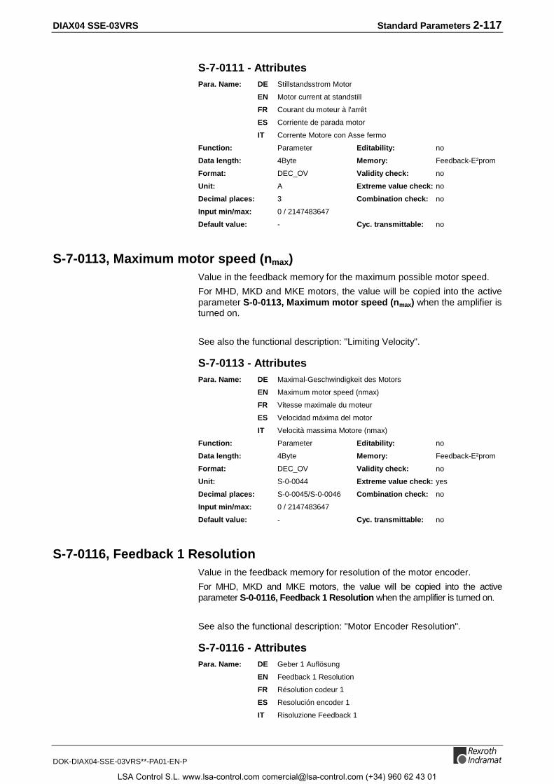
DIAX04 SSE-03VRS Standard Parameters 2-117
DOK-DIAX04-SSE-03VRS**-PA01-EN-P
S-7-0111 - AttributesPara. Name: DE Stillstandsstrom Motor
EN Motor current at standstill
FR Courant du moteur à l'arrêt
ES Corriente de parada motor
IT Corrente Motore con Asse fermo
Function: Parameter Editability: no
Data length: 4Byte Memory: Feedback-E²prom
Format: DEC_OV Validity check: no
Unit: A Extreme value check: no
Decimal places: 3 Combination check: no
Input min/max: 0 / 2147483647
Default value: - Cyc. transmittable: no
S-7-0113, Maximum motor speed (nmax)Value in the feedback memory for the maximum possible motor speed.
For MHD, MKD and MKE motors, the value will be copied into the activeparameter S-0-0113, Maximum motor speed (nmax) when the amplifier isturned on.
See also the functional description: "Limiting Velocity".
S-7-0113 - AttributesPara. Name: DE Maximal-Geschwindigkeit des Motors
EN Maximum motor speed (nmax)
FR Vitesse maximale du moteur
ES Velocidad máxima del motor
IT Velocità massima Motore (nmax)
Function: Parameter Editability: no
Data length: 4Byte Memory: Feedback-E²prom
Format: DEC_OV Validity check: no
Unit: S-0-0044 Extreme value check: yes
Decimal places: S-0-0045/S-0-0046 Combination check: no
Input min/max: 0 / 2147483647
Default value: - Cyc. transmittable: no
S-7-0116, Feedback 1 ResolutionValue in the feedback memory for resolution of the motor encoder.
For MHD, MKD and MKE motors, the value will be copied into the activeparameter S-0-0116, Feedback 1 Resolution when the amplifier is turned on.
See also the functional description: "Motor Encoder Resolution".
S-7-0116 - AttributesPara. Name: DE Geber 1 Auflösung
EN Feedback 1 Resolution
FR Résolution codeur 1
ES Resolución encoder 1
IT Risoluzione Feedback 1
LSA Control S.L. www.lsa-control.com [email protected] (+34) 960 62 43 01

2-118 Standard Parameters DIAX04 SSE-03VRS
DOK-DIAX04-SSE-03VRS**-PA01-EN-P
Function: Parameter Editability: no
Data length: 4Byte Memory: Feedback-E²prom
Format: DEC_OV Validity check: no
Unit: Cycles/Rev Extreme value check: no
Decimal places: 0 Combination check: no
Input min/max: 0 / 2147483647
Default value: - Cyc. transmittable: no
S-7-0117, Feedback 2 ResolutionValue in the feedback memory for resolution of the motor encoder.
The value will be copied into the active parameter S-0-0117, Feedback 2Resolution when the amplifier is turned on.
See also the functional description: "Motor Encoder Resolution".
S-7-0117 - AttributesPara. Name: DE Geber 2 Auflösung
EN Feedback 2 Resolution
FR Résolution codeur 2
ES Resolución encoder 2
IT Risoluzione Feedback 2
Function: Parameter Editability: no
Data length: 4Byte Memory: Feedback-E²prom
Format: DEC_OV Validity check: no
Unit: Cycles/Rev Extreme value check: no
Decimal places: 0 Combination check: no
Input min/max: 1 / 65536
Default value: - Cyc. transmittable: no
S-7-0141, Motor typeText in the feedback memory for the motor type.
For MHD, MKD and MKE motors, the value will be copied into the activeparameter S-0-0141, Motor type when the amplifier is turned on.
The diagnostic message „F208 UL motor type has changed“ is based ona comparison between S-0-0141 and S-7-0141.
Examples:
MKD 071B-061-KP1-BN
MKE 096B-047-GG0-KN
See also the functional description: "Drive Controllers".
S-7-0141 - AttributesPara. Name: DE Motor-Typ
EN Motor type
FR Type de moteur
ES Tipo de motor
IT Tipo Motore
LSA Control S.L. www.lsa-control.com [email protected] (+34) 960 62 43 01

DIAX04 SSE-03VRS Standard Parameters 2-119
DOK-DIAX04-SSE-03VRS**-PA01-EN-P
Function: Parameter Editability: no
Data length: 1Byte var. Memory: Feedback-E²prom
Format: ASCII Validity check: no
Unit: -- Extreme value check: no
Decimal places: - Combination check: no
Input min/max: - / -
Default value: - Cyc. transmittable: no
S-7-0177, Absolute distance 1This parameter is used for the homing procedure of an absolute motorfeedback. It describes the offset between the zero point of the motorfeedback and the machine’s zero-point.
S-7-0177 - AttributesPara. Name: DE Absolutgeber-Offset 1
EN Absolute distance 1
FR Décalage absolu 1
ES Distancia absoluta 1
IT Offset 1 per Dimensionamenti assoluti (Feedback Motore)
Function: Parameter Editability: P23
Data length: 4Byte Memory: Feedback-E²prom
Format: DEC_MV Validity check: no
Decimal places: - Combination check: no
Input min/max: 0 / 2147483647
Default value: - Cyc. transmittable: no
S-7-0178, Absolute distance 2This parameter is used for the homing procedure of an absolute optionalfeedback. It describes the offset between the zero point of the optionalfeedback and the machine’s zero-point.
S-7-0178 - AttributesPara. Name: DE Absolutgeber-Offset 2
EN Absolute distance 2
FR Décalage absolu 2
ES Distancia absoluta 2
IT Offset 2 per Dimensionamenti assoluti (Feedback Motore)
Function: Parameter Editability: P23
Data length: 4Byte Memory: Feedback-E²prom
Format: DEC_MV Validity check: no
Decimal places: - Combination check: no
Input min/max: 0 / 2147483647
Default value: - Cyc. transmittable: no
LSA Control S.L. www.lsa-control.com [email protected] (+34) 960 62 43 01

2-120 Standard Parameters DIAX04 SSE-03VRS
DOK-DIAX04-SSE-03VRS**-PA01-EN-P
Notes
LSA Control S.L. www.lsa-control.com [email protected] (+34) 960 62 43 01
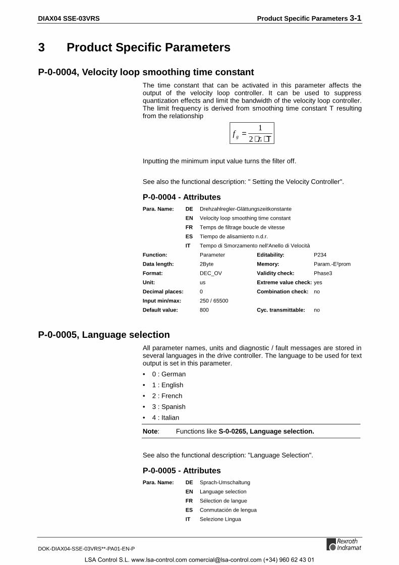
DIAX04 SSE-03VRS Product Specific Parameters 3-1
DOK-DIAX04-SSE-03VRS**-PA01-EN-P
3 Product Specific Parameters
P-0-0004, Velocity loop smoothing time constantThe time constant that can be activated in this parameter affects theoutput of the velocity loop controller. It can be used to suppressquantization effects and limit the bandwidth of the velocity loop controller.The limit frequency is derived from smoothing time constant T resultingfrom the relationship
f g =⋅ ⋅
1
2 π Τ
Inputting the minimum input value turns the filter off.
See also the functional description: " Setting the Velocity Controller".
P-0-0004 - AttributesPara. Name: DE Drehzahlregler-Glättungszeitkonstante
EN Velocity loop smoothing time constant
FR Temps de filtrage boucle de vitesse
ES Tiempo de alisamiento n.d.r.
IT Tempo di Smorzamento nell'Anello di Velocità
Function: Parameter Editability: P234
Data length: 2Byte Memory: Param.-E²prom
Format: DEC_OV Validity check: Phase3
Unit: us Extreme value check: yes
Decimal places: 0 Combination check: no
Input min/max: 250 / 65500
Default value: 800 Cyc. transmittable: no
P-0-0005, Language selectionAll parameter names, units and diagnostic / fault messages are stored inseveral languages in the drive controller. The language to be used for textoutput is set in this parameter.
• 0 : German
• 1 : English
• 2 : French
• 3 : Spanish
• 4 : Italian
Note: Functions like S-0-0265, Language selection.
See also the functional description: "Language Selection".
P-0-0005 - AttributesPara. Name: DE Sprach-Umschaltung
EN Language selection
FR Sélection de langue
ES Conmutación de lengua
IT Selezione Lingua
LSA Control S.L. www.lsa-control.com [email protected] (+34) 960 62 43 01

3-2 Product Specific Parameters DIAX04 SSE-03VRS
DOK-DIAX04-SSE-03VRS**-PA01-EN-P
Function: Parameter Editability: P234
Data length: 2Byte Memory: Param. EE
Format: DEC_OV Validity check: no
Unit: -- Extreme value check: no
Decimal places: 0 Combination check: no
Input min/max: 00000 / 00001
Default value: --- Cyc. transmittable: no
P-0-0008, Activation E-Stop functionParameter P-0-0008 can be used to activate the E-Stop input and toselect a response for bringing the drive to standstill.
Parameter structure:
Bit 0: E-Stop activation0: inactive1: active
Bit 1: Error class in case ofinterpretation as error (bit 2 = 0)0: Best possible standstill (P-0-0119)1: Set velocity command value to zero
Bit 2: Interpretation0: as non-fatal error1: as fatal warning
Fig. 3-1:: P-0-0008, Activation of E-Stop function
Note: The input polarity is always 0-active.
Note: For DIAX devices, bit 0 also activates the monitoring of theexternal 24V supply.
See also the functional description: "Activation and Polarity of the E-StopInput".
P-0-0008 - AttributesPara. Name: DE Aktivierung E-Stop-Funktion
EN Activation E-Stop function
FR Activation fonction Arrêt d'urgence
ES Activación función parada de emergencia
IT Attivazione della Funzione E-Stop
Function: Parameter Editability: P23
Data length: 2Byte Memory: Param. EE
Format: BIN Validity check: Phase3
Unit: -- Extreme value check: no
Decimal places: 0 Combination check: yes
Input min/max: --- / ---
Default value: 0 Cyc. transmittable: no
LSA Control S.L. www.lsa-control.com [email protected] (+34) 960 62 43 01
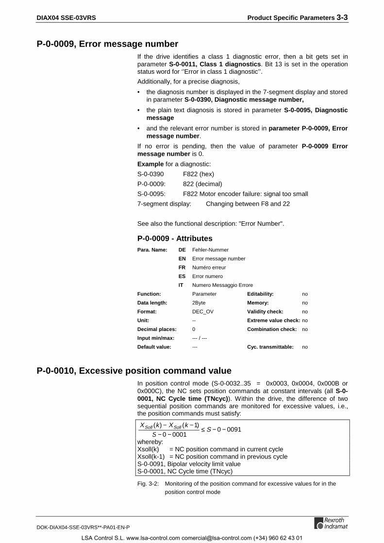
DIAX04 SSE-03VRS Product Specific Parameters 3-3
DOK-DIAX04-SSE-03VRS**-PA01-EN-P
P-0-0009, Error message numberIf the drive identifies a class 1 diagnostic error, then a bit gets set inparameter S-0-0011, Class 1 diagnostics. Bit 13 is set in the operationstatus word for ‘’Error in class 1 diagnostic’’.
Additionally, for a precise diagnosis,
• the diagnosis number is displayed in the 7-segment display and storedin parameter S-0-0390, Diagnostic message number,
• the plain text diagnosis is stored in parameter S-0-0095, Diagnosticmessage
• and the relevant error number is stored in parameter P-0-0009, Errormessage number.
If no error is pending, then the value of parameter P-0-0009 Errormessage number is 0.
Example for a diagnostic:
S-0-0390 F822 (hex)
P-0-0009: 822 (decimal)
S-0-0095: F822 Motor encoder failure: signal too small
7-segment display: Changing between F8 and 22
See also the functional description: "Error Number".
P-0-0009 - AttributesPara. Name: DE Fehler-Nummer
EN Error message number
FR Numéro erreur
ES Error numero
IT Numero Messaggio Errore
Function: Parameter Editability: no
Data length: 2Byte Memory: no
Format: DEC_OV Validity check: no
Unit: -- Extreme value check: no
Decimal places: 0 Combination check: no
Input min/max: --- / ---
Default value: --- Cyc. transmittable: no
P-0-0010, Excessive position command valueIn position control mode (S-0-0032..35 = 0x0003, 0x0004, 0x000B or0x000C), the NC sets position commands at constant intervals (all S-0-0001, NC Cycle time (TNcyc)). Within the drive, the difference of twosequential position commands are monitored for excessive values, i.e.,the position commands must satisfy:
0091000010
)1()(−−≤
−−−−
SS
kXkX SollSoll
whereby:Xsoll(k) = NC position command in current cycleXsoll(k-1) = NC position command in previous cycleS-0-0091, Bipolar velocity limit valueS-0-0001, NC Cycle time (TNcyc)
Fig. 3-2: Monitoring of the position command for excessive values for in theposition control mode
LSA Control S.L. www.lsa-control.com [email protected] (+34) 960 62 43 01

3-4 Product Specific Parameters DIAX04 SSE-03VRS
DOK-DIAX04-SSE-03VRS**-PA01-EN-P
If the above condition is violated, then error F237, Excessive positioncommand difference is triggered and the drive decelerates as set inparameter P-0-0119, Best possible deceleration.
The error triggering excessive position command value (Xsoll(k)) is storedin parameter P-0-0010, Excessive position command value, the lastvalid position command (Xsoll(k-1)) in parameter P-0-0011, Last validposition command value.
See also the functional description: "Position Command ValueMonitoring".
P-0-0010 - AttributesPara. Name: DE Exzessiver Lagesollwert
EN Excessive position command value
FR Consigne de position excessive
ES Valor nominal de posición excesivo
IT Posizione comandata eccessiva
Function: Parameter Editability: no
Data length: 4Byte Memory: no
Format: DEC_MV Validity check: no
Unit: S-0-0076 Extreme value check: no
Decimal places: S-0-0077/S-0-0078 Combination check: no
Input min/max: --- / ---
Default value: --- Cyc. transmittable: no
P-0-0011, Last valid position command valueIn position control mode (S-0-0032..35 = 0x0003, 0x0004, 0x000B or0x000C), the NC sets position commands at constant intervals (everyS-0-0001, NC Cycle time TNcyc). The difference of two sequentialposition commands is monitored for excessive value. The positioncommand values must satisfy the following relation:
0091000010
)1()(−−≤
−−−−
SS
kXkX ComCom
whereby:Xcom(k) = NC-position command in current cycleXcom(k-1) = NC-position command in previous cycleS-0-0091, Bipolar velocity limit valueS-0-0001, NC Cycle time (TNcyc)
Fig. 3-3: Monitoring of the position command for excessive values in theposition control mode
If the above condition is violated, then error F237, Excessive positioncommand difference is triggered, and the drive decelerates as set inparameter P-0-0119, Best possible declaration.
The error triggering excessive position command value Xcom(k) is storedin parameter P-0-0010, Excessive position command value, the lastvalid position command Xcom(k-1) in parameter P-0-0011, Last validposition command value.
See also the functional description: "Position Command ValueMonitoring".
LSA Control S.L. www.lsa-control.com [email protected] (+34) 960 62 43 01
DIAX04 SSE-03VRS Product Specific Parameters 3-5
DOK-DIAX04-SSE-03VRS**-PA01-EN-P
P-0-0011 - AttributesPara. Name: DE Letzter gültiger Lagesollwert
EN Last valid position command value
FR Dernière consigne de position valable
ES Valor nominal de posición ultimo valido
IT Ultima Posizione comandata valida
Function: Parameter Editability: no
Data length: 4Byte Memory: no
Format: DEC_MV Validity check: no
Unit: S-0-0076 Extreme value check: no
Decimal places: S-0-0077/S-0-0078 Combination check: no
Input min/max: --- / ---
Default value: --- Cyc. transmittable: no
P-0-0012, C300 Command ’Set absolute measurement’When an absolute measuring system is started for the first time, the drivewill indicate a random feedback value that is not referenced to themachine zero-point.
The position feedback of this measuring system can be set to the desiredvalue with the command "Set absolute measurement". After the "Setabsolute measurement" command is executed, the position feedbackvalue of the measurement-supplied encoder will contain a definedreference to the machine zero-point. Thereafter, the value of parameterS-0-0403, Position feedback value status is 1. The corresponding bit inthe parameter S-0-0403, Position feedback status is set for the selectedencoder.
All information will be available after reset because all necessary datafrom the absolute measurement system is buffered in feedback datamemory or in parameter data memory. The position feedback valuepermanently retains its reference to the machine zero-point.
Parameter P-0-0012 can be used to execute this function.
See also the functional description: " Set Absolute Measuring".
P-0-0012 - AttributesPara. Name: DE C300 Kommando Absolutmaß setzen
EN C300 Command 'Set absolute measurement'
FR C300 Commande du chargement de valeur absolue
ES C300 Comando Poner medición absoluta
IT C300 Comando Azzeramento Encoder assoluto
Function: Command Editability: P4
Data length: 2Byte Memory: no
Format: BIN Validity check: no
Unit: -- Extreme value check: no
Decimal places: 0 Combination check: no
Input min/max: --- / ---
Default value: --- Cyc. transmittable: no
LSA Control S.L. www.lsa-control.com [email protected] (+34) 960 62 43 01
3-6 Product Specific Parameters DIAX04 SSE-03VRS
DOK-DIAX04-SSE-03VRS**-PA01-EN-P
P-0-0014, D500 Command determine marker positionThe command P-0-0014, D500 Command determine marker positionis used to check the detection of the reference marker of an incrementalmeasuring system. If there is an incremental measuring system and thecommand has been activated, then once the reference mark is detected,the actual position of the measuring systems stored in parameter S-0-0173, Marker position A. It is then signalled that the command iscompleted. Given 2 measuring systems, the bit 3 in S-0-0147, Homingparameter determines which measuring system is used.
See also the functional description: "Command - detect marker position"
P-0-0014 - AttributesPara. Name: DE D500 Kommando Markerposition ermitteln
EN D500 Command determine marker position
FR D500 Commande évaluation position marqueur
ES D500 Comando calcular posición de marcador
IT D500 Comando prendere posizione marca
Function: Command Editability: P4
Data length: 2Byte Memory: no
Format: BIN Validity check: no
Unit: -- Extreme value check: no
Decimal places: 0 Combination check: no
Input min/max: 0 / 3
Default value: 0 Cyc. transmittable: no
P-0-0015, Memory addressThis parameter can be used to select a memory address in the drive foroperation-internal test purposes. The contents will be displayed in theparameter P-0-0016, Content of memory address.
P-0-0015 - AttributesPara. Name: DE Speicheradresse
EN Memory address
FR Adresse mémoire
ES Dirección de memoria
IT Indirizzo Memoria
Function: Parameter Editability: P234
Data length: 2Byte Memory: Param. EE
Format: HEX Validity check: no
Unit: -- Extreme value check: no
Decimal places: 0 Combination check: no
Input min/max: 0x0000 / 0xffff
Default value: 0x8000 Cyc. transmittable: no
LSA Control S.L. www.lsa-control.com [email protected] (+34) 960 62 43 01
DIAX04 SSE-03VRS Product Specific Parameters 3-7
DOK-DIAX04-SSE-03VRS**-PA01-EN-P
P-0-0016, Content of memory addressThis parameter displays the contents of the memory address set inparameter P-0-0015, Memory address (only for test purposes).
P-0-0016 - AttributesPara. Name: DE Inhalt der Speicheradresse
EN Content of memory address
FR Contenu de l'adresse mémoire
ES Contenido de la dirección de memoria
IT Contesto degli Indirizzi di Memoria
Function: Parameter Editability: no
Data length: 4Byte Memory: no
Format: HEX Validity check: no
Unit: -- Extreme value check: no
Decimal places: 0 Combination check: no
Input min/max: --- / ---
Default value: --- Cyc. transmittable: no
P-0-0018, Number of pole pairs/pole pair distanceThis indicates the number of pole pairs per motor revolution forrotating motors.
For linear motors, the length of a pole pair must be indicated here.
This value does not need to be indicated here for motors with motorfeedback data memory, like MKD.
See also the functional description: "Motor Feedback-Data Memory".
P-0-0018 - AttributesPara. Name: DE Polpaarzahl/Polpaarweite
EN Number of pole pairs/pole pair distance
FR Nombre de paires de pôles/distance polaire
ES Numero de par de polo/espacio de par de polo
IT Numero di Coppie Poli
Function: Parameter Editability: P23
Data length: 4Byte Memory: Param. EE
Format: DEC_OV Validity check: Phase3
Unit: Pole pairs or mm Extreme value check: no
Decimal places: 0 Combination check: no
Input min/max: --- / ---
Default value: 3 Cyc. transmittable: no
LSA Control S.L. www.lsa-control.com [email protected] (+34) 960 62 43 01

3-8 Product Specific Parameters DIAX04 SSE-03VRS
DOK-DIAX04-SSE-03VRS**-PA01-EN-P
P-0-0019, Position start valueThe position start value sets a defined initialization value for positionfeedback values 1 and 2 in non-absolute measurement systems.
During initialization of the position feedback value with commandS-0-0128, C200 Communication phase 4 transition check, the drivechecks whether the position start value has been written incommunications phase 2 or 3. Only then will position feedback values 1and 2 be set to that value. The position start value is used only for non-absolute encoders.
To preset the actual position value of the drive, the parameter P-0-0019,Position start value is used.
See also the functional description: "Actual Feedback Values of Non-Absolute Measurement Systems After Initialization".
P-0-0019 - AttributesPara. Name: DE Lageanfangswert
EN Position start value
FR Position à la mise sous tension
ES Valor inicial de posición
IT Valore di Posizione di Partenza
Function: Parameter Editability: P23
Data length: 4Byte Memory: Param. EE
Format: DEC_MV Validity check: no
Unit: S-0-0076 Extreme value check: no
Decimal places: S-0-0077/S-0-0078 Combination check: no
Input min/max: -214748.3648 / 0214748.3647
Default value: --- Cyc. transmittable: no
P-0-0021, List of scope data 1The measured values of channel 1 of the oscilloscope function are storedin chronological sequence in parameter P-0-0022, List of scope data 2.(The oldest scope value is the first element of the list.)
See also the functional description: "Oscilloscope Feature".
P-0-0021 - AttributesPara. Name: DE Messwertliste 1
EN List of scope data 1
FR Liste des valeurs mesurées 1
ES Lista de valor de medición 1
IT Lista Misure 1
Function: Parameter Editability: no
Data length: 4Byte Memory: no
Format: P-0-0023 Validity check: no
Unit: P-0-0023 Extreme value check: no
Decimal places: P-0-0023 Combination check: no
Input min/max: --- / ---
Default value: --- Cyc. transmittable: no
LSA Control S.L. www.lsa-control.com [email protected] (+34) 960 62 43 01

DIAX04 SSE-03VRS Product Specific Parameters 3-9
DOK-DIAX04-SSE-03VRS**-PA01-EN-P
P-0-0022, List of scope data 2The measured values of channel 2 of the oscilloscope function are storedin chronological sequence in parameter P-0-0022, List of scope data 2.(The oldest scope value is the first element of the list.)
See also the functional description: "Oscilloscope Feature".
P-0-0022 - AttributesPara. Name: DE Messwertliste 2
EN List of scope data 2
FR Liste des valeurs mesurées 2
ES Lista de valor de medición 2
IT Lista Misure 2
Function: Parameter Editability: no
Data length: 4Byte Memory: no
Format: P-0-0024 Validity check: no
Unit: P-0-0024 Extreme value check: no
Decimal places: P-0-0024 Combination check: no
Input min/max: --- / ---
Default value: --- Cyc. transmittable: no
P-0-0023, Signal select scope channel 1Parameter P-0-0023 determines the signal that will be recorded. Thefollowing fixed predefined signals are available:
Number Signal selectionUnit of thescope data list
0 x 00 Channel not activated --
0 x 01 Actual feedback valuedependent on operating modeS-0-0051 or S-0-0053
Dependent on positionscaling
0 x 02 Velocity value parameter(S-0-0040)
Dependent on velocityscaling
0 x 03 Velocity control deviation(S-0-0347)
Dependent on velocityscaling
0 x 04 Following error parameter(S-0-0189)
Dependent on positionscaling
0 x 05 Torque/force command valueparameter S-0-0080
Percent
0 x 06 Position feedback 1, S-0-0051 Dependent on positionscaling
0 x 07 Position feedback 2, S-0-0053 Dependent on positionscaling
0 x 08 Position command value Dependent on positionscaling
Fig. 3-4: P-0-0023, Signal select scope channel 1
Expanded oscilloscope recording feature:
In addition to the fixed predefined signal selection, it is also possible torecord any memory address of the drive. To do this, bit 12 = 1 must beset. Bit 13 defines the data length of the memory signal in question.
LSA Control S.L. www.lsa-control.com [email protected] (+34) 960 62 43 01
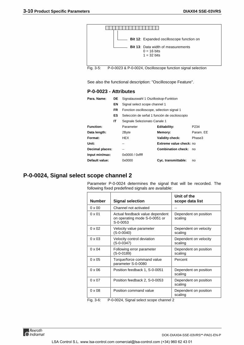
3-10 Product Specific Parameters DIAX04 SSE-03VRS
DOK-DIAX04-SSE-03VRS**-PA01-EN-P
Bit 13: Data width of measurements0 = 16 bits1 = 32 bits
Bit 12: Expanded oscilloscope function on
Fig. 3-5: P-0-0023 & P-0-0024, Oscilloscope function signal selection
See also the functional description: "Oscilloscope Feature".
P-0-0023 - AttributesPara. Name: DE Signalauswahl 1 Oszilloskop-Funktion
EN Signal select scope channel 1
FR Fonction oscilloscope, sélection signal 1
ES Selección de señal 1 función de osciloscopio
IT Segnale Selezionato Canale 1
Function: Parameter Editability: P234
Data length: 2Byte Memory: Param. EE
Format: HEX Validity check: Phase3
Unit: -- Extreme value check: no
Decimal places: -- Combination check: no
Input min/max: 0x0000 / 0xffff
Default value: 0x0000 Cyc. transmittable: no
P-0-0024, Signal select scope channel 2Parameter P-0-0024 determines the signal that will be recorded. Thefollowing fixed predefined signals are available:
Number Signal selectionUnit of thescope data list
0 x 00 Channel not activated --
0 x 01 Actual feedback value dependenton operating mode S-0-0051 orS-0-0053
Dependent on positionscaling
0 x 02 Velocity value parameter(S-0-0040)
Dependent on velocityscaling
0 x 03 Velocity control deviation(S-0-0347)
Dependent on velocityscaling
0 x 04 Following error parameter(S-0-0189)
Dependent on positionscaling
0 x 05 Torque/force command valueparameter S-0-0080
Percent
0 x 06 Position feedback 1, S-0-0051 Dependent on positionscaling
0 x 07 Position feedback 2, S-0-0053 Dependent on positionscaling
0 x 08 Position command value Dependent on positionscaling
Fig. 3-6: P-0-0024, Signal select scope channel 2
LSA Control S.L. www.lsa-control.com [email protected] (+34) 960 62 43 01
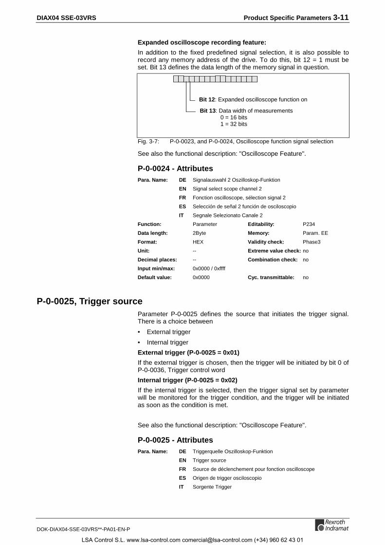
DIAX04 SSE-03VRS Product Specific Parameters 3-11
DOK-DIAX04-SSE-03VRS**-PA01-EN-P
Expanded oscilloscope recording feature:
In addition to the fixed predefined signal selection, it is also possible torecord any memory address of the drive. To do this, bit 12 = 1 must beset. Bit 13 defines the data length of the memory signal in question.
Bit 13: Data width of measurements0 = 16 bits1 = 32 bits
Bit 12: Expanded oscilloscope function on
Fig. 3-7: P-0-0023, and P-0-0024, Oscilloscope function signal selection
See also the functional description: "Oscilloscope Feature".
P-0-0024 - AttributesPara. Name: DE Signalauswahl 2 Oszilloskop-Funktion
EN Signal select scope channel 2
FR Fonction oscilloscope, sélection signal 2
ES Selección de señal 2 función de osciloscopio
IT Segnale Selezionato Canale 2
Function: Parameter Editability: P234
Data length: 2Byte Memory: Param. EE
Format: HEX Validity check: Phase3
Unit: -- Extreme value check: no
Decimal places: -- Combination check: no
Input min/max: 0x0000 / 0xffff
Default value: 0x0000 Cyc. transmittable: no
P-0-0025, Trigger sourceParameter P-0-0025 defines the source that initiates the trigger signal.There is a choice between
• External trigger
• Internal trigger
External trigger (P-0-0025 = 0x01)
If the external trigger is chosen, then the trigger will be initiated by bit 0 ofP-0-0036, Trigger control word
Internal trigger (P-0-0025 = 0x02)
If the internal trigger is selected, then the trigger signal set by parameterwill be monitored for the trigger condition, and the trigger will be initiatedas soon as the condition is met.
See also the functional description: "Oscilloscope Feature".
P-0-0025 - AttributesPara. Name: DE Triggerquelle Oszilloskop-Funktion
EN Trigger source
FR Source de déclenchement pour fonction oscilloscope
ES Origen de trigger osciloscopio
IT Sorgente Trigger
LSA Control S.L. www.lsa-control.com [email protected] (+34) 960 62 43 01

3-12 Product Specific Parameters DIAX04 SSE-03VRS
DOK-DIAX04-SSE-03VRS**-PA01-EN-P
Function: Parameter Editability: P234
Data length: 2Byte Memory: Param. EE
Format: DEC_OV Validity check: Phase3
Unit: -- Extreme value check: yes
Decimal places: 0 Combination check: no
Input min/max: 00001 / 00002
Default value: 2 Cyc. transmittable: no
P-0-0026, Trigger signal selectionFor internal trigger sources, the parameter P-0-0026, Trigger signalselection defines the signal that is monitored for the parameterized triggercondition. The following fixed predefined signals are available:
Trigger signalnumbers Trigger signal
Correspondingtrigger threshold
0 x 00 Not defined Not defined
0 x 01 Actual feedback valuebased onmode of operation
Position data P-0-0027
0 x 02 Velocity feedback valueParameter S-0-0040
Velocity data P-0-0028
0 x 03 Velocity deviationparameter --
Velocity data P-0-0028
0 x 04 Following error, parameterS-0-0189
Position data P-0-0027
0 x 05 Torque command value,parameter S-0-0080
Torque data P-0-0029
0 x 06 Position feedback 1,S-0-0051
Depending on positionscaling
0 x 07 Position feedback 2,S-0-0053
Depending on positionscaling
0 x 08 Position command value Depending on positionscaling
Fig. 3-8: P-0-0026, Trigger signal selection
Additional trigger signals can also be defined by setting bit 12.
Bit 12: Expanded trigger function On
Fig. 3-9: P-0-0026, Trigger signal selection
See also the functional description: "Oscilloscope Feature".
P-0-0026 - AttributesPara. Name: DE Triggersignalauswahl Oszilloskop-Funktion
EN Trigger signal selection
FR Fonction oscilloscope, sélection signal de déclenc.
ES Selección de señal de trigger función osciloscopio
IT Segnale di Trigger selezionato
LSA Control S.L. www.lsa-control.com [email protected] (+34) 960 62 43 01
DIAX04 SSE-03VRS Product Specific Parameters 3-13
DOK-DIAX04-SSE-03VRS**-PA01-EN-P
Function: Parameter Editability: P234
Data length: 2Byte Memory: Param. EE
Format: HEX Validity check: Phase3
Unit: -- Extreme value check: yes
Decimal places: -- Combination check: no
Input min/max: 0x0000 / 0x0005
Default value: 0x0001 Cyc. transmittable: no
P-0-0027, Trigger level for position dataIf P-0-0026, Trigger signal selection = “1“or “4“, then Parameter P-0-0027, Trigger level for position data determines the position value atwhich the trigger will be released as long as the correct edge has beenrecognized.
See also the functional description: "Oscilloscope Feature".
P-0-0027 - AttributesPara. Name: DE Triggerschwelle für Lagedaten
EN Trigger level for position data
FR Seuil de déclenchement données de position
ES Umbral de trigger para datos de posición
IT Livello di Trigger per Dati di Posizione
Function: Parameter Editability: P234
Data length: 4Byte Memory: Param. EE
Format: DEC_MV Validity check: Phase3
Unit: S-0-0076 Extreme value check: yes
Decimal places: S-0-0077/S-0-0078 Combination check: no
Input min/max: -214748.3648 / 0214748.3647
Default value: 0,0 Cyc. transmittable: no
P-0-0028, Trigger level for velocity dataIf P-0-0026, Trigger signal selection = “2“ or “3“, then Parameter P-0-0028, Trigger level for velocity data determines the velocity feedbackvalue at which the trigger will be released as long as the correct edge hasbeen recognized.
See also the functional description: "Oscilloscope Feature".
P-0-0028 - AttributesPara. Name: DE Triggerschwelle für Geschwindigkeitsdaten
EN Trigger level for velocity data
FR Seuil de déclenchement données de vitesse
ES Umbral de trigger para datos de velocidad
IT Livello di Trigger per Dati di Velocità
Function: Parameter Editability: P234
Data length: 4Byte Memory: Param. EE
Format: DEC_MV Validity check: Phase3
Unit: S-0-0044 Extreme value check: yes
Decimal places: S-0-0045/S-0-0046 Combination check: no
Input min/max: -000060000.0 / 0000060000.0
Default value: 0,0 Cyc. transmittable: no
LSA Control S.L. www.lsa-control.com [email protected] (+34) 960 62 43 01

3-14 Product Specific Parameters DIAX04 SSE-03VRS
DOK-DIAX04-SSE-03VRS**-PA01-EN-P
P-0-0029, Trigger level for torque/force dataIf P-0-0026, Trigger signal selection = “5“, then Parameter P-0-0029,Trigger level for torque data determines the torque/force value at whichthe trigger will be released as long as the correct edge has beenrecognized.
See also the functional description: "Oscilloscope Feature".
P-0-0029 - AttributesPara. Name: DE Triggerschwelle für Drehmoment/Kraftdaten
EN Trigger level for torque/force data
FR Seuil de déclenchement données de couple/force
ES Umbral de trigger para datos de par/fuerza
IT Livello di Trigger per Dati Coppia/Forza
Function: Parameter Editability: P234
Data length: 2Byte Memory: Param. EE
Format: DEC_MV Validity check: Phase3
Unit: % Extreme value check: yes
Decimal places: 1 Combination check: no
Input min/max: -0099.6 / 00099.6
Default value: 0,0 Cyc. transmittable: no
P-0-0030, Trigger edgeParameter P-0-0030 Trigger edge defines the signal change at which atrigger event can be initiated.
Number: Trigger edge:
1 Triggering on the positive edge of the trigger signal
2 Triggering on the negative edge of the trigger signal
3 Triggering on both the positive edge and negative edge of thetrigger signal
4 Triggering if the trigger signal equals the trigger levelFig. 3-10: Selection of trigger edges
See also the functional description: "Oscilloscope Feature".
P-0-0030 - AttributesPara. Name: DE Triggerflanke
EN Trigger edge
FR Front de déclenchement
ES Lado de trigger
IT Fronte di Trigger
Function: Parameter Editability: P234
Data length: 2Byte Memory: Param. EE
Format: DEC_OV Validity check: Phase3
Unit: -- Extreme value check: yes
Decimal places: 0 Combination check: no
Input min/max: 00001 / 00004
Default value: 3 Cyc. transmittable: no
LSA Control S.L. www.lsa-control.com [email protected] (+34) 960 62 43 01

DIAX04 SSE-03VRS Product Specific Parameters 3-15
DOK-DIAX04-SSE-03VRS**-PA01-EN-P
P-0-0031, TimebaseThe Timebase defines the time intervals in which the probe values of theselected signals are sampled. Possible time intervals range from 250 µs(resp. 500 µs) to 100 ms.
Note that in general:
Recording duration = Time resolution • Size of memory [µs]
See also the functional description: "Oscilloscope Feature".
P-0-0031 - AttributesPara. Name: DE Zeitauflösung
EN Timebase
FR Base de temps
ES Resolución de tiempo
IT Base dei Tempi
Function: Parameter Editability: P234
Data length: 4Byte Memory: Param. EE
Format: DEC_OV Validity check: Phase3
Unit: us Extreme value check: yes
Decimal places: 0 Combination check: no
Input min/max: 0000000250 / 0000100000
Default value: 250,0 Cyc. transmittable: no
P-0-0032, Size of memoryThe size of memory determines the number of recorded probe values permeasurement. A maximum of 512 probe values can be recorded perchannel.
The memory size and time resolution together determine the recordingduration. The minimum recording duration is 128 ms, and the maximumduration is 51.2 s.
Note that in general:
Recording duration = Time resolution • Size of memory [us]
See also the functional description: "Oscilloscope Feature".
P-0-0032 - AttributesPara. Name: DE Speichertiefe
EN Size of memory
FR Taille mémoire
ES Tamaño de memoria
IT Dimensione Memoria
Function: Parameter Editability: P234
Data length: 2Byte Memory: Param. EE
Format: DEC_OV Validity check: Phase3
Unit: -- Extreme value check: yes
Decimal places: 0 Combination check: no
Input min/max: 00002 / 00512
Default value: 512 Cyc. transmittable: no
LSA Control S.L. www.lsa-control.com [email protected] (+34) 960 62 43 01

3-16 Product Specific Parameters DIAX04 SSE-03VRS
DOK-DIAX04-SSE-03VRS**-PA01-EN-P
P-0-0033, Number of samples after triggerParameter P-0-0033 defines the number of probe values, or samples, thatwill be entered in the probe value list after the trigger event. In this way itis possible to set a parameter to define a trigger delay. Parameter P-0-0033 is used for this.
Trigger signalTriggerthreshold
Trigger status(bit 0)
Trigger delay
Recording duration
P-0-0033: Number ofmeasurements afterthe trigger action
Fig. 3-11: Triggering
See also the functional description: "Oscilloscope Feature".
P-0-0033 - AttributesPara. Name: DE Anzahl der Messwerte nach Triggerereignis
EN Number of samples after trigger
FR Nombre de mesures après déclenchement
ES Numero de muestras despues de trigger
IT Numero di Campionamenti dopo Trigger
Function: Parameter Editability: P234
Data length: 2Byte Memory: Param. EE
Format: DEC_OV Validity check: Phase3
Unit: -- Extreme value check: yes
Decimal places: 0 Combination check: no
Input min/max: 00000 / 00512
Default value: 0 Cyc. transmittable: no
P-0-0035, Delay from trigger to startParameter P-0-0035 indicates the number of cycles between the triggerevent (internal) and the release of the trigger (bit 0 trigger control word) inexternal triggering.
Trigger signal
Trigger
Trigger status(bit 0)
Triggersteuer(Bit 0)
P-0-0035Trigger control mixing
Trigger delay
Recording duration
P-0-0033:Number of measurementsafter the trigger action
Fig. 3-12: Triggering
LSA Control S.L. www.lsa-control.com [email protected] (+34) 960 62 43 01
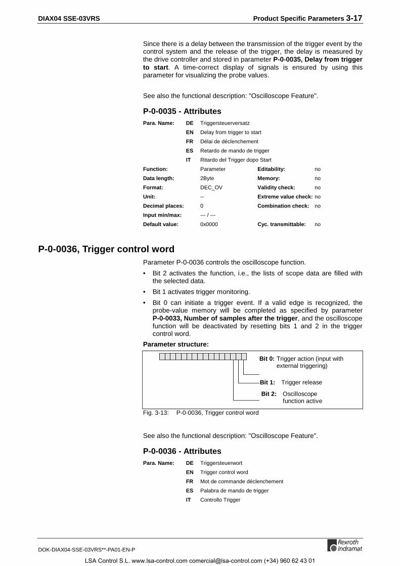
DIAX04 SSE-03VRS Product Specific Parameters 3-17
DOK-DIAX04-SSE-03VRS**-PA01-EN-P
Since there is a delay between the transmission of the trigger event by thecontrol system and the release of the trigger, the delay is measured bythe drive controller and stored in parameter P-0-0035, Delay from triggerto start. A time-correct display of signals is ensured by using thisparameter for visualizing the probe values.
See also the functional description: "Oscilloscope Feature".
P-0-0035 - AttributesPara. Name: DE Triggersteuerversatz
EN Delay from trigger to start
FR Délai de déclenchement
ES Retardo de mando de trigger
IT Ritardo del Trigger dopo Start
Function: Parameter Editability: no
Data length: 2Byte Memory: no
Format: DEC_OV Validity check: no
Unit: -- Extreme value check: no
Decimal places: 0 Combination check: no
Input min/max: --- / ---
Default value: 0x0000 Cyc. transmittable: no
P-0-0036, Trigger control wordParameter P-0-0036 controls the oscilloscope function.
• Bit 2 activates the function, i.e., the lists of scope data are filled withthe selected data.
• Bit 1 activates trigger monitoring.
• Bit 0 can initiate a trigger event. If a valid edge is recognized, theprobe-value memory will be completed as specified by parameterP-0-0033, Number of samples after the trigger, and the oscilloscopefunction will be deactivated by resetting bits 1 and 2 in the triggercontrol word.
Parameter structure:
Bit 0: Trigger action (input with external triggering)
Bit 1: Trigger release
Bit 2: Oscilloscope function active
Fig. 3-13: P-0-0036, Trigger control word
See also the functional description: "Oscilloscope Feature".
P-0-0036 - AttributesPara. Name: DE Triggersteuerwort
EN Trigger control word
FR Mot de commande déclenchement
ES Palabra de mando de trigger
IT Controllo Trigger
LSA Control S.L. www.lsa-control.com [email protected] (+34) 960 62 43 01

3-18 Product Specific Parameters DIAX04 SSE-03VRS
DOK-DIAX04-SSE-03VRS**-PA01-EN-P
Function: Parameter Editability: P234
Data length: 2Byte Memory: no
Format: HEX Validity check: no
Unit: -- Extreme value check: no
Decimal places: -- Combination check: no
Input min/max: --- / ---
Default value: 0x0000 Cyc. transmittable: no
P-0-0037, Trigger status wordStatus messages for the oscilloscope function.
The parameter P-0-0037 offers various pieces of information about thecurrent status of the oscilloscope function.
Parameter structure:
Bit 0: Trigger actionexternal: message to control
systeminternal: activation of the trigger
delay function
Bit 1: Signal < Trigger threshold
Bit 3: Signal > Trigger threshold
Bit 2: is recording
Fig. 3-14: P-0-0037, Trigger status word
See also the functional description: "Oscilloscope Feature".
P-0-0037 - AttributesPara. Name: DE Triggerstatuswort
EN Trigger status word
FR Mot d'état déclenchement
ES Palabra de estado de trigger
IT Stato Trigger
Function: Parameter Editability: no
Data length: 2Byte Memory: no
Format: HEX Validity check: no
Unit: -- Extreme value check: no
Decimal places: -- Combination check: no
Input min/max: --- / ---
Default value: --- Cyc. transmittable: no
P-0-0051, Torque/force constantThe torque/force constant determines what drive torque or force themotor will deliver at a specific effective current.
For synchronous motors, this value depends entirely on the design of themotor.
In asynchronous motors, this value is valid as long as the motor is notoperated in the field-weakening range.
For MHD, MKD and MKE motors, this parameter is stored in the feedbackdata memory and cannot be changed.
LSA Control S.L. www.lsa-control.com [email protected] (+34) 960 62 43 01

DIAX04 SSE-03VRS Product Specific Parameters 3-19
DOK-DIAX04-SSE-03VRS**-PA01-EN-P
MA [Nm, N] = (P-0-0051)•(S-0-0111)•(S-0-0080)where:
MA = Drive torqueP-0-0051 = Torque/force constant, [Nm/A] or [N/A]S-0-0111 = Motor current at standstill [A]S-0-0080 = Torque/force command [%]
Fig. 3-15: Drive torque
See also the functional description: "Motor Feedback-Data Memory".
P-0-0051 - AttributesPara. Name: DE Drehmoment/Kraft-Konstante
EN Torque/force constant
FR Constante de couple/force
ES Constante de par/fuerza
IT Costante di Coppia/Forza
Function: Parameter Editability: P23
Data length: 4Byte Memory: Param. EE
Format: DEC_OV Validity check: no
Unit: Nm/A Extreme value check: no
Decimal places: 2 Combination check: no
Input min/max: 000.01 / 655.35
Default value: 100 Cyc. transmittable: no
P-0-0074, Feedback 1 typeThis parameter determines the encoder interface to which the motorencoder is connected. The number of the corresponding interface moduleshould be entered in this parameter.
Module: P-0-0074: Measurement system:
- 0 None (only with rotary asynchronous motors)
Standard 1 Digital servo feed back or resolver
DLF01.1M 2 Incremental encoder with sine signals fromthe Heidenhain company, with either µA or 1Vsignals
DZF02.1M 3 Indramat gear-type encoder
DEF01.1M 5 Incremental encoder with square-wavesignals from the Heidenhain company
DAG01.2M 8 Encoder with EnDat interface from theHeidenhain company
DZF03.1M 9 Gearwheel with 1Vpp signals
Standard 10 Resolver without feedback data memory
Standard +DLF01.1M
11 Resolver without feedback data memory plusincremental encoder with sine signals
Fig. 3-16: P-0-0037, Trigger status word
Restrictions:
Modules DLF, DZF, DRF and DEF 1 must not be operated simultaneouslyin a controller. => Danger of Damage!
It is not possible to combine DLF and DZF.Module DEF 2 can be used to operate an incremental encoder along withDLF or DZF.
LSA Control S.L. www.lsa-control.com [email protected] (+34) 960 62 43 01
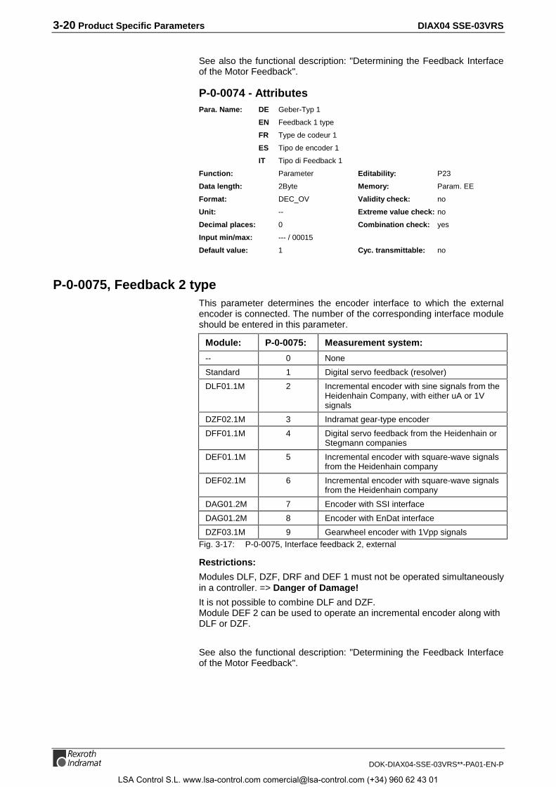
3-20 Product Specific Parameters DIAX04 SSE-03VRS
DOK-DIAX04-SSE-03VRS**-PA01-EN-P
See also the functional description: "Determining the Feedback Interfaceof the Motor Feedback".
P-0-0074 - AttributesPara. Name: DE Geber-Typ 1
EN Feedback 1 type
FR Type de codeur 1
ES Tipo de encoder 1
IT Tipo di Feedback 1
Function: Parameter Editability: P23
Data length: 2Byte Memory: Param. EE
Format: DEC_OV Validity check: no
Unit: -- Extreme value check: no
Decimal places: 0 Combination check: yes
Input min/max: --- / 00015
Default value: 1 Cyc. transmittable: no
P-0-0075, Feedback 2 typeThis parameter determines the encoder interface to which the externalencoder is connected. The number of the corresponding interface moduleshould be entered in this parameter.
Module: P-0-0075: Measurement system:
-- 0 None
Standard 1 Digital servo feedback (resolver)
DLF01.1M 2 Incremental encoder with sine signals from theHeidenhain Company, with either uA or 1Vsignals
DZF02.1M 3 Indramat gear-type encoder
DFF01.1M 4 Digital servo feedback from the Heidenhain orStegmann companies
DEF01.1M 5 Incremental encoder with square-wave signalsfrom the Heidenhain company
DEF02.1M 6 Incremental encoder with square-wave signalsfrom the Heidenhain company
DAG01.2M 7 Encoder with SSI interface
DAG01.2M 8 Encoder with EnDat interface
DZF03.1M 9 Gearwheel encoder with 1Vpp signalsFig. 3-17: P-0-0075, Interface feedback 2, external
Restrictions:
Modules DLF, DZF, DRF and DEF 1 must not be operated simultaneouslyin a controller. => Danger of Damage!
It is not possible to combine DLF and DZF.Module DEF 2 can be used to operate an incremental encoder along withDLF or DZF.
See also the functional description: "Determining the Feedback Interfaceof the Motor Feedback".
LSA Control S.L. www.lsa-control.com [email protected] (+34) 960 62 43 01

DIAX04 SSE-03VRS Product Specific Parameters 3-21
DOK-DIAX04-SSE-03VRS**-PA01-EN-P
P-0-0075 - AttributesPara. Name: DE Geber-Typ 2
EN Feedback 2 type
FR Type de codeur 2
ES Tipo de encoder 2
IT Tipo di Feedback 2
Function: Parameter Editability: P23
Data length: 2Byte Memory: Param. EE
Format: DEC_OV Validity check: no
Unit: -- Extreme value check: no
Decimal places: 0 Combination check: no
Input min/max: 00000 / 00009
Default value: 0 Cyc. transmittable: no
P-0-0081, Parallel I/O output 1The control system can use this parameter to address the outputs of theDEA 4.1 I/O card.
See also the functional description: "Digital Input/Output".
P-0-0081 - AttributesPara. Name: DE Paralleler Ausgang 1
EN Parallel I/O output 1
FR Sortie parallèle 1
ES Salida paralela 1
IT Uscita parallela 1
Function: Parameter Editability: P234
Data length: 4Byte Memory: no
Format: HEX Validity check: no
Unit: -- Extreme value check: no
Decimal places: 0 Combination check: no
Input min/max: 0x0000 / ---
Default value: --- Cyc. transmittable: MDT
P-0-0082, Parallel I/O input 1The control system can use this parameter to address the inputs of theDEA 4.1 I/O card.
See also the functional description: "Digital Input/Output"
P-0-0082 - AttributesPara. Name: DE Paralleler Eingang 1
EN Parallel I/O input 1
FR Entrée parallèle 1
ES Entrada paralela 1
IT Ingressi paralleli 1
LSA Control S.L. www.lsa-control.com [email protected] (+34) 960 62 43 01
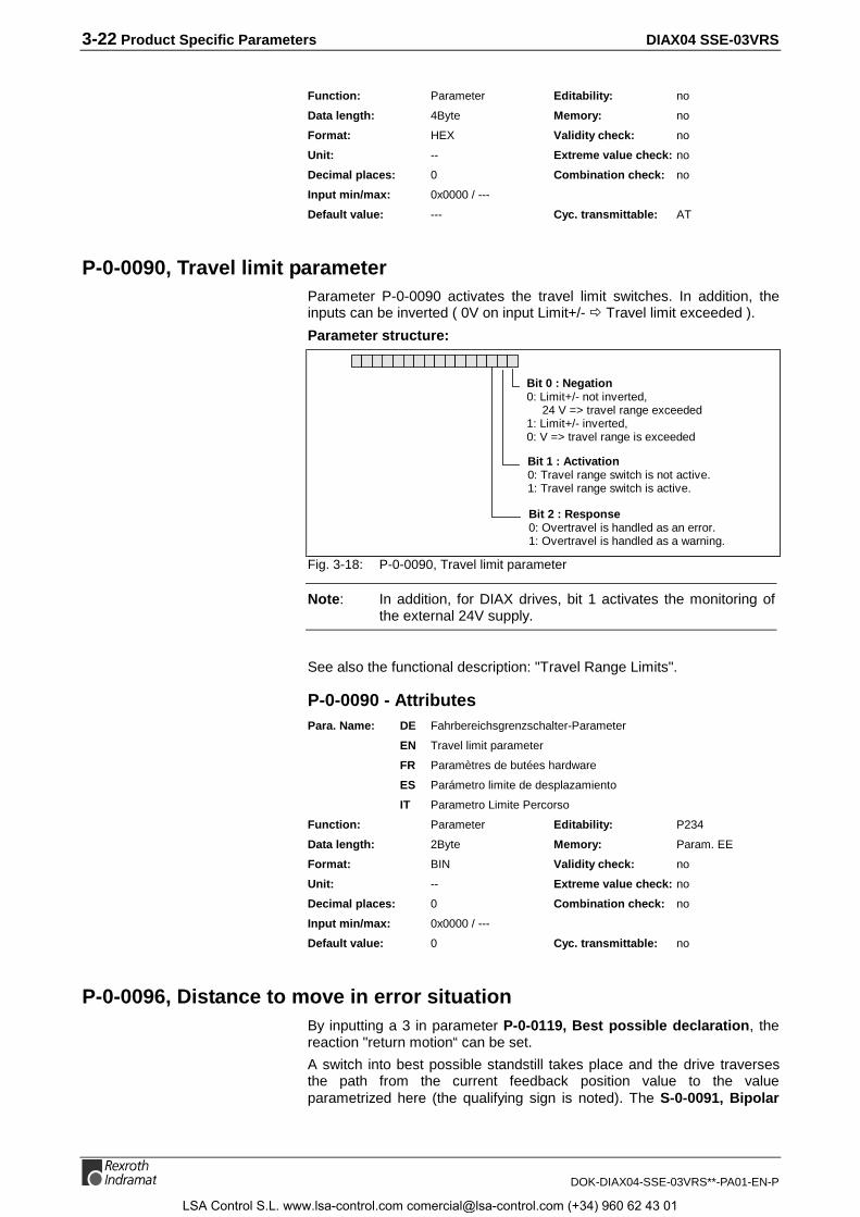
3-22 Product Specific Parameters DIAX04 SSE-03VRS
DOK-DIAX04-SSE-03VRS**-PA01-EN-P
Function: Parameter Editability: no
Data length: 4Byte Memory: no
Format: HEX Validity check: no
Unit: -- Extreme value check: no
Decimal places: 0 Combination check: no
Input min/max: 0x0000 / ---
Default value: --- Cyc. transmittable: AT
P-0-0090, Travel limit parameterParameter P-0-0090 activates the travel limit switches. In addition, theinputs can be inverted ( 0V on input Limit+/- Õ Travel limit exceeded ).
Parameter structure:
Bit 0 : Negation0: Limit+/- not inverted,
24 V => travel range exceeded1: Limit+/- inverted,0: V => travel range is exceeded
Bit 1 : Activation0: Travel range switch is not active.1: Travel range switch is active.
Bit 2 : Response0: Overtravel is handled as an error.1: Overtravel is handled as a warning.
Fig. 3-18: P-0-0090, Travel limit parameter
Note: In addition, for DIAX drives, bit 1 activates the monitoring ofthe external 24V supply.
See also the functional description: "Travel Range Limits".
P-0-0090 - AttributesPara. Name: DE Fahrbereichsgrenzschalter-Parameter
EN Travel limit parameter
FR Paramètres de butées hardware
ES Parámetro limite de desplazamiento
IT Parametro Limite Percorso
Function: Parameter Editability: P234
Data length: 2Byte Memory: Param. EE
Format: BIN Validity check: no
Unit: -- Extreme value check: no
Decimal places: 0 Combination check: no
Input min/max: 0x0000 / ---
Default value: 0 Cyc. transmittable: no
P-0-0096, Distance to move in error situationBy inputting a 3 in parameter P-0-0119, Best possible declaration, thereaction "return motion“ can be set.
A switch into best possible standstill takes place and the drive traversesthe path from the current feedback position value to the valueparametrized here (the qualifying sign is noted). The S-0-0091, Bipolar
LSA Control S.L. www.lsa-control.com [email protected] (+34) 960 62 43 01
DIAX04 SSE-03VRS Product Specific Parameters 3-23
DOK-DIAX04-SSE-03VRS**-PA01-EN-P
velocity limit value, S-0-0138, Bipolar acceleration limit value and S-0-0349, Jerk limit bipolar are used as limiting factors.
It is necessary to parametrize a sufficiently sized value in P-0-0126,Maximum braking time to give the drive enough time to traverse thespecified path.
If the position limit values are active, then the drive keeps the returnmotion from travelling over them. The drive then stops at the S-0-0057,Position window at the respective position limit value.
See also the functional description: "Return motion".
P-0-0096 - AttributesPara. Name: DE Verfahrweg im Fehlerfall
EN Distance to move in error situation
FR Déplacement en cas de défaut
ES Recorrido de desplazamiento en caso de error
IT Distanza Movimento in Caso di Errore
Function: Parameter Editability: P234
Data length: 4Byte Memory: Param. EE
Format: DEC_MV Validity check: Phase3
Unit: S-0-0076 Extreme value check: yes
Decimal places: S-0-0077/S-0-0078 Combination check: no
Input min/max: S-0-0076 / S-0-0076
Default value: 100000 Cyc. transmittable: no
P-0-0097, Absolute encoder monitoring windowDuring S-0-0128, C200 Communication phase 4 transition check, theabsolute encoder monitoring compares the position saved during the lastpowering down with the current absolute feedback.
If the difference is greater than the value set in parameter P-0-0097,Absolute encoder monitoring window, the error message F276Absolute encoder out of allowed window will be generated. This canhappen when the axis has been moved with the power off, or afterchanging the motor.
Note: If a 0 is parametrized in P-0-0097, Absolute encodermonitoring window, the absolute encoder monitor isdeactivated.
As a standard value, 0.1 motor revolution ( = 36 degrees in reference tothe motor shaft ) can be programmed if the axis has an electricallyreleased brake or an electrically activated braking mechanism.
See also the functional description: "Absolute Encoder Monitoring".
P-0-0097 - AttributesPara. Name: DE Absolutgeber-Überwachungsfenster
EN Absolute encoder monitoring window
FR Fenêtre de surveillance du codeur absolu
ES Ventana de control de encoder absoluto
IT Finestra di Controllo del Encoder assoluto
LSA Control S.L. www.lsa-control.com [email protected] (+34) 960 62 43 01

3-24 Product Specific Parameters DIAX04 SSE-03VRS
DOK-DIAX04-SSE-03VRS**-PA01-EN-P
Function: Parameter Editability: P234
Data length: 4Byte Memory: Param. EE
Format: DEC_MV Validity check: Phase3
Unit: S-0-0076 Extreme value check: yes
Decimal places: S-0-0077/S-0-0078 Combination check: no
Input min/max: 0000000.0000 / 0214748.3647
Default value: 100000 Cyc. transmittable: no
P-0-0098, Max. model deviationThe maximum model deviation is the maximum deviation between thereal position feedback value and the model position feedback valuecalculated by the drive.
This parameter can be read out by the user to help set the parameter forS-0-0159, Monitoring window.
Two cases must be distinguished for determining the model positionfeedback value:
1) Position control with following (lag) error
In this operating mode, the controlled system is simulated by a model.
The maximum deviation between the calculated position feedback modulevalue and the real position feedback value is stored in the parameterP-0-0098.
2) Position control without following (lag) error
In this operating mode, the position command value is compared to theposition feedback value. The maximum deviation encountered is stored inP-0-0098.
Note: This parameter can be write accessed so that it can be setback to 0, for example.
See also the functional description: " Position Control Loop Monitoring".
P-0-0098 - AttributesPara. Name: DE Max. Modellabweichung
EN Max. model deviation
FR Ecart maxi. au modèle
ES Desviación máx. del modelo
IT Deviazione mass. da Modello
Function: Parameter Editability: P234
Data length: 4Byte Memory: no
Format: DEC_MV Validity check: no
Unit: S-0-0076 Extreme value check: yes
Decimal places: S-0-0077/S-0-0078 Combination check: no
Input min/max: 0000000.0000 / 0214748.3647
Default value: --- Cyc. transmittable: no
LSA Control S.L. www.lsa-control.com [email protected] (+34) 960 62 43 01

DIAX04 SSE-03VRS Product Specific Parameters 3-25
DOK-DIAX04-SSE-03VRS**-PA01-EN-P
P-0-0099, Position command smoothing time constantThe position command smoothing time constant determines the maximum jerkpossible in operation modes with closed loop position control.
The maximum jerk is determined by:
2nd derivative of the positioncommand values
max. jerk = P-0-0099 Position command valuesmoothing filter time constant
Fig. 3-19: Max. jerk
If you don’t want to activate a filter, set P-0-0099 >= S-0-0001, NC Cycletime (TNcyc) (greater or equal).
See also the functional description: "Command value processing: PositionControl".
P-0-0099 - AttributesPara. Name: DE Lagesollwert-Glättungsfilter-Zeitkonstante
EN Position command smoothing time constant
FR Temps de filtrage consigne de pos.
ES Tiempo de alisamiento posición comando
IT Tempo per Smorzamento Comandi Posiz.
Function: Parameter Editability: P234
Data length: 2Byte Memory: Param. EE
Format: DEC_OV Validity check: Phase3
Unit: ms Extreme value check: yes
Decimal places: 2 Combination check: no
Input min/max: 000.00 / 655.35
Default value: 0 Cyc. transmittable: no
P-0-0109, Torque/force peak limitThe maximum peak torque of a drive can be limited in a manner suitableto an application with the use of parameter P-0-0109, Torque/ force peaklimit. In other words, the parameter ensures that the max. torque specificto the application is not exceeded even if S-0-0092, Bipolar torque/forcelimit value is set exceedingly high.
See also functional description: "Torque Limit".
P-0-0109 - AttributesPara. Name: DE Spitzendrehmoment/-Kraft-Begrenzung
EN Torque/force peak limit
FR Limitation couple/force crête
ES Limite par/fuerza punta
IT Limitazione Picco Coppia/Forza
Function: Parameter Editability: P234
Data length: 2Byte Memory: Param. EE
Format: DEC_OV Validity check: Phase3
Unit: S-0-0086 Extreme value check: yes
Decimal places: S-0-0086 Combination check: no
Input min/max: 0000.0 / 0099.6
Default value: 4000 Cyc. transmittable: no
LSA Control S.L. www.lsa-control.com [email protected] (+34) 960 62 43 01

3-26 Product Specific Parameters DIAX04 SSE-03VRS
DOK-DIAX04-SSE-03VRS**-PA01-EN-P
P-0-0117, NC reaction on errorThis parameter allows the NC 30 seconds to bring the drive controller to acoordinated deceleration in an error situation if the parameter is set with a"1“. The drive follows the command for this period. The drive reacts withthe preset P-0-0119, Best possible deceleration.
This feature works for non-fatal errors.
Parameter structure:
Bit 0: Activation 0: instant control drive reaction to
non-fatal errors with"best possible standstill"
1: reaction to non-fatal errors delayed 30 sec
Fig. 3-20: P-0-0117, NC reaction on error
See also the functional description: "NC Response in Error Situation"
P-0-0117 - AttributesPara. Name: DE Aktivierung NC-Reaktion im Fehlerfall
EN NC reaction on error
FR Activation réaction CN en cas de défaut
ES Activación reaccion NC en caso de error
IT Reazione in Presenza Errore NC
Function: Parameter Editability: P23
Data length: 2Byte Memory: Param. EE
Format: DEC_OV Validity check: Phase3
Unit: -- Extreme value check: yes
Decimal places: 0 Combination check: no
Input min/max: 00000 / 00001
Default value: 0 Cyc. transmittable: no
P-0-0118, Power off on errorHow a drive error is signalled to the drive pack or to the supply module,can be activated in the parameter P-0-0118, Power off on error.
Moreover, there are the following possibilities to set the reaction uponerror:
• Power off / packet reaction in case of error (bit 0)
• Condition for power up (bit 1)
• Time for switching the power off (bit 2)
• Reaction upon undervoltage (bit 3)
• Undervoltage as fatal warning (bit 4)
• Automatic clearance of undervoltage (bit 5)
LSA Control S.L. www.lsa-control.com [email protected] (+34) 960 62 43 01

DIAX04 SSE-03VRS Product Specific Parameters 3-27
DOK-DIAX04-SSE-03VRS**-PA01-EN-P
Parameter structure:
Bit 0 : Packet reaction or power cutoff onerror
0: For modular devices: No packet reaction(do not cutoff the common DC busvoltage) on error
For compact devices: no power cutoff onerror
1: Packet reaction and power cutoff on error
Bit 1 : Condition for power on0: Power on allowed, if no error and operation
mode (comm. phase 4)1: Power on allowed, if no error ("passive
axis“)
Bit 2 : At what time power cutoff happens incase of an error
(only if bit 0 = 1)0: Modular devices: The message is output
immediately when the error happens.(packet response of all drive controllersmounted to the same supply module,prefered setting for modular devices)
Compact devices: The power is switched offimmediately when the error happens.
1: Modular devices: The message is only outputafter the end of the error reaction.
Compact devices: The Power is only switched offafter the end of the error reaction.(preferred setting for compact devices)
Bit 3 : Reaction to DC bus undervoltage0: Undervoltage is treated as an error or a non-
fatal warning.1: Undervoltage is treated as a fatal warning with
suppression of driving operation.
Bit 4 : Automatic reset of the undervoltage error0: Undervoltage error is stored.1: Undervoltage error is reset by the drive upon
dropping drive enable (RF) to 0.
Bit 5 : Undervoltage as warning0: Undervoltage with error or non-fatal warning1: Undervoltage is treated as non-fatal warning.
Fig. 3-21: P-0-0118, Power off on error
See also the functional description: " Power off on error".
P-0-0118 - AttributesPara. Name: DE Leistungsabschaltung im Fehlerfall
EN Power off on error
FR Mise hors tension en cas de défaut
ES Desconexion de potencia en caso de error
IT Spegnimento Potenza in Caso di Errore
Function: Parameter Editability: P23
Data length: -- Memory: Param. EE
Format: BIN Validity check: Phase3
Unit: -- Extreme value check: yes
Decimal places: -- Combination check: no
Input min/max: 00000 / 00001
Default value: 1 Cyc. transmittable: no
LSA Control S.L. www.lsa-control.com [email protected] (+34) 960 62 43 01

3-28 Product Specific Parameters DIAX04 SSE-03VRS
DOK-DIAX04-SSE-03VRS**-PA01-EN-P
P-0-0119, Best possible decelerationThis parameter specifies the type of braking to standstill for the drive inthe event of
• a non-fatal error
• an interface error
• a phase regression
• switching off the drive enable signal
P-0-0119: Reaction type:
0 Velocity command value set to zero
The motor brakes in regard to the torque limit value.The Braking time is set in parameter P-0-0126. Assoon as the braking time elapses, the motor holdingbrake is activated. If the velocity has previously fallenbelow 10 rpm (rotational motors) or below 10 mm/min(linear motors), then the motor holding brake will beengaged immediately. 150 milliseconds after themechanical brake is set, the motor is torque free.
1 Switch to torque-free state
2 Velocity command to zero with command ramp andfilter.
The ramp, i.e. the maximum acceleration, is set viaP-0-1201, Ramp 1 pitch, the jerk filter via P-0-1222,Velocity command filter.
3 Return motion
The drive generates a position command profile fortraversing the set "path on error“ in which case arelative path is activated which is defined with
P-0-0096, Distance to move in error situation,
S-0-0091, Bipolar Velocity Limit Value,
S-0-0138, Bipolar acceleration limit value and
S-0-0349, Jerk Limit bipolar.Fig. 3-22: Deceleration mode for the drive
The drive enable can be set again, at the earliest, after the operation ofthe error reaction.
See also the functional description: "Best Possible Deceleration".
P-0-0119 - AttributesPara. Name: DE Bestmögliche Stillsetzung
EN Best possible deceleration
FR Arrêt au plus vite
ES La mejor parada posible
IT Decellerazione massima
Function: Parameter Editability: P23
Data length: 2Byte Memory: Param. EE
Format: DEC_OV Validity check: Phase3
Unit: -- Extreme value check: yes
Decimal places: 0 Combination check: no
Input min/max: 00000 / 00002
Default value: --- Cyc. transmittable: no
LSA Control S.L. www.lsa-control.com [email protected] (+34) 960 62 43 01

DIAX04 SSE-03VRS Product Specific Parameters 3-29
DOK-DIAX04-SSE-03VRS**-PA01-EN-P
P-0-0121, Velocity mix factor feedback 1 & 2The Velocity mix factor parameter determines the ratio of the velocityfeedback values between the motor encoder and the optional encoder.
The input is percentage-based. Note the following:
0 % : The velocity controller works solely with the velocity of the motorencoder ( = encoder 1).
100 % : The velocity controller works solely with the velocity of the opt.encoder ( = encoder 2).
If no optional encoder is available, then the parameter is set to 0 % .
See also the functional description: " Setting the Velocity Mix Factor".
P-0-0121 - AttributesPara. Name: DE Geschwindigkeits-Mischfaktor Geber 1 & Geber 2
EN Velocity mix factor feedback 1 & 2
FR Facteur de mixage vitesse codeur 1 & codeur 2
ES Factor mixto de velocidad encoder 1 & 2
IT Fattore di Correzione Feedback 1 & 2
Function: Parameter Editability: P234
Data length: 2Byte Memory: Param. EE
Format: DEC_OV Validity check: Phase3
Unit: % Extreme value check: no
Decimal places: 1 Combination check: no
Input min/max: 0000.0 / 0100.0
Default value: 0 Cyc. transmittable: no
P-0-0126, Maximum braking timeThe maximum braking time for the drive is set in this parameter.
The value should always be set higher then the time needed to decelerate theshaft from maximum velocity to zero using the error reaction “ Velocitycommand value set to zero.”
The velocity command value is switched to zero if P-0-0119, Bestpossible deceleration is set to 0 and either
• The drive enable (RF) is removed
• The drive is switched to parameter mode with RF switched on
• A drive error is recognized that still allows a reaction from the drive (allnon-fatal errors)
• In the case of separately supplied devices, a drive connected to thesame supply module reports an error to that module, so that theintermediate voltage is switched off.
P-0-0126 - AttributesPara. Name: DE Maximale Bremszeit
EN Maximum braking time
FR Temps de freinage max.
ES Tiempo máx. de frenado
IT Tempo massimo di Frenata
LSA Control S.L. www.lsa-control.com [email protected] (+34) 960 62 43 01

3-30 Product Specific Parameters DIAX04 SSE-03VRS
DOK-DIAX04-SSE-03VRS**-PA01-EN-P
Function: Parameter Editability: P23
Data length: 4Byte Memory: Param. EE
Format: DEC_OV Validity check: Phase3
Unit: ms Extreme value check: yes
Decimal places: 0 Combination check: no
Input min/max: 0000000500 / 0000100000
Default value: 10000 Cyc. transmittable: no
P-0-0127, Overload warningTo protect the power stage, the temperature is calculated with atemperature model for the transistor output stage. If the temperatureexceeds 125°C, then the torque-producing command current will belimited.
To avoid an unexpected disruption of the torque from the drive, a warningthreshold can be set in this parameter.
If the thermal load rises above the set value, warning E261 Continuouscurrent limiting prewarning will be generated.
If 100% is entered, this warning will be deactivated, because then themessage E257 Continuous current limit active will be generatedinstead.
See also the functional description: "Current Limit".
P-0-0127 - AttributesPara. Name: DE Überlastwarnung
EN Overload warning
FR Alerte surcharge
ES Aviso de sobrecarga
IT Preallarme Sovracarico
Function: Parameter Editability: P23
Data length: 2Byte Memory: Param. EE
Format: DEC_OV Validity check: Phase3
Unit: % Extreme value check: yes
Decimal places: 0 Combination check: no
Input min/max: 00000 / 00100
Default value: 80 Cyc. transmittable: no
P-0-0139, Analog output 1The parameter P-0-0139, Analog output 1 sets the voltage value for theanalog output 1 of the drive controller.
See also the functional description: "Analog Output".
P-0-0139 - AttributesPara. Name: DE Analogausgang 1
EN Analog output 1
FR Sortie analogique 1
ES Salida analogica 1
IT Uscita analogica 1
LSA Control S.L. www.lsa-control.com [email protected] (+34) 960 62 43 01
DIAX04 SSE-03VRS Product Specific Parameters 3-31
DOK-DIAX04-SSE-03VRS**-PA01-EN-P
Function: Parameter Editability: P234
Data length: 2Byte Memory: no
Format: DEC_MV Validity check: no
Unit: V Extreme value check: yes
Decimal places: 3 Combination check: no
Input min/max: - / -
Default value: --- Cyc. transmittable: MDT
P-0-0140, Analog output 2The parameter P-0-0140, Analog output 2 sets the voltage value for theanalog output 2 of the drive controller.
See also the functional description: "Analog Output".
P-0-0140 - AttributesPara. Name: DE Analogausgang 2
EN Analog output 2
FR Sortie analogique 2
ES Salida analogica 2
IT Uscita analogica 2
Function: Parameter Editability: P234
Data length: 2Byte Memory: no
Format: DEC_MV Validity check: no
Unit: V Extreme value check: yes
Decimal places: 3 Combination check: no
Input min/max: - / -
Default value: --- Cyc. transmittable: MDT
P-0-0141, Thermal drive loadThe parameter P-0-0141, Thermal drive load is for diagnostic purposes.In this parameter, 0% corresponds to a chip over-temperature of 0 Kelvin,100% corresponds to the maximum chip over-temperature. The thermalload should not exceed a value of 80% for the applied operating cycles ifthe drive is set up correctly.
It typically takes about 10 minutes to warm up a drive controller end stageto its final temperature. To check the thermal load of a drive duringinstallation without having to run operating cycles during this period oftime, the drive controller load can be preset with 80%. This can happen bywriting an arbitrary value to the parameter P-0-0141, Thermal drive load.
See also the functional description: "Current Limit".
P-0-0141 - AttributesPara. Name: DE Thermische Regelgeräte-Auslastung
EN Thermal drive load
FR Charge thermique variateur
ES Descarga termica de reguladores
IT Carico termico Azionamento
LSA Control S.L. www.lsa-control.com [email protected] (+34) 960 62 43 01
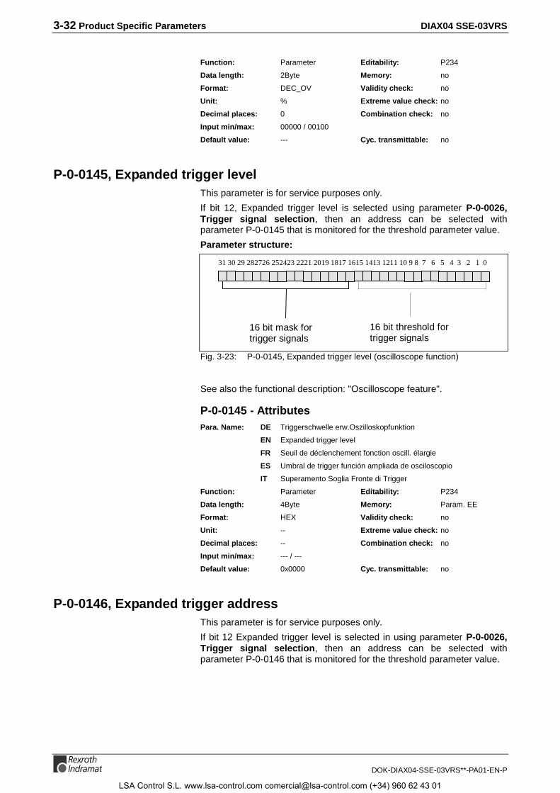
3-32 Product Specific Parameters DIAX04 SSE-03VRS
DOK-DIAX04-SSE-03VRS**-PA01-EN-P
Function: Parameter Editability: P234
Data length: 2Byte Memory: no
Format: DEC_OV Validity check: no
Unit: % Extreme value check: no
Decimal places: 0 Combination check: no
Input min/max: 00000 / 00100
Default value: --- Cyc. transmittable: no
P-0-0145, Expanded trigger levelThis parameter is for service purposes only.
If bit 12, Expanded trigger level is selected using parameter P-0-0026,Trigger signal selection, then an address can be selected withparameter P-0-0145 that is monitored for the threshold parameter value.
Parameter structure:
31 30 29 282726 252423 2221 2019 1817 1615 1413 1211 10 9 8 7 6 5 4 3 2 1 0
16 bit threshold fortrigger signals
16 bit mask fortrigger signals
Fig. 3-23: P-0-0145, Expanded trigger level (oscilloscope function)
See also the functional description: "Oscilloscope feature".
P-0-0145 - AttributesPara. Name: DE Triggerschwelle erw.Oszilloskopfunktion
EN Expanded trigger level
FR Seuil de déclenchement fonction oscill. élargie
ES Umbral de trigger función ampliada de osciloscopio
IT Superamento Soglia Fronte di Trigger
Function: Parameter Editability: P234
Data length: 4Byte Memory: Param. EE
Format: HEX Validity check: no
Unit: -- Extreme value check: no
Decimal places: -- Combination check: no
Input min/max: --- / ---
Default value: 0x0000 Cyc. transmittable: no
P-0-0146, Expanded trigger addressThis parameter is for service purposes only.
If bit 12 Expanded trigger level is selected in using parameter P-0-0026,Trigger signal selection, then an address can be selected withparameter P-0-0146 that is monitored for the threshold parameter value.
LSA Control S.L. www.lsa-control.com [email protected] (+34) 960 62 43 01
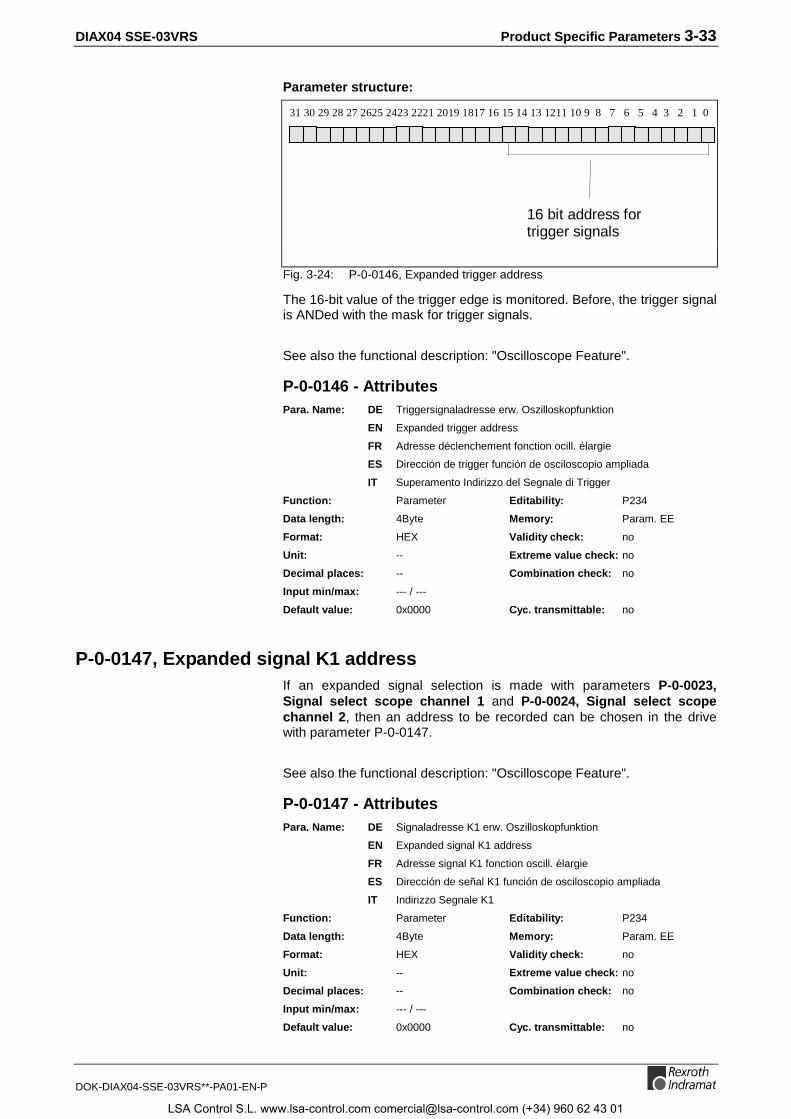
DIAX04 SSE-03VRS Product Specific Parameters 3-33
DOK-DIAX04-SSE-03VRS**-PA01-EN-P
Parameter structure:
31 30 29 28 27 2625 2423 2221 2019 1817 16 15 14 13 1211 10 9 8 7 6 5 4 3 2 1 0
16 bit address fortrigger signals
Fig. 3-24: P-0-0146, Expanded trigger address
The 16-bit value of the trigger edge is monitored. Before, the trigger signalis ANDed with the mask for trigger signals.
See also the functional description: "Oscilloscope Feature".
P-0-0146 - AttributesPara. Name: DE Triggersignaladresse erw. Oszilloskopfunktion
EN Expanded trigger address
FR Adresse déclenchement fonction ocill. élargie
ES Dirección de trigger función de osciloscopio ampliada
IT Superamento Indirizzo del Segnale di Trigger
Function: Parameter Editability: P234
Data length: 4Byte Memory: Param. EE
Format: HEX Validity check: no
Unit: -- Extreme value check: no
Decimal places: -- Combination check: no
Input min/max: --- / ---
Default value: 0x0000 Cyc. transmittable: no
P-0-0147, Expanded signal K1 addressIf an expanded signal selection is made with parameters P-0-0023,Signal select scope channel 1 and P-0-0024, Signal select scopechannel 2, then an address to be recorded can be chosen in the drivewith parameter P-0-0147.
See also the functional description: "Oscilloscope Feature".
P-0-0147 - AttributesPara. Name: DE Signaladresse K1 erw. Oszilloskopfunktion
EN Expanded signal K1 address
FR Adresse signal K1 fonction oscill. élargie
ES Dirección de señal K1 función de osciloscopio ampliada
IT Indirizzo Segnale K1
Function: Parameter Editability: P234
Data length: 4Byte Memory: Param. EE
Format: HEX Validity check: no
Unit: -- Extreme value check: no
Decimal places: -- Combination check: no
Input min/max: --- / ---
Default value: 0x0000 Cyc. transmittable: no
LSA Control S.L. www.lsa-control.com [email protected] (+34) 960 62 43 01

3-34 Product Specific Parameters DIAX04 SSE-03VRS
DOK-DIAX04-SSE-03VRS**-PA01-EN-P
P-0-0148, Expanded signal K2 addressIf an expanded signal selection is chosen with parameters P-0-0023,Signal select scope channel 1 and P-0-0024, Signal select scopechannel 2, then an address to be recorded can be chosen in the drivewith parameter P-0-0148.
See also the functional description: "Oscilloscope Feature".
P-0-0148 - AttributesPara. Name: DE Signaladresse K2 erw. Oszilloskopfunktion
EN Expanded signal K2 address
FR Adresse signal K2 fonction oscill. élargie
ES Dirección de señal K2 función de osciloscopio ampliada
IT Indirizzo Segnale K2
Function: Parameter Editability: P234
Data length: 4Byte Memory: Param. EE
Format: HEX Validity check: no
Unit: -- Extreme value check: no
Decimal places: -- Combination check: no
Input min/max: --- / ---
Default value: 0x0000 Cyc. transmittable: no
P-0-0149, List of selectable signals for oscilloscope functionThe control system can read drive-supported, predefined signals withparameter P-0-0149. This permits a user interface to prepare a signalselect menu using the information in the listed parameters in the drive.
List entries: ID number of:
1 S-0-0051 or S-0-0053
2 S-0-0040
3 S-0-0347
4 S-0-0189
5 S-0-0080
6 S-0-0051
7 S-0-0053
8 S-0-0047
9 P-0-0147
10 P-0-0148Fig. 3-25: P-0-0149, List of selectable signals for oscilloscope function
See also the functional description: "Oscilloscope Feature".
P-0-0149 - AttributesPara. Name: DE Signalauswahlliste für Oszilloskopfunktion
EN List of selectable signals for oscilloscope function
FR Liste sélection signaux pour fonction oscilloscope
ES Lista de selección de señal para función de osciloscopio
IT Lista dei Segnali validi per Funzione Oscilloscopio
LSA Control S.L. www.lsa-control.com [email protected] (+34) 960 62 43 01
DIAX04 SSE-03VRS Product Specific Parameters 3-35
DOK-DIAX04-SSE-03VRS**-PA01-EN-P
Function: Parameter Editability: no
Data length: 2Byte var. Memory: no
Format: IDN Validity check: no
Unit: -- Extreme value check: no
Decimal places: 0 Combination check: no
Input min/max: --- / ---
Default value: leer Cyc. transmittable: no
P-0-0150, Number of valid samples for oscilloscope functionIf the oscilloscope function is activated then the signal to be recorded iscontinuously fed to a value memory. If triggering occurs, then therecording procedure is stored and the value list can be read out. Theoldest measured value is the first element of this list, the newest value thelast.
If triggering occurs before the memory is completely filled, then a numberof values at the start of the list are invalid. The number of valid valuesbefore triggering is available in parameter P-0-0150, Number of validsamples for oscilloscope function.
See also the functional description: "Oscilloscope Feature".
P-0-0150 - AttributesPara. Name: DE Anzahl gültiger Messwerte für Oszilloskopfunktion
EN Number of valid samples for oscilloscope function
FR Nombre de mesures valides pour fonction oscilloscope
ES Numero valores de medición validos para función osciloscopio
IT Numero dei Campionamenti validi per Funz. Oscill.
Function: Parameter Editability: no
Data length: 2Byte Memory: no
Format: DEC_OV Validity check: no
Unit: -- Extreme value check: no
Decimal places: 0 Combination check: no
Input min/max: --- / ---
Default value: --- Cyc. transmittable: no
P-0-0153, Optimal distance home switch - reference markDuring command "Drive-controlled homing" when the home switchedge and reference mark evaluation are activated, the distance betweenthe home-switch edge and the reference mark is monitored. Forreference marks with equal intervals, the optimal distance is half thereference mark interval. The optimal distance can be entered inparameter P-0-0153, Optimal distance home switch - reference mark asper the following table:
LSA Control S.L. www.lsa-control.com [email protected] (+34) 960 62 43 01

3-36 Product Specific Parameters DIAX04 SSE-03VRS
DOK-DIAX04-SSE-03VRS**-PA01-EN-P
Encoder type P-0-0153 Function
Rotational 0 The home-switch - reference mark interval is monitored. The optimal distancewill be calculated internally, and is equal to 1/2 of an encoder revolution forDSF or incr. rotary encoders, or 1/2 of an encoder revolution / S-0-0116,Rotary encoder resolution - 1 for resolvers.
Rotational x The home-switch - reference mark interval is monitored. Half the referencemark distance must be entered in P-0-0153, Optimal distance home switch -reference mark.
Linear 0 The home-switch - reference mark interval is not monitored. The linearencoder does not affect reference marks with constant intervals. The realdistance between the home-switch and the reference mark must be largeenough to ensure recognition of the home-switch edge, taking into account themaximum homing velocity and the cycle time for the home-switch inputrequest.
Linear x The home-switch - reference mark interval is monitored. Half the referencemark distance must be entered in P-0-0153, Optimal distance home switch -reference mark.
Fig. 3-26: Interval monitoring, home switch - reference mark
See also the functional description: " Drive-Controlled Homing".
P-0-0153 - AttributesPara. Name: DE Optimaler Abstand Referenzschalter-Referenzmarke
EN Optimal distance home switch - reference mark
FR Distance optimale entre contact d’origine et marque de réf.
ES Distancia optima marca de puesta a cero
IT Distanza ottimale Camma di Zero
Function: Parameter Editability: P234
Data length: 4Byte Memory: Param. EE
Format: S-0-0076 Validity check: Phase3
Unit: S-0-0076 Extreme value check: yes
Decimal places: S-0-0077/S-0-0078 Combination check: no
Input min/max: -214748.3648 / 0214748.3647
Default value: 0,0 Cyc. transmittable: no
P-0-0170, Parallel I/O output 4Parameter P-0-0170, Parallel I/O Output 4 displays the parallel outputsof the DEA. 8.1 I/O module which can address the outputs of this module.
See also the functional description: "Digital Input/Output"
P-0-0170 - AttributesPara. Name: DE Paralleler Ausgang 4
EN Parallel I/O output 4
FR Sortie parallèle 4
ES Salida paralela 4
IT Uscita parallela 4
Function: Parameter Editability: P234
Data length: 4Byte Memory: -
Format: HEX Validity check: no
Decimal places: -- Combination check: no
Input min/max: - / -
Default value: - Cyc. transmittable: -
LSA Control S.L. www.lsa-control.com [email protected] (+34) 960 62 43 01

DIAX04 SSE-03VRS Product Specific Parameters 3-37
DOK-DIAX04-SSE-03VRS**-PA01-EN-P
P-0-0171, Parallel I/O input 4Parameter P-0-0171, Parallel I/O Input 4 displays the parallel inputs ofthe DEA. 5.1 I/O module which can address the inputs of this module.
See also the functional description: "Digital Input/Output"
P-0-0171 - AttributesPara. Name: DE Paralleler Eingang 4
EN Parallel I/O input 4
FR Entrée parallele 4
ES Entrada paralela 4
IT Ingressi paralleli 4
Function: Parameter Editability: no
Data length: 4Byte Memory: -
Format: HEX Validity check: no
Decimal places: -- Combination check: no
Input min/max: - / -
Default value: - Cyc. transmittable: -
P-0-0176, Torque/Force command smoothing time constantThe parameter P-0-0176, Torque/force command smoothing timeconstant is only active during the operation mode Torque control.
During torque control, the time constant input here is used to filter thecommand value given by S-0-0080, Torque/Force command via a lowpass filter. This can smoothen acceleration jumps in successivecommand values.
See also the functional description: "Operating Mode: Torque Control".
P-0-0176 - AttributesPara. Name: DE Drehmoment/Kraft-Sollwert Glättungszeitkonstante
EN Torque/Force command smoothing time constant
FR Temps de filtrage pour consigne de couple/force
ES Tiempo de alisamiento para comando par/fuerza
IT Tempo di Smorzamento per Coppia/Forza comandata
Function: Parameter Editability: P234
Data length: 2Byte Memory: -
Format: DEC_OV Validity check: P3-4
Unit: ms Extreme value check: yes
Decimal places: 0 Combination check: no
Input min/max: - / -
Default value: - Cyc. transmittable: -
P-0-0177, Absolute encoder buffer 1All the data that the absolute encoder needs for position initialization isstored in this parameter.
See also the functional description: "Supplementary Settings for AbsoluteMeasuring Systems".
LSA Control S.L. www.lsa-control.com [email protected] (+34) 960 62 43 01

3-38 Product Specific Parameters DIAX04 SSE-03VRS
DOK-DIAX04-SSE-03VRS**-PA01-EN-P
P-0-0177 - AttributesPara. Name: DE Absolutgeber-Puffer 1
EN Absolute encoder buffer 1
FR Tampon codeur absolu 1
ES Buffer de encoder absoluto 1
IT Buffer Encoder assoluto 1
Function: Parameter Editability: P23
Data length: 4Byte var. Memory: Param.-E²prom
Format: HEX Validity check: no
Decimal places: - Combination check: no
Input min/max: -- / --
Default value: -- Cyc. transmittable: no
P-0-0178, Absolute encoder buffer 2All the data that the absolute encoder needs for position initialization isstored in this parameter.
See also the functional description: "Supplementary Settings for AbsoluteMeasuring Systems".
P-0-0178 - AttributesPara. Name: DE Absolutgeber-Puffer 2
EN Absolute encoder buffer 2
FR Tampon codeur absolu 2
ES Buffer de encoder absoluto 2
IT Buffer Encoder assoluto 2
Function: Parameter Editability: P23
Data length: 4Byte var. Memory: Param.-E²prom
Format: HEX Validity check: no
Decimal places: 0 Combination check: no
Input min/max: -- / --
Default value: -- Cyc. transmittable: no
P-0-0180, Rejection frequency velocity loopTo suppress the mechanical resonance frequency, a band filter can beactivated at the output of the velocity controller .It is parametrized withparameters P-0-0180, Rejection frequency velocity loop andP-0-0181, Rejection bandwidth velocity loop.
P-0-0180, Rejection frequency velocity loop indicates the mostattenuated frequency.
See also the functional description: "Filtering oscillations from mechanicalresonance".
P-0-0180 - AttributesPara. Name: DE Sperrfrequenz Geschwindigkeitsregler
EN Rejection frequency velocity loop
FR Fréquence á supprimer, boucle de vitesse
ES Frecuencia a eliminar Regulador de velocidad
IT Frequenza da sopprimere, Anello di Velocità
LSA Control S.L. www.lsa-control.com [email protected] (+34) 960 62 43 01

DIAX04 SSE-03VRS Product Specific Parameters 3-39
DOK-DIAX04-SSE-03VRS**-PA01-EN-P
Function: Parameter Editability: P234
Data length: 2Byte Memory: Param. EE
Format: DEC_OV Validity check: Phase3
Unit: Hz Extreme value check: yes
Decimal places: 0 Combination check: no
Input min/max: 00150 / 01950
Default value: 1900 Cyc. transmittable: no
P-0-0181, Rejection bandwidth velocity loopTo supress the mechanical resonance frequency, a band filter can beactivated at the output of the velocity controller.
It is parametrized with parameters:
• P-0-0180, Rejection frequency velocity loop and
• P-0-0181, Rejection bandwidth velocity loop.
P-0-0181, Rejection bandwidth velocity loop sets the frequency rangefor the rejection frequency with an attenuation smaller than -3dB.
Example:
P-0-0180 = 500 Hz,
P-0-0181 = 200 Hz;
then: attenuation < -3dB in range of 400..600 Hz.
Parametercontent Effect of P-0-0181
-1 Low pass filter with time constant P-0-0004
0 Filter is off
>0 bandwidth of suppression (notch) filter
Fig. 3-27: P-0-0181, Rejection bandwidth velocity loop
See also the functional description: "Filtering oscillations from mechanicalresonance".
P-0-0181 - AttributesPara. Name: DE Bandbreite Sperrfilter Geschwindigkeitsregler
EN Rejection bandwidth velocity loop
FR Gamme de bande à supprimer, boucle de vitesse
ES Ancho de banda a eliminar regulador de velocidad
IT Larghezza Banda da sopprimere, Anello di Velocità
Function: Parameter Editability: P234
Data length: 2Byte Memory: Param. EE
Format: DEC_OV Validity check: Phase3
Unit: Hz Extreme value check: yes
Decimal places: 0 Combination check: no
Input min/max: 00000 / 03900
Default value: 0 Cyc. transmittable: no
LSA Control S.L. www.lsa-control.com [email protected] (+34) 960 62 43 01

3-40 Product Specific Parameters DIAX04 SSE-03VRS
DOK-DIAX04-SSE-03VRS**-PA01-EN-P
P-0-0185, Function of encoder 2Parameter P-0-0185 can be used to allocate a specific function to anexternal encoder. The following functions are defined:
P-0-0185 Function of the external encoder
0 ext. control function
2 Load side motor encoderFig. 3-28: Ext. encoder function
Explanation:
• If the ext. encoder is used as a control encoder, it can be used toclose the control loop. All modes are possible with ext. enc. Theposition value is set in S-0-0053, Position feedback value 2 (ext.feedback)
• If the ext. enc. is used as a motor encoder, the control loop andcommutation are generated from this encoder. Only S-0-0053,Position feedback value 2 (ext. feedback) is supported.
See also the functional description: "Optional encoder".
P-0-0185 - AttributesPara. Name: DE Funktion Geber 2
EN Function of encoder 2
FR Fonction du codeur 2
ES Función del encoder 2
IT Funzione del Encoder 2
Function: Parameter Editability: P23
Data length: 2Byte Memory: Param. EE
Format: DEC_OV Validity check: Phase3
Unit: -- Extreme value check: no
Decimal places: 0 Combination check: yes
Input min/max: - / -
Default value: 0 Cyc. transmittable: no
P-0-0187, Position command processing modeParameter Structure:
Bit 0: Select com.val. interpolator0: linear1: cubic
Fig. 3-29: Structure of parameter P-0-0187
Description of bit 0: Selecting command value interpolator
For a jerk-free motion in position control mode, the position commandvalues transmitted via the command value channel are interpolated.Using bit 0 of parameter P-0-0187 Position command processingmode it is possible to select either a linear or cubic interpolator. The useof the cubic interpolator is generally recommended unless the timingbehaviour of the linear interpolator is required (see individual descriptionbelow).
LSA Control S.L. www.lsa-control.com [email protected] (+34) 960 62 43 01
DIAX04 SSE-03VRS Product Specific Parameters 3-41
DOK-DIAX04-SSE-03VRS**-PA01-EN-P
The default setting is the linear interpolator.
Bit 0 = 0: Linear interpolator
The linear interpolator generates interim values that are on a straightconnection between two position command values. As two positioncommand values are needed for interpolation, the drive achieves thecommand position of a command cycle as per the default.
Bit 0 = 1: Cubic interpolator
Using four command values, the cubic interpolator determines apolynomial of the third order that supports the generation of interimvalues. To do so and in contrast to a linear interpolator, an additional andnew position command value is required. This is why the drive needs twocommand value cycles to reach the command value position.
The maximum value of the NC cycle time for a cubic interpolator equals amaximum of (Parameter S-0-0001) 20ms.
P-0-0187 - AttributesPara. Name: DE Modus der Lagesollwertverarbeitung
EN Position command processing mode
Function: Parameter Editability: P234
Data length: 2Byte Memory: Param.-E²prom
Format: BIN Validity check: P3-4
Decimal places: - Combination check: yes
Input min/max: - / -
Default value: 0 Cyc. transmittable: no
P-0-0190, Operating hours control sectionThe operating hours of the control section are displayed here. With thisparameter, the entire on time of control electronics since installation of theunit can be displayed. If a class 1 error occurs, the contents of thisparameter at that time is first stored in P-0-0193, Error recorder,operating hours control section.
See also the functional description: "Error memory and operating hourcounter".
P-0-0190 - AttributesPara. Name: DE Betriebsstunden Steuerteil
EN Operating hours control section
FR Heures de fonctionnement contrôle
ES Horas de servicio sesión de control
IT Ore d'Operazione Sezione Controllo
Function: Parameter Editability: no
Data length: 4Byte Memory: Verst. EE
Format: DEC_OV Validity check: Phase3
Unit: h Extreme value check: no
Decimal places: 4 Combination check: no
Input min/max: 0 / 2147483647
Default value: --- Cyc. transmittable: no
LSA Control S.L. www.lsa-control.com [email protected] (+34) 960 62 43 01

3-42 Product Specific Parameters DIAX04 SSE-03VRS
DOK-DIAX04-SSE-03VRS**-PA01-EN-P
P-0-0191, Operating hours power sectionWith this parameter, the entire on time of power electronics sinceinstallation of the unit can be displayed. This is the time over which thedrive was operated with drive enable on.
See also the functional description: "Error memory and operating hourcounter".
P-0-0191 - AttributesPara. Name: DE Betriebsstunden Leistungsteil
EN Operating hours power section
FR Heures de fonctionnnement puissance
ES Horas de servicio parte de potencia
IT Ore d’Operazione Sezione Potenza
Function: Parameter Editability: no
Data length: 4Byte Memory: Verst. EE
Format: DEC_OV Validity check: Phase3
Unit: h Extreme value check: no
Decimal places: 4 Combination check: no
Input min/max: 0 / 2147483647
Default value: --- Cyc. transmittable: no
P-0-0192, Error recorder, diagnosis numberIf the drive reports a class 1 error (C1D), a bit is set in S-0-0011, Class 1diagnostics C1D. In the drive status word Bit 13 for "Error C1D“ is set.
Additionally, for a precise diagnosis,
• the diagnosis number is shown in the 7- segment display and stored inS-0-0390, Diagnostic message number,
• the plain text diagnosis is stored in S-0-0095, Diagnostic message,
• and the relevant error number in P-0-0009, Error message number.
When the error is cleared, then the diagnosis number of the errordisplayed in S-0-0390, Diagnostic message number is stored inP-0-0192, Error recorder diagnosis number. This parameter shows thediagnosis numbers of the last 19 errors in chronological order in the formof a stack memory. The last cleared error is on top.
The status of P-0-0190, Operating hours control section at the time theerror was deleted is stored in P-0-0193, Error recorder, operating hourscontrol section.
See also the functional description: "Error memory and operating hourcounter".
P-0-0192 - AttributesPara. Name: DE Fehlerspeicher Diagnosenummer
EN Error recorder, diagnosis number
FR Enregistrement d'erreurs, numéros de diagnostique
ES Memoria de errores número de diagnóstico
IT Memoria dei Guasti, Numeri Diagnosi
LSA Control S.L. www.lsa-control.com [email protected] (+34) 960 62 43 01

DIAX04 SSE-03VRS Product Specific Parameters 3-43
DOK-DIAX04-SSE-03VRS**-PA01-EN-P
Function: Parameter Editability: no
Data length: 2Byte var. Memory: Verst. EE
Format: HEX Validity check: Phase3
Unit: -- Extreme value check: no
Decimal places: -- Combination check: no
Input min/max: - / -
Default value: leer C5959yc. transmittable: no
P-0-0193, Error recorder, operating hours control sectionIf the drive reports a class 1 error (C1D), then a bit is set in S-0-0011,Class 1 diagnostics C1D. Bit 13 for "Error C1D“ is set in the drive statusword.
Additionally, for a precise diagnosis,
• the diagnosis number is shown in the 7-segment display and stored inS-0-0390, Diagnostic message number,
• the clear text diagnosis is stored in S-0-0095, Diagnostic message,
• and the relevant error number in P-0-0009, Error message number.
When the error is reset, then the status of P-0-0190, Operating hourscontrol section at the time the error was detected is stored in P-0-0193,Error recorder, operating hours control section. This parametershows the diagnosis numbers of the last 19 errors in chronological order.The first position is the counter value of the last error to occur.
The status of P-0-0192, Error recorder diagnosis number at the timethe error was deleted is stored in S-0-0390, Diagnostic messagenumber.
See also the functional description: "Error memory and operating hourcounter".
P-0-0193 - AttributesPara. Name: DE Fehlerspeicher Betriebsstunden Steuerteil
EN Error recorder, operating hours control section
FR Enregistrement d’erreurs, heures de fonctionnement cont.
ES Memoria de errores horas de servicio parte de control
IT Memoria dei Guasti, Ore d’Operazione
Function: Parameter Editability: no
Data length: 4Byte var. Memory: Verst. EE
Format: HEX Validity check: Phase3
Unit: -- Extreme value check: no
Decimal places: -- Combination check: no
Input min/max: 0 / 2147483647
Default value: leer Cyc. transmittable: no
LSA Control S.L. www.lsa-control.com [email protected] (+34) 960 62 43 01

3-44 Product Specific Parameters DIAX04 SSE-03VRS
DOK-DIAX04-SSE-03VRS**-PA01-EN-P
P-0-0194, List of present plug-in modulesEach plug-in module is assigned a card code. The code for the cardsinstalled in the controller can be read off in the list below.
There is the following relationship between plug-in card and card code:
Cardcode
Plug-inmodule
Cardcode
Plug-in module
1 DEF2.1 17 DEA10.1
2 DEF1.1 18 DEA11.1
3 DLF1.1 19 DEF4.1
4 DAE1.1 20 DEF3.1
5 DQM1.1 21 DLC1.1
6 DAE2.1 22 DSS1.1
7 DAA1.1 23 DSS2.1
8 DEA4.1 24 DBS2.1
9 DEA5.1 25 DPF2.1
10 DEA6.1 26 DPF3.1
11 DFF1.1 27 DPF4.1
12 free 28 DRF1.1
13 DAG1.2 29 DBS1.1
14 DAF1 30 DSA1.1
15 DEA8.1 31 DZF1.1 or DZF2.1
16 DEA9.1 32 DZF3.1
P-0-0194 - AttributesPara. Name: DE Liste der gesteckten Einschubmodule
EN List of present plug-in modules
FR Liste des modules branchés
ES Lista de los módulos introducidos
IT Lista dei moduli collegati
Function: Parameter Editability: no
Data length: 2Byte var. Memory: -
Format: DEC_OV Validity check: no
Unit: -- Extreme value check: no
Decimal places: -- Combination check: no
Input min/max: - / -
Default value: - Cyc. transmittable: -
P-0-0200, Signal select probe 1This parameter is used to select what measured quantity will be used forprobe input 1.
The following signals can be selected:
P-0-0200: Selected signal:
0 Position feedback value 1 or 2, dependent onS-0-0169, Probe control parameter bit 4
1 Time measurement in µsFig. 3-30: P-0-0200, Signal select probe 1
LSA Control S.L. www.lsa-control.com [email protected] (+34) 960 62 43 01

DIAX04 SSE-03VRS Product Specific Parameters 3-45
DOK-DIAX04-SSE-03VRS**-PA01-EN-P
See also the functional description: "Probe Input Feature".
P-0-0200 - AttributesPara. Name: DE Signal-Auswahl Messtaster 1
EN Signal select probe 1
FR Sélection signal pour sonde 1
ES Selección de señal muestra 1
IT Selezione Segnale Probe 1
Function: Parameter Editability: P234
Data length: 2Byte Memory: Param. EE
Format: DEC_OV Validity check: no
Unit: -- Extreme value check: yes
Decimal places: 0 Combination check: no
Input min/max: 00000 / 00001
Default value: 0 Cyc. transmittable: no
P-0-0201, Signal select probe 2This parameter is used to select what measured quantity will be used forprobe input 2.
The following signals can be selected:
P-0-0201: Selected signal:
0 Position feedback value 1 or 2, dependent onS-0-0169, Probe control parameter bit 4
1 Time measurement in µsFig. 3-31: P-0-0201, Signal select probe 2
See also the functional description: "Probe Input Feature".
P-0-0201 - AttributesPara. Name: DE Signal-Auswahl Messtaster 2
EN Signal select probe 2
FR Sélection signal pour sonde 2
ES Selección de señal muestra 2
IT Selezione Segnale Probe 2
Function: Parameter Editability: P234
Data length: 2Byte Memory: Param. EE
Format: DEC_OV Validity check: no
Unit: -- Extreme value check: yes
Decimal places: 0 Combination check: no
Input min/max: 00000 / 00001
Default value: 0 Cyc. transmittable: no
P-0-0202, Difference probe values 1The difference between the S-0-0130, Probe value 1 positive edge andthe S-0-0131, Probe value 1 negative edge of probe 1 is stored in thisparameter. The value is always recalculated when a new positive ornegative probe value is latched.
See also the functional description: "Probe Input Feature".
LSA Control S.L. www.lsa-control.com [email protected] (+34) 960 62 43 01

3-46 Product Specific Parameters DIAX04 SSE-03VRS
DOK-DIAX04-SSE-03VRS**-PA01-EN-P
P-0-0202 - AttributesPara. Name: DE Differenz Messwerte 1
EN Difference probe values 1
FR Différence mesure 1
ES Diferencia valores de medición 1
IT Differenza Valore Misurato 1
Function: Parameter Editability: no
Data length: 4Byte Memory: no
Format: DEC_MV Validity check: no
Unit: S-0-0076/P-0-0200 Extreme value check: no
Decimal places: S-0-0076/P-0-0200 Combination check: no
Input min/max: --- / ---
Default value: --- Cyc. transmittable: AT
P-0-0203, Difference probe values 2The difference between the S-0-0132, Probe value 2 positive edge andthe S-0-0133, Probe value 2 negative edge of probe 2 is stored in thisparameter. The value is always recalculated when a new positive ornegative probe value is latched.
See also the functional description: "Probe Input Feature".
P-0-0203 - AttributesPara. Name: DE Differenz Messwerte 2
EN Difference probe values 2
FR Différence mesure 2
ES Diferencia valores de medición 2
IT Differenza Valore Misurato 2
Function: Parameter Editability: no
Data length: 4Byte Memory: no
Format: DEC_MV Validity check: no
Unit: S-0-0076/P-0-0200 Extreme value check: no
Decimal places: S-0-0076/P-0-0200 Combination check: no
Input min/max: --- / ---
Default value: --- Cyc. transmittable: AT
P-0-0222, State of Travel range limit inputsThis parameter displays the inputs of the travel range limit switches. Theparameter is used for diagnostic purposes of the limit switches. Thestructure is as follows :
Bit 0: Travel range limit switchpositive activated
0: 0V at Limit+ input1: +24V at Limit+ input
Bit 1: Travel range limit switchnegative activated
0: 0V at Limit- input1: +24V an Limit- input
Fig. 3-32: Structure P-0-0222, Travel range limit inputs
See also the functional description: "Travel Zone Limit Switch Monitoring"
LSA Control S.L. www.lsa-control.com [email protected] (+34) 960 62 43 01

DIAX04 SSE-03VRS Product Specific Parameters 3-47
DOK-DIAX04-SSE-03VRS**-PA01-EN-P
P-0-0222 - AttributesPara. Name: DE Status Fahrbereichsgrenzschalter-Eingänge
EN State of Travel range limit inputs
FR Etat entrées fin de course
ES Estado entradas fin de curso
IT Stato Ingressi Finecorsa
Function: Parameter Editability: no
Data length: 2Byte Memory: no
Format: BIN Validity check: no
Unit: -- Extreme value check: no
Decimal places: -- Combination check: no
Input min/max: - / -
Default value: - Cyc. transmittable: AT
P-0-0223, Status Input E-Stop functionThis Parameter shows the state of the emergency stop input. Theparameter can be used to read back the E-Stop input or for display in aset-up program.
P-0-0223, Input E-Stop function
Bit 0 : State of the E-Stop input0: not actuated (0 V)1: actuated (+24 V)
Fig. 3-33: Structure of the parameter P-0-0223, Input E-Stop function
For normal operation of the drive, the hardware input must be actuatedwith 24V.
See also the functional description: " Emergency stop feature"
P-0-0223 - AttributesPara. Name: DE Status E-Stop-Eingang
EN Status Input E-Stop function
FR Etat entrée Arrêt d'urgence
ES Estado entrada parada de emergencia
IT Stato Ingresso E-Stop
Function: Parameter Editability: no
Data length: 2Byte Memory: -
Format: BIN Validity check: no
Unit: -- Extreme value check: no
Decimal places: 0 Combination check: no
Input min/max: - / -
Default value: - Cyc. transmittable: -
P-0-0247, Version of safety functionsThis parameter shows the version of the safety functions implemented inthe firmware release.
Example: "FWC-HSM1.1-IST-01V03".
See also the functional description: "Intelligent Safety Technology IST".
LSA Control S.L. www.lsa-control.com [email protected] (+34) 960 62 43 01

3-48 Product Specific Parameters DIAX04 SSE-03VRS
DOK-DIAX04-SSE-03VRS**-PA01-EN-P
P-0-0247 - AttributesPara. Name: DE Version der Sicherheitsfunktionen
EN Version of safety functions
FR Version des fonctions de sécurité
IT Versione dei Funzioni di Sicurezza
Function: Parameter Editability: no
Data length: 2Byte var. Memory: Eprom
Format: ASCII Validity check: no
Decimal places: - Combination check: no
Input min/max: 0 / -
Default value: - Cyc. transmittable: no
P-0-0248, Checksum over scaled data, driveA checksum is determined from all the parameters which influence theactual position evaluation by the drive.
This checksum must be parametrized on the control’s side, when thesafety functions are used.
See also the functional description: "Intelligent Safety Technology IST".
P-0-0248 - AttributesPara. Name: DE Checksumme über Wichtungsdaten, Antrieb
EN Checksum over scaled data, drive
Function: Parameter Editability: no
Data length: 2Byte Memory: no
Format: DEC_OV Validity check: no
Decimal places: 0 Combination check: no
Input min/max: 0 / 65535
Default value: 0 Cyc. transmittable: AT
P-0-0249, Activation of the safety functionsWhen the safety functions are used, the bit 0 must be set to 1.
The safety functions can only be switched on together with a controlwhich supplies them as well.
See also the functional description: "Intelligent Safety Technology IST".
P-0-0249 - AttributesPara. Name: DE Aktivierung der Sicherheitsfunktionen
EN Activation of the safety functions
FR Activation des fonctions de sécurité
ES Activación de las funciones de seguridad
IT Attivazione delle Funzione di Securità
Function: Parameter Editability: P23
Data length: 2Byte Memory: Param.-E²prom
Format: BIN Validity check: P3-4
Decimal places: - Combination check: no
Input min/max: 0 / 32767
Default value: - Cyc. transmittable: no
LSA Control S.L. www.lsa-control.com [email protected] (+34) 960 62 43 01
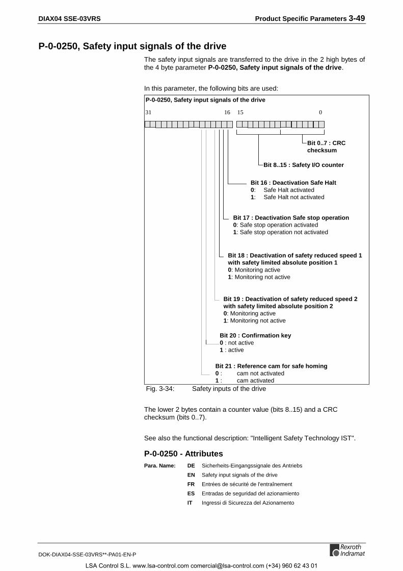
DIAX04 SSE-03VRS Product Specific Parameters 3-49
DOK-DIAX04-SSE-03VRS**-PA01-EN-P
P-0-0250, Safety input signals of the driveThe safety input signals are transferred to the drive in the 2 high bytes ofthe 4 byte parameter P-0-0250, Safety input signals of the drive.
In this parameter, the following bits are used:
Bit 16 : Deactivation Safe Halt0: Safe Halt activated1: Safe Halt not activated
P-0-0250, Safety input signals of the drive
Bit 17 : Deactivation Safe stop operation0: Safe stop operation activated1: Safe stop operation not activated
Bit 18 : Deactivation of safety reduced speed 1with safety limited absolute position 10: Monitoring active1: Monitoring not active
Bit 19 : Deactivation of safety reduced speed 2with safety limited absolute position 20: Monitoring active1: Monitoring not active
Bit 20 : Confirmation key0 : not active1 : active
Bit 21 : Reference cam for safe homing0 : cam not activated1 : cam activated
16 15 031
Bit 0..7 : CRCchecksum
Bit 8..15 : Safety I/O counter
Fig. 3-34: Safety inputs of the drive
The lower 2 bytes contain a counter value (bits 8..15) and a CRCchecksum (bits 0..7).
See also the functional description: "Intelligent Safety Technology IST".
P-0-0250 - AttributesPara. Name: DE Sicherheits-Eingangssignale des Antriebs
EN Safety input signals of the drive
FR Entrées de sécurité de l'entraînement
ES Entradas de seguridad del azionamiento
IT Ingressi di Sicurezza del Azionamento
LSA Control S.L. www.lsa-control.com [email protected] (+34) 960 62 43 01

3-50 Product Specific Parameters DIAX04 SSE-03VRS
DOK-DIAX04-SSE-03VRS**-PA01-EN-P
Function: Parameter Editability: -
Data length: 4Byte Memory: no
Unit: -- Extreme value check: -
Decimal places: - Combination check: -
Input min/max: 0 / 2147483647
Default value: 0 Cyc. transmittable: MDT
P-0-0251, Safety output signals of the driveThe safety output signals are transferred to the drive in the 2 highsignificant bytes of the 4 byte parameter P-0-0251, Safety outputsignals of the drive.
In this parameter, the following bits are occupied:
Bit 16 : Safety function active0: No safety function active1: Safety function active
P-0-0251 Safety output signals of the drive
Bit 17 : Switchover finished0: Switchover active1: Switchover not active
Bit 18 : Position switch 10: act. position value < P-0-0260 or > P-0-02591: P-0-0260 < act. position value < P-0-0259
Bit 19 : Position switch 20: act. position value < P-0-0262 or > P-0-02611: P-0-0262 < act. position value < P-0-0261
Bit 20 : Position switch 30: act. position value < P-0-0264 or > P-0-02631: P-0-0264 < act. position value < P-0-0263
Bit 21 : Position switch 40: act. position value < P-0-0266 or > P-0-02651: P-0-0266 < act. position value < P-0-0265
16 15 031
Bit 0..7 : CRCchecksum
Bit 8..15 : Drive counter
Fig. 3-35: Safety outputs of the drive
The bits 16 and 17 are both 1, when the selected safety functions areactive. This is the case, when the selection acknowledge bits 24..28 inP-0-0252, State of safety function, drive are the same as the preset bits16..20 in P-0-0250, Safety input signals of the drive and the activationof the selected safety functions was without error.
LSA Control S.L. www.lsa-control.com [email protected] (+34) 960 62 43 01

DIAX04 SSE-03VRS Product Specific Parameters 3-51
DOK-DIAX04-SSE-03VRS**-PA01-EN-P
A change of the selection resets the bit 17 (switchover finished) to 0 untilthe newly selected safety function is active.
The lower 2 bytes contain a counter value (bits 8..15) and a CRCchecksum (bits 0..7).
The counter value is incremented by 1 every 100 ms by the drive.
The CRC checksum is determined from the 2 high significant bytes of theoutput signals, the counter and a further byte containing the driveaddress.
See also the functional description: "Intelligent Safety Technology IST".
P-0-0251 - AttributesPara. Name: DE Sicherheits-Ausgangssignale des Antriebs
EN Safety output signals of the drive
FR Sorties de sécurité de l'entraînement
ES Salidas de seguridad del azionamiento
IT Uscite di Sicurezza del Azionamento
Function: Parameter Editability: -
Data length: 4Byte Memory: no
Unit: -- Extreme value check: -
Decimal places: - Combination check: -
Input min/max: 0 / 2147483647
Default value: - Cyc. transmittable: AT
LSA Control S.L. www.lsa-control.com [email protected] (+34) 960 62 43 01

3-52 Product Specific Parameters DIAX04 SSE-03VRS
DOK-DIAX04-SSE-03VRS**-PA01-EN-P
P-0-0252, State of safety function, driveThe state of the safety function can be seen in the most significant byte ofthe 4 byte parameter P-0-0252, State of safety function, drive.
In this parameter, the following bits are occupied:
Bit 24 : Acknowledge Safe Halt0: Safe Halt selected1: Safe Halt not selected
P-0-0252, State of the safety function, drive
Bit 25 : Acknowledge safe stop operation0: Safe stop operation selected1: Safe stop operation not selected
Bit 26 : Acknowledge safety reduced speed 1 withsafety limited absolute position 10: Red. speed 1 and lim. absolute position 1 selected1: Red. speed 1 and lim. absolute position 1 not selected
Bit 28 : Acknowledge Confirmation key0: Confirmation key not activated1: Confirmation key activated
Bit 29 : Signal Motion enabled0: Motion is not enabled1: Motion is enabled
16 15 031 24
Bit 27 : Acknowledge safety reduced speed 2 withsafetylimited absolute position 20: Red. speed 2 and lim. absolute position 2 selected1: Red. speed 2 and lim. absolute position 2 not selected
Bit 0..15 : Life-counterBit 16..23 : Drive address
Fig. 3-36: State of the safety function
The signal ‚Enable Motion‘ is set, when no safety function is active (bit24..27 = 1) or when Safe reduced speed with safe limited absoluteposition is active (bit 26 or 27 = 0) and the confirmation key is pushed (bit28 = 1).
The bits 16 to 23 show the drive address.
In the bits 0..15, there is the life-counter of the drive. Upon reaching theoperation mode (Communication phase 4), this counter is initialized with astart value calculated after the following equation :
Start value = ( ( Drive address - 1 ) mod 64 ) • 1024.
From then on, the life-counter is incremented by 1 in every SERCOScycle.
See also the functional description: "Intelligent Safety Technology IST".
LSA Control S.L. www.lsa-control.com [email protected] (+34) 960 62 43 01

DIAX04 SSE-03VRS Product Specific Parameters 3-53
DOK-DIAX04-SSE-03VRS**-PA01-EN-P
P-0-0252 - AttributesPara. Name: DE Status der Sicherheitsfunktion, Antrieb
EN State of safety function, drive
FR Etat fonction sécurité, entraînement
ES Estado función seguridad, azionamiento
IT Stato Funzione Sicurezza, Azionamento
Function: Parameter Editability: -
Data length: 4Byte Memory: no
Unit: -- Extreme value check: -
Decimal places: - Combination check: -
Input min/max: 0 / 2147483647
Default value: - Cyc. transmittable: AT
P-0-0253, Max. speed 1 for safety function, driveThis parameter sets the maximum speed which is allowable with active safetyfunction "Safe reduced speed 1 with safely limited absolute position 1“.
See also the functional description: "Intelligent Safety Technology IST".
P-0-0253 - AttributesPara. Name: DE Maximale Geschwindigkeit 1 für Sicherheitsfkt., Antrieb
EN Max. speed 1 for safety function, drive
FR Vitesse maxi. 1 pour fonction de sécurité, entraînement
ES Velocidad max. 1 por función seguridad, azionamiento
IT Velocità mass. 1 per Funzione Sicurezza, Azionamento
Function: Parameter Editability: -
Data length: 4Byte Memory: Param.-E²prom
Unit: S-0-0044 Extreme value check: -
Decimal places: - Combination check: -
Input min/max: 0 / S-0-0044
Default value: 0 Cyc. transmittable: AT
P-0-0254, Upper position limit 1 for safety function, driveThis parameter sets the upper position limit which is allowable with active safetyfunction „Safe reduced speed 1 with safely limited absolute position 1“.
See also the functional description: "Intelligent Safety Technology IST".
P-0-0254 - AttributesPara. Name: DE Oberes Positionslimit 1 für Sicherheitsfkt., Antrieb
EN Upper position limit 1 for safety function, drive
FR Limite de position supérieure 1, fonct. de sécurité, entr.
IT Límite di Posizione sup. 1, Funz. Sicurezza, Azion.
Function: Parameter Editability: -
Data length: 4Byte Memory: Param.-E²prom
Unit: S-0-0076 Extreme value check: -
Decimal places: - Combination check: -
Input min/max: 0 / S-0-0076
Default value: 0 Cyc. transmittable: AT
LSA Control S.L. www.lsa-control.com [email protected] (+34) 960 62 43 01

3-54 Product Specific Parameters DIAX04 SSE-03VRS
DOK-DIAX04-SSE-03VRS**-PA01-EN-P
P-0-0255, Lower position limit 1 for safety function, driveThis parameter sets the lower position limit which is allowable with active safetyfunction "Safe reduced speed 1 with safely limited absolute position 1".
See also the functional description: "Intelligent Safety Technology IST".
P-0-0255 - AttributesPara. Name: DE Unteres Positionslimit 1 für Sicherheitsfkt., Antrieb
EN Lower position limit 1 for safety function, drive
FR Limite de position inférieure 1, fonct. de sécurité, entr.
IT Límite di Posizione inf. 1, Funz. Sicurezza, Azion.
Function: Parameter Editability: -
Data length: 4Byte Memory: Param.-E²prom
Unit: S-0-0076 Extreme value check: -
Decimal places: - Combination check: -
Input min/max: 0 / S-0-0076
Default value: 0 Cyc. transmittable: AT
P-0-0256, Max. speed 2 for safety function, driveThis parameter sets the maximum speed which is allowable with active safetyfunction „Safe reduced speed 2 with safely limited absolute position 2“.
See also the functional description: "Intelligent Safety Technology IST".
P-0-0256 - AttributesPara. Name: DE Maximale Geschwindigkeit 2 für Sicherheitsfkt., Antrieb
EN Max. speed 2 for safety function, drive
FR Vitesse maxi. 2 pour fonction de sécurité, entraînement
ES Velocidad max. 2 por función seguridad, azionamiento
IT Velocità mass. 2 per Funzione Sicurezza, Azionamento
Function: Parameter Editability: -
Data length: 4Byte Memory: Param.-E²prom
Unit: S-0-0044 Extreme value check: -
Decimal places: - Combination check: -
Input min/max: 0 / S-0-0044
Default value: - Cyc. transmittable: AT
LSA Control S.L. www.lsa-control.com [email protected] (+34) 960 62 43 01

DIAX04 SSE-03VRS Product-specific parameters 3-55
DOK-DIAX04-SSE-03VRS**-PA01-EN-P
P-0-0257, Upper position limit 2 for safety function, driveThis parameter sets the upper position limit which is allowable with activesafety function „Safety reduced speed 2 with safety limited absoluteposition 2“.
See also the functional description: "Intelligent Safety Technology IST".
P-0-0257 - AttributesPara. Name: DE Oberes Positionslimit 2 für Sicherheitsfkt., Antrieb
EN Upper position limit 2 for safety function, drive
FR Limite de position supérieure 2, fonct. de sécurité, entr.
IT Límite di Posizione sup. 2, Funz. Sicurezza, Azion.
Function: Parameter Editability: -
Data length: 4Byte Memory: Param.-E²prom
Unit: S-0-0076 Extreme value check: -
Decimal places: - Combination check: -
Input min/max: S-0-0076 / S-0-0076
Default value: - Cyc. transmittable: AT
P-0-0258, Lower position limit 2 for safety function, driveThis parameter sets the lower position limit which is allowable with activesafety function "Safety reduced speed 2 with safety limited absoluteposition 2".
See also the functional description: "Intelligent Safety Technology IST".
P-0-0258 - AttributesPara. Name: DE Unteres Positionslimit 2 für Sicherheitsfkt., Antrieb
EN Lower position limit 2 for safety function, drive
FR Limite de position inférieure 2, fonct. de sécurité, entr.
IT Límite di Posizione inf. 2, Funz. Sicurezza, Azion.
Function: Parameter Editability: -
Data length: 4Byte Memory: Param.-E²prom
Unit: S-0-0076 Extreme value check: -
Decimal places: - Combination check: -
Input min/max: S-0-0076 / S-0-0076
Default value: - Cyc. transmittable: AT
P-0-0259, Upper position limit for position switch 1, driveThis parameter sets the upper position limit for the position switch 1.
See also the functional description: "Intelligent Safety Technology IST".
LSA Control S.L. www.lsa-control.com [email protected] (+34) 960 62 43 01

3-56 Product-specific parameters DIAX04 SSE-03VRS
DOK-DIAX04-SSE-03VRS**-PA01-EN-P
P-0-0259 - AttributesPara. Name: DE Oberes Pos.-Limit für Positionsschaltpunkt 1, Antrieb
EN Upper position limit for position switch 1, drive
Function: Parameter Editability: -
Data length: 4Byte Memory: Param.-E²prom
Unit: S-0-0076 Extreme value check: -
Decimal places: - Combination check: -
Input min/max: S-0-0076 / S-0-0076
Default value: - Cyc. transmittable: AT
P-0-0260, Lower position limit for position switch 1, driveThis parameter sets the lower position limit for the position switch 1.
See also the functional description: "Intelligent Safety Technology IST".
P-0-0260 - AttributesPara. Name: DE Unteres Pos.-Limit für Positionsschaltpunkt 1, Antrieb
EN Lower position limit for position switch 1, drive
Function: Parameter Editability: -
Data length: 4Byte Memory: Param.-E²prom
Unit: S-0-0076 Extreme value check: -
Decimal places: - Combination check: -
Input min/max: S-0-0076 / S-0-0076
Default value: 0 Cyc. transmittable: AT
P-0-0261, Upper position limit for position switch 2, driveThis parameter sets the upper position limit for the position switch 2.
See also the functional description: "Intelligent Safety Technology IST".
P-0-0261 - AttributesPara. Name: DE Oberes Pos.-Limit für Positionsschaltpunkt 2, Antrieb
EN Upper position limit for position switch 2, drive
Function: Parameter Editability: -
Data length: 4Byte Memory: Param.-E²prom
Unit: S-0-0076 Extreme value check: -
Decimal places: - Combination check: -
Input min/max: S-0-0076 / S-0-0076
Default value: 0 Cyc. transmittable: AT
P-0-0262, Lower position limit for position switch 2, driveThis parameter sets the lower position limit for the position switch 2.
See also the functional description: "Intelligent Safety Technology IST".
LSA Control S.L. www.lsa-control.com [email protected] (+34) 960 62 43 01

DIAX04 SSE-03VRS Product-specific parameters 3-57
DOK-DIAX04-SSE-03VRS**-PA01-EN-P
P-0-0262 - AttributesPara. Name: DE Unteres Pos.-Limit für Positionsschaltpunkt 2, Antrieb
EN Lower position limit for position switch 2, drive
Function: Parameter Editability: -
Data length: 4Byte Memory: Param.-E²prom
Unit: S-0-0076 Extreme value check: -
Decimal places: - Combination check: -
Input min/max: S-0-0076 / S-0-0076
Default value: 0 Cyc. transmittable: AT
P-0-0263, Upper position limit for position switch 3, driveThis parameter sets the upper position limit for the position switch 3.
See also the functional description: "Intelligent Safety Technology IST".
P-0-0263 - AttributesPara. Name: DE Oberes Pos.-Limit für Positionsschaltpunkt 3, Antrieb
EN Upper position limit for position switch 3, drive
Function: Parameter Editability: -
Data length: 4Byte Memory: Param.-E²prom
Unit: S-0-0076 Extreme value check: -
Decimal places: - Combination check: -
Input min/max: S-0-0076 / S-0-0076
Default value: 0 Cyc. transmittable: AT
P-0-0264, Lower position limit for position switch 3, driveThis parameter sets the lower position limit for the position switch 3.
See also the functional description: "Intelligent Safety Technology IST".
P-0-0264 - AttributesPara. Name: DE Unteres Pos.-Limit für Positionsschaltpunkt 3, Antrieb
EN Lower position limit for position switch 3, drive
Function: Parameter Editability: -
Data length: 4Byte Memory: Param.-E²prom
Unit: S-0-0076 Extreme value check: -
Decimal places: - Combination check: -
Input min/max: S-0-0076 / S-0-0076
Default value: 0 Cyc. transmittable: AT
P-0-0265, Upper position limit for position switch 4, driveThis parameter sets the upper position limit for the position switch 4.
See also the functional description: "Intelligent Safety Technology IST".
LSA Control S.L. www.lsa-control.com [email protected] (+34) 960 62 43 01

3-58 Product-specific parameters DIAX04 SSE-03VRS
DOK-DIAX04-SSE-03VRS**-PA01-EN-P
P-0-0265 - AttributesPara. Name: DE Oberes Pos.-Limit für Positionsschaltpunkt 4, Antrieb
EN Upper position limit for position switch 4, drive
Function: Parameter Editability: -
Data length: 4Byte Memory: Param.-E²prom
Unit: S-0-0076 Extreme value check: -
Decimal places: - Combination check: -
Input min/max: S-0-0076 / S-0-0076
Default value: 0 Cyc. transmittable: AT
P-0-0266, Lower position limit for position switch 4, driveThis parameter sets the lower position limit for the position switch 4.
See also the functional description: "Intelligent Safety Technology IST".
P-0-0266 - AttributesPara. Name: DE Unteres Pos.-Limit für Positionsschaltpunkt 4, Antrieb
EN Lower position limit for position switch 4, drive
Function: Parameter Editability: -
Data length: 4Byte Memory: Param.-E²prom
Unit: S-0-0076 Extreme value check: -
Decimal places: - Combination check: -
Input min/max: S-0-0076 / S-0-0076
Default value: 0 Cyc. transmittable: AT
P-0-0267, Pos. monitoring window for safe stop operation, driveThis parameter sets the position window which may not be exceededduring active safety function „Safe stop operation“.
See also the functional description: "Intelligent Safety Technology IST".
P-0-0267 - AttributesPara. Name: DE Pos.-Überwachungsfenster für sicheren Betriebshalt, Antrieb
EN Pos. monitoring window for safe stop operation, drive
FR Fenêtre de surveillance en pos. pour arrêt sûr, entraînement
Function: Parameter Editability: -
Data length: 4Byte Memory: Param.-E²prom
Unit: S-0-0076 Extreme value check: -
Decimal places: - Combination check: -
Input min/max: 0 / S-0-0076
Default value: 0 Cyc. transmittable: AT
P-0-0268, Reference position for safe homing, driveThis parameter sets the position where the signal for the safe referencecam comes. The signal is requested during the „P-0-0272, CommandCheck reference“.
See also the functional description: "Intelligent Safety Technology IST".
LSA Control S.L. www.lsa-control.com [email protected] (+34) 960 62 43 01
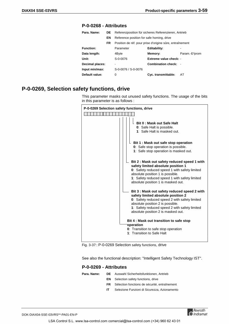
DIAX04 SSE-03VRS Product-specific parameters 3-59
DOK-DIAX04-SSE-03VRS**-PA01-EN-P
P-0-0268 - AttributesPara. Name: DE Referenzposition für sicheres Referenzieren, Antrieb
EN Reference position for safe homing, drive
FR Position de réf. pour prise d'origine sûre, entraînement
Function: Parameter Editability: -
Data length: 4Byte Memory: Param.-E²prom
Unit: S-0-0076 Extreme value check: -
Decimal places: - Combination check: -
Input min/max: S-0-0076 / S-0-0076
Default value: 0 Cyc. transmittable: AT
P-0-0269, Selection safety functions, driveThis parameter masks out unused safety functions. The usage of the bitsin this parameter is as follows :
Bit 0 : Mask out Safe Halt0: Safe Halt is possible.1: Safe Halt is masked out.
P-0-0269 Selection safety functions, drive
Bit 1 : Mask out safe stop operation0: Safe stop operation is possible.1: Safe stop operation is masked out.
Bit 2 : Mask out safety reduced speed 1 withsafety limited absolute position 10: Safety reduced speed 1 with safety limitedabsolute position 1 is possible.1: Safety reduced speed 1 with safety limitedabsolute position 1 is masked out.
Bit 3 : Mask out safety reduced speed 2 withsafety limited absolute position 20: Safety reduced speed 2 with safety limitedabsolute position 2 is possible.1: Safety reduced speed 2 with safety limitedabsolute position 2 is masked out.
Bit 4 : Mask out transition to safe stopoperation0: Transition to safe stop operation1: Transition to Safe Halt
Fig. 3-37:: P-0-0269 Selection safety functions, drive
See also the functional description: "Intelligent Safety Technology IST".
P-0-0269 - AttributesPara. Name: DE Auswahl Sicherheitsfunktionen, Antrieb
EN Selection safety functions, drive
FR Sélection fonctions de sécurité, entraînement
IT Selezione Funzioni di Sicurezza, Azionamento
LSA Control S.L. www.lsa-control.com [email protected] (+34) 960 62 43 01

3-60 Product-specific parameters DIAX04 SSE-03VRS
DOK-DIAX04-SSE-03VRS**-PA01-EN-P
Function: Parameter Editability: -
Data length: 2Byte Memory: Param.-E²prom
Unit: -- Extreme value check: -
Decimal places: - Combination check: -
Input min/max: 0 / 32767
Default value: 0 Cyc. transmittable: AT
P-0-0270, Changeover time for safety function, driveThis parameter sets how long it takes during switching of safety functionsuntil the selected one becomes active. The changeover time is only takeninto account when the new safety function allows a smaller speed thanthe one active before.
See also the functional description: "Intelligent Safety Technology IST".
P-0-0270 - AttributesPara. Name: DE Übergangszeit für Umschaltung der Sicherheitsfkt., Antrieb
EN Changeover time for safety function, drive
FR Temps de transition pour fonction de sécurité, entraînement
IT Tempo di Transizione per Funzione di Sicurezza, Azionamento
Function: Parameter Editability: -
Data length: 2Byte Memory: Param.-E²prom
Unit: ms Extreme value check: -
Decimal places: - Combination check: -
Input min/max: 0 / 32767
Default value: 0 Cyc. transmittable: AT
P-0-0271, Time interval for forced dynamization, driveThis parameter sets the time intervals, how often the communications forshut-off are monitored by drive and control.
See also the functional description: "Intelligent Safety Technology IST".
P-0-0271 - AttributesPara. Name: DE Zeitintervall für Zwangsdynamisierung, Antrieb
EN Time interval for forced dynamization, drive
FR Lapse de temps pour dynamisation forcée, entraînement
Function: Parameter Editability: -
Data length: 2Byte Memory: Param.-E²prom
Unit: h Extreme value check: -
Decimal places: - Combination check: -
Input min/max: 0 / 32767
Default value: 0 Cyc. transmittable: AT
LSA Control S.L. www.lsa-control.com [email protected] (+34) 960 62 43 01
DIAX04 SSE-03VRS Product-specific parameters 3-61
DOK-DIAX04-SSE-03VRS**-PA01-EN-P
P-0-0272, C000 Command Check referenceThe successful execution of this command is a precondition for thosesafety functions, where the absolute reference of the actual positionvalues is necessary.
In this command, the drive checks whether the following conditions aremet :
• The axis has been homed(S-0-0403, Position feedback value status = 1).
• The actual position may differ by less than the P-0-0267, Pos.monitoring window for safe stop operation from the P-0-0268,Reference position for safe homing.
• The signal for the safe reference cam is set.
See also the functional description: "Intelligent Safety Technology IST".
P-0-0272 - AttributesPara. Name: DE C000 Kommando Überprüfung der Referenz
EN C000 Command Check reference
FR C000 Commande Vérification de l'origine
IT C000 Comando Verificazione Azzeramento
Function: Command Editability: -
Data length: 2Byte Memory: no
Unit: -- Extreme value check: no
Decimal places: - Combination check: no
Input min/max: 0 / 3
Default value: 0 Cyc. transmittable: no
P-0-0273, Monitored actual position, driveThis parameter displays the value of the actual position that the driveuses for the safety functions.
See also the functional description: "Intelligent Safety Technology IST".
P-0-0273 - AttributesPara. Name: DE Überwachter Lageistwert, Antrieb
EN Monitored actual position, drive
FR Position actuelle surveillée, entraînement
Function: Parameter Editability: -
Data length: 4Byte Memory: no
Unit: S-0-0076 Extreme value check: -
Decimal places: - Combination check: -
Input min/max: S-0-0076 / S-0-0076
Default value: - Cyc. transmittable: AT
LSA Control S.L. www.lsa-control.com [email protected] (+34) 960 62 43 01

3-62 Product-specific parameters DIAX04 SSE-03VRS
DOK-DIAX04-SSE-03VRS**-PA01-EN-P
P-0-0274, Preset forced dynamizationThe forced dynamization is used for the monitoring of the switch-off signalpaths of drive and control. This way, drive and control survey each other.
Seven different steps are designed into the procedure which are doneone after the other. Inputting the actual step is done with this parameter.The drive acknowledges the actual step with the parameter P-0-0275,Acknowledge forced dynamization.
See also the functional description: "Intelligent Safety Technology IST".
P-0-0274 - AttributesPara. Name: DE Vorgabe Zwangsdynamisierung
EN Preset forced dynamization
Function: Parameter Editability: -
Data length: 2Byte Memory: no
Unit: -- Extreme value check: -
Decimal places: - Combination check: -
Input min/max: 0 / 32767
Default value: 0 Cyc. transmittable: no
P-0-0275, Acknowledge forced dynamizationThe forced dynamization is used for the monitoring of the switch-off signalpaths of drive and control. This way, drive and control survey each other.
Seven different steps are foreseen in the procedure which are done oneafter the other. Inputting the actual step is done with the parameter P-0-0274, Preset forced dynamization. The drive acknowledges the actualstep with this parameter.
See also the functional description: "Intelligent Safety Technology IST".
P-0-0275 - AttributesPara. Name: DE Rückmeldung Zwangsdynamisierung
EN Acknowledge forced dynamization
FR Aquittement dynamisation forcée
Function: Parameter Editability: -
Data length: 2Byte Memory: no
Unit: -- Extreme value check: -
Decimal places: - Combination check: -
Input min/max: 0 / 32767
Default value: 0 Cyc. transmittable: no
P-0-0276, State of safety function, controlThe state of the safety function from the control is analogous to the onefrom the drive (P-0-0252).
The value is transferred to the drive for monitoring purposes.
See also the functional description: "Intelligent Safety Technology IST".
LSA Control S.L. www.lsa-control.com [email protected] (+34) 960 62 43 01

DIAX04 SSE-03VRS Product-specific parameters 3-63
DOK-DIAX04-SSE-03VRS**-PA01-EN-P
P-0-0276 - AttributesPara. Name: DE Status der Sicherheitsfunktion, Steuerung
EN State of safety function, control
FR Etat fonction sécurité, contrôle
IT Stato Funzione Sicurezza, Controllo
Function: Parameter Editability: -
Data length: 4Byte Memory: no
Unit: -- Extreme value check: -
Decimal places: - Combination check: -
Input min/max: 0 / 2147483647
Default value: 0 Cyc. transmittable: MDT
P-0-0277, Max. speed 1 for safety function, controlThis parameter sets the maximum speed which is allowable withactivated safety function „Safety reduced speed 1 with safety limitedabsolute position 1“.
The value has been parametrized on the control side and is transferred tothe drive for monitoring purposes.
See also the functional description: "Intelligent Safety Technology IST".
P-0-0277 - AttributesPara. Name: DE Maximale Geschwindigkeit 1 für Sicherheitsfkt., Steuerung
EN Max. speed 1 for safety function, control
FR Vitesse maxi. 1 pour fonction de sécurité, contrôle
ES Velocidad max. 1 por función seguridad, mando
IT Velocità mass. 1 per Funzione Sicurezza, Controllo
Function: Parameter Editability: -
Data length: 4Byte Memory: no
Unit: S-0-0044 Extreme value check: -
Decimal places: - Combination check: -
Input min/max: 0 / S-0-0044
Default value: 0 Cyc. transmittable: MDT
P-0-0278, Upper position limit 1 for safety function, controlThis parameter sets the upper position limit which is allowable with activesafety function „Safety reduced speed 1 with safety limited absoluteposition 1“.
The value has been parametrized on the control side and is transferred tothe drive for monitoring purposes.
See also the functional description: "Intelligent Safety Technology IST".
P-0-0278 - AttributesPara. Name: DE Oberes Positionslimit 1 für Sicherheitsfunktion, Steuerung
EN Upper position limit 1 for safety function, control
FR Limite de position supérieure 1, fonct. de sécurité, contr.
IT Límite di Posizione sup. 1, Funz. Sicurezza, Contr.
LSA Control S.L. www.lsa-control.com [email protected] (+34) 960 62 43 01

3-64 Product-specific parameters DIAX04 SSE-03VRS
DOK-DIAX04-SSE-03VRS**-PA01-EN-P
Function: Parameter Editability: -
Data length: 4Byte Memory: no
Unit: S-0-0076 Extreme value check: -
Decimal places: - Combination check: -
Input min/max: S-0-0076 / S-0-0076
Default value: 0 Cyc. transmittable: MDT
P-0-0279, Lower position limit 1 for safety function, controlThis parameter sets the lower position limit which is allowable with activesafety function „Safety reduced speed 1 with safety limited absoluteposition 1“.
The value has been parametrized on the control side and is transferred tothe drive for monitoring purposes.
See also the functional description: "Intelligent Safety Technology IST".
P-0-0279 - AttributesPara. Name: DE Unteres Positionslimit 1 für Sicherheitsfunktion, Steuerung
EN Lower position limit 1 for safety function, control
FR Limite de position inférieure 1, fonct. de sécurité, contr.
IT Límite di Posizione inf. 1, Funz. Sicurezza, Contr.
Function: Parameter Editability: -
Data length: 4Byte Memory: no
Unit: S-0-0076 Extreme value check: -
Decimal places: - Combination check: -
Input min/max: S-0-0076 / S-0-0076
Default value: 0 Cyc. transmittable: MDT
P-0-0280, Max. speed 2 for safety function, controlThis parameter sets the maximum speed which is allowable with activesafety function „Safety reduced speed 2 with safety limited absoluteposition 2“.
The value has been parametrized on the control side and is transferred tothe drive for monitoring purposes.
See also the functional description: "Intelligent Safety Technology IST".
P-0-0280 - AttributesPara. Name: DE Maximale Geschwindigkeit 2 für Sicherheitsfkt., Steuerung
EN Max. speed 2 for safety function, control
FR Vitesse maxi. 2 pour fonction de sécurité, contrôle
ES Velocidad max. 2 por función seguridad, mando
IT Velocità mass. 2 per Funzione Sicurezza, Controllo
Function: Parameter Editability: -
Data length: 4Byte Memory: no
Unit: S-0-0044 Extreme value check: -
Decimal places: - Combination check: -
Input min/max: 0 / S-0-0044
Default value: 0 Cyc. transmittable: MDT
LSA Control S.L. www.lsa-control.com [email protected] (+34) 960 62 43 01
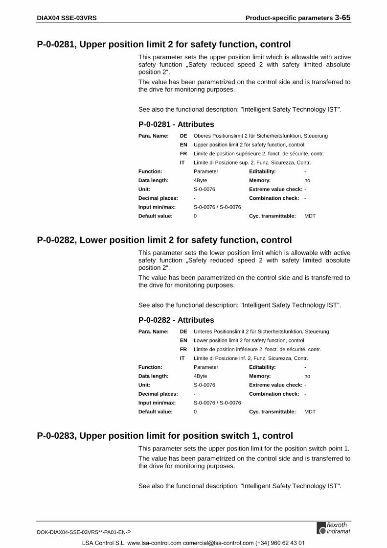
DIAX04 SSE-03VRS Product-specific parameters 3-65
DOK-DIAX04-SSE-03VRS**-PA01-EN-P
P-0-0281, Upper position limit 2 for safety function, controlThis parameter sets the upper position limit which is allowable with activesafety function „Safety reduced speed 2 with safety limited absoluteposition 2“.
The value has been parametrized on the control side and is transferred tothe drive for monitoring purposes.
See also the functional description: "Intelligent Safety Technology IST".
P-0-0281 - AttributesPara. Name: DE Oberes Positionslimit 2 für Sicherheitsfunktion, Steuerung
EN Upper position limit 2 for safety function, control
FR Limite de position supérieure 2, fonct. de sécurité, contr.
IT Límite di Posizione sup. 2, Funz. Sicurezza, Contr.
Function: Parameter Editability: -
Data length: 4Byte Memory: no
Unit: S-0-0076 Extreme value check: -
Decimal places: - Combination check: -
Input min/max: S-0-0076 / S-0-0076
Default value: 0 Cyc. transmittable: MDT
P-0-0282, Lower position limit 2 for safety function, controlThis parameter sets the lower position limit which is allowable with activesafety function „Safety reduced speed 2 with safety limited absoluteposition 2“.
The value has been parametrized on the control side and is transferred tothe drive for monitoring purposes.
See also the functional description: "Intelligent Safety Technology IST".
P-0-0282 - AttributesPara. Name: DE Unteres Positionslimit 2 für Sicherheitsfunktion, Steuerung
EN Lower position limit 2 for safety function, control
FR Limite de position inférieure 2, fonct. de sécurité, contr.
IT Límite di Posizione inf. 2, Funz. Sicurezza, Contr.
Function: Parameter Editability: -
Data length: 4Byte Memory: no
Unit: S-0-0076 Extreme value check: -
Decimal places: - Combination check: -
Input min/max: S-0-0076 / S-0-0076
Default value: 0 Cyc. transmittable: MDT
P-0-0283, Upper position limit for position switch 1, controlThis parameter sets the upper position limit for the position switch point 1.
The value has been parametrized on the control side and is transferred tothe drive for monitoring purposes.
See also the functional description: "Intelligent Safety Technology IST".
LSA Control S.L. www.lsa-control.com [email protected] (+34) 960 62 43 01
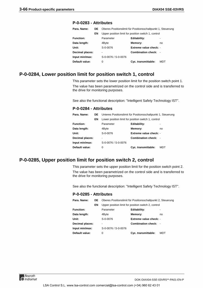
3-66 Product-specific parameters DIAX04 SSE-03VRS
DOK-DIAX04-SSE-03VRS**-PA01-EN-P
P-0-0283 - AttributesPara. Name: DE Oberes Positionslimit für Positionsschaltpunkt 1, Steuerung
EN Upper position limit for position switch 1, control
Function: Parameter Editability: -
Data length: 4Byte Memory: no
Unit: S-0-0076 Extreme value check: -
Decimal places: - Combination check: -
Input min/max: S-0-0076 / S-0-0076
Default value: 0 Cyc. transmittable: MDT
P-0-0284, Lower position limit for position switch 1, controlThis parameter sets the lower position limit for the position switch point 1.
The value has been parametrized on the control side and is transferred tothe drive for monitoring purposes.
See also the functional description: "Intelligent Safety Technology IST".
P-0-0284 - AttributesPara. Name: DE Unteres Positionslimit für Positionsschaltpunkt 1, Steuerung
EN Lower position limit for position switch 1, control
Function: Parameter Editability: -
Data length: 4Byte Memory: no
Unit: S-0-0076 Extreme value check: -
Decimal places: - Combination check: -
Input min/max: S-0-0076 / S-0-0076
Default value: 0 Cyc. transmittable: MDT
P-0-0285, Upper position limit for position switch 2, controlThis parameter sets the upper position limit for the position switch point 2.
The value has been parametrized on the control side and is transferred tothe drive for monitoring purposes.
See also the functional description: "Intelligent Safety Technology IST".
P-0-0285 - AttributesPara. Name: DE Oberes Positionslimit für Positionsschaltpunkt 2, Steuerung
EN Upper position limit for position switch 2, control
Function: Parameter Editability: -
Data length: 4Byte Memory: no
Unit: S-0-0076 Extreme value check: -
Decimal places: - Combination check: -
Input min/max: S-0-0076 / S-0-0076
Default value: 0 Cyc. transmittable: MDT
LSA Control S.L. www.lsa-control.com [email protected] (+34) 960 62 43 01
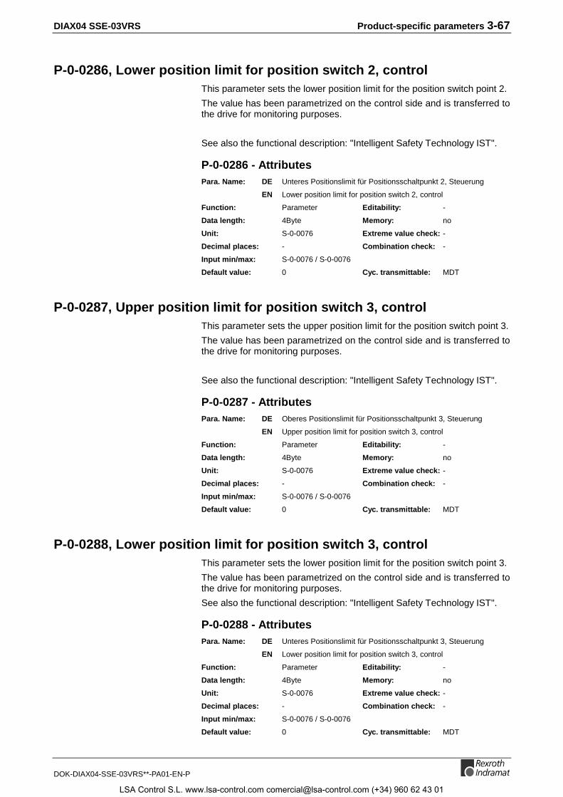
DIAX04 SSE-03VRS Product-specific parameters 3-67
DOK-DIAX04-SSE-03VRS**-PA01-EN-P
P-0-0286, Lower position limit for position switch 2, controlThis parameter sets the lower position limit for the position switch point 2.
The value has been parametrized on the control side and is transferred tothe drive for monitoring purposes.
See also the functional description: "Intelligent Safety Technology IST".
P-0-0286 - AttributesPara. Name: DE Unteres Positionslimit für Positionsschaltpunkt 2, Steuerung
EN Lower position limit for position switch 2, control
Function: Parameter Editability: -
Data length: 4Byte Memory: no
Unit: S-0-0076 Extreme value check: -
Decimal places: - Combination check: -
Input min/max: S-0-0076 / S-0-0076
Default value: 0 Cyc. transmittable: MDT
P-0-0287, Upper position limit for position switch 3, controlThis parameter sets the upper position limit for the position switch point 3.
The value has been parametrized on the control side and is transferred tothe drive for monitoring purposes.
See also the functional description: "Intelligent Safety Technology IST".
P-0-0287 - AttributesPara. Name: DE Oberes Positionslimit für Positionsschaltpunkt 3, Steuerung
EN Upper position limit for position switch 3, control
Function: Parameter Editability: -
Data length: 4Byte Memory: no
Unit: S-0-0076 Extreme value check: -
Decimal places: - Combination check: -
Input min/max: S-0-0076 / S-0-0076
Default value: 0 Cyc. transmittable: MDT
P-0-0288, Lower position limit for position switch 3, controlThis parameter sets the lower position limit for the position switch point 3.
The value has been parametrized on the control side and is transferred tothe drive for monitoring purposes.
See also the functional description: "Intelligent Safety Technology IST".
P-0-0288 - AttributesPara. Name: DE Unteres Positionslimit für Positionsschaltpunkt 3, Steuerung
EN Lower position limit for position switch 3, control
Function: Parameter Editability: -
Data length: 4Byte Memory: no
Unit: S-0-0076 Extreme value check: -
Decimal places: - Combination check: -
Input min/max: S-0-0076 / S-0-0076
Default value: 0 Cyc. transmittable: MDT
LSA Control S.L. www.lsa-control.com [email protected] (+34) 960 62 43 01

3-68 Product-specific parameters DIAX04 SSE-03VRS
DOK-DIAX04-SSE-03VRS**-PA01-EN-P
P-0-0289, Upper position limit for position switch 4, controlThis parameter sets the upper position limit for the position switch point 4.
The value has been parametrized on the control side and is transferred tothe drive for monitoring purposes.
See also the functional description: "Intelligent Safety Technology IST".
P-0-0289 - AttributesPara. Name: DE Oberes Positionslimit für Positionsschaltpunkt 4, Steuerung
EN Upper position limit for position switch 4, control
Function: Parameter Editability: -
Data length: 4Byte Memory: no
Unit: S-0-0076 Extreme value check: -
Decimal places: - Combination check: -
Input min/max: S-0-0076 / S-0-0076
Default value: 0 Cyc. transmittable: MDT
P-0-0290, Lower position limit for position switch 4, controlThis parameter sets the lower position limit for the position switch point 4.
The value has been parametrized on the control side and is transferred tothe drive for monitoring purposes.
See also the functional description: "Intelligent Safety Technology IST".
P-0-0290 - AttributesPara. Name: DE Unteres Positionslimit für Positionsschaltpunkt 4, Steuerung
EN Lower position limit for position switch 4, control
Function: Parameter Editability: -
Data length: 4Byte Memory: no
Unit: S-0-0076 Extreme value check: -
Decimal places: - Combination check: -
Input min/max: S-0-0076 / S-0-0076
Default value: 0 Cyc. transmittable: MDT
P-0-0291, Pos. monitoring window for safe stop operation, controlThis parameter sets the position window which may not be exceeded withactive safety function „Safe stop operation“.
The value has been parametrized on the control side and is transferred tothe drive for monitoring purposes.
See also the functional description: "Intelligent Safety Technology IST".
P-0-0291 - AttributesPara. Name: DE Pos.-Überwachungsfenster für sicheren Betriebshalt, Stg.
EN Pos. monitoring window for safe stop operation, control
FR Fenêtre de surveillance en pos. pour arrêt sûr, contrôle
LSA Control S.L. www.lsa-control.com [email protected] (+34) 960 62 43 01
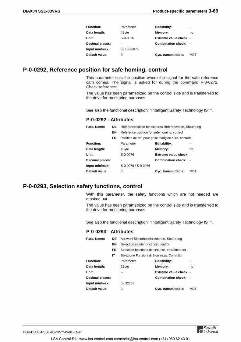
DIAX04 SSE-03VRS Product-specific parameters 3-69
DOK-DIAX04-SSE-03VRS**-PA01-EN-P
Function: Parameter Editability: -
Data length: 4Byte Memory: no
Unit: S-0-0076 Extreme value check: -
Decimal places: - Combination check: -
Input min/max: 0 / S-0-0076
Default value: 0 Cyc. transmittable: MDT
P-0-0292, Reference position for safe homing, controlThis parameter sets the position where the signal for the safe referencecam comes. The signal is asked for during the command P-0-0272,Check reference“.
The value has been parametrized on the control side and is transferred tothe drive for monitoring purposes.
See also the functional description: "Intelligent Safety Technology IST".
P-0-0292 - AttributesPara. Name: DE Referenzposition für sicheres Referenzieren, Steuerung
EN Reference position for safe homing, control
FR Position de réf. pour prise d'origine sûre, contrôle
Function: Parameter Editability: -
Data length: 4Byte Memory: no
Unit: S-0-0076 Extreme value check: -
Decimal places: - Combination check: -
Input min/max: S-0-0076 / S-0-0076
Default value: 0 Cyc. transmittable: MDT
P-0-0293, Selection safety functions, controlWith this parameter, the safety functions which are not needed aremasked out.
The value has been parametrized on the control side and is transferred tothe drive for monitoring purposes.
See also the functional description: "Intelligent Safety Technology IST".
P-0-0293 - AttributesPara. Name: DE Auswahl Sicherheitsfunktionen, Steuerung
EN Selection safety functions, control
FR Sélection fonctions de sécurité, entraînement
IT Selezione Funzioni di Sicurezza, Controllo
Function: Parameter Editability: -
Data length: 2Byte Memory: no
Unit: -- Extreme value check: -
Decimal places: - Combination check: -
Input min/max: 0 / 32767
Default value: 0 Cyc. transmittable: MDT
LSA Control S.L. www.lsa-control.com [email protected] (+34) 960 62 43 01
3-70 Product-specific parameters DIAX04 SSE-03VRS
DOK-DIAX04-SSE-03VRS**-PA01-EN-P
P-0-0294, Changeover time for safety functions, controlThis parameter sets how long it takes during switching between safetyfunctions, until the target safety function becomes active. The changeovertime is only taken into account when the new safety function allows asmaller speed than the one active before.
The value has been parametrized on the control side and is transferred tothe drive for monitoring purposes.
See also the functional description: "Intelligent Safety Technology IST".
P-0-0294 - AttributesPara. Name: DE Übergangszeit für Umschaltung der Sicherheitsfkt., Steuerung
EN Changeover time for safety functions, control
FR Temps de transition pour fonctions de sécurité, contrôle
IT Tempo di Transizione per Funzioni di Sicurezza, Controllo
Function: Parameter Editability: -
Data length: 4Byte Memory: no
Unit: ms Extreme value check: -
Decimal places: - Combination check: -
Input min/max: 0 / 32767
Default value: 0 Cyc. transmittable: MDT
P-0-0295, Time interval for forced dynamization, controlThis parameter sets the time intervals, how often the switch-off signalpaths of drive and control are checked.
The value has been parametrized on the control side and is transferred tothe drive for monitoring purposes.
See also the functional description: "Intelligent Safety Technology IST".
P-0-0295 - AttributesPara. Name: DE Zeitintervall für Zwangsdynamisierung, Steuerung
EN Time interval for forced dynamization, control
FR Lapse de temps pour dynamisation forcée, contrôle
Function: parameter Editability: -
Data length: 2Byte Memory: no
Unit: h Extreme value check: -
Decimal places: - Combination check: -
Input min/max: 0 / 32767
Default value: 0 Cyc. transmittable: MDT
P-0-0296, Monitored actual position, controlThe control transfers the actual position value, which it uses for the safetyfunctions, into this parameter.
See also the functional description: "Intelligent Safety Technology IST".
LSA Control S.L. www.lsa-control.com [email protected] (+34) 960 62 43 01
DIAX04 SSE-03VRS Product-specific parameters 3-71
DOK-DIAX04-SSE-03VRS**-PA01-EN-P
P-0-0296 - AttributesPara. Name: DE Überwachter Lageistwert, Steuerung
EN Monitored actual position, control
FR Position actuelle surveillée, contrôle
Function: Parameter Editability: -
Data length: 4Byte Memory: no
Unit: S-0-0076 Extreme value check: -
Decimal places: - Combination check: -
Input min/max: S-0-0076 / S-0-0076
Default value: 0 Cyc. transmittable: MDT
P-0-0297, Checksum over scaled data, controlA checksum is determined from all parameter values which influence theactual position value composed by the drive.
This checksum built by the drive must be parametrized on the control sidewhen the safety functions are in use.
With this parameter, the value is transferred to the drive for monitoringpurposes.
See also the functional description: "Intelligent Safety Technology IST".
P-0-0297 - AttributesPara. Name: DE Checksumme über Wichtungsdaten, Steuerung
EN Checksum over scaled data, control
Function: Parameter Editability: P234
Data length: 2Byte Memory: no
Format: DEC_OV Validity check: no
Decimal places: 0 Combination check: no
Input min/max: 0 / 65535
Default value: 0 Cyc. transmittable: MDT
P-0-0400, Pos. corr., external correction valueThe control system can use parameter P-0-0400, Pos. corr., externalcorrection value to assign correction values directly for the encoderspecified by S-0-0147, Homing parameter. The correction value set inthe parameter will be added to the appropriate actual feedback value.
See also the functional description: "Axis Error Correction"
P-0-0400 - AttributesPara. Name: DE Pos.-Korr., Korrekturwert extern
EN Pos. corr., external correction value
FR Corr. de pos., valeur externe de correction
ES Corrección de posición, valor de corrección externo
IT Correzione Valore esterna
LSA Control S.L. www.lsa-control.com [email protected] (+34) 960 62 43 01
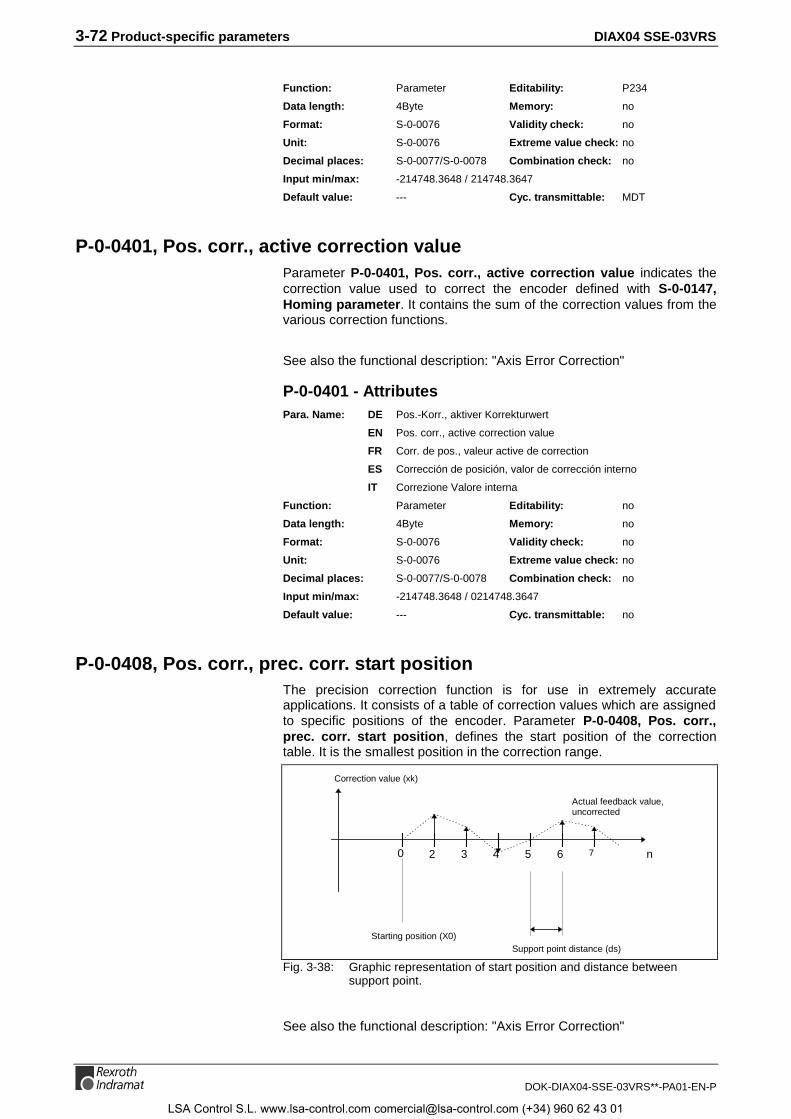
3-72 Product-specific parameters DIAX04 SSE-03VRS
DOK-DIAX04-SSE-03VRS**-PA01-EN-P
Function: Parameter Editability: P234
Data length: 4Byte Memory: no
Format: S-0-0076 Validity check: no
Unit: S-0-0076 Extreme value check: no
Decimal places: S-0-0077/S-0-0078 Combination check: no
Input min/max: -214748.3648 / 214748.3647
Default value: --- Cyc. transmittable: MDT
P-0-0401, Pos. corr., active correction valueParameter P-0-0401, Pos. corr., active correction value indicates thecorrection value used to correct the encoder defined with S-0-0147,Homing parameter. It contains the sum of the correction values from thevarious correction functions.
See also the functional description: "Axis Error Correction"
P-0-0401 - AttributesPara. Name: DE Pos.-Korr., aktiver Korrekturwert
EN Pos. corr., active correction value
FR Corr. de pos., valeur active de correction
ES Corrección de posición, valor de corrección interno
IT Correzione Valore interna
Function: Parameter Editability: no
Data length: 4Byte Memory: no
Format: S-0-0076 Validity check: no
Unit: S-0-0076 Extreme value check: no
Decimal places: S-0-0077/S-0-0078 Combination check: no
Input min/max: -214748.3648 / 0214748.3647
Default value: --- Cyc. transmittable: no
P-0-0408, Pos. corr., prec. corr. start positionThe precision correction function is for use in extremely accurateapplications. It consists of a table of correction values which are assignedto specific positions of the encoder. Parameter P-0-0408, Pos. corr.,prec. corr. start position, defines the start position of the correctiontable. It is the smallest position in the correction range.
0 42 5 763 n
Starting position (X0)Support point distance (ds)
Correction value (xk)
Actual feedback value,uncorrected
Fig. 3-38: Graphic representation of start position and distance betweensupport point.
See also the functional description: "Axis Error Correction"
LSA Control S.L. www.lsa-control.com [email protected] (+34) 960 62 43 01

DIAX04 SSE-03VRS Product-specific parameters 3-73
DOK-DIAX04-SSE-03VRS**-PA01-EN-P
P-0-0408 - AttributesPara. Name: DE Pos.-Korr., Startposition Präz.
EN Pos. corr., prec. corr. start position
FR Corr. de pos., position initiale préc.
ES Corrección de pos., factor de temp. depend. de pos.
IT Corr. Pos., Posizione iniziale prec.
Function: Parameter Editability: P234
Data length: 4Byte Memory: Param. EE
Format: DEC_MV Validity check: Phase3
Unit: S-0-0076 Extreme value check: no
Decimal places: S-0-0077/S-0-0078 Combination check: no
Input min/max: -214748.3648 / 0214748.3647
Default value: 0 Cyc. transmittable: no
P-0-0409, Pos. corr., correction table for prec. corr.For highly accurate applications, correction values for the encoder aredetermined by measuring the axis. These correction values are stored inparameter P-0-0409, Pos. corr., correction table for prec. corr.. 500correction values can be stored for motion in each direction. The first 500correction values are reserved for motion in the positive direction, and thesecond 500 are reserved for motion in the negative direction.
A correction value is defined as a 2-byte unit of data, which limits inputvalues to ±2^15 in the selected direction of motion.
The difference between two adjacent correction values must not begreater than the value of parameter P-0-0410, Pos. corr., support pointdistance for prec. corr..
To avoid excessive leaps in feedback values, the first and last correctionvalue in each direction must be defined as 0. All 1000 correction valuesmust always be written. Support points which are not needed can be setto 0.
The table is composed as follows:
Actual length
Maximum length
Correction value 1 = 0
Correction value 2
Correction value 1000 = 0
Correction value 502
Correction value 501 = 0
Correction value 500 = 0
Correction values fornegative direction of motion
Correction values forpositive direction of motion
Fig. 3-39: Structure of the correction table
LSA Control S.L. www.lsa-control.com [email protected] (+34) 960 62 43 01

3-74 Product-specific parameters DIAX04 SSE-03VRS
DOK-DIAX04-SSE-03VRS**-PA01-EN-P
See also the functional description: "Axis Error Correction"
P-0-0409 - AttributesPara. Name: DE Pos.-Korr., Korrekturtabelle Präz.
EN Pos. corr., correction table for prec. corr.
FR Corr. de pos., table de corr. préc.
ES Corrección de pos., tabla corrección de precisión
IT Corr. Pos., Tabella di Precisione
Function: Parameter Editability: P234
Data length: 2Byte var. Memory: Param. EE
Format: DEC_MV Validity check: Phase3
Unit: S-0-0076 Extreme value check: no
Decimal places: S-0-0077/S-0-0078 Combination check: no
Input min/max: -3.2768 / 03.2767
Default value: leer Cyc. transmittable: no
P-0-0410, Pos. corr., support point distance for prec. corr.Parameter P-0-0410, Pos. corr., support point distance for prec. corr.,defines the distance between two adjacent correction values.
It is constant for the entire correction range (=start position + 499*supportpoint distance), depending on P-0-0408, Pos. corr., prec. corr. startposition, and defines the positions for which correction values in thetable must be determined.
See also the functional description: "Axis Error Correction"
P-0-0410 - AttributesPara. Name: DE Pos.-Korr., Stützpunktabstand Präz.
EN Pos. corr., support point distance for prec. corr.
FR Corr. de pos., écartement des points d'appui préc.
ES Corr. pos, distancia de puntos de apoyo prec.
IT Corr. Pos., Distanza di Campionamento per prec.
Function: Parameter Editability: P234
Data length: 4Byte Memory: Param. EE
Format: DEC_MV Validity check: Phase3
Unit: S-0-0076 Extreme value check: no
Decimal places: S-0-0077/S-0-0078 Combination check: no
Input min/max: -214748.3648 / 0214748.3647
Default value: 0 Cyc. transmittable: no
P-0-0420, Analog output 1 signal selectionUsing P-0-0420, Analog output 1 signal selection, an ID no. can beassigned to the analog AK1 output channel of the drive controller. Theparameter with the assigned ID no. can be viewed with an oscilloscope inthe form of an analog voltage. Only those ID no. contained in the list P-0-0426, Analog outputs, IDN list of assignable parameters can be used.
See also the functional description: "Analog Output".
LSA Control S.L. www.lsa-control.com [email protected] (+34) 960 62 43 01

DIAX04 SSE-03VRS Product-specific parameters 3-75
DOK-DIAX04-SSE-03VRS**-PA01-EN-P
P-0-0420 - AttributesPara. Name: DE Analog-Ausgang 1, Signalauswahl
EN Analog output 1 signal selection
FR Sortie analogique 1, sélection de signal
ES Salida analógica 1, selección de señal
IT Uscita analogica 1, Scelta del Segnale
Function: Parameter Editability: P234
Data length: 2Byte Memory: Param. EE
Format: IDN Validity check: no
Unit: -- Extreme value check: no
Decimal places: -- Combination check: no
Input min/max: 0 / 2^32-1
Default value: 0 Cyc. transmittable: no
P-0-0421, Analog output 1, expanded signal selectionTo be able to show signals as analog voltage, which are not in theparameter P-0-0426, Analog outputs, IDN list of assignableparameters, the option of an expanded signal selection is possible. Thisbecomes active as long as no parameter is assigned via P-0-0420,Analog output 1 signal selection.
The following expanded signal select options are available:
• expanded signal select with permanently defined signals
• byte output
• bit output
1) Expanded signal selection with fixed signals
Internal signals are assigned to numbers which are not in the drive in theform of ident numbers. These signals get permanent units making anevaluation via P-0-0422, Analog output 1, scaling per 10V full scalepossible. The evaluation factor 1.0 equals the permanent unit. Thefollowing permanently defined signals are possible:
Signal numberP-0-0421 Output signal
Ref. Unit:scaling factor = 1.0
0x00000001 motor encoder sine signal 0.5V/10V
0x00000002 motor encoder cosine signal 0.5V/10V
0x00000003 Opt. enc. sine signal 0.5V/10V
0x00000004 Opt. enc. cosine signal 0.5V/10V
0x00000005 Position command differenceon the pos. controler
rot. =>1000rpm/10Vlin. =>100m/min/10V
0x00000006 DC bus power 1kW/10V
0x00000007 absolute DC bus power value 1kW/10V
0x00000008 effective current S-0-0110/10V
0x00000009 relative current S-0-0110/10V
0x0000000a thermal load 100%/10V,no scaling possible
0x0000000b motor temperature 150°C/10V
0x0000000c magnetizing current S-0-0110/10V
0x0000000d velocity command at thevelocity controller
rot. => 1000rpm/10Vlin. => 100m/min/10V
Fig. 3-40: Signal select list with predefined signal selection
LSA Control S.L. www.lsa-control.com [email protected] (+34) 960 62 43 01

3-76 Product-specific parameters DIAX04 SSE-03VRS
DOK-DIAX04-SSE-03VRS**-PA01-EN-P
The outputs are not scaling dependent, and position and velocity dataalways refer to the motor shaft.
2) Byte output
With this option it is possible to output memory locations of the datamemory as an analog voltage. It can only be practically applied if the datastorage structure is known. As this is, however, different from version toversion, the function can only be used by the respective developer. Thefunction is activated by setting bit 28 in P-0-0421, Analog output 1,expanded signal selection. The address of the memory cell is defined inthe least significant 24 bit of the expanded signal selection.
31 30 29 282726 252423 2221 2019 1817 1615 1413 1211 10 9 8 7 6 5 4 3 2 1 0
Bit 28 :Byte output
Bit 0..2324 Bit address
Fig. 3-41: Definition P-0-0421, Analog output 1, expanded signal selectionwith byte output
3) Bit output
With this option individual bits of the data memory can be shown as ananalog voltage. If the respective bit is set, then 10V is output at the analogoutput. A cleared bit outputs -10V. The function is activated by setting bit29 and inputting the desired memory address in P-0-0421, Analogoutput 1, expanded signal selection.
31 30 29 282726 252423 2221 2019 1817 1615 1413 1211 10 9 8 7 6 5 4 3 2 1 0
Bit 0..2324 Bit address
Bit 29 :Bit output
Fig. 3-42: Definition P-0-0421, Analog output 1, expanded signal selectionwith bit output
See also the functional description: "Analog Output".
P-0-0421 - AttributesPara. Name: DE Analog-Ausgang 1, erweiterte Signalauswahl
EN Analog output 1, expanded signal selection
FR Sortie analogique 1, sélection de signal élargie
ES Salida analógica 1, selección de señal ampliada
IT Uscita analogica 1, Superamento Scelta
LSA Control S.L. www.lsa-control.com [email protected] (+34) 960 62 43 01

DIAX04 SSE-03VRS Product-specific parameters 3-77
DOK-DIAX04-SSE-03VRS**-PA01-EN-P
Function: Parameter Editability: P234
Data length: 4Byte Memory: Param. EE
Format: HEX Validity check: no
Unit: -- Extreme value check: no
Decimal places: -- Combination check: no
Input min/max: 0 / 23
Default value: 0 Cyc. transmittable: no
P-0-0422, Analog output 1, scaling per 10V full scaleThe resolution of the selected signal can be varied with parameterP-0-0422, Analog output 1 scaling per 10V full scale. If an ID no. isassigned via P-0-0420, Analog output 1, signal selection, the evalutionis assigned the same unit as the parameter with the assigned ID number.
The output of pre-defined signals means that the scaling has a decimalfactor of 4 decimal places. It has a permanent reference with fixed unit.
The scaling defines the least significant bit for bit and byte outputs. Theinput is an integer value without decimal places.
See also the functional description: "Analog Output".
P-0-0422 - AttributesPara. Name: DE Analog-Ausgang 1, Bewertung [1/10V]
EN Analog output 1, scaling per 10V full scale
FR Sortie analogique 1, calibrage [1/10V]
ES Salida analógica 1, calibrado [1/10V]
IT Uscita analogica 1, Scala per 10V fondo scala
Function: Parameter Editability: P234
Data length: --- Memory: Param. EE
Format: P-0-0420/P-0-0421 Validity check: no
Unit: P-0-0420/P-0-0421 Extreme value check: no
Decimal places: P-0-0420/P-0-0421 Combination check: no
Input min/max: 0 / 2^32-1
Default value: 0 Cyc. transmittable: no
P-0-0423, Analog output 2, signal selectionUsing P-0-0423, Analog output 2, signal selection, an ID no. can beassigned to the analog AK2 output channel of the drive controller. Theparameter with the assigned ID no. can be viewed with an oscilloscope inthe form of an analog voltage. Only those ID no. contained in the list P-0-0426, Analog outputs, IDN list of assignable parameters can be used.
See also the functional description: "Analog Output".
P-0-0423 - AttributesPara. Name: DE Analog-Ausgang 2, Signalauswahl
EN Analog output 2, signal selection
FR Sortie analogique 2, sélection de signal
ES Salida analógica 2, selección de señal
IT Uscita analogica 2, Scelta del SegnaleAusnahme: B000
LSA Control S.L. www.lsa-control.com [email protected] (+34) 960 62 43 01

3-78 Product-specific parameters DIAX04 SSE-03VRS
DOK-DIAX04-SSE-03VRS**-PA01-EN-P
Function: Parameter Editability: P234
Data length: 2Byte Memory: Param. EE
Format: IDN Validity check: no
Unit: -- Extreme value check: no
Decimal places: 0 Combination check: no
Input min/max: 0 / 2^32-1
Default value: 0 Cyc. transmittable: no
P-0-0424, Analog output 2, expanded signal selectionTo be able to show signals as analog voltage, which are not in theparameter P-0-0426, Analog outputs, IDN list of assignableparameters, the option of an expanded signal selection is possible. Thisbecomes active as long as no parameter is assigned via P-0-0423,Analog output 2 signal selection.
The following expanded signal select options are available:
• expanded signal select with permanently defined signals
• byte output
• bit output
1) Expanded signal selection with fixed signals
Internal signals are assigned to numbers which are not in the drive in theform of ident numbers. These signals have permanent units making anevaluation via P-0-0425, Analog output 2, scalling per 10V full scalepossible. The evaluation factor 1.0 equals the permanent unit.
The following permanently defined signals are possible:
Signal numberP-0-0424 Output signal
Ref. Unit:scaling factor = 1.0
0x00000001 motor encoder sine signal 0.5V/10V
0x00000002 motor encoder cosinesignal
0.5V/10V
0x00000003 Opt. enc. sine signal 0.5V/10V
0x00000004 Opt. enc. cosine signal 0.5V/10V
0x00000005 Position commanddifference on the pos.controler
rot. =>1000rpm/10Vlin. =>100m/min/10V
0x00000006 DC bus power 1kW/10V
0x00000007 absolute DC bus powervalue
1kW/10V
0x00000008 effective current S-0-0110/10V
0x00000009 relative current S-0-0110/10V
0x0000000a thermal load 100%/10Vno scaling possible
0x0000000b motor temperature 150°C/10V
0x0000000c magnetizing current S-0-0110/10V
0x0000000d velocity command at thevelocity controller
rot. =>1000rpm/10Vlin. => 100m/min/10V
Fig. 3-43: Signal select list with predefined signal selection
The outputs are not scaling dependent, and position and velocity dataalways refer to the motor shaft.
LSA Control S.L. www.lsa-control.com [email protected] (+34) 960 62 43 01

DIAX04 SSE-03VRS Product-specific parameters 3-79
DOK-DIAX04-SSE-03VRS**-PA01-EN-P
2) Byte output
With this option it is possible to output memory locations of the datamemory as an analog voltage. It can only be practically applied if the datastorage structure is known. As this is, however, different from version toversion, the function can only be used by the respective developer. Thefunction is activated by setting bit 28 in P-0-0424, Analog output 2,expanded signal selection. The address of the memory cell is defined inthe least significant 24 bit of the expanded signal selection.
31 30 29 282726 252423 2221 2019 1817 1615 1413 1211 10 9 8 7 6 5 4 3 2 1 0
Bit 28 :Byte output
Bit 0..2324 Bit address
Fig. 3-44: Definition P-0-0424, Analog output 2, expanded signal selectionwith byte output
3) Bit output
With this option individual bits of the data memory can be shown as ananalog voltage. If the respective bit is set, then 10V is output at the analogoutput. A cleared bit outputs -10V. The function is activated by setting bit29 and inputting the desired memory address in P-0-0424, Analogoutput 2, expanded signal selection.
31 30 29 282726 252423 2221 2019 1817 1615 1413 1211 10 9 8 7 6 5 4 3 2 1 0
Bit 0..2324 Bit address
Bit 29 :Bit output
Fig. 3-45: Definition P-0-0424, Analog output 2, expanded signal selectionwith bit output
See also the functional description: "Analog Output".
P-0-0424 - AttributesPara. Name: DE Analog-Ausgang 2, erweiterte Signalauswahl
EN Analog output 2, expanded signal selection
FR Sortie analogique 2, sélection de signal élargie
ES Salida analógica 2, selección de señal ampliada
IT Uscita analogica 2, Superamento Scelta
Function: Parameter Editability: P234
Data length: 4Byte Memory: no
Format: HEX Validity check: no
Unit: -- Extreme value check: no
Decimal places: -- Combination check: no
Input min/max: -- / --
Default value: --- Cyc. transmittable: no
LSA Control S.L. www.lsa-control.com [email protected] (+34) 960 62 43 01
3-80 Product-specific parameters DIAX04 SSE-03VRS
DOK-DIAX04-SSE-03VRS**-PA01-EN-P
P-0-0425, Analog output 2, scaling per 10V full scaleThe resolution of the selected signal can be varied with parameterP-0-0425, Analog output 2 scaling per 10V full scale. If an ID no. isassigned via P-0-0423, Analog output 2, signal selection, the evalutionis assigned the same unit as the parameter with the assigned ID number.
The output of pre-defined signals means that the scaling has a decimalfactor of 4 decimal places. It has a permanent reference with fixed unit.
The scaling defines the least significant bit for bit and byte outputs. Theinput is an integer value without decimal places.
See also the functional description: "Analog Output".
P-0-0425 - AttributesPara. Name: DE Analog-Ausgang 2, Bewertung [1/10V]
EN Analog output 2, scaling per 10V full scale
FR Sortie analogique 2, calibrage [1/10V]
ES Salida analógica 2, calibrado [1/10V]
IT Uscita analogica 2, Scala per 10V fondo scala
Function: Parameter Editability: P234
Format: P-0-0420/P-0-0421 Validity check: no
Unit: P-0-0420/P-0-0421 Extreme value check: no
Decimal places: P-0-0420/P-0-0421 Combination check: no
Input min/max: - / -
Default value: 0 Cyc. transmittable: no
P-0-0426, Analog outputs, IDN list of assignable parametersThe parameter P-0-0426, Analog outputs, IDN list of assignableparameters contains a list of all parameters assignable via P-0-0420,Analog output 1 signal selection and P-0-0423, Analog output 2, signalselection.
See also the functional description: "Analog Output".
P-0-0426 - AttributesPara. Name: DE Analog-Ausgabe, IDN-Liste der zuweisbaren Parameter
EN Analog outputs, IDN list of assignable parameters
FR Sorties analog., liste des paramètres pouvant être assignés
ES Salida analógica, lista IDN de los números ID asignables
IT Uscite analogiche, Lista IDN dei Parametri assignabili
Function: Parameter Editability: no
Data length: 2Byte var. Memory: no
Format: IDN Validity check: no
Unit: -- Extreme value check: no
Decimal places: 0 Combination check: no
Input min/max: - / -
Default value: --- Cyc. transmittable: no
LSA Control S.L. www.lsa-control.com [email protected] (+34) 960 62 43 01
DIAX04 SSE-03VRS Product-specific parameters 3-81
DOK-DIAX04-SSE-03VRS**-PA01-EN-P
P-0-0508, Commutation offsetFor synchronous motors, this parameter indicates the offset between theinitial position value of the motor encoder and the resulting absoluteelectrical angle between the stator current vector and the rotor flux vector.For motors with motor feedback data memory, like MKD, thecommutation offset is stored in the feedback and therefore does not needto be entered.
This value must always be redetermined, if
• the motor feedback system encounters a change in its mechanicalstructure,
• A mechanical restructuring of primary and secondary portions takesplace.
For asynchronous motors, this parameter has no meaning.
See also the functional description: "Synchronous-Asynchronous".
P-0-0508 - AttributesPara. Name: DE Kommutierungs-Offset
EN Commutation offset
FR Offset de commutation
ES Offset de conmutación
IT Offset di Commutazione
Function: Parameter Editability: no
Data length: 2Byte Memory: Param. EE
Format: DEC_OV Validity check: no
Unit: -- Extreme value check: no
Decimal places: 0 Combination check: no
Input min/max: 00000 / 65535
Default value: 0 Cyc. transmittable: no
P-0-0509, Slot angleThis parameter is not currently available for use.
P-0-0509 - AttributesPara. Name: DE Passfedernut-Winkel
EN Slot angle
FR Angle de clavette
ES Angulo de chavetero
IT Angolo di Inserzione
Function: Parameter Editability: no
Data length: 4Byte Memory: Param. EE
Format: DEC_MV Validity check: no
Unit: -- Extreme value check: no
Decimal places: 0 Combination check: no
Input min/max: --- / ---
Default value: --- Cyc. transmittable: no
LSA Control S.L. www.lsa-control.com [email protected] (+34) 960 62 43 01
3-82 Product-specific parameters DIAX04 SSE-03VRS
DOK-DIAX04-SSE-03VRS**-PA01-EN-P
P-0-0510, Moment of inertia of the rotorThis parameter indicates the moment of inertia of the rotor without load.For motors with feedback memory (e.g. MKD), it is saved in the feedback.
See also the functional description: "Motor Feedback-Data Memory".
P-0-0510 - AttributesPara. Name: DE Rotor-Trägheitsmoment
EN Moment of inertia of the rotor
FR Couple d'inertie du rotor
ES Par de inercia de rotor
IT Coppia di Inerzia del Rotore
Function: Parameter Editability: P23
Data length: 4Byte Memory: Param. EE
Format: DEC_OV Validity check: Phase3
Unit: kgm² Extreme value check: no
Decimal places: 5 Combination check: no
Input min/max: 00000.00001 / 00100.00000
Default value: 10000 Cyc. transmittable: no
P-0-0511, Brake currentThe brake current is monitored by the drive controller if the motor isequipped with a blocking brake and a value other than 0 is entered in thisparameter. If the brake current lies outside the range
(0.4 . . . 1.6) • P-0-0511,
then error message F268 Brake fault will be generated.
See also the functional description: "Motor Holding Brake"
P-0-0511 - AttributesPara. Name: DE Haltebremsenstrom
EN Brake current
FR Courant frein
ES Corriente de freno
IT Corrente Freno
Function: Parameter Editability: P23
Data length: 4Byte Memory: Param. EE
Format: DEC_OV Validity check: Phase3
Unit: A Extreme value check: yes
Decimal places: 3 Combination check: no
Input min/max: 0000000.000 / 0000500.000
Default value: 0 Cyc. transmittable: no
LSA Control S.L. www.lsa-control.com [email protected] (+34) 960 62 43 01

DIAX04 SSE-03VRS Product-specific parameters 3-83
DOK-DIAX04-SSE-03VRS**-PA01-EN-P
P-0-0518, Amplifier nominal current 2The parameter specifies the maximum nominal current of the amplifier atreduced peak current.
It specifies together with the parameters
• S-0-0110, Amplifier peak current
• S-0-0112, Amplifier nominal current
• P-0-0519, Amplifier peak current 2
the length of the peak current characteristics line for the peak current limitof the amplifier.
No value can be entered, since it is permanently programmed within theamplifier.
P-0-0518 - AttributesPara. Name: DE Verstärker-Nennstrom 2
EN Amplifier nominal current 2
FR Courant nominal variateur 2
ES Amplificador corriente nominal 2
IT Corrente Nominale Azionamento 2
Function: Parameter Editability: no
Data length: 4Byte Memory: Verst. EE
Format: DEC_OV Validity check: Phase3
Unit: A Extreme value check: yes
Decimal places: 3 Combination check: no
Input min/max: 0000000.001 / 0000500.000
Default value: --- Cyc. transmittable: no
P-0-0519, Amplifier peak current 2The drive offers the possibility to define a different continuous/peakcurrent characteristic line with reduced amplifier peak current, andtherefore an increased amplifier continuous current.
Parameter P-0-0519 specifies an amplifier peak current for this case.
It determines the working points on the peak current characteristic line.
No value for this parameter can be entered, since it is permanentlyprogrammed in the amplifier.
P-0-0519 - AttributesPara. Name: DE Verstärker-Spitzenstrom 2
EN Amplifier peak current 2
FR Courant crête variateur 2
ES Amplificador corriente punta 2
IT Corrente di Picco Azionamento 2
Function: Parameter Editability: no
Data length: 4Byte Memory: Verst. EE
Format: DEC_OV Validity check: Phase3
Unit: A Extreme value check: yes
Decimal places: 3 Combination check: no
Input min/max: 0000000.001 / 0000500.000
Default value: --- Cyc. transmittable: no
LSA Control S.L. www.lsa-control.com [email protected] (+34) 960 62 43 01

3-84 Product-specific parameters DIAX04 SSE-03VRS
DOK-DIAX04-SSE-03VRS**-PA01-EN-P
P-0-0523, Commutation, probe valueIf the commutation offset for linear synchronous motors is to be set withthe P-0-0524, Commutation adjustment command, then the settingprobe value should be entered in the P-0-0523, Commutation, probevalue parameter.
See also the functional description: "Determining commutation offset".
P-0-0523 - AttributesPara. Name: DE Kommutierungseinstellung Messwert
EN Commutation, probe value
FR Mesure reglage de commutation
ES Ajuste de conmutación, valor de medición
IT Commutazione, Valore di Probe
Function: Parameter Editability: no
Data length: 4Byte Memory: no
Format: DEC_OV Validity check: no
Unit: S-0-0076 Extreme value check: yes
Decimal places: S-0-0077/S-0-0078 Combination check: no
Input min/max: -214748.3648 / 0214748.3647
Default value: --- Cyc. transmittable: no
P-0-0524, D300 Commutation adjustment commandParameter P-0-0524 can activate the command for setting thecommutation offset. The command can only be used when:
• the appropriate password is entered
• torque control mode is active
• drive enable is on
If these criteria are met, the drive will automatically set the appropriatecommutation offset for synchronous motors.
See also the functional description: "Determining commutation offset"
P-0-0524 - AttributesPara. Name: DE D300 Kommando Kommutierungseinstellung
EN D300 Commutation adjustment command
FR D300 Commande reglage de commutation
ES D300 Comando ajuste de conmutación
IT D300 Commutazione - Comando
Function: Command Editability: no
Data length: 2Byte Memory: no
Format: BIN Validity check: no
Unit: -- Extreme value check: no
Decimal places: -- Combination check: no
Input min/max: --- / ---
Default value: --- Cyc. transmittable: no
LSA Control S.L. www.lsa-control.com [email protected] (+34) 960 62 43 01

DIAX04 SSE-03VRS Product-specific parameters 3-85
DOK-DIAX04-SSE-03VRS**-PA01-EN-P
P-0-0525, Type of motor brakeThis parameter specifies whether an electrically released or electricallyengaged brake is being used. If an MHD or MKD motor is used, then thebrake will be electrically released, if there is one. The bit 0 will be setautomatically to 0. If other motor types are used, this bit must be enteredduring the start-up procedure.
P-0-0525, Type of motor brake
Bit 0 : 0 - electrically released brake0V applied engages the brake.1 - electrically engaged brake24V applied engages the brake.
Bit 1 : 0 - Servo brakeThe brake will be engaged after max.braking time.1 - Main spindle brakeThe brake will only be engaged below10 Rpm.
Fig. 3-46: Setting the type of motor brake
See also the functional description: "Motor Holding Brake".
P-0-0525 - AttributesPara. Name: DE Haltebremsentyp
EN Type of motor brake
FR Type de frein
ES Tipo de freno
IT Tipo di Freno
Function: Parameter Editability: P23
Data length: 2Byte Memory: Param. EE
Format: BIN Validity check: Phase3
Unit: -- Extreme value check: yes
Decimal places: -- Combination check: no
Input min/max: 0x0000 / ---
Default value: 0 Cyc. transmittable: no
P-0-0526, Brake control delayIf a holding brake is used, the time delay between the activation of thebrake and the time when it gets its full force must be set in this parameter.
It must be sure that the drive is still electrically controlled as long as thebrake does not grip firmly.
This value is entered automatically when MHD, MKD or MKE motors areused. When using Indramat brakes in conjunction with asynchronousmotors, then the standard value to be entered is 150 ms.
LSA Control S.L. www.lsa-control.com [email protected] (+34) 960 62 43 01
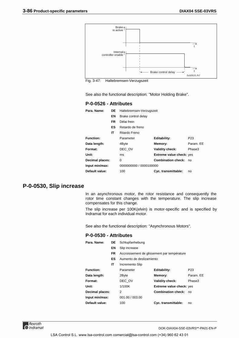
3-86 Product-specific parameters DIAX04 SSE-03VRS
DOK-DIAX04-SSE-03VRS**-PA01-EN-P
Sv5051f1.fh7
Brakeis active
t
Internalcontroller enable
tBrake control delay
Fig. 3-47: Haltebremsen-Verzugszeit
See also the functional description: "Motor Holding Brake".
P-0-0526 - AttributesPara. Name: DE Haltebremsen-Verzugszeit
EN Brake control delay
FR Délai frein
ES Retardo de freno
IT Ritardo Freno
Function: Parameter Editability: P23
Data length: 4Byte Memory: Param. EE
Format: DEC_OV Validity check: Phase3
Unit: ms Extreme value check: yes
Decimal places: 0 Combination check: no
Input min/max: 0000000000 / 0000100000
Default value: 100 Cyc. transmittable: no
P-0-0530, Slip increaseIn an asynchronous motor, the rotor resistance and consequently therotor time constant changes with the temperature. The slip increasecompensates for this change.
The slip increase per 100K(elvin) is motor-specific and is specified byIndramat for each individual motor.
See also the functional description: "Asynchronous Motors".
P-0-0530 - AttributesPara. Name: DE Schlupfanhebung
EN Slip increase
FR Accroissement de glissement par température
ES Aumento de deslizamiento
IT Incremento Slip
Function: Parameter Editability: P23
Data length: 2Byte Memory: Param. EE
Format: DEC_OV Validity check: Phase3
Unit: 1/100K Extreme value check: yes
Decimal places: 2 Combination check: no
Input min/max: 001.00 / 003.00
Default value: 100 Cyc. transmittable: no
LSA Control S.L. www.lsa-control.com [email protected] (+34) 960 62 43 01
DIAX04 SSE-03VRS Product-specific parameters 3-87
DOK-DIAX04-SSE-03VRS**-PA01-EN-P
P-0-0531, Stall current factorThe stall current limit is used to limit the peak current of the motor toreasonable values when operating at high velocities. Higher currents leadonly to higher losses, not to more shaft output power.
This limit value is set by Indramat. If 0 is entered, the limit is inactive.
See also the functional description: "Asynchronous Motors".
P-0-0531 - AttributesPara. Name: DE Kippstromfaktor
EN Stall current factor
FR Facteur de courant bascule
ES Factor de corriente de volcado
IT Fattore di Corrente di Inversione
Function: Parameter Editability: P234
Data length: 4Byte Memory: Param. EE
Format: DEC_OV Validity check: Phase3
Unit: A/Vmin Extreme value check: yes
Decimal places: 0 Combination check: no
Input min/max: 0000000000 / 4294967295
Default value: 100 Cyc. transmittable: no
P-0-0532, Premagnetization factorThe pre-magnetization factor is used for application-dependent decreasesin the Servo magnetization current. Together with parameter P-0-4004,Magnetizing current, it specifies the motor’s magnetization current.
Effective magnetization current =
magnetization current • pre-magnetization scaling factor
With a pre-magnetizing factor of 100%, the Servo magnetization currentin the motor will flow so that in the constant Torque range, a torqueproportional to the moment-producing current will result.
See also the functional description: "Scaling Factor Pre-Magnetizing".
P-0-0532 - AttributesPara. Name: DE Vormagnetisierungsfaktor
EN Premagnetization factor
FR Facteur de pré-magnétisation
ES Factor de magnetización previa
IT Fattore di Premagnetizzazione
Function: Parameter Editability: P234
Data length: 2Byte Memory: Param. EE
Format: DEC_OV Validity check: Phase3
Unit: % Extreme value check: yes
Decimal places: 0 Combination check: no
Input min/max: 00025 / 00100
Default value: 100 Cyc. transmittable: no
LSA Control S.L. www.lsa-control.com [email protected] (+34) 960 62 43 01
3-88 Product-specific parameters DIAX04 SSE-03VRS
DOK-DIAX04-SSE-03VRS**-PA01-EN-P
P-0-0533, Flux loop prop. gainThe flux loop controls the magnetization current in the field-weakeningrange.
The parameter value is set by Indramat.
See also the functional description: "Asynchronous Motors".
P-0-0533 - AttributesPara. Name: DE Feldregler Prop.verst.
EN Flux loop prop. gain
FR Gain prop. de l’asservissement de flux
ES Regulador de campo amplificación proporcional
IT Guadagno prop. Anello di Flusso
Function: Parameter Editability: P234
Data length: 2Byte Memory: Param. EE
Format: DEC_OV Validity check: Phase3
Unit: A/V Extreme value check: yes
Decimal places: 3 Combination check: no
Input min/max: 00.100 / 65.535
Default value: 1000 Cyc. transmittable: no
P-0-0534, Flux loop integral action timeThe flux loop controls the magnetization current in the field-weakeningrange.
The parameter value is set by Indramat.
See also the functional description: "Asynchronous Motors".
P-0-0534 - AttributesPara. Name: DE Feldregler Nachstellzeit
EN Flux loop integral action time
FR Part intégrale de l'asservissement de flux
ES Regulador de campo tiempo de reajuste
IT Tempo Integrazione Anello di Flusso
Function: Parameter Editability: P234
Data length: 2Byte Memory: Param. EE
Format: DEC_OV Validity check: Phase3
Unit: ms Extreme value check: yes
Decimal places: 1 Combination check: no
Input min/max: 0000.0 / 6553.5
Default value: 100 Cyc. transmittable: no
P-0-0535, Motor voltage at no loadThe motor voltage in the field-weakening range is set so that it reaches avalue lower than or equal to the DC bus voltage.
Under load, the motor voltage will be raised to the maximum motorvoltage.
See also the functional description: "Asynchronous Motors".
LSA Control S.L. www.lsa-control.com [email protected] (+34) 960 62 43 01
DIAX04 SSE-03VRS Product-specific parameters 3-89
DOK-DIAX04-SSE-03VRS**-PA01-EN-P
P-0-0535 - AttributesPara. Name: DE Motorleerlaufspannung
EN Motor voltage at no load
FR Tension moteur á vide
ES Tension de marcha en vacio de motor
IT No Carico Tensione Motore
Function: Parameter Editability: P234
Data length: 2Byte Memory: Param. EE
Format: DEC_OV Validity check: Phase3
Unit: %Uzwk Extreme value check: yes
Decimal places: 1 Combination check: no
Input min/max: 0050.0 / 0100.0
Default value: 1000 Cyc. transmittable: no
P-0-0536, Motor voltage max.The motor voltage in the field-weakening range is set so that it reaches avalue lower than or equal to the DC bus voltage.
At full load, the motor voltage will rise to the maximum motor voltage. Theoutput voltage will be sinusoidal up to a value of 90% .
See also the functional description: "Asynchronous Motors".
P-0-0536 - AttributesPara. Name: DE Motormaximalspannung
EN Motor voltage max.
FR Tension max. moteur
ES Tensión máxima de motor
IT Tensione Motore massima
Function: Parameter Editability: P234
Data length: 2Byte Memory: Param. EE
Format: DEC_OV Validity check: Phase3
Unit: %Uzwk Extreme value check: yes
Decimal places: 1 Combination check: no
Input min/max: 0050.0 / 0100.0
Default value: 1000 Cyc. transmittable: no
P-0-0537, S1-Kink-speedFrom the S1 kink speed on, core losses result in a drop in power. Thismotor-specific velocity determined by Indramat is only useful for the "S1operating mode". From this velocity on, the field is weakened earlyenough as to keep the motor temperature low.
See also the functional description: "Asynchronous Motors".
P-0-0537 - AttributesPara. Name: DE S1-Eckdrehzahl
EN S1-Kink-speed
FR Vitesse coin S1
ES S1-N.d.r. angular
IT S1 Velocità di Curvatura
LSA Control S.L. www.lsa-control.com [email protected] (+34) 960 62 43 01
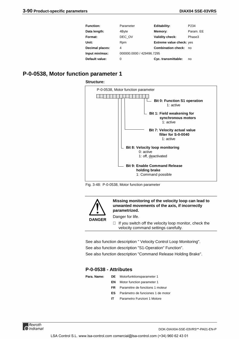
3-90 Product-specific parameters DIAX04 SSE-03VRS
DOK-DIAX04-SSE-03VRS**-PA01-EN-P
Function: Parameter Editability: P234
Data length: 4Byte Memory: Param. EE
Format: DEC_OV Validity check: Phase3
Unit: Rpm Extreme value check: yes
Decimal places: 4 Combination check: no
Input min/max: 000000.0000 / 429496.7295
Default value: 0 Cyc. transmittable: no
P-0-0538, Motor function parameter 1Structure:
P-0-0538, Motor function parameter
Bit 0: Function S1 operation1: active
Bit 1: Field weakening forsynchronous motors
1: active
Bit 8: Velocity loop monitoring0: active1: off, deactivated
Bit 7: Velocity actual valuefilter for S-0-0040
1: active
Bit 9: Enable Command Releaseholding brake1: Command possible
Fig. 3-48: P-0-0538, Motor function parameter
DANGER
Missing monitoring of the velocity loop can lead tounwanted movements of the axis, if incorrectlyparametrized.
Danger for life.
⇒ If you switch off the velocity loop monitor, check thevelocity command settings carefully.
See also function description " Velocity Control Loop Monitoring".
See also function description "S1-Operation" Function".
See also function description "Command Release Holding Brake".
P-0-0538 - AttributesPara. Name: DE Motorfunktionsparameter 1
EN Motor function parameter 1
FR Paramètre de fonctions 1 moteur
ES Parámetro de funciones 1 de motor
IT Parametro Funzioni 1 Motore
LSA Control S.L. www.lsa-control.com [email protected] (+34) 960 62 43 01

DIAX04 SSE-03VRS Product-specific parameters 3-91
DOK-DIAX04-SSE-03VRS**-PA01-EN-P
Function: Parameter Editability: P23
Data length: 2Byte Memory: Param. EE
Format: BIN Validity check: Phase3
Unit: --- Extreme value check: no
Decimal places: -- Combination check: yes
Input min/max: --- / ---
Default value: 0 Cyc. transmittable: no
P-0-0542, B100 Command Release motor holding brakeThe command is used to release the motor holding brake when the driveenable is switched off.
The command must be enabled via the motor function parameterP-0-0538, bit 7, before activating it.
When activating the command, the motor holding brake is opened andstays open until the command is finished or until the brake is closed byanother switching off the drive enable.
See also the functional description: "Motor Holding Brake".
P-0-0542 - AttributesPara. Name: DE B100 Kommando Öffnen der Motorhaltebremse
EN B100 Command Release motor holding brake
FR B100 Commande Lâcher frein
ES B100 Comando Abrir del freno de motor
IT B100 Comando Sblocco Freno
Function: Command Editability: P4
Data length: 2Byte Memory: -
Format: BIN Validity check: no
Unit: -- Extreme value check: no
Decimal places: 0 Combination check: no
Input min/max: - / -
Default value: - Cyc. transmittable: -
P-0-0560, Commutation adjustment currentThe parameter commutation adjustment current contains the currentvalue with which the automatic commutation adjustment is performed.The value is displayed as a percentage of the motor current at standstill.
If the automatic commutation adjustment aborts with the error„Commutation adjustment not possible“, you can change the value so thatthe automatic commutation adjustment runs successfully.
If the value represents a current greater than the motor peak current, thevalue is set to 100 % when the automatic commutation adjustment isstarted.
One input or displayed value is used for a first try to adjust thecommutation. If the commutation could not be adjusted with this value,the firmware will change the value and start another try; depending on thecircumstances, this might happen several times.
See also the functional description: „Asynchronous Motors".
LSA Control S.L. www.lsa-control.com [email protected] (+34) 960 62 43 01
3-92 Product-specific parameters DIAX04 SSE-03VRS
DOK-DIAX04-SSE-03VRS**-PA01-EN-P
P-0-0560 - AttributesPara. Name: DE Kommutierungseinstellung Strom
EN Commutation adjustment current
FR Justage de commutation, courant
Function: Parameter Editability: P234
Data length: 2Byte Memory: Prog.-Modul
Format: DEC_OV Validity check: no
Unit: % Extreme value check: yes
Decimal places: 3 Combination check: no
Input min/max: 250 / 400
Default value: 100 Cyc. transmittable: no
P-0-0562, Commutation adjustment periodic timeThe parameter commutation adjustment periodic time contains theperiodic time of the stimulus for the automatic commutation adjustment.
If the automatic commutation adjustment aborts with the error„Commutation adjustment not possible“, you can change the value so thatthe automatic commutation adjustment runs successfully. Find a valuewhich is not in the range of a mechanical resonance point, if possible.
One input or displayed value is used for a first try to adjust thecommutation. If the commutation could not be adjusted with this value,the firmware will change the value and start another try; depending on thecircumstances, this might happen several times.
See also the functional description: „Asynchronous Motors".
P-0-0562 - AttributesPara. Name: DE Kommutierungseinstellung Periodendauer
EN Commutation adjustment periodic time
FR Justage de commutation, période
Function: Parameter Editability: P234
Data length: 2Byte Memory: prog.-Modul
Format: DEC_OV Validity check: no
Unit: ms Extreme value check: no
Decimal places: 0 Combination check: no
Input min/max: 0 / 65535
Default value: 4 Cyc. transmittable: no
P-0-0640, Cooling typeThe parameter P-0-0640 Cooling type indicates, how the motor is cooled.Dependent from the cooling type, the reference value of the Force/Torquevalues is adjusted, so that the following applies:
100% Force/Torque value are equivalent to
Motor current at standstill S-0-0111 • Factor for cooling type • Torqueconstant
Cooling type Parametervalue
Factor
without blower 0 100 %
with forced air flow 1 150 %
Water_cooled 2 190 %
LSA Control S.L. www.lsa-control.com [email protected] (+34) 960 62 43 01
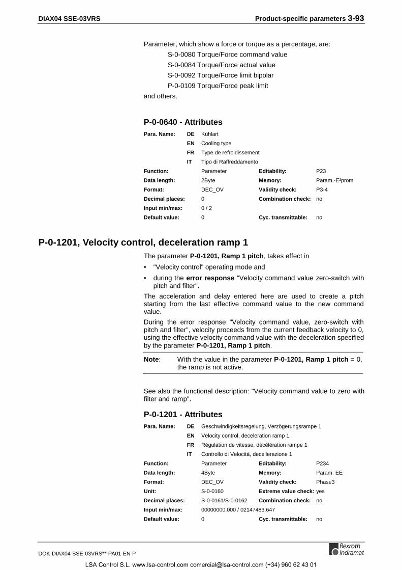
DIAX04 SSE-03VRS Product-specific parameters 3-93
DOK-DIAX04-SSE-03VRS**-PA01-EN-P
Parameter, which show a force or torque as a percentage, are:
S-0-0080 Torque/Force command value
S-0-0084 Torque/Force actual value
S-0-0092 Torque/Force limit bipolar
P-0-0109 Torque/Force peak limit
and others.
P-0-0640 - AttributesPara. Name: DE Kühlart
EN Cooling type
FR Type de refroidissement
IT Tipo di Raffreddamento
Function: Parameter Editability: P23
Data length: 2Byte Memory: Param.-E²prom
Format: DEC_OV Validity check: P3-4
Decimal places: 0 Combination check: no
Input min/max: 0 / 2
Default value: 0 Cyc. transmittable: no
P-0-1201, Velocity control, deceleration ramp 1The parameter P-0-1201, Ramp 1 pitch, takes effect in
• "Velocity control" operating mode and
• during the error response "Velocity command value zero-switch withpitch and filter".
The acceleration and delay entered here are used to create a pitchstarting from the last effective command value to the new commandvalue.
During the error response "Velocity command value, zero-switch withpitch and filter", velocity proceeds from the current feedback velocity to 0,using the effective velocity command value with the deceleration specifiedby the parameter P-0-1201, Ramp 1 pitch.
Note: With the value in the parameter P-0-1201, Ramp 1 pitch = 0,the ramp is not active.
See also the functional description: "Velocity command value to zero withfilter and ramp".
P-0-1201 - AttributesPara. Name: DE Geschwindigkeitsregelung, Verzögerungsrampe 1
EN Velocity control, deceleration ramp 1
FR Régulation de vitesse, décélération rampe 1
IT Controllo di Velocità, decellerazione 1
Function: Parameter Editability: P234
Data length: 4Byte Memory: Param. EE
Format: DEC_OV Validity check: Phase3
Unit: S-0-0160 Extreme value check: yes
Decimal places: S-0-0161/S-0-0162 Combination check: no
Input min/max: 00000000.000 / 02147483.647
Default value: 0 Cyc. transmittable: no
LSA Control S.L. www.lsa-control.com [email protected] (+34) 960 62 43 01

3-94 Product-specific parameters DIAX04 SSE-03VRS
DOK-DIAX04-SSE-03VRS**-PA01-EN-P
P-0-1222, Velocity command filterThe parameter P-0-1222, Velocity command filter works
• in the Velocity control operating mode and
• during the error response "Velocity command value zero-switch withslope and filter."
The time constant entered here is used in the velocity control operatingmode to pass the value in S-0-0036, Velocity command value, which islimited to the acceleration set in P-0-1201, Ramp 1 pitch, through a low-pass filter. This serves to smooth abrupt changes in acceleration over thecourse of command value changes.
When error response "Velocity command value to zero-switch with pitchand filter" is executed, velocity proceeds from the current feedbackvelocity to 0, using the effective velocity command value with the delayspecified by the parameter in P-0-1201, Ramp 1 pitch. It is also passedthrough the low pass filter specified by P-0-1222, Velocity commandfilter.
See also the functional description: "Velocity command value to zero withfilter and ramp".
P-0-1222 - AttributesPara. Name: DE Geschwindigkeits-Sollwert-Filter
EN Velocity command filter
FR Filtrage de consigne vitesse
ES Filtro para valor nominal de velocidad
IT Filtro su Velocità comandata
Function: Parameter Editability: P234
Data length: 2Byte Memory: Param. EE
Format: DEC_OV Validity check: Phase3
Unit: ms Extreme value check: yes
Decimal places: 0 Combination check: no
Input min/max: 00000 / 00999
Default value: 0 Cyc. transmittable: no
P-0-4000, Current-zero-trim phase UThis parameter serves to display the determined result of the zero-trimprocedure for the current feedback sensor of phase U.
P-0-4000 - AttributesPara. Name: DE Strommess-Nullabgleich Phase U
EN Current-zero-trim phase U
FR Reglage courant nul phase U
ES Compensación cero de medición de corriente fase U
IT Regolazione Corrente 0 Fase U
Function: Parameter Editability: no
Data length: 2Byte Memory: no
Format: DEC_MV Validity check: no
Unit: % Extreme value check: yes
Decimal places: 2 Combination check: no
Input min/max: 0000.00 / 0100.00
Default value: --- Cyc. transmittable: no
LSA Control S.L. www.lsa-control.com [email protected] (+34) 960 62 43 01

DIAX04 SSE-03VRS Product-specific parameters 3-95
DOK-DIAX04-SSE-03VRS**-PA01-EN-P
P-0-4001, Current-zero-trim phase VThis parameter serves to display the determined result of the zero-trimprocedure for the current feedback sensor of phase V.
P-0-4001 - AttributesPara. Name: DE Strommess-Nullabgleich Phase V
EN Current-zero-trim phase V
FR Reglage courant nul phase V
ES Compensación cero de medición de corriente fase V
IT Regolazione Corrente 0 Fase V
Function: Parameter Editability: no
Data length: 2Byte Memory: no
Format: DEC_MV Validity check: no
Unit: % Extreme value check: yes
Decimal places: 2 Combination check: no
Input min/max: 0000.00 / 0100.00
Default value: --- Cyc. transmittable: no
P-0-4002, Current-amplify-trim phase UFor trimming of the current sensor regarding its gain error, this parameteris determined in the test area for the Indramat drive controllers.
P-0-4002 - AttributesPara. Name: DE Strommess-Verst.abgleich Phase U
EN Current-amplify-trim phase U
FR Reglage amplification courant phase U
ES Compensación de amplif. de medición de corriente fase U
IT Regolaz. Aplif. Corrente Fase U
Function: Parameter Editability: no
Data length: 2Byte Memory: Verst. EE
Format: DEC_OV Validity check: Phase3
Unit: -- Extreme value check: yes
Decimal places: 4 Combination check: no
Input min/max: 0.0000 / 6.5535
Default value: --- Cyc. transmittable: no
P-0-4003, Current-amplify-trim phase VFor trimming of the current sensor regarding its gain error, this parameteris determined in the test area for the Indramat drive controllers.
P-0-4003 - AttributesPara. Name: DE Strommess-Verst.abgleich Phase V
EN Current-amplify-trim phase V
FR Reglage amplification courant phase V
ES Compensación de amplif. de medición de corriente fase V
IT Regolaz. Amplif. Corrente Fase V
LSA Control S.L. www.lsa-control.com [email protected] (+34) 960 62 43 01
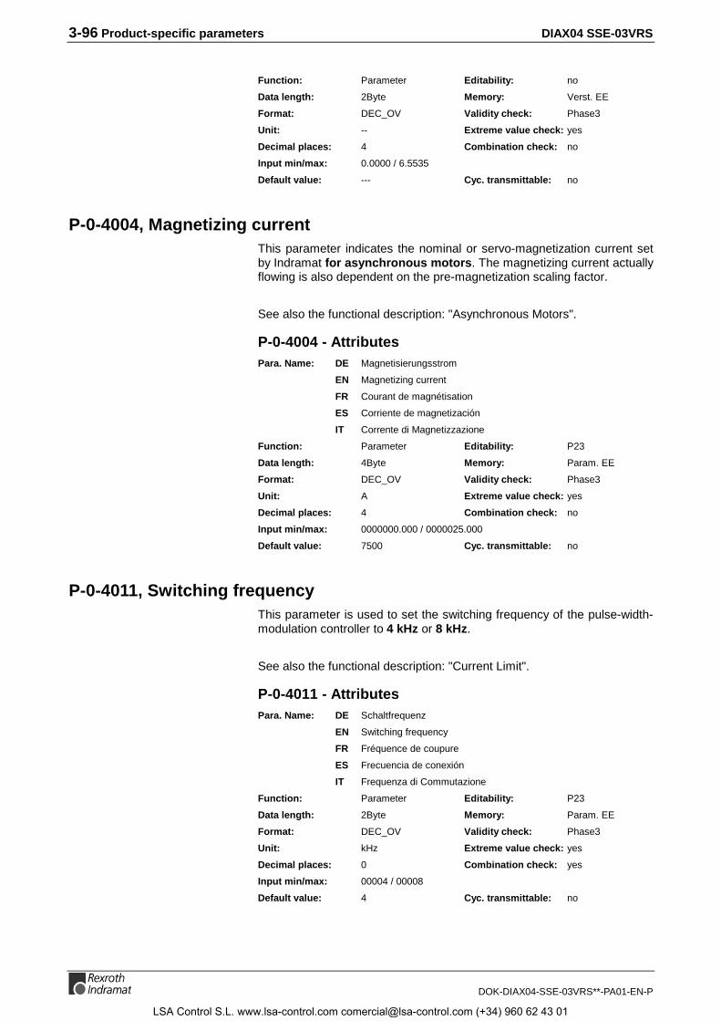
3-96 Product-specific parameters DIAX04 SSE-03VRS
DOK-DIAX04-SSE-03VRS**-PA01-EN-P
Function: Parameter Editability: no
Data length: 2Byte Memory: Verst. EE
Format: DEC_OV Validity check: Phase3
Unit: -- Extreme value check: yes
Decimal places: 4 Combination check: no
Input min/max: 0.0000 / 6.5535
Default value: --- Cyc. transmittable: no
P-0-4004, Magnetizing currentThis parameter indicates the nominal or servo-magnetization current setby Indramat for asynchronous motors. The magnetizing current actuallyflowing is also dependent on the pre-magnetization scaling factor.
See also the functional description: "Asynchronous Motors".
P-0-4004 - AttributesPara. Name: DE Magnetisierungsstrom
EN Magnetizing current
FR Courant de magnétisation
ES Corriente de magnetización
IT Corrente di Magnetizzazione
Function: Parameter Editability: P23
Data length: 4Byte Memory: Param. EE
Format: DEC_OV Validity check: Phase3
Unit: A Extreme value check: yes
Decimal places: 4 Combination check: no
Input min/max: 0000000.000 / 0000025.000
Default value: 7500 Cyc. transmittable: no
P-0-4011, Switching frequencyThis parameter is used to set the switching frequency of the pulse-width-modulation controller to 4 kHz or 8 kHz.
See also the functional description: "Current Limit".
P-0-4011 - AttributesPara. Name: DE Schaltfrequenz
EN Switching frequency
FR Fréquence de coupure
ES Frecuencia de conexión
IT Frequenza di Commutazione
Function: Parameter Editability: P23
Data length: 2Byte Memory: Param. EE
Format: DEC_OV Validity check: Phase3
Unit: kHz Extreme value check: yes
Decimal places: 0 Combination check: yes
Input min/max: 00004 / 00008
Default value: 4 Cyc. transmittable: no
LSA Control S.L. www.lsa-control.com [email protected] (+34) 960 62 43 01

DIAX04 SSE-03VRS Product-specific parameters 3-97
DOK-DIAX04-SSE-03VRS**-PA01-EN-P
P-0-4012, Slip factorThe slip factor is the most important parameter for asynchronous motors.It indicates the rotor frequency in relation to the torque-producing current.The lower the rotor time constant is, the higher the slip factor.
This parameter is set motor-specifically by Indramat.
See also the functional description: "Asynchronous Motors".
P-0-4012 - AttributesPara. Name: DE Schlupffaktor
EN Slip factor
FR Facteur de glissement
ES Factor de deslizamiento
IT Fattore di Slip
Function: Parameter Editability: P234
Data length: 2Byte Memory: Param. EE
Format: DEC_OV Validity check: Phase3
Unit: Hz/100A Extreme value check: yes
Decimal places: 2 Combination check: no
Input min/max: 000.01 / 500.00
Default value: 100 Cyc. transmittable: no
P-0-4014, Motor typeThe motor type can be selected with this parameter. The following motortypes are supported:
• 1: MHD
• 2: 2AD / 1MB with NTC sensor
• 3: LSF
• 4: LAR / LAF
• 5: MKD / MKE
• 6: 2AD /1MB with PTC sensor
• 7: synchronous kit motor
See also the functional description: "Setting of the Motor Type through P-0-4014, Motor Type".
P-0-4014 - AttributesPara. Name: DE Motorart
EN Motor type
FR Type de moteur
ES Tipo de motor
IT Tipo Motore
Function: Parameter Editability: P23
Data length: 2Byte Memory: no
Format: DEC_OV Validity check: Phase3
Unit: -- Extreme value check: yes
Decimal places: 0 Combination check: no
Input min/max: 00001 / 00006
Default value: 1 Cyc. transmittable: no
LSA Control S.L. www.lsa-control.com [email protected] (+34) 960 62 43 01

3-98 Product-specific parameters DIAX04 SSE-03VRS
DOK-DIAX04-SSE-03VRS**-PA01-EN-P
P-0-4015, Intermediate DC bus voltageThe intermediate voltage of the DC bus is stored in the amplifier as aparameter.
The parameter cannot be edited and is only for display and for internalcalculations (PWM).
P-0-4015 - AttributesPara. Name: DE Zwischenkreisspannung
EN Intermediate DC bus voltage
FR Tension du circuit intermédiaire CD
ES Tensión de circuito intermedio
IT Tensione sul Bus DC
Function: Parameter Editability: no
Data length: 2Byte Memory: Verst. EE
Format: DEC_OV Validity check: Phase3
Unit: V Extreme value check: yes
Decimal places: 0 Combination check: no
Input min/max: 00000 / 01000
Default value: --- Cyc. transmittable: no
P-0-4035, Trim-currentIn this parameter, the current value is stored with which the currentmeasurement of the drive control is precisely adjusted in the factory. Thiseliminates systematical errors in the current measurement. The value hasno meaning to the user and cannot be changed.
P-0-4035 - AttributesPara. Name: DE Abgleichstrom
EN Trim-current
FR Courant pour le calibrage
ES Corriente para calibrar
IT Corrente per calibrare
Function: Parameter Editability: no
Data length: 4Byte Memory: Verst. EE
Format: DEC_OV Validity check: Phase3
Unit: A Extreme value check: yes
Decimal places: 3 Combination check: no
Input min/max: 0000000.001 / 0000500.000
Default value: --- Cyc. transmittable: no
P-0-4045, Active permanent currentThis parameter shows how much current the drive can supply in theactual combination in continual operation. Multiplying with the P-0-0051,torque constant of the motor yields the continual operational torque.
With this current, the device is not overloaded. It is also the current towhich the current limit reduces.
This parameter is calculated by the drive control during switching to theoperating mode and is not changeable.
LSA Control S.L. www.lsa-control.com [email protected] (+34) 960 62 43 01

DIAX04 SSE-03VRS Product-specific parameters 3-99
DOK-DIAX04-SSE-03VRS**-PA01-EN-P
Determining this limit is influenced by the following current and torquelimitations and settings:
ID-Nr. Name Unit
S-0-0111 Motor continuous current at standstill 1) A
S-0-0112 Amplifier nominal current A
P-0-4058 Amplifier type data
S-0-0092 Torque limit bipolar %
Fig. 3-49: Active continuous current, dependencies
Note: The continuous current at standstill of the motor is the valuethat the percentage specifications refers to: it corresponds to100%.
See also the functional description: "Current Limit".
P-0-4045 - AttributesPara. Name: DE Wirksamer Dauerstrom
EN Active permanent current
FR Courant permanent actuel
ES Corriente continua activa
IT Corrente continuativa attiva
Function: Parameter Editability: no
Data length: 4Byte Memory: no
Format: DEC_OV Validity check: no
Unit: A Extreme value check: no
Decimal places: 3 Combination check: no
Input min/max: --- / ---
Default value: --- Cyc. transmittable: no
P-0-4046, Active peak currentThis parameter shows how much current the drive can supply in theactual combination momentarily (0.4 s). Multiplying with the P-0-0051,torque constant of the motor yields the momentary operation torque (i.e.for acceleration operations).
This parameter is calculated and preset by the drive control duringswitching to the operating mode. The dynamic current limiting reducesthis value according to the load of the amplifier.
Determining this limit is influenced by the following current and torquelimitations and settings:
ID-Nr. Name Unit
S-0-0109 Motor peak current A
S-0-0110 Amplifier peak current A
P-0-4058 Amplifier type data
S-0-0092 Torque limit bipolar %
Fig. 3-50: Active peak current, dependencies
See also the functional description: "Current Limit".
LSA Control S.L. www.lsa-control.com [email protected] (+34) 960 62 43 01

3-100 Product-specific parameters DIAX04 SSE-03VRS
DOK-DIAX04-SSE-03VRS**-PA01-EN-P
P-0-4046 - AttributesPara. Name: DE Wirksamer Spitzenstrom
EN Active peak current
FR Courant crête actuel
ES Corriente punta activa
IT Corrente di Picco Attiva
Function: Parameter Editability: no
Data length: 4Byte Memory: no
Format: DEC_OV Validity check: no
Unit: A Extreme value check: no
Decimal places: 3 Combination check: no
Input min/max: --- / ---
Default value: --- Cyc. transmittable: no
P-0-4047, Motor inductanceInductance of the motor, measured between two terminals (phase to phase).
The parameter is set at the factory and cannot be changed.
P-0-4047 - AttributesPara. Name: DE Motor-Induktivität
EN Motor inductance
FR Inductance moteur
ES Inductividad de motor
IT Induttanza Motore
Function: Parameter Editability: -
Data length: 2Byte Memory: -
Format: DEC_OV Validity check: -
Unit: mH Extreme value check: -
Decimal places: 2 Combination check: no
Input min/max: 0 / 655,36
Default value: --- Cyc. transmittable: no
P-0-4094, C800 Command Base-parameter loadWith the execution of this command, all parameters in S-0-0192, IDN listof backup operation data are set to their base values.
If the firmware in theprogramming module is replaced with anotherversion and the parameter memory is incompatible, then error F209 PLLoad parameter default values is generated. “PL“ appears on thedisplay. (At this time, the SERCOS interface is not yet active.)
Afterwards, execute the command by pressing the S1 button.
See also the functional description: "Basic parameter block".
P-0-4094 - AttributesPara. Name: DE C800 Kommando Basisparameter laden
EN C800 Command Base-parameter load
FR C800 Commande chargement des paramètres de base
ES C800 Comando cargar parámetros base
IT C800 Comando Caricare Parametri di Base
LSA Control S.L. www.lsa-control.com [email protected] (+34) 960 62 43 01
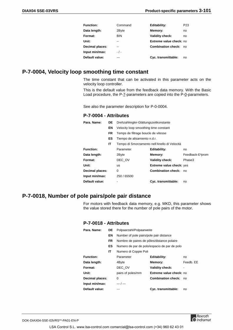
DIAX04 SSE-03VRS Product-specific parameters 3-101
DOK-DIAX04-SSE-03VRS**-PA01-EN-P
Function: Command Editability: P23
Data length: 2Byte Memory: no
Format: BIN Validity check: no
Unit: -- Extreme value check: no
Decimal places: -- Combination check: no
Input min/max: - / -
Default value: --- Cyc. transmittable: no
P-7-0004, Velocity loop smoothing time constantThe time constant that can be activated in this parameter acts on thevelocity loop controller.
This is the default value from the feedback data memory. With the BasicLoad procedure, the P-7-parameters are copied into the P-0-parameters.
See also the parameter description for P-0-0004.
P-7-0004 - AttributesPara. Name: DE Drehzahlregler-Glättungszeitkonstante
EN Velocity loop smoothing time constant
FR Temps de filtrage boucle de vitesse
ES Tiempo de alisamiento n.d.r.
IT Tempo di Smorzamento nell'Anello di Velocità
Function: Parameter Editability: no
Data length: 2Byte Memory: Feedback-E²prom
Format: DEC_OV Validity check: Phase3
Unit: us Extreme value check: yes
Decimal places: 0 Combination check: no
Input min/max: 250 / 65500
Default value: - Cyc. transmittable: no
P-7-0018, Number of pole pairs/pole pair distanceFor motors with feedback data memory, e.g. MKD, this parameter showsthe value stored there for the number of pole pairs of the motor.
P-7-0018 - AttributesPara. Name: DE Polpaarzahl/Polpaarweite
EN Number of pole pairs/pole pair distance
FR Nombre de paires de pôles/distance polaire
ES Numero de par de polo/espacio de par de polo
IT Numero di Coppie Poli
Function: Parameter Editability: no
Data length: 4Byte Memory: Feedb. EE
Format: DEC_OV Validity check: -
Unit: pairs of poles/mm Extreme value check: no
Decimal places: 0 Combination check: no
Input min/max: --- / ---
Default value: --- Cyc. transmittable: no
LSA Control S.L. www.lsa-control.com [email protected] (+34) 960 62 43 01
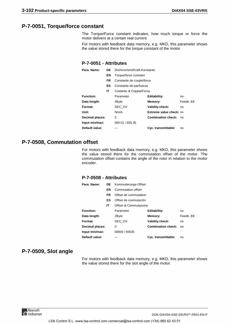
3-102 Product-specific parameters DIAX04 SSE-03VRS
DOK-DIAX04-SSE-03VRS**-PA01-EN-P
P-7-0051, Torque/force constantThe Torque/Force constant indicates, how much torque or force themotor delivers at a certain real current.
For motors with feedback data memory, e.g. MKD, this parameter showsthe value stored there for the torque constant of the motor.
P-7-0051 - AttributesPara. Name: DE Drehmoment/Kraft-Konstante
EN Torque/force constant
FR Constante de couple/force
ES Constante de par/fuerza
IT Costante di Coppia/Forza
Function: Parameter Editability: no
Data length: 4Byte Memory: Feedb. EE
Format: DEC_OV Validity check: no
Unit: Nm/A Extreme value check: no
Decimal places: 2 Combination check: no
Input min/max: 000.01 / 655.35
Default value: --- Cyc. transmittable: no
P-7-0508, Commutation offsetFor motors with feedback data memory, e.g. MKD, this parameter showsthe value stored there for the commutation offset of the motor. Thecommutation offset contains the angle of the rotor in relation to the motorencoder.
P-7-0508 - AttributesPara. Name: DE Kommutierungs-Offset
EN Commutation offset
FR Offset de commutation
ES Offset de conmutación
IT Offset di Commutazione
Function: Parameter Editability: no
Data length: 2Byte Memory: Feedb. EE
Format: DEC_OV Validity check: no
Decimal places: 0 Combination check: no
Input min/max: 00000 / 65535
Default value: --- Cyc. transmittable: no
P-7-0509, Slot angleFor motors with feedback data memory, e.g. MKD, this parameter showsthe value stored there for the slot angle of the motor.
LSA Control S.L. www.lsa-control.com [email protected] (+34) 960 62 43 01
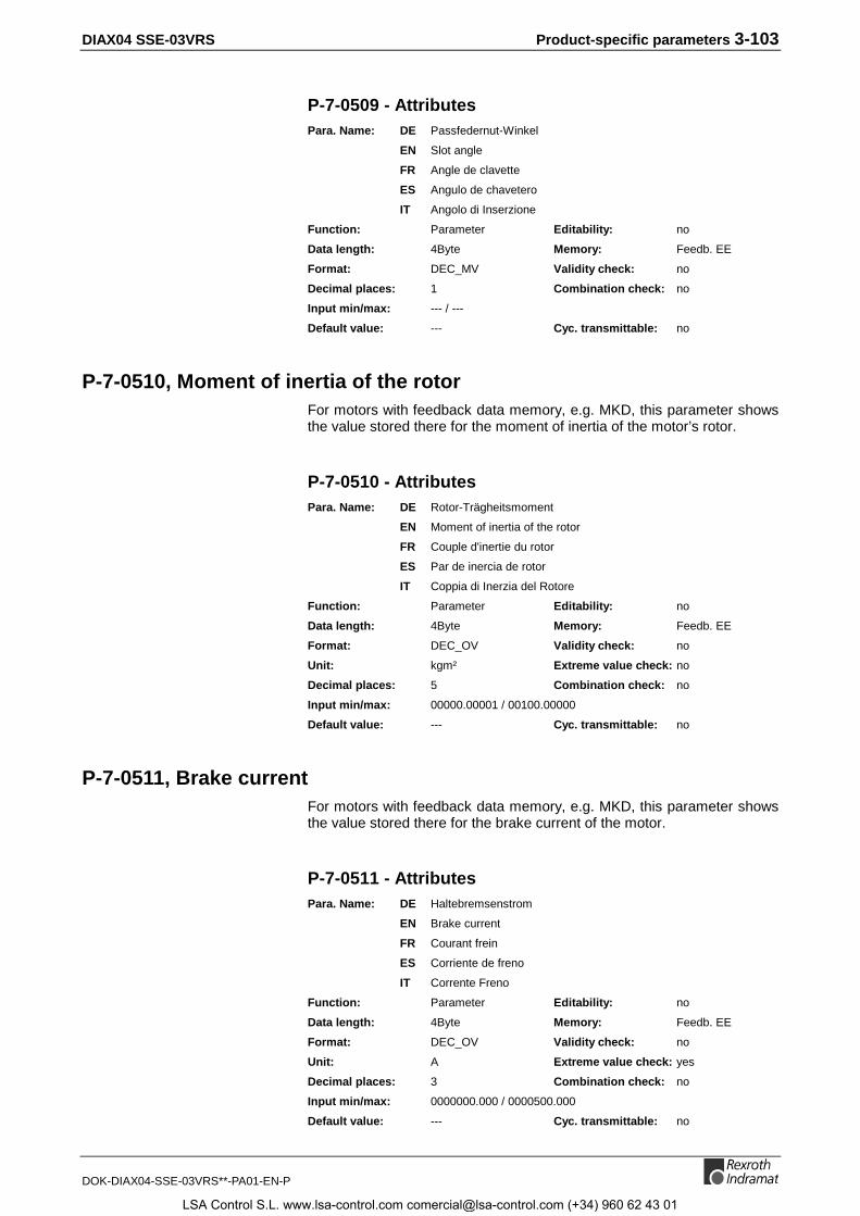
DIAX04 SSE-03VRS Product-specific parameters 3-103
DOK-DIAX04-SSE-03VRS**-PA01-EN-P
P-7-0509 - AttributesPara. Name: DE Passfedernut-Winkel
EN Slot angle
FR Angle de clavette
ES Angulo de chavetero
IT Angolo di Inserzione
Function: Parameter Editability: no
Data length: 4Byte Memory: Feedb. EE
Format: DEC_MV Validity check: no
Decimal places: 1 Combination check: no
Input min/max: --- / ---
Default value: --- Cyc. transmittable: no
P-7-0510, Moment of inertia of the rotorFor motors with feedback data memory, e.g. MKD, this parameter showsthe value stored there for the moment of inertia of the motor’s rotor.
P-7-0510 - AttributesPara. Name: DE Rotor-Trägheitsmoment
EN Moment of inertia of the rotor
FR Couple d'inertie du rotor
ES Par de inercia de rotor
IT Coppia di Inerzia del Rotore
Function: Parameter Editability: no
Data length: 4Byte Memory: Feedb. EE
Format: DEC_OV Validity check: no
Unit: kgm² Extreme value check: no
Decimal places: 5 Combination check: no
Input min/max: 00000.00001 / 00100.00000
Default value: --- Cyc. transmittable: no
P-7-0511, Brake currentFor motors with feedback data memory, e.g. MKD, this parameter showsthe value stored there for the brake current of the motor.
P-7-0511 - AttributesPara. Name: DE Haltebremsenstrom
EN Brake current
FR Courant frein
ES Corriente de freno
IT Corrente Freno
Function: Parameter Editability: no
Data length: 4Byte Memory: Feedb. EE
Format: DEC_OV Validity check: no
Unit: A Extreme value check: yes
Decimal places: 3 Combination check: no
Input min/max: 0000000.000 / 0000500.000
Default value: --- Cyc. transmittable: no
LSA Control S.L. www.lsa-control.com [email protected] (+34) 960 62 43 01

3-104 Product-specific parameters DIAX04 SSE-03VRS
DOK-DIAX04-SSE-03VRS**-PA01-EN-P
P-7-0513, Feedback type 1For motors with feedback data memory, e.g. MKD, this parameter showsthe value stored there for the kind and type of the feedback.
P-7-0513 - AttributesPara. Name: DE Feedback-Typ 1
EN Feedback type 1
FR Type de feedback 1
ES Tipo de retroalimentación 1
IT Tipo di Feedback 1
Function: Parameter Editability: no
Data length: 2Byte Memory: Feedb. EE
Format: DEC_OV Validity check: no
Unit: -- Extreme value check: no
Decimal places: 0 Combination check: no
Input min/max: --- / ---
Default value: --- Cyc. transmittable: no
P-7-0517, Feedback type 2For optional encoder with feedback data memory, this parameter showsthe value stored there for the kind and type of the feedback 2.
P-7-0517 - AttributesPara. Name: DE Feedback-Typ 2
EN Feedback type 2
FR Type de feedback 2
ES Tipo de retroalimentación 2
IT Tipo di Feedback 2
Function: Parameter Editability: no
Data length: 2Byte Memory: Feedback-E²prom
Format: DEC_OV Validity check: no
Unit: -- Extreme value check: no
Decimal places: 0 Combination check: no
Input min/max: 0 / 65536
Default value: - Cyc. transmittable: no
P-7-4014, Motor typeThis parameter defines the motor type. The parameter is stored in thefeedback data memory of the motor, if present. Upon power-up, it istransferred into the parameter P-0-4014, if it is valid and defines a motortype > 0.
See also functional description: "Setting of the Motor Type through P-0-4014, Motor Type".
LSA Control S.L. www.lsa-control.com [email protected] (+34) 960 62 43 01
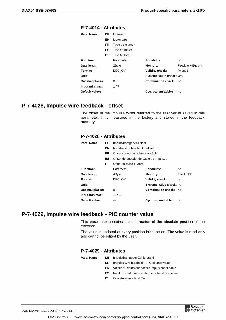
DIAX04 SSE-03VRS Product-specific parameters 3-105
DOK-DIAX04-SSE-03VRS**-PA01-EN-P
P-7-4014 - AttributesPara. Name: DE Motorart
EN Motor type
FR Type de moteur
ES Tipo de motor
IT Tipo Motore
Function: Parameter Editability: no
Data length: 2Byte Memory: Feedback-E²prom
Format: DEC_OV Validity check: Phase3
Unit: -- Extreme value check: yes
Decimal places: 0 Combination check: no
Input min/max: 1 / 7
Default value: - Cyc. transmittable: no
P-7-4028, Impulse wire feedback - offsetThe offset of the impulse wires referred to the resolver is saved in thisparameter. It is measured in the factory and stored in the feedbackmemory.
P-7-4028 - AttributesPara. Name: DE Impulsdrahtgeber-Offset
EN Impulse wire feedback - offset
FR Offset codeur impulsionnel câblé
ES Offset de encoder de cable de impulsos
IT Offset Impulso di Zero
Function: Parameter Editability: no
Data length: 4Byte Memory: Feedb. EE
Format: DEC_OV Validity check: no
Unit: -- Extreme value check: no
Decimal places: 0 Combination check: no
Input min/max: --- / ---
Default value: --- Cyc. transmittable: no
P-7-4029, Impulse wire feedback - PIC counter valueThis parameter contains the information of the absolute position of theencoder.
The value is updated at every position initialization. The value is read-onlyand cannot be edited by the user.
P-7-4029 - AttributesPara. Name: DE Impulsdrahtgeber-Zählerstand
EN Impulse wire feedback - PIC counter value
FR Valeur du compteur codeur impulsionnel câblé
ES Nivel de contador encoder de cable de impulsos
IT Contatore Impulsi di Zero
LSA Control S.L. www.lsa-control.com [email protected] (+34) 960 62 43 01
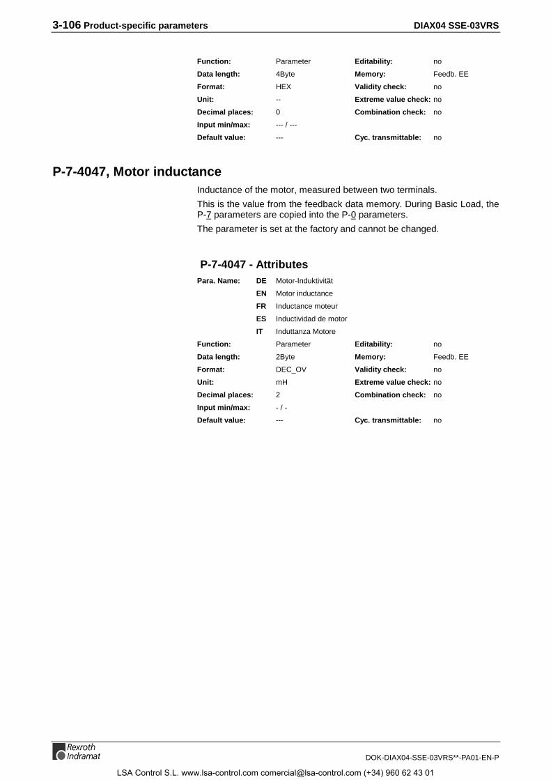
3-106 Product-specific parameters DIAX04 SSE-03VRS
DOK-DIAX04-SSE-03VRS**-PA01-EN-P
Function: Parameter Editability: no
Data length: 4Byte Memory: Feedb. EE
Format: HEX Validity check: no
Unit: -- Extreme value check: no
Decimal places: 0 Combination check: no
Input min/max: --- / ---
Default value: --- Cyc. transmittable: no
P-7-4047, Motor inductanceInductance of the motor, measured between two terminals.
This is the value from the feedback data memory. During Basic Load, theP-7 parameters are copied into the P-0 parameters.
The parameter is set at the factory and cannot be changed.
P-7-4047 - AttributesPara. Name: DE Motor-Induktivität
EN Motor inductance
FR Inductance moteur
ES Inductividad de motor
IT Induttanza Motore
Function: Parameter Editability: no
Data length: 2Byte Memory: Feedb. EE
Format: DEC_OV Validity check: no
Unit: mH Extreme value check: no
Decimal places: 2 Combination check: no
Input min/max: - / -
Default value: --- Cyc. transmittable: no
LSA Control S.L. www.lsa-control.com [email protected] (+34) 960 62 43 01
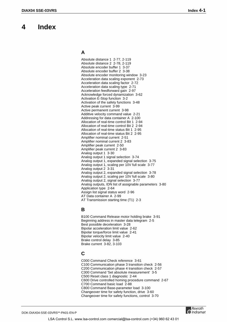
DIAX04 SSE-03VRS Index 4-1
DOK-DIAX04-SSE-03VRS**-PA01-EN-P
4 Index
AAbsolute distance 1 2-77, 2-119Absolute distance 2 2-78, 2-119Absolute encoder buffer 1 3-37Absolute encoder buffer 2 3-38Absolute encoder monitoring window 3-23Acceleration data scaling exponent 2-73Acceleration data scaling factor 2-72Acceleration data scaling type 2-71Acceleration feedforward gain 2-97Acknowledge forced dynamization 3-62Activation E-Stop function 3-2Activation of the safety functions 3-48Active peak current 3-99Active permanent current 3-98Additive velocity command value 2-21Addressing for data container A 2-100Allocation of real-time control Bit 1 2-94Allocation of real-time control Bit 2 2-94Allocation of real-time status Bit 1 2-95Allocation of real-time status Bit 2 2-95Amplifier nominal current 2-51Amplifier nominal current 2 3-83Amplifier peak current 2-50Amplifier peak current 2 3-83Analog output 1 3-30Analog output 1 signal selection 3-74Analog output 1, expanded signal selection 3-75Analog output 1, scaling per 10V full scale 3-77Analog output 2 3-31Analog output 2, expanded signal selection 3-78Analog output 2, scaling per 10V full scale 3-80Analog output 2, signal selection 3-77Analog outputs, IDN list of assignable parameters 3-80Application type 2-64Assign list signal status word 2-96AT Data container A 2-99AT Transmission starting time (T1) 2-3
BB100 Command Release motor holding brake 3-91Beginning address in master data telegram 2-5Best possible deceleration 3-28Bipolar acceleration limit value 2-62Bipolar torque/force limit value 2-41Bipolar velocity limit value 2-40Brake control delay 3-85Brake current 3-82, 3-103
CC000 Command Check reference 3-61C100 Communication phase 3 transition check 2-56C200 Communication phase 4 transition check 2-57C300 Command ’Set absolute measurement’ 3-5C500 Reset class 1 diagnostic 2-44C600 Drive controlled homing procedure command 2-67C700 Command basic load 2-88C800 Command Base-parameter load 3-100Changeover time for safety function, drive 3-60Changeover time for safety functions, control 3-70
LSA Control S.L. www.lsa-control.com [email protected] (+34) 960 62 43 01
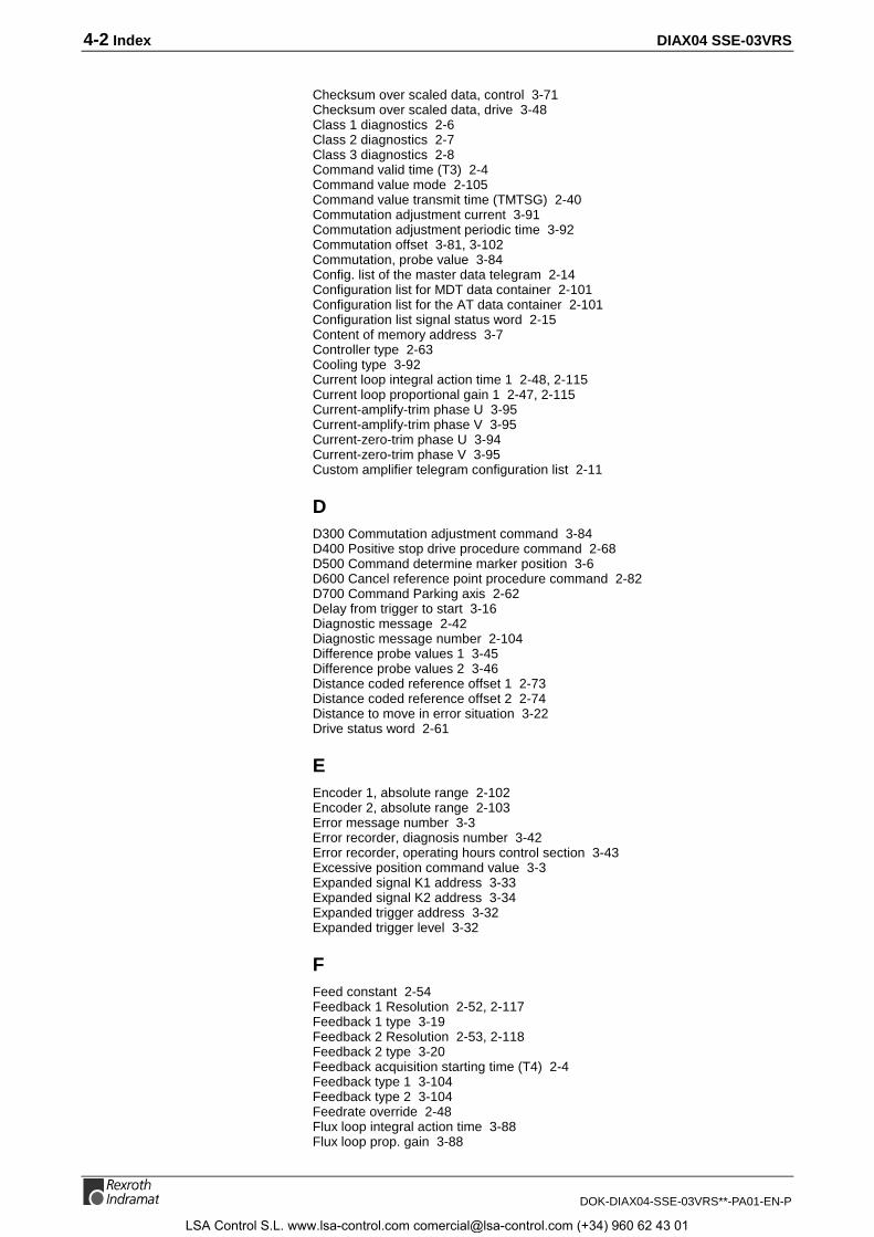
4-2 Index DIAX04 SSE-03VRS
DOK-DIAX04-SSE-03VRS**-PA01-EN-P
Checksum over scaled data, control 3-71Checksum over scaled data, drive 3-48Class 1 diagnostics 2-6Class 2 diagnostics 2-7Class 3 diagnostics 2-8Command valid time (T3) 2-4Command value mode 2-105Command value transmit time (TMTSG) 2-40Commutation adjustment current 3-91Commutation adjustment periodic time 3-92Commutation offset 3-81, 3-102Commutation, probe value 3-84Config. list of the master data telegram 2-14Configuration list for MDT data container 2-101Configuration list for the AT data container 2-101Configuration list signal status word 2-15Content of memory address 3-7Controller type 2-63Cooling type 3-92Current loop integral action time 1 2-48, 2-115Current loop proportional gain 1 2-47, 2-115Current-amplify-trim phase U 3-95Current-amplify-trim phase V 3-95Current-zero-trim phase U 3-94Current-zero-trim phase V 3-95Custom amplifier telegram configuration list 2-11
DD300 Commutation adjustment command 3-84D400 Positive stop drive procedure command 2-68D500 Command determine marker position 3-6D600 Cancel reference point procedure command 2-82D700 Command Parking axis 2-62Delay from trigger to start 3-16Diagnostic message 2-42Diagnostic message number 2-104Difference probe values 1 3-45Difference probe values 2 3-46Distance coded reference offset 1 2-73Distance coded reference offset 2 2-74Distance to move in error situation 3-22Drive status word 2-61
EEncoder 1, absolute range 2-102Encoder 2, absolute range 2-103Error message number 3-3Error recorder, diagnosis number 3-42Error recorder, operating hours control section 3-43Excessive position command value 3-3Expanded signal K1 address 3-33Expanded signal K2 address 3-34Expanded trigger address 3-32Expanded trigger level 3-32
FFeed constant 2-54Feedback 1 Resolution 2-52, 2-117Feedback 1 type 3-19Feedback 2 Resolution 2-53, 2-118Feedback 2 type 3-20Feedback acquisition starting time (T4) 2-4Feedback type 1 3-104Feedback type 2 3-104Feedrate override 2-48Flux loop integral action time 3-88Flux loop prop. gain 3-88
LSA Control S.L. www.lsa-control.com [email protected] (+34) 960 62 43 01

DIAX04 SSE-03VRS Index 4-3
DOK-DIAX04-SSE-03VRS**-PA01-EN-P
Following error 2-82Friction compensation 2-69Function of encoder 2 3-40
HHome switch 2-106Home switch offset 2-93Homing acceleration 2-22Homing parameter 2-66Homing velocity 2-22
IIDN-list of all operation data 2-11IDN-list of all procedure commands 2-14IDN-list of backup operation data 2-83IDN-list of invalid op. data for comm. Ph. 2 2-13IDN-list of invalid op. data for comm. Ph. 3 2-13IDN-list of operation data for CP2 2-12IDN-list of operation data for CP3 2-12Impulse wire feedback - offset 3-105Impulse wire feedback - PIC counter value 3-105Input revolutions of load gear 2-53Interface status 2-9Intermediate bus power 2-103Intermediate DC bus voltage 3-98
JJerk limit bipolar 2-98
LLanguage selection 2-88, 3-1Last valid position command value 3-4Length of master data telegram 2-5Length of the configurable data record in the AT 2-79Length of the configurable data record in the MDT 2-80Linear position data scaling exponent 2-35Linear position data scaling factor 2-34List of all operating modes 2-92List of configurable data in the AT 2-80List of configurable data in the MDT 2-81List of diagnostic numbers 2-102List of present plug-in modules 3-44List of scope data 1 3-8List of scope data 2 3-9List of selectable signals for oscilloscope function 3-34Lower position limit 1 for safety function, control 3-64Lower position limit 1 for safety function, drive 3-54Lower position limit 2 for safety function, control 3-65Lower position limit 2 for safety function, drive 3-55Lower position limit for position switch 1, control 3-66Lower position limit for position switch 1, drive 3-56Lower position limit for position switch 2, control 3-67Lower position limit for position switch 2, drive 3-56Lower position limit for position switch 3, control 3-67Lower position limit for position switch 3, drive 3-57Lower position limit for position switch 4, control 3-68Lower position limit for position switch 4, drive 3-58
MMagnetizing current 3-96Manufacturer class 3 diagnostics 2-78Manufacturer version 2-16Marker position A 2-77Mask class 2 diagnostic 2-43
LSA Control S.L. www.lsa-control.com [email protected] (+34) 960 62 43 01

4-4 Index DIAX04 SSE-03VRS
DOK-DIAX04-SSE-03VRS**-PA01-EN-P
Mask class 3 diagnostic 2-44Master control word 2-61Max. model deviation 3-24Max. speed 1 for safety function, control 3-63Max. speed 1 for safety function, drive 3-53Max. speed 2 for safety function, control 3-64Max. speed 2 for safety function, drive 3-54Maximum braking time 3-29Maximum motor speed (nmax) 2-51, 2-117Maximum travel range 2-91MDT Data container A 2-99MDT error counter 2-16MDT Transmit starting time (T2) 2-39Memory address 3-6Minimum AT transmit starting time (T1min) 2-2Minimum feedback acquisition time(T4min) 2-3Modulo value 2-46Moment of inertia of the rotor 3-82, 3-103Monitored actual position, control 3-70Monitored actual position, drive 3-61Monitoring window 2-70Monitoring window feedback 2 2-105Motor current at standstill 2-50, 2-116Motor function parameter 1 3-90Motor inductance 3-100, 3-106Motor peak current 2-49, 2-116Motor shutdown temperature 2-85Motor temperature 2-104Motor type 2-64, 2-118, 3-97, 3-104Motor voltage at no load 3-88Motor voltage max. 3-89Motor warning temperature 2-84MST error counter 2-15Multiplication 1 2-85Multiplication 2 2-86
NNC Cycle time (TNcyc) 2-1NC reaction on error 3-26Negative position limit value 2-27Number of pole pairs/pole pair distance 3-7, 3-101Number of samples after trigger 3-16Number of valid samples for oscilloscope function 3-35
OOperating hours control section 3-41Operating hours power section 3-42Optimal distance home switch - reference mark 3-35Output revolutions of load gear 2-54Overload warning 3-30
PParallel I/O input 1 3-21Parallel I/O input 4 3-37Parallel I/O output 1 3-21Parallel I/O output 4 3-36Parameter buffer mode 2-89Password 2-89Pos. corr., active correction value 3-72Pos. corr., correction table for prec. corr. 3-73Pos. corr., external correction value 3-71Pos. corr., prec. corr. start position 3-72Pos. corr., support point distance for prec. corr. 3-74Pos. monitoring window for safe stop operation, control 3-68Pos. monitoring window for safe stop operation, drive 3-58Position command processing mode 3-40Position command smoothing time constant 3-25
LSA Control S.L. www.lsa-control.com [email protected] (+34) 960 62 43 01

DIAX04 SSE-03VRS Index 4-5
DOK-DIAX04-SSE-03VRS**-PA01-EN-P
Position command value 2-25Position data scaling type 2-33Position feedback 1 type 2-90Position feedback 1 value 2-27Position feedback 2 type 2-52Position feedback 2 value 2-29Position feedback value status 2-108Position loop Kv-factor 2-47, 2-114Position polarities 2-30Position start value 3-8Position window 2-31Positioning Acceleration 2-87Positioning Deceleration 2-98Positioning Jerk 2-84Positioning Velocity 2-87Positive position limit value 2-26Power off on error 3-26Premagnetization factor 3-87Preset forced dynamization 3-62Primary mode of operation 2-17Probe 1 2-106Probe 1 enable 2-109Probe 1 negative latched 2-111Probe 1 positive latched 2-110Probe 2 2-107Probe 2 enable 2-109Probe 2 negative latched 2-112Probe 2 positive latched 2-112Probe control parameter 2-74Probe value 1 negative edge 2-59Probe value 1 positive edge 2-59Probe value 2 negative edge 2-60Probe value 2 positive edge 2-60Probing cycle procedure command 2-76
RReceive to receive recovery time (TMTSG) 2-39Reference cam shift 2-92Reference distance 1 2-28Reference distance 2 2-29Reference offset 1 2-68Reference offset 2 2-69Reference position for safe homing, control 3-69Reference position for safe homing, drive 3-58Rejection bandwidth velocity loop 3-39Rejection frequency velocity loop 3-38Reversal clearance 2-32Rotational position resolution 2-36
SS1-Kink-speed 3-89Safety input signals of the drive 3-49Safety output signals of the drive 3-50Secondary operation mode 1 2-18Secondary operation mode 2 2-19Secondary operation mode 3 2-19Selection safety functions, control 3-69Selection safety functions, drive 3-59SERCOS Cycle time (Tscyc) 2-1Signal select probe 1 3-44Signal select probe 2 3-45Signal select scope channel 1 3-9Signal select scope channel 2 3-10Signal status word 2-65Size of memory 3-15Slave arrangement (SLKN) 2-43Slip factor 3-97Slip increase 3-86
LSA Control S.L. www.lsa-control.com [email protected] (+34) 960 62 43 01
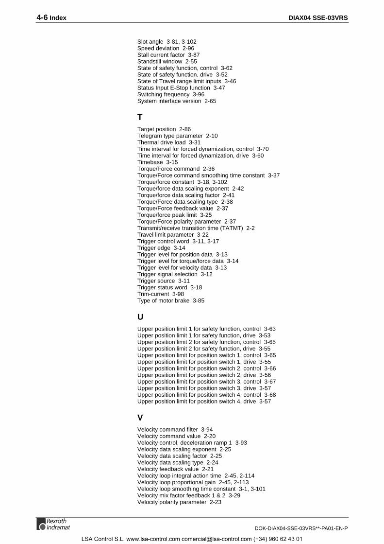
4-6 Index DIAX04 SSE-03VRS
DOK-DIAX04-SSE-03VRS**-PA01-EN-P
Slot angle 3-81, 3-102Speed deviation 2-96Stall current factor 3-87Standstill window 2-55State of safety function, control 3-62State of safety function, drive 3-52State of Travel range limit inputs 3-46Status Input E-Stop function 3-47Switching frequency 3-96System interface version 2-65
TTarget position 2-86Telegram type parameter 2-10Thermal drive load 3-31Time interval for forced dynamization, control 3-70Time interval for forced dynamization, drive 3-60Timebase 3-15Torque/Force command 2-36Torque/Force command smoothing time constant 3-37Torque/force constant 3-18, 3-102Torque/force data scaling exponent 2-42Torque/force data scaling factor 2-41Torque/Force data scaling type 2-38Torque/Force feedback value 2-37Torque/force peak limit 3-25Torque/Force polarity parameter 2-37Transmit/receive transition time (TATMT) 2-2Travel limit parameter 3-22Trigger control word 3-11, 3-17Trigger edge 3-14Trigger level for position data 3-13Trigger level for torque/force data 3-14Trigger level for velocity data 3-13Trigger signal selection 3-12Trigger source 3-11Trigger status word 3-18Trim-current 3-98Type of motor brake 3-85
UUpper position limit 1 for safety function, control 3-63Upper position limit 1 for safety function, drive 3-53Upper position limit 2 for safety function, control 3-65Upper position limit 2 for safety function, drive 3-55Upper position limit for position switch 1, control 3-65Upper position limit for position switch 1, drive 3-55Upper position limit for position switch 2, control 3-66Upper position limit for position switch 2, drive 3-56Upper position limit for position switch 3, control 3-67Upper position limit for position switch 3, drive 3-57Upper position limit for position switch 4, control 3-68Upper position limit for position switch 4, drive 3-57
VVelocity command filter 3-94Velocity command value 2-20Velocity control, deceleration ramp 1 3-93Velocity data scaling exponent 2-25Velocity data scaling factor 2-25Velocity data scaling type 2-24Velocity feedback value 2-21Velocity loop integral action time 2-45, 2-114Velocity loop proportional gain 2-45, 2-113Velocity loop smoothing time constant 3-1, 3-101Velocity mix factor feedback 1 & 2 3-29Velocity polarity parameter 2-23
LSA Control S.L. www.lsa-control.com [email protected] (+34) 960 62 43 01

DIAX04 SSE-03VRS Index 4-7
DOK-DIAX04-SSE-03VRS**-PA01-EN-P
Velocity threshold nx 2-56Velocity window 2-70Version of safety functions 3-47
LSA Control S.L. www.lsa-control.com [email protected] (+34) 960 62 43 01

4-2 Index DIAX04 SSE-03VRS
DOK-DIAX04-SSE-03VRS**-PA01-EN-P
LSA Control S.L. www.lsa-control.com [email protected] (+34) 960 62 43 01
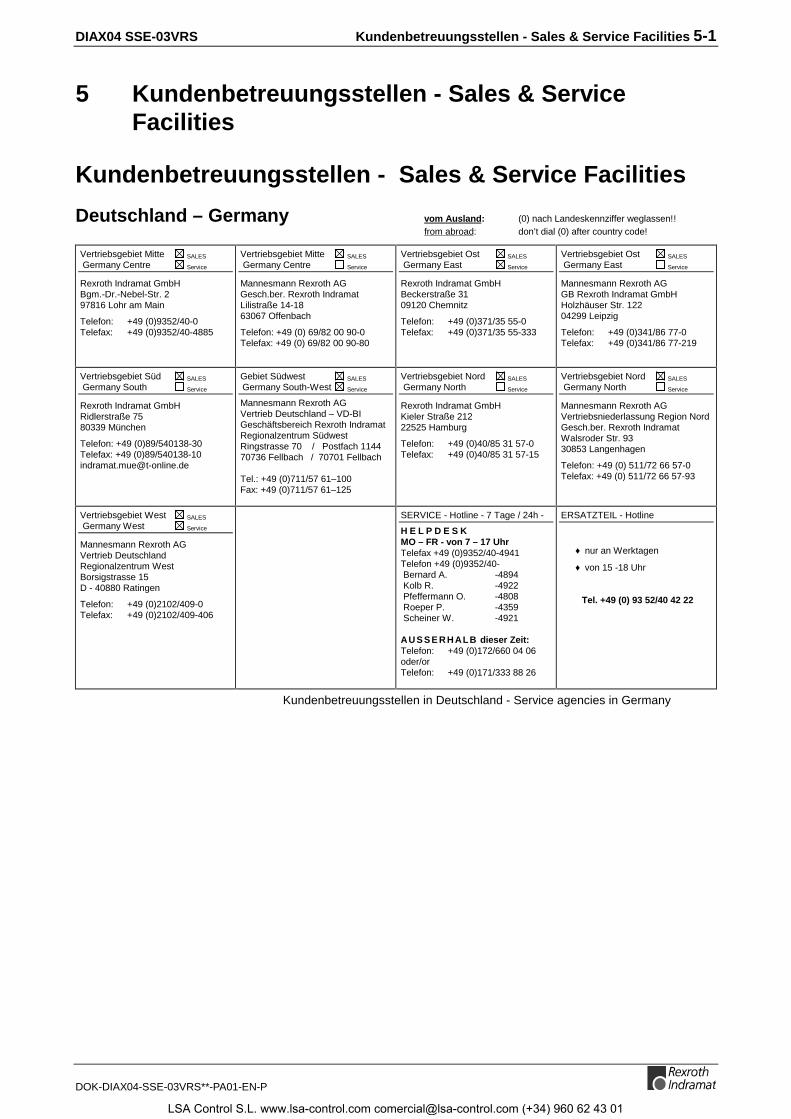
DIAX04 SSE-03VRS Kundenbetreuungsstellen - Sales & Service Facilities 5-1
DOK-DIAX04-SSE-03VRS**-PA01-EN-P
5 Kundenbetreuungsstellen - Sales & ServiceFacilities
Kundenbetreuungsstellen - Sales & Service Facilities
Deutschland – Germany vom Ausland: (0) nach Landeskennziffer weglassen!!from abroad: don’t dial (0) after country code!
Vertriebsgebiet Mitte SALES
Germany Centre Service
Rexroth Indramat GmbHBgm.-Dr.-Nebel-Str. 297816 Lohr am Main
Telefon: +49 (0)9352/40-0Telefax: +49 (0)9352/40-4885
Vertriebsgebiet Mitte SALES
Germany Centre Service
Mannesmann Rexroth AGGesch.ber. Rexroth IndramatLilistraße 14-1863067 Offenbach
Telefon: +49 (0) 69/82 00 90-0Telefax: +49 (0) 69/82 00 90-80
Vertriebsgebiet Ost SALES
Germany East Service
Rexroth Indramat GmbHBeckerstraße 3109120 Chemnitz
Telefon: +49 (0)371/35 55-0Telefax: +49 (0)371/35 55-333
Vertriebsgebiet Ost SALES
Germany East Service
Mannesmann Rexroth AGGB Rexroth Indramat GmbHHolzhäuser Str. 12204299 Leipzig
Telefon: +49 (0)341/86 77-0Telefax: +49 (0)341/86 77-219
Vertriebsgebiet Süd SALES
Germany South Service
Rexroth Indramat GmbHRidlerstraße 7580339 München
Telefon: +49 (0)89/540138-30Telefax: +49 (0)89/[email protected]
Gebiet Südwest SALES
Germany South-West Service
Mannesmann Rexroth AGVertrieb Deutschland – VD-BIGeschäftsbereich Rexroth IndramatRegionalzentrum SüdwestRingstrasse 70 / Postfach 114470736 Fellbach / 70701 Fellbach
Tel.: +49 (0)711/57 61–100Fax: +49 (0)711/57 61–125
Vertriebsgebiet Nord SALES
Germany North Service
Rexroth Indramat GmbHKieler Straße 21222525 Hamburg
Telefon: +49 (0)40/85 31 57-0Telefax: +49 (0)40/85 31 57-15
Vertriebsgebiet Nord SALES
Germany North Service
Mannesmann Rexroth AGVertriebsniederlassung Region NordGesch.ber. Rexroth IndramatWalsroder Str. 9330853 Langenhagen
Telefon: +49 (0) 511/72 66 57-0Telefax: +49 (0) 511/72 66 57-93
Vertriebsgebiet West SALES
Germany West Service
Mannesmann Rexroth AGVertrieb DeutschlandRegionalzentrum WestBorsigstrasse 15D - 40880 Ratingen
Telefon: +49 (0)2102/409-0Telefax: +49 (0)2102/409-406
SERVICE - Hotline - 7 Tage / 24h -
H E L P D E S KMO – FR - von 7 – 17 UhrTelefax +49 (0)9352/40-4941Telefon +49 (0)9352/40- Bernard A. -4894 Kolb R. -4922 Pfeffermann O. -4808 Roeper P. -4359 Scheiner W. -4921
AU S S E R H ALB dieser Zeit:Telefon: +49 (0)172/660 04 06oder/orTelefon: +49 (0)171/333 88 26
ERSATZTEIL - Hotline
♦ nur an Werktagen
♦ von 15 -18 Uhr
Tel. +49 (0) 93 52/40 42 22
Kundenbetreuungsstellen in Deutschland - Service agencies in Germany
LSA Control S.L. www.lsa-control.com [email protected] (+34) 960 62 43 01
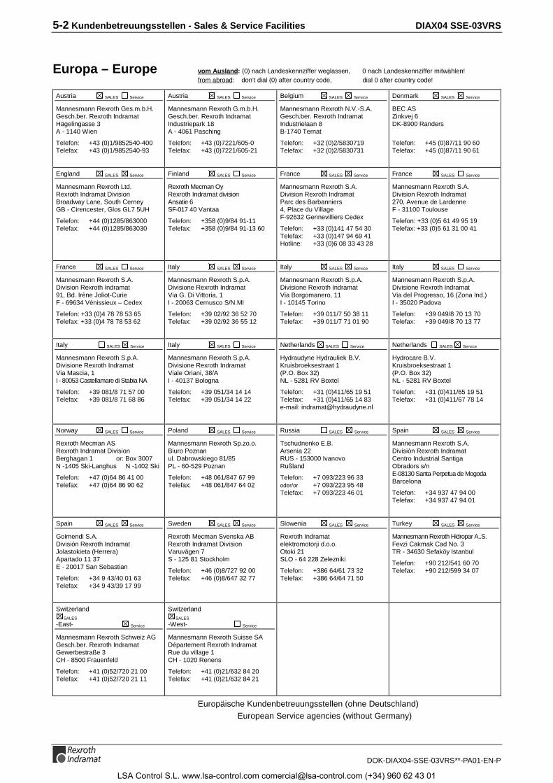
5-2 Kundenbetreuungsstellen - Sales & Service Facilities DIAX04 SSE-03VRS
DOK-DIAX04-SSE-03VRS**-PA01-EN-P
Europa – Europe vom Ausland: (0) nach Landeskennziffer weglassen, 0 nach Landeskennziffer mitwählen!from abroad: don’t dial (0) after country code, dial 0 after country code!
Austria SALES Service
Mannesmann Rexroth Ges.m.b.H.Gesch.ber. Rexroth IndramatHägelingasse 3A - 1140 Wien
Telefon: +43 (0)1/9852540-400Telefax: +43 (0)1/9852540-93
Austria SALES Service
Mannesmann Rexroth G.m.b.H.Gesch.ber. Rexroth IndramatIndustriepark 18A - 4061 Pasching
Telefon: +43 (0)7221/605-0Telefax: +43 (0)7221/605-21
Belgium SALES Service
Mannesmann Rexroth N.V.-S.A.Gesch.ber. Rexroth IndramatIndustrielaan 8B-1740 Ternat
Telefon: +32 (0)2/5830719Telefax: +32 (0)2/5830731
Denmark SALES Service
BEC ASZinkvej 6DK-8900 Randers
Telefon: +45 (0)87/11 90 60Telefax: +45 (0)87/11 90 61
England SALES Service
Mannesmann Rexroth Ltd.Rexroth Indramat DivisionBroadway Lane, South CerneyGB - Cirencester, Glos GL7 5UH
Telefon: +44 (0)1285/863000Telefax: +44 (0)1285/863030
Finland SALES Service
Rexroth Mecman OyRexroth Indramat divisionAnsatie 6SF-017 40 Vantaa
Telefon: +358 (0)9/84 91-11Telefax: +358 (0)9/84 91-13 60
France SALES Service
Mannesmann Rexroth S.A.Division Rexroth IndramatParc des Barbanniers4, Place du VillageF-92632 Gennevilliers Cedex
Telefon: +33 (0)141 47 54 30Telefax: +33 (0)147 94 69 41Hotline: +33 (0)6 08 33 43 28
France SALES Service
Mannesmann Rexroth S.A.Division Rexroth Indramat270, Avenue de LardenneF - 31100 Toulouse
Telefon: +33 (0)5 61 49 95 19Telefax: +33 (0)5 61 31 00 41
France SALES Service
Mannesmann Rexroth S.A.Division Rexroth Indramat91, Bd. Irène Joliot-CurieF - 69634 Vénissieux – Cedex
Telefon: +33 (0)4 78 78 53 65Telefax: +33 (0)4 78 78 53 62
Italy SALES Service
Mannesmann Rexroth S.p.A.Divisione Rexroth IndramatVia G. Di Vittoria, 1I - 20063 Cernusco S/N.MI
Telefon: +39 02/92 36 52 70Telefax: +39 02/92 36 55 12
Italy SALES Service
Mannesmann Rexroth S.p.A.Divisione Rexroth IndramatVia Borgomanero, 11I - 10145 Torino
Telefon: +39 011/7 50 38 11Telefax: +39 011/7 71 01 90
Italy SALES Service
Mannesmann Rexroth S.p.A.Divisione Rexroth IndramatVia del Progresso, 16 (Zona Ind.)I - 35020 Padova
Telefon: +39 049/8 70 13 70Telefax: +39 049/8 70 13 77
Italy SALES Service
Mannesmann Rexroth S.p.A.Divisione Rexroth IndramatVia Mascia, 1I - 80053 Castellamare di Stabia NA
Telefon: +39 081/8 71 57 00Telefax: +39 081/8 71 68 86
Italy SALES Service
Mannesmann Rexroth S.p.A.Divisione Rexroth IndramatViale Oriani, 38/AI - 40137 Bologna
Telefon: +39 051/34 14 14Telefax: +39 051/34 14 22
Netherlands SALES Service
Hydraudyne Hydrauliek B.V.Kruisbroeksestraat 1(P.O. Box 32)NL - 5281 RV Boxtel
Telefon: +31 (0)411/65 19 51Telefax: +31 (0)411/65 14 83e-mail: [email protected]
Netherlands SALES Service
Hydrocare B.V.Kruisbroeksestraat 1(P.O. Box 32)NL - 5281 RV Boxtel
Telefon: +31 (0)411/65 19 51Telefax: +31 (0)411/67 78 14
Norway SALES Service
Rexroth Mecman ASRexroth Indramat DivisionBerghagan 1 or: Box 3007N -1405 Ski-Langhus N -1402 Ski
Telefon: +47 (0)64 86 41 00Telefax: +47 (0)64 86 90 62
Poland SALES Service
Mannesmann Rexroth Sp.zo.o.Biuro Poznanul. Dabrowskiego 81/85PL - 60-529 Poznan
Telefon: +48 061/847 67 99Telefax: +48 061/847 64 02
Russia SALES Service
Tschudnenko E.B.Arsenia 22RUS - 153000 IvanovoRußland
Telefon: +7 093/223 96 33oder/or +7 093/223 95 48Telefax: +7 093/223 46 01
Spain SALES Service
Mannesmann Rexroth S.A.Divisiòn Rexroth IndramatCentro Industrial SantigaObradors s/nE-08130 Santa Perpetua de MogodaBarcelona
Telefon: +34 937 47 94 00Telefax: +34 937 47 94 01
Spain SALES Service
Goimendi S.A.División Rexroth IndramatJolastokieta (Herrera)Apartado 11 37E - 20017 San Sebastian
Telefon: +34 9 43/40 01 63Telefax: +34 9 43/39 17 99
Sweden SALES Service
Rexroth Mecman Svenska ABRexroth Indramat DivisionVaruvägen 7S - 125 81 Stockholm
Telefon: +46 (0)8/727 92 00Telefax: +46 (0)8/647 32 77
Slowenia SALES Service
Rexroth Indramatelektromotorji d.o.o.Otoki 21SLO - 64 228 Zelezniki
Telefon: +386 64/61 73 32Telefax: +386 64/64 71 50
Turkey SALES Service
Mannesmann Rexroth Hidropar A..S.Fevzi Cakmak Cad No. 3TR - 34630 Sefaköy Istanbul
Telefon: +90 212/541 60 70Telefax: +90 212/599 34 07
SwitzerlandSALES
-East- Service
Mannesmann Rexroth Schweiz AGGesch.ber. Rexroth IndramatGewerbestraße 3CH - 8500 Frauenfeld
Telefon: +41 (0)52/720 21 00Telefax: +41 (0)52/720 21 11
SwitzerlandSALES
-West- Service
Mannesmann Rexroth Suisse SADépartement Rexroth IndramatRue du village 1CH - 1020 Renens
Telefon: +41 (0)21/632 84 20Telefax: +41 (0)21/632 84 21
Europäische Kundenbetreuungsstellen (ohne Deutschland)European Service agencies (without Germany)
LSA Control S.L. www.lsa-control.com [email protected] (+34) 960 62 43 01
DIAX04 SSE-03VRS Kundenbetreuungsstellen - Sales & Service Facilities 5-3
DOK-DIAX04-SSE-03VRS**-PA01-EN-P
Außerhalb Europa - outside Europe vom Ausland: (0) nach Landeskennziffer weglassen!from abroad: don’t dial (0) after country code!
Argentina SALES Service
Mannesmann Rexroth S.A.I.C.Division Rexroth IndramatAcassusso 48 41/7RA - 1605 Munro (Buenos Aires)
Telefon: +54 (0)11/4756 01 40Telefax: +54 (0)11/4762 6862e-mail:[email protected]
Argentina SALES Service
NAKASEServicio Tecnico CNCCalle 49, No. 5764/66RA - 1653 Villa BalesterProv. - Buenos Aires
Telefon: +54 (0) 11/4768 36 43Telefax: +54 (0) 11/4768 24 13e-mail: [email protected]
Australia SALES Service
AIMS - Australian IndustrialMachinery Services Pty. Ltd.Unit 3/45 Horne STCampbellfield , VIC 3061AUS - Melbourne
Telefon: +61 (0)3/93 59 02 28Telefax: +61 (0)3/93 59 02 86
Australia SALES Service
Mannesmann Rexroth Pty. Ltd.No. 7, Endeavour WayBraeside Victoria, 31 95AUS – Melbourne
Telefon: +61 (0)3/95 80 39 33Telefax: +61 (0)3/95 80 17 33Email: [email protected]
Brazil SALES Service
Mannesmann RexrothAutomação Ltda.Divisão Rexroth IndramatRua Georg Rexroth, 609Vila Padre AnchietaBR - 09951-270 Diadema-SP[ Caixa Postal 377 ][ BR-09901-970 Diadema-SP ]
Telefon: +55 (0)11/745 90 60+55 (0)11/745 90 70
Telefax: +55 (0)11/745 90 50e-mail: [email protected]
Brazil SALES Service
Mannesmann RexrothAutomação Ltda.Divisão Rexroth IndramatR. Dr.Humberto Pinheiro Vieira, 100Distrito IndustrialBR - 89220-390 Joinville - SC[ Caixa Postal 1273 ]
Tel./Fax: +55 (0)47/473 58 33Mobil: +55 (0)47 974 66 45e-mail: [email protected]
Canada SALES Service
Basic Technologies CorporationBurlington Division3426 Mainway DriveBurlington, OntarioCanada L7M 1A8
Telefon: +1 905/335 55 11Telefax: +1 905/335-41 84
China SALES Service
Mannesmann Rexroth (China) Ldt.Shanghai Parts & Service Center199 Wu Cao Road, Hua CaoMinhang DistrictPRC - Shanghai 201 103
Telefon: +86 21/62 20 00 58Telefax: +86 21/62 20 00 68
China SALES Service
Mannesmann Rexroth (China) Ldt.15/F China World Trade Center1, Jianguomenwai AvenuePRC - Beijing 100004
Telefon: +86 10/65 05 03 80Telefax: +86 10/65 05 03 79
China SALES Service
Mannesmann Rexroth (China) Ldt.A-5F., 123 Lian Shan StreetSha He Kou DistrictPRC - Dalian 116 023
Telefon: +86 411/46 78 930Telefax: +86 411/46 78 932
Hongkong SALES Service
Rexroth (China) Ldt.1/F., 19 Cheung Shun StreetCheung Sha Wan,Kowloon, Hongkong
Telefon: +852 22 62 51 00Telefax: +852 27 44 02 78
India SALES Service
Mannesmann Rexroth (India) Ltd.Rexroth Indramat DivisionPlot. 96, Phase IIIPeenya Industrial AreaIND - Bangalore - 560058
Telefon: +91 (0)80/8 39 73 74Telefax: +91 (0)80/8 39 43 45
India SALES Service
Mannesmann Rexroth (India) Ltd.Rexroth Indramat DivisionPlot. A-58, TTC Industrial AreaThane Turbhe Midc RoadMahape VillageIND - Navi Mumbai - 400 701
Telefon: +91 (0)22/7 61 46 22Telefax: +91 (0)22/7 68 15 31
Indonesia SALES Service
PT. Rexroth WijayakusumaJl. Raya Bekasi Km 21PulogadungRI - Jakarta Timur 13920
Telefon: +62 21/4 61 04 87+62 21/4 61 04 88
Telefax: +62 21/4 60 01 52
Japan SALES Service
Rexroth Automation Co., Ltd.Service Center JapanYutakagaoka 1810, Meito-ku,NAGOYA 465-0035, Japan
Telefon: +81 (0)52/777 88 41+81 (0)52/777 88 53+81 (0)52/777 88 79
Telefax: +81 (0)52/777 89 01
Japan SALES Service
Rexroth Automation Co., Ltd.Rexroth Indramat Division1F, I.R. BuildingNakamachidai 4-26-44, Tsuzuki-kuYOKOHAMA 224-0041, Japan
Telefon: +81 (0)45/942 72 10Telefax: +81 (0)45/942 03 41
Mexico SALES Service
Mannesmann Rexroth Mexico S.A.de C.V.Calle Neptuno 72Unidad Ind. VallejoMEX - 07700 Mexico, D.F.
Telefon: +52 5 754 17 11+52 5 754 36 84+52 5 754 12 60
Telefax: +52 5 754 50 73+52 5 752 59 43
e-mail: [email protected]
Korea SALES Service
Mannesmann Rexroth-Seki Co Ltd.1500-12 Da-Dae-DongROK - Saha-Ku, Pusan, 604-050
Telefon: +82 (0)51/2 60 06 18Telefax: +82 (0)51/2 60 06 19
Korea SALES Service
Seo Chang Corporation Ltd.Room 903, Jeail Building44-35 Yeouido-DongYeoungdeungpo-KuC.P.O.Box 97 56ROK - Seoul
Telefon: +82 (0)2/7 80 82 08+82 (0)2/7 80 82 09
Telefax: +82 (0)2/7 84 54 08
South Africa SALES Service
TECTRA Automation (Pty) Ltd.28 Banfield Road,Industria NorthRSA - Maraisburg 1700
Telefon: +27 (0)11/673 20 80Telefax: +27 (0)11/673 72 69
Taiwan SALES Service
Rexroth Uchida Co., Ltd.No.1, Tsu Chiang StreetTu Cheng Ind. EstateTaipei Hsien, Taiwan, R.O.C.
Telefon: +886 2/2 68 13 47Telefax: +886 2/2 68 53 88
Kundenbetreuungsstellen außerhalb Europa - Service agencies outside Europe
LSA Control S.L. www.lsa-control.com [email protected] (+34) 960 62 43 01

5-4 Kundenbetreuungsstellen - Sales & Service Facilities DIAX04 SSE-03VRS
DOK-DIAX04-SSE-03VRS**-PA01-EN-P
Außerhalb Europa / USA - outside Europe / USAUSA SALES Service
Mannesmann Rexroth CorporationRexroth Indramat Division5150 Prairie Stone ParkwayUSA -Hoffman Estates, IL 60192-3707
Telefon: +1 847/6 45 36 00Telefax: +1 847/6 45 62 01 [email protected]
USA SALES Service
Mannesmann Rexroth CorporationRexroth Indramat DivisionCentral Region Technical CenterUSA - Auburn Hills, MI 48326
Telefon: +1 248/3 93 33 30Telefax: +1 248/3 93 29 06
USA SALES Service
Mannesmann Rexroth CorporationRexroth Indramat DivisionSoutheastern Technical Center3625 Swiftwater Park DriveUSA - SuwaneeGeorgia 30174
Telefon: +1 770/9 32 32 00+1 770/9 32 19 03
USA SALES Service
Mannesmann Rexroth CorporationRexroth Indramat DivisionNortheastern Technical Center99 Rainbow RoadUSA - East Granby,Connecticut 06026
Telefon: +1 860/8 44 83 77+1 860/8 44 85 95
USA SALES Service
Mannesmann Rexroth CorporationRexroth Indramat DivisionCharlotte Regional Sales Office14001 South Lakes DriveUSA - Charlotte,North Carolina 28273
Telefon: +1 704/5 83 97 62+1 704/5 83 14 86
USA Service HOTLINE
+1-800-860-1055
- 7 days / 24hrs -
Kundenbetreuungsstellen außerhalb Europa / USA Service agencies outside Europe / USA
LSA Control S.L. www.lsa-control.com [email protected] (+34) 960 62 43 01

LSA Control S.L. www.lsa-control.com [email protected] (+34) 960 62 43 01

284051
IndramatRexroth
Prin
ted
in G
erm
any
LSA Control S.L. www.lsa-control.com [email protected] (+34) 960 62 43 01


