Download - Constitutive Equations (Linear Elasticity)
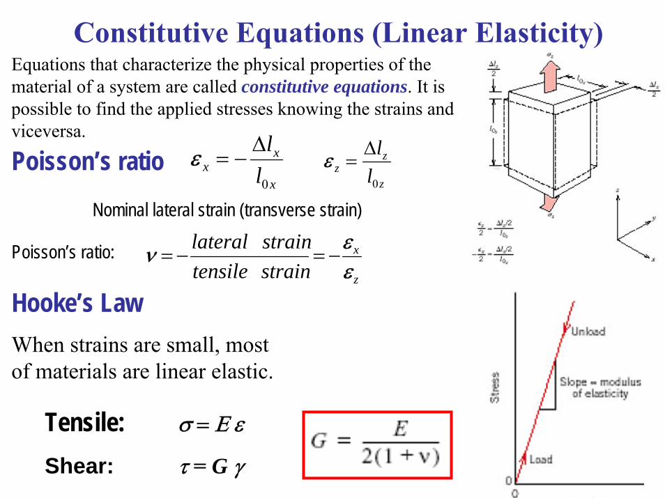
Constitutive Equations (Linear Elasticity)Equations that characterize the physical properties of the material of a system are called constitutive equations. It is possible to find the applied stresses knowing the strains and viceversa.
Poisson’s ratio
Nominal lateral strain (transverse strain)z
zz l
l
0
Δ=ε
x
xx l
l
0
Δ−=ε
Poisson’s ratio:z
x
straintensilestrainlateral
εεν −=−=
Hooke’s LawWhen strains are small, most of materials are linear elastic.
Tensile: σ = Ε ε
Shear: τ = G γ
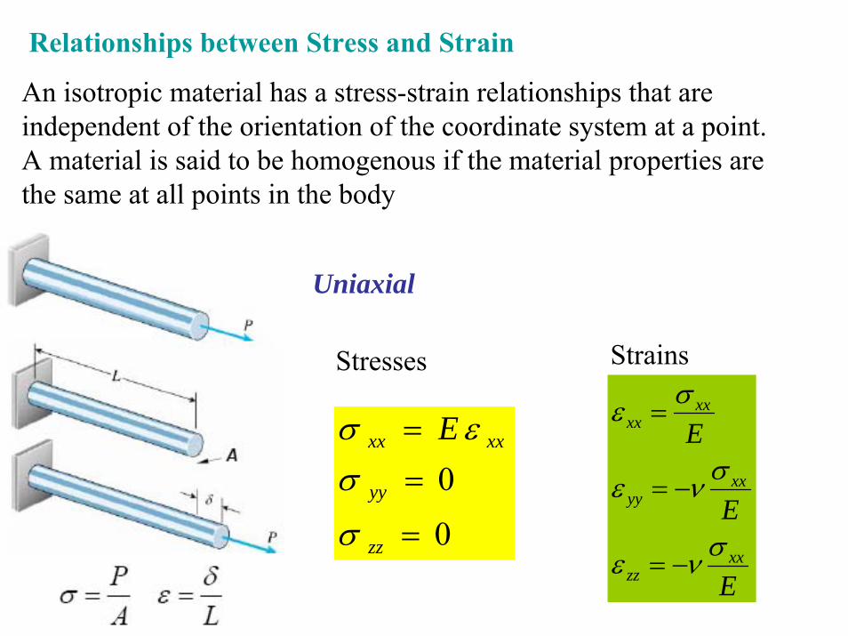
Relationships between Stress and Strain
An isotropic material has a stress-strain relationships that are independent of the orientation of the coordinate system at a point. A material is said to be homogenous if the material properties are the same at all points in the body
0
0
=
==
zz
yy
xxxx E
σ
σεσ
Stresses Strains
E
E
E
xxzz
xxyy
xxxx
σνε
σνε
σε
−=
−=
=
Uniaxial
( )
( )
01
1
2
2
=++
=
++
=
zz
yyxxyy
yyxxxx
E
E
σν
ενεσ
ννεε
σStresses Strains
EE
EE
EE
yyxxzz
yyxxyy
yyxxxx
σνσνε
σσνε
σνσε
−−=
+−=
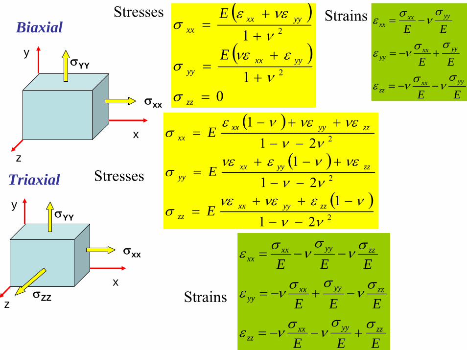
−=Biaxial
x
σxx
y
z
σYY
( )
( )
( )2
2
2
211
211
211
νννενενε
σ
νννενενε
σ
νννενενε
σ
−−−++
=
−−+−+
=
−−++−
=
zzyyxxzz
zzyyxxyy
zzyyxxxx
E
E
E
Stresses
Strains
EEE
EEE
EEE
zzyyxxzz
zzyyxxyy
zzyyxxxx
σσνσνε
σνσσνε
σνσ
νσε
+−−=
−+−=
−−=
Triaxial
x
σxx
y
z
σYY
σZZ
OR [ ]
⎪⎪⎪⎪
⎭
⎪⎪⎪⎪
⎬
⎫
⎪⎪⎪⎪
⎩
⎪⎪⎪⎪
⎨
⎧
=
xy
zx
yz
zz
yy
xx
τττσσσ
σ
[ ]
⎪⎪⎪⎪
⎭
⎪⎪⎪⎪
⎬
⎫
⎪⎪⎪⎪
⎩
⎪⎪⎪⎪
⎨
⎧
=
xy
zx
yz
zz
yy
xx
γγγεεε
ε
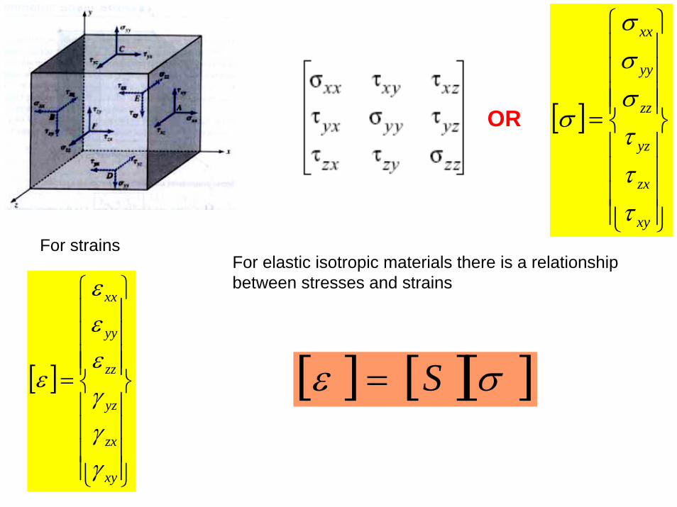
For strains
[ ] [ ][ ]σε S=
For elastic isotropic materials there is a relationship between stresses and strains
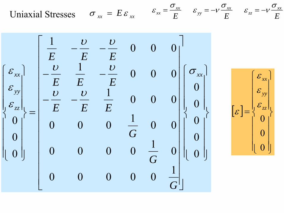
xxxx E εσ = EEExx
zzxx
yyxx
xxσνεσνεσε −=−==
[ ]
⎪⎪⎪⎪
⎭
⎪⎪⎪⎪
⎬
⎫
⎪⎪⎪⎪
⎩
⎪⎪⎪⎪
⎨
⎧
=
000zz
yy
xx
εεε
ε
⎪⎪⎪⎪
⎭
⎪⎪⎪⎪
⎬
⎫
⎪⎪⎪⎪
⎩
⎪⎪⎪⎪
⎨
⎧
⎥⎥⎥⎥⎥⎥⎥⎥⎥⎥⎥⎥⎥
⎦
⎤
⎢⎢⎢⎢⎢⎢⎢⎢⎢⎢⎢⎢⎢
⎣
⎡
−−
−−
−−
=
⎪⎪⎪⎪
⎭
⎪⎪⎪⎪
⎬
⎫
⎪⎪⎪⎪
⎩
⎪⎪⎪⎪
⎨
⎧
00000
100000
010000
001000
0001
0001
0001
000
xx
zz
yy
xx
G
G
G
EEE
EEE
EEEσ
υυ
υυ
υυ
εεε
Uniaxial Stresses
1
1
1
zzyyxxzz
zzyyxxyy
zzyyxxxx
EEE
EEE
EEE
σσνσνε
σνσσνε
σνσνσε
+−−=
−+−=
−−=
[ ]
⎪⎪⎪⎪
⎭
⎪⎪⎪⎪
⎬
⎫
⎪⎪⎪⎪
⎩
⎪⎪⎪⎪
⎨
⎧
=
000zz
yy
xx
εεε
ε
⎪⎪⎪⎪
⎭
⎪⎪⎪⎪
⎬
⎫
⎪⎪⎪⎪
⎩
⎪⎪⎪⎪
⎨
⎧
⎥⎥⎥⎥⎥⎥⎥⎥⎥⎥⎥⎥⎥
⎦
⎤
⎢⎢⎢⎢⎢⎢⎢⎢⎢⎢⎢⎢⎢
⎣
⎡
−−
−−
−−
=
⎪⎪⎪⎪
⎭
⎪⎪⎪⎪
⎬
⎫
⎪⎪⎪⎪
⎩
⎪⎪⎪⎪
⎨
⎧
000
100000
010000
001000
0001
0001
0001
000
z
y
x
z
y
x
G
G
G
EEE
EEE
EEE
σσσ
υυ
υυ
υυ
εεε
[ ]
⎪⎪⎪⎪
⎭
⎪⎪⎪⎪
⎬
⎫
⎪⎪⎪⎪
⎩
⎪⎪⎪⎪
⎨
⎧
=
000
zz
yy
xx
σσσ
σ
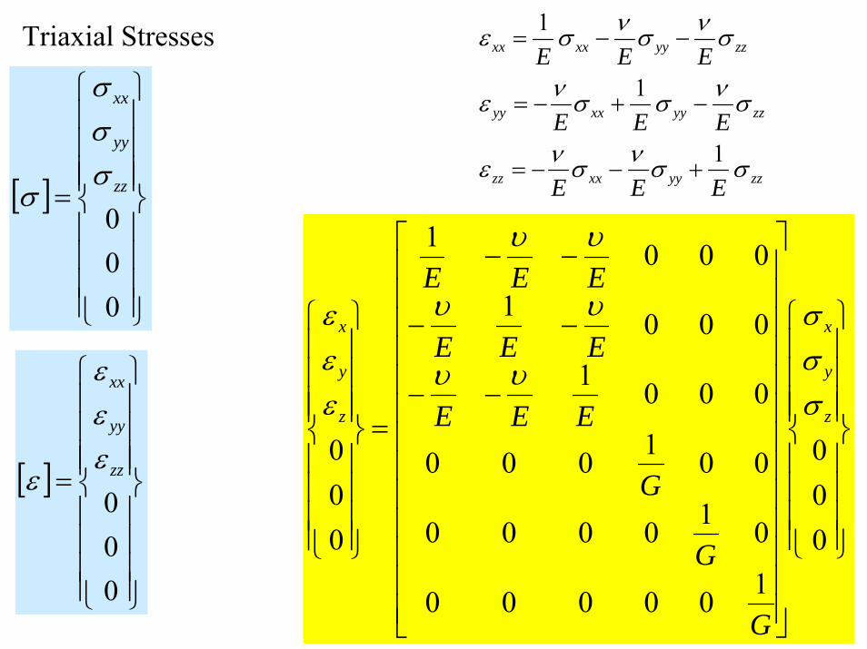
Triaxial Stresses
EEE
EEE
EEE
zzyyxxzz
zzyyxxyy
zzyyxxxx
σσνσνε
σνσσνε
σνσ
νσε
+−−=
−+−=
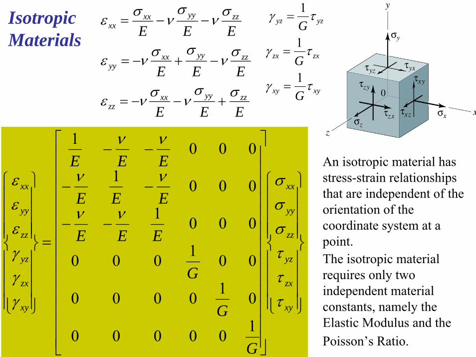
−−=Isotropic Materials
1
1
1
xyxy
zxzx
yzyz
G
G
G
τγ
τγ
τγ
=
=
=
An isotropic material has stress-strain relationships that are independent of the orientation of the coordinate system at a point.The isotropic material requires only two independent material constants, namely the Elastic Modulus and the Poisson’s Ratio.
⎪⎪⎪⎪
⎭
⎪⎪⎪⎪
⎬
⎫
⎪⎪⎪⎪
⎩
⎪⎪⎪⎪
⎨
⎧
⎥⎥⎥⎥⎥⎥⎥⎥⎥⎥⎥⎥⎥
⎦
⎤
⎢⎢⎢⎢⎢⎢⎢⎢⎢⎢⎢⎢⎢
⎣
⎡
−−
−−
−−
=
⎪⎪⎪⎪
⎭
⎪⎪⎪⎪
⎬
⎫
⎪⎪⎪⎪
⎩
⎪⎪⎪⎪
⎨
⎧
xy
zx
yz
zz
yy
xx
xy
zx
yz
zz
yy
xx
G
G
G
EEE
EEE
EEE
τττσσσ
νν
νν
νν
γγγεεε
100000
010000
001000
0001
0001
0001
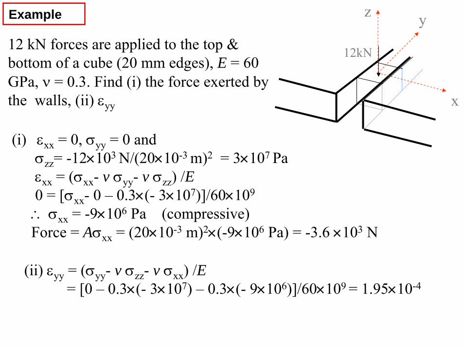
Example
12 kN forces are applied to the top & bottom of a cube (20 mm edges), E = 60 GPa, ν = 0.3. Find (i) the force exerted by the walls, (ii) εyy
z y
12kN
x
(i) εxx = 0, σyy = 0 and σzz= -12×103 N/(20×10-3 m)2 = 3×10⁷ Paεxx = (σxx- v σyy- v σzz) /E0 = [σxx- 0 – 0.3×(- 3×10⁷)]/60×109
∴ σxx = -9×10⁶ Pa (compressive)Force = Aσxx = (20×10-3 m)2×(-9×10⁶ Pa) = -3.6 ×10³ N
(ii) εyy = (σyy- v σzz- v σxx) /E= [0 – 0.3×(- 3×10⁷) – 0.3×(- 9×10⁶)]/60×109 = 1.95×10⁻⁴
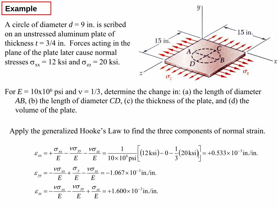
Example
A circle of diameter d = 9 in. is scribed on an unstressed aluminum plate of thickness t = 3/4 in. Forces acting in the plane of the plate later cause normal stresses σxx = 12 ksi and σzz = 20 ksi.
For E = 10x106 psi and ν = 1/3, determine the change in: (a) the length of diameter AB, (b) the length of diameter CD, (c) the thickness of the plate, and (d) the volume of the plate.
Apply the generalized Hooke’s Law to find the three components of normal strain.
( ) ( )
in./in.10600.1
in./in.10067.1
in./in.10533.0ksi20310ksi12
psi10101
3
3
36
−
−
−
×+=+−−=
×−=−+−=
×+=⎥⎦⎤
⎢⎣⎡ −−
×=−−+=
EEE
EEE
EEE
zzyyxxzz
zzyxxyy
zzyyxxxx
σνσνσε
νσσνσε
νσνσσε
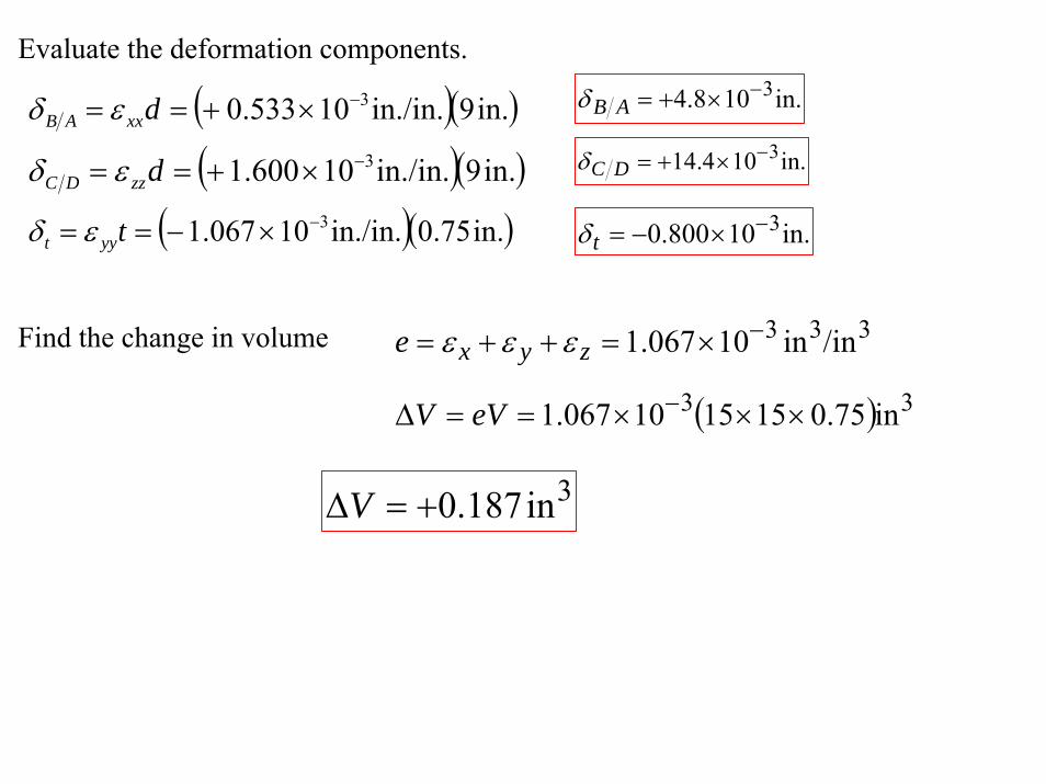
Evaluate the deformation components.
( )( )in.9in./in.10533.0 3−×+== dxxAB εδ
( )( )in.9in./in.10600.1 3−×+== dzzDC εδ
( )( )in.75.0in./in.10067.1 3−×−== tyyt εδ
in.108.4 3−×+=ABδ
in.104.14 3−×+=DCδ
in.10800.0 3−×−=tδ
Find the change in volume
( ) 33
333
in75.0151510067.1
/inin10067.1
×××==Δ
×=++=
−
−
eVV
e zyx εεε
3in187.0+=ΔV
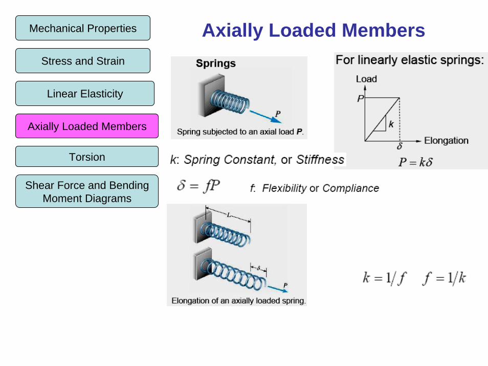
Axially Loaded MembersMechanical Properties
Stress and Strain
Linear Elasticity
Axially Loaded Members
Torsion
Shear Force and Bending Moment Diagrams
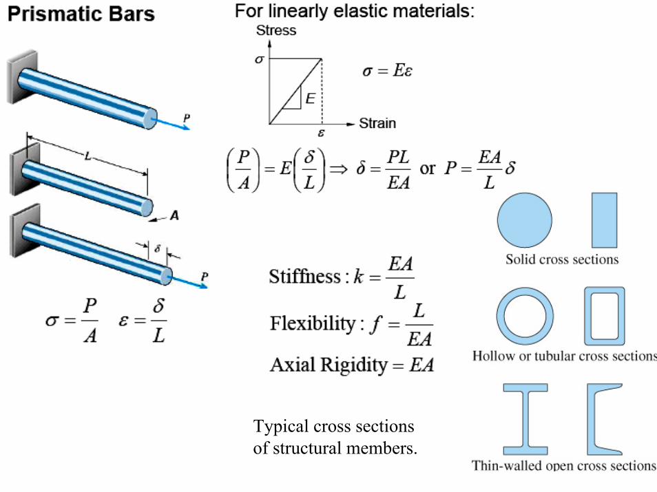
Typical cross sections of structural members.
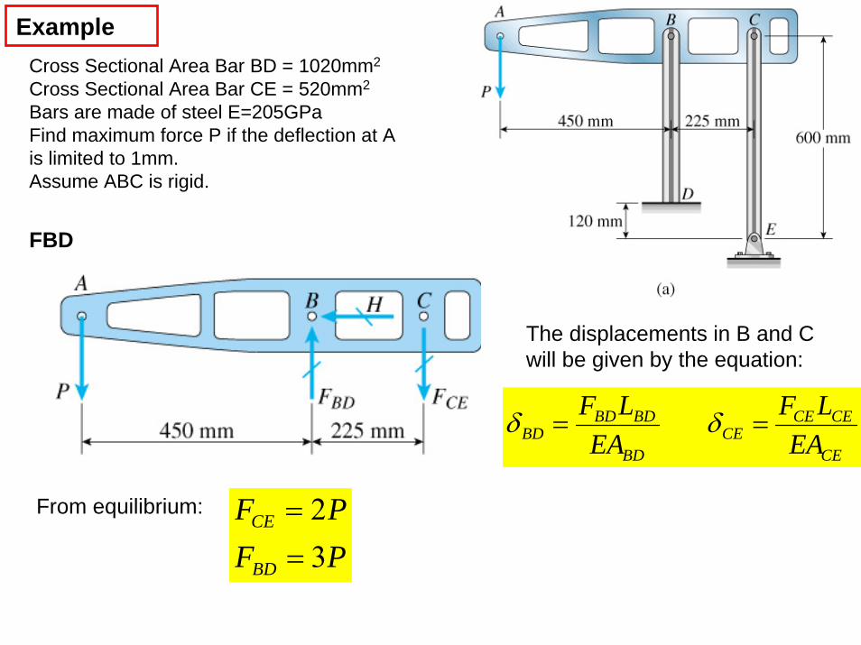
ExampleCross Sectional Area Bar BD = 1020mm2
Cross Sectional Area Bar CE = 520mm2
Bars are made of steel E=205GPaFind maximum force P if the deflection at A is limited to 1mm.Assume ABC is rigid.
FBD
The displacements in B and C will be given by the equation:
CE
CECECE
BD
BDBDBD EA
LFEA
LF== δδ
From equilibrium:
PFPF
BD
CE
32
==
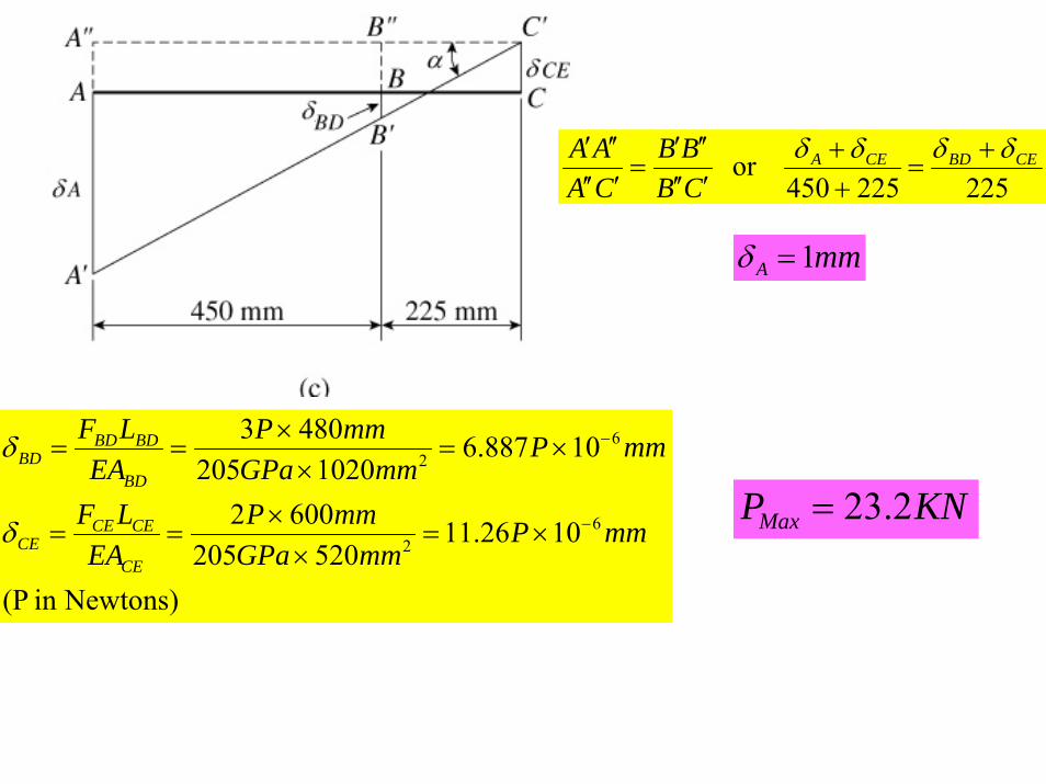
225225450or CEBDCEA
CBBB
CAAA δδδδ +
=++
′′′′′′
=′′′′′′
Newtons)in (P
1026.11520205
6002
10887.61020205
4803
62
62
mmPmmGPa
mmPEA
LF
mmPmmGPa
mmPEA
LF
CE
CECECE
BD
BDBDBD
−
−
×=×
×==
×=×
×==
δ
δ
mmA 1=δ
KNPMax 2.23=
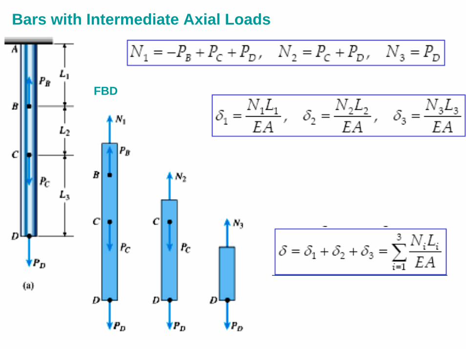
Bars with Intermediate Axial Loads
FBD
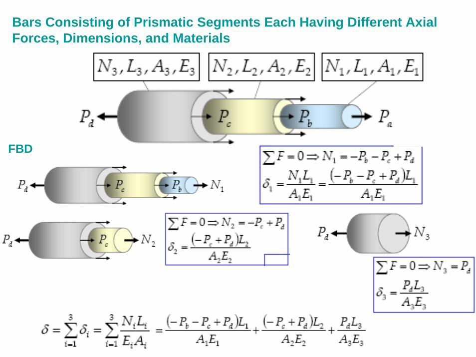
Bars Consisting of Prismatic Segments Each Having Different Axial Forces, Dimensions, and Materials
FBD
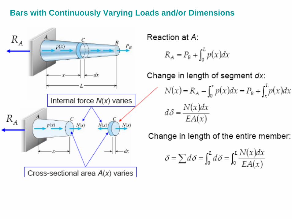
Bars with Continuously Varying Loads and/or Dimensions
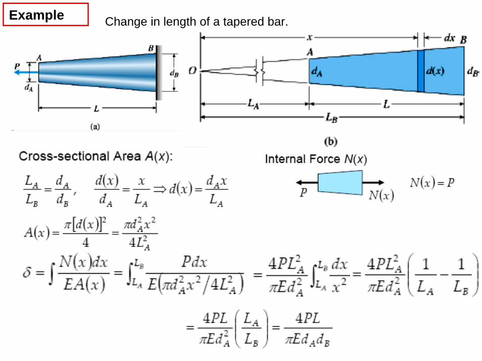
Change in length of a tapered bar.Example
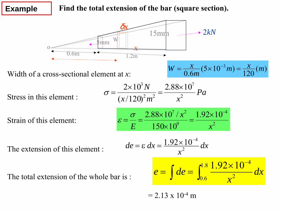
Example Find the total extension of the bar (square section).
dxx
dxde 2
41092.1 −×=ε=
)(120)105(6.03 mxmm
xW =×= −
Paxmx
N2
7
22
3 1088.2)120/(
102 ×=
×=σ
X
15mmW5mm
1.2m0.6mo
kN2δx
2
4
9
27 1092.110150
/1088.2x
xE
−×=
××
==σε
The total extension of the whole bar is :
= 2.13 x 10⁻⁴ m
∫ ∫−×
==8.1
6.0 2
41092.1 dxx
dee
The extension of this element :
Width of a cross-sectional element at x:
Stress in this element :
Strain of this element:
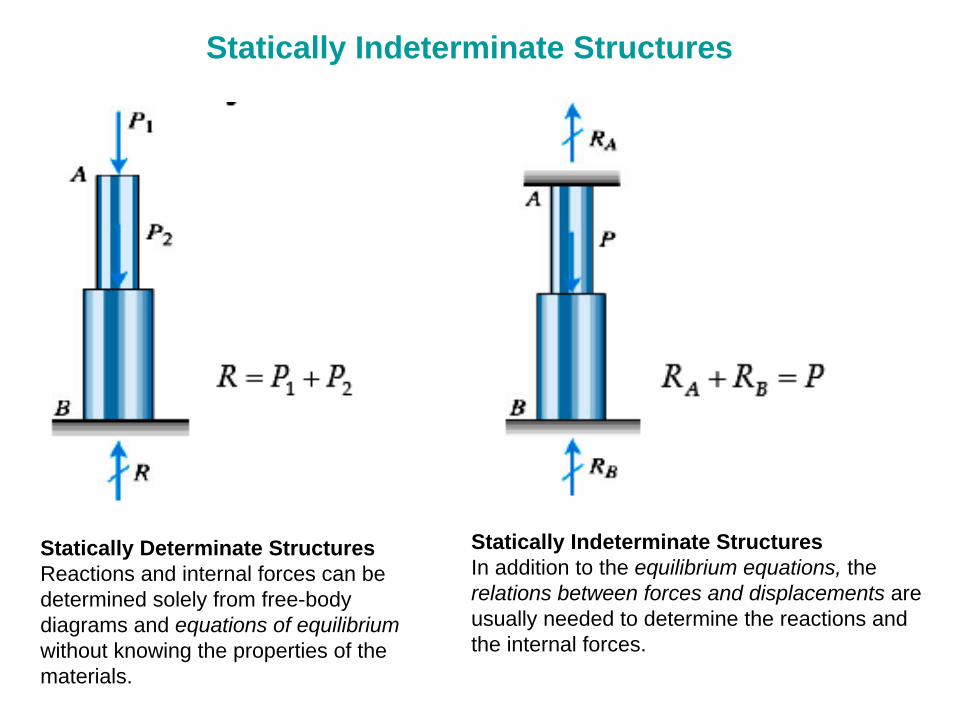
Statically Determinate StructuresReactions and internal forces can bedetermined solely from free-bodydiagrams and equations of equilibriumwithout knowing the properties of thematerials.
Statically Indeterminate StructuresIn addition to the equilibrium equations, therelations between forces and displacements are usually needed to determine the reactions and the internal forces.
Statically Indeterminate Structures
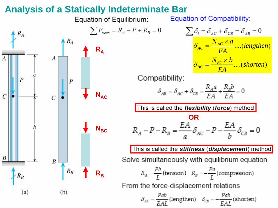
Analysis of a Statically Indeterminate Bar
RA
NAC
NBC
RB
)....(
)....(
shortenEA
bN
lengthenEA
aN
BCBC
ACAC
×=
×=
δ
δ
OR
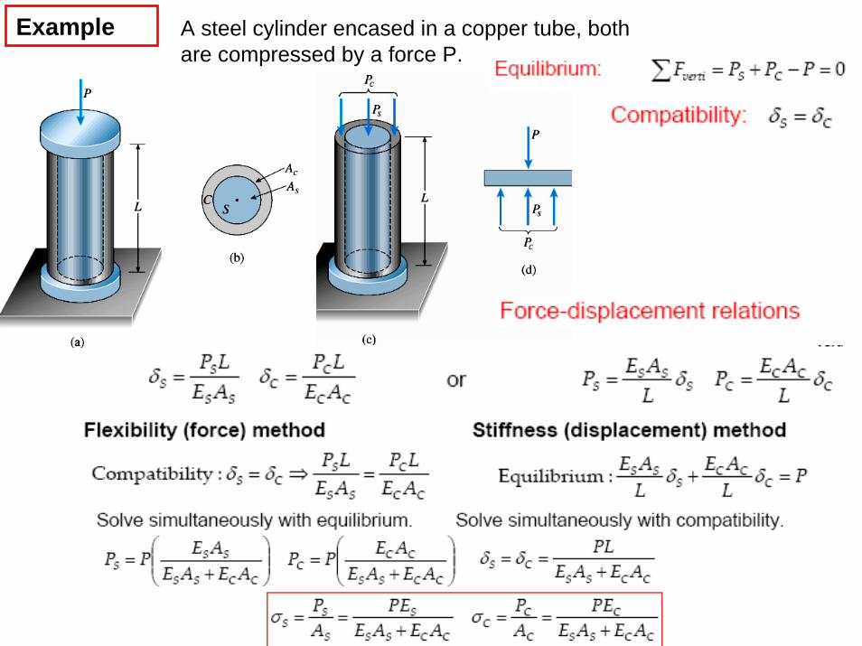
Example A steel cylinder encased in a copper tube, both are compressed by a force P.
Example
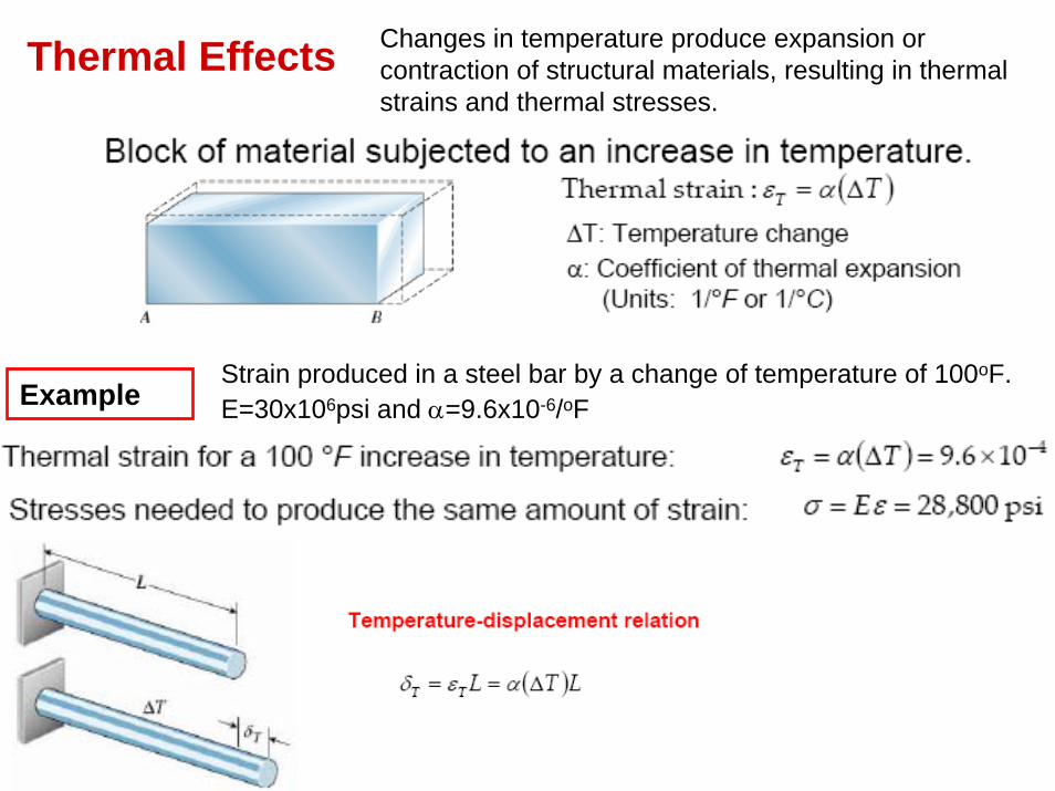
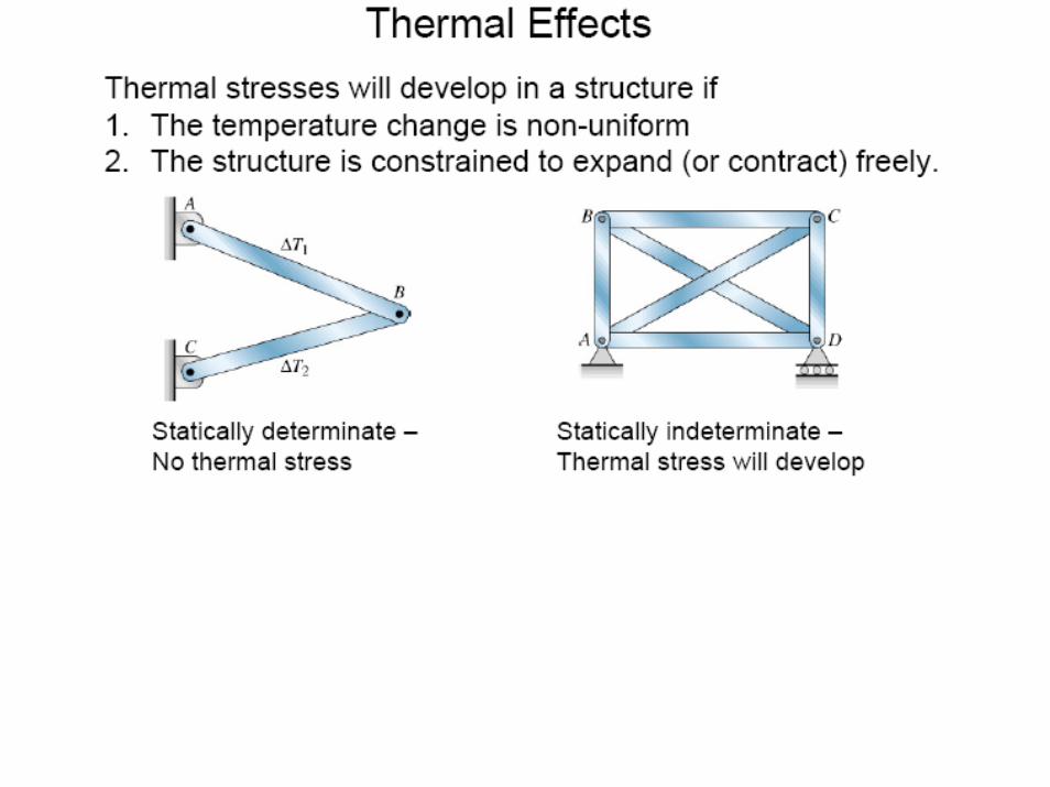
Thermal Effects Changes in temperature produce expansion or contraction of structural materials, resulting in thermal strains and thermal stresses.
ExampleStrain produced in a steel bar by a change of temperature of 100oF.E=30x106psi and α=9.6x10⁻⁶/oF
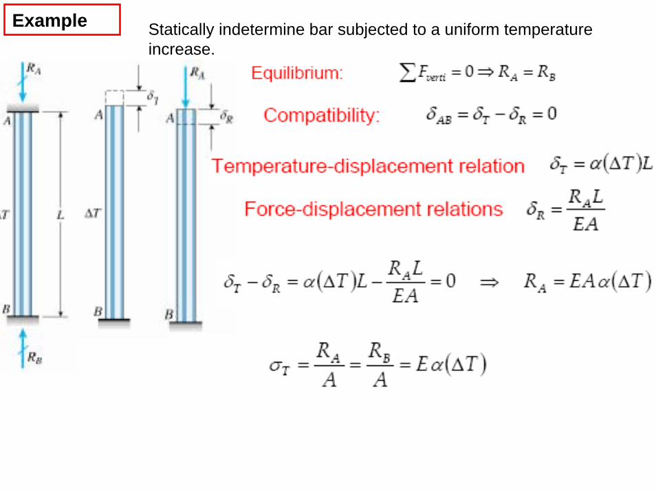
Example Statically indetermine bar subjected to a uniform temperature increase.
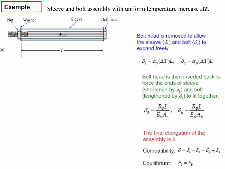
Example Sleeve and bolt assembly with uniform temperature increase ΔT.
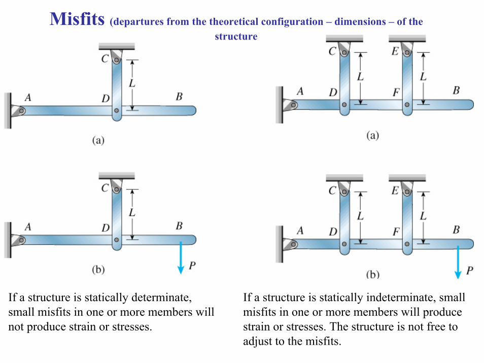
Misfits (departures from the theoretical configuration – dimensions – of the structure
If a structure is statically determinate, small misfits in one or more members will not produce strain or stresses.
If a structure is statically indeterminate, small misfits in one or more members will produce strain or stresses. The structure is not free to adjust to the misfits.
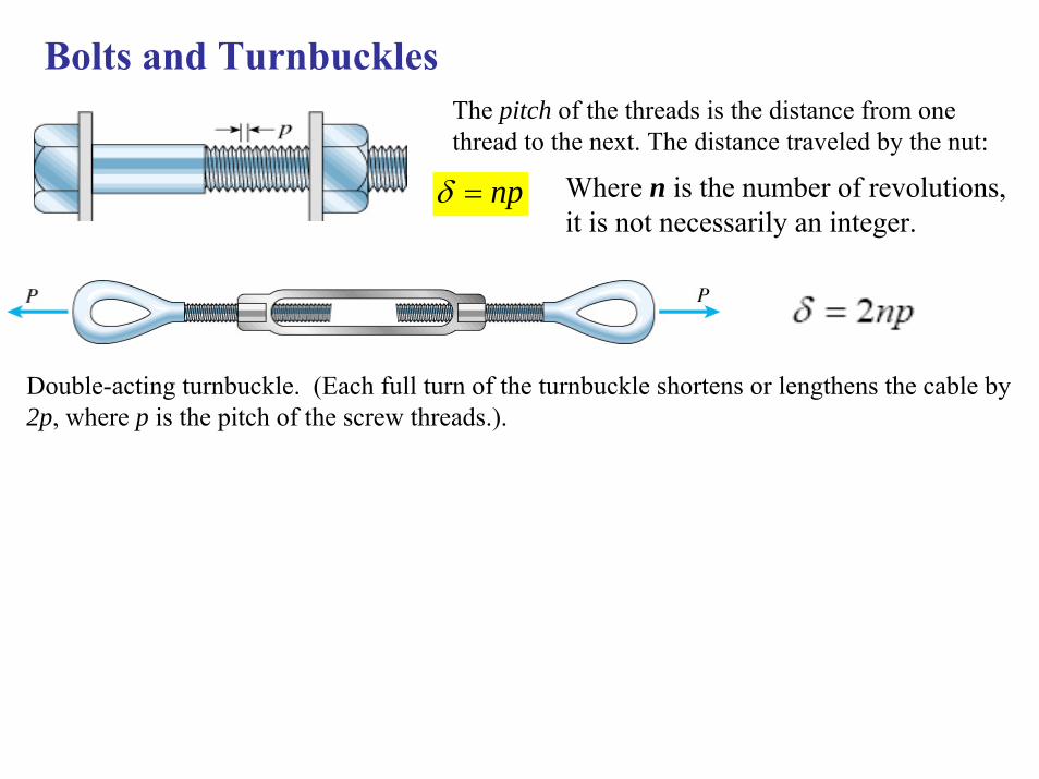
The pitch of the threads is the distance from one thread to the next. The distance traveled by the nut:
Bolts and Turnbuckles
np=δ Where n is the number of revolutions, it is not necessarily an integer.
Double-acting turnbuckle. (Each full turn of the turnbuckle shortens or lengthens the cable by 2p, where p is the pitch of the screw threads.).
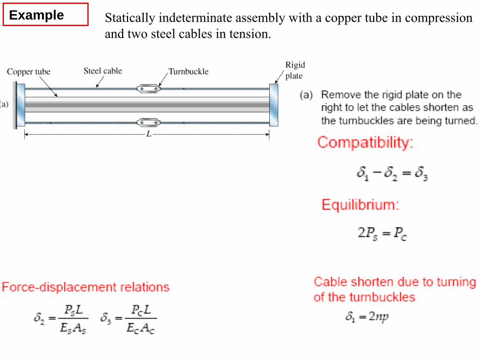
Statically indeterminate assembly with a copper tube in compression and two steel cables in tension.
Example
Example
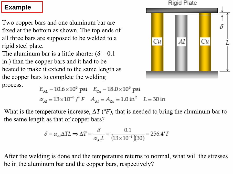
Two copper bars and one aluminum bar are fixed at the bottom as shown. The top ends of all three bars are supposed to be welded to arigid steel plate. The aluminum bar is a little shorter (δ = 0.1 in.) than the copper bars and it had to be heated to make it extend to the same length as the copper bars to complete the weldingprocess.
What is the temperature increase, ΔT (ºF), that is needed to bring the aluminum bar to the same length as that of copper bars?
After the welding is done and the temperature returns to normal, what will the stresses be in the aluminum bar and the copper bars, respectively?
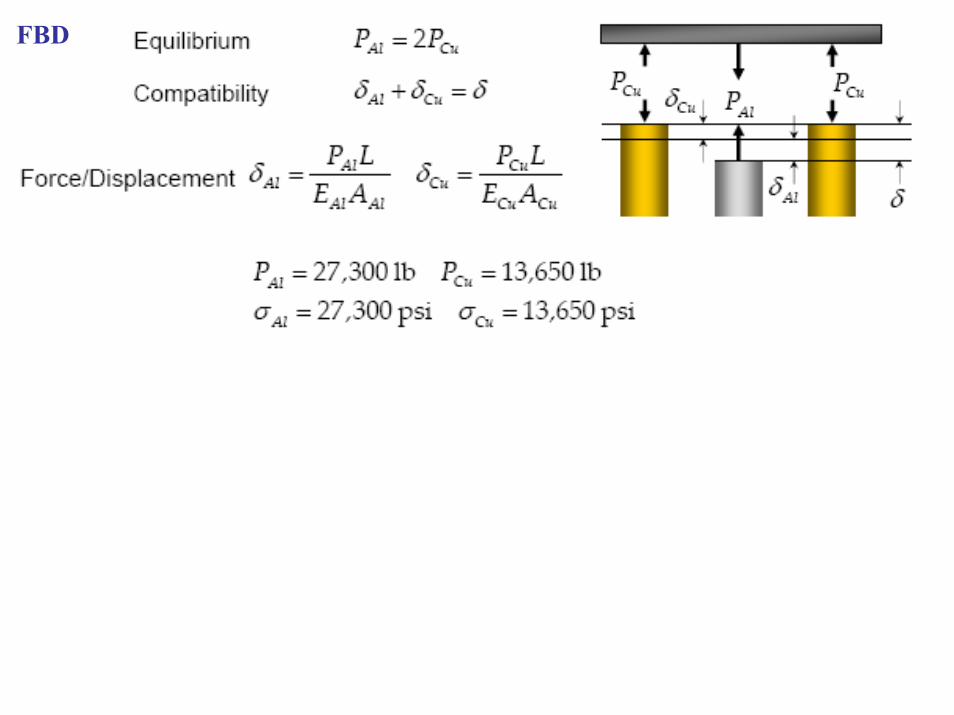
FBD
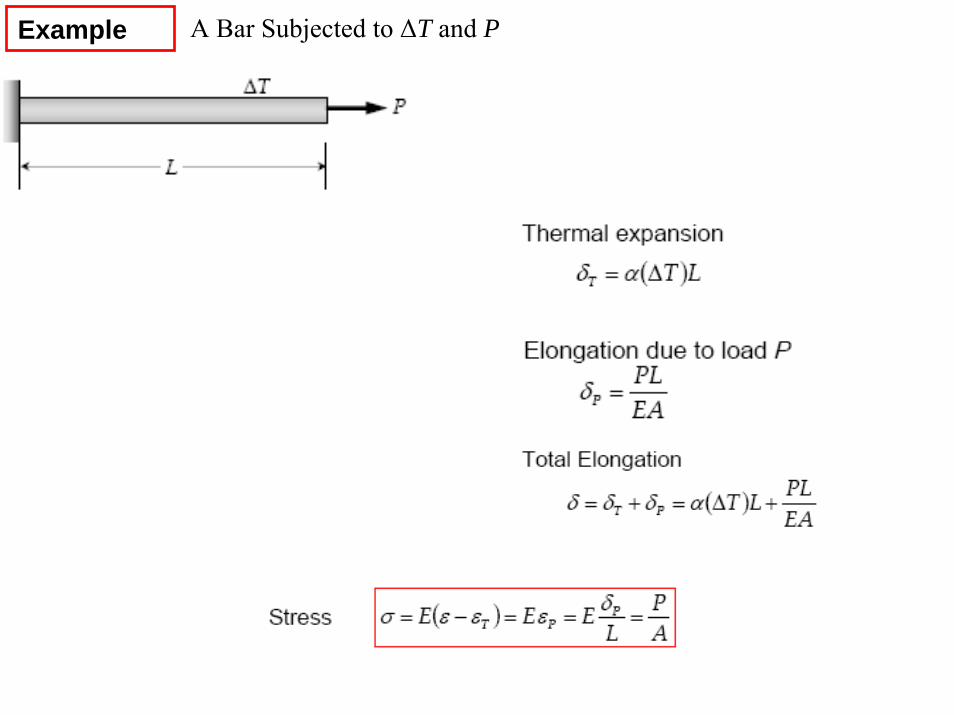
A Bar Subjected to ΔT and PExample
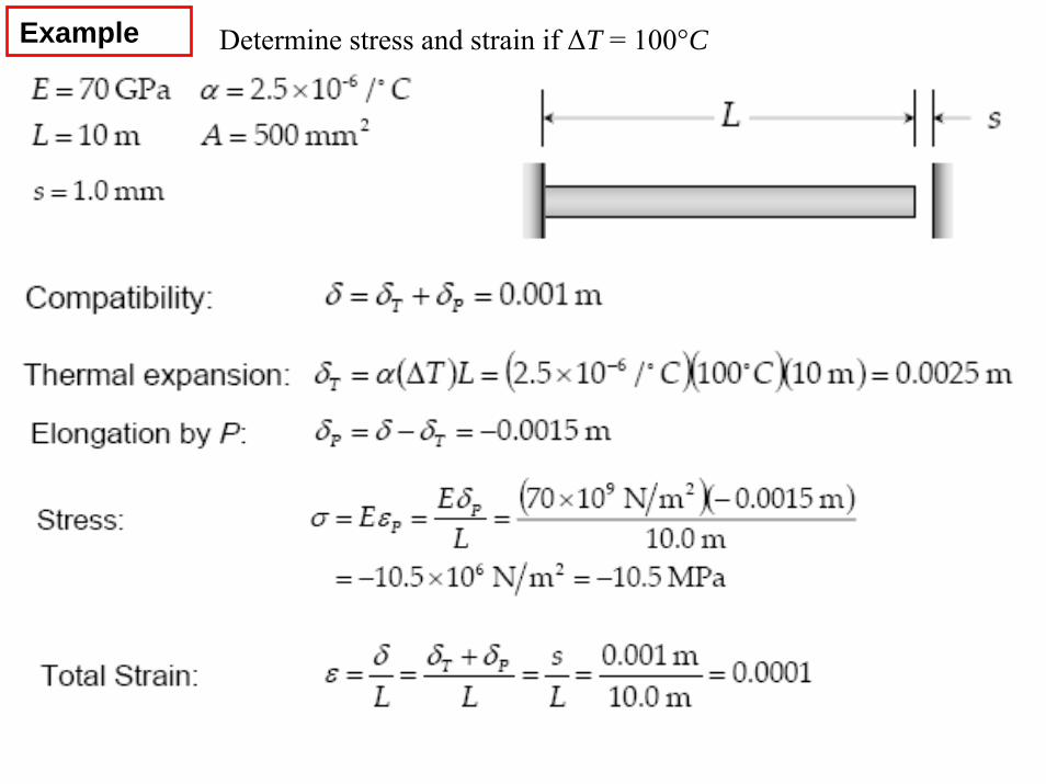
Example Determine stress and strain if ΔT = 100°C

Example
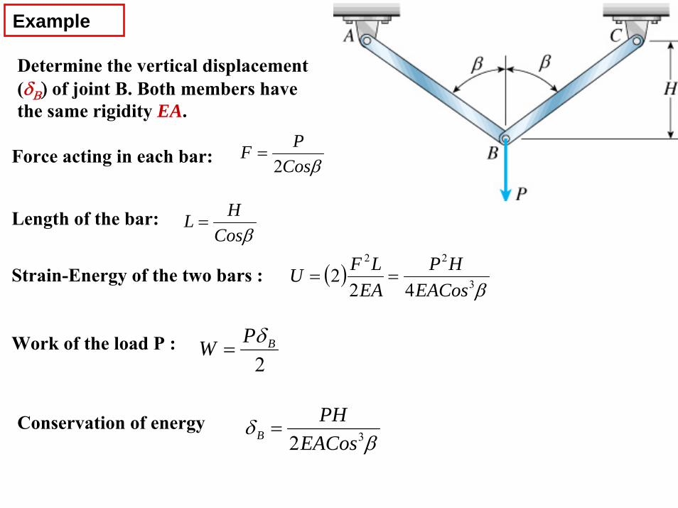
Determine the vertical displacement (δΒ) of joint B. Both members have the same rigidity EA.
Force acting in each bar: βCosPF
2=
Length of the bar: βCos
HL =
Strain-Energy of the two bars : ( )β3
22
422
EACosHP
EALFU ==
Work of the load P : 2
BPW δ=
Conservation of energyβ
δ 32EACosPH
B =
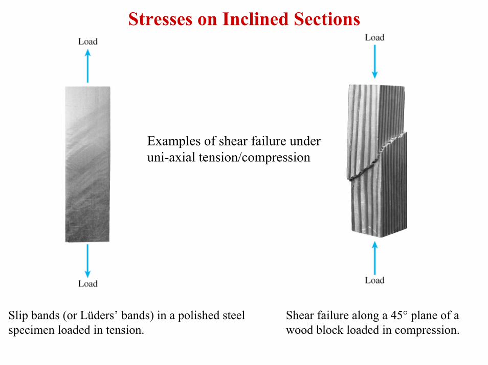
Stresses on Inclined Sections
Slip bands (or Lüders’ bands) in a polished steel specimen loaded in tension.
Shear failure along a 45° plane of a wood block loaded in compression.
Examples of shear failure under uni-axial tension/compression
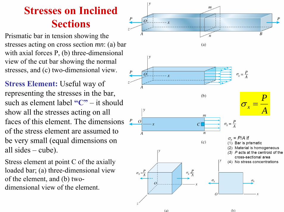
Stresses on Inclined Sections
Prismatic bar in tension showing the stresses acting on cross section mn: (a) bar with axial forces P, (b) three-dimensional view of the cut bar showing the normal stresses, and (c) two-dimensional view.
Stress Element: Useful way of representing the stresses in the bar, such as element label “C” – it should show all the stresses acting on all faces of this element. The dimensions of the stress element are assumed to be very small (equal dimensions on all sides – cube).Stress element at point C of the axially loaded bar; (a) three-dimensional view of the element, and (b) two-dimensional view of the element.
AP
x =σ
Stresses on Inclined Sections
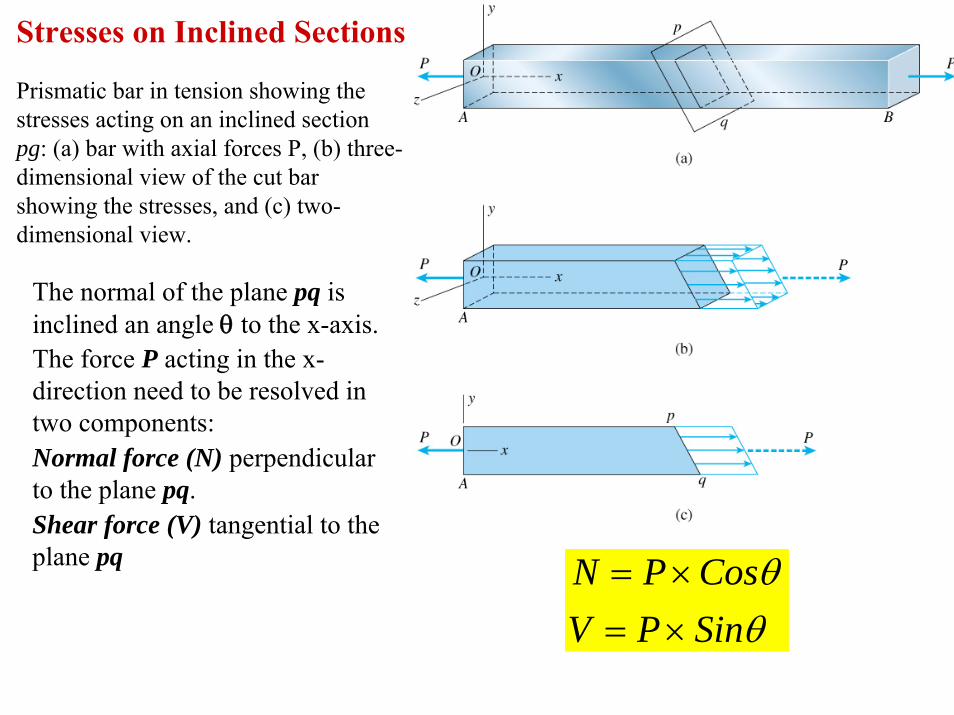
Prismatic bar in tension showing the stresses acting on an inclined section pg: (a) bar with axial forces P, (b) three-dimensional view of the cut bar showing the stresses, and (c) two-dimensional view.
The normal of the plane pq is inclined an angle θ to the x-axis.The force P acting in the x-direction need to be resolved in two components:Normal force (N) perpendicular to the plane pq.Shear force (V) tangential to the plane pq
θθ
SinPVCosPN
×=×=
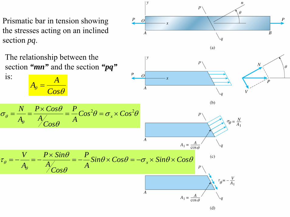
Prismatic bar in tension showing the stresses acting on an inclined section pq.
The relationship between the section “mn” and the section “pq”is:
θθ CosAA =
θσθθ
θσθ
θ22 CosCos
AP
CosA
CosPAN
x ×==×
==
θθσθθθ
θτθ
θ CosSinCosSinAP
CosA
SinPAV
x ××−=×−=×
−=−=
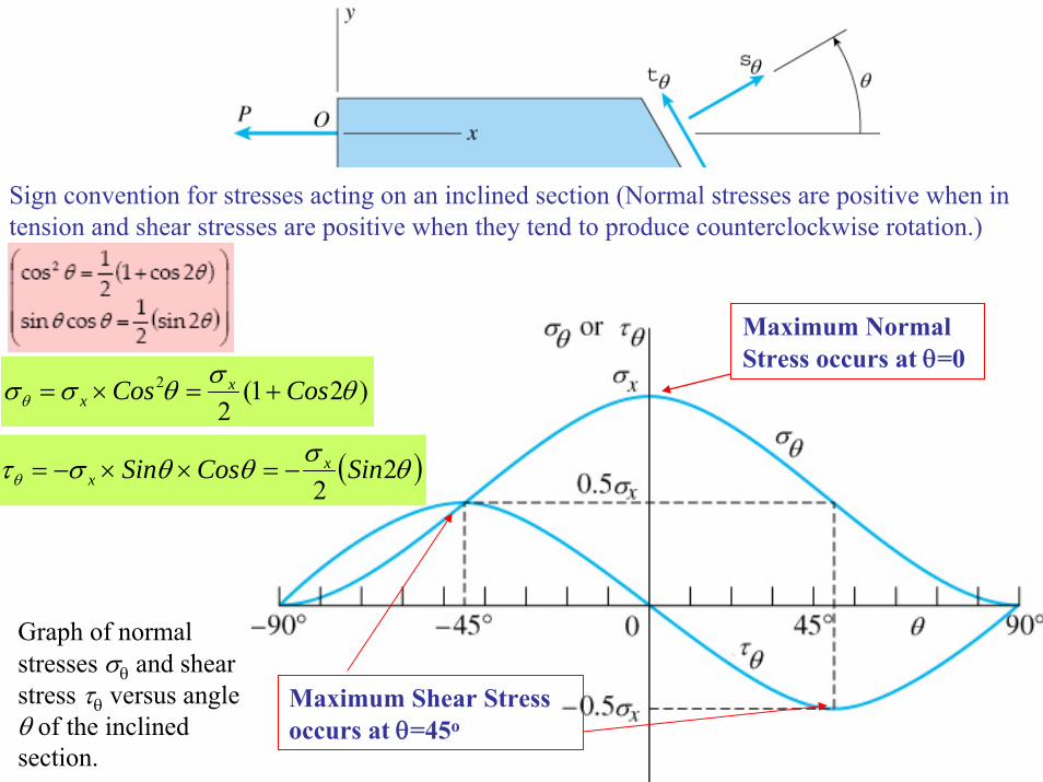
Sign convention for stresses acting on an inclined section (Normal stresses are positive when in tension and shear stresses are positive when they tend to produce counterclockwise rotation.)
Graph of normal stresses σθ and shear stress τθ versus angle θ of the inclined section.
)21(2
2 θσθσσθ CosCos xx +=×=
( )θσθθστθ 22
SinCosSin xx −=××−=
Maximum Normal Stress occurs at θ=0
Maximum Shear Stress occurs at θ=45o
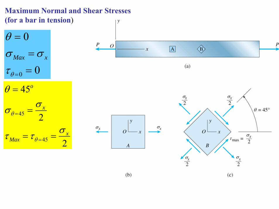
0
0
0 ==
=
=θτσσ
θ
xMax
Maximum Normal and Shear Stresses (for a bar in tension)
2
2
45
45
45
xMax
x
o
σττ
σσ
θ
θ
θ
==
=
=
=
=
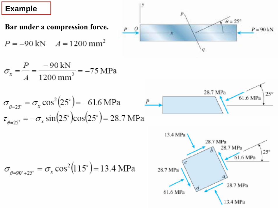
Example
Bar under a compression force.
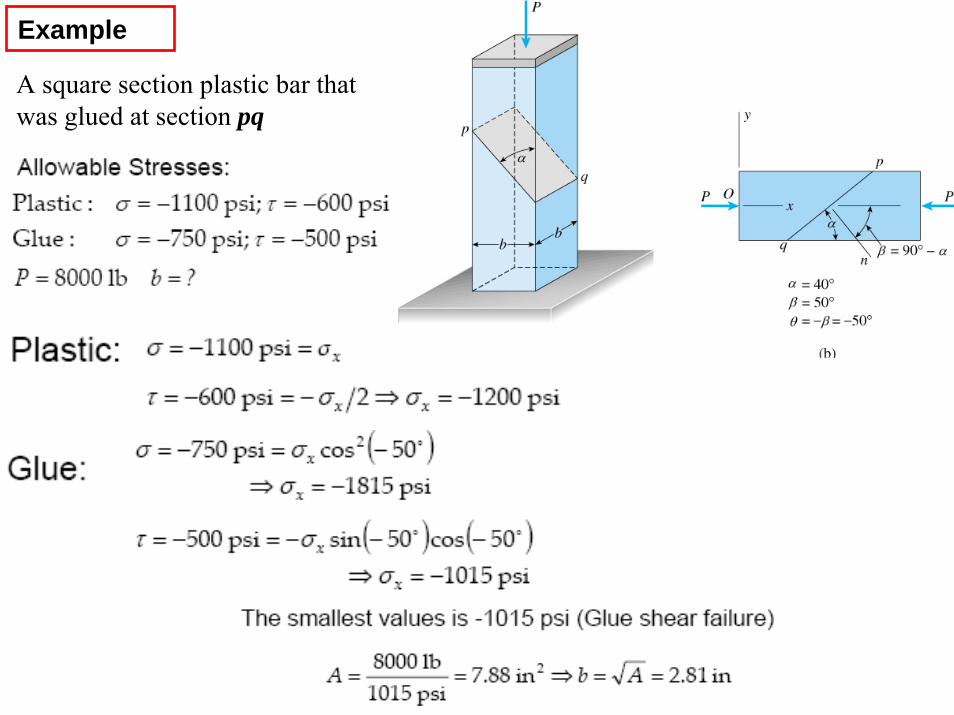
Example
A square section plastic bar that was glued at section pq
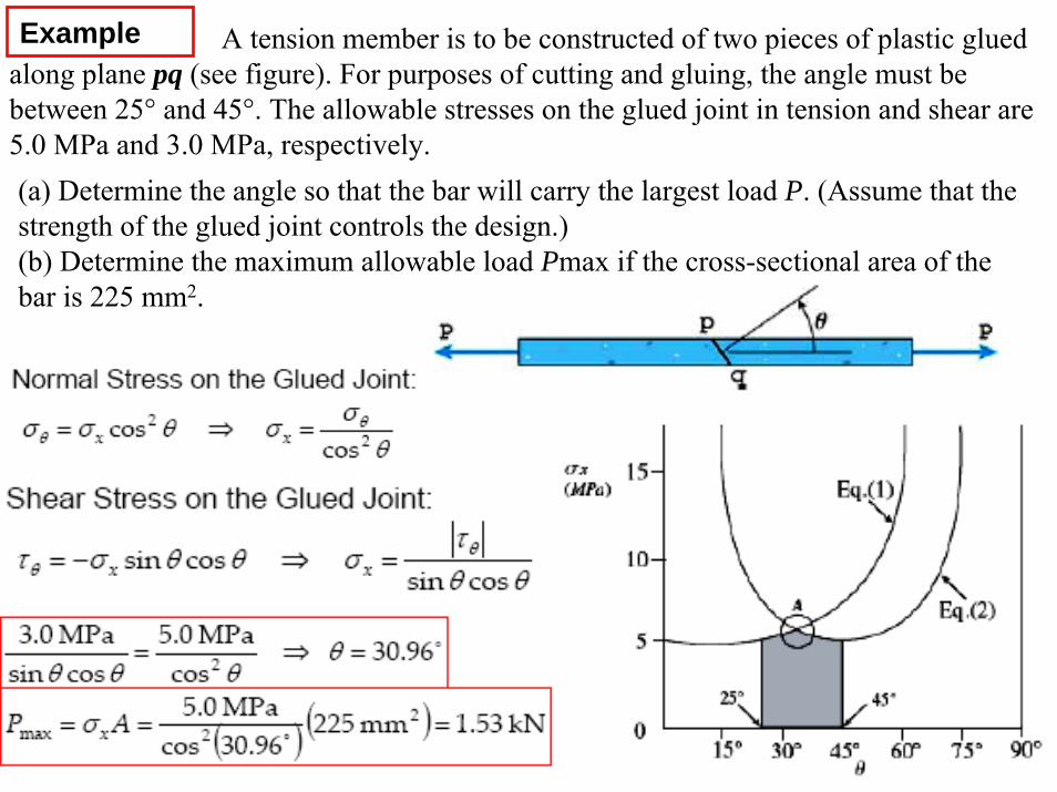
(a) Determine the angle so that the bar will carry the largest load P. (Assume that thestrength of the glued joint controls the design.)(b) Determine the maximum allowable load Pmax if the cross-sectional area of the bar is 225 mm2.
Example A tension member is to be constructed of two pieces of plastic glued along plane pq (see figure). For purposes of cutting and gluing, the angle must be between 25° and 45°. The allowable stresses on the glued joint in tension and shear are 5.0 MPa and 3.0 MPa, respectively.
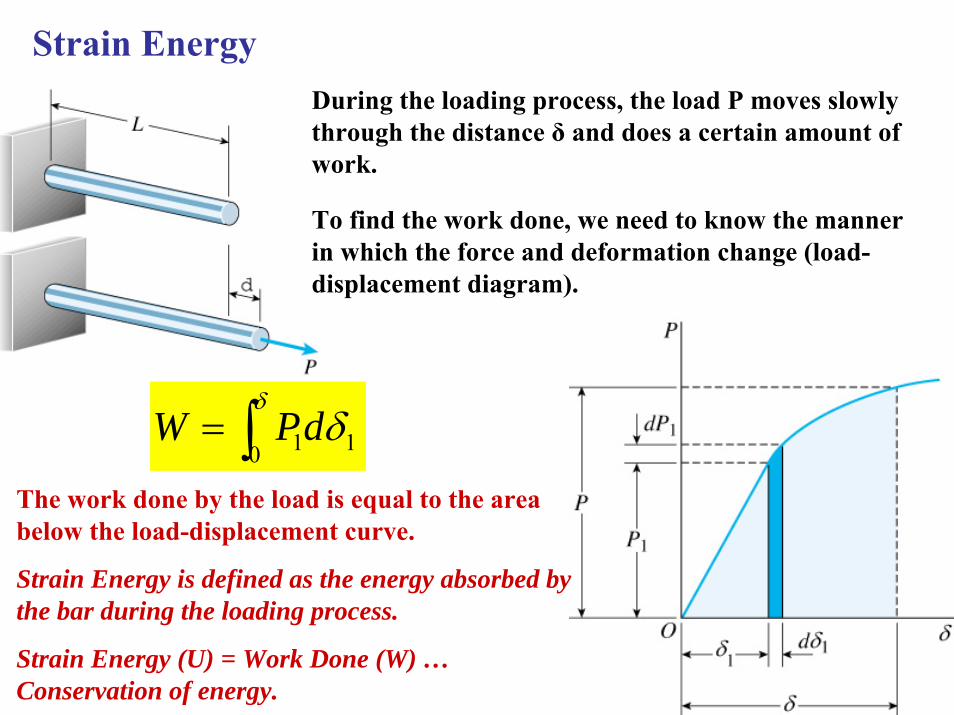
Strain EnergyDuring the loading process, the load P moves slowly through the distance δ and does a certain amount of work.
To find the work done, we need to know the manner in which the force and deformation change (load-displacement diagram).
The work done by the load is equal to the area below the load-displacement curve.
Strain Energy is defined as the energy absorbed by the bar during the loading process.
Strain Energy (U) = Work Done (W) …Conservation of energy.
∫=δ
δ0 11dPW
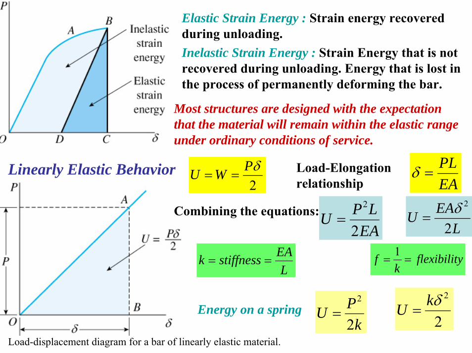
Elastic Strain Energy : Strain energy recovered during unloading.Inelastic Strain Energy : Strain Energy that is not recovered during unloading. Energy that is lost in the process of permanently deforming the bar.
Most structures are designed with the expectation that the material will remain within the elastic range under ordinary conditions of service.
Load-displacement diagram for a bar of linearly elastic material.
Linearly Elastic Behavior2δPWU == Load-Elongation
relationship EAPL
=δ
Combining the equations:EA
LPU2
2
= LEAU
2
2δ=
LEAstiffnessk ==
Energy on a springk
PU2
2
= 2
2δkU =
yflexibilitk
f ==1
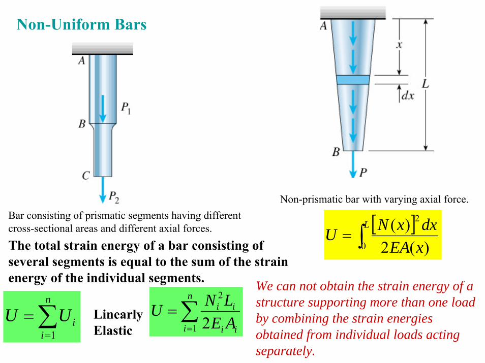
Bar consisting of prismatic segments having different cross-sectional areas and different axial forces.
Non-Uniform Bars
∑=
=n
iiUU
1
The total strain energy of a bar consisting of several segments is equal to the sum of the strain energy of the individual segments.
Non-prismatic bar with varying axial force.
Linearly Elastic
∑=
=n
i ii
ii
AELNU
1
2
2
[ ]∫=
L
xEAdxxNU
0
2
)(2)(
We can not obtain the strain energy of a structure supporting more than one load by combining the strain energies obtained from individual loads acting separately.
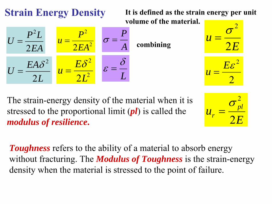
Strain Energy Density It is defined as the strain energy per unit volume of the material.
2
2
2EAPu =
2
2
2LEu δ
=
EALPU
2
2
=
LEAU
2
2δ=
AP
=σ
Lδε =
Eu
2
2σ=
2
2εEu =
combining
The strain-energy density of the material when it is stressed to the proportional limit (pl) is called the modulus of resilience. E
u plr 2
2σ=
Toughness refers to the ability of a material to absorb energy without fracturing. The Modulus of Toughness is the strain-energy density when the material is stressed to the point of failure.
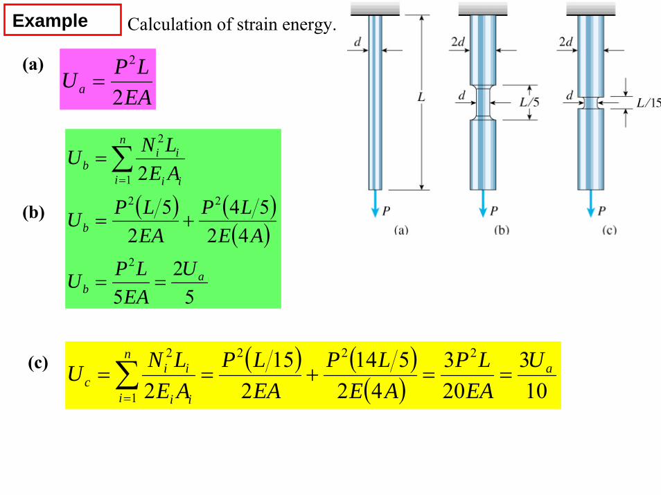
Calculation of strain energy.Example
(a)
EALPUa 2
2
=
(b) ( ) ( )( )
52
5
4254
25
2
2
22
1
2
ab
b
n
i ii
iib
UEA
LPU
AELP
EALPU
AELNU
==
+=
=∑=
(c) ( ) ( )( ) 10
3203
42514
215
2
222
1
2a
n
i ii
iic
UEA
LPAE
LPEALP
AELNU ==+==∑
=
Determine the vertical displacement (δΒ) of joint B. Both members have the same rigidity EA.
Force acting in each bar: βCosPF
2=
Length of the bar: βCos
HL =
Strain-Energy of the two bars : ( )β3
22
422
EACosHP
EALFU ==
Work of the load P : 2
BPW δ=
Conservation of energyβ
δ 32EACosPH
B =
Example
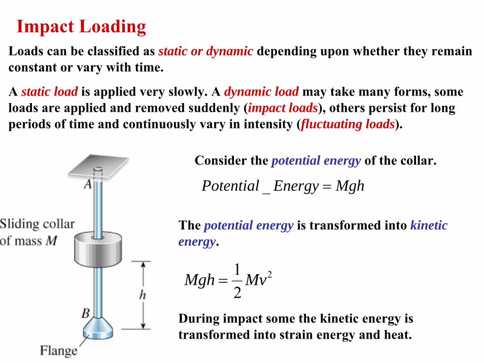
Impact LoadingLoads can be classified as static or dynamic depending upon whether they remain constant or vary with time.
A static load is applied very slowly. A dynamic load may take many forms, some loads are applied and removed suddenly (impact loads), others persist for long periods of time and continuously vary in intensity (fluctuating loads).
Consider the potential energy of the collar.
MghEnergyPotential =_
The potential energy is transformed into kinetic energy.
2
21 MvMgh =
During impact some the kinetic energy is transformed into strain energy and heat.
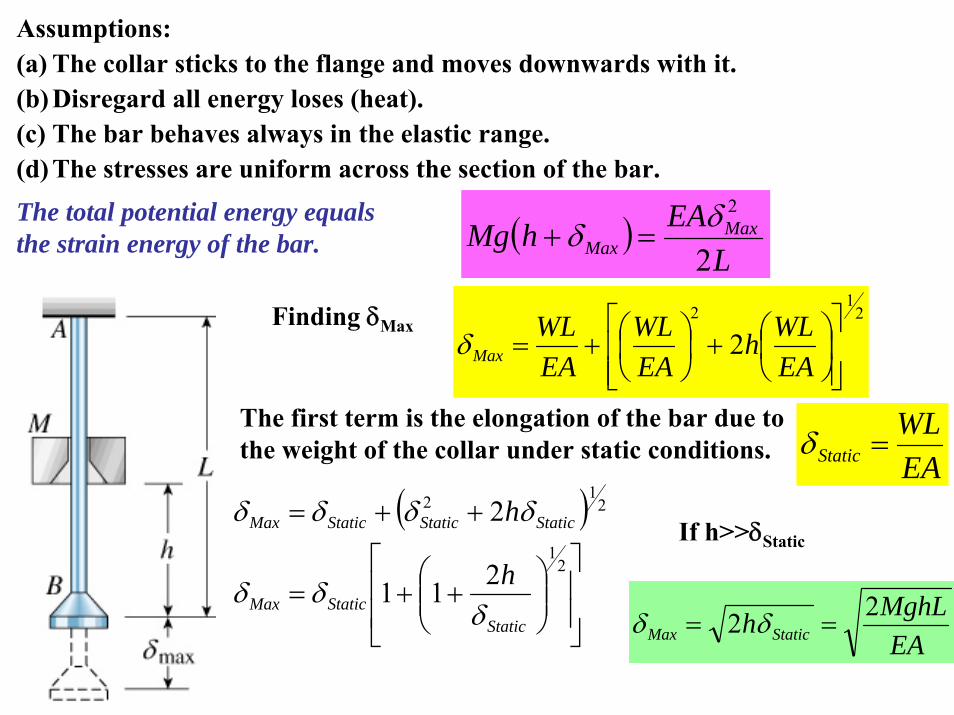
Assumptions:(a) The collar sticks to the flange and moves downwards with it.(b) Disregard all energy loses (heat).(c) The bar behaves always in the elastic range.(d) The stresses are uniform across the section of the bar.The total potential energy equals the strain energy of the bar. ( )
LEAhMg Max
Max 2
2δδ =+
Finding δMax2
12
2⎥⎥⎦
⎤
⎢⎢⎣
⎡⎟⎠⎞
⎜⎝⎛+⎟
⎠⎞
⎜⎝⎛+=
EAWLh
EAWL
EAWL
Maxδ
EAWL
Static =δThe first term is the elongation of the bar due to the weight of the collar under static conditions.
( )
⎥⎥
⎦
⎤
⎢⎢
⎣
⎡⎟⎟⎠
⎞⎜⎜⎝
⎛++=
++=
21
212
211
2
StaticStaticMax
StaticStaticStaticMax
h
h
δδδ
δδδδIf h>>δStatic
EAMghLh StaticMax
22 == δδ
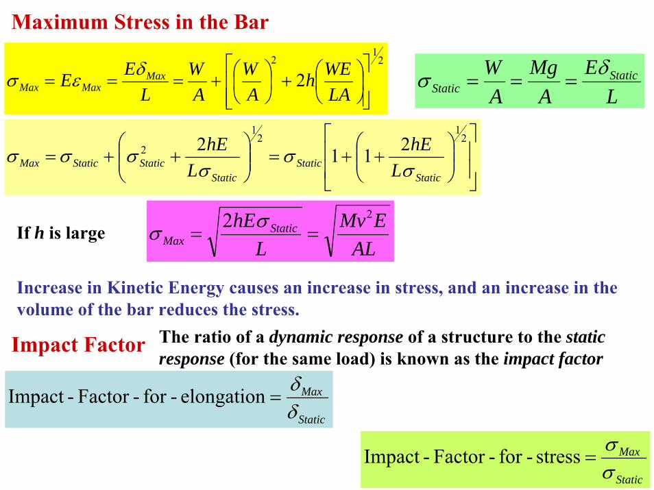
Maximum Stress in the Bar2
12
2⎥⎥⎦
⎤
⎢⎢⎣
⎡⎟⎠⎞
⎜⎝⎛+⎟
⎠⎞
⎜⎝⎛+===
LAWEh
AW
AW
LEE Max
MaxMaxδεσ
LE
AMg
AW Static
Staticδσ ===
⎥⎥
⎦
⎤
⎢⎢
⎣
⎡⎟⎟⎠
⎞⎜⎜⎝
⎛++=⎟⎟
⎠
⎞⎜⎜⎝
⎛++=
21
21
2 2112Static
StaticStatic
StaticStaticMax LhE
LhE
σσ
σσσσ
If h is largeAL
EMvL
hE StaticMax
22==
σσ
Increase in Kinetic Energy causes an increase in stress, and an increase in the volume of the bar reduces the stress.
Impact Factor
Static
Max
δδ
=elongation-for-Factor-Impact
The ratio of a dynamic response of a structure to the static response (for the same load) is known as the impact factor
Static
Max
σσ
=stress-for-Factor-Impact
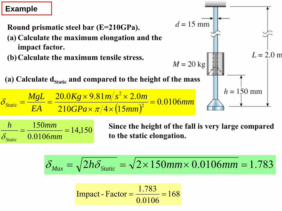
Example
Round prismatic steel bar (E=210GPa).(a) Calculate the maximum elongation and the
impact factor.(b) Calculate the maximum tensile stress.
( )mm
mmGPamsmKg
EAMgL
Static 0106.0154210
0.281.90.202
2
=××
××==
πδ
(a) Calculate dStatic and compared to the height of the mass
150,140106.0150
==mm
mmh
Staticδ
783.10106.015022 =××== mmmmh StaticMax δδ
Since the height of the fall is very large compared to the static elongation.
1680.01061.783Factor-Impact ==
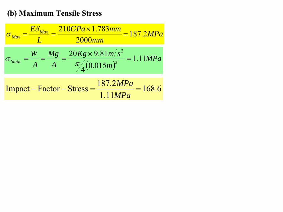
(b) Maximum Tensile Stress
( )MPa
msmKg
AMg
AW
Static 11.1015.04
81.9202
2
=×
=== πσ
MPamm
mmGPaL
E MaxMax 2.187
2000783.1210
=×
==δσ
6.16811.1
2.187StressFactorImpact ==−−MPaMPa
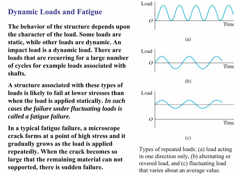
Types of repeated loads: (a) load acting in one direction only, (b) alternating or revered load, and (c) fluctuating load that varies about an average value.
Dynamic Loads and Fatigue
The behavior of the structure depends upon the character of the load. Some loads are static, while other loads are dynamic. An impact load is a dynamic load. There are loads that are recurring for a large number of cycles for example loads associated with shafts.
A structure associated with these types of loads is likely to fail at lower stresses than when the load is applied statically. In such cases the failure under fluctuating loads is called a fatigue failure.
In a typical fatigue failure, a microscope crack forms at a point of high stress and it gradually grows as the load is applied repeatedly. When the crack becomes so large that the remaining material can not supported, there is sudden failure.
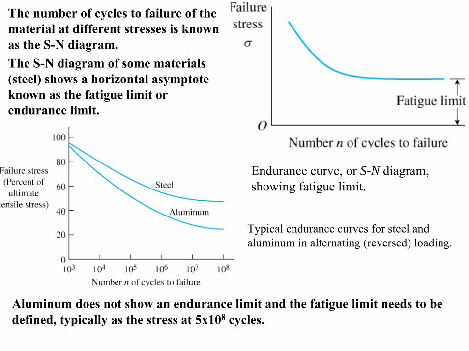
Endurance curve, or S-N diagram, showing fatigue limit.
The number of cycles to failure of the material at different stresses is known as the S-N diagram.The S-N diagram of some materials (steel) shows a horizontal asymptote known as the fatigue limit or endurance limit.
Typical endurance curves for steel and aluminum in alternating (reversed) loading.
Aluminum does not show an endurance limit and the fatigue limit needs to be defined, typically as the stress at 5x10⁸ cycles.
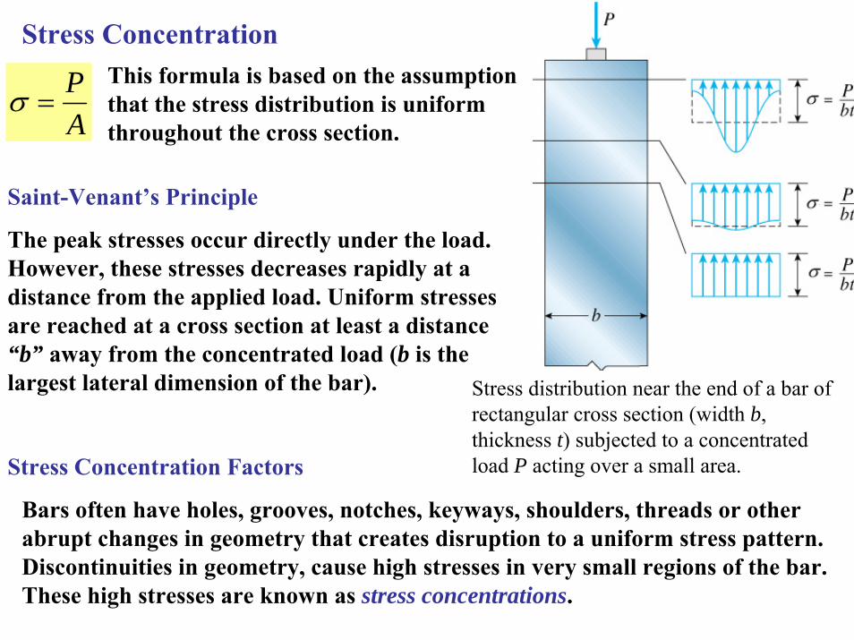
Stress Concentration
Stress distribution near the end of a bar of rectangular cross section (width b, thickness t) subjected to a concentrated load P acting over a small area.
AP
=σThis formula is based on the assumption that the stress distribution is uniform throughout the cross section.
Saint-Venant’s Principle
The peak stresses occur directly under the load. However, these stresses decreases rapidly at a distance from the applied load. Uniform stresses are reached at a cross section at least a distance “b” away from the concentrated load (b is the largest lateral dimension of the bar).
Stress Concentration Factors
Bars often have holes, grooves, notches, keyways, shoulders, threads or other abrupt changes in geometry that creates disruption to a uniform stress pattern. Discontinuities in geometry, cause high stresses in very small regions of the bar. These high stresses are known as stress concentrations.
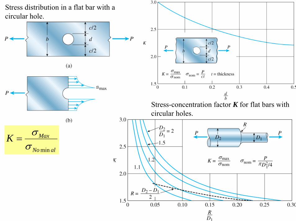
Stress distribution in a flat bar with a circular hole.
Stress-concentration factor K for flat bars with circular holes.
alNo
MaxKminσ
σ=


