Download - Hygienic Diaphragm Valves

TOP-FLO® Diaphragm Valves
www.toplineonline.com
Engineered Valve Solutions for
High Purity Industries

“Our Name Says It All”
TOP-FLO® BIOPRO® Forged . . . . . . . . . . . . . 1
TOP-FLO® BIOPRO® Cast . . . . . . . . . . . . . . . 2
TOP-FLO® BIOFLO® II . . . . . . . . . . . . . . . . . . 3
TOP-FLO® Specialty Valve Assemblies . . . . . . 4
TOP-FLO® ZERODL™ T-Pattern Dimensions . . 5
TOP-FLO® ZERODL™ POU Dimensions . . . . . 6
TOP-FLO® ZERODL™ T-Pattern & Topworks Dimensions . . . . . . . . . . . . . . . . . . 7
TOP-FLO® ZERODL™ Tank Bottom . . . . . . . . . 8
TOP-FLO® ZERODL™ Tank Bottom Topworks Dimensions . . . . . . . . . . . . . . . . . . 9
TOP-FLO® Tandem Valve Assemblies . . . . . . 10
TOP-FLO® Divert Valves . . . . . . . . . . . . . . . . 11
TOP-FLO® Actuation . . . . . . . . . . . . . . . .12-15
TOP-FLO® Bonnet Assemblies . . . . . . . . . . . 16
TOP-FLO® Diaphragms . . . . . . . . . . . . . . . . 17
Engineering . . . . . . . . . . . . . . . . . . . . . . .18-19
Ordering Information . . . . . . . . . . . . . . . . . . 20
Automation Accessories . . . . . . . . . . . . . . . 21
Table of Contents
TOP-FLO® Diaphragm Valves
Top Line Process Equipment Company is well known for
providing its customers with products that will meet or exceed the
quality standards found in the many markets we serve. Top Line
competes with the major suppliers in the industry in North and South
America for weir type diaphragm valves and are CE conforming in
accordance to PED. Pricing is very competitive and our lead times
are typically outstanding compared to our competition.
TOP-FLO® diaphragm valves, because of their unique design,
reliability, versatility, and ease of maintenance have been the ideal
choice for high purity process piping applications. We combine
world class industry experience with engineering and manufacturing
facilities located in the USA and Canada. Our R&D, engineering, and
manufacturing groups are committed to providing high quality valves
that are unsurpassed by any of our competitors.
Here are some key standard features to consider for your next
requirement:
• Low ferrite DIN 1.4435 316L forged body sizes 1/4”-4” with
controlled sulfur content to BPE 0.005-0.017 with 3.1 Material
Certification
• Autoclaveable FKM o-ring sealed 304SS stainless steel manual
bonnet with PPS thermoplastic handwheel
• Thermoplastic piston type pneumatic actuators with your choice
of popular controls for feedback (Westlock, StoneL, Burkert, etc.)
• FDA and USP Class VI (Sections 87 & 88) conforming steam grade
EPDM, MPTFE/EPDM, and MPTFE/FKM backed diaphragms
• Specialty fabricated sterile access and GMP style valves
• ZERODL™ machined block body style valve types - Point of Use,
T-pattern, Divert style, Tank Bottom, and many others specialties
as designed
• Interchangeable diaphragms and topworks with most other
manufacturers
• Extensive on the shelf inventory for project support
Top Line’s name adds essential value, including specification
assistance, outstanding delivery performance, and on-site technical
support. All of these benefits allow Top Line to offer a wide range
of products and services designed specifically to meet your every
requirement.

1
TOP-FLO® BIOPRO® Forged Diaphragm Valves
* MACHINED FROM 316L BAR
The forged body has always been the optimum choice for applications within the bioprocessing and pharmaceutical industries.
BIOPRO® forged body diaphragm valves will be the valves of choice when high purity mechanical and electropolished surface finishes are required.
BIOPRO® forged bodies are manufactured from ASTM A182 GR F316L material with additional controls in regards to chemical content. The sulfur content is maintained to meet and exceed the stringent requirements of BPE. All forgings are solution annealed to maintain the ferrite content to be .05% or less. This low ferrite content eliminates the concern for contaminants and migration of oxides throughout the system. Machining of the contours are performed by using state of the art cad/cam system assuring repeatability of the weir and valve cavity profiles for full drainability. Each forging contains two hash marks clearly indicating the drain angle plane for ease of installation.
BIOPRO® forged bodies are in compliance with FDA guidelines as well as cGMP principles, and are specifically designed for use in ultra pure applications where sterility is critical. Top Line provides these bodies with heat numbers etched into them for full traceability. Mill test summaries are provided with each shipment.
BIOPRO® forged diaphragm valves are available in sizes ranging from 1/2” through 6” with clamp or weld end connections and surface finishes ranging through 10Ra. Top Line can also manufacture valves in other material grades upon request.
STANDARD END CONNECTIONS
14-16-18 Gauge Tube end style valves have 0.75” O.D. Tube Minimum tangent length to facilitate orbital welding
OPTIONAL END CONNECTIONS
Schedule 5,10,40 Various clamp type connections including ISO 2852 (BS 4825-Part 3)
ISO 1127 Hygienic screwed connections DIN 11850 inclusive of BS 1864, SMS, DIN SMS 3008 11851, ISO 2853, (BS4825-Part 4)
#10 #12
A B C D (#10) D (#12) E Size Clamp End Od Tube End Weld Tangent Center To Top Center To Top Handwheel Drain Angle
1/2 See Cast Valves 3.27
3/4 See Cast Valves 3.66
1 See Cast Valves 4.17
1-1/2 5.50 6.25 1.31 8.47 6.10 4.75 20°
2 6.25 7.50 1.59 9.88 7.065 4.75 20°
2-1/2 See Cast Valves
3 8.75 10.00 1.75 10.00 8.00 20°
4 11.50 12.50 1.63 13.63 10.00 15°
6 See Cast Valves
BIOPRO® Manual Valve Forged Dimensions

2
TOP-FLO® BIOPRO® Cast Diaphragm Valves
BIOPRO® cast valves offer an economical alternative for
less demanding service applications in food, beverage,
dairy, cosmetics, biotechnology, pharmaceutical, and
electronics processing industries.
BIOPRO® cast bodies are low carbon stainless steel
investment castings that conform to ASTM A351 grade
CF3M (316L) material. Castings are solution annealed to
provide a sanitary and clean outside finish. Available in
sizes 1-1/2” through 4” with either clamp or butt weld end
connections.
BIOPRO® cast bodies are available with 20Ra or 20Ra
with electropolish internal surface finish. Hash marks are
provided on each body to optimize drainability and facilitate
installation. Heat numbers are marked on the bodies to
provide full traceability with material test summaries being
furnished with each order.
STANDARD END CONNECTIONS
14-16-18 Gauge Tube end style valves have 0.75” O.D. Tube Minimum tangent length to facilitate orbital welding
OPTIONAL END CONNECTIONS
Schedule 5,10,40 Various clamp type connections including ISO 2852 (BS 4825-Part 3)
ISO 1127 Hygienic screwed connections DIN 11850 inclusive of BS 1864, SMS, DIN 11851, SMS 3008 ISO 2853, (BS4825-Part 4)
#10 #12
BIOPRO® Cast Manual Valve Dimensions A B C D (#10) D (#12) E Size Clamp End Od Tube End Weld Tangent Center To Top Center To Top Handwheel Drain Angle 1/2 3.50 4.88 1.50 4.47 3.27 3.00 30° 3/4 4.00 5.31 1.50 5.00 3.66 3.00 25° 1 4.50 5.56 1.50 5.69 4.17 3.00 28° 1-1/2 5.50 6.63 1.50 8.47 6.10 4.75 20° 2 6.25 7.50 1.63 9.88 7.065 4.75 20° 2-1/2 7.63 10.00 1.88 8.82 8.00 18° 3 8.75 10.00 1.88 10.00 8.00 20° 4 11.50 12.84 2.00 13.63 10.00 15° 6* 13.40 18.00 3.00 18.00 16.00 15°
3
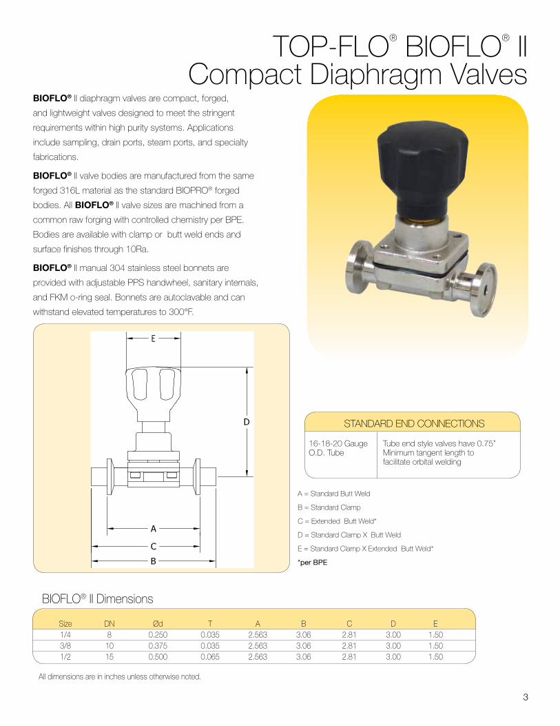
TOP-FLO® BIOFLO® II Compact Diaphragm Valves
BIOFLO® II diaphragm valves are compact, forged,
and lightweight valves designed to meet the stringent
requirements within high purity systems. Applications
include sampling, drain ports, steam ports, and specialty
fabrications.
BIOFLO® II valve bodies are manufactured from the same
forged 316L material as the standard BIOPRO® forged
bodies. All BIOFLO® II valve sizes are machined from a
common raw forging with controlled chemistry per BPE.
Bodies are available with clamp or butt weld ends and
surface finishes through 10Ra.
BIOFLO® II manual 304 stainless steel bonnets are
provided with adjustable PPS handwheel, sanitary internals,
and FKM o-ring seal. Bonnets are autoclavable and can
withstand elevated temperatures to 300°F.
A = Standard Butt Weld
B = Standard Clamp
C = Extended Butt Weld*
D = Standard Clamp X Butt Weld
E = Standard Clamp X Extended Butt Weld*
*per BPE
BIOFLO® II Dimensions
Size DN Ød T A B C D E 1/4 8 0.250 0.035 2.563 3.06 2.81 3.00 1.50 3/8 10 0.375 0.035 2.563 3.06 2.81 3.00 1.50 1/2 15 0.500 0.065 2.563 3.06 2.81 3.00 1.50
All dimensions are in inches unless otherwise noted.
STANDARD END CONNECTIONS
16-18-20 Gauge Tube end style valves have 0.75” O.D. Tube Minimum tangent length to facilitate orbital welding

4
Specialty Valve AssembliesTop Line for years has specialized in
manufacturing custom fabricated products
designed specifically to meet our customers
requirements.
Our primary objective has always been to design
and manufacture these specialty products by
using state-of-the-art manufacturing practices
and technologies.
Top Line and its affiliates employ engineers with
a vast range of expertise and knowledge in the
bioprocessing and pharmaceutical industries. The
benefit of this is our ability to provide quick and
accurate solutions to even the most complicated
problems that occur in the field.
All specialty products are manufactured using
good manufacturing practices and are put
through a very rigid quality control inspection
before leaving our facility. These practices ensure
that our customers receive quality parts ready for
immediate installation.
In addition to the standard 2-way valve bodies,
TOP-FLO® diaphragm valves offer various
configurations and assembly types.
• Tank Bottom • Access
• T-Pattern • Point-of-Use
• L-Pattern
The ZERODL™ Point-of-Use Valve utilizes the T-pattern design to promote efficient installation when used on clean water loops. The main valve body is machined from a solid block of 316L SS. It’s design improves drainability and eliminates dead legs within a processing system. Available in valve sizes 1/2” through 6” with tubing run sizes through 6” in clamp, butt weld ends, and other specialty connections.
Integral sample valves, and downstream purge ports available upon request.
TOP-FLO® ZERODL™ Point-of-Use Diaphragm Valve
TOP-FLO® ZERODL™ T-Pattern Diaphragm ValvesT-pattern type valves improve drainability and greatly eliminate dead leg. Typically installed in a horizontal position, this valve also provides for excellent sampling or diverting of critical process fluids throughout the process system.
ZERODL™ T-pattern valves are available in sizes ranging from 1/4” through 6”. These valves are machined from a solid block of 316L SS with T characteristics through 6”. A wide variety of end connections and surface finishes are offered to meet your specifications.
Integral sample valves available upon request.

5
TOP-FLO® ZERODL™ T-Pattern DimensionsZERODL™ T-PATTERN TABLE
MATERIAL: 316LSSID FINISH: AS SPECIFIED BY CUSTOMEROD FINISH: 32Ra (STANDARD) OTHER FINISHES UPON REQUEST

6
TOP-FLO® ZERODL™ POU Dimensions
MATERIAL: 316LSSID FINISH: AS SPECIFIED BY CUSTOMEROD FINISH: 32Ra (STANDARD) OTHER FINISHES UPON REQUEST

7
TOP-FLO® ZERODL™ T-Pattern & POU Topworks Dimensions

8
TOP-FLO® ZERODL™ 45° Tank Bottom Diaphragm Valves
MATERIAL: 316L PER SA-479 (MAIN WELD FLANGE)ID FINISH: AS SPECIFIED BY CUSTOMEROD FINISH: 32Ra (STANDARD) OTHER FINISHES UPON REQUEST
When bacteria entrapment or leaking gland seals associated with other types of valve
problems in the system, the ZERODL™ tank bottom valve is a reliable solution that can
be used to eliminate such concerns.
The ZERODL™ tank bottom valve, with its conical profile allows for complete drainability
and the prevention of deadlegs or entrapment areas. These valves are installed by
either bolting or welding to the tank surface.
ZERODL™ tank bottom valves are available in sizes
ranging from 1/4” through 4”. They are manufactured
using type SA-479 316L stainless steel and are available
with a wide variety of drain ports and end connections.
Positive closure can be achieved by means of manual or
pneumatic actuation.
Top Line offers many surface finish options to meet your
specifications. In addition, heat numbers are etched into
the body providing full traceability with mill test summaries
provided.
45° outlet - standard

9
TOP-FLO® ZERODL™ 45° Tank Bottom Valves Topworks Dimensions
"10"
4.124.575.317.338.01
3.153.614.166.157.05
"10" "10"
10
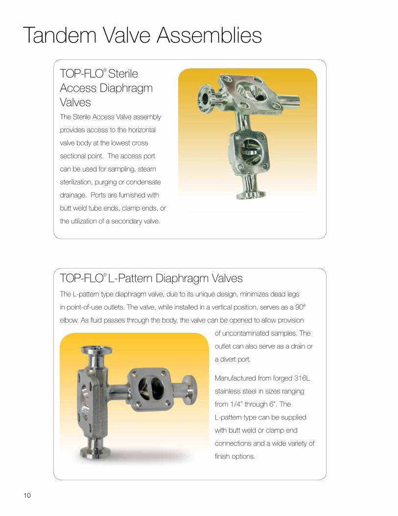
TOP-FLO® Sterile Access Diaphragm Valves The Sterile Access Valve assembly
provides access to the horizontal
valve body at the lowest cross
sectional point. The access port
can be used for sampling, steam
sterilization, purging or condensate
drainage. Ports are furnished with
butt weld tube ends, clamp ends, or
the utilization of a secondary valve.
Tandem Valve Assemblies
TOP-FLO® L-Pattern Diaphragm Valves The L-pattern type diaphragm valve, due to its unique design, minimizes dead legs
in point-of-use outlets. The valve, while installed in a vertical position, serves as a 90°
elbow. As fluid passes through the body, the valve can be opened to allow provision
of uncontaminated samples. The
outlet can also serve as a drain or
a divert port.
Manufactured from forged 316L
stainless steel in sizes ranging
from 1/4” through 6”. The
L-pattern type can be supplied
with butt weld or clamp end
connections and a wide variety of
finish options.
11
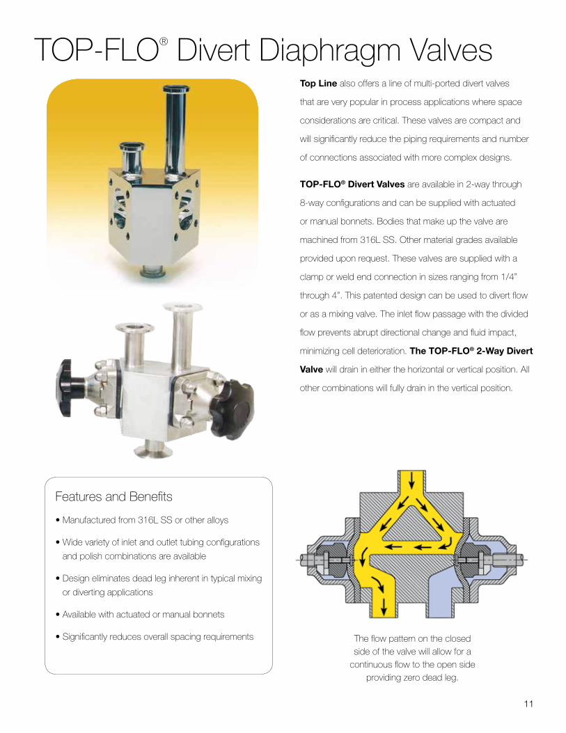
TOP-FLO® Divert Diaphragm ValvesTop Line also offers a line of multi-ported divert valves
that are very popular in process applications where space
considerations are critical. These valves are compact and
will significantly reduce the piping requirements and number
of connections associated with more complex designs.
TOP-FLO® Divert Valves are available in 2-way through
8-way configurations and can be supplied with actuated
or manual bonnets. Bodies that make up the valve are
machined from 316L SS. Other material grades available
provided upon request. These valves are supplied with a
clamp or weld end connection in sizes ranging from 1/4”
through 4”. This patented design can be used to divert flow
or as a mixing valve. The inlet flow passage with the divided
flow prevents abrupt directional change and fluid impact,
minimizing cell deterioration. The TOP-FLO® 2-Way Divert
Valve will drain in either the horizontal or vertical position. All
other combinations will fully drain in the vertical position.
The flow pattern on the closed side of the valve will allow for a
continuous flow to the open side providing zero dead leg.
Features and Benefits
• Manufactured from 316L SS or other alloys
• Wide variety of inlet and outlet tubing configurations
and polish combinations are available
• Design eliminates dead leg inherent in typical mixing
or diverting applications
• Available with actuated or manual bonnets
• Significantly reduces overall spacing requirements

12
ActuationSRS 50 Actuators The TOP-FLO® pneumatic actuator is highly suited for
today’s modern space-saving environment within the high
purity industry. Simplicity of design and robust structure
ensures long service life and economical operation.
Molded from a high performance polymer to withstand
the rigors of cleaning and sterilization temperatures, this
lightweight actuator has no corrosive components exposed
to atmosphere. All internal and external components are
corrosion resistant. In-line retrofitting is easily achieved
without the use of special tooling. Available in size ranging
from 1/4” through 4”.
Features and Benefits• Compact / Lightweight
Space-saving. Ease of installation and maintenance and mounts without additional support.
• Fully Sealed Prevents contaminants from entering the housing while minimizing the risk of leakage between chambers.
• Durability Longer life expectancy. Higher cycle performance.
• Air Connections Perpendicular to piping system - 1/8” BSPP thread (Compact valves) - 1/4” BSPP thread (Standard size valves)
• Visual Indicator Identifies valve position.
• Material of construction Molded from a high performance thermoplastic capable of withstanding elevated temperatures common to cleaning protocols.
• Accessories Stroke Limiter Electropneumatic 4-20MA positioner Mechanical switch package Proximity switch package
SRS 20-30-40 ActuatorsDesigned to be economical, featuring a rugged cast iron
housing and steel diaphragm plates, TOP-FLO® actuators are
ideally suited for automatic and remote control of sanitary weir
type diaphragm valves.
Features and Benefits• Epoxy Coated Cast Iron Housing
Highly durable in demanding environments.
• Steel Diaphragm Plates Superior performance in high pressure service.
• Positive Stop Provides added safety when manual override is used.
• Actuator Diaphragm Highly flexible for repeated cycling.
• Bonnet Compact and integral to the actuator providing better alignment to insure exceptional cycling. This unique design allows for easy field installation and adapts to most diaphragm valve bodies.
• Stem Guide Unique seal arrangement prevents lateral stem movement.
• Position Indicator Indicates valve position
• Spring Adjustment Spring tension can be externally adjusted to provide optimum performance to compensate for high internal line pressures.
TOP-FLO® SRS 50 actuators provide the
perfect solution to any valve automation
requirement.

13
Actuation Data (SRS 50)
BIOPRO® Forged Automated Valve Dimensions Elastomer Diaphragm Type
A B C D E
Size Clamp End Od Tube End Weld Tangent Center To Top Act Ø Drain Angle
1/2 3.50 4.88 1.50 4.60 2.50 30°
3/4 4.00 5.31 1.50 5.70 3.15 25°
1 4.50 5.56 1.50 6.10 3.15 28°
1-1/2 5.50 6.63 1.50 9.10 5.00 20°
2 6.25 7.50 1.63 9.60 5.00 20°
2-1/2 7.63 10.00 1.88 15.04 8.31 18°
3 8.75 10.00 1.88 15.71 8.31 20°
4 11.50 12.84 2.00 16.11 10.28 15°
6* 13.40 18.00 3.00 37.00 18.13 15°
* Machined From 316L Wrought Bar
BIOPRO® Forged Automated Valve Dimensions MPTFE Faced Diaphragm Type
A B C D E
Size Clamp End Od Tube End Weld Tangent Center To Top Act Ø Drain Angle
1/2 3.50 4.88 1.50 5.30 3.15 30°
3/4 4.00 5.31 1.50 6.80 4.00 25°
1 4.50 5.56 1.50 6.90 4.00 28°
1-1/2 5.50 6.63 1.50 10.70 6.00 20°
2 6.25 7.50 1.63 10.90 6.00 20°
2-1/2 7.63 10.00 1.88 15.27 10.28 18°
3 8.75 10.00 1.88 15.51 10.28 20°
4 11.50 12.84 2.00 16.11 10.28 15°
6* 13.40 18.00 3.00 7.00 18.13 15°
* Machined From 316L Wrought Bar
100
80
60
40
20
010 20 30 40 50 60 70 80 90 100
Flow Characteristics
PER
CEN
TAG
E O
F FL
OW
PERCENTAGE OF OPENING
100
80
60
40
20
010 20 30 40 50 60 70 80 90 100

14
Actuation Data (SRS 50)
100
80
60
40
20
010 20 30 40 50 60 70 80 90 100
100
80
60
40
20
010 20 30 40 50 60 70 80 90 100
Flow Characteristics
PER
CEN
TAG
E O
F FL
OW
PERCENTAGE OF OPENING
BIOPRO® Cast Automated Valve Dimensions Elastomer Diaphragm Type
A B C D E
Size Clamp End Od Tube End Weld Tangent Center To Top Act Ø Drain Angle
1/2 See Forged Valves
3/4 See Forged Valves
1 See Forged Valves
1-1/2 5.50 6.25 1.31 9.10 5.00 20°
2 6.25 7.50 1.59 9.60 5.00 20°
2-1/2 See Forged Valves
3 8.75 10.00 1.75 10.00 8.00 20°
4 11.50 12.50 1.63 13.63 10.00 15°
6 See Forged Valves
BIOPRO® Cast Automated Valve Dimensions MPTFE Faced Diaphragm Type
A B C D E
Size Clamp End Od Tube End Weld Tangent Center To Top Act Ø Drain Angle
1/2 See Forged Valves
3/4 See Forged Valves
1 See Forged Valves
1-1/2 5.50 6.25 1.31 10.70 6.00 20°
2 6.25 7.50 1.59 10.90 6.00 20°
2-1/2 See Forged Valves
3 8.75 10.00 1.75 10.00 8.00 20°
4 11.50 12.50 1.63 13.63 10.00 15°
6 See Forged Valves

15
Actuation Data (SRS 20, 30,40)
20 Series - Double Acting Actuators Dia. Center to Top (B)
Model (A) 1 1-1/2 2 2-1/2 3 4 6 6 8-15/16 - - - - - 7-3/4 9-7/8 9-9/16 11-1/8 - - - - 21 9-1/2 - 10-7/16 12 11-11/16 11-13/16 - - 12-1/4 - - 12-7/8 12-9/16 12-11/16 13-7/8 - 14-7/8 - - - - - 14-1/2 17-15/16
40 Series - Spring To Open Actuators Dia. Center to Top (B)
Model (A) 1 1-1/2 2 2-1/2 3 4 6 6 8-15/16 - - - - - - 7-3/4 9-7/8 9-9/16 11-1/8 - - - - 47 9-1/2 - 10-7/16 12 11-11/16 11-13/16 - - 12-1/4 - - 12-9/16 12-9/16 12-11/16 13-7/8 - 14-7/8 - - - - - 14-1/2 17-15/16
30 Series - Spring Close Actuators Dia. Center to Top (B)
Model (A) 1 1-1/2 2 2-1/2 3 4 6 6 18-15/16 - - - - - - 7-3/4 19-7/8 19-9/16 - - - - - 34 9-1/2 20-3/4 20-7/16 22 - - - - 12-1/4 - - 22-7/8 27-7/16 27-9/16 30-7/8 - 14-7/8 - - - 28-1/16 28-3/16 31-1/2 - 18-1/8 - - - - - - 49-9/16
21 Series - Double acting: Air to open/Air to close47 Series Spring to open/Air to close
34 Series Air to open/Spring to close

16
#18A BonnetSizes 1/4” - 3/8” -1/2”
• Adjustable Close Stop
• 304 SS Base with PPS Hand wheel
• Dual FKM O-ring Sealed
• Sanitary Internals
TOP-FLO® Bonnet Assemblies For Diaphragm ValvesTOP-FLO® manual bonnets offer many features that have been carefully designed with the user in mind. The advanced
bonnet design takes into account environmental stresses such as cleanability, reliability, autoclave use, adjustment, and ease of
maintenance.
TOP-FLO® stainless steel bonnets are produced using the investment casting process resulting in a durable and lightweight
valve operator. Stainless steel bonnets are electropolished externally providing a bright and sanitary exterior that also enhance
its corrosion resistance. Ergonomically designed thermoplastic hand wheel and highly visible yellow indicator are standard on
stainless steel bonnets sizes 1/2” through 2”. Bonnet sizes 2-1/2” through 4” have electropolished stainless steel bodies with
stainless steel handwheels. All TOP-FLO® manual bonnet versions have sanitary internals as standard.
#12 BonnetSizes 1/2” - 2”
• Non-Adjustable Low Profile
• 304 SS Base with PPS Hand wheel
• Dual FKM O-ring Sealed
• Sanitary Internals
#15 BonnetSizes 1/2” - 2”
• Adjustable Open Stop
• 304 SS Base with PPS Hand wheel
• Brass Visual Indicator with position gradient
#10 BonnetSizes 1/2” - 2”
• Adjustable close stop
• 304 SS base with 304 SS hand wheel
• Dual FKM O-ring sealed
• Sanitary internals
#60 BonnetSizes 1/2” - 2”
• Non-Adjustable low profile
• 304 SS base with 304 SS hand wheel
• Dual FKM O-ring sealed
• Sanitary internals
#09 BonnetSizes 2-1/2” - 4”
• 304 SS base with 304 SS hand wheel
• Dual FKM O-ring sealed
• Sanitary internals

17
Top Line understands that the most important factor of diaphragm valve reliability is the diaphragm itself. To achieve optimum diaphragm performance, only the highest-grade specially engineered materials are used in our diaphragm production.
All diaphragms are produced and controlled in the United States and Canada under a compliant and registered ISO 9001-2000 Quality Management System (QMS).
TOP-FLO® replacement diaphragms are interchangeable with key industry manufacturers when a threaded or bayonet type connection is required.
Each TOP-FLO® diaphragm valve can be supplied with a variety of elastomer or MPTFE faced materials. All diaphragms are compliant with FDA codes and USP Class VI standards and are fully traceable.
Diaphragms are molded in both the open and closed position dependent on type. All elastomer type diaphragms are attached to the compressor by a threaded stud. MPTFE diaphragms are attached by a bayonet type fixture that eliminates point loading, thus providing constant diaphragm compression across the weir resulting in a more uniform and reliable seal.
EPDM elastomer diaphragm features:• Proprietary low extractable steam grade material• Superior cycle life• FDA compliant & USP Class VI certified by NAMSA
FKM elastomer diaphragm features:• High chemical resistance with the life cycle benefits of an elastomer• FDA compliant material
MPTFE faced high-pressure molded diaphragm features:• Steam grade material• Superior cycle life• Better density• Virtually non-permeable• FDA compliant & USP Class VI certified by NAMSA
TOP-FLO® FDA & USP Weir Diaphragms
CROSS REFERENCE CHART DIAPHRAGM GRADES
TOP LINE DIAPHRAGM - MATERIAL OF CONSTRUCTIONCONNECTION
TYPETOP LINE SAUNDERS ITT BURKERT
PEROXIDE CURED EPDM* THREADED 2E E2 (425)17
ABE1
FKM FLUOROELASTOMER* THREADED 2V 226 (NON-FDA) - FF
MPTFE FACED/EPDM BACKED - STEAM GRADE BAYONET 1KSP2 (214/425) - EA
S5 (214S/425C) - EU
MPTFE FACED/FKM BACKED - STEAM GRADE BAYONET 1PSP3 (214/226) - -
P3S (214S/226) - -
*SIZES 1” (DN25) & ABOVE FOR SAUNDERS HC4 & BURKERT TYPE ONLYALL TOP LINE DIAPHRAGM FACES AND BACKING MATERIALS ARE FDA CONFORMINGALL TOP LINE DIAPHRAGMS ARE USP CLASS VI CERTIFIED - EXCLUDING GRADE 2V
topln.co/diaphragmvalves

18
Engineering
Flow Data - Forged & Cast 2-Way Valves CV Values USGPM At One PSI BIOFLO® II BIOPRO®
Size 1/4 3/8 1/2 1/2 3/4 1 1-1/2 2 2-1/2 3 4 % Open 12.5 0.47 0.49 0.50 0.52 1.75 2.60 9.80 13.50 29.00 38.30 49.00 25 0.61 0.68 0.71 0.87 3.28 5.65 18.60 35.00 54.00 68.90 1 12.00 50 0.67 1.56 1.66 1.87 5.47 12.50 35.50 54.30 77.60 136.40 270.00 75 0.69 1.84 2.23 2.48 6.78 16.70 44.60 68.00 88.60 167.00 376.00 100 0.78 1.90 2.45 3.32 7.60 18.70 46.80 71.00 91.90 177.60 404.00
KV Values Cubic Meter per Hour per At One Bar BIOFLO® II BIOPRO®
Size 1/4 3/8 1/2 1/2 3/4 1 1-1/2 2 2-1/2 3 4 % Open 12.5 0.41 0.42 0.43 0.45 1.51 2.25 8.48 11.68 25.09 33.13 42.39 25 0.53 0.59 0.61 0.75 2.84 4.89 16.09 30.28 46.71 59.60 96.88 50 0.58 1.35 1.44 1.62 4.73 10.81 30.71 46.97 67.12 117.99 233.55 75 0.60 1.59 1.93 2.15 5.86 14.45 38.58 58.82 76.64 144.46 325.24 100 0.67 1.64 2.12 2.87 6.57 16.18 40.48 61.42 79.49 153.62 349.46
Fig. AA Fig. AB Fig. AC
Fig. AD Fig. AE Fig. AF
P1P1
P1 P1
P1 P1 P1
P1
P2
P2
P2 P2
P2 P2P2
P2
Fig. LA Fig. LB Fig. LC
Fig. LD Fig. LE Fig. LF
Fig. LG Fig. LH
P1 P1
P1
P1P1
P1
P1 P1
P2 P2
P2
P2P2
P2
P2 P2
P3 P3P3
P3P3
P3 P3 P3 P3 P3
P3P3
P3 P3 P3
P3
Fig. AG Fig. AH
Sterile L-Pattern Configurations Sterile Access Configurations
Drain Angle Size 1/4 3/8 1/2 3/4 1 1-1/2 2 2-1/2 3 4 6 BIOFLO® II 35° 30° 25° - - - - - - - - BIOPRO® - - 30° 25° 28° 20° 20° 18° 20° 15° 15°
DRAIN ANGLE

19
Engineering
MECHANICAL POLISH MECHANICAL POLISH WITH ELECTROPOLISH
Micron Microinch (Ra) Grit No. BPE Micron Microinch (Ra) Grit No. BPE
0.75 30-35 150 SF3 0.62 25 180 SF6
0.62 25 180 SF2 0.50 20 240 SF5
0.50 20 240 SF1 0.37 15 320 SF4
One of the effective methods known for removal
of minor surface abnormalities after mechanical
polishing and to improve the finish on a product is
the electropolish process.
Electropolishing reduces minor scratches and other
surface imperfections by removing metal from the
product. The process creates a smoother and more
level surface finish which cannot be achieved by
mechanical polishing alone. The end result is the
reduction of such imperfections from the product
thus making them easier to be cleaned and lessens
the potential for corrosion or contamination to occur.
Benefits of the electropolishing process:• Peaks and scratched surfaces caused by
mechanical polishing are greatly reduced
• The passivation process provides greater
corrosion resistance
• Any defective welds or pitting on the surface
of the product will be revealed
• The overall appearance of the product can
be enhanced
• Cleaning and sterilization of the product is
made easier
• Assists removal of surface entrapped
contaminants
Surface finish in the pharmaceutical and bio-
processing industries is normally measured in
(Ra) or roughness average, expressed in terms
of microinch or micrometer (micron) values.
Grade Material Temperature Range Fahrenheit Celsius
2E & BE FDA/USP Black EPDM -40° – 300°F 40° – 150°C
2V FDA Black FKM 0° – 350°F -15° – 150°C
BK Compact MPTFE/EPDM 0° – 300°F -15° – 150°C
1KS Bayonet Steam MPTFE/EPDM 0° – 350°F -15° – 175°C
1PS Bayonet Steam MPTFE/FKM 25° – 350°F -4° – 175°C
Surface Finish Comparisons
Diaphragm Materials And Temperature Range

20
EXAMPLE:
316 L Forged Clamp 20Ra Finish Sealed Stainless, MPTFE/ Valve Body Valve Ends (SF5) Bonnet W/SS EPDM Size(1”) Handwheel 7 4 L4 10 1KS 10
Ordering Information 2-Way ValvesBIOFLO® II Compact Valves
Body Type End Connection ID Surface Finish Operator Type Diaphragm Material Valve Size
6 BIOFLO® II - Forged 4 Clamp X Clamp L3 20Ra (SF1) 18A SS Base/Plastic Handwheel - Close Stop - (1/4” - 1/2”)
BE Peroxide Cured Black EPDM (Button)
25 1/4”
8 Weld X Weld L4 20Ra EP (SF5) 51 Thermoplastic - Double Acting - (1/4” - 4”)
BK MPTFE Faced / EPDM Backed (Button)
37 3/8”
C Clamp X Weld L5 15Ra 54 Thermoplastic - Fail Close - (1/4” - 4”)
50 1/2”
L6 15Ra EP (SF4) 57 Thermoplastic - Fail Open - (1/4” - 4”)
BIOPRO® Standard ValvesBody Type End Connection ID Surface Finish Operator Type Diaphragm Material Valve Size
7 BIOPRO® - Forged 4 Clamp X Clamp L3 20Ra (SF1) 09 SS Base/SS Handwheel - Non-Adjustable - (2.5” - 4”)
2E Peroxide Cured Black EPDM (Threaded)
50 1/2”
8 BIOPRO® - Cast 8 Weld X Weld L4 20Ra EP (SF5) 10 SS Base/SS Handwheel - Close Stop - (1/2” - 2”)
2V Black FKM (Threaded)
75 3/4”
C Clamp X Weld L5 15Ra 12 SS Base/Plastic Handwheel - Non-Adjustable - (1/2” - 2”)
1KS MPTFE Faced / EPDM Backed (Bayonet)
10 1”
L6 15Ra EP (SF4) 13 Epoxy Coated Cast Iron - Non-Adjustable - (6”)
1PS MPTFE Faced / FKM Backed (Bayonet)
15 1-1/2”
15 SS Base/Plastic Handwheel - Open Stop - (1/2” - 2”)
20 2”
21 Epoxy Coated Cast Iron - Double Acting - (1/2” - 6”)
25 2-1/2”
34 Epoxy Coated Cast Iron - Fail Close - (1/2” - 6”)
30 3”
47 Epoxy Coated Cast Iron - Fail Open - (1/2” - 6”)
40 4”
51 Thermoplastic - Double Acting - (1/4” - 4”)
60 6”
54 Thermoplastic - Fail Close - (1/4” - 4”)
57 Thermoplastic - Fail Open - (1/4” - 4”)
60 SS Base/SS Handwheel - Non Adjustable - (1/2” - 2”)
For all other valve types - consult factory for part numbers depending on your requirements
21
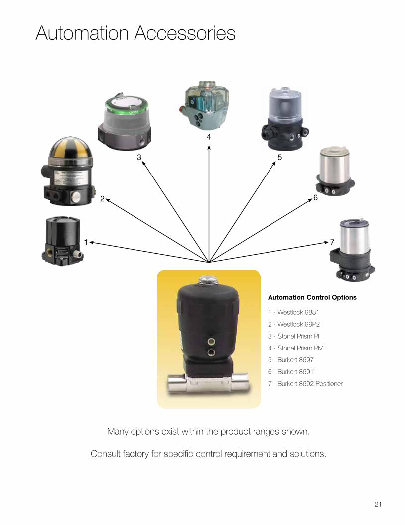
Automation Accessories
1
2
3
4
5
6
7
Automation Control Options
1 - Westlock 9881
2 - Westlock 99P2
3 - Stonel Prism PI
4 - Stonel Prism PM
5 - Burkert 8697
6 - Burkert 8691
7 - Burkert 8692 Positioner
Many options exist within the product ranges shown.
Consult factory for specific control requirement and solutions.

22
Contact your Top Line Representative for Assistance
Office: P.O. Box 264 · Bradford, PA 16701
Plant: 21 Valley Hunt Drive · Lewis Run, PA 16738
800-458-6095
814-362-4626
Fax: 814-362-4453
CAT-DV 8/16
Top Line is a leading supplier of sanitary stainless steel process equipment. Serving the food, beverage, dairy, pharmaceutical, biotechnological and personal care industries. For over 50 years we’ve provided our customers with exceptional customer service and quality products. We are committed to meeting the fastest delivery, new product development and application engineering to meet all our customer’s needs with our extensive inventory and expert sales team.
Top Line specializes in stainless steel materials – type 304 and 316L. Our modern, well equipped manufacturing facilities are staffed by skilled and dedicated craftsmen. Consistently meeting important tolerances and finish specifications is of primary concern to us. Before any products leave our plant they are subjected to rigid quality assurance checks.
Top Line should always be considered your first choice for both standard and custom fabricated stainless steel products.
Limited WarrantyTop Line Process Equipment Company products are warranted to be free of defects in material or
workmanship for a period of one year from date of shipment. Warranty covers those Top Line products used in an approved installation and maintained in strict accordance with recognized standard industry practice. If, after properly authorized return, Top Line determines that products are defective, Top Line may at its option, repair or replace such defective products.
Top Line shall not be liable for consequential, indirect or incidental damages. The above warranty is in lieu of all other warranties, expressed or implied.
Always Giving You Top of the Line Service
and Quality
www.toplineonline.com


