Download - NEDAS Toronto 2015 - Presentations

NEDAS Toronto Workshops & Social 2nd Floor Events
September 29, 2015 #NEDASToronto

The Evolution of Airport Communications and the
Demand for Technology & Bandwidth
Cellular Capacity in Crisis

Introductions
Steve Yapsuga 18+ years technical telecom/ wireless/software/ security applications. Advisory Council, NEDAS & Small Cell Association, MD-DC/WA Wireless Video Surveillance Group, Wireless PSA Advisor, Public Speaker, Educator, Market, Executive MBA
Dan Elliott Manager Communication Systems, Integrated Operations Control Centre (IOCC), Greater Toronto Airports Authority. Responsible for Public Safety Land Mobile Radio System, and In Building Distributed Antenna System. Responsible for all dispatch communications at Toronto Pearson IOCC in addition to operation of the Airport Weather systems.
Rob Graham – CEO, Genwave Technologies Inc., an RF Engineering firm that designs, builds and supports in-building wireless systems. Held roles as GM, SVP Business Development & CTO for PageNet. Startup of Weblink Wireless as VP, Sales and Marketing. Helped launch the wholesale division @ Rogers Cantel.

• January 2014, Pearson Airport’s existing DAS was 11 years old and operating on only one of the four cellular bands and with no LTE capability.
• Toronto Pearson is Canada’s largest, and a hub airport for Air Canada, the Star Alliance, WestJet and FedEx.
• The airport averages 98,900+ daily passengers (36.1M annually) • 10.8 Million connecting flights. There are over 1,175 GTAA
employees • GTAA is ranked 15th busiest flight airports in the world.
• Passenger traffic increasing 7.7% annually. 39 million PAX in 2014. • Smart phone share in Canada increased to 74% in 2014. • Mobile Data has increased +82% from 2013.. • Smart Phones usage increased by 37 times more than basic cell
service.
Trouble brewing

“The ground stop has been lifted and aircraft are once again arriving. Please continue to check with your airlines for schedule changes.” http://toronto.ctvnews.ca/video?clipId=270983
— Toronto Pearson (@TorontoPearson) January 7, 2014

• January 6, 2015: A Cold Snap of -40 hit halted arrivals, stranded hundreds causing extreme pressures on the existing networks.
• The airport instituted the ground stop early on Jan 7th as the wind chill
readings hovered around the -40 C mark. • More than 600 flights were cancelled during a 24 hour span due to weather. • Thousands of passengers were stranded and sleeping at the airport, and
there were thousands of bags of luggage waiting for pickup. • GTAA: The ground stop was implemented due to the cold was affecting
equipment and safety concerns related to time outdoors for employees.
• On Jan 8th, in an effort to reduce further impact, GTAA and the airlines were still advising customers to check online or by phone to confirm that their flight is operating before going to the airport.
The Situation

‘IRRPOPS’ = Irregular Operations: • Between Jan 5 to 9, 2014, significant weather events disrupted airport
operations and passenger flow. Rain, snow and wind chill factors as low as -39C, resulting in a Flash Freeze.
Cellular Capacity in Crisis

GTAA IRRPOPS Event Factors • Arriving aircraft far outnumbered departing aircraft.
• Snow clearing operations and priorities impacted passenger
flow as well as severely impacting baggage flow.
• Information sharing protocols did not adequately update passengers, media or employees.
• Pearson Wi-Fi system upgrade planned, not yet implemented.
• Caused many tens of thousands of passengers unable to move through the terminal and unable to get information.
Cellular Capacity in Crisis

GTAA Call Talking/Dispatch

0.0% 2.0% 4.0% 6.0% 8.0%
10.0%
Jan 1
Jan 2
Jan 3
Jan 4
Jan 5
Jan 6
Jan 7
Jan 8
Jan 9
Jan 10
Voice Dropped Calls Data Dropped Calls
Source: Sample from Single Sector in T1
Dropped Voice & Data ‘Calls’
Cellular Capacity in Crisis

• GTAA Board convened special panel to address issues,
report issued April 7, 2014 .
• Project for solution design awarded to Genwave in May 2014.
• Scope to design and implement a solution to deliver 20+% additional cellular capacity over the IRROPS failure levels.
• Deliverable timeline: To be online and operational by December 15, 2014.
Cellular Capacity Solution Scope

Process to Develop Solution: • Engage Sr. Management of major Cellular Carriers and Airport to
create a Taskforce team.
• Establish baseline data. • Team developed a 5 Element Capacity Enhancement Plan.
• Key criteria: What can be done in a very short timeframe,
implemented in a difficult working environment and deliver meaningful capacity improvements.
Cellular Capacity Solution Scope

Elements 1 & 2 – Installation of AWS LTE Small Cells • Genwave worked with Rogers & Bell to develop an RF design
to deploy 55 LTE Small Cells in the public facing areas.
• This constellation of Small Cells enabled access to AWS band and LTE technology in the Pearson terminals.
• Of note: Largest deployment of small cells servicing an indoor environment in Canada at the time.
Cellular Capacity Solution

Element 3 – Re-Sectorization of Terminals. • During IRROPS, some sectors were overloaded and others
underutilized. Team carefully examined current sectorization and re-mapped to more accurately balance capacity for today’s requirements.
Element 4 – Upgrade Channel Technology. • Canada is quite far along the smart phone and 3/4G technology
adoption curve. There is reduced requirement for 2G channels. Team performed traffic analysis and migrated channels from 2G to 3G with no loss of performance for 2G customers, significantly increased capacity for 3G.
Element 5 – Tweak Uplink Algorithms
Cellular Capacity Solution

0
50
100
150
200
250
300
IRROPS Jan 2014
Dec 2014
Uplink Channel Upgrade Re-sectorization Small Cells Baseline
The Results

The jointly developed solution delivered 160+% additional cellular capacity, on time, on budget. Keys to success: • Aligned and committed stakeholders.
• GTAA extended full access to premises and significant
financial backing to support project
• Real time, ongoing communication to all stakeholders.
Cellular Capacity Enhancement Outcome

• Key vendor/partner alliances are key • Business objectives must be shared with strategic partners • Business growth and technological change go hand in hand • Industry Associations need participation, and provide valuable
insight and input • Be ready for the inevitable
Summary

• In 2016, a Next Generation DAS will be live. This DAS will encompass all bands, all major carriers with a 10 year planned lifetime. All major carriers.
• Key in the plan is the provision for 100% additional capacity than forecast requirements.
• Process for Quality Assurance – Direct collaboration with major carriers on a quarterly basis to monitor performance and capacity.
• Interim Small Cell installation will live on as a DR facility in case it is needed in the future.
Summary

• Key aspect for GTAA is continuous improvement.
• Monitor and leverage potential convergence of Wi-Fi and
DAS/mobile device usage. • Explore and leverage impact of 5G • Seek and implement monetization opportunities of
wireless assets.
Going Forward

Thank you!

Cost Issues in In-‐Building DAS Systems
Presenter
Glenn Poulos Co-‐Founder, VP & GM
Presented by Gap Wireless

Canada and the USA
-‐ There are 3 huge differences between Canada and the USA -‐ In Canada the Carriers own: • Towers • Backhaul • DAS -‐ In the USA Carriers lease all three. Towers, backhaul and DAS

35.8 Million 325.1 Million -‐ Control can only be maintained with limited size. -‐ Due to scale in the USA they need the partnerships to get to all the
venues. -‐ Imagine the sheer quanSty of stadiums, hospitals, malls, etc. -‐ It’s simply just not feasible for carriers to control (fund) all aspects of DAS
Why?

Graphics courtesy AFL Global
Carrier Funded Neutral Host Enterprise
Funding Sources (a primer)
Again there are 3 scenarios …..
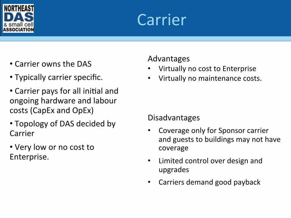
Carrier
• Carrier owns the DAS • Typically carrier specific. • Carrier pays for all iniSal and ongoing hardware and labour costs (CapEx and OpEx) • Topology of DAS decided by Carrier • Very low or no cost to Enterprise.
Advantages • Virtually no cost to Enterprise • Virtually no maintenance costs.
Disadvantages • Coverage only for Sponsor carrier
and guests to buildings may not have coverage
• Limited control over design and upgrades
• Carriers demand good payback

Neutral Host
• Neutral Host is a third party operaSng independent of Enterprise and Carrier. • Typically this is a mulScarrier soluSon which is then leased out to Carriers for access. • Topology of DAS decided by Neutral Host and approved by Carrier • AaracSve to carriers in large venues with a large number users. • AaracSve for the Enterprise due to greatly reduced or eliminated costs. • Carriers as tenants provided opSmal signal sources either off air or local BTS.
Advantages • Typically mulScarrier • Enterprise is not responsible for
costs • Enterprise is typically not
responsible for maintenance either
Disadvantages • Enterprise has no control over
design and ongoing evoluSon. • Enterprise may be stuck in a
long term contract with liale to no flexibility

Enterprise
Advantages • Typically mulScarrier • Customer owns system and controls
DAS • Customer can decide when, if, and
how to upgrade as technology evolves.
• Enterprise owns the complete DAS system • Enterprise pays for all iniSal and ongoing hardware and labour costs (CapEx and OpEx) • Enterprise can select single or mulScarrier. Typically mulScarrier allowing new bring-‐your-‐own-‐device (BYOD) programs • Topology of DAS decided by Enterprise • Carrier agreement is sSll required • Capacity is typically derived from local cell site with a repeater soluSon
Disadvantages • Enterprise customer must cover the
enSre cost of the DAS with no outside help
• No carrier or third party to assist with troubleshooSng, maintenance, etc.
• Requires well trained technical staff

Carrier Neutral Host
• Carrier builds a DAS but based on neutral host design • They typically do not sell access or service. • The goal is to barter with other carriers for equal access to their systems. • For instance • Carrier A – Large Shopping Mall
• Carrier B – Large Stadium
• Carrier C – Large Arena
• All barter for shared access with the ulSmate goal being equilibrium
Advantages • Cost is divided by the number of
compeSSve local carriers. • Same approach can be applied to
towers and roof access sites.
Disadvantages • Carriers may struggle to keep up their
build plans to and balance access to other carriers systems.
• Designs vary by compeStor. No ubiquitous soluSon.

Other Cost Drivers of DAS
• DAS is expensive. • Carriers are looking for ways to get rid of coax - Expensive to buy, expensive to install, expensive to test - This drives up the total cost and limits deployments • New solutions over Cat5/6 solutions are much easier
- Much easier to installers - Well trained installers are easy to find
• Solutions today tend to be one carrier specific - No support for Neutral host - Cost is still prohibitive
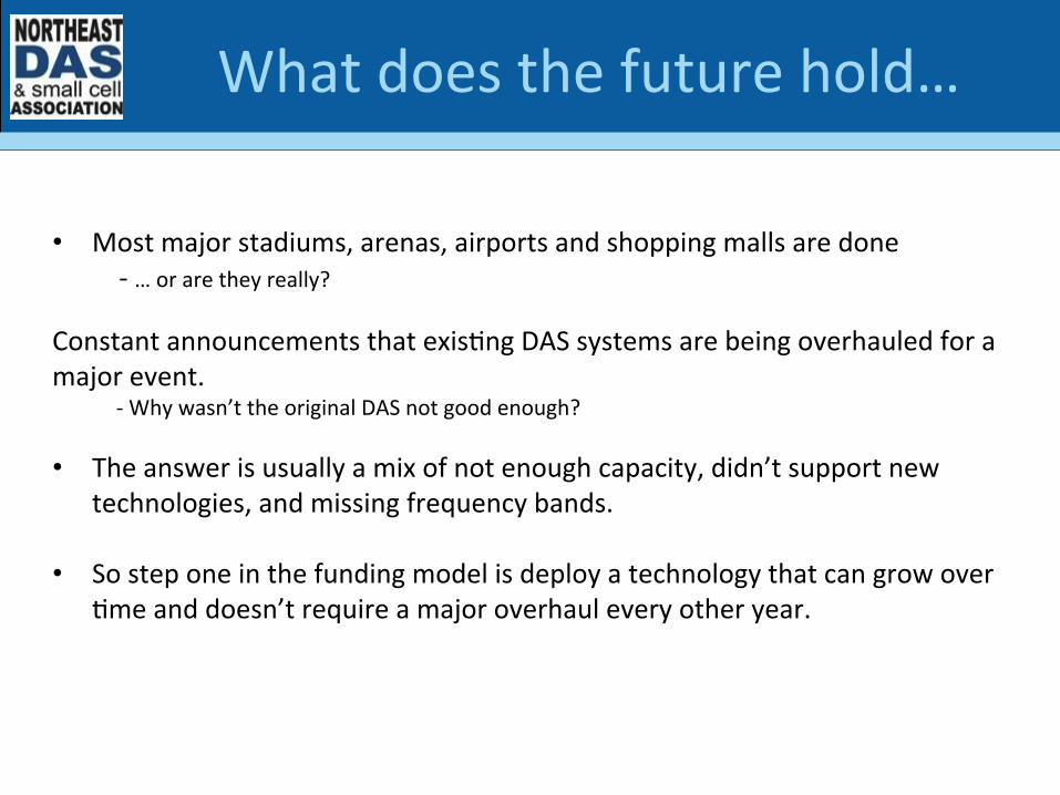
What does the future hold…
• Most major stadiums, arenas, airports and shopping malls are done -‐ … or are they really? Constant announcements that exisSng DAS systems are being overhauled for a major event. -‐ Why wasn’t the original DAS not good enough? • The answer is usually a mix of not enough capacity, didn’t support new
technologies, and missing frequency bands. • So step one in the funding model is deploy a technology that can grow over
Sme and doesn’t require a major overhaul every other year.

The not so far future (3-‐5 years)
• The next fronSer is MDUs (MulS-‐Dwelling Units) ie Condos -‐ 5G is desSned to explode driving true unlimited data plans • First we cut the phone line. Next we’ll cut the internet cord! -‐ Based on today’s technology this may not be economically viable. • One of two things have to happen (or even beaer both!) : -‐ The technology becomes more affordable or -‐ The infrastructure required is funded by alternaSve methods • Water, HVAC, Electricity, Cable and Phone are all standard -‐ Wireless networks should be a standard part of the building • Voice, Internet, etc. could all come from your wireless provider

In a perfect world…
Carriers strive for:
100% PenetraSon

Stepping Through an In-‐Building Project Lifecycle
Presenters
Philippe Lefebvre Sales Engineer, iBwave
Presented by iBwave and PCTEL
Jay Maciejewski Vice President of Business
Development, PCTEL

Content
1. Introductions/Overview
2. Lifecycle of an In-Building project
3. PCTEL SeeHawk Integration with iBwave Mobile Demo
4. Q&A
34

35 NEDAS Toronto -‐ Stepping Through an In-‐Building Project Lifecycle
PCTEL OVERVIEW Jay Maciejewski, VP of Business Development
35

36
PCTEL RF Solutions
Network Engineering Services Expert Knowledge, Exceptional Tools PCTEL’s engineering services team provides Wireless network services with an emphasis on in-building distributed antenna systems(DAS). • Network Benchmarking • Baseline Testing • CW Testing • Design • Commissioning • Optimization • Acceptance • PIM, Sweep, Fiber Testing • Interference Mitigation • Consulting
Products for all your design, deployment, testing and optimization
37
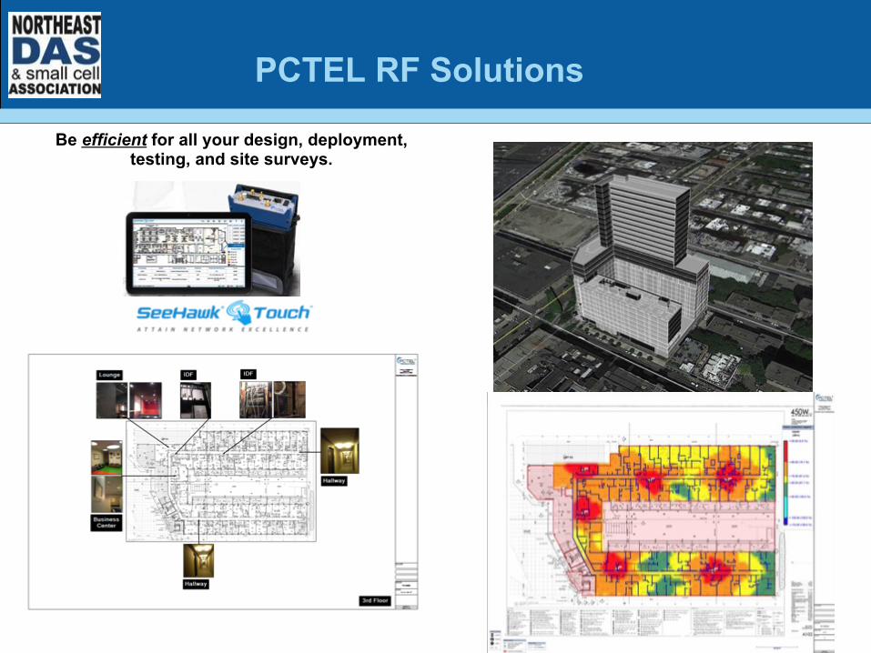
PCTEL RF Solutions
Be efficient for all your design, deployment, testing, and site surveys.

38 NEDAS Toronto -‐ Stepping Through an In-‐Building Project Lifecycle
iBwave OVERVIEW Philippe Lefebvre, Sales Engineer
38

39 NEDAS Toronto -‐ Stepping Through an In-‐Building Project Lifecycle
• THE STANDARD for in-building network design and documentation
• LEADING TECHNOLOGY & FIRST MOVER in a dynamic and fast-growing industry
• TRUSTED BY 700+ CUSTOMERS in more than 85 countries
• TIER-1 operators, OEMs and systems integrators worldwide
NETWORK MANAGEMENT DESIGN & PLANNING WIRELESS MOBILITY
EXPERT TRAINING & CERTIFICATION
39

40 NEDAS Toronto -‐ Stepping Through an In-‐Building Project Lifecycle 40
iBwave Unity (Cloud &
Enterprise)
iBwave Design
Ideal for Small Cells & Wi-Fi • Site Survey • Data collection • System Design • Installation and Maintenance
! 3D Building Modeling ! Detailed RF Engineering ! Complete Project Documentation ! Capacity Analysis
Unity Enterprise ! Team Collaboration & Project Management ! Project Documentation Repository ! Advanced reporting & Dashboards ! API to external applications
Mobile Planner
Ideal for any Indoor project • Site Survey • Documentation • Installation and maintenance
Mobile Note
THE RIGHT TOOLS FOR YOUR FIELD TEAM

Lifecycle of an IB project
41
BUSINESS CASE SITE SURVEY DETAILED
ENGINEERING INSTALL &
COMMISSION OPERATE & MAINTAIN

z
Challenges: • Lack of engineering
and expertise resources versus the number of projects
• Project gets stalled at the initial stage
42
BUSINESS CASE SITE SURVEY DETAILED
ENGINEERING INSTALL &
COMMISSION OPERATE & MAINTAIN

Challenge: • Gathering site info using paper plans/notepads and
documenting with pictures can be cumbersome • RF survey data post processing can take significant time
and often requires 3rd party software
BUSINESS CASE SITE SURVEY DETAILED
ENGINEERING INSTALL &
COMMISSION OPERATE & MAINTAIN

44
BUSINESS CASE SITE SURVEY DETAILED
ENGINEERING INSTALL &
COMMISSION OPERATE & MAINTAIN

Challenges: • Design complexity due to multitude of technologies,
bands, operators, and KPI’s • End users expect optimal data rate for best QoE
45
BUSINESS CASE SITE SURVEY DETAILED
ENGINEERING INSTALL &
COMMISSION OPERATE & MAINTAIN

BUSINESS CASE SITE SURVEY DETAILED
ENGINEERING INSTALL &
COMMISSION OPERATE & MAINTAIN

Challenge: • The actual system final installation and performance is
rarely as per original design • It is often require to make onsite last minute changes • Modifications aren’t documented
47
BUSINESS CASE SITE SURVEY DETAILED
ENGINEERING INSTALL &
COMMISSION OPERATE & MAINTAIN

Original Design
48
BUSINESS CASE SITE SURVEY DETAILED
ENGINEERING INSTALL &
COMMISSION OPERATE & MAINTAIN
Updated, as-built

Challenges: • Evolution of site conditions • Staff turnover
49
BUSINESS CASE SITE SURVEY DETAILED
ENGINEERING INSTALL &
COMMISSION OPERATE & MAINTAIN

50
BUSINESS CASE SITE SURVEY DETAILED
ENGINEERING INSTALL &
COMMISSION OPERATE & MAINTAIN

Summary
BUSINESS CASE
• Leverage field people to collect site information • Accelerate quotation process and jumpstart project

Summary
BUSINESS CASE SITE SURVEY
• Streamline survey data and RF collection process

Summary
BUSINESS CASE SITE SURVEY DETAILED
ENGINEERING
• Automated, reliable tool to achieve compliancy • Detailed reporting for project sign-off

Summary
BUSINESS CASE SITE SURVEY DETAILED
ENGINEERING INSTALL &
COMMISSION
• Track and document last minute field changes • Validate changes, verify compliancy

Summary
BUSINESS CASE SITE SURVEY DETAILED
ENGINEERING INSTALL &
COMMISSION OPERATE & MAINTAIN
• Baseline for potential system upgrades • Easily locate components for repairs, or EOL replacements

56 NEDAS Toronto -‐ Stepping Through an In-‐Building Project Lifecycle
DEMONSTRATION PCTEL SEEHAWK & IBWAVE MOBILE INTEGRATION
JOE HILL , PCTEL
56

57 NEDAS Toronto -‐ Stepping Through an In-‐Building Project Lifecycle
Q & A
57

Passive, AcSve, and MulS-‐Carrier DAS Architectures and Issues at Each Level
Presenter
William Wong Senior DAS Engineer
Presented by ADRF

Limited Scalability, Oscillation, Shared Capacity, Macro-dependent
UL Noise, Low-PIM, Installation Feasibility, PCI Dominance
Participant Interference, Power Allocation, Criteria
Sector Handover, Zones, Space Constraints
Discuss varying levels of DAS complexity, engineering and project management challenges associated with each, and their resoluSons.
ObjecSve

Resolving Issues Building Tenants using Macro’s Capacity
Building Tenants using DAS- Dedicated BTS
• Two methods o Distribute Capacity
" AcSve or passive DAS
o Add Capacity " Small Cells/BTS " Wi-‐Fi Offload
• CombinaSon o New BTS feeds DAS

Passive DAS
Unique Issues • Dependent on donor site input • Increases coverage area of donor cell site – shares capacity
• PotenSal OscillaSon / IsolaSon Requirement • Boosts all signal and noise in band • UL noise is sent back to donor site • Limited scalability • AGC or ALC needed to protect the network!
BDA
Donor Site Antenna Infrastructure
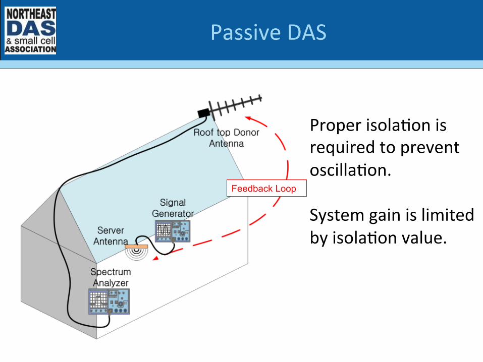
Passive DAS
Feedback Loop
Proper isolaSon is required to prevent oscillaSon. System gain is limited by isolaSon value.

iDAS Macro
Macro and iDAS share BTS Capacity UL Noise
AGC or ALC needed to protect the network!
Passive DAS

AcSve Fiber DAS
Signal Source Head End Remote Amp Antenna Infrastructure
Optical Transport
• Fiber-‐fed remote amplifiers • Scalable
o Small BDA-‐fed single-‐WSP o Large BTS-‐fed mulS-‐sector neutral host

Single WSP
Head End Remote Amp
850MHZ
700MHz
2100MHZ
1900MHz
• AcSve Components are band-‐specific • Plan for future expansion
o Neutral Host PotenSal? " Design to limiSng band/technology!
o AddiSon of WSPs o Upgrading to new frequency bands

• Ubiquitous Coverage Requirement • Areas of weaker coverage will cause undesired handoff to
Macro – possible trouble areas
Single WSP

PCI Dominance
Before In-‐Building DAS InstallaSon

PCI Dominance
Aler In-‐Building DAS InstallaSon

Single WSP
• Low Power o More amplifiers needed o Increased scalability (smaller power increments)
• High Power
o Higher DL and UL Power for More Coverage
o High Power – Generally 5 Waas and above
o Increased PotenSal for PIM o Generally more antennas/amplifier
" Increased potenSal for UL noise 40W
2W

Single WSP
• DL issues are typically localized to a single amplifier • UL issues feed back into BTS, deafening enSre sector; inside and out
• Causes o Improper opSmizaSon o Non-‐parScipant
" fax machine o Too many antennas/amplifiers on a single sector

Single WSP
• Fiber o Spare Strands? o TesSng – OTDR/power meter o Cable management
• Coaxial Cable
o TesSng – sweep tesSng of every segment " Return loss, DTF, Cable loss
o Cable management

Single WSP
• Feasibility of install o Coax Runs
" Design depends on length of cable runs
o Antenna locaSons " AestheScs, material types, high ceilings

DAS Head End
WSP 1
WSP 2
Remote Units
Neutral Host

Verizon 25%
AT&T 25%
Sprint 25%
T-Mob 25%
• Power sharing • Balancing output power among WSPs
AT&T BTS
+24dBm
Verizon BTS
+43dBm
Sprint BTS
+10dBm
Sprint 16.6%
AT&T 16.6%
Verizon 50%
T-Mob 16.6%
T-‐Mob BTS
+37dBm
HE Input
RU Output
Neutral Host

Neutral Host
• Can the WSPs share amplifiers? • Do all WSPs need a coverage soluSon?
700 MHz RSRP Baseline Measurement Averages AT&T -‐72dBm Sprint -‐104dBm Verizon -‐96dBm T-‐Mobile -‐83dBm
• Do they need a soluSon for all bands? • BDA or BTS for signal source?

Neutral Host
• Non-‐parScipant interference o Interference caused by devices or equipment that are not intended to enter the system
• Filters may be required to eliminate unwanted interference o UL of one band is too close to DL of another
" Commercial 850MHz and PS 800MHz

UL Filtering Scheme
UL Filter
Desired Signal
Full Band
Non-participant
Desired Signal
Full Band
Filtered Portion
Neutral Host

Neutral Host
• Room/GUI access for each involved party o Security
• Financial model o WSP-‐funded
" Other WSPs “buy in” " Who owns which equipment?
o Enterprise funded • Physical space constraints for addiSonal WSP
o AlternaSve mounSng opSons " Smaller signal source equipment " Above ceiling

MulS-‐Sector
Zone 3
Zone 2
Zone 1
Sector 1
Sector 2
Sector 3

MulS-‐Sector
• Capacity analysis o PopulaSon at max venue capacity o Number of simultaneous users o User demographic
" Usage type – voice, video, email, mms • Cell handoff at sector edge
o BTS neighbor lists o Placement of handoff zones o OpSmizaSon of DAS parameters to achieve proper handoff

Copyright © 2013 | CIBET | All rights reserved 81
Handoff to Macro
MulS-‐Sector
• Cell Handoff • Sectors should be opSmized to transiSon UE at desired interface o entrance of a building o between seaSng and concessions

iDAS
oDAS
Macro
• PCI Dominance • Ubiquitous Coverage • Cell Handoff • Capacity • SNR
MulS-‐Sector
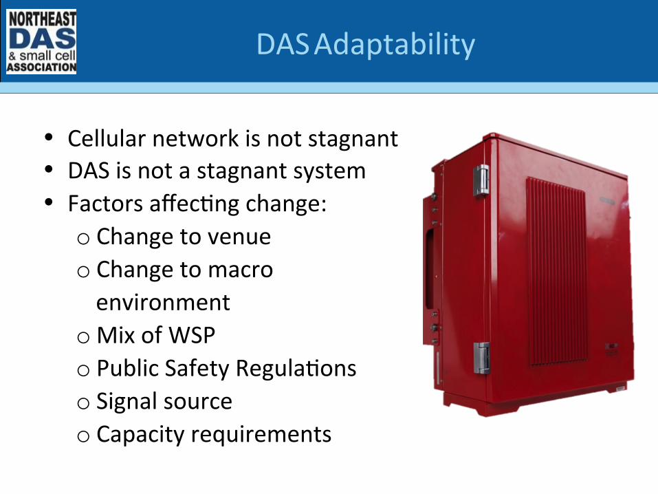
DAS Adaptability
• Cellular network is not stagnant • DAS is not a stagnant system • Factors affecSng change:
o Change to venue o Change to macro environment
o Mix of WSP o Public Safety RegulaSons o Signal source o Capacity requirements

DAS Adaptability
Post-‐installaKon, a DAS must be able to o Add fiber amplifiers o Add hardware for new frequency bands o TransiSon from BDA to BTS signal sources o Expand to a MIMO configuraSon o Expand to a mulS-‐sector system o Alter sectorizaSon zones o Allow for external filtering o Add public safety frequencies (UHF/VHF/700/800)
o Dynamically control output powers of each WSP

Reference Sources
• 3GPP TS 36.331, "Evolved Universal Terrestrial Radio Access (E-‐UTRA); Radio Resource Control (RRC); Protocol SpecificaSon (Release 8)", version 8.4.0, December 2008.
• Dimou, K.; Min Wang; Yu Yang; Kazmi, M.; Larmo, A.; Peaersson, J.; Muller, W.; Timner, Y., "Handover within 3GPP LTE: Design Principles and Performance," Vehicular Technology Conference Fall (VTC 2009-‐Fall), 2009 IEEE 70th , vol., no., pp.1,5, 20-‐23 Sept. 2009 doi: 10.1109/VETECF.2009.5378909

Public Safety Trends Panel
Moderator
Chief Alan Perdue Safer Building
CoaliKon
Panelists
Mike Collado SOLiD
Alec Yauk CommScope
Castor Waye Linkwave

Cross Border PracSce – What to Consider When Expanding Across the Border
Presenter
Benjamin M. Farber Partner
Presented by Phillips Lytle

Topics that I will be covering: 1. Formation of Business Entities in United States
2. Taxation Issues Associated with Business Activities in United States
3. Immigration Law Issues
4. State Incentives for Canadian Companies
5. Intellectual Property Issues
Cross Border PracSce – What to Consider When Expanding Across the Border

Formation of Business Entities in United States
1. Choosing to form a US subsidiary vs. operating a US branch/division of Canadian entity
2. Types of US business entities
• Corporations
• Limited liability companies
Cross Border PracSce – What to Consider When Expanding Across the Border

Taxation Issues Associated with Business Activities in United States
1. Canada – US Tax Treaty
2. “Permanent Establishment” in the United States
3. Tax Issues associated with operation of a Canadian corporation in the United States
4. Tax Issues associated with using a US subsidiary to conduct US operations
Cross Border PracSce – What to Consider When Expanding Across the Border

Immigration Law Issues
1. North American Free Trade Agreement (NAFTA)
2. Visas
• New Office L1 Visas
• E2 Visas
• E1 Visas
• TN Visas
• H-1B Visas
Cross Border PracSce – What to Consider When Expanding Across the Border

State Incentives for Canadian Companies 1. START-UP NY
Cross Border PracSce – What to Consider When Expanding Across the Border
Intellectual Property Issues
1. Copyrights
2. Patents
3. Trademarks
4. Trade Secrets
Cross Border PracSce – What to Consider When Expanding Across the Border

Design & Infrastructure Trends Panel
Moderator
Ron Poulin BTI Wireless
Panelists
Mike Collado SOLiD
Alex Berezhnoy Linkwave
Edmond Zauner Anritsu

THANK YOU TO OUR ANNUAL SPONSORS
PLATINUM
GOLD
SILVER

THANK YOU TO OUR EVENT SPONSORS
Platinum Sponsor Lanyard Sponsor
Tabletop Sponsors
Platinum Sponsor
Charging Station Sponsor
Napkin Sponsor
Raffle Sponsor


