
www.weg.net
Automation
Low Voltage Industrial Controls

1-800-ASK-4WEG
www.weg.net
Data is subject to change without notice.B-2
www.weg.net
B-2
High Technology in Manufacturing
Research and Development
Product Certifications

WEG Automation - Products and Solutions
www.weg.net
Data is subject to change without notice. B-3
TIM
ING
RELA
YSM
PW S
ERIE
SEN
cLoS
Ed S
TART
ERS
PuSh
buTT
oNS
AcW
SER
IES
RW S
ERIE
SSR
W01
SER
IES
coNT
AcTo
RSTE
RMIN
AL b
LocK
SPo
WER
FAc
ToR
Table of ContentsIndex – Industrial Controls
Miniature Contactors – CWC SeriesFeatures ..................................................................................... B-12Product Selection ....................................................................... B-17Technical Data ............................................................................ B-24Dimensions ................................................................................ B-28
IEC Contactors – CWM SeriesFeatures ..................................................................................... B-29Product Selection ................................................................... B-35Technical Data ............................................................................. B-45Dimensions ................................................................................. B-57
NEMA Rated Contactors – CWM-N SeriesFeatures ..................................................................................... B-39Product Selection ........................................................................ B-41Technical Data ............................................................................. B-45Dimensions .................................................................................. B-57
Overload Relays – RW SeriesFeatures ...................................................................................... B-68Product Selection ........................................................................ B-70Technical Data ............................................................................ B-72Dimension .................................................................................. B-76
Smart Relays – SRW SeriesFeatures ...................................................................................... B-85Product Selection ...................................................................... B-92Technical Data ............................................................................. B-96Dimensions .................................................................................. B-97
Molded Case Circuit Breakers - ACW SeriesMolded Case Circuit Breakers – ACW Series ............................. B-105Features – Trip Units ................................................................ B-106Product Selection ...................................................................... B-108 Technical Data .......................................................................... B-116Trip Curves ................................................................................ B-123Dimensions ................................................................................ B-136
Manual Motor Protectors – MPW SeriesFeatures .................................................................................... B-147Product Selection .................................................................... B-154Technical Data ........................................................................... B-173Dimensions ................................................................................ B-196
1-800-ASK-4WEG Data is subject to change without notice.B-4
TIMING RELAYS
MPW
SERIESENcLoSEd STARTERS
PuShbuTToNSAcW
SERIESRW
SERIESSRW
01 SERIEScoNTAcToRS
TERMINAL bLocKS
PoWER FAcToR
B-4
TIMING RELAYS
MPW
SERIESENcLoSEd STARTERS
PuShbuTToNSAcW
SERIESRW
SERIESSRW
01 SERIEScoNTAcToRS
TERMINAL bLocKS
PoWER FAcToR
Table of ContentsIndex – Industrial Controls
Enclosed StartersFeatures ................................................................................... B-203Non-Combination Starters Product Selection ........................... B-208Combination Starters Product Selection ................................... B-209Dimensions ............................................................................... B-248
Pushbuttons and Pilot Lights – CSW SeriesFeatures ................................................................................... B-254CSW Series (22mm) Product Selection ..................................... B-258CSW Series (22mm) Dimension ................................................ B-265CSW30 Series (30mm Industrial) Product Selection ................... B-267CSW30 Series (30mm Industrial) Dimension ............................. B-274CSW30H Series (30mm Hazardous) Product Selection ............. B-279CSW30H Series (30mm Hazardous) Dimension ........................ B-284Pushbutton Stations Product Selection ..................................... B-290
Timing Relays RTW Series – Protection Relays RPW SeriesLevel Relays RNW SeriesFeatures .................................................................................... B-291Product Selection ..................................................................... B-293RTW Technical Data .................................................................. B-299RPW Technical Data ................................................................. B-305RNW Technical Data ................................................................ B-310
Terminal Blocks – BTW SeriesFeatures .................................................................................... B-312BTWP Series Product Selection ................................................. B-317BTWM Series Product Selection ............................................... B-324
Power Factor CorrectionSuggested Maximum Capacitor Ratingfor T-Frame NEMA Motors ......................................................... B-335Overview – Concepts ................................................................ B-341Sizing ....................................................................................... B-344Product Selection - Single & Three Phase Capacitor Elements .. B-356Enclosed Three Phase Capacitors ............................................. B-363Contactors for Capacitive Switching .......................................... B-368

WEG Automation - Products and Solutions
www.weg.net
Data is subject to change without notice. B-5
coNT
AcTo
RS
www.weg.net
coNT
AcTo
RS
Contactors and Overload Relays
Operation and Protection of Motors
www.weg.net
Data is subject to change without notice.1-800-ASK-4WEGB-6
coNTAcToRS
www.weg.net
coNTAcToRS
Overview
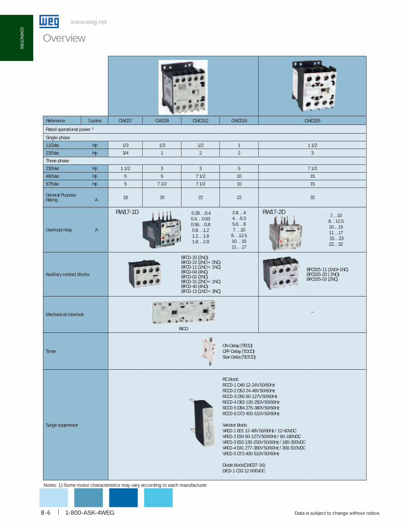
Reference 3 poles cWc07 cWc09 cWc012 cWc016 cWc025
Rated operational power 1)
Single-phase
115Vac Hp 1/3 1/3 1/2 1 1 1/2
230Vac Hp 3/4 1 2 2 3
Three-phase
230Vac Hp 1 1/2 3 3 5 7 1/2
460Vac Hp 5 5 7 1/2 10 15
575Vac Hp 5 7 1/2 7 1/2 10 15
General PurposeRating A 18 20 22 22 32
Overload relay A
0.28. . .0.40.4. . .0.630.56. . .0.80.8. . .1.21.2. . .1.81.8. . .2.8
2.8. . .4 4. . .6.35.6. . .8 7. . .10
8. . .12.510. . .1511. . .17
7…108…12.510…1511…17 15…2322…32
Auxiliary contact blocks
BFC0-20 (2NO)BFC0-22 (2NO + 2NC)BFC0-11 (1NO + 1NC)BFC0-04 (4NC)BFC0-02 (2NC)BFC0-31 (2NO + 1NC)BFC0-40 (4NO)BFC0-13 (1NO + 3NC)
BFC025-11 (1NO+1NC) BFC025-20 ( 2NO) BFC025-02 (2NC)
Mechanical interlock
BICO
_
TimerON-Delay (TECO)OFF-Delay (TDCO)Star-Delta (TETCO)
Surge suppressor
RC block: RCC0-1 D49 12-24V 50/60HzRCC0-2 D53 24-48V 50/60HzRCC0-3 D55 50-127V 50/60HzRCC0-4 D63 130-250V 50/60HzRCC0-5 D84 275-380V 50/60HzRCC0-6 D73 400-510V 50/60Hz
Varistor block: VRC0-1 E01 12-48V 50/60Hz / 12-60VDCVRC0-2 E34 50-127V 50/60Hz / 60-180VDCVRC0-3 E50 130-250V 50/60Hz / 180-300VDC VRC0-4 E41 277-380V 50/60Hz / 300-510VDCVRC0-5 D73 400-510V 50/60Hz
Diode block(CWC07-16):DIC0-1 C33 12-600VDC
RW17-1D RW17-2D
Notes: 1) Some motor characteristics may vary according to each manufacturer.
WEG Automation - Products and Solutions
www.weg.net
Data is subject to change without notice. B-7
coNT
AcTo
RS
www.weg.net
coNT
AcTo
RS
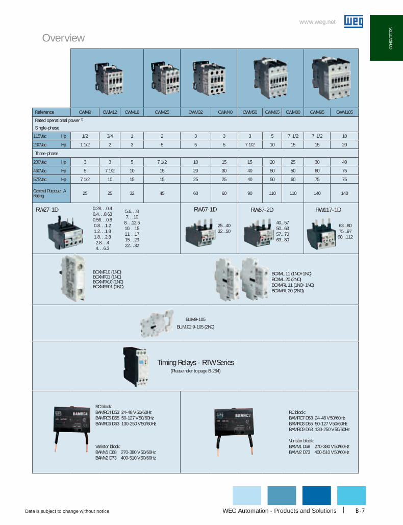
Reference cWM9 cWM12 cWM18 cWM25 cWM32 cWM40 cWM50 cWM65 cWM80 cWM95 cWM105
Rated operational power 1)
Single-phase
115Vac Hp 1/2 3/4 1 2 3 3 3 5 7 1/2 7 1/2 10
230Vac Hp 1 1/2 2 3 5 5 5 7 1/2 10 15 15 20
Three-phase
230Vac Hp 3 3 5 7 1/2 10 15 15 20 25 30 40
460Vac Hp 5 7 1/2 10 15 20 30 40 50 50 60 75
575Vac Hp 7 1/2 10 15 15 25 25 40 50 60 75 75
General Purpose A Rating 25 25 32 45 60 60 90 110 110 140 140
0.28. . .0.40.4. . .0.630.56. . .0.80.8. . .1.21.2. . .1.81.8. . .2.82.8. . .4 4. . .6.3
5.6. . .8 7. . .10
8. . .12.510. . .1511. . .1715…2322…32
25...40 32...50
40...5750...6357...70 63...80
63...8075...9790...112
BCXMF10 (1NO)BCXMF01 (1NC)BCXMFA10 (1NC)BCXMFR01 (1NC)
BCXML 11 (1NO+1NC)BCXML 20 (2NO)BCXMRL 11 (1NO+1NC)BCXMRL 20 (2NO)
BLIM9-105
BLIM.02 9-105 (2NC)
Timing Relays - RTW Series (Please refer to page B-264)
RC block:BAMRC4 D53 24-48 V 50/60HzBAMRC5 D55 50-127 V 50/60HzBAMRC6 D63 130-250 V 50/60Hz
Varistor block:BAMV1 D68 270-380 V 50/60HzBAMV2 D73 400-510 V 50/60Hz
RC block: BAMRC7 D53 24-48 V 50/60HzBAMRC8 D55 50-127 V 50/60HzBAMRC9 D63 130-250 V 50/60Hz
Varistor block: BAMV1 D68 270-380 V 50/60HzBAMV2 D73 400-510 V 50/60Hz
RW27-1D RW67-1D RW67-2D RW117-1D
Overview

www.weg.net
Data is subject to change without notice.1-800-ASK-4WEGB-8
coNTAcToRS
www.weg.net
coNTAcToRS
Reference 3 Poles cWM112 cWM150 cWM180 cWM250 cWM300
Rated operational power 1)
Single-phase
115Vac Hp - - - - -
230Vac Hp - - - - -
Three-phase
230Vac Hp 50 60 75 100 125
460Vac Hp 100 125 150 200 250
575Vac Hp 100 150 200 250 350
General Purpose
Rating A180 225 225 350 410
Overload relays A75...9790...112
100...150140...215200...310275...420
Auxiliary contact blocks
BCXML11 (1NO+1NC)BCXML20 (2NO)BCXMRL11 (1NO+1NC)BCXMRL20 (2NO)
Mechanical interlock BLIM112-300
Surge suppressor
1) Note: Some motors characteristics may vary according to each manufacturer.
Overview
RW117-2D RW317-1D
built-in with electronic module
WEG Automation - Products and Solutions
www.weg.net
Data is subject to change without notice. B-9
coNT
AcTo
RS
www.weg.net
coNT
AcTo
RS
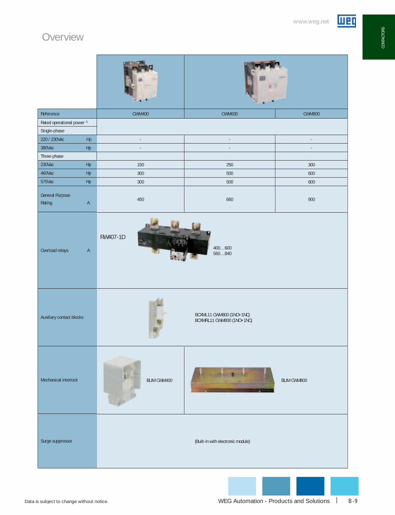
cWM400 cWM630 cWM800
- - -
- - -
150 250 300
300 500 600
300 500 600
450 660 900
400…600 560…840
BCXML11 CWM800 (1NO+1NC) BCXMRL11 CWM800 (1NO+1NC)
BLIM CWM400 BLIM CWM800
(Built-in with electronic module)
RW407-1D
Reference
Rated operational power 1)
Single-phase
220 / 230Vac Hp
380Vac Hp
Three-phase
230Vac Hp
460Vac Hp
575Vac Hp
General Purpose
Rating A
Overload relays A
Auxiliary contact blocks
Mechanical interlock
Surge suppressor
Overview
www.weg.net
Data is subject to change without notice.1-800-ASK-4WEGB-10
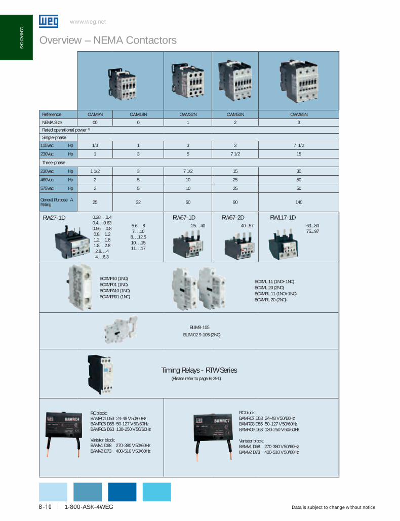
coNTAcToRS Overview – NEMA Contactors
Reference cWM9N cWM18N cWM32N cWM50N cWM95N
NEMA Size 00 0 1 2 3
Rated operational power 1)
Single-phase
115Vac Hp 1/3 1 3 3 7 1/2
230Vac Hp 1 3 5 7 1/2 15
Three-phase
230Vac Hp 1 1/2 3 7 1/2 15 30
460Vac Hp 2 5 10 25 50
575Vac Hp 2 5 10 25 50
General Purpose A Rating 25 32 60 90 140
0.28. . .0.40.4. . .0.630.56. . .0.80.8. . .1.21.2. . .1.81.8. . .2.82.8. . .4 4. . .6.3
5.6. . .8 7. . .10
8. . .12.510. . .1511. . .17
25…40 40...57 63...8075...97
BCXMF10 (1NO)BCXMF01 (1NC)BCXMFA10 (1NC)BCXMFR01 (1NC)
BCXML 11 (1NO+1NC)BCXML 20 (2NO)BCXMRL 11 (1NO+1NC)BCXMRL 20 (2NO)
BLIM9-105
BLIM.02 9-105 (2NC)
Timing Relays - RTW Series (Please refer to page B-291)
RW27-1D RW67-1D RW67-2D RW117-1D
RC block:BAMRC4 D53 24-48 V 50/60HzBAMRC5 D55 50-127 V 50/60HzBAMRC6 D63 130-250 V 50/60Hz
Varistor block:BAMV1 D68 270-380 V 50/60HzBAMV2 D73 400-510 V 50/60Hz
RC block: BAMRC7 D53 24-48 V 50/60HzBAMRC8 D55 50-127 V 50/60HzBAMRC9 D63 130-250 V 50/60Hz
Varistor block: BAMV1 D68 270-380 V 50/60HzBAMV2 D73 400-510 V 50/60Hz

WEG Automation - Products and Solutions
www.weg.net
Data is subject to change without notice. B-11
coNT
AcTo
RS
Overview – NEMA Contactors
Reference 3 Poles cWM150N cWM300N
NEMA Sizes 4 5
Rated operational power 1)
Single-phase
115Vac Hp - -
230Vac Hp - -
Three Phase
230Vac Hp 50 100
460Vac Hp 100 200
575Vac Hp 100 200
General Purpose
Rating A225 410
Overload relays A
Auxiliary contact blocks
BCXML11 (1NO+1NC)BCXML20 (2NO)BCXMRL11 (1NO+1NC)BCXMRL20 (2NO)
Mechanical interlock BLIM112-300
Surge suppressor built-in with electronic module
1) Note: Some motors characteristics may vary according to each manufacturer.
RW317-1DRW117-2D RW317-1D
75...9790...112
100... 150
100… 150140… 215200… 310275… 420

www.weg.net
Data is subject to change without notice.1-800-ASK-4WEGB-12
coNTAcToRS
www.weg.net
coNTAcToRS
Featuresg Rated up to 15 HP @ 460Vg Direct mounting to the WEG RW17D
overload relay and MPW16 & MPW25 manual motor protectors with ECCMP-C0 accessory
g Frame size remains the same for AC and DC coil contactors up to 16A
g Heavy-duty operationg Tool-free DIN rail mountingg Complete line of snap-on accessories
WEG‘s new generation of miniature contactors has arrived. Introducing the new technologically advanced CWC Series, manufactured by WEG‘s Controls and Switchgear Division.
More Horse Power in a Smaller Frame The CWC Series miniature contactor features more horsepower for its size than any other miniature contactor on the market. The CWC’s compact dimensions for its current rating, up to 25A, AC-3 utilization category, allows it to take up less space inside electrical enclosures while still maintaining a powerful 15 HP @ 460V. Dimensions from 7A to 16A remain the same whether the coil voltage is AC or DC making panel design and assembly easier. DC models feature low consumption coils allowing the CWC to be operated directly from a PLC without interface relays.
The following configurations are available “off-the-shelf.”
g 3 Pole Normally Open Power Contacts with one built-in Auxiliary Contact (Either Normally Open or Normally Closed)
g 3 Pole Normally Open Reversing Contactors rated AC-4 Utilization Category
g 4 Pole Power Contacts (four Normally Open, or two Normally Open and two Normally Closed)
g Control Relay (multiple auxiliary contacts configurations)
An extensive lineup of modular and tool-free accessories makes the CWC Series the most flexible and easy-to-use miniature contactor available today.
Controls Miniature Contactors - CWC Series
Certifications

WEG Automation - Products and Solutions
www.weg.net
Data is subject to change without notice. B-13
coNT
AcTo
RS
www.weg.net
coNT
AcTo
RS
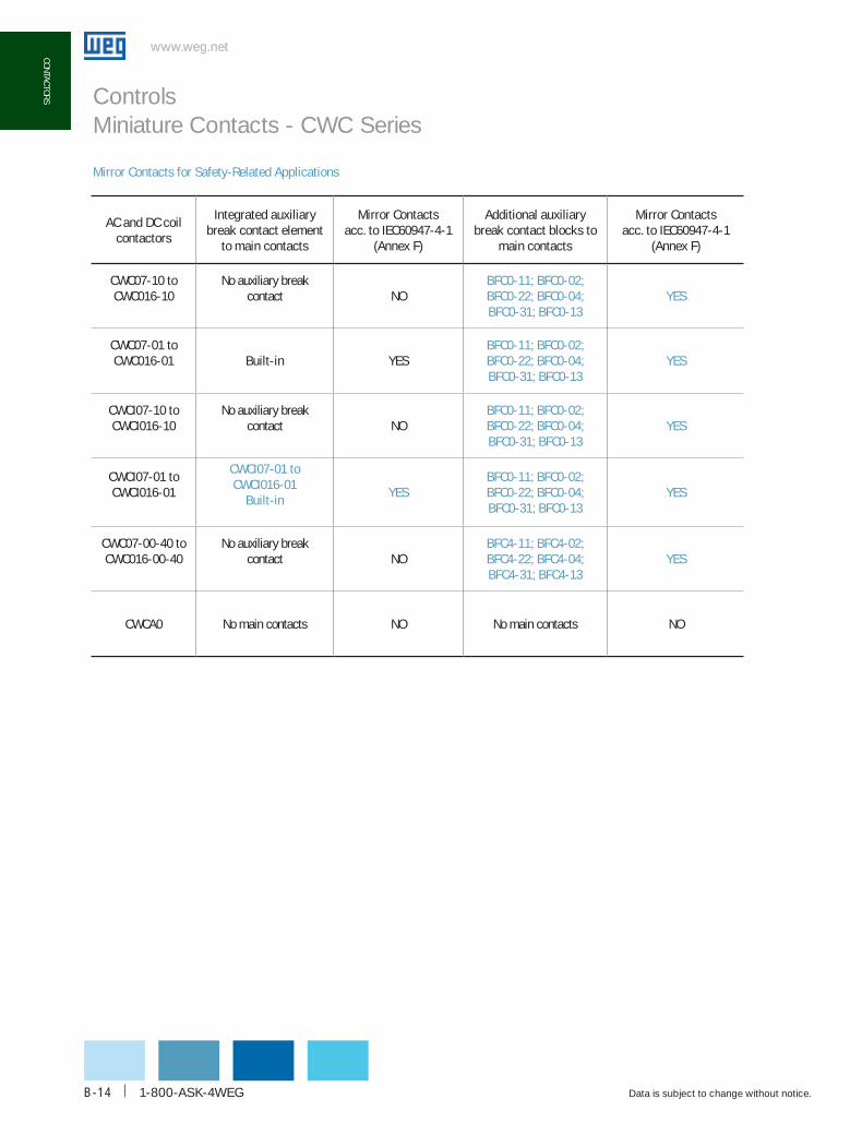
Mirror Contacts for Safety-Related ApplicationsThe increase demand for reliable and safety –related circuits for personnel protection has considerably increased within the last two decades. Not only the standards for personnel protection are leading this evolution on high level of system availability, but also the financial aspects of critical operation downtime events.
Although there are significant differences between Mechanically Linked Contact Element(s) described on Annex L of IEC60947-5-1 and Mirror Contacts described on Annex F of IEC60947 -4-1, those differences do not prevent a given auxiliary contact to comply with both requirements.
The following paragraphs will describe key aspects of above Annex and its difference in order to help engineers to select an appropriate device for each application. WEG has incorporated the Mirror Contact feature on all contactors and standard auxiliary contact blocks extending this safety feature to all standard applications. See table at following page.
Mechnicaly Linked Auxiliary Contact Elements: Defined by IEC60947 -5-1 (Annex L) it is a combination of "n" Make contact element(s) and "m" Break contact element (s) designed in such way that they cannot be in closed position simultaneously.
• While any of the "n" Make contact element(s) is closed, none of the "m" Break contact elements(s) shall be closed;
• While any of the "m" Break contact element(s) is closed, none of the "n" Make contact elements(s) shall be closed.
Mirror Contacts:
So, if you export your motor control panels Defined by IEC60947 -4-1 (Annex F) it is a limited feature related to an auxiliary contact normally closed (N.C.) form, which is used to mirror the status of all mechanically linked main contact normally open (N.O.) form. Thus, Control Relays can never feature a mirror contact since it has no main contact to be mechanically linked to.
The indication of this feature is observed when any of the main normally open (N.O.) contact is welded. The auxiliary normally closed (N.C.) contact will not be closed under any possibility providing a clear status of main switching elements.
Mirror Contacts are used where it is essential to rely on switch position of auxiliary contacts and it’s linked main contacts. A typical application for mirror contacts is to implement very reliable monitoring of switched state of a contactor in machine control circuits. It is prudent to emphasize that it is not recommended to rely exclusively on mirror contacts as a safety device, and it recommends self -monitoring of the mirror contact circuit.
Controls Miniature Contacts - CWC Series
Note: both contact configurations have previously been referred to as forced contacts, positive activated contacts or linked contacts.
www.weg.net
Data is subject to change without notice.1-800-ASK-4WEGB-14
coNTAcToRS
www.weg.net
coNTAcToRS Controls Miniature Contacts - CWC Series
Mirror contacts for Safety-Related Applications
Ac and dc coilcontactors
Integrated auxiliary break contact element
to main contacts
Mirror contactsacc. to IEc60947-4-1
(Annex F)
Additional auxiliarybreak contact blocks to
main contacts
Mirror contactsacc. to IEc60947-4-1
(Annex F)
cWc07-10 tocWc016-10
No auxiliary breakcontact NO
bFc0-11; bFc0-02;bFc0-22; bFc0-04;bFc0-31; bFc0-13
YES
cWc07-01 tocWc016-01 built-in YES
bFc0-11; bFc0-02;bFc0-22; bFc0-04;bFc0-31; bFc0-13
YES
cWcI07-10 tocWcI016-10
No auxiliary breakcontact NO
bFc0-11; bFc0-02;bFc0-22; bFc0-04;bFc0-31; bFc0-13
YES
cWcI07-01 tocWcI016-01
cWcI07-01 tocWcI016-01
built-inYES
bFc0-11; bFc0-02;bFc0-22; bFc0-04;bFc0-31; bFc0-13
YES
cWc07-00-40 tocWc016-00-40
No auxiliary breakcontact NO
bFc4-11; bFc4-02;bFc4-22; bFc4-04;bFc4-31; bFc4-13
YES
cWcA0 No main contacts NO No main contacts NO

WEG Automation - Products and Solutions
www.weg.net
Data is subject to change without notice. B-15
coNT
AcTo
RS
www.weg.net
coNT
AcTo
RS
1 - Miniature contactors CWC07...16
2 - Front auxiliary contact block BFC0
3 - Mechanical interlock block BIC0
4 - Surge supressor blocks RCC0 (RC), VRC0 (Varistor), DIC0 (Diode)
5 - Manual motor protector MPW25
6 - Connector ECCMP-C0 (MPW25 + CWC07...16)
7 - Overload Relay RW17-1D
8 - Electronic timers TEC0, TDC0 and TETC0
12
14
1
7
6
1
7
5
13
10
15
4
2
3
3
3
1
9 - Link module for printed circuit board CIC0
10 - Mini contactor CWC025
11 - Front auxiliary contact block BFC025
12 - Manual motor protector MPW16
13 - Connector ECCMP-C025 (MPW25 + CWC025)
14 - Connector ECCMP-C016 (MPW16 + CWC07...16)
15 - Overload Relay RW17-2D
1
8
29
4
8
4
10
11
Controls Miniature Contactor Overview

www.weg.net
Data is subject to change without notice.1-800-ASK-4WEGB-16
coNTAcToRS
www.weg.net
coNTAcToRS
Catalog part number composition
Controls Miniature Contactors - CWC Series
- -CWC 10 30 V18016
MINIATURE CONTACTOR SERIES:
CWC : Miniature Power Contactor CWCA: Control Relay
AUXILIARY CONTACTS:
For CWC0 00: None 10: 1 NO 01: 1 NC
For CWCA0 22: 2 NO + 2 NC 31: 3 NO + 1 NC 13: 1 NO + 3 NC 40: 4 NO 04: 4 NC
POWER POLE
00: Control Relay (4 auxiliary terminals) 30: CWC0 with 3 NO Power Poles 22: CWC0 with 2 NO + 2 NC Power Poles 40: CWC0 with 4 NO Power Poles
COIL VOLTAGE
VAC COI V04: 24Vac 60Hz V18: 120Vac 60Hz V24: 208-240Vac 60Hz V47: 480Vac 60Hz
C ( A DA CONSUMPTIO C03: 24Vdc C12: 110Vdc
VDC COIL (LOW CONSUMPTION) L03: 24Vdc
FRAME RATING:
Blank: Control Relay (Ith = 10Amps) 7: 07Amps 9: 09Amps 12: 012Amps 16: 016Amps 25: 025Amps

WEG Automation - Products and Solutions
www.weg.net
Data is subject to change without notice. B-17
coNT
AcTo
RS
www.weg.net
coNT
AcTo
RS
Note: Other voltages available upon request.
+ DC COIL VOLTAGE CODE SELECTION
Note: Other voltages available upon request.* See page B-22 for coil consumption
Vdc 24V 110V 24V LOW CONSUMPTION*
codE c03 c12 L03
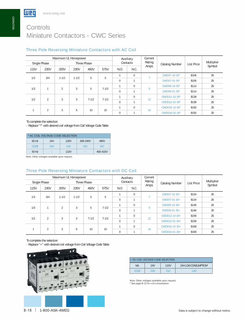
Three Pole Miniature Contactor with AC Coil
* AC COIL VOLTAGE CODE SELECTION
60 Hz 24V 120V 208-240V 480V
codE V04 V18 V24 V47
50 Hz - 110V - 400-415V
Maximum uL horsepower Auxiliary contacts
current Rating Amps
catalog NumberList
PriceMultiplier Symbol
Single Phase Three Phase
115V 230V 200V 230V 460V 575V N.o. N.c.
1/3 3/4 1-1/2 1-1/2 5 51 0
7cWc07-10-30* $48 Z6
0 1 cWc07-01-30* $48 Z6
1/3 1 2 3 5 7-1/21 0
9cWc09-10-30* $52 Z6
0 1 cWc09-01-30* $52 Z6
1/2 2 3 3 7-1/2 7-1/21 0
12cWc012-10-30* $64 Z6
0 1 cWc012-01-30* $64 Z6
1 2 3 5 10 101 0
16cWc016-10-30* $70 Z6
0 1 cWc016-01-30* $70 Z6
1-1/2 3 5 7 -1/2 15 15 0 0 25 cWc025-00-30* $80 Z6
To complete the selection- Replace “*” with desired coil voltage from Coil Voltage Code Table
Three Pole Miniature Contactors with DC Coil
Maximum uL horsepower Auxiliary contacts
current Rating Amps
catalog NumberList
PriceMultiplier Symbol
Single Phase Three Phase
115V 230V 200V 230V 460V 575V N.o. N.c.
1/3 3/4 1-1/2 1-1/2 5 51 0
7cWc07-10-30+ $62 Z6
0 1 cWc07-01-30+ $62 Z6
1/3 1 2 3 5 7-1/21 0
9cWc09-10-30+ $68 Z6
0 1 cWc09-01-30+ $68 Z6
1/2 2 3 3 7-1/2 7-1/21 0
12cWc012-10-30+ $74 Z6
0 1 cWc012-01-30+ $74 Z6
1 2 3 5 10 101 0
16cWc016-10-30+ $79 Z6
0 1 cWc016-01-30+ $79 Z6
To complete the selection- Replace “+” with desired coil voltage from Coil Voltage Code Table
Controls Miniature Contactors - CWC Series
www.weg.net
Data is subject to change without notice.1-800-ASK-4WEGB-18
coNTAcToRS
www.weg.net
coNTAcToRS
Three Pole Reversing Miniature Contactors with AC Coil
* AC COIL VOLTAGE CODE SELECTION
60 Hz 24V 120V 208-240V 480V
codE V04 V18 V24 V47
50 Hz - 110V - 400-415V
Three Pole Reversing Miniature Contactors with DC Coil
Note: Other voltages available upon request.
To complete the selection- Replace “*” with desired coil voltage from Coil Voltage Code Table
+ DC COIL VOLTAGE CODE SELECTION
Note: Other voltages available upon request.* See page B-22 for coil consumption
Vdc 24V 110V 24V LOW CONSUMPTION*
codE c03 c12 L03
Maximum uL horsepower Auxiliary contacts
current Rating Amps
catalog Number List PriceMultiplier Symbol
Single Phase Three Phase
115V 230V 200V 230V 460V 575V N.o. N.c.
1/3 3/4 1-1/2 1-1/2 5 51 0
7cWcI07-10-30* $106 Z6
0 1 cWcI07-01-30* $106 Z6
1/3 1 2 3 5 7-1/21 0
9cWcI09-10-30* $114 Z6
0 1 cWcI09-01-30* $114 Z6
1/2 2 3 3 7-1/2 7-1/21 0
12cWcI012-10-30* $138 Z6
0 1 cWcI012-01-30* $138 Z6
1 2 3 5 10 101 0
16cWcI016-10-30* $150 Z6
0 1 cWcI016-01-30* $150 Z6
Maximum uL horsepower Auxiliary contacts
current Rating Amps
catalog Number List PriceMultiplier Symbol
Single Phase Three Phase
115V 230V 200V 230V 460V 575V N.o. N.c.
1/3 3/4 1-1/2 1-1/2 5 51 0
7cWcI07-10-30+ $134 Z6
0 1 cWcI07-01-30+ $134 Z6
1/3 1 2 3 5 7-1/21 0
9cWcI09-10-30+ $146 Z6
0 1 cWcI09-01-30+ $146 Z6
1/2 2 3 3 7-1/2 7-1/21 0
12cWcI012-10-30+ $158 Z6
0 1 cWcI012-01-30+ $158 Z6
1 2 3 5 10 101 0
16cWcI016-10-30+ $168 Z6
0 1 cWcI016-01-30+ $168 Z6
To complete the selection- Replace “+” with desired coil voltage from Coil Voltage Code Table
Controls Miniature Contactors - CWC Series

WEG Automation - Products and Solutions
www.weg.net
Data is subject to change without notice. B-19
coNT
AcTo
RS
www.weg.net
coNT
AcTo
RS
Miniature Control Relay with AC Coil
Miniature Control Relay with DC Coil
* AC COIL VOLTAGE CODE SELECTION
60 Hz 24V 120V 208-240V 480V
codE V04 V18 V24 V47
50 Hz - 110V - 400-415V
+ DC COIL VOLTAGE CODE SELECTION
Note: Other voltages available upon request.* See page B-22 for coil consumption
Vdc 24V 110V 24V LOW CONSUMPTION*
codE c03 c12 L03
current Rating Amps
RatingAuxiliary contacts
catalog Number List PriceMultiplier SymbolN.o. N.c.
10 A600, Q600
2 2 cWcA0-22-00* $45 Z6
3 1 cWcA0-31-00* $45 Z6
4 0 cWcA0-40-00* $45 Z6
1 3 cWcA0-13-00* $45 Z6
0 4 cWcA0-04-00* $45 Z6
current Rating Amps
RatingAuxiliary contacts
catalog Number List PriceMultiplier SymbolN.o. N.c.
10 A600, Q600
2 2 cWcA0-22-00+ $59 Z6
3 1 cWcA0-31-00+ $59 Z6
4 0 cWcA0-40-00+ $59 Z6
1 3 cWcA0-13-00+ $59 Z6
0 4 cWcA0-04-00+ $59 Z6
To complete the selection- Replace “*” with desired coil voltage from Coil Voltage Code Table
Note: Other voltages available upon request.
To complete the selection- Replace “+” with desired coil voltage from Coil Voltage Code Table
Controls Miniature Contactors - CWC Series
www.weg.net
Data is subject to change without notice.1-800-ASK-4WEGB-20
coNTAcToRS
www.weg.net
coNTAcToRS
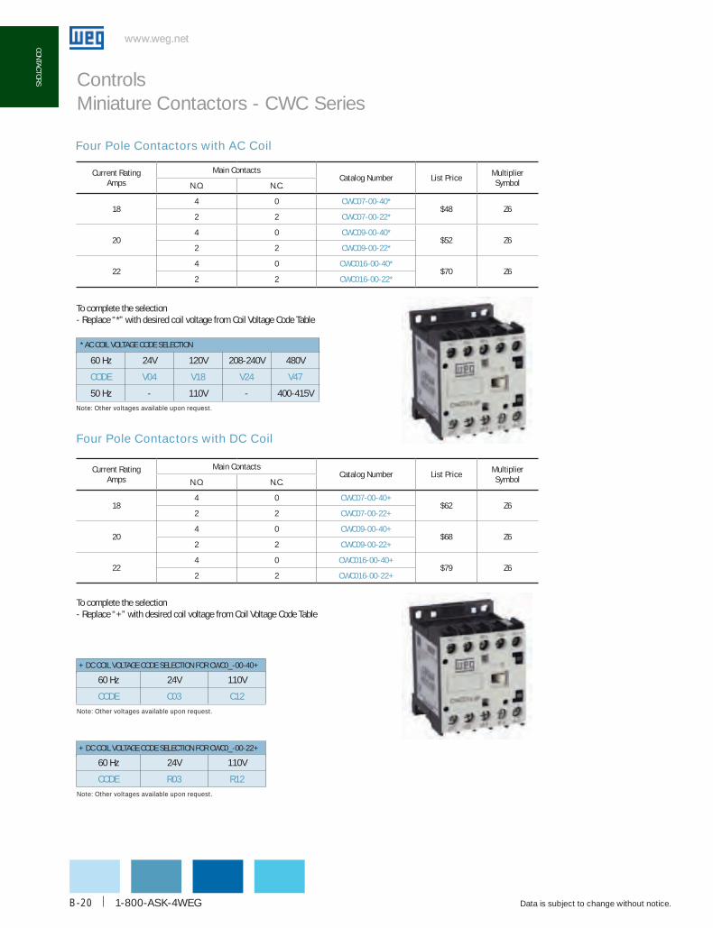
Four Pole Contactors with AC Coil
* AC COIL VOLTAGE CODE SELECTION
60 Hz 24V 120V 208-240V 480V
codE V04 V18 V24 V47
50 Hz - 110V - 400-415V
+ DC COIL VOLTAGE CODE SELECTION FOR CWC0_-00-40+
Note: Other voltages available upon request.
60 Hz 24V 110V
codE c03 c12
Four Pole Contactors with DC Coil
Note: Other voltages available upon request.
To complete the selection- Replace “*” with desired coil voltage from Coil Voltage Code Table
To complete the selection- Replace “+” with desired coil voltage from Coil Voltage Code Table
current Rating Amps
Main contactscatalog Number List Price
Multiplier SymbolN.o. N.c.
184 0 cWc07-00-40*
$48 Z62 2 cWc07-00-22*
204 0 cWc09-00-40*
$52 Z62 2 cWc09-00-22*
224 0 cWc016-00-40*
$70 Z62 2 cWc016-00-22*
current Rating Amps
Main contactscatalog Number List Price
Multiplier SymbolN.o. N.c.
184 0 cWc07-00-40+
$62 Z62 2 cWc07-00-22+
204 0 cWc09-00-40+
$68 Z62 2 cWc09-00-22+
224 0 cWc016-00-40+
$79 Z62 2 cWc016-00-22+
Controls Miniature Contactors - CWC Series
+ DC COIL VOLTAGE CODE SELECTION FOR CWC0_-00-22+
Note: Other voltages available upon request.
60 Hz 24V 110V
codE R03 R12
WEG Automation - Products and Solutions
www.weg.net
Data is subject to change without notice. B-21
coNT
AcTo
RS
www.weg.net
coNT
AcTo
RS
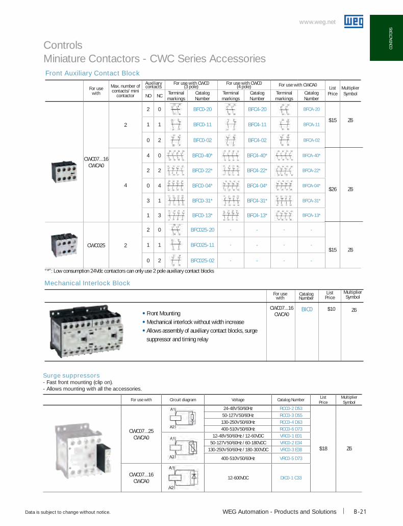
Front Auxiliary Contact Block
bIc0 $10
Mechanical Interlock Block
• Front Mounting
• Mechanical interlock without width increase
• Allows assembly of auxiliary contact blocks, surge
suppressor and timing relay
Z6
catalog Number
ListPrice
MultiplierSymbol
Controls Miniature Contactors - CWC Series Accessories
“*”: Low consumption 24Vdc contactors can only use 2 pole auxiliary contact blocks
For usewith
Max. number of contacts/ mini
contactor
Auxiliary contacts
For use with cWc0 (3 pole)
For use with cWc0 (4 pole) For use with cWcA0
ListPrice
MultiplierSymbolNo Nc
Terminal markings
catalog Number
Terminal markings
catalog Number
Terminal markings
catalog Number
cWc07...16cWcA0
2
2 0 bFc0-20 bFc4-20 bFcA-20
$15
$26
$15
Z6
Z6
Z6
1 1 bFc0-11 bFc4-11 bFcA-11
0 2 bFc0-02 bFc4-02 bFcA-02
4
4 0 bFc0-40* bFc4-40* bFcA-40*
2 2 bFc0-22* bFc4-22* bFcA-22*
0 4 bFc0-04* bFc4-04* bFcA-04*
3 1 bFc0-31* bFc4-31* bFcA-31*
1 3 bFc0-13* bFc4-13* bFcA-13*
cWc025 2
2 0 bFc025-20 - - - -
1 1 bFc025-11 - - - -
0 2 bFc025-02 - - - -
CWC07...16CWCA0
For use with
For use with circuit diagram Voltage catalog NumberList
PriceMultiplierSymbol
cWc07...25cWcA0
24-48V 50/60Hz Rcc0-2 d53
$18 Z6
50-127V 50/60Hz Rcc0-3 d55130-250V 50/60Hz Rcc0-4 d63400-510V 50/60Hz Rcc0-6 d73
12-48V 50/60Hz / 12-60VDC VRc0-1 E0150-127V 50/60Hz / 60-180VDC VRc0-2 E34
130-250V 50/60Hz / 180-300VDC VRc0-3 E38
400-510V 50/60Hz VRc0-5 d73
cWc07...16cWcA0
12-600VDC dIc0-1 c33
Surge suppressors- Fast front mounting (clip on).- Allows mounting with all the accessories.
www.weg.net
Data is subject to change without notice.1-800-ASK-4WEGB-22
coNTAcToRS
www.weg.net
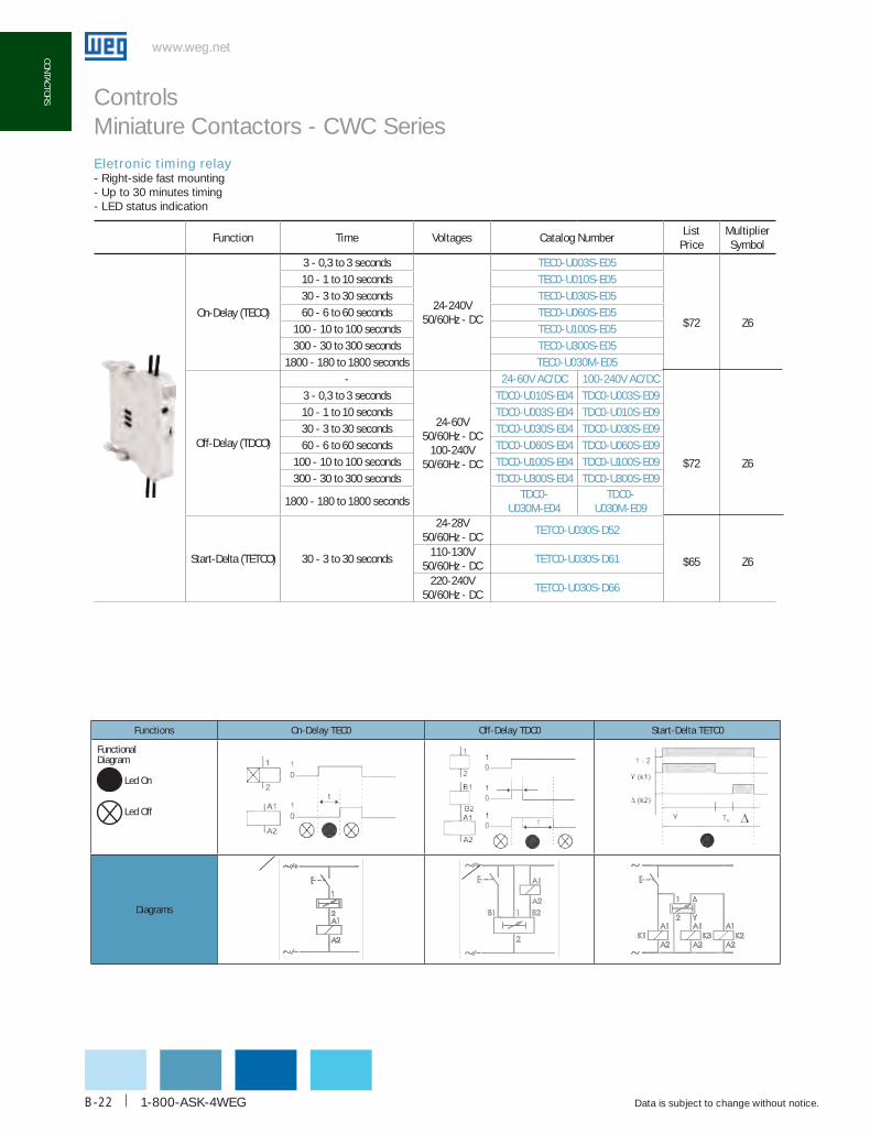
coNTAcToRS Controls Miniature Contactors - CWC SeriesEletronic timing relay- Right-side fast mounting- Up to 30 minutes timing- LED status indication
Function Time Voltages catalog NumberList
PriceMultiplierSymbol
On-Delay (TECO)
3 - 0,3 to 3 seconds
24-240V 50/60Hz - DC
TEc0-u003S-E05
$72
$72
$65
Z6
Z6
Z6
10 - 1 to 10 seconds TEc0-u010S-E0530 - 3 to 30 seconds TEc0-u030S-E0560 - 6 to 60 seconds TEc0-u060S-E05
100 - 10 to 100 seconds TEc0-u100S-E05300 - 30 to 300 seconds TEc0-u300S-E05
1800 - 180 to 1800 seconds TEc0-u030M-E05
Off-Delay (TDCO)
-
24-60V 50/60Hz - DC
100-240V 50/60Hz - DC
24-60V Ac/dc 100-240V Ac/dc3 - 0,3 to 3 seconds Tdc0-u010S-E04 Tdc0-u003S-E0910 - 1 to 10 seconds Tdc0-u003S-E04 Tdc0-u010S-E0930 - 3 to 30 seconds Tdc0-u030S-E04 Tdc0-u030S-E0960 - 6 to 60 seconds Tdc0-u060S-E04 Tdc0-u060S-E09
100 - 10 to 100 seconds Tdc0-u100S-E04 Tdc0-u100S-E09300 - 30 to 300 seconds Tdc0-u300S-E04 Tdc0-u300S-E09
1800 - 180 to 1800 secondsTdc0-
u030M-E04Tdc0-
u030M-E09
Start-Delta (TETCO) 30 - 3 to 30 seconds
24-28V 50/60Hz - DC
TETc0-u030S-d52
110-130V 50/60Hz - DC
TETc0-u030S-d61
220-240V 50/60Hz - DC
TETc0-u030S-d66
Functions on-delay TEc0 off-delay Tdc0 Start-delta TETc0
Functional Diagram
Led On
Led Off
Diagrams

WEG Automation - Products and Solutions
www.weg.net
Data is subject to change without notice. B-23
coNT
AcTo
RS
www.weg.net
coNT
AcTo
RS
• Quick and easy assembly for wye-delta and reversing starters
• Allows assemble of overload relay RW17D, manual motor protectors MPW16 & MPW25 and timer
Easy-Connection Busbar
Printed Circuit Board Connector
• Each CIC0 comes with a set of two connectors • Mounting on contactor’s top and bottom
• No derating on contactor’s rating
Rating (HP) Contactor
230V 460V 575V K1=K2 K3
3 7-1/2 7-1/2 CWC07 CWC07
5 7-1/2 10 CWC09 CWC07
5 10 10 CWC012 CWC07
7-1/2 15 15 CWC016 CWC09
Rating (HP) Contactor
230V 460V 575V K1=K2
1-1/2 5 5 CWC07
3 5 7-1/2 CWC09
3 7-1/2 7-1/2 CWC012
5 10 10 CWC016
Wye-Delta
Reversing
Controls Miniature Contactors - CWC Series
catalog Number
cIc0 $20 Z6
catalog Number
Ecco-Sd $34 Z6
Ecco-R $ 34 Z6
ListPrice
MultiplierSymbol
ListPrice
MultiplierSymbol
For use with
CWC07...16
CWCA0
For use with
CWC07...16
CWCA0

1-800-ASK-4WEGB-24
www.weg.net
Data is subject to change without notice.
www.weg.net
110-130 Vac 50/60 (TETC0)
Inputs
Time Adjust
AWG Cables
Auxiliary contact block
Timing Relay
Controls Miniature Contactors - CWC Series
Type cWc07 cWc09 cWc012 cWc016 cWc025
300.8
2....30,27
Standard 2.6...3.7 / Low Consumption 1.7...2.7Standard 2.6...3.7 / Low Consumption 1.7...2.7
580.8
4.5....5.8
--
-
--
--
1....1.8(8.9.....15.9)
AC (60Hz)
DC
0.27
Single Coil No Load
CW
C S
eR
ieS
General Purpose Rating
Electrical Lifespan
(A) 18 20 22 22 32
(Ops x 106) 1.4 1.3 1.2 1.2 0.6
WEG Automation - Products and Solutions
www.weg.net
Data is subject to change without notice. B-25
coNT
AcTo
RS
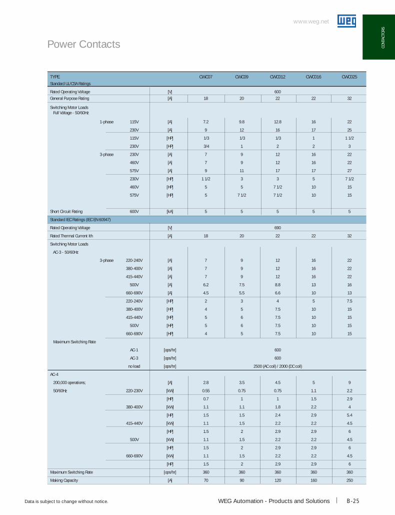
TYPE cWc07 cWc09 cWc012 cWc016 cWc025Standard UL/CSA Ratings
Rated Operating Voltage [V] 600
General Purpose Rating [A] 18 20 22 22 32
Switching Motor Loads Full Voltage - 50/60Hz
1-phase 115V [A] 7.2 9.8 12.8 16 22
230V [A] 9 12 16 17 25
115V [HP] 1/3 1/3 1/3 1 1 1/2
230V [HP] 3/4 1 2 2 3
3-phase 230V [A] 7 9 12 16 22
460V [A] 7 9 12 16 22
575V [A] 9 11 17 17 27
230V [HP] 1 1/2 3 3 5 7 1/2
460V [HP] 5 5 7 1/2 10 15
575V [HP] 5 7 1/2 7 1/2 10 15
Short Circuit Rating 600V [kA] 5 5 5 5 5
Standard IEC Ratings (IEC EN 60947)
Rated Operating Voltage [V] 690
Rated Thermal Current Ith [A] 18 20 22 22 32
Switching Motor Loads
AC-3 - 50/60Hz
3-phase 220-240V [A] 7 9 12 16 22
380-400V [A] 7 9 12 16 22
415-440V [A] 7 9 12 16 22
500V [A] 6.2 7.5 8.8 13 16
660-690V [A] 4.5 5.5 6.6 10 13
220-240V [HP] 2 3 4 5 7.5
380-400V [HP] 4 5 7.5 10 15
415-440V [HP] 5 6 7.5 10 15
500V [HP] 5 6 7.5 10 15
660-690V [HP] 4 5 7.5 10 15
Maximum Switching Rate
AC-1 [ops/hr] 600
AC-3 [ops/hr] 600
no load [ops/hr] 2500 (AC coil) / 2000 (DC coil)
AC-4
200,000 operations; [A] 2.8 3.5 4.5 5 9
50/60Hz 220-230V [kW] 0.55 0.75 0.75 1.1 2.2
[HP] 0.7 1 1 1.5 2.9
380-400V [kW] 1.1 1.1 1.8 2.2 4
[HP] 1.5 1.5 2.4 2.9 5.4
415-440V [kW] 1.1 1.5 2.2 2.2 4.5
[HP] 1.5 2 2.9 2.9 6
500V [kW] 1.1 1.5 2.2 2.2 4.5
[HP] 1.5 2 2.9 2.9 6
660-690V [kW] 1.1 1.5 2.2 2.2 4.5
[HP] 1.5 2 2.9 2.9 6
Maximum Switching Rate [ops/hr] 360 360 360 360 360
Making Capacity [A] 70 90 120 160 250
Power Contacts
www.weg.net
Data is subject to change without notice.1-800-ASK-4WEGB-26
coNTAcToRS
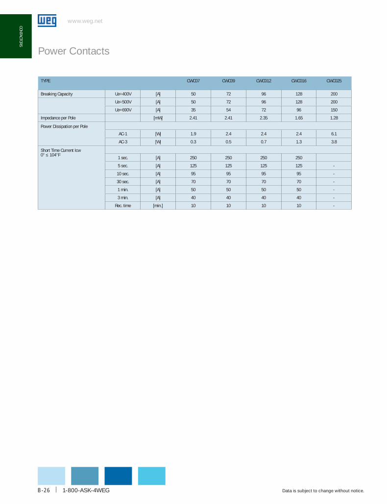
TYPE cWc07 cWc09 cWc012 cWc016 cWc025
Breaking Capacity Ue=400V [A] 50 72 96 128 200
Ue=500V [A] 50 72 96 128 200
Ue=690V [A] 35 54 72 96 150
Impedance per Pole [mW] 2.41 2.41 2.35 1.65 1.28
Power Dissipation per Pole
AC-1 [W] 1.9 2.4 2.4 2.4 6.1
AC-3 [W] 0.3 0.5 0.7 1.3 3.8
Short Time Current Icw0° ≤ 104°F
1 sec. [A] 250 250 250 250
5 sec. [A] 125 125 125 125 -
10 sec. [A] 95 95 95 95 -
30 sec. [A] 70 70 70 70 -
1 min. [A] 50 50 50 50 -
3 min. [A] 40 40 40 40 -
Rec. time [min.] 10 10 10 10 -
Power Contacts

WEG Automation - Products and Solutions
www.weg.net
Data is subject to change without notice. B-27
coNT
AcTo
RS
www.weg.net
coNT
AcTo
RS
Electrical Lifespan
Num
ber o
f ope
ratio
n (1
06 )
0,1
0,011
Rated operational current Ie (A)
16,8 24,6 45,57 8520,4
35,3
4
6036
64,8
0 100
1
Num
ber o
f ope
ratio
n (1
06 )
1
10
0,11 7 910
Rated operational current Ie (A)
12 16 25 100
CWC025
CWC016
CWC012
CWC09CW
C07
Mounting position of all miniature contactors
Electrical Lifespan
Controls Miniature Contactors - CWC Series
AC-4 (Ue ≤ 460VAC) AC-3 (Ue ≤ 460VAC)
360°360°30°30°30°30°

www.weg.net
Data is subject to change without notice.1-800-ASK-4WEGB-28
coNTAcToRS
www.weg.net
coNTAcToRS
www.weg.net
Dimensions mm (in)
Controls Miniature Contactors - CWC Series
CWC07...016 AND CWCA0
45/ [1.8] 9/ [0.4]
58/ [
2.3]
56/ [2.2]
83/ [3.3]
TDCOTECOTETCO
BFC025
CWC025
TDCOTECOTETCO
VRCORCCODICO
RMCO & BICO

WEG Automation - Products and Solutions
www.weg.net
Data is subject to change without notice. B-29
coNT
AcTo
RS
The CWM general-purpose contactor line has been designed taking into consideration industrial duty and reliability in mind.
Rated for inductive loads up to 800A or 600Hp@460V, WEG can offer the suitable contactor for your application.
Given their compact footprints, CWM contactors allow total panel space optimization, with only a few compact frame sizes from 5 to 600Hp@460V. Reducing inventory is a “snap” with CWM’s common accessories. For example, side-mounted auxiliary contact blocks are the same from 5 to 250 Hp@460V..
Designed for extended mechanical and electrical life, dependable switching in even the most heavy-duty applications can be achieved. No matter how demanding the application, all WEG contactors are tested and approved to be used under Type 1 and Type 2 short circuit coordination.
Ensuring global acceptance, all components conform to UL508, CSA C.22.2, IEC60947 and CE.
All contactors are manufactured to assure the highest quality manufacturing processes and component materials. This way, WEG offers reliable solutions for low-voltage applications in electric panel assemblers, OEMs, distributors and end users.
Certifications
Controls Standard IEC Contactors
www.weg.net
Data is subject to change without notice.1-800-ASK-4WEGB-30
coNTAcToRS
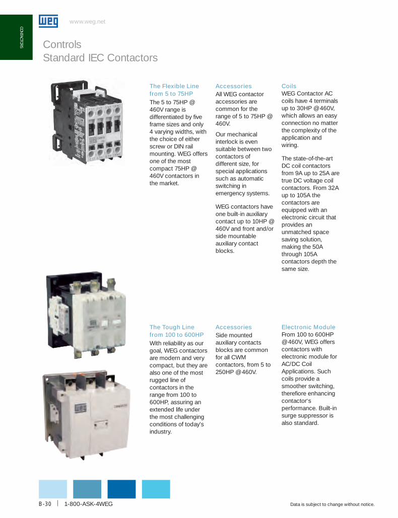
The Flexible Line from 5 to 75HPThe 5 to 75HP @ 460V range is differentiated by five frame sizes and only 4 varying widths, with the choice of either screw or DIN rail mounting. WEG offers one of the most compact 75HP @ 460V contactors in the market.
AccessoriesAll WEG contactor accessories are common for the range of 5 to 75HP @ 460V.
Our mechanical interlock is even suitable between two contactors of different size, for special applications such as automatic switching in emergency systems.
WEG contactors have one built-in auxiliary contact up to 10HP @ 460V and front and/or side mountable auxiliary contact blocks.
Coils WEG Contactor AC coils have 4 terminals up to 30HP @ 460V, which allows an easy connection no matter the complexity of the application and wiring.
The state-of-the-art DC coil contactors from 9A up to 25A are true DC voltage coil contactors. From 32A up to 105A the contactors are equipped with an electronic circuit that provides an unmatched space saving solution, making the 50A through 105A contactors depth the same size.
Controls Standard IEC Contactors
The Tough Line from 100 to 600HPWith reliability as our goal, WEG contactors are modern and very compact, but they are also one of the most rugged line of contactors in the range from 100 to 600HP, assuring an extended life under the most challenging conditions of today’s industry.
AccessoriesSide mounted auxiliary contacts blocks are common for all CWM contactors, from 5 to 250HP @ 460V.
Electronic Module From 100 to 600HP @ 460V, WEG offers contactors with electronic module for AC/DC Coil Applications. Such coils provide a smoother switching, therefiore enhancing contactor‘s performance. Built-in surge suppressor is also standard.
WEG Automation - Products and Solutions
www.weg.net
Data is subject to change without notice. B-31
coNT
AcTo
RS
MIRROR CONTACTS FOR SAFETY-RELATED APPLICATIONSThe increase demand for reliable and safety –related circuits for personnel protection has considerably increased within the last two decades. Not only standards for personnel protection are leading this evolution on high level of system availability, but also the financial aspects of critical operation downtime events.
Although there are significant differences between Mechanically Linked Contact Element(s) described on Annex L of IEC60947-5-1 and Mirror Contacts described on Annex F of IEC60947 -4-1, those differences do not prevent a given auxiliary contact to comply with both requirements.
The following paragraphs will describe key aspects of above Annex and its difference in order to help engineers to select an appropriate device for each application. WEG has incorporated the Mirror Contact feature on all contactors and standard auxiliary contact blocks extending this safety feature to all standard applications. See table at the following page.
Mechnicaly Linked Auxiliary Contact Elements: Defined by IEC60947 -5-1 (Annex L) it is a combination of "n" Make contact element(s) and "m" Break contact element (s) designed in such way that they cannot be in closed position simultaneously.
• While any of the "n" Make contact element(s) is closed, none of the "m" Break contact elements(s) shall be closed;
• While any of the "m" Break contact element(s) is closed, none of the "n" Make contact elements(s) shall be closed.
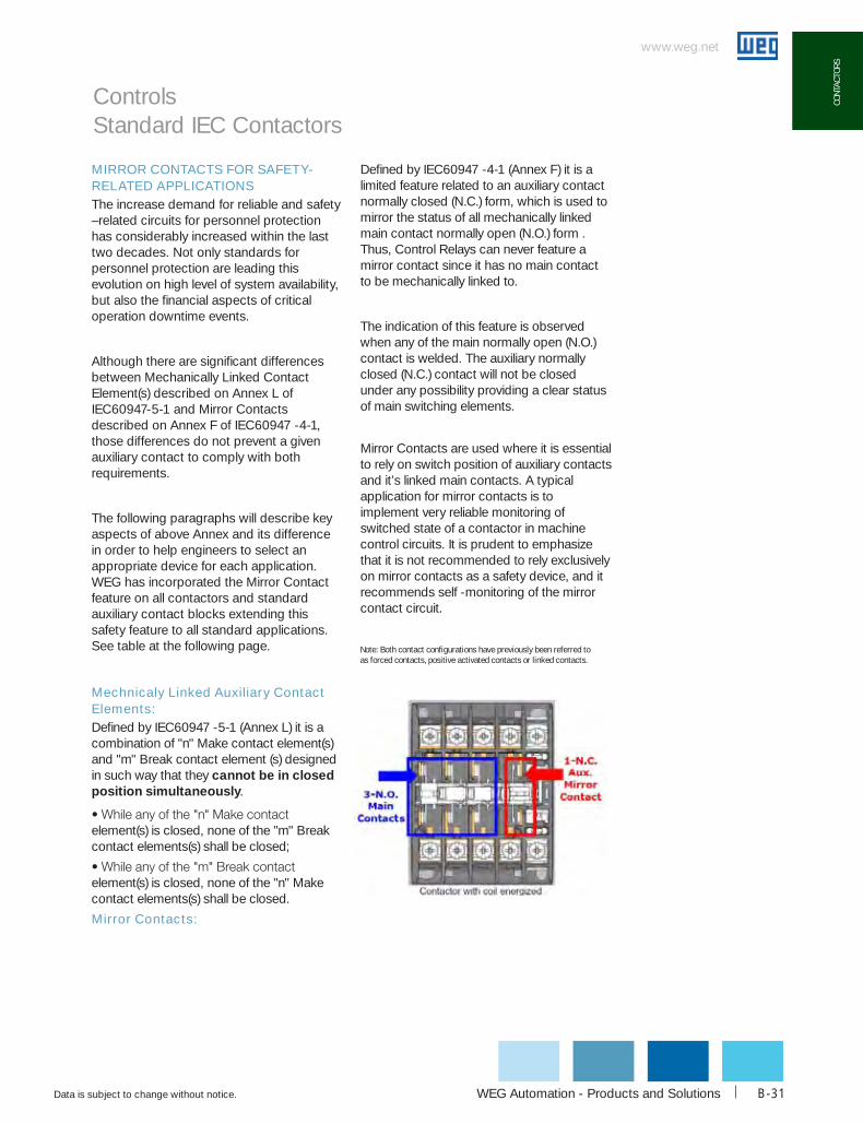
Mirror Contacts:
Defined by IEC60947 -4-1 (Annex F) it is a limited feature related to an auxiliary contact normally closed (N.C.) form, which is used to mirror the status of all mechanically linked main contact normally open (N.O.) form . Thus, Control Relays can never feature a mirror contact since it has no main contact to be mechanically linked to.
The indication of this feature is observed when any of the main normally open (N.O.) contact is welded. The auxiliary normally closed (N.C.) contact will not be closed under any possibility providing a clear status of main switching elements.
Mirror Contacts are used where it is essential to rely on switch position of auxiliary contacts and it’s linked main contacts. A typical application for mirror contacts is to implement very reliable monitoring of switched state of a contactor in machine control circuits. It is prudent to emphasize that it is not recommended to rely exclusively on mirror contacts as a safety device, and it recommends self -monitoring of the mirror contact circuit.
Controls Standard IEC Contactors
Note: both contact configurations have previously been referred to as forced contacts, positive activated contacts or linked contacts.

www.weg.net
Data is subject to change without notice.1-800-ASK-4WEGB-32
coNTAcToRS Controls Standard IEC Contactors
Mirror contacts for Safety-related Applications
Ac and dc coilcontactors
Integrated auxiliary breakcontact element to main
contacts
Mirror contactsacc. to IEc60947-4-1
(Annex F)
Additional auxiliarybreak contact blocks
to main contacts
Mirror contactsacc. to
IEc60947-4-1(Annex F)
CWM9-10 toCWM18-10
No auxiliary breakcontact NO
bcXMF01;bcXML01;bcXML11
YES
CWM9-01 toCWM18-01 built-in YES
bcXMF01;bcXML01;bcXML11
YES
CWM25-00 toCWM105-00
No auxiliary breakcontact NO
bcXMF01;bcXML01;bcXML11
YES
CWM25-11 toCWM105-11
Front Mountable1xbcXMF01 YES
bcXMF01;bcXML01;bcXML11
YES
CWM112-22 toCWM300-22
Side* Mountable2xBCXML11
YES bcXMRL11 YES
WEG Automation - Products and Solutions
www.weg.net
Data is subject to change without notice. B-33
coNT
AcTo
RS
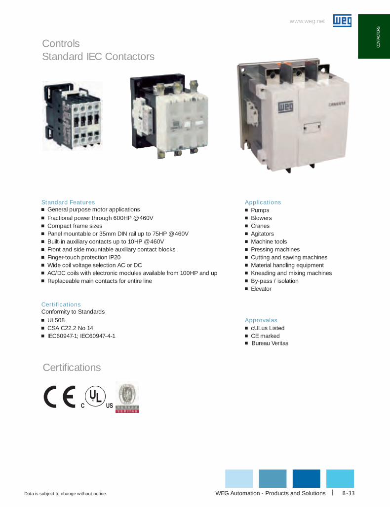
Standard Features g General purpose motor applicationsg Fractional power through 600HP @ 460Vg Compact frame sizesg Panel mountable or 35mm DIN rail up to 75HP @ 460Vg Built-in auxiliary contacts up to 10HP @ 460Vg Front and side mountable auxiliary contact blocksg Finger-touch protection IP20g Wide coil voltage selection AC or DCg AC/DC coils with electronic modules available from 100HP and upg Replaceable main contacts for entire line
Certifications Conformity to Standardsg UL508g CSA C22.2 No 14g IEC60947-1; IEC60947-4-1
Controls Standard IEC Contactors
Applicationsg Pumpsg Blowersg Cranesg Agitatorsg Machine toolsg Pressing machinesg Cutting and sawing machinesg Material handling equipmentg Kneading and mixing machinesg By-pass / isolationg Elevator
Approvalasg cULus Listedg CE markedg Bureau Veritas
Certifications

www.weg.net
Data is subject to change without notice.1-800-ASK-4WEGB-34
coNTAcToRS
Catalog part number composition
Controls Standard IEC Contactors - CWM Series

WEG Automation - Products and Solutions
www.weg.net
Data is subject to change without notice. B-35
coNT
AcTo
RS
3 pole contactors with AC coil
Maximum uL horsepowerAuxiliary contacts current
RatingAmps
catalog Number1 List PriceMultiplier Symbol
Single Phase Three Phase
115V 230V 200V 230V 460V 575V N.o. N.c.
1/2 1 1/2 3 3 5 7 1/21 0
9cWM9-10-30*
$72 Z10 1 cWM9-01-30*
3/4 2 3 3 7 1/2 101 0
12cWM12-10-30*
$89 Z10 1 cWM12-01-30*
1 3 5 5 10 151 0
18cWM18-10-30*
$103 Z10 1 cWM18-01-30*
2 5 7 1/2 7 1/2 15 150 0
25cWM25-00-30* $118 Z1
1 1 cWM25-11-30* $138 Z1
3 5 10 10 20 250 0
32cWM32-00-30* $140 Z1
1 1 cWM32-11-30* $160 Z1
3 7 1/2 10 15 30 250 0
40cWM40-00-30* $164 Z1
1 1 cWM40-11-30* $184 Z1
3 10 15 15 40 400 0
50cWM50-00-30* $190 Z1
1 1 cWM50-11-30* $210 Z1
5 10 20 20 50 500 0
65cWM65-00-30* $215 Z1
1 1 cWM65-11-30* $235 Z1
7 1/2 15 20 25 50 600 0
80cWM80-00-30* $261 Z1
1 1 cWM80-11-30* $281 Z1
7 1/2 15 25 30 60 750 0
95cWM95-00-30* $294 Z1
1 1 cWM95-11-30* $314 Z1
10 20 30 40 75 750 0
105cWM105-00-30* $393 Z1
1 1 cWM105-11-30* $413 Z1
Controls IEC Contactors - CWM Series
To complete the selection- Replace “*” with desired coil voltage from Coil Voltage Code Table
Note:1) Stock available only for contactor version …-10-30... and …-00-30…. -10 = 1 N.O. Auxilliary contact. -00 = No Auxilliary contact For … -11-30… = 1 N.O. & 1 N.C. version or other auxilliary contact configurations please refer to page B-42.
60 Hz 24V1) 48V1) 120V 208-240V 277V1) 480V 600V1)
codE V04 V10 V18 V24 V37 V47 V56
50 Hz - 42V 110V - 230-240V 400-415V 500V
* Ac coIL VoLTAGE codE SELEcTIoN FoR coNTAcToRS cWM9...cWM105
- Other coil voltages available upon request
www.weg.net
Data is subject to change without notice.1-800-ASK-4WEGB-36
coNTAcToRS
Maximum uL horsepowerAuxiliary contacts current
RatingAmps
catalog Number List PriceMultiplier Symbol
Single Phase Three Phase
115V 230V 200V 230V 460V 575V N.o. N.c.
1/2 1 1/2 3 3 5 7 1/21 0
9cWM9-10-30+
$93 Z10 1 cWM9-01-30+
3/4 2 3 3 7 1/2 101 0
12cWM12-10-30+
$111 Z10 1 cWM12-01-30+
1 3 5 5 10 151 0
18cWM18-10-30+
$125 Z10 1 cWM18-01-30+
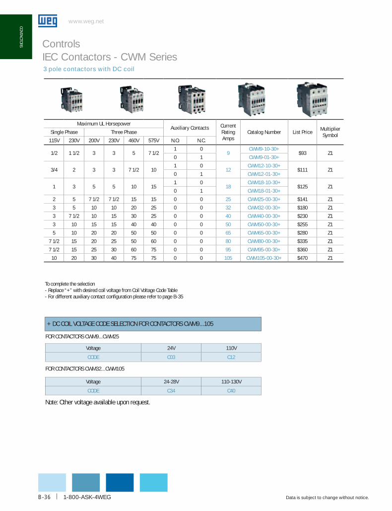
2 5 7 1/2 7 1/2 15 15 0 0 25 cWM25-00-30+ $141 Z1
3 5 10 10 20 25 0 0 32 cWM32-00-30+ $180 Z1
3 7 1/2 10 15 30 25 0 0 40 cWM40-00-30+ $230 Z1
3 10 15 15 40 40 0 0 50 cWM50-00-30+ $255 Z1
5 10 20 20 50 50 0 0 65 cWM65-00-30+ $280 Z1
7 1/2 15 20 25 50 60 0 0 80 cWM80-00-30+ $335 Z1
7 1/2 15 25 30 60 75 0 0 95 cWM95-00-30+ $360 Z1
10 20 30 40 75 75 0 0 105 cWM105-00-30+ $470 Z1
+ DC COIL VOLTAGE CODE SELECTION FOR CONTACTORS CWM9...105
3 pole contactors with DC coil
Voltage 24V 110V
codE c03 c12
Voltage 24-28V 110-130V
codE c34 c40
FOR CONTACTORS CWM9...CWM25
FOR CONTACTORS CWM32...CWM105
Controls IEC Contactors - CWM Series
Note: Other voltage available upon request.
To complete the selection- Replace “+” with desired coil voltage from Coil Voltage Code Table- For different auxiliary contact configuration please refer to page B-35

WEG Automation - Products and Solutions
www.weg.net
Data is subject to change without notice. B-37
coNT
AcTo
RS
3 pole contactors with AC/DC electronic module coil
Maximum uL horsepowerAuxiliary contacts current
RatingAmps
catalog Number List PriceMultiplier Symbol
Single Phase Three Phase
115V 230V 200V 230V 460V 575V N.o. N.c.
- - 40 50 100 100 2 2 112 cWM112-22-30# $765 Z1
- - 50 60 125 150 2 2 150 cWM150-22-30# $945 Z1
- - 60 75 150 200 2 2 180 cWM180-22-30# $1,260 Z1
- - 75 100 200 250 2 2 250 cWM250-22-30# $1,755 Z1
- - 100 125 250 300 2 2 300 cWM300-22-30# $1,890 Z1
- - 125 150 300 300 2 2 400 cWM400-22-30^ $2,520 Z1
- - 200 250 500 500 2 2 630 cWM630-22-30^ $3,870 Z1
- - 200 300 600 600 2 2 800 cWM800-22-30^ $5,670 Z1
Voltage 24-28Vac/Vdc 110-130Vac/Vdc 208-250Vac/Vdc 430-500Vac/Vdc
codE E02 E10 E13 E21
Mounting on CWM112-CWM300 CWM112-CWM300 CWM112-CWM300 CWM112-CWM300
Voltage 100-240Vac/100-220Vdc 100-127Vac/100-110Vdc 200-240Vac/200-220Vdc 440-575Vac
codE E36 E35 E39 d82
Mounting on CWM400 CWM630-CWM800 CWM630-CWM800 CWM400-CWM800
# AC/DC COIL VOLTAGE CODE SELECTION FOR CONTACTORS CWM112, 150, 180, 250, 300
Controls IEC Contactors - CWM Series
^ AC/DC COIL VOLTAGE CODE SELECTION FOR CONTACTORS CWM400...800
Note: Other voltage available upon request.
To complete the selection- Replace “#” or “^”with desired coil voltage from Coil Voltage Code Table- For different auxiliary contact configuration please refer to page B-35

www.weg.net
Data is subject to change without notice.1-800-ASK-4WEGB-38
coNTAcToRS
www.weg.net
Controls IEC Contactors - CWM Series
Maximum uL horsepower Auxiliary contacts current
RatingAmps
catalog Number List PriceMultiplier SymbolSingle Phase
115V 230V N.o. N.c.
1/2 1 1/2 0 0 9 cWM9-00-20* $65 Z1
3/4 2 0 0 12 cWM12-00-20* $68 Z1
1 3 0 0 18 cWM18-00-20* $73 Z1
2 5 0 0 25 cWM25-00-20* $99 Z1
3 5 0 0 32 cWM32-00-20* $126 Z1
3 7 1/2 0 0 40 cWM40-00-20* $160 Z1
3 10 0 0 50 cWM50-00-20* $174 Z1
5 10 0 0 65 cWM65-00-20* $200 Z1
7 1/2 15 0 0 80 cWM80-00-20* $231 Z1
7 1/2 15 0 0 95 cWM95-00-20* $273 Z1
10 20 0 0 105 cWM105-00-20* $321 Z1
* AC COIL VOLTAGE CODE SELECTION
60 Hz 24V 120V 208-240V
codE V04 V18 V24
50 Hz - 110V -
FOR CONTACTORS CWM9...CWM105
Note1: Availability upon request.
To complete the selection- Replace “*” with desired coil voltage from Coil Voltage Code Table- For different auxiliary contact configuration please refer to page B-35
2 pole contactors with AC coil1
WEG Automation - Products and Solutions
www.weg.net
Data is subject to change without notice. B-39
coNT
AcTo
RS
www.weg.net
Controls
NEMA Rated ContactorsNEMA contactors have been a mainstay in the industrial marketplace in the US for decades. NEMA contactors were known for being robust & able to handle any industrial application.
WEG’s NEMA rated contactors meet or exceed the standards defined by the National Electrical Manufacturers Association (NEMA), for full voltage or reduced voltage motor starting. (1)
• Available from size 00 to size 5
• Designed for Industrial Applications with Reliability in mind
• Enclosed NEMA Starters & Custom NEMA Starter panels, available on request
• Reduced inventory with common accessories
• Ease of choosing product
• Adjustable Overload Protection available (No heaters needed)
(1) NEMA Standards Publication ICS 2-2000 (R2005) Industrial Control and Systems Controllers, Contactors and Overload Relays Rated 600 Volts
www.weg.net
Data is subject to change without notice.1-800-ASK-4WEGB-40
coNTAcToRS
www.weg.net
Controls
NEMA Rated Contactors
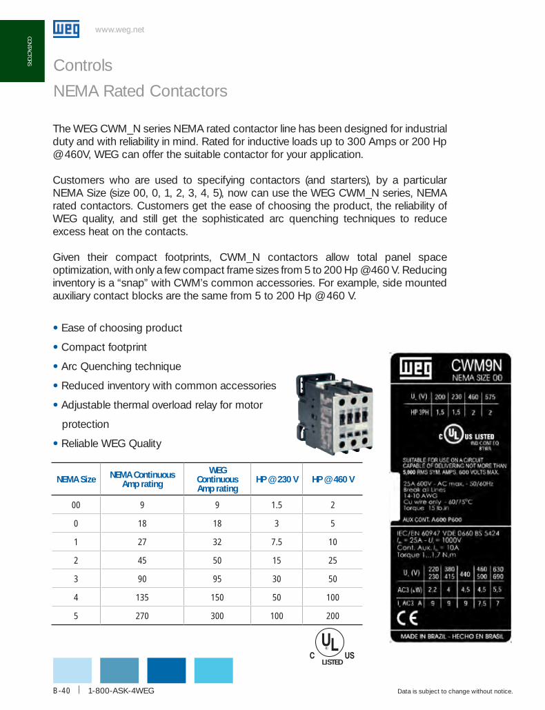
The WEG CWM_N series NEMA rated contactor line has been designed for industrial duty and with reliability in mind. Rated for inductive loads up to 300 Amps or 200 Hp @ 460V, WEG can offer the suitable contactor for your application.
Customers who are used to specifying contactors (and starters), by a particular NEMA Size (size 00, 0, 1, 2, 3, 4, 5), now can use the WEG CWM_N series, NEMA rated contactors. Customers get the ease of choosing the product, the reliability of WEG quality, and still get the sophisticated arc quenching techniques to reduce excess heat on the contacts.
Given their compact footprints, CWM_N contactors allow total panel space optimization, with only a few compact frame sizes from 5 to 200 Hp @ 460 V. Reducing inventory is a “snap” with CWM’s common accessories. For example, side mounted auxiliary contact blocks are the same from 5 to 200 Hp @ 460 V.
• Ease of choosing product
• Compact footprint
• Arc Quenching technique
• Reduced inventory with common accessories
• Adjustable thermal overload relay for motor
protection
• Reliable WEG Quality
NEMA Size NEMA Continuous Amp rating
WEG Continuous Amp rating
HP @ 230 V HP @ 460 V
00 9 9 1.5 2
0 18 18 3 5
1 27 32 7.5 10
2 45 50 15 25
3 90 95 30 50
4 135 150 50 100
5 270 300 100 200
LISTED
WEG Automation - Products and Solutions
www.weg.net
Data is subject to change without notice. B-41
coNT
AcTo
RS
www.weg.net
Controls
NEMA Rated Contactors
CWM_N Series
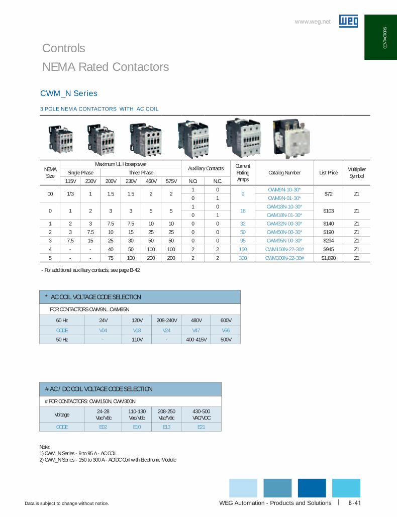
3 POLE NEMA CONTACTORS WITH AC COIL
NEMA Size
Maximum UL HorsepowerAuxiliary Contacts Current
RatingAmps
Catalog Number List PriceMultiplier Symbol
Single Phase Three Phase
115V 230V 200V 230V 460V 575V N.O. N.C.
00 1/3 1 1.5 1.5 2 21 0
9cWM9N-10-30*
$72 Z10 1 cWM9N-01-30*
0 1 2 3 3 5 51 0
18cWM18N-10-30*
$103 Z10 1 cWM18N-01-30*
1 2 3 7.5 7.5 10 10 0 0 32 cWM32N-00-30* $140 Z1
2 3 7.5 10 15 25 25 0 0 50 cWM50N-00-30* $190 Z1
3 7.5 15 25 30 50 50 0 0 95 cWM95N-00-30* $294 Z1
4 - - 40 50 100 100 2 2 150 cWM150N-22-30# $945 Z1
5 - - 75 100 200 200 2 2 300 cWM300N-22-30# $1,890 Z1
Note:1) CWM_N Series - 9 to 95 A - AC COIL2) CWM_N Series - 150 to 300 A - AC/DC Coil with Electronic Module
# FoR coNTAcToRS: cWM150N, cWM300N
Voltage24-28
Vac/Vdc110-130 Vac/Vdc
208-250 Vac/Vdc
430-500 VAC/VDC
CODE E02 E10 E13 E21
# Ac / dc coIL VoLTAGE codE SELEcTIoN
FoR coNTAcToRS cWM9N...cWM95N
60 Hz 24V 120V 208-240V 480V 600V
CODE V04 V18 V24 V47 V56
50 Hz - 110V - 400-415V 500V
* Ac coIL VoLTAGE codE SELEcTIoN
- For additional auxilliary contacts, see page B-42
www.weg.net
Data is subject to change without notice.1-800-ASK-4WEGB-42
coNTAcToRS
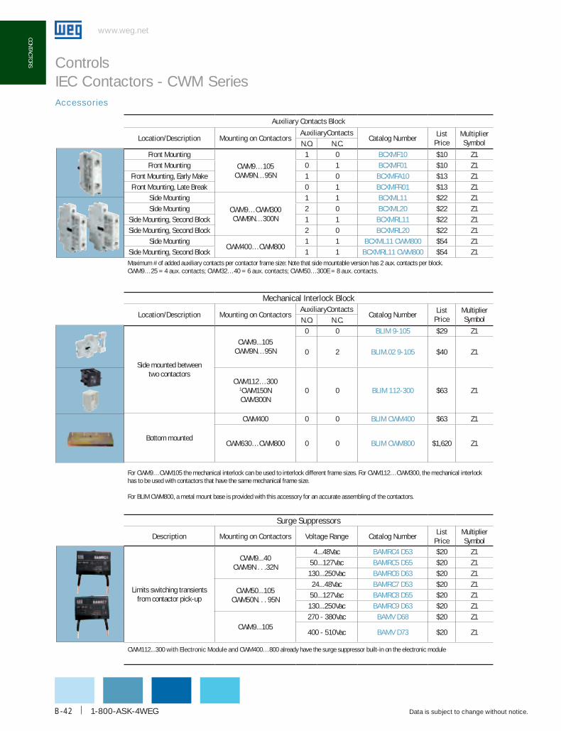
Auxiliary contacts block
Location/description Mounting on contactorsAuxiliarycontacts
catalog NumberList
PriceMultiplier SymbolN.o. N.c.
Front Mounting
CWM9…105CWM9N…95N
1 0 bcXMF10 $10 Z1
Front Mounting 0 1 bcXMF01 $10 Z1
Front Mounting, Early Make 1 0 bcXMFA10 $13 Z1
Front Mounting, Late Break 0 1 bcXMFR01 $13 Z1
Side Mounting
CWM9…CWM300CWM9N…300N
1 1 bcXML11 $22 Z1
Side Mounting 2 0 bcXML20 $22 Z1
Side Mounting, Second Block 1 1 bcXMRL11 $22 Z1
Side Mounting, Second Block 2 0 bcXMRL20 $22 Z1
Side MountingCWM400…CWM800
1 1 bcXML11 cWM800 $54 Z1
Side Mounting, Second Block 1 1 bcXMRL11 cWM800 $54 Z1Maximum # of added auxiliary contacts per contactor frame size: Note that side mountable version has 2 aux. contacts per block. cWM9…25 = 4 aux. contacts; cWM32…40 = 6 aux. contacts; cWM50…300E = 8 aux. contacts.
Mechanical Interlock block
Location/description Mounting on contactorsAuxiliarycontacts
catalog NumberList
PriceMultiplier SymbolN.o. N.c.
Side mounted between two contactors
CWM9...105CWM9N…95N
0 0 bLIM 9-105 $29 Z1
0 2 bLIM.02 9-105 $40 Z1
CWM112…3001CWM150NCWM300N
0 0 bLIM 112-300 $63 Z1
Bottom mounted
CWM400 0 0 bLIM cWM400 $63 Z1
CWM630…CWM800 0 0 bLIM cWM800 $1,620 Z1
For CWM9…CWM105 the mechanical interlock can be used to interlock different frame sizes. For CWM112…CWM300, the mechanical interlock has to be used with contactors that have the same mechanical frame size.
For BLIM CWM800, a metal mount base is provided with this accessory for an accurate assembling of the contactors.
Surge Suppressors
description Mounting on contactors Voltage Range catalog NumberList
PriceMultiplier Symbol
Limits switching transients from contactor pick-up
CWM9...40CWM9N . . .32N
4...48Vac bAMRc4 d53 $20 Z1
50...127Vac bAMRc5 d55 $20 Z1
130...250Vac bAMRc6 d63 $20 Z1
CWM50...105CWM50N. . . 95N
24...48Vac bAMRc7 d53 $20 Z1
50...127Vac bAMRc8 d55 $20 Z1
130...250Vac bAMRc9 d63 $20 Z1
CWM9...105270 - 380Vac bAMV d68 $20 Z1
400 - 510Vac bAMV d73 $20 Z1
cWM112...300 with Electronic Module and cWM400…800 already have the surge suppressor built-in on the electronic module
Accessories
Controls IEC Contactors - CWM Series

WEG Automation - Products and Solutions
www.weg.net
Data is subject to change without notice. B-43
coNT
AcTo
RS
Terminal cover for cWM_E contactor Series
Location/description Mounting on contactors catalog NumberList
PriceMultiplier Symbol
Protection for contactor terminals
(3 covers per package)
CWM400 bMP cWM400 $60 Z1
CWM630…CWM800 bMP cWM800 $110 Z1
Lugs for cWM contactor Series (3 units per package)
description / Wire Range Mounting on contactors catalog NumberList
PriceMultiplier Symbol
300 MCM…6 AWG CWM112...150 LW1-S300 $52 Z1
300 MCM…6 AWG CWM180 LW2-S300 $52 Z1
600 MCM…4 AWG CWM250…CWM300 LW1-S600 $98 Z1
(2) 3-4/0 AWG CWM400 bMJ cWM400 $98 Z1
(2) 3/0-600 MCM CWM630…CWM800 bMJ cWM800 $158 Z1
Accessories
Controls IEC Contactors - CWM Series
www.weg.net
Data is subject to change without notice.1-800-ASK-4WEGB-44
coNTAcToRS
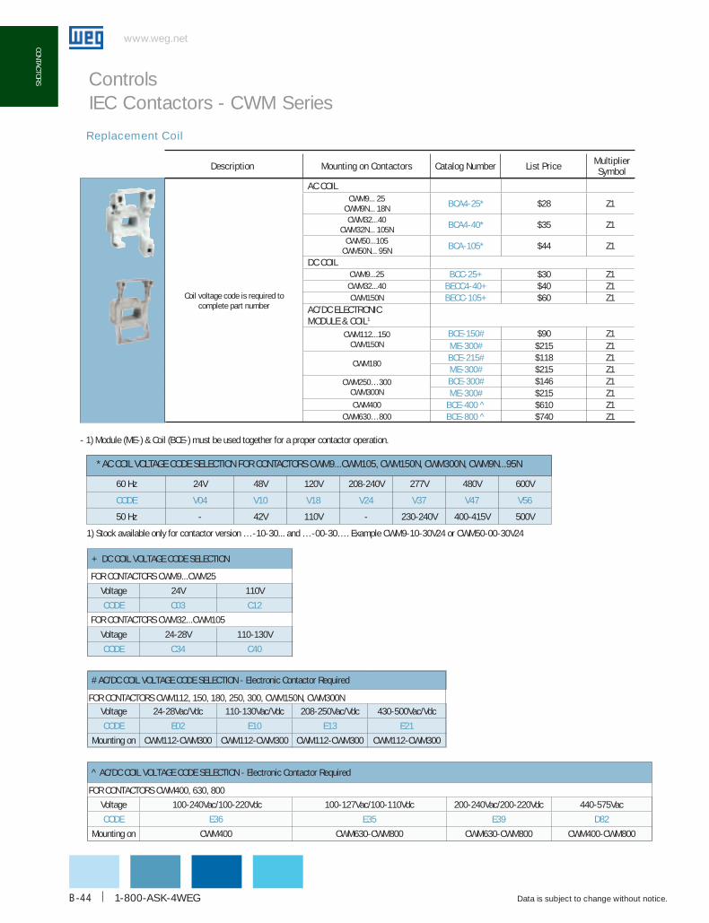
description Mounting on contactors catalog Number List Price MultiplierSymbol
Replacement Coil
Coil voltage code is required to complete part number
Ac coILCWM9... 25
CWM9N... 18N bcA4-25* $28 Z1
CWM32...40CWM32N... 105N bcA4-40* $35 Z1
CWM50...105CWM50N... 95N bcA-105* $44 Z1
dc coILCWM9...25 bcc-25+ $30 Z1CWM32...40 bEcc4-40+ $40 Z1CWM150N bEcc-105+ $60 Z1
Ac/dc ELEcTRoNIcModuLE & coIL1
CWM112...150CWM150N
bcE-150# $90 Z1ME-300# $215 Z1
CWM180bcE-215# $118 Z1ME-300# $215 Z1
CWM250…300CWM300N
bcE-300# $146 Z1ME-300# $215 Z1
CWM400 bcE-400 ^ $610 Z1CWM630…800 bcE-800 ^ $740 Z1
Controls IEC Contactors - CWM Series
+ DC COIL VOLTAGE CODE SELECTION
Voltage 24V 110V
codE c03 c12
Voltage 24-28V 110-130V
codE c34 c40
# AC/DC COIL VOLTAGE CODE SELECTION - Electronic Contactor Required
Voltage 24-28Vac/Vdc 110-130Vac/Vdc 208-250Vac/Vdc 430-500Vac/Vdc
codE E02 E10 E13 E21
Mounting on CWM112-CWM300 CWM112-CWM300 CWM112-CWM300 CWM112-CWM300
^ AC/DC COIL VOLTAGE CODE SELECTION - Electronic Contactor Required
Voltage 100-240Vac/100-220Vdc 100-127Vac/100-110Vdc 200-240Vac/200-220Vdc 440-575Vac
codE E36 E35 E39 d82
Mounting on CWM400 CWM630-CWM800 CWM630-CWM800 CWM400-CWM800
FOR CONTACTORS CWM9...CWM25
FOR CONTACTORS CWM32...CWM105
FOR CONTACTORS CWM112, 150, 180, 250, 300, CWM150N, CWM300N
FOR CONTACTORS CWM400, 630, 800
60 Hz 24V 48V 120V 208-240V 277V 480V 600V
codE V04 V10 V18 V24 V37 V47 V56
50 Hz - 42V 110V - 230-240V 400-415V 500V
* AC COIL VOLTAGE CODE SELECTION FOR CONTACTORS CWM9...CWM105, CWM150N, CWM300N, CWM9N...95N
1) Stock available only for contactor version …-10-30... and …-00-30…. Example CWM9-10-30V24 or CWM50-00-30V24
- 1) Module (ME-) & Coil (BCE-) must be used together for a proper contactor operation.
WEG Automation - Products and Solutions
www.weg.net
Data is subject to change without notice. B-45
coNT
AcTo
RS
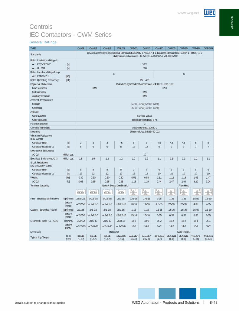
TYPE cWM9 cWM12 cWM18 cWM25 cWM32 cWM40 cWM50 cWM65 cWM80 cWM95 cWM105
StandardsDevices according to International Standards IEC 60947-1 / 60947-4-1, European Standards EN 60947-1 / 60947-4-1,
Underwriters Laboratories - UL 508; CSA C.22.2/14; VDE 0660/102
Rated Insulation Voltage ui
Acc. IEC; VDE 0660 [V] 1000
Acc. UL; CSA [V] 600
Rated Impulse Voltage uimp6 8
Acc. IEC60947-1 [kV]
Rated operating Frequency [Hz] 25…400
degree of Protection Protection against direct contact Acc. VDE 0160 - Part. 100
Main terminals IP20 IP10
Coil terminals IP20
Auxiliary terminals IP20
Ambient Temperature
Storage -55 to +80oC (-67 to +176oF)
Operating -25 to +55oC (-13 to +131oF)
Altitude
Up to 1,500m Nominal values
Other altitudes See graphic on page B-45
Pollution degree 3
climatic Withstand According to IEC 60680-2
Mounting 35mm rail Acc. DIN EN 50 022
Vibration Resistance(5 to 200 hz)
Contactor open [g] 3 3 3 7.5 8 8 4.5 4.5 4.5 5 5
Contactor closed at Uc [g] 6 6 6 8 12 12 9 9 9 7 7
Mechanical Endurance
AC Coil Million ops. 10
Electrical Endurance Ac-3 Million ops. 1.8 1.6 1.2 1.2 1.2 1.2 1.1 1.1 1.1 1.1 1.1
Shock Resistance (1/2 sin wave = 11ms)
Contactor open [g] 8 8 8 8 7 7 6 6 6 6 6
Contactor closed at Uc [g] 12 12 12 12 12 12 10 10 10 10 10
Weight [kg] 0.30 0.30 0.30 0.30 0.52 0.54 1.11 1.12 1.13 1.45 1.47
AC Coil [lb] 0.65 0.65 0.65 0.65 1.15 1.19 2.44 2.47 2.49 3.20 3.24
Terminal capacity Allen Head
Fine - Stranded with sleeve Top [mm2] 2x0.5-2.5 2x0.5-2.5 2x0.5-2.5 2x1-2.5 0.75-16 0.75-16 1-35 1-35 1-35 1.5-50 1.5-50
Bottom [mm2]
or 2x2.5-6 or 2x2.5-6 or 2x2.5-6 or 2x2.5-10 1.0-16 1.0-16 2.5-35 2.5-35 2.5-35 4-35 4-35
coarse - Stranded / Solid Top [mm2] 2x1-2.5 2x1-2.5 2x1-2.5 2x1-2.5 1-16 1-16 1.5-35 1.5-35 1.5-35 2.5-50 2.5-50
Bottom [mm2]
or 2x2.5-6 or 2x2.5-6 or 2x2.5-6 or 2x2.5-10 1.5-16 1.5-16 6-35 6-35 6-35 6-35 6-35
Stranded / Solid (uL / cSA) Top [AWG] 2x20-12 2x20-12 2x20-12 2x18-12 18-6 18-6 16-2 16-2 16-2 16-1 16-1
Bottom [AWG]
or 2x12-10 or 2x12-10 or 2x12-10 or 2x12-8 16-6 16-6 14-2 14-2 14-2 10-2 10-2
drive Size Philips #2 5/32” (4mm.)
Tightening Torquelb-in (Nm)
8.9...15 (1...1.7)
8.9...15 (1...1.7)
8.9...15 (1...1.7)
14.2...26.6 (1.6...3)
22.1...35..4 (2.5...4)
22.1...35..4 (2.5...4)
35.4...53.1 (4...6)
35.4...53.1 (4...6)
35.4...53.1 (4...6)
44.3...57.5 (5...6.5)
44.3...57.5 (5...6.5)
General Ratings
Controls IEC Contactors - CWM Series
Cross / Slotted Combination

www.weg.net
Data is subject to change without notice.1-800-ASK-4WEGB-46
coNTAcToRS
General Ratings
Controls IEC Contactors - CWM Series
TYPE cWM112 cWM150 cWM180 cWM250 cWM300 cWM400 cWM630 cWM800
Standards Devices according to International Standards IEC 60947-1 / 60947-4-1, European Standards EN 60947-1 / 60947-4-1, Underwriters Laboratories - UL 508; CSA C.22.2/14; VDE 0660/102
Rated Insulation Voltage ui
Acc. IEC; VDE 0660 [V] 1000
Acc. UL; CSA [V] 600
Rated Impulse Voltage uimp
Acc. IEC60947-1 [kV] 8
Rated operating Frequency [Hz] 25…400
degree of protection Protection against direct contact acc. VDE 0160 - Part. 100
Main terminals IP00
Coil terminals IP20
Auxiliary terminals IP20
Ambient Temperature
Storage -55 to +80oC (-67 to +176oF)
Operating -25 to +55oC (-13 to +131oF)
Altitude
Up to 1,500m Nominal values
Other altitudes See graphic on page 45 up to 2000m
Pollution degree 3
climatic withstand According to IEC 68-2
Mounting Screw to panel
Vibration Resistance (5 to 200 hz)
Contactor open [g] 4
Contactor closed at Uc [g] 4
Mechanical Endurance
AC Coil Million ops 10 5
Electrical Endurance Ac-3 Million ops 1.1 1.1 1.0 1.0 1.0 0.5
Shock Resistance (1/2 sin wave = 11ms)
Contactor open [g] 3
Contactor closed at Uc [g] 3
Weight
AC/DC Coil
[kg] 2.54 2.54 4.04 6.14 6.14 9.2 22.4 22.4
[lb] 5.60 5.60 8.91 13.54 13.54 20 49 49
Terminal capacity
Fine - Stranded with sleeve [mm2] 2 x (25-70) 2 x (50-120) 2 x (50-150) 1 x 150 1 x 240 1 x 240
AWG wires with end sleeve 1 x 300 or 2 x 10⁷ 1 x 500 or 2 x 300 Nº2 30×5 Nº2 50×5 Nº2 60×5
Busbars [mm] 2 x (15 x 3) 2 x (20 x 3) 2 x (30 x 5) - - -
Tightening Torque lb-in (Nm) 47.8-53.1(5.4-6) 123.9-141.6 (14-16) 203.6-230.1 (23-26) 203.6 (23) 504.5 (57) 504.5 (57)
0.50.5

WEG Automation - Products and Solutions
www.weg.net
Data is subject to change without notice. B-47
coNT
AcTo
RS
TYPE cWM9 cWM12 cWM18 cWM25 cWM32 cWM40 cWM50 cWM65 cWM80 cWM95 cWM105
Standard uL/cSA Ratings
Rated operating Voltage [V] 600
General Purpose Rating [A] 25 25 32 32 60 60 90 110 110 140 140
Switching Motor Loads
Full Voltage - 50/60Hz
1-phase 115V [A] 9.8 13.8 16 24 34 34 56 56 80 80 100
230V [A] 10 12 17 28 28 28 40 50 68 68 88
115V [HP] 1/2 3/4 1 2 3 3 5 5 7-1/2 7-1/2 10
230V [HP] 1-1/2 2 3 5 5 7 1/2 10 10 15 15 20
3-phase 200V [A] 11 11 17.5 25 32.2 32.2 48.3 62.1 62.1 78.2 92
230V [A] 9.6 9.6 15.2 22 28 42 42 54 68 80 104
460V [A] 7.6 11 14 21 27 40 52 65 65 77 96
575V [A] 9 11 17 17 27 27 41 52 62 77 77
200V [HP] 3 3 5 7-1/2 10 10 15 20 20 25 30
230V [HP] 3 3 5 7-1/2 10 15 15 20 25 30 40
460V [HP] 5 7-1/2 10 15 20 30 40 50 50 60 75
575V [HP] 7-1/2 10 15 15 25 25 40 50 60 75 75
Short circuit Rating 600V [kA] 5 5 5 5 5 5 10 10 10 10 10
Standard IEc Ratings (IEc EN 60947)
Rated operating Voltage [V] 690 1000
Rated Thermal current Ith [A] 25 25 32 45 60 60 90 110 110 140 140
Switching Motor Loads
AC-3 - 50/60Hz
3-phase 220-240V [A] 9 12 18 25 32 40 50 65 80 95 105
380-400V [A] 9 12 18 25 32 40 50 65 80 95 105
415-440V [A] 9 12 18 25 32 40 50 65 80 95 105
500V [A] 7.5 10.5 14 19 24 32 38 55 63 79 85
660-690V [A] 7 9 13 15 22 25 34 44 48 60 80
220-240V [kW] 2.2 3 4 7.5 9 11 15 18.5 22 25 30
380-400V [kW] 4 5.5 7.5 11 15 18.5 22 30 37 45 55
415-440V [kW] 4 5.5 7.5 11 15 22 25 37 45 50 55
500V [kW] 5.5 7.5 10 15 18.5 25 30 40 45 55 65
660-690V [kW] 5.5 7.5 10 15 18.5 30 35 45 45 55 65
Maximum Switching Rate
AC-1 [ops/hr] 1,200 1,200 1,200 1,200 1,200 1,200 1,200 1,200 1,200 1,200 1,200
AC-3 [ops/hr] 1,200 1,200 1,200 1,200 1,200 1,200 1,200 1,200 1,200 600 600
no load [ops/hr] 9,000 9,000 9,000 9,000 9,000 9,000 5,000 5,000 5,000 5,000 5,000
AC-4
200,000 operations; <= 690V [A] 5 7 8 12 16 18.5 23 30 37 44 50
50/60Hz 220-230V [kW] 1.1 1.5 1.5 3 4 4.5 5.5 7.5 9.2 11 12.5
[HP] 1.5 2 2 4 5.4 6 7.5 10 12.5 15 17
380-400V [kW] 2.2 3 3.7 5.5 7.5 9.2 11 15 18.5 22 22
[HP] 3 4 5 7.5 10 12.5 15 20 25 30 30
415-440V [kW] 2.2 3.7 4.5 5.5 9.2 11 11 15 22 22 30
[HP] 3 5 6 7.5 12.5 15 15 20 30 30 40
500V [kW] 3 4 5.5 7.5 10 11 15 18.5 22 25 30
[HP] 4 5.4 7.5 10 13 15 20 25 30 33 40
660-690V [kW] 3 4.5 5.5 7.5 11 12.5 15 20 25 30 33
[HP] 4 6 7.5 10 15 17 20 27 33 40 45
Maximum Switching Rate [ops/hr] 360 360 360 360 360 200 200 200 200 200 200
Making capacity [A] 300 300 300 450 550 550 1000 1000 1000 1280 1280
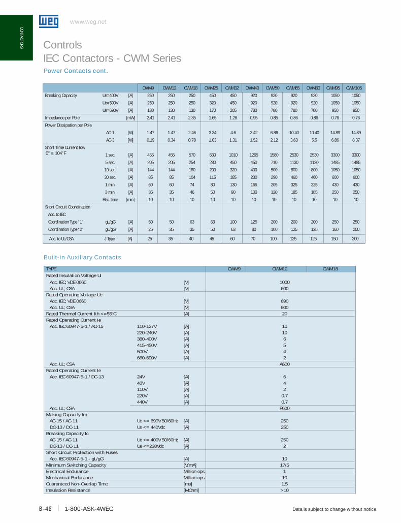
Power Contacts
Controls IEC Contactors - CWM Series
1-800-ASK-4WEGB-48
www.weg.net
Data is subject to change without notice.
coNTAcToRS
Built-in Auxiliary Contacts
TYPE CWM9 CWM12 CWM18
Rated Insulation Voltage ui
Acc. IEC; VDE 0660 [V] 1000 Acc. UL; CSA [V] 600Rated operating Voltage ue Acc. IEC; VDE 0660 [V] 690 Acc. UL; CSA [V] 600Rated Thermal current Ith <=55oc [A] 20Rated operating current Ie Acc. IEC 60947-5-1 / AC-15 110-127V [A] 10
220-240V [A] 10380-400V [A] 6415-450V [A] 5500V [A] 4660-690V [A] 2
Acc. UL; CSA A600Rated operating current Ie Acc. IEC 60947-5-1 / DC-13 24V [A] 6
48V [A] 4110V [A] 2220V [A] 0.7440V [A] 0.7
Acc. UL; CSA P600Making capacity Im AC-15 / AC-11 Ue <= 690V 50/60Hz [A] 250 DC-13 / DC-11 Ue <= 440Vdc [A] 250breaking capacity Ic AC-15 / AC-11 Ue <= 400V 50/60Hz [A] 250 DC-13 / DC-11 Ue <=220Vdc [A] 2Short circuit Protection with Fuses Acc. IEC 60947-5-1 - gL/gG [A] 10Minimum Switching capacity [V/mA] 17/5Electrical Endurance Million ops. 1Mechanical Endurance Million ops. 10Guaranteed Non-overlap Time [ms] 1.5Insulation Resistance [MOhm] >10
Controls IEC Contactors - CWM SeriesPower Contacts cont.
breaking capacity Ue=400V [A] 250 250 250 450 450 920 920 920 920 1050 1050
Ue=500V [A] 250 250 250 320 450 920 920 920 920 1050 1050
Ue=690V [A] 130 130 130 170 205 780 780 780 780 950 950
Impedance per Pole [mW] 2.41 2.41 2.35 1.65 1.28 0.95 0.85 0.86 0.86 0.76 0.76
Power dissipation per Pole
AC-1 [W] 1.47 1.47 2.46 3.34 4.6 3.42 6.86 10.40 10.40 14.89 14.89
AC-3 [W] 0.19 0.34 0.78 1.03 1.31 1.52 2.12 3.63 5.5 6.86 8.37
Short Time current Icw
1 sec. [A] 455 455 570 630 1010 1265 1580 2530 2530 3300 3300
5 sec. [A] 205 205 254 280 450 450 710 1130 1130 1485 1485
10 sec. [A] 144 144 180 200 320 400 500 800 800 1050 1050
30 sec. [A] 85 85 104 115 185 230 290 460 460 600 600
1 min. [A] 60 60 74 80 130 165 205 325 325 430 430
3 min. [A] 35 35 46 50 90 100 120 185 185 250 250
Rec. time [min.] 10 10 10 10 10 10 10 10 10 10 10
Short circuit coordination
Acc. to IEC
Coordination Type “1” gL/gG [A] 50 50 63 63 100 125 200 200 200 250 250
Coordination Type “2” gL/gG [A] 25 35 35 50 63 80 100 125 125 160 200
Acc. to UL/CSA J Type [A] 25 35 40 45 60 70 100 125 125 150 200
CWM9 CWM12 CWM18 CWM25 CWM32 CWM40 CWM50 CWM65 CWM80 CWM95 CWM105
Power Contacts cont.
0° ≤ 104°F

WEG Automation - Products and Solutions
www.weg.net
Data is subject to change without notice. B-49
coNT
AcTo
RS
Power Contact
Controls IEC Contactors - CWM Series
TYPE cWM112 cWM150 cWM180 cWM250 cWM300 cWM400 cWM630 cWM800
NEMA Ratings
Rated operating Voltage [V] 600
General Purpose Rating [A] 170 170 200 300 400 450 660 900
Switching Motor Loads
Full Voltage - 50/60Hz
1-phase 115V [A] - - - - - - - -
230V [A] - - - - - - - -
115V [HP] - - - - - - - -
230V [HP] - - - - - - - -
3-phase 200V [A] 120 150 177 221 285 359 414 552
230V [A] 130 154 192 248 312 360 480 772
460V [A] 124 156 180 240 302 361 477 -
575V [A] 99 144 192 242 336 289 382 -
200V [HP] 40 50 60 75 100 125 150 200
230V [HP] 50 60 75 100 125 150 200 300
460V [HP] 100 125 150 200 250 300 400 600
575V [HP] 100 150 200 250 350 300 400 600
Short circuit Rating 600V [kA] 10 10 10 18 18 18 30 30
Standard IEc Ratings (IEc/EN 60947)
Rated operating Voltage [V] 1000
Rated Thermal current Ith [A] 180 225 225 350 350 450 660 900
Switching Motor Loads
AC-3 - 50/60Hz
3-phase 220-240V [A] 112 150 180 250 300 400 630 800
380-400V [A] 112 150 180 250 300 400 630 800
415-440V [A] 112 150 180 250 300 400 630 800
500V [A] 95 130 155 220 265 350 500 720
660-690V [A] 82 110 135 185 220 300 420 630
220-240V [kW] 30 45 55 75 90 110 185 220
380-400V [kW] 55 75 90 132 160 220 330 450
415-440V [kW] 55 90 110 150 185 220 370 500
500V [kW] 55 90 110 160 200 220 330 500
660-690V [kW] 75 110 110 160 200 260 400 560
Maximum Switching Rate
AC-1 [ops/hr] 600 600 600 600 600 500 500 500
AC-3 [ops/hr] 600 600 600 600 600 500 500 500
no load [ops/hr] 1,000 1,000 1,000 1,000 1,000 1,000 1,000 1,000

www.weg.net
Data is subject to change without notice.1-800-ASK-4WEGB-50
coNTAcToRS
Power Contact cont.
Controls IEC Contactors - CWM Series
TYPE cWM112 cWM150 cWM180 cWM250 cWM300 cWM400 cWM500 cWM630 cWM800
AC-4
200,000 operations; <= 690V [A] 50 55 58 100 130 - - -
50/60Hz 220-230V [kW] 18.5 20 22 37 45 90 110 185
[HP] 25 27 30 50 60 125 150 250
380-400V [kW] 30 33 37 55 75 150 220 330
[HP] 40 44 50 75 100 200 300 450
415-440V [kW] 37 40 45 63 80 185 220 370
[HP] 50 54 60 84 107 250 300 500
500V [kW] 40 45 50 75 90 - - -
[HP] 54 60 67 100 121 - - -
660-690V [kW] 45 50 55 90 100 - - -
[HP] 600 67 75 121 133 - - -
Maximum Switching Rate [ops/hr] 150 150 150 150 150 - - -
Making capacity [A] 1430 1820 2100 2600 3000
breaking capacity
Ue<=400V [A] 1290 1350 1400 2000 - 4000 6300 8000
Ue=500V [A] 1290 1350 1400 2000 - 4000 6300 8000
Impedance per pole [mW] 0.5 0.5 0.45 0.3 0.3 - - -
Power dissipation per Pole
AC-1 [W] 16 25 21.6 35 45.7 - - -
AC-3 [W] 6.2 11.1 13.8 17.9 25.7 - - -
Short Time current Icw
°≤ 104°F 1 sec. [A] 3165 3763 4649 4427 - - - -
5 sec. [A] 1820 2164 2673 2546 - - - -
10 sec. [A] 1430 1700 2100 2000 - - - -
30 sec. [A] 826 980 1212 1155 - - - -
1 min. [A] 584 694 857 816 - - - -
3 min. [A] 337 401 495 471 - - - -
Recovery time [min.] 10 10 10 10 10 - - -
Short circuit coordination
Acc. to IEC
Coordination type “1” gL/gG [A] 315 355 355 500 630 630 800 1000
Coordination type “2” gL/gG [A] 224 250 250 400 500 - - -
Acc. to UL/CSA J Type [A] 250 350 400 500 700 700 900 1100
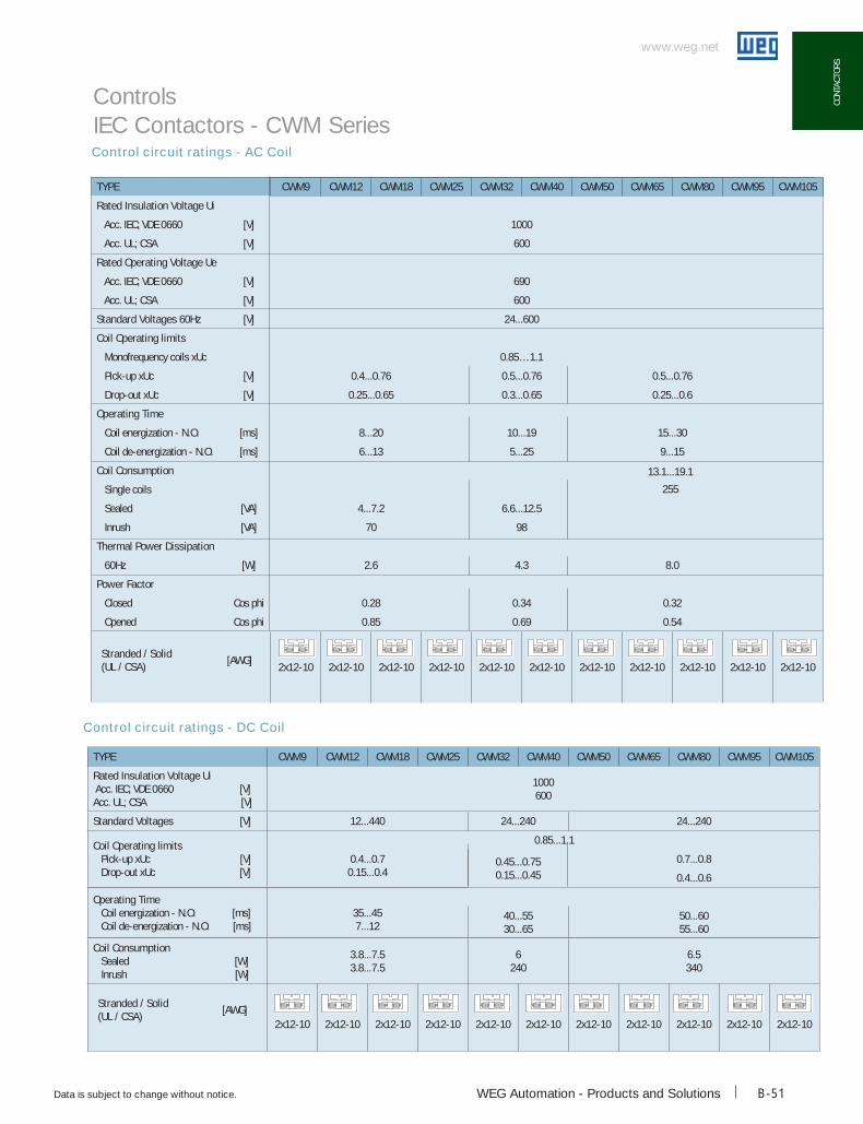
TYPE cWM9 cWM12 cWM18 cWM25 cWM32 cWM40 cWM50 cWM65 cWM80 cWM95 cWM105
Rated Insulation Voltage ui Acc. IEC; VDE 0660 [V]Acc. UL; CSA [V]
1000600
Standard Voltages [V] 12...440 24...240 24...240
coil operating limits Pick-up xUc [V] Drop-out xUc [V]
0.4...0.70.15...0.4
0.85...1.1
0.45...0.750.15...0.45
0.7...0.8
0.4...0.6
operating Time Coil energization - N.O. [ms] Coil de-energization - N.O. [ms]
35...457...12
40...5530...65
50...6055...60
coil consumption Sealed [W] Inrush [W]
3.8...7.53.8...7.5
6240
6.5340
Stranded / Solid(uL / cSA)
[AWG]2x12-10 2x12-10 2x12-10 2x12-10 2x12-10 2x12-10 2x12-10 2x12-10 2x12-10 2x12-10 2x12-10
WEG Automation - Products and Solutions
www.weg.net
Data is subject to change without notice. B-51
coNT
AcTo
RS
TYPE cWM9 cWM12 cWM18 cWM25 cWM32 cWM40 cWM50 cWM65 cWM80 cWM95 cWM105
Rated Insulation Voltage ui
Acc. IEC; VDE 0660 [V] 1000
Acc. UL; CSA [V] 600
Rated operating Voltage ue
Acc. IEC; VDE 0660 [V] 690
Acc. UL; CSA [V] 600
Standard Voltages 60hz [V] 24...600
coil operating limits
Monofrequency coils xUc 0.85…1.1
Pick-up xUc [V] 0.4...0.76 0.5...0.76 0.5...0.76
Drop-out xUc [V] 0.25...0.65 0.3...0.65 0.25...0.6
operating Time
Coil energization - N.O. [ms] 8...20 10...19 15...30
Coil de-energization - N.O. [ms] 6...13 5...25 9...15
coil consumption
Single coils
Sealed [VA] 4...7.2 6.6...12.5
Inrush [VA] 70 98
Thermal Power dissipation
60Hz [W] 2.6 4.3 8.0
Power Factor
Closed Cos phi 0.28 0.34 0.32
Opened Cos phi 0.85 0.69 0.54
Stranded / Solid(uL / cSA)
[AWG]2x12-10 2x12-10 2x12-10 2x12-10 2x12-10 2x12-10 2x12-10 2x12-10 2x12-10 2x12-10 2x12-10
Control circuit ratings - AC Coil
Control circuit ratings - DC Coil
Controls IEC Contactors - CWM Series
13.1...19.1
255
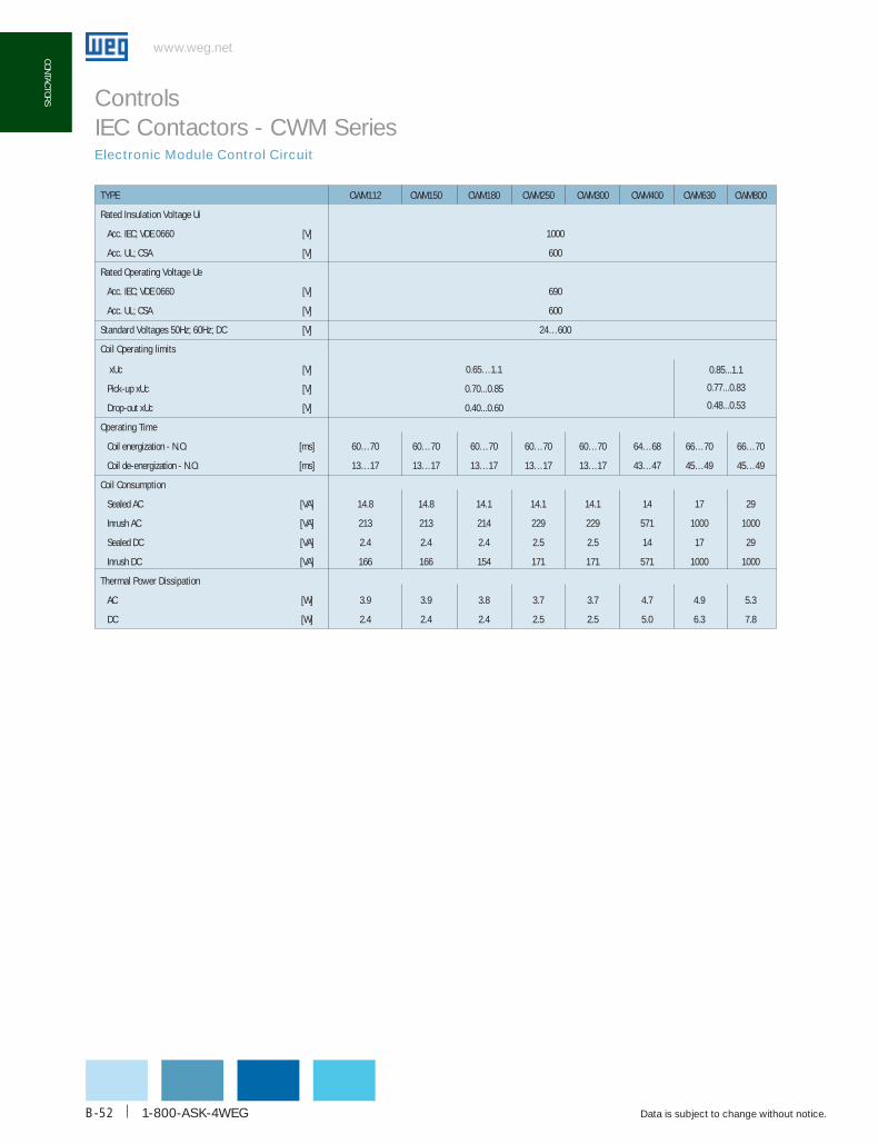
www.weg.net
Data is subject to change without notice.1-800-ASK-4WEGB-52
coNTAcToRS
Electronic Module Control Circuit
Controls IEC Contactors - CWM Series
TYPE CWM112 CWM150 CWM180 CWM250 CWM300 CWM400 CWM630 CWM800
Rated Insulation Voltage ui
Acc. IEC; VDE 0660 [V] 1000
Acc. UL; CSA [V] 600
Rated operating Voltage ue
Acc. IEC; VDE 0660 [V] 690
Acc. UL; CSA [V] 600
Standard Voltages 50hz; 60hz; dc [V] 24…600
coil operating limits
xUc [V] 0.65…1.1
Pick-up xUc [V] 0.70...0.85
Drop-out xUc [V] 0.40...0.60
operating Time
Coil energization - N.O. [ms] 60…70 60…70 60…70 60…70 60…70 64…68 66…70 66…70
Coil de-energization - N.O. [ms] 13…17 13…17 13…17 13…17 13…17 43…47 45…49 45…49
coil consumption
Sealed AC [VA] 14.8 14.8 14.1 14.1 14.1 14 17 29
Inrush AC [VA] 213 213 214 229 229 571 1000 1000
Sealed DC [VA] 2.4 2.4 2.4 2.5 2.5 14 17 29
Inrush DC [VA] 166 166 154 171 171 571 1000 1000
Thermal Power dissipation
AC [W] 3.9 3.9 3.8 3.7 3.7 4.7 4.9 5.3
DC [W] 2.4 2.4 2.4 2.5 2.5 5.0 6.3 7.8
0.85...1.1
0.77...0.83
0.48...0.53
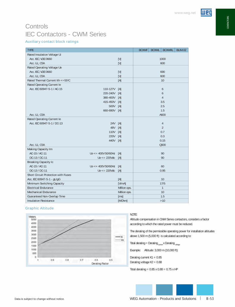
WEG Automation - Products and Solutions
www.weg.net
Data is subject to change without notice. B-53
coNT
AcTo
RS
TYPE bcXMF bcXML bcXMRL bLIM.02
Rated Insulation Voltage ui
Acc. IEC; VDE 0660 [V] 1000
Acc. UL; CSA [V] 600
Rated operating Voltage ue
Acc. IEC; VDE 0660 [V] 690
Acc. UL; CSA [V] 600
Rated Thermal current Ith <=55oC [A] 10
Rated operating current Ie
Acc. IEC 60947-5-1 / AC-15 110-127V [A] 6
220-240V [A] 6
380-400V [A] 4
415-450V [A] 3.5
500V [A] 2.5
660-690V [A] 1.5
Acc. UL; CSA A600
Rated operating current Ie
Acc. IEC 60947-5-1 / DC-13 24V [A] 4
48V [A] 2
110V [A] 0.7
220V [A] 0.3
440V [A] 0.15
Acc. UL; CSA Q600
Making capacity Im
AC-15 / AC-11 Ue <= 400V 50/60Hz [A] 90
DC-13 / DC-11 Ue <= 220Vdc [A] 90
breaking capacity Ic
AC-15 / AC-11 Ue <= 400V 50/60Hz [A] 60
DC-13 / DC-11 Ue <= 220Vdc [A] 0.95
Short circuit Protection with Fuses
Acc. IEC 60947-5-1 - gL/gG [A] 10
Minimum Switching capacity [V/mA] 17/5
Electrical Endurance Million ops. 1
Mechanical Endurance Million ops. 10
Guaranteed Non-overlap Time [ms] 1.5
Insulation Resistance [MOhm] >10
MetersNOTE:
Altitude compensation in CWM Series contactors, considers a factor
according to which the rated power must be reduced.
The derating of the permissible operating power for installation altitudes
above 1,500 m (5,000 ft) is calculated according to:
Total derating = Derating current x Derating voltage
Example: Altitude: 3,000 m (10,000 ft):
Derating current K1 = 0.85
Derating voltage K2 = 0.88
Total derating = 0.85 x 0.88 = 0.75 x HP
derating Factor
Graphic Altitude
Auxiliary contact block ratings
Controls IEC Contactors - CWM Series
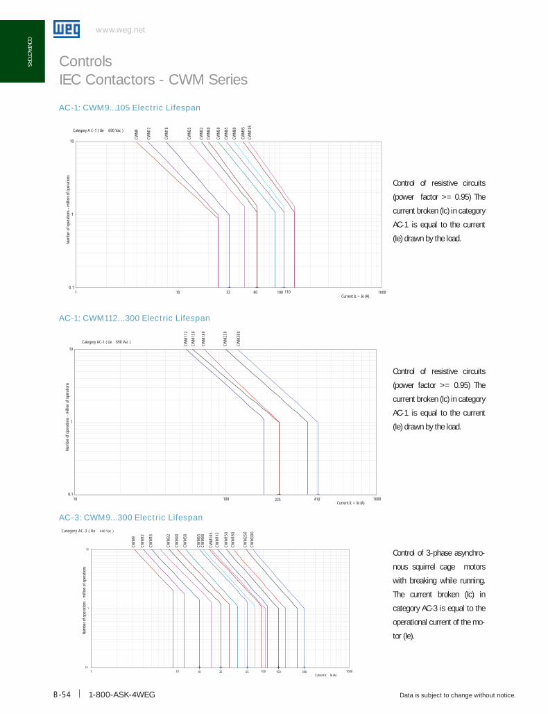
1-800-ASK-4WEGB-54
www.weg.net
Data is subject to change without notice.
coNTAcToRS
32 60 1100.1
1
10
1 10 100 1000Current Ic = Ie (A)
Num
ber o
f ope
ratio
ns -
mill
ion
of o
pera
tions
CWM
9
CWM
32
CWM
12
CWM
40
CWM
18
CWM
25
CWM
105
CWM
65
CWM
80
CWM
95
CWM
50Category A C-1 ( Ue 690 Vac )
225 4100.1
1
10
10 100 1000Current Ic = Ie (A)
Num
ber o
f ope
ratio
ns -
mill
ion
of o
pera
tions
CWM
112
CWM
150
CWM
250
CWM
180
CWM
300
Category AC-1 ( Ue 690 Vac )
Control of resistive circuits
(power factor >= 0.95) The
current broken (Ic) in category
AC-1 is equal to the current
(Ie) drawn by the load.
Control of resistive circuits
(power factor >= 0.95) The
current broken (Ic) in category
AC-1 is equal to the current
(Ie) drawn by the load.
Control of 3-phase asynchro-
nous squirrel cage motors
with breaking while running.
The current broken (Ic) in
category AC-3 is equal to the
operational current of the mo-
tor (Ie).
AC-1: CWM9...105 Electric Lifespan
AC-1: CWM112...300 Electric Lifespan
AC-3: CWM9...300 Electric Lifespan
Controls IEC Contactors - CWM Series
CW
M9
CW
M12
CW
M18
18 32
CW
M32
CW
M40
CW
M50
65
CW
M65
CW
M80
CW
M10
5
CW
M11
2
150
CW
M15
0
CW
M18
0
CW
M25
0
300
CW
M30
0
0 1
1
10
1 10 100 1000Current Ic Ie (A)
Num
ber o
f ope
ratio
ns -
mill
ion
of o
pera
tions
Category AC-3 ( Ue 440 Vac )

WEG Automation - Products and Solutions
www.weg.net
Data is subject to change without notice. B-55
coNT
AcTo
RS
Control of 3-phase asynchronous
squirrel cage motors with breaking
while motor stalled.
The current broken (Ic) in category
AC-4 is equal to 6 times the opera-
tional current of the motor (Ie).
Control of 3-phase asynchronous
squirrel cage motors with breaking
while motor stalled.
The current broken (Ic) in category
AC-4 is equal to 6 times the opera-
tional current of the motor (Ie).
In many applications there is a mixture of AC-3 and AC-4 duty. For these applications the electric
lifespan of a particular contactor can be estimated using the formula:
W
E= Estimated electric lifespan for mixed duty application.
AC-3= Number of electrical operations taken from the AC-3 Duty life curve.
AC-4= Number of electrical operations taken from the AC-4 Duty life curve.
P= Proportion of AC-4 operations to total operations for the application, expressed as a percentage.
CWM
9
CWM
12
CWM
18
CWM
25
CWM
32
CWM
40
CWM
50
CWM
65CW
M80
CWM
95CW
M10
5
30 72 180 3000.01
0.1
1
10
1 10 100 1000
Current Ic = 6 x Ie (A)
Num
ber o
f ope
ratio
ns -
mlli
on o
f ope
ratio
ns
Category AC-4 ( Ue 440 Vac )C
WM
112E
CW
M15
0E
CW
M18
0E
CW
M25
0E
1800
CW
M30
0E
0.01
0.1
1
10
10 100 1000 10000Current Ic = 6 x Ie (A)
Num
ber o
f ope
ratio
ns -
mill
ion
of o
pera
tions
Category AC-4 ( Ue 440 )
AC-4: CWM9...105 Electric Lifespan
AC-4: CWM112...300 Electric Lifespan
Controls IEC Contactors - CWM Series

www.weg.net
Data is subject to change without notice.1-800-ASK-4WEGB-56
coNTAcToRS
Electrical Lifespan
Ue ≤ 220-240 VAC
Ue ≤ 380-460 VAC
Rated operational current Ie (A)
Num
ber o
f ope
ratio
ns (1
05 )Nu
mbe
r of o
pera
tions
(105 )
Controls IEC Contactors - CWM Series

WEG Automation - Products and Solutions
www.weg.net
Data is subject to change without notice. B-57
coNT
AcTo
RS
BCXML BCXML BCXMF
BCXMF
144 [5.67]115 [4.53]
Vac Contactors Vdc Contactors
BCXML
BCXML
BCXMF
146 [5.75]117 [4.61]
147.29 [5.80]
118 [4.65]
5
BCXMLBCXML BCXMF
BCXMF
6 [4
Mechanical Drawings mm (in)
CWM9, CWM9N, CWM12, CWM18, and CWM18N
CWM25
CWM32, CWM32N and CWM40
Controls IEC & NEMA Contactors - CWM and CWM-N Series
Vac Contactors Vdc Contactors
Vac Contactors Vdc Contactors
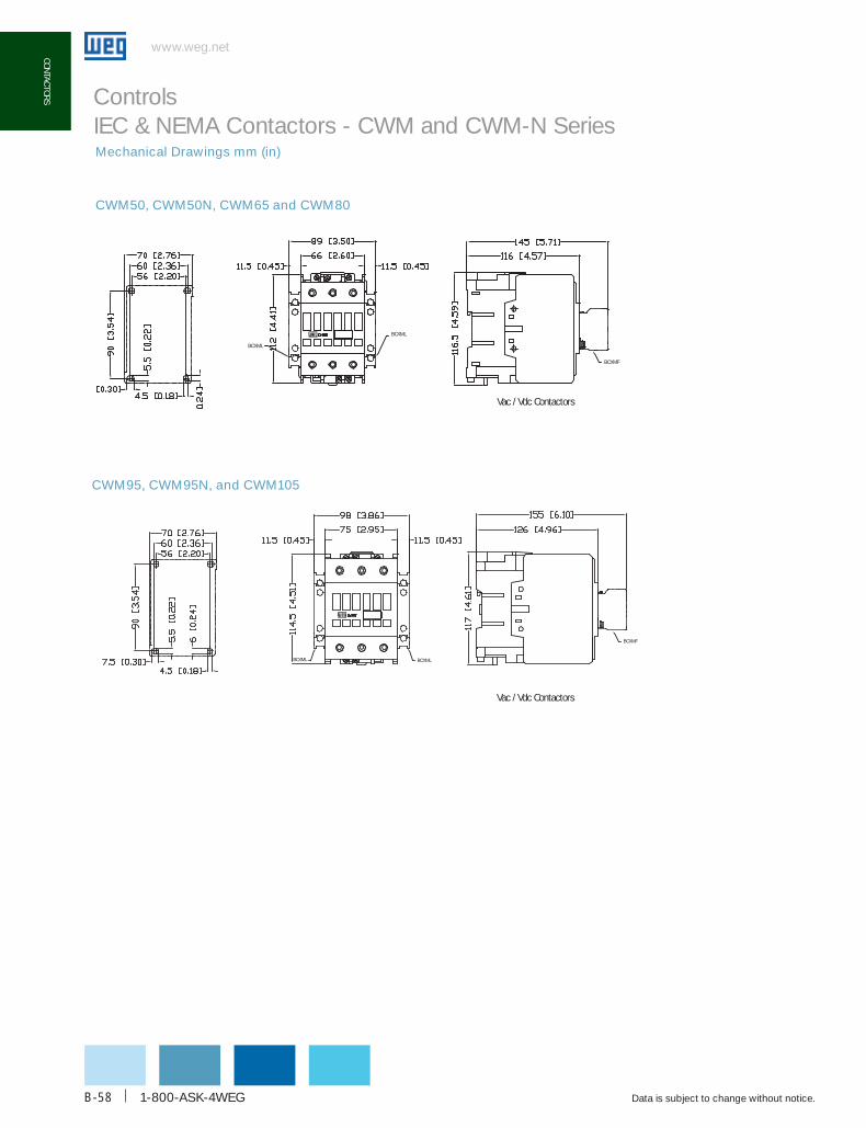
www.weg.net
Data is subject to change without notice.1-800-ASK-4WEGB-58
coNTAcToRS
BCXML
BCXML
BCXMF
Vac / Vdc Contactors
BCXML BCXML
BCXMF
Vac / Vdc Contactors
CWM95, CWM95N, and CWM105
Controls IEC & NEMA Contactors - CWM and CWM-N SeriesMechanical Drawings mm (in)
CWM50, CWM50N, CWM65 and CWM80
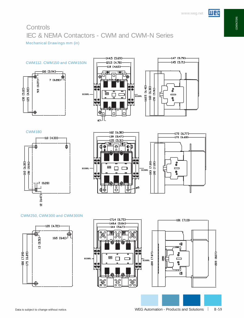
WEG Automation - Products and Solutions
www.weg.net
Data is subject to change without notice. B-59
coNT
AcTo
RS
Mechanical Drawings mm (in)
Controls IEC & NEMA Contactors - CWM and CWM-N Series
CWM180
CWM112. CWM150 and CWM150N
CWM250, CWM300 and CWM300N

www.weg.net
Data is subject to change without notice.1-800-ASK-4WEGB-60
coNTAcToRS
Mechanical Drawings mm (in)
CWM400
CWM630 and CWM800
Controls IEC & NEMA Contactors - CWM and CWM-N Series
80/ [3 16]
160/ [6 31]
6xØ
17/ [
Ø0.
67]
270/
[10.
62]
40/ [1 57]
329/
[12.
96]
243/ [9 58]
2xØ12/ [Ø0 47]
250/ [9 84]
250/
[9.8
4]
289/
[11.
38]
284/ [11 18]
R6/ [R0 24]
284/ [11 18]
310/
[12.
19]
20/ [
0.78
]
149/ [5 88]

WEG Automation - Products and Solutions
www.weg.net
Data is subject to change without notice. B-61
coNT
AcTo
RS
Mechanical Drawings mm (in)
CWM112 - CWM150 + LW1-S300 (contactor with lugs)
Controls IEC & NEMA Contactors - CWM and CWM-N Series

www.weg.net
Data is subject to change without notice.1-800-ASK-4WEGB-62
coNTAcToRS
Mechanical Drawings mm (in)
CWM180 + LW2-S300 (contactor with lugs)
Controls IEC & NEMA Contactors - CWM and CWM-N Series

WEG Automation - Products and Solutions
www.weg.net
Data is subject to change without notice. B-63
coNT
AcTo
RS
Mechanical Drawings mm (in)
CWM250 + LW1-S600 (contactor with lugs)
Controls IEC & NEMA Contactors - CWM and CWM-N Series

www.weg.net
Data is subject to change without notice.1-800-ASK-4WEGB-64
coNTAcToRS
www.weg.net
Mechanical Drawings mm (in)
CWM400 + BMJ (contactor with lugs)
Controls IEC & NEMA Contactors - CWM and CWM-N Series

WEG Automation - Products and Solutions
www.weg.net
Data is subject to change without notice. B-65
coNT
AcTo
RS
Mechanical Drawings mm (in)
CWM630-CWM800 + BMJ (contactor with lugs)
Controls IEC & NEMA Contactors - CWM and CWM-N Series
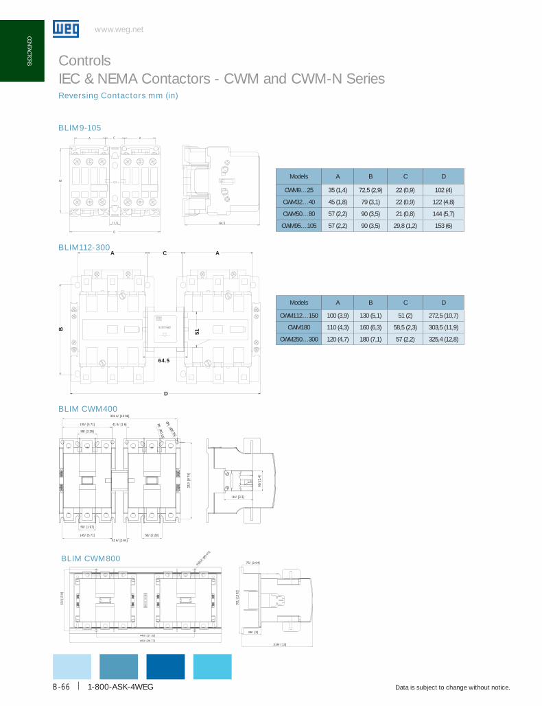
www.weg.net
Data is subject to change without notice.1-800-ASK-4WEGB-66
coNTAcToRS
BLIM9-105
A
B
C A
51
64.5
D
BLIM112-300
Controls IEC & NEMA Contactors - CWM and CWM-N SeriesReversing Contactors mm (in)
BLIM CWM400
BLIM CWM800
440/ [17 32]
4xØ12
/ [Ø0.4
72]
86/ [3]
318/ [13]
351/
[13
82]
321/
[12
64]
680/ [26 77]
75/ [2 94]
41 6/ [1 64]
60/
[2.4
]
84/ [3 3]
145/ [5 71]
222/
[874
]
50/ [1 97]
58/ [2 28]
145/ [5 71]
58/ [2 28]
41 6/ [1 6]
331 6/ [13 06]
Ø9
[Ø0
35]
R5 [R0.18]
Models A b c d
cWM9…25 35 (1,4) 72,5 (2,9) 22 (0,9) 102 (4)
cWM32…40 45 (1,8) 79 (3,1) 22 (0,9) 122 (4,8)
cWM50…80 57 (2,2) 90 (3,5) 21 (0,8) 144 (5,7)
cWM95…105 57 (2,2) 90 (3,5) 29,8 (1,2) 153 (6)
Models A b c d
cWM112…150 100 (3,9) 130 (5,1) 51 (2) 272,5 (10,7)
cWM180 110 (4,3) 160 (6,3) 58,5 (2,3) 303,5 (11,9)
cWM250…300 120 (4,7) 180 (7,1) 57 (2,2) 325,4 (12,8)
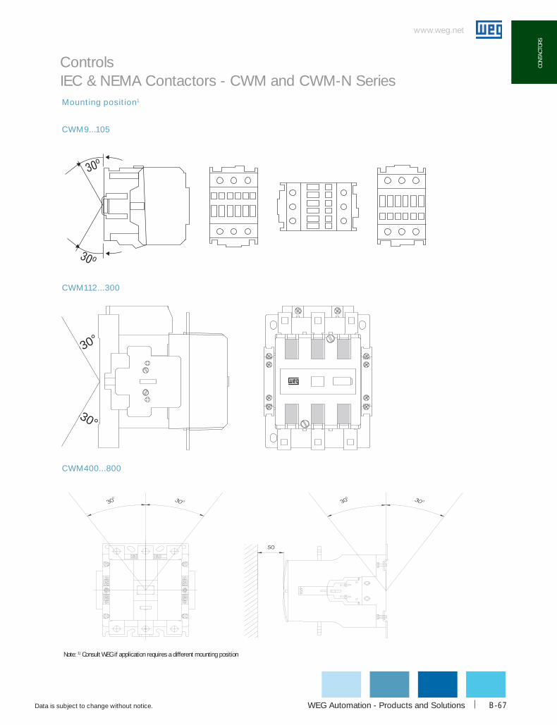
WEG Automation - Products and Solutions
www.weg.net
Data is subject to change without notice. B-67
coNT
AcTo
RS
CWM9...105
CWM112...300
Mounting position1
30°
30°
CWM400...800
Controls IEC & NEMA Contactors - CWM and CWM-N Series
Note: 1) Consult WEG if application requires a different mounting position

1-800-ASK-4WEG
www.weg.net
Data is subject to change without notice.B-68
RW SERIES
Rated for the new industryRW overload relays are an important part of WEG Controls’ range of products. As usual in WEG products, an extended operational service life is one of the main features you can find in RW overload relays.
WEG’s RW Class 10 Thermal Overload Relays are designed for use with, and as perfect compliment to, the CWC miniature and CWM standard contactors.
Effectively, RW overload relays can be mounted directly under WEG contactors, assuring electrical and mechanical operation as an open across-the-line starter, from fractional power to 75HP @ 460V. Accessories are also available for separate mounting. RW overload relays are available in compact frame sizes, from 0.28 to 840A.
Modern ArchitecturePrevious models of open overloads with “heaters” encounter problems in the field, includingg Inaccurate trip point, because of
uneven screw tightness when installed on the field, one phase at a time.
g Ambient problems, such as dust and other contaminants, because of their open design,
g Inability to protect in case of single phase failure,
g Nuisance tripping, because no temperature compensation is possible.
WEG overload relays’ modern design solves all of these problems. RW overload relays are fitted with fixed bimetallic elements, which eliminate any need for heater elements for field installation or future upgrading to a more efficient motor. All sizes provide complete motor protection by offering
g Ambient temperature compensation (-40F to +1400F)g Phase loss sensitivity protection,g Current unbalance sensitivity.
Dial FLA SettingThe trip-current is set via an infinitely adjustable dial designed with the motor’s full load current (FLA) in mind.
Temperature CompensationBecause RW overload relays include a fourth bimetallic strip in addition to the three that are directly heated by the motor current, ambient temperature variations in the range of -4ºF to +140ºF are no obstacle for accurate protection of your motors even in the toughest conditions.
Phase Failure SensitivityWEG overload relays include phase failure sensitivity protection as standard. This feature ensures fast tripping in case of phase loss, protecting your motor and avoiding expensive repairs / corrective maintenances.
Multi Function Button “R”The programmable RESET button can be selected to operate in a Manual or Automatic mode, with or without TEST capabilities of the isolated “trip” NC and “alarm” NO auxiliary contacts. The “R” multifunction RESET / TEST button can be set in four different positions; H (manual RESET only), HAND (manual RESET/TEST), AUTO (automatic RESET/TEST) and A (automatic RESET only).In HAND and AUTO positions, when gray R button is pushed, both N.O. 97-98 and N.C. 95-96 contacts change states.
Standards and Approvals
IEC 60947 and VDE 0660.
cULus
CE
Marine
Thermal Overload Relays
Controls - RW Series

WEG Automation - Products and Solutions
www.weg.net
Data is subject to change without notice. B-69
RW S
ERIE
S
Certifications
Controls Thermal Overload Relays - RW SeriesN OL
3 - U00427-1DRW
OVERLOAD RELAY SERIES:
RW: Thermal overload relay
POWER POLE:
3: 3 NO Power Poles 2: 2 NO Power Poles
OVERLOAD SETTING CURRENT:
RW17 D004: 0,28 ... 0,40A ... U032: 11 … 32A
RW27 D004: 0,28 ... 0,40A ... U032: 11 … 32A
RW67 U040: 25 ... 40A ... U080: 63 … 80A ________________________________ For more details refer to selection table
RW117 U080: 63 … 80A ... U112: 90 ... 112A
RW317 U150: 100 … 150A ... U420: 275 ... 420A
RW407 U600: 400 … 600A ... U840: 560 ... 840A
Catalog part number composition

1-800-ASK-4WEG
www.weg.net
Data is subject to change without notice.B-70
RW SERIES
Three-pole Thermal Overload Relay Class 10
Matching contactorSetting Range [A]
Max. Fuse [A] catalog Number List Price Multiplier SymbolMin. Max.
cWc07…cWc016cWcA0(Mini-contactor)
0.28 0.40 15 RW17-1d3-d004 $46 Z20.40 0.63 15 RW17-1d3-c063 $46 Z20.56 0.80 15 RW17-1d3-d008 $46 Z20.80 1.20 15 RW17-1d3-d012 $46 Z21.20 1.80 15 RW17-1d3-d018 $46 Z21.80 2.80 15 RW17-1d3-d028 $46 Z22.80 4.00 15 RW17-1d3-u004 $46 Z24.00 6.30 25 RW17-1d3-d063 $46 Z25.60 8.00 30 RW17-1d3-u008 $46 Z27.00 10.0 40 RW17-1d3-u010 $46 Z28.00 12.5 50 RW17-1d3-d125 $46 Z210.0 15.0 60 RW17-1d3-u015 $46 Z211.0 17.0 60 RW17-1d3-u017 $46 Z2
cWc025 (Mini-contactor)15.0 23.0 90 RW17-2d3-u023 $46 Z2
22.0 32.0 100 RW17-2d3-u032 $46 Z2
cWM9...cWM40cWM9N...cWM32N
0.28 0.40 15 RW27-1d3-d004 $50 Z20.40 0.63 15 RW27-1d3-c063 $50 Z20.56 0.80 15 RW27-1d3-d008 $50 Z20.80 1.20 15 RW27-1d3-d012 $50 Z21.20 1.80 15 RW27-1d3-d018 $50 Z21.80 2.80 15 RW27-1d3-d028 $50 Z22.80 4.00 15 RW27-1d3-u004 $50 Z24.00 6.30 25 RW27-1d3-d063 $50 Z25.60 8.00 30 RW27-1d3-u008 $50 Z27.00 10.0 40 RW27-1d3-u010 $50 Z28.00 12.5 50 RW27-1d3-d125 $50 Z210.0 15.0 60 RW27-1d3-u015 $50 Z211.0 17.0 60 RW27-1d3-u017 $50 Z215.0 23.0 90 RW27-1d3-u023 $50 Z222.0 32.0 90 RW27-1d3-u032 $50 Z2
cWM32...cWM40cWM32N
25.0 40.0 90 RW67-1d3-u040 $73 Z232.0 50.0 125 RW67-1d3-u050 $73 Z2
cWM50...cWM80cWM50N
25.0 40.0 90 RW67-2d3-u040 $85 Z232.0 50.0 125 RW67-2d3-u050 $85 Z240.0 57.0 150 RW67-2d3-u057 $85 Z250.0 63.0 150 RW67-2d3-u063 $85 Z257.0 70.0 175 RW67-2d3-u070 $85 Z263.0 80.0 175 RW67-2d3-u080 $110 Z2
cWM95...cWM105cWM95N
63.0 80.0 200 RW117-1d3-u080 $150 Z275.0 97.0 225 RW117-1d3-u097 $192 Z290.0 112 250 RW117-1d3-u112 $192 Z2
cWM112...cWM150cWM150N
75.0 97 225 RW117-2d3-u097 $232 Z290.0 112 250 RW117-2d3-u112 $232 Z2
cWM112…cWM300cWM300N
100 150 300 RW317-1d3-u150 $285 Z2140 215 350 RW317-1d3-u215 $285 Z2200 310 500 RW317-1d3-u310 $320 Z2
cWM400...cWM800275 420 700 RW317-1d3-u420 $320 Z2400 600 1000 RW407-1d3-u600 $690 Z2560 840 1250 RW407-1d3-u840 $690 Z2
Note: RW117-2D, RW317-1D and RW407-1D are for separate mounting - Connector links for contactors CWM112…CWM300 are available as an accessory on page B-59.
Controls Thermal Overload Relays - RW Series
g Adjustable tripping current g Phase-loss sensitivity g Tripping class 10 g Auxiliary contacts 1NO + 1NCg Temperature compensation from -40F to +1400Fg Hand/Auto/Reset button
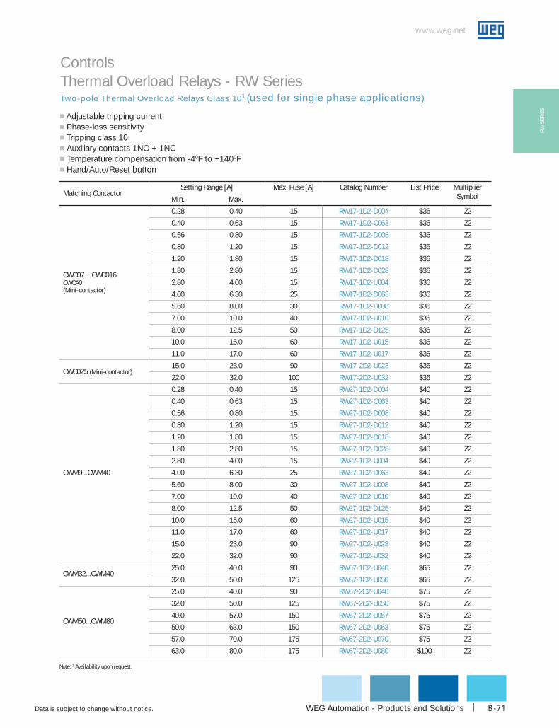
WEG Automation - Products and Solutions
www.weg.net
Data is subject to change without notice. B-71
RW S
ERIE
S
Two-pole Thermal Overload Relays Class 101 (used for single phase applications)
Controls Thermal Overload Relays - RW Series
g Adjustable tripping current g Phase-loss sensitivity g Tripping class 10 g Auxiliary contacts 1NO + 1NCg Temperature compensation from -40F to +1400Fg Hand/Auto/Reset button
Matching contactorSetting Range [A] Max. Fuse [A] catalog Number List Price Multiplier
SymbolMin. Max.
cWc07…cWc016cWcA0(Mini-contactor)
0.28 0.40 15 RW17-1d2-d004 $36 Z2
0.40 0.63 15 RW17-1d2-c063 $36 Z2
0.56 0.80 15 RW17-1d2-d008 $36 Z2
0.80 1.20 15 RW17-1d2-d012 $36 Z2
1.20 1.80 15 RW17-1d2-d018 $36 Z2
1.80 2.80 15 RW17-1d2-d028 $36 Z2
2.80 4.00 15 RW17-1d2-u004 $36 Z2
4.00 6.30 25 RW17-1d2-d063 $36 Z2
5.60 8.00 30 RW17-1d2-u008 $36 Z2
7.00 10.0 40 RW17-1d2-u010 $36 Z2
8.00 12.5 50 RW17-1d2-d125 $36 Z2
10.0 15.0 60 RW17-1d2-u015 $36 Z2
11.0 17.0 60 RW17-1d2-u017 $36 Z2
cWc025 (Mini-contactor)15.0 23.0 90 RW17-2d2-u023 $36 Z2
22.0 32.0 100 RW17-2d2-u032 $36 Z2
cWM9...cWM40
0.28 0.40 15 RW27-1d2-d004 $40 Z2
0.40 0.63 15 RW27-1d2-c063 $40 Z2
0.56 0.80 15 RW27-1d2-d008 $40 Z2
0.80 1.20 15 RW27-1d2-d012 $40 Z2
1.20 1.80 15 RW27-1d2-d018 $40 Z2
1.80 2.80 15 RW27-1d2-d028 $40 Z2
2.80 4.00 15 RW27-1d2-u004 $40 Z2
4.00 6.30 25 RW27-1d2-d063 $40 Z2
5.60 8.00 30 RW27-1d2-u008 $40 Z2
7.00 10.0 40 RW27-1d2-u010 $40 Z2
8.00 12.5 50 RW27-1d2-d125 $40 Z2
10.0 15.0 60 RW27-1d2-u015 $40 Z2
11.0 17.0 60 RW27-1d2-u017 $40 Z2
15.0 23.0 90 RW27-1d2-u023 $40 Z2
22.0 32.0 90 RW27-1d2-u032 $40 Z2
cWM32...cWM4025.0 40.0 90 RW67-1d2-u040 $65 Z2
32.0 50.0 125 RW67-1d2-u050 $65 Z2
cWM50...cWM80
25.0 40.0 90 RW67-2d2-u040 $75 Z2
32.0 50.0 125 RW67-2d2-u050 $75 Z2
40.0 57.0 150 RW67-2d2-u057 $75 Z2
50.0 63.0 150 RW67-2d2-u063 $75 Z2
57.0 70.0 175 RW67-2d2-u070 $75 Z2
63.0 80.0 175 RW67-2d2-u080 $100 Z2
Note: 1 Availability upon request.

1-800-ASK-4WEG
www.weg.net
Data is subject to change without notice.B-72
RW SERIES
description Mounting on overload Relays (2 or 3 pole) catalog Number List Price Multiplier Symbol
Enables overload relay to be directly mounted to a back panel via screws or DIN rail
RW27-1D bF27d $14 Z2
RW67-1D and RW67-2D bF67.1d $23 Z2
RW117-1D bF117d $26 Z2
description Mounting in cover of control Panel catalog Number List Price Multiplier Symbol
Enables overload relay to be Reset from control panel, without opening the cover
22 MM Flush Reset PB Blue 'R' cSW-RSbF4R $20 Z5
30 MM Flush Reset PB Black 'Reset' cSW30-RSbW $22 Z5
description contactor overload Relay catalog Number List Price Multiplier Symbol
Link connectors for easier CWM contactors and RW overload relays assembly
CWM112 RW117-2D3 GA117d $41 Z2CWM150 RW317-1D3 GA317-1d $68 Z2CWM180 RW317-1D3 GA317-2d $70 Z2
CWM250 / CWM300 RW317-1D3 GA317-3d $118 Z2CWM400 RW317-1D3 GA317-10d $118 Z2
Controls Thermal Overload Relays - RW Series
TYPE RW17d RW27d RW67d RW117d RW317d RW407d
StandardsDevices according to International Standards IEC 60947-1 / 60947-4-1, European Standards EN 60947-1 /
60947-4-1, Underwriters Laboratories - UL 508; CSA C.22.2/14; VDE 0660/102
Number of Poles 2 or 3
Tripping class 10
Phase Failure Sensitivity Yes
Temperature compensation Yes
Rated Insulation Voltage ui
Acc. IEC 60947-4-1 [V] 690 1000
Acc. UL; CSA [V] 600
Rated operation Voltage ue
Acc. IEC 60947-4-1 [V] 690 1000
Acc. UL; CSA [V] 600
Rated Impulse Voltage uimp [kV] 6
current
Direct YES NO
Alternating [Hz] up to 400 50/60
degree of Protection Protection against direct contact acc. VDE 0160 - Part 100 - IP20
Ambient Temperature
Storage -50 to +80ºC (-58 to 176ºF)
Operating -20 to +70ºC (-4 to 158ºF)
Ambient temperature compensation -20 to +60ºC (-4 to 140ºF)
Pollution degree 3
Mounting Direct on contactor or separately with accessory Separate
current heat Loss
Lower value of setting range (W) 0.9 0.9 1.5 2.3 1 1
Higher value of setting range (W) 1.4 1.7 4.7 4.7 1.9 1.9
Weight [kg] 0.15 0.15 0.31 0.52 2.30 3.12
[lb] 0.33 0.32 0.68 1.15 5.06 6.88
Shock Resistance
IEC 60 068 part 2-27 [g/ms]
Main Terminals capacity Cross / Slotted Combination1 Allen Head Slide Bar Slide Bar
Fine - Stranded with Sleeve [mm2] 1.5 - 10 1.5 - 10 6.0 - 35 6.0 - 35 - -
Coarse - Stranded / Solid [mm2] 1.5 - 6.0 1.5 - 6.0 6.0 - 35 25 - 35 - -
Slide Bars [mm2] - - - - 2x(25x5) 2x(60x10)
Stranded / Solid (UL / CSA) [AWG] 14 - 6 14 - 6 18 - 2 8 – 1/0 8 – 1/0 8 – 1/0
Tightening Torque [N.m] 1.4 - 2.3 1.4 - 2.3 4.0 - 6.0 4.0 - 6.0 14 - 26 23 - 26
[lb-in] 12.4 - 20.4 12.4 - 20.4 35.4 - 53.1 35.4 - 53.1 123.9 - 230.1 203.6 - 230.1
Short circuit Rating 600V [kA] 5 5 5 (40-57A)10(50-63A) 10 10 200
General Ratings
8/10
External Reset Button
Connector links (3 per package)
Separate Mounting Bracket
Assemblies with
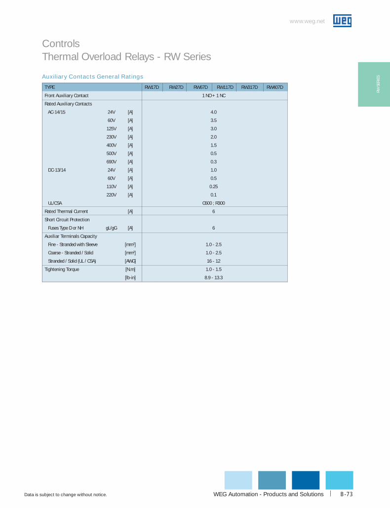
WEG Automation - Products and Solutions
www.weg.net
Data is subject to change without notice. B-73
RW S
ERIE
SAuxiliary Contacts General Ratings
TYPE RW17d RW27d RW67d RW117d RW317d RW407d
Front Auxiliary contact 1 NO + 1 NC
Rated Auxiliary contacts
AC-14/15 24V [A] 4.0
60V [A] 3.5
125V [A] 3.0
230V [A] 2.0
400V [A] 1.5
500V [A] 0.5
690V [A] 0.3
DC-13/14 24V [A] 1.0
60V [A] 0.5
110V [A] 0.25
220V [A] 0.1
UL/CSA C600 ; R300
Rated Thermal current [A] 6
Short circuit Protection
Fuses Type D or NH gL/gG [A] 6
Auxiliar Terminals capacity
Fine - Stranded with Sleeve [mm2] 1.0 - 2.5
Coarse - Stranded / Solid [mm2] 1.0 - 2.5
Stranded / Solid (UL / CSA) [AWG] 16 - 12
Tightening Torque [N.m] 1.0 - 1.5
[lb-in] 8.9 - 13.3
Controls Thermal Overload Relays - RW Series

1-800-ASK-4WEG
www.weg.net
Data is subject to change without notice.B-74
RW SERIES
The derating of the permissible operating current for installation altitudes above 2,000m
(6,667 ft) and ambient temperatures over 60ºC (140ºF) is calculated according to:
Total derating = Derating altitude x Derating ambient temperature
Example;
Altitude: 3,000 m (10,000 ft) K1 = 0.96
Ambient temperature: 70ºC (158ºF) K2 = 0.87
Total current derating = 0.96 x 0.87 = 0.84 x Ie
In this case, the maximum rated voltage we can connect to our RW overload relay is
550V.
In order to select the proper overload relay, you have to choose a device with a cur-
rent range that accommodates:
Overload Setting Point = FLAmotor / (K1 x K2)
As in the example above, K1 x K2 = 0.84
For a motor with FLA = 20Amps
Overload Setting Point = 20 / 0.84 = 23.8Amps
RW Tripping Characteristics
The derating of a RW overload relay has two possible factors:
1) Ambient temperature
• Temperature compensation considers a factor according to which the rated
current must be reduced when ambient temperature is higher than 60ºC (140ºF).
2) Altitude
• Altitude compensation involves both, rated current and voltage.
• Current compensation considers a factor according to the rated current
must be reduced.
• For voltage, altitude limits the higher operating voltage the overload relay
can be used.
Meters
Derating Factor
Controls Thermal Overload Relays - RW Series
These tripping characteristics show the tripping of RW in relation to the
current. They show the mean values of the tolerance ranges at on ambient
temperature of 68ºF (20ºC), starting from cold stats. The tripping time of the
overloa d releases at operational temperature is reduced to approximately
25% of the values shown.
Under normal operational conditions, all three phases of the RWs should
be loaded.
x Setting current
Altitude & Temperature Derating
149ºF158ºF167ºF176ºF
(65ºC)(70ºC)(75ºC)(80ºC)
Temperature Compensation
Altitude
Current Correction
Voltage Correction [Ue]

WEG Automation - Products and Solutions
www.weg.net
Data is subject to change without notice. B-75
RW S
ERIE
S
Operating Positions1
RW17D, RW27D, RW67D, RW117D, RW317D, RW407D
RW17D with CWC Series
RW27D, RW67D, RW117D, RW317D, RW407D with CWM/CWM Series
Mou ing w h contac or
Controls Thermal Overload Relays - RW Series
Th elay us b mou t
r ll , s
sho ed t t ri tio s
Mo t ng w
to 0º deg es no
180º, owever the mounting w h the elay above t
Mounting without contactor
The overload relays can be mounted at any position.
As showed at the left figure below, the inclination can not exceed ±30º degrees for a perfectly functioning of the contactor. Laterally, asshowed at the right figure below, the mounting position isequivalent to 0º degrees - not requiring a correction factor on thedial of the relay. The assembly can work with mounting variationsof 0º to 180º.
The mounting position showed at the left figure below is equivalentto 0º degrees - not requiring a correction factor on the dial of therelay. The assembly can work with mounting variations of 0º to135º for each side, however the mounting with the relay above the contactor,position between 135º and 225º, is required a correction factor of+10% on the dial of the relay. Laterally, as showed at the rightfigure below, the inclination can not exceed ± 30º for a perfectfunctioning of the contactor.
Note: 1 Please consult WEG for different mounting positions.
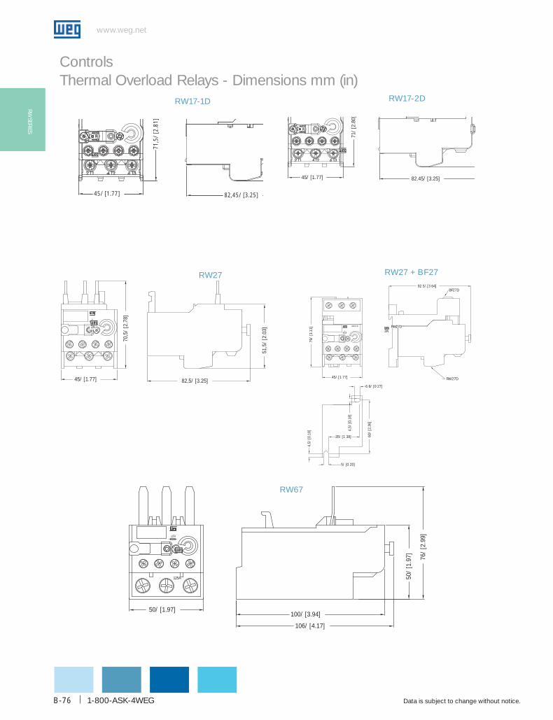
1-800-ASK-4WEG
www.weg.net
Data is subject to change without notice.B-76
RW SERIES
Controls Thermal Overload Relays - Dimensions mm (in)
RW17-1D
45/ [1.77]
71,5
/ [2
.81]
82,45/ [3.25]
RW17-2D
45/ [1.77]
71/
[2.8
0]
82.45/ [3.25]
RW27
82,5/ [3.25]
51,5
/ [2
.03]
45/ [1.77]
70,5
/ [2
.78]2A
RW27 + BF27
RW67
106/ [4.17]
100/ [3.94]50/ [1.97]
76/
[2.9
9]
50/
[1.9
7]
125A
RW27D
2A
79/
[3.1
1]
45/ [1 77]
60/
[2.3
6]
4,5/
[0.1
8]
6 8/ [0 27]
4,5/
[0.1
8]
35/ [1 38]
5/ [0 20]
RW27D
BF27D92 5/ [3 64]
2A RW27D2A
125A

WEG Automation - Products and Solutions
www.weg.net
Data is subject to change without notice. B-77
RW S
ERIE
S
Controls Thermal Overload Relays - Dimensions mm (in)
RW67 + BF67
RW117-1D RW117-2D
6,8/ [0.27]
4,5/
[0.1
8]
60/
[2.3
6]
7,5/ [0.30]
35/ [1.38]
4,5/
[0.1
8]
5/ [0.20]
50/ [1.97]
71/
[2.8
0]
100/ [3.94]
106/ [4.17]
BF67D
RW67
RW67D
1 5A
80,5
/ [3
.17]
99,5
/ [3
.92]
75/ [2.95]
24/ [0.94] 24/ [0.94]
8,4/ [0.33]
98,5/ [3.88]
20/
[0.7
9]
40/ [1.57] 3/ [0.12]
00A
106 2/ [4 18]
98 3/ [3 87]
106/
[417
]
7,4/
[029
]
5,4/
[021
]
7 4/ [0 29]
5 4/ [0 21]
56
75/ [2 95]
BF117D
116,
4/ [
8]
2 0A
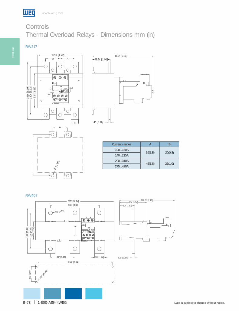
1-800-ASK-4WEG
www.weg.net
Data is subject to change without notice.B-78
RW SERIES
Controls Thermal Overload Relays - Dimensions mm (in)
RW317
RW407
93
/ [3
.66]
130/
[5.1
2]15
5/ [6
.10]
48,5/ [1.91]
120/ [4.72]7/
[028
]166/ [6.54]
4/ [0.16]
A A
B
5 A
250/ [9.84]
162/ [6.38]
260/ [10.24]
150/
[5.9
1]
O5/ [O
0.20]
50/
[1.9
7]11
9/ [4
.69]
60/
[2.3
6]
13/ [0.51]
182,5/ [7.19]
50/ [1.97]
90/ [3.54]
9,5/ [0.37]32/ [1.26]81/ [3.19]
1 5 A
A
current ranges A b
100...150A39(1.5) 20(0.8)
140...215A
200...310A45(1.8) 25(1.0)
275...420A
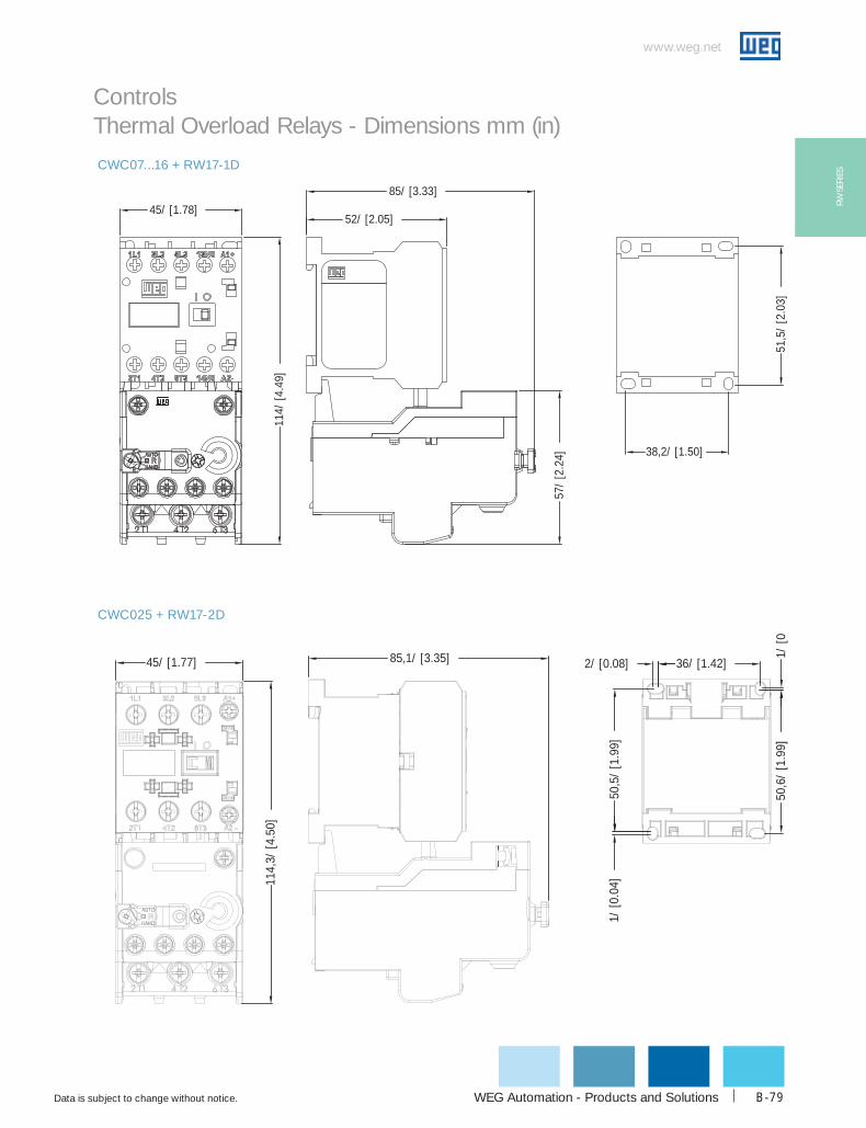
WEG Automation - Products and Solutions
www.weg.net
Data is subject to change without notice. B-79
RW S
ERIE
SCWC07...16 + RW17-1D
45/ [1.78]
38,2/ [1.50]
51,5
/ [2
.03]
85/ [3.33]
57/
[2.2
4]
114/
[4.4
9]
52/ [2.05]
CWC025 + RW17-2D
114,
3/ [4
.50]
85,1/ [3.35]45/ [1.77]
50,5
/ [1
.99]
1/ [0
.04]
2/ [0.08] 36/ [1.42]
50,6
/ [1
.99]
1/ [0
Controls Thermal Overload Relays - Dimensions mm (in)

1-800-ASK-4WEG
www.weg.net
Data is subject to change without notice.B-80
RW SERIES
CWM9...25 + RW27, CWM9N...CWM18N + RW27
CWM32 + RW27, CWM32N + RW27
A
2A
55/ [2.17]
138/
[5.4
3]
4,5/ [0.18]
79/
[3.1
1]
16,5
/ [0
.65]
12,5
/ [0
.49]
45/ [1.77]
98/ [3.86]A
cWM32 AAC coil 98(3.9)DC coil 118 (4.7)
Controls Thermal Overload Relays - Dimensions mm (in)
cWM9...25 AAC coil 94(3.7)DC coil 124(4.9)
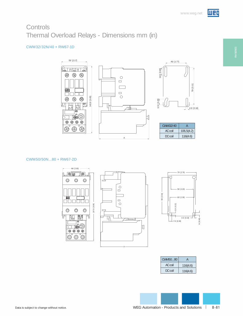
WEG Automation - Products and Solutions
www.weg.net
Data is subject to change without notice. B-81
RW S
ERIE
S
Controls Thermal Overload Relays - Dimensions mm (in)
CWM32/32N/40 + RW67-1D
CWM50/50N...80 + RW67-2D
66/ [2.60]
1 5A
167.
5/ [6
.59]
90/
[3.5
4]
56/ [2.20]
60/ [2.36]
70/ [2.76]
6/ [0
.24]
4.5/ [0.18]
5.5/
[0.2
2]
7.5/ [0.30]
A
cWM50...80 A
AC coil 116(4.6)
DC coil 116(4.6)
25A
55/ [2.17]
143,
5/ [5
.65]
4,5/ [0.18]
79/
[3.1
1]
16,5
/ [0
.65]
12,5
/ [0
.49]
45/ [1.77]
A
cWM32/40 A
AC coil 106,5(4.2)
DC coil 116(4.6)
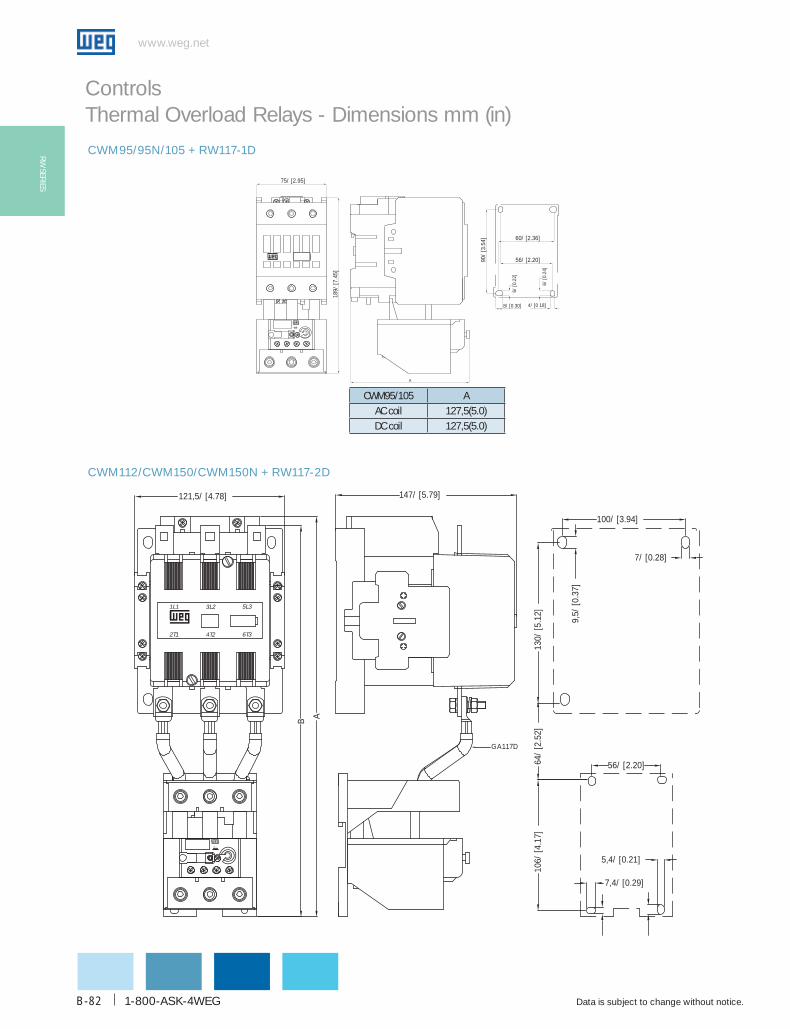
1-800-ASK-4WEG
www.weg.net
Data is subject to change without notice.B-82
RW SERIES
Controls Thermal Overload Relays - Dimensions mm (in)
CWM112/CWM150/CWM150N + RW117-2D
CWM95/95N/105 + RW117-1D
189/
[7.4
5]
2 A
75/ [2.95]
4/ [0 18]
6/ [0
.24]
60/ [2.36]
56/ [2.20]90/
[3.5
4]
8/ [0 30]
6/ [0
.22]
A
CWM95/105 AAC coil 127,5(5.0)DC coil 127,5(5.0)
GA117D
130/
[5.1
2]10
6/ [4
.17]
7,4/ [0.29]
5,4/ [0.21]
56/ [2.20]
147/ [5.79]
100/ [3.94]
9,5/
[0.3
7]
121,5/ [4.78]
4T2
3L2
2T1
1L1
7/ [0.28]
5L3
6T3
64/
[2.5
2]
AB
20 A
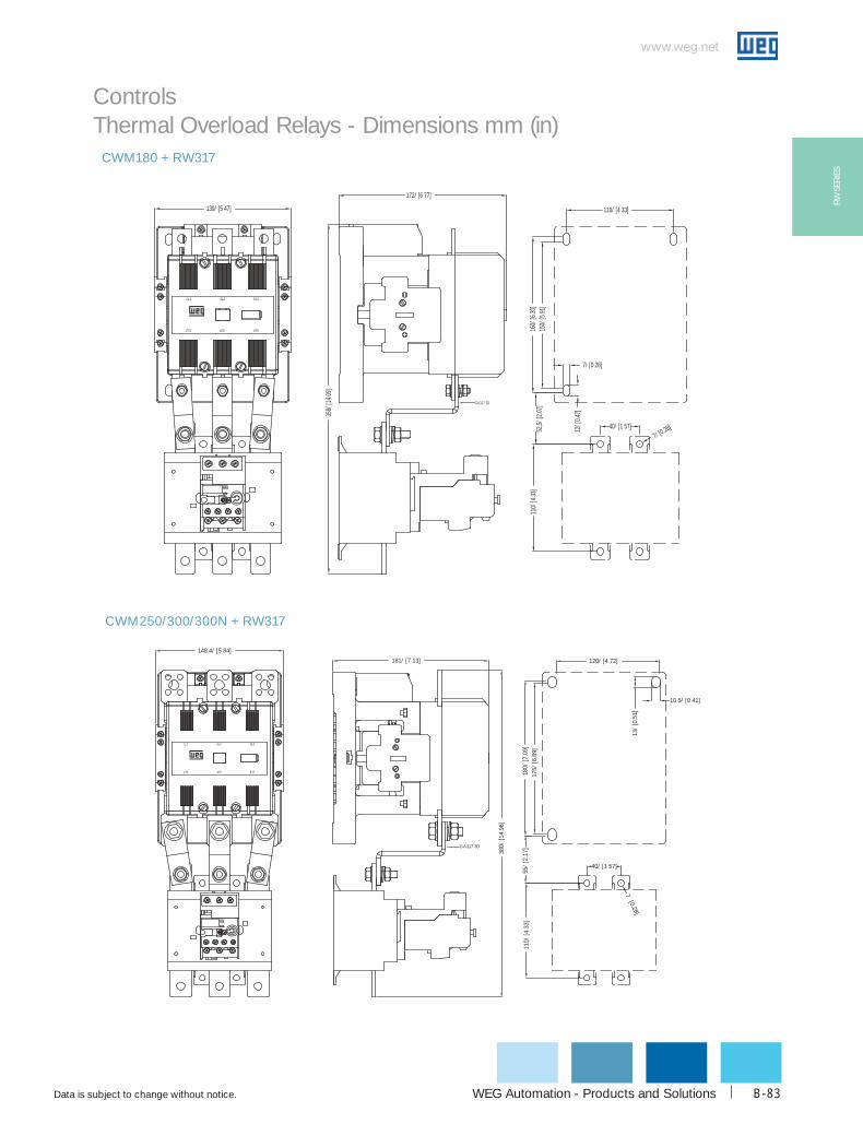
WEG Automation - Products and Solutions
www.weg.net
Data is subject to change without notice. B-83
RW S
ERIE
S
Controls Thermal Overload Relays - Dimensions mm (in)
CWM180 + RW317
5 A
12/ [
0.47]
160/
[6.30
]11
0/ [4
.33]
40/ [1 57]7/ [0.28]
110/ [4 33]
150/
[5.91
]
7/ [0 28]
5L3
6T32T1 4T2
1L1 3L2
52,5/
[2.07
]GA317 2D
172/ [6 77]
358/
[14.0
9]
139/ [5 47]
CWM250/300/300N + RW317
5A
181/ [7 13]
148 4/ [5 84]
1L1
2T1 4T2 6T3
5L33L2
380/
[14.
96]
175/
[6.8
9]18
0/ [7
.09]
120/ [4 72]
10 5/ [0 41]
13/
[0.5
1]
110/
[4.3
3]
40/ [1 57]
GA317 3D
55/
[2.1
7]
7 [0.28]
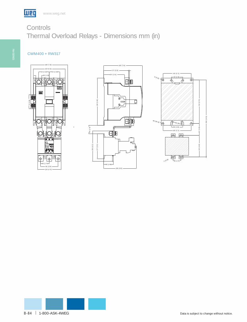
1-800-ASK-4WEG
www.weg.net
Data is subject to change without notice.B-84
RW SERIES
Controls Thermal Overload Relays - Dimensions mm (in)
CWM400 + RW317
30/ [1 19]
54/ [2 13] 54/ [2 13]
45/ [1 77]
90/ [3 54]
120/ [4 73]
163/ [6 42]
188/ [7 39]
72/
[2.8
4]
127/
[5.0
1]
155/
[6.1
1]
44/
[173
]
240/
[946
]
50/ [1 98]
168/ [6 62]
107/ [4 22]
127/ [5 02] 6
198/ [7 81]
145/ [5 71]
58/ [2 28]
58/ [2 28]
145/ [5 71]
110/
[4.3
4]
40/ [1 57]
222/
[874
]62
/ [2
.43]
394/
[15.
51]
7/ [0.28]
R5/ [R0 18] R5/ [R0 18]
9/ [0 35]

WEG Automation - Products and Solutions
www.weg.net
Data is subject to change without notice. B-85
SRW
01 S
ERIE
S
Smart Relay SRW01Controls
VersatilityThe SRW01 supports the following communication network protocols: DeviceNet, Modbus-RTU, and ProfiBus-DP. The communication modules can be easily exchanged due to plug-and-play capabilities. An HMI also can be used for quick system monitoring and relay parameterization. Additionally, the SRW01 provides a USB port for relay monitoring and programming through PC when using WLP software. The SRW01 includes a thermal memory circuit in order to maintain a motor thermal image, even if power supply is removed.
FlexibilityThe SRW01 modular concept allows easy functionality expansions. The control unit can also be mechanically assembled with the control measurement unit or separately (up to 2 meters), allowing system integration versatility.
The relay offers pre-programmed operating modes that perform various types of standard starting or monitoring conditions. Its friendly parameterization mode allows users to program the relay according to their needs.
The SRW01 is a low-voltage electric motor management system with
state-of-the-art technology and network communication capabilities.
Additionally, its modular concept allows to be used in various applications.
Certifications

1-800-ASK-4WEG
www.weg.net
Data is subject to change without notice.B-86
SRW01 SERIES
Controls Smart Relays - SRW01 Series
The SRW01 incorporates a main control unit (SRW01-UC) and a current measurement unit (SRW01-UMC) to provide flexible assembly options.
The SRW01-UC and SRW01-UMC are electrically connected using the SRW01-CB flat cable.
The interface with the relay may be performed in three ways:
g Via Fieldbus (ModBus, DeviceNet, Profibus)g Via Keypad (SRW01-IHM)g Via software – WLP (USB)
Through Fieldbus, the user can operate, monitor, and configure the SRW01 remotely, via PLC or supervisory system.
Modular Design

WEG Automation - Products and Solutions
www.weg.net
Data is subject to change without notice. B-87
SRW
01 S
ERIE
S
Controls Smart Relays - SRW01 Series
The SRW01 relay has a (110...240Vac / Vdc) supply voltage range, making system integration flexible. The reduced size of SRW01-UC, with a width of 45mm and
height of 100mm, makes it a compact product
The SRW01-UC control unit provides LED indicators for input and output activations, status, operation mode, power supply status, failure and alarm status.The assembly of the control unit can be done either by 35mm DIN rail or onto back panel mounting.
Communication protocols: DeviceNet, Modbus, and Profibus are defined using proper protocol installed in the communication drawer.
The plug and play concept automatically recognizes and configures the SRW01 for safe operation avoiding manual error connections.
ProfiBus - DPnetwork connection
ModBus, DeviceNetor ProfiBus - DP connection
Mini USB port
Connection forHMI and accessories
Communication module
Reset button
Characteristics

1-800-ASK-4WEG
www.weg.net
Data is subject to change without notice.B-88
SRW01 SERIES
Controls Smart Relays - SRW01 Series
Width (mm) Current (A) Power connection
45
0.25 - 2.5
Cable through UMC0.5 - 5
1.25 - 12.5
2.5 - 25
Width (mm) Current (A) Power connection
66 12.5 - 125 Cable through UMC
Width (mm) Current (A) Power connection
120 42 - 420 Busbar
Width (mm) Current (A) Power connection
265 84 - 840 Cable through UMC or busbar
SRW01-CB connection cableThe SRW01-CB connects the control units SRW01-UC to the current measuring unit SRW01-UMC allowing the two units to be separate assembled up to 2 meters.
Current Measuring Units
The current measuring unit SRW01-UMC shall be chose according to motor rated current ranging from 0.25A through 840A

WEG Automation - Products and Solutions
www.weg.net
Data is subject to change without notice. B-89
SRW
01 S
ERIE
S
Controls Smart Relays - SRW01 SeriesFunctionsThe SRW01 protection, monitoring and operating functions enhance system protection reliability and precision. The operating modes are auto-adjustable, meaning the user selects the operating mode and the relay automatically search for proper parameters. This feature ensures quick and safe parameterization, allowing motor monitoring. Its friendly parameterization mode allows users to access all digital inputs and outputs, thus increasing flexibility to cover many applications.
Protectiong Overload protection (adjustable tripping class 5-45).g Thermal protection via PTC.g Phase loss protection.g Protection against current umbalance between phases.g Protection against overcurrent and locked rotor.g Protection against undercurrent.g Internal ground fault protection.g Protection against out of range frequency.
Operating Modes1
g Transparent operation - Digital input and output can be configured according to application needs .
g Operation as overload relay – similar to an overload relay.
g Direct starter - direct-on-line starter for single and three phase motors
g Reversing starter - reversing starter for three phase motors.
g Star-Delta starter - star-delta starter for three phase motors.
g Dahlander starter- starter for Dahlander three phase motors.
g Two windings starter - starter for two windings three phase motors.
g PLC mode – similar to the running of a PLC. In this mode the SRW01 – UMC current measuring
unit is not used.
Monitoringg Digital input and output activation.g RMS current of each phase and average in amperes or % of In adjusted current.g Motor frequencyg Number of activation per failute type.g Number of start ups.g Motor running hours.g Relay running hours.g Phase umbalance levels.g Internal ground fault current.
1 When applicable, additional power components are required.
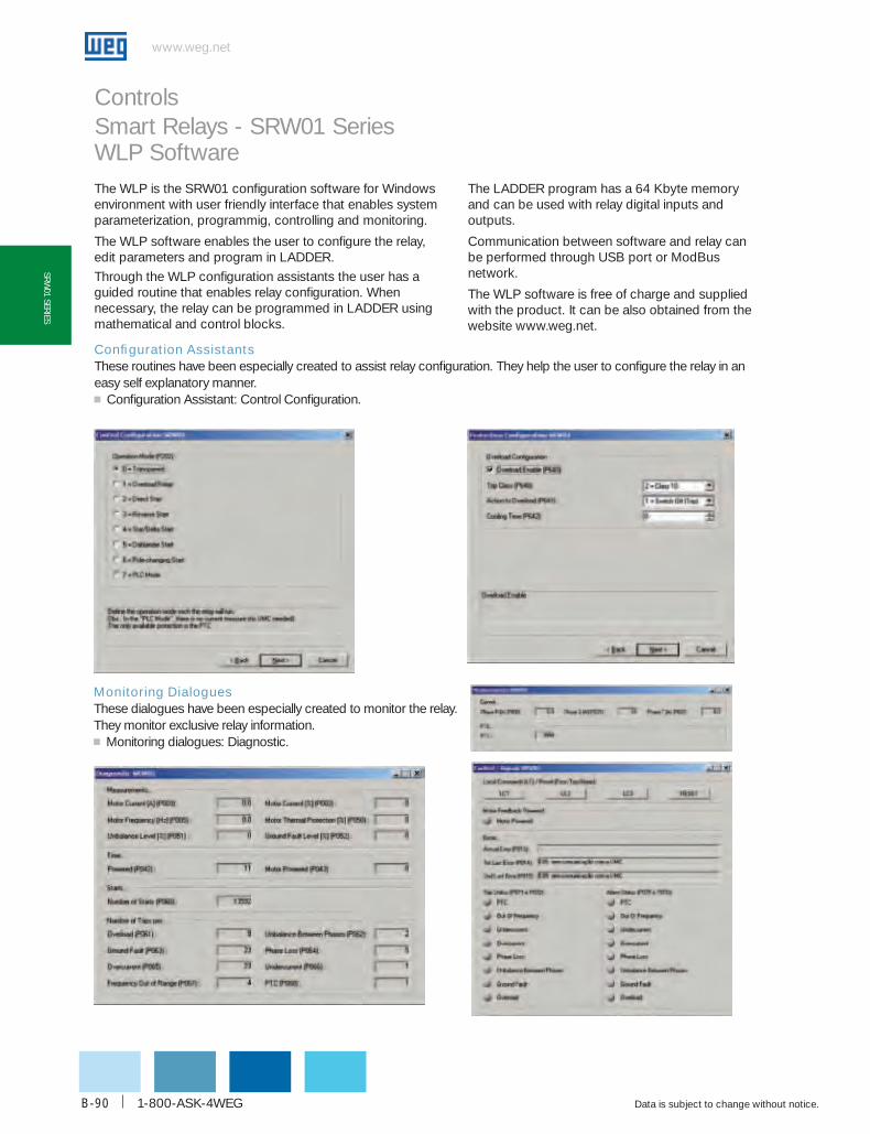
1-800-ASK-4WEG
www.weg.net
Data is subject to change without notice.B-90
SRW01 SERIES
Controls Smart Relays - SRW01 SeriesWLP SoftwareThe WLP is the SRW01 configuration software for Windows environment with user friendly interface that enables system parameterization, programmig, controlling and monitoring.
The WLP software enables the user to configure the relay, edit parameters and program in LADDER. Through the WLP configuration assistants the user has a guided routine that enables relay configuration. When necessary, the relay can be programmed in LADDER using mathematical and control blocks.
The LADDER program has a 64 Kbyte memory and can be used with relay digital inputs and outputs.
Communication between software and relay can be performed through USB port or ModBus network.
The WLP software is free of charge and supplied with the product. It can be also obtained from the website www.weg.net.
Configuration AssistantsThese routines have been especially created to assist relay configuration. They help the user to configure the relay in an easy self explanatory manner.g Configuration Assistant: Control Configuration.
Monitoring DialoguesThese dialogues have been especially created to monitor the relay. They monitor exclusive relay information.g Monitoring dialogues: Diagnostic.
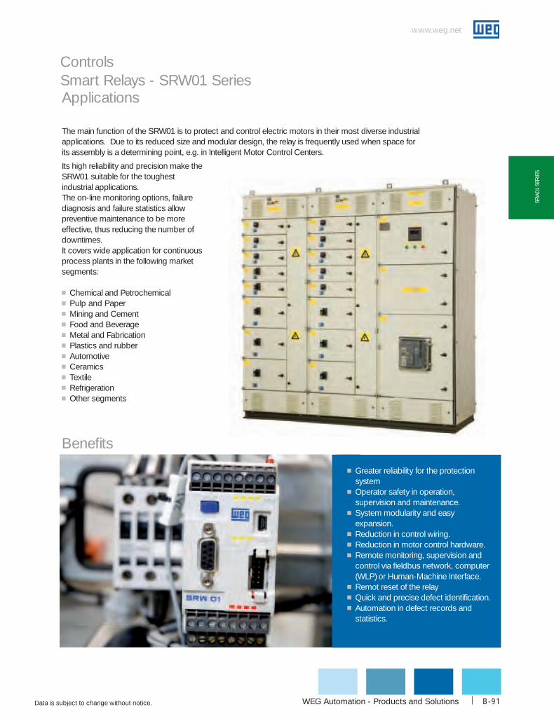
WEG Automation - Products and Solutions
www.weg.net
Data is subject to change without notice. B-91
SRW
01 S
ERIE
S
Controls Smart Relays - SRW01 SeriesApplications
The main function of the SRW01 is to protect and control electric motors in their most diverse industrial applications. Due to its reduced size and modular design, the relay is frequently used when space for its assembly is a determining point, e.g. in Intelligent Motor Control Centers.
Its high reliability and precision make the SRW01 suitable for the toughest industrial applications.The on-line monitoring options, failure diagnosis and failure statistics allow preventive maintenance to be more effective, thus reducing the number of downtimes. It covers wide application for continuous process plants in the following market segments:
g Chemical and Petrochemicalg Pulp and Paperg Mining and Cementg Food and Beverageg Metal and Fabricationg Plastics and rubberg Automotiveg Ceramicsg Textileg Refrigerationg Other segments
Benefits
g Greater reliability for the protection system
g Operator safety in operation, supervision and maintenance.
g System modularity and easy expansion.
g Reduction in control wiring.g Reduction in motor control hardware.g Remote monitoring, supervision and
control via fieldbus network, computer (WLP) or Human-Machine Interface.
g Remot reset of the relayg Quick and precise defect identification.g Automation in defect records and
statistics.

1-800-ASK-4WEG
www.weg.net
Data is subject to change without notice.B-92
SRW01 SERIES
Controls Smart Relays - SRW01 Series
Selection guide
Current range1 = 0.5...5 A2 = 1.25....12.5 A3 = 2.5...25 A4 = 12.5...125 A5 = 42...420 A6 = 84...840 A
SRW01-UMC 1
UMC - Current Measuring Unit
For current range of 0.25 to 2.5A pass the cable twice through the primary when using SRW01 – UMC1 .
UC - Control Unit
Supply voltageE47 = 110-240Vac / Vdc
Communication protocolB = without communicationD = DeviceNetM = ModBusP = ProfiBus
SRW01-U C T E47
Digital input operating voltage1 = 24Vdc2 = 110Vac
Terminal S1-S2 FunctionT = PTC
Supply Voltage
catalog Number List PriceMult.
Symbol
110-240Vac/Vdc
SRW01-ucbT1E47 $ 680.00
Z8
SRW01-ucbT2E47 $ 680.00 SRW01-ucdT1E47 $ 770.00 SRW01-ucdT2E47 $ 770.00 SRW01-ucMT1E47 $845.00 SRW01-ucMT2E47 $ 845.00 SRW01-ucPT1E47 $ 1010.00 SRW01-ucPT2E47 $ 1010.00
current Range
catalog Number List PriceMult.
Symbol0.5 ... 5A SRW01-uMc1 $ 290.00
Z8
1.25 ... 12.5A SRW01-uMc2 $ 290.00 2.5 ... 25A SRW01-uMc3 $ 290.00
12.5 ... 125A SRW01-uMc4 $ 480.00 42 ... 420A SRW01-uMc5 $ 600.00 84 ... 840A SRW01-uMc6 $ 800.00
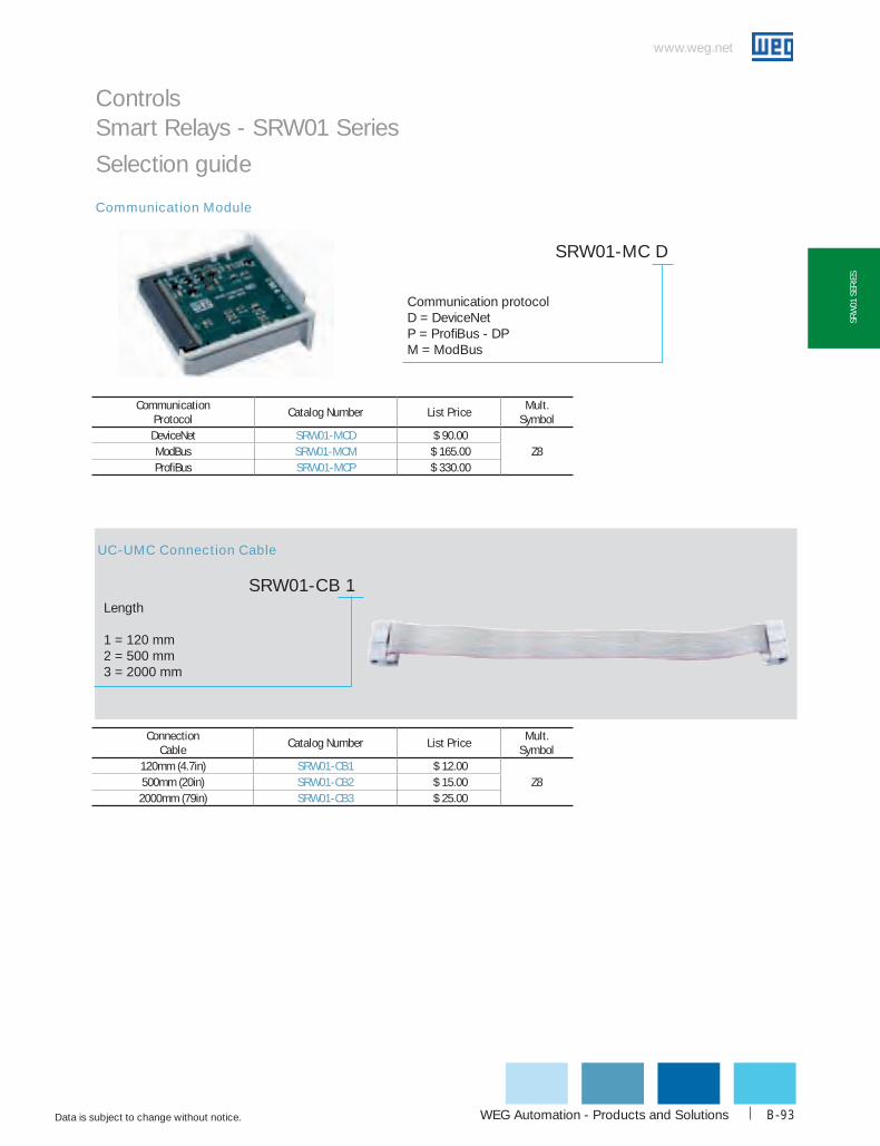
WEG Automation - Products and Solutions
www.weg.net
Data is subject to change without notice. B-93
SRW
01 S
ERIE
S
Controls Smart Relays - SRW01 Series
Communication protocolD = DeviceNetP = ProfiBus - DPM = ModBus
SRW01-MC D
Length
1 = 120 mm2 = 500 mm3 = 2000 mm
SRW01-CB 1
Communication Module
UC-UMC Connection Cable
Selection guide
connection cable
catalog Number List PriceMult.
Symbol120mm (4.7in) SRW01-cb1 $ 12.00
Z8500mm (20in) SRW01-cb2 $ 15.00 2000mm (79in) SRW01-cb3 $ 25.00
communication Protocol
catalog Number List PriceMult.
SymbolDeviceNet SRW01-Mcd $ 90.00
Z8ModBus SRW01-McM $ 165.00 ProfiBus SRW01-McP $ 330.00
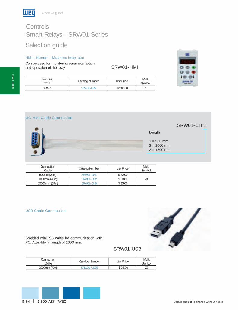
1-800-ASK-4WEG
www.weg.net
Data is subject to change without notice.B-94
SRW01 SERIES
Controls Smart Relays - SRW01 Series
Selection guide
HMI - Human - Machine Interface
Can be used for monitoring parameterization and operation of the relay SRW01-HMI
UC-HMI Cable Connection
USB Cable Connection
Shielded miniUSB cable for communication with PC. Available in length of 2000 mm.
SRW01-USB
SRW01-CH 1Length
1 = 500 mm2 = 1000 mm3 = 1500 mm
For use with
catalog Number List PriceMult.
Symbol
SRW01 SRW01-IhM $ 210.00 Z8
connection cable
catalog Number List PriceMult.
Symbol500mm (20in) SRW01-ch1 $ 22.00
Z81000mm (40in) SRW01-ch2 $ 30.00 15000mm (59in) SRW01-ch3 $ 35.00
connection cable
catalog Number List PriceMult.
Symbol2000mm (79in) SRW01-uSb5 $ 35.00 Z8

WEG Automation - Products and Solutions
www.weg.net
Data is subject to change without notice. B-95
SRW
01 S
ERIE
S
Controls Smart Relays - SRW01 Series
Available for UMC6 only
SRW01-BARBus bar for UMC
Adaptor for screw mounting.
Note: Quantity per package: 2 pieces.
PLMP
Fixing adaptor
For use with
catalog Number List PriceMult.
SymbolSRW01 PLMP $ 0.50 Z8
For use with
catalog Number List PriceMult.
Symbol
UMC6 only SRW01-bAR $ 260.00 Z8
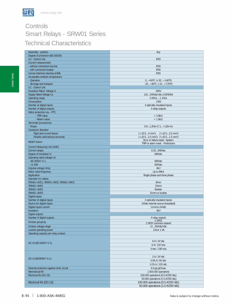
1-800-ASK-4WEG
www.weg.net
Data is subject to change without notice.B-96
SRW01 SERIES
Controls Smart Relays - SRW01 SeriesTechnical Characteristics
Assembly position Any Degree of protection (IEC 60529)UC - Control Unit IP20Current measurement: - without connection bus bar IP20- with connection busbar IP00Human Machine Interface (HMI) IP20Acceptable ambient temperature:- Operation 0...+60ºC (+32...+1400F)- Strorage and transport -25...+80ºC (-10...+1760F)UC - Control UnitInsulation Rated Voltage Ui 300VSupply Rated Voltage Us 110...240Vac/Vdc a 50/60HzOperating range 0.90Us ...1.10Us Consumption 13W Number of digital inputs 4 optically insulated inputsNumber of digital outputs 4 relay outputsMotor protection via – PTC:
- TRIP value > 3.9kΩ- Rearm value < 1.6kΩ
Terminals (connectors)- Torque 0.8...1.2Nm (7.1...+11lb-in)Conductor diameter: Rigid and no end sleeve 1 x (0.5...4 mm2); 2 x (0.5...2.5 mm2) Flexible with/without terminals 1 x (0.5...2.5 mm2); 2 x (0.5...1.5 mm2)
RESET buttonError or failure reset– System
TRIP or alarm reset - Protections Current Measuring Unit (UMC)Current ranges 0.25...840AacDegree of insulation Ui 690VacOperating rated voltage Ue - IEC 60947-4-1 690Vac - UL 508 600VacImpulse voltage Uimp 6kVMotor rated frequency Up to 99HzApplication Single phase and three phaseDiameter for cables:SRW01-UMC1, SRW01-UMC2, SRW01-UMC3 8mmSRW01-UMC4 15mmSRW01-UMC5 BusbarSRW01-UMC6 31mm or busbarDigital inputsNumber of digital inputs 4 optically insulated inputsSource for digital inputs 24Vdc internal source (insulated)Digital inputs current 11mA to 24VdcInsulation 3kVDigital outputsNumber of digital outputs 4 relay outputs
Contact grouping 2 SPST2 SPST commom shared
Contact voltage range 12...250Vac/VdcLowest operating power 1W or 1 VAOperating capacity per relay contact:
AC-15 (IEC 60947-5-1)6 A / 24 Vac
6 A / 120 Vca3 Aac / 230 Vca
DC-13 (IEC60947-5-1)2 A / 24 Vdc
0.55 A / 60 Vdc0.25 A / 125 Vdc
External protection against short circuit 6 A gL/gG fuseMechanical life 1.000.000 operationsElectrical life (AC-15): 100.000 operations (0.5 A/250 Vac)
50.000 operations (1.5 A/250 Vac)Electrical life (DC-13): 100.000 operations (0.5 A/250 Vdc)
50.000 operations (1.5 A/250 Vdc)

WEG Automation - Products and Solutions
www.weg.net
Data is subject to change without notice. B-97
SRW
01 S
ERIE
S
Controls Smart Relays - SRW01 Series
Dimensions (mm)SRW01-UC - Control Unit
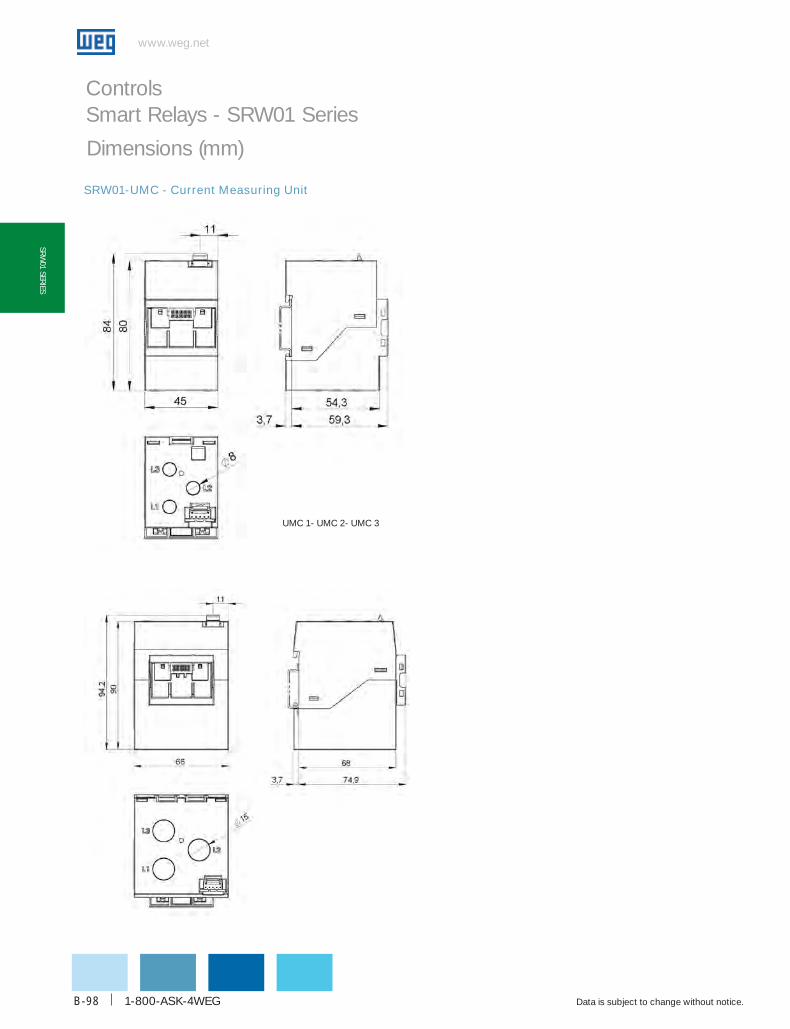
1-800-ASK-4WEG
www.weg.net
Data is subject to change without notice.B-98
SRW01 SERIES
Controls Smart Relays - SRW01 Series
UMC 1- UMC 2- UMC 3
SRW01-UMC - Current Measuring Unit
Dimensions (mm)

WEG Automation - Products and Solutions
www.weg.net
Data is subject to change without notice. B-99
SRW
01 S
ERIE
S
Controls Smart Relays - SRW01 SeriesDimensions (mm)
SRW01-UMC - current Measuring Unit
UMC 5
UMC 6
(without busbar)
UMC 6
(with busbar)
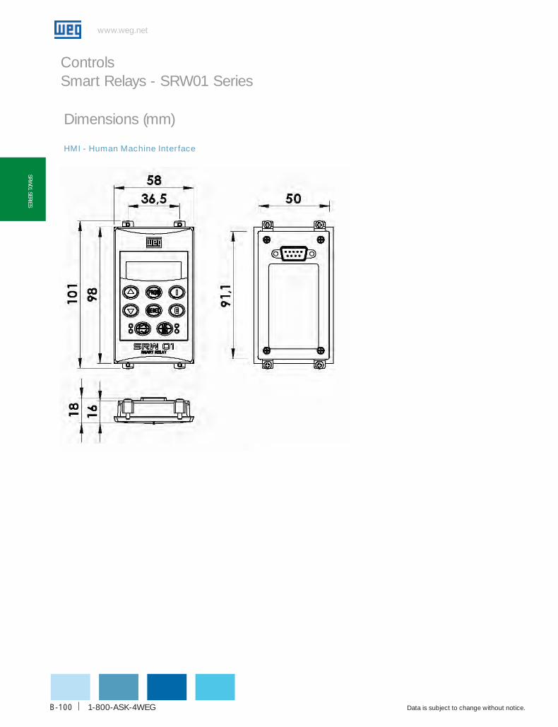
1-800-ASK-4WEG
www.weg.net
Data is subject to change without notice.B-100
SRW01 SERIES
Controls Smart Relays - SRW01 Series
HMI - Human Machine Interface
Dimensions (mm)
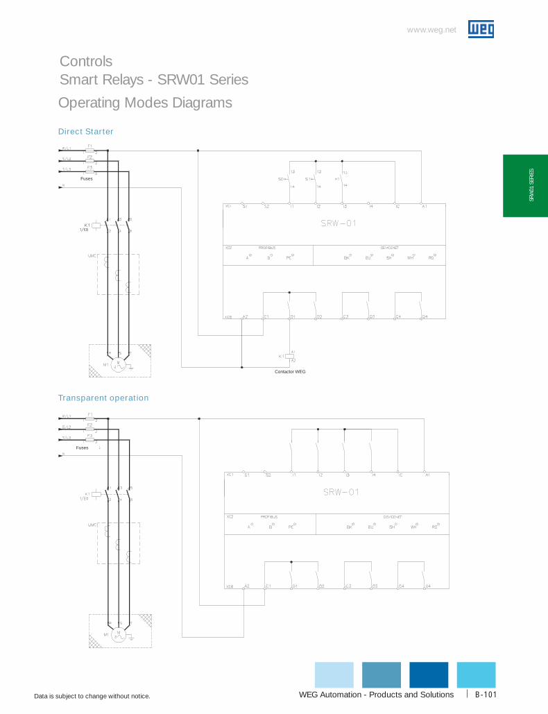
WEG Automation - Products and Solutions
www.weg.net
Data is subject to change without notice. B-101
SRW
01 S
ERIE
S
Controls Smart Relays - SRW01 Series
Operating Modes Diagrams
Contactor WEG
Fuses
Fuses G
Direct Starter
Transparent operation

1-800-ASK-4WEG
www.weg.net
Data is subject to change without notice.B-102
SRW01 SERIES
Controls Smart Relays - SRW01 Series
Fuses
Contactor WEG
Contactor WEG
Fuses
Contactor WEG
Operating Modes Diagrams
Operation as overload relay
Reversing starter

WEG Automation - Products and Solutions
www.weg.net
Data is subject to change without notice. B-103
SRW
01 S
ERIE
S
Controls Smart Relays - SRW01 Series
Operating Modes Diagrams
Fuses
Contactor WEG Contactor WEG Contactor WEG
Fuses
Contactor WEG Contactor WEGContactor WEG
Star-Delta starter
Dahlander starter
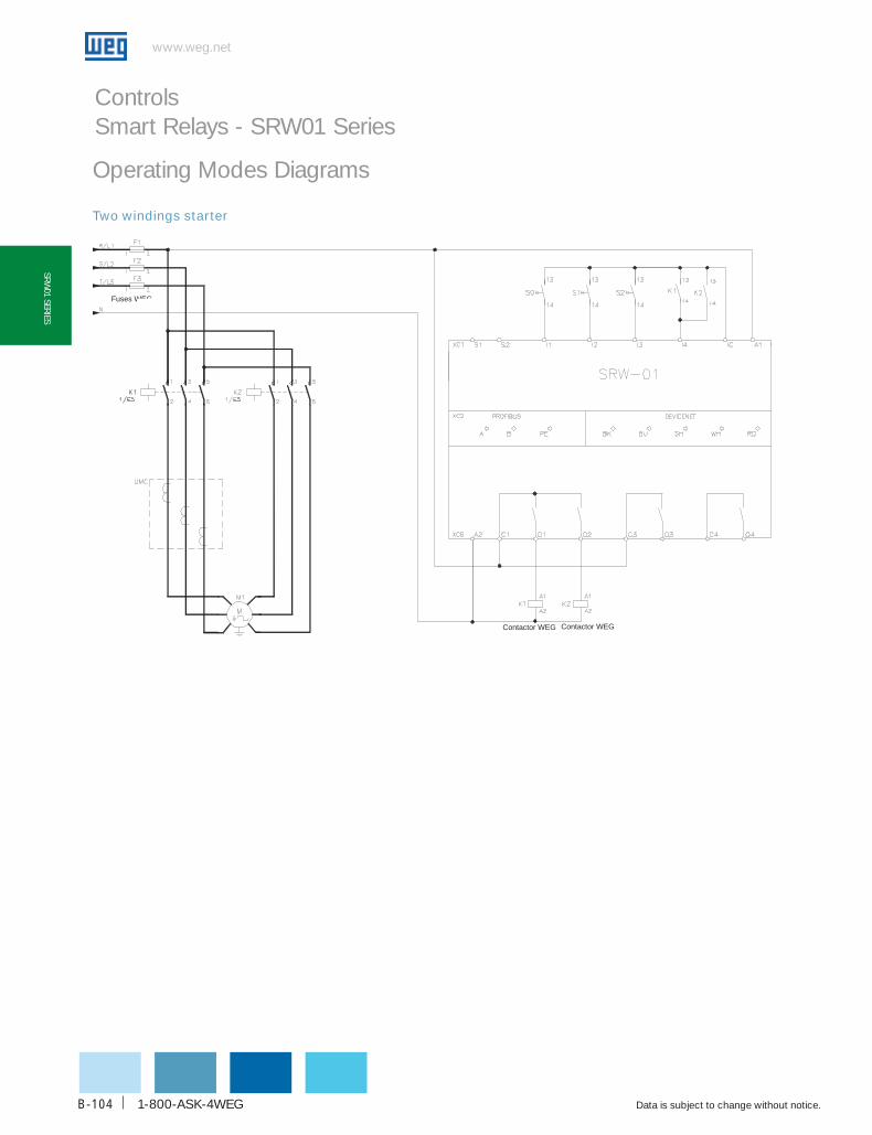
1-800-ASK-4WEG
www.weg.net
Data is subject to change without notice.B-104
SRW01 SERIES
Controls Smart Relays - SRW01 Series
Fuses WEG
Contactor WEG Contactor WEG
Operating Modes Diagrams
Two windings starter

WEG Automation - Products and Solutions
www.weg.net
Data is subject to change without notice. B-105
AcW
SER
IES
Introducing the WEG ACW Series of Molded Case Circuit Breakers now availa-ble with UL489 certification. Available in four different compact frames, the New ACW Series will assure top performance for both thermal and short-circuit pro-tection from 15 to 800Amps.
The ACW series is also available in two levels of short-circuit interrupting capacity – “P” for standard industrial and commercial standard applications and “W” for high-performance applications.
Common plug-in accessories simplify field installation and minimize inventory va-riations on distributors’ shelves.
ACW
Molded-Case Circuit BreakerUL 489 Listed
ACW125
In 15…125
ACW250
In 128…250
ACW400
In 240…400
ACW800
In 400…800
UL interrupting rating (kA)
Current ratings
Mccb AcW125 AcW250 AcW400 AcW800
Type P W P W P W P W
@ 120V 50 100 - - - - - -
@ 240V 50 100 50 100 50 100 50 100
@ 480V 35 65 35 65 35 65 35 65
@ 600V 10 14 10 18 14 20 18 25
Reference Rated current In (A)
AcW125 15, 20, 30, 40, 50, 60, 80, 100, 125
AcW250 128-160, 160-200, 200-250
AcW400 240-300, 320-400
AcW800 400-500, 480-600, 640-800
Certifications:
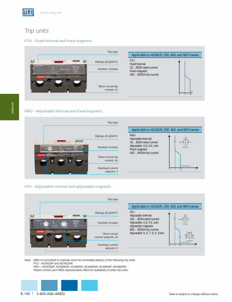
1-800-ASK-4WEG
www.weg.net
Data is subject to change without notice.B-106
AcW SERIES
Trip type
Ratings (A) @ 40oC
Number of poles
Short-circuit current setpoint, Im
Overload current setpoint, Ir
Trip unitsFTU - Fixed thermal and fixed magnetic
FMU - Adjustable thermal and fixed magnetic
ATU - Adjustable thermal and adjustable magnetic
Trip type
Ratings (A) @ 40oC
Number of poles
Short-circuit trip current, Im
Applicable to AcW125, 250, 400, and 800 frames
FTUFixed thermal15…800A rated currentFixed magnetic400…8000A trip current
Im
t
0 Ir
Applicable to AcW125, 250, 400, and 800 frames
FMUAdjustable thermal40…800A rated currentAdjustable: 0.8, 0.9, 1xInFixed magnetic400…8000A trip current
Applicable to AcW125, 250, 400, and 800 frames
ATUAdjustable thermal160…800A rated currentAdjustable: 0.8, 0.9, 1xInAdjustable magnetic800…8000A trip currentAdjustable: 5, 6, 7, 8, 9, 10xIn
Note: WEG is committed to maintain stock for immediate delivery of the following trip units: FTU – ACW125P and ACW125W FMU – ACW250P, ACW250W, ACW400P, ACW400W, ACW800P, ACW800W Please contact your WEG representative office for availability of other trip units.
Trip type
Ratings (A) @ 40oC
Number of poles
Short-circuit tripcurrent, Im
Overload current setpoint, Ir

WEG Automation - Products and Solutions
www.weg.net
Data is subject to change without notice. B-107
AcW
SER
IES
Selection guide
Rated current In code
15A 15
20A 20
30A 30
40A 40
50A 50
60A 60
80A 80
100A 100
125A 125
160A 160
200A 200
250A 250
300A 300
400A 400
500A 500
600A 600
700A 700
800A 800
A C W 1 2 5 P - F T U 8 0 - 3
Number of poles
code
3 3
Trip unit code
Fixed thermal and fixed magnetic FTU
Adjustable thermal and fixed magnetic FMU
Adjustable thermal and adjustable magnetic
ATU
Frame code
125 ACW125
250 ACW250
400 ACW400
800 ACW800
kA rating @ 460VAc
code
35 P
65 W
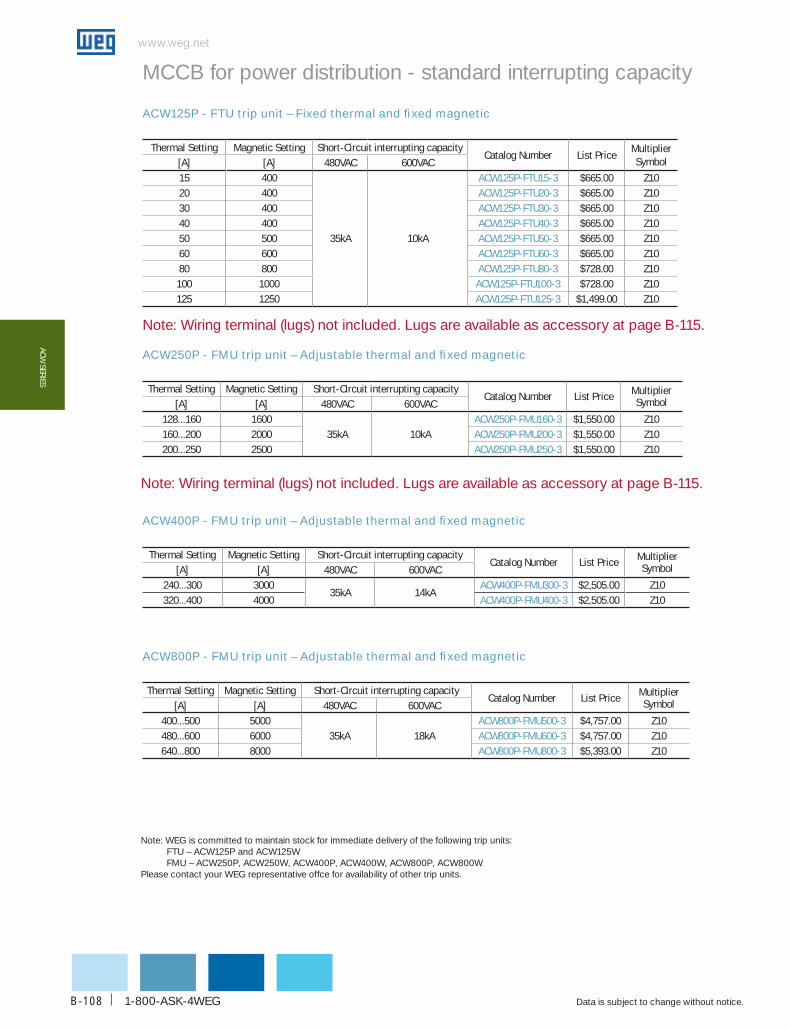
1-800-ASK-4WEG
www.weg.net
Data is subject to change without notice.B-108
AcW SERIES
MCCB for power distribution - standard interrupting capacity
ACW125P - FTU trip unit – Fixed thermal and fixed magnetic
ACW250P - FMU trip unit – Adjustable thermal and fixed magnetic
ACW400P - FMU trip unit – Adjustable thermal and fixed magnetic
ACW800P - FMU trip unit – Adjustable thermal and fixed magnetic
Thermal Setting Magnetic Setting Short-circuit interrupting capacitycatalog Number List Price
Multiplier Symbol[A] [A] 480VAc 600VAc
15 400
35kA 10kA
AcW125P-FTu15-3 $665.00 Z1020 400 AcW125P-FTu20-3 $665.00 Z1030 400 AcW125P-FTu30-3 $665.00 Z1040 400 AcW125P-FTu40-3 $665.00 Z1050 500 AcW125P-FTu50-3 $665.00 Z1060 600 AcW125P-FTu60-3 $665.00 Z1080 800 AcW125P-FTu80-3 $728.00 Z10
100 1000 AcW125P-FTu100-3 $728.00 Z10125 1250 AcW125P-FTu125-3 $1,499.00 Z10
Note: Wiring terminal (lugs) not included. Lugs are available as accessory at page B-115.
Note: Wiring terminal (lugs) not included. Lugs are available as accessory at page B-115.
Thermal Setting Magnetic Setting Short-circuit interrupting capacitycatalog Number List Price Multiplier
Symbol[A] [A] 480VAc 600VAc128...160 1600
35kA 10kAAcW250P-FMu160-3 $1,550.00 Z10
160...200 2000 AcW250P-FMu200-3 $1,550.00 Z10200...250 2500 AcW250P-FMu250-3 $1,550.00 Z10
Thermal Setting Magnetic Setting Short-circuit interrupting capacitycatalog Number List Price Multiplier
Symbol[A] [A] 480VAc 600VAc400...500 5000
35kA 18kAAcW800P-FMu500-3 $4,757.00 Z10
480...600 6000 AcW800P-FMu600-3 $4,757.00 Z10640...800 8000 AcW800P-FMu800-3 $5,393.00 Z10
Thermal Setting Magnetic Setting Short-circuit interrupting capacitycatalog Number List Price Multiplier
Symbol[A] [A] 480VAc 600VAc240...300 3000
35kA 14kAAcW400P-FMu300-3 $2,505.00 Z10
320...400 4000 AcW400P-FMu400-3 $2,505.00 Z10
Note: WEG is committed to maintain stock for immediate delivery of the following trip units: FTU – ACW125P and ACW125W FMU – ACW250P, ACW250W, ACW400P, ACW400W, ACW800P, ACW800WPlease contact your WEG representative offce for availability of other trip units.

WEG Automation - Products and Solutions
www.weg.net
Data is subject to change without notice. B-109
AcW
SER
IES
Note: Wiring terminal (lugs) not included. Lugs are available as accessory at page B-115.
Note: Wiring terminal (lugs) not included. Lugs are available as accessory at page B-115.
MCCB for power distribution - high interrupting capacity
ACW125W - FTU trip unit – Fixed thermal and fixed magnetic
ACW250W - FMU trip unit – Adjustable thermal and fixed magnetic
ACW400W - FMU trip unit – Adjustable thermal and fixed magnetic
ACW800W - FMU trip unit – Adjustable thermal and fixed magnetic
Thermal Setting Magnetic Setting Short-circuit interrupting capacitycatalog Number List Price Multiplier Symbol
[A] [A] 480VAc 600VAc15 400
65kA 14kA
AcW125W-FTu15-3 $965.00 Z1020 400 AcW125W-FTu20-3 $965.00 Z1030 400 AcW125W-FTu30-3 $965.00 Z1040 400 AcW125W-FTu40-3 $965.00 Z1050 500 AcW125W-FTu50-3 $965.00 Z1060 600 AcW125W-FTu60-3 $965.00 Z1080 800 AcW125W-FTu80-3 $1,055.00 Z10100 1000 AcW125W-FTu100-3 $1,055.00 Z10125 1250 AcW125W-FTu125-3 $2,101.00 Z10
Thermal Setting Magnetic Setting Short-circuit interrupting capacitycatalog Number List Price Multiplier Symbol
[A] [A] 480VAc 600VAc128...160 1600
65kA 18kAAcW250W-FMu160-3 $2,826.00 Z10
160...200 2000 AcW250W-FMu200-3 $2,826.00 Z10200...250 2500 AcW250W-FMu250-3 $2,826.00 Z10
Thermal Setting Magnetic Setting Short-circuit interrupting capacitycatalog Number List Price Multiplier Symbol
[A] [A] 480VAc 600VAc400...500 5000
65kA 25kAAcW800W-FMu500-3 $6,392.00 Z10
480...600 6000 AcW800W-FMu600-3 $6,392.00 Z10640...800 8000 AcW800W-FMu800-3 $7,358.00 Z10
Thermal Setting Magnetic Setting Short-circuit interrupting capacitycatalog Number List Price Multiplier Symbol
[A] [A] 480VAc 600VAc240...300 3000
65kA 20kAAcW400W-FMu300-3 $4,312.00 Z10
320...400 4000 AcW400W-FMu400-3 $4,312.00 Z10
Note: WEG is committed to maintain stock for immediate delivery of the following trip units: FTU – ACW125P and ACW125W FMU – ACW250P, ACW250W, ACW400P, ACW400W, ACW800P, ACW800WPlease contact your WEG representative offce for availability of other trip units.

1-800-ASK-4WEG
www.weg.net
Data is subject to change without notice.B-110
AcW SERIES
Internal accessories
Auxiliary contact
AcW oN oFF TRIP
Auxiliary contact AXc1
AXa1AXc1
AXa1
AXb1 AXb1
Suitable for catalog Number List Price Multiplier Symbol
ACW125...800 AX AcW 125-800 $103.00 Z10
Suitable for catalog Number List Price Multiplier Symbol
ACW125…800 AL AcW 125-800 $103.00 Z10
ACW ON OFF TRIP
Alarm contact ALc1Ala1
ALc1Ala1
ALb1 ALb1
The auxiliary contact block contains one set of form ‘C’ contacts. This contact indicates remote circuit-breaker status “ON” and “OFF”.
Alarm contactAlarm contact offers provisions for audio and visual indication of a tripped breaker due to overload, short-circuit, shunt trip or under voltage release conditions. The contact opens when the circuit breaker is reset.
Suitable for Rated voltage catalog Number List Price Multiplier Symbol
ACW125…800
12VDC ShT c02 AcW 125-800 $235.00 Z10
24VAC/DC ShT E26 AcW 125-800 $235.00 Z10
48VAC/DC ShT E27 AcW 125-800 $235.00 Z10
110-130VAC/DC ShT E10 AcW 125-800 $235.00 Z10
220-240VAC/250VDC ShT E14 AcW125-800 $235.00 Z10
380-500VAC ShT E52 AcW125-800 $235.00 Z10
Shunt releaseThe shunt release opens the breaker in response to an externally voltage signal.
Range of operational voltage: 0.7…1.1xUnFrequency: 45…65Hz
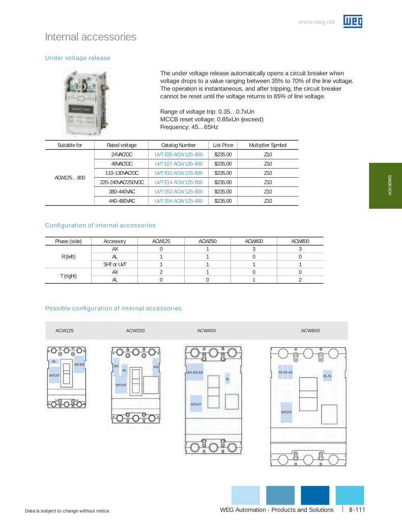
WEG Automation - Products and Solutions
www.weg.net
Data is subject to change without notice. B-111
AcW
SER
IES
Under voltage release
Suitable for Rated voltage catalog Number List Price Multiplier Symbol
ACW125…800
24VAC/DC uVT E26 AcW 125-800 $235.00 Z10
48VAC/DC uVT E27 AcW 125-800 $235.00 Z10
110-130VAC/DC uVT E10 AcW 125-800 $235.00 Z10
220-240VAC/250VDC uVT E14 AcW 125-800 $235.00 Z10
380-440VAC uVT E53 AcW 125-800 $235.00 Z10
440-480VAC uVT E54 AcW 125-800 $235.00 Z10
The under voltage release automatically opens a circuit breaker when voltage drops to a value ranging between 35% to 70% of the line voltage. The operation is instantaneous, and after tripping, the circuit breaker cannot be reset until the voltage returns to 85% of line voltage.
Range of voltage trip: 0.35…0.7xUnMCCB reset voltage: 0.85xUn (exceed)Frequency: 45…65Hz
Configuration of internal accessories
Internal accessories
Phase (side) Accessory AcW125 AcW250 AcW400 AcW800
R (left)AX 0 1 3 3AL 1 1 0 0
SHT or UVT 1 1 1 1
T (right)AX 2 1 0 0AL 0 0 1 2
Possible configuration of internal accessories
ACW125 ACW250 ACW400 ACW800
AX AX
SHT/UVT
AL
AX AX
SHT/UVT
ALAX AX AX
SHT/UVT
AL
SHT/UVT
AL ALAX AX AX

1-800-ASK-4WEG
www.weg.net
Data is subject to change without notice.B-112
AcW SERIES
Rotary handle
External accessories
The through-the-door rotary handle operating mechanism is available in NEMA 3(R), 12 and 4X versions. Units are offered either complete (rotary handle + operating mechanism + shaft 12”) or as seperate components (different shaft sizes sold separately). Lockable in OFF position.
Suitable for catalog Number List Price Multiplier SymbolRotary handle + mechanism + shaft 12“ (uL Type 1, 3(R), 12)
ACW125 Ehu 12 AcW 125 $254.00 Z10ACW250 Ehu 12 AcW 250 $275.00 Z10ACW400 Ehu 12 AcW 400 $336.00 Z10ACW800 Ehu 12 AcW 800 $449.00 Z10
Rotary handle + mechanism + shaft 12“ (uL Type 4X)ACW125 EhX 12 AcW 125 $331.00 Z10ACW250 EhX 12 AcW 250 $352.00 Z10ACW400 EhX 12 AcW 400 $422.00 Z10ACW800 EhX 12 AcW 800 $586.00 Z10
Suitable for catalog Number List Price Multiplier SymbolRotary handle + mechanism (without shaft) (uL Type 1, 3(R), 12)
ACW125 Ehu AcW 125 $221.00 Z10ACW250 Ehu AcW 250 $239.00 Z10ACW400 Ehu AcW 400 $305.00 Z10ACW800 Ehu AcW 800 $427.00 Z10
Rotary handle + mechanism (without shaft) (uL Type 4X) ACW125 EhX AcW 125 $305.00 Z10ACW250 EhX AcW 250 $322.00 Z10ACW400 EhX AcW 400 $398.00 Z10ACW800 EhX AcW 800 $575.00 Z10
16” shaft for rotary handleACW125…800 ES 16 AcW 125-800 $53.00 Z10
24” shaft for rotary handleACW125…800 ES 24 AcW 125-800 $71.00 Z10

WEG Automation - Products and Solutions
www.weg.net
Data is subject to change without notice. B-113
AcW
SER
IES
Flange handle
External accessories
The flange disconnect handle is available in NEMA 3(R), 12 and 4X versions. Flexible cables are available in four different sizes (36”, 48”, 60”, 72”) and are ordered separately. Lockable in OFF position.
Suitable for catalog Number List Price Multiplier SymbolFlange handle + mechanism (without flexible cable) (uL Type 1, 3(R), 12)
ACW125 Fhu AcW 125 $365.00 Z10ACW250 Fhu AcW 250 $410.00 Z10ACW400 Fhu AcW 400 $480.00 Z10ACW800 Fhu AcW 800 $551.00 Z10
Flange handle + mechanism (without flexible cable) (uL Type 4X)ACW125 FhX AcW 125 $458.00 Z10ACW250 FhX AcW 250 $526.00 Z10ACW400 FhX AcW 400 $594.00 Z10ACW800 FhX AcW 800 $656.00 Z10
Suitable for catalog Number List Price Multiplier SymbolFlexible cable
cable 36”ACW125…250 Fc 36 AcW 125-250 $146.00 Z10ACW400…800 Fc 36 AcW 400-800 $155.00 Z10
cable 48”ACW125…250 Fc 48 AcW 125-250 $169.00 Z10ACW400…800 Fc 48 AcW 400-800 $179.00 Z10
cable 60”ACW125…250 Fc 60 AcW 125-250 $188.00 Z10ACW400…800 Fc 60 AcW 400-800 $198.00 Z10
cable 72”ACW125…250 Fc 72 AcW 125-250 $208.00 Z10ACW400…800 Fc 72 AcW 400-800 $227.00 Z10

1-800-ASK-4WEG
www.weg.net
Data is subject to change without notice.B-114
AcW SERIES
Pad lock
Handle lock
External accessories
T ad lock allows the handle to be locked in the “OFF” on. Maximum three padlocks with shackle diameters ng from 0.2 to 0.3in (5 to 8mm) may be used. (Padlocks
ot supplied)ng in the “OFF” position guarantee isolation required per UL 489.
The handle lock allows the handle to be locked in the “ON” and “OFF” positions. Maximum three padlocks with shackle diameters ranging from 0.2 to 0.3inch (5 to 8mm) may be used.(Padlocks are not supplied)Locking in the “OFF” position guarantee isolation required per UL 489.
Suitable for catalog Number List Price Multiplier Symbol
ACW125 PL AcW 125 $59.00 Z10
ACW250 PL AcW 250 $65.00 Z10
ACW400 PL AcW 400 $78.00 Z10
ACW800 PL AcW 800 $90.00 Z10
Suitable for catalog Number List Price Multiplier Symbol
ACW125 hL AcW 125 $95.00 Z10
ACW250 hL AcW 250 $101.00 Z10
ACW400 hL AcW 400 $158.00 Z10
ACW800 hL AcW 800 $165.00 Z10

WEG Automation - Products and Solutions
www.weg.net
Data is subject to change without notice. B-115
AcW
SER
IES
Wiring terminal (Lugs)
Mechanical interlock
External accessories
The mechanical interlock can be applied on the front of two breakers mounted side by side and prevents simultaneous closing of the two breakers. Interlock is assembled directly to the front cover of the breakers. The interlocking plate allows installation of a padlock to maintain the position. The operator can lock out either one or both breakers in the “OFF” position. (Padlocks are not supplied)
Suitable for catalog Number List Price Multiplier Symbol
ACW125 MIT AcW 125 $338.00 Z10
ACW250 MIT AcW 250 $377.00 Z10
ACW400 MIT AcW 400 $413.00 Z10
ACW800 MIT AcW 800 $440.00 Z10
Suitable for catalog Number List Price Multiplier Symbol Set with 3 pieces
ACW125 LW1 3P AcW 125 $48.00 Z10ACW250 LW2 3P AcW 250 $81.00 Z10
Set with 15 piecesACW125 LW1 15P AcW 125 $168.00 Z10ACW250 LW2 15P AcW 250 $283.00 Z10
Line and Load terminals provide the means for connecting the circuit breaker to the power source and the load. Each breaker accepts up to 6 lugs (a set of 3 units for the line terminals and another set of 3 units for the load terminals); Each lug is suitable for either line or load terminals.
Locked in OFF position
Locked in OFF position
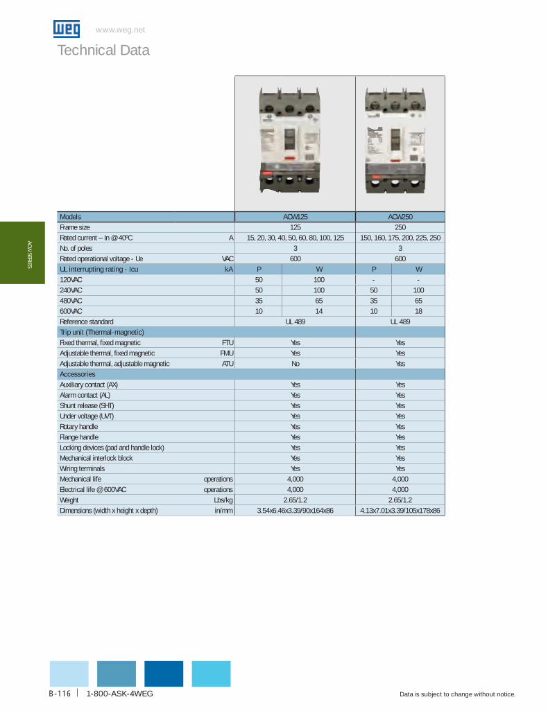
1-800-ASK-4WEG
www.weg.net
Data is subject to change without notice.B-116
AcW SERIES
Technical Data
Models AcW125 AcW250Frame size 125 250Rated current – In @ 40ºC A 15, 20, 30, 40, 50, 60, 80, 100, 125 150, 160, 175, 200, 225, 250No. of poles 3 3Rated operational voltage - Ue VAC 600 600uL interrupting rating - Icu kA P W P W120VAC 50 100 - -240VAC 50 100 50 100480VAC 35 65 35 65600VAC 10 14 10 18Reference standard UL 489 UL 489Trip unit (Thermal-magnetic)Fixed thermal, fixed magnetic FTU Yes YesAdjustable thermal, fixed magnetic FMU Yes YesAdjustable thermal, adjustable magnetic ATU No YesAccessoriesAuxiliary contact (AX) Yes YesAlarm contact (AL) Yes YesShunt release (SHT) Yes YesUnder voltage (UVT) Yes YesRotary handle Yes YesFlange handle Yes YesLocking devices (pad and handle lock) Yes YesMechanical interlock block Yes YesWiring terminals Yes YesMechanical life operations 4,000 4,000Electrical life @ 600VAC operations 4,000 4,000Weight Lbs/kg 2.65/1.2 2.65/1.2Dimensions (width x height x depth) in/mm 3.54x6.46x3.39/90x164x86 4.13x7.01x3.39/105x178x86
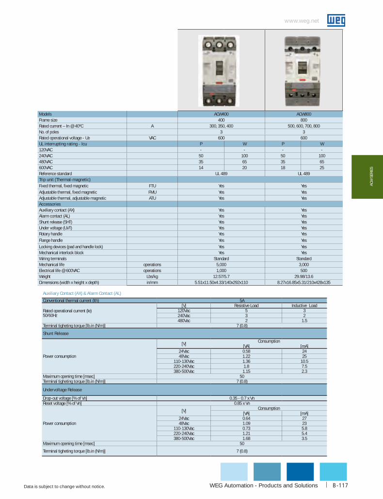
WEG Automation - Products and Solutions
www.weg.net
Data is subject to change without notice. B-117
AcW
SER
IES
Auxiliary contact (AX) & Alarm contact (AL)
Conventional thermal current (Ith) 5A
Rated operational current (Ie) 50/60Hz
[V] Resistive Load Inductive Load120Vac 5 3240Vac 3 2480Vac 2 1.5
Terminal tigheting torque [lb.in (N/m)] 7 (0.8)
Shunt Release
Power consumption
[V] Consumption[VA] [mA]
24Vac 0.58 2448Vac 1.22 25
110-130Vac 1.36 10.5220-240Vac 1.8 7.5380-500Vac 1.15 2.3
Maximum opening time [msec] 50Terminal tigheting torque [lb.in (N/m)] 7 (0.8)
undervoltage Release
Drop-out voltage [% of Vn] 0.35 - 0.7 x VnReset voltage [% of Vn] 0.85 x Vn
Power consumption
[V] Consumption[VA] [mA]
24Vac 0.64 2748Vac 1.09 23
110-130Vac 0.73 5.8220-240Vac 1.21 5.4380-500Vac 1.68 3.5
Maximum opening time [msec] 50
Terminal tigheting torque [lb.in (N/m)] 7 (0.8)
Models ACW400 ACW800Frame size 400 800Rated current – In @ 40ºC A 300, 350, 400 500, 600, 700, 800No. of poles 3 3Rated operational voltage - Ue VAC 600 600uL interrupting rating - Icu P W P W120VAC - - - -240VAC 50 100 50 100480VAC 35 65 35 65600VAC 14 20 18 25Reference standard UL 489 UL 489Trip unit (Thermal-magnetic)Fixed thermal, fixed magnetic FTU Yes YesAdjustable thermal, fixed magnetic FMU Yes YesAdjustable thermal, adjustable magnetic ATU Yes YesAccessoriesAuxiliary contact (AX) Yes YesAlarm contact (AL) Yes YesShunt release (SHT) Yes YesUnder voltage (UVT) Yes YesRotary handle Yes YesFlange handle Yes YesLocking devices (pad and handle lock) Yes YesMechanical interlock block Yes YesWiring terminals Standard StandardMechanical life operations 5,000 3,000Electrical life @ 600VAC operations 1,000 500Weight Lbs/kg 12.57/5.7 29.98/13.6Dimensions (width x height x depth) in/mm 5.51x11.50x4.33/140x292x110 8.27x16.85x5.31/210x428x135

1-800-ASK-4WEG
www.weg.net
Data is subject to change without notice.B-118
AcW SERIES
Screw and connection
Screw mounting
Connecting terminal and conductor
AcW125 AcW250 AcW400 AcW800
Screw for mounting
4EA(NO.8-32 UNC-2A, L100)
4EA(NO.10-24 UNC-2A, L120)
4EA(1/4”-20 UNC2A, L140)
Screw for connection of
terminals6EA(M5×L16) 6EA(M8×L20)
N.A. N.A.
Torque: Max 78kgf·cm
67.7lbf·in
Torque: Max 197kgf·cm
170lbf·inN.A. N.A.
Terminal (mm) Conductor (mm)
AcW125
Max 78kgf·cm
AcW250
Max 147kgf·cm
18
8
23
22
M5x16
20
28
22
M8x20
>8>8
1025
21
2510
Note: ACW400 and ACW800 are supplied with lugs.
Note: ACW400 and ACW800 are supplied with lugs.

WEG Automation - Products and Solutions
www.weg.net
Data is subject to change without notice. B-119
AcW
SER
IES
Mccb Rating(A)
Fixed Mccb (thermal-magnetic trip unit)
50°F 68°F 86°F 104°F 122°F 140°F 158°F 176°F10°c 20°c 30°c 40°c 50°c 60°c 70°c 80°c
AcW125
15 15 15 15 15 15 14 13 1220 20 20 20 20 19 19 18 16
30 30 30 30 30 29 28 26 24
40 40 40 40 40 39 38 35 3350 50 50 50 50 48 47 44 4160 60 60 60 60 58 56 53 4980 80 80 80 80 78 75 71 66100 100 100 100 100 97 94 88 82125 125 125 125 125 121 117 110 103
AcW250
150 150 150 150 150 145 140 131 121160 160 160 160 160 155 150 141 131175 175 175 175 175 170 165 156 145200 200 200 200 200 194 188 176 164225 225 225 225 225 219 213 201 189250 250 250 250 250 242 234 220 205
AcW400300 300 300 300 300 291 281 264 246350 350 350 350 350 341 331 314 296400 400 400 400 400 388 375 353 328
AcW800
500 500 500 500 500 484 469 441 410600 600 600 600 600 580 571 525 487700 700 700 700 700 680 661 625 587800 800 800 800 800 775 750 705 656
A derating of the rated operational current for ACW series is necessary if the ambient temperature is greater than 40oC (+104oF), because the overload-protection characteristics are slightly modified.
Frame TypeWire Range
"conductor "Number of Tightening Torquecross-section" conductors" [lb.in.]
AcW12514 - 8 AWG 1 606 - 1/0 AWG 1 90
AcW250
1 AWG 1 1501/0 - 2/0 AWG 1 1803/0 - 4/0 AWG 1 250
250 - 300 kcmil 1 Tightening Torque 325
AcW400250 - 400 kcmil 1 325
500 kcmil 1 3753/0 AWG up to 2 250
AcW800 (500 and 600A) 250 - 500 kcmil up to 2 375
AcW800 (800A)250 - 400 kcmil up to 3 375
500 kcmil up to 2 375
Terminal size acceptability and terminal torque
Temperature derating
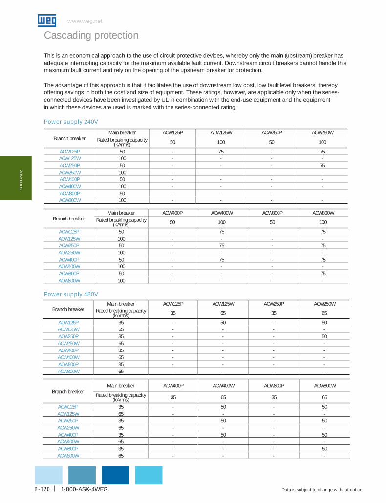
1-800-ASK-4WEG
www.weg.net
Data is subject to change without notice.B-120
AcW SERIES
Cascading protection
Power supply 240V
branch breakerMain breaker AcW125P AcW125W AcW250P AcW250W
Rated breaking capacity (kArms) 50 100 50 100
AcW125P 50 - 75 - 75AcW125W 100 - - - -AcW250P 50 - - - 75AcW250W 100 - - - -AcW400P 50 - - - -AcW400W 100 - - - -AcW800P 50 - - - -AcW800W 100 - - - -
branch breakerMain breaker AcW400P AcW400W AcW800P AcW800W
Rated breaking capacity (kArms) 50 100 50 100
AcW125P 50 - 75 - 75AcW125W 100 - - - -AcW250P 50 - 75 - 75AcW250W 100 - - - -AcW400P 50 - 75 - 75AcW400W 100 - - - -AcW800P 50 - - - 75AcW800W 100 - - - -
Power supply 480V
branch breakerMain breaker AcW125P AcW125W AcW250P AcW250W
Rated breaking capacity (kArms) 35 65 35 65
AcW125P 35 - 50 - 50AcW125W 65 - - - -AcW250P 35 - - - 50AcW250W 65 - - - -AcW400P 35 - - - -AcW400W 65 - - - -AcW800P 35 - - - -AcW800W 65 - - - -
branch breakerMain breaker AcW400P AcW400W AcW800P AcW800W
Rated breaking capacity (kArms) 35 65 35 65
AcW125P 35 - 50 - 50AcW125W 65 - - - -AcW250P 35 - 50 - 50AcW250W 65 - - - -AcW400P 35 - 50 - 50AcW400W 65 - - - -AcW800P 35 - - - 50AcW800W 65 - - - -
This is an economical approach to the use of circuit protective devices, whereby only the main (upstream) breaker has adequate interrupting capacity for the maximum available fault current. Downstream circuit breakers cannot handle this maximum fault current and rely on the opening of the upstream breaker for protection.
The advantage of this approach is that it facilitates the use of downstream low cost, low fault level breakers, thereby offering savings in both the cost and size of equipment. These ratings, however, are applicable only when the series-connected devices have been investigated by UL in combination with the end-use equipment and the equipmentin which these devices are used is marked with the series-connected rating.
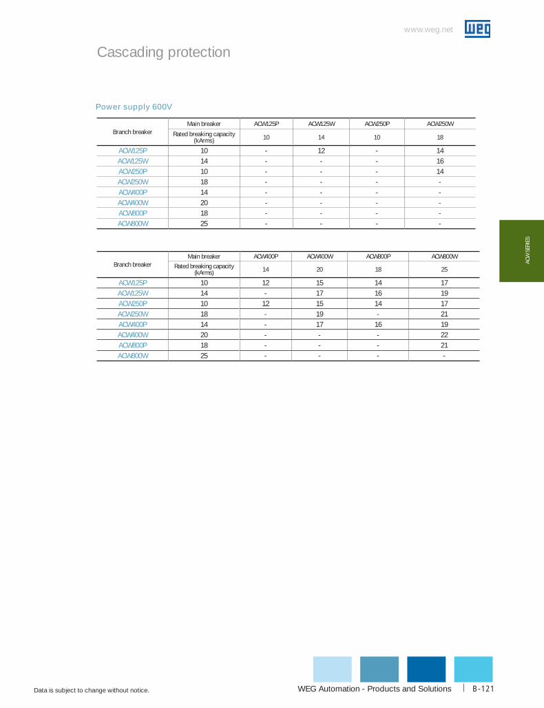
WEG Automation - Products and Solutions
www.weg.net
Data is subject to change without notice. B-121
AcW
SER
IES
Power supply 600V
branch breakerMain breaker AcW125P AcW125W AcW250P AcW250W
Rated breaking capacity (kArms) 10 14 10 18
AcW125P 10 - 12 - 14AcW125W 14 - - - 16AcW250P 10 - - - 14AcW250W 18 - - - -AcW400P 14 - - - -AcW400W 20 - - - -AcW800P 18 - - - -AcW800W 25 - - - -
Branch breakerMain breaker ACW400P ACW400W ACW800P ACW800W
Rated breaking capacity (kArms) 14 20 18 25
AcW125P 10 12 15 14 17AcW125W 14 - 17 16 19AcW250P 10 12 15 14 17AcW250W 18 - 19 - 21AcW400P 14 - 17 16 19AcW400W 20 - - - 22AcW800P 18 - - - 21AcW800W 25 - - - -
Cascading protection

1-800-ASK-4WEG
www.weg.net
Data is subject to change without notice.B-122
AcW SERIES
Selectivity (Coordination tables)
branch breaker
Main breaker AcW125P/W AcW250P/W
Rating (A)Trip units – Thermal magnetic Trip units – Thermal magnetic
15 20 30 40 50 60 80 100 125 150 160 175 200 225
ACW
P
Trip units – thermal magnetic
15 0.5kA 0.5kA 0.5kA 0.63kA 0.8kA 2kA 2kA 2kA T T T20 0.5kA 0.5kA 0.63kA 0.8kA 2kA 2kA 2kA T T T30 0.5kA 0.63kA 0.8kA 2kA 2kA 2kA T T T40 0.63kA 0.8kA 2kA 2kA 2kA T T T50 0.63kA 0.8kA 2kA 2kA 2kA T T T60 0.8kA 2kA 2kA 2kA T T T80 1.25kA 2kA 2kA T T T100 1.6kA 1.6kA T T T125 1.25kA 1.25kA 4kA 4kA
W
15 0.5kA 0.5kA 0.5kA 0.63kA 0.8kA 2kA T T T T T20 0.5kA 0.5kA 0.63kA 0.8kA 2kA T T T T T30 0.5kA 0.63kA 0.8kA 2kA 50kA 50kA 50kA 50kA 50kA40 0.63kA 0.8kA 2kA 50kA 50kA 50kA 50kA 50kA50 0.63kA 0.8kA 2kA 50kA 50kA 50kA 50kA 50kA60 0.8kA 2kA 50kA 50kA 50kA 50kA 50kA80 50kA 50kA 50kA 50kA 50kA
100 50kA 50kA 50kA 50kA 50kA125 1.25kA 1.25kA 1.25kA 4kA 4kA
ACW
P
Trip units – thermal magnetic
150160175200225250
W
150 1.25kA160175200225250
Note: T means Total Selectivity.
Definition of selectivity is given by the IEC 60947-1. "Trip selectivity is the coordination between the operating char-acteristics of two or more overcurrent protection devices, so that when an overcurrent within established limits oc-curs, the device intended to operate within those limits trips whereas the others do not trip".The definitions of total selectivity and partial selectivity are, on the other hand, given in Part 2 of the same Standard IEC 60947-2 "Low voltage Equipment - Part 2: Circuit-breakers"
"Total selectivity"Overcurrent selectivity where, in the presence of two protection devices against overcurrent in series, the load-side protection device carries out the protection without making the other device trip."
"Partial selectivity"Overcurrent selectivity where, in the presence of two protection devices against overcurrent in series, the load-side protection device carries out the protection up to a given level of overcurrent, without making the other device trip."
Selection of proper protection system is fundamental to guarantee correct economical and functional service of the whole installation and to reduce the problems caused by abnormal service conditions or actual faults to a minimum.
ExampleThe following two circuit-breakers are considered: - Main breaker ACW250W-175-3 (Icu = 65kA)- Branch breaker ACW125W-20-3 (Icu = 65kA)Extracting the data from the table above, it can be seen that there is total selectivity (T) between these circuit-breakers. In other words, there is selectivity up to 65kA (the lower of the two values).
Now the following two circuit-breakers are considered:- Main breaker ACW250W-175-3 (Icu = 65kA)- Branch breaker ACW125W-30-3 (Icu = 65kA)Extracting the data from the table above, it can be seen that the selectivity value is 50kA between the two circuit-breakers. This means that, if the maximum prospective short-circuit current on the load-side of the ACW125W-30-3 circuit-breaker is less than 50kA, there will be total selectivity, whereas if the short-circuit current has a higher value, there will be partial selectivity (non-tripping of the supply-side cir-cuit-breaker is not guaranteed).

WEG Automation - Products and Solutions
www.weg.net
Data is subject to change without notice. B-123
AcW
SER
IES
Trip curves
ACW125 – FTU & FMU (15…125A)
Min
ute
Ope
ratin
g tim
e
Sec
ond
X Rated Current In (I/Ir)

1-800-ASK-4WEG
www.weg.net
Data is subject to change without notice.B-124
AcW SERIES
ACW250 – FTU & FMU (128…250A)
Trip curves
Min
ute
Ope
ratin
g tim
e
Sec
ond
X Rated Current In (I/Ir)
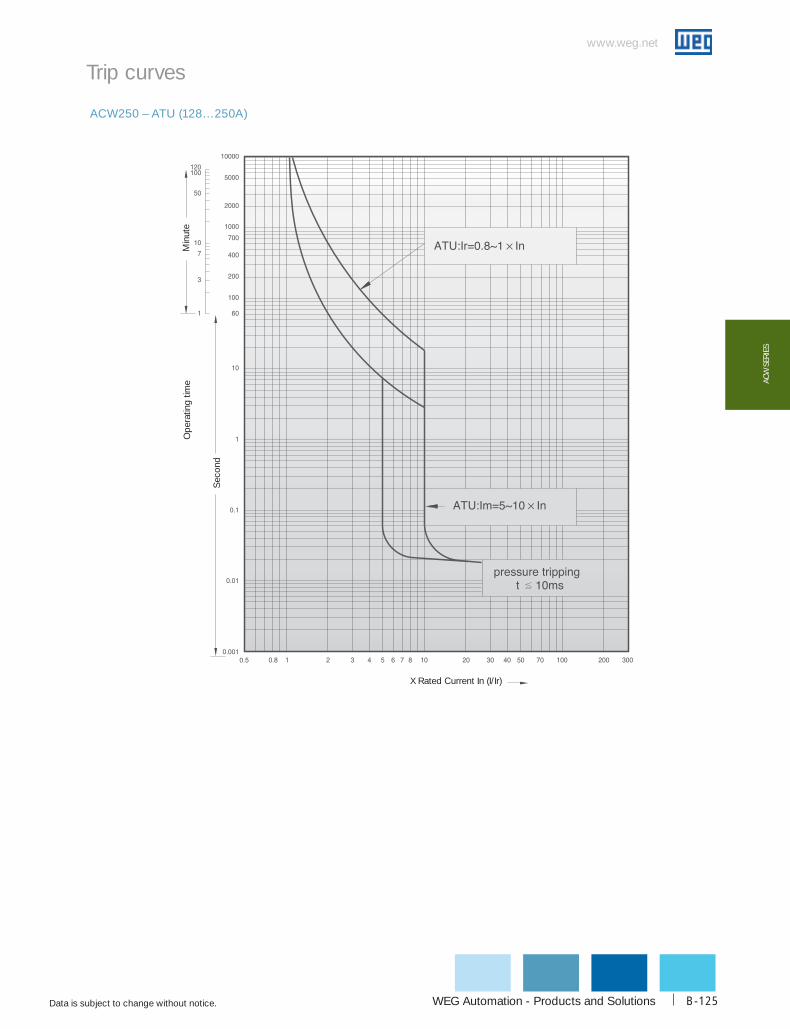
WEG Automation - Products and Solutions
www.weg.net
Data is subject to change without notice. B-125
AcW
SER
IES
ACW250 – ATU (128…250A)
Trip curves
Min
ute
Ope
ratin
g tim
e
Sec
ond
X Rated Current In (I/Ir)
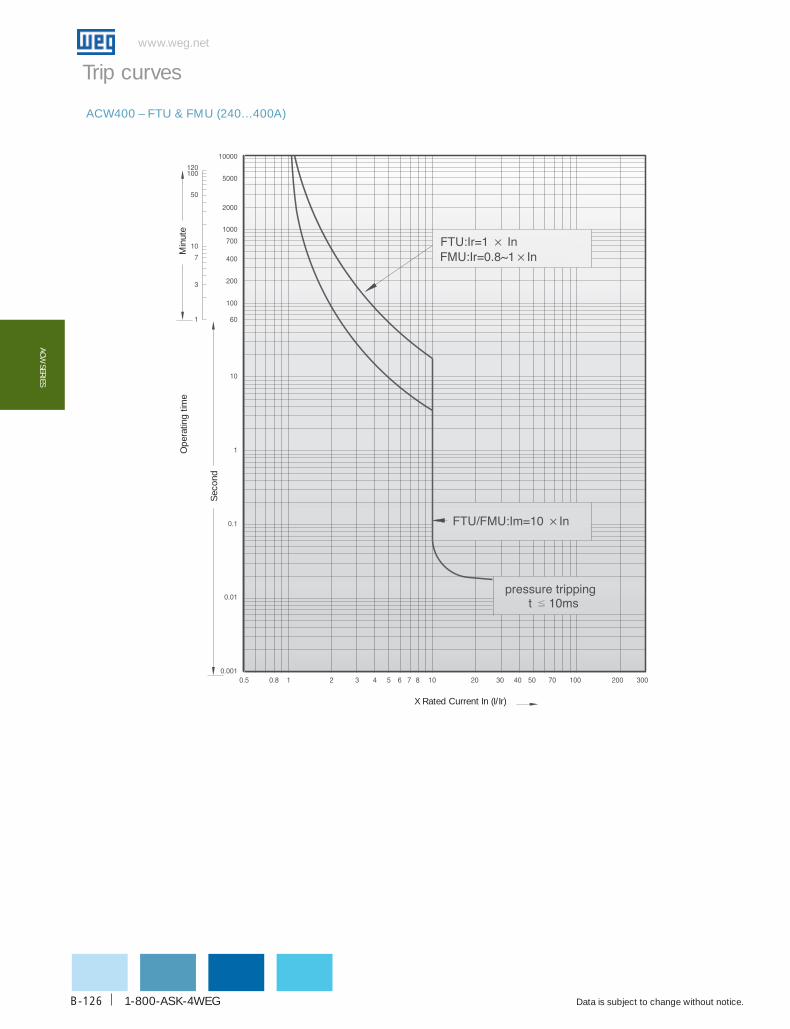
1-800-ASK-4WEG
www.weg.net
Data is subject to change without notice.B-126
AcW SERIES
ACW400 – FTU & FMU (240…400A)
Trip curves
Min
ute
Ope
ratin
g tim
e
Sec
ond
X Rated Current In (I/Ir)

WEG Automation - Products and Solutions
www.weg.net
Data is subject to change without notice. B-127
AcW
SER
IES
ACW400 – ATU (240…400A)
Trip curves
Min
ute
Ope
ratin
g tim
e
Sec
ond
X Rated Current In (I/Ir)

1-800-ASK-4WEG
www.weg.net
Data is subject to change without notice.B-128
AcW SERIES
ACW800 – FTU & FMU 400…800A)
Trip curves
Min
ute
Ope
ratin
g tim
e
Sec
ond
X Rated Current In (I/Ir)
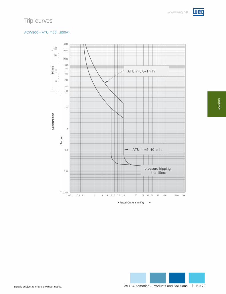
WEG Automation - Products and Solutions
www.weg.net
Data is subject to change without notice. B-129
AcW
SER
IES
ACW800 – ATU (400…800A)
Trip curves
Min
ute
Ope
ratin
g tim
e
Sec
ond
X Rated Current In (I/Ir)
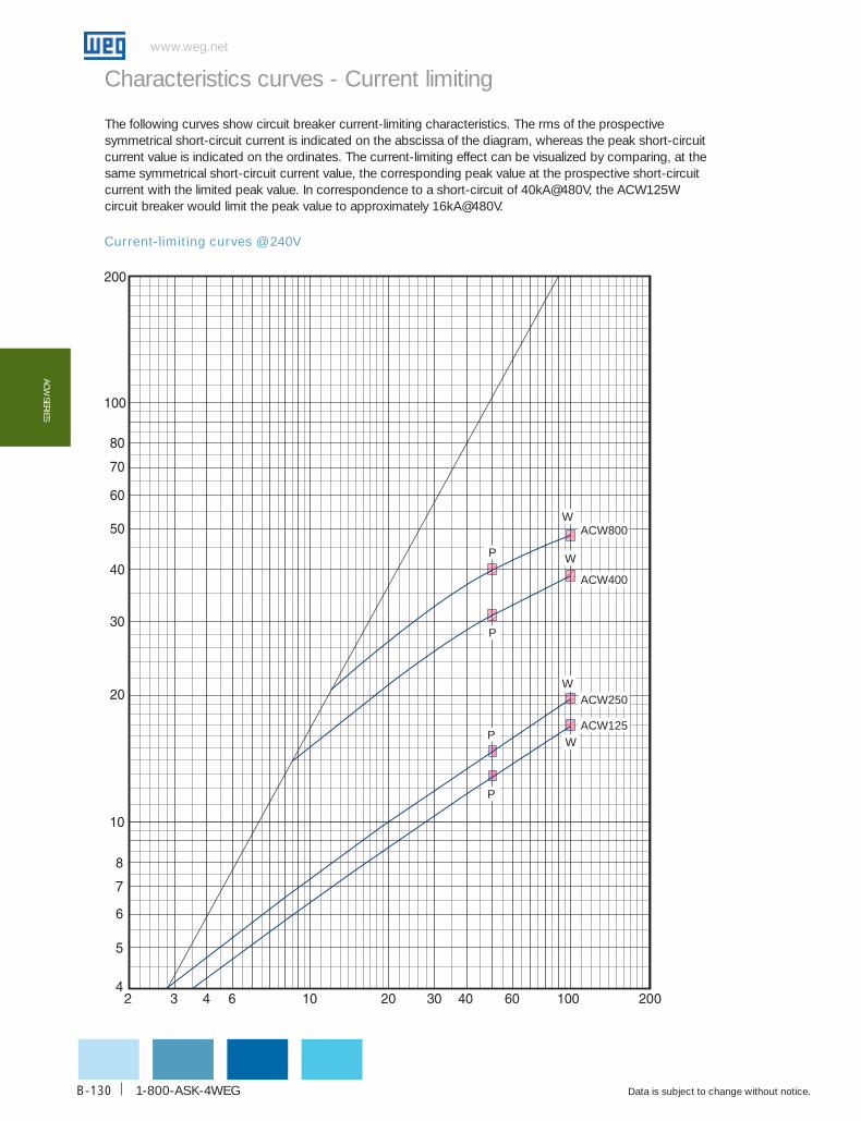
1-800-ASK-4WEG
www.weg.net
Data is subject to change without notice.B-130
AcW SERIES
Current-limiting curves @ 240V
Characteristics curves - Current limiting
The following curves show circuit breaker current-limiting characteristics. The rms of the prospective symmetrical short-circuit current is indicated on the abscissa of the diagram, whereas the peak short-circuit current value is indicated on the ordinates. The current-limiting effect can be visualized by comparing, at the same symmetrical short-circuit current value, the corresponding peak value at the prospective short-circuit current with the limited peak value. In correspondence to a short-circuit of 40kA@480V, the ACW125W circuit breaker would limit the peak value to approximately 16kA@480V.
ACW800
ACW400
W
WP
P
W
P
P
W
ACW250
ACW125
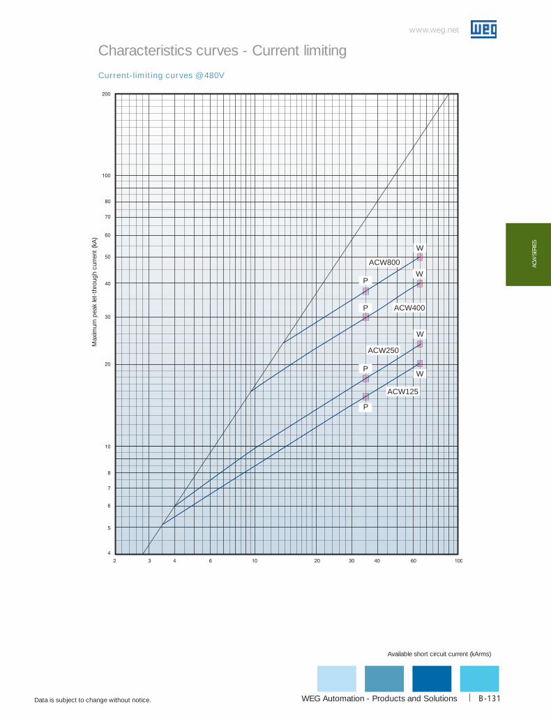
WEG Automation - Products and Solutions
www.weg.net
Data is subject to change without notice. B-131
AcW
SER
IES
Current-limiting curves @ 480V
Characteristics curves - Current limiting
Available short circuit current (kArms)
Max
imum
pea
k le
t-th
roug
h cu
rren
t (kA
)
P
W
P
W
W
WP
P
ACW800
ACW400
ACW250
ACW125

1-800-ASK-4WEG
www.weg.net
Data is subject to change without notice.B-132
AcW SERIES
Current-limiting curves @600V
Characteristics curves - Current limiting
ACW800
W
P
ACW400
W
P
W
ACW250
P
W
P
ACW125

WEG Automation - Products and Solutions
www.weg.net
Data is subject to change without notice. B-133
AcW
SER
IES
Let-through energy curves @240V
Characteristics curves - Let-through energy
Max
imum
let-
thro
ugh
l²t (A
²s)
Available short circuit current (kArms)
The prospective symmetrical short-circuit current is indicated on the abscissa of the diagram, whereas the ordinates show the specific let through energy values expressed in A2s. In correspondence to a short-cir-cuit of 65kA@480V, the ACW125W circuit breaker lets through a value of I2t approximately to 400kA2s.
W
ACW800
ACW400
W
W
W
P
P
P
P
ACW250
ACW125

1-800-ASK-4WEG
www.weg.net
Data is subject to change without notice.B-134
AcW SERIES
Let-through energy curves @ 480V
Characteristics curves - Let-through energyM
axim
um le
t-th
roug
h l²t
(A²s
)
ACW800
ACW400
ACW250
ACW125
W
W
P
P
P
P
W
W
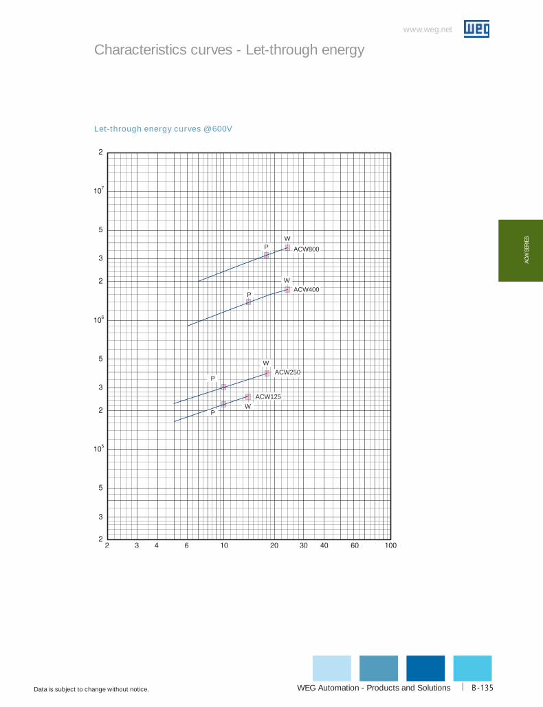
WEG Automation - Products and Solutions
www.weg.net
Data is subject to change without notice. B-135
AcW
SER
IES
Let-through energy curves @ 600V
Characteristics curves - Let-through energy
ACW800
ACW400
ACW250
ACW125
W
P
P
W
P
P
W
W

1-800-ASK-4WEG
www.weg.net
Data is subject to change without notice.B-136
AcW SERIES
ACW125
Dimensions - inch (mm)
ACW250
Drillingtemplate
Drillingtemplate
Front viewcut-out
Front viewcut-out
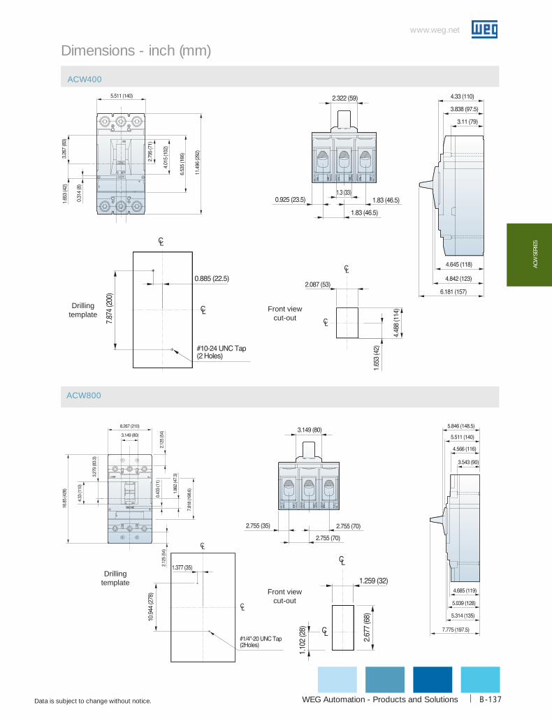
WEG Automation - Products and Solutions
www.weg.net
Data is subject to change without notice. B-137
AcW
SER
IES
ACW400
ACW800
Dimensions - inch (mm)
Drillingtemplate
Drillingtemplate
Front viewcut-out
Front viewcut-out

1-800-ASK-4WEG
www.weg.net
Data is subject to change without notice.B-138
AcW SERIES
14.5 (368.3)
14.5(368.3) - 12” shaft18.5(470) - 16” shaft26.5(673.1) - 24” shaft
Panel drilling Way of installation
Dimensions - inch (mm)
Extended rotary handle - ACW125

WEG Automation - Products and Solutions
www.weg.net
Data is subject to change without notice. B-139
AcW
SER
IES
Panel drilling Way of installation
Dimensions - inch (mm)
Extended rotary handle - ACW250
14.54 (369.3)
14.54 (369.3) -12” shaft18.54 (471) - 16” shaft26.54 (674.1) - 24” shaft

1-800-ASK-4WEG
www.weg.net
Data is subject to change without notice.B-140
AcW SERIES
15.93 (404.6) -12” shaft19.93 (506) - 16” shaft27.93 (709.4) -24” shaft
Panel drilling Way of installation
Dimensions - inch (mm)
Extended rotary handle - ACW400

WEG Automation - Products and Solutions
www.weg.net
Data is subject to change without notice. B-141
AcW
SER
IES
Panel drilling Way of installation
Dimensions - inch (mm)
Extended rotary handle - ACW800
17.42 (442.5) - 12” shaft21.42 (541.2) - 16” shaft29.42 (747.32) - 24” shaft
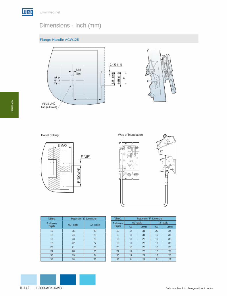
1-800-ASK-4WEG
www.weg.net
Data is subject to change without notice.B-142
AcW SERIES
Dimensions - inch (mm)
Flange Handle ACW125
Panel drilling Way of installation
Table 1 Maximum "E" Dimension
Enclosure Depth 60” cable 72” cable
10 25 30
12 24 29
16 23 28
18 22 27
20 21 26
24 20 25
30 19 24
36 18 23
Table 2 Maximum "F" Dimension
Enclosure Depth
60” cable 72” cable
Up Down Up Down
10 17 31 20 34
12 17 31 19 33
16 17 28 19 30
18 17 28 19 30
20 16 26 18 28
24 14 26 16 28
30 11 24 13 26
36 6 21 8 22
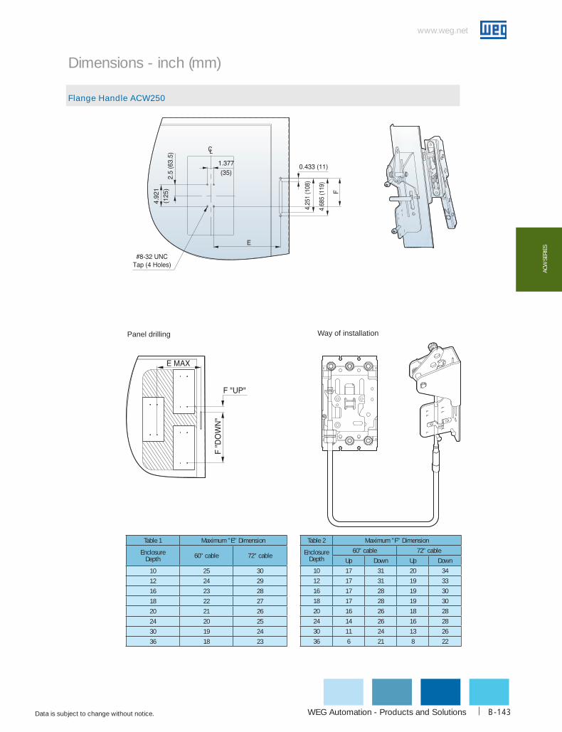
WEG Automation - Products and Solutions
www.weg.net
Data is subject to change without notice. B-143
AcW
SER
IES
Dimensions - inch (mm)
Flange Handle ACW250
Panel drilling Way of installation
Table 1 Maximum "E" Dimension
Enclosure Depth 60” cable 72” cable
10 25 30
12 24 29
16 23 28
18 22 27
20 21 26
24 20 25
30 19 24
36 18 23
Table 2 Maximum "F" Dimension
Enclosure Depth
60” cable 72” cable
Up Down Up Down
10 17 31 20 34
12 17 31 19 33
16 17 28 19 30
18 17 28 19 30
20 16 26 18 28
24 14 26 16 28
30 11 24 13 26
36 6 21 8 22

1-800-ASK-4WEG
www.weg.net
Data is subject to change without notice.B-144
AcW SERIES
Dimensions - inch (mm)
Flange Handle ACW400
Panel drilling Way of installation
Table 1 Maximum "E" Dimension
Enclosure Depth 60” cable 72” cable
10 25 30
12 24 29
16 23 28
18 22 27
20 21 26
24 20 25
30 19 24
36 18 23
Table 2 Maximum "F" Dimension
Enclosure Depth
60” cable 72” cable
Up Down Up Down
10 17 31 20 34
12 17 31 19 33
16 17 28 19 30
18 17 28 19 30
20 16 26 18 28
24 14 26 16 28
30 11 24 13 26
36 6 21 8 22
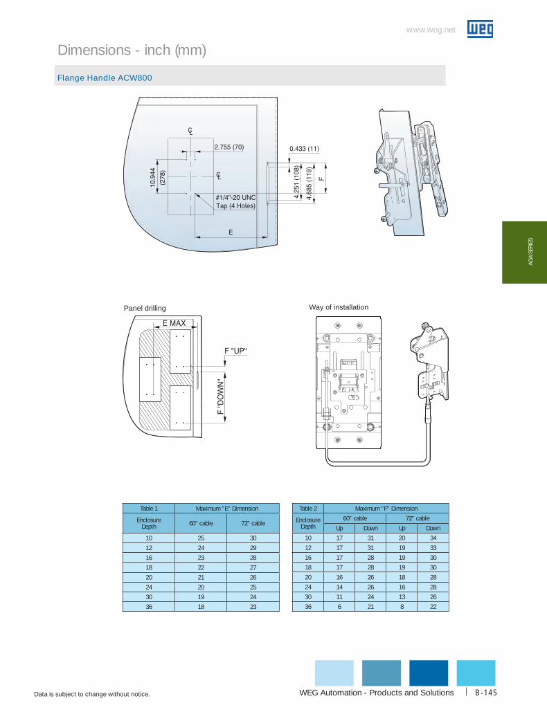
WEG Automation - Products and Solutions
www.weg.net
Data is subject to change without notice. B-145
AcW
SER
IES
Dimensions - inch (mm)
Flange Handle ACW800
Panel drilling Way of installation
Table 1 Maximum "E" Dimension
Enclosure Depth 60” cable 72” cable
10 25 30
12 24 29
16 23 28
18 22 27
20 21 26
24 20 25
30 19 24
36 18 23
Table 2 Maximum "F" Dimension
Enclosure Depth
60” cable 72” cable
Up Down Up Down
10 17 31 20 34
12 17 31 19 33
16 17 28 19 30
18 17 28 19 30
20 16 26 18 28
24 14 26 16 28
30 11 24 13 26
36 6 21 8 22

1-800-ASK-4WEG
www.weg.net
Data is subject to change without notice.B-146
AcW SERIES
Dimensions - inch (mm)
Mechanical interlocking device - MIT
Mechanical interlocking device - Mounting dimension for MIT
A (inch) B (inch)
ACW125 3.267 3.385
ACW250 4.015 3.385
ACW400 6.614 4.330
ACW800 7.193 5.314
3 Pole MCCB C(inch) D(inch) E(inch)
ACW125 4.212 3.543 1.181
ACW250 4.921 4.133 1.377
ACW400 7.874 5.490 1.830
ACW800 10.944 8.267 2.755
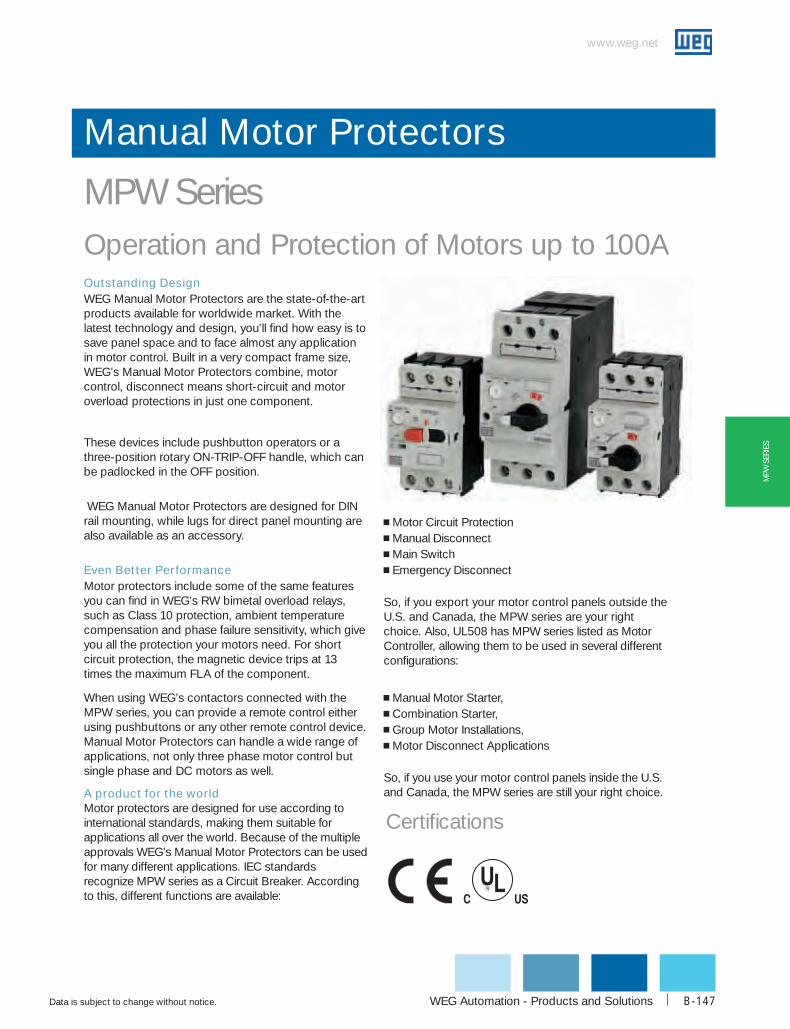
WEG Automation - Products and Solutions
www.weg.net
Data is subject to change without notice. B-147
MPW
SER
IES
Manual Motor Protectors
MPW SeriesOperation and Protection of Motors up to 100AOutstanding DesignWEG Manual Motor Protectors are the state-of-the-art products available for worldwide market. With the latest technology and design, you’ll find how easy is to save panel space and to face almost any application in motor control. Built in a very compact frame size, WEG’s Manual Motor Protectors combine, motor control, disconnect means short-circuit and motor overload protections in just one component.
These devices include pushbutton operators or a three-position rotary ON-TRIP-OFF handle, which can be padlocked in the OFF position.
WEG Manual Motor Protectors are designed for DIN rail mounting, while lugs for direct panel mounting are also available as an accessory.
Even Better PerformanceMotor protectors include some of the same features you can find in WEG’s RW bimetal overload relays, such as Class 10 protection, ambient temperature compensation and phase failure sensitivity, which give you all the protection your motors need. For short circuit protection, the magnetic device trips at 13 times the maximum FLA of the component.
When using WEG’s contactors connected with the MPW series, you can provide a remote control either using pushbuttons or any other remote control device. Manual Motor Protectors can handle a wide range of applications, not only three phase motor control but single phase and DC motors as well.
A product for the world Motor protectors are designed for use according to international standards, making them suitable for applications all over the world. Because of the multiple approvals WEG’s Manual Motor Protectors can be used for many different applications. IEC standards recognize MPW series as a Circuit Breaker. According to this, different functions are available:
g Motor Circuit Protectiong Manual Disconnectg Main Switchg Emergency Disconnect
So, if you export your motor control panels outside the U.S. and Canada, the MPW series are your right choice. Also, UL508 has MPW series listed as Motor Controller, allowing them to be used in several different configurations:
g Manual Motor Starter, g Combination Starter,g Group Motor Installations,g Motor Disconnect Applications
So, if you use your motor control panels inside the U.S. and Canada, the MPW series are still your right choice.
Certifications
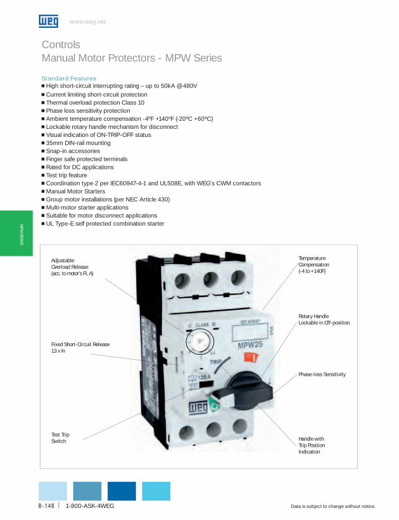
www.weg.net
Data is subject to change without notice.1-800-ASK-4WEGB-148
MPW
SERIES
Controls Manual Motor Protectors - MPW Series
Adjustableoverload Release(acc. to motor’s FL A)
Fixed Short-circuit Release13 x In
Test TripSwitch
Temperaturecompensation(-4 to +140F)
Rotary handleLockable in off-position
Phase-loss Sensitivity
handle withTrip PositionIndication
Standard Features g High short-circuit interrupting rating – up to 50kA @ 480Vg Current limiting short-circuit protectiong Thermal overload protection Class 10g Phase loss sensitivity protectiong Ambient temperature compensation -4ºF +140ºF (-20ºC +60ºC)g Lockable rotary handle mechanism for disconnectg Visual indication of ON-TRIP-OFF statusg 35mm DIN-rail mountingg Snap-in accessoriesg Finger safe protected terminalsg Rated for DC applicationsg Test trip featureg Coordination type 2 per IEC60947-4-1 and UL508E, with WEG’s CWM contactorsg Manual Motor Startersg Group motor installations (per NEC Article 430)g Multi-motor starter applicationsg Suitable for motor disconnect applicationsg UL Type-E self protected combination starter
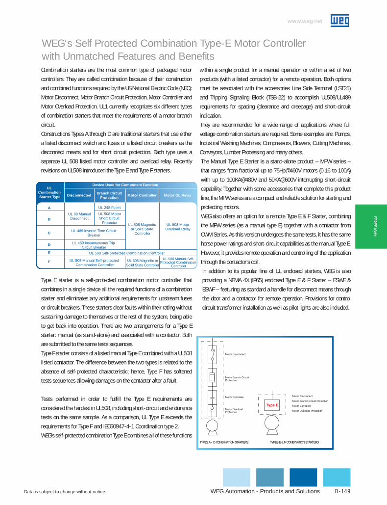
WEG Automation - Products and Solutions
www.weg.net
Data is subject to change without notice. B-149
MPW
SER
IES
WEG‘s Self Protected Combination Type-E Motor Controller with Unmatched Features and BenefitsCombination starters are the most common type of packaged motor
controllers. They are called combination because of their construction
and combined functions required by the US National Electric Code (NEC):
Motor Disconnect, Motor Branch Circuit Protection, Motor Controller and
Motor Overload Protection. UL1 currently recognizes six different types
of combination starters that meet the requirements of a motor branch
circuit.
Constructions Types A through D are traditional starters that use either
a listed disconnect switch and fuses or a listed circuit breakers as the
disconnect means and for short circuit protection. Each type uses a
separate UL 508 listed motor controller and overload relay. Recently
revisions on UL508 introduced the Type E and Type F starters.
Type E starter is a self-protected combination motor controller that
combines in a single device all the required functions of a combination
starter and eliminates any additional requirements for upstream fuses
or circuit breakers. These starters clear faults within their rating without
sustaining damage to themselves or the rest of the system, being able
to get back into operation. There are two arrangements for a Type E
starter: manual (as stand-alone) and associated with a contactor. Both
are submitted to the same tests sequences.
Type F starter consists of a listed manual Type E combined with a UL508
listed contactor. The difference between the two types is related to the
absence of self-protected characteristic; hence, Type F has softened
tests sequences allowing damages on the contactor after a fault.
Tests performed in order to fulfill the Type E requirements are
considered the hardest in UL508, including short-circuit and endurance
tests on the same sample. As a comparison, UL Type E exceeds the
requirements for Type F and IEC60947-4-1 Coordination type 2.
WEG’s self-protected combination Type E combines all of these functions
within a single product for a manual operation or within a set of two
products (with a listed contactor) for a remote operation. Both options
must be associated with the accessories Line Side Terminal (LST25)
and Tripping Signaling Block (TSB-22) to accomplish UL508/UL489
requirements for spacing (clearance and creepage) and short-circuit
indication.
They are recommended for a wide range of applications where full
voltage combination starters are required. Some examples are: Pumps,
Industrial Washing Machines, Compressors, Blowers, Cutting Machines,
Conveyors, Lumber Processing and many others.
The Manual Type E Starter is a stand-alone product – MPW series –
that ranges from fractional up to 75Hp@460V motors (0.16 to 100A)
with up to 100KA@480V and 50KA@600V interrupting short-circuit
capability. Together with some accessories that complete this product
line, the MPW series are a compact and reliable solution for starting and
protecting motors.
WEG also offers an option for a remote Type E & F Starter, combining
the MPW series (as a manual type E) together with a contactor from
CWM Series. As this version undergoes the same tests, it has the same
horse power ratings and short-circuit capabilities as the manual Type E.
However, it provides remote operation and controlling of the application
through the contactor’s coil.
In addition to its popular line of UL enclosed starters, WEG is also
providing a NEMA 4X (IP65) enclosed Type E & F Starter – ESWE &
ESWF – featuring as standard a handle for disconnect means through
the door and a contactor for remote operation. Provisions for control
circuit transformer installation as well as pilot lights are also included.
UL Combination Starter Type
UL 489 Inverse Time CircuitBreaker
UL 508 Manual Self-protected Combination Controller
UL 508 Magnetic orSolid State Controller
UL 508 Manual Self-Protected Combination
Controller
UL 508 Magnetic or Solid State
Controller
UL 508 MotorOverload Relay
UL 489 Instantaneous Trip Circuit Breaker
UL 508 Self-protected Combination Controller
UL 248 Fuses
UL 98 ManualDisconnect
UL 508 MotorShort Circuit
Protector
A
B
C
D
E
F
Branch CircuitProtection
Disconnected Motor Controller
Device Used for Component Function
Motor OL Relay
TYPES A - d coMbINATIoN STARTERS TYPES E & F coMbINATIoN STARTERS

www.weg.net
Data is subject to change without notice.1-800-ASK-4WEGB-150
MPW
SERIES
Controls Manual Motor Protectors - MPW SeriesN OL
OTO T T P S
- 3 - U00416MPW
MANUAL MOTOR PROTECTOR SERIES:
MPW: Manual Motor Protectors POWER POLE:
3: 3 NO Power Poles
FRAME SIZE:
16: to use with CWC07…025 & CWM9…CWM1825: to use with CWC07…025 & CWM9…40 65: to use with CWM50…80 100: to use with CWM95…105
OVERLOAD SETTING CURRENT:
MPW16 C016: 0.10 ... 0.16A ... U016: 10 … 16A
MPW25 C016: 0.10 ... 0.16A ... U032: 25 … 32A
For more details refer to selection table for each frame size
MPW65 U016: 10 … 16A ... U065: 50 ... 65A
MPW100 U075: 55 … 75A ... U100: 80 ... 100A
Catalog part number composition
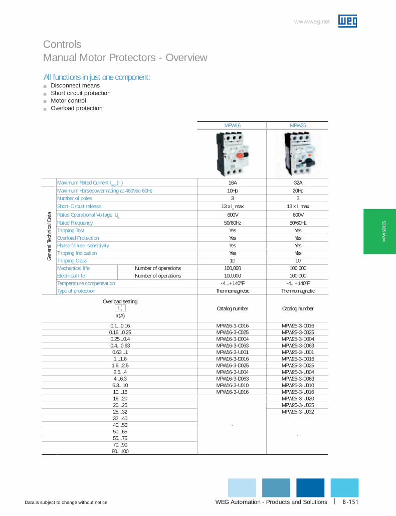
WEG Automation - Products and Solutions
www.weg.net
Data is subject to change without notice. B-151
MPW
SER
IES
Controls Manual Motor Protectors - Overview
MPW16 MPW25
Gene
ral T
echn
ical
dat
a
Maximum Rated current Imax(Iu) 16A 32A
Maximum horsepower rating at 460Vac 60hz 10Hp 20HpNumber of poles 3 3
Short-circuit release 13 x lu max 13 x lu max
Rated operational Voltage ue 600V 600V
Rated Frequency 50/60Hz 50/60HzTripping Test Yes Yesoverload Protection Yes YesPhase failure sensitivity Yes YesTripping Indication Yes YesTripping class 10 10Mechanical life Number of operations 100,000 100,000Electrical life Number of operations 100,000 100,000Temperature compensation -4...+140ºF -4...+140ºFType of protection Thermomagnetic Thermomagnetic
overload setting
Ir(A)
Catalog number Catalog number
0.1...0.16 MPW16-3-C016 MPW25-3-C0160.16...0.25 MPW16-3-C025 MPW25-3-C0250.25...0.4 MPW16-3-D004 MPW25-3-D0040.4...0.63 MPW16-3-C063 MPW25-3-C0630.63...1 MPW16-3-U001 MPW25-3-U0011...1.6 MPW16-3-D016 MPW25-3-D016
1.6...2.5 MPW16-3-D025 MPW25-3-D0252.5...4 MPW16-3-U004 MPW25-3-U0044...6.3 MPW16-3-D063 MPW25-3-D063
6.3...10 MPW16-3-U010 MPW25-3-U01010...16 MPW16-3-U016 MPW25-3-U01616...20
-
MPW25-3-U02020...25 MPW25-3-U02525...32 MPW25-3-U03232...40
-
40...5050...6555...7570...9080...100
All functions in just one component:g Disconnect meansg Short circuit protectiong Motor controlg Overload protection
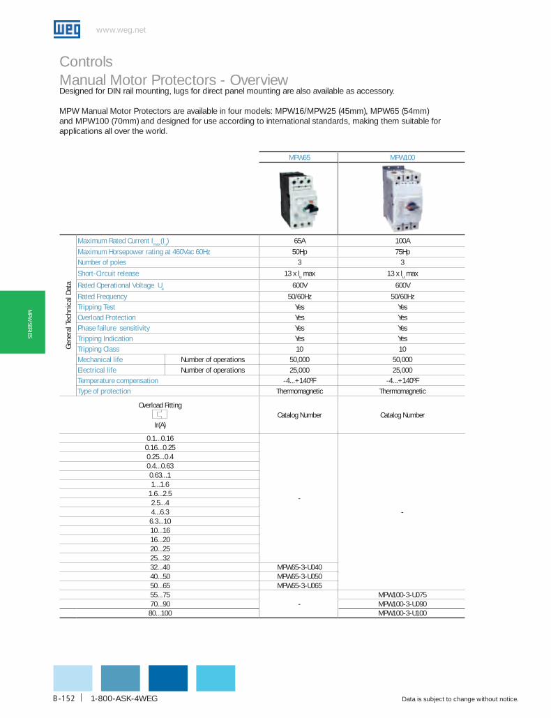
www.weg.net
Data is subject to change without notice.1-800-ASK-4WEGB-152
MPW
SERIES
MPW65 MPW100
Gene
ral T
echn
ical
dat
a
Maximum Rated current Imax(Iu) 65A 100A
Maximum horsepower rating at 460Vac 60hz 50Hp 75HpNumber of poles 3 3
Short-circuit release 13 x lu max 13 x lu max
Rated operational Voltage ue 600V 600V
Rated Frequency 50/60Hz 50/60HzTripping Test Yes Yesoverload Protection Yes YesPhase failure sensitivity Yes YesTripping Indication Yes YesTripping class 10 10Mechanical life Number of operations 50,000 50,000Electrical life Number of operations 25,000 25,000Temperature compensation -4...+140ºF -4...+140ºFType of protection Thermomagnetic Thermomagnetic
Overload Fitting
Ir(A)
Catalog Number Catalog Number
0.1...0.16
-
-
0.16...0.250.25...0.40.4...0.630.63...11...1.6
1.6...2.52.5...44...6.36.3...1010...1616...2020...2525...3232...40 MPW65-3-U04040...50 MPW65-3-U05050...65 MPW65-3-U06555...75
-MPW100-3-U075
70...90 MPW100-3-U09080...100 MPW100-3-U100
Controls Manual Motor Protectors - OverviewDesigned for DIN rail mounting, lugs for direct panel mounting are also available as accessory.
MPW Manual Motor Protectors are available in four models: MPW16/MPW25 (45mm), MPW65 (54mm) and MPW100 (70mm) and designed for use according to international standards, making them suitable for applications all over the world.

WEG Automation - Products and Solutions
www.weg.net
Data is subject to change without notice. B-153
MPW
SER
IES
1. MPW16 Manual Motor Protector - MPW16 Series
2 FTbbS Three Phase Line Side Feeder Terminal
3. bbS Three Phase Busbars
4. PLMP Push-in Lugs for panel mounting
5. AcbS Auxiliary Contact Block Side-Mounting
6. uRMP/SRMP Undervoltage Release / Shunt Release
7. AcbF Auxiliary Contact Block Front-Mounting
8. EccMP-c016 Connection Link (MPW16 to + CWC07...16)
9. cWc 07, 09, 012, 016, Miniature Contactors
10. PE66GN IP66 Non Metallic Insulated Enclosure
11. Printed Circuit Board Connector for Power Terminals
12. Printed Circuit Board Connector front Auxiliary Contact Block
13. ScMP Scale Cover
Controls Manual Motor Protectors - MPW Series
MPW16 - Overview
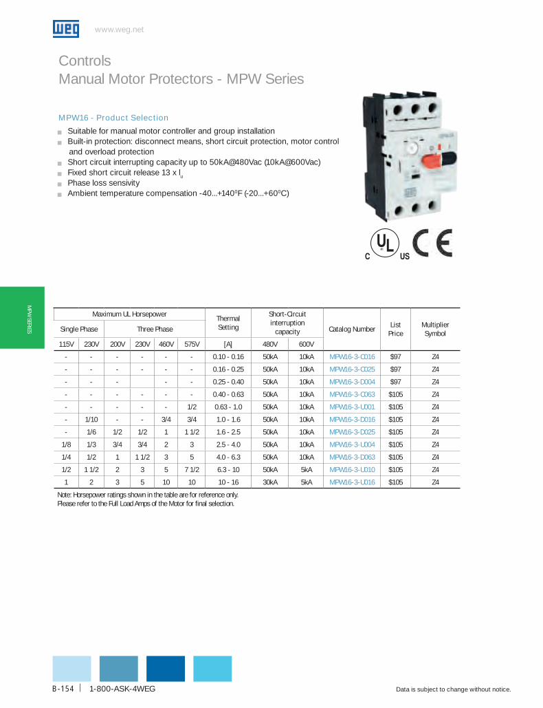
www.weg.net
Data is subject to change without notice.1-800-ASK-4WEGB-154
MPW
SERIES
Controls Manual Motor Protectors - MPW Series
MPW16 - Product Selection
g Suitable for manual motor controller and group installationg Built-in protection: disconnect means, short circuit protection, motor control and overload protectiong Short circuit interrupting capacity up to 50kA@480Vac (10kA@600Vac)g Fixed short circuit release 13 x lug Phase loss sensivityg Ambient temperature compensation -40...+1400F (-20...+600C)
Maximum uL horsepowerThermal Setting
Short-circuit interruption
capacity catalog NumberList
PriceMultiplier Symbol
Single Phase Three Phase
115V 230V 200V 230V 460V 575V [A] 480V 600V
- - - - - - 0.10 - 0.16 50kA 10kA MPW16-3-c016 $97 Z4
- - - - - - 0.16 - 0.25 50kA 10kA MPW16-3-c025 $97 Z4
- - - - - 0.25 - 0.40 50kA 10kA MPW16-3-d004 $97 Z4
- - - - - - 0.40 - 0.63 50kA 10kA MPW16-3-c063 $105 Z4
- - - - - 1/2 0.63 - 1.0 50kA 10kA MPW16-3-u001 $105 Z4
- 1/10 - - 3/4 3/4 1.0 - 1.6 50kA 10kA MPW16-3-d016 $105 Z4
- 1/6 1/2 1/2 1 1 1/2 1.6 - 2.5 50kA 10kA MPW16-3-d025 $105 Z4
1/8 1/3 3/4 3/4 2 3 2.5 - 4.0 50kA 10kA MPW16-3-u004 $105 Z4
1/4 1/2 1 1 1/2 3 5 4.0 - 6.3 50kA 10kA MPW16-3-d063 $105 Z4
1/2 1 1/2 2 3 5 7 1/2 6.3 - 10 50kA 5kA MPW16-3-u010 $105 Z4
1 2 3 5 10 10 10 - 16 30kA 5kA MPW16-3-u016 $105 Z4
Note: Horsepower ratings shown in the table are for reference only. Please refer to the Full Load Amps of the Motor for final selection.

WEG Automation - Products and Solutions
www.weg.net
Data is subject to change without notice. B-155
MPW
SER
IES
Controls Manual Motor Protectors - MPW Series
description catalog Number List PriceMultiplier Symbol
Auxiliary contact blocks
1NO&1NC auxiliary contact block front mounting - 250Vmax. AcbF-11 $20 Z4
1NO&1NC auxiliary contact block left side mounting - 600Vmax. AcbS-11 $22 Z4
2NO Auxiliary contact block left side mounting - 600Vmax. AcbS-20 $22 Z4
2NC Auxiliary contact block left side mounting - 600Vmax. AcbS-02 $22 Z4
Link Modules
Mechanical and electrical link module for CWC07 to CWC016 miniature contactor series EccMP-c016 $20 Z4
Mechanical and electrical link module for CWC025 miniature contactor series EccMP-c025 $20 Z4
Accessories for Group Motor Installation 1
Three Phase Line Side Feeder Terminal FTbbS $35 Z4
Bus bar system 45mm (for 2 MPW without side mounting auxiliary contacts) bbS45-2 $32 Z4
Bus bar system 45mm (for 3 MPW without side mounting auxiliary contacts) bbS45-3 $35 Z4
Bus bar system 45mm (for 4 MPW without side mounting auxiliary contacts) bbS45-4 $45 Z4
Bus bar system 45mm (for 5 MPW without side mounting auxiliary contacts) bbS45-5 $60 Z4
Bus bar system 54mm (for 2 MPW with side mounting auxiliary contacts) bbS54-2 $32 Z4
Bus bar system 54mm (for 3 MPW with side mounting auxiliary contacts) bbS54-3 $35 Z4
Bus bar system 54mm (for 4 MPW with side mounting auxiliary contacts) bbS54-4 $45 Z4
Bus bar system 54mm (for 5 MPW with side mounting auxiliary contacts) bbS54-5 $60 Z4
Shroud for unused terminals of BBS bars cSd $10 2 Z4
under Voltage and Shunt block Releases
Shunt release block right side mounting - 20-24V 50/60Hz SRMP d51 $56 Z4
Shunt release block right side mounting - 100-127V 50/60Hz SRMP d59 $56 Z4
Shunt release block right side mounting - 200-240V 50/60Hz SRMP d65 $56 Z4
Under voltage release block right side mounting - 24V 60Hz uRMP V05 $56 Z4
Under voltage release block right side mounting - 120V 60Hz uRMP V18 $56 Z4
Under voltage release block right side mounting - 208V 60Hz uRMP V23 $56 Z4
Under voltage release block right side mounting - 240V 60Hz uRMP V30 $56 Z4
Under voltage release block right side mounting - 480V 60Hz uRMP V47 $56 Z4
IEc Enclosures
IEC IP66 enclosure (non-UL) PE66GN $45 Z4
other Accessories
Scale cover protection for the current range adjustment - package with 5 units ScMP $5 Z4
Lugs for panel mounting - package with 2 pieces (one MPW mounting) PLMP $0.50 Z4
Accessories for MPW16 - Summary
Notes: 1 Maximum Amps of each Bus bar system (BBS) must not be exceeded by adding multiple MPW. Bus bar capacity is 63Amps. 2 Unit list price. Product sold in multiples of 5 units.
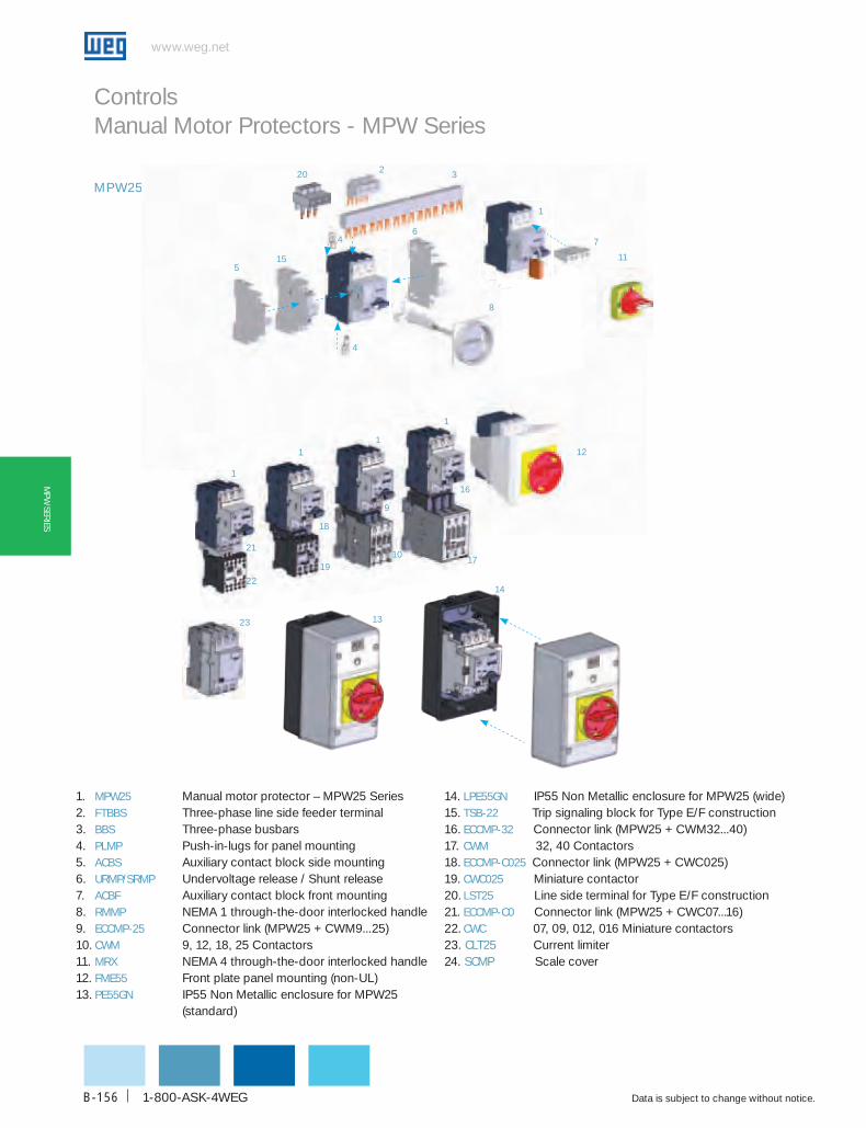
www.weg.net
Data is subject to change without notice.1-800-ASK-4WEGB-156
MPW
SERIES
Controls Manual Motor Protectors - MPW Series
MPW25
12
13
1
1
1
18
16
1910
17
9
1
7
8
155
6
2 3
4
4
21
22
20
23
14
11
1
24
1. MPW25 Manual motor protector – MPW25 Series 2. FTbbS Three-phase line side feeder terminal3. bbS Three-phase busbars4. PLMP Push-in-lugs for panel mounting5. AcbS Auxiliary contact block side mounting6. uRMP/SRMP Undervoltage release / Shunt release 7. AcbF Auxiliary contact block front mounting8. RMMP NEMA 1 through-the-door interlocked handle9. EccMP-25 Connector link (MPW25 + CWM9...25)10. cWM 9, 12, 18, 25 Contactors 11. MRX NEMA 4 through-the-door interlocked handle12. FME55 Front plate panel mounting (non-UL)13. PE55GN IP55 Non Metallic enclosure for MPW25 (standard)
14. LPE55GN IP55 Non Metallic enclosure for MPW25 (wide)15. TSb-22 Trip signaling block for Type E/F construction16. EccMP-32 Connector link (MPW25 + CWM32...40)17. cWM 32, 40 Contactors18. EccMP-c025 Connector link (MPW25 + CWC025)19. cWc025 Miniature contactor20. LST25 Line side terminal for Type E/F construction21. EccMP-c0 Connector link (MPW25 + CWC07...16)22. cWc 07, 09, 012, 016 Miniature contactors23. cLT25 Current limiter24. ScMP Scale cover

WEG Automation - Products and Solutions
www.weg.net
Data is subject to change without notice. B-157
MPW
SER
IES
MPW25 - Product Selection
Maximum uL horsepowerThermal Setting
Short-circuit Ratings for Group Installation catalog Number
List Price
Multiplier Symbol
Single Phase Three Phase
115V 230V 200V 230V 460V 575V [A] 480V 600V
- - - - - - 0.10 - 0.16 50kA 25kA MPW25-3-c016 $116 Z4
- - - - - - 0.16 - 0.25 50kA 25kA MPW25-3-c025 $116 Z4
- - - - - - 0.25 - 0.40 50kA 25kA MPW25-3-d004 $116 Z4
- - - - - 1/4 0.40 - 0.63 50kA 25kA MPW25-3-c063 $137 Z4
- - - - 1/2 1/2 0.63 - 1.0 50kA 25kA MPW25-3-u001 $137 Z4
- 1/10 1/4 1/3 3/4 1 1.0 - 1.6 50kA 25kA MPW25-3-d016 $137 Z4
- 1/6 1/2 1/2 1 1/2 1 1/2 1.6 - 2.5 50kA 25kA MPW25-3-d025 $137 Z4
1/8 1/3 3/4 1 2 3 2.5 - 4.0 50kA 25kA MPW25-3-u004 $137 Z4
1/4 3/4 1 1/2 1 1/2 3 5 4.0 - 6.3 50kA 25kA MPW25-3-d063 $137 Z4
1/2 1 1/2 3 3 5 7 1/2 6.3 - 10 50kA 25kA MPW25-3-u010 $137 Z4
1 3 5 5 10 15 10 - 16 50kA 25kA MPW25-3-u016 $150 Z4
1 1/2 3 5 7 1/2 15 15 16 - 20 50kA 25kA MPW25-3-u020 $150 Z4
2 3 7 1/2 7 1/2 15 20 20 - 25 50kA 25kA MPW25-3-u025 $150 Z4
- 5 10 10 20 25 25 - 32 42kA 25kA MPW25-3-u032 $190 Z4
Note: Horsepower ratings shown in the table are for reference only. Please refer to the Full Load Amps of the Motor for final selection.
Controls
Manual Motor Protectors - MPW Series
g Suitable for manual motor controller, group installation, tap conductor and combination starters* type E & type Fg Built-in protection: disconnect means, short-circuit protection, motor control and overload protectiong Short-circuit interrupting capacity up to 50kA@480Vac (25kA@600Vac)g Fixed short-circuit release 13 x Iug Phase loss sensitivityg Ambient temperature compensation -4…+140ºF (-20…+60ºC)
* When associated with line side terminal LST25 and trip indicator TSB-22
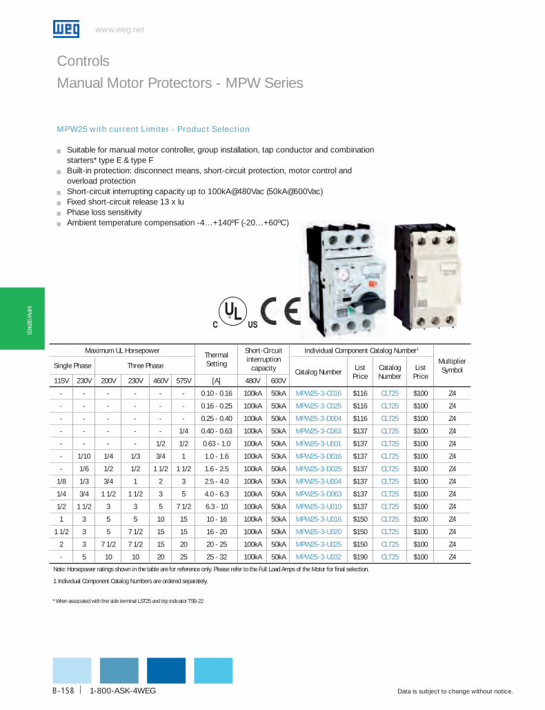
www.weg.net
Data is subject to change without notice.1-800-ASK-4WEGB-158
MPW
SERIES
Controls
Manual Motor Protectors - MPW Series
MPW25 with current Limiter - Product Selection
g Suitable for manual motor controller, group installation, tap conductor and combination starters* type E & type Fg Built-in protection: disconnect means, short-circuit protection, motor control and overload protectiong Short-circuit interrupting capacity up to 100kA@480Vac (50kA@600Vac)g Fixed short-circuit release 13 x Iug Phase loss sensitivityg Ambient temperature compensation -4…+140ºF (-20…+60ºC)
Maximum uL horsepowerThermal Setting
Short-circuit interruption
capacity
Individual component catalog Number1
Multiplier Symbol
Single Phase Three Phasecatalog Number
List Price
catalog Number
List Price
115V 230V 200V 230V 460V 575V [A] 480V 600V
- - - - - - 0.10 - 0.16 100kA 50kA MPW25-3-c016 $116 cLT25 $100 Z4
- - - - - - 0.16 - 0.25 100kA 50kA MPW25-3-c025 $116 cLT25 $100 Z4
- - - - - - 0.25 - 0.40 100kA 50kA MPW25-3-d004 $116 cLT25 $100 Z4
- - - - - 1/4 0.40 - 0.63 100kA 50kA MPW25-3-c063 $137 cLT25 $100 Z4
- - - - 1/2 1/2 0.63 - 1.0 100kA 50kA MPW25-3-u001 $137 cLT25 $100 Z4
- 1/10 1/4 1/3 3/4 1 1.0 - 1.6 100kA 50kA MPW25-3-d016 $137 cLT25 $100 Z4
- 1/6 1/2 1/2 1 1/2 1 1/2 1.6 - 2.5 100kA 50kA MPW25-3-d025 $137 cLT25 $100 Z4
1/8 1/3 3/4 1 2 3 2.5 - 4.0 100kA 50kA MPW25-3-u004 $137 cLT25 $100 Z4
1/4 3/4 1 1/2 1 1/2 3 5 4.0 - 6.3 100kA 50kA MPW25-3-d063 $137 cLT25 $100 Z4
1/2 1 1/2 3 3 5 7 1/2 6.3 - 10 100kA 50kA MPW25-3-u010 $137 cLT25 $100 Z4
1 3 5 5 10 15 10 - 16 100kA 50kA MPW25-3-u016 $150 cLT25 $100 Z4
1 1/2 3 5 7 1/2 15 15 16 - 20 100kA 50kA MPW25-3-u020 $150 cLT25 $100 Z4
2 3 7 1/2 7 1/2 15 20 20 - 25 100kA 50kA MPW25-3-u025 $150 cLT25 $100 Z4
- 5 10 10 20 25 25 - 32 100kA 50kA MPW25-3-u032 $190 cLT25 $100 Z4
Note: Horsepower ratings shown in the table are for reference only. Please refer to the Full Load Amps of the Motor for final selection.
1 Individual Component Catalog Numbers are ordered separately.
* When associated with line side terminal LST25 and trip indicator TSB-22

WEG Automation - Products and Solutions
www.weg.net
Data is subject to change without notice. B-159
MPW
SER
IES
Controls
Manual Motor Protectors - MPW Series
Accessories for MPW25 - Summary
description catalog NumberList
PriceMultiplier Symbol
Auxiliary contact blocks 1NO&1NC auxiliary contact block front mounting - 250Vmax. AcbF-11 $20 Z4 1NO&1NC auxiliary contact block left side mounting - 600Vmax. AcbS-11 $22 Z4 2NO Auxiliary contact block left side mounting - 600Vmax. AcbS-20 $22 Z4 2NC Auxiliary contact block left side mounting - 600Vmax. AcbS-02 $22 Z4 Accessories for combination Type-E construction Line power terminal LST25 $38 Z4 Trip Signaling and Alarm Contact Block (1NO&1NC for Short-circuit and 1NO&1NC for Overload) TSb-22 $38 Z4 current Limiter Current Limiter cLT25 $100 Z4 Link Modules Mechanical and electrical link module for CWC07 to CWC016 miniature contactor series EccMP-c0 $20 Z4 Mechanical and electrical link module for CWM9…CWM25 contactor series EccMP-25 $20 Z4 Mechanical and electrical link module for CWM32…CWM40 contactor series EccMP-32 $25 Z4 Accessories for Group Motor Installation 1
Income power terminal for bus bar system FTbbS $35 Z4 Bus bar system 45mm (for 2 MPW without side mounting auxiliary contacts) bbS45-2 $32 Z4 Bus bar system 45mm (for 3 MPW without side mounting auxiliary contacts) bbS45-3 $35 Z4 Bus bar system 45mm (for 4 MPW without side mounting auxiliary contacts) bbS45-4 $45 Z4 Bus bar system 45mm (for 5 MPW without side mounting auxiliary contacts) bbS45-5 $60 Z4 Bus bar system 54mm (for 2 MPW with side mounting auxiliary contacts) bbS54-2 $32 Z4 Bus bar system 54mm (for 3 MPW with side mounting auxiliary contacts) bbS54-3 $35 Z4 Bus bar system 54mm (for 4 MPW with side mounting auxiliary contacts) bbS54-4 $45 Z4 Bus bar system 54mm (for 5 MPW with side mounting auxiliary contacts) bbS54-5 $60 Z4 Shroud for unused terminals of BBS bars cSd $102 Z4 Through-the-door Rotary Mechanisms Rotary NEMA 1 Through the Door Mechanism - gray/black handle with 130mm shaft RMMP-130 $60 Z4 Rotary NEMA 1 Through the Door Mechanism - yellow/red handle with 130mm shaft RMMP-130-E $60 Z4 Rotary NEMA 1 Through the Door Mechanism - gray/black handle with 330mm shaft RMMP-330 $70 Z4 Rotary NEMA 1 Through the Door Mechanism - yellow/red handle with 330mm shaft RMMP-330-E $70 Z4 Rotary NEMA 4X Through the Door Mechanism - gray/black handle with 130mm shaft MRX-130 $105 Z4 Rotary NEMA 4X Through the Door Mechanism - yellow/red handle with 130mm shaft MRX-130-E $105 Z4 Rotary NEMA 4X Through the Door Mechanism - gray/black handle with 330mm shaft MRX-330 $115 Z4 Rotary NEMA 4X Through the Door Mechanism - yellow/red handle with 330mm shaft MRX-330-E $115 Z4 under Voltage and Shunt block Releases Shunt release block right side mounting - 20-24V 50/60Hz SRMP d51 $56 Z4 Shunt release block right side mounting - 100-127V 50/60Hz SRMP d59 $56 Z4 Shunt release block right side mounting - 200-240V 50/60Hz SRMP d65 $56 Z4 Under voltage release block right side mounting - 24V 60Hz uRMP V05 $56 Z4 Under voltage release block right side mounting - 120V 60Hz uRMP V18 $56 Z4 Under voltage release block right side mounting - 208V 60Hz uRMP V23 $56 Z4 Under voltage release block right side mounting - 240V 60Hz uRMP V30 $56 Z4 Under voltage release block right side mounting - 480V 60Hz uRMP V47 $56 Z4 Mounting adapter Mounting adapter for a D.O.L. assembly with MPW25 and CWM contactors series MA45doL $40 Z4 Mounting adapter for a REVERSING assembly with MPW25 and CWM contactors series MA90RVS $50 Z4 Mounting adapter for a STAR-DELTA assembly with MPW25 and CWM contactors series MA90SdS $50 Z4 IEc Enclosures IEC IP55 enclosure yellow/red handle (non-UL) PE55GN-E $45 Z4 IEC IP55 enclosure + lateral auxiliary device yellow/red handle (non-UL) LPE55GN-E $55 Z4 IEC IP55 enclosure gray/black handle (non-UL) PE55GN $45 Z4 IEC IP55 enclosure + lateral auxiliary device gray/black handle (non-UL) LPE55GN $55 Z4 other Accessories Scale cover protection for the current range adjustment - package with 5 units ScMP $5 Z4 Lugs for panel mounting - package with 2 pieces (one MPW mounting) PLMP $0.50 Z4
Notes: 1 Maximum Amps of each Bus bar system (BBS) must not be exceeded by adding multiple MPW. Bus bar capacity is 63Amps. 2 Unit list price. Product sold in multiples of 5 units.
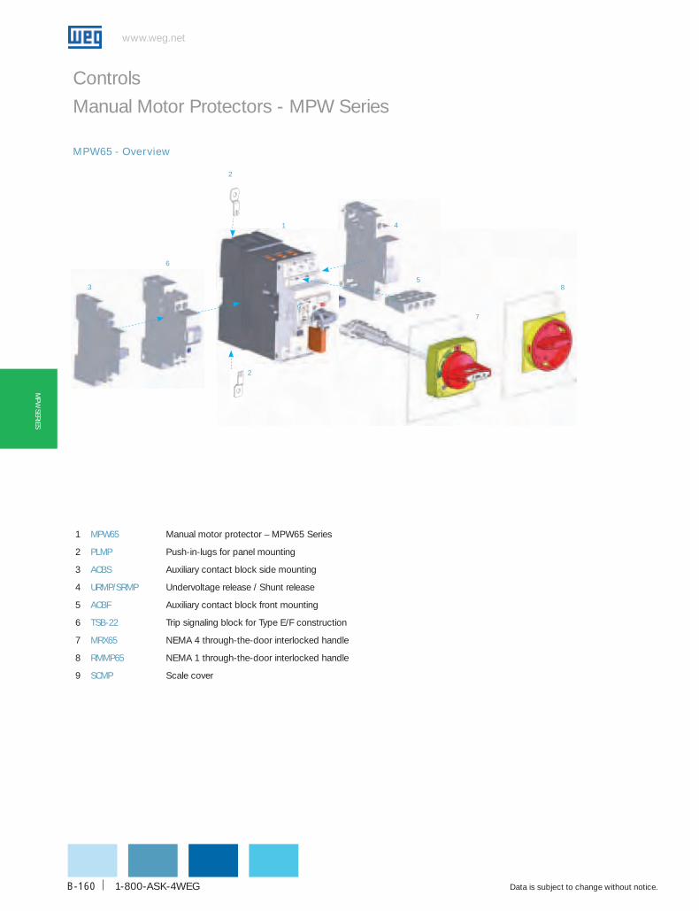
www.weg.net
Data is subject to change without notice.1-800-ASK-4WEGB-160
MPW
SERIES
Controls
Manual Motor Protectors - MPW Series
MPW65 - Overview
1
5
6
2
2
3
4
7
8
9
1 MPW65 Manual motor protector – MPW65 Series
2 PLMP Push-in-lugs for panel mounting
3 AcbS Auxiliary contact block side mounting
4 uRMP/SRMP Undervoltage release / Shunt release
5 AcbF Auxiliary contact block front mounting
6 TSb-22 Trip signaling block for Type E/F construction
7 MRX65 NEMA 4 through-the-door interlocked handle
8 RMMP65 NEMA 1 through-the-door interlocked handle
9 ScMP Scale cover

WEG Automation - Products and Solutions
www.weg.net
Data is subject to change without notice. B-161
MPW
SER
IES
Maximum uL horsepower Thermal Setting
Short-circuit inter-ruption capacity catalog Number List Price
Multiplier Symbol
Single Phase Three Phase
115V 230V 200V 230V 460V 575V [A] 480V 600V
3 7 1/2 - 15 25 30 32 ... 40 35kA 10kA MPW65-3-u040 $380 Z4
- 10 15 15 30 40 40 ... 50 35kA 10kA MPW65-3-u050 $380 Z4
5 10 20 20 50 60 50 ... 65 35kA 10kA MPW65-3-u065 $380 Z4
Maximum uL horsepower Thermal Setting
Short-circuit inter-ruption capacity catalog Number List Price
Multiplier Symbol
Single Phase Three Phase
115V 230V 200V 230V 460V 575V [A] 480V 600V
5 15 20 25 50 60 55 ... 75 50kA 10kA MPW100-3-u075 $460 Z4
7 1/2 20 25 30 60 75 70 ... 90 50kA 10kA MPW100-3-u090 $530 Z4
10 20 30 30 75 100 80 ... 100 50kA 10kA MPW100-3-u100 $530 Z4
Controls
Manual Motor Protectors - MPW Series
MPW65 - Product Selection
g Suitable for manual motor controller, group installation, tap conductor and combination starters1 type E & type Fg Built-in protection: disconnect means, short-circuit protection, motor control and overload protectiong Short-circuit interrupting capacity up to 35kA@480Vac (10kA@600Vac)g Fixed short-circuit release 13 x Iug Phase loss sensitivityg Ambient temperature compensation -4…+140ºF (-20…+60ºC)
MPW100 - Product Selection
g Suitable for manual motor controller, group installation, tap conductor and combination starters2 type E & type Fg Built-in protection: disconnect means, short-circuit protection, motor control and overload protectiong Short-circuit interrupting capacity up to 50kA@480Vac (10kA@600Vac)g Fixed short-circuit release 13 x Iug Phase loss sensitivityg Ambient temperature compensation -4…+140ºF (-20…+60ºC)
Note: Horsepower ratings shown in the table are for reference only. Please refer to the Full Load Amps of the Motor for final selection1 When associated with line side terminal (LST65) and Trip indicator (TSB-22)
Note: Horsepower ratings shown in the table are for reference only. Please refer to the Full Load Amps of the Motor for final selection.2 When associated with line side terminal (IB MPW100) and Trip indicator (TSB SC-11 MPW100)

www.weg.net
Data is subject to change without notice.1-800-ASK-4WEGB-162
MPW
SERIES
description catalog Number List Price Multiplier Symbol
Auxiliary contact blocks 1NO&1NC auxiliary contact block front mounting - 250Vmax. AcbF-11 $20 Z4 1NO&1NC auxiliary contact block left side mounting - 600Vmax. AcbS-11 $22 Z4 2NO Auxiliary contact block left side mounting - 600Vmax. AcbS-20 $22 Z4 2NC Auxiliary contact block left side mounting - 600Vmax. AcbS-02 $22 Z4 Accessories for combination Type-E construction Line power terminal (for MPW65-3-U040 to MPW65-3-U065) LST65 $75 Z4 Trip Signaling and Alarm Contact Block (1NO&1NC for Short-circuit and 1NO&1NC for Overload) TSb-22 $38 Z4 Through-the-door Rotary Mechanisms Rotary NEMA 1 Through the Door Mechanism - gray/black handle with 130mm shaft RMMP65-130 $80 Z4 Rotary NEMA 1 Through the Door Mechanism - yellow/red handle with 130mm shaft RMMP65-130-E $80 Z4 Rotary NEMA 1 Through the Door Mechanism - gray/black handle with 330mm shaft RMMP65-330 $90 Z4 Rotary NEMA 1 Through the Door Mechanism - yellow/red handle with 330mm shaft RMMP65-330-E $90 Z4 Rotary NEMA 4X Through the Door Mechanism - black/red handle with 130mm shaft MRX65-130 $120 Z4 Rotary NEMA 4X Through the Door Mechanism - yellow/red handle with 130mm shaft MRX65-130-E $120 Z4 Rotary NEMA 4X Through the Door Mechanism - black/red handle with 330mm shaft MRX65-330 $130 Z4 Rotary NEMA 4X Through the Door Mechanism - yellow/red handle with 330mm shaft MRX65-330-E $130 Z4 under Voltage and Shunt block Releases Shunt release block right side mounting - 20-24V 50/60Hz SRMP d51 $56 Z4 Shunt release block right side mounting - 100-127V 50/60Hz SRMP d59 $56 Z4 Shunt release block right side mounting - 200-240V 50/60Hz SRMP d65 $56 Z4 Under voltage release block right side mounting - 24V 60Hz uRMP V05 $56 Z4 Under voltage release block right side mounting - 120V 60Hz uRMP V18 $56 Z4 Under voltage release block right side mounting - 208V 60Hz uRMP V23 $56 Z4 Under voltage release block right side mounting - 240V 60Hz uRMP V30 $56 Z4 Under voltage release block right side mounting - 480V 60Hz uRMP V47 $56 Z4 other Accessories Scale cover protection for the current range adjustment - package with 5 units ScMP $5 Z4 Lugs for panel mounting - package with 2 pieces (one MPW mounting) PLMP $0.50 Z4
description catalog Number List Price Multiplier Symbol
Auxiliary contact blocks 1NO&1NC auxiliary contact block front mounting - 250Vmax. AcbF-11 MPW100 $20 Z4 1NO&1NC auxiliary contact block left side mounting - 600Vmax. AcbS-11 MPW100 $221 Z4 2NO Auxiliary contact block left side mounting - 600Vmax. AcbS-20 MPW100 $221 Z4 2NC Auxiliary contact block left side mounting - 600Vmax. AcbS-02 MPW100 $221 Z4 Accessories for combination Type-E construction Insulators Ib MPW100 $30 Z4 Trip Signaling and Alarm Contact Block (1NO&1NC for Short-circuit and Overload) TSb-11 MPW100 $381 Z4 Through-the-door Rotary Mechanisms Rotary NEMA 1 Through the Door Mechanism - gray/black handle with 115mm shaft MR MPW100-115 $80 Z4 Rotary NEMA 1 Through the Door Mechanism - gray/black handle with 315mm shaft MR MPW100-315 $90 Z4 Rotary NEMA 4X Through the Door Mechanism - gray/black handle with 130mm shaft MRX100-130 $130 Z4 Rotary NEMA 4X Through the Door Mechanism - yellow/red handle with 130mm shaft MRX100-130E $130 Z4 under Voltage and Shunt block Releases Shunt release block right side mounting - 120V 50/60Hz SRMP V18 MPW100 $56 Z4 Shunt release block right side mounting - 240-260V 60Hz SRMP V33 MPW100 $56 Z4 Under voltage release block right side mounting - 120V 60Hz uRMP V18 MPW100 $56 Z4 Under voltage release block right side mounting - 240V 60Hz uRMP V33 MPW100 $56 Z4 Under voltage release block right side mounting - 460V 60Hz uRMP V43 MPW100 $56 Z4
Controls
Manual Motor Protectors - MPW Series
Accessories for MPW65 - Summary
Accessories for MPW100 - Summary
Notes: 1 Unit list price. Product sold in multiples of 2 units.

WEG Automation - Products and Solutions
www.weg.net
Data is subject to change without notice. B-163
MPW
SER
IES
WEG‘s Self Protected Combination Type-E Motor Controller with Unmatched Features and BenefitsCombination starters are the most common type of packaged motor
controllers. They are called combination because of their construction
and combined functions required by the US National Electric Code
(NEC): Motor Disconnect, Motor Branch Circuit Protection, Motor
Controller and Motor Overload Protection. UL1 currently recognizes
six different types of combination starters that meet the requirements
of a motor branch circuit.
Constructions Types A through D are traditional starters that use either
a listed disconnect switch and fuses or a listed circuit breakers as the
disconnect means and for short circuit protection. Each type uses a
separate UL 508 listed motor controller and overload relay. Recently
revisions on UL508 introduced the Type E and Type F starters.
Type E starter is a self-protected combination motor controller that
combines in a single device all the required functions of a combination
starter and eliminates any additional requirements for upstream
fuses or circuit breakers. These starters clear faults within their rating
without sustaining damage to themselves or the rest of the system,
being able to get back into operation. There are two arrangements
for a Type E starter: manual (as stand-alone) and associated with a
contactor. Both are submitted to the same tests sequences.
Type F starter consists of a listed manual Type E combined with
a UL508 listed contactor. The difference between the two types is
related to the absence of self-protected characteristic; hence, Type
F has softened tests sequences allowing damages on the contactor
after a fault.
Tests performed in order to fulfill the Type E requirements are
considered the hardest in UL508, including short-circuit and
endurance tests on the same sample. As a comparison, UL
Type E exceeds the requirements for Type F and IEC60947-4-1
Coordination type 2.
WEG’s self-protected combination Type E combines all of these
functions within a single product for a manual operation or within a set
of two products (with a listed contactor) for a remote operation. Both
options must be associated with the accessories Line Side Terminal
(LST25) and Tripping Signaling Block (TSB-22) to accomplish UL508/
UL489 requirements for spacing (clearance and creepage) and short-
circuit indication.
They are recommended for a wide range of applications where
full voltage combination starters are required. Some examples are:
Pumps, Industrial Washing Machines, Compressors, Blowers, Cutting
Machines, Conveyors, Lumber Processing and many others.
The Manual Type E Starter is a stand-alone product – MPW series
– that ranges from fractional up to 75Hp@460V motors (0.16 to
100A) with up to 100KA@480V and 50KA@600V interrupting short-
circuit capability. Together with some accessories that complete this
product line, the MPW series are a compact and reliable solution for
starting and protecting motors.
WEG also offers an option for a remote Type E & F Starter, combining
the MPW series (as a manual type E) together with a contactor
from CWM Series. As this version undergoes the same tests, it
has the same horse power ratings and short-circuit capabilities
as the manual Type E. However, it provides remote operation and
controlling of the application through the contactor’s coil.
In addition to its popular line of UL enclosed starters, WEG is also
providing a NEMA 4X (IP65) enclosed Type E & F Starter – ESWE
& ESWF – featuring as standard a handle for disconnect means
through the door and a contactor for remote operation. Provisions
for control circuit transformer installation as well as pilot lights are
also included.
UL Combination Starter Type
UL 489 Inverse Time CircuitBreaker
UL 508 Manual Self-protected Combination Controller
UL 508 Magnetic orSolid State Controller
UL 508 Manual Self-Protected Combination
Controller
UL 508 Magnetic or Solid State
Controller
UL 508 MotorOverload Relay
UL 489 Instantaneous Trip Circuit Breaker
UL 508 Self-protected Combination Controller
UL 248 Fuses
UL 98 ManualDisconnect
UL 508 MotorShort Circuit
Protector
A
B
C
D
E
F
Branch CircuitProtection
Disconnected Motor Controller
Device Used for Component Function
Motor OL Relay
TYPES A - d coMbINATIoN STARTERS TYPES E & F coMbINATIoN STARTERS

www.weg.net
Data is subject to change without notice.1-800-ASK-4WEGB-164
www.weg.net
Controls
Manual Motor Protectors - MPW SeriesManual Self-Protected Combination Motor Controller Type-Eg No need of upstream protective devices such as UL489 MCCB or UL248 fuses
g Built-in protections: disconnect means, short-circuit protection, motor control and overload protection
g Short-circuit interrupting capacity up to 100kA@480Vac (50kA@600Vac)
g Compact combination starter
g Phase loss sensitivity
g Ambient temperature compensation -4…+140ºF (-20…+60ºC)
Maximum uL horsepowerThermalSetting
Short-circuit
Interruption capacity
Individual component catalog Number1
Single Phase Three Phase Manual Motor Protector
Line Side Terminal
Tripping IndicatorList
PriceMultiplierSymbol
115V 230V 200V 230V 460V 575V [A] 480V
- - - - - - 0.10 - 0.16 50kA MPW25-3-c016 LST25 TSb-22$192
Z4
- - - - - - 0.16 - 0.25 50kA MPW25-3-c025 LST25 TSb-22- - - - - - 0.25 - 0.40 50kA MPW25-3-d004 LST25 TSb-22- - - - - 1/4 0.40 - 0.63 50kA MPW25-3-c063 LST25 TSb-22
$213
- - - - 1/2 1/2 0.63 - 1.0 50kA MPW25-3-u001 LST25 TSb-22- 1/10 1/4 1/3 3/4 1 1.0 - 1.6 50kA MPW25-3-d016 LST25 TSb-22- 1/6 1/2 1/2 1 1/2 1 1/2 1.6 - 2.5 50kA MPW25-3-d025 LST25 TSb-22
1/8 1/3 3/4 1 2 3 2.5 - 4.0 50kA MPW25-3-u004 LST25 TSb-221/4 3/4 1 1/2 1 1/2 3 5 4.0 - 6.3 50kA MPW25-3-d063 LST25 TSb-221/2 1 1/2 3 3 5 7 1/2 6.3 - 10 50kA MPW25-3-u010 LST25 TSb-221 3 5 5 10 15 10 - 16 50kA MPW25-3-u016 LST25 TSb-22
$2261 1/2 3 5 7 1/2 15 15 16 - 20 50kA MPW25-3-u020 LST25 TSb-222 3 7 1/2 7 1/2 15 20 20 - 25 50kA MPW25-3-u025 LST25 TSb-22- 5 10 10 20 25 25 - 32 42kA MPW25-3-u032 LST25 TSb-22 $2643 7 1/2 - 15 25 30 32 ... 40 35kA MPW65-3-u040 LST65 TSb-22
$483- 10 15 15 30 40 40 ... 50 35kA MPW65-3-u050 LST65 TSb-225 10 20 20 50 60 50 ... 65 35kA MPW65-3-u065 LST65 TSb-225 15 20 25 50 60 55 ... 75 50kA MPW100-3-u075 Ib MPW100 TSb Sc-11 MPW100 $526
7 1/2 20 25 30 60 75 70 ... 90 50kA MPW100-3-u090 Ib MPW100 TSb Sc-11 MPW100$596
10 20 30 30 75 100 80 ... 100 50kA MPW100-3-u100 Ib MPW100 TSb Sc-11 MPW100
Note: Horsepower ratings shown in the table are for reference only. Please refer to the Full Load Amps of the Motor for final selection.1 Individual Component Catalog Numbers are ordered separately. Multiplier Symbol Z4.
Note: Horsepower ratings shown in the table are for reference only. Please refer to the Full Load Amps of the Motor for final selection.1 Individual Component Catalog Numbers are ordered separately. Multiplier Symbol Z4.
High Interruption Capacity
Extra High Interruption Capacity
Maximum uL horsepowerThermal Setting
Short-circuit
Interruption capacity
Individual component catalog Number1
Single Phase Three Phase Manual Motor Protector
current Limiter
Line Side Terminal
Tripping Indicator
List Price
MultiplierSymbol
115V 230V 200V 230V 460V 575V [A] 480V- - - - - - 0.10 - 0.16 100kA MPW25-3-c016 cLT25 LST25 TSb-22
$292
Z4
- - - - - - 0.16 - 0.25 100kA MPW25-3-c025 cLT25 LST25 TSb-22- - - - - - 0.25 - 0.40 100kA MPW25-3-d004 cLT25 LST25 TSb-22- - - - - 1/4 0.40 - 0.63 100kA MPW25-3-c063 cLT25 LST25 TSb-22
$313
- - - - 1/2 1/2 0.63 - 1.0 100kA MPW25-3-u001 cLT25 LST25 TSb-22- 1/10 1/4 1/3 3/4 1 1.0 - 1.6 100kA MPW25-3-d016 cLT25 LST25 TSb-22- 1/6 1/2 1/2 1 1/2 1 1/2 1.6 - 2.5 100kA MPW25-3-d025 cLT25 LST25 TSb-22
1/8 1/3 3/4 1 2 3 2.5 - 4.0 100kA MPW25-3-u004 cLT25 LST25 TSb-221/4 3/4 1 1/2 1 1/2 3 5 4.0 - 6.3 100kA MPW25-3-d063 cLT25 LST25 TSb-221/2 1 1/2 3 3 5 7 1/2 6.3 - 10 100kA MPW25-3-u010 cLT25 LST25 TSb-221 3 5 5 10 15 10 - 16 100kA MPW25-3-u016 cLT25 LST25 TSb-22
$3361 1/2 3 5 7 1/2 15 15 16 - 20 100kA MPW25-3-u020 cLT25 LST25 TSb-222 3 7 1/2 7 1/2 15 20 20 - 25 100kA MPW25-3-u025 cLT25 LST25 TSb-22- 5 10 10 20 25 25 - 32 100kA MPW25-3-u032 cLT25 LST25 TSb-22 $364

WEG Automation - Products and Solutions
www.weg.net
Data is subject to change without notice. B-165
MPW
SER
IES
Controls
Manual Motor Protectors - MPW Series
Combination Motor Controller Type-F
g No need of upstream protective devices such as UL489 MCCB or UL248 fuses
g Built-in protections: disconnect means, short-circuit protection, motor control and overload protection
g Short-circuit interrupting capacity up to 100kA@480Vac (50kA@600Vac)
g Compact combination starter
g Phase loss sensitivity
g Ambient temperature compensation -4…+140ºF (-20…+60ºC)
g Remote operation
high interruption capacity
Maximum uL horsepowerThermal Setting
Short-circuit Interruption
capacity
Individual component catalog Number1
Single Phase Three Phase Manual Motor Protector
Line Side Terminal
Tripping Indicator
ListPrice2 contactor3 List
Price3
115V 230V 200V 230V 460V 575V [A] 480V- - - - - - 0.10 - 0.16 50kA MPW25-3-c016 LST25 TSb-22
$192cWM9
$72
- - - - - - 0.16 - 0.25 50kA MPW25-3-c025 LST25 TSb-22 cWM9- - - - - - 0.25 - 0.40 50kA MPW25-3-d004 LST25 TSb-22 cWM9- - - - - 1/4 0.40 - 0.63 50kA MPW25-3-c063 LST25 TSb-22
$213
cWM9- - - - 1/2 1/2 0.63 - 1.0 50kA MPW25-3-u001 LST25 TSb-22 cWM9- 1/10 1/4 1/3 3/4 1 1.0 - 1.6 50kA MPW25-3-d016 LST25 TSb-22 cWM9- 1/6 1/2 1/2 1 1/2 1 1/2 1.6 - 2.5 50kA MPW25-3-d025 LST25 TSb-22 cWM9
1/8 1/3 3/4 1 2 3 2.5 - 4.0 50kA MPW25-3-u004 LST25 TSb-22 cWM91/4 3/4 1 1/2 1 1/2 3 5 4.0 - 6.3 50kA MPW25-3-d063 LST25 TSb-22 cWM91/2 1 1/2 3 3 5 7 1/2 6.3 - 10 50kA MPW25-3-u010 LST25 TSb-22 cWM91 3 5 5 10 15 10 - 16 50kA MPW25-3-u016 LST25 TSb-22
$226cWM18 $103
1 1/2 3 5 7 1/2 15 15 16 - 20 50kA MPW25-3-u020 LST25 TSb-22 cWM25 $1182 3 7 1/2 7 1/2 15 20 20 - 25 50kA MPW25-3-u025 LST25 TSb-22 cWM32 $140- 5 10 10 20 25 25 - 32 42kA MPW25-3-u032 LST25 TSb-22 $264 cWM40 $1643 7 1/2 - 15 25 30 32 ... 40 30kA MPW65-3-u040 LST65 TSb-22
$483cWM50 $190
- 10 15 15 30 40 40 ... 50 30kA MPW65-3-u050 LST65 TSb-22 cWM65 $2155 10 20 20 50 60 50 ... 65 30kA MPW65-3-u065 LST65 TSb-22 cWM80 $2615 15 20 25 50 60 55 ... 75 50kA MPW100-3-u075 Ib MPW100 TSb Sc-11 MPW100 $526 cWM95
$2947 1/2 20 25 30 60 75 70 ... 90 50kA MPW100-3-u090 Ib MPW100 TSb Sc-11 MPW100
$596cWM95
10 20 30 30 75 100 80 ... 100 50kA MPW100-3-u100 Ib MPW100 TSb Sc-11 MPW100 cWM105 $393Note: Horsepower ratings shown in the table are for reference only. Please refer to the Full Load Amps of the Motor for final selection.¹ Individual Component Catalog Numbers are ordered separately. 2 Multiplier Symbol Z43 Multiplier Symbol Z14 For Link Module, see accessories
Extra-high interruption capacity
Maximum uL horsepowerThermal Setting
Short-circuit Interruption
capacity
Individual component catalog Number1
Single Phase
Three Phase Manual Motor Protector
current Limiter
Line Side
Terminal
Tripping Indicator
ListPrice2 contactor3 List
Price3
115V 230V 200V 230V 460V 575V [A] 480V- - - - - - 0.10 - 0.16 100kA MPW25-3-c016 cLT25 LST25 TSb-22
$292cWM9
$72
- - - - - - 0.16 - 0.25 100kA MPW25-3-c025 cLT25 LST25 TSb-22 cWM9- - - - - - 0.25 - 0.40 100kA MPW25-3-d004 cLT25 LST25 TSb-22 cWM9- - - - - 1/4 0.40 - 0.63 100kA MPW25-3-c063 cLT25 LST25 TSb-22
$313
cWM9- - - - 1/2 1/2 0.63 - 1.0 100kA MPW25-3-u001 cLT25 LST25 TSb-22 cWM9- 1/10 1/4 1/3 3/4 1 1.0 - 1.6 100kA MPW25-3-d016 cLT25 LST25 TSb-22 cWM9- 1/6 1/2 1/2 1 1/2 1 1/2 1.6 - 2.5 100kA MPW25-3-d025 cLT25 LST25 TSb-22 cWM9
1/8 1/3 3/4 1 2 3 2.5 - 4.0 100kA MPW25-3-u004 cLT25 LST25 TSb-22 cWM91/4 3/4 1 1/2 1 1/2 3 5 4.0 - 6.3 100kA MPW25-3-d063 cLT25 LST25 TSb-22 cWM91/2 1 1/2 3 3 5 7 1/2 6.3 - 10 100kA MPW25-3-u010 cLT25 LST25 TSb-22 cWM91 3 5 5 10 15 10 - 16 100kA MPW25-3-u016 cLT25 LST25 TSb-22
$336cWM18 $103
1 1/2 3 5 7 1/2 15 15 16 - 20 100kA MPW25-3-u020 cLT25 LST25 TSb-22 cWM25 $1182 3 7 1/2 7 1/2 15 20 20 - 25 100kA MPW25-3-u025 cLT25 LST25 TSb-22 cWM32 $140- 5 10 10 20 25 25 - 32 100kA MPW25-3-u032 cLT25 LST25 TSb-22 $364 cWM40 $164
Note: Horsepower ratings shown in the table are for reference only. Please refer to the Full Load Amps of the Motor for final selection.¹ Individual Component Catalog Numbers are ordered separately. 2 Multiplier Symbol Z43 Multiplier Symbol Z1
(4)
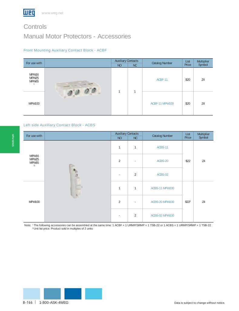
www.weg.net
Data is subject to change without notice.1-800-ASK-4WEGB-166
MPW
SERIES
For use withAuxiliary contacts
catalog Number ListPrice
MultiplierSymbolNo Nc
MPW16MPW25MPW65
1
1 1
AcbF-11 $20 Z4
MPW100 AcbF-11 MPW100 $20 Z4
For use withAuxiliary contacts
catalog Number ListPrice
MultiplierSymbolNo Nc
MPW16MPW25MPW65
1)
1 1 AcbS-11
$22 Z42 - AcbS-20
- 2 AcbS-02
MPW100
1 1 AcbS-11 MPW100
$222 Z42 - AcbS-20 MPW100
- 2 AcbS-02 MPW100
Front Mounting Auxiliary Contact Block - ACBF
Left side Auxiliary Contact Block - ACBS
Note: 1 The following accessories can be assembled at the same time: 1 ACBF + 1 URMP/SRMP + 1 TSB-22 or 1 ACBS + 1 URMP/SRMP + 1 TSB-22 2 Unit list price. Product sold in multiples of 2 units
Controls
Manual Motor Protectors - Accessories

WEG Automation - Products and Solutions
www.weg.net
Data is subject to change without notice. B-167
MPW
SER
IES
Controls
Manual Motor Protectors - Accessories
For use with description catalog Number List Price
MultiplierSymbol
MPW25MPW65
1)
-Equipped with 2 auxiliary contacts (1NO + 1NC) for overload trip signalling and 2 other auxiliary contacts (1NO + 1NC) for short-circuit trip signalling.
- To reset the MPW after a short-circuit, the blue flag must be manually reset after the cause of the failure has been solved.
- Left side auxiliary contacts can be assembled together with the trip signalling block.
- Left side assembly only
TSb-22 $38 Z4
MPW100
- Equipped with 2 auxiliary contacts (1NO + 1NC) for short-circuit trip signalling.
- Left side assembly only
TSb Sc-11 MPW100 $382 Z4
Trip Signalling Block - TSB-22
Undervoltage Release - URMP
For use with Voltage catalog Number List Price
MultiplierSymbol
MPW16MPW25MPW65
1)
208V 60Hz24V 50/60Hz400-415V 50Hz / 480V 60Hz110V 50Hz / 120V 60Hz240V 60Hz
uRMP V23uRMP d02uRMP V47uRMP V18uRMP V30
$56 Z4
MPW100
Note: - Operating voltage > 0,85 x Ue- Non operating voltage 0,35...0,7 x Ue
110V 50Hz / 120V 60Hz220-230V 50Hz / 240V 60Hz380-400V 50Hz / 460V 60Hz
uRMP V18 MPW100uRMP V33 MPW100uRMP V43 MPW100
$56 Z4
Note: 1 The following accessories can be assembled at the same time: 1 ACBF + 1 URMP/SRMP + 1 TSB-22 or 1 ACBS + 1 URMP/SRMP + 1 TSB-22 2 Unit list price. Product sold in multiples of 2 units
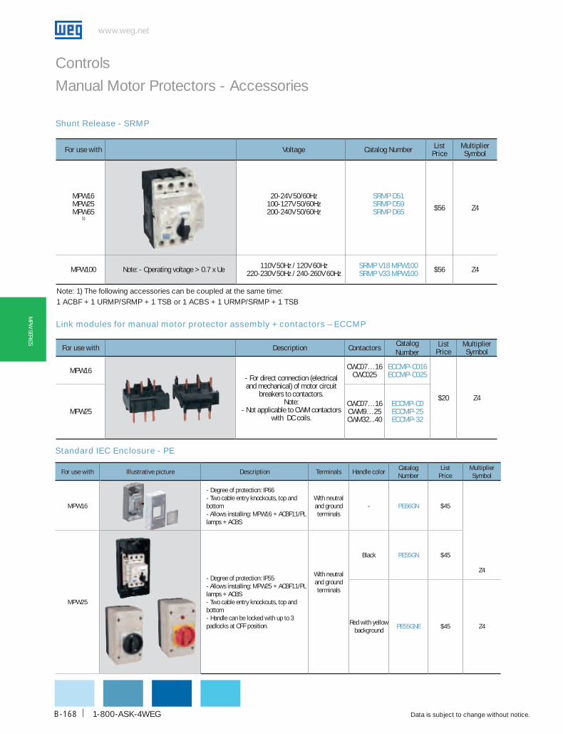
www.weg.net
Data is subject to change without notice.1-800-ASK-4WEGB-168
MPW
SERIES
Shunt Release - SRMP
Controls
Manual Motor Protectors - Accessories
Link modules for manual motor protector assembly + contactors – ECCMP
For use with Voltage catalog Number List Price
MultiplierSymbol
MPW16MPW25MPW65
1)
20-24V 50/60Hz100-127V 50/60Hz200-240V 50/60Hz
SRMP d51SRMP d59SRMP d65 $56 Z4
MPW100 Note: - Operating voltage > 0.7 x Ue 110V 50Hz / 120V 60Hz220-230V 50Hz / 240-260V 60Hz
SRMP V18 MPW100SRMP V33 MPW100 $56 Z4
For use with description contactorscatalog Number
List Price
MultiplierSymbol
MPW16- For direct connection (electrical and mechanical) of motor circuit
breakers to contactors.Note:
- Not applicable to CWM contactors with DC coils.
CWC07…16CWC025
EccMP-c016EccMP-c025
$20 Z4
MPW25CWC07…16CWM9…25CWM32...40
EccMP-c0EccMP-25EccMP-32
Note: 1) The following accessories can be coupled at the same time: 1 ACBF + 1 URMP/SRMP + 1 TSB or 1 ACBS + 1 URMP/SRMP + 1 TSB
For use with Illustrative picture description Terminals handle colorcatalog Number
ListPrice
MultiplierSymbol
MPW16
- Degree of protection: IP66- Two cable entry knockouts, top and bottom - Allows installing: MPW16 + ACBF11/PL lamps + ACBS
With neutral and ground terminals
- PE66GN $45
Z4
MPW25
- Degree of protection: IP55- Allows installing: MPW25 + ACBF11/PL lamps + ACBS - Two cable entry knockouts, top and bottom - Handle can be locked with up to 3 padlocks at OFF position.
With neutral and ground terminals
Black PE55GN $45
Red with yellow background
PE55GNE $45 Z4
Standard IEC Enclosure - PE

WEG Automation - Products and Solutions
www.weg.net
Data is subject to change without notice. B-169
MPW
SER
IES
Through-the-door Rotary Handle - RMMP and MRX
Controls
Manual Motor Protectors - Accessories
For use with Illustrative picture description handle color
catalog Number
PriceList
MultiplierSymbol
MPW25- Degree of protection IP55/NEMA1;
- Shows MPW position “I”(ON) or
“O”(OFF);
- Panel door can only be opened in OFF position;
- Adjustable shaft length. There are 2 standard shaft sizes: 130-
155mm (Model 130) and 330-355mm (Model 330). To
assemble the handle on the MPW the shaft must have a length
of at least 80mm;
- Up to 3 padlocks can be used in the OFF position. This blocks
MPW operation and panel door opening;
- Handle can be mounted on panels with thickness of 1 to 5mm;
- Handle can be assembled even with MPW turned in 90º position
Gray/Black
RMMP-130 $60
Z4
RMMP-330 $70
Red/Yellow
RMMP-130E $60
RMMP-330E $70
MPW65
Gray/Black
RMMP65-130 $60
RMMP65-330 $70
Red/Yellow
RMMP65-130E $60
RMMP65-330E $70
MPW100
- Degree of protection NEMA1;
- Shows MPW position “I”(ON) or “O”(OFF);
- Panel door can be opened at ON position (thermometry) by
defeating mechanism;
- Adjustable shaft length. There are 2 standard shaft sizes:
115mm (Model 115) and 315mm (Model 315). To assemble the
handle to the MPW, the shaft must have a min. length of at least
80mm;
- Up to 3 padlocks can be used in the OFF position. This blocks
the MPW operation and opens panel door.
Gray/Black
MR MPW100-115 $80
Gray/Black
MR MPW100-315 $90
MPW25 - Panel door can be opened in ON position (thermometry) by
defeating mechanism.
- Degree of protection: IP65/Nema 4X
- Shows MPW position “I”(ON) or “O”(OFF)
- Adjustable shaft length. There are 2 standard shaft sizes: 130-
155mm (Model 130) and 330-355mm (Model 330). To
assemble the handle ON the MPW the shaft must have a length
of at least 80mm
- Up to 3 padlocks can be used in the OFF position. This blocks
MPW operation and opens panel door. Handle can be mounted
on panels with thickness of 1 to 5mm
Gray/Black
MRX-130 $105MRX-330 $115
Red/Yellow
MRX-130E $105MRX-330E $115
MPW65
Gray/Black
MRX65-130 $120MRX65-330 $130
Red/Yellow
MRX65-130E $120MRX65-330E $130
MPW100
Gray/Black MRX100-130-E $130
Red/Yellow MRX100-130-E $130

www.weg.net
Data is subject to change without notice.1-800-ASK-4WEGB-170
MPW
SERIES
Controls
Manual Motor Protectors - Accessories
Large IEC Enclosure - LPE55
Manual Motor Protector mounting adapter - MA
For use with description contactors catalogNumber
ListPrice
MultiplierSymbol
MPW25
Used for direct on line starters
45mm width
CWC07...25CWM9…CWM25 MA45doL $40
Z4MPW25
Used for rever-sing starters
90mm width
2 x CWC07...252x CWM9...CWM25 MA90RVS $50
MPW25
Used for star-delta motor
starters
90mm width
2 x CWC07...252x CWM9…CWM25 MA90SdS $50
For use with description Terminals handle color
catalogNumber
ListPrice
MultiplierSymbol
MPW25
- Degree of protection: IP55- For use with MPW25 + URMP/ SRMP + ACBF11 + ACBS + PL lamps- Two cable entry knockouts. top and bottom - Handle can be locked with up to 3 padlocks at OFF position.
With neutral and ground terminals
Black LPE55GN
$55 Z4
Red with yellow
backgroundLPE55GN-E

WEG Automation - Products and Solutions
www.weg.net
Data is subject to change without notice. B-171
MPW
SER
IES
Controls
Manual Motor Protectors - Accessories
Three-phase feeder terminal – FTBBS and LST25
Three-phase feeder terminals for MPW without side auxiliary contacts – BBS45
For use with description catalogNumber
List Price
MultiplierSymbol
MPW16MPW25
- For feeding the feeder terminals;- Rated insulation voltage: 690VAC;- Ie: 63A;- Terminals: 6-25mm2 rigid wire and 6-16mm2 flexible wire with terminal.
FTbbS $35 Z4
MPW25
- Block module for “ Type E“ Combination motor Controller” in accordance with UL (LST25+MPW+TSB-22);- Rated insulation voltage: 690VAC; - Ie: 63A.- Terminals: 8-20AWG.
LST25 $30 Z4
For use with description Numbers of MPW
catalogNumber
List Price
MultiplierSymbol
MPW16MPW25
- For parallel blocking of side-by-side mounted MPW, without side auxiliary contacts; - - Enables the use of frontal auxiliary contact block ACBF-11; - Ue: 690VAC;- Ie: 63A.
2 bbS45-2 $32
Z4 3 bbS45-3 $35
4 bbS45-4 $45
5 bbS45-5 $60
Insulators - IB
For use with description catalog Number List Price
MultiplierSymbol
MPW100Insulators for increasing cree-page distance and clearances according to UL requirements.
Ib MPW100 $30 Z4
Three-phase feeder terminals for MPW with side auxiliary contacts – BBS54
For use with descriptionNumbers of MPW
catalogNumber
List Price
MultiplierSymbol
MPW16/MPW25
- For parallel blocking of side-by-side mounted MPW; - Enables the use of frontal auxiliary contact block ACBF-11 and side auxiliary contact block ACBS;- Ue: 690VAC;- Ie: 63A.
2 bbS54-2 $32
Z43 bbS54-3 $35
4 bbS54-4 $45
5 bbS54-5 $60
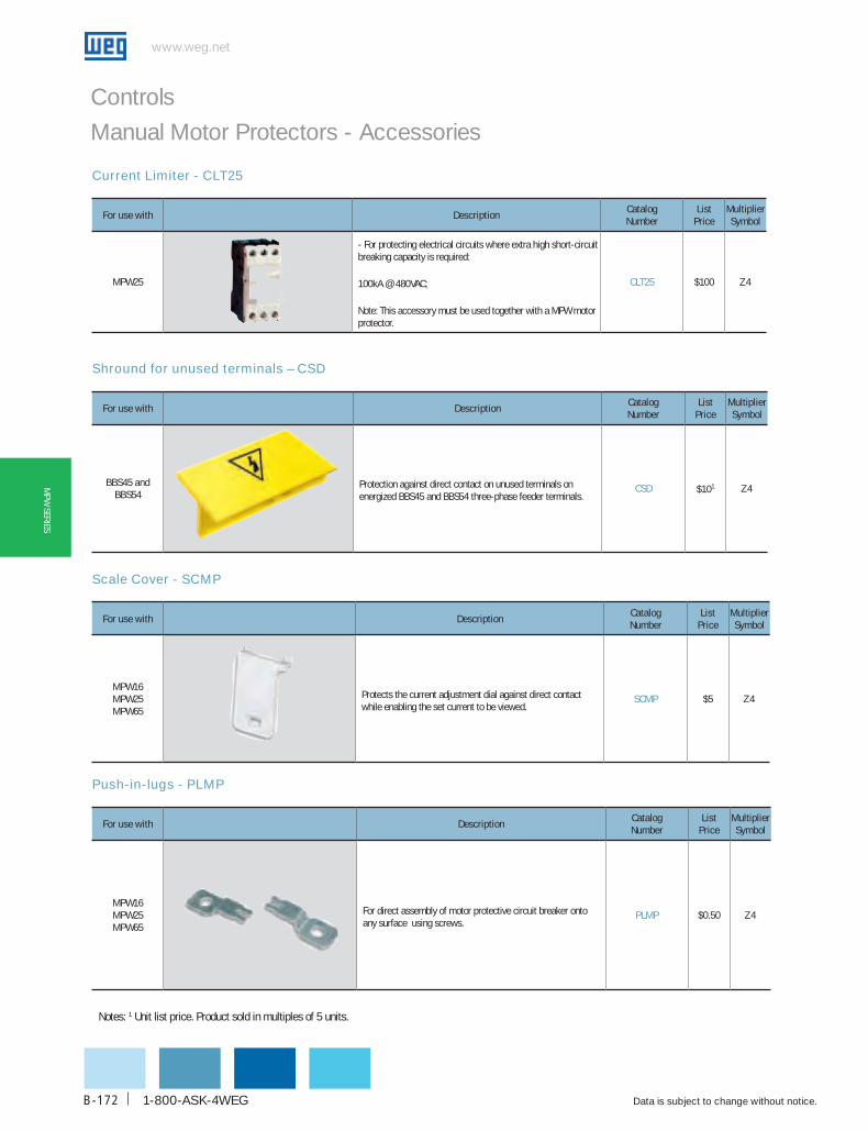
www.weg.net
Data is subject to change without notice.1-800-ASK-4WEGB-172
MPW
SERIES
Controls
Manual Motor Protectors - Accessories
Shround for unused terminals – CSD
Scale Cover - SCMP
Push-in-lugs - PLMP
For use with descriptioncatalogNumber
List Price
MultiplierSymbol
bbS45 and bbS54
Protection against direct contact on unused terminals on energized BBS45 and BBS54 three-phase feeder terminals.
cSd $101 Z4
For use with descriptioncatalogNumber
List Price
MultiplierSymbol
MPW16MPW25MPW65
Protects the current adjustment dial against direct contact while enabling the set current to be viewed.
ScMP $5 Z4
For use with descriptioncatalogNumber
List Price
MultiplierSymbol
MPW16MPW25MPW65
For direct assembly of motor protective circuit breaker onto any surface using screws.
PLMP $0.50 Z4
Current Limiter - CLT25
For use with descriptioncatalogNumber
List Price
MultiplierSymbol
MPW25
- For protecting electrical circuits where extra high short-circuit breaking capacity is required:
100kA @ 480VAC;
Note: This accessory must be used together with a MPW motor protector.
cLT25 $100 Z4
Notes: 1 Unit list price. Product sold in multiples of 5 units.
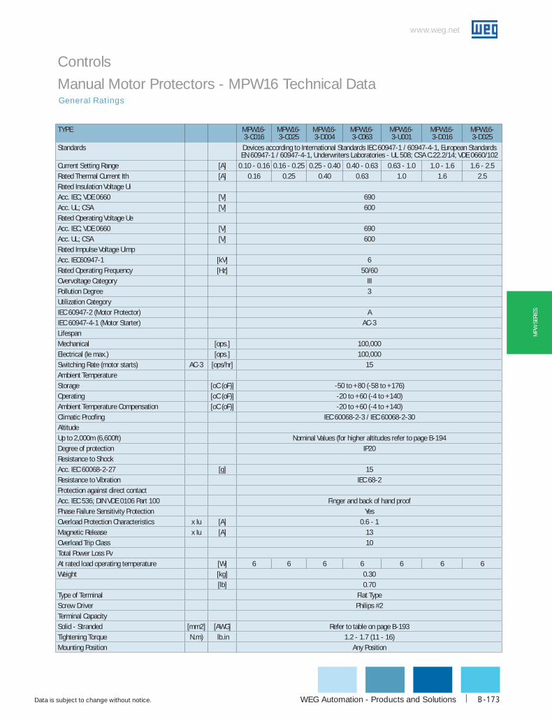
WEG Automation - Products and Solutions
www.weg.net
Data is subject to change without notice. B-173
MPW
SER
IES
Controls
Manual Motor Protectors - MPW16 Technical Data
TYPE MPW16-3-c016
MPW16-3-c025
MPW16-3-d004
MPW16-3-c063
MPW16-3-u001
MPW16-3-d016
MPW16-3-d025
Standards Devices according to International Standards IEC 60947-1 / 60947-4-1, European Standards EN 60947-1 / 60947-4-1, Underwriters Laboratories - UL 508; CSA C.22.2/14; VDE 0660/102
Current Setting Range [A] 0.10 - 0.16 0.16 - 0.25 0.25 - 0.40 0.40 - 0.63 0.63 - 1.0 1.0 - 1.6 1.6 - 2.5Rated Thermal Current Ith [A] 0.16 0.25 0.40 0.63 1.0 1.6 2.5Rated Insulation Voltage UiAcc. IEC; VDE 0660 [V] 690Acc. UL; CSA [V] 600Rated Operating Voltage UeAcc. IEC; VDE 0660 [V] 690Acc. UL; CSA [V] 600Rated Impulse Voltage UimpAcc. IEC60947-1 [kV] 6Rated Operating Frequency [Hz] 50/60Overvoltage Category IIIPollution Degree 3Utilization CategoryIEC 60947-2 (Motor Protector) AIEC 60947-4-1 (Motor Starter) AC-3LifespanMechanical [ops.] 100,000Electrical (Ie max.) [ops.] 100,000Switching Rate (motor starts) AC-3 [ops/hr] 15Ambient TemperatureStorage [oC (oF)] -50 to +80 (-58 to +176)Operating [oC (oF)] -20 to +60 (-4 to +140)Ambient Temperature Compensation [oC (oF)] -20 to +60 (-4 to +140)Climatic Proofing IEC 60068-2-3 / IEC 60068-2-30AltitudeUp to 2,000m (6,600ft) Nominal Values (for higher altitudes refer to page B-194Degree of protection IP20Resistance to ShockAcc. IEC 60068-2-27 [g] 15Resistance to Vibration IEC 68-2Protection against direct contactAcc. IEC 536; DIN VDE 0106 Part 100 Finger and back of hand proofPhase Failure Sensitivity Protection YesOverload Protection Characteristics x Iu [A] 0.6 - 1Magnetic Release x Iu [A] 13Overload Trip Class 10Total Power Loss PvAt rated load operating temperature [W] 6 6 6 6 6 6 6Weight [kg] 0.30
[lb] 0.70Type of Terminal Flat TypeScrew Driver Philips #2Terminal CapacitySolid - Stranded [mm2] [AWG] Refer to table on page B-193Tightening Torque N.m) lb.in 1.2 - 1.7 (11 - 16)Mounting Position Any Position
General Ratings

www.weg.net
Data is subject to change without notice.1-800-ASK-4WEGB-174
MPW
SERIES
Controls
Manual Motor Protectors - MPW16 Technical DataGeneral Ratings
TYPE MPW16-3-u004
MPW16-3-d063
MPW16-3-u010
MPW16-3-u016
Standards Devices according to International Standards IEC 60947-1 / 60947-4-1, European Standards EN 60947-1 / 60947-4-1, Underwriters Laboratories - UL 508; CSA
C.22.2/14; VDE 0660/102
Current Setting Range [A] 2.5 - 4.0 4.0 - 6.3 6.3 - 10 10 - 16
Rated Thermal Current Ith [A] 4.0 6.3 10 16
Rated Insulation Voltage Ui
Acc. IEC; VDE 0660 [V] 690
Acc. UL; CSA [V] 600
Rated Operating Voltage Ue
Acc. IEC; VDE 0660 [V] 690
Acc. UL; CSA [V] 600
Rated Impulse Voltage Uimp
Acc. IEC60947-1 [kV] 6
Rated Operating Frequency [Hz] 50/60
Overvoltage Category III
Pollution Degree 3
Utilization Category
IEC 60947-2 (Motor Protector) A
IEC 60947-4-1 (Motor Starter) AC-3
Lifespan
Mechanical [ops.] 100,000
Electrical (Ie max.) [ops.] 100,000
Switching Rate (motor starts) AC-3 [ops/hr] 15
Ambient Temperature
Storage [oC (oF)] -50 to +80 (-58 to +176)
Operating [oC (oF)] -20 to +60 (-4 to +140)
Ambient Temperature Compensation [oC (oF)] -20 to +60 (-4 to +140)
Climatic Proofing IEC 60068-2-3 / IEC 60068-2-30
Altitude
Up to 2,000m (6,600ft) Nominal Values (for higher altitudes refer to page B-194
Degree of protection IP20
Resistance to Shock
Acc. IEC 60068-2-27 [g] 15
Resistance to Vibration IEC 68-2
Protection against direct contact
Acc. IEC 536; DIN VDE 0106 Part 100 Finger and back of hand proof
Phase Failure Sensitivity Protection YesOverload Protection Characteristics x Iu [A] 0.6 - 1Magnetic Release x Iu [A] 12Overload Trip Class 10Total Power Loss PvAt rated load operating temperature [W] 6 6 6 6Weight [kg] 0.3
[lb] 0.7Type of Terminal Flat TypeScrew Driver Philips #2Terminal CapacitySolid - Stranded [mm2] [AWG] Refer to table on page B-193Tightening Torque N.m) lb.in 1.2 - 1.7 (11 - 16)Mounting Position Any Position
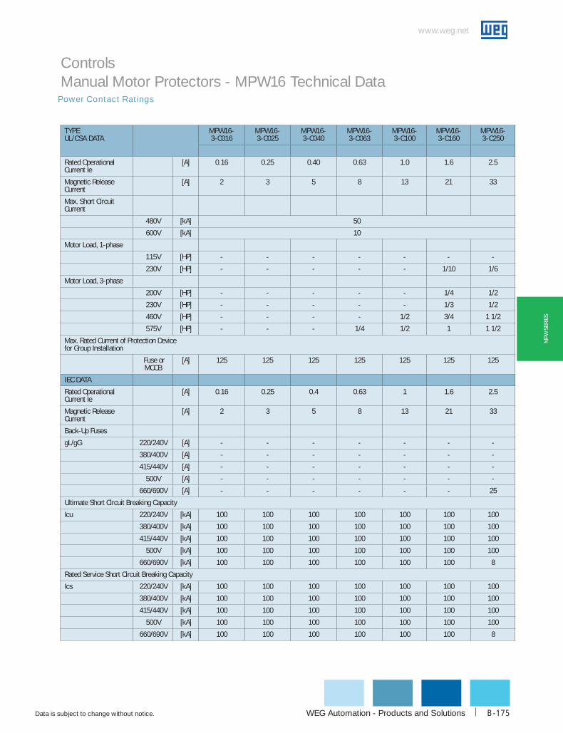
WEG Automation - Products and Solutions
www.weg.net
Data is subject to change without notice. B-175
MPW
SER
IES
Power Contact Ratings
Controls Manual Motor Protectors - MPW16 Technical Data
TYPEuL/cSA dATA
MPW16-3-c016
MPW16-3-c025
MPW16-3-c040
MPW16-3-c063
MPW16-3-c100
MPW16-3-c160
MPW16-3-c250
Rated Operational Current Ie
[A] 0.16 0.25 0.40 0.63 1.0 1.6 2.5
Magnetic Release Current
[A] 2 3 5 8 13 21 33
Max. Short Circuit Current
480V [kA] 50
600V [kA] 10
Motor Load, 1-phase
115V [HP] - - - - - - -
230V [HP] - - - - - 1/10 1/6
Motor Load, 3-phase
200V [HP] - - - - - 1/4 1/2
230V [HP] - - - - - 1/3 1/2
460V [HP] - - - - 1/2 3/4 1 1/2
575V [HP] - - - 1/4 1/2 1 1 1/2
Max. Rated Current of Protection Devicefor Group Installation
Fuse or MCCB
[A] 125 125 125 125 125 125 125
IEc dATA
Rated Operational Current Ie
[A] 0.16 0.25 0.4 0.63 1 1.6 2.5
Magnetic Release Current
[A] 2 3 5 8 13 21 33
Back-Up Fuses
gL/gG 220/240V [A] - - - - - - -
380/400V [A] - - - - - - -
415/440V [A] - - - - - - -
500V [A] - - - - - - -
660/690V [A] - - - - - - 25
Ultimate Short Circuit Breaking Capacity
Icu 220/240V [kA] 100 100 100 100 100 100 100
380/400V [kA] 100 100 100 100 100 100 100
415/440V [kA] 100 100 100 100 100 100 100
500V [kA] 100 100 100 100 100 100 100
660/690V [kA] 100 100 100 100 100 100 8
Rated Service Short Circuit Breaking Capacity
Ics 220/240V [kA] 100 100 100 100 100 100 100
380/400V [kA] 100 100 100 100 100 100 100
415/440V [kA] 100 100 100 100 100 100 100
500V [kA] 100 100 100 100 100 100 100
660/690V [kA] 100 100 100 100 100 100 8

www.weg.net
Data is subject to change without notice.1-800-ASK-4WEGB-176
MPW
SERIES
Power Contact Ratings
Controls Manual Motor Protectors - MPW16 Technical Data
TYPE MPW16-3-u004 MPW16-3-d063 MPW16-3-u010 MPW16-3-u016
uL/cSA dATA
Rated Operational Current Ie [A] 4.0 6.3 10 16
Magnetic Release Current [A] 52 82 130 208
Max. Short Circuit Current
480V [kA] 50 50 50 30
600V [kA] 10 10 5 5
Motor Load, 1-phase
115V [HP] 1/8 1/4 1/2 1
230V [HP] 1/3 3/4 1 1/2 3
Motor Load, 3-phase
200V [HP] 3/4 1 1/2 3 5
230V [HP] 1 1 1/2 3 5
460V [HP] 2 5 7 1/2 10
575V [HP] 3 5 10 15
Max. Rated Current of Protection Device for Group Installation
Fuse or MCCB
[A] 125 125 125 160
IEc dATA
Rated Operational Current Ie [A] 4 6.3 10 16
Magnetic Release Current [A] 52 82 130 208
Back-Up Fuses
gL/gG 220/240V [A] - - - -
380/400V [A] - - 100 100
415/440V [A] - - 80 80
500V [A] - - 63 80
660/690V [A] 35 50 50 63
Ultimate Short Circuit Breaking Capacity
Icu 220/240V [kA] 100 100 100 100
380/400V [kA] 100 100 50 10
415/440V [kA] 100 100 50 10
500V [kA] 100 100 10 10
660/690V [kA] 8 8 5 4
Rated Service Short Circuit Breaking Capacity
Ics 220/240V [kA] 100 100 100 100
380/400V [kA] 100 100 10 10
415/440V [kA] 100 100 10 10
500V [kA] 100 100 10 10
660/690V [kA] 8 8 5 3
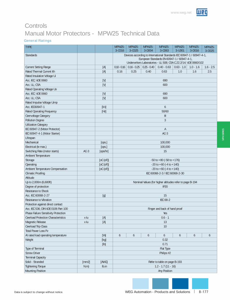
WEG Automation - Products and Solutions
www.weg.net
Data is subject to change without notice. B-177
MPW
SER
IES
General Ratings
Controls Manual Motor Protectors - MPW25 Technical Data
TYPE MPW25-3-c016
MPW25-3-c025
MPW25-3-d004
MPW25-3-c063
MPW25-3-u001
MPW25-3-d016
MPW25-3-d025
Standards Devices according to International Standards IEC 60947-1 / 60947-4-1, European Standards EN 60947-1 / 60947-4-1,
Underwriters Laboratories - UL 508; CSA C.22.2/14; VDE 0660/102Current Setting Range [A] 0.10 - 0.16 0.16 - 0.25 0.25 - 0.40 0.40 - 0.63 0.63 - 1.0 1.0 - 1.6 1.6 - 2.5Rated Thermal Current Ith [A] 0.16 0.25 0.40 0.63 1.0 1.6 2.5Rated Insulation Voltage UiAcc. IEC; VDE 0660 [V] 690Acc. UL; CSA [V] 600Rated Operating Voltage UeAcc. IEC; VDE 0660 [V] 690Acc. UL; CSA [V] 600Rated Impulse Voltage UimpAcc. IEC60947-1 [kV] 6Rated Operating Frequency [Hz] 50/60Overvoltage Category IIIPollution Degree 3Utilization CategoryIEC 60947-2 (Motor Protector) AIEC 60947-4-1 (Motor Starter) AC-3LifespanMechanical [ops.] 100,000Electrical (Ie max.) [ops.] 100,000Switching Rate (motor starts) AC-3 [ops/hr] 15Ambient TemperatureStorage [oC (oF)] -50 to +80 (-58 to +176)Operating [oC (oF)] -20 to +60 (-4 to +140)Ambient Temperature Compensation [oC (oF)] -20 to +60 (-4 to +140)Climatic Proofing IEC 60068-2-3 / IEC 60068-2-30AltitudeUp to 2,000m (6,600ft) Nominal Values (for higher altitudes refer to page B-194Degree of protection IP20Resistance to ShockAcc. IEC 60068-2-27 [g] 15Resistance to Vibration IEC 68-2Protection against direct contactAcc. IEC 536; DIN VDE 0106 Part 100 Finger and back of hand proofPhase Failure Sensitivity Protection YesOverload Protection Characteristics x Iu [A] 0.6 - 1Magnetic Release x Iu [A] 13Overload Trip Class 10Total Power Loss PvAt rated load operating temperature [W] 6 6 6 6 6 6 6Weight [kg] 0.32
[lb] 0.71Type of Terminal Flat TypeScrew Driver Philips #2Terminal Capacity
Solid - Stranded [mm2] [AWG] Refer to table on page B-193
Tightening Torque N.m) lb.in 1.2 - 1.7 (11 - 16)
Mounting Position Any Position
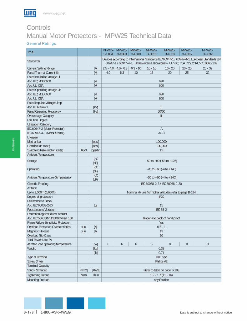
www.weg.net
Data is subject to change without notice.1-800-ASK-4WEGB-178
MPW
SERIES
General Ratings
Controls Manual Motor Protectors - MPW25 Technical Data
TYPEMPW25-3-u004
MPW25-3-d063
MPW25-3-u010
MPW25-3-u016
MPW25-3-u020
MPW25-3-u025
MPW25-3-u032
StandardsDevices according to International Standards IEC 60947-1 / 60947-4-1, European Standards EN
60947-1 / 60947-4-1, Underwriters Laboratories - UL 508; CSA C.22.2/14; VDE 0660/102
Current Setting Range [A] 2.5 - 4.0 4.0 - 6.3 6.3 - 10 10 - 16 16 - 20 20 - 25 25 - 32Rated Thermal Current Ith [A] 4.0 6.3 10 16 20 25 32Rated Insulation Voltage UiAcc. IEC; VDE 0660 [V] 690Acc. UL; CSA [V] 600Rated Operating Voltage UeAcc. IEC; VDE 0660 [V] 690Acc. UL; CSA [V] 600Rated Impulse Voltage UimpAcc. IEC60947-1 [kV] 6Rated Operating Frequency [Hz] 50/60Overvoltage Category IIIPollution Degree 3Utilization CategoryIEC 60947-2 (Motor Protector) AIEC 60947-4-1 (Motor Starter) AC-3LifespanMechanical [ops.] 100,000Electrical (Ie max.) [ops.] 100,000Switching Rate (motor starts) AC-3 [ops/hr] 15Ambient Temperature
Storage[oC (oF)]
-50 to +80 (-58 to +176)
Operating[oC (oF)]
-20 to +60 (-4 to +140)
Ambient Temperature Compensation[oC (oF)]
-20 to +60 (-4 to +140)
Climatic Proofing IEC 60068-2-3 / IEC 60068-2-30AltitudeUp to 2,000m (6,600ft) Nominal Values (for higher altitudes refer to page B-194Degree of protection IP20Resistance to Shock Acc. IEC 60068-2-27 [g] 15Resistance to Vibration IEC 68-2Protection against direct contactAcc. IEC 536; DIN VDE 0106 Part 100 Finger and back of hand proofPhase Failure Sensitivity Protection YesOverload Protection Characteristics x Iu [A] 0.6 - 1Magnetic Release x Iu [A] 13Overload Trip Class 10Total Power Loss PvAt rated load operating temperature [W] 6 6 6 6 8 8 8Weight [kg] 0.32
[lb] 0.71Type of Terminal Flat TypeScrew Driver Philips #2Terminal CapacitySolid - Stranded [mm2] [AWG] Refer to table on page B-193
Tightening Torque N.m) lb.in 1.2 - 1.7 (11 - 16)
Mounting Position Any Position

WEG Automation - Products and Solutions
www.weg.net
Data is subject to change without notice. B-179
MPW
SER
IES
Power Contact Ratings
Controls Manual Motor Protectors - MPW25 Technical Data
TYPE MPW25-3-c016
MPW25-3-c025
MPW25-3-c040
MPW25-3-c063
MPW25-3-u001
MPW25-3-d016
MPW25-3-d025
uL/cSA dATA
Rated Operational Current Ie [A] 0.16 0.25 0.40 0.63 1.0 1.6 2.5
Magnetic Release Current [A] 2 3 5 8 13 21 33
Max. Short Circuit Current
without CLT25
480V [kA] 50
600V [kA] 25
with CLT25
480V [kA] 100
600V [kA] 50
Motor Load, 1-phase
115V [HP] - - - - - - -
230V [HP] - - - - - 1/10 1/6
Motor Load, 3-phase
200V [HP] - - - - - 1/4 1/2
230V [HP] - - - - - 1/3 1/2
460V [HP] - - - - 1/2 3/4 1 1/2
575V [HP] - - - 1/4 1/2 1 1 1/2
Max. Rated Current of Protection Device for Group Installation
Fuse or MCCB [A] 125 125 125 125 125 125 125
IEc dATA
Rated Operational Current Ie [A] 0.16 0.25 0.4 0.63 1 1.6 2.5
Magnetic Release Current [A] 2 3 5 8 13 21 33
Back-Up Fuses
gL/gG 220/240V [A] - - - - - - -
380/400V [A] - - - - - - -
415/440V [A] - - - - - - -
500V [A] - - - - - - -
660/690V [A] - - - - - - 25
Ultimate Short Circuit Breaking Capacity
Icu 220/240V [kA] 100 100 100 100 100 100 100
380/400V [kA] 100 100 100 100 100 100 100
415/440V [kA] 100 100 100 100 100 100 100
500V [kA] 100 100 100 100 100 100 100
660/690V [kA] 100 100 100 100 100 100 8
Rated Service Short Circuit Breaking Capacity
Ics 220/240V [kA] 100 100 100 100 100 100 100
380/400V [kA] 100 100 100 100 100 100 100
415/440V [kA] 100 100 100 100 100 100 100
500V [kA] 100 100 100 100 100 100 100
660/690V [kA] 100 100 100 100 100 100 8

www.weg.net
Data is subject to change without notice.1-800-ASK-4WEGB-180
MPW
SERIES
Power Contact Ratings
Controls Manual Motor Protectors - MPW25 Technical Data
TYPE MPW25-3-u004
MPW25-3-d063
MPW25-3-u010
MPW25-3-u016
MPW25-3-u020
MPW25-3-u025
MPW25-3-u032
uL/cSA dATA
Rated Operational Current Ie [A] 4.0 6.3 10 16 20 25 32
Magnetic Release Current [A] 52 82 130 208 260 325 416
Max. Short Circuit Current
without CLT25
480V [kA] 50 42
600V [kA] 25 25
with CLT25
480V [kA] 100
600V [kA] 50
Motor Load, 1-phase
115V [HP] 1/8 1/4 1/2 1 1 1/2 2 -
230V [HP] 1/3 3/4 1 1/2 3 3 3 5
Motor Load, 3-phase
200V [HP] 3/4 1 1/2 3 5 5 7 1/2 10
230V [HP] 1 1 1/2 3 5 7 1/2 7 1/2 10
460V [HP] 2 5 7 1/2 10 15 15 20
575V [HP] 3 5 10 15 20 20 25
Max. Rated Current of Protection Device for Group Installation
Fuse or MCCB
[A] 125 125 125 160 250 250 300
IEc dATA
Rated Operational Current Ie [A] 4 6.3 10 16 20 25 32
Magnetic Release Current [A] 52 82 130 208 260 325 416
Back-Up Fuses
gL/gG 220/240V [A] - - - - - - -
380/400V [A] - - - 100 125 125 125
415/440V [A] - - 80 80 80 100 100
500V [A] - - 63 80 80 80 80
660/690V [A] 35 50 50 63 63 63 63
Ultimate Short Circuit Breaking Capacity
Icu 220/240V [kA] 100 100 100 100 100 100 100
380/400V [kA] 100 100 100 50 50 50 50
415/440V [kA] 100 100 50 50 50 50 25
500V [kA] 100 100 42 10 10 10 10
660/690V [kA] 8 8 8 5 5 5 5
Rated Service Short Circuit Breaking Capacity
Ics 220/240V [kA] 100 100 100 100 100 100 100
380/400V [kA] 100 100 100 25 25 25 25
415/440V [kA] 100 100 25 15 15 15 15
500V [kA] 100 100 21 8 8 8 8
660/690V [kA] 8 8 8 5 5 5 5
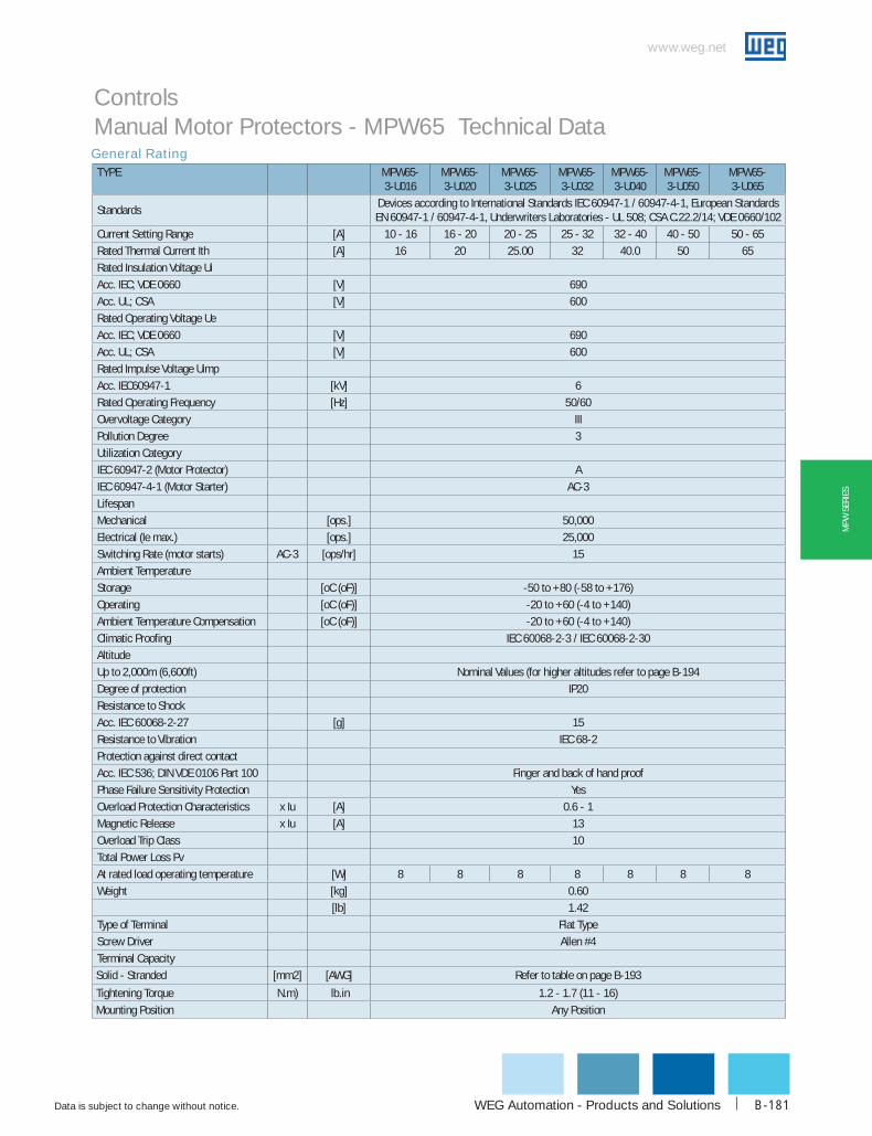
WEG Automation - Products and Solutions
www.weg.net
Data is subject to change without notice. B-181
MPW
SER
IES
General Rating
Controls Manual Motor Protectors - MPW65 Technical Data
TYPE MPW65-3-u016
MPW65-3-u020
MPW65-3-u025
MPW65-3-u032
MPW65-3-u040
MPW65-3-u050
MPW65-3-u065
StandardsDevices according to International Standards IEC 60947-1 / 60947-4-1, European Standards EN 60947-1 / 60947-4-1, Underwriters Laboratories - UL 508; CSA C.22.2/14; VDE 0660/102
Current Setting Range [A] 10 - 16 16 - 20 20 - 25 25 - 32 32 - 40 40 - 50 50 - 65
Rated Thermal Current Ith [A] 16 20 25.00 32 40.0 50 65
Rated Insulation Voltage Ui
Acc. IEC; VDE 0660 [V] 690
Acc. UL; CSA [V] 600
Rated Operating Voltage Ue
Acc. IEC; VDE 0660 [V] 690
Acc. UL; CSA [V] 600
Rated Impulse Voltage Uimp
Acc. IEC60947-1 [kV] 6
Rated Operating Frequency [Hz] 50/60
Overvoltage Category III
Pollution Degree 3
Utilization Category
IEC 60947-2 (Motor Protector) A
IEC 60947-4-1 (Motor Starter) AC-3
Lifespan
Mechanical [ops.] 50,000
Electrical (Ie max.) [ops.] 25,000
Switching Rate (motor starts) AC-3 [ops/hr] 15
Ambient Temperature
Storage [oC (oF)] -50 to +80 (-58 to +176)
Operating [oC (oF)] -20 to +60 (-4 to +140)
Ambient Temperature Compensation [oC (oF)] -20 to +60 (-4 to +140)
Climatic Proofing IEC 60068-2-3 / IEC 60068-2-30
Altitude
Up to 2,000m (6,600ft) Nominal Values (for higher altitudes refer to page B-194
Degree of protection IP20
Resistance to Shock
Acc. IEC 60068-2-27 [g] 15
Resistance to Vibration IEC 68-2
Protection against direct contact
Acc. IEC 536; DIN VDE 0106 Part 100 Finger and back of hand proof
Phase Failure Sensitivity Protection Yes
Overload Protection Characteristics x Iu [A] 0.6 - 1
Magnetic Release x Iu [A] 13
Overload Trip Class 10
Total Power Loss Pv
At rated load operating temperature [W] 8 8 8 8 8 8 8
Weight [kg] 0.60
[lb] 1.42
Type of Terminal Flat Type
Screw Driver Allen #4
Terminal Capacity
Solid - Stranded [mm2] [AWG] Refer to table on page B-193
Tightening Torque N.m) lb.in 1.2 - 1.7 (11 - 16)
Mounting Position Any Position

www.weg.net
Data is subject to change without notice.1-800-ASK-4WEGB-182
MPW
SERIES
Power Contact Ratings
Controls Manual Motor Protectors - MPW65 Technical Data
TYPE MPW65-3-u016
MPW65-3-u020
MPW65-3-u025
MPW65-3-u032
MPW65-3-u040
MPW65-3-u050
MPW65-3-u065
uL/cSA dATA
Rated Operational Current Ie [A] 16 20 25 32 40 50 65
Magnetic Release Current [A] 208 260 325 416 520 650 845
Max. Short Circuit Current
480V [kA] 50 35
600V [kA] 30 10
Motor Load, 1-phase
115V [HP] 3 - 5
230V [HP] 71/2 10 10
Motor Load, 3-phase
200V [HP] - 15 20
230V [HP] 15 15 20
460V [HP] 25 30 50
575V [HP] 30 40 60
Max. Rated Current of Protection Device for Group Installation
Fuse or MCCB
[A]
IEc dATA
Rated Operational Current Ie [A] 16 20 25 32 40 50 65
Magnetic Release Current [A] 208 260 325 416 520 650 845
Back-Up Fuses
gL/gG 220/240V [A] - - - - - - -
380/400V [A] 100 125 125 125 160 160 160
415/440V [A] 80 80 80 100 125 125 125
500V [A] 80 80 100 80 100 100 100
660/690V [A] 63 63 63 63 63 80 80
Ultimate Short Circuit Breaking Capacity
Icu 220/240V [kA] 100 100 100 100 100 100 100
380/400V [kA] 50 50 50 50 50 50 50
415/440V [kA] 50 50 50 50 50 50 50
500V [kA] 15 15 15 15 15 15 15
660/690V [kA] 8 8 8 5 5 5 5
Rated Service Short Circuit Breaking Capacity
Ics 220/240V [kA] 100 100 100 100 100 100 100
380/400V [kA] 50 50 50 50 50 50 50
415/440V [kA] 50 50 50 50 50 50 50
500V [kA] 15 15 15 15 10 10 10
660/690V [kA] 8 8 8 5 5 5 5

WEG Automation - Products and Solutions
www.weg.net
Data is subject to change without notice. B-183
MPW
SER
IES
General Contact Ratings
Controls Manual Motor Protectors - MPW100 Technical Data
TYPE MPW100-3-u075 MPW100-3-u090 MPW100-3-u100Standards Devices according to International Standards IEC 60947-1 / 60947-4-1, European
Standards EN 60947-1 / 60947-4-1, Underwriters Laboratories - UL 508; CSA C.22.2/14; VDE 0660/102
Current Setting Range [A] 55 - 75 70 - 90 80 - 100Rated Thermal Current Ith [A] 75 90 100.00Rated Insulation Voltage UiAcc. IEC; VDE 0660 [V] 690Acc. UL; CSA [V] 600Rated Operating Voltage UeAcc. IEC; VDE 0660 [V] 690Acc. UL; CSA [V] 600Rated Impulse Voltage UimpAcc. IEC60947-1 [kV] 6Rated Operating Frequency [Hz] 50/60Overvoltage Category IIIPollution Degree 3Utilization CategoryIEC 60947-2 (Motor Protector) AIEC 60947-4-1 (Motor Starter) AC-3LifespanMechanical [ops.] 50,000Electrical (Ie max.) [ops.] 25,000Switching Rate (motor starts) AC-3 [ops/hr] 15Ambient TemperatureStorage [oC (oF)] -50 to +80 (-58 to +176)Operating [oC (oF)] -20 to +60 (-4 to +140)Ambient Temperature Compensation [oC (oF)] -20 to +60 (-4 to +140)Climatic Proofing IEC 60068-2-3 / IEC 60068-2-30AltitudeUp to 2,000m (6,600ft) Nominal Values (for higher altitudes refer to page B-194Degree of protection IP20Resistance to ShockAcc. IEC 60068-2-27 [g] 15Resistance to Vibration IEC 68-2Protection against direct contactAcc. IEC 536; DIN VDE 0106 Part 100 Finger and back of hand proofPhase Failure Sensitivity Protection YesOverload Protection Characteristics x Iu [A] 0.6 - 1Magnetic Release x Iu [A] 13Overload Trip Class 10Total Power Loss PvAt rated load operating temperature [W] 10 10 10Weight [kg] 1.20
[lb] 3.00Type of Terminal Flat TypeScrew Driver Allen #4Terminal CapacitySolid [mm2] Refer to table on page B-193Stranded [mm2]Solid or Stranded [AWG]Tightening Torque [N.m (lb.
in)]4.0 - 4.6 (35 - 55)
Mounting Position Any Position
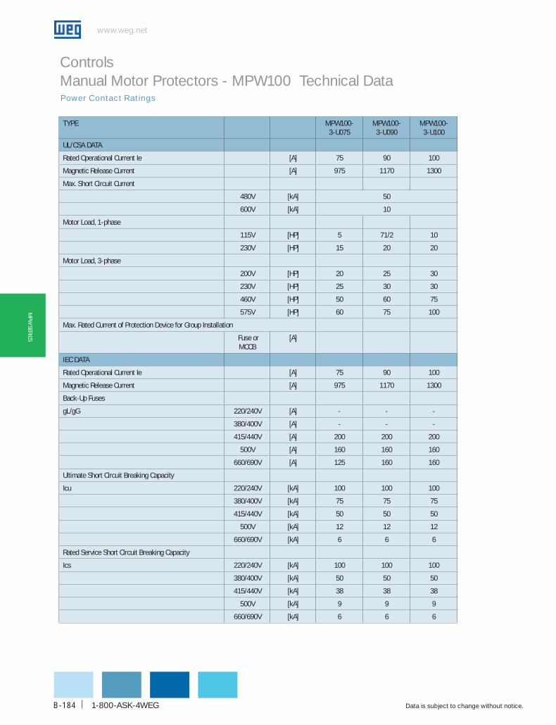
www.weg.net
Data is subject to change without notice.1-800-ASK-4WEGB-184
MPW
SERIES
Power Contact Ratings
Controls Manual Motor Protectors - MPW100 Technical Data
TYPE MPW100-3-u075
MPW100-3-u090
MPW100-3-u100
uL/cSA dATA
Rated Operational Current Ie [A] 75 90 100
Magnetic Release Current [A] 975 1170 1300
Max. Short Circuit Current
480V [kA] 50
600V [kA] 10
Motor Load, 1-phase
115V [HP] 5 71/2 10
230V [HP] 15 20 20
Motor Load, 3-phase
200V [HP] 20 25 30
230V [HP] 25 30 30
460V [HP] 50 60 75
575V [HP] 60 75 100
Max. Rated Current of Protection Device for Group Installation
Fuse or MCCB
[A]
IEc dATA
Rated Operational Current Ie [A] 75 90 100
Magnetic Release Current [A] 975 1170 1300
Back-Up Fuses
gL/gG 220/240V [A] - - -
380/400V [A] - - -
415/440V [A] 200 200 200
500V [A] 160 160 160
660/690V [A] 125 160 160
Ultimate Short Circuit Breaking Capacity
Icu 220/240V [kA] 100 100 100
380/400V [kA] 75 75 75
415/440V [kA] 50 50 50
500V [kA] 12 12 12
660/690V [kA] 6 6 6
Rated Service Short Circuit Breaking Capacity
Ics 220/240V [kA] 100 100 100
380/400V [kA] 50 50 50
415/440V [kA] 38 38 38
500V [kA] 9 9 9
660/690V [kA] 6 6 6
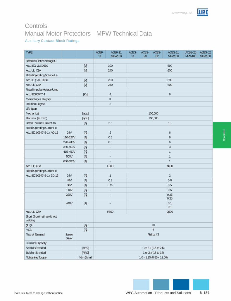
WEG Automation - Products and Solutions
www.weg.net
Data is subject to change without notice. B-185
MPW
SER
IES
Auxiliary Contact Block Ratings
Controls Manual Motor Protectors - MPW Technical Data
TYPE AcbF-11
AcbF-11 MPW100
AcbS-11
AcbS-20
AcbS-02
AcbS-11 MPW100
AcbS-20 MPW100
AcbS-02 MPW100
Rated Insulation Voltage Ui
Acc. IEC; VDE 0660 [V] 300 690
Acc. UL; CSA [V] 240 600
Rated Operating Voltage Ue
Acc. IEC; VDE 0660 [V] 250 690
Acc. UL; CSA [V] 240 600
Rated Impulse Voltage Uimp
Acc. IEC60947-1 [kV] 4 6
Overvoltage Category III
Pollution Degree 3
Life Span
Mechanical [ops.] 100,000
Electrical (Ie max.) [ops.] 100,000
Rated Thermal Current Ith [A] 2.5 10
Rated Operating Current Ie
Acc. IEC 60947-5-1 / AC-15 24V [A] 2 6
110-127V [A] 0.5 6
220-240V [A] 0.5 6
380-400V [A] - 3
415-450V [A] - 1
500V [A] - 1
660-690V [A] - 1
Acc. UL; CSA C300 A600
Rated Operating Current Ie
Acc. IEC 60947-5-1 / DC-13 24V [A] 1 2
48V [A] 0.3 0.8
60V [A] 0.15 0.5
110V [A] - 0.5
220V [A] - 0.250.25
440V [A] - 0.10.1
Acc. UL; CSA R300 Q600
Short Circuit rating without welding
gL/gG [A] 10
MCB [A] 6
Type of Terminal Screw Driver
Philips #2
Terminal Capacity
Solid or Stranded [mm2] 1 or 2 x (0.5 to 2.5)
Solid or Stranded [AWG] 1 or 2 x (18 to 14)
Tightening Torque [N.m (lb.in)] 1.0 - 1.25 (8.85 - 11.06)
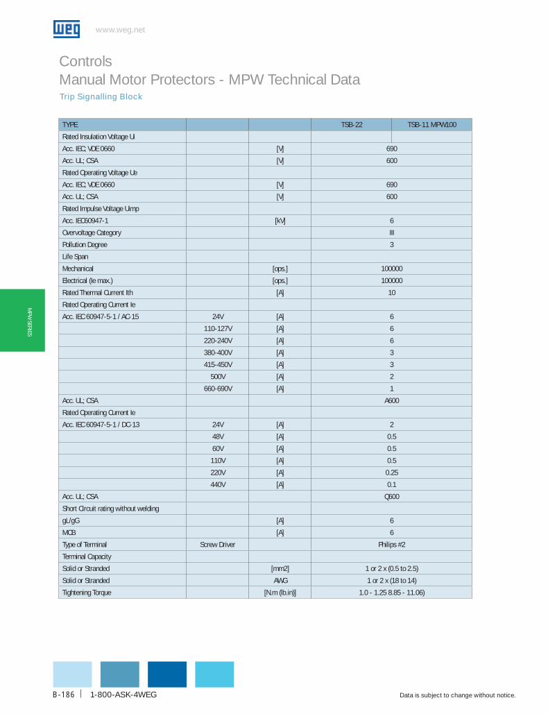
www.weg.net
Data is subject to change without notice.1-800-ASK-4WEGB-186
MPW
SERIES
Trip Signalling Block
Controls Manual Motor Protectors - MPW Technical Data
TYPE TSb-22 TSb-11 MPW100
Rated Insulation Voltage Ui
Acc. IEC; VDE 0660 [V] 690
Acc. UL; CSA [V] 600
Rated Operating Voltage Ue
Acc. IEC; VDE 0660 [V] 690
Acc. UL; CSA [V] 600
Rated Impulse Voltage Uimp
Acc. IEC60947-1 [kV] 6
Overvoltage Category III
Pollution Degree 3
Life Span
Mechanical [ops.] 100000
Electrical (Ie max.) [ops.] 100000
Rated Thermal Current Ith [A] 10
Rated Operating Current Ie
Acc. IEC 60947-5-1 / AC-15 24V [A] 6
110-127V [A] 6
220-240V [A] 6
380-400V [A] 3
415-450V [A] 3
500V [A] 2
660-690V [A] 1
Acc. UL; CSA A600
Rated Operating Current Ie
Acc. IEC 60947-5-1 / DC-13 24V [A] 2
48V [A] 0.5
60V [A] 0.5
110V [A] 0.5
220V [A] 0.25
440V [A] 0.1
Acc. UL; CSA Q600
Short Circuit rating without welding
gL/gG [A] 6
MCB [A] 6
Type of Terminal Screw Driver Philips #2
Terminal Capacity
Solid or Stranded [mm2] 1 or 2 x (0.5 to 2.5)
Solid or Stranded AWG 1 or 2 x (18 to 14)
Tightening Torque [N.m (lb.in)] 1.0 - 1.25 8.85 - 11.06)

WEG Automation - Products and Solutions
www.weg.net
Data is subject to change without notice. B-187
MPW
SER
IES
Shunt Release Block
Controls Manual Motor Protectors - MPW Technical Data
TYPE SRMP SRMP MPW100Rated Insulation Voltage UiAcc. IEC; VDE 0660 [V] 690Acc. UL; CSA [V] 600Rated Operating Voltage UeAcc. IEC; VDE 0660 [V] 690Acc. UL; CSA [V] 600Rated Impulse Voltage UimpAcc. IEC60947-1 [kV] 6Overvoltage Category IIIPollution Degree 3Life SpanMechanical [ops.] 100000Electrical (Ie max.) [ops.] 100000Actuating Voltage x Us [V] 0.7 - 1.1Power ConsumptionPull-In [VA (W)] 20.2 (13) 8.5 (6)Hold [VA (W)] 7.2 (2.4) 3 (1.2)Maximum Opening Time [ms] 20Short Circuit Rating without WeldingFuse gL/gG [A] 10MCB [A] 6Type of Terminal Screw Driver Philips #2Terminal CapacitySolid or Stranded [mm2] 1 or 2 x (0.5 to 2.5)Solid or Stranded AWG 1 or 2 x (18 to 14)Tightening Torque [N.m (lb.in)] 1.0 - 1.25 (8.85 - 11.06)
TYPE uRMP uRMP MPW100Rated Insulation Voltage UiAcc. IEC; VDE 0660 [V] 690Acc. UL; CSA [V] 600Rated Operating Voltage UeAcc. IEC; VDE 0660 [V] 690Acc. UL; CSA [V] 600Rated Impulse Voltage UimpAcc. IEC60947-1 [kV] 6Overvoltage Category IIIPollution Degree 3Life SpanMechanical [ops.] 100000Electrical (Ie max.) [ops.] 100000Pick-Up Voltage x Us [V] 0.85 - 1.1Drop-Out Voltage x Us [V] 0.7 - 0.35Power ConsumptionPull-In [VA (W)] 20.2 (13) 8.5 (6)Hold [VA (W)] 7.2 (2.4) 3 (1.2)Maximum Opening Time [ms] 20Short Circuit Rating without WeldingFuse gL/gG [A] 10MCB [A] 6Type of Terminal Screw Driver Philips #2Terminal CapacitySolid or Stranded [mm2] 1 or 2 x (0.5 to 2.5)Solid or Stranded AWG 1 or 2 x (18 to 14)Tightening Torque [lb. in] 1.0 - 1.25 (8.85 - 11.06)
Under Voltage Release Block
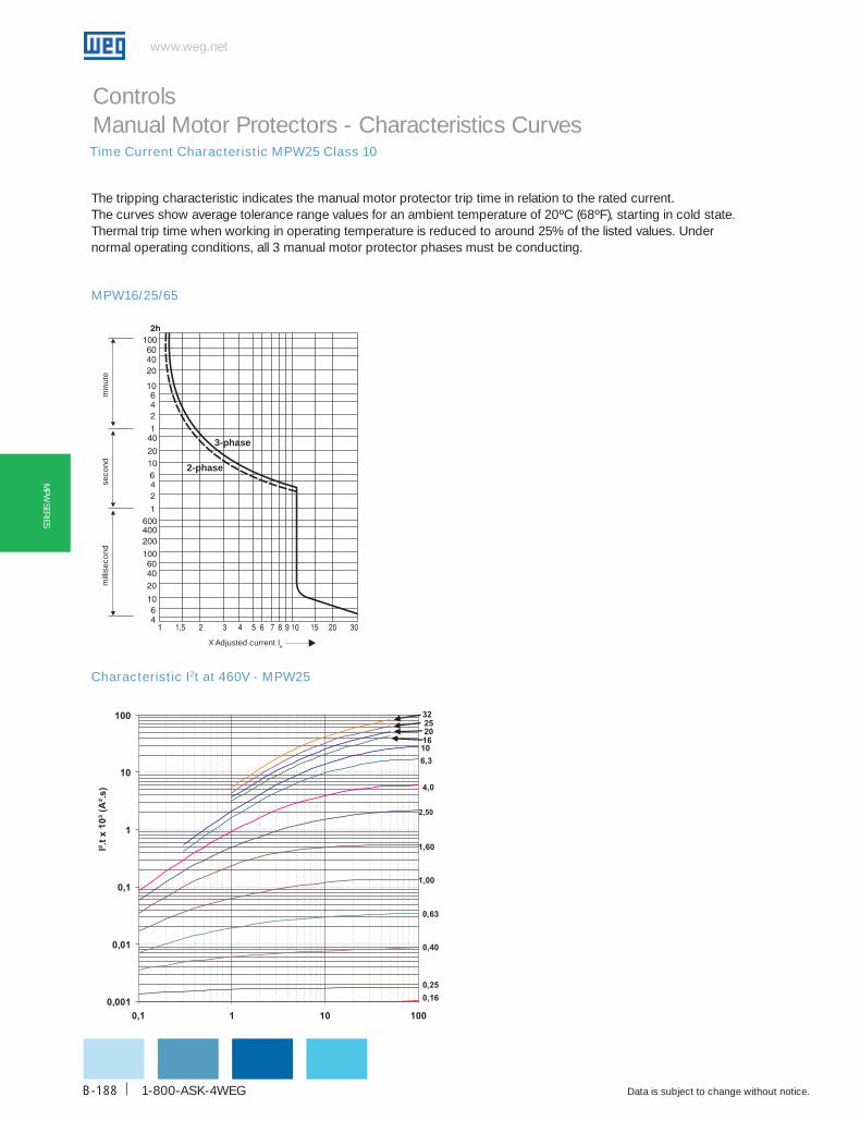
www.weg.net
Data is subject to change without notice.1-800-ASK-4WEGB-188
MPW
SERIES
Time Current Characteristic MPW25 Class 10
Controls Manual Motor Protectors - Characteristics Curves
The tripping characteristic indicates the manual motor protector trip time in relation to the rated current.The curves show average tolerance range values for an ambient temperature of 20ºC (68ºF), starting in cold state. Thermal trip time when working in operating temperature is reduced to around 25% of the listed values. Under normal operating conditions, all 3 manual motor protector phases must be conducting.
MPW16/25/65
Characteristic I2t at 460V - MPW25
3-phase
2-phase
mill
isec
ond
seco
ndm
inut
e
X Adjusted current Ie
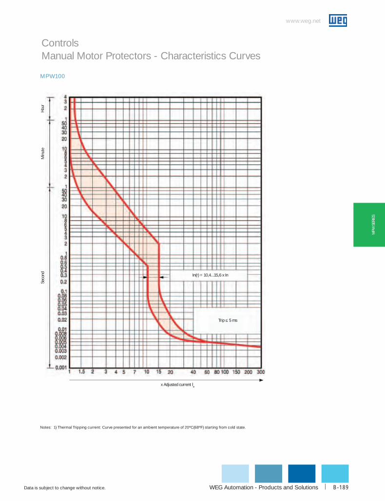
WEG Automation - Products and Solutions
www.weg.net
Data is subject to change without notice. B-189
MPW
SER
IES
Notes: 1) Thermal Tripping current: Curve presented for an ambient temperature of 20ºC(68ºF) starting from cold state.
MPW100
Min
ute
Seco
nd
x Adjusted current Ie
Trip ≤ 5 ms
In(r) = 10,4...15,6 x In
Hour
Controls Manual Motor Protectors - Characteristics Curves

www.weg.net
Data is subject to change without notice.1-800-ASK-4WEGB-190
MPW
SERIES
Controls Manual Motor ProtectorsShort Circuit Interruption Capacity UL/CSA for MPW16, MPW25, MPW65, MPW100
Manual Motor controller high capacity
combination Motor controller (Type E/F) high capacity
combination Motor controller (Type E/F)
Extra high capacity
catalog Number
Setting overload Release
(A)
240VAc480VAc
Y/277VAc600VAc
Y/347VAc
Max. Fuse or Mccb
240VAc480VAc
Y/277VAc600VAc
Y/347VAc
Max. Fuse or Mccb
240VAc480VAc
Y/277VAc600VAc
Y/347VAc
Max. Fuse or Mccb
kA kA kA A kA kA kA A kA kA kA A
MPW
16
0.10 - 0.16 50 50 10 125 - - - - - - - -
0.16 - 0.25 50 50 10 125 - - - - - - - -
0.25 - 0.40 50 50 10 125 - - - - - - - -
0.40 - 0.63 50 50 10 125 - - - - - - - -
0.63 - 1.0 50 50 10 125 - - - - - - - -
1.0 - 1.6 50 50 10 125 - - - - - - - -
1.6 - 2.5 50 50 10 125 - - - - - - - -
2.5 - 4.0 50 50 10 125 - - - - - - - -
4.0 - 6.3 50 50 10 125 - - - - - - - -
6.3 - 10 50 50 5 125 - - - - - - - -
10 - 16 30 30 5 160 - - - - - - - -
MPW
25
0.10 - 0.16 50 50 25 125 50 50 25 - 100 100 50 -
0.16 - 0.25 50 50 25 125 50 50 25 - 100 100 50 -
0.25 - 0.40 50 50 25 125 50 50 25 - 100 100 50 -
0.40 - 0.63 50 50 25 125 50 50 25 - 100 100 50 -
0.63 - 1.0 50 50 25 125 50 50 25 - 100 100 50 -
1.0 - 1.6 50 50 25 125 50 50 25 - 100 100 50 -
1.6 - 2.5 50 50 25 125 50 50 25 - 100 100 50 -
2.5 - 4.0 50 50 25 125 50 50 25 - 100 100 50 -
4.0 - 6.3 50 50 25 125 50 50 25 - 100 100 50 -
6.3 - 10 50 50 25 125 50 50 25 - 100 100 50 -
10 - 16 50 50 25 160 50 50 25 - 100 100 50 -
16 - 20 50 50 25 250 50 50 25 - 100 100 50 -
20 - 25 50 50 25 250 50 50 25 - 100 100 50 -
25 - 32 42 42 25 500 42 42 25 - 100 100 50 -
MPW
65
10 ... 16 50 50 30 160 50 50 30 - - - - -
16 ... 20 50 50 30 250 50 50 30 - - - - -
20 ... 25 50 50 30 250 50 50 30 - - - - -
25 ... 32 50 50 30 500 50 50 30 - - - - -
32 ... 40 35 35 10 500 35 35 10 - - - - -
40 ... 50 35 35 10 750 35 35 10 - - - - -
50 ... 65 35 35 10 750 35 35 10 - - - - -
MPW
100 55 ... 75 50 50 10 1250 50 50 10 - - - - -
70 ... 90 50 50 10 1250 50 50 10 - - - - -
80 ... 100 50 50 10 1250 50 50 10 - - - - -
Note: “-” Fuse or MCCB not required.
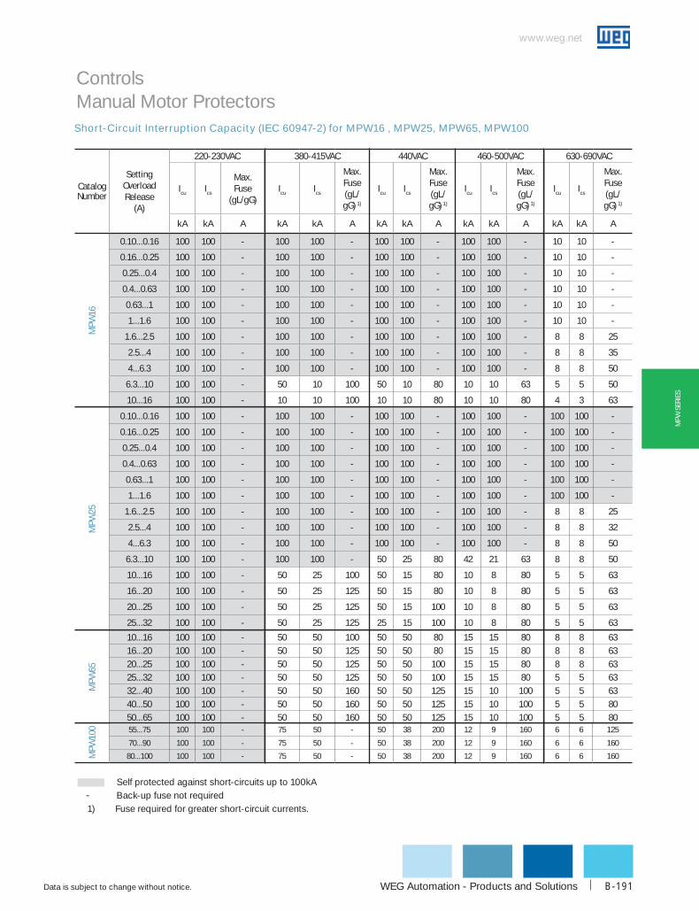
WEG Automation - Products and Solutions
www.weg.net
Data is subject to change without notice. B-191
MPW
SER
IES
Controls Manual Motor ProtectorsShort-Circuit Interruption Capacity (IEC 60947-2) for MPW16 , MPW25, MPW65, MPW100
catalogNumber
Setting overload Release
(A)
220-230VAc 380-415VAc 440VAc 460-500VAc 630-690VAc
Icu Ics
Max. Fuse
(gL/gG)Icu Ics
Max. Fuse (gL/gG) 1)
Icu Ics
Max. Fuse (gL/gG) 1)
Icu Ics
Max. Fuse (gL/gG) 1)
Icu Ics
Max. Fuse (gL/gG) 1)
kA kA A kA kA A kA kA A kA kA A kA kA A
MPW
16
0.10...0.16 100 100 - 100 100 - 100 100 - 100 100 - 10 10 -
0.16...0.25 100 100 - 100 100 - 100 100 - 100 100 - 10 10 -
0.25...0.4 100 100 - 100 100 - 100 100 - 100 100 - 10 10 -
0.4...0.63 100 100 - 100 100 - 100 100 - 100 100 - 10 10 -
0.63...1 100 100 - 100 100 - 100 100 - 100 100 - 10 10 -
1...1.6 100 100 - 100 100 - 100 100 - 100 100 - 10 10 -
1.6...2.5 100 100 - 100 100 - 100 100 - 100 100 - 8 8 25
2.5...4 100 100 - 100 100 - 100 100 - 100 100 - 8 8 35
4...6.3 100 100 - 100 100 - 100 100 - 100 100 - 8 8 50
6.3...10 100 100 - 50 10 100 50 10 80 10 10 63 5 5 50
10...16 100 100 - 10 10 100 10 10 80 10 10 80 4 3 63
MPW
25
0.10...0.16 100 100 - 100 100 - 100 100 - 100 100 - 100 100 -
0.16...0.25 100 100 - 100 100 - 100 100 - 100 100 - 100 100 -
0.25...0.4 100 100 - 100 100 - 100 100 - 100 100 - 100 100 -
0.4...0.63 100 100 - 100 100 - 100 100 - 100 100 - 100 100 -
0.63...1 100 100 - 100 100 - 100 100 - 100 100 - 100 100 -
1...1.6 100 100 - 100 100 - 100 100 - 100 100 - 100 100 -
1.6...2.5 100 100 - 100 100 - 100 100 - 100 100 - 8 8 25
2.5...4 100 100 - 100 100 - 100 100 - 100 100 - 8 8 32
4...6.3 100 100 - 100 100 - 100 100 - 100 100 - 8 8 50
6.3...10 100 100 - 100 100 - 50 25 80 42 21 63 8 8 50
10...16 100 100 - 50 25 100 50 15 80 10 8 80 5 5 63
16...20 100 100 - 50 25 125 50 15 80 10 8 80 5 5 63
20...25 100 100 - 50 25 125 50 15 100 10 8 80 5 5 63
25...32 100 100 - 50 25 125 25 15 100 10 8 80 5 5 63
MPW
65
10...16 100 100 - 50 50 100 50 50 80 15 15 80 8 8 6316...20 100 100 - 50 50 125 50 50 80 15 15 80 8 8 6320...25 100 100 - 50 50 125 50 50 100 15 15 80 8 8 6325...32 100 100 - 50 50 125 50 50 100 15 15 80 5 5 6332...40 100 100 - 50 50 160 50 50 125 15 10 100 5 5 6340...50 100 100 - 50 50 160 50 50 125 15 10 100 5 5 8050...65 100 100 - 50 50 160 50 50 125 15 10 100 5 5 80
MPW
100 55...75 100 100 - 75 50 - 50 38 200 12 9 160 6 6 125
70...90 100 100 - 75 50 - 50 38 200 12 9 160 6 6 160
80...100 100 100 - 75 50 - 50 38 200 12 9 160 6 6 160
Self protected against short-circuits up to 100kA - Back-up fuse not required 1) Fuse required for greater short-circuit currents.
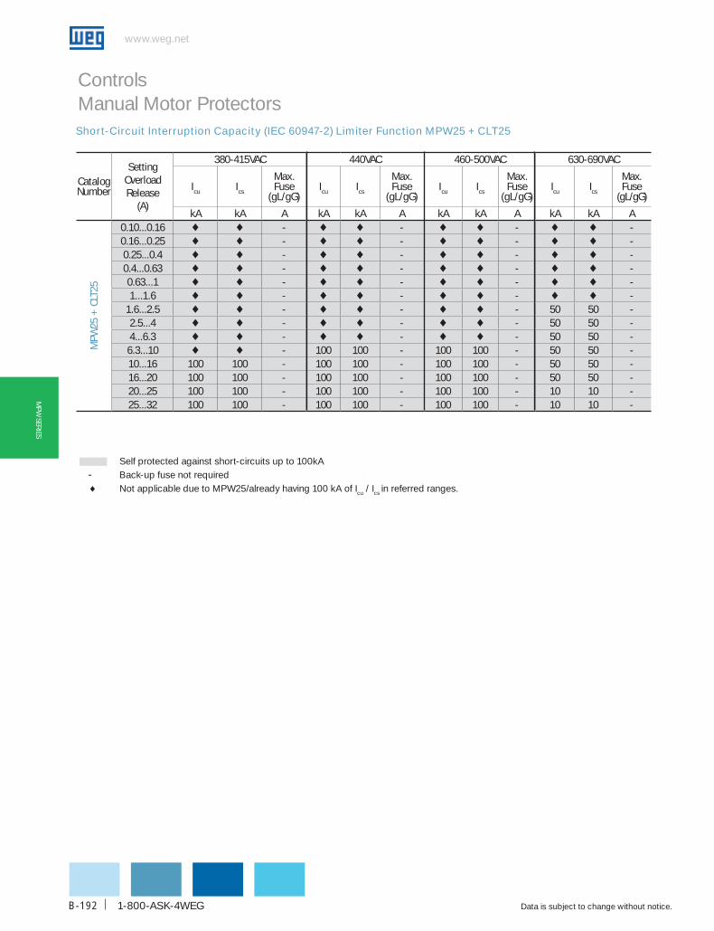
www.weg.net
Data is subject to change without notice.1-800-ASK-4WEGB-192
MPW
SERIES
Controls Manual Motor ProtectorsShort-Circuit Interruption Capacity (IEC 60947-2) Limiter Function MPW25 + CLT25
Self protected against short-circuits up to 100kA - Back-up fuse not required ♦ Not applicable due to MPW25/already having 100 kA of Icu / Ics in referred ranges.
catalogNumber
Setting Overload Release
(A)
380-415VAC 440VAC 460-500VAC 630-690VAC
Icu Ics
Max. Fuse
(gL/gG)Icu Ics
Max. Fuse
(gL/gG)Icu Ics
Max. Fuse
(gL/gG)Icu Ics
Max. Fuse
(gL/gG)
kA kA A kA kA A kA kA A kA kA A
MPW
25 +
CLT
25
0.10...0.16 ♦ ♦ - ♦ ♦ - ♦ ♦ - ♦ ♦ -0.16...0.25 ♦ ♦ - ♦ ♦ - ♦ ♦ - ♦ ♦ -0.25...0.4 ♦ ♦ - ♦ ♦ - ♦ ♦ - ♦ ♦ -0.4...0.63 ♦ ♦ - ♦ ♦ - ♦ ♦ - ♦ ♦ -0.63...1 ♦ ♦ - ♦ ♦ - ♦ ♦ - ♦ ♦ -1...1.6 ♦ ♦ - ♦ ♦ - ♦ ♦ - ♦ ♦ -
1.6...2.5 ♦ ♦ - ♦ ♦ - ♦ ♦ - 50 50 -2.5...4 ♦ ♦ - ♦ ♦ - ♦ ♦ - 50 50 -4...6.3 ♦ ♦ - ♦ ♦ - ♦ ♦ - 50 50 -
6.3...10 ♦ ♦ - 100 100 - 100 100 - 50 50 -10...16 100 100 - 100 100 - 100 100 - 50 50 -16...20 100 100 - 100 100 - 100 100 - 50 50 -20...25 100 100 - 100 100 - 100 100 - 10 10 -25...32 100 100 - 100 100 - 100 100 - 10 10 -

WEG Automation - Products and Solutions
www.weg.net
Data is subject to change without notice. B-193
MPW
SER
IES
Controls Manual Motor Protectors - MPW Technical DataMain Terminal Capacity
catalog Number Type Number of conductors cross-Section
MPW16 Rigid or flexible cable 1 or 21...4 mm2
18...12 AWG
MPW25 Rigid or flexible cable 1 or 21...2.5 mm2
2.5...6 mm2
14...8 AWG 1)
MPW65
Type 1 conductor connection in upper part only Cross-Section Rigid cable 1...35 mm2
Cable without terminal 1.5...35 mm2
Cable with terminal 1...35 mm2
Flexible cable1.5...35 mm2
16...2 AWGType 1 conductor connection in lower part only Cross-Section
Rigid cable 2.5...35mm2
Cable without terminal 6...35mm2
Cable with terminal 2.5...35mm2
Flexible cable6...35mm2
12...2 AWGType Connection of 2 condutors - Conductor in upper part Cross-Section
Rigid cable 1...35mm2
Cable without terminal 1.5...35mm2
Cable with terminal 1...35mm2
Flexible cable1.5...35mm2
16...2 AWGType Conductor in lower part Cross-Section
Rigid cable 2.5...35mm2
Cable without terminal 6...35mm2
Cable with terminal 2.5...35mm2
Flexible cable6...35mm2
12...2 AWG
MPW100
Type Number of conductors Cross-Section
Rigid cable1
2.5...70 mm2
12...2/0 AWG
22.5...50 mm2
12...1/0 AWG
Flexible cable1
2.5...50 mm2
12...1/0 AWG
22.5...35 mm2
10...2 AWG
Note: 1) 8 AWG for flexible cable only

www.weg.net
Data is subject to change without notice.1-800-ASK-4WEGB-194
MPW
SERIES
Altitude (above sea level) - h
Rated operational voltage ue
current correction factor Iu
h ≤ 2000 m 690 V 1 x Iu2000 < h ≤ 3000 m 550 V 0,96 x Iu3000 < h ≤ 4000 m 480 V 0,93 x Iu4000 < h ≤ 5000 m 420 V 0,90 x Iu
Controls Manual Motor Protectors - MPW Technical Data
Altitude - Correction factorThe MPW manual motor protectors do not undergo any change to their specified performance when applied at an altitude of up to 2000 meters above sea level.However, as the altitude increases, the reduced atmospheric pressure produces decreasing dielectric properties. Therefore, current and voltage correction factors must be applied for altitudes exceeding 2000 meters, as shown in the table on the right.
DC operationThe MPW16, MPW25 and MPW65 motor protective circuit breakers can also be used for operating DC loads. For such operation it is necessary to connect 2 or 3 poles in series.See recommended circuits and their voltage limits in the table on the right.
Time constant t = 5 ms
Short-circuit breaking capacity Icu = 10 kA for all configurations
circuits Max. Vdc Notes
150 VDC
System notgrounded
2 pole series connected
300 VDC
System grounded
2 pole series connected
450 VDC
System grounded
3 pole series connected
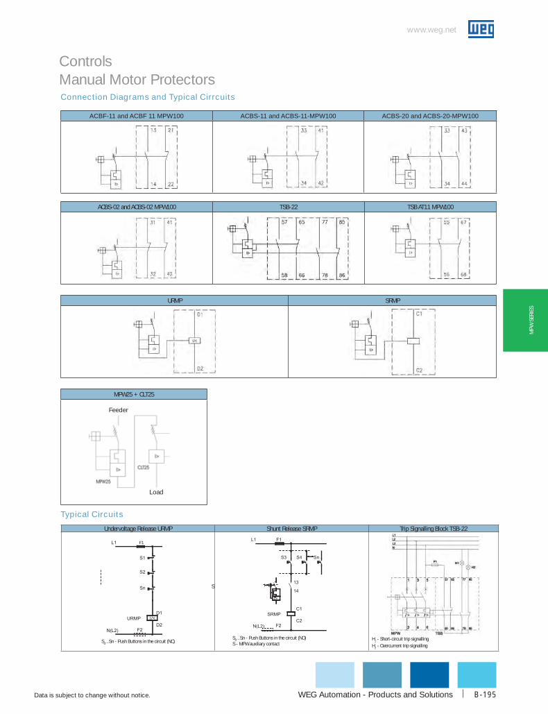
WEG Automation - Products and Solutions
www.weg.net
Data is subject to change without notice. B-195
MPW
SER
IES
Controls Manual Motor ProtectorsConnection Diagrams and Typical Cirrcuits
Typical Circuits
ACBF-11 and ACBF 11 MPW100 ACBS-11 and ACBS-11-MPW100 ACBS-20 and ACBS-20-MPW100
ACBS-02 and ACBS-02 MPW100 TSB-22 TSB AT11 MPW100
URMP SRMP
Undervoltage Release URMP Shunt Release SRMP Trip Signalling Block TSB-22
F1
S0...Sn - Push Buttons in the circuit (NC)S0...Sn - Push Buttons in the circuit (NO)S - MPW auxiliary contact
H1 - Short-circuit trip signallingH2 - Overcurrent trip signalling
S
MPW25 + CLT25
Load
Feeder

www.weg.net
Data is subject to change without notice.1-800-ASK-4WEGB-196
MPW
SERIES
Controls Manual Motor Protectors - Dimensions mm (in)
MPW16 + CWC07...16
MPW16 + Accessories Mounting Position
Insulated Enclosure - PE66 (IP66)
45 [1.76]
165
[6.4
9]
175
[6.9
1]
77 [3.03]
DIN rail35 [1 38]
MP
ECCMP C016
CWC07 16
92 [3.62]
7]
83.2 [3.28]
157
[6.1
8]
PG 16PG 16
150.
32 [5
.92]
18 [0.71]45 [1.77]18 [0.71]
9 [0.36]
90 [3.55]
119
[4.6
7]
5 [ 0.19]
30 [1.19]
106
[4.1
6]
ACBS
URMPSRMPTSB
ACBF
97 [3
.84]
DIN ra l35 [1 38]
77 [3.05]
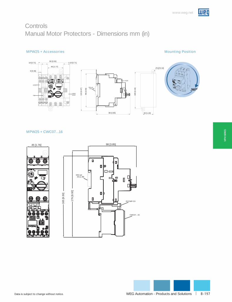
WEG Automation - Products and Solutions
www.weg.net
Data is subject to change without notice. B-197
MPW
SER
IES
Controls Manual Motor Protectors - Dimensions mm (in)
MPW25 + CWC07…16
MPW25 + Accessories Mounting Position
45 [1.76] 98 [3.85]
165
[6.5
0]
DIN rail35 [1.38]
176
[6.9
2]
ECCMP-C0
CWC07...16
18 [0.71]
45 [1.77]
18 [0.71]
9 [0.36]
90 [3.55]
5 [ 0.19]
30 [1.19]
106
[4.1
6]
ACBS
URMPSRMPTSB
ACBF
98 [3
.84]
119
[4.6
7]
98 [3.85]
DIN rail35 [1 38]

www.weg.net
Data is subject to change without notice.1-800-ASK-4WEGB-198
MPW
SERIES
MPW25 + CWC025
MPW25 + CWM9...18
MPW25 + CWM25
45 [1.76]
176
[6.9
4]
165
[6.5
1]
98 [3.84]
DIN rail35 [1 38]
ECCMP C025
CWC025
45 [1 76]97 3 83]
193
[7.6
0]
183
[7.1
9]
4 5 [0 18]
35 [1 38]10 [0
.39]
183
[7.2
0]
5 0 19]
30 [1 18]
DIN ra l35 1 38]
MPW25
ECCMP 25
CWM9 18
45 [1 76]
193
[7.6
0]
183
[7.1
9]
97 [3 83]
CWM25
10 [0
.39]
35 [1 38]
4 5 [0 18]
183
[7.2
0]
5 [ 0 19]
30 [1 18]
ECCMP 25
MPW25
D N rail35 [1 38]
Controls Manual Motor Protectors - Dimensions mm (in)
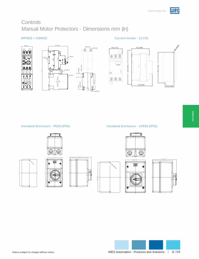
WEG Automation - Products and Solutions
www.weg.net
Data is subject to change without notice. B-199
MPW
SER
IES
MPW25 + CWM32
Insulated Enclosure - PE55 (IP55) Insulated Enclosure - LPE55 (IP55)
Current limiter - CLT25
183
[7.2
0]
5 [ 0 20]30 [1 18]
200
[7.8
7]
98 3 86]55 [2 17]
ECCMP 32
CWM32
MPW25D N a l35 [1 38]
13 [0
.47]
16.5
[0.6
5]
4 5 [0 18]
79 [3
.11]
128 7 [5 07]109 2 [4 30]
167
[657
Ø4 5 [Ø0 18]
155
[610
92 [3 62]
PG 16PG 16PG 16 PG 16
108 [4 25]
155
[6.1
0]
Ø4 5 [Ø0 18]
109 2 [4 30]128 72 [5 07]
45 [1,772]
CLT25
72 [2,820]
118
[4,6
46]
Ø4 8 Ø0,1
90]
30 [1,193]
61 [2,385]
106
[4,1
60]
Controls Manual Motor Protectors - Dimensions mm (in)

www.weg.net
Data is subject to change without notice.1-800-ASK-4WEGB-200
MPW
SERIES
Accessories: BBS45, BBS54, FTBBS, LST25
Through the Door Rotary Handle - RMMP
Through the Door Rotary Handle - MR MPW25
118
[4.6
5]
19.4 [0.76]97 [3.82]
R20
Ø4 [Ø0.16]MPW25
45 [1.77]
MPW25i
Widthfrom 1.0 to 3.5mm
ACBF
PLMP
ACBSURMPSRMP
97 [3
.82]
9 [0.35] 18 [0.71]72 [2.83]
45°
149 [5.87] 28 to 302
177 a 451
5.5 [0.22]
Connect ng Rod (130 or 330mm)
12.2
[0.4
9]
6.9 [0.28]
Ø16 [Ø0 63]
[5.12 or 13.0]
[1.10 to 11.89]
[.04 to 0.14]
Drilling holes located on door panel
118
[4.6
5]
97 [3 82]Drilling holes located on door panel
MPW25
45 [1 77]
MPW25i
Widthfrom 1 0 to 3 5mm
ACBF
PLMP
ACBSURMPSRMP
97 [3
.82]
9 [0 35] 18 [0 71]
72 [2 83]
149 [5 87] 15 to 280
164 to 429
5 5 [0 22]
Connecting Rod (130 or 330mm)
12.2
[0.4
8]
33 [1 30]
24.5
[0.9
6]
3 2 [0 13]
Ø22.5
[Ø0.8
9]
6 9 [0 27] 20 [0 79]
[6 46 to 16 89]
[5 12 or 13 0]
[0 59 to 11 02]
[0 4 to 0 14]I ON
0 O
FF
Catalog Number BBS45-2 BBS45-3 BBS45-2 BBS45-5
A 85 130 175 220
Catalog Number BBS54-2 BBS54-3 BBS54-2 BBS54-5
B 94 149 202 256
Controls Manual Motor Protectors - Dimensions mm (in)
85 [3 36]
20 [079]
14 [057]
45 [1 77]
13 0 [0 51]
28 1 2]
4 0 95]
40 156
44 [1 7 ]
28 [1.09]
40 [1.57]
25 [1
.00]
51 [2
.01]
B 13 [0 51]
20 [079]
14 [057]
54 2 13]

WEG Automation - Products and Solutions
www.weg.net
Data is subject to change without notice. B-201
MPW
SER
IES
Through the Door Rotary Handle - MRX
Through the Door Rotary Handle - RMMP65
Through the Door Rotary Handle - MRX65
MPW65 + Accessories Mounting Position
213 [8 50]
19 22 [0 77]
125
[5.0
0]
52 60 [2 07]
MPW65MPW6
3 5 [0 14
10 [0 40]
AR2
0
45°
4 [ 0 16]
16 [ 0 64]
241 to 515
28 to 302
Dri ling holes on the door panel
Connecting Rod130 or 330[5 12 or 12 99]
A < 5 0[A < 20]
[9 49 to 20 28]
[1 10 to 11 89]
3 5 [0 14]
10 [0 39]
A
50 7 [2 00]
213 [8 37]
125
[4.9
2]
33 [1 30]
MPW65MPW65i
23.5
[0.9
3]
3 2 [0 13]
4 [ 0 16]24 25 [0 95]
24.2
5 [0
.95]
22 5 [ 0 89]
48 5 [1 91]
48.5
[1.9
1]
Dr lling holes on the door panel
Connecting Rod130 or 330
A < 5 0
261 to 489
48 to 276[1 89 to 10 87]
[5 12 or 12 99]
[10 27 to 19 25]
[A < 20]
9 [0 37]
99 [3 97]
18 0 72] 54 2 16] 18 0 72]
157 [6 27]
125
[5.0
0]
144
[575
]
131
[5.2
4]
30 1 20]
5 0 19]
DIN ra l35 [1 38]
URMPSRMPTSB
ACBS
ACBF
154 2 [6 07] 48 to 276
50 7 [2 00]
97.2
[3.8
3]
11.5
[0.4
5]
7 2 [0 28]
A
3 2 [0 13]
23.5
[0.9
3]
4 [ 0 16]
24 3 [0 95]
24.3
[0.9
5]
48.5
[1.9
1]
48 5 [1 91]
Drilling the panel door
130 or 330
A < 5 0 MPWMPWMPW25t
202 to 430
[5 12 or 13 0]
[7 95 to 16 93]
[A < 19 ]
[1 89 to 10 87]
Controls Manual Motor Protectors - Dimensions mm (in)

www.weg.net
Data is subject to change without notice.1-800-ASK-4WEGB-202
MPW
SERIES
MPW100
Through the Door Coupling Rotary Handle - MR MPW100
Mounting position
35 [1 38]
DIN rail:75 [2 95]
11 MPW100
ACBS
URMPSRMP
MPW100
165
[6.5
0]
70 [2 76] 171 [6.73]
155
[6.1
0]
30 [1.18]
[
0.2
0]
18 [0.71]18 [0.71]
9 [0.35]
106.5 [4.19]
Ø43
53,6
4x Ø3,4
56
4,5
0,9
B
Drilling the panel door
A < 7,6
Reference Code B (mm)
MR MPW100-115min: 220max: 282
MR MPW100-315min: 220max: 482
4 5mm
A < 7 6mm
∅43
B
0,9m
mControls Manual Motor Protectors - Dimensions mm (in)


