ecological aspects of the implementation of new...
TRANSCRIPT
MIDDLE POMERANIAN SCIENTIFIC SOCIETY OF THE ENVIRONMENT PROTECTION ŚRODKOWO-POMORSKIE TOWARZYSTWO NAUKOWE OCHRONY ŚRODOWISKA
Annual Set The Environment Protection Rocznik Ochrona Środowiska
Volume/Tom 18. Year/Rok 2016 ISSN 1506-218X 137-157
Ecological Aspects of the Implementation of New Technologies Processing
for Machinery Parts
Krzysztof Kukiełka Politechnika Koszalińska
1. Introduction
Recently manufacturing companies to meet the demands of the market and existing laws must fulfil many criteria (Patyk et al. 2014). Currently, the most important criteria (according to the intention of the European Union) is to deliver ecological products primarily organic. The Roadmap to a Resource Efficient Europe the target for 2020 is to provide citizens and public authorities the appropriate incentives to choose the most resource-efficient products, through appropriate economic signals and understandable environmental information. The market share of products with economical use of resources is currently at a low level, despite the possibility of providing such products for industry and agri-culture and growing demand among consumers.
The statement provided above already indicates that the scope of interest of pro-ecological teaching is very broad and that the field can be divided further into specialized areas related directly to a given situation (Piecuch & Piecuch 2011, Piecuch & Piecuch 2013).
Chipboard processing such as turning, milling, grinding belong to the traditional methods of modern part of machines and equipment. They belong to the group treatments so-called material removal and are harm-ful to the environment (produce a chip during the process) and service (noise, vibration, dust, oil spill, evaporation cutting fluid, etc.), and may
138 Krzysztof Kukiełka
even dangerous, for example break of grinding wheel. The tools have a low shelf life and the process is electric energy and time consuming.
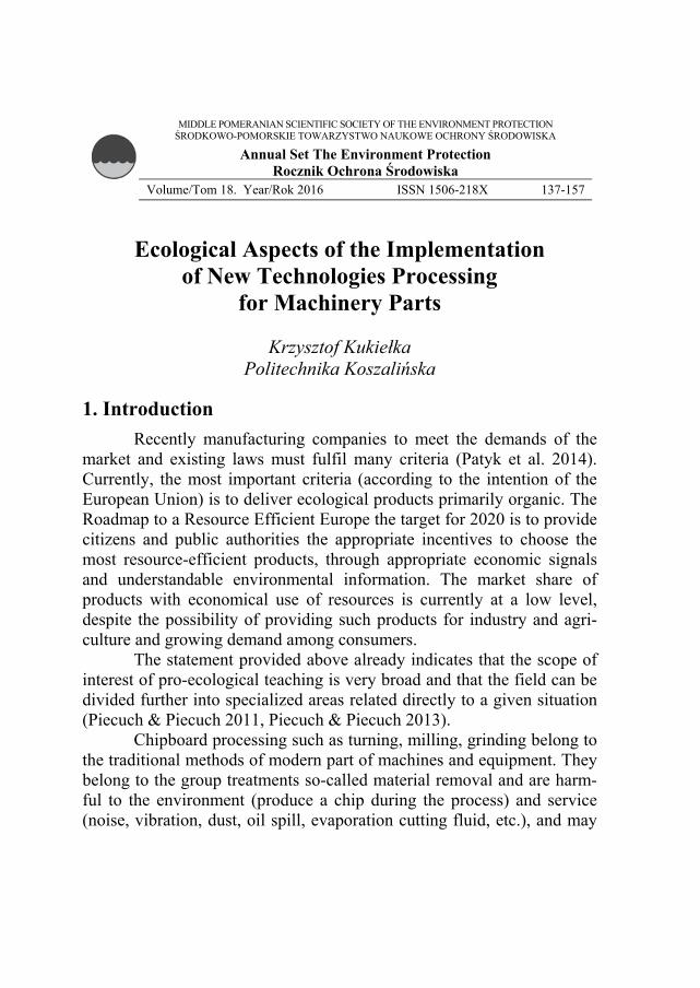
For example, parts with thread (screws, nuts) are numerically the most common group in the manufacturing industry. It is estimated that approximately 40-50% of machine parts has a thread. The vast range of production scale is the cause of a large variety of processes for producing these parts. There are the following, having industrial importance, meth-od of the thread manufacturing: rolling, grinding, milling, cutting thread-ing heads (external threads), die cutting (external threads), cutting a tap (internal threads), cutting tool on a lathe. The vast majority of all these methods are include into the profiling method, i.e. thread profile is formed by mapping of the outline tool and its accuracy depends on the accuracy of the tool. Turning is the most universal method of threads development. For turning of the thread are used knives gripper shaped, holder, block cutter or conic holder. Thread turning requires several pas-sage of the tools. Even use of the modest cutting-edge design solutions (Fig. 1) requires a 4-6 move.
Fig. 1. Turning of an external trapezoidal thread in four passages (a), turning the internal thread with the triangular outline in six passages by knife AVRC 40-4 with a plate Mulit 4IR8APIRD2M manufactured by VARGUS (b) and milling internal threads using a special type of head MiTM with plate with multi blade (c) (Vardex 2012): 1 – screw with trapezoidal thread, 2 – turning tool with a plate 3 – pipe with internal thread, 4 – thread milling head Rys. 1. Toczenie zewnętrznego gwintu trapezowego w czterech przejściach (a), toczenie metrycznego gwintu wewnętrznego w sześciu przejściach za pomocą noża do gwintów AVRC 40-4 z płytką skrawającą Mulit 4IR8APIRD2M wykonaną przez firmę VARGUS (b) i specjalna wieloostrzowa głowica gwintująca do gwintów wewnętrznych produkcji MiTM (c) (Vardex 2012): 1 – śruba z gwintem trapezowym, 2 – nóż tokarski z wymienną płytką 3 – rura z gwintem wewnętrznym, 4 – głowica do frezowania gwintów wewnętrznych
1
3
2 4
a) b) c)
2
Ecological Aspects of the Implementation of New Technologies… 139
Thread execution time depends on the dimensions and ranges from several seconds to several minutes. The accuracy of the major di-ameter depends on the turner, thread pitch accuracy – from the kinematic machine accuracy (practically on the accuracy of lead-screw), outline accuracy – geometrical accuracy of the tool and the accuracy of the set-ting of the knife.
In order to eliminate these negative phenomena is proposed to re-place these technologies by modern methods of forming such as rolling, smooth and strengthen burnishing that belong to the so-called chip less treatments. Besides to the reduced impact on the environment and im-proved industrial safety conditions, in addition achieved a significant re-duction of the cost-consuming and labor-intensive of the process, while increasing tool life and quality of manufactured parts.
Volume plastic forming allows to achieve high accuracy of prod-uct and process productivity (Kukiełka K. 2009, Łyczko2010, Olszak 2008). During the execution of machine parts using this technology the use of the starting material is about 85-97% and material savings entail large energy savings. Savings should also include lower cost of material storage, eliminating the chips management, less need for coolant, lower expenditure on transport and depreciation of production equipment. Thread rolling technology has several advantages, namely: less waist of material, extremely short times of execution, which has an impact on the production with high performance, high durability of the tools, the use of the machinery. In contrast to machining, after which the waste is pro-duced in the form of chips, using a rolling technology as the volume of plastic forming, it is possible execution thread at full use of the material. The diameter of the blank under the rolled thread is smaller compared to the diameter of the thread rolling, which results in considerable savings of material.
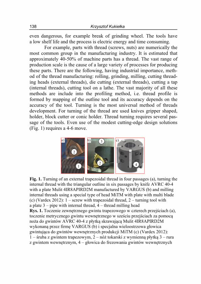
With respect to the threading is proposed to introduce thread rolling, which can be divided into three groups (Kukiełka K. 2009, Łyczko 2010, Olszak 2008) (Fig. 2): axial rolling, radial rolling and tangent rolling.
Not all threaded machines parts can be rolled on the common thread mills. Where the shape or dimensions (eg. too large length of the parts) limit this possibility, with very little financial expenditure and ma-chine park possession, all over the world rolling heads are used flanks (Łyczko 2010). Thread rolling heads can roll external threads: metric,
140 Krzysztof Kukiełka
metric fine threads, unified, pipes and other special threads, for example trapezoidal and rope.
Fig. 2. Thread rolling methods: axial by three rollers (a), axial by two rollers (b) radial (c) and tangential (d) Rys. 2. Metody walcowania gwintów: osiowa w układzie trzyrolkowym (a), osiowa w układzie dwurolkowym (b), promieniowa (c) i styczna (d)
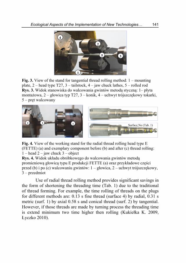
Due to the diversity of the threaded parts of the most commonly types of heads are used: double roller for rolling by tangential method (Fig. 3) by triple roller by rolling with radial method (Fig. 4) by triple roller by axial rolling method (Fig. 5) and the multi-roller (four-, five- and six-roller) by angular axial rolling method.
View of Machine-Object-Holder-Tool for the thread rolling by FETTE head type T27 is shown in Figure 3. The stand is located in the Department of Applied Mechanics and Strength of Materials at the Fac-ulty of Mechanical Engineering at Koszalin University of Technology. On a conventional lathe saddle in place of jaws knife, mounted plate (1) which support the head type T27 (2) (FETTE) for rolling by axial meth-od. This head allows for rolling metric, trapezoidal and special thread also conducting smoothing processing. Adapting the stand for the type of treatment involves the exchange of rollers.
roll
a)
object
b)
object
roll
c) d)
object
roll
object
roll
Ecological Aspects of the Implementation of New Technologies… 141
Fig. 3. View of the stand for tangential thread rolling method: 1 – mounting plate, 2 – head type T27, 3 – tailstock, 4 – jaw chuck lathes, 5 – rolled rod Rys. 3. Widok stanowiska do walcowania gwintów metodą styczną: 1– płyta montażowa, 2 – głowica typ T27, 3 – konik, 4 – uchwyt trójszczękowy tokarki, 5 – pręt walcowany
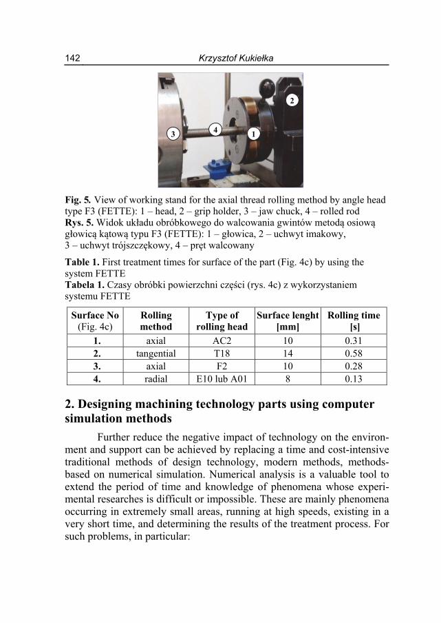
Fig. 4. View of the working stand for the radial thread rolling head type E (FETTE) (a) and exemplary component before (b) and after (c) thread rolling: 1 – head 2 – jaw chuck 3 – object Rys. 4. Widok układu obróbkowego do walcowania gwintów metodą promieniową głowicą typu E produkcji FETTE (a) oraz przykładowe części przed (b) i po (c) walcowaniu gwintów: 1 – głowica, 2 – uchwyt trójszczękowy, 3 – przedmiot
Use of radial thread rolling method provides significant savings in the form of shortening the threading time (Tab. 1) due to the traditional of thread forming. For example, the time rolling of threads on the plugs for different methods are: 0.13 s fine thread (surface 4) by radial, 0.31 s metric (surf. 1) by axial 0.58 s and conical thread (surf. 2) by tangential. However, if those threads are made by turning process the threading time is extend minimum two time higher then rolling (Kukiełka K. 2009, Łyczko 2010).
3 4
a) b)
c) 3 12
1 2
Surface No (Tab. 1)
3
2
1
4
5
142 Krzysztof Kukiełka
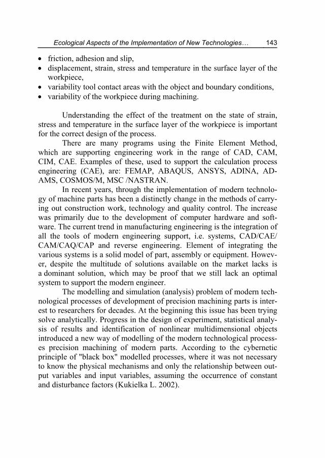
Fig. 5. View of working stand for the axial thread rolling method by angle head type F3 (FETTE): 1 – head, 2 – grip holder, 3 – jaw chuck, 4 – rolled rod Rys. 5. Widok układu obróbkowego do walcowania gwintów metodą osiową głowicą kątową typu F3 (FETTE): 1 – głowica, 2 – uchwyt imakowy, 3 – uchwyt trójszczękowy, 4 – pręt walcowany
Table 1. First treatment times for surface of the part (Fig. 4c) by using the system FETTE Tabela 1. Czasy obróbki powierzchni części (rys. 4c) z wykorzystaniem systemu FETTE
Surface No(Fig. 4c)
Rolling method
Type of rolling head
Surface lenght [mm]
Rolling time [s]
1. axial AC2 10 0.31 2. tangential T18 14 0.58 3. axial F2 10 0.28 4. radial E10 lub A01 8 0.13
2. Designing machining technology parts using computer simulation methods
Further reduce the negative impact of technology on the environ-ment and support can be achieved by replacing a time and cost-intensive traditional methods of design technology, modern methods, methods-based on numerical simulation. Numerical analysis is a valuable tool to extend the period of time and knowledge of phenomena whose experi-mental researches is difficult or impossible. These are mainly phenomena occurring in extremely small areas, running at high speeds, existing in a very short time, and determining the results of the treatment process. For such problems, in particular:
1
2
43
Ecological Aspects of the Implementation of New Technologies… 143
friction, adhesion and slip, displacement, strain, stress and temperature in the surface layer of the
workpiece, variability tool contact areas with the object and boundary conditions, variability of the workpiece during machining.
Understanding the effect of the treatment on the state of strain,
stress and temperature in the surface layer of the workpiece is important for the correct design of the process.
There are many programs using the Finite Element Method, which are supporting engineering work in the range of CAD, CAM, CIM, CAE. Examples of these, used to support the calculation process engineering (CAE), are: FEMAP, ABAQUS, ANSYS, ADINA, AD-AMS, COSMOS/M, MSC /NASTRAN.
In recent years, through the implementation of modern technolo-gy of machine parts has been a distinctly change in the methods of carry-ing out construction work, technology and quality control. The increase was primarily due to the development of computer hardware and soft-ware. The current trend in manufacturing engineering is the integration of all the tools of modern engineering support, i.e. systems, CAD/CAE/ CAM/CAQ/CAP and reverse engineering. Element of integrating the various systems is a solid model of part, assembly or equipment. Howev-er, despite the multitude of solutions available on the market lacks is a dominant solution, which may be proof that we still lack an optimal system to support the modern engineer.
The modelling and simulation (analysis) problem of modern tech-nological processes of development of precision machining parts is inter-est to researchers for decades. At the beginning this issue has been trying solve analytically. Progress in the design of experiment, statistical analy-sis of results and identification of nonlinear multidimensional objects introduced a new way of modelling of the modern technological process-es precision machining of modern parts. According to the cybernetic principle of "black box" modelled processes, where it was not necessary to know the physical mechanisms and only the relationship between out-put variables and input variables, assuming the occurrence of constant and disturbance factors (Kukielka L. 2002).
144 Krzysztof Kukiełka
The latest trend in the modelling and analysis processes is the numerical modelling using Finite Element Method (FEM) (Fig. 6). It involves replacing the continuous object (the real) discrete object with separate sub-volumes and/or sub-areas – finite elements containing a finite number of nodes. The development of the computational capabili-ties of computers and software allows analysis of modern technological processes precision machining of automotive parts using computer pro-grams using FEM (Domblesky 2002), Kukiełka K. 2009, Kukiełka L. 1999, Kukiełka L. 2000, Kukiełka L. 2001, Myśliński et al. 2004) and iterative calculation using the updated Lagrangian description (Patyk & Kukiełka L. 2008, Zienkiewicz & Taylor 2000).
One major steps to achieve effective solutions to the Finite Ele-ment Method is to develop a universal model of the investigated process.
At Department of Technical Mechanics at the Faculty of Mechan-ical Engineering of the Koszalin University of Technology developed applications on the system ANSYS (APDL language), which allow a comprehensive time analysis for deformation (displacement, strain), and stresses occurring in the object, both the spatial conditions as well as plane, in the process technological precision machining parts: cutting processes (Bohdal & Walczak 2013, Bohdal & Kukielka L. 2014), cut-ting and burnishing processes sliding (Bohdal et al. 2014), cutting by an abrasive single grain (Chodór 2014, Forysiewicz et al. 2016, Kukielka L. et al. 2005), embossing trapezoidal stamp (Kałduński & Kukielka 2014), thread rolling (Kukiełka K. 2009, Kukiełka K. & Kukielka L. 2013, Kukiełka K. 2014, Kukiełka K. 2014, Kukiełka L. Kukiełka K. 2007, Kukiełka L. & Kukiełka K. 2012), duplex burnishing (Patyk & Kukielka L. 2008, Patyk 2010, Patyk Kułakowska et al. 2014, Patyk Kukiełka et al. 2014), burnishing rolling (Kukiełka L. 1994, Kukiełka L. 1999, Kukiełka L. & Krzyżyński T. 2000, Kukiełka L. 2001, Kukiełka L. 2002, Kukiełka L. et al. 2012, Kukiełka L. et al. 2012, Kułakowska et al. 2009, Kułakow-ska, Kukiełka L. et al. 2014, Kułakowska, Patyk et al. 2014, Myśliński et al. 2004, Patyk & Kukielka L. 2008), shot penning (Szyc 2014) and modern material behaviour modelling (Malag et al. 2014). In applications using a theoretical and modelling processes precision machining of mod-ern parts, using the models of incremental method (Kukiełka L. 1994, Kukiełka L. 1999, Kukiełka L. & Krzyżyński T. 2000, Kukiełka L. 2001, Kukiełka L. et al 2012, Kukiełka L. et al. 2014, Myślński et al. 2004).
Ecological Aspects of the Implementation of New Technologies… 145
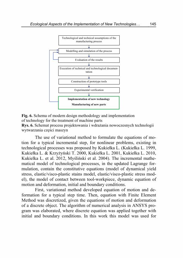
Fig. 6. Schema of modern design methodology and implementation of technology for the treatment of machine parts Rys. 6. Schemat procesu projektowania i wdrażania nowoczesnych technologii wytwarzania części maszyn
The use of variational method to formulate the equations of mo-tion for a typical incremental step, for nonlinear problems, existing in technological processes was proposed by Kukiełka L. (Kukiełka L. 1999, Kukiełka L. & Krzyżyński T. 2000, Kukiełka L. 2001, Kukiełka L. 2010, Kukielka L. et al. 2012, Myśliński et al. 2004). The incremental mathe-matical model of technological processes, in the updated Lagrange for-mulation, contain the constitutive equations (model of dynamical yield stress, elastic/visco-plastic stains model, elastic/visco-plastic stress mod-el), the model of contact between tool-workpiece, dynamic equation of motion and deformation, initial and boundary conditions.
First, variational method developed equation of motion and de-formation for a typical step time. Then, equation with Finite Element Method was discretized, given the equations of motion and deformation of a discrete object. The algorithm of numerical analysis in ANSYS pro-gram was elaborated, where discrete equation was applied together with initial and boundary conditions. In this work this model was used for
Implementation of new technology
Manufacturing of new parts
Technological and technical assumptions of the manufacturing process
Evaluation of the results
Modelling and simulation of the process
Execution of technical and technological documen-tation
Construction of prototype tools
Experimental verification
146 Krzysztof Kukiełka
stress, strain and displacement states analysis for case of the external rope thread rolling processes.
2. Modelling of the Thread Rolling Process
2.1. Algorithm of Modern Modelling and Analysis
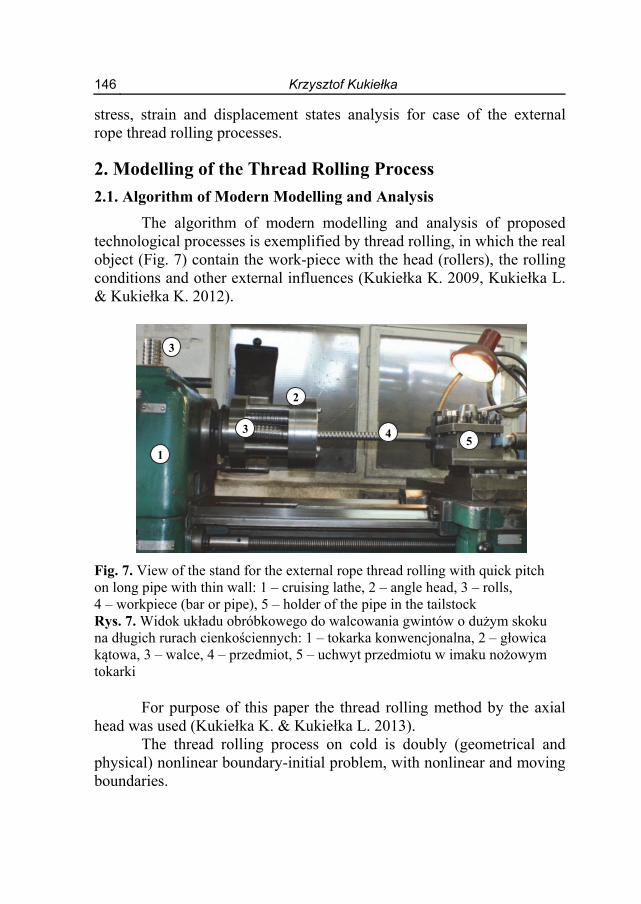
The algorithm of modern modelling and analysis of proposed technological processes is exemplified by thread rolling, in which the real object (Fig. 7) contain the work-piece with the head (rollers), the rolling conditions and other external influences (Kukiełka K. 2009, Kukiełka L. & Kukiełka K. 2012).
Fig. 7. View of the stand for the external rope thread rolling with quick pitch on long pipe with thin wall: 1 – cruising lathe, 2 – angle head, 3 – rolls, 4 – workpiece (bar or pipe), 5 – holder of the pipe in the tailstock Rys. 7. Widok układu obróbkowego do walcowania gwintów o dużym skoku na długich rurach cienkościennych: 1 – tokarka konwencjonalna, 2 – głowica kątowa, 3 – walce, 4 – przedmiot, 5 – uchwyt przedmiotu w imaku nożowym tokarki
For purpose of this paper the thread rolling method by the axial head was used (Kukiełka K. & Kukiełka L. 2013).
The thread rolling process on cold is doubly (geometrical and physical) nonlinear boundary-initial problem, with nonlinear and moving boundaries.
1
3
3
2
45
Ecological Aspects of the Implementation of New Technologies… 147
The boundary conditions in contact zone are unknown. Physical nonlinearities, called also as a material nonlinearities, are results from the nonlinear equations describing the material properties of the processes part. Geometrical nonlinearities caused by a change in the initial part geometry, leading to nonlinear relationships between strain-displacement. Inclusion of these nonlinearities in the analysis of the thread rolling issue is extremely complex. Make it necessary to operate increments of particular kinematic quantities (displacement, velocity, acceleration), static (force, force moment, stress) and use of incremental description (Kukiełka L. 2010, Kukiełka L. & Kukiełka K. 2012).
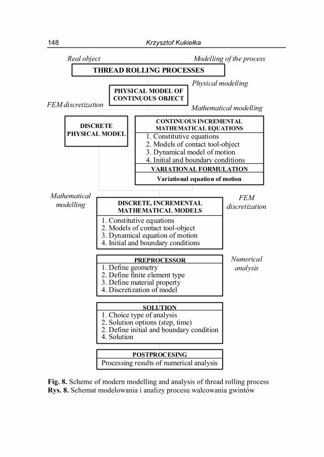
Modern modelling and analysis of the thread rolling processes us-ing variational and FEM methods proceeds in stages shown in Fig. 8 (Kleiber 1985, Kukiełka L. & Kukiełka K. 2012).
An own application in ANSYS program for the thread rolling process were elaborated. Numerical analysis let for forecast behavior of rolled thread during whole multistage technological process. For the most important possibilities of the numerical analysis in application for the thread rolling is determination of: dimensions of the pipe before rolling (mainly nominal and outline
diameter), local strain and stress states in the thread, geometry and thread outline during thread rolling and after elastic
relieving, maximum strain – where crack of the thread is possible, expected rolling force, influence of the friction coefficient on the process flow and quality of
the thread, number and geometry of the rolls, in that active rolls surface in the
introducing, shaping, calibrating and outing zone, state of loads, stresses and strains of the tools, areas of contact, slip and stick.
148 Krzysztof Kukiełka
Fig. 8. Scheme of modern modelling and analysis of thread rolling process Rys. 8. Schemat modelowania i analizy procesu walcowania gwintów
Modelling of the process Real object
THREAD ROLLING PROCESSES
Physical modelling PHYSICAL MODEL OF CONTINUOUS OBJECT
Mathematical modelling FEM discretization
DISCRETE PHYSICAL MODEL
CONTINUOUS INCREMENTAL MATHEMATICAL EQUATIONS
1. Constitutive equations 2. Models of contact tool-object 3. Dynamical model of motion 4. Initial and boundary conditions
VARIATIONAL FORMULATION
Variational equation of motion
DISCRETE, INCREMENTAL MATHEMATICAL MODELS
1. Constitutive equations 2. Models of contact tool-object 3. Dynamical equation of motion 4. Initial and boundary conditions
FEM discretization
Mathematical modelling
PREPROCESSOR 1. Define geometry 2. Define finite element type 3. Define material property 4. Discretization of model
SOLUTION 1. Choice type of analysis 2. Solution options (step, time) 2. Define initial and boundary condition 4. Solution
POSTPROCESING Processing results of numerical analysis
Numerical analysis
Ecological Aspects of the Implementation of New Technologies… 149
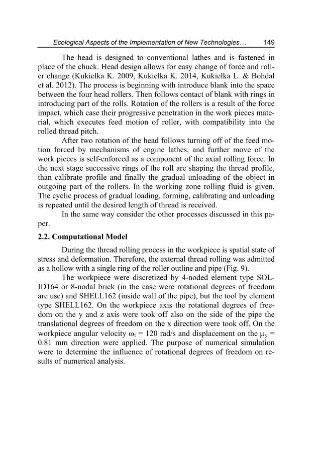
The head is designed to conventional lathes and is fastened in place of the chuck. Head design allows for easy change of force and roll-er change (Kukiełka K. 2009, Kukiełka K. 2014, Kukiełka L. & Bohdal et al. 2012). The process is beginning with introduce blank into the space between the four head rollers. Then follows contact of blank with rings in introducing part of the rolls. Rotation of the rollers is a result of the force impact, which case their progressive penetration in the work pieces mate-rial, which executes feed motion of roller, with compatibility into the rolled thread pitch.
After two rotation of the head follows turning off of the feed mo-tion forced by mechanisms of engine lathes, and further move of the work pieces is self-enforced as a component of the axial rolling force. In the next stage successive rings of the roll are shaping the thread profile, than calibrate profile and finally the gradual unloading of the object in outgoing part of the rollers. In the working zone rolling fluid is given. The cyclic process of gradual loading, forming, calibrating and unloading is repeated until the desired length of thread is received.
In the same way consider the other processes discussed in this pa-per.
2.2. Computational Model
During the thread rolling process in the workpiece is spatial state of stress and deformation. Therefore, the external thread rolling was admitted as a hollow with a single ring of the roller outline and pipe (Fig. 9).
The workpiece were discretized by 4-noded element type SOL-ID164 or 8-nodal brick (in the case were rotational degrees of freedom are use) and SHELL162 (inside wall of the pipe), but the tool by element type SHELL162. On the workpiece axis the rotational degrees of free-dom on the y and z axis were took off also on the side of the pipe the translational degrees of freedom on the x direction were took off. On the workpiece angular velocity t = 120 rad/s and displacement on the y = 0.81 mm direction were applied. The purpose of numerical simulation were to determine the influence of rotational degrees of freedom on re-sults of numerical analysis.
150 Krzysztof Kukiełka
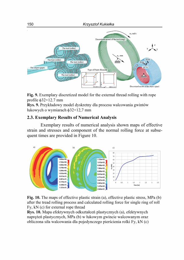
Fig. 9. Exemplary discretized model for the external thread rolling with rope profile 32×12.7 mm Rys. 9. Przykładowy model dyskretny dla procesu walcowania gwintów łukowych o wymiarach 32×12,7 mm
2.3. Exemplary Results of Numerical Analysis
Exemplary results of numerical analysis shown maps of effective strain and stresses and component of the normal rolling force at subse-quent times are provided in Figure 10.
Fig. 10. The maps of effective plastic strain (a), effective plastic stress, MPa (b) after the tread rolling process and calculated rolling force for single ring of roll Fy, kN (c) for external rope thread Rys. 10. Mapa efektywnych odkształceń plastycznych (a), efektywnych naprężeń plastycznych, MPa (b) w łukowym gwincie walcowanym oraz obliczona siła walcowania dla pojedynczego pierścienia rolki Fy, kN (c)
Ecological Aspects of the Implementation of New Technologies… 151
3. Conclusions
1. Replacement of traditional treatment technologies by plastic forming methods and use of modern methods of modeling and analysis of these technologies with the use of FEM, causes a significant reduc-tion in adverse effects on the environment and improve industrial safety conditions. Developed in Our Department applications in the ANSYS system allow for time analysis of physical phenomena in technological processes: cutting, rolling, burnishing, draw parts. It’s possible to carry on numerical analysis for the following data: any geometry object (e.g. roller, sleeve, plane, cone) and tools
(sphere, cone, truncated cone, polygon, polyhedron, etc..) any material object and the material grain (any Young's modulus,
nonlinear dependence of the plastic properties of material from: the intensity of deformation, the intensity of strain rate and tem-perature and their history; dependence of the material temperature constants, different models of hardening, etc.)
different conditions of friction at contact surface, any horizontal and vertical displacement of the tool in time.
2. Difficulties in designing technology, part make the most commonly used traditional technologies, which are time-consuming and cost-intensive, and adversely impact on the environment and service.
3. The analysis of the literature and the results of studies show that dur-ing the comprehensive machining processes occur very complicated physical phenomena that determine the quality of the product. The analysis of the literature on the rolling process, e.g. (Domblesky & Feng 2002, Kukiełka K. 2009, Łyczko 2010, Olszak 2008), own stud-ies and computer simulations (Domblesky & Feng 2002, Kukiełka K. 2009, Kukiełka K. et al. 2014, Kukiełka L. & Kukiełka K. 2006, Kukiełka L. & Kukiełka K. 2007, Kukiełka L. & Kukiełka K. 2012) shown that the technological quality of the rolled thread is depend on the following factors: material factors: Young’s modulus, Poisson ratio, initial yield
point, plastic hardening modulus, sensitivity on the strain rate, plastic anisotropy, value of border-strain, inclination to brittle cracking.
152 Krzysztof Kukiełka
geometrical of the object and tool factors: dimensions, surface state and physical state of surface layer (state of stress) of the ob-ject after preceded treatment,
technological parameters, friction conditions in the contact zones (depends of the kind of
lubricant): friction moment, friction forces. 4. Example given modeling and numerical analysis of the rope thread
rolling process on pipe may be applied to other parts of processing technologies.
5. All this allows to facilitate the design of new technologies and im-prove product quality with less time-consuming and cost-consuming of machining process.
References VARDEX (2012). Advanced Threading Solutions. Bohdal, Ł., Walczak, P. (2013). Eco-modeling of metal sheet cutting with disc
shears. Rocznik Ochrona Środowiska (Annual Set of Environment Protec-tion), 15, 863-872.
Bohdal, L., Kukielka, L. (2014). Application of variational and FEM methods to the modelling and numerical analysis of guillotining process for geomet-rical and physical nonlinearity. Mechanika, 20/2, 197-204.
Bohdal, Ł, Kulakowska, A., Patyk, R. (2014). Analysis of Slitting of Aluminum Body Panels in the Aspect of Scrap Reduction. Rocznik Ochrona Środowi-ska (Annual Set of Environment Protection), 16, 105-114.
Bohdal, L., Kukielka, L., Kukielka, K., Kulakowska, A., Malag, L., Patyk, R. (2014). Three Dimensional Finite Element Simulation of Sheet Metal Blanking Process. Mechanics and Materials “Novel Trends in Production Devices and Systems”, 474, 430-435.
Chodor, J., Kukielka, L. (2014). Using Nonlinear Contact Mechanics in Process of Tool Edge Movement on Deformable Body to Analysis of Cutting and Sliding Burnishing Processes. Mechanics and Materials “Novel Trends in Production Devices and Systems”, 474, 339-344.
Domblesky J.P., Feng F. (2002). Two-dimensional and three-dimensional finite element models of external thread rolling. Professional Engineering Pub-lishing, 216(4/2002), 507-517.
Forysiewicz, M., Kukielka, L., Gotowala, K. (2016). Finite element simulation of physical phenomena in real conditions of a single grain cutting process. Nov-el Trends in Production Devices and Systems "Materials Science Forum".
Ecological Aspects of the Implementation of New Technologies… 153
Kaldunski, P., Kukielka, L. (2014). Numerical Analysis and Simulation of Drawpiece Forming Process by Finite Element Method. Applied Mechan-ics and Materials “Novel Trends in Production Devices and Systems”, 474, 153-158.
Kleiber, M. (1985). Finite element method in non-linear solid mechanics (in Polish). Warszawa: PWN.
Kukiełka, K. (2009). Modelling and numerical analysis of the states of defor-mations and stresses in the surface layer of the trapezoidal and round threads rolled on cold (in Polish). PhD Thesis, Koszalin University of Technology.
Kukiełka, K., Kukiełka, L. (2013). External thread rolling head. (in Polish) The polish patent No PL402652–A1, PL220175–B1, 4.02.2013.
Kukiełka, K. (2014). Effective numerical model to analyze the trapezoidal thread rolling process with finite element method. (in Polish) Mechanik, 11, 156-167.
Kukielka, K., Kukielka, L., Bohdal, L., Kulakowska, A., Malag, L., Patyk, R. (2014). 3D Numerical Analysis the State of Elastic/Visco–Plastic Strain in the External Round Thread Rolled on Cold. Applied Mechanics and Mate-rials “Novel Trends in Production Devices and Systems”, 474, 436-441.
Kukiełka, L. (1994). Theoretical and experimental foundations of surface roller burnishing with the electrocontact heating. (in Polish) Book WM, 47. WSI Koszalin.
Kukielka, L. (1999). Application of the variational and finite element methods to dynamic incremental nonlinear analysis in the burnishing rolling opera-tion. ESM'99 - Modelling And Simulation A Tool For The Next Millennium, Vol. II, 221-225.
Kukielka, L., Krzyzynski T. (2000). New thermo-elastic thermo-viscoplastic material model and its application. Zeitschrift Fur Angewandte Mathematik Und Mechanik, 80, supplement: 3, S595-S596.
Kukielka, L. (2001). Mathematical modelling and numerical simulation of non-linear deformation of the asperity in the burnishing cold rolling operation. Computational Methods in Contact Mechanics V, Book Series: Computa-tional and Experimental Methods, 5, 317-326.
Kukiełka, L. (2002). Bases of engineering research. (in Polish) Warsaw: PWN. Kukielka, L., Kustra, J., Kukielka, K. (2005). Numerical analysis of states of
strain and stress of material during machining with a single abrasive grain. Computer Methods and Experimental Measurements for Surface Effects and Contact Mechanics VII, Southampton–Boston: WITPRESS, 57-66.
154 Krzysztof Kukiełka
Kukielka, L., Kukielka, K. (2006). Numerical analysis of the process of trape-zoidal thread rolling. High Performance Structures and Materials III,. Southampton–Boston: WITPRESS, 663-672.
Kukielka, L., Kukielka, K. (2007). Numerical analysis of the physical phenom-ena in the working zone in the rolling process of the round thread. Comput-er Methods and Experimental Measurements for Surface Effects and Con-tact Mechanics VIII, Southampton–Boston: WITPRESS, 125-124.
Kukiełka, L. (2010). New damping of models of metallic materials and its ap-plication in non-linear dynamical cold processes of metal forming. The 13th International Conference Metal Forming 2010, Steel Research Inter-national, Toyohashi, 81, 1482-1485.
Kukielka, L., Geleta, K., Kukielka, K. (2012). Modelling and Analysis of Non-linear Physical Phenomena in the Burnishing Rolling Operation with Elec-trical Current. Steel Research International, Special Edition: 14th Interna-tional Conference Metal Forming, Kraków, 1379-1382.
Kukielka, L., Geleta, K., Kukielka, K. (2012). Modelling of Initial and Bounda-ry Problems with Geometrical and Physical Nonlinearity and its Applica-tion in Burnishing Processes. Steel Research International, Special Edi-tion: 14th International Conference Metal Forming, Krakow, 1375-1378.
Kukiełka, L., Kukiełka, K. (2012). The modern method of modeling and analy-sis precision machining processes auto parts. (in Polish) Environmental as-pects of the use of new technologies in transport, Book of Mechanical En-gineering, 235, Mechanical Faculty, Koszalin University of Technology, 109-128.
Kukielka, L., Kukielka, K., Kulakowska, A., Patyk, R., Malag, L., Bohdal, L. (2014). Incremental Modelling and Numerical Solution of the Contact Problem between Movable Elastic and Elastic/Visco–Plastic Bodies and Application in the Technological Processes. Applied Mechanics and Mate-rials “Novel Trends in Production Devices and Systems”, 474, 159-165.
Kukiełka, L., Bohdal, Ł., Chodór, J., Forysiewicz, M., Geleta, K., Kałduński P., Kukiełka, K., Patyk, R., Szyc, M. (2012). Numerical analysis of selected processes precision machining of automotive parts. Environmental aspects of the use of new technologies in transport, Book of Mechanical Engineering, 235, Mechanical Faculty, Koszalin University of Technology, 129-194.
Kukielka, L., Szczesniak, M., Patyk, R., Kulakowska, A., Kukielka, K., Patyk S., Gotowala, K., Kozak, D. (2016). Analysis of the states of deformation and stress in the surface layer of the product after the burnishing cold roll-ing operation. Novel Trends in Production Devices and Systems "Materials Science Forum".
Ecological Aspects of the Implementation of New Technologies… 155
Kulakowska, A., Patyk, R., Kukielka, L. (2009). Numerical analysis and exper-imental researches of burnishing rolling process of workpieces with real surface. WMSCI 2009 – The 13th World Multi-Conference on Systemics, Cybernetics and Informatics, Jointly with the 15th International Confer-ence on Information Systems Analysis and Synthesis, ISAS, 2, 63-68.
Kulakowska, A., Kukielka, L., Kukielka, K., Malag, L., Patyk, R., Bohdal, L. (2014). Possibility of steering of product surface layers properties in bur-nishing rolling process. Applied Mechanics and Materials “Novel Trends in Production Devices and Systems”, 474, 442-447.
Kulakowska, A., Patyk, R., Bohdal, L. (2014). Application of Burnishing Pro-cess in Creating Environmental Product. Rocznik Ochrona Środowiska (Annual Set of Environment Protection), 16, 323-335.
Łyczko, K. (2010). External thread rolling technology. (in polish) Warszawa: WNT.
Malag, L., Kukielka, L., Kukielka, K., Kulakowska, A., Patyk, R., Bohdal, L. (2014). Problems Determining of the Mechanical Properties of Metallic Materials from the Tensile Test in the Aspect of Numerical Calculations of the Technological Processes. Applied Mechanics and Materials “Novel Trends in Production Devices and Systems”, 474, 454-459.
Myslinski, P., Precht, W., Kukielka, L, et al. (2004). A possibility of application of MTDIL to the residual stresses analysis – The hard coating-substrate system. Journal Of Thermal Analysis And Calorimetry, 77(1), 253-258.
Olszak, W. (2008). Machining. (in polish) Warszawa: WNT. Patyk, R., Kukielka, L. (2008). Optimization of geometrical parameters of regu-
lar triangular asperities of surface put to smooth burnishing. The 12th Inter-national Conference Metal Forming 2008, Steel Research International, Kraków, 2, 642-647.
Patyk, R. (2010). Theoretical and experimental basis of regular asperities about triangular outline embossing technology. The 13th International Conference Metal Forming 2010, Steel Research International, Toyohashi, 81, 190-193.
Patyk, R., Kulakowska, A., Bohdal, L. (2010). Environmental, Economic and Exploitation Aspects of the Use of Burnishing Rolling Treatments. Rocznik Ochrona Środowiska (Annual Set of Environment Protection), 16, 351-362.
Patyk, R., Kukielka, L., Kukielka, K., Kulakowska, A., Malag, L., Bohdal, L. (2014). Numerical Study of the Influence of Surface Regular Asperities Prepared in Previous Treatment by Embossing Process on the Object Sur-face Layer State after Burnishing. Applied Mechanics and Materials “Nov-el Trends in Production Devices and Systems”, 474, 448-453.
156 Krzysztof Kukiełka
Piecuch, I., Piecuch, T. (2011). Teaching About the Environment - It Is Never too Early and It Is Never too Late. Rocznik Ochrona Środowiska (Annual Set of Environment Protection), 13, 711-722.
Piecuch, I., Piecuch, T. (2013). Environmental Education and Its Social Effects. Rocznik Ochrona Środowiska (Annual Set of Environment Protection), 15, 192-212.
Szyc, M. (2014). Modeling and simulation of the geometrical structure of the process of shaping the surface of the steel burnishing by dynamic spherical pellet. (in Polish) PhD Thesis, Koszalin University of Technology.
Zienkiewicz, O.C., Taylor, R. L. (2000). The finite element method, vol. 1 – The Basis. United Kingdom: Butterworth-Heinemann.
Ekologiczne aspekty implementacji nowoczesnych metod obróbki części maszyn
Streszczenie
Artykuł dotyczy propozycji wyeliminowania niekorzystnego oddziały-wania na środowisko i poprawienia warunków BHP obsługi, powodowanych przez tradycyjne technologie wytwarzania części maszyn. Cel ten autorzy pro-ponują osiągnąć w dwóch etapach. W etapie pierwszym należy zastąpić trady-cyjne wytwarzania części maszyn, które są energo- i czasochłonne, takie jak: toczenie, frezowanie, szlifowanie, które należą do tzw. obróbek ubytkowych (inaczej wiórowych), metodami nowoczesnymi takimi jak walcowanie, nagnia-tanie gładkościowe i umacniające, które należą do tzw. obróbek bezubytkowych (inaczej bezwiórowych). Oprócz zmniejszonego oddziaływania na środowisko i poprawę warunków BHP, dodatkowo uzyskuje się znaczne zmniejszenie kosz-tochłonności i pracochłonności procesu, przy jednoczesnym wzroście jakości wytwarzanych części. W drugim etapie, dalsze zmniejszenie niekorzystnego oddziaływania na środowisko i poprawę warunków BHP, można uzyskać zastę-pując tradycyjne metodyki projektowania technologii nowoczesnymi metodami symulacji komputerowej. Dotyczy to głównie bardzo kosztownych badań eks-perymentalnych prowadzonych w celu określenia warunków realizacji procesu technologicznego. Podano propozycję realizacji takiego przedsięwzięcia na przykładzie zastąpienia technologii toczenia gwintu o zarysie łukowym o dużym skoku technologią walcowania.
Ecological Aspects of the Implementation of New Technologies… 157
Abstract
The article concerns the proposal to eliminate the adverse impact on the environment and improve service conditions of industrial safety, caused by the traditional technologies of production of the machine parts. This aim is achieved in two stages proposed by the authors. In the first stage should be the traditional technologies of machine parts, such as turning, boring, drilling, threading, mill-ing, grinding, which belong to the so-called machining, which are harmful to the environment and servicing also energy- and time-consuming to replace by modern methods of plastic forming such as rolling, smooth burnishing and strengthen that belong to the so-called chipless treatments. In addition to the reduced impact on the environment (reduction of material waste, better lubrica-tion management), increase industrial safety, in addition achieved a significant reduction cost-consuming (reduced energy consuming) and labour-intensive process while increasing tool life and quality of manufactured parts. In the sec-ond stage, further reducing the adverse impact on the environment and improve industrial safety, it can received by replace the traditional design implementa-tion methodology by modern methods of technology, which use computer simu-lation. In this article is propose to replace traditional method of reducing adverb impact on environment is concern mainly on very expensive experimental stud-ies conducted to determine the conditions of the (technological parameters) technological process. The proposal on the example for such realization in round thread turning process, replaced by thread rolling process. Słowa kluczowe: ochrona środowiska, nowoczesne technologie, obróbka bezwiórowa, symulacja numeryczna, zmniejszone zapotrzebowanie na energię
Keywords: environment protection, modern technologies, metal chipless treatments, numerical simulations, reduced energy consuming