ehest safety-considerations
TRANSCRIPT
Page 13 – Color-Logo-Combination 2
HE 1
safety consiDerations
TRAininG LEAFLETmETHODS TO imPROVE HELiCOPTER PiLOTS’ CAPABiLiTiES
2 >> Safety considerations for helicopter pilots
Training leaflet >> 3
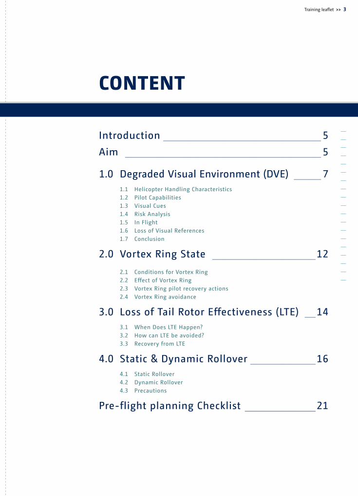
content
Introduction ����������������������������� 5
Aim ������������������������������������ 5
1.0 Degraded Visual Environment (DVE) ����� 7 1.1 Helicopter Handling Characteristics 1.2 Pilot Capabilities 1.3 Visual Cues 1.4 Risk Analysis 1.5 In Flight 1.6 Loss of Visual References 1.7 Conclusion
2.0 Vortex Ring State �������������������12
2.1 Conditions for Vortex Ring 2.2 Effect of Vortex Ring 2.3 Vortex Ring pilot recovery actions 2.4 Vortex Ring avoidance
3.0 Loss of Tail Rotor Effectiveness (LTE) ��14 3.1 When Does LTE Happen? 3.2 How can LTE be avoided? 3.3 Recovery from LTE
4.0 Static & Dynamic Rollover ������������16 4.1 Static Rollover 4.2 Dynamic Rollover 4.3 Precautions
Pre-flight planning Checklist �������������21
4 >> Safety considerations for helicopter pilots
Training leaflet >> 5
Introduction
The European Helicopter Safety Implementation Team (EHSIT) is a component of the European Helicopter Safety Team (EHEST). The EHSIT is tasked to process the Implementation Recommendations (IRs) issues identified from the research conducted by the European Helicopter Safety Analysis Team (EHSAT) (see Final Report - EHEST Analysis of 2000 – 2005 European helicopter accidents1).
This leaflet is the first in a series of safety related leaflets and publications aiming at improving safety by sharing good practises. These leaflets will be accompanied by web based training materials including videos, which will be available freely to all pilots in order to enhance flight safety by addressing recognised training related issues.
Aim
Data from the EHSAT review confirm that a continuing significant number of helicopter accidents is due to pilot disorientation in the Degraded Visual Environment, Vortex Ring State, Loss of Tail Rotor Effectiveness and Static & Dynamic Rollover. Therefore, the aim of this leaflet is to improve the safety of helicopter operations by providing pilots with the relevant information for each of these topics in order to allow a basic understanding of the causes, the prevention and the recovery actions thereby enabling pilots to make better, more informed decisions.
1 Document ref.: Final Report - EHEST Analysis of 2000 – 2005 European helicopter accidents (ISBN 92-9210-095-7)
6 >> Safety considerations for helicopter pilots
Training leaflet >> 7
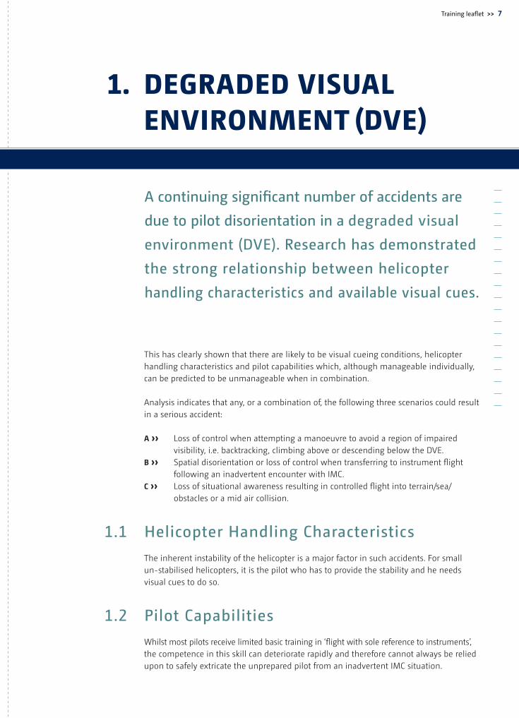
A continuing significant number of accidents are
due to pilot disorientation in a degraded visual
environment (DVE). Research has demonstrated
the strong relationship between helicopter
handling characteristics and available visual cues.
This has clearly shown that there are likely to be visual cueing conditions, helicopter handling characteristics and pilot capabilities which, although manageable individually, can be predicted to be unmanageable when in combination.
Analysis indicates that any, or a combination of, the following three scenarios could result in a serious accident:
A ›› Loss of control when attempting a manoeuvre to avoid a region of impaired visibility, i.e. backtracking, climbing above or descending below the DVE.B ›› Spatial disorientation or loss of control when transferring to instrument flight following an inadvertent encounter with IMC.C ›› Loss of situational awareness resulting in controlled flight into terrain/sea/ obstacles or a mid air collision.
1.1 Helicopter Handling Characteristics
The inherent instability of the helicopter is a major factor in such accidents. For small un-stabilised helicopters, it is the pilot who has to provide the stability and he needs visual cues to do so.
1.2 Pilot Capabilities
Whilst most pilots receive limited basic training in ‘flight with sole reference to instruments’, the competence in this skill can deteriorate rapidly and therefore cannot always be relied upon to safely extricate the unprepared pilot from an inadvertent IMC situation.
1. DegraDeD Visual enVironment (DVe)
8 >> Safety considerations for helicopter pilots
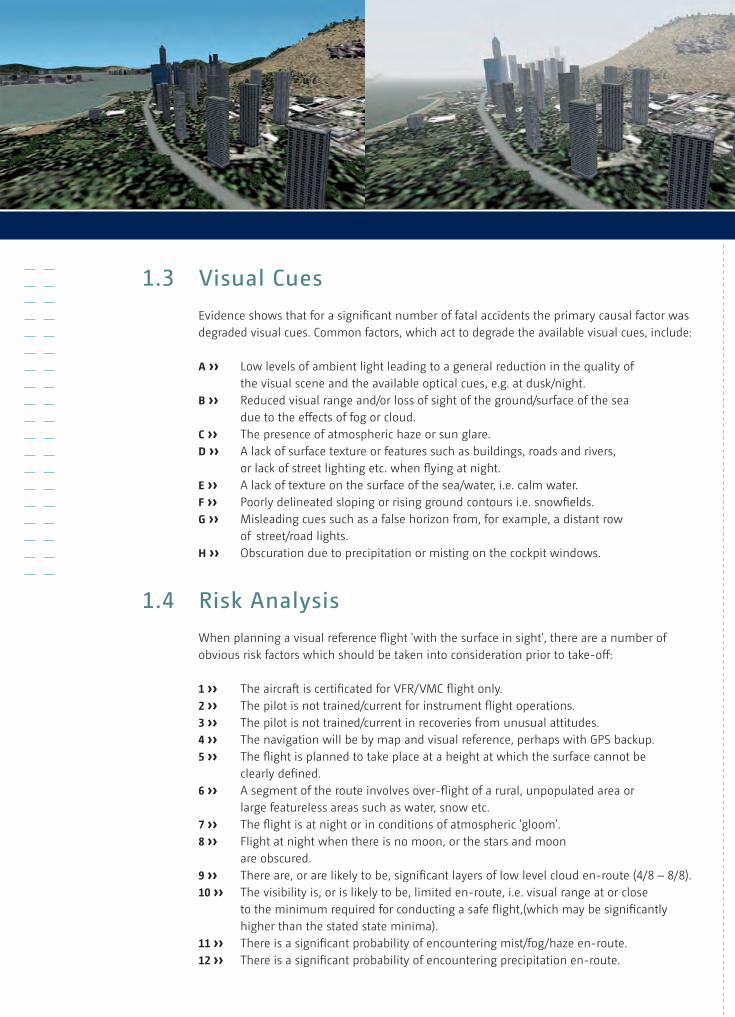
1.3 Visual Cues
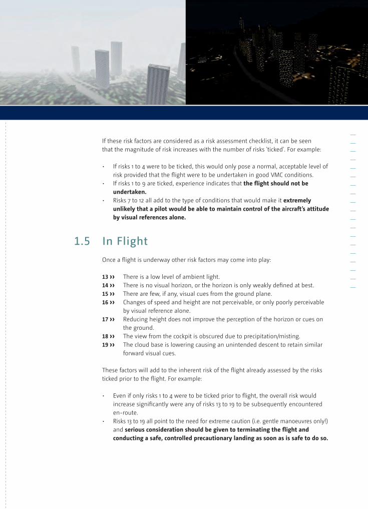
Evidence shows that for a significant number of fatal accidents the primary causal factor was degraded visual cues. Common factors, which act to degrade the available visual cues, include:
A ›› Low levels of ambient light leading to a general reduction in the quality of the visual scene and the available optical cues, e.g. at dusk/night.B ›› Reduced visual range and/or loss of sight of the ground/surface of the sea due to the effects of fog or cloud.C ›› The presence of atmospheric haze or sun glare.D ›› A lack of surface texture or features such as buildings, roads and rivers, or lack of street lighting etc. when flying at night.E ›› A lack of texture on the surface of the sea/water, i.e. calm water.F ›› Poorly delineated sloping or rising ground contours i.e. snowfields.G ›› Misleading cues such as a false horizon from, for example, a distant row of street/road lights.H ›› Obscuration due to precipitation or misting on the cockpit windows.
1.4 Risk Analysis
When planning a visual reference flight 'with the surface in sight', there are a number of obvious risk factors which should be taken into consideration prior to take-off:
1 ›› The aircraft is certificated for VFR/VMC flight only.2 ›› The pilot is not trained/current for instrument flight operations.3 ›› The pilot is not trained/current in recoveries from unusual attitudes.4 ›› The navigation will be by map and visual reference, perhaps with GPS backup.5 ›› The flight is planned to take place at a height at which the surface cannot be clearly defined.6 ›› A segment of the route involves over-flight of a rural, unpopulated area or large featureless areas such as water, snow etc.7 ›› The flight is at night or in conditions of atmospheric 'gloom'.8 ›› Flight at night when there is no moon, or the stars and moon are obscured.9 ›› There are, or are likely to be, significant layers of low level cloud en-route (4/8 – 8/8).10 ›› The visibility is, or is likely to be, limited en-route, i.e. visual range at or close to the minimum required for conducting a safe flight,(which may be significantly higher than the stated state minima).11 ›› There is a significant probability of encountering mist/fog/haze en-route.12 ›› There is a significant probability of encountering precipitation en-route.
Training leaflet >> 9
If these risk factors are considered as a risk assessment checklist, it can be seen that the magnitude of risk increases with the number of risks 'ticked'. For example:
• Ifrisks1to4weretobeticked,thiswouldonlyposeanormal,acceptablelevelof risk provided that the flight were to be undertaken in good VMC conditions. • Ifrisks1to9areticked,experienceindicatesthatthe flight should not be undertaken. • Risks7to12alladdtothetypeofconditionsthatwouldmakeitextremely unlikely that a pilot would be able to maintain control of the aircraft’s attitude by visual references alone.
1.5 In Flight
Once a flight is underway other risk factors may come into play:
13 ›› There is a low level of ambient light.14 ›› There is no visual horizon, or the horizon is only weakly defined at best.15 ›› There are few, if any, visual cues from the ground plane.16 ›› Changes of speed and height are not perceivable, or only poorly perceivable by visual reference alone.17 ›› Reducing height does not improve the perception of the horizon or cues on the ground.18 ›› The view from the cockpit is obscured due to precipitation/misting.19 ›› The cloud base is lowering causing an unintended descent to retain similar forward visual cues.
These factors will add to the inherent risk of the flight already assessed by the risks ticked prior to the flight. For example: • Evenifonlyrisks1to4weretobetickedpriortoflight,theoverallriskwould increasesignificantlywereanyofrisks13to19tobesubsequentlyencountered en-route. • Risks13to19allpointtotheneedforextremecaution(i.e.gentlemanoeuvresonly!) and serious consideration should be given to terminating the flight and conducting a safe, controlled precautionary landing as soon as is safe to do so.
10 >> Safety considerations for helicopter pilots
1.6 Loss of Visual References
If external visual references are lost then to prevent spatial disorientation, a pilot will need to transfer his attention immediately onto the aircraft instruments and use them to establish a safe flight profile. A rapid risk assessment, taking into consideration the weather, terrain, aircraft limitations, fuel and pilot’s capability is critical to a speedy establishment of a nominated safe flight profile. This may require the pilot, once established on instruments, to conduct a turn back, a descent or a climb to a safe altitude or a combination of these.
1.7 Conclusion
Risk analysis and timely decision-making are essential tools to be used by the pilot during both the planning and the flight stages. Constant updating and evaluation of all of the available information should assist the pilot to recognize dangers inherent to a degraded visual environment. This will assist the pilot to carry out the appropriate actions in order to prevent the situation from developing into a critical stage for which the pilot may not have the relevant skill level, capabilities and/or helicopter instrumentation to cope with safely.
Training leaflet >> 11
12 >> Safety considerations for helicopter pilots
Often considered as the equivalent of the fixed-wing stall, Vortex Ring is a condition of powered flight where the helicopter “settles” into its own downwash. Consequently, the Rate of Descent (ROD) will increase dramatically (typically, at least three times the ROD before entering Vortex Ring), for the same power setting.
2.1 Conditions for Vortex Ring
Vortex Ring is likely to occur when descending in powered flight at an airspeed below 30KtswithaRateofDescent(ROD)closetothemainrotor“downwashvelocity”.
Downwash velocity or induced velocity is defined as the airspeed of the airflow drawn down through the rotor disc (Froude formula). The induced velocity is a function of the helicopter type and gross weight. For example, a three bladed helicopter with a rotordiameterof10.69mandaweightof2,250kgwouldresultinaninducedvelocityof10m/s.(1,000ft/min.).Whereas,foratwobladedhelicoptertypewitharotordiameterof11mandaweightof1,000kgtheinducedvelocityis6.5m/s(700ft/min.).Therefore, although Vortex Ring State is shown to be dependant on the helicopter type and weight, a commonly accepted unsafe ROD is considered to be in excess of 500ft/min.
2.2 Effect of Vortex Ring
• Vibrationsasvorticesbreakawayatthebladetips• Lessresponsive(sluggish)pitch&rollcontrolsasaresultoftheunstableairflow constantly modifying the thrust and moment of control• Fluctuationsinpowerrequirement(torqueorMAP2) as the large changes in drag cause thrust variations• AbnormallyhighRODasvortexdevelops,whichcanbeinexcessof3,000ft/min.
2.3 Vortex Ring pilot recovery actions
Recovery actions may be taken by cyclic and/or collective application. However, depending on the rotor system, cyclic input alone could be insufficient to modify the helicopter attitude to gain airspeed. It is also possible to recover from Vortex Ring by reducing the collective to minimum pitch. However, the loss of height during recovery by collective
2. Vortex ring state
2 Manifold Air Pressure
Training leaflet >> 13
pitch reduction is greater than the corresponding loss of height by cyclic input, which is the result of the ROD in autorotation at low airspeed being very high.
Therefore, the following recovery actions should be initiated at the incipient stage to minimise the loss of height:• Applyapositiveforwardcyclicinputtoachieveanaccelerativeattitude3 to gain airspeed• Ifanaccelerativeattitudecannotbereached,decreasecollectivepitchto enter autorotation and then apply forward cyclic, as required to increase airspeed.
2.4 Vortex Ring avoidance
Since the recovery actions will entail a considerable loss of height, it is imperative to avoid Vortex Ring especially when close to the ground. Therefore, a ROD in excess of 500ft/min.atanairspeedoflessthan30Ktswhilstinpoweredflightshouldbeavoided.Therefore, the following operations should be conducted with great care:
• Confinedareasrecceandapproaches• Downwindapproaches• Steepapproaches• HoverOutofGroundEffect(HOGE)• Lowspeedautorotationrecovery• Downwindquickstops• Aerialphotography
to exit Vortex ring
1. Apply a positive forward cyclic input to achieve an accelerative attitude to gain airspeed.2. If airspeed increases; recover helicopter when IAS reaches 40 Kt.3. If airspeed does not increase; decrease collective pitch to enter autorotation and then apply forward cyclic, as required to increase airspeed.
3 Depending on rotor system recommended nose down attitude can vary
14 >> Safety considerations for helicopter pilots
On a single rotor helicopter, one of the main functions of tail rotor thrust is to control the helicopter heading. If tail rotor thrust is insufficient, an unanticipated and uncommanded yaw may occur. This phenomenon has been a contributing factor in a number of helicopter accidents and is commonly referred to as LTE.
For the purpose of this leaflet, LTE is considered to be an insufficient tail rotor thrust associated with a control margin deficiency which can result in an uncommanded rapid yaw rate. This yaw may not subside of its own accord and if not corrected can result in the loss of a helicopter.
3.1 When Does LTE Happen?
LTE is more likely to occur when the critical yaw pedal is close to the full travel position. The critical yaw pedal is considered to be the right pedal for clockwise rotating main rotor systems and the left pedal for anti-clockwise rotating ones.
LTEisgenerallyencounteredatlowforwardairspeed,normallylessthan30kt,where:• Thetailfinhaslowaerodynamicefficiency• Theairflowanddownwashgeneratedbythemainrotorinterfereswiththe airflow entering the tail rotor• Ahighpowersettingrequiresayawpedalpositionwhichisclosetoitsfull travel• Anadversewindconditionincreasesthetailrotorthrustrequirement• Turbulentwindconditionsrequirelargeandrapidcollectiveandyawinputs
The following are some of the operations where pilots can typically find themselves at a low height, low airspeed and a high power setting, where the wind velocity is difficult to determine and the pilot is often preoccupied with positioning the aircraft for the task:• Powerlineandpipelinepatrolsectors• Externalload• Hoisting• Firefighting• Landingsitereconnaissance• Lowspeedaerialfilming/photograph• PoliceandHEMS• HighDensityAltitude(DA)landingandtakeoff
3. loss of tail rotor effectiVeness (lte)
Training leaflet >> 15
3.2 How can LTE be avoided?
During flight planning pilots must consider the Rotorcraft Flight Manual, especially regarding performance in relation to the critical wind azimuths, the DA at which they are operating, the helicopter All Up Mass (AUM) and flight characteristics.
During the flight, pilots should be constantly aware of the wind conditions and the available tail rotor thrust margin, which is represented by the critical pedal position.
Whenever possible, pilots should avoid combinations of the following:• Adversewindconditionsatlowairspeed• Uncommandedyaw• Largeandrapidcollectiveandyawinputsatlowairspeed• Lowairspeedflightinturbulentwindconditions
3.3 Recovery from LTE
Pilots should be aware that if they enter a flight regime where any, or a combination of the above occur, they are entering a potential LTE situation and they must be able to recognise the onset and commence the positive recovery actions without delay. Recovery actions will vary according to the circumstances, if height permits, attaining forward airspeed without increasing power (if possible reducing power) will normally resolve the situation. Therefore, as these actions may involve a considerable loss of altitude, it is recommended that pilots identify a clear escape route in advance of the operations listed above.
to exit lte
1. Apply full opposing pedal to the direction of turn2. Adopt an accelerative attitude to gain forward airspeed3. If altitude permits; reduce power
16 >> Safety considerations for helicopter pilots
4.1 Static Rollover
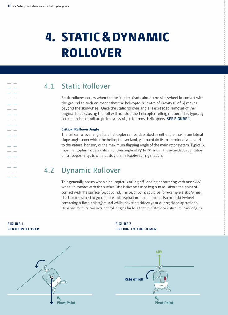
Static rollover occurs when the helicopter pivots about one skid/wheel in contact with the ground to such an extent that the helicopter’s Centre of Gravity (C of G) moves beyond the skid/wheel. Once the static rollover angle is exceeded removal of the original force causing the roll will not stop the helicopter rolling motion. This typically correspondstoarollangleinexcessof30°formosthelicopters,SEE FiGuRE 1.
Critical Rollover AngleThe critical rollover angle for a helicopter can be described as either the maximum lateral slope angle upon which the helicopter can land, yet maintain its main rotor disc parallel to the natural horizon, or the maximum flapping angle of the main rotor system. Typically, mosthelicoptershaveacriticalrolloverangleof13°to17°andifitisexceeded,application of full opposite cyclic will not stop the helicopter rolling motion.
4.2 Dynamic Rollover
This generally occurs when a helicopter is taking off, landing or hovering with one skid/wheel in contact with the surface. The helicopter may begin to roll about the point of contact with the surface (pivot point). The pivot point could be for example a skid/wheel, stuck or restrained to ground, ice, soft asphalt or mud. It could also be a skid/wheel contacting a fixed object/ground whilst hovering sideways or during slope operations. Dynamic rollover can occur at roll angles far less than the static or critical rollover angles.
4. static & Dynamic rolloVer
Pivot Point Pivot Point
Lift
Rate of roll
Pivot Point
Rate of roll
Lift
FiGuRE 1 STATiC ROLLOVER
FiGuRE 2 LiFTinG TO THE HOVER
Training leaflet >> 17
Pivot Point
Rate of roll
Main Rotor Thrust Lift
Horizontal Component
Pivot Point
Inertia andTail Rotor
Thrust
Pivot Point
Rate of roll
Lift
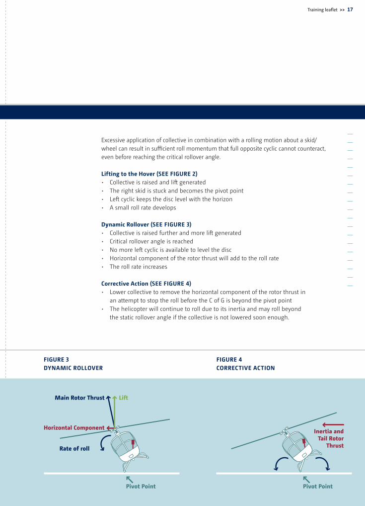
Excessive application of collective in combination with a rolling motion about a skid/wheel can result in sufficient roll momentum that full opposite cyclic cannot counteract, even before reaching the critical rollover angle.
Lifting to the Hover (SEE FiGuRE 2)• Collectiveisraisedandliftgenerated• Therightskidisstuckandbecomesthepivotpoint• Leftcyclickeepsthedisclevelwiththehorizon• Asmallrollratedevelops
Dynamic Rollover (SEE FiGuRE 3)• Collectiveisraisedfurtherandmoreliftgenerated• Criticalrolloverangleisreached• Nomoreleftcyclicisavailabletolevelthedisc• Horizontalcomponentoftherotorthrustwilladdtotherollrate• Therollrateincreases
Corrective Action (SEE FiGuRE 4)• Lowercollectivetoremovethehorizontalcomponentoftherotorthrustin an attempt to stop the roll before the C of G is beyond the pivot point• Thehelicopterwillcontinuetorollduetoitsinertiaandmayrollbeyond the static rollover angle if the collective is not lowered soon enough.
FiGuRE 3 DynAmiC ROLLOVER
FiGuRE 4 CORRECTiVE ACTiOn
18 >> Safety considerations for helicopter pilots
4.3 Precautions
›› Any change in lateral C of G will modify the lateral cyclic requirement and availability›› Always practice hovering Engine Off Landing (EOL) into the wind›› When hovering or taxiing close to obstacles / ground use extreme caution›› Whenever possible, slope operations should be conducted into the wind›› During take-off and landing, especially on a slope, all control inputs should be made slowly, smoothly and gently; helicopter sideward motion should be avoided›› During slope operations if the upslope skid / wheel starts to leave the ground before the down slope skid / wheel, lifting to the hover should be aborted›› On landing, if the cyclic control limit is reached, further lowering of the collective may cause a rollover›› When landing or taking off on a floating platform that is pitching and / or rolling, extreme caution should be exercised
imprint
Disclaimer:The safety improvement analyses and recommendations produced by the EHSIT are based on expert judgment and are supplementary to the official reports of the accident investigation boards (AIBs). Such recommendations, and the safety improvement actions that may follow, are solely aimed at improving helicopter safety, are not binding and under no circumstances should be considered to take precedence over the official AIB reports. The adoption of such safety improvement recommendations is subject to voluntary commitment, and engages only the responsibility of those who endorse these actions. The EHSIT accepts no responsibility or liability whatsoever with regard to the content or for any actions resulting from the use of the information contained in these recommendations.
Picture creditsCover: AgustaWestland / Inside front cover: Eurocopter / Page 4: Eurocopter / Page 6: Eurocopter / Page 11: AgustaWestland
Contact details for enquiries: European Helicopter Safety Team E-mail: [email protected] www.easa.europa.eu/essi
For a download of the Helicopter Preflight Planning Checklist please visit our website: http://www.easa.europa.eu/essi/ehestEN.hmtl
Training leaflet >> 19
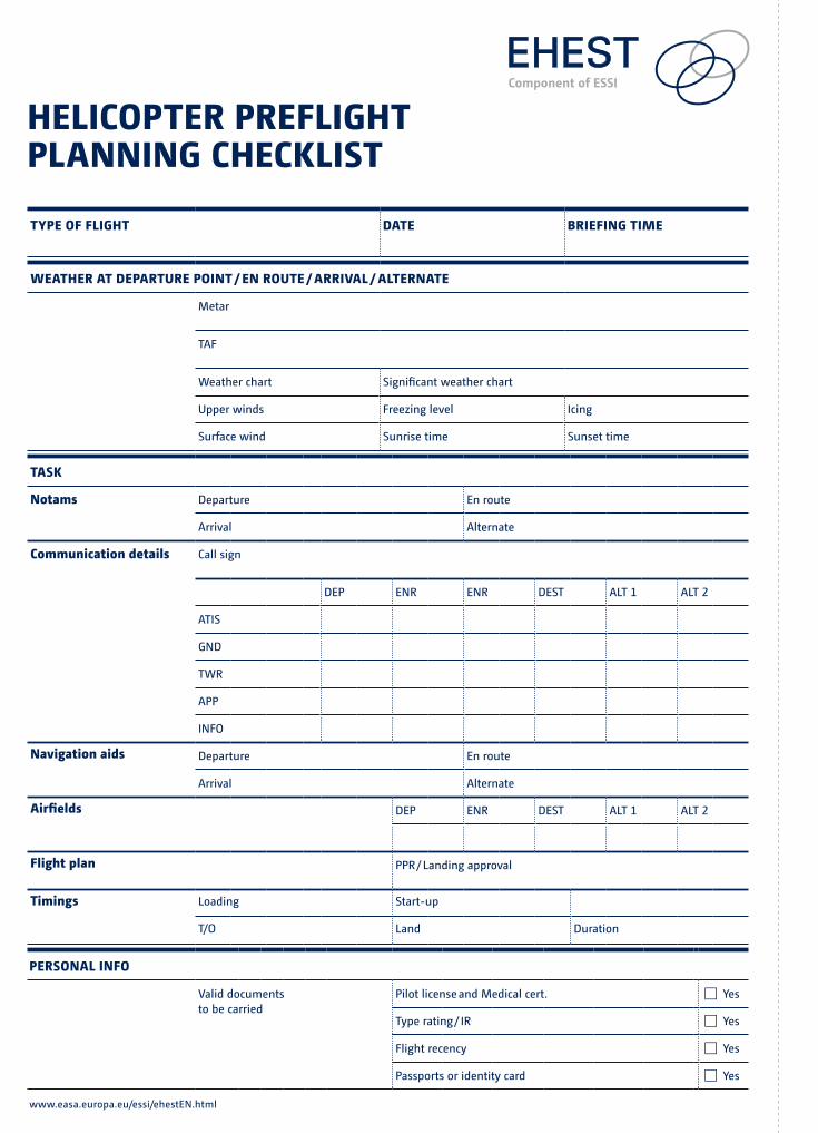
Helicopter prefligHt planning cHecklist
type of fligHt Date briefing time
WeatHer at Departure point / en route / arriVal / alternate
Metar
TAF
Weather chart Significant weather chart
Upper winds Freezing level Icing
Surface wind Sunrise time Sunset time
task
notams Departure En route
Arrival Alternate
communication details Call sign
DEP ENR ENR DEST ALT 1 ALT 2
ATIS
GND
TWR
APP
INFO
navigation aids Departure En route
Arrival Alternate
airfields DEP ENR DEST ALT 1 ALT 2
flight plan PPR / Landing approval
timings Loading Start-up
T/O Land Duration
personal info
Valid documents to be carried
Pilot license and Medical cert. Yes
Type rating / IR Yes
Flight recency Yes
Passports or identity card Yes
www.easa.europa.eu/essi/ehestEN.html
Page 13 – Color-Logo-Combination 2
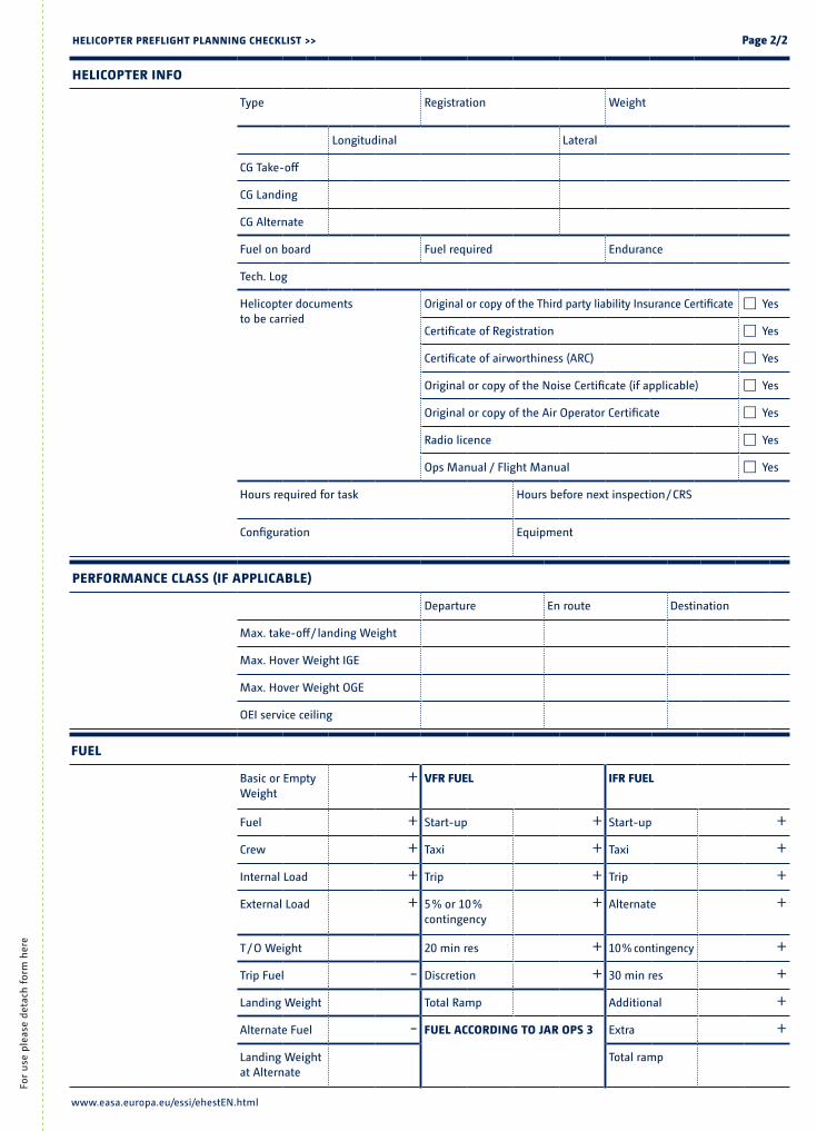
Helicopter info
Type Registration Weight
Longitudinal Lateral
CG Take-off
CG Landing
CG Alternate
Fuel on board Fuel required Endurance
Tech. Log
Helicopter documents to be carried
Original or copy of the Third party liability Insurance Certificate Yes
Certificate of Registration Yes
Certificate of airworthiness (ARC) Yes
Original or copy of the Noise Certificate (if applicable) Yes
Original or copy of the Air Operator Certificate Yes
Radio licence Yes
Ops Manual / Flight Manual Yes
Hours required for task Hours before next inspection / CRS
Configuration Equipment
Helicopter prefligHt planning cHecklist >> page 2/2
fuel
Basic or Empty Weight
+ Vfr fuel ifr fuel
Fuel + Start-up + Start-up +Crew + Taxi + Taxi +Internal Load + Trip + Trip +External Load + 5 % or 10 %
contingency+ Alternate +
T / O Weight 20 min res + 10 % contingency +Trip Fuel - Discretion + 30 min res +Landing Weight Total Ramp Additional +Alternate Fuel - fuel accorDing to Jar ops 3 Extra +Landing Weightat Alternate
Total ramp
performance class (if applicable)
Departure En route Destination
Max. take-off / landing Weight
Max. Hover Weight IGE
Max. Hover Weight OGE
OEI service ceiling
www.easa.europa.eu/essi/ehestEN.html
For
use
ple
ase
deta
ch f
orm
her
e
EuROPEAn HELiCOPTER SAFETy TEAm (EHEST)Component of ESSI
European Aviation Safety Agency (EASA)Safety Analysis and Research DepartmentOttoplatz1,50679Köln,Germany
mail [email protected] www.easa.europa.eu/essi/ehestEN.html
OCT2010
Page 13 – Color-Logo-Combination 2
type of fligHt Date briefing time
WeatHer at Departure point / en route / arriVal / alternate
Metar
TAF
Weather chart Significant weather chart
Upper winds Freezing level Icing
Surface wind Sunrise time Sunset time