electromagnetic testing emt-mft chapter 9b
TRANSCRIPT

Charlie Chong Fion Zhang
Electromagnetic TestingMFLT ECT MicrowaveRFTChapter 9B ndash漏磁检测More Reading on Magnetic Field Leakage Testing MFLT 1st Feb 2015My ASNT Level III Pre-Exam Preparatory Self Study Notes
Charlie Chong Fion Zhang
Refinery amp Appurtenances
Charlie Chong Fion Zhang
Ship building
Charlie Chong Fion Zhang httpenwikipediaorgwikiCANDU_reactor
Offshore Structures amp Appurtenances
Charlie Chong Fion Zhang
Offshore Structures amp Appurtenances
httpenwikipediaorgwikiCANDU_reactor
Charlie Chong Fion Zhang httpenwikipediaorgwikiCANDU_reactor
Offshore Structures amp Appurtenances
Charlie Chong Fion Zhang httpenwikipediaorgwikiCANDU_reactor
Offshore Structures amp Appurtenances
Charlie Chong Fion Zhang httpenwikipediaorgwikiCANDU_reactor
Offshore Structures amp Appurtenances
Charlie Chong Fion Zhang
Offshore Structures amp Appurtenances
Charlie Chong Fion Zhang
Nuclear Power Station
Charlie Chong Fion Zhang
Offshore Structures amp Appurtenances
Charlie Chong Fion Zhang
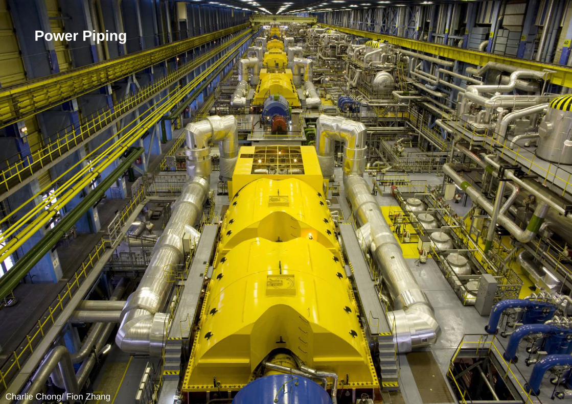
Power Piping
Charlie Chong Fion Zhang
Power Piping
Charlie Chong Fion Zhang
Offshore Structures amp Appurtenances
Charlie Chong Fion Zhang
Charlie Chong Fion Zhang
NDT Level III ExaminationsBasic and Method ExamsASNT NDT Level III certification candidates are required to pass both the NDT Basic and a method examination in order to receive the ASNT NDT Level III certificateExam SpecificationsThe table below lists the number of questions and time allowed for each exam Clicking on an exam will take you to an abbreviated topical outline and reference page for that exam For the full topical outlines and complete list of references see the topical outlines listed in the American National Standard ANSIASNT CP-105 Standard Topical Outlines for Qualification of Nondestructive Testing Personnel
MFLMagnetic Flux Leakage Testing90 Questions Time 2 hrs Certification NDT only
Fion Zhang at Shanghai2015 February
Charlie Chong Fion Zhang Shanghai 上海
Charlie Chong Fion Zhang
Charlie Chong Fion Zhang
Chapter 9BMagnetic Field Testing
ASM Metal Handbook Vol17 Nondestructive evaluation and Quality control
Charlie Chong Fion Zhang
PART 1 Magnetic Field Testing 10 IntroductionMAGNETIC FIELD TESTING includes some of the older and more widely used methods for the nondestructive evaluation of materials Historically such methods have been in use for more than 50 years in the examination of magnetic materials for defects such as cracks voids or inclusions of foreign material More recently magnetic methods for assessing other material properties such as grain size texture or hardness have received increasing attention
Because of this diversion of applications it is natural to divide the field of magnetic materials testing into two parts one directed toward defect detection and characterization and the other aimed at material properties measurements This article is primarily concerned with the first class of applications namely the detection classification and sizing of material flaws However an attempt has also been made to provide at least an introductory description of materials characterization principles along with a few examples of applications This is supplemented by references to other review articles
ASM Metal Handbook Vol17 Nondestructive evaluation and Quality control
Charlie Chong Fion Zhang
Keywords
Field of magnetic materials testing into two parts one directed toward defect detection and characterization and the other aimed at material properties measurements
ASM Metal Handbook Vol17 Nondestructive evaluation and Quality control
Charlie Chong Fion Zhang
All magnetic methods of flaw detection rely in some way on the detection and measurement of the magnetic flux leakage field near the surface of the material which is caused by the presence of the flaw For this reason magnetic testing techniques are often described as flux leakage field or magnetic perturbation methods The magnetic particle inspection method is one such flux leakage method that derives its name from the particular method used to detect the leakage field Because the magnetic particle method is described in the article Magnetic Particle Inspection in this Volume the techniques discussed in this article will be limited to other forms of leakage field measurement
Keywordsflux leakage field FLF or magnetic perturbation 扰动 methods
Charlie Chong Fion Zhang
Although it is conceivable that leakage field fluctuations associated with metallurgical microstructure might be used in the analysis of material properties the characterization methods now in use rely on bulkmeasurements of the hysteretic properties of material magnetization or of some related phenomenon such as Barkhausen noise The principles and applications of magnetic characterization presented in this article are not intended to be exhaustive but rather to serve as illustrations of this type of magnetic testing
The principles and techniques of leakage field testing and magnetic characterization are described in the two sections that follow These sections will discuss concepts and methods that are essential to an understanding of the applications described in later sections The examples of applications presented in the third section will provide a brief overview of the variety of inspection methods that fall under the general heading of magnetic testing
Keywords Barkhausen noise
Charlie Chong Fion Zhang
Barkhausen NoiseThe Barkhausen effect is a name given to the noise in the magnetic output of a ferromagnet when the magnetizing force applied to it is changed Discovered by German physicist Heinrich Barkhausen in 1919 it is caused by rapid changes of size of magnetic domains (similarly magnetically oriented atoms in ferromagnetic materials)
Barkhausens work in acoustics and magnetism led to the discovery which provided evidence that magnetization affects whole domains of a ferromagnetic material rather than individual atoms alone The Barkhausen effect is a series of sudden changes in the size and orientation of ferromagnetic domains or microscopic clusters of aligned atomic magnets (spins) that occurs during a continuous process of magnetization or demagnetization The Barkhausen effect offered direct evidence for the existence of ferromagnetic domains which previously had been postulated theoretically Heinrich Barkhausen discovered that a slow smooth increase of a magnetic field applied to a piece of ferromagnetic material such as iron causes it to become magnetized not continuously but in minute steps
httpenwikipediaorgwikiBarkhausen_effect
Charlie Chong Fion Zhang
Barkhausen noise Magnetization (J) or flux density (B) curve as a function of magnetic field intensity (H) in ferromagnetic material The inset shows Barkhausen jumps
httpenwikipediaorgwikiBarkhausen_effect
Charlie Chong Fion Zhang
Barkhausen noise Domain wall motion with a Barkhausen jump
httpuploadwikimediaorgwikipediacommons779Barkhausensprunggif

Charlie Chong Fion Zhang
Refinery amp Appurtenances
Charlie Chong Fion Zhang
Ship building
Charlie Chong Fion Zhang httpenwikipediaorgwikiCANDU_reactor
Offshore Structures amp Appurtenances
Charlie Chong Fion Zhang
Offshore Structures amp Appurtenances
httpenwikipediaorgwikiCANDU_reactor
Charlie Chong Fion Zhang httpenwikipediaorgwikiCANDU_reactor
Offshore Structures amp Appurtenances
Charlie Chong Fion Zhang httpenwikipediaorgwikiCANDU_reactor
Offshore Structures amp Appurtenances
Charlie Chong Fion Zhang httpenwikipediaorgwikiCANDU_reactor
Offshore Structures amp Appurtenances
Charlie Chong Fion Zhang
Offshore Structures amp Appurtenances
Charlie Chong Fion Zhang
Nuclear Power Station
Charlie Chong Fion Zhang
Offshore Structures amp Appurtenances
Charlie Chong Fion Zhang
Power Piping
Charlie Chong Fion Zhang
Power Piping
Charlie Chong Fion Zhang
Offshore Structures amp Appurtenances
Charlie Chong Fion Zhang
Charlie Chong Fion Zhang
NDT Level III ExaminationsBasic and Method ExamsASNT NDT Level III certification candidates are required to pass both the NDT Basic and a method examination in order to receive the ASNT NDT Level III certificateExam SpecificationsThe table below lists the number of questions and time allowed for each exam Clicking on an exam will take you to an abbreviated topical outline and reference page for that exam For the full topical outlines and complete list of references see the topical outlines listed in the American National Standard ANSIASNT CP-105 Standard Topical Outlines for Qualification of Nondestructive Testing Personnel
MFLMagnetic Flux Leakage Testing90 Questions Time 2 hrs Certification NDT only
Fion Zhang at Shanghai2015 February
Charlie Chong Fion Zhang Shanghai 上海
Charlie Chong Fion Zhang
Charlie Chong Fion Zhang
Chapter 9BMagnetic Field Testing
ASM Metal Handbook Vol17 Nondestructive evaluation and Quality control
Charlie Chong Fion Zhang
PART 1 Magnetic Field Testing 10 IntroductionMAGNETIC FIELD TESTING includes some of the older and more widely used methods for the nondestructive evaluation of materials Historically such methods have been in use for more than 50 years in the examination of magnetic materials for defects such as cracks voids or inclusions of foreign material More recently magnetic methods for assessing other material properties such as grain size texture or hardness have received increasing attention
Because of this diversion of applications it is natural to divide the field of magnetic materials testing into two parts one directed toward defect detection and characterization and the other aimed at material properties measurements This article is primarily concerned with the first class of applications namely the detection classification and sizing of material flaws However an attempt has also been made to provide at least an introductory description of materials characterization principles along with a few examples of applications This is supplemented by references to other review articles
ASM Metal Handbook Vol17 Nondestructive evaluation and Quality control
Charlie Chong Fion Zhang
Keywords
Field of magnetic materials testing into two parts one directed toward defect detection and characterization and the other aimed at material properties measurements
ASM Metal Handbook Vol17 Nondestructive evaluation and Quality control
Charlie Chong Fion Zhang
All magnetic methods of flaw detection rely in some way on the detection and measurement of the magnetic flux leakage field near the surface of the material which is caused by the presence of the flaw For this reason magnetic testing techniques are often described as flux leakage field or magnetic perturbation methods The magnetic particle inspection method is one such flux leakage method that derives its name from the particular method used to detect the leakage field Because the magnetic particle method is described in the article Magnetic Particle Inspection in this Volume the techniques discussed in this article will be limited to other forms of leakage field measurement
Keywordsflux leakage field FLF or magnetic perturbation 扰动 methods
Charlie Chong Fion Zhang
Although it is conceivable that leakage field fluctuations associated with metallurgical microstructure might be used in the analysis of material properties the characterization methods now in use rely on bulkmeasurements of the hysteretic properties of material magnetization or of some related phenomenon such as Barkhausen noise The principles and applications of magnetic characterization presented in this article are not intended to be exhaustive but rather to serve as illustrations of this type of magnetic testing
The principles and techniques of leakage field testing and magnetic characterization are described in the two sections that follow These sections will discuss concepts and methods that are essential to an understanding of the applications described in later sections The examples of applications presented in the third section will provide a brief overview of the variety of inspection methods that fall under the general heading of magnetic testing
Keywords Barkhausen noise
Charlie Chong Fion Zhang
Barkhausen NoiseThe Barkhausen effect is a name given to the noise in the magnetic output of a ferromagnet when the magnetizing force applied to it is changed Discovered by German physicist Heinrich Barkhausen in 1919 it is caused by rapid changes of size of magnetic domains (similarly magnetically oriented atoms in ferromagnetic materials)
Barkhausens work in acoustics and magnetism led to the discovery which provided evidence that magnetization affects whole domains of a ferromagnetic material rather than individual atoms alone The Barkhausen effect is a series of sudden changes in the size and orientation of ferromagnetic domains or microscopic clusters of aligned atomic magnets (spins) that occurs during a continuous process of magnetization or demagnetization The Barkhausen effect offered direct evidence for the existence of ferromagnetic domains which previously had been postulated theoretically Heinrich Barkhausen discovered that a slow smooth increase of a magnetic field applied to a piece of ferromagnetic material such as iron causes it to become magnetized not continuously but in minute steps
httpenwikipediaorgwikiBarkhausen_effect
Charlie Chong Fion Zhang
Barkhausen noise Magnetization (J) or flux density (B) curve as a function of magnetic field intensity (H) in ferromagnetic material The inset shows Barkhausen jumps
httpenwikipediaorgwikiBarkhausen_effect
Charlie Chong Fion Zhang
Barkhausen noise Domain wall motion with a Barkhausen jump
httpuploadwikimediaorgwikipediacommons779Barkhausensprunggif

Charlie Chong Fion Zhang
Ship building
Charlie Chong Fion Zhang httpenwikipediaorgwikiCANDU_reactor
Offshore Structures amp Appurtenances
Charlie Chong Fion Zhang
Offshore Structures amp Appurtenances
httpenwikipediaorgwikiCANDU_reactor
Charlie Chong Fion Zhang httpenwikipediaorgwikiCANDU_reactor
Offshore Structures amp Appurtenances
Charlie Chong Fion Zhang httpenwikipediaorgwikiCANDU_reactor
Offshore Structures amp Appurtenances
Charlie Chong Fion Zhang httpenwikipediaorgwikiCANDU_reactor
Offshore Structures amp Appurtenances
Charlie Chong Fion Zhang
Offshore Structures amp Appurtenances
Charlie Chong Fion Zhang
Nuclear Power Station
Charlie Chong Fion Zhang
Offshore Structures amp Appurtenances
Charlie Chong Fion Zhang
Power Piping
Charlie Chong Fion Zhang
Power Piping
Charlie Chong Fion Zhang
Offshore Structures amp Appurtenances
Charlie Chong Fion Zhang
Charlie Chong Fion Zhang
NDT Level III ExaminationsBasic and Method ExamsASNT NDT Level III certification candidates are required to pass both the NDT Basic and a method examination in order to receive the ASNT NDT Level III certificateExam SpecificationsThe table below lists the number of questions and time allowed for each exam Clicking on an exam will take you to an abbreviated topical outline and reference page for that exam For the full topical outlines and complete list of references see the topical outlines listed in the American National Standard ANSIASNT CP-105 Standard Topical Outlines for Qualification of Nondestructive Testing Personnel
MFLMagnetic Flux Leakage Testing90 Questions Time 2 hrs Certification NDT only
Fion Zhang at Shanghai2015 February
Charlie Chong Fion Zhang Shanghai 上海
Charlie Chong Fion Zhang
Charlie Chong Fion Zhang
Chapter 9BMagnetic Field Testing
ASM Metal Handbook Vol17 Nondestructive evaluation and Quality control
Charlie Chong Fion Zhang
PART 1 Magnetic Field Testing 10 IntroductionMAGNETIC FIELD TESTING includes some of the older and more widely used methods for the nondestructive evaluation of materials Historically such methods have been in use for more than 50 years in the examination of magnetic materials for defects such as cracks voids or inclusions of foreign material More recently magnetic methods for assessing other material properties such as grain size texture or hardness have received increasing attention
Because of this diversion of applications it is natural to divide the field of magnetic materials testing into two parts one directed toward defect detection and characterization and the other aimed at material properties measurements This article is primarily concerned with the first class of applications namely the detection classification and sizing of material flaws However an attempt has also been made to provide at least an introductory description of materials characterization principles along with a few examples of applications This is supplemented by references to other review articles
ASM Metal Handbook Vol17 Nondestructive evaluation and Quality control
Charlie Chong Fion Zhang
Keywords
Field of magnetic materials testing into two parts one directed toward defect detection and characterization and the other aimed at material properties measurements
ASM Metal Handbook Vol17 Nondestructive evaluation and Quality control
Charlie Chong Fion Zhang
All magnetic methods of flaw detection rely in some way on the detection and measurement of the magnetic flux leakage field near the surface of the material which is caused by the presence of the flaw For this reason magnetic testing techniques are often described as flux leakage field or magnetic perturbation methods The magnetic particle inspection method is one such flux leakage method that derives its name from the particular method used to detect the leakage field Because the magnetic particle method is described in the article Magnetic Particle Inspection in this Volume the techniques discussed in this article will be limited to other forms of leakage field measurement
Keywordsflux leakage field FLF or magnetic perturbation 扰动 methods
Charlie Chong Fion Zhang
Although it is conceivable that leakage field fluctuations associated with metallurgical microstructure might be used in the analysis of material properties the characterization methods now in use rely on bulkmeasurements of the hysteretic properties of material magnetization or of some related phenomenon such as Barkhausen noise The principles and applications of magnetic characterization presented in this article are not intended to be exhaustive but rather to serve as illustrations of this type of magnetic testing
The principles and techniques of leakage field testing and magnetic characterization are described in the two sections that follow These sections will discuss concepts and methods that are essential to an understanding of the applications described in later sections The examples of applications presented in the third section will provide a brief overview of the variety of inspection methods that fall under the general heading of magnetic testing
Keywords Barkhausen noise
Charlie Chong Fion Zhang
Barkhausen NoiseThe Barkhausen effect is a name given to the noise in the magnetic output of a ferromagnet when the magnetizing force applied to it is changed Discovered by German physicist Heinrich Barkhausen in 1919 it is caused by rapid changes of size of magnetic domains (similarly magnetically oriented atoms in ferromagnetic materials)
Barkhausens work in acoustics and magnetism led to the discovery which provided evidence that magnetization affects whole domains of a ferromagnetic material rather than individual atoms alone The Barkhausen effect is a series of sudden changes in the size and orientation of ferromagnetic domains or microscopic clusters of aligned atomic magnets (spins) that occurs during a continuous process of magnetization or demagnetization The Barkhausen effect offered direct evidence for the existence of ferromagnetic domains which previously had been postulated theoretically Heinrich Barkhausen discovered that a slow smooth increase of a magnetic field applied to a piece of ferromagnetic material such as iron causes it to become magnetized not continuously but in minute steps
httpenwikipediaorgwikiBarkhausen_effect
Charlie Chong Fion Zhang
Barkhausen noise Magnetization (J) or flux density (B) curve as a function of magnetic field intensity (H) in ferromagnetic material The inset shows Barkhausen jumps
httpenwikipediaorgwikiBarkhausen_effect
Charlie Chong Fion Zhang
Barkhausen noise Domain wall motion with a Barkhausen jump
httpuploadwikimediaorgwikipediacommons779Barkhausensprunggif

Charlie Chong Fion Zhang httpenwikipediaorgwikiCANDU_reactor
Offshore Structures amp Appurtenances
Charlie Chong Fion Zhang
Offshore Structures amp Appurtenances
httpenwikipediaorgwikiCANDU_reactor
Charlie Chong Fion Zhang httpenwikipediaorgwikiCANDU_reactor
Offshore Structures amp Appurtenances
Charlie Chong Fion Zhang httpenwikipediaorgwikiCANDU_reactor
Offshore Structures amp Appurtenances
Charlie Chong Fion Zhang httpenwikipediaorgwikiCANDU_reactor
Offshore Structures amp Appurtenances
Charlie Chong Fion Zhang
Offshore Structures amp Appurtenances
Charlie Chong Fion Zhang
Nuclear Power Station
Charlie Chong Fion Zhang
Offshore Structures amp Appurtenances
Charlie Chong Fion Zhang
Power Piping
Charlie Chong Fion Zhang
Power Piping
Charlie Chong Fion Zhang
Offshore Structures amp Appurtenances
Charlie Chong Fion Zhang
Charlie Chong Fion Zhang
NDT Level III ExaminationsBasic and Method ExamsASNT NDT Level III certification candidates are required to pass both the NDT Basic and a method examination in order to receive the ASNT NDT Level III certificateExam SpecificationsThe table below lists the number of questions and time allowed for each exam Clicking on an exam will take you to an abbreviated topical outline and reference page for that exam For the full topical outlines and complete list of references see the topical outlines listed in the American National Standard ANSIASNT CP-105 Standard Topical Outlines for Qualification of Nondestructive Testing Personnel
MFLMagnetic Flux Leakage Testing90 Questions Time 2 hrs Certification NDT only
Fion Zhang at Shanghai2015 February
Charlie Chong Fion Zhang Shanghai 上海
Charlie Chong Fion Zhang
Charlie Chong Fion Zhang
Chapter 9BMagnetic Field Testing
ASM Metal Handbook Vol17 Nondestructive evaluation and Quality control
Charlie Chong Fion Zhang
PART 1 Magnetic Field Testing 10 IntroductionMAGNETIC FIELD TESTING includes some of the older and more widely used methods for the nondestructive evaluation of materials Historically such methods have been in use for more than 50 years in the examination of magnetic materials for defects such as cracks voids or inclusions of foreign material More recently magnetic methods for assessing other material properties such as grain size texture or hardness have received increasing attention
Because of this diversion of applications it is natural to divide the field of magnetic materials testing into two parts one directed toward defect detection and characterization and the other aimed at material properties measurements This article is primarily concerned with the first class of applications namely the detection classification and sizing of material flaws However an attempt has also been made to provide at least an introductory description of materials characterization principles along with a few examples of applications This is supplemented by references to other review articles
ASM Metal Handbook Vol17 Nondestructive evaluation and Quality control
Charlie Chong Fion Zhang
Keywords
Field of magnetic materials testing into two parts one directed toward defect detection and characterization and the other aimed at material properties measurements
ASM Metal Handbook Vol17 Nondestructive evaluation and Quality control
Charlie Chong Fion Zhang
All magnetic methods of flaw detection rely in some way on the detection and measurement of the magnetic flux leakage field near the surface of the material which is caused by the presence of the flaw For this reason magnetic testing techniques are often described as flux leakage field or magnetic perturbation methods The magnetic particle inspection method is one such flux leakage method that derives its name from the particular method used to detect the leakage field Because the magnetic particle method is described in the article Magnetic Particle Inspection in this Volume the techniques discussed in this article will be limited to other forms of leakage field measurement
Keywordsflux leakage field FLF or magnetic perturbation 扰动 methods
Charlie Chong Fion Zhang
Although it is conceivable that leakage field fluctuations associated with metallurgical microstructure might be used in the analysis of material properties the characterization methods now in use rely on bulkmeasurements of the hysteretic properties of material magnetization or of some related phenomenon such as Barkhausen noise The principles and applications of magnetic characterization presented in this article are not intended to be exhaustive but rather to serve as illustrations of this type of magnetic testing
The principles and techniques of leakage field testing and magnetic characterization are described in the two sections that follow These sections will discuss concepts and methods that are essential to an understanding of the applications described in later sections The examples of applications presented in the third section will provide a brief overview of the variety of inspection methods that fall under the general heading of magnetic testing
Keywords Barkhausen noise
Charlie Chong Fion Zhang
Barkhausen NoiseThe Barkhausen effect is a name given to the noise in the magnetic output of a ferromagnet when the magnetizing force applied to it is changed Discovered by German physicist Heinrich Barkhausen in 1919 it is caused by rapid changes of size of magnetic domains (similarly magnetically oriented atoms in ferromagnetic materials)
Barkhausens work in acoustics and magnetism led to the discovery which provided evidence that magnetization affects whole domains of a ferromagnetic material rather than individual atoms alone The Barkhausen effect is a series of sudden changes in the size and orientation of ferromagnetic domains or microscopic clusters of aligned atomic magnets (spins) that occurs during a continuous process of magnetization or demagnetization The Barkhausen effect offered direct evidence for the existence of ferromagnetic domains which previously had been postulated theoretically Heinrich Barkhausen discovered that a slow smooth increase of a magnetic field applied to a piece of ferromagnetic material such as iron causes it to become magnetized not continuously but in minute steps
httpenwikipediaorgwikiBarkhausen_effect
Charlie Chong Fion Zhang
Barkhausen noise Magnetization (J) or flux density (B) curve as a function of magnetic field intensity (H) in ferromagnetic material The inset shows Barkhausen jumps
httpenwikipediaorgwikiBarkhausen_effect
Charlie Chong Fion Zhang
Barkhausen noise Domain wall motion with a Barkhausen jump
httpuploadwikimediaorgwikipediacommons779Barkhausensprunggif

Charlie Chong Fion Zhang
Offshore Structures amp Appurtenances
httpenwikipediaorgwikiCANDU_reactor
Charlie Chong Fion Zhang httpenwikipediaorgwikiCANDU_reactor
Offshore Structures amp Appurtenances
Charlie Chong Fion Zhang httpenwikipediaorgwikiCANDU_reactor
Offshore Structures amp Appurtenances
Charlie Chong Fion Zhang httpenwikipediaorgwikiCANDU_reactor
Offshore Structures amp Appurtenances
Charlie Chong Fion Zhang
Offshore Structures amp Appurtenances
Charlie Chong Fion Zhang
Nuclear Power Station
Charlie Chong Fion Zhang
Offshore Structures amp Appurtenances
Charlie Chong Fion Zhang
Power Piping
Charlie Chong Fion Zhang
Power Piping
Charlie Chong Fion Zhang
Offshore Structures amp Appurtenances
Charlie Chong Fion Zhang
Charlie Chong Fion Zhang
NDT Level III ExaminationsBasic and Method ExamsASNT NDT Level III certification candidates are required to pass both the NDT Basic and a method examination in order to receive the ASNT NDT Level III certificateExam SpecificationsThe table below lists the number of questions and time allowed for each exam Clicking on an exam will take you to an abbreviated topical outline and reference page for that exam For the full topical outlines and complete list of references see the topical outlines listed in the American National Standard ANSIASNT CP-105 Standard Topical Outlines for Qualification of Nondestructive Testing Personnel
MFLMagnetic Flux Leakage Testing90 Questions Time 2 hrs Certification NDT only
Fion Zhang at Shanghai2015 February
Charlie Chong Fion Zhang Shanghai 上海
Charlie Chong Fion Zhang
Charlie Chong Fion Zhang
Chapter 9BMagnetic Field Testing
ASM Metal Handbook Vol17 Nondestructive evaluation and Quality control
Charlie Chong Fion Zhang
PART 1 Magnetic Field Testing 10 IntroductionMAGNETIC FIELD TESTING includes some of the older and more widely used methods for the nondestructive evaluation of materials Historically such methods have been in use for more than 50 years in the examination of magnetic materials for defects such as cracks voids or inclusions of foreign material More recently magnetic methods for assessing other material properties such as grain size texture or hardness have received increasing attention
Because of this diversion of applications it is natural to divide the field of magnetic materials testing into two parts one directed toward defect detection and characterization and the other aimed at material properties measurements This article is primarily concerned with the first class of applications namely the detection classification and sizing of material flaws However an attempt has also been made to provide at least an introductory description of materials characterization principles along with a few examples of applications This is supplemented by references to other review articles
ASM Metal Handbook Vol17 Nondestructive evaluation and Quality control
Charlie Chong Fion Zhang
Keywords
Field of magnetic materials testing into two parts one directed toward defect detection and characterization and the other aimed at material properties measurements
ASM Metal Handbook Vol17 Nondestructive evaluation and Quality control
Charlie Chong Fion Zhang
All magnetic methods of flaw detection rely in some way on the detection and measurement of the magnetic flux leakage field near the surface of the material which is caused by the presence of the flaw For this reason magnetic testing techniques are often described as flux leakage field or magnetic perturbation methods The magnetic particle inspection method is one such flux leakage method that derives its name from the particular method used to detect the leakage field Because the magnetic particle method is described in the article Magnetic Particle Inspection in this Volume the techniques discussed in this article will be limited to other forms of leakage field measurement
Keywordsflux leakage field FLF or magnetic perturbation 扰动 methods
Charlie Chong Fion Zhang
Although it is conceivable that leakage field fluctuations associated with metallurgical microstructure might be used in the analysis of material properties the characterization methods now in use rely on bulkmeasurements of the hysteretic properties of material magnetization or of some related phenomenon such as Barkhausen noise The principles and applications of magnetic characterization presented in this article are not intended to be exhaustive but rather to serve as illustrations of this type of magnetic testing
The principles and techniques of leakage field testing and magnetic characterization are described in the two sections that follow These sections will discuss concepts and methods that are essential to an understanding of the applications described in later sections The examples of applications presented in the third section will provide a brief overview of the variety of inspection methods that fall under the general heading of magnetic testing
Keywords Barkhausen noise
Charlie Chong Fion Zhang
Barkhausen NoiseThe Barkhausen effect is a name given to the noise in the magnetic output of a ferromagnet when the magnetizing force applied to it is changed Discovered by German physicist Heinrich Barkhausen in 1919 it is caused by rapid changes of size of magnetic domains (similarly magnetically oriented atoms in ferromagnetic materials)
Barkhausens work in acoustics and magnetism led to the discovery which provided evidence that magnetization affects whole domains of a ferromagnetic material rather than individual atoms alone The Barkhausen effect is a series of sudden changes in the size and orientation of ferromagnetic domains or microscopic clusters of aligned atomic magnets (spins) that occurs during a continuous process of magnetization or demagnetization The Barkhausen effect offered direct evidence for the existence of ferromagnetic domains which previously had been postulated theoretically Heinrich Barkhausen discovered that a slow smooth increase of a magnetic field applied to a piece of ferromagnetic material such as iron causes it to become magnetized not continuously but in minute steps
httpenwikipediaorgwikiBarkhausen_effect
Charlie Chong Fion Zhang
Barkhausen noise Magnetization (J) or flux density (B) curve as a function of magnetic field intensity (H) in ferromagnetic material The inset shows Barkhausen jumps
httpenwikipediaorgwikiBarkhausen_effect
Charlie Chong Fion Zhang
Barkhausen noise Domain wall motion with a Barkhausen jump
httpuploadwikimediaorgwikipediacommons779Barkhausensprunggif

Charlie Chong Fion Zhang httpenwikipediaorgwikiCANDU_reactor
Offshore Structures amp Appurtenances
Charlie Chong Fion Zhang httpenwikipediaorgwikiCANDU_reactor
Offshore Structures amp Appurtenances
Charlie Chong Fion Zhang httpenwikipediaorgwikiCANDU_reactor
Offshore Structures amp Appurtenances
Charlie Chong Fion Zhang
Offshore Structures amp Appurtenances
Charlie Chong Fion Zhang
Nuclear Power Station
Charlie Chong Fion Zhang
Offshore Structures amp Appurtenances
Charlie Chong Fion Zhang
Power Piping
Charlie Chong Fion Zhang
Power Piping
Charlie Chong Fion Zhang
Offshore Structures amp Appurtenances
Charlie Chong Fion Zhang
Charlie Chong Fion Zhang
NDT Level III ExaminationsBasic and Method ExamsASNT NDT Level III certification candidates are required to pass both the NDT Basic and a method examination in order to receive the ASNT NDT Level III certificateExam SpecificationsThe table below lists the number of questions and time allowed for each exam Clicking on an exam will take you to an abbreviated topical outline and reference page for that exam For the full topical outlines and complete list of references see the topical outlines listed in the American National Standard ANSIASNT CP-105 Standard Topical Outlines for Qualification of Nondestructive Testing Personnel
MFLMagnetic Flux Leakage Testing90 Questions Time 2 hrs Certification NDT only
Fion Zhang at Shanghai2015 February
Charlie Chong Fion Zhang Shanghai 上海
Charlie Chong Fion Zhang
Charlie Chong Fion Zhang
Chapter 9BMagnetic Field Testing
ASM Metal Handbook Vol17 Nondestructive evaluation and Quality control
Charlie Chong Fion Zhang
PART 1 Magnetic Field Testing 10 IntroductionMAGNETIC FIELD TESTING includes some of the older and more widely used methods for the nondestructive evaluation of materials Historically such methods have been in use for more than 50 years in the examination of magnetic materials for defects such as cracks voids or inclusions of foreign material More recently magnetic methods for assessing other material properties such as grain size texture or hardness have received increasing attention
Because of this diversion of applications it is natural to divide the field of magnetic materials testing into two parts one directed toward defect detection and characterization and the other aimed at material properties measurements This article is primarily concerned with the first class of applications namely the detection classification and sizing of material flaws However an attempt has also been made to provide at least an introductory description of materials characterization principles along with a few examples of applications This is supplemented by references to other review articles
ASM Metal Handbook Vol17 Nondestructive evaluation and Quality control
Charlie Chong Fion Zhang
Keywords
Field of magnetic materials testing into two parts one directed toward defect detection and characterization and the other aimed at material properties measurements
ASM Metal Handbook Vol17 Nondestructive evaluation and Quality control
Charlie Chong Fion Zhang
All magnetic methods of flaw detection rely in some way on the detection and measurement of the magnetic flux leakage field near the surface of the material which is caused by the presence of the flaw For this reason magnetic testing techniques are often described as flux leakage field or magnetic perturbation methods The magnetic particle inspection method is one such flux leakage method that derives its name from the particular method used to detect the leakage field Because the magnetic particle method is described in the article Magnetic Particle Inspection in this Volume the techniques discussed in this article will be limited to other forms of leakage field measurement
Keywordsflux leakage field FLF or magnetic perturbation 扰动 methods
Charlie Chong Fion Zhang
Although it is conceivable that leakage field fluctuations associated with metallurgical microstructure might be used in the analysis of material properties the characterization methods now in use rely on bulkmeasurements of the hysteretic properties of material magnetization or of some related phenomenon such as Barkhausen noise The principles and applications of magnetic characterization presented in this article are not intended to be exhaustive but rather to serve as illustrations of this type of magnetic testing
The principles and techniques of leakage field testing and magnetic characterization are described in the two sections that follow These sections will discuss concepts and methods that are essential to an understanding of the applications described in later sections The examples of applications presented in the third section will provide a brief overview of the variety of inspection methods that fall under the general heading of magnetic testing
Keywords Barkhausen noise
Charlie Chong Fion Zhang
Barkhausen NoiseThe Barkhausen effect is a name given to the noise in the magnetic output of a ferromagnet when the magnetizing force applied to it is changed Discovered by German physicist Heinrich Barkhausen in 1919 it is caused by rapid changes of size of magnetic domains (similarly magnetically oriented atoms in ferromagnetic materials)
Barkhausens work in acoustics and magnetism led to the discovery which provided evidence that magnetization affects whole domains of a ferromagnetic material rather than individual atoms alone The Barkhausen effect is a series of sudden changes in the size and orientation of ferromagnetic domains or microscopic clusters of aligned atomic magnets (spins) that occurs during a continuous process of magnetization or demagnetization The Barkhausen effect offered direct evidence for the existence of ferromagnetic domains which previously had been postulated theoretically Heinrich Barkhausen discovered that a slow smooth increase of a magnetic field applied to a piece of ferromagnetic material such as iron causes it to become magnetized not continuously but in minute steps
httpenwikipediaorgwikiBarkhausen_effect
Charlie Chong Fion Zhang
Barkhausen noise Magnetization (J) or flux density (B) curve as a function of magnetic field intensity (H) in ferromagnetic material The inset shows Barkhausen jumps
httpenwikipediaorgwikiBarkhausen_effect
Charlie Chong Fion Zhang
Barkhausen noise Domain wall motion with a Barkhausen jump
httpuploadwikimediaorgwikipediacommons779Barkhausensprunggif

Charlie Chong Fion Zhang httpenwikipediaorgwikiCANDU_reactor
Offshore Structures amp Appurtenances
Charlie Chong Fion Zhang httpenwikipediaorgwikiCANDU_reactor
Offshore Structures amp Appurtenances
Charlie Chong Fion Zhang
Offshore Structures amp Appurtenances
Charlie Chong Fion Zhang
Nuclear Power Station
Charlie Chong Fion Zhang
Offshore Structures amp Appurtenances
Charlie Chong Fion Zhang
Power Piping
Charlie Chong Fion Zhang
Power Piping
Charlie Chong Fion Zhang
Offshore Structures amp Appurtenances
Charlie Chong Fion Zhang
Charlie Chong Fion Zhang
NDT Level III ExaminationsBasic and Method ExamsASNT NDT Level III certification candidates are required to pass both the NDT Basic and a method examination in order to receive the ASNT NDT Level III certificateExam SpecificationsThe table below lists the number of questions and time allowed for each exam Clicking on an exam will take you to an abbreviated topical outline and reference page for that exam For the full topical outlines and complete list of references see the topical outlines listed in the American National Standard ANSIASNT CP-105 Standard Topical Outlines for Qualification of Nondestructive Testing Personnel
MFLMagnetic Flux Leakage Testing90 Questions Time 2 hrs Certification NDT only
Fion Zhang at Shanghai2015 February
Charlie Chong Fion Zhang Shanghai 上海
Charlie Chong Fion Zhang
Charlie Chong Fion Zhang
Chapter 9BMagnetic Field Testing
ASM Metal Handbook Vol17 Nondestructive evaluation and Quality control
Charlie Chong Fion Zhang
PART 1 Magnetic Field Testing 10 IntroductionMAGNETIC FIELD TESTING includes some of the older and more widely used methods for the nondestructive evaluation of materials Historically such methods have been in use for more than 50 years in the examination of magnetic materials for defects such as cracks voids or inclusions of foreign material More recently magnetic methods for assessing other material properties such as grain size texture or hardness have received increasing attention
Because of this diversion of applications it is natural to divide the field of magnetic materials testing into two parts one directed toward defect detection and characterization and the other aimed at material properties measurements This article is primarily concerned with the first class of applications namely the detection classification and sizing of material flaws However an attempt has also been made to provide at least an introductory description of materials characterization principles along with a few examples of applications This is supplemented by references to other review articles
ASM Metal Handbook Vol17 Nondestructive evaluation and Quality control
Charlie Chong Fion Zhang
Keywords
Field of magnetic materials testing into two parts one directed toward defect detection and characterization and the other aimed at material properties measurements
ASM Metal Handbook Vol17 Nondestructive evaluation and Quality control
Charlie Chong Fion Zhang
All magnetic methods of flaw detection rely in some way on the detection and measurement of the magnetic flux leakage field near the surface of the material which is caused by the presence of the flaw For this reason magnetic testing techniques are often described as flux leakage field or magnetic perturbation methods The magnetic particle inspection method is one such flux leakage method that derives its name from the particular method used to detect the leakage field Because the magnetic particle method is described in the article Magnetic Particle Inspection in this Volume the techniques discussed in this article will be limited to other forms of leakage field measurement
Keywordsflux leakage field FLF or magnetic perturbation 扰动 methods
Charlie Chong Fion Zhang
Although it is conceivable that leakage field fluctuations associated with metallurgical microstructure might be used in the analysis of material properties the characterization methods now in use rely on bulkmeasurements of the hysteretic properties of material magnetization or of some related phenomenon such as Barkhausen noise The principles and applications of magnetic characterization presented in this article are not intended to be exhaustive but rather to serve as illustrations of this type of magnetic testing
The principles and techniques of leakage field testing and magnetic characterization are described in the two sections that follow These sections will discuss concepts and methods that are essential to an understanding of the applications described in later sections The examples of applications presented in the third section will provide a brief overview of the variety of inspection methods that fall under the general heading of magnetic testing
Keywords Barkhausen noise
Charlie Chong Fion Zhang
Barkhausen NoiseThe Barkhausen effect is a name given to the noise in the magnetic output of a ferromagnet when the magnetizing force applied to it is changed Discovered by German physicist Heinrich Barkhausen in 1919 it is caused by rapid changes of size of magnetic domains (similarly magnetically oriented atoms in ferromagnetic materials)
Barkhausens work in acoustics and magnetism led to the discovery which provided evidence that magnetization affects whole domains of a ferromagnetic material rather than individual atoms alone The Barkhausen effect is a series of sudden changes in the size and orientation of ferromagnetic domains or microscopic clusters of aligned atomic magnets (spins) that occurs during a continuous process of magnetization or demagnetization The Barkhausen effect offered direct evidence for the existence of ferromagnetic domains which previously had been postulated theoretically Heinrich Barkhausen discovered that a slow smooth increase of a magnetic field applied to a piece of ferromagnetic material such as iron causes it to become magnetized not continuously but in minute steps
httpenwikipediaorgwikiBarkhausen_effect
Charlie Chong Fion Zhang
Barkhausen noise Magnetization (J) or flux density (B) curve as a function of magnetic field intensity (H) in ferromagnetic material The inset shows Barkhausen jumps
httpenwikipediaorgwikiBarkhausen_effect
Charlie Chong Fion Zhang
Barkhausen noise Domain wall motion with a Barkhausen jump
httpuploadwikimediaorgwikipediacommons779Barkhausensprunggif

Charlie Chong Fion Zhang httpenwikipediaorgwikiCANDU_reactor
Offshore Structures amp Appurtenances
Charlie Chong Fion Zhang
Offshore Structures amp Appurtenances
Charlie Chong Fion Zhang
Nuclear Power Station
Charlie Chong Fion Zhang
Offshore Structures amp Appurtenances
Charlie Chong Fion Zhang
Power Piping
Charlie Chong Fion Zhang
Power Piping
Charlie Chong Fion Zhang
Offshore Structures amp Appurtenances
Charlie Chong Fion Zhang
Charlie Chong Fion Zhang
NDT Level III ExaminationsBasic and Method ExamsASNT NDT Level III certification candidates are required to pass both the NDT Basic and a method examination in order to receive the ASNT NDT Level III certificateExam SpecificationsThe table below lists the number of questions and time allowed for each exam Clicking on an exam will take you to an abbreviated topical outline and reference page for that exam For the full topical outlines and complete list of references see the topical outlines listed in the American National Standard ANSIASNT CP-105 Standard Topical Outlines for Qualification of Nondestructive Testing Personnel
MFLMagnetic Flux Leakage Testing90 Questions Time 2 hrs Certification NDT only
Fion Zhang at Shanghai2015 February
Charlie Chong Fion Zhang Shanghai 上海
Charlie Chong Fion Zhang
Charlie Chong Fion Zhang
Chapter 9BMagnetic Field Testing
ASM Metal Handbook Vol17 Nondestructive evaluation and Quality control
Charlie Chong Fion Zhang
PART 1 Magnetic Field Testing 10 IntroductionMAGNETIC FIELD TESTING includes some of the older and more widely used methods for the nondestructive evaluation of materials Historically such methods have been in use for more than 50 years in the examination of magnetic materials for defects such as cracks voids or inclusions of foreign material More recently magnetic methods for assessing other material properties such as grain size texture or hardness have received increasing attention
Because of this diversion of applications it is natural to divide the field of magnetic materials testing into two parts one directed toward defect detection and characterization and the other aimed at material properties measurements This article is primarily concerned with the first class of applications namely the detection classification and sizing of material flaws However an attempt has also been made to provide at least an introductory description of materials characterization principles along with a few examples of applications This is supplemented by references to other review articles
ASM Metal Handbook Vol17 Nondestructive evaluation and Quality control
Charlie Chong Fion Zhang
Keywords
Field of magnetic materials testing into two parts one directed toward defect detection and characterization and the other aimed at material properties measurements
ASM Metal Handbook Vol17 Nondestructive evaluation and Quality control
Charlie Chong Fion Zhang
All magnetic methods of flaw detection rely in some way on the detection and measurement of the magnetic flux leakage field near the surface of the material which is caused by the presence of the flaw For this reason magnetic testing techniques are often described as flux leakage field or magnetic perturbation methods The magnetic particle inspection method is one such flux leakage method that derives its name from the particular method used to detect the leakage field Because the magnetic particle method is described in the article Magnetic Particle Inspection in this Volume the techniques discussed in this article will be limited to other forms of leakage field measurement
Keywordsflux leakage field FLF or magnetic perturbation 扰动 methods
Charlie Chong Fion Zhang
Although it is conceivable that leakage field fluctuations associated with metallurgical microstructure might be used in the analysis of material properties the characterization methods now in use rely on bulkmeasurements of the hysteretic properties of material magnetization or of some related phenomenon such as Barkhausen noise The principles and applications of magnetic characterization presented in this article are not intended to be exhaustive but rather to serve as illustrations of this type of magnetic testing
The principles and techniques of leakage field testing and magnetic characterization are described in the two sections that follow These sections will discuss concepts and methods that are essential to an understanding of the applications described in later sections The examples of applications presented in the third section will provide a brief overview of the variety of inspection methods that fall under the general heading of magnetic testing
Keywords Barkhausen noise
Charlie Chong Fion Zhang
Barkhausen NoiseThe Barkhausen effect is a name given to the noise in the magnetic output of a ferromagnet when the magnetizing force applied to it is changed Discovered by German physicist Heinrich Barkhausen in 1919 it is caused by rapid changes of size of magnetic domains (similarly magnetically oriented atoms in ferromagnetic materials)
Barkhausens work in acoustics and magnetism led to the discovery which provided evidence that magnetization affects whole domains of a ferromagnetic material rather than individual atoms alone The Barkhausen effect is a series of sudden changes in the size and orientation of ferromagnetic domains or microscopic clusters of aligned atomic magnets (spins) that occurs during a continuous process of magnetization or demagnetization The Barkhausen effect offered direct evidence for the existence of ferromagnetic domains which previously had been postulated theoretically Heinrich Barkhausen discovered that a slow smooth increase of a magnetic field applied to a piece of ferromagnetic material such as iron causes it to become magnetized not continuously but in minute steps
httpenwikipediaorgwikiBarkhausen_effect
Charlie Chong Fion Zhang
Barkhausen noise Magnetization (J) or flux density (B) curve as a function of magnetic field intensity (H) in ferromagnetic material The inset shows Barkhausen jumps
httpenwikipediaorgwikiBarkhausen_effect
Charlie Chong Fion Zhang
Barkhausen noise Domain wall motion with a Barkhausen jump
httpuploadwikimediaorgwikipediacommons779Barkhausensprunggif

Charlie Chong Fion Zhang
Offshore Structures amp Appurtenances
Charlie Chong Fion Zhang
Nuclear Power Station
Charlie Chong Fion Zhang
Offshore Structures amp Appurtenances
Charlie Chong Fion Zhang
Power Piping
Charlie Chong Fion Zhang
Power Piping
Charlie Chong Fion Zhang
Offshore Structures amp Appurtenances
Charlie Chong Fion Zhang
Charlie Chong Fion Zhang
NDT Level III ExaminationsBasic and Method ExamsASNT NDT Level III certification candidates are required to pass both the NDT Basic and a method examination in order to receive the ASNT NDT Level III certificateExam SpecificationsThe table below lists the number of questions and time allowed for each exam Clicking on an exam will take you to an abbreviated topical outline and reference page for that exam For the full topical outlines and complete list of references see the topical outlines listed in the American National Standard ANSIASNT CP-105 Standard Topical Outlines for Qualification of Nondestructive Testing Personnel
MFLMagnetic Flux Leakage Testing90 Questions Time 2 hrs Certification NDT only
Fion Zhang at Shanghai2015 February
Charlie Chong Fion Zhang Shanghai 上海
Charlie Chong Fion Zhang
Charlie Chong Fion Zhang
Chapter 9BMagnetic Field Testing
ASM Metal Handbook Vol17 Nondestructive evaluation and Quality control
Charlie Chong Fion Zhang
PART 1 Magnetic Field Testing 10 IntroductionMAGNETIC FIELD TESTING includes some of the older and more widely used methods for the nondestructive evaluation of materials Historically such methods have been in use for more than 50 years in the examination of magnetic materials for defects such as cracks voids or inclusions of foreign material More recently magnetic methods for assessing other material properties such as grain size texture or hardness have received increasing attention
Because of this diversion of applications it is natural to divide the field of magnetic materials testing into two parts one directed toward defect detection and characterization and the other aimed at material properties measurements This article is primarily concerned with the first class of applications namely the detection classification and sizing of material flaws However an attempt has also been made to provide at least an introductory description of materials characterization principles along with a few examples of applications This is supplemented by references to other review articles
ASM Metal Handbook Vol17 Nondestructive evaluation and Quality control
Charlie Chong Fion Zhang
Keywords
Field of magnetic materials testing into two parts one directed toward defect detection and characterization and the other aimed at material properties measurements
ASM Metal Handbook Vol17 Nondestructive evaluation and Quality control
Charlie Chong Fion Zhang
All magnetic methods of flaw detection rely in some way on the detection and measurement of the magnetic flux leakage field near the surface of the material which is caused by the presence of the flaw For this reason magnetic testing techniques are often described as flux leakage field or magnetic perturbation methods The magnetic particle inspection method is one such flux leakage method that derives its name from the particular method used to detect the leakage field Because the magnetic particle method is described in the article Magnetic Particle Inspection in this Volume the techniques discussed in this article will be limited to other forms of leakage field measurement
Keywordsflux leakage field FLF or magnetic perturbation 扰动 methods
Charlie Chong Fion Zhang
Although it is conceivable that leakage field fluctuations associated with metallurgical microstructure might be used in the analysis of material properties the characterization methods now in use rely on bulkmeasurements of the hysteretic properties of material magnetization or of some related phenomenon such as Barkhausen noise The principles and applications of magnetic characterization presented in this article are not intended to be exhaustive but rather to serve as illustrations of this type of magnetic testing
The principles and techniques of leakage field testing and magnetic characterization are described in the two sections that follow These sections will discuss concepts and methods that are essential to an understanding of the applications described in later sections The examples of applications presented in the third section will provide a brief overview of the variety of inspection methods that fall under the general heading of magnetic testing
Keywords Barkhausen noise
Charlie Chong Fion Zhang
Barkhausen NoiseThe Barkhausen effect is a name given to the noise in the magnetic output of a ferromagnet when the magnetizing force applied to it is changed Discovered by German physicist Heinrich Barkhausen in 1919 it is caused by rapid changes of size of magnetic domains (similarly magnetically oriented atoms in ferromagnetic materials)
Barkhausens work in acoustics and magnetism led to the discovery which provided evidence that magnetization affects whole domains of a ferromagnetic material rather than individual atoms alone The Barkhausen effect is a series of sudden changes in the size and orientation of ferromagnetic domains or microscopic clusters of aligned atomic magnets (spins) that occurs during a continuous process of magnetization or demagnetization The Barkhausen effect offered direct evidence for the existence of ferromagnetic domains which previously had been postulated theoretically Heinrich Barkhausen discovered that a slow smooth increase of a magnetic field applied to a piece of ferromagnetic material such as iron causes it to become magnetized not continuously but in minute steps
httpenwikipediaorgwikiBarkhausen_effect
Charlie Chong Fion Zhang
Barkhausen noise Magnetization (J) or flux density (B) curve as a function of magnetic field intensity (H) in ferromagnetic material The inset shows Barkhausen jumps
httpenwikipediaorgwikiBarkhausen_effect
Charlie Chong Fion Zhang
Barkhausen noise Domain wall motion with a Barkhausen jump
httpuploadwikimediaorgwikipediacommons779Barkhausensprunggif

Charlie Chong Fion Zhang
Offshore Structures amp Appurtenances
Charlie Chong Fion Zhang
Power Piping
Charlie Chong Fion Zhang
Power Piping
Charlie Chong Fion Zhang
Offshore Structures amp Appurtenances
Charlie Chong Fion Zhang
Charlie Chong Fion Zhang
NDT Level III ExaminationsBasic and Method ExamsASNT NDT Level III certification candidates are required to pass both the NDT Basic and a method examination in order to receive the ASNT NDT Level III certificateExam SpecificationsThe table below lists the number of questions and time allowed for each exam Clicking on an exam will take you to an abbreviated topical outline and reference page for that exam For the full topical outlines and complete list of references see the topical outlines listed in the American National Standard ANSIASNT CP-105 Standard Topical Outlines for Qualification of Nondestructive Testing Personnel
MFLMagnetic Flux Leakage Testing90 Questions Time 2 hrs Certification NDT only
Fion Zhang at Shanghai2015 February
Charlie Chong Fion Zhang Shanghai 上海
Charlie Chong Fion Zhang
Charlie Chong Fion Zhang
Chapter 9BMagnetic Field Testing
ASM Metal Handbook Vol17 Nondestructive evaluation and Quality control
Charlie Chong Fion Zhang
PART 1 Magnetic Field Testing 10 IntroductionMAGNETIC FIELD TESTING includes some of the older and more widely used methods for the nondestructive evaluation of materials Historically such methods have been in use for more than 50 years in the examination of magnetic materials for defects such as cracks voids or inclusions of foreign material More recently magnetic methods for assessing other material properties such as grain size texture or hardness have received increasing attention
Because of this diversion of applications it is natural to divide the field of magnetic materials testing into two parts one directed toward defect detection and characterization and the other aimed at material properties measurements This article is primarily concerned with the first class of applications namely the detection classification and sizing of material flaws However an attempt has also been made to provide at least an introductory description of materials characterization principles along with a few examples of applications This is supplemented by references to other review articles
ASM Metal Handbook Vol17 Nondestructive evaluation and Quality control
Charlie Chong Fion Zhang
Keywords
Field of magnetic materials testing into two parts one directed toward defect detection and characterization and the other aimed at material properties measurements
ASM Metal Handbook Vol17 Nondestructive evaluation and Quality control
Charlie Chong Fion Zhang
All magnetic methods of flaw detection rely in some way on the detection and measurement of the magnetic flux leakage field near the surface of the material which is caused by the presence of the flaw For this reason magnetic testing techniques are often described as flux leakage field or magnetic perturbation methods The magnetic particle inspection method is one such flux leakage method that derives its name from the particular method used to detect the leakage field Because the magnetic particle method is described in the article Magnetic Particle Inspection in this Volume the techniques discussed in this article will be limited to other forms of leakage field measurement
Keywordsflux leakage field FLF or magnetic perturbation 扰动 methods
Charlie Chong Fion Zhang
Although it is conceivable that leakage field fluctuations associated with metallurgical microstructure might be used in the analysis of material properties the characterization methods now in use rely on bulkmeasurements of the hysteretic properties of material magnetization or of some related phenomenon such as Barkhausen noise The principles and applications of magnetic characterization presented in this article are not intended to be exhaustive but rather to serve as illustrations of this type of magnetic testing
The principles and techniques of leakage field testing and magnetic characterization are described in the two sections that follow These sections will discuss concepts and methods that are essential to an understanding of the applications described in later sections The examples of applications presented in the third section will provide a brief overview of the variety of inspection methods that fall under the general heading of magnetic testing
Keywords Barkhausen noise
Charlie Chong Fion Zhang
Barkhausen NoiseThe Barkhausen effect is a name given to the noise in the magnetic output of a ferromagnet when the magnetizing force applied to it is changed Discovered by German physicist Heinrich Barkhausen in 1919 it is caused by rapid changes of size of magnetic domains (similarly magnetically oriented atoms in ferromagnetic materials)
Barkhausens work in acoustics and magnetism led to the discovery which provided evidence that magnetization affects whole domains of a ferromagnetic material rather than individual atoms alone The Barkhausen effect is a series of sudden changes in the size and orientation of ferromagnetic domains or microscopic clusters of aligned atomic magnets (spins) that occurs during a continuous process of magnetization or demagnetization The Barkhausen effect offered direct evidence for the existence of ferromagnetic domains which previously had been postulated theoretically Heinrich Barkhausen discovered that a slow smooth increase of a magnetic field applied to a piece of ferromagnetic material such as iron causes it to become magnetized not continuously but in minute steps
httpenwikipediaorgwikiBarkhausen_effect
Charlie Chong Fion Zhang
Barkhausen noise Magnetization (J) or flux density (B) curve as a function of magnetic field intensity (H) in ferromagnetic material The inset shows Barkhausen jumps
httpenwikipediaorgwikiBarkhausen_effect
Charlie Chong Fion Zhang
Barkhausen noise Domain wall motion with a Barkhausen jump
httpuploadwikimediaorgwikipediacommons779Barkhausensprunggif
Charlie Chong Fion Zhang
Power Piping
Charlie Chong Fion Zhang
Power Piping
Charlie Chong Fion Zhang
Offshore Structures amp Appurtenances
Charlie Chong Fion Zhang
Charlie Chong Fion Zhang
NDT Level III ExaminationsBasic and Method ExamsASNT NDT Level III certification candidates are required to pass both the NDT Basic and a method examination in order to receive the ASNT NDT Level III certificateExam SpecificationsThe table below lists the number of questions and time allowed for each exam Clicking on an exam will take you to an abbreviated topical outline and reference page for that exam For the full topical outlines and complete list of references see the topical outlines listed in the American National Standard ANSIASNT CP-105 Standard Topical Outlines for Qualification of Nondestructive Testing Personnel
MFLMagnetic Flux Leakage Testing90 Questions Time 2 hrs Certification NDT only
Fion Zhang at Shanghai2015 February
Charlie Chong Fion Zhang Shanghai 上海
Charlie Chong Fion Zhang
Charlie Chong Fion Zhang
Chapter 9BMagnetic Field Testing
ASM Metal Handbook Vol17 Nondestructive evaluation and Quality control
Charlie Chong Fion Zhang
PART 1 Magnetic Field Testing 10 IntroductionMAGNETIC FIELD TESTING includes some of the older and more widely used methods for the nondestructive evaluation of materials Historically such methods have been in use for more than 50 years in the examination of magnetic materials for defects such as cracks voids or inclusions of foreign material More recently magnetic methods for assessing other material properties such as grain size texture or hardness have received increasing attention
Because of this diversion of applications it is natural to divide the field of magnetic materials testing into two parts one directed toward defect detection and characterization and the other aimed at material properties measurements This article is primarily concerned with the first class of applications namely the detection classification and sizing of material flaws However an attempt has also been made to provide at least an introductory description of materials characterization principles along with a few examples of applications This is supplemented by references to other review articles
ASM Metal Handbook Vol17 Nondestructive evaluation and Quality control
Charlie Chong Fion Zhang
Keywords
Field of magnetic materials testing into two parts one directed toward defect detection and characterization and the other aimed at material properties measurements
ASM Metal Handbook Vol17 Nondestructive evaluation and Quality control
Charlie Chong Fion Zhang
All magnetic methods of flaw detection rely in some way on the detection and measurement of the magnetic flux leakage field near the surface of the material which is caused by the presence of the flaw For this reason magnetic testing techniques are often described as flux leakage field or magnetic perturbation methods The magnetic particle inspection method is one such flux leakage method that derives its name from the particular method used to detect the leakage field Because the magnetic particle method is described in the article Magnetic Particle Inspection in this Volume the techniques discussed in this article will be limited to other forms of leakage field measurement
Keywordsflux leakage field FLF or magnetic perturbation 扰动 methods
Charlie Chong Fion Zhang
Although it is conceivable that leakage field fluctuations associated with metallurgical microstructure might be used in the analysis of material properties the characterization methods now in use rely on bulkmeasurements of the hysteretic properties of material magnetization or of some related phenomenon such as Barkhausen noise The principles and applications of magnetic characterization presented in this article are not intended to be exhaustive but rather to serve as illustrations of this type of magnetic testing
The principles and techniques of leakage field testing and magnetic characterization are described in the two sections that follow These sections will discuss concepts and methods that are essential to an understanding of the applications described in later sections The examples of applications presented in the third section will provide a brief overview of the variety of inspection methods that fall under the general heading of magnetic testing
Keywords Barkhausen noise
Charlie Chong Fion Zhang
Barkhausen NoiseThe Barkhausen effect is a name given to the noise in the magnetic output of a ferromagnet when the magnetizing force applied to it is changed Discovered by German physicist Heinrich Barkhausen in 1919 it is caused by rapid changes of size of magnetic domains (similarly magnetically oriented atoms in ferromagnetic materials)
Barkhausens work in acoustics and magnetism led to the discovery which provided evidence that magnetization affects whole domains of a ferromagnetic material rather than individual atoms alone The Barkhausen effect is a series of sudden changes in the size and orientation of ferromagnetic domains or microscopic clusters of aligned atomic magnets (spins) that occurs during a continuous process of magnetization or demagnetization The Barkhausen effect offered direct evidence for the existence of ferromagnetic domains which previously had been postulated theoretically Heinrich Barkhausen discovered that a slow smooth increase of a magnetic field applied to a piece of ferromagnetic material such as iron causes it to become magnetized not continuously but in minute steps
httpenwikipediaorgwikiBarkhausen_effect
Charlie Chong Fion Zhang
Barkhausen noise Magnetization (J) or flux density (B) curve as a function of magnetic field intensity (H) in ferromagnetic material The inset shows Barkhausen jumps
httpenwikipediaorgwikiBarkhausen_effect
Charlie Chong Fion Zhang
Barkhausen noise Domain wall motion with a Barkhausen jump
httpuploadwikimediaorgwikipediacommons779Barkhausensprunggif

Charlie Chong Fion Zhang
Charlie Chong Fion Zhang
NDT Level III ExaminationsBasic and Method ExamsASNT NDT Level III certification candidates are required to pass both the NDT Basic and a method examination in order to receive the ASNT NDT Level III certificateExam SpecificationsThe table below lists the number of questions and time allowed for each exam Clicking on an exam will take you to an abbreviated topical outline and reference page for that exam For the full topical outlines and complete list of references see the topical outlines listed in the American National Standard ANSIASNT CP-105 Standard Topical Outlines for Qualification of Nondestructive Testing Personnel
MFLMagnetic Flux Leakage Testing90 Questions Time 2 hrs Certification NDT only
Fion Zhang at Shanghai2015 February
Charlie Chong Fion Zhang Shanghai 上海
Charlie Chong Fion Zhang
Charlie Chong Fion Zhang
Chapter 9BMagnetic Field Testing
ASM Metal Handbook Vol17 Nondestructive evaluation and Quality control
Charlie Chong Fion Zhang
PART 1 Magnetic Field Testing 10 IntroductionMAGNETIC FIELD TESTING includes some of the older and more widely used methods for the nondestructive evaluation of materials Historically such methods have been in use for more than 50 years in the examination of magnetic materials for defects such as cracks voids or inclusions of foreign material More recently magnetic methods for assessing other material properties such as grain size texture or hardness have received increasing attention
Because of this diversion of applications it is natural to divide the field of magnetic materials testing into two parts one directed toward defect detection and characterization and the other aimed at material properties measurements This article is primarily concerned with the first class of applications namely the detection classification and sizing of material flaws However an attempt has also been made to provide at least an introductory description of materials characterization principles along with a few examples of applications This is supplemented by references to other review articles
ASM Metal Handbook Vol17 Nondestructive evaluation and Quality control
Charlie Chong Fion Zhang
Keywords
Field of magnetic materials testing into two parts one directed toward defect detection and characterization and the other aimed at material properties measurements
ASM Metal Handbook Vol17 Nondestructive evaluation and Quality control
Charlie Chong Fion Zhang
All magnetic methods of flaw detection rely in some way on the detection and measurement of the magnetic flux leakage field near the surface of the material which is caused by the presence of the flaw For this reason magnetic testing techniques are often described as flux leakage field or magnetic perturbation methods The magnetic particle inspection method is one such flux leakage method that derives its name from the particular method used to detect the leakage field Because the magnetic particle method is described in the article Magnetic Particle Inspection in this Volume the techniques discussed in this article will be limited to other forms of leakage field measurement
Keywordsflux leakage field FLF or magnetic perturbation 扰动 methods
Charlie Chong Fion Zhang
Although it is conceivable that leakage field fluctuations associated with metallurgical microstructure might be used in the analysis of material properties the characterization methods now in use rely on bulkmeasurements of the hysteretic properties of material magnetization or of some related phenomenon such as Barkhausen noise The principles and applications of magnetic characterization presented in this article are not intended to be exhaustive but rather to serve as illustrations of this type of magnetic testing
The principles and techniques of leakage field testing and magnetic characterization are described in the two sections that follow These sections will discuss concepts and methods that are essential to an understanding of the applications described in later sections The examples of applications presented in the third section will provide a brief overview of the variety of inspection methods that fall under the general heading of magnetic testing
Keywords Barkhausen noise
Charlie Chong Fion Zhang
Barkhausen NoiseThe Barkhausen effect is a name given to the noise in the magnetic output of a ferromagnet when the magnetizing force applied to it is changed Discovered by German physicist Heinrich Barkhausen in 1919 it is caused by rapid changes of size of magnetic domains (similarly magnetically oriented atoms in ferromagnetic materials)
Barkhausens work in acoustics and magnetism led to the discovery which provided evidence that magnetization affects whole domains of a ferromagnetic material rather than individual atoms alone The Barkhausen effect is a series of sudden changes in the size and orientation of ferromagnetic domains or microscopic clusters of aligned atomic magnets (spins) that occurs during a continuous process of magnetization or demagnetization The Barkhausen effect offered direct evidence for the existence of ferromagnetic domains which previously had been postulated theoretically Heinrich Barkhausen discovered that a slow smooth increase of a magnetic field applied to a piece of ferromagnetic material such as iron causes it to become magnetized not continuously but in minute steps
httpenwikipediaorgwikiBarkhausen_effect
Charlie Chong Fion Zhang
Barkhausen noise Magnetization (J) or flux density (B) curve as a function of magnetic field intensity (H) in ferromagnetic material The inset shows Barkhausen jumps
httpenwikipediaorgwikiBarkhausen_effect
Charlie Chong Fion Zhang
Barkhausen noise Domain wall motion with a Barkhausen jump
httpuploadwikimediaorgwikipediacommons779Barkhausensprunggif

Charlie Chong Fion Zhang
NDT Level III ExaminationsBasic and Method ExamsASNT NDT Level III certification candidates are required to pass both the NDT Basic and a method examination in order to receive the ASNT NDT Level III certificateExam SpecificationsThe table below lists the number of questions and time allowed for each exam Clicking on an exam will take you to an abbreviated topical outline and reference page for that exam For the full topical outlines and complete list of references see the topical outlines listed in the American National Standard ANSIASNT CP-105 Standard Topical Outlines for Qualification of Nondestructive Testing Personnel
MFLMagnetic Flux Leakage Testing90 Questions Time 2 hrs Certification NDT only
Fion Zhang at Shanghai2015 February
Charlie Chong Fion Zhang Shanghai 上海
Charlie Chong Fion Zhang
Charlie Chong Fion Zhang
Chapter 9BMagnetic Field Testing
ASM Metal Handbook Vol17 Nondestructive evaluation and Quality control
Charlie Chong Fion Zhang
PART 1 Magnetic Field Testing 10 IntroductionMAGNETIC FIELD TESTING includes some of the older and more widely used methods for the nondestructive evaluation of materials Historically such methods have been in use for more than 50 years in the examination of magnetic materials for defects such as cracks voids or inclusions of foreign material More recently magnetic methods for assessing other material properties such as grain size texture or hardness have received increasing attention
Because of this diversion of applications it is natural to divide the field of magnetic materials testing into two parts one directed toward defect detection and characterization and the other aimed at material properties measurements This article is primarily concerned with the first class of applications namely the detection classification and sizing of material flaws However an attempt has also been made to provide at least an introductory description of materials characterization principles along with a few examples of applications This is supplemented by references to other review articles
ASM Metal Handbook Vol17 Nondestructive evaluation and Quality control
Charlie Chong Fion Zhang
Keywords
Field of magnetic materials testing into two parts one directed toward defect detection and characterization and the other aimed at material properties measurements
ASM Metal Handbook Vol17 Nondestructive evaluation and Quality control
Charlie Chong Fion Zhang
All magnetic methods of flaw detection rely in some way on the detection and measurement of the magnetic flux leakage field near the surface of the material which is caused by the presence of the flaw For this reason magnetic testing techniques are often described as flux leakage field or magnetic perturbation methods The magnetic particle inspection method is one such flux leakage method that derives its name from the particular method used to detect the leakage field Because the magnetic particle method is described in the article Magnetic Particle Inspection in this Volume the techniques discussed in this article will be limited to other forms of leakage field measurement
Keywordsflux leakage field FLF or magnetic perturbation 扰动 methods
Charlie Chong Fion Zhang
Although it is conceivable that leakage field fluctuations associated with metallurgical microstructure might be used in the analysis of material properties the characterization methods now in use rely on bulkmeasurements of the hysteretic properties of material magnetization or of some related phenomenon such as Barkhausen noise The principles and applications of magnetic characterization presented in this article are not intended to be exhaustive but rather to serve as illustrations of this type of magnetic testing
The principles and techniques of leakage field testing and magnetic characterization are described in the two sections that follow These sections will discuss concepts and methods that are essential to an understanding of the applications described in later sections The examples of applications presented in the third section will provide a brief overview of the variety of inspection methods that fall under the general heading of magnetic testing
Keywords Barkhausen noise
Charlie Chong Fion Zhang
Barkhausen NoiseThe Barkhausen effect is a name given to the noise in the magnetic output of a ferromagnet when the magnetizing force applied to it is changed Discovered by German physicist Heinrich Barkhausen in 1919 it is caused by rapid changes of size of magnetic domains (similarly magnetically oriented atoms in ferromagnetic materials)
Barkhausens work in acoustics and magnetism led to the discovery which provided evidence that magnetization affects whole domains of a ferromagnetic material rather than individual atoms alone The Barkhausen effect is a series of sudden changes in the size and orientation of ferromagnetic domains or microscopic clusters of aligned atomic magnets (spins) that occurs during a continuous process of magnetization or demagnetization The Barkhausen effect offered direct evidence for the existence of ferromagnetic domains which previously had been postulated theoretically Heinrich Barkhausen discovered that a slow smooth increase of a magnetic field applied to a piece of ferromagnetic material such as iron causes it to become magnetized not continuously but in minute steps
httpenwikipediaorgwikiBarkhausen_effect
Charlie Chong Fion Zhang
Barkhausen noise Magnetization (J) or flux density (B) curve as a function of magnetic field intensity (H) in ferromagnetic material The inset shows Barkhausen jumps
httpenwikipediaorgwikiBarkhausen_effect
Charlie Chong Fion Zhang
Barkhausen noise Domain wall motion with a Barkhausen jump
httpuploadwikimediaorgwikipediacommons779Barkhausensprunggif

Charlie Chong Fion Zhang
Charlie Chong Fion Zhang
Chapter 9BMagnetic Field Testing
ASM Metal Handbook Vol17 Nondestructive evaluation and Quality control
Charlie Chong Fion Zhang
PART 1 Magnetic Field Testing 10 IntroductionMAGNETIC FIELD TESTING includes some of the older and more widely used methods for the nondestructive evaluation of materials Historically such methods have been in use for more than 50 years in the examination of magnetic materials for defects such as cracks voids or inclusions of foreign material More recently magnetic methods for assessing other material properties such as grain size texture or hardness have received increasing attention
Because of this diversion of applications it is natural to divide the field of magnetic materials testing into two parts one directed toward defect detection and characterization and the other aimed at material properties measurements This article is primarily concerned with the first class of applications namely the detection classification and sizing of material flaws However an attempt has also been made to provide at least an introductory description of materials characterization principles along with a few examples of applications This is supplemented by references to other review articles
ASM Metal Handbook Vol17 Nondestructive evaluation and Quality control
Charlie Chong Fion Zhang
Keywords
Field of magnetic materials testing into two parts one directed toward defect detection and characterization and the other aimed at material properties measurements
ASM Metal Handbook Vol17 Nondestructive evaluation and Quality control
Charlie Chong Fion Zhang
All magnetic methods of flaw detection rely in some way on the detection and measurement of the magnetic flux leakage field near the surface of the material which is caused by the presence of the flaw For this reason magnetic testing techniques are often described as flux leakage field or magnetic perturbation methods The magnetic particle inspection method is one such flux leakage method that derives its name from the particular method used to detect the leakage field Because the magnetic particle method is described in the article Magnetic Particle Inspection in this Volume the techniques discussed in this article will be limited to other forms of leakage field measurement
Keywordsflux leakage field FLF or magnetic perturbation 扰动 methods
Charlie Chong Fion Zhang
Although it is conceivable that leakage field fluctuations associated with metallurgical microstructure might be used in the analysis of material properties the characterization methods now in use rely on bulkmeasurements of the hysteretic properties of material magnetization or of some related phenomenon such as Barkhausen noise The principles and applications of magnetic characterization presented in this article are not intended to be exhaustive but rather to serve as illustrations of this type of magnetic testing
The principles and techniques of leakage field testing and magnetic characterization are described in the two sections that follow These sections will discuss concepts and methods that are essential to an understanding of the applications described in later sections The examples of applications presented in the third section will provide a brief overview of the variety of inspection methods that fall under the general heading of magnetic testing
Keywords Barkhausen noise
Charlie Chong Fion Zhang
Barkhausen NoiseThe Barkhausen effect is a name given to the noise in the magnetic output of a ferromagnet when the magnetizing force applied to it is changed Discovered by German physicist Heinrich Barkhausen in 1919 it is caused by rapid changes of size of magnetic domains (similarly magnetically oriented atoms in ferromagnetic materials)
Barkhausens work in acoustics and magnetism led to the discovery which provided evidence that magnetization affects whole domains of a ferromagnetic material rather than individual atoms alone The Barkhausen effect is a series of sudden changes in the size and orientation of ferromagnetic domains or microscopic clusters of aligned atomic magnets (spins) that occurs during a continuous process of magnetization or demagnetization The Barkhausen effect offered direct evidence for the existence of ferromagnetic domains which previously had been postulated theoretically Heinrich Barkhausen discovered that a slow smooth increase of a magnetic field applied to a piece of ferromagnetic material such as iron causes it to become magnetized not continuously but in minute steps
httpenwikipediaorgwikiBarkhausen_effect
Charlie Chong Fion Zhang
Barkhausen noise Magnetization (J) or flux density (B) curve as a function of magnetic field intensity (H) in ferromagnetic material The inset shows Barkhausen jumps
httpenwikipediaorgwikiBarkhausen_effect
Charlie Chong Fion Zhang
Barkhausen noise Domain wall motion with a Barkhausen jump
httpuploadwikimediaorgwikipediacommons779Barkhausensprunggif

Charlie Chong Fion Zhang
Barkhausen noise Domain wall motion with a Barkhausen jump
httpuploadwikimediaorgwikipediacommons779Barkhausensprunggif
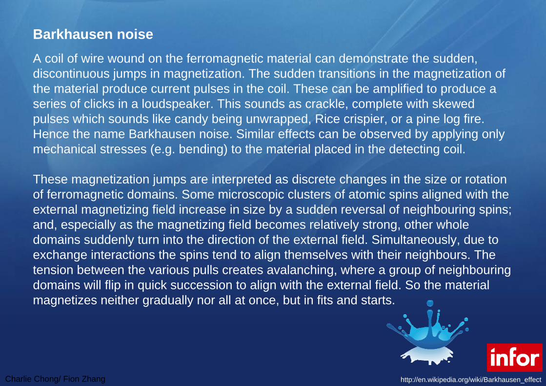
Charlie Chong Fion Zhang
Barkhausen noiseA coil of wire wound on the ferromagnetic material can demonstrate the sudden discontinuous jumps in magnetization The sudden transitions in the magnetization of the material produce current pulses in the coil These can be amplified to produce a series of clicks in a loudspeaker This sounds as crackle complete with skewed pulses which sounds like candy being unwrapped Rice crispier or a pine log fire Hence the name Barkhausen noise Similar effects can be observed by applying only mechanical stresses (eg bending) to the material placed in the detecting coil
These magnetization jumps are interpreted as discrete changes in the size or rotation of ferromagnetic domains Some microscopic clusters of atomic spins aligned with the external magnetizing field increase in size by a sudden reversal of neighbouring spins and especially as the magnetizing field becomes relatively strong other whole domains suddenly turn into the direction of the external field Simultaneously due to exchange interactions the spins tend to align themselves with their neighbours The tension between the various pulls creates avalanching where a group of neighbouringdomains will flip in quick succession to align with the external field So the material magnetizes neither gradually nor all at once but in fits and starts
httpenwikipediaorgwikiBarkhausen_effect
Charlie Chong Fion Zhang
Practical use A set-up for non-destructive testing of ferromagnetic materials green ndash magnetisingyoke red ndash inductive sensor grey ndash sample under test The amount of Barkhausen noise for a given material is linked with the amount of impurities crystal dislocations etc and can be a good indication of mechanical properties of such a material Therefore the Barkhausen noise can be used as a method of non-destructive evaluation of the degradation of mechanical properties in magnetic materials subjected to cyclic mechanical stresses (eg in pipeline transport) or high-energy particles (eg nuclear reactor) or materials such as high-strength steels which may be subjected to damage from grinding Schematic diagram of a simple non-destructive set-up for such a purpose is shown on the right
Barkhausen noise can also indicate physical damage in a thin film structure due to various nanofabrication processes such as reactive ion etching or using an ion milling machine
httpenwikipediaorgwikiBarkhausen_effect
Charlie Chong Fion Zhang
A set-up for non-destructive testing of ferromagnetic materials green ndash magnetizing yoke red ndash inductive sensor grey ndash sample under test
httpenwikipediaorgwikiBarkhausen_effect
Charlie Chong Fion Zhang
Magnetic Dipole
Charlie Chong Fion Zhang
Magnetic Dipole
Charlie Chong Fion Zhang
20 Principles of Magnetic Leakage Field Testing MLFT21 Origin of Defect Leakage Fields
The origin of the flaw leakage field is illustrated in Fig 1 Figure 1(a) shows a uniformly magnetized rod which consists of a large number of elementary magnets aligned with the direction of magnetization Inside the material each magnetic pole is exactly compensated by the presence of an adjacent pole of opposite polarity and the net result is that interior poles do not contribute to the magnetic field outside the material At the surfaces however magnetic poles are uncompensated and therefore produce a magnetic field in the region surrounding the specimen This is illustrated in Fig 1(a) by flux lines connecting uncompensated elementary poles
Charlie Chong Fion Zhang
If a slot is cut in the rod as illustrated in Fig 1(b) the poles on the surface of this slot are now also uncompensated and therefore produce a localized magnetic field near the slot This additional magnetic field which is represented by the extra flux lines in Fig 1(b) is the leakage field associated with the slot Figure 1 although adequate for a qualitative understanding of the origin of leakage fields does not provide an exact quantitative description The difficulty is the assumption that the magnetization remains uniform when the flaw is introduced In general this does not happen because the presence of the flaw changes the magnetic field in the vicinity of the flaw and this in turn leads to a change in magnetization near the flaw With regard to
Fig 1 this means that the strengths and orientations of the elementary dipoles (magnets) actually vary from point to point in the vicinity of the flaw and this variation also contributes to the flaw leakage field The end result is that the accurate description of a flaw leakage field poses a difficult mathematical problem that usually requires a special-purpose computer code for its solution
Charlie Chong Fion Zhang
Fig 1 Origin of defect leakage fields (a) Magnetic flux lines of a magnet without a defect (b) Magnetic flux lines of a magnet with a surface defect Source Ref 1
Charlie Chong Fion Zhang
22 Experimental Techniques
One of the first considerations in the experimental application of magnetic leakage field methods is the generation of a suitable magnetic field within the material In some ferromagnetic materials the residual field (the field that remains after removal of an external magnetizing field) is often adequate for surface flaw detection In practice however residual magnetization is rarely used because use of an applied magnetizing field ensures that the material is in a desired magnetic state (which should be known and well characterized) and because applied fields provide more flexibility (that is one can produce a high or low flux density in the specimen as desired Experience has shown that control of the strength and direction of the magnetization can be useful in improving flaw detectability and in discriminating among different types of flaws In general the magnitude of the magnetization should be chosen to maximize the flaw leakage field with respect to other field sources that might interfere with flaw detection the optimum magnetization is usually difficult to determine in advance of a test and is often approached by trial-and-error experimentation The direction of the field should be perpendicular to the largest flaw dimension to maximize the effect of the flaw on the leakage field
Charlie Chong Fion Zhang
Keywords
The direction of the field should be perpendicular to the largest flaw dimension to maximize the effect of the flaw on the leakage field
Charlie Chong Fion Zhang
It is possible to generate a magnetic field in a specimen either directly or indirectly In direct magnetization current is passed directly through the part With the indirect approach magnetization is induced by placing the part in a magnetic field that is generated by an adjacent current conductor or permanent magnet This can be done for example by threading a conductor through a hollow part such as a tube or by passing an electric current through a cable wound around the part Methods of magnetizing a part both directly and indirectly are illustrated schematically in Fig 2
Charlie Chong Fion Zhang
Fig 2 Methods of magnetization (1) Head-shot method (b) Magnetization with prods (c) Magnetization with a central conductor (d) Longitudinal magnetization (e) Yoke magnetization
Charlie Chong Fion Zhang
The flaw leakage field can be detected with one of several types of magnetic field sensors Aside from the use of magnetic particles the sensors most often used are the inductive coil and the Hall effect device The inductive coil sensor is based on Faradays law of induction which states that the voltage induced in the coil is proportional to the number of turns in the coil multiplied by the time rate of change of the flux Ф threading the coil It follows that detection of a magnetostatic field requires that the coil be in motion so that the flux through the coil changes with time The principle is illustrated in Fig 3 in which the coil is oriented so as to sense the change in flux parallel to the surface of the specimen If the direction of coil motion is taken as x then the induced electromotive force E in volts is given by
for Ф = B∙A
Charlie Chong Fion Zhang
where N is the number of turns in the coil A is its cross-sectional area and B is the flux density in Gauss parallel to the surface of the part Thus the voltage induced in the coil is proportional to the gradient of the flux density along the direction of coil motion multiplied by the coil velocity Figure 4 shows the flux density typical of the leakage field from a slot along with the corresponding signal from a search coil oriented as in Fig 3
Charlie Chong Fion Zhang
Fig 3 Flux leakage measurement using a search coil Source
Charlie Chong Fion Zhang
Fig 4 Leakage flux and search coil signal as a function of position
Charlie Chong Fion Zhang
Unlike the inductive coil which provides a measure of the flux gradient a Hall effect sensor directly measures the component of the flux itself in the direction perpendicular to the sensitive area of the device Because the response of a Hall effect sensor does not depend on the motion of the probe it can be scanned over the surface to be inspected at any rate that is mechanically convenient In this respect the Hall device has an advantage over the coil sensor because there is no need to maintain a constant scanning speed during the inspection On the other hand Hall effect sensors are more difficult to fabricate are somewhat delicate compared to inductive coil sensors and require more complex electronics Other magnetic field sensors that are used less often in leakage field applications include the flux gate magnetometer magnetoresistive sensors magnetic resonance sensors and magnetographicsensors in which the magnetic field at the surface of a part is registered on a magnetic tape pressed onto the surface
KeywordsHall device has an advantage over the coil sensor because there is no need to maintain a constant scanning speed during the inspection
Charlie Chong Fion Zhang
23 Analysis of Leakage Field Data
In most applications of the leakage field method there is a need not only to detect the presence of a flaw but also to estimate its severity This leads to the problem of flaw characterization that is the determination of flaw dimensions from an analysis of leakage field data The most widely used method of flaw characterization is based on the assumptions that the leakage field signal amplitude is proportional to the size of the flaw (which usually means its depth into the material) and that the signal amplitude can therefore be taken as a direct measure of flaw severity In situations where all flaws have approximately the same shape and where calibration experiments show that the signal amplitude is indeed proportional to the size parameter of concern this empirical method of sizing works quite well
KeywordsThe most widely used method of flaw characterization is based on the assumptions that the leakage field signal amplitude is proportional to the size of the flaw (which usually means its depth into the material) ()
Charlie Chong Fion Zhang
There are however many situations of interest where flaw shapes vary considerably and where signal amplitude is not uniquely related to flaw depth as is the case for corrosion pits in steel tubing In addition different types of flaws such as cracks and pits can occur in the same part in which case it becomes necessary to determine the flaw types present as well as their severity
In such cases a more careful analysis of the relationship between signal and flaw characteristics is required if serious errors in flaw characterization are to be avoided One of the earliest attempts to use a theoretical model in the analysis of leakage field data was based on the analytic solution for the field perturbed by a spherical inclusion Two conclusions were drawn from this analysis First when one measures the leakage flux component normal to the surface of the part the center of the flaw is located below the scan plane at a distance equal to the peak-to-peak separation distance in the flaw signal (Fig 5) and second the peak-to-peak signal amplitude is proportional to the flaw volume A number of experimental tests of these sizing rules have confirmed the predicted relationships for nonmagnetic inclusions in steel parts
Charlie Chong Fion Zhang
Keywords
Two conclusions were drawn from this analysis
bull First when one measures the leakage flux component normal to the surface of the part the center of the flaw is located below the scan plane at a distance equal to the peak-to-peak separation distance in the flaw signal (Fig 5) and
bull Second the peak-to-peak signal amplitude is proportional to the flaw volume A number of experimental tests of these sizing rules have confirmed the predicted relationships for nonmagnetic inclusions in steel parts
peak-to-peak signal amplitude is proportional to the flaw volume
Lateral dimension
Charlie Chong Fion Zhang
Fig 5 Dependence of magnetic signal peak separation (a) on the depth of a spherical inclusion (b)
Charlie Chong Fion Zhang
Further theoretical and experimental data for spheroidal inclusions and surface pits have shown however that the simple characterization rules for spherical inclusions do not apply when the flaw shape differs significantly from the ideal sphere In such cases the signal amplitude depends on the lateral extent of the flaw and on its volume and characterization on the basis of leakage field analysis becomes much more complicated
Finally there has been at least one attempt to apply finite-element calculations of flaw leakage fields to the development of characterization rules for a more general class of flaws Hwang and Lord performed most of their computations for simple flaw shapes such as rectangular and triangular slots and inclusions and from the results devised a set of rules for estimating the depth width and angle of inclination of a flaw with respect to the surface of the part One of their applications to a flaw of complex shape is shown in Fig 6
Charlie Chong Fion Zhang
Fig 6 Characterization of a ferrite-tail type of defect The dashed line shows the flaw configuration estimated from the leakage field data
Charlie Chong Fion Zhang
The promising results obtained from the finite-element work of Hwang and Lord as well as the analytically based work on spheroidal flaws suggest that the estimation of flaw size and shape from leakage field data is feasible Another numerical method potentially applicable to flux leakage problems is the boundary integral method which may prove useful in flaw characterization Unfortunately much more work must be done on both the theoretical basis and on experimental testing before it will be possible to analyze experimental leakage field data with confidence in terms of flaw characteristics
Charlie Chong Fion Zhang
PART 2 Principles of Magnetic Characterization of Materials10 Metallurgical and Magnetic Properties
The use of magnetic measurements to monitor the metallurgical propertiesof ferromagnetic materials is based on the fact that variables such as crystallographic phase chemical composition and microstructure which determine the physical properties of materials also affect their magnetic characteristics Some parameters such as grain size and orientation dislocation density and the existence of precipitates are closely related to measurable characteristics of magnetic hysteresis that is to the behavior of the flux density B induced in a material as a function of the magnetic field strength H This relationship can be understood in principle from the physical theory of magnetic domains Magnetization in a particular direction increases as the domains aligned in that direction grow at the expense of domains aligned in other directions Factors that impede domain growth also impede dislocation motion hence the connection at a very fundamental level between magnetic and mechanical properties
Charlie Chong Fion Zhang
Keywords
Metallurgical properties
Crystallographic phase Chemical composition Grain size and orientation Dislocation density and Existence of precipitates
are closely related to measurable characteristics of magnetic hysteresis that is to the behavior of the flux density B induced in a material as a function of the magnetic field strength H
Charlie Chong Fion Zhang
Hysteresis Curves
Charlie Chong Fion Zhang
Other magnetic properties such as the saturation magnetization which is the maximum value B can achieve or the Curie temperature at which there is a transition to a nonmagnetic state are less dependent on microstructure but are sensitive to such factors as crystal structure and chemical composition Interest in the magnetic characterization of materials principally steels derives from many such relationships between measurable magneticparameters and metallurgical properties These relationships are however quite complicated in general and it is often difficult to determine how or if a particular measurement or combination of measurements can be used to determine a property of interest
Charlie Chong Fion Zhang
Nevertheless the prospect of nondestructive monitoring and quality control is an attractive one and for this reason research on magnetic materials characterization continues to be an active field It is not the purpose of this article to explore such magnetic methods in depth but simply to point out that it is an active branch of nondestructive magnetic testing The more fundamental aspects of the relationship between magnetism and metallurgy are discussed in Ref 26 and 28 Engineering considerations are reviewed in Ref 24 The proceedings of various symposia also contain several papers that provide a good overview of the current status of magnetic materials characterization
Charlie Chong Fion Zhang
Curie temperature In physics and materials science the Curie temperature (Tc) or Curie point is the temperature where a materials permanent magnetism changes to induced magnetism The force of magnetism is determined by magnetic moments The Curie temperature is the critical point where a materials intrinsic magnetic moments change direction Magnetic moments are permanent dipole moments within the atom which originate from electrons angular momentum and spin Materials have different structures of intrinsic magnetic moments that depend on temperature At a materials Curie Temperature those intrinsic magnetic moments change direction
Permanent magnetism is caused by the alignment of magnetic moments and induced magnetism is created when disordered magnetic moments are forced to align in an applied magnetic field For example the ordered magnetic moments (ferromagnetic figure 1) change and become disordered (paramagnetic figure 2) at the Curie Temperature Higher temperatures make magnets weaker as spontaneous magnetism only occurs below the Curie Temperature Magnetic susceptibility only occurs above the Curie Temperature and can be calculated from the Curie-Weiss Law which is derived from Curies Law In analogy to ferromagnetic and paramagnetic materials the Curie temperature can also be used to describe the temperature where a materials spontaneous electric polarisation changes to induced electric polarisation or the reverse upon reduction of the temperature below the Curie temperature
httpenwikipediaorgwikiCurie_temperature
Charlie Chong Fion Zhang
Curie temperature
harr ParamagneticAntiferromagneticharr ParamagneticFerrimagneticharr ParamagneticFerromagneticAbove TcBelow Tc
httpenwikipediaorgwikiCurie_temperature
Charlie Chong Fion Zhang
Ferromagnetism The magnetic moments in a ferromagnetic material The moments are ordered and of the same magnitude in the absence of an applied magnetic field
httpenwikipediaorgwikiCurie_temperature
Charlie Chong Fion Zhang
Paramagnetism The magnetic moments in a paramagnetic material The moments are disordered in the absence of an applied magnetic field and ordered in the presence of an applied magnetic field
httpenwikipediaorgwikiCurie_temperature
Charlie Chong Fion Zhang
Ferrimagnetism The magnetic moments in a ferrimagnetic material The moments are aligned oppositely and have different magnitudes due to being made up of two different ions This is in the absence of an applied magnetic field
httpenwikipediaorgwikiCurie_temperature
Charlie Chong Fion Zhang
Antiferromagnetism The magnetic moments in an antiferromagneticmaterial The moments are aligned oppositely and have the same magnitudes This is in the absence of an applied magnetic field
httpenwikipediaorgwikiCurie_temperature
Charlie Chong Fion Zhang
20 Experimental Techniques
A typical setup for measuring the B-H characteristic of a rod specimen is shown in Fig 7 The essential elements are an electromagnet for generating the magnetizing field a coil wound around the specimen for measuring the time rate of change of the magnetic flux B in the material and a magnetic field sensor in this case a Hall effect probe for measuring the magnetic field strength H parallel to the surface of the part The signal generator provides a low-frequency magnetizing field typically of the order of a few Hertz and the output of the flux measuring coil is integrated over time to give the flux density in the material In the arrangement shown in Fig 7 an additional feature is the provision for applying a tensile load to the specimen for studies of the effects of stress on the hysteresis data When using a rod specimen such as this it is important that the length-to-diameter ratio of the specimen be large so as to minimize the effects of stray fields from the ends of the rod on the measurements of B and H
Charlie Chong Fion Zhang
Fig 7 Experimental arrangement for hysteresis loop measurements
Charlie Chong Fion Zhang
Another magnetic method that uses a similar arrangement is the measurement of Barkhausen noise As the magnetic field strength H is varied at a very slow rate discontinuous jumps in the magnetization of the material can be observed during certain portions of the hysteresis cycle These jumps are associated with the sudden growth of a series of magnetic domains that have been temporarily stopped from further growth by such obstacles as grain boundaries precipitates or dislocations Barkhausen noise is therefore dependent on microstructure and can be used independently of hysteresis measurements or in conjunction with such measurements as another method of magnetic testing The experimental arrangement differs from that shown in Fig 7 in that a single sensor coil oriented to measure the flux normal to the surface of the specimen is used instead of the Hall probe and the flux winding
Charlie Chong Fion Zhang
The review articles and conference proceedings cited above contain additional detail on experimental technique and a wealth of information on the interpretation of hysteresis and Barkhausen data However it should be noted that test methods and data interpretation are often very specific to a particular class of alloy and techniques that seem to work well for one type of material may be totally inappropriate for another The analysis of magnetic characterization data is still largely empirical in nature and controlled testing of a candidate technique with the specific alloy system of interest is advisable
Charlie Chong Fion Zhang
PART 3 Application10 Flaw Detection by the Flux Leakage MethodPerhaps the most prevalent use of the flux leakage method is theinspection of ferromagnetic tubular goods such as gas pipelines down hole casing and a variety of other forms of steel piping In applications in the petroleum industry the technique is highly developed but details on inspection devices and methods of data analysis are for the most part considered proprietary by the companies that provide inspection services Still the techniques currently in use have certain features in common and these are exemplified by the typical system described below The device shown in Fig 8 is an inspection tool for large-diameter pipelines Magnetization is provided by a large electromagnet fitted with wire brushes to direct magnetic flux from the electromagnet into the pipe wall To avoid spurious signals from hard spots in the material the magnetization circuit is designed for maximum flux density in the pipe wall in an attempt to magnetically saturate the material
Charlie Chong Fion Zhang
Leakage field sensors are mounted between the pole pieces of the magnet in a circle around the axis of the device to provide as nearly as possible full coverage of the pipe wall In most such tools the sensors are the inductive coil type oriented to measure the axial component of the leakage field gradient Data are usually recorded on magnetic tape as the system is propelled down a section of pipe After the inspection the recorded signals are compared with those from calibration standards in an attempt to interpret flaw indications in terms of flaw type and size
Charlie Chong Fion Zhang
Fig 8 Typical gas pipeline inspection pig The tool consists of a drive unit an instrumentation unit and a center section with an electromagnetic and flux leakage sensors
Pipe
Sensor
Sensor
Pole
Coil
Pole
Charlie Chong Fion Zhang
In addition to systems for inspecting rotationally symmetric cylindrical parts flux leakage inspection has been applied to very irregular components such as helicopter rotor blade D-spars gear teeth and artillery projectiles Several of these special-purpose applications have involved only laboratory investigations but in some cases specialized instrumentation systems have been developed and fabricated for factory use These systems are uniquely adapted to the particular application involved and in most cases only one or at most several instrumentation systems have been built Even in the case of laboratory investigations special-purpose detection probe and magnetizing arrangements have been developed for specific applications
Charlie Chong Fion Zhang
One such system for automated thread inspection on drill pipe and collars is described The device consists of an electromagnet and an array of sensors mounted outside a nonmagnetic cone that threads onto the tool joint The assembly is driven in a helical path along the threads by a motorclutch assembly To minimize the leakage flux signal variations caused by the threads signals from the sensor array are compared differentially The system is capable of operating in a high field strength mode for the detection of cracks and corrosion pits and also in a residual field mode for the detection of other forms of damage At last report the system was undergoing field tests and was found to offer advantages in terms of ease of application and defect detection over the magnetic particle technique normally used for thread inspection
Charlie Chong Fion Zhang
The flux leakage method is also finding application in the inspection of ropes and cables made of strands of ferromagnetic material One approach is to induce magnetization in the piece by means of an encircling coil energized by a direct current (dc) With this method one measures the leakage field associated with broken strands using a Hall effect probe or an auxiliary sensor coil A complementary method with alternating current (ac) which is actually an eddy current test rather than flux leakage is to measure the ac impedance variations in an encircling coil caused by irregularities in the cross-sectional area of the specimen Haynes and Underbakke describe practical field tests of an instrumentation system that utilizes both the ac and dc methods They conclude that instrumentation capable of a combination of inspection techniques offers the best possibility of detecting both localized flaws and overall loss of cross section caused by generalized corrosion and wear They also present detailed information on the practical characteristics of a commercially available device that makes use of both the ac and dc methods
Charlie C
hong Fion Zhang
The flux leakage method is also finding application in the inspection of ropes and cables
Charlie Chong Fion Zhang
Another area in which the flux leakage method has been successfully implemented is the inspection of rolling-element antifriction bearings A schematic illustration of the method as applied to an inner bearing race is shown in Fig 9 In this application the part is magnetized by an electromagnet as indicated in Fig 9(a) The race is then rotated by a spindle and the surface is scanned with an induction coil sensor Typically the race is rotated at a surface speed of about 23 ms (75 fts) and the active portion of the raceway is inspected by incrementally indexing the sensor across the raceway Magnetizing fields are applied in the radial and circumferential orientations It has been shown that radial field inspection works best for surface flaws while circumferential field inspection shows greater sensitivity to subsurface flaws Data have been collected on a large number of bearing races to establish the correlation between leakage field signals and inclusion depths and dimensions determined by metallurgical sectioning
Charlie Chong Fion Zhang
Fig 9 Flux leakage inspection of a bearing race (a) Magnetization of inner race (b) Perturbation in the magnetic flux at the surface of the inner race (c) Probe scanning the surface
Charlie Chong Fion Zhang
Finally the flux leakage method has also been adapted to the inspection of steel reinforcement in concrete beams The basic function of the magnetic field disturbance (MFD) inspection equipment is to provide maps of the magnetic field across the bottom and sides of the beam An electromagnet on an inspection cart which is suspended on tracks below the beam provides a magnetic field that induces magnetization in permeable structures in its vicinity such as steel rebars cables and stirrups An array of Hall effect sensors distributed across the bottom and sides of the beam measures the field produced by magnetized structures within the beam If a flaw is present in one of these magnetized structures it will produce a disturbance of the normal magnetic field pattern associated with the unflawed beam Thus the idea behind the MFD system is to search the surface of the beam for field anomalies that indicate the presence of flaws in reinforcing steel within the structure
Keywordsmagnetic field disturbance (MFD)
Charlie Chong Fion Zhang
A flaw such as a broken wire in a cable or a fractured rebar produces a distinctive magnetic field anomaly that depends on the size of the discontinuity and its distance from the sensor Because the signal shape that results from such an anomaly is known flaw detection is enhanced by searching magnetic field records for specific signal shapes that is those that are characteristic of discontinuities in magnetic materials In the MFD system this is accomplished by a computer program that compares signal shapes with typical flaw signal shapes The program produces a correlation coefficient that serves as a measure of similarity of the observed signal shape to a typical flaw signal shape Flaw detection is therefore not only enhanced by signal shape discrimination but also automated by computer processing of the magnetic field data Laboratory tests have demonstrated the ability of the system to detect fracture in steel rebars and cables in a large pre-stressed concrete structure Also planned are field tests of the equipment in the inspection of bridge decks for reinforcement corrosion damage
Charlie Chong Fion Zhang
Steel rebars and cables in a large pre-stressed concrete structure
Charlie Chong Fion Zhang
20 Nondestructive Characterization of Materials Only two examples of magnetic methods for monitoring materialproperties are given because the examples chosen should suffice to illustrate the types of tests that might be employed Measurements of magnetic characteristics can however provide a wealth of data and various features of such data can yield information on different material properties For example it has been demonstrated that different features of magnetic hysteresis data can be interpreted in terms of heat treatment and microstructure plastic deformation residual stress and mechanical hardness An example of the effects of mechanical hardness on hysteresis data is shown in Fig 10 These data were obtained in the absence of applied tensile stress with the experimental arrangement shown in Fig 7 Specimens of different hardness were prepared by tempering at different temperatures The grain size (ASTM No 7) was the same for all four specimens used in these tests Other data showed however that grain size has little effect on hysteretic behavior for the classes of alloys studied
Charlie Chong Fion Zhang
Fig 10 Effect of mechanical hardness on hysteresis loop data (a) AISI 410 stainless steel (b) SAE 4340 steel
Charlie Chong Fion Zhang
The main point illustrated in Fig 10 is that the mechanically harder specimens of the same alloy are also harder to magnetize that is the flux density B obtained at a large value of H is smaller for mechanically harder specimens than for softer specimens For one alloy AISI 410 stainless steel the hysteresis loop intersects the B = 0 axis at larger values of H for the harder specimen than for the softer specimen that is the coercive force is greater for the harder material However for the other material SAE 4340 steel the coercive force does not change with hardness This suggests that for the two alloys considered here the saturation flux density provides a more reliable measure of hardness than the coercive force Mayos et al used two quite different techniques to measure the depth of surface decarburization of steels One method was a variation of a standard eddy current test with the difference from standard practice being that eddy current probe response was measured in the presence of a low-frequency (~01 Hz) magnetic field This arrangement provides a measure of incremental permeability that is the magnetic permeability corresponding to changes in the applied field about some quasistatic value The second method employed was Barkhausen noise analysis
Charlie Chong Fion Zhang
Keywords
For one alloy AISI 410 stainless steel the hysteresis loop intersects the B = 0 axis at larger values of H for the harder specimen than for the softer specimen that is the coercive force is greater for the harder material However for the other material SAE 4340 steel the coercive force does not change with hardness
This suggests that for the two alloys considered here the saturation flux density provides a more reliable measure of hardness than the coercive force
Charlie Chong Fion Zhang
Depth of decarburization was analyzed by varying the frequency of the excitation field thus changing the skin depth in the material Experiments were performed with both artificial samples containing two layers of different carbon content and industrial samples in which carbon concentration varied smoothly with distance from the surface It was shown that certain features of both Barkhausen noise and incremental permeability data can be correlated with depth of decarburization The Barkhausen noise method showed a somewhat stronger sensitivity to depth but was useful over a smaller range of depths than the incremental permeability method It can be concluded that both methods are useful with the optimum choice depending on accuracy requirements and the expected depth of decarburization
Charlie Chong Fion Zhang
Offshore Structures
Charlie Chong Fion Zhang
Offshore Structures
Charlie Chong Fion Zhang
VLCC
Charlie Chong Fion Zhang
Offshore Structures
Charlie Chong Fion Zhang
Offshore Structures
Charlie Chong Fion Zhang
Offshore Structures
Charlie Chong Fion Zhang
Pipeline amp Piping
Charlie Chong Fion Zhang
Pipeline amp Piping
Charlie Chong Fion Zhang
Charlie Chong Fion Zhang
ass
- Electromagnetic Testing MFLT ECT MicrowaveRFT Chapter 9B ndash漏磁检测 More Reading on Magnetic Field Leakage Testing MFLT
- PART 1 Magnetic Field Testing
-
- 10 Introduction
- 20 Principles of Magnetic Leakage Field Testing MLFT
-
- PART 2 Principles of Magnetic Characterization of Materials
-
- 10 Metallurgical and Magnetic Properties
- 20 Experimental Techniques
-
- PART 3 Application
-
- 10 Flaw Detection by the Flux Leakage Method
- 20 Nondestructive Characterization of Materials
-
- Good Luck
-

Charlie Chong Fion Zhang
Practical use A set-up for non-destructive testing of ferromagnetic materials green ndash magnetisingyoke red ndash inductive sensor grey ndash sample under test The amount of Barkhausen noise for a given material is linked with the amount of impurities crystal dislocations etc and can be a good indication of mechanical properties of such a material Therefore the Barkhausen noise can be used as a method of non-destructive evaluation of the degradation of mechanical properties in magnetic materials subjected to cyclic mechanical stresses (eg in pipeline transport) or high-energy particles (eg nuclear reactor) or materials such as high-strength steels which may be subjected to damage from grinding Schematic diagram of a simple non-destructive set-up for such a purpose is shown on the right
Barkhausen noise can also indicate physical damage in a thin film structure due to various nanofabrication processes such as reactive ion etching or using an ion milling machine
httpenwikipediaorgwikiBarkhausen_effect
Charlie Chong Fion Zhang
A set-up for non-destructive testing of ferromagnetic materials green ndash magnetizing yoke red ndash inductive sensor grey ndash sample under test
httpenwikipediaorgwikiBarkhausen_effect
Charlie Chong Fion Zhang
Magnetic Dipole
Charlie Chong Fion Zhang
Magnetic Dipole
Charlie Chong Fion Zhang
20 Principles of Magnetic Leakage Field Testing MLFT21 Origin of Defect Leakage Fields
The origin of the flaw leakage field is illustrated in Fig 1 Figure 1(a) shows a uniformly magnetized rod which consists of a large number of elementary magnets aligned with the direction of magnetization Inside the material each magnetic pole is exactly compensated by the presence of an adjacent pole of opposite polarity and the net result is that interior poles do not contribute to the magnetic field outside the material At the surfaces however magnetic poles are uncompensated and therefore produce a magnetic field in the region surrounding the specimen This is illustrated in Fig 1(a) by flux lines connecting uncompensated elementary poles
Charlie Chong Fion Zhang
If a slot is cut in the rod as illustrated in Fig 1(b) the poles on the surface of this slot are now also uncompensated and therefore produce a localized magnetic field near the slot This additional magnetic field which is represented by the extra flux lines in Fig 1(b) is the leakage field associated with the slot Figure 1 although adequate for a qualitative understanding of the origin of leakage fields does not provide an exact quantitative description The difficulty is the assumption that the magnetization remains uniform when the flaw is introduced In general this does not happen because the presence of the flaw changes the magnetic field in the vicinity of the flaw and this in turn leads to a change in magnetization near the flaw With regard to
Fig 1 this means that the strengths and orientations of the elementary dipoles (magnets) actually vary from point to point in the vicinity of the flaw and this variation also contributes to the flaw leakage field The end result is that the accurate description of a flaw leakage field poses a difficult mathematical problem that usually requires a special-purpose computer code for its solution
Charlie Chong Fion Zhang
Fig 1 Origin of defect leakage fields (a) Magnetic flux lines of a magnet without a defect (b) Magnetic flux lines of a magnet with a surface defect Source Ref 1
Charlie Chong Fion Zhang
22 Experimental Techniques
One of the first considerations in the experimental application of magnetic leakage field methods is the generation of a suitable magnetic field within the material In some ferromagnetic materials the residual field (the field that remains after removal of an external magnetizing field) is often adequate for surface flaw detection In practice however residual magnetization is rarely used because use of an applied magnetizing field ensures that the material is in a desired magnetic state (which should be known and well characterized) and because applied fields provide more flexibility (that is one can produce a high or low flux density in the specimen as desired Experience has shown that control of the strength and direction of the magnetization can be useful in improving flaw detectability and in discriminating among different types of flaws In general the magnitude of the magnetization should be chosen to maximize the flaw leakage field with respect to other field sources that might interfere with flaw detection the optimum magnetization is usually difficult to determine in advance of a test and is often approached by trial-and-error experimentation The direction of the field should be perpendicular to the largest flaw dimension to maximize the effect of the flaw on the leakage field
Charlie Chong Fion Zhang
Keywords
The direction of the field should be perpendicular to the largest flaw dimension to maximize the effect of the flaw on the leakage field
Charlie Chong Fion Zhang
It is possible to generate a magnetic field in a specimen either directly or indirectly In direct magnetization current is passed directly through the part With the indirect approach magnetization is induced by placing the part in a magnetic field that is generated by an adjacent current conductor or permanent magnet This can be done for example by threading a conductor through a hollow part such as a tube or by passing an electric current through a cable wound around the part Methods of magnetizing a part both directly and indirectly are illustrated schematically in Fig 2
Charlie Chong Fion Zhang
Fig 2 Methods of magnetization (1) Head-shot method (b) Magnetization with prods (c) Magnetization with a central conductor (d) Longitudinal magnetization (e) Yoke magnetization
Charlie Chong Fion Zhang
The flaw leakage field can be detected with one of several types of magnetic field sensors Aside from the use of magnetic particles the sensors most often used are the inductive coil and the Hall effect device The inductive coil sensor is based on Faradays law of induction which states that the voltage induced in the coil is proportional to the number of turns in the coil multiplied by the time rate of change of the flux Ф threading the coil It follows that detection of a magnetostatic field requires that the coil be in motion so that the flux through the coil changes with time The principle is illustrated in Fig 3 in which the coil is oriented so as to sense the change in flux parallel to the surface of the specimen If the direction of coil motion is taken as x then the induced electromotive force E in volts is given by
for Ф = B∙A
Charlie Chong Fion Zhang
where N is the number of turns in the coil A is its cross-sectional area and B is the flux density in Gauss parallel to the surface of the part Thus the voltage induced in the coil is proportional to the gradient of the flux density along the direction of coil motion multiplied by the coil velocity Figure 4 shows the flux density typical of the leakage field from a slot along with the corresponding signal from a search coil oriented as in Fig 3
Charlie Chong Fion Zhang
Fig 3 Flux leakage measurement using a search coil Source
Charlie Chong Fion Zhang
Fig 4 Leakage flux and search coil signal as a function of position
Charlie Chong Fion Zhang
Unlike the inductive coil which provides a measure of the flux gradient a Hall effect sensor directly measures the component of the flux itself in the direction perpendicular to the sensitive area of the device Because the response of a Hall effect sensor does not depend on the motion of the probe it can be scanned over the surface to be inspected at any rate that is mechanically convenient In this respect the Hall device has an advantage over the coil sensor because there is no need to maintain a constant scanning speed during the inspection On the other hand Hall effect sensors are more difficult to fabricate are somewhat delicate compared to inductive coil sensors and require more complex electronics Other magnetic field sensors that are used less often in leakage field applications include the flux gate magnetometer magnetoresistive sensors magnetic resonance sensors and magnetographicsensors in which the magnetic field at the surface of a part is registered on a magnetic tape pressed onto the surface
KeywordsHall device has an advantage over the coil sensor because there is no need to maintain a constant scanning speed during the inspection
Charlie Chong Fion Zhang
23 Analysis of Leakage Field Data
In most applications of the leakage field method there is a need not only to detect the presence of a flaw but also to estimate its severity This leads to the problem of flaw characterization that is the determination of flaw dimensions from an analysis of leakage field data The most widely used method of flaw characterization is based on the assumptions that the leakage field signal amplitude is proportional to the size of the flaw (which usually means its depth into the material) and that the signal amplitude can therefore be taken as a direct measure of flaw severity In situations where all flaws have approximately the same shape and where calibration experiments show that the signal amplitude is indeed proportional to the size parameter of concern this empirical method of sizing works quite well
KeywordsThe most widely used method of flaw characterization is based on the assumptions that the leakage field signal amplitude is proportional to the size of the flaw (which usually means its depth into the material) ()
Charlie Chong Fion Zhang
There are however many situations of interest where flaw shapes vary considerably and where signal amplitude is not uniquely related to flaw depth as is the case for corrosion pits in steel tubing In addition different types of flaws such as cracks and pits can occur in the same part in which case it becomes necessary to determine the flaw types present as well as their severity
In such cases a more careful analysis of the relationship between signal and flaw characteristics is required if serious errors in flaw characterization are to be avoided One of the earliest attempts to use a theoretical model in the analysis of leakage field data was based on the analytic solution for the field perturbed by a spherical inclusion Two conclusions were drawn from this analysis First when one measures the leakage flux component normal to the surface of the part the center of the flaw is located below the scan plane at a distance equal to the peak-to-peak separation distance in the flaw signal (Fig 5) and second the peak-to-peak signal amplitude is proportional to the flaw volume A number of experimental tests of these sizing rules have confirmed the predicted relationships for nonmagnetic inclusions in steel parts
Charlie Chong Fion Zhang
Keywords
Two conclusions were drawn from this analysis
bull First when one measures the leakage flux component normal to the surface of the part the center of the flaw is located below the scan plane at a distance equal to the peak-to-peak separation distance in the flaw signal (Fig 5) and
bull Second the peak-to-peak signal amplitude is proportional to the flaw volume A number of experimental tests of these sizing rules have confirmed the predicted relationships for nonmagnetic inclusions in steel parts
peak-to-peak signal amplitude is proportional to the flaw volume
Lateral dimension
Charlie Chong Fion Zhang
Fig 5 Dependence of magnetic signal peak separation (a) on the depth of a spherical inclusion (b)
Charlie Chong Fion Zhang
Further theoretical and experimental data for spheroidal inclusions and surface pits have shown however that the simple characterization rules for spherical inclusions do not apply when the flaw shape differs significantly from the ideal sphere In such cases the signal amplitude depends on the lateral extent of the flaw and on its volume and characterization on the basis of leakage field analysis becomes much more complicated
Finally there has been at least one attempt to apply finite-element calculations of flaw leakage fields to the development of characterization rules for a more general class of flaws Hwang and Lord performed most of their computations for simple flaw shapes such as rectangular and triangular slots and inclusions and from the results devised a set of rules for estimating the depth width and angle of inclination of a flaw with respect to the surface of the part One of their applications to a flaw of complex shape is shown in Fig 6
Charlie Chong Fion Zhang
Fig 6 Characterization of a ferrite-tail type of defect The dashed line shows the flaw configuration estimated from the leakage field data
Charlie Chong Fion Zhang
The promising results obtained from the finite-element work of Hwang and Lord as well as the analytically based work on spheroidal flaws suggest that the estimation of flaw size and shape from leakage field data is feasible Another numerical method potentially applicable to flux leakage problems is the boundary integral method which may prove useful in flaw characterization Unfortunately much more work must be done on both the theoretical basis and on experimental testing before it will be possible to analyze experimental leakage field data with confidence in terms of flaw characteristics
Charlie Chong Fion Zhang
PART 2 Principles of Magnetic Characterization of Materials10 Metallurgical and Magnetic Properties
The use of magnetic measurements to monitor the metallurgical propertiesof ferromagnetic materials is based on the fact that variables such as crystallographic phase chemical composition and microstructure which determine the physical properties of materials also affect their magnetic characteristics Some parameters such as grain size and orientation dislocation density and the existence of precipitates are closely related to measurable characteristics of magnetic hysteresis that is to the behavior of the flux density B induced in a material as a function of the magnetic field strength H This relationship can be understood in principle from the physical theory of magnetic domains Magnetization in a particular direction increases as the domains aligned in that direction grow at the expense of domains aligned in other directions Factors that impede domain growth also impede dislocation motion hence the connection at a very fundamental level between magnetic and mechanical properties
Charlie Chong Fion Zhang
Keywords
Metallurgical properties
Crystallographic phase Chemical composition Grain size and orientation Dislocation density and Existence of precipitates
are closely related to measurable characteristics of magnetic hysteresis that is to the behavior of the flux density B induced in a material as a function of the magnetic field strength H
Charlie Chong Fion Zhang
Hysteresis Curves
Charlie Chong Fion Zhang
Other magnetic properties such as the saturation magnetization which is the maximum value B can achieve or the Curie temperature at which there is a transition to a nonmagnetic state are less dependent on microstructure but are sensitive to such factors as crystal structure and chemical composition Interest in the magnetic characterization of materials principally steels derives from many such relationships between measurable magneticparameters and metallurgical properties These relationships are however quite complicated in general and it is often difficult to determine how or if a particular measurement or combination of measurements can be used to determine a property of interest
Charlie Chong Fion Zhang
Nevertheless the prospect of nondestructive monitoring and quality control is an attractive one and for this reason research on magnetic materials characterization continues to be an active field It is not the purpose of this article to explore such magnetic methods in depth but simply to point out that it is an active branch of nondestructive magnetic testing The more fundamental aspects of the relationship between magnetism and metallurgy are discussed in Ref 26 and 28 Engineering considerations are reviewed in Ref 24 The proceedings of various symposia also contain several papers that provide a good overview of the current status of magnetic materials characterization
Charlie Chong Fion Zhang
Curie temperature In physics and materials science the Curie temperature (Tc) or Curie point is the temperature where a materials permanent magnetism changes to induced magnetism The force of magnetism is determined by magnetic moments The Curie temperature is the critical point where a materials intrinsic magnetic moments change direction Magnetic moments are permanent dipole moments within the atom which originate from electrons angular momentum and spin Materials have different structures of intrinsic magnetic moments that depend on temperature At a materials Curie Temperature those intrinsic magnetic moments change direction
Permanent magnetism is caused by the alignment of magnetic moments and induced magnetism is created when disordered magnetic moments are forced to align in an applied magnetic field For example the ordered magnetic moments (ferromagnetic figure 1) change and become disordered (paramagnetic figure 2) at the Curie Temperature Higher temperatures make magnets weaker as spontaneous magnetism only occurs below the Curie Temperature Magnetic susceptibility only occurs above the Curie Temperature and can be calculated from the Curie-Weiss Law which is derived from Curies Law In analogy to ferromagnetic and paramagnetic materials the Curie temperature can also be used to describe the temperature where a materials spontaneous electric polarisation changes to induced electric polarisation or the reverse upon reduction of the temperature below the Curie temperature
httpenwikipediaorgwikiCurie_temperature
Charlie Chong Fion Zhang
Curie temperature
harr ParamagneticAntiferromagneticharr ParamagneticFerrimagneticharr ParamagneticFerromagneticAbove TcBelow Tc
httpenwikipediaorgwikiCurie_temperature
Charlie Chong Fion Zhang
Ferromagnetism The magnetic moments in a ferromagnetic material The moments are ordered and of the same magnitude in the absence of an applied magnetic field
httpenwikipediaorgwikiCurie_temperature
Charlie Chong Fion Zhang
Paramagnetism The magnetic moments in a paramagnetic material The moments are disordered in the absence of an applied magnetic field and ordered in the presence of an applied magnetic field
httpenwikipediaorgwikiCurie_temperature
Charlie Chong Fion Zhang
Ferrimagnetism The magnetic moments in a ferrimagnetic material The moments are aligned oppositely and have different magnitudes due to being made up of two different ions This is in the absence of an applied magnetic field
httpenwikipediaorgwikiCurie_temperature
Charlie Chong Fion Zhang
Antiferromagnetism The magnetic moments in an antiferromagneticmaterial The moments are aligned oppositely and have the same magnitudes This is in the absence of an applied magnetic field
httpenwikipediaorgwikiCurie_temperature
Charlie Chong Fion Zhang
20 Experimental Techniques
A typical setup for measuring the B-H characteristic of a rod specimen is shown in Fig 7 The essential elements are an electromagnet for generating the magnetizing field a coil wound around the specimen for measuring the time rate of change of the magnetic flux B in the material and a magnetic field sensor in this case a Hall effect probe for measuring the magnetic field strength H parallel to the surface of the part The signal generator provides a low-frequency magnetizing field typically of the order of a few Hertz and the output of the flux measuring coil is integrated over time to give the flux density in the material In the arrangement shown in Fig 7 an additional feature is the provision for applying a tensile load to the specimen for studies of the effects of stress on the hysteresis data When using a rod specimen such as this it is important that the length-to-diameter ratio of the specimen be large so as to minimize the effects of stray fields from the ends of the rod on the measurements of B and H
Charlie Chong Fion Zhang
Fig 7 Experimental arrangement for hysteresis loop measurements
Charlie Chong Fion Zhang
Another magnetic method that uses a similar arrangement is the measurement of Barkhausen noise As the magnetic field strength H is varied at a very slow rate discontinuous jumps in the magnetization of the material can be observed during certain portions of the hysteresis cycle These jumps are associated with the sudden growth of a series of magnetic domains that have been temporarily stopped from further growth by such obstacles as grain boundaries precipitates or dislocations Barkhausen noise is therefore dependent on microstructure and can be used independently of hysteresis measurements or in conjunction with such measurements as another method of magnetic testing The experimental arrangement differs from that shown in Fig 7 in that a single sensor coil oriented to measure the flux normal to the surface of the specimen is used instead of the Hall probe and the flux winding
Charlie Chong Fion Zhang
The review articles and conference proceedings cited above contain additional detail on experimental technique and a wealth of information on the interpretation of hysteresis and Barkhausen data However it should be noted that test methods and data interpretation are often very specific to a particular class of alloy and techniques that seem to work well for one type of material may be totally inappropriate for another The analysis of magnetic characterization data is still largely empirical in nature and controlled testing of a candidate technique with the specific alloy system of interest is advisable
Charlie Chong Fion Zhang
PART 3 Application10 Flaw Detection by the Flux Leakage MethodPerhaps the most prevalent use of the flux leakage method is theinspection of ferromagnetic tubular goods such as gas pipelines down hole casing and a variety of other forms of steel piping In applications in the petroleum industry the technique is highly developed but details on inspection devices and methods of data analysis are for the most part considered proprietary by the companies that provide inspection services Still the techniques currently in use have certain features in common and these are exemplified by the typical system described below The device shown in Fig 8 is an inspection tool for large-diameter pipelines Magnetization is provided by a large electromagnet fitted with wire brushes to direct magnetic flux from the electromagnet into the pipe wall To avoid spurious signals from hard spots in the material the magnetization circuit is designed for maximum flux density in the pipe wall in an attempt to magnetically saturate the material
Charlie Chong Fion Zhang
Leakage field sensors are mounted between the pole pieces of the magnet in a circle around the axis of the device to provide as nearly as possible full coverage of the pipe wall In most such tools the sensors are the inductive coil type oriented to measure the axial component of the leakage field gradient Data are usually recorded on magnetic tape as the system is propelled down a section of pipe After the inspection the recorded signals are compared with those from calibration standards in an attempt to interpret flaw indications in terms of flaw type and size
Charlie Chong Fion Zhang
Fig 8 Typical gas pipeline inspection pig The tool consists of a drive unit an instrumentation unit and a center section with an electromagnetic and flux leakage sensors
Pipe
Sensor
Sensor
Pole
Coil
Pole
Charlie Chong Fion Zhang
In addition to systems for inspecting rotationally symmetric cylindrical parts flux leakage inspection has been applied to very irregular components such as helicopter rotor blade D-spars gear teeth and artillery projectiles Several of these special-purpose applications have involved only laboratory investigations but in some cases specialized instrumentation systems have been developed and fabricated for factory use These systems are uniquely adapted to the particular application involved and in most cases only one or at most several instrumentation systems have been built Even in the case of laboratory investigations special-purpose detection probe and magnetizing arrangements have been developed for specific applications
Charlie Chong Fion Zhang
One such system for automated thread inspection on drill pipe and collars is described The device consists of an electromagnet and an array of sensors mounted outside a nonmagnetic cone that threads onto the tool joint The assembly is driven in a helical path along the threads by a motorclutch assembly To minimize the leakage flux signal variations caused by the threads signals from the sensor array are compared differentially The system is capable of operating in a high field strength mode for the detection of cracks and corrosion pits and also in a residual field mode for the detection of other forms of damage At last report the system was undergoing field tests and was found to offer advantages in terms of ease of application and defect detection over the magnetic particle technique normally used for thread inspection
Charlie Chong Fion Zhang
The flux leakage method is also finding application in the inspection of ropes and cables made of strands of ferromagnetic material One approach is to induce magnetization in the piece by means of an encircling coil energized by a direct current (dc) With this method one measures the leakage field associated with broken strands using a Hall effect probe or an auxiliary sensor coil A complementary method with alternating current (ac) which is actually an eddy current test rather than flux leakage is to measure the ac impedance variations in an encircling coil caused by irregularities in the cross-sectional area of the specimen Haynes and Underbakke describe practical field tests of an instrumentation system that utilizes both the ac and dc methods They conclude that instrumentation capable of a combination of inspection techniques offers the best possibility of detecting both localized flaws and overall loss of cross section caused by generalized corrosion and wear They also present detailed information on the practical characteristics of a commercially available device that makes use of both the ac and dc methods
Charlie C
hong Fion Zhang
The flux leakage method is also finding application in the inspection of ropes and cables
Charlie Chong Fion Zhang
Another area in which the flux leakage method has been successfully implemented is the inspection of rolling-element antifriction bearings A schematic illustration of the method as applied to an inner bearing race is shown in Fig 9 In this application the part is magnetized by an electromagnet as indicated in Fig 9(a) The race is then rotated by a spindle and the surface is scanned with an induction coil sensor Typically the race is rotated at a surface speed of about 23 ms (75 fts) and the active portion of the raceway is inspected by incrementally indexing the sensor across the raceway Magnetizing fields are applied in the radial and circumferential orientations It has been shown that radial field inspection works best for surface flaws while circumferential field inspection shows greater sensitivity to subsurface flaws Data have been collected on a large number of bearing races to establish the correlation between leakage field signals and inclusion depths and dimensions determined by metallurgical sectioning
Charlie Chong Fion Zhang
Fig 9 Flux leakage inspection of a bearing race (a) Magnetization of inner race (b) Perturbation in the magnetic flux at the surface of the inner race (c) Probe scanning the surface
Charlie Chong Fion Zhang
Finally the flux leakage method has also been adapted to the inspection of steel reinforcement in concrete beams The basic function of the magnetic field disturbance (MFD) inspection equipment is to provide maps of the magnetic field across the bottom and sides of the beam An electromagnet on an inspection cart which is suspended on tracks below the beam provides a magnetic field that induces magnetization in permeable structures in its vicinity such as steel rebars cables and stirrups An array of Hall effect sensors distributed across the bottom and sides of the beam measures the field produced by magnetized structures within the beam If a flaw is present in one of these magnetized structures it will produce a disturbance of the normal magnetic field pattern associated with the unflawed beam Thus the idea behind the MFD system is to search the surface of the beam for field anomalies that indicate the presence of flaws in reinforcing steel within the structure
Keywordsmagnetic field disturbance (MFD)
Charlie Chong Fion Zhang
A flaw such as a broken wire in a cable or a fractured rebar produces a distinctive magnetic field anomaly that depends on the size of the discontinuity and its distance from the sensor Because the signal shape that results from such an anomaly is known flaw detection is enhanced by searching magnetic field records for specific signal shapes that is those that are characteristic of discontinuities in magnetic materials In the MFD system this is accomplished by a computer program that compares signal shapes with typical flaw signal shapes The program produces a correlation coefficient that serves as a measure of similarity of the observed signal shape to a typical flaw signal shape Flaw detection is therefore not only enhanced by signal shape discrimination but also automated by computer processing of the magnetic field data Laboratory tests have demonstrated the ability of the system to detect fracture in steel rebars and cables in a large pre-stressed concrete structure Also planned are field tests of the equipment in the inspection of bridge decks for reinforcement corrosion damage
Charlie Chong Fion Zhang
Steel rebars and cables in a large pre-stressed concrete structure
Charlie Chong Fion Zhang
20 Nondestructive Characterization of Materials Only two examples of magnetic methods for monitoring materialproperties are given because the examples chosen should suffice to illustrate the types of tests that might be employed Measurements of magnetic characteristics can however provide a wealth of data and various features of such data can yield information on different material properties For example it has been demonstrated that different features of magnetic hysteresis data can be interpreted in terms of heat treatment and microstructure plastic deformation residual stress and mechanical hardness An example of the effects of mechanical hardness on hysteresis data is shown in Fig 10 These data were obtained in the absence of applied tensile stress with the experimental arrangement shown in Fig 7 Specimens of different hardness were prepared by tempering at different temperatures The grain size (ASTM No 7) was the same for all four specimens used in these tests Other data showed however that grain size has little effect on hysteretic behavior for the classes of alloys studied
Charlie Chong Fion Zhang
Fig 10 Effect of mechanical hardness on hysteresis loop data (a) AISI 410 stainless steel (b) SAE 4340 steel
Charlie Chong Fion Zhang
The main point illustrated in Fig 10 is that the mechanically harder specimens of the same alloy are also harder to magnetize that is the flux density B obtained at a large value of H is smaller for mechanically harder specimens than for softer specimens For one alloy AISI 410 stainless steel the hysteresis loop intersects the B = 0 axis at larger values of H for the harder specimen than for the softer specimen that is the coercive force is greater for the harder material However for the other material SAE 4340 steel the coercive force does not change with hardness This suggests that for the two alloys considered here the saturation flux density provides a more reliable measure of hardness than the coercive force Mayos et al used two quite different techniques to measure the depth of surface decarburization of steels One method was a variation of a standard eddy current test with the difference from standard practice being that eddy current probe response was measured in the presence of a low-frequency (~01 Hz) magnetic field This arrangement provides a measure of incremental permeability that is the magnetic permeability corresponding to changes in the applied field about some quasistatic value The second method employed was Barkhausen noise analysis
Charlie Chong Fion Zhang
Keywords
For one alloy AISI 410 stainless steel the hysteresis loop intersects the B = 0 axis at larger values of H for the harder specimen than for the softer specimen that is the coercive force is greater for the harder material However for the other material SAE 4340 steel the coercive force does not change with hardness
This suggests that for the two alloys considered here the saturation flux density provides a more reliable measure of hardness than the coercive force
Charlie Chong Fion Zhang
Depth of decarburization was analyzed by varying the frequency of the excitation field thus changing the skin depth in the material Experiments were performed with both artificial samples containing two layers of different carbon content and industrial samples in which carbon concentration varied smoothly with distance from the surface It was shown that certain features of both Barkhausen noise and incremental permeability data can be correlated with depth of decarburization The Barkhausen noise method showed a somewhat stronger sensitivity to depth but was useful over a smaller range of depths than the incremental permeability method It can be concluded that both methods are useful with the optimum choice depending on accuracy requirements and the expected depth of decarburization
Charlie Chong Fion Zhang
Offshore Structures
Charlie Chong Fion Zhang
Offshore Structures
Charlie Chong Fion Zhang
VLCC
Charlie Chong Fion Zhang
Offshore Structures
Charlie Chong Fion Zhang
Offshore Structures
Charlie Chong Fion Zhang
Offshore Structures
Charlie Chong Fion Zhang
Pipeline amp Piping
Charlie Chong Fion Zhang
Pipeline amp Piping
Charlie Chong Fion Zhang
Charlie Chong Fion Zhang
ass
- Electromagnetic Testing MFLT ECT MicrowaveRFT Chapter 9B ndash漏磁检测 More Reading on Magnetic Field Leakage Testing MFLT
- PART 1 Magnetic Field Testing
-
- 10 Introduction
- 20 Principles of Magnetic Leakage Field Testing MLFT
-
- PART 2 Principles of Magnetic Characterization of Materials
-
- 10 Metallurgical and Magnetic Properties
- 20 Experimental Techniques
-
- PART 3 Application
-
- 10 Flaw Detection by the Flux Leakage Method
- 20 Nondestructive Characterization of Materials
-
- Good Luck
-
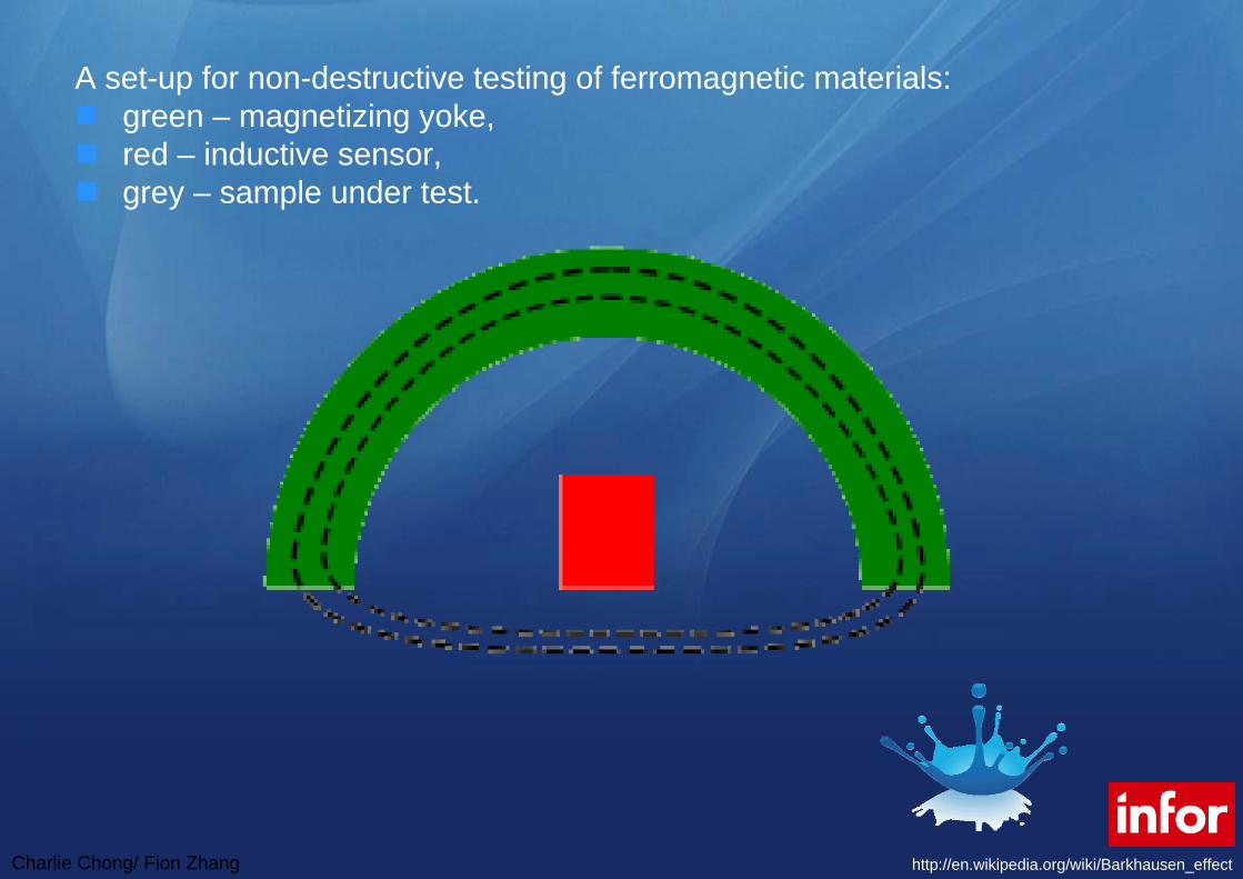
Charlie Chong Fion Zhang
Magnetic Dipole
Charlie Chong Fion Zhang
Magnetic Dipole
Charlie Chong Fion Zhang
20 Principles of Magnetic Leakage Field Testing MLFT21 Origin of Defect Leakage Fields
The origin of the flaw leakage field is illustrated in Fig 1 Figure 1(a) shows a uniformly magnetized rod which consists of a large number of elementary magnets aligned with the direction of magnetization Inside the material each magnetic pole is exactly compensated by the presence of an adjacent pole of opposite polarity and the net result is that interior poles do not contribute to the magnetic field outside the material At the surfaces however magnetic poles are uncompensated and therefore produce a magnetic field in the region surrounding the specimen This is illustrated in Fig 1(a) by flux lines connecting uncompensated elementary poles
Charlie Chong Fion Zhang
If a slot is cut in the rod as illustrated in Fig 1(b) the poles on the surface of this slot are now also uncompensated and therefore produce a localized magnetic field near the slot This additional magnetic field which is represented by the extra flux lines in Fig 1(b) is the leakage field associated with the slot Figure 1 although adequate for a qualitative understanding of the origin of leakage fields does not provide an exact quantitative description The difficulty is the assumption that the magnetization remains uniform when the flaw is introduced In general this does not happen because the presence of the flaw changes the magnetic field in the vicinity of the flaw and this in turn leads to a change in magnetization near the flaw With regard to
Fig 1 this means that the strengths and orientations of the elementary dipoles (magnets) actually vary from point to point in the vicinity of the flaw and this variation also contributes to the flaw leakage field The end result is that the accurate description of a flaw leakage field poses a difficult mathematical problem that usually requires a special-purpose computer code for its solution
Charlie Chong Fion Zhang
Fig 1 Origin of defect leakage fields (a) Magnetic flux lines of a magnet without a defect (b) Magnetic flux lines of a magnet with a surface defect Source Ref 1
Charlie Chong Fion Zhang
22 Experimental Techniques
One of the first considerations in the experimental application of magnetic leakage field methods is the generation of a suitable magnetic field within the material In some ferromagnetic materials the residual field (the field that remains after removal of an external magnetizing field) is often adequate for surface flaw detection In practice however residual magnetization is rarely used because use of an applied magnetizing field ensures that the material is in a desired magnetic state (which should be known and well characterized) and because applied fields provide more flexibility (that is one can produce a high or low flux density in the specimen as desired Experience has shown that control of the strength and direction of the magnetization can be useful in improving flaw detectability and in discriminating among different types of flaws In general the magnitude of the magnetization should be chosen to maximize the flaw leakage field with respect to other field sources that might interfere with flaw detection the optimum magnetization is usually difficult to determine in advance of a test and is often approached by trial-and-error experimentation The direction of the field should be perpendicular to the largest flaw dimension to maximize the effect of the flaw on the leakage field
Charlie Chong Fion Zhang
Keywords
The direction of the field should be perpendicular to the largest flaw dimension to maximize the effect of the flaw on the leakage field
Charlie Chong Fion Zhang
It is possible to generate a magnetic field in a specimen either directly or indirectly In direct magnetization current is passed directly through the part With the indirect approach magnetization is induced by placing the part in a magnetic field that is generated by an adjacent current conductor or permanent magnet This can be done for example by threading a conductor through a hollow part such as a tube or by passing an electric current through a cable wound around the part Methods of magnetizing a part both directly and indirectly are illustrated schematically in Fig 2
Charlie Chong Fion Zhang
Fig 2 Methods of magnetization (1) Head-shot method (b) Magnetization with prods (c) Magnetization with a central conductor (d) Longitudinal magnetization (e) Yoke magnetization
Charlie Chong Fion Zhang
The flaw leakage field can be detected with one of several types of magnetic field sensors Aside from the use of magnetic particles the sensors most often used are the inductive coil and the Hall effect device The inductive coil sensor is based on Faradays law of induction which states that the voltage induced in the coil is proportional to the number of turns in the coil multiplied by the time rate of change of the flux Ф threading the coil It follows that detection of a magnetostatic field requires that the coil be in motion so that the flux through the coil changes with time The principle is illustrated in Fig 3 in which the coil is oriented so as to sense the change in flux parallel to the surface of the specimen If the direction of coil motion is taken as x then the induced electromotive force E in volts is given by
for Ф = B∙A
Charlie Chong Fion Zhang
where N is the number of turns in the coil A is its cross-sectional area and B is the flux density in Gauss parallel to the surface of the part Thus the voltage induced in the coil is proportional to the gradient of the flux density along the direction of coil motion multiplied by the coil velocity Figure 4 shows the flux density typical of the leakage field from a slot along with the corresponding signal from a search coil oriented as in Fig 3
Charlie Chong Fion Zhang
Fig 3 Flux leakage measurement using a search coil Source
Charlie Chong Fion Zhang
Fig 4 Leakage flux and search coil signal as a function of position
Charlie Chong Fion Zhang
Unlike the inductive coil which provides a measure of the flux gradient a Hall effect sensor directly measures the component of the flux itself in the direction perpendicular to the sensitive area of the device Because the response of a Hall effect sensor does not depend on the motion of the probe it can be scanned over the surface to be inspected at any rate that is mechanically convenient In this respect the Hall device has an advantage over the coil sensor because there is no need to maintain a constant scanning speed during the inspection On the other hand Hall effect sensors are more difficult to fabricate are somewhat delicate compared to inductive coil sensors and require more complex electronics Other magnetic field sensors that are used less often in leakage field applications include the flux gate magnetometer magnetoresistive sensors magnetic resonance sensors and magnetographicsensors in which the magnetic field at the surface of a part is registered on a magnetic tape pressed onto the surface
KeywordsHall device has an advantage over the coil sensor because there is no need to maintain a constant scanning speed during the inspection
Charlie Chong Fion Zhang
23 Analysis of Leakage Field Data
In most applications of the leakage field method there is a need not only to detect the presence of a flaw but also to estimate its severity This leads to the problem of flaw characterization that is the determination of flaw dimensions from an analysis of leakage field data The most widely used method of flaw characterization is based on the assumptions that the leakage field signal amplitude is proportional to the size of the flaw (which usually means its depth into the material) and that the signal amplitude can therefore be taken as a direct measure of flaw severity In situations where all flaws have approximately the same shape and where calibration experiments show that the signal amplitude is indeed proportional to the size parameter of concern this empirical method of sizing works quite well
KeywordsThe most widely used method of flaw characterization is based on the assumptions that the leakage field signal amplitude is proportional to the size of the flaw (which usually means its depth into the material) ()
Charlie Chong Fion Zhang
There are however many situations of interest where flaw shapes vary considerably and where signal amplitude is not uniquely related to flaw depth as is the case for corrosion pits in steel tubing In addition different types of flaws such as cracks and pits can occur in the same part in which case it becomes necessary to determine the flaw types present as well as their severity
In such cases a more careful analysis of the relationship between signal and flaw characteristics is required if serious errors in flaw characterization are to be avoided One of the earliest attempts to use a theoretical model in the analysis of leakage field data was based on the analytic solution for the field perturbed by a spherical inclusion Two conclusions were drawn from this analysis First when one measures the leakage flux component normal to the surface of the part the center of the flaw is located below the scan plane at a distance equal to the peak-to-peak separation distance in the flaw signal (Fig 5) and second the peak-to-peak signal amplitude is proportional to the flaw volume A number of experimental tests of these sizing rules have confirmed the predicted relationships for nonmagnetic inclusions in steel parts
Charlie Chong Fion Zhang
Keywords
Two conclusions were drawn from this analysis
bull First when one measures the leakage flux component normal to the surface of the part the center of the flaw is located below the scan plane at a distance equal to the peak-to-peak separation distance in the flaw signal (Fig 5) and
bull Second the peak-to-peak signal amplitude is proportional to the flaw volume A number of experimental tests of these sizing rules have confirmed the predicted relationships for nonmagnetic inclusions in steel parts
peak-to-peak signal amplitude is proportional to the flaw volume
Lateral dimension
Charlie Chong Fion Zhang
Fig 5 Dependence of magnetic signal peak separation (a) on the depth of a spherical inclusion (b)
Charlie Chong Fion Zhang
Further theoretical and experimental data for spheroidal inclusions and surface pits have shown however that the simple characterization rules for spherical inclusions do not apply when the flaw shape differs significantly from the ideal sphere In such cases the signal amplitude depends on the lateral extent of the flaw and on its volume and characterization on the basis of leakage field analysis becomes much more complicated
Finally there has been at least one attempt to apply finite-element calculations of flaw leakage fields to the development of characterization rules for a more general class of flaws Hwang and Lord performed most of their computations for simple flaw shapes such as rectangular and triangular slots and inclusions and from the results devised a set of rules for estimating the depth width and angle of inclination of a flaw with respect to the surface of the part One of their applications to a flaw of complex shape is shown in Fig 6
Charlie Chong Fion Zhang
Fig 6 Characterization of a ferrite-tail type of defect The dashed line shows the flaw configuration estimated from the leakage field data
Charlie Chong Fion Zhang
The promising results obtained from the finite-element work of Hwang and Lord as well as the analytically based work on spheroidal flaws suggest that the estimation of flaw size and shape from leakage field data is feasible Another numerical method potentially applicable to flux leakage problems is the boundary integral method which may prove useful in flaw characterization Unfortunately much more work must be done on both the theoretical basis and on experimental testing before it will be possible to analyze experimental leakage field data with confidence in terms of flaw characteristics
Charlie Chong Fion Zhang
PART 2 Principles of Magnetic Characterization of Materials10 Metallurgical and Magnetic Properties
The use of magnetic measurements to monitor the metallurgical propertiesof ferromagnetic materials is based on the fact that variables such as crystallographic phase chemical composition and microstructure which determine the physical properties of materials also affect their magnetic characteristics Some parameters such as grain size and orientation dislocation density and the existence of precipitates are closely related to measurable characteristics of magnetic hysteresis that is to the behavior of the flux density B induced in a material as a function of the magnetic field strength H This relationship can be understood in principle from the physical theory of magnetic domains Magnetization in a particular direction increases as the domains aligned in that direction grow at the expense of domains aligned in other directions Factors that impede domain growth also impede dislocation motion hence the connection at a very fundamental level between magnetic and mechanical properties
Charlie Chong Fion Zhang
Keywords
Metallurgical properties
Crystallographic phase Chemical composition Grain size and orientation Dislocation density and Existence of precipitates
are closely related to measurable characteristics of magnetic hysteresis that is to the behavior of the flux density B induced in a material as a function of the magnetic field strength H
Charlie Chong Fion Zhang
Hysteresis Curves
Charlie Chong Fion Zhang
Other magnetic properties such as the saturation magnetization which is the maximum value B can achieve or the Curie temperature at which there is a transition to a nonmagnetic state are less dependent on microstructure but are sensitive to such factors as crystal structure and chemical composition Interest in the magnetic characterization of materials principally steels derives from many such relationships between measurable magneticparameters and metallurgical properties These relationships are however quite complicated in general and it is often difficult to determine how or if a particular measurement or combination of measurements can be used to determine a property of interest
Charlie Chong Fion Zhang
Nevertheless the prospect of nondestructive monitoring and quality control is an attractive one and for this reason research on magnetic materials characterization continues to be an active field It is not the purpose of this article to explore such magnetic methods in depth but simply to point out that it is an active branch of nondestructive magnetic testing The more fundamental aspects of the relationship between magnetism and metallurgy are discussed in Ref 26 and 28 Engineering considerations are reviewed in Ref 24 The proceedings of various symposia also contain several papers that provide a good overview of the current status of magnetic materials characterization
Charlie Chong Fion Zhang
Curie temperature In physics and materials science the Curie temperature (Tc) or Curie point is the temperature where a materials permanent magnetism changes to induced magnetism The force of magnetism is determined by magnetic moments The Curie temperature is the critical point where a materials intrinsic magnetic moments change direction Magnetic moments are permanent dipole moments within the atom which originate from electrons angular momentum and spin Materials have different structures of intrinsic magnetic moments that depend on temperature At a materials Curie Temperature those intrinsic magnetic moments change direction
Permanent magnetism is caused by the alignment of magnetic moments and induced magnetism is created when disordered magnetic moments are forced to align in an applied magnetic field For example the ordered magnetic moments (ferromagnetic figure 1) change and become disordered (paramagnetic figure 2) at the Curie Temperature Higher temperatures make magnets weaker as spontaneous magnetism only occurs below the Curie Temperature Magnetic susceptibility only occurs above the Curie Temperature and can be calculated from the Curie-Weiss Law which is derived from Curies Law In analogy to ferromagnetic and paramagnetic materials the Curie temperature can also be used to describe the temperature where a materials spontaneous electric polarisation changes to induced electric polarisation or the reverse upon reduction of the temperature below the Curie temperature
httpenwikipediaorgwikiCurie_temperature
Charlie Chong Fion Zhang
Curie temperature
harr ParamagneticAntiferromagneticharr ParamagneticFerrimagneticharr ParamagneticFerromagneticAbove TcBelow Tc
httpenwikipediaorgwikiCurie_temperature
Charlie Chong Fion Zhang
Ferromagnetism The magnetic moments in a ferromagnetic material The moments are ordered and of the same magnitude in the absence of an applied magnetic field
httpenwikipediaorgwikiCurie_temperature
Charlie Chong Fion Zhang
Paramagnetism The magnetic moments in a paramagnetic material The moments are disordered in the absence of an applied magnetic field and ordered in the presence of an applied magnetic field
httpenwikipediaorgwikiCurie_temperature
Charlie Chong Fion Zhang
Ferrimagnetism The magnetic moments in a ferrimagnetic material The moments are aligned oppositely and have different magnitudes due to being made up of two different ions This is in the absence of an applied magnetic field
httpenwikipediaorgwikiCurie_temperature
Charlie Chong Fion Zhang
Antiferromagnetism The magnetic moments in an antiferromagneticmaterial The moments are aligned oppositely and have the same magnitudes This is in the absence of an applied magnetic field
httpenwikipediaorgwikiCurie_temperature
Charlie Chong Fion Zhang
20 Experimental Techniques
A typical setup for measuring the B-H characteristic of a rod specimen is shown in Fig 7 The essential elements are an electromagnet for generating the magnetizing field a coil wound around the specimen for measuring the time rate of change of the magnetic flux B in the material and a magnetic field sensor in this case a Hall effect probe for measuring the magnetic field strength H parallel to the surface of the part The signal generator provides a low-frequency magnetizing field typically of the order of a few Hertz and the output of the flux measuring coil is integrated over time to give the flux density in the material In the arrangement shown in Fig 7 an additional feature is the provision for applying a tensile load to the specimen for studies of the effects of stress on the hysteresis data When using a rod specimen such as this it is important that the length-to-diameter ratio of the specimen be large so as to minimize the effects of stray fields from the ends of the rod on the measurements of B and H
Charlie Chong Fion Zhang
Fig 7 Experimental arrangement for hysteresis loop measurements
Charlie Chong Fion Zhang
Another magnetic method that uses a similar arrangement is the measurement of Barkhausen noise As the magnetic field strength H is varied at a very slow rate discontinuous jumps in the magnetization of the material can be observed during certain portions of the hysteresis cycle These jumps are associated with the sudden growth of a series of magnetic domains that have been temporarily stopped from further growth by such obstacles as grain boundaries precipitates or dislocations Barkhausen noise is therefore dependent on microstructure and can be used independently of hysteresis measurements or in conjunction with such measurements as another method of magnetic testing The experimental arrangement differs from that shown in Fig 7 in that a single sensor coil oriented to measure the flux normal to the surface of the specimen is used instead of the Hall probe and the flux winding
Charlie Chong Fion Zhang
The review articles and conference proceedings cited above contain additional detail on experimental technique and a wealth of information on the interpretation of hysteresis and Barkhausen data However it should be noted that test methods and data interpretation are often very specific to a particular class of alloy and techniques that seem to work well for one type of material may be totally inappropriate for another The analysis of magnetic characterization data is still largely empirical in nature and controlled testing of a candidate technique with the specific alloy system of interest is advisable
Charlie Chong Fion Zhang
PART 3 Application10 Flaw Detection by the Flux Leakage MethodPerhaps the most prevalent use of the flux leakage method is theinspection of ferromagnetic tubular goods such as gas pipelines down hole casing and a variety of other forms of steel piping In applications in the petroleum industry the technique is highly developed but details on inspection devices and methods of data analysis are for the most part considered proprietary by the companies that provide inspection services Still the techniques currently in use have certain features in common and these are exemplified by the typical system described below The device shown in Fig 8 is an inspection tool for large-diameter pipelines Magnetization is provided by a large electromagnet fitted with wire brushes to direct magnetic flux from the electromagnet into the pipe wall To avoid spurious signals from hard spots in the material the magnetization circuit is designed for maximum flux density in the pipe wall in an attempt to magnetically saturate the material
Charlie Chong Fion Zhang
Leakage field sensors are mounted between the pole pieces of the magnet in a circle around the axis of the device to provide as nearly as possible full coverage of the pipe wall In most such tools the sensors are the inductive coil type oriented to measure the axial component of the leakage field gradient Data are usually recorded on magnetic tape as the system is propelled down a section of pipe After the inspection the recorded signals are compared with those from calibration standards in an attempt to interpret flaw indications in terms of flaw type and size
Charlie Chong Fion Zhang
Fig 8 Typical gas pipeline inspection pig The tool consists of a drive unit an instrumentation unit and a center section with an electromagnetic and flux leakage sensors
Pipe
Sensor
Sensor
Pole
Coil
Pole
Charlie Chong Fion Zhang
In addition to systems for inspecting rotationally symmetric cylindrical parts flux leakage inspection has been applied to very irregular components such as helicopter rotor blade D-spars gear teeth and artillery projectiles Several of these special-purpose applications have involved only laboratory investigations but in some cases specialized instrumentation systems have been developed and fabricated for factory use These systems are uniquely adapted to the particular application involved and in most cases only one or at most several instrumentation systems have been built Even in the case of laboratory investigations special-purpose detection probe and magnetizing arrangements have been developed for specific applications
Charlie Chong Fion Zhang
One such system for automated thread inspection on drill pipe and collars is described The device consists of an electromagnet and an array of sensors mounted outside a nonmagnetic cone that threads onto the tool joint The assembly is driven in a helical path along the threads by a motorclutch assembly To minimize the leakage flux signal variations caused by the threads signals from the sensor array are compared differentially The system is capable of operating in a high field strength mode for the detection of cracks and corrosion pits and also in a residual field mode for the detection of other forms of damage At last report the system was undergoing field tests and was found to offer advantages in terms of ease of application and defect detection over the magnetic particle technique normally used for thread inspection
Charlie Chong Fion Zhang
The flux leakage method is also finding application in the inspection of ropes and cables made of strands of ferromagnetic material One approach is to induce magnetization in the piece by means of an encircling coil energized by a direct current (dc) With this method one measures the leakage field associated with broken strands using a Hall effect probe or an auxiliary sensor coil A complementary method with alternating current (ac) which is actually an eddy current test rather than flux leakage is to measure the ac impedance variations in an encircling coil caused by irregularities in the cross-sectional area of the specimen Haynes and Underbakke describe practical field tests of an instrumentation system that utilizes both the ac and dc methods They conclude that instrumentation capable of a combination of inspection techniques offers the best possibility of detecting both localized flaws and overall loss of cross section caused by generalized corrosion and wear They also present detailed information on the practical characteristics of a commercially available device that makes use of both the ac and dc methods
Charlie C
hong Fion Zhang
The flux leakage method is also finding application in the inspection of ropes and cables
Charlie Chong Fion Zhang
Another area in which the flux leakage method has been successfully implemented is the inspection of rolling-element antifriction bearings A schematic illustration of the method as applied to an inner bearing race is shown in Fig 9 In this application the part is magnetized by an electromagnet as indicated in Fig 9(a) The race is then rotated by a spindle and the surface is scanned with an induction coil sensor Typically the race is rotated at a surface speed of about 23 ms (75 fts) and the active portion of the raceway is inspected by incrementally indexing the sensor across the raceway Magnetizing fields are applied in the radial and circumferential orientations It has been shown that radial field inspection works best for surface flaws while circumferential field inspection shows greater sensitivity to subsurface flaws Data have been collected on a large number of bearing races to establish the correlation between leakage field signals and inclusion depths and dimensions determined by metallurgical sectioning
Charlie Chong Fion Zhang
Fig 9 Flux leakage inspection of a bearing race (a) Magnetization of inner race (b) Perturbation in the magnetic flux at the surface of the inner race (c) Probe scanning the surface
Charlie Chong Fion Zhang
Finally the flux leakage method has also been adapted to the inspection of steel reinforcement in concrete beams The basic function of the magnetic field disturbance (MFD) inspection equipment is to provide maps of the magnetic field across the bottom and sides of the beam An electromagnet on an inspection cart which is suspended on tracks below the beam provides a magnetic field that induces magnetization in permeable structures in its vicinity such as steel rebars cables and stirrups An array of Hall effect sensors distributed across the bottom and sides of the beam measures the field produced by magnetized structures within the beam If a flaw is present in one of these magnetized structures it will produce a disturbance of the normal magnetic field pattern associated with the unflawed beam Thus the idea behind the MFD system is to search the surface of the beam for field anomalies that indicate the presence of flaws in reinforcing steel within the structure
Keywordsmagnetic field disturbance (MFD)
Charlie Chong Fion Zhang
A flaw such as a broken wire in a cable or a fractured rebar produces a distinctive magnetic field anomaly that depends on the size of the discontinuity and its distance from the sensor Because the signal shape that results from such an anomaly is known flaw detection is enhanced by searching magnetic field records for specific signal shapes that is those that are characteristic of discontinuities in magnetic materials In the MFD system this is accomplished by a computer program that compares signal shapes with typical flaw signal shapes The program produces a correlation coefficient that serves as a measure of similarity of the observed signal shape to a typical flaw signal shape Flaw detection is therefore not only enhanced by signal shape discrimination but also automated by computer processing of the magnetic field data Laboratory tests have demonstrated the ability of the system to detect fracture in steel rebars and cables in a large pre-stressed concrete structure Also planned are field tests of the equipment in the inspection of bridge decks for reinforcement corrosion damage
Charlie Chong Fion Zhang
Steel rebars and cables in a large pre-stressed concrete structure
Charlie Chong Fion Zhang
20 Nondestructive Characterization of Materials Only two examples of magnetic methods for monitoring materialproperties are given because the examples chosen should suffice to illustrate the types of tests that might be employed Measurements of magnetic characteristics can however provide a wealth of data and various features of such data can yield information on different material properties For example it has been demonstrated that different features of magnetic hysteresis data can be interpreted in terms of heat treatment and microstructure plastic deformation residual stress and mechanical hardness An example of the effects of mechanical hardness on hysteresis data is shown in Fig 10 These data were obtained in the absence of applied tensile stress with the experimental arrangement shown in Fig 7 Specimens of different hardness were prepared by tempering at different temperatures The grain size (ASTM No 7) was the same for all four specimens used in these tests Other data showed however that grain size has little effect on hysteretic behavior for the classes of alloys studied
Charlie Chong Fion Zhang
Fig 10 Effect of mechanical hardness on hysteresis loop data (a) AISI 410 stainless steel (b) SAE 4340 steel
Charlie Chong Fion Zhang
The main point illustrated in Fig 10 is that the mechanically harder specimens of the same alloy are also harder to magnetize that is the flux density B obtained at a large value of H is smaller for mechanically harder specimens than for softer specimens For one alloy AISI 410 stainless steel the hysteresis loop intersects the B = 0 axis at larger values of H for the harder specimen than for the softer specimen that is the coercive force is greater for the harder material However for the other material SAE 4340 steel the coercive force does not change with hardness This suggests that for the two alloys considered here the saturation flux density provides a more reliable measure of hardness than the coercive force Mayos et al used two quite different techniques to measure the depth of surface decarburization of steels One method was a variation of a standard eddy current test with the difference from standard practice being that eddy current probe response was measured in the presence of a low-frequency (~01 Hz) magnetic field This arrangement provides a measure of incremental permeability that is the magnetic permeability corresponding to changes in the applied field about some quasistatic value The second method employed was Barkhausen noise analysis
Charlie Chong Fion Zhang
Keywords
For one alloy AISI 410 stainless steel the hysteresis loop intersects the B = 0 axis at larger values of H for the harder specimen than for the softer specimen that is the coercive force is greater for the harder material However for the other material SAE 4340 steel the coercive force does not change with hardness
This suggests that for the two alloys considered here the saturation flux density provides a more reliable measure of hardness than the coercive force
Charlie Chong Fion Zhang
Depth of decarburization was analyzed by varying the frequency of the excitation field thus changing the skin depth in the material Experiments were performed with both artificial samples containing two layers of different carbon content and industrial samples in which carbon concentration varied smoothly with distance from the surface It was shown that certain features of both Barkhausen noise and incremental permeability data can be correlated with depth of decarburization The Barkhausen noise method showed a somewhat stronger sensitivity to depth but was useful over a smaller range of depths than the incremental permeability method It can be concluded that both methods are useful with the optimum choice depending on accuracy requirements and the expected depth of decarburization
Charlie Chong Fion Zhang
Offshore Structures
Charlie Chong Fion Zhang
Offshore Structures
Charlie Chong Fion Zhang
VLCC
Charlie Chong Fion Zhang
Offshore Structures
Charlie Chong Fion Zhang
Offshore Structures
Charlie Chong Fion Zhang
Offshore Structures
Charlie Chong Fion Zhang
Pipeline amp Piping
Charlie Chong Fion Zhang
Pipeline amp Piping
Charlie Chong Fion Zhang
Charlie Chong Fion Zhang
ass
- Electromagnetic Testing MFLT ECT MicrowaveRFT Chapter 9B ndash漏磁检测 More Reading on Magnetic Field Leakage Testing MFLT
- PART 1 Magnetic Field Testing
-
- 10 Introduction
- 20 Principles of Magnetic Leakage Field Testing MLFT
-
- PART 2 Principles of Magnetic Characterization of Materials
-
- 10 Metallurgical and Magnetic Properties
- 20 Experimental Techniques
-
- PART 3 Application
-
- 10 Flaw Detection by the Flux Leakage Method
- 20 Nondestructive Characterization of Materials
-
- Good Luck
-

Charlie Chong Fion Zhang
Magnetic Dipole
Charlie Chong Fion Zhang
20 Principles of Magnetic Leakage Field Testing MLFT21 Origin of Defect Leakage Fields
The origin of the flaw leakage field is illustrated in Fig 1 Figure 1(a) shows a uniformly magnetized rod which consists of a large number of elementary magnets aligned with the direction of magnetization Inside the material each magnetic pole is exactly compensated by the presence of an adjacent pole of opposite polarity and the net result is that interior poles do not contribute to the magnetic field outside the material At the surfaces however magnetic poles are uncompensated and therefore produce a magnetic field in the region surrounding the specimen This is illustrated in Fig 1(a) by flux lines connecting uncompensated elementary poles
Charlie Chong Fion Zhang
If a slot is cut in the rod as illustrated in Fig 1(b) the poles on the surface of this slot are now also uncompensated and therefore produce a localized magnetic field near the slot This additional magnetic field which is represented by the extra flux lines in Fig 1(b) is the leakage field associated with the slot Figure 1 although adequate for a qualitative understanding of the origin of leakage fields does not provide an exact quantitative description The difficulty is the assumption that the magnetization remains uniform when the flaw is introduced In general this does not happen because the presence of the flaw changes the magnetic field in the vicinity of the flaw and this in turn leads to a change in magnetization near the flaw With regard to
Fig 1 this means that the strengths and orientations of the elementary dipoles (magnets) actually vary from point to point in the vicinity of the flaw and this variation also contributes to the flaw leakage field The end result is that the accurate description of a flaw leakage field poses a difficult mathematical problem that usually requires a special-purpose computer code for its solution
Charlie Chong Fion Zhang
Fig 1 Origin of defect leakage fields (a) Magnetic flux lines of a magnet without a defect (b) Magnetic flux lines of a magnet with a surface defect Source Ref 1
Charlie Chong Fion Zhang
22 Experimental Techniques
One of the first considerations in the experimental application of magnetic leakage field methods is the generation of a suitable magnetic field within the material In some ferromagnetic materials the residual field (the field that remains after removal of an external magnetizing field) is often adequate for surface flaw detection In practice however residual magnetization is rarely used because use of an applied magnetizing field ensures that the material is in a desired magnetic state (which should be known and well characterized) and because applied fields provide more flexibility (that is one can produce a high or low flux density in the specimen as desired Experience has shown that control of the strength and direction of the magnetization can be useful in improving flaw detectability and in discriminating among different types of flaws In general the magnitude of the magnetization should be chosen to maximize the flaw leakage field with respect to other field sources that might interfere with flaw detection the optimum magnetization is usually difficult to determine in advance of a test and is often approached by trial-and-error experimentation The direction of the field should be perpendicular to the largest flaw dimension to maximize the effect of the flaw on the leakage field
Charlie Chong Fion Zhang
Keywords
The direction of the field should be perpendicular to the largest flaw dimension to maximize the effect of the flaw on the leakage field
Charlie Chong Fion Zhang
It is possible to generate a magnetic field in a specimen either directly or indirectly In direct magnetization current is passed directly through the part With the indirect approach magnetization is induced by placing the part in a magnetic field that is generated by an adjacent current conductor or permanent magnet This can be done for example by threading a conductor through a hollow part such as a tube or by passing an electric current through a cable wound around the part Methods of magnetizing a part both directly and indirectly are illustrated schematically in Fig 2
Charlie Chong Fion Zhang
Fig 2 Methods of magnetization (1) Head-shot method (b) Magnetization with prods (c) Magnetization with a central conductor (d) Longitudinal magnetization (e) Yoke magnetization
Charlie Chong Fion Zhang
The flaw leakage field can be detected with one of several types of magnetic field sensors Aside from the use of magnetic particles the sensors most often used are the inductive coil and the Hall effect device The inductive coil sensor is based on Faradays law of induction which states that the voltage induced in the coil is proportional to the number of turns in the coil multiplied by the time rate of change of the flux Ф threading the coil It follows that detection of a magnetostatic field requires that the coil be in motion so that the flux through the coil changes with time The principle is illustrated in Fig 3 in which the coil is oriented so as to sense the change in flux parallel to the surface of the specimen If the direction of coil motion is taken as x then the induced electromotive force E in volts is given by
for Ф = B∙A
Charlie Chong Fion Zhang
where N is the number of turns in the coil A is its cross-sectional area and B is the flux density in Gauss parallel to the surface of the part Thus the voltage induced in the coil is proportional to the gradient of the flux density along the direction of coil motion multiplied by the coil velocity Figure 4 shows the flux density typical of the leakage field from a slot along with the corresponding signal from a search coil oriented as in Fig 3
Charlie Chong Fion Zhang
Fig 3 Flux leakage measurement using a search coil Source
Charlie Chong Fion Zhang
Fig 4 Leakage flux and search coil signal as a function of position
Charlie Chong Fion Zhang
Unlike the inductive coil which provides a measure of the flux gradient a Hall effect sensor directly measures the component of the flux itself in the direction perpendicular to the sensitive area of the device Because the response of a Hall effect sensor does not depend on the motion of the probe it can be scanned over the surface to be inspected at any rate that is mechanically convenient In this respect the Hall device has an advantage over the coil sensor because there is no need to maintain a constant scanning speed during the inspection On the other hand Hall effect sensors are more difficult to fabricate are somewhat delicate compared to inductive coil sensors and require more complex electronics Other magnetic field sensors that are used less often in leakage field applications include the flux gate magnetometer magnetoresistive sensors magnetic resonance sensors and magnetographicsensors in which the magnetic field at the surface of a part is registered on a magnetic tape pressed onto the surface
KeywordsHall device has an advantage over the coil sensor because there is no need to maintain a constant scanning speed during the inspection
Charlie Chong Fion Zhang
23 Analysis of Leakage Field Data
In most applications of the leakage field method there is a need not only to detect the presence of a flaw but also to estimate its severity This leads to the problem of flaw characterization that is the determination of flaw dimensions from an analysis of leakage field data The most widely used method of flaw characterization is based on the assumptions that the leakage field signal amplitude is proportional to the size of the flaw (which usually means its depth into the material) and that the signal amplitude can therefore be taken as a direct measure of flaw severity In situations where all flaws have approximately the same shape and where calibration experiments show that the signal amplitude is indeed proportional to the size parameter of concern this empirical method of sizing works quite well
KeywordsThe most widely used method of flaw characterization is based on the assumptions that the leakage field signal amplitude is proportional to the size of the flaw (which usually means its depth into the material) ()
Charlie Chong Fion Zhang
There are however many situations of interest where flaw shapes vary considerably and where signal amplitude is not uniquely related to flaw depth as is the case for corrosion pits in steel tubing In addition different types of flaws such as cracks and pits can occur in the same part in which case it becomes necessary to determine the flaw types present as well as their severity
In such cases a more careful analysis of the relationship between signal and flaw characteristics is required if serious errors in flaw characterization are to be avoided One of the earliest attempts to use a theoretical model in the analysis of leakage field data was based on the analytic solution for the field perturbed by a spherical inclusion Two conclusions were drawn from this analysis First when one measures the leakage flux component normal to the surface of the part the center of the flaw is located below the scan plane at a distance equal to the peak-to-peak separation distance in the flaw signal (Fig 5) and second the peak-to-peak signal amplitude is proportional to the flaw volume A number of experimental tests of these sizing rules have confirmed the predicted relationships for nonmagnetic inclusions in steel parts
Charlie Chong Fion Zhang
Keywords
Two conclusions were drawn from this analysis
bull First when one measures the leakage flux component normal to the surface of the part the center of the flaw is located below the scan plane at a distance equal to the peak-to-peak separation distance in the flaw signal (Fig 5) and
bull Second the peak-to-peak signal amplitude is proportional to the flaw volume A number of experimental tests of these sizing rules have confirmed the predicted relationships for nonmagnetic inclusions in steel parts
peak-to-peak signal amplitude is proportional to the flaw volume
Lateral dimension
Charlie Chong Fion Zhang
Fig 5 Dependence of magnetic signal peak separation (a) on the depth of a spherical inclusion (b)
Charlie Chong Fion Zhang
Further theoretical and experimental data for spheroidal inclusions and surface pits have shown however that the simple characterization rules for spherical inclusions do not apply when the flaw shape differs significantly from the ideal sphere In such cases the signal amplitude depends on the lateral extent of the flaw and on its volume and characterization on the basis of leakage field analysis becomes much more complicated
Finally there has been at least one attempt to apply finite-element calculations of flaw leakage fields to the development of characterization rules for a more general class of flaws Hwang and Lord performed most of their computations for simple flaw shapes such as rectangular and triangular slots and inclusions and from the results devised a set of rules for estimating the depth width and angle of inclination of a flaw with respect to the surface of the part One of their applications to a flaw of complex shape is shown in Fig 6
Charlie Chong Fion Zhang
Fig 6 Characterization of a ferrite-tail type of defect The dashed line shows the flaw configuration estimated from the leakage field data
Charlie Chong Fion Zhang
The promising results obtained from the finite-element work of Hwang and Lord as well as the analytically based work on spheroidal flaws suggest that the estimation of flaw size and shape from leakage field data is feasible Another numerical method potentially applicable to flux leakage problems is the boundary integral method which may prove useful in flaw characterization Unfortunately much more work must be done on both the theoretical basis and on experimental testing before it will be possible to analyze experimental leakage field data with confidence in terms of flaw characteristics
Charlie Chong Fion Zhang
PART 2 Principles of Magnetic Characterization of Materials10 Metallurgical and Magnetic Properties
The use of magnetic measurements to monitor the metallurgical propertiesof ferromagnetic materials is based on the fact that variables such as crystallographic phase chemical composition and microstructure which determine the physical properties of materials also affect their magnetic characteristics Some parameters such as grain size and orientation dislocation density and the existence of precipitates are closely related to measurable characteristics of magnetic hysteresis that is to the behavior of the flux density B induced in a material as a function of the magnetic field strength H This relationship can be understood in principle from the physical theory of magnetic domains Magnetization in a particular direction increases as the domains aligned in that direction grow at the expense of domains aligned in other directions Factors that impede domain growth also impede dislocation motion hence the connection at a very fundamental level between magnetic and mechanical properties
Charlie Chong Fion Zhang
Keywords
Metallurgical properties
Crystallographic phase Chemical composition Grain size and orientation Dislocation density and Existence of precipitates
are closely related to measurable characteristics of magnetic hysteresis that is to the behavior of the flux density B induced in a material as a function of the magnetic field strength H
Charlie Chong Fion Zhang
Hysteresis Curves
Charlie Chong Fion Zhang
Other magnetic properties such as the saturation magnetization which is the maximum value B can achieve or the Curie temperature at which there is a transition to a nonmagnetic state are less dependent on microstructure but are sensitive to such factors as crystal structure and chemical composition Interest in the magnetic characterization of materials principally steels derives from many such relationships between measurable magneticparameters and metallurgical properties These relationships are however quite complicated in general and it is often difficult to determine how or if a particular measurement or combination of measurements can be used to determine a property of interest
Charlie Chong Fion Zhang
Nevertheless the prospect of nondestructive monitoring and quality control is an attractive one and for this reason research on magnetic materials characterization continues to be an active field It is not the purpose of this article to explore such magnetic methods in depth but simply to point out that it is an active branch of nondestructive magnetic testing The more fundamental aspects of the relationship between magnetism and metallurgy are discussed in Ref 26 and 28 Engineering considerations are reviewed in Ref 24 The proceedings of various symposia also contain several papers that provide a good overview of the current status of magnetic materials characterization
Charlie Chong Fion Zhang
Curie temperature In physics and materials science the Curie temperature (Tc) or Curie point is the temperature where a materials permanent magnetism changes to induced magnetism The force of magnetism is determined by magnetic moments The Curie temperature is the critical point where a materials intrinsic magnetic moments change direction Magnetic moments are permanent dipole moments within the atom which originate from electrons angular momentum and spin Materials have different structures of intrinsic magnetic moments that depend on temperature At a materials Curie Temperature those intrinsic magnetic moments change direction
Permanent magnetism is caused by the alignment of magnetic moments and induced magnetism is created when disordered magnetic moments are forced to align in an applied magnetic field For example the ordered magnetic moments (ferromagnetic figure 1) change and become disordered (paramagnetic figure 2) at the Curie Temperature Higher temperatures make magnets weaker as spontaneous magnetism only occurs below the Curie Temperature Magnetic susceptibility only occurs above the Curie Temperature and can be calculated from the Curie-Weiss Law which is derived from Curies Law In analogy to ferromagnetic and paramagnetic materials the Curie temperature can also be used to describe the temperature where a materials spontaneous electric polarisation changes to induced electric polarisation or the reverse upon reduction of the temperature below the Curie temperature
httpenwikipediaorgwikiCurie_temperature
Charlie Chong Fion Zhang
Curie temperature
harr ParamagneticAntiferromagneticharr ParamagneticFerrimagneticharr ParamagneticFerromagneticAbove TcBelow Tc
httpenwikipediaorgwikiCurie_temperature
Charlie Chong Fion Zhang
Ferromagnetism The magnetic moments in a ferromagnetic material The moments are ordered and of the same magnitude in the absence of an applied magnetic field
httpenwikipediaorgwikiCurie_temperature
Charlie Chong Fion Zhang
Paramagnetism The magnetic moments in a paramagnetic material The moments are disordered in the absence of an applied magnetic field and ordered in the presence of an applied magnetic field
httpenwikipediaorgwikiCurie_temperature
Charlie Chong Fion Zhang
Ferrimagnetism The magnetic moments in a ferrimagnetic material The moments are aligned oppositely and have different magnitudes due to being made up of two different ions This is in the absence of an applied magnetic field
httpenwikipediaorgwikiCurie_temperature
Charlie Chong Fion Zhang
Antiferromagnetism The magnetic moments in an antiferromagneticmaterial The moments are aligned oppositely and have the same magnitudes This is in the absence of an applied magnetic field
httpenwikipediaorgwikiCurie_temperature
Charlie Chong Fion Zhang
20 Experimental Techniques
A typical setup for measuring the B-H characteristic of a rod specimen is shown in Fig 7 The essential elements are an electromagnet for generating the magnetizing field a coil wound around the specimen for measuring the time rate of change of the magnetic flux B in the material and a magnetic field sensor in this case a Hall effect probe for measuring the magnetic field strength H parallel to the surface of the part The signal generator provides a low-frequency magnetizing field typically of the order of a few Hertz and the output of the flux measuring coil is integrated over time to give the flux density in the material In the arrangement shown in Fig 7 an additional feature is the provision for applying a tensile load to the specimen for studies of the effects of stress on the hysteresis data When using a rod specimen such as this it is important that the length-to-diameter ratio of the specimen be large so as to minimize the effects of stray fields from the ends of the rod on the measurements of B and H
Charlie Chong Fion Zhang
Fig 7 Experimental arrangement for hysteresis loop measurements
Charlie Chong Fion Zhang
Another magnetic method that uses a similar arrangement is the measurement of Barkhausen noise As the magnetic field strength H is varied at a very slow rate discontinuous jumps in the magnetization of the material can be observed during certain portions of the hysteresis cycle These jumps are associated with the sudden growth of a series of magnetic domains that have been temporarily stopped from further growth by such obstacles as grain boundaries precipitates or dislocations Barkhausen noise is therefore dependent on microstructure and can be used independently of hysteresis measurements or in conjunction with such measurements as another method of magnetic testing The experimental arrangement differs from that shown in Fig 7 in that a single sensor coil oriented to measure the flux normal to the surface of the specimen is used instead of the Hall probe and the flux winding
Charlie Chong Fion Zhang
The review articles and conference proceedings cited above contain additional detail on experimental technique and a wealth of information on the interpretation of hysteresis and Barkhausen data However it should be noted that test methods and data interpretation are often very specific to a particular class of alloy and techniques that seem to work well for one type of material may be totally inappropriate for another The analysis of magnetic characterization data is still largely empirical in nature and controlled testing of a candidate technique with the specific alloy system of interest is advisable
Charlie Chong Fion Zhang
PART 3 Application10 Flaw Detection by the Flux Leakage MethodPerhaps the most prevalent use of the flux leakage method is theinspection of ferromagnetic tubular goods such as gas pipelines down hole casing and a variety of other forms of steel piping In applications in the petroleum industry the technique is highly developed but details on inspection devices and methods of data analysis are for the most part considered proprietary by the companies that provide inspection services Still the techniques currently in use have certain features in common and these are exemplified by the typical system described below The device shown in Fig 8 is an inspection tool for large-diameter pipelines Magnetization is provided by a large electromagnet fitted with wire brushes to direct magnetic flux from the electromagnet into the pipe wall To avoid spurious signals from hard spots in the material the magnetization circuit is designed for maximum flux density in the pipe wall in an attempt to magnetically saturate the material
Charlie Chong Fion Zhang
Leakage field sensors are mounted between the pole pieces of the magnet in a circle around the axis of the device to provide as nearly as possible full coverage of the pipe wall In most such tools the sensors are the inductive coil type oriented to measure the axial component of the leakage field gradient Data are usually recorded on magnetic tape as the system is propelled down a section of pipe After the inspection the recorded signals are compared with those from calibration standards in an attempt to interpret flaw indications in terms of flaw type and size
Charlie Chong Fion Zhang
Fig 8 Typical gas pipeline inspection pig The tool consists of a drive unit an instrumentation unit and a center section with an electromagnetic and flux leakage sensors
Pipe
Sensor
Sensor
Pole
Coil
Pole
Charlie Chong Fion Zhang
In addition to systems for inspecting rotationally symmetric cylindrical parts flux leakage inspection has been applied to very irregular components such as helicopter rotor blade D-spars gear teeth and artillery projectiles Several of these special-purpose applications have involved only laboratory investigations but in some cases specialized instrumentation systems have been developed and fabricated for factory use These systems are uniquely adapted to the particular application involved and in most cases only one or at most several instrumentation systems have been built Even in the case of laboratory investigations special-purpose detection probe and magnetizing arrangements have been developed for specific applications
Charlie Chong Fion Zhang
One such system for automated thread inspection on drill pipe and collars is described The device consists of an electromagnet and an array of sensors mounted outside a nonmagnetic cone that threads onto the tool joint The assembly is driven in a helical path along the threads by a motorclutch assembly To minimize the leakage flux signal variations caused by the threads signals from the sensor array are compared differentially The system is capable of operating in a high field strength mode for the detection of cracks and corrosion pits and also in a residual field mode for the detection of other forms of damage At last report the system was undergoing field tests and was found to offer advantages in terms of ease of application and defect detection over the magnetic particle technique normally used for thread inspection
Charlie Chong Fion Zhang
The flux leakage method is also finding application in the inspection of ropes and cables made of strands of ferromagnetic material One approach is to induce magnetization in the piece by means of an encircling coil energized by a direct current (dc) With this method one measures the leakage field associated with broken strands using a Hall effect probe or an auxiliary sensor coil A complementary method with alternating current (ac) which is actually an eddy current test rather than flux leakage is to measure the ac impedance variations in an encircling coil caused by irregularities in the cross-sectional area of the specimen Haynes and Underbakke describe practical field tests of an instrumentation system that utilizes both the ac and dc methods They conclude that instrumentation capable of a combination of inspection techniques offers the best possibility of detecting both localized flaws and overall loss of cross section caused by generalized corrosion and wear They also present detailed information on the practical characteristics of a commercially available device that makes use of both the ac and dc methods
Charlie C
hong Fion Zhang
The flux leakage method is also finding application in the inspection of ropes and cables
Charlie Chong Fion Zhang
Another area in which the flux leakage method has been successfully implemented is the inspection of rolling-element antifriction bearings A schematic illustration of the method as applied to an inner bearing race is shown in Fig 9 In this application the part is magnetized by an electromagnet as indicated in Fig 9(a) The race is then rotated by a spindle and the surface is scanned with an induction coil sensor Typically the race is rotated at a surface speed of about 23 ms (75 fts) and the active portion of the raceway is inspected by incrementally indexing the sensor across the raceway Magnetizing fields are applied in the radial and circumferential orientations It has been shown that radial field inspection works best for surface flaws while circumferential field inspection shows greater sensitivity to subsurface flaws Data have been collected on a large number of bearing races to establish the correlation between leakage field signals and inclusion depths and dimensions determined by metallurgical sectioning
Charlie Chong Fion Zhang
Fig 9 Flux leakage inspection of a bearing race (a) Magnetization of inner race (b) Perturbation in the magnetic flux at the surface of the inner race (c) Probe scanning the surface
Charlie Chong Fion Zhang
Finally the flux leakage method has also been adapted to the inspection of steel reinforcement in concrete beams The basic function of the magnetic field disturbance (MFD) inspection equipment is to provide maps of the magnetic field across the bottom and sides of the beam An electromagnet on an inspection cart which is suspended on tracks below the beam provides a magnetic field that induces magnetization in permeable structures in its vicinity such as steel rebars cables and stirrups An array of Hall effect sensors distributed across the bottom and sides of the beam measures the field produced by magnetized structures within the beam If a flaw is present in one of these magnetized structures it will produce a disturbance of the normal magnetic field pattern associated with the unflawed beam Thus the idea behind the MFD system is to search the surface of the beam for field anomalies that indicate the presence of flaws in reinforcing steel within the structure
Keywordsmagnetic field disturbance (MFD)
Charlie Chong Fion Zhang
A flaw such as a broken wire in a cable or a fractured rebar produces a distinctive magnetic field anomaly that depends on the size of the discontinuity and its distance from the sensor Because the signal shape that results from such an anomaly is known flaw detection is enhanced by searching magnetic field records for specific signal shapes that is those that are characteristic of discontinuities in magnetic materials In the MFD system this is accomplished by a computer program that compares signal shapes with typical flaw signal shapes The program produces a correlation coefficient that serves as a measure of similarity of the observed signal shape to a typical flaw signal shape Flaw detection is therefore not only enhanced by signal shape discrimination but also automated by computer processing of the magnetic field data Laboratory tests have demonstrated the ability of the system to detect fracture in steel rebars and cables in a large pre-stressed concrete structure Also planned are field tests of the equipment in the inspection of bridge decks for reinforcement corrosion damage
Charlie Chong Fion Zhang
Steel rebars and cables in a large pre-stressed concrete structure
Charlie Chong Fion Zhang
20 Nondestructive Characterization of Materials Only two examples of magnetic methods for monitoring materialproperties are given because the examples chosen should suffice to illustrate the types of tests that might be employed Measurements of magnetic characteristics can however provide a wealth of data and various features of such data can yield information on different material properties For example it has been demonstrated that different features of magnetic hysteresis data can be interpreted in terms of heat treatment and microstructure plastic deformation residual stress and mechanical hardness An example of the effects of mechanical hardness on hysteresis data is shown in Fig 10 These data were obtained in the absence of applied tensile stress with the experimental arrangement shown in Fig 7 Specimens of different hardness were prepared by tempering at different temperatures The grain size (ASTM No 7) was the same for all four specimens used in these tests Other data showed however that grain size has little effect on hysteretic behavior for the classes of alloys studied
Charlie Chong Fion Zhang
Fig 10 Effect of mechanical hardness on hysteresis loop data (a) AISI 410 stainless steel (b) SAE 4340 steel
Charlie Chong Fion Zhang
The main point illustrated in Fig 10 is that the mechanically harder specimens of the same alloy are also harder to magnetize that is the flux density B obtained at a large value of H is smaller for mechanically harder specimens than for softer specimens For one alloy AISI 410 stainless steel the hysteresis loop intersects the B = 0 axis at larger values of H for the harder specimen than for the softer specimen that is the coercive force is greater for the harder material However for the other material SAE 4340 steel the coercive force does not change with hardness This suggests that for the two alloys considered here the saturation flux density provides a more reliable measure of hardness than the coercive force Mayos et al used two quite different techniques to measure the depth of surface decarburization of steels One method was a variation of a standard eddy current test with the difference from standard practice being that eddy current probe response was measured in the presence of a low-frequency (~01 Hz) magnetic field This arrangement provides a measure of incremental permeability that is the magnetic permeability corresponding to changes in the applied field about some quasistatic value The second method employed was Barkhausen noise analysis
Charlie Chong Fion Zhang
Keywords
For one alloy AISI 410 stainless steel the hysteresis loop intersects the B = 0 axis at larger values of H for the harder specimen than for the softer specimen that is the coercive force is greater for the harder material However for the other material SAE 4340 steel the coercive force does not change with hardness
This suggests that for the two alloys considered here the saturation flux density provides a more reliable measure of hardness than the coercive force
Charlie Chong Fion Zhang
Depth of decarburization was analyzed by varying the frequency of the excitation field thus changing the skin depth in the material Experiments were performed with both artificial samples containing two layers of different carbon content and industrial samples in which carbon concentration varied smoothly with distance from the surface It was shown that certain features of both Barkhausen noise and incremental permeability data can be correlated with depth of decarburization The Barkhausen noise method showed a somewhat stronger sensitivity to depth but was useful over a smaller range of depths than the incremental permeability method It can be concluded that both methods are useful with the optimum choice depending on accuracy requirements and the expected depth of decarburization
Charlie Chong Fion Zhang
Offshore Structures
Charlie Chong Fion Zhang
Offshore Structures
Charlie Chong Fion Zhang
VLCC
Charlie Chong Fion Zhang
Offshore Structures
Charlie Chong Fion Zhang
Offshore Structures
Charlie Chong Fion Zhang
Offshore Structures
Charlie Chong Fion Zhang
Pipeline amp Piping
Charlie Chong Fion Zhang
Pipeline amp Piping
Charlie Chong Fion Zhang
Charlie Chong Fion Zhang
ass
- Electromagnetic Testing MFLT ECT MicrowaveRFT Chapter 9B ndash漏磁检测 More Reading on Magnetic Field Leakage Testing MFLT
- PART 1 Magnetic Field Testing
-
- 10 Introduction
- 20 Principles of Magnetic Leakage Field Testing MLFT
-
- PART 2 Principles of Magnetic Characterization of Materials
-
- 10 Metallurgical and Magnetic Properties
- 20 Experimental Techniques
-
- PART 3 Application
-
- 10 Flaw Detection by the Flux Leakage Method
- 20 Nondestructive Characterization of Materials
-
- Good Luck
-

Charlie Chong Fion Zhang
20 Principles of Magnetic Leakage Field Testing MLFT21 Origin of Defect Leakage Fields
The origin of the flaw leakage field is illustrated in Fig 1 Figure 1(a) shows a uniformly magnetized rod which consists of a large number of elementary magnets aligned with the direction of magnetization Inside the material each magnetic pole is exactly compensated by the presence of an adjacent pole of opposite polarity and the net result is that interior poles do not contribute to the magnetic field outside the material At the surfaces however magnetic poles are uncompensated and therefore produce a magnetic field in the region surrounding the specimen This is illustrated in Fig 1(a) by flux lines connecting uncompensated elementary poles
Charlie Chong Fion Zhang
If a slot is cut in the rod as illustrated in Fig 1(b) the poles on the surface of this slot are now also uncompensated and therefore produce a localized magnetic field near the slot This additional magnetic field which is represented by the extra flux lines in Fig 1(b) is the leakage field associated with the slot Figure 1 although adequate for a qualitative understanding of the origin of leakage fields does not provide an exact quantitative description The difficulty is the assumption that the magnetization remains uniform when the flaw is introduced In general this does not happen because the presence of the flaw changes the magnetic field in the vicinity of the flaw and this in turn leads to a change in magnetization near the flaw With regard to
Fig 1 this means that the strengths and orientations of the elementary dipoles (magnets) actually vary from point to point in the vicinity of the flaw and this variation also contributes to the flaw leakage field The end result is that the accurate description of a flaw leakage field poses a difficult mathematical problem that usually requires a special-purpose computer code for its solution
Charlie Chong Fion Zhang
Fig 1 Origin of defect leakage fields (a) Magnetic flux lines of a magnet without a defect (b) Magnetic flux lines of a magnet with a surface defect Source Ref 1
Charlie Chong Fion Zhang
22 Experimental Techniques
One of the first considerations in the experimental application of magnetic leakage field methods is the generation of a suitable magnetic field within the material In some ferromagnetic materials the residual field (the field that remains after removal of an external magnetizing field) is often adequate for surface flaw detection In practice however residual magnetization is rarely used because use of an applied magnetizing field ensures that the material is in a desired magnetic state (which should be known and well characterized) and because applied fields provide more flexibility (that is one can produce a high or low flux density in the specimen as desired Experience has shown that control of the strength and direction of the magnetization can be useful in improving flaw detectability and in discriminating among different types of flaws In general the magnitude of the magnetization should be chosen to maximize the flaw leakage field with respect to other field sources that might interfere with flaw detection the optimum magnetization is usually difficult to determine in advance of a test and is often approached by trial-and-error experimentation The direction of the field should be perpendicular to the largest flaw dimension to maximize the effect of the flaw on the leakage field
Charlie Chong Fion Zhang
Keywords
The direction of the field should be perpendicular to the largest flaw dimension to maximize the effect of the flaw on the leakage field
Charlie Chong Fion Zhang
It is possible to generate a magnetic field in a specimen either directly or indirectly In direct magnetization current is passed directly through the part With the indirect approach magnetization is induced by placing the part in a magnetic field that is generated by an adjacent current conductor or permanent magnet This can be done for example by threading a conductor through a hollow part such as a tube or by passing an electric current through a cable wound around the part Methods of magnetizing a part both directly and indirectly are illustrated schematically in Fig 2
Charlie Chong Fion Zhang
Fig 2 Methods of magnetization (1) Head-shot method (b) Magnetization with prods (c) Magnetization with a central conductor (d) Longitudinal magnetization (e) Yoke magnetization
Charlie Chong Fion Zhang
The flaw leakage field can be detected with one of several types of magnetic field sensors Aside from the use of magnetic particles the sensors most often used are the inductive coil and the Hall effect device The inductive coil sensor is based on Faradays law of induction which states that the voltage induced in the coil is proportional to the number of turns in the coil multiplied by the time rate of change of the flux Ф threading the coil It follows that detection of a magnetostatic field requires that the coil be in motion so that the flux through the coil changes with time The principle is illustrated in Fig 3 in which the coil is oriented so as to sense the change in flux parallel to the surface of the specimen If the direction of coil motion is taken as x then the induced electromotive force E in volts is given by
for Ф = B∙A
Charlie Chong Fion Zhang
where N is the number of turns in the coil A is its cross-sectional area and B is the flux density in Gauss parallel to the surface of the part Thus the voltage induced in the coil is proportional to the gradient of the flux density along the direction of coil motion multiplied by the coil velocity Figure 4 shows the flux density typical of the leakage field from a slot along with the corresponding signal from a search coil oriented as in Fig 3
Charlie Chong Fion Zhang
Fig 3 Flux leakage measurement using a search coil Source
Charlie Chong Fion Zhang
Fig 4 Leakage flux and search coil signal as a function of position
Charlie Chong Fion Zhang
Unlike the inductive coil which provides a measure of the flux gradient a Hall effect sensor directly measures the component of the flux itself in the direction perpendicular to the sensitive area of the device Because the response of a Hall effect sensor does not depend on the motion of the probe it can be scanned over the surface to be inspected at any rate that is mechanically convenient In this respect the Hall device has an advantage over the coil sensor because there is no need to maintain a constant scanning speed during the inspection On the other hand Hall effect sensors are more difficult to fabricate are somewhat delicate compared to inductive coil sensors and require more complex electronics Other magnetic field sensors that are used less often in leakage field applications include the flux gate magnetometer magnetoresistive sensors magnetic resonance sensors and magnetographicsensors in which the magnetic field at the surface of a part is registered on a magnetic tape pressed onto the surface
KeywordsHall device has an advantage over the coil sensor because there is no need to maintain a constant scanning speed during the inspection
Charlie Chong Fion Zhang
23 Analysis of Leakage Field Data
In most applications of the leakage field method there is a need not only to detect the presence of a flaw but also to estimate its severity This leads to the problem of flaw characterization that is the determination of flaw dimensions from an analysis of leakage field data The most widely used method of flaw characterization is based on the assumptions that the leakage field signal amplitude is proportional to the size of the flaw (which usually means its depth into the material) and that the signal amplitude can therefore be taken as a direct measure of flaw severity In situations where all flaws have approximately the same shape and where calibration experiments show that the signal amplitude is indeed proportional to the size parameter of concern this empirical method of sizing works quite well
KeywordsThe most widely used method of flaw characterization is based on the assumptions that the leakage field signal amplitude is proportional to the size of the flaw (which usually means its depth into the material) ()
Charlie Chong Fion Zhang
There are however many situations of interest where flaw shapes vary considerably and where signal amplitude is not uniquely related to flaw depth as is the case for corrosion pits in steel tubing In addition different types of flaws such as cracks and pits can occur in the same part in which case it becomes necessary to determine the flaw types present as well as their severity
In such cases a more careful analysis of the relationship between signal and flaw characteristics is required if serious errors in flaw characterization are to be avoided One of the earliest attempts to use a theoretical model in the analysis of leakage field data was based on the analytic solution for the field perturbed by a spherical inclusion Two conclusions were drawn from this analysis First when one measures the leakage flux component normal to the surface of the part the center of the flaw is located below the scan plane at a distance equal to the peak-to-peak separation distance in the flaw signal (Fig 5) and second the peak-to-peak signal amplitude is proportional to the flaw volume A number of experimental tests of these sizing rules have confirmed the predicted relationships for nonmagnetic inclusions in steel parts
Charlie Chong Fion Zhang
Keywords
Two conclusions were drawn from this analysis
bull First when one measures the leakage flux component normal to the surface of the part the center of the flaw is located below the scan plane at a distance equal to the peak-to-peak separation distance in the flaw signal (Fig 5) and
bull Second the peak-to-peak signal amplitude is proportional to the flaw volume A number of experimental tests of these sizing rules have confirmed the predicted relationships for nonmagnetic inclusions in steel parts
peak-to-peak signal amplitude is proportional to the flaw volume
Lateral dimension
Charlie Chong Fion Zhang
Fig 5 Dependence of magnetic signal peak separation (a) on the depth of a spherical inclusion (b)
Charlie Chong Fion Zhang
Further theoretical and experimental data for spheroidal inclusions and surface pits have shown however that the simple characterization rules for spherical inclusions do not apply when the flaw shape differs significantly from the ideal sphere In such cases the signal amplitude depends on the lateral extent of the flaw and on its volume and characterization on the basis of leakage field analysis becomes much more complicated
Finally there has been at least one attempt to apply finite-element calculations of flaw leakage fields to the development of characterization rules for a more general class of flaws Hwang and Lord performed most of their computations for simple flaw shapes such as rectangular and triangular slots and inclusions and from the results devised a set of rules for estimating the depth width and angle of inclination of a flaw with respect to the surface of the part One of their applications to a flaw of complex shape is shown in Fig 6
Charlie Chong Fion Zhang
Fig 6 Characterization of a ferrite-tail type of defect The dashed line shows the flaw configuration estimated from the leakage field data
Charlie Chong Fion Zhang
The promising results obtained from the finite-element work of Hwang and Lord as well as the analytically based work on spheroidal flaws suggest that the estimation of flaw size and shape from leakage field data is feasible Another numerical method potentially applicable to flux leakage problems is the boundary integral method which may prove useful in flaw characterization Unfortunately much more work must be done on both the theoretical basis and on experimental testing before it will be possible to analyze experimental leakage field data with confidence in terms of flaw characteristics
Charlie Chong Fion Zhang
PART 2 Principles of Magnetic Characterization of Materials10 Metallurgical and Magnetic Properties
The use of magnetic measurements to monitor the metallurgical propertiesof ferromagnetic materials is based on the fact that variables such as crystallographic phase chemical composition and microstructure which determine the physical properties of materials also affect their magnetic characteristics Some parameters such as grain size and orientation dislocation density and the existence of precipitates are closely related to measurable characteristics of magnetic hysteresis that is to the behavior of the flux density B induced in a material as a function of the magnetic field strength H This relationship can be understood in principle from the physical theory of magnetic domains Magnetization in a particular direction increases as the domains aligned in that direction grow at the expense of domains aligned in other directions Factors that impede domain growth also impede dislocation motion hence the connection at a very fundamental level between magnetic and mechanical properties
Charlie Chong Fion Zhang
Keywords
Metallurgical properties
Crystallographic phase Chemical composition Grain size and orientation Dislocation density and Existence of precipitates
are closely related to measurable characteristics of magnetic hysteresis that is to the behavior of the flux density B induced in a material as a function of the magnetic field strength H
Charlie Chong Fion Zhang
Hysteresis Curves
Charlie Chong Fion Zhang
Other magnetic properties such as the saturation magnetization which is the maximum value B can achieve or the Curie temperature at which there is a transition to a nonmagnetic state are less dependent on microstructure but are sensitive to such factors as crystal structure and chemical composition Interest in the magnetic characterization of materials principally steels derives from many such relationships between measurable magneticparameters and metallurgical properties These relationships are however quite complicated in general and it is often difficult to determine how or if a particular measurement or combination of measurements can be used to determine a property of interest
Charlie Chong Fion Zhang
Nevertheless the prospect of nondestructive monitoring and quality control is an attractive one and for this reason research on magnetic materials characterization continues to be an active field It is not the purpose of this article to explore such magnetic methods in depth but simply to point out that it is an active branch of nondestructive magnetic testing The more fundamental aspects of the relationship between magnetism and metallurgy are discussed in Ref 26 and 28 Engineering considerations are reviewed in Ref 24 The proceedings of various symposia also contain several papers that provide a good overview of the current status of magnetic materials characterization
Charlie Chong Fion Zhang
Curie temperature In physics and materials science the Curie temperature (Tc) or Curie point is the temperature where a materials permanent magnetism changes to induced magnetism The force of magnetism is determined by magnetic moments The Curie temperature is the critical point where a materials intrinsic magnetic moments change direction Magnetic moments are permanent dipole moments within the atom which originate from electrons angular momentum and spin Materials have different structures of intrinsic magnetic moments that depend on temperature At a materials Curie Temperature those intrinsic magnetic moments change direction
Permanent magnetism is caused by the alignment of magnetic moments and induced magnetism is created when disordered magnetic moments are forced to align in an applied magnetic field For example the ordered magnetic moments (ferromagnetic figure 1) change and become disordered (paramagnetic figure 2) at the Curie Temperature Higher temperatures make magnets weaker as spontaneous magnetism only occurs below the Curie Temperature Magnetic susceptibility only occurs above the Curie Temperature and can be calculated from the Curie-Weiss Law which is derived from Curies Law In analogy to ferromagnetic and paramagnetic materials the Curie temperature can also be used to describe the temperature where a materials spontaneous electric polarisation changes to induced electric polarisation or the reverse upon reduction of the temperature below the Curie temperature
httpenwikipediaorgwikiCurie_temperature
Charlie Chong Fion Zhang
Curie temperature
harr ParamagneticAntiferromagneticharr ParamagneticFerrimagneticharr ParamagneticFerromagneticAbove TcBelow Tc
httpenwikipediaorgwikiCurie_temperature
Charlie Chong Fion Zhang
Ferromagnetism The magnetic moments in a ferromagnetic material The moments are ordered and of the same magnitude in the absence of an applied magnetic field
httpenwikipediaorgwikiCurie_temperature
Charlie Chong Fion Zhang
Paramagnetism The magnetic moments in a paramagnetic material The moments are disordered in the absence of an applied magnetic field and ordered in the presence of an applied magnetic field
httpenwikipediaorgwikiCurie_temperature
Charlie Chong Fion Zhang
Ferrimagnetism The magnetic moments in a ferrimagnetic material The moments are aligned oppositely and have different magnitudes due to being made up of two different ions This is in the absence of an applied magnetic field
httpenwikipediaorgwikiCurie_temperature
Charlie Chong Fion Zhang
Antiferromagnetism The magnetic moments in an antiferromagneticmaterial The moments are aligned oppositely and have the same magnitudes This is in the absence of an applied magnetic field
httpenwikipediaorgwikiCurie_temperature
Charlie Chong Fion Zhang
20 Experimental Techniques
A typical setup for measuring the B-H characteristic of a rod specimen is shown in Fig 7 The essential elements are an electromagnet for generating the magnetizing field a coil wound around the specimen for measuring the time rate of change of the magnetic flux B in the material and a magnetic field sensor in this case a Hall effect probe for measuring the magnetic field strength H parallel to the surface of the part The signal generator provides a low-frequency magnetizing field typically of the order of a few Hertz and the output of the flux measuring coil is integrated over time to give the flux density in the material In the arrangement shown in Fig 7 an additional feature is the provision for applying a tensile load to the specimen for studies of the effects of stress on the hysteresis data When using a rod specimen such as this it is important that the length-to-diameter ratio of the specimen be large so as to minimize the effects of stray fields from the ends of the rod on the measurements of B and H
Charlie Chong Fion Zhang
Fig 7 Experimental arrangement for hysteresis loop measurements
Charlie Chong Fion Zhang
Another magnetic method that uses a similar arrangement is the measurement of Barkhausen noise As the magnetic field strength H is varied at a very slow rate discontinuous jumps in the magnetization of the material can be observed during certain portions of the hysteresis cycle These jumps are associated with the sudden growth of a series of magnetic domains that have been temporarily stopped from further growth by such obstacles as grain boundaries precipitates or dislocations Barkhausen noise is therefore dependent on microstructure and can be used independently of hysteresis measurements or in conjunction with such measurements as another method of magnetic testing The experimental arrangement differs from that shown in Fig 7 in that a single sensor coil oriented to measure the flux normal to the surface of the specimen is used instead of the Hall probe and the flux winding
Charlie Chong Fion Zhang
The review articles and conference proceedings cited above contain additional detail on experimental technique and a wealth of information on the interpretation of hysteresis and Barkhausen data However it should be noted that test methods and data interpretation are often very specific to a particular class of alloy and techniques that seem to work well for one type of material may be totally inappropriate for another The analysis of magnetic characterization data is still largely empirical in nature and controlled testing of a candidate technique with the specific alloy system of interest is advisable
Charlie Chong Fion Zhang
PART 3 Application10 Flaw Detection by the Flux Leakage MethodPerhaps the most prevalent use of the flux leakage method is theinspection of ferromagnetic tubular goods such as gas pipelines down hole casing and a variety of other forms of steel piping In applications in the petroleum industry the technique is highly developed but details on inspection devices and methods of data analysis are for the most part considered proprietary by the companies that provide inspection services Still the techniques currently in use have certain features in common and these are exemplified by the typical system described below The device shown in Fig 8 is an inspection tool for large-diameter pipelines Magnetization is provided by a large electromagnet fitted with wire brushes to direct magnetic flux from the electromagnet into the pipe wall To avoid spurious signals from hard spots in the material the magnetization circuit is designed for maximum flux density in the pipe wall in an attempt to magnetically saturate the material
Charlie Chong Fion Zhang
Leakage field sensors are mounted between the pole pieces of the magnet in a circle around the axis of the device to provide as nearly as possible full coverage of the pipe wall In most such tools the sensors are the inductive coil type oriented to measure the axial component of the leakage field gradient Data are usually recorded on magnetic tape as the system is propelled down a section of pipe After the inspection the recorded signals are compared with those from calibration standards in an attempt to interpret flaw indications in terms of flaw type and size
Charlie Chong Fion Zhang
Fig 8 Typical gas pipeline inspection pig The tool consists of a drive unit an instrumentation unit and a center section with an electromagnetic and flux leakage sensors
Pipe
Sensor
Sensor
Pole
Coil
Pole
Charlie Chong Fion Zhang
In addition to systems for inspecting rotationally symmetric cylindrical parts flux leakage inspection has been applied to very irregular components such as helicopter rotor blade D-spars gear teeth and artillery projectiles Several of these special-purpose applications have involved only laboratory investigations but in some cases specialized instrumentation systems have been developed and fabricated for factory use These systems are uniquely adapted to the particular application involved and in most cases only one or at most several instrumentation systems have been built Even in the case of laboratory investigations special-purpose detection probe and magnetizing arrangements have been developed for specific applications
Charlie Chong Fion Zhang
One such system for automated thread inspection on drill pipe and collars is described The device consists of an electromagnet and an array of sensors mounted outside a nonmagnetic cone that threads onto the tool joint The assembly is driven in a helical path along the threads by a motorclutch assembly To minimize the leakage flux signal variations caused by the threads signals from the sensor array are compared differentially The system is capable of operating in a high field strength mode for the detection of cracks and corrosion pits and also in a residual field mode for the detection of other forms of damage At last report the system was undergoing field tests and was found to offer advantages in terms of ease of application and defect detection over the magnetic particle technique normally used for thread inspection
Charlie Chong Fion Zhang
The flux leakage method is also finding application in the inspection of ropes and cables made of strands of ferromagnetic material One approach is to induce magnetization in the piece by means of an encircling coil energized by a direct current (dc) With this method one measures the leakage field associated with broken strands using a Hall effect probe or an auxiliary sensor coil A complementary method with alternating current (ac) which is actually an eddy current test rather than flux leakage is to measure the ac impedance variations in an encircling coil caused by irregularities in the cross-sectional area of the specimen Haynes and Underbakke describe practical field tests of an instrumentation system that utilizes both the ac and dc methods They conclude that instrumentation capable of a combination of inspection techniques offers the best possibility of detecting both localized flaws and overall loss of cross section caused by generalized corrosion and wear They also present detailed information on the practical characteristics of a commercially available device that makes use of both the ac and dc methods
Charlie C
hong Fion Zhang
The flux leakage method is also finding application in the inspection of ropes and cables
Charlie Chong Fion Zhang
Another area in which the flux leakage method has been successfully implemented is the inspection of rolling-element antifriction bearings A schematic illustration of the method as applied to an inner bearing race is shown in Fig 9 In this application the part is magnetized by an electromagnet as indicated in Fig 9(a) The race is then rotated by a spindle and the surface is scanned with an induction coil sensor Typically the race is rotated at a surface speed of about 23 ms (75 fts) and the active portion of the raceway is inspected by incrementally indexing the sensor across the raceway Magnetizing fields are applied in the radial and circumferential orientations It has been shown that radial field inspection works best for surface flaws while circumferential field inspection shows greater sensitivity to subsurface flaws Data have been collected on a large number of bearing races to establish the correlation between leakage field signals and inclusion depths and dimensions determined by metallurgical sectioning
Charlie Chong Fion Zhang
Fig 9 Flux leakage inspection of a bearing race (a) Magnetization of inner race (b) Perturbation in the magnetic flux at the surface of the inner race (c) Probe scanning the surface
Charlie Chong Fion Zhang
Finally the flux leakage method has also been adapted to the inspection of steel reinforcement in concrete beams The basic function of the magnetic field disturbance (MFD) inspection equipment is to provide maps of the magnetic field across the bottom and sides of the beam An electromagnet on an inspection cart which is suspended on tracks below the beam provides a magnetic field that induces magnetization in permeable structures in its vicinity such as steel rebars cables and stirrups An array of Hall effect sensors distributed across the bottom and sides of the beam measures the field produced by magnetized structures within the beam If a flaw is present in one of these magnetized structures it will produce a disturbance of the normal magnetic field pattern associated with the unflawed beam Thus the idea behind the MFD system is to search the surface of the beam for field anomalies that indicate the presence of flaws in reinforcing steel within the structure
Keywordsmagnetic field disturbance (MFD)
Charlie Chong Fion Zhang
A flaw such as a broken wire in a cable or a fractured rebar produces a distinctive magnetic field anomaly that depends on the size of the discontinuity and its distance from the sensor Because the signal shape that results from such an anomaly is known flaw detection is enhanced by searching magnetic field records for specific signal shapes that is those that are characteristic of discontinuities in magnetic materials In the MFD system this is accomplished by a computer program that compares signal shapes with typical flaw signal shapes The program produces a correlation coefficient that serves as a measure of similarity of the observed signal shape to a typical flaw signal shape Flaw detection is therefore not only enhanced by signal shape discrimination but also automated by computer processing of the magnetic field data Laboratory tests have demonstrated the ability of the system to detect fracture in steel rebars and cables in a large pre-stressed concrete structure Also planned are field tests of the equipment in the inspection of bridge decks for reinforcement corrosion damage
Charlie Chong Fion Zhang
Steel rebars and cables in a large pre-stressed concrete structure
Charlie Chong Fion Zhang
20 Nondestructive Characterization of Materials Only two examples of magnetic methods for monitoring materialproperties are given because the examples chosen should suffice to illustrate the types of tests that might be employed Measurements of magnetic characteristics can however provide a wealth of data and various features of such data can yield information on different material properties For example it has been demonstrated that different features of magnetic hysteresis data can be interpreted in terms of heat treatment and microstructure plastic deformation residual stress and mechanical hardness An example of the effects of mechanical hardness on hysteresis data is shown in Fig 10 These data were obtained in the absence of applied tensile stress with the experimental arrangement shown in Fig 7 Specimens of different hardness were prepared by tempering at different temperatures The grain size (ASTM No 7) was the same for all four specimens used in these tests Other data showed however that grain size has little effect on hysteretic behavior for the classes of alloys studied
Charlie Chong Fion Zhang
Fig 10 Effect of mechanical hardness on hysteresis loop data (a) AISI 410 stainless steel (b) SAE 4340 steel
Charlie Chong Fion Zhang
The main point illustrated in Fig 10 is that the mechanically harder specimens of the same alloy are also harder to magnetize that is the flux density B obtained at a large value of H is smaller for mechanically harder specimens than for softer specimens For one alloy AISI 410 stainless steel the hysteresis loop intersects the B = 0 axis at larger values of H for the harder specimen than for the softer specimen that is the coercive force is greater for the harder material However for the other material SAE 4340 steel the coercive force does not change with hardness This suggests that for the two alloys considered here the saturation flux density provides a more reliable measure of hardness than the coercive force Mayos et al used two quite different techniques to measure the depth of surface decarburization of steels One method was a variation of a standard eddy current test with the difference from standard practice being that eddy current probe response was measured in the presence of a low-frequency (~01 Hz) magnetic field This arrangement provides a measure of incremental permeability that is the magnetic permeability corresponding to changes in the applied field about some quasistatic value The second method employed was Barkhausen noise analysis
Charlie Chong Fion Zhang
Keywords
For one alloy AISI 410 stainless steel the hysteresis loop intersects the B = 0 axis at larger values of H for the harder specimen than for the softer specimen that is the coercive force is greater for the harder material However for the other material SAE 4340 steel the coercive force does not change with hardness
This suggests that for the two alloys considered here the saturation flux density provides a more reliable measure of hardness than the coercive force
Charlie Chong Fion Zhang
Depth of decarburization was analyzed by varying the frequency of the excitation field thus changing the skin depth in the material Experiments were performed with both artificial samples containing two layers of different carbon content and industrial samples in which carbon concentration varied smoothly with distance from the surface It was shown that certain features of both Barkhausen noise and incremental permeability data can be correlated with depth of decarburization The Barkhausen noise method showed a somewhat stronger sensitivity to depth but was useful over a smaller range of depths than the incremental permeability method It can be concluded that both methods are useful with the optimum choice depending on accuracy requirements and the expected depth of decarburization
Charlie Chong Fion Zhang
Offshore Structures
Charlie Chong Fion Zhang
Offshore Structures
Charlie Chong Fion Zhang
VLCC
Charlie Chong Fion Zhang
Offshore Structures
Charlie Chong Fion Zhang
Offshore Structures
Charlie Chong Fion Zhang
Offshore Structures
Charlie Chong Fion Zhang
Pipeline amp Piping
Charlie Chong Fion Zhang
Pipeline amp Piping
Charlie Chong Fion Zhang
Charlie Chong Fion Zhang
ass
- Electromagnetic Testing MFLT ECT MicrowaveRFT Chapter 9B ndash漏磁检测 More Reading on Magnetic Field Leakage Testing MFLT
- PART 1 Magnetic Field Testing
-
- 10 Introduction
- 20 Principles of Magnetic Leakage Field Testing MLFT
-
- PART 2 Principles of Magnetic Characterization of Materials
-
- 10 Metallurgical and Magnetic Properties
- 20 Experimental Techniques
-
- PART 3 Application
-
- 10 Flaw Detection by the Flux Leakage Method
- 20 Nondestructive Characterization of Materials
-
- Good Luck
-
Charlie Chong Fion Zhang
If a slot is cut in the rod as illustrated in Fig 1(b) the poles on the surface of this slot are now also uncompensated and therefore produce a localized magnetic field near the slot This additional magnetic field which is represented by the extra flux lines in Fig 1(b) is the leakage field associated with the slot Figure 1 although adequate for a qualitative understanding of the origin of leakage fields does not provide an exact quantitative description The difficulty is the assumption that the magnetization remains uniform when the flaw is introduced In general this does not happen because the presence of the flaw changes the magnetic field in the vicinity of the flaw and this in turn leads to a change in magnetization near the flaw With regard to
Fig 1 this means that the strengths and orientations of the elementary dipoles (magnets) actually vary from point to point in the vicinity of the flaw and this variation also contributes to the flaw leakage field The end result is that the accurate description of a flaw leakage field poses a difficult mathematical problem that usually requires a special-purpose computer code for its solution
Charlie Chong Fion Zhang
Fig 1 Origin of defect leakage fields (a) Magnetic flux lines of a magnet without a defect (b) Magnetic flux lines of a magnet with a surface defect Source Ref 1
Charlie Chong Fion Zhang
22 Experimental Techniques
One of the first considerations in the experimental application of magnetic leakage field methods is the generation of a suitable magnetic field within the material In some ferromagnetic materials the residual field (the field that remains after removal of an external magnetizing field) is often adequate for surface flaw detection In practice however residual magnetization is rarely used because use of an applied magnetizing field ensures that the material is in a desired magnetic state (which should be known and well characterized) and because applied fields provide more flexibility (that is one can produce a high or low flux density in the specimen as desired Experience has shown that control of the strength and direction of the magnetization can be useful in improving flaw detectability and in discriminating among different types of flaws In general the magnitude of the magnetization should be chosen to maximize the flaw leakage field with respect to other field sources that might interfere with flaw detection the optimum magnetization is usually difficult to determine in advance of a test and is often approached by trial-and-error experimentation The direction of the field should be perpendicular to the largest flaw dimension to maximize the effect of the flaw on the leakage field
Charlie Chong Fion Zhang
Keywords
The direction of the field should be perpendicular to the largest flaw dimension to maximize the effect of the flaw on the leakage field
Charlie Chong Fion Zhang
It is possible to generate a magnetic field in a specimen either directly or indirectly In direct magnetization current is passed directly through the part With the indirect approach magnetization is induced by placing the part in a magnetic field that is generated by an adjacent current conductor or permanent magnet This can be done for example by threading a conductor through a hollow part such as a tube or by passing an electric current through a cable wound around the part Methods of magnetizing a part both directly and indirectly are illustrated schematically in Fig 2
Charlie Chong Fion Zhang
Fig 2 Methods of magnetization (1) Head-shot method (b) Magnetization with prods (c) Magnetization with a central conductor (d) Longitudinal magnetization (e) Yoke magnetization
Charlie Chong Fion Zhang
The flaw leakage field can be detected with one of several types of magnetic field sensors Aside from the use of magnetic particles the sensors most often used are the inductive coil and the Hall effect device The inductive coil sensor is based on Faradays law of induction which states that the voltage induced in the coil is proportional to the number of turns in the coil multiplied by the time rate of change of the flux Ф threading the coil It follows that detection of a magnetostatic field requires that the coil be in motion so that the flux through the coil changes with time The principle is illustrated in Fig 3 in which the coil is oriented so as to sense the change in flux parallel to the surface of the specimen If the direction of coil motion is taken as x then the induced electromotive force E in volts is given by
for Ф = B∙A
Charlie Chong Fion Zhang
where N is the number of turns in the coil A is its cross-sectional area and B is the flux density in Gauss parallel to the surface of the part Thus the voltage induced in the coil is proportional to the gradient of the flux density along the direction of coil motion multiplied by the coil velocity Figure 4 shows the flux density typical of the leakage field from a slot along with the corresponding signal from a search coil oriented as in Fig 3
Charlie Chong Fion Zhang
Fig 3 Flux leakage measurement using a search coil Source
Charlie Chong Fion Zhang
Fig 4 Leakage flux and search coil signal as a function of position
Charlie Chong Fion Zhang
Unlike the inductive coil which provides a measure of the flux gradient a Hall effect sensor directly measures the component of the flux itself in the direction perpendicular to the sensitive area of the device Because the response of a Hall effect sensor does not depend on the motion of the probe it can be scanned over the surface to be inspected at any rate that is mechanically convenient In this respect the Hall device has an advantage over the coil sensor because there is no need to maintain a constant scanning speed during the inspection On the other hand Hall effect sensors are more difficult to fabricate are somewhat delicate compared to inductive coil sensors and require more complex electronics Other magnetic field sensors that are used less often in leakage field applications include the flux gate magnetometer magnetoresistive sensors magnetic resonance sensors and magnetographicsensors in which the magnetic field at the surface of a part is registered on a magnetic tape pressed onto the surface
KeywordsHall device has an advantage over the coil sensor because there is no need to maintain a constant scanning speed during the inspection
Charlie Chong Fion Zhang
23 Analysis of Leakage Field Data
In most applications of the leakage field method there is a need not only to detect the presence of a flaw but also to estimate its severity This leads to the problem of flaw characterization that is the determination of flaw dimensions from an analysis of leakage field data The most widely used method of flaw characterization is based on the assumptions that the leakage field signal amplitude is proportional to the size of the flaw (which usually means its depth into the material) and that the signal amplitude can therefore be taken as a direct measure of flaw severity In situations where all flaws have approximately the same shape and where calibration experiments show that the signal amplitude is indeed proportional to the size parameter of concern this empirical method of sizing works quite well
KeywordsThe most widely used method of flaw characterization is based on the assumptions that the leakage field signal amplitude is proportional to the size of the flaw (which usually means its depth into the material) ()
Charlie Chong Fion Zhang
There are however many situations of interest where flaw shapes vary considerably and where signal amplitude is not uniquely related to flaw depth as is the case for corrosion pits in steel tubing In addition different types of flaws such as cracks and pits can occur in the same part in which case it becomes necessary to determine the flaw types present as well as their severity
In such cases a more careful analysis of the relationship between signal and flaw characteristics is required if serious errors in flaw characterization are to be avoided One of the earliest attempts to use a theoretical model in the analysis of leakage field data was based on the analytic solution for the field perturbed by a spherical inclusion Two conclusions were drawn from this analysis First when one measures the leakage flux component normal to the surface of the part the center of the flaw is located below the scan plane at a distance equal to the peak-to-peak separation distance in the flaw signal (Fig 5) and second the peak-to-peak signal amplitude is proportional to the flaw volume A number of experimental tests of these sizing rules have confirmed the predicted relationships for nonmagnetic inclusions in steel parts
Charlie Chong Fion Zhang
Keywords
Two conclusions were drawn from this analysis
bull First when one measures the leakage flux component normal to the surface of the part the center of the flaw is located below the scan plane at a distance equal to the peak-to-peak separation distance in the flaw signal (Fig 5) and
bull Second the peak-to-peak signal amplitude is proportional to the flaw volume A number of experimental tests of these sizing rules have confirmed the predicted relationships for nonmagnetic inclusions in steel parts
peak-to-peak signal amplitude is proportional to the flaw volume
Lateral dimension
Charlie Chong Fion Zhang
Fig 5 Dependence of magnetic signal peak separation (a) on the depth of a spherical inclusion (b)
Charlie Chong Fion Zhang
Further theoretical and experimental data for spheroidal inclusions and surface pits have shown however that the simple characterization rules for spherical inclusions do not apply when the flaw shape differs significantly from the ideal sphere In such cases the signal amplitude depends on the lateral extent of the flaw and on its volume and characterization on the basis of leakage field analysis becomes much more complicated
Finally there has been at least one attempt to apply finite-element calculations of flaw leakage fields to the development of characterization rules for a more general class of flaws Hwang and Lord performed most of their computations for simple flaw shapes such as rectangular and triangular slots and inclusions and from the results devised a set of rules for estimating the depth width and angle of inclination of a flaw with respect to the surface of the part One of their applications to a flaw of complex shape is shown in Fig 6
Charlie Chong Fion Zhang
Fig 6 Characterization of a ferrite-tail type of defect The dashed line shows the flaw configuration estimated from the leakage field data
Charlie Chong Fion Zhang
The promising results obtained from the finite-element work of Hwang and Lord as well as the analytically based work on spheroidal flaws suggest that the estimation of flaw size and shape from leakage field data is feasible Another numerical method potentially applicable to flux leakage problems is the boundary integral method which may prove useful in flaw characterization Unfortunately much more work must be done on both the theoretical basis and on experimental testing before it will be possible to analyze experimental leakage field data with confidence in terms of flaw characteristics
Charlie Chong Fion Zhang
PART 2 Principles of Magnetic Characterization of Materials10 Metallurgical and Magnetic Properties
The use of magnetic measurements to monitor the metallurgical propertiesof ferromagnetic materials is based on the fact that variables such as crystallographic phase chemical composition and microstructure which determine the physical properties of materials also affect their magnetic characteristics Some parameters such as grain size and orientation dislocation density and the existence of precipitates are closely related to measurable characteristics of magnetic hysteresis that is to the behavior of the flux density B induced in a material as a function of the magnetic field strength H This relationship can be understood in principle from the physical theory of magnetic domains Magnetization in a particular direction increases as the domains aligned in that direction grow at the expense of domains aligned in other directions Factors that impede domain growth also impede dislocation motion hence the connection at a very fundamental level between magnetic and mechanical properties
Charlie Chong Fion Zhang
Keywords
Metallurgical properties
Crystallographic phase Chemical composition Grain size and orientation Dislocation density and Existence of precipitates
are closely related to measurable characteristics of magnetic hysteresis that is to the behavior of the flux density B induced in a material as a function of the magnetic field strength H
Charlie Chong Fion Zhang
Hysteresis Curves
Charlie Chong Fion Zhang
Other magnetic properties such as the saturation magnetization which is the maximum value B can achieve or the Curie temperature at which there is a transition to a nonmagnetic state are less dependent on microstructure but are sensitive to such factors as crystal structure and chemical composition Interest in the magnetic characterization of materials principally steels derives from many such relationships between measurable magneticparameters and metallurgical properties These relationships are however quite complicated in general and it is often difficult to determine how or if a particular measurement or combination of measurements can be used to determine a property of interest
Charlie Chong Fion Zhang
Nevertheless the prospect of nondestructive monitoring and quality control is an attractive one and for this reason research on magnetic materials characterization continues to be an active field It is not the purpose of this article to explore such magnetic methods in depth but simply to point out that it is an active branch of nondestructive magnetic testing The more fundamental aspects of the relationship between magnetism and metallurgy are discussed in Ref 26 and 28 Engineering considerations are reviewed in Ref 24 The proceedings of various symposia also contain several papers that provide a good overview of the current status of magnetic materials characterization
Charlie Chong Fion Zhang
Curie temperature In physics and materials science the Curie temperature (Tc) or Curie point is the temperature where a materials permanent magnetism changes to induced magnetism The force of magnetism is determined by magnetic moments The Curie temperature is the critical point where a materials intrinsic magnetic moments change direction Magnetic moments are permanent dipole moments within the atom which originate from electrons angular momentum and spin Materials have different structures of intrinsic magnetic moments that depend on temperature At a materials Curie Temperature those intrinsic magnetic moments change direction
Permanent magnetism is caused by the alignment of magnetic moments and induced magnetism is created when disordered magnetic moments are forced to align in an applied magnetic field For example the ordered magnetic moments (ferromagnetic figure 1) change and become disordered (paramagnetic figure 2) at the Curie Temperature Higher temperatures make magnets weaker as spontaneous magnetism only occurs below the Curie Temperature Magnetic susceptibility only occurs above the Curie Temperature and can be calculated from the Curie-Weiss Law which is derived from Curies Law In analogy to ferromagnetic and paramagnetic materials the Curie temperature can also be used to describe the temperature where a materials spontaneous electric polarisation changes to induced electric polarisation or the reverse upon reduction of the temperature below the Curie temperature
httpenwikipediaorgwikiCurie_temperature
Charlie Chong Fion Zhang
Curie temperature
harr ParamagneticAntiferromagneticharr ParamagneticFerrimagneticharr ParamagneticFerromagneticAbove TcBelow Tc
httpenwikipediaorgwikiCurie_temperature
Charlie Chong Fion Zhang
Ferromagnetism The magnetic moments in a ferromagnetic material The moments are ordered and of the same magnitude in the absence of an applied magnetic field
httpenwikipediaorgwikiCurie_temperature
Charlie Chong Fion Zhang
Paramagnetism The magnetic moments in a paramagnetic material The moments are disordered in the absence of an applied magnetic field and ordered in the presence of an applied magnetic field
httpenwikipediaorgwikiCurie_temperature
Charlie Chong Fion Zhang
Ferrimagnetism The magnetic moments in a ferrimagnetic material The moments are aligned oppositely and have different magnitudes due to being made up of two different ions This is in the absence of an applied magnetic field
httpenwikipediaorgwikiCurie_temperature
Charlie Chong Fion Zhang
Antiferromagnetism The magnetic moments in an antiferromagneticmaterial The moments are aligned oppositely and have the same magnitudes This is in the absence of an applied magnetic field
httpenwikipediaorgwikiCurie_temperature
Charlie Chong Fion Zhang
20 Experimental Techniques
A typical setup for measuring the B-H characteristic of a rod specimen is shown in Fig 7 The essential elements are an electromagnet for generating the magnetizing field a coil wound around the specimen for measuring the time rate of change of the magnetic flux B in the material and a magnetic field sensor in this case a Hall effect probe for measuring the magnetic field strength H parallel to the surface of the part The signal generator provides a low-frequency magnetizing field typically of the order of a few Hertz and the output of the flux measuring coil is integrated over time to give the flux density in the material In the arrangement shown in Fig 7 an additional feature is the provision for applying a tensile load to the specimen for studies of the effects of stress on the hysteresis data When using a rod specimen such as this it is important that the length-to-diameter ratio of the specimen be large so as to minimize the effects of stray fields from the ends of the rod on the measurements of B and H
Charlie Chong Fion Zhang
Fig 7 Experimental arrangement for hysteresis loop measurements
Charlie Chong Fion Zhang
Another magnetic method that uses a similar arrangement is the measurement of Barkhausen noise As the magnetic field strength H is varied at a very slow rate discontinuous jumps in the magnetization of the material can be observed during certain portions of the hysteresis cycle These jumps are associated with the sudden growth of a series of magnetic domains that have been temporarily stopped from further growth by such obstacles as grain boundaries precipitates or dislocations Barkhausen noise is therefore dependent on microstructure and can be used independently of hysteresis measurements or in conjunction with such measurements as another method of magnetic testing The experimental arrangement differs from that shown in Fig 7 in that a single sensor coil oriented to measure the flux normal to the surface of the specimen is used instead of the Hall probe and the flux winding
Charlie Chong Fion Zhang
The review articles and conference proceedings cited above contain additional detail on experimental technique and a wealth of information on the interpretation of hysteresis and Barkhausen data However it should be noted that test methods and data interpretation are often very specific to a particular class of alloy and techniques that seem to work well for one type of material may be totally inappropriate for another The analysis of magnetic characterization data is still largely empirical in nature and controlled testing of a candidate technique with the specific alloy system of interest is advisable
Charlie Chong Fion Zhang
PART 3 Application10 Flaw Detection by the Flux Leakage MethodPerhaps the most prevalent use of the flux leakage method is theinspection of ferromagnetic tubular goods such as gas pipelines down hole casing and a variety of other forms of steel piping In applications in the petroleum industry the technique is highly developed but details on inspection devices and methods of data analysis are for the most part considered proprietary by the companies that provide inspection services Still the techniques currently in use have certain features in common and these are exemplified by the typical system described below The device shown in Fig 8 is an inspection tool for large-diameter pipelines Magnetization is provided by a large electromagnet fitted with wire brushes to direct magnetic flux from the electromagnet into the pipe wall To avoid spurious signals from hard spots in the material the magnetization circuit is designed for maximum flux density in the pipe wall in an attempt to magnetically saturate the material
Charlie Chong Fion Zhang
Leakage field sensors are mounted between the pole pieces of the magnet in a circle around the axis of the device to provide as nearly as possible full coverage of the pipe wall In most such tools the sensors are the inductive coil type oriented to measure the axial component of the leakage field gradient Data are usually recorded on magnetic tape as the system is propelled down a section of pipe After the inspection the recorded signals are compared with those from calibration standards in an attempt to interpret flaw indications in terms of flaw type and size
Charlie Chong Fion Zhang
Fig 8 Typical gas pipeline inspection pig The tool consists of a drive unit an instrumentation unit and a center section with an electromagnetic and flux leakage sensors
Pipe
Sensor
Sensor
Pole
Coil
Pole
Charlie Chong Fion Zhang
In addition to systems for inspecting rotationally symmetric cylindrical parts flux leakage inspection has been applied to very irregular components such as helicopter rotor blade D-spars gear teeth and artillery projectiles Several of these special-purpose applications have involved only laboratory investigations but in some cases specialized instrumentation systems have been developed and fabricated for factory use These systems are uniquely adapted to the particular application involved and in most cases only one or at most several instrumentation systems have been built Even in the case of laboratory investigations special-purpose detection probe and magnetizing arrangements have been developed for specific applications
Charlie Chong Fion Zhang
One such system for automated thread inspection on drill pipe and collars is described The device consists of an electromagnet and an array of sensors mounted outside a nonmagnetic cone that threads onto the tool joint The assembly is driven in a helical path along the threads by a motorclutch assembly To minimize the leakage flux signal variations caused by the threads signals from the sensor array are compared differentially The system is capable of operating in a high field strength mode for the detection of cracks and corrosion pits and also in a residual field mode for the detection of other forms of damage At last report the system was undergoing field tests and was found to offer advantages in terms of ease of application and defect detection over the magnetic particle technique normally used for thread inspection
Charlie Chong Fion Zhang
The flux leakage method is also finding application in the inspection of ropes and cables made of strands of ferromagnetic material One approach is to induce magnetization in the piece by means of an encircling coil energized by a direct current (dc) With this method one measures the leakage field associated with broken strands using a Hall effect probe or an auxiliary sensor coil A complementary method with alternating current (ac) which is actually an eddy current test rather than flux leakage is to measure the ac impedance variations in an encircling coil caused by irregularities in the cross-sectional area of the specimen Haynes and Underbakke describe practical field tests of an instrumentation system that utilizes both the ac and dc methods They conclude that instrumentation capable of a combination of inspection techniques offers the best possibility of detecting both localized flaws and overall loss of cross section caused by generalized corrosion and wear They also present detailed information on the practical characteristics of a commercially available device that makes use of both the ac and dc methods
Charlie C
hong Fion Zhang
The flux leakage method is also finding application in the inspection of ropes and cables
Charlie Chong Fion Zhang
Another area in which the flux leakage method has been successfully implemented is the inspection of rolling-element antifriction bearings A schematic illustration of the method as applied to an inner bearing race is shown in Fig 9 In this application the part is magnetized by an electromagnet as indicated in Fig 9(a) The race is then rotated by a spindle and the surface is scanned with an induction coil sensor Typically the race is rotated at a surface speed of about 23 ms (75 fts) and the active portion of the raceway is inspected by incrementally indexing the sensor across the raceway Magnetizing fields are applied in the radial and circumferential orientations It has been shown that radial field inspection works best for surface flaws while circumferential field inspection shows greater sensitivity to subsurface flaws Data have been collected on a large number of bearing races to establish the correlation between leakage field signals and inclusion depths and dimensions determined by metallurgical sectioning
Charlie Chong Fion Zhang
Fig 9 Flux leakage inspection of a bearing race (a) Magnetization of inner race (b) Perturbation in the magnetic flux at the surface of the inner race (c) Probe scanning the surface
Charlie Chong Fion Zhang
Finally the flux leakage method has also been adapted to the inspection of steel reinforcement in concrete beams The basic function of the magnetic field disturbance (MFD) inspection equipment is to provide maps of the magnetic field across the bottom and sides of the beam An electromagnet on an inspection cart which is suspended on tracks below the beam provides a magnetic field that induces magnetization in permeable structures in its vicinity such as steel rebars cables and stirrups An array of Hall effect sensors distributed across the bottom and sides of the beam measures the field produced by magnetized structures within the beam If a flaw is present in one of these magnetized structures it will produce a disturbance of the normal magnetic field pattern associated with the unflawed beam Thus the idea behind the MFD system is to search the surface of the beam for field anomalies that indicate the presence of flaws in reinforcing steel within the structure
Keywordsmagnetic field disturbance (MFD)
Charlie Chong Fion Zhang
A flaw such as a broken wire in a cable or a fractured rebar produces a distinctive magnetic field anomaly that depends on the size of the discontinuity and its distance from the sensor Because the signal shape that results from such an anomaly is known flaw detection is enhanced by searching magnetic field records for specific signal shapes that is those that are characteristic of discontinuities in magnetic materials In the MFD system this is accomplished by a computer program that compares signal shapes with typical flaw signal shapes The program produces a correlation coefficient that serves as a measure of similarity of the observed signal shape to a typical flaw signal shape Flaw detection is therefore not only enhanced by signal shape discrimination but also automated by computer processing of the magnetic field data Laboratory tests have demonstrated the ability of the system to detect fracture in steel rebars and cables in a large pre-stressed concrete structure Also planned are field tests of the equipment in the inspection of bridge decks for reinforcement corrosion damage
Charlie Chong Fion Zhang
Steel rebars and cables in a large pre-stressed concrete structure
Charlie Chong Fion Zhang
20 Nondestructive Characterization of Materials Only two examples of magnetic methods for monitoring materialproperties are given because the examples chosen should suffice to illustrate the types of tests that might be employed Measurements of magnetic characteristics can however provide a wealth of data and various features of such data can yield information on different material properties For example it has been demonstrated that different features of magnetic hysteresis data can be interpreted in terms of heat treatment and microstructure plastic deformation residual stress and mechanical hardness An example of the effects of mechanical hardness on hysteresis data is shown in Fig 10 These data were obtained in the absence of applied tensile stress with the experimental arrangement shown in Fig 7 Specimens of different hardness were prepared by tempering at different temperatures The grain size (ASTM No 7) was the same for all four specimens used in these tests Other data showed however that grain size has little effect on hysteretic behavior for the classes of alloys studied
Charlie Chong Fion Zhang
Fig 10 Effect of mechanical hardness on hysteresis loop data (a) AISI 410 stainless steel (b) SAE 4340 steel
Charlie Chong Fion Zhang
The main point illustrated in Fig 10 is that the mechanically harder specimens of the same alloy are also harder to magnetize that is the flux density B obtained at a large value of H is smaller for mechanically harder specimens than for softer specimens For one alloy AISI 410 stainless steel the hysteresis loop intersects the B = 0 axis at larger values of H for the harder specimen than for the softer specimen that is the coercive force is greater for the harder material However for the other material SAE 4340 steel the coercive force does not change with hardness This suggests that for the two alloys considered here the saturation flux density provides a more reliable measure of hardness than the coercive force Mayos et al used two quite different techniques to measure the depth of surface decarburization of steels One method was a variation of a standard eddy current test with the difference from standard practice being that eddy current probe response was measured in the presence of a low-frequency (~01 Hz) magnetic field This arrangement provides a measure of incremental permeability that is the magnetic permeability corresponding to changes in the applied field about some quasistatic value The second method employed was Barkhausen noise analysis
Charlie Chong Fion Zhang
Keywords
For one alloy AISI 410 stainless steel the hysteresis loop intersects the B = 0 axis at larger values of H for the harder specimen than for the softer specimen that is the coercive force is greater for the harder material However for the other material SAE 4340 steel the coercive force does not change with hardness
This suggests that for the two alloys considered here the saturation flux density provides a more reliable measure of hardness than the coercive force
Charlie Chong Fion Zhang
Depth of decarburization was analyzed by varying the frequency of the excitation field thus changing the skin depth in the material Experiments were performed with both artificial samples containing two layers of different carbon content and industrial samples in which carbon concentration varied smoothly with distance from the surface It was shown that certain features of both Barkhausen noise and incremental permeability data can be correlated with depth of decarburization The Barkhausen noise method showed a somewhat stronger sensitivity to depth but was useful over a smaller range of depths than the incremental permeability method It can be concluded that both methods are useful with the optimum choice depending on accuracy requirements and the expected depth of decarburization
Charlie Chong Fion Zhang
Offshore Structures
Charlie Chong Fion Zhang
Offshore Structures
Charlie Chong Fion Zhang
VLCC
Charlie Chong Fion Zhang
Offshore Structures
Charlie Chong Fion Zhang
Offshore Structures
Charlie Chong Fion Zhang
Offshore Structures
Charlie Chong Fion Zhang
Pipeline amp Piping
Charlie Chong Fion Zhang
Pipeline amp Piping
Charlie Chong Fion Zhang
Charlie Chong Fion Zhang
ass
- Electromagnetic Testing MFLT ECT MicrowaveRFT Chapter 9B ndash漏磁检测 More Reading on Magnetic Field Leakage Testing MFLT
- PART 1 Magnetic Field Testing
-
- 10 Introduction
- 20 Principles of Magnetic Leakage Field Testing MLFT
-
- PART 2 Principles of Magnetic Characterization of Materials
-
- 10 Metallurgical and Magnetic Properties
- 20 Experimental Techniques
-
- PART 3 Application
-
- 10 Flaw Detection by the Flux Leakage Method
- 20 Nondestructive Characterization of Materials
-
- Good Luck
-

Charlie Chong Fion Zhang
Fig 1 Origin of defect leakage fields (a) Magnetic flux lines of a magnet without a defect (b) Magnetic flux lines of a magnet with a surface defect Source Ref 1
Charlie Chong Fion Zhang
22 Experimental Techniques
One of the first considerations in the experimental application of magnetic leakage field methods is the generation of a suitable magnetic field within the material In some ferromagnetic materials the residual field (the field that remains after removal of an external magnetizing field) is often adequate for surface flaw detection In practice however residual magnetization is rarely used because use of an applied magnetizing field ensures that the material is in a desired magnetic state (which should be known and well characterized) and because applied fields provide more flexibility (that is one can produce a high or low flux density in the specimen as desired Experience has shown that control of the strength and direction of the magnetization can be useful in improving flaw detectability and in discriminating among different types of flaws In general the magnitude of the magnetization should be chosen to maximize the flaw leakage field with respect to other field sources that might interfere with flaw detection the optimum magnetization is usually difficult to determine in advance of a test and is often approached by trial-and-error experimentation The direction of the field should be perpendicular to the largest flaw dimension to maximize the effect of the flaw on the leakage field
Charlie Chong Fion Zhang
Keywords
The direction of the field should be perpendicular to the largest flaw dimension to maximize the effect of the flaw on the leakage field
Charlie Chong Fion Zhang
It is possible to generate a magnetic field in a specimen either directly or indirectly In direct magnetization current is passed directly through the part With the indirect approach magnetization is induced by placing the part in a magnetic field that is generated by an adjacent current conductor or permanent magnet This can be done for example by threading a conductor through a hollow part such as a tube or by passing an electric current through a cable wound around the part Methods of magnetizing a part both directly and indirectly are illustrated schematically in Fig 2
Charlie Chong Fion Zhang
Fig 2 Methods of magnetization (1) Head-shot method (b) Magnetization with prods (c) Magnetization with a central conductor (d) Longitudinal magnetization (e) Yoke magnetization
Charlie Chong Fion Zhang
The flaw leakage field can be detected with one of several types of magnetic field sensors Aside from the use of magnetic particles the sensors most often used are the inductive coil and the Hall effect device The inductive coil sensor is based on Faradays law of induction which states that the voltage induced in the coil is proportional to the number of turns in the coil multiplied by the time rate of change of the flux Ф threading the coil It follows that detection of a magnetostatic field requires that the coil be in motion so that the flux through the coil changes with time The principle is illustrated in Fig 3 in which the coil is oriented so as to sense the change in flux parallel to the surface of the specimen If the direction of coil motion is taken as x then the induced electromotive force E in volts is given by
for Ф = B∙A
Charlie Chong Fion Zhang
where N is the number of turns in the coil A is its cross-sectional area and B is the flux density in Gauss parallel to the surface of the part Thus the voltage induced in the coil is proportional to the gradient of the flux density along the direction of coil motion multiplied by the coil velocity Figure 4 shows the flux density typical of the leakage field from a slot along with the corresponding signal from a search coil oriented as in Fig 3
Charlie Chong Fion Zhang
Fig 3 Flux leakage measurement using a search coil Source
Charlie Chong Fion Zhang
Fig 4 Leakage flux and search coil signal as a function of position
Charlie Chong Fion Zhang
Unlike the inductive coil which provides a measure of the flux gradient a Hall effect sensor directly measures the component of the flux itself in the direction perpendicular to the sensitive area of the device Because the response of a Hall effect sensor does not depend on the motion of the probe it can be scanned over the surface to be inspected at any rate that is mechanically convenient In this respect the Hall device has an advantage over the coil sensor because there is no need to maintain a constant scanning speed during the inspection On the other hand Hall effect sensors are more difficult to fabricate are somewhat delicate compared to inductive coil sensors and require more complex electronics Other magnetic field sensors that are used less often in leakage field applications include the flux gate magnetometer magnetoresistive sensors magnetic resonance sensors and magnetographicsensors in which the magnetic field at the surface of a part is registered on a magnetic tape pressed onto the surface
KeywordsHall device has an advantage over the coil sensor because there is no need to maintain a constant scanning speed during the inspection
Charlie Chong Fion Zhang
23 Analysis of Leakage Field Data
In most applications of the leakage field method there is a need not only to detect the presence of a flaw but also to estimate its severity This leads to the problem of flaw characterization that is the determination of flaw dimensions from an analysis of leakage field data The most widely used method of flaw characterization is based on the assumptions that the leakage field signal amplitude is proportional to the size of the flaw (which usually means its depth into the material) and that the signal amplitude can therefore be taken as a direct measure of flaw severity In situations where all flaws have approximately the same shape and where calibration experiments show that the signal amplitude is indeed proportional to the size parameter of concern this empirical method of sizing works quite well
KeywordsThe most widely used method of flaw characterization is based on the assumptions that the leakage field signal amplitude is proportional to the size of the flaw (which usually means its depth into the material) ()
Charlie Chong Fion Zhang
There are however many situations of interest where flaw shapes vary considerably and where signal amplitude is not uniquely related to flaw depth as is the case for corrosion pits in steel tubing In addition different types of flaws such as cracks and pits can occur in the same part in which case it becomes necessary to determine the flaw types present as well as their severity
In such cases a more careful analysis of the relationship between signal and flaw characteristics is required if serious errors in flaw characterization are to be avoided One of the earliest attempts to use a theoretical model in the analysis of leakage field data was based on the analytic solution for the field perturbed by a spherical inclusion Two conclusions were drawn from this analysis First when one measures the leakage flux component normal to the surface of the part the center of the flaw is located below the scan plane at a distance equal to the peak-to-peak separation distance in the flaw signal (Fig 5) and second the peak-to-peak signal amplitude is proportional to the flaw volume A number of experimental tests of these sizing rules have confirmed the predicted relationships for nonmagnetic inclusions in steel parts
Charlie Chong Fion Zhang
Keywords
Two conclusions were drawn from this analysis
bull First when one measures the leakage flux component normal to the surface of the part the center of the flaw is located below the scan plane at a distance equal to the peak-to-peak separation distance in the flaw signal (Fig 5) and
bull Second the peak-to-peak signal amplitude is proportional to the flaw volume A number of experimental tests of these sizing rules have confirmed the predicted relationships for nonmagnetic inclusions in steel parts
peak-to-peak signal amplitude is proportional to the flaw volume
Lateral dimension
Charlie Chong Fion Zhang
Fig 5 Dependence of magnetic signal peak separation (a) on the depth of a spherical inclusion (b)
Charlie Chong Fion Zhang
Further theoretical and experimental data for spheroidal inclusions and surface pits have shown however that the simple characterization rules for spherical inclusions do not apply when the flaw shape differs significantly from the ideal sphere In such cases the signal amplitude depends on the lateral extent of the flaw and on its volume and characterization on the basis of leakage field analysis becomes much more complicated
Finally there has been at least one attempt to apply finite-element calculations of flaw leakage fields to the development of characterization rules for a more general class of flaws Hwang and Lord performed most of their computations for simple flaw shapes such as rectangular and triangular slots and inclusions and from the results devised a set of rules for estimating the depth width and angle of inclination of a flaw with respect to the surface of the part One of their applications to a flaw of complex shape is shown in Fig 6
Charlie Chong Fion Zhang
Fig 6 Characterization of a ferrite-tail type of defect The dashed line shows the flaw configuration estimated from the leakage field data
Charlie Chong Fion Zhang
The promising results obtained from the finite-element work of Hwang and Lord as well as the analytically based work on spheroidal flaws suggest that the estimation of flaw size and shape from leakage field data is feasible Another numerical method potentially applicable to flux leakage problems is the boundary integral method which may prove useful in flaw characterization Unfortunately much more work must be done on both the theoretical basis and on experimental testing before it will be possible to analyze experimental leakage field data with confidence in terms of flaw characteristics
Charlie Chong Fion Zhang
PART 2 Principles of Magnetic Characterization of Materials10 Metallurgical and Magnetic Properties
The use of magnetic measurements to monitor the metallurgical propertiesof ferromagnetic materials is based on the fact that variables such as crystallographic phase chemical composition and microstructure which determine the physical properties of materials also affect their magnetic characteristics Some parameters such as grain size and orientation dislocation density and the existence of precipitates are closely related to measurable characteristics of magnetic hysteresis that is to the behavior of the flux density B induced in a material as a function of the magnetic field strength H This relationship can be understood in principle from the physical theory of magnetic domains Magnetization in a particular direction increases as the domains aligned in that direction grow at the expense of domains aligned in other directions Factors that impede domain growth also impede dislocation motion hence the connection at a very fundamental level between magnetic and mechanical properties
Charlie Chong Fion Zhang
Keywords
Metallurgical properties
Crystallographic phase Chemical composition Grain size and orientation Dislocation density and Existence of precipitates
are closely related to measurable characteristics of magnetic hysteresis that is to the behavior of the flux density B induced in a material as a function of the magnetic field strength H
Charlie Chong Fion Zhang
Hysteresis Curves
Charlie Chong Fion Zhang
Other magnetic properties such as the saturation magnetization which is the maximum value B can achieve or the Curie temperature at which there is a transition to a nonmagnetic state are less dependent on microstructure but are sensitive to such factors as crystal structure and chemical composition Interest in the magnetic characterization of materials principally steels derives from many such relationships between measurable magneticparameters and metallurgical properties These relationships are however quite complicated in general and it is often difficult to determine how or if a particular measurement or combination of measurements can be used to determine a property of interest
Charlie Chong Fion Zhang
Nevertheless the prospect of nondestructive monitoring and quality control is an attractive one and for this reason research on magnetic materials characterization continues to be an active field It is not the purpose of this article to explore such magnetic methods in depth but simply to point out that it is an active branch of nondestructive magnetic testing The more fundamental aspects of the relationship between magnetism and metallurgy are discussed in Ref 26 and 28 Engineering considerations are reviewed in Ref 24 The proceedings of various symposia also contain several papers that provide a good overview of the current status of magnetic materials characterization
Charlie Chong Fion Zhang
Curie temperature In physics and materials science the Curie temperature (Tc) or Curie point is the temperature where a materials permanent magnetism changes to induced magnetism The force of magnetism is determined by magnetic moments The Curie temperature is the critical point where a materials intrinsic magnetic moments change direction Magnetic moments are permanent dipole moments within the atom which originate from electrons angular momentum and spin Materials have different structures of intrinsic magnetic moments that depend on temperature At a materials Curie Temperature those intrinsic magnetic moments change direction
Permanent magnetism is caused by the alignment of magnetic moments and induced magnetism is created when disordered magnetic moments are forced to align in an applied magnetic field For example the ordered magnetic moments (ferromagnetic figure 1) change and become disordered (paramagnetic figure 2) at the Curie Temperature Higher temperatures make magnets weaker as spontaneous magnetism only occurs below the Curie Temperature Magnetic susceptibility only occurs above the Curie Temperature and can be calculated from the Curie-Weiss Law which is derived from Curies Law In analogy to ferromagnetic and paramagnetic materials the Curie temperature can also be used to describe the temperature where a materials spontaneous electric polarisation changes to induced electric polarisation or the reverse upon reduction of the temperature below the Curie temperature
httpenwikipediaorgwikiCurie_temperature
Charlie Chong Fion Zhang
Curie temperature
harr ParamagneticAntiferromagneticharr ParamagneticFerrimagneticharr ParamagneticFerromagneticAbove TcBelow Tc
httpenwikipediaorgwikiCurie_temperature
Charlie Chong Fion Zhang
Ferromagnetism The magnetic moments in a ferromagnetic material The moments are ordered and of the same magnitude in the absence of an applied magnetic field
httpenwikipediaorgwikiCurie_temperature
Charlie Chong Fion Zhang
Paramagnetism The magnetic moments in a paramagnetic material The moments are disordered in the absence of an applied magnetic field and ordered in the presence of an applied magnetic field
httpenwikipediaorgwikiCurie_temperature
Charlie Chong Fion Zhang
Ferrimagnetism The magnetic moments in a ferrimagnetic material The moments are aligned oppositely and have different magnitudes due to being made up of two different ions This is in the absence of an applied magnetic field
httpenwikipediaorgwikiCurie_temperature
Charlie Chong Fion Zhang
Antiferromagnetism The magnetic moments in an antiferromagneticmaterial The moments are aligned oppositely and have the same magnitudes This is in the absence of an applied magnetic field
httpenwikipediaorgwikiCurie_temperature
Charlie Chong Fion Zhang
20 Experimental Techniques
A typical setup for measuring the B-H characteristic of a rod specimen is shown in Fig 7 The essential elements are an electromagnet for generating the magnetizing field a coil wound around the specimen for measuring the time rate of change of the magnetic flux B in the material and a magnetic field sensor in this case a Hall effect probe for measuring the magnetic field strength H parallel to the surface of the part The signal generator provides a low-frequency magnetizing field typically of the order of a few Hertz and the output of the flux measuring coil is integrated over time to give the flux density in the material In the arrangement shown in Fig 7 an additional feature is the provision for applying a tensile load to the specimen for studies of the effects of stress on the hysteresis data When using a rod specimen such as this it is important that the length-to-diameter ratio of the specimen be large so as to minimize the effects of stray fields from the ends of the rod on the measurements of B and H
Charlie Chong Fion Zhang
Fig 7 Experimental arrangement for hysteresis loop measurements
Charlie Chong Fion Zhang
Another magnetic method that uses a similar arrangement is the measurement of Barkhausen noise As the magnetic field strength H is varied at a very slow rate discontinuous jumps in the magnetization of the material can be observed during certain portions of the hysteresis cycle These jumps are associated with the sudden growth of a series of magnetic domains that have been temporarily stopped from further growth by such obstacles as grain boundaries precipitates or dislocations Barkhausen noise is therefore dependent on microstructure and can be used independently of hysteresis measurements or in conjunction with such measurements as another method of magnetic testing The experimental arrangement differs from that shown in Fig 7 in that a single sensor coil oriented to measure the flux normal to the surface of the specimen is used instead of the Hall probe and the flux winding
Charlie Chong Fion Zhang
The review articles and conference proceedings cited above contain additional detail on experimental technique and a wealth of information on the interpretation of hysteresis and Barkhausen data However it should be noted that test methods and data interpretation are often very specific to a particular class of alloy and techniques that seem to work well for one type of material may be totally inappropriate for another The analysis of magnetic characterization data is still largely empirical in nature and controlled testing of a candidate technique with the specific alloy system of interest is advisable
Charlie Chong Fion Zhang
PART 3 Application10 Flaw Detection by the Flux Leakage MethodPerhaps the most prevalent use of the flux leakage method is theinspection of ferromagnetic tubular goods such as gas pipelines down hole casing and a variety of other forms of steel piping In applications in the petroleum industry the technique is highly developed but details on inspection devices and methods of data analysis are for the most part considered proprietary by the companies that provide inspection services Still the techniques currently in use have certain features in common and these are exemplified by the typical system described below The device shown in Fig 8 is an inspection tool for large-diameter pipelines Magnetization is provided by a large electromagnet fitted with wire brushes to direct magnetic flux from the electromagnet into the pipe wall To avoid spurious signals from hard spots in the material the magnetization circuit is designed for maximum flux density in the pipe wall in an attempt to magnetically saturate the material
Charlie Chong Fion Zhang
Leakage field sensors are mounted between the pole pieces of the magnet in a circle around the axis of the device to provide as nearly as possible full coverage of the pipe wall In most such tools the sensors are the inductive coil type oriented to measure the axial component of the leakage field gradient Data are usually recorded on magnetic tape as the system is propelled down a section of pipe After the inspection the recorded signals are compared with those from calibration standards in an attempt to interpret flaw indications in terms of flaw type and size
Charlie Chong Fion Zhang
Fig 8 Typical gas pipeline inspection pig The tool consists of a drive unit an instrumentation unit and a center section with an electromagnetic and flux leakage sensors
Pipe
Sensor
Sensor
Pole
Coil
Pole
Charlie Chong Fion Zhang
In addition to systems for inspecting rotationally symmetric cylindrical parts flux leakage inspection has been applied to very irregular components such as helicopter rotor blade D-spars gear teeth and artillery projectiles Several of these special-purpose applications have involved only laboratory investigations but in some cases specialized instrumentation systems have been developed and fabricated for factory use These systems are uniquely adapted to the particular application involved and in most cases only one or at most several instrumentation systems have been built Even in the case of laboratory investigations special-purpose detection probe and magnetizing arrangements have been developed for specific applications
Charlie Chong Fion Zhang
One such system for automated thread inspection on drill pipe and collars is described The device consists of an electromagnet and an array of sensors mounted outside a nonmagnetic cone that threads onto the tool joint The assembly is driven in a helical path along the threads by a motorclutch assembly To minimize the leakage flux signal variations caused by the threads signals from the sensor array are compared differentially The system is capable of operating in a high field strength mode for the detection of cracks and corrosion pits and also in a residual field mode for the detection of other forms of damage At last report the system was undergoing field tests and was found to offer advantages in terms of ease of application and defect detection over the magnetic particle technique normally used for thread inspection
Charlie Chong Fion Zhang
The flux leakage method is also finding application in the inspection of ropes and cables made of strands of ferromagnetic material One approach is to induce magnetization in the piece by means of an encircling coil energized by a direct current (dc) With this method one measures the leakage field associated with broken strands using a Hall effect probe or an auxiliary sensor coil A complementary method with alternating current (ac) which is actually an eddy current test rather than flux leakage is to measure the ac impedance variations in an encircling coil caused by irregularities in the cross-sectional area of the specimen Haynes and Underbakke describe practical field tests of an instrumentation system that utilizes both the ac and dc methods They conclude that instrumentation capable of a combination of inspection techniques offers the best possibility of detecting both localized flaws and overall loss of cross section caused by generalized corrosion and wear They also present detailed information on the practical characteristics of a commercially available device that makes use of both the ac and dc methods
Charlie C
hong Fion Zhang
The flux leakage method is also finding application in the inspection of ropes and cables
Charlie Chong Fion Zhang
Another area in which the flux leakage method has been successfully implemented is the inspection of rolling-element antifriction bearings A schematic illustration of the method as applied to an inner bearing race is shown in Fig 9 In this application the part is magnetized by an electromagnet as indicated in Fig 9(a) The race is then rotated by a spindle and the surface is scanned with an induction coil sensor Typically the race is rotated at a surface speed of about 23 ms (75 fts) and the active portion of the raceway is inspected by incrementally indexing the sensor across the raceway Magnetizing fields are applied in the radial and circumferential orientations It has been shown that radial field inspection works best for surface flaws while circumferential field inspection shows greater sensitivity to subsurface flaws Data have been collected on a large number of bearing races to establish the correlation between leakage field signals and inclusion depths and dimensions determined by metallurgical sectioning
Charlie Chong Fion Zhang
Fig 9 Flux leakage inspection of a bearing race (a) Magnetization of inner race (b) Perturbation in the magnetic flux at the surface of the inner race (c) Probe scanning the surface
Charlie Chong Fion Zhang
Finally the flux leakage method has also been adapted to the inspection of steel reinforcement in concrete beams The basic function of the magnetic field disturbance (MFD) inspection equipment is to provide maps of the magnetic field across the bottom and sides of the beam An electromagnet on an inspection cart which is suspended on tracks below the beam provides a magnetic field that induces magnetization in permeable structures in its vicinity such as steel rebars cables and stirrups An array of Hall effect sensors distributed across the bottom and sides of the beam measures the field produced by magnetized structures within the beam If a flaw is present in one of these magnetized structures it will produce a disturbance of the normal magnetic field pattern associated with the unflawed beam Thus the idea behind the MFD system is to search the surface of the beam for field anomalies that indicate the presence of flaws in reinforcing steel within the structure
Keywordsmagnetic field disturbance (MFD)
Charlie Chong Fion Zhang
A flaw such as a broken wire in a cable or a fractured rebar produces a distinctive magnetic field anomaly that depends on the size of the discontinuity and its distance from the sensor Because the signal shape that results from such an anomaly is known flaw detection is enhanced by searching magnetic field records for specific signal shapes that is those that are characteristic of discontinuities in magnetic materials In the MFD system this is accomplished by a computer program that compares signal shapes with typical flaw signal shapes The program produces a correlation coefficient that serves as a measure of similarity of the observed signal shape to a typical flaw signal shape Flaw detection is therefore not only enhanced by signal shape discrimination but also automated by computer processing of the magnetic field data Laboratory tests have demonstrated the ability of the system to detect fracture in steel rebars and cables in a large pre-stressed concrete structure Also planned are field tests of the equipment in the inspection of bridge decks for reinforcement corrosion damage
Charlie Chong Fion Zhang
Steel rebars and cables in a large pre-stressed concrete structure
Charlie Chong Fion Zhang
20 Nondestructive Characterization of Materials Only two examples of magnetic methods for monitoring materialproperties are given because the examples chosen should suffice to illustrate the types of tests that might be employed Measurements of magnetic characteristics can however provide a wealth of data and various features of such data can yield information on different material properties For example it has been demonstrated that different features of magnetic hysteresis data can be interpreted in terms of heat treatment and microstructure plastic deformation residual stress and mechanical hardness An example of the effects of mechanical hardness on hysteresis data is shown in Fig 10 These data were obtained in the absence of applied tensile stress with the experimental arrangement shown in Fig 7 Specimens of different hardness were prepared by tempering at different temperatures The grain size (ASTM No 7) was the same for all four specimens used in these tests Other data showed however that grain size has little effect on hysteretic behavior for the classes of alloys studied
Charlie Chong Fion Zhang
Fig 10 Effect of mechanical hardness on hysteresis loop data (a) AISI 410 stainless steel (b) SAE 4340 steel
Charlie Chong Fion Zhang
The main point illustrated in Fig 10 is that the mechanically harder specimens of the same alloy are also harder to magnetize that is the flux density B obtained at a large value of H is smaller for mechanically harder specimens than for softer specimens For one alloy AISI 410 stainless steel the hysteresis loop intersects the B = 0 axis at larger values of H for the harder specimen than for the softer specimen that is the coercive force is greater for the harder material However for the other material SAE 4340 steel the coercive force does not change with hardness This suggests that for the two alloys considered here the saturation flux density provides a more reliable measure of hardness than the coercive force Mayos et al used two quite different techniques to measure the depth of surface decarburization of steels One method was a variation of a standard eddy current test with the difference from standard practice being that eddy current probe response was measured in the presence of a low-frequency (~01 Hz) magnetic field This arrangement provides a measure of incremental permeability that is the magnetic permeability corresponding to changes in the applied field about some quasistatic value The second method employed was Barkhausen noise analysis
Charlie Chong Fion Zhang
Keywords
For one alloy AISI 410 stainless steel the hysteresis loop intersects the B = 0 axis at larger values of H for the harder specimen than for the softer specimen that is the coercive force is greater for the harder material However for the other material SAE 4340 steel the coercive force does not change with hardness
This suggests that for the two alloys considered here the saturation flux density provides a more reliable measure of hardness than the coercive force
Charlie Chong Fion Zhang
Depth of decarburization was analyzed by varying the frequency of the excitation field thus changing the skin depth in the material Experiments were performed with both artificial samples containing two layers of different carbon content and industrial samples in which carbon concentration varied smoothly with distance from the surface It was shown that certain features of both Barkhausen noise and incremental permeability data can be correlated with depth of decarburization The Barkhausen noise method showed a somewhat stronger sensitivity to depth but was useful over a smaller range of depths than the incremental permeability method It can be concluded that both methods are useful with the optimum choice depending on accuracy requirements and the expected depth of decarburization
Charlie Chong Fion Zhang
Offshore Structures
Charlie Chong Fion Zhang
Offshore Structures
Charlie Chong Fion Zhang
VLCC
Charlie Chong Fion Zhang
Offshore Structures
Charlie Chong Fion Zhang
Offshore Structures
Charlie Chong Fion Zhang
Offshore Structures
Charlie Chong Fion Zhang
Pipeline amp Piping
Charlie Chong Fion Zhang
Pipeline amp Piping
Charlie Chong Fion Zhang
Charlie Chong Fion Zhang
ass
- Electromagnetic Testing MFLT ECT MicrowaveRFT Chapter 9B ndash漏磁检测 More Reading on Magnetic Field Leakage Testing MFLT
- PART 1 Magnetic Field Testing
-
- 10 Introduction
- 20 Principles of Magnetic Leakage Field Testing MLFT
-
- PART 2 Principles of Magnetic Characterization of Materials
-
- 10 Metallurgical and Magnetic Properties
- 20 Experimental Techniques
-
- PART 3 Application
-
- 10 Flaw Detection by the Flux Leakage Method
- 20 Nondestructive Characterization of Materials
-
- Good Luck
-
Charlie Chong Fion Zhang
22 Experimental Techniques
One of the first considerations in the experimental application of magnetic leakage field methods is the generation of a suitable magnetic field within the material In some ferromagnetic materials the residual field (the field that remains after removal of an external magnetizing field) is often adequate for surface flaw detection In practice however residual magnetization is rarely used because use of an applied magnetizing field ensures that the material is in a desired magnetic state (which should be known and well characterized) and because applied fields provide more flexibility (that is one can produce a high or low flux density in the specimen as desired Experience has shown that control of the strength and direction of the magnetization can be useful in improving flaw detectability and in discriminating among different types of flaws In general the magnitude of the magnetization should be chosen to maximize the flaw leakage field with respect to other field sources that might interfere with flaw detection the optimum magnetization is usually difficult to determine in advance of a test and is often approached by trial-and-error experimentation The direction of the field should be perpendicular to the largest flaw dimension to maximize the effect of the flaw on the leakage field
Charlie Chong Fion Zhang
Keywords
The direction of the field should be perpendicular to the largest flaw dimension to maximize the effect of the flaw on the leakage field
Charlie Chong Fion Zhang
It is possible to generate a magnetic field in a specimen either directly or indirectly In direct magnetization current is passed directly through the part With the indirect approach magnetization is induced by placing the part in a magnetic field that is generated by an adjacent current conductor or permanent magnet This can be done for example by threading a conductor through a hollow part such as a tube or by passing an electric current through a cable wound around the part Methods of magnetizing a part both directly and indirectly are illustrated schematically in Fig 2
Charlie Chong Fion Zhang
Fig 2 Methods of magnetization (1) Head-shot method (b) Magnetization with prods (c) Magnetization with a central conductor (d) Longitudinal magnetization (e) Yoke magnetization
Charlie Chong Fion Zhang
The flaw leakage field can be detected with one of several types of magnetic field sensors Aside from the use of magnetic particles the sensors most often used are the inductive coil and the Hall effect device The inductive coil sensor is based on Faradays law of induction which states that the voltage induced in the coil is proportional to the number of turns in the coil multiplied by the time rate of change of the flux Ф threading the coil It follows that detection of a magnetostatic field requires that the coil be in motion so that the flux through the coil changes with time The principle is illustrated in Fig 3 in which the coil is oriented so as to sense the change in flux parallel to the surface of the specimen If the direction of coil motion is taken as x then the induced electromotive force E in volts is given by
for Ф = B∙A
Charlie Chong Fion Zhang
where N is the number of turns in the coil A is its cross-sectional area and B is the flux density in Gauss parallel to the surface of the part Thus the voltage induced in the coil is proportional to the gradient of the flux density along the direction of coil motion multiplied by the coil velocity Figure 4 shows the flux density typical of the leakage field from a slot along with the corresponding signal from a search coil oriented as in Fig 3
Charlie Chong Fion Zhang
Fig 3 Flux leakage measurement using a search coil Source
Charlie Chong Fion Zhang
Fig 4 Leakage flux and search coil signal as a function of position
Charlie Chong Fion Zhang
Unlike the inductive coil which provides a measure of the flux gradient a Hall effect sensor directly measures the component of the flux itself in the direction perpendicular to the sensitive area of the device Because the response of a Hall effect sensor does not depend on the motion of the probe it can be scanned over the surface to be inspected at any rate that is mechanically convenient In this respect the Hall device has an advantage over the coil sensor because there is no need to maintain a constant scanning speed during the inspection On the other hand Hall effect sensors are more difficult to fabricate are somewhat delicate compared to inductive coil sensors and require more complex electronics Other magnetic field sensors that are used less often in leakage field applications include the flux gate magnetometer magnetoresistive sensors magnetic resonance sensors and magnetographicsensors in which the magnetic field at the surface of a part is registered on a magnetic tape pressed onto the surface
KeywordsHall device has an advantage over the coil sensor because there is no need to maintain a constant scanning speed during the inspection
Charlie Chong Fion Zhang
23 Analysis of Leakage Field Data
In most applications of the leakage field method there is a need not only to detect the presence of a flaw but also to estimate its severity This leads to the problem of flaw characterization that is the determination of flaw dimensions from an analysis of leakage field data The most widely used method of flaw characterization is based on the assumptions that the leakage field signal amplitude is proportional to the size of the flaw (which usually means its depth into the material) and that the signal amplitude can therefore be taken as a direct measure of flaw severity In situations where all flaws have approximately the same shape and where calibration experiments show that the signal amplitude is indeed proportional to the size parameter of concern this empirical method of sizing works quite well
KeywordsThe most widely used method of flaw characterization is based on the assumptions that the leakage field signal amplitude is proportional to the size of the flaw (which usually means its depth into the material) ()
Charlie Chong Fion Zhang
There are however many situations of interest where flaw shapes vary considerably and where signal amplitude is not uniquely related to flaw depth as is the case for corrosion pits in steel tubing In addition different types of flaws such as cracks and pits can occur in the same part in which case it becomes necessary to determine the flaw types present as well as their severity
In such cases a more careful analysis of the relationship between signal and flaw characteristics is required if serious errors in flaw characterization are to be avoided One of the earliest attempts to use a theoretical model in the analysis of leakage field data was based on the analytic solution for the field perturbed by a spherical inclusion Two conclusions were drawn from this analysis First when one measures the leakage flux component normal to the surface of the part the center of the flaw is located below the scan plane at a distance equal to the peak-to-peak separation distance in the flaw signal (Fig 5) and second the peak-to-peak signal amplitude is proportional to the flaw volume A number of experimental tests of these sizing rules have confirmed the predicted relationships for nonmagnetic inclusions in steel parts
Charlie Chong Fion Zhang
Keywords
Two conclusions were drawn from this analysis
bull First when one measures the leakage flux component normal to the surface of the part the center of the flaw is located below the scan plane at a distance equal to the peak-to-peak separation distance in the flaw signal (Fig 5) and
bull Second the peak-to-peak signal amplitude is proportional to the flaw volume A number of experimental tests of these sizing rules have confirmed the predicted relationships for nonmagnetic inclusions in steel parts
peak-to-peak signal amplitude is proportional to the flaw volume
Lateral dimension
Charlie Chong Fion Zhang
Fig 5 Dependence of magnetic signal peak separation (a) on the depth of a spherical inclusion (b)
Charlie Chong Fion Zhang
Further theoretical and experimental data for spheroidal inclusions and surface pits have shown however that the simple characterization rules for spherical inclusions do not apply when the flaw shape differs significantly from the ideal sphere In such cases the signal amplitude depends on the lateral extent of the flaw and on its volume and characterization on the basis of leakage field analysis becomes much more complicated
Finally there has been at least one attempt to apply finite-element calculations of flaw leakage fields to the development of characterization rules for a more general class of flaws Hwang and Lord performed most of their computations for simple flaw shapes such as rectangular and triangular slots and inclusions and from the results devised a set of rules for estimating the depth width and angle of inclination of a flaw with respect to the surface of the part One of their applications to a flaw of complex shape is shown in Fig 6
Charlie Chong Fion Zhang
Fig 6 Characterization of a ferrite-tail type of defect The dashed line shows the flaw configuration estimated from the leakage field data
Charlie Chong Fion Zhang
The promising results obtained from the finite-element work of Hwang and Lord as well as the analytically based work on spheroidal flaws suggest that the estimation of flaw size and shape from leakage field data is feasible Another numerical method potentially applicable to flux leakage problems is the boundary integral method which may prove useful in flaw characterization Unfortunately much more work must be done on both the theoretical basis and on experimental testing before it will be possible to analyze experimental leakage field data with confidence in terms of flaw characteristics
Charlie Chong Fion Zhang
PART 2 Principles of Magnetic Characterization of Materials10 Metallurgical and Magnetic Properties
The use of magnetic measurements to monitor the metallurgical propertiesof ferromagnetic materials is based on the fact that variables such as crystallographic phase chemical composition and microstructure which determine the physical properties of materials also affect their magnetic characteristics Some parameters such as grain size and orientation dislocation density and the existence of precipitates are closely related to measurable characteristics of magnetic hysteresis that is to the behavior of the flux density B induced in a material as a function of the magnetic field strength H This relationship can be understood in principle from the physical theory of magnetic domains Magnetization in a particular direction increases as the domains aligned in that direction grow at the expense of domains aligned in other directions Factors that impede domain growth also impede dislocation motion hence the connection at a very fundamental level between magnetic and mechanical properties
Charlie Chong Fion Zhang
Keywords
Metallurgical properties
Crystallographic phase Chemical composition Grain size and orientation Dislocation density and Existence of precipitates
are closely related to measurable characteristics of magnetic hysteresis that is to the behavior of the flux density B induced in a material as a function of the magnetic field strength H
Charlie Chong Fion Zhang
Hysteresis Curves
Charlie Chong Fion Zhang
Other magnetic properties such as the saturation magnetization which is the maximum value B can achieve or the Curie temperature at which there is a transition to a nonmagnetic state are less dependent on microstructure but are sensitive to such factors as crystal structure and chemical composition Interest in the magnetic characterization of materials principally steels derives from many such relationships between measurable magneticparameters and metallurgical properties These relationships are however quite complicated in general and it is often difficult to determine how or if a particular measurement or combination of measurements can be used to determine a property of interest
Charlie Chong Fion Zhang
Nevertheless the prospect of nondestructive monitoring and quality control is an attractive one and for this reason research on magnetic materials characterization continues to be an active field It is not the purpose of this article to explore such magnetic methods in depth but simply to point out that it is an active branch of nondestructive magnetic testing The more fundamental aspects of the relationship between magnetism and metallurgy are discussed in Ref 26 and 28 Engineering considerations are reviewed in Ref 24 The proceedings of various symposia also contain several papers that provide a good overview of the current status of magnetic materials characterization
Charlie Chong Fion Zhang
Curie temperature In physics and materials science the Curie temperature (Tc) or Curie point is the temperature where a materials permanent magnetism changes to induced magnetism The force of magnetism is determined by magnetic moments The Curie temperature is the critical point where a materials intrinsic magnetic moments change direction Magnetic moments are permanent dipole moments within the atom which originate from electrons angular momentum and spin Materials have different structures of intrinsic magnetic moments that depend on temperature At a materials Curie Temperature those intrinsic magnetic moments change direction
Permanent magnetism is caused by the alignment of magnetic moments and induced magnetism is created when disordered magnetic moments are forced to align in an applied magnetic field For example the ordered magnetic moments (ferromagnetic figure 1) change and become disordered (paramagnetic figure 2) at the Curie Temperature Higher temperatures make magnets weaker as spontaneous magnetism only occurs below the Curie Temperature Magnetic susceptibility only occurs above the Curie Temperature and can be calculated from the Curie-Weiss Law which is derived from Curies Law In analogy to ferromagnetic and paramagnetic materials the Curie temperature can also be used to describe the temperature where a materials spontaneous electric polarisation changes to induced electric polarisation or the reverse upon reduction of the temperature below the Curie temperature
httpenwikipediaorgwikiCurie_temperature
Charlie Chong Fion Zhang
Curie temperature
harr ParamagneticAntiferromagneticharr ParamagneticFerrimagneticharr ParamagneticFerromagneticAbove TcBelow Tc
httpenwikipediaorgwikiCurie_temperature
Charlie Chong Fion Zhang
Ferromagnetism The magnetic moments in a ferromagnetic material The moments are ordered and of the same magnitude in the absence of an applied magnetic field
httpenwikipediaorgwikiCurie_temperature
Charlie Chong Fion Zhang
Paramagnetism The magnetic moments in a paramagnetic material The moments are disordered in the absence of an applied magnetic field and ordered in the presence of an applied magnetic field
httpenwikipediaorgwikiCurie_temperature
Charlie Chong Fion Zhang
Ferrimagnetism The magnetic moments in a ferrimagnetic material The moments are aligned oppositely and have different magnitudes due to being made up of two different ions This is in the absence of an applied magnetic field
httpenwikipediaorgwikiCurie_temperature
Charlie Chong Fion Zhang
Antiferromagnetism The magnetic moments in an antiferromagneticmaterial The moments are aligned oppositely and have the same magnitudes This is in the absence of an applied magnetic field
httpenwikipediaorgwikiCurie_temperature
Charlie Chong Fion Zhang
20 Experimental Techniques
A typical setup for measuring the B-H characteristic of a rod specimen is shown in Fig 7 The essential elements are an electromagnet for generating the magnetizing field a coil wound around the specimen for measuring the time rate of change of the magnetic flux B in the material and a magnetic field sensor in this case a Hall effect probe for measuring the magnetic field strength H parallel to the surface of the part The signal generator provides a low-frequency magnetizing field typically of the order of a few Hertz and the output of the flux measuring coil is integrated over time to give the flux density in the material In the arrangement shown in Fig 7 an additional feature is the provision for applying a tensile load to the specimen for studies of the effects of stress on the hysteresis data When using a rod specimen such as this it is important that the length-to-diameter ratio of the specimen be large so as to minimize the effects of stray fields from the ends of the rod on the measurements of B and H
Charlie Chong Fion Zhang
Fig 7 Experimental arrangement for hysteresis loop measurements
Charlie Chong Fion Zhang
Another magnetic method that uses a similar arrangement is the measurement of Barkhausen noise As the magnetic field strength H is varied at a very slow rate discontinuous jumps in the magnetization of the material can be observed during certain portions of the hysteresis cycle These jumps are associated with the sudden growth of a series of magnetic domains that have been temporarily stopped from further growth by such obstacles as grain boundaries precipitates or dislocations Barkhausen noise is therefore dependent on microstructure and can be used independently of hysteresis measurements or in conjunction with such measurements as another method of magnetic testing The experimental arrangement differs from that shown in Fig 7 in that a single sensor coil oriented to measure the flux normal to the surface of the specimen is used instead of the Hall probe and the flux winding
Charlie Chong Fion Zhang
The review articles and conference proceedings cited above contain additional detail on experimental technique and a wealth of information on the interpretation of hysteresis and Barkhausen data However it should be noted that test methods and data interpretation are often very specific to a particular class of alloy and techniques that seem to work well for one type of material may be totally inappropriate for another The analysis of magnetic characterization data is still largely empirical in nature and controlled testing of a candidate technique with the specific alloy system of interest is advisable
Charlie Chong Fion Zhang
PART 3 Application10 Flaw Detection by the Flux Leakage MethodPerhaps the most prevalent use of the flux leakage method is theinspection of ferromagnetic tubular goods such as gas pipelines down hole casing and a variety of other forms of steel piping In applications in the petroleum industry the technique is highly developed but details on inspection devices and methods of data analysis are for the most part considered proprietary by the companies that provide inspection services Still the techniques currently in use have certain features in common and these are exemplified by the typical system described below The device shown in Fig 8 is an inspection tool for large-diameter pipelines Magnetization is provided by a large electromagnet fitted with wire brushes to direct magnetic flux from the electromagnet into the pipe wall To avoid spurious signals from hard spots in the material the magnetization circuit is designed for maximum flux density in the pipe wall in an attempt to magnetically saturate the material
Charlie Chong Fion Zhang
Leakage field sensors are mounted between the pole pieces of the magnet in a circle around the axis of the device to provide as nearly as possible full coverage of the pipe wall In most such tools the sensors are the inductive coil type oriented to measure the axial component of the leakage field gradient Data are usually recorded on magnetic tape as the system is propelled down a section of pipe After the inspection the recorded signals are compared with those from calibration standards in an attempt to interpret flaw indications in terms of flaw type and size
Charlie Chong Fion Zhang
Fig 8 Typical gas pipeline inspection pig The tool consists of a drive unit an instrumentation unit and a center section with an electromagnetic and flux leakage sensors
Pipe
Sensor
Sensor
Pole
Coil
Pole
Charlie Chong Fion Zhang
In addition to systems for inspecting rotationally symmetric cylindrical parts flux leakage inspection has been applied to very irregular components such as helicopter rotor blade D-spars gear teeth and artillery projectiles Several of these special-purpose applications have involved only laboratory investigations but in some cases specialized instrumentation systems have been developed and fabricated for factory use These systems are uniquely adapted to the particular application involved and in most cases only one or at most several instrumentation systems have been built Even in the case of laboratory investigations special-purpose detection probe and magnetizing arrangements have been developed for specific applications
Charlie Chong Fion Zhang
One such system for automated thread inspection on drill pipe and collars is described The device consists of an electromagnet and an array of sensors mounted outside a nonmagnetic cone that threads onto the tool joint The assembly is driven in a helical path along the threads by a motorclutch assembly To minimize the leakage flux signal variations caused by the threads signals from the sensor array are compared differentially The system is capable of operating in a high field strength mode for the detection of cracks and corrosion pits and also in a residual field mode for the detection of other forms of damage At last report the system was undergoing field tests and was found to offer advantages in terms of ease of application and defect detection over the magnetic particle technique normally used for thread inspection
Charlie Chong Fion Zhang
The flux leakage method is also finding application in the inspection of ropes and cables made of strands of ferromagnetic material One approach is to induce magnetization in the piece by means of an encircling coil energized by a direct current (dc) With this method one measures the leakage field associated with broken strands using a Hall effect probe or an auxiliary sensor coil A complementary method with alternating current (ac) which is actually an eddy current test rather than flux leakage is to measure the ac impedance variations in an encircling coil caused by irregularities in the cross-sectional area of the specimen Haynes and Underbakke describe practical field tests of an instrumentation system that utilizes both the ac and dc methods They conclude that instrumentation capable of a combination of inspection techniques offers the best possibility of detecting both localized flaws and overall loss of cross section caused by generalized corrosion and wear They also present detailed information on the practical characteristics of a commercially available device that makes use of both the ac and dc methods
Charlie C
hong Fion Zhang
The flux leakage method is also finding application in the inspection of ropes and cables
Charlie Chong Fion Zhang
Another area in which the flux leakage method has been successfully implemented is the inspection of rolling-element antifriction bearings A schematic illustration of the method as applied to an inner bearing race is shown in Fig 9 In this application the part is magnetized by an electromagnet as indicated in Fig 9(a) The race is then rotated by a spindle and the surface is scanned with an induction coil sensor Typically the race is rotated at a surface speed of about 23 ms (75 fts) and the active portion of the raceway is inspected by incrementally indexing the sensor across the raceway Magnetizing fields are applied in the radial and circumferential orientations It has been shown that radial field inspection works best for surface flaws while circumferential field inspection shows greater sensitivity to subsurface flaws Data have been collected on a large number of bearing races to establish the correlation between leakage field signals and inclusion depths and dimensions determined by metallurgical sectioning
Charlie Chong Fion Zhang
Fig 9 Flux leakage inspection of a bearing race (a) Magnetization of inner race (b) Perturbation in the magnetic flux at the surface of the inner race (c) Probe scanning the surface
Charlie Chong Fion Zhang
Finally the flux leakage method has also been adapted to the inspection of steel reinforcement in concrete beams The basic function of the magnetic field disturbance (MFD) inspection equipment is to provide maps of the magnetic field across the bottom and sides of the beam An electromagnet on an inspection cart which is suspended on tracks below the beam provides a magnetic field that induces magnetization in permeable structures in its vicinity such as steel rebars cables and stirrups An array of Hall effect sensors distributed across the bottom and sides of the beam measures the field produced by magnetized structures within the beam If a flaw is present in one of these magnetized structures it will produce a disturbance of the normal magnetic field pattern associated with the unflawed beam Thus the idea behind the MFD system is to search the surface of the beam for field anomalies that indicate the presence of flaws in reinforcing steel within the structure
Keywordsmagnetic field disturbance (MFD)
Charlie Chong Fion Zhang
A flaw such as a broken wire in a cable or a fractured rebar produces a distinctive magnetic field anomaly that depends on the size of the discontinuity and its distance from the sensor Because the signal shape that results from such an anomaly is known flaw detection is enhanced by searching magnetic field records for specific signal shapes that is those that are characteristic of discontinuities in magnetic materials In the MFD system this is accomplished by a computer program that compares signal shapes with typical flaw signal shapes The program produces a correlation coefficient that serves as a measure of similarity of the observed signal shape to a typical flaw signal shape Flaw detection is therefore not only enhanced by signal shape discrimination but also automated by computer processing of the magnetic field data Laboratory tests have demonstrated the ability of the system to detect fracture in steel rebars and cables in a large pre-stressed concrete structure Also planned are field tests of the equipment in the inspection of bridge decks for reinforcement corrosion damage
Charlie Chong Fion Zhang
Steel rebars and cables in a large pre-stressed concrete structure
Charlie Chong Fion Zhang
20 Nondestructive Characterization of Materials Only two examples of magnetic methods for monitoring materialproperties are given because the examples chosen should suffice to illustrate the types of tests that might be employed Measurements of magnetic characteristics can however provide a wealth of data and various features of such data can yield information on different material properties For example it has been demonstrated that different features of magnetic hysteresis data can be interpreted in terms of heat treatment and microstructure plastic deformation residual stress and mechanical hardness An example of the effects of mechanical hardness on hysteresis data is shown in Fig 10 These data were obtained in the absence of applied tensile stress with the experimental arrangement shown in Fig 7 Specimens of different hardness were prepared by tempering at different temperatures The grain size (ASTM No 7) was the same for all four specimens used in these tests Other data showed however that grain size has little effect on hysteretic behavior for the classes of alloys studied
Charlie Chong Fion Zhang
Fig 10 Effect of mechanical hardness on hysteresis loop data (a) AISI 410 stainless steel (b) SAE 4340 steel
Charlie Chong Fion Zhang
The main point illustrated in Fig 10 is that the mechanically harder specimens of the same alloy are also harder to magnetize that is the flux density B obtained at a large value of H is smaller for mechanically harder specimens than for softer specimens For one alloy AISI 410 stainless steel the hysteresis loop intersects the B = 0 axis at larger values of H for the harder specimen than for the softer specimen that is the coercive force is greater for the harder material However for the other material SAE 4340 steel the coercive force does not change with hardness This suggests that for the two alloys considered here the saturation flux density provides a more reliable measure of hardness than the coercive force Mayos et al used two quite different techniques to measure the depth of surface decarburization of steels One method was a variation of a standard eddy current test with the difference from standard practice being that eddy current probe response was measured in the presence of a low-frequency (~01 Hz) magnetic field This arrangement provides a measure of incremental permeability that is the magnetic permeability corresponding to changes in the applied field about some quasistatic value The second method employed was Barkhausen noise analysis
Charlie Chong Fion Zhang
Keywords
For one alloy AISI 410 stainless steel the hysteresis loop intersects the B = 0 axis at larger values of H for the harder specimen than for the softer specimen that is the coercive force is greater for the harder material However for the other material SAE 4340 steel the coercive force does not change with hardness
This suggests that for the two alloys considered here the saturation flux density provides a more reliable measure of hardness than the coercive force
Charlie Chong Fion Zhang
Depth of decarburization was analyzed by varying the frequency of the excitation field thus changing the skin depth in the material Experiments were performed with both artificial samples containing two layers of different carbon content and industrial samples in which carbon concentration varied smoothly with distance from the surface It was shown that certain features of both Barkhausen noise and incremental permeability data can be correlated with depth of decarburization The Barkhausen noise method showed a somewhat stronger sensitivity to depth but was useful over a smaller range of depths than the incremental permeability method It can be concluded that both methods are useful with the optimum choice depending on accuracy requirements and the expected depth of decarburization
Charlie Chong Fion Zhang
Offshore Structures
Charlie Chong Fion Zhang
Offshore Structures
Charlie Chong Fion Zhang
VLCC
Charlie Chong Fion Zhang
Offshore Structures
Charlie Chong Fion Zhang
Offshore Structures
Charlie Chong Fion Zhang
Offshore Structures
Charlie Chong Fion Zhang
Pipeline amp Piping
Charlie Chong Fion Zhang
Pipeline amp Piping
Charlie Chong Fion Zhang
Charlie Chong Fion Zhang
ass
- Electromagnetic Testing MFLT ECT MicrowaveRFT Chapter 9B ndash漏磁检测 More Reading on Magnetic Field Leakage Testing MFLT
- PART 1 Magnetic Field Testing
-
- 10 Introduction
- 20 Principles of Magnetic Leakage Field Testing MLFT
-
- PART 2 Principles of Magnetic Characterization of Materials
-
- 10 Metallurgical and Magnetic Properties
- 20 Experimental Techniques
-
- PART 3 Application
-
- 10 Flaw Detection by the Flux Leakage Method
- 20 Nondestructive Characterization of Materials
-
- Good Luck
-

Charlie Chong Fion Zhang
Keywords
The direction of the field should be perpendicular to the largest flaw dimension to maximize the effect of the flaw on the leakage field
Charlie Chong Fion Zhang
It is possible to generate a magnetic field in a specimen either directly or indirectly In direct magnetization current is passed directly through the part With the indirect approach magnetization is induced by placing the part in a magnetic field that is generated by an adjacent current conductor or permanent magnet This can be done for example by threading a conductor through a hollow part such as a tube or by passing an electric current through a cable wound around the part Methods of magnetizing a part both directly and indirectly are illustrated schematically in Fig 2
Charlie Chong Fion Zhang
Fig 2 Methods of magnetization (1) Head-shot method (b) Magnetization with prods (c) Magnetization with a central conductor (d) Longitudinal magnetization (e) Yoke magnetization
Charlie Chong Fion Zhang
The flaw leakage field can be detected with one of several types of magnetic field sensors Aside from the use of magnetic particles the sensors most often used are the inductive coil and the Hall effect device The inductive coil sensor is based on Faradays law of induction which states that the voltage induced in the coil is proportional to the number of turns in the coil multiplied by the time rate of change of the flux Ф threading the coil It follows that detection of a magnetostatic field requires that the coil be in motion so that the flux through the coil changes with time The principle is illustrated in Fig 3 in which the coil is oriented so as to sense the change in flux parallel to the surface of the specimen If the direction of coil motion is taken as x then the induced electromotive force E in volts is given by
for Ф = B∙A
Charlie Chong Fion Zhang
where N is the number of turns in the coil A is its cross-sectional area and B is the flux density in Gauss parallel to the surface of the part Thus the voltage induced in the coil is proportional to the gradient of the flux density along the direction of coil motion multiplied by the coil velocity Figure 4 shows the flux density typical of the leakage field from a slot along with the corresponding signal from a search coil oriented as in Fig 3
Charlie Chong Fion Zhang
Fig 3 Flux leakage measurement using a search coil Source
Charlie Chong Fion Zhang
Fig 4 Leakage flux and search coil signal as a function of position
Charlie Chong Fion Zhang
Unlike the inductive coil which provides a measure of the flux gradient a Hall effect sensor directly measures the component of the flux itself in the direction perpendicular to the sensitive area of the device Because the response of a Hall effect sensor does not depend on the motion of the probe it can be scanned over the surface to be inspected at any rate that is mechanically convenient In this respect the Hall device has an advantage over the coil sensor because there is no need to maintain a constant scanning speed during the inspection On the other hand Hall effect sensors are more difficult to fabricate are somewhat delicate compared to inductive coil sensors and require more complex electronics Other magnetic field sensors that are used less often in leakage field applications include the flux gate magnetometer magnetoresistive sensors magnetic resonance sensors and magnetographicsensors in which the magnetic field at the surface of a part is registered on a magnetic tape pressed onto the surface
KeywordsHall device has an advantage over the coil sensor because there is no need to maintain a constant scanning speed during the inspection
Charlie Chong Fion Zhang
23 Analysis of Leakage Field Data
In most applications of the leakage field method there is a need not only to detect the presence of a flaw but also to estimate its severity This leads to the problem of flaw characterization that is the determination of flaw dimensions from an analysis of leakage field data The most widely used method of flaw characterization is based on the assumptions that the leakage field signal amplitude is proportional to the size of the flaw (which usually means its depth into the material) and that the signal amplitude can therefore be taken as a direct measure of flaw severity In situations where all flaws have approximately the same shape and where calibration experiments show that the signal amplitude is indeed proportional to the size parameter of concern this empirical method of sizing works quite well
KeywordsThe most widely used method of flaw characterization is based on the assumptions that the leakage field signal amplitude is proportional to the size of the flaw (which usually means its depth into the material) ()
Charlie Chong Fion Zhang
There are however many situations of interest where flaw shapes vary considerably and where signal amplitude is not uniquely related to flaw depth as is the case for corrosion pits in steel tubing In addition different types of flaws such as cracks and pits can occur in the same part in which case it becomes necessary to determine the flaw types present as well as their severity
In such cases a more careful analysis of the relationship between signal and flaw characteristics is required if serious errors in flaw characterization are to be avoided One of the earliest attempts to use a theoretical model in the analysis of leakage field data was based on the analytic solution for the field perturbed by a spherical inclusion Two conclusions were drawn from this analysis First when one measures the leakage flux component normal to the surface of the part the center of the flaw is located below the scan plane at a distance equal to the peak-to-peak separation distance in the flaw signal (Fig 5) and second the peak-to-peak signal amplitude is proportional to the flaw volume A number of experimental tests of these sizing rules have confirmed the predicted relationships for nonmagnetic inclusions in steel parts
Charlie Chong Fion Zhang
Keywords
Two conclusions were drawn from this analysis
bull First when one measures the leakage flux component normal to the surface of the part the center of the flaw is located below the scan plane at a distance equal to the peak-to-peak separation distance in the flaw signal (Fig 5) and
bull Second the peak-to-peak signal amplitude is proportional to the flaw volume A number of experimental tests of these sizing rules have confirmed the predicted relationships for nonmagnetic inclusions in steel parts
peak-to-peak signal amplitude is proportional to the flaw volume
Lateral dimension
Charlie Chong Fion Zhang
Fig 5 Dependence of magnetic signal peak separation (a) on the depth of a spherical inclusion (b)
Charlie Chong Fion Zhang
Further theoretical and experimental data for spheroidal inclusions and surface pits have shown however that the simple characterization rules for spherical inclusions do not apply when the flaw shape differs significantly from the ideal sphere In such cases the signal amplitude depends on the lateral extent of the flaw and on its volume and characterization on the basis of leakage field analysis becomes much more complicated
Finally there has been at least one attempt to apply finite-element calculations of flaw leakage fields to the development of characterization rules for a more general class of flaws Hwang and Lord performed most of their computations for simple flaw shapes such as rectangular and triangular slots and inclusions and from the results devised a set of rules for estimating the depth width and angle of inclination of a flaw with respect to the surface of the part One of their applications to a flaw of complex shape is shown in Fig 6
Charlie Chong Fion Zhang
Fig 6 Characterization of a ferrite-tail type of defect The dashed line shows the flaw configuration estimated from the leakage field data
Charlie Chong Fion Zhang
The promising results obtained from the finite-element work of Hwang and Lord as well as the analytically based work on spheroidal flaws suggest that the estimation of flaw size and shape from leakage field data is feasible Another numerical method potentially applicable to flux leakage problems is the boundary integral method which may prove useful in flaw characterization Unfortunately much more work must be done on both the theoretical basis and on experimental testing before it will be possible to analyze experimental leakage field data with confidence in terms of flaw characteristics
Charlie Chong Fion Zhang
PART 2 Principles of Magnetic Characterization of Materials10 Metallurgical and Magnetic Properties
The use of magnetic measurements to monitor the metallurgical propertiesof ferromagnetic materials is based on the fact that variables such as crystallographic phase chemical composition and microstructure which determine the physical properties of materials also affect their magnetic characteristics Some parameters such as grain size and orientation dislocation density and the existence of precipitates are closely related to measurable characteristics of magnetic hysteresis that is to the behavior of the flux density B induced in a material as a function of the magnetic field strength H This relationship can be understood in principle from the physical theory of magnetic domains Magnetization in a particular direction increases as the domains aligned in that direction grow at the expense of domains aligned in other directions Factors that impede domain growth also impede dislocation motion hence the connection at a very fundamental level between magnetic and mechanical properties
Charlie Chong Fion Zhang
Keywords
Metallurgical properties
Crystallographic phase Chemical composition Grain size and orientation Dislocation density and Existence of precipitates
are closely related to measurable characteristics of magnetic hysteresis that is to the behavior of the flux density B induced in a material as a function of the magnetic field strength H
Charlie Chong Fion Zhang
Hysteresis Curves
Charlie Chong Fion Zhang
Other magnetic properties such as the saturation magnetization which is the maximum value B can achieve or the Curie temperature at which there is a transition to a nonmagnetic state are less dependent on microstructure but are sensitive to such factors as crystal structure and chemical composition Interest in the magnetic characterization of materials principally steels derives from many such relationships between measurable magneticparameters and metallurgical properties These relationships are however quite complicated in general and it is often difficult to determine how or if a particular measurement or combination of measurements can be used to determine a property of interest
Charlie Chong Fion Zhang
Nevertheless the prospect of nondestructive monitoring and quality control is an attractive one and for this reason research on magnetic materials characterization continues to be an active field It is not the purpose of this article to explore such magnetic methods in depth but simply to point out that it is an active branch of nondestructive magnetic testing The more fundamental aspects of the relationship between magnetism and metallurgy are discussed in Ref 26 and 28 Engineering considerations are reviewed in Ref 24 The proceedings of various symposia also contain several papers that provide a good overview of the current status of magnetic materials characterization
Charlie Chong Fion Zhang
Curie temperature In physics and materials science the Curie temperature (Tc) or Curie point is the temperature where a materials permanent magnetism changes to induced magnetism The force of magnetism is determined by magnetic moments The Curie temperature is the critical point where a materials intrinsic magnetic moments change direction Magnetic moments are permanent dipole moments within the atom which originate from electrons angular momentum and spin Materials have different structures of intrinsic magnetic moments that depend on temperature At a materials Curie Temperature those intrinsic magnetic moments change direction
Permanent magnetism is caused by the alignment of magnetic moments and induced magnetism is created when disordered magnetic moments are forced to align in an applied magnetic field For example the ordered magnetic moments (ferromagnetic figure 1) change and become disordered (paramagnetic figure 2) at the Curie Temperature Higher temperatures make magnets weaker as spontaneous magnetism only occurs below the Curie Temperature Magnetic susceptibility only occurs above the Curie Temperature and can be calculated from the Curie-Weiss Law which is derived from Curies Law In analogy to ferromagnetic and paramagnetic materials the Curie temperature can also be used to describe the temperature where a materials spontaneous electric polarisation changes to induced electric polarisation or the reverse upon reduction of the temperature below the Curie temperature
httpenwikipediaorgwikiCurie_temperature
Charlie Chong Fion Zhang
Curie temperature
harr ParamagneticAntiferromagneticharr ParamagneticFerrimagneticharr ParamagneticFerromagneticAbove TcBelow Tc
httpenwikipediaorgwikiCurie_temperature
Charlie Chong Fion Zhang
Ferromagnetism The magnetic moments in a ferromagnetic material The moments are ordered and of the same magnitude in the absence of an applied magnetic field
httpenwikipediaorgwikiCurie_temperature
Charlie Chong Fion Zhang
Paramagnetism The magnetic moments in a paramagnetic material The moments are disordered in the absence of an applied magnetic field and ordered in the presence of an applied magnetic field
httpenwikipediaorgwikiCurie_temperature
Charlie Chong Fion Zhang
Ferrimagnetism The magnetic moments in a ferrimagnetic material The moments are aligned oppositely and have different magnitudes due to being made up of two different ions This is in the absence of an applied magnetic field
httpenwikipediaorgwikiCurie_temperature
Charlie Chong Fion Zhang
Antiferromagnetism The magnetic moments in an antiferromagneticmaterial The moments are aligned oppositely and have the same magnitudes This is in the absence of an applied magnetic field
httpenwikipediaorgwikiCurie_temperature
Charlie Chong Fion Zhang
20 Experimental Techniques
A typical setup for measuring the B-H characteristic of a rod specimen is shown in Fig 7 The essential elements are an electromagnet for generating the magnetizing field a coil wound around the specimen for measuring the time rate of change of the magnetic flux B in the material and a magnetic field sensor in this case a Hall effect probe for measuring the magnetic field strength H parallel to the surface of the part The signal generator provides a low-frequency magnetizing field typically of the order of a few Hertz and the output of the flux measuring coil is integrated over time to give the flux density in the material In the arrangement shown in Fig 7 an additional feature is the provision for applying a tensile load to the specimen for studies of the effects of stress on the hysteresis data When using a rod specimen such as this it is important that the length-to-diameter ratio of the specimen be large so as to minimize the effects of stray fields from the ends of the rod on the measurements of B and H
Charlie Chong Fion Zhang
Fig 7 Experimental arrangement for hysteresis loop measurements
Charlie Chong Fion Zhang
Another magnetic method that uses a similar arrangement is the measurement of Barkhausen noise As the magnetic field strength H is varied at a very slow rate discontinuous jumps in the magnetization of the material can be observed during certain portions of the hysteresis cycle These jumps are associated with the sudden growth of a series of magnetic domains that have been temporarily stopped from further growth by such obstacles as grain boundaries precipitates or dislocations Barkhausen noise is therefore dependent on microstructure and can be used independently of hysteresis measurements or in conjunction with such measurements as another method of magnetic testing The experimental arrangement differs from that shown in Fig 7 in that a single sensor coil oriented to measure the flux normal to the surface of the specimen is used instead of the Hall probe and the flux winding
Charlie Chong Fion Zhang
The review articles and conference proceedings cited above contain additional detail on experimental technique and a wealth of information on the interpretation of hysteresis and Barkhausen data However it should be noted that test methods and data interpretation are often very specific to a particular class of alloy and techniques that seem to work well for one type of material may be totally inappropriate for another The analysis of magnetic characterization data is still largely empirical in nature and controlled testing of a candidate technique with the specific alloy system of interest is advisable
Charlie Chong Fion Zhang
PART 3 Application10 Flaw Detection by the Flux Leakage MethodPerhaps the most prevalent use of the flux leakage method is theinspection of ferromagnetic tubular goods such as gas pipelines down hole casing and a variety of other forms of steel piping In applications in the petroleum industry the technique is highly developed but details on inspection devices and methods of data analysis are for the most part considered proprietary by the companies that provide inspection services Still the techniques currently in use have certain features in common and these are exemplified by the typical system described below The device shown in Fig 8 is an inspection tool for large-diameter pipelines Magnetization is provided by a large electromagnet fitted with wire brushes to direct magnetic flux from the electromagnet into the pipe wall To avoid spurious signals from hard spots in the material the magnetization circuit is designed for maximum flux density in the pipe wall in an attempt to magnetically saturate the material
Charlie Chong Fion Zhang
Leakage field sensors are mounted between the pole pieces of the magnet in a circle around the axis of the device to provide as nearly as possible full coverage of the pipe wall In most such tools the sensors are the inductive coil type oriented to measure the axial component of the leakage field gradient Data are usually recorded on magnetic tape as the system is propelled down a section of pipe After the inspection the recorded signals are compared with those from calibration standards in an attempt to interpret flaw indications in terms of flaw type and size
Charlie Chong Fion Zhang
Fig 8 Typical gas pipeline inspection pig The tool consists of a drive unit an instrumentation unit and a center section with an electromagnetic and flux leakage sensors
Pipe
Sensor
Sensor
Pole
Coil
Pole
Charlie Chong Fion Zhang
In addition to systems for inspecting rotationally symmetric cylindrical parts flux leakage inspection has been applied to very irregular components such as helicopter rotor blade D-spars gear teeth and artillery projectiles Several of these special-purpose applications have involved only laboratory investigations but in some cases specialized instrumentation systems have been developed and fabricated for factory use These systems are uniquely adapted to the particular application involved and in most cases only one or at most several instrumentation systems have been built Even in the case of laboratory investigations special-purpose detection probe and magnetizing arrangements have been developed for specific applications
Charlie Chong Fion Zhang
One such system for automated thread inspection on drill pipe and collars is described The device consists of an electromagnet and an array of sensors mounted outside a nonmagnetic cone that threads onto the tool joint The assembly is driven in a helical path along the threads by a motorclutch assembly To minimize the leakage flux signal variations caused by the threads signals from the sensor array are compared differentially The system is capable of operating in a high field strength mode for the detection of cracks and corrosion pits and also in a residual field mode for the detection of other forms of damage At last report the system was undergoing field tests and was found to offer advantages in terms of ease of application and defect detection over the magnetic particle technique normally used for thread inspection
Charlie Chong Fion Zhang
The flux leakage method is also finding application in the inspection of ropes and cables made of strands of ferromagnetic material One approach is to induce magnetization in the piece by means of an encircling coil energized by a direct current (dc) With this method one measures the leakage field associated with broken strands using a Hall effect probe or an auxiliary sensor coil A complementary method with alternating current (ac) which is actually an eddy current test rather than flux leakage is to measure the ac impedance variations in an encircling coil caused by irregularities in the cross-sectional area of the specimen Haynes and Underbakke describe practical field tests of an instrumentation system that utilizes both the ac and dc methods They conclude that instrumentation capable of a combination of inspection techniques offers the best possibility of detecting both localized flaws and overall loss of cross section caused by generalized corrosion and wear They also present detailed information on the practical characteristics of a commercially available device that makes use of both the ac and dc methods
Charlie C
hong Fion Zhang
The flux leakage method is also finding application in the inspection of ropes and cables
Charlie Chong Fion Zhang
Another area in which the flux leakage method has been successfully implemented is the inspection of rolling-element antifriction bearings A schematic illustration of the method as applied to an inner bearing race is shown in Fig 9 In this application the part is magnetized by an electromagnet as indicated in Fig 9(a) The race is then rotated by a spindle and the surface is scanned with an induction coil sensor Typically the race is rotated at a surface speed of about 23 ms (75 fts) and the active portion of the raceway is inspected by incrementally indexing the sensor across the raceway Magnetizing fields are applied in the radial and circumferential orientations It has been shown that radial field inspection works best for surface flaws while circumferential field inspection shows greater sensitivity to subsurface flaws Data have been collected on a large number of bearing races to establish the correlation between leakage field signals and inclusion depths and dimensions determined by metallurgical sectioning
Charlie Chong Fion Zhang
Fig 9 Flux leakage inspection of a bearing race (a) Magnetization of inner race (b) Perturbation in the magnetic flux at the surface of the inner race (c) Probe scanning the surface
Charlie Chong Fion Zhang
Finally the flux leakage method has also been adapted to the inspection of steel reinforcement in concrete beams The basic function of the magnetic field disturbance (MFD) inspection equipment is to provide maps of the magnetic field across the bottom and sides of the beam An electromagnet on an inspection cart which is suspended on tracks below the beam provides a magnetic field that induces magnetization in permeable structures in its vicinity such as steel rebars cables and stirrups An array of Hall effect sensors distributed across the bottom and sides of the beam measures the field produced by magnetized structures within the beam If a flaw is present in one of these magnetized structures it will produce a disturbance of the normal magnetic field pattern associated with the unflawed beam Thus the idea behind the MFD system is to search the surface of the beam for field anomalies that indicate the presence of flaws in reinforcing steel within the structure
Keywordsmagnetic field disturbance (MFD)
Charlie Chong Fion Zhang
A flaw such as a broken wire in a cable or a fractured rebar produces a distinctive magnetic field anomaly that depends on the size of the discontinuity and its distance from the sensor Because the signal shape that results from such an anomaly is known flaw detection is enhanced by searching magnetic field records for specific signal shapes that is those that are characteristic of discontinuities in magnetic materials In the MFD system this is accomplished by a computer program that compares signal shapes with typical flaw signal shapes The program produces a correlation coefficient that serves as a measure of similarity of the observed signal shape to a typical flaw signal shape Flaw detection is therefore not only enhanced by signal shape discrimination but also automated by computer processing of the magnetic field data Laboratory tests have demonstrated the ability of the system to detect fracture in steel rebars and cables in a large pre-stressed concrete structure Also planned are field tests of the equipment in the inspection of bridge decks for reinforcement corrosion damage
Charlie Chong Fion Zhang
Steel rebars and cables in a large pre-stressed concrete structure
Charlie Chong Fion Zhang
20 Nondestructive Characterization of Materials Only two examples of magnetic methods for monitoring materialproperties are given because the examples chosen should suffice to illustrate the types of tests that might be employed Measurements of magnetic characteristics can however provide a wealth of data and various features of such data can yield information on different material properties For example it has been demonstrated that different features of magnetic hysteresis data can be interpreted in terms of heat treatment and microstructure plastic deformation residual stress and mechanical hardness An example of the effects of mechanical hardness on hysteresis data is shown in Fig 10 These data were obtained in the absence of applied tensile stress with the experimental arrangement shown in Fig 7 Specimens of different hardness were prepared by tempering at different temperatures The grain size (ASTM No 7) was the same for all four specimens used in these tests Other data showed however that grain size has little effect on hysteretic behavior for the classes of alloys studied
Charlie Chong Fion Zhang
Fig 10 Effect of mechanical hardness on hysteresis loop data (a) AISI 410 stainless steel (b) SAE 4340 steel
Charlie Chong Fion Zhang
The main point illustrated in Fig 10 is that the mechanically harder specimens of the same alloy are also harder to magnetize that is the flux density B obtained at a large value of H is smaller for mechanically harder specimens than for softer specimens For one alloy AISI 410 stainless steel the hysteresis loop intersects the B = 0 axis at larger values of H for the harder specimen than for the softer specimen that is the coercive force is greater for the harder material However for the other material SAE 4340 steel the coercive force does not change with hardness This suggests that for the two alloys considered here the saturation flux density provides a more reliable measure of hardness than the coercive force Mayos et al used two quite different techniques to measure the depth of surface decarburization of steels One method was a variation of a standard eddy current test with the difference from standard practice being that eddy current probe response was measured in the presence of a low-frequency (~01 Hz) magnetic field This arrangement provides a measure of incremental permeability that is the magnetic permeability corresponding to changes in the applied field about some quasistatic value The second method employed was Barkhausen noise analysis
Charlie Chong Fion Zhang
Keywords
For one alloy AISI 410 stainless steel the hysteresis loop intersects the B = 0 axis at larger values of H for the harder specimen than for the softer specimen that is the coercive force is greater for the harder material However for the other material SAE 4340 steel the coercive force does not change with hardness
This suggests that for the two alloys considered here the saturation flux density provides a more reliable measure of hardness than the coercive force
Charlie Chong Fion Zhang
Depth of decarburization was analyzed by varying the frequency of the excitation field thus changing the skin depth in the material Experiments were performed with both artificial samples containing two layers of different carbon content and industrial samples in which carbon concentration varied smoothly with distance from the surface It was shown that certain features of both Barkhausen noise and incremental permeability data can be correlated with depth of decarburization The Barkhausen noise method showed a somewhat stronger sensitivity to depth but was useful over a smaller range of depths than the incremental permeability method It can be concluded that both methods are useful with the optimum choice depending on accuracy requirements and the expected depth of decarburization
Charlie Chong Fion Zhang
Offshore Structures
Charlie Chong Fion Zhang
Offshore Structures
Charlie Chong Fion Zhang
VLCC
Charlie Chong Fion Zhang
Offshore Structures
Charlie Chong Fion Zhang
Offshore Structures
Charlie Chong Fion Zhang
Offshore Structures
Charlie Chong Fion Zhang
Pipeline amp Piping
Charlie Chong Fion Zhang
Pipeline amp Piping
Charlie Chong Fion Zhang
Charlie Chong Fion Zhang
ass
- Electromagnetic Testing MFLT ECT MicrowaveRFT Chapter 9B ndash漏磁检测 More Reading on Magnetic Field Leakage Testing MFLT
- PART 1 Magnetic Field Testing
-
- 10 Introduction
- 20 Principles of Magnetic Leakage Field Testing MLFT
-
- PART 2 Principles of Magnetic Characterization of Materials
-
- 10 Metallurgical and Magnetic Properties
- 20 Experimental Techniques
-
- PART 3 Application
-
- 10 Flaw Detection by the Flux Leakage Method
- 20 Nondestructive Characterization of Materials
-
- Good Luck
-

Charlie Chong Fion Zhang
It is possible to generate a magnetic field in a specimen either directly or indirectly In direct magnetization current is passed directly through the part With the indirect approach magnetization is induced by placing the part in a magnetic field that is generated by an adjacent current conductor or permanent magnet This can be done for example by threading a conductor through a hollow part such as a tube or by passing an electric current through a cable wound around the part Methods of magnetizing a part both directly and indirectly are illustrated schematically in Fig 2
Charlie Chong Fion Zhang
Fig 2 Methods of magnetization (1) Head-shot method (b) Magnetization with prods (c) Magnetization with a central conductor (d) Longitudinal magnetization (e) Yoke magnetization
Charlie Chong Fion Zhang
The flaw leakage field can be detected with one of several types of magnetic field sensors Aside from the use of magnetic particles the sensors most often used are the inductive coil and the Hall effect device The inductive coil sensor is based on Faradays law of induction which states that the voltage induced in the coil is proportional to the number of turns in the coil multiplied by the time rate of change of the flux Ф threading the coil It follows that detection of a magnetostatic field requires that the coil be in motion so that the flux through the coil changes with time The principle is illustrated in Fig 3 in which the coil is oriented so as to sense the change in flux parallel to the surface of the specimen If the direction of coil motion is taken as x then the induced electromotive force E in volts is given by
for Ф = B∙A
Charlie Chong Fion Zhang
where N is the number of turns in the coil A is its cross-sectional area and B is the flux density in Gauss parallel to the surface of the part Thus the voltage induced in the coil is proportional to the gradient of the flux density along the direction of coil motion multiplied by the coil velocity Figure 4 shows the flux density typical of the leakage field from a slot along with the corresponding signal from a search coil oriented as in Fig 3
Charlie Chong Fion Zhang
Fig 3 Flux leakage measurement using a search coil Source
Charlie Chong Fion Zhang
Fig 4 Leakage flux and search coil signal as a function of position
Charlie Chong Fion Zhang
Unlike the inductive coil which provides a measure of the flux gradient a Hall effect sensor directly measures the component of the flux itself in the direction perpendicular to the sensitive area of the device Because the response of a Hall effect sensor does not depend on the motion of the probe it can be scanned over the surface to be inspected at any rate that is mechanically convenient In this respect the Hall device has an advantage over the coil sensor because there is no need to maintain a constant scanning speed during the inspection On the other hand Hall effect sensors are more difficult to fabricate are somewhat delicate compared to inductive coil sensors and require more complex electronics Other magnetic field sensors that are used less often in leakage field applications include the flux gate magnetometer magnetoresistive sensors magnetic resonance sensors and magnetographicsensors in which the magnetic field at the surface of a part is registered on a magnetic tape pressed onto the surface
KeywordsHall device has an advantage over the coil sensor because there is no need to maintain a constant scanning speed during the inspection
Charlie Chong Fion Zhang
23 Analysis of Leakage Field Data
In most applications of the leakage field method there is a need not only to detect the presence of a flaw but also to estimate its severity This leads to the problem of flaw characterization that is the determination of flaw dimensions from an analysis of leakage field data The most widely used method of flaw characterization is based on the assumptions that the leakage field signal amplitude is proportional to the size of the flaw (which usually means its depth into the material) and that the signal amplitude can therefore be taken as a direct measure of flaw severity In situations where all flaws have approximately the same shape and where calibration experiments show that the signal amplitude is indeed proportional to the size parameter of concern this empirical method of sizing works quite well
KeywordsThe most widely used method of flaw characterization is based on the assumptions that the leakage field signal amplitude is proportional to the size of the flaw (which usually means its depth into the material) ()
Charlie Chong Fion Zhang
There are however many situations of interest where flaw shapes vary considerably and where signal amplitude is not uniquely related to flaw depth as is the case for corrosion pits in steel tubing In addition different types of flaws such as cracks and pits can occur in the same part in which case it becomes necessary to determine the flaw types present as well as their severity
In such cases a more careful analysis of the relationship between signal and flaw characteristics is required if serious errors in flaw characterization are to be avoided One of the earliest attempts to use a theoretical model in the analysis of leakage field data was based on the analytic solution for the field perturbed by a spherical inclusion Two conclusions were drawn from this analysis First when one measures the leakage flux component normal to the surface of the part the center of the flaw is located below the scan plane at a distance equal to the peak-to-peak separation distance in the flaw signal (Fig 5) and second the peak-to-peak signal amplitude is proportional to the flaw volume A number of experimental tests of these sizing rules have confirmed the predicted relationships for nonmagnetic inclusions in steel parts
Charlie Chong Fion Zhang
Keywords
Two conclusions were drawn from this analysis
bull First when one measures the leakage flux component normal to the surface of the part the center of the flaw is located below the scan plane at a distance equal to the peak-to-peak separation distance in the flaw signal (Fig 5) and
bull Second the peak-to-peak signal amplitude is proportional to the flaw volume A number of experimental tests of these sizing rules have confirmed the predicted relationships for nonmagnetic inclusions in steel parts
peak-to-peak signal amplitude is proportional to the flaw volume
Lateral dimension
Charlie Chong Fion Zhang
Fig 5 Dependence of magnetic signal peak separation (a) on the depth of a spherical inclusion (b)
Charlie Chong Fion Zhang
Further theoretical and experimental data for spheroidal inclusions and surface pits have shown however that the simple characterization rules for spherical inclusions do not apply when the flaw shape differs significantly from the ideal sphere In such cases the signal amplitude depends on the lateral extent of the flaw and on its volume and characterization on the basis of leakage field analysis becomes much more complicated
Finally there has been at least one attempt to apply finite-element calculations of flaw leakage fields to the development of characterization rules for a more general class of flaws Hwang and Lord performed most of their computations for simple flaw shapes such as rectangular and triangular slots and inclusions and from the results devised a set of rules for estimating the depth width and angle of inclination of a flaw with respect to the surface of the part One of their applications to a flaw of complex shape is shown in Fig 6
Charlie Chong Fion Zhang
Fig 6 Characterization of a ferrite-tail type of defect The dashed line shows the flaw configuration estimated from the leakage field data
Charlie Chong Fion Zhang
The promising results obtained from the finite-element work of Hwang and Lord as well as the analytically based work on spheroidal flaws suggest that the estimation of flaw size and shape from leakage field data is feasible Another numerical method potentially applicable to flux leakage problems is the boundary integral method which may prove useful in flaw characterization Unfortunately much more work must be done on both the theoretical basis and on experimental testing before it will be possible to analyze experimental leakage field data with confidence in terms of flaw characteristics
Charlie Chong Fion Zhang
PART 2 Principles of Magnetic Characterization of Materials10 Metallurgical and Magnetic Properties
The use of magnetic measurements to monitor the metallurgical propertiesof ferromagnetic materials is based on the fact that variables such as crystallographic phase chemical composition and microstructure which determine the physical properties of materials also affect their magnetic characteristics Some parameters such as grain size and orientation dislocation density and the existence of precipitates are closely related to measurable characteristics of magnetic hysteresis that is to the behavior of the flux density B induced in a material as a function of the magnetic field strength H This relationship can be understood in principle from the physical theory of magnetic domains Magnetization in a particular direction increases as the domains aligned in that direction grow at the expense of domains aligned in other directions Factors that impede domain growth also impede dislocation motion hence the connection at a very fundamental level between magnetic and mechanical properties
Charlie Chong Fion Zhang
Keywords
Metallurgical properties
Crystallographic phase Chemical composition Grain size and orientation Dislocation density and Existence of precipitates
are closely related to measurable characteristics of magnetic hysteresis that is to the behavior of the flux density B induced in a material as a function of the magnetic field strength H
Charlie Chong Fion Zhang
Hysteresis Curves
Charlie Chong Fion Zhang
Other magnetic properties such as the saturation magnetization which is the maximum value B can achieve or the Curie temperature at which there is a transition to a nonmagnetic state are less dependent on microstructure but are sensitive to such factors as crystal structure and chemical composition Interest in the magnetic characterization of materials principally steels derives from many such relationships between measurable magneticparameters and metallurgical properties These relationships are however quite complicated in general and it is often difficult to determine how or if a particular measurement or combination of measurements can be used to determine a property of interest
Charlie Chong Fion Zhang
Nevertheless the prospect of nondestructive monitoring and quality control is an attractive one and for this reason research on magnetic materials characterization continues to be an active field It is not the purpose of this article to explore such magnetic methods in depth but simply to point out that it is an active branch of nondestructive magnetic testing The more fundamental aspects of the relationship between magnetism and metallurgy are discussed in Ref 26 and 28 Engineering considerations are reviewed in Ref 24 The proceedings of various symposia also contain several papers that provide a good overview of the current status of magnetic materials characterization
Charlie Chong Fion Zhang
Curie temperature In physics and materials science the Curie temperature (Tc) or Curie point is the temperature where a materials permanent magnetism changes to induced magnetism The force of magnetism is determined by magnetic moments The Curie temperature is the critical point where a materials intrinsic magnetic moments change direction Magnetic moments are permanent dipole moments within the atom which originate from electrons angular momentum and spin Materials have different structures of intrinsic magnetic moments that depend on temperature At a materials Curie Temperature those intrinsic magnetic moments change direction
Permanent magnetism is caused by the alignment of magnetic moments and induced magnetism is created when disordered magnetic moments are forced to align in an applied magnetic field For example the ordered magnetic moments (ferromagnetic figure 1) change and become disordered (paramagnetic figure 2) at the Curie Temperature Higher temperatures make magnets weaker as spontaneous magnetism only occurs below the Curie Temperature Magnetic susceptibility only occurs above the Curie Temperature and can be calculated from the Curie-Weiss Law which is derived from Curies Law In analogy to ferromagnetic and paramagnetic materials the Curie temperature can also be used to describe the temperature where a materials spontaneous electric polarisation changes to induced electric polarisation or the reverse upon reduction of the temperature below the Curie temperature
httpenwikipediaorgwikiCurie_temperature
Charlie Chong Fion Zhang
Curie temperature
harr ParamagneticAntiferromagneticharr ParamagneticFerrimagneticharr ParamagneticFerromagneticAbove TcBelow Tc
httpenwikipediaorgwikiCurie_temperature
Charlie Chong Fion Zhang
Ferromagnetism The magnetic moments in a ferromagnetic material The moments are ordered and of the same magnitude in the absence of an applied magnetic field
httpenwikipediaorgwikiCurie_temperature
Charlie Chong Fion Zhang
Paramagnetism The magnetic moments in a paramagnetic material The moments are disordered in the absence of an applied magnetic field and ordered in the presence of an applied magnetic field
httpenwikipediaorgwikiCurie_temperature
Charlie Chong Fion Zhang
Ferrimagnetism The magnetic moments in a ferrimagnetic material The moments are aligned oppositely and have different magnitudes due to being made up of two different ions This is in the absence of an applied magnetic field
httpenwikipediaorgwikiCurie_temperature
Charlie Chong Fion Zhang
Antiferromagnetism The magnetic moments in an antiferromagneticmaterial The moments are aligned oppositely and have the same magnitudes This is in the absence of an applied magnetic field
httpenwikipediaorgwikiCurie_temperature
Charlie Chong Fion Zhang
20 Experimental Techniques
A typical setup for measuring the B-H characteristic of a rod specimen is shown in Fig 7 The essential elements are an electromagnet for generating the magnetizing field a coil wound around the specimen for measuring the time rate of change of the magnetic flux B in the material and a magnetic field sensor in this case a Hall effect probe for measuring the magnetic field strength H parallel to the surface of the part The signal generator provides a low-frequency magnetizing field typically of the order of a few Hertz and the output of the flux measuring coil is integrated over time to give the flux density in the material In the arrangement shown in Fig 7 an additional feature is the provision for applying a tensile load to the specimen for studies of the effects of stress on the hysteresis data When using a rod specimen such as this it is important that the length-to-diameter ratio of the specimen be large so as to minimize the effects of stray fields from the ends of the rod on the measurements of B and H
Charlie Chong Fion Zhang
Fig 7 Experimental arrangement for hysteresis loop measurements
Charlie Chong Fion Zhang
Another magnetic method that uses a similar arrangement is the measurement of Barkhausen noise As the magnetic field strength H is varied at a very slow rate discontinuous jumps in the magnetization of the material can be observed during certain portions of the hysteresis cycle These jumps are associated with the sudden growth of a series of magnetic domains that have been temporarily stopped from further growth by such obstacles as grain boundaries precipitates or dislocations Barkhausen noise is therefore dependent on microstructure and can be used independently of hysteresis measurements or in conjunction with such measurements as another method of magnetic testing The experimental arrangement differs from that shown in Fig 7 in that a single sensor coil oriented to measure the flux normal to the surface of the specimen is used instead of the Hall probe and the flux winding
Charlie Chong Fion Zhang
The review articles and conference proceedings cited above contain additional detail on experimental technique and a wealth of information on the interpretation of hysteresis and Barkhausen data However it should be noted that test methods and data interpretation are often very specific to a particular class of alloy and techniques that seem to work well for one type of material may be totally inappropriate for another The analysis of magnetic characterization data is still largely empirical in nature and controlled testing of a candidate technique with the specific alloy system of interest is advisable
Charlie Chong Fion Zhang
PART 3 Application10 Flaw Detection by the Flux Leakage MethodPerhaps the most prevalent use of the flux leakage method is theinspection of ferromagnetic tubular goods such as gas pipelines down hole casing and a variety of other forms of steel piping In applications in the petroleum industry the technique is highly developed but details on inspection devices and methods of data analysis are for the most part considered proprietary by the companies that provide inspection services Still the techniques currently in use have certain features in common and these are exemplified by the typical system described below The device shown in Fig 8 is an inspection tool for large-diameter pipelines Magnetization is provided by a large electromagnet fitted with wire brushes to direct magnetic flux from the electromagnet into the pipe wall To avoid spurious signals from hard spots in the material the magnetization circuit is designed for maximum flux density in the pipe wall in an attempt to magnetically saturate the material
Charlie Chong Fion Zhang
Leakage field sensors are mounted between the pole pieces of the magnet in a circle around the axis of the device to provide as nearly as possible full coverage of the pipe wall In most such tools the sensors are the inductive coil type oriented to measure the axial component of the leakage field gradient Data are usually recorded on magnetic tape as the system is propelled down a section of pipe After the inspection the recorded signals are compared with those from calibration standards in an attempt to interpret flaw indications in terms of flaw type and size
Charlie Chong Fion Zhang
Fig 8 Typical gas pipeline inspection pig The tool consists of a drive unit an instrumentation unit and a center section with an electromagnetic and flux leakage sensors
Pipe
Sensor
Sensor
Pole
Coil
Pole
Charlie Chong Fion Zhang
In addition to systems for inspecting rotationally symmetric cylindrical parts flux leakage inspection has been applied to very irregular components such as helicopter rotor blade D-spars gear teeth and artillery projectiles Several of these special-purpose applications have involved only laboratory investigations but in some cases specialized instrumentation systems have been developed and fabricated for factory use These systems are uniquely adapted to the particular application involved and in most cases only one or at most several instrumentation systems have been built Even in the case of laboratory investigations special-purpose detection probe and magnetizing arrangements have been developed for specific applications
Charlie Chong Fion Zhang
One such system for automated thread inspection on drill pipe and collars is described The device consists of an electromagnet and an array of sensors mounted outside a nonmagnetic cone that threads onto the tool joint The assembly is driven in a helical path along the threads by a motorclutch assembly To minimize the leakage flux signal variations caused by the threads signals from the sensor array are compared differentially The system is capable of operating in a high field strength mode for the detection of cracks and corrosion pits and also in a residual field mode for the detection of other forms of damage At last report the system was undergoing field tests and was found to offer advantages in terms of ease of application and defect detection over the magnetic particle technique normally used for thread inspection
Charlie Chong Fion Zhang
The flux leakage method is also finding application in the inspection of ropes and cables made of strands of ferromagnetic material One approach is to induce magnetization in the piece by means of an encircling coil energized by a direct current (dc) With this method one measures the leakage field associated with broken strands using a Hall effect probe or an auxiliary sensor coil A complementary method with alternating current (ac) which is actually an eddy current test rather than flux leakage is to measure the ac impedance variations in an encircling coil caused by irregularities in the cross-sectional area of the specimen Haynes and Underbakke describe practical field tests of an instrumentation system that utilizes both the ac and dc methods They conclude that instrumentation capable of a combination of inspection techniques offers the best possibility of detecting both localized flaws and overall loss of cross section caused by generalized corrosion and wear They also present detailed information on the practical characteristics of a commercially available device that makes use of both the ac and dc methods
Charlie C
hong Fion Zhang
The flux leakage method is also finding application in the inspection of ropes and cables
Charlie Chong Fion Zhang
Another area in which the flux leakage method has been successfully implemented is the inspection of rolling-element antifriction bearings A schematic illustration of the method as applied to an inner bearing race is shown in Fig 9 In this application the part is magnetized by an electromagnet as indicated in Fig 9(a) The race is then rotated by a spindle and the surface is scanned with an induction coil sensor Typically the race is rotated at a surface speed of about 23 ms (75 fts) and the active portion of the raceway is inspected by incrementally indexing the sensor across the raceway Magnetizing fields are applied in the radial and circumferential orientations It has been shown that radial field inspection works best for surface flaws while circumferential field inspection shows greater sensitivity to subsurface flaws Data have been collected on a large number of bearing races to establish the correlation between leakage field signals and inclusion depths and dimensions determined by metallurgical sectioning
Charlie Chong Fion Zhang
Fig 9 Flux leakage inspection of a bearing race (a) Magnetization of inner race (b) Perturbation in the magnetic flux at the surface of the inner race (c) Probe scanning the surface
Charlie Chong Fion Zhang
Finally the flux leakage method has also been adapted to the inspection of steel reinforcement in concrete beams The basic function of the magnetic field disturbance (MFD) inspection equipment is to provide maps of the magnetic field across the bottom and sides of the beam An electromagnet on an inspection cart which is suspended on tracks below the beam provides a magnetic field that induces magnetization in permeable structures in its vicinity such as steel rebars cables and stirrups An array of Hall effect sensors distributed across the bottom and sides of the beam measures the field produced by magnetized structures within the beam If a flaw is present in one of these magnetized structures it will produce a disturbance of the normal magnetic field pattern associated with the unflawed beam Thus the idea behind the MFD system is to search the surface of the beam for field anomalies that indicate the presence of flaws in reinforcing steel within the structure
Keywordsmagnetic field disturbance (MFD)
Charlie Chong Fion Zhang
A flaw such as a broken wire in a cable or a fractured rebar produces a distinctive magnetic field anomaly that depends on the size of the discontinuity and its distance from the sensor Because the signal shape that results from such an anomaly is known flaw detection is enhanced by searching magnetic field records for specific signal shapes that is those that are characteristic of discontinuities in magnetic materials In the MFD system this is accomplished by a computer program that compares signal shapes with typical flaw signal shapes The program produces a correlation coefficient that serves as a measure of similarity of the observed signal shape to a typical flaw signal shape Flaw detection is therefore not only enhanced by signal shape discrimination but also automated by computer processing of the magnetic field data Laboratory tests have demonstrated the ability of the system to detect fracture in steel rebars and cables in a large pre-stressed concrete structure Also planned are field tests of the equipment in the inspection of bridge decks for reinforcement corrosion damage
Charlie Chong Fion Zhang
Steel rebars and cables in a large pre-stressed concrete structure
Charlie Chong Fion Zhang
20 Nondestructive Characterization of Materials Only two examples of magnetic methods for monitoring materialproperties are given because the examples chosen should suffice to illustrate the types of tests that might be employed Measurements of magnetic characteristics can however provide a wealth of data and various features of such data can yield information on different material properties For example it has been demonstrated that different features of magnetic hysteresis data can be interpreted in terms of heat treatment and microstructure plastic deformation residual stress and mechanical hardness An example of the effects of mechanical hardness on hysteresis data is shown in Fig 10 These data were obtained in the absence of applied tensile stress with the experimental arrangement shown in Fig 7 Specimens of different hardness were prepared by tempering at different temperatures The grain size (ASTM No 7) was the same for all four specimens used in these tests Other data showed however that grain size has little effect on hysteretic behavior for the classes of alloys studied
Charlie Chong Fion Zhang
Fig 10 Effect of mechanical hardness on hysteresis loop data (a) AISI 410 stainless steel (b) SAE 4340 steel
Charlie Chong Fion Zhang
The main point illustrated in Fig 10 is that the mechanically harder specimens of the same alloy are also harder to magnetize that is the flux density B obtained at a large value of H is smaller for mechanically harder specimens than for softer specimens For one alloy AISI 410 stainless steel the hysteresis loop intersects the B = 0 axis at larger values of H for the harder specimen than for the softer specimen that is the coercive force is greater for the harder material However for the other material SAE 4340 steel the coercive force does not change with hardness This suggests that for the two alloys considered here the saturation flux density provides a more reliable measure of hardness than the coercive force Mayos et al used two quite different techniques to measure the depth of surface decarburization of steels One method was a variation of a standard eddy current test with the difference from standard practice being that eddy current probe response was measured in the presence of a low-frequency (~01 Hz) magnetic field This arrangement provides a measure of incremental permeability that is the magnetic permeability corresponding to changes in the applied field about some quasistatic value The second method employed was Barkhausen noise analysis
Charlie Chong Fion Zhang
Keywords
For one alloy AISI 410 stainless steel the hysteresis loop intersects the B = 0 axis at larger values of H for the harder specimen than for the softer specimen that is the coercive force is greater for the harder material However for the other material SAE 4340 steel the coercive force does not change with hardness
This suggests that for the two alloys considered here the saturation flux density provides a more reliable measure of hardness than the coercive force
Charlie Chong Fion Zhang
Depth of decarburization was analyzed by varying the frequency of the excitation field thus changing the skin depth in the material Experiments were performed with both artificial samples containing two layers of different carbon content and industrial samples in which carbon concentration varied smoothly with distance from the surface It was shown that certain features of both Barkhausen noise and incremental permeability data can be correlated with depth of decarburization The Barkhausen noise method showed a somewhat stronger sensitivity to depth but was useful over a smaller range of depths than the incremental permeability method It can be concluded that both methods are useful with the optimum choice depending on accuracy requirements and the expected depth of decarburization
Charlie Chong Fion Zhang
Offshore Structures
Charlie Chong Fion Zhang
Offshore Structures
Charlie Chong Fion Zhang
VLCC
Charlie Chong Fion Zhang
Offshore Structures
Charlie Chong Fion Zhang
Offshore Structures
Charlie Chong Fion Zhang
Offshore Structures
Charlie Chong Fion Zhang
Pipeline amp Piping
Charlie Chong Fion Zhang
Pipeline amp Piping
Charlie Chong Fion Zhang
Charlie Chong Fion Zhang
ass
- Electromagnetic Testing MFLT ECT MicrowaveRFT Chapter 9B ndash漏磁检测 More Reading on Magnetic Field Leakage Testing MFLT
- PART 1 Magnetic Field Testing
-
- 10 Introduction
- 20 Principles of Magnetic Leakage Field Testing MLFT
-
- PART 2 Principles of Magnetic Characterization of Materials
-
- 10 Metallurgical and Magnetic Properties
- 20 Experimental Techniques
-
- PART 3 Application
-
- 10 Flaw Detection by the Flux Leakage Method
- 20 Nondestructive Characterization of Materials
-
- Good Luck
-
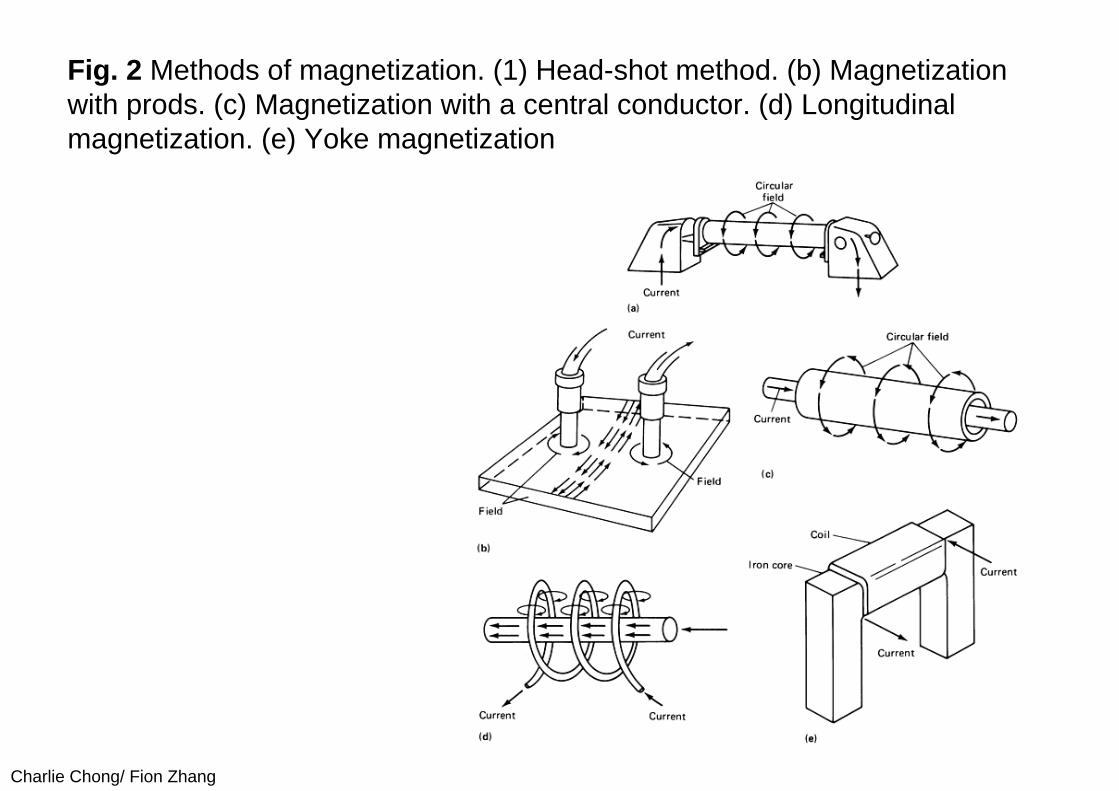
Charlie Chong Fion Zhang
There are however many situations of interest where flaw shapes vary considerably and where signal amplitude is not uniquely related to flaw depth as is the case for corrosion pits in steel tubing In addition different types of flaws such as cracks and pits can occur in the same part in which case it becomes necessary to determine the flaw types present as well as their severity
In such cases a more careful analysis of the relationship between signal and flaw characteristics is required if serious errors in flaw characterization are to be avoided One of the earliest attempts to use a theoretical model in the analysis of leakage field data was based on the analytic solution for the field perturbed by a spherical inclusion Two conclusions were drawn from this analysis First when one measures the leakage flux component normal to the surface of the part the center of the flaw is located below the scan plane at a distance equal to the peak-to-peak separation distance in the flaw signal (Fig 5) and second the peak-to-peak signal amplitude is proportional to the flaw volume A number of experimental tests of these sizing rules have confirmed the predicted relationships for nonmagnetic inclusions in steel parts
Charlie Chong Fion Zhang
Keywords
Two conclusions were drawn from this analysis
bull First when one measures the leakage flux component normal to the surface of the part the center of the flaw is located below the scan plane at a distance equal to the peak-to-peak separation distance in the flaw signal (Fig 5) and
bull Second the peak-to-peak signal amplitude is proportional to the flaw volume A number of experimental tests of these sizing rules have confirmed the predicted relationships for nonmagnetic inclusions in steel parts
peak-to-peak signal amplitude is proportional to the flaw volume
Lateral dimension
Charlie Chong Fion Zhang
Fig 5 Dependence of magnetic signal peak separation (a) on the depth of a spherical inclusion (b)
Charlie Chong Fion Zhang
Further theoretical and experimental data for spheroidal inclusions and surface pits have shown however that the simple characterization rules for spherical inclusions do not apply when the flaw shape differs significantly from the ideal sphere In such cases the signal amplitude depends on the lateral extent of the flaw and on its volume and characterization on the basis of leakage field analysis becomes much more complicated
Finally there has been at least one attempt to apply finite-element calculations of flaw leakage fields to the development of characterization rules for a more general class of flaws Hwang and Lord performed most of their computations for simple flaw shapes such as rectangular and triangular slots and inclusions and from the results devised a set of rules for estimating the depth width and angle of inclination of a flaw with respect to the surface of the part One of their applications to a flaw of complex shape is shown in Fig 6
Charlie Chong Fion Zhang
Fig 6 Characterization of a ferrite-tail type of defect The dashed line shows the flaw configuration estimated from the leakage field data
Charlie Chong Fion Zhang
The promising results obtained from the finite-element work of Hwang and Lord as well as the analytically based work on spheroidal flaws suggest that the estimation of flaw size and shape from leakage field data is feasible Another numerical method potentially applicable to flux leakage problems is the boundary integral method which may prove useful in flaw characterization Unfortunately much more work must be done on both the theoretical basis and on experimental testing before it will be possible to analyze experimental leakage field data with confidence in terms of flaw characteristics
Charlie Chong Fion Zhang
PART 2 Principles of Magnetic Characterization of Materials10 Metallurgical and Magnetic Properties
The use of magnetic measurements to monitor the metallurgical propertiesof ferromagnetic materials is based on the fact that variables such as crystallographic phase chemical composition and microstructure which determine the physical properties of materials also affect their magnetic characteristics Some parameters such as grain size and orientation dislocation density and the existence of precipitates are closely related to measurable characteristics of magnetic hysteresis that is to the behavior of the flux density B induced in a material as a function of the magnetic field strength H This relationship can be understood in principle from the physical theory of magnetic domains Magnetization in a particular direction increases as the domains aligned in that direction grow at the expense of domains aligned in other directions Factors that impede domain growth also impede dislocation motion hence the connection at a very fundamental level between magnetic and mechanical properties
Charlie Chong Fion Zhang
Keywords
Metallurgical properties
Crystallographic phase Chemical composition Grain size and orientation Dislocation density and Existence of precipitates
are closely related to measurable characteristics of magnetic hysteresis that is to the behavior of the flux density B induced in a material as a function of the magnetic field strength H
Charlie Chong Fion Zhang
Hysteresis Curves
Charlie Chong Fion Zhang
Other magnetic properties such as the saturation magnetization which is the maximum value B can achieve or the Curie temperature at which there is a transition to a nonmagnetic state are less dependent on microstructure but are sensitive to such factors as crystal structure and chemical composition Interest in the magnetic characterization of materials principally steels derives from many such relationships between measurable magneticparameters and metallurgical properties These relationships are however quite complicated in general and it is often difficult to determine how or if a particular measurement or combination of measurements can be used to determine a property of interest
Charlie Chong Fion Zhang
Nevertheless the prospect of nondestructive monitoring and quality control is an attractive one and for this reason research on magnetic materials characterization continues to be an active field It is not the purpose of this article to explore such magnetic methods in depth but simply to point out that it is an active branch of nondestructive magnetic testing The more fundamental aspects of the relationship between magnetism and metallurgy are discussed in Ref 26 and 28 Engineering considerations are reviewed in Ref 24 The proceedings of various symposia also contain several papers that provide a good overview of the current status of magnetic materials characterization
Charlie Chong Fion Zhang
Curie temperature In physics and materials science the Curie temperature (Tc) or Curie point is the temperature where a materials permanent magnetism changes to induced magnetism The force of magnetism is determined by magnetic moments The Curie temperature is the critical point where a materials intrinsic magnetic moments change direction Magnetic moments are permanent dipole moments within the atom which originate from electrons angular momentum and spin Materials have different structures of intrinsic magnetic moments that depend on temperature At a materials Curie Temperature those intrinsic magnetic moments change direction
Permanent magnetism is caused by the alignment of magnetic moments and induced magnetism is created when disordered magnetic moments are forced to align in an applied magnetic field For example the ordered magnetic moments (ferromagnetic figure 1) change and become disordered (paramagnetic figure 2) at the Curie Temperature Higher temperatures make magnets weaker as spontaneous magnetism only occurs below the Curie Temperature Magnetic susceptibility only occurs above the Curie Temperature and can be calculated from the Curie-Weiss Law which is derived from Curies Law In analogy to ferromagnetic and paramagnetic materials the Curie temperature can also be used to describe the temperature where a materials spontaneous electric polarisation changes to induced electric polarisation or the reverse upon reduction of the temperature below the Curie temperature
httpenwikipediaorgwikiCurie_temperature
Charlie Chong Fion Zhang
Curie temperature
harr ParamagneticAntiferromagneticharr ParamagneticFerrimagneticharr ParamagneticFerromagneticAbove TcBelow Tc
httpenwikipediaorgwikiCurie_temperature
Charlie Chong Fion Zhang
Ferromagnetism The magnetic moments in a ferromagnetic material The moments are ordered and of the same magnitude in the absence of an applied magnetic field
httpenwikipediaorgwikiCurie_temperature
Charlie Chong Fion Zhang
Paramagnetism The magnetic moments in a paramagnetic material The moments are disordered in the absence of an applied magnetic field and ordered in the presence of an applied magnetic field
httpenwikipediaorgwikiCurie_temperature
Charlie Chong Fion Zhang
Ferrimagnetism The magnetic moments in a ferrimagnetic material The moments are aligned oppositely and have different magnitudes due to being made up of two different ions This is in the absence of an applied magnetic field
httpenwikipediaorgwikiCurie_temperature
Charlie Chong Fion Zhang
Antiferromagnetism The magnetic moments in an antiferromagneticmaterial The moments are aligned oppositely and have the same magnitudes This is in the absence of an applied magnetic field
httpenwikipediaorgwikiCurie_temperature
Charlie Chong Fion Zhang
20 Experimental Techniques
A typical setup for measuring the B-H characteristic of a rod specimen is shown in Fig 7 The essential elements are an electromagnet for generating the magnetizing field a coil wound around the specimen for measuring the time rate of change of the magnetic flux B in the material and a magnetic field sensor in this case a Hall effect probe for measuring the magnetic field strength H parallel to the surface of the part The signal generator provides a low-frequency magnetizing field typically of the order of a few Hertz and the output of the flux measuring coil is integrated over time to give the flux density in the material In the arrangement shown in Fig 7 an additional feature is the provision for applying a tensile load to the specimen for studies of the effects of stress on the hysteresis data When using a rod specimen such as this it is important that the length-to-diameter ratio of the specimen be large so as to minimize the effects of stray fields from the ends of the rod on the measurements of B and H
Charlie Chong Fion Zhang
Fig 7 Experimental arrangement for hysteresis loop measurements
Charlie Chong Fion Zhang
Another magnetic method that uses a similar arrangement is the measurement of Barkhausen noise As the magnetic field strength H is varied at a very slow rate discontinuous jumps in the magnetization of the material can be observed during certain portions of the hysteresis cycle These jumps are associated with the sudden growth of a series of magnetic domains that have been temporarily stopped from further growth by such obstacles as grain boundaries precipitates or dislocations Barkhausen noise is therefore dependent on microstructure and can be used independently of hysteresis measurements or in conjunction with such measurements as another method of magnetic testing The experimental arrangement differs from that shown in Fig 7 in that a single sensor coil oriented to measure the flux normal to the surface of the specimen is used instead of the Hall probe and the flux winding
Charlie Chong Fion Zhang
The review articles and conference proceedings cited above contain additional detail on experimental technique and a wealth of information on the interpretation of hysteresis and Barkhausen data However it should be noted that test methods and data interpretation are often very specific to a particular class of alloy and techniques that seem to work well for one type of material may be totally inappropriate for another The analysis of magnetic characterization data is still largely empirical in nature and controlled testing of a candidate technique with the specific alloy system of interest is advisable
Charlie Chong Fion Zhang
PART 3 Application10 Flaw Detection by the Flux Leakage MethodPerhaps the most prevalent use of the flux leakage method is theinspection of ferromagnetic tubular goods such as gas pipelines down hole casing and a variety of other forms of steel piping In applications in the petroleum industry the technique is highly developed but details on inspection devices and methods of data analysis are for the most part considered proprietary by the companies that provide inspection services Still the techniques currently in use have certain features in common and these are exemplified by the typical system described below The device shown in Fig 8 is an inspection tool for large-diameter pipelines Magnetization is provided by a large electromagnet fitted with wire brushes to direct magnetic flux from the electromagnet into the pipe wall To avoid spurious signals from hard spots in the material the magnetization circuit is designed for maximum flux density in the pipe wall in an attempt to magnetically saturate the material
Charlie Chong Fion Zhang
Leakage field sensors are mounted between the pole pieces of the magnet in a circle around the axis of the device to provide as nearly as possible full coverage of the pipe wall In most such tools the sensors are the inductive coil type oriented to measure the axial component of the leakage field gradient Data are usually recorded on magnetic tape as the system is propelled down a section of pipe After the inspection the recorded signals are compared with those from calibration standards in an attempt to interpret flaw indications in terms of flaw type and size
Charlie Chong Fion Zhang
Fig 8 Typical gas pipeline inspection pig The tool consists of a drive unit an instrumentation unit and a center section with an electromagnetic and flux leakage sensors
Pipe
Sensor
Sensor
Pole
Coil
Pole
Charlie Chong Fion Zhang
In addition to systems for inspecting rotationally symmetric cylindrical parts flux leakage inspection has been applied to very irregular components such as helicopter rotor blade D-spars gear teeth and artillery projectiles Several of these special-purpose applications have involved only laboratory investigations but in some cases specialized instrumentation systems have been developed and fabricated for factory use These systems are uniquely adapted to the particular application involved and in most cases only one or at most several instrumentation systems have been built Even in the case of laboratory investigations special-purpose detection probe and magnetizing arrangements have been developed for specific applications
Charlie Chong Fion Zhang
One such system for automated thread inspection on drill pipe and collars is described The device consists of an electromagnet and an array of sensors mounted outside a nonmagnetic cone that threads onto the tool joint The assembly is driven in a helical path along the threads by a motorclutch assembly To minimize the leakage flux signal variations caused by the threads signals from the sensor array are compared differentially The system is capable of operating in a high field strength mode for the detection of cracks and corrosion pits and also in a residual field mode for the detection of other forms of damage At last report the system was undergoing field tests and was found to offer advantages in terms of ease of application and defect detection over the magnetic particle technique normally used for thread inspection
Charlie Chong Fion Zhang
The flux leakage method is also finding application in the inspection of ropes and cables made of strands of ferromagnetic material One approach is to induce magnetization in the piece by means of an encircling coil energized by a direct current (dc) With this method one measures the leakage field associated with broken strands using a Hall effect probe or an auxiliary sensor coil A complementary method with alternating current (ac) which is actually an eddy current test rather than flux leakage is to measure the ac impedance variations in an encircling coil caused by irregularities in the cross-sectional area of the specimen Haynes and Underbakke describe practical field tests of an instrumentation system that utilizes both the ac and dc methods They conclude that instrumentation capable of a combination of inspection techniques offers the best possibility of detecting both localized flaws and overall loss of cross section caused by generalized corrosion and wear They also present detailed information on the practical characteristics of a commercially available device that makes use of both the ac and dc methods
Charlie C
hong Fion Zhang
The flux leakage method is also finding application in the inspection of ropes and cables
Charlie Chong Fion Zhang
Another area in which the flux leakage method has been successfully implemented is the inspection of rolling-element antifriction bearings A schematic illustration of the method as applied to an inner bearing race is shown in Fig 9 In this application the part is magnetized by an electromagnet as indicated in Fig 9(a) The race is then rotated by a spindle and the surface is scanned with an induction coil sensor Typically the race is rotated at a surface speed of about 23 ms (75 fts) and the active portion of the raceway is inspected by incrementally indexing the sensor across the raceway Magnetizing fields are applied in the radial and circumferential orientations It has been shown that radial field inspection works best for surface flaws while circumferential field inspection shows greater sensitivity to subsurface flaws Data have been collected on a large number of bearing races to establish the correlation between leakage field signals and inclusion depths and dimensions determined by metallurgical sectioning
Charlie Chong Fion Zhang
Fig 9 Flux leakage inspection of a bearing race (a) Magnetization of inner race (b) Perturbation in the magnetic flux at the surface of the inner race (c) Probe scanning the surface
Charlie Chong Fion Zhang
Finally the flux leakage method has also been adapted to the inspection of steel reinforcement in concrete beams The basic function of the magnetic field disturbance (MFD) inspection equipment is to provide maps of the magnetic field across the bottom and sides of the beam An electromagnet on an inspection cart which is suspended on tracks below the beam provides a magnetic field that induces magnetization in permeable structures in its vicinity such as steel rebars cables and stirrups An array of Hall effect sensors distributed across the bottom and sides of the beam measures the field produced by magnetized structures within the beam If a flaw is present in one of these magnetized structures it will produce a disturbance of the normal magnetic field pattern associated with the unflawed beam Thus the idea behind the MFD system is to search the surface of the beam for field anomalies that indicate the presence of flaws in reinforcing steel within the structure
Keywordsmagnetic field disturbance (MFD)
Charlie Chong Fion Zhang
A flaw such as a broken wire in a cable or a fractured rebar produces a distinctive magnetic field anomaly that depends on the size of the discontinuity and its distance from the sensor Because the signal shape that results from such an anomaly is known flaw detection is enhanced by searching magnetic field records for specific signal shapes that is those that are characteristic of discontinuities in magnetic materials In the MFD system this is accomplished by a computer program that compares signal shapes with typical flaw signal shapes The program produces a correlation coefficient that serves as a measure of similarity of the observed signal shape to a typical flaw signal shape Flaw detection is therefore not only enhanced by signal shape discrimination but also automated by computer processing of the magnetic field data Laboratory tests have demonstrated the ability of the system to detect fracture in steel rebars and cables in a large pre-stressed concrete structure Also planned are field tests of the equipment in the inspection of bridge decks for reinforcement corrosion damage
Charlie Chong Fion Zhang
Steel rebars and cables in a large pre-stressed concrete structure
Charlie Chong Fion Zhang
20 Nondestructive Characterization of Materials Only two examples of magnetic methods for monitoring materialproperties are given because the examples chosen should suffice to illustrate the types of tests that might be employed Measurements of magnetic characteristics can however provide a wealth of data and various features of such data can yield information on different material properties For example it has been demonstrated that different features of magnetic hysteresis data can be interpreted in terms of heat treatment and microstructure plastic deformation residual stress and mechanical hardness An example of the effects of mechanical hardness on hysteresis data is shown in Fig 10 These data were obtained in the absence of applied tensile stress with the experimental arrangement shown in Fig 7 Specimens of different hardness were prepared by tempering at different temperatures The grain size (ASTM No 7) was the same for all four specimens used in these tests Other data showed however that grain size has little effect on hysteretic behavior for the classes of alloys studied
Charlie Chong Fion Zhang
Fig 10 Effect of mechanical hardness on hysteresis loop data (a) AISI 410 stainless steel (b) SAE 4340 steel
Charlie Chong Fion Zhang
The main point illustrated in Fig 10 is that the mechanically harder specimens of the same alloy are also harder to magnetize that is the flux density B obtained at a large value of H is smaller for mechanically harder specimens than for softer specimens For one alloy AISI 410 stainless steel the hysteresis loop intersects the B = 0 axis at larger values of H for the harder specimen than for the softer specimen that is the coercive force is greater for the harder material However for the other material SAE 4340 steel the coercive force does not change with hardness This suggests that for the two alloys considered here the saturation flux density provides a more reliable measure of hardness than the coercive force Mayos et al used two quite different techniques to measure the depth of surface decarburization of steels One method was a variation of a standard eddy current test with the difference from standard practice being that eddy current probe response was measured in the presence of a low-frequency (~01 Hz) magnetic field This arrangement provides a measure of incremental permeability that is the magnetic permeability corresponding to changes in the applied field about some quasistatic value The second method employed was Barkhausen noise analysis
Charlie Chong Fion Zhang
Keywords
For one alloy AISI 410 stainless steel the hysteresis loop intersects the B = 0 axis at larger values of H for the harder specimen than for the softer specimen that is the coercive force is greater for the harder material However for the other material SAE 4340 steel the coercive force does not change with hardness
This suggests that for the two alloys considered here the saturation flux density provides a more reliable measure of hardness than the coercive force
Charlie Chong Fion Zhang
Depth of decarburization was analyzed by varying the frequency of the excitation field thus changing the skin depth in the material Experiments were performed with both artificial samples containing two layers of different carbon content and industrial samples in which carbon concentration varied smoothly with distance from the surface It was shown that certain features of both Barkhausen noise and incremental permeability data can be correlated with depth of decarburization The Barkhausen noise method showed a somewhat stronger sensitivity to depth but was useful over a smaller range of depths than the incremental permeability method It can be concluded that both methods are useful with the optimum choice depending on accuracy requirements and the expected depth of decarburization
Charlie Chong Fion Zhang
Offshore Structures
Charlie Chong Fion Zhang
Offshore Structures
Charlie Chong Fion Zhang
VLCC
Charlie Chong Fion Zhang
Offshore Structures
Charlie Chong Fion Zhang
Offshore Structures
Charlie Chong Fion Zhang
Offshore Structures
Charlie Chong Fion Zhang
Pipeline amp Piping
Charlie Chong Fion Zhang
Pipeline amp Piping
Charlie Chong Fion Zhang
Charlie Chong Fion Zhang
ass
- Electromagnetic Testing MFLT ECT MicrowaveRFT Chapter 9B ndash漏磁检测 More Reading on Magnetic Field Leakage Testing MFLT
- PART 1 Magnetic Field Testing
-
- 10 Introduction
- 20 Principles of Magnetic Leakage Field Testing MLFT
-
- PART 2 Principles of Magnetic Characterization of Materials
-
- 10 Metallurgical and Magnetic Properties
- 20 Experimental Techniques
-
- PART 3 Application
-
- 10 Flaw Detection by the Flux Leakage Method
- 20 Nondestructive Characterization of Materials
-
- Good Luck
-
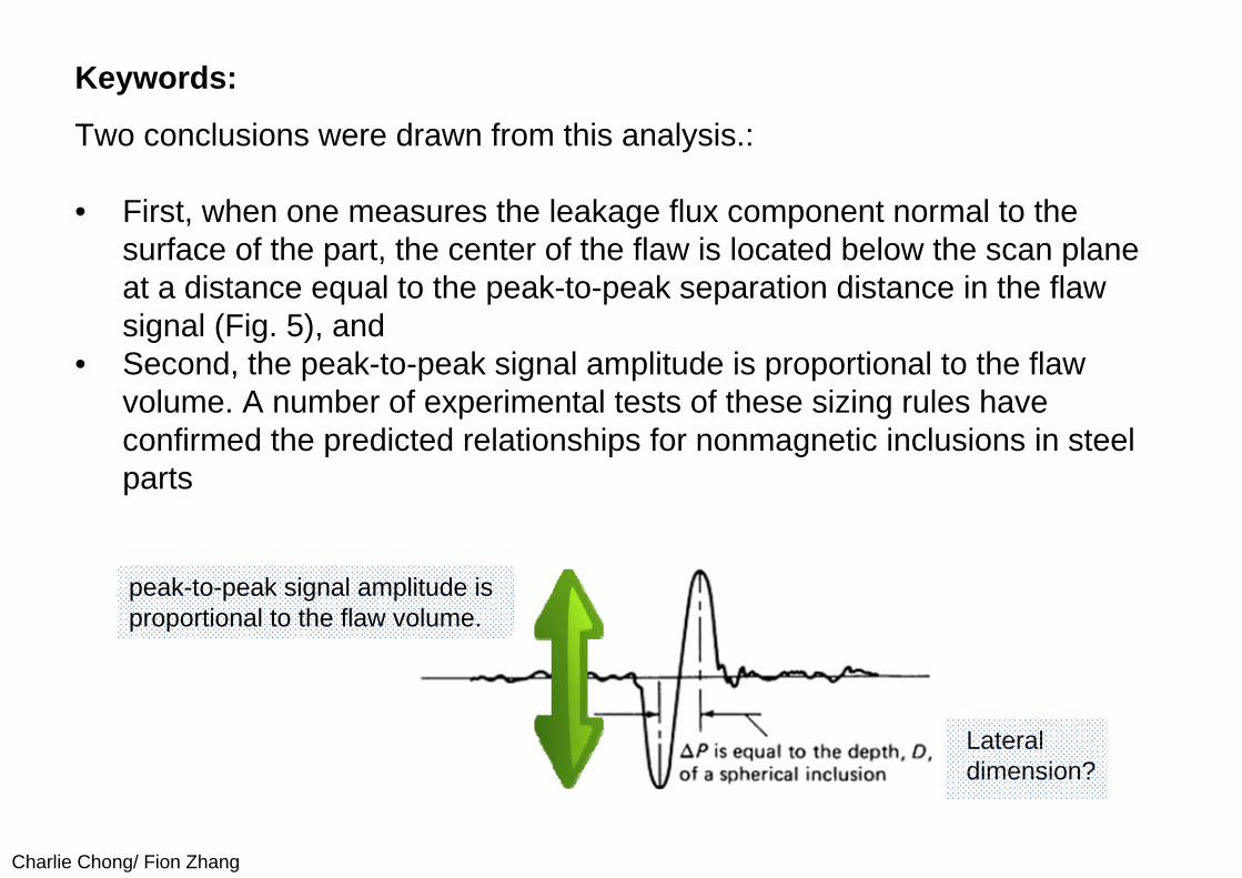
Charlie Chong Fion Zhang
Keywords
Two conclusions were drawn from this analysis
bull First when one measures the leakage flux component normal to the surface of the part the center of the flaw is located below the scan plane at a distance equal to the peak-to-peak separation distance in the flaw signal (Fig 5) and
bull Second the peak-to-peak signal amplitude is proportional to the flaw volume A number of experimental tests of these sizing rules have confirmed the predicted relationships for nonmagnetic inclusions in steel parts
peak-to-peak signal amplitude is proportional to the flaw volume
Lateral dimension
Charlie Chong Fion Zhang
Fig 5 Dependence of magnetic signal peak separation (a) on the depth of a spherical inclusion (b)
Charlie Chong Fion Zhang
Further theoretical and experimental data for spheroidal inclusions and surface pits have shown however that the simple characterization rules for spherical inclusions do not apply when the flaw shape differs significantly from the ideal sphere In such cases the signal amplitude depends on the lateral extent of the flaw and on its volume and characterization on the basis of leakage field analysis becomes much more complicated
Finally there has been at least one attempt to apply finite-element calculations of flaw leakage fields to the development of characterization rules for a more general class of flaws Hwang and Lord performed most of their computations for simple flaw shapes such as rectangular and triangular slots and inclusions and from the results devised a set of rules for estimating the depth width and angle of inclination of a flaw with respect to the surface of the part One of their applications to a flaw of complex shape is shown in Fig 6
Charlie Chong Fion Zhang
Fig 6 Characterization of a ferrite-tail type of defect The dashed line shows the flaw configuration estimated from the leakage field data
Charlie Chong Fion Zhang
The promising results obtained from the finite-element work of Hwang and Lord as well as the analytically based work on spheroidal flaws suggest that the estimation of flaw size and shape from leakage field data is feasible Another numerical method potentially applicable to flux leakage problems is the boundary integral method which may prove useful in flaw characterization Unfortunately much more work must be done on both the theoretical basis and on experimental testing before it will be possible to analyze experimental leakage field data with confidence in terms of flaw characteristics
Charlie Chong Fion Zhang
PART 2 Principles of Magnetic Characterization of Materials10 Metallurgical and Magnetic Properties
The use of magnetic measurements to monitor the metallurgical propertiesof ferromagnetic materials is based on the fact that variables such as crystallographic phase chemical composition and microstructure which determine the physical properties of materials also affect their magnetic characteristics Some parameters such as grain size and orientation dislocation density and the existence of precipitates are closely related to measurable characteristics of magnetic hysteresis that is to the behavior of the flux density B induced in a material as a function of the magnetic field strength H This relationship can be understood in principle from the physical theory of magnetic domains Magnetization in a particular direction increases as the domains aligned in that direction grow at the expense of domains aligned in other directions Factors that impede domain growth also impede dislocation motion hence the connection at a very fundamental level between magnetic and mechanical properties
Charlie Chong Fion Zhang
Keywords
Metallurgical properties
Crystallographic phase Chemical composition Grain size and orientation Dislocation density and Existence of precipitates
are closely related to measurable characteristics of magnetic hysteresis that is to the behavior of the flux density B induced in a material as a function of the magnetic field strength H
Charlie Chong Fion Zhang
Hysteresis Curves
Charlie Chong Fion Zhang
Other magnetic properties such as the saturation magnetization which is the maximum value B can achieve or the Curie temperature at which there is a transition to a nonmagnetic state are less dependent on microstructure but are sensitive to such factors as crystal structure and chemical composition Interest in the magnetic characterization of materials principally steels derives from many such relationships between measurable magneticparameters and metallurgical properties These relationships are however quite complicated in general and it is often difficult to determine how or if a particular measurement or combination of measurements can be used to determine a property of interest
Charlie Chong Fion Zhang
Nevertheless the prospect of nondestructive monitoring and quality control is an attractive one and for this reason research on magnetic materials characterization continues to be an active field It is not the purpose of this article to explore such magnetic methods in depth but simply to point out that it is an active branch of nondestructive magnetic testing The more fundamental aspects of the relationship between magnetism and metallurgy are discussed in Ref 26 and 28 Engineering considerations are reviewed in Ref 24 The proceedings of various symposia also contain several papers that provide a good overview of the current status of magnetic materials characterization
Charlie Chong Fion Zhang
Curie temperature In physics and materials science the Curie temperature (Tc) or Curie point is the temperature where a materials permanent magnetism changes to induced magnetism The force of magnetism is determined by magnetic moments The Curie temperature is the critical point where a materials intrinsic magnetic moments change direction Magnetic moments are permanent dipole moments within the atom which originate from electrons angular momentum and spin Materials have different structures of intrinsic magnetic moments that depend on temperature At a materials Curie Temperature those intrinsic magnetic moments change direction
Permanent magnetism is caused by the alignment of magnetic moments and induced magnetism is created when disordered magnetic moments are forced to align in an applied magnetic field For example the ordered magnetic moments (ferromagnetic figure 1) change and become disordered (paramagnetic figure 2) at the Curie Temperature Higher temperatures make magnets weaker as spontaneous magnetism only occurs below the Curie Temperature Magnetic susceptibility only occurs above the Curie Temperature and can be calculated from the Curie-Weiss Law which is derived from Curies Law In analogy to ferromagnetic and paramagnetic materials the Curie temperature can also be used to describe the temperature where a materials spontaneous electric polarisation changes to induced electric polarisation or the reverse upon reduction of the temperature below the Curie temperature
httpenwikipediaorgwikiCurie_temperature
Charlie Chong Fion Zhang
Curie temperature
harr ParamagneticAntiferromagneticharr ParamagneticFerrimagneticharr ParamagneticFerromagneticAbove TcBelow Tc
httpenwikipediaorgwikiCurie_temperature
Charlie Chong Fion Zhang
Ferromagnetism The magnetic moments in a ferromagnetic material The moments are ordered and of the same magnitude in the absence of an applied magnetic field
httpenwikipediaorgwikiCurie_temperature
Charlie Chong Fion Zhang
Paramagnetism The magnetic moments in a paramagnetic material The moments are disordered in the absence of an applied magnetic field and ordered in the presence of an applied magnetic field
httpenwikipediaorgwikiCurie_temperature
Charlie Chong Fion Zhang
Ferrimagnetism The magnetic moments in a ferrimagnetic material The moments are aligned oppositely and have different magnitudes due to being made up of two different ions This is in the absence of an applied magnetic field
httpenwikipediaorgwikiCurie_temperature
Charlie Chong Fion Zhang
Antiferromagnetism The magnetic moments in an antiferromagneticmaterial The moments are aligned oppositely and have the same magnitudes This is in the absence of an applied magnetic field
httpenwikipediaorgwikiCurie_temperature
Charlie Chong Fion Zhang
20 Experimental Techniques
A typical setup for measuring the B-H characteristic of a rod specimen is shown in Fig 7 The essential elements are an electromagnet for generating the magnetizing field a coil wound around the specimen for measuring the time rate of change of the magnetic flux B in the material and a magnetic field sensor in this case a Hall effect probe for measuring the magnetic field strength H parallel to the surface of the part The signal generator provides a low-frequency magnetizing field typically of the order of a few Hertz and the output of the flux measuring coil is integrated over time to give the flux density in the material In the arrangement shown in Fig 7 an additional feature is the provision for applying a tensile load to the specimen for studies of the effects of stress on the hysteresis data When using a rod specimen such as this it is important that the length-to-diameter ratio of the specimen be large so as to minimize the effects of stray fields from the ends of the rod on the measurements of B and H
Charlie Chong Fion Zhang
Fig 7 Experimental arrangement for hysteresis loop measurements
Charlie Chong Fion Zhang
Another magnetic method that uses a similar arrangement is the measurement of Barkhausen noise As the magnetic field strength H is varied at a very slow rate discontinuous jumps in the magnetization of the material can be observed during certain portions of the hysteresis cycle These jumps are associated with the sudden growth of a series of magnetic domains that have been temporarily stopped from further growth by such obstacles as grain boundaries precipitates or dislocations Barkhausen noise is therefore dependent on microstructure and can be used independently of hysteresis measurements or in conjunction with such measurements as another method of magnetic testing The experimental arrangement differs from that shown in Fig 7 in that a single sensor coil oriented to measure the flux normal to the surface of the specimen is used instead of the Hall probe and the flux winding
Charlie Chong Fion Zhang
The review articles and conference proceedings cited above contain additional detail on experimental technique and a wealth of information on the interpretation of hysteresis and Barkhausen data However it should be noted that test methods and data interpretation are often very specific to a particular class of alloy and techniques that seem to work well for one type of material may be totally inappropriate for another The analysis of magnetic characterization data is still largely empirical in nature and controlled testing of a candidate technique with the specific alloy system of interest is advisable
Charlie Chong Fion Zhang
PART 3 Application10 Flaw Detection by the Flux Leakage MethodPerhaps the most prevalent use of the flux leakage method is theinspection of ferromagnetic tubular goods such as gas pipelines down hole casing and a variety of other forms of steel piping In applications in the petroleum industry the technique is highly developed but details on inspection devices and methods of data analysis are for the most part considered proprietary by the companies that provide inspection services Still the techniques currently in use have certain features in common and these are exemplified by the typical system described below The device shown in Fig 8 is an inspection tool for large-diameter pipelines Magnetization is provided by a large electromagnet fitted with wire brushes to direct magnetic flux from the electromagnet into the pipe wall To avoid spurious signals from hard spots in the material the magnetization circuit is designed for maximum flux density in the pipe wall in an attempt to magnetically saturate the material
Charlie Chong Fion Zhang
Leakage field sensors are mounted between the pole pieces of the magnet in a circle around the axis of the device to provide as nearly as possible full coverage of the pipe wall In most such tools the sensors are the inductive coil type oriented to measure the axial component of the leakage field gradient Data are usually recorded on magnetic tape as the system is propelled down a section of pipe After the inspection the recorded signals are compared with those from calibration standards in an attempt to interpret flaw indications in terms of flaw type and size
Charlie Chong Fion Zhang
Fig 8 Typical gas pipeline inspection pig The tool consists of a drive unit an instrumentation unit and a center section with an electromagnetic and flux leakage sensors
Pipe
Sensor
Sensor
Pole
Coil
Pole
Charlie Chong Fion Zhang
In addition to systems for inspecting rotationally symmetric cylindrical parts flux leakage inspection has been applied to very irregular components such as helicopter rotor blade D-spars gear teeth and artillery projectiles Several of these special-purpose applications have involved only laboratory investigations but in some cases specialized instrumentation systems have been developed and fabricated for factory use These systems are uniquely adapted to the particular application involved and in most cases only one or at most several instrumentation systems have been built Even in the case of laboratory investigations special-purpose detection probe and magnetizing arrangements have been developed for specific applications
Charlie Chong Fion Zhang
One such system for automated thread inspection on drill pipe and collars is described The device consists of an electromagnet and an array of sensors mounted outside a nonmagnetic cone that threads onto the tool joint The assembly is driven in a helical path along the threads by a motorclutch assembly To minimize the leakage flux signal variations caused by the threads signals from the sensor array are compared differentially The system is capable of operating in a high field strength mode for the detection of cracks and corrosion pits and also in a residual field mode for the detection of other forms of damage At last report the system was undergoing field tests and was found to offer advantages in terms of ease of application and defect detection over the magnetic particle technique normally used for thread inspection
Charlie Chong Fion Zhang
The flux leakage method is also finding application in the inspection of ropes and cables made of strands of ferromagnetic material One approach is to induce magnetization in the piece by means of an encircling coil energized by a direct current (dc) With this method one measures the leakage field associated with broken strands using a Hall effect probe or an auxiliary sensor coil A complementary method with alternating current (ac) which is actually an eddy current test rather than flux leakage is to measure the ac impedance variations in an encircling coil caused by irregularities in the cross-sectional area of the specimen Haynes and Underbakke describe practical field tests of an instrumentation system that utilizes both the ac and dc methods They conclude that instrumentation capable of a combination of inspection techniques offers the best possibility of detecting both localized flaws and overall loss of cross section caused by generalized corrosion and wear They also present detailed information on the practical characteristics of a commercially available device that makes use of both the ac and dc methods
Charlie C
hong Fion Zhang
The flux leakage method is also finding application in the inspection of ropes and cables
Charlie Chong Fion Zhang
Another area in which the flux leakage method has been successfully implemented is the inspection of rolling-element antifriction bearings A schematic illustration of the method as applied to an inner bearing race is shown in Fig 9 In this application the part is magnetized by an electromagnet as indicated in Fig 9(a) The race is then rotated by a spindle and the surface is scanned with an induction coil sensor Typically the race is rotated at a surface speed of about 23 ms (75 fts) and the active portion of the raceway is inspected by incrementally indexing the sensor across the raceway Magnetizing fields are applied in the radial and circumferential orientations It has been shown that radial field inspection works best for surface flaws while circumferential field inspection shows greater sensitivity to subsurface flaws Data have been collected on a large number of bearing races to establish the correlation between leakage field signals and inclusion depths and dimensions determined by metallurgical sectioning
Charlie Chong Fion Zhang
Fig 9 Flux leakage inspection of a bearing race (a) Magnetization of inner race (b) Perturbation in the magnetic flux at the surface of the inner race (c) Probe scanning the surface
Charlie Chong Fion Zhang
Finally the flux leakage method has also been adapted to the inspection of steel reinforcement in concrete beams The basic function of the magnetic field disturbance (MFD) inspection equipment is to provide maps of the magnetic field across the bottom and sides of the beam An electromagnet on an inspection cart which is suspended on tracks below the beam provides a magnetic field that induces magnetization in permeable structures in its vicinity such as steel rebars cables and stirrups An array of Hall effect sensors distributed across the bottom and sides of the beam measures the field produced by magnetized structures within the beam If a flaw is present in one of these magnetized structures it will produce a disturbance of the normal magnetic field pattern associated with the unflawed beam Thus the idea behind the MFD system is to search the surface of the beam for field anomalies that indicate the presence of flaws in reinforcing steel within the structure
Keywordsmagnetic field disturbance (MFD)
Charlie Chong Fion Zhang
A flaw such as a broken wire in a cable or a fractured rebar produces a distinctive magnetic field anomaly that depends on the size of the discontinuity and its distance from the sensor Because the signal shape that results from such an anomaly is known flaw detection is enhanced by searching magnetic field records for specific signal shapes that is those that are characteristic of discontinuities in magnetic materials In the MFD system this is accomplished by a computer program that compares signal shapes with typical flaw signal shapes The program produces a correlation coefficient that serves as a measure of similarity of the observed signal shape to a typical flaw signal shape Flaw detection is therefore not only enhanced by signal shape discrimination but also automated by computer processing of the magnetic field data Laboratory tests have demonstrated the ability of the system to detect fracture in steel rebars and cables in a large pre-stressed concrete structure Also planned are field tests of the equipment in the inspection of bridge decks for reinforcement corrosion damage
Charlie Chong Fion Zhang
Steel rebars and cables in a large pre-stressed concrete structure
Charlie Chong Fion Zhang
20 Nondestructive Characterization of Materials Only two examples of magnetic methods for monitoring materialproperties are given because the examples chosen should suffice to illustrate the types of tests that might be employed Measurements of magnetic characteristics can however provide a wealth of data and various features of such data can yield information on different material properties For example it has been demonstrated that different features of magnetic hysteresis data can be interpreted in terms of heat treatment and microstructure plastic deformation residual stress and mechanical hardness An example of the effects of mechanical hardness on hysteresis data is shown in Fig 10 These data were obtained in the absence of applied tensile stress with the experimental arrangement shown in Fig 7 Specimens of different hardness were prepared by tempering at different temperatures The grain size (ASTM No 7) was the same for all four specimens used in these tests Other data showed however that grain size has little effect on hysteretic behavior for the classes of alloys studied
Charlie Chong Fion Zhang
Fig 10 Effect of mechanical hardness on hysteresis loop data (a) AISI 410 stainless steel (b) SAE 4340 steel
Charlie Chong Fion Zhang
The main point illustrated in Fig 10 is that the mechanically harder specimens of the same alloy are also harder to magnetize that is the flux density B obtained at a large value of H is smaller for mechanically harder specimens than for softer specimens For one alloy AISI 410 stainless steel the hysteresis loop intersects the B = 0 axis at larger values of H for the harder specimen than for the softer specimen that is the coercive force is greater for the harder material However for the other material SAE 4340 steel the coercive force does not change with hardness This suggests that for the two alloys considered here the saturation flux density provides a more reliable measure of hardness than the coercive force Mayos et al used two quite different techniques to measure the depth of surface decarburization of steels One method was a variation of a standard eddy current test with the difference from standard practice being that eddy current probe response was measured in the presence of a low-frequency (~01 Hz) magnetic field This arrangement provides a measure of incremental permeability that is the magnetic permeability corresponding to changes in the applied field about some quasistatic value The second method employed was Barkhausen noise analysis
Charlie Chong Fion Zhang
Keywords
For one alloy AISI 410 stainless steel the hysteresis loop intersects the B = 0 axis at larger values of H for the harder specimen than for the softer specimen that is the coercive force is greater for the harder material However for the other material SAE 4340 steel the coercive force does not change with hardness
This suggests that for the two alloys considered here the saturation flux density provides a more reliable measure of hardness than the coercive force
Charlie Chong Fion Zhang
Depth of decarburization was analyzed by varying the frequency of the excitation field thus changing the skin depth in the material Experiments were performed with both artificial samples containing two layers of different carbon content and industrial samples in which carbon concentration varied smoothly with distance from the surface It was shown that certain features of both Barkhausen noise and incremental permeability data can be correlated with depth of decarburization The Barkhausen noise method showed a somewhat stronger sensitivity to depth but was useful over a smaller range of depths than the incremental permeability method It can be concluded that both methods are useful with the optimum choice depending on accuracy requirements and the expected depth of decarburization
Charlie Chong Fion Zhang
Offshore Structures
Charlie Chong Fion Zhang
Offshore Structures
Charlie Chong Fion Zhang
VLCC
Charlie Chong Fion Zhang
Offshore Structures
Charlie Chong Fion Zhang
Offshore Structures
Charlie Chong Fion Zhang
Offshore Structures
Charlie Chong Fion Zhang
Pipeline amp Piping
Charlie Chong Fion Zhang
Pipeline amp Piping
Charlie Chong Fion Zhang
Charlie Chong Fion Zhang
ass
- Electromagnetic Testing MFLT ECT MicrowaveRFT Chapter 9B ndash漏磁检测 More Reading on Magnetic Field Leakage Testing MFLT
- PART 1 Magnetic Field Testing
-
- 10 Introduction
- 20 Principles of Magnetic Leakage Field Testing MLFT
-
- PART 2 Principles of Magnetic Characterization of Materials
-
- 10 Metallurgical and Magnetic Properties
- 20 Experimental Techniques
-
- PART 3 Application
-
- 10 Flaw Detection by the Flux Leakage Method
- 20 Nondestructive Characterization of Materials
-
- Good Luck
-
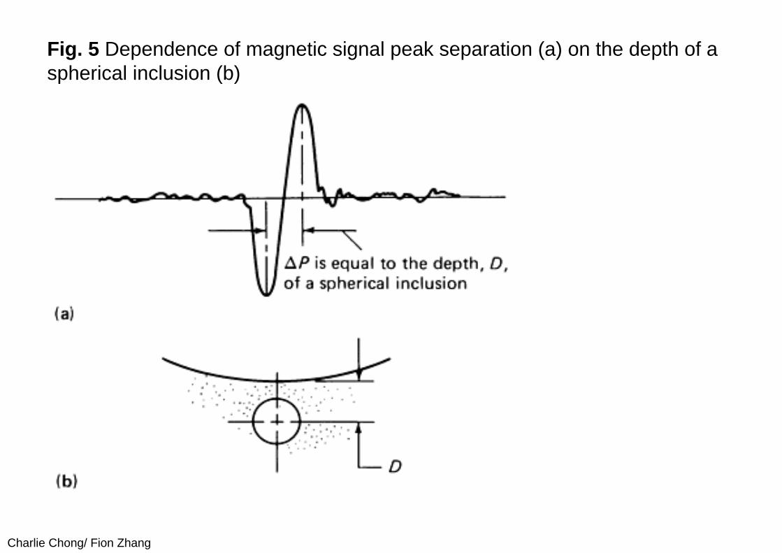
Charlie Chong Fion Zhang
Further theoretical and experimental data for spheroidal inclusions and surface pits have shown however that the simple characterization rules for spherical inclusions do not apply when the flaw shape differs significantly from the ideal sphere In such cases the signal amplitude depends on the lateral extent of the flaw and on its volume and characterization on the basis of leakage field analysis becomes much more complicated
Finally there has been at least one attempt to apply finite-element calculations of flaw leakage fields to the development of characterization rules for a more general class of flaws Hwang and Lord performed most of their computations for simple flaw shapes such as rectangular and triangular slots and inclusions and from the results devised a set of rules for estimating the depth width and angle of inclination of a flaw with respect to the surface of the part One of their applications to a flaw of complex shape is shown in Fig 6
Charlie Chong Fion Zhang
Fig 6 Characterization of a ferrite-tail type of defect The dashed line shows the flaw configuration estimated from the leakage field data
Charlie Chong Fion Zhang
The promising results obtained from the finite-element work of Hwang and Lord as well as the analytically based work on spheroidal flaws suggest that the estimation of flaw size and shape from leakage field data is feasible Another numerical method potentially applicable to flux leakage problems is the boundary integral method which may prove useful in flaw characterization Unfortunately much more work must be done on both the theoretical basis and on experimental testing before it will be possible to analyze experimental leakage field data with confidence in terms of flaw characteristics
Charlie Chong Fion Zhang
PART 2 Principles of Magnetic Characterization of Materials10 Metallurgical and Magnetic Properties
The use of magnetic measurements to monitor the metallurgical propertiesof ferromagnetic materials is based on the fact that variables such as crystallographic phase chemical composition and microstructure which determine the physical properties of materials also affect their magnetic characteristics Some parameters such as grain size and orientation dislocation density and the existence of precipitates are closely related to measurable characteristics of magnetic hysteresis that is to the behavior of the flux density B induced in a material as a function of the magnetic field strength H This relationship can be understood in principle from the physical theory of magnetic domains Magnetization in a particular direction increases as the domains aligned in that direction grow at the expense of domains aligned in other directions Factors that impede domain growth also impede dislocation motion hence the connection at a very fundamental level between magnetic and mechanical properties
Charlie Chong Fion Zhang
Keywords
Metallurgical properties
Crystallographic phase Chemical composition Grain size and orientation Dislocation density and Existence of precipitates
are closely related to measurable characteristics of magnetic hysteresis that is to the behavior of the flux density B induced in a material as a function of the magnetic field strength H
Charlie Chong Fion Zhang
Hysteresis Curves
Charlie Chong Fion Zhang
Other magnetic properties such as the saturation magnetization which is the maximum value B can achieve or the Curie temperature at which there is a transition to a nonmagnetic state are less dependent on microstructure but are sensitive to such factors as crystal structure and chemical composition Interest in the magnetic characterization of materials principally steels derives from many such relationships between measurable magneticparameters and metallurgical properties These relationships are however quite complicated in general and it is often difficult to determine how or if a particular measurement or combination of measurements can be used to determine a property of interest
Charlie Chong Fion Zhang
Nevertheless the prospect of nondestructive monitoring and quality control is an attractive one and for this reason research on magnetic materials characterization continues to be an active field It is not the purpose of this article to explore such magnetic methods in depth but simply to point out that it is an active branch of nondestructive magnetic testing The more fundamental aspects of the relationship between magnetism and metallurgy are discussed in Ref 26 and 28 Engineering considerations are reviewed in Ref 24 The proceedings of various symposia also contain several papers that provide a good overview of the current status of magnetic materials characterization
Charlie Chong Fion Zhang
Curie temperature In physics and materials science the Curie temperature (Tc) or Curie point is the temperature where a materials permanent magnetism changes to induced magnetism The force of magnetism is determined by magnetic moments The Curie temperature is the critical point where a materials intrinsic magnetic moments change direction Magnetic moments are permanent dipole moments within the atom which originate from electrons angular momentum and spin Materials have different structures of intrinsic magnetic moments that depend on temperature At a materials Curie Temperature those intrinsic magnetic moments change direction
Permanent magnetism is caused by the alignment of magnetic moments and induced magnetism is created when disordered magnetic moments are forced to align in an applied magnetic field For example the ordered magnetic moments (ferromagnetic figure 1) change and become disordered (paramagnetic figure 2) at the Curie Temperature Higher temperatures make magnets weaker as spontaneous magnetism only occurs below the Curie Temperature Magnetic susceptibility only occurs above the Curie Temperature and can be calculated from the Curie-Weiss Law which is derived from Curies Law In analogy to ferromagnetic and paramagnetic materials the Curie temperature can also be used to describe the temperature where a materials spontaneous electric polarisation changes to induced electric polarisation or the reverse upon reduction of the temperature below the Curie temperature
httpenwikipediaorgwikiCurie_temperature
Charlie Chong Fion Zhang
Curie temperature
harr ParamagneticAntiferromagneticharr ParamagneticFerrimagneticharr ParamagneticFerromagneticAbove TcBelow Tc
httpenwikipediaorgwikiCurie_temperature
Charlie Chong Fion Zhang
Ferromagnetism The magnetic moments in a ferromagnetic material The moments are ordered and of the same magnitude in the absence of an applied magnetic field
httpenwikipediaorgwikiCurie_temperature
Charlie Chong Fion Zhang
Paramagnetism The magnetic moments in a paramagnetic material The moments are disordered in the absence of an applied magnetic field and ordered in the presence of an applied magnetic field
httpenwikipediaorgwikiCurie_temperature
Charlie Chong Fion Zhang
Ferrimagnetism The magnetic moments in a ferrimagnetic material The moments are aligned oppositely and have different magnitudes due to being made up of two different ions This is in the absence of an applied magnetic field
httpenwikipediaorgwikiCurie_temperature
Charlie Chong Fion Zhang
Antiferromagnetism The magnetic moments in an antiferromagneticmaterial The moments are aligned oppositely and have the same magnitudes This is in the absence of an applied magnetic field
httpenwikipediaorgwikiCurie_temperature
Charlie Chong Fion Zhang
20 Experimental Techniques
A typical setup for measuring the B-H characteristic of a rod specimen is shown in Fig 7 The essential elements are an electromagnet for generating the magnetizing field a coil wound around the specimen for measuring the time rate of change of the magnetic flux B in the material and a magnetic field sensor in this case a Hall effect probe for measuring the magnetic field strength H parallel to the surface of the part The signal generator provides a low-frequency magnetizing field typically of the order of a few Hertz and the output of the flux measuring coil is integrated over time to give the flux density in the material In the arrangement shown in Fig 7 an additional feature is the provision for applying a tensile load to the specimen for studies of the effects of stress on the hysteresis data When using a rod specimen such as this it is important that the length-to-diameter ratio of the specimen be large so as to minimize the effects of stray fields from the ends of the rod on the measurements of B and H
Charlie Chong Fion Zhang
Fig 7 Experimental arrangement for hysteresis loop measurements
Charlie Chong Fion Zhang
Another magnetic method that uses a similar arrangement is the measurement of Barkhausen noise As the magnetic field strength H is varied at a very slow rate discontinuous jumps in the magnetization of the material can be observed during certain portions of the hysteresis cycle These jumps are associated with the sudden growth of a series of magnetic domains that have been temporarily stopped from further growth by such obstacles as grain boundaries precipitates or dislocations Barkhausen noise is therefore dependent on microstructure and can be used independently of hysteresis measurements or in conjunction with such measurements as another method of magnetic testing The experimental arrangement differs from that shown in Fig 7 in that a single sensor coil oriented to measure the flux normal to the surface of the specimen is used instead of the Hall probe and the flux winding
Charlie Chong Fion Zhang
The review articles and conference proceedings cited above contain additional detail on experimental technique and a wealth of information on the interpretation of hysteresis and Barkhausen data However it should be noted that test methods and data interpretation are often very specific to a particular class of alloy and techniques that seem to work well for one type of material may be totally inappropriate for another The analysis of magnetic characterization data is still largely empirical in nature and controlled testing of a candidate technique with the specific alloy system of interest is advisable
Charlie Chong Fion Zhang
PART 3 Application10 Flaw Detection by the Flux Leakage MethodPerhaps the most prevalent use of the flux leakage method is theinspection of ferromagnetic tubular goods such as gas pipelines down hole casing and a variety of other forms of steel piping In applications in the petroleum industry the technique is highly developed but details on inspection devices and methods of data analysis are for the most part considered proprietary by the companies that provide inspection services Still the techniques currently in use have certain features in common and these are exemplified by the typical system described below The device shown in Fig 8 is an inspection tool for large-diameter pipelines Magnetization is provided by a large electromagnet fitted with wire brushes to direct magnetic flux from the electromagnet into the pipe wall To avoid spurious signals from hard spots in the material the magnetization circuit is designed for maximum flux density in the pipe wall in an attempt to magnetically saturate the material
Charlie Chong Fion Zhang
Leakage field sensors are mounted between the pole pieces of the magnet in a circle around the axis of the device to provide as nearly as possible full coverage of the pipe wall In most such tools the sensors are the inductive coil type oriented to measure the axial component of the leakage field gradient Data are usually recorded on magnetic tape as the system is propelled down a section of pipe After the inspection the recorded signals are compared with those from calibration standards in an attempt to interpret flaw indications in terms of flaw type and size
Charlie Chong Fion Zhang
Fig 8 Typical gas pipeline inspection pig The tool consists of a drive unit an instrumentation unit and a center section with an electromagnetic and flux leakage sensors
Pipe
Sensor
Sensor
Pole
Coil
Pole
Charlie Chong Fion Zhang
In addition to systems for inspecting rotationally symmetric cylindrical parts flux leakage inspection has been applied to very irregular components such as helicopter rotor blade D-spars gear teeth and artillery projectiles Several of these special-purpose applications have involved only laboratory investigations but in some cases specialized instrumentation systems have been developed and fabricated for factory use These systems are uniquely adapted to the particular application involved and in most cases only one or at most several instrumentation systems have been built Even in the case of laboratory investigations special-purpose detection probe and magnetizing arrangements have been developed for specific applications
Charlie Chong Fion Zhang
One such system for automated thread inspection on drill pipe and collars is described The device consists of an electromagnet and an array of sensors mounted outside a nonmagnetic cone that threads onto the tool joint The assembly is driven in a helical path along the threads by a motorclutch assembly To minimize the leakage flux signal variations caused by the threads signals from the sensor array are compared differentially The system is capable of operating in a high field strength mode for the detection of cracks and corrosion pits and also in a residual field mode for the detection of other forms of damage At last report the system was undergoing field tests and was found to offer advantages in terms of ease of application and defect detection over the magnetic particle technique normally used for thread inspection
Charlie Chong Fion Zhang
The flux leakage method is also finding application in the inspection of ropes and cables made of strands of ferromagnetic material One approach is to induce magnetization in the piece by means of an encircling coil energized by a direct current (dc) With this method one measures the leakage field associated with broken strands using a Hall effect probe or an auxiliary sensor coil A complementary method with alternating current (ac) which is actually an eddy current test rather than flux leakage is to measure the ac impedance variations in an encircling coil caused by irregularities in the cross-sectional area of the specimen Haynes and Underbakke describe practical field tests of an instrumentation system that utilizes both the ac and dc methods They conclude that instrumentation capable of a combination of inspection techniques offers the best possibility of detecting both localized flaws and overall loss of cross section caused by generalized corrosion and wear They also present detailed information on the practical characteristics of a commercially available device that makes use of both the ac and dc methods
Charlie C
hong Fion Zhang
The flux leakage method is also finding application in the inspection of ropes and cables
Charlie Chong Fion Zhang
Another area in which the flux leakage method has been successfully implemented is the inspection of rolling-element antifriction bearings A schematic illustration of the method as applied to an inner bearing race is shown in Fig 9 In this application the part is magnetized by an electromagnet as indicated in Fig 9(a) The race is then rotated by a spindle and the surface is scanned with an induction coil sensor Typically the race is rotated at a surface speed of about 23 ms (75 fts) and the active portion of the raceway is inspected by incrementally indexing the sensor across the raceway Magnetizing fields are applied in the radial and circumferential orientations It has been shown that radial field inspection works best for surface flaws while circumferential field inspection shows greater sensitivity to subsurface flaws Data have been collected on a large number of bearing races to establish the correlation between leakage field signals and inclusion depths and dimensions determined by metallurgical sectioning
Charlie Chong Fion Zhang
Fig 9 Flux leakage inspection of a bearing race (a) Magnetization of inner race (b) Perturbation in the magnetic flux at the surface of the inner race (c) Probe scanning the surface
Charlie Chong Fion Zhang
Finally the flux leakage method has also been adapted to the inspection of steel reinforcement in concrete beams The basic function of the magnetic field disturbance (MFD) inspection equipment is to provide maps of the magnetic field across the bottom and sides of the beam An electromagnet on an inspection cart which is suspended on tracks below the beam provides a magnetic field that induces magnetization in permeable structures in its vicinity such as steel rebars cables and stirrups An array of Hall effect sensors distributed across the bottom and sides of the beam measures the field produced by magnetized structures within the beam If a flaw is present in one of these magnetized structures it will produce a disturbance of the normal magnetic field pattern associated with the unflawed beam Thus the idea behind the MFD system is to search the surface of the beam for field anomalies that indicate the presence of flaws in reinforcing steel within the structure
Keywordsmagnetic field disturbance (MFD)
Charlie Chong Fion Zhang
A flaw such as a broken wire in a cable or a fractured rebar produces a distinctive magnetic field anomaly that depends on the size of the discontinuity and its distance from the sensor Because the signal shape that results from such an anomaly is known flaw detection is enhanced by searching magnetic field records for specific signal shapes that is those that are characteristic of discontinuities in magnetic materials In the MFD system this is accomplished by a computer program that compares signal shapes with typical flaw signal shapes The program produces a correlation coefficient that serves as a measure of similarity of the observed signal shape to a typical flaw signal shape Flaw detection is therefore not only enhanced by signal shape discrimination but also automated by computer processing of the magnetic field data Laboratory tests have demonstrated the ability of the system to detect fracture in steel rebars and cables in a large pre-stressed concrete structure Also planned are field tests of the equipment in the inspection of bridge decks for reinforcement corrosion damage
Charlie Chong Fion Zhang
Steel rebars and cables in a large pre-stressed concrete structure
Charlie Chong Fion Zhang
20 Nondestructive Characterization of Materials Only two examples of magnetic methods for monitoring materialproperties are given because the examples chosen should suffice to illustrate the types of tests that might be employed Measurements of magnetic characteristics can however provide a wealth of data and various features of such data can yield information on different material properties For example it has been demonstrated that different features of magnetic hysteresis data can be interpreted in terms of heat treatment and microstructure plastic deformation residual stress and mechanical hardness An example of the effects of mechanical hardness on hysteresis data is shown in Fig 10 These data were obtained in the absence of applied tensile stress with the experimental arrangement shown in Fig 7 Specimens of different hardness were prepared by tempering at different temperatures The grain size (ASTM No 7) was the same for all four specimens used in these tests Other data showed however that grain size has little effect on hysteretic behavior for the classes of alloys studied
Charlie Chong Fion Zhang
Fig 10 Effect of mechanical hardness on hysteresis loop data (a) AISI 410 stainless steel (b) SAE 4340 steel
Charlie Chong Fion Zhang
The main point illustrated in Fig 10 is that the mechanically harder specimens of the same alloy are also harder to magnetize that is the flux density B obtained at a large value of H is smaller for mechanically harder specimens than for softer specimens For one alloy AISI 410 stainless steel the hysteresis loop intersects the B = 0 axis at larger values of H for the harder specimen than for the softer specimen that is the coercive force is greater for the harder material However for the other material SAE 4340 steel the coercive force does not change with hardness This suggests that for the two alloys considered here the saturation flux density provides a more reliable measure of hardness than the coercive force Mayos et al used two quite different techniques to measure the depth of surface decarburization of steels One method was a variation of a standard eddy current test with the difference from standard practice being that eddy current probe response was measured in the presence of a low-frequency (~01 Hz) magnetic field This arrangement provides a measure of incremental permeability that is the magnetic permeability corresponding to changes in the applied field about some quasistatic value The second method employed was Barkhausen noise analysis
Charlie Chong Fion Zhang
Keywords
For one alloy AISI 410 stainless steel the hysteresis loop intersects the B = 0 axis at larger values of H for the harder specimen than for the softer specimen that is the coercive force is greater for the harder material However for the other material SAE 4340 steel the coercive force does not change with hardness
This suggests that for the two alloys considered here the saturation flux density provides a more reliable measure of hardness than the coercive force
Charlie Chong Fion Zhang
Depth of decarburization was analyzed by varying the frequency of the excitation field thus changing the skin depth in the material Experiments were performed with both artificial samples containing two layers of different carbon content and industrial samples in which carbon concentration varied smoothly with distance from the surface It was shown that certain features of both Barkhausen noise and incremental permeability data can be correlated with depth of decarburization The Barkhausen noise method showed a somewhat stronger sensitivity to depth but was useful over a smaller range of depths than the incremental permeability method It can be concluded that both methods are useful with the optimum choice depending on accuracy requirements and the expected depth of decarburization
Charlie Chong Fion Zhang
Offshore Structures
Charlie Chong Fion Zhang
Offshore Structures
Charlie Chong Fion Zhang
VLCC
Charlie Chong Fion Zhang
Offshore Structures
Charlie Chong Fion Zhang
Offshore Structures
Charlie Chong Fion Zhang
Offshore Structures
Charlie Chong Fion Zhang
Pipeline amp Piping
Charlie Chong Fion Zhang
Pipeline amp Piping
Charlie Chong Fion Zhang
Charlie Chong Fion Zhang
ass
- Electromagnetic Testing MFLT ECT MicrowaveRFT Chapter 9B ndash漏磁检测 More Reading on Magnetic Field Leakage Testing MFLT
- PART 1 Magnetic Field Testing
-
- 10 Introduction
- 20 Principles of Magnetic Leakage Field Testing MLFT
-
- PART 2 Principles of Magnetic Characterization of Materials
-
- 10 Metallurgical and Magnetic Properties
- 20 Experimental Techniques
-
- PART 3 Application
-
- 10 Flaw Detection by the Flux Leakage Method
- 20 Nondestructive Characterization of Materials
-
- Good Luck
-
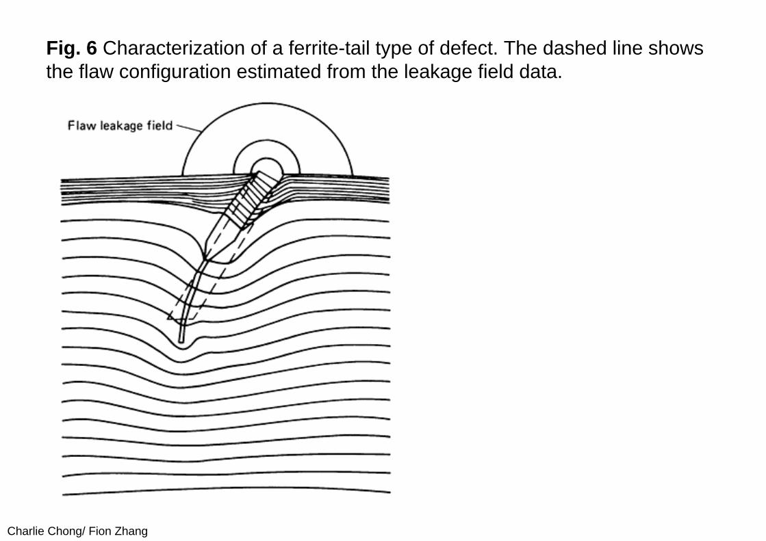
Charlie Chong Fion Zhang
PART 2 Principles of Magnetic Characterization of Materials10 Metallurgical and Magnetic Properties
The use of magnetic measurements to monitor the metallurgical propertiesof ferromagnetic materials is based on the fact that variables such as crystallographic phase chemical composition and microstructure which determine the physical properties of materials also affect their magnetic characteristics Some parameters such as grain size and orientation dislocation density and the existence of precipitates are closely related to measurable characteristics of magnetic hysteresis that is to the behavior of the flux density B induced in a material as a function of the magnetic field strength H This relationship can be understood in principle from the physical theory of magnetic domains Magnetization in a particular direction increases as the domains aligned in that direction grow at the expense of domains aligned in other directions Factors that impede domain growth also impede dislocation motion hence the connection at a very fundamental level between magnetic and mechanical properties
Charlie Chong Fion Zhang
Keywords
Metallurgical properties
Crystallographic phase Chemical composition Grain size and orientation Dislocation density and Existence of precipitates
are closely related to measurable characteristics of magnetic hysteresis that is to the behavior of the flux density B induced in a material as a function of the magnetic field strength H
Charlie Chong Fion Zhang
Hysteresis Curves
Charlie Chong Fion Zhang
Other magnetic properties such as the saturation magnetization which is the maximum value B can achieve or the Curie temperature at which there is a transition to a nonmagnetic state are less dependent on microstructure but are sensitive to such factors as crystal structure and chemical composition Interest in the magnetic characterization of materials principally steels derives from many such relationships between measurable magneticparameters and metallurgical properties These relationships are however quite complicated in general and it is often difficult to determine how or if a particular measurement or combination of measurements can be used to determine a property of interest
Charlie Chong Fion Zhang
Nevertheless the prospect of nondestructive monitoring and quality control is an attractive one and for this reason research on magnetic materials characterization continues to be an active field It is not the purpose of this article to explore such magnetic methods in depth but simply to point out that it is an active branch of nondestructive magnetic testing The more fundamental aspects of the relationship between magnetism and metallurgy are discussed in Ref 26 and 28 Engineering considerations are reviewed in Ref 24 The proceedings of various symposia also contain several papers that provide a good overview of the current status of magnetic materials characterization
Charlie Chong Fion Zhang
Curie temperature In physics and materials science the Curie temperature (Tc) or Curie point is the temperature where a materials permanent magnetism changes to induced magnetism The force of magnetism is determined by magnetic moments The Curie temperature is the critical point where a materials intrinsic magnetic moments change direction Magnetic moments are permanent dipole moments within the atom which originate from electrons angular momentum and spin Materials have different structures of intrinsic magnetic moments that depend on temperature At a materials Curie Temperature those intrinsic magnetic moments change direction
Permanent magnetism is caused by the alignment of magnetic moments and induced magnetism is created when disordered magnetic moments are forced to align in an applied magnetic field For example the ordered magnetic moments (ferromagnetic figure 1) change and become disordered (paramagnetic figure 2) at the Curie Temperature Higher temperatures make magnets weaker as spontaneous magnetism only occurs below the Curie Temperature Magnetic susceptibility only occurs above the Curie Temperature and can be calculated from the Curie-Weiss Law which is derived from Curies Law In analogy to ferromagnetic and paramagnetic materials the Curie temperature can also be used to describe the temperature where a materials spontaneous electric polarisation changes to induced electric polarisation or the reverse upon reduction of the temperature below the Curie temperature
httpenwikipediaorgwikiCurie_temperature
Charlie Chong Fion Zhang
Curie temperature
harr ParamagneticAntiferromagneticharr ParamagneticFerrimagneticharr ParamagneticFerromagneticAbove TcBelow Tc
httpenwikipediaorgwikiCurie_temperature
Charlie Chong Fion Zhang
Ferromagnetism The magnetic moments in a ferromagnetic material The moments are ordered and of the same magnitude in the absence of an applied magnetic field
httpenwikipediaorgwikiCurie_temperature
Charlie Chong Fion Zhang
Paramagnetism The magnetic moments in a paramagnetic material The moments are disordered in the absence of an applied magnetic field and ordered in the presence of an applied magnetic field
httpenwikipediaorgwikiCurie_temperature
Charlie Chong Fion Zhang
Ferrimagnetism The magnetic moments in a ferrimagnetic material The moments are aligned oppositely and have different magnitudes due to being made up of two different ions This is in the absence of an applied magnetic field
httpenwikipediaorgwikiCurie_temperature
Charlie Chong Fion Zhang
Antiferromagnetism The magnetic moments in an antiferromagneticmaterial The moments are aligned oppositely and have the same magnitudes This is in the absence of an applied magnetic field
httpenwikipediaorgwikiCurie_temperature
Charlie Chong Fion Zhang
20 Experimental Techniques
A typical setup for measuring the B-H characteristic of a rod specimen is shown in Fig 7 The essential elements are an electromagnet for generating the magnetizing field a coil wound around the specimen for measuring the time rate of change of the magnetic flux B in the material and a magnetic field sensor in this case a Hall effect probe for measuring the magnetic field strength H parallel to the surface of the part The signal generator provides a low-frequency magnetizing field typically of the order of a few Hertz and the output of the flux measuring coil is integrated over time to give the flux density in the material In the arrangement shown in Fig 7 an additional feature is the provision for applying a tensile load to the specimen for studies of the effects of stress on the hysteresis data When using a rod specimen such as this it is important that the length-to-diameter ratio of the specimen be large so as to minimize the effects of stray fields from the ends of the rod on the measurements of B and H
Charlie Chong Fion Zhang
Fig 7 Experimental arrangement for hysteresis loop measurements
Charlie Chong Fion Zhang
Another magnetic method that uses a similar arrangement is the measurement of Barkhausen noise As the magnetic field strength H is varied at a very slow rate discontinuous jumps in the magnetization of the material can be observed during certain portions of the hysteresis cycle These jumps are associated with the sudden growth of a series of magnetic domains that have been temporarily stopped from further growth by such obstacles as grain boundaries precipitates or dislocations Barkhausen noise is therefore dependent on microstructure and can be used independently of hysteresis measurements or in conjunction with such measurements as another method of magnetic testing The experimental arrangement differs from that shown in Fig 7 in that a single sensor coil oriented to measure the flux normal to the surface of the specimen is used instead of the Hall probe and the flux winding
Charlie Chong Fion Zhang
The review articles and conference proceedings cited above contain additional detail on experimental technique and a wealth of information on the interpretation of hysteresis and Barkhausen data However it should be noted that test methods and data interpretation are often very specific to a particular class of alloy and techniques that seem to work well for one type of material may be totally inappropriate for another The analysis of magnetic characterization data is still largely empirical in nature and controlled testing of a candidate technique with the specific alloy system of interest is advisable
Charlie Chong Fion Zhang
PART 3 Application10 Flaw Detection by the Flux Leakage MethodPerhaps the most prevalent use of the flux leakage method is theinspection of ferromagnetic tubular goods such as gas pipelines down hole casing and a variety of other forms of steel piping In applications in the petroleum industry the technique is highly developed but details on inspection devices and methods of data analysis are for the most part considered proprietary by the companies that provide inspection services Still the techniques currently in use have certain features in common and these are exemplified by the typical system described below The device shown in Fig 8 is an inspection tool for large-diameter pipelines Magnetization is provided by a large electromagnet fitted with wire brushes to direct magnetic flux from the electromagnet into the pipe wall To avoid spurious signals from hard spots in the material the magnetization circuit is designed for maximum flux density in the pipe wall in an attempt to magnetically saturate the material
Charlie Chong Fion Zhang
Leakage field sensors are mounted between the pole pieces of the magnet in a circle around the axis of the device to provide as nearly as possible full coverage of the pipe wall In most such tools the sensors are the inductive coil type oriented to measure the axial component of the leakage field gradient Data are usually recorded on magnetic tape as the system is propelled down a section of pipe After the inspection the recorded signals are compared with those from calibration standards in an attempt to interpret flaw indications in terms of flaw type and size
Charlie Chong Fion Zhang
Fig 8 Typical gas pipeline inspection pig The tool consists of a drive unit an instrumentation unit and a center section with an electromagnetic and flux leakage sensors
Pipe
Sensor
Sensor
Pole
Coil
Pole
Charlie Chong Fion Zhang
In addition to systems for inspecting rotationally symmetric cylindrical parts flux leakage inspection has been applied to very irregular components such as helicopter rotor blade D-spars gear teeth and artillery projectiles Several of these special-purpose applications have involved only laboratory investigations but in some cases specialized instrumentation systems have been developed and fabricated for factory use These systems are uniquely adapted to the particular application involved and in most cases only one or at most several instrumentation systems have been built Even in the case of laboratory investigations special-purpose detection probe and magnetizing arrangements have been developed for specific applications
Charlie Chong Fion Zhang
One such system for automated thread inspection on drill pipe and collars is described The device consists of an electromagnet and an array of sensors mounted outside a nonmagnetic cone that threads onto the tool joint The assembly is driven in a helical path along the threads by a motorclutch assembly To minimize the leakage flux signal variations caused by the threads signals from the sensor array are compared differentially The system is capable of operating in a high field strength mode for the detection of cracks and corrosion pits and also in a residual field mode for the detection of other forms of damage At last report the system was undergoing field tests and was found to offer advantages in terms of ease of application and defect detection over the magnetic particle technique normally used for thread inspection
Charlie Chong Fion Zhang
The flux leakage method is also finding application in the inspection of ropes and cables made of strands of ferromagnetic material One approach is to induce magnetization in the piece by means of an encircling coil energized by a direct current (dc) With this method one measures the leakage field associated with broken strands using a Hall effect probe or an auxiliary sensor coil A complementary method with alternating current (ac) which is actually an eddy current test rather than flux leakage is to measure the ac impedance variations in an encircling coil caused by irregularities in the cross-sectional area of the specimen Haynes and Underbakke describe practical field tests of an instrumentation system that utilizes both the ac and dc methods They conclude that instrumentation capable of a combination of inspection techniques offers the best possibility of detecting both localized flaws and overall loss of cross section caused by generalized corrosion and wear They also present detailed information on the practical characteristics of a commercially available device that makes use of both the ac and dc methods
Charlie C
hong Fion Zhang
The flux leakage method is also finding application in the inspection of ropes and cables
Charlie Chong Fion Zhang
Another area in which the flux leakage method has been successfully implemented is the inspection of rolling-element antifriction bearings A schematic illustration of the method as applied to an inner bearing race is shown in Fig 9 In this application the part is magnetized by an electromagnet as indicated in Fig 9(a) The race is then rotated by a spindle and the surface is scanned with an induction coil sensor Typically the race is rotated at a surface speed of about 23 ms (75 fts) and the active portion of the raceway is inspected by incrementally indexing the sensor across the raceway Magnetizing fields are applied in the radial and circumferential orientations It has been shown that radial field inspection works best for surface flaws while circumferential field inspection shows greater sensitivity to subsurface flaws Data have been collected on a large number of bearing races to establish the correlation between leakage field signals and inclusion depths and dimensions determined by metallurgical sectioning
Charlie Chong Fion Zhang
Fig 9 Flux leakage inspection of a bearing race (a) Magnetization of inner race (b) Perturbation in the magnetic flux at the surface of the inner race (c) Probe scanning the surface
Charlie Chong Fion Zhang
Finally the flux leakage method has also been adapted to the inspection of steel reinforcement in concrete beams The basic function of the magnetic field disturbance (MFD) inspection equipment is to provide maps of the magnetic field across the bottom and sides of the beam An electromagnet on an inspection cart which is suspended on tracks below the beam provides a magnetic field that induces magnetization in permeable structures in its vicinity such as steel rebars cables and stirrups An array of Hall effect sensors distributed across the bottom and sides of the beam measures the field produced by magnetized structures within the beam If a flaw is present in one of these magnetized structures it will produce a disturbance of the normal magnetic field pattern associated with the unflawed beam Thus the idea behind the MFD system is to search the surface of the beam for field anomalies that indicate the presence of flaws in reinforcing steel within the structure
Keywordsmagnetic field disturbance (MFD)
Charlie Chong Fion Zhang
A flaw such as a broken wire in a cable or a fractured rebar produces a distinctive magnetic field anomaly that depends on the size of the discontinuity and its distance from the sensor Because the signal shape that results from such an anomaly is known flaw detection is enhanced by searching magnetic field records for specific signal shapes that is those that are characteristic of discontinuities in magnetic materials In the MFD system this is accomplished by a computer program that compares signal shapes with typical flaw signal shapes The program produces a correlation coefficient that serves as a measure of similarity of the observed signal shape to a typical flaw signal shape Flaw detection is therefore not only enhanced by signal shape discrimination but also automated by computer processing of the magnetic field data Laboratory tests have demonstrated the ability of the system to detect fracture in steel rebars and cables in a large pre-stressed concrete structure Also planned are field tests of the equipment in the inspection of bridge decks for reinforcement corrosion damage
Charlie Chong Fion Zhang
Steel rebars and cables in a large pre-stressed concrete structure
Charlie Chong Fion Zhang
20 Nondestructive Characterization of Materials Only two examples of magnetic methods for monitoring materialproperties are given because the examples chosen should suffice to illustrate the types of tests that might be employed Measurements of magnetic characteristics can however provide a wealth of data and various features of such data can yield information on different material properties For example it has been demonstrated that different features of magnetic hysteresis data can be interpreted in terms of heat treatment and microstructure plastic deformation residual stress and mechanical hardness An example of the effects of mechanical hardness on hysteresis data is shown in Fig 10 These data were obtained in the absence of applied tensile stress with the experimental arrangement shown in Fig 7 Specimens of different hardness were prepared by tempering at different temperatures The grain size (ASTM No 7) was the same for all four specimens used in these tests Other data showed however that grain size has little effect on hysteretic behavior for the classes of alloys studied
Charlie Chong Fion Zhang
Fig 10 Effect of mechanical hardness on hysteresis loop data (a) AISI 410 stainless steel (b) SAE 4340 steel
Charlie Chong Fion Zhang
The main point illustrated in Fig 10 is that the mechanically harder specimens of the same alloy are also harder to magnetize that is the flux density B obtained at a large value of H is smaller for mechanically harder specimens than for softer specimens For one alloy AISI 410 stainless steel the hysteresis loop intersects the B = 0 axis at larger values of H for the harder specimen than for the softer specimen that is the coercive force is greater for the harder material However for the other material SAE 4340 steel the coercive force does not change with hardness This suggests that for the two alloys considered here the saturation flux density provides a more reliable measure of hardness than the coercive force Mayos et al used two quite different techniques to measure the depth of surface decarburization of steels One method was a variation of a standard eddy current test with the difference from standard practice being that eddy current probe response was measured in the presence of a low-frequency (~01 Hz) magnetic field This arrangement provides a measure of incremental permeability that is the magnetic permeability corresponding to changes in the applied field about some quasistatic value The second method employed was Barkhausen noise analysis
Charlie Chong Fion Zhang
Keywords
For one alloy AISI 410 stainless steel the hysteresis loop intersects the B = 0 axis at larger values of H for the harder specimen than for the softer specimen that is the coercive force is greater for the harder material However for the other material SAE 4340 steel the coercive force does not change with hardness
This suggests that for the two alloys considered here the saturation flux density provides a more reliable measure of hardness than the coercive force
Charlie Chong Fion Zhang
Depth of decarburization was analyzed by varying the frequency of the excitation field thus changing the skin depth in the material Experiments were performed with both artificial samples containing two layers of different carbon content and industrial samples in which carbon concentration varied smoothly with distance from the surface It was shown that certain features of both Barkhausen noise and incremental permeability data can be correlated with depth of decarburization The Barkhausen noise method showed a somewhat stronger sensitivity to depth but was useful over a smaller range of depths than the incremental permeability method It can be concluded that both methods are useful with the optimum choice depending on accuracy requirements and the expected depth of decarburization
Charlie Chong Fion Zhang
Offshore Structures
Charlie Chong Fion Zhang
Offshore Structures
Charlie Chong Fion Zhang
VLCC
Charlie Chong Fion Zhang
Offshore Structures
Charlie Chong Fion Zhang
Offshore Structures
Charlie Chong Fion Zhang
Offshore Structures
Charlie Chong Fion Zhang
Pipeline amp Piping
Charlie Chong Fion Zhang
Pipeline amp Piping
Charlie Chong Fion Zhang
Charlie Chong Fion Zhang
ass
- Electromagnetic Testing MFLT ECT MicrowaveRFT Chapter 9B ndash漏磁检测 More Reading on Magnetic Field Leakage Testing MFLT
- PART 1 Magnetic Field Testing
-
- 10 Introduction
- 20 Principles of Magnetic Leakage Field Testing MLFT
-
- PART 2 Principles of Magnetic Characterization of Materials
-
- 10 Metallurgical and Magnetic Properties
- 20 Experimental Techniques
-
- PART 3 Application
-
- 10 Flaw Detection by the Flux Leakage Method
- 20 Nondestructive Characterization of Materials
-
- Good Luck
-
Charlie Chong Fion Zhang
Keywords
Metallurgical properties
Crystallographic phase Chemical composition Grain size and orientation Dislocation density and Existence of precipitates
are closely related to measurable characteristics of magnetic hysteresis that is to the behavior of the flux density B induced in a material as a function of the magnetic field strength H
Charlie Chong Fion Zhang
Hysteresis Curves
Charlie Chong Fion Zhang
Other magnetic properties such as the saturation magnetization which is the maximum value B can achieve or the Curie temperature at which there is a transition to a nonmagnetic state are less dependent on microstructure but are sensitive to such factors as crystal structure and chemical composition Interest in the magnetic characterization of materials principally steels derives from many such relationships between measurable magneticparameters and metallurgical properties These relationships are however quite complicated in general and it is often difficult to determine how or if a particular measurement or combination of measurements can be used to determine a property of interest
Charlie Chong Fion Zhang
Nevertheless the prospect of nondestructive monitoring and quality control is an attractive one and for this reason research on magnetic materials characterization continues to be an active field It is not the purpose of this article to explore such magnetic methods in depth but simply to point out that it is an active branch of nondestructive magnetic testing The more fundamental aspects of the relationship between magnetism and metallurgy are discussed in Ref 26 and 28 Engineering considerations are reviewed in Ref 24 The proceedings of various symposia also contain several papers that provide a good overview of the current status of magnetic materials characterization
Charlie Chong Fion Zhang
Curie temperature In physics and materials science the Curie temperature (Tc) or Curie point is the temperature where a materials permanent magnetism changes to induced magnetism The force of magnetism is determined by magnetic moments The Curie temperature is the critical point where a materials intrinsic magnetic moments change direction Magnetic moments are permanent dipole moments within the atom which originate from electrons angular momentum and spin Materials have different structures of intrinsic magnetic moments that depend on temperature At a materials Curie Temperature those intrinsic magnetic moments change direction
Permanent magnetism is caused by the alignment of magnetic moments and induced magnetism is created when disordered magnetic moments are forced to align in an applied magnetic field For example the ordered magnetic moments (ferromagnetic figure 1) change and become disordered (paramagnetic figure 2) at the Curie Temperature Higher temperatures make magnets weaker as spontaneous magnetism only occurs below the Curie Temperature Magnetic susceptibility only occurs above the Curie Temperature and can be calculated from the Curie-Weiss Law which is derived from Curies Law In analogy to ferromagnetic and paramagnetic materials the Curie temperature can also be used to describe the temperature where a materials spontaneous electric polarisation changes to induced electric polarisation or the reverse upon reduction of the temperature below the Curie temperature
httpenwikipediaorgwikiCurie_temperature
Charlie Chong Fion Zhang
Curie temperature
harr ParamagneticAntiferromagneticharr ParamagneticFerrimagneticharr ParamagneticFerromagneticAbove TcBelow Tc
httpenwikipediaorgwikiCurie_temperature
Charlie Chong Fion Zhang
Ferromagnetism The magnetic moments in a ferromagnetic material The moments are ordered and of the same magnitude in the absence of an applied magnetic field
httpenwikipediaorgwikiCurie_temperature
Charlie Chong Fion Zhang
Paramagnetism The magnetic moments in a paramagnetic material The moments are disordered in the absence of an applied magnetic field and ordered in the presence of an applied magnetic field
httpenwikipediaorgwikiCurie_temperature
Charlie Chong Fion Zhang
Ferrimagnetism The magnetic moments in a ferrimagnetic material The moments are aligned oppositely and have different magnitudes due to being made up of two different ions This is in the absence of an applied magnetic field
httpenwikipediaorgwikiCurie_temperature
Charlie Chong Fion Zhang
Antiferromagnetism The magnetic moments in an antiferromagneticmaterial The moments are aligned oppositely and have the same magnitudes This is in the absence of an applied magnetic field
httpenwikipediaorgwikiCurie_temperature
Charlie Chong Fion Zhang
20 Experimental Techniques
A typical setup for measuring the B-H characteristic of a rod specimen is shown in Fig 7 The essential elements are an electromagnet for generating the magnetizing field a coil wound around the specimen for measuring the time rate of change of the magnetic flux B in the material and a magnetic field sensor in this case a Hall effect probe for measuring the magnetic field strength H parallel to the surface of the part The signal generator provides a low-frequency magnetizing field typically of the order of a few Hertz and the output of the flux measuring coil is integrated over time to give the flux density in the material In the arrangement shown in Fig 7 an additional feature is the provision for applying a tensile load to the specimen for studies of the effects of stress on the hysteresis data When using a rod specimen such as this it is important that the length-to-diameter ratio of the specimen be large so as to minimize the effects of stray fields from the ends of the rod on the measurements of B and H
Charlie Chong Fion Zhang
Fig 7 Experimental arrangement for hysteresis loop measurements
Charlie Chong Fion Zhang
Another magnetic method that uses a similar arrangement is the measurement of Barkhausen noise As the magnetic field strength H is varied at a very slow rate discontinuous jumps in the magnetization of the material can be observed during certain portions of the hysteresis cycle These jumps are associated with the sudden growth of a series of magnetic domains that have been temporarily stopped from further growth by such obstacles as grain boundaries precipitates or dislocations Barkhausen noise is therefore dependent on microstructure and can be used independently of hysteresis measurements or in conjunction with such measurements as another method of magnetic testing The experimental arrangement differs from that shown in Fig 7 in that a single sensor coil oriented to measure the flux normal to the surface of the specimen is used instead of the Hall probe and the flux winding
Charlie Chong Fion Zhang
The review articles and conference proceedings cited above contain additional detail on experimental technique and a wealth of information on the interpretation of hysteresis and Barkhausen data However it should be noted that test methods and data interpretation are often very specific to a particular class of alloy and techniques that seem to work well for one type of material may be totally inappropriate for another The analysis of magnetic characterization data is still largely empirical in nature and controlled testing of a candidate technique with the specific alloy system of interest is advisable
Charlie Chong Fion Zhang
PART 3 Application10 Flaw Detection by the Flux Leakage MethodPerhaps the most prevalent use of the flux leakage method is theinspection of ferromagnetic tubular goods such as gas pipelines down hole casing and a variety of other forms of steel piping In applications in the petroleum industry the technique is highly developed but details on inspection devices and methods of data analysis are for the most part considered proprietary by the companies that provide inspection services Still the techniques currently in use have certain features in common and these are exemplified by the typical system described below The device shown in Fig 8 is an inspection tool for large-diameter pipelines Magnetization is provided by a large electromagnet fitted with wire brushes to direct magnetic flux from the electromagnet into the pipe wall To avoid spurious signals from hard spots in the material the magnetization circuit is designed for maximum flux density in the pipe wall in an attempt to magnetically saturate the material
Charlie Chong Fion Zhang
Leakage field sensors are mounted between the pole pieces of the magnet in a circle around the axis of the device to provide as nearly as possible full coverage of the pipe wall In most such tools the sensors are the inductive coil type oriented to measure the axial component of the leakage field gradient Data are usually recorded on magnetic tape as the system is propelled down a section of pipe After the inspection the recorded signals are compared with those from calibration standards in an attempt to interpret flaw indications in terms of flaw type and size
Charlie Chong Fion Zhang
Fig 8 Typical gas pipeline inspection pig The tool consists of a drive unit an instrumentation unit and a center section with an electromagnetic and flux leakage sensors
Pipe
Sensor
Sensor
Pole
Coil
Pole
Charlie Chong Fion Zhang
In addition to systems for inspecting rotationally symmetric cylindrical parts flux leakage inspection has been applied to very irregular components such as helicopter rotor blade D-spars gear teeth and artillery projectiles Several of these special-purpose applications have involved only laboratory investigations but in some cases specialized instrumentation systems have been developed and fabricated for factory use These systems are uniquely adapted to the particular application involved and in most cases only one or at most several instrumentation systems have been built Even in the case of laboratory investigations special-purpose detection probe and magnetizing arrangements have been developed for specific applications
Charlie Chong Fion Zhang
One such system for automated thread inspection on drill pipe and collars is described The device consists of an electromagnet and an array of sensors mounted outside a nonmagnetic cone that threads onto the tool joint The assembly is driven in a helical path along the threads by a motorclutch assembly To minimize the leakage flux signal variations caused by the threads signals from the sensor array are compared differentially The system is capable of operating in a high field strength mode for the detection of cracks and corrosion pits and also in a residual field mode for the detection of other forms of damage At last report the system was undergoing field tests and was found to offer advantages in terms of ease of application and defect detection over the magnetic particle technique normally used for thread inspection
Charlie Chong Fion Zhang
The flux leakage method is also finding application in the inspection of ropes and cables made of strands of ferromagnetic material One approach is to induce magnetization in the piece by means of an encircling coil energized by a direct current (dc) With this method one measures the leakage field associated with broken strands using a Hall effect probe or an auxiliary sensor coil A complementary method with alternating current (ac) which is actually an eddy current test rather than flux leakage is to measure the ac impedance variations in an encircling coil caused by irregularities in the cross-sectional area of the specimen Haynes and Underbakke describe practical field tests of an instrumentation system that utilizes both the ac and dc methods They conclude that instrumentation capable of a combination of inspection techniques offers the best possibility of detecting both localized flaws and overall loss of cross section caused by generalized corrosion and wear They also present detailed information on the practical characteristics of a commercially available device that makes use of both the ac and dc methods
Charlie C
hong Fion Zhang
The flux leakage method is also finding application in the inspection of ropes and cables
Charlie Chong Fion Zhang
Another area in which the flux leakage method has been successfully implemented is the inspection of rolling-element antifriction bearings A schematic illustration of the method as applied to an inner bearing race is shown in Fig 9 In this application the part is magnetized by an electromagnet as indicated in Fig 9(a) The race is then rotated by a spindle and the surface is scanned with an induction coil sensor Typically the race is rotated at a surface speed of about 23 ms (75 fts) and the active portion of the raceway is inspected by incrementally indexing the sensor across the raceway Magnetizing fields are applied in the radial and circumferential orientations It has been shown that radial field inspection works best for surface flaws while circumferential field inspection shows greater sensitivity to subsurface flaws Data have been collected on a large number of bearing races to establish the correlation between leakage field signals and inclusion depths and dimensions determined by metallurgical sectioning
Charlie Chong Fion Zhang
Fig 9 Flux leakage inspection of a bearing race (a) Magnetization of inner race (b) Perturbation in the magnetic flux at the surface of the inner race (c) Probe scanning the surface
Charlie Chong Fion Zhang
Finally the flux leakage method has also been adapted to the inspection of steel reinforcement in concrete beams The basic function of the magnetic field disturbance (MFD) inspection equipment is to provide maps of the magnetic field across the bottom and sides of the beam An electromagnet on an inspection cart which is suspended on tracks below the beam provides a magnetic field that induces magnetization in permeable structures in its vicinity such as steel rebars cables and stirrups An array of Hall effect sensors distributed across the bottom and sides of the beam measures the field produced by magnetized structures within the beam If a flaw is present in one of these magnetized structures it will produce a disturbance of the normal magnetic field pattern associated with the unflawed beam Thus the idea behind the MFD system is to search the surface of the beam for field anomalies that indicate the presence of flaws in reinforcing steel within the structure
Keywordsmagnetic field disturbance (MFD)
Charlie Chong Fion Zhang
A flaw such as a broken wire in a cable or a fractured rebar produces a distinctive magnetic field anomaly that depends on the size of the discontinuity and its distance from the sensor Because the signal shape that results from such an anomaly is known flaw detection is enhanced by searching magnetic field records for specific signal shapes that is those that are characteristic of discontinuities in magnetic materials In the MFD system this is accomplished by a computer program that compares signal shapes with typical flaw signal shapes The program produces a correlation coefficient that serves as a measure of similarity of the observed signal shape to a typical flaw signal shape Flaw detection is therefore not only enhanced by signal shape discrimination but also automated by computer processing of the magnetic field data Laboratory tests have demonstrated the ability of the system to detect fracture in steel rebars and cables in a large pre-stressed concrete structure Also planned are field tests of the equipment in the inspection of bridge decks for reinforcement corrosion damage
Charlie Chong Fion Zhang
Steel rebars and cables in a large pre-stressed concrete structure
Charlie Chong Fion Zhang
20 Nondestructive Characterization of Materials Only two examples of magnetic methods for monitoring materialproperties are given because the examples chosen should suffice to illustrate the types of tests that might be employed Measurements of magnetic characteristics can however provide a wealth of data and various features of such data can yield information on different material properties For example it has been demonstrated that different features of magnetic hysteresis data can be interpreted in terms of heat treatment and microstructure plastic deformation residual stress and mechanical hardness An example of the effects of mechanical hardness on hysteresis data is shown in Fig 10 These data were obtained in the absence of applied tensile stress with the experimental arrangement shown in Fig 7 Specimens of different hardness were prepared by tempering at different temperatures The grain size (ASTM No 7) was the same for all four specimens used in these tests Other data showed however that grain size has little effect on hysteretic behavior for the classes of alloys studied
Charlie Chong Fion Zhang
Fig 10 Effect of mechanical hardness on hysteresis loop data (a) AISI 410 stainless steel (b) SAE 4340 steel
Charlie Chong Fion Zhang
The main point illustrated in Fig 10 is that the mechanically harder specimens of the same alloy are also harder to magnetize that is the flux density B obtained at a large value of H is smaller for mechanically harder specimens than for softer specimens For one alloy AISI 410 stainless steel the hysteresis loop intersects the B = 0 axis at larger values of H for the harder specimen than for the softer specimen that is the coercive force is greater for the harder material However for the other material SAE 4340 steel the coercive force does not change with hardness This suggests that for the two alloys considered here the saturation flux density provides a more reliable measure of hardness than the coercive force Mayos et al used two quite different techniques to measure the depth of surface decarburization of steels One method was a variation of a standard eddy current test with the difference from standard practice being that eddy current probe response was measured in the presence of a low-frequency (~01 Hz) magnetic field This arrangement provides a measure of incremental permeability that is the magnetic permeability corresponding to changes in the applied field about some quasistatic value The second method employed was Barkhausen noise analysis
Charlie Chong Fion Zhang
Keywords
For one alloy AISI 410 stainless steel the hysteresis loop intersects the B = 0 axis at larger values of H for the harder specimen than for the softer specimen that is the coercive force is greater for the harder material However for the other material SAE 4340 steel the coercive force does not change with hardness
This suggests that for the two alloys considered here the saturation flux density provides a more reliable measure of hardness than the coercive force
Charlie Chong Fion Zhang
Depth of decarburization was analyzed by varying the frequency of the excitation field thus changing the skin depth in the material Experiments were performed with both artificial samples containing two layers of different carbon content and industrial samples in which carbon concentration varied smoothly with distance from the surface It was shown that certain features of both Barkhausen noise and incremental permeability data can be correlated with depth of decarburization The Barkhausen noise method showed a somewhat stronger sensitivity to depth but was useful over a smaller range of depths than the incremental permeability method It can be concluded that both methods are useful with the optimum choice depending on accuracy requirements and the expected depth of decarburization
Charlie Chong Fion Zhang
Offshore Structures
Charlie Chong Fion Zhang
Offshore Structures
Charlie Chong Fion Zhang
VLCC
Charlie Chong Fion Zhang
Offshore Structures
Charlie Chong Fion Zhang
Offshore Structures
Charlie Chong Fion Zhang
Offshore Structures
Charlie Chong Fion Zhang
Pipeline amp Piping
Charlie Chong Fion Zhang
Pipeline amp Piping
Charlie Chong Fion Zhang
Charlie Chong Fion Zhang
ass
- Electromagnetic Testing MFLT ECT MicrowaveRFT Chapter 9B ndash漏磁检测 More Reading on Magnetic Field Leakage Testing MFLT
- PART 1 Magnetic Field Testing
-
- 10 Introduction
- 20 Principles of Magnetic Leakage Field Testing MLFT
-
- PART 2 Principles of Magnetic Characterization of Materials
-
- 10 Metallurgical and Magnetic Properties
- 20 Experimental Techniques
-
- PART 3 Application
-
- 10 Flaw Detection by the Flux Leakage Method
- 20 Nondestructive Characterization of Materials
-
- Good Luck
-

Charlie Chong Fion Zhang
PART 3 Application10 Flaw Detection by the Flux Leakage MethodPerhaps the most prevalent use of the flux leakage method is theinspection of ferromagnetic tubular goods such as gas pipelines down hole casing and a variety of other forms of steel piping In applications in the petroleum industry the technique is highly developed but details on inspection devices and methods of data analysis are for the most part considered proprietary by the companies that provide inspection services Still the techniques currently in use have certain features in common and these are exemplified by the typical system described below The device shown in Fig 8 is an inspection tool for large-diameter pipelines Magnetization is provided by a large electromagnet fitted with wire brushes to direct magnetic flux from the electromagnet into the pipe wall To avoid spurious signals from hard spots in the material the magnetization circuit is designed for maximum flux density in the pipe wall in an attempt to magnetically saturate the material
Charlie Chong Fion Zhang
Leakage field sensors are mounted between the pole pieces of the magnet in a circle around the axis of the device to provide as nearly as possible full coverage of the pipe wall In most such tools the sensors are the inductive coil type oriented to measure the axial component of the leakage field gradient Data are usually recorded on magnetic tape as the system is propelled down a section of pipe After the inspection the recorded signals are compared with those from calibration standards in an attempt to interpret flaw indications in terms of flaw type and size
Charlie Chong Fion Zhang
Fig 8 Typical gas pipeline inspection pig The tool consists of a drive unit an instrumentation unit and a center section with an electromagnetic and flux leakage sensors
Pipe
Sensor
Sensor
Pole
Coil
Pole
Charlie Chong Fion Zhang
In addition to systems for inspecting rotationally symmetric cylindrical parts flux leakage inspection has been applied to very irregular components such as helicopter rotor blade D-spars gear teeth and artillery projectiles Several of these special-purpose applications have involved only laboratory investigations but in some cases specialized instrumentation systems have been developed and fabricated for factory use These systems are uniquely adapted to the particular application involved and in most cases only one or at most several instrumentation systems have been built Even in the case of laboratory investigations special-purpose detection probe and magnetizing arrangements have been developed for specific applications
Charlie Chong Fion Zhang
One such system for automated thread inspection on drill pipe and collars is described The device consists of an electromagnet and an array of sensors mounted outside a nonmagnetic cone that threads onto the tool joint The assembly is driven in a helical path along the threads by a motorclutch assembly To minimize the leakage flux signal variations caused by the threads signals from the sensor array are compared differentially The system is capable of operating in a high field strength mode for the detection of cracks and corrosion pits and also in a residual field mode for the detection of other forms of damage At last report the system was undergoing field tests and was found to offer advantages in terms of ease of application and defect detection over the magnetic particle technique normally used for thread inspection
Charlie Chong Fion Zhang
The flux leakage method is also finding application in the inspection of ropes and cables made of strands of ferromagnetic material One approach is to induce magnetization in the piece by means of an encircling coil energized by a direct current (dc) With this method one measures the leakage field associated with broken strands using a Hall effect probe or an auxiliary sensor coil A complementary method with alternating current (ac) which is actually an eddy current test rather than flux leakage is to measure the ac impedance variations in an encircling coil caused by irregularities in the cross-sectional area of the specimen Haynes and Underbakke describe practical field tests of an instrumentation system that utilizes both the ac and dc methods They conclude that instrumentation capable of a combination of inspection techniques offers the best possibility of detecting both localized flaws and overall loss of cross section caused by generalized corrosion and wear They also present detailed information on the practical characteristics of a commercially available device that makes use of both the ac and dc methods
Charlie C
hong Fion Zhang
The flux leakage method is also finding application in the inspection of ropes and cables
Charlie Chong Fion Zhang
Another area in which the flux leakage method has been successfully implemented is the inspection of rolling-element antifriction bearings A schematic illustration of the method as applied to an inner bearing race is shown in Fig 9 In this application the part is magnetized by an electromagnet as indicated in Fig 9(a) The race is then rotated by a spindle and the surface is scanned with an induction coil sensor Typically the race is rotated at a surface speed of about 23 ms (75 fts) and the active portion of the raceway is inspected by incrementally indexing the sensor across the raceway Magnetizing fields are applied in the radial and circumferential orientations It has been shown that radial field inspection works best for surface flaws while circumferential field inspection shows greater sensitivity to subsurface flaws Data have been collected on a large number of bearing races to establish the correlation between leakage field signals and inclusion depths and dimensions determined by metallurgical sectioning
Charlie Chong Fion Zhang
Fig 9 Flux leakage inspection of a bearing race (a) Magnetization of inner race (b) Perturbation in the magnetic flux at the surface of the inner race (c) Probe scanning the surface
Charlie Chong Fion Zhang
Finally the flux leakage method has also been adapted to the inspection of steel reinforcement in concrete beams The basic function of the magnetic field disturbance (MFD) inspection equipment is to provide maps of the magnetic field across the bottom and sides of the beam An electromagnet on an inspection cart which is suspended on tracks below the beam provides a magnetic field that induces magnetization in permeable structures in its vicinity such as steel rebars cables and stirrups An array of Hall effect sensors distributed across the bottom and sides of the beam measures the field produced by magnetized structures within the beam If a flaw is present in one of these magnetized structures it will produce a disturbance of the normal magnetic field pattern associated with the unflawed beam Thus the idea behind the MFD system is to search the surface of the beam for field anomalies that indicate the presence of flaws in reinforcing steel within the structure
Keywordsmagnetic field disturbance (MFD)
Charlie Chong Fion Zhang
A flaw such as a broken wire in a cable or a fractured rebar produces a distinctive magnetic field anomaly that depends on the size of the discontinuity and its distance from the sensor Because the signal shape that results from such an anomaly is known flaw detection is enhanced by searching magnetic field records for specific signal shapes that is those that are characteristic of discontinuities in magnetic materials In the MFD system this is accomplished by a computer program that compares signal shapes with typical flaw signal shapes The program produces a correlation coefficient that serves as a measure of similarity of the observed signal shape to a typical flaw signal shape Flaw detection is therefore not only enhanced by signal shape discrimination but also automated by computer processing of the magnetic field data Laboratory tests have demonstrated the ability of the system to detect fracture in steel rebars and cables in a large pre-stressed concrete structure Also planned are field tests of the equipment in the inspection of bridge decks for reinforcement corrosion damage
Charlie Chong Fion Zhang
Steel rebars and cables in a large pre-stressed concrete structure
Charlie Chong Fion Zhang
20 Nondestructive Characterization of Materials Only two examples of magnetic methods for monitoring materialproperties are given because the examples chosen should suffice to illustrate the types of tests that might be employed Measurements of magnetic characteristics can however provide a wealth of data and various features of such data can yield information on different material properties For example it has been demonstrated that different features of magnetic hysteresis data can be interpreted in terms of heat treatment and microstructure plastic deformation residual stress and mechanical hardness An example of the effects of mechanical hardness on hysteresis data is shown in Fig 10 These data were obtained in the absence of applied tensile stress with the experimental arrangement shown in Fig 7 Specimens of different hardness were prepared by tempering at different temperatures The grain size (ASTM No 7) was the same for all four specimens used in these tests Other data showed however that grain size has little effect on hysteretic behavior for the classes of alloys studied
Charlie Chong Fion Zhang
Fig 10 Effect of mechanical hardness on hysteresis loop data (a) AISI 410 stainless steel (b) SAE 4340 steel
Charlie Chong Fion Zhang
The main point illustrated in Fig 10 is that the mechanically harder specimens of the same alloy are also harder to magnetize that is the flux density B obtained at a large value of H is smaller for mechanically harder specimens than for softer specimens For one alloy AISI 410 stainless steel the hysteresis loop intersects the B = 0 axis at larger values of H for the harder specimen than for the softer specimen that is the coercive force is greater for the harder material However for the other material SAE 4340 steel the coercive force does not change with hardness This suggests that for the two alloys considered here the saturation flux density provides a more reliable measure of hardness than the coercive force Mayos et al used two quite different techniques to measure the depth of surface decarburization of steels One method was a variation of a standard eddy current test with the difference from standard practice being that eddy current probe response was measured in the presence of a low-frequency (~01 Hz) magnetic field This arrangement provides a measure of incremental permeability that is the magnetic permeability corresponding to changes in the applied field about some quasistatic value The second method employed was Barkhausen noise analysis
Charlie Chong Fion Zhang
Keywords
For one alloy AISI 410 stainless steel the hysteresis loop intersects the B = 0 axis at larger values of H for the harder specimen than for the softer specimen that is the coercive force is greater for the harder material However for the other material SAE 4340 steel the coercive force does not change with hardness
This suggests that for the two alloys considered here the saturation flux density provides a more reliable measure of hardness than the coercive force
Charlie Chong Fion Zhang
Depth of decarburization was analyzed by varying the frequency of the excitation field thus changing the skin depth in the material Experiments were performed with both artificial samples containing two layers of different carbon content and industrial samples in which carbon concentration varied smoothly with distance from the surface It was shown that certain features of both Barkhausen noise and incremental permeability data can be correlated with depth of decarburization The Barkhausen noise method showed a somewhat stronger sensitivity to depth but was useful over a smaller range of depths than the incremental permeability method It can be concluded that both methods are useful with the optimum choice depending on accuracy requirements and the expected depth of decarburization
Charlie Chong Fion Zhang
Offshore Structures
Charlie Chong Fion Zhang
Offshore Structures
Charlie Chong Fion Zhang
VLCC
Charlie Chong Fion Zhang
Offshore Structures
Charlie Chong Fion Zhang
Offshore Structures
Charlie Chong Fion Zhang
Offshore Structures
Charlie Chong Fion Zhang
Pipeline amp Piping
Charlie Chong Fion Zhang
Pipeline amp Piping
Charlie Chong Fion Zhang
Charlie Chong Fion Zhang
ass
- Electromagnetic Testing MFLT ECT MicrowaveRFT Chapter 9B ndash漏磁检测 More Reading on Magnetic Field Leakage Testing MFLT
- PART 1 Magnetic Field Testing
-
- 10 Introduction
- 20 Principles of Magnetic Leakage Field Testing MLFT
-
- PART 2 Principles of Magnetic Characterization of Materials
-
- 10 Metallurgical and Magnetic Properties
- 20 Experimental Techniques
-
- PART 3 Application
-
- 10 Flaw Detection by the Flux Leakage Method
- 20 Nondestructive Characterization of Materials
-
- Good Luck
-
Charlie Chong Fion Zhang
Leakage field sensors are mounted between the pole pieces of the magnet in a circle around the axis of the device to provide as nearly as possible full coverage of the pipe wall In most such tools the sensors are the inductive coil type oriented to measure the axial component of the leakage field gradient Data are usually recorded on magnetic tape as the system is propelled down a section of pipe After the inspection the recorded signals are compared with those from calibration standards in an attempt to interpret flaw indications in terms of flaw type and size
Charlie Chong Fion Zhang
Fig 8 Typical gas pipeline inspection pig The tool consists of a drive unit an instrumentation unit and a center section with an electromagnetic and flux leakage sensors
Pipe
Sensor
Sensor
Pole
Coil
Pole
Charlie Chong Fion Zhang
In addition to systems for inspecting rotationally symmetric cylindrical parts flux leakage inspection has been applied to very irregular components such as helicopter rotor blade D-spars gear teeth and artillery projectiles Several of these special-purpose applications have involved only laboratory investigations but in some cases specialized instrumentation systems have been developed and fabricated for factory use These systems are uniquely adapted to the particular application involved and in most cases only one or at most several instrumentation systems have been built Even in the case of laboratory investigations special-purpose detection probe and magnetizing arrangements have been developed for specific applications
Charlie Chong Fion Zhang
One such system for automated thread inspection on drill pipe and collars is described The device consists of an electromagnet and an array of sensors mounted outside a nonmagnetic cone that threads onto the tool joint The assembly is driven in a helical path along the threads by a motorclutch assembly To minimize the leakage flux signal variations caused by the threads signals from the sensor array are compared differentially The system is capable of operating in a high field strength mode for the detection of cracks and corrosion pits and also in a residual field mode for the detection of other forms of damage At last report the system was undergoing field tests and was found to offer advantages in terms of ease of application and defect detection over the magnetic particle technique normally used for thread inspection
Charlie Chong Fion Zhang
The flux leakage method is also finding application in the inspection of ropes and cables made of strands of ferromagnetic material One approach is to induce magnetization in the piece by means of an encircling coil energized by a direct current (dc) With this method one measures the leakage field associated with broken strands using a Hall effect probe or an auxiliary sensor coil A complementary method with alternating current (ac) which is actually an eddy current test rather than flux leakage is to measure the ac impedance variations in an encircling coil caused by irregularities in the cross-sectional area of the specimen Haynes and Underbakke describe practical field tests of an instrumentation system that utilizes both the ac and dc methods They conclude that instrumentation capable of a combination of inspection techniques offers the best possibility of detecting both localized flaws and overall loss of cross section caused by generalized corrosion and wear They also present detailed information on the practical characteristics of a commercially available device that makes use of both the ac and dc methods
Charlie C
hong Fion Zhang
The flux leakage method is also finding application in the inspection of ropes and cables
Charlie Chong Fion Zhang
Another area in which the flux leakage method has been successfully implemented is the inspection of rolling-element antifriction bearings A schematic illustration of the method as applied to an inner bearing race is shown in Fig 9 In this application the part is magnetized by an electromagnet as indicated in Fig 9(a) The race is then rotated by a spindle and the surface is scanned with an induction coil sensor Typically the race is rotated at a surface speed of about 23 ms (75 fts) and the active portion of the raceway is inspected by incrementally indexing the sensor across the raceway Magnetizing fields are applied in the radial and circumferential orientations It has been shown that radial field inspection works best for surface flaws while circumferential field inspection shows greater sensitivity to subsurface flaws Data have been collected on a large number of bearing races to establish the correlation between leakage field signals and inclusion depths and dimensions determined by metallurgical sectioning
Charlie Chong Fion Zhang
Fig 9 Flux leakage inspection of a bearing race (a) Magnetization of inner race (b) Perturbation in the magnetic flux at the surface of the inner race (c) Probe scanning the surface
Charlie Chong Fion Zhang
Finally the flux leakage method has also been adapted to the inspection of steel reinforcement in concrete beams The basic function of the magnetic field disturbance (MFD) inspection equipment is to provide maps of the magnetic field across the bottom and sides of the beam An electromagnet on an inspection cart which is suspended on tracks below the beam provides a magnetic field that induces magnetization in permeable structures in its vicinity such as steel rebars cables and stirrups An array of Hall effect sensors distributed across the bottom and sides of the beam measures the field produced by magnetized structures within the beam If a flaw is present in one of these magnetized structures it will produce a disturbance of the normal magnetic field pattern associated with the unflawed beam Thus the idea behind the MFD system is to search the surface of the beam for field anomalies that indicate the presence of flaws in reinforcing steel within the structure
Keywordsmagnetic field disturbance (MFD)
Charlie Chong Fion Zhang
A flaw such as a broken wire in a cable or a fractured rebar produces a distinctive magnetic field anomaly that depends on the size of the discontinuity and its distance from the sensor Because the signal shape that results from such an anomaly is known flaw detection is enhanced by searching magnetic field records for specific signal shapes that is those that are characteristic of discontinuities in magnetic materials In the MFD system this is accomplished by a computer program that compares signal shapes with typical flaw signal shapes The program produces a correlation coefficient that serves as a measure of similarity of the observed signal shape to a typical flaw signal shape Flaw detection is therefore not only enhanced by signal shape discrimination but also automated by computer processing of the magnetic field data Laboratory tests have demonstrated the ability of the system to detect fracture in steel rebars and cables in a large pre-stressed concrete structure Also planned are field tests of the equipment in the inspection of bridge decks for reinforcement corrosion damage
Charlie Chong Fion Zhang
Steel rebars and cables in a large pre-stressed concrete structure
Charlie Chong Fion Zhang
20 Nondestructive Characterization of Materials Only two examples of magnetic methods for monitoring materialproperties are given because the examples chosen should suffice to illustrate the types of tests that might be employed Measurements of magnetic characteristics can however provide a wealth of data and various features of such data can yield information on different material properties For example it has been demonstrated that different features of magnetic hysteresis data can be interpreted in terms of heat treatment and microstructure plastic deformation residual stress and mechanical hardness An example of the effects of mechanical hardness on hysteresis data is shown in Fig 10 These data were obtained in the absence of applied tensile stress with the experimental arrangement shown in Fig 7 Specimens of different hardness were prepared by tempering at different temperatures The grain size (ASTM No 7) was the same for all four specimens used in these tests Other data showed however that grain size has little effect on hysteretic behavior for the classes of alloys studied
Charlie Chong Fion Zhang
Fig 10 Effect of mechanical hardness on hysteresis loop data (a) AISI 410 stainless steel (b) SAE 4340 steel
Charlie Chong Fion Zhang
The main point illustrated in Fig 10 is that the mechanically harder specimens of the same alloy are also harder to magnetize that is the flux density B obtained at a large value of H is smaller for mechanically harder specimens than for softer specimens For one alloy AISI 410 stainless steel the hysteresis loop intersects the B = 0 axis at larger values of H for the harder specimen than for the softer specimen that is the coercive force is greater for the harder material However for the other material SAE 4340 steel the coercive force does not change with hardness This suggests that for the two alloys considered here the saturation flux density provides a more reliable measure of hardness than the coercive force Mayos et al used two quite different techniques to measure the depth of surface decarburization of steels One method was a variation of a standard eddy current test with the difference from standard practice being that eddy current probe response was measured in the presence of a low-frequency (~01 Hz) magnetic field This arrangement provides a measure of incremental permeability that is the magnetic permeability corresponding to changes in the applied field about some quasistatic value The second method employed was Barkhausen noise analysis
Charlie Chong Fion Zhang
Keywords
For one alloy AISI 410 stainless steel the hysteresis loop intersects the B = 0 axis at larger values of H for the harder specimen than for the softer specimen that is the coercive force is greater for the harder material However for the other material SAE 4340 steel the coercive force does not change with hardness
This suggests that for the two alloys considered here the saturation flux density provides a more reliable measure of hardness than the coercive force
Charlie Chong Fion Zhang
Depth of decarburization was analyzed by varying the frequency of the excitation field thus changing the skin depth in the material Experiments were performed with both artificial samples containing two layers of different carbon content and industrial samples in which carbon concentration varied smoothly with distance from the surface It was shown that certain features of both Barkhausen noise and incremental permeability data can be correlated with depth of decarburization The Barkhausen noise method showed a somewhat stronger sensitivity to depth but was useful over a smaller range of depths than the incremental permeability method It can be concluded that both methods are useful with the optimum choice depending on accuracy requirements and the expected depth of decarburization
Charlie Chong Fion Zhang
Offshore Structures
Charlie Chong Fion Zhang
Offshore Structures
Charlie Chong Fion Zhang
VLCC
Charlie Chong Fion Zhang
Offshore Structures
Charlie Chong Fion Zhang
Offshore Structures
Charlie Chong Fion Zhang
Offshore Structures
Charlie Chong Fion Zhang
Pipeline amp Piping
Charlie Chong Fion Zhang
Pipeline amp Piping
Charlie Chong Fion Zhang
Charlie Chong Fion Zhang
ass
- Electromagnetic Testing MFLT ECT MicrowaveRFT Chapter 9B ndash漏磁检测 More Reading on Magnetic Field Leakage Testing MFLT
- PART 1 Magnetic Field Testing
-
- 10 Introduction
- 20 Principles of Magnetic Leakage Field Testing MLFT
-
- PART 2 Principles of Magnetic Characterization of Materials
-
- 10 Metallurgical and Magnetic Properties
- 20 Experimental Techniques
-
- PART 3 Application
-
- 10 Flaw Detection by the Flux Leakage Method
- 20 Nondestructive Characterization of Materials
-
- Good Luck
-

Charlie Chong Fion Zhang
The flux leakage method is also finding application in the inspection of ropes and cables made of strands of ferromagnetic material One approach is to induce magnetization in the piece by means of an encircling coil energized by a direct current (dc) With this method one measures the leakage field associated with broken strands using a Hall effect probe or an auxiliary sensor coil A complementary method with alternating current (ac) which is actually an eddy current test rather than flux leakage is to measure the ac impedance variations in an encircling coil caused by irregularities in the cross-sectional area of the specimen Haynes and Underbakke describe practical field tests of an instrumentation system that utilizes both the ac and dc methods They conclude that instrumentation capable of a combination of inspection techniques offers the best possibility of detecting both localized flaws and overall loss of cross section caused by generalized corrosion and wear They also present detailed information on the practical characteristics of a commercially available device that makes use of both the ac and dc methods
Charlie C
hong Fion Zhang
The flux leakage method is also finding application in the inspection of ropes and cables
Charlie Chong Fion Zhang
Another area in which the flux leakage method has been successfully implemented is the inspection of rolling-element antifriction bearings A schematic illustration of the method as applied to an inner bearing race is shown in Fig 9 In this application the part is magnetized by an electromagnet as indicated in Fig 9(a) The race is then rotated by a spindle and the surface is scanned with an induction coil sensor Typically the race is rotated at a surface speed of about 23 ms (75 fts) and the active portion of the raceway is inspected by incrementally indexing the sensor across the raceway Magnetizing fields are applied in the radial and circumferential orientations It has been shown that radial field inspection works best for surface flaws while circumferential field inspection shows greater sensitivity to subsurface flaws Data have been collected on a large number of bearing races to establish the correlation between leakage field signals and inclusion depths and dimensions determined by metallurgical sectioning
Charlie Chong Fion Zhang
Fig 9 Flux leakage inspection of a bearing race (a) Magnetization of inner race (b) Perturbation in the magnetic flux at the surface of the inner race (c) Probe scanning the surface
Charlie Chong Fion Zhang
Finally the flux leakage method has also been adapted to the inspection of steel reinforcement in concrete beams The basic function of the magnetic field disturbance (MFD) inspection equipment is to provide maps of the magnetic field across the bottom and sides of the beam An electromagnet on an inspection cart which is suspended on tracks below the beam provides a magnetic field that induces magnetization in permeable structures in its vicinity such as steel rebars cables and stirrups An array of Hall effect sensors distributed across the bottom and sides of the beam measures the field produced by magnetized structures within the beam If a flaw is present in one of these magnetized structures it will produce a disturbance of the normal magnetic field pattern associated with the unflawed beam Thus the idea behind the MFD system is to search the surface of the beam for field anomalies that indicate the presence of flaws in reinforcing steel within the structure
Keywordsmagnetic field disturbance (MFD)
Charlie Chong Fion Zhang
A flaw such as a broken wire in a cable or a fractured rebar produces a distinctive magnetic field anomaly that depends on the size of the discontinuity and its distance from the sensor Because the signal shape that results from such an anomaly is known flaw detection is enhanced by searching magnetic field records for specific signal shapes that is those that are characteristic of discontinuities in magnetic materials In the MFD system this is accomplished by a computer program that compares signal shapes with typical flaw signal shapes The program produces a correlation coefficient that serves as a measure of similarity of the observed signal shape to a typical flaw signal shape Flaw detection is therefore not only enhanced by signal shape discrimination but also automated by computer processing of the magnetic field data Laboratory tests have demonstrated the ability of the system to detect fracture in steel rebars and cables in a large pre-stressed concrete structure Also planned are field tests of the equipment in the inspection of bridge decks for reinforcement corrosion damage
Charlie Chong Fion Zhang
Steel rebars and cables in a large pre-stressed concrete structure
Charlie Chong Fion Zhang
20 Nondestructive Characterization of Materials Only two examples of magnetic methods for monitoring materialproperties are given because the examples chosen should suffice to illustrate the types of tests that might be employed Measurements of magnetic characteristics can however provide a wealth of data and various features of such data can yield information on different material properties For example it has been demonstrated that different features of magnetic hysteresis data can be interpreted in terms of heat treatment and microstructure plastic deformation residual stress and mechanical hardness An example of the effects of mechanical hardness on hysteresis data is shown in Fig 10 These data were obtained in the absence of applied tensile stress with the experimental arrangement shown in Fig 7 Specimens of different hardness were prepared by tempering at different temperatures The grain size (ASTM No 7) was the same for all four specimens used in these tests Other data showed however that grain size has little effect on hysteretic behavior for the classes of alloys studied
Charlie Chong Fion Zhang
Fig 10 Effect of mechanical hardness on hysteresis loop data (a) AISI 410 stainless steel (b) SAE 4340 steel
Charlie Chong Fion Zhang
The main point illustrated in Fig 10 is that the mechanically harder specimens of the same alloy are also harder to magnetize that is the flux density B obtained at a large value of H is smaller for mechanically harder specimens than for softer specimens For one alloy AISI 410 stainless steel the hysteresis loop intersects the B = 0 axis at larger values of H for the harder specimen than for the softer specimen that is the coercive force is greater for the harder material However for the other material SAE 4340 steel the coercive force does not change with hardness This suggests that for the two alloys considered here the saturation flux density provides a more reliable measure of hardness than the coercive force Mayos et al used two quite different techniques to measure the depth of surface decarburization of steels One method was a variation of a standard eddy current test with the difference from standard practice being that eddy current probe response was measured in the presence of a low-frequency (~01 Hz) magnetic field This arrangement provides a measure of incremental permeability that is the magnetic permeability corresponding to changes in the applied field about some quasistatic value The second method employed was Barkhausen noise analysis
Charlie Chong Fion Zhang
Keywords
For one alloy AISI 410 stainless steel the hysteresis loop intersects the B = 0 axis at larger values of H for the harder specimen than for the softer specimen that is the coercive force is greater for the harder material However for the other material SAE 4340 steel the coercive force does not change with hardness
This suggests that for the two alloys considered here the saturation flux density provides a more reliable measure of hardness than the coercive force
Charlie Chong Fion Zhang
Depth of decarburization was analyzed by varying the frequency of the excitation field thus changing the skin depth in the material Experiments were performed with both artificial samples containing two layers of different carbon content and industrial samples in which carbon concentration varied smoothly with distance from the surface It was shown that certain features of both Barkhausen noise and incremental permeability data can be correlated with depth of decarburization The Barkhausen noise method showed a somewhat stronger sensitivity to depth but was useful over a smaller range of depths than the incremental permeability method It can be concluded that both methods are useful with the optimum choice depending on accuracy requirements and the expected depth of decarburization
Charlie Chong Fion Zhang
Offshore Structures
Charlie Chong Fion Zhang
Offshore Structures
Charlie Chong Fion Zhang
VLCC
Charlie Chong Fion Zhang
Offshore Structures
Charlie Chong Fion Zhang
Offshore Structures
Charlie Chong Fion Zhang
Offshore Structures
Charlie Chong Fion Zhang
Pipeline amp Piping
Charlie Chong Fion Zhang
Pipeline amp Piping
Charlie Chong Fion Zhang
Charlie Chong Fion Zhang
ass
- Electromagnetic Testing MFLT ECT MicrowaveRFT Chapter 9B ndash漏磁检测 More Reading on Magnetic Field Leakage Testing MFLT
- PART 1 Magnetic Field Testing
-
- 10 Introduction
- 20 Principles of Magnetic Leakage Field Testing MLFT
-
- PART 2 Principles of Magnetic Characterization of Materials
-
- 10 Metallurgical and Magnetic Properties
- 20 Experimental Techniques
-
- PART 3 Application
-
- 10 Flaw Detection by the Flux Leakage Method
- 20 Nondestructive Characterization of Materials
-
- Good Luck
-
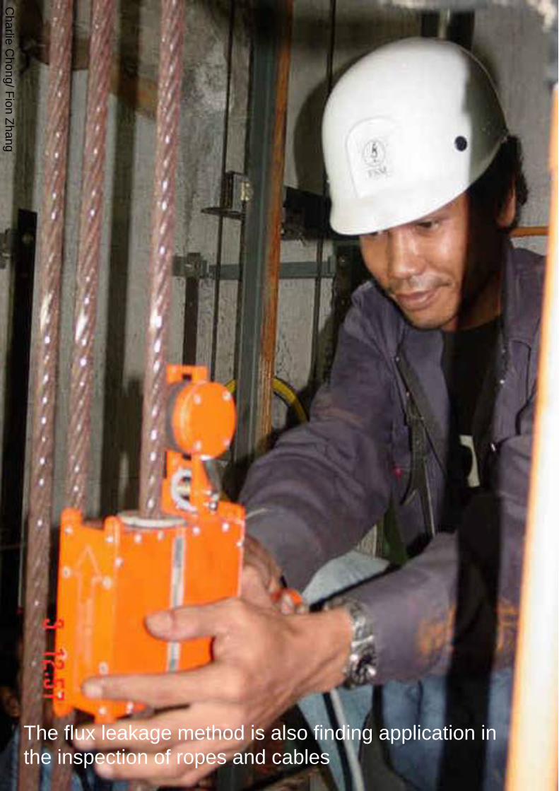
Charlie Chong Fion Zhang
Another area in which the flux leakage method has been successfully implemented is the inspection of rolling-element antifriction bearings A schematic illustration of the method as applied to an inner bearing race is shown in Fig 9 In this application the part is magnetized by an electromagnet as indicated in Fig 9(a) The race is then rotated by a spindle and the surface is scanned with an induction coil sensor Typically the race is rotated at a surface speed of about 23 ms (75 fts) and the active portion of the raceway is inspected by incrementally indexing the sensor across the raceway Magnetizing fields are applied in the radial and circumferential orientations It has been shown that radial field inspection works best for surface flaws while circumferential field inspection shows greater sensitivity to subsurface flaws Data have been collected on a large number of bearing races to establish the correlation between leakage field signals and inclusion depths and dimensions determined by metallurgical sectioning
Charlie Chong Fion Zhang
Fig 9 Flux leakage inspection of a bearing race (a) Magnetization of inner race (b) Perturbation in the magnetic flux at the surface of the inner race (c) Probe scanning the surface
Charlie Chong Fion Zhang
Finally the flux leakage method has also been adapted to the inspection of steel reinforcement in concrete beams The basic function of the magnetic field disturbance (MFD) inspection equipment is to provide maps of the magnetic field across the bottom and sides of the beam An electromagnet on an inspection cart which is suspended on tracks below the beam provides a magnetic field that induces magnetization in permeable structures in its vicinity such as steel rebars cables and stirrups An array of Hall effect sensors distributed across the bottom and sides of the beam measures the field produced by magnetized structures within the beam If a flaw is present in one of these magnetized structures it will produce a disturbance of the normal magnetic field pattern associated with the unflawed beam Thus the idea behind the MFD system is to search the surface of the beam for field anomalies that indicate the presence of flaws in reinforcing steel within the structure
Keywordsmagnetic field disturbance (MFD)
Charlie Chong Fion Zhang
A flaw such as a broken wire in a cable or a fractured rebar produces a distinctive magnetic field anomaly that depends on the size of the discontinuity and its distance from the sensor Because the signal shape that results from such an anomaly is known flaw detection is enhanced by searching magnetic field records for specific signal shapes that is those that are characteristic of discontinuities in magnetic materials In the MFD system this is accomplished by a computer program that compares signal shapes with typical flaw signal shapes The program produces a correlation coefficient that serves as a measure of similarity of the observed signal shape to a typical flaw signal shape Flaw detection is therefore not only enhanced by signal shape discrimination but also automated by computer processing of the magnetic field data Laboratory tests have demonstrated the ability of the system to detect fracture in steel rebars and cables in a large pre-stressed concrete structure Also planned are field tests of the equipment in the inspection of bridge decks for reinforcement corrosion damage
Charlie Chong Fion Zhang
Steel rebars and cables in a large pre-stressed concrete structure
Charlie Chong Fion Zhang
20 Nondestructive Characterization of Materials Only two examples of magnetic methods for monitoring materialproperties are given because the examples chosen should suffice to illustrate the types of tests that might be employed Measurements of magnetic characteristics can however provide a wealth of data and various features of such data can yield information on different material properties For example it has been demonstrated that different features of magnetic hysteresis data can be interpreted in terms of heat treatment and microstructure plastic deformation residual stress and mechanical hardness An example of the effects of mechanical hardness on hysteresis data is shown in Fig 10 These data were obtained in the absence of applied tensile stress with the experimental arrangement shown in Fig 7 Specimens of different hardness were prepared by tempering at different temperatures The grain size (ASTM No 7) was the same for all four specimens used in these tests Other data showed however that grain size has little effect on hysteretic behavior for the classes of alloys studied
Charlie Chong Fion Zhang
Fig 10 Effect of mechanical hardness on hysteresis loop data (a) AISI 410 stainless steel (b) SAE 4340 steel
Charlie Chong Fion Zhang
The main point illustrated in Fig 10 is that the mechanically harder specimens of the same alloy are also harder to magnetize that is the flux density B obtained at a large value of H is smaller for mechanically harder specimens than for softer specimens For one alloy AISI 410 stainless steel the hysteresis loop intersects the B = 0 axis at larger values of H for the harder specimen than for the softer specimen that is the coercive force is greater for the harder material However for the other material SAE 4340 steel the coercive force does not change with hardness This suggests that for the two alloys considered here the saturation flux density provides a more reliable measure of hardness than the coercive force Mayos et al used two quite different techniques to measure the depth of surface decarburization of steels One method was a variation of a standard eddy current test with the difference from standard practice being that eddy current probe response was measured in the presence of a low-frequency (~01 Hz) magnetic field This arrangement provides a measure of incremental permeability that is the magnetic permeability corresponding to changes in the applied field about some quasistatic value The second method employed was Barkhausen noise analysis
Charlie Chong Fion Zhang
Keywords
For one alloy AISI 410 stainless steel the hysteresis loop intersects the B = 0 axis at larger values of H for the harder specimen than for the softer specimen that is the coercive force is greater for the harder material However for the other material SAE 4340 steel the coercive force does not change with hardness
This suggests that for the two alloys considered here the saturation flux density provides a more reliable measure of hardness than the coercive force
Charlie Chong Fion Zhang
Depth of decarburization was analyzed by varying the frequency of the excitation field thus changing the skin depth in the material Experiments were performed with both artificial samples containing two layers of different carbon content and industrial samples in which carbon concentration varied smoothly with distance from the surface It was shown that certain features of both Barkhausen noise and incremental permeability data can be correlated with depth of decarburization The Barkhausen noise method showed a somewhat stronger sensitivity to depth but was useful over a smaller range of depths than the incremental permeability method It can be concluded that both methods are useful with the optimum choice depending on accuracy requirements and the expected depth of decarburization
Charlie Chong Fion Zhang
Offshore Structures
Charlie Chong Fion Zhang
Offshore Structures
Charlie Chong Fion Zhang
VLCC
Charlie Chong Fion Zhang
Offshore Structures
Charlie Chong Fion Zhang
Offshore Structures
Charlie Chong Fion Zhang
Offshore Structures
Charlie Chong Fion Zhang
Pipeline amp Piping
Charlie Chong Fion Zhang
Pipeline amp Piping
Charlie Chong Fion Zhang
Charlie Chong Fion Zhang
ass
- Electromagnetic Testing MFLT ECT MicrowaveRFT Chapter 9B ndash漏磁检测 More Reading on Magnetic Field Leakage Testing MFLT
- PART 1 Magnetic Field Testing
-
- 10 Introduction
- 20 Principles of Magnetic Leakage Field Testing MLFT
-
- PART 2 Principles of Magnetic Characterization of Materials
-
- 10 Metallurgical and Magnetic Properties
- 20 Experimental Techniques
-
- PART 3 Application
-
- 10 Flaw Detection by the Flux Leakage Method
- 20 Nondestructive Characterization of Materials
-
- Good Luck
-

Charlie Chong Fion Zhang
Fig 9 Flux leakage inspection of a bearing race (a) Magnetization of inner race (b) Perturbation in the magnetic flux at the surface of the inner race (c) Probe scanning the surface
Charlie Chong Fion Zhang
Finally the flux leakage method has also been adapted to the inspection of steel reinforcement in concrete beams The basic function of the magnetic field disturbance (MFD) inspection equipment is to provide maps of the magnetic field across the bottom and sides of the beam An electromagnet on an inspection cart which is suspended on tracks below the beam provides a magnetic field that induces magnetization in permeable structures in its vicinity such as steel rebars cables and stirrups An array of Hall effect sensors distributed across the bottom and sides of the beam measures the field produced by magnetized structures within the beam If a flaw is present in one of these magnetized structures it will produce a disturbance of the normal magnetic field pattern associated with the unflawed beam Thus the idea behind the MFD system is to search the surface of the beam for field anomalies that indicate the presence of flaws in reinforcing steel within the structure
Keywordsmagnetic field disturbance (MFD)
Charlie Chong Fion Zhang
A flaw such as a broken wire in a cable or a fractured rebar produces a distinctive magnetic field anomaly that depends on the size of the discontinuity and its distance from the sensor Because the signal shape that results from such an anomaly is known flaw detection is enhanced by searching magnetic field records for specific signal shapes that is those that are characteristic of discontinuities in magnetic materials In the MFD system this is accomplished by a computer program that compares signal shapes with typical flaw signal shapes The program produces a correlation coefficient that serves as a measure of similarity of the observed signal shape to a typical flaw signal shape Flaw detection is therefore not only enhanced by signal shape discrimination but also automated by computer processing of the magnetic field data Laboratory tests have demonstrated the ability of the system to detect fracture in steel rebars and cables in a large pre-stressed concrete structure Also planned are field tests of the equipment in the inspection of bridge decks for reinforcement corrosion damage
Charlie Chong Fion Zhang
Steel rebars and cables in a large pre-stressed concrete structure
Charlie Chong Fion Zhang
20 Nondestructive Characterization of Materials Only two examples of magnetic methods for monitoring materialproperties are given because the examples chosen should suffice to illustrate the types of tests that might be employed Measurements of magnetic characteristics can however provide a wealth of data and various features of such data can yield information on different material properties For example it has been demonstrated that different features of magnetic hysteresis data can be interpreted in terms of heat treatment and microstructure plastic deformation residual stress and mechanical hardness An example of the effects of mechanical hardness on hysteresis data is shown in Fig 10 These data were obtained in the absence of applied tensile stress with the experimental arrangement shown in Fig 7 Specimens of different hardness were prepared by tempering at different temperatures The grain size (ASTM No 7) was the same for all four specimens used in these tests Other data showed however that grain size has little effect on hysteretic behavior for the classes of alloys studied
Charlie Chong Fion Zhang
Fig 10 Effect of mechanical hardness on hysteresis loop data (a) AISI 410 stainless steel (b) SAE 4340 steel
Charlie Chong Fion Zhang
The main point illustrated in Fig 10 is that the mechanically harder specimens of the same alloy are also harder to magnetize that is the flux density B obtained at a large value of H is smaller for mechanically harder specimens than for softer specimens For one alloy AISI 410 stainless steel the hysteresis loop intersects the B = 0 axis at larger values of H for the harder specimen than for the softer specimen that is the coercive force is greater for the harder material However for the other material SAE 4340 steel the coercive force does not change with hardness This suggests that for the two alloys considered here the saturation flux density provides a more reliable measure of hardness than the coercive force Mayos et al used two quite different techniques to measure the depth of surface decarburization of steels One method was a variation of a standard eddy current test with the difference from standard practice being that eddy current probe response was measured in the presence of a low-frequency (~01 Hz) magnetic field This arrangement provides a measure of incremental permeability that is the magnetic permeability corresponding to changes in the applied field about some quasistatic value The second method employed was Barkhausen noise analysis
Charlie Chong Fion Zhang
Keywords
For one alloy AISI 410 stainless steel the hysteresis loop intersects the B = 0 axis at larger values of H for the harder specimen than for the softer specimen that is the coercive force is greater for the harder material However for the other material SAE 4340 steel the coercive force does not change with hardness
This suggests that for the two alloys considered here the saturation flux density provides a more reliable measure of hardness than the coercive force
Charlie Chong Fion Zhang
Depth of decarburization was analyzed by varying the frequency of the excitation field thus changing the skin depth in the material Experiments were performed with both artificial samples containing two layers of different carbon content and industrial samples in which carbon concentration varied smoothly with distance from the surface It was shown that certain features of both Barkhausen noise and incremental permeability data can be correlated with depth of decarburization The Barkhausen noise method showed a somewhat stronger sensitivity to depth but was useful over a smaller range of depths than the incremental permeability method It can be concluded that both methods are useful with the optimum choice depending on accuracy requirements and the expected depth of decarburization
Charlie Chong Fion Zhang
Offshore Structures
Charlie Chong Fion Zhang
Offshore Structures
Charlie Chong Fion Zhang
VLCC
Charlie Chong Fion Zhang
Offshore Structures
Charlie Chong Fion Zhang
Offshore Structures
Charlie Chong Fion Zhang
Offshore Structures
Charlie Chong Fion Zhang
Pipeline amp Piping
Charlie Chong Fion Zhang
Pipeline amp Piping
Charlie Chong Fion Zhang
Charlie Chong Fion Zhang
ass
- Electromagnetic Testing MFLT ECT MicrowaveRFT Chapter 9B ndash漏磁检测 More Reading on Magnetic Field Leakage Testing MFLT
- PART 1 Magnetic Field Testing
-
- 10 Introduction
- 20 Principles of Magnetic Leakage Field Testing MLFT
-
- PART 2 Principles of Magnetic Characterization of Materials
-
- 10 Metallurgical and Magnetic Properties
- 20 Experimental Techniques
-
- PART 3 Application
-
- 10 Flaw Detection by the Flux Leakage Method
- 20 Nondestructive Characterization of Materials
-
- Good Luck
-
Charlie Chong Fion Zhang
Finally the flux leakage method has also been adapted to the inspection of steel reinforcement in concrete beams The basic function of the magnetic field disturbance (MFD) inspection equipment is to provide maps of the magnetic field across the bottom and sides of the beam An electromagnet on an inspection cart which is suspended on tracks below the beam provides a magnetic field that induces magnetization in permeable structures in its vicinity such as steel rebars cables and stirrups An array of Hall effect sensors distributed across the bottom and sides of the beam measures the field produced by magnetized structures within the beam If a flaw is present in one of these magnetized structures it will produce a disturbance of the normal magnetic field pattern associated with the unflawed beam Thus the idea behind the MFD system is to search the surface of the beam for field anomalies that indicate the presence of flaws in reinforcing steel within the structure
Keywordsmagnetic field disturbance (MFD)
Charlie Chong Fion Zhang
A flaw such as a broken wire in a cable or a fractured rebar produces a distinctive magnetic field anomaly that depends on the size of the discontinuity and its distance from the sensor Because the signal shape that results from such an anomaly is known flaw detection is enhanced by searching magnetic field records for specific signal shapes that is those that are characteristic of discontinuities in magnetic materials In the MFD system this is accomplished by a computer program that compares signal shapes with typical flaw signal shapes The program produces a correlation coefficient that serves as a measure of similarity of the observed signal shape to a typical flaw signal shape Flaw detection is therefore not only enhanced by signal shape discrimination but also automated by computer processing of the magnetic field data Laboratory tests have demonstrated the ability of the system to detect fracture in steel rebars and cables in a large pre-stressed concrete structure Also planned are field tests of the equipment in the inspection of bridge decks for reinforcement corrosion damage
Charlie Chong Fion Zhang
Steel rebars and cables in a large pre-stressed concrete structure
Charlie Chong Fion Zhang
20 Nondestructive Characterization of Materials Only two examples of magnetic methods for monitoring materialproperties are given because the examples chosen should suffice to illustrate the types of tests that might be employed Measurements of magnetic characteristics can however provide a wealth of data and various features of such data can yield information on different material properties For example it has been demonstrated that different features of magnetic hysteresis data can be interpreted in terms of heat treatment and microstructure plastic deformation residual stress and mechanical hardness An example of the effects of mechanical hardness on hysteresis data is shown in Fig 10 These data were obtained in the absence of applied tensile stress with the experimental arrangement shown in Fig 7 Specimens of different hardness were prepared by tempering at different temperatures The grain size (ASTM No 7) was the same for all four specimens used in these tests Other data showed however that grain size has little effect on hysteretic behavior for the classes of alloys studied
Charlie Chong Fion Zhang
Fig 10 Effect of mechanical hardness on hysteresis loop data (a) AISI 410 stainless steel (b) SAE 4340 steel
Charlie Chong Fion Zhang
The main point illustrated in Fig 10 is that the mechanically harder specimens of the same alloy are also harder to magnetize that is the flux density B obtained at a large value of H is smaller for mechanically harder specimens than for softer specimens For one alloy AISI 410 stainless steel the hysteresis loop intersects the B = 0 axis at larger values of H for the harder specimen than for the softer specimen that is the coercive force is greater for the harder material However for the other material SAE 4340 steel the coercive force does not change with hardness This suggests that for the two alloys considered here the saturation flux density provides a more reliable measure of hardness than the coercive force Mayos et al used two quite different techniques to measure the depth of surface decarburization of steels One method was a variation of a standard eddy current test with the difference from standard practice being that eddy current probe response was measured in the presence of a low-frequency (~01 Hz) magnetic field This arrangement provides a measure of incremental permeability that is the magnetic permeability corresponding to changes in the applied field about some quasistatic value The second method employed was Barkhausen noise analysis
Charlie Chong Fion Zhang
Keywords
For one alloy AISI 410 stainless steel the hysteresis loop intersects the B = 0 axis at larger values of H for the harder specimen than for the softer specimen that is the coercive force is greater for the harder material However for the other material SAE 4340 steel the coercive force does not change with hardness
This suggests that for the two alloys considered here the saturation flux density provides a more reliable measure of hardness than the coercive force
Charlie Chong Fion Zhang
Depth of decarburization was analyzed by varying the frequency of the excitation field thus changing the skin depth in the material Experiments were performed with both artificial samples containing two layers of different carbon content and industrial samples in which carbon concentration varied smoothly with distance from the surface It was shown that certain features of both Barkhausen noise and incremental permeability data can be correlated with depth of decarburization The Barkhausen noise method showed a somewhat stronger sensitivity to depth but was useful over a smaller range of depths than the incremental permeability method It can be concluded that both methods are useful with the optimum choice depending on accuracy requirements and the expected depth of decarburization
Charlie Chong Fion Zhang
Offshore Structures
Charlie Chong Fion Zhang
Offshore Structures
Charlie Chong Fion Zhang
VLCC
Charlie Chong Fion Zhang
Offshore Structures
Charlie Chong Fion Zhang
Offshore Structures
Charlie Chong Fion Zhang
Offshore Structures
Charlie Chong Fion Zhang
Pipeline amp Piping
Charlie Chong Fion Zhang
Pipeline amp Piping
Charlie Chong Fion Zhang
Charlie Chong Fion Zhang
ass
- Electromagnetic Testing MFLT ECT MicrowaveRFT Chapter 9B ndash漏磁检测 More Reading on Magnetic Field Leakage Testing MFLT
- PART 1 Magnetic Field Testing
-
- 10 Introduction
- 20 Principles of Magnetic Leakage Field Testing MLFT
-
- PART 2 Principles of Magnetic Characterization of Materials
-
- 10 Metallurgical and Magnetic Properties
- 20 Experimental Techniques
-
- PART 3 Application
-
- 10 Flaw Detection by the Flux Leakage Method
- 20 Nondestructive Characterization of Materials
-
- Good Luck
-

Charlie Chong Fion Zhang
Offshore Structures
Charlie Chong Fion Zhang
Offshore Structures
Charlie Chong Fion Zhang
VLCC
Charlie Chong Fion Zhang
Offshore Structures
Charlie Chong Fion Zhang
Offshore Structures
Charlie Chong Fion Zhang
Offshore Structures
Charlie Chong Fion Zhang
Pipeline amp Piping
Charlie Chong Fion Zhang
Pipeline amp Piping
Charlie Chong Fion Zhang
Charlie Chong Fion Zhang
ass
- Electromagnetic Testing MFLT ECT MicrowaveRFT Chapter 9B ndash漏磁检测 More Reading on Magnetic Field Leakage Testing MFLT
- PART 1 Magnetic Field Testing
-
- 10 Introduction
- 20 Principles of Magnetic Leakage Field Testing MLFT
-
- PART 2 Principles of Magnetic Characterization of Materials
-
- 10 Metallurgical and Magnetic Properties
- 20 Experimental Techniques
-
- PART 3 Application
-
- 10 Flaw Detection by the Flux Leakage Method
- 20 Nondestructive Characterization of Materials
-
- Good Luck
-
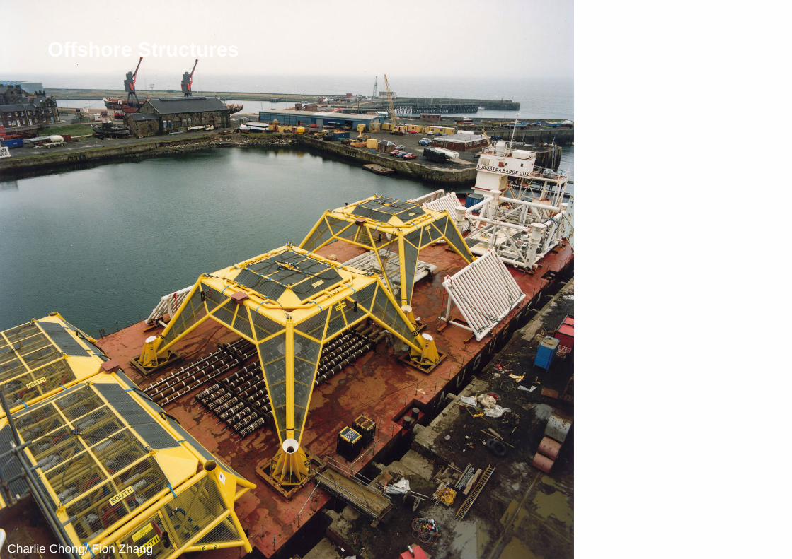
Charlie Chong Fion Zhang
Offshore Structures
Charlie Chong Fion Zhang
VLCC
Charlie Chong Fion Zhang
Offshore Structures
Charlie Chong Fion Zhang
Offshore Structures
Charlie Chong Fion Zhang
Offshore Structures
Charlie Chong Fion Zhang
Pipeline amp Piping
Charlie Chong Fion Zhang
Pipeline amp Piping
Charlie Chong Fion Zhang
Charlie Chong Fion Zhang
ass
- Electromagnetic Testing MFLT ECT MicrowaveRFT Chapter 9B ndash漏磁检测 More Reading on Magnetic Field Leakage Testing MFLT
- PART 1 Magnetic Field Testing
-
- 10 Introduction
- 20 Principles of Magnetic Leakage Field Testing MLFT
-
- PART 2 Principles of Magnetic Characterization of Materials
-
- 10 Metallurgical and Magnetic Properties
- 20 Experimental Techniques
-
- PART 3 Application
-
- 10 Flaw Detection by the Flux Leakage Method
- 20 Nondestructive Characterization of Materials
-
- Good Luck
-

Charlie Chong Fion Zhang
Offshore Structures
Charlie Chong Fion Zhang
Offshore Structures
Charlie Chong Fion Zhang
Offshore Structures
Charlie Chong Fion Zhang
Pipeline amp Piping
Charlie Chong Fion Zhang
Pipeline amp Piping
Charlie Chong Fion Zhang
Charlie Chong Fion Zhang
ass
- Electromagnetic Testing MFLT ECT MicrowaveRFT Chapter 9B ndash漏磁检测 More Reading on Magnetic Field Leakage Testing MFLT
- PART 1 Magnetic Field Testing
-
- 10 Introduction
- 20 Principles of Magnetic Leakage Field Testing MLFT
-
- PART 2 Principles of Magnetic Characterization of Materials
-
- 10 Metallurgical and Magnetic Properties
- 20 Experimental Techniques
-
- PART 3 Application
-
- 10 Flaw Detection by the Flux Leakage Method
- 20 Nondestructive Characterization of Materials
-
- Good Luck
-

Charlie Chong Fion Zhang
Offshore Structures
Charlie Chong Fion Zhang
Offshore Structures
Charlie Chong Fion Zhang
Pipeline amp Piping
Charlie Chong Fion Zhang
Pipeline amp Piping
Charlie Chong Fion Zhang
Charlie Chong Fion Zhang
ass
- Electromagnetic Testing MFLT ECT MicrowaveRFT Chapter 9B ndash漏磁检测 More Reading on Magnetic Field Leakage Testing MFLT
- PART 1 Magnetic Field Testing
-
- 10 Introduction
- 20 Principles of Magnetic Leakage Field Testing MLFT
-
- PART 2 Principles of Magnetic Characterization of Materials
-
- 10 Metallurgical and Magnetic Properties
- 20 Experimental Techniques
-
- PART 3 Application
-
- 10 Flaw Detection by the Flux Leakage Method
- 20 Nondestructive Characterization of Materials
-
- Good Luck
-

Charlie Chong Fion Zhang
Offshore Structures
Charlie Chong Fion Zhang
Pipeline amp Piping
Charlie Chong Fion Zhang
Pipeline amp Piping
Charlie Chong Fion Zhang
Charlie Chong Fion Zhang
ass
- Electromagnetic Testing MFLT ECT MicrowaveRFT Chapter 9B ndash漏磁检测 More Reading on Magnetic Field Leakage Testing MFLT
- PART 1 Magnetic Field Testing
-
- 10 Introduction
- 20 Principles of Magnetic Leakage Field Testing MLFT
-
- PART 2 Principles of Magnetic Characterization of Materials
-
- 10 Metallurgical and Magnetic Properties
- 20 Experimental Techniques
-
- PART 3 Application
-
- 10 Flaw Detection by the Flux Leakage Method
- 20 Nondestructive Characterization of Materials
-
- Good Luck
-

Charlie Chong Fion Zhang
Pipeline amp Piping
Charlie Chong Fion Zhang
Pipeline amp Piping
Charlie Chong Fion Zhang
Charlie Chong Fion Zhang
ass
- Electromagnetic Testing MFLT ECT MicrowaveRFT Chapter 9B ndash漏磁检测 More Reading on Magnetic Field Leakage Testing MFLT
- PART 1 Magnetic Field Testing
-
- 10 Introduction
- 20 Principles of Magnetic Leakage Field Testing MLFT
-
- PART 2 Principles of Magnetic Characterization of Materials
-
- 10 Metallurgical and Magnetic Properties
- 20 Experimental Techniques
-
- PART 3 Application
-
- 10 Flaw Detection by the Flux Leakage Method
- 20 Nondestructive Characterization of Materials
-
- Good Luck
-

Charlie Chong Fion Zhang
Pipeline amp Piping
Charlie Chong Fion Zhang
Charlie Chong Fion Zhang
ass
- Electromagnetic Testing MFLT ECT MicrowaveRFT Chapter 9B ndash漏磁检测 More Reading on Magnetic Field Leakage Testing MFLT
- PART 1 Magnetic Field Testing
-
- 10 Introduction
- 20 Principles of Magnetic Leakage Field Testing MLFT
-
- PART 2 Principles of Magnetic Characterization of Materials
-
- 10 Metallurgical and Magnetic Properties
- 20 Experimental Techniques
-
- PART 3 Application
-
- 10 Flaw Detection by the Flux Leakage Method
- 20 Nondestructive Characterization of Materials
-
- Good Luck
-

Charlie Chong Fion Zhang
Charlie Chong Fion Zhang
ass
- Electromagnetic Testing MFLT ECT MicrowaveRFT Chapter 9B ndash漏磁检测 More Reading on Magnetic Field Leakage Testing MFLT
- PART 1 Magnetic Field Testing
-
- 10 Introduction
- 20 Principles of Magnetic Leakage Field Testing MLFT
-
- PART 2 Principles of Magnetic Characterization of Materials
-
- 10 Metallurgical and Magnetic Properties
- 20 Experimental Techniques
-
- PART 3 Application
-
- 10 Flaw Detection by the Flux Leakage Method
- 20 Nondestructive Characterization of Materials
-
- Good Luck
-

Charlie Chong Fion Zhang
ass
- Electromagnetic Testing MFLT ECT MicrowaveRFT Chapter 9B ndash漏磁检测 More Reading on Magnetic Field Leakage Testing MFLT
- PART 1 Magnetic Field Testing
-
- 10 Introduction
- 20 Principles of Magnetic Leakage Field Testing MLFT
-
- PART 2 Principles of Magnetic Characterization of Materials
-
- 10 Metallurgical and Magnetic Properties
- 20 Experimental Techniques
-
- PART 3 Application
-
- 10 Flaw Detection by the Flux Leakage Method
- 20 Nondestructive Characterization of Materials
-
- Good Luck
-