emas katalog 2014 j 10 · kontaktörler contactors j 6 ir13 ir02 i85 hr serisi kontaktörlerin...
TRANSCRIPT

KontaktörlerContactors
J

KontaktörlerContactors
J
2
Genel Özellikler ve Teknik Bilgiler 03Genel fiema 04HR Serisi Kontaktörlerin Seçim Tablosu 05HR Serisi Kontaktörlerin Aksesuarlar› 06JA25 Serisi Termik RölelerJA25 Serisi Termik Rölelerin Seçim Tablosu Kontaktörlü ve Termik Röleli Kutular Teknik ÖzelliklerBoyutlar
Genel Özellikler ve Teknik Bilgiler 07JA25 Serisi Termik Röleler 08JA25 Serisi Termik Rölelerin Seçim Tablosu 09 Kontaktörlü ve Termik Röleli Kutular 10Teknik Özellikler 12Boyutlar 14
Genel Özellikler ve Teknik Bilgiler 15HN Serisi Kontaktörlerin Seçim Tablosu 16HN Serisi Kontaktörlerin Aksesuarlar› 17Boyutlar 18
General Specifi cations and Technical lnformation 03General Scheme 04HR Series Contactors Selection Table 05Accessories of HR Series Contactors 06JA25 Series Thermal RelaysJA25 Series Thermal Relays Selection Table Direct Starters With Contactor and Thermal Relay Fitted Technical Specifi cations / InformationDimensions
General Specifi cations and Technical lnformation 07JA25 Series Thermal Relays 08JA25 Series Thermal Relays Selection Table 09Direct Starters With Contactor andThermal Relay Fitted 10Technical Specifi cations / Information 12Dimensions 14
General Specifi cations and Technical lnformation 15HN Series Contactors Selection Table 16Accessories of HN Series Contactors 17Dimensions 18
HR
JA25
HN
HR
JA25
HN
Serisi Kontaktör
Serisi Termik Röleler
Serisi
Series Contactor
Series Thermal Relay
Series

J
3
Series Contactor
Series
HR
HR
Serisi Kontaktör
Series Contactor
• 9 - 55 A oras› 3 farkl› boyutta ak›m tafl›ma özelli€i • Üstün anahtarlama kapasitesi • Titreflime karfl› dirençli, güvenli ve kolay kablo ba€lant›s› sa€layan terminaller • S›cakl›€a karfl› kompanze edilmifl• Yüksek koruma sa€layan sistemle tam
uyumlu termik röle• 35 mm’lik montaj ray›na h›zl› ve basit montaj özelli€i • Genifl aksesuar seçenekleri ile kullan›c›lar›n tüm ihtiyaçlar›na cevap verecek ürün çeflitlili€i
• To be used from 9A to 55A with 3 different sizes • High switching capacity • Terminals resistant against vibration, reliable and enabling easy cable connection • Temperature compensated
• Thermal relay in canformity with high protection system• Fast and simple mounting feature to 35 mm mounting roil • Product variety with wide accessories fulfi lling of all applications of users
Teknik Bilgiler Mekanik Ömür : 10 milyon açma-kapama min. Elektriksel Ömür : Grafi €e bak›n›z Çal›flma S›cakl›€› : min./maks. ˚C -5/+40 Anma ‹flletme Gerilimi Ue : 380/415 V ACAnma ‹flletme Ak›m› Ie : 9-55 A aras› Anma Termik Ak›m› Ith : 25- 110 A aras›Yal›t›m Gerilimi Ui : 660 V ‹zolasyon Gerilimi : 2500 V AC K›sa Devre Kesme Kapasitesi : 50 kA Standart : TS EN 60947-4-1
Technical Information Mechanical Life : 10 million operations min. Electrical Life : See graphics Operating Temperature : min./max. ˚C -5/+40 Rated Operating Voltage Ue : 380/415 V AC Rated Operating Current Ie : 9-55 A Rated Thermal Current Ith : 25-110 A Insulation Voltage Ui : 660 V Insulation Voltage : 2500 V AC Short circuit breaking capacity : 50 kA Standard : TS EN 60947-4-1

KontaktörlerContactors
J
4
Genel fiema / General Scheme
Kutu Insulated enclosure Bobin
Control Coil
Kilit / Yan tarafa monte edilir Mechanical Interlock / Side Mounting
Termik Röle / Alt tarafa monte edilir Thermal Relay / Bottom Assembly
Yard›mc› Kontak Bloklar / Üst tarafa monte edilir Auxiliary Contact Blocks / Fix to the top of the contactor
J
5
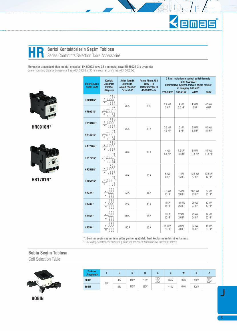
Serisi Kontaktörlerin Seçim TablosuSeries Contactors Selection Table Accessories
Bobin Seçim Tablosu Coil Selection Table
HR
HR0910N*
HR1701N*
BOB‹N
Merkezler aras›ndaki vida montaj mesafesi EN 50003 veya 35 mm metal raya EN 50022-3’e uygundur Screw mounting distance between centres to EN 50003 or 35 mm metal rail conforms to EN 50022-3
*: Gerilim bobin seçimi için y›ld›z yerine afla€›daki harf kodlar›ndan birini kullan›n›z. *: For voltage control coil selection please use the cades written below, instead of asterix.
Siparifl KoduOrder Code
Kontak DiyagramContact Diagram
Anl›k Termik Ak›m› Ith
Rated Thermal Current Ith
Anma Ak›m› AC3 380V ~ le
Rated Current in AC3 380V ~ le
3 Fazl› motorlarda kontrol edilebilen güç(s›n›f AC2-AC3)
Controllable powers of three-phase motorsin category AC2-AC3
220-240V 380-415V 440V 660V
HR0910N*
25 A 9 A 2.2 kW 3 HP
4 kW5.5 HP
4.5 kW6 HP
4.5 kW6 HP
HR0901N*
HR131ON*
25 A 13 A 3.2 kW 4.5 HP
6 kW8 HP
6.5 kW8.8 HP
6.5 kW8.8 HP
HR1301N*
HR171ON*
40 A 17 A 4 kW
5.5 HP7.5 kW10.5 HP
8.5 kW11.5 HP
8.5 kW11.5 HP
HR1701N*
HR2510N*
40 A 25 A 6 kW 8 HP
11 kW15 HP
12.5 kW17 HP
12.5 kW17 HP
HR2501N*
HR33N* 72 A 33 A7.5 kW 10 HP
15 kW20 HP
18.5 kW25 HP
22 kW30 HP
HR40N* 72 A 40 A11 kW 15 HP
18.5 kW25 HP
20 kW27 HP
30 kW40 HP
HR46N* 90 A 46 A15 kW 20 HP
22 kW20 HP
25 kW34 HP
37 kW50 HP
HR55N* 110 A 55 A18.5 kW 25 HP
30 kW40 HP
33 kW45 HP
45 kW60 HP
FrekansFrequency F G D U X C W B Z
50 HZ24V
48V 110V
115V
220V
230V
220V240V
366V 380V
400V
440V480V500V
60 HZ 58V 440V 528V

KontaktörlerContactors
J
6
IR13
IR02
I85
HR Serisi Kontaktörlerin Aksesuarlar›Accessories For HR Series Contactors Accessories
Yard›mc› Kontak Bloklar (Kontaktörün üst k›sm›na montajlan›r) Auxiliary Contact Blocks (to fi x to the top of the contactors)
Mekanik Kilitleme Aparat› (Yan tarafa montajlan›r) Mechanical Interlock (side mounting)
Siparifl KoduOrder Code
Kontak DiyagramContact Diagram
Anl›k Termik Ak›m› Ith
Rated Thermal Current Ith
Anma Ak›m› le AC15Rated Current le
EN 60947 -5-1 IEC947-5-1220V240V
380V415V 500V
IR02 10 A 3 A 1.5 A 1 A
IR11 10 A 3 A 1.5 A 1 A
IR22 10 A 3 A 1.5 A 1 A
IR13 10 A 3 A 1.5 A 1 A
IR31 10 A 3 A 1.5 A 1 A
Siparifl KoduOrder Code
Aç›klamaDescription
I85Farkl› ölçülerde dahil olmak üzere iki kontaktörün yan yana montaj›n› sa€lar. Enabling side by side mounting of two contactors even of different sizes.
J
7
JA25
JA25
Serisi Termik Röleler
Series Thermal Relay
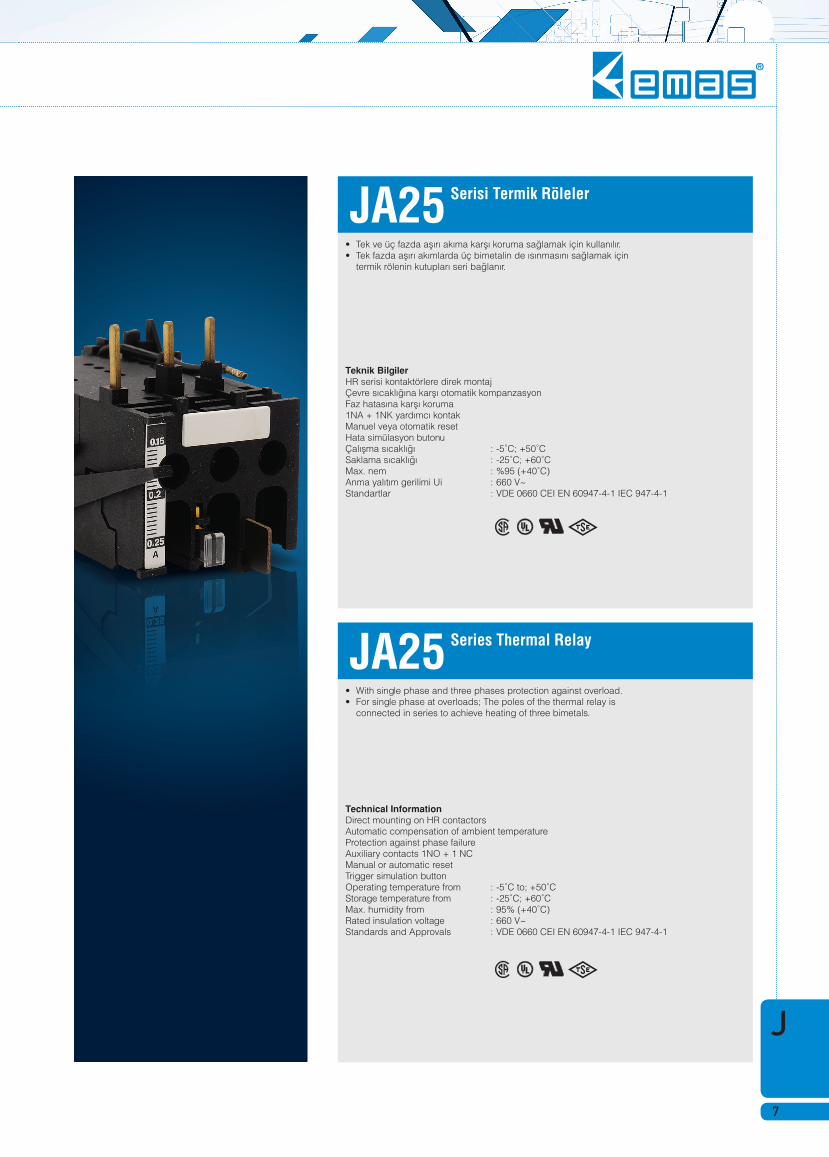
• Tek ve üç fazda afl›r› ak›ma karfl› koruma sa€lamak için kullan›l›r. • Tek fazda afl›r› ak›mlarda üç bimetalin de ›s›nmas›n› sa€lamak için termik rölenin kutuplar› seri ba€lan›r.
• With single phase and three phases protection against overload. • For single phase at overloads; The poles of the thermal relay is connected in series to achieve heating of three bimetals.
Teknik Bilgiler HR serisi kontaktörlere direk montaj Çevre s›cakl›€›na karfl› otomatik kompanzasyon Faz hatas›na karfl› koruma 1NA + 1NK yard›mc› kontak Manuel veya otomatik reset Hata simülasyon butonu Çal›flma s›cakl›€› : -5˚C; +50˚C Saklama s›cakl›€› : -25˚C; +60˚C Max. nem : %95 (+40˚C) Anma yal›t›m gerilimi Ui : 660 V~Standartlar : VDE 0660 CEI EN 60947-4-1 IEC 947-4-1
Technical Information Direct mounting on HR contactors Automatic compensation of ambient temperature Protection against phase failure Auxiliary contacts 1NO + 1 NC Manual or automatic reset Trigger simulation button Operating temperature from : -5˚C to; +50˚C Storage temperature from : -25˚C; +60˚C Max. humidity from : 95% (+40˚C) Rated insulation voltage : 660 V~Standards and Approvals : VDE 0660 CEI EN 60947-4-1 IEC 947-4-1
KontaktörlerContactors
J
8
Serisi Termik RölelerSeries Thermal RelayJA25
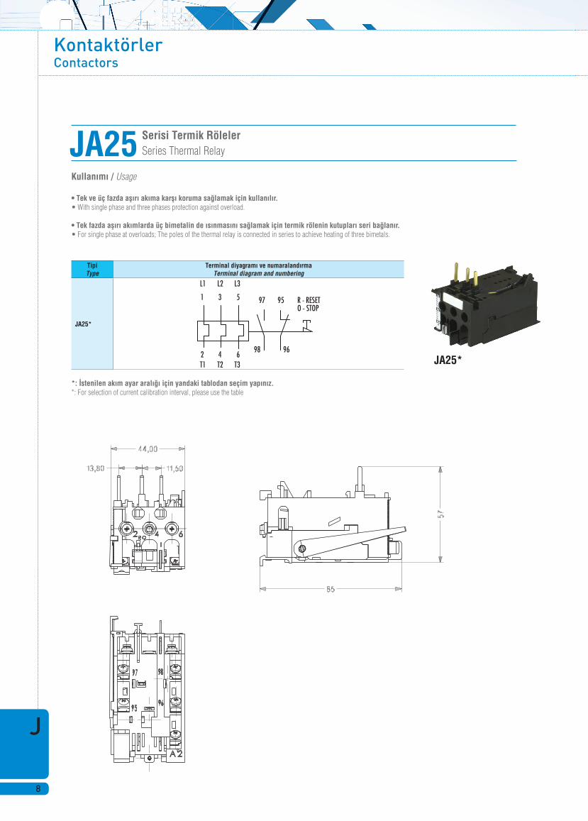
• Tek ve üç fazda afl›r› ak›ma karfl› koruma sa€lamak için kullan›l›r. • With single phase and three phases protection against overload.
• Tek fazda afl›r› ak›mlarda üç bimetalin de ›s›nmas›n› sa€lamak için termik rölenin kutuplar› seri ba€lan›r. • For single phase at overloads; The poles of the thermal relay is connected in series to achieve heating of three bimetals.
Kullan›m› / Usage
*: ‹stenilen ak›m ayar aral›€› için yandaki tablodan seçim yap›n›z. *: For selection of current calibration interval, please use the table
JA25*
TipiType
Terminal diyagram› ve numaraland›rmaTerminal diagram and numbering
JA25*
J
9
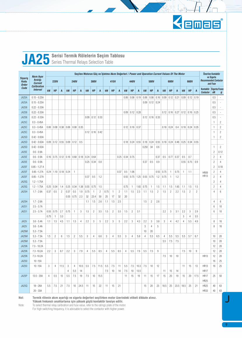
Serisi Termik Rölelerin Seçim TablosuSeries Thermal Relays Selection TableJA25
Not: Termik rölenin ak›m ayarl›€› ve sigorta de€erleri seçilirken motor üzerindeki etiketi dikkate al›n›z. Yüksek frekansl› anahtarlama için yüksek güçlü kontaktör tavsiye edilir. Note: To select thermal relay calibration and fuse value, refer to the ratings plate of the motor. For high switching frequency, it is advisable to select the contactor with higher power.
Siparifl KoduOrder Code
Ak›m Ayar Aral›€› Current
Calibration Interval
Seçilen Motorun Güç ve ‹flletme Ak›m De€erleri / Power and Operation Current Values Of The Motor Önerilen Kontaktörve Sigorta
Recommended Contactor and Fuse
220V 240V 380V 415V 440V 500V 600V 660V
kW HP A kW HP A kW HP A kW HP A kW HP A kW HP A kW HP A kW HP A KontaktörContactor
Sigorta/FusesaM gl
JA25A 0.15 - 0.25A 0.06 0.08 0.19 0.06 0.08 0.16 0.09 0.12 0.21 0.09 0.12 0.19
HR09 HR13
0.5 -
JA25A 0.15 - 0.25A 0.09 0.12 0.24 0.5 -
JA258 0.22 - 0.33A 0.5 -
JA258 0.22 - 0.33A 0.09 0.12 0.28 0.12 0.16 0.27 0.12 0.16 0.25 0.5 -
JA258 0.22 - 0.33A 0.09 0.12 0.33 0.12 0.16 0.33 0.5 -
JA25C 0.3 - 0.45A 1 2
JA25C 0.3 - 0.45A 0.06 0.08 0.38 0.06 0.08 0.35 0.12 0.16 0.37 0.18 0.24 0.4 0.18 0.24 0.35 1 2
JA25C 0.3 - 0.45A 0.12 0.16 0.42 1 2
JA25D 0.42 - 0.63A 1 2
JA25D 0.42 - 0.63A 0.09 0.12 0.55 0.09 0.12 0.5 0.18 0.24 0.55 0.18 0.24 0.55 0.18 0.24 0.46 0.25 0.34 0.55
JA25D 0.42 - 0.63A 0.250 34 0.6 1 2
JA25E 0.6 - 0.9A 2 0.12
JA25E 0.6 - 0.9A 0.16 0.75 0.12 0.16 0.68 0.18 0.24 0.64 0.25 0.34 0.75 0.37 0.5 0.77 0.37 0.5 0.7 2 4
JA25E 0.6 - 0.9A 0.25 0.34 0.8 0.37 0.5 0.9 0.55 0.75 0.9 2 4
JA25F 0.85 - 1.27 A 2 0.18
JA25F 0.85 -1.27A 0.24 1.10 0.18 0.24 1 0.37 0.5 1.06 0.55 0.75 1 0.75 1 1.1 2 4
JA25F 0.85 - 1.27A 0.37 0.5 1.2 0.55 0.75 1.25 0.55 0.75 1.2 0.75 1 1.2 2 4
JA25G 1.2 - 1.75A 2 4
JA25G 1.2 - 1.75A 0.25 0.34 1.4 0.25 0.34 1.38 0.55 0.75 1.5 0.75 1 1.65 0.75 1 1.5 1.1 1.5 1.65 1.1 1.5 1.5 2 4
JA25H 1.7 - 2.6A 0.37 0.5 2 0.37 0.5 1.9 0.75 1 2 0.75 1 2 1.1 1.5 2.3 1.1 1.5 2 1.5 2 2.2 1.5 2 2 4 6
0.55 0.75 2.3 32 23.4 50 25 17 32 20
JA25H 1.7 - 2.6A 1.1 1.5 2.6 1.1 1.5 2.5 1.5 2 2.6 4 6
JA251 2.5 - 3.7A 6 10
JA251 2.5 - 3.7A 0.55 0.75 2.7 0.75 1 3 1.5 2 3.5 1.5 2 3.5 1.5 2 3.1 2.2 3 3.1 2.2 3 2.9 6 10
0.75 1 3.3 3 4 3.5
JA25l 3.6 - 5.4A 1.1 1.5 4.5 1.1 1.5 4 2.2 3 5 2.2 3 5 2.2 3 4.3 2.2 3 3.8 3 4 4.2 4 5.5 4.9 8 16
JA25l 3.6 - 5.4A 3 4 5 8 16
JA25M 5.3 - 7.5A 10 20
JA25M 5.3 - 7.5A 1.5 2 6 1.5 2 5.5 3 4 6.6 3 4 5.5 3 4 5.8 4 5.5 6.5 4 5.5 5.5 5.5 5.7 6.7 10 20
JA25M 5.3 - 7.5A 5.5 7.5 7.5 10 20
JA25N 7.3 - 10.2A 12 20
JA25N 7.3 -10.2A 2.2 3 8.7 2.2 3 7.9 4 5.5 8.5 4 5.5 8.5 4 5.5 7.6 5.5 7.5 9 7.5 10 9 12 20
JA25N 7.3 -10.2A 7.5 10 10 HR13 12 20
JA250 10 -15A 16 25
JA250 10 -15A 3 4 11.5 3 4 10.5 5.5 7.5 11.5 5.5 7.5 11 5.5 7.5 10.3 7.5 10 12 11 15 13 HR13 16 25
4 5.5 14 7.5 10 14 7.5 10 13.5 11 15 14 HR17
JA25P 13.5 - 20A 4 5.5 15 5.5 7.5 19 7.5 10 15.5 11 15 19 11 15 17 15 20 19 15 20 17.5 HR17 25 50
HR25
JA25Q 18 - 26A 5.5 7.5 21 7.5 10 24.5 11 15 22 11 15 21 15 20 23 18.5 25 23.5 18.5 25 21 HR25 40 63
20 - 33A HR33 40 63

KontaktörlerContactors
J
10
Kontaktörlü ve Termik Röleli Kutular (IP65) Direct Starters With Contactor and Thermal Relay (IP65)
HJ22HJ21HJ12
HJ12
HJ11
Tip / Type A B C D E
HJ11 90 150 98 50 140HJ12 90 150 120 50 140HJ21 100 170 110 52 165HJ22 100 170 138 52 165
Siparifl KoduOrder Code
Aç›klamaDescription
HJ11 HR09 - HR13 Serileri için resel butonlu ve anahtarl›, sinyalli kutu (1. BOY) Enclosure with Reset button for HR09 - HR13 Series
HJ21 HR17 - HR25 Serileri için reset butonlu ve anahtarl›, sinyalli kutu (2. BOY) Enclosure with Reset button for H17 - HR25 Series
HJ12 HR09 - HR13 Serileri için start-stop/reset butonlu kutu (3. BOY) Enclosure with start-stop / Reset button for HR09 - HR13 Series
HJ22 HR17 - HR25 Serileri için start-stap/reset butonlu kutu (4. BOY) Enclosure with start-stop / Reset button for HR17 - HR25 Series

J
11
Kontaktörlü ve Termik Röleli KutularDirect Starters With Contactor and Thermal Relay
HJ11A09UGE
HJ12X09UA
Not : Standart olarak kutuda reset butonu, ›fl›kl› aç-kapa anahtar› ve bir adet Ø 10 mm kablolu sinyal lambas› montajl› olarak mevcuttur. Note : Reset button, illuminated on-off switch and signal with Ø 10 mm cable are mounted on the standard box
Not : Standart olarak kutuda start ve reset butonu montajl› olarak mevcuttur. Note : Start and reset buttons are mounted on box as standard.
Not : Standart ›fl›kl› aç-kapa anahtar› rengi yeflil; Ø 10 mm kablolu sinyal lambas› rengi de k›rm›z›d›r. Note : The colour of the illuminated on-off switch is green, where by the colour of the Ø 10 mm cable is red.
Siparifl KoduOrder Code
Termik Ak›m Ayar Sahası (A)
Thermal Current Calibration Field
Kontaktör Anma Ak›m› (A) 380V
Contactor RotedCurrent
Güç (kW) 380-415VPower
Kutu EbatıBox Size
HJ11A09UG 1.20 - 1.75 9 0.55 I.BOY
HJ11A09UH 1.70 - 2.60 9 1.10 I.BOY
HJ11A09UI 2.50 - 3.70 9 1.50 I.BOY
HJ11A09UL 3.60 - 5.40 9 2.20 I.BOY
HJ11A09UM 5.30 - 7.50 9 3.00 I.BOY
HJ11A13UN 7.30 - 10.20 13 4.00 I.BOY
HJ21A17UO 10.00 - 15.00 17 5.50 2.BOY
HJ21A25UP 13.50 - 20.00 25 7.50 2.BOY
HJ21A25UQ 18.00 - 26.00 25 11.00 2.BOY
Siparifl KoduOrder Code
Termik Ak›m Ayar Sahası (A)
Thermal Current Calibration Field
Kontaktör Anma Ak›m› (A) 380V
Contactor RotedCurrent
Güç (kW) 380-415VPower
Kutu EbatıBox Size
HJ12X09UA 0.15 - 0.25 9 0.06 3.BOY
HJ12X09UB 0.22 - 0.33 9 0.09 3.BOY
HJ12X09UC 0.30 - 0.45 9 0.12 3.BOY
HJ12X09UD 0.42 - 0.63 9 0.15 3.BOY
HJ12X09UE 0.60 - 0.90 9 0.24 3.BOY
HJ12X09UF 0.85 - 1.27 9 0.37 3.BOY
HJ12X09UG 1.20 - 1.75 9 0.55 3.BOY
HJ12X09UH 1.70 - 2.60 9 1.10 3.BOY
HJ12X09UI 2.50 - 3.70 9 1.50 3.BOY
HJ12X09UL 3.60 - 5.40 9 2.20 3.BOY
HJ12X09UM 5.30 - 7.50 9 3.00 3.BOY
HJ22X13UN 7.30 - 10.20 13 4.00 4.BOY
HJ22X17UO 10.00 - 15.00 17 5.50 4.BOY
HJ22X25UP 13.50 - 20.00 25 7.50 4.BOY
HJ22X25UQ 18.00 - 26.00 25 11.00 4.BOY

KontaktörlerContactors
J
12
Teknik Özellikler / Technical Specifi cations
HR09 HR13 HR17 HR25Anma Yal›t›m Gerilimi IEC Ui / Rated insulation voltage IEC Ui V~ 660 660 660 660Anma Termik Gerilimi IEC Ith / Rated thermal voltage IEC Ith A 25 25 40 25Anma ‹flletim Ak›m› 380V~AC-1-le / Rated operating current at 380V ~in AC-1-Ie A 22 22 35 22Anma ‹flletim Ak›m› 380V~AC-3-le / Rated operating current at 380V ~in AC-3-le A 9 13 17 13Mekanik Ömür / Mechanical life (cl. IV 1200man/h) millions of cvcles 20 20 20 20AC·3 Katagorisine göre kontrol edilebilen güç (3 faz) / CONTROLLABLE POWERS IN 220 - 240 V~ kW (HP) 2.2 (3) 3.2 (4.5) 4 (5.5) 6 (8) OPERATING CATEGORY AC-3 Three Phase 380 - 415 V~ kW (HP) 4 (5.5) 6 (8) 5.5 (7.5) 11 (15) IEC 947-4-1 CEI EN 60947-4-1 / IEC 947-4-1 CEI EN 60947-4-1 500 V~ kW (HP) 5.5 (7.5) 8 (11) 7.5 (10) 15 (20) Standard›na göre kontrol edilebilen güç 120 V~ HP 1 1.5 2 3
220 - 240 V~ HP 2 3 5 7.5 CONTROLLABLE POWERS IN 440 - 480 V~ HP 5 7.5 10 15According to Standards 550 - 600 V- HP 7.5 10 15 120
le A 9 11 17 22 Standard›na göre kontrol edilebilen güç 220 - 240 V~ HP 3 5 7.5 20
440 - 480 V- HP 7.5 10 15 10 CONTROLLABLE POWERS IN 550 - 600 V- HP 7.5 10 15 20 According to Standards / Rated operating current at 600 V~ le A 25 25 25 25
HR09 HR13 HR17 HR25Anma Yal›t›m Gerilimi IEC Ui / Rated insulation voltage IEC Ui V- 660 660 660 660 Anma Termik Gerilimi IEC Ith / Rated thermal voltage IEC Ith A 72 72 90 110 Anma ‹flletim Ak›m› 380V AC-1-le / Rated operating current at 380V ~in AC-1-Ie A 64 64 80 100 Anma ‹flletim Ak›m› 380V AC-3-le/ Rated operating current at 380V ~in AC-3-le A 33 40 46 55 Mekanik Ömür / Mechanicallile (cl. IV 1200man/h) millions ol cvcles 10 10 10 10AC-3 Katagorisine göre kontrol edilebilen güç (3 faz) / CONTROLLABLE POWERS IN 220 - 240 V~ kW (HP) 7.5 (10) 11 (15) 15 (10) 18.5 (15)OPERATING CATEGORY AC·3 Three Phase 380 - 415 V~ kW (HP) 15 (20) 18.5 (25) 22 (30) 30 (40) IEC 947-4-1 CEI EN 60947-4-1/ IEC 947-4-1 CEI EN 60947-4-1 500 V~ kW (HP) 20 (27) 22 (30) 30 (37) 37 (50) Standard›na göre kontrol edilebilen güç 120 V~ HP 5 7.5 10 15
220 - 240 V~ HP 10 15 20 25CONTROLLABLE POWERS IN 440 - 480 V~ HP 20 25 30 40According to Standards 550 - 600 V~ HP 25 30 40 40
le A 40 50 70 90 Standard›na göre kontrol edilebilen güç 120 V~ HP 5 7.5 10 15
220 - 240 V~ HP 10 15 20 25CONTROLLABLE POWERS IN 440 - 480 V~ HP 20 25 30 40According to Standards / Rated operating current at 600 V~ 440 - 480 V~ HP 25 30 40 40
le A 40 50 70 90
Kontrol Bobini / Control Coil HR09-13 HR17-25 HR33-55
Alternatif Ak›m Çekimi / Alternating current absorptionanl›k / instantaneous VA 60 80 90sürekli / continuous VA 7 7 9
Do€ru Ak›m Çekimi / Direct current absorptionanl›k /instantaneous W 80 130 130sürekli /continuous W 5 8 8
Minimum ve Maksimum Besleme voltaj› / Minimum and maximum supply voltage Un 0.85 - 1.1 0.85 - 1.1 0.85 - 11
Anma Geriliminde Anahtarlama Zaman› / Switching times at rated voltageanl›k /instantaneous ms 20 - 25 20 - 30 20 - 25sürekli /continuous ms1 13 - 18 17 - 22 15 - 20
Bobin Yal›t›m› / Coil insulation S›n›f› /Class F F F
Yard›mc› Kontaklar / Instantaneous Auxiliary ContactsAnma Termik Ak›m› /Rated thermal current a.c. Ith A 10AC15 Kategorisinde Anma ‹flletim Ak›m›
AC-15220/240V~ A 3
RATED OPERATING CURRENT IN 380/415V~ A 1.5CATEGORY 500V~ A 1IEC947-5-1 CEI EN 60947-5-1
DC-13110V c.c. A 1230V c.c. A 0.5
Standard›na göreclassif. A600 A 1.5 According to
J
13
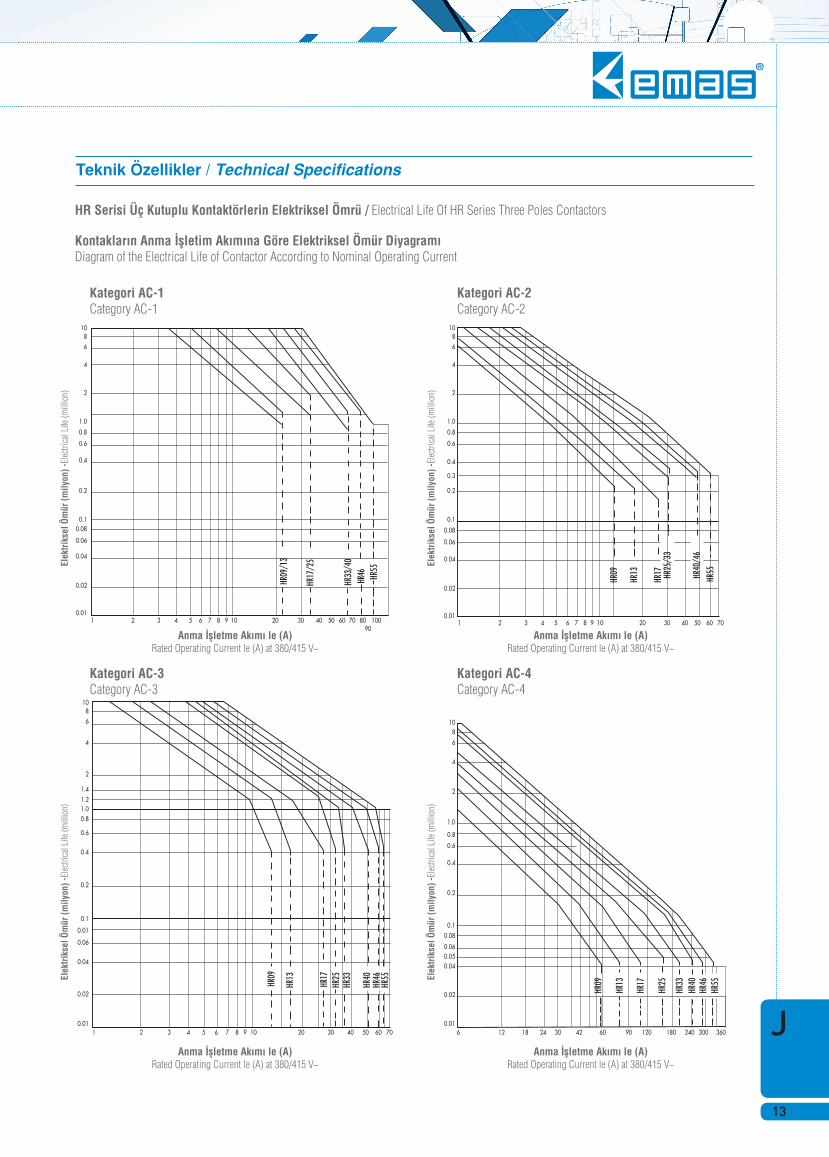
Anma ‹flletme Ak›m› le (A) Rated Operating Current le (A) at 380/415 V~
Anma ‹flletme Ak›m› le (A) Rated Operating Current le (A) at 380/415 V~
Elek
trik
sel Ö
mür
(mily
on) -
Elec
trica
l Life
(mill
ion)
Elek
trik
sel Ö
mür
(mily
on) -
Elec
trica
l Life
(mill
ion)
Elek
trik
sel Ö
mür
(mily
on) -
Elec
trica
l Life
(mill
ion)
Elek
trik
sel Ö
mür
(mily
on) -
Elec
trica
l Life
(mill
ion)
Kategori AC-3 Category AC-3
Kategori AC-1 Category AC-1
HR Serisi Üç Kutuplu Kontaktörlerin Elektriksel Ömrü / Electrical Life Of HR Series Three Poles Contactors
Kontaklar›n Anma ‹flletim Ak›m›na Göre Elektriksel Ömür Diyagram› Diagram of the Electrical Life of Contactor According to Nominal Operating Current
Kategori AC-4 Category AC-4
Kategori AC-2 Category AC-2
Anma ‹flletme Ak›m› le (A) Rated Operating Current le (A) at 380/415 V~
Anma ‹flletme Ak›m› le (A) Rated Operating Current le (A) at 380/415 V~
Teknik Özellikler / Technical Specifi cations
KontaktörlerContactors
J
14
HR0910N*
HR1701N*
HR33N*
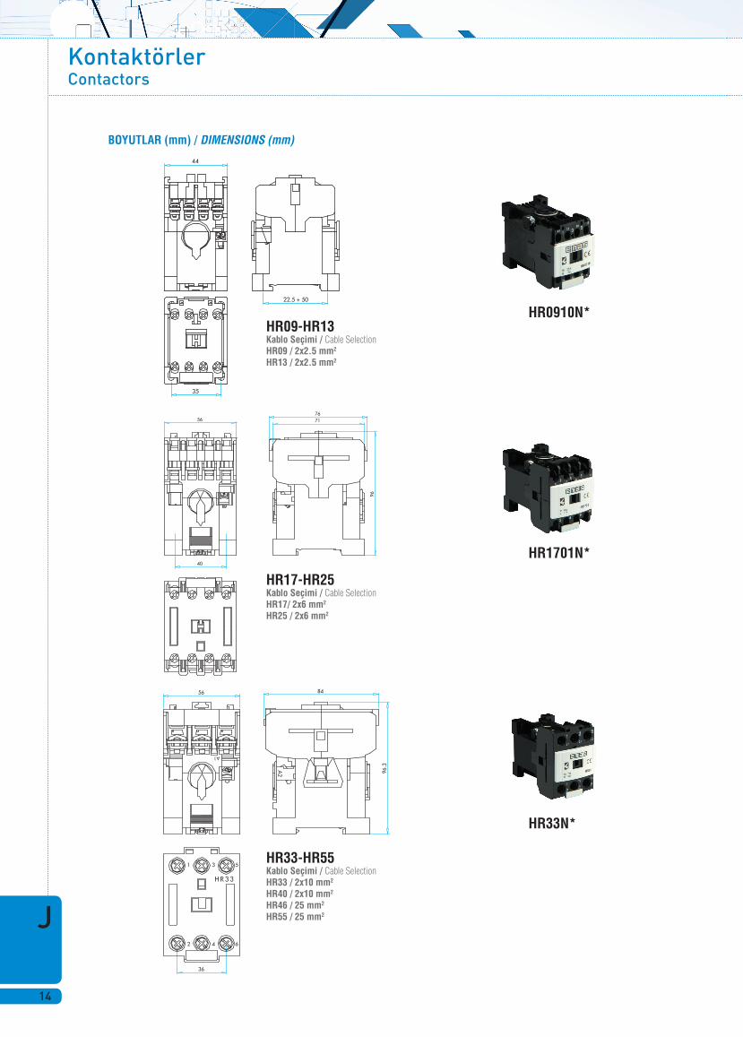
BOYUTLAR (mm) / DIMENSIONS (mm)
HR09-HR13 Kablo Seçimi / Cable Selection HR09 / 2x2.5 mm2 HR13 / 2x2.5 mm2
HR17-HR25 Kablo Seçimi / Cable Selection HR17/ 2x6 mm2 HR25 / 2x6 mm2
HR33-HR55 Kablo Seçimi / Cable Selection HR33 / 2x10 mm2 HR40 / 2x10 mm2 HR46 / 25 mm2 HR55 / 25 mm2

J
15
HN
HN
Serisi Kontaktör
Series Contactor
• 9-400 A aras› 7 farkl› boyutta ak›m tafl›ma özelli€i • Üstün anahtarlama kapasitesi • Titreflime karfl› dirençli, güvenli ve kolay kablo ba€lant›s› sa€layan terminaller • S›cakl›€a karfl› kompanze edilmifl • Yeni estetik tasar›m
• Yüksek koruma sa€layan sistemle tam uyumlu termik röle • 35 mm’lik montaj ray›na h›zl› ve basit montaj özelli€i • Genifl aksesuar seçenekleri ile kullan›c›lar›n tüm ihtiyaçlar›na cevap verecek ürün çeflitlili€i
• To be used from 9A to 400Awith 7 different sizes • High switching capacity • Terminals resistant against vibration, reliable and enabling easy cable connection • Temperature compensated
• Thermal relay in conformity with high protection system • New esthetical design• Fast and simple mounting feature to 35 mm mounting rail • Product variety with wide accessories fulfi lling of all applications of users
Teknik Bilgiler Mekanik Ömür : 10 milyon açma-kapama min. Elektriksel Ömür : Grafi €e bak›n›z (Bkz. HR serisi kontaktör)Çal›flma S›cakl›€› : min./maks. ˚C -5/+40 Anma ‹flletme Gerilimi Ue : 380/415 V AC Anma ‹flletme Ak›m› Ie : 9-400 A aras› Anma Termik Ak›m› Ith : 25-120 A aras› Yal›t›m Gerilimi Ui : 660 V ‹zolasyon Gerilimi : 2500 V AC K›sa Devre Kesme Kapasitesi : 50 kA Standart : TS EN 60947-4-1
Technical Information Mechanical Life : 10 million operations min. Electrical Life : See graphics (See HR series contactor)Operating Temperature : min./max. ˚C -5/+40 Rated Operating Voltage Ue : 380/415 V AC Rated Operating Current Ie : 9-400 A Rated Thermal Current Ith : 25-120 A Insulation Voltage Ui : 660 V Insulation Voltage : 2500 V AC Short circuit breaking capacity : 50 kA Standard : TS EN 60947-4-1
KontaktörlerContactors
J
16
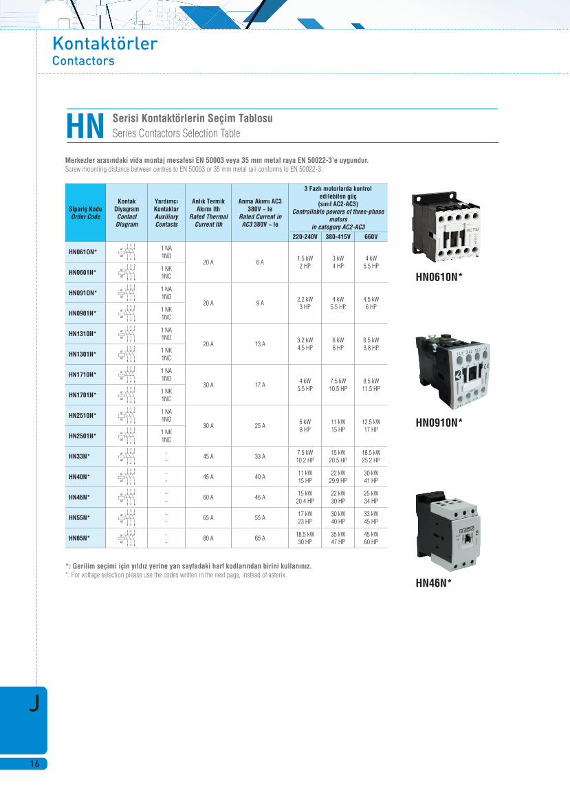
Serisi Kontaktörlerin Seçim TablosuSeries Contactors Selection TableHN
HN0610N*
HN0910N*
HN46N*
Merkezler aras›ndaki vida montaj mesafesi EN 50003 veya 35 mm metal raya EN 50022-3’e uygundur. Screw mounting distance between centres to EN 50003 or 35 mm metal rail conforms to EN 50022-3.
*: Gerilim seçimi için y›ld›z yerine yan sayfadaki harf kodlar›ndan birini kullan›n›z. *: For voltage selection please use the codes written in the next page, instead of asterix.
Siparifl KoduOrder Code
Kontak DiyagramContact Diagram
Yardımcı KontaklarAuxiliary Contacts
Anl›k Termik Ak›m› Ith
Rated Thermal Current Ith
Anma Ak›m› AC3 380V ~ le
Rated Current in AC3 380V ~ le
3 Fazl› motorlarda kontrol edilebilen güç(s›n›f AC2-AC3)
Controllable powers of three-phase motors
in category AC2-AC3220-240V 380-415V 660V
HN061ON* 1 NA1NO
20 A 6 A 1.5 kW 2 HP
3 kW 4 HP
4 kW 5.5 HP
HN0601N* 1 NK1NC
HN091ON*1 NA1NO
20 A 9 A 2.2 kW 3 HP
4 kW 5.5 HP
4.5 kW 6 HP
HN0901N* 1 NK1NC
HN1310N*1 NA1NO
20 A 13 A 3.2 kW 4.5 HP
6 kW 8 HP
6.5 kW 8.8 HP
HN1301N* 1 NK1NC
HN1710N* 1 NA1NO
30 A 17 A 4 kW
5.5 HP7.5 kW 10.5 HP
8.5 kW 11.5 HP
HN1701N* 1 NK1NC
HN2510N* 1 NA1NO
30 A 25 A6 kW 8 HP
11 kW 15 HP
12.5 kW 17 HP
HN2501N* 1 NK1NC
HN33N* --
45 A 33 A7.5 kW 10.2 HP
15 kW20.5 HP
18.5 kW25.2 HP
HN40N*--
45 A 40 A11 kW 15 HP
22 kW29.9 HP
30 kW41 HP
HN46N* --
60 A 46 A15 kW
20.4 HP22 kW30 HP
25 kW34 HP
HN55N*--
65 A 55 A17 kW 23 HP
30 kW40 HP
33 kW45 HP
HN65N* --
80 A 65 A18.5 kW 30 HP
35 kW47 HP
45 kW60 HP
J
17
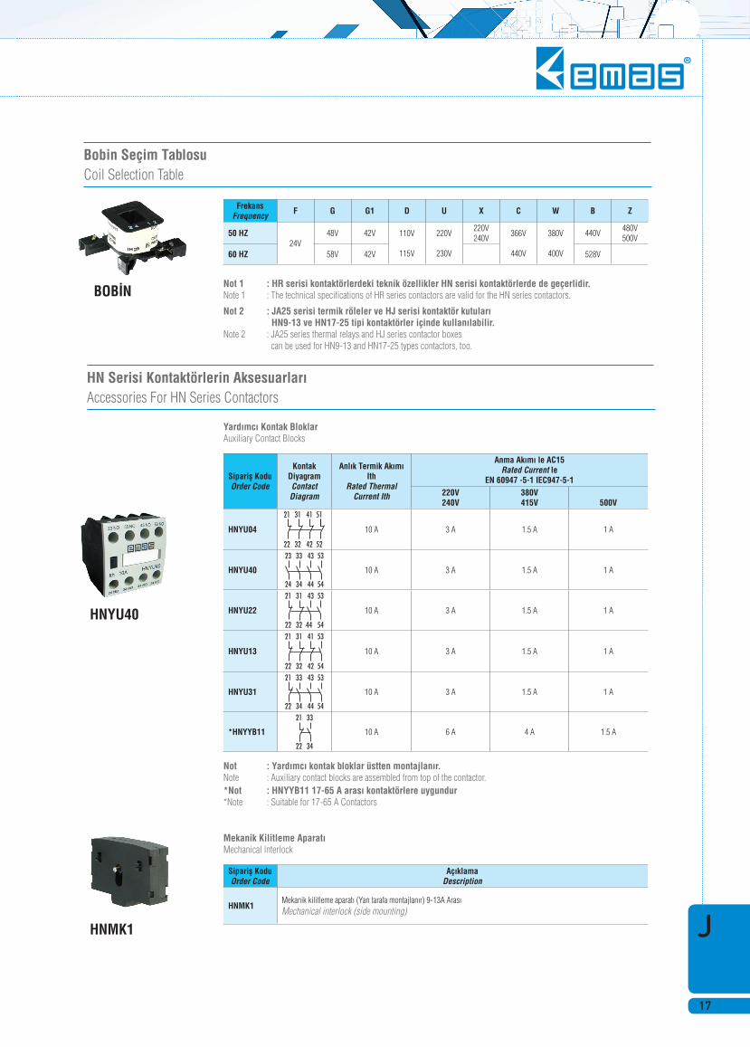
Bobin Seçim Tablosu Coil Selection Table
BOB‹NNot 1 : HR serisi kontaktörlerdeki teknik özellikler HN serisi kontaktörlerde de geçerlidir. Note 1 : The technical specifi cations of HR series contactors are valid for the HN series contactors.
Not 2 : JA25 serisi termik röleler ve HJ serisi kontaktör kutular› HN9-13 ve HN17-25 tipi kontaktörler içinde kullan›labilir. Note 2 : JA25 series thermal relays and HJ series contactor boxes can be used for HN9-13 and HN17-25 types contactors, too.
FrekansFrequency F G G1 D U X C W B Z
50 HZ24V
48V 42V 110V
115V
220V
230V
220V240V
366V
440V
380V
400V
440V480V500V
60 HZ 58V 42V 528V
HNYU40
HNMK1
HN Serisi Kontaktörlerin Aksesuarlar›Accessories For HN Series Contactors
Yard›mc› Kontak Bloklar Auxiliary Contact Blocks
Mekanik Kilitleme Aparat› Mechanical lnterlock
Not : Yard›mc› kontak bloklar üstten montajlan›r. Note : Auxiliary contact blocks are assembled from top of the contactor. *Not : HNYYB11 17-65 A aras› kontaktörlere uygundur *Note : Suitable for 17-65 A Contactors
Siparifl KoduOrder Code
Kontak DiyagramContact Diagram
Anl›k Termik Ak›m› Ith
Rated Thermal Current Ith
Anma Ak›m› le AC15Rated Current le
EN 60947 -5-1 IEC947-5-1220V240V
380V415V 500V
HNYU04 10 A 3 A 1.5 A 1 A
HNYU40 10 A 3 A 1.5 A 1 A
HNYU22 10 A 3 A 1.5 A 1 A
HNYU13 10 A 3 A 1.5 A 1 A
HNYU31 10 A 3 A 1.5 A 1 A
*HNYYB11 10 A 6 A 4 A 1.5 A
Siparifl KoduOrder Code
Aç›klamaDescription
HNMK1Mekanik kilitleme aparat› (Yan tarafa montajlan›r) 9-13A Aras›Mechanical interlock (side mounting)

KontaktörlerContactors
J
18
BOYUTLAR (mm) / DIMENSIONS (mm)
HN09/13 HN17/25
HN46/65