engineering & construction - hakko-sangyo.co.jp · gl engineering & construction hakko...
TRANSCRIPT

GL
ENGINEERING & CONSTRUCTION
HAKKO SANGYO CO.,LTD.
本 社 ・ 工 場 〒871-8688 大分県中津市大字是則1136番地
TEL(0979)32-2460 FAX(0979)32-4134
東京営業部 〒103-0025 東京都中央区日本橋茅場町2-12-5 カワイビル3F
TEL(03)3667-8511㈹ FAX(03)3667-1621
大阪営業部 〒541-0051 大阪市中央区備後町1丁目2番9号 備後町吉田ビル7F
TEL(06)6231-9457 FAX(06)6231-4831
Head Office 1136,Oaza Korenori, Nakatsu-City, Oita-Pref 871-8688
TEL (0979)32-2460 FAX (0979)32-4134
Tokyo sales department Kawai Bld.,3F,12-5,Nihonbashi Kayabacho, 2-chome, Chuo-ku, Tokyo 103-0025
TE(03)3667-8511 FAX (03)3667-1621
Osaka sales department Yoshida Bld.,7F,2-9, Bingo-cho 1-chome, Chuo-ku, Osaka-City 541-0051
TE:(06)6231-9457 FAX (06)6231-4831
HAKKO SANGYO CO., LTD.
● ご用命は
このカタログの内容は製品の機能向上またはその他の理由により、予告なく変更することがあります。また、このカタログの記載数値は参考値であり、あらゆる条件に機能を保証するものではありません。

八光産業は創業(1955年6月)以来、化学業界、医薬業界を始め、多様化・高度化する産業界のニーズ
に応えながら、企業経営の発展に努力してまいりました。
特に、近年では、医薬業界、半導体業界のファイン指向や化学業界の帯電防止要求にマッチしたグラス
ライニング製品の開発に取り組むと共に、更なるグラス性能の向上に注力しております。また、一方で、
国際化が進む産業界の動向をとらえ、技術供与や業務提携も視野に入れたグローバル企業も目指して
いきます。
Hakko Sangyo Co., LTD has been contributing to chemical industries and medicine industries as well as
petrochemical industry since its established in June, 1955.
Also this company had made an effort to the development of enterprise management, while answering the
needs of diversifying and advancing chemical industries.
Especially in the recent years, this company works on the development of the glass lining product that
matches to a needs of the medicine industry and the semiconductor industry and the electrification
prevention demands of a chemical industry, and this company concentrates on the improvement of a
further glass performance.
Furthermore, the trend of an industrial world advanced by the internationalization is caught on the other
hand, and this company aims the global enterprise that contemplates the licensing of technology and
business tie-up.
HAKKO SANGYO CO., LTD.URL http://hakko-sangyo.co.jp/
目 次 C O N T E N T S
グラスライニング機器の取扱いに関しては、
別途メンテナンスマニュアル(据付・組立編、
保守点検と修理編)を御参照下さい。
About the handling of the glass lining, please
refer to an extra maintenance manual.
5
6
7
10
12
13
16
17
22
24
28
29
30
33
34
38
42
44
47
47
48
50
グラスライニング GLASS LINING
グラスライニングとは/グラスライニングの構成 About the glass lining/Structure of the glass lining
豊富なグラスライニング材料 Abundant glass lining materials
特殊グラスライニング Special glass lining
腐食チャート Corrosion chart
物理的特性 Physical characteristics
許容温度 Allowable temperature
機器類 EQUIPMENTグラスライニング用本体ノズル Nozzle for glass lining
反応機寸法表 Reactor dimensions
貯槽寸法表 Tank dimensions
多管式熱交換器寸法表 Heat exchanger dimensions
多重管コンデンサー寸法表 Condenser dimensions
加圧ろ過器寸法表 Filter dimensions
コニカル乾燥機寸法表 Conical dryer dimensions
撹拌 AGITATOR撹拌特性 Agitation character
BENDLEAF翼 Hyper-stirrer“BENDLEAF”
MOLEPAW翼 The next Generation stir wing“MOLEPAW”
アクセサリー ACCESSORIES軸封装置 Shaft seal devices
フラッシュバルブ Flush valve
ハンドホール/マンホールカバー Handhole/Manhole cover
ゲージバルブ Gauge valve
配管 Piping
クランプ/異径フランジ/割フランジ Clamp/Reducing flange/Split flange

グラスライニングとは ABOUT THE GLASS LINING
グラスライニングは、腐食環境等から金属を保護するために金属の表面にガラスを焼き付けた複合材料です。一般に金属は安価な工業材料で優れた加工性を有していますが、化学的耐久性に乏しく、一方、ガラスは化学的に優れた材料であるが、脆性材料であるために割れ易い欠点があります。そこで、金属の欠点をガラスで補い、ガラスの欠点を金属で補ったものがグラスライニング材料です。
The glass lining is composite materials by united glass on the surface of the metal. It protects the metal from the erosive environment etc.In generally, the metal is a cheap material and an excellent processability is possessed. However, chemical durability is scarce. One side, the glass is a chemically excellent material. But there is a fault that cracks fragilely easily.The glass lining material is making up for both the metal and the glass faults.
グラスライニング範囲
うわぐすり
したぐすり
素 地 金 属
長 所Merit
○ 安価な工業材料○ 優れた加工性○ 機械的強度が高い
● Cheap material● Excellent processability● High mechanical strength
短 所Demerit
○ 化学的耐久性が低い● Low chemical durability
金属 METAL
○ 機械的強度が高い○ 耐食性に優れる○ 高級耐食金属に比べ安価
● Mechanical strength is high.● It is excellent in corrosion resistance.● It is cheaper than the high-level anticorrosion metal.
グラスライニング GLASS LINING
複 合 化Composite
長 所Merit
○ セラミックの中では安価○ 耐久性(耐食性)に優れている
● Cheap in the ceramic● Excellent in durability
短 所Demerit
○ 割れやすい● Easy to crack
ガラス GLASS
グラスライニングの構成 STRUCTURE OF THE GLASS LINING
グラスライニングは、ガラスの成型品をはめ込んだり、ガラス板を貼り付けるという施工ではありません。グラスライニングは、粉末状にしたガラスを耐食部の金属表面に吹き付け800℃前後の高温で焼き付ける方法にて施工しています。但し、耐食性の優れたガラス(うわぐすり)を無欠陥にて直接金属表面に焼き付けることは難しく、素地金属表面と“うわぐすり”の中間に“したぐすり”を施工し、金属とガラスを結合させています。“うわぐすり”は優れた耐食性を有するのに対し、“したぐすり”は耐食性は劣りますが素地金属との密着性に優れ、“うわぐすり”とも馴染むように開発されたガラスです。
The glass lining is not construction of setting goods of construction it of the glass, and putting the glass board.The glass lining method sprays the powder of the glass on the surface of the metal first. And next, it is united at the high temperature of about 800℃.After the glass with strong adhesion is united with the surface of the metal of foundation, the glass with excellent corrosion resistance is united on that.
GLASS LINING

5
グラスライニングとは ABOUT THE GLASS LINING
グラスライニングは、腐食環境等から金属を保護するために金属の表面にガラスを焼き付けた複合材料です。一般に金属は安価な工業材料で優れた加工性を有していますが、化学的耐久性に乏しく、一方、ガラスは化学的に優れた材料であるが、脆性材料であるために割れ易い欠点があります。そこで、金属の欠点をガラスで補い、ガラスの欠点を金属で補ったものがグラスライニング材料です。
The glass lining is composite materials by united glass on the surface of the metal. It protects the metal from the erosive environment etc.In generally, the metal is a cheap material and an excellent processability is possessed. However, chemical durability is scarce. One side, the glass is a chemically excellent material. But there is a fault that cracks fragilely easily.The glass lining material is making up for both the metal and the glass faults.
グラスライニング範囲
うわぐすり
したぐすり
素 地 金 属
長 所Merit
○ 安価な工業材料○ 優れた加工性○ 機械的強度が高い
● Cheap material● Excellent processability● High mechanical strength
短 所Demerit
○ 化学的耐久性が低い● Low chemical durability
金属 METAL
○ 機械的強度が高い○ 耐食性に優れる○ 高級耐食金属に比べ安価
● Mechanical strength is high.● It is excellent in corrosion resistance.● It is cheaper than the high-level anticorrosion metal.
グラスライニング GLASS LINING
複 合 化Composite
長 所Merit
○ セラミックの中では安価○ 耐久性(耐食性)に優れている
● Cheap in the ceramic● Excellent in durability
短 所Demerit
○ 割れやすい● Easy to crack
ガラス GLASS
グラスライニングの構成 STRUCTURE OF THE GLASS LINING
グラスライニングは、ガラスの成型品をはめ込んだり、ガラス板を貼り付けるという施工ではありません。グラスライニングは、粉末状にしたガラスを耐食部の金属表面に吹き付け800℃前後の高温で焼き付ける方法にて施工しています。但し、耐食性の優れたガラス(うわぐすり)を無欠陥にて直接金属表面に焼き付けることは難しく、素地金属表面と“うわぐすり”の中間に“したぐすり”を施工し、金属とガラスを結合させています。“うわぐすり”は優れた耐食性を有するのに対し、“したぐすり”は耐食性は劣りますが素地金属との密着性に優れ、“うわぐすり”とも馴染むように開発されたガラスです。
The glass lining is not construction of setting goods of construction it of the glass, and putting the glass board.The glass lining method sprays the powder of the glass on the surface of the metal first. And next, it is united at the high temperature of about 800℃.After the glass with strong adhesion is united with the surface of the metal of foundation, the glass with excellent corrosion resistance is united on that.
グラスライニング
GLASS LIN
ING

6
バランスに長けた標準仕様のグラスライニングです。
耐酸性、耐水性、耐アルカリ性に優れ、あらゆるプロセスに適用でき
ます。
視認性の良いSky Blue カラーが標準仕様となります。
It is a standard glass lining that good at balance.
The“200 SERIES”can be applied to any process because it is
excellent acid resistance, water resistance and alkali resistance.
Sky Blue color with good visibility is a standard specification.
色見本 Colorings
色見本 Colorings
青 Blue水色 Sky Blue 白 White
色見本 Colorings
水色 Sky Blue 青 Blue
水色 Sky Blue
色見本 Colorings
青 Blue
注) グラス色は写真印刷のため、現物と若干異なることをご了承願います。
■ 高耐食性グラス High corrosion resistance
ステンレス鋼用のグラスライニングです。
耐食性及び物理特性は“Octa88-200”と同等です。
視認性の良いSky Blue カラーが標準仕様となります。
It is a glass for stainless steel.
Physical properties and corrosion resistance is equivalent to
the“200 SERIES”.
Sky Blue color with good visibility is a standard specification.
■ ステンレス用グラス Glass for stainless steel
180℃以上で使用する場合の耐熱衝撃用グラスです。
“200 SERIES”に比べ、加熱急冷や試験値が30℃向上しているため、
高温域での使用に最適です。
視認性の良い Sky Blueカラーが標準仕様となります。
It is a glass for thermal shock resistance when used in more than 180 ℃.
When compared to the“200 SERIES”, it is ideal for use in
high-temperature range for rapid cooling or heating test value has been
improved 30℃.
Sky Blue color with good visibility is a standard specification.
■ 耐熱衝撃用グラス Glass for thermal shock resistance
“200 SERIES”に比べ、2倍の耐アルカリ性能を有したグラスです。
これまでの“500”に比べ、耐酸性能が30%向上しています。
但し、酸性側との併用が考えられる場合には事前にサンプルテストを
行うことを推奨致します。
It is a glass compared to the“200 SERIES”, had a double performance
of alkali resistance.
“500”compared to our past, performance has improved 30% acid.
However, if you can be considered in combination with the acidic side,
we recommend that you perform a sample test in advance.
■ 耐アルカリ用グラス Glass for the alkali resistance
豊富なグラスライニング材料 ABUNDANT GLASS LINING MATERIALS
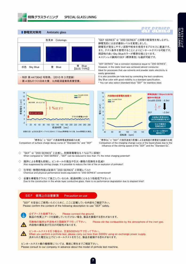
◇ “SEF”は“200 SERIES”と比較し、初期帯電電位も1%以下に抑制!! When compared to“200 SERIES”,“SEF”can be reduced to less than 1% the initial charging potential!!
◇ 撹拌による帯電も抑制し、ピンホールの発生や引火・爆発の危険性を低減!! Also suppressed by stirring charge, it is possible to reduce the risk of fire or explosion of pinholes!!
◇ 化学的・物理的性能は従来の“200 SERIES”と同等レベル!! Chemical and physical performance levels equivalent to“200 SERIES”conventional!!
◇ 全層を導電性グラスにて施工しているため、経過時間にともなう性能低下がない!! Due to the construction in the whole layer conductive glass, there is no performance degradation due to elapsed time!!
“SEF”を安全にご使用いただくために、ここに記載している内容をご確認下さい。Please confirm the content of the following description to use“SEF”safely.
可燃物の撹拌は不活性ガス雰囲気下で行って下さい。 Please stir the combustible by the atmosphere of the inert gas.内容物の爆発及び引火の可能性があります。
必ずアースを接続下さい。 Please connect the ground.製品の性質上アースを接続していただけない場合、製品を損傷する恐れがあります。
SEF 使用上の注意事項 Precaution on use
測定初期=約12kV
ピンホールテストを行う場合は、交流5000V以下で行って下さい。When you perform a pinhole test, please carry out less than 5000V using an exchange power supply.決められた電圧以上でピンホールテストを行うと、製品を破損する恐れがあります。
“SEF SERIES”は“200 SERIES”と同等の耐食性を有しながら、静電気的にはほぼ導体レベルを実現しました。静電気が発生しやすい溶剤や粉体を使用するプロセスに最適です。また、テスト条件を管理することによりピンホールテストも可能です。視認性の良いSky Blueカラーが標準仕様となります。*ステンレス鋼用のSEF(標準青色)も選択可能です。
“SEF SERIES”has a corrosion resistance equal to“200 SERIES”. However, in the static level was achieved almost conductor.Ideal for processes that use solvents and powder static electricity is easily generated.It is also possible pin hole test by controlling the test conditions.Sky Blue color with good visibility is a standard specification.* You can also select (standard blue)“SEF”for stainless steel.
特殊グラスライニング SPECIAL GLASS LINING
色見本 Colorings
青 Blue水色 Sky Blue
・特許 第 4473642 号取得。(2010 年 3月登録)・第 4回ものづくり日本大賞、九州経済産業局長賞受賞。
青 Blue【SUS TYPE】
0 20 40 60 80 100 120 140 160 180 200 220 240 260 280
試験方法:φ200丸型サンプルを-20kVにて10sec間帯電させた後、5min間電位を測定。
“標準GL” と “SEF”の表面帯電減衰曲線の比較Comparison of surface charge decay curve of“Standard GL”and“SEF”
“標準GL” と “SEF”の撹拌速度の影響による液相部の帯電変化曲線の比較Comparison of the charging change curve of the liquid phase due to theinfluence of the stirring speed of the“SEF”and the“Standard GL”.
経過時間 [sec]
回転数 [rpm]
帯電電位[-kV]
電位[-kV]
14
12
10
8
6
4
2
0
-2
グラスの帯電は≒0!!グラスの帯電は≒0!!ス ≒グラスの帯電は≒0!!
測定初期 約-12.0[kV]
1%以下!!14
測定初期 約-12.0[kV]定 2 V
Octa88-200BSEF
約-0.1(kV)以下!!
‼
Octa88-200BSEF Octa88-200B :-8.5kV
内容物の帯電を抑え反応利用範囲が拡大!!
ピンホール発生の確率低下!!
引火や爆発の危険性減少!!
SEF :-2.0kV
10
9
8
7
6
5
4
3
2
1
040 60 80 100 120 140
Octa88-200BO 0OSEFSS
内容物の低帯電を実現 !!標準回転数(138rpm)における撹拌中の電位差
ピンホールテスト機の機種等については、事前に弊社までご相談下さい。Please consult to our company in advance about the model of pinhole test machine.
■ 静電気対策用 Antistatic glass
グラスライニング
GLASS LINING
7
バランスに長けた標準仕様のグラスライニングです。
耐酸性、耐水性、耐アルカリ性に優れ、あらゆるプロセスに適用でき
ます。
視認性の良いSky Blue カラーが標準仕様となります。
It is a standard glass lining that good at balance.
The“200 SERIES”can be applied to any process because it is
excellent acid resistance, water resistance and alkali resistance.
Sky Blue color with good visibility is a standard specification.
色見本 Colorings
色見本 Colorings
青 Blue水色 Sky Blue 白 White
色見本 Colorings
水色 Sky Blue 青 Blue
水色 Sky Blue
色見本 Colorings
青 Blue
注) グラス色は写真印刷のため、現物と若干異なることをご了承願います。
■ 高耐食性グラス High corrosion resistance
ステンレス鋼用のグラスライニングです。
耐食性及び物理特性は“Octa88-200”と同等です。
視認性の良いSky Blue カラーが標準仕様となります。
It is a glass for stainless steel.
Physical properties and corrosion resistance is equivalent to
the“200 SERIES”.
Sky Blue color with good visibility is a standard specification.
■ ステンレス用グラス Glass for stainless steel
180℃以上で使用する場合の耐熱衝撃用グラスです。
“200 SERIES”に比べ、加熱急冷や試験値が30℃向上しているため、
高温域での使用に最適です。
視認性の良い Sky Blueカラーが標準仕様となります。
It is a glass for thermal shock resistance when used in more than 180 ℃.
When compared to the“200 SERIES”, it is ideal for use in
high-temperature range for rapid cooling or heating test value has been
improved 30℃.
Sky Blue color with good visibility is a standard specification.
■ 耐熱衝撃用グラス Glass for thermal shock resistance
“200 SERIES”に比べ、2倍の耐アルカリ性能を有したグラスです。
これまでの“500”に比べ、耐酸性能が30%向上しています。
但し、酸性側との併用が考えられる場合には事前にサンプルテストを
行うことを推奨致します。
It is a glass compared to the“200 SERIES”, had a double performance
of alkali resistance.
“500”compared to our past, performance has improved 30% acid.
However, if you can be considered in combination with the acidic side,
we recommend that you perform a sample test in advance.
■ 耐アルカリ用グラス Glass for the alkali resistance
豊富なグラスライニング材料 ABUNDANT GLASS LINING MATERIALS
◇ “SEF”は“200 SERIES”と比較し、初期帯電電位も1%以下に抑制!! When compared to“200 SERIES”,“SEF”can be reduced to less than 1% the initial charging potential!!
◇ 撹拌による帯電も抑制し、ピンホールの発生や引火・爆発の危険性を低減!! Also suppressed by stirring charge, it is possible to reduce the risk of fire or explosion of pinholes!!
◇ 化学的・物理的性能は従来の“200 SERIES”と同等レベル!! Chemical and physical performance levels equivalent to“200 SERIES”conventional!!
◇ 全層を導電性グラスにて施工しているため、経過時間にともなう性能低下がない!! Due to the construction in the whole layer conductive glass, there is no performance degradation due to elapsed time!!
“SEF”を安全にご使用いただくために、ここに記載している内容をご確認下さい。Please confirm the content of the following description to use“SEF”safely.
可燃物の撹拌は不活性ガス雰囲気下で行って下さい。 Please stir the combustible by the atmosphere of the inert gas.内容物の爆発及び引火の可能性があります。
必ずアースを接続下さい。 Please connect the ground.製品の性質上アースを接続していただけない場合、製品を損傷する恐れがあります。
SEF 使用上の注意事項 Precaution on use
測定初期=約12kV
ピンホールテストを行う場合は、交流5000V以下で行って下さい。When you perform a pinhole test, please carry out less than 5000V using an exchange power supply.決められた電圧以上でピンホールテストを行うと、製品を破損する恐れがあります。
“SEF SERIES”は“200 SERIES”と同等の耐食性を有しながら、静電気的にはほぼ導体レベルを実現しました。静電気が発生しやすい溶剤や粉体を使用するプロセスに最適です。また、テスト条件を管理することによりピンホールテストも可能です。視認性の良いSky Blueカラーが標準仕様となります。*ステンレス鋼用のSEF(標準青色)も選択可能です。
“SEF SERIES”has a corrosion resistance equal to“200 SERIES”. However, in the static level was achieved almost conductor.Ideal for processes that use solvents and powder static electricity is easily generated.It is also possible pin hole test by controlling the test conditions.Sky Blue color with good visibility is a standard specification.* You can also select (standard blue)“SEF”for stainless steel.
特殊グラスライニング SPECIAL GLASS LINING
色見本 Colorings
青 Blue水色 Sky Blue
・特許 第 4473642 号取得。(2010 年 3月登録)・第 4回ものづくり日本大賞、九州経済産業局長賞受賞。
青 Blue【SUS TYPE】
0 20 40 60 80 100 120 140 160 180 200 220 240 260 280
試験方法:φ200丸型サンプルを-20kVにて10sec間帯電させた後、5min間電位を測定。
“標準GL” と “SEF”の表面帯電減衰曲線の比較Comparison of surface charge decay curve of“Standard GL”and“SEF”
“標準GL” と “SEF”の撹拌速度の影響による液相部の帯電変化曲線の比較Comparison of the charging change curve of the liquid phase due to theinfluence of the stirring speed of the“SEF”and the“Standard GL”.
経過時間 [sec]
回転数 [rpm]
帯電電位[-kV]
電位[-kV]
14
12
10
8
6
4
2
0
-2
グラスの帯電は≒0!!グラスの帯電は≒0!!ス ≒グラスの帯電は≒0!!
測定初期 約-12.0[kV]
1%以下!!14
測定初期 約-12.0[kV]定 2 V
Octa88-200BSEF
約-0.1(kV)以下!!
‼
Octa88-200BSEF Octa88-200B :-8.5kV
内容物の帯電を抑え反応利用範囲が拡大!!
ピンホール発生の確率低下!!
引火や爆発の危険性減少!!
SEF :-2.0kV
10
9
8
7
6
5
4
3
2
1
040 60 80 100 120 140
Octa88-200BO 0OSEFSS
内容物の低帯電を実現 !!標準回転数(138rpm)における撹拌中の電位差
ピンホールテスト機の機種等については、事前に弊社までご相談下さい。Please consult to our company in advance about the model of pinhole test machine.
■ 静電気対策用 Antistatic glass
グラスライニング
GLASS LIN
ING

8
高温および高圧などの高腐食環境ではグラス骨格が損傷するため金属成分の溶出量が増大するおそれがあります。In corrosive environments of high temperature and high pressure is a possibility that the amount of elution of the metal component increased for the damage to the glass skeleton!!
MIZ 使用上の注意事項 Precaution on use
アルカリ金属(Li, Na, K, etc.)の溶出による製品へのコンタミを抑制するグラスライニングです。アルカリ金属だけではなく各種金属イオンの溶出量も低減しています。半導体用原料・高純度試薬・電子材料用原料などの製造分野に適しています。
It is a glass lining to prevent the contamination to the product by the elution of the alkali metal(Li, Na, K, etc.).It also reduces the amount of elution of various metal ions as well as the alkali metal.It is suitable for the production field of “Raw materials for the electronic materials”, “High purity reagents”, “Raw materials for semiconductor”.
◇ グラスから溶出するNaを従来の標準グラスの約6分の1にまで軽減!!◇ Li, Kなどの1価のアルカリ金属の溶出量を大幅に低減!!◇ Caなどの2価のアルカリ土類金属の溶出量も低減!!
◆ The sodium component eluting from the glass reduced to about one-sixth compared to the conventional standard glass .◆ Significantly reduces the amount of elution of monovalent alkali metal such as Li and K.◆ Reducing the amount of elution of valent alkaline earth metal such as Ca.
◇ 従来の標準グラスに比べ、グラス組成中のNaの存在量を約20% 減少させることでNaの溶出量を抑制!!
◆ Reduced the amount of elution of Na by reducing the about 20% of existing amount of Na in glass composition than the conventional standard glass!!
■ 金属元素低溶出用グラス Glass for low elution
特殊グラスライニング SPECIAL GLASS LINING
色見本 Colorings
青 Blue
0
20
40
60
80
100
Na K Li Ca
標準グラス
Metal-IonZERO
[ppb]
試験方法:希酸溶液 50℃に 24hr サンプルを浸漬
6 8 10 12
GL面表層(0~20μm)
GL面深層(50~100μm)
標準グラス
[Na wt%]
標準グラスとMetal-Ion ZEROのAlkali-metal溶出量の比較(溶媒:希酸溶液50℃)Comparison of the elution amount of alkali metal components of standard glass and Metal-Ion ZERO (Solvent:Dilute acid solution of 50 ℃)
グラス表面層からのNa存在率の比較Comparison of the presence of Na from the glass surface layer
Metal-IonZERO Naの含有率を20 %低減
注) グラス色は写真印刷のため、現物と若干異なることをご了承願います。
グラスライニング
GLASS LINING


10
腐食チャート CORROSION CHART
弊社標準グラス “Octa88-200” に対する代表的な酸とアルカリの腐食チャートを示します。この腐食チャートは、1日24時間連続テストの結果から計算された年間腐食速度です。年間腐食速度が 0.1mm/year 以下の場合は、耐用年数は5年以上の完全耐食の範囲になります。なお 0.1~0.2mm/yearの場合は2~5年,0.2mm/year以上の場合は1~2年あるいはそれ以下の耐用年数になります。
The chart below shows the corrosion speed during year of typical acids and alkalis, obtained from a 24hours/day continuous corrosion test. In case corrosion speed during year is less than 0.1mm/year, the glass can serve for more than 5 years in the condition of resisting corrosion perfectly. In case corrosion speed during year is 0.1~0.2mm/year, or 0.2mm/year or more, the service life will be 2~5 years, or 2 years or less, respectively.
温
度(℃)
HCI濃度(%)使用可能範囲 完全耐食範囲
0 10 15 20 25 30 35 37100
110
120
130
140
150
160
170
180
190
200
0.2 0.1 ㎜/year
5
温
度(℃)
CH3COOH濃度(%)使用可能範囲 完全耐食範囲
0 10 20 30 40 50 60 70 80 90 100100
110
120
130
140
150
160
170
180
190
200
0.10.2 ㎜/year
温
度(℃)
H3PO4濃度(%)使用可能範囲 完全耐食範囲
0 10 20 30 40 50 60 70 80 90 100100
110
120
130
140
150
160
170
180
190
200
0.2
0.1
㎜/year
温
度(℃)
HNO3濃度(%)使用可能範囲 完全耐食範囲
0 10 20 30 40 50 60 70 80 90 100100
110
120
130
140
150
160
170
180
190
200
0.10.2 ㎜/year
温
度(℃)
H2SO4濃度(%)使用可能範囲 完全耐食範囲
0 10 20 30 40 50 60 70 80 90 100100
120
140
160
180
200
220
240
260
280
300
0.10.2 ㎜/year
硫酸の腐食チャートの点線はグラスライニング機器の使用限界温度を示しています。The dotted line in the corrosion chart of sulfuric acidshows the temperature limit for utilization of Glassed-Steel Equipment.
■ 塩 酸 Hydrochloric Acid
■ りん酸 Phosphoric Acid
りん酸に対するグラスの腐食は、他の酸に対する腐食と著しく異なります。通常グラスは酸の濃度が増すにつれて耐食性は増加しますが、りん酸の場合は濃度が増すにつれて耐食性は逆に低下します。りん酸はしばしば不純物としてふっ素を含有しているので、一週間以上の長期の腐食試験が必要です。
The corrosion resistance of glass to phosphoric acid changes in a much different way from that to other kinds of acids. Usually corrosion resistance of glass increases with the increases of concentration of acid, but in case of phosphoric acid, corrosion resistance decreases with the increases of concentration. As phosphoric acid often contains fluorine as a impurity, the corrosion test for a period as long as more than one week is necessary.
■ 硫酸 ・ 硝酸 ・ 酢酸 Sulfuric Acid ・ Nitric Acid ・ Acetic Acid
何れも低濃度に耐食性のピークがあり、20%付近に耐食性の最低値があります。20%をこえると濃度の増加と共に耐食性は増加します。このチャートは、亜硫酸・亜硝酸にも適用できます。酢酸は有機物(カルボン酸)の代表例として加えました。
The corrosion resistance of these acids show a peak at a low concentration and a bottom at a concentration around 20%. When concentration exceeds 20%, corrosion resistance increases with the increases of concentration. This chart is also applicable to sulfurous acid and nitrous acid. Acetic acid is added as an example of organic acid (Carboxy acid).
塩酸は化学工業において最も多く使用される酸である一方、機器材料を最も激しく腐食させる酸でもあります。“Octa88-200”は、この腐食性の酸に対して極めて優れた耐食性を示します。この腐食チャートが示すように、低濃度域では、1%のところに耐食性のピークがあり、10%で最低となりますが、10%を超えると耐食性は急激に増加します。このチャートは、臭化水素酸、沃化水素酸、クロル酢酸にも適用できます。
Among all kinds of acids for the chemical industry, hydrochloric acid is used most popularly, but it corrodes the materials of equipment most severely.“Octa88-200” Glass shows very excellent resistance to this corrosive acid.As indicated in this chart, corrosion resistance changes in the low concentration area, showing a peak at 1% and a minimum at 10%, but beyond 10%, it increases rapidly. This chart is also applicable to hydrobromic acid, hydriodic acid and chloroacetic acid.
グラスライニング
GLASS LINING

11
腐食チャート CORROSION CHART
弊社標準グラス “Octa88-200” に対する代表的な酸とアルカリの腐食チャートを示します。この腐食チャートは、1日24時間連続テストの結果から計算された年間腐食速度です。年間腐食速度が 0.1mm/year 以下の場合は、耐用年数は5年以上の完全耐食の範囲になります。なお 0.1~0.2mm/yearの場合は2~5年,0.2mm/year以上の場合は1~2年あるいはそれ以下の耐用年数になります。
The chart below shows the corrosion speed during year of typical acids and alkalis, obtained from a 24hours/day continuous corrosion test. In case corrosion speed during year is less than 0.1mm/year, the glass can serve for more than 5 years in the condition of resisting corrosion perfectly. In case corrosion speed during year is 0.1~0.2mm/year, or 0.2mm/year or more, the service life will be 2~5 years, or 2 years or less, respectively.
温
度(℃)
HCI濃度(%)使用可能範囲 完全耐食範囲
0 10 15 20 25 30 35 37100
110
120
130
140
150
160
170
180
190
200
0.2 0.1 ㎜/year
5
温
度(℃)
CH3COOH濃度(%)使用可能範囲 完全耐食範囲
0 10 20 30 40 50 60 70 80 90 100100
110
120
130
140
150
160
170
180
190
200
0.10.2 ㎜/year
温
度(℃)
H3PO4濃度(%)使用可能範囲 完全耐食範囲
0 10 20 30 40 50 60 70 80 90 100100
110
120
130
140
150
160
170
180
190
200
0.2
0.1
㎜/year
温
度(℃)
HNO3濃度(%)使用可能範囲 完全耐食範囲
0 10 20 30 40 50 60 70 80 90 100100
110
120
130
140
150
160
170
180
190
200
0.10.2 ㎜/year
温
度(℃)
H2SO4濃度(%)使用可能範囲 完全耐食範囲
0 10 20 30 40 50 60 70 80 90 100100
120
140
160
180
200
220
240
260
280
300
0.10.2 ㎜/year
硫酸の腐食チャートの点線はグラスライニング機器の使用限界温度を示しています。The dotted line in the corrosion chart of sulfuric acidshows the temperature limit for utilization of Glassed-Steel Equipment.
■ 塩 酸 Hydrochloric Acid
■ りん酸 Phosphoric Acid
りん酸に対するグラスの腐食は、他の酸に対する腐食と著しく異なります。通常グラスは酸の濃度が増すにつれて耐食性は増加しますが、りん酸の場合は濃度が増すにつれて耐食性は逆に低下します。りん酸はしばしば不純物としてふっ素を含有しているので、一週間以上の長期の腐食試験が必要です。
The corrosion resistance of glass to phosphoric acid changes in a much different way from that to other kinds of acids. Usually corrosion resistance of glass increases with the increases of concentration of acid, but in case of phosphoric acid, corrosion resistance decreases with the increases of concentration. As phosphoric acid often contains fluorine as a impurity, the corrosion test for a period as long as more than one week is necessary.
■ 硫酸 ・ 硝酸 ・ 酢酸 Sulfuric Acid ・ Nitric Acid ・ Acetic Acid
何れも低濃度に耐食性のピークがあり、20%付近に耐食性の最低値があります。20%をこえると濃度の増加と共に耐食性は増加します。このチャートは、亜硫酸・亜硝酸にも適用できます。酢酸は有機物(カルボン酸)の代表例として加えました。
The corrosion resistance of these acids show a peak at a low concentration and a bottom at a concentration around 20%. When concentration exceeds 20%, corrosion resistance increases with the increases of concentration. This chart is also applicable to sulfurous acid and nitrous acid. Acetic acid is added as an example of organic acid (Carboxy acid).
塩酸は化学工業において最も多く使用される酸である一方、機器材料を最も激しく腐食させる酸でもあります。“Octa88-200”は、この腐食性の酸に対して極めて優れた耐食性を示します。この腐食チャートが示すように、低濃度域では、1%のところに耐食性のピークがあり、10%で最低となりますが、10%を超えると耐食性は急激に増加します。このチャートは、臭化水素酸、沃化水素酸、クロル酢酸にも適用できます。
Among all kinds of acids for the chemical industry, hydrochloric acid is used most popularly, but it corrodes the materials of equipment most severely.“Octa88-200” Glass shows very excellent resistance to this corrosive acid.As indicated in this chart, corrosion resistance changes in the low concentration area, showing a peak at 1% and a minimum at 10%, but beyond 10%, it increases rapidly. This chart is also applicable to hydrobromic acid, hydriodic acid and chloroacetic acid.
■ アルカリ Alkalis
室温であれば如何なるpH値に対しても使用できますが、温度が高くなるにつれてグラスの耐アルカリ性は低下します。苛性ソーダ、苛性カリのpH14以上での最高使用温度は濃度10%で66℃、20%で60℃、30%で57℃、50%で54℃です。中和操作の場合、pH13で100℃まで許容されます。アルカリ溶液やアルカリ固形物を缶内に挿入する時は、グラス面に付着したり局部的に過熱状態にならないよう缶内液を撹拌しながら、出来るだけ缶の中心部に注入するよう心掛けて下さい。またプロセス条件が、完全な無水の状態であればふっ素化合物を除く有機金属化合物はグラスに影響を与えません。
At room temperature,“Octa88-200”Glass is fully resistant to any pH values. But with the rise of temperature, the resistance of the glass to alkali decreases. For the caustic soda and caustic potash at pH 14 or more, the maximum usable temperature at respective concentrations are : 66℃ at 10%, 60℃ at 20%, 57℃ at 30%, 54℃ at 50%.For operation of neutralization, maximum allowable temperature is 100℃ at pH 13. When alkaline solution or alkaline solid is charged into a vessel, care should be taken to put the material into the center of the vessel agitating the liquid well so that it may not cause sticking of the material to the glass nor any partial overheat in the vessel.Organometallic compounds except for fluorides do not influence the glass, if they are in a perfect alkali condition.
■ 水 Water
水の沸点以下の温度では、液相・気相ともに完全な耐食性を示しますが、一般的に沸点以上になると液相・気相とも150℃が使用限界です。耐食性の良好なグラスは必ずしも同時に耐水性も良いとは限りませんので注意が必要です。
At temperatures lower than the boiling point of water,“Octa88-200” shows perfect corrosion resistance to water both in the phases of liquid and gas, but generally above the boiling point, maximum service temperature is 150℃ in both phases.Attention should be paid to the fact that the glass with high acid resistance has not always good water resistance at a time.
■ ふっ化物 Fluoride
一般的にふっ化物は痕跡量であっても注意が必要です。りん酸、りん酸化合物、塩酸や硫酸の再生酸の中にはふっ化物が含まれていることがあります。これらの液を使用する場合は、前以て腐食試験を行わなければなりません。
Generally if only traces of fluoride is found in the liquid, sufficient care should be taken in the operation.Often fluorine is contained in phosphoric acid, phosphoric compounds, and regenerated products of hydrochloric acid and sulfuric acid. Therefore for the use of those liquids, corrosion test should be conducted before the operation.
■ 塩 類 Salts
塩類(ふっ素塩類を除く)の腐食性は溶液のpHに関係します。例えば個体の塩化ナトリウムは中性ですが、塩化ナトリウム水溶液には水としての腐食性があります。また、塩化アルミニウムは水と反応して塩化水素を発生させるため、塩酸の腐食チャートが参考になります。
The corrosiveness of salts(except those containing fluorine) is closely related to the pH values of the solution. For instance, sodium chloride of solid is neutral, but in its aqueous solution water acts as a corrosive. Also, the chloridization aluminum generates the hydrogen chloride reacting with water. As for the corrosion resistance of“Octa88-200” Glass, by these reactions, the corrosion chart of the hydrochloric acid becomes reference.
■ 有機溶剤 Organic Solvents
有機溶剤に対しては、グラスライニング機器の運転温度限界まで完全な耐食性を示します。しかし、ヘキサン、キシレン、トルエン、ベンゼン、ヘプタンの単独液、他の液体との混合液、あるいは固体との混合液などの低い誘電率の液体は、液体中、液体と気体間、液体と容器壁、あるいはアクセサリー間で静電気放電を起こします。このスパークは発火性蒸気の発火、あるいはグラス面に亀裂またはピンホールを発生させることがありますので注意が必要です。
For organic solvents,“Octa88-200” shows perfect corrosion resistance up to the maximum operating temperature of the glassed steel equipment.But the liquids with low dielectric constant such as the liquids of hexane, xylene, toluene, benzene and heptane, when used single or mixed with other liquids or solids, discharge static electricity between different liquids, liquids and gases, liquids and vessel wall or accessories. The sparks of such electricity may ignite combustible vapors, or cause cracks or pinholes on the glass surface, and so sufficient cares are necessary in handling those liquids.
温
度(℃)
PH使用可能範囲 完全耐食範囲
770
80
90
100
110
120
130
140
150
160
170
0.2
0.1
㎜/year
8 9 10 11 12 13 14
グラスライニング
GLASS LIN
ING
12
物理的特性 PHYSICAL CHARACTERISTICS
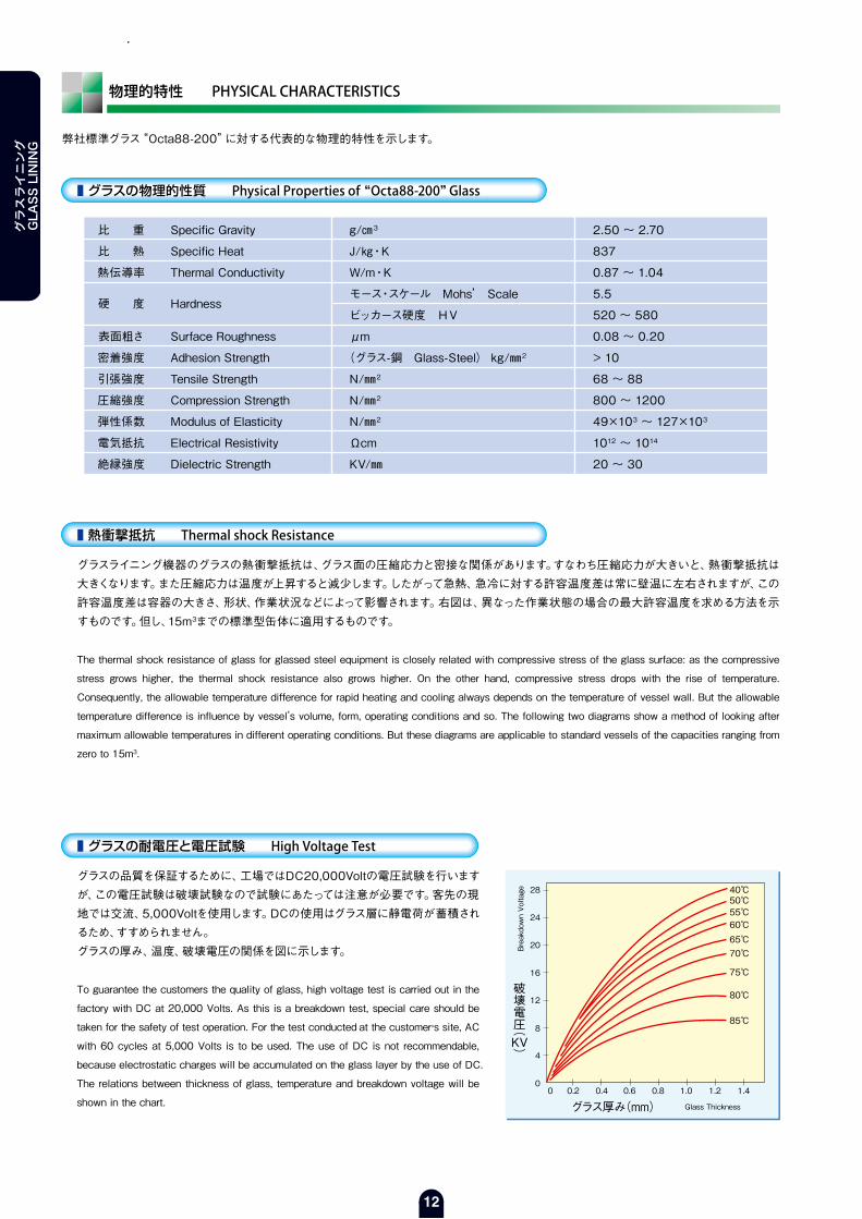
弊社標準グラス“Octa88-200”に対する代表的な物理的特性を示します。
■ グラスの物理的性質 Physical Properties of “Octa88-200” Glass
2.50 ~ 2.70
837
0.87 ~ 1.04
5.5
520 ~ 580
0.08 ~ 0.20
> 10
68 ~ 88
800 ~ 1200
49×103 ~ 127×103
1012 ~ 1014
20 ~ 30
破壊電圧(KV)
00 0.2 0.4 0.6 0.8 1.0 1.2 1.4
4
8
12
16
20
24
28
グラス厚み(mm) Glass Thickness
Breakdown Voltage 40℃
50℃55℃60℃65℃70℃
75℃
80℃
85℃
■ 熱衝撃抵抗 Thermal shock Resistance
グラスライニング機器のグラスの熱衝撃抵抗は、グラス面の圧縮応力と密接な関係があります。すなわち圧縮応力が大きいと、熱衝撃抵抗は大きくなります。また圧縮応力は温度が上昇すると減少します。したがって急熱、急冷に対する許容温度差は常に壁温に左右されますが、この許容温度差は容器の大きさ、形状、作業状況などによって影響されます。右図は、異なった作業状態の場合の最大許容温度を求める方法を示すものです。但し、15m3までの標準型缶体に適用するものです。
The thermal shock resistance of glass for glassed steel equipment is closely related with compressive stress of the glass surface: as the compressive
stress grows higher, the thermal shock resistance also grows higher. On the other hand, compressive stress drops with the rise of temperature.
Consequently, the allowable temperature difference for rapid heating and cooling always depends on the temperature of vessel wall. But the allowable
temperature difference is influence by vessel’s volume, form, operating conditions and so. The following two diagrams show a method of looking after
maximum allowable temperatures in different operating conditions. But these diagrams are applicable to standard vessels of the capacities ranging from
zero to 15m3.
■ グラスの耐電圧と電圧試験 High Voltage Test
グラスの品質を保証するために、工場ではDC20,000Voltの電圧試験を行いますが、この電圧試験は破壊試験なので試験にあたっては注意が必要です。客先の現地では交流、5,000Voltを使用します。DCの使用はグラス層に静電荷が蓄積されるため、すすめられません。グラスの厚み、温度、破壊電圧の関係を図に示します。
To guarantee the customers the quality of glass, high voltage test is carried out in the
factory with DC at 20,000 Volts. As this is a breakdown test, special care should be
taken for the safety of test operation. For the test conducted at the customer,s site, AC
with 60 cycles at 5,000 Volts is to be used. The use of DC is not recommendable,
because electrostatic charges will be accumulated on the glass layer by the use of DC.
The relations between thickness of glass, temperature and breakdown voltage will be
shown in the chart.
比 重
比 熱
熱伝導率
硬 度
表面粗さ
密着強度
引張強度
圧縮強度
弾性係数
電気抵抗
絶縁強度
Specific Gravity
Specific Heat
Thermal Conductivity
Hardness
Surface Roughness
Adhesion Strength
Tensile Strength
Compression Strength
Modulus of Elasticity
Electrical Resistivity
Dielectric Strength
g/㎝3
J/㎏・K
W/m・K
モース・スケール Mohs’ Scale
ビッカース硬度 HV
μm
(グラス-鋼 Glass-Steel) kg/㎜2
N/㎜2
N/㎜2
N/㎜2
Ωcm
KV/㎜
グラスライニング
GLASS LINING

13
グラスライニング
GLASS LIN
ING
許容温度 ALLOWABLE TEMPERATURE
容器内に液を注入する場合(チャートA)
Pouring Liquid into the Vessel(Chart A)
Tp :注入液温度 Temp. of pouring liquidTw :缶壁の温度 Temp. of vessel wall
冷たい容器に熱い液を注入する場合 (Tp>Twの場合) Tw:缶壁の温度For pouring hot liquid into the cold vessel (in case of Tp>Tw)
熱い容器に冷たい液を注入する場合 (Tp<Twの場合) Tw:缶壁の温度For pouring cold liquid into the hot vessel (in case of Tp<Tw)
チャートA : 種々の缶壁温度 Tw に対する仕込液の許容温度 Tp SLA材にライニングした場合
(Ex.1)Minimum allowable temperature (Tp<Tw) for pouring a cold liquid into a hot vessel (Tw=180℃) Procedure ① Read wall temperature Tw = 180℃ on the axis of abscissa in Chart A. ② Draw a perpendicular at the point of 180℃ and find an intersecting point on the blue line. ③ Draw a line parallel to the axis of abscissa from the intersecting point on the blue line, and read the intersecting point Tp on the axis of ordinate. Tpmin=70℃
(Ex.2)Maximum allowable temperature (Tp>Tw) for pouring a hot liquid into a cold vessel (Tw=20℃) Procedure ① Read wall temperature Tw=20℃ on the axis of abscissa in chart A. ② Draw a perpendicular at the point of 20℃ and find an intersecting point on the red line. ③ Draw a line parallel to the axis of abscissa from the intersecting point on the red line, and read the intersecting point Tp on the axis of ordinate. Tpmax=155℃
Chat A : Allowable temperatures, Tp for pouring liquid against Various temperatures, Tw of vessel wall.
This chart adjusts when the parent metal is SLA 235A.
(例1)熱い容器(Tw=180℃)に冷たい液を注入する場合の最小許容温度(Tp<Tw) 手 順 ① チャートAの横軸線上の壁温Tw180℃を読む ② 180℃の点に垂線を立て青線との交点を求める ③ 青線との交点から横軸に平行線を引き縦軸と交わる点Tpを読む Tpmin=70℃
(例2)冷たい容器(Tw=20℃)に熱い液を注入する場合の最大許容温度(Tp>Tw) 手 順 ① チャートAの横軸線上の壁温Tw20℃を読む ② 20℃の点に垂線を立て赤線との交点を求める ③ 赤線との交点から横軸に平行線を引き縦軸と交わる点Tpを読む Tpmax=155℃
Tp(℃)
300
250
200
150
100
50
-50
-50 50 100 150
Tw(℃)200 250
Tp(℃)
300
250
200
150
100
50
-50
-50 50 100 150
Tw(℃)200 250
SLA325A
SLA235A
SLA235A
SLA325A
グラスライニング
GLASS LIN
ING

14
許容温度 ALLOWABLE TEMPERATURE
容器内をジャケットより加熱・冷却する場合(チャートB)
Heating and Cooling Vessel from the Jacket(Chart B)
(Ex.1)Minimum allowable temperature (Tj<Tw) for pouring cooling medium into the jacket of hot vessel (Tw=200℃) Procedure ① Read the temperature (Tw=200℃) of vessel wall on the axis of abscissa in Chart B. ② Draw a perpendicular at the point of 200℃ and find an intersecting point on the blue line. ③ Draw a line parallel to the axis of abscissa from the intersecting point on the blue line, and read the intersecting point Tj on the axis of ordinate. Tjmin=65℃
(Ex.2)Maximum allowable temperature (Tj>Tw) for pouring heating medium into the jacket of cold vessel (Tw=30℃) Procedure ① Read the temperature (Tw=30℃) of vessel wall on the axis of abscissa in Chart B. ② Draw a perpendicular at the point of 30℃ and find an intersecting point on the red line. ③ Draw a line parallel to the axis of abscissa from the intersecting point on the red line, and the intersecting point Tj on the axis of ordinate. Tjmax=170℃
Chat B : Allowable temperatures, Tj for heating or cooling vessel from the jacket against various temperatures, Tw of vessel wall.
This chart adjusts when the parent metal is SLA 235A.
(例1)熱い容器(Tw=200℃)のジャケットの中へ冷媒を入れる時の最小許容温度(Tj<Tw) 手 順 ① チャートBの横軸線上の缶壁温度Tw200℃を読む ② 200℃の点に垂線を立て青線との交点を求める ③ その交点から横軸に平行線を引き縦軸と交わる点Tjを読む Tjmin=65℃
(例2)冷たい容器(Tw=30℃)のジャケットの中へ熱媒を入れる時の最高許容温度(Tj>Tw) 手 順 ① チャートBの横軸線上の缶壁温度Tw30℃を読む ② 30℃の点に垂線を立て赤線との交点を求める ③ その交点から横軸に平行線を引き縦軸と交わる点Tjを読む Tjmax=170℃
Tj :熱媒または冷媒の温度 Temp. of heating medium or cooling mediumTw :缶壁の温度 Temp. of vessel wall
加 熱 (Tj > Twの場合) Heating (in case of Tj>Tw)
冷 却 (Tj < Twの場合) Cooling (in case of Tj<Tw)
チャートB : 種々の缶壁温度 Tw に対するジャケット加熱 あるいは冷却の許容温度 Tj SLA材にライニングした場合
Tj(℃)
300
250
200
150
100
50
-50
-50 50 100 150
Tw(℃)200 250
Tj(℃)
300
250
200
150
100
50
-50
-50 50 100 150
Tw(℃)200 250
Tj(℃)
300
250
200
150
100
50
-50
-50 50 100 150
Tw(℃)200 250
SLA325A
SLA235A
SLA235A
SLA325A
グラスライニング
GLASS LINING

EQUIPMENT

16
NOZZLE FOR GLASS LININGグラスライニング用本体ノズル
本体ノズル 標準寸法表 NOZZLE DIMENSIONS
標準 Standard 端面グラスライニング Nozzle edge Glass lining
(オプション Option)
呼称径NominalDia. ㎜
内 径d ㎜(注)
外 径D ㎜
径g ㎜
厚みt ㎜
割フランジ ~ガスケット面H ㎜
中心円の径C ㎜
ボルト穴
数径h ㎜
ボルトねじの呼び
40A
50A
65A
80A
100A
125A
150A
175A
200A
250A
300A
350A
400A
42
53
68
79
106
130
154
180
205
256
310
355
410
140
155
175
185
210
250
280
305
330
400
445
490
560
85
100
120
130
155
185
25
240
265
325
370
415
475
19
19
21
21
23
23
25
25
27
27
30
30
35
37
37
39
39
41
43
47
47
54
54
57
57
105
120
140
150
175
210
240
265
290
355
400
445
510
4
4
4
8
8
8
8
8
12
12
12
16
16
19
19
19
19
19
23
23
23
23
25
25
25
27
M16
M16
M16
M16
M16
M20
M20
M20
M20
M22
M22
M22
M24
※ 上記寸法は、予告無く変更することがあります。 This size is a previous notice and might change.
ノズル端面グラスライニング 無Standard
ノズル端面グラスライニング 有(オプション)Nozzle edge Glass lining(Option)
内径寸法はグラスライニング施工前の寸法です。ライニングされたグラスの厚みは、約1.5㎜です。JIS10K規格を基本にしていますが、ANSI規格も製作できます。
The inside diameter size is a size before glass lining.The thickness of the lining glass is about 1.5mm.The JIS10K standard is made basic, and ANSI standard can be produced.
フランジの各部寸法
Cn - h
JIS10kSplit Flange
グラスライニング終端Edge of Glass lining
H
dt
g
D
グラスライニング終端Edge of Glass lining
機 器 類
EQUIPMENT

17
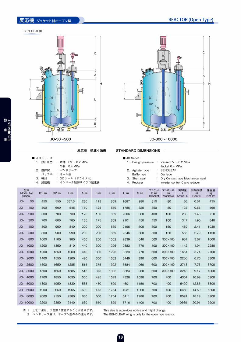
REACTOR (Open Type)反応機 ジャケット付オープン型
反応機 標準寸法表 STANDARD DIMENSIONS
JO-50~500 JO-800~10000
■ JOシリーズ 1.設計圧力 : 本体 FV~0.2 MPa 外套 0.4 MPa 2.撹拌翼 : MOLEPAW バッフル : オール型 3.軸封 : DCシール(ドライメカ) 4.減速機 : インバータ制御サイクロ減速機
■ JO Series 1.Design pressure : Vessel FV ~ 0.2 MPa Jacket 0.4 MPa 2.Agitater type : MOLEPAW Baffle type : Oar type 3.Shaft seal : Dry Contact type Mechanical seal 4.Reducer : Inverter control Cyclo reducer
型式Model No(Capa.)
D1 ㎜ D2 ㎜ L ㎜ A ㎜ B ㎜ C ㎜ H ㎜ S ㎜ブラケットh ㎜Bracket
マンホール㎜
Manhole
伝熱面積㎡
Heat.S
裸重量㎏
Net W.
JO- 50
JO- 100
JO- 200
JO- 300
JO- 400
JO- 500
JO- 800
JO- 1000
JO- 1500
JO- 2000
JO- 2500
JO- 3000
JO- 4000
JO- 5000
JO- 6000
JO- 8000
JO- 10000
450
500
600
700
800
800
1000
1200
1200
1400
1500
1500
1700
1800
1900
2000
2200
550
600
700
800
900
900
1100
1350
1350
1550
1650
1650
1850
1950
2050
2150
2350
337.5
545
730
785
840
990
980
810
1260
1200
1285
1585
1635
1830
1965
2380
2440
113
125
150
175
200
200
250
300
300
350
375
375
425
450
475
500
550
280
160
170
185
200
200
450
440
440
490
515
515
550
585
600
630
680
859
859
859
859
859
859
1052
1226
1226
1302
1302
1302
1599
1599
1754
1754
1899
1687
1786
2006
2101
2196
2346
2839
2883
3333
3449
3584
3884
4326
4601
4931
5411
5716
255
250
300
350
400
400
500
600
600
700
750
750
850
900
950
1000
1100
310
350
400
450
500
500
500
500
600
600
600
600
700
700
700
700
700
80
80
100
100
150
150
300×400
300×400
300×400
300×400
300×400
300×400
400
400
400
400
400
66
123
235
347
489
565
901
1142
1651
2206
2713
3243
4354
5420
6469
8524
10669
0.51
0.86
1.46
1.90
2.41
2.79
3.67
4.04
5.74
6.75
7.76
9.17
10.99
12.85
14.59
18.19
20.91
415
530
675
800
980
1060
1580
2170
2570
3100
3500
3800
4900
5500
6000
7800
9400
※ 上記寸法は、予告無く変更することがあります。 This size is a previous notice and might change.
MOLEPAW翼
h
L
A
C
B
D1
D2
H
S
h
L
A
C
B
D1
D2
H
S
実容量ℓ
Actual C
機 器 類
EQUIPMENT
18
REACTOR (Open Type)反応機 ジャケット付オープン型
反応機 標準寸法表 STANDARD DIMENSIONS
BENDLEAF翼
JO-50~500 JO-800~10000
■ JOシリーズ 1.設計圧力 : 本体 FV~ 0.2 MPa 外套 0.4 MPa 2.撹拌翼 : ベンドリーフ バッフル : オール型 3.軸封 : DCシール(ドライメカ) 4.減速機 : インバータ制御サイクロ減速機
■ JO Series 1.Design pressure : Vessel FV ~ 0.2 MPa Jacket 0.4 MPa 2.Agitater type : BENDLEAF Baffle type : Oar type 3.Shaft seal : Dry Contact type Mechanical seal 4.Reducer : Inverter control Cyclo reducer
型式Model No(Capa.)
D1 ㎜ D2 ㎜ L ㎜ A ㎜ B ㎜ C ㎜ H ㎜ S ㎜ブラケットh ㎜Bracket
マンホール㎜
Manhole
実容量ℓ
Actual C
伝熱面積㎡
Heat.S
裸重量㎏
Net W.
JO- 50
JO- 100
JO- 200
JO- 300
JO- 400
JO- 500
JO- 800
JO- 1000
JO- 1500
JO- 2000
JO- 2500
JO- 3000
JO- 4000
JO- 5000
JO- 6000
JO- 8000
JO- 10000
450
500
600
700
800
800
1000
1200
1200
1400
1500
1500
1700
1800
1900
2000
2200
550
600
700
800
900
900
1100
1350
1350
1550
1650
1650
1850
1950
2050
2150
2350
337.5
545
730
785
840
990
980
810
1260
1200
1285
1585
1635
1830
1965
2380
2440
113
125
150
175
200
200
250
300
300
350
375
375
425
450
475
500
550
280
160
170
185
200
200
450
440
440
490
515
515
550
585
600
630
680
859
859
859
859
859
859
1052
1226
1226
1302
1302
1302
1599
1599
1754
1754
1899
1687
1786
2006
2101
2196
2346
2839
2883
3333
3449
3584
3884
4326
4601
4931
5411
5716
280
320
380
450
500
500
640
770
770
890
960
960
1090
1150
1200
1280
1400
310
350
400
450
500
500
500
500
600
600
600
600
700
700
700
700
700
80
80
100
100
150
150
300×400
300×400
300×400
300×400
300×400
300×400
400
400
400
400
400
66
123
235
347
489
565
901
1142
1651
2206
2713
3243
4354
5420
6469
8524
10669
0.51
0.86
1.46
1.90
2.41
2.79
3.67
4.04
5.74
6.75
7.76
9.17
10.99
12.85
14.59
18.19
20.91
435
560
710
840
1030
1150
1660
2280
2700
3300
3700
4000
5200
5800
6300
8200
9900
※ 1 上記寸法は、予告無く変更することがあります。 This size is a previous notice and might change. 2 ベンドリーフ翼は、オープン型のみの適用です。 The BENDLEAF wing is only for the open type reactor.
h
L
A
C
B
D1
D2
H
S S
h
L
A
C
B
D1
D2
H
機 器 類
EQUIPMENT
19
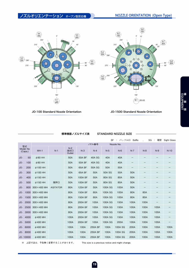
NOZZLE ORIENTATION (Open Type)ノズルオリエンテーション オープン型反応機
標準機器ノズルサイズ表 STANDARD NOZZLE SIZE
JO-100 Standard Nozzle Orientation JO-1500 Standard Nozzle Orientation
型式Model No(Capa.) MH-1 N-1
N-2液出口Outlet
N-3 N-4 N-5
ノズル番号 Nozzle No.
N-6 N-7 N-8 N-9 N-10
JO- 50
JO- 100
JO- 200
JO- 300
JO- 400
JO- 500
JO- 800
JO- 1000
JO- 1500
JO- 2000
JO- 2500
JO- 3000
JO- 4000
JO- 5000
JO- 6000
JO- 8000
JO- 10000
φ80 HH
φ80 HH
φ100 HH
φ100 HH
φ150 HH
φ150 HH
300×400 MH
300×400 MH
300×400 MH
300×400 MH
300×400 MH
300×400 MH
φ400 MH
φ400 MH
φ400 MH
φ400 MH
φ400 MH
撹拌口
AGITATOR
50A BF
50A BF
65A BF
65A BF
100A BF
100A BF
125A BF
150A BF
150A BF
200A BF
200A BF
200A BF
200A BF
200A BF
100A
100A
100A
50A
50A
50A
50A
50A
50A
80A
80A
80A
80A
80A
80A
100A
100A
100A
100A
100A
40A SG
40A SG
50A SG
50A
50A
50A
50A
80A
80A
100A
100A
100A
100A
100A
250A BF
250A BF
250A BF
40A
40A
50A
50A SG
80A SG
80A SG
100A SG
100A SG
100A SG
100A SG
100A SG
100A SG
100A SG
100A SG
100A
100A
100A
40A
40A
50A
50A
80A
80A
100A
100A
100A
150A
150A
150A
150A
200A
100A SG
100A SG
100A SG
-
-
-
50A
50A
50A
50A
80A
80A
100A
100A
100A
100A
100A
200A
200A
200A
-
-
-
-
-
-
-
80A
80A
100A
100A
100A
100A
100A
100A
100A
100A
-
-
-
-
-
-
-
-
-
-
100A
100A
100A
100A
100A
100A
100A
-
-
-
-
-
-
-
-
-
-
-
-
-
-
100A
100A
100A
※ 上記寸法は、予告無く変更することがあります。 This size is a previous notice and might change.
BF : バッフル口 Baffle , SG : 覗窓 Sight Glass
90°
45°
35°340°
0°
180°
135°225°
280°
270°
315°
85°
φ80H-1
40AN-6
40AN-540A
N-4
50AN-3
85°
50°
90°
45°
10°0°
330°
315°
290°
270°
250°
225°
180°
135°
M-1 300×400
N-3150A
80AN-4
N-5100A
N-6100A
80AN-7
80AN-8
機 器 類
EQUIPMENT

20
REACTOR (Close Type)反応機 ジャケット付クローズ型
※ 上記寸法は、予告無く変更することがあります。 This size is a previous notice and might change.
MOLEPAW翼
反応機 標準寸法表 STANDARD DIMENSIONS
■JCシリーズ 1.設計圧力 : 本体 FV~ 0.2 MPa 外套 0.4 MPa 2.撹拌翼 : MOLEPAW バッフル : オール型 3.軸封 : DCシール(ドライメカ) 4.減速機 : インバータ制御サイクロ減速機
■ JC Series 1.Design pressure : Vessel FV ~ 0.2 MPa Jacket 0.4 MPa 2.Agitater type : MOLEPAW Baffle type : Oar type 3.Shaft seal : Dry Contact type Mechanical seal 4.Reducer : Inverter control Cyclo reducer
型式Model No(Capa.)
D1 ㎜ D2 ㎜ L ㎜ A ㎜ B ㎜ C ㎜ H ㎜ S ㎜ブラケットh ㎜Bracket
マンホール㎜
Manhole
実容量ℓ
Actual C
伝熱面積㎡
Heat.S
裸重量㎏
Net W.
JC- 2000
JC- 3000
JC- 4000
JC- 5000
JC- 6000
JC- 8000
JC- 10000
JC- 12000
JC- 15000
JC- 18000
JC- 20000
JC- 25000
JC- 30000
1500
1500
1700
1800
1900
2000
2200
2300
2500
2700
2700
2800
3000
1650
1650
1850
1950
2050
2150
2350
2450
2650
2850
2850
2950
3150
885
1455
1485
1670
1805
2220
2270
2505
2645
2695
3045
3600
3750
652
652
722
747
787
812
887
912
992
1057
1057
1097
1147
375
375
425
450
475
500
550
575
625
675
675
700
750
1226
1302
1599
1599
1599
1754
1899
2008
2258
2279
2279
2730
2730
3238
3884
4341
4596
4796
5426
5746
6140
6660
6846
7196
8277
8527
650
650
800
850
900
950
1050
1100
1200
1300
1300
1350
1450
850
1050
1050
1050
1200
1200
1200
1500
1500
1700
1700
1700
1700
300×400
300×400
400
400
400
400
400
400
450
450
450
450
450
2006
3013
4014
5013
6016
8022
10023
12000
15029
18006
20011
25041
30041
6.86
9.55
11.33
13.25
15.00
18.63
21.32
24.25
28.01
31.27
34.24
40.69
45.67
3050
3700
4550
5250
6000
7650
9150
10250
13950
15400
16400
21600
23800
S
h
L
A
C
B
D1
D2
H
機 器 類
EQUIPMENT

21
NOZZLE ORIENTATION (Close Type)ノズルオリエンテーション クローズ型反応機
標準機器ノズルサイズ表 STANDARD NOZZLE SIZE
JC-5000 Standard Nozzle Orientation JC-25000 Standard Nozzle Orientation
※ 上記寸法は、予告無く変更することがあります。 This size is a previous notice and might change.
BF : バッフル口 Baffle , SG : 覗窓 Sight Glass
90°
60°
45°
30°
0°355°
320°315°
290°
270°
250°
225°
180°
135°
M-1 φ400(48)
200AN-3
100AN-4
100AN-5
200AN-6
100AN-7
100AN-8
100AN-9 90°
60°
45°40°
10°0°340°
320°315°
300°
270°
240°
225° 135°
180°
M-1 φ450(54)
N-4300A
N-3100A
300AN-11
100AN-10
N-9100A
N-8200A
N-6100A
N-7100A
N-5100A
型式Model No(Capa.) MH-1 N-1
N-2液出口Outlet
N-3 N-4 N-5
ノズル番号 Nozzle No.
N-6 N-7 N-8 N-9 N-10 N-11
JC- 2000
JC- 3000
JC- 4000
JC- 5000
JC- 6000
JC- 8000
JC- 10000
JC- 12000
JC- 15000
JC- 18000
JC- 20000
JC- 25000
JC- 30000
300×400 MH
300×400 MH
φ400 MH
φ400 MH
φ400 MH
φ400 MH
φ400 MH
φ400 MH
φ450 MH
φ450 MH
φ450 MH
φ450 MH
φ450 MH
撹拌口
AGITATOR
200A BF
200A BF
200A BF
200A BF
100A
100A
100A
100A
100A
100A
100A
100A
100A
80A
80A
100A
100A
100A
100A
100A
100A
100A
100A
100A
100A
100A
100A
100A
100A
100A
250A BF
250A BF
250A BF
300A BF
300A BF
300A BF
300A BF
300A BF
300A BF
100A SG
100A SG
100A SG
100A SG
100A
100A
100A
100A
100A
100A
100A
100A
100A
150A
150A
150A
200A
100A SG
100A SG
100A SG
100A SG
100A
100A
100A
100A
100A
100A
100A
100A
100A
200A
200A
200A
200A
100A SG
100A SG
100A SG
100A SG
100A SG
100A
100A
100A
100A
100A
100A
100A
100A
200A
200A
200A
200A
200A
100A
100A
100A
100A
100A
100A
100A
100A
100A
100A
100A
100A
100A
-
-
-
-
100A
100A
100A
100A
100A
100A
100A
100A
100A
-
-
-
-
-
-
-
-
300A BF
300A BF
300A BF
300A BF
300A BF
機 器 類
EQUIPMENT

22
TANK (Vertical Type)貯 槽 縦型
※ 上記寸法は、予告無く変更することがあります。 This size is a previous notice and might change.
貯槽 標準寸法表 STANDARD DIMENSIONS
VS-25~800 VS-1000~35000
■ VSシリーズ 1.設計圧力 : 大気圧
■ VS Series 1.Design pressure : ATM
型式Model No(Capa.)
D ㎜ A ㎜ B ㎜ C ㎜ L ㎜ブラケットh ㎜Bracket
S1 ㎜ S2 ㎜マンホール㎜
Manhole
実容量ℓ
Actual C
裸重量㎏
Net W.
VS- 25
VS- 50
VS- 100
VS- 200
VS- 300
VS- 400
VS- 500
VS- 800
VS- 1000
VS- 1500
VS- 2000
VS- 3000
VS- 4000
VS- 5000
VS- 6000
VS- 8000
VS- 10000
VS- 12000
VS- 15000
VS- 20000
VS- 25000
VS- 30000
VS- 35000
350
450
500
600
700
800
800
1000
1000
1200
1200
1500
1500
1650
1800
1950
2100
2100
2400
2700
2700
2800
3000
68
87
97
116
136
155
155
194
194
233
233
291
291
320
349
378
407
407
466
524
524
543
582
47
60
60
72
85
100
100
295
194
233
233
291
291
320
349
378
407
407
466
524
524
543
582
272
333
503
714
814
845
995
956
1251
1252
1702
1599
2149
2200
2151
2453
2703
3253
3049
3201
4101
4602
4598
349
487
667
909
1042
1107
1257
1452
1639
1718
2168
2181
2731
2840
2849
3209
3517
4067
3981
4249
5149
5688
5762
255
300
350
400
450
450
500
500
600
600
700
700
700
800
800
800
900
900
900
900
1000
1500
1500
470
570
680
840
940
1040
1040
1245
1245
1440
1440
1830
1834
1990
2140
2290
2520
2520
2940
3330
3330
3430
3580
-
-
-
550
650
700
700
850
850
1000
1000
1350
1350
1500
1650
1800
1900
1900
2200
2500
2500
2600
2800
-
80
100
150
150
200
200
400
400
400
400
400
400
400
400
400
450
450
450
450
450
450
450
30
62
111
223
347
475
551
850
1181
1587
2096
3160
4132
5149
6051
8057
10279
12184
15161
20275
25428
30509
35173
130
185
245
325
425
505
535
830
800
1050
1250
1600
2050
2450
2750
3750
4800
5450
6250
8650
10100
11500
12500
h
C
A
A
B
S1
D
L
C
A
B
D
L
S2
①ラダー&プラットホーム Ladder & Platform
②自立脚 Self-Standing Legs
③ゲージバルブ Gauge Valve
⑤ドレンバルブ Drain Valve
①~⑤ はオプションです。 ①~⑤:Optional Accessory
④液面計 Level Gage
機 器 類
EQUIPMENT

23
TANK (Horizontal Type)貯 槽 横型
※ 上記寸法は、予告無く変更することがあります。 This size is a previous notice and might change.
貯槽 標準寸法表 STANDARD DIMENSIONS
■ HSシリーズ 1.設計圧力 : 大気圧
■ HS Series 1.Design pressure : ATM
h
S1
BA
L
B
S2
D
型式Model No(Capa.)
D ㎜ A ㎜ B ㎜ L ㎜ブラケットh ㎜Bracket
S1 ㎜ S2 ㎜マンホール㎜
Manhole
実容量ℓ
Actual C
裸重量㎏
Net W.
HS- 1000
HS- 1500
HS- 2000
HS- 3000
HS- 4000
HS- 5000
HS- 6000
HS- 8000
HS- 10000
HS- 12000
HS- 15000
HS- 20000
HS- 25000
HS- 30000
HS- 35000
HS- 40000
1252
1852
1704
2096
2148
2200
2700
3002
2706
3256
3696
4148
4800
4852
5304
4996
1000
1000
1200
1300
1500
1650
1650
1800
2100
2100
2200
2400
2500
2700
2800
3000
194
194
233
252
291
320
320
349
407
407
427
466
485
524
543
582
1640
2240
2170
2600
2730
2840
3340
3700
3520
4070
4550
5080
5770
5900
6390
6160
450
750
850
900
1000
1100
1100
1150
1300
1300
1350
1450
1500
1600
1650
1750
1050
1650
1460
1860
1880
1930
2430
2690
2395
2945
3285
3740
4390
4400
4850
4540
800
800
1000
1100
1250
1450
1450
1500
1800
1800
1850
2050
2150
1900
2000
2100
400
400
400
400
400
400
400
400
450
450
450
450
450
450
450
450
1150
1600
2200
3200
4464
5593
6662
8793
11205
13110
16157
21501
26654
31676
37004
40658
800
1000
1650
2000
2350
2850
3200
4100
4900
5400
7100
8650
9950
12300
13650
14300
機 器 類
EQUIPMENT

24
HEAT EXCHANGER (Horizontal Type)多管式熱交換器 横型
※ 1 上記寸法は、予告無く変更することがあります。 This size is a previous notice and might change. 2 伝熱面積は、外径基準にて算出しています。 The heat transter area is calculate by the outside diameter of the tube.
h
AB
B
3°
D
L
S2S1
①ダビット Davit
①ダビット Davit
①,② はオプションです。 ①,②:Optional Accessory
②トラック型洗浄口 Opening
多管式熱交換器 標準寸法表 STANDARD DIMENSIONS
■ STHシリーズ 1.設計圧力 : プロセス側(チューブ) FV~0.1 MPa 加熱冷却側(シェル) 0.40 MPa
■ STH Series 1.Design pressure : Tube Side FV ~ 0.1 MPa Shell Side 0.40 MPa
型式Model No(Capa.)
D ㎜ A ㎜ B ㎜ L ㎜ブラケットh ㎜Bracket
S1 ㎜ S2 ㎜管本数
Number P
実容量ℓ
Actual C
伝熱面積㎡
Heat.S
裸重量㎏
Net W.
STH- 1
STH- 2
STH- 3
STH- 5
STH- 10
STH- 15
STH- 20
STH- 25
STH- 30
STH- 35
STH- 40
200A
250A
300A
300A
400A
500A
500A
500A
500A
550A
550A
311
361
376
376
409
519
519
539
539
619
619
1400
1400
1400
2000
2000
2000
2750
3500
3500
3500
3500
2036
2136
2166
2766
2832
3052
3802
4592
4592
4752
4752
600
600
600
600
600
600
610
595
595
645
645
700
700
700
950
950
940
1370
2000
2000
2000
2000
120
130
180
180
280
380
380
380
380
410
410
9
17
25
27
50
76
76
76
89
101
112
26
48
70
81
150
270
304
344
371
481
503
1.3
2.5
3.6
5.6
10.3
15.7
21.7
27.8
32.5
36.9
40.9
270
340
380
550
860
1250
1550
1850
2000
2300
2400
機 器 類
EQUIPMENT
25
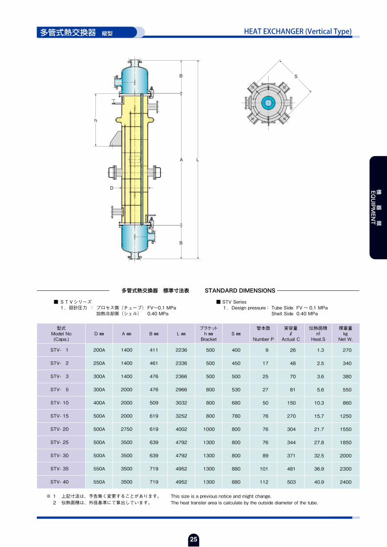
HEAT EXCHANGER (Vertical Type)多管式熱交換器 縦型
※ 1 上記寸法は、予告無く変更することがあります。 This size is a previous notice and might change. 2 伝熱面積は、外径基準にて算出しています。 The heat transter area is calculate by the outside diameter of the tube.
多管式熱交換器 標準寸法表 STANDARD DIMENSIONS
■ STVシリーズ 1.設計圧力 : プロセス側(チューブ) FV~0.1 MPa 加熱冷却側(シェル) 0.40 MPa
■ STV Series 1.Design pressure : Tube Side FV ~ 0.1 MPa Shell Side 0.40 MPa
h
B
B
A L
S
D
型式Model No(Capa.)
D ㎜ A ㎜ B ㎜ L ㎜ブラケットh ㎜Bracket
S ㎜管本数
Number P
実容量ℓ
Actual C
伝熱面積㎡
Heat.S
裸重量㎏
Net W.
STV- 1
STV- 2
STV- 3
STV- 5
STV- 10
STV- 15
STV- 20
STV- 25
STV- 30
STV- 35
STV- 40
1400
1400
1400
2000
2000
2000
2750
3500
3500
3500
3500
200A
250A
300A
300A
400A
500A
500A
500A
500A
550A
550A
411
461
476
476
509
619
619
639
639
719
719
2236
2336
2366
2966
3032
3252
4002
4792
4792
4952
4952
500
500
500
800
800
800
1000
1300
1300
1300
1300
400
450
500
530
680
780
800
800
800
880
880
9
17
25
27
50
76
76
76
89
101
112
26
48
70
81
150
270
304
344
371
481
503
1.3
2.5
3.6
5.6
10.3
15.7
21.7
27.8
32.5
36.9
40.9
270
340
380
550
860
1250
1550
1850
2000
2300
2400
機 器 類
EQUIPMENT

26
多管式熱交換器
最高設計圧力Maximum Design pressure
最高設計温度Maximum Design temperature
許容熱衝撃温度差Allowable temperature difference against thermal shock
総括伝熱係数Overall heat-transfer coefficient
グラス面検査Pinhole test
水圧試験Hydraulic test
気密試験Air-tight test
シェル側Shell sideチューブ側Tube sideシェル側Shell sideチューブ側Tube side
伝熱管(25A×n本)Heat exchanger tube
構 造 Structure
シェル&チューブの1パス型熱交換器で、内面はグラスライニングされており、内面側にプロセス流体、シェル側に加熱、冷却媒体を通過させる構造です。チューブ内面のグラスは、インサート方式(中空ガラス管を鋼管内面に融圧着させる方式)によりライニングしているため、含泡率が少なく、ピンホールはありません。管板とチューブは、溶接構造になっていますので、プロセス流体と熱媒、冷媒とは完全に分離されています。尚、管板とチューブとの接合部のライニングは、当社の焼成技術を駆使した特殊焼成方法により初めて実現したものです。
Tubes are completely welded to the tube-sheets to make a mono-block structure.The entire surface coming in contact with corrosive fluids is completely glass-lined. It is installable both vertically and horizontally. Thoroughly inspected by pinhole and hydraulic tests.
特 徴 Characteristics
標 準 仕 様 Standard Model
① 弗酸、リン酸を除くすべての酸に対し、全濃度に渡り沸点までの温度に良好な耐食性を有します。② 表面が不活性であり金属イオンの溶出がない為、内容物を汚染しません。③ 表面が滑らかであり、物質が付着しにくく洗浄も容易です。④ 単位伝熱面積あたりの占有容量が小さくコンパクトである為、設置面積が少なくてすみます。
① Excellent Corrosion Resistance.② No Contamination of Contents.③ Free form Fouling Deposits and Easy for Cleaning Work.④ Space-saving apparatus.
ドレン抜きDrain
点検口Inspection
冷却水入口Water inlet
凝縮液出口Condensate outlet
0.59 MPa
FV ~ 0.59 MPa
180℃ (453 K)
180℃ (453 K)
⊿t = 100℃ (100 K) 但し、条件によって ⊿t = 80℃ (80 K)
150 ~ 350 kcal / m2 h℃ (170 ~ 400 W/m2 K)
D.C. 10,000 V Electric test
0.59 MPa
客先指示によるBy the customer’s instruction
ベーパー口Vapor inlet
冷却水出口Water outlet
点検口Inspection
ベントVent
機 器 類
EQUIPMENT

27
HEAT EXCHANGER
用 途 Applocation
次の用途に使用できます。 ① 蒸気の凝縮 ② 液の蒸発 ③ 気・液の加熱 ④ 気・液の冷却納入実績では蒸気の凝縮が最も多くなっています。
I can use it for the next use. ① The condensation of the steam ② Evaporation of the liquid ③ Heating of mind / the liquid ④ Cooling of mind / the liquidThe condensation of the steam increases by the delivery results most.
オプション Option
当社のグラスライニング製多管式熱交換器は、当社独自の高度な焼成技術と多種多様な熱交換器製造の経験と実績から生まれた優れた製品です。低温仕様、GMP対応品、ダビット等の付属部品取付け等、標準仕様以外でも製作可能です。
低温にて水とブラインを使用する場合に、管板面の凝結防止として、シェル内部にポリマー施工を行っています。施工を行うことにより、低温での水とブラインの併用が可能となります。
Various types are prepared according to the process and maintenance. ① Polymer construction type ② Easy washing type ③ Davit installation type ④ The other
樹脂施工部 断面
● ポリマー施工
シェル内部のスケールを容易に除去できるよう、トラック型の開口部を設けたものです。スケールの除去を行うことにより、伝熱の低下防止、外部腐食状態の確認等が行えます。
● シェル内洗浄タイプ
シェル内の管板面を樹脂にて保護する。Polymer construction
機 器 類
EQUIPMENT

28
CONDENSER多重管コンデンサー
※ 上記寸法は、予告無く変更することがあります。 This size is a previous notice and might change.
CE-1~3 CE-4~20
h
D1 D4
D1
D2
D3
D2
D3
L H L H
h
多重管コンデンサー 標準寸法表 STANDARD DIMENSIONS
■ CEシリーズ 1.設計圧力 : プロセス側 FV~0.2 MPa 冷却側 0.40 MPa
■ CE Series 1.Design pressure : Process Side FV ~ 0.2 MPa Cooling Side 0.4MPa
型式Model No(Capa.)
D1 ㎜ D2 ㎜ D3 ㎜ D4 ㎜ L ㎜ H ㎜ブラケットh ㎜Bracket
S ㎜実容量ℓ
Actual C
伝熱面積㎡
Heat.S
裸重量㎏
Net W.
CE- 1
CE- 2
CE- 3
CE- 4
CE- 5
CE- 6
CE- 8
CE- 10
CE- 12
CE- 15
CE- 20
267.4
267.4
406.4
600
600
600
750
850
850
1100
1100
410
410
612
800
800
800
950
1050
1050
1350
1350
318.5
318.5
500
700
700
700
850
950
950
1200
1200
-
-
-
500
500
500
650
750
750
1000
1000
850
1300
1300
1300
1500
1700
1900
2100
2600
2400
3000
1133
1583
1652
1626
1826
2026
2283
2479
2979
2984
3584
530
530
610
640
640
640
740
820
820
870
870
580
580
780
970
970
970
1180
1280
1280
1645
1645
15
20
70
120
205
225
240
300
450
430
440
1.2
2.1
3.1
4.2
5.5
6.9
8.4
11.5
13.6
16.2
20.1
360
470
750
1100
1250
1350
1900
2700
3200
4200
5000
機 器 類
EQUIPMENT

29
FILTER加圧ろ過器
※ 上記寸法は、予告無く変更することがあります。 This size is a previous notice and might change.
BASE MODEL
本体の旋回・傾斜・移動 及び 手動・自動等の製作も致します。
We are manufacturing Various Types.Turn and slant to body,cover,bottom plate.Manual Type. Automatic Type.
H
W×L
AB D
ベッドBed
支柱Support
拡散板Diffused Plate
本体カバーCover
ろ布Filter Cloth
PTFE 多孔板Perforated Plate
底板Base Plate
油圧ジャッキHydraulic Jack
油圧ポンプHydraulic Pump
レールRail
油圧ジャッキHydraulic Jack
油圧ポンプHydraulic Pump
本体Body
旋 回
昇 降
加圧ろ過器 標準寸法表 STANDARD DIMENSIONS
■ FIシリーズ 1.設計圧力 : 本体 FV~0.2 MPa
■ FI Series 1.Design pressure : Vessel FV ~ 0.2 MPa
型式Model No(Capa.)
D ㎜ A ㎜ B ㎜ H ㎜ W ㎜ L ㎜実容量ℓ
Actual C
ろ過面積㎡Filt.A
裸重量㎏
Net W.
FI- 01
FI- 015
FI- 02
FI- 03
FI- 04
FI- 05
350
450
500
600
700
800
232
263
253
284
264
245
300
350
350
400
400
400
1170
1250
1430
1480
1790
1790
750
850
1000
1100
1350
1450
600
700
800
900
1100
1200
20
40
45
80
100
120
0.1
0.2
0.2
0.3
0.4
0.5
300
350
400
500
800
900
機 器 類
EQUIPMENT

30
ドライシール Dry Seal
プランマブロック Plummer Block
コニカル乾燥機
※ 上記寸法は、予告無く変更することがあります。 This size is a previous notice and might change.
W × L
B
D1
D2
H
A
90°
② ステンレス製カバー Stainless-steel Cover
マンホールカバーManhole Cover
吸引管Suction Pipe ③ 保温&保温カバー
Insulation & Insulation Cover
② ステンレス製カバー Stainless-steel Cover
プランマブロック Plummer Block
ロータリージョイント Rotary Joint
減速機 Speed Reducer
バルブ Valve ①~③ はオプションです。 ①~③:Optional Accessory
① 測温抵抗体 Resistance Bulb
コニカル乾燥機 標準寸法表 STANDARD DIMENSIONS
■ CDシリーズ 1.設計圧力 : 本体 FV~ATM 外套 0.3 MPa 2.吸引管 : 固定式 吸引管材質 : MA22(ハステロイ C-22) 3.軸封 : DCシール(ドライメカ) 4.減速機 : インバーター制御ウォーム減速機
■ CD Series 1.Design pressure : Vessel FV ~ ATM Jacket 0.3 MPa 2.Suction tube : Fixation Type Suction tube Material : MA22(Hastelloy C-22) 3.Shaft seal : Dry Contact type Mechanical seal 4.Reducer : Inverter control Worm reducer
型式Model No(Capa.)
D1 ㎜ D2 ㎜ A ㎜ B ㎜ H ㎜ W ㎜ L ㎜マンホール㎜
Manhole
実容量ℓ
Actual C
仕込容量ℓ
Work.Cap
伝熱面積㎡
Heat.S
裸重量㎏
Net W.
CD- 100
CD- 200
CD- 500
CD- 800
CD- 1000
CD- 1500
CD- 2000
CD- 3000
CD- 4000
CD- 5000
CD- 6000
600
750
1000
1200
1250
1500
1600
1800
2000
2150
2300
700
850
1150
1350
1400
1650
1750
1950
2150
2300
2450
440
505
705
805
855
955
1055
1220
1335
1430
1495
440
415
610
715
765
865
965
1150
1240
1340
1440
1100
1200
1400
1400
1450
1500
1650
1900
2000
2000
2000
1800
2011
2532
2842
2892
3342
4010
4260
4724
4874
5150
600
800
1200
1300
1400
1500
1600
1700
2000
2100
2200
250
400
400
400
400
400
400
400
400
400
400
100
210
550
870
1030
1550
2085
3000
4000
5050
6000
70
130
320
500
650
1000
1300
2000
2400
3000
3600
1.0
1.4
2.9
4.1
5.5
6.2
7.6
10.1
12.1
14.5
14.5
600
100
2700
3000
3500
4000
5500
6500
9800
10200
12800
機 器 類
EQUIPMENT

31
ドライシール Dry Seal
プランマブロック Plummer Block
コニカル乾燥機
※ 上記寸法は、予告無く変更することがあります。 This size is a previous notice and might change.
W × L
B
D1
D2
H
A
90°
② ステンレス製カバー Stainless-steel Cover
マンホールカバーManhole Cover
吸引管Suction Pipe ③ 保温&保温カバー
Insulation & Insulation Cover
② ステンレス製カバー Stainless-steel Cover
プランマブロック Plummer Block
ロータリージョイント Rotary Joint
減速機 Speed Reducer
バルブ Valve ①~③ はオプションです。 ①~③:Optional Accessory
① 測温抵抗体 Resistance Bulb
コニカル乾燥機 標準寸法表 STANDARD DIMENSIONS
■ CDシリーズ 1.設計圧力 : 本体 FV~ATM 外套 0.3 MPa 2.吸引管 : 固定式 吸引管材質 : MA22(ハステロイ C-22) 3.軸封 : DCシール(ドライメカ) 4.減速機 : インバーター制御ウォーム減速機
■ CD Series 1.Design pressure : Vessel FV ~ ATM Jacket 0.3 MPa 2.Suction tube : Fixation Type Suction tube Material : MA22(Hastelloy C-22) 3.Shaft seal : Dry Contact type Mechanical seal 4.Reducer : Inverter control Worm reducer
型式Model No(Capa.)
D1 ㎜ D2 ㎜ A ㎜ B ㎜ H ㎜ W ㎜ L ㎜マンホール㎜
Manhole
実容量ℓ
Actual C
仕込容量ℓ
Work.Cap
伝熱面積㎡
Heat.S
裸重量㎏
Net W.
CD- 100
CD- 200
CD- 500
CD- 800
CD- 1000
CD- 1500
CD- 2000
CD- 3000
CD- 4000
CD- 5000
CD- 6000
600
750
1000
1200
1250
1500
1600
1800
2000
2150
2300
700
850
1150
1350
1400
1650
1750
1950
2150
2300
2450
440
505
705
805
855
955
1055
1220
1335
1430
1495
440
415
610
715
765
865
965
1150
1240
1340
1440
1100
1200
1400
1400
1450
1500
1650
1900
2000
2000
2000
1800
2011
2532
2842
2892
3342
4010
4260
4724
4874
5150
600
800
1200
1300
1400
1500
1600
1700
2000
2100
2200
250
400
400
400
400
400
400
400
400
400
400
100
210
550
870
1030
1550
2085
3000
4000
5050
6000
70
130
320
500
650
1000
1300
2000
2400
3000
3600
1.0
1.4
2.9
4.1
5.5
6.2
7.6
10.1
12.1
14.5
14.5
600
100
2700
3000
3500
4000
5500
6500
9800
10200
12800
ギヤー&ピニオン型 Gear & Pinion type直 結 型 Directly connected type
共廻り式吸引管 Rotating type固定式吸引管 Fixation type
CONICAL DRYER
入口 IN
出口 OUT
N2ガス IN
N2ガス
吸引口
吸引口
駆動装置 Drive assembly
コニカル乾燥機の駆動装置は、機器の使用温度 及び 機器サイズによって下記の2通りとなります。直結型は最高使用温度 90℃ まで、ギヤー&ピニオン型は 150℃ となります。
There are 2 kinds of driving device of the following of the dryer, depending on the using temperature and the dryer's size.The maximum working temperature of a directly connected type is 90℃, Gear & Pinion type is 150℃.
吸引管 Suction pipe
吸引管には、固定式と回転式の2通りがあります。固定式での仕込み量は全体容量の60%、回転式での仕込み量は全体容量の45%となります。共廻り式は、吸引管と本体が一緒に回転する為、内容物の汚染がありません。乾燥促進や発火防止の為に、N2ガス吹込み口を設けられます。
There are 2 kinds of suction pipe, a fixed type and a rotary type. In case of a fixed type, the maximum volume is 60% of whole capacity.And in case of a rotary type, the maximum volume is 45% of whole capacity.The rotary type : suction pipe is rotated together with the vessel, so no contamination of contents.To prevent the ignition or promote dryness, the N2 gas blowing nozzle can be installed.
プランマブロックPlummer Block
ドライシールDry Seal
ろ布 Filter Cloth
吸引管Suction Pipe
フィルターSintering Metal
減速機 Speed Reducer 減速機Speed Reducer
ロータリージョイントRotary Joint ロータリージョイント
Rotary Joint
駆動軸 Drive Shaft 駆動軸 Drive Shaft
プランマブロック Plummer Block
プランマブロックPlummer Block
ギヤー&ピニオンGear & Pinion
本体 Body 本体 Body
ハンドル Handle
ハンドルHandle
固定スリーブFixed Sleeve
プランマブロックPlummer Block
ドライシールDry Seal
ろ布 Filter Cloth
吸引管Suction Pipe
Oリング O-Ring Oリング O-RingPTFEスリーブPTFE Sleeve
機 器 類
EQUIPMENT
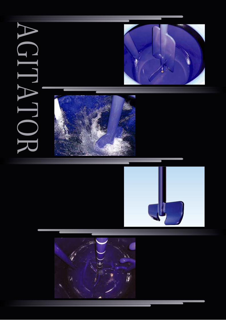
AGITATOR

33
撹 拌
AGITATOR
撹拌及び撹拌所要動力 AGITATION POWER
撹拌槽内の液の流動状態については、槽内全体の対流状態に着目した場合の巨視的な
流れと、分子粘性などが強く作用している局部的なせん断流などの様子に着目した場合
の微視的な流れの2つに分けて考えなければなりません。前者の槽内液全体の撹拌に有
効に寄与している巨視的な流れは、主としてRe(撹拌レイノルズ数)と密接な関係があり、
一方局部的な混合作用、異相間の界面更新などによる物質や熱の移動、気泡や液滴の
分裂微細化その他の分散作用などを促進するのに重要な役割を果す後者の微視的な流
れは、液単位容積当りの撹拌所要動力Pv=P/V(kw/㎥)と密接な関係があります。
バッフル付撹拌槽において、Re≧104の範囲では、翼端からの吐出流が非常に強くなっ
て、上下循環流が盛んになると共に充分な撹拌エネルギーを供給することができるの
で、巨視的、微視的な強い流れを得ることができます。
従って弊社では、グラスライニング製3枚後退翼の場合、撹拌強さ選定図によって撹拌
強度を決めています。さらにこの撹拌強度を達成するための撹拌翼回転数は、液質が水
相当の場合、回転数選定図より得られます。正味撹拌所要動力Pnet〔kW〕は、いわゆる
Np-Re線図より求めることができます。
The flow of liquid in the agitating tank should be observed from two
viewpoints: macroscopic view of circulation in the whole tank, and
microscopic view of the shearing action of the blades of impeller. In the
macroscopic view, the flow affected by agitation is closely related with
Re (Reynolds Number). On the other hand, in the microscopic view, the
flow is closely related with the agitation Power Pv=P/V(kW/㎥).
In case of baffled tanks, in the range of Re≧104, vertical circulation
becomes active and sufficient agitation energy can be provided.
Therefore, for three-blade impellers, we use“Chart for Selection of
Agitation Power”shown here for determining necessary agitation power.
Further for three- blade impellers and anchor agitators, in case the
liquid has aqueous properties, the agitation power can be obtained from
the “Np-Re Diagram”shown below.
One of the advantages of glassed-steel is that it is free from fouling deposits, and in most cases fouling resistance of glass surface can be disregarded,
except for special substances and high viscosity liquids. Overall heat transfer coefficient U(W/㎡K)is obtained from the following well-known equations.
物質が付着しにくいというのがグラスライニングの1つの特長であり、特殊な物質あるいは高粘度液等を除いて、多くの場合グラスライニング側内面の汚れ抵抗を無視することができます。総括伝熱面積U(W/㎡K)の計算は、よく知られた次の式によります。
普通 Normal
混 合Mixing
Agitation Power
(kW/㎥)
単位容積当りの動力
強 Strong
0
0.5
1.0
1.5
2.0
撹拌強さ選定図 Chart for Selection of Agitation Power
ガス吸収Gas Absorption
熱伝達Heat Transfer
懸 濁Suspension
乳 化Emulsification
動力数 Power Number(Np)
レイノルズ数 Reynolds Number(Re)
Np (動力数 Power Number)
Re (撹拌レイノルズ Reynolds Number)
Pnet×103 Pnet :正味撹拌所用動力 :Net Agitation Power Required 〔kW〕ρ :液密度 :Liquid Density 〔kg・m-3〕μ :液粘度 :Liquid Viscosity 〔μPa・s〕n :撹拌翼回転数 :Rotational Speed of Impeller 〔rps〕d :撹拌翼スパン :Impeller Span 〔m〕
ρn3d5
ρnd2
μ
=
0.4
5 10 5×10 5×10² 5×103102 103 104 5×10⁴ 105
0.5
1
5
10
50
JO-3000標準型反応機のNp-Re線図 Np-Re Diagram of Type JO-3000 Reactor
3枚インペラー バッフル2本Three-blade impeller with two finger baffles
3枚インペラー バッフル1本Three-blade impeller with one finger baffle
アンカー翼Anchor agitator
=
グラスライニング製反応機の伝熱特性 HEAT TRANSFER OF GLASSED-STEEL JACKETED REACTORS
Cp・μ μ
Heat transfer coefficient of vessel wall
(W/m
2 k)
缶壁の伝熱係数
鋼板の厚み Metal thickness(mm)
350
465
580
695
810
925
10 20 30 40
缶壁の伝熱係数 Heat Transfer Coefficient of Vessel Wall hw
hi :内面側境膜伝熱係数 :Inside film coefficient of heat transfer 〔W/m2K〕ho :外面側境膜伝熱係数 :Outside film coefficient of heat transter 〔W/m2K〕 ジャケット内スチーム加熱の場合 :For heating by steam in the jacket 〔ho≒5800〕 アジテーティングノズルによる For heating by hot water or cooling 〔ho≒1700 温水加熱または冷水冷却の場合 by cold water thru agitating nozzle ~3400〕hw :缶壁の伝熱係数 :Heat transfer coeffcient of vessel wall 〔W/m2K〕Ri :内面側汚れ抵抗 :Fouling resistance of the inside 〔m2K/W〕Ro :外面側汚れ抵抗 :Fouling resistance of the outside 〔m2K/W〕D :撹拌槽内径 :Vessel I. D. 〔m〕d :撹拌翼スパン :Impeller span 〔m〕n :撹拌翼回転数 :Rotational speed of impeller 〔rps〕ρ :液の密度 :Density of liquid 〔kg/m3〕k :液の熱伝導率 :Thermal conductivity of liquid 〔W/mK〕Cp :液比熱 :Specific heat of liquid 〔kJ/kg・K〕μ :撹拌槽内液粘度 :Viscosity of liquid inside the vessel 〔μPa・s〕μw :缶壁温度における液粘度 :Viscosity of liquid at the temperature of vessel wall 〔μPa・s〕
β γ δU1 1
ρnd2
ρnd2※Re=
hi= +
KhiD =α ・μ
μ
K μw
1hw + +1
ho Ri + Ro 尚缶壁の伝熱係数hw〔W/m2K〕を下図に示しますが、Uの概略値は下記の通りです。The heat transfer coefficient of the vessel wallhw〔W/m2K〕is shown in the following chart.
スチームによる水の加熱 For heating water by steam
水による有機液体の冷却 For cooling organic liquid by water
349~465
Uの概略値Approximate values
of U
139~1863枚後退翼
撹拌翼 Impeller
Three-blade impeller
アンカー翼 Anchor agitator
104~106
※Reの範囲Range of Re
50~500
500~106
0.33
δγβα
1.0
0.35
2/3
1/2
2/3
1/3
1/3
1/3
0.14
0.20
0.14
1.2mm
1.5mm
グラス厚み Glass thickness 1.0mm
AGITATOR
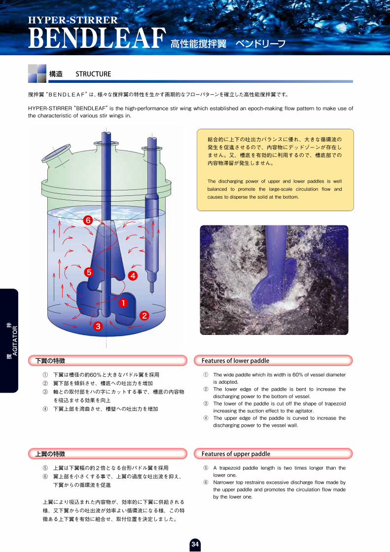
34
構造 STRUCTURE
撹拌翼“BENDLEAF”は、様々な撹拌翼の特性を生かす画期的なフローパターンを確立した高性能撹拌翼です。
HYPER-STIRRER“BENDLEAF”is the high-performance stir wing which established an epoch-making flow pattern to make use of the characteristic of various stir wings in.
HYPER-STIRRER
BENDLEAF 高性能撹拌翼 ベンドリーフ
Features of lower paddle下翼の特徴
Features of upper paddle上翼の特徴
3
1
2
45
6
① 下翼は槽径の約60%と大きなパドル翼を採用② 翼下部を傾斜させ、槽底への吐出力を増加③ 軸との取付部をハの字にカットする事で、槽底の内容物 を吸込ませる効果を向上④ 下翼上部を湾曲させ、槽壁への吐出力を増加
① The wide paddle which its width is 60% of vessel diameter is adopted.
② The lower edge of the paddle is bent to increase the discharging power to the bottom of vessel.
③ The lower of the paddle is cut off the shape of trapezoid increasing the suction effect to the agitator.
④ The upper edge of the paddle is curved to increase the discharging power to the vessel wall.
⑤ 上翼は下翼幅の約2倍となる台形パドル翼を採用⑥ 翼上部を小さくする事で、上翼の過度な吐出流を抑え、 下翼からの循環流を促進
上翼により吸込まれた内容物が、効率的に下翼に供給される様、又下翼からの吐出流が効率よい循環流になる様、この特徴ある上下翼を有効に組合せ、取付位置を決定しました。
⑤ A trapezoid paddle length is two times longer than the lower one.
⑥ Narrower top restrains excessive discharge flow made by the upper paddle and promotes the circulation flow made by the lower one.
総合的に上下の吐出力バランスに優れ、大きな循環流の発生を促進させるので、内容物にデッドゾーンが存在しません。又、槽底を有効的に利用するので、槽底部での内容物滞留が発生しません。
The discharging power of upper and lower paddles is well
balanced to promote the large-scale circulation flow and
causes to disperse the solid at the bottom.
撹 拌
AGITATOR
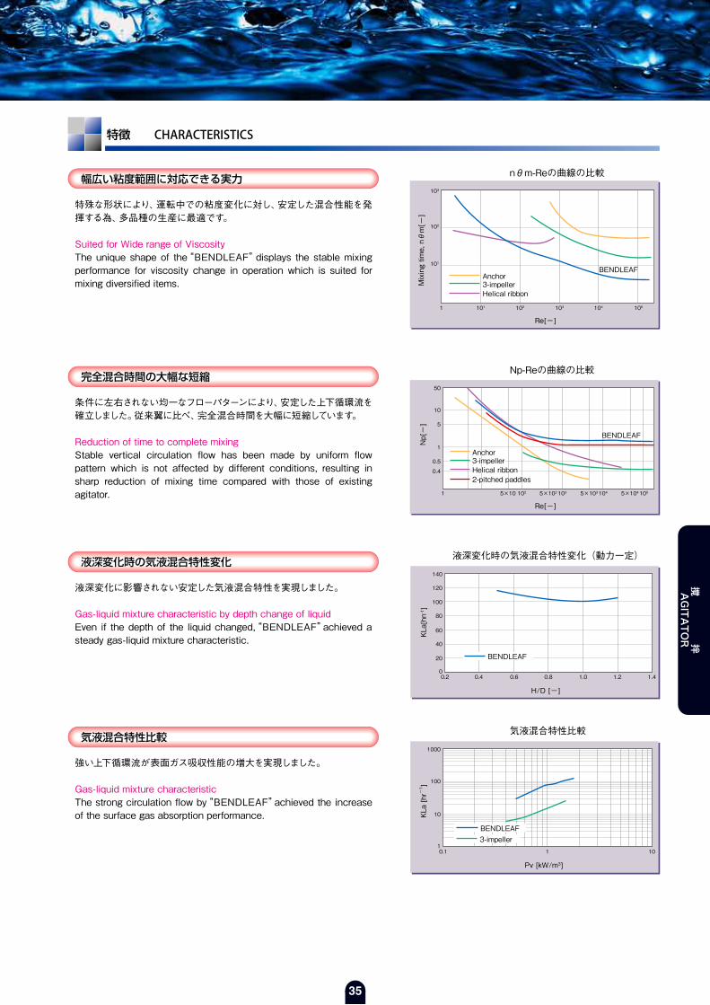
35
特徴 CHARACTERISTICS
幅広い粘度範囲に対応できる実力
完全混合時間の大幅な短縮
液深変化時の気液混合特性変化
気液混合特性比較
特殊な形状により、運転中での粘度変化に対し、安定した混合性能を発揮する為、多品種の生産に最適です。
Suited for Wide range of ViscosityThe unique shape of the“BENDLEAF”displays the stable mixing performance for viscosity change in operation which is suited for mixing diversified items.
条件に左右されない均一なフローパターンにより、安定した上下循環流を確立しました。従来翼に比べ、完全混合時間を大幅に短縮しています。
Reduction of time to complete mixingStable vertical circulation flow has been made by uniform flow pattern which is not affected by different conditions, resulting in sharp reduction of mixing time compared with those of existing agitator.
Mixing time, nθm[ー]
Re[ー]
103
102
101
101 102 103 104 1051
nθm-Reの曲線の比較
BENDLEAFAnchor3-impellerHelical ribbon
Np[ー]
Re[ー]
50
10
5
1
0.5
0.4
1025×10 1035×102 1045×103 1055×1041
Np-Reの曲線の比較
BENDLEAF
Anchor3-impellerHelical ribbon2-pitched paddles
液深変化に影響されない安定した気液混合特性を実現しました。
Gas-liquid mixture characteristic by depth change of liquidEven if the depth of the liquid changed,“BENDLEAF”achieved a steady gas-liquid mixture characteristic. K
La[hn-1 ]
H/D [-]
140
0
20
40
60
80
100
120
0.2 0.4 0.6 0.8 1.0 1.2 1.4
液深変化時の気液混合特性変化(動力一定)
強い上下循環流が表面ガス吸収性能の増大を実現しました。
Gas-liquid mixture characteristicThe strong circulation flow by“BENDLEAF”achieved the increase of the surface gas absorption performance. K
La [hr-1 ]
Pv [kW/m3]
1000
1
10
100
0.1 1 10
気液混合特性比較
BENDLEAF
3-impellerBENDLEAF
撹 拌
AGITATOR

36
少ない消費動力で効率的に混合
粒子破砕の軽減
吐出流方向の安定を図る事で、回転数の変化が直接効率的に全体循環に寄与する様に設計しましたので、少ない消費動力で従来翼以上の混合性能を発揮します。
Efficient mixing with low consumed power“BENDLEAF”is specially designed so that the change of the agitator speed directly and efficiently contributes to the whole circulation by stabilizing the discharge flow force. So the mixing performance is superior to existent agitator.
特徴あるフローパターンにより、局部的なせん断領域を解消しましたので、固体粒子の破砕を最小限に抑えられます。
Decrease of particle destructionPartial shearing zone will disappear because of the unique flow pattern, which is able to minimize solid’s particle destruction.
平パドル二段(15hr後)
粒径(μ)
(Wt%)
100
20
40
60
80
200 400 600 8000
重量百分率
ベンドリーフ(15hr後)
粒径(μ)
(Wt%)
100
20
40
60
80
200 400 600 8000
重量百分率
槽内面局所伝熱分布
槽内全域において、比較的高い伝熱係数を示し、安定した伝熱特性を実現しました。
Local heat transfer coefficient on shell wallIn the whole area in the shell, a comparatively high value heat coefficient has be shown, and a steady heat transfer characteristic has be achieved.This smooth, gradual flow is the best for crystallization reaction.
H/D [-]
[W/m2・K]
1.2
0.0
0.2
0.4
0.6
0.8
1.0
0 2000 4000 6000 8000
槽壁面局所伝熱係数分布
均一な固体分散性
撹拌槽底部への強い吐出流と撹拌翼への吸込効果により、低回転・低動力で固体の均一分散が得られるだけでなく、従来翼の様な翼下での滞留部を解消しました。
Uniform dispersion of solidStrong discharge flow to the bottom of vessel and the suction effect to the agitator enables uniform dispersion of solid under low agitator speed and low power as well as avoiding for the solid to stay under the agitator.
Suspended height[%]
Peripheral velocity[m/sec]
100
50
0.5 1.0 1.50
3-impellerBENDLEAF
ρS/ρL=2.23
Solid~40wt%
2-pitched paddles2-Flat paddles
BENDLEAF
撹 拌
AGITATOR

37
混合試験 MIXING TEST
2液混合試験 Mixing test of two liquids
比較試験の一例を示します。Show the one of comparative mixing tests.
脱色反応試験 Mixing test of decolorizing chemical reaction
比重差のある2液の混合特性Compare mixing performance of two liquids difference of specific gravity.
条件 Specification ρj / ρo = 1.54 ρj : 水あめの比重 Specific gravity of millet jelly ρo : 油の比重 Specific gravity of salad oil回転数 Number of revolutions 250rpm所要動力 Consumed power of mixing BENDLEAF ~ 1.5kW/m3
2-Pitched paddles ~ 2.6kW/m3
Mixing test of two liquids
start
BENDLEAF
30sec. 60sec. 90sec. 120sec.
2-Pitched paddles
高粘度溶液による脱色反応Compare decolorizing chemical reaction in hight viscous liquid.
条件 Specification μ : 液体の粘度 Viscosity of liquid. μ = 5000cp (5Pa・s) P : 所要動力 Consumed power of mixing P = 2.0kW/m3
回転数 Number of revolutions BENDLEAF ~ 300rpm Helical ribbon ~ 150rpm
Mixing test of decolorizing chemical reaction
start
BENDLEAF
5sec. 10sec. 15sec. 20sec.
Helical ribbon
撹 拌
AGITATOR

38
構造 STRUCTURE
GL3枚後退翼に代わる新型撹拌翼“MOLEPAW”は、新たなニーズに応えます。This stir wing takes the place of 3-retreat impeller. And this answers new needs.
The Next Generation Stir Wing
MOLEPAW 次世代型撹拌翼 モールポー
Shape of paddle翼の形状
少量液と翼取付位置
MOLEPAW
3-Impeller
3
4
① 基本形状は高性能撹拌翼“BENDLEAF”の下翼。
② 撹拌翼スパンは槽径の約50%。
③ 翼下部は槽底に沿った後退翼。
④ 翼取付部をハの字にカット。
● 中、低粘度で3枚後退翼に比べ、1.5~2倍の混合性能。 The mixing performance becomes from 1.5 to 2.0 times higher than the 3-retreat impeller in a low viscosity area.
● 3枚後退翼の50~80% の動力で粒子の均一分散及び液滴の均一分散が可能。 A uniform dispersion of solid and liquid can be made of the power of from 50% to 80% of the 3-retreat impeller.
● 撹拌槽容量の約3% の少液量からの混合が可能。 This wing can stir the capacity of about 3% of the amount of the vessel content.
● クローズタイプの3枚後退翼との取替えが可能。(センターマンホールからの挿入が可能) It is possible to exchange the stir wing“MOLEPAW”for the 3-retreat impeller of closed type vessel.
● シンプルな形状なので、洗浄性が良い。 It is easy to wash, because it is simple shape.
● 既設撹拌槽の性能アップにも最適。 It is the best for the performance gain of the existing stir vessel.
3% 液量においても混合可能です。
3%
10%
3%
10%
液量10% 以下では十分な撹拌が行えません。
① Basic shape is a wing of the efficient stir wing“BENDLEAF”in under.
② The wing span of stir wing“MOLEPAW”is about 50% of vessel diameter.
③ The lower side of the wing is a retreat wing shape along the vessel bottom.
④ The lower side of the wing is made like the trapezoid.
撹 拌
AGITATOR

39
特徴 CHARACTERISTICS
混合時間の短縮
固液分散特性
液滴分散特性
気液分散特性
混合時間を無次元化したグラフでは、“MOLEPAW”は“BENDLEAF”などの大型パドル翼と3枚後退翼のほぼ中間位置になっています。これにより、中低粘度域(Re=300~105以上)では、3枚後退翼よりも高い混合性能を示すことが判ります。
Shortening of mixture timeThe mixing performance of a“MOLEPAW”wing in the medium viscosity area is higher than a 3-retreat impeller.
固液分散特性の比較として、“MOLEPAW”と3枚後退翼について撹拌動力を変化させ、イオン交換樹脂粒子の懸濁試験(粒子濃度20Vol%)を行い、粒子の分散状態を観察しました。“MOLEPAW”は3枚後退翼の約50%で粒子の均一分散が可能なことが判ります。
Dispersion property of solid - liquidBy using a“MOLEPAW”wing, uniform dispersion of a particle will be made of about 50% of power of a 3-retreat impeller.
液滴分散特性の比較として、“MOLEPAW”と3枚後退翼について撹拌動力を変化させ、水-灯油系で懸濁試験(灯油濃度20Vol%)を行い、粒子の分散状態を観察しました。“MOLEPAW”は3枚後退翼の約70~80%で液滴の均一分散が可能なことが判ります。
Dispersion property of liquid - dropBy using a“MOLEPAW”wing, uniform dispersion of liquid-dropis made of about 80% of power of the 3-retreat impeller.
気液分散特性の比較として、“MOLEPAW”と3枚後退翼について撹拌動力を変化させ、水-酸素系の表面ガス吸収における物質移動容量係数KLaを測定しました。“MOLEPAW”は3枚後退翼の約2倍の気液分散性能を示すことが判ります。
Dispersion property of gas - liquidBy using a“MOLEPAW”wing, the gas-liquid dispersion performance becomes about 2.0 times as good as a 3-retreat impeller.
Mixing time, nθm [ー]
Re [ー]
103
102
101
102101 103 104 105
nθm-Re 線図
MOLEPAW
Particalate Concentration
粒子濃度 [Vol %]
Pv [kW/m3]
0
5
10
15
20
25
0.100.00 0.20 0.30 0.50
動力変化時の液面付近 粒子濃度
0.40
MOLEPAW
均一分散点
KLa [ー]
Pv [kW/m3]
100
10
10.1 1 10
動力変化時の表面ガス吸収特性
MOLEPAW3-ImpellerBENDLEAF
Homogeneous dispersion point
MOLEPAW3-Impeller
Kerosene Concentration
灯油濃度 [Vol %]
Pv [kW/m3]
0
5
10
15
20
25
0.050.00 0.10 0.15 0.30
動力変化時のT.L.部付近 灯油濃度
0.250.20
均一分散点 Homogeneous dispersion point
MOLEPAW3-Impeller
MOLEPAW
MOLEPAW
MOLEPAW3-Impeller
撹 拌
AGITATOR
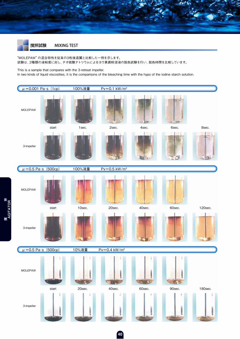
40
撹拌試験 MIXING TEST
μ=0.001 Pa・s(1cp) 100%液量 Pv=0.1 kW/m3
μ=0.5 Pa・s(500cp) 100%液量 Pv=0.5 kW/m3
μ=0.5 Pa・s(500cp) 10%液量 Pv=0.4 kW/m3
“MOLEPAW”の混合特性を従来の3枚後退翼と比較した一例を示します。試験は、2種類の液粘度に対し、チオ硫酸ナトリウムによるヨウ素澱粉溶液の脱色試験を行い、脱色時間を比較しています。
This is a sample that compares with the 3-retreat impeller.In two kinds of liquid viscosities, it is the comparisons of the bleaching time with the hypo of the iodine starch solution.
start
MOLEPAW
1sec. 2sec. 4sec. 6sec. 8sec.
3-Impeller
start
MOLEPAW
10sec. 20sec. 40sec. 60sec. 120sec.
3-Impeller
start
MOLEPAW
20sec. 40sec. 60sec. 90sec. 180sec.
3-Impeller
撹 拌
AGITATOR

ACCESSORIES

42
SHAFT SEAL DEVICES
撹拌機の回転部シールは、内容液やガスの性状に伴い、高い気密性が要求されます。
当社では、さまざまな仕様に対応できる様に、各条件に合った軸封装置を選定します。
High air-tightness is demanded for rotary shaft in stir machines, depending on the properties of liquid and gases in the vessels.
Our company selects the shaft seal device suitable for each condition to correspond to various specifications.
ドライシールはシールボックスの無い簡単な構造で、潤滑油や冷却水を必要としません。
メンテナンスフリーであり、潤滑油や粉じんの槽内への混入を防ぎます。
“Dry seal”needs neither the lubricant nor cooling water in an easy structure without the seal box.
It is maintenance free, and prevents coming in the vessel of the lubricant and the dust.
○ 固定環 標準材質 : セラミック ○ Mating ring standard material : Ceramic
○ 回転環 標準材質 : 特殊充填材入りPTFE ○ Seal ring standard material : PTFE with special filler material
チリ受用フランジの設置で、摺動面から発生する摩耗粉が槽内に混入すること
を防ぐと共に、飛散した結晶や液体の摺動面への付着をブロックするので、安
定した運転を提供します。
チリ受内に溜まった摩耗粉は、ドレン抜きより排出できます。
また、既設“ドライシール”との取替えも可能です。
This“dust receiving box”will offer a steady driving.
This“dust receiving box”prevents mixing the abrasion powder generated from sliding surfaces in the vessel.And the adhesion of the crystal and the liquid that disperses to sliding surfaces is blocked.The abrasion powders in the dust receiving box can be taking out from the drain nozzle. This seal is possible to replacement for the existing“Dry seal”.
○ チリ受用フランジ 標準材質 : ハステロイ 又は SUS304+PFAライニング ○ Dust receiving box material : Hastelloy or SUS304+PFA-lining
軸 封 装 置
ドライシール DRY SEAL
標準タイプ(ベローズ) Standard Type(Bellows)
ファインシール Special Dry Seal
高圧タイプ(Oリング) High Pressure Type(O-Ring)
標 準 許 容 圧 力Allowable pressure
標 準 許 容 温 度Allowable temperature
真空 ~ 0.20 [MPa]
-30 ~ 175 [℃]
標 準 許 容 圧 力Allowable pressure
標 準 許 容 温 度Allowable temperature
真空 ~ 0.50 [MPa]
-40 ~ 175 [℃]
撹拌翼軸頭部Agitating Shaft
グラスライニング終端Edge of Glass lining
クランピングリングClamping Ring
シート受フランジGL-Flange
ガスケットGasket
グラスライニング終端Edge of Glass lining
チリ受用フランジDust Receiving Box
回転環 Seal Ring
固定環 Mating Ring
カラー Collar
スプリングリテーナSpring Retainer
回転環(ベローズ) Bellows
固定環 Mating Ring
アクリルカバー Acryl Cover
撹拌翼軸頭部Agitating Shaft
グラスライニング終端Edge of Glass lining
カラー Collar
ガスケットGasket
コンプレスリングCompress Ring
回転環 Seal Ring
Oリング O-Ring
固定環 Mating Ring
シート受フランジGL-Flange
アクリルカバー Acryl Cover
ドレン抜きDrainア
クセサリー
ACCESSORIES

43
ダブルメカニカルシールは、シール液にて背圧を与える為、缶内側と大気側とに2個のシール部があります。他の軸封装置に比べ、耐久性に優れ、高温・高圧下でも使用できます。
“Double mechanical seal”has two seals on an inside of the vessel and an atmospheric side, because it gives the back pressure with the seal liquid.It is possible to excel in durability compared with other shaft seal devices, and to use it under the high pressure of the high temperature.
○ 固定環 標準材質 : セラミック ○ 回転環 標準材質 : カーボン
○ Mating ring standard material : Ceramic ○ Seal ring standard material : Carbon
ダブルメカニカルシール DOUBLE MECHANICAL SEAL
マルチシールはドライシール部を2個所使用し、ダブルメカニカルシールの特徴を生かした気体シール構造の軸封装置です。外部へのプロセスガスのリークを抑え、内部へのリークは空気又は窒素などの気体であるため、液体による内部汚染がありません。既設“ダブルメカニカルシール”(イーグル工業㈱製)と取替えが可能です。
The“Multi Seal”uses a dry contact seal by two places, and is a shaft seal device of the gas seal structure to make the best use of the feature of“Double Mechanical Seal”.Leakage to the outside of the process gas is suppressed, and there is no self-contamination with the liquid because leakage to the inside is gases such as air or nitrogen.“Multi Seal”is possible to replacement for the existing“Double mechanical seal”(made of Eagle Industry Co., LTD.).
○ 固定環 標準材質 : セラミック ○ 回転環 標準材質 : 特殊充填材入りPTFE ○ Mating ring standard material : Ceramic ○ Seal ring standard material : PTFE with special filler material
“均圧バルブ”は槽内の圧力変動に追従して、軸封装置内に一定の背圧を発生させる装置です。軸封装置内の背圧を0.02MPaに自動調整することで、シールリングの寿命を大幅に延長します。
“Equalizing valve”is a device that follows to the pressure fluctuation in the vessel and generates a constant back pressure in the shaft seal device.The longevity of the seal ring is greatly extended by the self adjustment of the back pressure in the shaft seal device to 0.02MPa.
マルチシール MULTI SEAL
均圧バルブの設置要領図
撹拌翼軸頭部Agitating Shaft
オイルシール Oil Seal
ベアリング Bearing
スリーブ Sleeve
オイルシール Oil Seal
固定環 Mating Ring
固定環 Mating Ring
固定環 Mating Ring
Oリング O-Ring
シート受フランジFlange
シート受フランジFlange
ガスケットGasket
ガスケットGasket
マルチシールMulti Seal
均圧バルブEqualizing Valve
グラスライニング終端Edge of Glass lining
Vパッキン V-Packing
回転環 Seal Ring
撹拌翼軸頭部Agitating Shaft
オイルシール Oil Seal
ベアリング Bearing
スリーブ Sleeve
オイルシール Oil Seal
固定環 Mating Ring
グラスライニング終端Edge of Glass lining
回転環 Seal Ring
標 準 許 容 圧 力Allowable pressure
標 準 許 容 温 度Allowable temperature
真空 ~ 1.00 [MPa]
-40 ~ 200 [℃]
標 準 許 容 圧 力Allowable pressure
標 準 許 容 温 度Allowable temperature
真空 ~ 0.60 [MPa]
-30 ~ 175 [℃]
標 準 許 容 圧 力Allowable pressure
標 準 許 容 温 度Allowable temperature
真空 ~ 0.60 [MPa]
-10 ~ 120 [℃]ドレン抜きDrain
冷 却 水Cooling Water
冷 却 水Cooling Water
シール気体Sealing Gas
排 気Exhaust
アクセサリー
ACCESSORIES

44
FLUSH VALVE
グラスライニング槽の排出口に取付けるバルブです。接液部はグラスライニングされているので、ほとんどの化学薬品に侵される事がありません。取付は弁棒を槽内部に挿入するタイプなので、槽内の液溜まりを極力少なくできます。
This value is mounted to the discharge port of the glass-lined vessel. Since the liquid contact face is glass-lined, the surface is not eroded by almost any chemicals. Also since the valve stem is inserted into the vessel, liquid accumulation can be extremely minimized.
シール部にVリングを使用しています。A V-ring is used for the sealing section.
フラッシュバルブ
標準タイプ STANDARD TYPE
手動フラッシュバルブ(Vパッキン式) Manual Type呼称径NominalDia. ㎜
50 - 40
80 - 50
100 - 80
A ㎜
99
97
96
B ㎜
390
430
458
リフトL ㎜Lift
35
45
45
重量kg
17
28
38
自動フラッシュバルブ(Vパッキン式) Automatic Type呼称径NominalDia. ㎜
50 - 40
80 - 50
100 - 80
A ㎜
99
97
96
B ㎜
675
722
748
リフトL ㎜Lift
35
45
45
重量kg
21
38
49
弁棒軸シール部にベローズを採用しました。補助のUパッキンにより万一ベローズが切損しても直ちに使用不能にはなりません。
The bellows is used for the sealing section of the valve stem. Even if the bellows is damaged, the valve is not immediately failed for use due to installation of the supplemental U packing.
ベローズタイプ BELLOWS TYPE
手動フラッシュバルブ(ベローズ式) Manual Bellows Type呼称径NominalDia. ㎜
50 - 40
80 - 50
100 - 80
A ㎜
89
97
96
B ㎜
407
448
474
リフトL ㎜Lift
35
45
45
重量kg
20
29
40
自動フラッシュバルブ(ベローズ式) Automatic Bellows Type呼称径NominalDia. ㎜
50 - 40
80 - 50
100 - 80
A ㎜
89
97
96
B ㎜
692
740
766
リフトL ㎜Lift
35
45
45
重量kg
25
40
50
B
A
L
B
A
L
B
A
L
B
A
L
アクセサリー
ACCESSORIES

45
少量液の温度が測定できる様に、測温抵抗体を取付しています。
A resistance bulb is provided so that the temperature for a small amount of liquid can be measured.
● 構成部品が少なく、スパナ1つで容易に分解。 従来品の面倒な分解・組立作業を1/5に短縮、洗浄作業を大幅に短縮できます。 It is easily disassembly in one spanner, because complete parts are few. The disassembly and assembly work-hours can be shortened to 1/5.
● 洗浄し易さを追及。 駆動部を分解することなく、接液部のみ洗浄可能です。 This type pursued easiness to wash.
● 既設品(ベローズタイプ)の“Easy-Wash”化も容易に出来ます。 Remodeling to a new type is also easy.
● ダブルOリングで、漏れをカット。 シール部にはPTFEベローズを使用。 The leakage is suppressed by using O-ring double. The bellows is used for the sealing section.
手動フラッシュバルブ(測温抵抗体付) Manual Type with resistance bulb呼称径NominalDia. ㎜
50 - 40
80 - 50
100 - 80
A ㎜
105
113
112
B ㎜
550
591
618
リフトL ㎜Lift
35
45
45
重量kg
18
29
40
自動フラッシュバルブ(測温抵抗体付) Automatic Type with resistance bulb呼称径NominalDia. ㎜
50 - 40
80 - 50
100 - 80
A ㎜
105
113
112
B ㎜
800
857
883
リフトL ㎜Lift
35
45
45
重量kg
30
42
52
手動フラッシュバルブ(EW) Manual EW Type呼称径NominalDia. ㎜
50 - 40
80 - 50
100 - 80
A ㎜
89
97
96
B ㎜
392
432
459
リフトL ㎜Lift
35
45
45
重量kg
20
29
40
自動フラッシュバルブ(EW) Automatic EW Type呼称径NominalDia. ㎜
50 - 40
80 - 50
100 - 80
A ㎜
89
97
96
B ㎜
677
724
750
リフトL ㎜Lift
35
45
45
重量kg
25
40
50
測温抵抗体付 WITH RESISTANCE BULB
洗浄型 EASY-WASH
B
A
L
B
A
L
ベローズタイプも製作可能です。The bellows type can be produced.
OリングO-Ring
ベローズ(PTFE)Bellows
駆動部,ハンドルDrive,Handle
固定リングFixed Ring
本体(GL)Body
バルブシート(PTFE)Valve Sheet
弁棒(GL)Shaft
特徴 Characteristics
分解図 Exploded View
アクセサリー
ACCESSORIES

46
FLUSH VALVE
自動フラッシュバルブには下記制御装置を取付け出来ます。The following controller is attachable to an automatic flush-valve.
フラッシュバルブ
オプション OPTION
AC100V , 50/60Hz
AC200V , 50/60Hz
DC24V
その他 Other
測温抵抗体付自動フラッシュバルブ 標準付属品 Automatic type flush-valve standaed accessory部品名Part Name
仕 様Specification
測温抵抗体Resistance Bulb
Pt=100Ω , 3 線 2素子 , ExdⅡCT6(d2G4) , A 級 , トレーサビリティ付Pt=100Ω , 3 wires 2 elements , ExdⅡCT6(d2G4) , A class with traceability
エアシリンダAir Cylinder Valve
薄型シリンダ(無給油) , 最高使用圧力 : 1.0MPaThin type cylinder(oilless) , Max A.WP. : 1.0MPa
リミットスイッチLimit Switch
調整レバー付防爆形(d2G4)スイッチWith adjustment lever. Explosion-proof type(d2G4)
制御装置 Control device部品名Part Name
仕 様Specification
ソレノイドバルブSolenoid Valve
3ポートパイロット形 , 防爆形(d2G4)3-port pilot type , Explosion-proof type(d2G4)
フィルタレギュレータFilter Regulator
圧力計付 , 最高使用圧力 : 1.0MPa , ろ過度 : 5μmWith PG , Max A.W.P. : 1.0MPa , Filtration rate : 5μm
スピードコントローラSpeed Controller
スイベルタイプ , ニードル弁抜止め機構付Swivel type , With needle valve omiassion stop mechanism
温度計ケースTW Case
弁棒Stem
バルブシートValve Seat
弁体Body
測温抵抗体Resistance Bulb
リミットスイッチLimit Switch
スピードコントローラSpeed Controller
ソレノイドバルブSolenoid Valve
フィルタレギュレータFilter Regulator
エアシリンダAir Cylinder Valve
スピードコントローラSpeed Controller
スタンドStand
エア入口 Air IN設定圧 Set Pressure : 0.4MPa
エア入口 Air IN
定格電圧の種類を指定下さい。
Please specify the kind of the ratedVltage.
アクセサリー
ACCESSORIES

47
HANDHOLE/MANHOLE COVER
標準サイズのハンドホール及びマンホールカバーです。カバー端面及びプロテクションリング端面にグラスライニングを施工し、端部からの腐食を防ぐタイプもあります。(オプション)
It is a handhole cover and a manhole cover of the standard type.There is a type of the Glass Lining to the edge face of the cover and the protection ring, too.
ガラス管式液面計用に開発したバルブです。グラスライニングされた本体とPTFE製の弁棒で構成されています。万一ガラスが破損しても、液圧によりバルブ内部のキャッチボールがバルブを閉めるので、内溶液の流出を抑えます。又、ガラス管取付フランジは20A JIS10k規格なので、他の液面計との接続が可能です。
This valve has been especially developed for the glass tube level gage. It consists of a glass lined body and PTFE valve stem. Even if the glass is broken, since the check valve provided inside the valve closes it by the liquid pressure, leakage of the liquid can be minimized. In addition, since a flange with glass tube is 20A JIS 10k standard, connection with other level gages can be achieved.
ハンドホール/マンホールカバー
GAUGE VALVEゲージバルブ
サイズSize
φ 83
φ103
φ154
φ205
φ255
φ 80
φ100
φ150
φ200
φ250
d ㎜
φ150
φ165
φ216
φ265
φ325
D ㎜ 覗窓サイズView Port Size 40A
40A
50A
80A
100A
78
71
本体Body
本体Body
弁棒Stem
弁棒Stem
20A JIS10k
20A JIS10k
25A JIS10k
ボールBoll
ハンドルHandle
ハンドルHandle
バルブシートValve Seat
バルブシートValve Seat
ガラス管Glass tube
ガラス管Glass tube
20A JIS10k
25A JIS10k
I.D. d
O.D. D
ハンドホール Handhole マンホール Manhole
25Aガラス管用,ボール無,ドレン無
25Aガラス管用,ボール有,ドレン有
TYPE A TYPE B
I.D. d
O.D. D
I.D. d
O.D. D
71
78
78
ゲージバルブ Gauge Valve
ゲージバルブ Gauge Valve
ドレンバルブ Drain ValveGL 配管 GL-Piping
GL 配管 GL-Piping
ガラス管 Glass tube
保護枠 Protection Frame
ハンドホールカバー H
andhole Cover
サイズSize
300×400
φ400
φ450
300×400
φ400
φ450
d ㎜
400×500
φ480
φ490
φ530
φ540
D ㎜ 形 状TypeA.B
A.B
B
B
B
覗窓サイズView Port Size100A
100A
100A
マンホールカバー M
anhole Cover
アクセサリー
ACCESSORIES

48
PIPING配 管
直管 STRAIGHT
ティー管 TEE
90°エルボ管 90°ELBOW
T
JIS10kSplit Flange
H
X
φD
φG
X
最大長さMaximum Length
25A40A50A80A100A125A150A200A250A300A350A
特殊寸法については別途御相談願います。 Please consult about a special size separately.
1011111415161719222425
SIZE T
2629293233363946495154
H
7085100130155185215265325370415
G
27.641.652.980.7105.3130.8155.2204.7254.2304.7339.8
D
25A40A50A80A100A125A150A200A250A300A350A
5001000150020002000200020002000200020002000
SIZE 最大長さ Maximum Length
25A40A50A80A100A125A150A200A250A300A350A
SIZE
100105120140150170190220260290320
Y
100105120140150170190220260290320
X
25A40A50A80A100A125A150A200A250A300A350A
SIZE
100120135140150180210230285340390
X
X X
Y
アクセサリー
ACCESSORIES

49
レジューサ管 REDUCER
45°エルボ管 45°ELBOW
異径ティー管 REDUCER TEE
クロス管 CROSS
Y
X X
X
X
45°
X
25A25A40A40A50A40A50A80A50A80A100A50A80A100A125A
40A50A
80A
100A
125A
150A
SIZE100100100100120--120135--135150150150160170
Y100100110120130--135145--155165170180180190
X80A100A125A150A100A125A150A200A150A200A250A150A200A250A
200A
250A
300A
350A
SIZE--190200210--230230250285285285320320320
Y--210210210--250250250285285285320320320
X
25A 25A 40A 40A 50A 40A 50A 80A 50A 80A100A 50A 80A100A125A
40A50A
80A
100A
125A
150A
SIZE120130130150150160160160190190190--200200200
X80A100A125A150A100A125A150A200A150A200A250A150A200A250A
200A
250A
300A
350A
SIZE--230230230250255255255280280280410410410
X
25A40A50A80A100A125A150A200A250A300A350A
707070100105120120160180230---
SIZE X
25A40A50A80A100A125A150A200A250A300A350A
SIZE100105120140150170190220260290320
Y100105120140150170190220260290320
X
X X
Y
Y
アクセサリー
ACCESSORIES

50
CLAMP
グラスライニング製の本体とカバー等を締付ける場合に使用しています。フランジ面に不必要な力がかかるのを避けられるので、製品の保護の役目もあります。クランプはS25C製で、締付け幅により各サイズを揃えています。(SUS製も製作できます。)又、用途によりアイナットや袋ナットの使用が可能です。
This clamp is used for when the glass lined body, cover, etc. are secured. Since unnecessary force to the flange face can be prevented, the product can be also protected. The clamp is made of S25C, various sizes for different securing width are available. (SUS is also available) Also, the eyenuts and cap nuts may be used for various applications.
クランプ
REDUCING FLANGE異径フランジ SPLIT FLANGE割フランジ
L
L
M16CL- 75
M16CL- 95
M20CL- 80
M20CL- 100
M20CL- 120
M22CL- 75
M22CL- 95
M22CL- 115
M24CL- 110
M24CL- 130
M24CL- 150
呼称Symbol
締付範囲 L ㎜Tightening Range
M16
M16
M20
M20
M20
M22
M22
M22
M24
M24
M24
ネジサイズBolt Size
クランプ寸法表CLAMP STANDARD DIMENSION
C
B SIZEφD
φA
A SIZE
25A
40A
50A
65A
80A
100A
125A
150A
200A
250A
300A
4-M16
4-M16
4-M16
4-M16
8-M16
8-M16
8-M20
8-M20
12-M20
12-M22
16-M22
呼称径NominalDia. ㎜
ボルト数・サイズ
125
140
155
175
185
210
250
280
330
400
445
外 径D ㎜
90
105
120
140
150
175
210
240
290
355
400
中心円の径C ㎜
72
87
104
122
132
157
187
218
267
327
372
内 径A ㎜
割フランジ 寸法表SPLIT FLANGE STANDARD DIMENSION
φC
※ ボルト穴は JIS10k 規格 According to JIS10k standard.
48
48
48
48
48
48
48
250A
48
48
48
48
48
48
48
48
200A
45
45
45
45
45
45
45
150A
45
45
45
45
45
45
125A
40
40
40
40
40
40
40
100A
40
40
40
40
40
40
80A
A SIZE
40
40
40
40
40
65A
40
40
40
40
50A
40
40
40
40A●40●40
25A●4015A
20A
25A
40A
50A
65A
80A
100A
125A
150A
200A
20A
異径フランジ 寸法表REDUCING FLANGE STANDARD DIMENSION
※ ボルト穴は JIS10k 規格 According to JIS10k standard. “●”印は両面スタッドボルト使用。
B SIZE
50 ~ 75
70 ~ 95
55 ~ 80
75 ~ 100
95 ~ 120
55 ~ 75
70 ~ 95
90 ~ 115
85 ~ 110
105 ~ 130
125 ~ 150
アクセサリー
ACCESSORIES

■ 営業品目 ● 工業用機器及びプラント グラスライニング製各種機器及び装置 ステンレス鋼,ステンレスクラット鋼各種機器及び装置 各種合金鋼及び非鉄金属製各種機器及び装置 合成樹脂ライニング製各種機器及び装置 多管式熱交換機各種 化学装置及びプラントの設計並びに施工一式 ● 技術サービス グラス検査,部品交換工事 熱交ジャケット薬液洗浄 ブラスト洗浄 ポンプメカシール工事 等
■ PRODUCT LINES ● Equipment & Plants for Chemical Industries Glassed Steel Equipment and Apparatus Stainless Steel & Other Alloy Vessels/Equipment Nonferrous Metal Equipment Resin lined Steel Equipment Shell and Tube Heat Exchangers Engineering & Construction of Chemical Equipment/Plants ● Technical Service Inspection on glass side Exchange construction of parts Washing of chemical drug solution for jacket of heat exchanger Blast washing on the glass side Shaft seal construction of pump
改 定 2013年02月01日
初 版 2010年06月01日
編 集発 行

GL
ENGINEERING & CONSTRUCTION
HAKKO SANGYO CO.,LTD.
本 社 ・ 工 場 〒871-8688 大分県中津市大字是則1136番地
TEL(0979)32-2460 FAX(0979)32-4134
東京営業部 〒103-0025 東京都中央区日本橋茅場町2-12-5 カワイビル3F
TEL(03)3667-8511㈹ FAX(03)3667-1621
大阪営業部 〒541-0051 大阪市中央区備後町1丁目2番9号 備後町吉田ビル7F
TEL(06)6231-9457 FAX(06)6231-4831
Head Office 1136,Oaza Korenori, Nakatsu-City, Oita-Pref 871-8688
TEL (0979)32-2460 FAX (0979)32-4134
Tokyo sales department Kawai Bld.,3F,12-5,Nihonbashi Kayabacho, 2-chome, Chuo-ku, Tokyo 103-0025
TE(03)3667-8511 FAX (03)3667-1621
Osaka sales department Yoshida Bld.,7F,2-9, Bingo-cho 1-chome, Chuo-ku, Osaka-City 541-0051
TE:(06)6231-9457 FAX (06)6231-4831
HAKKO SANGYO CO., LTD.
● ご用命は
このカタログの内容は製品の機能向上またはその他の理由により、予告なく変更することがあります。また、このカタログの記載数値は参考値であり、あらゆる条件に機能を保証するものではありません。