eureka presonus
DESCRIPTION
PreSonus Pre-amplifier TutorialTRANSCRIPT
!"#!$%&M I C R O P H O N E P R E A M P L I F I E R
C O M P R E S S O R
P A R A M E T R I C E Q U A L I Z E R
USER’S MANUAL
version 3.0
2003-2007, PreSonus Audio Electronics, Incorporated. Al l r ights reserved.

W A R R A N T Y
PreSonus Limited Warranty PreSonus Audio Electronics Inc. warrants this product to be free of defects in material and workmanship for a period of one year from the date of original retail purchase. This warranty is enforceable only by the original retail purchaser. To be protected by this warranty, the purchaser must complete and return the enclosed warranty card within 14 days of purchase. During the warranty period PreSonus shall, at its sole and absolute option, either repair or replace, free of charge, any product that proves to be defective on inspection by PreSonus or its authorized service representative. To obtain warranty service, the purchaser must first call or write PreSonus at the address and telephone number printed below to obtain a Return Authorization Number and instructions of where to return the unit for service. All inquiries must be accompanied by a description of the problem. All authorized returns must be sent to the PreSonus repair facility postage prepaid, insured and properly packaged. PreSonus reserves the right to update any unit returned for repair. PreSonus reserves the right to change or improve the design of the product at any time without prior notice. This warranty does not cover claims for damage due to abuse, neglect, alteration or attempted repair by unauthorized personnel, and is limited to failures arising during normal use that are due to defects in material or workmanship in the product. Any implied warranties, including implied warranties of merchantability and fitness for a particular purpose, are limited in duration to the length of this limited warranty. Some states do not allow limitations on how long an implied warranty lasts, so the above limitation may not apply to you. In no event will PreSonus be liable for incidental, consequential or other damages resulting from the breach of any express or implied warranty, including, among other things, damage to property, damage based on inconvenience or on loss of use of the product, and, to the extent permitted by law, damages for personal injury. Some states do not allow the exclusion of limitation of incidental or consequential damages, so the above limitation or exclusion may not apply to you. This warranty gives you specific legal rights, and you may also have other rights, which vary form state to state. This warranty only applies to products sold and used in the United States of America. For warranty information in all other countries please refer to your local distributor.
PreSonus Audio Electronics, Inc. 7257 Florida Blvd. Baton Rouge, LA 70806 (225) 216-7887 (800) 750-0323 www.presonus.com
2003, PreSonus Audio Electronics, Incorporated. All rights reserved.

TABLE OF CONTENTS
3
1 Overview 1.1 Introduction 4 1.2 Features 4
2 Controls & Connections 2.1 Front Panel Basic Layout 7 2.2 Preamplifier 9 2.3 Compressor 10 2.4 Equalizer 12 2.5 Master 13 2.6 Back Panel 13 2.7 Power Supply 14
3 Operation 3.1 Microphones 15 3.2 Send and Return 15 3.3 192k/24-Bit Digital Output Card 16 3.4 Application Settings 17
4 Technical 3.5 Specifications 22
1 OVERVIEW
4
1 . 1 I N T R O D U C T I O N
Thank you for purchasing the PreSonus EUREKA. PreSonus Audio Electronics has designed the EUREKA utilizing high-grade components to insure optimum performance for an infinite period of time. We believe the EUREKA to be an exceptional sounding unit and an exceptional value. We encourage you to contact us at 1-800-750-0323 with any questions or comments you may have regarding your PreSonus equipment. PreSonus Audio Electronics is committed to constant product improvement, and we value your suggestions highly. We believe the best way to achieve our goal of constant product improvement is by listening to the real experts, our valued customers. We appreciate the support you have shown us through the purchase of this product.
Please pay close attention to how you connect your EUREKA to your system. Improper grounding is the most common cause of noise problems found in studio or “live” sound environments. We would like to suggest that you use this manual to familiarize yourself with the features, applications and correct connection procedure for your EUREKA before trying to hook it up to your system. Thank you, once again, for buying our product and may we wish you Good Luck and enjoy your EUREKA!
1 . 2 F E A T U R E S
The following information is a summary of your EUREKA’s features:
Microphone Pre-Amplifier. Your EUREKA contains a Class A discrete input buffer followed by a dual servo gain stage. This arrangement results in ultra low noise and wide gain control allowing the EUREKA user to boost desirable signal without increasing unwanted background noise.
48 Volt Phantom Power. The EUREKA has 48V Phantom power available. This assures optimum performance of your condenser microphones that require Phantom power and that the power supplied will be free of noise or distortion.
Pad. A 20dB pad is available for reducing the in-coming signal level. This pad provides a more manageable signal from high output devices giving greater control over the in-coming signal and a much reduced
OVERVIEW
5
chance of over-driving the input and avoiding distortion.
+22dBu Headroom. The EUREKA mic-pre has +22 dBu of headroom. This feature gives you wide dynamic range and excellent transient response characteristics.
Saturation Control. The EUREKA offers a very high quality transformer and features an SATURATION control (this control adjusts the drain current on the input FET amplifier altering the even harmonic levels of the signal being passed) with an adjustment range of 0% to 100%. The 0% position passes a pure signal. As the control is rotated to the 100% position, the signal’s even harmonic series is boosted giving the signal “warmth” very much like a vacuum tube or similar to the sound of analog tape saturation. This remarkable effect gives you the sound of a tube without the headache of uneven performance often encountered with vacuum tube devices (“no tube to pick-up RF or to age and become “microphonic”).
Variable Microphone Input Impedance. This feature enables you to “tune” your microphone – by matching the output impedance of your microphone with your microphone preamplifier. This works especially well for ribbon microphones. Changing the input impedance is also effective for dynamic and condenser microphones and can be the perfect solution for a given recording application.
Phase Reverse. Use the phase reverse switch to combat phase cancellation with other open microphones.
Full Featured Compressor with High Pass Filter. The EUREKA is equipped with a Compressor with a high pass side chain filter designed especially for frequency specific processing.
Soft Knee Compression. Soft Knee Compression causes the compression to set in gradually producing a more musical response
Bypass. The Bypass switch lets you compare the compressed sound quickly to the uncompressed sound.
OVERVIEW
6
3-Band Parametric Equalizer. Total tonal control is what the Equalizer section provides. The EQ will let you fine tune the sound to suit your taste with exacting precision.
Bypass Switch. A bypass switch is provided to audition the signal in an equalized version as compared to a direct unaffected signal.
Variable Q. Adjusts the width of the frequency band between wide and narrow during equalization.
EQ COMP. Switches the order of the signal chain putting EQ before the Compressor.
Master Section
Gain Reduction to Meter. Shows gain reduction on the meter implemented by the compressor.
Level. The output of the EUREKA is adjusted by the Level control and is useful for compensating for gain loss due to compression or to decrease output signal that boosting frequencies with the Equalizer section may have caused. The output is variable from –80 dB to +10 dB.
VU Meter. The VU meter provides an accurate reading of the output level and a reference of signal presence. It can also be switched to monitor gain reduction when using the compressor.
2 CONTROLS & CONNECTIONS
7
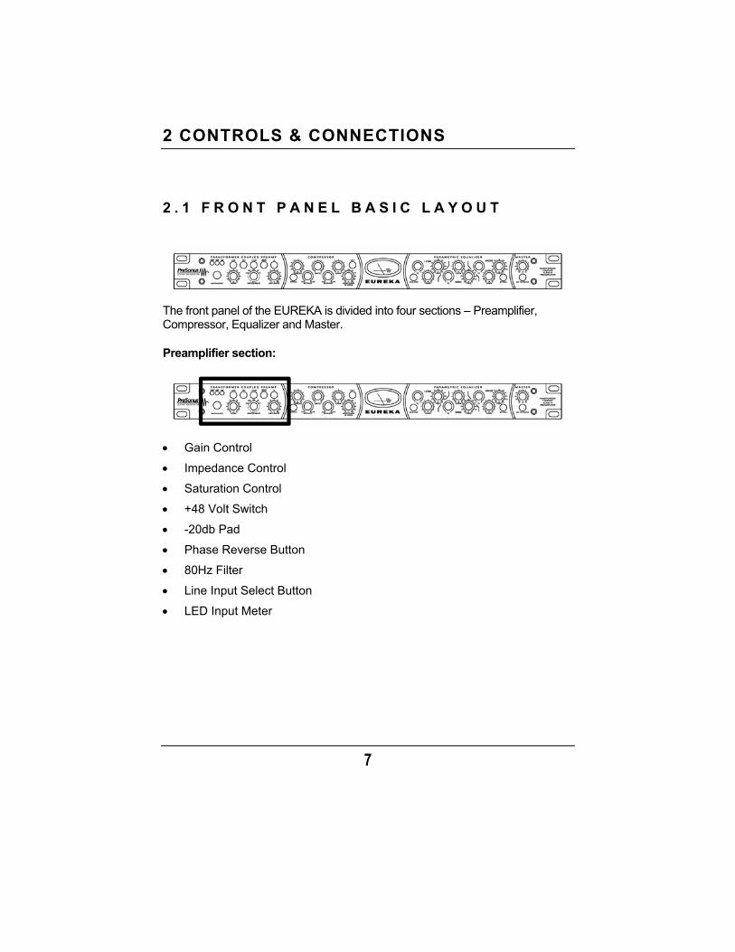
2 . 1 F R O N T P A N E L B A S I C L A Y O U T
The front panel of the EUREKA is divided into four sections – Preamplifier, Compressor, Equalizer and Master.
Preamplifier section:
Gain Control
Impedance Control
Saturation Control
+48 Volt Switch
-20db Pad
Phase Reverse Button
80Hz Filter
Line Input Select Button
LED Input Meter
CONTROLS & CONNECTIONS
8
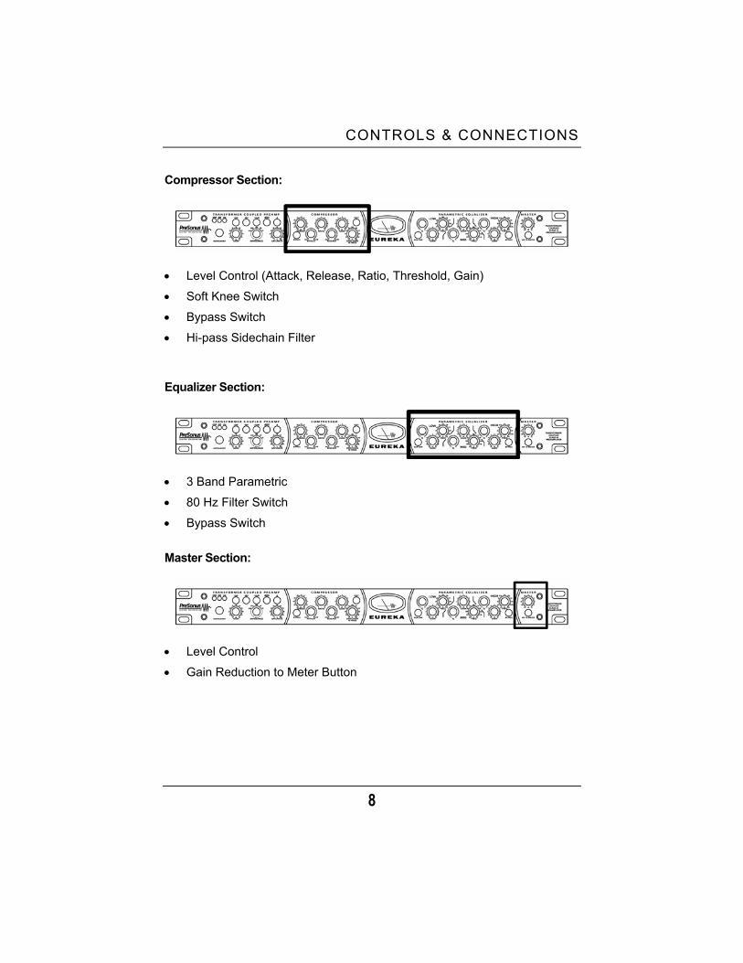
Compressor Section:
Level Control (Attack, Release, Ratio, Threshold, Gain)
Soft Knee Switch
Bypass Switch
Hi-pass Sidechain Filter
Equalizer Section:
3 Band Parametric
80 Hz Filter Switch
Bypass Switch
Master Section:
Level Control
Gain Reduction to Meter Button
CONTROLS & CONNECTIONS
9
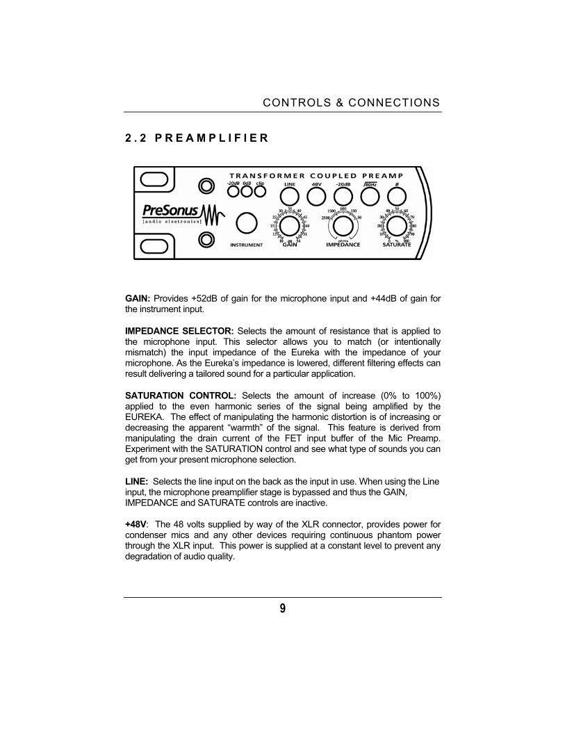
2 . 2 P R E A M P L I F I E R
GAIN: Provides +52dB of gain for the microphone input and +44dB of gain for the instrument input.
IMPEDANCE SELECTOR: Selects the amount of resistance that is applied to the microphone input. This selector allows you to match (or intentionally mismatch) the input impedance of the Eureka with the impedance of your microphone. As the Eureka’s impedance is lowered, different filtering effects can result delivering a tailored sound for a particular application.
SATURATION CONTROL: Selects the amount of increase (0% to 100%) applied to the even harmonic series of the signal being amplified by the EUREKA. The effect of manipulating the harmonic distortion is of increasing or decreasing the apparent “warmth” of the signal. This feature is derived from manipulating the drain current of the FET input buffer of the Mic Preamp. Experiment with the SATURATION control and see what type of sounds you can get from your present microphone selection.
LINE: Selects the line input on the back as the input in use. When using the Line input, the microphone preamplifier stage is bypassed and thus the GAIN, IMPEDANCE and SATURATE controls are inactive.
+48V: The 48 volts supplied by way of the XLR connector, provides power for condenser mics and any other devices requiring continuous phantom power through the XLR input. This power is supplied at a constant level to prevent any degradation of audio quality.
CONTROLS & CONNECTIONS
10
XLR connector wiring for Phantom Power
Pin 1= GND Pin 2= +48V Pin3= +48V
PAD: Engaging the Pad switch provides -20dB of attenuation with the push of a button. This is a very useful feature for rapidly reducing the level coming into the EUREKA and thus preventing the input signal from over-driving (distorting) the input. This may occur due to high output level from a microphone or other device. Padding the input serves to provide increased “headroom” for the operator while lessening the likelihood of input signal overload.
80Hz: The 80Hz button is a low-end roll-off filter. When pushed in, the 80Hz button causes all frequencies below 80Hz to be attenuated (dropped) by 12dB. This filter can be handy in live and studio applications. For example, the 80Hz filter can help to reduce the “boominess” or “muddiness” of a vocal and improve the overall clarity.
Ø (Phase Reverse): Reverses the polarity of the signal. Use the phase reverse when recording with more than one open microphone to combat phase cancellation between microphones.
INSTRUMENT: !” TS connector. When an instrument is plugged into the instrument input, the microphone preamplifier is bypassed and the Eureka becomes an active instrument preamplifier.
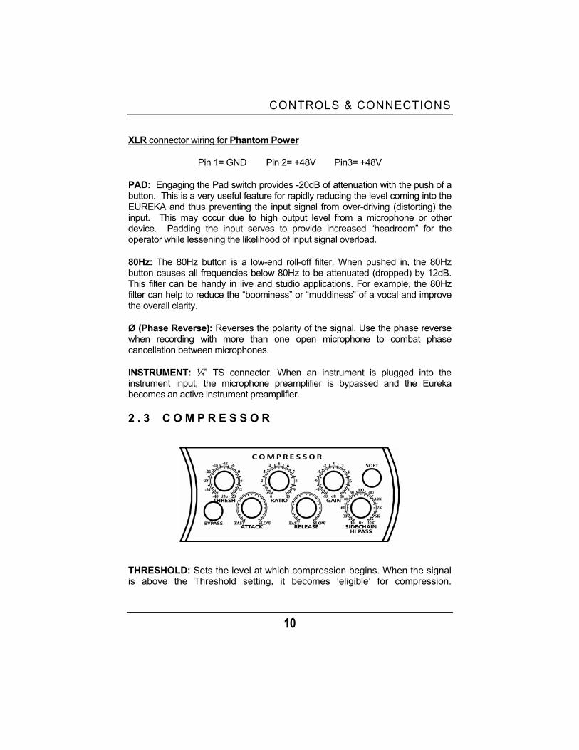
2 . 3 C O M P R E S S O R
THRESHOLD: Sets the level at which compression begins. When the signal is above the Threshold setting, it becomes ‘eligible’ for compression.

CONTROLS & CONNECTIONS
11
Basically, as you turn the Threshold knob counter-clockwise, the input signal is compressed. (If you have a ratio setting of greater than 1:1.) RATIO: Sets the compression slope. This is defined as the output level versus the input level. For example, if you have the Ratio set to 2:1, any signal level above the Threshold setting will be compressed at a compression ratio of 2:1. This simply means that that for every 1dB of level increase into the compressor, the output will only increase " dB, thus producing an attenuation of 0.5 dB. ATTACK: Sets the speed at which the compressor ‘acts’ on the input signal. A slow attack time (fully clockwise) allows the beginning envelope of a signal (commonly referred to as the initial transient) to pass through the compressor uncompressed, whereas a fast attack time (fully counterclockwise) immediately subjects the signal to the Ratio and Threshold settings of the compressor. RELEASE: Sets the length of time the compressor takes to return the Gain reduction back to zero (no gain reduction). Very short Release times can produce a very choppy or ‘jittery’ sound, especially in low frequency instruments such as bass guitar. Very long Release times can result in an overly compressed signal, sometimes referred to as ‘squashing’ the sound. All ranges of Release can be useful at different times however and you should experiment to become familiar with the different sound possibilities. (Refer to the applications section of this manual for some ideas.) SOFT: selects Soft Knee and Hard Knee compression curves. When this button is pushed in, Soft knee compression curves are used, otherwise hard knee compression curves are used. With Hard knee compression, the gain reduction applied to the signal occurs as soon as the signal exceeds the level set by the threshold. With Soft knee compression, the onset of gain reduction occurs gradually after the signal has exceeded the Threshold, producing a more musical response (to some folks).
CONTROLS & CONNECTIONS
12
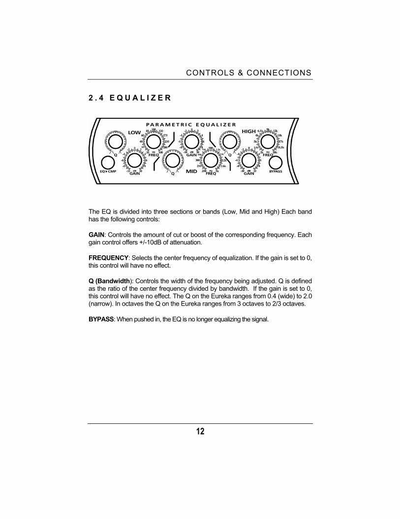
2 . 4 E Q U A L I Z E R
The EQ is divided into three sections or bands (Low, Mid and High) Each band has the following controls:
GAIN: Controls the amount of cut or boost of the corresponding frequency. Each gain control offers +/-10dB of attenuation.
FREQUENCY: Selects the center frequency of equalization. If the gain is set to 0, this control will have no effect.
Q (Bandwidth): Controls the width of the frequency being adjusted. Q is defined as the ratio of the center frequency divided by bandwidth. If the gain is set to 0, this control will have no effect. The Q on the Eureka ranges from 0.4 (wide) to 2.0 (narrow). In octaves the Q on the Eureka ranges from 3 octaves to 2/3 octaves.
BYPASS: When pushed in, the EQ is no longer equalizing the signal.
CONTROLS & CONNECTIONS
13
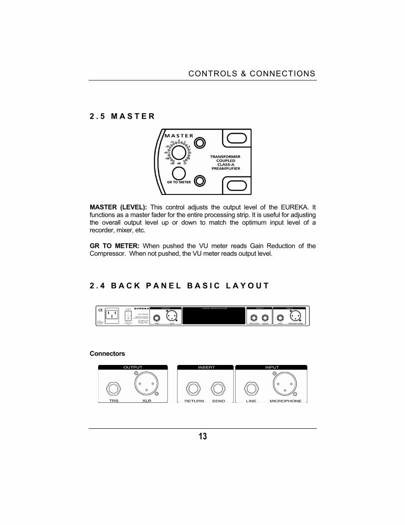
2 . 5 M A S T E R
MASTER (LEVEL): This control adjusts the output level of the EUREKA. It functions as a master fader for the entire processing strip. It is useful for adjusting the overall output level up or down to match the optimum input level of a recorder, mixer, etc.
GR TO METER: When pushed the VU meter reads Gain Reduction of the Compressor. When not pushed, the VU meter reads output level.
2 . 4 B A C K P A N E L B A S I C L A Y O U T
Connectors
CONTROLS & CONNECTIONS
14
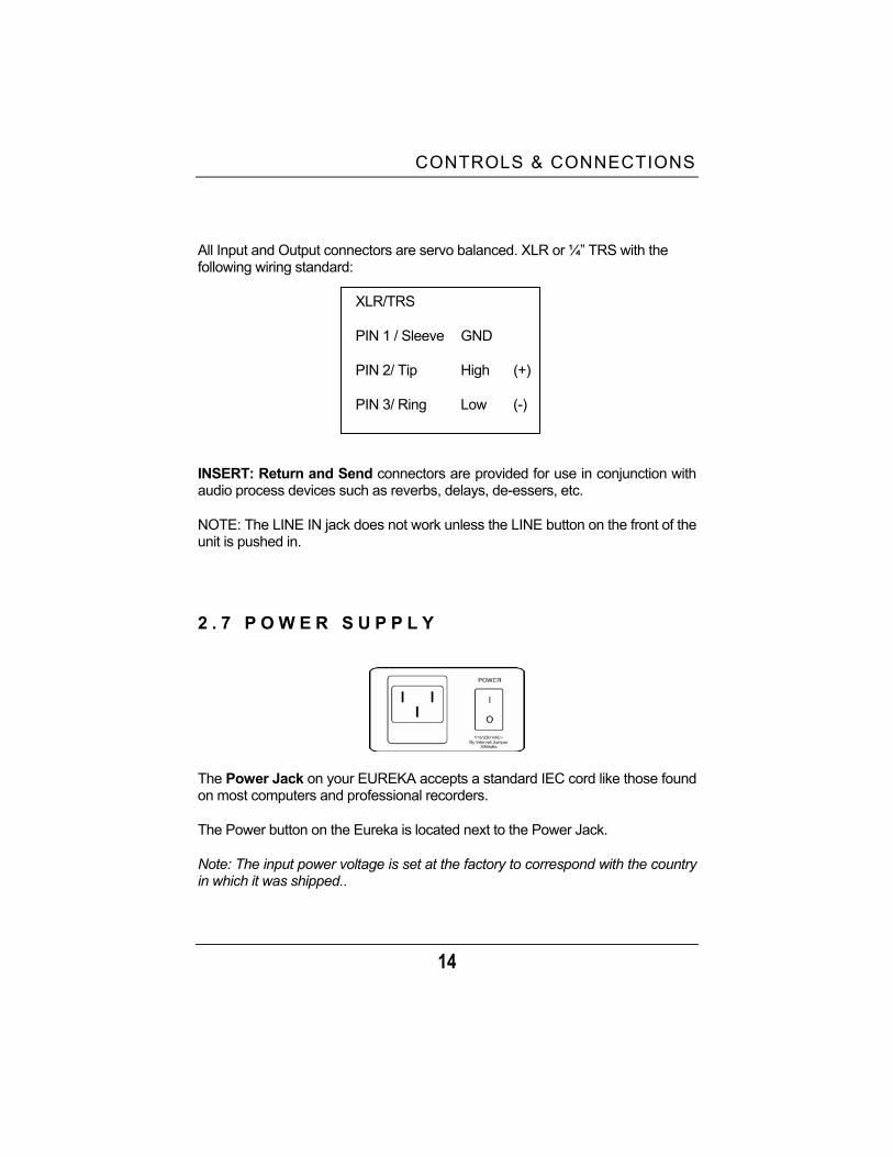
All Input and Output connectors are servo balanced. XLR or !” TRS with the following wiring standard:
XLR/TRS
PIN 1 / Sleeve GND
PIN 2/ Tip High (+)
PIN 3/ Ring Low (-)
INSERT: Return and Send connectors are provided for use in conjunction with audio process devices such as reverbs, delays, de-essers, etc.
NOTE: The LINE IN jack does not work unless the LINE button on the front of the unit is pushed in.
2 . 7 P O W E R S U P P L Y
The Power Jack on your EUREKA accepts a standard IEC cord like those found on most computers and professional recorders.
The Power button on the Eureka is located next to the Power Jack.
Note: The input power voltage is set at the factory to correspond with the country in which it was shipped..
3 OPERATION
15
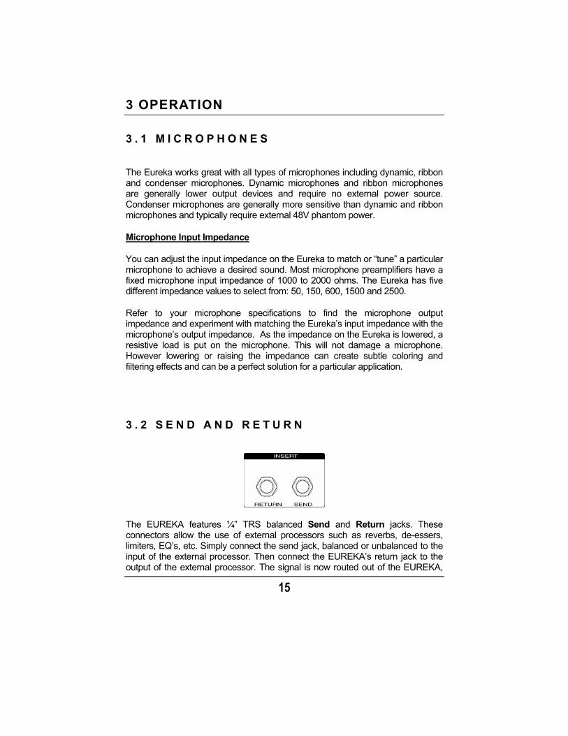
3 . 1 M I C R O P H O N E S
The Eureka works great with all types of microphones including dynamic, ribbon and condenser microphones. Dynamic microphones and ribbon microphones are generally lower output devices and require no external power source. Condenser microphones are generally more sensitive than dynamic and ribbon microphones and typically require external 48V phantom power.
Microphone Input Impedance
You can adjust the input impedance on the Eureka to match or “tune” a particular microphone to achieve a desired sound. Most microphone preamplifiers have a fixed microphone input impedance of 1000 to 2000 ohms. The Eureka has five different impedance values to select from: 50, 150, 600, 1500 and 2500.
Refer to your microphone specifications to find the microphone output impedance and experiment with matching the Eureka’s input impedance with the microphone’s output impedance. As the impedance on the Eureka is lowered, a resistive load is put on the microphone. This will not damage a microphone. However lowering or raising the impedance can create subtle coloring and filtering effects and can be a perfect solution for a particular application.
3 . 2 S E N D A N D R E T U R N
The EUREKA features !” TRS balanced Send and Return jacks. These connectors allow the use of external processors such as reverbs, de-essers, limiters, EQ’s, etc. Simply connect the send jack, balanced or unbalanced to the input of the external processor. Then connect the EUREKA’s return jack to the output of the external processor. The signal is now routed out of the EUREKA,
OPERATION
16
into the external processor, then back into the EUREKA. The final, processed signal will be available at the EUREKA output connector. The Send and Return signal will be inserted after the microphone preamplifier, before the compressor.
3.3 192K/24-BIT DIGITAL OUTPUT CARD (OPTIONAL)
A 192K/24-BIT Digital Output Card is available as an option for the PreSonus EUREKA. It has AES/EBU and SPDIF output connectors, as well as, an auxiliary !” TRS analog Line input connector. The card has a selectable sample rate of 192kHz, 96kHz, 48kHz and 44.1kHz. The A/D converters provide psycho-acoustic dithering for improved BIT resolution when conversion from 24-BIT to 16-BIT sampling is necessary. The !” TRS Line input will provide the benefit of allowing two EUREKA‘s to share one Digital Output Card and in so doing, share both sides of the A/D converter.
OPERATION
17
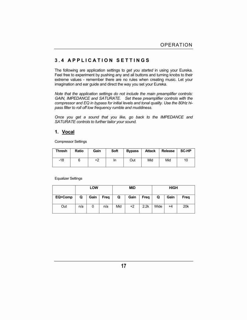
3 . 4 A P P L I C A T I O N S E T T I N G S
The following are application settings to get you started in using your Eureka. Feel free to experiment by pushing any and all buttons and turning knobs to their extreme values - remember there are no rules when creating music. Let your imagination and ear guide and direct the way you set your Eureka.
Note that the application settings do not include the main preamplifier controls: GAIN, IMPEDANCE and SATURATE. Set these preamplifier controls with the compressor and EQ in bypass for initial levels and tonal quality. Use the 80Hz hi-pass filter to roll off low frequency rumble and muddiness.
Once you get a sound that you like, go back to the IMPEDANCE and SATURATE controls to further tailor your sound.
1. Vocal
Compressor Settings
Thresh Ratio Gain Soft Bypass Attack Release SC-HP
-18 6 +2 In Out Mid Mid 10
Equalizer Settings
LOW MID HIGH
EQ>Comp Q Gain Freq Q Gain Freq Q Gain Freq
Out n/a 0 n/a Mid +2 2.2k Wide +4 20k
OPERATION
18
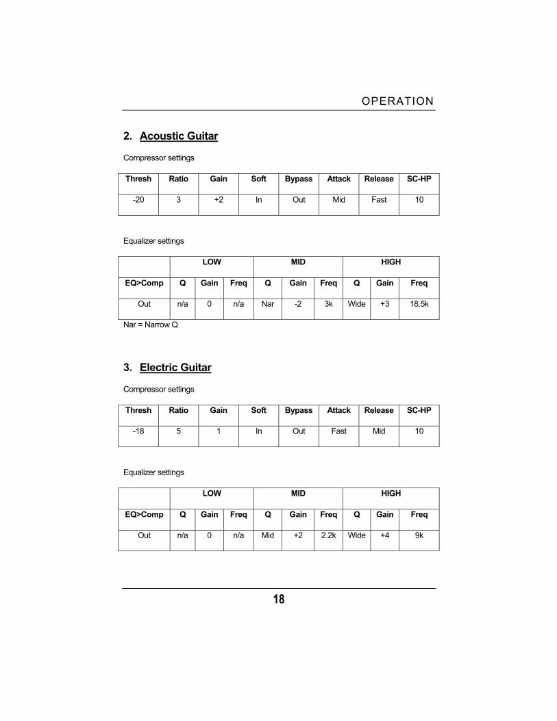
2. Acoustic Guitar
Compressor settings
Thresh Ratio Gain Soft Bypass Attack Release SC-HP
-20 3 +2 In Out Mid Fast 10
Equalizer settings
LOW MID HIGH
EQ>Comp Q Gain Freq Q Gain Freq Q Gain Freq
Out n/a 0 n/a Nar -2 3k Wide +3 18.5k
Nar = Narrow Q
3. Electric Guitar
Compressor settings
Thresh Ratio Gain Soft Bypass Attack Release SC-HP
-18 5 1 In Out Fast Mid 10
Equalizer settings
LOW MID HIGH
EQ>Comp Q Gain Freq Q Gain Freq Q Gain Freq
Out n/a 0 n/a Mid +2 2.2k Wide +4 9k
OPERATION
19
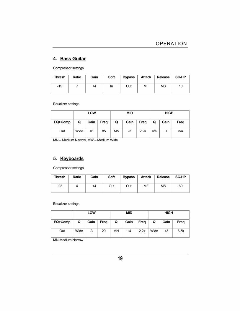
4. Bass Guitar
Compressor settings
Thresh Ratio Gain Soft Bypass Attack Release SC-HP
-15 7 +4 In Out MF MS 10
Equalizer settings
LOW MID HIGH
EQ>Comp Q Gain Freq Q Gain Freq Q Gain Freq
Out Wide +6 85 MN -3 2.2k n/a 0 n/a
MN – Medium Narrow, MW – Medium Wide
5. Keyboards
Compressor settings
Thresh Ratio Gain Soft Bypass Attack Release SC-HP
-22 4 +4 Out Out MF MS 60
Equalizer settings
LOW MID HIGH
EQ>Comp Q Gain Freq Q Gain Freq Q Gain Freq
Out Wide -3 20 MN +4 2.2k Wide +3 6.5k
MN-Medium Narrow

OPERATION
20
6. Kick Drum
Compressor settings
Thresh Ratio Gain Soft Bypass Attack Release SC-HP
-18 5 +2 Out Out MF MF 80
Equalizer settings
LOW MID HIGH
EQ>Comp Q Gain Freq Q Gain Freq Q Gain Freq
In Wide +8 60 Nar -8 400 Wide +6 2.5k
7. Snare
Compressor settings
Thresh Ratio Gain Soft Bypass Attack Release SC-HP
-22 6 +4 In Out Med Med 10
Equalizer settings
LOW MID HIGH
EQ>Comp Q Gain Freq Q Gain Freq Q Gain Freq
Out n/a 0 n/a Med +2 1k Wide -2 20k
OPERATION
21
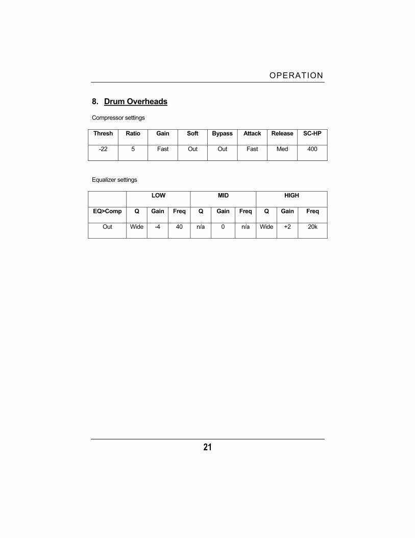
8. Drum Overheads
Compressor settings
Thresh Ratio Gain Soft Bypass Attack Release SC-HP
-22 5 Fast Out Out Fast Med 400
Equalizer settings
LOW MID HIGH
EQ>Comp Q Gain Freq Q Gain Freq Q Gain Freq
Out Wide -4 40 n/a 0 n/a Wide +2 20k

4 TECHNICAL
22
EUREKA SPECIFICATIONS Channels ....................................................................................................ONE Dynamic Range.....................................................................................>115dB Headroom .............................................................................................+22dBu Frequency Response.................................................................10Hz to 50kHz Internal Operating Level................................................................. 0dBu = 0dB Microphone /Instrument Preamplifier Gain........................................................................................ + 12dB to +52dB Noise Floor.....................................................................-112dBu (+12dB gain) EIN .........................................................................................................-127dB THD + Noise(0% Saturation) .............................................................. <0.005% THD + Noise (Full Saturation)................................................................. <0.5% Microphone Input Connector...................................................................... XLR Mic Input Impedance (selectable) ...................2.5K, 1.5K, 600, 150, 50 Ohms Instrument Input Connector .....................................................................!” TS Instrument Input Impedance ...........................................................1 Meg Ohm Send Connector ............................................. 1/4” TRS Balanced/Unbalanced Send Output Impedance .....................................................................51 Ohms Return Connector............................................ 1/4”TRS Balanced/Unbalanced Return Input Impedance................................................................... 10K Ohms Metering (3-LED)................................................................. -20dBu, 0dBu, Clip Line input (switchable) .............................!” TRS, 10k Ohm Input Impedance Phantom Power (switchable) ......................................+48V (Pin 1, Pin 2 XLR) Pad (switchable)............................................................................... 0dB/-20dB Phase (switchable)................................................................................. 0, 180º Hi-pass Filter (switchable)....................................................-3dB shelf at 80Hz Compressor Threshold (variable) ............................................................. -40dBu to +20dBu Ratio (variable)..........................................................................1-10 (1:1 – 7:1) Attack (variable) ............................................................................ 0.1 – 200ms Release (variable) .............................................................................0.05 – 3 S Output Attenuation/Gain........................................................... -20dB to +20dB High Pass Sidechain Filter (variable).........................................10Hz to 10kHz Metering ......................................... Analog VU (Gain Reduction/Output Level)

TECHNICAL
23
Equalizer Low Band (+/-10dB) ................................................................... 20Hz – 300Hz Mid Band (+/-10dB)....................................................................200Hz to 3kHz High Band )+/- 10dB) ..................................................................2kHz – 20kHz Q (variable all bands) .................................Q=0.4 to 2 (3 octave to 2/3 octave) Master Output Fader ........................................................................... -70dB to + 10dB Output Connectors ......... XLR Balanced and 1/4” TRS Balanced/Unbalanced Output Impedance................................................................................51Ohms Metering (Output level) ...................................... Analog VU (-20dBu – +6dBu) Metering (Gain reduction) .........................................Analog VU (-20dB – 0dB) Output Headroom..................................................................................+22dBu Physical Power Supply ................................................ Internally Regulated Linear Type Power Requirements (factory configure) .............. 100-120VAC, 200-240VAC Size ..........................................................................1U Rack (19” x 1.75” x 7”) Weight .......................................................................................................8 lbs. As a commi tmen t to cons tan t improvement , P reSonus Aud io E lec t ron ics , Inc . rese rves the r i gh t to change any spec i f i ca t i on s ta ted he re in a t any t ime in the fu tu re w i thou t no t i f i ca t i on .