eval seismic req
TRANSCRIPT

8/8/2019 Eval Seismic Req
http://slidepdf.com/reader/full/eval-seismic-req 1/12
Page 1 of 1
Evaluating Seismic Requirements in SpecificationsUpdated April 29, 2003
When reviewing a Specification, there are 4 or 5 items that are critical in determining the extent ofthe seismic componentry that will be required. Once the need for restraint is determined, themagnitude of the restraint must be evaluated to select the actual components.
The initial 4 items affecting all codes are:1) The effective national Code that applies (Code document and year)2) The location of the project and ground acceleration coefficient (Av or Z depending on the
code.)3) The type of occupancy (in particular is it essential, hazardous, or emergency service related).4) Any special seismic factors that may be listed in the spec and that exceed code requirements
(These may dictate restraint even if the code would not normally require it and a seismicrequirement is often added to a spec to afford some degree of bomb blast protection).
And a fifth item that affects only the 97 UBC, 2000 IBC and TI 809-04 spec is:5) The class of soil present at the jobsite (geotechnical report data).
The above information will need to be applied to the code requirements to determine the extent ofseismic restraint to be included in the project. Once the above information is gathered up, we cancompare it to the appropriate code to gather specifics.
A typical map for the BOCA, SBC and UBC codes is shown below for reference.
1996 BOCA and 1997 SBC: Beginning with the 2 oldest codes currently referenced at the statelevel, we find the last version of both the BOCA and SBC codes. These two codes have basicallyidentical seismic design parameters and both are being phased out by the 2000 IBC code.

8/8/2019 Eval Seismic Req
http://slidepdf.com/reader/full/eval-seismic-req 2/12
Page 2 of 2
Initially, review the job to see if restraint can be ruled out of the project globally.
The first step in the process is to determine the Seismic Use (or Hazard Exposure) Group. Thisshould fall into 1 of 3 classifications.
I – Anything not in Groups II or III.II – High occupancy structures and schools.
III - Emergency, Hazardous, and Essential facilities.
Using this input and applying it to the table below along with the site ground acceleration factor, a“Performance” factor can be obtained. Equipment in buildings with a Performance factor of “A” or“B” is exempt from seismic design requirements.
.
Effective Peak Velocity Siesmic Hazard Exp Grp
Related Accelerations I II III
Av<.05 A A A. < v<. B B C. < v<. C C C
. < v<. C D D. < v D D E
Seismic Performance Factor In addition, Mechanical equipment in Performance category “C” buildings which fall into SeismicUse Group I occupancies and is not related to safety, emergency power, or hazardous materialtransfer is also exempt.
Piping does not require restraint in any seismic zone or performance category as long as it is 1)Not hazardous, and 2) mounted such that the dimension from the top of the pipe to the supportingsurface does not exceed 12” and adequate flexes are included at equipment connections. Inaddition, 3) if the pipe is under 2-1/2” in diameter and is not in a mechanical room or if it is under1-1/4” in diameter and is in a mechanical room, no restraint is required.
Ducting does not require restraint in any seismic zone or performance category as long as it is 1)Not hazardous, and 2) mounted such that the pendulum length from the support surface to thetrapeze does not exceed 12” and adequate flexes are included at equipment connections. Also,3) if the Duct is under 6 sq ft in area, no restraint is required.
In the BOCA and SBC codes, there is no specific equipment exemption by weight of mountinglocation. (If there is a requirement in the building to restrain equipment, it must all be restrainedwithout regard to weight.)
Estimating Seismic forces:
To estimate Seismic forces a performance criteria factor is required. Refer to the table below toselect the appropriate factor:
The global lateral g load can be initially estimated as follows:For hard mounted equipment – Av * Cc * PFor resilient mounted equipment at grade – Av * Cc * PFor resilient mounted equipment above grade – 2* Av * Cc * P
The total lateral load would then be the equipment weight multiplied by this final factor.

8/8/2019 Eval Seismic Req
http://slidepdf.com/reader/full/eval-seismic-req 3/12
Page 3 of 3
For restraint load estimatesWorst case lateral load is:
The total lateral load / number of restraints * 2Worst case vertical load is:
For horizontal g < .25, vertical load is 0For .25 < horizontal g < .5, vertical load is .5 * horizontal loadFor . 5 < horizontal g < .75, vertical load is equal to the horizontal loadFor horizontal g > 1.0, vertical load is 2 * horizontal load
Mech / Elec component or system Cc P
Ssmc Hzrd Grp
I II III
Fire protection equip and systems 2.0 1.5 1.5 1.5
Emergency or standby Electrical systems 2.0 1.5 1.5 1.5
General Equipment 2.0 0.5 1.0 1.5
A) Boilers, furnaces, incinerators, water htrs and other equipment utilizing combustible
energy sources or high-temperature energy sources
B) Communication systems
C) Electrical bus ducts and primary cable systems suspended further than 12" from
supporting surface or 2-1/2" or more inside diameter
D) Electrical motor control centers, motor control devices, switchgear, transformers and
unit substations
E) Reciprocating or rotating equipment
F) Tanks, heat exchangers and pressure vessels.
Manufacturing and process machinery 0.67 0.5 1.0 1.5
Pipe systems
A) Gas and high-hazard piping 2.0 1.5 1.5 1.5
B) Fire suppression piping 2.0 1.5 1.5 1.5
C) Other pipe systems 0.67 0.5 1.0 1.5
HVAC ducts 0.67 0.5 1.0 1.5
Electrical panel boards 0.67 0.5 1.0 1.5
Lighting fixtures (Cc for pendulum fixtures must be 1.5) 0.67 0.5 1.0 1.5
For general guidance, when restraint is required with these codes, FHS and FLSS isolators aswell as ¼” restraint cables will work in virtually all zones and with most equipment types. Ifattached to concrete in higher seismic zones, load spreader plates will almost certainly berequired.
For non-hazardous piping and ductwork, a reasonable estimate of the restraints required is (forpiping) the total length of restrained pipe divided by 25 and (for ductwork) the total length ofrestrained duct divided by 20. For hazardous systems, the values would be about 2/3 of theabove.
1997 UBC: The 97 UBC code is considerably more complex than are the BOCA and SBC codes.
This code introduces soil factors, equipment elevation and fault proximity into the equation.
When determining the seismic requirements, the first step as with BOCA and SBC, is to reviewthe job to see if restraint can be ruled out of the project globally. The 97 UBC code contains onlyone global exclusion. This indicates that all components in buildings constructed in seismiczones 2 and higher must be designed. By exclusion, that indicates that components in allbuildings constructed in Seismic Zone 1 (Z < .075) need not be reviewed.
The 97 UBC contains an exclusion for equipment weighing 400 lb or less and which is floor orroof mounted. This exclusion indicates that, when confronted by this equipment, it need only be

8/8/2019 Eval Seismic Req
http://slidepdf.com/reader/full/eval-seismic-req 4/12
Page 4 of 4
restrained in the manner normally recommended for general applications by the equipmentmanufacturer. No engineering support documentation is required to substantiate the design andno special components are required.
Piping does not require restraint in any zone as long as it is 1) Not hazardous, and 2) mountedwith a swivel type connection such that the dimension from the top of the pipe to the supportingsurface does not exceed 12” and adequate flexes are included at equipment connections.
Ducting does not require restraint in any seismic zone or performance category as long as it ismounted with a swivel type connection such that the pendulum length from the support surface tothe trapeze does not exceed 12” and adequate flexes are included at equipment connections.
Raceways do not require restraint in any seismic zone or performance category as long as theyare mounted with a swivel type connection such that the pendulum length from the supportsurface to the raceway does not exceed 12” and adequate flexes are included at equipmentconnections.
Although not in the code, it is accepted practice to not restrain piping outside of mechanicalrooms that is under 2-1/2” in diameter or ductwork that is under 6 sq ft in area. This is referencedin the SMACNA guidelines and these guidelines have been accepted by the UBC as meeting
code compliance. These can be excluded if SMACNA is referenced in the spec.
Estimating Seismic forces:
To begin with, the basic ground motion acceleration (Ca) must be determined. This requires thefollowing input.
1) The site ground acceleration coefficient (z). This will range from .075 to .4 dependingon location.
2) The site soil classification (Hard Rock-“Sa”, Rock-“Sb”, Dense Soil-“Sc”, Stiff Soil-“Sd”, Soft Soil-“Se”, and Other-“Sf”). If unknown, use “Sd”.
3) If the site ground acceleration coefficient (z) is .4, then the proximity to the nearestactive fault is required. Fault maps can be pulled up on the internet to help in thistask. If the Fault is greater than 10 km, it is a non-issue. If less than 10 km, the
distance in km should be estimated.4) If the site ground acceleration coefficient (z) is .4, then the seismic source type must
be identified. “A” – Faults that are capable of producing large magnitudeearthquakes and that have a high rate of seismic activity. “C” – Faults not capable ofproducing large magnitude earthquakes and that have a relatively low rate of seismicactivity. “B” – All other faults.
Step one in determining the design ground acceleration is to use the table below along with theproximity and source type information to determine the factor Na.
Seismic Source Type <= 2 km 5 km >= 10 km
A 1.5 1.2 1.0
B 1.3 1.0 1.0
C 1.0 1.0 1.0
Near Source Factor (Na)
Closest Distance to know Seismic Source
Linear Inter olation for distance is ermitted
Using the Na determined above, the basic ground motion acceleration (Ca) can be determinedfrom the table below:

8/8/2019 Eval Seismic Req
http://slidepdf.com/reader/full/eval-seismic-req 5/12
Page 5 of 5
Soil Profile Type z = 0.075 z = 0.15 z = 0.2 z = 0.3 z = 0.4
Sa 0.06 0.12 0.16 0.24 0.32N a
Sb 0.08 0.15 0.20 0.30 0.40N a
Sc 0.09 0.18 0.24 0.33 0.40N a
Sd 0.12 0.22 0.28 0.36 0.44N a
Se 0.19 0.30 0.34 0.36 0.36N a
Sf
Seismic Zone Factor, z
Site Specific Geotechnical Report Required
Seismic Coefficient Ca
This factor now has to be tailored to individual equipment types, mountings and locations in thebuilding structure. In order to do this, some specifics are required on the equipment.
1) Equipment Type (what is it?)2) Importance factor of Equipment3) Roof Elevation of Building (hr)
4) Elevation of equipment mounting point in Building (hx)5) Is the Equipment Isolated6) Is the Equipment anchored to concrete?
The Importance factor Ip for a piece of equipment is 1.5 if the equipment is essential to thecontinued operation of essential or hazardous services (whether or not the building itself isessential). Otherwise it is 1.0.
For a particular piece of equipment (ignoring anchorage for the moment), the maximum effectiveseismic design acceleration is:
4 * Ca * Ip
If the value of the following equation is less, it can be used in place of the above. In higherseismic areas and particularly if the equipment is not located on the roof, it can reduce the loadssignificantly.
ap * Ca * Ip / Rp * (1 + 3 * (hx / hr))
ap and Rp can be drawn from the table below:
Components ap Rp
Ceilings and light fixtures 1 3
Equipment
Tanks and Vessels 1 3
Elec, Mech, Plumbing Equip, Conduit, Piping, Ductwork 1 3
All Equip anchored to structure below its center of mass 2.5 3
Emergency Systems and Essential Communications 1 3
Isolated Equipment 2.5 1.5
Horizontal Force Factors
Under no circumstances can the seismic design acceleration be less than:
0.7 * Ca * Ip

8/8/2019 Eval Seismic Req
http://slidepdf.com/reader/full/eval-seismic-req 6/12
Page 6 of 6
If the equipment is anchored to concrete, because the anchor rating and the load factors are nowbased on different design factors, the load can be reduced by a factor of 1.4 (this applies toeither hard mounted or isolated equipment).
If the equipment is isolated and only if it is anchored to concrete with post installed or shallow(less than 8 bolt diameter) cast in place anchors, the design load used must be doubled theabove for dynamic impact reasons.
The total lateral load would then be the equipment weight multiplied by this final factor.
For restraint load estimatesWorst case lateral load is:
The total lateral load / number of restraints * 2Worst case vertical load is:
For horizontal g < .25, vertical load is 0For .25 < horizontal g < .5, vertical load is .5 * horizontal loadFor . 5 < horizontal g < .75, vertical load is equal to the horizontal loadFor 1.0 < horizontal g < 2.0, vertical load is 2 * horizontal loadFor horizontal g > 2.0, vertical load is 4 * horizontal load
For general guidance, when restraint is required with this code, FHS and FLSS isolators as wellas ¼” restraint cables will work for “at grade” applications in virtually all zones and with mostequipment types. For equipment locations at higher elevations and the roof, particularly in higherseismic zones, it may be necessary to use separate restraints (HS-5 or 7). If attached toconcrete, load spreader plates will almost certainly be required.
For non-hazardous piping and ductwork at grade, a reasonable estimate of the restraints requiredis (for piping) the total length of restrained pipe divided by 20 and (for ductwork) the total length ofrestrained duct divided by 15. For hazardous systems, the values would be about 2/3 of theabove. For piping and duct at the roof, these spacings will decrease to about half of the abovevalues. For pipes over 6” diameter in all cases, cable sizes will increase to 3/8” and for pipesover 12” diameter, the size can increase to ½”.
2000 IBC and TI 809-04: This Code and Federal Spec represent the latest round of thinking inSeismic design. They are similar to the 97 UBC, but use new maps and factors to allow moreaccurate load assessments at a given site without having to research fault information. Soilfactors and equipment elevation still factor into the equation.
The primary difference between TI 809-04 and the 2000 IBC is in the area of exclusions. The2000 IBC excludes some structures and components from the seismic design scope that TI 809-04 does not.
Current maps applicable to either specification can be quite detailed and unreadable in a small
scale. To resolve this, dynamic Maps can be downloaded from the following websites: http://geohazards.cr.usgs.gov/eq/design/ibc/IBC1615-1us.pdf or short period acceleration (Ss)and http://geohazards.cr.usgs.gov/eq/design/ibc/IBC1615-2us.pdf for long period acceleration
(S1). For evaluating the attachment of Equipment and Architectural Components, the maps ofinterest are those that list the Maximum Short Period Spectral Response (.2 second). The mapsidentifying Maximum Long Period Spectral Response (1 second) are of interest to us only todetermine if the structure can be exempted (IBC applications only) from seismic analysis.
It must be noted that the maps indicate the Maximum Spectral Response for long and shortperiods (SS & Sl) and not the Design Spectral Response. The ground accelerations used for thedesign of Architectural and Equipment’s attachment are the short period (.2 second) values only(SS). These are multiplied by the site (soil) Classification Factor (Fa) from table 1615.1.2(1) andthen multiplied by a factor of 2/3 except in the case of immediate occupancy structures under TI

8/8/2019 Eval Seismic Req
http://slidepdf.com/reader/full/eval-seismic-req 7/12
Page 7 of 7
809-04. In the TI 809-04 immediate occupancy case (“A”), the reduction factor is increased to ¾.This, the Design Spectral Response at Short Periods or SDS is the final acceleration coefficientused in the design. The Site Factors for various soil types and mapped Acceleration Factors (SS)are listed in the table below.
Site Soil
Class Type Ss < 0.25 Ss = 0.50 Ss = 0.75 Ss = 1.0 Ss > 1.25
A Hard Rock 0.8 0.8 0.8 0.8 0.8
B Moderate Rock 1 1 1 1 1
C Dense Soil, Soft Rock 1.2 1.2 1.1 1 1
Dc
Stiff Soil 1.6 1.4 1.2 1.1 1
E Soft Soil, Clay 2.5 1.7 1.2 0.9 Note b
F Fill and Other Note b Note b Note b Note b Note baUse straight line interpolation for intermediate values of mapped spectral acceleration
bSite specific geotechnical investigation and dynamic site response analyses shall be performed to determine values
cIn lieu of geotechnical data an in cases where Site Class E or F are not expected, Site Class D shall be assumed.
Mapped Spectral Response Accel at Short Periods
Site Factor (Fa) Based on Site Class and Mapped
Spectral Response for Short Periods (Ss)
a
A similar Table exists for Long Period Response SD1. It is computed in the same manner (2/3 S1 x Fv). For our purposes, this is a second screen that must be met to exempt a project from theneed to perform a seismic analysis. The table is shown below.
Site Soil
Class Type Ss < 0.1 Ss = 0.2 Ss = 0.3 Ss = 0.4 Ss > 0.5
A Hard Rock 0.8 0.8 0.8 0.8 0.8
B Moderate Rock 1.0 1.0 1.0 1.0 1.0
C Dense Soil, Soft Rock 1.7 1.6 1.5 1.4 1.3
Dc
Stiff Soil 2.4 2.0 1.8 1.6 1.5
E Soft Soil, Clay 3.5 3.2 2.8 2.4 Note b
F Fill and Other Note b Note b Note b Note b Note ba
Use straight line interpolation for intermediate values of mapped spectral accelerationb Site specific geotechnical investigation and dynamic site response analyses shall be performed to determine values
c In lieu of geotechnical data an in cases where Site Class E or F are not expected, Site Class D shall be assumed.
Mapped Spectral Response Accel at Short Periods
Site Factor (Fv) Based on Site Class and Mapped
Spectral Response for Long Periods (S1)a
Levels of Seismic Concern are identified in the new code as ”Seismic Design Category”. Theseare a function of the structure’s end use and the ground acceleration coefficient. A roughdefinition of the 3 possible Use Groups (I, II and III) is as follows: Group III is an EmergencyTreatment, an Essential Service structure or a structure containing potentially HazardousMaterial. Group II is a high occupancy structure or non-Essential Utilities. Group I is what is left.Below are 2 Tables from the code indicating the Seismic Design Categories for variousconditions. The Seismic Design Category appropriate for a project is the highest letter valueobtained from the 2 tables below.
SDS Value I II III
SDS < 0.167g A A A
0.167g<SDS<0.33g B B C
0.33<SDS<0.50g C C D
0.50g<SDS D D D
0.75g<S1a
E E FaS1 is Ma ed Max Considered S ectral Res onse
Seismic Design Category based on
.2 Second Response Accelerations
Seismic Use GroupSD1 Value I II III
SD1 < 0.067g A A A
0.067g<SD1<0.133g B B C
0.133<SD1<0.20g C C D
0.20g<SD1 D D D
0.75g<S1a
E E FaS1 is Mapped Max Considered Spectral Response
Seismic Design Category based on
1.0 Second Response AccelerationsSeismic Use Group

8/8/2019 Eval Seismic Req
http://slidepdf.com/reader/full/eval-seismic-req 8/12
Page 8 of 8
The Importance Factor in the 2000 IBC or TI 809-04 document is now tied more closely to theuse of the equipment rather than the use of the structure. There are 2 levels of importance (1.0and 1.5). The Importance Factor of 1.5 is used under the following conditions:
1) The component is a Life-Safety Component that must function after an Earthquake2) The component contains hazardous or flammable material in excess of exempted
limits.3) Storage Racks in structures that are open to the public (Home Depot for example)4) Components needed for continued operation of Group III Occupancy Structure.
All other conditions use an Importance Factor of 1.0.
In the case of the 2000 IBC, the occasions when it is not necessary to have seismic restraint are:
Entire Structures (and contents) that are exempted from Seismic review are:1) Group R-3, Single family stand alone residential structures not more than 3 stories in
height, in areas where the mapped SDS value is less than .5g.2) Agricultural storage structures intended only for incidental human occupancy.3) All structures where the mapped SDS value is less than .167g and the mapped SD1
value is less than .067g.Mechanical/Electrical Components and Arch Elements exempted from Seismic review are:
1) All non-structural mechanical components and architectural elements in structuresthat fall into Seismic Design Category A or B.
2) All mechanical components in structures that fall into Seismic Design Category C andwhere the Importance Factor is1.0
3) All architectural elements in structures that fall into Seismic Design Category C andwhere the Importance Factor is1.0, and there are fewer than 3 stories.
Specific Component exemptions for Mechanical/Electrical Equipment are:1) All components (no matter what Seismic Design Category) with an Importance Factor
of 1.0 weighing less than 400 lb, mounted to the floor with legs under 4’ in height,connected via flexible connections between components and associated ductwork,piping, etc. and not critical to the continued operation of the structure.
2) Mechanical and Electrical components in Seismic Design Categories D and E that
weigh 20 lb or less (no matter where mounted), that are connected via flexibleconnections between components and associated ductwork, piping, etc., where theImportance Factor does not exceed 1.0.
3) Ductwork that is less than 6 sq ft in area for the full length of a run where theImportance Factor does not exceed 1.0 (no matter what Seismic Design Category)and the motion induced by a seismic event will not result in contact with othercomponents.
4) All ductwork that is suspended on hangers 12” or less in length for the full length of arun with a non-moment generating connection to the structure and where theImportance Factor does not exceed 1.0 (no matter what Seismic Design Category)and motion induced by a seismic event will not result in contact with othercomponents.
5) High deformability piping in all Seismic Design Categories that is 3.0 inches or less in
diameter and has an Importance Factor of 1.0. (Note: High deformability is ameasure of ductility as defined in the code section 1602.1.) (Note: if trapezemounted and the accumulative total area of the pipes supported is less than 5”, norestraint is required.)
6) High deformability piping in Seismic Design Category C that is 2.0 inches or less indiameter with an Importance Factor of 1.5. (Note: if trapeze mounted and theaccumulative total area of the pipes supported is less than 3.2”, no restraint isrequired.)
7) High deformability piping in Seismic Design Category D or E that is 1.0 inch or less indiameter, with an Importance Factor of 1.5.

8/8/2019 Eval Seismic Req
http://slidepdf.com/reader/full/eval-seismic-req 9/12
8/8/2019 Eval Seismic Req
http://slidepdf.com/reader/full/eval-seismic-req 10/12
Page 10 of 10
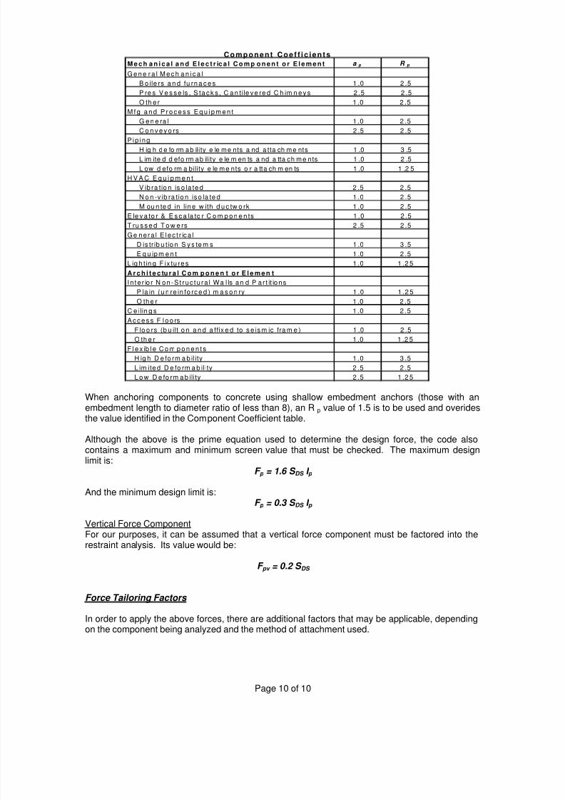
When anchoring components to concrete using shallow embedment anchors (those with anembedment length to diameter ratio of less than 8), an R p value of 1.5 is to be used and overides
the value identified in the Component Coefficient table.
Although the above is the prime equation used to determine the design force, the code alsocontains a maximum and minimum screen value that must be checked. The maximum designlimit is:
F p = 1.6 S DS I p
And the minimum design limit is:F p = 0.3 S DS I p
Vertical Force ComponentFor our purposes, it can be assumed that a vertical force component must be factored into therestraint analysis. Its value would be:
F pv = 0.2 S DS
Force Tailoring Factors
In order to apply the above forces, there are additional factors that may be applicable, dependingon the component being analyzed and the method of attachment used.
M e c h a n i c a l a n d E l e c t r ic a l C o m p o n e n t o r E l e m e n t a p R p
G e n e r a l M e c h a n i c a l
B o ile rs a n d fu rn a c e s 1 .0 2 .5
P re s V e s s e ls , S ta c k s , C a n tile v e re d C h im n e y s 2 .5 2 .5
O th e r 1 .0 2 .5
M f g a n d P r o c e s s E q u i p m e n t
G e n e ra l 1 .0 2 .5
C o n v e y o rs 2 .5 2 .5
P ip i ngH ig h d e fo rm ab ility e le me nts a nd a tta ch me nts 1 .0 3 .5
L im ite d d efo rm ab il ity e le m en ts a nd a tta ch me nts 1 .0 2 .5
L ow d efo rm a bility e le me nts o r a tta ch m en ts 1 .0 1 .2 5
H V A C E q u i p m e n t
V ib ra tio n is o la te d 2 .5 2 .5
N o n -v ib ra tio n is o la te d 1 .0 2 .5
M ou n te d in lin e w ith d u c tw o rk 1 .0 2 .5
E le v a to r & E s c a la to r C o m p o n e n ts 1 .0 2 .5
T ru s s e d T o w e rs 2 .5 2 .5
Ge nera l E lec t r ic a l
D is tr ib u tio n S y s te m s 1 .0 3 .5
E q u ip m e n t 1 .0 2 .5
L ig h t in g F ix tu re s 1 .0 1 .2 5
A r c h i t e c tu r a l C o m p o n e n t o r E l e m e n t
I n t e r io r N on-S t ruc tu ra l Wa l ls an d P ar t it ions
P la in (u n re in fo rc e d ) m a s o n ry 1 .0 1 .2 5
O th e r 1 .0 2 .5
C e ilin g s 1 .0 2 .5
A c c e s s F l o o rs
F lo o rs (b u ilt o n a n d a ffix e d to s e is m ic fra m e ) 1 .0 2 .5
O th e r 1 .0 1 .2 5
F l e x ib l e C o m p o n e n t s
H ig h D e fo rm a b il ity 1 .0 3 .5
L im ite d D e fo rm a b ility 2 .5 2 .5
L o w D e fo rm a b ility 2 .5 1 .2 5
C om ponent C oe f f ic ien t s

8/8/2019 Eval Seismic Req
http://slidepdf.com/reader/full/eval-seismic-req 11/12
Page 11 of 11
1) As with the 97 UBC, he outputted forces from the above equations are working strengthbased figures. Because of this, it can be reduced by a factor of 1.4 when computing concreteanchorage loads (working stress based ratings). It comes into play when evaluatingconnections using the older ASD (Allowable Stress Design) bolt allowables, connections totimber with lag screws or connections to concrete with post installed anchors.
2) Permitted design loads and resulting stresses in the attachment hardware can be increasedby a factor of 1.33 for short term wind and seismic load applications when working withworking stress based allowables.
3) Shallow embedment anchors must be sized to withstand 1.95 (or 1.3 x Rp (where Rp equals1.5)) times the computed design load.
4) For Mechanical or Electrical equipment that is supported on vibration isolation systems, theDesign Lateral force shall be taken as 2 Fp
Consolidating the above into simple understandable equations, we get the following:
Using the previously determined design force Fp, steel and bolt and fastener allowables as perLFR, ASD and/or published post installed anchor allowables per ICBO
1) Rigid Equipment Connection via Through Bolts using the ASD Bolt Allowables:Lateral Design Load = Fp / 1.4, but increase Bolt Allowables by multiplying by 4/3
Vertical Design Load = Fpv / 1.4, but increase Bolt Allowables by multiplying by 4/3
2) Rigid Equipment Connection to Concrete with Post Installed Anchors using ICBO AnchorRatings (Non OSHPD Applications):
Shallow embed anchors (< 8 dias)Lateral Design Load = 1.95 x Fp / 1.4, but increase Anchor Allowables by multiplying by 4/3
Vertical Design Load = 1.95 x Fpv / 1.4, but increase Anchor Allowables by multiplying by 4/3Standard embed anchors (>= 8 dias)
Lateral Design Load = 1.3 x Fp / 1.4, but increase Anchor Allowables by multiplying by 4/3Vertical Design Load = 1.3 x Fpv / 1.4, but increase Anchor Allowables by multiplying by 4/3
3) Rigid Equipment Connection to Concrete with Post Installed Anchors using ICBO Special
Inspection Anchor Ratings (OSHPD Applications):
Shallow embed anchors (< 8 dias)Lateral Design Load = 1.95 x Fp / 1.4
Vertical Design Load = 1.95 x Fpv / 1.4Standard embed anchors (>= 8 dias)
Lateral Design Load = 1.3 x Fp / 1.4Vertical Design Load = 1.3 x Fpv / 1.4
4) Rigid Equipment Connection to wood with Lag Screws as rated per ASD:Lateral Design Load = Fp / 1.4, but increase Anchor Allowables by 1.6
Vertical Design Load = Fpv / 1.4, but increase Anchor Allowables by 1.6
5) Isolated Equipment Connection via Through Bolts using the ASD Bolt Allowables:Lateral Design Load = 2 x Fp / 1.4, but increase Bolt Allowables by multiplying by 4/3Vertical Design Load = 2 x Fpv / 1.4, but increase Bolt Allowables by multiplying by 4/3
6) Isolated Equipment Connection to Concrete with Post Installed Anchors using ICBO AnchorRatings (Non OSHPD Applications):
Shallow embed anchors (< 8 dias)Lateral Design Load = 3.9 x Fp / 1.4, but increase Anchor Allowables by multiplying by 4/3
Vertical Design Load = 3.9 x Fpv / 1.4, but increase Anchor Allowables by multiplying by 4/3

8/8/2019 Eval Seismic Req
http://slidepdf.com/reader/full/eval-seismic-req 12/12
Page 12 of 12
Standard embed anchors (>= 8 dias)Lateral Design Load = 2.6 x Fp / 1.4, but increase Anchor Allowables by multiplying by 4/3
Vertical Design Load = 2.6 x Fpv / 1.4, but increase Anchor Allowables by multiplying by 4/3
7) Isolated Equipment Connection to Concrete with Post Installed Anchors using ICBO SpecialInspection Anchor Ratings (OSHPD Applications):
Shallow embed anchors (< 8 dias)Lateral Design Load = 3.9 x Fp / 1.4
Vertical Design Load = 3.9 x Fpv / 1.4Standard embed anchors (>= 8 dias)
Lateral Design Load = 2.6 x Fp / 1.4Vertical Design Load = 2.6 x Fpv / 1.4
8) Isolated Equipment Connection to wood with Lag Screws as rated per ASD:Lateral Design Load = 2 x Fp / 1.4, but increase Anchor Allowables by 1.6
Vertical Design Load = 2 x Fpv / 1.4, but increase Anchor Allowables by 1.6
Special Anchorage Requirements
With the exception of undercut anchors, expansion anchors shall not be used to attach non-vibration isolated equipment rated at over 10 hp. Conventional wedge type post-installed anchorsare acceptable for isolated equipment as long as they meet the load requirements as definedhere.
For general guidance, when restraint is required with this code, FHS and FLSS isolators as wellas ¼” restraint cables will work for “at grade” applications in lower level (below 1 g) zones andwith most equipment types. For equipment locations in more severe zones and/or at higherelevations and the roof, particularly in higher seismic zones, it will likely be necessary to useseparate restraints (HS-5 or 7). If attached to concrete, load spreader plates will be required.
For non-hazardous piping and ductwork at grade, a reasonable estimate of the restraints requiredis (for piping) the total length of restrained pipe divided by 20 and (for ductwork) the total length of
restrained duct divided by 15. For hazardous systems, the values would be about 2/3 of theabove. For piping and duct at the roof, these spacings will decrease to about half of the abovevalues. For pipes over 6” diameter in all cases, cable sizes will increase to 3/8” and for pipesover 12” diameter, the size can increase to ½”.
In higher seismic areas, the use of anchor bolts will be heavily restricted, not only because ofsevere limitations for their use on equipment over 10 hp, but also because of factors that dictatemore severe design load magnitudes when they are used. The higher loads require largeranchors and the larger anchors require greater embedment depths. If an embedment depth ofunder 8 bolt diameters is required due to slab thickness limitations, the design load is againdoubled and the idea of using concrete anchors can be effectively eliminated. This leavesthrough bolting through the slab as the only viable option.
Unless Housekeeping pads are monolithic to the floor slab, their added thickness cannot beincluded in the embedment depth. Therefore an anchor that penetrates a 6” housekeeping padand extends 2” into the structural floor slab is considered to have an embedment depth of 2”instead of 8”. Significant pre-planning is needed to ensure that the problems that can result fromthese situations are adequately addressed.