evaluation of web-based implementation for o&m
TRANSCRIPT

University of Jyväskylä
Department of Mathematical Information Technology
Ville Tuomas Räisänen
EVALUATION OF WEB-BASED IMPLEMENTATION FOR
O&M FUNCTIONALITY IN MOBILE CORE NETWORK
Master’s Thesis
In Software Engineering
17/8/2006

II
Author: Ville Räisänen
Contact information: [email protected], phone 044-3060999
Title: Evaluation of web-based O&M functionality in mobile core network
Työn nimi: Mobiilirunkoverkon web-pohjaisen O&M toiminnallisuuden toteutuksen
arviointi
Project: Master's Thesis
Page count: 96+2
Line of studies: Software Engineering.
Orderer: University of Jyväskylä, Department of Mathematical Information Technology
and TietoEnator Telecom&Media Oyj
Keywords: Mobile core network, GSM, UMTS, Operation and Maintenance, Network
Element, GUI, J2EE, Performance Management, network management
Avainsanat: Mobiilirunkoverkko, GSM, UMTS, ylläpito ja hallinta, verkkoelementti,
graafinen käyttöliittymä, J2EE, suorituskyvyn hallinta, verkonhallinta
Abstract: In this thesis, operation and maintenance of mobile core networks is studied.
First the structures of GSM and UMTS networks, concentrating on the core network, are
studied. As a theoretical basis, two models for management of the GSM and UMTS
networks, X.700 and TMN, are presented. Additionally general models and features for
network management systems are considered. Future of network management is then
shortly discussed. As a practical example, a case study of implementation of a web-based
performance management application for Nokia Networks’ DX -network element hardware
is presented. The application was implemented in TietoEnator Telecom&Media Oyj as an
internal research project during spring 2006.

III
Tiivistelmä: Tässä pro gradu -tutkielmassa tutkitaan mobiili- eli
matkapuhelinrunkoverkkojen ylläpitoa ja hallintaa. Aluksi käydään läpi GSM- ja UMTS-
verkkojen rakennetta erityisesti runkoverkon osalta. Teoriapohjaksi esitetään kaksi noiden
verkkojen hallintaan kehitettyä mallia, X.700 sekä TMN. Lisäksi esitellään yleisiä
verkonhallintajärjestelmien toteuttamiseen liittyviä malleja ja suosituksia sekä käydään
lyhyesti läpi myös verkonhallinnan tulevaisuuden avaintekijöitä. Käytännön esimerkkinä
esitetään tapaustutkimus web-pohjaisen suorituskyvynhallintasovelluksen toteuttamisesta
Nokia Networksin DX-verkkoelementtialustalle. Sovellus toteutettiin TietoEnator
Telecom&Media Oy:n sisäisenä tutkimusprojektina kevään 2006 aikana.

IV
Esipuhe
En olisi aluksi uskonut, että pystyn tekemään tämän tutkielman noin kahden kuukauden
aikana. Tarvittiin kuitenkin vain päättäväisyyttä, jota ajan mittaan alkoi kertyä enemmän ja
enemmän. Vaikka kirjoittaminen välillä vähän tökkikin, niin eteenpäin mentiin kuitenkin
koko ajan ja pahoja vastoinkäymisiä ei tullut. Kokonaisuutena näin ison haasteen
suorittaminen lyhyessä ajassa oli rankkaa mutta antoisaa. Gradun tekeminen vaatii
kuitenkin vain paljon työtä, ei taikatemppuja.
Haluaisin kiittää ensimmäiseksi Anna-Kaisaa, joka jaksoi uskoa työni valmistumiseen ja
jolta sain tukea koko prosessin ajan. Lisäksi kiitokset kuuluvat tietysti tutkielmani
ohjaajille, Tommi Kärkkäiselle ja Jani Kurhiselle Tietotekniikan laitokselta sekä Sami
Korhoselle TietoEnatorilta, jotka antoivat hyvää palautetta ja neuvoja, sekä olivat
kiitettävästi mukana myös tukemassa ja kannustamassa työn edetessä. Kiitoksia myös Jussi
Kostamolle sekä Tommi Meriläiselle TE:lta mielenkiintoisesta aiheesta, joka tutkielman
julkisuusvaatimuksen mukaiseksi korjattunakin oli hyvin toteutuskelpoinen. Heikki
Hännikäiselle TE:ltä paljon kiitoksia ITU:n spekseistä, joita olisi ilman häntä ollut hankala
saada käsiin. Kiitokset myös vanhemmilleni sekä muille sukulaisille, joiden taloudellisen
tuen ansiosta pystyin kaksi kuukautta keskittymään vain graduni tekemiseen.

V
Terms and abbreviations
3GPP Third Generation Partnership Project
8PSK Eight-Phase Shift Keying
AD Adaptation Device
AM Accounting Management
AMPS Advanced Mobile Phone Service
AP Access Point (WLAN)
API Application Programming Interface
AS Application Server
ATCA Advanced Telecom Computing Architecture, Advanced
TCA
AuC Authentication Center
BGCF Breakout Gateway Control Function
BG Border Gateway
BRAN Broadband Radio Access Network
BS Base Station
BSC Base Station Controller
BSS Base Station Subsystem
BTS Base Transceiver Station

VI
CEPT Conference of Posts and Telecommunications
Administrations
CN Core Network
CM Configuration Management
CSCF Call Session Control Function
D-AMPS Digital AMPS
DAB Digital Audio Broadcast
DCN Data Communication Network
DMX DX internal operating system messages
DVB-H Digital Video Broadcast - Handheld
DX Nokia’s hardware platform base for network elements
ECSD Enhanced Circuit Switched Data
EDGE Enhanced Data Rates for Global Evolution
EGPRS Enhanced GPRS
EIR Equipment Identity Register
EIS Enterprise Information Systems
EM (Network) Element Manager
EMT External Message Transfer
ETSI European Telecommunications Standards Institute
FM Fault Management
VII
FTP File Transfer Protocol
GERAN GSM/EDGE Radio Access Network
GGSN Gateway GPRS Support Node
GMSC Gateway MSC
GPRS General Packet Radio Service
GPS Global Positioning System
GSM Global System for Mobile Communications
GUI Graphical User Interface
HAPS High-Altitude Platform Station
HLR Home Location Register
HSCSD High-speed Circuit Switched Data
HSDPA High-Speed Downlink Packet Access
IDE Integrated Development Environment
IEEE Institute of Electrical and Electronics Engineers
IIOP Inter-Orb Protocol
IMS IP Multimedia System
IMSI International Mobile Subscriber Identity
IP Internet Protocol
ITU International Telecommunication Union

VIII
ISO/IEC The International Standards Organization/ International
Electrotechnical Commission
IWF Interworking Functions
J2EE Java 2 Enterprise edition , programming platform for
developing and running distributed multi-tier
architecture Java applications (up to Java version 1.4)
JAR Java Archive
Java EE New naming convention for Enterprise edition of Java
version 1.4 onwards.
JCA J2EE Connector Architecture
JMS Java Messaging Service
JNDI Java Naming and Directory Interface
JSP Java Server Pages
JVM Java Virtual Machine
KPI Key Performance Indicator
MAP Mobile Application Part
MGCF Media Gateway Control Function
ME Mobile Equipment
MD Mediation Device
MMI Man-Machine Interface
MML Man-Machine Language

IX
MS Mobile System, ME + SIM
MSC Mobile Services Switching Centre
MT Mobile Terminal
MTX Mobile Telephone Exchange
NGOSS New Generation Operations Systems and Software
NE Network Element
NEF Network Element Function
NM Network Manager
NMC Network Management Centre
NMT Nordic Mobile Telephone System
NMS Network Management System / Subsystem
NSS Network and Switching Sub-System
O&M Operation(s) & Maintenance
OA&M Operations, Administration & Maintenance
OMC Operations and Maintenance Center
OMSS The Operation and Maintenance Subsystem
OS Operations System
OSF Operations Systems Function
OSI Open Systems Interconnection
X
OSIE OSI environment
OSS Operation Sub-System / Operations Support System /
Operations Systems and Software
OSS/J OSS through Java initiative
PCU Packet Control Unit
PDC Personal Digital Cellular
PLMN Public Land Mobile Network
PM Performance Management / Performance Monitoring
POMEC Proof of O&M Evolution Concept
PSTN Public Switched Telephone Network
QAF Q Adapter Function
QPSK Quadrature Phase Shift Keying
RAN Radio Access Network
RMI Remote Method Invocation
RNC Radio Network Controller
SFS Finnish Standards Association, Suomen
Standardisoimisliitto
SGSN Serving GPRS Support Node
SIM Subscriber Identity Module
SIP Session Initiation Protocol

XI
SM Security Management
SMK Shared Management Knowledge
SMSS The Switching and Management Subsystem
SOAP Simple Object Access Protocol
SVN Subversion
TACS Total Access Communications System
TE Terminal Equipment
TF Transformation Function
TMF Telemanagement Forum
TMN Telecommunication Management Network
U(A)M User (Access) Management
UMTS Universal Mobile Telecommunications System
USRAN UMTS Satellite Radio Access Network
UTRA(N) UMTS Terrestrial Radio Access (Network)
VLR Visitor Location Register
WLAN Wireless Local Area Network
WSF Workstation Function
XML Extensible Markup Language
XoH XML over HTTP

XII
Contents
1 INTRODUCTION .......................................................................................................1
2 MOBILE NETWORKS ..............................................................................................3
2.1 COMMON CHARACTERISTICS ...................................................................................3
2.2 STANDARDIZATION .................................................................................................5
2.3 THE GSM NETWORK...............................................................................................6
2.3.1 History............................................................................................................6
2.3.2 GSM subsystems............................................................................................8
2.4 EVOLUTION FROM GSM TOWARDS UMTS - THE 2.5G .........................................12
2.4.1 HSCSD.........................................................................................................13
2.4.2 GPRS ...........................................................................................................13
2.4.3 EDGE...........................................................................................................16
2.5 THE UMTS NETWORK ..........................................................................................17
2.5.1 History..........................................................................................................18
2.5.2 Network .......................................................................................................18
2.5.3 Services and applications.............................................................................23
2.5.4 Phases of UMTS evolution ..........................................................................25
2.6 DISCUSSION ..........................................................................................................27
3 NETWORK MANAGEMENT SYSTEMS .............................................................28
3.1 NETWORK MANAGEMENT .....................................................................................28
3.1.1 Objectives for Network Management ..........................................................29
3.1.2 X.700............................................................................................................32
3.1.3 The TMN Concept .......................................................................................35
3.2 PERFORMANCE MANAGEMENT .............................................................................44
3.3 NETWORK MANAGEMENT SYSTEMS .....................................................................47
3.3.1 Model for the Management Interactions ......................................................47
3.3.2 Features and Requirements ..........................................................................48
3.3.3 TMN-based Design for a NMS....................................................................49
4 FUTURE PROSPECTS.............................................................................................51
4.1 NETWORK .............................................................................................................51
4.1.1 WLAN & VoIP ............................................................................................51
4.1.2 ATCA...........................................................................................................53
4.1.3 4G & UMTS evolution ................................................................................53

XIII
4.2 SOFTWARE ............................................................................................................55
4.2.1 NGOSS & OSS/J .........................................................................................55
4.3 DISCUSSION ..........................................................................................................59
5 CASE STUDY: IMPLEMENTATION OF WEB-BASED PM
FUNCTIONALITY ON DX NETWORK ELEMENT ..................................................60
5.1 BACKGROUND.......................................................................................................60
5.2 REQUIREMENTS.....................................................................................................62
5.3 DESIGNING THE SYSTEM AS A TMN......................................................................64
5.3.1 Functional Architecture ...............................................................................64
5.3.2 Information Architecture..............................................................................66
5.3.3 Physical Architecture ...................................................................................68
5.4 SELECTION OF TOOLS............................................................................................69
5.4.1 J2EE.............................................................................................................70
5.4.2 Web Tier (GUI)............................................................................................72
5.4.3 Programming Environment..........................................................................73
5.5 IMPLEMENTATION .................................................................................................74
5.5.1 Middleware Layer ........................................................................................74
5.5.2 Architecture..................................................................................................75
5.5.3 User Interface...............................................................................................79
5.5.4 Functionality ................................................................................................80
5.5.5 Utilized Cost-Free Components...................................................................83
5.6 EVALUATION OF THE IMPLEMENTATION ................................................................84
5.6.1 Features ........................................................................................................84
5.6.2 X.700............................................................................................................85
5.6.3 TMN.............................................................................................................85
5.6.4 General PM Requirements...........................................................................86
5.6.5 Structure.......................................................................................................86
5.6.6 POMEC-based Model for Network Management .......................................87
6 CONCLUSION ..........................................................................................................89
REFERENCES...................................................................................................................91
APPENDICES......................................................................................................................1
APPENDICE 1. STRUTS-CONFIG.XML OF POMEC.................................................................1

1
1 Introduction
As mobile networks complexity is expanding constantly, the importance of systems used
for managing the networks also increases. Network management systems are for network
operators both an expense and an asset. Since no real common specifications for the
network management systems exist, network equipment vendors pretty much have their
own proprietary implementations. They are, thus, constantly seeking for and evaluating
new implementation alternatives for the systems. Web-based GUIs and J2EE architecture
are among of the many technologies that might be of key potential in the future. Projects,
such as OSS/J presented in Chapter 4, have arisen to help in providing interoperability for
the management systems in the multi-vendor environment.
Chapter 2 provides a comprehensive overview on mobile networks. First some history in
terms of NMT system is presented. Then second generation mobile network system GSM,
third generation mobile network system UMTS, as well as the evolution path from GSM
towards UMTS are introduced in detail. Focus is on the core network, which is the
backbone of the whole network system. One directing theme is the ever-growing
complexity, which can be clearly noticed. Knowing one’s way around GSM and UMTS
network systems is crucial for practical understanding of the network management domain
and other issues handled in this thesis.
Some theoretical background for network management and network management systems
is provided in Chapter 3. The only universally applicable model for network management,
TMN, is presented broadly. X.700 concept by ISO is also handled shortly. Then one of the
functional areas presented in X.700, performance management (PM), is handled in more
detail. Chapter 3 also presents some features and requirements for network management
systems and a TMN-based design method to help in the system design.
Chapter 4 discusses the most important and interesting future issues of mobile networks
and network management. The development pace for both the network and network
management systems is fast. Fourth generation of mobile networks is in hand in the coming
decade and UMTS is constantly evolving towards it. Strong characteristic of future
2
networks is the integration of different technologies into a huge network of networks. For
network management systems, OSS/J and NGOSS are probably the most crucial issues in
the coming years.
Lastly, Chapter 5 introduces the case study of implementation of web-based performance
management application for Nokia Networks’ DX network element hardware. This
application was implemented for TietoEnator Telecom&Media Oyj during spring 2006.
The case study provides an overview of the technologies and protocols used in the
implementation and evaluation of the implementation in terms of the theoretical
background of Chapter 3. The TMN-based design method is also used for designing the
application in order to better comprehend and evaluate the presented TMN model.
3
2 Mobile networks
The structures of GSM and UMTS networks are introduced in this chapter. GSM and
UMTS are European second and third generation (2G and 3G) wireless network systems
and globally the most used of the wide spectrum of standards available. Special attention is
given for the core network, which is the backbone of the whole mobile network system.
Also the evolution of GSM towards UMTS and some history of mobile networks are
presented.
Knowing the basics of mobile networks on a general level is favorable for the
understanding of mobile network management systems presented in Chapter 3.
Furthermore knowledge on GSM and UMTS networks and the evolution that has resulted
to the networks being as they are today is essential to properly comprehend the other issues
of Chapter 3, future prospects presented in Chapter 4 and the case study described in
Chapter 5.
2.1 Common characteristics
GSM and UMTS can be described as large-scale mobile networks. Common characteristics
of such a network are the fairly large amounts of customers, provided services and types of
network elements. The network becomes more complex in the long run as a result of its
evolution. Because of the complexity of the network and the elements, only a few network
hardware manufacturers exist [20, p. 1139]. Customers or users of the mobile network are
usually referred to as subscribers. Anttalainen [11, p. 2] claims that telecommunications
networks are the most complex systems in the world. One key factor enforcing this is that
many other networks are interconnected with them. A mobile network can not work on its
own, but utilizes, for example, existing telephone and data networks.
4
Mobile Switching
Center
Public Land Mobile
Network (PLMN)To public switched
telephone network
(PSTN)
Base Station
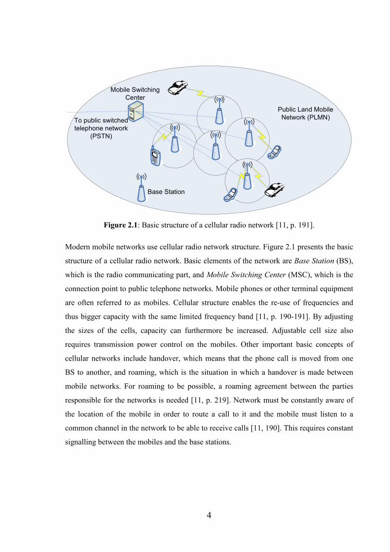
Figure 2.1: Basic structure of a cellular radio network [11, p. 191].
Modern mobile networks use cellular radio network structure. Figure 2.1 presents the basic
structure of a cellular radio network. Basic elements of the network are Base Station (BS),
which is the radio communicating part, and Mobile Switching Center (MSC), which is the
connection point to public telephone networks. Mobile phones or other terminal equipment
are often referred to as mobiles. Cellular structure enables the re-use of frequencies and
thus bigger capacity with the same limited frequency band [11, p. 190-191]. By adjusting
the sizes of the cells, capacity can furthermore be increased. Adjustable cell size also
requires transmission power control on the mobiles. Other important basic concepts of
cellular networks include handover, which means that the phone call is moved from one
BS to another, and roaming, which is the situation in which a handover is made between
mobile networks. For roaming to be possible, a roaming agreement between the parties
responsible for the networks is needed [11, p. 219]. Network must be constantly aware of
the location of the mobile in order to route a call to it and the mobile must listen to a
common channel in the network to be able to receive calls [11, 190]. This requires constant
signalling between the mobiles and the base stations.

5
2.2 Standardization
Common for all modern mobile networks is the fact that they are designed and built on
basis of standards and specifications. Open standards exist in order to make multivendor
systems inter-operable and compatible. Imaginably for roaming to be possible, a huge
amount of issues must be standardized. In the case of mobile networks, it is especially
important that any mobile phone or other terminal equipment works with any network in
the system that it’s designed for [9, p. 479]. There are always some manufacturer specific
features so the implementations of the specifications and standards vary to some extent in
the limits set by the specifications. Anttalainen [11, p. 7-9] points out some of the most
important aspects of standards: they enable competition, cheaper manufacturing and
engineering, interconnection and availability of systems as well as make it possible for
small manufacturers to be competitive against their bigger competitors. Standards are not
only a technical matter but they can also be used as political assets to, for example, support
local industry.
There exists a wide range of standardization organizations in the telecommunications area.
Firstly, official national standards based on guidelines and alternatives of international
standards are approved by the national standardization authorities. The Finnish
organization for standardization is the Finnish Standards Association (SFS). On the next
level are the European and American standardization organizations. Most important of the
European organizations are European Telecommunications Standards Institute (ETSI) and
European Conference of Posts and Telecommunications Administrations (CEPT) and of
the American ones is Institute of Electrical and Electronics Engineers (IEEE). On the
global scale there are 2 major organizations of importance: International
Telecommunication Union (ITU) with its sub organizations specialized in
Telecommunications (ITU-T) and Radiocommunications (ITU-R) and joint organization
The International Standards Organization/International Electrotechnical Commission
(ISO/IEC). Besides these organizations there exists some unofficial groups that often
conduct the initial work in the standardization process. To mention a few, Universal
Mobile Telecommunications System (UMTS) Forum and Telemanagement Forum (TMF)

6
are open organizations of cellular mobile system manufacturers. Latter works with issues
concerning network management, which are discussed in Chapter 3. UMTS forum is
working with UMTS matters. UMTS is presented in Section 2.5. The clear advantage of
these unofficial groups is their flexibility and lack of unnecessary bureaucracy. [11, p. 7-9]
A network operator is an organization that has an operating license for a network and
owns, operates, and manages the network. Service provider is an organization that sells the
services of the network but does not itself own the network equipment [9, p. 298]. Operator
can also be the service provider itself. Previously there was usually only one local
telephone network operator [11, p. 15-17]. Later on, the competition has been opened and
many parties have appeared offering both internet and mobile connections. The number of
licenses permitted to mobile operators is limited especially in the case of UMTS, since the
limited frequency band is divided between the operators in each country [10, p. 350-357].
In addition, the network element hardware is expensive and only large organizations can
afford to set up their own networks.
2.3 The GSM network
This section presents first some history behind the GSM system, then briefly one of its
predecessors, NMT, and finally the structure of the GSM network.
2.3.1 History
The term 1G or 1st Generation is used for the analog mobile communication systems
designed and used in the 1980s. They were not the first mobile systems, but the first to use
cellular networks. The most important first generation standards were Nordic Mobile
Telephone (NMT), which was used in the Nordic Countries and some other European
countries; Total Access Communications System (TACS), used primarily in the United
Kingdom, and Advanced Mobile Phone Service (AMPS), standard used in the North
America [9, p. 1]. The primary purpose of use for the first generation networks was plain
speech, but they also enabled some low-bit-rate services, for example data transfer [29].

7
NMT network structure was very simple. Figure 2.2 presents both the general structure of
first generation cellular radio network as presented by Rappaport [25, p. 445] and the
structure of NMT network based on [29]. NMT network contained only three types of
network elements: Mobile Station (MS), Base Station (BS), and Mobile Telephone
Exchange (MTX). MS, the mobile phone, and subscriber identity were not separated as
they are in, for example, GSM. Many MSs could be connected to a single MTX and it was
also the connection point to public telephone networks. NMT was based on basic switched
telephone networks and open standards and thereby equipment from any vendor was
compatible [29].
Figure 2.2: Structure of A) First Generation (1G) cellular radio network in general [25, p.
445] and B) NMT network [29].
The specification work of second generation digital mobile network Global System for
Mobile Communications (GSM) began as early as in the beginning of 1980s. It was coming
clear that the analog cellular communication systems could not serve the growing customer
demand due to their low capacity and weak support for mobility [4, p. 88]. Another version
of NMT was introduced, using 900 MHz frequency band instead of the original 450 MHz
and thus offering better capacity and mobility [29], but that was only a temporary solution.
GSM was digital, used hierarchical cell structure and more efficient channel coding and,
therefore, increased capacity dramatically [9, p 2-3]. Analog – digital separation has been
thought to be the boundary line between first and second generation systems.

8
GSM specification work was driven throughout the 1980s by CEPT and continued by
ETSI. By 1990 the first GSM specification was ready. First commercial network was
launched in Finland by Radiolinja mobile network operator in 1991. The specification
work has, however, continued after that with improving the existing networks by
developing new, so called 2.5 generation techniques, which are presented in Section 2.3.
[11, p. 212], [4, p. 88]
Other second generation mobile cellular systems include Digital AMPS (D-AMPS), Code-
Division Multiple Access (CDMA) IS-95, and Personal Digital Cellular (PDC). D-AMPS
is mainly used in North and South America and in some Asian countries, IS-95 in East
Asia. PDC is a purely Japanese standard and only in use there [9, s. 2-3]. GSM is, however,
the most widely spread and used of the second generation techniques with over 1.7 billion
subscribers globally in the end of 2005 [27].
Figure 2.3 shows the common high-level architecture of an advanced mobile network.
Figure is generalized from Korhonen [9, p. 206], and applicable for most of the 2G and 3G
systems.
Figure 2.3: Common high-level advanced mobile network architecture, generalized from
Korhonen [9, p. 206].
2.3.2 GSM subsystems
GSM specification 01.02 [7] describes the GSM Public Land Mobile Network (PLMN) on
a general level. Issues defined are the elements of the network, their functions and

9
performance objectives, and services offered by the network. A Network Element (NE) is
one physical and functional part of the whole network system that has a defined task and
works in interrelation with other elements. Telecommunication services are communication
capabilities of the GSM PLMN offered by operators for the users. Services are divided to
two groups named together as Basic Services: Bearer Services that enable the subscriber to
transmit signals in the network, and Teleservices that offer the subscriber capacity to
communicate with other users. A functional entity implements the functions that are
required in order for the system to support the services. The whole system consists of
unbounded number of these entities. For example, Mobile Station (MS) and BSS are
presented as functional entities. The specification also contains a division of GSM into
three subsystems to obtain a higher level of understanding. These subsystems are The Base
Station System (BSS), The Switching and Management Subsystem (SMSS), and The
Operation and Maintenance Subsystem (OMSS). The definitions of BSS and SMSS are
close to those of BSS and NSS presented later on. OMSS is introduced in Chapter 3.
In the literature a different separation, based on the common architecture presented in
Figure 2.3, into subsystems is presented. A subsystem contains certain network elements
and has a specific task. For example, MS is presented as one of the subsystems. The
subsystems and interfaces of the GSM network as they are usually presented in the
literature are shown in Figure 2.4 [5, p. 153] and briefly reviewed after the next paragraph.
GSM network can be divided into areas. The smallest area is cell, the radio coverage area
of one BTS. BSC area is the area consisting of one or more cells which one BSC controls.
Location area (LA) is an area comprising one or more cells in which a MS can move freely
without updating the location register. MSC area is the part of network of which one MSC
is responsible, and can consist of one or more location areas and BSC areas. VLR area,
which means the part of the network controlled by one VLR, is the largest and may
comprise one or more MSC areas. [26, p. 10]

10
Figure 2.4: The subsystems and interfaces of the GSM network [5, p. 153].
Mobile Station
MS consists of two parts as contrary to NMT. Mobile Equipment (ME) is the actual mobile
phone or other terminal equipment and Subscriber Identity Module (SIM) is a smart card
containing user identity related information, for example, list of user’s services and
networks to provide service. Separation of the phone and subscriber identity makes
possible for the user to switch network operator by changing the SIM and on the other hand
to change her mobile equipment and use the same SIM. On the network, ME is identified
by International Mobile Equipment Identity (IMEI) code which is fixed, and subscriber by
International Mobile Subscriber Identity (IMSI) code which is stored on the SIM. [7, p.14],
[5, p. 152-155]
Base Station System
The Base Station System (BSS) is the radio part of GSM network. It comprises two
elements, Base Transceiver Station (BTS) and Base Station Controller (BSC), the physical
equipment to give radio coverage of a cell and to communicate with MS. Its main function
is to connect the MS to the core network. BTS carries out radio transmitting function,
which includes transmitting and receiving of radio signals, speech encoding and decoding,
and rate adaptation of data transmission. BSC is responsible for the control function, which
11
includes BSS switching functions, communication with the MSC, handoff management
and radio channel allocation and releasing. One BSC is usually responsible for several
BTSs. BSC is a new architectural element compared to first generation systems. Its
function is to reduce MSC’s computational load and with its existence the interface
between BSC and MSC can be standardized. This should allow operators to use in their
network MSCs and BSCs from different manufacturers. [7, p.15-17], [5, p. 155-156], [25,
p. 448]
Network and Switching Subsystem
The Network and Switching Subsystem (NSS) is the core network of GSM. It contains
elements Home Location Register (HLR), Visitor Location Register (VLR), Mobile-
Services Switching Center (MSC), Authentication Center (AuC), and Equipment Identity
Register (EIR). HLR, VLR, AuC, and EIR are the network’s databases. Information about
subscriber’s subscriptions and location is stored in the HLR of his home network.
Subscription information contains the description for the user’s enabled services. VLR is
the temporary storage for information of roaming subscribers. Together HLR and VLR
implement the location register function, which means that the network knows where the
MS is located in order to establish a call to it. AuC is associated and only communicates
with the HLR. It contains for each subscriber an identity key which is used for
authentication and ciphering purposes. EIR holds IMEI codes in one to three separate lists.
The purpose of these lists is to prevent mobile phone thefts. When an IMEI code is put to
the black list, the ME is declared stolen and not allowed to communicate in the network.
[5, p. 157] [26, p. 9, 12-14]
MSC is the most important element of NSS. It carries out all switching and signalling
functions. Signalling protocol follows the one used in the telephone network, and MSC
also communicates with external networks using the same protocol. This interworking with
other networks, for example Public Switched Telephone Network (PSTN), demands
specific functions known as the Interworking Functions (IWF). IWFs are dependent on the
network to be interconnected and the type of the desired service. [5, p. 157], [7, p.15]
12
MSC’s tasks include also handling and updating the location registration procedure,
handover management, collecting billing data, frequency allocation, and paging. [9, p. 208]
Interfaces
Interfaces of the GSM network can be divided into three categories. First there are totally
open interfaces, which are so well specified that equipment from different vendors work
together over those interfaces. On the other end are interfaces, for which there exist no
specifications, only a name and description of its tasks. Vendors either have their own
proprietary implementations for those interfaces or they are not used at all. Third category
includes interfaces, for which specifications exist but they are not complete and thus
implementations are vendor proprietary and only equipment from the same vendor can be
used together. [9, p. 221]
The most important interfaces are the air (radio) interface between the MS and BTS, and
A-interface between MSC and BSS (BSC). Both of them are fully open multi-vendor
interfaces. [9, p. 221-222].
2.4 Evolution from GSM towards UMTS - The 2.5G
2.5G is a common term used for all advanced upgrades for the 2G mobile network systems
[9, p. 5-8]. These techniques are a development step providing a smooth transition on the
way towards 3G. The initial driving force for designing the 2.5G was the low data
transferring rates in the 2G networks. This problem appears only in the air interface; core
networks could support much higher rates. In the case of GSM, the following 2.5G
architectures, presented in this section, are the most significant: General Packet Radio
Service (GPRS), High-speed Circuit Switched Data (HSCSD), and Enhanced Data Rates
for Global Evolution (EDGE). There are also upgrades to, for example, TDMA IS-95, but
they are not discussed in the scope of this thesis.
The original GSM specifications were termed as phase 1 and closed in 1995. Further
improvements on the system were released under the name GSM phase 2. The phase 2+

13
program was then established in order to make the specification phase more flexible and
modular and to decrease the time-to-market with annual releases starting from 1996. It was
these GSM phase 2+ annual releases where the 2.5G techniques were specified.
Specification known as Release ’99 was the first integrated GSM/UMTS release. [8, p. 7-
11]
2.4.1 HSCSD
First improvement and easiest of the three to implement is HSCSD. With HSCSD, mobile
station can use up to four timeslots instead of one for data connection. Total data rate is
then the rate of one timeslot, 9.6 Kbps or 14.4 Kbps multiplied by the number of timeslots
used. Since as its name implies HSCSD is circuit-switched, it reserves the timeslots
constantly and thus holds back radio resources from other users. On cells with already high
congestion this can cause problems. On the other hand being circuit-switched, it is suitable
for many real-time applications like video. In practice the data rate is not high enough to
enable video calls with decent quality; common video call services were just introduced in
UMTS, see Section 2.5. Upgrading the GSM network to HSCSD is easy and inexpensive
since only software upgrades on BTS, BSC, and MSC are needed. Core network
experiences no physical changes but most of them are implemented on the data and
signalling protocols. Mobile stations must, however, be upgraded to support HSCSD.
Charging of HSCSD calls is usually based on the number of channels used, so the costs are
increased by the number of used channels making HSCSD considerably costlier than basic
GSM data transfer. [9, p. 5], [8, p. 81-83]
2.4.2 GPRS
GPRS is the second and the most crucial of the GSM upgrades. It uses packet switched
connection so the radio resources are not allocated continuously, but only when data is sent
[8, p. 65-66]. When connection is idle, the resources are shared to other users, which
results to efficient use of the radio interface and network resources. Downside of this is that
the data rates vary, since different amount of radio resources are disposable at different
times. Contrary to HSCSD, GPRS is not suitable for real-time applications but applications

14
that make use of bursty data transfer with variable size data packets, such as web-surfing,
e-mail, or transferring of small files [8, p. 65-66]. GPRS connections are either charged
based on the amount of data transmitted, when no costs of unused capacity result to the
subscriber, or with a monthly fee including a certain or no up limit at all for the amount of
data transferred [11, p. 233]. MS needs to be upgraded in order to support GPRS.
GPRS requires new elements to the network in order to implement the packet switched
functionality. Figure 2.4 shows the structure of GSM network upgraded with GPRS. Core
network is now divided into two domains: circuit switched, which is the old GSM NSS,
and packet switched, which is the new GPRS part that requires its own backbone network.
The introduced new elements performing the routing functionality are called support nodes.
Gateway GPRS Support Node (GGSN) functions as a router and connects the GPRS
PLMN to external data networks such as internet. Charging information collection is also
task of GGSN. Delivering packets to MSs is responsibility of Serving GPRS Support Node
(SGSN). Service area is the area of which one SGSN is responsible of. Other
responsibilities of SGSN are similar to those of MSC in GSM, for example, charging and
mobility management. Border Gateway (BG) is the connection point between several
GPRS PLMNs. It offers adequate security over the used backbone network, which can be
public internet or a rented private connection. BG is not specified in the GPRS
specifications and its functionality and the backbone network to be used are agreed
between operators in roaming agreements. [9, p. 6], [11, p. 229-232]

15
Figure 2.5: Structure of GSM network upgraded with GPRS, combined from Anttalainen
[11, p. 229] and Zvonar [8, p. 67].
BSC must be upgraded with Packet Control Unit (PCU) functionality. PCU can also be
located in SGSN or be a separate element. PCU controls and manages the GPRS functions
related to radio interface. Its tasks include controlling of packet-switched calls and cell
changes as well as allocation of radio resources. BTS is only responsibly for modulation
and demodulation and channel measurements [11, p. 232]. On the radio interface, GPRS
offers maximum data rate up to 171.2 Kbps [8, p. 66] by using up to 8 time slots, but
average throughput in normal conditions is around 10 Kbps [9, p. 6].
Implementation of GPRS is expensive due to the need for new elements and upgrades to
the existing ones but obligatory on the process of upgrading GSM towards UMTS [9, p. 6].
UMTS core network is in its early stage based on the GSM and GPRS core networks, see

16
Section 2.5.2 for further information. Usage of GPRS requires new MSs [11, p. 232] that
can be mobile phones or, for example, cards for laptop computers since GPRS offers a
reasonable mobile data rate and is thus a good choice for mobile internet connections.
2.4.3 EDGE
Third of the 2.5G upgrades is EDGE, which still raises the data rates to a new level topping
at theoretical maximum of 473 Kbps [10, p. 76-77]. This is due to new radio modulation
scheme Eight-Phase Shift Keying (8PSK), which up to triples the bit rate on the radio
interface. 8PSK is able to transmit three bits instead of one in each symbol on the same
carrier [11, p. 228]. Old and new modulations co-exist after upgrading GSM network with
EDGE, since EDGE can only be used effectively in micro-cell environment that is over
short distances from the BTS [9, p. 6-7]. On the longer distances, the GSM modulation is
still used. EDGE requires upgrades on the BTS and in order to take EDGE in use on the
MS, yet again new terminal equipment support is needed.
Most important application of EDGE is GPRS, named Enhanced GPRS (EGPRS) [28, p.
52]. EGPRS utilizes the GPRS core network and, thus, only fairly low-cost software
upgrades are needed [10, p. 77]. EDGE’s 8PSK modulation can also be combined with
HSCSD, resulting to Enhanced Circuit Switched Data (ECSD) [28, p. 52], which in turn
utilizes the network’s existing HSCSD implementation. Significance of ECSD is, however,
small since GPRS has dominated over HSCSD. So after successful GPRS and/or HSCSD
upgrade of the whole network, bringing the network a step further with EDGE is both fast
and relatively cheap.
Combination of these three 2.5G techniques provides a system that has capabilities close to
those of early 3G implementations [9, p. 7]. GSM radio network (BSS) enhanced with
EDGE and GPRS capabilities is termed as the GSM/EDGE Radio Access Network
(GERAN) when referred in the context of 3G mobile communications as distinct from 3G
radio access networks [28, p. 69].

17
2.5 The UMTS network
Universal Mobile Telecommunications System (UMTS) is the most commonly
acknowledged and widely used standard for 3G networks. UMTS is based on Wideband
CDMA (WCDMA) based Universal Terrestrial Radio Access (UTRA) radio interface, and
on GSM/GPRS Mobile Application Part (MAP) core network [9, p. 9-11]. Other standards
that use WCDMA technology on the radio interface exist, for example, CDMA2000 is
based on the IS-95 system used in the North America. Research on other air interface
technologies such as Advanced TDMA and Hybrid CDMA/TDMA has been conducted
and some proposals have been presented, but Korhonen [9, p. 23] predicts that eventually
only two 3G systems, UTRAN (network using UTRA interface) and CDMA2000 will
survive with UTRAN being the dominant one.
Third Generation Partnership Project (3GPP) organization [12] is responsible for
developing UMTS specifications as well as continuing the GSM specification work
formerly carried out by ETSI [9, p. 14]. 3GPP is comprised of major standardization
organizations from Europe, USA, Japan, Korea, and China [10, p. 250]. Original targets of
UMTS specification work included full compatibility with the GSM system and taking as
much advantage of the existing core networks as possible. UMTS specifications were also
to be made attractive enough to be accepted and implemented worldwide [10, p. 250].
Specifications were and are published in releases starting from release ’99. Third
Generation Partnership Project 2 (3GPP2) is a similar organization, which promotes and
specifies the CDMA2000 system and the evolution of IS-95 to 3G.
With WCDMA and new modulation Quadrature Phase Shift Keying (QPSK) UMTS has
theoretical maximum data rate of 2 Mbps. In QPSK the data bits are coded into symbols
and each symbol can carry two or even four bits. Both circuit and packet switched
transmission modes are supported. UTRA supports two operating modes: Frequency
Division Duplex (FDD), which is most used of the two, and Time Division Duplex (TDD).
In FDD separate frequency bands are used for uplink and downlink connections but in
TDD the same carrier is used for both directions. However, UTRA interface is only usable
in micro-cell environment and the data rates are in practice much below the maximum,

18
though there are techniques that improve the downlink capacity. For instance, High-Speed
Downlink Packet Access (HSDPA) is a technique that enhances the downlink data
transmission capacity. [9, p. 14-15, 67-68, 204-205, 355]
2.5.1 History
The specification work for UMTS was started by ETSI in the same year, 1991, that the first
commercial GSM network was launched [9, p. 8]. It was then unclear how big a success
GSM system would be globally. As GSM pervaded, more and more telecommunications
companies and research programs wanted to participate in the specification process of the
next generation system. UMTS Forum was established in 1996 to define standards based
on the work of the numerous parties. Later on the 3GPP consortium continued the work of
UMTS Forum [9, p. 11].
2.5.2 Network
The network architecture of UMTS, covering both UTRAN and GERAN radio access
technologies, is described in the 3GPP TS 23.002 specification, latest version of Release
‘99 being 3.6.0 from 2002 [32]. Figure 2.6 presents the elements and most important
interfaces of the UMTS network as defined in the Release ’99. The changes of UTRAN,
MS and core network compared to GSM phase 2+ are presented next.

19
Figure 2.6: Elements and most important interfaces of the UMTS network release ’99
based on Korhonen [9, p. 207] and 3G TS 23.002, version 3.6.0 [32, p. 22].
Radio Network System and Mobile Station
UTRAN, which is shown in the figure, is only one option for UMTS’s Radio Network
System (RNS). Future implementation options include Broadband Radio Access Network
(BRAN) and UMTS Satellite Radio Access Network (USRAN) [9, p. 213]. Standardized
interfaces from RNS, Uu to MS and Iu to core network, enable the change of the technique.
The Iu interface is divided into circuit switched and packet switched interfaces named IuPS
and IuCS, since UMTS supports both.
Radio Network Controller (RNC) is a new element and comparable to BSC in GSM BSS
[9. p. 213-214]. RNC controls one or more Node Bs, which are the base stations of the

20
UTRAN. One Node B supports one cell [32, p 17], but in the later releases possibly several
cells [33, p. 22]. Tasks of RNC include power control, traffic management, channelization
code allocation and control of Node B logical operation and maintenance resources. Node
B handles all the radio interface related matters such as communicating with the MS.
The SIM smart card in the MS is in UMTS called UMTS Subscriber Identity Module
(USIM) [32, p.17] and mobile equipment (ME) is often referred to as User Equipment
(UE).
Core network
The release ’99 introduces little changes to the core network. Network registers, HLR,
VLR, AuC, and EIR must be upgraded to support the new functionalities. MSC must also
be upgraded and the same upgraded MSC can be used for both connections through the
GSM BSS and UTRAN [9, p. 208]. Situation is the same with SGSN. Gateway MSC
(GMSC) is a role of MSC, and a GMSC is responsible for routing the call to the MSC of
the actual network location of the MS [32, p. 15]. The same physical MSC can act as
GMSC and basic MSC or designated GMSCs can be used; the decision is left to operator.
VLR is implemented on the same physical equipment with MSC so the interface between
them is only logical [9, p. 208].
Release 5, latest version of which is described in the 3GPP TS 23.002 version 5.12.0 [33],
changes the core network more considerably by introducing a new IP Multimedia System
(IMS) domain in addition to the existing packet and circuit switched ones. IMS uses
enhanced packet switched connections to offer IMS multimedia services, but does not have
its own switch. IMS implements an all-IP network, which uses IP protocol version 6 (IPv6)
and in which control signals and data have their own paths. IMS powered core network is
still backwards compatible. Figure 2.7 presents the release 5 of UTMS network without the
parts of IMS domain. IMS architecture is very complex and the IMS domain entities are
presented separately in Figure 2.8. [9, p. 243-246]

21
Figure 2.7: Release 5 UMTS network without the IMS domain, based on Korhonen [9, p.
244] and 3GPP TS 23.002 version 5.12.0 [33, p. 30].
New elements introduced are Home Subscriber Server (HSS), which is the combination of
enhanced HLR and AuC [33, p. 14-16], and the connection point between packet switched
and IMS domains [9, p. 243]. Basic MSC has been divided into two logical entities: MSC
server handles control logic and data goes through Media Gateway (MGW) [9, p. 261-
262]. The entities can be implemented in the same or separate units. By separating the data
traffic from control signals, circuit switched data can be more efficiently routed.

22
Figure 2.8: Basic IMS domain architecture based on Korhonen [9, p. 245] and the 3GPP
TS 23.002 specification [33, p. 33-34].
Figure 2.8 presents the control elements of IMS domain in its basic form with LCS,
CAMEL, and CBS service elements excluded (see Section 2.5.3 for more information).
IMS traffic is packet data and thereby transported through the packet switched domain.
Call Session Control Function (CSCF) is divided into three types: serving, proxy, and
interrogating CSCF. CSCF handles all the multimedia session controlling related matters
[9, p. 246]. Session Initiation Protocol (SIP) is used to establish the sessions between the
UE and Application Server (AS) and to deliver the multimedia [10, p.123]. AS hosts and
offers value-added IM services and is either located in the subscriber’s home network or a
third party network [33, p. 27-28]. Task of Breakout Gateway Control Function (BGCF) is
to select the network in which PSTN/circuit switched domain interworking is to be carried
out [9, p. 246]. If the interworking is not to happen in the same network, the request is
routed to another BGCF in a different network. If the interworking with PSTN/CS is to be
done in the same network, the session is forwarded to a responsible Media Gateway

23
Control Function (MGCF). MGCF is the interworking management entity between IMS
and traditional telecommunication networks (PSTN, ISDN and PLMN) [10, p. 123].
Multimedia Resource Function Controller (MRFC) is responsible for controlling and
manipulating various media-stream resources in the Multimedia Resource Function
Processor (MRFP) as well as collecting charging information and communicating with
CSCF. MRFP manages the bearers on the Mb reference points and offers resources to the
MRFC [9, p. 247]. IP Multimedia Subsystem--Media Gateway (IMS-MGW) terminates
bearer channels from a switched circuit network (e.g. PSTN) and media-streams from a
packet network [33, p. 26-27] and converts media and controls bearers between the
networks.
According to the specification, all the functions of IMS domain should be implemented in
different logical nodes, and two logical nodes should not be in the same physical
equipment since it would make the interfaces internal to the equipment [33, p. 33].
However, Franz [10, p. 124] suggests that a new network element is introduced to handle
the CSCF functions and a Voice over IP (VoIP) server is responsible for transport and
switching functions. Korhonen [9, p. 265] also guesses that there will only be few new
physical elements implementing the IMS functions, which results to some of the interfaces
being only logical.
The current version of UMTS network architecture is named Release 7 and latest Release 7
specifications were released in March 2006 [34]. These specifications are, however, not
handled in the scope of this thesis.
2.5.3 Services and applications
One aim of the UMTS development has been to offer the same services to mobile
computer and phone users no matter where they are in the world. This means that the user
is constantly connected to the Internet and can obtain the same services despite the location
[10, p. 100-105]. Existing Internet services are improved by location, mobile multimedia,
and interactivity offered by the UMTS. The way the connection is implemented will

24
change in the evolution of the UMTS system, starting from GPRS based solution and
resulting via All-IP CN in the release 5 to a complete All-IP network. IP will then be used
all the way from UE to the Internet server [9, p. 417].
Enhanced data transfer and common speech are just a small fraction of the services enabled
by UMTS network. Some service and application concepts of the UMTS are presented
next.
Location Services (LCS) are based on the knowledge of location of the MS. LCS existed
already in the GSM networks. LCS applications vary from locating an emergency call to
finding services such as restaurants nearby. The LCS client can be located in the UE,
PLMN, or outside the PLMN. Three basic methods for obtaining the location exist: the first
is based on the cell coverage, the second on time difference of received signals from
different Node Bs, and the third on the satellite positioning of Global Positioning System
(GPS). [9, p. 343-349]
Cell Broadcast Service (CBS) includes broadcasting of text messages to every MS in a cell
capable of receiving the service [9, p. 182]. GSM networks also supported CBS, but it was
not very widely used [9, p. 199]. Broadcast messages are classified by message class type
and subscribers can decide whether to receive messages of certain class. Similar non-real-
time service for multimedia is called Multimedia Broadcast / Multicast service (MBMS)
[9, p. 358-361]. Broadcast service is intended for all subscribers in the network whereas
multicast service for a specific group of subscribers, who have distinctly subscribed the
service.
Multimedia Messaging Service (MMS) is designed for delivering short multimedia
presentations to the subscribers. Similar service exists in GSM, but with UMTS
capabilities it is taken to a new level. MMS messages are constructed of message elements
which can be text, images, voice, and video. [9, p. 361-363]
Intelligent Network (IN) concept means that the network is capable of flexible routing of
calls and voice notifications. Mapping of a physical number to the number of a service is

25
not fixed. For example, a call to customer service can be routed to different places on
different times of day. IN helps the provision of new services by centralizing control data
to be available to all switches. Therefore, service data only needs to be updated to a single
place if changes are made to it. [11, p. 53-55]
Customized Application for Mobile Network Enhanced Logic (CAMEL) extends the IN
concept by enabling the usage of operator specific services outside the operator’s network.
Information about the services between the serving network and home network are
exchanged via CAMEL Service Environment, which is a logical network entity. CAMEL
enables another concept called Virtual Home Environment (VHE), which means that the
subscribers can get the same services, features and tools despite their location. VHE is an
UMTS requirement, whereas CAMEL was first presented in the GSM Phase 2+
specifications, and IN is used in the GSM network as well as fixed telephone networks. [8,
p. 97-98]
The most interesting and fussed-about of the real-time applications of UMTS is mobile TV
using the Digital Video Broadcast – Handheld (DVB-H) technology [43]. The properties of
UMTS have been to proven to be enough for transmission of TV picture and sound with
good quality. Video calls are another example of the newly enabled real-time applications.
Korhonen [9, p. 431-434] points out that games are a major application for 3G.
Entertainment applications including games bring outstanding revenues to the operators.
With the enhanced properties of the new 3G mobile phones such as bigger displays, more
powerful processors and 3D graphics as well as the new possibilities offered by the
network for networked games, the gaming experience is enriched. Other entertainment
applications include advertising, dating and adult entertainment applications, the lastly
mentioned being in general the most profitable one.
2.5.4 Phases of UMTS evolution
UMTS network is constructed in phases in the same manner as 2.5G techniques on top of
GSM. The network is upgraded with more features little by little to meet the requirements

26
of a particular phase. First phase is, as described earlier, the release ’99 based
implementation of UTRAN besides GSM/GPRS MAP [9, p. 204]. Usually the next step is
the implementation of IMS domain.
Several reasons for the phased development can be distinguished. First of all the
specification and engineering costs of UMTS have been vast since the specification process
has been and is long and difficult. The 3G network operating licenses are in many countries
very expensive. Thus, building the UMTS network, especially if wide-area-coverage is
realized, is extremely expensive, and usually funded by the subscribers of existing 2G
networks. Expenses can be better divided into a longer time period by phased upgrade
implementation. [9, p. 204-206]
In many places, for example in Finland, UMTS has just recently begun to gain popularity
and true operator investments. One reason for the slow introduction of UMTS systems has
been the lack for real value-adding services. There’s a contradiction, as noted by Korhonen
[9, p. 407-408], in which one should exist first, the network implementation enabling
services or the services to drive the implementation of network. As mentioned earlier, from
UMTS release 5 onwards the IMS domain implements an All-IP core network, in which all
traffic is transferred as IP packets. IMS domain will eventually replace the old CS and PS
domains when voice too is transmitted as IP packets (see Section 4.1.1 for further
information on VoIP) [9, p. 245-246]. IP applications will with the IMS be usable in the
3G mobile environment, which is hoped to ease the task of finding real revenue-creating
applications [9, p. 245]. All-IP network will also reduce the costs of network deployment
since the underlying transport technology is uniform. Network operator can then be an
Internet Service Provider (ISP) that offers Internet connections and services [10, p. 105].
The downside of real-life implementation of IMS domain is the ever-growing complexity
of the core network architecture. As the network has to be backwards compatible with all
the earlier releases due to old MS equipment usability, operators face a situation where the
network comprises packet and circuit switched domains as well as IMS domain [9, p. 246].
Operating such a network is very costly and tricky.
27
From the users point of view the differences between UMTS and 2.5 GSM are not
significant [9, p. 204]. This too has clearly slowed down the interest for introduction of
UMTS.
2.6 Discussion
Several factors characterize the evolution of mobile communications. First of all, during
the couple of decades of existence the mobile industry has grown to a vast global business
with customers counted in billions. On the same time, the complexity of mobile networks
has increased dramatically. If, for example, NMT system is compared to UMTS system as
it’s defined in the earliest release ’99 specifications, the difference is huge. Due to great
design and standardization costs only the most popular and supported systems survive.
Also because of high expertise needed for designing and manufacturing network
equipment, only few network vendors exist. On the other hand, many techniques are
integrated as part of the mobile networks, which brings more vendors to compete the
mobile connection market. The significance of services offered via the networks will grow
bigger. Some of the interesting future issues of mobile networks are further discussed in
Chapter 4.
The constant evolution of mobile networks brings challenges for development of the
network management systems. As the amount of information in the networks and the
number of different physical elements and interfaces grow bigger and bigger, significance
of the systems and applications used for the management of the networks expands.

28
3 Network Management Systems
This chapter considers issues related to network management system design and
implementation. First part presents some basic concepts and specifications for the network
management domain. In the second part, one functional area of network management,
performance management, is described in more detail since the case study of Chapter 5 is
related to that area. The last part then discusses issues concerning the development of
network management systems.
Efficient implementation of network management systems is a competitive advantage for
both the network operators and the vendors of network equipment. Information on the
status of the network is needed for many purposes and the systems implemented for this
task should be as compatible with each other as possible. Especially the evolution of the
network resulting to up to three different domains existing in the core network, and the fact
that the network equipment can be acquired from different vendors, makes the task of
implementing such a system difficult. In principle some standards for network management
exist, but they are on a high abstraction level and in practice the implementation of the
interfaces and protocols in the equipment are vendor proprietary.
3.1 Network Management
Network operator must constantly be aware of the state and performance of the network.
Efficient implementation of information systems that support this activity can increase the
cost efficiency by offering precise information about the network and its faults, thereby
improving the success-rate of the use of services. Objective of PLMN management is to
achieve coherent non-stop information of the network to support and assist in achieving the
network operator’s quality of service and business objectives. A Network Management
System (NMS) is for the operator both an expense and a competitive advantage. [30, p. 14].
Operations, Administration & Maintenance (OAM, also Operation & Maintenance (O&M)
is used) is a common term used for all the activities of operation and maintenance of any
system. Maintenance is defined as all the technical and managerial actions which aim to

29
maintain the correct operation of the system and restore the normal operation as quickly as
possible after a breakdown in the equipment [7, p. 19]. The objective of OAM of a PLMN
is to have the capabilities needed to operate and maintain the PLMN efficiently while
providing service that fulfills the operator’s performance requirements [30, p. 14].
There are no strict specifications for OAM since “it is very difficult to define a common
telecommunications-network-management scheme suitable for all the various networks”
[9, p. 279]. Although network standards are strict as in the case of UMTS, the actual
implementations are always different for each manufacturer. The TMN and X.700 concepts
presented later on in this section have been designed on a very general level in order to be
usable in as many situations as possible. The next section describes matters related to
requirements for network management in the case of GSM and UMTS networks.
The GSM specifications define an own subsystem for the management of the network.
Operation and Maintenance Subsystem (OMSS) contains elements AUC and EIR, since
they handle features related to system security, and another entity called Operations and
Maintenance Centre (OMC), which manages control functions [7, s. 18-19]. The control
functions include all the technical and administrative actions needed due to changes in the
conditions external to the network, for example, the opening or closing of a service.
Network Management Centre (NMC) is a centralized management point controlling several
OMCs. The definitions of OMC and NMC are identical to those of EM and NM presented
later on.
3.1.1 Objectives for Network Management
As mentioned in the beginning of Chapter 2, both GSM and UMTS systems can be
described as large-scale mobile networks. Man Yi et al. point out the effects of the large-
scale on the network management [20, p. 1139]. First there is a vast amount of data on the
network to be managed and analyzed. Data appears in numerous and complex forms and
the management interfaces and data models on the network hardware differ from vendor to
vendor. These facts reduce the usability of operator’s business functions.

30
The 3GPP TS 32.101 specification [37, p. 12-13] describes the objectives for 3G UMTS
management specifications, which are quite close to those of second generation systems:
- being capable of managing the equipment including management systems, from
different vendors,
- minimizing the complexity of the management as well as the costs of managing a
PLMN,
- providing the communication between NEs and OSs or between OSs using
standardized interfaces (for example, Common Management Information Protocol
(CMIP), Simple Network Management Protocol (SNMP), or Common Object
Request Broker Architecture (CORBA)) as needed,
- providing flexible configuration capabilities that allow fast deployment of services,
- offering integrated fault management capabilities,
- supporting remote maintenance operations,
- allowing interoperability with other PLMNS as well as other networks and services
to enable the exchange of management and charging information between the
network operators and service providers,
- being scalable that is support the controlling of a increasing number of resources,
from small and simple to huge and complex configuration,
- re-using the existing appropriate standards when possible,
- supporting the security management of PLMNs, especially the new UMTS features
such as automatic roaming and packet switched services (most importantly the IMS
domain),
- supporting flexible billing and accounting management and charging across several
PLMNs,
31
- being able to assess the system performance (performance management) by using
common measurements and, thereby, comparing actual performance to the planned
targets,
- hiding the implementation details of information: for example, only one action is
needed to change the value of a parameter, but values of all the instances of the
parameter in the system are changed as the result of that action,
- supporting the restoration of an OS, and
- having exactly one naming convention also used by the co-operating applications,
for the network resources under management.
Since the requirements for both 2G and 3G management are quite similar, the management
of them should be implemented as uniformly as possible. When both generations’ systems
exist simultaneously in an early release UTMS network, it is clear that the operator of such
a network gains benefit from a uniform OAM solution.
The GSM Specification 12.00 [30, p. 15-16] provides some requirements for the network
to enable the implementation of cost-efficient OAM. The costs of OAM need to be reduced
so they don’t rise higher that the comparable costs of existing similar systems. For a good
balance between operator’s OAM costs and experienced QoS as well as reduced overall
costs of the PLMN the network should have:
- a hardware configuration that’s easy to expand
- a functionally structured software configuration that provides simple error
detection and is easy to modify
- simple Man-Machine Interfaces (MMI) and Man-Machine Languages (MML) for
OAM; MMI is the direct interface between a human user and the machine and
MML defines the commands that are used over the MMI
- ability for self-controlling

32
- a low failure rate or immunity to faults
- enough simplified maintenance so that anyone can perform it and
- cheap and simple spare parts and repair services.
For classifying and handling the requirements for NMSs two concepts are described next.
X.700 gives a classification for the OAM tasks and TMN presents a very elementary
framework for defining and designing NMSs.
3.1.2 X.700
The division of network O&M tasks by their functionality is presented in the X.700
recommendation [6] by ITU-T. X.700 provides a framework to help the development of
Open Systems Interconnection (OSI) management standards. OSI includes standards for the
exchange of information between open systems [44, p. 1]. A system is open when it uses
such standards that can be recognized and applied by other open systems. OSI management
addresses the users’ needs for managing the interconnection services (between open
systems), for being able to respond to changes in requirements, for being aware of the
communications behavior and for assuring the data security issues in their network
systems. OSI management environment is part of OSI environment (OSIE) that includes
the tools and services that are used to manage the interconnection activities. [6, p. 1-4]
A managed object is the resource that is the subject to management as it’s viewed by the
OSI management. It can be a connection, a layer entity, or physical equipment. A managed
object is specified by its attributes, operations performed upon it, notifications it can
receive or send. and its relations to other objects. Management Information Base (MIB)
comprises all the managed objects of the system i.e. includes everything that is subject to
the management. [6, p. 3]
The requirements for OSI management are divided into functional areas and these areas are
presented next. Managed objects and the actual management functions may be common to
33
multiple functional areas [6, p. 3]. Nokia networks’ NMS systems often follow this very
classification.
Accounting Management
Accounting Management (AM) deals with charging of the use of OSIE resources. With
AM the costs of resource usage are identified and subscribers are informed of those costs.
Also combining costs of using multiple resources can be performed and accounting limits
can be set with AM. Thus, in practice, AM deals with billing management; gathering
statistics for users and billing them using those statistics. [6, p. 4]
AM is often, as in the case of Nokia networks, not included in the network equipment
vendor’s NMS implementations but separate systems implemented by third party
companies or the network operator itself, are used. In the case of roaming, AM also
requires interaction between two network operators [9, p. 285], which can be more
efficiently implemented by that third party.
Configuration Management
Functional area of Configuration Management (CM) manages the interconnection services
in order to prepare for, initialize, start, operate continuously, and terminate them. The
functions of CM include initializing, terminating and naming of the managed objects,
setting the parameters that control system operation, on-demand collection of information
about the system’s state, gathering announcements of changes on the system’s state, and
changing the configuration of the system. [6, p. 4]
On practical level configuration management deals with managing updates and
configurations in the network elements and recording the events related to the actions.
Configurations are changes made to hardware, software or documentation, updates
configurations that aim at improving or fixing the operation of some element of the
network.
Fault Management
34
The purpose of Fault Management (FM) is to detect, isolate, and correct persistent or
transient faults in order to maintain the normal operation of the OSIE. Faults are
recognized through error detection. FM functions include management of error logs and
error detection notifications, fault tracing and identification as well as performing
diagnostic tests and correcting the found faults. [6, p. 4]
In practice, fault management’s tasks include collecting fault information including alarms,
which are sent in case of emerged severe faults, from the network elements, and correcting
the found faults in the NEs. Fault management applications collect the information to logs,
which can then be used for tracing the faults.
Performance Management
Performance Management (PM) handles the measuring and evaluation of OSIE resources
and the performance of communication. Its functions include statistical information
gathering and system state history log management in order to evaluate the performance of
the system in different conditions. Another function is the changing of system’s operation
to enable the PM activities to be performed. [6, p. 4]
In practice, performance management deals with collecting performance data from the
network elements and handling of that data in order to assess the network’s performance.
PM’s tasks also include configuration of the elements and NMSs to enable the assessment.
PM is the most significant of the functional areas for this thesis since the case study in
chapter 5 presents a PM application. PM is thus discussed more deeply in Section 3.2.
Security Management
Security Management (SM) functions include management of security services and
mechanisms as well as sharing and reporting of relevant information on security matters
and events. SM functions support the application of security policies. [6, p. 4]
In practice, security management’s tasks include management of network users’ access
rights and keeping both the network elements’ and network management systems’ software
35
components up-to-date (in co-ordination with configuration management) in order to fix
found security risks. Physical security management deals with, for example, keeping the
network equipment in a safe place and preparing for thefts. Data transfers between NMSs
and NEs are often ciphered for safety.
3.1.3 The TMN Concept
The Telecommunications Management Network (TMN) concept defined by ITU-T was
originally presented in recommendation M.3010 [35]. Both GSM and UMTS network
management is based on TMN, and defined on a general level for GSM system in GSM
12.00 [30] and for UMTS in 3GPP TS 32.101 [37].
TMN specifications provide a framework for telecommunications management. The target
is to standardize the interfaces and create generic information models for management of
versatile networks, equipment and services [35, p. 8]. TMN is designed in order to support
all areas of management, but it does not consider the classification and development issues
on the actual applications. The TMN classification of information exchange is independent
of the purpose of use for that information. The X.700 classification of network
management into functional areas was presented in the last section and network
management applications are considered in the next section.
Figure 3.1 presents the relationship between a TMN and a telecommunications network
managed by it. The TMN is conceptually a separate network. TMN connects to and
controls the telecommunications network via several points. The connection from TMN to
an exchange can be established directly or by using parts of the telecommunications
network, the transmissions systems. An exchange is any physical element of the network.
[35, p. 6-7]

36
Figure 3.1: Relationship of TMN to a telecommunication network [35, p. 7].
TMN Functional Architecture
The TMN functional architecture provides a framework for management functionalities
[35, p. 9-10]. Figure 3.2 shows the basic elements of the TMN functional architecture:
management function blocks and the reference points between them. These elements are
presented next.
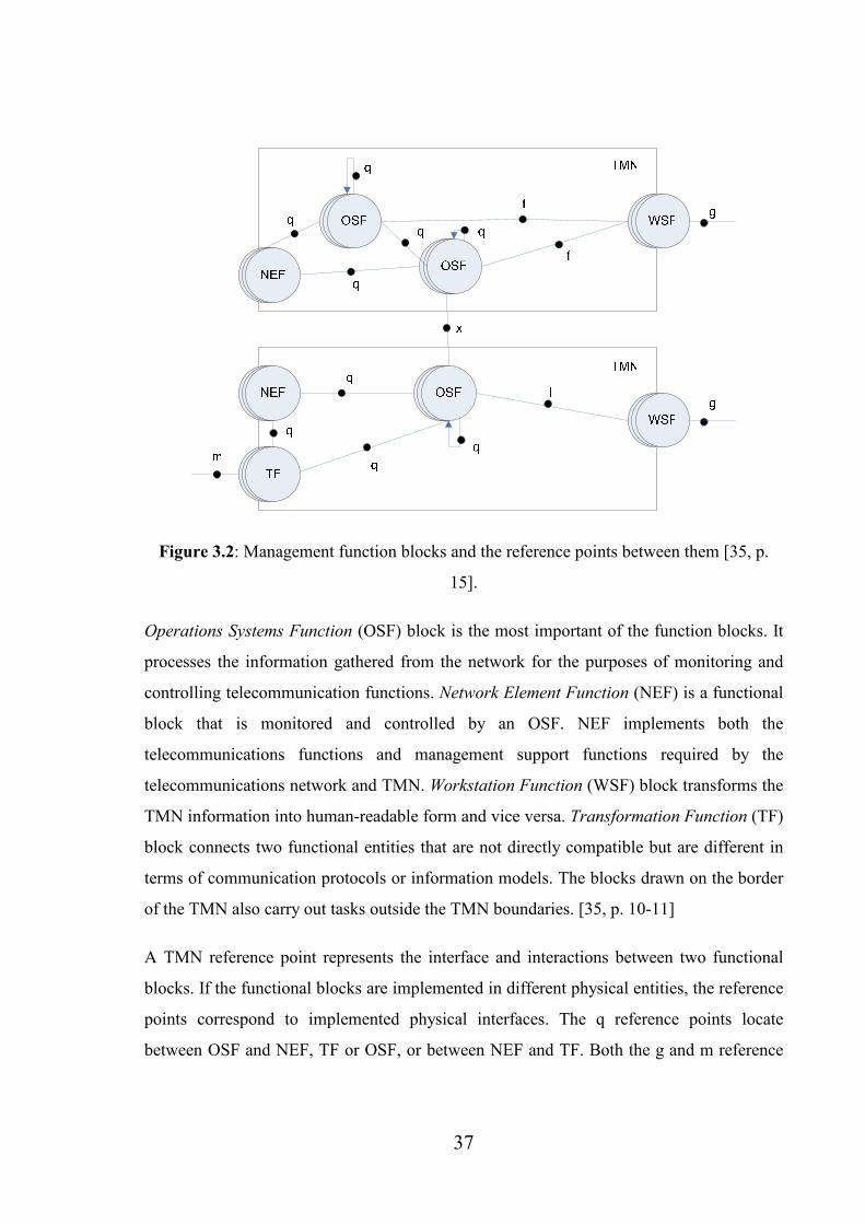
37
Figure 3.2: Management function blocks and the reference points between them [35, p.
15].
Operations Systems Function (OSF) block is the most important of the function blocks. It
processes the information gathered from the network for the purposes of monitoring and
controlling telecommunication functions. Network Element Function (NEF) is a functional
block that is monitored and controlled by an OSF. NEF implements both the
telecommunications functions and management support functions required by the
telecommunications network and TMN. Workstation Function (WSF) block transforms the
TMN information into human-readable form and vice versa. Transformation Function (TF)
block connects two functional entities that are not directly compatible but are different in
terms of communication protocols or information models. The blocks drawn on the border
of the TMN also carry out tasks outside the TMN boundaries. [35, p. 10-11]
A TMN reference point represents the interface and interactions between two functional
blocks. If the functional blocks are implemented in different physical entities, the reference
points correspond to implemented physical interfaces. The q reference points locate
between OSF and NEF, TF or OSF, or between NEF and TF. Both the g and m reference
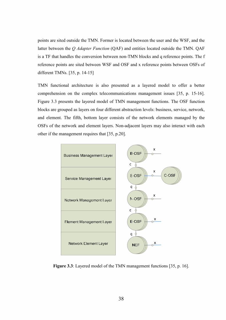
38
points are sited outside the TMN. Former is located between the user and the WSF, and the
latter between the Q Adapter Function (QAF) and entities located outside the TMN. QAF
is a TF that handles the conversion between non-TMN blocks and q reference points. The f
reference points are sited between WSF and OSF and x reference points between OSFs of
different TMNs. [35, p. 14-15]
TMN functional architecture is also presented as a layered model to offer a better
comprehension on the complex telecommunications management issues [35, p. 15-16].
Figure 3.3 presents the layered model of TMN management functions. The OSF function
blocks are grouped as layers on four different abstraction levels: business, service, network,
and element. The fifth, bottom layer consists of the network elements managed by the
OSFs of the network and element layers. Non-adjacent layers may also interact with each
other if the management requires that [35, p.20].
Figure 3.3: Layered model of the TMN management functions [35, p. 16].

39
Element Management Layer implements one or more element OSFs (E-OSF), each of
which is responsible for some part of the network element functions assigned by the upper
network management layer. Element management layer abstracts the functions of the
network element layer in order to fulfill the objective of providing vendor independent
view to the upper layer. The elements are managed on individual or group basis. Three
basic tasks of element management layer include acting as a mediator between network
management layer and network element layer to provide full access to NE functionality,
collective controlling of a subset of network elements, and collecting of up-to-date
statistical and log data from the elements being managed by it. [35, p. 17]
Network Management Layer performs network OSFs (N-OSF), purpose of which is the
management of a wide geographical area. The whole network is visible for the network
management layer and its objective is to offer a technology independent view for the upper
service management layer. [35, p. 17-18]
Service Management Layer is responsible for all the phases of providing a service to a
customer [18, p. 17]. Related functions are called service OSFs (S-OSF). Phases include
service order and complaint handling and invoicing. Service management layer has four
principal tasks: communicating with the customers and other operators, interacting with
service providers, collecting statistical data related to, for example, quality of service
(QoS), and coordinating the interaction between services. The GSM specification 12.00
[30, p. 22] presents yet another function called the customer OSF (C-OSF), which is peer
of S-OSF.
Business Management Layer is on the top of the layers and uses all the information and
functionality offered by the other layers to optimize the investments and use of new
resources. These functions that carry out goal setting tasks are called business OSFs (B-
OSF). [35, p. 18]
TMN Information Architecture

40
The TMN information architecture is designed to support the interoperability and exchange
of management information between applications in multiple managing and managed
systems. Managed systems handle the TMN information and are controlled by the
managing systems. Managing systems receive the information and act upon it.
Management of a telecommunications network is a distributed information processing
application and, therefore, the information from the distributed sources must follow
standardized models. TMN information models are based on object-oriented techniques
and favor the usage of encapsulation, inheritance, and specialization. The techniques used
for defining the exchanged information should leave the implementation of management
and managed systems open. [35, p. 20-21]
TMN information architecture consists of interaction and information models. Interaction
model is the description of rules and patterns that are applied to the information on a
reference point between TMN functional blocks. Different information models include
manager/agent, client/server, peer-to-peer, invoker/responder, publisher/subscriber, and
consumer/producer. Information model is an abstracted management view of network
resources and the support management activities related to them. The model tells what
information can be exchanged and revealed. Model comprises of information elements
which are in the object-oriented case modeled as objects, named as managed objects. [35,
p. 20-21]
The manager/agent information model is presented in Figure 3.4. Manager is the part of the
management application that receives the notifications, which give information on events,
concerning the managed objects in the managed system. Agent is the part in the managed
side that forwards the management operations to the managed objects and offers a view on
the objects to the manager. Important task of the agent is to convert the information model
used in the managed NE to the object-oriented information model used in the
communication with manager. [2, p. 1005]

41
Figure 3.4: The manager/agent interaction of TMN.
The TMN information and functional architectures are unified by the reference point
concept. A reference point between two function blocks describes the exchanged
functionalities and information. Fully specified reference points correspond to
implemented physical interfaces if the function blocks lie in different physical equipment.
[35, p. 22]
TMN Physical Architecture
The TMN physical architecture describes the actual implementation of the TMN. Figure
3.5 shows an example of a simplified TMN physical architecture. The elements presented
are the physical blocks and interfaces between them [35, p. 22-23]. Physical blocks, the
management functions of the layered model they implement, and the interfaces are
presented next.

42
OSOS
Operations
System (OS)
Data
communications
network (DCN)Workstation
(WS)
Workstation
(WS)
Workstation
(WS)
Workstati
on (WS)
Workstati
on (WS)
Network
Element
(NE)
Workstati
on (WS)
Workstati
on (WS)
Network
Element
(NE)
Workstati
on (WS)
Workstati
on (WS)
Q-adapter
(QA)
Workstation
(WS)
Workstation
(WS)
Q-Mediation
Device
(QMD)
TMN
Q
Q
F
X/F/Q
X
Figure 3.5: A simplified example of TMN physical architecture. [35, p. 23]
Operations System (OS) implements the OSFs and optionally QAFs and WSFs. There are
two types of transformation that implement the Transformation Function (TF): adaptation
and mediation. Adapter or Adaptation Device (AD) implements adaptation which means
the transformation between TMN NE or OS and non-TMN element. For example, Q-
adapter (QA) adapts non-TMN elements to Q interface. Mediation Device (MD)
transforms the communication mechanisms between incompatible TMN physical blocks.
Q-mediation device (QMD) is located between two blocks in the same TMN and X-
mediation device (XMD) between two OSs in different TMNs. Network Elements (NE)
implement NEFs and optionally any of the other functions. NE consists of
telecommunication and support equipment. Workstation (WS) only performs WSFs. [35, p.
24-25]
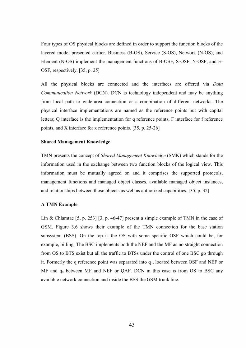
43
Four types of OS physical blocks are defined in order to support the function blocks of the
layered model presented earlier. Business (B-OS), Service (S-OS), Network (N-OS), and
Element (N-OS) implement the management functions of B-OSF, S-OSF, N-OSF, and E-
OSF, respectively. [35, p. 25]
All the physical blocks are connected and the interfaces are offered via Data
Communication Network (DCN). DCN is technology independent and may be anything
from local path to wide-area connection or a combination of different networks. The
physical interface implementations are named as the reference points but with capital
letters; Q interface is the implementation for q reference points, F interface for f reference
points, and X interface for x reference points. [35, p. 25-26]
Shared Management Knowledge
TMN presents the concept of Shared Management Knowledge (SMK) which stands for the
information used in the exchange between two function blocks of the logical view. This
information must be mutually agreed on and it comprises the supported protocols,
management functions and managed object classes, available managed object instances,
and relationships between those objects as well as authorized capabilities. [35, p. 32]
A TMN Example
Lin & Chlamtac [5, p. 253] [3, p. 46-47] present a simple example of TMN in the case of
GSM. Figure 3.6 shows their example of the TMN connection for the base station
subsystem (BSS). On the top is the OS with some specific OSF which could be, for
example, billing. The BSC implements both the NEF and the MF as no straight connection
from OS to BTS exist but all the traffic to BTSs under the control of one BSC go through
it. Formerly the q reference point was separated into q3, located between OSF and NEF or
MF and qx between MF and NEF or QAF. DCN in this case is from OS to BSC any
available network connection and inside the BSS the GSM trunk line.

44
OSF
OS
BSC
BTS
NEF MF
NEF
q (former q3)
q (former qx)
Figure 3.6: The TMN connection for the GSM BSS [3, p. 47].
3.2 Performance Management
UMTS and GSM performance management issues are presented in the 3GPP TS 32.401
specification [38]. The specification describes the requirements for the management of
performance measurements and the collection of performance measurement result data.
Phases of the PM process include administration of measurement schedules in the Network
Element Manager (EM), generation of the measurement results in the network elements,
and the transfer of the results to OS(s), EM(s), or NM(s) (Network Manager). EM is the
managing unit for one network element when NM manages several EMs and is thus the
managing unit for the whole network. EM and NM are introduced more closely in the next
section.
The concept of PM means the collection and recording of performance data from the NEs
in a PLMN system according to a schedule [38, p. 10]. The type of the data is defined in
the measurements. The purpose of PM is to locate potential problems in the network as
early as possible and to verify the configuration of the network. Figure 3.7 shows the PM
concept in the context of UTRAN, the radio access network of UMTS. The network
elements, NodeBs and RNCs, collect measurement data which is then transferred to

45
element level management systems. They prepare the data to be used for network level
management purposes. The figure also shows the interfaces between the elements and
management systems.
Figure 3.7: Performance management concept in the context of UTRAN.
The performance of the network can be evaluated from five perspectives and for each
perspective, different measurements or characteristics of the measurements are used. First
signalling and user traffic levels can be measured by traffic measurements, which provide
data for the uses of planning and operation of the network. Verification of the network
configuration can be obtained by measurements that indicate the traffic levels with
relevance to the way the traffic uses the network. To evaluate resource access in the
network, all the measurement results must be produced regularly. Resource availability on
the other hand is dependent on the defined objectives and physical and administrative
conditions. Quality of Service (QoS) is the indication of the network’s performance as
experienced by the user. The set of measurements available from the NEs is expected to
cover all these requirements. [38, p. 10-12]

46
The first phase of the PM process is measurement administration, which is used to select
the measurement type, measured resources, and the time of the measurement execution.
Measurement job is a process executed in the NE that produces the measurement result
data. Measurement job administration in the EM comprises creating, deleting, modifying,
suspending/resuming, and viewing the status of measurement jobs, managing the job
schedules, specifying the measurement types and identifying measured resources, and
setting up any necessary requirements for the reporting and transferring of measurement
results. [38, p. 12]
Second phase is the measurement result generation in the NEs. The NEs collect the result
data in number of ways, for example, with cumulative counters, status inspection, gauges,
or discrete event registration. Data is stored in the NE until it’s sent to or retrieved by the
destination OS. Data is retained in the NE under the control of OS or EM, and the storage
capacity and duration are implementation dependent. Data may also be retained in the EMs
until successfully transferred to a NM, if the result data is to be routed that way. [38, p. 13-
14]
Transferring the measurement results is the next phase. Results can be transferred either
from NE to the EM or from the network to the NM. The former has two standard
implementations: the reports can be saved in the NE and transferred to EM when required
or notifications can be sent to EM immediately when the results of scheduled reports are
available. Notifications may comprise the actual result data or be announcements to let EM
know when to retrieve the results. Transfer from the network to the NM may be
implemented via EMs or straight to NEs. The results are transferred via a bulk, such as file-
based, transfer. [38, p. 14]
The final and most important phases are the presentation and analysis of the performance
data. Presentation means viewing the data in a user interface and includes storage and
preparation of the data in the OS [38, p. 14]. Analysis is the process of retrieving important
information from the data to support the operator’s various business objectives. The data
can be visualized in a number of ways and different types of graphs can be used to support

47
different objectives. The example implementation of the case study is presented in Chapter
5.
3.3 Network Management Systems
This section provides basic requirements and implementation related issues for network
management systems. It is discussed how a performance management solution could be
implemented and what matters must be considered.
3.3.1 Model for the Management Interactions
Enterprise Systems
Organization A Organization B
NM NM
EM EM EM
NE NE NENE
EM
Itf-N
Figure 3.8: The management reference model [37, p.15].
Figure 3.8 shows the management reference model, the OS interfacing with other systems,
as presented in the UMTS management specification [37]. It provides a higher level of
comprehension compared to, for example, Figure 3.7 presented in the last section. A
Network Element Manager (EM) implements a set of end-user functions for management

48
of network elements of the same type [38, p. 8]. Those functions can be divided into two
categories: element management functions that are for the management of the NEs as such
and sub-network management functions for managing a sub-network, a clearly defined part
of the whole network. A Network Manager (NM) is an implementation of a set of end-user
functions responsible for the management of a whole network [38, p. 8]. NM is supported
by the EMs and may include direct connections to the elements. The most important of the
interfaces shown in the figure and the primary target of standardization is the Itf-N between
EM and NM or NE and NM if the EM implementation resides in the NE.
3.3.2 Features and Requirements
Basic Features
GSM specification 12.00 [30, p. 29] suggests some points to be generally considered for
the implementation of any Public Land Mobile Network (PLMN) management system. The
PLMN management system should:
• be as transparent as possible for the technologies used in the PLMN
implementation,
• allow the evolution of PLMN functions and services,
• be scalable i.e. support management tasks independently of the size of the PLMN,
• be fail-safe i.e. remain operable in all circumstances, and
• be manufacturer independent and allow the interworking of different
manufacturers’ equipment in the same TMN.
The logical functions need to be distributed to the physical PLMN entities in a way that
basic service is offered even in the case of failure of some of the OSs. Management
functions of the OS can be distributed so that OS only contains the non-vital functions and
other physical entities execute the vital ones so that in the case of OS breakdown PLMN
still offers some management services. [30, p. 29]

49
Requirements for PM Implementation
The 3GPP TS 32.401 specification [38, p. 17-19] describes the functional requirements for
the implementation of a PM system. Once implemented, the system allows the operator to
administer, plan, and execute measurements and to store and analyze the measurement
results. The standardized Itf-N interface between EM and NM or NE and NM in the case of
PM is used to transfer the performance measurement result data files as well as the
emission of notifications.
The EM should be able to administer the measurements, for example, by creating and
deleting them and defining the schedules. If EM is to receive the result data from the NEs,
it can also control the immediate transfer of scheduled reports, storage of the scheduled
reports. and deferred retrieval of the scheduled reports in the NE. [38, p. 18-19]
The NM must provide the ability to handle the measurement result data it receives. It thus
needs to understand the used file formats. Data is used as such or post-processed according
to the system operator’s requirements. [38, p. 19]
3.3.3 TMN-based Design for a NMS
The three different and interrelated TMN architectures can be efficiently used as a basis for
a NMS implementation. With functional and information specifications of the
corresponding architectures it can be documented what business needs the implementation
should fulfill. Functional specification includes the functions to be implemented and
information specification the information that has to be stored and interchanged in the
system in order to support those functions. [35, p. 27]
The actual implementations of the specifications can vary greatly from one implementation
to another [35, p. 27-28]. An implementation is always some kind of a compromise
between the costs, performance, time-to-market, features offered, technologies used, and
overall quality. The existing physical implementations have different distribution of those
properties, but all of them implement the requirements of the specifications. Figure 3.9
shows an example of how the functional and information architecture specifications can be

50
used as the basis for two different TMN implementations, which are shown as physical
architectures.
Figure 3.9: TMN functional and information architectures as basis for physical
architecture, based on Recommendation M.3010 [35, p. 29, 31].

51
4 Future Prospects
This section discusses some key issues of the future of mobile networks and especially
network management. Actual implementations of some of the presented concepts already
exist and their significance will increase dramatically in the coming years. However, a lot
of development work on all of them is carried out at the moment and thus this chapter just
provides a short glance on the most important features.
4.1 Network
This section contains the future issues concerning the mobile core networks. WLAN &
VoIP, ATCA, and 4G are discussed since they are and probably will be of most
importance.
4.1.1 WLAN & VoIP
Voice is transferred in all the mobile networks as a circuit-switched service. Circuit-
switched systems have been originally designed for transferring voice and they are
optimized for that purpose [9, p. 428]. Transferring voice as packets has traditionally
impaired the voice quality since packet-switched systems are not optimized for handling
voice. New voice coding schemes and enhanced VoIP protocols have, however, improved
the situation and voice as a packet service has recently gained very much attention. Once
the UMTS network becomes all-IP, voice too will be packet-formed.
Wireless data can also be transferred via other than cellular networks. The most popular of
them is WLAN (Wireless LAN). Both private and public WLAN systems exist. WLAN
can be combined with existing 3G networks to efficiently enhance the capacity in certain
spots [9, p. 463]. Since WLAN uses IP protocol and has considerably high data rates, VoIP
can be efficiently used.
The cellular network and the WLAN system can be integrated by two methods shown in
Figure 4.1: loose or tight interworking. In the loose interworking scenario the access
networks are separate for both systems [9, p. 464]. The core networks, cellular core, and

52
Internet backbone are connected with each other. SIM card based authentication and
charging information from the WLAN access network is routed via the Internet to the
cellular core. In the tight interworking model the WLAN technology works as a new radio
access technology. Core network is common for all the radio access technologies. Two
ways of integrating WLAN to the existing 3G system in the tight interworking case have
been proposed: either the WLAN access point (AP) would be connected to RNC or WLAN
would have its own specific RAN. Loose interworking model requires much less changes
to the existing system implementations than the tight one and is, therefore, easier and
cheaper to implement. WLAN deployment, if made wide-coverage, will be costly since the
range of one AP is limited. APs as such are relatively cheap so the costs come from the
transmission media from the APs and the fact that many APs are needed.
Figure 4.1: A) Loose and B) Tight interworking models of WLAN and cellular network [9,
p. 465].

53
4.1.2 ATCA
Advanced Telecom Computing Architecture (ATCA or Advanced TCA) is a series of
standard specifications developed by the telecom industry consortium PICMG for the next
generation of carrier grade communications equipment. ATCA provides standardized
platform architecture for carrier-grade telecommunications applications. The specifications
incorporate newest trends in high speed interconnect technologies, next generation
processors and improved reliability and manageability of the equipment. The difficult task
of integrating multivendor equipment into a working overall system can be made easier
when all the vendors’ equipment is built on the same platform basis. [41]
Traditionally a number of hardware platforms have been used as basis for the network
element implementations. With ATCA many elements, for example MSC, SGSN, GGSN,
and HLR, can be implemented on the same signaling platform [42]. This means that the
same hardware can act in different roles and the element is basically just an installable
software package. Other profits gained include easier implementation of common O&M
interfaces and decreased costs for the operators.
Some ATCA solutions have already been published and it will be one of the key issues in
the coming years of mobile core networks.
4.1.3 4G & UMTS evolution
UMTS networks evolve towards the fourth generation (4G) in the same way as GSM
networks have evolved to UMTS. HSDPA, for example, is thought to be one of the 3.5G
techniques, presented in the release 5 of UMTS [9, p. 460]. It is not yet clear though what
the 4G will contain. Certain is that 4G will not be constructed of a single network system
but a collection of networks and an extended variety of terminal equipment and other smart
devices that communicate with each other [9, p. 472]. The integration of all sorts of
networks to a whole by adding interworking functionality is a strong characteristic. For
example UMTS and enhanced GSM deployments, WLAN networks, satellite networks and
broadcast networks could together constitute a 4G system.
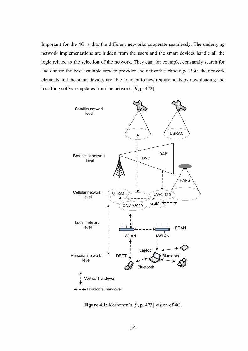
54
Important for the 4G is that the different networks cooperate seamlessly. The underlying
network implementations are hidden from the users and the smart devices handle all the
logic related to the selection of the network. They can, for example, constantly search for
and choose the best available service provider and network technology. Both the network
elements and the smart devices are able to adapt to new requirements by downloading and
installing software updates from the network. [9, p. 472]
USRAN
Satellite network
level
Broadcast network
level
Cellular network
levelUTRAN
CDMA2000GSM
UWC-136
DVBDAB
HAPS
Local network
level BRAN
WLAN WLAN
Personal network
levelBluetooth
Laptop
Bluetooth
DECT
Vertical handover
Horizontal handover
Figure 4.1: Korhonen’s [9, p. 473] vision of 4G.

55
4G network will have a kind of a layered architecture. Figure 4.1 shows one vision by
Korhonen [9, p. 473] of the 4G architecture. The lowest, personal network level contains
all the equipment that uses the system. This equipment is connected with each other via
Bluetooth and infrared connections [9, p. 474]. Local network level is constructed of
LANs, mainly WLANs. Data transmission rates are high but mobility is quite local.
Cellular level includes all the 2G and 3G techniques. Coverage and mobility are global but
data rates considerably lower. Broadcast level provides wide-coverage broadcast services
such as DVB and DAB (Digital Audio Broadcast). The highest level consists of satellite
systems which provide low data speeds but true global coverage.
High-Altitude Platform Station (HAPS) is a base station located high above the ground in a
solar-powered air ship or ultra light airplane [9, p. 474-475]. Advantage of HAPS is the
fast allocation of capacity by its mobility and downside the difficulty to keep it stationary
in the air. Handovers can be made on two different levels. Vertical handover means a
handover made between different layers and horizontal handover takes place within one
layer.
The numerous 4G network techniques will probably evolve separately. The actual 4G
research work is then making the interworking possible. It will be highly market driven:
only the features that may have commercial potential will be implemented. [9, p. 475]
4.2 Software
This section discusses two key concepts of the future in the network management system
software area. Importance of NGOSS & OSS/J is growing and it is crucial to introduce
them.
4.2.1 NGOSS & OSS/J
It is claimed in the OSS/J API roadmap [45, p. 9] that the technology currently used for
Operations Support System (OSS) solutions cannot meet the demands of the increasing
56
diversity of communications technology and scale of networks. OSS is a common concept
used in the telecom industry for any network O&M system. The time-to-market of OSS
applications and services must also be reduced and availability and reliability of the
systems improved.
New Generation Operations Systems and Software (NGOSS) and OSS through Java
Initiative (OSS/J) are programs started in the year 2000 by TeleManagement Forum [39]
aiming at promoting the delivery of reusable OSS solutions and components to service
providers [40, p. 5].
NGOSS deals with the business and system aspects of OSS solution delivery and is thus on
a higher abstraction level whereas OSS/J is focused on the solution implementation using
Java technology. The programs are complementary as NGOSS has delivered higher level
frameworks and methodologies and OSS/J actual free-of-charge Application Programming
Interfaces (API) for the implementation. NGOSS concentrates on the technology-neutral
aspects and OSS/J on the Java technology-specific aspects of network management. [40, p.
5]
NGOSS architecture can be modelled by 4 types of models [40, p. 7-8]:
- Shared information model enables integration and interoperability and presents the
data, operations, and interactions between managed entities.
- Security policy model describes the security policies and mechanisms.
- Policy management model defines the rules that control the behavior of the system.
The NGOSS system architecture is policy-enabled which means that its operation
and management are dependent on the execution of policies.
- Business process model describes the behavior of the NGOSS system in a
technology-neutral manner.
OSS business application is an implementation for the business-related functions specified
using NGOSS [40, p. 8-9]. Two types of these applications exist: NGOSS integrated

57
applications that are designed from scratch to be deployed in an NGOSS environment and
integrated legacy applications that were not implemented in NGOSS architecture but have
been made available for NGOSS components. Other noticeable features of the architecture
include framework services that provide distributed computing functionality, for example,
logging, tracing and naming services, and inter-working mechanisms that enable the
communication of independently deployed NGOSS components [40, p. 9-11]. Each
NGOSS system has at least one communication mechanism which offers one or more
transport mechanisms.
NGOSS architecture is quite similar to the TMN and can be used as a basis for OSS
implementation design in the same way as TMN, refer back to Section 3.3.3 for more
information. TMNs role is to complement NGOSS, for example, physical architecture is
something that is not really included in NGOSS.
The architecture of OSS/J is based on the Java 2 Enterprise Edition1 (J2EE) architecture
(see Section 5.4.1 for more information). Implementation of the OSS/J APIs is driven by
the Java Community Process [40, p. 11-13], which means that the international Java
community involves in developing the specifications. The initial OSS/J APIs were
strongly-typed tightly-coupled APIs using RMI over IIOP. Later, with the introduction of
message-driven beans in the J2EE architecture, the APIs were developed strongly-typed but
loosely-coupled using Extensible Markup Language (XML) over JMS. The latest initiative
is developing equivalent Web-service interfaces. Therefore, the following features of J2EE
are of significance in the scope of OSS/J:
- Object serialization enables marshalling of Java objects to and from a storage
medium or communications channel.
1 The name for enterprise edition Java will be simplified in the next version to Java Enterprise Edition (Java
EE) [21]. However, this version has not yet been released, and therefore the older naming convention will be
used in this thesis as it is used in the references.
58
- Java Naming and Directory Interface (JNDI) provides information location
services on run-time.
- J2EE Connector Architecture (JCA) is an implementation of the interface to
external information systems and provides the possibility to integrate non-JMS
compliant systems into the EJB environment.
- Java Messaging Service (JMS) uses an enterprise messaging system for
communications between applications or components.
- Remote Method Invocation (RMI) is used to establish the synchronous connections
between an EJB client and EJB server. Inter-Orb Protocol (IIOP) is one option for
the protocol used for RMI implementation. It delivers CORBA computing
capabilities to the Java platform.
OSS/J includes interfaces for e.g. customer and order management, service activation,
testing, billing, performance monitoring as well as service and resource inventories [45, p.
9-12]. For performance management an interface by the name (resource) performance
monitoring is currently under development [45, p. 15].
A considerable part of mobile network management can be predicted to be based on
NGOSS and OSS/J in the future. OSS/J APIs can be downloaded free of charge which will
probably lower the deployment costs. Free-of-charge open source software though is not
just a price advantage; there also will be expenses on support and training. Nokia Networks
[46] predicts that the OSS area of business will grow considerably by 2008. OSS/J
frameworks will offer true compatibility between equipment vendors that will be needed
even more in the future, see Figure 4.2. As majority of these frameworks have already been
published, the feasibility of transforming the current O&M solutions to be OSS/J
compatible should be investigated.

59
Figure 4.2: Horizontal multi-vendor solutions for service and network management [46].
4.3 Discussion
The future of mobile networks looks both very interesting and in the same time complex
and blurred. 4G will be a very wide concept that we as users don’t necessarily even are
aware of using. Not only mobile phones and laptops but also even refrigerators and
microwave ovens will be connected to the same huge network system.
Mobile network O&M will definitely unify in the coming years. This will reduce the
differences between vendors and increase the inter-vendor compatibility. Competition will
even further tighten as O&M spending will increase and time-to-market and quality of the
implementations improve.
60
5 Case Study: Implementation of web-based PM functionality
on DX network element
This section provides a case study of implementation of web-based performance
management application for Nokia’s DX network element hardware. The application was
implemented in the Proof of O&M Evolution Concept (POMEC) project in TietoEnator
Telecom & Media’s Nokia Networks & Tools (NNT) division as an internal research
project. The project took place from beginning of February to end of April in 2006 and
total of three persons took part in the implementation.
Some background on the POMEC project is presented first. Then a glance is taken on the
requirements for the implementation and selection of tools that were used. Next the actual
implementation is described, and finally the implementation is evaluated in terms of the
theories and the requirements for NMSs presented earlier.
5.1 Background
Goal of the project implementing the POMEC solution was to study the possibilities of
getting performance management data from a DX based network element. The project was
a proof-of-concept for web-based PM solution, and its objective was to study how difficult
the implementation would be and which cost-free open source or other free software could
be used. PM was selected since there did not exist previously implemented web-based
solutions. The project had already started when it was decided that the implementation
would use an existing Java Struts based framework, implemented by TietoEnator for Nokia
Networks, for its user interface and, thereby, the project would serve as a demonstration for
future projects that will be using the framework.
DX is a Nokia proprietary digital switching hardware platform for network elements [47,
p.139]. It has a long history which roots all the way back in the early 1980s [31] with first
version released in 1982. DX200 and newer version DX220 are used as a basis for GSM
and UMTS NEs, for example for MSC and HLR. The project used a DX200 HLR as the
testing platform for the solution.

61
DX as such is pretty difficult to program [47, p. 140], but it offers a wide variety of
protocols and APIs for the programmers to obtain information of its state and operations.
The protocols are Nokia proprietary and thus only a short introduction can be presented
here.
DMX messages are operating system messages that are sent inside the DX system. The
DMX messages can be sent to DX from an external system via External Message Transfer
(EMT) protocol.
MML via MMI is the most extensive of the interfaces and all DX operations can be
accessed by it. MML is used over a Telnet connection and offers a text-based user
interface. Programming on top of the MMI interface is not very efficient since the text-
stream must be read from the Telnet connection in order to interpret the responses. For
example, command MIO:IMSI=5 prints HLR subscriber, identified by the parameter
IMSI (International Mobile Subscriber Identity), information on the screen. The syntax is
common for all the MML commands and multiple parameters are separated by commas.
DX also contains an XML over HTTP (XoH) interface, which is used for the measurement
notifications. XoH is a nearly-standard Simple Object Access Protocol (SOAP)
implementation. The basic idea of SOAP is to send information in XML form over HTTP
protocol in envelopes, which are the top elements of the XML document that represents the
message [48]. The IP-address and port of the desired listener for the notification events is
sent in one message, and another one is used for removing the listener. DX then sends
notifications, which contain the names of the measurement result files that are ready for
transferring, to the listeners. Third message type is for deleting the files that have already
been transferred from DX.
For the measurement result files DX contains a File Transfer Protocol (FTP) server, from
where the files are obtained with a FTP client. The format of the files is Nokia Networks
proprietary XML based format, which can not be described in detail since it is company
confidential.

62
One conceptual idea behind the project was also that if the element platform were Linux-
based in the future, would that enable running the application server in the network
element itself. That would erase the need for a separate server for element management
applications. The internal communication mechanisms of DX could then possibly be used
directly from the applications on the Linux server, and no additional network connections
would be needed. Therefore, all the code was written in Linux-transferable form. The
application server itself did not need to be directly Linux-compatible, since the J2EE
application code could be easily deployed on different servers running on Windows or
Linux platform.
5.2 Requirements
No specific project model was used in the POMEC project and thus the requirement
collection phase was free form. The realized requirements were documented in a project
log, which also included the implementation schedule and persons responsible for each
requirement. The functional requirements/features for POMEC implementation were:
- Management of a single DX based NE.
- Capability to receive and handle PM measurement data from the DX.
- Visualization of the PM data by graphs.
- A web-based Graphical User Interface (GUI).
- DMX messages and/or MML over Telnet used for managing the measurements.
- Administration, including creation, deletion, modification, and scheduling of
measurement jobs.
- HLR subscriber management including creation, deletion, modification, and
viewing of subscriber data.
- Measurement notification handling via the XoH interface.

63
Non-functional requirements and objectives included:
- Conformance to J2EE architecture. (requirement)
- Integration to the existing Struts based framework. (requirement)
- Free software components and programming tools to be used as much as possible.
(objective)
The subscriber management part was implemented in another project and integrated to
POMEC in order to investigate and prove the functionality of DMX over EMT based
implementation.
Web-based GUI
One important factor in the project was the web-based GUI. Several reasons contributed to
the selection of GUI implementation technique:
- Web-based GUIs are thought to be easily implementable and rather light-weight
compared to, for example, basic Java GUIs.
- With modern web GUI frameworks the solution development can be done using
advanced IDEs such as Eclipse [50] or Borland’s JBuilder [49].
- Platform-independence of the client; it can be any Linux, Windows, or Apple
Macintosh workstation with a web browser.
- Reduction of time-to-market due to faster implementation that will be very critical
in the future, see, for example, Sections 4.3 and 4.5.
- Web GUIs’ significance will probably altogether rise in the future in the OSS area.
Nokia Networks too at some level encourages their usage.
- From employer’s point of view competence build-up in the anticipated key area.

64
5.3 Designing the System as a TMN
This section provides an example design following the TMN based design method
presented in Section 3.3.3. The purpose of the method is that the physical architecture is
constructed based on information and functional architectures. The physical architecture
can then be used as a strong basis for implementation specifications.
TMN concept was presented in Section 3.1.3 and it is the only universally applicable
model for designing an NMS. By presenting the design of the system in terms of TMN
architectures, the implementation can be efficiently linked to the theoretical background of
the network management domain .
5.3.1 Functional Architecture
Figure 5.1 shows the TMN functional architecture for POMEC. There are three basic
element level OSFs that have been derived from the requirements presented in Section 5.2:
- E-OSF1: Mediation and interpretation of measurement results from DX to the
WSF.
- E-OSF2: Management of measurement jobs.
- E-OSF3: HLR subscriber management.
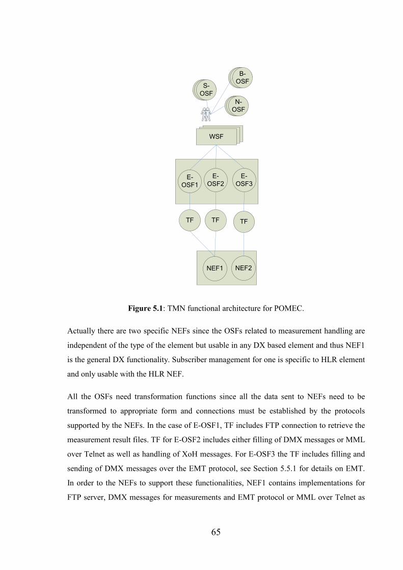
65
E-
OSF1
TF
NEF1
E-
OSF2
WSF
N-OSF
S-
OSF
B-OSF
E-
OSF3
NEF2
TFTF
Figure 5.1: TMN functional architecture for POMEC.
Actually there are two specific NEFs since the OSFs related to measurement handling are
independent of the type of the element but usable in any DX based element and thus NEF1
is the general DX functionality. Subscriber management for one is specific to HLR element
and only usable with the HLR NEF.
All the OSFs need transformation functions since all the data sent to NEFs need to be
transformed to appropriate form and connections must be established by the protocols
supported by the NEFs. In the case of E-OSF1, TF includes FTP connection to retrieve the
measurement result files. TF for E-OSF2 includes either filling of DMX messages or MML
over Telnet as well as handling of XoH messages. For E-OSF3 the TF includes filling and
sending of DMX messages over the EMT protocol, see Section 5.5.1 for details on EMT.
In order to the NEFs to support these functionalities, NEF1 contains implementations for
FTP server, DMX messages for measurements and EMT protocol or MML over Telnet as

66
well as XoH notification handling. NEF2 then contains implementation for EMT protocol
and DMX messages for subscriber management.
The human user who uses the WSF is driven by several upper level OSFs. As the POMEC
solution is only designed for element management, the N-OSFs can be implemented only
via the human user, since data is not automatically gathered or sent forward for network
management purposes. The upper level OSFs are however not handled in more detail.
5.3.2 Information Architecture
Figure 5.2: TMN information architecture for POMEC.
Figure 5.2 shows the information architecture for POMEC. Neither the internal
implementation, internal class structure of the OSFs, nor specific information or interaction
models described in the TMN specifications are handled in this context, but the reference
points between the function blocks of functional architecture resulting to interfaces to and
from the transformation functions are described. The interface 1 between WSF, which both
includes the implementation of the GUI in the appropriate web GUI framework and the

67
web browser, and all the OSFs, contains the connections from the web browser to the GUI
framework and internal J2EE communication from the GUI to the components
implementing the OSFs. So actually the WSF as well as the interface can be divided to two
parts. The interfaces between OSFs and TFs and TFs and NEFs are of more importance.
The data that is transferred over those interfaces and the protocols that are used are
described shortly in Table 5.1.
INTER-
FACE
OSF -> TF TF -> OSF TF -> NEF NEF -> TF
2 Requests for obtaining
measurement files. J2EE
internal communication
Measurement files.
J2EE internal
communication.
3 Data for notification
requests (XoH), Data for
DMX messages or MML
commands. J2EE internal
communication
Notification
responses (XoH),
DMX/MML
responses. J2EE
internal
communication.
4 Data for HLR subscriber
requests (DMX messages).
J2EE internal communi-
cation.
DMX message
responses. J2EE
internal
communication.
5 FTP client
connection to the
FTP server in NEF.
Measurement result
files.
6 XoH requests via
HTTP, DMX
messages over
EMT.
XoH responses via
HTTP, DMX
message responses
over EMT.

68
7 Subscriber DMX
messages over
EMT.
Subscriber DMX
responses over
EMT
Table 5.1: The used protocols and data transferred over the interfaces of the TMN
information architecture.
5.3.3 Physical Architecture
The TMN physical architecture of POMEC that is based on the previously presented
functional and information architectures is presented in Figure 5.3. The user’s workstation
(WS) with web browser implements the WSFs. OS also implements some WSFs since it
uses an XML parser to decode the XML formatting of the files so that the data can be
viewed by the web GUI, which too is a WSF. As it can be seen from Table 5.1, all the
communications between the OSFs and TFs are internal to the J2EE framework, and thus
the implementation for OSFs, OS, and implementations for TFs, the QMDs are
implemented on the same Linux compatible J2EE application server. DX based HLR
network element implements both the NEFs. Another DX based NE could also be used, but
it would implement only the general DX NEF. Data communications network between the
workstation and the Linux server is any availably connection line, and between the Linux
server and DX either any available connection line or if the Linux server is physically
plugged in the same hardware, an internal DX message bus.

69
(DX200 HLR)
Application
server on
Linux
DCN
DCN
NE
Physical
WS
QMDQMDQMD
E-
OSF1
TF
NEF1
E-
OSF2
NEF2
WSF
Functional
N-
OSF
S-OSF
B-
OSF
E-
OSF3
TF TF
OS
Figure 5.3: TMN functional architecture as a basis for physical architecture.
5.4 Selection of Tools
This section describes how the tools that were used were selected. First the J2EE and web
GUI technology selections are justified and then the programming environment is
presented. This is also the order in which they were chosen; first J2EE as the application
framework, then a GUI that supports it, next the programming Integrated Development

70
Environment (IDE) for the technologies and finally an application server that supports them
both and easily integrates to the used IDE.
5.4.1 J2EE
The J2EE architecture was a natural choice as the implementation technology. There were
several reasons that contributed to the choice. The most important one, although not used
in PM part of the project, was OSS/J, which as described in Section 4.3 is based on J2EE.
It is supposed to be a key issue in the future O&M solutions. The subscriber management
component also uses OSS/J APIs. Therefore, POMEC project acted as a competence-
builder in J2EE. Additionally J2EE is free-of-cost, nowadays very popular and its
significance altogether increasing due to its popularity. J2EE architecture offers a wide
range of system services to application components and also enables component-based
design, development and deployment of applications [51, p. 54]. Altogether J2EE offers a
highly reusable architecture that is based on components and which supports Model-View-
Controller (MVC) architecture based design. MVC is presented in detail later on.
Figure 5.4 shows the architecture of J2EE. There are 4 tiers in the J2EE architecture: client,
web, Enterprise Java Beans (EJB) and Enterprise Information Systems (EIS) tier [40, p.
12-13]. Tiers are constructed of containers, which contain the actual client, integration and
server components [40, p. 13] and provide the connections between the components and
the services of J2EE platform [51, p. 53]. Applet container and application client container
constitute the client tier, which contains the end-user clients. The web tier contains the web
container, which runs on a J2EE server and is responsible for managing the execution of
Java Server Pages (JSP) and Servlets. EJB tier is constructed of the EJB container also
running on a J2EE server. The EJB container manages the execution of EJBs, in which the
business logic is implemented. The EIS tier contains the databases that are accessed by the
applications.

71
EJBConnector
JDBC
JMS
JAAS
JAXP
JTA
JSP Servlet
Connector
JDBC
JMS
JAAS
JTA
JAXP
Web Container EJB ContainerApplet Container
Application
ClientContainer
J2SE
Applet
J2SE
Applet
J2SE
JMS
JAAS
JAXP
JDBC
HTTP,
SSL
HTTP,
SSL
JAF
JAF
Java Mail
J2SE
Client tier Web tier EJB tier Enterprise
Information
Systems tier
Database
Figure 5.4: J2EE architecture [40, p.12].
There are three types of enterprise beans: session, entity, and message driven beans.
Session bean is a representation for a single client inside the application server. Client
invokes session bean’s methods to access an application on the server and thus the session
bean hides the complexity of execution of server-side business tasks of the application.
There exist two types of session beans, stateless and stateful. Stateful beans can hold
information about the client-bean session. All the EJBs of the POMEC implementation are
stateless session beans. Entity bean represents a business object in a persistent storage,
relational database in the application server. They are saved in the database between
sessions and therefore maintain their state. Message-driven beans for their part are used for
handling asynchronous messages. They can be used as JMS-message listeners but any other
message types can be used too. Message-driven beans do not offer interfaces for clients to
access as session and entity beans do. [54, p. 857-866]

72
Each enterprise bean can have two types of clients: local and remote. Remote clients can
run, but not necessarily, on a different Java Virtual Machine (JVM) as the beans they
access. Two interfaces must be defined for remote clients: home interface, which includes
the bean’s life-cycle methods, and in the case of entity beans, finder and home methods
(class methods); and remote interface, which includes the business methods. The remote
interface needs to be defined in order to enable remote access to the bean. A remote client
can be a web component, an application client, or another enterprise bean. Local clients,
web components or other beans are located in the same JVM as the bean they access. For
local clients, two interfaces need to be defined: local interface for the business methods and
local home interface for life-cycle and finder methods. [54, p. 867-868]
5.4.2 Web Tier (GUI)
When developing a J2EE application, the selection of GUI implementation technology
equals to selecting an appropriate web container for the web tier. A simple combination of
JSPs & servlets can be used, but there exist several frameworks that offer more advanced
structure for the application. They are not just GUI technologies, but web application
frameworks, which additionally simplify and enhance the implementation of the GUI.
As mentioned earlier, another project had developed the framework based on Apache’s
Struts web application framework and that framework was also selected to be used with
POMEC. The framework includes tag libraries for easy creation of web GUIs with uniform
look-and-feel.
Apache Struts [1] is a project that develops two frameworks, Struts Action framework and
Struts Shale framework. The one used in the project is Struts Action framework, which is a
flexible control layer based on standard technologies like Java Servlets, JavaBeans, and
XML. Struts encourages MVC design pattern based solution Model2, in which the servlets,
called actions in Struts, manage business logic execution, JSPs contain the presentation
logic and the Action framework acts as the controller layer. Struts includes its own tag
libraries and is configured with XML files.

73
MVC architecture splits the application logic in three parts: the model, the view, and the
controller [51, p. 119]. Model represents the data of the application and contains logic for
accessing it. Controller accesses the model’s methods based on user’s actions and passes
the model’s responses to the view. View renders the state of the model and includes
presentation logic to provide a view for the user to the application data, as well as forwards
the user’s actions to the controller.
Other options for a Java-based web framework supporting the MVC model and easily
integration capable into J2EE environment could be, for example, Apache’s Cocoon [22]
or Struts Shale [1], Jakarta Tapestry [23], and Apache’s MyFaces [24]. The last mentioned
is an upcoming JavaServer Faces implementation [24], which is quite comparable to Struts
but with some features enhanced. JavaServer Faces [52] is a technology for building
interfaces from reusable UI components for JavaServer applications. Struts Shale
framework [1] is also based on JavaServer Faces and as distinction to Struts, it is
component-based while Struts is request-based. Apache’s Cocoon [22] is an XML based
web development framework that supports component-based design with components in a
“pipeline”. Cocoon is similar to Struts but much more complex for standard web
applications. Jakarta Tapestry [23] divides the web application into a set of pages, which
contain components and with which Java code can be combined by using XML descriptor
files. Tapestry focuses on good scalability and easy creation of new components.
5.4.3 Programming Environment
MyEclipse [13] was selected as the IDE for the implementation. It extends the basic
Eclipse IDE [50] with a collection of carefully selected plugins for advanced application
development. The plugins are packaged into an “extension”, which can be installed to
Eclipse with the Eclipse extension mechanism. The plugins include, for example,
Subclipse [19], a plug-in for SUBversion version control system [18], which was used in
the project; JBOSS connector for controlling the application server and Struts
Editor/Modeler for enhanced Struts development. MyEclipse is also a good choice for
74
J2EE development. MyEclipse does not pass the cost-free tools requirement, but with its
very modest license fee it’s a feasible choice.
For an application server that is free of cost and runs J2EE on Linux, there was basically
only one reasonable option: JBOSS application server [16]. With some previous
experience on setting up the servers, JBOSS had turned out to be easy to configure and it
could easily be integrated to be used with MyEclipse. JBOSS supports perfectly both J2EE
and Struts.
5.5 Implementation
This section provides an overview on the actual POMEC implementation. First the
middleware layer that is the software layer between the GUI and DX is described. Then the
structure of the application is depicted by an architectural figure, class diagram, and XML
formed configuration file. Functionality is then enlightened by sequence diagrams. Finally,
the cost-free components that were used are listed.
There are three types of measurements, called load observations, which can be managed by
POMEC: computer unit, which measures the load of each computing unit of DX; message
bus, which can be used for measuring the load of the DX internal message bus, and
rejected calls measuring the amount and percentage of rejected calls by the DX element.
For computer unit and rejected calls load observations the units of DX that are to be
included can be selected and some threshold values set.
5.5.1 Middleware Layer
The “Middleware Layer” in this case stands for the layer of software components that
handle the protocol and data presentation conversions between the DX and the software
implementation.
EMT/J is the client implementation in Java for the EMT protocol, which is used to send
DMX messages between any network element that includes the EMT server
implementation and an external system. EMT/J uses TCP/IP connections and consists
75
purely of library code. It only enables synchronic data transfers. EMT/J is included in the
project as a separate Java Archive (JAR) package.
HLRConnector is the component that is used for subscriber management. It uses EMT/J to
send DMX messages to Nokia’s HLR. Another Nokia Networks proprietary tool called
TTRAN/J is used to generate Java classes for the DMX messages. The generation is done
statically before the implementation. The messages or the Java classes that represent them
are filled with information stored in OSS/J compatible objects. HLRConnector only
includes implementations for subscriber management messages. The EMT/J component
can also be used for sending any other DMX messages. In that case the message filling part
needs to be implemented separately. HLRConnector’s tasks include filling of the message
classes which means converting OSS/J specific data types into Java’s basic data types,
connection handling via EMT/J, and error message interpretation and passing.
HLRConnector is also included in the implementation as a JAR package.
CORBA is an often-used solution, as suggested in the UMTS requirements (see section
3.1.3) for providing a standardized interface between the NEs and OSs. It is a good choice
if data is to be gathered from heterogeneous elements around the network. However, a
distinct server(s) would be needed for converting the data from the element(s) to the
CORBA compliant form.
The J2EE connector architecture (JCA) would be an interesting implementation alternative
for the middleware layer. It is designed for creating resource adapters for enterprise
information systems that can be plugged in to a J2EE product [54, p. 1399-1406]. Each
EIS, located outside the J2EE server, needs its own resource adapter.
5.5.2 Architecture
POMEC architecture is presented in Figure 5.5. The components presented are the
elements of the 4-tier architecture model of J2EE. The web browser, which connects to the
JBOSS application server, locates on the client tier. The JBOSS server runs the
implementations for web and EJB tiers, the web and application (EJB) containers. Web

76
container contains the Struts framework parts, JSP pages, Struts ActionServlet and action
classes, of the application. Application container is the storage for session beans, register
bean for handling the notifications, measurement bean for measurements, and subscriber
bean for HLR subscriber handling. The figure also shows the protocols that are used to
communicate with DX.
There is also another application running on the JBOSS server: measurement listener is a
tiny Java application that listens for the notifications from DX and handles the
measurement result file transfers with FTP based on them. Thus, the measurement bean
does not actually transfer the files from DX but reads them from the hard disk where the
listener writes them.
Figure 5.5: POMEC architecture.
Action classes invoke the session beans’ methods and write results to HttpServletRequest
variable from which they can be accessed on the JSP pages. Once the method of the action
class is executed, an ActionForward is returned, which describes the next JSP to be read.
ActionForwards are defined in a XML-based configuration file struts-config.xml
(see Appendix 1). There are four action classes altogether: LoadObservationAction,

77
LoadObservationManagementAction, ConfigureAction, and ManageSubscribersAction.
The class diagram of the action classes is shown in Figure 5.6. They all inherit the abstract
DispatchAction class which enables the combination of many similar actions into a single
Action class by dispatching a request parameter to a public method.
Figure 5.6: Class diagram of the Struts action classes.

78
Figure 5.7 shows the class diagram of EJB classes of POMEC. The actual implemented
beans are a little different from those presented in Figure 5.5. RegisterSessionBean uses
SoapClient helper class to send the SOAP/XoH requests for notification listeners. There
are only two types of those requests: creation and deletion of event handler.
LoadObservationManagementBean handles the management of the measurements that is
starting and stopping them. It either uses Telnet and MML via TelnetConnector helper
class or EMT/J and DMX messages via Executor class. The messages are filled in the
bean.
<<interface>>
SessionBean
ejbActivate()
ejbPassivate()
ejbRemove()
setSessionContext(SessionContext)
LoadObservationManagementBean
HashMap sessionData
TelnetConnector telnetConnector
Executor executor
public boolean startLoadObservation(String, boolean,
boolean)
public boolean stopLoadObservation(String)
public Object getSessionData(String)
public void setSessionData(String, Object)
private byte[] dispatch(byte[])
private void fillMsgHeader(msg_header_t, int, int, int)
private String[] getConnectionInfo()
RegisterSessionBean
SoapClient soapclient
public String createEHClient(String)
public String deleteEHClient(String)
EmtSessionBean
HlrConnector hlrConnector
XmlObject[] savedMeasurements
FTPClient ftp
public HashMap createSubscriber(HashMap)
public HashMap deleteSubscriber(HashMap)
public HashMap interrogateSubscriber(String, String)
public HashMap modifySubscriber(HashMap)
public Boolean ftpGet(String, String, String, String, String, String, String, String)
public XmlObject[] readMeasurementObjectFromFile(String)
public void transferFiles(ArrayList, String, String, String, String, boolean)
public ArrayList getMeasurementFiles(String, String, String ftpDir)
public XmlObject[] getSavedMeasurements()
public void setSavedMeasurements(XmlObject[] savedMeasurements)
protected String connect(HashMap)
Figure 5.7: Class diagram of the EJBs of POMEC implementation.

79
The transferring of measurement result files is done in EmtSessionBean when logically it
would rather belong to the management bean. FTPClient helper class is used for managing
the connections and transfers. EmtSessionBean also uses the HlrConnector class for
subscriber management operations.
Although all the session beans are stateless, data is in the case of EmtSessionBean and
LoadObservationManagementBean saved to the bean instance, since only one client uses
POMEC at a time. If there would be multiple simultaneous users, any of them could access
each others session bean data, since there exists no client and identity association, and the
bean instances are pooled until needed again. In that case stateful beans would have to be
used. [54, p. 872-875]
5.5.3 User Interface
The user interface consists of four distinct views: configuration, subscriber, measurement
result, and measurement administration view. Each view comprises one or more JSP pages.
Configuration view is used for defining the IP address and port of the NE and the used
username and password needed for EMT and FTP connections. Subscriber view is used for
managing the HLR subscribers. Measurement result view visualizes the results and
administration view is used for scheduling and starting/stopping the measurements. Figure
5.8 shows the measurement result (load observation results) view. Cewolf [15] is the free
component used for visualization of the results, that is, for drawing the graphs. The
properties of the graphs can be dynamically changed to gain a better view for different
types of data. Each line in the line diagram represents a computing unit of DX and each
diagram contains the results of one measured value. View can also be arranged by units and
there exists a distinct graph for each of the various units. In the figure, the graph on top-left
visualizes the peak load percentages, the next on top-right load percentage, and the last on
bottom time of the peak load in seconds, of each computing unit.

80
Figure 5.8: The measurement result view of POMEC.
5.5.4 Functionality
The functionality of POMEC implementation is described with five sequence diagrams that
show the information flow between the components of the application. The sequence
diagrams are based on the following use cases:
- Figure 5.9: Starting an observation by using DMX messages over EMT.
- Figure 5.10: Starting an observation by using MML over Telnet connection.
- Figure 5.11: Creating a subscriber by using DMX messages over EMT.
- Figure 5.12: Registering an event listener (for observation notifications) by using
XoH.

81
- Figure 5.13: Viewing observation results in the web GUI on a graphical form.
:Struts web GUI :EMT/J
start
Start load observation
:LoadObservationManagementAction
:LoadObservationManagementBean
Start load observation (useTelnet = false)
response
Start load observation (useTelnet = false)
Send DMX Message
response
:DX
sends the message
responseresult
response
Figure 5.9: Start observation using DMX messages over EMT.
:Struts web GUI :TelnetConnector
start
Start load observation
:LoadObservationManagementAction
:LoadObservationManagementBean
Start load observation (useTelnet = true)
response
Send message to start load observation
connect
response
:DX
sends the message
responseresult
response
Send MML message
Establish connection
Figure 5.10: Start observation using MML over Telnet connection.

82
:Struts web GUI :EMT/J
create
Create subscriber
:ManageSubscribersAction :EmtSessionBean
Create subscriber
response
Send message to create subscriber
Send DMX message
response
:DX
sends the message
responseresult
response
Figure 5.11: Create subscriber using DMX messages over EMT.
:Struts web GUI :SoapClient
register
Register Event Handler
:ConfigureAction
:RegisterSessionBean
Register event handler
response
Send registration request
response
:DX
sends the request
response
result
response
:Notification listener
notifications
Fill and send the request
creates
Figure 5.12: Register an event listener by using XoH.

83
:Struts web GUI
File selected
View observation results
:LoadObservationAction
:EmtSessionBean
View observation results
result data
Read the saved results
responseresult
Figure 5.13: View observation results in the web GUI.
5.5.5 Utilized Cost-Free Components
The visualization of PM data is done with Cewolf component [15]. Cewolf is based on
JFreeChart [14] and can be used to create many sorts of graphical charts. It uses
JFreeChart’s rendering engine and the created graphs can be accessed via JFreeChart’s
interfaces. Cewolf can be used in a Java Servlet/JSP based web application. It includes a
tag library to define the properties of the chart. The charts are created as session objects on
the server and can be accessed in the Java code of the Struts Action classes. Data is
inputted to the charts via a data producer class. JFreeChart uses another common class
library called JCommon.
Many of Jakarta Commons project’s [53] free components are used in the implementation.
Digester is used for parsing the PM data XML files into Java classes. Validator is used for
creating validators for user input. The Logging component is used for universal logging.
Commons Codec includes encoder and decoder for URLs and is needed in SoapClient.
Commons Net has client side implementations for many necessary protocols such as FTP
and Telnet.

84
The HLRConnector component uses several OSS/J [55] APIs to convert the subscriber data
from HLR to OSS/J conformable form. OSS common contains APIs common across the
OSS/J. OSS Inventory defines J2EE based interfaces between inventory repositories and
other OSS components. Service Activation API is also used. The HLRConnector
component can not be described in detail due to confidentiality issues.
5.6 Evaluation of the Implementation
This section provides an evaluation of the implementation presented in the previous section
in terms of the theoretical background for NMS presented in Section 3. The equivalence of
POMEC and X.700, TMN, and PM in general is considered. A model, which would further
improve POMEC’s usability, is presented.
5.6.1 Features
Several desirable features for any mobile network management system were presented in
Section 3.3.2. They were not really held in mind when designing the POMEC
implementation, but it is assessed in terms of the features:
- PLMN technology transparency. Since POMEC is an EM application, the user
needs to know which element is to be managed with it. It has to be DX-based and
precisely HLR, if subscriber management part is to be used.
- Evolution of PLMN functions and services. POMEC does not set any restrictions
for the evolution as long as the interfaces remain the same. If, for example, new
computing units are added to DX, POMEC can handle them as long as they are
added to the server-side measurement implementation in DX.
- Scalability. Scalability (size of the PLMN) is more of an issue on network level
management and needs to be considered when designing a NM. If the measurement
data from POMEC would be sent to a NM, it would have to be figured out in the
NM side how to deal with increasing amount of measurements.

85
- Fail-safety. The fail-safety of POMEC depends largely on where the server running
the application is located. If it runs on a separate Linux server, the server can be
easily duplicated and if the other one crashes, the other one can be used. This
scenario also demands a mechanism for syncronizing the data between the servers.
On the other hand, if the application server runs directly in the DX hardware,
crashing of DX could also crash the application, and not even the measurements
that already have been transferred could be viewed.
- Manufacturer independency. Section 5.6.5 presents a model, in which any
solution that’s structured like POMEC, is placed on a bigger frame to provide
manufacturer independent O&M data on network level. As such, POMEC is totally
manufacturer dependent and can only be used with Nokia Networks DX element
hardware.
5.6.2 X.700
When considering POMEC as a X.700 PM application, we notice that it only implements a
fraction of the requirements presented in Section 3.1.2. Neither logs can be managed nor
statistical information collected with POMEC. Other systems are needed for changing the
system’s operation too. But the most important task, measuring performance of resources
and communication is to an adequate extent implemented.
5.6.3 TMN
The usability and generality of the TMN model became obvious as it was used as the basis
for POMEC design in Section 5.3. The information architecture is the most usable as a
design document; the others can be used more or less just for providing a higher level of
understanding. TMN does not include any real requirements so POMEC cannot be assessed
in their terms.

86
5.6.4 General PM Requirements
The data collection process in POMEC follows the 5 step procedure described in Section
3.2. A schedule can be created for the measurements using the web GUI. The
measurements are started in the DX NE accoring to the schedule. DX gathers PM data and
the ready measurement result files can be obtained with FTP. DX can also be configured to
send notifications on ready-made files. PM data is presented in a graphical form and some
small-scale analysis can be performed on the single-NE data.
The specific PM requirements, presented in Section 3.3.2, are mostly fulfilled in the
POMEC implementation. Operator can administer the measurements and analyze the
results. Itf-N is not used at all, but the interface between EM and DX is used both for
transferring the result files and notifications. The only insufficiencies are the facts that the
data is not sent forward for network management purposes, and that local data storage
cannot be managed. The measurement listener writes to and reads the XML files from a
specific folder, which cannot be changed, in the hard disk
5.6.5 Structure
The architecture of POMEC implementation supports requirements presented in Section
5.2 well: all of them can be extracted to different Action and bean classes. This improves
the extendibility and modificability of the solution. The enterprise beans are easy to add if
new business requirements appear. On the web tier, a new JSP page, a new Action class,
and possibly a new Actionform are needed to add a new view. It must be though
considered well how to divide the code between the Action classes and the enterprise
beans.
J2EE as well as OSS/J will most probably be important in the future so in that perspective
POMEC is compatible or at least in line with the upcoming solutions. With few changes it
can be integrated as a part of any coming NM implementation.

87
5.6.6 POMEC-based Model for Network Management
As POMEC is only meant for element management and can not be efficiently used for
network management purposes, a generalized model is presented of the situation in which
the POMEC implementation would be of more real use. Figure 5.14 presents this model
which uses OSS/J compliant data and can be used for any of the functional areas of X.700,
presented in Section 3.1.2. The figure is a modification of the one presented in Section 4.3.
Customer relationship management
Service management
Network management
Multi-domain
Multi-domain
Nokia Vendor X Vendor Y
Network Elements
Sub-network / element managementJ2EE
Bean
J2EE
Bean
????
?? ??
??
OSS/J OSS/J OSS/J
EM
GUI
Standardized interface (Itf-N)
Figure 5.14: Suggestion for a NM system that uses OSS/J and built-in EM on Nokia’s
equipment.
Element management in this model is vendor-dependent and each vendor has its own
solutions. EM systems then offer the data in OSS/J compatible form over a standardized
interface to be consumed by inter-vendor network management. EM applications can be
implemented as J2EE beans and the interface to network management could consist of, for
example, session beans or web services. In the case of Nokia, the application server
running the J2EE is in the same hardware as the network element controlled by the EM

88
applications. User interface to the EM can also be anything from Java web GUI to
traditional GUIs.
POMEC would require some changes in order to fit in to the model. The measurement
results should be outputted in an OSS/J compatible form and sent forward to network
mangement level.
The model fulfils the requirements for PM presented in Section 3.3.2: The EM GUI is
used for management of the measurements and the actual data is sent to NM. Either EM or
NM could then be used for changing the system’s operation, as the X.700 requirements for
PM in section 3.1.2 suggest, if needed to enable the PM activities to be performed or due to
a discovered malfunction.

89
6 Conclusion
This thesis first presented the structures of two most common mobile networks, GSM and
UMTS, concentrating on the core network. For theoretical background two models, X.700
and TMN, designed for management of GSM and UMTS networks, were studied. Features,
requirements, and some models for network management systems were also described.
Future issues of both the networks and network management system software were then
shortly glanced. Lastly the practical example of case study of implementation of a web-
based performance mangement application was presented. The application was
implemented in POMEC project in TietoEnator Telecom&Media Oyj and it is meant for
managing Nokia Networks DX-based network elements. The implementation was then
evaluated in terms of the theoretical background.
The most important outcome of the project was the improved competence on both the DX
interfaces and protocols and implementation technologies for an O&M solution. The
solution as such is of very little or no use at all, but with minor changes it could be
integrated to be part of a bigger network management system. The project as a whole
succeeded to reach its goals and was finished in time.
Selected implementation technologies supported the requirements for the implementation
well. Implementation of the user interface was easy and the component that was used for
drawing the graphs was very straightforward to use. J2EE enabled division of business-
logic into units of reasonable size. The Struts framework was discovered to be easy to
configure. Integration to the used Struts-based framework was also painless and really
straight-forward. Web service based implementation for the notification listener was first
experimented on, but as it did not work as expected, it was decided to implement the
listener as a distinct application. Struts and J2EE were integrated succesfully on the JBOSS
server, and no problems arose in the communications between the components. JBOSS
server worked well on both Windows and Linux platforms.
There were of course some problems too. The various interfaces of DX seemed to not work
as expected. The XoH messages for removing the notification listener and removing the
90
ready measurement files did not work. Also the DMX message based implementation for
measurement management did not work completely. The MML over Telnet option for one
worked as it was expected, but the implementation was very simple and not extendable at
all. These appeared problems, on the other hand, provided valuable information of the
functioning of the DX protocol implementation.
In the Telecommunications business area, many concepts and ideas that originate in the
TMN model are used without people even noticing it. TMN provides a very high-level
architecture, which all O&M follows. The TMN-based design model could be modified, so
that it could be used as a design method for O&M systems. O&M implementations are yet
still very vendor- and equipment-dependent, but the situation will be different in the future.

91
References
[1] The Apache Struts Project, Apache Struts Project, can be obtained in HTML-form
from <URL: http://struts.apache.org/>, 9.1.2006.
[2] Tom Leskinen, GSM Subscriber Management on top of a Generic TMN Agent,
Personal, Indoor and Mobile Radio Communications, 5th IEEE International Symposium
on Wireless Networks - Catching the Mobile Future, 1994, pages 1004-1008.
[3] Yi-Bing Lin, OA&M for the GSM Network, IEEE Network, March/April 1997, pages
46-51.
[4] Gilbert Held, “Data Over Wireless Networks”, McGraw-Hill, New York, 2001, pages
87-112.
[5] Yi-Bing Lin & Imrich Chlamtac, “Wireless and Mobile Network Architectures”, Wiley
Computer Publishing, New York, 2001, 532 pages.
[6] International Telecommunication Union ITU, “Management framework for Open
Systems Interconnection (OSI) for CCITT applications”, Recommendation X.700, 1992,
11 pages.
[7] European Telecommunications Standards Institute ETSI, GSM 01.02 version 6.0.1
Release 1997, 1997, 23 pages.
[8] Zoran Zvonar, Peter Jung and Karl Kammerlander, “GSM – Evolution Towards 3rd
Generation Systems”, Kluwer Academic Publishers, New York, 2002, 368 pages.
[9] Juha Korhonen, “Introduction to 3G Mobile Communications”, Artech House,
Norwood, 2003, 565 pages.
[10] Alexander Joseph Huber and Josef Franz Huber, “UMTS and Mobile Computing”,
Artech House, Norwood, 2002, 454 pages.
92
[11] Tarmo Anttalainen, “Introduction to Telecommunications Network Engineering,
Second Edition”, Artech House, Norwood, 2003, 394 pages.
[12] 3GPP project, 3GPP home page, can be obtained in HTML-form from <URL:
www.3gpp.org >, 2.5.2006.
[13] Genuitec LLC, MyEclipse J2EE IDE – Easy and affordable eclipse plugin
development tools, can be obtained in HTML-form from <URL:
http://www.myeclipseide.com/>, referred 5.5.2006.
[14] David Gilbert and Thomas Morgner, www.jfree.org – JFreeChart, can be obtained in
HTML-form from <URL: http://www.jfree.org/jfreechart/index.php>,
referred 5.5.2006.
[15] Guido Laures, CeWolf – Chart Enabling Web Object Framework, can be obtained in
HTML-form from <URL:
http://cewolf.sourceforge.net/new/index.html>, referred 5.5.2006.
[16] JBOSS, JBOSS application server, can be obtained in HTML-form from <URL:
http://labs.jboss.com/portal/index.html?ctrl:id=page.default.
info&project=jbossas>, referred 5.5.2006.
[18] Tigris.org, Subversion, can be obtained in HTML-form.from <URL:
http://subversion.tigris.org/>, referred 4.5.2006.
[19] Tigris.org, Subclipse – A Subversion Eclipse plugin, can be obtained in HTML-
form.from <URL: http://subclipse.tigris.org/>, referred 4.5.2006.
[20] Man Yi, Shang Jing, Song Junde and Song Mei, Considerations for the Development
of Large Scale Mobile Network Management System, Canadian Conference on Electrical
and Computer Engineering, May 2004, pages 1139-1142.
[21] Sun Developer Network, Java Platform, Enterprise Edition (Java EE), can be obtained
in HTML-form.from <URL: http://java.sun.com/javaee/>, referred 5.5.2006.

93
[22] The Apache Cocoon project, The Apache Cocoon Project, can be obtained in HTML-
form.from <URL: http://cocoon.apache.org/>, referred 5.5.2006.
[23] The Apache Jakarta Project, Jakarta Tapestry, can be obtained in HTML-form.from
<URL: http://jakarta.apache.org/tapestry/>, referred 5.5.2006.
[24] The Apache MyFaces Project, Welcome to the Apache MyFaces Project, can be
obtained in HTML-form.from <URL: http://myfaces.apache.org/>, referred
5.5.2006.
[25] Theodore S. Rappaport, “Wireless communications”, Prentice Hall, New Jersey, 1996,
641 pages.
[26] European Telecommunications Standards Institute ETSI, GSM 03.02 version 4.2.1,
1996, 19 pages.
[27] GSM Association, GSM subscriber statistics, can be obtained in HTML-form from
<URL:
http://uk.sitestat.com/gsm/gsmworld/s?Stats_Q1_2006&ns_type=p
df&ns_url=[http://www.gsmworld.com/news/statistics/pdf/gsma_s
tats_q1_06.pdf >, referred 9.5.2006.
[28] Gunnar Heine and Holger Sagkob, “GPRS: Gateway to Third Generation Mobile
Networks (Second Edition)” Artech House, Norwood, 2003, 322 pages.
[29] Tomi Engdahl, Matkapuhelinten kehitys, can be obtained in HTML-form from <URL:
http://users.tkk.fi/~then/matkapuhelin/nmt.html >, referred
10.5.2006.
[30] ETSI, GSM 12.00 version 4.5.1, 1996, 85 pages.
[31] Nokia Oyj, Nokia – Nokia Firsts, can be obtained in HTML-form from <URL:
http://www.nokia.com/A402763>, referred 11.5.2006.
[32] 3rd Generation Partnership Project, 3GPP TS 23.002 V3.6.0, 2002, 37 pages.

94
[33] 3rd Generation Partnership Project, 3GPP TS 23.002 V5.12.0, 2003, 52 pages.
[34] 3rd Generation Partnership Project, 3GPP TS 23.002 V7.1.0, 2006, 61 pages.
[34] 3rd Generation Partnership Project, 3GPP TS 23.002 V7.1.0, 2006, 61 pages.
[35] International Telecommunication Union ITU, “Principles for a telecommunications
management network”, Recommendation M.3010, 2000, 35 pages.
[36] International Telecommunication Union ITU, “Generic Network Information Model”,
Recommendation M.3100, 2000, 92 pages.
[37] 3rd Generation Partnership Project, 3GPP TS 32.101 V7.0.0, 2006, 46 pages.
[38] 3rd Generation Partnership Project, 3GPP TS 32.401 V6.4.1, 2005, 32 pages.
[39] TeleManagement Forum, TM Forum, can be obtained in HTML-form from <URL:
http://www.tmforum.org/>, referred 26.5.2006.
[40] TeleManagement Forum, OSS through Java as an Implementation of NGOSS - A
White Paper, 2004, 38 pages.
[41] PICMG, PICMG – New Initiative for Next-Generation Telecom Equipment, can be
obtained in HTML-form from <URL:
http://www.picmg.org/newinitiative.stm>, referred 5.6.2006.
[42] TietoEnator, AdvancedTCA Signaling Blade, can be obtained in HTML-form from
<URL: http://signaling.tietoenator.com/index.asp?id=795&typ=>,
referred 5.6.2006.
[43] Nokia Mobile TV Forum, Technology – DVB-H, can be obtained in HTML-form
from <URL: http://www.mobiletv.nokia.com/technology/dvb/>, referred
5.6.2006.

95
[44] International Telecommunication Union ITU, “Information Technology – Open
systems interconnection – Basic reference model: The basic model”, Recommendation
X.200, 1994, 59 pages.
[45] OSS/J Product Team, “The OSS through JavaTm API Roadmap”, 2006, 63 pages.
[46] Nokia Networks, NGOSS as a strategy vehicle: Product portfolio management, can be
obtained in HTML-form from <URL:
http://www.nokia.com/NOKIA_COM_1/Microsites/OSS_Middleware/Do
wnloads/pdf/nokiangosspresentationattwm_nice.pdf>, referred
8.6.2006.
[47] A. Ahtiainen, J. Keskinen, J. Simolin, K. Tarpila, I. Turunen, “Designing and
implementing a general purpose OSI stack for the DX 200 switching system using software
tools”, XIII International Switching Symposium Proceedings Vol VI, 1990, pages 139-145.
[48] W3C, Simple Object Access Protocol (SOAP) 1.1, can be obtained in HTML-form
from <URL: http://www.w3.org/TR/2000/NOTE-SOAP-20000508/>, referred
13.6.2006.
[49] Borland, Borland IDE: JBuilder – Tools for Java and J2EE Application Development,
can be obtained in HTML-form from <URL:
http://www.borland.com/us/products/jbuilder/index.html>, referred
14.6.2006.
[50] Eclipse.org, Eclipse.org home, can be obtained in HTML-form from <URL:
http://www.eclipse.org/>, referred 14.6.2006.
[51] Nadir Gulzar, “Practical J2EE Application Architecture”, McGraw-Hill/Osborne, New
York, 2003, 402 pages.
[52] Sun Developer Network (SDN), JavaServer Faces Technology, can be obtained in
HTML-form from <URL:
http://java.sun.com/javaee/javaserverfaces/>, referred 20.6.2006.

96
[53] The Apache Jakarta Project, Jakarta Commons, can be obtained in HTML-form from
<URL: http://jakarta.apache.org/commons/>, referred 20.6.2006.
[54] Eric Armstrong et al, The J2EE 1.4 Tutorial, can be obtained in HTML-form from
<URL:
http://java.sun.com/j2ee/1.4/docs/tutorial/doc/J2EETutorial.p
df >, referred 21.6.2006.
[55] OSS through Java initiative, OSS through Java Initiative Produces Java APIs for
Next-Generation Telecommunications Networks, can be obtained in HTML-form from
<URL: http://ossj.org/>, referred 26.6.2006.
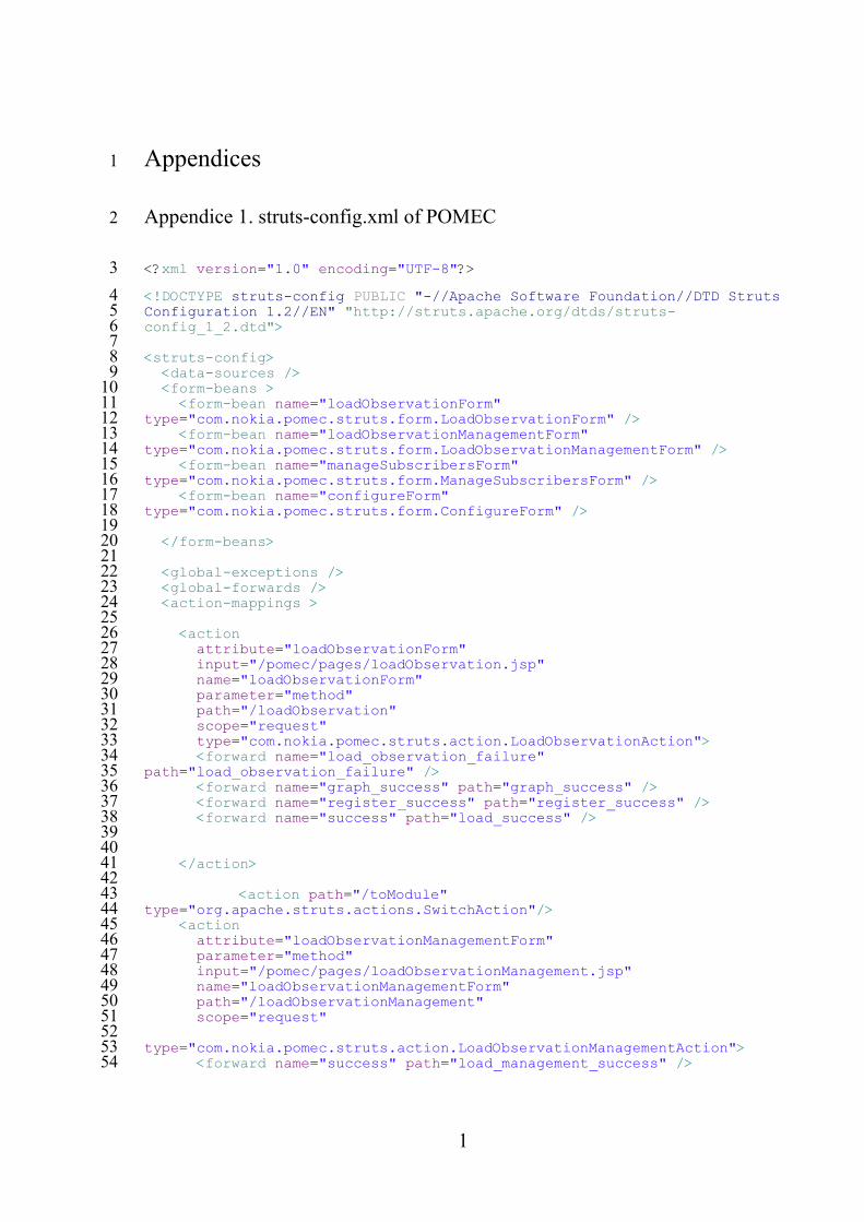
1
Appendices 1
Appendice 1. struts-config.xml of POMEC 2
<?xml version="1.0" encoding="UTF-8"?> 3
<!DOCTYPE struts-config PUBLIC "-//Apache Software Foundation//DTD Struts 4 Configuration 1.2//EN" "http://struts.apache.org/dtds/struts-5 config_1_2.dtd"> 6 7 <struts-config> 8 <data-sources /> 9 <form-beans > 10 <form-bean name="loadObservationForm" 11 type="com.nokia.pomec.struts.form.LoadObservationForm" /> 12 <form-bean name="loadObservationManagementForm" 13 type="com.nokia.pomec.struts.form.LoadObservationManagementForm" /> 14 <form-bean name="manageSubscribersForm" 15 type="com.nokia.pomec.struts.form.ManageSubscribersForm" /> 16 <form-bean name="configureForm" 17 type="com.nokia.pomec.struts.form.ConfigureForm" /> 18 19 </form-beans> 20 21 <global-exceptions /> 22 <global-forwards /> 23 <action-mappings > 24 25 <action 26 attribute="loadObservationForm" 27 input="/pomec/pages/loadObservation.jsp" 28 name="loadObservationForm" 29 parameter="method" 30 path="/loadObservation" 31 scope="request" 32 type="com.nokia.pomec.struts.action.LoadObservationAction"> 33 <forward name="load_observation_failure" 34 path="load_observation_failure" /> 35 <forward name="graph_success" path="graph_success" /> 36 <forward name="register_success" path="register_success" /> 37 <forward name="success" path="load_success" /> 38 39 40 </action> 41 42 <action path="/toModule" 43 type="org.apache.struts.actions.SwitchAction"/> 44 <action 45 attribute="loadObservationManagementForm" 46 parameter="method" 47 input="/pomec/pages/loadObservationManagement.jsp" 48 name="loadObservationManagementForm" 49 path="/loadObservationManagement" 50 scope="request" 51 52 type="com.nokia.pomec.struts.action.LoadObservationManagementAction"> 53 <forward name="success" path="load_management_success" /> 54

2
</action> 55 56 <action 57 attribute="manageSubscribersForm" 58 input="/pomec/pages/createSubscriber.jsp" 59 name="manageSubscribersForm" 60 parameter="method" 61 path="/manageSubscribers" 62 scope="request" 63 type="com.nokia.pomec.struts.action.ManageSubscribersAction"> 64 <forward name="operation_failure" path="operation_failure" /> 65 <forward name="create" path="create" /> 66 <forward name="modify_success" path="modify_success" /> 67 <forward name="interrogate" path="interrogate" /> 68 <forward name="operation_successful" path="operation_successful" /> 69 <forward name="delete" path="delete" /> 70 <forward name="modify_forward" path="modify_forward" /> 71 <forward name="interrogate_success" path="interrogate_success" /> 72 </action> 73 <action forward="popup" path="/popup" /> 74 <action 75 attribute="configureForm" 76 name="configureForm" 77 parameter="method" 78 path="/configure" 79 scope="request" 80 type="com.nokia.pomec.struts.action.ConfigureAction"> 81 <forward name="configure_success" path="configure_success" /> 82 <forward name="configure" path="configure" /> 83 </action> 84 85 </action-mappings> 86 87 <message-resources parameter="com.nokia.pomec.struts.PomecResources" /> 88 <plug-in className="org.apache.struts.tiles.TilesPlugin"> 89 <set-property property="definitions-config" value="/WEB-INF/tiles-90 defs-neosp_webui_pomec.xml" /> 91 <set-property property="moduleAware" value="true" /> 92 <set-property property="definitions-parser-validate" value="true" /> 93 </plug-in> 94 </struts-config> 95