fiber optics - 光纤光谱仪,积分球,均匀光源,太赫兹系统 ... • page 3 kieler str....
TRANSCRIPT
INTERFEROMETRY
Applications:
11 of1000
Particle Measurement
Read-Out of Imaging Plates
Optical Tweezers
LASERS FOR SPACE
Laser for Adjustment and Alignment
agneto pticalrap
MOT
Scratch detector
Open Brain Stimulation
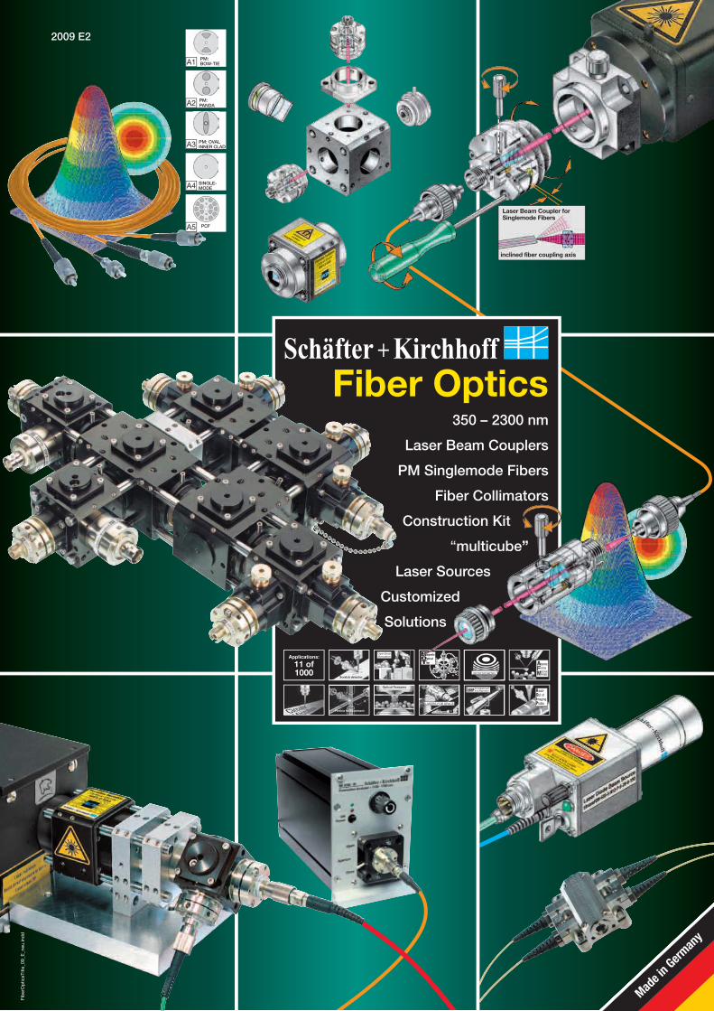
Fiber Optics350 – 2300 nm
Laser Beam Couplers
PM Singlemode Fibers
Fiber Collimators
Construction Kit
“multicube”
Laser Sources
Customized
Solutions
A1 PM:BOW-TIE
A2 PM:PANDA
A3 PM: OVAL INNER CLAD
A4 SINGLE-MODE
A5 PCF
Laser Beam Coupler for Singlemode Fibers
inclined fiber coupling axis
Made i
n Germ
any
Fib
erO
ptic
sTitl
e_09
_E_n
eu.in
dd
2009 E2

Fib
erO
ptic
s_In
halt_
09_E
D_g
ruen
.ind
d •
Pag
e 2
Kieler Str. 212, 22525 Hamburg, Germany • Tel: +49 40 85 39 97-0 • Fax: +49 40 85 39 97-79 • [email protected] • www.SuKHamburg.de
2
2009 E
Page 9Singlemode fiber cables SMC-… Polarization-maintaining fiber cables PMC-... Photonic crystal fiber PCF-...
Laser beam couplers 60SMS-... Page 5• For singlemode and polarization-maintaining fibers• Adjustable and focussable• For lasers with 370 - 2300 nm wavelengths• Inclined or coaxial coupling axis for connectors of the types FC-PC and
DIN-AVIO (F-SMA and ST available but without angle)• Adapters for the "multicube"-system and other standard laser systems
Contents
Fiber collimators 60FC-...
Inclined fiber coupling axis
A1
A2 A4
A3PM:BOW-TIE
PM:PANDA
PM: OVAL- INNER CLAD
Single-mode
• Wavelengths 360 - 1550 nm• FC-APC and FC-PC Connectors (connectors of the types ST, DIN AVIO and
F-SMA available on request)
• Collimating optics with focal lengths f ’ = 2.7 - 2000 mm for beams with beam diameters 0.5 - 36 mm • Focussing mechanism• Inclined coupling axis for connectors of the type FC-APC• Tilt adjustment for aligning the optical axis with the mechanical axis for f ’ � 20 mm• Pilot laser beam• Front connection for the attachement of optical adapters
Fiber Optics
Micro-focus optics 5M-.../13M-...• The collimated laser beam is focussed onto a laser spot with � � 0,6 μm
Vacuum feed-throughsV-KF-... and F-SF-...• Polarization-maintaining, singlemode or multimode fiber cables• Two different flange types: small flange KF16 and screw-type flange M12 x 1 mm• FC-APC and FC-PC Connectors (connectors of the types ST, DIN AVIO and F-SMA available on request)
Fiber optical beam splitter FBS-...• Wavelength 460 - 1550 nm• Standard splitting ratio 50:50• FC-APC and FC-PC Connectors (connectors of the types ST, DIN AVIO and F-SMA available on request)
Polarization filters 5PF-.../13PF-...• For increasing the polarization extinction at the end of a fiber cable
Retardation optics 5WP-...• For adjusting the polarization axis and changing the state of polarization
Fiber collimators 60FC-Q... with integrated quarter-wave plate• For the direct implementation of circularly polarized radiation
Fiber collimators with elliptical beams Page 22
RGBV fiber optics
• Apochromatic corrected optics for the simultaneous coupling of 405, 460/488, 532 and 630 nm laser beams with high efficiency
• RGBV laser beam couplers and collimators• Integration unit for combining RGBV lasers, each coupled to a polarization-maintaining singlemode fiber• Dichroic mirrors for combining lasers with different colors• Polarization-maintaining broadband fiber cables for the wavelength range 405 - 660 nm• Photonic crystal fiber cables with singlemode operation from the UV to 800 nm
Page 27
Fiber delay lines PMC/SMA-CAS-...• Fiber cables, spooled in a compact cassette• Singlemode or polarization-maintaining
Iris diaphragms 5BL-... ,13 BL-... , 25 BL-... and 40 BL-...• For adjusting the collimated beam diameter
FC adapters without optics and FC mating sleevs• For connecting fiber cables• Various designs
RED
GREEN
BLUE
VIOLET 405 460 532 633
A5 PCF
Anamorphic beam shaping optics 5AN-... Page 25• Afocal beam-shaping optics transform the elliptical shape of a collimated laser diode into a rotationally symmetric profile• Form factors: 0.33, 0.4, 0.5, and 0.63• Correction of laser diode astigmatism
Special Collimators
Page 19
Page 19
Page 19
Page 18
Page 15
Page 14
Page 14
Page 13
Page 13
Page 23
• Gaussian profile• Elliptical axis ratio e.g. 15 : 5 mm
Fiber collimators with retro reflector • With integrated quarter-wave plate• For reflection of polarized light without changes in polarization state
Page 24
Fiber collimators with integrated power monitor• For online control of laser power and fluctuations
Page 24
Fiber collimators with dichroic beam combiner• Laser beams of different wavelength are combined and collimated• Espacially for wavelength which can not be guided in one singlemode fiber
Page 24
Fiber Collimators
Fiber Cables
RGBV
Beam Couplers
Laser beam expanders 48EO-... Page 7• Different expansion, for higher coupling efficiency
Laser Pattern Generators 5P... Page 26• Miscellaneous pattern• Focusable with integrated mechanism• Adaptable to 60FC-... fiber collimators

Fib
erO
ptic
s_In
halt_
09_E
D_g
ruen
.ind
d •
Pag
e 3
Kieler Str. 212, 22525 Hamburg, Germany • Tel: +49 40 85 39 97-0 • Fax: +49 40 85 39 97-79 • [email protected] • www.SuKHamburg.de
3
2009 E
HeNe laser with fiber optics, singlemode and polarisation-maintaining Page 49
Laser diode beam source 58FCM-… Page 48
Laser diode collimator 48TE-SOT-... Page 43
• Fiber coupling of HeNe lasers from various manufacturers• Output powers up to 28 mW• Polarization maintaining• High coupling efficiency
• Fiber coupled diode lasers • Polarization-maintaining singlemode fiber• Wavelengths 405 - 1330 nm
• For laser diodes in 9 mm (TO 9), 5.6 mm (TO 5.6) or TOW housings• Laterally adjustable and focussable• Integrated thermoelectric cooling• Collimating optics for the wavelengths 370 - 1550 nm
Fiber coupled laser beam sources
Page 31• For integration of laser beam couplers, beam combiners, beam splitters, retardation optics and polarizers• For rugged and distortion free setups without the need for an optical breadboard• Microbench compatible
"multicube" system
Page 32• With adjustment mounts for the "multicube" systemm
Beam splitter and combiner, polarizers and retardation optics
Opto-Mechanics and Optics
Faraday isolators - Page 40• Standard wavelengths 400 - 1080 nm• Isolation > 30 dB, insertion loss < 0.5 dB• Apertures Ø 3 mm or Ø 5 mm• Compatible with „multicube“ and micro-bench systems
Electro-magnetical shutter EMS-3-30 + SK97120 Page 37• Aperture Ø 3 mm• Bi-stable• For use with the "multicube" system• Controller with USB interface
Fiber coupling for chopper SK 206-... Page 38Optical choppers are used for the periodic modulation of light, such as for lock-in detection purposes when the laser cannot be modulated directly
Laser diode beam source 51nanoFCM-… Page 45• Polarization maintaining singlemode fiber coupled diode lasers • Low noise version with decreased coherence length• Wavelengths 405 - 1330 nm• Laser source with multiple outputs
EOM electro-optical modulators with fiber optics Page 39• Electro-optical modulators (EOMs) are used for amplitude, phase or frequency modulation of laser beams• Ruggedized systems for many different modulation tasks can be implemented using the fiber optic com ponents from Schäfter+Kirchhoff
Laser diode beam source 51nanoFI-... Page 47• Fiber coupled diode lasers with integrated Faraday isolator• Low noise version with decreased coherence length• Polarization-maintaining singlemode fiber• Wavelengths 405 - 1330 nm
LOWNOISEand
REDUCEDSPECKLE
LOWNOISEand
REDUCEDSPECKLE
Fiber-fiber couplers 60FF-...• For coupling fiber cables with different types of connectors• For singlemode coupling fibers with different numerical apertures• For coupling polarization-maintaining fiber cables with high polarization extinction ratio
Laser attenuators 48AT-FC-... Page 3LaserOUT
LaserIN
• Reproducible and precise attenuation of fiber-coupled laser power• Polarization maintaining• Coupling of various fiber and connector types• For fiber connectors of the types FC-PC, FC-APC and more
Page 33Adapters and Accessories
Page 34
Applications for "multicube"• Fiber port cluster 1-to-4• Two-fiber system - laser beam source 532 nm• Fiber port cluster fiber-to-fiber coupler with Faraday isolator
Page 34
AOM acousto-optical modulators Page 38• An acousto-optic modulator (AOM, Bragg cell) diffracts light using sound waves • Used for Q-switching, signal modulation and frequency control
AOTF acousto-optic tunable filters• Acoustic waves of different frequency for dependet diffraction of the beam • For wavelength separation or diffraction of broadband sources at one common point
Page 38
Laser Sources
Electro Optics
Construction Kit
Applications for Faraday isolators Page 41• Fiber couplings with beam shaping and feedback protection• Cascadable fast laser switch with back reflection protection• EC laser with polarization-maintaining fiber optics• Fiber couplings of a single pulse picosecond laser system

Fib
erO
ptic
s_In
halt_
09_E
D_g
ruen
.ind
d •
Pag
e 4
Kieler Str. 212, 22525 Hamburg, Germany • Tel: +49 40 85 39 97-0 • Fax: +49 40 85 39 97-79 • [email protected] • www.SuKHamburg.de
4
2009 E
slow axis Index FCconnector
stressinducingstructure
PM-fiber, Type PANDA
fibercore
Polarization analyzer SK9782-VIS/NIRA universal measurement and test system for laser beam sources with polarization-maintaining fiber optics• Measurement of all three Stokes parameters for display on a Poincaré sphere• Adapter for fiber connectors and micro-bench system• Plug & play device, connected to a USB interface
Page 53
Laser safety and measurement
Laser safety Page 51• Laser safety goggles• Laser safety signs
Beam detection cards Page 52
Fiberport cluster Page 55• Fiber optical beam delivery and splitting system• Polarization-maintaining• Variable power splitting• Cascadable number of input and output ports• Optionally dichroic for combining and splitting several distinct wavelengths
Customized fiber couplings Page 59• Coupling of COHERENT Innova lasers 351 nm / 364 nm• Switchable multi-colour system 467, 488 nm, 514 nm, and 633 nm for fluorescence microscopy• Coupling of COHERENT Sapphire HP laser with external, fiber-coupled AOM• Outer space applications
Applications
Notes

Lase
rBea
mC
oup
ler_
09_E
D.in
dd
• P
age
5
Kieler Str. 212, 22525 Hamburg, Germany • Tel: +49 40 85 39 97-0 • Fax: +49 40 85 39 97-79 • [email protected] • www.SuKHamburg.de
5
2009 E
Output powers >80% of the initial power are achieved when coupling laser sources with rotationally symmetric beams of high quality (M2 < 1.05).Sources for loss are:Transmission loss of the laser beam coupler ...................... ......... ~ 1%Imaging aberration, stray loss, and beam distortion (M2 = 1) ......... ~ 8%Fresnel reflection loss at fiber endfaces .............................. ............ 8%
Coupling efficiency
Singlemode fibers with 8°-inclined polish (APC) avoid directly reflected radiation in the laser source and are used with Schäfter + Kirchhoff laser beam couplers that have an inclined coupling axis A . These inclined laser beam couplers ensure a coupling efficiency
as high as those using a coaxial coupling axis with 0° polish.
Inclined or coaxial fiber coupling axis
Figure 2: Typical fiber connectionsLaser beam coupler 60SMS-... No. 1 and 3 have an inclined coupling axis for accepting 8°-polish APC fiber connectors
* grub screw for additional fixing of the fiber ferrule
1 2 3 4 5
APC PC PCAPCST
* * * *
inclined fiber coupling axis
Laser Beam Coupler for Singlemode Fibers
This opto-mechanical device with integrated precision optics and mechanical fine-adjustment elements provides an efficient coupling of a collimated laser beam into a singlemode fiber with MFD > 2μm and multimode fiber respectively. The system covers 17 different coupling focal lengths and more then 6 AR coatings with >100 nm bandwidth. The inclined fiber coupling axis of type APC fiber connectors prevents back reflection into the laser resonator.1
3
1.3
1.2.1
1.51.4
1.2
TILT
X
1.1
Laser Beam Couplers 60SMS-... for diode, gas and solid state lasers 370 - 2300 nm
6
F-SMA
*
DIN AVIOFC
FP-PC DIN AVIO-4-T ST
Figure 1: Fiber optics 1 Laser Beam Coupler 60SMS-…
1.1 Tightly fitting cylinder with circular V-groove Ø 19.5 mm 1.2 Tilt adjustment with integrated adjustment and locking screws
(hex screwdriver WS 1.5 - type 50HD-15 1.2.1 ). 1.3 Internal lens focusing mechanism (with eccentric key 60EX-4)1.4 Lens locking (with screwdriver Ø 1.2 mm – type 9D-12) 1.5 Option: Additional fixing of the fiber ferrule (with screwdriver Ø 1.2)2 Adapter flange 60A19.5-F to connect laser beam source
2.1 Conical screws for system locking (with hex key WS1.5) 3 Singlemode fiber with FC connector X Adjustment of polarization axis
B
A D
2
2.1
The major performance features include:
• Singlemode and multimode laser beam coupler.
• Inclined or coaxial coupling axis.
• Integrated tilt and focussing adjustment.
• A selection of 17 different coupling lenses.
• Sensitive alignment of the polarization axes ensured by a circular V-groove with tightly fitting cylinder.
• 6 different fiber connections, FC or for space applications with DIN-AVIO connector, each with an inclined or coaxial coupling axis as well as ST and F-SMA, predestinated for multimode coupler.
• Nickel silver or titanium made.
• Carbide bearings for the locking screws of the tilt adjustment guarantee a sensitive, repeatable, lateral setting of the focal position.
• An additional grub screw, locks the fiber ferrule to prevent displacement or rotation.
Laser beam coupler 60SMS-SMA-0-...with coaxial fiber coupling axis for F-SMA connector(0° polish) 5.522.4
Laser beam coupler 60SMS-AVIO-...
5.522.4APC-Connector
PC-Connector
with inclined or coaxial fiber
coupling axis for DIN-AVIO connector
Laser beam coupler 60SMS-1-...
5.5
Ø19
.5
22.4
Ø24
.5
APC-Connector
with inclined or coaxial fiber
coupling axis for FC connector
PC-Connector
Dimensions
5.522.4
Laser beam coupler 60SMS-ST-0-...with coaxial fiber coupling axis for ST connector
4
1
3
2
Additional Schäfter+Kirchhoff fiber optics: polarization-main taining singlemode fiber cables PMC-..., fiber collimators 60FC-..., micro-focus optics, see www.SuKHamburg.de/dl/fiber-cat_e.pdf
Coupling of LasersA lateral beam displacement causes lower coupling efficiency. Therefore, the optics must be centered to the optical axis of the laser beam using adapter 60A19.5-F. The laser beam coupler is simply replaced by an aperture (e.g. 13BL1-13). By adjusting the adapter position concentrically (using the oversized mounting holes) while measuring the laser power, the transmitted power can be maximized. For a detail description see adjustment of laser beam coupler 60SMS-..., page 8.
Iris diaphragm 13BL1-13
Adapters for laser beam coupler 60SMS-...
Adapter 60A19.5-F
Inclined coupling axis, 8°-polish fiber
Suppression of back reflection into the laser resonator. The laser spectrum does not change D .
Coaxial coupling axis, 0°-polish fiber
About 8% of laser radiation is reflected back into the laser reso nator cau-sing multimode emission C and optical noise.
C
Mismatched componentsA fiber with 8° polish mismatched with a coaxial laser beam coupler, or vice versa, a fiber with 0° polish mismatched with an inclined laser beam coupler, can reduce coupling efficiency dramatically (by up to 50%) because of the geometric mismatch of the components.
Lase
rBea
mC
oup
ler_
09_E
D.in
dd
• P
age
6
Kieler Str. 212, 22525 Hamburg, Germany • Tel: +49 40 85 39 97-0 • Fax: +49 40 85 39 97-79 • [email protected] • www.SuKHamburg.de
6
2009 E
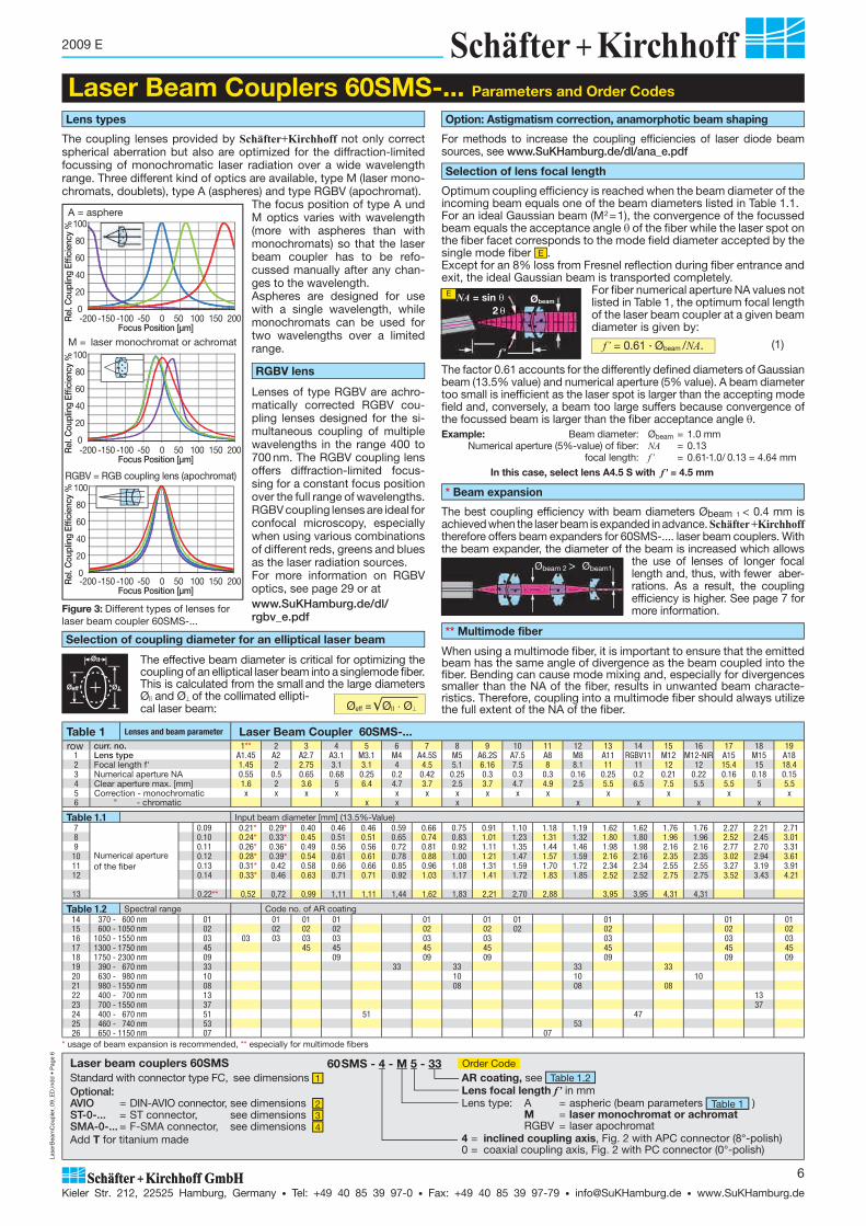
The best coupling efficiency with beam diameters Øbeam 1 < 0.4 mm is achieved when the laser beam is expanded in advance. Schäfter +Kirchhoff therefore offers beam expanders for 60SMS-.... laser beam couplers. With the beam expander, the diameter of the beam is in creased which allows
the use of lenses of longer focal length and, thus, with fewer aber-rations. As a result, the coupling efficiency is higher. See page 7 for more information.
Laser Beam Couplers 60SMS-... Parameters and Order Codes
Lens types
Lenses of type RGBV are achro-matically corrected RGBV cou-pling lenses designed for the si-multaneous coupling of multiple wavelengths in the range 400 to 700 nm. The RGBV coupling lens offers diffraction-limited focus-sing for a constant focus position over the full range of wavelengths.RGBV coupling lenses are ideal for confocal microscopy, especially when using various combinations of different reds, greens and blues as the laser radiation sources.For more information on RGBV optics, see page 29 or atwww.SuKHamburg.de/dl/rgbv_e.pdf
The coupling lenses provided by Schäfter+Kirchhoff not only correct spherical aberration but also are optimized for the diffraction-limited focussing of monochromatic laser radiation over a wide wavelength range. Three different kind of optics are available, type M (laser mono-chromats, doublets), type A (aspheres) and type RGBV (apochromat).
The focus position of type A und M optics varies with wavelength (more with aspheres than with mono chro mats) so that the laser beam coupler has to be refo-cussed manually after any chan-ges to the wavelength.Aspheres are designed for use with a single wavelength, while mono chromats can be used for two wavelengths over a limited range.
Figure 3: Different types of lenses for laser beam coupler 60SMS-...
RGBV lens
Selection of coupling diameter for an elliptical laser beam
The effective beam diameter is critical for optimizing the coupling of an elliptical laser beam into a singlemode fiber. This is calculated from the small and the large diameters Ø|| and Ø� of the collimated ellipti-cal laser beam:
Option: Astigmatism correction, anamorphotic beam shaping
For methods to increase the coupling efficiencies of laser diode beam sources, see www.SuKHamburg.de/dl/ana_e.pdf
Øeff = ��ØII � Ø�
Optimum coupling efficiency is reached when the beam diameter of the incoming beam equals one of the beam diameters listed in Table 1.1. For an ideal Gaussian beam (M2=1), the convergence of the focussed beam equals the acceptance angle � of the fiber while the laser spot on the fiber facet corresponds to the mode field diameter accepted by the single mode fiber E . Except for an 8% loss from Fresnel reflection during fiber entrance and exit, the ideal Gaussian beam is transported completely.
For fiber numerical aperture NA values not listed in Table 1, the optimum focal length of the laser beam coupler at a given beam diameter is given by:
Selection of lens focal length
E NA = sin �2 �
f’
Øbeam
f’ = 0.61 ·�Øbeam /NA. (1)
The factor 0.61 accounts for the differently defined diameters of Gaussian beam (13.5% value) and numerical aperture (5% value). A beam diameter too small is inefficient as the laser spot is larger than the accepting mode field and, conversely, a beam too large suffers because convergence of the focussed beam is larger than the fiber acceptance angle �.Example: Beam diameter: Øbeam = 1.0 mm Numerical aperture (5%-value) of fiber: NA = 0.13 focal length: f’ = 0.61·1.0/ 0.13 = 4.64 mm
In this case, select lens A4.5 S with f’ = 4.5 mm
Table 1 Lenses and beam parameter Laser Beam Coupler 60SMS-... row curr. no. 1** 2 3 4 5 6 7 8 9 10 11 12 13 14 15 16 17 18 19
1 Lens type A1.45 A2 A2.7 A3.1 M3.1 M4 A4.5S M5 A6.2S A7.5 A8 M8 A11 RGBV11 M12 M12-NIR A15 M15 A182 Focal length f' 1.45 2 2.75 3.1 3.1 4 4.5 5.1 6.16 7.5 8 8.1 11 11 12 12 15.4 15 18.43 Numerical aperture NA 0.55 0.5 0.65 0.68 0.25 0.2 0.42 0.25 0.3 0.3 0.3 0.16 0.25 0.2 0.21 0.22 0.16 0.18 0.154 Clear aperture max. [mm] 1.6 2 3.6 5 6.4 4.7 3.7 2.5 3.7 4.7 4.9 2.5 5.5 6.5 7.5 5.5 5.5 5 5.55 Correction - monochromatic x x x x x x x x x x x x x x6 " - chromatic x x x x x x x
Table 1.1 Input beam diameter [mm] (13.5%-Value) 7
Numerical aperture of the fiber
0.09 0.21* 0.29* 0.40 0.46 0.46 0.59 0.66 0.75 0.91 1.10 1.18 1.19 1.62 1.62 1.76 1.76 2.27 2.21 2.718 0.10 0.24* 0.33* 0.45 0.51 0.51 0.65 0.74 0.83 1.01 1.23 1.31 1.32 1.80 1.80 1.96 1.96 2.52 2.45 3.019 0.11 0.26* 0.36* 0.49 0.56 0.56 0.72 0.81 0.92 1.11 1.35 1.44 1.46 1.98 1.98 2.16 2.16 2.77 2.70 3.3110 0.12 0.28* 0.39* 0.54 0.61 0.61 0.78 0.88 1.00 1.21 1.47 1.57 1.59 2.16 2.16 2.35 2.35 3.02 2.94 3.6111 0.13 0.31* 0.42 0.58 0.66 0.66 0.85 0.96 1.08 1.31 1.59 1.70 1.72 2.34 2.34 2.55 2.55 3.27 3.19 3.9112 0.14 0.33* 0.46 0.63 0.71 0.71 0.92 1.03 1.17 1.41 1.72 1.83 1.85 2.52 2.52 2.75 2.75 3.52 3.43 4.21
13 0.22** 0,52 0,72 0,99 1,11 1,11 1,44 1,62 1,83 2,21 2,70 2,88 3,95 3,95 4,31 4,31
Table 1.2 Spectral range Code no. of AR coating14 370 - 600 nm 01 01 01 01 01 01 01 01 01 0115 600 - 1050 nm 02 02 02 02 02 02 02 02 02 0216 1050 - 1550 nm 03 03 03 03 03 03 03 03 03 0317 1300 - 1750 nm 45 45 45 45 45 45 45 4518 1750 - 2300 nm 09 09 09 09 09 09 0919 390 - 670 nm 33 33 33 33 3320 630 - 980 nm 10 10 10 1021 980 - 1550 nm 08 08 08 0822 400 - 700 nm 13 1323 700 - 1550 nm 37 3724 400 - 670 nm 51 51 4725 460 - 740 nm 53 5326 650 - 1150 nm 07 07
* Beam expansion
* usage of beam expansion is recommended, ** especially for multimode fibers
Øbeam1Øbeam 2 >
AR coating, see Table 1.2 Lens focal length f’ in mmLens type: A = aspheric (beam parameters Table 1 ) M = laser monochromat or achromat RGBV = laser apochromat4 = inclined coupling axis, Fig. 2 with APC connector (8°-polish)0 = coaxial coupling axis, Fig. 2 with PC connector (0°-polish)
60SMS - 4 - M 5 - 33 Order Code Standard with connector type FC, see dimensions 1 Optional:AVIO = DIN-AVIO connector, see dimensions 2 ST-0-... = ST connector, see dimensions 3 SMA-0-... = F-SMA connector, see dimensions 4 Add T for titanium made
Laser beam couplers 60SMS
When using a multimode fiber, it is important to ensure that the emitted beam has the same angle of divergence as the beam coupled into the fiber. Bending can cause mode mixing and, especially for divergences smaller than the NA of the fiber, results in unwanted beam characte-ristics. Therefore, coupling into a multimode fiber should always utilize the full extent of the NA of the fiber.
** Multimode fiber
-200 -150 -100 -50 0 50 100 150 200 Rel
. Cou
plin
g Ef
ficie
ncy
% 100
80
60
40
20
0
Focus Position [μm]
M = laser monochromat or achromat
-200 -150 -100 -50 0 50 100 150 200 Rel
. Cou
plin
g Ef
ficie
ncy
% 100
80
60
40
20
0
Focus Position [μm]
A = asphere
-200 -150 -100 -50 0 50 100 150 200 Focus Position [μm]
Rel
. Cou
plin
g Ef
ficie
ncy
% 100
80
60
40
20
0
RGBV = RGB coupling lens (apochromat)

Lase
rBea
mC
oup
ler_
09_E
D.in
dd
• P
age
7
Kieler Str. 212, 22525 Hamburg, Germany • Tel: +49 40 85 39 97-0 • Fax: +49 40 85 39 97-79 • [email protected] • www.SuKHamburg.de
7
2009 E
Adapters and Tools for laser beam couplers 60SMS-…Descriptions and technical drawings are available at www.SuKHamburg.de
Expansion Optics 48EO-...
Hex screwdriver SW Ø 1.5 mm Order Code 50HD-15
Tools for assembly and adjustment
Description see adjustment of laser beam coupler 60SMS-..., page 8.
Iris Diaphragm
Anti-Reflection Coatings
13BL1-13
Eccentric keyOrder Code 60EX-4
Screwdriver Ø 1.2 mmOrder Code 9D-12
25.4
19.5 1212
21
Order Code
Adapter 19.5 AM25
Adapter AdapterAdapter 19.5 AM25-L
20
Ø 3.8
Ø19
.5
34
25.510
6.5
3
M3
60A19.5-F
with integrated attenuator 60A19.5-F-AT
Ø19
.5
Ø25
Ø25
155
33
M3
Ø28
Ø19
.5
25.5
25
34
5
17
Adapter with integrated shutter 60A19.5-F-S
Ø19
.5
25.5
25
34
5
17
Mounting Set
60A19.5-F-MSMounting set for 60A19.5-F-... and HeNe laser4 pcs. screws 4-40 x 3/8" (similar DIN 912),washers and hex key 3/32
48MC-MP-19.5 For Ø 19.5 mm components compatible with the micro-bench system
Ø3.8
Ø3.8
Plate Order Code Order Code
Order Code Order Code Order Code Order Code
Order Code
Expansion: 3:1, 6:1 (others on request)
Expansion Optics 48EO-... 48EO - 415 - 1 - 3:1 Order Code
400 600 800 1000 1200 1400 1600 1800 2000
1
2
0
1
2
0
02 09
45
10
03
01
400 600 800 1000 1200 1400 1600 1800 2000
1
2
0
1
2
0
08
37
07
33
13
The lenses of table 1, page 6 and table 2-6, page 16 ff can be orde-red with the following AR-coationgs:
Anamorphotic Beam-Shaping Optics 5AN-...
1
2
1.1
Center wavelength [nm]1 = housing with Ø25.4 flange A
2 = Ø12 mm housing B
The best coupling efficiency with beam diameters Øbeam 1 < 0.4 mm is achieved when the laser beam is expanded in ad-vance. The beam expander allows the use of lenses of longer focal length and, thus, with fewer aberrations. As a result, the coupling efficiency is higher.
Detailed information at page 25.
Anamorphic optics act one-dimensionally on the elliptical profile of the collimated beam produced by a laser diode. By reducing the larger beam diameter and matching it with the smaller beam diameter, a radially symmetrical beam is obtained. Coupling efficiencies of 80% or more are possible with anamorphic beam-shaping optics, depending on the beam characteristics of the laser diode.
Anamorphotic Beam Shaping Optics 5AN-...Order Code and
Dimensions A, B, C can be found at page 25.
Eccentric key with long handle as an alternative to 60EX-4 Order Code 60EX-4-L
Beam expansion op-tics 48EO-...Wavelength depending correctionLaser beam source with beam diameter < 0.4 mm
1
1.1
2
1.1
2
1
1
1.1
2
Anamorphic beam-shaping optics 5AN-...Correction of laser diode astigmatismLaser beam source with elliptical beam profile

Lase
rBea
mC
oup
ler_
09_E
D.in
dd
• P
age
8
Kieler Str. 212, 22525 Hamburg, Germany • Tel: +49 40 85 39 97-0 • Fax: +49 40 85 39 97-79 • [email protected] • www.SuKHamburg.de
8
2009 E
For efficient beam coupling, the choice of coupling optics is made according to the diameter of the incoming beam and the numerical aperture of the coupled fiber. The precision adjustment mechanism is then used for the precise placement of the laser spot on the transmitted mode field of the fiber and - with polarization-maintaining fibers - for orientation of the polarization-maintaining axis of the fiber so that it is in parallel with the polarization plane of the incoming radiation.
Four steps to perfect alignment:1. Center the laser beam coupler with the laser beam propagation axis
1 by using the adapter 60A19.5F (or similar).2. Move the mode field of the fiber laterally within the laser focus area
using the tilt adjustment 2 .3. Alter the preset factory setting of the focal plane 3 (only needed for
a wavelength different from specification or when beam splitting is experienced).
4. Rotate the laser beam coupler to align the polarization-maintaining axes (only PM-fibers) 4 .
Centering the laser beam coupler with the propagation axis 1
A beam displaced laterally from the optical axis causes it to focus onto the fiber center, but with inclined propagation in relation to the fiber endface. Parts of the beam exceed the acceptance angle of the fiber A . The asymmetric propagation causes lens aberrations such as coma and astigmatism to appear. These are removed by centering the laser beam axis and coupling optic by using adapter 60A19.5F. The laser beam coupler is simply replaced by an aperture (e.g. 13BL1-13) B . The aperture diameter should be near the 1/e2
level of the laser beam. By adjusting the adapter position concentrically (using the oversized mounting holes) while measuring the laser power, the transmitted power can be maximized. The centering precision required is of the order of tenths of a millimeter. With a longer focal length lens, manual adjustment is totally adequate and quickly performed A .
Lateral adjustment of the mode field and the laser spot 2
Lateral displacement of the laser beam focus from the mode field of the fiber arises because of• production tolerances in the centering of the coupling lens and/or the centering of the fiber core in the fiber ferrule. With a mode field or spot diameter of 2-5 μm, the required precision is in the range of sub-microns D .
• inclined laser beam propaga tion E . Using a 5mm focal length lens,
a beam inclined by 1 mrad results in a lateral offset of 5 μm – completely missing the mode field. By using the tilt mechanism of the laser beam coupler, the mode field of the fiber is then placed very precisely onto the laser focus area.Cyclical tightening and release F of
the three radially arranged adjustment screws maximizes the coupled beam power. The final position is locked by the adjacent grub screws which have carbide bearings.
Focussing 3
The positioning accuracy in the coaxial direction is less critical than for the lateral directions. From the depth of field of the laser focus (Rayleigh range), a decrease in coupling efficiency of a few percent occurs even with a displacement of only a few microns G .
Schäfter + Kirchhoff laser beam couplers are supplied already adjusted for the coupled wave-
length and re- focussing is not necessary for a highly collimated laser beam.Refocussing can be performed, ho-wever, by releasing two lens locking screws (ac ces sible via small holes)
using the screwdriver 9D-12 H . Use the eccentric key 60EX-4 to correct the location of the focal plane before tightening the locking screws again.
Coupling efficiencies with f’ 5-15 mm lenses for uncentered parallel beams.
Coupling efficiencies for laser spots laterally displaced from the fiber mode field
0 10 20 30 40 50Defocus D / μm
Rel
. Eff
icen
cy %
1009080706050
430 nm532 nm660 nm
D
Coupling efficiency with unfocussed lens
H
G
Laser beam coupler with schematic illustration of the functional and adjustable elements
1 Laser beam coupler 60SMS-1-4-…2 Adapter 60A19.5-F3 Laser beam source (HeNe laser)4 Singlemode fiber cable with FC-APC connector 5 Grub screws for fixing the fiber ferrule position6 Coupling lens 7 Lens focussing mechanism 8 Locking screws for the indirect fixing of the coupling lens 9 Adjustment screws (3 x tilt adjustment) 10 Locking screws (3 x tilt adjustment) 11 Carbide bearings (3 x)
I
Orientation of the polarization axis 4Polarization-maintaining singlemode fibers guide radiation in the two orthogonal planes of oscillation (fast and slow), independently. When li-nearly polarized radiation is not exactly coupled in orientation with one of the fiber axes, the radiation is distributed between the fast and slow propagation speeds and recombines at the fiber end as elliptically pola-
rized radiation L . Linear polarization losses are major and the state of polarization is sen-sitive to vibration, temperature and fiber bending.
The laser beam coupler is rotated in the adapter
60A19.5-F K (after releasing the locking screws of the adapter with screwdriver 50HD-15) until the polarization analyzer shows a ma-ximum and stable state of polariza-tion, as confirmed by its resistance to physical displacement of the fi-ber. Lock the position by tighten the screws after adjustment
The polarization analyzer SK9782-VIS/NIR is specifically developed for analysis of the state of polarization at the fiber end. The analyzer evaluates the extinction ratio and visualize adjustments of the polarization directly.
Laser Beam Coupler 60SMS-…Assembly and adjustment
31 6 2
tilt�
10
4
5
9
11
7
8
8
B
0Rel
. Eff
icen
cy %
10080604020
0 0.5 1 1.5 2 2.5Lateral Shift / μm
3D
Rel
. Eff
icen
cy %
10090807060
500 0,2 0,4 0,6 0,8 1,0
Entrance Beam Decentration / mm
5.0 mm6.2 mm8.0 mm11 mm15 mm
A
0 0,2 0,4 0,6 0,8 1,0Entrance Beam Tilt / mrad
Rel
. Eff
icen
cy %
10080
604020 0
E
F
Coupling efficiencies for inclined beam propagation
slow axis FCconnector index
stress-inducingstructure
PM fiber, type PANDA
fibercore
K
0 2 4 6 8 10Entrance Beam Twist / Grad
Ext
inct
ion
Rat
io d
B 5040
302010 0
�
�
L
Extinction ratio for polarization axis twisted in respect to the slow and fast axis of the fiber.
J
K
Polarization Analyzer SK9782-VIS/NIRMeasurement and test system for laser sour ces with PM singlemode fiber cables, see page 53.
Fib
erC
able
_09_
ED
.ind
d •
Pag
e 9
Kieler Str. 212, 22525 Hamburg, Germany • Tel: +49 40 85 39 97-0 • Fax: +49 40 85 39 97-79 • [email protected] • www.SuKHamburg.de
9
2009 E
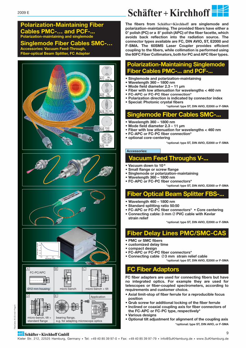
• Wavelength 460 – 1800 nm• Standard splitting ratio 50:50• FC-APC or FC-PC fiber connectors* • Core centering• Connecting cable: 3 mm Ø PVC cable with Kevlar strain relief
*optional: type ST, DIN AVIO, E2000 or F-SMA
• PMC or SMC fibers• customized delay time• compact design• FC-APC or FC-PC fiber connectors*• Connecting cable Ø 3 mm strain relief cable
*optional: type ST, DIN AVIO, E2000 or F-SMA
• Singlemode and polarization-maintaining • Wavelength 360 – 1800 nm• Mode field diameter 2.3 – 11 μm• Fiber with low attenuation for wavelengths < 460 nm• FC-APC or FC-PC fiber connection*• Polarization direction is indicated by connector index• Special: Photonic crystal fibers
*optional: type ST, DIN AVIO, E2000 or F-SMA
Polarization-Maintaining Fiber Cables PMC-… and PCF-...Polarization-maintaining and singlemode
Singlemode Fiber Cables SMC-…Accessories: Vacuum Feed-Through, Fiber-optical Beam Splitter, FC Adapter
• Wavelength 360 – 1800 nm• Mode field diameter 2.3 – 11 μm• Fiber with low attenuation for wavelengths < 460 nm• FC-APC or FC-PC fiber connection*• optional core-centering
*optional: type ST, DIN AVIO, E2000 or F-SMA
FC fiber adapters are used for connecting fibers but have no integrated optics. For example they are used for telescopes or fiber-coupled spectrometers, according to requirements and customer choice.• Axial limit-stop of fiber ferrule for a reproducible focus
position• Grub screw for additional locking of the fiber ferrule• Inclined or coaxial coupling axis for fiber connectors of
the FC-APC or FC-PC type, respectively*• Various designs• Optional tilt adjustment for alignment of the coupling axis
*optional: type ST, DIN AVIO, or F-SMA
• Vacuum down to 10-9
• Small flange or screw flange• Singlemode or polarization-maintaining• Wavelength 360 – 1800 nm• FC-APC or FC-PC fiber connectors*
*optional: type ST, DIN AVIO, E2000 or F-SMA
A1 PM:BOW-TIE
A2 PM:PANDA
A3 PM: OVAL INNER CLAD
A4 Single-mode
A5 PCF
CA B
ED
The fibers from Schäfter+Kirchhoff are singlemode and polarization-maintaining. The provided fibers have either a 0° polish (PC) or a 8° polish (APC) of the fiber facette, which avoids back reflection into the radiation source. The connector types available are FC, DIN AVIO, ST, E2000 and F-SMA. The 60SMS Laser Coupler provides efficient coupling to the fibers, while collimation is performed using the 60FC Fiber Collimators, both for PC and APC fiber types.
Polarization-Maintaining Singlemode Fiber Cables PMC-... and PCF-...
Singlemode Fiber Cables SMC-...
Accessories:
Vacuum Feed Throughs V-...
Fiber Optical Beam Splitter FBS-...
Fiber Delay Lines PMC/SMC-CAS
FC Fiber Adaptors
Application
Ø12 mm housing
FC-PC/APC
micro-bench micro-bench + tilt
micro-bench, tilt + standard flange
bearing flange, e.g. for adapting microscope optics
400 600 800 10004.85
4.9
4.95
5
5.05
5.1
Wavelength λ [nm]
Gro
up d
elay
τ �[n
s/m
]

Fib
erC
able
_09_
ED
.ind
d •
Pag
e 10
Kieler Str. 212, 22525 Hamburg, Germany • Tel: +49 40 85 39 97-0 • Fax: +49 40 85 39 97-79 • [email protected] • www.SuKHamburg.de
10
2009 E
Figure 1: Singlemode fiber cable with different types of polarization-maintaining singlemode fibers 1A - 1C , a standard single mode fiber 1D and photonic crystal fiber 1E .
co
operation range
A
losses due to bending(schematic)
typ. 1.3 co
singlemode
BSchäfter + Kirchhoff HamburgIntensity ProfileLaser Beam Analysis:
Ref.: SK970703 Intensities100.0%
90.0%80.0%70.0%60.0%50.0%40.0%30.0%20.0%10.0%
Object:
Fiber CollimatorCollimating Lens M12Beam Diameter (1/e2) 2.18 mm
Gaussian Fit
C
multimode Figure 5:Operating wavelength range of a singlemode fiber A
Gaussian mode profile of a singlemode fiber B and C
By using a fiber with a wavelength just below the cut-off wavelength, the multiple modes of the butterfly effect D and E are producedin this example: co = 780 nm = 633 nm
Polarization-maintaining singlemode fibers guide coupled radiation in two perpendicular principal states with different speeds of propagation, denoted the fast and slow fiber axes.Linearly polarized radiation not coupled exactly into one of these axes is transformed into an elliptical state of polarization because of these different speeds of propagation.Polarization-maintaining fibers are either step index fibers or photonic crystal fibers and the two unequal axes are caused by birefringence from stress-induction components in the fiber cladding, as in „PANDA“ fibers, „Bow-Tie“ fibers or „Oval-Inner Clad“ fibers. The slow axis is orientated in parallel with the stress-inducing elements („PANDA“ and „Bow-Tie“ fiber) or in parallel with the larger diameter of the inner cladding („Oval-Inner Clad“ fiber). The linearly polarized laser radiation is usually coupled into the slow axis, because of its lower sensitivity to bending, Fig. 2 .The polarization-maintaining fiber cables made by Schäfter+Kirchhoff have the fiber axes aligned with the index of the FC type fiber connector with extremely high precision (<1°).The fiber cables made by Schäfter+Kirchhoff typically have a polarization extinction > 200:1 (23 dB), for > 780 nm > 400:1 (26 dB).
Good Alignment: Connector key axis = slow axisOutput beamlinearly polarized
Bad Alignment:Connector key axis slow axisOutput beam linearly + circularly polarized
• Polarization-maintaining singlemode• Wavelength 360 – 1550 nm• Mode field diameter 2.3 – 11 μm• Fiber with low attenuation for wavelength < 460 nm• FC-APC or FC-PC fiber connector• Polarization direction is indicated by connector index• Special: Photonic crystal fiber
• Singlemode• Wavelength 360 – 1550 nm• Mode field diameter 2.3 – 11 μm• Fiber with low attenuation for wavelength < 460 nm• FC-APC or FC-PC fiber connector• Core-centering as an option
The cut-off wavelength co is defined as the shortest wavelength for which a guided wave is singlemode. The beam profile can only have a Gaussian intensity distribution and rotational symmetry above co.If the wavelength of the guided radiation is shorter than the cut-off wa velength specified, two or more modes are guided with decrea sing wavelength. The beam and intensity profile differ significantly from a Gaussian distribution. Asymmetry through bending of the fiber or temperature changes (butterfly effect) is worse.If the operation wavelength is longer than the cut-off wavelength, the guidance of the radiation becomes increasingly weaker. A movement or bending of the fiber (even micro-bends) cause attenuation of the guided radiation.The wavelength range in which the fiber is singlemode depends on the fiber parameter and can reach 1.3 times co. The usable wavelength range of fibers with a pure silica core is smaller. When more than one fiber from tables 1, 2, and 3 can be used for a particular wavelength then the fiber with a larger cut-off wavelength should be chosen.The cut-off wavelenth co of a fiber can be up to 10% different from the specified values because of manufacturing tolerances. Selected fibers with characterized values are available on request.
D E
Figure 2: Orientation of the axes of a polarization-maintaining fiber to the connector index
Cut-Off Wavelength
Polarization-Maintaining Fibers
2A 2B
Schäfter+Kirchhoff provides polarization-maintaining photonic crystal fibers, PCF, in addition to the standard singlemode and polarization-maintaining fibers. PCFs are optimized for single-mode operation in a wide spectral range in combination with a relatively large mode field diameter and are made from fused silica, which makes the fiber extremely stable for radiation at short wavelengths. In contrast with step index singlemode fibers, it is the numerical aperture (and not the mode field diameter) that varies proportionally with the wavelength used. In addition, the fiber provides practically endless singlemode operation with no cut-off wavelength. In this regard, attenuation is approximately 10 dB higher at shorter wavelengths, in comparison with pure silica core fibers, and the beam only approximates to a Gaussian profile.
Photonic Crystal Fibers
Figure 3: Differences between p o l a r i z a t i o n -m a i n t a i n i n g photonic crystal
fibers PCF (left) and standard single-mode fibers SMC/PMC (right). For PCF fibers, NA is function of wavelength, while MFD is constant. For SMC/PMC fibers, the converse applies and MFD varies with wavelength.
NA() NA = const. MFD()MFD = const.
1A PM:BOW-TIE
1B PM:PANDA
1C PM: OVAL INNER CLAD
1D Single-mode
1E PCF
PCF
Singlemode fiberCore diameterMFD = mode field ØIntensity level 13.5%Intensity level 5 % 2 ��NA (5 %)2 ��NA (13.5 %)
SF
1
2
3
4
5
6
Ø50%Ø13.5%
Ø 5%
3
6
24 1
5
SF
Figure 4: Beam profile of a sinlgemode fiber, definition of numerical aperture NA, angle of beam divergence � and mode field diameter MFD
The numerical aperture NA of a singlemode fiber describes the angle of beam divergence (5% level) of the Gaussian-shaped radiation that is emitted by the fiber and is defined as the sine of half the angle of beam divergence: NA = sin �/2 .
The total angle of beam divergence � in degrees is calculated from NA via the equation: � = 2 ��NA ��180°/ ��� 114.6° ��NAExample: numerical aperture NA = 0.11 angle of beam divergence � � 12.6°.For singlemode fibers and for polarization-maintaining fibers, NA is normally independent of the used wavelength .
Numerical Aperture
Singlemode SMC-...
Polarization-Maintaining Singlemode Fiber Cables PMC-...
Angular offset
Core
Connector Key
PCF-... PMC-...
Fib
erC
able
_09_
ED
.ind
d •
Pag
e 11
Kieler Str. 212, 22525 Hamburg, Germany • Tel: +49 40 85 39 97-0 • Fax: +49 40 85 39 97-79 • [email protected] • www.SuKHamburg.de
11
2009 E
Ø 0.9 Ø 3
L1 FC connector for SMC-... fiber
cables, L1 = 45 mm fiber cable Ø 3 mm,
integr. Kevlar strain relief
L2 FC connector for PMC-... fiber cables, (polarization-maintaining) L2 = 58 mm
L3 FC connector (Short) for SMC-... fiber cables, L3 = 25 mmfiber cable Ø 0.9mm (nylon buffer)
L4 FC connector (Short) for PMC-... fiber cables, (polarization-maintaining) L4 = 39 mm, fiber cable Ø 0.9mm (nylon buffer)
Ø 0.9
Ø 3
L4
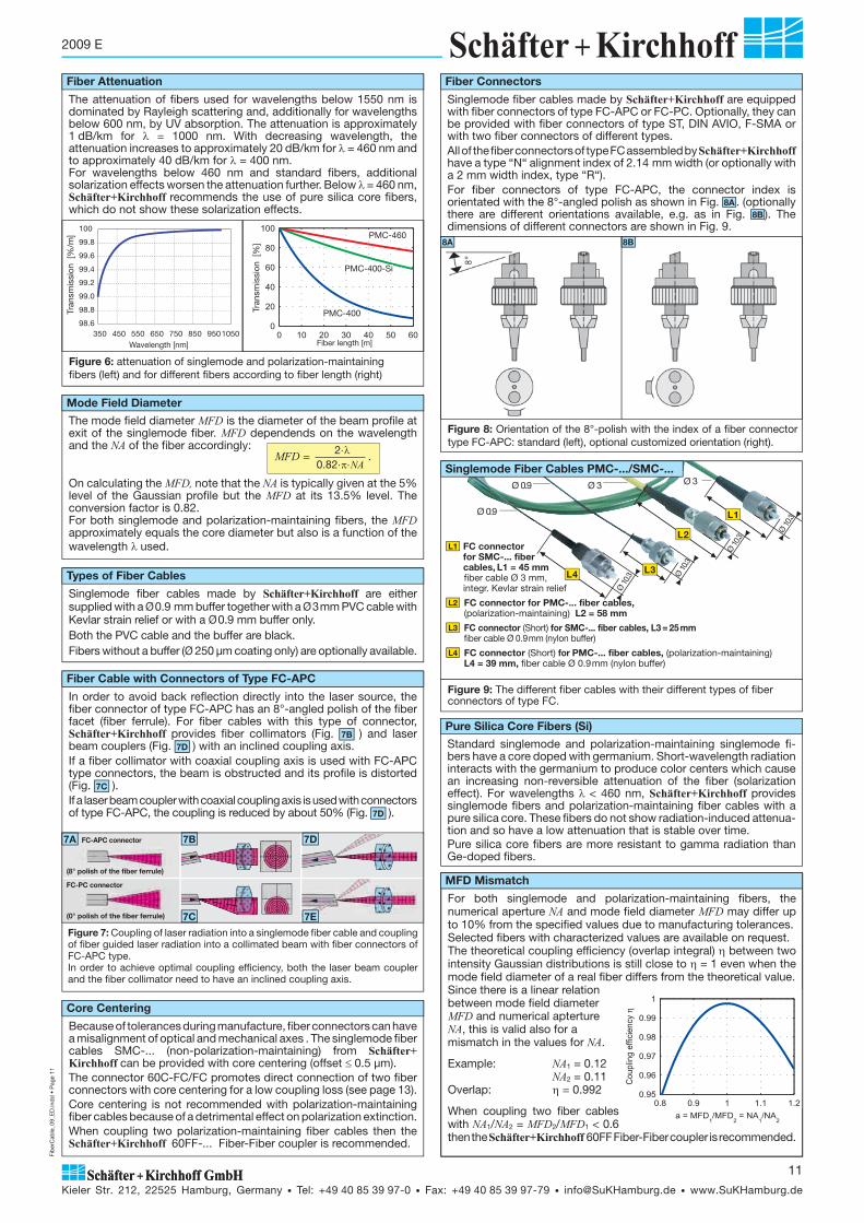
Figure 9: The different fiber cables with their different types of fiber connectors of type FC.In order to avoid back reflection directly into the laser source, the
fiber connector of type FC-APC has an 8°-angled polish of the fiber facet (fiber ferrule). For fiber cables with this type of connector, Schäfter+Kirchhoff provides fiber collimators (Fig. 7B ) and laserbeam couplers (Fig. 7D ) with an inclined coupling axis.If a fiber collimator with coaxial coupling axis is used with FC-APC type connec tors, the beam is obstructed and its profile is distorted (Fig. 7C ).If a laser beam coupler with coaxial coupling axis is used with connectors of type FC-APC, the coupling is reduced by about 50% (Fig. 7D ).
Figure 7: Coupling of laser radiation into a singlemode fiber cable and coupling of fiber guided laser radiation into a collimated beam with fiber connectors of FC-APC type.In order to achieve optimal coupling efficiency, both the laser beam coupler and the fiber collimator need to have an inclined coupling axis.
5B
5C
7A
(0° polish of the fiber ferrule)
FC-APC connector
FC-PC connector
(8° polish of the fiber ferrule)
7E7C
7B 7D
Because of tolerances during manufacture, fiber connectors can have a misalignment of optical and mechanical axes . The singlemode fiber cables SMC-... (non-polarization-maintaining) from Schäfter+Kirchhoff can be provided with core centering (offset �0.5 μm).The connector 60C-FC/FC promotes direct connection of two fiber connectors with core centering for a low coupling loss (see page 13).Core centering is not recommended with polarization-maintaining fiber cables because of a detrimental effect on polarization extinction.When coupling two polarization-maintaining fiber cables then the Schäfter+Kirchhoff 60FF-... Fiber-Fiber coupler is recommended.
Singlemode fiber cables made by Schäfter+Kirchhoff are equipped with fiber connectors of type FC-APC or FC-PC. Optionally, they can be provided with fiber connectors of type ST, DIN AVIO, F-SMA or with two fiber connectors of different types.All of the fiber connectors of type FC assembled by Schäfter+Kirchhoff have a type “N“ alignment index of 2.14 mm width (or optionally with a 2 mm width index, type “R“).For fiber connectors of type FC-APC, the connector index is orientated with the 8°-angled polish as shown in Fig. 8A . (optionally there are different orientations available, e.g. as in Fig. 8B ). The dimensions of different connectors are shown in Fig. 9.
Singlemode fiber cables made by Schäfter+Kirchhoff are either supplied with a Ø 0.9 mm buffer together with a Ø 3mm PVC cable with Kevlar strain relief or with a Ø 0.9 mm buffer only.Both the PVC cable and the buffer are black.Fibers without a buffer (Ø 250 μm coating only) are optionally available.
0 10 20 30 40 50 600
20
40
60
80
100PMC-460
PMC-400-Si
PMC-400Tran
smis
sion
[%
]
Fiber length [m]
For both singlemode and polarization-maintaining fibers, the numerical aperture NA and mode field diameter MFD may differ up to 10% from the specified values due to manufacturing tolerances.Selected fibers with characterized values are available on request.The theoretical coupling efficiency (overlap integral) � between two intensity Gaussian distributions is still close to � = 1 even when the mode field diameter of a real fiber differs from the theoretical value.Since there is a linear relation between mode field diameter MFD and numerical apterture NA, this is valid also for a mismatch in the values for NA.
Example: NA1 = 0.12 NA2 = 0.11Overlap: � = 0.992
When coupling two fiber cables with NA1/NA2 = MFD2/MFD1 < 0.6 then the Schäfter+Kirchhoff 60FF Fiber-Fiber coupler is recommended.
Fiber Cable with Connectors of Type FC-APC
Fiber Connectors
Core Centering
Figure 8: Orientation of the 8°-polish with the index of a fiber connector type FC-APC: standard (left), optional customized orientation (right).
8B8A
Types of Fiber Cables
Figure 6: attenuation of singlemode and polarization-maintainingfibers (left) and for different fibers according to fiber length (right)
a = MFD1/MFD
2 = NA
1/NA
2
0.8 0.9 1 1.1 1.20.95
0.96
0.97
0.98
0.99
1
Cou
plin
g ef
ficie
ncy
η
The attenuation of fibers used for wavelengths below 1550 nm is dominated by Rayleigh scattering and, ad ditionally for wavelengths below 600 nm, by UV absorption. The attenuation is approximately 1 dB/km for = 1000 nm. With decreasing wavelength, the attenuation increases to approximately 20 dB/km for = 460 nm and to approximately 40 dB/km for = 400 nm.For wavelengths below 460 nm and standard fibers, additional solarization effects worsen the attenuation further. Below = 460 nm, Schäfter+Kirchhoff recommends the use of pure silica core fibers, which do not show these solarization effects.
The mode field diameter MFD is the diameter of the beam profile at exit of the singlemode fiber. MFD dependends on the wavelength and the NA of the fiber accordingly:
On calculating the MFD, note that the NA is typically given at the 5% level of the Gaussian profile but the MFD at its 13.5% level. The conversion factor is 0.82.For both singlemode and polarization-maintaining fibers, the MFD approximately equals the core diameter but also is a function of the wavelength used.
2�� 0.82�����NA
MFD = .
Mode Field Diameter
Standard singlemode and polarization-maintaining singlemode fi-bers have a core doped with germanium. Short-wavelength radiation interacts with the germanium to produce color centers which cause an increasing non-reversible attenuation of the fiber (solarization effect). For wavelengths �< 460 nm, Schäfter+Kirchhoff provides singlemode fibers and polarization-maintaining fiber cables with a pure silica core. These fibers do not show radiation-induced attenua-tion and so have a low attenuation that is stable over time.Pure silica core fibers are more resistant to gamma radiation than Ge-doped fibers.
Pure Silica Core Fibers (Si)
Ø 10
.3
L3 Ø 10
.3
L2
Ø 10
.3
L1
Ø 10
.3
Tran
smis
sion
[%
/m]
Wavelength [nm]350 450 550 650 750 850 9501050
98.6
98.8
99.0
99.2
99.4
99.6
99.8
100
MFD Mismatch
Singlemode Fiber Cables PMC-.../SMC-...
Fiber Attenuation

Fib
erC
able
_09_
ED
.ind
d •
Pag
e 12
Kieler Str. 212, 22525 Hamburg, Germany • Tel: +49 40 85 39 97-0 • Fax: +49 40 85 39 97-79 • [email protected] • www.SuKHamburg.de
12
2009 E
PM fiber type:S = standard (fiber type not specified)P = PandaB = Bow-TieV = Oval-Inner Clad
Length in cm (standard = 150)
Connector Type:APC = FC-APC (8°-angled polish)0PC = FC-PC (0°-polish)XPC = one end FC-APC, other FC-PCAVIO, AVIO-APC
cable type:3 = Ø 3 mm PVC cable with Kevlar strain relief (standard)1 = fiber cable with Ø 0.9 mm buffer (w. FC conn. short design)
Numerical aperture NA
PMC-780-5.0-NA012-3-APC-150-S
Polarization-Maintaining Singlemode Fiber Cables PMC-...
Order Code
Si For wavelengths < 460 nm, Schäfter+Kirchhoff provides polarization-maintaining singlemode fiber cables with extra low attenuation that have a pure silica core and are devoid of solarization effects.F
Selection diagramm for polarization-maintaining singlemode fiber cables PMC-....
Table 1 Polarization Maintaining Fiber Cable PMC-... row curr. no 1 2 3 4 5 6 7 8 9 10 11 12 13
1 Nominal wavelength nom 360 Si 400 Si 460 Si 460 Si 460 530 630 Si 630 780 980 980 1300 1550
2 Cut-off wavelength co* < 360 < 400 < 460 < 460 < 460 < 530 < 630 < 630 < 780 < 980 < 980 < 1300 < 1550
3 Operation wavelength range 360 - 460
400 - 500
460 - 550
460 - 550
460 - 630
530 - 700
630 - 780
630 - 800
780 - 1000
980 - 1300
980 - 1300
1300 - 1600
1550 - 1800
4 Mode field diameter MFD [μm]** 2.3 - 3.0 2.8 - 3.5 3.2 - 3.9 4.0 - 4.7 3.2 - 4.4 4.1 - 5.4 4.4 - 5.5 4.4 - 5.6 5.0 - 6.5 6.3 - 8.4 9.5 -
12.69.2 - 11.3
10 - 11.6
5 Numerical aperture NA* [μm] 0.12 0.11 0.11 0.09 0.11 0.10 0.11 0.11 0.12 0.12 0.08 0.11 0.12
6 PM fiber type P P P P P P P P P P P P P
7 Large MFD X X X
8 Pure Silica core X X X X X
* Determined by the 5% level** Calculated from the NA and from the wavelength
Mode field diameter MFD at nominal wavelength
Nominal wavelength (+Si when stated)
PMC = polarization-maintaining singlemode fiber cable
The major parameters of a polarization-maintaining singlemode fibers are numerical aperture NA, mode field diameter MFD and cut-off wavelenth co. Manufacturing tolerances mean specified values may differ by up to 10%. Selected fibers with characterized values are available on request.
Fibers with the current numbers 4, 6, and 11 are fibers with a large mode field diameter and are used for coupling higher optical powers.
The offered fibers in table 1 are just an extract of all fibers delivera-ble. Please contact Schäfter+Kirchhoff if the required specifications vary from the listed values at table 1. By selecting the fibers it is possible for Schäfter+Kirchhoff to offer fibers with different MFD, NA, cut-off wavelenth and operation wavelength then specified from the manufacturer.
Order Options
Polarization-Maintaining Photonic Crystal Fiber PCF-...
curr. no 1
Nominal wavelength nom UV
Cut-off wavelength co none
Operation wavelength range UV - 800
Mode field diameter MFD [μm] 4.2 ± 0.5
Numerical aperture NA [μm] 0.087 ± 0.01 @ 470 nm
Picture of the hexagonal micro structure of the photonic crystal fiber. The major advantages of this fiber are the large mode field diameter and the wide spectral range during singlemode operation.
Polarization-Maintaining Photonic Crystal Fibers PCF-...
PCF-UV
400 600 800 1000 1200 1400 1600 1800
wavelength [nm]Spectral diagramm for polarization-maintaining singlemode photonic crystal fiber PCF-....
405 nm
532 nm
685 nm
Polarization-maintaining photonic crystal fibers have a constant mode field diameter and the NA depends on the wavelength. Therefore, the FWHM of the intensi-ty profiles increase with the wavelength.
More information about PCF-... fibers, see page 30
�NA � 0.07
�NA � 0.09
�NA � 0.12
5%-Level
NA()MFD = const.
0.06
0.08
0.1
0.12
0.14
0.16
3
3.5
4
4.5
5
5.5
350 450 550 650 750 850wavelength [nm]
NA
MFD
[μm
]
Fib
erC
able
_09_
ED
.ind
d •
Pag
e 13
Kieler Str. 212, 22525 Hamburg, Germany • Tel: +49 40 85 39 97-0 • Fax: +49 40 85 39 97-79 • [email protected] • www.SuKHamburg.de
13
2009 E
cable type:3 = Ø 3 mm PVC cable with Kevlar strain relief (standard)1 = fiber cable with Ø 0.9 mm buffer (w. FC conn. short design)Numerical aperture NAMode field diameter MFD at nominal wavelengthNominal wavelength (+Si when stated)SMC = singlemode fiber cable
SMC-630-4.4-NA011-3-APC-0-150
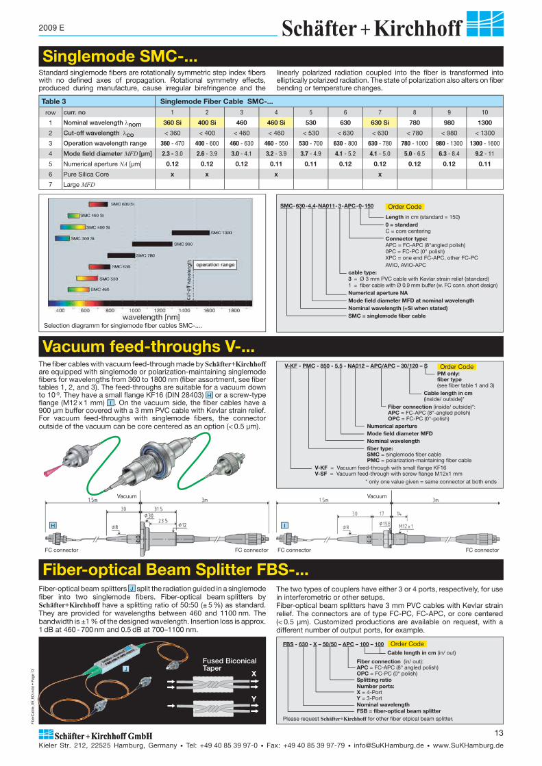
Table 3 Singlemode Fiber Cable SMC-... row curr. no 1 2 3 4 5 6 7 8 9 10
1 Nominal wavelength nom 360 Si 400 Si 460 460 Si 530 630 630 Si 780 980 1300
2 Cut-off wavelength co < 360 < 400 < 460 < 460 < 530 < 630 < 630 < 780 < 980 < 1300
3 Operation wavelength range 360 - 470 400 - 600 460 - 630 460 - 550 530 - 700 630 - 800 630 - 780 780 - 1000 980 - 1300 1300 - 1600
4 Mode field diameter MFD [μm] 2.3 - 3.0 2.6 - 3.9 3.0 - 4.1 3.2 - 3.9 3.7 - 4.9 4.1 - 5.2 4.1 - 5.0 5.0 - 6.5 6.3 - 8.4 9.2 - 11
5 Numerical aperture NA [μm] 0.12 0.12 0.12 0.11 0.11 0.12 0.12 0.12 0.12 0.11
6 Pure Silica Core x x x x
7 Large MFD
FBS - 630 - X – 50/50 – APC – 100 – 100
Cable length in cm (in/ out)
Fiber connection (in/ out): APC = FC-APC (8° angled polish) OPC = FC-PC (0° polish) Splitting ratio Number ports: X = 4-Port Y = 3-Port Nominal wavelength FSB = fiber-optical beam splitterPlease request Schäfter+Kirchhoff for other fiber otpical beam splitter.
J
Fiber-optical beam splitters J split the radiation guided in a singlemode fiber into two singlemode fibers. Fiber-optical beam splitters by Schäfter+Kirchhoff have a splitting ratio of 50:50 (± 5 %) as standard. They are provided for wavelengths between 460 and 1100 nm. The bandwidth is ±1 % of the designed wavelength. Inser tion loss is approx. 1 dB at 460 - 700 nm and 0.5 dB at 700–1100 nm.
The two types of couplers have either 3 or 4 ports, respectively, for use in interferometric or other setups.Fiber-optical beam splitters have 3 mm PVC cables with Kevlar strain relief. The connectors are of type FC-PC, FC-APC, or core centered (< 0.5 μm). Customized productions are available on request, with a different number of output ports, for example.
Length in cm (standard = 150)0 = standardC = core centeringConnector type:APC = FC-APC (8°angled polish)0PC = FC-PC (0° polish)XPC = one end FC-APC, other FC-PCAVIO, AVIO-APC
Standard singlemode fibers are rotationally symmetric step index fibers with no defined axes of propagation. Rotational symmetry effects, produced during manufacture, cause irregular birefringence and the
linearly polarized radiation coupled into the fiber is transformed into elliptically polarized radiation. The state of polarization also alters on fiber bending or temperature changes.
The fiber cables with vacuum feed-through made by Schäfter+Kirchhoff are equipped with singlemode or polarization-maintaining singlemode fibers for wave lengths from 360 to 1800 nm (fiber assort ment, see fiber tables 1, 2, and 3). The feed-throughs are sui table for a vacuum down to 10-9. They have a small flange KF16 (DIN 28403) H or a screw-type flange (M12 x 1 mm) I . On the vacuum side, the fiber cables have a 900 μm buffer covered with a 3 mm PVC cable with Kevlar strain relief. For vacu um feed-throughs with singlemode fibers, the connector outside of the vacuum can be core centered as an option (< 0.5 μm).
V-KF - PMC - 850 - 5.5 - NA012 – APC/APC – 30/120 – S PM only: fiber type (see fiber table 1 and 3)
Cable length in cm (inside/ outside)* Fiber connection (inside/ outside)*: APC = FC-APC (8°-angled polish) OPC = FC-PC (0°-polish) Numerical aperture Mode field diameter MFD Nominal wavelength fiber type: SMC = singlemode fiber cable PMC = polarization-maintaining fiber cable V-KF = Vacuum feed-through with small flange KF16 V-SF = Vacuum feed-through with screw flange M12x1 mm
* only one value given = same connector at both ends
H I
FC connector FC connectorFC connector FC connector
Vacuum Vacuum
Selection diagramm for singlemode fiber cables SMC-....
Order Code
Order Code
Order Code
Singlemode SMC-...
Vacuum feed-throughs V-...
Fiber-optical Beam Splitter FBS-...
X
Y
Fused Biconical Taper

Fib
erC
able
_09_
ED
.ind
d •
Pag
e 14
Kieler Str. 212, 22525 Hamburg, Germany • Tel: +49 40 85 39 97-0 • Fax: +49 40 85 39 97-79 • [email protected] • www.SuKHamburg.de
14
2009 E
Mating sleeves provide a direct (physical contact) connection between two singlemode or two polari zation-maintaining fiber cables SMC-... and PMC-... respectively. Either two connectors of type FC-PC (0° po-lish) or of type FC-APC (8° polish) can be connected.Mating sleeves for two FC connectors (panel mount F ): 60C-FC/FCHybrid adapter for joining connector type E-2000 to connector type FC (panel mount G ): 60C-FC/E2000
FC fiber adapters are used either for beam outputs, where no collimation or focussing of the beam is necessary, or for beam coupling to fiber connectors but without integrated optics, e.g. because microscope optics are used. Schäfter+Kirchhoff FC fiber adaptors have a fiber connection with inclined coupling axis for use with fiber connectors of the FC-APC type or a fiber connection with co axial coupling axis for use with fiber connector of the FC-PC type (optional types: ST, DIN AVIO, or F-SMA). Other performance features include:
• Axial limit stop of the fiber ferrule for a constant focus position, especially with fiber adapters with inclined coupling axis
• Grub screw for an additional locking of the fiber ferrule• With integrated tilt adjustment for alignment of the coupling axis• FC fiber adapter with tilt adjustment and integrated quarter-wave plate
for generating circularly polarized radiation. Typical application: magneto-optical atom traps (see www.SuKHamburg.de\dl\appmot_e.pdf).
Figure 9: PMC-CAS-... Fiber-optical delay line with polarization-maintaining fiber PMC – CAS - 780-5.1-NA013-APC-100000-150/150-S Order Code
Pigtail length in cm (in / out)* Fiber lengths in cm
Fiber connection (in/ out)*: APC = FC-APC (8° angled polish) OPC = FC-PC (0° polish) Numerical aperture NA Mode field diameter MFD Nominal wavelength PMC polarization maintaining fiber SMC singlemode fiber* when only one value given = same connector at both ends
}see fiber tables 1 - 3
Fiber cables are used as optical delay lines. The group delay �g () of a singlemode fiber is given by:
for the effective refractive index neff ()As a good approximation, the effective refractive index of the singlemode fiber neff () is the same as the core index, ncore (). The group delay for this approximation is shown (left) for a fiber with NA 0.11 over a wavelength range of ����400 - 1000 nm. Schäfter+Kirchhoff offers singlemode fibers and polarization-maintaining fibers with lengths > 20 m, also spooled in compact cassettes. The two fiber ends are pigtailed with Ø 3 mm cabling, strain relief, and fiber connectors.
l��ng()c
�g() = , dneff ()dng() = neff () - ����������� .
FC Mating Sleeves
15
Ø2,
2
Ø9
9,5
15
4.95.95
221813
6.5
28.45
F G 60C-FC/FC 60C-FC/E2000Order Code Order Code
Order Code
Order Code
Fiber Delay Lines PMC/SMC-CAS-...
FC Fiber Adapters without Optics
FC-APC adapter Order Code
25AF-4-FC
FC-PC adapter Order Code
25AF-0-FC
25AF-... FC adapter with Ø25 mm fit for micro-bench system e.g. for collimators with long focal length.
FC-APC adapter Order Code
12AF-4-FC
FC-PC adapter Order Code
12AF-0-FC
12AF-... compact design with Ø12 mm diameter.
FC-APC adapter Order Code
25AM-4-FC
FC-PC adapter Order Code
25AM-0-FC
25AM-... FC adapter with Ø25 mm fit for micro-bench system with integrated tilt adjustment for aligning the axis of the emitted radiation.
FC-APC adapter Order Code
19.5AC-4-FC
FC-PC adapter Order Code
19.5AC-0-FC
19.5AC-... FC adapter with tilt adjustment for aligning the axis of the emitted radiation. With standard adapter flange Ø19.5 mm.
4x M2
Ø20
3Ø16 FC-APC adapter
Order Code 10AF-4-FC
FC-PC adapter Order Code
10AF-0-FC
10AF-... FC adapter as OEM version with bearing flange.Application Simultaneous fiber coupling of different laser sources by use of chromatic
corrected microscopy lenses for fluorescence microscopy.
Application
chromatic-corrected microscopy lenses
FC-APC adapter with bearing flange
42TE/ 213.2 168 208.62.5
3HE
/ 12
8.4
Dimensions
400 600 800 10004.85
4.9
4.95
5
5.05
5.1
Wavelength λ [nm]
Gro
up d
elay
τ �[n
s/m
]

Fib
erC
ollim
ator
s_09
_ED
.ind
d •
Pag
e 15
Kieler Str. 212, 22525 Hamburg, Germany • Tel: +49 40 85 39 97-0 • Fax: +49 40 85 39 97-79 • [email protected] • www.SuKHamburg.de
15
2009 E
In order to avoid back reflection directly into the laser source, the fiber connector of type FC-APC has an 8°-angled polish of the fiber facet (fiber ferrule). Therefore, Schäfter+Kirchhoff provides fiber collimators with inclined coupling axis (Fig. B ) and coaxial coupling axis (Fig. C ).If a fiber collimator with coaxial coupling axis is used with FC-APC type connec tors (Fig. D ), or vice versa, a fiber wirth 0° polish is used incorrectly with an inclined coupled fiber collimator (Fig. E ) then the beam is obstructed and its profile is distorted.
The fiber collimators made by Schäfter+Kirchhoff transform the divergent radiation emitted at the end of a singlemode fiber into a collimated beam of 0.5 to 36 mm diameter. The fiber collimators have a coaxial or inclined coupling axis for connection to a fiber connector of the types FC-PC and FC-APC. The fiber collimators have a fitting for the connection of micro-focus optics, used for generation of micro spots � 0.6 μm, or for pola ri zation filters.
Performance features of the fiber collimators are:• Assortment of 30 collimating lenses with focal lengths between
2.7 and 200 mm • AR coatings 370 – 2300 nm with > 100 nm bandwidth each • Inclined or coaxial coupling axis for fiber connectors of the type
FC-APC and FC-PC, respectively (optional type ST, DIN AVIO or F-SMA, see Fig. 2)
• Lens focussing with indirect clamping, even with adapters • Front connection for the attachment of optical adapters• FC connection with axial limit stop for the fiber ferrule (constant
focus position, in particular for fiber collimators with inclined cou-pling axis)
• FC connection with grub screw for addi tional locking of the fiber ferrule (in creased pointing stability of the laser beam).
• Option: fiber collimators with integrated quarter-wave plate for circularly polarized laser beams.
Application: magneto-optical trap (MOT)
Fiber collimator 60FC-T-... with integrated TILT adjustment
The line 60FC-T-... has a fiber connection with integrated TILT adjustment. In
case of fiber collimators with large focal length (f’ 20 mm to
f’ 200 mm) the emitted beam can accurately
be aligned A to the mechani-
cal axis.
Accessories: Micro Focus Optics / Polarization filters
Fiber Collimators 60FC-T-... / 60FC-Q...
Micro-focus Optics5M-.../13M-.../25M-...
Polarization filter 5PF-.../13PF-...
Table 1 Overview Fiber Collimators
Fiber Collimator
Table / curr. no. Ø [mm] f ' [mm] Ø [mm] [mm]
Tab. 2 12 2.7 - 20 0.5 - 3.6 x x x x Ø 8Tab. 3, no. 1 - 6 25 20 - 60 3.6 - 11 x x x x x x Ø 19.5Tab. 3, no. 7 - 10 32 40 - 100 7.2 - 18 x x x x x x M27x0.5Tab. 3, no. 11 - 13 55 100 - 200 18 - 36 x x x x x x Ø 52
Fiber connection with integrated tilt adjustment flangeOption: Fiber connection with integrated retardation opticsOption: Fiber connection type ST, F-SMA, or DIN-AVIOFront fitting for additional optics
Fiber connectionInclined for FC-APC connectors (8° polish)Coaxial for FC-PC connectors (0° polish)Internal lens focussingBeam diameter (1/e2)Focal lengthHousing diameter
Fiber Collimators 60FC-… APC or PC connector interface
60FC-T-… Integrated beam alignment
60FC-Q-… Integrated retardation optics /4
Accessories: Micro-Focus Optics 5M-... / 13M-...,Polarizations Optics 5PF-... / 13PF-...
Micro-focus optics 5M-.../13M-.../25M-... (page 18)Micro-focus optics in combination with fiber collimators generate micro spots � 0.6 μm. Micro-focus optics by Schäfter+Kirchhoff aredesigned for fitting to the fiber collimators, see tables 4 - 6. Polarization filter 5PF-.../13PF-... (page 19)Polarization filter with extinction ratio � 1:5000. The optional frontattachment of the polarization filter can again take adapters for a fiber collimator or micro-focus optics.
45°
Option: /4 Retardation plate
Figure 1: Back side few of the fiber collimator 60FC-Q... with tilt adjustement and /4 retardation optics. A window shows the axes of the retardation optics.
Option:Fiber Ferrule
Ø 2.5 mm
Micro-focus Optics 5M-... und 13M-...
Polarization filter 5PF-.../13PF-...
1.2
1.3
1.41
Ø 12 mm
2
1.1
3
22
4
Fiber Collimator 60FC-...
Lens focusing
Lens locking by indirect clampingLocking of the attachmentsGrub screw M1.6 for additional locking of the fiber ferrule
1.1
1.2
1.3
1.4
Fiber collimators of type 60FC-... made by Schäfter+Kirchhoff are available with focal lengths from 2.7 to 200 mm. If the focal length is � 20 mm, they optionally have an integrated tilt adjustment for adjusting the beam axis with respect to the mechanical axis. Fiber collimators of type 60FC-Q... are fit with a quarter-wave plate directly generating circularly polarized beam.
1 2 3 4 5
APC PC PCAPC ST
* * * * 6
F-SMA
*
DIN AVIOFC
Inclined and Coaxial Fiber Connection (APC/PC)
Figure 3: Coupling of fiber guided laser radiation into a collimated beam with fiber connectors of FC-APC and FC-PC type.In order to achieve optimal coupling efficiency, the fiber collimator need to have an inclined coupling axis for 8° polished fibers and a coaxial coupling axis for 0° polished fibers. A mismatch causes displacement and assymetric effects.
Figure 2: Typical fiber connectionsFiber collimators 60FC... No. 1 and 3 have an inclined coupling axis for accepting 8°-polish APC fiber connectors
* grub screw for additional fixing of the fiber ferrule
E
D
C(0° polish of the fiber ferrule)
FC-PC connector
A
(8° polish of the fiber ferrule)
BFC-APC connector
�-TILT
A
Any small beam deviations caused by attached optical
devices can also be re-aligned. The deflections and aberrations caused by vignetting B of the collimated beam are also obviated.
B
Fiber Collimator 60FC-Q...
FC Connector
Fib
erC
ollim
ator
s_09
_ED
.ind
d •
Pag
e 16
Kieler Str. 212, 22525 Hamburg, Germany • Tel: +49 40 85 39 97-0 • Fax: +49 40 85 39 97-79 • [email protected] • www.SuKHamburg.de
16
2009 E
Fig C : Ray path for a fiber collimator with Micro-
Focus lens attachment. Intensity distribution and beam profile are preserved.
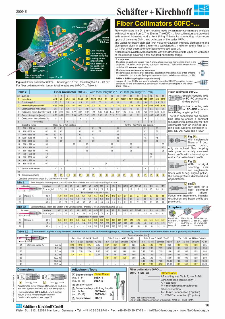
Figure 5: Fiber collimator 60FC-..., housing Ø 12 mm, focal lengths 2.7 – 20 mmFor fiber collimators with longer focal lengths see 60FC-T-... Table 3.
C
B
A
Fiber collimators in a Ø 12 mm housing made by Schäfter+Kirchhoff are available with focal lengths from 2.7 to 20 mm. The 60FC-... fiber collimators are provided with internal focussing and a front fitting Ø 8 mm for connecting micro-focus optics of the series 5M-... and polarizers of the series 5PF-... .The values for beam diameter (1/e2-value of Gaussian intensity distribution) and divergence given in table 2 refer to a wavelength = 670 nm and a fiber NA = 0.11. For other beam and fiber parameters see page 21. All lenses are available AR coated for wavelengths from 370 to 2300 nm with each of the coatings covering a few hundred nanometer range.
Table 2 Fiber Collimator 60FC-... with focal lengths 2.7 – 20 mm (housing Ø 12 mm)row curr. no 1 2 3 4 5 6 7 8 9 10 11 12 * 13 14 15 16 17 181 Lens type A2.7 A3 M3.1 M4 A4.5S M5 A6.2S A7.5 A8 M8 A11 RGBV11 M12 M12-NIR A15 M15 A18 M202 Focal length f' 2.75 3.1 3.1 4 4.5 5.1 6.16 7.5 8 8.1 11 11 12 12 15.4 15 18.4 20.13 Numerical aperture NA 0.68 0.68 0.25 0.2 0.42 0.25 0.3 0.3 0.3 0.16 0.25 0.2 0.23 0.22 0.16 0.18 0.15 0.164 Clear aperture max. [mm] 3.6 5 6.4 4.7 3.7 2.5 3.7 4.7 4.9 2.5 5.5 6.5 7.5 5.5 5 5.5 5.5 6.55 Collimated beam diameter [mm] 0.49 0.56 0.56 0.72 0.81 0.92 1.11 1.35 1.44 1.45 1.97 1.97 2.15 2.15 2.76 2.69 3.30 3.616 Beam divergence [mrad] 0.86 0.77 0.77 0.59 0.53 0.47 0.39 0.32 0.3 0.29 0.22 0.22 0.2 0.2 0.15 0.16 0.13 0.127 Correction - monochromatic x x x x x x x x x x x x x8 " - chromatic x x x x x x x
Spectral range Code no. of AR coating �����for the RGBV lens see page 279 370 - 600 nm 01 01 01 01 01 01 01 01 0110 600 - 1050 nm 02 02 02 02 02 02 02 02 0211 1050 - 1550 nm 03 03 03 03 03 03 03 0312 1300 - 1750 nm 45 45 45 45 45 45 45 4513 1750 - 2300 nm 09 09 09 09 09 09 0914 390 - 670 nm 33 33 33 33 33 3315 630 - 980 nm 10 10 10 10 10 1016 980 - 1550 nm 08 08 08 08 0817 400 - 700 nm 13 1318 700 - 1550 nm 37 3719 400 - 670 nm 51 51 4720 650 - 1150 nm 07 07
21 Suitable for UH vacuum x x x x x x x x x22
23 Dimensional drawing 1 1 1 1 1 1 1 1 1 1 1 1 1 1 1 1 2 2
Table 2.1 Beam divergence: beam expansion due to diffraction. Beam diameter as a function of the working distance A.
24 Lens type A2.7 A3 M3.1 M4 A4.5S M5 A6.2S A7.5 A8 M8 A11 RGBV11 M12 M12-NIR A15 M15 A18 M2025 Focal length f' 2.75 3.1 3.1 4 4.5 5.1 6.16 7.5 8 8.1 11 11 12 12 15.4 15 18.4 20.1
Beam diameter in distance A [mm]26 Distance A 0.5 m 1.00 0.95 0.95 0.93 0.97 1.03 1.17 1.38 1.47 1.48 2.0 2.0 2.2 2.7 2.8 2.7 3.3 3.627 1.0 m 1.80 1.63 1.63 1.39 1.33 1.31 1.35 1.49 1.55 1.6 2.0 2.0 2.2 2.7 2.8 2.7 3.3 3.628 5.0 m 8.6 7.7 7.7 6.0 5.3 4.7 4.0 3.4 3.3 3.3 2.9 2.9 2.9 3.1 3.2 3.1 3.5 3.8
** Optional connector types St, Din-AVIO or F-SMA
Table 2.3 Pilot beam: approximately constant beam diameter across entire working range A, obtained by fine adjustment. Position of beam waist is given by distance A2.
Beam diameter [mm]34 Tab. 2 No. 13: M12 / f'=12. Tab. 3 No. 1: M20 / f'=20 Tab. 3 No. 5: M40 / f'=40 Tab. 3 No. 6: M60 / f'=60.5
at A at coll. at waist A2 [m] at A at coll. at waist A2 [m] at A at coll. at waist A2 [m] at A at coll. at waist A2 [m]
34 Working range A 0.5 m 2.18 2.18 2.17 0.25 3.61 3.61 3.61 0.25 7.19 7.19 7.19 0.25 10.9 10.9 10.9 0.2535 1.0 m 2.18 2.18 2.17 0.50 3.61 3.61 3.60 0.50 7.19 7.19 7.19 0.50 10.9 10.9 10.9 0.5036 2.0 m 2.18 2.18 2.14 1.00 3.61 3.61 3.60 1.00 7.19 7.19 7.19 1.00 10.9 10.9 10.9 1.0037 5.0 m 2.24 2.18 1.90 2.37 3.61 3.61 3.56 2.50 7.19 7.19 7.18 2.50 10.9 10.9 10.9 2.5038 10.0 m 3.61 3.61 3.38 5.00 7.19 7.19 7.17 5.00 10.9 10.9 10.9 5.0039 20.0 m - - - - 7.19 7.19 7.09 10.00 10.9 10.9 10.8 10.0040 50.0 m - - - - - - - - 7.19 7.19 6.36 25.00 10.9 10.9 10.7 25.00
A Eccentric key Order Code(no. 1- 14) 60EX-4(no. 15-18) 60EX-5as an alternative:B Eccentric key with long handle (no. 1- 14) 60EX-4-L(no. 15-18) 60EX-5-LC Screwdriver 9D-12
Table 2.2 Diameter of focussed beam as a function of the working distance. For spot Ø < 100 μm, micro-focus optics are used.
29 Lens type A2.7 A3 M3.1 M4 A4.5S M5 A6.2S A7.5 A8 M8 A11 RGBV11 M12 M12-NIR A15 M15 A18 M2030 Focal length f' 2.75 3.1 3.1 4 4.5 5.1 6.16 7.5 8 8.1 11 11 12 12 15.4 15 18.4 20.1
Spot diameter in distance A [mm]31 Distance A 0.5 m 0.86 0.77 0.77 0.59 0.53 0.47 0.39 0.32 0.30 0.29 0.22 0.22 0.20 0.20 0.15 0.16 0.13 0.1232 1.0 m 1.73 1.53 1.53 1.19 1.06 0.93 0.77 0.63 0.59 0.59 0.43 0.43 0.40 0.40 0.31 0.32 0.26 0.2433 5.0 m - - - - - 4.66 3.86 3.17 2.97 2.93 2.16 2.16 1.98 1.98 1.54 1.58 1.29 1.18
BW
collimated
focussed
�Fiber collimators 60FC-…60FC-4-M5-33 Order Code
AR coating (see Table 2, row 9 - 20)Lens type (see Table 2, row 1)A = asphereM = monochromat or achromatFiber connection:4= FC-APC connection (8°polish)0 = FC-PC connection (0° polish)
Ø12 Ø8
241
Ø12 Ø8
312
Dimensions
Fiber Collimators 60FC-...
Adapters for mirror mounts Ø 25 mm, Ø 25.4 mm, and with system mount Ø 19.5 mm see page 20.
Fiber collimators 60FC-A19.5-... with system mount Ø 19.5 mm (fit directly into the "multicube"- system), see page 20.
Adjustment Tools
B
Add T for titanium madeAs an option fiber connection of type: DIN-AVIO, ST, and F-SMA
Fiber collimator 60FC... Straight coupling axis for FC-PC connectors (0 deg. polish)
inclined coupling axis for FC-APC connec-
tors (8 deg. angled polish)
Option:Fiber ferrule
Ø 2.5 mm
Polarization filter5PF-.../13PF-...
1.2
1.3
1.41
Ø 12 mm
FC Connector
22
4
Micro focus optics5M-... and 13M-...
Lens focusingLens locking by indirect clampingLocking of the attachmentsGrub screw M1.6 for additional locking of the fiber ferrule
1.11.2
1.3
1.4
2
3
Fig. B : With straight coupling axis and singlemode
fibers with 8 deg. angled polish, the beam profile is displaced and asym metrical.
Fig. A : With singlemode fibers of 8 deg. angled polish,
only an inclined fiber coupling axis gives an axially centered beam profile with rotational sym-metric Gaussian beam profile.
1.1
A = asphere The glass bi-aspheric lenses type A show a fine structure (concentric rings) in the projected Gaussian beam profile, but not in the focus. That kind of lenses is sui-table for UH vacuum applications.M = laser monochromat or achromatThe lenses are corrected for spherical aberration (mono chromat) or for chroma-tic aberration (achromat). Both produce an undisturbed Gaussian beam profile.RGBV = RGB coupling lens (apochromat)Lenses of type RGBV are achromatically corrected RGBV coupling lenses designed for the simultaneous coupling of multiple wavelengths in the range 400 to 700 nm.
The fiber connection has an axial limit stop to ensure a constant focus position, particulary for fiber collimators with an inclined cou-pling axis. Optional connector ty-pes: ST, DIN AVIO and F-SMA
A
B
C
Adapters
Micro focus optics 5M-... and 13M-..., page 18
Polarization filter 5PF-.../ 13PF-..., page 19
Diffractive op-tics 5P..., page 26 or www.SuK-Hamburg.de
page 18 + 19

Fib
erC
ollim
ator
s_09
_ED
.ind
d •
Pag
e 17
Kieler Str. 212, 22525 Hamburg, Germany • Tel: +49 40 85 39 97-0 • Fax: +49 40 85 39 97-79 • [email protected] • www.SuKHamburg.de
17
2009 E
Fiber collimators of type 60FC-T-... made by Schäfter+Kirchhoff are availa-ble with focal lengths from 20 to 200 mm. They optionally have an integrated tilt adjustment for adjusting the beam axis with respect to the mechanical axis. All fiber collimators are provided with a focussing mechanism and with front fitting for adding micro-focus optics. Values for beam diameter and divergence given in table 3 refer to a wavelength = 670 nm and a NA = 0.11 for the fiber. For other beam and fiber parameters, see page 21. The collimating lenses of type M are corrected for spherical aberration (mono chromat) or for chromatic aberration (achromat). Both produce an undisturbed Gaussian beam profile. All lenses are available AR coated for wavelengths from 390 to 1550 nm with each of the coatings covering a few hundred nanometer range. The fiber collimators have a coaxial or inclined coupling axis for accepting the fiber
con nectors FC-PC and FC-APC, respectively (optionally ST, DIN AVIO and F-SMA). The fiber connection has an axial limit stop to ensure a constant
focus position, particulary for fiber collimators with an inclined cou-pling axis. As an option, these fiber collimators are provided with integrated quarter-wave plates, see 60FC-Q-... on page 23.
Table 3 Lenses and beam parameters Fiber Collimator 60FC-T-... with focal lengths 20 - 200 mm row curr. no 1 2 3 4 5 6 7 8 9 10 11 12 13
1 Lens type M20 L M25 M30 M35 M40 M60 M40 L M60 L M75 M100 S M100 M150 M200
2 Focal length f' 20 25 30 35 40 60.5 40.0 60 75 100 100 150 200
3 Numerical aperture NA 0.28 0.23 0.22 0.15 0.20 0.14 0.30 0.20 0.16 0.12 0.24 0.16 0.12
4 Clear aperture max. [mm] 11 13 13 14 16 16 24 24 24 24 48 48 48
5 Collimated beam diameter [mm] 3.6 4.5 5.4 6.3 7.2 10.9 7.2 10.8 13.5 18.0 18.0 26.9 35.9
6 Beam divergence [mrad] 0.12 0.1 0.08 0.07 0.06 0.04 0.06 0.04 0.03 0.02 0.02 0.02 0.01
7 Correction - monochromatic x8 " - chromatic x x x x x x x x x x x x
Spectral range Code no. of AR coating
9 390 - 670 nm 33 33
10 630 - 980 nm 10 10 10
11 980 - 1550 nm 08 08
12 400 - 700 nm 13 13 13 13 13 13 13 13 13 13 13 13 13
13 700 - 1550 nm 37 37 37 37 37 37 37 37 37 37 37 37
14 650 - 1050 nm 02 02 02 02 02
15 450 - 700 nm 04 04 04 04 04 04
16 725 - 1200 nm 40 40 40
17 Tilt adjustment with T T T T T T T T T T T T T
18 w/o - - - - - - - - - - - - -
19 integrated quarter-wave plate Q… Q… Q… Q… Q… Q… Q… Q… Q… Q… Q… Q… Q…
21 Connector type * FC-APC 4 4 4 4 4 4 4 4 4 4 4 4 4
22 FC-PC 0 0 0 0 0 0 0 0 0 0 0 0 0
23 Housing diameter 25/(28) 25/(28) 25/(28) 25/(28) 25/(28) 25/(28) 32/34.5 32/34.5 32/34.5 32/34.5 55/59 55/59 55/59
24 Front fitting Ø 19.5 Ø 19.5 Ø 19.5 Ø 19.5 Ø 19.5 Ø 19.5 M 27x0.5 M 27x0.5 M 27x0.5 M 27x0.5 Ø 52 Ø 52 Ø 52
25 Dimensional drawing ** with 5 5 5 7 7 9 10 11 12 13
w/o 3 4 4 6 6 8 10 11 12 13
Figure 6: Fiber collimator 60FC-T-..., with focal lengths 20 - 200 mm and tilt adjustment. For fiber collimators with shorter focal lengths see 60FC-... Table 2.
Table 3.1 Beam divergence: beam expansion due to diffraction. Beam diameter as a function of the working distance A
26 Lens type M20 L M25 M30 M35 M40 M60 M40 L M60 L M75 M100 S M100 M150 M20027 Focal length f' 20 25 30 35 40 60.5 40 60 75 100 100 150 200
Beam diameter in distance A [mm]
28 Distance A 5 m 3.8 4.6 5.4 6.3 7.2 10.9 7.2 10.8 13.5 18.0 18.0 26.9 35.9
29 10 m 4.3 4.9 5.6 6.4 7.3 10.9 7.3 10.8 13.5 18.0 18.0 26.9 35.9
30 20 m 6.0 5.9 6.2 6.8 7.6 11.0 7.6 10.9 13.5 18.0 18.0 26.9 35.9
Table 3.2 Diameter of focussed beam as a function of the working distance. For spot Ø < 100 μm, micro-focus optics are used.
31 Lens type M20 L M25 M30 M35 M40 M60 M40 L M60 L M75 M100 S M100 M150 M20032 Focal length f' 20 25 30 35 40 60.5 40 60 75 100 100 150 200
Spot diameter in distance A [mm]
33 Distance A 1 m 0.24 0.19 0.16 0.14 0.12 0.08 0.12 0.08 0.06 0.05 0.05 0.03 0.02
34 5 m 1.19 0.95 0.79 0.68 0.59 0.39 0.59 0.40 0.32 0.24 0.24 0.16 0.12
35 10 m 2.38 1.90 1.58 1.36 1.19 0.79 1.19 0.79 0.63 0.48 0.48 0.32 0.24
collimated
focussed
4
Ø25
Ø19
.5
Ø28
18 5 1143
6
Ø28Ø
25
Ø19
.5
18 1813.5 11.553.5
Dimensions
More dimensional drawings see page 20Clamp collars for fiber collimators see page 20
Ø19
.5
Ø28
16.533.53
Ø25
8
Ø28Ø
19.5
21 30.574.5
11.5
Ø25
Fiber Collimators 60FC-T-...
A Eccentric key 55EX-5for 60FC-T-... with tilt adjustment and for all fiber collimators 60FC-... starting with row 8
as an alternative: B Eccentric key withlong handle
C Screwdriver 9D-12D Hex screwdriver 50HD-15
Assembly and adjustment toolsOrder Code
A
B
C
D
Fiber Collimator 60FC-T-… 60FC-T-4-M60-10
AR coating(see Table 3, row 9 - 16)Collimating lens (see Table 3, row 1
4 = FC-APC0 = FC-PC
T = tilt adjustment- = w/o tilt adjustmentQ... = /4 plate,
e.g. Q671 for = 671 nm
Order Code
As an option with fiber connection of type :DIN-AVIO, ST, and F-SMAAdd T for titanium made
�-TILT
Ø25
Ø19
.5
425
A
B
55EX-5-L
B Bad alignment: the beam is vignetted and diffraction patterns occure
A Accurate alignment of emitted beam to the mechanical axis
* Optional connector types St, Din-AVIO or F-SMA ** For other dimensional drawings, please call Schäfter+Kirchhhoff

Fib
erC
ollim
ator
s_09
_ED
.ind
d •
Pag
e 18
Kieler Str. 212, 22525 Hamburg, Germany • Tel: +49 40 85 39 97-0 • Fax: +49 40 85 39 97-79 • [email protected] • www.SuKHamburg.de
18
2009 E
Table 6 Micro-Focus Optics 25M-... for fiber collimators from table 3, curr. no. 7-10 with outer Ø 32 mm
row curr. no 1 2 3 4
1 Lens type M50 M100 M150 M300
2 Focal length f' 50 100 150 300
3 Numerical aperture NA 0.24 0.125 0.08 0.04
4 Clear aperture max. [mm] 25 25 25 25
Spectral range Code no. of AR coating
5 400 - 700 nm 13 13 13 13 13
6 700 - 1550 nm 37 37 37 37
7 Design S S S S
8 Dimensional drawing 3 3 3 3
9 Length B [mm] 12 12 12 12
10 Working distance A [mm] 41.9 92.3 142 292
11 Suitable for UH vacuum
Table 5 Micro-Focus Optics 13M-... for fiber collimators from table 3, curr. no. 1-6 with outer Ø 25 mm
row curr. no 1 2 3 4 5 6 7
1 Lens type M40 M60 M100 M125 S250 S500 S1000
2 Focal length f' 40 60 100 125 250 500 1000
3 Numerical aperture NA 0.15 0.125 0.06 0.03 0.016 0.007
4 Clear aperture max. [mm] 13.5 13.5 13.5 13.5 13.5 13.5 13.5
Spectral range Code no. of AR coating
5 390 - 670 nm 33 33 33 33 33
6 450 - 700 nm 04 04 04 04
7 630 - 980 nm 10 10 10 10
8 980 - 1550 nm 08 08
9 600 - 1200 nm 05 05 05 05
10 Design S S S S S S S
11 Dimensional drawing 2 2 2 2 2 2 2
12 Length B [mm] 8 8 8 8 8 8 8
13 Working distance A [mm] 33 54 93 120 245 492 973
14 Suitable for UH vacuum X X X
Applications:2 of 1000s
Fiber Collimator with Micro-Focus Optics
Polarization filter 5PF-.../13PF-...
Micro-focus optics5M-… and 13M-…
Fiber collimator60FC-…
For locking of attachments
1
2
3
Figure 7: Fiber collimator 1 with micro-focus optics 2 and polarization filter 3 . The attachments are locked in position with radially arranged screws 1.3 .
Micro-focus optics transform collimated laser beams into micro-spots with diameters > 0.6 μm. Depending on focal length, micro-focus optics are as-sembled with a sphe ric lenses, achro mates or singlet lenses. Micro-focus optics from Schäfter+ Kirchhoff are AR coated for wavelengths 370 to 2300 nm with each covering a few hundred nanometers. The size of the micro spot Øspot depends on the focal length ratio of micro-focus to fiber collimator and on the mode field diameter MFD of the singlemode fiber.
Figure 8: Optical path of a fiber collimator with attached micro-focus optics. Intensity distribution and beam shape are maintained.
Øspot �f’micro-focus
f’fiber collimatorMFD
Figure 9: The Rayleigh range is the depth of sharpness of a laser focus with a Gaussian intensi-ty distribution.Within the range 2�zR the beam waist increases by a factor of 1.41.
� = wavelength in μmØspot = beam waist in μm
A B
Ø 8
Ø 11
1
A B
Ø 2
5
Ø 1
9.5
2
1.3
Table 4 Micro-Focus Optics 5M-... for fiber collimators of table 2 with outer Ø 12 mmrow curr. no 1 2 3 4 5 7 8 10 11 12 13 14 15 16 17 18 19 20 21 22
1 Lens type A2.7 A3.1 A4 A4.5 A6.2 A8 A11 A15 A18 M12 M20 M25 M30 M40 M50 M60 S50 S88 S150 S325
2 Focal length f' 2.7 3.1 4 4.5 6.2 8 11 15 18 12 20 25 30 40 50 60 50 88 150 325
3 Numerical aperture NA 0.65 0.68 0.58 0.41 0.4 0.5 0.25 0.16 0.15 0.2 0.13 0.11 0.09 0.06 0.05 0.05 0.05 0.03 0.018 0.009
4 Clear aperture max. [mm] 3.6 5 4.6 5 5 5 5 5 5 5 5 5 5 5 5 5 5 5 5 5
Spectral range Code no. of AR coating
5 370 - 600 nm 01 01 01 01 01 01 01 01 01 01
6 600 - 1050 nm 02 02 02 02 02 02 02 02 02 02
7 1050 - 1550 nm 03 03 03 03 03 03 03 03 03 03
8 1300 - 1750 nm 45 45 45 45 45 45
9 1750 - 2300 nm 09 09 09 09 09 09 09
10 390 - 670 nm 33 33 33 33 33 33 33
11 630 - 980 nm 10 10 10 10 10 10 10
12 980 - 1550 nm 08 08 08 08 08 08 08
13 400 - 700 nm 13 13 13 13 13 13
14 700 - 1550 nm 37 37 37 37
15 Design S S S S S S S S S S S S S S S S S S S S
16 Dimensional drawing 1 1 1 1 1 1 1 1 1 1 1 1 1 1 1 1 1 1 1 1
17 Length B [mm] 4.75 4.4 4.6 4.5 4.5 4.5 4.5 4.5 4.5 4.5 4.8 4.4 4.5 4.5 4.4 4.5 1.2 1.2 1.2 1.2
18 Working distance A [mm] 1.26 1.6 1.66 2.37 3 5.4 7.4 13.4 16.5 9.9 17.9 22.8 26.7 38 48.2 58 46.2 82.4 147 317
19 Suitable for UH vacuum x x x x x x x x x x x x x
3
Øspot
2�zR
1.41� Øspot
Singlemode fiber NA 0.11Wavelength Mode field Ø 480 3.4 μm 630 4.3 μm 780 5.7 μm 980 6.2 μm
Micro-Focus Optics 5M-.../13M-...
S = short design
AR coating, see table 4 - 6, row 5 ff
Focal length f' in mm, see table 4 - 6, row 2
Lens type: A Asphere M Achromat S Singlet
Micro-Focus Optics 5M-… 13M - M 60 - 13 - S
Serien: 5M for fiber collimator with outer Ø 12 mm, table. 4 13M for fiber collimator with outer Ø 25 mm, table. 5 25M for fiber collimator with outer Ø 32 mm, table. 6
Order Code
Add T for titanium made
2�zR = 2���Øspot2
�� 4

Fib
erC
ollim
ator
s_09
_ED
.ind
d •
Pag
e 19
Kieler Str. 212, 22525 Hamburg, Germany • Tel: +49 40 85 39 97-0 • Fax: +49 40 85 39 97-79 • [email protected] • www.SuKHamburg.de
19
2009 E
Table 10 Adjustment and Assembly Toolsrow Order Code used for fiber collimators ...
1 Eccentric key 60EX-4 A 60FC-... focal lengths f'<15 mm Table 2, curr. no. 1-122 Eccentric key 60EX-4-L D as alternative for A and with longer handle3 Eccentric key 60EX-5 B 60FC-... focal lengths 20 > f'> 15 mm Table 2, curr. no. 12-184 Eccentric key 55EX-5 C 60FC-T-... and 60FC-Q-... Table 3, with tilt adjustment
5 Screwdriver 9D-12 E all
6 Hex screwdriver 50HD-15 F 60FC-..., f' > 20 mm Table 3, all7 Adjustment tool 60Z-2803 G 60FC-Q..., with quarter-wave plate Page 23
Ø 1
9.5
Ø 1
9.5
Ø 2
5
Ø 2
5
Ø 1
9.5
Ø 2
5
Ø
10.9
10.9
10.9
Ø11 Ø8
2768
14
4.5 9.5 12.59
Dimensions
Ø 1
9.5
Ø 2
5
21.5
1 2 3 4 5 7 8
13PF-...5PF-...
Polarization filters are used to generate linearly polarized light. Polarization filters produced by Schäfter+Kirchhoff have an extinction ratio of typically 10,000:1. They are provided for wavelengths from 450 nm to 1400 nm and have a surface form deviation of /4. The two different types of polarization filters (table 7):
Polarizing beam splitter cubes (pola rizer type 5PF-C-... / 13PF-C-...) have a high trans mission of the parallel polarized radiation and deflect the un-wanted orthogonally polarized radi a tion.
Dichroic glass polarization filters (polari zer type 5PF-P-... / 13PF-P-...) have smaller dimensions because of their narrow 2 mm thickness. In order to avoid back reflection directly into the optical path, the dichroic glass polarizer has an inclined mounting of 3° (5PF-...) and 0.5° (13PF-...).
All Schäfter + Kirchhoff polarization filters are AR coated. The residual reflectivity is <1.5 % for incident polarized radiation.
An optional front fitting allows their use between a fiber collimator and, for exa-mple, micro-focus optics with positive locking ( 2 , 4 , 6 and 8 ).
Iris Diaphragms 5BL-... ,13 BL-... , 25 BL-... and 40 BL-...
Table 8 Retardation Optics 5 WP-... For fiber collimators of table 2 with outer Ø 12 mmrow curr. no 1 2 3 4 5 6 7 8 9 10 11 12 13 14 15 16
1 Retardation /4 /4 /4 /4 /4 /2 /2 /2 /2 /2 /2 /2 /2 /2 /2 /22 Order L: low, Z: zero L L L Z L L L L L L L L L Z L L3 Wavelength [nm] 405 670 760 773 780 405 461 532 589 670 689 760 767 773 780 8524 Clear aperture max. [mm] 5 5 5 5 5 5 5 5 5 5 5 5 5 5 5 5
5 Design S S S S S S S S S S S S S S S S6 Dimensional drawing 1 1 1 1 1 1 1 1 1 1 1 1 1 1 1 1
7 Length B [mm] 5.5 5.5 5.5 5.5 5.5 5.5 5.5 5.5 5.5 5.5 5.5 5.5 5.5 5.5 5.5 5.5
Quarter-wave retardation plates are used for generating circularly pola-rized radiation. With half-wave retardation plates, the orientation of a linear state of polarization is rotated. The 5 WP-... wave plates from Schäfter+Kirchhoff are directly fixed to the fiber collimators of series 60FC-... with outer diameter 12 mm, see table 2. The wave plates can be rotated and are locked in position with radially arranged screws. For fiber collimators with focal lengths f' � 20 mm, table 3, which gener-ate larger beam diameters, Schäfter+Kirchhoff recommends the use of fiber collimators of type 60FC-Q... with integrated retardation optics, see page 23.
Other retardation optics, e.g. other wavelengths or dichroic retardation optics on request.
Quarter-wave optics5WP-…
Fiber collimator 60FC-…
1
2
Figure 9: Fiber collimator 1 with quarter-wave optics 2 for generating circularly polarized light. The optics are locked in position with radially arranged screws 1.3 .For the fiber collimators that generate larger collimated beam diameters use the Schäfter+Kirchhoff fiber collimators 60TC-Q... with integrated quarter-wave plate, see page 23.
1.3
Retardation L: low order, Z: zero orderWavelength [nm]Retardation 4 for /4, 2 for /2
Retardation Optics 5WP-… 5WP - 4 - 780 L
Series: 5WP
Table 9 Iris Diaphragms xx BL-...row Series Ø min-max [mm] Order Code mount for fiber collimators
1 5BL-... 0.8 - 5 5BL - 0.8 - 5 Ø 8 mm Table 2, all2 13BL-... 0 - 12 13BL - 0 - 12 Ø 19.5 mm Table 3 curr. no. 1 - 63 13BL-... 1 - 13 13BL - 1 - 13 Ø 19.5 mm Table 3 curr. no. 1 - 64 25BL-... 1 - 20 25BL - 1 - 20 M 27x0.5 Table curr. no. 7 - 105 40BL-... 2 - 42 40BL - 2 - 42 Ø 52 mm Table curr. no. 11 - 13
Iris diaphragms are used for truncating the diameter of a collimated beam.Schäfter+Kirchhoff offers iris diaphragms for all series of fiber collimators. For fiber collimators with outer diameter 25 mm (focal lengths 20 - 60 mm), an iris diaphragm which can be closed completely is available.
F
C
E G
B
A
Adjustment and Assembling Tools for Fiber Collimators (Overview)
D
Dimensions
Polarization Filters 5PF-... / 13PF-...
Retardation Optics 5WP-...
Order Code
Table 7 Polarization Filter 5PF-.../ 13PF-...
Row Series Polarizer typ Spectral range Extinction Transmis-sion
Clear aperture
(mm)
Polaization filter (short)
Order Code
Dra-wing
Polaization filter (long)
Order Code
Dra-wing
1
5PF-P 1 22 600-850 104:1 >84-93 5 5PF-P - 600-S 5PF-P - 600-L3 750 - 1400 104:1 >87-93 5 5PF-P - 750-S 5PF-P - 750-L4 1280 - 1500 104:1 >96-98 5 5PF-P-1300-S 5PF-P-1300-L5
5PF-C
390 - 480 104:1 >95 4 5PF-C - 400-S
3
5PF-C - 400-L
46 450 - 700 104:1 >95 4 5PF-C - 450-S 5PF-C - 450-L7 750 - 1100 104:1 >95 4 5PF-C - 750-S 5PF-C - 750-L8 1100 - 1700 104:1 >98 4 5PF-C-1100-S 5PF-C-1100-L
9
13PF-P 5 610 600 - 850 104:1 >84-93 12 13PF-P - 600-S 13PF-P - 600-L11 750 - 1400 104:1 >87-93 12 13PF-P - 750-S 13PF-P - 750-L12 1280 - 1500 104:1 >96-98 12 13PF-P-1300-S 13PF-P-1300-L13
13PF-C
340 - 440 5x10³:1 >98 8 13PF-C - 350-S
7
13PF-C - 350-L
814 450 - 700 104:1 >95 10 13PF-C - 450-S 13PF-C - 450-L15 750 - 1100 104:1 >95 10 13PF-C - 750-S 13PF-C - 750-L16 1100 - 1700 104:1 >98 10 13PF-C-1100-S 13PF-C-1100-L
6
1

Fib
erC
ollim
ator
s_09
_ED
.ind
d •
Pag
e 20
Kieler Str. 212, 22525 Hamburg, Germany • Tel: +49 40 85 39 97-0 • Fax: +49 40 85 39 97-79 • [email protected] • www.SuKHamburg.de
20
2009 E
Ø25
Ø19
.5
42
Fiber collimator
Fiber collimators 60FC-x-4-M100-...
Fiber collimators 60FC-x-4-M75-...
Fiber collimators 60FC-x-4-M100S-...
Fiber collimators 60FC-x-4-M150-...
Ø12 Ø8
24
Fiber collimators 60FC-... f = 2.7 - 15 mm
Ø12 Ø8
31
Fiber collimators 60FC-... f' = 18 - 20 mm
Fiber collimators 60FC-x-4-M20 L
Ø19
.5
Ø28
16.5
33.5
Ø25
Ø25
Ø19
.5
Ø28
18 5 11
43
Ø25
Ø19
.5
42
Fiber collimators 60FC-x-... f' = 25 - 30 mm
Ø28Ø
19.5
21 30.574.5
11.5
Ø25
Fiber collimators 60FC-x-4-M60-...
Ø19
.5
77.5
Ø25
Fiber collimators 60FC-x... f' = 35 - 40 mm
Ø28Ø
25
Ø19
.5
18 13.5 11.5
53.5
Ø25
Ø19
.5
55
12C-AM25 12AM25.4 12AM-19.5
Clamp Collars
Dimensional Drawings
4
12
3
11
2
101
9
8
76
5
13
Schäfter+Kirchhoff supplies clamp collars 2 for the fiber collimators with outer diameter 25 mm, 32 mm, and 55 mm.
Table 11 Dimensions of the clamp collars
row for collimator Order Code clear aper-ture A [mm]
drillings B (4 x 90°)
outer diame-ter ØC/ C
pitch circle D [mm]
depth E [mm]
thickness F [mm]
1 Table 3, No. 1 - 6 CC-25 Ø25 M2.5 Ø36/ 31.8 Ø31 3.7 5.52 Table 3, No. 7 - 10 CC-32 Ø32 M3 Ø44.5/ 39.5 Ø39 2.7 63 Table 3, No. 11 - 13 CC-55 Ø55 M4 Ø74/ 64 Ø66 5.8 8
Adapters for fiber collimators 60FC-... with focal lengths f' = 2.7 - 20 mm with diameter Ø12 mm to outer Ø25 mm, Ø1" (25.4 mm) or with system mount Ø 19.5 mm.
Ø12
H7
Ø25
h8
9.9
Ø12
H7
Ø25
.4 h
8
9.9
Ø19
.5
Ø12
H7
Ø25
h8
8.5
5
ØD
C
ØC
F
E
ØA
B
Dimensions
Fiber Collimators for Use with the "multicube" System
Schäfter+Kirchhoff offers fiber collimator with focal lengths up to 15 mm which directly can be adapted to the "multicube" system. Such as the Schäfter+Kirchhoff laser beam couplers 60SMS-.... the fiber collimators 60FC-19.5-... have a system mount Ø 19.5 mm
Ø12
Ø19
.5
Ø24
.5
11.5
Dimensions
�Fiber Collimator 60FC-A19.5-…
For the lens selection please see the order code on page 18.)
Order Code
1 fiber collimator 60FC-T-4-M100-...
2 clamp collar CC-55
3 Mounting plate
1
1
2
2
3
3
Fiber collimators 60FC-A19.5-... with system mount Ø 19.5 mm (fits directly into the "multicube"-system)

Fib
erC
ollim
ator
s_09
_ED
.ind
d •
Pag
e 21
Kieler Str. 212, 22525 Hamburg, Germany • Tel: +49 40 85 39 97-0 • Fax: +49 40 85 39 97-79 • [email protected] • www.SuKHamburg.de
21
2009 E
1 Fiber Collimator 60FC-0-... with coaxial coupling axis for singlemode fibers with connectors type FC-PC (0° polish)
1.1 Fiber connection (coaxial)1.2 Grub screw for an additional locking of the
fiber ferrule2 Singlemode fiber with 0° polish3 Diverging emission ��= 10.4° for a fiber with
NA = 0.11 (1/e2) 4 Collimating lens 5 Collimated laser beam6 Concentrically symmetric beam profile with a Gaussian intensity distribution
Fundamentals ofFiber Collimators 60FC-...
Fiber collimators made by Schäfter+Kirchhoff are designed for single-mode fibers with FC connectors (optional type ST, DIN AVIO and F-SMA). To combine fibers with 8° angled polish (FC-APC, for avoidance of back reflection into the optical path) the fiber collimators 60FC-4-... and 60FC-T-4-... have an inclined coupling axis. This ensures a centered and concentrically symmetric laser beam equal to that of the 0° polished fiber and fiber collimator with a coaxial coupling axis (Fig. 1). The fiber collimators have an axial stop for the fiber ferrule. In addition, the fiber ferrule can be locked by a grub screw 1.4 , ensuring a constant focal position and highly reproducible stability. The eccentric key 1.1 is used to focus the fiber collimator and the desired position is locked using two radially arranged clamping screws 1.2 .
Focusing of the collimating lensLocking of the collimating lensLocking of lens attachmentsGrub screw M1.6 for additional locking of the fiber ferrule
Option:Fiber Ferrule
Ø 2.5 mm
Micro-Focus Optics 5M-... ,13M-... , and 25M-...
Polarization Filter 5PF-.../13PF-...
1.2
1.3
1.4
1.3
1.2
1.11.4
3
11
Fiber Collimator 60FC-...
Ø 12 mm
FC Connector
2
1.1
Fig. 1: Fiber collimator 60FC-... with lens attachments and adjustment tools
Fiber Collimator 60FC-...
Opto-MechanicalAdjustment
Figure 2: Fiber collimator with coaxial fiber connection
Figure 3: Fiber Collimator with inclined fiber connnection
Figure 5: Beam Diameter
Figure 6: Beam Divergence
Figure 7: Pilot Beam with approximate constant beam diameter across working range A
Figure 8: Focussed Laser Beam Bild 8: Laserstrahlfokussierung
Figure 9: Focussed Laser Spot: Fiber Collimator 60FC-... and Micro-Focus Optics 5M-... / 13M-... / 25M-...
Figure 10: Rayleigh Range
1 Fiber collimator 60FC-4-... with inclined coupling axis for singlemode fibers with connectors type FC-APC (8° polish)
1.1 Fiber connection (inclined)1.2 Grub screw for an additional locking of the fiber ferrule2 Singlemode fiber with 8° angled polish3 Diverging emission ��= 10.4° for a fiber with
NA = 0.11 (1/e2) 4 Collimating lens 5 Collimated laser beam6 Concentrically symmetric beam profile with a Gaussian intensity distribution
When a fiber with 8° polish is used incorrectly with a coaxially coupled fiber collimator, or vice versa, a fiber with 0° polish is used incorrectly with an inclined coupled fiber collimator then the collimated beam is axially displaced, assymetric and differs significantly from a Gaussian beam because of the resultant diffraction.
In principle, even a collimated beam has a diver-gence greater then zero, i.e., the beam diameter varies with distance A from the fiber collimator. The beam divergence � depends (for large distances A) on the beam diameter Øbeam at the position of the fiber collimator and on the wavelength �
Concomitantly, the beam diameter depends on the numerical aperture NA of the sin-glemode fiber and the focal length f’ of the collimating lens.
A pilot beam is a Gaussiam beam of essential-ly constant diameter within a certain working range A, which is achieved by fine-adjustment. The optimum position of the beam waist is de-fined as distance A2 (see table 1.3).
The maximum working range A of a pilotbeam is limited because of diffraction, according to:
Figure 4: Combination Mismatch
The beam diameter is given by the focal length of the collimating lens and by the numerical aperture of the singlemode fiber. The beam diameter is defined as the 1/e2 level (13.5% value) of the Gaussian intensity distribution.
For singlemode fibers, the numerical aperture NA is given at the 5% level. To account for the differences in definition, a correction factor of 0.82 is introduced and the beam diameter calculated as:
Example:
Wavelength = 670 nmFocal length f’ = 4.5 mmNumerical aperture NA = 0.11Beam diameter Øbeam = 0.81 mmBeam divergence � = 0.53 mrad
Example:
Fiber collimator f’ = 4.5 mmMicro-focus lens f’ = 11 mmMode field Ø MFD = 4.3 μmSpot diammeter Øspot = 10.5 μm
Beam diameter:
where Øbeam is the collimated beam diameter as in figure 5.
Readjustment of the collimating lens generates a focus sed beam is. At distance A, relative to the fiber collimator, a beam waist with diameter Øspot is formed.
Focussing a beam using a fiber collimator alone is only suitable for longer working distances (figure 8) where the spot size of the focussed beam is a multiple of the fiber mode field diameter. Focused micro spots <1 μm are generated by using micro-focus optics. The micro-focus optics are form-fitted to the fiber collimators. The spot size is given by the focal length ratio, micro-focus / fiber collimator, and by the mode field diameter of the singlemode
fiber. To a good approximation, the spot size is given by:
Notice should be taken of the mode field diameter wavelength dependency (see table). A small change in focus alters the focus position and the spot size.
The Rayleigh range is the depth of sharpness of the laser focus with a Gaussian intensity distribution. Within the range 2 �zR, the beam waist increases by a factor 1.41.
Øspot : Beam diameter in focusA : Working distance f’ : Focal length of collimating lensMFD : Mode field diameter of singlemode fiber
The mode field diameter MFD is calculatedfrom the the numerical aperture NA at wavelength
Deflection limits the maximum distance of the focus, where
and Øbeam is the collimated beam diameter as in figure 5.
The 8° polish of the singlemode fiber causes the emitted radiation to be defracted and the optical path is inclined. The design of the inclined fiber connection this fiber collimator compensates for the beam deflection. The collimated beam is centered and concentrically symmetric.
1.1
4
5 3 26
1
4
5 3 26
1
Øbeam
A
A
Øspot Øbeam
zR
Øspot
Example: Focal length f’ = 4.5 mm, Numerical Apertur NA = 0.11Øbeam = 2���4.5mm ���0.11���0.82 = 0.81mm
Example:
Spot size: Øspot = 10.5 μmWavelength: = 670 nm
Rayleigh range:
� = 2����Øbeam
= ����f’��NA���0.82
A �2�f’ +Ø2beam����
4
�
A
Øbeam
A2
1.2
1.1
1.2
Øbeam
f’
2�������NA���0.82
MFD = ��� .
Af’
Øspot = MFD����������+1)
A Amax = f’ + ,Ø2beam����
8���
Øspot = f’ micro-focus ���MFD
f’ fiber collimator
Øbeam = 2���f’ ��NA���0.82 zR = � 10.52 μm2
= 129 μm 4���0.67
2���zR = 2�������Øspot2
���4
Singlemode fiber NA 0.11Wavelength [nm] Mode field Ø
480 3.4 μm 630 4.3 μm 780 5.7 μm 980 6.2 μm

Customized optical and opto-mechanical designs are a speciality of Schäfter+Kirchhoff. The resulting products combine optimum optical performance with a ruggedized mechanical design.
Fib
erC
ollim
ator
s_09
_ED
.ind
d •
Pag
e 22
Kieler Str. 212, 22525 Hamburg, Germany • Tel: +49 40 85 39 97-0 • Fax: +49 40 85 39 97-79 • [email protected] • www.SuKHamburg.de
22
2009 E
In some quantum-optical experiments collimated laser beams with an elleptical cross section are used as cooling beams in so called 2D-MOTs (2 dimensional magneto-optic traps). Schäfter+Kirchhoff offers fiber collimator 60FC-E-... with an collimated elliptical beam. The state of polarization can be linear or circular.
spectral range 4 = FC-APC0 = FC-PCDimensions of elliptical axes long axis x short axis
60FC - E15x5 - 4 - 420-660 Order Code
Special Fiber Collimatorsfor Quantum Optics and for
Singlemode fiberwith circular emission profile
4 3 2 1
Dimensions
Output
Input
Schäfter+Kirchhoff offers a variety of fiber collimators with special features. Special fiber collimators are built up with standard col-limator housings (see page 20), with construction kit "multicube" (see page 31) or with customized design. We combine all optics depicted at page 6, 16 and 17 with retardation optics and polariza-tion filters (see page 19), optics like beam combiner, splitter, photo diode (see page 32), anamorphotic optics (see page 25), diffractive optics (see page 26), Faraday isolator (see page 41), diaphragms (see page 19), special adjustment possibilities and more. The out-put can be collimated or focussed respectively. For example, we offer fiber collimators with integrated:
1 Retro reflector and quarter-wave plate for the reflection of circular polarized light without changes in state of polarization, e.g. for magneto-optical traps. 60FC-...-RR, see page 24
2 Beam combiner for the combination of different wavelength���which are too different as to be guided by one single fiber. or for combining two fiber-coupled inputs in order to have different states of polarization 60FC-48BC-..., see page 24
3 Anamorphotic optics for elliptical beams with low deviation and Gaussian shaped beam profiles in x-y direction. 60FC-E-... orFiber collimators with cylindrical micro-focus optics for genera-ting laser spots with elliptic cross section
4 Quarter-wave plate for circularly polarized collimated beams, e.g. for a selective stimulation of individual Zeeman levels in a magneto -optical trap MOT. 60FC-Q-..., see page 23
5 Power monitoring for the online control of laser power and power fluctuations. 60FC-48PD-..., see page 24
6 Tilt adjustment to avoid a vignetting of the beam by aligning the optical to the mechanical axis. 60FC-T-..., see page 19
Figure 3: Optical scheme1 Fiber cable, 2 Laser beam coupler used as fiber collimator 3 Anamorphotic beam expander, 4 Expansion optics
4
Fiber Collimators
with Elliptical Beams for 2D-MOTs
1 2
5 6
4
MOT
agneto
ptical
raps
The main features are:• Polarization extinction ratio > 200 : 1• Gaussian intensity profiles in x direction and in y directionExample:• Elliptical beam 14.7 mm x 5 mm (3:1)• Spectral range 420 - 660 nm, design wavelength 425 nm
Figure 2: Elliptical cross section of a collimated beam. The state of polarization can be adjusted with respect to the ellipse achses
Fiber Collimators with Micro-focus Optics
for Elliptical Spots
Figure 4: Optical scheme1 Fiber cable, 2 Laser beam coupler used as fiber collimator 3 beam expander, 4 cylindric focussing optics
4 3 2 1
Schäfter+Kirchhoff offers fiber collimator with cylindrical micro-focus op-tics generating a spot with eliptic cross section, as example:• Elliptical spot 600 μm x 150 μm (4:1)• Working distance 300 mm
Customized optical and opto-mechanical designs are a speciality of Schäfter+Kirchhoff. The resulting products combine optimum optical performance with a ruggedized mechanical design.
good
bad
�-TILT
Special Fiber Collimators 1. Retro reflector2. Beam combiner3. Elliptical beam4. Circular polarisation5. Power monitoring6. Tilt adjustment Elliptical
beam profile
3
2
3
1

Fib
erC
ollim
ator
s_09
_ED
.ind
d •
Pag
e 23
Kieler Str. 212, 22525 Hamburg, Germany • Tel: +49 40 85 39 97-0 • Fax: +49 40 85 39 97-79 • [email protected] • www.SuKHamburg.de
23
2009 E
Figure 1: Fiber Collimator 60FC-Q... with f’ = 75 mm with an integrated quarter-wave plate.
45°
F /4-retardation plate
A
E BC
D
F
Fiber Collimator 60FC-Q...A Collimating lens (achromat f ’ = 40 - 200mm)B Connection for singlemode fiber cable
with connector type FC-APCC Tilt adjustmentD Inner focussing mechanismE Locking of the
collimating lens
The fiber collimators of series 60FC-Q... have an integrated quarter-wave plate. The radiation emitted by these fiber collimators is used in magneto-optical traps (MOT) as �+ (left-hand circularly polarized) and �- (right-hand circularly polarized) radiation for a selective stimulation of individual Zeeman levels, for example. Low order quarter-wave plates are used because of their low angular dependency.Fiber collimators of type 60FC-Q... are provided for the wavelengths 461 nm, 671 nm, 767 nm and 780 nm with other wavelengths available
on request. The retardation optics are aligned after assembly by use of a special cogged adjustment tool and, finally, the desired positi-on is locked using two radially arranged grub screws, see Fig. 1.Fiber collimators made by Schäfter+Kirchhoff of series 60FC-Q... are designed for beam diame-ters up to 36 mm. A connection for singlemode fiber cables with con-nectors of the type FC-APC is provided and they have an integrated tilt adjustment.
More fiber collimators with integrated quarter-wave plate, see table 3, fiber collimators 60FC-T-...* with fiber NA 0.11, ** optional type ST, DIN-AVIO, or F-SMA
Figure 2: Rear view of fiber collimators 60FC-Q... with integrated tilt adjustment and quarter-wave plate. The marked axis of the retardation plate is shown in a window. A special cogged adjustment tool 60Z-2803 is shown in place on the fiber collimator.
3.1
3.2
Figure 3 Polarization analyzer attached to a fiber collimator using a micro-bench adapter. Screenshot 3.1 shows an elliptical polarization state and screenshot 3.2 a circular state of polarization.
Table 12 Fiber collimators with integrated quarter-wave plates 60FC-Q...
row curr. no 8 9 10 11 12 131 Lens type M40 L M60 L M75 M100 S M100 M1502 Focal length f' 40 60 75 100 100 1503 Numerical aperture NA 0.30 0.20 0.16 0.12 0.24 0.164 Clear aperture max. [mm] 24 24 24 24 48 485 Collimated beam diameter [mm]* 7.2 10.8 13.5 18.0 18.0 26.96 Beam divergence [mrad]* 0.06 0.04 0.03 0.02 0.02 0.027 Correction - monochromatic8 - chromatic x x x x x x
Spectral range9 400 - 700 nm 13 13 13 13 13 13
10 450 - 700 nm 04 0411 630 - 980 nm 10 1012 650 - 1050 nm 02 0213 700 - 1550 nm 37 37 37 37 37 3714 725 - 1200 nm 40 40
15 Housing diameter 32/34.5 32/34.5 32/34.5 32/34.5 55/59 55/5916 Front fitting 27x0.5 27x0.5 27x0.5 27x0.5 Ø 52 Ø 52
17 Dimensional drawing 10 10 10 11 12 13
Adjustment of quarter-wave plate
A Eccentric key 55EX-5B Hex screwdriver 50HD-15
WS 1.5 mm
C Screwdriver 9D-12WS 1.2 mm
D Adjustment tool 60Z-2803for wave plateC
Assembly and adjustment tools
BA D
An accurate alignment of the retardation optics is achieved using the computer-controlled Schäfter+Kirchhoff SK9782 polarization analyzer, which is attached to the fiber collimator using a micro-bench adapter (Fig. 3). After loosening the two radially arranged fixing screws, the retardation plate is aligned using a cogged adjustment tool (Fig. 2). The accuracy of the alignment and the circularity of the laser radiation is monitored on screen using the polarization analyzer. Screenshot 3.1 shows the state of polarization before alignment of the retardation plate (or of a fiber collimator without a wave retarder) and screenshot 3.2 shows a perfectly adjusted, circularly polarized state (indicated by the spot at the north pole on the Poincaré sphere, arrowed).
After removal of the special adjustment tool and tightening of the two locking screws, the retardation plate is fully protected against un-intentional displacement during use or shipment.
Fiber collimator with quarter-wave retarder plate for a magneto-optical trap (MOT)A fiber collimator transforms the divergent radiation at the end of a single mode fiber into a collimated beam, whose diameter and diver-gence are dependent on the numerical aperture (NA) of the fiber and on the focal length f’ of the collimating lens.The 60FC-series of fiber collimators made by Schäfter+Kirchhoff can produce beam diameters up to 27 mm from a input source of >2.5 μm, have an integrated tilt adjustment and a threaded socket for coupling the input singlemode fiber cable using an FC-APC connector.
Fiber Collimators 60FC-... with integrated tilt adjustmentThe 60FC-... series is supplied with a fiber cable
connection with an integrated tilt adjustment. Emitted radiation is coaxially aligned A with
the mechanical axis of those fiber collimators with longer focal lengths
( f ’ 20 mm to f ’ 150 mm).
Fiber Collimators 60FC-Q...with integrated quarter-wave plate
Any small beam deviations caused
by attached optical devices can also be re-aligned. The
deflections and aberrations caused by vignetting B of the collimated beam are also obviated.
�-TILT
A
B
Dimensional drawings
AR coating (see Table 12, row 9 - 14)Collimating lens (see Table 12, row 1))4 = FC-APC0 = FC-PCT = tilt adjustmentQ... = /4 plate,
e.g. Q671 for = 671 nm
60FC - Q ... - 4 - M75 - 13 Order Code
More dimensional drawings see page 20
13

Fib
erC
ollim
ator
s_09
_ED
.ind
d •
Pag
e 24
Kieler Str. 212, 22525 Hamburg, Germany • Tel: +49 40 85 39 97-0 • Fax: +49 40 85 39 97-79 • [email protected] • www.SuKHamburg.de
24
2009 E
Fiber collimators with retro reflectors have an integrated mirror to back reflect the beam into the fiber. It must be considered that circular po-larized light changes its rotation direction after reflection. Therefore, Schäfter+Kirchhoff offers as an option retro reflectors with integrated quarter-wave plate. The quarter-wave plate transforms the circular po-larized light into a linear state of polarization, which is uneffected by the reflection. When the beam passes the plate again it is transformed in the former circular polarization state.
60FC-RR- Qxxx - T - 4 - M75 - 13 Order Code
AR coating (see Table 2-3, row 9 ff) Collimating lens (see Tab.2-3, row 1) 4 = FC-APC0 = FC-PC
Tilt adjustment
1 Retro reflector 2 Quarter-wave plate 3 Tubus and focus
adjustment4 Focussing lens
3 2 1
Some laser sources show variations in laser power or in the state of po-larization over time. In that case, a power monitor is usefull to check or log the laser power during use online. Schäfer+Kirchhoff offers fiber col-limators with integrated beam splitter and photo diode for that purpose. The incomming beam is collimated and a polarizer suppresses radiation guided in the fast fiber axis due to cross talk. The radiation is split in such way that 1% of the power is detected by the photo diode. Since all parts are system mount, further optics can be adapted, e.g. with a beam expander. The design of the collimator takes into account that the beam gets an offset when it transmitts the beam splitter.
Beam expansion ratio AR coating (see Table 2-3, row 9 ff) Collimating lens (see Tab.2-3, row 1)4 = FC-APC0 = FC-PCT = Tilt adjustmentPhoto diode
60FC - 48PD - T - 4 - M75 - 13 - 3:1 Order Code
The "multicube" system is used to produce fiber collimators with dichroic beam combiner.Fiber collimators with two fiber connections are used, when the diffe-rence in the two wavelengths of the beams is too large to be transmit-ted by a common singlemode fiber. Additionally, by defocussing one of the input channels it is possible to compensate chromatic aberration of the exit optics. The main features are:• Two or more input channels• Great selection of collimation optics, see page 16ff • Adaptable optics, e.g. beam expander• Spectral range 360 - 2700 nm• Compatible to "multicube" and micro bench• robust design•
The described collimator is just an example of several possible solutions. Please contact Schäfter+Kichhoff for further information.
60FC - 48BC-CC - T - 4 - M75 - 13 - 3:1 Order Code
Beam combiner 48BC-CC 48BC-CCThe described collimator is just an example of several possible solutions. Please contact Schäfter+Kichhoff for further information.
Beam expansion ratio AR coating (see Table 2-3, row 9 ff)
Collimating lens (see Tab.2-3, row 1)
4 = FC-APC0 = FC-PC
T = Tilt adjustment
Fiber Collimators with Retro Reflector
Fiber Collimators with Integrated Power Monitor
Fiber Collimators with Dichroic Beam Combiner
Reflection Transm. Pol.long pass
LP436 370 - 412 460 - 700 sLP510 405 - 488 532 - 660 sLP570 532 - 544 594 - 660 sLP580 500 - 560 600 - 700 pLP725 500 - 560 780 - 2100 pLP800 630 - 780 820 - 880 s
short passSP1500 1650-1700 1200-1380 p
2 Beam Combiner 48BC - CC - LP xxx Order Code
Spectral range [nm]
4
1 Laser beam coupler 60SMS 2 Beam splitter 98/1 3 Expansion optics4 Photo diode 48PD
3 2 1
4
1 Laser Beam coupler 60SMS 2 Beam combiner 48BC 3 Expansion optics
3 21
1
2 14
The main features are:• Integrated photodiode • Integrated beam splitter 98:1• Great selection of collimation optics, see page 16ff • Adaptable optics, e.g. beam expander• Spectral range 400 - 1100 nm• compatible to "multicube" and micro bench• robust design • BNC connector
Retardation opticsQ + wavelength (nm)- = none

Ana
mor
phi
cOp
tics_
09_E
.ind
d •
Pag
e 25
Kieler Str. 212, 22525 Hamburg, Germany • Tel: +49 40 85 39 97-0 • Fax: +49 40 85 39 97-79 • [email protected] • www.SuKHamburg.de
25
2009 E
Adapter Order Code 19.5 AM25-L Attachments
A Laser diodes have large aperture angles vertically (s) and smaller aperture angles in parallel (p) with the light-emitting layer. These virtual emission sources of the s- and p-directions are manifest in the local displacement, �As, of the optical axes.
B The collimating lens produces a collimated elliptical beam with a Gaussian intensity profile C . The astigmatic difference, �As, determines that the beam is parallel in only one of the directions and is divergent in the other.
D The anamorphic beam-shaping optics contains both positive and negative cylinder lenses, reducing the longer elliptical axis to that of the shorter axis and correcting the astigmatism. To compensate for the divergence induced in the s-direction, the distance between the elements of the cylinder lens is increased (astigmatism correction).
E The output beam profile of the anamorphic beam-shaping optics is circular and the beam is parallel (depending on the beam divergences of the laser diode and on the anamorphic form factor). After astigmatism correction, the wave fronts are planar. The in put aperture of a laser beam coupler (see laser beam couplers 60SMS-... page 5) is matched to the smaller output beam diameter (typically 1.3 mm).
F The focussed laser spot of the coupling lens is not only circular but also has plane wave fronts. Without astigmatism correction (e.g. when beam shaping is performed using anamorphic prism optics), the focal area retains the curved wave fronts of the elliptic beam.
Often, the elliptical beam profile of laser diodes is not desired but a circular profile. Anamorphic optics act one-dimensionally on the ellip-tical profile of the collimated beam and reduce the larger beam dia-meter and matching it with the smaller one. Thus, a radially symme-trical beam is obtained. The anamorphic beam-shaping optics from Schäfter+Kirch hoff are cylinder lens systems and can, therefore, be used to correct the astigmatic difference, �As, of the laser diode through a re-focussing of the optical system.Coupling efficiencies of 80% to singlemode fibers or more are pos-sible with anamorphic beam-shaping optics, depending on the beam characteristics of the laser diode.• Radially symmetrical output beam by reduction of the longer
elliptical axis (beam-shaping factor 0.33 - 0.63)• Maximum laser beam diameter 5 mm• Integrated astigmatism correction• No lateral beam shift or beam deviation problems• Spectral range 390 - 2100 nm• High fiber-coupling efficiency (over 80%)• Fully integratable with "multicube" system, collimators and
adapters through Ø 19.5 mm mounting
*F
The anamorphic effect is described by the form factor F, which indicates the relative diameter change of the parallel beam. The target value is calculated from the ratio of the beam apertures � and ���of the laser diode. The beam apertures at 13.5% of the Gaussian beam profile are calcu-lated from the 50% values (FWHM) of the laser diode aperture angles ���and ����according to the formula: NA � = 1.7��sin (�/2).
Anamorphic Beam-Shaping Optics 5AN-...
Form Factor
The adapter 19.5AM25-L enables the laser beam coupler 60SMS-... to be positively and reproducibly locked into the beam-shaping optics.
20
Ø25
A Eccentric key 60EX-4B Hex screwdriver WS 1.5 mm 50HD-15C Screwdriver WS 1.2 mm 9D-12
B
A
C
Tools
1
Technical Data Order Code
Dimensions Form factor
Wavelengths range [nm]
A B C F
31.3 8 5.5 0.63 600 - 1020 5 AN-1.6-V-0533.3 8 12 0.5 390 - 490 5 AN - 2- V-3533.3 8 12 0.5 600 - 1020 5 AN - 2- V-0533.3 8 12 0.5 980 - 1550 5 AN - 2- V-0831.3 8 10 0.4 600 - 1020 5 AN-2.5-V-0531.3 8 10 0.4 980 - 1550 5 AN-2.5-V-0833.3 8 12 0.33 390 - 490 5 AN - 3- V-3539.3 15 11 0.33 600 - 1020 5 AN - 3- V-0539.3 15 11 0.33 980 - 1550 5 AN - 3- V-0839.3 15 11 0.33 1500 - 2100 5 AN - 3- V-19A Anamorphic beam-shaping optics
B Adapter 19.5 AM25-LC Laser beam coupler 60SMS-...D Laser beam source with elliptical beam profileE Singlemode fiber with FC connector
The optically active axis of the anamorphic beam-shaping optics is orientated in parallel with the longer elliptical axis of the collimated laser beam. The circular V-groove at the inlet of the anamorphic optics pro-vides a positive, rotatable and lockable socket connection with the laser diode collimator 1 . When coupling into polarization-maintaining fibers, the polarization axis of the laser beam must be aligned with one of the two polarization axes of the fiber (usually the slow axis). The alignment of the polarization axis is facilitated by the rotatable and lockable adap-ter flange 19.5AM25-L on the exit side of the anamorphic optics 4 . On both the FC connector and the laser beam coupler, a mechanical index not only indicates the polarization axis but also engages in a groove to provide a reproducible and positive locking of the desired orientation.
Beam shaping and coupling into singlemode fibers
E Beam cross-section, circular
▼
▼
▼▼
▼
▼
▼
Laser Beam Coupler60SMS-...
▼
A Laser diode
B Collimation Lens 50CL-... / 60CL-...
▼
C Beam cross-section, elliptical
D Anamorphic Beam- Shaping Optics 5AN-...
Singlemode Fiber Cable with FC-APC Connector
▼▼▼
Anamorphicprism lens
Anamorphic lens with astigmatic correction
E
Circular beam profile
Elliptical beam profile
C
Laser diode with astigmaticdifference��As*
A
Adjustment andlocking of thepolarization axis
4
Orientation and locking of the anamorphic beam-shaping optics with the laser beam ellipse
1
Astigmatism correction 2
Locking of optics for astigmatism correction
3
B
3
C
4
1
D
A
2
Anamorphic beam shaping optics
E
1 2
1 Laser beam coupler 60SMS-...
2 Anamorphic beam- shaping optics
1.1
2
11.12
Anamorphic beam-shaping optics 5AN-...Correction of laser diode astigmatismLaser beam source with elliptical beam profile

Lase
r_P
atte
rn_1
3P_E
.ind
d •
Pag
e 2
6
Kieler Str. 212, 22525 Hamburg, Germany • Tel: +49 40 85 39 97-0 • Fax: +49 40 85 39 97-79 • [email protected] • www.SuKHamburg.de
26
2009 E
Laser Pattern Generators 5P...
Diffractive beam-shaping optics• Adapter for fiber collimator 60FC-...-M12-10• Miscellaneous patterns, consisting of single laser spots• High diffractive efficiency • precise structures, high power density and minimal granulation• Optics for various working distances• Focussable with integrated focussing mechanism• Spectral range 635 – 660 nm• Minimal distortion of the beam pattern because of perfect Gaussian
beam shape of the coupling beam• Flexible handling because of the small desing and the singlemode
fiber coupling
Diffractive beam shaping is produced by dif-fraction at periodical and non-periodical micro-structures (synthetic hologram).The diffractive optical elements from Schäfter+Kirchhoff are multi-level or analogous phase structures of high transparency and generate line patterns with a regular structure, including grids, circles, crosses or multiple lines. The grid sizes, diameters or line distances specified in table 1 are valid for the standard working distance of the beam-shaping optic. Working distances different from the stated focussing range can be achieved by simply refocussing, with the size of the generated pattern changing as a function of the chosen working distance. The more complex structures (such as grid, circle or cross) consist of a large number of single laser spots. In principle, all diffractive beam-shaping optics show minimal geometric deviations from the ideal (distortion). In applications such as 3D profile measurements, cali bration techniques are used to account for pattern distortion.The diffractive optical elements used by Schäfter+Kirchhoff have a high diffraction efficiency and the desired pattern contains approximatly 70% of the laser power. The resulting laser power appears as an undiffracted central spot (0th diffraction order) in the center of the pattern.
Beam Parameters Pattern Optics
Table 1 Line Length
Diameter L/D [mm]
Line Dis-
tance d [mm]
Line Width
B [mm]
Working Dis-
tance A [mm]
Rayleigh Range
2zR
[mm]
Focusing Range [mm]
5P...
Laser Pattern Generator 5P...
Order Code
Table 1.1
91 9.7 0.074 120 3.3 100-400 5PG40-9x9-M125
364 39 0.296 496 52 400-800 5PG40-9x9-S500
728 78 0.592 977 208 800-2000 5PG40-9x9-S1000
Table 1.2
91 - 0.074 120 3.3 100-400 5PX40-M125
364 - 0.296 496 52 400-800 5PX40-S500
728 - 0.592 977 208 800-2000 5PX40-S1000
Table 1.3
46 - 0.074 120 3.3 100-400 5PC21-M125
185 - 0.296 496 52 400-800 5PC21-S500
371 - 0.592 977 208 800-2000 5PC21-S1000
Table 1.4
67 6.5 0.074 120 3.3 100-400 5PL30-1.5-3-M125
268 26 0.296 496 52 400-800 5PL30-1.5-3-S500
536 52 0.592 977 208 800-2000 5PL30-1.5-3-S1000
Multi-line
Fan angle� = 30°
Circle
Fan angle� = 21°
Fan angle� = 40°
Cros-shair
Fan angle� = 40°
Grid
Crosshair 5PX-…
Two apposed perpendicular lines
Fan angle 40°1053 spots
LB
Grid 5PG-…
Grid with 9x9 areas
Fan angle 40°4689 spots
L
B d
Multi-line 5PL2-…
3 lines
Fan angle 30°Line distance 1.5°
dBL
Circle 5PC-…
Circle concentric to a central spot
Fan angle 21°720 spots
D
Dimensions
Laser Pattern Generator 5P-…
Pattern optics:
5PG Grid pattern, table 1.1 5PX Crosshair pattern, table 1.2 5PC Circle pattern, table 1.3 5PL Multi-line pattern, table 1.4
Order Code5PG40 - 9x9 - M125 + 60FC - 4 - M12 - 10
Ø 8
Ø 11
d 4.5
Ø12 Ø8
24
Fiber Collimator 60FC-...Laser Pattern Generator 5P...
Fiber collimators 60FC-...:
60FC-4-M12-10 with FC-APC connector 60FC-0-M12-10 with FC-PC connector
For more fiber collimators see page 16-17
More information obout pattern optics, e.g. laser diode modules with integrated pattern generators, see www.SuKHamburg.de or „LaserLi-ne, Micro Focus, Laser Pattern Generators, Laser Diode Collimators“ catalog
Laser Sources for Fiber Collimators with Pattern Generators
LOWNOISEand
REDUCEDSPECKLE
Schäfter + Kirchhoff HamburgIntensity ProfileLaser Beam Analysis:
Ref.: SK970703 Intensities100.0%90.0%80.0%70.0%60.0%50.0%40.0%30.0%20.0%10.0%
Object:
Fiber CollimatorCollimating Lens M12Beam Diameter (1/e2) 2.18 mmWavelength 635 nmLasersource Singlemode FiberMode Field Diameter 4 .5 μmNumerical Aperture 0.11
Gaussian Fit
51nanoFMC-...pagepage 45
58FCM-...pagepage 48
HeNe-633-...page 49
Fiber collimator 60FC-...
Application
Contour monitoring and 3D ob ject measurement with structured illumination
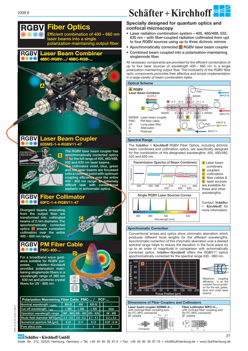
RG
BV
_2p
_09_
ED
_fg.
ind
d •
Pag
e 27
Kieler Str. 212, 22525 Hamburg, Germany • Tel: +49 40 85 39 97-0 • Fax: +49 40 85 39 97-79 • [email protected] • www.SuKHamburg.de
27
2009 E
The Schäfter + Kirchhoff RGBV Fiber Optics, including dichroic beam combiners and collimation optics, are specifically designed for the combination of the designated wavelengths: 405, 460/480, 532 and 630 nm.
A Laser beam combiners B couplers C collimators D fiber cables & E laser sources are available for these and other wavelengths.
Contact Schäfter+ Kirchhoff for more information.
Efficient combination of 400 – 660 nm laser beams into a single polarization-maintaining output fiber
Fiber Optics
LP-1AP
A A
LP-3
PMC60SMS
OUTPUT 60SMS
60SMS
LP-2 60SMS
60SMS
INPUT V
PMC
PMC
PMC
INPUT R
INPUT G
INPUT B
A A
PMC
1
A RGBV Laser Beam Combiner
B
Fiber Collimator60FC-1-4-RGBV11-47
PM Fiber CablePMC-400-...
Conventional lenses and optics show chromatic aberration which produces different focal lengths for the different wavelengths. Apochromatic correction of this chromatic aberration over a desired spectral range helps to reduce the deviation in the focal plane by up to an order of magnitude in comparison with achromatically corrected optics. Schäfter+Kirchhoff offers the RGBV11 optics apochromatically corrected for the spectral range 400 - 660 nm.
C
Laser Beam Combiner48BC-RGBV-.../ 48BC-RGB-...
Divergent beams emanating from the output fiber are transformed into collimated beams of 2 mm diameter. The apochromatically corrected optics 1 ensure consistent collimation over the entire 400 – 600 nm range.
For a broadband wave guid-ance suitable for RGBV pur-poses, Schäfter+Kirchhoff provides polarization main-taining singlemode fibers in a wavelength range of 360 nm - 630 nm and photonic crystal fibers for UV - 800 nm.
Optical Scheme
OUT Apochromatic Correction
Spectral Range
A
B
D
C
D
Polarization Maintaining Fiber Cable PMC-... / PCF-...Nominal wavelength nom 360-Si 400 420-Si -
Cut-off wavelength co < 360 < 400 < 420 none
Operation wavelength range 360 - 460 400 - 600 420 - 630 UV - 800
Mode field diameter MFD[μm] 2.3 - 3.0 2.8 - 4.2 2.7 - 4.1 4.2 ± 0.5
Numerical aperture NA [μm] 0.12 0.11 0.12 0.07 - 0.18
Pure silica core x x x
60SMS Laser beam couplerPMC PM fiber cableLP Long-pass filterA AttenuatorP Polarizer
Laser beam coupler 60SMS-4-...with inclined fiber coupling axis for FC-APC connector(8° polish) 5.5
Ø19
.5
22.4
Connector
Ø12
Ø8
23
Fiber collimator 60FC-4-...with inclined fiber coupling axis for FC-APC connector(8° polish)
Dimensions of Fiber Couplers and Collimators
Specially designed for quantum optics and confocal microscopy
-200 -150 -100 -50 0 50 100 150 200
Rel
. Co
uplin
g E
ffici
ency
%
100
80
60
40
20
0
Focus Position [μm]
1
RGBV
RGBV
RGBV
• Laser radiation combination system – 405, 460/488, 532, 630 nm – with fiber-coupled radiation collimated from upt to four RGBV sources using up to three dichroic mirrors
• Apochromatically corrected 1 RGBV laser beam coupler• Combined beam coupled into a polarization-maintaining
singlemode fiber
All necessary components are provided for the efficient combination of up to four laser sources of wavelength 400 – 660 nm in a single polarization maintaining output fiber. The modularity of the RGBV fiber optic components promotes their effective and simple implementation in a large variety of beam combination tasks.
RGBV
Ø24
.5
Maximum coupling efficiency is at the conjoint focus positi-on for the red, green, blue and violet laser beams.
Laser Beam Coupler60SMS-1-4-RGBV11-47
RGBV
The RGBV laser beam coupler has apochromatically corrected optics 1 for the full range of 405, 460/488,
532 and 630 nm laser beams. The collimated violet, blue, green and red laser beams are focussed onto a common point with optimum coupling efficiency over the entire 400 - 660 nm range: an extremely difficult task with conventional aspheric or achromatic optics.
Laser Beam Coupler for Singlemode fiber
inclined fiber coupling axis
405 460 532 633Wavelength [nm]
Single RGBV Laser Sources Curves
405 460 488 544 6600
TT
T
RR
R LP436LP510
LP570
612633
1
594532
Transmission Spectra of Beam Combiners
Tran
smis
sion

RG
BV
_2p
_09_
ED
_fg.
ind
d •
Pag
e 28
Kieler Str. 212, 22525 Hamburg, Germany • Tel: +49 40 85 39 97-0 • Fax: +49 40 85 39 97-79 • [email protected] • www.SuKHamburg.de
28
2009 E
• Laser radiation combination system – 405, 460/488, 532 and 630 nm – for collimated fiber-coupled radiation
• Apochromatically corrected RGBV Laser Beam Coupler• Long pass LP, broad transmission band for cascaded use
of various long pass filters (transmission up to 95 % and reflection up to 99 %)
• Fused silica substrates with 0.3° wedge angle to suppress interference
• Inclined coupling axes to avoid back reflection
RGBV60SMS
POUT
60SMS
LP-1
LP-2 60SMS
AA
A
A
60SMS
PMC
PMC
PMC
PMC
RED
GREEN
BLUE
RGBV Laser Beam Coupler60SMS-1-4- RGBV-...60SMS Laser beam couplerPMC PM Fiber cableLP Long-pass filterA AttenuatorP Polarizer
Optical schemeRGB Laser Beam Combiner
Beam Combiner / Long Pass48BC - CC - LP-...
Reflection Transm. Pol.
nm 99% 95%436 370 - 412 460 - 700 s510 405 - 488 532 - 660 s570 532 - 544 594 - 660 s
The Laser Beam Combiner takes the individual beams, each incoupled via polarization-maintaining singlemode fiber cables, and produces a combined output into a single polarization-maintaining fiber. This particular modular system combines up to four wavelengths in the range 400 - 660 nm. The individual laser power sources of each wavelength can be attenuated separately so that any desired power relations can be obtained. The fully optimized dichroics from Schäfter+Kirchhoff superimpose the individual laser beams and have a 0.3° wedge profile to avoid interference from back reflected light (Etalon effect). Propagation through parallel plates causes a beam off-set, which is corrected by a compensatory axial displacement of the laser beam couplers. An attenuator allows the adjustment of the combined laser power. The tilt adjustement and inner focussing mechanism of the laser beam couplers, as well as the tilt adjustment of the dichroics, provide all of the degrees of freedom needed for alignment.The design ensures a highly stable structure that can be immediately put to use with confidence.
Optical scheme for 48BC-CC-LP... beam combiner with s-polarization optimization: for all linear states of polarization perpendicular to the plane of incidence
405 460 488 532 544 594 612 633 6600
1
Wavelength [nm]
Tran
smis
sion
TT
T
RR
R LP436LP510
LP570
Transmission spectra of the dichroic beam combiners 48BC-CC-LP...
Beam splitter and beam combiner with wedge-shaped substrate:
A Substrate without wedge: Beams are reflected twice at the substrate/air interfaces together with the primary beam. All are focussed by the coupling lens onto the shared fiber input. Interference of the primary beam by these secondary beams causes intensity instabilities (Etalon effect).
B Substrate with wedge:The principle beam and the beams reflected at the substrate/air interface are inclined twice with respect to each other. The focussing optics transforms the different beams into distinct spots. The tilt mechanism of the laser beam coupler brings the principle spot onto that of the fiber input and the inclined secondary spots are lost. The loss of inter ference ensures inten-sity stability.
B
A
Dimensions
Laser Beam Combiner48BC-RGBV-.../ 48BC-RGB-...
RGBV
fiber 1out
fiber
3fib
er 2
60
�30
/Ø6
�42
1910
.519
10.5
DIN 913 - M3 x 3(8x)
fiber 1out
fiber
4
fiber
2
fiber
3
86
�30
/Ø6
�42
1910
.519
10.5
DIN 913 - M3 x 3(8x)
Laser Beam Combiner 48BC-RGBV-...RGBV
Laser Beam Combiner 48BC-RGB-...RGB
• Combination of four different wavelength • Three dichroics for superposition• See page 27 for optical scheme and A for dimensions
• Combination of three different wavelength • Two dichroics for superposition• See left for optical scheme and B for dimensions
A Laser Beam Combiner 48BC-RGBV-... B Laser Beam Combiner 48BC-RGB-...
See page 27 for optical scheme of laser beam combiner 48BC-RGBV-...“
Spectral range

RG
BV
_2p
_09_
ED
_fg.
ind
d •
Pag
e 29
Kieler Str. 212, 22525 Hamburg, Germany • Tel: +49 40 85 39 97-0 • Fax: +49 40 85 39 97-79 • [email protected] • www.SuKHamburg.de
29
2009 E
Figure 2: Maximum coupling efficiency is at the conjoint focus position for the red, green, blue and violet laser beams.
1
The RGBV-... laser beam couplers are specially designed for cou-pling to polarization-maintaining singlemode fibers and provide apochromatic correction over the range 400 - 660 nm. Individual red, green, blue and violet laser beams are combined and focussed onto the same position with optimum coupling efficiency over the entire wavelength range. Major applications include confo-cal microscopy, quantum optics and fluorescence microscopy.
Figure 1: Apochromatic RGBV lenses are supplied as:1 Laser Beam Couplers Order Code 60SMS-1-4-RGBV11-47 or as2 Fiber Collimators Order Code 60FC-1-4-RGBV11-47
RED
GREEN
BLUE
VIOLET 405 460 532 633
Fig. 3: Fiber collimator 60FC-..., housing Ø 12 mm, focal lengths up to 20mm. For fiber collimators with longer focal lengths see 60FC-T-... page 17.
Table 3 Lenses and beam parameters Fiber Collimator 60FC-... (housing Ø 12 mm)row curr. no 1 2 3 4 5 6 7 8 9 10 11 12 13 14
1 Lens type M4 M5 A6.2S A7.5 M8 A11 RGBV11 M12-NIR A15 M15 A18 M20
2 Focal length f' 4 5.1 6.16 7.5 8.1 11 11 12 15.4 15 18.4 20.1
3 Numerical aperture NA 0.2 0.25 0.3 0.3 0.16 0.25 0.2 0.22 0.16 0.18 0.15 0.16
4 Clear aperture max. [mm] 4.7 2.5 3.7 4.7 2.5 5.5 6.5 5.5 5 5.5 5.5 6.5
5 Collimated beam diameter [mm] 0.72 0.92 1.11 1.35 1.45 1.97 1.97 2.15 2.76 2.69 3.30 3.61
6 Beam divergence [mrad] 0.59 0.47 0.39 0.32 0.29 0.22 0.22 0.2 0.15 0.16 0.13 0.12
7 Correction - monochromatic x x x x x x x x
8 " - chromatic x x x x x x
9 Beam diameter [mm] 0.93 1.03 1.17 1.38 1.48 2.0 2.0 2.2 2.8 2.7 3.3 3.6
Spectral range Code no. of AR coating
10 370 - 600 nm 01 01 01 01 01 01
11 390 - 670 nm 33 33 33 33 33 33
12 400 - 700 nm 13 13
13 400 - 670 nm 51 47
Fundamentals on fiber connection see page
A inclined
B coaxial
�
60FC-4-M5-33
Fiber collimator
Fiber connection for:4 = FC-APC connection (8°polish)0 = FC-PC connection (0° polish)
AR coating
Lens type:A = asphereM = monochromat or achromat
60FC-… 60FC-A19.5… with system mount Ø 19.5 mm (fits directly into the "multicube"- system)
Order Code
Table 2 Lenses and beam parameter
row curr. no. 1 Lens type RGBV112 Focal length f' 113 Numerical aperture NA 0.24 Clear aperture max. [mm] 6.55 Correction - monochromatic6 " - chromatic x
Input Beam Diameter7
Numerical aperture of the fiber
0.09 1.628 0.10 1.809 0.11 1.98
10 0.12 2.1611 0.13 2.3412 0.14 2.52
AR-coating13 400 - 670 nm 47
2
�Order Option
The 48BC-RGBV-... Laser Beam Combiner is supplied as a completly adjusted system with:
Schäfter+Kirchhoff recommends ordering fiber cables (PMC-.../ PCF-...) with APC polish and fiber collimators, especially with RGBV optics and FC-APC connector (60FC-1-4-RGBV11-47). Please do not hesitate to ask Schäfter+Kirchhoff about suitable beam sources or other specifications of beam combiners, e.g. with other combinations of wavelengths, different numbers of beam sources or other connectors according to your needs.
Laser Beam Coupler60SMS-...
RGBV
-200 -150 -100 -50 0 50 100 150 200
Rel
. Co
uplin
g E
ffici
ency
%
100
80
60
40
20
0
Focus Position [μm]
Fiber Collimator60FC-...
RGBVFiber collimators in a Ø 12 mm housing made by Schäfter+Kirchhoff are available with a variaty of focal lengths (see page 16). 60FC-... fiber collimators are provided with internal focussing and a front fitting Ø 8 mm for connecting micro-focus optics of the series 5M-... .
The values for beam diameter (1/e2-value of Gaussian intensity distribution) and divergence given in table 3 refer to a wavelength = 670 nm and a fiber NA = 0.11.
The collimating lenses of type M are corrected for spherical aberration (mono chromat) or for chromatic aberration (achromat). Both produce an undisturbed Gaussian beam profile.
The collimating lenses of type A are aspheric lenses. Their specific manu facturing process leaves micro-structures on the lens surface, which also affect the collimated beam but not the focussed beam.
The fiber collimators have a coaxial or inclined coupling axis for accepting the fiber con nectors FC-PC and FC-APC, respectively (optionally ST, DIN AVIO and F-SMA). The fiber connection has an axial limit stop to ensure a constant focus position, particulary for fiber collimators with an inclined coupling axis.
48BC-RGBV-... 48BC-RGB-...
3 dichroics for RGBV combination 48BC-CC-LP436, LP510, LP570 2 dichroics for RGB combination 48BC-CC-LP510, LP570
Laser Beam Coupler with RGBV optics and FC-APC connector 60SMS-4-RGBV11-47
4 Laser Beam Couplers with FC-APC connector for input sources of the wavelength 405 nm, 460/488 nm, 532 nm and 630 nm
3 Laser Beam Couplers with FC-APC connector for input sources of the wavelength 460/488 nm, 532 nm and 630 nm
Apochromat

Pho
toni
cCry
stal
.ind
d •
Pag
e 30
Kieler Str. 212, 22525 Hamburg, Germany • Tel: +49 40 85 39 97-0 • Fax: +49 40 85 39 97-79 • [email protected] • www.SuKHamburg.de
30
2009 E
Polarization Maintaining Singlemode Fiber Cables Schäfter+Kirchhoff supplies polarization-maintaining fiber optics with broadband wave guidance for RGBV purposes
Schäfter+Kirchhoff supplies polarization-maintaining singlemode fiber cables for RGBV applications:
• Wavelength range: 360 – 630 nm• Pure silica core fibers for an increased transmission in the short
wavelength range• Mode field diameter 2.3– 4.2 μm• FC-APC or FC-PC fiber connection
• Polarization direction indicated by the connector index
For other PM fiber cables, singlemode fiber cables SMC-... and the order codes, see page 9.
Table 4 Polarization Maintaining Fiber Cable PMC-... row curr. no 1 2 3 4
1 Nominal wavelength nom 360-Si 400 400-Si 420-Si
2 Cut-off wavelength co < 360 < 400 < 400 < 420
3 Operation wavelength range 360 - 460 400 - 600 400 - 500 420 - 630
4 Mode field diameter MFD[μm] 2.3 - 3.0 2.8 - 4.2 2.8 - 3.5 2.7 - 4.1
5 Numerical aperture NA [μm] 0.12 0.11 0.11 0.12
6 PM fiber type PMC-...-P PMC-...-P PMC-...-P PMC-...-P
7 Pure silica core x x x
Photonic crystal fibers optimized for singlemode operation have a wide spectral range combined with a relatively large mode field diameter. Being made from fused silica the fiber is resistant to solarization effects.
The numerical aperture of photonic crystal fibers is a function of the wavelength used (unlike the more conventional step-index single-mode fibers where mode field diameter varies with wavelength). Photonic crystal fibers are capable of providing an essentially endless singlemode operation with no cut-off wavelength.
It must be noted that attenuation is about 10 dB higher for shorter wavelengths in comparison with pure silica core fibers and that the beam only approximates a Gaussian profile.
A selection of different types of photonic crystal fibers is available, all manufactured by Crystal Fibre, www.crystal-fibre.com. Please contact Schäfter+Kirchhoff for further information.
Depiction of the hexa-gonal pattern of the photonic crystal fiber micro structure. The major benefits include a larger mode field dia-meter and a wider spectral range for singlemode ope ration.
Photonic Crystal Fiber PCF-...
Length in cm (standard = 150)
Connector Type:0PC = FC-PC (0°-polish)FC-APC, AVIO, AVIO-APC
cable type:3 = Ø 3 mm PVC cable with Kevlar strain relief (standard)1 = fiber cable with Ø 0.9 mm buffer (for short FC connector)
PCF = polarization-maintaining photonic crystal fiber cable
PCF-3-APC-150
PM fiber type:P = PandaLength in cm (standard = 150)Connector Type:APC = FC-APC (8°-angled polish)0PC = FC-PC (0°-polish)XPC = one end FC-APC, other FC-PCAVIO, AVIO-APC
cable type:3 = Ø 3 mm PVC cable with Kevlar strain relief (standard)1 = fiber cable with Ø 0.9 mm buffer (for short FC connector)Numerical aperture NAMode field diameter MFD at nominal wavelengthNominal wavelengthPMC = polarization-maintaining singlemode fiber cable
PMC-400-2.8-NA011-3-APC-150-P
Table 5 PM Photonic Crystal Fiber Cable PCF-...row curr. no 5
1 Nominal wavelength nom UV
2 Cut-off wavelength co none
3 Operation wavelength range UV - 800
4 Mode field diameter MFD[μm] 4.2 ± 0.5
5 Numerical aperture NA [μm] 0.07 - 0.18
6 PM fiber type PCF
7 Pure silica core x
PMC-... Type Panda or Oval-Inner Clad
Depiction of a ‘Panda’ fiber with the two stress induction com-ponents in the fiber clad ding that cause birefringence. As for all singlemode fibers, the PMC fibers have a cut-off wavelength.
The MFD of PMC fibers is a function of the wavelength while the NA remains constant
The NA of PCF fibers is a function of the wavelength while the MFD remains constant
NA()MFD = const. NA = const. MFD()
0.070.080.090.10.110.120.130.140.15
22.5
33.5
44.5
55.5
6
350 450 550 650 750 850wavelength [nm]
MFD
[μm
]
NA
0.06
0.08
0.1
0.12
0.14
0.16
3
3.5
4
4.5
5
5.5
350 450 550 650 750 850wavelength [nm]
NA
MFD
[μm
]
Order Code
Order Code
Differences between step-index singlemode fibers SMC/PMC (right) and polarization-maintaining photonic crystal fibers PCF (left).
The NA of PCF fibers is a function of the wavelength and the MFD remains constant, while the converse pertains for SMC/PMC fibers.
Gaussian intensity profile at �= 405 nm. The laser source has a reduced coherence length (51nanoFCM-.., page 45). The diame-ter of the in ten si ty dis-tri bu tion is small at this wavelength.
Gaussian intensity profile at 685 nm. The laser source is again a 51nanoFCM-... with reduced coherence length. The diameter is obviously lar-ger in comparison to 405 nm and 532 nm. This clearify the wavelength dependency of the NA for PCF-... fibers.
Typical intensity pro-file of a PMC-... fiber. The diameter of the profile is independet from the wavelength.
Intensitity profile for 532 nm. For lasers with long cohe rence length the inten-sity dis tri bution would differ from the Gaussian shape.
405 nm 532 nm 685 nm
�NA � 0.07 �NA � 0.09
�NA � 0.12
5%-Level

Mul
ticub
e_09
_ED
.ind
d •
Pag
e 31
Kieler Str. 212, 22525 Hamburg, Germany • Tel: +49 40 85 39 97-0 • Fax: +49 40 85 39 97-79 • [email protected] • www.SuKHamburg.de
31
2009 E
124
4
5
5
3
6
6
Construction Kit “multicube”48MC-...
The “multicube” construction system is the perfect integration platform for laser beam couplers, beam combiners, beam split-ters, polarizers or retardation optics. The “multicubes” are combined and supported using four Ø 6 mm rods in parallel, which are compatible with established micro-bench systems. The rods are located in full through-holes or partial blind-holes at least 2 diameters deep (12 mm). Each rod is locked using two M3 screws (1.5 mm Hex screwdriver) that are radially opposed across the “multicube”, ensuring high reproducibility by totally preventing any distortion.Self-supporting modules and laser beam sources can be created that are extremely resistant to torsion, by combining components such as a laser diode collimator 48TA…, a Faraday iso lator 48FI-5-… and the mounting console 48MB.The design features of the Schäfter+Kirchhoff “multicube” com-ponents ensure highly rugged and warp-resistant setups, espe-cially for singlemode coupling. Precision is everything: as the mode field diameter of a singlemode fiber at 780 nm is only 5 μm - ten times thinner than a human hair!Applications: see the laser diode beam sources 48TE-..., page 43 and fiber port clusters for magneto-optical traps (MOT) on page 55.
Laser beam coupler 60SMS…, page 5
Applications: see page 55 Fiber port cluster for a magneto- optical trap
F
8
A.1F
A
E A.3
A.2
6
B
C
D
Fiber-optical components:1 Retardation optics /2 48WP-2- CA-532L2 Polarization beam splitter 48PM-CC-A3 Polarizer 48PM-S4 Laser beam coupler 60SMS-...5 Singlemode fiber cable PMC-480-...6 Option: fiber collimator 60FC-4-...
Double-Cubewith through holes for linear arrangementsOrder Code 48MC-LI-195
Single-X-Cubefor X-arrangementsOrder Code 48MC-LTD-19.5
Triple-X-Cubefor X-arrangementsOrder Code 48MC-CL-19.5
Extended Mounting Plate for components with 19.5 mm system mount or with 25 mmOrder Code 48MC-SP-19.5 Order Code 48MC-SP-25
Mechanical Shutteraperture Ø�3 mmsystem mount Ø 19.5 mmOrder Code 48AT-S
Double-T-Cubefor T-arrangementsOrder Code 48MC-LT-19.5
Extended Mounting Bracket150 x 60 mm or 60 x 60 mm, system mount Ø 19.5 mmOrder Code 48MB-19.5-150Order Code 48MB-19.5-60
Mounting Platefor components with Ø 19.5 mm system mount or with Ø 25 mmOrder Code 48MC-MP-19.5 Order Code 48MC-MP-25
Combination Cubes and Plates 48MC-…
Single-Cubewith through holes for linear ar-rangements, short designOrder Code 48MC-SM-19.5
Single-T-Cubefor T-arrangementsOrder Code 48MC-LTS-19.5
Mechanical Shutterwith micrometer screw, aperture Ø�3 mmsystem mount Ø 19.5 mmOrder Code 48AT-A
8
x-y Adjustment platefor lateral adjustment, translation 1mmOrder Code 48MB-19.5-SXY-1
Fig.1: Laser with two fiber system
Figure 1:A “multicube” element A.1 radially arranged
screws M3 for fixing the connecting rods 8 ,A.2 screws M3 for fixing components with 19.5 mm system mount,
andA.3 screws M2 for fixing a variety of adapter flanges 6 . B Polarization beam splitter, C Beam splitter, D Beam combiner, E Retardation optics,F Laser beam coupler

Mul
ticub
e_09
_ED
.ind
d •
Pag
e 32
Kieler Str. 212, 22525 Hamburg, Germany • Tel: +49 40 85 39 97-0 • Fax: +49 40 85 39 97-79 • [email protected] • www.SuKHamburg.de
32
2009 E
Polarization Beam Splitter48PM - CC - A Order Code
Spectral range [nm]A = 450 - 700 nmB = 750 - 1100 nmC = 1100 - 1700 nm
Beam Combiner 48BC-CC-LP...Two laser beams of different wavelengths are coaxially combined into a single laser beam with equal polarization. In adjustable mount, for mounting with clamp collar (included). • 1mm fused silica plate with wavelength-dependent dielec-
triccoating and 0.3° wedge angle for interference suppression• long pass (LP) and short pass (SP) version• optimized for angle of incidence 45°, p-polarization• fused silica plate • coated reverse surface• aperture 10 mm• reflection up to 99%, transmission up to 95%.
Beam Splitter 98/1 48BS-CC-PA00 In adjustable mount, for mounting with clamp collar (included).• 1 mm fused silica plate, uncoated• 0.3° wedge angle for interference suppression.• transmission 98% (p-polarization)• reflection 1% per surface (p-polarization)• aperture 10 mm
Beam Splitter 98/148BS - CC - PA00 Order Code
Application:Beam splitter with adjus table splitting ratio, in combination with retardation optics48WP-CA-...
Application: Separation of a partial beam for power monitoring
Application:For the coincident coupling of laser diode beam sources of different wavelengths and identical polarization into one singlemode fiber
�
Application: For increasing the ex tinction ratio after collimating the radiation of a polarization- main taining fiber
A Polarizerin adapter flange as 48MB-19.5ACOrder Code 48PM-S-...
Polarization Beam Splitter 48PM-CC... Beam-splitting cube with internal dielectric and polarizing multi-layer coating. In adjustable mount, for mounting with clamp collar (included).50:50 split ratio for linearly polarized input radiation with polariza-tion direction ��= 45°. Maximum transmission at ��= 0° (p-pol.), maximum reflection at ��= 90° (s-pol.).• extinction ratio 10,000 : 1• aperture 6 mm• reflection angle 90°• broadband AR coating R < 0.5% per surface
B
A
D
D Polarizer with attenuatorin adapter flange 48AT-19.5AC-S1Order Code 48PM-AT-19.5AC-...
B Polarizer as 48PM-Sdecentered 0.3 mm for combining with beam splitter plate 48BS-...Order Code 48PM-S-D-...
Polarizer48PM - S - A Order Code
Spectral rangeA = 450 - 700 nmB = 750 - 1100 nmC = 1100 - 1700 nm
Optics for the "multicube" SystemBeam Splitter and Beam Combiner Polarizers
Retardation Optics
Photo DetectorPhotodetektor 48PD-...
Reflection Transm. Pol.long pass
LP436 370 - 412 460 - 700 sLP510 405 - 488 532 - 660 sLP570 532 - 544 594 - 660 sLP580 500 - 560 600 - 700 pLP725 500 - 560 780 - 2100 pLP800 630 - 780 820 - 880 s
short passSP1500 1650-1700 1200-1380 p
Beam Combiner48BC - CC - LP xxx Order Code Spectral range [nm]
Beam splitter and beam combiner with wedge-shaped substrate:
A Substrate without wedge: Beams are twice reflected at the substrate/air interfaces in parallel with the primary beam. They are focussed by the coupling lens onto the shared fiber input. Interference of the primary beam by secondary beams (Etalon effect) causes intensity instabilities.
B Substrate with wedge: The principle beam and beams reflected at the substrate/air interface are inclined twice with respect to each other. The focussing optics transform the different beams into distinct spots. The tilt mechanism of the laser beam coupler brings the principle spot onto that of the fiber input and the inclined secondary spots are lost. The removal of inter ference ensures no intensity instabilities.
B
A
Polarizer 48PM-...• adjustable within adapter flange• polarization: linear • extinction ratio 10,000:1• aperture 3.5 mm• broadband AR coating: R < 0.5% per surface• variety of designs
Retardation Optics /2 48WP-2-CA-...The /2-plate rotates the polarization direction of a linearly pola-rized input beam.• aperture 5 mm• in adjustable mount with self-locking tubular axis (0 - 360°)• to avoid interference and back reflection, the mount is in-
clined 3° with respect to the longitudinal axis• quartz plate type L: low order for low angle sensitivity type Z: zero order for low wavelength dependency
�
2��
Application:In combination withpolarization beam splitter 48PM-CC-..., beam splitter with adjus table splitting ratio
Retardation Optics /248WP - 2 - CA - 780 L Order Code
low order Lzero order Z wavelength in nm
Dichroic Retardation Optics 48WP-2--1-The dichroic retardation plate is a /2-plate for one wavelength and does not affect the polarization of another wavelength. The correct-ly positioned plate rotates two ortho gonally polarized input beams of different wave lengths into linear polarization states in parallel.• aperture 5 mm• in adjustable mount with self-locking tubular axis (0 - 360°)• to avoid interference and back reflection, the mount is in-
clined at 3° with respect to the tubular axis• quartz plate of low order
�
2��
Dichroic Retardation Optics48WP - 2-780 - 1-767 Order Code
wavelength in nm/2 wavelength in nm
Application:In combination withpolarization beam splitter 48PM-CC-..., beam combiner for two wavelengths too close for dichroic beam combiners (�< 30 nm)
Si-Detector 48PD-BPX61• photo diode BPX 61• spectral range 400-1100 nm• > 50 nA/lx, >320 mV/lx, 72 pF, 20 ns• active area 7 mm2
• 3° angled mount in housing for system mount Ø 19.5 mm• diode and BNC connector galvanically isolated
Application:Power monitoring in combination with beam splitter 98/1 48BS-CC-PA
Photo Detector48PD-BPX61 Order Code
For a complete, fiber-coupledRGBV-coupler, see page 24 orwww.SuKHamburg.de\dl\rgbv_e.pdf
Beam Splitter Cube 50/50 48BM-CC... • 50:50 split ratio• independent of polarization• aperture 6 mm• reflection angle 90°• broadband AR coating per surface
Beam Splitter 50/5048BM - CC - A
Spectral range [nm]A = 450 - 700 nmB = 750 - 1100 nmC = 1100 - 1700 nm
Order Code

Mul
ticub
e_09
_ED
.ind
d •
Pag
e 33
Kieler Str. 212, 22525 Hamburg, Germany • Tel: +49 40 85 39 97-0 • Fax: +49 40 85 39 97-79 • [email protected] • www.SuKHamburg.de
33
2009 E
L
Adapter FlangeFor components with Ø 8 mm for fitting to Ø 19.5 mm system mount Order Code
48MB-19.5 AC
SpacerWith Ø 19.5 mm both endsOrder Code
48S-19.5
AdapterFor components withØ 12 mm forØ 19.5 mm mountingOrder Code
12AM-19.5
Light TrapFor absorbing unused beamsOrder Code
48LT-19.5
CapWith Ø 19.5 mmsystem mounting Order Code
48C-19.5
IrisAperture Ø 1 - 13 mmOrder Code 13BL1-13
Aperture Ø 0 - 12 mmOrder Code 13BL0-12
Adapter C-mountAdapter for Ø 19.5 mm to C-mountOrder Code
C-mount-19.5
Adapter for Microscope LensesAdapter for Ø 19.5 mm to W0.8“x1/36“Order Code
W0.8-19.5
Adapter - Both ends with Ø 19.5 mm mount(v-groove)Order Code
19.5AC19.5
Hex grub screw DIN 914 M3x3-conicalfor mounting Ø 19.5 mm components with v-groove- set of 50 pcs. Order Code
48-M3-3-914-50Hex Screwdriver 50HD-15
Hex screw DIN 912 M2x8for mounting compo-nents Ø 19.5 mm with clamp collar - set of 50 pcs. Order Code
48-M2-8-912-50 Hex Screwdriver Order Code
50HD-15
Hex grub screwDIN913 M3x3-flat for fixing rods to the cubes - set of 50 pcs. Order Code
48-M3-3-913-50Hex Screwdriver 50HD-15
Grub screwDIN 553 M1.6 x1.5-conical for mounting Ø 8 mm com-ponents with v-groove- set of 50 pcs. Order Code
48-M1.6-1.5-553-50Screwdriver Order Code
9D-12
Grub screwDIN 551 M1.6x3 for fixing fiber ferrules to 60FC-... and 60SMS-...- set of 50 pcs. Order Code
48-M1.6-3-551-50Screwdriver Order Code
9D-12
Rod for combining cubesOrder Code 48MC-6-L
L = 30L = 75L = 150xxx = length of choice
Hex screwdriver WS 1.5 mm for screwsDIN 912, 913, and 914Order Code 50HD-15
Eccentric tool for laser beam couplers 60SMS-... and fiber collimators 60FC-...Order Code 60EX-4Order Code 60EX-5
for focal length f’�20mm
Screwdriver WS 1.2 mm for grub screw at fiber ferrulesand accessories 5M-...Order Code
9D-12
Adjustment tool for rotating quarter-wave plates in fiber collimators 60FC-Q...Order Code 60Z-2803
Filter MountFor filters with Ø 25.4 mm to Ø 19.5 mm mountOrder Code
19.5AF25.4-S
Accessories Tools for Assembly and Adjustment
Flanges and Adapters for System Mount Ø 19.5 mm
Eccentric tool for fiber collimators 60FC-T-... and 60FC-Q...Order Code
55EX-5
Adapter Flange with AttenuatorFrom Ø 3 mm to Ø 19.5 mm system mountOrder Code
48AT-19.5AC-S1
Eccentric tool with longer handlefor laser beam couplers 60SMS-... and fiber collimators 60FC-... as an alternative to 60EX-4, 60EX-5, 55EX-5Order Code 60EX-4-L Order Code 60EX-5-L Order Code 55EX-5-L
1 2 3
654
7 8 9
J
K
Polarization Analyzer SK9782-VIS/NIRMeasurement and test system for laser sour ces with PM singlemode fiber cables, see page 53.
List of adapters
Description: adapter with
Dimensions Model Picture
A B
Hole basis fit 8 1219.525 25.4
1 , 3 (19.5 only 1 )
1 2
Shaft basis fit 19.519.5V2525V25.4
1 (19.5 also in 2 )
5 6
Internal thread C-mountM27 x 0.5M27 x 0.75
1 , 3
External thread
C-mountM27 x 0.5M27 x 0.75W0.8"x1/36"
1 , 3 4
Filter mount Ø25.4 x 1Ø12 x 1
1 7
For the "multicube" system, Schäfter+Kirchhoff offers suitable adap-ters and flanges. Standard adapters have a system mount with Ø 19.5 mm tightly fitting cylinder and V-groove 1 , while flanges have through holes for the mounting in front of combination cubes with rods 3 . The depicted adapters and flanges are just an extract of the possible components deliverabel by Schäfter+Kirchhoff, some more are listed at the table. Please contact for special dimensions.
1 2 3
A A AB B B
Ø19
.5
Ø19
.5
Ø19
.5
Ø2.4�20.5�25.4
Ø19.5 with V-groove
Ø19.5 Flange

Mul
ticub
e_09
_ED
.ind
d •
Pag
e 34
Kieler Str. 212, 22525 Hamburg, Germany • Tel: +49 40 85 39 97-0 • Fax: +49 40 85 39 97-79 • [email protected] • www.SuKHamburg.de
34
2009 E
60FF-... Fiber-fiber couplers are used to connect singlemode fiber cables with unequal numerical apertures and mode field diameters.A large variety of fiber collimator lenses 1 and 6 (see Fiber Collimators 60FC-...) and of laser beam coupler lenses 1 (see Laser Beam Coup-ler 60SMS-...) is available. The fiber-fiber coupler can be aligned and focussed so that fiber cables with non-core centered connectors can be coupled with low coupling loss. Additionally, the polarization axes can be aligned.60FF-... Fiber-fiber couplers are available with optics for wavelengths in the range 370 – 2300 nm and with inclined and coaxial coupling axes for use with connectors of type FC-PC and FC-APC, respectively. A core system A is delivered with an extended mounting bracket 4 , a laser beam coupler 1 and a fiber collimator (with suitable adapters as required). A core system can be expanded using any "multicube" optics and flanges B , e.g. a polarizer 2 or iris diaphragm 3 . For extending the fiber-fiber coupler, a second mounting plate 5 and 4 more rods are supplied. Optionally, the 60FF-... Fiber-fiber coupler can be ordered with a maximum outer diameter of Ø 24.5 mm C , either with or without a base plate 7 .
60FF – 60SMS - … - 60FC - … - 13BL1-13
Fiber-Fiber Couplers 60FF-... Combination Cubes and Plates 48MC-...
Figure 2: F60FF Fiber-fiber couplers. Modular system combined by the following components:
1
4
1
4
6
7
1
Order Code
A
B
C
60FF = Fiber-fiber coupler
Laser beam couplerFor versions of Laser Beam Coupler 60SMS-...,pages 5-8
Fiber collimatorFor versions of Fiber Collimator 60FC-..., see pages 15-24
Optics for "multicube"For versions of Construction Kit 48MC-..., see pages 32-33
1 Laser beam coupler 60SMS-... 2 Polarizer 48PM-S-... 3 Iris 13BL1-13 4 Mounting bracket 48MB-19.5-60
5 Mounting plate 48MC-MP-19.5 6 Fiber collimator 60FC-... 7 Base plate 60FF-CC-19.5
Applications
53
Fiber-to-Fiber Coupler with Faraday Isolator
The fiber-to-fiber coupler with Faraday isolator from Schäfter+Kirchhoff supresses back reflections and offers an attenuator and shutter. The Faraday isolator consists of two polarizers with a distorted main axis and a Faraday crystal. The first polarizer is adjusted for incoming beam transmission without loss. By applying a strong magnetic field to the Faraday crystal, the polarization axis of this beam is rotated. The second polarizer is aligned with the distorted polarization axis. Back reflected light results in another transit of the beam through the Faraday crystal and the polarization axis is rotated yet again. The resultant polarization axis is perpendicular to the initial axis and so the distorted beam is blocked by the polarizer. A fiber-to-fiber coupler with Faraday isolator is used to protect laser beam sources where the attached fiber connectors cannot be removed (e.g. a fiber pig-tail) or when a back coupling to the fiber is a desirable characteristic (e.g. in interferometry).
Set-up
Pos. Description Order Code Explanation
1 Laser beam coupler 60SMS-1-4-...is equivalent to fiber collimator 60FC-A19.5-4-..., adjustable
2 Faraday isolator 48FI-...to avoid back coupling of laser radiation into the fiber
4 Console 48MB19.5-60
3 Attenuator/Shutter 48AT-A/ 48AT-S Attenuator or Shutter
5 Mounting Plate 48MC-MP-19.5
Fiber-coupled beam delivery systems, post card sized, replaces 1 m2 sized bread board constructions. Assem bled with fiber optic components from Schäfter+Kirchhoff.
Fiber Port Cluster for MOT
agneto
ptical
rap
See www.SuKHamburg.de/dl/appmot_e.pdf
In global use: Austria
France
Italy
VR China
Germany
U.K.
USA
India
New:Dichroic System
Input: 2 PM fiber cables, differing wavelengths, e.g. Sr: 461 mm and 689 mm.
Output: 6 PM fiber cables, both wavelengths superimposed
with linear polarization in parallel orientation
For more information, see pages 55-59
1 13 2
2
1
1
4
6
3
Input
13
4
2
5
1
Fig.3: Fiber-fiber coupler with Faraday isolator

Mul
ticub
e_09
_ED
.ind
d •
Pag
e 35
Kieler Str. 212, 22525 Hamburg, Germany • Tel: +49 40 85 39 97-0 • Fax: +49 40 85 39 97-79 • [email protected] • www.SuKHamburg.de
35
2009 E
Fiber Port Cluster 1 to 4
The optical scheme depicts the beam propagation. An incoming beam A is polarized firstly 2 that a weak polarization stability of the laser source does not cause disturbing side-effects. At the beam splitter 3 <2% of the beam is reflected onto a photodiode 12 acting as a power monitor. The majority of the radiation passes the first /2 optics 4 and enables the adjustment of the splitting ratio of the subsequent beam splitter 5 . This combination of half-wave plate and beam splitter can be cascaded endlessly. The four split beams are directed into the laser beam couplers which act as outgoing ports to the attached fiber cables. Polarizing beam splitters produce a high degree of polarization in the non-deflected and a low degree in the deflected beam. Thus, it is necessary to use smaller additional polarizers 6 to increase the degree of polarization of the outgoing beam.
Set-up
Pos. Description Order Code Explanation
1 Laser beam coupler
60SMS-1-4-...is equivalent to fiber collimator 60FC-A19.5-4-..., adjustable
2 Polarizer (small) decentered
48PM-S-Dto increase extinction ratio, off-set correction for 3
3 Beam splitter 98:1 48BS-CC-PA00reflects 1% of beam to photo-diode 48PD-65 for monitoring
4 Retardation optics /2 48WP-2-CA-...
manual adjustment of laser outputs
5 Polarization beam splitter, adjustable
48PM-CC-...splits the polarization axes (50:50 @ 45°)*
6 Polarizer (small) 48PM-Sto improve extinction ratio before coupling*
7 Console 48MB19.5-608 Combination cube 48MC-SM-19.59 Combination cube 48MC-LTS-19.5
10 Spacer 48S-19.5to avoid gap between console and cube
11 Cap 48C-19.5
12 Photo diode 48PD-BPX61together with adapter flange 48MB-19.5 AC
13 Rod 48MC-6-... to stiffen the system*other angles than 45° at 48PM-CC-... causes lower extinction ratios
1
111
1
2
3
4
4
4
5
5
5
6
6
7
8
8
8
9
10
11
12
13
The fiber port cluster 1 to 4 from Schäfter+Kirchhoff allows the splitting of an entrance beam into four outputs. The power at the outputs can be adjusted individually. The system is built from "multicube" components, providing high flexibility with great stability and reliability.
1 1
1
12
3
4
4
5
5
6
6
12
A
1
3
4
5
2
4
A
A1
A2
A3
A4
Two-Fiber System - Laser Beam Source 532 nm
Principle:In the two-fiber system, the laser power is split between the two polarization-maintaining fiber cables. The splitting is performed by a polarization beam splitter. An arbitrary splitting ratio is achieved by rotating the polarization of the incoming radiation by means of a half-wave plate. At the polarization beam splitter, radiation perpen-dicular to the plane of incidence is deflected. In the deflected beam path, a small polarizer is used to increase the degree of polarization (polarization beam splitters produce a high degree of polarization in the transmitted beam only). With two laser beam couplers, the split radiation is then coupled into two polarization-maintaining fibers.
Laser Source: Coherent Compass 315-150Output Power: 150 mW cw Beam Profile: Gaussian, M² �1.05
Singlemode Fiber Cable:Polarization-maintaining, NA 0.11, with FC-APC (8° angled polish) connectors on both sides
Output power ex-fiber: typ. 123 mW (82%), variably split up to the two output fibers
Gaussian beam and intensity profile
Linear polarization ex-fiber: better than 1:200
Figure 4: Fiber port cluster 1 to 4, mechanical set-up
Fig. 6: Laser with two fiber system
124
4
5
5
3
6
6
Fig. 7: Optical scheme two-fiber system
Fiber-optical components:1 Retardation optics /2 48WP-2- CA-532L2 Polarization beam splitter 48PM-CC-A3 Polarizer 48PM-S4 Laser beam coupler 60SMS-...5 Singlemode fiber cable PMC-480-...6 Option: fiber collimator 60FC-4-...
Opto-mechanics and laser source:A Laser beam source Compass 315M-150
A1 Base plate 48MP-315A2 Extended mounting plate 48MC-SP-19.5A3 Rods 48MC-6-75A4 Single cube 48MC-SM-19.5

Mul
ticub
e_09
_ED
.ind
d •
Pag
e 36
Kieler Str. 212, 22525 Hamburg, Germany • Tel: +49 40 85 39 97-0 • Fax: +49 40 85 39 97-79 • [email protected] • www.SuKHamburg.de
36
2009 E
Laser Attenuators 48AT-...
LaserOUT
LaserIN
48AT-... Laser Attenuators are used for reproducible and precise laser output power reduction.A precision ball on a reed bearing is transported by a scaled micrometer screw into the collimated laser beam and reduces the beam profile. The subsequent fiber coupling results in mode filtering.This mechanically stable attenuation method allows the precise and reproducible setting of the laser output power over a wide range (typically 0.5 to > 60 dB).Compared with power regulation by laser current control, the wavelength and polarization status of the laser beam are both preserved.
48 AT-0-FC-4 - A11 - 02 + SMS- 4 - A11 - 02 Order Code
Input: Fiber Collimator 60FC-...coaxial coupling axisfor FC-PC connector = 0inclined coupling axisfor FC-APC connector = 4Collimating lens
Output: Laser beam coupler 60SMS-…Coupling lensfor FC-PC connectorinclined coupling axisfor FC-APC connector
0 =4 =
Relative OutputPower
7 8 9 10
Micrometer Position (mm)
1
0,6
0,4
0,2
0
0,8
• Reproducible power attenuation and functional safety are only assured for singlemode fibers with a Gaussian intensity profile
• Fiber collimator and laser beam coupler with inclined or coaxial coupling axis for singlemode fibers with FC-APC or FC-PC connector (optionally SMA)
• Insertion loss typically 0.5 dB, extinction > 60 dB• Can be used as interface between different fiber or connector types
Figure 8: 48AT-... laser attenuatorAssortment see Fiber Collimator 60FC-..., page 15-24
Assortment see Laser Beam Coupler 60SMS-..., page 5-8
-20
-40
-607 8 9 10
Micrometer Position (mm)
Attenuation in dB
0
Typical calibration curves
Notes
Photo diode
Optional:48-AT-F-...Laser Attenuator with 1% partial beam separa-tion for power monitoring

Shu
tter
_09-
E.in
dd
• P
age
37
Kieler Str. 212, 22525 Hamburg, Germany • Tel: +49 40 85 39 97-0 • Fax: +49 40 85 39 97-79 • [email protected] • www.SuKHamburg.de
37
2009 E
ApplicationsElectro-Magnetical Shutter EMS-3-30 + SK97120
• Bi-stable Shutter • No power consumption in OFF position• Internal, external, automatic and manual trigger mode• with USB 2.0 and RS232 interface• System mount Ø 19.5 mm compatible with
“multicube” systemShutter SpecificationsSolenoid type . . . . . . . . . . . . Bi-stableShutter rise/fall time trise / tfall . 11 ms / 22 ms (24 V pulse)Holding voltage . . . . . . . . . 0 VMaximum pulse rate . . . . . . . Up to 10 Hz (steady),
Up to 30 Hz (< 1 s burst)Aperture . . . . . . . . . . . . . . . . 3 mmWeight . . . . . . . . . . . . . . . . . . 100 gController Specifications• Shutter status indicator• Voltage 24V +/- 5% DC• Power start up peak 1A / 250 mA• 19" Housing, 3HE / 10 TE, 300 gTimingTiming resolution . . . . . . . . . 1 msShutter OPEN time tOPEN . . . 12 – 60000 ms Shutter CLOSE time tCLOSE . . 0 – 60000 ms (pre trigger)(Shutter open/close time programmable in software mode only)Trigger IN . . . . . . . . . . . . . . . TTL (BNC connected)
Operating Modes: • Manual . . . User-controlled open/close• Software . . PC-controlled operation via USB2 or RS232• Single . . . Open/close cycles by microcontroller (μC)• Auto . . . Multiple open/close cycles by microcontroller (μC)• Extern . . . . Externally TTL-triggered open/close
The bi-stable shutter operation means that it does not conform
to laser safety rules according to
ICE 60825-1
EMS-3-30 Shutter headSK97120 Controller with power supply, driver and control software48MC-SM-19.5-SM “multicube” with shock absorbers
Order Code
1
2
Electrical scheme
Figure 1: 1 EMS-3-30 electro-magnetical shutter
with 2 SK97120 shutter controller.
Shutter open
Shutter closed
trise
tOPEN
tfall
tCLOSE
timing diagramm
Dimensions
HeNe Lasers with fiber optics and electrical shutter
2
1
4
5
A
A.1
2.1
2.2
ComponentsA HeNe laser, A.1 Power supply for laser, 1 Mounting console MC-MG-C-44.5-F-R, 2 Electrical shutter EMS-3-30, 2.1 Shutter controller SK97120, 2.2 Power supply for shutter, 2.3 "multicube" with shock absorbers 48MC-SM-19.5-SM, 3 Attenuator 60A19.5-F-AT, 4 Laser beam coupler 60SMS-1-4-..., 5 Fiber cable SMC-630-.../ PMC-630-....
1
2
1
A.1
4
3
5
2.12.2
A HeNe laser 632.8 nm
EMS-…60SMS-…
Power supplyControllerPower supply
2.3
Upon activation, HeNe Lasers require several minutes to reach a stable state of radia tion. To circumvent this latency, it is advantageous to use a shutter to block the beam, rather than subjecting the laser to a series of on-off cycles. In the present application, the shutter is mounted in a “multicube” immediately in front of the laser. Shock absorbers prevent any vibration caused by the shutter operation. The power of the laser radiation can be reproducibly modulated with the attenuator 60A19.5-F-AT. Subsequently, the beam is coupled using a highly efficent beam coupler into a singlemode SMC-... or a polariziation-maintaining singlemode PMC-... fiber. The coupling axes can be either coaxial FC or inclined APC to prevent back reflections into the laser source.For further information about this application, please see www.SuKHamburg.com/dl/shutter_e.pdf
3
For further information about this product, please seehttp://www.SuKHamburg.com/dl/shutter_e.pdf
75
50.8/10TE
133.
3/ 3
HE

Cho
pp
er+
AO
M_0
9_E
D.in
dd
• P
age
38
Kieler Str. 212, 22525 Hamburg, Germany • Tel: +49 40 85 39 97-0 • Fax: +49 40 85 39 97-79 • [email protected] • www.SuKHamburg.de
38
2009 E
Fiber-Coupling for Chopper SK 206-...
1.1
3.1
24
56
Optical choppers are used for a periodical modulation of light, such as for lock-in detection purposes when the laser cannot be modulated directly. Schäfter+Kirchhoff offers a chopper coupled to a polarization-maintaining singlemode fiber.• 10 kHz square wave modulation employing a standard blade (100
slits)• 30 kHz and higher when using specially designed blades • Short rise and fall times of the signal edges by laser micro-spot and
adapted beam waist• With polarization-maintaining fiber optics for laser beam sources in the
370 - 2300 nm rangeOptionally: increased rise and fall times (equal to an open beam configuration) with a sinusoidal signal form obtained by placing the chopper head parallel to the beam.Fiber type: singlemode, polarization-maintaining fiber with FC-APC connectors producing a Gaussian beam intensity distribution. The quality of the wave front and the Gaussian intensity distribution of the primary laser beam source are conserved or substantially improved by the characteristics of the singlemode fiber.
a bFigure 2:Polarization-maintaining fiber-coupled chopper.
1 Chopper head HMS 220 A with chopper blade 1.1
2 Chopper mounting device 3 Fiber optics
3.1 Singlemode fiber cable PMC-630-4.5-NA011-3-APC-150-P3.2 Laser beam coupler 60SMS-A4.5-02 3.3 Micro-focus optics 5M-A18-02 3.4 Fiber collimator 60FC-4-A4.5-02 4 Fiber collimator 60FC-4-...5 Polarization filter 5PF-...6 Micro-focus optics 5M-...
Figure 3: Optical scheme for figure 2.
3.13.1 3.23.33.33.4 3.5
Chopper blade1.1
SK206-1-100 Bench with beam-shaping optics, see Figure 3SK206-HMS220A Chopper head with DC motor and reference pick-upSK206-HMS220/100 Chopper blade, Ø 120 mm, 100 slitsSK206-HMS221 Chopper control, speed 60-6000 rpm SK206-Hood Protection cover for chopper blade
Order Code
Figure 4: Intensity characteristics of the chopped laser beam at a chopping frequency of 10 kHz.a Oscilloscope trace with a time scale of 350 μs/divisionb Oscilloscope trace with a time scale of 260 ns/division
AOM - Acoustic-Optic ModulatorsSchäfter+Kirchhoff offers fiber-coupled acousto-optic modulators (AOMs) from different manufacturers. The fiber-coupled acousto-optical systems provide high transmission and extinction with a long-term stability. They are sealed against light leakage, for laser safety, and against dust for application in the most demanding of industrial environments.
AOTF - Acousto-Optic Tunable FiltersA standard AOM is designed for use with monochromatic radiation.
For broad band radiation applies:The modulated beam (first refraction order) is dispersive and its refraction angle is a function of the optical wavelength. Hence, the radiation cannot be coupled into a single singlemode fiber.
To modulate multiple superimposed wavelengths simultaneously, an acousto-optical tunable filter (AOTF) is used. This is a special AOM in which the light dispersion is compensated for by applying different acoustic frequencies with different amplitudes simultaneously, so that the corresponding different optical wavelengths are switched or modulated precisely.
The radiation arising from a polarization-maintaining singlemode fiber is collimated and passed through the acousto-optic cell. The zero-order beam is blocked by a trap and the first refracted beam is coupled to the output fiber. To achieve shorter switching times, the radiation can be focussed into the acousto-optic cell. All necessary adjustment possibilities are available and these can be locked in a desired position.
Figure 5: Acousto-optic modulator with polarization-maintaining fiber coupling from Schäfter+ Kirchhoff.Fully customized monitoring systems with a beam splitter are also available.
1
1
2
2
3
IN OUT
RF INFigure 6: Optical scheme of an acousto-optic modulator with polarization-maintaining fiber coupling:1 Input and output fiber cables PMC-..., polarization-maintaining,2 Laser beam couplers 60SMS-... for collimating from a fiber and for coupling
into a fiber, and3 acousto-optical modulator AOM.
12 3
12
Figure 7: Optical scheme of an acousto-optic modulator versus an AOTF: 1 the beam modulated by the AOM has a refraction angle determined by the incident wavelength. 2 the beam modulated by the AOTF has a refraction angle independent of the wavelength and so can be coupled to a common singlemode fiber, 3 .
IN OUT
RF IN
IN
RF IN
2 3
1
Optical Chopper SK 206-1-100Frequency stability ± 0.2% at 10 kHzRefolution 60 - 6000 / minChopper frequency 100 Hz - 10 kHz with Chopper- blade HMS 200/100(with 4 Hz and up to 30 kHz with special blades)
1
3
A
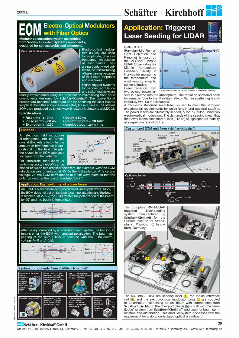
EO
M_0
9-E
_neu
.ind
d •
Pag
e 39
Kieler Str. 212, 22525 Hamburg, Germany • Tel: +49 40 85 39 97-0 • Fax: +49 40 85 39 97-79 • [email protected] • www.SuKHamburg.de
39
2009 E
Application: Fast switching of a laser beamAn EOM is placed between two crossed linear polarizers. At V=0, the EOM does not act on the laser beam polarization and the beam is blocked. At V= V�, the EOM rotates the polarization of the beam by 90° and the beam is transmitted.
V
< 50 ns
< 10 ns
V�
Beam
After being combined by a polarizing beam splitter, the two input beams enter the EOM with crossed polarization. The beam ap-pearing at the output fiber is selected with the EOM control voltage (V=0 or V= V�).
< 50 ns
< 10 ns
Retardation optics 48WP-...�/2 plate for rotation of the polariza tion axis
Polarization beam splitter 48PM-..., Beam splitter 98/1 48BS-..., for power monitoring
"multicube" system48MC-...
PMC-… pola ri zation- maintaining fiber cables for 360 – 1600 nm
Laser beam coupler60SMS-… tilt adjust-ment and inclined coup ling axis for con-nectors type FC-APC
Faraday Isolator 48FI
Polarization Analyzer SK9782 for polari-zation analysis and pre-cise fiber adjust-ment
Electro-magnetic shutter EMS-3-30, timing resolution 1 ms
System components from Schäfter+Kirchhoff
An electrical field introduces bi-refringence into an optical crystal (Pockels effect). As the amount of birefringence is pro-portional to the field intensity, the crystal in an EOM acts as a voltage-controlled retarder.For amplitude modulation or switching tasks, the EOM can be placed between two crossed polarizers, for example, with the EOM retardation axis orientated at 45° to the first polarizer. At a certain voltage, V�, the EOM corresponds to a half-wave plate so that the polarization after the crystal is rotated by 90°.
V
�(V) Input polarizer
Pockels cell
Outputpolarizer
Electro-optical modula-tors (EOMs) are used for amplitude, phase or fre quency modulation of laser beams. They are particularly well sui-ted to the fast switching of laser beams because of their short response and rise times. Highly rugged systems for various modulation and switching tasks are
readily implemented using the polarization-maintaining fiber optic components designed by Schäfter+Kirchhoff. The conventional breadboard becomes redundant and by confining the laser beams in optical fibers this enhances laser safety (Laser Class I). The offered EOMs are produced by Linos (www.linos.com), shown is a LM0202. Specifications: • Rise time < 10 ns • Delay < 50 ns • Pulse width > 30 ns • Repetition rate < 20 MHz • Extinction < 1:250 • Input/output jitter < 1 ns
Electro-Optical Modulatorswith Fiber OpticsEOM
V�
Beam 1
Beam 2
V
Modular construction system assembled from Schäfter+Kirchhoff system components, designed for self assembly and alignment. RMR-LIDAR
(Rayleigh-Mie-Raman Light Detection and Ranging) is used by the ALOMAR (Arctic LIDAR Observatory for Middle Atmosphere Research) facility in Norway for measuring the temperature and wind velocity in up to 80 km altitudes. Laser radiation from two pulsed power la-sers is directed into the atmosphere. The radiation scattered back by aerosols (due to the Rayleigh, Mie or Raman scattering) is col-lected by two 1.8 m telescopes. A frequency stabilized seed laser is used to meet the stringent experimental requirements for pulse length and spectral stability. The power lasers are alternately seeded, pulse-by-pulse, using two electro-optical modulators. The demands of the seeding mean that the power lasers emit short pulses (~12 ns) of high spectral stability at a repetition rate of 30 Hz.
Application: Triggered Laser Seeding for LIDAR
The 532 nm / 1064 nm seeding laser A , the iodine reference cell B , and the electro-optical modulator units C are coupled to polarization-maintaining optical fibers with components from Schäfter+Kirchhoff. The fiber port cluster D is built with the “mul-ticube” system from Schäfter+Kirchhoff and used for beam com-bination and distribution. This modular system dispenses with the requirement for a vibration-isolated optical breadboard.
© Leibnitz Institute for Atmospheric Physics, Kühlungsborn, Germany
© A
LOM
AR
Ob
s.
Input Fiber
LaserBeamCoupler60SMS
Power monitoring
FaradayIsolator
Beam combiner
Output Fiber
EOM Output
Optical scheme
Customized EOM unit from Schäfter+Kirchhoff
B C
C
A
The complete RMR-LIDAR triggered laser-seeding system, manufactured by Schäfter+Kirchhoff for the Leibnitz Institute for Atmos-pheric Physics, Kühlungs-born, Germany:
D
Electro-Optic Modulator
Function

Not
es.in
dd
• P
age
40
Kieler Str. 212, 22525 Hamburg, Germany • Tel: +49 40 85 39 97-0 • Fax: +49 40 85 39 97-79 • [email protected] • www.SuKHamburg.de
40
2009 E
Notes
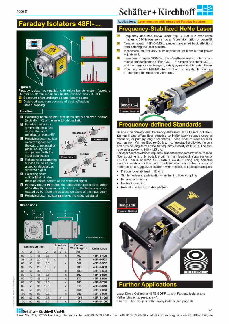
Fara
day
Isol
ator
-48F
I_09
_ED
.ind
d •
Pag
e 41
Kieler Str. 212, 22525 Hamburg, Germany • Tel: +49 40 85 39 97-0 • Fax: +49 40 85 39 97-79 • [email protected] • www.SuKHamburg.de
41
2009 E
Faraday Isolators 48FI-...
1
2
1 Polarizing beam splitter eliminates the s-polarized portion (typically 1 %) of the laser (diode) radiation
2 Faraday crystal in a strong magnetic field rotates the input polarization plane 45°
3 Polarizing beam splitterexactly aligned with the output polarization plane, i.e. by 45° in comparison with the input polarization
4 Reflective or scatteringsurface causes a pol- arized or depolarized reflected signal
5 Polarizing beam splitter 3 eliminates the s-polarized portion of the reflected signal
6 Faraday rotator 2 rotates the polarization plane by a further 45° so that the polarization plane of the reflected signal is now rotated by 90° from the polari zation plane of the input beam
7 Polarizing beam splitter 1 blocks the reflected signal
Function
Transmission
Beam input
1
2
Beam outputIsolation
7
6
54
Applications: Laser sources with integrated Faraday Isolators
Frequency-Stabilized HeNe Laser
Figure 1: Faraday isolator compatible with micro-bench system (aperture Ø 5 mm or Ø 2 mm, isolation > 30 dB, insertion loss < 0.5 dB) 1 Spectrum of an undisturbed laser beam source 2 Disturbed spectrum because of back reflections (mode-hopping)
Dimensions
Dimension [mm] Aperture[mm]
Center Wavelength Order Code
A B C D 2 3 5 [nm]80 70 48 19.5 x 400 48FI-5-40039 27 20 18 x 532 48FI-2-53265 55 33 19.5 x 532 48FI-5-53239 27 20 18 x 633 48FI-2-63365 55 33 19.5 x 633 48FI-5-63380 70 48 19.5 x 660 48FI-5-66080 70 48 19.5 x 670 48FI-5-67065 55 33 19.5 x 780 48FI-5-78065 55 33 19.5 x 810 48FI-5-81065 55 33 19.5 x 850 48FI-5-850
100 90 68 19.5 x 980 48FI-5-98092 82 60 19.5 x 1064 48FI-3-1064100 90 68 19.5 x 1080 48FI-5-1080
4230
ABC
Ø36D
Ø 6
dimensions in mm
3
632,816 nm
Frequency Stabilized
A
B
D
C
E
A Frequency-stabilized HeNe Laser (typ. < 500 kHz over some minutes, < 5 MHz over some hours). More information on page 49.
B Faraday isolator 48FI-5-820 to prevent unwanted back reflections from entering the laser system.
C Mechanical shutter 48AT-S or attenuator for laser output power adjustment.
D Laser beam coupler 60SMS-... transfers the beam into polarization- maintaining singlemode fiber PMC-... or singlemode fiber SMC-.... and it emerges as a divergent, axially symmetric Gaussian beam.
E Mounting console MC-MG-44.5-F-R with spring shock mounts for damping of shock and vibrations.
Laser Diode Collimator 48TE-SOT-F-... with Faraday isolator and Peltier Elements, see page 41.Fiber-to-Fiber Coupler with Farady isolator, see page 34.
Besides the conventional frequency-stabilized HeNe Lasers, Schäfter+Kirchhoff also offers fiber coupling to HeNe laser sources used as frequency or primary length standards. These kinds of laser sources, such as from Winters Electro-Optics, Inc., are stabilized by iodine cells and provide long-term absolute frequency stability of 12 kHz. The ave-rage laser power is 100 - 125 μW. For laser sources whose frequency is used for standardization purposes, fiber coupling is only possible with a high feedback suppression of > 40 dB. This is ensured by Schäfter+Kirchhoff using only selected Faraday isolators for this task. The laser source and fiber coupling is mounted on a ruggedized platform with handles to facilitate transport.
• Frequency-stabilized < 12 kHz• Singlemode and polarization-maintaining fiber coupling• External attenuator• No back coupling• Robust and transportable platform
Frequency-defined Standards
632,816 nm
Frequency Stabilized
INTERFEROMETRY
Further Applications

Fara
day
Isol
ator
-48F
I_09
_ED
.ind
d •
Pag
e 42
Kieler Str. 212, 22525 Hamburg, Germany • Tel: +49 40 85 39 97-0 • Fax: +49 40 85 39 97-79 • [email protected] • www.SuKHamburg.de
42
2009 E
Customized Solutions
A Diode laser at 820 nm with external resonator in Littman configuration, single frequency configuration.B Faraday isolator 48FI-5-820 to prevent unwanted back reflections from
the incident laser source.C Anamorphic beam shaping optics 5AN-3-V-05 reduce ellipticity and
astigmatism of intrinsic laser beam.D Beam splitter 48BS-..., mounted in "multicube" 48MC-SM-19.5, diverts
1% of the beam intensity for wavelength or power monitoring.E The two laser beam couplers 60SMS-... each transfer one beam into
polarization-maintaining singlemode fibers PMC-... F . Both beams emerge as divergent, axially symmetric Gaussian beam.
A beam inclined to the housing can be accommodated on a common mounting bracket with numerous adjustment possibilities, retaining the Faraday isolator and adjacent optical elements.
1064 nm
532 nm
EC-Laser
Some applications like LIDAR need a laser source with a relatively high frequency stability in combination with a fast switching operation. The depicted optical scheme reveals a solution. The Faraday isolator prevents the laser beam source from disturbing back reflections, while the EOM provides a fast pulse operation. A polarization beam splitter together with retardation optics offers a stepless splitting of the laser power. This additional channel allows a cascading of the beam and can be automatically connected to an electro-magnetic shutter. Power monitors at the input and the output provide complete control.
Sensitive laser resonators must be protected against back reflections of the emitted laser light. Schäfter+Kirchhoff couples singlemode and polarization-maintaining fibers to the laser source of a customer and integrates a Faraday isolator to prevent a laser feedback. A complete system could have additional power monitors, as shown. To guarantee the highest coupling efficiencies, different kinds of beam shaping optics are used to reduce astigmatism and produce a circular beam.
Pulse PickerMira Optima ps-Laser Source
VerdiPump Laser
Single laser pulses from a Mira Optima 900-P laser with Verdi V5 pump, emitting picosecond pulses at a repetition rate of 76 MHz, are selected by an acousto-optical pulse selector. Opto-mechanics and fiber optic components from Schäfter+Kirchhoff are used to coup-le the beam to a polarization-maintaining optical fiber cable. Laser feedback is prevented by use of a Faraday isolator. The fiber coupling is solidly mounted on an adjustable 4-axis translational and rotational stage.A Mira Optima 900-P picosecond laserB Acousto-optical pulse pickerC Faraday isolator 48FI-5-830 D Laser beam coupler 60SMS-...E Polarization-maintaining singlemode fiber cable PMC-...
Fiber Coupling with Beam Shaping and Feedback Protection
Cascadable Fast Laser Switch with Back-Reflection Protection
EC Laser with Polarization-maintaining Fiber Optics
Fiber Coupling of Singlemode Pulse Picosecond Laser Systems
F 4-axis translation and rotation stage from
Schäfter+KirchhoffG Breadboard
AB
C
D
E
G
F

Lase
Dio
deC
ollim
ator
48TE
_09_
E.in
dd
• P
age
43
Kieler Str. 212, 22525 Hamburg, Germany • Tel: +49 40 85 39 97-0 • Fax: +49 40 85 39 97-79 • [email protected] • www.SuKHamburg.de
43
2009 E
Laser Beam Coupler for Singlemode Fiber
inclined fiber coupling axis
TILT
PM:BOW-TIE
PM:PANDA
PM: OVAL- INNER CLADA3
A2
A1
Both temperature and the power influence the emitted wavelength of laser diodes. The wavelength center is shifted by 0.25-0.3 nm/K of temperature and either the modes ‘hop’, one-by-one, or many modes may be excited simultaneously. The wavelength center can drift by 2.5 – 3 nm in the range of 20-30°C.Conversely, when the laser power is increased from threshold up to the nominal power, the wavelength is increased by 2 – 4 nm.
For constant laser power, the thermo electric temperature control maintains the laser at a constant temperature and wavelength. Peltier elements establish a temperature gradient, which in magnitude and direction is regulated by the Peltier current by refererence to the measured signal of the temperature sen-sor.
Laser Diode Collimator48TE-SOT-F-...with polarization-maintaining singlemode fiber, Peltier element / thermosensor and Faraday isolator
• Wavelength range 390 - 1650 nm• Integrated Peltier element and temperature sensor for
thermoelectric temperature control of the laser diode• Faraday Isolator 48FI-5-...• For encased laser diodes of Ø 5.6 mm and Ø 9 mm,
optionally TO3 and TOW2• Applicable as DBR laser diodesUniversal modular system of laser diode collimators, designed for easy customer assembly and adjustment
B
4 Faraday isolators are used to protect laser sources from back reflection (“optical diode”). Radiation coupled back into a laser diode leads to mode hopping, noise, frequency instability and decrease in lifetime.A Spectrum of an undisturbed laser beam
sourceB Disturbed spectrum because of
back reflections (mode hopping)
A For a detailed description of the modular laser diode beam source 48TE-SOT-... see download:www.SuKHamburg.de/download/ldk48te_en.pdf
6
1
3
4
5
7
8
2
9
Laser diodes 370 - 2300 nm
Laser diodes with inte gra ted TE-CoolerLaser diodeCase TO3mounted inLaser diode base 48-O-TO3
Laser diodeSuperlumCase TOWmounted inLaser diode base 48-O-TOW2
Encased Ø 5.6 mmand Ø 9 mmmounted inLaser diode base 48TE-SOT
10
1
7
4
8
5
910
The 48TE-SOT-... consists of three basic elements:1 Laser diode base 48TE-SOT with: • integrated Peltier elements and temperatur control• for laser diodes with diameter 5.6 and 9 mm • easy to handle x/y adjustment (see next page) • solderless contacting • and an optional fan 48L
2 Collimation flange 48CFS • for system mount Ø 19.5 mm• collimator adjustment with inderect clamping,
even with adapters3 Diode collimator 60CL • focal length f' from 2.7 mm to 8 mm (up to 60 mm
with collimator 50CL)• NA up to 0.55• spectral range 400 - 1800 nm
For more information, seehttp://www.sukhamburg.com/dl/48TE_e.pdf
For assembly in micro-bench systems. High precision through-holes for 4 parallel rod guides. Ensures high mechanical stability and distortion resistance of the whole system.
• isolation > 30 dB• laser beam aperture max. 5 mm• attenuation < 0.5 dB • standard wavelengths 400 - 1080 nm
Combination of cylinder lenses with integrated astigmatic correction.Afocal (i.e., non- focussing) beam shaping op tics that transforms the ellip tical beam profile of the collimated laser diode in to a near circular profile.
• laser beam aperture max. 6 mm• beam shaping factor 2, 2.5, and 3
Adjustable and focussable for singlemode fiber cable with FC connector
• focal length f' from 2 mm to 18 mm• NA up to 0.68• spectral range 370 - 2300 nm• Inclined (8°, FC-APC) or paraxial fiber coupling axis
• Singlemode, polarization maintaining • MFD 3 - 10 μm�� = 360 - 1800 nm
Fiber connectors: FC-APC: 8° po lish of the fiber ferrule, supression of back reflexion into the laser source.FC-PC: 0° polish
9 Fiber Collimator 60FC-… FocussableInclined or paraxial fiber coupling axis. Both beam diameter and di-vergence are determined by the focal length f’ of the collimating lens.
• focal length f' from 2.7 mm to 200 mm• NA up to 0.68• spectral range 370 - 2300 nm• pilot beam option
10 Microfocus Optics, Series 5M-… and 13M-…These lens attachments for fiber collimators 60FC-... focus the collimated laser beam onto a diffraction limited (� 0.6 μm)
1 Laser diode base 48TE-SOT-... with integrated Peltier elements and temperature sensor for thermoelectrical temperature control
2 Collimating lens3 Mounting bracket, microbench compatible4 Faraday Isolator5 Anamorphic beam-shaping optics6 Mechanical shutter or attenuator7 Laser beam coupler for singlemode fiber8 Polarization-maintaining singlemode fiber9 Fiber collimator with FC connection10 Micro-focus optics
Optical Power Output Dependece of Wavelength Wavelength vs. Temperaturenm
836
832
828
826 828 830 20 30 40 50Wavelength p [nm] Case temperature TC [°C]
Po=40mW
Po=10mW
Po=3mW
Laser Diode Collimator 48TE-SOT-...
1
3
2
Faraday Isolator (optical diode) 48FI-5 4
See page 40
Anamorphotic Beam Shaping Optics 5AN-... 5
See page 25
To block the laser beam manually
• for system mount Ø 19.5 mm• aperture Ø 3 mm
Mechanical Shutter 48AT-S 6
Laser Beam Coupler 60SMS-... 7
See page 5
Polarization-maintaining and Singlemode Fiber CablesPMC-.../ SMC-... 8
See page 9
Fiber Collimator and Focussing
See page 15
The laser diode beam sources are delivered, fully assembled and adjusted, with laser diodes from our stocklist, according to customer specifications or with diodes from the customer. Detailed instructions for assembly and adjustment by the user are included.
Order Options
See page 31

Lase
Dio
deC
ollim
ator
48TE
_09_
E.in
dd
• P
age
44
Kieler Str. 212, 22525 Hamburg, Germany • Tel: +49 40 85 39 97-0 • Fax: +49 40 85 39 97-79 • [email protected] • www.SuKHamburg.de
44
2009 E
Laser Diode Collimator 48TE-SOT-...
Main specifications:• x/y-centering of the laser diode onto the optical axis with
adjustment tool 48AD • Solderless contact for laser diode using spring contact connectors
so laser diode galvanically isolated from collimator base• Integrated Peltier element and temperatur sensor for thermo-
electrical closed-loop control of the laser diode temperature• Peltier-Element provides up to 2 W heat transfer power
Imax. = 1.5 A, Umax. = 2.8 V• Temperatur sensor: thermistor (NTC 10 k�)• Separate connection cables for power supply, for the monitoring
of the laser diode and temperature control• Modular fan 48L A3 for increased thermal transfer efficiency
(12VDC-0.1A power supply is not designed for use with vibration- sensitive applications)
• Compatible with micro-bench (30 mm pitch)• The components are adjusted and fixed using radially located grub
screws and for positive locking• An elastomere diaphragm A1 encloses the laser diode and prevents
laser beam egress and dust ingress
48CFS
• Internal lens focussing: a left or right turn with the eccentric key I offers fine adjustment of the collimation lenses and so of the
focus position and the collimation, even with attached adapters.• Lens locking II• System mount Ø 19.5 mm for attachment of further beam shaping
optics and adapters. The adapters have a tightly fitting cylinder with circular V-groove for fitting into the collimator flange. The adapters can be rotated and are locked by circumferential grub screws III .
A1
A2
60CL
Application: Laser diodes with Ø 5.6 mm housin are inserted into teh retainer for laser diodes with Ø 9 mm housing with the active area at the same position: the laser diode beam axis and the posi-tion of the emitter does not change. Adapter Order Code 50AL-5.6 2 parts A housing outer-Ø 9 mmB Retaining ring for laser diodeC Laser diode with housing Ø5.6 mmD Assembly key Order Code 50LD9.0
A
B
C
D
A2
A2
B
I
III II
Adjustment with mounted collimator
Adapters for Laser Diodes Ø 5.6 mm
A3
1 Screwdriver Order Code 48SD-002 Hex screwdriver SW Ø 1.5 mm Order Code 50HD-153 Hex screwdriver SW Ø 2.5 mm
for adjustment fixture 48AD Order Code 50HD-254 Eccentric key
for collimation lenses 60CL-... Order Code 55EX-55 Focussing key
for collimation lenses 50CL-... Order Code 50LF-03
Assembly and Adjustment Tools
214
35
Collimator flange 48CFS
Laser Diode Base 48TE-SOT A
B
Table 1 Beam parameters Collimation Lens 50 CL / 60 CL
row curr. no 1 2 3 4 5 6 7 8 9 10 11 12 13Collimation lensCollimator flange
60CL48CFS
50CL48CFL
1 Lens type G2.7 A3,1 A4 A4.5 T5 M5 A6.2 A8 A8 T12 T12F M12 M60
2 Focal length f' 2.7 3.1 4 4.5 5 5.1 6.2 8 8 12.5 12.5 12.1 60
3 Numerical aperture NA 0.35 0.68 0.6 0.55 0.5 0.16 0.4 0.3 0.5 0.54 0.54 0.22 0.14
4 Clear aperture [mm] 1.9 4.2 4.8 4.95 5 2.5 5 4.8 8 13.5 13.5 5.5 17
5 Max. active area [mm] 0.1 0.05 0.05 0.18 0.14 0.1 0.2 0.1 0.1 0.2 0.2 0.2 0.2
6 Lens for UHV application x x x x x x x x x
Spectral range Code no. of AR coating�
7 370 - 600 nm 01 01 01 01 01 01
8 600 - 1050 nm 02 02 02 02 02 02
9 1050 - 1550 nm 03 03 03 03 03 03
10 1300 - 1750 nm 45 45 45 45 45 45
11 650 - 1350 nm 07 07
12 390 - 670 nm 33 33 33 33
13 600 - 1020 nm 05 05
14 630 - 980 nm 10 10 10 10 10 10
15 830 - 1550 nm 25 25 25
16 1550 - 1750 nm 22 22 22 22 22 22
17 1750 - 2300 nm 09 09 09 09 09 09
Beam parameter for the collimated laser beam using a 670 nm laser diode with active area 0.1 x 3 μm and beam divergence 10°x 30° (FWHM), beam-Ø 1/e² (13.5%), # beam cross-section restricted by lens aperture
18 beam-Ø || [mm] 0.8 0.9 1.2 1.3 1.5 1.5 1.8 2.4 2.4 3.7 3.7 3.6 #17
19 beam-Ø � [mm] 1.9 2.7 3.4 3.9 4.3 #2.5 #5.0 #4.8 #6.9 10.8 10.8 #5.5 #17
20 divergence || [mrad] 0.53 0.47 0.36 0.32 0.29 0.28 0.23 0.18 0.18 0.12 0.12 0.12 0.03
21 divergence � [mrad] 0.22 0.16 0.12 0.11 0.1 0.17 0.09 0.09 0.06 0.04 0.04 0.08 0.03
Beam parameter for the collmated laser beam using a 635 nm CircuLaser™ diode with beam divergence 8°x 8° (FWHM)
22 beam-Ø 1/e² (13.5%) [mm] 0.6 0.7 0.9 1.1 1.2 1.2 1.5 1.9 1.9 3.0 3.0 2.9 14.2
23 divergence [mrad] 0.63 0.55 0.43 0.38 0.34 0.33 0.28 0.21 0.21 0.14 0.14 0.14 0.03
The 48TE-SOT-F-... laser diode collimator with Faraday isolator is supplied as a completly adjusted system consisting of laser diode base 48TE-SOT, with integrated Peltier element, diode collimator 60CL, Faraday isolator 48FI-5, anamorphic optics 5AN, shutter 48AT-S, laser beam coupler with FC-APC connector 60SMS-..., PM fiber or singlemode fiber cable PMC-.../ SMC-... and fiber collimator 60FC. Please specify when ordering: • Laser Diode wavelength, base type and output power• Fiber Cable length and type• Fiber Collimator focus size or collimation diameter• Fan module option (with or without)Please contact Schäfter+Kirchhoff for details of suitable laser diode beam sources or other specifications of laser diode collimators.
Order Options
Adjustment fixture Order Code 48AD A2
For an optimum collimation of the laser beam free of aberration (e.g. coma), it is necessary to launch the center of emission onto the optical axis of the collimator optics. With the tripartite x/y-centering fixture 48AD, the mounting plate of the laser diode can be ad-justed laterally (for details, see assembly in-structions).
The lateral displacement is realized with the screws 1 and 2 , while 3 provides the necessary counter force.
1
23
1
2
3
x/y-Centering of the Laser Diode Base
��Ø
��
�
�
Ø||
�

Title
_51n
anoF
CM
_09_
E_2
.ind
d •
Pag
e 1
Kieler Str. 212, 22525 Hamburg, Germany • Tel: +49 40 85 39 97-0 • Fax: +49 40 85 39 97-79 • [email protected] • www.SuKHamburg.de
1
2009 E
51nanoFI-.../51nanoFCM-...Laser Diode Beam Sources with singlemode and polarization-maintaining fiber cable
P1
Vacuum Feed-Throughs V-...
Fiber-optical Beam Splitters FBS-...
Laser diode beam sources of type 51nanoFCM-... and 51nanoFI-... have reduced power noise, reduced coherence length and low speckle contrast. They are used, e.g., for atomic force microscopy (AFM), particle measurements and as pilot lasers during alignment applications.• Coherence length 300 μm • Noise < 0.1% RMS (<1MHz)• Spectral range 405 nm to 1080 nm• Laser output power up to 30 mW• Output power adjustable with potentiometer or ext. voltage
control input• Modulation inputs for analog and TTL control (100 kHz)• Operation mode: constant power• Singlemode fiber cable, polarization-maintaining or standard• FC-APC connector (8° polish), optional DIN AVIO, ST or E2000• Beam profile rotational sym metry with Gaussian intensity
distri bution P1
Advantages of laser beam source 51nanoFCM-... / 51nanoFI-...Laser Speckles
Broadened spectrum (~1.5 nm FWHM) with re-duced coherence length (~ 0.3 mm) as a result of RF modulation. No mode hopping appears
50%
1.5 nmFWHM
Laser Spectrum
up: RF modulation results in constant mean laser po-wer with noise < 0.1% RMS (<1MHz).down: power noise caused by back reflections and mode hopping.
Noise
Additionally, the 51nanoFI features an integrated Faraday isolator (optical diode) for protecting the laser diode against disturbing back reflections.The 51nanoFI laser source is predestined for applications which require high power stability, reduced coherence length and protection against radiation reflected back from the object under test.• For fiberoptic AFM setups (Fabry-Perot interferometers) 1• For back reflection particle measurements 4• Available with directly connected fiber optical beam splitter
(x- or y-coupler)
• Coherence length 300 μm • Noise < 0.1% RMS (<1MHz)• Spectral range 405 nm to 1080 nm• Laser output power up to 30 mW• Beam profile rotational sym metry with
Gaussian intensity distribution P1• FC-APC connector (8° polish), optional
DIN AVIO or E2000
Accessories
Low speckle contrast from reduced co he rence length: uniform illumi-nation of 4-quadrant diodes for AFM, improved edge detection during position measure ments
0
0.8
0.4
0
0.8
0.4
060 min
Pnoise peak value in %
Fiber Collimators 60FC-...Micro focus optic 5M-...
page 15 ff page 13 page 13
New51nanoFI-...
with integrated Faraday isolator
Applications: Fig. 1 and 4
LOWNOISEand
REDUCEDSPECKLE
for increased accuracy and reproducibility
in laser metrologyand nano
technology
51nanoFCM-...
Particle measurement with scattered laser light may be determined by measuring the light a particle deflects when passing through a laser beam. The radiation of the laser source is guided via a polarization-maintaining sin-glemode fiber and a fiber optical beam splitter to a particel flow. Particles transiting the focussed beam scattere the light and back reflect some of it to the fiber. That back coupled light is splitted at the fiber optical beam splitter were one part is guided to a detector and the other part to the laser source. Therefore, the laser source is protected by a Faraday isolator (optical diode). Without the Faraday isolator the back coupled light would cause spectral disturbances (mode hopping G ) and increased noise. Precise measure-ments require a low speckle contrast and constant laser power. By RF-modu-lation the coherence length is reduced, the spectrum broadend I and the power averaged.
51nanoFi-...
Standard LaserDiode
A Faraday isolator (FI)B Polarization-maintaining fiberC Fiber optical beam splitter
D Fiber collimator and focussingE Particel flowF Detector
Fig. 2: optical scheme particle measurementLaser spectra
51nanoFI
Signal of particles at detector
B
C
D
E F
H
I
G
Application: Back Reflection Particle Measurement 4
51nanoFi-...
Application: Fiber optical Fabry-Perot Interferometers 1
0 2 4 6 8 10 0
0.2 0.4
0.6
0.8
1 1.2 1.4
1.6 1.8
time (ms)
Sig
nal (
V)
With singlemode fibers it is possible to build up a compact interferometer e.g. for AFM. The light leaving the fiber is back reflected at the fiber end facette (approx. 4%) and at a moving mirror or cantilever. The back coupled light is guided through a fiber optical beam splitter where one part is splitted to a detector for the interference measurement. The other part of the light is blo-cked by a Faraday isolator integrated in the laser source 51nano-FI-.... The signals of fiber optical Fabry-Perot interferometers benefit from the power and wavelength stability of the 51nanoFI-.... The reduced coherence length is an additional advantage as disturbing interference is suppressed and only interfe-rence between the surfaces of interest contribute to the interferometer signal.
A Faraday isolatorB Polarization-maintaining fiberC Fiber optical beam splitter
D FC-PC fiber coupler E CantileverF Detector and interferometric signal
Fig. 1: scheme of a fiber optical interferometer
A
B
C
D
E
F
A
Oszillogramm
FABRY-PEROTInterferometer
Back reflectionparticle measurement
51nanoFI-...
Laser Diode with FI
Scratch Detector
Lasers for Adjustment and Alignment
Back reflectionparticle measurement
FABRY-PEROTInterferometer
FIBER OPTIC
51nanoFI-...
A
MF
tomicorceicro-scopy
Optical Tweezers
2 3
654
1

51na
noFC
M_0
9_E
D.in
dd
• P
age
2
Kieler Str. 212, 22525 Hamburg, Germany • Tel: +49 40 85 39 97-0 • Fax: +49 40 85 39 97-79 • [email protected] • www.SuKHamburg.de
2
2009 E
LOWNOISEand
REDUCEDSPECKLE
Fig. 1: Laser Diode Beam Source 51nanoFCM-... (Tab. 1.1)
1.1 Singlemode fiber with 1.2 FC-APC connector1.3 Key switch: ON/OFF - LED ON1.4 Potentiometer (for reduction of laser power output)X2 Connector, ext. modulation and interlock
Attachments: A Fiber collimator, focusable, 60FC-...
B Micro-focus optics 5M-... and 13M-...
B
A
1.2
1.1
1.3
1.4
X2
Figure 2: Beam Parameters and advantages of the Laser Diode Beam Source 51nano...
**
*
Fiber type:18 = singlemode fiber cable, FC-APC28 = PM singlemode fiber cable, FC-APCoptional: Connector DIN-Avio, ST, E-2000.
51nanoFCM... - S - 660 - 6 - M01 - P - 5 - 2 - 28 - 0 - 150 Order Code
Length fiber cable in cm (standard = 150)
Connector option: 0 = standard C = core centered
(singlemode only)
Laser Diode Beam SourceSafety:with key switch and interlock . . . . . . . . . . . .Swithout key switch and interlock (OEM) . . . .NLaser diode operation mode:Constant power . . . . . . . . . . . . . . . . . . . . . . .PSupply power:5V DC (standard) . . . . . . . . . . . . . . . . . . . . . . 512V DC (option) . . . . . . . . . . . . . . . . . . . . . . 12Electr. cable1.5 m shielded 3 x 0.14 mm2 . . . . . . . . . . . . . 1as for 1, with connector SV30 (5V) . . . . . . . . 2as for 1, with connector SV40 (12V) . . . . . . . .4cable specified by customer . . . . . . . . . . . . . 5 * Typical laser output power, the actual power output may differ by ±10%.
** With fiber NA = 0.11
Supply voltage standard 5 V DC (± 0.2V) optional 12 V DC (± 0.2V)Laser diode operation mode constant power Max. operating current 260 mAAmbient temperature range 15 - 35 °CModulation frequency analog DC - 100 kHz
TTL 0 - 100 kHzWith pot. adjustable output power < 20-100%TTL modulation logic TTL highAnalog control voltage 0 - 2.5V depending on laser diode: see table 1, col. 13
*
*
Figure 3: Disadvantages of standard laser diode sources with conventional fiber coupling
134
38
32
Ø 4
2
Single-mode fiber cable Ø 3 mm
Cable for power supply
Connector Lumberg SV30 (5 V)SV40 (12 V)
FC connector
PotentiometerM3
X1
44
Connector ext. modulation
and interlock
X2
Laser diode beam source 51nanoL-...
M338 20
32
70124
Connector Lumberg SV30 (5V)SV40 (12V)
X1
FC connector
Singlemodefiber cable Ø 3 mm
Ø 5
4
66
Connector ext. modulation and
interlock X2
Potentiometer
PotentiometerCable for power supply
56
Table 2 Laser Diode Beam Source 51nanoFCM...
Row 1 2 3 4 5 6 7 8 9 10 11 12 13 14
Cur. No. Type Ver-
sion
Wave-length (nm)
Pout
(mW)
Laser diode code
LD operati-on mode
Supply power
(V)
Electr. connec-
tion
Fibertype
Fiber con-nector op-
tion
Fiber length(cm)
Case type
Spec-trum
MFD1⁄e2
(μm)
Power adjust-ment %
1 51nanoFCM S 405 20 M29 P 12 .. .. .. .. L S2 2.9 <1 - 1002 51nanoFCM S 637 2.5 H10 P 5 .. .. .. .. M S2 4.5 <1 - 1003 51nanoFCM S 635 5 N12 P 5 .. .. .. .. M S2 4.5 <1 - 1004 51nanoFCM S 660 6 M01 P 5 .. .. .. .. M S2 4.7 <1 - 1005 51nanoFCM S 660 30 B15 P 12 .. .. .. .. L S2 4.7 <1 - 1006 51nanoFCM S 685 10 M22 P 5 .. .. .. .. M S2 4.8 <1 - 1007 51nanoFCM S 780 10 H06 P 5 .. .. .. .. M S2 5.6 <1 - 1008 51nanoFCM S 785 19 N08 P 5 .. .. .. .. M S2 5.6 <1 - 1009 51nanoFCM S 830 7 A14 P 5 .. .. .. .. M S2 5.9 <1 - 10010 51nanoFCM S 830 25 N07 P 5 .. .. .. .. M S2 5.9 <1 - 10011 51nanoFCM S 1080 20 EY10 P 5 .. .. .. .. M S2 7.6 <1 - 100
L
M
Electrical Data
Laser diode beam source 51nanoFCM-...
Laser diode beam sources of type 51nanoFCM-... have reduced power noise, reduced coherence length and low speckle contrast as a result of the internal RF modulation. The laser diode beam source 51nanoFCM-... is typically used for atomic force microscopy (AFM) and as a pilot laser during alignment applications.• Spectral range 405 nm to 1080 nm • Laser output power up to 30 mW • Noise < 0.1 % RMS (<1 MHz)• Output power adjustable with potentiometer or external voltage
control input• Modulation inputs for analog and TTL control (up to 100 kHz)• Operation mode: constant power• Coherence length 300 μm• Beam profile rotationally symmetric with Gaussian intensity
distribution P1• Singlemode fiber cable or polarization-maintaining singlemode
fiber cable(polarization aligned to connector index)• FC-APC connector (8° polish), optional DIN AVIO, ST or E-2000• Fiber cable with strain relief and protective sleeving (Ø 3 mm)Laser safety according IEC 825 / EN 60825-1 by: • Key switch 1.3 • LED-indicator for laser operation • Interlock connection X2 • Potentiomenter for reduction of power outputOption: laser diode beam source 51nanoFCM-N-...OEM version without key switch and interlock on request. Does not meet requirements of EN 60825-1.
Applications
Adjustment and Alignment by laser
Optical Tweezers
Scratch Detector
Particle Measurement
Laser speckles are interference arising from, e. g., the diffuse re flection of coherent radiation at rough surfaces. The degree of coherence (coherence length) determines the speckle contrast. Laser Speckles
Laser Diode Beam Source 51nanoFCM-...with singlemode and polarization-maintaining singlemode fiber cable • low noise • reduced coherence length • low speckle contrast
Front view
Front view
Potentio-meter
Laser Speckles Low speckle contrast due to reduced coherence length: uniform illumination of 4-quadrant diodes for AFM and improved edge detection during position measure ments.
Laser Spectrum Broadened spectrum (~1.5 nm FWHM) with reduced coherence length (~ 0.3 mm) as a result of RF modulati-on.
50%
1.5 nmFWHM
0
Pnoise peak value in %0
1.6
0.8
60 min
Noise RF modulation re-sults in constant mean laser power.Power noise < 0.1% RMS (<1MHz).
Interferences Gaussian intensity distribu-tion of collimated laser beam direct recorded with a CCD sensor. No interfe-rence patterns despite the protection window of the CCD sensor
Laser SpecklesThe laser spot produced by a standard laser diode beam produces a speckle pattern, increasing the statistical uncertainty in position deter mi nations.
Laser Spectrum Mode hopping: tem-poral shifts between modes. The short-term coherence of individual modes is > 1 m, but effective coherence length is reduced.
0
Pnoise peak value in %0
1.6
0.8
60 min
Noise Power noise from a laser source coupled to a fiber. The fiber gene-rates an external cavity with the laser diode, resulting in jumps in power stochastically.
InterferencesCollimated laser beam re-corded directly with a CCD sensor, whose protec-tive window generates a disturbing interference pat-tern.
Laser Source with Multiple Fiber OutputsFor special applications Schäfter+Kirchhoff offers a 51nanoFCM-... with fiber optical beam splitter conver-ting the single laser input source to 2 - 6 fiber coupled outputs all integrated in a compact housing with bend protection of the singlemode fibers. The fiber outputs are collimated with a special 60FC-4-M40-10 fiber collimator with angular adjustment of the collimated- or pilot beam referring to a tilt- and mounting plate.
Order Code C4-FCM-S-637For further information and combination possibilities please visit www.SuKHamburg.de or contact Schäfter+Kirchhoff.
Fiber collimators60FC-F-4-M40-10
Housing with laser source and multiple fiber outputs C4-FCM-S-637
Dimensions
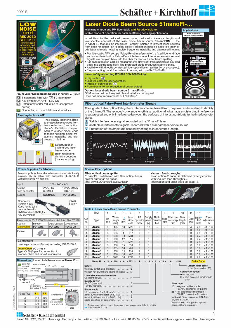
51na
noFC
M_0
9_E
D.in
dd
• P
age
3
Kieler Str. 212, 22525 Hamburg, Germany • Tel: +49 40 85 39 97-0 • Fax: +49 40 85 39 97-79 • [email protected] • www.SuKHamburg.de
3
2009 E
Table 2 Laser Diode Beam Source 51nanoFI...
Row 1 2 3 4 5 6 7 8 9 10 11 12 13
Cur. No. Type Ver-
sion
Wave-length (nm)
Pout
(mW)
Laser diode code
LD operation
mode
Supply power
(V)
Electr. connec-
tion
Fibertype
Fiber con-nector op-
tion
Fiber length(cm)
Case type
MFD**1⁄e2
(μm)
Power adjustment
%1 51nanoFI S 405 18 M29 P 12 .. .. .. .. A 2.9 <1 - 1002 51nanoFI S 637 2.3 H10 P 5 .. .. .. .. B 4.5 <1 - 1003 51nanoFI S 635 4 N12 P 5 .. .. .. .. B 4.5 <1 - 1004 51nanoFI S 660 5.4 M01 P 5 .. .. .. .. B 4.7 <1 - 1005 51nanoFI S 660 27 B15 P 5 .. .. .. .. B 4.7 <1 - 1006 51nanoFI S 680 8 M22 P 5 .. .. .. .. B 4.8 <1 - 1007 51nanoFI S 780 15 B10 P 5 .. .. .. .. C 5.6 <1 - 1008 51nanoFI S 785 16 N08 P 5 .. .. .. .. C 5.6 <1 - 1009 51nanoFI S 830 6.2 A14 P 5 .. .. .. .. D 5.9 <1 - 10010 51nanoFI S 830 18 N07 P 5 .. .. .. .. D 5.9 <1 - 10011 51nanoFI S 1080 18 EY10 P 5 .. .. .. .. D 7.6 <1 - 100
*
* Nominal average laser output power, the actual power output may differ by ±10%.** With fiber NA = 0.11
Fiber type:18 = singlemode fiber cable,
FC-APC connector (8° polish)28 = PM singlemode fiber cable,
FC-APC connector (8° polish)optional: Fiber connector DIN-Avio, ST, and E-2000.Vacuum feed through and optical beamsplitter on request.
51nanoFI - S - 660 - 6 - M01 - P - 5 - 2 - 28 - 0 - 150 Order Code
Length fiber cable in cm (standard = 150)
Connector option: 0 = standard C = core centered (singlemode
only)
* Typical laser output power, the actual power output may differ by ±10%.** With fiber NA = 0.11
Safety:with key switch and interlock . . . . . . . . . . . .Swithout key switch and interlock (OEM) . . . N
Laser diode operation mode:Constant power . . . . . . . . . . . . . . . . . . . . . . .PSupply power:5V DC (standard) . . . . . . . . . . . . . . . . . . . . . . 512V DC (option) . . . . . . . . . . . . . . . . . . . . . . 12
Electr. cable 1.5 m shielded 3 x 0.14 mm2 . . . . . . . . . . . . . 1as for 1, with connector SV30 (5V) . . . . . . . . 2as for 1, with connector SV40 (12V) . . . . . . . 4cable specified by customer . . . . . . . . . . . . . 5
Power supply for laser diode beam sources, elec trically isolated, 1.5 m cable with connector (IEC60130-9) Lumberg series KV (female).
Power Supplies for 51nano...
Input 100 - 240 V AC
Output with connector
5VDC/1ABC0103F
12VDC /0.5ABC0104F
Europe PS051003E PS120516E
Vacuum feed-throughs:as an option 51nano...is delivered directly coupled with vacuum feed-through V-...Information and order code on page 13.
Special Fiber options
Fiber optical beam splitter:51nanoFI... is delivered with fiber optical beam splitter output as an option.Info: www.SuKHamburg.de/download/
LOWNOISEand
REDUCEDSPECKLE
Dimensions Laser diode beam source 51nanoFI-...
Case Type L1 L2
A 141 195B 111 165C 126 180D 118 172
L1 L2
Singlemode fiber cable Ø 3 mm
Cable for po-wer supply
Connetor Lumberg
SV30 (5 V)SV40 (12 V)
FC connector
PotentiometerX1 38 20 M3
32
Ø 5
4
L1L2
Connector ext. modulation
and interlock
Potentiometer
Front view
X2
66
LOWNOISE
andREDUCEDSPECKLE for increased accuracy and reproducibility in laser metrlcs
and nano- technology
Faraday-Isolator
Faraday-Isolator 48FI
ConnectorsLumberg connector (female) according IEC 60130-9
Order Code BC 01 06 FType KV 60 (6-pin) for connection tointerlock chain and for ext. modulation
In addition to the reduced power noise, reduced coherence length and low speckle contrast of the laser diode beam source 51nanoFCM-..., the 51nanoFI... features an integrated Faraday isolator to protect laser sources from back reflection ( an "optical diode"). Radiation coupled back to a laser di-ode leads to mode hopping, noise, frequency instability and decreased lifetime.• For fiber-optic AFM setups (Fabry-Perot Interferometer): a fixed fiber end face
and a cantilever build a Fabry-Perot interferometer. Interference measurement signals are coupled back into the fiber for read-out after beam splitting.
• For back reflection particle measurement: stray light from particles is coupled back into distributing fiber. The protected diode produces stable signals.
• Available with directly connected fiber optical beam splitter (x- or y-coupled).• Easy mounting on all four sides of housing with profile TP-66-40.Laser safety according IEC 825 / EN 60825-1 by: • Key switch 4.2• LED-indicator for laser operation • Interlock connection X2 • Potentiomenter for reduction of power outputOption: laser diode beam source 51nanoFI-N-...OEM version without key switch and interlock on request. Does not meet requirements of EN 60825-1.
Laser Diode Beam Source 51nanoFI-...with singlemode and PM fiber cable and Faraday Isolator,stable mode of operation for back scattering sensing applications
4.24.1
4.3
Fig. 4: Laser Diode Beam Source 51nanoFI-... (Tab. 2)
4.1 Singlemode fiber with 4.4 FC connector4.2 Key switch: ON/OFF - LED ON4.3 Potentiometer (for reduction of laser power
output)X2 Connector, ext. modulation and interlock
1 2
FABRY-PEROTInterferometer
FIBER OPTIC
A
MF
INTERFEROMETRY
Back reflectionparticle measurement
51nanoFI-...
Fiber optical Fabry-Perot Interferometer Signals
The signals of fiber optical Fabry-Perot interferometers benefit from the power and wavelength stability of the 51nanoFI. The reduced coherence length is an additional advantage as disturbing interference is suppressed and only interference between the surfaces of interest contribute to the interferometer signal. A Stable interferometer signal, recorded with a 51nanoFI laserB Unstable interferometer signals, recorded with a standard laser diode sourceC Fluctuation of the amplitude caused by changes in coherence length.
0 2 4 6 8 10 0
0.2 0.4
0.6
0.8
1 1.2 1.4
1.6 1.8
time (ms)
Sig
nal (
V)
A
time (ms)
B
time (ms)
C
The Faraday isolator is used to protect laser sources from back reflection ( an optical diode“). Radiation coupled back to a laser diode leads to mode hopping, noise, fre-quency instability and de-crease of lifetime.
1 Spectrum of an undisturbed laser beam source
2 Back reflections disturb spectrum (mode-hopping)
Applications4.4
Power Supply
Connector (female 5-pin) KV50 for 5V (pins compatible with SV30) or 4 pol. KV40 for 12V DC version
DE US UK
Power cord for PS...E, IEC320 3 pin line socket, 1.5 m, 10A, 250 VAC
Country Europe USA/Canada Great BritainPC150DE PC150US PC150 UK
Picture
Order Code
X2
for increased accuracy and reproducibility
in laser metrologyand nano
technology

58FC
M_0
9_E
.ind
d •
Pag
e 48
Kieler Str. 212, 22525 Hamburg, Germany • Tel: +49 40 85 39 97-0 • Fax: +49 40 85 39 97-79 • [email protected] • www.SuKHamburg.de
48
2009 E
Laser diode beam source (see table 1)
Laser diode operation mode:constant power (standard) . . . . . . . . . . P constant current . . . . . . . . . . . . . . . . . . CSupply voltage:5V DC (standard) . . . . . . . . . . . . . . . . . . . . . . 512V DC . . . . . . . . . . . . . . . . . . . . . . . . . . . . 12Electr. cable1.5 m shielded 3 x 0.14 mm2 . . . . . . . . . . . . . 1 as for 1, with connector SV30 (5V) . . . . . . . . 2as for 1, with connector SV40 (12V) . . . . . . . 4 cable length specified by customer . . . . . . . 5
58FCM - 637 - 5 - H10 - P - 5 - C - 2 - 28 - 0 - 150
Typical laser output power.For the lower of two specified power outputs, the housing length is L = 146 mm (standard) . For the higher power value, the housing length is L = 166 mm, see dimensional drawing. Constant power: An internal control loop keeps the laser powerconstant. Advantage: Temperature variations and aging of laser diode are compensated.
Constant current: The internal control loop keeps the lasercurrent constant. The power output depends on temperature. Advantage: reduced noise. With fiber NA 0.11
*
***
**
Fiber length in cm, standardConnector option: 0 = standard C = core centered < 0.25 μm(singlemode only)
Dimensions
Potentiometer
50 506
M4
146/(166)
60 1 x M61 x A1/4
5850
Potentiometer
FC connector
Cable for power supply
Laser Diode Beam Source 58FCM-…
X1X2
Connector Lumberg SV30 (5 V)SV40 (12 V)
*
Singlemode fiber cableØ 3 mm
Fiber type:10 = singlemode fiber cable, FC-PC connector
(0° polish)18 = singlemode fiber cable, FC-APC connector
(8° polish)20 = PM singlemode fiber cable, FC-PC
connector (0° polish)28 = PM singlemode fiber cable, FC-APC
connector (8° polish)Connector type ST, DIN-Avio, and E-2000 on request
FC-APC connector: 8° polish of the connector ferrule and orientation of the principal axes of a polarization-maintaining singlemode fiber (type Panda) with the connector index
Orientation of the fiber slow axis and axis with the linearly polarized radiation of the source.
Connector index
Spectral width (FWHM) 12 nm, coherence length 0.05 mm, LD beam source Nr. 11 (Y03), low current
Spectral width (FWHM) 2.2 nm, coherence length 0.2 mm, LD beam source Nr. 11 (Y03), high current
S2
S1
Spectral width (FWHM) ~0.14 nm (red. 2. mode), coherence length ~3 mm, e.g., laser diode beam source Nr. 3 (H10)S3
The wavelength spectrum depends on the laser diode used and varies with temperature and power output. Mode hopping appears.
8°
1 Laser diode beam source 58FCM-…1.1 Singlemode fiber cable with 1.2 FC-APC connector1.3 Key switch: ON/OFF - LED ON1.4 Potentiometer (reduction of laser power output)1.5 Cable for power supplyX2 Connector, ext. modulation and interlock
A Fiber collimator, focusable, 60FC-…B Micro-focus optics 5M-…C FC-APC connector Technical data, see data sheets on www.SuKHamburg.de
AB C
Laser Diode Beam Source 58FCM-…Fiber-coupled, singlemode and polarization-maintaining with FC-APC connector
• Concentrically symmetric beam profile with Gaussian intensity distribution P1• Singlemode fiber cable or polarization-maintaining singlemode fiber cable (polarization axis aligned with connector index)• Spectral range 405 nm to 1330 nm • Laser output power up to 70 mW• Fiber cable with strain relief and protective sleeving (Ø 3 mm)• FC-APC connector (8° polish) reducing power noise caused by back reflection into the laser resonator • Output power adjustable using potentiometer or external voltage control input (0-2.5 V)• AND-wired modulation inputs, analog and TTL, fmax = 100 kHz• Operation mode: constant power (standard) and constant current
Laser safety according IEC 825 / EN 60825 from: • Key switch 1.3 and LED-indicator for laser operation • interlock connection X2
Options: • To fullfill lower laser safety requirements (e.g. laser class 2), the laser source can be delivered with
reduced maximum power output• Supply voltage 5 V (standard) or 12 V (exception: Table 1, row 1 is available with 12 V supply voltage
only), reverse voltage protection• Protection of the potentiometer by protective cap
• Laser diode beam source 52FCM: Version w/o key switch and w/o interlock (for OEM purposes only)• Laser diode beam source 51nanoFCM: Low Noise version with reduced coherence length and
speckle contrast• Laser diode beam source 51nanoFI: Low Noise version with integrated Faraday isolator (reduced
coherence length and speckle contrast)
Related products
See technical data sheet for timing diagram: www.SuKHamburg.de/download/58FCM_e.pdf
1
1.3
1.4
1.5
X2
1.2
Power supply for laser diode beam sources, elec trical isolated, 1.5 m cable with connector (IEC60130-9) Lumberg series KV (female).
Accessories
ConnectorsLumberg connector (female) according IEC 60130-9Order Code BC 01 06 F
Type KV 60 (6-pin) for connection tointerlock chain and for ext. modulation
Order Code BC 01 03 FType KV 30 (3-pin) for 5 V power supply
Order Code BC 01 04 FType KV 40 (4-pin) for 12 V power supply
Input 100 - 240 V AC Output with connector
5VDC/1ABC0103F
12VDC /0.5ABC0104F
Order Code PS051003E PS120516E
Electrical Data
Attachments: Fiber Optics Fiber Connector Laser Spectrum and Coherence Length
1.1
Supply voltage standard 5 V DC (± 0.2V) optional 12 V DC (± 0.2V)Laser diode operation mode constant power optional constant currentMax. operating current 260 mAAmbient temperature range 15 - 35 °CModulation frequency analog DC - 100 kHz
TTL 0 - 100 kHzPower output potentiometer < 1-100%TTL modulation logic Laser ON TTL highAnalog control voltage Pmin to Pmax 0 - 2.5V
P1
Power Supply
Connector (fem.) 5 pol. KV50 for 5V (pin comp. to SV30) or 4 pol. KV40 for 12V DC version
Power Supplies for 58FCM…
Table 2 Laser Diode Beam Source 51nanoFCM...Row 1 2 3 4 5 6 7 8 9 10 11 12
Cur. No. Type
Wave-length (nm)
Pout*(mW)
Laser diode code
LD operation mode**
Supply power
(V)
Electro-nics
Electr. connec-
tion
Fibertype
Fiber connec. option
Fiber length(cm)
Spec-trum
***MFD(μm)
1 58FCM 405 40 M29 P/C 12 C .. .. .. .. S3 2.92 58FCM 635 1 H01 P/C 5/12 C .. .. .. .. S3 4.53 58FCM 637 5 H10 P/C 5/12 C .. .. .. .. S3 4.54 58FCM 637 14 N12 P/C 5/12 C .. .. .. .. S3 4.55 58FCM 660 14 M01 P/C 5/12 C .. .. .. .. S3 4.76 58FCM 660 24 M26 P/C 5/12 C .. .. .. .. S3 4.77 58FCM 660 55 AR1 P/C 5/12 C .. .. .. .. S3 4.78 58FCM 670 1.2/1.9 T07 P/C 5/12 C .. .. .. .. S2 4.79 58FCM 685 14 M03 P/C 5/12 C .. .. .. .. S3 4.9
10 58FCM 785 23/29 H06 P/C 5/12 C .. .. .. .. S3 5.611 58FCM 785 15/20 Y03 P/C 5/12 C .. .. .. .. S1/S2 5.612 58FCM 830 70 N07 P/C 5/12 C .. .. .. .. S3 5.913 58FCM 980 3.5 W01 P/C 5/12 C .. .. .. .. S3 6.914 58FCM 1064 11/18 U01 P/C 5/12 C .. .. .. .. S3 7.515 58FCM 1330 2.5 M14 P/C 5/12 C .. .. .. .. S3 9.4
DE US UK
Power cord for PS...E, IEC320 3 pin line socket, 1.5 m, 10A, 250 VAC
Country Europe USA/Canada Great BritainPC150DE PC150US PC150 UK
Picture
Order Code
Order Code

HeN
eLas
er_0
9_E
D_2
Sei
ten.
ind
d •
Pag
e 49
Kieler Str. 212, 22525 Hamburg, Germany • Tel: +49 40 85 39 97-0 • Fax: +49 40 85 39 97-79 • [email protected] • www.SuKHamburg.de
49
2009 E
HeNe Laser with Fiber OpticsSinglemode and polarization-maintaining
• Polarization-maintaining singlemode fiber• Wavelength 632.8 nm • Output power > 0.6 mW - > 12 mW leaving the fiber
• Polarization-maintaining singlemode fiber• Wavelength 543.5 nm • Output power > 0.7 mW leaving the fiber
• Polarization-maintaining singlemode fiber• Wavelength 632.8 nm • Output power > 0.6 mW - > 12 mW leaving the fiber
Universal Beam Source for Interferometry and Frequency StandardsThe Schäfter+Kirchhoff HeNe lasers and fiber optics are polarization-main taining, they provide a high coupling effi ciency and ex hibit extreme transport stability. A large selection of coupling lenses is provided that match the different laser beam diame ters to the particular PM fiber chosen for use. To minimize laser back reflection and power noise effectively, both ends of the singlemode fibers are provided with an 8° polish (connectors Type FC-APC). • Coupling efficiency > 75%, typically 80%• Degree of polarization at fiber end > 200:1• Fiber cable MFD = 4.4 μm, NA = 0.12• FC-APC type connector for coupler and fiber end (others availab-
le on request)• Fiber coupling solutions for HeNe lasers supplied by the customer• Mechanical shutter or attenutator locked by a grub screw and
usable with special tool to ensure laser safety • Electro-magnetical shutter for all HeNe laser types• Mounting consoles for strainless mounting with shock mounts to
avoid vibration, shocks and thermal deformation suitable for indu-strial environment
• Power supplies and customized power supplies
For more information and mechanical drawings of the laser sources please contact Schäfter+Kirchhoff or download product information at www.SuKHamburg/dl/HeNe-Laser_e.pdf
• Polarization-maintaining singlemode fiber• Wavelength 594.1 nm • Output power > 1.0 mW leaving the fiber
• Polarization-maintaining singlemode fiber• Wavelength 632.8 nm • Output power > 1 mW leaving the fiber• Overall length of system approximately 520 mm• Faraday Isolator for frequency stabilized fiber coupling
• Polarization-maintaining singlemode fiber• Wavelength 1523 nm • Output power > 0.6 mW leaving the fiber
632,816 nm
Frequency Stabilized
Application
1 Green HeNe Laser HeNe - 543 - 0.7 - P - LGP193 - ...
3 HeNe - 633 -...
4 HeNe - 633 - 28 - P - MG928 - ...
2 Yellow HeNe Laser HeNe - 594 - 1.0 - P - LYP173 - ...
Infrared HeNe Laser HeNe - 1523 - 0.6 - P - LIP171 - ...
Options
5 HeNe - 633 - 0.7 - P - REO32734 - ... Frequency stabilized
All HeNe laser sources can be combined with following options:
A Adapter flange 60A19.5-F, standard adapterB Mechanical attenuator 60A19.5-F-ATC Adapter flange with integrated shutter 60A19.5-F-SD Vibration absorbing support bracket MC-MG-44.5-R E Mounting console with integrated flange for fiber coupling
(increased long-term stability) MC-MG-44.5-F-R, standard mountF Mounting console with integrated flange for fiber coupling
(increased long-term stability) and with steel shock mounts type MC-MG-44.5-F-S
G Electromagnetic bi-stable shutter EMS-3-30 For more information on the shutter EMS-3-30, see page 37
H Faraday isolator 48FI-5-..., see page 41
RED632.8 nm
4
B
3
G
B
F
RED632.8 nm
632,816 nm
Frequency Stabilized
5
H
Interferometry
1
GREEN543.5 nm
A
YELLOW594.1 nm
2
B
D
Color Green Yellow Red Infrared
Wavelength [nm]
543.5 594.1 632.8 632.8 632.8 1523
Output Power ex Fiber [mW] 0.7 1.4 1-12 28 0.7 0.6
Freq. Stabilized - - - - yes -
Picture 1 2 3 4 5 -
E
RED632.8 nm
C
3
C F
Fiber Collimators 60FC-...Micro focus optic 5M-...Page 15 ffSeite 15 ff
Vacuum Feed-Throughs V-...
Fiber-optical Beam Splitters FBS-...
Fiber Optics Accessories
Page 13 Page 13
RED632.8 nm

HeN
eLas
er_0
9_E
D_2
Sei
ten.
ind
d •
Pag
e 50
Kieler Str. 212, 22525 Hamburg, Germany • Tel: +49 40 85 39 97-0 • Fax: +49 40 85 39 97-79 • [email protected] • www.SuKHamburg.de
50
2009 E
HeNe - 633 - 3,5 - P - LHP151 - 2 - A - 28 - 0 - 150
Wavelength [nm]Optical power ex fiber [mW]Polarization:linear (standard) . . . . . . . . . . . P random (option) . . . . . . . . . . . RLaser typeSupply voltage:230V (standard) . . . . . . . . . . 2110 V . . . . . . . . . . . . . . . . . . . 112 V ** . . . . . . . . . . . . . . . . . 3Shutter/Attenuatormechanical shutter * . . . . . . . S mechanical attenuator . . . . . . Aw/o . . . . . . . . . . . . . . . . . . . . . 0
Fiber length [cm]Connector option: 0 = standard C = core centered < 0.25 μm(singlemode only)
Fiber / connector type:10 = singlemode fiber cable, FC-PC connector (0° polish)18 = singlemode fiber cable, FC-APC connector (8° polish)20 = PM singlemode fiber cable, FC-PC connector
(0°-polish)28 = PM singlemode fiber cable, FC-APC connector
(8°-polish), standardConnector type ST, DIN-Avio, and E-2000 on request
** In case the laser has its own shutter, see table, column 10, an external shutter is dispensable.
** 12 V OEM power supply only available for laser type 1107P, Table 1 row 1.
Overview: HeNe lasers 633, 543, 594, and 1523 nm – output power 0.6 – 28 mW ex fiber
Mounting Console MC-MG-44.5-F-S for lasers with diameter 44.5 mm / 1.75'' (set of two). Wire rope shock mounts for improved damping of shock and vibrations, and for avoidance of ther mal defor mations in xyz-directions. For optimum sta bility, the console MC-MG-44.5-F-S holds both laser and adapter.
Mounting Console MC-MG-44.5-F-R for HeNe lasers with diameter 44.5 mm/1.75'' (set of two). Elastomer shock mounts for damping of shock and vibrations, and for avoidance of thermal deformations. For optimum stability, the console MC-MG-44.5-F-R holds both laser and adapter.
Mounting Console MC-MG-44.5-R for HeNe lasers with diameter 44.5 mm /1.75'' (set of two). Elastomer shock mounts are used for damping of shock and vibrations and for avoidance of thermal defor mations. The adapter A 60A19.5-F, B 60A19.5-F-AT, or C 60A19.5-F-S is attached to the front plate of the laser.
Table 1 HeNe LaserColumn 1 2 3 4 5 6 7 8 9 10 11 12 13 14 15 16 17
No.
Wav
elen
gth
[nm
]
Pow
er e
x fib
er
[mW
]
Pola
rizat
ion
Lase
r Typ
e
Lase
r Pow
er
[mW
]
Supp
ly V
olta
ge
Shut
ter/
Atte
nua-
tor
Fibe
r Typ
e
Fibe
r Con
nect
or
Optio
n
Fibe
r Len
gth
[cm
]
Laser
Pow
er S
uppl
y St
yle
Fiber Cable
Shut
ter*
Lase
r Dia
-m
eter
[mm
]Le
ngth
[m
m]
Lase
r Cla
ss
NA
MFD
1/e
² [μ
m]
Red1 HeNe 633 0.5 P 1107P 0.8 .. .. .. .. .. - 31.6 178 2 A 0.12 4.1
2 HeNe 633 1.5 P LHP 121 2 .. .. .. .. .. X 44.5 272 3B B 0.12 4.13 HeNe 633 3.5 P LHP 151 5 .. .. .. .. .. X 44.5 396 3B B 0.12 4.14 HeNe 633 7 P LHP 991 10 .. .. .. .. .. X 44.5 484 3B C 0.12 4.15 HeNe 633 12 P LHP 925 17 .. .. .. .. .. X 44.5 637 3B C 0.12 4.1
6 HeNe 633 28 P LHP 928 35 .. .. .. .. .. X rect. 1030 3B C 0.12 4.1
Green7 HeNe 543 0.7 P LGP 121 1 .. .. .. .. .. X 44.5 510 3B B 0.12 3.5
Yellow8 HeNe 594 0.7 P LYP 173 1 .. .. .. .. .. X 44.5 456 3B B 0.12 3.9
Infrared8 HeNe 1523 0.6 P LIP 171 0.8 .. .. .. .. .. X 44.5 456 3B C 0.13 9.1
Order Code
Adapters for laser beam couplers 60SMS-…
Schäfter+Kirchhoff offers different adapters for attaching the laser beam couplers 60SMS-... to HeNe laser with standard fitting 4x 4-40, Ø1"
��Mounting set with screws and washers Order Code 60A19.5-F-MS
Ø 3.8
Ø19
.5
34
25.5
5
17
Ø19
.5
25.534
Ø3.8
106.5
3
M3
Adapter flange Order Code
60A19.5-F
Adapter flange with attenuator Order Code
60A19.5-F-AT
Mounting Consoles and Accessories
OEM power supplies with input voltage 12 V DC or 230/100 V AC are available for HeNe laser HeNe-633-0,6-P-1107P (Table 1 line 1). OEM power supplies for other HeNe lasers are available on request.
38.1
5.125.4
95.3
58.4
Power supplyPower supply 12 V DC
Power supply 115/230 V AC
64.8
108
58.4 30.5Holes = Ø426.4
76.2
HeNe lasers from Schäfter+Kirchhoff are supplied along with power supplies. Desktop power supplies are available for 230 V and 110 V line voltage. For some HeNe lasers there are OEM power supplies with input voltage 12 V DC or 230/100 V AC.
205
67
160Power On/OFFKey switch Remote/interlockHV connect.
129
61
136Power On/OFFKey switch Main powerHV connect.
161
54
241Power On/OFFKey switch Remote/interlockHV connect.
Style A
Style B
StyleStyle C
Dimensional Drawings for Power Supplies
Ø19
.5
25.5
25
34
5
17
Ø3.8
Adapter flange with integrated shutter Order Code
60A19.5-F-S
25
Accessories
Electro Magnetic Shutter EMS-3-30 and shutter controller SK97120. For more information, see page 37
Faraday Isolator 48FI-5-... See page 40 for more information
A
B
C
A
B
C
A
B
C
A
B
C
Socket head screws DIN912 4-40 UNC x 3/8'', set of 4 pcs.Order Code
48-4-40-3/8-912-4
Fitting tool: hex keylOrder Code
50HD-3/32

Saf
etyA
tWor
k_2s
pal
t_09
_ED
.ind
d •
Pag
e 51
Kieler Str. 212, 22525 Hamburg, Germany • Tel: +49 40 85 39 97-0 • Fax: +49 40 85 39 97-79 • [email protected] • www.SuKHamburg.de
51
2009 E
Safety at Work
Laser Safety Goggles - Function and CharacteristicsProtective function. The two different protective functions of laser safety goggles need highlighting in full protection goggles and alignment goggles.Full protection goggles, conforming to European standard EN 207, provide personal protection against laser radiation. The laser radiation is blocked and is no longer visible. The protection levels (such as protection level L..) differ in the maximum spectral transmission of the filter glasses. The EN 207 standard specifies a maximum incident laser power density (power per unit area, in W/m2) for the laser power that is allowed to irradiate the filter glass.Alignment protection goggles, conforming to European standard EN 208, reduce the visible laser radiation (400 - 700 nm wavelengths) down to the power of a laser of class 2 (EN 60825-1). The laser radiation remains visible, so that the alignment protection glasses can be used for adjustment tasks. The protection levels (protection level R..) describe the maximum power (Watts) of a collimated laser beam that is allowed to irradiate the goggles. Maximum power (EN 208): the maximum power of a laser beam in a specified wavelength range that is sufficiently attenuated by the alignment protection goggles (in accord with EN 208).Maximum transmission (EN 207): maximum trans mission (minimum attenuation) in a specified wavelength range (according to EN 208).Maximum power density (EN 207): maximum power density that the filter glasses can withstand over a longer period (according to EN 207).VLT: (visible light transmission): in addition to the specified wavelengths, laser protection goggles also attenuate the ambient light. The VLT is the percentage of daylight transmitted.OD (optical density): logarithmic scale for the attenuation of radiation at a specified wavelength. The OD at wavelength is defined as:
OD�� = -log10 ����
Insert for Prescription GlassesAs an accessory for the laser protection goggles type 007.T0082.00 and 007.T0048.00, the insert RX7 for personal prescription glasses is available.
Order Code RX7
Laser safety and laser adjustment goggles The use of laser safety goggles is recommended for work with lower power lasers from laser protection class 3R and beyond, such as all visible lasers from Schäfter+Kirchhoff with up to 5 mW of output power.Laser safety goggles are mandatory for protection class 3B and beyond, such as all invisible infrared lasers and all visible lasers from Schäfter+Kirchhoff with more than 5 mW of output power.The correct handling and use of the laser safety goggles protects you and your colleagues against eye injuries from hazardous laser radiation.A selection of CE and GS certified laser safety goggles (manufactured by LaserVision, www.lvg.com) are provided for the lasers manufactured by Schäfter+ Kirchhoff.The two different protective functions of laser safety goggles need highlighting in full protection goggles and alignment goggles. The type of frame is dependent upon whether glass or plastic filters are fitted. Laser safety goggles with glass filters (Order Code RX7) have a heavier frame with a facility for attaching personal spectacles, according to individual requirements.Laser safety goggles with plastic filters are lighter and can be worn over normal spectacles.
Please Note Typical density curves for the respective filters are shown for information only and are not guaranteed values. Only the protection levels (R.. or L..) are guaranteed by Schäfter+Kirchhoff.
Full and Alignment Protection GogglesDIN EN 208/DIN EN 207 Order Code 620.P1002.00
VLT = 35%
Protection Wavelength[nm]
ProtectionLevel
max. Trans-mission (EN 207)
max. PowerDensity (EN 207)
max. Power(EN 208)
Alignment 650 - 680 R1 - - 10 mWFull 770 - 800 L4 10-4 105 W/m2 -Full 800 - 1100 L5 10-5 106 W/m2 -
Full protection goggles for lasers in the 315 - 532 nm wavelength range
Usable Range
Full and Alignment Protection GogglesDIN EN 207 / DIN EN 207 Order Code 620.P0004.00
VLT = 40%
6
4
2
8
10
0
500 700 900 1100
Wellenlänge in nm400 600 800 1200
13003001000
Optical Density OD
Protection Wavelength[nm]
Protection Level
max. Trans-mission (EN 207)
max. PowerDensity (EN 207)
max. Power(EN 208)
Alignment 620 - 644 R2 - - 100 mWFull 665 - 685 L4 10-4 105 W/m2 -
Alignment protection goggles are for lasers in the 620 - 644 nm wavelength rangeUse full protection goggles for the 665 - 685 nm wavelengths
Usable Range
VLT = 20%
Full Protection GogglesDIN EN 207 Order Code 620.P1000.00
6
4
2
8
10
0500 700 900 1100
Wellenlänge in nm400 600 800 1200
13003001000
Optical Density OD
Protection Wavelength[nm]
ProtectionLevel
max. Trans-mission (EN 207)
max. PowerDensity (EN 207)
max. Power(EN 208)
Full 315 - 532 L5 10-5 106 W/m2 -Full protection goggles for lasers in the 315 - 532 nm wavelength range
Usable Range
Full Protection GogglesDIN EN 207 Order Code 007.T0048.00
VLT = 35%
Attenuation Area
Optical Density OD
6
4
2
8
10
0500 700 900 1100
Wellenlänge in nm400 600 800 1200
13003001000
Protection Wavelength[nm]
Protection Level
max. Trans-mission (EN 207)
max. PowerDensity (EN 207)
max. Power(EN 208)
Full 690 - 1320 L4 10-4 105 W/m2 -Full 1320-1500 L2 10-2 103 W/m2 -
Allround googles as full protection for lasers in the 690 - 1500 nm wavelength range
Usable Range
Full Protection GogglesDIN EN 207 Order Code 007.T0082.00
VLT = 25%
Optical Density OD
6
4
2
8
10
0
500 700 900 1100
Wellenlänge in nm400 600 800 1200
13003001000
Protection Wavelength[nm]
Protection Level
max. Trans-mission (EN 207)
max. PowerDensity (EN 207)
max. Power(EN 208)
Alignment 630 - 690 R2 - - 100 mWAlignment protection goggles for lasers in the 630 - 690 nm wavelength range
Usable Range
Optical Density OD
6
4
2
8
10
0
1000500 700 900 1100
Wellenlänge in nm400 600 800 1200
1300300
< 100 nm 100 - 315 nm 315 - 400 nm 400 - 1400 nm 1.4 - 1000 μm > 1 mm
X-ray and gamma radiation
UV-B and UV-C
UV-A VIS and IR-A IR-B and IR-C Microwave
Keratitis and conjunctivitis (pink eye)
Eye cataract
Photochemical and thermal injury of the retina
Burning of the cornea
Eye cataract
Wavelength
Damage Caused to Eye Health by Radiation
Wavelength in nm
Wavelength in nm
Wavelength in nm
Wavelength in nm
Wavelength in nm

Saf
etyA
tWor
k_2s
pal
t_09
_ED
.ind
d •
Pag
e 52
Kieler Str. 212, 22525 Hamburg, Germany • Tel: +49 40 85 39 97-0 • Fax: +49 40 85 39 97-79 • [email protected] • www.SuKHamburg.de
52
2009 E
Invisible infrared radiation in the range 1100–1800 nm is converted to vi-sible light by luminescence. The luminescence in the active detector layer indicates the position and approximate size of the beam.The detector cards should not be used for measurement tasks like the quantitative determination of the beam diameter. With high power lasers, even the border area of the beam with less than <1 % of the intensity maximum will be visible, additionally widened by scattering processes in the detector layer. With a low power beam, only the central area will be visible.
IR Detection Card SK100RLeft: active sensor area Right: plot of spectral sensitivity
LASER RADIATIONAVOID EXPOSURE TO BEAMCLASS 3 B LASER PRODUCT (CDRH)
CLASS 3B LASER PRODUCT (DIN EN 60825-1:2007)
Detector cards of series SK...R diffusely “reflect” the luminescent radiation at the active layer. These cards are impermeable for the beam. Converse-ly, the detector cards of the series SK...T are transparent. The beam tra-verses the layer and the diffusely luminescent radiation is also visible from the back of the card.
IR Detection Card
Laser Safety
IR Detection Card
Order Codemax. sensitivitySpectral rangeactive sensor area
SK 100R1000 nm750 - 1300 nm20 x 20 mm² 1
SK 101R1000 nm750 - 1300 nm40 x 60 mm² 2
Order Codemax. sensitivitySpectral rangeactive sensor area
SK 100T1000 nm750 - 1300 nm20 x 20 mm² 1
SK 101T1000 nm750 - 1300 nm40 x 60 mm² 2
IR Laser Reflection
Transmission
Order Code Size
SK-LB-T1 Triangle 10 mm
SK-LB-T2 Triangle 46 mm
SK-LB-T3 Triangle 92 mm
SK-LB-T4 Triangle 185 mm
Laser classification1, 1M, 2, 2M, 3R, 3B (see list above)
Wavelength [nm]
Laser power [W] or pulse energy [J]
Laser Type: HeNe DiodeNd:Yag others
SK-LB - 3B - 633 - 25 - HeNe - 100x50 - BI
Option:E = Sign for removable enclosureB = Basic information sign without
specificationsI = Laser specification signBI = both B and I
Label size105 x 52 mm type A . .100x50148 x 74 mm type A . .140x7080 x 50 mm type B . . . .80x50
B
A
According to DIN IEC 60825-1:2007, every laser system must be signalized by a warning sign (triangle). Additionally, all lasers must be labeld with additional signs referring the laser class:
Class 1: "CLASS 1 LASER PRODUCT"Class 1M: " LASER RADIATION, DO NOT VIEW DIRECTLY WITH OPTICAL INSTRUMENTS, CLASS 1M LASER PRODUCT"Class 2: "LASER RADIATION, DO NOT STARE INTO BEAM, CLASS 2 LASER PRODUCT"Class 2M: " LASER RADIATION, DO NOT STARE INTO BEAM OR VIEW DIRECTLY WITH OPTICAL INSTRUMENTS, CLASS 2M LASER PRODUCT"Class 3R: " LASER RADIATION, AVOID DIRECT EYE EXPOSURE, CLASS 3R LASER PRODUCT"Class 3B: " LASER RADIATION, AVOID EXPOSURE TO THE BEAM, CLASS 3B LASER PRODUCT"Class 4: "LASER RADIATION, AVOID EYE OR SKIN EXPOSURE TO DIRECT OR SCATTERED RADIATION, CLASS 4 LASER PRO- DUCT"
Furthermore, all lasers of class 2 to 4 must have a sign with laser specifications which indicates the laser source, the wavelength, the laser power or pulse energy.
If the laser is enclosed but the sealing is removeable, the enclosure must be labeld with an caution shield with an information about the laser class and a warning like the list before.
The different laser classes are defined as follows:
Class 1: The laser is safe in any circumstance. The user cannot be exceeded the maximum permitted exposure (MPE). Enclosed high power laser systems with automatic shutdown option when opened are included in that laser class. Class 1M: The same like class 1 except magnifying optics such as microscopes and telescopes are used. In that case the safety limits are exceeded. Class 2: Visible laser ligth (400 - 700 nm) with < 1 mW CW and/or < 0.25 s exposure time (with an energy limit according to the standard) are save. Additional radiation below or above 400 - 700 nm fulfill the conditons of class 1. Class 2M: The same like class 2 except magnifying optics such as microscopes and telescopes are used.Class 3R: If handled carefully, the laser is considerd safe because only a low risk of injury exists. Visible CW lasers in Class 3R are limited to 5 mW. For other wavelengths and for pulsed lasers, other limits apply.Class 3B: A direct exposure to the eye is hazardous, but diffuse reflections such as from paper are not harmful. The limits apply to wavelengths and to operation mode (like CW and pulsed lasers). La-ser safety goggles are required when a direct view to the laser beam is possible. Class-3B lasers must be equipped with a key switch and a safety interlock.Class 4: Every laser greater then class 3B.
2
1
Order Code

Pol
ariz
atio
nAna
lyze
r_09
_E.in
dd
• P
age
53
Kieler Str. 212, 22525 Hamburg, Germany • Tel: +49 40 85 39 97-0 • Fax: +49 40 85 39 97-79 • [email protected] • www.SuKHamburg.de
53
2009 E
Polarization AnalyzerSK9782-VIS-450-700 nm...SK9782-NIR-700-1100 nm...SK9782-IR-1100-1600 nm...
Order Code SK9782 - VIS Wavelength range:VIS 450 - 700 nm NIR 700 - 1100 nm IR 1100 - 1600 nm
Figure 1: Polarization measurement setup: A Analyzer SK9782,B polarization-maintaining fiber with FC connector, C Display
Power range: 0.01 - 50 mWSpectral range: VIS 450 - 700 nm NIR 700 - 1100 nm IR 1100 - 1600 nmAccuracy: ���0.2°, ���0.2°, Extinction ratio ER��0.5 dB, Degree of polarization: 2%Sensor Aperture: 2.85 by 2.85 mm²Supply power: 12 V DC, > 1 A, DIN 4-pol. (male 4-pin)PC interface: USBHousing: 19“ Rack 3HE-16TEAnalysis software: SKPolarimeter (included) for WINDOWS 7/Vista/XP (32/64 Bit)Accessories (included):• Power supply: PS123704, 12 V• USB cable• Adapter for fiber connectors of type FC-APC
Adapter for fiber connec-tors of
other wavelengths
Adapters for fiber connectors type F-SMA, ST and DIN-AVIO are available on request.Adapter plateFor attaching beam optical components with Ø 19.5 mm system mount orwith Ø 25 mm compatible with micro-bench systems
Order Code 48MC-MP-19.5 Ø 19.5 mm48MC-MP-25 Ø 25 mm
Rod for mounting tomicro-bench system Order Code 48MC-6-75
75 mm
A
B
C
Polarization Measurements
Technical Data
Attachments
The software of the polarization analyzer displays the measurement results and the user settings in a comprehensible user interface, see Figure 2.The user interface provides the following settings and functions:• Extinction ratio (ER) measurement• Display of polarization state on Poincaré sphere• Display of polarization ellipse (linear or logarithmic scale)• Adjustment help for PM fiber coupling for high and low
coherent sources• Saving of measurement results in a log file• Logging measurements over a period• Extra editable field for user comments• Continuous measurement• Dialog for user settings - number of averaging points
- number of FFT points for analysis• Calibration of polarization zero phase and resetting to the
factory setting
Analysis Software SKPolarimeter
High Coherent SourcesThe Poincaré sphere view is used with high coherent laser sources for PM fiber alignment.The measured current state of polarization is displayed on a Poincaré sphere and used to adjust the linear or circular polarisation states within a small radius of deviation.
Low Coherent SourcesFor low coherent laser sources exiting a PM fiber, their low degree of polarization is linearized my minimising the elliptical representation (see applications).
Figure 2:Polarization analyzer attached to a fiber collimator using a micro-bench adapter
Adapters
Connector Type Spectral Range Order CodeFC-APC 400 - 600 nm 9780-60SMS-4-A6.2-01
600 - 1050 nm 9780-60SMS-4-A6.2-021050 - 1550 nm 9780-60SMS-4-A6.2-031300 - 1750 nm 9780-60SMS-4-A6.2-45
FC-PC 400 - 600 nm 9780-60SMS-0-A6.2-011300 - 1750 nm 9780-60SMS-0-A6.2-45Figure 1.2:
Badly aligned source in elliptical viewFigure 1.3:Well aligned source in elliptical view
Sensor aperture for polari-zation analysis is 2.85 by 2.85 mm²
The polarization analyzer SK9782-VIS/NIR is a universal measurement and test system for laser beam sources with polarization-maintaining fiber optics that was developed for ease of use (Figure 1).
The polarization analyzer is a plug & play device and connects to the USB port of a standard computer. Alignments and measurements are performed rapidly, especially in comparison with tedious and highly time-con suming standard methods. A real-time interactive display shows the state of polarization and the oscillating axis of the linearly polarized fraction, as well as the orientation of the connector index should a fiber cable be attached.
The radiation coupled to the polarization analyzer is collimated and passed through a rotary quarter-wave plate and a polarizer. The signal from the photo detector and the rotary angle are evaluated by an on-board chip and transferred via the USB port to the computer. The software SKPolarimeter is used to ac quire and visualize the data.
• 'Plug & play' device, no interface card necessary• Large spectral range: 450 - 700 nm SK9782-VIS
700 - 1100 nm SK9782-NIR 1100 - 1600 nm SK9782-IR
• Connection for fiber connectors of types FC-PC and FC-APC• Compatible with micro-bench for beam optics• Power attenuator• Adjustable amplification factor• ‘real-time’ display with 30 measurements per sec• USB interface, PC operating system: Windows
Figure 1.1:PER measurement for high coherent sources

Pol
ariz
atio
nAna
lyze
r_09
_E.in
dd
• P
age
54
Kieler Str. 212, 22525 Hamburg, Germany • Tel: +49 40 85 39 97-0 • Fax: +49 40 85 39 97-79 • [email protected] • www.SuKHamburg.de
54
2009 E
Figure 5.1: The states of polarization of a rotated quarter wave plate describe a figure on the Poincaré sphere similar to a figure of eight.For an ideal waveplate the turning points lie on the poles of the sphere.
Application: Retardation measurement of quarter-wave plates
The telecentric view of the 3D Poincaré Sphere makes other measu-rements possible, in addition to the current states of polarization and alignment with the PM fiber axes.
Software applications: PM fiber alignment
PM fiber adjustment with coherent sourcesThe extinction ratio, ER, of fiber-coupled radiation is the ratio of the optical power coupled to the two main axes of a polarization-maintaining fiber. The polarization analyser can be used to optimize the couple alignment of polarization-maintaining fibers.
Figure 3: Further measurement adjustments for PM fiber axes
Figure 6.1: By turning the Poincaré sphere, the points of the two halves of the figu-re eight become congruent. By connecting the center of the Poincaré sphere with one of the turning points of the figure eight, it is possible to calculate the retardance of the quarter wave plate from the included angle between this imaginary line and the equator, as follows:
�
�
Figure 5.2: A non-ideal quarter wave plate is indicated by measurement points not lying on the poles. Additionally, the quarter wave plate might may be asymmetrical for right and left circular polarization.
For both images the blue measurement points are emphasised by blue lines.
Figure 6.2: For a non-ideal quarter waveplate, the points on the Poincaré sphere fail to touch the poles and the cross-section of the figure eight is not on the equator. By connecting the center of the Poincaré sphere with one of the turning points of the figure eight, the larger angle between this imaginary line and the equator supplies the retardance according to:
�
Dimensions
128.
4 (3
HE
)
81 (16TE) 170.5 76.4
� = tan�(�������) = �2
�4
� = tan�(�������) > �2
�4
Left: When linearly polarized radiation is not coupled exactly to one of the fiber polarization axes, the actual state of polarization fluctuates with temperature or with fiber position. The measured states of polarization are mapped as a circle on the Poincaré sphere. The center of this circle represents the mean extinction ratio for the given alignment. For an ideal linear birefringent fiber, the center is on the equator of the sphere. The circle data point furthest away from the equator represents the lowest extinction ratio that can occur with the current alignment.The radius of the circle is a measure of the misalignement angle of the fiber with a smaller radius indicating an improvement in the alignment of the PM fiber coupling. For perfect coupling of linear polarized radiation to one of the main axes of a polarization-maintaining linear birefringent fiber, the circle degrades to a single point located on the equator of the Poincaré sphere.In the software modus ER, a series of measurements are performed and the data logged. For the modulation of the polarization state, the fiber is stressed or heated and a circular cloud of data points is generated on the Poincaré sphere. After data acquisition, a circle is automatically fitted to the data.The aim of the subsequent adjustments is to cause the convergence of these data points on the center of this circle, by rotating the linear input state of polarization with respect to the fiber main axes.As additional help the reciprocal distance from the center is displayed continuously by means of a bar plot with a linear or logarithmic scale.
Right: A second measurement of the extinction ratio has been performed. This reduced radius indicates that the fluctuation of the current state of polarization is reduced. For a final ER measurement, the mean and minimum ER values are displayed on the linear or logarithmic bar plot.
PM fiber adjustment with low coherent sourcesThe ER measurement procedure described above applies only to coherent laser sour-ces showing a degree of polarization close to 100%.
For low coherent sources the light not coupled to the main axis of the fiber con-tributes to unpola-rized light, described by an extinction el-lipse, see figure 4.
For a measured degree of polarization lower than 80%, an additional dotted polarization ellipse depicts the ratio between linearly pola-rized light and the sum of circular and unpolarized light. For better alignments of the fiber axes with the linear polarized fraction of the light then the dotted ellipse becomes smaller.
Figure 4: Polarization ellipse of PM fiber alignment with a low coherent laser source

Ato
mic
trap
_Art
_For
Fib
erO
ptic
s_09
_E.in
dd
• P
age
55
Kieler Str. 212, 22525 Hamburg, Germany • Tel: +49 40 85 39 97-0 • Fax: +49 40 85 39 97-79 • [email protected] • www.SuKHamburg.de
55
2009 E
The cooling of an atomic cloud down to a very few micro-Kelvin in an atomic trap brings thermal motion to a virtual standstill. To reach micro-Kelvin temperatures, a magneto-optical trap produced from magnetic fields and laser radiation is used (Fig. 1)A magneto-optical trap (MOT) is often used for the initial cooling phase before other super-cooling mechanisms bring the temperature down for Bose-Einstein condensation.Experimental reproducibility when using cold atoms requires an extremely stable setup. This is achieved most effectively by using polarization-main tain ing fiber optics to mechanically decouple the vibration and temperature sensitive optics from the trap.Efficiency and reproducibility are the fundamental charac teristics of our multi mo du lar fiber delivery system (Fig. 2).The optical scheme of the fiber port cluster (Fig. 3) shows that the 2 input ports are connected to their frequency-shifted sources by sing le-mode fibers which maintain laser polarity. The 2 light sources are then combined and are split between the 6 output ports as required. At each out put port, the polarization of both frequencies is orientated in parallel and coupled into a polarization-maintaining singlemode fiber.The six output fibers and their fiber collimators, optionally fitted with integrated quarter-wave retarders, are attached to the MOT (Fig. 1).The delivered fiber port cluster is assembled and pre-aligned, together with highly detailed manuals, if further adjustment is desired.The coupling of laser radiation into singlemode fibers and their correct orientation with the axes of polarization are performed using computer-assisted beam and polarization analysis. This automation substantially reduces the alignment effort, especially in com parison with a more conventional breadboard configuration.Laser beam couplers, splitters and combiners, polarizers and retardation optics can be mixed together using “multicubes“ to produce almost any desired system in a postcard size.The 1 m2 and bigger breadboard arrangements are totally superseded by this fully integrated, ultra-compact, transportable sealed system.
• 'Plug & Play' device • Large spectral range• Connection for fiber connectors of types FC-PC and FC-APC • Power attenuator • 'real time' display, 30 measurements• USB Interface
MOT
agneto
ptical
raps
Fiber-coupled beam delivery sys tems. Postcard size replaces 1m2 bread board con-structions. As sem bled with fiber optic components from Schäfter+Kirchhoff.
New Dichroic system:Input: 2 polarization-maintaining single-
mode fibers, e.g. Sr at 461 nm and 689 nm.Output: 6 PM-SM fibers with both wavelengths
superimposed, with parallel-orientated linear polarization
See www.SuKHamburg.de/download/art_mot_e.pdf
Fiber collimator 60FC-Q-... with integrated /4 plate
Fiber Port Clustersfor
Fig. 3
Designed for Isotope
Wave-length
Sr 461Yb 556Na 589Li 671Sr 689Na 760K 767
Rb 780Kr 811Cs 852He 1083
Fiber-optical components made by Schäfter+Kirchhoff
In global use: Austria
France
Italy
China
Germany
U.K.
USA
India
Retardation optics 48WP-... /2 plate for rotation of the polariza tionaxis
Laser beam coupler 60SMS-1-4-.. Laser beam sourcesAdapter 60A19.5-F-S
„multicube“ System48MC-...
inclined fiber coupling axis
Laser Beam Coupler for Singlemode Fibers
AC
BABC
D
PolarizationBeam splitter 48PM-...
Beam Splitter 98/148BS-... for power monitoring D
PMC-… pola rization maintaining fiber cables for 350 - 1700 nm
Made i
n Germ
any
Optical scheme
1 2
3
5 6
�-TILT
Schäfter+Kirchhoff offers a varriety of fiber collimators with special features. We offer fiber collimators with integrated:1 retro reflector for reflection without change in state of polarization,
60FC-RR, see page 24 2 beam combiner for the combination of different�, 60FC-48BC, see
page 223 quarter-wave plate for circular polarized ligth, 60FC-Q, see page 234 anamorphotic optics for elliptical beams, 60FC-E, see page 245 power monitoring 60FC-48PD, see page 246 tilt adjustment 60FC-T, see page 17
Laser Measurement - Polarisation Analyzer SK9782
Special Fiber Collimators for M
OT
agneto
ptical
raps1. Retro reflector2. Beam combiner3. Circular polarisation4. Elliptical beam5. Power monitoring6. Tilt adjustment
4
Fig. 2
For more information see: www.SuKHamburg.de
Fig. 1

Ato
mic
trap
_Art
_For
Fib
erO
ptic
s_09
_E.in
dd
• P
age
56
Kieler Str. 212, 22525 Hamburg, Germany • Tel: +49 40 85 39 97-0 • Fax: +49 40 85 39 97-79 • [email protected] • www.SuKHamburg.de
56
2009 E
Fiber Port Cluster 1 4
Fiber port clusters made by Schäfter+Kirchhoff take the optical power carried by a polarization-maintaining single mode fiber and split it into multiple polarization-maintaining singlemode fibers with high efficiency. Additionally, numerous bulk-optical components can be integrated and, by use of actuating elements, the splitting ratio of the resultant beams can be adjusted arbitrarily and reproducibly.In principle, the cluster can be cascaded endlessly in order to generate any desirable number of outgoing ports. (for a fiber port cluster 2 6, see page 55).
Figure 5 depicts a 1 4 cluster with the incoming port 0 connected via a laser beam coupler to a polarizer. The polarizer defines the incoming polarization state even in the case of a source with weak polarization stability. A 98/1 beam splitter combined with a photo-detector acts as a power monitor 1 . The majority of the radiation passes the first half-wave retardation plate 2 that is mounted in a self-locking bearing free from backlash. The half-wave retarder rotates the axis of the incoming polarization in the freely adjustable range from 0:100 to 100:0 and so defines the splitting ratio reaching the polarization beam splitter 3.1 .Rotatable half-wave retarders and a further set of polarization beam splitters 3.2 and 3.3 are placed at each outgoing port to divide the beams yet again. There are now a total of four beams passing through the laser beam couplers 4.1 - 4.4 which act as the outgoing ports.Polarizing beam splitters produce a high degree of polarization in the non-deflected beam (typically 1:10,000). Conversely, the low degree of polarization in the deflected beam (typically 1:20) necessitates the use of small additional polarizers to increase the degree of polarization of these deflected beams. Polarization-maintaining singlemode fibers are connected to the outgoing ports.Figure 6 depicts the system components and the optical path arrange-ment schematically.
Alignment and Beam Analysis using CCD cameras
The quality of a fiber port cluster is determined by its polarization main-tenance ability and the power efficiency of the coupled laser radiation. The plano-optics, beam splitters and combiners need a highly precise alignment. Even the smallest deviations of the beam from the optical axis can lead to obstruction, diffraction or aberration and, thus, to red-uced coupling efficiency at the outgoing ports.The quality and precision of the connection between a laser beam coupler and its polarization-maintaining singlemode fiber cable is absolutely critical for the functionality of a fiber port cluster.
The laser beam couplers made by Schäfter+Kirchhoff (type 60SMS-..., Fig. 10B) are provided for a large variety of wavelengths and beam diameters. The tilt adjustment and inner focussing mechanism provide all of the degrees of freedom needed for alignment, while being compact and insensitive to unintentional displacement. The inclined coupling axis, provided by the fiber connectors of the FC-APC type, ensures that back-reflections into the optical path and laser source are avoided.The laser beam couplers have two different tasks in a fiber port cluster. One is to collimate the radiation that is emitted from the single mode fiber at the incoming port. The other is to couple the split radiation into the singlemode fibers at the outgoing ports.The “multicube” system from Schäfter+Kirchhoff is the integrating element for the fiber port cluster (Fig. 6) and provides a warp-resistant assembly of laser beam couplers.To maintain optimal polarization and beam profile characteristics, an expert and careful selection of the materials is required. Additionally, we take the utmost care to obviate mechanical stress during fiber termination in the coupler. Polarization-maintaining singlemode fiber cables are provided by Schäfter+Kirchhoff in a variety of wavelengths.Figure 7 shows the fiber port cluster depicted in Figure 5 during align-ment adjustment. All beam splitters and half-wave retarders are already mounted and, instead of laser beam couplers, CCD cameras have been attached to the outgoing ports 4.1 to 4.3 . The laser power incident on the sensitive cameras has to be reduced during the adjustment process. A vignetting aperture is produced by rotating the half-wave retardation plates, restricting the collimated laser beam to 5% of its full strength. The computer-assisted image analyzer determines the quality of the laser beam being coupled and uses a two-dimensional Gaussian to center the beam.The screenshot (inset, Fig. 7) reveals the position of the collimated beam at the sensor of port 4.1 that originates from the input port 0 . The left-hand beam profile shows that the beam is asymmetrically obstructed and, so, the laser beam coupler at port 0 , employed as collimator, has to be realigned using its tilt adjustor. The middle and right-hand beam profiles show the beam aligned correctly.The beam positions at the outgoing ports 4.2 and 4.3 are now aligned by tilting their respective beam splitters 3.1 and 3.2 . Finally, the beam position at port 4.4 is aligned by tilting its beam splitter 3.3 .After all adjustments have been completed, the cameras are replaced by laser beam couplers. The align ment of the fiber cable at the outgoing ports is performed using the tilt adjustment and, when needed, by fine-adjustment of the focus for each of the four couplers.The fully aligned fiber port cluster is now stable for transport and can be utilized without any requirement for a space-consuming optical breadboard.
Figure 6: System components for the fiber port cluster shown in Figure 5.
Optical Scheme
Configuration Scheme
B 3 5 2 1A G B G
B G
G
D1C
D E
F E
F E
34F
3
Figure 5: Fiber port cluster 1 4 with integrated power monitor, retardation optics, beam splitter and laser beam couplers for singlemode fibers.
Figure 7: Fiber port cluster 1 4 with cameras attached to ports 4.1 to 4.3 for the monitoring of the alignment process.
0 Laser In1 Power Monitor2 3x Retardation Optics3.1 - 3.3 Beam Splitter4.1 - 4.4 Laser Out 1
0
2
3.1
3.2
3.3
4.3
4.4
4.1
4.2
Beam Profile 1 Beam Profile 2 Beam Profile 3
1 Base Plate 48MB-19.52 “multicube“ 48MC-LTS-19.53 3x “multicube“ 48MC-SM-19.54 Spacer 48S-19.55 Cap 48C-19.5A 1x Laser Beam Coupler
60 SMS (laser IN)B 3x Polarizer 48PM-S-...C Beam Splitter 98/1
48BS-CC-...D Photo Detector 48PDD1 Adapter 48MB-19.5 ACE Retarder 48WP-2-CA-...F 3x Polarization
Beam Splitter 48PM-CCG 4x Laser Beam Coupler
60 SMS (laser OUT)

Ato
mic
trap
_Art
_For
Fib
erO
ptic
s_09
_E.in
dd
• P
age
57
Kieler Str. 212, 22525 Hamburg, Germany • Tel: +49 40 85 39 97-0 • Fax: +49 40 85 39 97-79 • [email protected] • www.SuKHamburg.de
57
2009 E
The laser beam couplers from Schäfter+Kirchhoff efficiently launch a collimated laser beam into a polarization-maintaining singlemode fiber with a mode field diameter as low as 2.5 μm.Features include:• Integral coupling lens, from f 2.7 to 18 mm, for
highly efficient matching of beam geometries.• Focus adjustment of integral lens 1 with positive
locking by ‘non-contact’ grub screws 2 .• A tilt adjustment 3 with carbide inlay for lateral
positioning of the beam focus on the mode field of a singlemode fiber in the FC connector 4 .
• FC connectors with either the inclined coupling axis of the FC-APC type or the coaxial FC-PC type
(optionally ST, DIN-AVIO, F-SMA) couple the singlemode fiber cable. The inclined coupling axis of the FC-APC connector prevents back-reflections into the laser beam source.
• FC connector fiber cable ferrule positively located with M1.6 grub screw.• Tightly fitting cylinder system 5 Ø 19.5 mm with a circular V-groove (to align
polarization axis) containing an O-ring (for ‘non-contact’ locking screws).
The “multicubes“ 1 and 2 form an integrated system for assembling laser beam couplers, split-ters and combiners B - H . Multiple function components, base plates 3 and mounting plates 4 can all be incorporated, producing a universal
mounting kit. All components have 6 mm precisi-on borings placed in a standardized 30 mm micro-bench layout.Hardened steel rods 5 with super-finish surfaces are used to mount and connect the single modules.With axially mounted grub screws 6 (M3/WS 1.5 hex allen key), the rods lock the components into a solid warp-resistant unit. Spacer 7 seals the assembly from dust ingress and light egress.
Polarization beam splitter cube• Polarization: linear• In transmission p-polarized, extinction 10,000:1• In reflection (90° deflection) s-polarized 20:1• Aperture Ø 6 mm • Splitting ratio depending on degree and state of polarization of the incoming radiation
• Polarisation: linear 10,000:1• Aperture Ø 3.5 mm• Mounted in self-locking bearing with rotatable
axis• Application: Suppression of the fractional p-polari zation (approx. 5%) falsely deflected by the polarization beam splitter
F
A
• Low order quartz retarders• Aperture Ø 5 mm• Self-locking adjustment flange • Rotary axis inclined 3° in order to avoid
back reflection and etalons• Application: Rotating the axis of linearly polarized laser radiation
Two laser beams of different wavelengths are combined to produce a coaxial beam with equal states of polarization• 1mm fused silica with a wavelength-dependent coating optimized for 45° incidence• 0.33° plate wedge angle to obviate etalon formation
• Beam splitting ratio 98:1 • Aperture Ø 10 mm• 1 mm fused silica plate • Optimized for 45° incident angle and p-polarization• Wedge angle of the plate: 0.33° to obviate the formation of etalons
Polarization Beam SplitterPM 48PM-CC
• Si-diode or Ge-diode• Aperture Ø 3 mm• Electrical: BNC socket• Mechanical: circular V-groove Ø 19.5mm to fit adapter 48MB-19.5AC
E Photo Diode 48PDfor Power Monitoring
Polarizer 48PM-S
Dichroic Beam Combiner 48BC-CC
Beam Splitter 98/148BS-CC-PA
�⁄2 Retardation Optics 48WP-CA
Figure 10: System ComponentsOptical system building blocks for self-assemby and alignmentFor examples and applications, see Figures 4 and 5
Singlemode fibers are characterized by their numerical aperture (NA), the mode field diameter(MFD) and the cut-off wavelength CT.• Polarization-maintaining singlemode fibers with polarization axis indicated by alignment marker • Mode field diameter 2.5 – 10 μm• Wavelength 370 – 1750 nm, usable spectral bandwidth typically CT to approx. 1.3 x CT
�
C
H
D
G
I
“multicubes“ 48MC-...
Polarization Maintainance and Analysis
Laser beam propagation in polarization-maintaining singlemode fibers enables countless modular and compact systems to be devised for scientific experimentation and measurements. The advantages of the substantial flexibility in spatial arrangements are complemented by the high intensity and Gaussian distribution of the beam emanating from our singlemode fibers. Modular fiber-optical systems also eliminate the need for elaborate opto-mechanical spatial filtering, with its resultant beam intensity loss.The potential problem of polarization fluctuations are totally obviated using modular fiber-optic
Figure 8: Polarization measurement. A SK9782 VIS/NIR Analyzer, B polarization-maintaining singlemode fiber, C display screenshot
Figure 9: Polarization analyzer software: measuring of extinction ratios
Left When linearly polarized radiation is not coupled exactly to one of the fiber polarization axes then the state of polarization can fluctuate with temperature or fiber position. The misaligned polarization axis, indicated by a ring around H, is realigned by maximizing the extinction ratio using a continuously updated red-green bar display (inset).
Right A second measurement of the extinction ratio indicates that the polarization state fluctuation is reduced, the ring is reduced to a small spot at H on the equator, denoting a stable linear state of polarization.
The final extinction ratio is displayed on a linear or logarithmic scale.
system components with specially designed and precise adjustment mechanisms.Polarization fluctuations in the fiber output is considered to hinder the effective replacement of a bulk-optical bread board by a modern fiber-optical system. While the use of inappropriate polarization-maintaining singlemode fibers can cause polarization fluctuations, it is usually the inadequate and suboptimal alignment of the polarization axis with the axes of the polarization-maintaining fibers that causes these problems. Polarization-maintaining singlemode fibers maintain the oscillation of the electromagnetic field in two orthogonal axes: one with fast and the other with slower light-propagating properties. When linearly polarized radiation is not coupled exactly with one of these axes, the beam is transformed into an elliptical polarization state because of the dif ferent light propagation speeds in the two axes. Temperature changes, fiber bending and even vibration can affect the polari zation state obtained at the end of the fiber.The SK9782-VIS/NIR polarization analyzer (Fig. 8) is a plug&play USB device developed for ease of use by practitioners in the field. Alignment measurements and verification are achieved more rapidly than with the more time- con suming conventional methods. The state of polarization (SOP) is displayed in real-time as the Stokes parameter or as a point on a Poincaré sphere with azimuth and inclina-tion angle. By maximising a bar display of the extinction ratio, the axial alignment of a polarization-maintaining fiber can be achieved.
C
Laser beam coupler 60SMS-...
B
5 6 7 3
1
2
4
The inclined fiber coupling axis
1
3
1
5
4
3 2
B
A
PM Fiber Cable PMC-... with inclined FC-APC Connectors
Ato
mic
trap
_Art
_For
Fib
erO
ptic
s_09
_E.in
dd
• P
age
58
Kieler Str. 212, 22525 Hamburg, Germany • Tel: +49 40 85 39 97-0 • Fax: +49 40 85 39 97-79 • [email protected] • www.SuKHamburg.de
58
2009 E
Notes

Ato
mic
trap
_Art
_For
Fib
erO
ptic
s_09
_E.in
dd
• P
age
59
Kieler Str. 212, 22525 Hamburg, Germany • Tel: +49 40 85 39 97-0 • Fax: +49 40 85 39 97-79 • [email protected] • www.SuKHamburg.de
59
2009 E
Figure 1: Fiber-coupled Sapphire HP laser with external acousto-optical modulator consisting of:1 COHERENT Sapphire 488 HP, 100 mW,
coupled to a polarization-maintaining fiber cable.2 Laser contol3 Acousto-optical modulator, fiber coupled using the "multicube" components from Schäfter+Kirchhoff4 Driver for the acousto-optical modulator • Over all coupling � 50 % of the intrinsic power • Polarization extinction � 23 dB
Figure 2: Fiber coupling of COHERENT Innova Laser 1
The fiber coupling system depicted is with a power dump 2 and an adjustable power-splitting unit 3 . The laser power is launched into two polarization-maintaining fiber cables 4 .
• Innova I-30x für for the visible range • Innova I-32x for the UV-range (wavelengths 364 nm and 351 nm) • Coupling � 70 % of the intinsic power • Polarizations extinction � 23 dB
Figure 4: Switchable multi-colour system consisting of:1 HeNe laser 633 nm, fiber-coupled2 Argon ion laser, multiline, 467 nm, 488 nm, and 514 nm.3 RGB(V) beam combiner, fiber-coupled with an apochromatic cor-
rected optics4 Acousto-optical tunable filter (AOTF) to select the individual wave-
lengths. Fiber-coupled with an apochromatic corrected optics and with "multicube" components from Schäfter+Kirchhoff.
5 Control for the AOTF • Coupling throughout: � 50 % of the intrinsic power • Polarization extinction: � 23 dB
1
2
43
5
2
1
3
4
4
Customized Fiber Optical Solutions
3
1
2
4
Laser and Fiber Optic Components for Space
Experiments Site YearMicrogravity ExperimentsTexus 35/36 Texus 1996
Alpha Magnetic Spectro-meter AMS-01
Disco-very
1998
Diffusion Coefficients in Crude OilDCCO
ISS 1998
Protein Microscope for International Space StationpromISS
ISS 2002/2003
Plasma Kristall Experi-mentPKE Nefedov
ISS 2001 - 2004
Protein Crystallisation Diagnostics FacilityPCDF
ISS 2004/ 2008
Alpha Magnetic Spectro-meterAMS-02
ISS 2010
Fiber Optics for Life Science405 nm, 467/488 nm, 514/532 nm, 633 nm
RGBV

Fib
erO
ptic
sBac
k_09
_ED
.ind
d •
Pag
e 60
Kieler Str. 212, 22525 Hamburg, Germany • Tel: +49 40 85 39 97-0 • Fax: +49 40 85 39 97-79 • [email protected] • www.SuKHamburg.de
60
2009 E
Flatbeam®-Laser 670Orbital Tube Welding Head 160-VIS Laser Diode Systems in Space3D Object ProfilingIORT Electron Applicator
OPTICS, METROLOGY AND PHOTONICS BY40 years of experience and substantial production know-how synergize in the advanced optical products and optoelectronic systems designed by Schäfter+Kirchhoff
German Patent: DE 39 00 884
▲ IR illumination head
TIG torch
IR camera head
▲▲
International Patents:Germany DE 33 39 182Europe EU O 160 687
Customized Line Scan Camera
X7
Product Catalogs:
also available at www.SuKHamburg.de