fieldbus-compatible vacuum unit - smc株式会社 · fieldbus-compatible vacuum unit zzk2-x198...
TRANSCRIPT

Fieldbus-compatible Vacuum UnitZZK2-X198
Applicable to 6 types of communication networks
Applicable to input/output units When connected to the input/output unit with a dedicated cable, output signals from switches with an energy saving function or digital pressure switches are sent to the communication network.
Applicable to vacuum pump systems*1 (*1 Not applicable to switches with an energy saving function)
Applicable to 4-station/8-station manifoldsTrademarkDeviceNet™ is a trademark of ODVA.EtherNet/IP™ is a trademark of ODVA.EtherCAT® is registered trademark and patented technology, licensed by Beckhoff Automation GmbH, Germany.
Features
To ensure the safest possible operation of this product, please be sure to thoroughly read the “Safety Instructions” in our “Best Pneumatics” catalog before use.Caution
©2018 SMC Corporation All Rights Reserved
4-14-1, SOTO-KANDA, CHIYODA-KU, TOKYO 101-0021, JAPAN URL: http://www.smcworld.com
P.G. informationPoint to Group
Specialized ProductContact our sales office for delivery dates and prices as this is a special model.
SP177E-018EP: WP
Fieldbus-compatible Vacuum UnitZZK2-X198 P.G. information
Point to GroupSpecialized Product
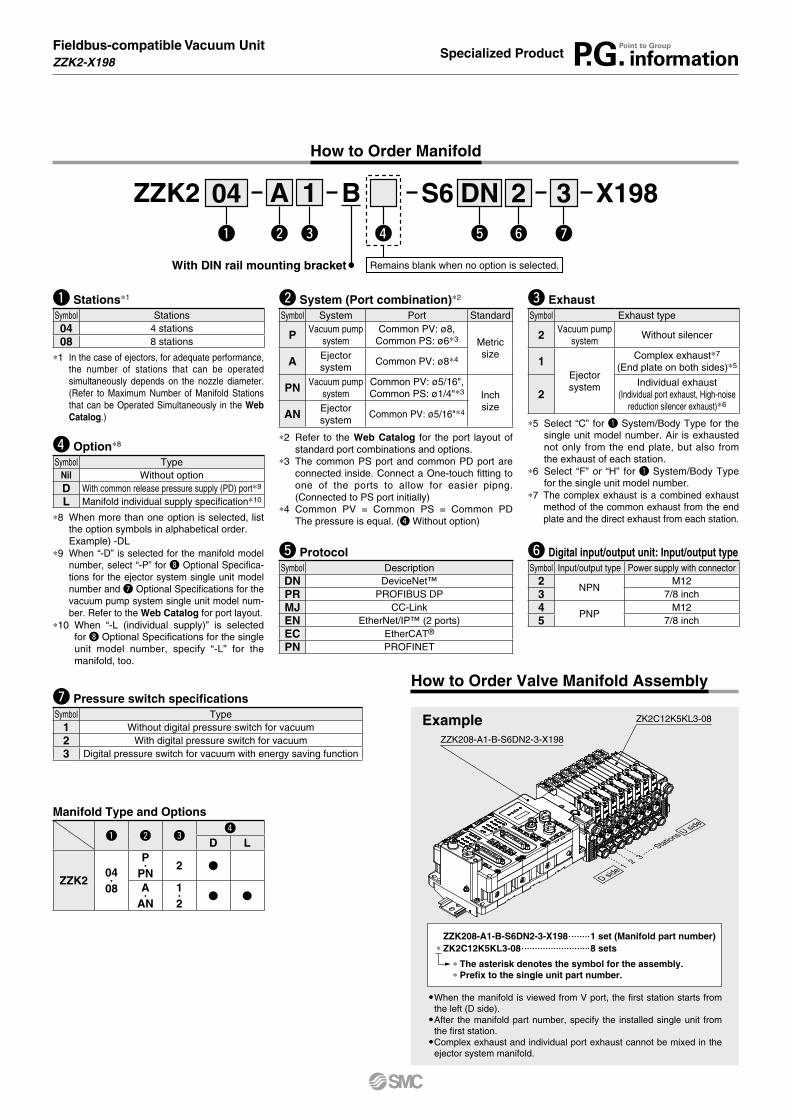
How to Order Manifold
AZZK2 S6 X19804q w t
DN 3u
2y
1e r
B
Remains blank when no option is selected.
q Stations*1
Symbol Stations04 4 stations08 8 stations
*1 In the case of ejectors, for adequate performance, the number of stations that can be operated simultaneously depends on the nozzle diameter. (Refer to Maximum Number of Manifold Stations that can be Operated Simultaneously in the Web Catalog.)
u Pressure switch specificationsSymbol Type
1 Without digital pressure switch for vacuum2 With digital pressure switch for vacuum3 Digital pressure switch for vacuum with energy saving function
y Digital input/output unit: Input/output typeSymbol Input/output type Power supply with connector
2NPN
M123 7/8 inch4
PNPM12
5 7/8 inch
t ProtocolSymbol DescriptionDN DeviceNet™PR PROFIBUS DPMJ CC-LinkEN EtherNet/IP™ (2 ports)EC EtherCAT®
PN PROFINET
w System (Port combination)*2
Symbol System Port Standard
P Vacuum pump system
Common PV: ø8,Common PS: ø6*3 Metric
sizeA Ejector
systemCommon PV: ø8*4
PN Vacuum pump system
Common PV: ø5/16",Common PS: ø1/4"*3 Inch
sizeAN Ejector
systemCommon PV: ø5/16"*4
*2 Refer to the Web Catalog for the port layout of standard port combinations and options.
*3 The common PS port and common PD port are connected inside. Connect a One-touch fitting to one of the ports to allow for easier pipng. (Connected to PS port initially)
*4 Common PV = Common PS = Common PD The pressure is equal. (r Without option)
Manifold Type and Options
q w er
D L
ZZK204·
08
P·
PN2 V
A·
AN1·2
V V
r Option*8
Symbol TypeNil Without optionD With common release pressure supply (PD) port*9
L Manifold individual supply specification*10
*8 When more than one option is selected, list the option symbols in alphabetical order.Example) -DL
*9 When “-D” is selected for the manifold model number, select “-P” for i Optional Specifica-tions for the ejector system single unit model number and u Optional Specifications for the vacuum pump system single unit model num-ber. Refer to the Web Catalog for port layout.
*10 When “-L (individual supply)” is selected for i Optional Specifications for the single unit model number, specify “-L” for the manifold, too.
e ExhaustSymbol Exhaust type
2 Vacuum pump system
Without silencer
1Ejector system
Complex exhaust*7
(End plate on both sides)*5
2Individual exhaust
(Individual port exhaust, High-noise reduction silencer exhaust)*6
*5 Select “C” for q System/Body Type for the single unit model number. Air is exhausted not only from the end plate, but also from the exhaust of each station.
*6 Select “F” or “H” for q System/Body Type for the single unit model number.
*7 The complex exhaust is a combined exhaust method of the common exhaust from the end plate and the direct exhaust from each station.
With DIN rail mounting bracket
When the manifold is viewed from V port, the first station starts from the left (D side).
After the manifold part number, specify the installed single unit from the first station.
Complex exhaust and individual port exhaust cannot be mixed in the ejector system manifold.
How to Order Valve Manifold Assembly
ZZK208-A1-B-S6DN2-3-X198 1 set (Manifold part number)* ZK2C12K5KL3-08 8 sets
* The asterisk denotes the symbol for the assembly.* Prefix to the single unit part number.
Example
D side
U side
Stations
ZK2C12K5KL3-08
ZZK208-A1-B-S6DN2-3-X198
1 2 3

Fieldbus-compatible Vacuum UnitZZK2-X198 P.G. information
Point to GroupSpecialized Product
How to Order Single Unit
Ejector System
w Nominal nozzle sizeSymbol System Nominal size07
Ejector system*3
ø0.710 ø1.012 ø1.215 ø1.5
*3 Standard supply pressure for nozzle size 07 to 12 is 0.35 MPa,
15 is 0.4 MPa
e Combination of supply valve and release valve*4
Symbol Supply valve Release valveK*6 N.C. N.C.J N.C. NoneR Self-holding release valve linked*5 N.C.
*4 Only non-locking type is available for the manu-al override for “K, J, R”.
*5 Self-holding type maintains vacuum by instan-taneous energization (20 ms or more). Stop-ping the vacuum turns on the release valve. (signal to stop vacuum not needed)
*6 When the digital pressure switch for vacuum with energy saving function is selected, select “K” for t Pressure Sensor/Digital Pressure Switch for Vacuum Specifications.
r Rated voltage*7
Symbol Voltage5 24 VDC
*7 Rated voltage for the supply and release valve
q System/Body typeSymbol System Body type Exhaust type
CEjector system
For manifold
Complex exhaust*1
F Individual port exhaust*2
H High-noise reduction silencer exhaust
*1 The complex exhaust is a combined exhaust method of the common exhaust from the end plate and the direct exhaust from each station.
*2 Individual port size of exhaust port: mm: ø8inch: ø5/16
t Digital pressure switch for vacuum specificationsSymbol Type Pressure range [kPa] Specifications
A
Digital pressure switch for vacuum
0 to −101
NPN 2 outputs
Unit selection function*8
B SI unit only*9
C PNP 2 outputs
Unit selection function*8
D SI unit only*9
E
−100 to 100
NPN 2 outputs
Unit selection function*8
F SI unit only*9
H PNP 2 outputs
Unit selection function*8
J SI unit only*9
KDigital pressure switch for vacuum with energy
saving function*10−100 to 100
NPN 1 output
Unit selection function*8
Q SI unit only*9
R PNP 1 output
Unit selection function*8
S SI unit only*9
N Without pressure sensor/digital pressure switch for vacuum
y Connector specificationsSymbol Type
C1 Without digital pressure switch for vacuum
L3 With digital pressure switch for vacuum
i Optional specifications*12
Symbol TypeNil Without option
B With one bracket for mounting a single unit(Mounting screw is attached.)
D With individual release pressure supply (PD) port*13
J Vacuum break flow adjusting needleRound lock nut type
K Vacuum break flow adjusting needleScrewdriver operation type
L Manifold individual supply specification*14
P*15
Manifold common release pressure supply specification
W*16*17*18*19
With exhaust interference prevention valve
*12 When more than one option is selected, list the option symbols in alphabetical order.Example) -BDRefer to the Web Catalog for Function/Application.
*13 Only M3 is available for PD port size. Use One-touch fitting (M-3AU-4) or barb fitting for piping. (O.D.: within ø6.2)
*14 Select body for manifold. Select “L” for manifold type. When the common supply and individual supply are mixed, please contact SMC.
*15 When “D” is selected for manifold option, select “P” option for the single unit model number.
*16 To prevent backflow of the manifold common exhaust, not for holding vacuum. This option does not completely stop the backflow of the exhaust air. Select port exhaust type depending on purpose.
*17 When “J” is selected for e Combination of Supply Valve and Release Valve and “W” (with exhaust interference prevention valve) is selected for i Optional Specifications, install a release valve or vacuum breaker.
*18 When “K, Q, R, S” is selected for t Digital Pressure Switch for Vacuum Specifications, models with exhaust interference prevention valve is provided. So, it is not necessary to select “W”.
*19 For high-noise reduction silencer exhaust, “W” (With exhaust interference prevention valve) cannot be selected.
u Vacuum (V) port*11
Symbol Type Port size
06 Metric size
ø6 One-touch fitting
08 ø8 One-touch fitting
07 Inch size
ø1/4" One-touch fitting
09 ø5/16" One-touch fitting
*11 Supply port (PV) size of single unit: ø6 (mm), ø1/4" (inch)
Single Unit and Options*20
q
System/ Body type
w
Nominal nozzle size
eCombination of
supply valve and release valve
r
Rated voltage
tDigital pressure
switch for vacuum specifications
y
Connector specifications
u
Vacuum (V) port
i
Optional specifications
C/F/H
07·
10·
12·
15
K
5
A/B/C/D/E/F/H/J L306·
08·
07·
09
J/K/L/P/WN C1K/Q/R/S L3 J/K/L/P
R A/B/C/D/E/F/H/J L3 J/K/L/P/WN C1
J A/B/C/D/E/F/H/J L3 L/WN C1*20 When “J” is selected for e Combination of Supply Valve and Release Valve, “J or K” cannot be
selected for i Optional Specifications.
For options not in the table, please contact SMC.* Refer to the Web Catalog when mounting a single unit onto the DIN rail.
wq e r t y u i
Remains blank when no option is selected.
ZK2 L3
*8 Unit selection func-tion is not available in Japan due to new measurement law.
*9 Fixed unit: kPa*10 When “K, Q, R, S”
is selected, select “K” for e Combi-nation of Supply Valve and Release Valve. Select “L3” for y.
12 K 5 AC 08
¡PV: Air pressure supply port/Port for vacuum source (Vacuum pump) ¡PS: Pilot pressure supply port¡PD: Individual release pressure supply port ¡V: Vacuum port ¡EXH: Exhaust port ¡PE: Pilot pressure exhaust port For details ⇒ Web Catalog

Fieldbus-compatible Vacuum UnitZZK2-X198 P.G. information
Point to GroupSpecialized Product
How to Order Single Unit
t Connector specificationsSymbol Type
C1 Without digital pressure switch for vacuum
L3 With digital pressure switch for vacuum
Vacuum Pump System
w Combination of supply valve and release valve*1
Symbol Supply valve Release valve
K N.C. N.C.
J N.C.*2 None
R Self-holding release valve linked*3 N.C.
*1 Only non-locking type is available for the manual override for “K, J, R”.
*2 When “J” is selected for vacuum pump system, install a release valve or vacuum breaker.
*3 Self-holding type maintains vacuum by instantaneous energization (20 ms or more). Stopping the vacuum turns on the release valve. (signal to stop vacuum not needed)
e Rated voltage*4
Symbol Voltage
5 24 VDC
*4 Rated voltage for the supply and release valve
q System/Body typeSymbol System Body type
Q Vacuum pump system
For manifold
* PS port size of pump system: mm: ø4inch: ø5/32"
u Optional specifications*8*12
Symbol Type
Nil Without option
B With one bracket for mounting a single unit(Mounting screw is attached.)
C Pump system PE port female thread specification (M3)*9
D With individual release pressure supply (PD) port*10
J Vacuum break flow adjusting needleRound lock nut type
K Vacuum break flow adjusting needleScrewdriver operation type
P Manifold common release pressure supply specification*11
*8 When more than one option is selected, list the option symbols in alphabetical order.Example) -BC
*9 Use One-touch fitting (M-3AU-4) or barb fitting for piping. (O.D.: within ø5.8)
*10 Only M3 is available for PD port size. Use One-touch fitting (M-3AU-4) or barb fitting for piping. (O.D.: within ø6.2)
*11 When “D” is selected for manifold option, select “P” option for the single unit model number.
*12 Refer to the Web Catalog for Function/Application.
Single Unit and Options*13
qSystem/
Body type
Vacuum pump system part number
wCombination of supply
valve and release valve
eRated
voltage
rPressure sensor/digital pressure switch for vacuum specifications
tConnector
specifications
yVacuum (V) port
uOptional
specifications
Q 00K/R
5
A/B/C/D/E/F/H/J L3 06·
08·
07·
09
C/J/K/PN C1
JA/B/C/D/E/F/H/J L3
CN C1
*13 When “J” is selected for w Combination of Supply Valve and Release Valve, “J or K” cannot be selected for u Optional Specifications.
For options not in the table, please contact SMC.* Refer to the Web Catalog when mounting a single unit onto the DIN rail.
r Pressure sensor/Digital pressure switch for vacuum specificationsSymbol Type Pressure range [kPa] Specifications
A
Digital pressure switch
for vacuum
0 to −101
NPN 2 outputs
Unit selection function*5
B SI unit only*6
C PNP 2 outputs
Unit selection function*5
D SI unit only*6
E
−100 to100
NPN 2 outputs
Unit selection function*5
F SI unit only*6
H PNP 2 outputs
Unit selection function*5
J SI unit only*6
N Without pressure sensor/digital pressure switch for vacuum
*5 Unit selection function is not available in Japan due to new measurement law.*6 Fixed unit: kPa
y Vacuum (V) port*7
Symbol Type Port size
06Metric size
ø6 One-touch fitting
V
08 ø8 One-touch fitting
07Inch size
ø1/4" One-touch fitting
09 ø5/16" One-touch fitting
*7 Supply port (PV) size of single unit: ø6 (mm), ø1/4" (inch)
ZK2 Q 00q w e r t y u
Remains blank when no option is selected.
08K 5 A L3
Digital pressure switch for vacuum
¡PV: Air pressure supply port/Port for vacuum source (Vacuum pump) ¡PS: Pilot pressure supply port¡PD: Individual release pressure supply port ¡V: Vacuum port ¡EXH: Exhaust port ¡PE: Pilot pressure exhaust port For details ⇒ Web Catalog
End plate
Connector
(Ref
er to
Tab
le 1
.)
(Ref
er to
Tab
le 2.
)
(Refer to Table 2.)
(Refer to Table 2.)
(Ref
er to
Tab
le 2
.)
Ful
ly o
pen:
10
Dedicated cable
Power connector
Digital output unit SI unit
2 x Common pilotpressure supply (PS) port
n x Individual air pressure supply (PV) portD side Stations
(n-1) x 15 [n: Stations]
For high-noise reductionsilencer exhaust
(Body type: H)
PD port dimensions (Option symbol: -D)
Individual (PV) port, PS port dimensions
(Option symbol: -L)
Common pilot pressure supply (PS) port
Individual air pressure supply (PV) port
Common release pressure (PD) port
For port exhaust (Body type: F)
Individual exhaust (EXH) portø8 (mm)ø5/16" (inch)
33.8
U side
2 x Common supply (PV) port
2 x Common release pressure supply (PD) port
(Ref
er to
Tab
le 2.
)
Fieldbus-compatible Vacuum UnitZZK2-X198 P.G. information
Point to GroupSpecialized Product
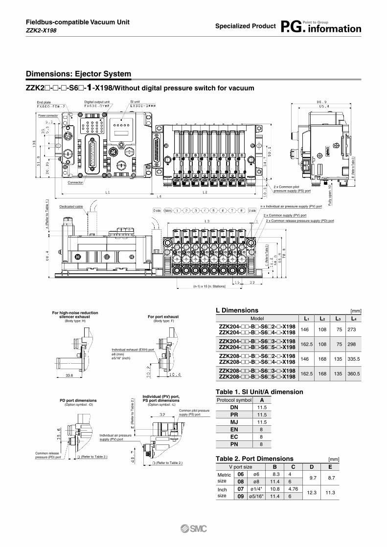
Dimensions: Ejector System
L Dimensions [mm]
Model L1 L2 L3 L4
ZZK204-mm-Bm-S6m2-m-X198ZZK204-mm-Bm-S6m4-m-X198 146 108 75 273
ZZK204-mm-Bm-S6m3-m-X198ZZK204-mm-Bm-S6m5-m-X198 162.5 108 75 298
ZZK208-mm-Bm-S6m2-m-X198ZZK208-mm-Bm-S6m4-m-X198 146 168 135 335.5
ZZK208-mm-Bm-S6m3-m-X198ZZK208-mm-Bm-S6m5-m-X198 162.5 168 135 360.5
ZZK2m-m-m-S6m-1-X198/Without digital pressure switch for vacuum
Table 2. Port Dimensions [mm]
V port size B C D EMetric size
06 ø6 8.3 49.7 8.7
08 ø8 11.4 6
Inch size
07 ø1/4" 10.8 4.7612.3 11.3
09 ø5/16" 11.4 6
Table 1. SI Unit/A dimensionProtocol symbol A
DN 11.5
PR 11.5
MJ 11.5
EN 8
EC 8
PN 8

(Refer to Table 2.)
(Refer to Table 2.)
(Ref
er to
Tab
le 2
.)
For high-noise reductionsilencer exhaust
(Body type: H)
PD port dimensions (Option symbol: -D)
Individual (PV) port, PS port dimensions
(Option symbol: -L)
Common pilot pressure supply (PS) port
Individual air pressure supply (PV) port
Common release pressure (PD) port
For port exhaust (Body type: F)
Individual exhaust (EXH) portø8 (mm)ø5/16" (inch)
33.8
End plate
Connector
(Ref
er to
Tab
le 2.
)
Ful
ly o
pen:
10
Dedicated cable(Connect to stations 1 to 4)
Power connector
Digital input/output unit 1
Digital input/output unit 2
SI unit
2 x Common pilotpressure supply (PS) port
n x Individual air pressure supply (PV) port
D side Stations
(n-1) x 15 [n: Stations]
U side2 x Common supply (PV) port
2 x Common release pressure supply (PD) port
Dedicated cable(Connect to stations 5 to 8)
Station number indication marks
(Ref
er to
Tab
le 2.
)
(Ref
er to
Tab
le 1
.)
Fieldbus-compatible Vacuum UnitZZK2-X198 P.G. information
Point to GroupSpecialized Product
Dimensions: Ejector System
L Dimensions [mm]
Model L1 L2 L3 L4
ZZK204-mm-Bm-S6m2-m-X198ZZK204-mm-Bm-S6m4-m-X198 146 90 75 260.5
ZZK204-mm-Bm-S6m3-m-X198ZZK204-mm-Bm-S6m5-m-X198 162.5 90 75 273
ZZK208-mm-Bm-S6m2-m-X198ZZK208-mm-Bm-S6m4-m-X198 193 150 135 373
ZZK208-mm-Bm-S6m3-m-X198ZZK208-mm-Bm-S6m5-m-X198 209.5 150 135 385.5
Table 2. Port Dimensions [mm]
V port size B C D EMetric size
06 ø6 8.3 49.7 8.7
08 ø8 11.4 6
Inch size
07 ø1/4" 10.8 4.7612.3 11.3
09 ø5/16" 11.4 6
Table 1. SI Unit/A dimensionProtocol symbol A
DN 11.5
PR 11.5
MJ 11.5
EN 8
EC 8
PN 8
ZZK2m-m-m-S6m- -X198/ With digital pressure switch for vacuum With digital pressure switch for vacuum with energy saving function
23

(Refer to Table 4.)
PD port dimensions (Option symbol: -D)
Common release pressure (PD) port
End plate
Connector
(Ref
er to
Tab
le 3
.)
(Ref
er to
Tab
le 4.
)
Ful
ly o
pen:
10
Dedicated cable
Power connector
Digital output unit SI unit
2 x Common pilotpressure supply (PS) port
n x Pilot pressure exhaust (PE) port
D side Stations
(n-1) x 15 [n: Stations]
U side
2 x Common supply (PV) port
2 x Common release pressure supply (PD) port
(Ref
er to
Tab
le 4.
)
Fieldbus-compatible Vacuum UnitZZK2-X198 P.G. information
Point to GroupSpecialized Product
Dimensions: Vacuum Pump System
L Dimensions [mm]
Model L1 L2 L3 L4
ZZK204-mm-Bm-S6m2-m-X198ZZK204-mm-Bm-S6m4-m-X198 146 108 75 273
ZZK204-mm-Bm-S6m3-m-X198ZZK204-mm-Bm-S6m5-m-X198 162.5 108 75 298
ZZK208-mm-Bm-S6m2-m-X198ZZK208-mm-Bm-S6m4-m-X198 146 168 135 335.5
ZZK208-mm-Bm-S6m3-m-X198ZZK208-mm-Bm-S6m5-m-X198 162.5 168 135 360.5
ZZK2m-m-m-S6m-1-X198/Without digital pressure switch for vacuum
Table 4. Port Dimensions [mm]
V port size B C DMetric size
06 ø6 8.3 49.7
08 ø8 11.4 6
Inch size
07 ø1/4" 10.8 4.7612.3
09 ø5/16" 11.4 6
Table 3. SI Unit/A dimensionProtocol symbol A
DN 11.5
PR 11.5
MJ 11.5
EN 8
EC 8
PN 8

(Refer to Table 4.)
PD port dimensions (Option symbol: -D)
Common release pressure (PD) port
End plate
Connector
(Ref
er to
Tab
le 4.
)
Ful
ly o
pen:
10
Dedicated cable(Connect to stations 1 to 4)
Power connector
Digital input/output unit 2
SI unit
2 x Common pilotpressure supply (PS) port
n x Pilot pressure exhaust (PE) port
D side Stations
(n-1) x 15 [n: Stations]
U side 2 x Common supply (PV) port
2 x Common release pressure supply (PD) port
Dedicated cable(Connect to stations 5 to 8)
Station number indication marks
(Ref
er to
Tab
le 4.
)
(Ref
er to
Tab
le 3
.)
Digital input/output unit 1
Fieldbus-compatible Vacuum UnitZZK2-X198 P.G. information
Point to GroupSpecialized Product
Dimensions: Vacuum Pump System
L Dimensions [mm]
Model L1 L2 L3 L4
ZZK204-mm-Bm-S6m2-m-X198ZZK204-mm-Bm-S6m4-m-X198 146 90 75 260.5
ZZK204-mm-Bm-S6m3-m-X198ZZK204-mm-Bm-S6m5-m-X198 162.5 90 75 273
ZZK208-mm-Bm-S6m2-m-X198ZZK208-mm-Bm-S6m4-m-X198 193 150 135 373
ZZK208-mm-Bm-S6m3-m-X198ZZK208-mm-Bm-S6m5-m-X198 209.5 150 135 385.5
Table 4. Port Dimensions [mm]
V port size B C DMetric size
06 ø6 8.3 49.7
08 ø8 11.4 6
Inch size
07 ø1/4" 10.8 4.7612.3
09 ø5/16" 11.4 6
Table 3. SI Unit/A dimensionProtocol symbol A
DN 11.5
PR 11.5
MJ 11.5
EN 8
EC 8
PN 8
ZZK2m-m-m-S6m-2-X198/With digital pressure switch for vacuum