fig 04-1 fig 05-1
TRANSCRIPT

210-0332 – edizione 2018-09
BB2205X BB2208X BB2212X
BB3005X BB3008X BB3012X
BB4505X BB4508X BB4512X
BB6005X BB6008X BB6012X
MANUALE ISTRUZIONI
SCALDABAGNO NAUTICO CON DOPPIO RISCALDAMENTO: RISCALDAMENTO ELETTRICO E RISCALDAMENTO INDIRETTO
INSTRUCTION MANUAL
MARINE WATER HEATER WITH DUAL HEATING AS STANDARD: ELECTRICAL HEATING AND INDIRECT HEATING
MANUAL DE INSTRUCCIONES
CALENTADOR DE AGUA PARA EMBARCACIONES CON DOBLE CALEFACCIÓN: CALENTAMIENTO ELÉCTRICO Y INDIRECTO
MANUEL D'UTILISATION
CHAUFFE-EAU POUR BATEAUX AVEC DOUBLE CHAUFFAGE: CHAUFFAGE ELECTRIQUE ET CHAUFFAGE INDIRECT
BEDIENUNGSANLEITUNG
MARINE WASSERBEREITER MIT DUAL HEIZUNG: ELEKTRO HEIZUNG UND INDIREKTE HEIZUNG
KULLANIM KILAVUZU
MARİN TİPİ SU ISITICISI: ELEKTRİK ve /veya MOTOR SUYU İLE ÇİFT ISITMA SİSTEMLİ

210-0332_figure.docx
FIG_04-1 FIG_05-1
FIG_05-2 FIG_07-1
FIG_07-2 FIG_07-3

IT – pag. 1/4 ITALIANO
210-0332_libretto_BB_inox_2016-02_testo_IT.docx
La gamma di scaldacqua BB...X comprende 24 differenti modelli disponibili con le seguenti caratteristiche per soddisfare ogni esigenza di installazione e di utilizzo
a) 4 capacità di stoccaggio (22 – 30 – 45 – 60 - 80 litri / 5,8 – 7,9 – 11,9 – 15,8 – 21,0 galloni) b) 3 potenze (500 w - 800 w - 1200 w) c) 2 alimentazioni elettriche (120 V - 230 V)
1. PRECAUZIONI GENERALI Le istruzioni che seguono sono importanti per garantire la sicurezza di installazione, uso e manutenzione dell'apparecchio. • Questo libretto è parte integrante ed essenziale del riscaldatore di acqua: quindi deve essere tenuto a portata di mano per
ogni ulteriore consultazione. • Il riscaldatore d’acqua è stata prodotto per la produzione di acqua calda: qualsiasi altro tipo di utilizzo è da considerarsi
pericoloso e non idoneo. • L'apparecchio non deve essere installato in ambienti umidi, vasche da bagno, lavabi, docce, piscine ecc. e deve essere
protetto da spruzzi d'acqua, getti d'acqua o altri liquidi, al fine di evitare corto circuiti dei dispositivi elettrici. • L'installazione deve essere effettuata da una persona qualificata, che è responsabile per l'applicazione delle norme di
sicurezza vigenti. L'installazione impropria, causata dal mancato rispetto delle istruzioni fornite dal produttore, può causare lesioni a persone, animali o danni ad altre apparecchiature per le quali il costruttore declina ogni responsabilità.
• Prima di collegare lo scaldabagno, assicurarsi che le caratteristiche elettriche stampate sulla targhetta dati corrispondano a quelle della rete elettrica.
• Se lo scaldabagno è installato in un bagno, in una stanza umida o vicino all'acqua, prendersi cura delle distanze di sicurezza previste dalla normativa CEI-CEE. Inoltre, interruttori o qualsiasi altro comando elettrico non devono essere raggiungibili da chiunque stia facendo una doccia o utilizzando la vasca da bagno. Non toccare l'apparecchio con mani bagnate o umide.
• Non consentire l'utilizzo da parte di bambini o persone incapaci senza alcun controllo. • Le parti di imballaggio (sacchetti di plastica, polistirolo, clip, ecc.) devono essere tenute lontane dai bambini, perché
possono essere pericolose. • Leggere attentamente questo libretto in quanto fornisce istruzioni utili in materia di sicurezza, d'installazione, uso e
manutenzione. • Se l'apparecchio dovesse essere venduto o spostato ad altro proprietario, assicurarsi che il presente libretto accompagni
l'apparecchio, in modo che il nuovo proprietario e / o l'installatore possano consultarlo. • Per evitare il rischio di danni dovuti al gelo, se l'apparecchio non viene utilizzato per un lungo periodo ed è installato in un
locale non riscaldato, si consiglia di svuotarlo completamente. Il produttore non è responsabile di eventuali danni o rotture dovute al gelo o perdite di acqua dall’impianto.
• Per ottenere le migliori prestazioni dal riscaldamento dell'acqua e per scopi di garanzia, rispettare rigorosamente le istruzioni riportate qui sotto.
2. CARATTERISTICHE TECNICHE
BB
2205
X
BB
2208
X
BB
2212
X
BB
3005
X
BB
3008
X
BB
3012
X
BB
4505
X
BB
4508
X
BB
0512
X
BB
6005
X
BB
6008
X
BB
6012
X
BB
8005
X
BB
8008
X
BB
8012
X
alimentazione V~ 230 230 230 230 230 230 230 230 230 230 230 230 230 230 230 elettrica A 2,2 3,5 5,2 2,2 3,5 5,2 2,2 3,5 5,2 2,2 3,5 5,2 2,2 3,5 5,2 potenza w 500 800 1.200 500 800 1.200 500 800 1.200 500 800 1.200 500 800 1.200
BB
2205
1X
BB
2208
1X
BB
2212
1X
BB
3005
1X
BB
3008
1X
BB
3012
1X
BB
4505
1X
BB
4508
1X
BB
4512
1X
BB
6005
1X
BB
6008
1X
BB
6012
1X
BB
8005
1X
BB
8008
1X
BB
8012
1X
alimentazione V~ 120 120 120 120 120 120 120 120 120 120 120 120 120 120 120 elettrica A 4,2 6,7 10,0 4,2 6,7 10,0 4,2 6,7 10,0 4,2 6,7 10,0 4,2 6,7 10,0 potenza w 500 800 1.200 500 800 1.200 500 800 1.200 500 800 1.200 500 800 1.200
capacità lt ( gal ) 22 ( 5,8 ) 30 ( 7,9 ) 45 ( 11,9 ) 60 ( 15,8 ) 80 ( 21,0 ) pressione massima kPa ( psi ) 700 ( 102 ) 700 ( 102 ) 700 ( 102 ) 700 ( 102 ) 700 ( 102 )
peso a vuoto kg ( lb ) 10,0 ( 22 ) 11,5 ( 25 ) 15,0 ( 33 ) 17,3 ( 38 ) 20,0 ( 40 ) dimensioni mm 322 x 334 x 515 322 x 334 x 650 322 x 334 x 910 322 x 334 x 1095 322 x 334 x 1305 inch" 12,6 x 13,0 x 20,3 12,6 x 13,0 x 25,6 12,6 x 13,0 x 35,8 12,6 x 13,0 x 43,1 12,6 x 13,0 x 51,4
3. CONTENUTO IMBALLO L’apparecchio è confezionato e consegnato in una scatola di cartone con una protezione adeguata. Oltre all'apparecchio, all'interno della scatola sono presenti :
a) il manuale di installazione b) le staffe di fissaggio ed il kit viti di fissaggio c) la valvola di ritegno/sicurezza

IT – pag. 2/4 ITALIANO
210-0332_libretto_BB_inox_2016-02_testo_IT.docx
4. DIMENSIONI (vedi fig. FIG_4-1)
A B C D E F BB2205X -- BB2208X -- BB2212X mm 322 267 365 334 440 515 BB22051X -- BB22081X -- BB22121X inch " 12,6 10,4 14,2 13,0 17,1 20,3 BB3005X -- BB3008X -- BB3012X mm 322 267 500 334 575 650 BB30051X -- BB30081X -- BB30121X inch " 12,6 10,4 19,5 13,0 22,4 25,6 BB4505X -- BB4508X -- BB4512X mm 322 267 760 334 835 910 BB45051X -- BB45081X -- BB45121X inch " 12,6 10,4 29,6 13,0 32,5 35,8 BB6005X -- BB6008X -- BB6012X mm 322 267 945 334 1.020 1.095 BB60051X -- BB60081X -- BB60121X inch " 12,6 10,4 36,8 13,0 39,7 43,1 BB8005X -- BB8008X -- BB8012X mm 322 267 1.155 334 1.230 1.305 BB80051X -- BB80081X -- BB80121X inch " 12,6 10,4 45,0 13,0 47,9 51,4
5. DESCRIZIONE COSTRUTTIVA E FUNZIONAMENTO
Lo scopo di questo apparecchio è di riscaldare l'acqua calda sanitaria in due modi diversi (vedi fig FIG_5-1): A. attraverso lo scambio di calore tra l'acqua di raffreddamento del motore e l'acqua immagazzinata nel serbatoio.
Tale scambio termico è possibile grazie ad uno scambiatore di calore. L'acqua di raffreddamento del motore circola attraverso una serpentina posta al centro del serbatoio per diffondere uniformemente il calore.
B. per mezzo di una resistenza elettrica (fornita di serie con l'apparecchio). Parti principali (vedi FIG_5-2.): 1. Serbatoio di stoccaggio: è interamente realizzato in acciaio inox AISI 316L. 2. Mantello esterno: è molto resistente agli urti e alle sollecitazioni esterne, avendo allo stesso tempo un design molto
piacevole. 3. Isolamento termico: realizzato in poliuretano espanso a cellule chiuse, evita inutili perdite di calore. In questo modo la
perdita di calore per inerzia termica è ridotta a 1 ° C ogni ora per un periodo di 24 ore. 4. Scambiatore di calore: è realizzato in acciaio inox AISI 316L. La sua superficie di scambio permette di sfruttare al
meglio il calore dell'acqua di raffreddamento del motore e di ottenere acqua calda anche in condizioni estreme (differenze di temperatura molto piccole).
5. Resistenza elettrica: l'apparecchio è dotato di un elemento riscaldante elettrico (500/800/1200W, 120/230V ~) per riscaldare l'acqua anche quando il motore della barca è spento (per esempio quando la barca è in banchina). Materiale: lega INCOLOY resistente alla corrosione.
6. Termostato: ha due funzioni, precisamente: a. termostato regolabile: interrompe l'alimentazione elettrica all'elemento riscaldatore al raggiungimento della
temperatura preimpostata (la temperatura può essere regolata tra 0 ° C e 65 ° C, secondo le esigenze dell'utente).
b. termostato di sicurezza: interrompe l'alimentazione elettrica all'elemento riscaldatore quando, in caso di cattivo funzionamento dell'apparecchio, la temperatura dell'acqua raggiunge i 90 ° C. E’ necessario un intervento manuale per far ripartire l'apparecchio (reset manuale).
Range di temperatura: da 0 ° C a 65 ° C Differenziale di temperatura: circa 9 ° C Temperatura di intervento: 90 ° C Corrente massima: 20 A Temperatura massima: 120 ° C
7. Ingresso acqua fredda 8. Valvola di sicurezza e di non ritorno: impedisce il riflusso di acqua calda nella conduttura di ingresso dell’acqua
fredda. È anche una valvola di sicurezza da sovrappressione: protegge il serbatoio da possibili pressioni eccessive causate dall’espansione dell’acqua durante il riscaldamento. L'acqua viene scaricata attraverso lo scarico di cui è dotato la valvola. Taratura: 800 ± 50 kPa (116 ± 7 psi)
9. Uscita acqua calda 10. Staffa di fissaggio
6. ISTRUZIONI INSTALLAZIONE
L'installazione deve essere effettuata, in conformità con la normativa vigente, da una persona qualificata che può fare, non solo un set up corretto dell'apparecchio, ma anche le prove necessarie prima di iniziare il riscaldamento dell'acqua.
Durante l'installazione originale o successiva manutenzione, seguire le istruzioni riportate in questo libretto con attenzione. Modifiche a qualsiasi tipo di connessione o la mancata osservanza delle istruzioni fornite causerà la decadenza della garanzia.
Prima dell'installazione, manutenzione o riparazione, togliere l'alimentazione elettrica all'apparecchio. 7. POSIZIONE E MONTAGGIO Sull'apparecchio sono presenti due staffe di fissaggio (A - FIG_7-1). In questo modo si ottiene un’installazione facile ma ferma e sicura. Per il fissaggio dell'apparecchio utilizzare il kit dadi di fissaggio (fornito di serie con l'apparecchio).

IT – pag. 3/4 ITALIANO
210-0332_libretto_BB_inox_2016-02_testo_IT.docx
L'apparecchio deve essere installato in modo tale che lo scambiatore di calore e/o la resistenza elettrica siano posti nella parte inferiore (FIG_7-2). E’ possibile installare l’apparecchio anche su pareti inclinate (FIG_7-3). Anche in questo caso occorre fare in modo che lo scambiatore di calore e/o la resistenza elettrica siano posti nella parte inferiore. L'apparecchio può essere installato in qualsiasi spazio, senza limitazioni alle sue condizioni. Quanto sopra descritto non esime dal rispettare le istruzioni fornite nel paragrafo "Norme generali di precauzione", all'inizio di questo opuscolo. Per altre installazione non contemplate in questo manuale e per installazioni su pareti inclinate, contattare il nostro ufficio tecnico. 8. COLLEGAMENTI IDRAULICI E QUALITA’ DELL’ACQUA Per prolungare la durata dell'apparecchio, la qualità dell'acqua dovrebbe essere secondo i seguenti parametri, come previsto dalla Direttiva Europea 98/83/CE (concernente la qualità delle acque destinate al consumo umano):
durezza compresa tra 15 e 50 ° F (in particolare, dove l'acqua ha subito un addolcimento o trattamento di desalinizzazione)
cloruri compresi tra 25 e 100 mg/l PH compreso tra 6,5 e 9,5 conducibilità compresa tra 400 e 1500 µS/cm
Collegare l'apparecchio secondo le seguenti indicazioni (FIG_8-1):
1. ingresso acqua fredda (1/2 ") 2. uscita acqua calda (1/2 ") 3. mandata acqua al circuito di raffreddamento del motore (1/2 ") 4. ritorno acqua dal circuito di raffreddamento del motore (1/2”)
Pressione minima di ingresso dell'acqua: 70 kpa. Si consiglia di isolare le condutture dell’acqua calda: si eviteranno così inutili sprechi di energia. Montaggio valvola di ritegno/sicurezza: la valvola è in dotazione all’apparecchio e non montata. E’ necessario montarla sull’ingresso dell’acqua fredda al momento dell’installazione dell’apparecchio. (S - FIG_8-1).
ATTENZIONE: non sostituire la valvola di sicurezza e non ritorno in dotazione con l'apparecchio con una valvola di non ritorno (clapet). ATTENZIONE: collegare lo scarico dell'acqua della valvola a un tubo di gomma avente un diametro interno di 9,5 mm. Questo tubo di scarico deve essere installato con una pendenza costante verso il basso e in un luogo protetto da ghiaccio.
9. COLLEGAMENTI ELETTRICI L'apparecchio deve essere collegato ad una alimentazione elettrica monofase (si prega di fare attenzione a collegare la corretta tensione: 120 V o 230 V secondo l’etichetta dati sull'apparecchio) e ad una buona connessione di terra.
IL COSTRUTTORE NON ACCETTA LA RESPONSABILITA PER DANNI POSSIBILI O LESIONI CAUSATI DALLA MANCANZA DI COLLEGAMENTO DI TERRA DELL'APPARECCHIO
L'apparecchio è dotato di un cavo di alimentazione con spina Schuko. Collegare il cavo di alimentazione in conformità con le norme di cablaggio in vigore nel paese in cui è installato l'apparecchio. In caso di sostituzione del cavo di alimentazione elettrica, utilizzare solo un cavo con le stesse caratteristiche (H05 VV-F - 3x1, 5 mmq). Nel caso in cui non sia necessario utilizzare la spina Schuko è possibile tagliare il cavo di alimentazione e collegarlo ad una spina differente o direttamente al collegamento dell'alimentazione. Si prega di fare attenzione a collegare correttamente le polarità (FIG_9-1):
• L fase (cavo marrone) • N neutro (cavo blu)
Prevedere un interruttore bipolare vicino all'apparecchio per consentire l'isolamento dell’apparecchio.
ATTENZIONE: PRIMA DI OPERARE SUL TERMOSTATO, ACCERTARSI CHE L'ALIMENTAZIONE ELETTRICA SIA COMPLETAMENTE SCOLLEGATA.
10. ISTRUZIONI PER L'USO La resistenza elettrica è dotata di un termostato che ha la seguente duplice funzione: 1. impostazione della temperatura. (T - FIG_9-1), interrompendo l'alimentazione elettrica alla resistenza elettrica
dell’apparecchio quando viene raggiunta la temperatura preimpostata (è possibile regolare il termostato tra 0 ° C e 65 ° C, secondo le necessità dell’utente).

IT – pag. 4/4 ITALIANO
210-0332_libretto_BB_inox_2016-02_testo_IT.docx
2. sicurezza, interrompendo l'alimentazione elettrica alla resistenza elettrica quando, in caso di cattivo funzionamento dell'apparecchio, la temperatura dell'acqua immagazzinata raggiunge i 90 ° C. Per avviare nuovamente l'apparecchio, è necessario un intervento manuale (riarmo manuale). In questo caso, attenersi alla seguente procedura: a) scollegare l’alimentazione elettrica b) rimuovere il cappuccio di protezione della resistenza elettrica c) premere il pulsante di reset posizionato sul termostato (R - FIG_9-1) d) mettere il coperchio di protezione della resistenza elettrica e) ripristinare l'alimentazione elettrica
ATTENZIONE: COLLEGARE L'ALIMENTAZIONE ALLA RESISTENZA ELETTRICA SOLO QUANDO IL SERBATOIO È PIENO D'ACQUA. L'ELEMENTO RISCALDANTE NON È ADATTO PER UN FUNZIONAMENTO A SECCO.
11. MANUTENZIONE DELL'APPARECCHIO Per rendere il funzionamento dell'apparecchio sicuro ed estendere la sua vita dello stesso, è consigliato almeno una volta all'anno un controllo periodico da parte di un servizio di assistenza autorizzato. 12. GARANZIA Le condizioni di garanzia sono valide a condizione che siano rispettate le istruzioni di installazione contenute in questo opuscolo. La garanzia decorre dalla data di produzione stampata sull'etichetta dati dell'apparecchio ed ha una durata di 36 mesi. Per motivi di sicurezza e per la validità della garanzia è obbligatorio usare solo parti di ricambio originali. 13. ACCESSORI DISPONIBILI SU RICHIESTA ABMIX (FIG_13-1) : permette di impostare una temperatura costante di acqua calda (tra 21° C e 70° C) ABRGOM (FIG_13-2) : permette di effettuare collegamenti idraulici mediante tubi in gomma, invece di collegamenti filettati. 14. PRINCIPALI RICAMBI
pos. cod. FIG_14-1
BB
2205
X
BB
2208
X
BB
2212
X
BB
3005
X
BB
3008
X
BB
3012
X
BB
4505
X
BB
4508
X
BB
4512
X
BB
6005
X
BB
6008
X
BB
6012
X
BB
8005
X
BB
8008
X
BB
8012
X
BB
2205
1X
BB
2208
1X
BB
2212
1X
BB
3005
1X
BB
3008
1X
BB
3012
1X
BB
4505
1X
BB
4508
1X
BB
4512
1X
BB
6005
1X
BB
6008
1X
BB
6012
1X
BB
8005
1X
BB
8008
1X
BB
8012
1X
01 0-0130 fascia di fissaggio
2 2 2 2 2 2 2 2 2 2 2 2 2 2 2 2 2 2 2 2 2 2 2 2 2 2 2 2 2 2
02 0-0132 staffa di fissaggio
2 2 2 2 2 2 2 2 2 2 2 2 2 2 2 2 2 2 2 2 2 2 2 2 2 2 2 2 2 2
03 020-0060 cuffiotto resistenza
1 1 1 1 1 1 1 1 1 1 1 1 1 1 1 1 1 1 1 1 1 1 1 1 1 1 1 1 1 1
04 100-0086 guarnizione 1 1 1 1 1 1 1 1 1 1 1 1 1 1 1 1 1 1 1 1 1 1 1 1 1 1 1 1 1 1 05 130-0081 raccordo diritto
maschio - 1/2 x 14
4 4 4 4 4 4 4 4 4 4 4 4 4 4 4 4 4 4 4 4 4 4 4 4 4 4 4 4 4 4
06 130-0092 valvola ritegno/sicurezza
1 1 1 1 1 1 1 1 1 1 1 1 1 1 1 1 1 1 1 1 1 1 1 1 1 1 1 1 1 1
07 130-0134 prolunga 1 1 1 1 1 1 1 1 1 1 1 1 1 1 1 1 1 1 1 1 1 1 1 1 1 1 1 1 1 1 08 140-0001 pressacavo PG
9 1 1 1 1 1 1 1 1 1 1 1 1 1 1 1 1 1 1 1 1 1 1 1 1 1 1 1 1 1 1
09 140-0007 dado PG 9 nero
1 1 1 1 1 1 1 1 1 1 1 1 1 1 1 1 1 1 1 1 1 1 1 1 1 1 1 1 1 1
10 280-0036 resistenza elettrica
1 1 1 1 1
10 280-0038 resistenza elettrica
1 1 1 1 1
10 280-0034 resistenza elettrica
1 1 1 1 1
10 280-0014 resistenza elettrica
1 1 1 1 1
10 280-0015 resistenza elettrica
1 1 1 1 1
10 280-0016 resistenza elettrica
1 1 1 1 1
11 280-0032 termostato 1 1 1 1 1 1 1 1 1 1 1 1 1 1 1 1 1 1 1 1 1 1 1 1 1 1 1 1 1 1 12 900-0131 cavo
alimentazione 1 1 1 1 1 1 1 1 1 1 1 1 1 1 1 1 1 1 1 1 1 1 1 1 1 1 1 1 1 1
13 900-0562 boiler isolato 1 1 1 1 1 1 13 900-0563 boiler isolato 1 1 1 1 1 1 13 900-0564 boiler isolato 1 1 1 1 1 1 13 900-0566 boiler isolato 1 1 1 1 1 1 13 900-0568 boiler isolato 1 1 1 1 1 1

UK – pag. 1/4
210-0332_libretto_BB_inox_2016-02_testo_UK.docx
The range of BB..X water heaters includes 24 different models with the following characteristics to satisfy every requirement of installation and use:
a) 4 storage capacities (22 - 30 - 45 – 60 - 80 liters / 5.8 - 7.9 - 11.9 - 15.8 -21.0 gallons) b) 3 powers (500 w - 800 w - w 1200) c) 2 electric voltages (120 V - 230 V)
1. GENERAL PRECAUTIONS The following instructions are important to guarantee a safe installation, use and maintenance of the appliance. • This book is an integral and essential part of the appliance and it has to be kept with care near it for any further
consultation. • The water heater is conceived for the production of hot water: any other use of it has to be considered dangerous and
unsuitable. • The appliance has not to be installed in damp rooms, baths, sinks, showers, swimming pools etc. and it has to be
protected from water sprinklings and sprays or from other liquids, in order to avoid short circuits of the electric devices. • The installation has to be carried out by a qualified person, who is responsible for the application of the current safety
regulations. An improper installation, caused by the non-observance of the manufacturer’s instructions, can cause damages to persons, animals or damns to other appliances for which the manufacturer refuses every responsibility.
• Before connecting the water heater, make sure that the electric characteristics printed on the data badge correspond to those of the electrical supply network.
• If the water heater is installed in a bath, in a damp room or in proximity of water, take care of the safety distances foreseen by the rule CEI-CEE. Furthermore, interrupters, or any other electric command, have not to be attainable by anybody having a shower or using the tub. Do not touch the appliance with wet or damp hands.
• Do not allow the use by children or incapable persons without any control. • The parts of packing (plastic bags, polystyrene, clip, etc.) can be harmful to children and should be carefully disposed of
immediately. • Read carefully the instructions and advice concerning safety, installation, use and maintenance contained in this booklet. • If the appliance must be sold or moved to another owner, make sure that the present book stays with the appliance so the
new owner and/or installer can consult it. • To avoid damages caused by low temperatures, if the appliance is left unused for a long period in a non-heated room, it is
recommended to empty the tank completely. The producer is not responsible for faults, breakdowns or water leakage from the plant that might be caused by low temperature.
• To get the best performances from the appliance and also for purposes of guarantee, respect rigorously the instructions given here below.
2. TECHNICAL SPECIFICATIONS
BB
2205
X
BB
2208
X
BB
2212
X
BB
3005
X
BB
3008
X
BB
3012
X
BB
4505
X
BB
4508
X
BB
0512
X
BB
6005
X
BB
6008
X
BB
6012
X
BB
8005
X
BB
8008
X
BB
8012
X
electric supply V~ 230 230 230 230 230 230 230 230 230 230 230 230 230 230 230 A 2,2 3,5 5,2 2,2 3,5 5,2 2,2 3,5 5,2 2,2 3,5 5,2 2,2 3,5 5,2 power w 500 800 1.200 500 800 1.200 500 800 1.200 500 800 1.200 500 800 1.200
BB
2205
1X
BB
2208
1X
BB
2212
1X
BB
3005
1X
BB
3008
1X
BB
3012
1X
BB
4505
1X
BB
4508
1X
BB
4512
1X
BB
6005
1X
BB
6008
1X
BB
6012
1X
BB
8005
1X
BB
8008
1X
BB
8012
1X
electric supply V~ 120 120 120 120 120 120 120 120 120 120 120 120 120 120 120 A 4,2 6,7 10,0 4,2 6,7 10,0 4,2 6,7 10,0 4,2 6,7 10,0 4,2 6,7 10,0 power w 500 800 1.200 500 800 1.200 500 800 1.200 500 800 1.200 500 800 1.200
capacity lt ( gal ) 22 ( 5,8 ) 30 ( 7,9 ) 45 ( 11,9 ) 60 ( 15,8 ) 80 ( 21,0 ) maximum pressure kPa ( psi ) 700 ( 102 ) 700 ( 102 ) 700 ( 102 ) 700 ( 102 ) 700 ( 102 ) empty weight kg ( lb ) 10,0 ( 22 ) 11,5 ( 25 ) 15,0 ( 33 ) 17,3 ( 38 ) 20,0 ( 40 ) dimensions mm 322 x 334 x 515 322 x 334 x 650 322 x 334 x 910 322 x 334 x 1095 322 x 334 x 1305 inch" 12,6 x 13,0 x 20,3 12,6 x 13,0 x 25,6 12,6 x 13,0 x 35,8 12,6 x 13,0 x 43,1 12,6 x 13,0 x 51,4
3. PACKING The appliance is manufactured and delivered in a cardboard box with a suitable protection. Besides the appliance, the box contains:
a) The manual of installation b) Fixing clamps and screws c) The pressure relief and non-return valve

UK – pag. 2/4
210-0332_libretto_BB_inox_2016-02_testo_UK.docx
4. DIMENSIONS (see FIG_4-1) A B C D E F BB2205X -- BB2208X -- BB2212X mm 322 267 365 334 440 515 BB22051X -- BB22081X -- BB22121X inch " 12,6 10,4 14,2 13,0 17,1 20,3 BB3005X -- BB3008X -- BB3012X mm 322 267 500 334 575 650 BB30051X -- BB30081X -- BB30121X inch " 12,6 10,4 19,5 13,0 22,4 25,6 BB4505X -- BB4508X -- BB4512X mm 322 267 760 334 835 910 BB45051X -- BB45081X -- BB45121X inch " 12,6 10,4 29,6 13,0 32,5 35,8 BB6005X -- BB6008X -- BB6012X mm 322 267 945 334 1.020 1.095 BB60051X -- BB60081X -- BB60121X inch " 12,6 10,4 36,8 13,0 39,7 43,1 BB8005X -- BB8008X -- BB8012X mm 322 267 1.155 334 1.230 1.305 BB80051X -- BB80081X -- BB80121X inch " 12,6 10,4 45,0 13,0 47,9 51,4
5. DESCRIPTION OF CONSTRUCTION AND OPERATION
The purpose of this appliance is to heat sanitary hot water in two different ways (see FIG_5-1): A. through the heat exchange between the engine cooling water and the water stored inside the tank. Such a
thermal exchange is possible thanks to a heat exchanger. The engine cooling water circulates through a heat exchanger placed in the middle of the tank to diffuse the heat uniformly.
B. by means of an electric resistance (supplied with the unit). Main parts (see FIG_5-2.) 1. Storage tank: it is entirely made of AISI 316L stainless steel. 2. External casing: it is highly resistant to shocks and external solicitations, having at the same time a very pleasant
design. 3. Thermal insulation: made of polyurethane closed-cell foam prevents unnecessary heat loss. In this way the heat loss
by thermal inertia is reduced to 1 ° C every hour for a period of 24 hours. 4. Heat exchanger: it is made of AISI 316L stainless steel and its exchange surface allows to exploit at best the heat of
the engine cooling water and to get hot water also in extreme conditions (very small temperature differences). 5. Electrical heating element: The unit is equipped with an electrical heating element (500/800 / 1200W, 120 / 230V) to
heat water even when the boat engine is turned off (for example when the boat is at the dock) . Material: Incoloy, an alloy resistant to corrosion
6. Thermostat: it has two functions: a. adjustable thermostat: it cuts off the power to the electrical heating element when the set temperature is
reached (the temperature can be adjusted between 0 ° C and 65 ° C, according to the user’s needs). b. safety thermostat: in case of bad operation of the appliance, it cuts off the power to the electrical heating
element when the water temperature reaches 90 ° C. A manual intervention is necessary to restart the appliance (manual reset).
Operating Temperature Range: 0 ° C to 65 ° C Temperature differential: about 9 ° C Safety temperature: 90 ° C Max current: 20 A Max temperature: 120 ° C
7. Cold water inlet 8. Pressure relief and non-return valve: it prevents the reflux of hot water through the cold water inlet. It is also a safety
valve against overpressure: it protects the tank against any possible excessive pressure caused by the expansion of water while heating. The water is discharged through a suitable drain, which the valve is equipped of. Setting: 800 ± 50 KPa ( 116 ± 7 psi )
9. Hot water outlet 10. Brackets
6. INSTALLATION INSTRUCTIONS The installation has to be carried out, in compliance with the current regulations, by a qualified person, being able not
only to set up the appliance correctly, but also to do all the necessary tests before starting up the water heater. During the original installation or further maintenance, follow the instructions contained in this booklet carefully. Changes
to any type of connection or the non-observance of the supplied instructions will cause the guarantee to be invalidated. Cut off the power to the appliance before installation or any intervention of maintenance or restoration.
7. LOCATION AND MOUNTING The appliance is equipped with two fixing brackets (A - FIG_7-1 ). In this way we get an easy, but fixed and stable installation. Use the kit of fixing nuts, that is supplied with the water heater, to fix the appliance. The appliance has to be installed in such a way that the heat exchanger and/or the electric heating element are placed at the bottom (FIG_7-2). It is possible to install the appliance also on tilted walls (FIG_7-3). Also in this case the heat exchanger and/or the electric heating element have to be placed at the bottom. The appliance can be installed in any space, with no restraint to its conditions. What above exposed does not exempt from respecting the instructions given in the paragraph "IMPORTANT PRECAUTIONS”, at the beginning of this booklet. For any other installation, which might not be contemplated in this manual, contact our technical office.

UK – pag. 3/4
210-0332_libretto_BB_inox_2016-02_testo_UK.docx
8. PLUMBING AND QUALITY OF WATER To extend the working life of the appliance the quality of the water must be within the following parameters, in accordance with the European Directive 98/83/CE (about the quality of water destined to human consumption):
hardness between 15 and 50 °F (in particular where water is subject to a softening or desalination treatment) chlorides between 25 and 100 mg / l PH between 6,5 and 9,5 conductivity between 400 and 1500 μS/cm
Connect the equipment according to the following (FIG_8-1):
1. cold water inlet (1/2 ") 2. hot water outlet (1/2 ") 3. engine cooling water inlet (1/2 ") 4. engine cooling water outlet (1/2 ")
Minimum inlet pressure of water: 70 kpa. It is suggested to insulate the hot water pipeline: useless waste of energy will thus be prevented. Installation of the pressure relief and non-return valve: the valve is factory supplied with the appliance but it is not installed. Therefore it is necessary to fit it to the cold water inlet when installing the appliance. (S-- FIG_8-1 ).
WARNING: DO NOT REPLACE THE SAFETY AND NON-RETURN VALVE SUPPLIED WITH THE UNIT WITH A SIMPLE NON-RETURN VALVE. WARNING: CONNECT THE DRAIN OF THE VALVE TO A RUBBER HOSE HAVING AN INTERNAL DIAMETER OF 9.5 MM. THIS DRAIN HOSE HAS TO BE INSTALLED WITH A CONSTANT DOWNWARD SLOPE AND PROTECTED AGAINST ICE.
9. WIRING The unit must be connected to a single-phase power supply (please be sure to connect the correct voltage: 120 V or 230 V according to the data label on the unit) and to an efficient ground wire. .
THE MANUFACTURER DENIES ANY RESPONSIBILITY FOR DAMAGES OR INJURIES RESULTING FROM THE FAILURE TO EARTH THE APPLIANCE
The unit is supplied with a power cable with Schuko plug. Connect the power cable in accordance with the wiring rules in force in the country where the appliance is installed. When replacing the power cable, use only a cable with the same characteristics (H05 VV-F - 3x1, 5 mmq). In the event that the Schuko plug is not needed, cut the power cable and connect it into a different plug or directly to the power connection. Please be sure to connect the polarity correctly (FIG_9-1):
• L phase (brown wire) • N neutral (blue wire)
Foresee a two-way switch next to the appliance to allow the isolation of the appliance.
WARNING: BEFORE WORKING ON THE THERMOSTAT, MAKE SURE THE POWER IS COMPLETELY DISCONNECTED.
10. OPERATING INSTRUCTIONS The electrical heating element is equipped with a thermostat that has the following two functions:
1. Adjustable thermostat (T - FIG_9-1), cutting off the power to the electrical heating element when the set temperature is reached (the temperature can be adjusted between 0 ° C and 65 ° C, according to the user’s needs).
2. Safety thermostat, cutting off the power to the electrical heating element when the water temperature reaches 90 ° C. A manual intervention is necessary to restart the appliance (manual reset). In this case, follow these steps:
a) disconnect the power supply b) remove the protection cap of the heating element c) press the reset button located on the thermostat (R - FIG_9-1) d) replace the protection cap of the heating element e) restore power
WARNING: CONNECT POWER TO THE ELECTRICAL HEATING ELEMENT ONLY WHEN THE TANK IS FULL OF WATER. THE HEATING ELEMENT IS NOT SUITABLE FOR DRY OPERATION
UK – pag. 4/4
210-0332_libretto_BB_inox_2016-02_testo_UK.docx
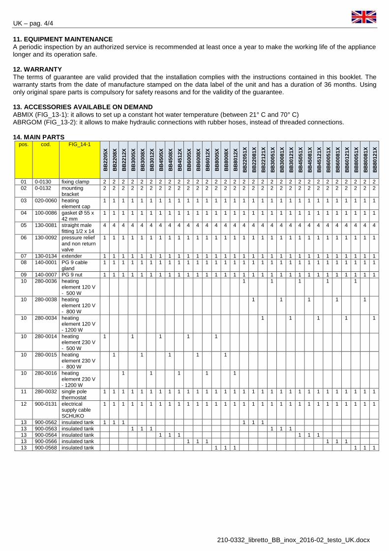
11. EQUIPMENT MAINTENANCE A periodic inspection by an authorized service is recommended at least once a year to make the working life of the appliance longer and its operation safe. 12. WARRANTY The terms of guarantee are valid provided that the installation complies with the instructions contained in this booklet. The warranty starts from the date of manufacture stamped on the data label of the unit and has a duration of 36 months. Using only original spare parts is compulsory for safety reasons and for the validity of the guarantee. 13. ACCESSORIES AVAILABLE ON DEMAND ABMIX (FIG_13-1): it allows to set up a constant hot water temperature (between 21° C and 70° C) ABRGOM (FIG_13-2): it allows to make hydraulic connections with rubber hoses, instead of threaded connections. 14. MAIN PARTS
pos. cod. FIG_14-1
BB
2205
X
BB
2208
X
BB
2212
X
BB
3005
X
BB
3008
X
BB
3012
X
BB
4505
X
BB
4508
X
BB
4512
X
BB
6005
X
BB
6008
X
BB
6012
X
BB
8005
X
BB
8008
X
BB
8012
X
BB
2205
1X
BB
2208
1X
BB
2212
1X
BB
3005
1X
BB
3008
1X
BB
3012
1X
BB
4505
1X
BB
4508
1X
BB
4512
1X
BB
6005
1X
BB
6008
1X
BB
6012
1X
BB
8005
1X
BB
8008
1X
BB
8012
1X
01 0-0130 fixing clamp 2 2 2 2 2 2 2 2 2 2 2 2 2 2 2 2 2 2 2 2 2 2 2 2 2 2 2 2 2 2 02 0-0132 mounting
bracket 2 2 2 2 2 2 2 2 2 2 2 2 2 2 2 2 2 2 2 2 2 2 2 2 2 2 2 2 2 2
03 020-0060 heating element cap
1 1 1 1 1 1 1 1 1 1 1 1 1 1 1 1 1 1 1 1 1 1 1 1 1 1 1 1 1 1
04 100-0086 gasket Ø 55 x 42 mm
1 1 1 1 1 1 1 1 1 1 1 1 1 1 1 1 1 1 1 1 1 1 1 1 1 1 1 1 1 1
05 130-0081 straight male fitting 1/2 x 14
4 4 4 4 4 4 4 4 4 4 4 4 4 4 4 4 4 4 4 4 4 4 4 4 4 4 4 4 4 4
06 130-0092 pressure relief and non return valve
1 1 1 1 1 1 1 1 1 1 1 1 1 1 1 1 1 1 1 1 1 1 1 1 1 1 1 1 1 1
07 130-0134 extender 1 1 1 1 1 1 1 1 1 1 1 1 1 1 1 1 1 1 1 1 1 1 1 1 1 1 1 1 1 1 08 140-0001 PG 9 cable
gland 1 1 1 1 1 1 1 1 1 1 1 1 1 1 1 1 1 1 1 1 1 1 1 1 1 1 1 1 1 1
09 140-0007 PG 9 nut 1 1 1 1 1 1 1 1 1 1 1 1 1 1 1 1 1 1 1 1 1 1 1 1 1 1 1 1 1 1 10 280-0036 heating
element 120 V - 500 W
1 1 1 1 1
10 280-0038 heating element 120 V - 800 W
1 1 1 1 1
10 280-0034 heating element 120 V - 1200 W
1 1 1 1 1
10 280-0014 heating element 230 V - 500 W
1 1 1 1 1
10 280-0015 heating element 230 V - 800 W
1 1 1 1 1
10 280-0016 heating element 230 V - 1200 W
1 1 1 1 1
11 280-0032 single pole thermostat
1 1 1 1 1 1 1 1 1 1 1 1 1 1 1 1 1 1 1 1 1 1 1 1 1 1 1 1 1 1
12 900-0131 electrical supply cable SCHUKO
1 1 1 1 1 1 1 1 1 1 1 1 1 1 1 1 1 1 1 1 1 1 1 1 1 1 1 1 1 1
13 900-0562 insulated tank 1 1 1 1 1 1 13 900-0563 insulated tank 1 1 1 1 1 1 13 900-0564 insulated tank 1 1 1 1 1 1 13 900-0566 insulated tank 1 1 1 1 1 1 13 900-0568 insulated tank 1 1 1 1 1 1

ES – pag. 1/4
210-0332_libretto_BB_inox_2016-02_testo_ES.docx
La gama de calentadores de agua BB...X incluye 24 modelos diferentes con las siguientes características para satisfacer todas las necesidades d’instalación y uso
a) 4 capacitades de acumulacíon (22 - 30 - 45 – 60 - 80 litros / 5,8 – 7,9 – 11,9 – 15,8 – 21,0 galónes) b) 3 potencias (500 W - 800 W - 1.200 W) c) 2 alimentaciónes eléctricas (120 V - 230 V)
1. PRECAUCIONES GENERALES Las instrucciones que van detrás son importantes para garantizar la seguridad de instalación, uso y manutención del aparato.
• Este libreto es parte integrante y esencial del calentador de agua: después tiene que haber tenido al alcance para cada ulterior consulta.
• El calentador de agua ha sido producido para la producción de agua caliente: cualquier otro tipo de utilización es de considerar peligroso y no idóneo.
• El aparato no tiene que estar establecido en ambientes húmedos, bañeras, lavabos, duchas, piscinas etc y tiene que ser protegido de chorros de agua u otros liquidos, para evitar corto circuitos de los dispositivos eléctricos.
• La instalación tiene que ser efectuada de una persona calificada, que es responsable para la aplicación de las normas de seguridad vigentes. La instalación impropia, causada del fallido respeto de las instrucciones provistas del productor, puede causar lesiones a personas, animales o daños a otras instrumentaciones para los cuáles el constructor declina cada responsabilidad.
• Antes de enlazar el calentador de agua, asegurarse que las características eléctricas impresas sobre la etiqueta datos corresponden a aquellos de la red eléctrica.
• Si el calentador de agua está establecido en un baño, en una habitación húmeda o cerca del agua, tomar cuidado de las distancias de seguridad previstas del normativo CEI-CEE. Además, interruptores o cualquier otro comando eléctrico no tienen que ser alcanzable de cualquier tiene una ducha o utiliza la bañera. No tocar el aparato con manos mojadas o húmedas.
• No consentir la utilización de parte de niños o personas incapaces sin algún control. • Partes de embalaje (saquitos de plastica, poliestireno, clip, etc ) tienen que haber tenidas lejas de los niños, porque
pueden ser peligrosas. • Leer cuidadosamente este libreto en cuanto suministra instrucciones útiles en materia de seguridad, instalación, uso
y manutención. • Si el aparato es vendido o desplazado a otro propietario, asegurarse que el presente libreto acompaña el aparato, de
modo que el nuevo propietario y/o el instalador pueden consultarlo. • Para evitar el riesgo de daños debidos al hielo, si el aparato no viene utilizado para un largo período y está
establecido en un local no calentado, se aconseja de vaciar el aparado completamente. El productor no es responsable de eventuales daños o roturas debidos al hielo o pérdidas de agua de l’instalacíon.
• Para obtener las mejores prestaciones de calentamiento del agua y para fines de garantía, respetar rigurosamente las instrucciones reportadas aquí debajo.
2. CARACTERÍSTICAS TÉCNICAS
BB
2205
X
BB
2208
X
BB
2212
X
BB
3005
X
BB
3008
X
BB
3012
X
BB
4505
X
BB
4508
X
BB
0512
X
BB
6005
X
BB
6008
X
BB
6012
X
BB
8005
X
BB
8008
X
BB
8012
X
alimentación V~ 230 230 230 230 230 230 230 230 230 230 230 230 230 230 230 Eléctrica A 2,2 3,5 5,2 2,2 3,5 5,2 2,2 3,5 5,2 2,2 3,5 5,2 2,2 3,5 5,2 potencia w 500 800 1.200 500 800 1.200 500 800 1.200 500 800 1.200 500 800 1.200
BB
2205
1X
BB
2208
1X
BB
2212
1X
BB
3005
1X
BB
3008
1X
BB
3012
1X
BB
4505
1X
BB
4508
1X
BB
4512
1X
BB
6005
1X
BB
6008
1X
BB
6012
1X
BB
8005
1X
BB
8008
1X
BB
8012
1X
alimentación V~ 120 120 120 120 120 120 120 120 120 120 120 120 120 120 120 Eléctrica A 4,2 6,7 10,0 4,2 6,7 10,0 4,2 6,7 10,0 4,2 6,7 10,0 4,2 6,7 10,0 potencia w 500 800 1.200 500 800 1.200 500 800 1.200 500 800 1.200 500 800 1.200
capacidad lt ( gal ) 22 ( 5,8 ) 30 ( 7,9 ) 45 ( 11,9 ) 60 ( 15,8 ) 80 ( 21,0 ) presión máxima kPa ( psi ) 700 ( 102 ) 700 ( 102 ) 700 ( 102 ) 700 ( 102 ) 700 ( 102 ) peso en vacío kg ( lb ) 10,0 ( 22 ) 11,5 ( 25 ) 15,0 ( 33 ) 17,3 ( 38 ) 20,0 ( 40 ) dimensiones mm 322 x 334 x 515 322 x 334 x 650 322 x 334 x 910 322 x 334 x 1095 322 x 334 x 1305 inch" 12,6 x 13,0 x 20,3 12,6 x 13,0 x 25,6 12,6 x 13,0 x 35,8 12,6 x 13,0 x 43,1 12,6 x 13,0 x 51,4

ES – pag. 2/4
210-0332_libretto_BB_inox_2016-02_testo_ES.docx
3. CONTENIDO EMBALAJE El aparato es empaquetado y remitido en una caja de cartón con una protección adecuada. Además del aparato, dentro de la caja está presente:
a ) el manual de instalación b ) los estribos de fijación y el kit vides de fijación c ) la válvula de retención y seguridad
4. DIMENSIONES ( ves a fig. FIG_4-1) A B C D E F BB2205X -- BB2208X -- BB2212X mm 322 267 365 334 440 515 BB22051X -- BB22081X -- BB22121X inch " 12,6 10,4 14,2 13,0 17,1 20,3 BB3005X -- BB3008X -- BB3012X mm 322 267 500 334 575 650 BB30051X -- BB30081X -- BB30121X inch " 12,6 10,4 19,5 13,0 22,4 25,6 BB4505X -- BB4508X -- BB4512X mm 322 267 760 334 835 910 BB45051X -- BB45081X -- BB45121X inch " 12,6 10,4 29,6 13,0 32,5 35,8 BB6005X -- BB6008X -- BB6012X mm 322 267 945 334 1.020 1.095 BB60051X -- BB60081X -- BB60121X inch " 12,6 10,4 36,8 13,0 39,7 43,1 BB8005X -- BB8008X -- BB8012X mm 322 267 1.155 334 1.230 1.305 BB80051X -- BB80081X -- BB80121X inch " 12,6 10,4 45,0 13,0 47,9 51,4
5. DESCRIPCIÓN CONSTRUCTIVO Y FUNCIONAMIENTO
El fin de este aparato es de calentar el agua caliente en dos modos diversos (FIG_5-1 ): A. atraviesa el cambio de calor entre el agua de enfriamiento del motor y el agua almacenada en el depósito. Tal
cambio térmico es posible gracias a un intercambiador de calor. El agua de enfriamiento del motor circula de través un serpentín sito al centro del depósito para difundir uniformemente el calor.
B. a través de una resistencia eléctrica (provista de serie con el aparato ). Partes principales ( ves a fig FIG_5-2.): 1. Depósito: es enteramente realizado en acero inoxidable AISI 316L. 2. Revestimiento exterior: es muy resistente a los empujones y a las solicitaciones exteriores, teniendo al mismo tiempo
un design muy agradable. 3. Aislamiento térmico: realizado en poliuretano expandido a células cerradas, evita inútiles pérdidas de calor. De este
modo la pérdida de calor para inercia térmica es reducida a 1 °C cada hora para un período de 24 horas. 4. Intercambiador de calor: es realizado en acero inoxidable AISI 316L. Su superficie de cambio permite de explotar de
la mejor manera el calor del agua de enfriamiento del motor y de obtener agua caliente también en condiciones extremas (diferencias de temperatura muy pequeñas).
5. Resistencia eléctrica: el aparato es dotado de una resistencia eléctrica (500/800/1200W, 120/230V~) para calentar el agua también cuando el motor de la barca están apagado (para ejemplo cuando la barca está en andén). Material: liga de INCOLOY resistente a la corrosión.
6. Termostato: tiene dos funciones, esmeradamente a. termostato regulable: interrumpe la alimentación eléctrica a la resistencia al alcance de la temperatura fijada
(la temperatura puede estar regulada entre 0 °C y 65 °C, según las exigencias del usuario). a. termostato de seguridad: interrumpe la alimentación eléctrica a la resistencia cuando, en caso de malo
funcionamiento del aparato, la temperatura del agua alcanza 90 °C. Es necesario una intervención manual para hacer repartir el aparato (reset manual).
Rango de temperatura: de 0 ° c a 65 ° c Diferencial de temperatura: en cuanto a 9 ° c Temperatura de intervención: 90 ° C Corriente máxima: 20 A Temperatura máxima: 120 ° C
7. Entrada agua fría 8. válvula de retención y seguridad: impide el reflujo de agua caliente en el tubo de entrada agua fría; es también una
válvula de seguridad de sobrepresión: protege el depósito de posible presione excesiva causada por la expansión del agua durante la calefacción. El agua viene descargada de través lo descargo que es dotado la válvula. Calibrado: 800 ± 50 KPa ( 116 ± 7 psi )
9. Salida agua caliente 10. Estribo de fijación
6. INSTRUCCIONES DE INSTALACIÓN
La instalación tiene que ser efectuada, en conformidad con la normativa vigente, para una persona calificada que puede hacer, no solo un set up correcto del aparato, pero también las pruebas necesarias antes de empezar la calefacción del agua.
Durante la instalación original o sucesivo manutención, sigue las instrucciones reportadas en este libreto con atención. Modificaciones a cualquier tipo de conexión o la fallida observancia de las instrucciones provistas causará la invalidation de la garantía.
Antes de la instalación, manutención o reparación, cortar la alimentación eléctrica del aparato.
ES – pag. 3/4
210-0332_libretto_BB_inox_2016-02_testo_ES.docx
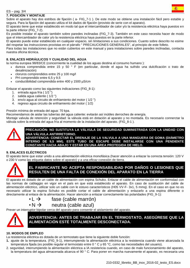
7. POSICIÓN Y MONTAJE Sobre el aparato hay dos estribos de fijación ( a- FIG_7-1 ). De este modo se obtiene una instalación fácil pero estable y segura. Para la fijación del aparato utiliza el kit dados de fijación (provisto de serie con el aparato). El aparato tiene que estar establecido en modo tal que el intercambiador de calor y/o la resistencia eléctrica haya puestos en la parte inferior (FIG_7-2). Es posible instalar el aparato también sobre paredes inclinadas (FIG_7-3). También en este caso necesita hacer de modo que el intercambiador de calor y/o la resistencia eléctrica haya puestos en la parte inferior. El aparato puede estar establecido en cualquier espacio, sin limitaciones a sus condiciones. Cuanto sobre descrito no esime del respetar las instrucciones provistas en el párrafo " PRECAUCIONES GENERALES", al principio de este folleto. Para todas las instalaciones que no están cubiertos en este manual y para instalaciones sobre paredes inclinadas, contacta nuestra oficina técnica. 8. ENLACES HIDRÁULICOS Y CUALIDAD DEL AGUA la norma europea 98/83/CE (concerniente la cualidad de los aguas destina al consumo humano ):
dureza comprendida entre 15 y 50 ° F (en particular, donde el agua ha sufrido una dulcificación o trato de desalinización)
cloruros comprendidos entre 25 y 100 mg/l PH comprendido entre 6,5 y 9,5 conductibilidad comprendida entre 400 y 1500 µS/cm
Enlazar el aparato como las siguientes indicaciones (FIG_8-1):
1. entrada agua fría ( 1/2 ") 2. salida agua caliente ( 1/2 ") 3. envío agua al circuito de enfriamiento del motor ( 1/2 ") 4. regreso agua circuito de enfriamiento del motor ( 1/2)
Presión mínima de entrada del agua: 70 kpa. Recomendamos de aislar las tuberías del agua caliente: evitarán así inútiles derroches de energía. Montaje valvula de retención y seguridad: la válvula está en dotación al aparato y no montada. Es necesario connerctar la válvula sobre la entrada del agua fría al momento de la instalación del aparato. (FIG_8-1 ).
PRECAUCIÓN: NO SUSTITUYA LA VÁLVULA DE SEGURIDAD SUMINISTRADA CON LA UNIDAD CON UNA VÁLVULA ANTIRRETORNO. ADVERTENCIA: CONECTAR EL DRENAJE DE LA VALVULA A UNA MANGUERA DE GOMA (DIÁMETRO INTERNO DE 9,5 MM). ESTE TUBO DE ESCAPE DEBE INSTALARSE CON UNA PENDIENTE CONSTANTE HACIA ABAJO Y ESTÁR EN UNA ÁREA PROTEGIDA DE HIELO.
9. ENLACES ELÉCTRICOS El aparato tiene que estar unido a una alimentación eléctrica monofásica (hacer atención a enlazar la correcta tensión: 120 V o 230 V como las etiqueta datos sobre el aparato) y a una eficaz conexión de tierra.
EL FABRICANTE NO ACEPTA RESPONSABILIDAD POR DAÑOS O LESIONES QUE RESULTEN DE UNA FALTA DE CONEXIÓN DEL APARATO EN LA TIERRA
El aparato es dotado de un cable de alimentación con espina Schuko. Enlazar el cable de alimentación en conformidad con las normas de cablaggio en vigor en el país en que está establecido el aparato. En caso de sustitución del cable de alimentación eléctrico, utilizar solo un cable con le estuvo característicos (H05 VV-F- 3x1, 5 mmq). En el caso en que no es necesario utilizar la espina Schuko es posible cortar el cable de alimentación y enlazarlo a una espina diferente o directamente al enlace de la alimentación. Hacer atención a enlazar correctamente las polaridades (FIG_9-1):
• L fase (cable marrón) • N neutra (cable azul)
Prever un interruptor bipolar cerca del aparato para consentir el aislamiento del aparato.
ADVERTENCIA: ANTES DE TRABAJAR EN EL TERMOSTATO, ASEGÚRESE QUE LA ALIMENTACIÓN ESTÉ TOTALMENTE DESCONECTADA.
10. MODOS DE EMPLEO La resistencia eléctrica es dotada de un termostato que tiene la siguiente doble función: 1. ajuste de la temperatura. (FIG_9-1), interrumpiendo la alimentación eléctrica a la resistencia cuando viene alcanzada la
temperatura fijada (es posible regular el termostato entre 0 ° C y 65 °C, como las necesidades del usuario). 2. seguridad, interrumpiendo la alimentación eléctrica a lA resistencia cuando, en caso de malo funcionamiento del aparato,
la temperatura del agua almacenada alcanza el 90 ° C. Para poner en marcha nuevamente el aparato, es necesaria una

ES – pag. 4/4
210-0332_libretto_BB_inox_2016-02_testo_ES.docx
intervención manual (rearme manual). En este caso, atenerse al siguiente procedimiento: a ) desconectar la alimentación eléctrica b ) remover la capucha de protección de la resistencia eléctrica c ) apretar el botón de reset situado sobre el termostato (FIG_9-1) d ) poner la tapa de protección de la resistencia eléctrica y ) restablecer la alimentación eléctrica
ATENCIÓN: ENLAZAR LA ALIMENTACIÓN A LA RESISTENCIA ELÉCTRICA SOLO CUANDO IL DEPÓSITO ES PIENO DE AGUA. LA RESISTENCIA ELECTRICA NO ES APTA PARA UN FUNCIONAMIENTO EN SECO
11. MANUTENCIÓN DEL APARATO Para devolver el funcionamiento del aparato seguro y extiender su vida, se recomienda una inspección periódica por un servicio autorizado por lo menos una vez al año. 12. GARANTÍA Las condiciones de garantía son válidas siempre que se cumplan las instrucciones de instalación en este folleto. La garantía comienza a partir de la fecha de fabricación estampada en la etiqueta de datos de la unidad y tiene una duración de 36 meses. Por razones de seguridad y para la validez de la garantía es obligatorio el uso de recambios originales. 13. ACCESORIOS DISPONIBLES A PETICIÓN ABMIX (FIG_13-1) : permite de plantear una temperatura constante de agua caliente ( entre 21° c y 70° c ) ABRGOM (FIG_13-2) : permite de efectuar enlaces hidráulicos a través de tubos en engoma, en vez de enlaces fileteados. 14. PRINCIPALES DEVUELVEN GESTO
pos. cod. FIG_14-1
BB
2205
X
BB
2208
X
BB
2212
X
BB
3005
X
BB
3008
X
BB
3012
X
BB
4505
X
BB
4508
X
BB
4512
X
BB
6005
X
BB
6008
X
BB
6012
X
BB
8005
X
BB
8008
X
BB
8012
X
BB
2205
1X
BB
2208
1X
BB
2212
1X
BB
3005
1X
BB
3008
1X
BB
3012
1X
BB
4505
1X
BB
4508
1X
BB
4512
1X
BB
6005
1X
BB
6008
1X
BB
6012
1X
BB
8005
1X
BB
8008
1X
BB
8012
1X
01 0-0130 faja de fijación 2 2 2 2 2 2 2 2 2 2 2 2 2 2 2 2 2 2 2 2 2 2 2 2 2 2 2 2 2 2 02 0-0132 estribo de
fijación 2 2 2 2 2 2 2 2 2 2 2 2 2 2 2 2 2 2 2 2 2 2 2 2 2 2 2 2 2 2
03 020-0060 cuffiotto resistencia
1 1 1 1 1 1 1 1 1 1 1 1 1 1 1 1 1 1 1 1 1 1 1 1 1 1 1 1 1 1
04 100-0086 guarnición 1 1 1 1 1 1 1 1 1 1 1 1 1 1 1 1 1 1 1 1 1 1 1 1 1 1 1 1 1 1 05 130-0081 enlace derecho
macho-- 1/2 x 14
4 4 4 4 4 4 4 4 4 4 4 4 4 4 4 4 4 4 4 4 4 4 4 4 4 4 4 4 4 4
06 130-0092 válvula recato/seguridad
1 1 1 1 1 1 1 1 1 1 1 1 1 1 1 1 1 1 1 1 1 1 1 1 1 1 1 1 1 1
07 130-0134 alargador 1 1 1 1 1 1 1 1 1 1 1 1 1 1 1 1 1 1 1 1 1 1 1 1 1 1 1 1 1 1 08 140-0001 pressacavo PG
9 1 1 1 1 1 1 1 1 1 1 1 1 1 1 1 1 1 1 1 1 1 1 1 1 1 1 1 1 1 1
09 140-0007 dado PG 9 negro
1 1 1 1 1 1 1 1 1 1 1 1 1 1 1 1 1 1 1 1 1 1 1 1 1 1 1 1 1 1
10 280-0036 resistencia eléctrica
1 1 1 1 1
10 280-0038 resistencia eléctrica
1 1 1 1 1
10 280-0034 resistencia eléctrica
1 1 1 1 1
10 280-0014 resistencia eléctrica
1 1 1 1 1
10 280-0015 resistencia eléctrica
1 1 1 1 1
10 280-0016 resistencia eléctrica
1 1 1 1 1
11 280-0032 termostato 1 1 1 1 1 1 1 1 1 1 1 1 1 1 1 1 1 1 1 1 1 1 1 1 1 1 1 1 1 1 12 900-0131 cable
alimentación 1 1 1 1 1 1 1 1 1 1 1 1 1 1 1 1 1 1 1 1 1 1 1 1 1 1 1 1 1 1
13 900-0562 calentador aislado
1 1 1 1 1 1
13 900-0563 calentador aislado
1 1 1 1 1 1
13 900-0564 calentador aislado
1 1 1 1 1 1
13 900-0566 calentador aislado
1 1 1 1 1 1
13 900-0568 calentador aislado
1 1 1 1 1 1

FR – pag. 1/4
210-0332_libretto_BB_inox_2016-02_testo_FR.docx
La gamme BB..X comprend 24 différents chauffe-eau qui sont disponibles avec les caractéristiques suivantes au but de satisfaire toutes exigence d'installation et d'utilisation
à ) 4 capacités de stockage ( 22 - 30 - 45 – 60 – 80 litres / 5,8 - 7,9 - 11,9 - 15,8 – 21,0 galons ) b ) 3 puissances ( 500 W -- 800 W - 1200 W) c ) 2 alimentations électriques (120 V- 230 V)
1. PRÉCAUTIONS GÉNÉRALES Les instructions qui suivent sont importantes pour garantir une installation, un mode d’emploie et d’entretien de l'appareil en sécurité. • Cette notice est partie intégrante et essentielle du chauffe-eau: elle doit être gardée tout près de l’appareil pour toutes
ultérieures consultations. • L’appareil a été fabriqué pour la production d’eau chaude sanitaire. Tout autre type d’utilisation aléatoire devra être
considéré comme impropre et dangereux. • L’appareil ne doit pas être installé dans des endroits humides, baignoires, lavabos, douches, piscines etc. et doit être
protégé contre les jets d'eau ou d’autre liquides, au fin d'éviter courts circuits aux dispositifs électriques. • L'installation doit être effectuée par une personne qualifiée, qui soit responsable pour l'application des normes de sécurité
en vigueur. Une installation impropre, causée par le manqué respect des instructions fournies par le fabricant, peut causer lésions à personnes, animaux ou dommages à d’autres appareillages pour lesquels le fabricant décline toute responsabilité.
• Avant de brancher l’appareil, vérifier si les caractéristiques électriques imprimées sur la plaquette signalétique de l’appareil correspondent à celles du réseau électrique.
• Si le chauffe-eau est installé dans une salle de bain, une pièce humide ou près de l'eau, respecter les distances de sécurité prévues par la norme CEI-CEE. En plus, les interrupteurs, ou n’importe quel commande électrique, ne doivent pas être joignables par qui est en train de prendre une douche ou d’utiliser la baignoire. Ne toucher pas l'appareil avec mains mouillées ou humides.
• Ne permettre pas l'utilisation de l’appareil aux enfants ou personnes incapables sans aucun contrôle. • Les parties d'emballage (sachets de plastique, polystyrène, clip, etc.) doivent être tenues hors portée des enfants car
dangereuses. • Lire attentivement ce livret car il donne des renseignements utiles en matière de sécurité, installation, emploie et entretien. • Ce livret doit accompagner l’appareil, dans le cas où il devrait être vendu ou transféré chez un utilisateur différent, afin que
le nouveau propriétaire et/ou l’installateur puisse le consulter. • Dans le cas où l’accumulateur resterait inutilisé en hiver pour une longue période dans un local non chauffé, on conseille
de le vidanger complètement pour éviter tout risque de gel. Le fabricant décline toute responsabilité dans le cas de dommages causés par le gel ou par fuites d’eau de l’installation.
• Pour obtenir la meilleure performance et la reconnaissance de la garantie, suivre attentivement les renseignements contenus dans cette notice et utiliser uniquement les parties de rechange fournies par le Fabricant.
2. CARACTÉRISTIQUES TECHNIQUES
BB
2205
X
BB
2208
X
BB
2212
X
BB
3005
X
BB
3008
X
BB
3012
X
BB
4505
X
BB
4508
X
BB
0512
X
BB
6005
X
BB
6008
X
BB
6012
X
BB
8005
X
BB
8008
X
BB
8012
X
alimentation V~ 230 230 230 230 230 230 230 230 230 230 230 230 230 230 230 électrique A 2,2 3,5 5,2 2,2 3,5 5,2 2,2 3,5 5,2 2,2 3,5 5,2 2,2 3,5 5,2 puissance w 500 800 1.200 500 800 1.200 500 800 1.200 500 800 1.200 500 800 1.200
BB
2205
1X
BB
2208
1X
BB
2212
1X
BB
3005
1X
BB
3008
1X
BB
3012
1X
BB
4505
1X
BB
4508
1X
BB
4512
1X
BB
6005
1X
BB
6008
1X
BB
6012
1X
BB
8005
1X
BB
8008
1X
BB
8012
1X
alimentation V~ 120 120 120 120 120 120 120 120 120 120 120 120 120 120 120 électrique A 4,2 6,7 10,0 4,2 6,7 10,0 4,2 6,7 10,0 4,2 6,7 10,0 4,2 6,7 10,0 puissance w 500 800 1.200 500 800 1.200 500 800 1.200 500 800 1.200 500 800 1.200
capacité lt ( gal ) 22 ( 5,8 ) 30 ( 7,9 ) 45 ( 11,9 ) 60 ( 15,8 ) 80 ( 21,0 ) pression maximale kPa ( psi ) 700 ( 102 ) 700 ( 102 ) 700 ( 102 ) 700 ( 102 ) 700 ( 102 ) poids à vide kg ( lb ) 10,0 ( 22 ) 11,5 ( 25 ) 15,0 ( 33 ) 17,3 ( 38 ) 20,0 ( 40 ) dimensions mm 322 x 334 x 515 322 x 334 x 650 322 x 334 x 910 322 x 334 x 1095 322 x 334 x 1305 L x P x H inch" 12,6 x 13,0 x 20,3 12,6 x 13,0 x 25,6 12,6 x 13,0 x 35,8 12,6 x 13,0 x 43,1 12,6 x 13,0 x 51,4
3 CONTENU DE L'EMBALLAGE L’accumulateur est livré dans une boîte en carton avec toutes protections convenables. A l'intérieur de la boîte il y a:
à ) le manuel d'installation b ) les étriers de fixation et un kit contenant les vis de fixation c ) la soupape de retenue et sécurité

FR – pag. 2/4
210-0332_libretto_BB_inox_2016-02_testo_FR.docx
4. DIMENSIONS ( voir FIG_4-1)
A B C D E F BB2205X -- BB2208X -- BB2212X mm 322 267 365 334 440 515 BB22051X -- BB22081X -- BB22121X inch " 12,6 10,4 14,2 13,0 17,1 20,3 BB3005X -- BB3008X -- BB3012X mm 322 267 500 334 575 650 BB30051X -- BB30081X -- BB30121X inch " 12,6 10,4 19,5 13,0 22,4 25,6 BB4505X -- BB4508X -- BB4512X mm 322 267 760 334 835 910 BB45051X -- BB45081X -- BB45121X inch " 12,6 10,4 29,6 13,0 32,5 35,8 BB6005X -- BB6008X -- BB6012X mm 322 267 945 334 1.020 1.095 BB60051X -- BB60081X -- BB60121X inch " 12,6 10,4 36,8 13,0 39,7 43,1 BB8005X -- BB8008X -- BB8012X mm 322 267 1.155 334 1.230 1.305 BB80051X -- BB80081X -- BB80121X inch " 12,6 10,4 45,0 13,0 47,9 51,4
5. DESCRIPTION CONSTRUCTIVE ET FONCTIONNEMENT
Le but de cet appareil est de réchauffer l'eau chaude sanitaire dans deux façons différentes (voir FIG_5-1 ): A. à travers l'échange de la chaleur entre l'eau de refroidissement du moteur et l'eau emmagasinée dans le
réservoir. Tel échange thermique est possible grâce à un échangeur de chaleur. L'eau de refroidissement du moteur circule à travers un serpentin situé au milieu du réservoir pour diffuser uniformément la chaleur.
B. au moyen d'une résistance électrique (fournie de série avec l'appareil). Parties principales ( voir FIG_5-2.): 1. Réservoir de stockage: il est entièrement réalisé en acière inoxydable AISI 316L. 2. Jaquette extérieure : la jaquette de l’appareil est très résistante aux coups extérieurs, en ayant, au même temps, un
design beaucoup agréable. 3. Isolation thermique: elle est réalisée en polyuréthane expansé aux cellules fermées et évite inutiles pertes de
chaleur. Dans cette façon la perte de la chaleur pour l'inertie thermique est réduite à 1°C chaque heure, pour une période de 24 heures.
4. Échangeur de chaleur: le serpentin est réalisé en acière inoxydable AISI 316L. Sa surface d’échange permet d'exploiter au mieux la chaleur de l'eau de refroidissement du moteur et d'obtenir eau chaude aussi dans des conditions difficiles (moindres différences de température).
5. Résistance électrique: l'appareil est pourvu d'une résistance électrique ( 500/800/1200W, 120/230V~) pour réchauffer l'eau aussi quand le moteur du bateau est éteint (par exemple quand le bateau est au quai). Matériel: ligue d’INCOLOY résistante à la corrosion.
6. Thermostat: il a deux fonctions, précisément a) thermostat de réglage: il coupe l'alimentation électrique à l'élément chauffant, lorsque la température
fixée est atteinte (la température peut être réglée entre 0 ° C et 65 ° C, selon les exigences de l'usager). b) thermostat de sécurité: il coupe l'alimentation électrique à l'élément chauffant quand, en cas de mauvais
fonctionnement de l'appareil, la température de l'eau atteint 90 °C. C’est nécessaire une intervention manuelle pour faire répartit l'appareil (reset manuel).
Gamme de température: entre 0 °C et 65 ° C Différentiel de température: environ 9 ° c Température d'intervention: 90 ° C Courant maximal 20 À Température maximale: 120 ° C
7. Entrée eau froide 8. Soupape de sécurité et de non-retour: la soupape empêche le reflux de l’eau chaude dans la tuyauterie d'entrée de
l’eau froide. Elle est aussi une soupape de sécurité contre la surpression: elle protège le réservoir des possibles pressions excessives causées par l'expansion de l'eau pendant son réchauffement. L'eau vient déchargée par la purge dont est douée la soupape. Étalonnage: 800 ± 50 KPa (116± 7 psi)
9. Sortie eau chaude 10. Étrier de fixation
6. INSTRUCTIONS D'INSTALLATION
L'installation doit être réalisée, conformément aux normes de sécurité en vigueur, par un technicien qualifié, qui peut faire, non seulement un correct allumage de l'appareil, mais aussi les preuves nécessaires avant de commencer le réchauffement de l'eau.
Pendant l'installation originale ou un entretien suivant, suivre attentivement les renseignements donnés dans ce livret. N'importe quelle modification aux connexions ou la manque d’observation des renseignements fournis causera la déchéance de la garantie.
Avant de l’installation, d’un entretien ou d’une réparation, couper l'alimentation électrique à l'appareil.

FR – pag. 3/4
210-0332_libretto_BB_inox_2016-02_testo_FR.docx
7. POSITION ET MONTAGE L'appareil est pourvu de deux étriers de fixation ( A- FIG_7-1 ). Dans cette façon on obtient une installation facile, mais aussi stable et sûre. Pour la fixation de l'appareil utiliser le kit d’écrous de fixation (fourni de série avec l'appareil). L'appareil doit être installé de façon que l'échangeur de chaleur et/ou la résistance électrique soient situés dans la partie inférieure ( FIG_7-2 ). C’est aussi possible installer l'appareil sur des murs inclinés (FIG_7-3). Aussi dans ce cas, il faut installer l’appareil de manière que l'échangeur de chaleur et/ou la résistance électrique soient situés dans la partie inférieure. L'appareil peut être installé dans n'importe quel endroit, sans de limitations à ses conditions. Ce qui a été écrit ci-dessus n'exempte pas du respect des instructions fournies dans le paragraphe "normes générales de précaution ", au début de cette brochure. Pour d’autres types d’installation, qui ne sont pas contemplés dans ce manuel, et pour une installation sur des murs inclinés, contacter notre bureau technique. 8. PLOMBERIE ET QUALITÉ DE L'EAU Pour prolonger la durée de l'appareil, la qualité de l'eau doit être entre les paramètres suivants, comme prévu par la directive européenne 98/83/CE (concernant la qualité des eaux destinées à la consommation humaine):
dureté comprise entre 15 et 50 °F (en particulier, si l'eau a subi un traitement d’adoucissement ou de dessalement) chlorures compris entre 25 et 100 mg/l PH compris entre 6,5 et 9,5 conductibilité comprise entre 400 et 1500 µS/cm
Raccorder l'appareil selon les indications suivantes ( FIG_8-1 ): 1. entrée d'eau froide (1/2") 2. sortie d'eau chaude (1/2") 3. entrée eau au circuit de refroidissement du moteur (1/2") 4. sortie eau du circuit de refroidissement du moteur (1/2")
Pression moindre d'entrée de l'eau: 70 kpa. On conseille d'isoler les tuyauteries de l'eau chaude: s'éviteront comme ça des inutiles gaspillages d'énergie. Montage de la soupape de retenue/sécurité: la soupape est en dotation avec l'appareil mais elle n’est pas istallée. Il faut la raccorder à l'entrée de l'eau froide au moment de l'installation de l'appareil. ( S - FIG_8-1 ).
ATTENTION: NE REMPLACER PAS LA SOUPAPE DE RETENUE ET DE SECURITE FOURNIE AVEC L'APPAREIL PAR UNE SOUPAPE DE RETOUR ( CLAPET ). ATTENTION: RACCORDER LA VIDANGE DE L'EAU DE LA SOUPAPE À UN TUBE DE CAOUTCHOUC AYANT UN DIAMÈTRE INTÉRIEUR DE 9,5 MM. CE TUBE DOIT ÊTRE INSTALLÉ AVEC UNE PENTE CONSTANTE VERS LE BAS ET ÊTRE PLACE DANS UN ENDROIT PROTÉGÉ CONTRE LE GÈL.
9. RACCORDEMENTS ÉLECTRIQUES L'appareil doit être branché à une alimentation électrique monophasée (faire attention à brancher la correcte tension: 120 V ou 230 V selon la plaque signalétique sur l'appareil ) et à une bonne connexion de terre.
LE FABRICANT N'ACCEPTE AUCUNE RESPONSABILITÉ POUR TOUS POSSIBLES DOMMAGES CAUSES PAR UNE MANQUE DE MISE A LA TERRE DE L'APPAREIL
L'appareil est pourvu d’un câble d’alimentation électrique avec épine Schuko. Brancher le câble d'alimentation en conformité aux normes de câblage en force dans le pays où l’appareil est installé. En cas de remplacement du câble d'alimentation électrique, utiliser uniquement un câble ayant les mêmes caractéristiques (H05 VV-F- 3x1 , 5 mmq). Au cas où l'épine Schuko n’est pas nécessaire, couper la câble d'alimentation et le raccorder à une épine différente ou directement à l'alimentation électrique. On prie de faire d'attention à brancher correctement les polarités ( FIG_9-1 ):
• L phase (câble marron ) • N neutre (câble bleu )
Prévoire un interrupteur bipolaire près de l'appareil pour permettre de l’isoler.
ATTENTION: AVANT D’AGIR SUR LE THERMOSTAT, S'ASSURER QUE L'ALIMENTATION ÉLECTRIQUE SOIT COMPLÈTEMENT COUPEE.
10. MODE D'EMPLOI La résistance électrique est pourvue d'un thermostat qui a la suivante double fonction: 1. réglage de la température. (T - FIG_9-1 ), coupant l'alimentation électrique à la résistance lorsque la température fixée est
atteinte (la température peut être réglée entre 0 ° C et 65 ° C, selon les exigences de l'usager). 2. sécurité, interrompant l'alimentation électrique à l'élément chauffant quand, en cas de mauvais fonctionnement de
l'appareil, la température de l'eau atteint 90 °C. C’est nécessaire une intervention manuelle pour faire répartit l'appareil

FR – pag. 4/4
210-0332_libretto_BB_inox_2016-02_testo_FR.docx
(reset manuel). Dans ce cas, suivre la procédure suivante: à ) couper l'alimentation électrique b ) enlever le capuchon de protection de la résistance électrique c ) appuyer sur le poussoir de reset positionné sur le thermostat (R - FIG_9-1 ) d ) mettre en place le capuchon de protection de la résistance e ) brancher de nouveau l'alimentation électrique
ATTENTION: BRANCHER L'ALIMENTATION À LA RÉSISTANCE ÉLECTRIQUE SEULEMENT QUAND LE RÉSERVOIR EST PLEIN D'EAU. L'ÉLÉMENT CHAUFFANT N'EST PAS INDIQUÉ POUR UN FONCTIONNEMENT AU SEC
11. ENTRETIEN DE L'APPAREIL Pour un fonctionnement sûr de l’appareil et pour en prolonger la durée de vie, on recommande une inspection périodique au moins une fois par an par un service agréé. 12. GARANTIE Les termes de garantie sont valables à condition que les renseignements d'installation contenus dans ce livret soient respectés. La garantie compte à partir de la date de production imprimée sur l'étiquette signalétique de l'appareil et a une durée de 36 mois. Pour des raisons de sécurité et pour la validité de la garantie, employer uniquement des parties de rechange originales. 13. ACCESSOIRES DISPONIBLES SUR DEMANDE ABMIX (FIG_13-1) : permet de fixer une température constante de l’’eau chaude (entre 21° C et 70° C) ABRGOM (FIG_13-2) : permet d'effectuer les raccordements hydrauliques par des tubes en gomme, au lieu des raccordements lisérés. 14. PIÈCES DE RECHANGE
pos. cod. FIG_14-1
BB
2205
X
BB
2208
X
BB
2212
X
BB
3005
X
BB
3008
X
BB
3012
X
BB
4505
X
BB
4508
X
BB
4512
X
BB
6005
X
BB
6008
X
BB
6012
X
BB
8005
X
BB
8008
X
BB
8012
X
BB
2205
1X
BB
2208
1X
BB
2212
1X
BB
3005
1X
BB
3008
1X
BB
3012
1X
BB
4505
1X
BB
4508
1X
BB
4512
1X
BB
6005
1X
BB
6008
1X
BB
6012
1X
BB
8005
1X
BB
8008
1X
BB
8012
1X
01 0-0130 bande de fixation
2 2 2 2 2 2 2 2 2 2 2 2 2 2 2 2 2 2 2 2 2 2 2 2 2 2 2 2 2 2
02 0-0132 étrier de fixation
2 2 2 2 2 2 2 2 2 2 2 2 2 2 2 2 2 2 2 2 2 2 2 2 2 2 2 2 2 2
03 020-0060 Capouchon résistance
1 1 1 1 1 1 1 1 1 1 1 1 1 1 1 1 1 1 1 1 1 1 1 1 1 1 1 1 1 1
04 100-0086 joint d'étanchéité
1 1 1 1 1 1 1 1 1 1 1 1 1 1 1 1 1 1 1 1 1 1 1 1 1 1 1 1 1 1
05 130-0081 raccordement droit de mâle-- 1/2 x 14
4 4 4 4 4 4 4 4 4 4 4 4 4 4 4 4 4 4 4 4 4 4 4 4 4 4 4 4 4 4
06 130-0092 Soupape anti-retour / sécurité
1 1 1 1 1 1 1 1 1 1 1 1 1 1 1 1 1 1 1 1 1 1 1 1 1 1 1 1 1 1
07 130-0134 rallonge 1 1 1 1 1 1 1 1 1 1 1 1 1 1 1 1 1 1 1 1 1 1 1 1 1 1 1 1 1 1 08 140-0001 Presse-câble
PG 9 1 1 1 1 1 1 1 1 1 1 1 1 1 1 1 1 1 1 1 1 1 1 1 1 1 1 1 1 1 1
09 140-0007 écrou Presse-câble PG 9
1 1 1 1 1 1 1 1 1 1 1 1 1 1 1 1 1 1 1 1 1 1 1 1 1 1 1 1 1 1
10 280-0036 résistance électrique
1 1 1 1 1
10 280-0038 résistance électrique
1 1 1 1 1
10 280-0034 résistance électrique
1 1 1 1 1
10 280-0014 résistance électrique
1 1 1 1 1
10 280-0015 résistance électrique
1 1 1 1 1
10 280-0016 résistance électrique
1 1 1 1 1
11 280-0032 thermostat 1 1 1 1 1 1 1 1 1 1 1 1 1 1 1 1 1 1 1 1 1 1 1 1 1 1 1 1 1 1 12 900-0131 câble
d'alimentation 1 1 1 1 1 1 1 1 1 1 1 1 1 1 1 1 1 1 1 1 1 1 1 1 1 1 1 1 1 1
13 900-0562 chauffe-eau isolé
1 1 1 1 1 1
13 900-0563 chauffe-eau isolé
1 1 1 1 1 1
13 900-0564 chauffe-eau isolé
1 1 1 1 1 1
13 900-0566 chauffe-eau isolé
1 1 1 1 1 1
13 900-0568 chauffe-eau isolé
1 1 1 1 1 1

DE – pag. 1/4
210-0332_libretto_BB_inox_2016-02_testo_DE.docx
Der Warmwasserbereiter BB…X ist in 24 verschiedene Modelle mit der folgenden Eigenschaften verfügbar, um alle Bedürfnisse von Installation und Verwendung zu erfüllen:
a) 4 Speicherkapazität (22 - 30 - 45 – 60 - 80 Liter / 5,8 - 7,9 - 11,9 - 15,8 – 21,0 gallonen) b) 3 Leistungen (500 W - 800 W - 1200 W) c) 2 Stromversorgungen (120 V - 230 V)
1. ALLGEMEINE VORSICHT Die folgenden Anweisungen sind wichtig, um die Sicherheit von Installation, Gebrauch und Instandhaltung des Apparats zu gewährleisten.
• Diese Gebrauchsanweisung ist wesentlicher und hauptsächlicher Bestandteil des Warmwasserbereiters: daher muss man es bei der Hand für jede weitere Befragung haben.
• Der Warmwasserbereiter ist für die Produktion von Warmwasser geplant: jeder andere Gebrauch ist gefährlich und nicht geeignet.
• Der Apparat muss nicht in feuchten Orte, Bäder, Waschbecken, Duschen, Schwimmbäder usw. installiert werden. Er muss auch von Spritzwasser oder anderen Flüssigkeiten geschützt werden, zwecks Kurzschlüsse von den elektrischen Vorrichtungen vermeiden.
• Die Installation muss von ein gelernt Person, die verantwortlich für die Anwendung von den geltenden Sicherheitsvorschriftenen ist, ausgeführt sein. Die unpassende Installation, die vom verfehlten Respekt von den Unterrichten des Erzeugers verursacht ist, kann Beschädigungen zu Personen, Tiere oder anderen Apparaturen, für die der Erbauer jegliche Verantwortung lehnt, verursachen.
• Vor der Warmwasserbereiter zu verbinden, vergewissern Sie dass die elektrischen Eigenschaften auf dem Aufkleber mit Seriennummer des Apparats, mit der vom Elektrizitätsnetz entsprechen.
• Wenn der Apparat in einem Bad, in einem feuchten Zimmer oder in der Nähe vom Wasser installiert ist, beachten Sie die vorgesehenen Sicherheitsabständen der Normative CEI-CEE. Außerdem, Schalter, oder irgendein anderen elektrischen Steuerungen, müssen nicht von Personen, die eine Dusche haben oder die Badewanne nutzen, erreichbar sein. Berühren Sie nicht den Apparat mit nassen oder feuchten Hände.
• Erlauben Sie nicht die Verwendung von Kinder oder unfähigen Personen ohne keine Kontrolle. • Die Verpackungsteile (Plastiktüten, Polystyrol, Heftklammer, und so weiter) müssen von der Kinder abhalten sein, weil
sie gefährlich sein können. • Lesen Sie diese Gebrauchsanweisung aufmerksam, weil sie nützlichen Unterrichte von Sicherheit, Installation und
Gebrauch enthalt. • Wenn der Apparat verkauft oder verlegt zu einem anderen Besitzer ist, sich versichern, dass diese
Gebrauchsanweisung mit dem Apparat bleibt, so dass der neue Besitzer und/oder Installateur ihn zuziehen kann. • Um das Risiko von Frostschäden zu vermeiden, wenn der Apparat für eine Länge Zeit nicht verwendet ist, und in einem
Raum nicht gewärmt installiert ist, entleeren Sie den Boiler. Der Erzeuger ist nicht verantwortlich für eventuellen Schäden oder nötigen Brüche, die vom Frost verursacht sind, oder für Wasser Verluste von der Anlage.
• Um die besseren Leistungen zu erhalten und um die Anerkennung der Garantie zu haben, respektieren Sie streng die folgenden Unterrichte.
2. TECHNISCHE MERKMALE
BB
2205
X
BB
2208
X
BB
2212
X
BB
3005
X
BB
3008
X
BB
3012
X
BB
4505
X
BB
4508
X
BB
0512
X
BB
6005
X
BB
6008
X
BB
6012
X
BB
8005
X
BB
8008
X
BB
8012
X
Stromversorgung V~ 230 230 230 230 230 230 230 230 230 230 230 230 230 230 230 A 2,2 3,5 5,2 2,2 3,5 5,2 2,2 3,5 5,2 2,2 3,5 5,2 2,2 3,5 5,2 Leistung w 500 800 1.200 500 800 1.200 500 800 1.200 500 800 1.200 500 800 1.200
BB
2205
1X
BB
2208
1X
BB
2212
1X
BB
3005
1X
BB
3008
1X
BB
3012
1X
BB
4505
1X
BB
4508
1X
BB
4512
1X
BB
6005
1X
BB
6008
1X
BB
6012
1X
BB
8005
1X
BB
8008
1X
BB
8012
1X
Stromversorgung V~ 120 120 120 120 120 120 120 120 120 120 120 120 120 120 120 A 4,2 6,7 10,0 4,2 6,7 10,0 4,2 6,7 10,0 4,2 6,7 10,0 4,2 6,7 10,0 Leistung w 500 800 1.200 500 800 1.200 500 800 1.200 500 800 1.200 500 800 1.200
Fassungsvermögen des Tanks lt ( gal ) 22 ( 5,8 ) 30 ( 7,9 ) 45 ( 11,9 ) 60 ( 15,8 ) 80 ( 21,0 )
Maximale Arbeitslast kPa ( psi ) 700 ( 102 ) 700 ( 102 ) 700 ( 102 ) 700 ( 102 ) 700 ( 102 ) Leergewicht kg ( lb ) 10,0 ( 22 ) 11,5 ( 25 ) 15,0 ( 33 ) 17,3 ( 38 ) 20,0 ( 40 ) Ausmasse mm 322 x 334 x 515 322 x 334 x 650 322 x 334 x 910 322 x 334 x 1095 322 x 334 x 1305
inch" 12,6 x 13,0 x 20,3
12,6 x 13,0 x 25,6
12,6 x 13,0 x 35,8
12,6 x 13,0 x 43,1
12,6 x 13,0 x 51,4

DE – pag. 2/4
210-0332_libretto_BB_inox_2016-02_testo_DE.docx
3. PACKUNGSINHALT Der Apparat ist in einem Karton mit einem angemessenen Schutz angefertigt und geliefert. Neben der Apparat, der Karton enthält:
a ) die Gebrauchsanweisung b ) die Befestigungsbänder und die Befestigungsschrauben c ) der Rückschlag / Sicherheit Ventil
4. AUSMASSE (FIG_4-1) A B C D E F BB2205X -- BB2208X -- BB2212X mm 322 267 365 334 440 515 BB22051X -- BB22081X -- BB22121X inch " 12,6 10,4 14,2 13,0 17,1 20,3 BB3005X -- BB3008X -- BB3012X mm 322 267 500 334 575 650 BB30051X -- BB30081X -- BB30121X inch " 12,6 10,4 19,5 13,0 22,4 25,6 BB4505X -- BB4508X -- BB4512X mm 322 267 760 334 835 910 BB45051X -- BB45081X -- BB45121X inch " 12,6 10,4 29,6 13,0 32,5 35,8 BB6005X -- BB6008X -- BB6012X mm 322 267 945 334 1.020 1.095 BB60051X -- BB60081X -- BB60121X inch " 12,6 10,4 36,8 13,0 39,7 43,1 BB8005X -- BB8008X -- BB8012X mm 322 267 1.155 334 1.230 1.305 BB80051X -- BB80081X -- BB80121X inch " 12,6 10,4 45,0 13,0 47,9 51,4
5. BAU BESCHREIBUNG UND ARBEITSWEISE Das Ziel von diesem Apparat ist das Wasser auf zwei verschiedene Weisen zu warmen (FIG_5-1):
A. durch den Wärmeaustausch zwischen das Motorkühlwasser und das Wasser im Tank. Der Wärmeaustausch wird durch einen Wärmetauscher zur Verfügung. Das Motorkühlwasser fährt durch eine Schlange, die in der Mitte des Tanks ist, um die Wärme einförmig zu verbreiten.
B. durch einen elektrischen Widerstand (mit dem Apparat geliefert). Haupte Teile (FIG_5-2): 1. Tank: er ist in Edelstahl AISI 316L realisiert. 2. Äuβerer Mantel: er ist sehr beständig gegen Stoß und äußere Belastungen. In trotzdem Zeit hat er ein sehr
angenehmes Design. 3. Wärmedämmung: die Wärmedämmung ist aus Harter Polyurethan-Schaumstoff mit geschlossenen Zellen. Auf diese
Weise der Wärmeverlust durch Wärmeträgheit ist in 1 ° C jeder Stunde für eine Periode von 24 Stunden reduziert. 4. Wärmetauscher: er ist auf Edelstahl AISI 316L. Sein Austauschfläche erlaubt am besten die Wärme von
Motorkühlwasser zu nutzen, und Warmwasser auch in äußersten Bedingungen zu haben (sehr klein Temperaturunterschieden).
5. Elektrischer Widerstand: der Apparat hat einen elektrischen Widerstand (500/800/1200W, 120/230V~) ums Wasser zu erwärmen auch als der Motor ist aus (zum Beispiel als der Boot ist in Kai). Material: korrosionsbeständige Legierung von INCOLOY.
6. Thermostat: er hat gerade zwei Funktionen: a. regelbarer Thermostat: er unterbricht die Stromversorgung zum elektrischen Widerstand, als die angesetzte
Temperatur erreicht ist (die Temperatur kann zwischen 0 ° C und 65 ° C geregelt sein) b. Sicherheitsthermostat: er unterbricht die Stromversorgung zu dem elektrischen Widerstand wenn, in Fall von
einer schlechten Arbeitsweise des Apparat, die Wassertemperatur der 90 ° C erreicht. Es ist notwendig ein manuelles Eingreifen um den Apparat wieder starten (manuelle Rückstellung).
Temperaturbereich: von 0 ° C bis 65 ° C Temperatur Differentialgetriebe: etwa 9 ° C Intervention Temperatur: 90 ° C Maximalstrom: 20 A maximale Temperatur: 120 ° C
7. Kaltwasserzulauf 8. Rückschlag / Sicherheit Ventil: es hindert der Rückfluss des Warmwassers in der Kaltwasserzulauf. Es ist auch ein
Sicherheitsventil gegen Überdruck: es schützt den Tank gegen möglichen Überdruck, der von der Ausbreitung vom Wasser während der Heizung verursacht ist. Das Wasser ist entladen durchs einen Ablauf, von dessen das Ventil ausgestattet ist. Eichung: 800 ± 50 kPa (116 ± 7 psi )
9. Warmwasserausgang 10. Befestigungsbügel
6. INSTALLATION UNTERRICHTE Die Installation muss in Übereinstimmung mit der geltenden Rechtsvorschriften von einer gelernten Person, die nicht nur
ein richtigen „Set up“ des Apparats, aber auch die notwendigen Proben vor der Wasserheizung zu beginnen, machen kann.
Während der originalen oder folgenden Installation, befolgen sie mit Achtung die Anweisungen in dieser Gebrauchsanweisung. Alle Änderungen an den Verbindungen oder die Nichtbefolgung der Anweisungen werden den Verfall der Garantie verursachen.
Vor der Installation, Instandhaltung oder Wiedergutmachung, unterbrechen Sie die Stromversorgung. 7. POSITION UND MONTAGE Der Apparat hat zwei Befestigungsbügel (FIG_7-1), um eine leichte, aber feste und sichere Installation zu machen. Nutzen sie die Befestigungsschrauben (die mit dem Apparat geliefert sind) für die Befestigung des Apparats. Der Apparat muss in einer Weise installiert sein, dass der Wärmetauscher und/oder der elektrische Widerstand in der

DE – pag. 3/4
210-0332_libretto_BB_inox_2016-02_testo_DE.docx
Unterseite gestellt sind (FIG_7-2). Es ist möglich den Apparat auf geneigte Wände zu installieren (FIG_7-3). Auch in dieser Fall, muss der Apparat in einer Weise installiert sein, dass der Wärmetauscher und/oder der elektrische Widerstand in der Unterseite gestellt sind. Der Apparat kann in irgendeinem Raum installiert sein, ohne Beschränkungen in seinen Bedingungen. Was oben beschrieben ist, freistellt nicht von der Einhaltung der Anweisungen in Absatz „ALLGEMEINE VORSICHT“. Für andere Installationen, die nicht in diesem Handbuch betrachten sind, und für Installationen auf geneigte Wände, kontaktieren sie unser technisches Büro. 8. HYDRAULISCH VERBINDUNGEN UND WASSERQUALITÄT Um die Lebensdauer des Gerätes zu verlängern, die Wasserqualität muss innerhalb den folgenden Parametern sein, wie vorgesehen von der EU-Richtlinie 98/83/CE (über die Wasserqualität für menschlichen Verbrauch): Härte zwischen 15 und 50 ° F (in Besondere, wo der Wasser hat ein Erweichung Behandlung oder Entsalzung
Behandlung erlitten) Chloriden zwischen 25 und 100 mg/l PH zwischen 6,5 und 9,5 Leitfähigkeit zwischen 400 und 1500 µS/cm
Verbinden sie den Apparat nach der folgenden Hinweise (FIG_8-1): 1. Kaltwasserzulauf ( 1/2 ") 2. Warmwasseraustritt ( 1/2 ") 3. Wasserzulauf Motorkühlsystem ( 1/2 ") 4. Wasseraustritt Motorkühlsystem ( 1/2)
Mindestdruck von Eingangswasser: 70 kpa. Es ist ratsam, Heißwasserrohre zu isolieren: es werden so zwecklos Energieverschwendungen vermeiden. Montage des Rückschlag / Sicherheit Ventils: der Ventil ist mit des Apparats geliefert, aber er ist nicht installiert. Es ist notwendig das Ventil auf dem Eingang vom kalten Wasser während der Installation des Apparats zu montieren. (S- FIG_8-1).
ACHTUNG: ERSETZEN NICHT DEN RÜCKSCHLAG / SICHERHEIT VENTIL NUR MIT EIN RÜCKSCHLAG VENTIL. ACHTUNG: SCHLIESSEN SIE DEN WASSERABLAUF DES VENTILS, ZU EINEM GUMMISCHLAUCH (INNENDURCHMESSER VON 9,5 MM). DIESER AUSPUFFROHR MUSS MIT EINER KONSTANTEN ABSTEIGUNG UND IN EINEM ORT VOR ICE GESCHÜTZT INSTALLIERT WERDEN.
9. ELEKTRISCHE VERBINDUNGEN Das Gerät muss an eine einphasige Stromversorgung (bitte achten Sie darauf, die richtige Spannung zu verbinden, 120 V oder 230 V, entsprechend den Daten auf der Etikette des Geräts) und an einen wirksamen Erdungsanschluss angeschlossen werden.
DER HERSTELLER ÜBERNIMMT KEINE VERANTWORTUNG FÜR SCHÄDEN ODER VERLETZUNG, DIE DURCH NICHTVORHANDENEN ERDUNGSANSCHLUSS ENTSTEHEN.
Das Gerät ist mit einem Netzkabel mit Schuko Stecker geliefert. Verbinden Sie das Kabel in Übereinstimmung mit den Verdrahtungsregeln, die in Kraft im Land in dem das Gerät installiert ist, sind. Im Fall von Netzkabelersatz, sollten Sie nur ein Kabel mit den gleichen Eigenschaften benutzen ( H05 VV-F- 3x1,5 mmq). Wenn der Schuko Stecker nicht erforderlich ist, ist es möglich das Kabel zu schneiden und es an einen anderen Stecker oder direkt an die Stromversorgung zu verbinden. Bitte achten Sie auf eine korrekte Verbindung der Polaritäten zu machen (FIG_9-1):
• L Phase (braunes Kabel) • N neutral (blaues Kabel)
Voraussehen Sie einen bipolaren Schalter in der Nähe vom Apparat um es zu isolieren.
ACHTUNG: UNTERBRECHEN SIE DIE STROMVERSORGUNG, BEVOR AM THERMOSTAT ZU ARBEITEN
10. Gebrauchsanweisungen Der elektrische Widerstand ist von einem Thermostat ausgestattet, der die folgende zweifache Funktion hat: 1. Ansetzung der Temperatur (T- FIG_9-1 ): er unterbrecht die Stromversorgung zum elektrischen Widerstand als die
angesetzte Temperatur erreicht ist (es ist möglich den Thermostat zwischen 0 ° C und 65 ° C , nach der Notwendigkeit vom Teilnehmer, zu regeln ).
2. Sicherheit: er unterbrecht die Stromversorgung zum elektrischen Widerstand als, in Fall von einer schlechten Arbeitsweise des Apparats, die gelagerte Wassertemperatur die 90 ° C erreicht. Ein Handeingriff ist notwendig, um das Apparat wider einzuschalten (Hand Wiederaufrüstung). In diesem Fall, befolgen Sie die folgende Prozedur:
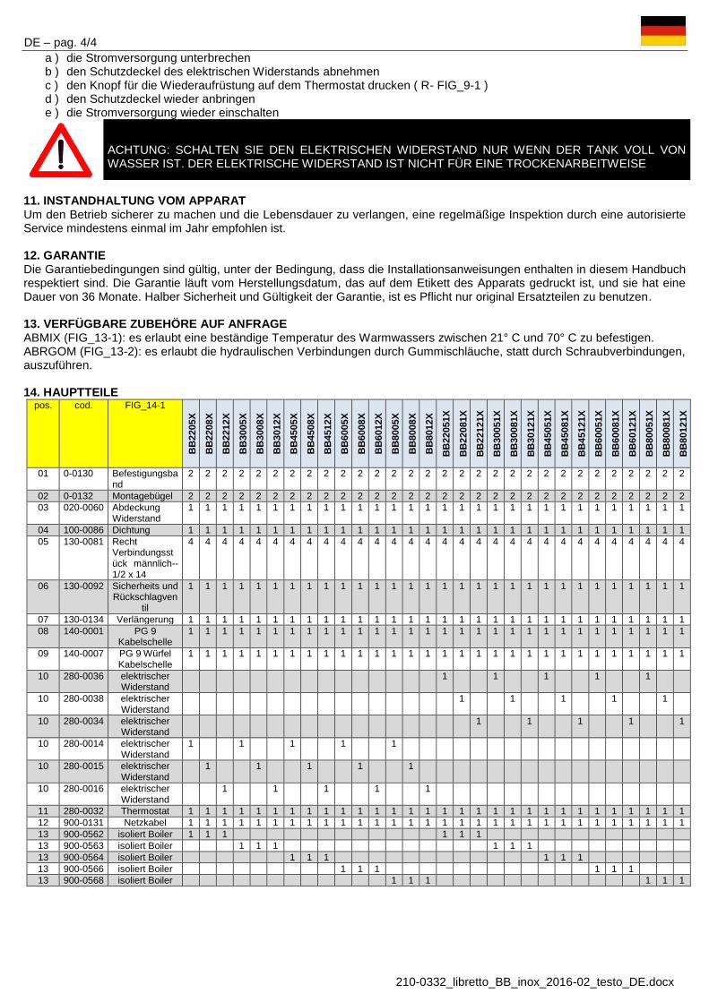
DE – pag. 4/4
210-0332_libretto_BB_inox_2016-02_testo_DE.docx
a ) die Stromversorgung unterbrechen b ) den Schutzdeckel des elektrischen Widerstands abnehmen c ) den Knopf für die Wiederaufrüstung auf dem Thermostat drucken ( R- FIG_9-1 ) d ) den Schutzdeckel wieder anbringen e ) die Stromversorgung wieder einschalten
ACHTUNG: SCHALTEN SIE DEN ELEKTRISCHEN WIDERSTAND NUR WENN DER TANK VOLL VON WASSER IST. DER ELEKTRISCHE WIDERSTAND IST NICHT FÜR EINE TROCKENARBEITWEISE
11. INSTANDHALTUNG VOM APPARAT Um den Betrieb sicherer zu machen und die Lebensdauer zu verlangen, eine regelmäßige Inspektion durch eine autorisierte Service mindestens einmal im Jahr empfohlen ist. 12. GARANTIE Die Garantiebedingungen sind gültig, unter der Bedingung, dass die Installationsanweisungen enthalten in diesem Handbuch respektiert sind. Die Garantie läuft vom Herstellungsdatum, das auf dem Etikett des Apparats gedruckt ist, und sie hat eine Dauer von 36 Monate. Halber Sicherheit und Gültigkeit der Garantie, ist es Pflicht nur original Ersatzteilen zu benutzen. 13. VERFÜGBARE ZUBEHÖRE AUF ANFRAGE ABMIX (FIG_13-1): es erlaubt eine beständige Temperatur des Warmwassers zwischen 21° C und 70° C zu befestigen. ABRGOM (FIG_13-2): es erlaubt die hydraulischen Verbindungen durch Gummischläuche, statt durch Schraubverbindungen, auszuführen. 14. HAUPTTEILE
pos. cod. FIG_14-1
BB
2205
X
BB
2208
X
BB
2212
X
BB
3005
X
BB
3008
X
BB
3012
X
BB
4505
X
BB
4508
X
BB
4512
X
BB
6005
X
BB
6008
X
BB
6012
X
BB
8005
X
BB
8008
X
BB
8012
X
BB
2205
1X
BB
2208
1X
BB
2212
1X
BB
3005
1X
BB
3008
1X
BB
3012
1X
BB
4505
1X
BB
4508
1X
BB
4512
1X
BB
6005
1X
BB
6008
1X
BB
6012
1X
BB
8005
1X
BB
8008
1X
BB
8012
1X
01 0-0130 Befestigungsband
2 2 2 2 2 2 2 2 2 2 2 2 2 2 2 2 2 2 2 2 2 2 2 2 2 2 2 2 2 2
02 0-0132 Montagebügel 2 2 2 2 2 2 2 2 2 2 2 2 2 2 2 2 2 2 2 2 2 2 2 2 2 2 2 2 2 2 03 020-0060 Abdeckung
Widerstand 1 1 1 1 1 1 1 1 1 1 1 1 1 1 1 1 1 1 1 1 1 1 1 1 1 1 1 1 1 1
04 100-0086 Dichtung 1 1 1 1 1 1 1 1 1 1 1 1 1 1 1 1 1 1 1 1 1 1 1 1 1 1 1 1 1 1 05 130-0081 Recht
Verbindungsstück männlich-- 1/2 x 14
4 4 4 4 4 4 4 4 4 4 4 4 4 4 4 4 4 4 4 4 4 4 4 4 4 4 4 4 4 4
06 130-0092 Sicherheits und Rückschlagven
til
1 1 1 1 1 1 1 1 1 1 1 1 1 1 1 1 1 1 1 1 1 1 1 1 1 1 1 1 1 1
07 130-0134 Verlängerung 1 1 1 1 1 1 1 1 1 1 1 1 1 1 1 1 1 1 1 1 1 1 1 1 1 1 1 1 1 1 08 140-0001 PG 9
Kabelschelle 1 1 1 1 1 1 1 1 1 1 1 1 1 1 1 1 1 1 1 1 1 1 1 1 1 1 1 1 1 1
09 140-0007 PG 9 Würfel Kabelschelle
1 1 1 1 1 1 1 1 1 1 1 1 1 1 1 1 1 1 1 1 1 1 1 1 1 1 1 1 1 1
10 280-0036 elektrischer Widerstand
1 1 1 1 1
10 280-0038 elektrischer Widerstand
1 1 1 1 1
10 280-0034 elektrischer Widerstand
1 1 1 1 1
10 280-0014 elektrischer Widerstand
1 1 1 1 1
10 280-0015 elektrischer Widerstand
1 1 1 1 1
10 280-0016 elektrischer Widerstand
1 1 1 1 1
11 280-0032 Thermostat 1 1 1 1 1 1 1 1 1 1 1 1 1 1 1 1 1 1 1 1 1 1 1 1 1 1 1 1 1 1 12 900-0131 Netzkabel 1 1 1 1 1 1 1 1 1 1 1 1 1 1 1 1 1 1 1 1 1 1 1 1 1 1 1 1 1 1 13 900-0562 isoliert Boiler 1 1 1 1 1 1 13 900-0563 isoliert Boiler 1 1 1 1 1 1 13 900-0564 isoliert Boiler 1 1 1 1 1 1 13 900-0566 isoliert Boiler 1 1 1 1 1 1 13 900-0568 isoliert Boiler 1 1 1 1 1 1

TR – sayfa 1/4 TÜRKÇE
210-0332_libretto_BB_inox_2016-02_testo_TR.docx
BB_ _ __ tipi Su ısıtıcıları değişik ihtiyaçları ve kurulum gereksinimlerini karşılamak için aşağıdaki özelliklere sahip 24 farklı
model içermektedir a) 4 farklı depolama kapasitesi ( 22 - 30 – 45 - 60 - litre / 6 - 8 - 12 – 16 galon) b) 3 farklı elektrikli ısıtma kapasitesi (500 W – 800 W - 1200 W) c) 2 farklı Voltaj (120 V - 230 V)
1. ÖNEMLİ GENEL ÖNLEMLER Aşağıdaki yönergeler, cihazın güvenli kurulumu, kullanımı ve bakımını sağlamak için önemlidir. • Bu kitapçık, su ısıtıcısının ayrılmaz ve vazgeçilmez bir parçasıdır ve bu nedenle ileride başvurmak için iyi saklanmalıdır. • Su ısıtıcısı, sıcak su üretimi için imal edilmiştir. Başka amaçla kullanımlar için uygun değildir ve çok tehlikelidir. • Cihaz nemli mahallere, banyolara, lavabolara, duşlara, yüzme havuzlarına vb yerlere monte edilmemelidir. Elektrikli
parçaların kısa devre yapmasını önlemek için su ve diğer sıvıların sıçrama, serpinti ve püskürmelerine karşı korunmalıdır. • Kurulum ve montaj, ulusal emniyet ve güvenlik kurallarını bilen yetkili bir kişi tarafından yapılmalıdır. Üreticinin
talimatlarına uyulmaması nedeniyle yanlış kurulumdan dolayı kişilere ve hayvanlara verilecek zarar veya yaralanma, veya diğer ekipmanlara verilecek hasardan dolayı üretici hiçbir sorumluluk kabul etmez.
• Su ısıtıcını bağlamadan önce, cihaz tanıtım plakası üzerinde yazılı elektriksel özelliklerin, elektrik şebekesi ile uyumlu olduğundan emin olun.
• Su ısıtıcısı banyo, nemli bir mahal yada su kaynağı yakınına monte edilmiş ise, CEI-CEE kurallarına göre tespit edilmiş emniyet mesafelerine dikkat edin. Buna ek olarak, her türlü elektrik anahtarları ya da diğer elektrik kumanda düğmeleri duş alan veya banyo yapan kişilerin ulaşılabileceği yerlerde olmamalıdır. Islak ve nemli ellerle Cihaza dokunmayın.
• Çocukların ya da ehliyetsiz kişilerin kullanımına izin vermeyin. • Ambalaj Parçaları (plastik torbalar, polistiren, klipler, vs.), çocuklara zarar verebilir ve tehlikeli olabilir. Bu parçalar ulusal
çevre yönergeleri doğrultusunda uzaklaştırılmalı ve imha edilmelidir. • Bu kitapçıkta önerilen ve tavsiye edilen; Emniyet, Montaj, Kullanım ve Bakım talimatlarını okuyun. • Eğer bu cihaz başka bir kullanıcıya satılır, veya başka bir yere taşınırsa, yeni sahibi ve / veya yeniden monte edenin
okuması ve danışması için bu kitapçığı muhakkak cihazla birlikte teslim edin. • Cihaz uzun süre kullanılmayacaksa ve ısıtmasız bir mahalde ise, don hasarı riskini önlemek için, cihazın tamamen
boşaltılması tavsiye edilir. Üretici donmanın neden olabileceği su sızıntıları ve hertürlü arızadan sorumlu değildir. • Cihazınızdan en iyi verimi almak ve garanti şartlarını sağlamak için aşağıdaki talimatlara kesinlikle uyulması
gerekmektedir. 2. TEKNİK ÖZELLİKLER
BB
2205
X
BB
2208
X
BB
2212
X
BB
3005
X
BB
3008
X
BB
3012
X
BB
4505
X
BB
4508
X
BB
4512
X
BB
6005
X
BB
6008
X
BB
6012
X
V ~ 230 230 230 230 230 230 230 230 230 230 230 230 Elektrik Bağlantısı A 2.2 3,5 5.2 2.2 3,5 5.2 2.2 3,5 5.2 2.2 3,5 5.2
Çekilen Güç W 500 800 1200 500 800 1200 500 800 1200 500 800 1200
BB
2205
1X
BB
2208
1X
BB
2212
1X
BB
3005
1X
BB
3008
1X
BB
3012
1X
BB
4505
1X
BB
4508
1X
BB
4512
1X
BB
6005
1X
BB
6008
1X
BB
6012
1X
V ~ 120 120 120 120 120 120 120 120 120 120 120 120 Elektrik Bağlantısı A 4.2 6.7 10.0 4.2 6.7 10.0 4.2 6.7 10.0 4.2 6.7 10.0
Çekilen Güç W 500 800 1200 500 800 1200 500 800 1200 500 800 1200
Kapasite l (gal) 22 (5.8) 30 (7,9) 45 (11.9) 60 (15.8)
Maksimum basınç kPa (psi) 700 (102) 700 (102) 700 (102) 700 (102) Boş Ağırlık kg (lb) 10,0 (22) 11,5 (25) 15,0 (33) 17.3 (38)
Boyutlar mm 322 x 334 x 485 322 x 334 x 620 322 x 334 x 880 322 x 334 x 1065 inç " 12.6 x 13.0 x 18.9 12.6 x 13.0 x 24.2 12.6 x 13.0 x 34.3 12.6 x 13.0 x 41.5
3. AMBALAJ Cihaz yeterli korumaya sahip karton kutu içerisinde teslim edilir. Cihaza ek olarak, kutu içinde aşağıdaki parçalar bulunur:
a) Kurulum ve Kullanım Kılavuzu b) Sabitleme braketleri ve vidaları c) Geri Dönüşsüz Emniyet Valfi (Yüksek basınç emniyet valfi )

TR – sayfa 2/4 TÜRKÇE
210-0332_libretto_BB_inox_2016-02_testo_TR.docx
4. BOYUTLAR (Bakınız Şekil FIG_4-1 )
A B C D E F
BB2205X - BB2208X - BB2212X mm 322 267 335 334 410 485 BB22051X - BB22081X - BB22121X inç " 12.6 10.4 13.1 13.0 16.0 18.9
BB3005X - BB3008X - BB3012X mm 322 267 470 334 545 620 BB30051X - BB30081X - BB30121X inç " 12.6 10.4 18.3 13.0 21.3 24.2
BB4505X - BB4508X - BB4512X mm 322 267 730 334 805 880 BB45051X - BB45081X - BB45121X inç " 12.6 10.4 28.5 13.0 31.4 34.3
BB6005X - BB6008X - BB6012X mm 322 267 920 334 995 1065 BB60051X - BB60081X - BB60121X inç " 12.6 10.4 35.9 13.0 38.8 41.5
5. CİHAZIN YAPISI VE KULLANIM Bu cihaz iki farklı yöntemle sıcak kullanım suyu hazırlamak için üretilmiştir. (Bkz. FIG_5-1 ) :
A. Motorun soğutma suyu ile cihazın tankında depolanan suyun arasındaki ısı alışverişi yoluyla. Bu tür bir ısı alışverişi, tankın içindeki ısı eşanjörü sayesinde mümkün olmaktadır. Motor soğutma suyu, tankın merkezinde bulunan ısı eşanjör borularında dolaşarak ısıyı eşit olarak tankın içindeki kullanım suyuna iletir.
B. Cihaz ile birlikte verilen daldırma tip Elektrik Isıtıcısı (Rezistansı) ile . Ana parçalar (Bkz. Şekil FIG_5-2): 1. Depolama tankı: Tamamen AISI 316 L Paslanmaz Çelikden üretilmiştir. 2. Dış gövde : Çekici bir tasarıma sahip, dış şoklara ve darbelere karşı çok dayanıklıdır. 3. Isı yalıtımı: Isı kaybını önleyen, kapalı hücreli Poliüretan köpükten yapılmıştır. Bu şekilde, ısı kaybı 24 saatlik bir süre
için saat başına 1 ° C kadar düşürülmüştür. 4. Isı Eşanjörü : AISI 316 L paslanmaz çelik borudan imal edilmiştir; Dış yüzeyi, motor soğutma suyunun sıcaklığını en
düşük ısı farklarında dahi tank içindeki suya verimli bir şekilde aktarılmasını sağlar. 5. Elektrik Isıtıcı Elemanı: Cihaz, tekne motoru kapalı iken (örneğin demirde veya limana bağlı olduğunda) suyu ısıtmak
için elektrikli bir ısıtma elemanı (500 / 800 / 1200W, 120/230V) ile donatılmıştır. Malzeme: Incoloy (korozyona dayanıklı bir alaşım)
6. Termostat: iki işlevi vardır a. Ayarlanabilir Termostat: Tank suyu sıcaklığı ayarlanan ısıya geldiğinde, ısıtma elemanına giden elektriği
keser. (sıcaklık, kullanıcı ihtiyaçlarına göre, 0 ° C ile 65 °C arasında ayarlanabilir). b. Emniyet Termostatı: arıza durumunda, su sıcaklığı 90 °C ulaştığında, ısıtma elemanına giden elektriği keser.
Cihazı tekrar devreye almak için el ile müdahele gerekir.(manuel sıfırlama ). Sıcaklık ayar aralığı : 0 °C ila 65 °C Sıcaklık farkı : yaklaşık 9 °C Emniyet Sıcaklığı : 90 ° C Maksimum akım : 20A Maksimum sıcaklık : 120 ° C
7. Soğuk su girişi: 8. Geri dönüşsüz Emniyet valfi: Sıcak suyun soğuk su hattına geri akışını engeller. Aynı zamanda ısıtma sırasında
suyun genişlemesinin neden olabileceği aşırı basınca karşı emniyet valfı görevi görür ve tankı korur. Tank içindeki aşırı basınç, emniyet valfi ile boşaltılır. Kalibrasyon:800 ± 50 kPa (116 ± 7 psi)
9. Sıcak su çıkışı 10. Montaj braketleri
6. KURULUM TALİMATLARI
Kurulum, ulusal emniyet ve güvenlik kurallarına uygun olarak, yetkili bir kişi tarafından yapılmalıdır. Yetkili montaj elemanı cihazı geçerli mevzuat çerçevesinde montajın yanı sıra, gerekli işletmeye alma testlerini de yapmalıdır.
İlk montaj ve sonrası bakım ve onarımlarda, bu kitapçıkta yer alan yönergeleri dikkatle uygulayın. Bu Yönergelere uyulmaması veya bağlantılarda yönergelere aykırı davranılması durumunda garanti geçersiz olacaktır.
Cihazın kurulumu, bakım ve onarımı öncesi elektrik bağlantısının kesildiğinden emin olun. 7. KONUM VE MONTAJ
Cihaz le birlikte iki adet sabitleme/bağlantı braketi verilmiştir (A- FIG_7-1). Cihazı sabitlemek için kutu içinden çıkan bu bağlantı elemanlarını, civata ve somunlarını kullanın.
Cihaz, (FIG_7-2) de gösterildiği şekilde, ısı eşanjörü bağlantıları ve/veya elektrik ısıtıcı elemanı aşağıya gelecek şekilde monte edilmelidir.
Cihaz eğimli duvarlara da (FIG_7-3) monte edilebilir. Bu durumda da, ısı eşanjörü bağlantıları ve/veya elektrik ısıtıcı elemanının aşağıya gelecek şekilde monte edildiğinden emin olun.
Cihaz şartlarda kısıtlama olmaksızın, bu kitapcıkta yukarıda Madde 1 "ÖNEMLİ/GENEL ÖNLEMLER" kısmında belirtilen talimatlara uygun olarak herhangi bir mahallere monte edilebilir.
Bu kılavuzda belirtilmemiş montaj şekilleri için Teknik Ofisimize danışınız.

TR – sayfa 3/4 TÜRKÇE
210-0332_libretto_BB_inox_2016-02_testo_TR.docx
8. TESİSAT BAĞLANTILARI VE SU KALİTESİ Cihazin ömrünü uzatmak için, kullanılan su kalitesi insani tüketim amaçlı su kalitesini düzenleyen AB Direktifi 98/83/EC parametlerine uygun olmalıdır. Sertlik: 15 - 50 °F arasında (özellikle, su, bir yumuşatma veya arıtma işleminden geçirilecek ise) Klorür : 25 - 100 mg / lt. arasında PH : 6.5 - 9.5 arasında İletkenlik : 400 - 1500 arasında µS / cm arasında
Cihazı şekil (FIG_8-1) gösterildiği şekilde aşağıda belirtildiği gibi tesisata bağlayın:
1. Soğuk su girişi (1/2 ") 2. Sıcak su çıkışı (1/2 ") 3. Motor (1/2 ") soğutma devresinden geliş 4. Motor (1/2 ") soğutma devresine dönüş
Minimum soğuk su giriş basıncı: 70 kpa. Enerji tasarrufu sağlamak için Sıcak su borularının yalıtılması tavsiye edilir. Geri dönüşsuz Emniyet valfi montajı : Valf cihaz ile birlikte verilmiş fakat monte edilmemiştir. Valfi şekil (FIG_8-1 (S)) cihazın soğuk su girişine bağlayınız.
DİKKAT: CİHAZ İLE BİRLİKTE VERİLEN GERİ DÖNÜŞSÜZ EMNİYET VANASINI BASİT ÇEK VALF LER İLE
DEĞİŞTİRMEYİNİZ. EMNİYET VANASININ ATIŞ UCUNU İÇ ÇAPI 9,5 mm OLAN KAUÇUK BİR HORTUMA BAĞLAYINIZ.
HORTUM DEVAMLI AŞAĞI MEYİLLİ OLACAK ŞEKİLDE VE DONMAYA KARŞI KORUNARAK MONTE EDİLMELİDİR
KIŞ MEVSİMİNDE CİHAZ KULLANILMAYACAK İSE, CİHAZI DONMANIN SEBEB OLABİLECEĞİ CİDDİ HASARLARDAN KORUMAK İÇİN CİHAZ İÇİNDEKİ SUYU BOŞALTINIZ.
9. ELEKTRİK BAĞLANTILARI Cihaz, üzerindeki etikette belirtilen ( 120V veya 230 V ) Tek fazlı güç kaynağına ve etkin bir topraklama sistemine bağlanmalıdır.
ÜRETİCİ, CİHAZIN ETKİN VE ÇALIŞIR BİR TOPRAKLAMA SİSTEMİNE BAĞLANMAMASINDAN DOLAYI OLABİLECEK HER TÜRLÜ HASAR VE YARALANMALARDAN DOLAYI HİÇ BİR SORUMLULUK KABUL ETMEZ.
Cihaz, ucu fişli bir güç kablosuyla birlikte gelir. Cihaz, monte edileceği ülkede geçerli elektrik kablolama, emniyet ve güvenlik kurallarına uygun olarak bağlanmalıdır. Güç kablosunu değiştirmek gerektiğinde, aynı özelliklere sahip (3x1, 5 mm² - H05 VV-F) kablo kullanın. Fiş – Priz bağlantısı kullanılmayacak ise fişi keserek kabloyu doğudan güç kaynağına bağlayın. Bu durumda kabloların doğru kutuplara bağlandığından emin olun. Şekil (FIG_9-1) .
• L Faz (kahverengi kablo) • N Nötr (mavi kablo)
Cihazın elektiğini kesmek için, cihaz yanında çift konumlu bir anahtar monte edilmesi tavsiye olunur.
DİKKAT: TERMOSTATA HERHANGİ BİR MÜDAHALEDE BULUNMADAN ÖNCE CİHAZIN ELEKTRİĞİNİN KESİLDİĞİNDEN EMİN OLUN .
10. KULLANIM TALİMATLARI Elektrik ısıtıcısı aşağıdaki iki fonksiyonu olan thermostat ile donatılmıştır: 1. Sıcaklık ayarı: Şekil (T - FIG_9-1), ayarlanan ısıya geldiğinde, ısıtma elemanına giden elektriği keser. (sıcaklık, kullanıcı
ihtiyaçlarına göre, 0 ° C ile 65 °C arasında ayarlanabilir). 2. Arıza durumunda: su sıcaklığı 90 °C ulaştığında, ısıtma elemanına giden elektriği keser. Cihazı tekrar devreye almak için
el ile mudahele gerekir (manuel sıfırlama). Bu durumda, aşağıdaki adımları izleyin: a) elektrik bağlantısını kesin b) Isıtıcı elemanın koruma kapağını çıkartın c) Termostat üzerindeki Reset düğmesine basın. Şekil (R - FIG_9-1) d) Koruma kapağını monte edin e) Elektrik bağlantısını açın.
UYARI: ELEKTRİK BAĞLANTISINI SADECE CİHAZ SU İLE DOLU OLDUĞU ZAMAN AÇIN. ISITICI ELEMAN (REZİSTANS) KURU/SUSUZ ÇALIŞMA İÇİN UYGUN DEĞİLDİR
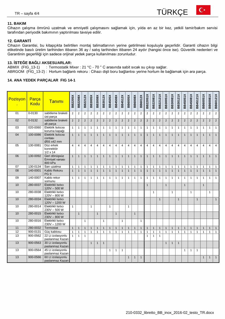
TR – sayfa 4/4 TÜRKÇE
210-0332_libretto_BB_inox_2016-02_testo_TR.docx
11. BAKIM Cihazın çalışma ömrünü uzatmak ve emniyetli çalışmasını sağlamak için, yılda en az bir kez, yetkili tamir/bakım servisi tarafından periyodik bakımının yaptırılması tavsiye edilir. 12. GARANTİ Cihazın Garantisi, bu kitapçıkta belirtilen montaj talimatlarının yerine getirilmesi koşuluyla geçerlidir. Garanti cihazın bilgi etiketinde basılı üretim tarihinden itibaren 36 ay / satış tarihinden itibaren 24 aydır (hangisi önce ise). Güvenlik nedenler i ve Garantinin geçerliliği için sadece orijinal yedek parça kullanılması zorunludur. 13. İSTEĞE BAĞLI AKSESUARLAR: ABMIX (FIG_13-1) : Termostatik Mixer : 21 °C - 70 ° C arasında sabit sıcak su çıkışı sağlar. ABRGOM (FIG_13-2) : Hortum bağlantı rekoru : Cihazı dişli boru bağlantısı yerine hortum ile bağlamak için ara parça. 14. ANA YEDEK PARÇALAR FIG 14-1
Pozisyon.
Parça Kodu Tanımı
BB
2205
X
BB
2208
X
BB
2212
X
BB
3005
X
BB
3008
X
BB
3012
X
BB
4505
X
BB
4508
X
BB
4512
X
BB
6005
X
BB
6008
X
BB
6012
X
BB
2205
1X
BB
2208
1X
BB
2212
1X
BB
3005
1X
BB
3008
1X
BB
3012
1X
BB
4505
1X
BB
4508
1X
BB
4512
1X
BB
6005
1X
BB
6008
1X
BB
6012
1X
01 0-0130 sabitleme braketi üst parça
2 2 2 2 2 2 2 2 2 2 2 2 2 2 2 2 2 2 2 2 2 2 2 2
02 0-0132 sabitleme braketi alt parça
2 2 2 2 2 2 2 2 2 2 2 2 2 2 2 2 2 2 2 2 2 2 2 2
03 020-0060 Elektrik Isıtıcısı koruma kapağı
1 1 1 1 1 1 1 1 1 1 1 1 1 1 1 1 1 1 1 1 1 1 1 1
04 100-0086 Elektrik Isıtıcısı contası Ø55 x42 mm
1 1 1 1 1 1 1 1 1 1 1 1 1 1 1 1 1 1 1 1 1 1 1 1
05 130-0081 Düz erkek konnektör 1/2 x 14
4 4 4 4 4 4 4 4 4 4 4 4 4 4 4 4 4 4 4 4 4 4 4 4
06 130-0092 Geri dönüşsüz Emniyet vanası 800 kPa
1 1 1 1 1 1 1 1 1 1 1 1 1 1 1 1 1 1 1 1 1 1 1 1
07 130-0134 Sarı uzatma 1 1 1 1 1 1 1 1 1 1 1 1 1 1 1 1 1 1 1 1 1 1 1 1
08 140-0001 Kablo Rekoru PG 9
1 1 1 1 1 1 1 1 1 1 1 1 1 1 1 1 1 1 1 1 1 1 1 1
09 140-0007 Kablo rekor somunu
1 1 1 1 1 1 1 1 1 1 1 1 1 1 1 1 1 1 1 1 1 1 1 1
10 280-0037 Elektrikli Isıtıcı 120V – 500 W
1 1 1 1
10 280-0038 Elektrikli Isıtıcı 120V – 800 W
1 1 1 1
10 280-0034 Elektrikli Isıtıcı 120V – 1200 W
1 1 1 1
10 280-0014 Elektrikli Isıtıcı 230V – 500 W
1 1 1 1
10 280-0015 Elektrikli Isıtıcı 230V – 800 W
1 1 1 1
10 280-0016 Elektrikli Isıtıcı 230V – 1200 W
1 1 1 1
11 280-0032 Termostat 1 1 1 1 1 1 1 1 1 1 1 1 1 1 1 1 1 1 1 1 1 1 1 1
12 900-0131 Güç kablosu 1 1 1 1 1 1 1 1 1 1 1 1 1 1 1 1 1 1 1 1 1 1 1 1
13 900-0562 22 Lt izolasyonlu paslanmaz Kazan
1 1 1 1 1 1
13 900-0563 30 Lt izolasyonlu paslanmaz Kazan
1 1 1 1 1 1
13 900-0564 45 Lt izolasyonlu paslanmaz Kazan
1 1 1 1 1 1
13 900-0566 60 Lt izolasyonlu paslanmaz Kazan
1 1 1 1 1 1

210-0332_figure.docx
FIG_08-1 FIG_09-1
FIG_13-1 FIG_13-2
FIG_14-1

210-0332 – edizione 2018-09
ATI DI MARIANI SRL Via E. Mattei 461
Zona Ind. Torre del Moro n°4 47522 Cesena (FC) - ITALIA
Tel. +int-39-0547 609711 Fax +int-39-0547 609724
www.nautica.atimariani.it