flaash module
TRANSCRIPT

832019 Flaash Module
httpslidepdfcomreaderfullflaash-module 144
Atmospheric Correction Module
Version 47
August 2009 EditionCopyright copy ITT Visual Information Solutions
Atmospheric CorrectionModule QUAC andFLAASH Userrsquos Guide
20AC47DOC
832019 Flaash Module
httpslidepdfcomreaderfullflaash-module 244
Restricted Rights Notice
The IDLreg IDL Advanced Math and Statstrade ENVIreg ENVI Zoomtrade and ENVIreg EX software programs and the accompanying procedures functions and
documentation described herein are sold under license agreement Their use duplication and disclosure are subject to the restrictions stated in the license
agreement ITT Visual Information Solutions reserves the right to make changes to this document at any time and without notice
Limitation of Warranty
ITT Visual Information Solutions makes no warranties either express or implied as to any matter not expressly set forth in the license agreement including
without limitation the condition of the software merchantability or fitness for any particular purpose
ITT Visual Information Solutions shall not be liable for any direct consequential or other damages suffered by the Licensee or any others resulting from use
of the software packages or their documentation
Permission to Reproduce this Manual
If you are a licensed user of these products ITT Visual Information Solutions grants you a limited nontransferable license to reproduce this particular
document provided such copies are for your use only and are not sold or distributed to third parties All such copies must contain the title page and this notice
page in their entirety
Export Control Information
This software and associated documentation are subject to US export controls including the United States Export Administration Regulations The recipient
is responsible for ensuring compliance with all applicable US export control laws and regulations These laws include restrictions on destinations end users
and end use
Acknowledgments
ENVIreg and IDLreg are registered trademarks of ITT Corporation registered in the United States Patent and Trademark Office IONtrade ION Scripttrade ION Javatrade and ENVI
Zoomtrade are trademarks of ITT Visual Information Solutions
ESRIreg ArcGISreg ArcViewreg and ArcInforeg are registered trademarks of ESRI
Portions of this work are Copyright copy 2009 ESRI All rights reserved
PowerPointreg and Windowsreg are registered trademarks of Microsoft Corporation in the United States andor other countries
Macintoshreg is a registered trademark of is a trademark of Apple Inc registered in the US and other countries
UNIXreg is a registered trademark of The Open Group
Adobe Illustratorreg and Adobe PDFreg Print Engine are either registered trademarks or trademarks of Adobe Systems Incorporated in the United States andor other countries
Numerical Recipestrade is a trademark of Numerical Recipes Software Numerical Recipes routines are used by permission
GRG2trade is a trademark of Windward Technologies Inc The GRG2 software for nonlinear optimization is used by permission
NCSA Hierarchical Data Format (HDF) Software Library and Ut ilities Copyright copy 1988-2001 The Board of Trustees of the University of Il linois All rights reserved
NCSA HDF5 (Hierarchical Data Format 5) Software Library and Utilities Copyright copy 1998-2002 by the Board of Trustees of the University of Illinois All rights reserved
CDF Library Copyright copy 2002 National Space Science Data Center NASAGoddard Space Flight Center
NetCDF Library Copyright copy 1993-1999 University Corporation for Atmospheric ResearchUnidata
HDF EOS Library Copyright copy 1996 Hughes and Applied Research Corporation
SMACC Copyright copy 2000-2004 Spectral Sciences Inc and ITT Visual Information Solutions All rights reserved
This software is based in part on the work of the Independent JPEG Group
Portions of this software are copyrighted by DataDirect Technologies copy 1991-2003
BandMaxreg Copyright copy 2003 The Galileo Group Inc
Portions of this computer program are copyright copy 1995-2008 Celartem Inc doing business as LizardTech All rights reserved MrSID is protected by US Patent No 5710835
Foreign Patents Pending
Portions of this software were developed using Unisearchrsquos Kakadu software for which ITT has a commercial license Kakadu Software Copyright copy 2001 The University of New
South Wales UNSW Sydney NSW 2052 Australia and Unisearch Ltd Australia
This product includes software developed by the Apache Software Foundation (wwwapacheorg )
MODTRAN is licensed from the United States of America under US Patent No 5315513 and US Patent No 5884226
QUAC and FLAASH are licensed from Spectral Sciences Inc under US Patent No 6909815 and US Patent No 7046859 B2
Portions of this software are copyrighted by Merge Technologies Incorporated
Support Vector Machine (SVM) is based on the LIBSVM library wri tten by Chih-Chung Chang and Chih-Jen Lin (wwwcsientuedutw~cjlinlibsvm) adapted by ITT Visual
Information Solutions for remote sensing image supervised classification purposes
IDL Wavelet Toolkit Copyright copy 2002 Christopher Torrence
IMSL is a trademark of Visual Numerics Inc Copyright copy 1970-2006 by Visual Numerics Inc All Rights Reserved
Other trademarks and registered trademarks are the property of the respective trademark holders
832019 Flaash Module
httpslidepdfcomreaderfullflaash-module 344
Atmospheric Correction Module Userrsquos Guide 3
ContentsChapter 1Introduction to QUAC and FLAASH 5
About Atmospheric Correction 6
About QUAC 6
About FLAASH 7
The QUAC Model 9
The FLAASH Model 10Input Data Requirements 12
QUAC Input Requirements 12
FLAASH Input Requirements 12
Preparing ASTER Data 13
Chapter 2Using QUAC and FLAASH 15
Using QUAC 16
Standard FLAASH Input Parameters 17
Specifying Input and Output File Information 17
Entering Scene and Sensor Information 19
Selecting Atmospheric Model Settings 20
Using Water Retrieval 22
Selecting an Aerosol Model 23
Using Aerosol Retrieval 23
Entering an Initial Visibility Value 24
Using Spectral Polishing 24
832019 Flaash Module
httpslidepdfcomreaderfullflaash-module 444
4
Atmospheric Correction Module Userrsquos Guide Contents
Recalibrating the Input Wavelengths 25
FLAASH Advanced Settings 31
Selecting a Spectrograph Definition File 31
Setting Modeling Parameters 32
Setting Viewing Geometry Parameters 35
Setting FLAASH Processing Controls 35Starting the Processing 37
Saving and Restoring FLAASH Run Parameters (Templates) 38
Saving the Template 38
Restoring a Template File 38
FLAASH Output Files 39
Surface Reflectance 39
Water Vapor 39
Cloud Map 39
Log File 39
FLAASH Template File (Optional) 39
Index 41
832019 Flaash Module
httpslidepdfcomreaderfullflaash-module 544
Atmospheric Correction Module Userrsquos Guide 5
Chapter 1
Introduction to QUAC and
FLAASHThis chapter covers the following topics
About Atmospheric Correction 6
The QUAC Model 9
The FLAASH Model 10
Input Data Requirements 12
832019 Flaash Module
httpslidepdfcomreaderfullflaash-module 644
6 Chapter 1 Introduction to QUAC and FLAASH
About Atmospheric Correction Atmospheric Correction Module Userrsquos Guide
About Atmospheric Correction
The nature of remote sensing requires that solar radiation pass through the atmosphere before
it is collected by the instrument Because of this remotely sensed images include information
about the atmosphere and the earthrsquos surface For those interested in quantitative analysis of
surface reflectance removing the influence of the atmosphere is a critical pre-processing stepTo compensate for atmospheric effects properties such as the amount of water vapor
distribution of aerosols and scene visibility must be known Because direct measurements of
these atmospheric properties are rarely available there are techniques that infer them from
their imprint on hyperspectral radiance data These properties are then used to constrain
highly accurate models of atmospheric radiation transfer to produce an estimate of the true
surface reflectance Moreover atmospheric corrections of this type can be applied on a pixel-
by-pixel basis because each pixel in a hyperspectral image contains an independent
measurement of atmospheric water vapor absorption bands
The Atmospheric Correction Module provides two atmospheric correction modeling tools for
retrieving spectral reflectance from multispectral and hyperspectral radiance images QUick
Atmospheric Correction (QUAC) and Fast Line-of-sight Atmospheric Analysis of SpectralHypercubes (FLAASH) With the Atmospheric Correction Module you can accurately
compensate for atmospheric effects
QUAC and FLAASH were developed by Spectral Sciences Inc a world leader in optical
phenomenology research under the sponsorship of the US Air Force Research Laboratory
Spectral Sciences has been an integral part in the development of modern atmospheric
radiation transfer models and has worked extensively on MODTRAN since the modelrsquos
inception in 1989
About QUAC
QUAC is a visible-near infrared through shortwave infrared (VNIR-SWIR) atmospheric
correction method for multispectral and hyperspectral imagery Unlike other first-principlesatmospheric correction methods it determines atmospheric compensation parameters directly
from the information contained within the scene (observed pixel spectra) without ancillary
information QUAC performs a more approximate atmospheric correction than FLAASH or
other physics-based first-principles methods generally producing reflectance spectra within
approximately +-15 of the physics-based approaches QUAC is based on the empirical
finding that the average reflectance of a collection of diverse material spectra such as the
endmember spectra in a scene is essentially scene-independent All of this means
significantly faster computational speed compared to the first-principles methods
QUAC also allows for any view or solar elevation angle Should a sensor not have proper
radiometric or wavelength calibration or the solar illumination intensity be unknown (such as
when a cloud deck is present) this approach still allows the retrieval of reasonably accuratereflectance spectra
QUAC provides the following
bull Automated atmospheric correction of MSI and HSI data in the solar reflective spectral
region (~04-25 m)
832019 Flaash Module
httpslidepdfcomreaderfullflaash-module 744
Chapter 1 Introduction to QUAC and FLAASH 7
Atmospheric Correction Module Userrsquos Guide About Atmospheric Correction
bull Support for AISA ASAS AVIRIS CAP ARCHER COMPASS HYCAS HYDICE
HyMap Hyperion IKONOS Landsat TM LASH MASTER MODIS MTI
QuickBird RGB and unknown sensor types
QUAC creates an image of retrieved surface reflectance scaled into two-byte signed integers
using a reflectance scale factor of 10000
About FLAASH
FLAASH is a first-principles atmospheric correction tool that corrects wavelengths in the
visible through near-infrared and shortwave infrared regions up to 3 m (For thermal
regions use the Basic Tools Preprocessing Calibration Utilities Thermal Atm
Correction menu option) Unlike many other atmospheric correction programs that
interpolate radiation transfer properties from a pre-calculated database of modeling results
FLAASH incorporates the MODTRAN4 radiation transfer code
NoteThe version of MODTRAN4 incorporated into ENVI FLAASH was modified to correct
errors in the HITRAN-96 water line parameters See Matthew et al (2000) for details
You can choose any of the standard MODTRAN model atmospheres and aerosol types to
represent the scene a unique MODTRAN solution is computed for each image
FLAASH also includes the following features
bull Correction for the adjacency effect (pixel mixing due to scattering of surface-reflected
radiance)
bull An option to compute a scene-average visibility (aerosolhaze amount) FLAASH uses
the most advanced techniques for handling particularly stressing atmospheric
conditions such as the presence of clouds
bull Cirrus and opaque cloud classification mapbull Adjustable spectral polishing for artifact suppression
FLAASH supports hyperspectral sensors (such as HyMAP AVIRIS HYDICE HYPERION
Probe-1 CASI and AISA) and multispectral sensors (such as ASTER IRS Landsat
RapidEye and SPOT) Water vapor and aerosol retrieval are only possible when the image
contains bands in appropriate wavelength positions (see ldquoInput Data Requirementsrdquo on
page 12 for details) In addition FLAASH can correct images collected in either vertical
(nadir) or slant-viewing geometries
References
For detailed scientific descriptions of the model employed by QUAC see the following
references
Bernstein L S S M Adler-Golden R L Sundberg et al 2005 Validation of the QUick
Atmospheric Correction (QUAC) algorithm for VNIR-SWIR multi- and hyperspectral
imagery SPIE Proceedings Algorithms and Technologies for Multispectral Hyperspectral
and Ultraspectral Imagery XI Vol 5806 pp 668-678
Bernstein L S S M Adler-Golden R L Sundberg and A Ratkowski 2006 Improved
Reflectance Retrieval from Hyper- and Multispectral Imagery without Prior Scene or Sensor
832019 Flaash Module
httpslidepdfcomreaderfullflaash-module 844
8 Chapter 1 Introduction to QUAC and FLAASH
About Atmospheric Correction Atmospheric Correction Module Userrsquos Guide
Information SPIE Proceedings Remote Sensing of Clouds and the Atmosphere XI Vol
6362
For detailed scientific descriptions of the model employed by FLAASH see the following
references
Adler-Golden S M M W Matthew L S Bernstein R Y Levine A Berk S C
Richtsmeier P K Acharya G P Anderson G Felde J Gardner M Hoke L S Jeong BPukall A Ratkowski and H-H Burke 1999 Atmospheric Correction for Short-wave
Spectral Imagery Based on MODTRAN4 SPIE Proceedings on Imaging Spectrometry Vol
3753 pp 61-69
Berk A L S Bernstein G P Anderson P K Acharya D C Robertson JH Chetwynd
and S M Adler-Golden 1998 MODTRAN Cloud and Multiple Scattering Upgrades with
Application to AVIRIS Remote Sensing of the Environment Vol 65 pp 367-375
Berk A L S Bernstein and D C Robertson 1989 MODTRAN a moderate resolution
model for LOWTRAN7 GL-TR-89-0122 Air Force Geophysical Laboratory Hanscom AFB
MA p 38
Matthew M W S M Adler-Golden A Berk S C Richtsmeier R Y Levine L SBernstein P K Acharya G P Anderson G W Felde M P Hoke A Ratkowski H-H
Burke R D Kaiser and D P Miller 2000 Status of Atmospheric Correction Using a
MODTRAN4-based Algorithm SPIE Proceedings Algorithms for Multispectral
Hyperspectral and Ultraspectral Imagery VI Vol 4049 pp 199-207
832019 Flaash Module
httpslidepdfcomreaderfullflaash-module 944
832019 Flaash Module
httpslidepdfcomreaderfullflaash-module 1044
10 Chapter 1 Introduction to QUAC and FLAASH
The FLAASH Model Atmospheric Correction Module Userrsquos Guide
The FLAASH Model
This section is a brief overview of the atmospheric correction method used by FLAASH
FLAASH starts from a standard equation for spectral radiance at a sensor pixel L that applies
to the solar wavelength range (thermal emission is neglected) and flat Lambertian materials
or their equivalents The equation is as follows
(1)
where
is the pixel surface reflectance
e is an average surface reflectance for the pixel and a surrounding region
S is the spherical albedo of the atmosphere
La is the radiance back scattered by the atmosphere
A and B are coefficients that depend on atmospheric and geometric conditions but not
on the surface
Each of these variables depends on the spectral channel the wavelength index has been
omitted for simplicity The first term in Equation (1) corresponds to radiance that is reflected
from the surface and travels directly into the sensor while the second term corresponds to
radiance from the surface that is scattered by the atmosphere into the sensor The distinction
between and e accounts for the adjacency effect (spatial mixing of radiance among nearby
pixels) caused by atmospheric scattering To ignore the adjacency effect correction set e =
However this correction can result in significant reflectance errors at short wavelengths
especially under hazy conditions and when strong contrasts occur among the materials in the
scene
The values of A B S and La are determined from MODTRAN4 calculations that use the
viewing and solar angles and the mean surface elevation of the measurement and they assume
a certain model atmosphere aerosol type and visible range The values of A B S and La are
strongly dependent on the water vapor column amount which is generally not well known
and may vary across the scene To account for unknown and variable column water vapor the
MODTRAN4 calculations are looped over a series of different column amounts then selected
wavelength channels of the image are analyzed to retrieve an estimated amount for each pixel
Specifically radiance averages are gathered for two sets of channels an absorption set
centered at a water band (typically 1130 nm) and a reference set of channels taken from just
outside the band A lookup table for retrieving the water vapor from these radiances is
constructed
NoteFor images that do not contain bands in the appropriate wavelength positions to support
water retrieval (for example Landsat or SPOT) the column water vapor amount is
determined by the user-selected atmospheric model (see ldquoUsing Water Retrievalrdquo on
page 22 for details)
LA
1 eSndash------------------
Be
1 eSndash------------------
La
+ +=
832019 Flaash Module
httpslidepdfcomreaderfullflaash-module 1144
Chapter 1 Introduction to QUAC and FLAASH 11
Atmospheric Correction Module Userrsquos Guide The FLAASH Model
After the water retrieval is performed Equation (1) is solved for the pixel surface reflectances
in all of the sensor channels The solution method involves computing a spatially averaged
radiance image Le from which the spatially averaged reflectance e is estimated using the
approximate equation
(2)
Spatial averaging is performed using a point-spread function that describes the relative
contributions to the pixel radiance from points on the ground at different distances from the
direct line of sight For accurate results cloud-containing pixels must be removed prior to
averaging The cloudy pixels are found using a combination of brightness band ratio and
water vapor tests as described by Matthew et al (2000)
The FLAASH model includes a method for retrieving an estimated aerosolhaze amount from
selected dark land pixels in the scene The method is based on observations by Kaufman et al
(1997) of a nearly fixed ratio between the reflectances for such pixels at 660 nm and 2100 nm
FLAASH retrieves the aerosol amount by iterating Equations (1) and (2) over a series of visible ranges for example 17 km to 200 km For each visible range it retrieves the scene-
average 660 nm and 2100 nm reflectances for the dark pixels and it interpolates the best
estimate of the visible range by matching the ratio to the average ratio of ~045 that was
observed by Kaufman et al (1997) Using this visible range estimate FLAASH performs a
second and final MODTRAN4 calculation loop over water
Reference
Kaufman Y J A E Wald L A Remer B-C Gao R-R Li and L Flynn 1997 The
MODIS 21-m Channel-Correlation with Visible Reflectance for Use in Remote Sensing of
Aerosol IEEE Transactions on Geoscience and Remote Sensing Vol 35 pp 1286-1298
Le
A B+ e
1 eSndash------------------------- La+
832019 Flaash Module
httpslidepdfcomreaderfullflaash-module 1244
12 Chapter 1 Introduction to QUAC and FLAASH
Input Data Requirements Atmospheric Correction Module Userrsquos Guide
Input Data Requirements
Input data requirements differ between QUAC and FLAASH In general QUAC does not
require the input data to meet as many requirements as FLAASH
QUAC Input RequirementsThe input data for QUAC can be in radiance apparent reflectance or rawuncalibrated units
QUAC supports band interleaved by line (BIL) band interleaved by pixel (BIP) and band
sequential (BSQ) formats and all data types Spatial subsets spectral subsets and masking are
allowed as QUAC input QUAC input files must have at least three bands and valid
wavelengths
QUAC supports atmospheric correction of visible near-infrared through shortwave infrared
(VNIR-SWIR) hyperspectral or multispectral imagery For multispectral and hyperspectral
sensors wavelength values must be available in the ENVI header file or in separate ASCII
files
FLAASH Input Requirements
The input image for FLAASH must be a radiometrically calibrated radiance image in band-
interleaved-by-line (BIL) or band-interleaved-by-pixel (BIP) format The data type may be
floating-point 4-byte signed integers 2-byte signed integers or 2-byte unsigned integers To
perform water retrieval the image bands must span at least one of the following ranges at 15
nm spectral resolution or better
bull 1050-1210 nm
bull 770-870 nm
bull 870-1020 nm
Additional wavelength coverage is required for aerosol retrieval (see ldquoUsing Aerosol
Retrievalrdquo on page 23) For hyperspectral sensors wavelengths and full width half maximum
(FWHM) values must be available in the ENVI header file or in separate ASCII files Known
multispectral sensors require only wavelength values while unknown (custom) multispectral
sensors also require spectral response filter functions (see ldquoMultispectral Settingsrdquo on
page 27)
FLAASH requires input data to be floating-point values in units of Wcm2 nm sr If the
input radiance image is not already in floating-point format you must also know the scale
factor (or factors) used to convert radiance data into these units The scale factors are division
factors that satisfy the following relationship
If the scale factor is not a constant for all bands a scale factor for each band must be provided
in an ASCII file An example of a scale factors file that is appropriate for 1995-2002 AVIRIS
data is available in Dataflaashhyperspectralinput_files AVIRIS_1998_scaletxt on the ENVI Resource DVD
832019 Flaash Module
httpslidepdfcomreaderfullflaash-module 1344
Chapter 1 Introduction to QUAC and FLAASH 13
Atmospheric Correction Module Userrsquos Guide Input Data Requirements
Preparing ASTER Data
ENVI automatically calibrates and applies scale factors to ASTER Level 1A and 1B data
when you first read them You do not need to perform these steps separately Because ASTER
Level 1A bands are not coregistered you cannot directly input Level 1A VNIR or SWIR
datasets into QUAC and FLAASH A recommended approach is to coregister visible near-
infrared (VNIR) and shortwave infrared (SWIR) bands then use ENVIs Layer Stacking tool
to combine them into a single dataset to input into QUAC and FLAASH
TipSee the ENVI Tutorials on the ITT Visual Information Solutions website (or on the ENVI
Resource DVD that shipped with your ENVI installation) for step-by-step examples
It is not recommended to retrieve visibility (aerosols) with ASTER data See ldquoUsing Aerosol
Retrievalrdquo on page 23 While ASTER bands cover the region required for the dark-land pixel-
retrieval method the bandwidth for Band 2 is fairly wide (660 nm) and will likely include the
vegetation red edge which could significantly bias the visibility estimate
832019 Flaash Module
httpslidepdfcomreaderfullflaash-module 1444
14 Chapter 1 Introduction to QUAC and FLAASH
Input Data Requirements Atmospheric Correction Module Userrsquos Guide
832019 Flaash Module
httpslidepdfcomreaderfullflaash-module 1544
Atmospheric Correction Module Userrsquos Guide 15
Chapter 2
Using QUAC and FLAASH
This chapter describes how to use the Atmospheric Correction Module QUAC and FLAASH including
detailed descriptions of the parameters and instructions for setting them It covers the following topics
Using QUAC 16
Standard FLAASH Input Parameters 17
FLAASH Advanced Settings 31
Starting the Processing 37
Saving and Restoring FLAASH Run Parameters
(Templates) 38
FLAASH Output Files 39
832019 Flaash Module
httpslidepdfcomreaderfullflaash-module 1644
16 Chapter 2 Using QUAC and FLAASH
Using QUAC Atmospheric Correction Module Userrsquos Guide
Using QUAC
The parameters for QUAC include selecting an input file specifying a sensor type and setting
output file defaults
1 From the ENVI main menu bar select one of the following
bull Basic Tools Preprocessing Calibration Utilities QUick Atmospheric
Correction
bull Spectral QUick Atmospheric Correction
bull Spectral Preprocessing Calibration Utilities QUick Atmospheric
Correction
The Input File dialog appears
2 Select an input file and click Open The file is added to the top of the Select Input File
dialog
3 Perform any optional spatial or spectral subsetting or apply a mask For subsetting
details see Subsetting Data in the ENVI Userrsquos Guide
4 Click OK on the Input File dialog The QUick Atmospheric Correction Parameters
dialog appears
5 Specify a sensor type If you do not know the sensor type of the input file or the sensor
type is not available in the drop-down list select Unknown ENVI will handle the
input file in a generic way
6 Select output to File or Memory
7 Click OK to process the file Click Queue to prepare multiple functions in advance for
processing For more information see Queuing ENVI Processes in Getting Started with
ENVI
832019 Flaash Module
httpslidepdfcomreaderfullflaash-module 1744
Chapter 2 Using QUAC and FLAASH 17
Atmospheric Correction Module Userrsquos Guide Standard FLAASH Input Parameters
Standard FLAASH Input Parameters
The parameters for ENVI FLAASH include selecting an input radiance image setting output
file defaults entering information about the sensor and scene selecting an atmosphere and
aerosol model and setting options for the atmosphere correction model
Advanced settings such as setting the azimuth and zenith for instruments that use a non-nadir
viewing geometry and entering a CO2 mixing ratio are described in ldquoFLAASH Advanced
Settingsrdquo on page 31
1 From the ENVI main menu bar select one of the following
bull Basic Tools Preprocessing Calibration Utilities FLAASH
bull Spectral FLAASH
bull Spectral Preprocessing Calibration Utilities FLAASH
The FLAASH Atmospheric Correction Model Input Parameters dialog appears (Figure
2-1)
2 Set the input parameters as described in the following sections
Specifying Input and Output File Information
1 In the FLAASH Atmospheric Corrections Model Input Parameters dialog click Input
Radiance Image to open the FLAASH Input File dialog
The input radiance image should contain calibrated radiance data in a floating-point
long integer (4-byte signed) or integer (2-byte signed or unsigned) data type and the
Figure 2-1 FLAASH Atmospheric Corrections Model Input Parameters Dialog
832019 Flaash Module
httpslidepdfcomreaderfullflaash-module 1844
18 Chapter 2 Using QUAC and FLAASH
Standard FLAASH Input Parameters Atmospheric Correction Module Userrsquos Guide
interleave must be BIL or BIP To convert between different interleaves select Basic
Tools Convert Data (BSQ BIL BIP) from the ENVI main menu bar
2 Select the input file and any spatial subsetting (see the ENVI Userrsquos Guide for
subsetting instructions) then click OK If you select a spatial subset you can make
adjustments to it later by using the FLAASH Advanced Settings dialog (see ldquoFLAASH
Advanced Settingsrdquo on page 31)
If wavelengths are not defined in the input image header file FLAASH prompts you to
read these values from an ASCII file using ENVIrsquos Input ASCII File dialog
The ASCII file should contain data in columns (for example the wavelengths are in
one column) Be sure to correctly specify the wavelength column and units when
reading the ASCII file
The Radiance Scale Factors dialog appears (Figure 2-2)
3 Select whether to enter a single scale factor (a constant) for all bands or to read an
array of scale factors (one per band) from an ASCII file
bull If you select Read array of scale factors (1 per band) from ASCII file a file
selection dialog appears Select the input ASCII file
bull If you select Use single scale factor for all bands the Single scale factor text box
appears Enter a scale factor
Be sure to specify the correct column for the scale factor For convenience you can
apply a multiplication factor andor inverse If you specify both the multiplication
factor is applied before the inverse If necessary you can redefine the scale factors later
using the FLAASH Advanced Settings dialog (detailed in ldquoFLAASH Advanced
Settingsrdquo on page 31) An example of an appropriate scale factors file for 1995-2002
AVIRIS data is available in Dataflaashhyperspectral input_filesAVIRIS_1998_scaletxt on the ENVI Resource DVD
Choose scale factors such that the input pixel values divided by these factors converts
the data into floating-point radiance values in units of Wcm2 nm sr If the input
image is already in floating-point radiance in the correct units then set the scale factors
to 1 for all bands
Figure 2-2 Radiance Scale Factors Dialog
832019 Flaash Module
httpslidepdfcomreaderfullflaash-module 1944
Chapter 2 Using QUAC and FLAASH 19
Atmospheric Correction Module Userrsquos Guide Standard FLAASH Input Parameters
After you select the input file and radiance scale factors the top three text boxes are
populated with the input filename and directory information the default output
filename and path and the default output directory
Output Filename
1 To change the output filename in the FLAASH Atmospheric Corrections Model Input
Parameters dialog click Output Reflectance File The Select Output File dialog
appears
2 Navigate to the desired output directory and enter the new filename in the text box
3 Click Open The new directory and output name appears in the Output Reflectance
File text box
bull Alternatively you can enter the path and filename directly into the text box If you
choose to enter a filename but do not enter a directory path the reflectance file
output is saved in the directory that is designated in the Output Directory for
FLAASH Files text box
Output Directory1 To change the output directory click Output Directory for FLAASH Files The
Browse for Folder dialog appears This setting is the location where all FLAASH files
(except the output reflectance file) are written The FLAASH files that are output to
this directory include the column water vapor and cloud map images the journal file
and optionally the template file
2 Navigate to the desired output directory and click OK The new directory information
appears in the Output Directory for FLAASH Files text box
bull Alternatively you can enter the path directly into the text box Be sure to include
the full directory path
Root Name
In the Rootname for FLAASH Files text box enter the prefix to add to each FLAASH file
produced during a FLAASH session Do not include a directory path
The root name is the prefix that is appended o the output FLAASH filenames ENVI
automatically adds an underscore character to the rootname For example a rootname of
MyHymapImage produces a cloud map output image called
MyHymapImage_cloudmaskdat
Entering Scene and Sensor Information
Scene and sensor information include the scene center location (latlon) the average groundelevation of the scene the sensor type the sensor altitude and the flight date and time These
data let FLAASH determine where the sun was in the sky and the path of sunlight through the
atmosphere to the ground and back to the sensor
1 In the Lat and Lon fields enter the latitude and longitude of the scene center
respectively using negative values for Southern and Western Hemispheres To toggle
between decimal degrees and degreesminutesseconds click DD lt-gt DMS
832019 Flaash Module
httpslidepdfcomreaderfullflaash-module 2044
20 Chapter 2 Using QUAC and FLAASH
Standard FLAASH Input Parameters Atmospheric Correction Module Userrsquos Guide
2 Click Sensor Type and select the name of the sensor that collected the input radiance
image The input parameters dialog changes slightly when switching between
Multispectral and Hyperspectral sensor types For spaceborne sensors a default
Sensor Altitude (km) is automatically set according to the sensor type
Note
For multispectral sensors the sensor type is used to automatically assign the correctspectral response functions for the image bands FLAASH uses ENVIrsquos filter
functions for the named multispectral sensors
3 In the Sensor Altitude (km) field enter the altitude of the sensor when the image was
collected in kilometers above sea level For spaceborne sensors the sensor altitude is
automatically set when you select the sensor type
4 In the Ground Elevation (km) field enter the average scene elevation in kilometers
above sea level
5 In the Pixel Size (m) field enter the image pixel size in meters The pixel size value is
used for the adjacency effect correction An approximate value is adequate For non-
nadir looking sensors (or any sensor with non-square pixels) enter the largest pixeldimension
6 Click the Flight Date drop-down lists select the month and date the scene was
collected Use the arrow increment buttons to select a year or enter the four-digit year
in the text box
7 In the Flight Time GMT (HHMMSS) fields enter the Greenwich Mean Time when
the scene was collected
Selecting Atmospheric Model Settings
Use the Atmospheric Model drop-down list to choose one of the standard MODTRAN
model atmospheres
For the best results select a model whose standard column water vapor amount is similar to
or somewhat greater than that expected for the scene The standard column water vapor
amounts (from sea level to space) for each model atmosphere are given in Table 2-1
If no water vapor information is available select an atmosphere according to the known or
expected surface air temperature which tends to correlate with water vapor If the temperature
is unknown select an atmosphere from Table 2-2 which is based on a seasonal-latitude
surface temperature model
Model AtmosphereWater Vapor
(std atm-cm)
Water Vapor
(gcm
2
)
Surface Air
TemperatureSub-Arctic Winter (SAW) 518 042 -16 degC or 3 degF
Mid-Latitude Winter (MLW) 1060 085 -1 degC or 30 degF
US Standard (US) 1762 142 15 degC or 59 deg
Table 2-1 Column Water Vapor Amounts and Surface Temperatures for the MODTRAN Model Atmospheres
832019 Flaash Module
httpslidepdfcomreaderfullflaash-module 2144
Chapter 2 Using QUAC and FLAASH 21
Atmospheric Correction Module Userrsquos Guide Standard FLAASH Input Parameters
Water Vapor Units
The ldquoatm-cmrdquo unit is specific to the atmospheric science community which typically uses
one of two units to measure the total amount of a gas in the atmospheric column from the
ground to the top of the atmosphere (where 200 to 300 km is generally a good number for the
location of the top)
Sub-Arctic Summer (SAS) 2589 208 14 degC or 57 deg
Mid-Latitude Summer (MLS) 3636 292 21 degC or 70 deg
Tropical (T) 5119 411 27 degC or 80 deg
Latitude(degN)
Jan March May July Sept Nov
80 SAW SAW SAW MLW MLW SAW
70 SAW SAW MLW MLW MLW SAW
60 MLW MLW MLW SAS SAS MLW
50 MLW MLW SAS SAS SAS SAS
40 SAS SAS SAS MLS MLS SAS
30 MLS MLS MLS T T MLS
20 T T T T T T
10 T T T T T T
0 T T T T T T
-10 T T T T T T
-20 T T T MLS MLS T
-30 MLS MLS MLS MLS MLS MLS
-40 SAS SAS SAS SAS SAS SAS
-50 SAS SAS SAS MLW MLW SAS
-60 MLW MLW MLW MLW MLW MLW
-70 MLW MLW MLW MLW MLW MLW
-80 MLW MLW MLW SAW MLW MLW
Table 2-2 Selection of MODTRAN Model Atmospheres Based on LatitudinalSeasonal Dependence of Surface Temperature
Model AtmosphereWater Vapor(std atm-cm)
Water Vapor(gcm2)
Surface AirTemperature
Table 2-1 Column Water Vapor Amounts and Surface Temperatures for the MODTRAN Model Atmospheres (Continued)
832019 Flaash Module
httpslidepdfcomreaderfullflaash-module 2244
22 Chapter 2 Using QUAC and FLAASH
Standard FLAASH Input Parameters Atmospheric Correction Module Userrsquos Guide
When you use units of ldquoatm-cmrdquo think of it as bringing all the water molecules down to a thin
layer of pure water vapor at the Earths surface at 1 atm of pressure and 0 degrees C That
layer has a thickness measured in centimeters so the water column is described in
atmosphere-centimeters If the pressure were doubled then the thickness would be halved
Thus the units of atm-cm (not just cm) are used to describe the amount of gas in the
atmospheric column to emphasize that the height and pressure are interdependent
Of course it is not physically possible to bring these molecules into such a condensed layer
All of the molecules in the layer would condense into a liquid under these conditions even if
they could be gathered in such a way The layer is imaginary
The second set of units gmcm2 is more easily understood as the mass of water molecules in
the atmospheric column over each cm2 of ground surface Since liquid water has a 1 gmcm2
density this value is numerically equal to the number of centimeters of water on the ground if
all the atmospheric water rained out at once
Using Water Retrieval
To solve the radiative transfer equations that allow apparent surface reflectance to be
computed the column water vapor amount for each pixel in the image must be determinedFLAASH includes a method for retrieving the water amount for each pixel This technique
produces a more accurate correction than using a constant water amount for the entire scene
To use this water retrieval method the image must have bands that span at least one of the
following ranges at a spectral resolution of 15 nm or better
bull 1050-1210 nm (for the 1135 nm water feature)
bull 870-1020 nm (for the 940 nm water feature)
bull 770-870 nm (for the 820 nm water feature)
For most of the multispectral sensor types the Water Retrieval setting is No because these
sensors do not have the appropriate bands to perform the retrieval
The Water Retrieval options are as follows
bull Yes Perform water retrieval From the Water Absorption Feature drop-down list
select the water feature you wish to use The 1135 nm feature is recommended if the
appropriate bands are available If you select 1135 nm or 940 nm and the feature is
saturated due to an extremely wet atmosphere then the 820 nm feature is automatically
used in its place if bands spanning this region are available
TipWhen performing a water retrieval on multispectral image data use the Multispectral
Settings dialog to manually set the water bands (see ldquoMultispectral Settingsrdquo on
page 27 for details)
bull No Use a constant column water vapor amount for all pixels in the image In this case
the column water vapor amount is determined according to the standard column water
vapor amount for the selected Atmospheric Model multiplied by an optional Water
Column Multiplier See Table 2-1 for the standard column water vapor amounts for
each Atmosphere Model Set the Water Column Multiplier value accordingly
832019 Flaash Module
httpslidepdfcomreaderfullflaash-module 2344
Chapter 2 Using QUAC and FLAASH 23
Atmospheric Correction Module Userrsquos Guide Standard FLAASH Input Parameters
Selecting an Aerosol Model
Click the Aerosol Model drop-down list and select one of the standard MODTRAN
aerosolhaze types
Note
The choice of model is not critical if the visibility is high (for example greater than 40 km)
The model choices are as follows
bull Rural Represents aerosols in areas not strongly affected by urban or industrial
sources The particle sizes are a blend of two distributions one large and one small
bull Urban A mixture of 80 rural aerosol with 20 soot-like aerosols appropriate for
high-density urbanindustrial areas
bull Maritime Represents the boundary layer over oceans or continents under a prevailing
wind from the ocean It is composed of two components one from sea spray and
another from rural continental aerosol (that omits the largest particles)
bull Tropospheric Applies to calm clear (visibility greater than 40 km) conditions over
land and consists of the small-particle component of the rural model For more details
on MODTRAN aerosol models see Abreu and Anderson (1996)
Using Aerosol Retrieval
FLAASH includes a method for retrieving the aerosol amount and estimating a scene average
visibility using a dark pixel reflectance ratio method based on work by Kaufman et al (1997)
The dark-land pixel-retrieval method requires the presence of sensor channels around 660 nm
and 2100 nm A dark-land pixel is defined to be one with a 2100 nm reflectance of 01 or less
and a 6602100 reflectance ratio of approximately 045 If the input image contains bands
near 800 nm and 420 nm an additional check is performed requiring the 800420 radianceratio to be 1 or less which eliminates pixels likely to be shadows and water bodies
Click the Aerosol Retrieval drop-down list and select an option
bull None When you select this option the value in the Initial Visibility (tm) field is used
for the aerosol model (described in the following section)
bull 2-Band (K-T) Use the aerosol retrieval method If no suitable dark pixels are found
then the value in the Initial Visibility field is used
TipWhen performing an aerosol retrieval on multispectral image data use the Multispectral
Settings dialog to manually set the aerosol bands (see ldquoMultispectral Settingsrdquo on page 27
for details)
NoteIt is not recommended that you scene-average visibility with ASTER data (see ldquoUsing
Aerosol Retrievalrdquo on page 23) While ASTER bands cover the region required for the dark-
land pixel-retrieval method the bandwidth for Band 2 is fairly wide (660 nm) and will likely
include the vegetation red edge which could significantly bias the visibility estimate
832019 Flaash Module
httpslidepdfcomreaderfullflaash-module 2444
24 Chapter 2 Using QUAC and FLAASH
Standard FLAASH Input Parameters Atmospheric Correction Module Userrsquos Guide
Entering an Initial Visibility Value
In the Initial Visibility field enter an estimate of the scene visibility in kilometers The initial
visibility value is assumed for the atmospheric correction if the aerosol is not being retrieved
Table 2-3 lists approximate values based on weather conditions
The visibility V is defined as the 550 nm meteorological range and is related to extinction
coefficient (base e) by the equation V = 3912 The extinction coefficient is defined as
the horizontal optical depth per km A related value the aerosol optical depth (AOD) ismeasured vertically (from the ground to space) To convert the AOD to divide AOD by the
effective aerosol thickness layer which typically has a value of around 2 km but varies with
the visibility elevation and other factors
NoteEnter an Initial Visibility (tm) value even if you have set the Aerosol Retrieval parameter
to 2-Band (K-T) as FLAASH uses the Initial Visibility (tm) value if the aerosol cannot be
retrieved
Using Spectral Polishing
Polishing is a term used by Boardman (1998) for a linear renormalization method that reduces
spectral artifacts in hyperspectral data using only the data itself The basic assumptions are as
follows
bull The artifacts may be removed by applying a uniform linear transformation (that is
channel-dependent gain factors and offsets) to the spectra
bull Spectrally smooth reference pixels (for example soil or pavement) can be found within
the scene from which the transformation can be derived
bull The true spectra of the reference pixels can be approximated by applying a spectral
smoothing operation
The gains and offsets are generated from the reference pixels by performing a linear fit of thesmoothed spectra to the original spectra Boardmanrsquos original algorithm which smooths by
Legendre polynomial fitting is found in the ENVI main menu bar under Spectral
EFFORT Polishing
The FLAASH polishing algorithm yields similar results with less input data The smoothing
is performed with a running average over n adjacent channels (where n is defined as the
polishing width) Spectrum endpoint and missing-channel complications are limited if only a
modest amount of smoothing is desired (n is low) For example a polishing width of 2 is
Weather Condition Scene Visibility
Clear 40 to 100 km
Moderate Haze 20 to 30 km
Thick Haze 15 km or less
Table 2-3 Approximate Scene Visibility Values
832019 Flaash Module
httpslidepdfcomreaderfullflaash-module 2544
Chapter 2 Using QUAC and FLAASH 25
Atmospheric Correction Module Userrsquos Guide Standard FLAASH Input Parameters
useful for removing residual sawtooth noise caused by a dark current offset between odd-
numbered and even-numbered channels as seen in early AVIRIS data A wider polishing
width (for example 5 to 11) is better for removing larger-scale artifacts such as atmospheric
absorption band residuals
1 Click the Spectral Polishing toggle button to select one of the following options
bull Yes Spectrally polish the reflectance image
bull No Output the unaltered modeled reflectance
2 In the Width (number of bands) field enter the width of the smoothing window to be
used in the FLAASH spectral polishing algorithm
The reference pixels are selected as follows
1 For each pixel a smoothed spectrum is calculated
2 The difference between the smoothed spectrum and the unsmoothed spectrum is
calculated for each measured wavelength
3 The RMS of the smoothed-unsmoothed difference at each wavelength is calculated
and normalized by dividing by the mean reflectance over all wavelengths for the pixel
4 The pixels with the lowest ten percent of normalized RMS differences are selected
from among the cloud-free non-blank and non-vegetated pixels
5 The normalized RMS differences for the selected pixels are histogrammed and the
pixels that fall into the lower half of the histogram are selected to be reference pixels
for the calculation of the gain factor This eliminates artifacts often found using
EFFORT with a vegetated scene
6 The gain factor for the linear transformation is computed as the ratio of the RMS
smoothed to RMS un-smoothed spectrum for these pixels There is no offset in the
transformation For this reason very dark pixels such as water are essentially
unaffected by the FLAASH polishingA larger number generates more smoothing A value of 9 is recommended for typical 10 nm-
resolution hyperspectral sensors (such as AVIRIS) A value of 2 provides minimal smoothing
but removes odd-even spectral band imbalances Odd polishing widths are slightly more
computationally efficient Spectral polishing requires hyperspectral input data and is
therefore disabled when a multispectral sensor type is selected
Recalibrating the Input Wavelengths
An accurate wavelength calibration is critical for atmospherically correcting hyperspectral
data Even slight errors in the locations of the band center wavelengths can introduce
significant errors into the water retrieval process and reduce the overall accuracy of the
modeled surface reflectance results To minimize such errors FLAASH includes a method for
identifying and correcting wavelength miscalibrations
Click the Wavelength Recalibration toggle button to select one of the following options
bull Yes Automatically adjust the wavelength calibration prior to computing the water
retrieval
bull No Use the input filersquos wavelengths
832019 Flaash Module
httpslidepdfcomreaderfullflaash-module 2644
26 Chapter 2 Using QUAC and FLAASH
Standard FLAASH Input Parameters Atmospheric Correction Module Userrsquos Guide
AVIRIS HYDICE HYMAP HYPERION CASI and AISA sensors are automatically
supported for wavelength recalibration All other hyperspectral sensors require a spectrograph
definition file (see the ldquoSelecting a Spectrograph Definition Filerdquo on page 31 for more
details)
When a wavelength recalibration is performed an additional output file is created which
summarizes the results The output file is saved to the FLAASH output directory and named
rootname + wl_recalibrationtxt In addition a message summarizing each spectrographs
wavelength correction is written in the journal file under the heading ldquoDetermined
Wavelength Shift Using NODD Algorithmrdquo One shift and variance value exist for each
spectrograph The shift value indicates the average wavelength shift in channels as computed
from a number of pixels near the centerline of the image the variance value indicates the
uncertainty in the shift determination In some cases both the shift and variance are zero This
can occur when wavelength calibration errors are not present or when no absorption feature
is available within the spectral range of the spectrograph preventing a wavelength correction
from being performed The FLAASH reflectance output file contains the new wavelength
assignments
If you find that the corrected wavelengths are an improvement after the FLAASH processing
is complete you may want to apply them to the original input radiance image To do thisselect File Edit ENVI Header Edit Attributes Wavelengths from the ENVI main
menu bar You can automatically import the new wavelengths using the FLAASH output file
called rootname + wl_recalibrationtxt If you choose to do this then any further processing
of the radiance file in FLAASH should be done with the Wavelength Recalibration toggle
button set to No which speeds processing time
For algorithm details see the following reference
Felde G W G P Anderson S M Adler-Golden M W Matthew and A Berk 2003
Analysis of Hyperion Data with the FLAASH Atmospheric Correction Algorithm Algorithms
and Technologies for Multispectral Hyperspectral and Ultraspectral Imagery IX SPIE
Aerosense Conference Orlando 21-25 April 2003
Hyperspectral Settings
The Hyperspectral Settings button appears at the bottom of the FLAASH Atmospheric
Correction Model Input Parameters dialog when you select a hyperspectral sensor from the
Sensor Type button menu This option allows you to choose how bands are selected for water
vapor andor aerosol retrieval
NoteIf the input data is from a named hyperspectral sensor (listed under the Sensor Type button
menu on the FLAASH Atmospheric Corrections Model Input Parameters dialog) and
neither water nor aerosol is being retrieved it is unnecessary to check the hyperspectral
settings before applying FLAASH
Click Hyperspectral Settings The Hyperspectral Settings dialog appears Select one of the
following options
bull File Specify a channel definition file Click Channel Definition File navigate to the
desired channel definition file and select the file The correct format for a channel
definitions file is described in ldquoHyperspectral Channel Definitions Filerdquo on page 27
832019 Flaash Module
httpslidepdfcomreaderfullflaash-module 2744
Chapter 2 Using QUAC and FLAASH 27
Atmospheric Correction Module Userrsquos Guide Standard FLAASH Input Parameters
bull Automatic Selection FLAASH automatically selects the channel definitions Channel
definitions are automatically assigned by FLAASH based on the spectral
characteristics of the data This is the default setting and is recommended
Hyperspectral Channel Definitions File
The channel definition file follows a simple format where each line contains one channel
definition in the form
channel_type = band_number
The valid channel_types are listed below and must be included in the file verbatim
water channels reference
water channels absorption
cirrus channel
KT upper channels
KT lower channels
alternate water channels absorption
alternate water channels reference
The alternate water channels are used in case the selected water channels are saturated
The first band in the file is referred to as band number 1 If more than one band is appropriate
for a channel_type the bands should be enclosed in curly brackets and separated with
white space Comments can be included as long as they are preceded with a semi-colon
character You only need to include channel definitions for those processing steps that are
being requested
The following text is an example channel definition file for an AVIRIS sensor
Standard AVIRIS channels
Channels are counted starting at 1
water channels reference = 73 74 75 87 88 89 wings must be
symmetric on absorption center channel
water channels absorption = 80 81 82 absorption band
cirrus channel = 109 no needed for single number
optional channels Can leave these out but will lose some
functionality KT is needed for automatic visibility
determination
Kaufman-Tanre method channels
KT upper channels = 184 185 186 187 188
KT lower channels = 29 30 31 32 33 34
alternate water channels absorption = 49 50 082 micron band
alternate water channels reference = 44 45 54 55
FLAASH produces a channel definition file for each processing run (both multispectral and
hyperspectral) The file named rootname_channel_definitiontxt is saved when theOutput Diagnostic Files option is set to Yes in the FLAASH Advanced Settings dialog
Multispectral Settings
The Multispectral Settings button appears at the bottom of the FLAASH Atmospheric
Correction Model Input Parameters dialog when you select a multispectral sensor from the
Sensor Type button menu When applying the FLAASH atmospheric correction model to a
832019 Flaash Module
httpslidepdfcomreaderfullflaash-module 2844
28 Chapter 2 Using QUAC and FLAASH
Standard FLAASH Input Parameters Atmospheric Correction Module Userrsquos Guide
multispectral dataset it is critical to properly choose the bands that are used for water vapor
andor aerosol retrieval In addition if the input data is from an unknown multispectral sensor
it is necessary to define the sensorrsquos spectral response functions
1 Use the FLAASH Multispectral Settings dialog to define the bands for water vapor and
aerosol retrieval
NoteIf the input data is from a named multispectral sensor (listed under the Sensor Type
button menu on the FLAASH Atmospheric Corrections Model Input Parameters
dialog) and neither water nor aerosol is being retrieved it is unnecessary to check the
multispectral settings before applying FLAASH
The channel definitions are used to assign bands from the input file for use in the water
and aerosol retrieval process If a FLAASH template file was restored before opening
the Multispectral Settings dialog then the channel definitions are set according to the
information saved in the template file Otherwise FLAASH selects default bands
according to pre-defined wavelength ranges (defined below) If bands within the pre-
defined ranges are not available then the channel is left undefined
2 Click Multispectral Settings The Multispectral Settings dialog appears Select from
the following options
bull File Specify a channel definition file Click Channel Definition File navigate to
the desired channel definition file and select the file The correct format for a
Figure 2-3 Multispectral Settings Dialog
832019 Flaash Module
httpslidepdfcomreaderfullflaash-module 2944
Chapter 2 Using QUAC and FLAASH 29
Atmospheric Correction Module Userrsquos Guide Standard FLAASH Input Parameters
channel definitions file is described in ldquoMultispectral Channel Definitions Filerdquo on
page 30
bull GUI Interactively select the channels using the Multispectral Settings dialog
bull Select either the Water Retrieval or the Kaufman-Tanre Aerosol Retrieval tabs
to choose the retrieval category (water or aerosol)
A Within each active retrieval category use the drop-down lists to select the desired
band
B In the Kaufman-Tanre Aerosol Retrieval tab set the Maximum Upper Channel
Reflectance and the Reflectance Ratio values These settings identify dark pixels
used for the visibility estimate Recommended values are assigned automatically
by choosing one of the options under the Defaults drop-down list For more
information about the Aerosol Retrieval algorithm and these settings see ldquoThe
FLAASH Modelrdquo on page 10 or the following reference
Y J Kaufman A E Wald L A Remer B-C Gao R-R Li and L Flynn 1997
The MODIS 21-m Channel-Correlation with Visible Reflectance for Use in
Remote Sensing of Aerosol IEEE Transactions on Geoscience and RemoteSensing Vol 35 pp 1286-1298
NoteIf you are using the Over-Water Retrieval default settings the KT Upper and Lower
bands are reversed This is done by design Applying a maximum reflectance
threshold to the 880 nm band tends to better discriminate clear water from turbid or
wet areas leading to more accurate visibility retrievals
You only need to define channels for the processing that is being requested For
example if you are requesting an aerosol retrieval but not a water retrieval then
you may leave the water channels undefined but both the KT Upper and KT Lower
channels have to be definedThe recommended wavelength ranges for each channel are as follows
Water
Retrieval
1135 nm absorption 1117 - 1143 nm
reference upper wing 1184 - 1210 nm
reference lower wing 1050 - 1067 nm
940 nm absorption 935 - 955 nm
reference upper wing 870 - 890 nm
reference lower wing 995 - 1020 nm
820 nm absorption 810 - 830 nm
reference upper wing 850 - 870 nm
reference lower wing 770 - 790 nm
Table 2-4 Recommended Wavelengths for Channel Definitions
832019 Flaash Module
httpslidepdfcomreaderfullflaash-module 3044
30 Chapter 2 Using QUAC and FLAASH
Standard FLAASH Input Parameters Atmospheric Correction Module Userrsquos Guide
C If the input image is from an unknown multispectral sensor type the sensorrsquos
spectral response functions must be defined using a filter function file Click Filter
Function File and select the multispectral sensorrsquos filter function file The filter
function file must be an ENVI spectral library format file and contain the sensorrsquos
filter functions consecutively one for each band in the sensor However the filter
function for the sensorrsquos first band need not be the first function in the file
D In the Index to first band field enter the index into the filter function file
(beginning at zero) where the sensorrsquos filter functions begin
NoteWhen using a known multispectral sensor (ie one whose name is listed under the
Sensor Type button menu) the filter function file and index are automatically set
properly to use the filter function files included in the ENVI distribution
Multispectral Channel Definitions File
The channel definition file follows a simple format where each line contains one channel
definition in the form
channel_type = band_number
The valid channel_types are listed below and must be included in the file verbatim
water channels reference
water channels absorption
cirrus channel
KT upper channels
KT lower channels
KT band cutoff
KT band ratio
The first band in the file is referred to as band number 1 If more than one band is appropriate
for a channel_type the bands should be enclosed in curly brackets and separated with
white space Comments can be included as long as they are preceded with a semi-colon
character You only need to include channel definitions for those processing steps that are
being requested For example a channel definition file for applying FLAASH to Landsat TM
with aerosol retrieval but a fixed water vapor amount could include the following text
FLAASH channel definition for Landsat TM
KT upper channels = 6
KT lower channels = 3
FLAASH produces a channel definition file for each processing run (both multispectral and
hyperspectral) The file named rootname_channel_definitiontxt is saved when the
Output Diagnostic Files option is set to Yes in the FLAASH Advanced Settings dialog
Aerosol
Retrieval
KT upper 2100 - 2250 nm
KT lower 640 - 680 nm
Cloud
Masking
cirrus clouds 1367 - 1383 nm
Table 2-4 Recommended Wavelengths for Channel Definitions (Continued)
832019 Flaash Module
httpslidepdfcomreaderfullflaash-module 3144
Chapter 2 Using QUAC and FLAASH 31
Atmospheric Correction Module Userrsquos Guide FLAASH Advanced Settings
FLAASH Advanced Settings
The FLAASH advanced settings are arranged into three categories modeling parameters
viewing geometry and FLAASH processing controls Use the Advanced Settings dialog to
modify the defaults enter additional data or to make changes to previous settings
To access the advanced settings click Advanced Settings in the lower-right corner of the
FLAASH Atmospheric Correction Model Input Parameters dialog The FLAASH Advanced
Settings dialog appears
Selecting a Spectrograph Definition File
The spectrograph definition file is used to assign the spectral features that are used to correct
the wavelength calibration for hyperspectral input images FLAASH includes built-in
spectrograph definitions for the AVIRIS HYMAP HYDICE HYPERION CASI and AISAsensors If the input image is from another hyperspectral sensor or you wish to customize the
built-in spectrograph definitions you must provide your own spectrograph definition file
To select a file click Spectrograph Definition File and navigate to the file on disk
Figure 2-4 FLAASH Advanced Settings Dialog
832019 Flaash Module
httpslidepdfcomreaderfullflaash-module 3244
32 Chapter 2 Using QUAC and FLAASH
FLAASH Advanced Settings Atmospheric Correction Module Userrsquos Guide
The Spectrograph Definition file is an ASCII text file which contains one line for each
spectrometer in the sensor Each spectrometerrsquos line contains the following information
bull The wavelength (in nanometers) of the reference absorption feature being used to
correct the wavelength calibration If no reliable absorption feature is contained within
the span of the spectrometer then no correction can be made and this value should be
set to zero
bull The full-width half-maximum (FWHM) factor for the reference absorption feature A
wavelength span equal to
4(FWHM factor)(mean FWHM)
on each side of the reference absorption feature is used to find the bands needed for
identifying the feature The exact value of the FWHM factor is not critical for a
successful wavelength recalibration Values between 05 and 15 tend to work well for
hyperspectral sensors with critical sampling (where the FWHM is approximately equal
to the band spacing) If no reference absorption feature exists for the spectrometer then
set this factor to zero
bull The first band number in the spectrometer relative to the first band in the sensor
(starting at band number 1)
bull The last band number in the spectrometer relative to the first band in the sensor
The required format of the file is illustrated in the following example which depicts the
default Spectrograph Definition File for the AVIRIS sensor
FLAASH spectrograph definition for AVIRIS
spectrograph = 0 0 1 32
spectrograph = 76017 06 33 96
spectrograph = 0 0 97 160
spectrograph = 20587 15 161 224
The first line in the file is a comment (comments can be placed anywhere in the file but must
be preceded with the semi-colon character) Each of the next four lines contain a spectrographdefinition for one of the AVIRIS instruments four spectrometers
The first spectrometer contains instrument bands 1-32 but does not span any known
absorption feature that can be used to recalibrate the wavelengths (so the first 2 values are set
to zero) The second spectrometer contains instrument bands 33-96 and the oxygen feature at
76017 nm is used as the reference absorption feature with a FWHM factor of 06 The third
spectrometer contains instrument bands 97-160 but does not contain any reliable features
The fourth spectrometer contains bands 161-224 and the CO2 feature at 20587 nm is used
also with a FWHM factor of 15
NoteFor CASI and AISA the built-in spectrograph definition file assumes that the collected
bands span the 760 nm oxygen feature
Setting Modeling Parameters
Set the following modeling parameters
1 In the Aerosol Scale Height (km) field enter the effective 1 e height of the aerosol
vertical profile in km Typical values are 1 to 2 km The default value is 15 km
832019 Flaash Module
httpslidepdfcomreaderfullflaash-module 3344
Chapter 2 Using QUAC and FLAASH 33
Atmospheric Correction Module Userrsquos Guide FLAASH Advanced Settings
NoteThe aerosol scale height is used only for the calculation of the adjacency scattering
range
2 In the CO2 Mixing Ratio (ppm) field enter the carbon dioxide (CO2) mixing ratio in
parts per million by volume In 2001 the value was approximately 370 ppm For best
results add 20 ppm to the actual value
3 Click the Use Square Slit Function toggle button to select Yes for images that were
derived by averaging together adjacent bands (for example LASH) This better models
the spectral response of the derived bands
4 Click the Use Adjacency Correction toggle button to specify whether or not to use
adjacency correction Unlike most atmospheric correction models the FLAASH model
accounts for both the radiance that is reflected from the surface that travels directly into
the sensor and the radiance from the surface that is scattered by the atmosphere into the
sensor The distinction between the two accounts for the adjacency effect (spatial
mixing of radiance among nearby pixels) caused by atmospheric scattering More
accurate reflectance retrievals result when adjacency is enabled however there may beoccasions when it is desirable to ignore this effect Turning adjacency correction off
sets e = in Equation (1) (see ldquoThe FLAASH Modelrdquo on page 10 for more
information)
5 Click the Reuse MODTRAN Calculations toggle button to specify whether or not to
reuse previous MODTRAN calculations Reusing previous MODTRAN calculations is
useful for rapidly processing multiple images taken under essentially identical
conditions the identical illumination viewing geometries and visibility are assumed
but the water vapor retrieval is performed again It is also useful for rapidly generating
images with and without polishing or with different polishing widths Following is an
explanation of the options
No FLAASH computes a new set of MODRTRAN radiative transfer calculations forthe selected image and model parameters
Yes FLAASH performs the atmospheric correction using the MODTRAN calculations
from the previous FLAASH run This change causes FLAASH to perform a water
retrieval therefore the Water Retrieval toggle button on the main FLAASH Input
Parameters dialog is automatically set to Yes You cannot reset Water Retrieval to No
until you set Reuse MODTRAN Calculations to No
Following each FLAASH run the MODTRAN calculations are stored in a file called
acc_modrootfla and a copy is saved in both the FLAASH output directory as well
as in ENVIrsquos temporary directory (defined in the ENVI preferences file) If you set
Reuse MODTRAN Calculations to Yes ENVI first looks in the current FLAASH
output directory for the acc_modrootfla file If the file is present it is usedOtherwise ENVI uses the copy that is in the temporary directory Therefore you can
force FLAASH to use the MODTRAN calculations from any previous run by copying
the desired acc_modrootfla from the desired run into the FLAASH output
directory for the current run
6 In the Modtran Resolution drop-down list select a resolution The Modtran
Resolution setting controls the MODTRAN spectral resolution and the trade-off of
speed versus accuracy for the MODTRAN4 portion of the calculation Lower
832019 Flaash Module
httpslidepdfcomreaderfullflaash-module 3444
34 Chapter 2 Using QUAC and FLAASH
FLAASH Advanced Settings Atmospheric Correction Module Userrsquos Guide
resolution yields proportionally better speed but less accuracy The main differences in
accuracy are seen near 2000 nm and beyond The 5 cm-1 resolution is the default value
when you select a hyperspectral sensor as input but it changes to 15 cm-1 when you
select a multispectral sensor If aerosol is being retrieved there are two MODTRAN4
runs performed at 15 cm-1 resolution followed by one MODTRAN4 run at the
resolution you select If aerosols are not being retrieved the first two runs are omitted
7 In the Modtran Multiscatter Model drop-down list select a multiple-scattering
algorithm to be used by MODTRAN4 FLAASH offers three options for multiscatter
models Isaacs Scaled DISORT and DISORT The default is Scaled DISORT with
eight streams
The DISORT model provides the most accurate short-wave (less than ~ 1000 nm)
corrections however it is very computationally intensive The Isaacs 2-stream method
is fast but oversimplified The Scaled DISORT method provides near-DISORT
accuracy with almost the same speed as Isaacs In the Scaled DISORT model DISORT
and Isaacs calculations are performed at a small number of atmospheric window
wavelengths The multiple scattering contributions in each method are identified and
ratios of the DISORT and Isaacs methods are computed This ratio is interpolated over
the full wavelength range and finally applied as a multiple scattering scale factor in aspectral radiance calculation performed with the Isaacs method This procedure yields
near-DISORT accuracy at window wavelengths and also improves the accuracy in
absorbing regions
8 If you select DISORT or Scaled DISORT as the multiscatter model specify the
number of streams 2 4 8 or 16 The number of streams is related to the number of
scattering directions evaluated by the model Calculations with two or four streams are
not recommended as they dramatically increase computation time (over Isaacs) with
little or no improvement Increasing the number of streams for the Scaled DISORT
model should not significantly increase processing time
Use of the DISORT multiscatter model dramatically increases FLAASH processing
time and is rarely necessary for accurate atmospheric corrections The magnitude of
multiple scattering in any scene is dependent on the amount of haze (water vapor and
aerosols) that are present Moreover scattering preferentially affects the shorter
(visible) wavelengths longer (near infrared) wavelengths are minimally affected You
should only consider using the DISORT model in the most severe cases when haze is
very strong and critical correction of the shortest wavelengths is required Computation
times vary with system resources but typical relative computation times are
Isaacs DISORT-2 DISORT-4 DISORT-8 DISORT-16 = 1 22 24 30 60
That is running DISORT with 8 streams usually takes about 30 times longer than using
Isaacs In addition a combination of DISORT (with any number of streams) and a
MODTRAN resolution of 1 cm
-1
is extremely computationally intensiveReferences
K Stamnes S-C Tsay W Wiscombe and K Jayaweera Numerically Stable Algorithm for
Discrete-Ordinate-Method Radiative Transfer in Multiple Scattering and Emitting Layered
Media Applied Optics Vol 27 1988 pp 2502-2509
R G Isaacs W C Wang R D Worsham and S Goldenberg Multiple Scattering LOWTRAN
and FASCODE Models Applied Optics Vol 26 1987 pp 1272-1281
832019 Flaash Module
httpslidepdfcomreaderfullflaash-module 3544
Chapter 2 Using QUAC and FLAASH 35
Atmospheric Correction Module Userrsquos Guide FLAASH Advanced Settings
Setting Viewing Geometry Parameters
For instruments that use a non-nadir viewing geometry you must specify the zenith and
azimuth angles The zenith angle is defined at the sensor as the angle between the line of sight
and the zenith (180 for nadir-viewing sensors) Zenith angles must be positive and between 90
and 180 degrees The azimuth angle is defined as the azimuth (the angle between the line of
sight and due North) of the sensor as viewed from the ground This angle is arbitrary for
nadir-viewing sensors Azimuth values must be between -180 and 180 degrees For example
if your azimuth from the sensor is 90 degrees (due east) then the azimuth from the ground is
-90 degrees (due west)
In the Zenith Angle and Azimuth Angle fields enter the correct angles
NoteTo toggle between degreesminutesseconds and decimal degrees click the DD lt-gt DMS
button
Setting FLAASH Processing ControlsSet the following parameters for processing
1 Click the Use Tiled Processing toggle button to specify whether or not to use tiled
processing Like all ENVI processing routines FLAASH processes the input data in
pieces (called tiles) then reassembles the tiles after processing is complete to produce
the final result Using tiled processing allows FLAASH to run on images of any size
regardless of system resources (that is available memory)
The default setting in FLAASH is to use tiled processing (Yes) Tiled processing is
highly recommended however some cases occur when FLAASH runs faster without
tiling
If you select Yes then enter a value (in megabytes) in the Tile Size field The defaulttile size is set to the larger of your ENVI Preferences Cache Size or 100 MB When
processing FLAASH ensures that the largest piece of the image that is read into
memory at any time never exceeds the tile size It is recommended that the tile size be
set to the largest value that does not leave the rest of the computer system deprived of
memory for essential functions For single user machines a reasonable estimate is
about 75 of the installed RAM
Large datasets that contain many pixels with values of 0 (such as a projected Landsat
scene) may cause the FLAASH process to fail because the tile can return all ldquo0rdquo pixels
An error message may appear in a popup window and in the file journaltxt that is
created in the output file directory specified in the FLAASH Atmospheric Corrections
Model Input Parameters dialogTo work around this problem increase (or even double) the Tile Size value so that each
tile contains some image data
2 Click Spatial Subset to re-define the spatial subset you selected during original input
file selection You can also use the information displayed in the Spatial Subset field to
verify the spatial subset that was defined when the input image was selected
832019 Flaash Module
httpslidepdfcomreaderfullflaash-module 3644
36 Chapter 2 Using QUAC and FLAASH
FLAASH Advanced Settings Atmospheric Correction Module Userrsquos Guide
3 Click Choose to re-define the scale factors you selected during the original input file
selection When the Radiance Scale Factors dialog appears select a scale factor
method (see ldquoSpecifying Input and Output File Informationrdquo on page 17 for details)
4 In the Output Reflectance Scale Factor field enter the value used to scale the output
reflectance image from floating-point into 2-byte integer data space
Signed integers have an absolute data range between -32768 and +32767 Therecommended scale factor is 10000 This value is stored as the Reflectance Scale
Factor Attribute in the header file of the output image
5 Click the Automatically Save Template File toggle button to specify if you want to
automatically save FLAASH parameters to a template file in the FLAASH output
directory For details about template files see ldquoSaving and Restoring FLAASH Run
Parameters (Templates)rdquo on page 38 The filename is templatetxt appended to
your defined root name
TipIt is recommended you leave this setting at Yes (default) as it can be helpful to retain
a copy of each runrsquos parameters for later reference
6 Click the Output Diagnostic Files toggle button to specify whether or not to create
intermediate data files including the channel definition files used for both
hyperspectral and multispectral corrections The intermediate files can be helpful in
diagnosing runtime problems
It is recommended you leave this setting at No (the default) unless instructed
otherwise or if you want to see the channel definition file used by FLAASH
832019 Flaash Module
httpslidepdfcomreaderfullflaash-module 3744
Chapter 2 Using QUAC and FLAASH 37
Atmospheric Correction Module Userrsquos Guide Starting the Processing
Starting the Processing
When all FLAASH parameters are set click Apply in the FLAASH Atmospheric Model
Input Parameters dialog to begin processing
832019 Flaash Module
httpslidepdfcomreaderfullflaash-module 3844
38 Chapter 2 Using QUAC and FLAASH
Saving and Restoring FLAASH Run Parameters (Templates)Atmospheric Correction Module Userrsquos Guide
Saving and Restoring FLAASH Run Parameters(Templates)
You can save a complete set of FLAASH run parameters including input and output file
names to a template file You can then use the FLAASH template to restore the run settings ata later date This can be quite useful for quickly re-defining the model settings or for
checking to see how the parameters were set in a previous run For convenience the template
file is in an ASCII format so it can easily be read outside of ENVI using any text editor
Template files can also be used to share FLAASH run details with colleagues who also have
FLAASH just send the template file to them to restore
Saving the Template
To save the FLAASH run settings to a template file at any time click Save in the lower-right
corner of the FLAASH Atmospheric Model Input Parameters dialog
If you set the Automatically Save Template File toggle button to Yes in the FLAASH
Advanced Settings dialog a template file is automatically saved into the FLAASH output
directory when you click Apply in the FLAASH Atmospheric Model Input Parameters
dialog
Restoring a Template File
To restore a FLAASH template file click Restore in the lower-right corner of the FLAASH
Atmospheric Model Input Parameters dialog
The template file stores the full path names of the input and output files (that is the file names
include the directory names) If the input file is not already opened in the current ENVI
session it is automatically opened If any of the files or directories cannot be located on the
computer where FLAASH is running the corresponding fields in the FLAASH dialogs willnot be filled in but ENVI reads the rest of the parameters This process allows template files
to be shared between users working in different locations
832019 Flaash Module
httpslidepdfcomreaderfullflaash-module 3944
Chapter 2 Using QUAC and FLAASH 39
Atmospheric Correction Module Userrsquos Guide FLAASH Output Files
FLAASH Output Files
The FLAASH atmospheric correction model produces the output files described in the
following sections
Surface ReflectanceFLAASH creates an image of retrieved surface reflectance scaled into two-byte signed
integers using the scale factor defined in the FLAASH Advanced Settings dialog (To set the
scale factor see ldquoSetting FLAASH Processing Controlsrdquo on page 35) The name and location
for this output file is defined in the FLAASH Atmospheric Correction Model Input
Parameters dialog in the Output Reflectance File field The reflectance image bad bands are
set according to the bad bands defined for the input radiance image as well as those for which
the atmospheric transmission as determined by FLAASH is too low for an accurate
reflectance calculation
Water Vapor
FLAASH creates an image of retrieved column water vapor in units of (atm bull cm) This file is
written to the FLAASH output directory with the name waterdat appended to your
specified root name
Cloud Map
FLAASH creates a cloud map classification image is written to the FLAASH output directory
with the name cloudmaskdat appended to your specified root name The cloud
determinations are used during FLAASH processing to refine the estimate of e in equation
(1) This quantity defines the magnitude of the adjacency effect
Log File
The log file is an ASCII file containing a detailed description of the FLAASH processing
This file is written to the FLAASH output directory with the name journaltxt appended
to your specified root name
FLAASH Template File (Optional)
If you set the Automatically Save Template File toggle button to Yes in the FLAASH
Advanced Settings dialog a template file is automatically saved into the FLAASH output
directory when you click Apply in the FLAASH Atmospheric Model Input Parameters
dialog The nametemplatetxt
is appended to your specified root name
832019 Flaash Module
httpslidepdfcomreaderfullflaash-module 4044
40 Chapter 2 Using QUAC and FLAASH
FLAASH Output Files Atmospheric Correction Module Userrsquos Guide
832019 Flaash Module
httpslidepdfcomreaderfullflaash-module 4144
Atmospheric Correction Module Userrsquos Guide 41
IndexA
adjacency correction 33
aerosols
retrieving 23
scale height 32
selecting models 23
ASTER datausing in QUAC and FLAASH 13
atmospheric correction 6
DISORT multiscattering 34
modeling parameters 32
multiscatter models 34
previous MODTRAN calculations 33
atmospheric models 20
seasonal-latitude models 21
standard column water vapor 20
azimuth angles defined 35
C
carbon dioxide mixing ratio (FLAASH) 33
cloud maps 39
copyrights 2
D
DISORT 34
F
file formats
ASCII
hyperspectral channel definitions 27
multispectral channel definitions 30
spectrograph definitions 31
FLAASH output files 39
cloud maps 39
log files 39
surface reflectance 39
water vapor 39
file naming conventions
FLAASH 19
FLAASH 6
advanced settings 31
aerosols 23
ASTER data 13
atmospheric model settings 20
average reflectance 11
cloud maps 39
diagnostic files 36
DISORT multiscattering 34
832019 Flaash Module
httpslidepdfcomreaderfullflaash-module 4244
42
Atmospheric Correction Module Userrsquos Guide Index
file naming conventions 19
hyperspectral channel definitions 27
hyperspectral settings 26
initial visibility 24
input data requirements 12
input parameters 17
input radiance image 17introduction 6
log files 39
modeling parameters 32
MODTRAN 10
MODTRAN resolution 33
multiscatter models 34
multispectral channel definitions 30
multispectral settings 27
output files 39
output parameters 19
scale factors 18
scene and sensor information 19
spectral polishing 24
spectrograph definition files 31
supported sensors 7
surface reflectance 39
templates 38 39
viewing geometry 35
water vapor 39
H
hyperspectral settings (FLAASH) 26
L
legalities 2
M
MODTRAN 10
multiscatter models 34
reusing calculations 33
saved calculations 33spectral resolution 33
multiscattering models (FLAASH) 34
Q
QUAC 6
ASTER data 13
input data requirements 12
introduction 6
R
radiance image (FLAASH) 17
radiance scale factor See scale factors
S
scale factors
FLAASH 12
units 18
spectral polishing (FLAASH) 24spectral radiance 10
square slit function (FLAASH) 33
surface reflectance 39
T
templates
FLAASH 38 39
trademarks 2
V
viewing geometry (FLAASH) 35
visibility in scenes 24
W
water vapor
output files 39
standard amounts 20
variance 10
Z
zenith angles defined 35
832019 Flaash Module
httpslidepdfcomreaderfullflaash-module 4344
43
Atmospheric Correction Module Userrsquos Guide Index
832019 Flaash Module
httpslidepdfcomreaderfullflaash-module 4444
44

832019 Flaash Module
httpslidepdfcomreaderfullflaash-module 1744
Chapter 2 Using QUAC and FLAASH 17
Atmospheric Correction Module Userrsquos Guide Standard FLAASH Input Parameters
Standard FLAASH Input Parameters
The parameters for ENVI FLAASH include selecting an input radiance image setting output
file defaults entering information about the sensor and scene selecting an atmosphere and
aerosol model and setting options for the atmosphere correction model
Advanced settings such as setting the azimuth and zenith for instruments that use a non-nadir
viewing geometry and entering a CO2 mixing ratio are described in ldquoFLAASH Advanced
Settingsrdquo on page 31
1 From the ENVI main menu bar select one of the following
bull Basic Tools Preprocessing Calibration Utilities FLAASH
bull Spectral FLAASH
bull Spectral Preprocessing Calibration Utilities FLAASH
The FLAASH Atmospheric Correction Model Input Parameters dialog appears (Figure
2-1)
2 Set the input parameters as described in the following sections
Specifying Input and Output File Information
1 In the FLAASH Atmospheric Corrections Model Input Parameters dialog click Input
Radiance Image to open the FLAASH Input File dialog
The input radiance image should contain calibrated radiance data in a floating-point
long integer (4-byte signed) or integer (2-byte signed or unsigned) data type and the
Figure 2-1 FLAASH Atmospheric Corrections Model Input Parameters Dialog
832019 Flaash Module
httpslidepdfcomreaderfullflaash-module 1844
18 Chapter 2 Using QUAC and FLAASH
Standard FLAASH Input Parameters Atmospheric Correction Module Userrsquos Guide
interleave must be BIL or BIP To convert between different interleaves select Basic
Tools Convert Data (BSQ BIL BIP) from the ENVI main menu bar
2 Select the input file and any spatial subsetting (see the ENVI Userrsquos Guide for
subsetting instructions) then click OK If you select a spatial subset you can make
adjustments to it later by using the FLAASH Advanced Settings dialog (see ldquoFLAASH
Advanced Settingsrdquo on page 31)
If wavelengths are not defined in the input image header file FLAASH prompts you to
read these values from an ASCII file using ENVIrsquos Input ASCII File dialog
The ASCII file should contain data in columns (for example the wavelengths are in
one column) Be sure to correctly specify the wavelength column and units when
reading the ASCII file
The Radiance Scale Factors dialog appears (Figure 2-2)
3 Select whether to enter a single scale factor (a constant) for all bands or to read an
array of scale factors (one per band) from an ASCII file
bull If you select Read array of scale factors (1 per band) from ASCII file a file
selection dialog appears Select the input ASCII file
bull If you select Use single scale factor for all bands the Single scale factor text box
appears Enter a scale factor
Be sure to specify the correct column for the scale factor For convenience you can
apply a multiplication factor andor inverse If you specify both the multiplication
factor is applied before the inverse If necessary you can redefine the scale factors later
using the FLAASH Advanced Settings dialog (detailed in ldquoFLAASH Advanced
Settingsrdquo on page 31) An example of an appropriate scale factors file for 1995-2002
AVIRIS data is available in Dataflaashhyperspectral input_filesAVIRIS_1998_scaletxt on the ENVI Resource DVD
Choose scale factors such that the input pixel values divided by these factors converts
the data into floating-point radiance values in units of Wcm2 nm sr If the input
image is already in floating-point radiance in the correct units then set the scale factors
to 1 for all bands
Figure 2-2 Radiance Scale Factors Dialog
832019 Flaash Module
httpslidepdfcomreaderfullflaash-module 1944
Chapter 2 Using QUAC and FLAASH 19
Atmospheric Correction Module Userrsquos Guide Standard FLAASH Input Parameters
After you select the input file and radiance scale factors the top three text boxes are
populated with the input filename and directory information the default output
filename and path and the default output directory
Output Filename
1 To change the output filename in the FLAASH Atmospheric Corrections Model Input
Parameters dialog click Output Reflectance File The Select Output File dialog
appears
2 Navigate to the desired output directory and enter the new filename in the text box
3 Click Open The new directory and output name appears in the Output Reflectance
File text box
bull Alternatively you can enter the path and filename directly into the text box If you
choose to enter a filename but do not enter a directory path the reflectance file
output is saved in the directory that is designated in the Output Directory for
FLAASH Files text box
Output Directory1 To change the output directory click Output Directory for FLAASH Files The
Browse for Folder dialog appears This setting is the location where all FLAASH files
(except the output reflectance file) are written The FLAASH files that are output to
this directory include the column water vapor and cloud map images the journal file
and optionally the template file
2 Navigate to the desired output directory and click OK The new directory information
appears in the Output Directory for FLAASH Files text box
bull Alternatively you can enter the path directly into the text box Be sure to include
the full directory path
Root Name
In the Rootname for FLAASH Files text box enter the prefix to add to each FLAASH file
produced during a FLAASH session Do not include a directory path
The root name is the prefix that is appended o the output FLAASH filenames ENVI
automatically adds an underscore character to the rootname For example a rootname of
MyHymapImage produces a cloud map output image called
MyHymapImage_cloudmaskdat
Entering Scene and Sensor Information
Scene and sensor information include the scene center location (latlon) the average groundelevation of the scene the sensor type the sensor altitude and the flight date and time These
data let FLAASH determine where the sun was in the sky and the path of sunlight through the
atmosphere to the ground and back to the sensor
1 In the Lat and Lon fields enter the latitude and longitude of the scene center
respectively using negative values for Southern and Western Hemispheres To toggle
between decimal degrees and degreesminutesseconds click DD lt-gt DMS
832019 Flaash Module
httpslidepdfcomreaderfullflaash-module 2044
20 Chapter 2 Using QUAC and FLAASH
Standard FLAASH Input Parameters Atmospheric Correction Module Userrsquos Guide
2 Click Sensor Type and select the name of the sensor that collected the input radiance
image The input parameters dialog changes slightly when switching between
Multispectral and Hyperspectral sensor types For spaceborne sensors a default
Sensor Altitude (km) is automatically set according to the sensor type
Note
For multispectral sensors the sensor type is used to automatically assign the correctspectral response functions for the image bands FLAASH uses ENVIrsquos filter
functions for the named multispectral sensors
3 In the Sensor Altitude (km) field enter the altitude of the sensor when the image was
collected in kilometers above sea level For spaceborne sensors the sensor altitude is
automatically set when you select the sensor type
4 In the Ground Elevation (km) field enter the average scene elevation in kilometers
above sea level
5 In the Pixel Size (m) field enter the image pixel size in meters The pixel size value is
used for the adjacency effect correction An approximate value is adequate For non-
nadir looking sensors (or any sensor with non-square pixels) enter the largest pixeldimension
6 Click the Flight Date drop-down lists select the month and date the scene was
collected Use the arrow increment buttons to select a year or enter the four-digit year
in the text box
7 In the Flight Time GMT (HHMMSS) fields enter the Greenwich Mean Time when
the scene was collected
Selecting Atmospheric Model Settings
Use the Atmospheric Model drop-down list to choose one of the standard MODTRAN
model atmospheres
For the best results select a model whose standard column water vapor amount is similar to
or somewhat greater than that expected for the scene The standard column water vapor
amounts (from sea level to space) for each model atmosphere are given in Table 2-1
If no water vapor information is available select an atmosphere according to the known or
expected surface air temperature which tends to correlate with water vapor If the temperature
is unknown select an atmosphere from Table 2-2 which is based on a seasonal-latitude
surface temperature model
Model AtmosphereWater Vapor
(std atm-cm)
Water Vapor
(gcm
2
)
Surface Air
TemperatureSub-Arctic Winter (SAW) 518 042 -16 degC or 3 degF
Mid-Latitude Winter (MLW) 1060 085 -1 degC or 30 degF
US Standard (US) 1762 142 15 degC or 59 deg
Table 2-1 Column Water Vapor Amounts and Surface Temperatures for the MODTRAN Model Atmospheres
832019 Flaash Module
httpslidepdfcomreaderfullflaash-module 2144
Chapter 2 Using QUAC and FLAASH 21
Atmospheric Correction Module Userrsquos Guide Standard FLAASH Input Parameters
Water Vapor Units
The ldquoatm-cmrdquo unit is specific to the atmospheric science community which typically uses
one of two units to measure the total amount of a gas in the atmospheric column from the
ground to the top of the atmosphere (where 200 to 300 km is generally a good number for the
location of the top)
Sub-Arctic Summer (SAS) 2589 208 14 degC or 57 deg
Mid-Latitude Summer (MLS) 3636 292 21 degC or 70 deg
Tropical (T) 5119 411 27 degC or 80 deg
Latitude(degN)
Jan March May July Sept Nov
80 SAW SAW SAW MLW MLW SAW
70 SAW SAW MLW MLW MLW SAW
60 MLW MLW MLW SAS SAS MLW
50 MLW MLW SAS SAS SAS SAS
40 SAS SAS SAS MLS MLS SAS
30 MLS MLS MLS T T MLS
20 T T T T T T
10 T T T T T T
0 T T T T T T
-10 T T T T T T
-20 T T T MLS MLS T
-30 MLS MLS MLS MLS MLS MLS
-40 SAS SAS SAS SAS SAS SAS
-50 SAS SAS SAS MLW MLW SAS
-60 MLW MLW MLW MLW MLW MLW
-70 MLW MLW MLW MLW MLW MLW
-80 MLW MLW MLW SAW MLW MLW
Table 2-2 Selection of MODTRAN Model Atmospheres Based on LatitudinalSeasonal Dependence of Surface Temperature
Model AtmosphereWater Vapor(std atm-cm)
Water Vapor(gcm2)
Surface AirTemperature
Table 2-1 Column Water Vapor Amounts and Surface Temperatures for the MODTRAN Model Atmospheres (Continued)
832019 Flaash Module
httpslidepdfcomreaderfullflaash-module 2244
22 Chapter 2 Using QUAC and FLAASH
Standard FLAASH Input Parameters Atmospheric Correction Module Userrsquos Guide
When you use units of ldquoatm-cmrdquo think of it as bringing all the water molecules down to a thin
layer of pure water vapor at the Earths surface at 1 atm of pressure and 0 degrees C That
layer has a thickness measured in centimeters so the water column is described in
atmosphere-centimeters If the pressure were doubled then the thickness would be halved
Thus the units of atm-cm (not just cm) are used to describe the amount of gas in the
atmospheric column to emphasize that the height and pressure are interdependent
Of course it is not physically possible to bring these molecules into such a condensed layer
All of the molecules in the layer would condense into a liquid under these conditions even if
they could be gathered in such a way The layer is imaginary
The second set of units gmcm2 is more easily understood as the mass of water molecules in
the atmospheric column over each cm2 of ground surface Since liquid water has a 1 gmcm2
density this value is numerically equal to the number of centimeters of water on the ground if
all the atmospheric water rained out at once
Using Water Retrieval
To solve the radiative transfer equations that allow apparent surface reflectance to be
computed the column water vapor amount for each pixel in the image must be determinedFLAASH includes a method for retrieving the water amount for each pixel This technique
produces a more accurate correction than using a constant water amount for the entire scene
To use this water retrieval method the image must have bands that span at least one of the
following ranges at a spectral resolution of 15 nm or better
bull 1050-1210 nm (for the 1135 nm water feature)
bull 870-1020 nm (for the 940 nm water feature)
bull 770-870 nm (for the 820 nm water feature)
For most of the multispectral sensor types the Water Retrieval setting is No because these
sensors do not have the appropriate bands to perform the retrieval
The Water Retrieval options are as follows
bull Yes Perform water retrieval From the Water Absorption Feature drop-down list
select the water feature you wish to use The 1135 nm feature is recommended if the
appropriate bands are available If you select 1135 nm or 940 nm and the feature is
saturated due to an extremely wet atmosphere then the 820 nm feature is automatically
used in its place if bands spanning this region are available
TipWhen performing a water retrieval on multispectral image data use the Multispectral
Settings dialog to manually set the water bands (see ldquoMultispectral Settingsrdquo on
page 27 for details)
bull No Use a constant column water vapor amount for all pixels in the image In this case
the column water vapor amount is determined according to the standard column water
vapor amount for the selected Atmospheric Model multiplied by an optional Water
Column Multiplier See Table 2-1 for the standard column water vapor amounts for
each Atmosphere Model Set the Water Column Multiplier value accordingly
832019 Flaash Module
httpslidepdfcomreaderfullflaash-module 2344
Chapter 2 Using QUAC and FLAASH 23
Atmospheric Correction Module Userrsquos Guide Standard FLAASH Input Parameters
Selecting an Aerosol Model
Click the Aerosol Model drop-down list and select one of the standard MODTRAN
aerosolhaze types
Note
The choice of model is not critical if the visibility is high (for example greater than 40 km)
The model choices are as follows
bull Rural Represents aerosols in areas not strongly affected by urban or industrial
sources The particle sizes are a blend of two distributions one large and one small
bull Urban A mixture of 80 rural aerosol with 20 soot-like aerosols appropriate for
high-density urbanindustrial areas
bull Maritime Represents the boundary layer over oceans or continents under a prevailing
wind from the ocean It is composed of two components one from sea spray and
another from rural continental aerosol (that omits the largest particles)
bull Tropospheric Applies to calm clear (visibility greater than 40 km) conditions over
land and consists of the small-particle component of the rural model For more details
on MODTRAN aerosol models see Abreu and Anderson (1996)
Using Aerosol Retrieval
FLAASH includes a method for retrieving the aerosol amount and estimating a scene average
visibility using a dark pixel reflectance ratio method based on work by Kaufman et al (1997)
The dark-land pixel-retrieval method requires the presence of sensor channels around 660 nm
and 2100 nm A dark-land pixel is defined to be one with a 2100 nm reflectance of 01 or less
and a 6602100 reflectance ratio of approximately 045 If the input image contains bands
near 800 nm and 420 nm an additional check is performed requiring the 800420 radianceratio to be 1 or less which eliminates pixels likely to be shadows and water bodies
Click the Aerosol Retrieval drop-down list and select an option
bull None When you select this option the value in the Initial Visibility (tm) field is used
for the aerosol model (described in the following section)
bull 2-Band (K-T) Use the aerosol retrieval method If no suitable dark pixels are found
then the value in the Initial Visibility field is used
TipWhen performing an aerosol retrieval on multispectral image data use the Multispectral
Settings dialog to manually set the aerosol bands (see ldquoMultispectral Settingsrdquo on page 27
for details)
NoteIt is not recommended that you scene-average visibility with ASTER data (see ldquoUsing
Aerosol Retrievalrdquo on page 23) While ASTER bands cover the region required for the dark-
land pixel-retrieval method the bandwidth for Band 2 is fairly wide (660 nm) and will likely
include the vegetation red edge which could significantly bias the visibility estimate
832019 Flaash Module
httpslidepdfcomreaderfullflaash-module 2444
24 Chapter 2 Using QUAC and FLAASH
Standard FLAASH Input Parameters Atmospheric Correction Module Userrsquos Guide
Entering an Initial Visibility Value
In the Initial Visibility field enter an estimate of the scene visibility in kilometers The initial
visibility value is assumed for the atmospheric correction if the aerosol is not being retrieved
Table 2-3 lists approximate values based on weather conditions
The visibility V is defined as the 550 nm meteorological range and is related to extinction
coefficient (base e) by the equation V = 3912 The extinction coefficient is defined as
the horizontal optical depth per km A related value the aerosol optical depth (AOD) ismeasured vertically (from the ground to space) To convert the AOD to divide AOD by the
effective aerosol thickness layer which typically has a value of around 2 km but varies with
the visibility elevation and other factors
NoteEnter an Initial Visibility (tm) value even if you have set the Aerosol Retrieval parameter
to 2-Band (K-T) as FLAASH uses the Initial Visibility (tm) value if the aerosol cannot be
retrieved
Using Spectral Polishing
Polishing is a term used by Boardman (1998) for a linear renormalization method that reduces
spectral artifacts in hyperspectral data using only the data itself The basic assumptions are as
follows
bull The artifacts may be removed by applying a uniform linear transformation (that is
channel-dependent gain factors and offsets) to the spectra
bull Spectrally smooth reference pixels (for example soil or pavement) can be found within
the scene from which the transformation can be derived
bull The true spectra of the reference pixels can be approximated by applying a spectral
smoothing operation
The gains and offsets are generated from the reference pixels by performing a linear fit of thesmoothed spectra to the original spectra Boardmanrsquos original algorithm which smooths by
Legendre polynomial fitting is found in the ENVI main menu bar under Spectral
EFFORT Polishing
The FLAASH polishing algorithm yields similar results with less input data The smoothing
is performed with a running average over n adjacent channels (where n is defined as the
polishing width) Spectrum endpoint and missing-channel complications are limited if only a
modest amount of smoothing is desired (n is low) For example a polishing width of 2 is
Weather Condition Scene Visibility
Clear 40 to 100 km
Moderate Haze 20 to 30 km
Thick Haze 15 km or less
Table 2-3 Approximate Scene Visibility Values
832019 Flaash Module
httpslidepdfcomreaderfullflaash-module 2544
Chapter 2 Using QUAC and FLAASH 25
Atmospheric Correction Module Userrsquos Guide Standard FLAASH Input Parameters
useful for removing residual sawtooth noise caused by a dark current offset between odd-
numbered and even-numbered channels as seen in early AVIRIS data A wider polishing
width (for example 5 to 11) is better for removing larger-scale artifacts such as atmospheric
absorption band residuals
1 Click the Spectral Polishing toggle button to select one of the following options
bull Yes Spectrally polish the reflectance image
bull No Output the unaltered modeled reflectance
2 In the Width (number of bands) field enter the width of the smoothing window to be
used in the FLAASH spectral polishing algorithm
The reference pixels are selected as follows
1 For each pixel a smoothed spectrum is calculated
2 The difference between the smoothed spectrum and the unsmoothed spectrum is
calculated for each measured wavelength
3 The RMS of the smoothed-unsmoothed difference at each wavelength is calculated
and normalized by dividing by the mean reflectance over all wavelengths for the pixel
4 The pixels with the lowest ten percent of normalized RMS differences are selected
from among the cloud-free non-blank and non-vegetated pixels
5 The normalized RMS differences for the selected pixels are histogrammed and the
pixels that fall into the lower half of the histogram are selected to be reference pixels
for the calculation of the gain factor This eliminates artifacts often found using
EFFORT with a vegetated scene
6 The gain factor for the linear transformation is computed as the ratio of the RMS
smoothed to RMS un-smoothed spectrum for these pixels There is no offset in the
transformation For this reason very dark pixels such as water are essentially
unaffected by the FLAASH polishingA larger number generates more smoothing A value of 9 is recommended for typical 10 nm-
resolution hyperspectral sensors (such as AVIRIS) A value of 2 provides minimal smoothing
but removes odd-even spectral band imbalances Odd polishing widths are slightly more
computationally efficient Spectral polishing requires hyperspectral input data and is
therefore disabled when a multispectral sensor type is selected
Recalibrating the Input Wavelengths
An accurate wavelength calibration is critical for atmospherically correcting hyperspectral
data Even slight errors in the locations of the band center wavelengths can introduce
significant errors into the water retrieval process and reduce the overall accuracy of the
modeled surface reflectance results To minimize such errors FLAASH includes a method for
identifying and correcting wavelength miscalibrations
Click the Wavelength Recalibration toggle button to select one of the following options
bull Yes Automatically adjust the wavelength calibration prior to computing the water
retrieval
bull No Use the input filersquos wavelengths
832019 Flaash Module
httpslidepdfcomreaderfullflaash-module 2644
26 Chapter 2 Using QUAC and FLAASH
Standard FLAASH Input Parameters Atmospheric Correction Module Userrsquos Guide
AVIRIS HYDICE HYMAP HYPERION CASI and AISA sensors are automatically
supported for wavelength recalibration All other hyperspectral sensors require a spectrograph
definition file (see the ldquoSelecting a Spectrograph Definition Filerdquo on page 31 for more
details)
When a wavelength recalibration is performed an additional output file is created which
summarizes the results The output file is saved to the FLAASH output directory and named
rootname + wl_recalibrationtxt In addition a message summarizing each spectrographs
wavelength correction is written in the journal file under the heading ldquoDetermined
Wavelength Shift Using NODD Algorithmrdquo One shift and variance value exist for each
spectrograph The shift value indicates the average wavelength shift in channels as computed
from a number of pixels near the centerline of the image the variance value indicates the
uncertainty in the shift determination In some cases both the shift and variance are zero This
can occur when wavelength calibration errors are not present or when no absorption feature
is available within the spectral range of the spectrograph preventing a wavelength correction
from being performed The FLAASH reflectance output file contains the new wavelength
assignments
If you find that the corrected wavelengths are an improvement after the FLAASH processing
is complete you may want to apply them to the original input radiance image To do thisselect File Edit ENVI Header Edit Attributes Wavelengths from the ENVI main
menu bar You can automatically import the new wavelengths using the FLAASH output file
called rootname + wl_recalibrationtxt If you choose to do this then any further processing
of the radiance file in FLAASH should be done with the Wavelength Recalibration toggle
button set to No which speeds processing time
For algorithm details see the following reference
Felde G W G P Anderson S M Adler-Golden M W Matthew and A Berk 2003
Analysis of Hyperion Data with the FLAASH Atmospheric Correction Algorithm Algorithms
and Technologies for Multispectral Hyperspectral and Ultraspectral Imagery IX SPIE
Aerosense Conference Orlando 21-25 April 2003
Hyperspectral Settings
The Hyperspectral Settings button appears at the bottom of the FLAASH Atmospheric
Correction Model Input Parameters dialog when you select a hyperspectral sensor from the
Sensor Type button menu This option allows you to choose how bands are selected for water
vapor andor aerosol retrieval
NoteIf the input data is from a named hyperspectral sensor (listed under the Sensor Type button
menu on the FLAASH Atmospheric Corrections Model Input Parameters dialog) and
neither water nor aerosol is being retrieved it is unnecessary to check the hyperspectral
settings before applying FLAASH
Click Hyperspectral Settings The Hyperspectral Settings dialog appears Select one of the
following options
bull File Specify a channel definition file Click Channel Definition File navigate to the
desired channel definition file and select the file The correct format for a channel
definitions file is described in ldquoHyperspectral Channel Definitions Filerdquo on page 27
832019 Flaash Module
httpslidepdfcomreaderfullflaash-module 2744
Chapter 2 Using QUAC and FLAASH 27
Atmospheric Correction Module Userrsquos Guide Standard FLAASH Input Parameters
bull Automatic Selection FLAASH automatically selects the channel definitions Channel
definitions are automatically assigned by FLAASH based on the spectral
characteristics of the data This is the default setting and is recommended
Hyperspectral Channel Definitions File
The channel definition file follows a simple format where each line contains one channel
definition in the form
channel_type = band_number
The valid channel_types are listed below and must be included in the file verbatim
water channels reference
water channels absorption
cirrus channel
KT upper channels
KT lower channels
alternate water channels absorption
alternate water channels reference
The alternate water channels are used in case the selected water channels are saturated
The first band in the file is referred to as band number 1 If more than one band is appropriate
for a channel_type the bands should be enclosed in curly brackets and separated with
white space Comments can be included as long as they are preceded with a semi-colon
character You only need to include channel definitions for those processing steps that are
being requested
The following text is an example channel definition file for an AVIRIS sensor
Standard AVIRIS channels
Channels are counted starting at 1
water channels reference = 73 74 75 87 88 89 wings must be
symmetric on absorption center channel
water channels absorption = 80 81 82 absorption band
cirrus channel = 109 no needed for single number
optional channels Can leave these out but will lose some
functionality KT is needed for automatic visibility
determination
Kaufman-Tanre method channels
KT upper channels = 184 185 186 187 188
KT lower channels = 29 30 31 32 33 34
alternate water channels absorption = 49 50 082 micron band
alternate water channels reference = 44 45 54 55
FLAASH produces a channel definition file for each processing run (both multispectral and
hyperspectral) The file named rootname_channel_definitiontxt is saved when theOutput Diagnostic Files option is set to Yes in the FLAASH Advanced Settings dialog
Multispectral Settings
The Multispectral Settings button appears at the bottom of the FLAASH Atmospheric
Correction Model Input Parameters dialog when you select a multispectral sensor from the
Sensor Type button menu When applying the FLAASH atmospheric correction model to a
832019 Flaash Module
httpslidepdfcomreaderfullflaash-module 2844
28 Chapter 2 Using QUAC and FLAASH
Standard FLAASH Input Parameters Atmospheric Correction Module Userrsquos Guide
multispectral dataset it is critical to properly choose the bands that are used for water vapor
andor aerosol retrieval In addition if the input data is from an unknown multispectral sensor
it is necessary to define the sensorrsquos spectral response functions
1 Use the FLAASH Multispectral Settings dialog to define the bands for water vapor and
aerosol retrieval
NoteIf the input data is from a named multispectral sensor (listed under the Sensor Type
button menu on the FLAASH Atmospheric Corrections Model Input Parameters
dialog) and neither water nor aerosol is being retrieved it is unnecessary to check the
multispectral settings before applying FLAASH
The channel definitions are used to assign bands from the input file for use in the water
and aerosol retrieval process If a FLAASH template file was restored before opening
the Multispectral Settings dialog then the channel definitions are set according to the
information saved in the template file Otherwise FLAASH selects default bands
according to pre-defined wavelength ranges (defined below) If bands within the pre-
defined ranges are not available then the channel is left undefined
2 Click Multispectral Settings The Multispectral Settings dialog appears Select from
the following options
bull File Specify a channel definition file Click Channel Definition File navigate to
the desired channel definition file and select the file The correct format for a
Figure 2-3 Multispectral Settings Dialog
832019 Flaash Module
httpslidepdfcomreaderfullflaash-module 2944
Chapter 2 Using QUAC and FLAASH 29
Atmospheric Correction Module Userrsquos Guide Standard FLAASH Input Parameters
channel definitions file is described in ldquoMultispectral Channel Definitions Filerdquo on
page 30
bull GUI Interactively select the channels using the Multispectral Settings dialog
bull Select either the Water Retrieval or the Kaufman-Tanre Aerosol Retrieval tabs
to choose the retrieval category (water or aerosol)
A Within each active retrieval category use the drop-down lists to select the desired
band
B In the Kaufman-Tanre Aerosol Retrieval tab set the Maximum Upper Channel
Reflectance and the Reflectance Ratio values These settings identify dark pixels
used for the visibility estimate Recommended values are assigned automatically
by choosing one of the options under the Defaults drop-down list For more
information about the Aerosol Retrieval algorithm and these settings see ldquoThe
FLAASH Modelrdquo on page 10 or the following reference
Y J Kaufman A E Wald L A Remer B-C Gao R-R Li and L Flynn 1997
The MODIS 21-m Channel-Correlation with Visible Reflectance for Use in
Remote Sensing of Aerosol IEEE Transactions on Geoscience and RemoteSensing Vol 35 pp 1286-1298
NoteIf you are using the Over-Water Retrieval default settings the KT Upper and Lower
bands are reversed This is done by design Applying a maximum reflectance
threshold to the 880 nm band tends to better discriminate clear water from turbid or
wet areas leading to more accurate visibility retrievals
You only need to define channels for the processing that is being requested For
example if you are requesting an aerosol retrieval but not a water retrieval then
you may leave the water channels undefined but both the KT Upper and KT Lower
channels have to be definedThe recommended wavelength ranges for each channel are as follows
Water
Retrieval
1135 nm absorption 1117 - 1143 nm
reference upper wing 1184 - 1210 nm
reference lower wing 1050 - 1067 nm
940 nm absorption 935 - 955 nm
reference upper wing 870 - 890 nm
reference lower wing 995 - 1020 nm
820 nm absorption 810 - 830 nm
reference upper wing 850 - 870 nm
reference lower wing 770 - 790 nm
Table 2-4 Recommended Wavelengths for Channel Definitions
832019 Flaash Module
httpslidepdfcomreaderfullflaash-module 3044
30 Chapter 2 Using QUAC and FLAASH
Standard FLAASH Input Parameters Atmospheric Correction Module Userrsquos Guide
C If the input image is from an unknown multispectral sensor type the sensorrsquos
spectral response functions must be defined using a filter function file Click Filter
Function File and select the multispectral sensorrsquos filter function file The filter
function file must be an ENVI spectral library format file and contain the sensorrsquos
filter functions consecutively one for each band in the sensor However the filter
function for the sensorrsquos first band need not be the first function in the file
D In the Index to first band field enter the index into the filter function file
(beginning at zero) where the sensorrsquos filter functions begin
NoteWhen using a known multispectral sensor (ie one whose name is listed under the
Sensor Type button menu) the filter function file and index are automatically set
properly to use the filter function files included in the ENVI distribution
Multispectral Channel Definitions File
The channel definition file follows a simple format where each line contains one channel
definition in the form
channel_type = band_number
The valid channel_types are listed below and must be included in the file verbatim
water channels reference
water channels absorption
cirrus channel
KT upper channels
KT lower channels
KT band cutoff
KT band ratio
The first band in the file is referred to as band number 1 If more than one band is appropriate
for a channel_type the bands should be enclosed in curly brackets and separated with
white space Comments can be included as long as they are preceded with a semi-colon
character You only need to include channel definitions for those processing steps that are
being requested For example a channel definition file for applying FLAASH to Landsat TM
with aerosol retrieval but a fixed water vapor amount could include the following text
FLAASH channel definition for Landsat TM
KT upper channels = 6
KT lower channels = 3
FLAASH produces a channel definition file for each processing run (both multispectral and
hyperspectral) The file named rootname_channel_definitiontxt is saved when the
Output Diagnostic Files option is set to Yes in the FLAASH Advanced Settings dialog
Aerosol
Retrieval
KT upper 2100 - 2250 nm
KT lower 640 - 680 nm
Cloud
Masking
cirrus clouds 1367 - 1383 nm
Table 2-4 Recommended Wavelengths for Channel Definitions (Continued)
832019 Flaash Module
httpslidepdfcomreaderfullflaash-module 3144
Chapter 2 Using QUAC and FLAASH 31
Atmospheric Correction Module Userrsquos Guide FLAASH Advanced Settings
FLAASH Advanced Settings
The FLAASH advanced settings are arranged into three categories modeling parameters
viewing geometry and FLAASH processing controls Use the Advanced Settings dialog to
modify the defaults enter additional data or to make changes to previous settings
To access the advanced settings click Advanced Settings in the lower-right corner of the
FLAASH Atmospheric Correction Model Input Parameters dialog The FLAASH Advanced
Settings dialog appears
Selecting a Spectrograph Definition File
The spectrograph definition file is used to assign the spectral features that are used to correct
the wavelength calibration for hyperspectral input images FLAASH includes built-in
spectrograph definitions for the AVIRIS HYMAP HYDICE HYPERION CASI and AISAsensors If the input image is from another hyperspectral sensor or you wish to customize the
built-in spectrograph definitions you must provide your own spectrograph definition file
To select a file click Spectrograph Definition File and navigate to the file on disk
Figure 2-4 FLAASH Advanced Settings Dialog
832019 Flaash Module
httpslidepdfcomreaderfullflaash-module 3244
32 Chapter 2 Using QUAC and FLAASH
FLAASH Advanced Settings Atmospheric Correction Module Userrsquos Guide
The Spectrograph Definition file is an ASCII text file which contains one line for each
spectrometer in the sensor Each spectrometerrsquos line contains the following information
bull The wavelength (in nanometers) of the reference absorption feature being used to
correct the wavelength calibration If no reliable absorption feature is contained within
the span of the spectrometer then no correction can be made and this value should be
set to zero
bull The full-width half-maximum (FWHM) factor for the reference absorption feature A
wavelength span equal to
4(FWHM factor)(mean FWHM)
on each side of the reference absorption feature is used to find the bands needed for
identifying the feature The exact value of the FWHM factor is not critical for a
successful wavelength recalibration Values between 05 and 15 tend to work well for
hyperspectral sensors with critical sampling (where the FWHM is approximately equal
to the band spacing) If no reference absorption feature exists for the spectrometer then
set this factor to zero
bull The first band number in the spectrometer relative to the first band in the sensor
(starting at band number 1)
bull The last band number in the spectrometer relative to the first band in the sensor
The required format of the file is illustrated in the following example which depicts the
default Spectrograph Definition File for the AVIRIS sensor
FLAASH spectrograph definition for AVIRIS
spectrograph = 0 0 1 32
spectrograph = 76017 06 33 96
spectrograph = 0 0 97 160
spectrograph = 20587 15 161 224
The first line in the file is a comment (comments can be placed anywhere in the file but must
be preceded with the semi-colon character) Each of the next four lines contain a spectrographdefinition for one of the AVIRIS instruments four spectrometers
The first spectrometer contains instrument bands 1-32 but does not span any known
absorption feature that can be used to recalibrate the wavelengths (so the first 2 values are set
to zero) The second spectrometer contains instrument bands 33-96 and the oxygen feature at
76017 nm is used as the reference absorption feature with a FWHM factor of 06 The third
spectrometer contains instrument bands 97-160 but does not contain any reliable features
The fourth spectrometer contains bands 161-224 and the CO2 feature at 20587 nm is used
also with a FWHM factor of 15
NoteFor CASI and AISA the built-in spectrograph definition file assumes that the collected
bands span the 760 nm oxygen feature
Setting Modeling Parameters
Set the following modeling parameters
1 In the Aerosol Scale Height (km) field enter the effective 1 e height of the aerosol
vertical profile in km Typical values are 1 to 2 km The default value is 15 km
832019 Flaash Module
httpslidepdfcomreaderfullflaash-module 3344
Chapter 2 Using QUAC and FLAASH 33
Atmospheric Correction Module Userrsquos Guide FLAASH Advanced Settings
NoteThe aerosol scale height is used only for the calculation of the adjacency scattering
range
2 In the CO2 Mixing Ratio (ppm) field enter the carbon dioxide (CO2) mixing ratio in
parts per million by volume In 2001 the value was approximately 370 ppm For best
results add 20 ppm to the actual value
3 Click the Use Square Slit Function toggle button to select Yes for images that were
derived by averaging together adjacent bands (for example LASH) This better models
the spectral response of the derived bands
4 Click the Use Adjacency Correction toggle button to specify whether or not to use
adjacency correction Unlike most atmospheric correction models the FLAASH model
accounts for both the radiance that is reflected from the surface that travels directly into
the sensor and the radiance from the surface that is scattered by the atmosphere into the
sensor The distinction between the two accounts for the adjacency effect (spatial
mixing of radiance among nearby pixels) caused by atmospheric scattering More
accurate reflectance retrievals result when adjacency is enabled however there may beoccasions when it is desirable to ignore this effect Turning adjacency correction off
sets e = in Equation (1) (see ldquoThe FLAASH Modelrdquo on page 10 for more
information)
5 Click the Reuse MODTRAN Calculations toggle button to specify whether or not to
reuse previous MODTRAN calculations Reusing previous MODTRAN calculations is
useful for rapidly processing multiple images taken under essentially identical
conditions the identical illumination viewing geometries and visibility are assumed
but the water vapor retrieval is performed again It is also useful for rapidly generating
images with and without polishing or with different polishing widths Following is an
explanation of the options
No FLAASH computes a new set of MODRTRAN radiative transfer calculations forthe selected image and model parameters
Yes FLAASH performs the atmospheric correction using the MODTRAN calculations
from the previous FLAASH run This change causes FLAASH to perform a water
retrieval therefore the Water Retrieval toggle button on the main FLAASH Input
Parameters dialog is automatically set to Yes You cannot reset Water Retrieval to No
until you set Reuse MODTRAN Calculations to No
Following each FLAASH run the MODTRAN calculations are stored in a file called
acc_modrootfla and a copy is saved in both the FLAASH output directory as well
as in ENVIrsquos temporary directory (defined in the ENVI preferences file) If you set
Reuse MODTRAN Calculations to Yes ENVI first looks in the current FLAASH
output directory for the acc_modrootfla file If the file is present it is usedOtherwise ENVI uses the copy that is in the temporary directory Therefore you can
force FLAASH to use the MODTRAN calculations from any previous run by copying
the desired acc_modrootfla from the desired run into the FLAASH output
directory for the current run
6 In the Modtran Resolution drop-down list select a resolution The Modtran
Resolution setting controls the MODTRAN spectral resolution and the trade-off of
speed versus accuracy for the MODTRAN4 portion of the calculation Lower
832019 Flaash Module
httpslidepdfcomreaderfullflaash-module 3444
34 Chapter 2 Using QUAC and FLAASH
FLAASH Advanced Settings Atmospheric Correction Module Userrsquos Guide
resolution yields proportionally better speed but less accuracy The main differences in
accuracy are seen near 2000 nm and beyond The 5 cm-1 resolution is the default value
when you select a hyperspectral sensor as input but it changes to 15 cm-1 when you
select a multispectral sensor If aerosol is being retrieved there are two MODTRAN4
runs performed at 15 cm-1 resolution followed by one MODTRAN4 run at the
resolution you select If aerosols are not being retrieved the first two runs are omitted
7 In the Modtran Multiscatter Model drop-down list select a multiple-scattering
algorithm to be used by MODTRAN4 FLAASH offers three options for multiscatter
models Isaacs Scaled DISORT and DISORT The default is Scaled DISORT with
eight streams
The DISORT model provides the most accurate short-wave (less than ~ 1000 nm)
corrections however it is very computationally intensive The Isaacs 2-stream method
is fast but oversimplified The Scaled DISORT method provides near-DISORT
accuracy with almost the same speed as Isaacs In the Scaled DISORT model DISORT
and Isaacs calculations are performed at a small number of atmospheric window
wavelengths The multiple scattering contributions in each method are identified and
ratios of the DISORT and Isaacs methods are computed This ratio is interpolated over
the full wavelength range and finally applied as a multiple scattering scale factor in aspectral radiance calculation performed with the Isaacs method This procedure yields
near-DISORT accuracy at window wavelengths and also improves the accuracy in
absorbing regions
8 If you select DISORT or Scaled DISORT as the multiscatter model specify the
number of streams 2 4 8 or 16 The number of streams is related to the number of
scattering directions evaluated by the model Calculations with two or four streams are
not recommended as they dramatically increase computation time (over Isaacs) with
little or no improvement Increasing the number of streams for the Scaled DISORT
model should not significantly increase processing time
Use of the DISORT multiscatter model dramatically increases FLAASH processing
time and is rarely necessary for accurate atmospheric corrections The magnitude of
multiple scattering in any scene is dependent on the amount of haze (water vapor and
aerosols) that are present Moreover scattering preferentially affects the shorter
(visible) wavelengths longer (near infrared) wavelengths are minimally affected You
should only consider using the DISORT model in the most severe cases when haze is
very strong and critical correction of the shortest wavelengths is required Computation
times vary with system resources but typical relative computation times are
Isaacs DISORT-2 DISORT-4 DISORT-8 DISORT-16 = 1 22 24 30 60
That is running DISORT with 8 streams usually takes about 30 times longer than using
Isaacs In addition a combination of DISORT (with any number of streams) and a
MODTRAN resolution of 1 cm
-1
is extremely computationally intensiveReferences
K Stamnes S-C Tsay W Wiscombe and K Jayaweera Numerically Stable Algorithm for
Discrete-Ordinate-Method Radiative Transfer in Multiple Scattering and Emitting Layered
Media Applied Optics Vol 27 1988 pp 2502-2509
R G Isaacs W C Wang R D Worsham and S Goldenberg Multiple Scattering LOWTRAN
and FASCODE Models Applied Optics Vol 26 1987 pp 1272-1281
832019 Flaash Module
httpslidepdfcomreaderfullflaash-module 3544
Chapter 2 Using QUAC and FLAASH 35
Atmospheric Correction Module Userrsquos Guide FLAASH Advanced Settings
Setting Viewing Geometry Parameters
For instruments that use a non-nadir viewing geometry you must specify the zenith and
azimuth angles The zenith angle is defined at the sensor as the angle between the line of sight
and the zenith (180 for nadir-viewing sensors) Zenith angles must be positive and between 90
and 180 degrees The azimuth angle is defined as the azimuth (the angle between the line of
sight and due North) of the sensor as viewed from the ground This angle is arbitrary for
nadir-viewing sensors Azimuth values must be between -180 and 180 degrees For example
if your azimuth from the sensor is 90 degrees (due east) then the azimuth from the ground is
-90 degrees (due west)
In the Zenith Angle and Azimuth Angle fields enter the correct angles
NoteTo toggle between degreesminutesseconds and decimal degrees click the DD lt-gt DMS
button
Setting FLAASH Processing ControlsSet the following parameters for processing
1 Click the Use Tiled Processing toggle button to specify whether or not to use tiled
processing Like all ENVI processing routines FLAASH processes the input data in
pieces (called tiles) then reassembles the tiles after processing is complete to produce
the final result Using tiled processing allows FLAASH to run on images of any size
regardless of system resources (that is available memory)
The default setting in FLAASH is to use tiled processing (Yes) Tiled processing is
highly recommended however some cases occur when FLAASH runs faster without
tiling
If you select Yes then enter a value (in megabytes) in the Tile Size field The defaulttile size is set to the larger of your ENVI Preferences Cache Size or 100 MB When
processing FLAASH ensures that the largest piece of the image that is read into
memory at any time never exceeds the tile size It is recommended that the tile size be
set to the largest value that does not leave the rest of the computer system deprived of
memory for essential functions For single user machines a reasonable estimate is
about 75 of the installed RAM
Large datasets that contain many pixels with values of 0 (such as a projected Landsat
scene) may cause the FLAASH process to fail because the tile can return all ldquo0rdquo pixels
An error message may appear in a popup window and in the file journaltxt that is
created in the output file directory specified in the FLAASH Atmospheric Corrections
Model Input Parameters dialogTo work around this problem increase (or even double) the Tile Size value so that each
tile contains some image data
2 Click Spatial Subset to re-define the spatial subset you selected during original input
file selection You can also use the information displayed in the Spatial Subset field to
verify the spatial subset that was defined when the input image was selected
832019 Flaash Module
httpslidepdfcomreaderfullflaash-module 3644
36 Chapter 2 Using QUAC and FLAASH
FLAASH Advanced Settings Atmospheric Correction Module Userrsquos Guide
3 Click Choose to re-define the scale factors you selected during the original input file
selection When the Radiance Scale Factors dialog appears select a scale factor
method (see ldquoSpecifying Input and Output File Informationrdquo on page 17 for details)
4 In the Output Reflectance Scale Factor field enter the value used to scale the output
reflectance image from floating-point into 2-byte integer data space
Signed integers have an absolute data range between -32768 and +32767 Therecommended scale factor is 10000 This value is stored as the Reflectance Scale
Factor Attribute in the header file of the output image
5 Click the Automatically Save Template File toggle button to specify if you want to
automatically save FLAASH parameters to a template file in the FLAASH output
directory For details about template files see ldquoSaving and Restoring FLAASH Run
Parameters (Templates)rdquo on page 38 The filename is templatetxt appended to
your defined root name
TipIt is recommended you leave this setting at Yes (default) as it can be helpful to retain
a copy of each runrsquos parameters for later reference
6 Click the Output Diagnostic Files toggle button to specify whether or not to create
intermediate data files including the channel definition files used for both
hyperspectral and multispectral corrections The intermediate files can be helpful in
diagnosing runtime problems
It is recommended you leave this setting at No (the default) unless instructed
otherwise or if you want to see the channel definition file used by FLAASH
832019 Flaash Module
httpslidepdfcomreaderfullflaash-module 3744
Chapter 2 Using QUAC and FLAASH 37
Atmospheric Correction Module Userrsquos Guide Starting the Processing
Starting the Processing
When all FLAASH parameters are set click Apply in the FLAASH Atmospheric Model
Input Parameters dialog to begin processing
832019 Flaash Module
httpslidepdfcomreaderfullflaash-module 3844
38 Chapter 2 Using QUAC and FLAASH
Saving and Restoring FLAASH Run Parameters (Templates)Atmospheric Correction Module Userrsquos Guide
Saving and Restoring FLAASH Run Parameters(Templates)
You can save a complete set of FLAASH run parameters including input and output file
names to a template file You can then use the FLAASH template to restore the run settings ata later date This can be quite useful for quickly re-defining the model settings or for
checking to see how the parameters were set in a previous run For convenience the template
file is in an ASCII format so it can easily be read outside of ENVI using any text editor
Template files can also be used to share FLAASH run details with colleagues who also have
FLAASH just send the template file to them to restore
Saving the Template
To save the FLAASH run settings to a template file at any time click Save in the lower-right
corner of the FLAASH Atmospheric Model Input Parameters dialog
If you set the Automatically Save Template File toggle button to Yes in the FLAASH
Advanced Settings dialog a template file is automatically saved into the FLAASH output
directory when you click Apply in the FLAASH Atmospheric Model Input Parameters
dialog
Restoring a Template File
To restore a FLAASH template file click Restore in the lower-right corner of the FLAASH
Atmospheric Model Input Parameters dialog
The template file stores the full path names of the input and output files (that is the file names
include the directory names) If the input file is not already opened in the current ENVI
session it is automatically opened If any of the files or directories cannot be located on the
computer where FLAASH is running the corresponding fields in the FLAASH dialogs willnot be filled in but ENVI reads the rest of the parameters This process allows template files
to be shared between users working in different locations
832019 Flaash Module
httpslidepdfcomreaderfullflaash-module 3944
Chapter 2 Using QUAC and FLAASH 39
Atmospheric Correction Module Userrsquos Guide FLAASH Output Files
FLAASH Output Files
The FLAASH atmospheric correction model produces the output files described in the
following sections
Surface ReflectanceFLAASH creates an image of retrieved surface reflectance scaled into two-byte signed
integers using the scale factor defined in the FLAASH Advanced Settings dialog (To set the
scale factor see ldquoSetting FLAASH Processing Controlsrdquo on page 35) The name and location
for this output file is defined in the FLAASH Atmospheric Correction Model Input
Parameters dialog in the Output Reflectance File field The reflectance image bad bands are
set according to the bad bands defined for the input radiance image as well as those for which
the atmospheric transmission as determined by FLAASH is too low for an accurate
reflectance calculation
Water Vapor
FLAASH creates an image of retrieved column water vapor in units of (atm bull cm) This file is
written to the FLAASH output directory with the name waterdat appended to your
specified root name
Cloud Map
FLAASH creates a cloud map classification image is written to the FLAASH output directory
with the name cloudmaskdat appended to your specified root name The cloud
determinations are used during FLAASH processing to refine the estimate of e in equation
(1) This quantity defines the magnitude of the adjacency effect
Log File
The log file is an ASCII file containing a detailed description of the FLAASH processing
This file is written to the FLAASH output directory with the name journaltxt appended
to your specified root name
FLAASH Template File (Optional)
If you set the Automatically Save Template File toggle button to Yes in the FLAASH
Advanced Settings dialog a template file is automatically saved into the FLAASH output
directory when you click Apply in the FLAASH Atmospheric Model Input Parameters
dialog The nametemplatetxt
is appended to your specified root name
832019 Flaash Module
httpslidepdfcomreaderfullflaash-module 4044
40 Chapter 2 Using QUAC and FLAASH
FLAASH Output Files Atmospheric Correction Module Userrsquos Guide
832019 Flaash Module
httpslidepdfcomreaderfullflaash-module 4144
Atmospheric Correction Module Userrsquos Guide 41
IndexA
adjacency correction 33
aerosols
retrieving 23
scale height 32
selecting models 23
ASTER datausing in QUAC and FLAASH 13
atmospheric correction 6
DISORT multiscattering 34
modeling parameters 32
multiscatter models 34
previous MODTRAN calculations 33
atmospheric models 20
seasonal-latitude models 21
standard column water vapor 20
azimuth angles defined 35
C
carbon dioxide mixing ratio (FLAASH) 33
cloud maps 39
copyrights 2
D
DISORT 34
F
file formats
ASCII
hyperspectral channel definitions 27
multispectral channel definitions 30
spectrograph definitions 31
FLAASH output files 39
cloud maps 39
log files 39
surface reflectance 39
water vapor 39
file naming conventions
FLAASH 19
FLAASH 6
advanced settings 31
aerosols 23
ASTER data 13
atmospheric model settings 20
average reflectance 11
cloud maps 39
diagnostic files 36
DISORT multiscattering 34
832019 Flaash Module
httpslidepdfcomreaderfullflaash-module 4244
42
Atmospheric Correction Module Userrsquos Guide Index
file naming conventions 19
hyperspectral channel definitions 27
hyperspectral settings 26
initial visibility 24
input data requirements 12
input parameters 17
input radiance image 17introduction 6
log files 39
modeling parameters 32
MODTRAN 10
MODTRAN resolution 33
multiscatter models 34
multispectral channel definitions 30
multispectral settings 27
output files 39
output parameters 19
scale factors 18
scene and sensor information 19
spectral polishing 24
spectrograph definition files 31
supported sensors 7
surface reflectance 39
templates 38 39
viewing geometry 35
water vapor 39
H
hyperspectral settings (FLAASH) 26
L
legalities 2
M
MODTRAN 10
multiscatter models 34
reusing calculations 33
saved calculations 33spectral resolution 33
multiscattering models (FLAASH) 34
Q
QUAC 6
ASTER data 13
input data requirements 12
introduction 6
R
radiance image (FLAASH) 17
radiance scale factor See scale factors
S
scale factors
FLAASH 12
units 18
spectral polishing (FLAASH) 24spectral radiance 10
square slit function (FLAASH) 33
surface reflectance 39
T
templates
FLAASH 38 39
trademarks 2
V
viewing geometry (FLAASH) 35
visibility in scenes 24
W
water vapor
output files 39
standard amounts 20
variance 10
Z
zenith angles defined 35
832019 Flaash Module
httpslidepdfcomreaderfullflaash-module 4344
43
Atmospheric Correction Module Userrsquos Guide Index
832019 Flaash Module
httpslidepdfcomreaderfullflaash-module 4444
44
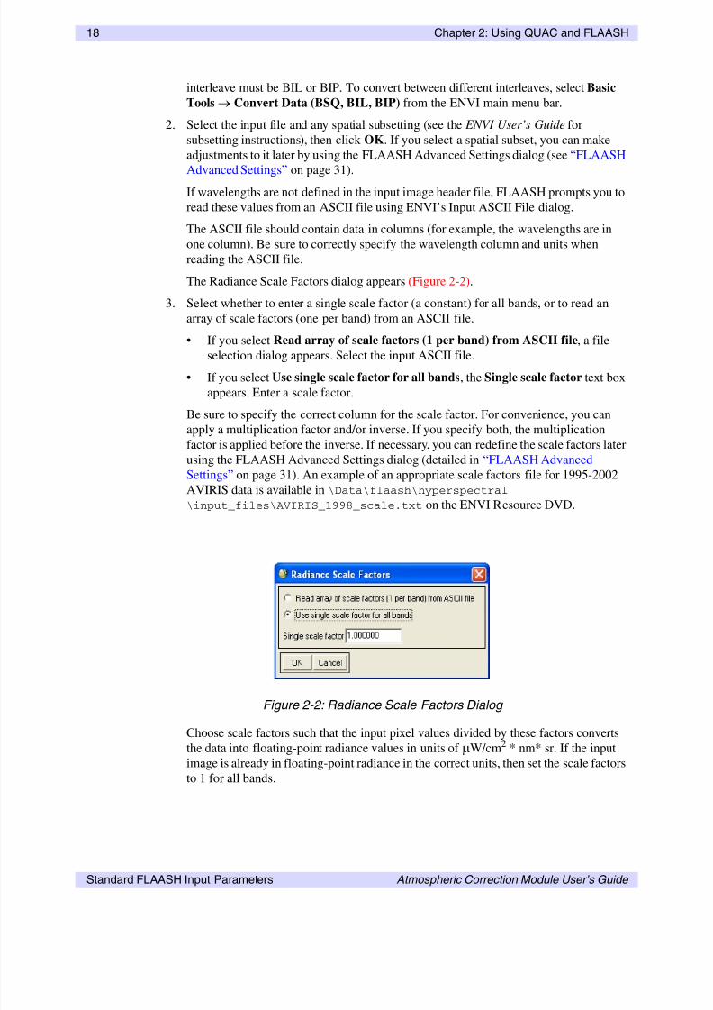
832019 Flaash Module
httpslidepdfcomreaderfullflaash-module 2644
26 Chapter 2 Using QUAC and FLAASH
Standard FLAASH Input Parameters Atmospheric Correction Module Userrsquos Guide
AVIRIS HYDICE HYMAP HYPERION CASI and AISA sensors are automatically
supported for wavelength recalibration All other hyperspectral sensors require a spectrograph
definition file (see the ldquoSelecting a Spectrograph Definition Filerdquo on page 31 for more
details)
When a wavelength recalibration is performed an additional output file is created which
summarizes the results The output file is saved to the FLAASH output directory and named
rootname + wl_recalibrationtxt In addition a message summarizing each spectrographs
wavelength correction is written in the journal file under the heading ldquoDetermined
Wavelength Shift Using NODD Algorithmrdquo One shift and variance value exist for each
spectrograph The shift value indicates the average wavelength shift in channels as computed
from a number of pixels near the centerline of the image the variance value indicates the
uncertainty in the shift determination In some cases both the shift and variance are zero This
can occur when wavelength calibration errors are not present or when no absorption feature
is available within the spectral range of the spectrograph preventing a wavelength correction
from being performed The FLAASH reflectance output file contains the new wavelength
assignments
If you find that the corrected wavelengths are an improvement after the FLAASH processing
is complete you may want to apply them to the original input radiance image To do thisselect File Edit ENVI Header Edit Attributes Wavelengths from the ENVI main
menu bar You can automatically import the new wavelengths using the FLAASH output file
called rootname + wl_recalibrationtxt If you choose to do this then any further processing
of the radiance file in FLAASH should be done with the Wavelength Recalibration toggle
button set to No which speeds processing time
For algorithm details see the following reference
Felde G W G P Anderson S M Adler-Golden M W Matthew and A Berk 2003
Analysis of Hyperion Data with the FLAASH Atmospheric Correction Algorithm Algorithms
and Technologies for Multispectral Hyperspectral and Ultraspectral Imagery IX SPIE
Aerosense Conference Orlando 21-25 April 2003
Hyperspectral Settings
The Hyperspectral Settings button appears at the bottom of the FLAASH Atmospheric
Correction Model Input Parameters dialog when you select a hyperspectral sensor from the
Sensor Type button menu This option allows you to choose how bands are selected for water
vapor andor aerosol retrieval
NoteIf the input data is from a named hyperspectral sensor (listed under the Sensor Type button
menu on the FLAASH Atmospheric Corrections Model Input Parameters dialog) and
neither water nor aerosol is being retrieved it is unnecessary to check the hyperspectral
settings before applying FLAASH
Click Hyperspectral Settings The Hyperspectral Settings dialog appears Select one of the
following options
bull File Specify a channel definition file Click Channel Definition File navigate to the
desired channel definition file and select the file The correct format for a channel
definitions file is described in ldquoHyperspectral Channel Definitions Filerdquo on page 27
832019 Flaash Module
httpslidepdfcomreaderfullflaash-module 2744
Chapter 2 Using QUAC and FLAASH 27
Atmospheric Correction Module Userrsquos Guide Standard FLAASH Input Parameters
bull Automatic Selection FLAASH automatically selects the channel definitions Channel
definitions are automatically assigned by FLAASH based on the spectral
characteristics of the data This is the default setting and is recommended
Hyperspectral Channel Definitions File
The channel definition file follows a simple format where each line contains one channel
definition in the form
channel_type = band_number
The valid channel_types are listed below and must be included in the file verbatim
water channels reference
water channels absorption
cirrus channel
KT upper channels
KT lower channels
alternate water channels absorption
alternate water channels reference
The alternate water channels are used in case the selected water channels are saturated
The first band in the file is referred to as band number 1 If more than one band is appropriate
for a channel_type the bands should be enclosed in curly brackets and separated with
white space Comments can be included as long as they are preceded with a semi-colon
character You only need to include channel definitions for those processing steps that are
being requested
The following text is an example channel definition file for an AVIRIS sensor
Standard AVIRIS channels
Channels are counted starting at 1
water channels reference = 73 74 75 87 88 89 wings must be
symmetric on absorption center channel
water channels absorption = 80 81 82 absorption band
cirrus channel = 109 no needed for single number
optional channels Can leave these out but will lose some
functionality KT is needed for automatic visibility
determination
Kaufman-Tanre method channels
KT upper channels = 184 185 186 187 188
KT lower channels = 29 30 31 32 33 34
alternate water channels absorption = 49 50 082 micron band
alternate water channels reference = 44 45 54 55
FLAASH produces a channel definition file for each processing run (both multispectral and
hyperspectral) The file named rootname_channel_definitiontxt is saved when theOutput Diagnostic Files option is set to Yes in the FLAASH Advanced Settings dialog
Multispectral Settings
The Multispectral Settings button appears at the bottom of the FLAASH Atmospheric
Correction Model Input Parameters dialog when you select a multispectral sensor from the
Sensor Type button menu When applying the FLAASH atmospheric correction model to a
832019 Flaash Module
httpslidepdfcomreaderfullflaash-module 2844
28 Chapter 2 Using QUAC and FLAASH
Standard FLAASH Input Parameters Atmospheric Correction Module Userrsquos Guide
multispectral dataset it is critical to properly choose the bands that are used for water vapor
andor aerosol retrieval In addition if the input data is from an unknown multispectral sensor
it is necessary to define the sensorrsquos spectral response functions
1 Use the FLAASH Multispectral Settings dialog to define the bands for water vapor and
aerosol retrieval
NoteIf the input data is from a named multispectral sensor (listed under the Sensor Type
button menu on the FLAASH Atmospheric Corrections Model Input Parameters
dialog) and neither water nor aerosol is being retrieved it is unnecessary to check the
multispectral settings before applying FLAASH
The channel definitions are used to assign bands from the input file for use in the water
and aerosol retrieval process If a FLAASH template file was restored before opening
the Multispectral Settings dialog then the channel definitions are set according to the
information saved in the template file Otherwise FLAASH selects default bands
according to pre-defined wavelength ranges (defined below) If bands within the pre-
defined ranges are not available then the channel is left undefined
2 Click Multispectral Settings The Multispectral Settings dialog appears Select from
the following options
bull File Specify a channel definition file Click Channel Definition File navigate to
the desired channel definition file and select the file The correct format for a
Figure 2-3 Multispectral Settings Dialog
832019 Flaash Module
httpslidepdfcomreaderfullflaash-module 2944
Chapter 2 Using QUAC and FLAASH 29
Atmospheric Correction Module Userrsquos Guide Standard FLAASH Input Parameters
channel definitions file is described in ldquoMultispectral Channel Definitions Filerdquo on
page 30
bull GUI Interactively select the channels using the Multispectral Settings dialog
bull Select either the Water Retrieval or the Kaufman-Tanre Aerosol Retrieval tabs
to choose the retrieval category (water or aerosol)
A Within each active retrieval category use the drop-down lists to select the desired
band
B In the Kaufman-Tanre Aerosol Retrieval tab set the Maximum Upper Channel
Reflectance and the Reflectance Ratio values These settings identify dark pixels
used for the visibility estimate Recommended values are assigned automatically
by choosing one of the options under the Defaults drop-down list For more
information about the Aerosol Retrieval algorithm and these settings see ldquoThe
FLAASH Modelrdquo on page 10 or the following reference
Y J Kaufman A E Wald L A Remer B-C Gao R-R Li and L Flynn 1997
The MODIS 21-m Channel-Correlation with Visible Reflectance for Use in
Remote Sensing of Aerosol IEEE Transactions on Geoscience and RemoteSensing Vol 35 pp 1286-1298
NoteIf you are using the Over-Water Retrieval default settings the KT Upper and Lower
bands are reversed This is done by design Applying a maximum reflectance
threshold to the 880 nm band tends to better discriminate clear water from turbid or
wet areas leading to more accurate visibility retrievals
You only need to define channels for the processing that is being requested For
example if you are requesting an aerosol retrieval but not a water retrieval then
you may leave the water channels undefined but both the KT Upper and KT Lower
channels have to be definedThe recommended wavelength ranges for each channel are as follows
Water
Retrieval
1135 nm absorption 1117 - 1143 nm
reference upper wing 1184 - 1210 nm
reference lower wing 1050 - 1067 nm
940 nm absorption 935 - 955 nm
reference upper wing 870 - 890 nm
reference lower wing 995 - 1020 nm
820 nm absorption 810 - 830 nm
reference upper wing 850 - 870 nm
reference lower wing 770 - 790 nm
Table 2-4 Recommended Wavelengths for Channel Definitions
832019 Flaash Module
httpslidepdfcomreaderfullflaash-module 3044
30 Chapter 2 Using QUAC and FLAASH
Standard FLAASH Input Parameters Atmospheric Correction Module Userrsquos Guide
C If the input image is from an unknown multispectral sensor type the sensorrsquos
spectral response functions must be defined using a filter function file Click Filter
Function File and select the multispectral sensorrsquos filter function file The filter
function file must be an ENVI spectral library format file and contain the sensorrsquos
filter functions consecutively one for each band in the sensor However the filter
function for the sensorrsquos first band need not be the first function in the file
D In the Index to first band field enter the index into the filter function file
(beginning at zero) where the sensorrsquos filter functions begin
NoteWhen using a known multispectral sensor (ie one whose name is listed under the
Sensor Type button menu) the filter function file and index are automatically set
properly to use the filter function files included in the ENVI distribution
Multispectral Channel Definitions File
The channel definition file follows a simple format where each line contains one channel
definition in the form
channel_type = band_number
The valid channel_types are listed below and must be included in the file verbatim
water channels reference
water channels absorption
cirrus channel
KT upper channels
KT lower channels
KT band cutoff
KT band ratio
The first band in the file is referred to as band number 1 If more than one band is appropriate
for a channel_type the bands should be enclosed in curly brackets and separated with
white space Comments can be included as long as they are preceded with a semi-colon
character You only need to include channel definitions for those processing steps that are
being requested For example a channel definition file for applying FLAASH to Landsat TM
with aerosol retrieval but a fixed water vapor amount could include the following text
FLAASH channel definition for Landsat TM
KT upper channels = 6
KT lower channels = 3
FLAASH produces a channel definition file for each processing run (both multispectral and
hyperspectral) The file named rootname_channel_definitiontxt is saved when the
Output Diagnostic Files option is set to Yes in the FLAASH Advanced Settings dialog
Aerosol
Retrieval
KT upper 2100 - 2250 nm
KT lower 640 - 680 nm
Cloud
Masking
cirrus clouds 1367 - 1383 nm
Table 2-4 Recommended Wavelengths for Channel Definitions (Continued)
832019 Flaash Module
httpslidepdfcomreaderfullflaash-module 3144
Chapter 2 Using QUAC and FLAASH 31
Atmospheric Correction Module Userrsquos Guide FLAASH Advanced Settings
FLAASH Advanced Settings
The FLAASH advanced settings are arranged into three categories modeling parameters
viewing geometry and FLAASH processing controls Use the Advanced Settings dialog to
modify the defaults enter additional data or to make changes to previous settings
To access the advanced settings click Advanced Settings in the lower-right corner of the
FLAASH Atmospheric Correction Model Input Parameters dialog The FLAASH Advanced
Settings dialog appears
Selecting a Spectrograph Definition File
The spectrograph definition file is used to assign the spectral features that are used to correct
the wavelength calibration for hyperspectral input images FLAASH includes built-in
spectrograph definitions for the AVIRIS HYMAP HYDICE HYPERION CASI and AISAsensors If the input image is from another hyperspectral sensor or you wish to customize the
built-in spectrograph definitions you must provide your own spectrograph definition file
To select a file click Spectrograph Definition File and navigate to the file on disk
Figure 2-4 FLAASH Advanced Settings Dialog
832019 Flaash Module
httpslidepdfcomreaderfullflaash-module 3244
32 Chapter 2 Using QUAC and FLAASH
FLAASH Advanced Settings Atmospheric Correction Module Userrsquos Guide
The Spectrograph Definition file is an ASCII text file which contains one line for each
spectrometer in the sensor Each spectrometerrsquos line contains the following information
bull The wavelength (in nanometers) of the reference absorption feature being used to
correct the wavelength calibration If no reliable absorption feature is contained within
the span of the spectrometer then no correction can be made and this value should be
set to zero
bull The full-width half-maximum (FWHM) factor for the reference absorption feature A
wavelength span equal to
4(FWHM factor)(mean FWHM)
on each side of the reference absorption feature is used to find the bands needed for
identifying the feature The exact value of the FWHM factor is not critical for a
successful wavelength recalibration Values between 05 and 15 tend to work well for
hyperspectral sensors with critical sampling (where the FWHM is approximately equal
to the band spacing) If no reference absorption feature exists for the spectrometer then
set this factor to zero
bull The first band number in the spectrometer relative to the first band in the sensor
(starting at band number 1)
bull The last band number in the spectrometer relative to the first band in the sensor
The required format of the file is illustrated in the following example which depicts the
default Spectrograph Definition File for the AVIRIS sensor
FLAASH spectrograph definition for AVIRIS
spectrograph = 0 0 1 32
spectrograph = 76017 06 33 96
spectrograph = 0 0 97 160
spectrograph = 20587 15 161 224
The first line in the file is a comment (comments can be placed anywhere in the file but must
be preceded with the semi-colon character) Each of the next four lines contain a spectrographdefinition for one of the AVIRIS instruments four spectrometers
The first spectrometer contains instrument bands 1-32 but does not span any known
absorption feature that can be used to recalibrate the wavelengths (so the first 2 values are set
to zero) The second spectrometer contains instrument bands 33-96 and the oxygen feature at
76017 nm is used as the reference absorption feature with a FWHM factor of 06 The third
spectrometer contains instrument bands 97-160 but does not contain any reliable features
The fourth spectrometer contains bands 161-224 and the CO2 feature at 20587 nm is used
also with a FWHM factor of 15
NoteFor CASI and AISA the built-in spectrograph definition file assumes that the collected
bands span the 760 nm oxygen feature
Setting Modeling Parameters
Set the following modeling parameters
1 In the Aerosol Scale Height (km) field enter the effective 1 e height of the aerosol
vertical profile in km Typical values are 1 to 2 km The default value is 15 km
832019 Flaash Module
httpslidepdfcomreaderfullflaash-module 3344
Chapter 2 Using QUAC and FLAASH 33
Atmospheric Correction Module Userrsquos Guide FLAASH Advanced Settings
NoteThe aerosol scale height is used only for the calculation of the adjacency scattering
range
2 In the CO2 Mixing Ratio (ppm) field enter the carbon dioxide (CO2) mixing ratio in
parts per million by volume In 2001 the value was approximately 370 ppm For best
results add 20 ppm to the actual value
3 Click the Use Square Slit Function toggle button to select Yes for images that were
derived by averaging together adjacent bands (for example LASH) This better models
the spectral response of the derived bands
4 Click the Use Adjacency Correction toggle button to specify whether or not to use
adjacency correction Unlike most atmospheric correction models the FLAASH model
accounts for both the radiance that is reflected from the surface that travels directly into
the sensor and the radiance from the surface that is scattered by the atmosphere into the
sensor The distinction between the two accounts for the adjacency effect (spatial
mixing of radiance among nearby pixels) caused by atmospheric scattering More
accurate reflectance retrievals result when adjacency is enabled however there may beoccasions when it is desirable to ignore this effect Turning adjacency correction off
sets e = in Equation (1) (see ldquoThe FLAASH Modelrdquo on page 10 for more
information)
5 Click the Reuse MODTRAN Calculations toggle button to specify whether or not to
reuse previous MODTRAN calculations Reusing previous MODTRAN calculations is
useful for rapidly processing multiple images taken under essentially identical
conditions the identical illumination viewing geometries and visibility are assumed
but the water vapor retrieval is performed again It is also useful for rapidly generating
images with and without polishing or with different polishing widths Following is an
explanation of the options
No FLAASH computes a new set of MODRTRAN radiative transfer calculations forthe selected image and model parameters
Yes FLAASH performs the atmospheric correction using the MODTRAN calculations
from the previous FLAASH run This change causes FLAASH to perform a water
retrieval therefore the Water Retrieval toggle button on the main FLAASH Input
Parameters dialog is automatically set to Yes You cannot reset Water Retrieval to No
until you set Reuse MODTRAN Calculations to No
Following each FLAASH run the MODTRAN calculations are stored in a file called
acc_modrootfla and a copy is saved in both the FLAASH output directory as well
as in ENVIrsquos temporary directory (defined in the ENVI preferences file) If you set
Reuse MODTRAN Calculations to Yes ENVI first looks in the current FLAASH
output directory for the acc_modrootfla file If the file is present it is usedOtherwise ENVI uses the copy that is in the temporary directory Therefore you can
force FLAASH to use the MODTRAN calculations from any previous run by copying
the desired acc_modrootfla from the desired run into the FLAASH output
directory for the current run
6 In the Modtran Resolution drop-down list select a resolution The Modtran
Resolution setting controls the MODTRAN spectral resolution and the trade-off of
speed versus accuracy for the MODTRAN4 portion of the calculation Lower
832019 Flaash Module
httpslidepdfcomreaderfullflaash-module 3444
34 Chapter 2 Using QUAC and FLAASH
FLAASH Advanced Settings Atmospheric Correction Module Userrsquos Guide
resolution yields proportionally better speed but less accuracy The main differences in
accuracy are seen near 2000 nm and beyond The 5 cm-1 resolution is the default value
when you select a hyperspectral sensor as input but it changes to 15 cm-1 when you
select a multispectral sensor If aerosol is being retrieved there are two MODTRAN4
runs performed at 15 cm-1 resolution followed by one MODTRAN4 run at the
resolution you select If aerosols are not being retrieved the first two runs are omitted
7 In the Modtran Multiscatter Model drop-down list select a multiple-scattering
algorithm to be used by MODTRAN4 FLAASH offers three options for multiscatter
models Isaacs Scaled DISORT and DISORT The default is Scaled DISORT with
eight streams
The DISORT model provides the most accurate short-wave (less than ~ 1000 nm)
corrections however it is very computationally intensive The Isaacs 2-stream method
is fast but oversimplified The Scaled DISORT method provides near-DISORT
accuracy with almost the same speed as Isaacs In the Scaled DISORT model DISORT
and Isaacs calculations are performed at a small number of atmospheric window
wavelengths The multiple scattering contributions in each method are identified and
ratios of the DISORT and Isaacs methods are computed This ratio is interpolated over
the full wavelength range and finally applied as a multiple scattering scale factor in aspectral radiance calculation performed with the Isaacs method This procedure yields
near-DISORT accuracy at window wavelengths and also improves the accuracy in
absorbing regions
8 If you select DISORT or Scaled DISORT as the multiscatter model specify the
number of streams 2 4 8 or 16 The number of streams is related to the number of
scattering directions evaluated by the model Calculations with two or four streams are
not recommended as they dramatically increase computation time (over Isaacs) with
little or no improvement Increasing the number of streams for the Scaled DISORT
model should not significantly increase processing time
Use of the DISORT multiscatter model dramatically increases FLAASH processing
time and is rarely necessary for accurate atmospheric corrections The magnitude of
multiple scattering in any scene is dependent on the amount of haze (water vapor and
aerosols) that are present Moreover scattering preferentially affects the shorter
(visible) wavelengths longer (near infrared) wavelengths are minimally affected You
should only consider using the DISORT model in the most severe cases when haze is
very strong and critical correction of the shortest wavelengths is required Computation
times vary with system resources but typical relative computation times are
Isaacs DISORT-2 DISORT-4 DISORT-8 DISORT-16 = 1 22 24 30 60
That is running DISORT with 8 streams usually takes about 30 times longer than using
Isaacs In addition a combination of DISORT (with any number of streams) and a
MODTRAN resolution of 1 cm
-1
is extremely computationally intensiveReferences
K Stamnes S-C Tsay W Wiscombe and K Jayaweera Numerically Stable Algorithm for
Discrete-Ordinate-Method Radiative Transfer in Multiple Scattering and Emitting Layered
Media Applied Optics Vol 27 1988 pp 2502-2509
R G Isaacs W C Wang R D Worsham and S Goldenberg Multiple Scattering LOWTRAN
and FASCODE Models Applied Optics Vol 26 1987 pp 1272-1281
832019 Flaash Module
httpslidepdfcomreaderfullflaash-module 3544
Chapter 2 Using QUAC and FLAASH 35
Atmospheric Correction Module Userrsquos Guide FLAASH Advanced Settings
Setting Viewing Geometry Parameters
For instruments that use a non-nadir viewing geometry you must specify the zenith and
azimuth angles The zenith angle is defined at the sensor as the angle between the line of sight
and the zenith (180 for nadir-viewing sensors) Zenith angles must be positive and between 90
and 180 degrees The azimuth angle is defined as the azimuth (the angle between the line of
sight and due North) of the sensor as viewed from the ground This angle is arbitrary for
nadir-viewing sensors Azimuth values must be between -180 and 180 degrees For example
if your azimuth from the sensor is 90 degrees (due east) then the azimuth from the ground is
-90 degrees (due west)
In the Zenith Angle and Azimuth Angle fields enter the correct angles
NoteTo toggle between degreesminutesseconds and decimal degrees click the DD lt-gt DMS
button
Setting FLAASH Processing ControlsSet the following parameters for processing
1 Click the Use Tiled Processing toggle button to specify whether or not to use tiled
processing Like all ENVI processing routines FLAASH processes the input data in
pieces (called tiles) then reassembles the tiles after processing is complete to produce
the final result Using tiled processing allows FLAASH to run on images of any size
regardless of system resources (that is available memory)
The default setting in FLAASH is to use tiled processing (Yes) Tiled processing is
highly recommended however some cases occur when FLAASH runs faster without
tiling
If you select Yes then enter a value (in megabytes) in the Tile Size field The defaulttile size is set to the larger of your ENVI Preferences Cache Size or 100 MB When
processing FLAASH ensures that the largest piece of the image that is read into
memory at any time never exceeds the tile size It is recommended that the tile size be
set to the largest value that does not leave the rest of the computer system deprived of
memory for essential functions For single user machines a reasonable estimate is
about 75 of the installed RAM
Large datasets that contain many pixels with values of 0 (such as a projected Landsat
scene) may cause the FLAASH process to fail because the tile can return all ldquo0rdquo pixels
An error message may appear in a popup window and in the file journaltxt that is
created in the output file directory specified in the FLAASH Atmospheric Corrections
Model Input Parameters dialogTo work around this problem increase (or even double) the Tile Size value so that each
tile contains some image data
2 Click Spatial Subset to re-define the spatial subset you selected during original input
file selection You can also use the information displayed in the Spatial Subset field to
verify the spatial subset that was defined when the input image was selected
832019 Flaash Module
httpslidepdfcomreaderfullflaash-module 3644
36 Chapter 2 Using QUAC and FLAASH
FLAASH Advanced Settings Atmospheric Correction Module Userrsquos Guide
3 Click Choose to re-define the scale factors you selected during the original input file
selection When the Radiance Scale Factors dialog appears select a scale factor
method (see ldquoSpecifying Input and Output File Informationrdquo on page 17 for details)
4 In the Output Reflectance Scale Factor field enter the value used to scale the output
reflectance image from floating-point into 2-byte integer data space
Signed integers have an absolute data range between -32768 and +32767 Therecommended scale factor is 10000 This value is stored as the Reflectance Scale
Factor Attribute in the header file of the output image
5 Click the Automatically Save Template File toggle button to specify if you want to
automatically save FLAASH parameters to a template file in the FLAASH output
directory For details about template files see ldquoSaving and Restoring FLAASH Run
Parameters (Templates)rdquo on page 38 The filename is templatetxt appended to
your defined root name
TipIt is recommended you leave this setting at Yes (default) as it can be helpful to retain
a copy of each runrsquos parameters for later reference
6 Click the Output Diagnostic Files toggle button to specify whether or not to create
intermediate data files including the channel definition files used for both
hyperspectral and multispectral corrections The intermediate files can be helpful in
diagnosing runtime problems
It is recommended you leave this setting at No (the default) unless instructed
otherwise or if you want to see the channel definition file used by FLAASH
832019 Flaash Module
httpslidepdfcomreaderfullflaash-module 3744
Chapter 2 Using QUAC and FLAASH 37
Atmospheric Correction Module Userrsquos Guide Starting the Processing
Starting the Processing
When all FLAASH parameters are set click Apply in the FLAASH Atmospheric Model
Input Parameters dialog to begin processing
832019 Flaash Module
httpslidepdfcomreaderfullflaash-module 3844
38 Chapter 2 Using QUAC and FLAASH
Saving and Restoring FLAASH Run Parameters (Templates)Atmospheric Correction Module Userrsquos Guide
Saving and Restoring FLAASH Run Parameters(Templates)
You can save a complete set of FLAASH run parameters including input and output file
names to a template file You can then use the FLAASH template to restore the run settings ata later date This can be quite useful for quickly re-defining the model settings or for
checking to see how the parameters were set in a previous run For convenience the template
file is in an ASCII format so it can easily be read outside of ENVI using any text editor
Template files can also be used to share FLAASH run details with colleagues who also have
FLAASH just send the template file to them to restore
Saving the Template
To save the FLAASH run settings to a template file at any time click Save in the lower-right
corner of the FLAASH Atmospheric Model Input Parameters dialog
If you set the Automatically Save Template File toggle button to Yes in the FLAASH
Advanced Settings dialog a template file is automatically saved into the FLAASH output
directory when you click Apply in the FLAASH Atmospheric Model Input Parameters
dialog
Restoring a Template File
To restore a FLAASH template file click Restore in the lower-right corner of the FLAASH
Atmospheric Model Input Parameters dialog
The template file stores the full path names of the input and output files (that is the file names
include the directory names) If the input file is not already opened in the current ENVI
session it is automatically opened If any of the files or directories cannot be located on the
computer where FLAASH is running the corresponding fields in the FLAASH dialogs willnot be filled in but ENVI reads the rest of the parameters This process allows template files
to be shared between users working in different locations
832019 Flaash Module
httpslidepdfcomreaderfullflaash-module 3944
Chapter 2 Using QUAC and FLAASH 39
Atmospheric Correction Module Userrsquos Guide FLAASH Output Files
FLAASH Output Files
The FLAASH atmospheric correction model produces the output files described in the
following sections
Surface ReflectanceFLAASH creates an image of retrieved surface reflectance scaled into two-byte signed
integers using the scale factor defined in the FLAASH Advanced Settings dialog (To set the
scale factor see ldquoSetting FLAASH Processing Controlsrdquo on page 35) The name and location
for this output file is defined in the FLAASH Atmospheric Correction Model Input
Parameters dialog in the Output Reflectance File field The reflectance image bad bands are
set according to the bad bands defined for the input radiance image as well as those for which
the atmospheric transmission as determined by FLAASH is too low for an accurate
reflectance calculation
Water Vapor
FLAASH creates an image of retrieved column water vapor in units of (atm bull cm) This file is
written to the FLAASH output directory with the name waterdat appended to your
specified root name
Cloud Map
FLAASH creates a cloud map classification image is written to the FLAASH output directory
with the name cloudmaskdat appended to your specified root name The cloud
determinations are used during FLAASH processing to refine the estimate of e in equation
(1) This quantity defines the magnitude of the adjacency effect
Log File
The log file is an ASCII file containing a detailed description of the FLAASH processing
This file is written to the FLAASH output directory with the name journaltxt appended
to your specified root name
FLAASH Template File (Optional)
If you set the Automatically Save Template File toggle button to Yes in the FLAASH
Advanced Settings dialog a template file is automatically saved into the FLAASH output
directory when you click Apply in the FLAASH Atmospheric Model Input Parameters
dialog The nametemplatetxt
is appended to your specified root name
832019 Flaash Module
httpslidepdfcomreaderfullflaash-module 4044
40 Chapter 2 Using QUAC and FLAASH
FLAASH Output Files Atmospheric Correction Module Userrsquos Guide
832019 Flaash Module
httpslidepdfcomreaderfullflaash-module 4144
Atmospheric Correction Module Userrsquos Guide 41
IndexA
adjacency correction 33
aerosols
retrieving 23
scale height 32
selecting models 23
ASTER datausing in QUAC and FLAASH 13
atmospheric correction 6
DISORT multiscattering 34
modeling parameters 32
multiscatter models 34
previous MODTRAN calculations 33
atmospheric models 20
seasonal-latitude models 21
standard column water vapor 20
azimuth angles defined 35
C
carbon dioxide mixing ratio (FLAASH) 33
cloud maps 39
copyrights 2
D
DISORT 34
F
file formats
ASCII
hyperspectral channel definitions 27
multispectral channel definitions 30
spectrograph definitions 31
FLAASH output files 39
cloud maps 39
log files 39
surface reflectance 39
water vapor 39
file naming conventions
FLAASH 19
FLAASH 6
advanced settings 31
aerosols 23
ASTER data 13
atmospheric model settings 20
average reflectance 11
cloud maps 39
diagnostic files 36
DISORT multiscattering 34
832019 Flaash Module
httpslidepdfcomreaderfullflaash-module 4244
42
Atmospheric Correction Module Userrsquos Guide Index
file naming conventions 19
hyperspectral channel definitions 27
hyperspectral settings 26
initial visibility 24
input data requirements 12
input parameters 17
input radiance image 17introduction 6
log files 39
modeling parameters 32
MODTRAN 10
MODTRAN resolution 33
multiscatter models 34
multispectral channel definitions 30
multispectral settings 27
output files 39
output parameters 19
scale factors 18
scene and sensor information 19
spectral polishing 24
spectrograph definition files 31
supported sensors 7
surface reflectance 39
templates 38 39
viewing geometry 35
water vapor 39
H
hyperspectral settings (FLAASH) 26
L
legalities 2
M
MODTRAN 10
multiscatter models 34
reusing calculations 33
saved calculations 33spectral resolution 33
multiscattering models (FLAASH) 34
Q
QUAC 6
ASTER data 13
input data requirements 12
introduction 6
R
radiance image (FLAASH) 17
radiance scale factor See scale factors
S
scale factors
FLAASH 12
units 18
spectral polishing (FLAASH) 24spectral radiance 10
square slit function (FLAASH) 33
surface reflectance 39
T
templates
FLAASH 38 39
trademarks 2
V
viewing geometry (FLAASH) 35
visibility in scenes 24
W
water vapor
output files 39
standard amounts 20
variance 10
Z
zenith angles defined 35
832019 Flaash Module
httpslidepdfcomreaderfullflaash-module 4344
43
Atmospheric Correction Module Userrsquos Guide Index
832019 Flaash Module
httpslidepdfcomreaderfullflaash-module 4444
44
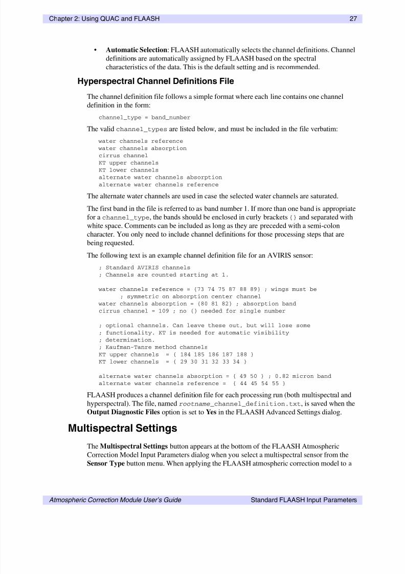
832019 Flaash Module
httpslidepdfcomreaderfullflaash-module 4344
43
Atmospheric Correction Module Userrsquos Guide Index
832019 Flaash Module
httpslidepdfcomreaderfullflaash-module 4444
44

832019 Flaash Module
httpslidepdfcomreaderfullflaash-module 4444
44