fracture mechanics you can understand
TRANSCRIPT
Fracture Mechanics You Can Understand.
John Goldak and Hossein Nimrouzi
October 14, 2018
This document is intended to present much of the theory of linear elastic fracturemechanics (LEFM) in a way that is readily understandable to a second year engineeringstudent. For a given crack geometry in a given structure, material type and boundaryconditions, LEFM provides the formula below for the normal stress σyy(x, 0) on the crackplane with the crack. See Fig. 1.
σyy(x, 0) =KI√2πr
f(θ) (1)
where KI is the amplitude of the function f(θ)/(√
2πr). The function f(θ)/(√
2πr) is onlya function of polar coordinates (r, θ). For a centre crack in an infinite plate with uniaxialtensile stress σ∗yy before (without) the crack and crack length a, the value of the coefficientKI , which is called the stress intensity factor, is computed from the equation below.
KI = σ∗yy√πa (2)
where σ∗yy is is the traction normal to the crack plane evaluated in the UNCRACKEDspecimen or structure. Note that σ∗yy and σyy(x, 0) are very different things.
LEFM succeeded because experiments showed that if for a given material, crack geom-etry and load case, KI was less than a critical value called the fracture toughness that isdenoted KIC , the crack was unlikely to grow rapidly and the risk the structure would failwas low. However, if KI was greater than the fracture toughness, the risk that the crackwould grow rapidly and the structure would fail was high. It is important to note that KIC
is not a material property but it is a function of the material, structure geometry, crackgeometry and load case. In other words, it is a function of the design.
The following sections will show several examples that demonstrate that the associatedstress distributions in the crack plane that are computed from LEFM theory and computeddirectly with FEM are in some sense equivalent.
1
1 A Center-Cracked Plate
In this example of a center-cracked plate of finite width b and σ∗yy is the tensile stress onthe crack plane without the crack, the value of the stress intensity factor KI for planestrain deformation is given by the equation below.
KI = σ∗yy
√πa
(2b
πatan
πa
2b
)(3)
Now the constant KI is not a fundamental constant like the speed of light. It is onlya constant for this particular crack geometry, material and this particular stress statein this particular structure or global body. Thousands of papers have been written totry to provide an equation to evaluate KI for every possible crack geometry and loadingsituation. A typical textbook on fracture mechanics will have many such equations, eachfor a different crack geometry, structure geometry and load case. Thousands of thesesand tens of thousands of papers have been devoted to LEFM. Just as one needs a contactinformation for each individual person, one needs a different equation for the stress intensityfactor for each variation of a crack geometry, crack location, structure design and material.
For a crack plane normal to the y-axis that is loaded with a uniaxial yy-stress, the yy-stress component near the crack tip as a function of polar coordinates, i.e., as a functionof distance r from the crack tip and angle θ from the crack plane, is denoted σyy(r, θ). Itsvalue is given by the following equation.
σyy(r, θ) =KI√2πr
cosθ
2
[1− sinθ
2sin
3θ
2
](4)
This equation is a useful approximation in a region near the crack tip. It is like Goldilock’sporridge, i.e., not too close and not too far. As the distances to the crack tip approacheszero, the stress in the equation goes to infinity. This is clearly not possible in real materialsthat cannot have an infinite yield stress. Advocates of LEFM rationalize this by arguingthat for sufficiently brittle materials, the region under going plastic strain is small andthe error caused by ignoring the error in this plastic region is acceptable. Therefore thisequation could only be realistic in the part of the curve for r > ε some distance from thecrack tip where the value of the stress declines with distance from the crack tip at the ratepredicted by the equations in LEFM theory. In real problems at stresses above the yieldstress, the material will yield plastically. In no real case will the stress go to infinity. InLEFM theory, the stress does go to infinity at the crack tip. At distances far from thecrack tip, the stress in this equation goes to zero. This is also not realistic. The stressnear a small crack should decay to the stress σ∗yy in the uncracked structure for distancessufficiently far from the crack, i.e., as r 7→ ∞. Thus the stress computed by LEFM is onlya useful approximation in the region not too close to the crack tip and not too far fromthe crack tip.
2

What is the basis of this theory? Who developed it and why? The answer is thatsome of world’s brightest applied mathematicians solved some very difficult mathematicalproblems to compute the eigenvalues and eigenfunctions associated with the singularity inthe stress state near the crack tip. The stress intensity factor KI is the real part of thecomplex eigenvalue with the lowest non-zero real part in this particular problem. It is abit like the first term in a Taylor series or the critical stress for Euler’s first buckling modefor a slender cylinder loaded in compression. However, to my knowledge, engineers whouse LEFM never compute any higher order eigen values or eigenfunctions.
So what is the justification for using a theory that is not realistic? Well all theoriesare based on a set of assumptions. In science and engineering there are no theories ofeverything. It is the user’s responsibility to decide if the assumptions in the theory aresufficiently realistic, i.e., what to leave in and what to leave out. To be more precise it is theusers responsibility to decide if the theory or mathematical model when used appropriatedlyprovides predictions and information that would be useful in making a decision. Clearly,there is no question that LEFM has been very useful.
Why did people accept the unrealistic assumptions? The only reason that we can imageis that people did not want or were not capable of analyzing the stress in a complex bodythat had a crack. In the period from 1950 to 1970 in which LEFM was developed andfirst used in engineering, LEFM was their best option. This is no longer true. Usingmodern FEM packages would be much cheaper, faster, more accurate, more realistic, moregeneral and easier to understand and would require far less training. Fracture mechanicswould be viewed as a standard mechanics problems requiring only a knowledge of standardfundamental principles of mechanics and a knowledge of the required properties of thematerials. Instead of computing only the first eigen pair as in LEFM, FEM would computeall of functions that project the exact solution of the infinite dimensional mathematicalproblem onto the function space defined by the FEM elements in the finite element meshnear the crack tip. To get a higher order approximation just refine the FEM mesh orreplace lower order elements with higher order elements.
Although LEFM theory will become irrelevant in modern engineering, just as theLATIN language and drafting are, the full mathematical theory that solves for complexeigen functions and eigen values could be a powerful tool for people who have the math-ematical expertise to understand and exploit it for applications that would benefit fromthis theory. Others are advised not to go near the full mathematical theory until they havesufficient understanding of the mathematics.
2 Replacing Linear Elastic Fracture Mechanics
The only reason for using LEFM that the authors can imagine is to avoid a global stressanalysis of a large and possibly complex structure that has the crack. The global stressanalysis of the large and possibly complex structure without the crack had to be done to
3
get the stress state in the neighbourhood of the crack before the crack formed. Decadesago, before FEM codes were developed and reached their current level of maturity, it wasvery expensive to compute even a crude estimate of the stress in the un-cracked complexstructure such as a ship. I cannot imagine how one could compute the stress in a complexstructure such as ship with even one crack using the classical theory of mechanics. I suspectthat this is exactly why LEFM was developed. It provided a tractable method of estimatingthe stress state near a crack in a complex structure. The theory was complicated and therewere serious limitations to the theory but at the time it clearly was the best option available.
Since that time FEM codes have been developed and reached a high level of maturity.Since domain decomposition algorithms are now available that enable a stress analysis tobe done quickly, cheaply and almost automatically using FEM in a subdomain that is onlylarge enough to contain the region in which the stress changes introduced by the crack aresignificant. The authors argue that it is easier, simpler and at least as accurate to computethe stress distribution near the crack tip using FEM on as fine a mesh as one deemsuseful. This would avoid a great deal of mathematical gymnastics, the highly restrictiveassumptions of doubtful validity that are assumed in LEFM and would be much easierfor design engineers to understand and to use in optimizing real designs. Since very fewdesign engineers actually understand the theory or the assumptions that underly LEFM,this seems highly desirable. Moreover, the FEM analysis can use nonlinear models of thematerial and geometry that are more realistic.
What must be retained from the past 70 or years of research on fracture mechanicsis the experimental data. The weaknesses and limitations of LEFM do not in any waydiminish the value of the data acquired in the vast number of experiments for fracturemechanics. This experimental data completely retains its value and remains essential tothe fracture mechanics analysis that will be done using FEM analysis. Not only could theFEM computer models could be correlated more strongly with the experimental data, butthey could be used to design optimal experiments.
3 Measuring KIC - Fracture Mechanics Tests
Designers would like to have the opportunity to conduct experiments quickly and at lowcost. Ideally the experiment would use the real structure or a prototype. In the early stagesdesign, this is not possible because nothing exists but concepts. Then test specimens mustbe designed.
This usually creates a need to design optimal experiments. Often one seeks to optimizethe specimen size. Smaller experiments could have a lower cost until the size reaches apoint at which the cost begins to climb. For example a standard Charpy Impact testspecimen is 1×1×10 cm which is usually considered the optimum size for a toughness testof a material such as steel. There are a few wide plate tensile test machines in the worldthat test very large specimens such 1 m diameter pipes width 25 mm thick walls of high
4
strength steel but the machines and the specimens are expensive. However, when one doesnot have material in sizes large enough to make the desired test specimen, one could bepushed to devise tests with specimens of smaller size. This has been done in the nuclearindustry where only very small specimens are sometimes available.
The risk of fracture is higher in larger structures for several reasons. The probabilityof more and larger defects is larger. The stress state is more highly constrained whichfavours lower toughness fracture modes. The quality of the microstructure is usually lowerin larger structures because of difficulties and limitations in the manufacturing process.Devising fracture toughness tests for very large structures such as nuclear reactor pressurevessels that can weigh hundreds of tonnes is a challenge. One of the challenges is thatthe fracture mode can be sensitive to whether the stress state is plane strain or planestress. Plane strain stress state has a lower fracture toughness. This is the reason that it isoften difficult to relate data from Charpy tests to the toughness of a large structure madewith essentially the same material. This has led to the design of special tests to measurefracture toughness. One of the most popular is the compact tension test (CT). CT tests areoften made in a size with thickness close to the thickness of the structure being designed.Designing smaller test specimens is an active research area.
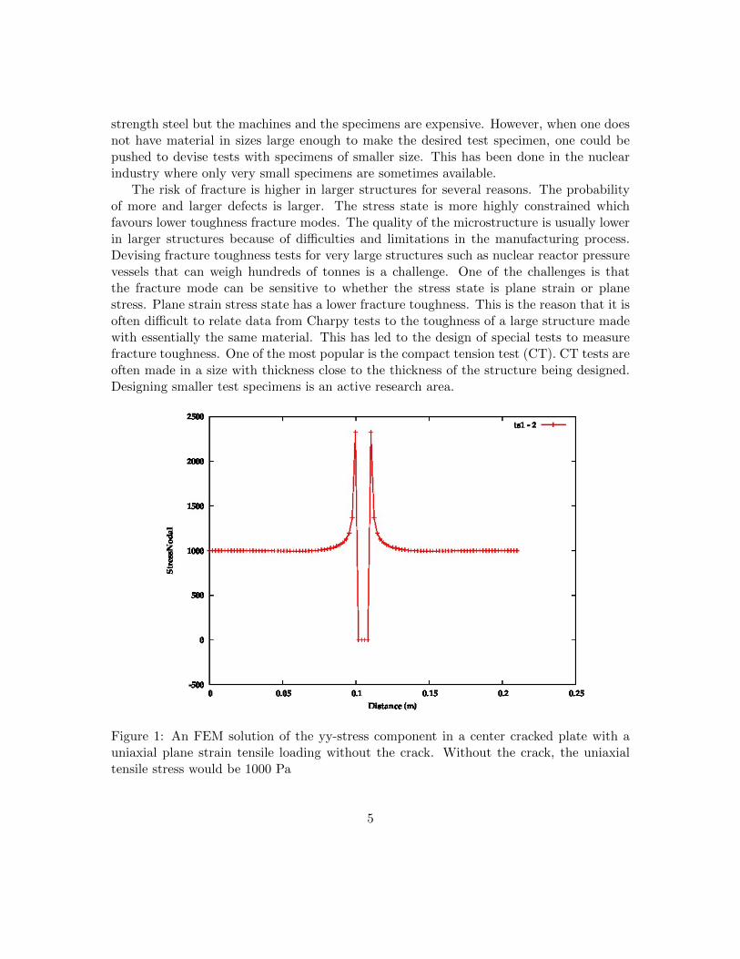
Figure 1: An FEM solution of the yy-stress component in a center cracked plate with auniaxial plane strain tensile loading without the crack. Without the crack, the uniaxialtensile stress would be 1000 Pa
5

Figure 2: An FEM solution of the xx-stress component in a center cracked plate with auniaxial plane strain tensile loading without the crack.
6
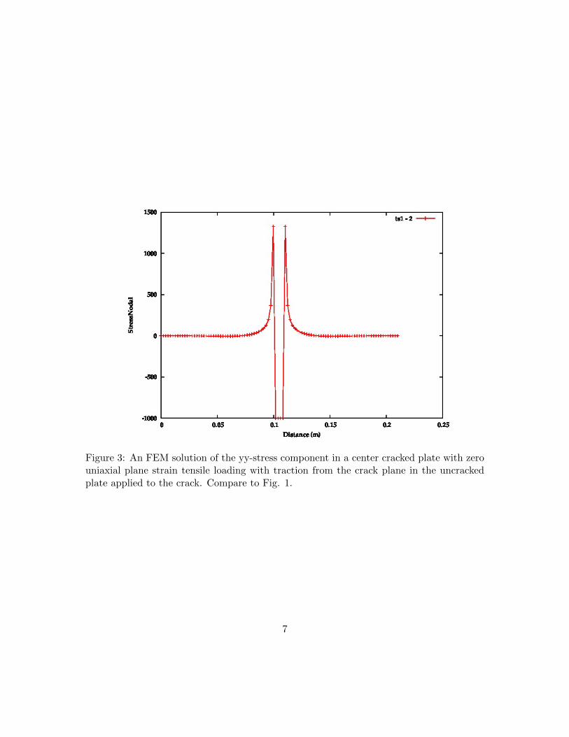
Figure 3: An FEM solution of the yy-stress component in a center cracked plate with zerouniaxial plane strain tensile loading with traction from the crack plane in the uncrackedplate applied to the crack. Compare to Fig. 1.
7

Figure 4: An FEM solution of the yy-stress component in a center cracked plate. Withoutthe crack it would be uniaxial plane strain tensile loading of 1000, 2000 and 4000 MPa.Compare to Fig. 1.
8
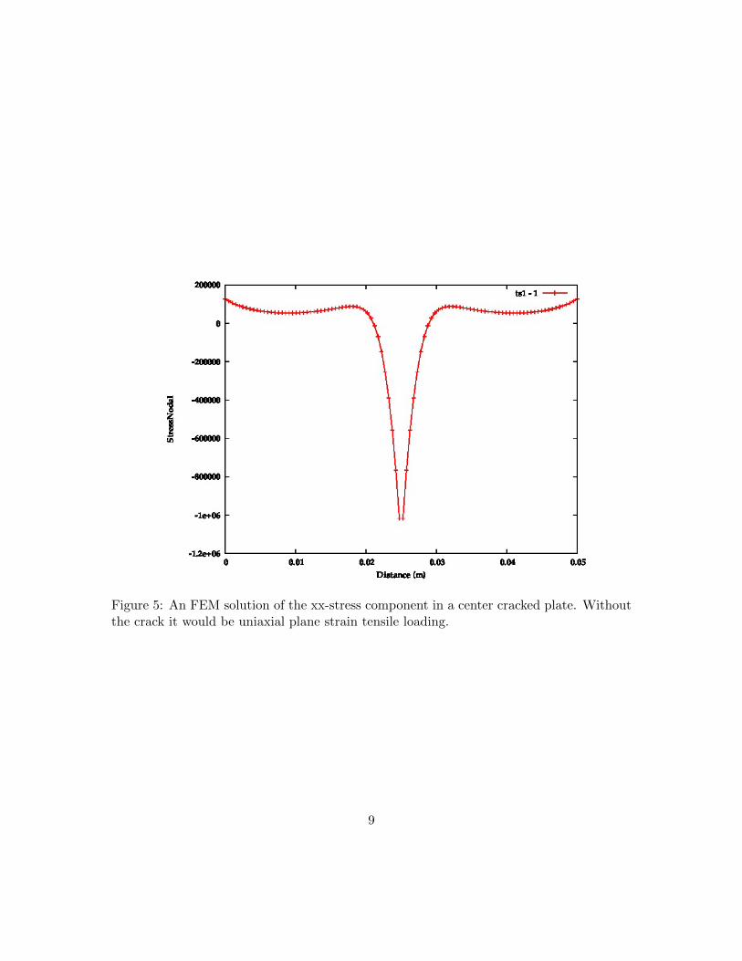
Figure 5: An FEM solution of the xx-stress component in a center cracked plate. Withoutthe crack it would be uniaxial plane strain tensile loading.
9
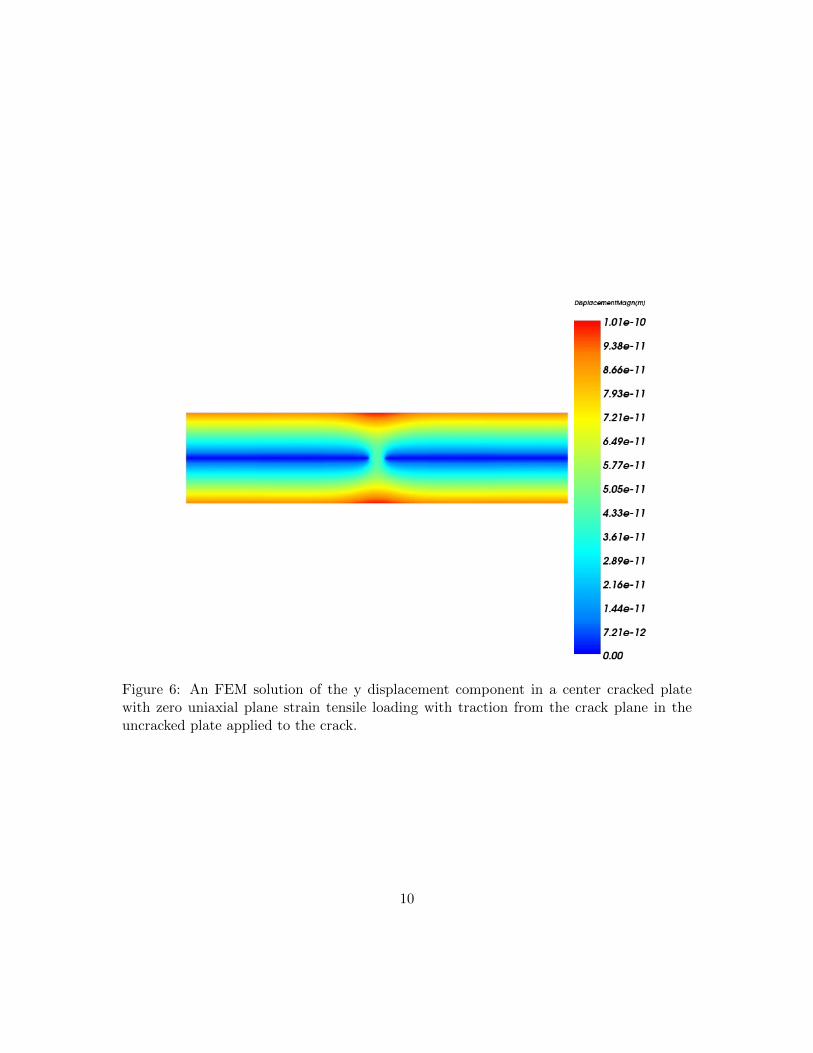
Figure 6: An FEM solution of the y displacement component in a center cracked platewith zero uniaxial plane strain tensile loading with traction from the crack plane in theuncracked plate applied to the crack.
10
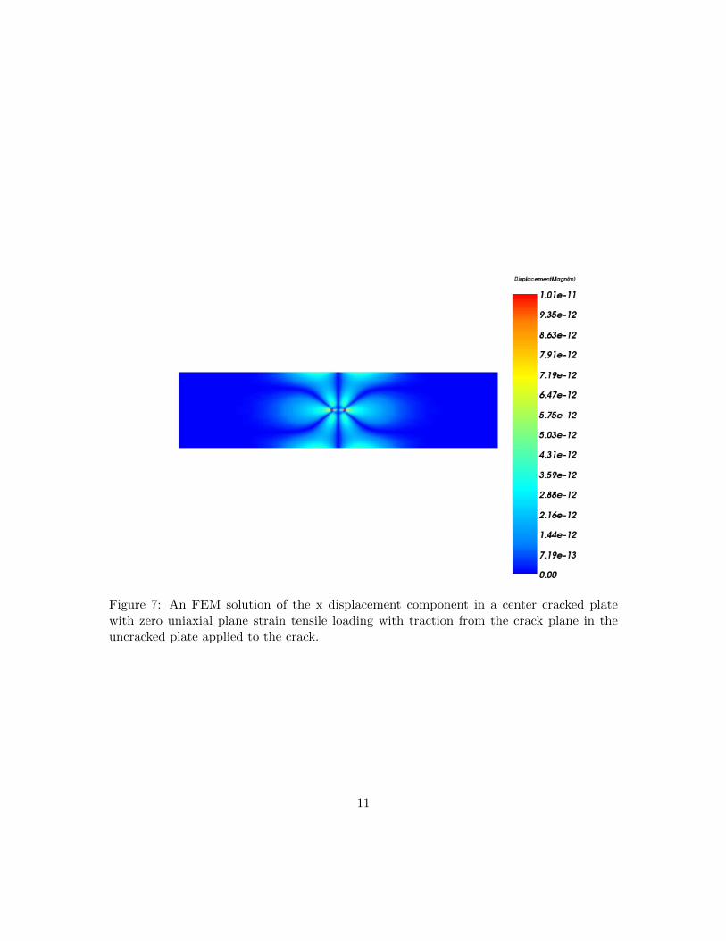
Figure 7: An FEM solution of the x displacement component in a center cracked platewith zero uniaxial plane strain tensile loading with traction from the crack plane in theuncracked plate applied to the crack.
11

Figure 8: An FEM solution of the y displacement component in a center cracked platewith zero uniaxial plane strain tensile loading with traction from the crack plane in theuncracked plate applied to the crack.
12

Figure 9: An FEM solution of the x displacement component in a center cracked platewith zero uniaxial plane strain tensile loading with traction (0, 1000, 0) the crack.
Figure 10: A plot of the yy-stress component in a center cracked plate with a uniaxial planestrain tensile in the plane of the crack. if the part of the plot to the right of the peak isplotted as a function of 1/
√r, a part would be the singular function that is approximated
in linear elastic fracture mechanics. This FEM analysis is closer to reality.
13

Figure 11: Illustration of different techniques that can be used to solve fatigue relatedissues. Marquis (2009)
14
References
[1] David A. Porter, Weldable High-Strength Steels: Challenges and Engineering Applica-tions, IIW International Conference High-Strength Materials - Challenges and Appli-cations, 2-3 July 2015, Helsinki, Finland
[2] G. I. Barenblatt, Some General Aspects of Fracture Mechanics, Ed, G. Herrmann, Mod-eling of Defects and Fracture Mechanics, Springer-Verlag, 1993, (International Centrefor Mechanical Sciences), Courses and Lectures - No. 331, pp 29-59.
[3] Felipe P. Calderon, Nobuo Sano, Yukio Matsushita, Diffusion of manganese and sil-icon in liquid iron over the whole range of composition, Metallurgical and MaterialsTransactions B, December 1971, Volume 2, Issue 12, pp 3325-3332
15