guai yeu kae - eprints.utm.myeprints.utm.my/id/eprint/11299/6/guaiyeukaemfkm2009.pdf · ujian impak...
TRANSCRIPT

TURBINE BLADE CRACK DETECTION USING VIBRATION TESTING
METHODS
GUAI YEU KAE
UNIVERSITI TEKNOLOGI MALAYSIA
TURBINE BLADE CRACK DETECTION USING VIBRATION TESTING
METHODS
GUAI YEU KAE
A thesis submitted in fulfilment of the
requirements for the award of the degree of
Master of Engineering (Mechanical)
Faculty of Mechanical Engineering
Universiti Teknologi Malaysia
DEC 2009

iii
To Papa, Mama and Tan Lin
for their support and love
iv
ACKNOWLEDGEMENT
I would like to express my sincere appreciation and gratitude to my thesis
supervisor, Prof. Ir. Dr. Mohd. Salman Leong, for his supervision, helpful
encouragement, knowledge, continued guidance and moral support throughout my
studies as well as freedom provided to work on this research. I am also grateful to my
colleagues, Wong, Tan and Asrie, for sharing their ideas and providing valuable
suggestions; laboratory assistants, Ali, for his patience, for answering endless
questions and making the time spent together working at the IKG laboratory a
valuable experience for me; Many thanks are also due to the staff of IKG, Kak Ana,
for her support and assistance in my studies.
Special thanks to Lim Chai Heng and Goh Hui Minn. Their great dedication
towards assisting me was above and beyond what I expected. I truly appreciated their
true friendship.
I would like to thank Papa, Mama, my sister and Tan Lin for their
unswerving belief and support to me all these years.
v
ABSTRACT
Turbine blades are the most common cause of failures in gas turbines. Failure
modes are typically cracking from foreign object damage (FOD), high cycle stress
(HCF), blade rubbing, degradation from erosion and corrosion. Fault detection of
blades is important function in reducing blade related failures. This study involved
the use of vibration analysis and dynamic testing of blades for failure detection.
Current field inspections of blades are based on visual inspections only, and the
intent here was to use impact testing of the blades during these inspections to
determine cracked blade (from the vibration response). Vibration impact tests were
undertaken using decommissioned turbine blades with and without cracks in the
laboratory. Four common crack patterns were deliberately induced to the turbine
blades to investigate changes in the blades normal mode response. Finite element
analysis (FEA) of the blades was also undertaken. FEA results were correlated to
experimental results and these results showed that each crack pattern was unique and
significant changes were found in higher modes. Dynamic vibration analysis was
also undertaken in a laboratory testrig fitted with rotating model straight blades.
Vibration measurements were undertaken on a baseline test case and other test
conditions where the blades had induced cracks. Steady state and transient vibration
responses were obtained from the controlled tests. Vibration measurements were on
the machine casing and on a blade (with an accelerometer surfaced mounted onto a
rotating blade). Order tracking analysis and continuous wavelet analysis were
performed to the measured data. Both techniques showed ability in detecting
changes in vibration response on the blades and casing for blades with cracks.
Results showed that significant changes were detected during transient analysis as
compared to the steady state. Changes were noted in the vibration response
corresponding to the machine running speed and blade passing frequencies. Changes
in wavelet maps were however qualitative in nature, which suggested that more work
need to be undertaken for cracks severity assessment using wavelet maps.
vi
ABSTRAK
Bilah turbin adalah salah satu punca utama yang menyebabkan kegagalan
dalam turbin-turbin gas. Kegagalan biasanya terjadi disebabkan oleh kerosakan objek
asing (FOD), tekanan kitaran tinggi (HCF), geseran bilah dan degradasi daripada
hakisan dan kakisan. Kajian ini melibatkan penggunaan analisis getaran dan ujian
dinamik bilah turbin untuk mengesan kegagalan bilah. Tujuan kajian ini adalah
dengan menggunakan ujian impak bilah bagi menentukan kegagalan bilah (daripada
tindakbalas getaran). Ujian impak getaran ini telah dijalankan dengan menggunakan
bilah turbin yang mempunyai dan tidak mempunyai retakan. Empat jenis corak retak
telah dikenakan pada bilah turbin bagi mengkaji perubahan pada bilah turbin itu
ketika dalam mod yang biasa. Analisis unsur terhingga bilah turbin juga dijalankan.
Keputusan analisis unsur terhingga telah dikorelasikan dengan hasil keputusan kajian.
Keputusan ini menunjukkan bahawa perubahan setiap corak retakan adalah unik dan
penemuan ketara telah ditemui dalam mod yang lebih tinggi. Analisis getaran
dinamik telah dijalankan di alatan ujian yang dipasang dengan bilah turbin lurus
yang berputar. Getaran mantap dan getaran fana diperolehi dari ujian yang dikawal
itu. Pengukuran getaran dilakukan pada penutup mesin dan pada salah satu bilah
(dengan satu meter pecutan yang dilekatkan pada bilah yang berputar). Analisis
pengesanan arah (order tracking) dan analisis gelombang kecil (wavelet analysis)
selanjar dilakukan pada data yang diperolehi. Kedua-dua teknik ini menunjukkan
keupayaan dalam mengesan perubahan tindakbalas getaran. Keputusan menunjukkan
perubahan yang ketara telah dikesan semasa analisis fana berbanding pada keadaan
mantap. Perubahan telah dikenalpasti di dalam tindakbalas getaran berdasarkan
kepada halaju mesin dan frekuensi halaju bilah. Perubahan dalam peta gelombang
kecil bagaimanapun adalah secara semulajadi dan dicadangkan bahawa kajian yang
lebih mendalam perlu dilakukan bagi mengesan retakan yang teruk dengan
menggunakan peta gelombang kecil.
vii
TABLE OF CONTENTS
CHAPTER TITLE PAGE
DECLARATION ii
DEDICATION iii
ACKNOWLEDGEMENT iv
ABSTRACT v
ABSTRAK vi
TABLE OF CONTENTS vii
LIST OF TABLES xi
LIST OF FIGURES xiii
LIST OF ABBREVIATIONS xxi
LIST OF APPENDICES xxii
1 INTRODUCTION 1
1.1 Overview 1
1.2 Subject Background 4
1.3 Problem Statement 6
1.4 Objectives of the Study 7
1.5 Scopes of the Study 7
viii
2 LITERATURE REVIEW 8
2.1 Introduction 8
2.2 Static Test Condition 9
2.3 Dynamic Test Condition 10
2.3.1 Wavelet Analysis 10
2.3.2 Order Tacking 11
2.3.3 Other Analysis Method 11
3 OVERVIEW OF VIBRATION ANALYSIS 12
3.1 Introduction 12
3.2 Fast Fourier Transform 13
3.3 Wavelet Analysis 14
4 RESEARCH METHODOLOGY 16
4.1 Overview 16
4.2 Stationary Test Condition 19
4.3 FEA Modeling 19
4.4 Dynamic Test Condition 20
5 EXPERIMENTAL SET UP AND PROCEDURE
PART I: STATIONARY TEST METHODS 21
5.1 Introduction 21
5.2 Test Rig Assembly 22
5.3 Instrumentation and Calibration 24
5.4 Experimental Procedures 28
6 COMPUTATIONAL STUDY USING FINITE ELEMENT
ANALYSIS 32
6.1 Introduction 32
ix
6.2 Preprocessing 33
6.3 Model Analysis 36
6.4 Post Processing 37
7 EXPERIMENTAL SET UP AND PROCEDURE
PART II: DYNAMIC TEST METHODS 38
7.1 Introduction 38
7.2 Experimental Rig Assembly 39
7.3 Instrumentation and Calibration 40
7.4 Experimental Procedures 42
8 EXPERIMENTAL RESULTS AND DISCUSSION 43
8.1 Overview 43
8.2 Experimental Results: Part I
Stationary Test Conditions 44
8.2.1 Cracks on The Air-Flow Leading Edge 49
8.2.2 Cracks on The Air-Flow Trailing Edge 53
8.2.3 Blade Root Cracks 56
8.2.4 Foreign Object Damage (FOD) at Blade Tip 59
8.3 Computational Study 62
8.3.1 Air-Flow Lead Crack 64
8.3.2 Air-Flow Trail Crack 66
8.3.3 Blade Root Crack 68
8.3.4 Foreign Object Damage (FOD) at Blade Tip 70
8.4 Experimental Results: Part II
Dynamic Test Conditions 72
8.4.1 Transient Analysis 76
8.4.1.1 Air-Flow Lead Crack 77
8.4.1.2 Air-Flow Trail Crack 93
8.4.1.3 Blade Root Crack 100
8.4.1.4 Foreign Object Damage (FOD)
at Blade Tip 108
x
8.4.1 Steady State Conditions 116
8.4.2.1 Air-Flow Lead Crack 118
8.4.2.2 Air-Flow Trail Crack 124
8.4.2.3 Blade Root Crack 127
8.4.2.4 Foreign Object Damage (FOD)
at Blade Tip 129
9 CONSOLIDATED FINDINGS AND DISCUSSION 130
9.1 Overview 130
9.2 Stationary Test Conditions & FEA Modeling 130
9.3 Dynamic Test Conditions 140
10 CONCLUSIONS AND RECOMMENDATIONS 145
10.1 Overview 145
10.2 Conclusion for Static Test Method and
Computational FEA Study 146
10.3 Conclusion for Dynamic Test Method 146
10.4 Recommendations for Future Work 147
REFERENCES 149
Appendices A1-A4 153-180
xi
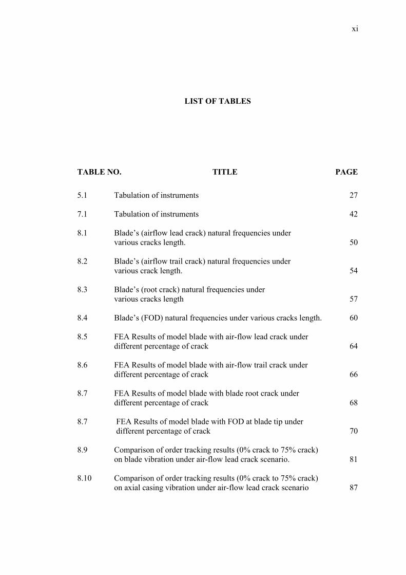
LIST OF TABLES
TABLE NO. TITLE PAGE
5.1 Tabulation of instruments 27
7.1 Tabulation of instruments 42
8.1 Blade’s (airflow lead crack) natural frequencies under
various cracks length. 50
8.2 Blade’s (airflow trail crack) natural frequencies under
various crack length. 54
8.3 Blade’s (root crack) natural frequencies under
various cracks length 57
8.4 Blade’s (FOD) natural frequencies under various cracks length. 60
8.5 FEA Results of model blade with air-flow lead crack under
different percentage of crack 64
8.6 FEA Results of model blade with air-flow trail crack under
different percentage of crack 66
8.7 FEA Results of model blade with blade root crack under
different percentage of crack 68
8.7 FEA Results of model blade with FOD at blade tip under
different percentage of crack 70
8.9 Comparison of order tracking results (0% crack to 75% crack)
on blade vibration under air-flow lead crack scenario. 81
8.10 Comparison of order tracking results (0% crack to 75% crack)
on axial casing vibration under air-flow lead crack scenario 87
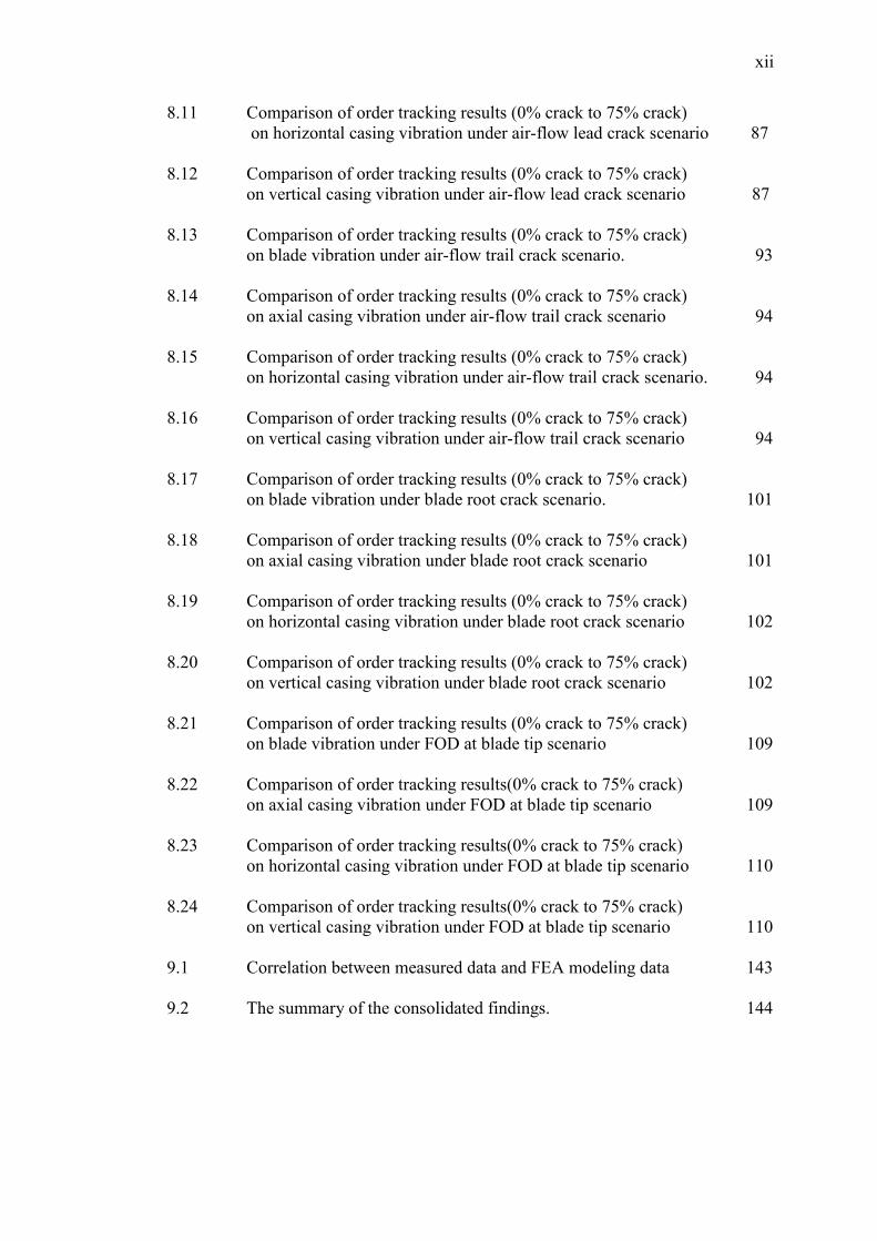
xii
8.11 Comparison of order tracking results (0% crack to 75% crack)
on horizontal casing vibration under air-flow lead crack scenario 87
8.12 Comparison of order tracking results (0% crack to 75% crack)
on vertical casing vibration under air-flow lead crack scenario 87
8.13 Comparison of order tracking results (0% crack to 75% crack)
on blade vibration under air-flow trail crack scenario. 93
8.14 Comparison of order tracking results (0% crack to 75% crack)
on axial casing vibration under air-flow trail crack scenario 94
8.15 Comparison of order tracking results (0% crack to 75% crack)
on horizontal casing vibration under air-flow trail crack scenario. 94
8.16 Comparison of order tracking results (0% crack to 75% crack)
on vertical casing vibration under air-flow trail crack scenario 94
8.17 Comparison of order tracking results (0% crack to 75% crack)
on blade vibration under blade root crack scenario. 101
8.18 Comparison of order tracking results (0% crack to 75% crack)
on axial casing vibration under blade root crack scenario 101
8.19 Comparison of order tracking results (0% crack to 75% crack)
on horizontal casing vibration under blade root crack scenario 102
8.20 Comparison of order tracking results (0% crack to 75% crack)
on vertical casing vibration under blade root crack scenario 102
8.21 Comparison of order tracking results (0% crack to 75% crack)
on blade vibration under FOD at blade tip scenario 109
8.22 Comparison of order tracking results(0% crack to 75% crack)
on axial casing vibration under FOD at blade tip scenario 109
8.23 Comparison of order tracking results(0% crack to 75% crack)
on horizontal casing vibration under FOD at blade tip scenario 110
8.24 Comparison of order tracking results(0% crack to 75% crack)
on vertical casing vibration under FOD at blade tip scenario 110
9.1 Correlation between measured data and FEA modeling data 143
9.2 The summary of the consolidated findings. 144
xiii
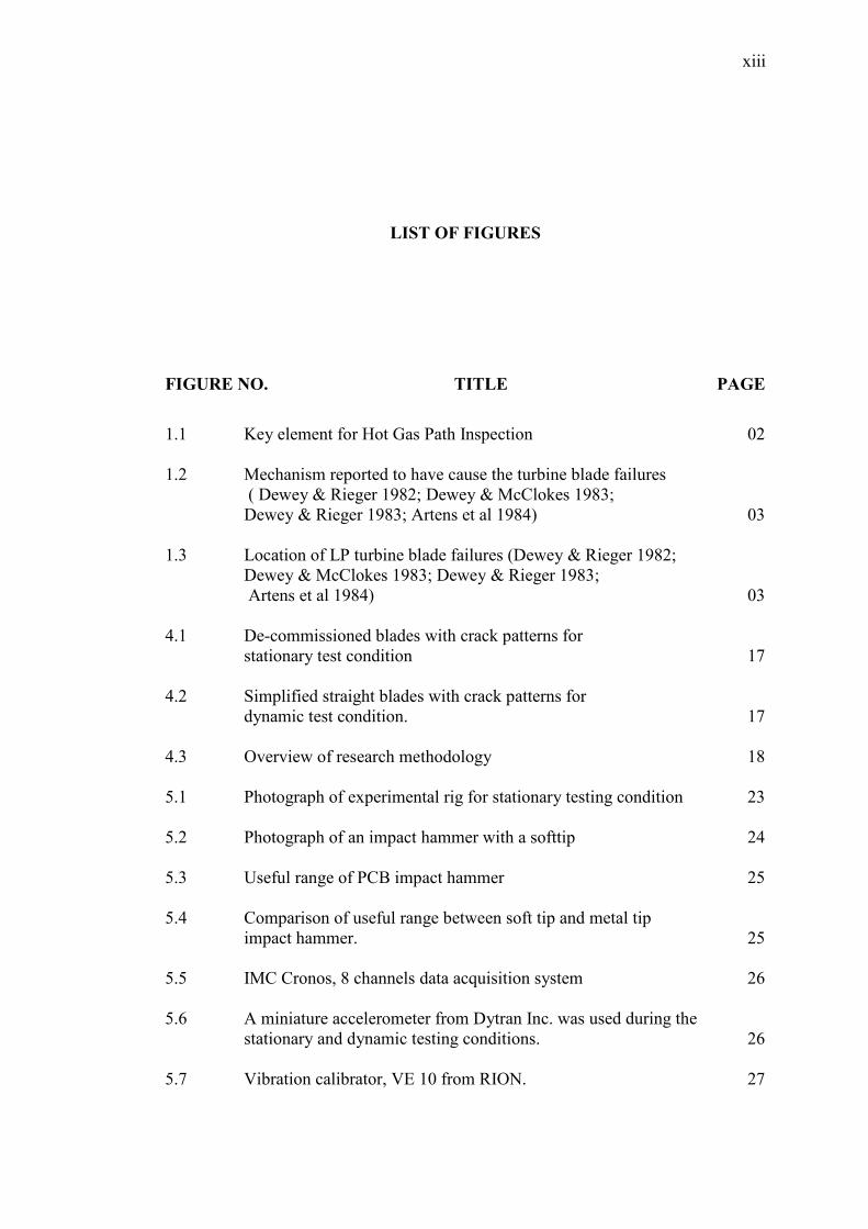
LIST OF FIGURES
FIGURE NO. TITLE PAGE
1.1 Key element for Hot Gas Path Inspection 02
1.2 Mechanism reported to have cause the turbine blade failures
( Dewey & Rieger 1982; Dewey & McClokes 1983;
Dewey & Rieger 1983; Artens et al 1984) 03
1.3 Location of LP turbine blade failures (Dewey & Rieger 1982;
Dewey & McClokes 1983; Dewey & Rieger 1983;
Artens et al 1984) 03
4.1 De-commissioned blades with crack patterns for
stationary test condition 17
4.2 Simplified straight blades with crack patterns for
dynamic test condition. 17
4.3 Overview of research methodology 18
5.1 Photograph of experimental rig for stationary testing condition 23
5.2 Photograph of an impact hammer with a softtip 24
5.3 Useful range of PCB impact hammer 25
5.4 Comparison of useful range between soft tip and metal tip
impact hammer. 25
5.5 IMC Cronos, 8 channels data acquisition system 26
5.6 A miniature accelerometer from Dytran Inc. was used during the
stationary and dynamic testing conditions. 26
5.7 Vibration calibrator, VE 10 from RION. 27
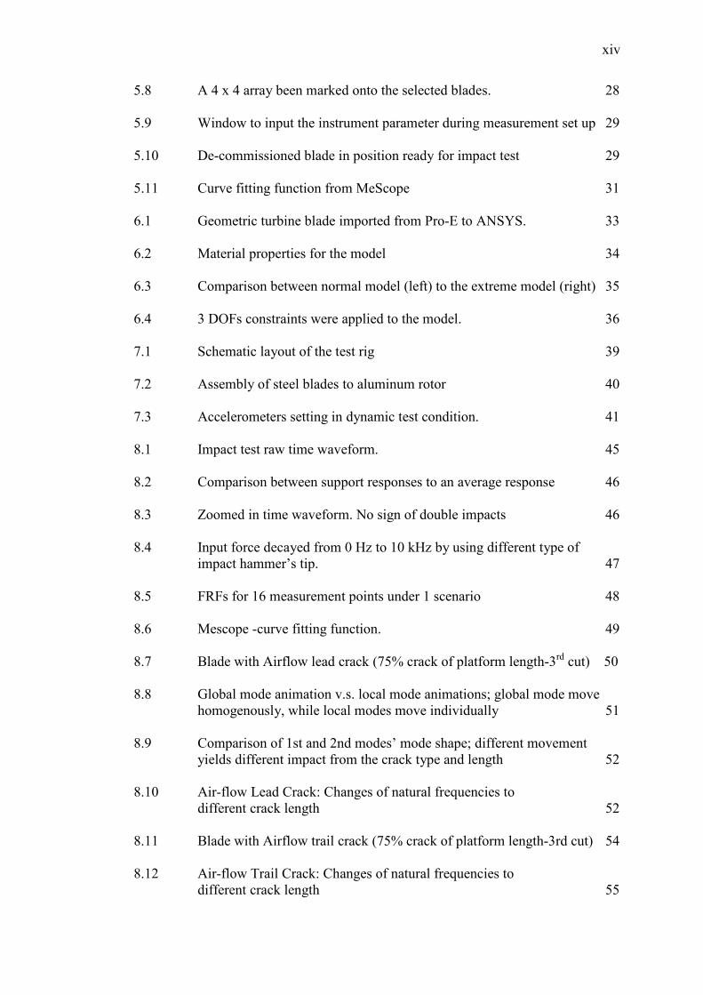
xiv
5.8 A 4 x 4 array been marked onto the selected blades. 28
5.9 Window to input the instrument parameter during measurement set up 29
5.10 De-commissioned blade in position ready for impact test 29
5.11 Curve fitting function from MeScope 31
6.1 Geometric turbine blade imported from Pro-E to ANSYS. 33
6.2 Material properties for the model 34
6.3 Comparison between normal model (left) to the extreme model (right) 35
6.4 3 DOFs constraints were applied to the model. 36
7.1 Schematic layout of the test rig 39
7.2 Assembly of steel blades to aluminum rotor 40
7.3 Accelerometers setting in dynamic test condition. 41
8.1 Impact test raw time waveform. 45
8.2 Comparison between support responses to an average response 46
8.3 Zoomed in time waveform. No sign of double impacts 46
8.4 Input force decayed from 0 Hz to 10 kHz by using different type of
impact hammer’s tip. 47
8.5 FRFs for 16 measurement points under 1 scenario 48
8.6 Mescope -curve fitting function. 49
8.7 Blade with Airflow lead crack (75% crack of platform length-3rd cut) 50
8.8 Global mode animation v.s. local mode animations; global mode move
homogenously, while local modes move individually 51
8.9 Comparison of 1st and 2nd modes’ mode shape; different movement
yields different impact from the crack type and length 52
8.10 Air-flow Lead Crack: Changes of natural frequencies to
different crack length 52
8.11 Blade with Airflow trail crack (75% crack of platform length-3rd cut) 54
8.12 Air-flow Trail Crack: Changes of natural frequencies to
different crack length 55
xv
8.13 Animation of 5th mode under airflow trail crack after the 3rd cut, 75%
crack of platform length. 56
8.14 Blade with root crack (75% crack of platform length-3rd cut) 57
8.15 The animation of 10th mode under blade root crack, where all most all
movement concentrated at blade tip. 58
8.16 Blade Root Crack: Changes of natural frequencies to
different crack 85
8.17 Blade with FOD at blade tip 60
8.18 Homogenous movement of lower modes (3rd & 4th mode) 61
8.19 FOD at Blade Tip: Changes of natural frequencies to
different crack length 61
8.20 Comparison between normal condition and extreme case 63
8.21 Homogenous movement (1st mode) vs. localize movement (5th mode)
in ANSYS modeling 63
8.22 Turbine Blade FEA modeling under airflow lead crack 65
8.23 FEA: Air-flow Lead Crack: Changes of natural frequencies to
difference crack length 65
8.24 Turbine Blade FEA modeling under airflow trail crack 67
8.25 FEA: Air-flow Trail Crack: Changes of natural frequencies to
different crack length 67
8.26 Turbine Blade FEA modeling under blade root crack 69
8.27 FEA: Root Blade Crack: Changes of natural frequencies to
different crack length 69
8.28 Turbine Blade FEA modeling under FOD. 71
8.29 FEA: FOD at Blade Tip: Changes of natural frequencies to
different crack length 71
8.30 Repeatability test results for dynamic test condition;
run up measurements at casing;
axial, horizontal and vertical directions. 73
xvi
8.31 Repeatability test results for dynamic test condition;
steady state measurements at casing;
axial, horizontal and vertical directions. 73
8.32 TWF of blade compare to TWF of tachometer in a
baseline complete cycle. 74
8.33 Zoomed in: TWF of blade compare to TWF of tachometer
in a complete cycle of baseline measurement 75
8.34 TWF of tri-axis compare to TWF tachometer
in a complete cycle of baseline measurement 75
8.35 Zoomed in: TWF of tri-axis compare to tachometer
TWF in a complete cycle of baseline measurement 76
8.36 Color map of blade vibration under air-flow lead crack pattern.
Comparison of 0% to 75% crack length. 78
8.37 The 4th order of run up and coast down results (acceleration) for blade
vibration under air-flow lead crack pattern. 79
8.38 The 4th order of run up and coast down results (velocity)
for blade vibration under air-flow lead crack pattern. 79
8.39 The 5th order of run up and coast down results (acceleration) for blade
vibration under air-flow lead crack pattern. 80
8.40 The 5th order of run up and coast down results (velocity)
for blade vibration under air-flow lead crack pattern. 80
8.41 Color map of axial casing vibration under air-flow lead cracked.
Comparison of 0% to 75% crack length. 82
8.42 Color map of horizontal casing vibration under air-flow lead cracked.
Comparison of 0% to 75% crack length 83
8.43 Color map of vertical casing vibration under air-flow lead cracked.
Comparison of 0% to 75% crack length 84
8.44 The 10th order of run up and coast down results (acceleration)
for axial casing vibration under air-flow lead crack pattern 85
8.45 The 12th order of run up and coast down results (acceleration)
for axial casing vibration under air-flow lead crack pattern. 85
8.46 The 12th order of run up and coast down results (acceleration) for
horizontal casing vibration under air-flow lead crack pattern. 86

xvii
8.47 The 12th order of run up and coast down results (acceleration) for
vertical casing vibration under air-flow lead crack pattern. 86
8.48 Coast down wavelet map of blade vibration under
air-flow lead crack pattern 89
8.49 Coast down wavelet map of axial casing vibration under
air-flow lead crack pattern 90
8.50 Coast down wavelet map of horizontal casing vibration
under air-flow lead crack pattern 91
8.51 Coast down wavelet map of vertical casing vibration
under air-flow lead crack pattern 92
8.52 The 5th order of coast down results (acceleration) for blade vibration
under air-flow trail crack pattern 95
8.52 The 12th order of coast down results (acceleration) for axial casing
vibration under air-flow trail crack pattern. 95
8.54 The 12th order of coast down results (acceleration) for horizontal casing
vibration under air-flow trail crack pattern 96
8.55 The 12th order of coast down results (acceleration) for vertical casing
vibration under air-flow trail crack pattern. 96
8.56 Coast down wavelet map of blade vibration under
air-flow trail crack pattern 97
8.57 Coast down wavelet map of axial casing vibration under
air-flow trail crack pattern 98
8.58 Coast down wavelet map of horizontal casing vibration under
air-flow trail crack pattern 99
8.59 Coast down wavelet map of vertical casing vibration under
air-flow trail crack pattern 100
8.60 The 1st order of coast down results (acceleration) for
blade vibration under blade root crack pattern 103
8.61 The 12th order of coast down results (acceleration) for
axial casing vibration under blade root crack pattern. 103
8.62 The 12th order of coast down results (acceleration) for
horizontal casing vibration under blade root crack pattern 104
8.63 The 12th order of coast down results (acceleration) for
vertical casing vibration under blade root crack pattern. 104
xviii
8.64 Coast down wavelet map of blade vibration under
blade root crack pattern 105
8.65 Coast down wavelet map of axial casing vibration under
blade root crack pattern 116
8.66 Coast down wavelet map of horizontal casing vibration under
blade root crack pattern 107
8.67 Coast down wavelet map of vertical casing vibration under
blade root crack pattern 108
8.68 The 1st order of coast down results (acceleration) for
blade vibration under FOD a blade tip. 111
8.69 The 1st & 12th order coast down results (acceleration) for
axial casing vibration under air-flow lead crack pattern. 111
8.70 The 1st & 12th order coast down results (acceleration) for
horizontal casing vibration under air-flow lead crack pattern 112
8.71 The 1st & 12th order coast down results (acceleration) for
vertical casing vibration under air-flow lead crack pattern 112
8.72 Coast down wavelet map of blade vibration under FOD at blade tip. 113
8.73 Coast down wavelet map of axial casing vibration under
FOD at blade tip. 114
8.74 Coast down wavelet map of horizontal casing vibration
under FOD at blade tip. 115
8.75 Coast down wavelet map of vertical casing vibration
under FOD at blade tip. 116
8.76 ‘Cleaner’ spectrum from PDS(below) compared
to conventional FFT(above) 117
8.77 The PDS in velocity (blow) is more sensitive to
capture the low frequency changes. 117
8.78 The steady state PDS (velocity) of blade vibration under
air-flow lead crack pattern. 118
8.79 The steady state PDS (velocity) of axial casing vibration
under air-flow lead crack pattern. 119
8.80 The steady state PDS (velocity) of horizontal casing vibration
under air-flow lead crack pattern. 119
xix
8.81 The steady state PDS (velocity) of vertical casing vibration
under air-flow lead crack pattern. 120
8.82 Steady state wavelet map of blade vibration under
air-flow lead crack pattern 121
8.83 Steady state wavelet map of axial casing vibration under
air-flow lead crack pattern 122
8.84 Steady state wavelet map of horizontal casing vibration under
air-flow lead crack pattern 123
8.85 Steady state wavelet map of vertical casing vibration under
air-flow lead crack pattern 124
8.86 The steady state PDS (velocity) of blade vibration under
air-flow trail crack pattern. 125
8.87 The steady state PDS (velocity) of axial casing vibration under
air-flow trail crack pattern 125
8.88 The steady state PDS (velocity) of horizontal casing vibration under
air-flow trail crack pattern 126
8.89 The steady state PDS (velocity) of vertical casing vibration under
air-flow trail crack pattern 126
8.90 The steady state PDS (velocity) of blade vibration under
blade root crack pattern 127
8.91 The steady state PDS (velocity) of axial casing vibration under
blade root crack pattern 128
8.92 The steady state PDS (velocity) of horizontal casing vibration
under blade root crack pattern 128
8.93 The steady state PDS (velocity) of vertical casing vibration under
blade root crack pattern 129
8.94 The steady state PDS (velocity) of blade vibration under
FOD at blade tip crack pattern 130
8.95 The steady state PDS (velocity) of axial casing vibration under
FOD at blade tip crack pattern 130
8.96 The steady state PDS (velocity) of horizontal casing vibration under
FOD at blade tip crack pattern 131
xx
8.97 The steady state PDS (velocity) of vertical casing vibration under
FOD at blade tip crack pattern 131
9.1 Validation of FEA model to the measured data under
air-flow lead crack pattern. 133
9.2 Validation of FEA model to the measured data under
air-flow trail crack pattern 134
9.3 Validation of FEA model to the measured data under
blade root crack pattern 134
9.4 Validation of FEA model to the measured data under
FOD at blade tip crack pattern 135
9.5 Made shape comparison of measured data (above) to
FEA model (below), 0% crack @ 1st mode. 136
9.6 Made shape comparison of measured data (above) to
FEA model (below), 0% crack @ 2nd mode. 137
9.7 Made shape comparison of measured data (above) to
FEA model (below), 0% crack @ 3rd mode. 138
9.8 Made shape comparison of measured data (above) to
FEA model (below), 0% crack @ 4th mode. 139
9.9 The 5th order of coast down results (acceleration) for
blade vibration under blade root crack pattern 141
xxi
LIST OF ABBREVIATIONS
BPS - Blade Passing Frequency
CWT - Continuous Wavelet Transform
Hz - Hertz
FFT - Fast Fourier Transform
FOD - Foreign Object Damage
FRF - Frequency Response Function
PDS - Power Density Spectrum
RPM - Revolution per minute
STFT - Short Time Fourier Transform
xxii
LIST OF APPENDICES
APPENDIX TITLE PAGE
A1 Wavelet Analysis 153
A2 Order Tracking 163
A3 Power Density Spectrum 171
A4 Accelerometer Catalogs 177
1
CHAPTER 1
INTRODUCTION
1.1 Overview
Gas turbines are common but critical machines used in power generation,
petrochemical and heavy industries. Unscheduled down time often result in
economic losses exceeding RM1milliom per day [1]. With such economic losses
quick diagnosis and trouble shooting is required. [2] Manufactures such as General
Electric [3], recommends 3 types of maintenance inspections namely standby,
running and disassembly inspections to prevent unscheduled down time. Turbine
blades being key components of the gas turbine which suffers high mechanical
loading due to drastic changes in both temperature and pressure. [4] These often
result in mechanical failures such as cracking, blade rubbing, degradation etc which
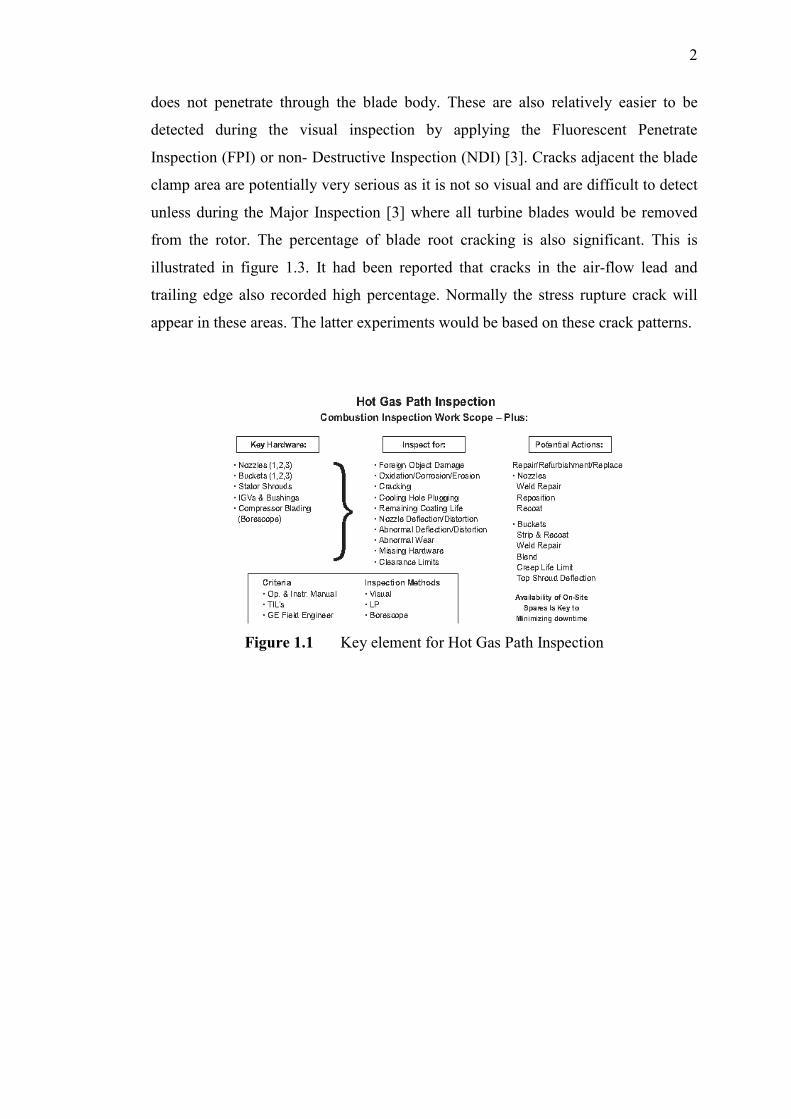
are often detected only during the Hot Gas Path Inspection under the disassembly
inspection [3]. Figure 1.1 provided an overview of the work scope during the
inspection. Minor repair could be carried at the same time. Tim J Carter (2004)
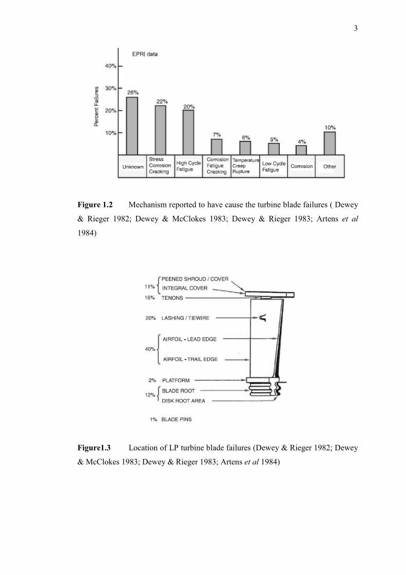
reported that turbine blade suffered most damage from crack which were either
caused by foreign object damage (FOD) or torsional forces. This is illustrated in the
figure 1.2. This figure shows possible turbine blade failures and the percentage
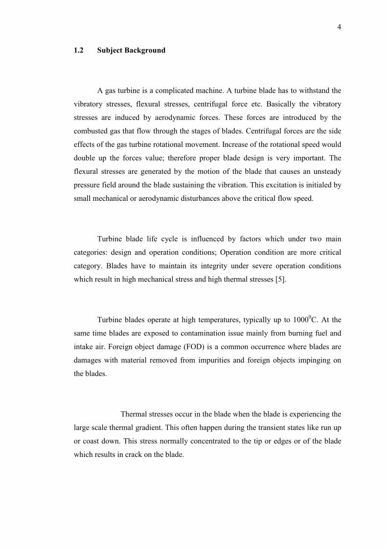
distribution. Cracks on surface, like which occurs on aerofoil & lashing area are not
as harmful as compared those in the blade root and disk root area; as long the failure
2
does not penetrate through the blade body. These are also relatively easier to be
detected during the visual inspection by applying the Fluorescent Penetrate
Inspection (FPI) or non- Destructive Inspection (NDI) [3]. Cracks adjacent the blade
clamp area are potentially very serious as it is not so visual and are difficult to detect
unless during the Major Inspection [3] where all turbine blades would be removed
from the rotor. The percentage of blade root cracking is also significant. This is
illustrated in figure 1.3. It had been reported that cracks in the air-flow lead and
trailing edge also recorded high percentage. Normally the stress rupture crack will
appear in these areas. The latter experiments would be based on these crack patterns.
Figure 1.1 Key element for Hot Gas Path Inspection
3
Figure 1.2 Mechanism reported to have cause the turbine blade failures ( Dewey
& Rieger 1982; Dewey & McClokes 1983; Dewey & Rieger 1983; Artens et al
1984)
Figure1.3 Location of LP turbine blade failures (Dewey & Rieger 1982; Dewey
& McClokes 1983; Dewey & Rieger 1983; Artens et al 1984)
4
1.2 Subject Background
A gas turbine is a complicated machine. A turbine blade has to withstand the
vibratory stresses, flexural stresses, centrifugal force etc. Basically the vibratory
stresses are induced by aerodynamic forces. These forces are introduced by the
combusted gas that flow through the stages of blades. Centrifugal forces are the side
effects of the gas turbine rotational movement. Increase of the rotational speed would
double up the forces value; therefore proper blade design is very important. The
flexural stresses are generated by the motion of the blade that causes an unsteady
pressure field around the blade sustaining the vibration. This excitation is initialed by
small mechanical or aerodynamic disturbances above the critical flow speed.
Turbine blade life cycle is influenced by factors which under two main
categories: design and operation conditions; Operation condition are more critical
category. Blades have to maintain its integrity under severe operation conditions
which result in high mechanical stress and high thermal stresses [5].
Turbine blades operate at high temperatures, typically up to 10000C. At the
same time blades are exposed to contamination issue mainly from burning fuel and
intake air. Foreign object damage (FOD) is a common occurrence where blades are
damages with material removed from impurities and foreign objects impinging on
the blades.
Thermal stresses occur in the blade when the blade is experiencing the
large scale thermal gradient. This often happen during the transient states like run up
or coast down. This stress normally concentrated to the tip or edges or of the blade
which results in crack on the blade.
5
Blade vibrations are often examined under two different perspectives: self
excited vibration and forced vibration. Self excited vibration is often known as
flutter. It is an aero-elastic self-induced vibration with a sustained amplitude,
normally seen at high speed rotation with no external forces involved. Force
vibration is induced by flow disturbances when working fluids pass through the
stages. This would results in an impulsive force to the blade body.
Blade vibration could only be measured from the casing and under such
situation would not off any direct measurement of the blade induced vibration. Even
though the blade vibration could not be measured directly, blade related diagnosis
still could be done from examination of response related to blade pass frequencies
(BPF).
The BPF is the pulsation force which occurs in bladed assembly. This force is
generated from the pressure fluctuation as a rotating vane or blade passes stationary
components like stator or housing. The stationary component produces a non-
uniform flow disturbance in the gas field. In vibration analysis, the number of blades
multiplied with the RPM of the rotor supporting the impeller physically defines the
blade passing frequency (BPF). The amplitude corresponding to the BPF is small. An
increase in the vibration amplitude of the BFP is usually due to:
(i ) A housing or rotor eccentricity
(ii ) Vane or blade wear (abrasive materials)
(iii) Bent, loose or misaligned housing diffuser vane
(iv ) A resonance Excitation
6
1.3 Problem Statement
The manufacture’s Major Inspection undertaken for gas turbine is expensive
and requires a long downtime. It is usually scheduled according to the
manufacturer’s recommendations or based on findings of previous inspection results.
This is normally undertaken 2-3 years after the turbine’s initial operation. With
thermal stresses from periodic on-off, turbine blade cracks had known to occur
rapidly with serious consequences prior to the Major Inspection. [6]
It is then very important to indicate the present of cracked blade from the
non-invasive measurements or procedures such as vibration. The current operational
vibration monitoring which mainly focus on overall vibration value, showed
insufficient sensitivity in detecting the cracked blade. Vibration FFT plots obtained
under steady state condition are also not sensitive enough for the detection of cracked
blade. Sophisticated analysis method such as order tracking, power density spectrum
and wavelet analysis could be considered to be used in maintenance inspection
especially it shown to be able to detect crack blade.
The visual inspection undertaken during maintenance relies on visual means
and human interpretation. Minute cracks or blade root crack could be missed out
easily during the visual inspection. A scientific based method such as the impact test
could be used as a more reliable tool to assist the visual inspection during
maintenance.
An understanding of dynamic behavior of a cracked blade needs to be
obtained prior to application in the maintenance inspection.
7
1.4 Objectives of the study
The objective of this study was to assess the practicability of vibration based
test method in detecting cracks in turbine blade. This can be explained as follow,
1. To verify the effectiveness of vibration impact test to capture the turbine
blade crack in a minor inspection. This required the study cracked blade
response from the impact tests.
2. To model a blade with or without cracks using FEA method. Computational
results would be correlated against the measurement results.
3. To study which vibration analysis methods (order tracking, FFT and wavelet)
for a rotating blade assembly for the detection of a cracked blade from the
measured vibration response.
1.5 Scopes of the study
The scope of this research were limited to the followings,
1. The identification of a common crack patterns that occur in real blades.
2. An experimental study for vibration response of stationary blades from
impact test for blades with the common crack patterns..
3. The comprehension of cracked blade effects from computational model and
modal analysis.
4. An experimental study of vibration measurement analysis for a rotating
bladed assembly with induced cracks in a test rig.