gug gateway 1.0 en mx7310
TRANSCRIPT

8/3/2019 Gug Gateway 1.0 en Mx7310
http://slidepdf.com/reader/full/gug-gateway-10-en-mx7310 1/11 1www.gateway.com
Replacing the AC Adapter
Technical SupportSee the label on the bottom of the notebook for CustomerCare Information. See your hardware guide for importantsafety, regulatory, and legal information.
© 2006 Gateway, Inc. All rights reserved. Gateway andeMachines are trademarks or registered trademarks of Gateway, Inc. in the United States and other countriesAll other brands and product names are trademarks or
registered trademarks of their respective companies.
Replacing the AC Adapter
To connect the AC adapter:
1 Connect the power cord to the AC adapter.
2 Connect the AC adapter to your notebook’s powerconnector.
3 Plug the power cord into a wall outlet. The AC powerindicator turns on.
If the AC power indicator does not turn on,complete the following steps until it turns on:
a Unplug the adapter from your notebook, thenplug it back in.
b Press FN+F1 to toggle the status lights on and off
Caution
Replace the power cord if it becomes damaged.The replacement cord must be of the same typeand voltage rating as the original cord or yournotebook may be damaged.
Warning
Do not attempt to disassemble the AC adapter.
The AC adapter has no user-replaceable oruser-serviceable parts inside. The AC adapterhas dangerous voltages that can cause seriousinjury or death. Contact Gateway about returningdefective AC adapters.
Important
If the battery charge indicator does not turn offafter three hours, contact Gateway CustomerCare at the Web address or telephone numbershown on the label on the bottom of yournotebook.

8/3/2019 Gug Gateway 1.0 en Mx7310
http://slidepdf.com/reader/full/gug-gateway-10-en-mx7310 2/11 1www.gateway.com
Replacing the Battery
Technical SupportSee the label on the bottom of the notebook for CustomerCare Information. See your hardware guide for importantsafety, regulatory, and legal information.
© 2006 Gateway, Inc. All rights reserved. Gateway andeMachines are trademarks or registered trademarks of Gateway, Inc. in the United States and other countriesAll other brands and product names are trademarks or
registered trademarks of their respective companies.
Replacing the Battery
Locating Components
To replace the battery:
1 If your notebook is on and is connected to AC power,go to Step 2.
- OR -If your notebook is on and is not connected to ACpower, save your work and turn off your notebook.
2 Close the LCD panel.
3 Turn your notebook over so the bottom is facing up.
4 Slide the battery lock to the unlock position.
5 Slide the battery release latch, then lift the batteryout of the notebook.
6 Place the replacement battery into the notebook andpress down until it snaps into place.
7 Slide the battery lock to the lock position.
8 Turn your notebook over.
9 Plug your notebook into an AC outlet.
10 Open the LCD panel and press the power button.
Tips & Tricks If your notebook is connected to AC power, you canreplace the battery while the notebook is turned on.
Warning
Danger of explosion if the battery is incorrectly
replaced.Replace only with a battery specificallymanufactured for your notebook. Recycle ordispose of the battery as hazardous waste.
The battery used in this device may present afire or chemical burn hazard if mishandled. Donot disassemble, heat above 212°F (100°C), orincinerate.
Keep away from children.
Battery
Important
If the battery charge indicator does not turn offafter three hours, contact Gateway CustomerCare at the Web address or telephone numbershown on the label on the bottom of yournotebook.
8/3/2019 Gug Gateway 1.0 en Mx7310
http://slidepdf.com/reader/full/gug-gateway-10-en-mx7310 3/11 1www.gateway.com
Replacing the DVD Drive
Technical SupportSee the label on the bottom of the notebook for CustomerCare Information. See your hardware guide for importantsafety, regulatory, and legal information.
© 2006 Gateway, Inc. All rights reserved. Gateway andeMachines are trademarks or registered trademarks of Gateway, Inc. in the United States and other countriesAll other brands and product names are trademarks or
registered trademarks of their respective companies.
Replacing the DVD Drive
Preventing static electricity dischargeThe components inside your notebook are extremely sensitiveto static electricity, also known as electrostatic discharge (ESD).ESD can permanently damage electrostatic discharge-sensitive
components in your notebook.
Before working with notebook components, follow theseguidelines:
• Avoid static-causing surfaces such as carpeted floors,plastic, and packing foam.
• Remove components from their antistatic bags only whenyou are ready to use them. Do not lay components on theoutside of antistatic bags because only the inside of the
bags provide electrostatic protection.
• Always hold components by their edges. Avoid touchingthe edge connectors. Never slide components over anysurface.
• Wear a grounding wrist strap (available at most electronicsstores) and attach it to a bare metal part of your workbenchor other grounded connection.
• Touch a bare metal surface on your workbench or othergrounded object.
Replacing the DVD drive
To replace the DVD drive:1 Follow the guidelines under “Preventing static
electricity discharge.”
2 Make sure that the DVD drive is empty.
3 Turn off your notebook.
4 Disconnect the AC adapter, modem cable, andnetwork cable.
5 Disconnect all peripheral devices and remove anyPC Cards.
6 Turn your notebook over so the bottom is facing up,then remove the battery. For more information, see
“Changing Batteries” in your online hardware guide.
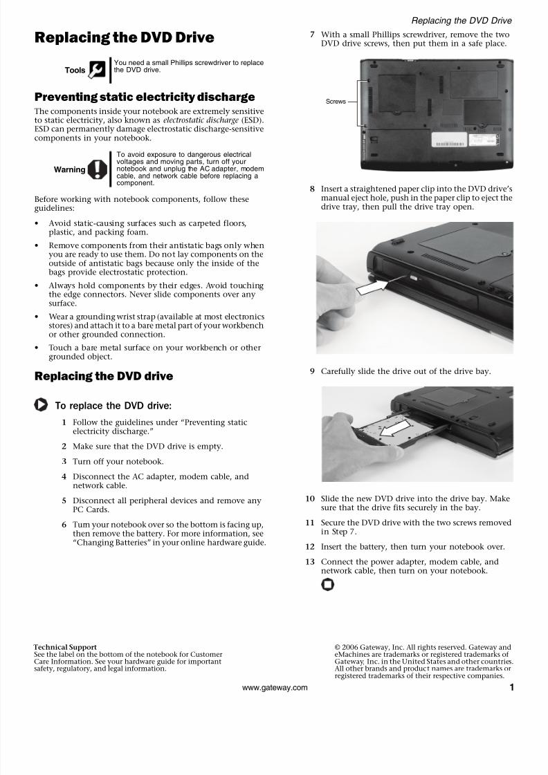
7 With a small Phillips screwdriver, remove the twoDVD drive screws, then put them in a safe place.
8 Insert a straightened paper clip into the DVD drive’smanual eject hole, push in the paper clip to eject thedrive tray, then pull the drive tray open.
9 Carefully slide the drive out of the drive bay.
10 Slide the new DVD drive into the drive bay. Makesure that the drive fits securely in the bay.
11 Secure the DVD drive with the two screws removedin Step 7.
12 Insert the battery, then turn your notebook over.
13 Connect the power adapter, modem cable, andnetwork cable, then turn on your notebook.
ToolsYou need a small Phillips screwdriver to replacethe DVD drive.
Warning
To avoid exposure to dangerous electricalvoltages and moving parts, turn off yournotebook and unplug the AC adapter, modemcable, and network cable before replacing acomponent.
Screws

8/3/2019 Gug Gateway 1.0 en Mx7310
http://slidepdf.com/reader/full/gug-gateway-10-en-mx7310 4/11 1www.gateway.com
Replacing the Hard Drive Kit
Technical SupportSee the label on the bottom of the notebook for CustomerCare Information. See your hardware guide for importantsafety, regulatory, and legal information.
© 2006 Gateway, Inc. All rights reserved. Gateway andeMachines are trademarks or registered trademarks of Gateway, Inc. in the United States and other countriesAll other brands and product names are trademarks or
registered trademarks of their respective companies.
Replacing the Hard Drive Kit
Locating Components
Preventing static electricity dischargeThe components inside your notebook are extremely sensitiveto static electricity, also known as electrostatic discharge (ESD).ESD can permanently damage electrostatic discharge-sensitivecomponents in your notebook.
Before working with notebook components, follow theseguidelines:
• Avoid static-causing surfaces such as carpeted floors,plastic, and packing foam.
• Remove components from their antistatic bags only whenyou are ready to use them. Do not lay components on theoutside of antistatic bags because only the inside of thebags provide electrostatic protection.
• Always hold components by their edges. Avoid touchingthe edge connectors. Never slide components over anysurface.
• Wear a grounding wrist strap (available at most electronicsstores) and attach it to a bare metal part of your workbenchor other grounded connection.
• Touch a bare metal surface on your workbench or othergrounded object.
Replacing the hard drive kit
To replace the hard drive kit:
1 If possible, create a Drivers and Applications Recoverydisc. For more information, see “Creating Driversand Applications Recovery discs” in the online UserGuide.
2 Follow the guidelines under “Preventing staticelectricity discharge.”
3 Turn off your notebook.
4 Disconnect the AC adapter, modem cable, andnetwork cable.
5 Disconnect all peripheral devices and remove anyPC Cards.
6 Turn your notebook over so the bottom is facing up,then remove the battery. For more information, see“Changing Batteries” in your online hardware guide
7 Remove the hard drive bay kit screw, slide the harddrive kit, then remove it.
8 If your new hard drive already includes the harddrive kit bracket, go to Step 13.
-OR-
If you need to move the hard drive kit bracket fromyour old hard drive to your new hard drive, go toStep 9.
Tools
You need a small Phillips screwdriver to replacethe hard drive.
You need the operating system disc that camewith your notebook.
Warning
To avoid exposure to dangerous electricalvoltages and moving parts, turn off yournotebook and unplug the AC adapter, modemcable, and network cable before replacing acomponent.
Hard drive bay
Important
If you cannot create a Drivers and Applications
Recovery disc, Gateway may send you a set ofrecovery discs or a replacement hard drive withthe drivers and applications already installed.Contact Gateway Customer Care at the Webaddress or telephone number shown on the labelon the bottom of your notebook.

8/3/2019 Gug Gateway 1.0 en Mx7310
http://slidepdf.com/reader/full/gug-gateway-10-en-mx7310 5/112 www.gateway.com
Replacing the Hard Drive Kit
Technical SupportSee the label on the bottom of the notebook for CustomerCare Information. See your hardware guide for importantsafety, regulatory, and legal information.
© 2006 Gateway, Inc. All rights reserved. Gateway andeMachines are trademarks or registered trademarks of Gateway, Inc. in the United States and other countriesAll other brands and product names are trademarks or
registered trademarks of their respective companies.
9 Remove the four screws that secure the hard driveto the hard drive kit bracket.
10 Remove the bracket from the old drive.
11 Place the new drive, label side up, onto the bracketso the screw holes line up.
12 Replace the four screws that secure the bracket to thedrive.
13 Slide the new hard drive kit into your notebook,then replace the screw that secures the hard drive kitto the notebook.
14 Insert the battery, then turn your notebook over.
15 Connect the power adapter, modem cable, andnetwork cable.
16 Turn on your notebook.
17 If the hard drive was sent to you from Gateway withthe operating system, applications, and driversinstalled, you will see the Windows startup screen.
-OR-
If you see a blank screen, restart your notebook, thenpress F11 while your computer is starting.
18 Insert the Operating System Recovery CD/DVD whenprompted.
Screw
ScrewScrew
Screw

8/3/2019 Gug Gateway 1.0 en Mx7310
http://slidepdf.com/reader/full/gug-gateway-10-en-mx7310 6/11 1www.gateway.com
Replacing the Keyboard
Technical SupportSee the label on the bottom of the notebook for CustomerCare Information. See your hardware guide for importantsafety, regulatory, and legal information.
© 2006 Gateway, Inc. All rights reserved. Gateway andeMachines are trademarks or registered trademarks of Gateway, Inc. in the United States and other countriesAll other brands and product names are trademarks or
registered trademarks of their respective companies.
Replacing the Keyboard
Preventing static electricity dischargeThe components inside your notebook are extremely sensitiveto static electricity, also known as electrostatic discharge (ESD).ESD can permanently damage electrostatic discharge-sensitive
components in your notebook.
Before working with notebook components, follow theseguidelines:
• Avoid static-causing surfaces such as carpeted floors,plastic, and packing foam.
• Remove components from their antistatic bags only whenyou are ready to use them. Do not lay components on theoutside of antistatic bags because only the inside of the
bags provide electrostatic protection.
• Always hold components by their edges. Avoid touchingthe edge connectors. Never slide components over anysurface.
• Wear a grounding wrist strap (available at most electronicsstores) and attach it to a bare metal part of your workbenchor other grounded connection.
• Touch a bare metal surface on your workbench or othergrounded object.
Removing the old keyboard
To remove the old keyboard:1 Follow the guidelines under “Preventing static
electricity discharge.”
2 Turn off your notebook.
3 Disconnect the AC adapter, modem cable, andnetwork cable.
4 Disconnect all peripheral devices and remove anyPC Cards.
5 Turn your notebook over so the bottom is facing up,then remove the battery. For more information, see“Changing Batteries” in your online hardware guide.
6 With a small Phillips screwdriver, remove the twokeyboard cover screws and put them in a safe place
7 Turn your notebook over so the top is facing up,then open the LCD panel to the fully openedposition.
8 Insert the small flat-blade screwdriver under thecenter of the keyboard cover and gently pry it up.
9 Lift the back edge of the keyboard cover, then slowlyrotate it toward you so it lies face-down on top of your notebook. You may hear small snapping
sounds as the cover comes away from yournotebook.
10 Lift the keyboard cover connector using two fingersand remove the cover from the notebook.
ToolsYou need a small Phillips and a small flat-bladescrewdriver to replace the keyboard.
Warning
To avoid exposure to dangerous electricalvoltages and moving parts, turn off yournotebook and unplug the AC adapter, modemcable, and network cable before replacing acomponent.
ImportantInserting a piece of cloth between thescrewdriver and keyboard will help preventdamage to your notebook.
CautionWhen removing the cover, be careful not tobreak off the tabs along the edges of the cover.
Screws

8/3/2019 Gug Gateway 1.0 en Mx7310
http://slidepdf.com/reader/full/gug-gateway-10-en-mx7310 7/112 www.gateway.com
Replacing the Keyboard
Technical SupportSee the label on the bottom of the notebook for CustomerCare Information. See your hardware guide for importantsafety, regulatory, and legal information.
© 2006 Gateway, Inc. All rights reserved. Gateway andeMachines are trademarks or registered trademarks of Gateway, Inc. in the United States and other countriesAll other brands and product names are trademarks or
registered trademarks of their respective companies.
11 With a small Phillips screwdriver, remove the twokeyboard screws and put them in a safe place.
12 Lift the back edge of the keyboard slightly, thenslowly slide it toward the LCD panel to release thekeyboard retaining tabs located on the front of thekeyboard.
13 Slowly rotate the keyboard toward you so it lieskeys-down on top of your notebook. Be careful tonot damage the LCD panel.
14 Lift the brown keyboard connector clip and removethe cable. Be careful not to touch or damage anyother components.
15 Remove the keyboard from the notebook.
Installing the new keyboard
To install the new keyboard:
1 Place the new keyboard keys-down on yournotebook with the space bar away from you.
2 Make sure the brown keyboard connector clip is inthe raised position, insert the cable into theconnector, then slide the brown clip to lock the
connector in place.
3 Rotate the keyboard toward the LCD panel until thekeyboard is almost face-up.
4 Insert the tabs on the front edge of the keyboard intothe slots under the palm rest. Press down on thekeyboard keys along the front edge of the keyboardto seat the retaining tabs into their correspondingslots.
5 Gently press the keyboard down until it is flat all the
way across. The keyboard should easily fall intoplace. Be careful to not damage the LCD panel.
6 Replace the two keyboard screws.
7 Reconnect the keyboard cover connector.
8 Replace the keyboard cover. Press down on the coverin several places until it clicks in place. The cover iscorrectly mounted when you can run you fingeralong the cover and find no loose spots. The covershould be flat all the way across.
9 Close the LCD panel, then turn your notebook overso the bottom is facing up.
10 Replace the two keyboard cover screws.
11 Insert the battery, then turn your notebook over.
12 Connect the power adapter, the modem cable, andthe network cable, then turn on your notebook.
Screws
Keyboardconnector
ImportantThe keyboard cable is correctly oriented if it isnot twisted.
CautionIf the cover is not correctly replaced, yournotebook could be damaged when you try toclose the LCD panel.

8/3/2019 Gug Gateway 1.0 en Mx7310
http://slidepdf.com/reader/full/gug-gateway-10-en-mx7310 8/11 1www.gateway.com
Replacing the Memory Module
Technical SupportSee the label on the bottom of the notebook for CustomerCare Information. See your hardware guide for importantsafety, regulatory, and legal information.
© 2006 Gateway, Inc. All rights reserved. Gateway andeMachines are trademarks or registered trademarks of Gateway, Inc. in the United States and other countriesAll other brands and product names are trademarks or
registered trademarks of their respective companies.
Replacing the Memory Module
Locating Components
Preventing static electricity discharge
The components inside your notebook are extremely sensitiveto static electricity, also known as electrostatic discharge (ESD).ESD can permanently damage electrostatic discharge-sensitivecomponents in your notebook.
Before working with notebook components, follow theseguidelines:
• Avoid static-causing surfaces such as carpeted floors,plastic, and packing foam.
• Remove components from their antistatic bags only whenyou are ready to use them. Do not lay components on theoutside of antistatic bags because only the inside of thebags provide electrostatic protection.
• Always hold components by their edges. Avoid touchingthe edge connectors. Never slide components over anysurface.
• Wear a grounding wrist strap (available at most electronicsstores) and attach it to a bare metal part of your workbenchor other grounded connection.
• Touch a bare metal surface on your workbench or othergrounded object.
Replacing the memory module
To replace the memory module:
1 Follow the guidelines under “Preventing staticelectricity discharge.”
2 Turn off your notebook.
3 Disconnect the AC adapter, modem cable, andnetwork cable.
4 Disconnect all peripheral devices and remove anyPC Cards.
5 Turn your notebook over so the bottom is facing up,then remove the battery. For more information, see“Changing Batteries” in your online hardware guide
6 Remove the memory bay screw, slide the cover, thenremove it.
7 To remove the memory module, gently pressoutward on the clip at each end of the module untilthe module tilts upward.
ToolsYou need a small Phillips screwdriver to replacethe memory module.
Warning
To avoid exposure to dangerous electricalvoltages and moving parts, turn off yournotebook and unplug the AC adapter, modemcable, and network cable before replacing acomponent.
Memorybay

8/3/2019 Gug Gateway 1.0 en Mx7310
http://slidepdf.com/reader/full/gug-gateway-10-en-mx7310 9/112 www.gateway.com
Replacing the Memory Module
Technical SupportSee the label on the bottom of the notebook for CustomerCare Information. See your hardware guide for importantsafety, regulatory, and legal information.
© 2006 Gateway, Inc. All rights reserved. Gateway andeMachines are trademarks or registered trademarks of Gateway, Inc. in the United States and other countriesAll other brands and product names are trademarks or
registered trademarks of their respective companies.
8 Pull the memory module out of the slot.
9 Hold the new or replacement module at a 30-degreeangle and insert it into the empty memory slot. Thismodule is keyed so it can only be inserted in onedirection. If the module does not fit, make sure thatthe notch in the module lines up with the tab in the
memory bay.
10 Gently push the module down until it clicks inplace.
11 Replace the memory bay cover, then replace thecover screw.
12 Insert the battery, then turn your notebook over.
13 Connect the power adapter, the modem cable, andthe network cable.
14 Turn on your notebook.
ImportantUse only memory modules designed for yourGateway notebook.

8/3/2019 Gug Gateway 1.0 en Mx7310
http://slidepdf.com/reader/full/gug-gateway-10-en-mx7310 10/11 1www.gateway.com
Replacing the Wireless Network Module
Technical SupportSee the label on the bottom of the notebook for CustomerCare Information. See your hardware guide for importantsafety, regulatory, and legal information.
© 2006 Gateway, Inc. All rights reserved. Gateway andeMachines are trademarks or registered trademarks of Gateway, Inc. in the United States and other countriesAll other brands and product names are trademarks or
registered trademarks of their respective companies.
Replacing the WirelessNetwork Module
Locating Components
Preventing static electricity dischargeThe components inside your notebook are extremely sensitiveto static electricity, also known as electrostatic discharge (ESD).ESD can permanently damage electrostatic discharge-sensitivecomponents in your notebook.
Before working with notebook components, follow theseguidelines:
• Avoid static-causing surfaces such as carpeted floors,plastic, and packing foam.
• Remove components from their antistatic bags only whenyou are ready to use them. Do not lay components on theoutside of antistatic bags because only the inside of thebags provide electrostatic protection.
• Always hold components by their edges. Avoid touchingthe edge connectors. Never slide components over anysurface.
• Wear a grounding wrist strap (available at most electronics
stores) and attach it to a bare metal part of your workbenchor other grounded connection.
• Touch a bare metal surface on your workbench or othergrounded object.
Replacing the wireless network module
To replace the wireless network module:
1 Follow the guidelines under “Preventing staticelectricity discharge.”
2 Turn off your notebook.
3 Disconnect the AC adapter, modem cable, andnetwork cable.
4 Disconnect all peripheral devices and remove anyPC Cards.
5 Turn your notebook over so the bottom is facing up,then remove the battery. For more information, see“Changing Batteries” in your online hardware guide
6 Remove the wireless network bay cover screw, slidethe wireless network bay cover, then remove it.
7 Unplug the two antenna cables.
Caution
By law, only approved wireless modulesprovided by Gateway, or a Gateway authorizedrepresentative, explicitly for your notebook maybe installed in this notebook.
ToolsYou need a small Phillips screwdriver to replacethe wireless network module.
Warning
To avoid exposure to dangerous electricalvoltages and moving parts, turn off yournotebook and unplug the AC adapter, modemcable, and network cable before replacing acomponent.
Wireless network bay

8/3/2019 Gug Gateway 1.0 en Mx7310
http://slidepdf.com/reader/full/gug-gateway-10-en-mx7310 11/11
Replacing the Wireless Network Module
Technical SupportSee the label on the bottom of the notebook for CustomerCare Information. See your hardware guide for importantsafety, regulatory, and legal information.
© 2006 Gateway, Inc. All rights reserved. Gateway andeMachines are trademarks or registered trademarks of Gateway, Inc. in the United States and other countriesAll other brands and product names are trademarks or
registered trademarks of their respective companies
8 Move the antenna cables out of the way, then pressoutward on the clip at each side of the module untilthe module tilts upward.
9 Pull the module out of the slot.
10 Hold the new module at a 30-degree angle and insertit into the empty slot. This module is keyed so it canonly be inserted in one direction. If the module doesnot fit, make sure that the notch in the module linesup with the tab in the module slot.
11 Move the antenna wires out of the way, then pressthe module down until it clicks into place.
12 Reattach the black antenna cable to the connectorlabelled MAIN or M, then reattach the light grayantenna cable to the connector labelled AUX or A
13 Replace the wireless network bay cover, then replacethe cover screw.
14 Insert the battery, then turn your notebook over.
15 Connect the power adapter, the modem cable, andthe network cable.
16 Turn on your notebook.