hao chen's portfolio 2015
DESCRIPTION
Hao's Selected Portfolio Both Academic and ProfessionalTRANSCRIPT

CHHao Chen 陳 昊
2012 - 2014Bachelor of Environment, University of Melbourne
ID: 397001
PORT-FOLIO

year 2 design studio: Water Refined Individual Work
Design Brief:
The Original Studley Boathouse situated on a picturesque river bend in Yarra Bend Park featuring a restaurant, kiosk, cafe and a boat club which offers hiring and storage ser-vices.
The theme of the studio is to ‘learn from the master’ and propose a new design for the Boathouse based on the design philosophy we abstracted from the master.
In my studio, the master architect are Herzog & de Mueron.
Figure 2: Perspective View from the river
Figure 1: Conceptual Drawing
The idea of this design is to create a new boathouse which embrace this picturesque site. Its form comes from a series of testing based on site analysis so it can has the maximum views over the river and a rational-ized spatial relationships.
The following scheme is a further developed conceptu-al design of the original scheme.
1
654
1 2 3
year 2 design studio: Water Refined Individual Work
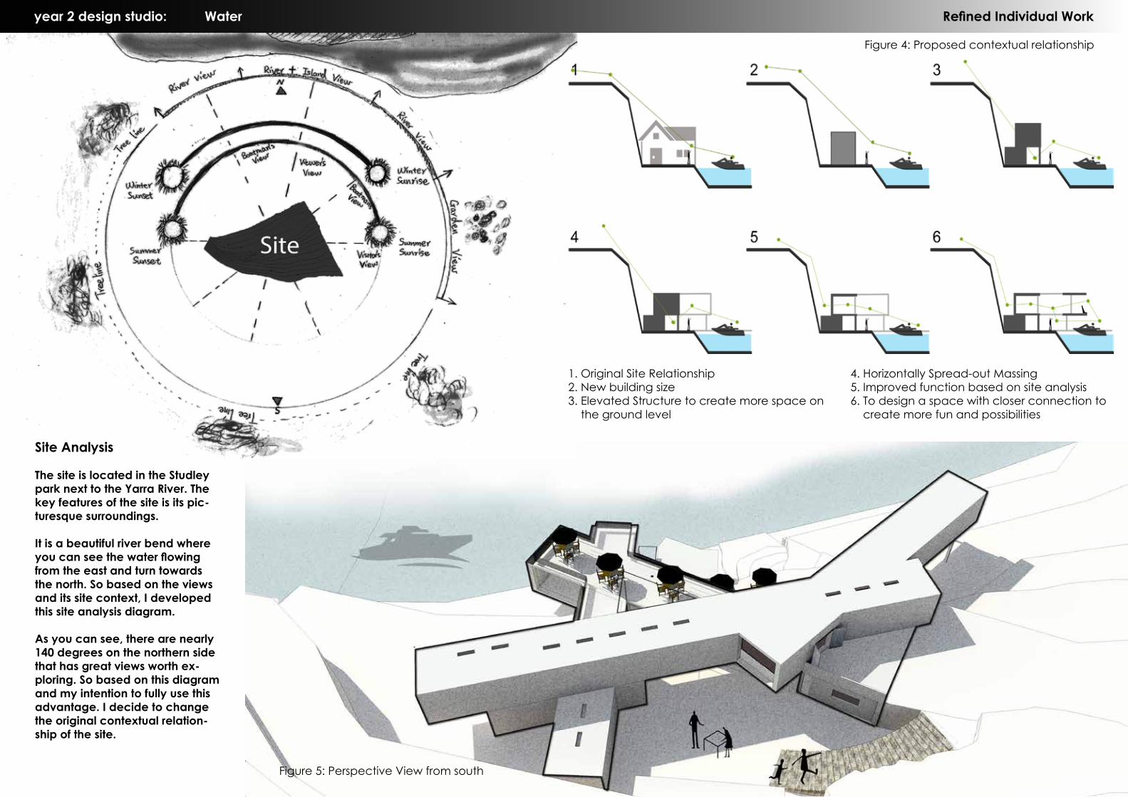
Site Analysis
The site is located in the Studley park next to the Yarra River. The key features of the site is its pic-turesque surroundings.
It is a beautiful river bend where you can see the water flowing from the east and turn towards the north. So based on the views and its site context, I developed this site analysis diagram.
As you can see, there are nearly 140 degrees on the northern side that has great views worth ex-ploring. So based on this diagram and my intention to fully use this advantage. I decide to change the original contextual relation-ship of the site.
Figure 4: Proposed contextual relationship
Figure 5: Perspective View from south
1. Original Site Relationship2. New building size3. Elevated Structure to create more space on the ground level
4. Horizontally Spread-out Massing 5. Improved function based on site analysis6. To design a space with closer connection to create more fun and possibilities

Actelion Business Centre
Vitre HauseFigure 1: Conceptual Drawing
Yarra Bend
Learn From the master
In the projects I selected from master Herzog & De Mueron’s previous designs, there are three main design philosophies I will try to learn from.
1. Function determine Form2. The use of Courtyard3. The use of “Stripe”s as design form
Based on the master’s design philosophies, I started experimenting with these design elements, and combining the result with my site analysis in order to rationalize it.
The conceptual drawing(Fighre 1) which briefly Summarized my design intention.
year 2 design studio: Water Refined Individual Work
Design Elements: Firstly, I start to experiment with the possibilities of how can a space been divided into stripes two-dimensionally. The stripes can be either with equal width or not and the number of stripes can varies as well. From the results shown in Figure 8, It is clear that the possibilities of these arrangement can be infinite. There can be even more possibilities if we try to split the space three dimensionally(Figure 7). The changes of the stripes sizes and the direction and orientation of the stacking will always lead to more possibilities and more potentials.
As a result, I need to introduce more variables to determine which would be the best in this situation. Therefore, I decide to look back into the site analysis and design brief.
Figure 6: Site feature Break down
Figure 8: Two Dimensional ExperimentationFigure 7: Three Dimensional Experimentation
Café
Restaurant
Kitchen Office
Toilets
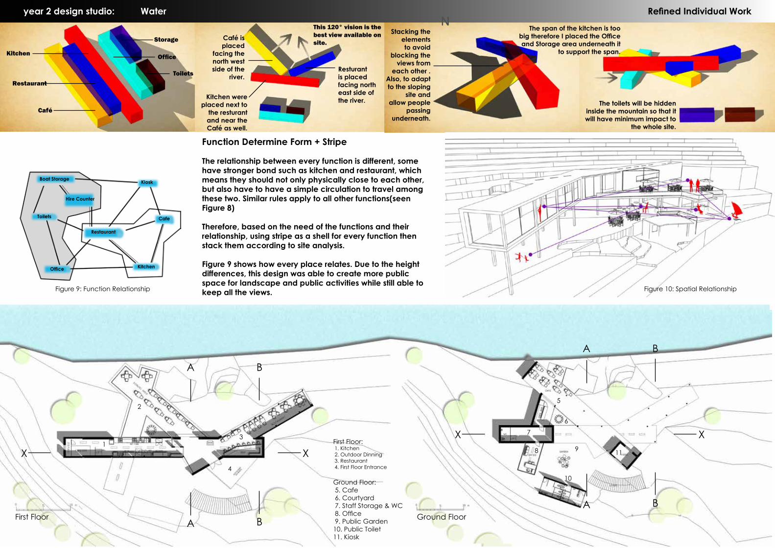
Storage Café is placed
facing the north west side of the
river.
Kitchen were placed next to
the resturant and near the Café as well.
This 120° vision is the best view available on site.
Resturant is placed facing north east side of the river.
Stacking the elements to avoid
blocking the views from
each other . Also, to adapt to the sloping
site and allow people
passing underneath.
The toilets will be hidden inside the mountain so that it will have minimum impact to
the whole site.
year 2 design studio: Water Refined Individual WorkThe span of the kitchen is too
big therefore I placed the Office and Storage area underneath it
to support the span.
Boat Storage
Toilets
Hire Counter
Office
Restaurant
Kiosk
Cafe
Kitchen
Function Determine Form + Stripe
The relationship between every function is different, some have stronger bond such as kitchen and restaurant, which means they should not only physically close to each other, but also have to have a simple circulation to travel among these two. Similar rules apply to all other functions(seen Figure 8)
Therefore, based on the need of the functions and their relationship, using stripe as a shell for every function then stack them according to site analysis.
Figure 9 shows how every place relates. Due to the height differences, this design was able to create more public space for landscape and public activities while still able to keep all the views. Figure 9: Function Relationship Figure 10: Spatial Relationship
N
First Floor Ground Floor
First Floor: 1. Kitchen 2. Outdoor Dinning 3. Restaurant 4. First Floor Entrance
Ground Floor: 5. Cafe 6. Courtyard 7. Staff Storage & WC 8. Office 9. Public Garden10. Public Toilet11. Kiosk
1
2
3
4
5
8 9 11
10
7
6
X
X
X
X
B
B
A
A
B
B
A
A
year 2 design studio: Water Refined Individual Work
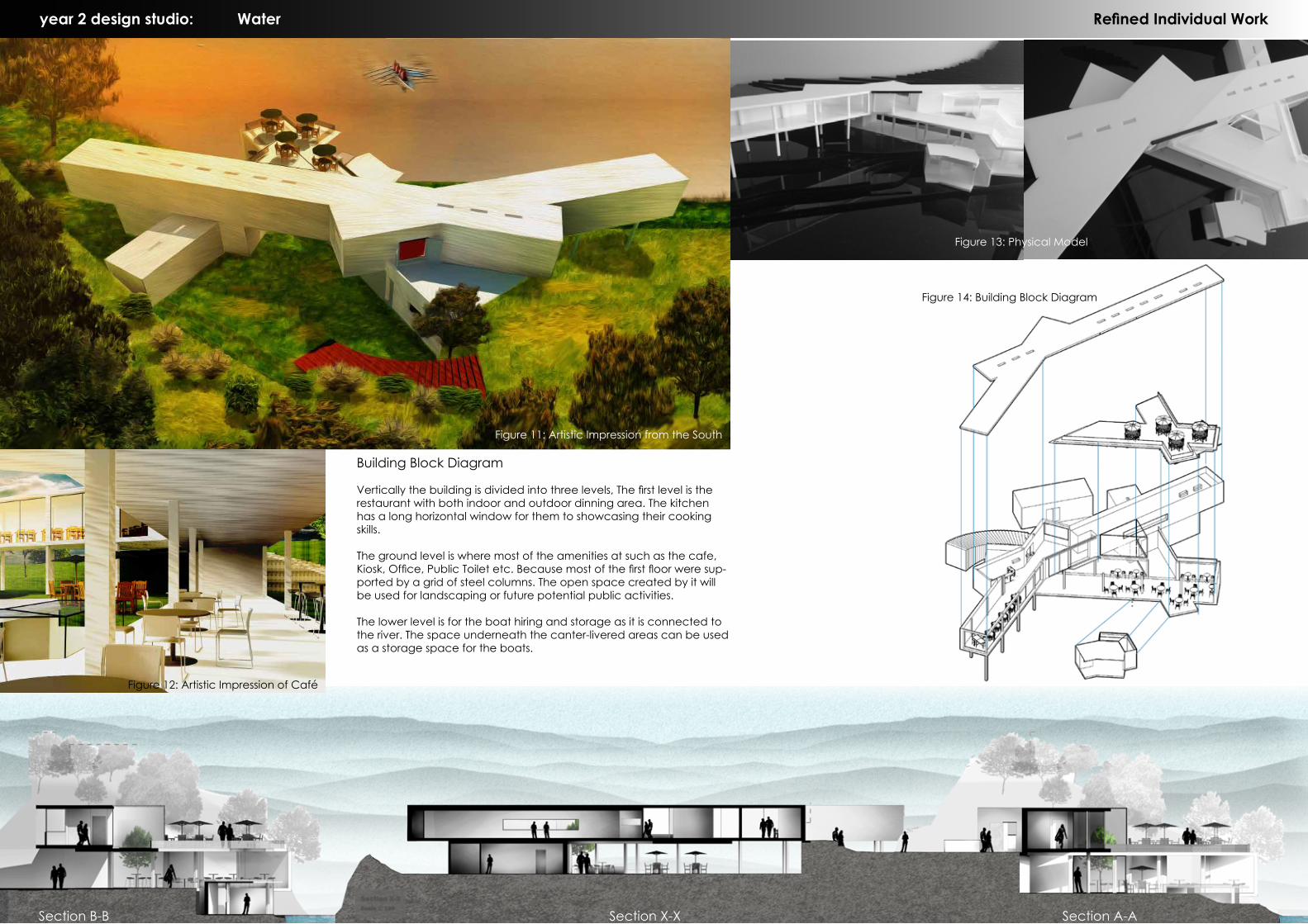
Building Block Diagram
Vertically the building is divided into three levels, The first level is the restaurant with both indoor and outdoor dinning area. The kitchen has a long horizontal window for them to showcasing their cooking skills.
The ground level is where most of the amenities at such as the cafe, Kiosk, Office, Public Toilet etc. Because most of the first floor were sup-ported by a grid of steel columns. The open space created by it will be used for landscaping or future potential public activities.
The lower level is for the boat hiring and storage as it is connected to the river. The space underneath the canter-livered areas can be used as a storage space for the boats.
Figure 11: Artistic Impression from the South
Figure 12: Artistic Impression of Café
Figure 14: Building Block Diagram
Section B-B Section X-X Section A-A
Figure 13: Physical Model
year 3 design studio: Air
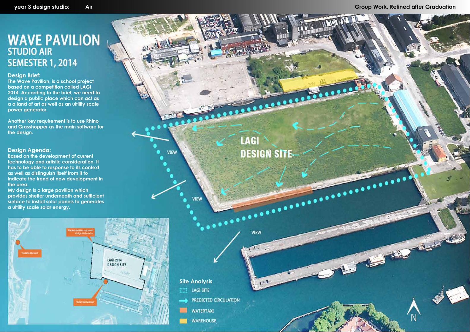
Design Brief:The Wave Pavilion, is a school project based on a competition called LAGI 2014. According to the brief, we need to design a public place which can act as a a land of art as well as an ultility scale power generator.
Another key requirement is to use Rhino and Grasshopper as the main software for the design.
Design Agenda:Based on the development of current technology and artistic consideration. It has to be able to response to its context as well as distinguish itself from it to indicate the trend of new development in the area.My design is a large pavilion which provides shelter underneath and sufficient surface to install solar panels to generates a ultility scale solar energy.
Site Analysis
Group Work, Refined after Graduation

year 3 design studio: Air
ConceptThe concept of this design comes from its context. The site is a man-made land which was once an important part of a major harbor. It is surrounded by the sea and was located right opposite of the famouse 'Little Mermaid' statue.
Since both historically and geologically the site is closely related with the sea. Therefore I decide to use Wave as my concept for this design.
The up sand downs of waves often used to symbolize changes over time. Which is the same theme I am trying to convey in this design.
The wave pavillion is a symbolic feature which symbolized the history of the site as well as showing the future of the site. A younger and greener Copenhagen.
Ship Circulation
Old harbor Preliminary Concept Experiment & Drawing
Original Site Context
Original Site View from the Little Mermaid
Current Site View from the Little Mermaid
Group Work, Refined after Graduation

景观视野 流线动态 建筑环境关系 内部流线
内部平面布置
内部视野
One Variable Two Variables Three Variables Four Variables
Plan
Section
景观视野 流线动态 建筑环境关系 内部流线
内部平面布置
内部视野
Major Views Dynamic Form Context Relationship Internal Circulation Internal View
year 3 design studio: Air
From the previous analysis, I gained a set of referencing points. With these points I developed a set of reference lines that I
can use to experiment in Rhino.
By moving these curves vertically and horizontally as well as trim them accroing
to the circulation. I was able to create more reference lines. Then using these lines I developped a surface that I can
planneling with.
Only till I got this form. I started to use grasshopper to work out the supporting
structuture. I do not want the idea of parametric design dominate my own ideas. Or tools determine my design.
Therefore, grasshopper was only used to panel the frame-structure for the surface.
Group Work, Refined after Graduation
FIgure 1: Refined Structure
year 3 design studio: Air Group Work, Refined after Graduation
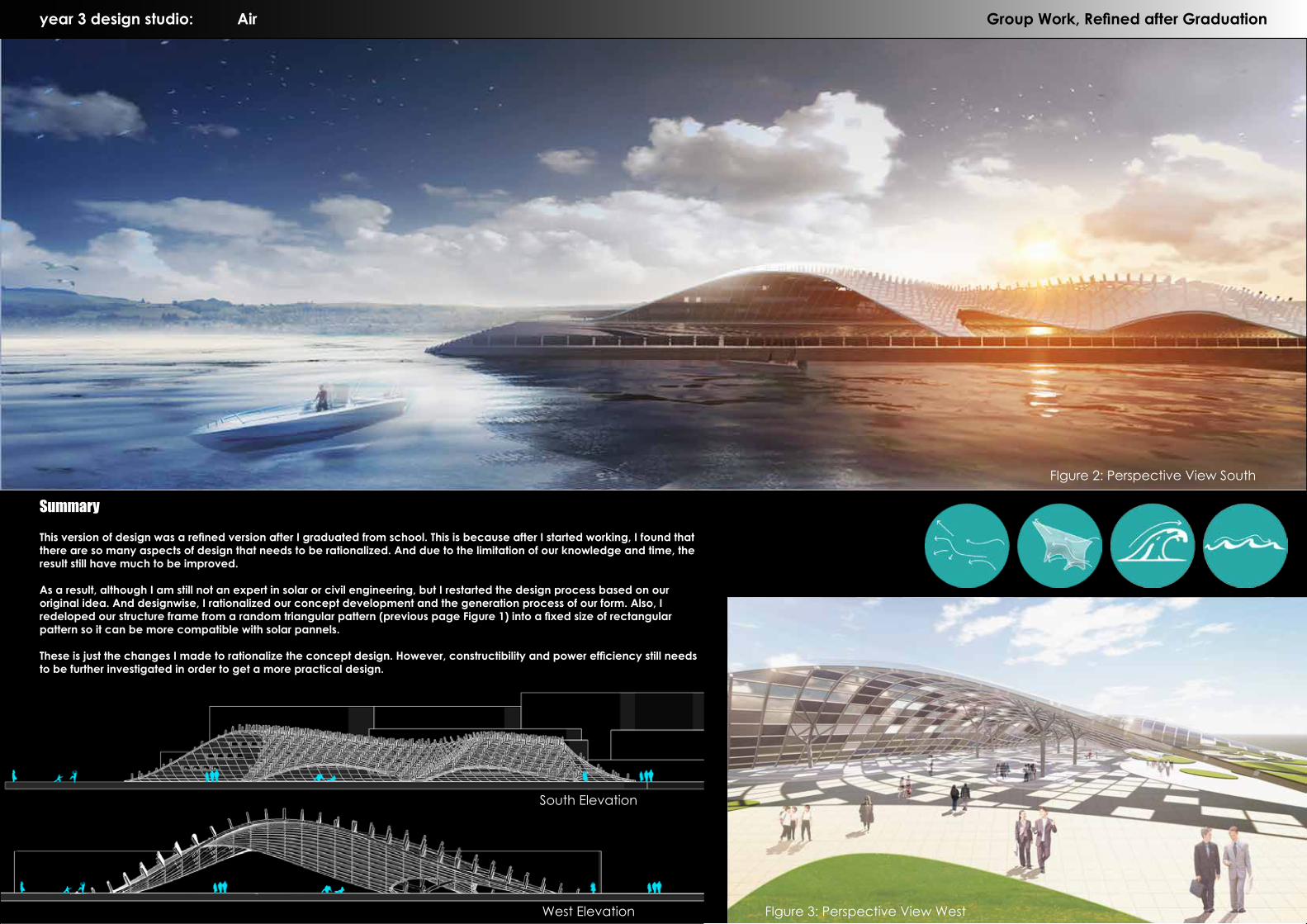
Summary
This version of design was a refined version after I graduated from school. This is because after I started working, I found that there are so many aspects of design that needs to be rationalized. And due to the limitation of our knowledge and time, the result still have much to be improved.
As a result, although I am still not an expert in solar or civil engineering, but I restarted the design process based on our original idea. And designwise, I rationalized our concept development and the generation process of our form. Also, I redeloped our structure frame from a random triangular pattern (previous page Figure 1) into a fixed size of rectangular pattern so it can be more compatible with solar pannels.
These is just the changes I made to rationalize the concept design. However, constructibility and power efficiency still needs to be further investigated in order to get a more practical design.
FIgure 2: Perspective View South
FIgure 3: Perspective View West
South Elevation
West Elevation

year 3 design studio: Fire Individual Work
Design Brief:
This design studio is to design a new shop for Outré Gallery in one of the most multi-cultural suburb in Melbourne-Brunswick. The shop con-sists of a bookshop, Café, Outré Gallery, its office and manager suite.
The idea of this design is to design a shop that can represent the culture of the gallery as well as responding to the trending cultural change in the suburb.
FIgure 1: Perspective View West
FIgure 3: Perspective View WestFIgure 2: Perspective View cafe
year 3 design studio: Fire Individual Work
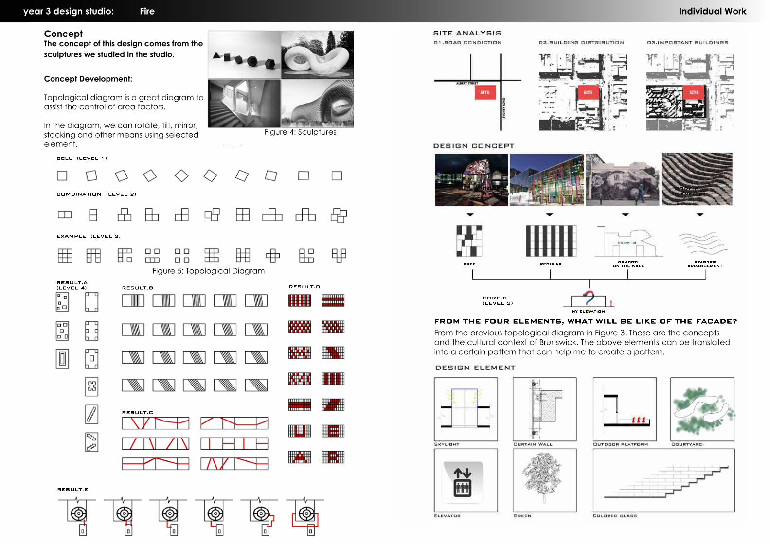
FROM THE FOUR ELEMENTS, WHAT WILL BE LIKE OF THE FACADE?
FREE REGULAR
MY ELEVATION
GRAFFITION THE WALL
STAGGERARRANGEMENT
1.CAFE
2.BOOKSTORE3.COURTYARD4.RECEPTION
5.GALLERY STORAGE
6.MANAGER'S CAR PARK
7.STAIRCASE
From the previous topological diagram in Figure 3. These are the concepts and the cultural context of Brunswick. The above elements can be translated into a certain pattern that can help me to create a pattern.
CELL (LEVEL 1)
COMBINATION (LEVEL 2)
EXAMPLE (LEVEL 3)
RESULT.A (LEVEL 4) RESULT.B
RESULT.C
RESULT.D
RESULT.E
CORE.C (LEVEL 3)
CORE.A (LEVEL 1)
CORE.B (LEVEL 2)
ConceptThe concept of this design comes from the sculptures we studied in the studio.
FIgure 4: Sculptures
CELL (LEVEL 1)
COMBINATION (LEVEL 2)
EXAMPLE (LEVEL 3)
RESULT.A (LEVEL 4) RESULT.B
RESULT.C
RESULT.D
RESULT.E
CORE.C (LEVEL 3)
CORE.A (LEVEL 1)
CORE.B (LEVEL 2)
Figure 5: Topological Diagram
Concept Development:
Topological diagram is a great diagram to assist the control of area factors.
In the diagram, we can rotate, tilt, mirror, stacking and other means using selected element.
year 3 design studio: Fire Individual Workyear 3 design studio: Fire Individual Work
Lounge, a relaxing space to everyone, at the same time as an exchange space exists.
Reception,located in the center of the whole house, to maximize the use of services in the
Lighting atrium area, a special space on behalf of quiet.
Reading area, for people to learn, access to information and rest.
Parking.
Vertical transportation. Employees and the general population is divided into two.
Open tour space, set exhibition, learning and thinking as one place.
Reception. Vertical transportation.
Graffiti roofs, open Area, where you can do!
Laundry room, while keeping the room clean.
Benroom (big).
Benroom (small).
Bathroom.
Living room,Rest space.
Staff toilet, right in the general population does not use.
Staff dinning Area, disposed in the corner, with separate open area
Staff kitchen
Open office, to visit the people to provide an opportunity to learn and exchange.
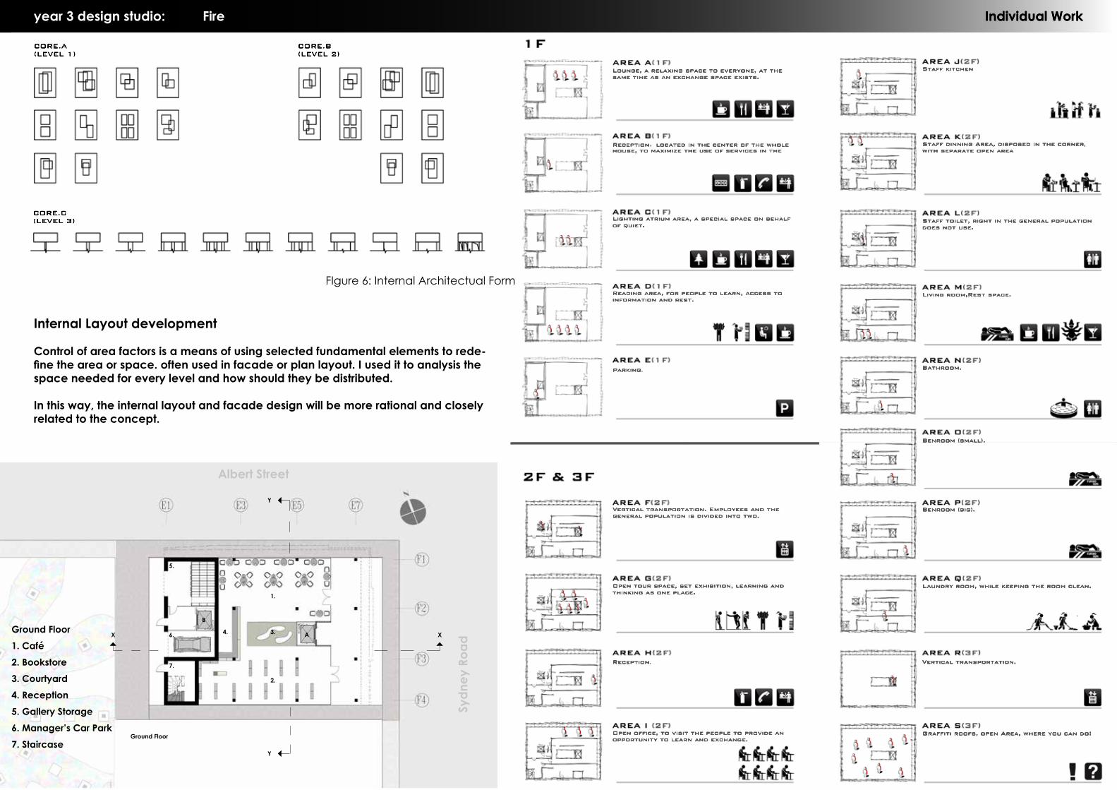
FIgure 6: Internal Architectual Form
CELL (LEVEL 1)
COMBINATION (LEVEL 2)
EXAMPLE (LEVEL 3)
RESULT.A (LEVEL 4) RESULT.B
RESULT.C
RESULT.D
RESULT.E
CORE.C (LEVEL 3)
CORE.A (LEVEL 1)
CORE.B (LEVEL 2)
C
1.
Albert Street
2.
3.4.
5.
6.
7.
Sydn
ey R
oadA
B
Ground Floor
X X
Y
Y
Ground Floor1. Café2. Bookstore3. Courtyard4. Reception5. Gallery Storage6. Manager’s Car Park7. Staircase
Internal Layout development
Control of area factors is a means of using selected fundamental elements to rede-fine the area or space. often used in facade or plan layout. I used it to analysis the space needed for every level and how should they be distributed.
In this way, the internal layout and facade design will be more rational and closely related to the concept.

8.
10.
11.
13.
14. 15. 16. 17.17.
16.18.
9.
First Floor
Second Floor
19.
20.
21.
Outré Gallery
Sdyney Road Elevation Albert Street Elevation
Section Y-Y Section X-X
First Floor8. Outré Gallery9. Reception10. Open Plan Office11. Staff Kitchen12. Staff Dinning Area13. Staff Toilet14. Living Room15. Kitchen & Dinning16. Bathroom17. Bedroom18. Laundry
Second Floor19. Graffiti Roof Garden20. Courtyard.21. Bridge
Services A: Main Customer Lift B. Staff Lift C. Staircases
year 3 design studio: Fire Individual Work
Albert Street Elevation
FIgure 8: Ground Floor Model
FIgure 7: North Perspective
Summary
The pattern of the facade was derived from the pattern of the brickwork commonly seen in Brunswick. I used a scaled dimension of a most commonly used brick to be my basic element. Also the stagger pattern is a reflection of its neighborhood character.
However, the characteristic of Outré Gallery and Brunswick need something special. Therefore, based on the pat-tern i choose, the use of bold color and new materials will help this design distinguish itself from its neighborhood while still able to fit into the trendy context of Brunswick.

Work Experience (Local) 2014-Now Selected Portfolio (Professional)
WALL TYPE A - EXTERNAL WALL WALL TYPE B - EXTERNAL WALL WALL TYPE C- EXTERNAL WALL (no fire requirement)
WALL TYPE D - CSR 184 - EXTERNAL WALL WALL TYPE E - CORRIDOR WALL(non-discontinuous)
WALL TYPE F - CSR 218- INTERTENANCY WALL (discontinuous)
WALL TYPE B2 - CSR 167 - EXTERNAL WALL WALL TYPE C2 --- CSR 165- EXTERNAL WALL (no fire requirement)
WALL TYPE A2 - EXTERNAL WALL WALL TYPE F2 - CSR 218- INTERTENANCY WALL (discontinuous)
Wet Area Lining: Moisture resistant plasterboard to all wet area wall and ceiling
WALL TYPE L - CSR 475- 2nd FLOOR INTERTENANCY WALL(non-discontinuous)
WALL TYPE M--- CSR 575-2nd FLOOR INTERTENANCY(discontinuous)
WALL TYPE O - LIFT SHAFT/BASEMENT LOBBY WALL
WALL TYPE N - LIFT SHAFT (discontinuous) WALL TYPE P - INTERTENANCY WALL(non-discontinuous)
WALL TYPE S - DUCT WALL WALL TYPE T - INTERNAL WALLGROUND TO FIRST FLOOR
WALL TYPE T2 - INTERNAL WALLSECOND FLOOR
WALL TYPE T3 - INTERNAL WALLCAVITY SLIDER PARTITION
WALL TYPE T4 - INTERNAL WALLPARTITION TO WET AREA
WALL TYPE G-INTERTENANCY WALL (discontinuous)
WALL TYPE H - CSR 255- CORRIDOR WALL
WALL TYPE H2 - CSR 155- CORRIDOR WALL
WALL TYPE I - STAIR/LIFT SHAFT WALL TYPE I2 - STAIR/LIFT SHAFT WALL TYPE I3 - STAIR/LIFT SHAFT WALL TYPE J - EXTERNAL WALL WALL TYPE K - CSR 907- 2ND FLOOR EXTERNAL WALL
WALL TYPE K2- G TO 1ST FLOOR EXTERNAL WALL
WALL TYPE K3- 2ND FLOOR EXTERNAL WALL
WALL TYPE T6 - INTERNAL WALLPARTITION TO WET AREA
WALL TYPE T5 - INTERNAL WALLCAVITY SLIDER PARTITION TO WET AREA
WALL TYPE SCHEDULEAL/JW
1:100 & 1:50
A601 J
Amendments No. Date
LOCATION OF ALL HARDWARE, FIXTURES AND FITTINGS TO BE CONFIRMED WITHARCHITECT PRIOR TO WORKS COMMENCING.
ANY ERRORS, DISCREPANCIES OR OMMISSIONS IN THE DRAWINGS, NOTATIONS ORDIMENSIONS SHALL BE IMMEDIATELY BROUGHT TO THE ATTENTION OF THE ARCHITECTFOR CLARIFICATION PRIOR TO WORKS COMMENCING.
DO NOT SCALE FROM DRAWINGS
ARCHITECTURAL DRAWINGS TO BE READ IN CONJUNCTION WITH SPECIFICATIONS,MECHANICAL, ELECTRICAL, HYDRAULIC, LANDSCAPE ARCHITECTURAL DRAWINGS
NotesDescription
Title
Project
DrawnDate
Project No.
ScaleChecked
Drawing No. Amendment
Suite 801, Level 8, 492 St Kilda Rd, Melbourne, VIC 3004
JESSE ANT ARCHITECTS994 TOORAK ROAD CAMBERWELL
13040
JW AL
ISSUE FOR CONSTRUCTION
Ph: (03)98205211
15.07.2015
SCALE 1:10 @ A1
WALL TYPE DETAILS
D 21.01.2015 wall type revised generally to include required FRL value; wall type N addedE 03.03.2015 wall type c change to system 165; wall type E & P revised as per acoustic reportF 08.05.2015 wall thickness revised generally. Wall A,B,C,D,F,H &K have been split into 2 -3 types to address the changes
in wall thickness.
G 18.05.2015 wall type h & k2 stud size revisedH 06.07.2015 wall type E, F, F2,G, H, H2, P revised; wall type F3 omitted; wall type I2, I3 addedJ 18.08.2015 wall type J revised
F
F
F
F
F
F
DIMENSION MEASURE TOSOUTH WEST SETOUT POINT
DIMENSION MEASURE TOSOUTH WEST SETOUT POINT
DIMENSION MEASURE TONORTH EAST SETOUT POINT
DIMENSION MEASURE TONORTH EAST SETOUT POINT
DIMENSION MEASURE TONORTH EAST SETOUT POINT
DIMENSION MEASURE TONORTH WEST SETOUT POINT
DIMENSION MEASURE TONORTH WEST SETOUT POINT
DIMENSION MEASURE TOSOUTH WEST SETOUT POINTG03 terrace G03 G04 G04 ens G05 wc G05 kit&dining G06 kit&dining G06 wc G07 entrance G08 study G08 bed
G03 terrace G03 living G03 wc G04 kit G04 bed G05 G06 G07 kit&dining G07 wc G07 bed2
G03 terrace G03 bed1 G03 bed2 G04 living G05 bed G05 living G06 living G06 bed G07 living G07 ens G07 bed 1
W12 W13 W14 W15 W16 W17 W18 W19 W20
G03 G04 G05 G06 G07
G02&3 terrace fence wall adjoining G02&3 corridor corridor G08
G02 terrace G02 G02 ens G01 G01 bed fire stair lobby G09 bed G09 living car path
G02 terrace G02 bed2 G02 wc G02 bed1 G01 living G01 bed2 G01 bed1 fire stair lobby G09 bed G09 terrace G09 terrace
W05 W03W04 W02 W01 W89 D06 W30 W29 W28 W27 W26 W24
lift
vent
corri
dor
G05
wc
G05
stu
dyG
05 b
edG
05 te
rrace
G01
terra
ceG
01 b
ed2
G01
bed
1G
01w
cG
01en
sco
rrido
rG
04 e
nsG
04 b
edG
04 li
ving
G04
terra
ce
G01
G01
terra
ceco
rrido
rG
04G
04 te
rrace
G02
bed
1G
02 e
nsG
02 k
itG
03 k
itG
03 w
cG
03 b
ed2
G03
terra
ce
G02
wc
G02
G03
livi
ngG
03 e
nsG
03 b
ed1
W06
W07
W08
W09
W10
W11
G09
bed
G09
terra
ceG
09 s
tudy
G09
wc
serv
ice
corri
dor
G06
G06
terra
ce
G09
terra
ceG
09co
rrido
rG
06 w
cG
06 s
tudy
G06
bed
G06
terra
ce
G08
wc
G08
G07
G07
terra
ce
G08
G07
wc
G07
ens
G07
terra
ce
G08
livi
ngG
08 b
edG
08 b
ed2
G08
bed
1G
07te
rrace
W25
W23
W22
W21
G08
G07
G08
priv
acy
scre
en
G09
priv
acy
scre
en
G08 terrace
fire
stai
r
Front fence
steps
dimension to mid point of the dividing fence
dim
ensi
on to
mid
poi
nt o
f the
div
idin
g fe
nce
dim
ensi
on to
mid
poi
nt o
f the
div
idin
g fe
nce
fenc
e
NO.998TILE ROOF
SINGLE STOREYBRICK HOUSE
SINGLE SPLIT LEVEL BRICKHOUSE ADDITION
TILE ROOF
NO.1SINGLE STOREYW'BOARD HOUSE
TILE ROOF
PLATFORMLIFT
UP
UP
UP
EXISTING CONC. CROSSOVER TO BEREMOVED;KERB & CHANNEL TO BEREINSTATED
A/C
A/C
A/C
A/CA/C
A/C
A/C
A/C
DP F/A
DP F/A
DP F/A
DP
DP F/A
DP
DP F/A
DP
DP
DP F/A
DP F/A
DP F/A
DP
DP F/A
DP
DP
DP F/A
DP F/A
DP
DP DP F/A
DP
DP F/A
DP F/A
DP
DP
DP F/A
DP F/A
DP F/A
DP
89°4
0' 2
5m
359°35' 45.72m
179°35' 45.72m
269°
40'
25m
G02
G01
G03
G04
G05 G06
G07
G08
G09
LOBBY
LIFT
BED1
BED2
WC
ENS
LIVING
KITCHEN &DINING
LIVING
LIVING
LIVING
LIVING LIVING
LIVING
LIVING
LIVING
BED1
BED1
BED
BED BED
BED
BED1
BED
BED2
BED2
BED2
ENS
ENS
ENS
ENS
WC
WC
WC WC
WC
KITCHEN &DINING
KITCHEN &DINING
KITCHEN &DINING
KITCHEN &DININGKITCHEN
DINING
DINING KITCHEN
KITCHEN
DINING
STUDY
STUDYKITCHEN
DINING
STUDY
STUDY
STUDY
WC
WC
UP
UP1
2
3
4
5
6
7
8 1
2
3
4
5
6
7
8
9
9
DN
A/C
A B C D E F
A B C D E F
1
2
3
4
1
2
3
4
NORTH WESTSETOUT POINT
SOUTH WESTSETOUT POINT
NORTH EASTSETOUT POINT
Energy Rating requirements
Draught Control methods
-----
‘ ’--
-
ALL Windows/glazed doors
‘ ’‘ ’
GROUND FLOOR PLANAL/JW
1:100
A102 P
Amendments No. Date
LOCATION OF ALL HARDWARE, FIXTURES AND FITTINGS TO BE CONFIRMED WITHARCHITECT PRIOR TO WORKS COMMENCING.
ANY ERRORS, DISCREPANCIES OR OMMISSIONS IN THE DRAWINGS, NOTATIONS ORDIMENSIONS SHALL BE IMMEDIATELY BROUGHT TO THE ATTENTION OF THE ARCHITECTFOR CLARIFICATION PRIOR TO WORKS COMMENCING.
DO NOT SCALE FROM DRAWINGS
ARCHITECTURAL DRAWINGS TO BE READ IN CONJUNCTION WITH SPECIFICATIONS,MECHANICAL, ELECTRICAL, HYDRAULIC, LANDSCAPE ARCHITECTURAL DRAWINGS
NotesDescription
Title
Project
DrawnDate
Project No.
ScaleChecked
Drawing No. Amendment
Suite 801, Level 8, 492 St Kilda Rd, Melbourne, VIC 3004
JESSE ANT ARCHITECTS994 TOORAK ROAD CAMBERWELL
13040
JW AL
ISSUE FOR CONSTRUCTION
Ph: (03)98205211
15.07.2015
SCALE 1:100 @ A1
GROUND FLOOR PLAN
ıı
ıı
ıı
K 17/06/2015 Size for service cupboards revised; balustrade and retaining wall height added where indicatedL 22/06/2015 location of lift core revised; section markers added to service cbd and mailbox; brick fence dimension revisedM 25/06/2015 location of steps next to grid C & D movedN 06/07/2015 wall types updated; stair in corridor moved by 88mm; door opening revisedO 18/08/2015 Wall types revisedP 24/08/2015 Down pipe location from 107 balcony revised
Amber994 Toorak Road, Camberwell, Melbourne, VIC 3124Multi Storey Residential Building
Jesse Ant Architects (Group Work)Stage: Under ConstructionRole: Drafting of the construction drawings
FIgure 1: Artistic Impression
FIgure 2: Artistic Impression
FIgure 4: Bathroom Figure 4: Construction Site till September Figure 5: Selected Drawings
FIgure 3: Artistic Impression
Work Experience (Overseas) 2013-2014 Selected Portfolio (Professional)
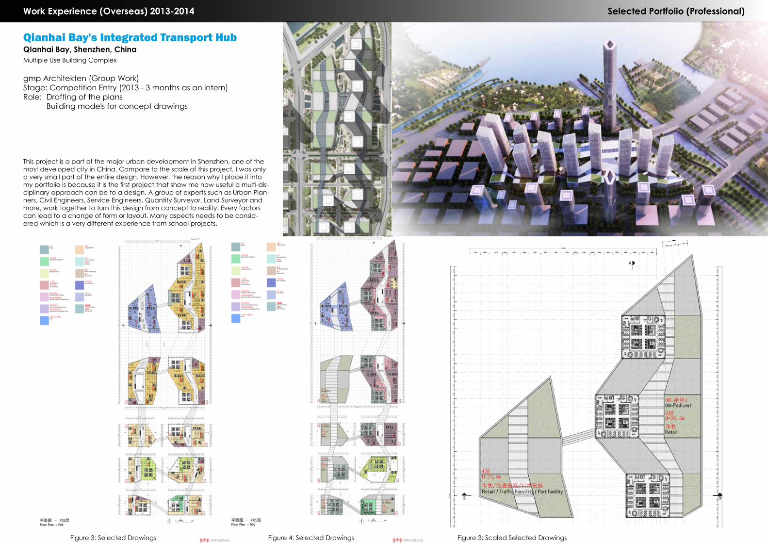
Qianhai Bay's Integrated Transport HubQIanhai Bay, Shenzhen, ChinaMultiple Use Building Complex
gmp Architekten (Group Work)Stage: Competition Entry (2013 - 3 months as an intern)Role: Drafting of the plans Building models for concept drawings
This project is a part of the major urban development in Shenzhen, one of the most developed city in China. Compare to the scale of this project, I was only a very small part of the entire design. However, the reason why I place it into my portfolio is because it is the first project that show me how useful a multi-dis-ciplinary approach can be to a design. A group of experts such as Urban Plan-ners, Civil Engineers, Service Engineers, Quantity Surveyor, Land Surveyor and more, work together to turn this design from concept to reality. Every factors can lead to a change of form or layout. Many aspects needs to be consid-ered which is a very different experience from school projects.
Figure 3: Selected Drawings Figure 4: Selected Drawings Figure 3: Scaled Selected Drawings