high performance vector control se2 series inverter...guide for manual guide for manual the shihlin...
TRANSCRIPT

www.seec.com.tw
ISO 14001BSMI
REGISTERED認可登錄
CERT. NO. 4A4E003
ISO 9001BSMI
REGISTERED認可登錄
CERT. NO. 4A4Y003
SE2 Series
High Performance Vector control SE2 Series Inverter

Guide for Manual
Guide for Manual
The Shihlin electric SE2-TYPE inverters have been designed with many complex parameterized
functions to meet most of the application requirements from the market. For customers who contact
inverters for the first time, such a complex inverter may cause troubles when using it. So the users
are expected to read each part of this manual carefully so as to master the operating method of the
inverter. In case there is any question, please feel free to contact us.
In Chapter 2 of this manual, all the series and the corresponding specifications of Shihlin electric
SE2-TYPE inverters are listed in detail. Section 2-5 guids customers how to install the inverter and
emphasizes on precautions for safety that much attention should be paid to when utilizing the
inverter.
Chapter 3 guides customers how to use the inverter. In Section 3-1, the operating mode of the
inverter is outlined briefly; in Section 3-2, how to use the operation panel is described, and in
Section 3-3, simple operating steps are explained. Chapter 4 explains the functions of each parameter
in detail.
The definitions of terminologies in this manual are as follows:
1. Output frequency, target frequency, steady output frequency
• The actual output current frequency of the inverter is called ‘output frequency’.
• The frequency set by user (through an operation panel, multi-speed terminals, voltage signal or
current signal) is called ‘target frequency’.
• When the motor starts running, the output frequency of the inverter will gradually accelerate to the
target frequency, and finally run steadily at the target frequency. The output frequency at this time
is called ‘steady output frequency’.
2. There are detailed instructions on parameter settings in Chapter 4. In case users are not familiar
with these settings, arbitrary adjustment of the parameter may result in abnormal operations. All
parameters can be reset to their default values by the parameter of P.998. For the setting
procedure of this parameter, please refer to P.998 in Chapter 4.
3. The ‘operation mode’ of inverter, and the ‘working mode’ of operation panel:
The operating mode determines the reference source for the target frequency and the signal source
for starting. The Shihlin inverter has totally 9 operating modes. Please refer to Section 3-1 for
details.
The operation panel mainly concerns monitoring of numeric values, setting of parameters and
setting of target frequency. The Shihlin operation panel has totally 5 working modes. Please refer
to Section 3-2 for details.
4. The difference between ‘terminal name’ and ‘function name’:
Near the terminals of the control board or the main board, printed letters can be found. These
letters are used to distinguish each terminal, and thus called ‘terminal name’.
For ‘multi-function control terminal’ and ‘multi-function output terminal’, besides the terminal
name, the ‘function name’ is also necessary to be defined. The function name indicates the actual
functions of the terminal.

Guide for Manual
Guide for Manual
When explaining the function for a terminal, the name used is its ‘function name’.
5. The difference between ‘on’ and ‘turn on’:
When explaining the function of the ‘multi-function control terminal’, the word ‘on and turn on’
are often used.
The ‘on’ is used to indicate that the external switch of the terminal is in close state, and thus
belongs to the description of the state.
The ‘turn on’ is employed to describe the action that the external switch of the terminal is shut on
from the open state to the close state, and thus belongs to the description of action.
6. All the ‘P.’s mentioned in this manual mean ‘parameter’.

Table of contents
Table of contents
Table of contents 1. Delivery Check ................................................................................................................................................................ 1
1.1 Nameplate instruction: ............................................................................................................................................ 1
1.2 Type instruction: ..................................................................................................................................................... 1
1.3 Order Code Description: ......................................................................................................................................... 1
2. Introduction of Shihlin Inverter ......................................................................................................................................... 2
2.1 Electric specification ............................................................................................................................................... 2
2.2 Common specification (Inverter characteristics) .................................................................................................... 4
2.3 Mechanical Dimensions .......................................................................................................................................... 6
2.4 Name of each part ................................................................................................................................................... 7
2.5 Installation and wiring ............................................................................................................................................ 9
2.6 Mini Jumper instruction ........................................................................................................................................ 20
2.7 Selection of peripheral equipments ....................................................................................................................... 21
3. Primary operation ............................................................................................................................................................ 28
3.1 Operating modes of the inverter............................................................................................................................ 28
3.2 Working modes of a operation panel..................................................................................................................... 30
3.3 The basic operation procedure for PU mode (P.79=0 or 1 ) .................................................................................. 34
3.4 The basic operation procedure for external mode ( , P.79=0 or 2) ........................................................... 34
3.5 The basic operation procedure for JOG mode ( , Pr79=0 or 1) ..................................................................... 35
3.6 The basic operation procedure for communication mode ( , P.79=3) ............................................................. 36
3.7 The basic operation procedure for Combined mode 1 ( , P.79=4 ) ................................................................... 36
3.8 The basic operation procedure for Combined mode 2 ( , P.79=5) .................................................................. 36
3.9 The basic operation procedure for Combined mode 3 ( , P.79=6) .................................................................. 37
3.10 The basic operation procedure for Combined mode 4 ( , P.79=7) ................................................................ 37
3.11 The basic operation procedure for Combined mode 5 ( , P.79=8) ................................................................. 37
3.12 Operation ............................................................................................................................................................ 37
4. Parameter description ...................................................................................................................................................... 40
4.1 Torque Boost (P.0, P.46) ....................................................................................................................................... 40
4.2 The Output Frequency Range (P.1, P.2, P.18) ...................................................................................................... 41
4.3 Base Frequency and Base Frequency Voltage (P.3, P.19, P.47) ............................................................................ 41
4.4 Multi-speed (P.4~P.6, P.24~P.27, P.142~P.149) .................................................................................................... 43
4.5 “Acceleration/deceleration Time (P.7, P.8, P.20, P.21, P.44, P.45) ........................................................................ 44
4.6 Electronic Thermal Relay Capacity (P.9) ............................................................................................................. 46
4.7 DC Injection Brake (P.10, P.11, P.12) .................................................................................................................. 46
4.8 Starting Frequency (P.13) ..................................................................................................................................... 47
4.9 Load Pattern Selection (P.14, P.98, P.99, P.162~P.169) ........................................................................................ 48
4.10 JOG Mode (P.15, P.16) ....................................................................................................................................... 51
4.11 Input Signal across Terminal 4-5 Selection Function (P.17) ............................................................................... 51
4.12 Stall Prevention (P.22, P.23, P.66) ....................................................................................................................... 52

Table of contents
Table of contents
4.13 Output Frequency Filter Constant (P.28) ............................................................................................................ 53
4.14 Acceleration/deceleration Curve Selection (P.29) .............................................................................................. 53
4.15 Regenerative Brake (P.30, P.70) .......................................................................................................................... 55
4.16 Soft-PWM (P.31) ................................................................................................................................................ 55
4.17 Communication Function (P.32, P.33, P.36, P.48~P.53, P.153~P.154) ................................................................. 56
4.18 Speed Display (P.37) ........................................................................................................................................... 71
4.19 Voltage Signal Selection and Target Frequency (P.38, P.59, P.73, P.76, P.139, P.140, P.141) ............................. 72
4.20 The Maximum Operation Frequency (the target frequency is set by the input signal of terminal 4-5) (P.39) .... 76
4.21 Multi-function Output (P.40, P.85, P.120) ........................................................................................................... 77
4.22 Up-to-frequency Sensitivity (P.41) ..................................................................................................................... 79
4.23 Output Frequency Detection (P.42, P.43) ............................................................................................................ 80
4.24 AM Terminal (P.54~P.56, P.190, P.191) .............................................................................................................. 80
4.25 Restart Function (P.57, P.58, P.150, P.160) ......................................................................................................... 82
4.26 Input Signal Filter Constant (P.60) ...................................................................................................................... 83
4.27 Remote Control Function Selection (P.61) ......................................................................................................... 83
4.28 Zero Current Detection (P.62, P.63) .................................................................................................................... 85
4.29 Retry (P.65, P.67, P.68, P.69) ............................................................................................................................... 86
4.30 Brake Selection (P.71) ......................................................................................................................................... 87
4.31 Carrier Frequency (P.72) ..................................................................................................................................... 87
4.32 Stop or Reset Function Selection (P.75) .............................................................................................................. 88
4.33 Parameters Write Protection (P.77) ..................................................................................................................... 89
4.34 Forward/reverse Rotation Prevention Selection (P.78) ....................................................................................... 89
4.35 Operation Mode Selection (P.79) ........................................................................................................................ 90
4.36 Multi-function Terminals Function Selection (P.80~P.84, P.86) ......................................................................... 91
4.37 Slip Compensation Coefficient (P.89) ................................................................................................................. 95
4.38 Frequency Jump (P.91~P.96) ............................................................................................................................... 95
4.39 Programmed Operation Mode (P.100~P.108, P.111~P.118, P.121~P.123, P.131~P.138) ..................................... 96
4.40 Operation Panel Monitoring Selection (P.110) ................................................................................................... 98
4.41 Expansion Board Function (P.125~P.130) .......................................................................................................... 98
4.42 Zero-speed Function (P.151~P.152) .................................................................................................................... 99
4.43 Over Torque Detection (P.155~P.156)............................................................................................................... 100
4.44 External Terminals Filter Adjusting Function (P.157) ....................................................................................... 100
4.45 External Terminal Power Enable Function (P.158) ........................................................................................... 101
4.46 Energy-saving Control Function(P.159) ............................................................................................................ 101
4.47 Multi-function Display (P.161) ......................................................................................................................... 101
4.48 PID Control (P.170~P.183)................................................................................................................................ 102
4.49 4-5 Terminal Disconnection Handling (P.184) .................................................................................................. 105
4.50 Ultra-high-speed Operation Function (P.187) ................................................................................................... 106
4.51 Firmware version (P.188) .................................................................................................................................. 106
4.52 Factory Setting Function (P.189) ...................................................................................................................... 106
4.53 Input Signal across Terminal 2-5 (P.192~P.195) ............................................................................................... 107
4.54 Input Signal across Terminal 4-5 (P.196~P.199) ............................................................................................... 108
4.55 Backlash Compensation Function (P.229~P.233) ............................................................................................. 109
4.56 Triangular Wave Function (P.234~P.239).......................................................................................................... 110
Table of contents
Table of contents
4.57 Auxiliary Frequency Function (P.240) .............................................................................................................. 111
4.58 DC Injection Brake Function before Starting (P.242~P.244) ............................................................................ 112
4.59 Bypass-inverter Switchover Function (P.247~P.250) ........................................................................................ 112
4.60 Alarm History (P.288~P.291) ............................................................................................................................ 115
4.61 Accumulative Motor Operation Time Function (P.292, P.293) ......................................................................... 116
4.62 Password Protection Function (P.294, P.295).................................................................................................... 117
4.63 Motor Control Mode (P.300, P.301) .................................................................................................................. 117
4.64 Motor Parameter (P.302~P.312) ........................................................................................................................ 119
4.65 Speed Control Gain Adjustment (P.320~P.321) ................................................................................................ 120
4.66 Parameter Copy Function (P.994, P.995) .......................................................................................................... 121
4.67 Alarm History Clear (P.996) ............................................................................................................................. 121
4.68 Inverter Reset (P.997) ....................................................................................................................................... 122
4.69 Parameter Initialization (P.998, P.999) .............................................................................................................. 122
5. Inspection and Maintenance .......................................................................................................................................... 123
5.1 Daily inspection .................................................................................................................................................. 123
5.2 Periodical inspection (during stop) ..................................................................................................................... 123
5.3 Regular replacement of parts (components) ....................................................................................................... 123
5.4 Inverter insulation resistance measurement ........................................................................................................ 124
5.5 Motor insulation resistance measurement ........................................................................................................... 124
5.6 Motor insulation resistance measurement ........................................................................................................... 124
Appendix 1 Parameter list ................................................................................................................................................. 126
Appendix 2 Alarm Code List ............................................................................................................................................ 137
Appendix 3 Warning code list ........................................................................................................................................... 140
Appendix 4 Troubles and Solutions .................................................................................................................................. 141
Appendix 5 Optional equipment ....................................................................................................................................... 142
Appendix 6 Frequency parameters of ultra-high-speed .................................................................................................... 150
Amendment record ............................................................................................................................................................ 153
1
1. Delivery Check
Product Examination
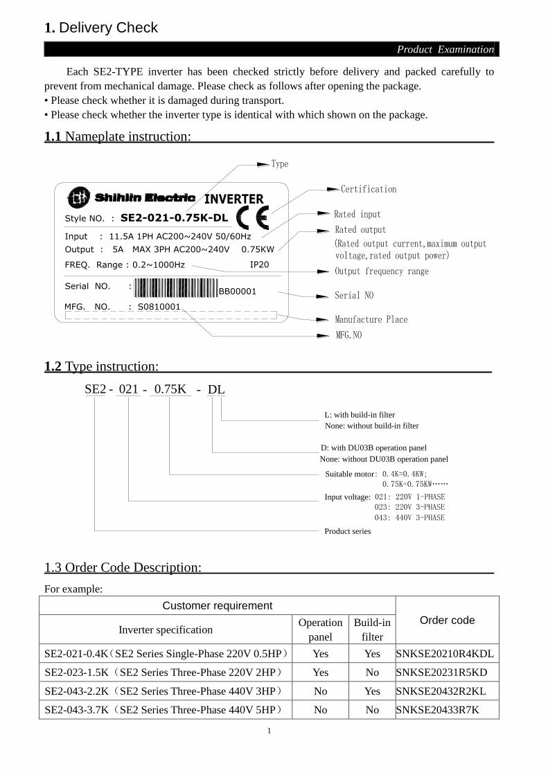
Each SE2-TYPE inverter has been checked strictly before delivery and packed carefully to
prevent from mechanical damage. Please check as follows after opening the package.
• Please check whether it is damaged during transport.
• Please check whether the inverter type is identical with which shown on the package.
1.1 Nameplate instruction:
BB00001
MFG. NO. : S0810001
Serial NO. :
Style NO. : SE2-021-0.75K-DL
Input : 11.5A 1PH AC200~240V 50/60Hz
Output : 5A MAX 3PH AC200~240V 0.75KW
FREQ. Range : 0.2~1000Hz IP20
1.2 Type instruction:
Product series
SE2 - 021 - 0.75K
Suitable motor: 0.4K=0.4KW;
- DL
Input voltage: 021: 220V 1-PHASE 023: 220V 3-PHASE
043: 440V 3-PHASE
0.75K=0.75KW……
None: without DU03B operation panel
D: with DU03B operation panel
None: without build-in filter
L: with build-in filter
1.3 Order Code Description:
For example:
Customer requirement
Order code Inverter specification
Operation
panel
Build-in
filter
SE2-021-0.4K(SE2 Series Single-Phase 220V 0.5HP) Yes Yes SNKSE20210R4KDL
SE2-023-1.5K(SE2 Series Three-Phase 220V 2HP) Yes No SNKSE20231R5KD
SE2-043-2.2K(SE2 Series Three-Phase 440V 3HP) No Yes SNKSE20432R2KL
SE2-043-3.7K(SE2 Series Three-Phase 440V 5HP) No No SNKSE20433R7K

2
2. Introduction of Shihlin Inverter
Introduction of Inverter
2.1 Electric specification
2.1.1 220V Series Single-Phase
Model SE2-021-□□□K 0.4K 0.75K 1.5K 2.2K
applicable motor capacity HP 0.5 1 2 3
kW 0.4 0.75 1.5 2.2
Output
Rated output capacity kVA (Note) 1.2 1.9 3.0 4.2
Rated output current A (Note) 3.0 5.0 8.0 11.0
Overload current rating 150% 60 seconds; 200% 1 second (inverse time
characteristics)
Maximum output voltage 3 Phase 200~240V AC
Power
supply
Rated power voltage single phase 200~240V 50Hz / 60Hz
Power voltage permissible
fluctuation single phase 180~264V 50Hz / 60Hz
Power frequency permissible
fluctuation ±5%
Power source capacity kVA 1.8 3 4.5 6.4
Cooling method Self cooling Forced air cooling
Weight kg 1.2 1.2 1.9 1.9
2.1.2 220V Series Three-Phase
Model SE2-023-□□□K 0.4K 0.75K 1.5K 2.2K 3.7K 5.5K 7.5K
applicable motor
capacity
HP 0.5 1 2 3 5 7 10
kW 0.4 0.75 1.5 2.2 3.7 5.5 7.5
Output
Rated output capacity kVA (Note) 1.2 1.9 3.0 4.2 6.7 9.2 12.6
Rated output current A (Note) 3.0 5.0 8.0 11.0 17.5 24 33
Overload current rating 150% 60 seconds; 200% 1 second (inverse time
characteristics)
Maximum output voltage 3 Phase 200~240V AC
Power
supply
Rated power voltage 3 Phase 200~240V 50Hz / 60Hz
Power voltage permissible
fluctuation 3 Phase 170~264V 50Hz / 60Hz
Power frequency permissible
fluctuation ±5%
Power source capacity kVA 1.8 3 4.5 6.4 10 13.8 19
Cooling method Self
cooling Forced air cooling
Weight kg 1.2 1.2 1.2 1.9 1.9 3.8 3.8

3
2. Introduction of Shihlin Inverter
Introduction of Inverter
2.1.3 440V Series Three-Phase
Model SE2-043-□□□K 0.4K 0.75K 1.5K 2.2K 3.7K 5.5K 7.5K 11K
applicable motor capacity HP 0.5 1 2 3 5 7 10 15
kW 0.4 0.75 1.5 2.2 3.7 5.5 7.5 11
Output
Rated output capacity kVA
(Note) 1.2 2.0 3.2 4.6 6.9 9.2 13 18
Rated output current A (Note) 1.5 2.6 4.2 6.0 9.0 12 17 23
Overload current rating 150% 60 Seconds; 200% 1 Second (inverse time
characteristics)
Maximum output voltage 3 Phase 380~480V
Power
supply
Rated power voltage 3 Phase 380~480V 50Hz / 60Hz
Power voltage permissible
fluctuation 323~506V 50Hz / 60Hz
Power frequency permissible
fluctuation ±5%
Power source capacity kVA 1.8 3 4.8 6.9 10.4 13.8 19.5 27
Cooling method Self
cooling Forced air cooling
Weight kg 1.2 1.2 1.2 1.9 1.9 3.8 3.8 3.8

4
2. Introduction of Shihlin Inverter
Introduction of Inverter
2.2 Common specification (Inverter characteristics)
Control method SVPWM control, V/F control, facility vector control, Sensorless vector
control.
Output frequency range 0.2~1000Hz (The starting frequency setting range is 0~600Hz). Please
refer to P.187 in Chapter 4.
Resolution for
setting frequency
Digital
setting
When P.187=0, if the frequency set value is below 100Hz, the resolution
will be 0.01Hz. If the frequency set value is above 100Hz, the resolution
will be 0.1Hz. When P.187=1, the resolution of frequency will be 0.1Hz.
Analog
setting
When setting DC 0~5V signals, the resolution will be 1/500;
When setting DC 0~10V or 4~20mA signals, the resolution will be
1/1000.
Output frequency accuracy 0.01Hz
Voltage / frequency output
characteristics
Base frequency voltage (P.19), base frequency (P.3) can be arbitrarily set
in available range.
Constant torque model, applicable load model can be selected (P.14).
Start torque 150% (1Hz): When the sensorless vector control is started.
Torque boost The torque boost setting range is 0~30% (P.0), auto boost, slip
compensation.
Acceleration/deceleration
curve characteristics
The resolution (0.01s/0.1s) of acceleration/deceleration time (P.7, P.8) is
switched by P.21. The setting range has 0~360s or 0~3600s for selection.
And different acceleration/deceleration curve model can be selected by
P.29.
DC braking
The DC braking action frequency is 0~120Hz (P.10); the DC braking
time is 0~60 Seconds (P.11); and the DC braking voltage is 0~30%
(P.12). Linear braking and Idling braking selection (P.71).
Stalling protection The stalling protection level can be set to 0~400% (P.22).
Target frequency setting
Operation panel setting;
DC 0~5V signal setting, DC 0~10V signal setting and DC 4~20mA
signal setting, 2 voltage input or one voltage and one current input can
be selected;
Multi-speed stage levels setting; Communication setting.
PID control Please refer to P.170~P.183 in Chapter 4.
Multi-function control
terminals
Motor starting (STF, STR), the second function (RT), the 16-speed
operation (RL, RM, RH, REX), external thermal relay (OH), reset
(RES) , etc. (they can be set by the user with P.80~P.84, P.86)
Multi-
function
output
terminals
Multi-function
output terminals
(SO, SE)
P.40
Inverter running (RUN), output frequency detection (FU), Up to
frequency (SU), overload alarm (OL), zero current detection
(OMD), alarm (ALARM), Section detection (PO1), Periodical
detection (PO2), and Pause detection (PO3), Inverter output (BP),
Commercial power-supply output (GP).
Multi-function
output relay P.85
Multi function
analogy meter
Multi-function DC (0~10V)(AM)
Output: output frequency, output current (P.54).

5
2. Introduction of Shihlin Inverter
Introduction of Inverter
Operation panel
Running status
monitoring
Output frequency monitoring, output current monitoring, and
output voltage monitoring.
HELP mode Alarm history monitoring, alarm history clear, all parameters clear,
and firmware version read.
LED indication
lamp(6)
Run indication lamp, frequency monitoring indication lamp,
voltage monitoring indication lamp, current monitoring indication
lamp, mode switching indication lamp, and PU/external terminals
control indication lamp.
Communication
function
RS485 Internal RS485 communication.
Communication
expansion board
Optional accesssories: Terminal type, RJ11, RJ-45, Profibus or
Device Net communication expansion board.
Protection mechanism
/ Alarm function
Output short circuit protection, Over-current protection, P-N
over-voltage protection, under-voltage protection, motor over heat
protection (P.9), IGBT module over heat protection, braking
transistor abnormality protection, communication abnormality
protection, etc.
Environmental
condition
Ambient
temperature -10 ~ +50℃ (non-freezing)
Ambient
humidity Below 90%Rh (non-condensing)
Storage
temperature -20 ~ +65℃
Environment
around In room, no corrosive gas, no flammable gas, no flammable dust
Altitude and
vibration Altitude below 1000 meters, Vibration below 5.9m/s2 (0.6G).
Certification Meet the requirements of CE certification standards (the –DL
type).
Note: 1.If several multi-function output relays are needed, you can choose the I/O expansion board, on which there
are 2 multi-function output relays. For detailed instruction, please refer to appendix 5.
2. Communications expansion board option details, please refer to Appendix 5.
3. Profibus is the registered trademark of Profibus international.
4. Device Net is the registered trademark of ODVA (Open Device Vendor Association).

6
2. Introduction of Shihlin Inverter
Introduction of Inverter
2.3 Mechanical Dimensions
2.3.1 Outline
2.3.2 Dimension
Model H(mm) W(mm) D(mm) W1(mm) H1(mm) C1(mm)
SE2-021-0.4K 148 85 148 75 138 Φ 5
SE2-021-0.75K 148 85 148 75 138 Φ 5
SE2-021-1.5K 186 100 157 90 176 Φ 5
SE2-021-2.2K 186 100 157 90 176 Φ 5
SE2-023-0.4K 148 85 148 75 138 Φ 5
SE2-023-0.75K 148 85 148 75 138 Φ 5
SE2-023-1.5K 148 85 148 75 138 Φ 5
SE2-023-2.2K 186 100 157 90 176 Φ 5
SE2-023-3.7K 186 100 157 90 176 Φ 5
SE2-023-5.5K 266 141 201.5 126 244 Φ 6
SE2-023-7.5K 266 141 201.5 126 244 Φ 6
SE2-043-0.4K 148 85 148 75 138 Φ 5
SE2-043-0.75K 148 85 148 75 138 Φ 5
SE2-043-1.5K 148 85 148 75 138 Φ 5
SE2-043-2.2K 186 100 157 90 176 Φ 5
SE2-043-3.7K 186 100 157 90 176 Φ 5
SE2-043-5.5K 266 141 201.5 126 244 Φ 6
SE2-043-7.5K 266 141 201.5 126 244 Φ 6
SE2-043-11K 266 141 201.5 126 244 Φ 6

7
2. Introduction of Shihlin Inverter
Introduction of Inverter
2.4 Name of each part
2.4.1 Nameplate and model
BB00001
MFG. NO. : S0810001
Serial NO. :
Style NO. : SE2-021-0.75K-DL
Input : 11.5A 1PH AC200~240V 50/60Hz
Output : 5A MAX 3PH AC200~240V 0.75KW
FREQ. Range : 0.2~1000Hz IP20
2.4.2 SE2-0XX-0.4K~11K (0.5HP~15HP)
When wiring, the wire must go through the ‘wiring outlet’ before connecting with the terminal bank.

8
2. Introduction of Shihlin Inverter
Introduction of Inverter
Note: 1. The enlarge figure of the control-circuit terminal block nameplate is as follows:
2. There’s no screw for the 1-Phase type.

9
2. Introduction of Shihlin Inverter
Introduction of Inverter
2.5 Installation and wiring
2.5.1 Transport
Take the pedestal when carrying and don’t only take the cover or any part of the inverter,
otherwise it may drop down.
2.5.2 Stockpile
This product before installing must be placed in the packaging, if not use, in order to meet the
company's warranty scope and future maintenance, you must pay attention to the following matters
when storage:
1. Must be placed in dry and without dirt place.
2. The environment temperature for storage position must range from -20℃ to +65℃.
3. The relative humidity for storage position must range from 0% to 95%, and no condensation.
4. Avoid storing in the environment which contains corrosion gas or liquid.
5. It had better be packed properly and kept on shelf or table.
Note: 1. Even if the humidity meets the standard requirements, icing and condensation can also occur when the
temperature changes rapidly. And the place should avoid.
2. Don't place it on the ground, and it should be placed on appropriate shelf. If in the bad surroundings, the
desiccant should be placed in the packaging bag.
3. If the custody period is more than 3 months, the ambient temperature should not be higher than 30℃. It is
to consider that the character will easily degrade in high temperature when the electrolytic capacitors are
deposited without electricity.
4. If the inverter is installed in device or control board when not in use (especially in construction site or the
humid and dusty place), the inverter should be removed and put in suitable environment according with
the above storage conditions.
5. If the electrolytic capacitors are long-term no electricity, the character will degrade. Do not place it in the
state of no electricity for more than one year.
2.5.3 EMC Installation instructions
Inverter is the same as other electrical and electronic equipment, when working in a distribution
system, it is both the electromagnetic interference sources and the electromagnetic receiver. The
working principle of inverter determines that it will produce certain electromagnetic interference
noise. In order to guarantee the inverter working reliably in the electromagnetic environment, it must
have a certain abilitily of anti-electromagnetic interference in design. In order to make the drive
system work normaly, and meet CE declared requirements, please meet the following several aspects
requirements in installation:
1. Field wiring
Power line supply electric independently from power transformer, five core or four core line are
generally used, null line and ground sharing a single line is forbidden.
10
2. Introduction of Shihlin Inverter
Introduction of Inverter
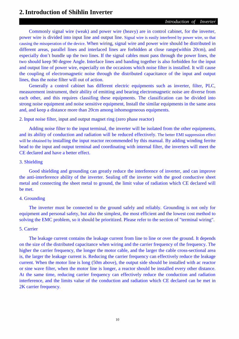
Commonly signal wire (weak) and power wire (heavy) are in control cabinet, for the inverter,
power wire is divided into input line and output line. Signal wire is easily interfered by power wire, so that
causing the misoperation of the device. When wiring, signal wire and power wire should be distributed in
different areas, parallel lines and interlaced lines are forbidden at close range(within 20cm), and
especially don’t bundle up the two lines. If the signal cables must pass through the power lines, the
two should keep 90 degree Angle. Interlace lines and banding together is also forbidden for the input
and output line of power wire, especially on the occasions which noise filter is installed. It will cause
the coupling of electromagnetic noise through the distributed capacitance of the input and output
lines, thus the noise filter will out of action.
Generally a control cabinet has different electric equipments such as inverter, filter, PLC,
measurement instrument, their ability of emitting and bearing electromagnetic noise are diverse from
each other, and this requires classifing these equipments. The classification can be divided into
strong noise equipment and noise sensitive equipment, Install the similar equipments in the same area
and, and keep a distance more than 20cm among inhomogeneous equipments.
2. Input noise filter, input and output magnet ring (zero phase reactor)
Adding noise filter to the input terminal, the inverter will be isolated from the other equipments,
and its ability of conduction and radiation will be reduced effectively. The better EMI suppression effect
will be obtained by installing the input reactor recommended by this manual. By adding winding ferrite
bead to the input and output terminal and coordinating with internal filter, the inverters will meet the
CE declared and have a better effect.
3. Shielding
Good shielding and grounding can greatly reduce the interference of inverter, and can improve
the anti-interference ability of the inverter. Sealing off the inverter with the good conductive sheet
metal and connecting the sheet metal to ground, the limit value of radiation which CE declared will
be met.
4. Grounding
The inverter must be connected to the ground safely and reliably. Grounding is not only for
equipment and personal safety, but also the simplest, the most efficient and the lowest cost method to
solving the EMC problem, so it should be prioritized. Please refer to the section of "terminal wiring".
5. Carrier
The leakage current contains the leakage current from line to line or over the ground. It depends
on the size of the distributed capacitance when wiring and the carrier frequency of the frequency. The
higher the carrier frequency, the longer the motor cable, and the larger the cable cross-sectional area
is, the larger the leakage current is. Reducing the carrier frequency can effectively reduce the leakage
current. When the motor line is long (50m above), the output side should be installed with ac reactor
or sine wave filter, when the motor line is longer, a reactor should be installed every other distance.
At the same time, reducing carrier frequency can effectively reduce the conduction and radiation
interference, and the limits value of the conduction and radiation which CE declared can be met in
2K carrier frequency.

11
2. Introduction of Shihlin Inverter
Introduction of Inverter
2.5.4 Installation notice
1. 1. Please install in an upright direction
2. Proper clearance shall be kept from surroundings
when installing
3. The ambient temperature shall not exceed the
permissible value.
4. Correct position for installing in a protection
case.
Ventilating fan
5. Please do not install the inverter on a surface of inflammable material such as wood etc.
6. Please do not install the inverter at places exposed to explosive gas, inflammable dust. 7. Please do not install the inverter at places with airborne oil mist and dust.
8. Please do not install the inverter at places exposed to corrosive gas or high salt air.
9. Please do not install the inverter in the environment of high temperature and high humidity.
Note: 1.Only qualified electrical professional personnel can carry out the installation, wire arrangement,
dismounting and maintenance.
2. Please ensure to comply with the installation notice. In case the installation notice has not been fully
complied with and damage of the inverter or dangerous accidence thus be resulted in, our company will
not undertake any legal responsibility. In case there is any question when installing, please feel free to
contact us.

12
2. Introduction of Shihlin Inverter
Introduction of Inverter
2.5.5 System wire arrangement of SE2-0XX-0.4K~11K (0.5HP~15HP) series
FUSE /NFB
Magnetic contactor
Input AC Line Reactor
Zero-phase Reactor
Output AC Line Reactor
EMI filter
R/L1 S/L2 T/L3
U/T1 V/T2 W/T3
Motor
BR
P
PR
Braking resistor
Power
N
Zero-phase Reactor
Power
supply
Please follow the specific
power supply requirement
shown in this manual.
Fuse/NFB
There may be an inrush
current during power up.
Please refer to 2.7.1 and
select the correct fuse /NFB.
Magnetic
contactor
Please do not use a Magnetic
contactor as the I/O switch of
the inverter, as it will reduce
the operating life cycle of the
inverter.
Input AC
Line Reactor
AC line reactor should be
installed to improve the input
power factor. The wiring
distance should be less than
10m. Please refer to 2.7.6.
Zero-phase
Reactor
Zero-phase reactors are used to
reduce radio noise especially
when audio equipment installed
near the inverter. Effective for
noise reduction on both the
input and output sides.
Attenuation quality is good for a
wide range from AM band to
10Mhz. Please refer to 2.7.5.
EMI filter Used to reduce electromagnetic
interference.
Braking unit Used to reduce stopping time of
the motor.
Output AC
Line Reactor
Motor surge voltage
amplitudes depending on
motor cable length. The output
AC line reactor is necessary to
install on the inverter output
side. Please refer to 2.7.6.

13
2. Introduction of Shihlin Inverter
Introduction of Inverter
2.5.6Terminal wire arrangement of SE2-0XX-0.4K~11K(0.5HP~15HP)series
===== Note: ==============================================================
1. For the usage of external thermal relay, please refer to P.80~P.84, P.86 in Chapter 4.
2. Make sure do not to short PC and SD.
3. In the above figure, Dotted line metal, please refer 2.5.7
4. The SE2-TYPE inverter have internal RS485 communication, and can also uses pluggable
communications expansion boards CB01, CB02, CB03, PD01, DN01; For detailed instructions,
please refer to appendix 5.
=======================================================================
14
2. Introduction of Shihlin Inverter
Introduction of Inverter
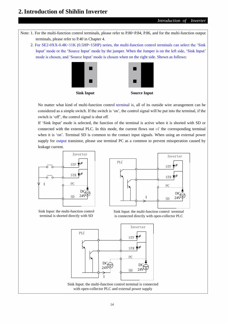
Note: 1. For the multi-function control terminals, please refer to P.80~P.84, P.86, and for the multi-function output
terminals, please refer to P.40 in Chapter 4.
2. For SE2-0XX-0.4K~11K (0.5HP~15HP) series, the multi-function control terminals can select the ‘Sink
Input’ mode or the ‘Source Input’ mode by the jumper. When the Jumper is on the left side, ‘Sink Input’
mode is chosen, and ‘Source Input’ mode is chosen when on the right side. Shown as follows:
Sink Input Source Input
No matter what kind of multi-function control terminal is, all of its outside wire arrangement can be
considered as a simple switch. If the switch is ‘on’, the control signal will be put into the terminal, if the
switch is ‘off’, the control signal is shut off.
If ‘Sink Input’ mode is selected, the function of the terminal is active when it is shorted with SD or
connected with the external PLC. In this mode, the current flows out of the corresponding terminal
when it is ‘on’. Terminal SD is common to the contact input signals. When using an external power
supply for output transistor, please use terminal PC as a common to prevent misoperation caused by
leakage current.
STF
STR
SD
Inverter
Sink Input: the multi-function control
terminal is shorted directly with SD
Sink Input: the multi-function control terminal
is connected directly with open-collector PLC
PLC
I
I
DC
24V
PC
STF
STR
SD
Inverter
DC
24V
PC
Sink Input: the multi-function control terminal is connected
with open-collector PLC and external power supply
PLC
I
STF
STR
SD
Inverter
DC
24V
PC
DC
24V

15
2. Introduction of Shihlin Inverter
Introduction of Inverter
If ‘Source Input’ mode is selected, the function of the multi-function control; terminal is active when it is
shorted with PC or connected with the external PLC. In this mode, the current flows into the
corresponding terminal when it is ‘on’. Terminal PC is common to the contact input signals. When using
an external power supply for transistor output, please use terminal SD as a common to prevent
misoperation caused by leakage current.
STF
STR
PC
Inverter
Source Input: the multi-function control
terminal is shorted directly with PC
Source Input: the multi-function control terminal
is connected directly with open-emitter PLC
PLC
I
I
DC
24V
SD
STF
STR
PC
Inverter
DC
24V
SD
Source Input: the multi-function control terminal is
connected with open-emitter PLC and external power supply
PLC
I
STF
STR
PC
Inverter
DC
24V
SD
DC24V
Main-circuit terminals
Terminal name Remarks
R/L1- S/L2- T/L3 Connect to the commercial power supply.
U/T1-V/T2-W/T3 Connect to three-phase squirrel-cage motor.
P- PR Connect to brake resistors. (Note1, 2)
P-N Connect to brake unit. (Note3)
Connect the enclosure of the inverter to ground. For 220V series, the third type of
grounding shall be adopted. For 440V series, special type of grounding shall be
adopted. (Note 4)
16
2. Introduction of Shihlin Inverter
Introduction of Inverter
Note: 1. For SE2-0XX-0.4K~11K (0.5HP~15HP) series of inverters, the brake resistor isn’t appended when sales.
2. For the related knowledge on regenerative voltage, please refer to P.30 in Chapter 4.
3. P and N are the positive and negative terminals of the internal DC voltage of the inverter. In order to
strengthen the braking capability during deceleration, it is suggested to purchase the option of ‘brake unit’
which is mounted between the terminals P and N. The ‘brake unit’ can effectively dissipate the feedback
energy from the motor to the inverter when decelerating. In case there is any problem on purchasing of
the ‘brake unit’, please feel free to contact us.
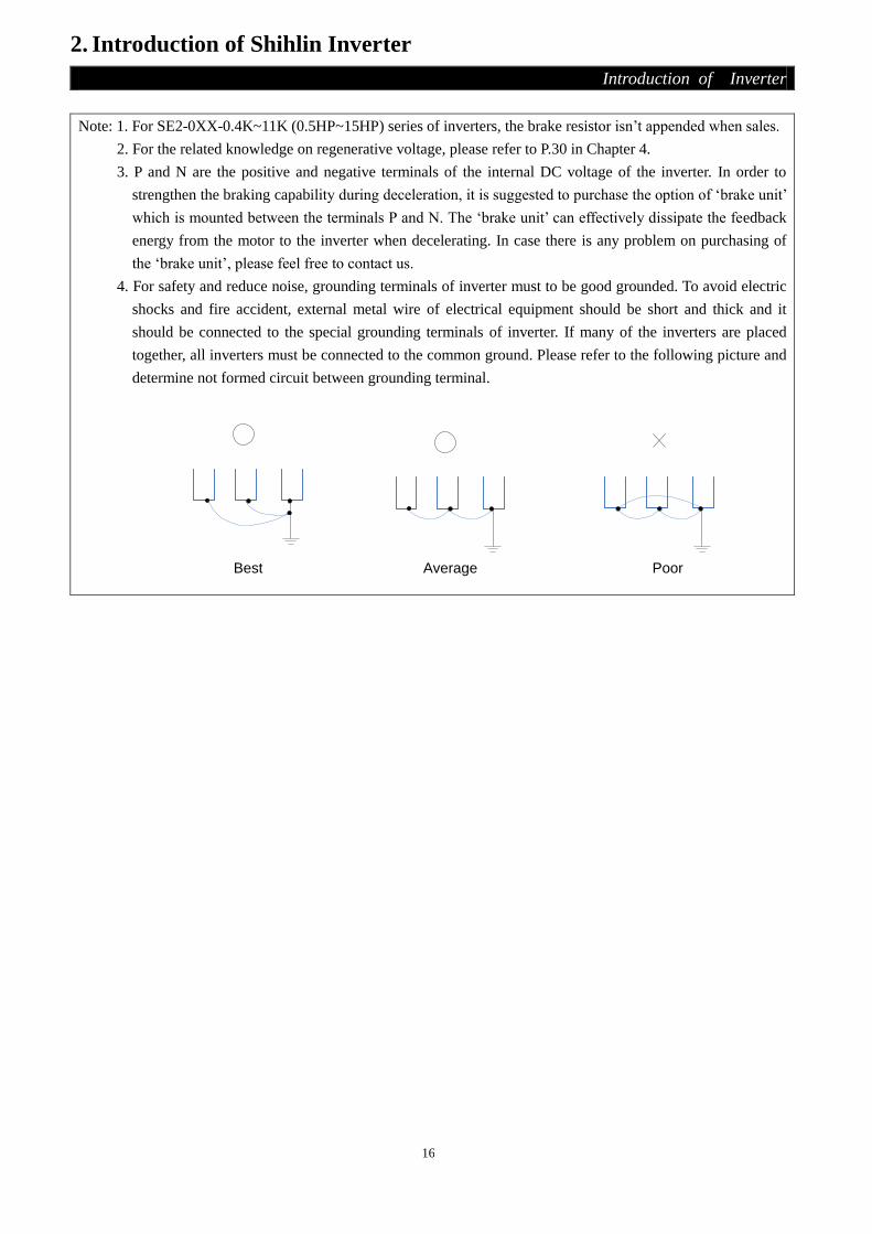
4. For safety and reduce noise, grounding terminals of inverter must to be good grounded. To avoid electric
shocks and fire accident, external metal wire of electrical equipment should be short and thick and it
should be connected to the special grounding terminals of inverter. If many of the inverters are placed
together, all inverters must be connected to the common ground. Please refer to the following picture and
determine not formed circuit between grounding terminal.
Best
Average
Poor

17
2. Introduction of Shihlin Inverter
Introduction of Inverter
Control terminals
Terminal type Terminal
name
Function
name Remarks and function description
On-off signal
input
STF Optional
These terminals are multi-function control terminals
(SINK/SOURCE mode switchable).
For detailed descriptions, please refer to P.80~P.84, P.86 in
Chapter 4.
STR Optional
M0 Optional
M1 Optional
M2 Optional
RES Optional
SD SD Common reference Ground for STF, STR, M0, M1, M2 and
RES
PC PC In the ‘Source input’ mode, it provides a common power
supply for the terminals referred above.
Analog signal
input
10 --- The internal power is DC 10V at this terminal.
2 --- The input of voltage signal 0~5V or 0~10V, is
used to set the target frequency. P.38
4 ---
The input of voltage signal 0~5V or 0~10V /
input of current signal 4mA~20mA (switch
with P.17), is used to set the target frequency.
(Note 1)
P.39
5 --- The common reference ground of 2, 4, 10 and AM.
Relay output
A --- Normally, A-C are normal open, and B-C are normal closed.
Contact capacity is VDC30V / VAC230V-0.3A B ---
C ---
Open collector
output
SO Optional
The terminal can also be called ‘multi-function output
terminal’. The function name can be set by P.40. For detailed
description, please refer to P.40 in Chapter 4.
SE SE Open collector output reference ground.
Analog signal
output AM ---
Connected with an external analog meter to indicate the
output frequency or current. Contact capacity is 0~10VDC/2mA.
Please refer to P.54, P.55, P.56, P.191, and P.192 in Chapter 4.
Communication
terminal
DA+ DA+ RS485 serial communication terminal
DB- DB-
Dedicated
terminals WF WF
Do not connect it during normal operation, otherwise may
cause a malfunction.

18
2. Introduction of Shihlin Inverter
Introduction of Inverter
2.5.7 Wiring precautions
Main circuit wiring: 1. Do not connect the power supply wires to the ‘inverter’s output terminals (U/T1)-(V/T2)-(W/T3)
which are designed for connecting motors, otherwise, the inverter may be damaged.
2. Please do not mount filtering capacitors, surge absorbers and electromagnetic contactors at the
output end of the inverter.
3. Please do not use ‘electromagnetic contactors’ or ‘no-fuse switches’ with an online power to start
or stop the motor.
4. Please ensure that the case of inverter and the motor are grounded, to avoid personnel electric
shock.
5. To appropriately select the diameter of the main wires and the corresponding wire terminals, the
no-fuse switches and the electromagnetic contactors, please refer to Section 2.7. And if the
inverter is far away from the motor, please employ a wire with larger diameter to ensure the
voltage drop along the wire within 2V. (The total length of the wire shall not exceed 500 meters)
6. ‘Pressing connection terminals with insulated sleeve’ shall be utilized for the wiring at the power
source side and the load side.
7. In a short period after the power supply is shut off, high voltage still exists between the terminals
P-N, thus please do not touch them within 10 minutes to avoid getting an electric shock.
Control circuit wire arrangement:
1. For wiring of signal input, ‘insulated wires’ must be used,and the ‘metal mesh’ of which must be
put to earth.
2. For wiring of the control board, wires with a diameter of 0.75mm2 are suggested to be used. And
for the stripping of the insulating layer, please comply with the instruction of the following
figure.
3. The control board wire (including signal input wire) shall be far away from the main circuit board
wire. Binding the control board wires together with the main circuit wires is strictly forbidden.
4. In the inverter, the ‘terminal SD’, ‘terminal SE’ and the ‘terminal 5’ are the referencing grounds
for the inner power sources which are isolated from each other.

19
2. Introduction of Shihlin Inverter
Introduction of Inverter
Note: 1. The terminal block screws must be screwed up tightly. Especially the wire cut pieces shall
not be left in the inverter.
2. Only qualified electrical professional personnel can carry out the installation, wire arrangement,
dismounting and maintenance.
3. Please comply with the wire arrangement notice. In case the installation has not been fully complied
with, and damage of the inverter or dangerous accidence thus be resulted in, our company will not
undertake any legal responsibility. In case there is any question on the wire arrangement, please feel
free to contact us.

20
2. Introduction of Shihlin Inverter
Introduction of Inverter
2.6 Mini Jumper instruction
Main power isolated from earth:
1. If the inverter is supplied with a non-grounded power system (IT power), the Mini jumper
must be cut off to prevent damaging center circuit (according to IEC61800-3) and reducing
earth leakage current.
2. Please switch the Mini jumper to “On” if the inverter has a build-in filter, but that time, the
earth leakage current will be increased. Please switch the Mini jumper to “Off” if the
inverter has not a build-in filter.
3. The Mini jumper is shown as follows:
==== Note: =============================================================
1. After applying power to the inverter, do not cut off the Mini jumper. Therefore, please make sure
that main power has been switched off before cutting off the Mini jumper.
2. The gap discharge may occur when transient voltage is high than 1000V. Besides, electro-magnetic
compatibility of the inverter will be lower after cutting the Mini jumper.
3. Do not cut the Mini jumper when main power is grounded. To prevent drive damage, the Mini
jumper shall be cut off if the inverter is installed on an ungrounded power system or a high
resistance-grounded (over 30 ohms) power system or a corner grounded TN system.
4. The Mini jumper cannot be cut when Hi-pot tests are performed.
========================================================================

21
2. Introduction of Shihlin Inverter
Introduction of Inverter
2.7 Selection of peripheral equipments
2.7.1 No-fuse switch
Inverter type Motor capacity Power source
capacity
Applicable NFB/MCCB type
(Shihlin)
Applicable MC
type (Shihlin)
Taiwan Motherland Taiwan/
Motherland
SE2-021-0.4K 220V 0.5HP 1.8kVA NF30 5A BM30SN3P5A S-P11
SE2-021-0.75K 220V 1HP 3kVA NF30 10A BM30SN3P10A S-P11
SE2-021-1.5K 220V 2HP 4.5kVA NF30 15A BM30SN3P15A S-P11
SE2-021-2.2K 220V 3HP 6.4kVA NF30 20A BM30SN3P20A S-P11/ S-P12
SE2-023-0.4K 220V 0.5HP 1.8kVA NF30 5A BM30SN3P5A S-P11
SE2-023-0.75K 220V 1HP 3kVA NF30 10A BM30SN3P10A S-P11
SE2-023-1.5K 220V 2HP 4.5kVA NF30 15A BM30SN3P15A S-P11
SE2-023-2.2K 220V 3HP 6.4kVA NF30 20A BM30SN3P20A S-P11 / S-P12
SE2-023-3.7K 220V 5HP 10kVA NF30 30A BM30SN3P30A S-P21
SE2-023-5.5K 220V 7.5HP 13.8kVA NF50 50A BM60SN3P50A S-P21
SE2-023-7.5K 220V 10HP 19kVA NF100 60A BM60SN3P60A S-P21
SE2-043-0.4K 440V 0.5HP 1.8kVA NF30 3A BM30SN3P3A S-P11
SE2-043-0.75K 440V 1HP 3kVA NF30 5A BM30SN3P5A S-P11
SE2-043-1.5K 440V 2HP 4.8kVA NF30 10A BM30SN3P10A S-P11
SE2-043-2.2K 440V 3HP 6.9kVA NF30 15A BM30SN3P15A S-P21
SE2-043-3.7K 440V 5HP 10.4kVA NF30 20A BM30SN3P20A S-P21
SE2-043-5.5K 440V 7.5HP 13.8kVA NF30 30A BM30SN3P30A S-P21
SE2-043-7.5K 440V 10HP 19.5kVA NF50 50A BM60SN3P50A S-P21
SE2-043-11K 440V 15HP 27kVA NF100 60A BM60SN3P60A S-P21

22
2. Introduction of Shihlin Inverter
Introduction of Inverter
2.7.2 Power cable specification/pressing connection terminals specification
Inverter type
Power cable specification Pressing connection terminal
specification (used by power cables)
Cables for the
power supply
R/L1.S/L2.T/L3
(mm2)
Cables for the
output
U/T1.V/T2.W/T3
(mm2)
Cables for the
power supply
R/L1.S/L2.T/L3
(mm2)
Cables for the
output
U/T1.V/T2.W/T3
(mm2)
SE2-021-0.4K 2 2 2 - 4 2 - 4
SE2-021-0.75K 2 2 2 - 4 2 - 4
SE2-021-1.5K 2 2 2 - 4 2 - 4
SE2-021-2.2K 3.5 3.5 5.5 - 4 5.5 - 4
SE2-023-0.4K 2 2 2 - 4 2 - 4
SE2-023-0.75K 2 2 2 - 4 2 - 4
SE2-023-1.5K 2 2 2 - 4 2 - 4
SE2-023-2.2K 2 2 2 - 4 2 - 4
SE2-023-3.7K 3.5 3.5 5.5 - 4 5.5 - 4
SE2-023-5.5K 5.5 5.5 5.5 - 5 5.5 - 5
SE2-023-7.5K 14 8 14.5 - 5 8 - 5
SE2-043-0.4K 2 2 2 - 4 2 - 4
SE2-043-0.75K 2 2 2 - 4 2 - 4
SE2-043-1.5K 2 2 2 - 4 2 - 4
SE2-043-2.2K 2 2 2 - 4 2 - 4
SE2-043-3.7K 2 2 2 - 4 2 - 4
SE2-043-5.5K 3.5 2 5.5 - 4 2 - 4
SE2-043-7.5K 3.5 3.5 5.5 - 4 5.5 - 4
SE2-043-11K 5.5 5.5 5.5 - 5 5.5 - 5

23
2. Introduction of Shihlin Inverter
Introduction of Inverter
2.7.3 Brake resistors
Inverter type Brake resistor specification Inverter type Brake resistor specification
SE2-021-0.4K 100W 220Ω SE2-023-5.5K 1000W 25Ω
SE2-021-0.75K 150W 120Ω SE2-023-7.5K 1200W 20Ω
SE2-021-1.5K 300W 60Ω SE2-043-0.4K 80W 1000Ω
SE2-021-2.2K 300W 60Ω SE2-043-0.75K 100W 800Ω
SE2-023-0.4K 100W 220Ω SE2-043-1.5K 200W 320Ω
SE2-023-0.75K 150W 120Ω SE2-043-2.2K 300W 160Ω
SE2-023-1.5K 300W 60Ω SE2-043-3.7K 500W 120Ω
SE2-023-2.2K 300W 60Ω SE2-043-5.5K 1000W 75Ω
SE2-023-3.7K 400W 40Ω SE2-043-7.5K 1200W 75Ω
SE2-043-11K 1800W 40Ω
Note: 1. The brake resistor capacity listed in the above table is based on the condition that the regenerative brake
duty is 10% (that is, in case braking lasts for 5 seconds, another 45 seconds must be provided for heat
dissipation). The brake resistor wattage can be reduced according to the user’s application (quantity of
heat) and the regenerative brake duty. But the resistance must be larger than the value list in the above
table (otherwise damage of the inverter thus be resulted in).
2. In case frequent start and stop operations are required, a larger regenerative brake duty should be set;
meanwhile, a larger brake resistor should be employed correspondingly. If there is any problem about
selection of brake resistors, please feel free to contact us.
2.7.4 EMI filter
Inverter type DUOJI filter type Inverter type DUOJI filter type
SE2-021-0.4K NF211B10/01
SE2-043-0.4K
NF311A5/01 SE2-021-0.75K SE2-043-0.75K
SE2-021-1.5K NF211B20/01
SE2-043-1.5K
SE2-021-2.2K SE2-043-2.2K NF311A10/01
SE2-023-0.4K NF311A5/01
SE2-043-3.7K
SE2-023-0.75K SE2-043-5.5K NF311A20/05
SE2-023-1.5K NF311A10/01 SE2-043-7.5K
SE2-023-2.2K NF311A20/05
SE2-043-11K NF311A30/05
SE2-023-3.7K
SE2-023-5.5K NF311A30/05
SE2-023-7.5K NF311A36/05
Note: Products of CHANGZHOU DUOJI EME TECHNICAL CO., LTD are recommended for the filter used here.

24
2. Introduction of Shihlin Inverter
Introduction of Inverter
2.7.5 Zero-phase Reactor
UNIT:mm
P41T63*38*25C
63
38
25
Motor capacity
Qty. Recommended Wire
Size (mm2)
Wiring Method HP kW
220V series
1/2 0.4
1
0.5-5.5
Diagram A
1 0.75
2 1.5
3 2.2 3.5-5.5
5 3.7 5.5
7.5 5.5 4 8 Diagram B
10 7.5
440V series
1/2 0.4
1
0.5-5.5
Diagram A
1 0.75
2 1.5
3 2.2
5 3.7
7.5 5.5 3.5-5.5
10 7.5 5.5
15 11 4 8-14 Diagram B

25
2. Introduction of Shihlin Inverter
Introduction of Inverter
Diagram A: Please wind each 4 times around the core.
Diagram B: Please put all wires through 4 cores in series without winding.

26
2. Introduction of Shihlin Inverter
Introduction of Inverter
2.7.6 Input/Output Reactor
Input AC Line Reactor
220V,50/60Hz,Three-phase
kW Rated Amps of
inverter 2% impedance reactor types 4% impedance reactor types
0.4 3 ACL-0005-EISC-E3M8 ACL-0005-EISC-E5M6
0.75 5 ACL-0005-EISC-E3M8 ACL-0005-EISC-E5M6
1.5 8 ACL-0010-EISC-E1M5 ACL-0010-EISC-E2M8
2.2 11 ACL-0015-EISC-E1M0 ACL-0015-EISC-E1M9
3.7 17.5 ACL-0020-EISC-EM75 ACL-0020-EISC-E1M4
5.5 24 ACL-0030-EISC-EM60 ACL-0030-EISC-EM93
7.5 33 ACL-0040-EISC-EM42 ACL-0040-EISC-EM70
440V,50/60Hz,Three-phase
kW Rated Amps of
inverter 2% impedance reactor types 4% impedance reactor types
0.4 1.5 ACL-0005-EISC-E3M8 ACL-0005-EISC-E5M6
0.75 2.6 ACL-0005-EISC-E3M8 ACL-0005-EISC- E5M6
1.5 4.2 ACL-0005-EISC-E3M8 ACL-0005-EISC- E5M6
2.2 6 ACL-0007-EISC-E2M5 ACL-0007-EISC-E3M5
3.7 9 ACL-0010-EISC-E1M5 ACL-0010-EISC-E2M8
5.5 12 ACL-0015-EISC-E1M0 ACL-0015-EISC-E1M9
7.5 17 ACL-0020-EISC-EM75 ACL-0020-EISC-E1M4
11 23 ACL-0030-EISC-EM60 ACL-0030-EISC-EM93
Output AC Line Reactor
220V,50/60Hz,Single-phase
kW Rated Amps of
inverter 1% impedance reactor types 2% impedance reactor types
0.4 3 OCL-0005-EISC-E1M4 OCL-0005-EISC-E2M8
0.75 5 OCL-0005-EISC-E1M4 OCL-0005-EISC-E2M8
1.5 8 OCL-0010-EISC-EM70 OCL-0010-EISC- E1M4
2.2 11 OCL -0015-EISC-EM47 OCL -0015-EISC-EM93

27
2. Introduction of Shihlin Inverter
Introduction of Inverter
220V,50/60Hz,Three-phase
kW Rated Amps of
inverter 1% impedance reactor types 2% impedance reactor types
0.4 3 OCL-0005-EISC-E1M4 OCL-0005-EISC-E2M8
0.75 5 OCL-0005-EISC-E1M4 OCL-0005-EISC-E2M8
1.5 8 OCL-0010-EISC-EM70 OCL-0010-EISC- E1M4
2.2 11 OCL -0015-EISC-EM47 OCL -0015-EISC-EM93
3.7 17.5 OCL -0020-EISC-EM35 OCL -0020-EISC-EM70
5.5 24 OCL -0030-EISC-EM23 OCL -0030-EISC-EM46
7.5 33 OCL-0040-EISC-EM18 OCL-0040-EISC-EM35
440V,50/60Hz,Three-phase
kW Rated Amps of
inverter 1% impedance reactor types 2% impedance reactor types
0.4 1.5 OCL-0005-EISC-E1M4 OCL-0005-EISC-E2M8
0.75 2.6 OCL-0005-EISC-E1M4 OCL-0005-EISC-E2M8
1.5 4.2 OCL-0005-EISC-E1M4 OCL-0005-EISC-E2M8
2.2 6 OCL-0007-EISC-E1M0 OCL-0007-EISC-E1M9
3.7 9 OCL-0010-EISC-EM70 OCL-0010-EISC- E1M4
5.5 12 OCL -0015-EISC-EM47 OCL -0015-EISC-EM93
7.5 17 OCL -0020-EISC-EM35 OCL -0020-EISC-EM70
11 23 OCL -0030-EISC-EM23 OCL -0030-EISC-EM46
Note: : It is recommended to use the AC input / output reactor which produced by SHANGHAI EAGTOP
ELECTRONIC TECHNOLOGY CO., LTD.

28
3. Primary operation
Primary operation
3.1 Operating modes of the inverter
● The operation modes are related to the reference source of the target frequency and the signal
source of the motor starting. The Shihlin SE2-TYPE inverter totally has 9 kinds of operation
modes which are the ‘PU mode’, ‘JOG mode’, ‘external mode’, ‘communication mode’,
‘combined mode 1’, ‘combined mode 2’ , ‘ combined mode 3’ , ‘combined mode 4’ and
‘combined mode 5’.
Related
parameters values
Operation
mode
The reference source of
target frequency
The signal source of
motor starting Remarks
Operation
mode
selection
P.79
0
PU mode
( ) DU03B operation panel
Press the keyFWD
orREV
on
the DU03B operation
panel
The ‘PU
mode’,
‘External
mode’ and
‘JOG mode’
are valid and
interchangeab
le.
JOG mode
( ) The set value of P.15
Press the keyFWD
orREV
on
the DU03B operation
panel
External
mode
( )
‘External voltage/current
signal’, ‘combination of
multi-speed stage levels’
or External JOG
External terminals
Frequency of each section
in Programmed
operation mode
(P.131~P.138)
External terminal STF
1
PU mode
( ) Equal to the ‘PU mode’ when P.79=0
The ‘PU
mode’ and
‘JOG mode’
are valid and
interchangeab
le.
JOG mode
( ) Equal to the ‘JOG mode’ when P.79=0
2
External
mode
( )
Equal to the ‘External mode’ when P.79=0
3
Communica
tion mode
( )
Communication Communication (Note )
4
Combined
mode 1
( )
DU03B operation panel External terminals
5
Combined
mode 2
( )
‘External voltage/current
signal’ or ‘combination of
multi-speed stage levels’
Press the keyFWD
orREV
on
the DU03B operation
panel

29
3. Primary operation
Primary operation
Related
parameters values
Operation
mode
The reference source of
target frequency
The signal source of
motor starting Remarks
Operation
mode
selection
P.79
6
Combined
mode 3
( )
Communication,
‘combination of
multi-speed stage levels’
or External JOG(P.15)
External terminals
(Note )
7
Combined
mode 4
( )
‘External voltage/current
signal’ or ‘combination of
multi-speed stage levels’
Communication
8
Combined
mode 5
( )
DU03B operation panel,
‘combination of
multi-speed stage levels’
or external JOG(P.15)
External terminals
Note: If P.79=0, the inverter is in external mode ( ) when it is started, and the operating mode
can be shifted by setting P.79.

30
4. 3. Primary operation
Primary operation
3.1.1 The flow charts for transferring operation modes with DU03B
PUMON
RUN
Hz
V
EXT
A
PUMON
RUN
Hz
V
EXT
APUMON
RUN
Hz
V
EXT
A
P.79=0
PUMON
RUN
Hz
V
EXT
APUMON
RUN
Hz
V
EXT
A
P.79=1
Note: 1. In ‘PU mode’, the indicating lamp in the operation panel will be lit.
2. In ‘external mode’ the indicating lamp will be lit.
3. In ‘combined mode 1, 2, 3, 4 or 5’, the indicating lamp will be flickered
4. In ‘JOG mode’, the indicating lamp will be lit, and at the same time the display screen
will display while the motor is not running.
5. If P.79=2, 3, 4, 5, 6, 7 or 8, the operation mode will be constant, so there are no flow charts for it.
3.2 Working modes of a operation panel
● The DU03B operation panel can be used to monitor the output frequency, output current, and
output voltage, browse the alarming information, set parameters and target frequency, etc.
Therefore, there are totally 5 working modes for a operation panel, namely, ‘operating mode’,
‘monitoring mode’, ‘frequency setting mode’, ‘parameter setting mode’, and ‘HELP mode’.
3.2.1 The flow charts for transferring working modes with DU03B
PUMONRUN
HzVEXT
A
PU
RUN
HzVEXT
A
PUMONRUN
HzVEXT
APUMONRUN
HzVEXT
A
PUMONRUN
HzV
EXT
A
After 2 seconds
Power on state
MON
PUMONRUN
Hz
VEXT
AMODE
MODE
MODE MODE
MODE

31
3. Primary operation
Primary operation
Note: 1. For detailed operating flow in monitoring mode, please refer to Section 3.2.2.
2. For detailed operating flow in frequency setting mode, please refer to Section3.2.3.
3. For detailed operating flow in parameter setting mode, please refer to Section 3.2.4.
4. For detailed operating flow in operating mode, please refer to Section 3.1.1.
5. For detailed operating flow in HELP mode, please refer to Section 3.2.5.
3.2.2 The operating flow charts for monitoring mode with DU03B
● PU mode as an example:
PUMONRUN
HzVEXT
A
PUMONRUN
HzVEXT
APUMONRUN
HzVEXT
A
PUMONRUN
HzVEXT
A
Aalarm record
Display output
frequency
Display
output voltage
Display output
current
SET
SET
SET
SET
Note: 1. When in ‘monitoring output frequency’ mode, the indicating lamp of and will be
lit, and at the same time the screen will display the current output frequency.
2. When in ‘monitoring output voltage’ mode, the indicating lamp of and will be lit, and the
screen will display the current output voltage value.
3. When in ‘monitoring output current’ mode, the indicating lamp of and will be lit, and the
screen will display the current output current value.
4. When in ‘browsing alarm record’ mode, the indicating lamp of will be lit, and the screen will
display the current alarm code.
5. For the alarm codes, please refer to Appendix 2.
3.2.3 The operating flow charts for frequency setting mode with DU03B
PUMONRUN
HzVEXT
APUMONRUN
HzVEXT
A
Read previous target
frequencyRead new target
frequency

32
3. Primary operation
Primary operation
Note: 1. When the inverter runs, the frequency can be changed by pressing and .
2. In the frequency setting mode, the indicating lamp will be lit, but will not be lit.
3. When setting frequency in PU mode, the set value can not exceed the upper frequency. When high
frequency is needed, the upper frequency should be changed first.
3.2.4 The operating flow charts for parameter setting mode with DU03B
Over
0.5s
PUMONRUN
HzVEXT
A
Read new set value
Parameter setting mode
operating flow chart
PUMONRUN
HzVEXT
A
PUMONRUN
HzVEXT
A PUMONRUN
HzVEXT
A
PUMONRUN
Hz
VEXT
APUMONRUN
HzVEXT
APUMONRUN
HzVEXT
A
PUMONRUN
HzVEXT
A PUMONRUN
HzVEXT
A
PUMONRUN
Hz
VEXT
A
PUMONRUN
HzV
EXT
A
Set value written
and it flashes
The first bit flashes
Enter the next
setting modeRead previous set value
The second bit flashes The third bit flashes
SET
SET
SET
SET
SET
SET
SET
SET
SET
Note: In the parameter setting mode, both the indicating lamp of and will turn off. Please make
sure to hold down the SET
key for more than 0.5s when writing the set value of the parameters.

33
3. Primary operation
Primary operation
3.2.5 The operating flow charts for HELP mode with DU03B
PUMONRUN
HzVEXT
A
PUMONRUN
HzVEXT
A
PUMONRUN
HzVEXT
A
PUMONRUN
HzVEXT
A
PUMONRUN
HzVEXT
A
PUMONRUN
HzVEXT
A
PUMONRUN
PUMONRUN
PUMONRUN
PUMONRUN
PUMONRUN
PUMONRUN
PUMONRUN
Software version
Alarm history
Alarm history clear
Software version clear
All parameters clear
HzVEXT
A
HzVEXT
A
HzVEXT
A
HzVEXT
A
HzVEXT
A
HzVEXT
A
HzVEXT
APU
MONRUN
PUMONRUN
超过 0.5s
超过0.5s
Flicker
Flicker
HzVEXT
A
HzVEXT
A
SET
SET
SET
SET
SET
SETSET
SET SET
SET
SET
SET
SET
SET
SETSET
SET SET
PMONRUN
HzVEXT
AP
MONRUN
HzVEXT
A
PMONRUN
HzVEXT
AP
MONRUN
HzVEXT
A
Alarm history
Note: 1. In E.HIS monitoring mode, press down the SET
key to display the alarm code (press down the SET
key again to return to E.HIS monitoring mode), then four latest alarm codes can be displayed by pressing
down the key. For the alarm code, please refer to appendix 2.
2. In Er.CL monitoring mode, press down the SET
key and the screen will display “0” (press down the
SET
key again to return to Er.CL monitoring mode), then change it to “1” with , the screen will
display Er.CL, Hold down the SET
key again for more than 0.5s and the screen will display Er.CL and
flicker, indicating that all the alarm records are being cleared. At this time, you should press MODE
to
return to HELP mode again.

34
3. Primary operation
Primary operation
3. In ALLC monitoring mode, press down the SET
key and the screen will display “0” (press down the
SET
key again to return to ALLC monitoring mode), then change it to “1”with , the screen will
display ALLC, Hold down the SET
key again for more than 0.5s and the screen will display ALLC and
flicker, indicating that all the parameter values are being initialized to the factory default. At this time, you
should press MODE
to return to HELP mode again.
4. In Sn monitoring mode, the software version of the inverter can be read.
3.3 The basic operation procedure for PU mode (P.79=0 or 1 )
Steps Description
1
• Change the operation mode to PU mode, and the indicating lamp of will be lit.
Note: 1. When P.79=0, after the power is switched on or the inverter is reset, the inverter will
enter external mode first.
2. For selection and shifting of operation modes, please refer to Section 3.1.
2 • Enter frequency setting mode, and write the target frequency into the memory.
Note: For the detailed setting procedure, please refer to Section 3.2.
3
• PressFWD
orREV
, then the motor will run.
• At this time, the indicating lamp of will flicker, indicating that the motor is
running. The DU03B operation panel then enters the monitoring mode automatically. (For
detailed descriptions, please refer to P.110 in Chapter 4.)
Note: 1. For the operating flow of monitoring mode, please refer to Section 3.2.
2. While the motor is running, the frequency setting mode is also valid, and thus the target
frequency can be changed to regulate the motor speed.
4
• Press
STOP
RESET
, then the motor will decelerate, till it stops.
• The indicating lamp of will not turn off until the inverter stops outputting
voltages.
3.4 The basic operation procedure for external mode ( , P.79=0 or 2)
Steps Description
1
• Change the operation mode to the external mode, and then the indicating lamp of will be lit.
35
3. Primary operation
Primary operation
Steps Description
1
Note: 1. When P.79=0, after the power is turned on or the inverter is reset, press MODE
to shift to
‘operating mode’. The inverter will enter the external mode first, then press or to
shift to PU mode.
2. When P.79=2, the inverter will always in external mode.
3. For selection and shifting of operation modes, please refer to Section 3.1.
2
• If the target frequency is set by the input signal across terminal 4-5, please refer to P.39 in
Chapter 4.
• If the target frequency is set by multi-speed stage levels, please refer to P.4 in Chapter 4. • If the target frequency is set by the input signal across terminal 2-5, please refer to P.38 in
Chapter 4.
• If programmable operating mode is chosen, please refer to multi-function terminals
P.80~P.84、P.86 in Chapter 4.
3
• Turn on STF or STR, the motor will run.
• At this time, the indicating lamp of will flicker which indicates that the motor is
running.
Note: 1. For advanced setting of the starting terminals STF and STR, please refer to P.78 and multi-function
terminal P.80~P.84、P.86 in Chapter 4.
2. For the operating procedure of the monitoring mode, please refer to Section 3.2.
3. If programmed operation mode is chosen, STF becomes starting signal and STR becomes pause
signal, they are not Run Forward or Run Reverse terminals anymore.
4
• Turn off STF or STR, and the motor will decelerate till it stops.
• The indicating lamp of will not turn off until the inverter has stopped putting out
voltages.
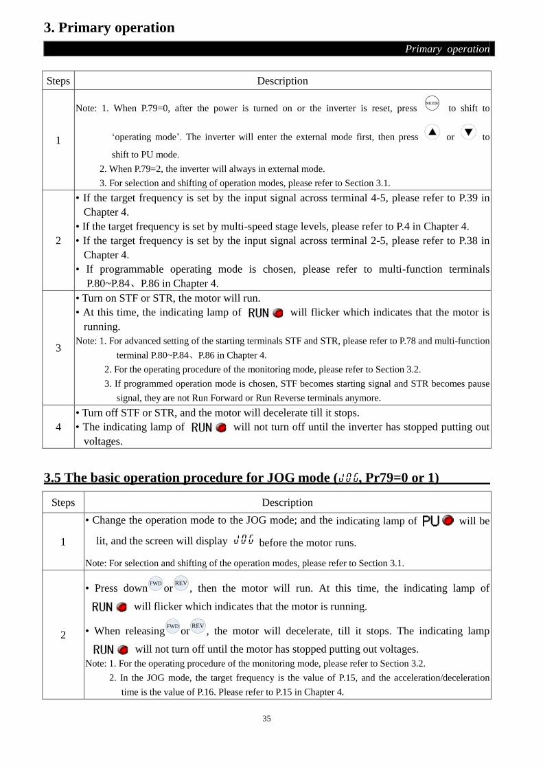
3.5 The basic operation procedure for JOG mode ( , Pr79=0 or 1)
Steps Description
1
• Change the operation mode to the JOG mode; and the indicating lamp of will be
lit, and the screen will display before the motor runs.
Note: For selection and shifting of the operation modes, please refer to Section 3.1.
2
• Press downFWD
orREV
, then the motor will run. At this time, the indicating lamp of
will flicker which indicates that the motor is running.
• When releasingFWD
orREV
, the motor will decelerate, till it stops. The indicating lamp
will not turn off until the motor has stopped putting out voltages.
Note: 1. For the operating procedure of the monitoring mode, please refer to Section 3.2.
2. In the JOG mode, the target frequency is the value of P.15, and the acceleration/deceleration
time is the value of P.16. Please refer to P.15 in Chapter 4.

36
3. Primary operation
Primary operation
3.6 The basic operation procedure for communication mode ( , P.79=3)
● In communication mode, the user can set parameters, run/stop, and reset the inverter by
communication. Please refer to P.33 for details.
3.7 The basic operation procedure for Combined mode 1 ( , P.79=4 )
Steps Description
1 • In Combined mode 1, the indicating lamp of will flicker.
Note: For selection and shifting of operation modes, please refer to Section 3.1.
2 • Enter the frequency setting mode, and write the target frequency into the memory.
Note: For the operating procedure of the frequency setting mode, please refer to Section 3.2.
3
• Set the target frequency by DU03B operation panel and start the inverter by the external
terminals.
• At this time, the indicating lamp of will flicker which indicated that the motor is
running. Note: For the operating procedure of the monitoring mode, please refer to Section 3.2.
4
• Turn off STF or STR, and then the motor will decelerate, till it stops.
• The indicating lamp of will not turn off until the inverter has stopped putting out
voltages.
3.8 The basic operation procedure for Combined mode 2 ( , P.79=5)
Steps Description
1 • In Combined mode 2, the indicating lamp of will flicker.
Note: For selection and shifting of the operation mode, please refer to Section 3.1.
2
• The target frequency is set by external terminals:
• If the target frequency is set by the input signal across terminal 4-5, please refer to P.39 in
Chapter 4.
• If the target frequency is set by multi-speed stage levels, please refer to P.4 in Chapter 4.
• If the target frequency is set by the input signal across terminal 2-5, please refer to P.38 in
Chapter 4.
3
• Press downFWD
orREV
, and then the motor start running. At this time, the indicating lamp of
will flicker, which indicates that the motor is running.
Note: 1. For the operating procedure of the monitoring mode, please refer to Section 3.2.
2. In case the motor is running, the frequency setting mode is also valid, and thus the target frequency
can be changed to regulate the motor speed.
4 • After pressing down
STOP
RESET
, the motor will decelerate, till it stops.
• indicating lamp of will not turn off until the inverter has stopped putting out
voltages.
37
3. Primary operation
Primary operation
3.9 The basic operation procedure for Combined mode 3 ( , P.79=6)
● The target frequency is determined by communication. When M0, M1, M2 and REX are ‘on’, the
target frequency is determined by combination of multi-speed stage levels (Please refer to
P.4~P.6, P.80~P.84, P.86). When EXJ is ‘on’, the target frequency is determined by the set value of
P.15. Acceleration/deceleration time is set by the value of P.16. The inverter starting is determined
by external terminals. The functions of P.996, P.998 and P.999 can be accomplished by
communication.
3.10 The basic operation procedure for Combined mode 4 ( , P.79=7)
● The target frequency of the inverter is determined by the external terminals, ‘external voltage
signal’, ‘external current signal’ or ‘combination of multi-speed stage levels’ terminals. The
inverter starting is determined by communication (including ‘Reset’).
3.11 The basic operation procedure for Combined mode 5 ( , P.79=8)
● The target frequency is determined by DU03B operation panel. When M0, M1, M2 and REX are
‘on’, the target frequency is determined by combination of multi-speed stage levels (Please refer
to P.4~P.6, P.80~P.84, P.86). When EXJ is ‘on’, the target frequency is determined by the set value
of P.15. Acceleration/deceleration time is set by the value of P.16. The inverter starting is
determined by external terminals.
3.12 Operation
3.12.1 Check and preparation before operation
Before the start of operation shall examine the following several aspects:
1. Check the wiring is true or not. Especially check ac motor driver output terminals (V/T1, U/T2,
W/T3) cannot be connected to the power, confirm grounding terminals ground well.
2. Confirm the terminal or the exposure of charged have short circuit or not.
3. Confirm terminal connections, plug connector (optional) and screw fastening are all fastening or
not.
4. Confirm motor have not connect the mechanical device.
5. All switch must disconnected before power on. Ensure the inverter won't start and without
abnormal action when power on.
6. Turn on the power must after cover installation.
7. Wet hand prohibit operation switch.
8. Ensure the following several aspects after power on:
1). Operation panel should be shown no fault.
(1). If the keyboard panel is not chosen, the indicating lamp of POWER is lit, and indicating
lamp of ALARM is not lit。
(2). If the keyboard panel is n chosen, the indicating lamp of and are all lit。

38
3. Primary operation
Primary operation
3.12.2 Operating methods
Various operating methods,please refer to the basic operating procedures of chapter 3 and parameter
description of chapter 4. According to the application requirements and regulations to select the most
appropriate operation method, usually with operating methods are shown below:
Operating methods The reference source of target frequency The signal source of
motor starting
Operation panel or FWD
orREV
External terminals
signal operation
SD
M1
M0
M2
Parameter
seting:P.4=40
P.5=30
P.6=10
Input by external
terminals:STF-SD
STR-SD
2-5,4-5
3.12.3 Trial Run
Confirm cables and no abnormalities before the operation you can try running. After power on, the
inverter is in the external mode.
1. After power on, ensure the indicating lamp of power is lit.
2. Please pick a switch between STF and SD or STR and SD.
3. Please pick a potentiometer among 2-5-10 or provide 0 ~ 5V dc between 2 and 5.
4. Please adjust potentiometer or 0 ~ 5V dc a minimum value (under 1V).
5. If STF on, forward rotation; if STR on, reverse rotation; Turn off STF or STR, and the motor will
decelerate till it stops.
6. Ensure the following several aspects:
1). Motor rotation direction is correct or not.
2). Motor rotating smoothly (whether there is no abnormal noise and vibration).
3). Whether or not smooth for acceleration/deceleration.
If there is operation panel, commissioning as follows:
1. Operation panel connected to inverter properly.
2. Change the operation mode to PU mode after power on, and the screen will display 50/60Hz.
3. Press button to set the target frequency is about 5Hz.
4. PressFWD
, forward rotation; pressREV
, reverse rotation; pressSTOP
RESET
then the motor will decelerate till
it stops.
39
3. Primary operation
Primary operation
5. Ensure the following several aspects:
1). Motor rotation direction is correct or not.
2). Motor rotating smoothly (whether there is no abnormal noise and vibration).
3). Whether or not smooth for acceleration/deceleration.
If there is no abnormal condition, increasing frequency to test run continue, through the above
commissioning, without any abnormal situation, can be put into operation.
Note: If inverter and motor running anomalies, shall be stopped working immediately, and according to the "fault
diagnosis," check anomalies causes. After inverter stop output, but the power terminal
((R/L1)/(S/L2)/(T/L3)) of main circuit is not disconnected, if you touching the output terminals
((U/T1)/(V/T2)/(W/T3)) of inverter, may occur shock. Otherwise, even cut off major loop power, because
the filter capacitor has recharging voltage, discharge end need some time, After cutting off major loop
power, wait for the indicating lamp of power burn out, and use a dc voltage meter to test intermediate dc
loop, confirm below safe voltage value, then you can contact the circuit which inside inverter.
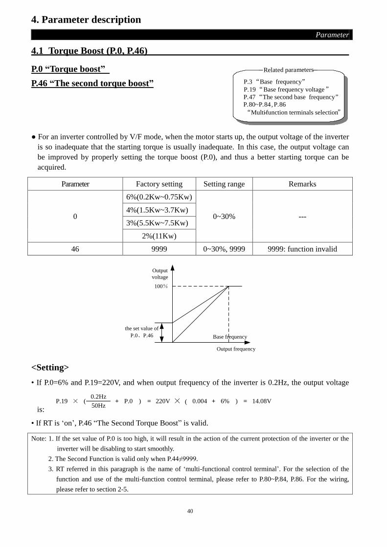
40
4. Parameter description
Parameter
4.1 Torque Boost (P.0, P.46)
P.0 “Torque boost”
P.46 “The second torque boost”
Related parameters
P.19“Base frequency voltage”
P.80~P.84, P.86
“Multi-function terminals selection”
P.3“Base frequency”
P.47“The second base frequency”
● For an inverter controlled by V/F mode, when the motor starts up, the output voltage of the inverter
is so inadequate that the starting torque is usually inadequate. In this case, the output voltage can
be improved by properly setting the torque boost (P.0), and thus a better starting torque can be
acquired.
Parameter Factory setting Setting range Remarks
0
6%(0.2Kw~0.75Kw)
0~30% --- 4%(1.5Kw~3.7Kw)
3%(5.5Kw~7.5Kw)
2%(11Kw)
46 9999 0~30%, 9999 9999: function invalid
the set value of
P.0、P.46
Output
voltage
Base frequency
Output frequency
100%
<Setting>
• If P.0=6% and P.19=220V, and when output frequency of the inverter is 0.2Hz, the output voltage
is:
0.2Hz
50Hz+ P.0( )P.19 × = 220V × 0.004 +( )6% = 14.08V
• If RT is ‘on’, P.46 “The Second Torque Boost” is valid.
Note: 1. If the set value of P.0 is too high, it will result in the action of the current protection of the inverter or the
inverter will be disabling to start smoothly.
2. The Second Function is valid only when P.44≠9999.
3. RT referred in this paragraph is the name of ‘multi-functional control terminal’. For the selection of the
function and use of the multi-function control terminal, please refer to P.80~P.84, P.86. For the wiring,
please refer to section 2-5.

41
4. Parameter description
Parameter
4.2 The Output Frequency Range (P.1, P.2, P.18)
P.1 “Maximum frequency”
P.2 “Minimum frequency”
P.18 “High-speed maximum
frequency”
Related parameters
P.13“Starting frequency”
The upper limit and the lower limit of the output frequency can be restricted.
Parameter Factory setting Setting range Remarks
1 120Hz 0~120Hz (Note 2) ---
2 0Hz 0~120Hz (Note 2) ---
18 120Hz 120~400Hz (Note 2) ---
P.1(P.18)P.2
Output
frequency
(Hz)
Setting frequency(Hz)
<Setting>
• If the target frequency ≦ P.2, the steady output frequency equals to P.2.
• If P.2 < target frequency ≦ P.1 (P.18), the steady output frequency equals to target frequency. • If P.1 (P.18) <target frequency, the steady output frequency equals to P.1.
Note: 1. The ‘maximum frequency’ and the ‘high-speed maximum frequency ’are related with each other. If the
target upper limit frequency is in the range of 0~120Hz, P.1 must be used (the setting range of P.1 is
0~120Hz); if the target upper limit frequency is in the range of 120~400Hz, then P.18 must be employed
(the setting range of P.18 is 120~400Hz).
2. If P.187=1, P.1 and P.2 are in the range of 0~1000Hz, P.18 is in the range of 120~1000Hz
3. If P.1 < P.2, the steady output frequency will be clamped to P.1.
4. The set frequency value can not exceed the value of P.1.
4.3 Base Frequency and Base Frequency Voltage (P.3, P.19, P.47)
P.3 “Base frequency”
P.19 “Base frequency voltage”
P.47 “The second base frequency”
Related parameters
P.80~P.84, P.86
P.189“Factory setting function”
P.14“Load pattern selection”
“Multi-function terminals selection”

42
4. Parameter description
Parameter
● The maximum output voltage of the inverter is called ‘base frequency voltage’.
● If the output frequency is lower than the base frequency, the output voltage of the inverter will
increase with the output frequency; if the output frequency has reached the base frequency
(P.3/P.47), the output voltage will just be equal to the base frequency voltage. If the output
frequency exceeds the base frequency and increase continuously, the output voltage will be
clamped to the base frequency voltage.
Parameter Factory setting Setting range Remarks
3 50Hz
0~400Hz (Note 4) When P.189=1
60Hz When P.189=0
19 220V/440V 0~1000V, 9999
220V series inverters: factory setting is 220
440V series inverters: factory setting is 440
9999: function invalid
47 9999 0~400Hz (Note 4) 9999: function invalid
P.3(P.47)
Output frequency
Output voltage
(V)
P.19
<Setting>
• The Base Frequency is set through P.3 and P.47.
• If RT is on, P.47 ‘The Second Base Frequency’ is valid. (Note 1)
• The Base frequency voltage is set through P.19. (Note 2)
Note: 1. The Second Function is valid only when P.44≠9999.
2. If P.19=9999, the maximum output voltage of the inverter will depend on the value of the power supply
voltage.
3. RT referred in this paragraph is the name of ‘multi-functional control terminal’. For the selection of the
function and use of the multi-function control terminal, please refer to P.80~P.84, P.86. For the wiring,
please refer to section 2-5.
4. If P.187=1, P.3 and P.47 are in the range of 0~1000Hz.

43
4. Parameter description
Parameter
4.4 Multi-speed (P.4~P.6, P.24~P.27, P.142~P.149)
P.4 “speed 1(high speed)”
P.5 “speed 2(medium speed)”
P.6 “speed 3 (low speed)”
P.24~P.27 “speed 4 to 7”
P.142~P.149 “speed 8 to 15”
Related parameters
P.2“Minimum frequency”P.1“Maximun frequency”
P.29“Acceleration /deceleration
curve selection”
P.80~P.84, P.86
P.79“Operation mode selection”
“Multi-function terminals selection”
Parameter Factory setting Setting range Remarks
4 60Hz 0~400Hz (Note 3) ---
5 30Hz 0~400Hz (Note 3) ---
6 10Hz 0~400Hz (Note 3) ---
24~27 9999 0~400Hz, 9999 (Note 3) 9999, is not chosen
142 0Hz 0~400Hz (Note 3) ---
143~149 9999 0~400Hz, 9999 (Note 3) 9999, is not chosen
<Setting>
• If all the setting values of P.24~P.27 and P.142~P.149 are not 9999, ‘16-speed operation’ is active. It
means that with the combination of RL, RM, RH and REX, there are 16 kinds of speeds in all. For
the setting of the target frequency of the inverter, please refer to the figure below.
RL
RH
RM
REX
ON
ON
ON ONON
ON
ON
ON ON
ON
ON
ON
ON
ON ON ON ON ON ON ON ON
ON
ON
ONON
ON
ON
ON
ON
ON
ON
ON
(High speed)
speed1
(Medium speed)
Speed 2
(Low speed)
Speed 3
Speed
4
Speed
5
Speed
6
Speed
7
Speed
8
Speed
9
Speed
10
speed
11
Speed
12
Speed
13
Speed
14
Speed
15
Out
put f
requ
ency
Speed
0

44
4. Parameter description
Parameter
• Provided that the values of P.24~P.27 and P.142~P.149 are all defaulted, ‘3-speed operation’ is
active. In this case, the target frequency can be set as follows (the priority for the terminals is
RL>RM>RH):
Parameter
Target
frequency
P.24=
9999
P.25=
9999
P.26=
9999
P.27=
9999
P.142=
9999
P.143=
9999
P.144=
9999
P.145=
9999
P.146=
9999
P.147=
9999
P.148=
9999
P.149=
9999
RL
(P.6) ○ ○ ○ ○ ○ ○ ○ ○
RM
(P.5) ○ ○ ○
RH
(P.4) ○
For example: if P.26=9999, the target frequency is determined by RM (the setting value of P.5).
Note: 1. Only in ‘external mode’, ‘combined mode 2’ or ‘combined mode 4’, the multi-speed is valid.
2. RL, RM, RH and REX mentioned in this section are the function names of the ‘multi-function control
terminal’. (For example: P.80=2, M0 terminal is chosen to perform the RL function). Please refer to
P.80~P.84, P.86 for multi-function selection, and refer to section 2-5 for wiring.
3. If P.187=1, the parameters from P.4 to P.6, from P.24 to P.27 and from P.142 to P.149 are in the range of
0~1000Hz.
4.5 “Acceleration/deceleration Time (P.7, P.8, P.20, P.21, P.44, P.45)
P.7 “Acceleration time”
P.8 “Deceleration time”
P.20 “Acceleration/deceleration
reference frequency”
P.21 Acceleration/deceleration time
increments
P.44 “The second acceleration time”
P.45 “The second deceleration time”
Related parameters
P. 47 “The second base frequency”
P. 3 “Base frequency”P. 29 “Acceleration /deceleration
curve selection”
P.80~P.84, P.86
“Multi-function terminal selection”P. 189 “Factory setting function”
● When the output frequency of the inverter is accelerated from 0Hz to P.20, the required time is
defined as ‘acceleration time (P.7)’.
● When the output frequency of the inverter is decelerated from P.20 to 0Hz, the required time is
defined as ‘deceleration time (P.8)’.
● P.21 is used to set the acceleration/deceleration time and minimum setting increments.

45
4. Parameter description
Parameter
Parameter Factory setting Setting range Remarks
7 5s 0~360s When P.21=0
0~3600s When P.21=1
8 5s 0~360s When P.21=0
0~3600s When P.21=1
20 50Hz 1~400Hz
(Note 2)
When P.189=1
60Hz When P.189=0
21 0 0, 1 0 Minimum setting increments:0.01s
1 Minimum setting increments:0.1s
44 9999
0~360s When P.21=0
0~3600s When P.21=1
9999 Not chosen
45 9999
0~360s When P.21=0
0~3600s When P.21=1
9999 Not chosen
<Setting>
• If P.21=0, the acceleration/deceleration time(P.7, P.8, P.16, P.44, P.45, and P.111~P.118)minimum
increments is 0.01 seconds.
• If P.21=1, the acceleration/deceleration time(P.7, P.8, P.16, P.44, P.45, and P.111~P.118)minimum
increments is 0.1 seconds.
• If RT is ‘on’, the second function is valid. In this case the running characteristics of the motor refer
to the second function.
• If P.44=9999 (default value), all the second function is disabled. In this case, even though RT is ‘on’,
the acceleration time is still the set value of P.7, and the deceleration time is still the set value of P.8,
the torque boost is still the set value of P.0, and the base frequency is still the set value of P.3.
• If P.44≠9999 and P.45=9999, when RT is ‘on’, the acceleration/deceleration time is the ‘set value
of P.44’.
• If P.44≠9999 and P.46=9999, when RT is ‘on’, the torque boost is the ‘set value of P.0’.
If P.44≠9999 and P.46≠9999, when RT is ‘on’, the torque boost is the ‘set value of P.46’.
• If P.44≠9999 and P.47=9999, when RT is ‘on’, the base frequency is the ‘set value of P.3’.
If P.44≠9999 and P.47≠9999, when RT is ‘on’, the base frequency is the ‘set value of P.47’.
Note: 1. The mentioned RT in this paragraph is the function name of ‘multi-function control terminal’. Please refer
to P.80~P.84, P.86 for function selection and features and refer to Section 2-5 for wiring.
2. If P.187=1, P.20 is in the range of 0~1000Hz.

46
4. Parameter description
Parameter
4.6 Electronic Thermal Relay Capacity (P.9)
P.9 “Electronic thermal relay capacity”
Related parameters
P.80~P.84, P.86
“Multi-function terminals selection”
● The ‘electronic thermal relay’ employed the built-in program to simulate a thermal relay to prevent
the motor from overheating.
Parameter Factory setting Setting range Remarks
9 Rated output current
(refer to the note of appendix 1) 0~500A ---
<Setting>
• Please set P.9 as the rated current of the motor at its rated frequency. The rated frequency of a
squirrel-cage inductive motor that made in different countries and areas is different. Please refer to
the nameplate instruction of the motor.
• If P.9=0, the electronic thermal relay is disabled.
• In case the calculated heat by the electronic thermal relay exceeds the upper limit, an alarm will be
output (at this time, the alarm lamp will be lit.), the screen of DU03B will display , and the
output will be stopped.
Note: 1. After the inverter is reset, the thermal accumulating record of the electronic thermal relay will be reset to
zero. Attention should be paid attention to it.
2. When two or more motors are connected to the inverter, they cannot be protected by the electronic thermal
relay. Install an external thermal relay to each motor.
3. When a special motor is employed, the electronic thermal relay is no longer valid. Install an external
thermal relay to each motor.
4. About wiring for an external thermal relay, refer to P.80~P.84, P.86.
4.7 DC Injection Brake (P.10, P.11, P.12)
P.10 “DC injection brake operation frequency”
P.11 “DC injection brake operation time”
P.12 “DC injection brake operation voltage”
Parameter Factory setting Setting range Remarks
10 3Hz 0~120Hz (Note 2) ---
11 0.5s 0~60s ---
12 4% 0~30% ---

47
4. Parameter description
Parameter
<Setting>
• After a stop signal is put in (please refer to Chapter 3 for the primary operation), the output
frequency of the inverter will decrease gradually. In case the output frequency reaches the ‘DC
injection brake operation frequency (P.10)’, the DC injection brake will be active.
• During DC injection brake, a DC voltage will be injected into the motor windings by the inverter,
which is used to lock the motor rotor. This voltage is called ‘DC injection brake operation voltage
(P.12)’. The larger the P.12 value is, the higher the DC brake voltage is, and the stronger the brake
capability is.
• The DC brake operation will last a period (the set value of P.11) to overcome the motor inertia. To
achieve an optimum control, P.11 and P.12 should be set properly.
As shown as follows:
P.12
Time
P.11
Output
frequency
(Hz)
P.10
DC
braking
voltage
Time
Stop signal input
Note: 1. Users must set P.11 and P.12 appropriately in order to obtain the best control characteristics.
2. If P.187=1, P.10 is in the range of 0~1000Hz.
4.8 Starting Frequency (P.13)
P.13 “Starting frequency” Related parameters
P.2“Minimum frequency”
●When the motor starts up, the instant output frequency of the inverter is called ‘starting frequency’.
Parameter Factory setting Setting range Remarks
13 0.5Hz 0~60Hz ---
<Setting>
• If the target frequency of the inverter is lower than the setting value of P.13, the motor will not run.
When the signal of the motor start, the output frequency will go up begin with the value of P.13.

48
4. Parameter description
Parameter
Time
Output
frequency
(Hz)
P.13 Startup signal input
4.9 Load Pattern Selection (P.14, P.98, P.99, P.162~P.169)
P.14 “Load pattern selection”
P.98 “Middle frequency 1”
P.99 “Output voltage 1 of middle
frequency”
P.162 “Middle frequency 2”
P.163 “Output voltage 2 of middle
frequency”
P.164 “Middle frequency 3”
P.165 “Output voltage 3 of middle
frequency”
P.166 “Middle frequency 4”
P.167 “Output voltage 4 of middle
frequency”
P.168 “Middle frequency 5”
P.169 “Output voltage 5 of middle
frequency”
Related parameters
P. 46 “The second torque boost”
P.80~P.84 , P. 86
“Multi-function terminals selection”
P. 0 “Torque boost”
Parameter Factory setting Setting range Remarks
14 0 0~13 When P.14=5~13, it provides 9 kinds
of different VF curve.
98 3Hz 0~400Hz (Note 3) ---
99 10% 0~100% ---
162 9999 0~400Hz, 9999 (Note 3) ---
163 0% 0~100% ---
164 9999 0~400Hz, 9999 (Note 3) ---
165 0% 0~100% ---
166 9999 0~400Hz, 9999 (Note 3) ---
167 0% 0~100% ---
168 9999 0~400Hz, 9999 (Note 3) ---
169 0% 0~100% ---

49
4. Parameter description
Parameter
<Setting>
• If P.14=4, suppose that P.19=220V, P.98=5HZ, P.99=10%, when the inverter is running at 5HZ, the
output voltage equals P.99×P.19=10%×220V=22V.
• If RT is ‘on’, P.46 ‘The Second Torque Boost’ is valid.
P.14=0
Output frequency
P.0
0 P.3
Ou
tpu
t v
olt
age
P.19
Applicable to Constant torque loads (conveyer belt etc.)
P.14=1
P.0
0 P.3
P.19
Ou
tpu
t v
olt
age
Output frequency
Applicable to Variable torque loads (fans and pumps etc.)
P.14=2
P.0
0 P.3
P.19
Forw
ard
rota
ting
Rev
erse
ly ro
tatin
g
Ou
tpu
t v
olt
age
Output frequency
Ascending/descending loads
P.14=3
P.0
0 P.3
P.19
Forw
ard
rota
ting
Rev
erse
ly ro
tatin
g
Outp
ut
volt
age
Output frequency
Ascending/descending loads
P.14=4
0
P.0
P.98 P.162 P.164 P.166 P.168
P.99
P.169
P.167
P.165
P.163
P.19
P.3
Ou
tpu
t v
olt
age (
%)
Output frequency (Hz)
Whether it is high startup torque or descending torque
is due to the set values(Note 1)
P.14=5
Output frequency
P.0
0 P.3
Outp
ut
volt
age
P. 19
A
P.98=3.00.1
When P.14=5, The value of A is 7.1%.

50
4. Parameter description
Parameter
P.14=6,7,8
P.0
0 P. 3
P. 19
A
3.0
Outp
ut
volt
age
Output frequency
0.1
When P.14=6, the value of A is 8.7%; when P.14=7, the
value of A is the value of A is 10.4%; when P.14=8, the
value of A is 12.0%.
P.14=9,10
P.0
0 P. 3
P. 19
A
300.1
Output frequency
Outp
ut
volt
age
When P.14=9, the value of A is 20.0%; when P.14=10,
the value of A is 25.0%.
P.14=11,12,13
P.0
0 P. 3
P. 19
A
60.1
Outp
ut
volt
age
Output frequency
When P.14=11, the value of A is 9.3%; when P.14=12,
the value of A is 12.7%; when P.14=13, the value of A
is 16.1%.
Note: 1. Refer to the picture above the form, if need the one point, set values of P.98、P.99, if need two points ,set
values of P.98、P.99、P162、P.163, if need three points, set values of P.98、P.99、P162、P.163、P164、
P.165, like this set every last.
2. If you set value of P.14 from 5 to 13, the curve will invalid when the value of P.0 is larger than the value
of A, the value of P.14 will be equal to P.0
3. If P.187=1, P.98, P.162, P.164, P.166 and P.168 are in the range of 0~1000Hz.

51
4. Parameter description
Parameter
4.10 JOG Mode (P.15, P.16)
P.15 “JOG frequency”
P.16 “JOG acceleration/deceleration
time”
Related parameters
P.20 “Acceleration/deceleration
reference frequency”
P.21 “Acceleration/deceleration
time increments”
● In JOG mode, the output frequency is the set value of P.15, and the acceleration/deceleration time
is the set value of P.16.
Parameter Factory setting Setting range Remarks
15 5Hz 0~400Hz (Note 2) ---
16 0.5s 0~360s When P.21=0
0~3600s When P.21=1
P.16
P.20
P.15
P.15
P.20
P.16Running
forward
Running
backward
Press
FWD
Press
REV
Output frequency
Time
Note: 1. Please refer to Section 3-1 for how to enter the JOG mode.
2. If P.187=1, P.15 is in the range of 0~1000Hz.
4.11 Input Signal across Terminal 4-5 Selection Function (P.17)
P.17 “Input signal across terminal 4-5 selection”
● SE2 series inverters have two analog input channels, terminal 2-5 and terminal 4-5. Only voltage
signal can enter across terminal 2-5, but both voltage signal and current signal can enter across
terminal 4-5, which is switched by P.17.
Parameter Factory setting Setting range Remarks
17 0 0~1 0 Current signal valid
1 Voltage signal valid
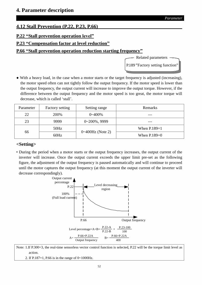
52
4. Parameter description
Parameter
4.12 Stall Prevention (P.22, P.23, P.66)
P.22 “Stall prevention operation level”
P.23 “Compensation factor at level reduction”
P.66 “Stall prevention operation reduction starting frequency”
P.189“Factory setting function”
Related parameters
● With a heavy load, in the case when a motor starts or the target frequency is adjusted (increasing),
the motor speed often can not tightly follow the output frequency. If the motor speed is lower than
the output frequency, the output current will increase to improve the output torque. However, if the
difference between the output frequency and the motor speed is too great, the motor torque will
decrease, which is called ‘stall’.
Parameter Factory setting Setting range Remarks
22 200% 0~400% ---
23 9999 0~200%, 9999 ---
66 50Hz
0~400Hz (Note 2) When P.189=1
60Hz When P.189=0
<Setting>
• During the period when a motor starts or the output frequency increases, the output current of the
inverter will increase. Once the output current exceeds the upper limit pre-set as the following
figure, the adjustment of the output frequency is paused automatically and will continue to proceed
until the motor captures the output frequency (at this moment the output current of the inverter will
decrease correspondingly).
P.22
Output frequency
Level decreasing
region
100%
Output current
percentage
P.66
(Full load current)
Level percentage=A+B×P.22-A
P.22-B×
P.23-100
B=
100
400A=
P.66×P.22A
Output frequency
P.66×P.22A
Note: 1.If P.300=3, the real-time sensorless vector control function is selected, P.22 will be the torque limit level as
action.
2. If P.187=1, P.66 is in the range of 0~1000Hz.

53
4. Parameter description
Parameter
4.13 Output Frequency Filter Constant (P.28)
P.28 “Output frequency filter constant”
● When the acceleration/deceleration time decreases and the output frequency switches from
high-frequency to low-frequency each other, machine vibration may be caused, which will affect
the product quality.
● We can filter the output frequency at the moment when high-frequency and low-frequency
switches each other by setting output frequency filter constant P.28, in order to reduce the machine
vibration. The bigger the set value of P.28, the better the filter effect, but the corresponding
response delay will increase. If the set value of P.28 is 0, the filter function is invalid.
Parameter Factory setting Setting range Remarks
28 0 0~31 ---
4.14 Acceleration/deceleration Curve Selection (P.29)
P.29 “Acceleration/deceleration curve
selection”
Related parameters
P. 7 “Acceleration time ”P. 8 “Deceleration time ”
P. 44 “The second acceleration time”P. 45 “The second deceleration time”
P. 3 “ Base frequency”
P. 20 “Acceleration / deceleration
reference frequency”
Parameter Factory setting Setting range Remarks
29 0 0~2 ---
<Setting>
• When P.29=0 ‘Linear acceleration/deceleration curve’
An acceleration slope is constructed by combination of P.7 and P.20. A deceleration slope is
fabricated by combination of P.8 and P.20.
When the target frequency varies, it increases with the ‘acceleration slope’ or decreases with the
‘deceleration slope’ linearly. Figure below:
Ou
tpu
t fr
equ
ency
TimeP.7 P.8
Acc
eler
ati
on
slo
pe
Decelera
tion
slop
e
P.20
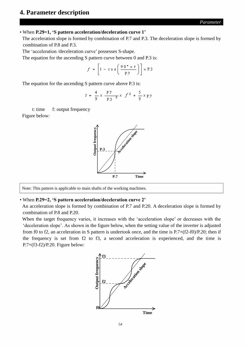
54
4. Parameter description
Parameter
• When P.29=1, ‘S pattern acceleration/deceleration curve 1’
The acceleration slope is formed by combination of P.7 and P.3. The deceleration slope is formed by
combination of P.8 and P.3.
The ‘acceleration /deceleration curve’ possesses S-shape.
The equation for the ascending S pattern curve between 0 and P.3 is:
The equation for the ascending S pattern curve above P.3 is:
t: time f: output frequency
Figure below: A
ccel
erat
ion
slop
e
Ou
tpu
t fr
equ
ency
P.7
P.3
Time
Note: This pattern is applicable to main shafts of the working machines.
• When P.29=2, ‘S pattern acceleration/deceleration curve 2’
An acceleration slope is formed by combination of P.7 and P.20. A deceleration slope is formed by
combination of P.8 and P.20.
When the target frequency varies, it increases with the ‘acceleration slope’ or decreases with the
‘deceleration slope’. As shown in the figure below, when the setting value of the inverter is adjusted
from f0 to f2, an acceleration in S pattern is undertook once, and the time is P.7×(f2-f0)/P.20; then if
the frequency is set from f2 to f3, a second acceleration is experienced, and the time is
P.7×(f3-f2)/P.20. Figure below:
Acc
eler
atio
n sl
ope
Time
Ou
tpu
t fr
equ
ency
f0
f2
f3

55
4. Parameter description
Parameter
Note: In this curve the motor vibration can be reduced substantially during acceleration/deceleration, and thus the
life span of belts and gears is expanded.
4.15 Regenerative Brake (P.30, P.70)
P.30 “Regenerative brake function selection”
P.70 “Special regenerative brake duty”
● At the moment when the output frequency switches from high to low, due to the load inertia, the
motor speed will be higher than the output frequency of the inverter, and thus the generator effect
is formed. It results in high voltage between the main-circuit terminals P and N, which will
damage the inverter. Therefore, a proper brake resistor shall be mounted between the terminals P
and PR to dissipate the fed-back energy.
● There’s a built-in transistor (called as brake transistor) in the inverter. The conducting time ratio of
the transistor is called as ‘regenerative brake duty’. The Higher the regenerative brake duty is, the
more energy the brake resistor consumes, and the stronger the brake capability is.
Parameter Factory setting Setting range Remarks
30 0 0~1
0 If regenerative brake duty is 3% fixedly, the
value of parameter 70 is failure.
1 The regenerative brake duty is the value witch
parameter 70 setting.
70 0 0~30% ---
Note: 1. In occasions where frequent start/stop occurs, a high capacity brake resistor is required.
2. Refer to Section 2-7 for brake resistor selection.
4.16 Soft-PWM (P.31)
P.31 “Soft-PWM selection”
● Soft-PWM is a method witch control the motor noise become melody.
● Motor noise modulation control is when the inverter varied its carrier frequency from time to time
during operation. The metal noise that generates by motor is not a single frequency. This function
selection is to improve the high peak single frequency noise.
● Soft-PWM is valid in V/F curve. It means P.300 must be set to 0.
Parameter Factory setting Setting range Remarks
31 0 0 No Soft-PWM selection
1 When P.72<“5”,with Soft-PWM selection

56
4. Parameter description
Parameter
4.17 Communication Function (P.32, P.33, P.36, P.48~P.53, P.153~P.154)
P.32 “Serial communication baud rate selection”
P.33 “Communication protocol selection”
P.36 “Inverter station number”
P.48 “Data length”
P.49 “STOP bit length”
P.50 “Parity check selection”
P.51 “CR & LF selection”
P.52 “Number of communication retries”
P.53 “Communication check time interval”
P.153 “Communication error handling”
P.154 “Modbus communication data format”
● When the communication parameters are revised, please reset the inverter.
● The SE2-type inverters have two communication protocols to select, Shihlin protocol and Modbus
protocol. If the communication expansion board is selected, the corresponding communication
protocol is provided. P.32, P.36, P.52, P.53, and P.153 are applied to both of the protocols.
P.48~P.51 is only applied to the Shihlin protocol and P.154 is only applied to the Modbus protocol.
● Continuous communication, please make the following listed parameters set correctly, otherwise it
will not carry out normal continuous communication.
Parameter Factory
setting Setting range Remarks
32 1 0~2
0 Baud rate: 4800bps
1 Baud rate: 9600bps
2 Baud rate: 19200bps
33 1 0, 1 0 Modbus protocol
1 Shihlin protocol
36 0 0~254 (Note 1)
48 0 0, 1 0 Data length: 8 bit
1 Data length: 7bit
49 0 0~1 0 STOP bit length: 1 bit
1 STOP bit length: 2 bit
50 0 0~2
0 Not Given
1 odd
2 even

57
4. Parameter description
Parameter
Parameter Factory
setting Setting range Remarks Parameter
51 1 1~2 1 Only CR
2 CR and LF
52 1 0~10 (Note 2)
53 9999 0~999.8s, 9999
0~999.8 do communication overtime test
according to the set value
9999 9999: No communication overtime test
(Note 3)
153 0 0, 1 0 Warn and coast to stop
1 No warning and keep running
154 4 0~5
0 Modbus ASCII mode, Protocol<1,7,N,2>
(Note 4)
1 Modbus ASCII mode, Protocol<1,7,E,1>
2 Modbus ASCII mode, Protocol<1,7,O,1>
3 Modbus RTU mode, Protocol<1,8,N,2>
4 Modbus RTU mode, Protocol<1,8,E,1>
5 Modbus RTU mode, Protocol<1,8,O,1>
Note: 1. The number of inverters which the communication interface enables a host computer to control is due to
the wiring method and impedance matching. Once Modbus protocol is selected, please set P.33 to nonzero
value.
2. If the time of communication error exceeds the set value of P.52, and P.153 is set to 0, an alarm will be
output, and the screen of DU03B will display .
3. When P.53=9999, there is no time limit.
4. Modbus protocol. Protocol<1,7,N,2> means 1 start bit, 7 data bits, No parity bit, and 2 stop bit. N: no
parity, E: 1-bit even parity, O: 1-bit odd parity.
System configuration of SE2-RS485 communications interface
● For only one inverter connecting to computer
computer
DA
+
DB
-
Station number 1Inverter 1
RS-485
DATA+/
cnverter
RS-232
DATA-RS-232 RS-485

58
4. Parameter description
Parameter
● For multi-inverter connecting to computer
computer DA
+
DB
-
Station number 1Inverter 1
RS-485
DATA+/
converter
RS-232
DATA-RS-485RS-232
DA
+
DB
-
Inverter 22
DA
+
DB
-
Inverter 33Station number Station number
● Two communication protocol of SE2-type inverter, there are Shihlin protocol and Modbus
protocol.
1. Shihlin protocol
● Communication between PC and inverter, ASCII code (hexadecimal) converted automatically.
● PC Data communication between the inverter, please follow the steps.
Communication type with or without data format for the step:
No. Description Operation
Command
Operation
Frequency
Write
Parameter Reset Monitoring
Read Out
Parameter
①
Computer send out
communication request to
inverter
A A A A B B
② Inverter Data Processing time yes yes yes no yes yes
③
Data responded
From inverter
(check fault of
①)
No error
(request
accepted)
C C C no E E
Error
(request
rejected)
D D D no D D
④ Computer data processing time no no no no no no
⑤
Data Responded
from PC (check
fault of ③)
No error
(no process) no no no no C C
Error
(output ③) no no no no F F
PC
PC
inverter
inverter
①
②
③
④
⑤ time
write date
read date

59
4. Parameter description
Parameter
① Communication Request from PC to Inverter
Format Information number
1 2 3 4 5 6 7 8 9 10 11 12 13 14
A
(Write data
to Inverter)
ENQ
*1)
Station
Number
Command
Code
Waiting
Time
*2)
Data
Sum
check
*7)
Stop
Character
*3)
B
(Read data
from
Inverter)
ENQ
*1)
Station
Number
Command
Code
Waiting
Time
*2)
Sum
check
*7)
Stop
Character
*3)
③ Computer transmit data to inverter, inverter response data
● Write data
Format Information number
1 2 3 4 5 6
C
(Data no error)
ACK
*1) Station Number
Stop Character
*3)
D
(Data error)
NAK
*1) Station Number
Error Code
*5)
Stop Character
*3)
● Readout data
Format Information number
1 2 3 4 5 6 7 8 9 10 11 12 13
E
(Data no
error)
STX
*1)
Station
Number Readout Data
Unit
*4) ETX
Sum check
*7)
Stop
Character
*3)
D
(Data error)
NAK
*1)
Station
Number
Error
Code
*5)
Stop
Character
*3)
⑤ When computer is in data reading, responding data after data receipt from inverter
Format Information number
1 2 3 4 5
C
(Data no error)
ACK
*1) Station Number
Stop Character
*3)
F
(Data error)
NAK
*1) Station Number
Stop Character
*3)

60
4. Parameter description
Parameter
*1) Description of Control Code (ASCII CODE)
Control Code ASCII CODE Description Control Code ASCII码 Description
NUL H00 NULL ACK H06 Acknowledge
STX H02 Start of Text LF H0A Line Feed
ETX H03 End of Text CR H0D Carriage Return
ENQ H05 Enquiry NAK H15 Negative Acknowledge
*2) Wait time setting is from 0 to 15,unit is 10ms, for example 5 means 50ms.
*3) Stop Character(CR、LF CODE)
From the PC to the inverter for data communication, packet last CR, LF code by way of the PC
is automatically set. The inverter with the PC must also make the necessary settings. If you
select only the CR, then only one register is needed. If you choose CR and LF, it will account
for two registers.
*4) Unit: 0 means unit is 1, 1 means unit is 0.1, 2 means unit is 0.01, 3 means unit is 0.001.
*5) Error Code:
Error
Code Error Item Communication error exception content
H01 Error Parity check which inverter received is different from the initial set.
H02 Sum Check
Error
Inverter side of the calculation of the received data value Sum Check
and the Sum Check which received are different.
H03 Protocol Error
The information which the inverter received is syntax errors, or not
within the specified time information has been received, or CR and LF
code is different from the initial set.
H04 Frame Error STOP bit which inverter received is different from the initial set.
H05 Overflow
Error
When the inverter receives data, has not yet been received, the PC in
turn write the incoming data.
H0A Mode
Exceptions
When the inverter is running or does not in right operation mode for
writing.
H0B Command
Code Error. Specifies command code which the inverter can not handle.
H0C Data Range
Error
The data is outside the range of the specified when set parameters and
frequency.
*6) When the parameters have 9999 properties, write or read HFFFF instead of 9999.
*7) Sum check code
ASCII code data transformed code, Add in binary code; the result (sum) of the next bit (the low
8-bit) is transformed into 2 bit ASCII code (hexadecimal), called the Sum Check Code.
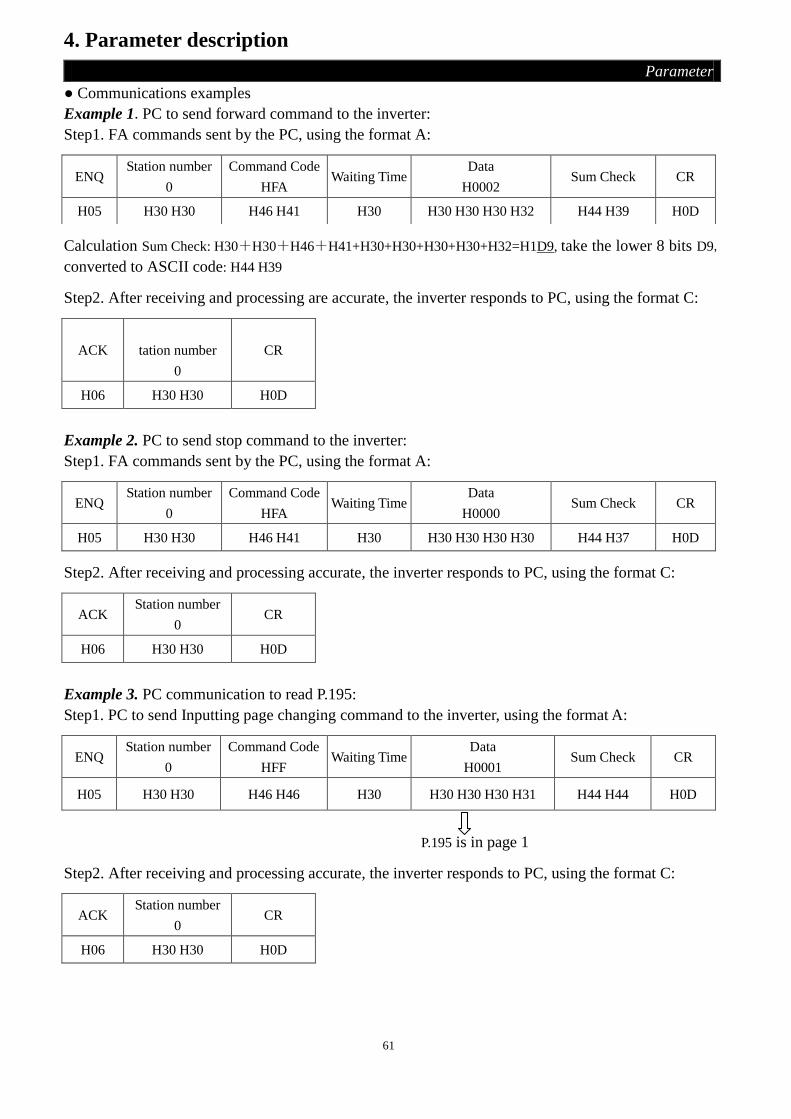
61
4. Parameter description
Parameter
● Communications examples
Example 1.PC to send forward command to the inverter:
Step1. FA commands sent by the PC, using the format A:
Calculation Sum Check: H30+H30+H46+H41+H30+H30+H30+H30+H32=H1D9, take the lower 8 bits D9,
converted to ASCII code: H44 H39
Step2. After receiving and processing are accurate, the inverter responds to PC, using the format C:
ACK
S
tation number
0
CR
H06 H30 H30 H0D
Example 2. PC to send stop command to the inverter:
Step1. FA commands sent by the PC, using the format A:
ENQ Station number
0
Command Code
HFA Waiting Time
Data
H0000 Sum Check CR
H05 H30 H30 H46 H41 H30 H30 H30 H30 H30 H44 H37 H0D
Step2. After receiving and processing accurate, the inverter responds to PC, using the format C:
ACK Station number
0 CR
H06 H30 H30 H0D
Example 3. PC communication to read P.195:
Step1. PC to send Inputting page changing command to the inverter, using the format A:
ENQ Station number
0
Command Code
HFF Waiting Time
Data
H0001 Sum Check CR
H05 H30 H30 H46 H46 H30 H30 H30 H30 H31 H44 H44 H0D
P.195 is in page 1
Step2. After receiving and processing accurate, the inverter responds to PC, using the format C:
ACK Station number
0 CR
H06 H30 H30 H0D
ENQ Station number
0
Command Code
HFA Waiting Time
Data
H0002 Sum Check CR
H05 H30 H30 H46 H41 H30 H30 H30 H30 H32 H44 H39 H0D
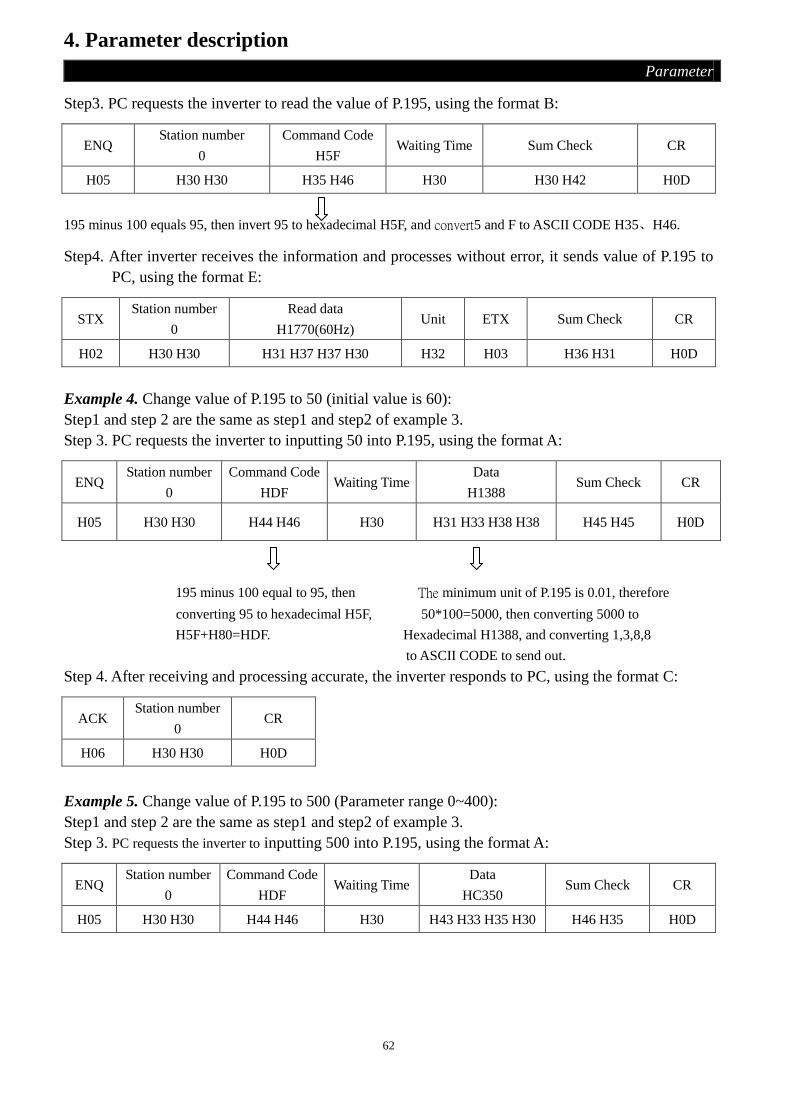
62
4. Parameter description
Parameter
Step3. PC requests the inverter to read the value of P.195, using the format B:
ENQ Station number
0
Command Code
H5F Waiting Time Sum Check CR
H05 H30 H30 H35 H46 H30 H30 H42 H0D
195 minus 100 equals 95, then invert 95 to hexadecimal H5F, and convert5 and F to ASCII CODE H35、H46.
Step4. After inverter receives the information and processes without error, it sends value of P.195 to
PC, using the format E:
STX Station number
0
Read data
H1770(60Hz) Unit ETX Sum Check CR
H02 H30 H30 H31 H37 H37 H30 H32 H03 H36 H31 H0D
Example 4. Change value of P.195 to 50 (initial value is 60):
Step1 and step 2 are the same as step1 and step2 of example 3.
Step 3. PC requests the inverter to inputting 50 into P.195, using the format A:
ENQ Station number
0
Command Code
HDF Waiting Time
Data
H1388 Sum Check CR
H05 H30 H30 H44 H46 H30 H31 H33 H38 H38 H45 H45 H0D
195 minus 100 equal to 95, then The minimum unit of P.195 is 0.01, therefore
converting 95 to hexadecimal H5F, 50*100=5000, then converting 5000 to
H5F+H80=HDF. Hexadecimal H1388, and converting 1,3,8,8
to ASCII CODE to send out.
Step 4. After receiving and processing accurate, the inverter responds to PC, using the format C:
ACK Station number
0 CR
H06 H30 H30 H0D
Example 5. Change value of P.195 to 500 (Parameter range 0~400):
Step1 and step 2 are the same as step1 and step2 of example 3.
Step 3. PC requests the inverter to inputting 500 into P.195, using the format A:
ENQ Station number
0
Command Code
HDF Waiting Time
Data
HC350 Sum Check CR
H05 H30 H30 H44 H46 H30 H43 H33 H35 H30 H46 H35 H0D

63
4. Parameter description
Parameter
Step 4. After processing, for information out of range, inverter replies to computer that this
information is incorrect, using the format D:
NAK Station number
0
Error Code
H0C CR
H15 H30 H30 H43 H0D
2. Modbus protocol
1). Information form
● Modbus serial transmission can be divided into two kinds. There are ASCII (American Standard
Code for Information Interchange) and RTU (Remote Terminal Unit) mod.
Query MsssagePC(Master)
INV(Slave)
Single
Response MessageASCII:CR、 LF
RTU:wait times >= 10ms
Response time for
INV
Query MesssagePC(Master)
INV(Slave)
Broadcast
No Response
(1). Query
PC (primary address) sends a message to the inverter (from the address) which is on the specified address.
(2). Normal Response
After sending a query to receive from PC, inverter to perform the requested function corresponds to the PC
and return to the normal response.
(3). Error Response
Inverter received an invalid function code, address, data, response returned to the PC.
(4). Broadcast
PC designated by the address 0, can send a message to all the inverters. All inverters which received
information from PC performed the requested function, but do not respond to the PC.
2). Communication format
● The master transmitted the Query Message to inverter, the inverter response message to the PC, the
address and function code will be copied when normal communication. Bit 7 of function will be
set 1(=H80) and Data Byte will be set by error code when abnormal communication.
● Message form:
Mode Start ①Address ②Function ③Data ④Error check End
ASCII H3A 8 Bit 8 Bit n×8 Bit 2×8 Bit
0D 0A
RTU >=10ms >=10ms
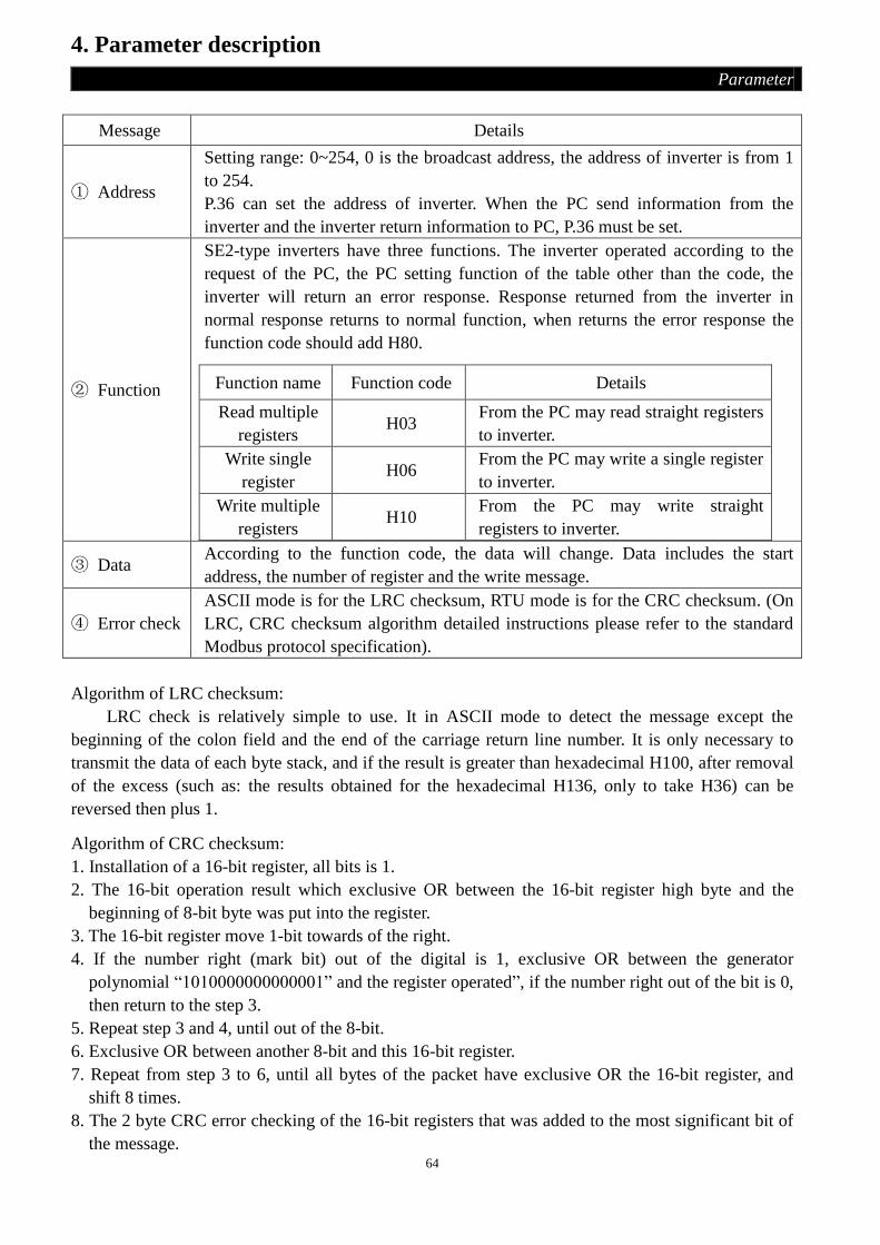
64
4. Parameter description
Parameter
Message Details
① Address
Setting range: 0~254, 0 is the broadcast address, the address of inverter is from 1
to 254.
P.36 can set the address of inverter. When the PC send information from the
inverter and the inverter return information to PC, P.36 must be set.
② Function
SE2-type inverters have three functions. The inverter operated according to the
request of the PC, the PC setting function of the table other than the code, the
inverter will return an error response. Response returned from the inverter in
normal response returns to normal function, when returns the error response the
function code should add H80.
Function name Function code Details
Read multiple
registers H03
From the PC may read straight registers
to inverter.
Write single
register H06
From the PC may write a single register
to inverter.
Write multiple
registers H10
From the PC may write straight
registers to inverter.
③ Data According to the function code, the data will change. Data includes the start
address, the number of register and the write message.
④ Error check
ASCII mode is for the LRC checksum, RTU mode is for the CRC checksum. (On
LRC, CRC checksum algorithm detailed instructions please refer to the standard
Modbus protocol specification).
Algorithm of LRC checksum:
LRC check is relatively simple to use. It in ASCII mode to detect the message except the
beginning of the colon field and the end of the carriage return line number. It is only necessary to
transmit the data of each byte stack, and if the result is greater than hexadecimal H100, after removal
of the excess (such as: the results obtained for the hexadecimal H136, only to take H36) can be
reversed then plus 1.
Algorithm of CRC checksum:
1. Installation of a 16-bit register, all bits is 1.
2. The 16-bit operation result which exclusive OR between the 16-bit register high byte and the
beginning of 8-bit byte was put into the register.
3. The 16-bit register move 1-bit towards of the right.
4. If the number right (mark bit) out of the digital is 1, exclusive OR between the generator
polynomial “1010000000000001” and the register operated”, if the number right out of the bit is 0,
then return to the step 3.
5. Repeat step 3 and 4, until out of the 8-bit.
6. Exclusive OR between another 8-bit and this 16-bit register.
7. Repeat from step 3 to 6, until all bytes of the packet have exclusive OR the 16-bit register, and
shift 8 times.
8. The 2 byte CRC error checking of the 16-bit registers that was added to the most significant bit of
the message.

65
4. Parameter description
Parameter
CRC added to the message, the low byte first join, and then the high byte.
● Communication format
(1). Read data (H03)
Mode Start Address
*1)
Function
*2)
Initial address
*3)
Register number
*4) Check End
ASCII H3A 2char 2char 4char 4char 2char 0D 0A
RTU >=10ms 8bit 8bit 2byte 2byte 2byte >=10ms
Normal response
Mode Start Address
*1)
Function
*2)
Read data
number
*5)
Read data
*6) Check End
ASCII H3A 2char 2char 2char 4char …2N×8bit 2char 0D 0A
RTU >=10ms 8bit 8bit 1byte 2byte …N×8bit 2byte >=10ms
Message Content
*1) Address Set the address to send information, 0 is in vain.
*2) Function code H03
*3) Initial address Set to the address of register to read.
*4) Register number
Set to the number of register to read. The number is most 20 can read.
*5) Read data number Twice to *4).
*6) Read data
Set information * 4) specified, read the data byte at the level of the order.
read. (2). Write data (H06)
Mode Start Address
*1)
Function
*2)
Initial address
*3)
Write data
*4) Check End
ASCII H3A 2char 2char 4char 4char 2char 0D 0A
RTU >=10ms 8bit 8bit 2byte 2byte 2byte >=10ms
Normal response
Mode Start Address
*1)
Function
*2)
Initial address
*3)
Write data
*4) Check End
ASCII H3A 2char 2char 4char 4char 2char 0D 0A
RTU >=10ms 8bit 8bit 2byte 2byte 2byte >=10ms
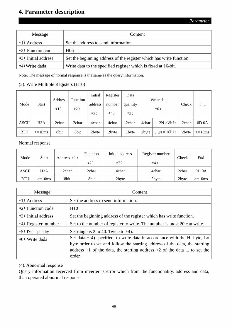
66
4. Parameter description
Parameter
Message Content
*1) Address Set the address to send information.
*2) Function code H06
*3) Initial address Set the beginning address of the register which has write function.
*4)Write dada Write data to the specified register which is fixed at 16-bit.
Note: The message of normal response is the same as the query information.
(3). Write Multiple Registers (H10)
Mode Start Address
*1)
Function
*2)
Initial
address
*3)
Register
number
*4)
Data
quantity
*5)
Write data
*6) Check End
ASCII H3A 2char 2char 4char 4char 2char 4char …2N×8bit 2char 0D 0A
RTU >=10ms 8bit 8bit 2byte 2byte 1byte 2byte …N×16bit 2byte >=10ms
Normal response
Mode Start Address *1) Function
*2)
Initial address
*3)
Register number
*4)
Check End
ASCII H3A 2char 2char 4char 4char 2char 0D 0A
RTU >=10ms 8bit 8bit 2byte 2byte 2byte >=10ms
Message Content
*1) Address Set the address to send information.
*2) Function code H10
*3) Initial address Set the beginning address of the register which has write function.
*4) Register number Set to the number of register to write. The number is most 20 can write.
*5) Data quantity
Set range is 2 to 40. Twice to *4).
*6) Write dada Set data * 4) specified, to write data in accordance with the Hi byte, Lo
byte order to set and follow the starting address of the data, the starting
address +1 of the data, the starting address +2 of the data ... to set the
order.
(4). Abnormal response
Query information received from inverter is error which from the functionality, address and data,
than operated abnormal response.
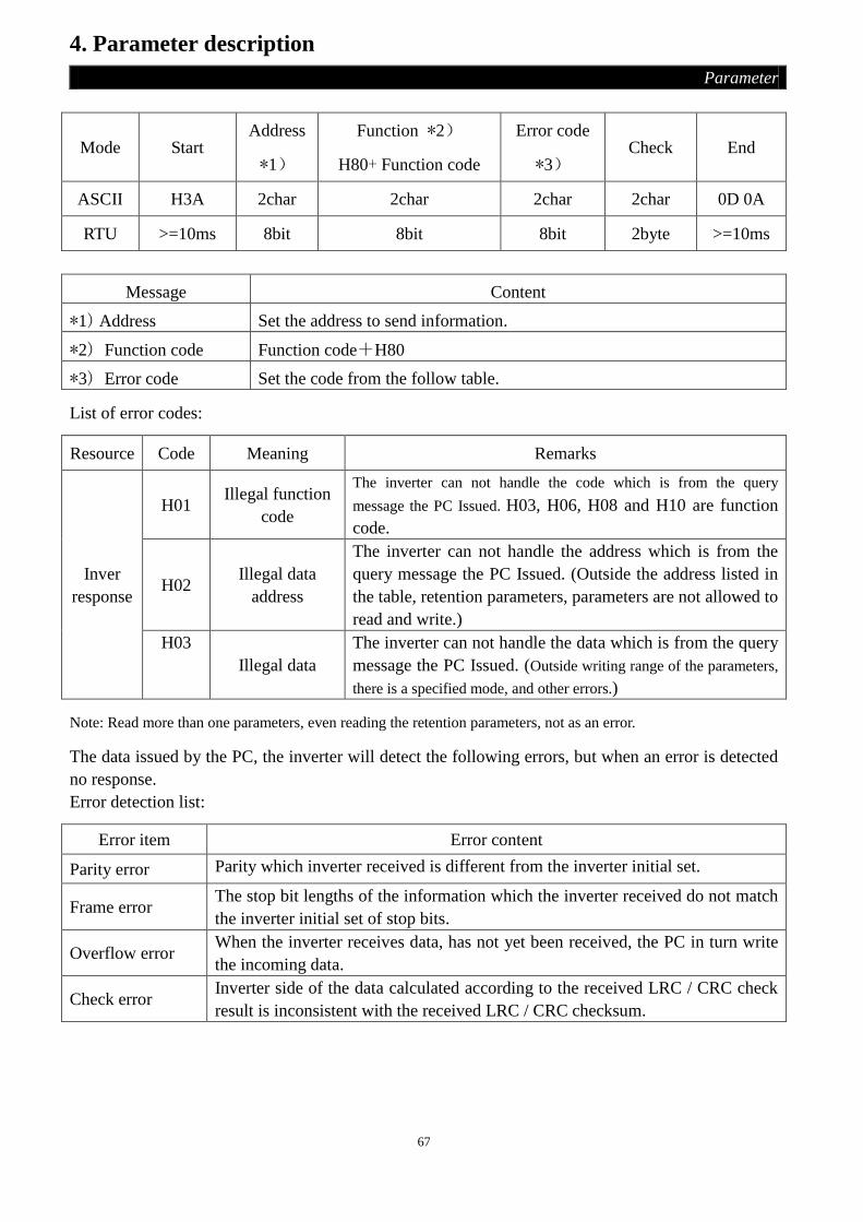
67
4. Parameter description
Parameter
Mode Start Address
*1)
Function *2)
H80+ Function code
Error code
*3) Check End
ASCII H3A 2char 2char 2char 2char 0D 0A
RTU >=10ms 8bit 8bit 8bit 2byte >=10ms
Message Content
*1) Address Set the address to send information.
*2) Function code Function code+H80
*3) Error code Set the code from the follow table.
List of error codes:
Resource Code Meaning Remarks
Inver
response
H01 Illegal function
code
The inverter can not handle the code which is from the query
message the PC Issued. H03, H06, H08 and H10 are function
code.
H02 Illegal data
address
The inverter can not handle the address which is from the
query message the PC Issued. (Outside the address listed in
the table, retention parameters, parameters are not allowed to
read and write.)
H03
Illegal data
The inverter can not handle the data which is from the query
message the PC Issued. (Outside writing range of the parameters,
there is a specified mode, and other errors.)
Note: Read more than one parameters, even reading the retention parameters, not as an error.
The data issued by the PC, the inverter will detect the following errors, but when an error is detected
no response.
Error detection list:
Error item Error content
Parity error Parity which inverter received is different from the inverter initial set.
Frame error The stop bit lengths of the information which the inverter received do not match
the inverter initial set of stop bits.
Overflow error When the inverter receives data, has not yet been received, the PC in turn write
the incoming data.
Check error Inverter side of the data calculated according to the received LRC / CRC check
result is inconsistent with the received LRC / CRC checksum.

68
4. Parameter description
Parameter
● Communications examples
Example 1.Write CU (communication) mode by Communication
Step 1.PC to modify the inverter mode
Mode Start Address Function Initial address Write data Check End
ASCII H3A H30 H31 H30 H36 H31H30 H30 H30 H30 H30 H30 H30 H45 H39 0D 0A
RTU >=10ms 01 06 10 00 00 00 8D 0A >=10ms
Step 2.After receiving and processing accurate, the inverter responds to PC
Mode Start Address Function Initial address Write data Check End
ASCII H3A H30 H31 H30 H36 H31H30 H30 H30 H30 H30 H30 H30 H45 H39 0D 0A
RTU >=10ms 01 06 10 00 00 00 8D 0A >=10ms
Example 2.PC communication to read P.195:
Step 1.PC requests the inverter to read the value of P.195. The address of P.195 is H00C3。
Mode Start Address Function Initial address Register number Check End
ASCII H3A H30 H31 H30 H33 H30H30 H43 H33 H30 H30 H30 H31 H33 H38 0D 0A
RTU >=10ms 01 03 00 C3 00 01 74 36 >=10ms
Step 2.After inverter receives the information and processes without error; it sends value of P.195 to
PC.
Mode Start Address Function Read data number Read data Check End
ASCII H3A H30 H31 H30 H33 H30 H32 H31 H37 H37 H30 H37 H33 0D 0A
RTU >=10ms 01 03 02 17 70 B6 50 >=10ms
H1770 into decimal is 6000, the unit of P.195 is 0.01,so 6000×0.01=60,60 is the value of P.195.
Example 3.Change value of P.195 to 50
Step 1.PC requests the inverter to inputting 50 into P.195.
Mode Start Address Function Initial address Write data Check End
ASCII H3A H30 H31 H30 H36 H30H30 H43 H33 H31 H33 H38 H38 H39 H42 0D 0A
RTU >=10ms 01 06 00 C3 13 88 74 A0 >=10ms
Step 2.After receiving and processing accurate, the inverter responds to PC
Mode Start Address Function Initial address Write data Check End
ASCII H3A H30 H31 H30 H36 H30H30 H43 H33 H31 H33 H38 H38 H39 H42 0D 0A
RTU >=10ms 01 06 00 C3 13 88 74 A0 >=10ms

69
4. Parameter description
Parameter
Example 4. PC communication to read parameter from P.0 to P.195:
Step 1.PC requests the inverter to read the value of P.0~P.11. The initial address is H0000.
Mode Start Address Function Initial address Register number Check End
ASCII H3A H30 H31 H30 H33 H30H30 H30 H30 H30 H30 H30 H43 H46 H30 0D 0A
RTU >=10ms 01 03 00 00 00 0C 45 CF >=10ms
Step 2.After receiving and processing accurate, the inverter responds to PC.
Mode Start Address Function Number of read data Read data Check End
ASCII H3A H30 H31 H30 H33 H31 H38 …12×4 char 2char 0D 0A
RTU >=10ms 01 03 18 …12×2 byte 2byte >=10ms
Example 5.PC communication to write parameter from P.0 to P.195:
Step 1.PC requests the inverter to write the value of P.0~P.11.
Mode Start Address Function Mode Register
number
Data
quantity
Write
data Check End
ASCII H3A H30 H31 H31 H30 H30
H30
H30
H30
H30
H30
H30
H43
H31
H38
…N×4
char 2char 0D 0A
RTU >=10ms 01 10 00 00 00 0C 18 …N×2
byte 2byte >=10ms
Step 2.After receiving and processing accurate, the inverter responds to PC.
Mode Start Address Function Initial address Register number Check End
ASCII H3A H30 H31 H31 H30 H30H30 H30 H30 H30 H30 H30 H43 H45 H33 0D 0A
RTU >=10ms 01 10 00 00 00 0C 00 18 >=10ms
3. Communication commands list
● Set the following command codes and data, you can control the various operations, surveillance
and so on.
Modbus
code Item
Shihlin protocol
code
Information content and its
functions
Modbus
address
H03 Read out operation
mode H7B
H0000:CU;
H0001:OPnd;
H0002:JOG;
H0003:H1,H3,H5;
H0004:H2,H4
H1000
H06/H10 Write operation mode HFB

70
4. Parameter description
Parameter
Modbus
code Item
Shihlin
protocol
code
Information content and its functions Modbus
address
H03 Inverter State H7A
H0000~H00FF
b8~b15:reserved
b7:Alarm occurrence
b6:Frequency detection
b5:Parameters to default values end.
b4:Overload
b3:Frequency achieved
b2:reverse rotation
b1:Forward rotation
b0:Operation
H1001
H03
Monit
ori
ng
set frequency H73 H0000~H9C40 H1002
Output
frequency H6F H0000~H9C40 H1003
Output current H70 H0000~HFFFF H1004
Output voltage H71 H0000~HFFFF H1005
Alarm
item
H74
H0000~HFFFF:
H74/H1007:Error code 1 and 2
b15 b8 b7 b0
Error code 2 Error code 1
H75/H1008:Error code 3 and 4
b15 b8 b7 b0
Error code 4 Error code 3
Error code can reference the table in page
108.
H1007
H75 H1008
H06/H10 Operation command HFA
H0000~HFFFF
b8~b15: reserved
b7: scram(MRS)
b6: 2nd
Acceleration/Declaration
Selection(RT)
b5: High Speed (RH)
b4: Mid Speed (RM)
b3: :Low Speed (RL)
b2: REV Rotation(STR)
b1: FWD Rotation (STF)
b0: reserved
H1001
H06/H10 Inverter reset HFD
H9696:The function of P.997
Communication with the PC, because the
inverter is reset, so the inverter can not be
returned data to the PC.
H1101

71
4. Parameter description
Parameter
Modbus
code Item
Shihlin
protocol
code
Information content and its functions Modbus
address
H06/H10 Operation
frequency write in HEE H0000~H9C40 H1002
H06/H10
Inverter parameter
and error code
erased.
HFC See parameter recovery
description table
H5A5A H1104
H9966 H1103
H9696 H1106
H55AA H1105
HA5A5 H1102
H03 Parameter read out H00~H63 P.0~P.499,The range and decimal point
Please refer to parameter list.
Every parameter modbus address is the 16
band parameter number. For example: the
modbus address of P.138 is H008A.
H0000
|
H01F3 H06/H10 Parameter write in H80~HE3
---
Write/read
Parameter/
page
change
Read H7F H0000:P.0~P.99;
H0001:P.100~P.199;
H0002:P.200~P.299;
H0003:P.300~P.399;
H0004:P.400~P.499。
--- Write HFF
● Parameter recovery description table
Data
content P operating
Communication
parameters
(Note)
P.0~P.191(except P.21,P.189
and Communication
parameter )
Another
parameters
Error
code
H5A5A P.999 o o x x
H9966 P.998 o o o x
H9696 Communication
999 x o x x
H55AA Communication
998 x o o x
HA5A5 P.996 x x x o
Note: Communication parameter include P.32、P.33、P.36、P.48~P.53、P.79、P.153 and P.154.
4.18 Speed Display (P.37)
P.37 “Speed display”
● In ‘output frequency monitoring mode’, the screen will display the corresponding mechanical
speed.

72
4. Parameter description
Parameter
Parameter Factory setting Setting range Remarks
37 0 r/min 0.1~5000r/min 0: output frequency
<Setting>
• The set value of P.37 is the mechanical speed of the inverter when its output frequency is 60Hz.
For example: If the transmitting belt speed is 950 m/minute when the inverter output frequency is
60Hz, P.37 shall be set to 950. In ‘output frequency monitoring mode’, the screen will
display the speed of the transmitting belt.
Note: 1. There’s minute discrepancy between the displayed mechanical speed and the actual one.
2. Please refer to Section 3-2 for detailed operation of the ‘operation panel working mode’.
3. When the output mechanical speed is more than 9998, the screen will display 9999.
4.19 Voltage Signal Selection and Target Frequency (P.38, P.59, P.73, P.76,
P.139, P.140, P.141)
P.38 “The maximum operation frequency (the target frequency is set by the input
signal of terminal 2-5)”
P.59 “Selection of frequency sources”
P.73 “Voltage signal selection”
P.76 “Panel knob signal input frequency bias”
P.139 “Voltage signal bias”
P.140 “Voltage signal gain”
P.141 “Voltage signal bias direction and
rotational direction setup”
Related parameters
P. 80~P. 84 , P. 86
“Multi - function terminals selection ”
P. 79 “ Operation mode selection ”
P. 194 “Frequency corresponds to the
minimum input voltage of terminal 2-5”
P. 195 “Frequency corresponds to the
maximum input voltage of terminal 2-5”
P. 189 “ Factory setting function ”
Parameter Factory setting Setting range Remarks
38 50Hz
1~400Hz (Note 4) When P.189=1
60Hz When P.189=0
59 1 0, 1 ---
73 0 0, 1
0 The range for the input voltage signal
(terminal 2-5/4-5) is 0~5V.
1 The range for the input voltage signal
(terminal 2-5/4-5) is 0~10V.
76 0 Hz 0~400Hz (Note 4) ---
139 0% 0%~100% ---
140 100% 0.1%~200% ---
141 0 0~11 ---

73
4. Parameter description
Parameter
< Setting >
• When P.59=0, the target frequency is set by the knob on DU03B operation panel (the range of the
voltage signal given by the knob is 0~5V). The frequency range is set by P.38.
• When P.59=1, the target frequency is set by the button and on DU03B operation panel.
• There are 2 digits in P.141, every digit have the different meaning, relevant positions as following:
P.141=
0:Positive Bias
1:Negative Bias
0:Negative Bias: REV Motion Disenabled
1:Negative Bias: REV Motion Enabled
• If you hope that the frequency is not 0Hz when the panel knob is set at 0V when setting frequency
with the knob, you can realized that by setting P.76. For example: If you hope that the frequency is
10Hz when the knob is set at 0V, you should set P.76=10, at this time the setting range of the
frequency is from 10Hz to the set value of P.38 when you turn the knob. Shown as follows:
0Hz
P.76
P.38
The set range of
the panel knob
Output
frequency
• Set the frequency of using negative bias benefits of avoids noise interference greatly. In harsh
environments, the user is advised to avoid using the drive signal which is below 1V to set the
operating frequency.
Now let’s see same examples:
Example 1: This is the most used setting. When the inverter is in ‘external mode’, ‘combined mode
2’ or ‘combined mode 4’, and the frequency is set by terminal 2-5。
0V 5V 10V0Hz
60Hz
30Hz
Max output
frequency
Parameter setting:
P.38 = 60Hz Max operation frequency
P.139 = 0% Bias adjustment
P.140 = 100% Gain adjustment
P.141 = 0 Positive Bias
P.73 = 1 Voltage signal selection
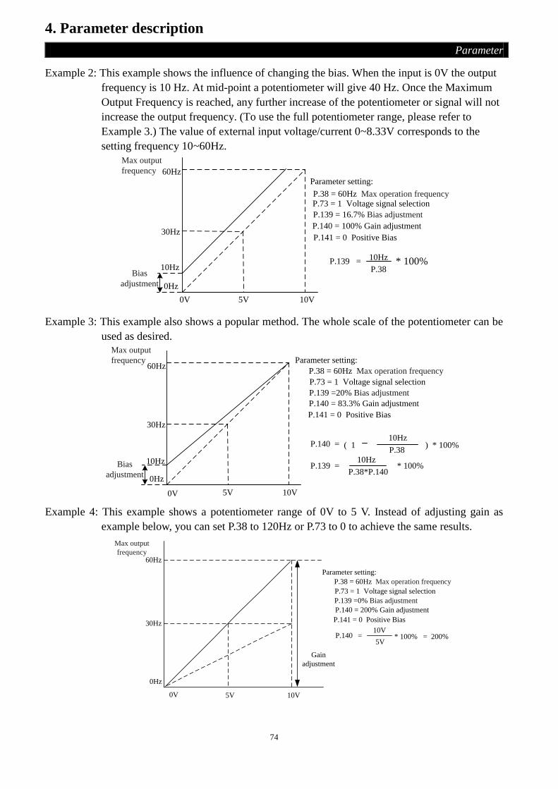
74
4. Parameter description
Parameter
Example 2: This example shows the influence of changing the bias. When the input is 0V the output
frequency is 10 Hz. At mid-point a potentiometer will give 40 Hz. Once the Maximum
Output Frequency is reached, any further increase of the potentiometer or signal will not
increase the output frequency. (To use the full potentiometer range, please refer to
Example 3.) The value of external input voltage/current 0~8.33V corresponds to the
setting frequency 10~60Hz.
0V 5V 10V
0Hz
60Hz
30Hz
10HzBias
adjustment
P.139 = 10Hz
P.38 * 100%
Max output
frequency
Parameter setting:
P.38 = 60Hz Max operation frequency
P.139 = 16.7% Bias adjustment
P.140 = 100% Gain adjustment
P.141 = 0 Positive Bias
P.73 = 1 Voltage signal selection
Example 3: This example also shows a popular method. The whole scale of the potentiometer can be
used as desired.
P.140 =P.38
) * 100%
0V 5V 10V
0Hz
60Hz
30Hz
10Hz
( 1 10Hz
P.139 =10Hz
P.38*P.140* 100%
Max output
frequency
Bias
adjustment
Parameter setting:
P.38 = 60Hz Max operation frequency
P.139 =20% Bias adjustment
P.140 = 83.3% Gain adjustment
P.141 = 0 Positive Bias
P.73 = 1 Voltage signal selection
Example 4: This example shows a potentiometer range of 0V to 5 V. Instead of adjusting gain as
example below, you can set P.38 to 120Hz or P.73 to 0 to achieve the same results.
10V5V0V
30Hz
60Hz
0Hz
Gain
adjustment
P.140 =10V
5V* 100% = 200%
Max output
frequency
Parameter setting:
P.38 = 60Hz Max operation frequency
P.139 =0% Bias adjustment
P.140 = 200% Gain adjustment
P.141 = 0 Positive Bias
P.73 = 1 Voltage signal selection

75
4. Parameter description
Parameter
Example 5: In this example, a 1V negative bias is used. In noisy environments it is advantageous to
use negative bias to provide a noise margin (1V in this example).
10V1V0V
54Hz
60Hz
0Hz
6Hz
Negative
Bias 6Hz
P.139 =1V
10V* 100%
Max output
frequency
Parameter setting:
P.38 = 60Hz Max operation frequency
P.139 =10% Bias adjustment
P.140 = 100% Gain adjustmentP.141 = 1 Negative Bias, can not reverse
P.73 = 1 Voltage signal selection
Example 6: In this example, a negative bias is used to provide a noise margin. Also a potentiometer
frequency gain is used to allow the Maximum Output Frequency to be reached.
10V1V0V
60Hz
0Hz
Bias
adjustment
6.6Hz
P.140 = 10V
* 100% = 111.1%9V
Max output
frequency
Negative
Bias 6.6Hz
Parameter setting:
P.38 = 60Hz Max operation frequency
P.139 =10% Bias adjustment
P.140 = 111% Gain adjustment
P.141 = 1 Negative Bias, can not reverse
P.73 = 1 Voltage signal selection
Example 7: In this example, the input is programmed to run a motor in both forward and reverse
direction. The motor will be idle when the potentiometer position is at mid-point of its
scale. Using the settings in this example disables the external FWD and REV controls.
10V5V
0V
30Hz
60Hz
0Hz
60Hz
30Hz
Max output frequency
Parameter setting:
P.38 = 60Hz Max operation frequency
P.139 =50% Bias adjustment
P.140 = 200% Gain adjustment
P.141 = 11 Negative Bias, can reverse
P.73 = 1 Voltage signal selection
Forward direction
Reverse direction

76
4. Parameter description
Parameter
Example 8: In this example, the use of negative slope is shown. Negative slopes are used in
applications for control of pressure, temperature or flow. The sensor that is connected
to the input generates a large signal (10V) at high pressure or flow. With negative slope
settings, the AC motor drive will slow stop the motor. With these settings the AC motor
drive will always run in only one direction (reverse). This can only be changed by
exchanging 2 wires to the motor.
10V0V
60Hz
0Hz
Negative slope
Max output
frequency
Parameter setting:
P.38 = 60Hz Max operation frequency
P.139 =100% Bias adjustment
P.140 = 100% Gain adjustment
P.141 = 11 Negative Bias, can reverse
P.73 = 1 Voltage signal selection
Note: 1. In ‘external mode’, ‘combined mode 2’ or ‘combined mode 4’, if RH, RM, RL and REX are all ‘off’, the
inverter target frequency is set by the input signal across terminal 2-5/4-5. If AU is ‘on’, the input signal
across terminal 4-5 has higher priority.
2. RL, RM, RH, REX, AU and RUN referred in this paragraph is the function names of ‘multi-function
control terminals’. For the corresponding function selection and features, please refer to P.80~84, P.86. For
wiring, please refer to Section 2-5.
3. The set value of P.76 must be smaller than the set value of P.38, and if it exceed the set value of P.38, it will
be clamped at the set value of P.38.
4. If P.187=1, P.38 is in the range of 1~1000Hz, P.76 is in the range of 0~1000Hz.
4.20 The Maximum Operation Frequency (the target frequency is set by the
input signal of terminal 4-5) (P.39)
P.39 “The maximum operation
frequency (the target frequency is set
by the input signal of terminal 4-5)”
Related parameters
P.80~P.84 , P.86“Multi-function terminals selection”
P.79 “Operation mode selection”
P. 196“Frequency corresponds to
the minimum input current/
voltage across terminal 4-5”
P. 197 “Gain of the input signal
across terminal 4-5”
P. 189 “Factory setting function”
P.73 “Voltage signal selection”
P.17 “Input signal across terminal
4 -5 selection”
Parameter Factory setting Setting range Remarks
39 50Hz
1~400Hz(Note 4) When P.189=1
60Hz When P.189=0

77
4. Parameter description
Parameter
20mA4mA
P. 39
10V
Set
ting f
requen
cy
0V
P. 39
Input signal across
terminal 4-5 0V
5V
P.17=0P.17=1
Input signal across
terminal 4-5
Set
ting f
requen
cy
Note: 1. In ‘external mode’, ‘combined mode 2’ or ‘combined mode 4’, if AU is ‘on’, the target frequency of the
inverter is set by the input signal across terminal 4-5.
2. In ‘external mode’, ‘combined mode 2’ or ‘combined mode 4’, if AU and one of RH, RM, RL and REX are
both valid at the same time, the multi-speed has higher priority.
3. RL, RM, RH, REX and AU referred in this paragraph are function names of ‘multi-function control
terminal’. For the corresponding function selection and features, please refer to P.80~P.84, P.86. For
wiring, please refer to Section 2-5.
4. If P.187=1, P.39 is in the range of 1~1000Hz.
4.21 Multi-function Output (P.40, P.85, P.120)
P.40 “Multi-function output terminal
pattern”
P.85 “Function selection for
multi-function relay”
P.120 “Output signal delay time”
Related parameters
P.41 “Up-to-frequency sensitivity”
P.42 “Output frequency detection
for forward rotation”
P.43 “Output frequency detection
for reverse rotation”
P.62 “Zero current detection level”
P.63 “Zero current detection time”
Parameter Factory
setting
Setting
range Remarks
40 0 0~10
0
RUN (Inverter running): Signal will be output when the
output frequency is equal to or higher than the starting
frequency.
1
SU (Up to frequency): Signal will be output once the
output frequency has reached within the set region of the
set frequency.
2
FU (Output frequency detection): Signal will be output
once the output frequency has reached or exceeded the
detection frequency set.

78
4. Parameter description
Parameter
Parameter Factory
setting
Setting
range Remarks
85 5 0~10
3 OL (Overload detection): Signal will be output once the
current limit function is triggered.
4
OMD (Zero current detection): If the output current
percentage of the inverter is less than the set value of P.62,
and lasts for the pre-defined time (the setting value of
P.63), OMD will output signal.
5 ALARM (Alarm detection): Alarm detection
6 PO1 (Section detection): In programmed operation mode,
PO1 signal will be output in the end of each section.
7 PO2 (Periodical detection): In programmed operation
mode, PO2 signal will be output in the end of each cycle.
8 PO3 (Pause detection): In programmed operation mode,
PO3 signal will be output when the inverter pauses.
9
BP (Inverter output): Switch between the inverter
operation and commercial power-supply operation
function, when the inverter operation, BP will output
signal.
10
GP (Commercial power-supply output): Switch between
the inverter operation and commercial power-supply
operation function, when the commercial power-supply
operation, GP will output signal.
120 0 0.1~3600s ---
< Setting >
• When P.120=0, if the set condition of P.40 (P.85) is met, the signal will be output directly.
• When P.120=0.1~3600, if the set condition of P.40 (P.85) is met, the signal will be output after the
set time.
For example: FU (Output frequency detection) function (For example: P.42/P.43=40Hz)
P.120 P.120
Output
frequency
(Hz)
40
Time (s)At least 100ms
OFF ON ONOFF OFF
FU
Output frequency
detection value
(P.42/P.43)

79
4. Parameter description
Parameter
Note: 1. The multi-function output terminal is SO, SE. When P.40=0 (the default value), it means ‘RUN’. When a
different value is set, the corresponding function will change as shown in the above table.
2. The internal electrical structures for the multi-function output terminals are ‘open collector output’.
Please refer to Section 2-5-2 and Section 2-5-3 for wiring.
3. When the set value of P.85 is 5(the default value), the function of the multi-function relay ABC is ALARM.
When the value of P.85 is revised, its function changes respectively as the corresponding function list in
the table above.
4.22 Up-to-frequency Sensitivity (P.41)
P.41 “Up-to-frequency sensitivity” Related parameters
P.40 “Multi-function output
terminal pattern”
P.85 “Function selection for
multi-function relay”
Parameter Factory setting Setting range Remarks
41 10% 0~100% ---
<Setting>
• If P.41=5%, a signal (SU) is output when the output frequency enter the ‘5% region near the target
frequency’. For example: the target frequency is set to 60Hz, and P.41=5%, then if the output
frequency is between 60±60×5%=63Hz and 57Hz region, the SU signal is output.
SU
Adjustment scope
P.41
Output
frequency
(Hz)
Target frequency
Output signal
OFF OFFON
Time(s)
Note: In this paragraph, SU is the function name of ‘multi-function output terminal’. Please refer to P.40 for
function selection and features. About wiring, please refer to section 2-5.

80
4. Parameter description
Parameter
4.23 Output Frequency Detection (P.42, P.43)
P.42 “Output frequency detection for
forward rotation”
P.43 “Output frequency detection for
reverse rotation”
Related parameters
P.40 “Multi-function output
terminal pattern”
P.85 “Function selection for
multi-function relay”
Parameter Factory setting Setting range Remarks
42 6Hz 0~400Hz (Note 2) ---
43 9999 0~400Hz, 9999 (Note 2) 9999: same as P.42 setting
<Setting>
• If P.42=30 and P.43=20, then a signal (FU) is output when the forward rotation output frequency
exceeds 30Hz or when the reverse rotation output frequency exceeds 20Hz.
• If P.42=30 and P.43=9999 (the default value), then a signal (FU) is output when the forward or
reverse rotation output frequency exceeds 30Hz.
FU
Output
frequency
(Hz)
Output signal
OFF OFFON
Time(s)
P.42
P.43
ON OFF
Run forward
Run reverse
Note: 1. In this paragraph FU is the function names of ‘multi-function output terminals’. Please refer to P.40 for
function selection and features. About wiring, please refer to section 2-5.
2. If P.187=1, P.42 and P.43 are in the range of 0~1000Hz.
4.24 AM Terminal (P.54~P.56, P.190, P.191)
P.54 “AM terminal function selection”
P.55 “Frequency display reference”
P.56 “Current monitoring reference”
P.190 “AM output bias”
P.191 “AM output gain”

81
4. Parameter description
Parameter
● Between terminals AM and terminal 5, an electric meter can be connected to indicate the output
current value or the output frequency.
Parameter Factory setting Setting range Remarks
54 0 0, 1 ---
55 50Hz
0~400Hz (Note) When P.189=1
60Hz When P.189=0
56 Rated current 0~500A ---
190 80 0~1024 ---
191 900 0~1024 ---
<Setting>
• When P.54=0, if the output frequency of the inverter is the set value of P.55, a voltage of 10V is
output at terminal AM.
• When P.54=1, if the output current of the inverter is the set value of P.56, a voltage of 10V is output
at terminal AM.
P.55 output frequency
P.56 output current
AM
output 10V
• AM terminal checking steps: 1. Connect an electric meter whose full graduation is 10V between terminal A and terminal 5, and
set P.54 to 0, then please check the meter because of the difference of the accessory.
2. Set P.13 to 0, then start the motor, and fix the output frequency of the inverter at 0Hz.
3. Read the set value of P.190, then the screen will display the current AM output bias.
4. Press , press SET
and hold for 0.5s, the finger of the meter moves upwards, the AM output
bias will increase. Press to change the value of P.190, press SET
and hold for 0.5s, the
finger of the meter moves downwards, the AM output bias will decrease. When adjusting the
scale pointer position to 0 to complete the AM output bias correction work.
5. Adjust and fix the output frequency of the inverter at 60Hz.
6. Read the setting value of P.191, then the screen will display the current AM output gain.
7. Press to adjust the AM output gain, press SET
and hold for 0.5s, the finger of the
meter moves upwards and downwards. When the finger of the meter moves to full range, finish
the checking.
Note: If P.187=1, P.55 is in the range of 0~1000Hz.

82
4. Parameter description
Parameter
4.25 Restart Function (P.57, P.58, P.150, P.160)
P.57 “Restart coasting time”
P.58 “Restart cushion time”
P.150 “Restart mode selection”
P.160 “Stall prevention operation level when restart”
Parameter Factory setting Setting range Remarks
57 9999 0~30s,9999 9999: restart function invalid
58 10s 0~60s ---
150 0 0~221 ---
160 120% 0~200% When restart, stall prevention
operation level
<Setting>
• When the motor is running, once the driving power is interrupted, the output voltage will not be
output instantly. When the power is recovered, if P.57=9999, the inverter will not restart
automatically, and if P.57=0.1~5, the motor coasts for a while (the set value of P.57), then the
inverter will restart the motor automatically.
• Once the motor was automatically restarted, the output frequency of the inverter is the target
frequency, but the output voltage is zero. Then the voltage will be increased gradually to the
expected voltage value. The period for voltage increasing is called ‘Restart cushion time (P.58)’. Instantaneous (power failure) time
Power supply
(R/L1,S/L2,T/L3)
Motor speed N
(r/min)
Inverter output
frequency f (Hz)
Inverter output
voltage E (v)
Restart cushion time
P.58 setting
Coasting time
P.57setting
*
* The output shut off timing differs
according to the load condtion • There are 4 digits in P.150, every digit have the different meaning, relevant positions as following:
P. 150 =0:No frequency search
1:Immediate frequency search
2:Cheapen voltage0:One electrify
1:Every starting
2:Stop momentary
0:No detection of rotation
1:The detection of rotation
2:P.78=0, The direction of rotation
P.78=1,2 No direction of rotation
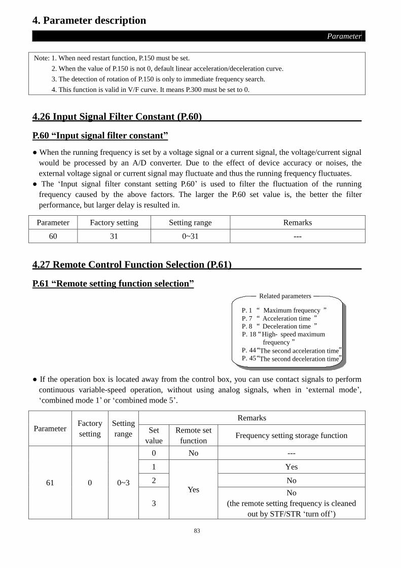
83
4. Parameter description
Parameter
Note: 1. When need restart function, P.150 must be set.
2. When the value of P.150 is not 0, default linear acceleration/deceleration curve.
3. The detection of rotation of P.150 is only to immediate frequency search.
4. This function is valid in V/F curve. It means P.300 must be set to 0.
4.26 Input Signal Filter Constant (P.60)
P.60 “Input signal filter constant”
● When the running frequency is set by a voltage signal or a current signal, the voltage/current signal
would be processed by an A/D converter. Due to the effect of device accuracy or noises, the
external voltage signal or current signal may fluctuate and thus the running frequency fluctuates.
● The ‘Input signal filter constant setting P.60’ is used to filter the fluctuation of the running
frequency caused by the above factors. The larger the P.60 set value is, the better the filter
performance, but larger delay is resulted in.
Parameter Factory setting Setting range Remarks
60 31 0~31 ---
4.27 Remote Control Function Selection (P.61)
P.61 “Remote setting function selection”
Related parameters
P. 18 “High- speed maximum
frequency”
P. 1 “ Maximum frequency ”
P. 8 “ Deceleration time ”P. 7 “ Acceleration time ”
P. 44 “The second acceleration time”P. 45 “The second deceleration time”
● If the operation box is located away from the control box, you can use contact signals to perform
continuous variable-speed operation, without using analog signals, when in ‘external mode’,
‘combined mode 1’ or ‘combined mode 5’.
Parameter Factory
setting
Setting
range
Remarks
Set
value
Remote set
function Frequency setting storage function
61 0 0~3
0 No ---
1
Yes
Yes
2 No
3
No
(the remote setting frequency is cleaned
out by STF/STR ‘turn off’)
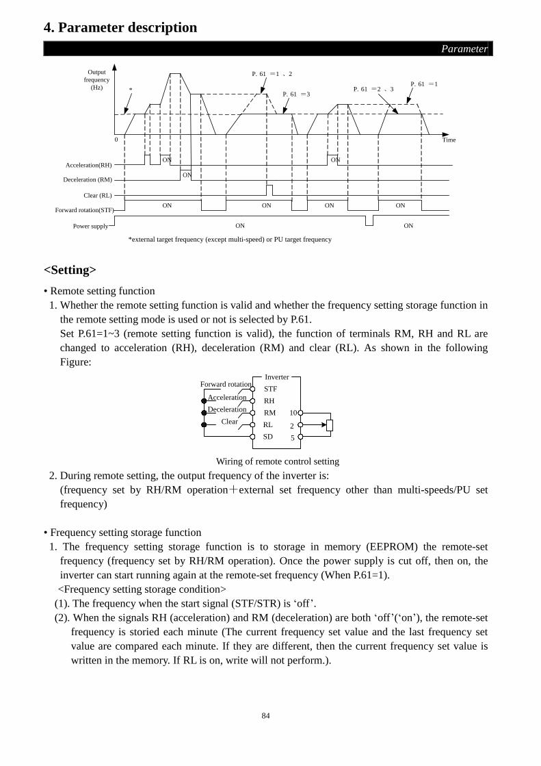
84
4. Parameter description
Parameter
Acceleration(RH)
Deceleration (RM)
Clear (RL)
Forward rotation(STF)ON
ON
ON
ON ON ON
ON ON
ON
P. 61 =1
P. 61 =3P. 61 =2 、3
P. 61 =1 、2
Power supply
Output
frequency
(Hz)
0 Time
*
*external target frequency (except multi-speed) or PU target frequency
<Setting>
• Remote setting function
1. Whether the remote setting function is valid and whether the frequency setting storage function in
the remote setting mode is used or not is selected by P.61.
Set P.61=1~3 (remote setting function is valid), the function of terminals RM, RH and RL are
changed to acceleration (RH), deceleration (RM) and clear (RL). As shown in the following
Figure:
InverterForward rotation
Acceleration
Deceleration
Clear
STF
RH
RL
RM
SD
10
2
5
Wiring of remote control setting
2. During remote setting, the output frequency of the inverter is:
(frequency set by RH/RM operation+external set frequency other than multi-speeds/PU set
frequency)
• Frequency setting storage function
1. The frequency setting storage function is to storage in memory (EEPROM) the remote-set
frequency (frequency set by RH/RM operation). Once the power supply is cut off, then on, the
inverter can start running again at the remote-set frequency (When P.61=1).
<Frequency setting storage condition>
(1). The frequency when the start signal (STF/STR) is ‘off’.
(2). When the signals RH (acceleration) and RM (deceleration) are both ‘off’(‘on’), the remote-set
frequency is storied each minute (The current frequency set value and the last frequency set
value are compared each minute. If they are different, then the current frequency set value is
written in the memory. If RL is on, write will not perform.).

85
4. Parameter description
Parameter
4.28 Zero Current Detection (P.62, P.63)
P.62 “Zero current detection level”
P.63 “Zero current detection time”
Related parameters
P.40 “Multi-function output
terminal pattern”
P.85 “Function selection for
multi-function relay”
Parameter Factory setting Setting range Remarks
62 5% 0~200%, 9999 9999: function invalid
63 0.5s 0.05~1s, 9999 9999: function invalid
<Setting>
• Assume that the rated full-load current of the inverter is 20A, P.62=5% and P.63=0.5s, in this case if the output current is lower than 20×5%=1A for more than 0.5s, a signal(OMD) is output, which
is depicted in the figure below.
Note: 1. The frequency can be varied by RH (acceleration) and RM (deceleration) between 0 and the maximum
frequency. The upper limit of the setting frequency is the maximum frequency, shown as follows:
P.1
Output
frequencySetting frequency
0Hz
Hz
Acceleration(RH)
Deceleration(RH)
Forward rotationSTF)
ON
ON
ON
2. When the acceleration or deceleration signal is ‘on’, the output frequency acceleration/deceleration times
are determined by P.7 (first acceleration time) and P.8 (first deceleration time) (When RT is ‘off’).
3. When P.44 ≠ 9999 (second acceleration time) and P.45 ≠ 9999 (second deceleration time), the
acceleration/deceleration times are due to P.44, P.45.
4. When the start signal (STF/STR) is ‘off’, if RH (acceleration)/RM (deceleration) is ‘on’, the target
frequency will also change.
5. When the start signal(STF/STR) becomes ‘off’ from ‘on’, or changing the frequency continually through
RH/RM, please make the frequency setting storage function invalid (P.61=2,3).
6. If the frequency setting storage function is valid (P.61=1), the life of the EEPROM will be shorten
because of frequent write frequency into the EEPROM.
7. Signals RH, RM and RL are determined by P.80~P.84, P.86. If the functions of the terminals are changed,
other functions are likely to be affected. Please make sure the functions of the terminals before changing
their functions.

86
4. Parameter description
Parameter
• If the set value of P.62 or P.63 is 9999, the zero current detection is disabled.
Note: In this paragraph OMD is one of the function names of ‘multi-function output terminal’. Please refer to P.40
for function selection and features, and section 2-5 for wiring.
4.29 Retry (P.65, P.67, P.68, P.69)
P.65 “Retry selection”
P.67 “Number of retries at alarm occurrence”
P.68 “Retry waiting time”
P.69 “Retry accumulation time at alarm”
● When an alarm occurs, the previous states before the alarm will be restored automatically. The
phenomenon is called ‘retry’.
● The Retry of the inverter is the conditional execution. For example, the first alarm occurs and the retry
has been executed. Unfortunately, a second alarm occurs successively within P.68*5 seconds. Such
a case is defined as ‘continuous alarms’. In case the continuous alarms occur for more times than
the pre-defined upper limit, a great malfunction is indicated, thus special measures should be taken
manually. At this time, the retry will not be executed any more. The number of pre-defined times is
called ‘number of retries at alarm occurrence (P.67)’.
● If the alarm doesn’t belong to ‘Continuous alarm’, the inverter can perform unlimited number of
times reset.
● The period from the moment of alarm to that of retry is defined ‘retry waiting time’.
Parameter Factory setting Setting range Remarks
65 0 0~4 ---
67 0 0~10 ---
68 6s 0~360s ---
<Setting>
• When P.65=0, retry is invalid. When alarm occurs, the voltage output is stopped, the ‘Alarm’ lamp
is lit, and all the inverter functions are disabled.
• When P.65=1, in case ‘over-voltage between P-N’ occurs, the voltage output is stopped. After a
period of waiting time (the set value of P.68), the retry is executed.

87
4. Parameter description
Parameter
• When P.65=2, once ‘over-current’ occurs, the voltage output is stopped. After a period of waiting
time (the set value of P.68), the retry is executed.
• When P.65=3, in case ‘over-voltage or over-current between P-N’ occurs, the voltage output is
stopped. After a period of waiting time (the set value of P.68), the retry is executed.
• When P.65=4, retry is effective. When alarm occurs, the voltage output is stopped. After a period of
waiting time (the set value of P.68), the retry is executed.
• When P.67=0, Retry is invalid.
• When P.67≠0, given continuous alarm occurs for times within the pre-defined upper limit of P.67,
retries will be valid. However, once the upper limit is exceeded, the retry is valid no more.
• For each time the retry occurs, the value of P.69 will be increased by 1 automatically, so the number
of P.69 read from the memory just indicates the number of retry accumulation time at alarm.
• If P.69 is rewritten with 0, the number of retry executed is erased.
Note: The inverter will retry until the return wait time of P.68 is past. Therefore, this function is selected, the
operator may cause danger, please be careful.
4.30 Brake Selection (P.71)
P.71 “Idling braking and linear braking selection”
Parameter factory setting Setting range Remarks
71 1 0~1 ---
<Setting>
• When P.71=0, it is now idling braking. The output of the inverter will terminate immediately after
pressingSTOP
RESET
, and the motor will be ‘racing’
• When P.71=1, it is now beeline brake. The output of the inverter will follow the
acceleration/deceleration curve after pressingSTOP
RESET
.
4.31 Carrier Frequency (P.72)
P.72 “Carrier frequency”
Parameter Factory setting Setting range Remarks
72 5.0kHz 0.7~14.5kHz ---
<Setting>
• The higher the carrier frequency is, the lower the motor acoustic noise is. Unfortunately, greater
leakage current and larger noises generated by the inverter are resulted in.
• The higher the carrier frequency is, the more energy is dissipated, and the higher the temperature of
the inverter is.
• In case a mechanical resonance occurs in a system with the inverter, P.72 is helpful for improved
the performance just by adjusting its value.

88
4. Parameter description
Parameter
• When the carrier frequency is increasing, the rated current of the inverter will decrease in order to
prevent the inverter being too hot and prolong the using life of IGBT, so it is necessary to take the
protective measure. When the carrier frequency is 8 kHZ or smaller than it, the rated current of the
inverter is 100%. The rated current of the inverter will decrease with the carrier frequency is
increasing, and it will accelerate the heat accumulating in order to protect the inverter. The relation
curve of the carrier frequency and the rated current is as figure below:
100%
90%
80%
70%
60%
50%
40%
2kHz 4kHz 6kHz 8kHz 10kHz 12kHz 14kHz 16kHzThe carrier ferquency
The rated current
Note: 1. The optimum carrier frequency shall be over 8 times greater than the target frequency.
2. When selected sensorless vector control (P.300=3), the carrier frequency can set to 2kHz, 6kHz, 10kHz,
14kHz. If the setting value is less 6kHz, the carrier frequency is 2kHz; If the setting value is less than
10kHz, the carrier frequency is 6kHz; If the setting value is less than 14kHz, the carrier frequency is
10kHz; If the setting value is more than 14kHz, the carrier frequency is 14kHz.
4.32 Stop or Reset Function Selection (P.75)
P.75 “Stop or reset function selection”
Parameter Factory setting Setting range Remarks
75 1 0, 1 ---
<Setting>
• When P.75=0, it is only suitable for PU mode and H2 mode (combined mode 2). Pressing STOP
RESET
during running is used to stop the motor. Only at trouble state, we can press STOP
RESET for 1.0s to reset
the inverter, and then the inverter will show the power on state.
• When P.75=1, it is only suitable for the mode chosen. Pressing STOP
RESET during running is used to stop
the motor. Only at trouble state, we can press STOP
RESET for 1.0s to reset the inverter, and then the
inverter will show the power on state.

89
4. Parameter description
Parameter
Note: 1. In normal or abnormal conditions, the reset can be executed by P.997.
2. There are two built-in program emulation thermally-accumulating relay, namely, ‘electronic thermal
relay’ and ‘IGBT module thermal relay’. Once reset occurs, the values of the two relay for ‘electronic
thermal relay’ and ‘IGBT module thermal relay’ will be set to zero.
3. In any modes except External mode or H2 mode, when P.75=1, the motor can be stopped by pressing
STOP
RESET
, then the inverter displays E0, and all the functions of the inverter are disabled. It can restart as follows:
(1). Terminate external STF/STR command (In programmed operation mode, there’s no need to terminate
the start signal. The inverter will continue to run at the section where it stopped after reset.)
(2). Press STOP
RESET
for 1.0s.
4.33 Parameters Write Protection (P.77)
P.77 “Parameters write protection”
Parameter Factory setting Setting range Remarks
77 0 0~2 ---
<Setting>
• If P.77=0, when the motor stops, all parameters except for P.125 and P.188 can be written, and when
the motor runs, only P.4~P.6, P.24~P.27, P.54~P.56, P.77, P.131~P.138, P.142~P.149, P.190~P.199,
P.230, P.232, P.288 and P.290 can be written.
• If P.77=1, when the motor runs, the parameter-writing is forbidden except P.77. When the motor
stops, only P.77 and P.79 can be written.
• If P.77=2, when motor stops, all parameters except for P.125 and P.188 can be written, and when
motor runs, only P.22, P.72, P. 78, P.79, P.125, P.155 and P.188 can not be written.
4.34 Forward/reverse Rotation Prevention Selection (P.78)
P.78 “Forward/reverse rotation prevention selection ”
Parameter Factory
setting
Setting
range Remarks
78 0 0~2
0 Forward rotation and reverse rotation are both permitted.
1 Reverse rotation is prohibited (PressREV
, the motor will stop).
2 Forward rotation is prohibited (PressFWD
, the motor will stop).

90
4. Parameter description
Parameter
4.35 Operation Mode Selection (P.79)
P.79 “Operation mode selection”
Parameter Factory
setting
Setting
range Remarks
79 0 0~8
0 ‘PU mode’, ‘external mode’ and ‘JOG mode’ are valid and
interchangeable.
1 PU mode’ and ‘JOG mode’ are active and interchangeable.
2 Only ‘external mode’ is valid.
3 Only communication mode’ is valid.
4 Only ‘combined mode 1’ is valid.
5 Only ‘combined mode 2’ is valid.
6 Only ‘combined mode 3’ is valid.
7 Only ‘combined mode 4’ is valid.
8 Only ‘combined mode 5’ is valid.
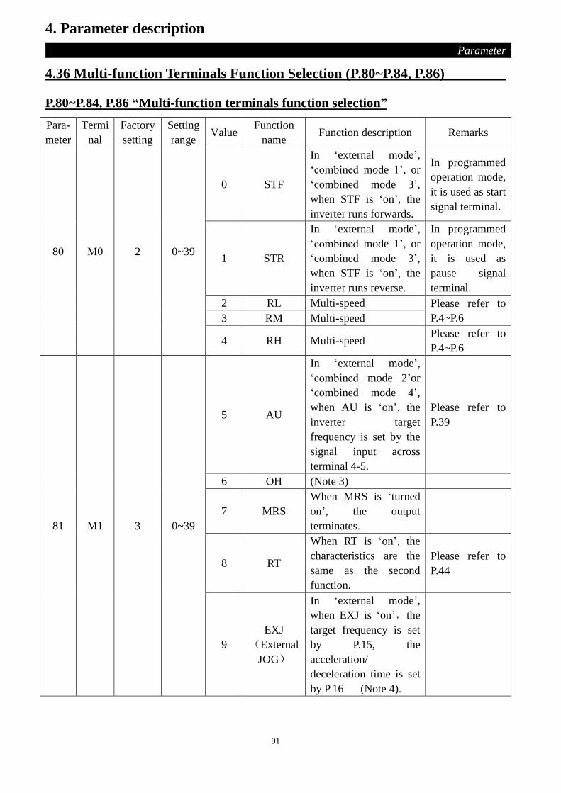
91
4. Parameter description
Parameter
4.36 Multi-function Terminals Function Selection (P.80~P.84, P.86)
P.80~P.84, P.86 “Multi-function terminals function selection”
Para-
meter
Termi
nal
Factory
setting
Setting
range Value
Function
name Function description Remarks
80 M0 2 0~39
0 STF
In ‘external mode’,
‘combined mode 1’, or
‘combined mode 3’,
when STF is ‘on’, the
inverter runs forwards.
In programmed
operation mode,
it is used as start
signal terminal.
1 STR
In ‘external mode’,
‘combined mode 1’, or
‘combined mode 3’,
when STF is ‘on’, the
inverter runs reverse.
In programmed
operation mode,
it is used as
pause signal
terminal.
2 RL Multi-speed Please refer to
P.4~P.6 3 RM Multi-speed
4 RH Multi-speed Please refer to
P.4~P.6
81 M1 3 0~39
5 AU
In ‘external mode’,
‘combined mode 2’or
‘combined mode 4’,
when AU is ‘on’, the
inverter target
frequency is set by the
signal input across
terminal 4-5.
Please refer to
P.39
6 OH (Note 3)
7 MRS
When MRS is ‘turned
on’, the output
terminates.
8 RT
When RT is ‘on’, the
characteristics are the
same as the second
function.
Please refer to
P.44
9
EXJ
(External
JOG)
In ‘external mode’,
when EXJ is ‘on’,the
target frequency is set
by P.15, the
acceleration/
deceleration time is set
by P.16 (Note 4).

92
4. Parameter description
Parameter
Para-
meter
Termi
nal
Factory
setting
Setting
range Value name Function Instruction
82 M2 4 0~39
10 STF+EXJ
Multiplexed function
The
multiplexed
function is
the complex
of several
basic
functions.
It means
that we can
use one
multiplexed
terminal to
realize
several
basic
functions.
11 STR+EXJ
12 STF+RT
13 STR+RT
14 STF+RL
15 STR+RL
16 STF+RM
17 STR+RM
83 STF 0 0~39
18 STF+RH
19 STR+RH
20 STF+RL+RM
21 STR+RL+RM
22 STF+RT+RL
23 STR+RT+RL
24 STF+RT+RM
25 STR+RT+RM
26 STF+RT+RL+RM
27 STR+RT+RL+RM
84 STR 1 0~39
28 RUN
In ‘external mode’,
when RUN is ‘on’,
the inverter runs.
29 STF/STR
In ‘external mode’, it
is used with RUN.
The inverter runs
forwards when
STF/STR is ‘on’, and
runs reverse when
STF/STR is ‘off’.
Run
forward
/reverse
control
signal
30 RES External Reset
Valid on
when alarm
occurs
31 STOP
In ‘external mode’, it
can be used as
three-wire mode with
RUN signal or
STF/STR terminal.
(note 4)

93
4. Parameter description
Parameter
Para-
meter
Termi
nal
Factory
setting
Setting
range Value name Function Instruction
86 RES 30 0~39
32 REX Multi-speed
33 PO
In ‘external mode’, when PO
is ‘on’, programmed
operation mode is chosen.
34 RES_E When alarms occur, external
Reset became effective
35 MPO
In ‘external mode’, when
MPO is ‘on’, manually
operation circle mode is
chosen
36 TRI When TRI is on, triangle
Wave function is chosen
37 GP_BP
Automatic switchover
frequency between inverter
and commercial
power-supply operation
38 CS Manual swicth to commercial
power-supply
39 STF/STR
+STOP
In ‘external mode’, it is used
with RUN. The inverter runs
reverse when STF/STR is
‘on’, stop when STF/STR is
‘off’. If you need runs
forwards, you should RUN
again.
Note: 1. The default values are: P.80=2 (RL), P.81=3 (RM), P.82=4 (RH), P.83=0 (STF), P.84=1 (STR), P.86=30
(RES).
2. When changing the value of P.80~P.84, P.86, the function of the terminals is changed. For example, P.80=2
means that the function of M0 is RL, but if P.80=8, its function changes to RT, as a second function
selection terminal, P.83=0 means that the STR terminal is chosen as running forward terminal, when
P.83=6, its function changes to ‘OH’, it is then external thermal relay terminal.
3. Wiring for external thermal relay (OH): In traditional wiring,
a thermal relay is added to the motor to prevent the motor
from being too hot. Its wring is on the right figure. When
the external thermal relay is separated, the inverter will
indicate alarm, and ‘OHT’ will be displayed on the screen.
4. There are 4 kinds of operating modes to drive the inverter (‘1’ means the terminal closes, ‘0’ means the
terminal opens, X=0,1,2,3,4,6):
(1). two-wire control mode1:

94
4. Parameter description
Parameter
K0
K1
STF(P.8X=0)
STR(P.8X=1)
SD
K0 K1Operating
Instructions
0
1
0
1
11
0
0
Stop
Run Forward
Run Reverse
Stop
(2). two-wire control mode2:
K0
K1
RUN(P.8X=28)
STF/STR(P.8X=29)
SD
K0 K1Operating
Instrnctions
0
1
0
1
11
0
0
Stop
Run Forward
Run Reverse
Sop
(3). three-wire control mode2 (with self maintaining function):K1: STOP signal, normally close. If it is
open, the inverter will stop. K2: RNU signal, normally open, and the pulse signal are active.
STOP(P.8X=31)
K0
K2
K1
STR(P.8X=1)
STF(P.8X=0)
SD
(4). three-wire control mode2 (with self maintaining function):K1: STOP signal, normally close. If K1
opened, the inverter will stop. K2: RNU signal, normally open, and the pulse signal are active. If the
external terminal corresponding related parameters settings for 39, when reversing, the motor will stop
until you start again.
STOP(P.8X=31)
K0
K2K1
STF/STR(P.8X=29)
RUN(P.8X=28)
Operating
Instruction
SD
K0
1
0 Run Forward
Run Reverse
5. In external mode, when PO is ‘on’, the programmed operation mode is chosen. Terminal STF becomes the
start signal. When STF is ‘on’, the inverter begins to run in programmed operation mode at the first
section. When STF is ‘off’, the inverter stops running, and STR becomes the pause signal. When STR is
‘on’, the inverter pauses and continues to run at the section where the inverter paused when STR is ‘off’.
For details, please refer to P.100, P.101~P.108, P.111~P.118, P.121~P.123 and P.131~P.138.
6. In external mode, when MPO is ‘on’, the manually operation circle mode is chosen. For details, please
refer to P.100, P.101~P.108, P.111~P.118, P.121~P.123 and P.131~P.138.
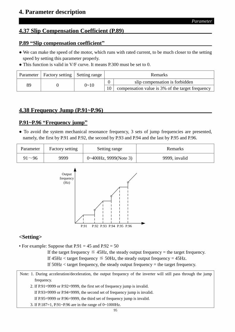
95
4. Parameter description
Parameter
4.37 Slip Compensation Coefficient (P.89)
P.89 “Slip compensation coefficient”
● We can make the speed of the motor, which runs with rated current, to be much closer to the setting
speed by setting this parameter properly.
● This function is valid in V/F curve. It means P.300 must be set to 0.
Parameter Factory setting Setting range Remarks
89 0 0~10 0 slip compensation is forbidden
10 compensation value is 3% of the target frequency
4.38 Frequency Jump (P.91~P.96)
P.91~P.96 “Frequency jump”
● To avoid the system mechanical resonance frequency, 3 sets of jump frequencies are presented,
namely, the first by P.91 and P.92, the second by P.93 and P.94 and the last by P.95 and P.96.
Parameter Factory setting Setting range Remarks
91~96 9999 0~400Hz, 9999(Note 3) 9999, invalid
P.91 P.92 P.93 P.94 P.95 P.96
Output
frequency
(Hz)
<Setting>
• For example: Suppose that P.91 = 45 and P.92 = 50
If the target frequency ≦ 45Hz, the steady output frequency = the target frequency.
If 45Hz < target frequency ≦ 50Hz, the steady output frequency = 45Hz.
If 50Hz < target frequency, the steady output frequency = the target frequency.
Note: 1. During acceleration/deceleration, the output frequency of the inverter will still pass through the jump
frequency.
2. If P.91=9999 or P.92=9999, the first set of frequency jump is invalid.
If P.93=9999 or P.94=9999, the second set of frequency jump is invalid.
If P.95=9999 or P.96=9999, the third set of frequency jump is invalid.
3. If P.187=1, P.91~P.96 are in the range of 0~1000Hz.

96
4. Parameter description
Parameter
4.39 Programmed Operation Mode (P.100~P.108, P.111~P.118, P.121~P.123,
P.131~P.138)
P.100 “Minute/second selection”
P.101~P.108 “Runtime of each section”
P.111~P.118 “Acceleration/deceleration time of each section”
P.121 “Run direction in each section”
P.122 “Cycle selection”
P.123 “Acceleration/deceleration time setting selection”
P.131~P.138 “Frequency of each section”
Related parameters
P.80~P.84, P.86
“Multi-function terminals selection”
P.8 “Deceleration time”P.7 “Acceleration time”
P.21 “Acceleration/deceleration
time increments”
Parameter Factory setting Setting range Remarks
100 1 0, 1
0 The running time minimum increment is 1
minute.
1 The running time minimum increment is 1
second.
101~108 0s 0~6000s ---
111~118 0s 0~600s When P.21=0
0~6000s When P.21=1
121 0 0~225 0: cycle function invalid;
1~8: run circularly
122 0 0~8 ---
123 0 0, 1 ---
131~138 0 Hz 0~400Hz (Note 4) ---
<Setting>
1. Programmed operation mode
• The calculation method of runtime and acceleration/deceleration time in each section is in the figure
below:

97
4. Parameter description
Parameter
frequency
Ru
n f
orw
ard
Ru
n r
ever
seP.111
P.101
P.112 P.113 P.114
P.115
P.102 pause P.103 P.104
P.116
P.105 P.106
P.117
P.107
P.118
P.108
P.118
• The run direction is set in binary form (8-bit), then translated to decimal form and stored in P.121.
‘1’ means run forward, and ‘0’ means run reverse. The highest bit is the run direction of section 8,
and the lowest bit is the direction of section 1.
For example: Suppose that section 1: run forward, section 2: run reverse, section 3: run reverse,
section 4: run forward, section 5: run reverse, section 6: run forward, section 7: run
forward, section 8: run reverse, than the value in binary form is 01101001:
P.121=0×27+1×26+1×25+0×24+1×23+0×22+0×21+1×20=105
• When P.122=0, it won’t run circularly.
• When the value of P.122 is 1~8, it is the initialization section of the cycle running.
For example: When P.122=3, the inverter will run circularly from the third section to the eighth
section after it finishes its running from the first section to the eighth section.
When P.123=0, the acceleration time is determined by P.7, and the deceleration time is
determined by P.8.
When P.123=1, the acceleration time and deceleration time are both determined by
P.111~P.118.
2. Manually operation circle mode
RL
INV
SD
Manually operation circle mode terminals wiring pattern
• Between RL and SD, connect an impulse type switch.
• After power on, setting P.80=35 according to the terminals wiring, in this time, inverter is standby.
• The mode of operation is in the figure below:

98
4. Parameter description
Parameter
frequency
RLON ON ON ON ON ON ON ON
……
P.131
P.132
P.133
P.134
P.135
P.131
P.132
0
Note: 1. The inverter will run the most 8 section, the frequency is determined by P.131~P.138
2. When the frequency is setting, if any section is 0, the inverter will run standby in this section. It means
that in this mode the value of P.131 is not 0. Like the figure above, no matter how value of P.137 and
P.138, when the press the switch sixth, the inverter will stop.
3. Manually operation circle mode has a single rotation direction. It has nothing to do with P.121 and STF or
STR signal.
4. If P.187=1, P.131~P.138 are in the range of 0~1000Hz.
4.40 Operation Panel Monitoring Selection (P.110)
P.110 “Operation panel monitoring selection”
Parameter Factory
setting
Setting
range Remarks
110 0 0, 1, 2
0
When the inverter starts, the operation panel enters the
monitoring mode automatically, and the screen displays
the output frequency.
1 When the inverter starts, the screen of the operation
panel displays the target frequency.
2
When the inverter starts, the operation panel enters the
monitoring mode automatically, and the screen displays
the output frequency steady.
4.41 Expansion Board Function (P.125~P.130)
P.125 “Expansion board type”
P.126 “I/0 expansion board input terminal M3 function selection”
P.127 “I/0 expansion board input terminal M4 function selection”
P.128 “I/0 expansion board input terminal M5 function selection”
P.129 “I/0 expansion board output relay1 function selection”
P.130 “I/0 expansion board output relay2 function selection”

99
4. Parameter description
Parameter
Parameter Factory setting Setting range Remarks
125 0 (Note) ---
126 9999 0~39, 9999
0~39
The function is the same with
‘multi-function control terminal’. For
detailed description, please refer to
P.80~P.84, P.86. 127 9999 0~39, 9999
128 9999 0~39, 9999 9999 Function invalid
129 9999 0~10, 9999 0~10
The function is the same with
multi-function output relay (ABC). For
detailed description, please refer to P.85.
130 9999 0~10, 9999 9999 Function invalid
Note: 1. The value of P.125 indicates the type of the expansion board. 0: communication expansion board(include
SE-CB01、SE-CB02、SE-CB03), 1: I/O expansion board (SE-EB01), 2: current source expansion board
(SE-IB01), 4. Profibus expansion board (SE-PD01), 6. DeviceNet expansion board (SE-DN01), 7: No
expansion board. When there is any expansion board is connected to the main machine, the inverter will
detect what kind of expansion board it is. If the first detection result is different from the next one; or they
are the same, but not the three types referred, an alarm will be output, and the screen will display . If
no expansion board is detected, the corresponding parameters are forbidden to read or write, but they are
restored to the default values when we read out P.998 or P.999 and rewrite in them.
2. On the details of the expansion board, refer to optional accessories of Appendix 5.
4.42 Zero-speed Function (P.151~P.152)
P.151 “Zero-speed control function selection”
P.152 “Voltage instruction at zero-speed control”
Related parameters
P.13“Starting frequency”
●You must set the value of P13 is zero, when you use to this function.
Parameter Factory setting Setting range Remarks
151 0 0~1 0 There are no output when zero-speed
1 Control by DC (Note 1)
152 5% 0~30% (Note 2)
Note: 1.The output mode selected by the value of P.151, when P.151 is 0 then there is no output, when P.151 is 1
then the value of P152 which is voltage output dc voltage as keep torque.
2. Suppose that P.152=6%, then the output voltage is P.19*6% when zero-speed.
3. This function is valid in V/F curve. It means P.300 must be set to 0.

100
4. Parameter description
Parameter
4.43 Over Torque Detection (P.155~P.156)
P.155 “Over torque detection level”
P.156 “Over torque detection time”
Related parameters
P.40 “Multi-function output
terminal pattern”
P.85 “Function selection for
multi-function relay”
● When the value of P.155 is not 0, the function of over torque detection is selection.
● When the output current is in excess of over torque detection level P.155 and over torque detection
time P.156, the display screen of the inverter will display and the motor stop.
Parameter Factory setting Setting range Remarks
155 0% 0~200%
0 No detection of over torque
0.1~200% When over torque detection, alarm
is display and the motor stop
156 1s 0~60s ---
100%
P.155
output
P.156
OL
Reset signal
Output current (%)
Invertor display the OL2 alarm,and the output
stopped,the motor stopped too.
(Overload alarm)
full load current level
time
4.44 External Terminals Filter Adjusting Function (P.157)
P.157 “External terminals filter adjusting function”
Parameter Factory setting Setting range
157 4ms 0~200ms
• P.157 select response time to the signal of external terminal.
101
4. Parameter description
Parameter
4.45 External Terminal Power Enable Function (P.158)
P.158 “External terminal power enable”
Parameter Factory setting Setting range
158 0 0~1
• If P.158=1, select the external terminal power enable function. At this situation, if the
multi-function terminal function is STF, STR, RUN or MPO witch have been set, and opposite
terminal is connected before the power on, the inverter will not run, you should connect the
terminal again, the inverter will start running. If P.158=1 the terminal connected before the power
on, if power on the inverter running immediately.
4.46 Energy-saving Control Function(P.159)
P.159 “Energy-saving control function”
Parameter Factory setting Setting range Remarks
159 0 0 Normal running mode
1 energy-saving running mode
● In the energy-saving running mode, the inverter will control the output voltage automatically in
order to reduce the output power losses when the inverter is running.
Note: 1.After select the energy-saving running mode, the deceleration time is longer than the setting value
probability. Also the regular torque load property will produce abnormal voltage easily, please setting the
deceleration time longer.
2. This function is valid in V/F curve. It means P.300 must be set to 0.
3. Big load purposes or frequent deceleration machine, saving energy effect may not too good.
4.47 Multi-function Display (P.161)
P.161 “Multi-function display selection”
Parameter Factory
setting
Setting
range Remarks
161 0 0~5
0 When in ‘monitoring output voltage’ mode, the screen will
display the current output voltage value.
1 When in ‘monitoring output voltage’ mode, the screen will
display the current voltage between P and N.
2
When in ‘monitoring output voltage’ mode, the screen will
display operating condition , and
3 When in ‘monitoring output voltage’ mode, the screen will
display the value of the input signal across terminal 2-5 (V).

102
4. Parameter description
Parameter
Parameter Factory
setting
Setting
range Remarks
160 0 0~5
4
When in ‘monitoring output voltage’ mode, the screen will
display the value of the input signal across terminal 4-5
(mA/V).
5 When in ‘monitoring output voltage’ mode, the screen will
display the current thermal accumulating record for inverter.
4.48 PID Control (P.170~P.183)
P.170 “PID function selection”
P.172 “PID proportion Gain ”
P.171 “PID feedback control method
selection”
P.173 “PID integration Gain ” P.174 “PID differential Gain”
P.175 “Abnormal deviation level” P.176 “Exception duration time”
P.177 “Exception handling mode” P.178 “Sleep detects deviation”
P.179 “ Sleep detects duration time” P.180 “Revival level”
P.181 “Outage level” P.182 “Integral upper limit frequency”
P.183 “Deceleration step length with stable pressure”
● During the operation of PID control, the frequency displayed on the screen is the output frequency
of the inverter.
● The function of Stall Prevention operates according to the setting frequency before PID control.
Please pay attention to the Gain setting during the process of PID Gain setting in case that the
output current can not be limited absolutely.
● Under PID control, the output frequency is also limited between maximum frequency and
minimum frequency.
● Please refer to the instructions of P.60 about the input signal filter on terminal 4-5 and terminal 2-5.
● The sketch map of PID function is as follows:
sT : Sampling period=10ms
Parameter Factory setting Setting range Remarks
170 0 0, 1, 2
0 When P.170 = 0, PID is forbidden
1 When P.170 = 1, the feedback value is set
by voltage which is from terminal 2-5
2 When P.170 = 2, the feedback value is set
by current which is from terminal 4-5
171 100% 0~1000% ---

103
4. Parameter description
Parameter
Parameter Factory setting Setting range Remarks
172 20 1~100
This gain determines the proportion controller’s
impact on feedback deviation. The greater the
gain, the faster the impact. Yet a gain that is too
big will cause vibration.
173 1s 0~100s
This parameter is use to set integral controller’s
integral time. When the integral gain is too big,
the integral effect will be too weak to eliminate
steady deviation. When the integral gain is too
small, the system vibration frequency will
increase, and therefore the system may be
unstable.
174 0 ms 0~1000ms
This gain determines deviation controller’s
impact on the amount of change of the deviation.
Appropriate deviation time can reduce the
overshooting between the proportion controller
and the integral controller. Yet when the
deviation time is too large, system vibration may
be induced.
175 70% 0~100% ---
176 0s 0~600s ---
177 0 0, 1 0 Coast stop
1 Deceleration stop
178 0 0~100% ---
179 10s 0~255s ---
180 90% 0~100% ---
181 40Hz 0~120Hz
(Note) ---
182
50Hz 0~120Hz
(Note)
P.189=1 When the deviation value
accumulated with the integral time,
an upper limit for deviation
accumulation should be set. 60Hz P.189=0
183 0.5Hz 0~10Hz (Note) ---
contravariance
convertor
Output frequency
54
IM
U/T1
V/T3
W/T2
feedback quantity
R/L1
S/L2
+
-
Set frequency
KI= P. 173
KP = P. 172
KD=P. 174
+
+
+ limit
P.182
PID module
e(t)
Feedback value
P. 171
2
filter
T/L3

104
4. Parameter description
Parameter
● When the feedback value is lower than exceptional deviation level and continues for exceptional
continuance time P.176, the PID is exceptional. At this time the screen will display , and it
will select freedom or brakes according to P.177.
For example: when P.175=60%, P.176=30s, P.177=0, when the feedback value is lower than 60%
of the target feedback value and continues for 30s, the screen will display , and
the inverter will select freedom stop.
the target
feel-back
value
the feel-back
value
Maximum frequency
P.176
0HZ
• If P.178=0, the value of P.179, P.180 and P.181 is invalid. If the value of P.178 is not 0, the PID
sleep function is selected. When absolute value which the feedback value minus the target feedback
value is lower than sleep detect deviation and continues for sleep detect time P.179, the inverter will
minish the output frequency gradually, when the output frequency is lower than outage level P.181,
the inverter will brakes stop. When the feedback value is lower than revival level P.180, the output
frequency of inverter will be controled by PID again.
For example: P.178=5%, P.179= 30s, P.180=90%, P.181=40Hz.
When the feedback value is larger than 95% of the target feedback value and is lower
than 105% of the target feedback value, the inverter will minish the output frequency
gradually after 10s. When the output frequency is lower than 40Hz, the inverter will
brakes stop derictly. When the feedback value is lower than 90% of the target
feedback value, the inverter will revive, and the output frequency of inverter will be
controlled by PID again.
the target feel-back value
Revival level
below
P.179
P.179feedback
actually
Output
frequency
Outage
level
0HZ
Revival
processOutage
proccess
Minishing the output
frequency gradually

105
4. Parameter description
Parameter
<Setting>
• PID gain easy setting:
(1)After changing target, response is slow ---Increase P-gain (KP =P.172)
response is quick but unstable ---Decrease P-gain (KP =P.172)
When KP is too small When KP is too large When KP is appropriate
(2)Target and feedback
do not become equal ---Decrease Integration time (KI =P.173)
become equal after unstable vibration ---Increase Integration time (KI =P.173)
When KI is appropriateWhen KI is too shortWhen KI is too long
(3)Even after increasing KP, response is still slow ---Increase D-gain (KD =P.174)
It is still unstable ---Decrease D-gain (KD =P.174)
Note: If P.187=1, P.181 and P.182 are in the range of 0~1000Hz, P.183 is in the range of 0~100Hz.
4.49 4-5 Terminal Disconnection Handling (P.184)
P.184 “4-5 terminal disconnection handling”
Parameter Factory setting Setting range Remarks
184 0 0~3 ---
<Setting>
• When P.184 = 0, this function is useless, if the terminal 4-5 is disconnected, the inverter will slow
down to 0Hz.
• When P.184 =1, if the terminal 4-5 is disconnected, the keyboard panel should be shown “AErr”,
the inverter will slow down to 0Hz. If connected the terminal 4-5 again, the alarm code will disappear, the
inverter will be accelerated to the current corresponding to the frequency.
• When P.184 = 2, if the terminal 4-5 is disconnected, the keyboard panel should be shown “AErr”,
the inverter Immediately stop and needs to be reset.
• When P.184 = 3, if the terminal 4-5 is disconnected, the keyboard panel should be shown “AErr”,
the frequency which is before disconnect of the inverter is continuing operation, reconnect the line, the alarm
disappears.
Note: When P.17=1, the terminal 4-5 is setting by current 4-5, this function will be useless.
106
4. Parameter description
Parameter
4.50 Ultra-high-speed Operation Function (P.187)
P.187 “Ultra-high-speed operation function selection”
Parameter Factory setting Setting range Remarks
187 0 0, 1
0 Frequency-dependent parameters set the
minimum unit of 0.01Hz.
1 Frequency-dependent parameters set the
minimum unit of 0.1Hz.
• A detailed explanation for P.187, please refer to Appendix 6, ultra-high-speed operation parameters
for frequency.
4.51 Firmware version (P.188)
P.188 “Firmware version”
● Parameter is not writable and only readable.
4.52 Factory Setting Function (P.189)
P.189 “Factory setting function”
Parameter Factory setting Setting range Remarks
189 1 0, 1 0 Apply to the 60Hz system
1 Apply to the 50Hz system
● The user can select the frequency witch factory setting is 50Hz or 60Hz according to the different
power frequency and the frequency witch motor factory setting. Correlation parameter directions
are in the chart below:
Parameter Name Setting range Minimum
setting unit
P.3 Base frequency 0~400Hz 0.01Hz
P.20 Acceleration/deceleration reference frequency 1~400Hz 0.01Hz
P.38 The maximum output frequency(the target frequency is
set by the input signal across terminal 2-5/panel knob) 1~400Hz 0.01Hz
P.39 The maximum output frequency(the target frequency is
set by the input signal across terminal 4-5) 1~400Hz 0.01Hz
P.55 Frequency display reference 0~400Hz 0.01Hz
P.66 Stall prevention operation reduction starting frequency 0~400Hz 0.01Hz
P.182 Integral upper limit frequency 0~120Hz 0.01Hz
P.195 Frequency corresponds to the maximum input voltage
across the terminal 2-5. 0~400Hz 0.01Hz
P.197 Frequency corresponds to the maximum input
voltage/current across the terminal 4-5. 0~400Hz 0.01Hz
P.305 Motor rated frequency 0~400Hz 0.01Hz

107
4. Parameter description
Parameter
Note: 1. If the customer have some problem in adjusting the factory setting which in the chart above, deceleration
time , output voltage, voltage signal and setting frequency will be affected probability
2. If the customer need to adjustment the factory setting to 60Hz, the step is below:
(1). Setting P.189=0;
(2).Setting P.998 to resume the factory setting (This time, the factory setting of interrelated parameter is
60Hz, P.189=0) Please refer to P.998 in section 4.
3. If the customers need to resume the 50Hz system, you should set P.189=1, then implement the step 2 in
Note 2 (this time, the factory setting of P.189 is 1).
4. The minimum setting value, you can select P.187 to set. When P.187=1, the minimum setting value of the
above parameters are 0.01Hz. When P.187=0, the minimum setting value of the above parameters are
0.1Hz.
4.53 Input Signal across Terminal 2-5 (P.192~P.195)
P.192“2-5 terminal minimum input voltage”
P.193“2-5 terminal maximum input voltage”
P.194“Frequency corresponds to the minimum input voltage of terminal 2-5”
P.195“Frequency corresponds to the maximum input voltage of terminal 2-5”
Related parameters
P. 73 “Voltage signal selection”P.80~P.84, P.86
“Multi-function terminals selection”P. 189 “Factory setting function”
Parameter Factory setting Setting range Remarks
192 0 0~10 ---
193 0 0~10 ---
194 0 Hz 0~60Hz(Note4) ---
195 50Hz
0~400Hz(Note 4) P.189=1
60Hz P.189=0
<Setting>
• Emendation steps:
1. Make sure that the voltage signal is correctly put in.
2. Assume that ‘the input voltage equals Value A, and the expected output frequency is 20Hz. Then
adjust the signal to Value A, and write 20 into P.194, also Value A will be write into P.192.
3. Assume that the input voltage equals Value B, and the expected output frequency is 60Hz. Then
adjust the signal to Value B, and write 60 into P.195, also Value B will be write into P.193.
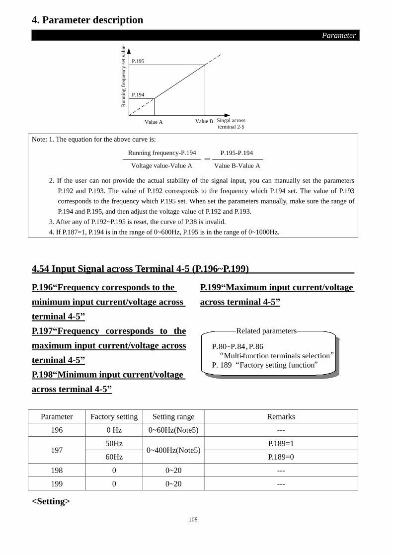
108
4. Parameter description
Parameter
P.195
P.194
Value A Value B Singal across
terminal 2-5R
unnin
g f
requen
cy s
et v
alue
Note: 1. The equation for the above curve is:
Running frequency-P.194
Voltage value-Value A
P.195-P.194
Value B-Value A=
2. If the user can not provide the actual stability of the signal input, you can manually set the parameters
P.192 and P.193. The value of P.192 corresponds to the frequency which P.194 set. The value of P.193
corresponds to the frequency which P.195 set. When set the parameters manually, make sure the range of
P.194 and P.195, and then adjust the voltage value of P.192 and P.193.
3. After any of P.192~P.195 is reset, the curve of P.38 is invalid.
4. If P.187=1, P.194 is in the range of 0~600Hz, P.195 is in the range of 0~1000Hz.
4.54 Input Signal across Terminal 4-5 (P.196~P.199)
P.196“Frequency corresponds to the
minimum input current/voltage across
terminal 4-5”
P.197“Frequency corresponds to the
maximum input current/voltage across
terminal 4-5”
P.198“Minimum input current/voltage
across terminal 4-5”
P.199“Maximum input current/voltage
across terminal 4-5”
Related parameters
P.80~P.84, P.86
“Multi-function terminals selection”P. 189 “Factory setting function”
Parameter Factory setting Setting range Remarks
196 0 Hz 0~60Hz(Note5) ---
197 50Hz
0~400Hz(Note5) P.189=1
60Hz P.189=0
198 0 0~20 ---
199 0 0~20 ---
<Setting>

109
4. Parameter description
Parameter
• Emendation steps:
1. Make sure that the current signal is correctly put in.
2. Assume that the input current equals Value A, and the expected output frequency is 20Hz. Then
adjust the signal to Value A, and write 20 into P.196, also Value A will be write into P.198.
3. Assume that the input current equals Value B, and the expected output frequency is 60Hz.Then
adjust the signal to Value B, and write 60 into P.197, also Value B will be write into P.199.
P.197
P.196
Value A Value B Signal across
terminal 4-5
Ru
nn
ing
fre
qu
en
cy
set
valu
e
Note: 1. The equation for the above figure is:
Running frequency-P.196
Current value-Value A
P.197-P.196
Value B-Value A=
2. If the user can not provide the actual stability of the signal input, you can manually set the parameters
P.198 and P.199. The value of P.198 corresponds to the frequency which P.196 set. The value of P.199
corresponds to the frequency which P.197 set. When set the parameters manually, make sure the range of
P.196 and P.197, and then adjust the voltage value of P.198 and P.199.
3. After any of P.196~P.197 is reset, the curve of P.39 is invalid.
4. Select the Input signal across terminal 4-5, please refer to P.17.
5. If P.187=1, P.196 is in the range of 0~600Hz, P.197 is in the range of 0~1000Hz.
4.55 Backlash Compensation Function (P.229~P.233)
P.229 “Backlash compensation function selection”
P.230 “The backlash compensation acceleration interrupt frequency”
P.231 “The backlash compensation acceleration interrupt time”
P.232 “The backlash compensation deceleration interrupt frequency”
P.233 “The backlash compensation deceleration interrupt time”
Parameter Factory setting Setting range Remarks
229 0 0~1 ---
230 1Hz 0~400Hz(Note3) ---
231 0.5s 0~360s ---
232 1Hz 0~400Hz(Note3) ---
233 0.5s 0~360s ---
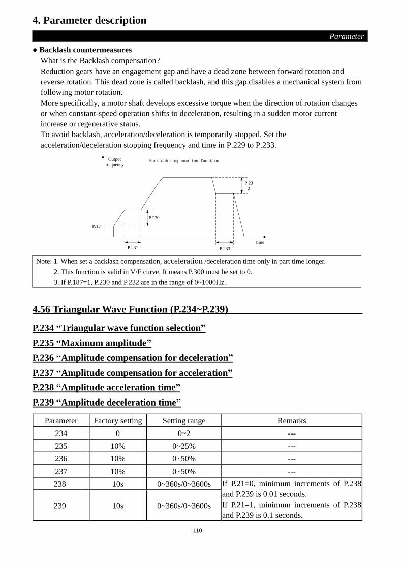
110
4. Parameter description
Parameter
● Backlash countermeasures
What is the Backlash compensation?
Reduction gears have an engagement gap and have a dead zone between forward rotation and
reverse rotation. This dead zone is called backlash, and this gap disables a mechanical system from
following motor rotation.
More specifically, a motor shaft develops excessive torque when the direction of rotation changes
or when constant-speed operation shifts to deceleration, resulting in a sudden motor current
increase or regenerative status.
To avoid backlash, acceleration/deceleration is temporarily stopped. Set the
acceleration/deceleration stopping frequency and time in P.229 to P.233.
Backlash compensation functionOutpot
frequency
P.13
P.231
P.230
P.23
2
P.233
time
Note: 1. When set a backlash compensation, acceleration /deceleration time only in part time longer.
2. This function is valid in V/F curve. It means P.300 must be set to 0.
3. If P.187=1, P.230 and P.232 are in the range of 0~1000Hz.
4.56 Triangular Wave Function (P.234~P.239)
P.234 “Triangular wave function selection”
P.235 “Maximum amplitude”
P.236 “Amplitude compensation for deceleration”
P.237 “Amplitude compensation for acceleration”
P.238 “Amplitude acceleration time”
P.239 “Amplitude deceleration time”
Parameter Factory setting Setting range Remarks
234 0 0~2 ---
235 10% 0~25% ---
236 10% 0~50% ---
237 10% 0~50% ---
238 10s 0~360s/0~3600s If P.21=0, minimum increments of P.238
and P.239 is 0.01 seconds.
If P.21=1, minimum increments of P.238
and P.239 is 0.1 seconds. 239 10s 0~360s/0~3600s

111
4. Parameter description
Parameter
<Setting>
• If the value of parameter P.234 is 1, and the signal is on, the triangular wave function is effective.
Please set 36 to any parameter: P.80 ~P.84, P.86, P.126~P.128, corresponding external terminal
assigned for TRI signal.
• If the value of parameter is 2, it means the triangular wave function is effective in anytime.
f0
f1
f1
f2
f3
triangular wave
operation
STF
TRI
time
P.239 P.238P.7
P.7
P.8
f0﹕Setting value of frequencyf1﹕Generated amplitude for
setting frequency (f0×P.235)f2﹕Compensation from acceleration
to deceleration (f1×P.236)f3﹕Compensation from deceleration
to acceleration (f1×P.237)
Output frequency
Note: 1.The output frequency will be limited by the maximum frequency and minimum frequency when the
triangular wave function is effective.
2. If the amplitude compensation (P.236 or P.237) is too larger, over-voltage trip and stall prevention
operation will automatically run, thus the inverter can not run according to the triangular wave function.
3. This function is valid in V/F curve. It means P.300 must be set to 0.
4.57 Auxiliary Frequency Function (P.240)
P.240 “Auxiliary frequency function selection”
Parameter Factory setting Setting range Remarks
240 0 0~4 ---
<Setting>
• When the value of P.240 is 0, auxiliary frequency function is not selected.
• When the value of P.240 is 1, operation frequency = basic frequency + auxiliary frequency (2-5),
• When the value of P.240 is 2, operation frequency = basic frequency + auxiliary frequency (4-5),
• When the value of P.240 is 3, operation frequency = basic frequency - auxiliary frequency (2-5),
• When the value of P.240 is 4, operation frequency = basic frequency - auxiliary frequency (4-5),
• When the operation frequency is less than P.2, the operation frequency should equal to P.2. When
the operation frequency is more than P.1, the operation frequency should equal to P.1.
Note: Basic frequency is set by the target frequency reference source DU03B, communications or combination of
multi-speed gears, or by 2-5、4-5 terminal.

112
4. Parameter description
Parameter
4.58 DC Injection Brake Function before Starting (P.242~P.244)
P.242 “DC injection brake function before starting selection”
P.243 “DC injection brake time before starting”
P.244 “DC injection brake voltage before starting”
Related parameters
P.13“Starting frequency”
Parameter Factory setting Setting range Remarks
242 0 0~1 ---
243 0.5s 0~60s ---
244 4% 0~30% ---
<Setting>
• If P.242=0, the DC injection brake function before starting is not selected. If P.242=1, the DC brake
injection function before starting is selected. When the output frequency reached the starting
frequency (P.13), a DC voltage (P.244) will be injected into the motor windings by the inverter,
which is used to lock the motor rotor. The DC brake operation will last a period (the set value of
P.243), the motor will start.
As shown as follows:
time
timeP.243
P.13
P.244
Output
frequency
DC injection
brake voltage
Note: This function is valid in V/F curve. It means P.300 must be set to 0.
4.59 Bypass-inverter Switchover Function (P.247~P.250)
P.247 “MC switchover interlock time”
P.248 “Start waiting time”
P.249 “Automatic switchover frequency from inverter to commercial power
supply frequency”
P.250 “Automatic switchover frequency range from commercial power supply to
inverter”

113
4. Parameter description
Parameter
Parameter Factory setting Setting range Remarks
247 1s 0.1~100s ---
248 0.5 s 0.1~100 s ---
249 9999 0~60Hz, 9999 (Note 4) ---
250 9999 0~10Hz, 9999 (Note 4) ---
<Setting>
• Set the frequency to switch inverter operation to bypass operation. Inverter operation is performed
from a start until P.249 is reached, and when the output frequency is at or above P.249, inverter
operation is automatically switched to bypass operation. If set 9999 to P.249, without automatic
switchover.
• If the value of P.250 is not 9999, valid during automatic switchover operation (P.249≠9999). When
the frequency command decreases below (P.249 - P.250) after operation is switched from inverter
operation to bypass operation. The inverter automatically switches operation to inverter operation
and operates at the frequency of frequency command. When the inverter start command (STF/STR)
is turned off, operation is switched to inverter operation also.
• If the value of P.250 is 9999, valid during automatic switchover operation (P.249≠9999).When the
inverter start command (STF/STR) is turned off after operation is switched from inverter operation
to bypass operation, operation is switched to inverter operation and the motor decelerates to stop.
The wiring diagram:
The following is the representative wring diagram of switching the commercial power-supply
operation. P.80 = 37, P.81 = 38, P.40 = 10, P.85 = 9.
NFB
R/L1
S/L2
T/L3
M
MC1
MC2
MC1
DC24V
STF
M1
M0
SD
SO
SE
K1
K3
K2
10
5
2
U/T1
V/T2
W/T3
MC2
DC24V
A
B
C
Please pay attention to the capacity of the output terminals. The terminals which used are according
to different settings for P.40 and P.85 (output terminal function selection).When the output terminal
function selection is 10, connect the relay which drives the commercial power-supply operation.
When the output terminal function selection is 9, connect the relay which drives the inverter
operation. When the external input terminal function selection is 37, select the switching inverter to
commercial power-supply operation. When the external input terminal function select 38, hand
switching signal CS.

114
4. Parameter description
Parameter
Warning:
1. MC1 and MC2 must be mechanical interlock, the running direction of the inverter operation
and the commercial power-supply operation should be consistent.
2. Bypass-inverter switchover function is effective in external mode.
3. So long as the signal “CS” is on, STF or STR is available.
Sequence diagram of switching the commercial power-supply:
1. Action which has not automatic switching in order.
MRS
STF
CS
MC2
MC1
P.247 P.247
P.248
P.57
P.58
Power supply
Inverter
operation
Free
operation
the commercial
power-supply
operation
stop
The motor speed
Free
operation
Inverter
operation
2. Action which has automatic switching in order (P.249≠9999, P.250=9999).
time
A A B C D
time
MC2
MC1
STF
P.249Setting
frequency
Output
frequency
Actual
motor speed
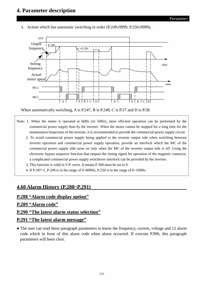
115
4. Parameter description
Parameter
3. Action which has automatic switching in order (P.249≠9999, P.250≠9999).
STF
time
A A B C D A A B C D
time
P.249
P.250
MC2
MC1
Setting
frequency
Output
frequency
Actual
motor speed
When automatically switching, A is P.247, B is P.248, C is P.57 and D is P.58.
Note: 1. When the motor is operated at 60Hz (or 50Hz), more efficient operation can be performed by the
commercial power supply than by the inverter. When the motor cannot be stopped for a long time for the
maintenance/inspection of the inverter, it is recommended to provide the commercial power supply circuit.
2. To avoid commercial power supply being applied to the inverter output side when switching between
inverter operation and commercial power supply operation, provide an interlock which the MC of the
commercial power supply side turns on only when the MC of the inverter output side is off. Using the
electronic bypass sequence function that outputs the timing signal for operation of the magnetic contactor,
a complicated commercial power supply switchover interlock can be provided by the inverter.
3. This function is valid in V/F curve. It means P.300 must be set to 0.
4. If P.187=1, P.249 is in the range of 0~600Hz, P.250 is in the range of 0~100Hz.
4.60 Alarm History (P.288~P.291)
P.288 “Alarm code display option”
P.289 “Alarm code”
P.290 “The latest alarm status selection”
P.291 “The latest alarm message”
● The user can read these paragraph parameters to know the frequency, current, voltage and 12 alarm
code which in front of this alarm code when alarm occurred. If execute P.996, this paragraph
parameters will been clear.

116
4. Parameter description
Parameter
Parameter Factory setting Setting range Remarks
288 0 0~12 1~12 are the value of P.288 which are
corresponding to abnormal number of alarm code
E1~E12 the P.289 display. 289 0 ---
290 0 0~5
If P.290=1, P.291 correspond to display frequency
for the latest alarm occurred.
If P.290=2, P.291 correspond to display current for
the latest alarm occurred.
If P.290=3, P.291 correspond to display output
voltage for the latest alarm occurred.
If P.290=4, P.291 correspond to display the
accumulation rate of temperature for the latest
alarm occurred.
If P.290=5, P.291*100 correspond to display busbar
voltage for the latest alarm occurred.
291 0 ---
If the value of P.288 and P.290 are 0, P.289 and P.291will display 0 too.
The abnormal number of the alarm code:
Abnormal
number Alarm code
Abnormal
number Alarm code
Abnormal
number Alarm code
Abnormal
number Alarm code
00 (H00) No alarm 33 (H21) OV2 64 (H40) EEP 144 (H90) OHT
16 (H10) OC1 34 (H22) OV3 66 (H42) PIDE 160 (HA0) OPT
17 (H11) OC2 35 (H23) OV0 97 (H61) OLS 192 (HC0) CPU
18 (H12) OC3 48 (H30) THT 98 (H62) OL2 193 (HC1) CPR
19 (H13) OC0 49 (H31) THN 179 (HB3) SCP 194 (HC2) EBE
32 (H20) OV1 50 (H32) NTC 129 (H81) AErr
4.61 Accumulative Motor Operation Time Function (P.292, P.293)
P.292 “Accumulative motor operation time (minutes)”
P.293 “Accumulative motor operation time (days)”
Parameter Factory setting Setting range Remarks
292 0 min 0~1439min ---
293 0 day 0~9999day ---
<Setting>
• P.292 means the minutes of accumulative motor operation, execute P.998, cut off the power,
updated value cannot change the value of P.292.Only set 0 to P.292, can clear the accumulation of
time.

117
4. Parameter description
Parameter
• P.293 means the days, execute P.998, cut off the power, updated value cannot change the value of
P.293.Only set 0 to P.293, can clear the accumulation of time.
4.62 Password Protection Function (P.294, P.295)
P.294 “Decryption parameter”
P.295 “Password setup”
Parameter Factory setting Setting range Remarks
294 0 0~9998 ---
295 0 2~9998 ---
<Setting>
• P.294 is a parameter which can decrypt, after decryption succeed, the value of P.294 is 0. When
P.295 is after setting a password-protected, P.294 enters the pre-set the password to unlock the
password-protected parameter, then the parameters can modify.
• P.295 is a parameter which can set password. The password must be larger than 1, after succeeding
to set password, the value of P.295 is 1, and after removing the password, the value of P.295 is 0. If
the password was set, the parameters would not be changed except P.294, and can’t execute P.998.
After cutting off the power, the password also exists. Only when deciphering is successful, that
parameters can be changed.
Note: If the password was forgotten, the inverter must return to factory to decipher.
4.63 Motor Control Mode (P.300, P.301)
P.300 “Motor control mode selection”
P.301 “Motor parameter auto-tuning function selection”
Parameter Factory setting Setting range Remarks
300 0 0~3
0 V/F control
1 ---
2 Facility vector control
3 Sensorless vector control
301 0 0~3
0 No motor parameter auto measurement function
1 Motor parameter auto measurement function
(Measured of the motor is running)
2 Motor parameter auto measurement function
(Measurement of the motor is not running)
3 Online auto measurement function

118
4. Parameter description
Parameter
<Setting>
• If P.300 = 0, the inverter have no motor parameter auto measurement function, to normal by V / F
control operation.
• When select the facility vector control, please setting P.300 to 2. We can use this function to
compensate the changes of the frequency when the load of the motor becomes heavier.
• If you need the motor parameter auto-tuning function, you must set P.301 to 1 or 2, then press
downFWD
orREV
. The screen of the operation panel will display “TUN” and flicker when in
measurement process. If the measurement is success, the operation panel will display “TEND” and
flicker. If the measurement is failure, the operation panel will display “FAL” and flicker. Press
downSTOP
RESET
for 1s, return to normal display.
• The step of the motor parameter auto measurement as follow: Confirm the wiring
Set motor parameters
1 、2
0
Y
N
Y
N
STOPRESET
STOPRESET
(Please refer 2.5.6 )
(P.302~P.307)
P.301
Success
Finish
Manually adjust
parameter values
FWDPress down or REV
of the operation panel
will display “TUN”
,The screen
If succeed, the operation
panel will display
“TEND” and flicker
If failure, the operation
panel will display “FAL”
and flicker
for 1s, return to normal
display.
Press down Press down
for 1s, return to normal
display.
Manual input parameters
(P.302~P.312), and then wtite
in P.997
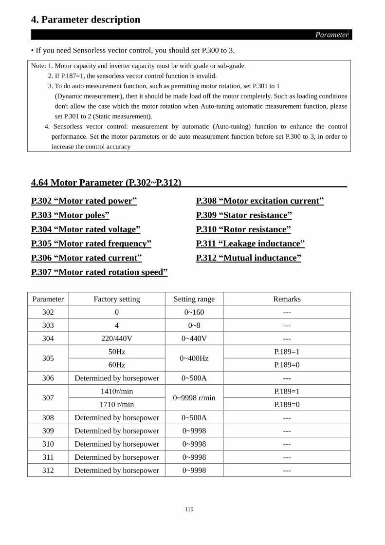
119
4. Parameter description
Parameter
• If you need Sensorless vector control, you should set P.300 to 3.
Note: 1. Motor capacity and inverter capacity must be with grade or sub-grade.
2. If P.187=1, the sensorless vector control function is invalid.
3. To do auto measurement function, such as permitting motor rotation, set P.301 to 1
(Dynamic measurement), then it should be made load off the motor completely. Such as loading conditions
don't allow the case which the motor rotation when Auto-tuning automatic measurement function, please
set P.301 to 2 (Static measurement).
4. Sensorless vector control: measurement by automatic (Auto-tuning) function to enhance the control
performance. Set the motor parameters or do auto measurement function before set P.300 to 3, in order to
increase the control accuracy
4.64 Motor Parameter (P.302~P.312)
P.302 “Motor rated power”
P.303 “Motor poles”
P.304 “Motor rated voltage”
P.305 “Motor rated frequency”
P.306 “Motor rated current”
P.307 “Motor rated rotation speed”
P.308 “Motor excitation current”
P.309 “Stator resistance”
P.310 “Rotor resistance”
P.311 “Leakage inductance”
P.312 “Mutual inductance”
Parameter Factory setting Setting range Remarks
302 0 0~160 ---
303 4 0~8 ---
304 220/440V 0~440V ---
305 50Hz
0~400Hz P.189=1
60Hz P.189=0
306 Determined by horsepower 0~500A ---
307 1410r/min
0~9998 r/min P.189=1
1710 r/min P.189=0
308 Determined by horsepower 0~500A ---
309 Determined by horsepower 0~9998 ---
310 Determined by horsepower 0~9998 ---
311 Determined by horsepower 0~9998 ---
312 Determined by horsepower 0~9998 ---

120
4. Parameter description
Parameter
<Setting>
• If the motor and load can be completely disengaged, please select P.301=1, when the motor rotation,
the motor parameters auto measurement, then press down FWD
orREV
, the inverter will automatically
calculate the following parameters: P.308~P.312.
• If the motor and load can not be fully disengaged, please select P.301=2, when the motor stopped, the
motor parameters auto measurement, then press down FWD
orREV
, the inverter will automatically
calculate the following parameters: P.308~P.312.
• Users can also calculate two parameters according to the motor nameplates. Used in the calculation
of the motor nameplate parameters: Rated voltage U, rated current I, rated frequency f and power
factor .
• Motor no-load excitation current calculation method and the motor mutual inductance are
calculated as follows, including L6 for motor leakage inductance.
No-load excitation current: 2
0 1 II
Mutual inductance: 6
032L
If
ULm
I0 is the no-load excitation current,Lm is the mutual inductance,L6 is the leakage inductance.
Note: 1. When the inverter and motor with different levels of use, please make sure the input parameters of the
motor nameplate from P.302 to P.307. The vector control mode dependent on motor parameters strongly. If
you need obtain good control performance, you must obtain the exact parameters of the controlled motor.
2. When any one or more parameters have been manually changed, please make a P.997 function, in order to
reload new parameters values.
4.65 Speed Control Gain Adjustment (P.320~P.321)
P.320 “Speed control proportion coefficient”
P.321 “Speed control integral coefficient”
Parameter Factory setting Setting range Remarks
320 100% 0~2000% ---
321 0.30s 0~20s ---
<Setting>
• P.320 set the speed control proportional gain. (The set value is set to a few bigger, for speed
changing follow instructions will become better, the speed changing caused by external disturbance
will be smaller. )

121
4. Parameter description
Parameter
• P.321 set the speed control integration time. (Because of external disturbance to speed changes, the
value will be set to be smaller, so that to reset time of the original speed is shorter.)
Note: 1. If use P.320 to improve the speed control gain, can improve the response time. But if the value is setting
too high will produce vibration and noise.
2. Reduce the speed control integral coefficient P.321, the reset time of the speed variation is shorter, but if
this value is too small, the overshoot will be produced.
4.66 Parameter Copy Function (P.994, P.995)
P.994 “Parameter copy readout”
P.995 “Parameter copy write-in”
● When set value into P.994, P.995, Motor rotation must be in a stop, this parameter value is only
valid when P.77=0 and in PU mode. When using same parameters for several inverter value setting.
Use P.994 and P.995 to perform duplication value to other inverter rapidly.
● Procedures of parameter copy:
1. When the first inverter is in PU mode, the value of P.994 is readout (the screen will
display ) and then press “Write”, at the same time the screen is flickering, it means that
the parameter copy from inverter to operation panel is in process. When no more flickering on
the screen is means the parameter copy is done.
2. When the second inverter is in PU mode, the value of P.995 is readout (the the screen
display ) and then press “write” at the same time, then the screen is flickering it means the
parameter copy from operation panel to inverter EEPROM is in process. When the screen is no
more flickering, the parameter copy is done.
* PU series operation panel need to purchase
Note: 1. Regarding parameter copy function in P.994 and P.995, it is only available on SH-PU series of Inverters.
2. When parameter copy is in process, the value of P.0 to P.390 will be copied and duplicate into Digital Unit
and inverter.
4.67 Alarm History Clear (P.996)
P.996 “Alarm history clear”
● Once P.996 is read out (after read out, the screen will display ) and rewritten in, all the
abnormal event logs are erased.

122
4. Parameter description
Parameter
4.68 Inverter Reset (P.997)
P.997 “Inverter reset”
● Once P.997 is read out (after read out, the screen will display ) and rewritten in, the
inverter is reset. Once the inverter is reset, the values of the ‘electronic thermal relay’ and the
‘IGBT module thermal relay’ will be set to zero.
4.69 Parameter Initialization (P.998, P.999)
P.998 “Restoring all parameters to default values”
P.999 “Restoring some parameters to default values”
● Once P.998 is read out (after read out, the screen will display ) and rewritten in, all
parameters except P.21, P.125, P.187, P.188, P.189, P.292, P.293 will be restored to the default
values.
● Once P.999 is read out (after read out, the screen will display ) and rewritten in, all
parameters except P.21, P.125, P.187, P.188, P.189, P.192, P.194~P.197, P.292, P.293, P.300~P.312
will be restored to the default values.
● Please make sure that do not carry out any other operations before the screen displays ,
which indicates that the corresponding parameters has been restored to the default values.

123
5. Inspection and Maintenance
Inspection and Maintenance
In order to avoid the malfunction and security problems resulting from aging of the devices which is
caused by environmental factors such as temperature, oil fog, dust, vibration, humidity and etc.,
‘daily inspection’ and ‘periodical inspection’ are necessary.
Note: Only fully-qualified electrical professional personnel can carry out installation, wiring, dismounting and
maintenance.
5.1 Daily inspection
1. Check whether the surrounding conditions are normal (including temperature, humidity, dust
density and etc.) at the installment place.
2. Check whether the power supply voltage is normal (the voltages among R/L1, S/L2 and T/L3).
3. Check whether wiring is ok (whether the external wiring for the main-circuit board and the
control-board terminal is loose).
4. Check whether the cooling system is abnormal (Whether there’s any abnormal acoustic noise
when operating. whether the wiring is ok.).
5. Check the indicating lamp (Whether the control-board indicating LED lamp, the operation panel
indicating LED lamp and the operation panel screen LED are normal).
6. Check whether the expected performance is maintained.
7. Check whether there’s any abnormal vibration, acoustic noise or smell during running.
8. Check whether there is liquid leaking from the filter capacitors.
5.2 Periodical inspection (during stop)
1. Check the connector and wiring (whether the connector and wiring between the main-circuit
board and control board is ok).
2. Check whether components on the main-circuit board and the control board are overheated.
3. Check whether the electrolytic capacitors on the main-circuit board and control board have liquid
leaking out.
4. Check the IGBT module on the main-circuit board.
5. Clean the dust and contaminants on the circuit board.
6. Check the insulation resistor.
7. Check whether the cooling system is abnormal (Whether the wiring is firm; clean the air filter,
etc).
8. Check screws and belts.
9. Check the external wires and the terminal banks for damage.
5.3 Regular replacement of parts (components)
Items
The corresponding
period for
replacement
Description
Cooling fan 2 years
For the axle of a fan, the standard lifetime is about 10~35
thousand hours. With reference to the time of 24 hours one day,
it is sure that the fan should be replaced every 2 years.

124
5. Inspection and Maintenance
Inspection and Maintenance
Items
The corresponding
period for
replacement
Description
Filter
capacitor 5 years
The filter capacitor is an electrolytic capacitor, and will
deteriorate with time. The deterioration speed is contingent on
the ambient conditions. Generally, it shall be replaced every 5
years.
Relay --- If bad contact occurs, please replace it immediately.
Note: Please send the inverters to the factory when replacement of the parts is necessary.
5.4 Inverter insulation resistance measurement
1. Before measurement, first dismount the ‘wiring of the main-circuit
terminals’ and the ‘control board’. Then execute wiring in the way of
the right picture.
2. The measurement is only suitable for the main circuit. Such
measurement is prohibited for control board terminals.
3. The value of the insulation resistance shall be
greater than 5MΩ.
Note: Please do not carry out a high-voltage test, because the built-in semiconductor components will be
damaged by such a test.
5.5 Motor insulation resistance measurement
1. Before measurement, please dismount the motor, and execute
wiring in the way of the right figure.
2. The insulation resistance shall be greater than 5MΩ.
5.6 Motor insulation resistance measurement
Before check, first dismount the external wires for the main-circuit terminals. Then, set your
multi-meter to the ohm-testing position.
Positive
voltage
Negative
voltage
Normal
result
Positive
voltage
Negative
voltage
Normal
result
Terminal
mark
R/L1 P Conducting
Terminal
mark
U/T1 P Conducting
S/L2 P Conducting V/T2 P Conducting
T/L3 P Conducting W/T3 P Conducting
P R/L1 Not
conducting P U/T1
Not
conducting
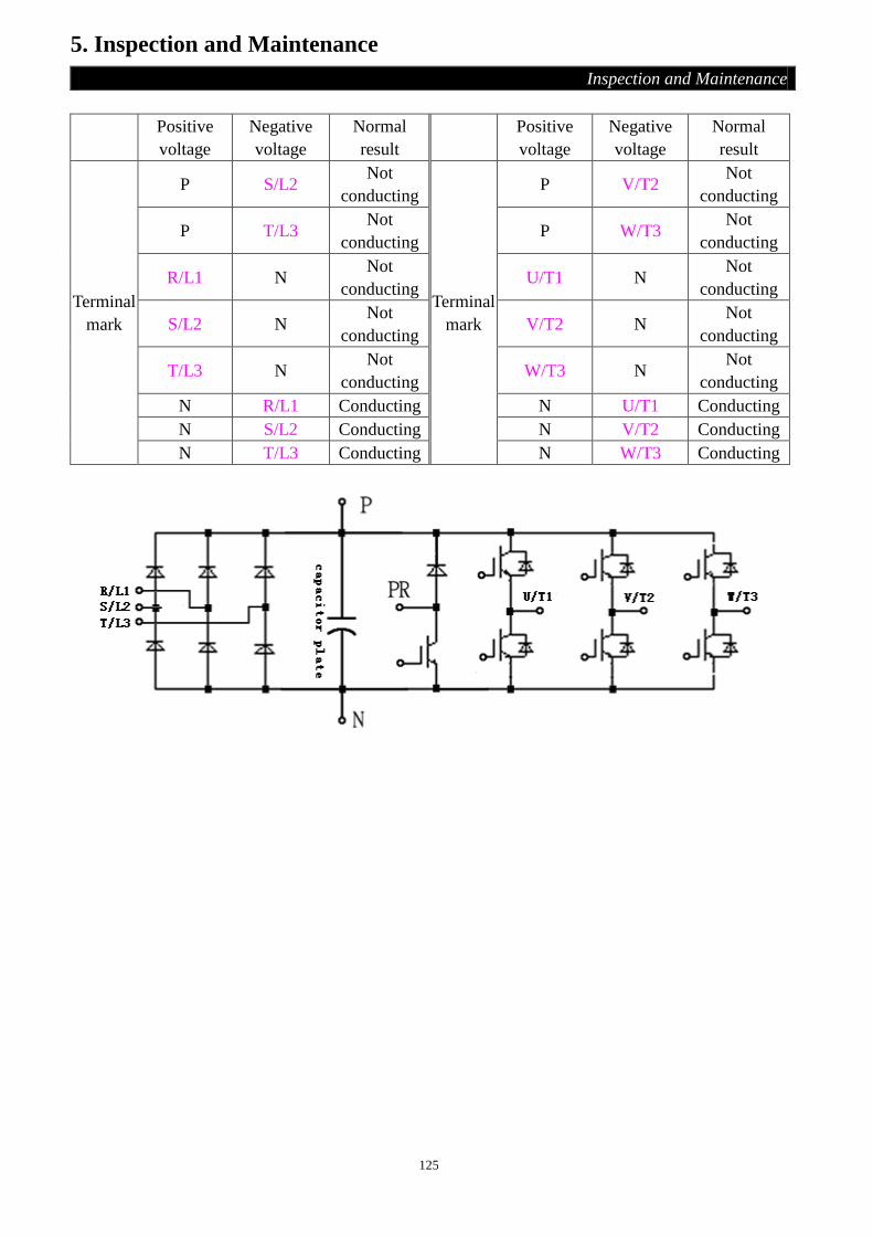
125
5. Inspection and Maintenance
Inspection and Maintenance
Positive
voltage
Negative
voltage
Normal
result
Positive
voltage
Negative
voltage
Normal
result
Terminal
mark
P S/L2 Not
conducting
Terminal
mark
P V/T2 Not
conducting
P T/L3 Not
conducting P W/T3
Not
conducting
R/L1 N Not
conducting U/T1 N
Not
conducting
S/L2 N Not
conducting V/T2 N
Not
conducting
T/L3 N Not
conducting W/T3 N
Not
conducting
N R/L1 Conducting N U/T1 Conducting
N S/L2 Conducting N V/T2 Conducting
N T/L3 Conducting N W/T3 Conducting

126
Appendix 1 Parameter list
Parameter list
Parameter
number Name Setting range
Minimum
setting unit Default value
User setting
value
Reference
page
P.0 Torque boost 0~30% 0.1% (Note 1) P40
P.1 Maximum frequency 0~120Hz 0.01Hz 120Hz P41
P.2 Minimum frequency 0~120Hz 0.01Hz 0Hz P41
P.3 Base frequency 0~400Hz 0.01Hz 50Hz/60Hz
(Note 2) P41
P.4 Speed 1 (high speed) 0~400Hz 0.01Hz 60Hz P43
P.5 Speed 2 (medium speed) 0~400Hz 0.01Hz 30Hz P43
P.6 Speed 3 (low speed) 0~400Hz 0.01Hz 10Hz P43
P.7 Acceleration time 0~360.00s/
0~3600.0s 0.01s/0.1s 5s P44
P.8 Deceleration time 0~360.00s/
0~3600.0s 0.1s/0.01s 5s P44
P.9 Electronic thermal relay
capacity 0~500A 0.01A
Motors rated current
(Note 1)
P46
P.10 DC injection brake
operation frequency 0~120Hz 0.01Hz 3Hz
P46
P.11 DC injection brake
operation time 0~60s 0.1s 0.5s
P46
P.12 DC injection brake
operation voltage 0~30% 0.1% 4% P46
P.13 Starting frequency 0~60Hz 0.01Hz 0.5Hz P47
P.14 Load pattern selection 0~13 1 0 P48
P.15 JOG frequency 0~400Hz 0.01Hz 5Hz P51
P.16 JOG acceleration /
deceleration time
0~360.00s/
0~3600.0s 0.1s/0.01s 0.5s P51
P.17 Input signal across terminal
4-5 selection 0、1 1 0 P51
P.18 High-speed maximum
frequency 120~400Hz 0.01Hz 120Hz P41
P.19 Base frequency voltage 0~1000V, 9999 0.1V 9999 P41
P.20 Acceleration/deceleration
reference frequency 1~400Hz 0.01Hz
50Hz/60Hz
(Note 2) P44
P.21 Acceleration/deceleration
time increments 0,1 1 0 P44
P.22 Stall prevention operation
level 0~400% 0.1% 200% P52
P.23 compensation factor at
level reduction 0~200%, 9999 0.1% 9999 P52
P.24 Speed 4 0~400Hz, 9999 0.01Hz 9999 P43

127
Appendix 1 Parameter list
Parameter list
Parameter
number Name Setting range
Minimum
setting unit Default value
User setting
value
Reference
page
P.25 Speed 5 0~400Hz, 9999 0.01Hz 9999 P43
P.26 Speed 6 0~400Hz, 9999 0.01Hz 9999 P43
P.27 Speed 7 0~400Hz, 9999 0.01Hz 9999 P43
P.28 Output frequency filter
constant 0~31 1 0 P53
P.29 Acceleration/deceleration
curve selection 0, 1, 2 1 0 P53
P.30 Regenerative brake
function selection 0, 1 1 0 P55
P.31 Soft-PWM selection 0、1 1 0 P55
P.32 Serial communication
Baud rate selection 0, 1, 2 1 1 P56
P.33 Communication protocol
selection 0, 1 1 0 P56
P.34 Reserved
P.35 Reserved
P.36 Inverter station number 0~254 1 0 P56
P.37 Speed display 0~5000r/min 0.1r/min 0 r/min P71
P.38
The maximum operation
frequency (the target
frequency is set by the
input signal of terminal
2-5)
1~400Hz 0.01Hz 50Hz/60Hz
(Note 2) P72
P.39
The maximum operation
frequency (the target
frequency is set by the
input signal of terminal
4-5)
1~400Hz 0.01Hz 50Hz/60Hz
(Note 2) P76
P.40 Multi-function output
terminal pattern 0~10 1 0 P77
P.41 Up-to-frequency sensitivity 0~100% 0.1% 10% P79
P.42 Output frequency detection
for forward rotation 0~400Hz 0.01Hz 6Hz P80
P.43 Output frequency detection
for reverse rotation 0~400Hz, 9999 0.01Hz 9999 P80
P.44 The second acceleration
time
0~360.00s/
0~3600.0s、9999 0.01s/0.1s 9999 P44
P.45 The second deceleration
time
0~360.00s/
0~3600.0s、9999 0.01s/0.1s 9999 P44
P.46 The second torque boost 0~30%, 9999 0.1% 9999 P40
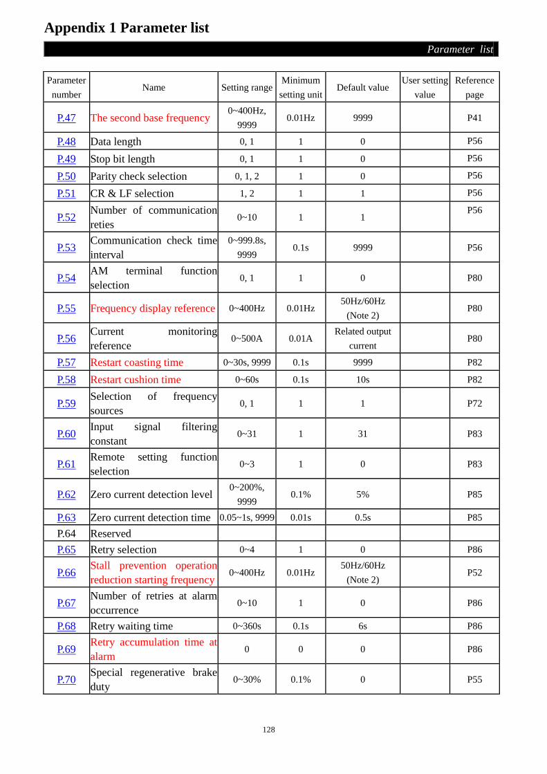
128
Appendix 1 Parameter list
Parameter list
Parameter
number Name Setting range
Minimum
setting unit Default value
User setting
value
Reference
page
P.47 The second base frequency 0~400Hz,
9999 0.01Hz 9999 P41
P.48 Data length 0, 1 1 0 P56
P.49 Stop bit length 0, 1 1 0 P56
P.50 Parity check selection 0, 1, 2 1 0 P56
P.51 CR & LF selection 1, 2 1 1 P56
P.52 Number of communication
reties 0~10 1 1
P56
P.53 Communication check time
interval
0~999.8s,
9999 0.1s 9999 P56
P.54 AM terminal function
selection 0, 1 1 0 P80
P.55 Frequency display reference 0~400Hz 0.01Hz 50Hz/60Hz
(Note 2) P80
P.56 Current monitoring
reference 0~500A 0.01A
Related output
current P80
P.57 Restart coasting time 0~30s, 9999 0.1s 9999 P82
P.58 Restart cushion time 0~60s 0.1s 10s P82
P.59 Selection of frequency
sources 0, 1 1 1 P72
P.60 Input signal filtering
constant 0~31 1 31 P83
P.61 Remote setting function
selection 0~3 1 0 P83
P.62 Zero current detection level 0~200%,
9999 0.1% 5% P85
P.63 Zero current detection time 0.05~1s, 9999 0.01s 0.5s P85
P.64 Reserved
P.65 Retry selection 0~4 1 0 P86
P.66 Stall prevention operation
reduction starting frequency 0~400Hz 0.01Hz
50Hz/60Hz
(Note 2) P52
P.67 Number of retries at alarm
occurrence 0~10 1 0 P86
P.68 Retry waiting time 0~360s 0.1s 6s P86
P.69 Retry accumulation time at
alarm 0 0 0 P86
P.70 Special regenerative brake
duty 0~30% 0.1% 0 P55

129
Appendix 1 Parameter list
Parameter list
Parameter
number Name Setting range
Minimum
setting unit Default value
User setting
value
Reference
page
P.71 Idling braking and linear
braking selection 0, 1 1 1 P87
P.72 Carrier frequency 0.7~14.5kHz 0.1kHz 5.0 kHz P87
P.73 Voltage signal selection 0, 1 1 0 P72
P.74 Reversed
P.75 Stop or Reset function
selection 0~1 1 1 P88
P.76 Panel knob signal input
frequency bias 0~400Hz 0.01Hz 0Hz P72
P.77 Parameters write
protection 0, 1, 2 1 0 P89
P.78 Forward/reverse rotation
prevention selection 0, 1, 2 1 0 P89
P.79 Operation mode selection 0~8 1 0 P90
P.80 Multi-function terminal
M0 function selection 0~39 1 2
P91
P.81 Multi-function terminal
M1 function selection 0~39 1 3
P91
P.82 Multi-function terminal
M2 function selection 0~39 1 4
P91
P.83 Multi-function terminal
STF function selection 0~39 1 0
P91
P.84 Multi-function terminal
STR function selection 0~39 1 1
P91
P.85 Function selection for
multi-function relay 0~10 1 5 P77
P.86 Multi-function terminal
RES function selection 0~39 1 30 P91
P.87 Reversed
P.88 Reversed
P.89 Slip compensation
coefficient 0~10 1 0 P95
P.90 Reserved
P.91 Frequency jump 1A 0~400Hz, 9999 0.01Hz 9999 P95
P.92 Frequency jump 1B 0~400Hz, 9999 0.01Hz 9999 P95
P.93 Frequency jump 2A 0~400Hz, 9999 0.01Hz 9999 P95
P.94 Frequency jump 2B 0~400Hz, 9999 0.01Hz 9999 P95
P.95 Frequency jump 3A 0~400Hz, 9999 0.01Hz 9999 P95

130
Appendix 1 Parameter list
Parameter list
Parameter
number Name Setting range
Minimum
setting unit Default value
User setting
value
Reference
page
P.96 Frequency jump 3B 0~400Hz, 9999 0.01Hz 9999 P95
P.97 Reserved
P.98 Middle frequency 1 0~400Hz 0.01Hz 3Hz P48
P.99 Output voltage 1 of middle
frequency 0~100% 0.1 10 P48
P.100 Minute/second selection 0, 1 1 1 P96
P.101 Runtime of section 1 in
programmed operation mode 0~6000s 0.1s 0s
P96
P.102 Runtime of section 2 in
programmed operation mode 0~6000s 0.1s 0s
P96
P.103 Runtime of section 3 in
programmed operation mode 0~6000s 0.1s 0s
P96
P.104
Runtime of section 4 in
programmed operation
mode
0~6000s 0.1s 0s
P96
P.105 Runtime of section 5 in
programmed operation mode 0~6000s 0.1s 0s
P96
P.106 Runtime of section 6 in
programmed operation mode 0~6000s 0.1s 0s
P96
P.107 Runtime of section 7 in
programmed operation mode 0~6000s 0.1s 0s
P96
P.108 Runtime of section 8 in
programmed operation mode 0~6000s 0.1s 0s P96
P.110 Operation panel monitoring
selection 0, 1, 2 1 0 P98
P.111 Acceleration/deceleration
time of section 1 0~600s/0~6000s 0.01s/0.1s 0s
P96
P.112 Acceleration/deceleration
time of section 2 0~600s/0~6000s 0.01s/0.1s 0s
P96
P.113 Acceleration/deceleration
time of section 3 0~600s/0~6000s 0.01s/0.1s 0s
P96
P.114 Acceleration/deceleration
time of section 4 0~600s/0~6000s 0.01s/0.1s 0s
P96
P.115 Acceleration/deceleration
time of section 5 0~600s/0~6000s 0.01s/0.1s 0s
P96
P.116 Acceleration/deceleration
time of section 6 0~600s/0~6000s 0.01s/0.1s 0s
P96
P.117 Acceleration/deceleration
time of section 7 0~600s/0~6000s 0.01s/0.1s 0s
P96

131
Appendix 1 Parameter list
Parameter list
Parameter
number Name Setting range
Minimum
setting unit Default value
User setting
value
Reference
page
P.118 Acceleration/deceleration
time of section 8 0~600s/0~6000s 0.01s/0.1s 0s P96
P.119 Reserved
P.120 Output signal delay time 0~3600s 0.1s 0s P77
P.121 Run direction in each section 0~255 1 0 P96
P.122 Cycle selection 0~8 1 0 P96
P.123 Acceleration/deceleration
time setting selection 0, 1 1 0 P96
P.125 Expansion board type --- --- 0 P98
P.126
I/O expansion board input
terminal M3 function
selection
0~39, 9999 1 9999
P98
P.127
I/O expansion board input
terminal M4 function
selection
0~39, 9999 1 9999
P98
P.128
I/O expansion board input
terminal M5 function
selection
0~39, 9999 1 9999
P98
P.129 I/O expansion board output
relay1 function selection 0~10, 9999 1 9999
P98
P.130 I/O expansion board output
relay2 function selection 0~10, 9999 1 9999 P98
P.131 Frequency of section 1 0~400Hz 0.01Hz 0Hz P96
P.132 Frequency of section 2 0~400Hz 0.01Hz 0Hz P96
P.133 Frequency of section 3 0~400Hz 0.01Hz 0Hz P96
P.134 Frequency of section 4 0~400Hz 0.01Hz 0Hz P96
P.135 Frequency of section 5 0~400Hz 0.01Hz 0Hz P96
P.136 Frequency of section 6 0~400Hz 0.01Hz 0Hz P96
P.137 Frequency of section 7 0~400Hz 0.01Hz 0Hz P96
P.138 Frequency of section 8 0~400Hz 0.01Hz 0Hz P96
P.139 Voltage signal bias 0%~100% 0.1% 0% P72
P.140 Voltage signal gain 0.1%~200% 0.1% 100% P72
P.141 Voltage signal bias direction
and rotational direction setup 0~11 1 0 P72
P.142 Speed 8 0~400Hz 0.01Hz 0Hz P43
P.143 Speed 9 0~400Hz, 9999 0.01Hz 9999 P43
P.144 Speed 10 0~400Hz, 9999 0.01Hz 9999 P43

132
Appendix 1 Parameter list
Parameter list
Parameter
number Name Setting range
Minimum
setting unit Default value
User
setting
value
Reference
page
P.145 Speed 11 0~400Hz, 9999 0.01Hz 9999 P43
P.146 Speed 12 0~400Hz, 9999 0.01Hz 9999 P43
P.147 Speed 13 0~400Hz, 9999 0.01Hz 9999 P43
P.148 Speed 14 0~400Hz, 9999 0.01Hz 9999 P43
P.149 Speed 15 0~400Hz, 9999 0.01Hz 9999 P43
P.150 Restart mode selection 0~221 1 0 P82
P.151 Zero-speed control function
selection 0, 1 1 0 P99
P.152 Voltage instruction at zero-speed
control 0~30% 0.1% 5% P99
P.153 Communication error handling 0, 1 1 0 P56
P.154 Modbus communication data
format 0~5 1 4 P56
P.155 Over torque detection level 0~200% 0.1% 0% P100
P.156 Over torque detection time 0~60s 0.1s 1s P100
P.157 External terminals filter adjusting
function 0~200ms 1ms 4ms P100
P.158 External terminal power enable 0、1 1 0 P101
P.159 Energy-saving control function 0、1 1 0 P101
P.160 Stall prevention operation level
when restart 0~200% 0.1% 120% P82
P.161 Multi-function display selection 0~5 1 0 P101
P.162 Middle frequency 2 0~400Hz、9999 0.01Hz 9999 P48
P.163 Output voltage 2 of middle
frequency 0~100% 0.1% 0
P48
P.164 Middle frequency 3 0~400Hz、9999 0.01Hz 9999 P48
P.165 Output voltage 3 of middle
frequency 0~100% 0.1% 0
P48
P.166 Middle frequency 4 0~400Hz、9999 0.01Hz 9999 P48
P.167 Output voltage 4 of middle
frequency 0~100% 0.1% 0
P48
P.168 Middle frequency 5 0~400Hz、9999 0.01Hz 9999 P48
P.169 Output voltage 5 of middle
frequency 0~100% 0.1% 0 P48
P.170 PID function selection 0、1、2 1 0 P102
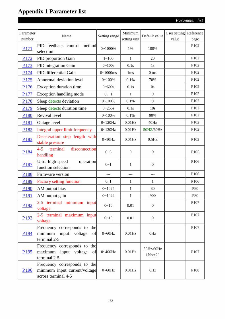
133
Appendix 1 Parameter list
Parameter list
Parameter
number Name Setting range
Minimum
setting unit Default value
User setting
value
Reference
page
P.171 PID feedback control method
selection 0~1000% 1% 100%
P102
P.172 PID proportion Gain 1~100 1 20 P102
P.173 PID integration Gain 0~100s 0.1s 1s P102
P.174 PID differential Gain 0~1000ms 1ms 0 ms P102
P.175 Abnormal deviation level 0~100% 0.1% 70% P102
P.176 Exception duration time 0~600s 0.1s 0s P102
P.177 Exception handling mode 0、1 1 0 P102
P.178 Sleep detects deviation 0~100% 0.1% 0 P102
P.179 Sleep detects duration time 0~255s 0.1s 10s P102
P.180 Revival level 0~100% 0.1% 90% P102
P.181 Outage level 0~120Hz 0.01Hz 40Hz P102
P.182 Integral upper limit frequency 0~120Hz 0.01Hz 50HZ/60Hz P102
P.183 Deceleration step length with
stable pressure 0~10Hz 0.01Hz 0.5Hz
P102
P.184 4-5 terminal disconnection
handling 0~3 0 0
P105
P.187 Ultra-high-speed operation
function selection 0~1 1 0
P106
P.188 Firmware version --- --- --- P106
P.189 Factory setting function 0, 1 1 1 P106
P.190 AM output bias 0~1024 1 80 P80
P.191 AM output gain 0~1024 1 900 P80
P.192 2-5 terminal minimum input
voltage 0~10 0.01 0
P107
P.193 2-5 terminal maximum input
voltage 0~10 0.01 0
P107
P.194
Frequency corresponds to the
minimum input voltage of
terminal 2-5
0~60Hz 0.01Hz 0Hz
P107
P.195
Frequency corresponds to the
maximum input voltage of
terminal 2-5
0~400Hz 0.01Hz 50Hz/60Hz
(Note2) P107
P.196
Frequency corresponds to the
minimum input current/voltage
across terminal 4-5
0~60Hz 0.01Hz 0Hz P108

134
Appendix 1 Parameter list
Parameter list
Parameter
number Name Setting range
Minimum
setting unit Default value
User setting
value
Reference
page
P.197
Frequency corresponds to the
maximum input current/voltage
across terminal 4-5
0~400Hz 0.01Hz 50Hz/60Hz
(Note2)
P108
P.198 Minimum input current/voltage
across terminal 4-5 0~20 0.01 0
P108
P.199 Maximum input current/voltage
across terminal 4-5 0~20 0.01 0 P108
P.229 Backlash compensation
function selection 0~1 1 0 P109
P.230 The backlash compensation
acceleration interrupt frequency 0~400Hz 0.01Hz 1Hz P109
P.231 The backlash compensation
acceleration interrupt time 0~360s 0.1s 0.5s P109
P.232 The backlash compensation
deceleration interrupt frequency 0~400Hz 0.01Hz 1Hz P109
P.233 The backlash compensation
deceleration interrupt time 0~360 s 0.1s 0.5s P109
P.234 Triangular wave function
selection 0~2 1 0
P110
P.235 Maximum amplitude 0~25% 0.1% 10% P110
P.236 Amplitude compensation for
deceleration 0~50% 0.1% 10%
P110
P.237 Amplitude compensation for
acceleration 0~50% 0.1% 10%
P110
P.238 Amplitude acceleration time 0~360s
/0~3600 s 0.01 s/0.1s 10 s
P110
P.239 Amplitude deceleration time 0~360s
/0~3600 s 0.01 s/0.1s 10s
P110
P.240 Auxiliary frequency function
selection 0~4 1 0
P111
P.242 DC injection brake function
before starting selection 0~1 1 0
P112
P.243 DC injection brake time before
starting 0~60s 0.1s 0.5s
P112
P.244 DC injection brake voltage
before starting 0~30% 0.1% 4%
P112
P.247 MC switchover interlock time 0.1~100s 0.1s 1s P112
P.248 Start waiting time 0.1~100s 0.1s 0.5s P112

135
Appendix 1 Parameter list
Parameter list
Parameter
number Name Setting range
Minimum
setting unit Default value
User
setting
value
Reference
page
P.249
Automatic switchover frequency
from inverter to commercial power
supply frequency
0~60Hz,9999 0.01Hz 9999
P112
P.250
Automatic switchover frequency
range from commercial power supply
to inverter
0~10Hz,9999 0.01Hz 9999
P112
P.288 Alarm code display option 0~12 1 0 P115
P.289 Alarm code --- --- 0 P115
P.290 The latest alarm status selection 0~5 1 0 P115
P.291 The latest alarm message --- --- 0 P115
P.292 Accumulative motor operation time
(min) 0~1439min 1min 0min
P116
P.293 Accumulative motor operation time
(day) 0~9999day 1day 0day
P116
P.294 Decryption parameter 0~9998 1 0 P117
P.295 Password setup 2~9998 1 0 P117
P.300 Motor control mode selection 0~3 1 0 P117
P.301 Motor parameter auto-tuning function
selection 0~3 1 0
P117
P.302 Motor rated power 0~160 0.01 0 P119
P.303 Motor poles 0~8 1 4 P119
P.304 Motor rated voltage 0~440V 1 V 220/440V P119
P.305 Motor rated frequency 0~400Hz 0.01Hz 50Hz/60Hz
(Note 2)
P119
P.306 Motor rated current 0~500A 0.01 A Determined by
horsepower
P119
P.307 Motor rated rotation speed 0~9998
r/min 1 r/min
1410/1710 r/min
(Note 2)
P119
P.308 Motor excitation current 0~500A 0.01 A Determined by
horsepower
P119
P.309 Stator resistance 0~9998 0.01 Determined by
horsepower
P119
P.310 Rotor resistance 0~9998 0.01 Determined by
horsepower
P119
P.311 Leakage inductance 0~9998 0.1 Determined by
horsepower
P119
P.312 Mutual inductance 0~9998 0.1 Determined by
horsepower
P119

136
Appendix 1 Parameter list
Parameter list
Note: 1.The torque boost, motor rated current and the stator resistance values are in the table as follows:
Inverter Type P. 0 P. 9(A)
SE2-021-0.4KW 6 3.0
SE2-021-0.75KW 6 5.0
SE2-021-1.5KW 4 8.0
SE2-021-2.2KW 4 11.0
SE2-023-0.4KW 6 3.0
SE2-023-0.75KW 6 5.0
SE2-023-1.5KW 4 8.0
SE2-023-2.2KW 4 11.0
SE2-023-3.7KW 4 17.5
SE2-023-5.5KW 3 24.0
SE2-023-7.5KW 3 33.0
SE2-043-0.4KW 6 1.5
SE2-043-0.75KW 6 2.6
SE2-043-1.5KW 4 4.2
SE2-043-2.2KW 4 6.0
SE2-043-3.7KW 4 9.0
SE2-043-5.5KW 3 12.0
SE2-043-7.5KW 3 17.0
SE2-043-11KW 2 23.0
SE2-021-0.2KW 6 1.6
2. The default value is due to the set value of P.189. When P.189=0, the default value is 60Hz, which is
applied to the 60Hz system. When P.189=1, when default value is 50Hz, which is apply to the 50Hz
system.
3. The minimum value and setting range of all the frequency related parameters can choose by P.187. You can
refer to Appendix 6 for details.
Parameter
number Name Setting range
Minimum
setting unit
Default
value
User setting
value
Reference
page
P.320 Speed control proportion
coefficient 0~2000% 1% 100%
P120
P.321 Speed control integral
coefficient 0~20s 0.01s 0.30s
P120
P.994 Parameter copy readout Refer to Chapter 4 --- --- --- P121
P.995 Parameter copy write-in Refer to Chapter 4 --- --- --- P121
P.996 Alarm history clear Refer to Chapter 4 --- --- --- P121
P.997 Inverter reset Refer to Chapter 4 --- --- --- P122
P.998 Restoring all parameters to
default values Refer to Chapter 4 --- --- --- P122
P.999 Restoring some parameters to
default values Refer to Chapter 4 --- --- --- P122

137
Appendix 2 Alarm Code List
Alarm Code
Code Screen Display Cause Troubleshooting
ERR
1. Under-voltage for
power supply
2. The RES is ‘on’
3. Bad connection
between the operation
panel and main
machine
4. Internal circuit
malfunction
5. Wrong operation of
CPU
1. Provide a normal power supply
2. Shut off RES
3. Ensure firm connection between
the operation panel and the main
machine
4. Replace the inverter
5. Restart the inverter
OC1
Over-current
when stop
The output current is two
times larger than the rated
current of the inverter.
The inverter may be disturbed. Please
restart the inverter. If the alarm
repeated, please send the inverter back
to the factory.
OC1
Over-current
during
acceleration
1. In case the time for acceleration or
deceleration is too short, please
prolong it.
2. Avoid abrupt increase of load.
3. Check Terminals U/T1, V/T2 and
W/T3 for short circuit.
OC2
Over-current at
constant speed
OC3
Over-current
during
deceleration
OV0
Over- voltage
when stop
Over-voltage between
Terminal P and Terminal
N
Check whether the power supply is
normal or abnormal.
OV1
Over-voltage
during
acceleration
1. In case the time for acceleration or
deceleration is too short, please
prolong it.
2. Check the brake resistor between
terminal P and PR for loose
connection.
3. Check whether the values of P.30
and P.70 are right or not.
OV2
Over-voltage at
constant speed

138
Appendix 2 Alarm Code List
Alarm Code
Code Screen Display Cause Troubleshooting
OV3
Over-voltage
during
deceleration
Over-voltage between Terminal
P and Terminal N Please refer to OV1, OV2.
THT
The IGBT
module is
overheating
The IGBT module thermal
accumulating relay acts
Avoid the inverter long timely
operating under overload
condition
THN
Motor
overheating
The electronic thermal relay
operates
1. Check whether the set
value of the P.9 is correct
or not (the set value should
comply the actual motor)
2. Reduce load
OHT
The external
thermal relay
operates.
The external thermal relay
operates
1. Check the capacity of the
external thermal relay and
the motor for matching.
2. Reduce the load
OPT
Peripheral
devices are
abnormal
1. Abnormal communication.
The maximum
communication retry
number is violated.
2. Interrupted communication.
The maximum
communication check time
interval is violated.
Correctly set the
communication parameters
EEP
Memory is
abnormal
The memory ROM fails Send it back to the factory.
CPU
CPU error
External electromagnetic
disturbance is too strong Improve external disturbance
OLS
Stall prevention
protection
The load of the motor is too
heavy.
1. Reduce the load of the
motor.
Increase the value of P.22.
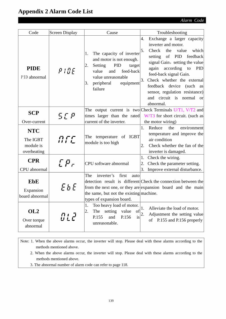
139
Appendix 2 Alarm Code List
Alarm Code
Code Screen Display Cause Troubleshooting
PIDE
PID abnormal
1. The capacity of inverter
and motor is not enough.
2. Setting PID target
value and feed-back
value unreasonable
3. peripheral equipment
failure
4. Exchange a larger capacity
inverter and motor.
5. Check the value which
setting of PID feedback
signal Gain,setting the value
again according to PID
feed-back signal Gain.
3. Check whether the external
feedback device (such as
sensor, regulation resistance)
and circuit is normal or
abnormal.
SCP
Over-current
The output current is two
times larger than the rated
current of the inverter.
Check Terminals U/T1, V/T2 and
W/T3 for short circuit. (such as
the motor wiring)
NTC
The IGBT
module is
overheating
The temperature of IGBT
module is too high
1. Reduce the environment
temperature and improve the
air condition
2. Check whether the fan of the
inverter is damaged.
CPR
CPU abnormal
CPU software abnormal
1. Check the wiring.
2. Check the parameter setting.
3. Improve external disturbance.
EbE
Expansion
board abnormal
The inverter’s first auto
detection result is different
from the next one, or they are
the same, but not the existing
types of expansion board.
Check the connection between the
expansion board and the main
machine.
OL2
Over torque abnormal
1. Too heavy load of motor.
2. The setting value of
P.155 and P.156 is
unreasonable.
1. Alleviate the load of motor.
2. Adjustment the setting value
of P.155 and P.156 properly
Note: 1. When the above alarms occur, the inverter will stop. Please deal with these alarms according to the
methods mentioned above.
2. When the above alarms occur, the inverter will stop. Please deal with these alarms according to the
methods mentioned above.
3. The abnormal number of alarm code can refer to page 118.
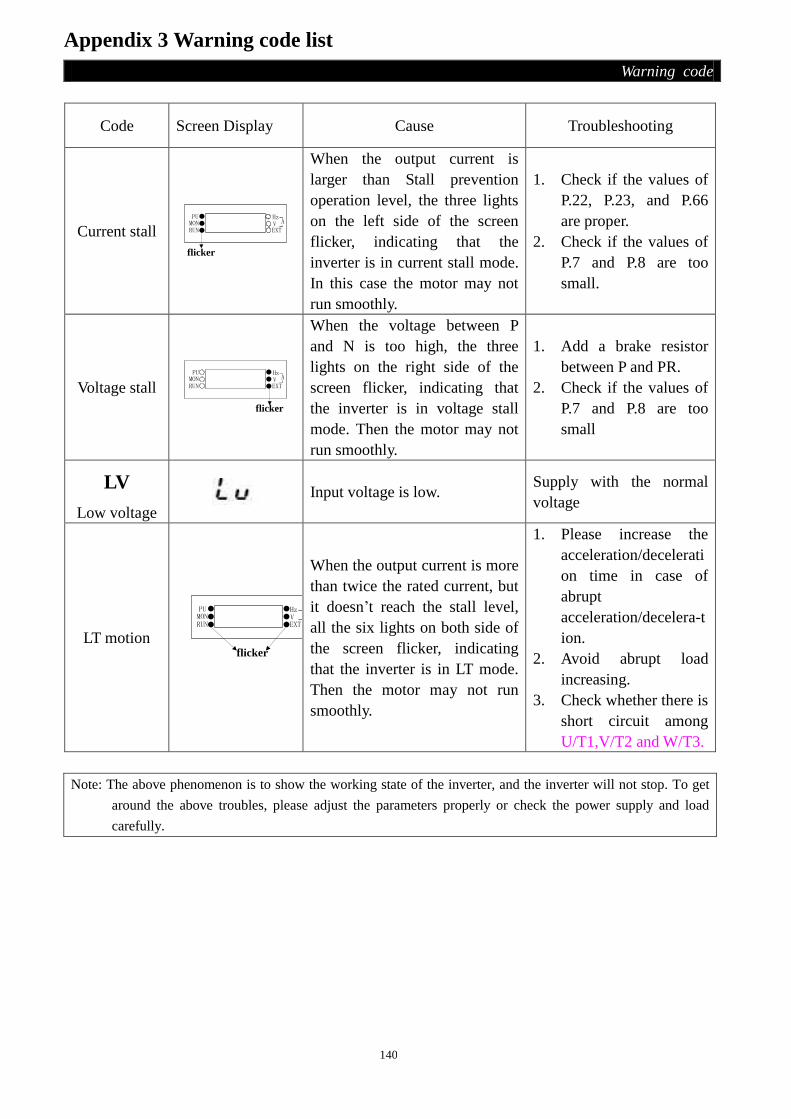
140
Appendix 3 Warning code list
Warning code
Code Screen Display Cause Troubleshooting
Current stall PUMONRUN
HzVEXT
A
flicker
When the output current is
larger than Stall prevention
operation level, the three lights
on the left side of the screen
flicker, indicating that the
inverter is in current stall mode.
In this case the motor may not
run smoothly.
1. Check if the values of
P.22, P.23, and P.66
are proper.
2. Check if the values of
P.7 and P.8 are too
small.
Voltage stall PU
MONRUN
HzVEXT
A
flicker
When the voltage between P
and N is too high, the three
lights on the right side of the
screen flicker, indicating that
the inverter is in voltage stall
mode. Then the motor may not
run smoothly.
1. Add a brake resistor
between P and PR.
2. Check if the values of
P.7 and P.8 are too
small
LV
Low voltage
Input voltage is low. Supply with the normal
voltage
LT motion
PUMONRUN
HzVEXT
A
flicker
When the output current is more
than twice the rated current, but
it doesn’t reach the stall level,
all the six lights on both side of
the screen flicker, indicating
that the inverter is in LT mode.
Then the motor may not run
smoothly.
1. Please increase the
acceleration/decelerati
on time in case of
abrupt
acceleration/decelera-t
ion.
2. Avoid abrupt load
increasing.
3. Check whether there is
short circuit among
U/T1,V/T2 and W/T3.
Note: The above phenomenon is to show the working state of the inverter, and the inverter will not stop. To get
around the above troubles, please adjust the parameters properly or check the power supply and load
carefully.

141
Appendix 4 Troubles and Solutions
Troubles and Solutions
Trouble Check points
Motor remains stopped
Check the
Main
circuit
• Check that a proper power supply voltage is applied.
• Check that the Power Lamp is lit.
• Check that the motor is connected properly.
Check the
load
• Check that the load is not too heavy.
• Check that the shaft is not locked.
Check the
parameter
settings
• Check that the starting frequency (P.13) setting is not
greater than the target frequency.
• Check that the operation mode (P.79) setting is correct.
• Check that the maximum frequency (P.1) is not set to 0.
• Check that the reverse rotation prevention (P.78) is not
selected.
• Check that the bias and gain (P.194~P.197) setting is correct.
• Check that the frequency jump (P.91~P.96) setting is correct.
Check the
control
circuit
• Check that the output stop signal (MRS) is not on. (The
related parameter is P.80~P.84, P.86.)
• Check that the reset signal (RES) is not on. (The related
parameter is P.80~P.84, P.86).
• Check that the external thermal relay does not operate.
• Check that the ALARM lamp is off and the reset is not
executed.
• Check that voltage/current start signal is input.
• Check that the signal STF/STR is correct.(The related
parameter is P.80~P.84, P.86.)
• Check that wiring for the control circuit is ok.
Motor rotates in opposite
direction
• Check that the phase sequence of output terminals U/T1, V/T2 and
W/T3 is correct.
• Check that the start signals (STF and STR) are connected properly.
Speed does not increase.
• Check that the load is not too heavy.
• Check that the stall prevention level (P.22) setting is correct.
• Check that the torque boost (P.0) setting is correct.
• Check that the maximum frequency (P.1) setting is correct.
Acceleration/ deceleration
is not smooth
• Check that the acceleration/ deceleration time (P.7, P.8) settings are not
too short.
• Check that the acceleration/ deceleration pattern (P.29) setting is correct.
• Check that the voltage/current input signal is affected by noises.
Motor current is large
• Check that the load is not too heavy.
• Check that the torque boost setting is not too large.
• Check whether the torque boost (P.0) is set too large.
Speed varies during
operation
• Check that the frequency setting signal is not affected by noise.
• Check that the load is not varying.
• Check that the wiring length for the main circuit is correct.

142
Appendix 5 Optional equipment
Optional equipment
1. Expansion board (Please according to the choose expansion board and the function to set the
parameter from P.126 to P.130)
(1). I/O expansion board(SE-EB01)
3 On-off signal input and 2 Relay output can be expanded, shown as follows:
Terminal
type
Terminal
name
Function
name Remarks and function description
On-off
signal input
M3 Optional For detailed descriptions, please refer to P.126~P.128 in
Chapter 4. M4 Optional
M5 Optional
SD SD Common reference Ground for M3, M4 and M5.
PC PC In the ‘source input’ mode, it provides a common power
supply for the terminals referred above.
Relay
output 1
A1 --- Normally, points A-C are always open-circuit; points B-C
are always ‘short-circuit’.
These terminals are multi-function relay output. For
detailed description, please refer to P.129~P.130.
(Note) Contactor capacity: VDC30V / VAC230V- 0.3A
B1 ---
C1 ---
Relay
output 2
A2 ---
B2 ---
C2 ---
(2). Terminal block communication expansion board(SE-CB01)
RS485/422 serial communication, both Shihlin protocol and Modbus protocol can be selected,
Shown as follows:

143
Appendix 5 Optional equipment
Optional equipment
Terminal type Terminal
name
Function
name Remarks and function description
485
communication
terminal
SDA SDA
RS485/422 serial communication terminal SDB SDB
RDA RDA
RDB RDB
P5S P5S 5V Source
SG SG 5V Ground
(3). Communication expansion board for RJ-11 connector (SE-CB02)
There are two RJ-11 connectors on the board, please use them with the corresponding
transmission cable.
(4). Communication expansion board for RJ-45 connector (SE-CB03)
This communication expansion board use CBL cable to connect DU01.
(5). 4~20mA current source expansion board (SE-IB01)

144
Appendix 5 Optional equipment
Optional equipment
Terminal
type
Terminal
name
Function
name Remarks and function description
Analog
signal
output
AMI --- Connected with an external analog meter to indicate the
output frequency or current.
P5S P5S 5V Source
5 5 5V Ground
(6). Profibus communication expansion board (SE2-PD01)
1). SE2-PD01 meets EN50170 standards, using profidrive DPV0 standards.
2). SE2-PD01 as a slave for Profibus network, the maximum rate of communication to support
12M.
3). SE2-PD01 using a common terminal form to connect profibus network, addresses is from 1
to 125.
4). Connect SE2-PD01, please use the unshielded twisted pair RS-485 cable (recommended
PROFIBUS approved cable).
5). SE2-PD01 power is supplied by the inverter which connected to it.
Terminal type Terminal
name
Function
name Remarks and function description
Profibus
communication
terminal
FG SHIELD Shield ground
D- RxD/TxD- N Profibus Data -
D+ RxD/TxD- P Profibus Data +
CNTR RTS Profibus request signal
V-
Data
reference
potential (C)
5V Ground and reference Ground for data
V+ +5V 5V Source
SP LED: Instructed the inverter and SE2-PD01 connection status.
NET LED: Instructed SE2-PD01 and the Profibus DP network connection status.
Note: The shihlin inverter can automatically identify the SE2-PD01 communications expansion board, and adjust
the corresponding parameters of its own with the SE2-PD01 to make a successful connection, the user in the
course of communication do not modify the drive parameters, so as not to affect the SE2-PD01 normal work

145
Appendix 5 Optional equipment
Optional equipment
(7). DeviceNet communication expansion board (SE2-DN01)
1). SE2-DN01 meets ODVA DeviceNet standards.
2). SE2-DN01 as a slave for DeviceNet network, support for 125k, 250k, 500k baud rate of
communication
3). SE2-DN01 using a common terminal form to connect DeviceNet network, addresses is from
0 to 63.
4). Connect SE2-DN01, please use the standard DeviceNet specific cable.
5). The power of SE2-DN01 is supplied by the 24V power supply from DeviceNet network.
Terminal type Terminal
name
Function
name Remarks and function description
DeviceNet
communication
terminal
V+ V+ Isolated 24V power supply
CAN+ CAN_H CAN_H signal
SHIELD SHIELD Network cable shield
CAN- CAN_L CAN_L signal
V- V- Isolated ground
--- Empty ---
NS LED: Instructed SE2-DN01 and the DeveceNet network connection status.
MS LED: Instructions SE2 - DN01 internal modules working condition.
SP LED: Instructed the inverter and SE2-DN01 Working condition.
Address switch 1~6: Set the communication address of SE2-DN01 in DeviceNet network.
Baud rate setting switch 7~8: Set the communication rate of SE2-DN01.
Note: 1. 00 representative of 125k, 01 representative of 250k, 10 representative of 500k, 11 representative
automatically set baud rate.
2. The shihlin inverter can automatically identify the SE2-DN01 communications expansion board, and adjust
the corresponding parameters of its own with the SE2-DN01 to make a successful connection, the user in
the course of communication do not modify the drive parameters, so as not to affect the SE2-DN01 normal
work

146
Appendix 5 Optional equipment
Optional equipment
2. Operation panel, fixing pedestal and transmission cable
(1). DU03B operation panel sets (operation panel and fixing pedestal, the units in the figure
below is mm)
The assembly dimensions of the fixing pedestal are as follows:
NO. Model Name
1 SNKDU03B DU03B operation panel sets

147
Appendix 5 Optional equipment
Optional equipment
(2). DU05 operation panel
The assembly dimensions of the fixing pedestal are as follows:
NO. Model Name
1 SNKDU05 DU05 operation panel

148
Appendix 5 Optional equipment
Optional equipment
(3). DU01 operation panel sets (operation panel and fixing pedestal)
NO. Model Name
1 SNKDU01S DU01 operation panel sets
(4). PU01 operation panel sets
NO. Model Name
1 SNKSHPU01 PU01 operation panel sets

149
Appendix 5 Optional equipment
Optional equipment
(5). CBL: Transmission cable used with the above operation panel
Ordering code instructions:
NO. Model Name Ordering code
1 CBL1R5GT Transmission cable (1.5M) SNKCBL1R5GT
2 CBL03GT Transmission cable (3M) SNKCBL03GT
3 CBL05GT Transmission cable (5M) SNKCBL05GT

150
Appendix 6 Frequency parameters of ultra-high-speed
Frequency parameters
1. After setting the inverter ultra high-speed operation function parameter P.187, please be sure to
set P.998 to adjust the frequency-dependent parameters.
2. In the use of inverter ultra-high-speed operation function, do not use PU series operation panels
to achieve parameter copy function by set P.994 and P.995.
3. Inverter ultra-high speed operation function, by the use of communication written in frequency,
please pay attention to the size of the set value. Because if P.187 = 1, minimum setting unit is 0.1
Hz.
For example: Change value of P.195 to 50 (initial value is 60) in communication example 4.
Step1 and step 2 are the same as step1 and step2 of example 3.
Step 3. The PC requests the inverter to inputting 50 into P.195, using the format A:
ENQ Station number
0
Command
Code HDF
Waiting
Time
Data
H1388 Sum Check CR
H05 H30 H30 H44 H46 H30 H31 H33 H38 H38 H45 H45 H0D
195 minus 100 equal to 95, then Minimum unit of P.195 is 0.1, therefore
converting 95 to hexadecimal H5F, 50*10=500, then convert 500 to
H5F+H80=HDF. Hexadecimal H01F4, and convert 0,1,F,4
to ASCII CODE to send out.
4. On the ultra-high-speed operation function, the can not use the sensor vector speed control
function.
5. When P.187=1, the minimum value and setting range of all the frequency related parameters is follow in the
below table.
Parameter number Name Setting range Minimum setting unit
P.1 Maximum frequency 0~1000Hz 0.1Hz
P.2 Minimum frequency 0~1000Hz 0.1Hz
P.3 Base frequency 0~1000Hz 0.1Hz
P.4 Speed 1 (high speed) 0~1000Hz 0.1Hz
P.5 Speed 2 (medium speed) 0~1000Hz 0.1Hz
P.6 Speed 3 (low speed) 0~1000Hz 0.1Hz
P.10 DC injection brake operation frequency 0~1000Hz 0.1Hz
P.13 Starting frequency 0~600Hz 0.1Hz
P.15 JOG frequency 0~1000Hz 0.1Hz
P.18 High-speed maximum frequency 120~1000Hz 0.1Hz
P.20 Acceleration/deceleration reference
frequency 1~1000Hz 0.1Hz
P.24 Speed 4 0~1000Hz、9999 0.1Hz
P.25 Speed 5 0~1000Hz、9999 0.1Hz
P.26 Speed 6 0~1000Hz、9999 0.1Hz
P.27 Speed 7 0~1000Hz、9999 0.1Hz
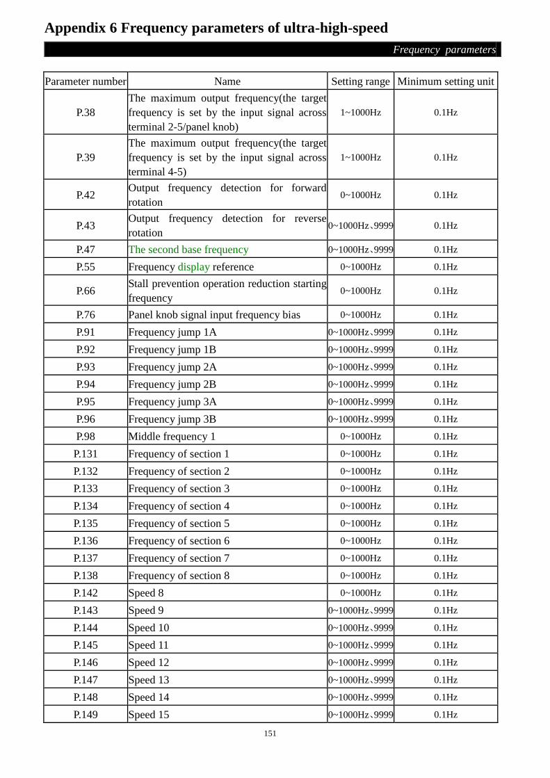
151
Appendix 6 Frequency parameters of ultra-high-speed
Frequency parameters
Parameter number Name Setting range Minimum setting unit
P.38
The maximum output frequency(the target
frequency is set by the input signal across
terminal 2-5/panel knob)
1~1000Hz 0.1Hz
P.39
The maximum output frequency(the target
frequency is set by the input signal across
terminal 4-5)
1~1000Hz 0.1Hz
P.42 Output frequency detection for forward
rotation 0~1000Hz 0.1Hz
P.43 Output frequency detection for reverse
rotation 0~1000Hz、9999 0.1Hz
P.47 The second base frequency 0~1000Hz、9999 0.1Hz
P.55 Frequency display reference 0~1000Hz 0.1Hz
P.66 Stall prevention operation reduction starting
frequency 0~1000Hz 0.1Hz
P.76 Panel knob signal input frequency bias 0~1000Hz 0.1Hz
P.91 Frequency jump 1A 0~1000Hz、9999 0.1Hz
P.92 Frequency jump 1B 0~1000Hz、9999 0.1Hz
P.93 Frequency jump 2A 0~1000Hz、9999 0.1Hz
P.94 Frequency jump 2B 0~1000Hz、9999 0.1Hz
P.95 Frequency jump 3A 0~1000Hz、9999 0.1Hz
P.96 Frequency jump 3B 0~1000Hz、9999 0.1Hz
P.98 Middle frequency 1 0~1000Hz 0.1Hz
P.131 Frequency of section 1 0~1000Hz 0.1Hz
P.132 Frequency of section 2 0~1000Hz 0.1Hz
P.133 Frequency of section 3 0~1000Hz 0.1Hz
P.134 Frequency of section 4 0~1000Hz 0.1Hz
P.135 Frequency of section 5 0~1000Hz 0.1Hz
P.136 Frequency of section 6 0~1000Hz 0.1Hz
P.137 Frequency of section 7 0~1000Hz 0.1Hz
P.138 Frequency of section 8 0~1000Hz 0.1Hz
P.142 Speed 8 0~1000Hz 0.1Hz
P.143 Speed 9 0~1000Hz、9999 0.1Hz
P.144 Speed 10 0~1000Hz、9999 0.1Hz
P.145 Speed 11 0~1000Hz、9999 0.1Hz
P.146 Speed 12 0~1000Hz、9999 0.1Hz
P.147 Speed 13 0~1000Hz、9999 0.1Hz
P.148 Speed 14 0~1000Hz、9999 0.1Hz
P.149 Speed 15 0~1000Hz、9999 0.1Hz

152
Appendix 6 Frequency parameters of ultra-high-speed
Frequency parameters
Parameter number Name Setting range Minimum setting unit
P.162 Middle frequency 2 0~1000Hz、9999 0.1Hz
P.164 Middle frequency 3 0~1000Hz、9999 0.1Hz
P.166 Middle frequency 4 0~1000Hz、9999 0.1Hz
P.168 Middle frequency 5 0~1000Hz、9999 0.1Hz
P.181 Outage level 0~1000Hz 0.1Hz
P.182 Integral upper limit frequency 0~1000Hz 0.1Hz
P.183 Deceleration step length with stable
pressure 0~100Hz 0.1Hz
P.194 Frequency corresponds to the minimum
input voltage across terminal 2-5 0~600Hz 0.1Hz
P.195 Frequency corresponds to the maximum
input voltage across terminal 2-5 0~1000Hz 0.1Hz
P.196 Frequency corresponds to the minimum
input current/voltage across terminal 4-5 0~600Hz 0.1Hz
P.197 Frequency corresponds to the maximum
input current/voltage across terminal 4-5 0~1000Hz 0.1Hz
P.230 The backlash compensation acceleration
interrupt frequency 0~1000Hz 0.1Hz
P.232 The backlash compensation deceleration
interrupt frequency 0~1000Hz 0.1Hz
P.249
Automatic switchover frequency from
inverter to commercial power supply
frequency
0~600Hz,9999 0.1Hz
P.250 Automatic switchover frequency range from
commercial power supply to inverter 0~100Hz,9999 0.1Hz
P.305 Motor rated frequency 0~1000Hz 0.1Hz

153
Amendment record
Amendment record
Printing Date The manual version Amendment
2011.05 V1.00 The first edition
2012.10
V1.01
(Applicable for V0.40
or above firmware)
1. Unifying names of some parameters
2. Amending some mistakes of the instruction manual
Version: V1.01
Printing Date: October.2012

Copyright reserved
Area Distributor
Inverter
Servo motor and drive
Temperature Controller
Human Machine Interface
Head Office: 16F, No. 88, Sec. 6, ChungShan N. Rd.., Taipei, Taiwan, 111TEL:+886-2-2834-2662 FAX:+886-2-2836-6187HsinFun Factory (Taiwan):No.234, Chung Lun, Hsin Fun, HsinChu, Taiwan, 304TEL:+886-3-599-5111 FAX:+886-3-5907173SuZhou Factory(China):No.22, HuoJu Rd., SuZhou Tech. District, JiangSu, China. 215009TEL:+86-512-6843-2662 FAX: +86-512-6843-2669
Shihlin Electric Factory Automation Products
Shihlin Electric & Engineering Corporation