dspace.jaist.ac.jp · i would like to warmly thank, first, my friends and ”senpai” amr mostafa...
TRANSCRIPT

Japan Advanced Institute of Science and Technology
JAIST Repositoryhttps://dspace.jaist.ac.jp/
TitleAn Energy Efficient Recovery Mechanism for
Tracking Systems
Author(s) Seide, Germine
Citation
Issue Date 2008-09
Type Thesis or Dissertation
Text version author
URL http://hdl.handle.net/10119/4760
Rights
Description Supervisor:TAN Yasuo, 情報科学研究科, 修士
An Energy Efficient Recovery Mechanism forTracking Systems
By Seide Germine
A thesis submitted toSchool of Information Science,
Japan Advanced Institute of Science and Technology,
in partial fulfillment of the requirementsfor the degree of
Master of Information ScienceGraduate Program in Information Science
Written under the direction ofProfessor Tan Yasuo
September, 2008
An Energy Efficient Recovery Mechanism forTracking Systems
By Seide Germine (610203)
A thesis submitted toSchool of Information Science,
Japan Advanced Institute of Science and Technology,
in partial fulfillment of the requirementsfor the degree of
Master of Information ScienceGraduate Program in Information Science
Written under the direction ofProfessor Tan Yasuo
and approved byProfessor Tan Yasuo
Professor Shinoda YoichiAssociate Professor Defago Xavier
August, 2008 (Submitted)
Copyright c 2008 by Seide Germine

Preface
The document is about my master thesis for obtaining the degree of master incomputer science at Japan Advanced Institute of Science and Technology (JAIST). Thethesis modeled a tracking system for monitoring mobile objects. This system can be ap-plied to different type of applications such as tracking intruders in a field (a pets in firmor human being in a certain area) or following a moving car.
The model used in this document lays its foundation on previous work andinspired from current work in wireless sensor network. In this document the trackingscenario is based on prediction to select the future object location, and on a multi-layerarchitecture to ensure scalability and to achieve recovery in case of lost objects. By in-vestigating the previous algorithms this work leads to a system in which the accuracy oftracking has been improved while showing a good performance of energy usage for objecttracking in wireless sensor network.
I would like to warmly thank, first, my friends and ”Senpai” Amr Mostafa Mo-hamed Ashmawy from Tanaka Lab, Takashi Okada from Tan Lab, Peng Chao, and NakataJunya from NICT Japan. The knowledge and know-how you taught me will remain valu-able for me. For your time, your patience and kindness, many Thanks.
To my supervisor Professor Tan Yasuo, I would like to express my deep gratitudefor his guidance and support. I would like to thank also Professors, Defago Xavier andShinoda Yoichi for answering my questions and their help with my thesis. Special thanksgo to the Japanese Government Scholarship (MONBUKAGAKUSHO) for supporting mystudy and living in Japan.
To my Heavenly father and my family: ”my ever lasting love”.
SEIDE GermineJAISTAugust 2008

Contents
1 Introduction 61.1 Background . . . . . . . . . . . . . . . . . . . . . . . . . . . . . . . . . . . 61.2 Problem Statement . . . . . . . . . . . . . . . . . . . . . . . . . . . . . . . 71.3 Research Objective . . . . . . . . . . . . . . . . . . . . . . . . . . . . . . . 81.4 Research Contributions . . . . . . . . . . . . . . . . . . . . . . . . . . . . . 81.5 Thesis Organization . . . . . . . . . . . . . . . . . . . . . . . . . . . . . . . 9
2 Object Tracking In Wireless Sensor Network 102.1 State Of The Art . . . . . . . . . . . . . . . . . . . . . . . . . . . . . . . . 102.2 Object Tracking . . . . . . . . . . . . . . . . . . . . . . . . . . . . . . . . . 12
2.2.1 Tracking Scenario . . . . . . . . . . . . . . . . . . . . . . . . . . . . 132.2.2 Approaches . . . . . . . . . . . . . . . . . . . . . . . . . . . . . . . 132.2.3 Object Tracking Application . . . . . . . . . . . . . . . . . . . . . . 14
2.3 Terminology . . . . . . . . . . . . . . . . . . . . . . . . . . . . . . . . . . . 15
3 Prediction-Based Method 173.1 The Context . . . . . . . . . . . . . . . . . . . . . . . . . . . . . . . . . . . 173.2 The Prediction Method in Object tracking . . . . . . . . . . . . . . . . . . 173.3 Prediction-Method Phases . . . . . . . . . . . . . . . . . . . . . . . . . . . 18
3.3.1 Phase 1 - Monitoring . . . . . . . . . . . . . . . . . . . . . . . . . . 183.3.2 Phase 2 - Prediction . . . . . . . . . . . . . . . . . . . . . . . . . . 203.3.3 Phase 3 - Localization . . . . . . . . . . . . . . . . . . . . . . . . . 20
3.4 Pro & Cons about Prediction-based Method . . . . . . . . . . . . . . . . . 203.5 Related Work . . . . . . . . . . . . . . . . . . . . . . . . . . . . . . . . . . 20
3.5.1 Prediction-Based Energy Saving (PES) . . . . . . . . . . . . . . . . 203.5.2 Dual Prediction-Based Reporting (DPR) . . . . . . . . . . . . . . . 213.5.3 Prediction-Based Monitoring in Sensor Networks(PREMON) . . . . 213.5.4 Distributed Prediction Tracking(DPT) . . . . . . . . . . . . . . . . 22
3.6 Fallbacks from the related work . . . . . . . . . . . . . . . . . . . . . . . . 23
4 Proposed Energy Efficient Tracking System 254.1 Object Tracking Application . . . . . . . . . . . . . . . . . . . . . . . . . . 25
4.1.1 Assumptions . . . . . . . . . . . . . . . . . . . . . . . . . . . . . . . 254.1.2 The Mobile Object . . . . . . . . . . . . . . . . . . . . . . . . . . . 26
2

4.1.3 The Sensor Node . . . . . . . . . . . . . . . . . . . . . . . . . . . . 264.1.4 Topologies . . . . . . . . . . . . . . . . . . . . . . . . . . . . . . . . 27
4.2 Problem Statement . . . . . . . . . . . . . . . . . . . . . . . . . . . . . . . 284.3 Proposed Solution . . . . . . . . . . . . . . . . . . . . . . . . . . . . . . . . 28
4.3.1 Network Architecture . . . . . . . . . . . . . . . . . . . . . . . . . . 294.3.2 Prediction Strategy . . . . . . . . . . . . . . . . . . . . . . . . . . . 304.3.3 Synchronization . . . . . . . . . . . . . . . . . . . . . . . . . . . . . 344.3.4 Recovery Mechanism . . . . . . . . . . . . . . . . . . . . . . . . . . 35
4.4 System flow chart . . . . . . . . . . . . . . . . . . . . . . . . . . . . . . . . 374.4.1 Mobile object . . . . . . . . . . . . . . . . . . . . . . . . . . . . . . 374.4.2 Sensor Node . . . . . . . . . . . . . . . . . . . . . . . . . . . . . . . 384.4.3 Cluster head . . . . . . . . . . . . . . . . . . . . . . . . . . . . . . . 394.4.4 Sink node . . . . . . . . . . . . . . . . . . . . . . . . . . . . . . . . 404.4.5 The System States Diagram . . . . . . . . . . . . . . . . . . . . . . 41
5 Experiment 425.1 Environment . . . . . . . . . . . . . . . . . . . . . . . . . . . . . . . . . . . 425.2 Experiment Setup . . . . . . . . . . . . . . . . . . . . . . . . . . . . . . . . 435.3 Path for the moving object . . . . . . . . . . . . . . . . . . . . . . . . . . . 445.4 Network Topology . . . . . . . . . . . . . . . . . . . . . . . . . . . . . . . 455.5 Programming . . . . . . . . . . . . . . . . . . . . . . . . . . . . . . . . . . 465.6 Modules . . . . . . . . . . . . . . . . . . . . . . . . . . . . . . . . . . . . . 465.7 Experiment Results . . . . . . . . . . . . . . . . . . . . . . . . . . . . . . . 47
6 Discussions 496.1 Performance Metrics . . . . . . . . . . . . . . . . . . . . . . . . . . . . . . 496.2 Missing Rate . . . . . . . . . . . . . . . . . . . . . . . . . . . . . . . . . . 49
6.2.1 Metric . . . . . . . . . . . . . . . . . . . . . . . . . . . . . . . . . . 506.2.2 Result Analysis . . . . . . . . . . . . . . . . . . . . . . . . . . . . . 506.2.3 Interpretation . . . . . . . . . . . . . . . . . . . . . . . . . . . . . . 51
6.3 Communication . . . . . . . . . . . . . . . . . . . . . . . . . . . . . . . . . 516.3.1 Metrics . . . . . . . . . . . . . . . . . . . . . . . . . . . . . . . . . 516.3.2 Result Analysis . . . . . . . . . . . . . . . . . . . . . . . . . . . . . 526.3.3 Interpretation . . . . . . . . . . . . . . . . . . . . . . . . . . . . . . 52
6.4 Total Energy Consumption . . . . . . . . . . . . . . . . . . . . . . . . . . . 536.4.1 Metrics . . . . . . . . . . . . . . . . . . . . . . . . . . . . . . . . . 536.4.2 Result Analysis . . . . . . . . . . . . . . . . . . . . . . . . . . . . . 536.4.3 Explanation . . . . . . . . . . . . . . . . . . . . . . . . . . . . . . . 53
6.5 Proposed approach vs DPT, PREMON and PES . . . . . . . . . . . . . . 54
7 Conclusion and Future Work 577.1 Conclusion . . . . . . . . . . . . . . . . . . . . . . . . . . . . . . . . . . . . 577.2 Future Work . . . . . . . . . . . . . . . . . . . . . . . . . . . . . . . . . . . 58

List of Figures
2.1 A Wireless Sensor Network . . . . . . . . . . . . . . . . . . . . . . . . . . . 112.2 Object Tracking Sensor Networks Reproduced from [1] . . . . . . . . . . . 122.3 Object Tracking Sensor Networks based on a hierarchical architecture . . . 15
3.1 Object Tracking Flow Chart . . . . . . . . . . . . . . . . . . . . . . . . . . 18
4.1 MPR2400-MICAz (Crossbow, 2005) . . . . . . . . . . . . . . . . . . . . . . 274.2 Topologies . . . . . . . . . . . . . . . . . . . . . . . . . . . . . . . . . . . . 284.3 Multi-tier architecture from [2] . . . . . . . . . . . . . . . . . . . . . . . . . 294.4 Detection . . . . . . . . . . . . . . . . . . . . . . . . . . . . . . . . . . . . 304.5 Prediction . . . . . . . . . . . . . . . . . . . . . . . . . . . . . . . . . . . . 324.6 Synchronisation . . . . . . . . . . . . . . . . . . . . . . . . . . . . . . . . . 344.7 Recovery . . . . . . . . . . . . . . . . . . . . . . . . . . . . . . . . . . . . . 364.8 The object flow chart . . . . . . . . . . . . . . . . . . . . . . . . . . . . . . 374.9 Sensor node flow chart . . . . . . . . . . . . . . . . . . . . . . . . . . . . . 384.10 Cluster Head flow chart . . . . . . . . . . . . . . . . . . . . . . . . . . . . 394.11 Sink node flow chart . . . . . . . . . . . . . . . . . . . . . . . . . . . . . . 404.12 States Diagram of the application . . . . . . . . . . . . . . . . . . . . . . . 41
5.1 Method to cover the sensing area . . . . . . . . . . . . . . . . . . . . . . . 435.2 Path for a mobile object . . . . . . . . . . . . . . . . . . . . . . . . . . . . 445.3 Sensor Network . . . . . . . . . . . . . . . . . . . . . . . . . . . . . . . . . 455.4 Number of sensor nodes from 0 to 100 and 1 sink . . . . . . . . . . . . . . 48
6.1 Prediction error . . . . . . . . . . . . . . . . . . . . . . . . . . . . . . . . . 506.2 Communication . . . . . . . . . . . . . . . . . . . . . . . . . . . . . . . . . 526.3 Energy . . . . . . . . . . . . . . . . . . . . . . . . . . . . . . . . . . . . . . 536.4 Total Energy Consumption . . . . . . . . . . . . . . . . . . . . . . . . . . . 556.5 Prediction Accuracy . . . . . . . . . . . . . . . . . . . . . . . . . . . . . . 56
4

List of Tables
3.1 Analytical evaluation for energy saving schemes . . . . . . . . . . . . . . . 193.2 Approaches comparison . . . . . . . . . . . . . . . . . . . . . . . . . . . . . 24
4.1 Sensor Node Algorithm . . . . . . . . . . . . . . . . . . . . . . . . . . . . . 314.2 Linear Predictor . . . . . . . . . . . . . . . . . . . . . . . . . . . . . . . . . 324.3 Cluster Head Algorithm . . . . . . . . . . . . . . . . . . . . . . . . . . . . 33
5.1 Functions and Features for Embedded Computer AR2000 Series . . . . . . 445.2 Parameters for the simulation model . . . . . . . . . . . . . . . . . . . . . 46
6.1 Root Mean Square Error parameters . . . . . . . . . . . . . . . . . . . . . 506.2 Energy Consumption on WINS nodes . . . . . . . . . . . . . . . . . . . . . 54
5

Chapter 1
Introduction
1.1 Background
Ever since computers have emerged from laboratory to personal use, technologicaladvances in microprocessor as well as micro-electro-mechanics and wireless communica-tion made them more pervasive and thus more dependant. Scientists and engineers comeup with applications feed by the needs to revolutionize living, work and even to interactwith the physical environment. To meet such a goal, there is a demand for devices tobe small enough to be embedded and cost-efficient in order to be widely deployed, pro-grammed, used and maintained.
The advent of sensors nodes makes this possible. They allow a combination ofsensing, data processing and computation capabilities into a single tiny device. Thosesensor nodes can therefore measure physical quantity and return a signal that can bereported wirelessly. They can be battery-powered and they are capable to work for a longperiod of time. Because of those characteristics and their ability to self-organize them-selves, gather, treat and send data relating to their located area, they are increasinglybeing used in applications in different areas.
In this thesis we study the problem of object tracking recently, applied in WirelessSensor Network. Object tracking is used for application such as battlefield surveillance formilitary operations [4], Habitat monitoring [5], medical surveillance (Code Blue) [6] andapplication for the elderly people [7]. They are densely and randomly deployed and mustreport information to base station (Sinks) based on a certain frequency. This procedurewill allow nodes to communicate to each other frequently and collaboratively accomplishtheir sensing tasks.
6

1.2. Problem Statement JAIST
How to manage the data routed within the network, insure accurate detectionand location when the object is moving randomly and its speed is changing along the way?Those questions raise an energy saving issue for networks used in such kind of applications.
1.2 Problem Statement
As we shown in previous paragraphs many tentative are being done in order toapply Wireless Sensor Networks application in real-world environment. In a near futuremore likewise applications are expected to provide access and information sharing in dif-ferent places by using wireless devices. For that purpose sensor networks are meant to bewidely deployed. However this new step of implementation cannot be done without anyconsequences. Indeed, beside some environment elements interference such as noise andweather, some constraints, directly related to its limitation such as power, synchroniza-tion, deployment and data routing, can be harmful in the implementation of such kind ofsystem.
Among all the constraints the energy is one of the most important becausethis system is made to be applied in environment until now unaccessible. A lot has beenwritten about finding a way to efficiently solve the energy saving issue in object trackingusing Wireless Sensor Networks. Prior researches devoted to that problem implementedalgorithms that focus on the two principal operations which are the monitoring and thereporting. Some in contrast based their interests on the communication cost while othersproposed many topologies to approach problems like the object speed, data fusion, com-puting components, and so on.
For the last few years prediction based approach is being widely discussed. Itused the information of the moving object to predict its next location. This method inorder to save energy schedule the states (sensing / sleep ) of the sensor nodes based on theobject position in the sensing region covered by the deployed Wireless Sensor Network.This approach can be applied to any architecture. However, as the movement of the mo-bile object can be based on certain underlying events and/or randomness, and also somefactors can influence the system, there is a need to provide a structure that can ensure anefficient energy saving sensing task without sacrificing the tracking accuracy of a mobileobject.
Clustering, nevertheless, has been shown as a very efficient grouping techniqueto reduce the energy consumption problem in large scale wireless sensor network applica-tions. However there is not enough concern about methods or mechanism to approach therecovery phase of a tracking application when the object is out of the scope or range of thesensor.
7

1.3. Research Objective JAIST
1.3 Research Objective
Baring that in mind, the main target of this thesis becomes obvious. It is to:
”Investigate the energy saving problem when object tracking application is being deployedon a large scale Wireless Sensor Networks”.
1.4 Research Contributions
Implementing a mobile tracking application that can scale in case of architecturechanges is not an easy task. In this thesis we will make use of an architecture that willserve as a backbone for a prediction-based tracking application over a large scale WirelessSensor Networks. Thus the thesis has two main contributions, one is based on the archi-tecture and the second one is about a prediction-based tracking application and a energyefficient recovery mechanism used in case of miss prediction. Thus, the proposed systemwill :
1. Address the large scale deployment issue
The system is based on a multi-layer cluster based architecture in which all level-(m-1) clusters are grouped into a single level-m cluster. The system results into astructure of nested clusters as shown in chapter 4.
We will show how this architecture will help reporting data from moving objectwhile balancing the load and the main energy consumption as much as possible.We will prove that the proposed architecture can scale in case of adding nodes andhandle the mobile object position with a margin of error adequate.
2. Address the energy saving issue of the tracking system
As in previous approaches enumerated in chapter 3, this application uses the prediction-based mechanism to keep tracking the mobile object route. Moreover our approachis different from them in two ways:
• In case of miss prediction we provide a recovery mechanism based on the pro-posed architecture and operate by the base station (sink node).
• As frequent transmission is one of the key element when talking about en-ergy consumption in object tracking application, we introduce a model named”sleep/predict/awake” between internal and boundary nodes. This model isexpected to regulate the amount of data flow and the reporting frequency.
8

1.5. Thesis Organization JAIST
1.5 Thesis Organization
The thesis will be as follow:
• Chapter 2 will give a brief resume of wireless sensor network. It describes how theobject tracking application is applied and enumerates examples for such kind of ap-plication. Finally it presents a list of terms that are frequently used in the document.
• Chapter 3 describes the prediction based method used in object tracking applicationto overcome handover problem. It surveys different works realized in that field andcompares every energy scheme use for monitoring.
• Chapter 4 presents our application. It explains each steps followed to implementthe proposed system through algorithms and flow charts. At last it presents the allsystem via a states diagram.
• Chapter 5 describes the experiment, which was carried out to evaluate the proposedapproach. and explains each step of the simulation by using data charts. It includesalso the design, scenarios, model, metrics, environment and tools used in the simu-lation environment.
• Chapter 6 provides graphs and explanation about the results obtained from thesimulation. It includes also discussions and comparisons based on the experimentoutputs.
• Chapter 7, finally draws an overall conclusion of this research and plans for futurework.
9

Chapter 2
Object Tracking In Wireless SensorNetwork
This section largely accentuates on the formal context of the topic: Object TrackingApplication in Wireless Sensor Network.
2.1 State Of The Art
The projection1 made by Gordon E. Moore that, ”by the year of 2002 more thanbillion wireless communication devices will be in used”, meets its expectation. Currently,the need for devices to be more accessible brings the wireless communication to a leveluntil now unreachable. Meanwhile, the continued miniaturization of mobile computingdevices and the extraordinary rise of processing power available, make wireless an integralpart of residential, commercial and military computing applications.
Among other applications, many are meant to report information about a spe-cific environment. This new evolutionary step in wireless communication requires devicesto be smart enough to collect information in a real world sensing process. Sensors arethen used. They can be self-organized and therefore offer the advantage to be densely de-ployed. Because of their ability to interact with the physical phenomena in real time andtheir pervasive attribute they can are being used in smart environments such as buildings,home, transportation system as illustrated in figure 2.1.
1Publication made in 19 April, 1965 ”Cramming more components onto integrated circuits” in Elec-tronics Magazine and coined as ”Moore’s law” around 1970 by the Caltech professor, VLSI pioneer, andentrepreneur Carver Mead.
10

2.1. State Of The ArtJAIST
Figure 2.1: A Wireless Sensor Network
Some researches group them into three categories such as:
1. Event detection application in which the source detects an event and sends mes-sages to the sink. An example of this category is an application that monitors thehumidity rate in a room. Once the rate reach the threshold humidity, an alert issent to the manager of the system for further assistance.
2. Applications that require periodic measurements. They describe any applicationthat needs to send periodical data to the sink. Applications like CodeBlue that pro-vide a wireless sensors network as a support for Medical Care, building automation,belong to this category.
3. Tracking application on which the thesis is based on, is an application in which theevent producer, in this case the object, is mobile. As examples we can cite containertracking in the global supply chain and transportation application realized by thethe Crossbow technology2 team.
2Crossbow is a leading supplier of wireless sensor technology and inertial MEMS sensors for navigationand control.
11

2.2. Object TrackingJAIST
2.2 Object Tracking
The problem of Object Tracking has raised many interests and has been the sub-ject of many researches for the last few years. Given a mobile object to track, the systemconsists of detecting the precise object, locating its position and reporting the retrieveddata from real world, for further assistance as illustrated in Figure 2.2.
Figure 2.2: Object Tracking Sensor Networks Reproduced from [1]
To obtain interested information (such as location, speed, direction, size andshape) of the object, different sensors need to work in a collaborative manner. Thosenodes must share their information. They must manage and appoint which nodes shouldsense, communicate, and receive information. They also have to decide how often thiswill need to be done. In the other side specific nodes, called base stations or gatewaysmust act as an interface between the network and applications to issue command to thenetwork and collect information from the field.
12

2.2. Object TrackingJAIST
2.2.1 Tracking Scenario
As an object X is moving along the sensor field a number of activities are to bereported in the network.
• Discovery: a sensor node A detects the object X and initializes the tracking
• Monitoring: node A estimates the target location for a time ti. The position esti-mation of the object X can be done by triangulation method, grid or by bayesianestimation.
• Reporting: node reports data collected from the monitored region based on a certainfrequency. Depend on the application, the reporting can be done with or withoutdelay.
• Location: finding nodes that can handle future movements of the mobile object.
2.2.2 Approaches
In the literature, mainly 3 different methods have approached the problem of ob-ject tracking.
• A Tree-based approach that improves data collection and aggregation as describedin [5-6].
• The authors of [7-8] come up with Cluster-based that uses multiple nodes insteadof single one to get more precision. It allows to reduce duplicated messages
• Researchers in [7-8-9-11] propose a Prediction-based method. It can minimize thenumber of nodes participating in the tracking. By using this strategy, the networkalerts appropriate sensor nodes to locate the target in the next tracking period.
13

2.2. Object TrackingJAIST
2.2.3 Object Tracking Application
Tracking a mobile object is a very important task because it enables several im-portant applications for:
Military such as
1. Security
• Tracking enemy vehicles
• Track and detect enemy intrusion over a battlefield instead using landmine.
2. Surveillance
• Locate fire in a building
• Detecting illegal border crossings.
Civilian such as
1. Health cares in which sensor nodes make less invasive patient monitoring and healthcare possible. [3]
2. Utilities such as electricity grid streetlights, and water municipals, wireless sensorsoffer a lower-cost method for collecting system health data to reduce energy usageand better manage resources.
3. Track current available doctor on a floor in case of an urgent intervention.
4. Retail space instrumentation to report current location of animal, object.
5. Traffic management to analyze flow, to detect accidents.
Hierarchical Architecture apply to Object Tracking
The figure 2.3 gives a preliminary vision of the proposed system. The dashedcircles represent the range of each sensor. Sensors are grouped into a clusters lead bycluster heads. The hierarchical update is made by the cluster heads within the networkuntil they report to the sink where the observer can plan for problem requiring drasticaction.
14

2.3. TerminologyJAIST
Figure 2.3: Object Tracking Sensor Networks based on a hierarchical architecture
2.3 Terminology
In the following section we define some of the key terms encountered in this docu-ment, the definitions below will be used in many parts of the document when describingobject-tracking system.
• Sensor Node.A sensor node is a node in a wireless sensor network. It contains low power-pagingchannel in the physic layer and support the four di erent radio modes (transmit,receive, idle and sleep). This channel keeps the node running at fully duty, allowssensor node to communicate and awake each other. When a group is spread outover a sensing area they are responsible to monitor the immediate environment andreport their data.
• Wireless sensor networkLarge number of heterogeneous sensor devices spread over a large field to cooper-atively monitor physical or environmental conditions, such as temperature, sound,vibration, pressure, motion or pollutants, at di erent locations.
• Cluster head or gateway
15

2.3. TerminologyJAIST
They act on behalf the sensing nodes. They collect the data sent by each node intheir cluster, compress it and transmit the aggregated data to the base station.
• Sink or Base StationA wireless communication station installed at a fixed location and used to commu-nicate to the nodes. They support requests and collect data reported by the sensornodes from the monitored region.
• Mobile objectEntity that generates various stimuli for sensor nodes.
• Object TrackingTrack an object is to locate the object to some accuracy in each tracking period.
• PredictionAnticipation of future movements of object based on initial information. Thus, onlythe sensor node expected to discover the object will be activated.
• Current nodeIt is a node that contains the mobile object in its range.
• Boundary nodeSensor nodes that are located in the boundary of its cluster.
• Internal Node Sensor nodes that are located inside its cluster.
• ScalabilityIn wireless sensor application the network should scale from ten to thousands or mil-lions of sensor nodes. This needs automatic-configuration, maintenance, upgradingof individual devices.
16

Chapter 3
Prediction-Based Method
This part of the document describes the prediction method. We will present the mainsteps of this method and we will explain related works that have been already done in that
field.
3.1 The Context
Prediction method is being used for a long time from now in mobile computingenvironments to improve system performance. Among others examples we can cite theuser search space prediction that reduces the paging overhead in cellular environment [6].
3.2 The Prediction Method in Object tracking
In object tracking application each position of the mobile object is to be monitoredand recorded. Like many wireless sensor network applications, object tracking must bereliable, accurate and precise, but unlike them, each task requires a lot of energy to beconsumed for both transmission, computation and also location. Thus the predictionmethod whom steps are in figure 3.1 will help reducing the number of awakened sensornodes to participate in the tracking application. By predicting each future movementof the mobile object, it can be feasible to reduce the energy consumption, increase theefficiency, provide a robust and reliable system.
17

3.3. Prediction-Method PhasesJAIST
Figure 3.1: Object Tracking Flow Chart
3.3 Prediction-Method Phases
3.3.1 Phase 1 - Monitoring
In the monitoring phase nodes detect the mobile object and get information aboutits location. To address the energy optimization issue in object tracking system, somemonitoring schemes have been discussed in previous literature. Authors in [10] describethree basic energy saving schemes as described in table 4.3.2.
1. Naıve monitoring in which all the sensors are active to monitor the sensing area allthe time. This scheme is not tunable to the application requirements for energysaving.
2. Scheduling monitoring addresses the fact that the network does not need to reportinformation all the time. It is assumed that all, the nodes and base station arewell synchronized. All the nodes can turn to sleep and wake up only when it istime to monitor their detection areas and report sensed results. In this network allthe nodes need to be activated for X second then go to sleep for a period of T-Xsceonds. This monitoring will last for the entire network operation period. Theadvantage of this method is to keep more node in sleeping mode as long as they canhence save energy.
18

3.3. Prediction-Method PhasesJAIST
3. Continuous monitoring only activates sensor node that has the object in its range.It will monitor the object until it enters its neighboring cell. The handoff happenswhen an object reaches the detection area boundary. It then wakes up the destina-tion node W seconds before it enters its range thus, it can handle the next locationof the moving object. This scheme involves only one sensor node to monitor theobject while the others are turn to sleep ans save energy. To ensure no missingreport, the active sensor has to stay awake while the object is in its detection area.
Schemes NodesInvolved
Continuous? Energy Consumption
Naıve All(= S) YesEwake TS S
Scheduling monitor-ing(SM
All(= S) No
(Ewake X + Esleep (T − S)) TS
T S
Continuous Monitor-ing(CM)
One foreachobject
Yes
Ewake TS + X + Esleep TS (S − 1)
Ideal One foreachobject
No
Ewake TS
T X+Esleep (TS S −
TS
T) X
Table 3.1: Analytical evaluation for energy saving schemes
In Table [3.1] we summarize the studies made on monitoring schemes. The tableshows an Analytical evaluation for energy saving schemes in which:
• Ewake denotes the energy consumption rate per second at a sensor node.
• Esleep denotes the energy consumption rate in sleeping mode.
• T represents the running time for the application.
• X denotes the number of sensor nodes participating in the tracking.
• S denotes number of sensor nodes in the networks.
• TST
Number of time transmission happens.
19

3.4. Pro & Cons about Prediction-based MethodJAIST
3.3.2 Phase 2 - Prediction
When the target enters the field its location is being reported to the sink node.Based on that information, prediction values can be calculated. Many methods can beused for prediction. Recent approach brings to light methods such as particle filter,movement history in which the past states recorded.
3.3.3 Phase 3 - Localization
Once the predicted value is issued the cluster head need to locate the node thatwill report the next location of the target. To select the next node to wake up a particlefilter can be used as well as geometric (coordinate) and symbolic model (grid, sensor celland triangle) as described in [6,7].
3.4 Pro & Cons about Prediction-based Method
1. It can minimize the number of nodes participating in the tracking.
2. Trades computation for communication
3. Different prediction models, wake up mechanisms and recovery mechanisms willaffect the system performance
4. Works well if one can tolerate
• small amount of errors in predictions.
• some latency in generating prediction models.
3.5 Related Work
3.5.1 Prediction-Based Energy Saving (PES)
This work relates strategies for saving energy in application such as Object Track-ing. Its objective is to achieve high-energy efficiency by minimizing the energy dissipationin the micro-controller unit (MCU) and sensors components.
PES [6] approaches the ideal scheme and minimizes both the sampling frequency
20

3.5. Related WorkJAIST
and the number of nodes involved in the tracking. The scheme consists of a predictionmodel, a wake up mechanism and recovery mechanism. The current node1 performs sens-ing for x seconds and report to the base station. Before going back to sleep it predictsthe object movement for the next period and informs the nodes target 2 located in thepredicted area. After sleeping for T-X seconds all, the target nodes and the current node,wake up together to track the object. The new current node will then repeat the sameprocess while the other nodes go to sleep.
3.5.2 Dual Prediction-Based Reporting (DPR)
This algorithm investigates the prediction-based approaches for performing energyefficient reporting in object tracking. It used a dual prediction reporting approach toreduce the energy consumption of radio components. In doing so it can minimize thenumber of long distance transmission between sensor and the base station with a reason-able overhead.
The DPR[7] has two main components a localization model and a predictionmodel that analyzes the history of the moving object and estimates its next location.In this mechanism, the prediction model is deployed at both the sensor nodes and thebase station. They both used the same historical data and make the same prediction.If their predictions match the sensor nodes can avoid transmitting to the base station.Otherwise the sensor nodes have to correct the base station by sending the real objectmovement. Thus the sensor nodes can make intelligent decisions about whether or not tosend updates of objects movement states to the base station and thus can save energy.
To allow the sensor nodes which never saw the object to make predictions, themovement history has to be passed between sensor nodes as the object moves along thesensing area. This method makes a trade off between two concepts which are: multi-hop/long range transmission, between sensor node and base station and one-hop/shortrange communication among neighbor sensor node.
3.5.3 Prediction-Based Monitoring in Sensor Networks(PREMON)
This work[14] mainly focuses on the reporting aspect in the tracking system. Itsgoal is to prevent a sensor node from unnecessarily transmitting all the readings that can
1the node that has the object in its range2Target nodes used to locate the next location of the object
21

3.5. Related WorkJAIST
be successfully predicted by the base station, thereby saving energy.
Sensor nodes detect the mobile object inside their detection regions only monitorits state and report the readings to the base station. This reporting process is done basedon a reporting frequency specified by the application. Nodes that do not have mobileobject in their detection area do not report to the base station. Node does not make anyprediction, thus, no exchange of historical data is necessary.
Once received the data, the base station makes prediction and then transmits itto the corresponding sensor node. If the prediction is not correct the sensor nodes do notneed to report their readings, otherwise they have to update the correct readings to thebase station.
3.5.4 Distributed Prediction Tracking(DPT)
DPT[16] is a distributed predictive tracking algorithm that can accurately trackmobile object. This algorithm aim is to minimize the communication between sensornodes and control overheads while using cluster based approach to achieve scalability.
DPT distinguishes two kinds of nodes. The border nodes are required to lo-cate the object when it enters the sensing field. The non-border nodes are keeping inhibernation mode until it is asked to start the sensing task.
When the object is in detected the algorithm requires tree sensors nodes tosense jointly the relative position of the moving object. Each of them reports its data tothe cluster head. It will aggregate this information and get the present location of theobject. The cluster will then estimate the next location of the mobile object after a periodof time. It is then inform the most likely downstream cluster heads to keep tracking theobject.
The protocol to be robust against node failures presents a recovery scheme.This scheme uses the high beam and the normal beam available for a sensor. It allowssensors around the predicted area to switch from one to another in order to locate themissing object. This scenario helps to quickly recover from node failures with the used oflittle additional energy.
22

3.6. Fallbacks from the related workJAIST
3.6 Fallbacks from the related work
Obviously these approaches bring a new network paradigm for mobile object track-ing in wireless sensor networks; however, some analysis show that
Prediction
1. In PES and DPR, because
• One sensor node detects and reports its own discovery to its neighbor.
• Node makes its own prediction and localization from its history.
More energy is to be consumed to transmit that history from one node to anotherwhen the target moves in the range of the latter.
2. Another key problem to point out is the fact that information (history) is sent topredicted node whether or not it can detect the mobile object. This latter comesup also with an extra energy waste problem.
3. No consideration for the case of failure nodes before reporting.
Recovery
1. In PES the recovery mechanism involves too many nodes which makes it not energyefficient enough.
2. As for the recovery process in DPT we consider the procedure excessive because ituses the maximum communication range of the sensor to overcome missing objectwhich consumes too much energy for only a single task.
23

3.6. Fallbacks from the related workJAIST
Approaches Comparison
Name MonitoringScheme
Approaches Recovery
Dual Predic-tion(DPT)
CM Prediction ismade in bothsensor andsink nodes
Dual prediction to preventmissed object
Prediction-based en-ergy saving (PES)
Ideal Prediction ismade by sen-sor nodes
Wake up all sensor nodes in thenetwork to locate missed object
Prediction-basedmonitoring in sensornetworks (PRE-MON)
SM Prediction ismade clusterHead
Wake up all the neighbor nodesof the predicted location to lo-cate missed object
Distributed predic-tion tracking(DPT)
Triangulationmethod
Prediction ismade by clus-ter head
Use of the extreme limit of sen-sor node range in case of missedobject
The proposed Track-ing System
SM done by clus-ter group
Prediction ismade by clus-ter Head andSink Node
Use of the upper layer to locatemissed object
Table 3.2: Approaches comparison
24

Chapter 4
Proposed Energy Efficient TrackingSystem
This part of the document presents the main objective of the thesis. It describes thecomponents of the proposed system and the steps used to evaluate the approach it is
based on.
4.1 Object Tracking Application
The main purpose of implementing an Object tracking application using wirelesssensor networks is to monitor the mobility of an object i.e. be able to detect, track itspositions, and possibly its speed and direction. In this application information about themobile object motion is being reported from the sensing field.
4.1.1 Assumptions
To realize the Object tracking application we pointed out some assumptions
• Sensor nodes are statically and randomly distributed to cover all the sensing area.
• The approximate geographical boundary of the monitored field is known to theapplication
• Each node can determine its location.
25

4.1. Object Tracking ApplicationJAIST
• The base station has full knowledge about the network topology.
• Sensor nodes are enabled for sensing and communication by the sensor componentsand the RF radio component respectively.
• Both the cluster heads and the sink (being special sensor nodes) are additionallyenabled for computation by the micro-controller unit (MCU).
4.1.2 The Mobile Object
The mobile object can be any object that can enter the sensing area at a randomboundary and time. It will move continuously until it goes out of the sensing area. In thatapplication we focus on two kind of objects; first humans who can execute a pre-definedroute with, more or less a fixed speed and second vehicles, whose speed can change at aundetermined period of time. For the purpose in hand, we assume that the objects areidentifiable1, so that sensor nodes (see Fig 4.1.) are able to store mobile objects’ history,to be used later to predict its future movement.
4.1.3 The Sensor Node
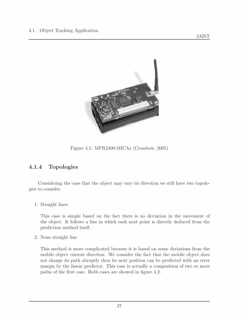
This section gives a brief description of a simple example of a sensor node. Thusfigure 4.1 represents a MICAz mote from Crossbow group. On the market, CrossbowTechnology[23] comes as a leader in supplying sensor systems. Among all their productsthe Mote-KIT2400-Micaz as shown in fig 4.1 can be used to implement the system in areal world environment. The choice of this kit is based on the fact that it supports thebasics functions of the system and provide the important initial raw data for evaluationand manipulation.
1Electronic tags or a pre-embedded object code table defined in the sensor nodes are some techniquesthat can be used to identify the tracked objects.
26
4.1. Object Tracking ApplicationJAIST
Figure 4.1: MPR2400-MICAz (Crossbow, 2005)
4.1.4 Topologies
Considering the case that the object may vary its direction we still have two topolo-gies to consider.
1. Straight lines
This case is simple based on the fact there is no deviation in the movement ofthe object. It follows a line in which each next point is directly deduced from theprediction method itself.
2. None straight line
This method is more complicated because it is based on some deviations from themobile object current direction. We consider the fact that the mobile object doesnot change its path abruptly then its next position can be predicted with an errormargin by the linear predictor. This case is actually a composition of two or morepaths of the first case. Both cases are showed in figure 4.2.
27

4.2. Problem StatementJAIST
Figure 4.2: Topologies
4.2 Problem Statement
Tracking application as other applications in wireless sensor network are meant to bedeployed on a large scale, therefore some issues such as scalability, accuracy and powerconsumption need to be considered. Addressing those issues for object tracking in wirelesssensor network is theoretically twofold:
1. How to expand the network over a large area?
• to handle the increased nodes number
• to protect the system against nodes failure
2. How to handle the tracking application in such conditions?
• to manage the communication through the network
• to minimize the energy consumption during communications between nodes
4.3 Proposed Solution
To resolve the problem described above we need to define first an architecture thatcan support any network change and second a tracking mechanism that can achieve, basedon that architecture, low energy for the application.
28

4.3. Proposed SolutionJAIST
4.3.1 Network Architecture
Settings
• Sensor initialization and identificationThe network is organized so that each node knows its ID and its location in thesensing field. At this step all nodes belong to level-0 in the architecture.
• ClusteringAfter the deployment of sensor nodes they will be grouped into cluster.
• ElectionNodes which are in the same range elect a cluster head2 and restarts clusteringin higher level. This process will continue until it reaches the sink node, thus alllevel-(m-1) clusters are grouped into a single level-m cluster. In this architectureeach level has its own tasks and communicates to others through its elected leader(cluster head) it is shown in figure 4.3.
Figure 4.3: Multi-tier architecture from [2]
2Determine the cluster head is out of the scope of the thesis.
29
4.3. Proposed SolutionJAIST
Advantages
This multi-tier architecture is proposed to solve the problem of large scale deploy-ment. In this network, nodes will report their data to the cluster head while the mobileobject is in their range otherwise keep silent. By using this architecture the transmissionwill be done within one hop to reduce the number of packets to be transferred. Thereforeless energy will be consumed to execute the tasks. This architecture although it facilitatesthe expansion of the network, it will permit the recovery process in case of node failureand keep the reporting rate low and only restricted within the cluster.
4.3.2 Prediction Strategy
Step 1: Object detection and monitoring
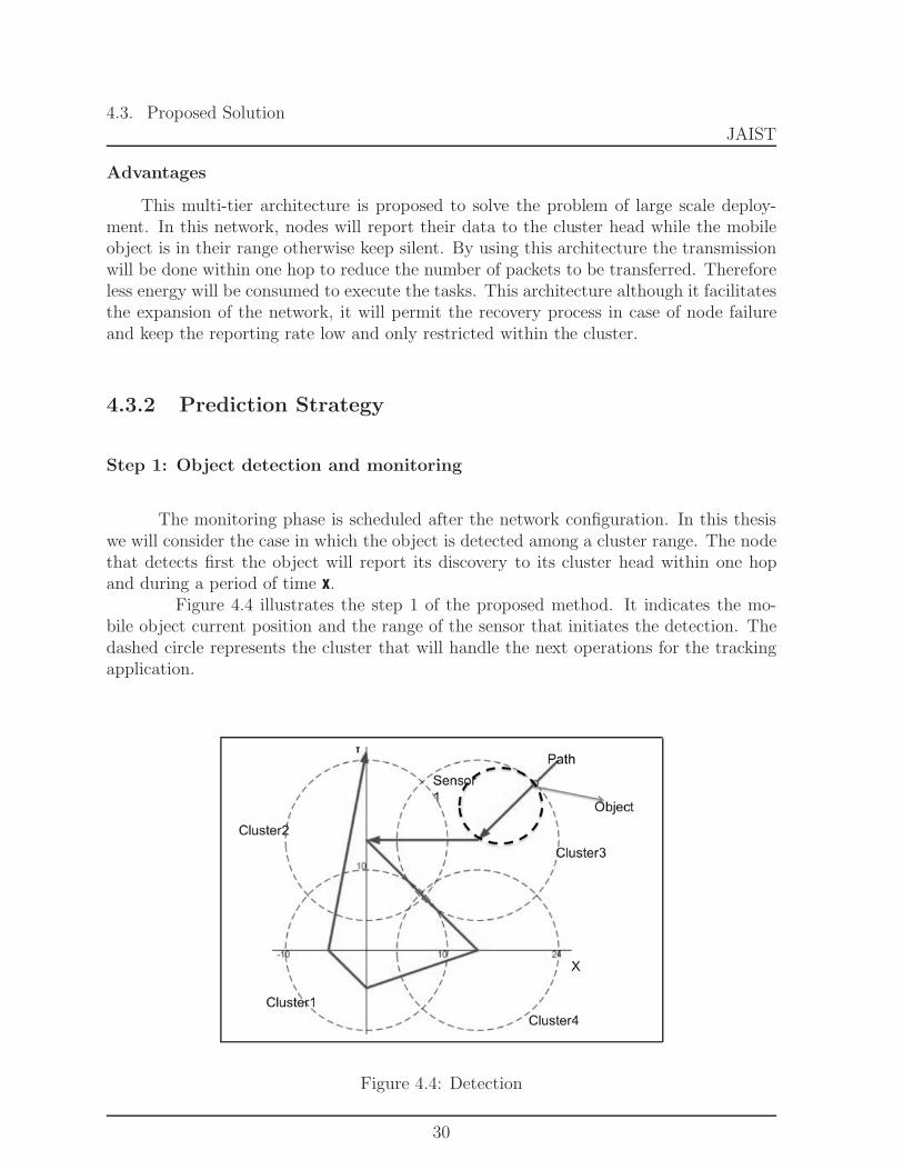
The monitoring phase is scheduled after the network configuration. In this thesiswe will consider the case in which the object is detected among a cluster range. The nodethat detects first the object will report its discovery to its cluster head within one hopand during a period of time x.
Figure 4.4 illustrates the step 1 of the proposed method. It indicates the mo-bile object current position and the range of the sensor that initiates the detection. Thedashed circle represents the cluster that will handle the next operations for the trackingapplication.
Figure 4.4: Detection
30

4.3. Proposed SolutionJAIST
Algorithm for Sensor Node
1: loop
2: Monitoring3: if Object Detected in range then
4: Report5: else
6: if sensor is boundary then
7: Go to sleep mode8: end if
9: end if
10: Delay11: end loop
Table 4.1: Sensor Node Algorithm
Step 2: Prediction
The cluster head will keep a history of all previous location of the object while it isin its range. When it approaches the boundary of the cluster range the prediction value isthen calculated. The next section presents the formulas used to compute the predictionvalue. Based on obtained predictive values figure 4.5 indicates the predicting area of thenode that will handle the next tracking.
Linear Predictor
The next location of the object is computed by using the linear predictor. Thelinear predictor uses only the previous two positions to linearly predict the next locationby using the following equations. We can estimate the speed, the direction and the nextlocation of the object by using the following equations.
• Speed of the moving object
v =
√(xi − xi−1)2 + (yi − yi−1)2
ti − ti−1
(4.1)
• Direction of the mobile object
θ = arccosti − ti−1√
(xi − xi−1)2 + (yi − yi−1)
2
(4.2)
31

4.3. Proposed SolutionJAIST
• Next location of the mobile object
xi+1 = xi + vt cos(θ) (4.3)
yi+1 = yi + vt sin(θ) (4.4)
X Position of the mobile object on X-axis
Y Position of the mobile object on Y-axis
t Time of motion detection
Table 4.2: Linear Predictor
Figure 4.5: Prediction
32

4.3. Proposed SolutionJAIST
Algorithm for Cluster Head
1: listen till timeout or receive2: if receive (CurrentPosition, SenderNode)//NewThread then
3: if LastPosition is defined then
4: PredictedPosition 2(CurrentPosition) − LastPosition5: acitveSN [ ] 06: cancel previously waiting Threads7: Locate8: if in range then
9: send wake up10: else
11: send recover12: end if
13: end if
14: LastPosition CurrentPosition15: acitveSN [SenderNode] 116: start timer17: continue to listen18: else
19: Timeout20: PredictedPosition 2(PredictedPosition) − LastPosition21: acitveSN [ ] 022: cancel previously waiting Threads23: Locate24: if in range then
25: send wake up26: else
27: send recover28: end if
29: PredictedPosition undefined30: end if
Table 4.3: Cluster Head Algorithm
33

4.3. Proposed SolutionJAIST
4.3.3 Synchronization
The synchronization problem can occur in three different situations all shown infigure 4.6.
1. Single report
One sensor reports its first detection and stops. In this case no prediction canbe done until the other sensors start reporting.
2. Unordered report
• One sensor reports the first detection of position x1 at time t1
• Another sensor reports its detection of position x2 at time t2
• cluster head receives the second report before the first.
• cluster head assumes reverse motion from position x2 to x1 such that t1 < t2and x1 = x2.
Figure 4.6: Synchronisation
3. Multiple reports
Two or three different sensors report simultaneously within a certain time frame.
34

4.3. Proposed SolutionJAIST
To resolve this problem, we propose a simple synchronization mechanism in-spired from the consensus problem for out of order reporting from nodes. For the lastsituation their data averaging can be useful.
1. Averaging can be used to provide an easy solution for the last situation with mini-mum accuracy loss.
2. For the second situation delay the direction calculation to give opportunity for anyof the reporting sensors to send two consecutive(making use of the guaranteed FIFOordered channel) reports, thus ignoring other in between reports.
4.3.4 Recovery Mechanism
Miss Prediction
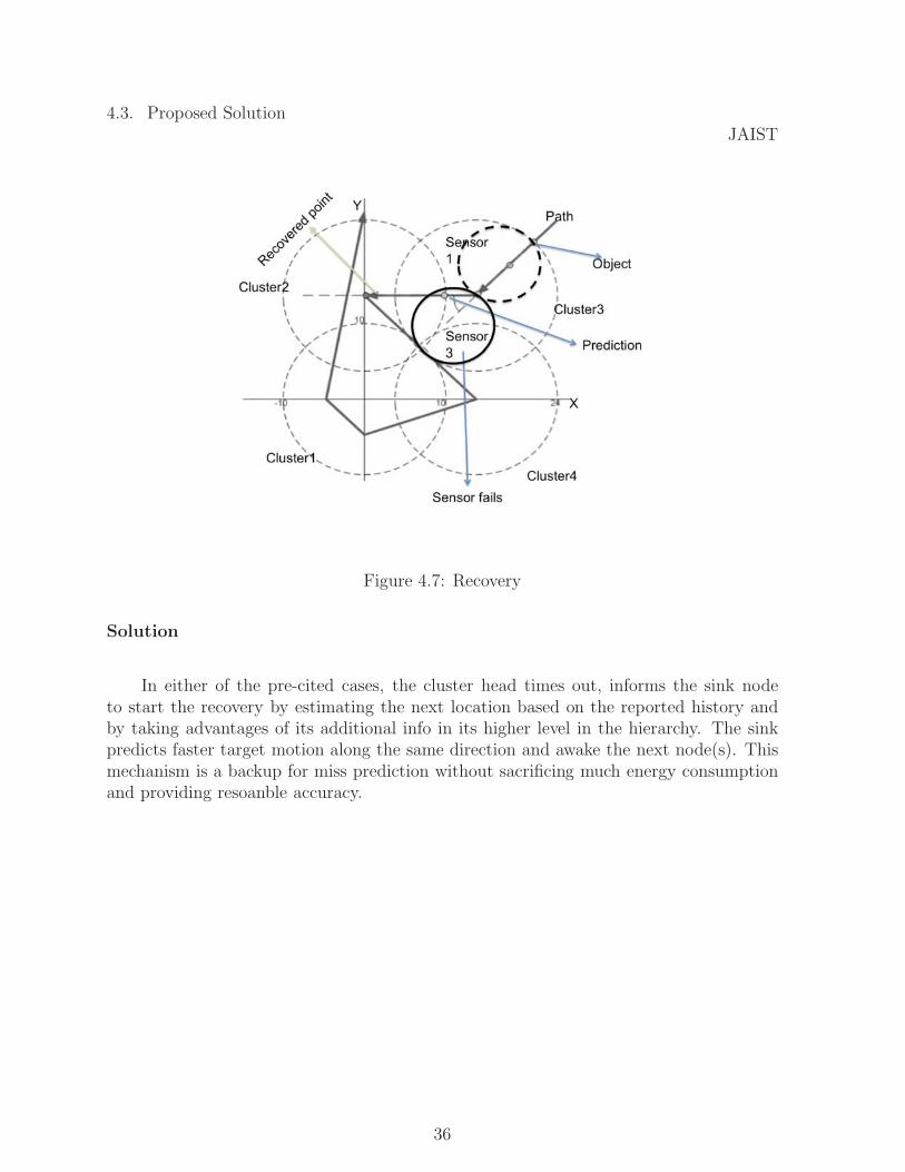
Like any other prediction, the prediction we proposed is associated with miss predic-tion and error. Figure 4.7 shows the recovery phase. The recovery mechanism is initiatedwhen the cluster head cannot locate the next position of the mobile object whether be-cause sensor fails to wake up, a bad prediction has been made or predicted outside therange. From figure 4.7
• the current position of the mobile object is identified
• the circle represents the sensor range of the detected sensor node
• the dashed circle represents the cluster range.
• the predicted position is shown in cluster 2 while the object is leaving the firstsensor.
• the position where the sensor failed to wake up causing cluster head to initiaterecovery is also indicated.
• the higher level predicted position is shown in cluster 2.
35
4.3. Proposed SolutionJAIST
Figure 4.7: Recovery
Solution
In either of the pre-cited cases, the cluster head times out, informs the sink nodeto start the recovery by estimating the next location based on the reported history andby taking advantages of its additional info in its higher level in the hierarchy. The sinkpredicts faster target motion along the same direction and awake the next node(s). Thismechanism is a backup for miss prediction without sacrificing much energy consumptionand providing resoanble accuracy.
36

4.4. System flow chart JAIST
4.4 System flow chart
4.4.1 Mobile object
Figure 4.8: The object flow chart
37

4.4. System flow chart JAIST
4.4.2 Sensor Node
Figure 4.9: Sensor node flow chart
38

4.4. System flow chart JAIST
4.4.3 Cluster head
Figure 4.10: Cluster Head flow chart
39

4.4. System flow chart JAIST
4.4.4 Sink node
Figure 4.11: Sink node flow chart
40
4.4. System flow chart JAIST
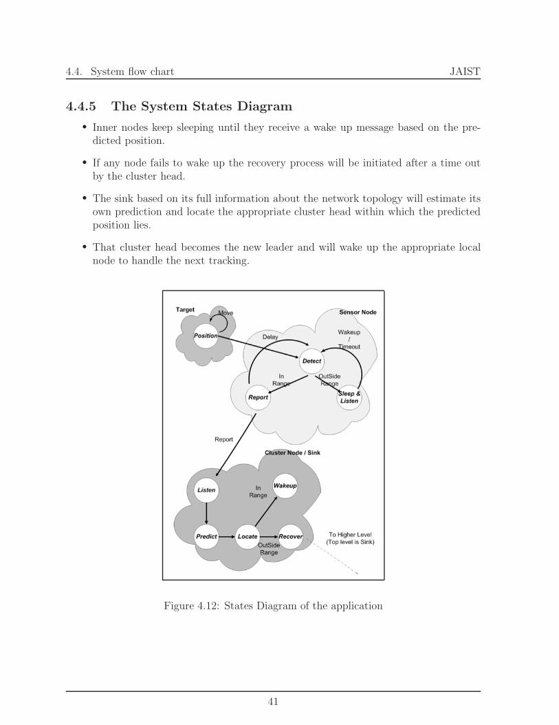
4.4.5 The System States Diagram
• Inner nodes keep sleeping until they receive a wake up message based on the pre-dicted position.
• If any node fails to wake up the recovery process will be initiated after a time outby the cluster head.
• The sink based on its full information about the network topology will estimate itsown prediction and locate the appropriate cluster head within which the predictedposition lies.
• That cluster head becomes the new leader and will wake up the appropriate localnode to handle the next tracking.
Figure 4.12: States Diagram of the application
41
Chapter 5
Experiment
It is di cult to directly deduce the e ciency of any approach without performing fairexperiments using varying simulation parameters. This chapter presents the experiment
conducted to determine whether or not the approach can improve the energy savingissue. It describes the tools, modules and metrics used for the simulation.
5.1 Environment
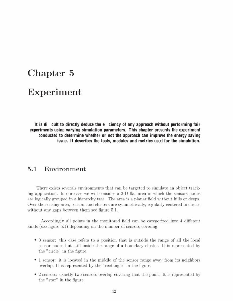
There exists severals environments that can be targeted to simulate an object track-ing application. In our case we will consider a 2-D flat area in which the sensors nodesare logically grouped in a hierarchy tree. The area is a planar field without hills or deeps.Over the sensing area, sensors and clusters are symmetrically, regularly centered in circleswithout any gaps between them see figure 5.1.
Accordingly all points in the monitored field can be categorized into 4 differentkinds (see figure 5.1) depending on the number of sensors covering.
• 0 sensor: this case refers to a position that is outside the range of all the localsensor nodes but still inside the range of a boundary cluster. It is represented bythe ”circle” in the figure.
• 1 sensor: it is located in the middle of the sensor range away from its neighborsoverlap. It is represented by the ”rectangle” in the figure.
• 2 sensors: exactly two sensors overlap covering that the point. It is represented bythe ”star” in the figure.
42
5.2. Experiment SetupJAIST
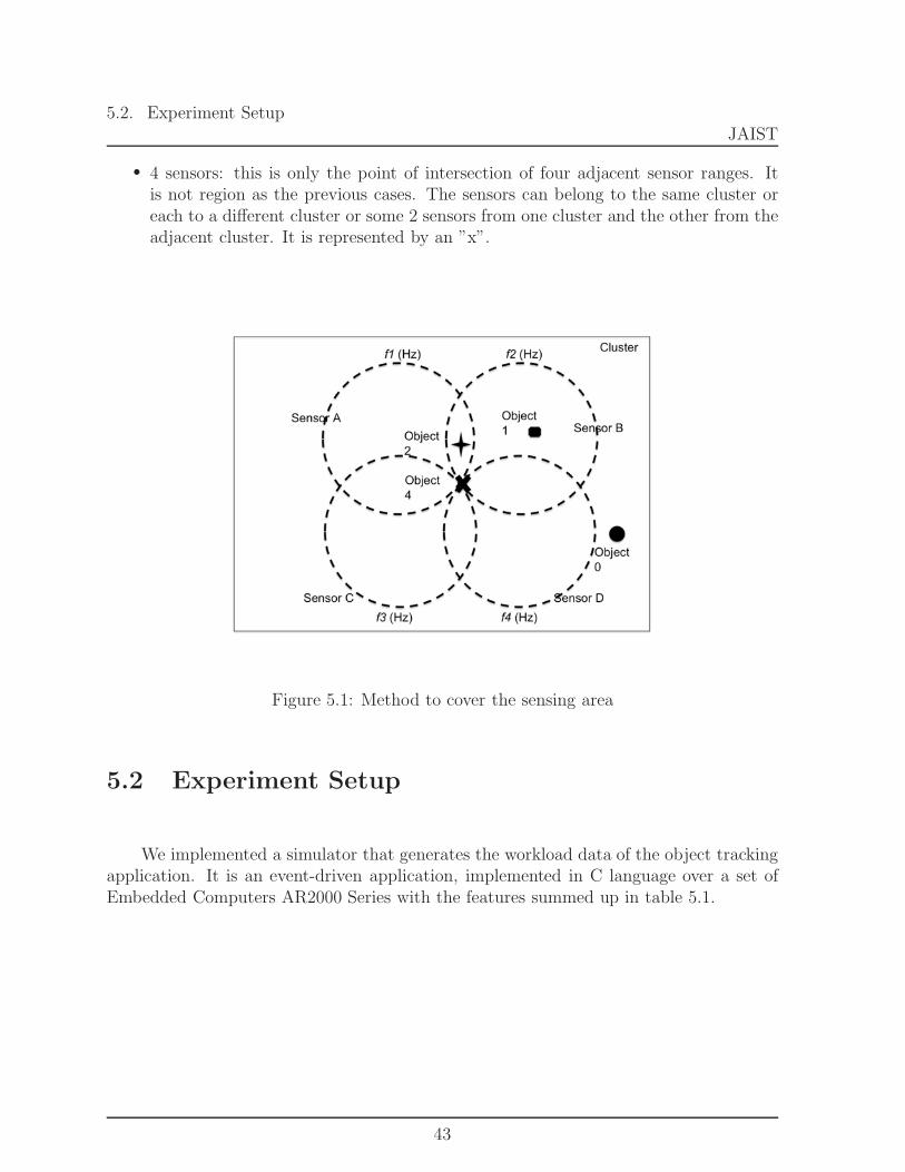
• 4 sensors: this is only the point of intersection of four adjacent sensor ranges. Itis not region as the previous cases. The sensors can belong to the same cluster oreach to a different cluster or some 2 sensors from one cluster and the other from theadjacent cluster. It is represented by an ”x”.
Figure 5.1: Method to cover the sensing area
5.2 Experiment Setup
We implemented a simulator that generates the workload data of the object trackingapplication. It is an event-driven application, implemented in C language over a set ofEmbedded Computers AR2000 Series with the features summed up in table 5.1.
43

5.3. Path for the moving objectJAIST
Name DescriptionPC Embedded Computers
AR2000 Series Model 110
Operating System FreeBSD 6.0
Processor Intel Pentium M
Card Supported CompactFlash, CardBus andPC Card Standard
Connectors Audio, USB 2.0, IEEE 1394
LAN 2xLAN (10/100BASE-T),PXE enabled
Power Supply AC & DC (16V to 24V )aresupported
Table 5.1: Functions and Features for Embedded Computer AR2000 Series
5.3 Path for the moving object
To evaluate the tracking method we define a path containing an example of thelatter topology described in chapter 4. The mobile object while executing the path canbe detected by any sensor in the network. We fixed a start point at which the objectmust start moving. Then the object keep moving along the path crossing specified points.The motion direction does not change in between the points but only at each point whenreaching it. In the other hand the speed between points can change randomly.
Figure 5.2: Path for a mobile object
44

5.4. Network TopologyJAIST
5.4 Network Topology
Once deployed in the sensing field the sensor nodes, as described in chapter 4, willbe clustered and arranged into an hierarchy. The result network shown in figure 5.4) is a3 layer architecture in which each embedded machine is emulated as a cluster and eachcluster is a group of 4 sensor nodes.
Figure 5.3: Sensor Network
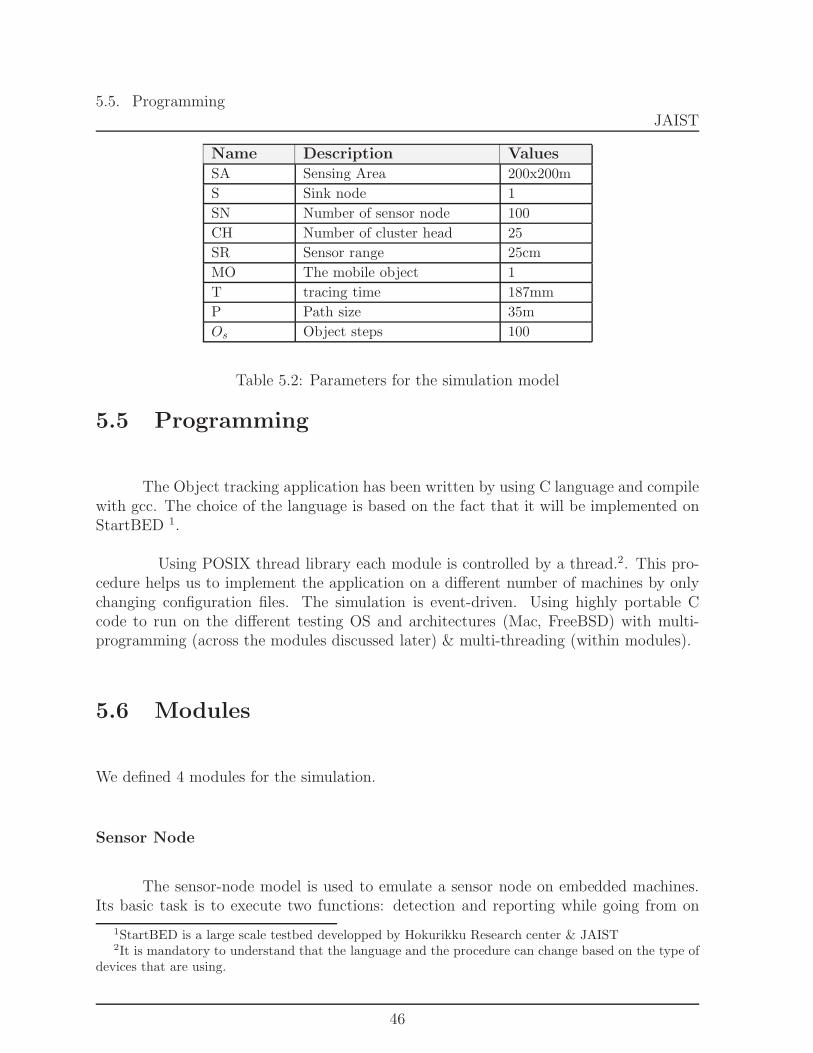
In table 5.2 we described all the paramters used to setup the experiment eniron-ment.
45
5.5. ProgrammingJAIST
Name Description ValuesSA Sensing Area 200x200m
S Sink node 1
SN Number of sensor node 100
CH Number of cluster head 25
SR Sensor range 25cm
MO The mobile object 1
T tracing time 187mm
P Path size 35m
Os Object steps 100
Table 5.2: Parameters for the simulation model
5.5 Programming
The Object tracking application has been written by using C language and compilewith gcc. The choice of the language is based on the fact that it will be implemented onStartBED 1.
Using POSIX thread library each module is controlled by a thread.2. This pro-cedure helps us to implement the application on a different number of machines by onlychanging configuration files. The simulation is event-driven. Using highly portable Ccode to run on the different testing OS and architectures (Mac, FreeBSD) with multi-programming (across the modules discussed later) & multi-threading (within modules).
5.6 Modules
We defined 4 modules for the simulation.
Sensor Node
The sensor-node model is used to emulate a sensor node on embedded machines.Its basic task is to execute two functions: detection and reporting while going from on
1StartBED is a large scale testbed developped by Hokurikku Research center & JAIST2It is mandatory to understand that the language and the procedure can change based on the type of
devices that are using.
46

5.7. Experiment ResultsJAIST
state to another; sleep, listen, wake.
Cluster Head
The cluster head model contains a set of functions that can received and save thedata in history and predict the next location of the mobile object.
Sink node
Sink node is the module used to handle the system architecture and the recoveryprocess.
Mobile Object
The object model represents the intruding object. It is meant to execute a pathand generate some stimuli to the nodes.
5.7 Experiment Results
These cases show the motion of the object in the sensing area. The object startsmoving from a random position, detected in sensors range and move continuously alongthe path.
Figure 5.4 shows the comparison between the proposed approach and the con-tinuous monitoring scheme. In the proposed approach, the monitoring is done by cluster.Each sensor reports to its cluster and cluster heads compute the predictive value basedon the order messages have been received. In the case continuous monitoring scheme,one sensor do both monitoring and reporting. It will predict the next node to handle thetracking before going to sleep.
On the Figures two information are revealed along the path: the detection andthe prediction. The prediction is represented by diamonds and indicates at which pointto initiate the recovery mechanism. In the case of the proposed approach figures ?? and5.4(b) show an intense detection each time a variation of the direction occurs. This is dueto the fact that the average position is computed by using the positions received from thesensor nodes. In each case the prediction is obtained based on that final coordinate.
47

5.7. Experiment ResultsJAIST
(a) Continuous monitoring(CM)
(b) [Proposed approach
Figure 5.4: Number of sensor nodes from 0 to 100 and 1 sink
48

Chapter 6
Discussions
This section first describes results obtained from the simulation, compares with previousapproaches’ results and shows how the proposed solution o ers better energy e cient
solution.
6.1 Performance Metrics
When solving the object tracking problem some important performance metricsneed to be considered. As announced in the introduction we evaluated the performanceof the proposed system:
• by varying the size of the network i.e. apply the system to different scales
• by considering the reporting frequency of sensor nodes to update packets.
In order to evaluate first, the prediction accuracy and second the total energyconsumes by the system for communication and computation. We used metrics such asmissing rate computed by using the Root Mean Square Error the Rmre, communicationbandwidth, total energy transmission.
6.2 Missing Rate
The missing rate is used to estimate the error that can occur while doing predic-tion. It represents an estimation for the distance of the actual target position from thepredicted position.
49

6.2. Missing RateJAIST
6.2.1 Metric
The Root Mean Square Error is directly interpretable in terms of measurementunits, and it is used to compare the deviation in predictions of a the mobile object’sposition. It is given by the equation bellow and denoted by Rmre.
Rmre =
∑n
√Δ2
x + Δ2y
Np
(6.1)
Δx Distance between the predicted and actualposition of the object at time t along thex component
Δy Distance between the predicted and actualposition of the object at time t along they component
Np Number of predictions
Table 6.1: Root Mean Square Error parameters
6.2.2 Result Analysis
Figure 6.1: Prediction error
50

6.3. CommunicationJAIST
6.2.3 Interpretation
The graph shows the prediction rate computed for each run of the experiment.The first case shows how the number of predictions increases. This is based on the factthat the number of nodes available to handle the next movement of the tracking is lessthan the other cases. The graph shows a slight difference between the other three runs.This is due to the fact that less predictions are done.
6.3 Communication
In Wireless Sensor Networks, nodes are capable of distributed sensing and controlto operate in dynamic environments where the occurrence of events can be very rare. Inthe other hand tracking applications when applied to these networks require far morereporting from the sensor nodes. This fact reveals other challenges such as how to econo-mize and adaptively control all resources such as energy, communication bandwidth, andsensor sampling frequency.
6.3.1 Metrics
Generally speaking, communication bandwidth in computer networks is often usedas a synonym for data transfer rate i.e. the amount of data that can be carried fromone point to another. The following line described the three parameters used to evaluatethe usage of the communication bandwidth. They are: Reporting messages, Wake upmessages, Recovery requests.
51

6.3. CommunicationJAIST
6.3.2 Result Analysis
Figure 6.2: Communication
6.3.3 Interpretation
The graph compares between the proposed approach and the simple detect reportapproach. The first chart represents the proposed system and the second one describesthe result of the naive scheme. The naive scheme considers only reporting messages whilethe proposed systems must handle in addition, wake up messages and recovery requests.From the obtained results shown in the graph we can notice that the difference betweenthe schemes in term of communication is negligible within 3% i.e the proposed approachcan balance the data flow as the size of the network increases.
52

6.4. Total Energy ConsumptionJAIST
6.4 Total Energy Consumption
6.4.1 Metrics
The total energy consumption in the system is denoted by TEC . It is the sum ofboth the total energy consuming for monitoring denoted by TEM and the total energyconsuming for communication denoted by TECM .
TEC = TEM + TECM (6.2)
6.4.2 Result Analysis
Figure 6.3: Energy
6.4.3 Explanation
To compute the energy consumption we adopted the values provided by the WINSproject from Rockwell science center as proprosed by Xu et al. 2004 [12].
53

6.5. Proposed approach vs DPT, PREMON and PESJAIST
ComponentMode PowerMCU Activate 360
MCU Sleep 0.9
Sensor Active 23
Radio Transmission 720
Radio Receiving 369
Table 6.2: Energy Consumption on WINS nodes
6.5 Proposed approach vs DPT, PREMON and PES
By developing the object tracking application our priority was to solve the fall-backs encountered by the previous methods.
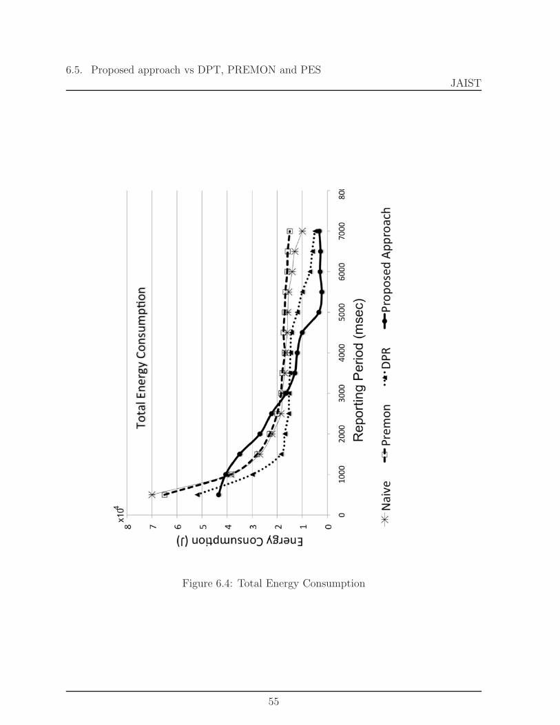
The first graph illustrated in figure 6.4 shows the effect of varying the reportinginterval of sensor nodes on energy. Since object tracking application must keep the re-porting frequency as low as possible in order to save energy.
We can notice that the energy efficiency of the approach falls under 50% whichis better comparing to the prior approaches 55%. This is practically the same until 5000msec, due to the fact that during this period the number of proposed sensors participatingin the tracking scenario is almost the same. The rest of the graph reaches a number lessthen 10% for the proposed approach since more nodes are available to track the objectbut not active. On the other hand more useless updates is performed by the prior work.
Figure 6.5 shows the graph that illustrates the energy of the system when thenumber of nodes increase. The prior work divided the monitoring area into grids. We didthe comparisons based on the fact that when the number of grids increases, the resultinggrid location model approaches our geometrical location model. The results show thatthe more accurate the system gets the more energy is consumed.
54
6.5. Proposed approach vs DPT, PREMON and PESJAIST
Figure 6.4: Total Energy Consumption
55

6.5. Proposed approach vs DPT, PREMON and PESJAIST
Figure 6.5: Prediction Accuracy
56

Chapter 7
Conclusion and Future Work
This section emphasizes the system improvement and mentions work that can beconducted to further enhance the proposed approach.
7.1 Conclusion
The thesis explored the usage of mobile object tracking applications in WirelessSensor Networks. In this kind of applications, scalability or reporting period or data pre-cision or network workload, or any other issue is somehow or another energy consumptionrelated. This is due on the fact that the power carried by each sensor node is very limited.This thesis main concern was two fold, first to simulate a tracking application to handlearchitecture modifications and second to address the energy saving problem under suchconditions.
To handle the architecture modifications problem we propose a multi-tiers archi-tecture. Over this architecture we simulate an object tracking application. This latter isbased on a prediction mechanism in which cluster heads decide whether or not sensor nodesshould be alerted to wake up and report the movement states of the object. Otherwisenodes keep sleeping thus save energy. The system consists of a detection phase that de-termines and reports the movement states of an object. Based on a Sleep/Predict/Awakemechanism a prediction estimates the next movement. As this method is subject to somemiss-prediction and errors, we proposed a recovery phase to reduce the effect of thosemiss predictions. At last a locating model to determine which node to wake up to handlethe next tracking scenario.
Simulation has been done to evaluate the proposed system. Besides other prob-lems encountered while running the experiments, the synchronization issue was consid-ered. This problem showed up during the reporting operations of sensor nodes but the
57
7.2. Future Work JAIST
system responded well with simple synchronization techniques. As shown in chapter 6the proposed system could:
1. Reduced the rate of increase in energy consumption by taking advantages of thehierarchical structure, figure 6.4.
2. Reduced the rate of monitoring by using sleep/predict /wake up mechanism.
3. Reduced the rate of communication bandwidth by suppressing useless wake up mes-sage in figure 6.2.
4. Reasonable recovery from miss predictions managed to reduce the effect of detectionfailures (miss prediction, real failures, target sudden variations) as shown in figure6.1
5. Minimized the management overhead of the prediction and wake up mechanism. 6.4
6. The higher average sleep time the more energy saved, as we analyzed the metricsdescribed in the experiment chapter. We showed that the proposed mechanism in-creases the sleep time per node thus it decreases the energy consumption, figure 6.5.
In conclusion, the proposed mechanism increases the sleep time per nodethus it decreases the energy consumption.
7.2 Future Work
1. Network In order to strongly experience the scalability issue of the system, the net-work must handle a large number of nodes. Therefore a potential future researchis to bring the system on a testbed. Due to node mobility, environmental obstruc-tions, restricted ressources etc the sensor networks exhibit a highly dynamic networktopology, additional future work can be to use a dynamic network to improve oursystem.
2. Reporting Mechanism Using other predictors would require more computationalcomplexity consuming more time or more sophisticated node architecture whichagain uses more energy. Yet a better synchronization solution can improve theaccuracy of the prediction and reduce the need to recover. The linear predictionaccuracy is maximized when the steps are very close, i.e., more samples are involved(transmissions). This process can consume more energy, thus a compromise shouldbe made between accuracy and energy conservation.
3. Deployment Finally, in the future we are expecting or at least we can challenge areal-world world application based on our system.
58

Bibliography
[1] Feng Zhao and Guibas Leonidas J. Wireless Sensor Networks An information pro-cedessing approach, Edited by Karyn Johnson Rick Adams. San Francisco, California:Morgan Kaufman: Elsevier Science 2004, 2004.
[2] Perkins, Charles E. Ad hoc networking Edited by Charles E. Perkins Editor. Boston,MA: Addison-Wesley, 2001.
[3] Stevens, W. Richard. UNIX network programming 2nd ed Vol. 2. Upper Saddle River,NJ 07458: Prentice Hall PTR, 1999.
[4] Tatiana, Bokareva, et al. Wireless Sensor Networks for Battlefield Surveillance LandWarfare Conference (LWC 2006). Brisbane, 2006. 8.
[5] Alan, Mainwaring, Polastre Joseph, Szewczyk Robert, Culler David, and AndersonJohn. Wireless Sensor Networks for Habitat Monitoring Edited by ACM. WSNA.Georgia, 2002. 10.
[6] Konrad, Lorincz, et al. Sensor Networks for Emergency Response: Challengesand Opportunities. PERVASIVE Computing (IEEE Pervasive Computing) 3, no. 4(October-December 2004): 16-23.
[7] Tabar, Ali Maleki, Keshavarz Arezou, and Aghajan Hamid. Smart Home Care Net-work using Sensor Fusion and Distributed Vision-based Reasoning. VSSN’06. Cali-fornia: ACM, 2006. 10.
[8] S. Banerjee and S. Khuller A clustering scheme for hierarchical control in multi-hopwireless networks Proceedings of IEEE INFOCOM, pp. 1028-1037, Anchorage AK,April 2001.
[9] Kung, H.T. and Vlah, D. E cient location tracking using sensor networks WirelessCommunications and Networking Conference (WCNC), 2003.
[10] Winter, J.; Xu, Y. and Lee, W. C. Prediction based strategies for energy savingin object-tracking sensor networks IEEE International Conference on Mobile DataManagement 2004, 364-357.
59

Bibliography JAIST
[11] Yingqi Xu and Wang-Chien Lee On Localized Prediction for Power E cient ObjectTracking in Sensor Networks Proceedings of the 23 rd International Conference onDistributed Computing Systems Workshops (ICDCSW03).
[12] Yingqi Xu; Winter, J. and Wang-Chien Lee Dual prediction-based reporting for objecttracking sensor networks The First Annual International Conference on Mobile andUbiquitous Systems: Networking and Services (MobiQuitous4), Aug. 22-26, 2004,pp. 154 163.
[13] T. Tung and A. Jamalipou A novel sectional paging strategy for location tracking incellular networks Communications Letters, IEEE, 8(1), Jan 2004.
[14] S Goel and T. Imielinski, Prediction-based monitoring in sensor networks: takinglessons from MPEG ACM computer Communication Review, 31(5), October 2001.
[15] Song Ci, Mohsen Guizani and Hamid Sharif, Adaptive clustering in Wireless SensorNetworks by mining sensor energy data, Computer Communications, Volume 30,Issues 14-15, 15 October 2007, Pages 2968-297.
[16] Yang, H. and Sikdar, B. A protocol for tracking mobile targets using sensor networksProceedings of the First IEEE. 2003 IEEE International Workshop 71- 81, 11 May2003.
[17] Network Embedded Systems Technology (NEST).http: / /dtsn.darpa.mil / ixo /programdetail.asp?progid=42.
[18] Engineering, UC Berkeley College of. http: / /www.coe.berkeley.edu .
[19] Inc., Dust. http: / /www.dust-inc.com .
[20] Research, Intel. http: / /www.intel.com / research / index.htm
[21] Systems, UCLA Center for Embedded Network. http: / /cens.ucla.edu /
[22] Wikipedia. http: / /en.wikipedia.org /wiki /Sensor Networks.
[23] Crossbow Tehnology. http: / /www.xbow.com / index.aspx
[24] Rockwell Science Center. http: / /www.wins.rsc.rosckwell.com
60