implementation of a real time analog secure image
TRANSCRIPT

POLİTEKNİK DERGİSİ JOURNAL of POLYTECHNIC
ISSN: 1302-0900 (PRINT), ISSN: 2147-9429 (ONLINE)
URL: http://dergipark.org.tr/politeknik
Implementation of a real time analog secure
image communication system via a chaotic
circuit
Kaotik devre ile gerçek zamanlı analog güvenli
görüntü iletişim sisteminin uygulanması
Yazar(lar) (Author(s)): Aybaba HANCERLİOGULLARI1, Khaled Mohamed EL HADAD2, Erol KURT3
ORCID1: 0000-0001-7008-480X
ORCID2: 0000-0002-0374-4350
ORCID3: 0000-0002-3615-6926
Bu makaleye şu şekilde atıfta bulunabilirsiniz(To cite to this article): Hancerliogulları A., El Hadad K.M.
and Kurt E., “Implementation of a real time analog secure image communication system via a chaotic
circuit”, Politeknik Dergisi, 22(4): 1083-1092, (2019).
Erişim linki (To link to this article): http://dergipark.org.tr/politeknik/archive
DOI: 10.2339/politeknik.557289

Politeknik Dergisi, 2019; 22(4): 1083-1092 Journal of Polytechnic, 2019; 22(4): 1083-1092
1083
Kaotik Devre ile Gerçek Zamanlı Analog Güvenli
Görüntü İletişim Sisteminin Uygulanması Araştırma Makalesi / Research Article
Aybaba HANCERLİOGULLARI1, Khaled Mohamed EL HADAD2, Erol KURT3* 1Faculty ofArts and Sciences Physics Department, Kastamonu University, Turkey
2Department of Electronics, College of Engineering, Elmergib University, 40414 Libya 3Technology Faculty Electric-Electronics Enginering Department, Gazi University, Turkey
(Geliş/Received 23.04.2019 ; Kabul/Accepted 27.05.2019)
ÖZ
Eşazmanlı bir kaotik devreyi temel alarak yeni bir güvenli görüntü haberleşme sistemi tasarlanıp uygulanmaktadır. Yazarlardan
biri tarafından yakın zamanda önerilen yeni kaotik devre direnç, bobin ve diyot çiftinden (yani R2L2D) müteşekkildir. Eşzamanlılık
birimi hakim - esir düzenlenimi ile çalışmaktadır. Gerçek zamanlı haberleşmeyi sağlamak için, analog bir hakim devre ilkin
sayıların kaotik dizilerini oluşturmak için uygulanmıştır. Sonrasında; bu analog araç bir bilgisayara bir analog / sayısal dönüştürücü
yardımıyla iletilmekte ve gizli görüntü elde edilmektedir. Ayrıca; esir devre görüntünün gri seviyelerinin çıkarılması işlemi için bu
kaotik dizilerin bir kopyasını almaktadır. Sayısal kaotik görüntü etkin bir yöntemle sayısal / analog dönüştürücü yardımıyla esir
devreye iletilmekte ve şifresi çözülmüş olan görüntü gerçek zamanlı olarak elde edilmektedir. Bu tekniğin geleneksel olanlara göre
üstünlüğü, gri renkli görüntüleri alıcıya gönderirken bile gerçek zamanlı olmasından dolayı sayısal verinin kaydedilmiş bir
kopyasını gerektirmemesidir. Geleneksel teknikler depolanmış ve işlenmiş verileri kullanır ve bu süreç, günümüzün gelişmiş ağ
ortamında güvenlik sorunlarına sebep olur. Böylece; şifrelenmiş bir görüntüyü gerçek zamanlı bir cihazda analog bir kaotik sistem
kullanarak göndermek belli bir güvenlik üstünlüğüne sahiptir. Şifresi çözülmüş görüntülerle yapılan ilk analizler sürecin zamanla
verimli ve güvenli olduğunu kanıtlamaktadır.
Anahtar Kelimeler: Güvenli iletişim, analog, kaotik devre, görüntü şifreleme, şifre çözme.
Implementation of a Real Time Analog Secure Image
Communication System via a Chaotic Circuit
ABSTRACT
A new secure image communication system has been designed and implemented based on a synchronized chaotic circuit. The new
chaotic circuit, which has recently proposed by one of the authors contains a resistor, two inductors, and two diodes (i.e. R2L2D).
The synchronization part operates with a master – slave configuration. In order to achieve the real-time communication, initially
the analog master circuit has been implemented to generate chaotic sequences of numbers. Then, that analog tool has been
transmitted to a computer via an analog/digital converter and a hidden image has been obtained. Besides, the slave circuit has also
received a copy of that chaotic sequences in order to use it in subtraction process of image gray levels. The digital chaotic image
has been transmitted to the slave circuit via a digital/analog converter with an efficient method and the decrypted image has been
obtained in real-time. The advantage of that technique over the conversional ones is that it does not require any saved copy of the
digital data, even for sending them in gray images to the receiver, since it is real-time. The conventional techniques use the stored
and processed data and that can cause security problems in today’s advanced web media. Thus to send the encrypted image in a
real-time device by using an analog chaotic equipment has certain security superiority. The analyses on the preliminary decrypted
images proves that the process is efficient in time and secure.
Keywords: Secure communication, analog, chaotic circuit, image encryption, decryption
1. INTRODUCTION
The researchers have shown great interest on the
nonlinear and chaotic circuits due to their broad
application areas such as synchronization, noise
characterization, optical beam production, Josephson
junctions, etc. Indeed, studying on a nonlinear system
and chaotic electrical circuits is the most economical and
easy way [1-4]. On the one hand, these circuits can be
defined by simple coupled differential equations.
According to literature, the simplest circuit can be
mentioned as resistor – inductor –diode circuit (RLD),
which leads to a sequence of many period-doublings,
thus it has been used to explore the universality of
“chaos” in that context [5, 6]. When a resistor, diode and
an inductor are joined in series, chaos occurs due to the
nonlinear charge - voltage behavior of the diode[5].
Furthermore, using the invariants characterizing
attractors as parameters for inputs, make it possible to get
single-step and multiple-step predictions of chaotic time-
series, which controls RLD circuits [7]. In other
applications, for instance, Chua’s diode and non-
autonomous Chua’s diode [6] there exists nonlinear
*Sorumlu Yazar (Corresponding Author)
e-posta : [email protected]

Aybaba HANCERLİOGULLARI, Khaled Mohamed El HADAD, Erol KURT /POLİTEKNİK DERGİSİ,Politeknik Dergisi,2019;22(4): 1083-1092
1084
resistors, which ensure the complexity. When Chua's
circuit was first invented in early 1980’s, it was
concerned by many researchers on the generation of True
Random Number Generators (TRNG) for the
cryptographic maneuvers[6]. Considering the artificial
TRNG with many advantages, randomness take place
through an unpredictable natural process in the hardware.
Random Number These generators provide sequential
and statistically independent random numbers [8]. Apart
from the studies above, many other circuits have also
been proposed for different applications, but discussion
over all those circuits is a comprehensive task and out of
the consideration of present paper.Chaotic
synchronization has recently gained more concern as area
of research in secure communication. Some chaotic
synchronizing and relevant factors are discussed by Feki
[9]. However, two identical chaotic system
synchronization was initially reported in 1990s [10].
Electrical engineers realized that the generated chaos can
be a possible source of communication system security,
because chaos is extremely sensitive to the initial
conditions and parameters [11]. Secure communication
using synchronization between chaotic systems was a
newly found method of communication security. This
“hardware key” secures communication that rapidly
takes place. The “hardware key” was a new concept but
engineers and scientists soon realized its importance for
secure communication systems. There was a great scope
of encryption through chaos; therefore, large number of
researchers conducted researches on it. Electrical
engineers of that time felt that it could help creating
communication security because of its unique
parameters. Later this type of chaotic hardware key was
acknowledged as useful by researchers, engineers and
experts all over the world [12]. Significant potentials of
“hardware key” led to vast and multiple researches in the
field of communication security that further opened new
avenues for progress in this field.Many image encryption
schemes based on chaos theory have been presented in
literature. In 1992, Bourbakis and Alexopoulos [13]
proposed an image encryption scheme utilizing SCAN
language for encryption and compression of an image.
During recent years, many logistic map algorithms were
studied. The usage of digital chaotic systems instead of
analog chaotic systems have also been proposed.
Algorithms convert pixels into chaotic maps to make
chaotic map lattice. This encryption is reprocessed using
secret system parameters. Pisarchik and Zanin [14],
Xiangdong, Junxing [15] have presented another
algorithm using chaos theory and sorted transformations.
Hu and Han [16] used pixel-based scrambling for digital
medical images protection. Tong and Cui [17] introduced
image encryption using dynamic cipher shifting.
Pisarchik and Zanin [14] dynamically shifted compound
chaotic cipher sequence. They moved all the pixels
through 2D chaotic map using substitution and
permutation, which moved new pixels as a permutation
of the original ones. In the substitution process, the pixel
values are altered sequentially by Fridrich [18], Gao,
Zhang [19]. The chaotic algorithm with its power and
tangent functions used a chaotic sequence generated by
XOR operation [20]. Zhou, Wong [21] have proposed
parallel image encryption algorithm using discretized
Kolmogorov flow map, which first permutes a chaotic
map and encrypts it in the cipher block chain mode.
Communication security using encryption works by
converting the data to an incomprehensible (not
understandable) format with the help of a transmitter.The
transmitter makes the data invisible and quite unreadable
during the communication/transmission processes. This
encryption is transmitted using any insecure link. On the
recipient side, encrypted data is reconverted into
comprehensible format and thus the information is
transmitted securely. There are various methods for data
hiding such as the spatial domain, frequency domain and
compressed data domain. Among them, direct methods
have certain advantages in the sense that they use all the
image-based data and provide very accurate registration
[22]. It has a disadvantage as well and that is their
memory requirement, and besides, close initialization
and techniques may not be easy to implement. In order to
prove robust chaos encryption system, there are many
tests to check. Histogram results and correlation values
have shown that encryption of images can be
unpredictable [23]. However, all those studies have come
out a security issue that one can reach the digital data
easier via internet and hardware or analog circuit-based
solutions can serve better solutions, when they are used
in real-time basis in order to prevent that online
insecurity.In a recent study[24], Kurt and Bingol has
proposed a new circuit, namely R2L2D circuit. A wide
feeding amplitude and frequency regimes have been
explored in this circuit. A new sweep up/down effect has
also been discovered by them and that effect governs the
identification of the dynamics in terms of periodic and
chaotic regimes in this circuit for sweeping parameters
[9, 24]. In the present paper, this new R2L2D circuit is
applied to a real-time secure image communication
application. Since this hardware and real-time based
operation is secure than the software and digital stored
systems, that new approach offers a good image security
method in that field.
2. BACKGROUND ON SYNCHRONIZATION
AND SECURE COMMUNICATION
The R2L2D circuit has been explored for its amplitude
and frequency regimes [24] because of its sweep
up/down behavior. In that manner, the periodic and
chaotic regimes may invade each other for different
frequencies. Thus, it defines an uncertainty region for the
thresholds of the dynamic regimes depending on the
feeding voltages. That effect has an importance for the
synchronization and encryption studies since the feeding
voltages affect the regime. To be at the safe side, one
should study on a chaotic region in the map given in
thresholds of the dynamic regimes d epending on the

IMPLEMENTATION OF A REAL TIME ANALOG SECURE IMAGE COMMUNICATION SY… Politeknik Dergisi, 2019; 22 (4) : 1083-1092
1085
feeding voltages. That effect has an importance for the
synchronization and encryption studies since the feeding
voltages affect the regime. To be at the safe side, one
should study on a chaotic region in the map given in
Ref.[25]. Strictly speaking, the synchronization of
R2L2D can be studied for a wider parameter region in
R2L2D circuit compared to the ordinary RLD circuit. It
is also obvious from Refs. [24, 25] that the best
synchronization performance can be obtained for lower
frequencies and amplitudes. According to experiments,
the chaotic regimes also affect the recovery of a masked
signal as proven in Ref.[26].The determination of
synchronization is defined via the Master circuit as
follows. The system equations of the Master function (m)
are formed as,
𝑑𝑥
𝑑𝑡= 𝑓(𝑥(𝑡)) (1)
A Slave function (s) can be written together
with master and the state equations are arrived
as,
𝑥 = [𝑥𝑚
𝑥𝑠] (2)
Dynamical form of these systems can be summarized as,
𝑚 = 𝑔(𝑥𝑚 , 𝑥𝑠) (3)
𝑠 = ℎ(𝑥𝑚 , 𝑥𝑠) (4)
According to the method of Pecora and Carroll [25], a
copy of slave circuit 𝑥𝑠 is driven together with master
circuit 𝑥𝑚 as follows,
𝑚 = 𝑔(𝑥𝑚 , 𝑥𝑠 )
(5)
𝑠 = ℎ(𝑥𝑚 , 𝑥𝑠 ) (6)
𝑠′ = ℎ(𝑥𝑚 , 𝑥𝑠
′ ) (7)
If time goes to infinity, and the difference |𝑥𝑠 − 𝑥𝑠′ |
converges to zero, and 𝑥𝑠 and 𝑥𝑠′ become identical and
synchronization is provided. As the first step, the
formation of chaotic masking and decryption is made as
in Fig. 1. Initially, the chaotic signal 𝑐(𝑡) is added to the
regular sequence of image pixels values “information
data”, then it is transmitted to the receiver for the
subtraction of chaotic data and decipher the image.
The state equations for the master circuit are given by,
Figure 1. The block diagram of the non-autonomous
chaotic secure communication system.
𝑚 = 𝛼 𝑙𝑛(𝑥𝑚 + 1) + 𝛽 sin(𝑢𝑚) − 𝑧𝑚
𝑚 = −𝛼 𝑙𝑛(𝑦𝑚 + 1) + 𝛽 𝑠𝑖𝑛 (𝑢𝑚) − 𝑧𝑚
𝑚 = (𝐿
𝑅𝐼𝑠) 𝑧𝑚
𝑚 = Ω𝐿
𝑅
(8)
Here x and y denotes the currents flowing from the
branches and z is the phase of the feeding voltage.
Besides, =kT/e as the exponent of diode and =V/L,
where V denotes the maximal applied voltage and L
is nothing else than the inductance of the inductor. Is
gives the saturation current of the diode. xm, ym, zm,
ym, qm and um gives two diode currents, total of diode
currents, charge accumulated on a diode and voltage
angular frequency. Similarly the equations for the
slave circuit are
𝑠 = 𝛼 𝑙𝑛(𝑥𝑠 + 1) − 𝑧𝑠
𝑠 = −𝛼 𝑙𝑛(𝑦𝑠 + 1) − 𝑧𝑠
𝑚 = (𝐿
𝑅𝐼𝑠) 𝑧𝑠
(9)
The slave circuit gets the charge amount q from the main
branch over two branches of slave circuits. Thus, that
process can be described by,
𝑠 = 𝛼 𝑙𝑛(𝑥𝑠 + 1) − 𝑧𝑚
𝑠 = −𝛼 𝑙𝑛(𝑦𝑠 + 1) − 𝑧𝑚
𝑠 = (𝐿
𝑅𝐼𝑠) 𝑧𝑠
(10)
Since the secure communication requires a high order
synchronization to decipher the signal, the functions xs,
ys and qs are controlled by the main current branch of the
master circuit. When the information signal is transmitted
to the system, the equations are defined as,
𝑠 = 𝛼 𝑙𝑛(𝑥𝑠 + 1) − 𝑠(𝑡)
𝑠 = −𝛼 𝑙𝑛(𝑦𝑠 + 1) − 𝑠(𝑡)
𝑠 = (𝐿
𝑅𝐼𝑠) 𝑧𝑠
(11)
In the chaotic modulation part, two methods are generally
used in order to combine the information signal and the
chaotic carrier signal. One is called chaotic parameter

Aybaba HANCERLİOGULLARI, Khaled Mohamed El HADAD, Erol KURT /POLİTEKNİK DERGİSİ,Politeknik Dergisi,2019;22(4): 1083-1092
1086
modulation [27] and the other is chaotic non-autonomous
modulation [26] as used in the present study. Signal I(t)
represents the information signal and modulates certain
parameters within the transmitter of the chaotic system.
At the receiver part, the slave part is synchronized in
terms of Eq. 10. Therefore, the synchronization error
approaches to zero.In the present study, the classical
cryptographic technique and chaotic synchronization are
combined and that enhances the communication security.
In order to apply the chaotic output to the image, the
process in Fig. 2 has been applied [28].
Figure 2. Plain image transmission and receive via the
chaotic encryption and decryption
The encryption signal drives the chaotic system, when a
transmitter transmits signal in a public channel, which
any intruder can get but since that intruder is unable to
get the hardware key, it becomes close to impossible to
get 𝑝(𝑡) from 𝑠(𝑡). On the receiver's end, the signal
𝑟(𝑡) = 𝑠(𝑡) + 𝑛(𝑡) is received, while 𝑛(𝑡) channel
noise synchronizes the chaotic systems. After the chaotic
synchronization, signals 𝑘(𝑡) and 𝑦(𝑡) are recoverable at
the receiver end though with some noise denoted by 𝑘’(𝑡)
and 𝑦’(𝑡) for the real-time based plain image. The chaotic
signal starts from the main branch of master circuit, the
masking and recovery circuit including the master and
slave parts (Fig 3). In addition to Master circuit (M) and
Slave circuit (S), the Adder circuit (Au) and the Recovery
circuit (Su) are also shown in Fig. 3. The Au circuit gets
the chaotic signal form M and combines it with the I(t)
signal and later, the masked signal is transmitted to the
Su circuit and the chaotic part is subtracted through the
slave circuit and a clear I(t) signal is obtained. R2L2D
analog chaotic circuits have been simulated in NI
Multisim software [29]. Fig. 4 shows the experimental
circuitry in line with Fig. 3.
Figure 3. Secure communication system scheme
Figure 4. Circuit system communication
3. IMAGE ENCRYPTION AND DECRYPTION
TECHNIQUE
The algorithms for the image encryption use the digital
random generation or chaotic maps with mathematical
algorithm based on complex mathematical steps, which
have drawbacks such as small key spaces, slow
performance and weaker security. The new image
encryption technique proposed in this paper depends on
a R2L2D chaotic circuit for secure image transfer without
saving any images and or secure keys since it is a real-
time-based technique. The circuit parameters are enough
to recover the data and no other parameter, image or
secure key are not required for the receiving side. The
new technique for the secure image encryption /
decryption is depicted in Fig. 5. The arrival of the
ciphered image is sufficient to have the original image.
IMPLEMENTATION OF A REAL TIME ANALOG SECURE IMAGE COMMUNICATION SY… Politeknik Dergisi, 2019; 22 (4) : 1083-1092
1087
Figure 5. The encryption/decryption technique
3.1. Image Encryption
Gray scale images have gray levels from 0 (black) to 255
(white) in the secure image communication study. These
values mean that every pixel is eight bits (i.e. one byte).
In the present study, we focused on applying gray scale
matrix by using MATLAB software and that matrix then
converted to an analog signal. Initially, the real images
were converted into the gray images to obtain the gray
image matrix with size MxN. Here M represents rows and
N columns. The matrix is transferred into double type
matrix for the mathematical operation. Conversion of
gray image matrix to the analog voltage can be done via
an 8 bit D/A converter circuit. It is responsible to convert
image matrix to the analog voltages via real time transfer.
R2R resistors DAC [30] convert digital to analog voltage.
It consists of resistors for every bit of output and they are
linked with the summing point for providing output. The
output vout is determined by Eq. 12 for N bits.
𝑣𝑜𝑢𝑡 = 𝑣𝑟𝑒𝑓 ∑ 𝑏𝑖
1
2𝑖+1 (12)
𝑛
𝑖=0
8bits represent image gray scale pixels between 0 and
255, thus by 8 bits one can represent 255 values by
introducing a conversion constant. Fig. 6 shows the R2R
D/A, where R=0.5 KΩ and 2R=1 KΩ
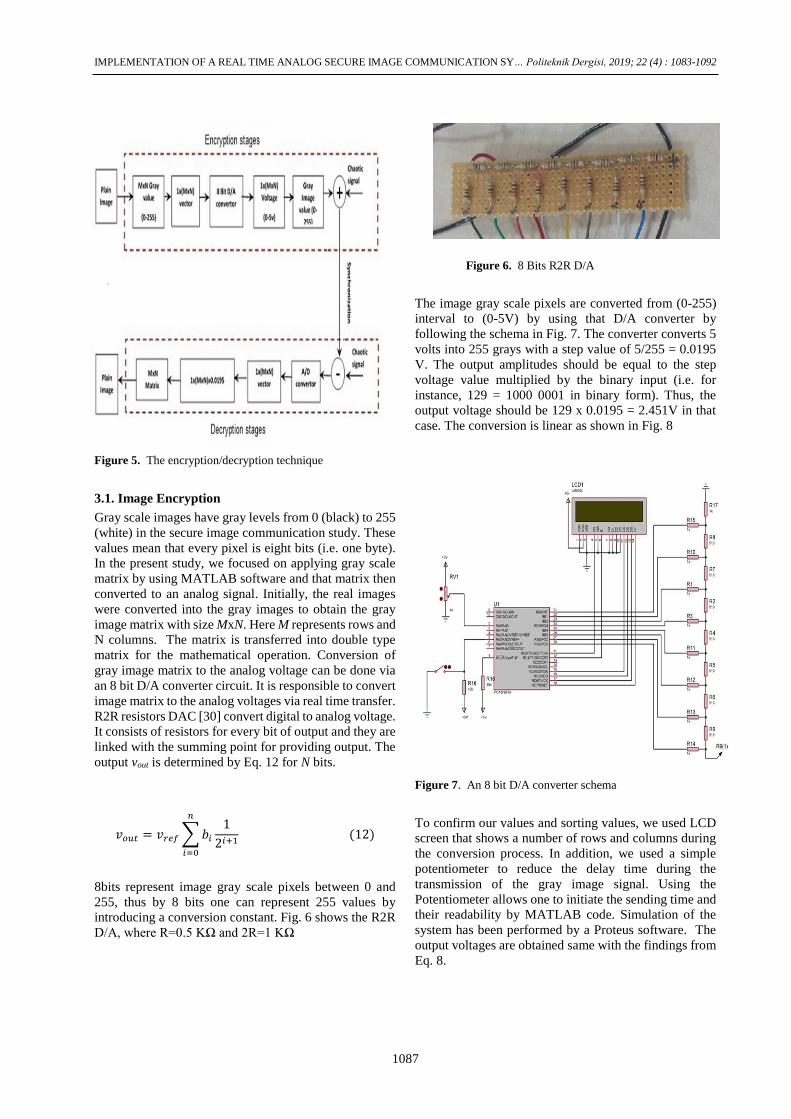
Figure 6. 8 Bits R2R D/A
The image gray scale pixels are converted from (0-255)
interval to (0-5V) by using that D/A converter by
following the schema in Fig. 7. The converter converts 5
volts into 255 grays with a step value of 5/255 = 0.0195
V. The output amplitudes should be equal to the step
voltage value multiplied by the binary input (i.e. for
instance, 129 = 1000 0001 in binary form). Thus, the
output voltage should be 129 x 0.0195 = 2.451V in that
case. The conversion is linear as shown in Fig. 8
Figure 7. An 8 bit D/A converter schema
To confirm our values and sorting values, we used LCD
screen that shows a number of rows and columns during
the conversion process. In addition, we used a simple
potentiometer to reduce the delay time during the
transmission of the gray image signal. Using the
Potentiometer allows one to initiate the sending time and
their readability by MATLAB code. Simulation of the
system has been performed by a Proteus software. The
output voltages are obtained same with the findings from
Eq. 8.

Aybaba HANCERLİOGULLARI, Khaled Mohamed El HADAD, Erol KURT /POLİTEKNİK DERGİSİ,Politeknik Dergisi,2019;22(4): 1083-1092
1088
Figure 8. The plot of gray level versus amplitude
for the conversion in D/A converter.
The gray value, number of rows/columns, and delay time
have been observed on the LCD screen as in Fig. 9.
Figure 9. An 8 bit D/A circuit in board.
Then, the initial condition for chaotic signal in R2L2D
circuit should be configured in the Master unit by
applying sine wave signal in the master unit and also for
configuring initial conation (frequency, amplitude
voltage and value of resistor) to obtain chaos signal as
shown in Fig. 10(a,b). Image gray signal comes from the
D/A converter to the adder circuit. After the adding
process, the encrypted signal is send through the insecure
channel. Fig. 11 shows the total transmitting circuit
including the adder and D/A converter.
(a)
(b)
Figure 10. (a) Setup and (b) a sample chaotic signal from
the oscilloscope.
3.2. Image Decryption
After the encrypted image is transmitted to the receiving
body, it should be decrypted. In order to decrypt the
image, there is no condition required for the receiving
body. Since the system operates real time, then receiver
can directly decrypt the masked image. The decryption
uses the following steps:
Step 1: In the receiver part including the slave circuit, the
pure chaotic signal is subtracted from the decrypted
signal and the gray levels of the image signals are
obtained.

IMPLEMENTATION OF A REAL TIME ANALOG SECURE IMAGE COMMUNICATION SY… Politeknik Dergisi, 2019; 22 (4) : 1083-1092
1089
Figure 11. The combination of the transmitter and D/A
converter
Step 2: The analog image signals from the subtraction
circuit are converted to the digitalized media into a data
file. That A/D converter unit is shown in Fig. 12. An
Arduino Uno works well with an absolute accuracy
within the error ranges +/- 10mV.
Step 3: After the extraction of the voltage values for the
gray levels, they are converted to the real gray level
values, thereby the decrypted image is obtained at last
step. The receiver part subtracts the encrypted signal
from the masked signal with a high accuracy as shown in
Fig. 13. According to Fig. 8, those values are converted
into the real image gray levels in the MatLab media.
4. EXPERIMENTAL RESULTS
The quality of the encryption of the images depends on
sending and reading processes. Strictly speaking, the
signal, which is transmitted and received from/to the
analog circuit can lose its originality, thus, it may cause
a certain error. Therefore the quality of the conversion
circuit and its connection are vital to fulfill the image
quality in masking and recovering.
Figure 12. The subtraction circuit and the Arduino A/D
converter in the receiver part
Figure 13. The decrypted gray level signals after the
A/D converter
Fig. 14(a,d,g,j) shows the original test image, the
encrypted ones are shown in Fig. 14(b,e,h,k) and finally
Fig. 14(c,f,i,l) shows the decrypted image. Note that the
images are tested for their 32x32 pixel image forms.
5. RESULTS AND DISCUSSION
The tests on the encrypted images are important in order
to make the communication in a safe way from the public
channel shown in Fig. 2. In that part, the histogram
analyses, pixel correlation tests and error measurements
have been carried out.
5.1. Histogram analysis
Histogram analysis is important in the sense that the
factors measuring the image encryption, prevent
information leakages to insecure sources or opponents,
because the encrypted images have no statistical
resemblance with the originals. In order to test the
histogram, the original and encrypted images are
considered. After the measurements of histograms, Fig.
15(a-h) has been plotted. Note that the encrypted images
have more distributed histograms, which prove good
encryption.
From the histograms, it is found that the most powerful
encryptions were performed for Figs. 14(d) and (g).
Strictly speaking, the histograms of the genuine images
are in the form of clustered spikes, the encrypted images
have a broader distribution to all gray levels.
They are also different from the histograms of the
genuine images by annihilating these clustering
appearances. Histograms of encrypted images do not give
any kind of information regarding the original images.
They can be acceptable as secure images in the
communication since no effort to decrypt those images
by any unauthorized person can be successful in that
manner.

Aybaba HANCERLİOGULLARI, Khaled Mohamed El HADAD, Erol KURT /POLİTEKNİK DERGİSİ,Politeknik Dergisi,2019;22(4): 1083-1092
1090
(a) (b) (c)
(d) (e) (f)
(g) (h) (i)
(j) (k) (l)
Figure 14. The images for testing. The original transmitted
images (a,d,g,j), the crypted ones (b,e,h,k) and the
decrypted forms (c,f,i,l).
5.2. Pixel Correlation
In the digital images, usually high redundancy data exists
and those show high correlation between neighboring
pixels. By definition, a good cryptal system should
reduce that correlation. Indeed, that becomes a major
defense against the statistical attacks. The correlation
coefficients of the encrypted pixels for different sizes of
images have been calculated for both the original and the
encrypted images within that test. The data correlation is
defined as ρ or co𝑟𝑟, which is the coefficient of
correlation. Besides, X and 𝑌 are datasets, and 𝜇 is the
mean value in the standard deviation. When variables 𝑋
and 𝑌 are highly correlated, the ρ value would be closer
to one. For instance, a positive correlation coefficient
indicates that as one variable increases, the other also
increases or vice versa. The opposite is true if their ρ
value is closer to zero.Zero indicates that the variables
are not correlated in this context. The coefficient
correlation can be read as,
𝜌𝑥,𝑦 = 𝑐𝑜𝑟𝑟(𝑋, 𝑌) =𝑐𝑜𝑣(𝑋, 𝑌)
𝜎𝑋𝜎𝑌
=𝐸((𝑋 − 𝜇𝑋)(𝑌 − 𝜇𝑌))
𝜎𝑋𝜎𝑌
(13)
Here 𝐸 is the expected value and 𝑐𝑜𝑣 stands for the
covariance. The correlation between the original and the
encrypted images are given in Table 1 for their 32x32
dimensions.
(a) (b)
(c) (d)
(e) (f)
(g) (h)
Figure 15. Histogram test results of the decrypted
images given in Fig14.

IMPLEMENTATION OF A REAL TIME ANALOG SECURE IMAGE COMMUNICATION SY… Politeknik Dergisi, 2019; 22 (4) : 1083-1092
1091
Generally speaking, while the correlations are higher
between the original and decrypted images, the
correlations decay to 0.35 or lower values between the
original and encrypted images as expected.
Table 1. Correlation coefficients of the original and
encrypted images
Image
Name
Correlation Coefficients
Between
original And
Encrypted Images
Between
Original-And
Decrypted Images
Cameraman 0.3584 0.897
Lena -0.374 0.847
Man 0.215 0.698
Sheep -0.0152 0.713
5.3. Error Measurement
The main error source is the real time conversion of the
images via the analog to/from digital platform. Indeed,
the experimental measurements of output analog signals
should also have an absolute error as in all real time
devices. Such errors have been measured and calculated
as in Table 2 .
While the lowest error is obtained for Lena, the largest
one is calculated for sheep. However, for a real time
cryptal system error amount about 5% is within the
acceptable limits
Table 2. Error Measurements with respect to test images.
Images Error (Original- Decrypt)
Cameraman 4%
Lena 3.7%
Man 3.9%
Sheep 5.3%
6. CONCLUSIONS
In the present study, a new chaos based secure image
communication technique has been designed and
implemented. The new technique uses a new proposed
chaotic synchronization circuit in master/slave form and
masks the plain image gray levels into the chaotic signal,
transmit it with a public channel and recover it with a
sufficient accuracy within 5% in a real-time based
environment. Since the system operates in real time, it is
more secure than any other cryptal systems. Because
synchronization between the sender and receiver are
ascertained for only the sending time period, thus one
cannot recover the image without having the same
chaotic signal. In addition, the analog equipment is
important to have the same chaotic output. In this regard,
if the public does not have the correct circuitry and
connection time and transmission time duration, they
would never recover the plain image.
Besides, the technique is useful because it does not need
to save any digital data while sending gray images to the
receiver, because they are converted to the noisy signals
in a synchronized way. Thus, that technique is better,
reliable and fast compared to the other traditional
techniques.
In fact, a digital media is always unsecure due to software
developments among the hackers, improvements in
internet systems, etc., and that has the digital
environment been weak for such secure communication
systems. Thereby, that new real time based technique can
be used to make more secure image communication in
this manner. The only disadvantage which has was
encountered in that technique was a little noise in the
decrypted image, however if larger memory is used, that
disadvantage can be annihil.
REFERENCES
[1] Murali, K., Lakshmanan, M. and Chua, L.O., “The
simplest dissipative nonautonomous chaotic circuit”,
IEEE Transactions on Circuits and Systems I:
Fundamental Theory and Applications, 41(6): 462-463,
(1994).
[2] Kurt, E., Acar, S. and Kasap, R. ,“A comparison of
chaotic circuits from a statistical approach.”.
Mathematical and Computational Applications,. 5(2):
95-103, (2000).
[3] Adak, S., Cangi, H. and Yılmaz, A.S.,”Design of an
LLCL type filter for stand-alone PV systems’
harmonics.” Journal of Energy Systems,; 3(1): 36-50,
(2019).
[4]. Kiers, K., Schmidt, D. and. Sprott, J.C ,“Precision
measurements of a simple chaotic circuit. American
Journal of Physics, 72(4): 503-509, (2004).
[5] Linsay, P.S., “Period doubling and chaotic behavior in a
driven anharmonic oscillator.” Physical Review Letters,
47(19):1349.,(1981).
[6] Kurt, E., “Nonlinearities from a non-autonomous chaotic
circuit with a non-autonomous model of Chua's diode”.
Physica Scripta,.74(1): 22, (2006).
[7] Hanias, M., Avgerinos, Z.and Tombras, G.,”Period
doubling, Feigenbaum constant and time series prediction
in an experimental chaotic RLD circuit”. Chaos, Solitons
& Fractals, 40(3):1050-1059, (2009).
[8] Andreatos, A.S.and Volos. C.K,“Secure text encryption
based on hardware chaotic noise generator. in 2nd
International Conference on Cryptography and Its
Applications in the Armed Forces, (2014).
[9]. Feki,M.,”An adaptive chaos synchronization scheme
applied to secure communication.” Chaos, Solitons &
Fractals, 18(1):141-148, (2003).
[10]. Cuomo,K.M.,“Oppenheim, and S.H. Strogatz,
Synchronization of Lorenz-based chaotic circuits with
applications to communications.”IEEE Transactions on
circuits and systems II: Analog and digital signal
processing,. 40(10): 626-633, (1993).

Aybaba HANCERLİOGULLARI, Khaled Mohamed El HADAD, Erol KURT /POLİTEKNİK DERGİSİ,Politeknik Dergisi,2019;22(4): 1083-1092
1092
[11]. Mu, X. and Pei, L. “Synchronization of the near-identical
chaotic systems with the unknown parameters.” Applied
Mathematical Modelling,34(7): 1788-1797, (2010).
[12]. Yang, T., “A survey of chaotic secure communication
systems.” International Journal of Computational
Cognition, 2(2): 81-130, (2004).
[13]. Bourbakis, N. and C. Alexopoulos, Picture data
encryption using scan patterns. Pattern Recognition,.
25(6): 567-581, (1992).
[14]. Pisarchik, A. and Zanin, M.”Image encryption with
chaotically coupled chaotic maps”. Physica D:
Nonlinear Phenomena, 237(20): 2638-2648, (2008).
[15]. Xiangdong, L.,”Image scrambling algorithm based on
chaos theory and sorting transformation.” IJCSNS
International Journal of Computer Science and
Network Security, 8(1): 64-68, (2008).
[16]. Hu, J. and Han, F.,” A pixel-based scrambling scheme for
digital medical images protection”. Journal of Network
and Computer Applications,32(4): 788-794, (2009).
[17]. Tong, X. and M. Cui,” Image encryption scheme based
on 3D baker with dynamical compound International
Journal of Bifurcation and chaos, cipher generator”.
Signal processing,. 89(4): 480-491, (2009).
[18]. Fridrich, J., “Symmetric ciphers based on two-
dimensional chaotic maps.” International Journal of
Bifurcation and chaos,. 8(06): 1259-1284, (1998).
[19]. Gao,H.,”A new chaotic algorithm for image
encryption”Chaos, Solitons & Fractals, 29(2): 393-399,
(2006).
[20] Rulkov, N.F.,”Generalized synchronization of chaos in
directionally coupled chaotic systems.” Physical Review
E,. 51(2): 980, (1995).
[21] Zhou, Q,“Parallel image encryption algorithm based on
discretized chaotic map”.Chaos, Solitons & Fractals,
38(4): 1081-1092, (2008).
[22]. Shelke, F.M.,. Dongre, A.A and. Soni, P.D ” Comparison
of different techniques for Steganography in images”.,
International Journal of Application , (2014).
[23]. Celik, K. and Kurt. E.” A new image encryption
algorithm based on lorenz system. in Electronics”,
Computers and Artificial Intelligence):8th International
Conference on. IEEE, (2016).
[24] Kurt, E. and Bingol, C. “A New Sweep Up/Down
Phenomenon between the Chaotic and Regular Regions
in a New R2L2D Circuit,” Politeknik Dergisi, 19(3):
305-310, (2016).
[25] Pecora, L.M. and Carroll, T.L,“Synchronization in
chaotic systems”Physical review letters, 64(8): 821,
(1990).
[26]. Wu, C.W. and. Chua, L.O.”A simple way to synchronize
chaotic systems with applications to secure
communication systems.”International Journal of
Bifurcation and Chaos, 3(6): 1619-1627, (1993).
[27] Yang, T. and. Chua, L.O “Secure communication via
chaotic parameter modulation.IEEE”Transactions on
Circuits and Systems:Fundamental Theory and
Applications, 43(9): 817-819, (1996).
[28] Yau, H.T.and Yan, J.J.”Chaos synchronization of
different chaotic systems subjected to input
nonlinearity”Applied Mathematics and Computation,
197(2):775-788, (2008).
[29] Kurt,E. and Bingol ,C.,” Exploration of Synchronization
Secure Communication and Signal Recovery in New
R2L2D Circuit,” 58th Int. Sci. Conf. Riga Tech. Uni.
Power and Elec. Eng. RTUCON. Riga, Latvia. (2017).
[30]. Hendriks, P.,”Specifying communications dacs.IEEE
spectrum,” 34(7): 58-69.(1997).Power and Elec. Eng.
RTUCON2017, 12-13 Oct. 2017, Riga, Latvia.