improving analysis efficiency at delphi by using a...
TRANSCRIPT
Fereydoon Dadkhah
Improving Analysis Efficiency at Delphi by using a GPU
2
Overview
Background – HPC POC team
– Delphi involvement
– Nvidia Maximus program
– Simulation at Delphi
– The GPU as a co-processor
Evaluation – Workstation hardware
– Models, sizes, run times, etc.
Benefits
Pros and Cons
3
Background Delphi Involvement
The Nvidia Maximus program – Description of the program
– Delphi E&S participation
– Delphi program (POC steering team)
Simulation at Delphi – Delphi engineers routinely use simulation, esp. FEA to design and improve
products
– The simulations range from linear, steady-state analysis to those involving material and geometric non-linearity as well as time dependence
– Full time analysts completed more than 600 FEA projects
4
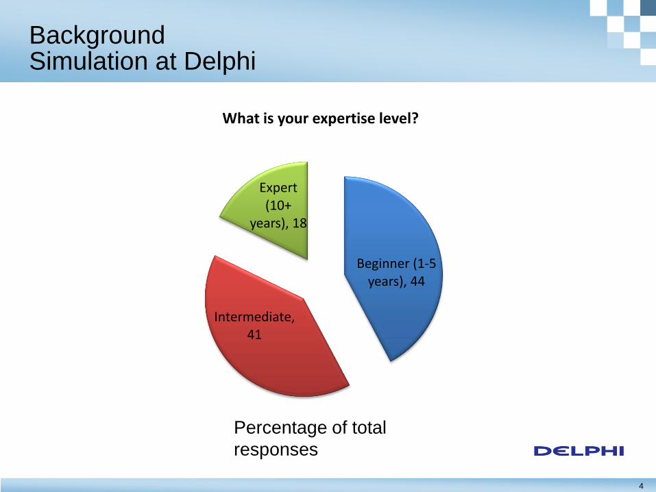
Background Simulation at Delphi
Beginner (1-5 years), 44
Intermediate, 41
Expert (10+
years), 18
What is your expertise level?
Percentage of total
responses
5
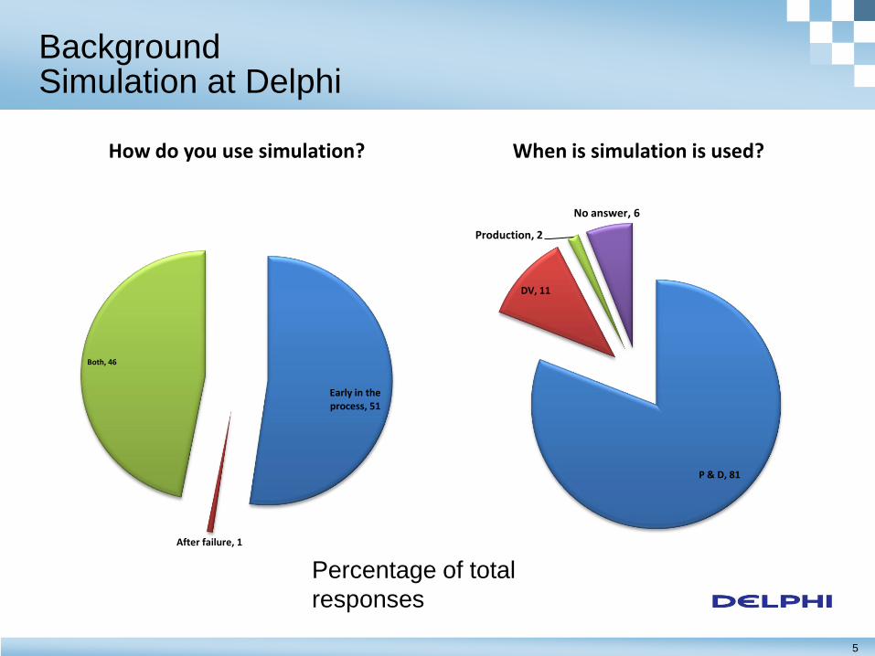
Background Simulation at Delphi
Early in the process, 51
After failure, 1
Both, 46
How do you use simulation?
P & D, 81
DV, 11
Production, 2
No answer, 6
When is simulation is used?
Percentage of total
responses
6
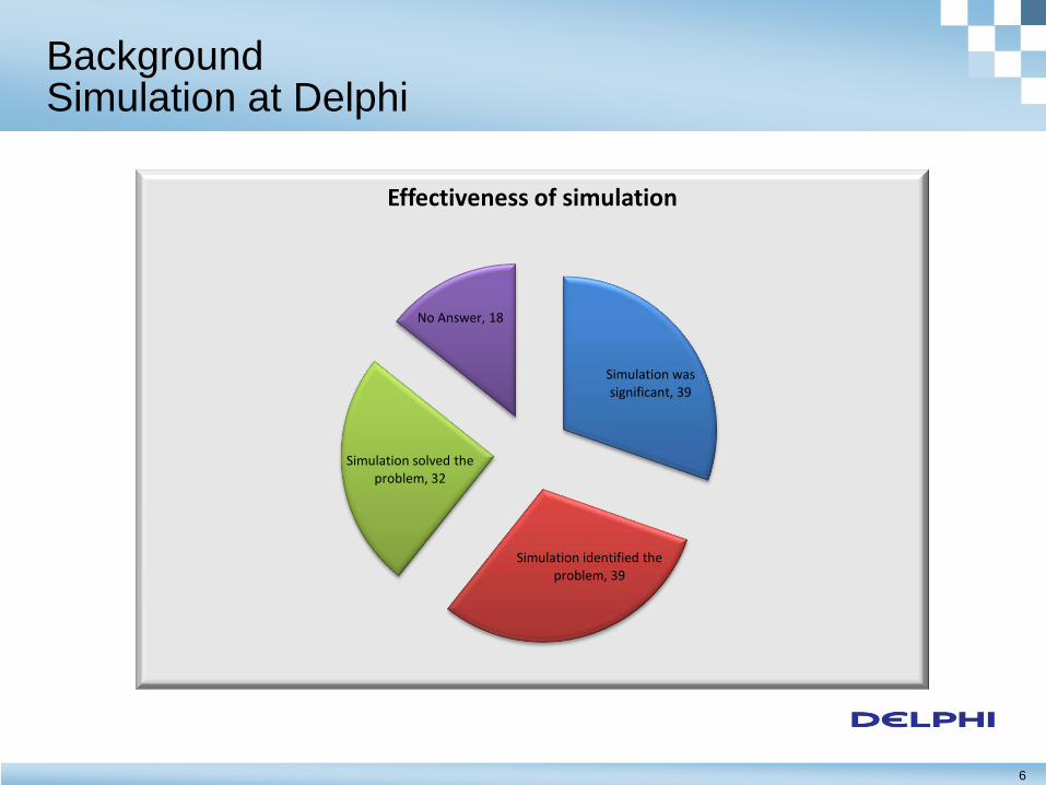
Background Simulation at Delphi
Simulation was significant, 39
Simulation identified the problem, 39
Simulation solved the problem, 32
No Answer, 18
Effectiveness of simulation
7
Background The GPU as a Co-processor
The Graphical Processing Unit is used as a co-processor
The CPU offloads some of the compute-intensive mathematical operations to the GPU
Modern GPUs have hundreds of smaller or light weight cores
By using the GPU the application appears to be running in a massively parallel environment
Modern GPUs such as the NVIDIA Tesla are fully programmable as opposed to the older devices which were dedicated to graphics (drawing polygons)
8
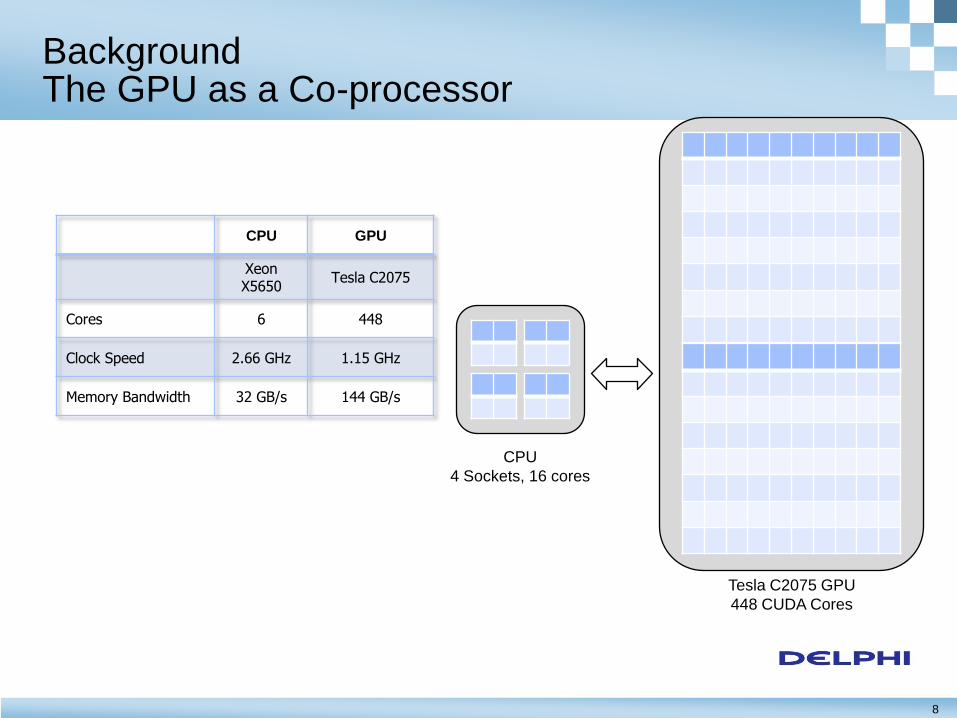
Background The GPU as a Co-processor
CPU
4 Sockets, 16 cores
Tesla C2075 GPU
448 CUDA Cores
CPU GPU
Xeon X5650
Tesla C2075
Cores 6 448
Clock Speed 2.66 GHz 1.15 GHz
Memory Bandwidth 32 GB/s 144 GB/s
9
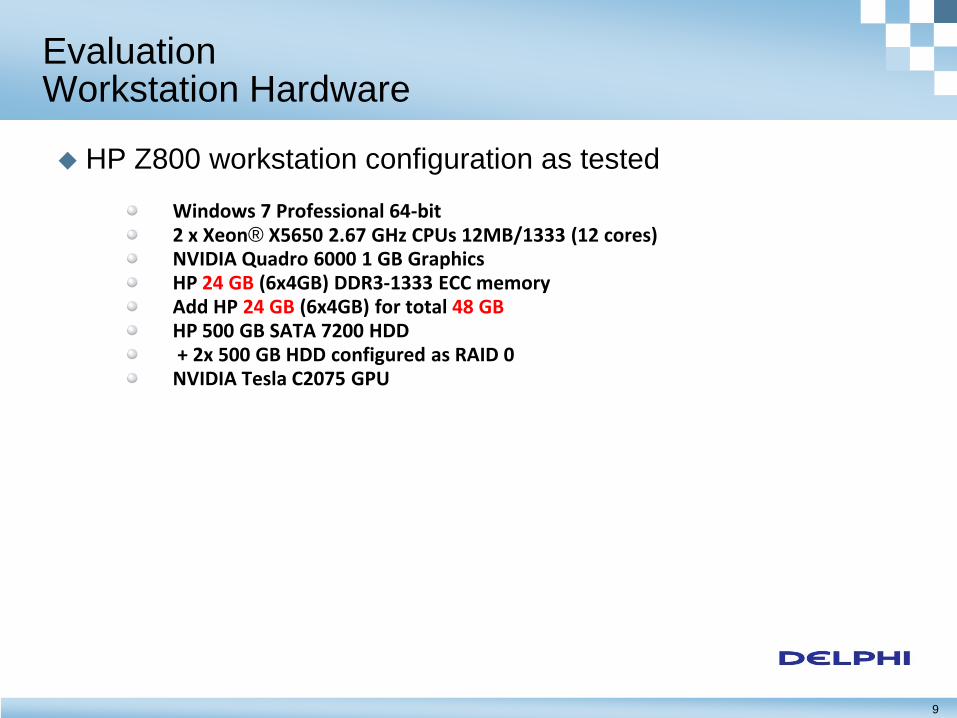
Evaluation Workstation Hardware
HP Z800 workstation configuration as tested Windows 7 Professional 64-bit 2 x Xeon® X5650 2.67 GHz CPUs 12MB/1333 (12 cores) NVIDIA Quadro 6000 1 GB Graphics HP 24 GB (6x4GB) DDR3-1333 ECC memory Add HP 24 GB (6x4GB) for total 48 GB HP 500 GB SATA 7200 HDD + 2x 500 GB HDD configured as RAID 0 NVIDIA Tesla C2075 GPU
10
Evaluation
Structural mechanics simulations suited for GPU use – Problem size (DOF)
– Analysis types
– Element types
– Solvers
Applicability and potential benefits to Delphi – POC steering team survey results
– SharePoint survey results
11
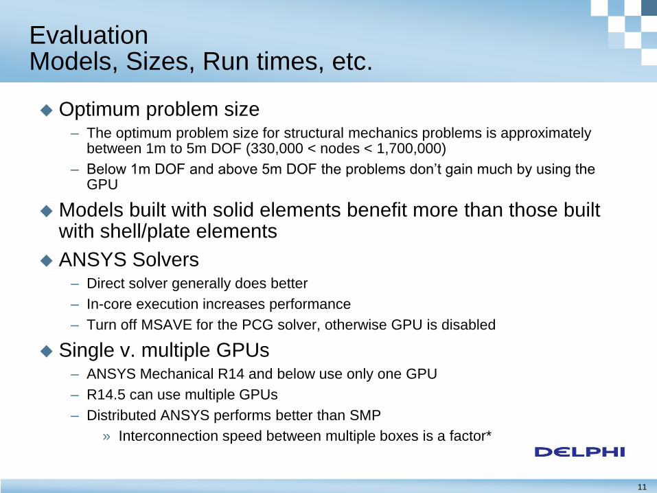
Evaluation Models, Sizes, Run times, etc.
Optimum problem size – The optimum problem size for structural mechanics problems is approximately
between 1m to 5m DOF (330,000 < nodes < 1,700,000)
– Below 1m DOF and above 5m DOF the problems don’t gain much by using the GPU
Models built with solid elements benefit more than those built with shell/plate elements
ANSYS Solvers – Direct solver generally does better
– In-core execution increases performance
– Turn off MSAVE for the PCG solver, otherwise GPU is disabled
Single v. multiple GPUs – ANSYS Mechanical R14 and below use only one GPU
– R14.5 can use multiple GPUs
– Distributed ANSYS performs better than SMP
» Interconnection speed between multiple boxes is a factor*
12
Evaluation Models, Sizes, Run times, etc.
0%
10%
20%
30%
40%
50%
60%
70%
80%
90%
100%
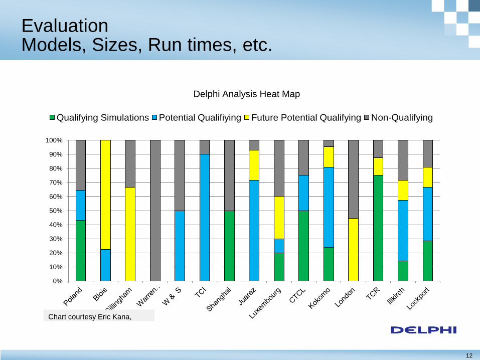
Qualifying Simulations Potential Qualifiying Future Potential Qualifying Non-Qualifying
Chart courtesy Eric Kana,
Delphi Analysis Heat Map
13
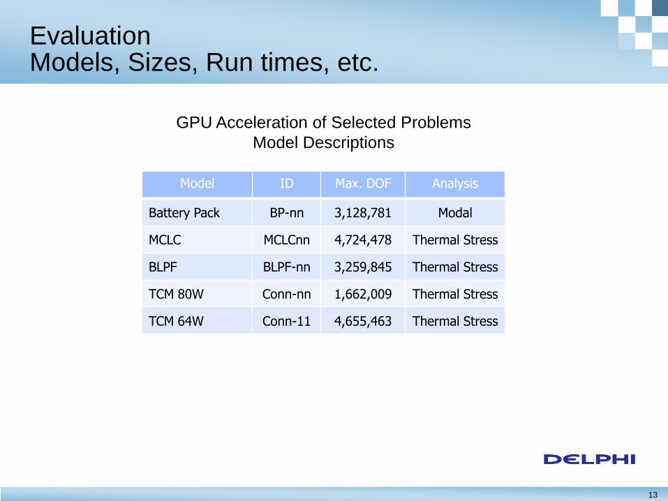
Evaluation Models, Sizes, Run times, etc.
Model ID Max. DOF Analysis
Battery Pack BP-nn 3,128,781 Modal
MCLC MCLCnn 4,724,478 Thermal Stress
BLPF BLPF-nn 3,259,845 Thermal Stress
TCM 80W Conn-nn 1,662,009 Thermal Stress
TCM 64W Conn-11 4,655,463 Thermal Stress
GPU Acceleration of Selected Problems
Model Descriptions
14
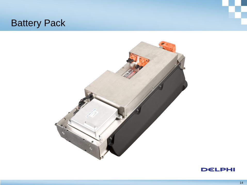
Battery Pack
15
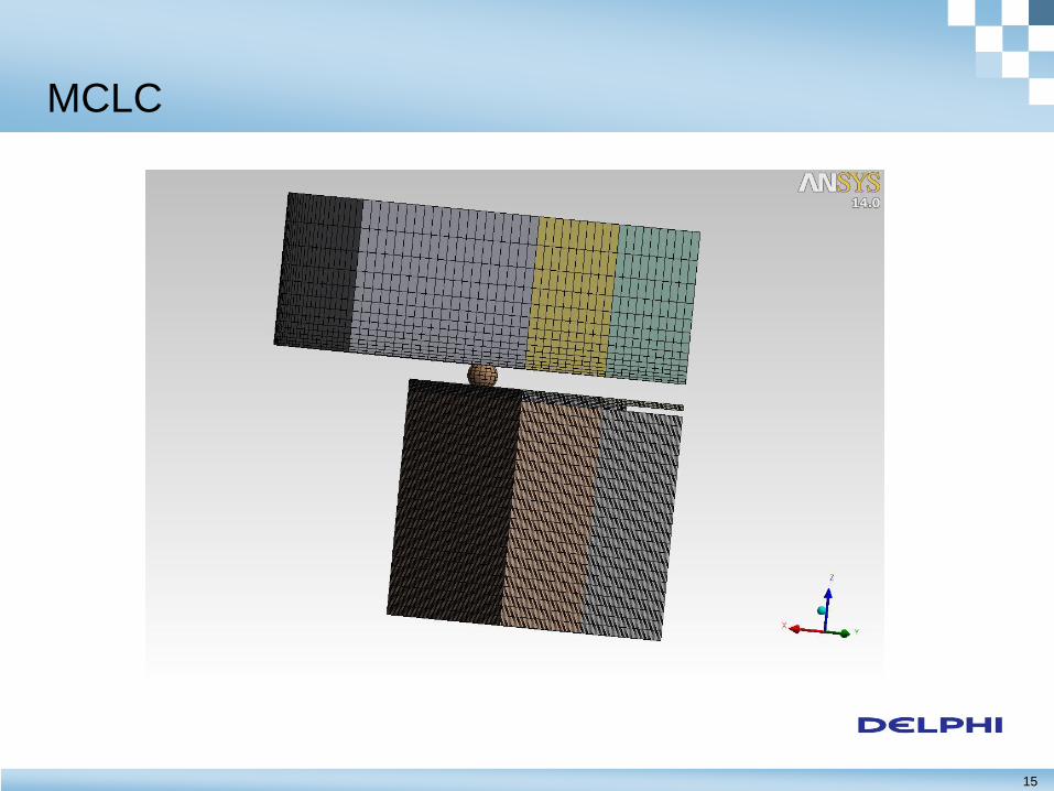
MCLC
16
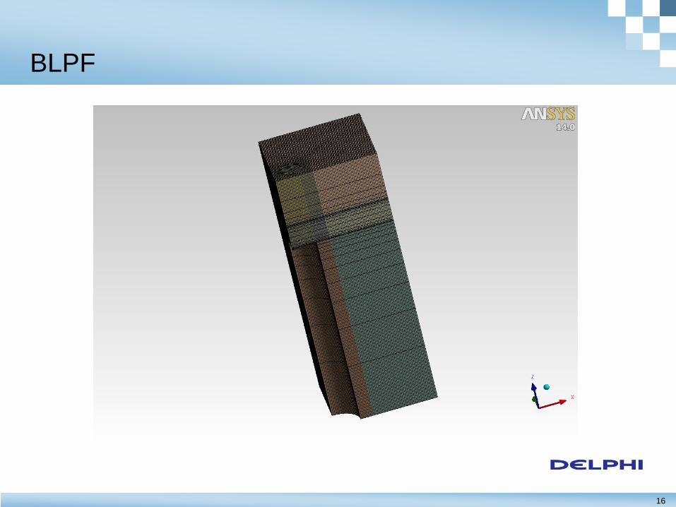
BLPF
17
Engine Control Module
18
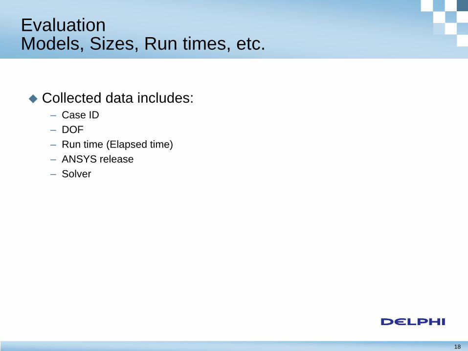
Evaluation Models, Sizes, Run times, etc.
Collected data includes: – Case ID
– DOF
– Run time (Elapsed time)
– ANSYS release
– Solver
19
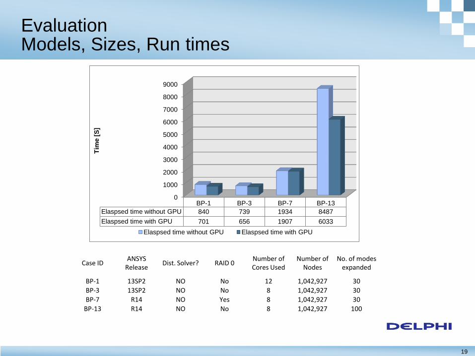
Evaluation Models, Sizes, Run times
0
1000
2000
3000
4000
5000
6000
7000
8000
9000
BP-1 BP-3 BP-7 BP-13
Elaspsed time without GPU 840 739 1934 8487
Elaspsed time with GPU 701 656 1907 6033
Tim
e [
S]
Elaspsed time without GPU Elaspsed time with GPU
Case ID ANSYS
Release Dist. Solver? RAID 0
Number of Cores Used
Number of Nodes
No. of modes expanded
BP-1 13SP2 NO No 12 1,042,927 30
BP-3 13SP2 NO No 8 1,042,927 30
BP-7 R14 NO Yes 8 1,042,927 30
BP-13 R14 NO No 8 1,042,927 100
20
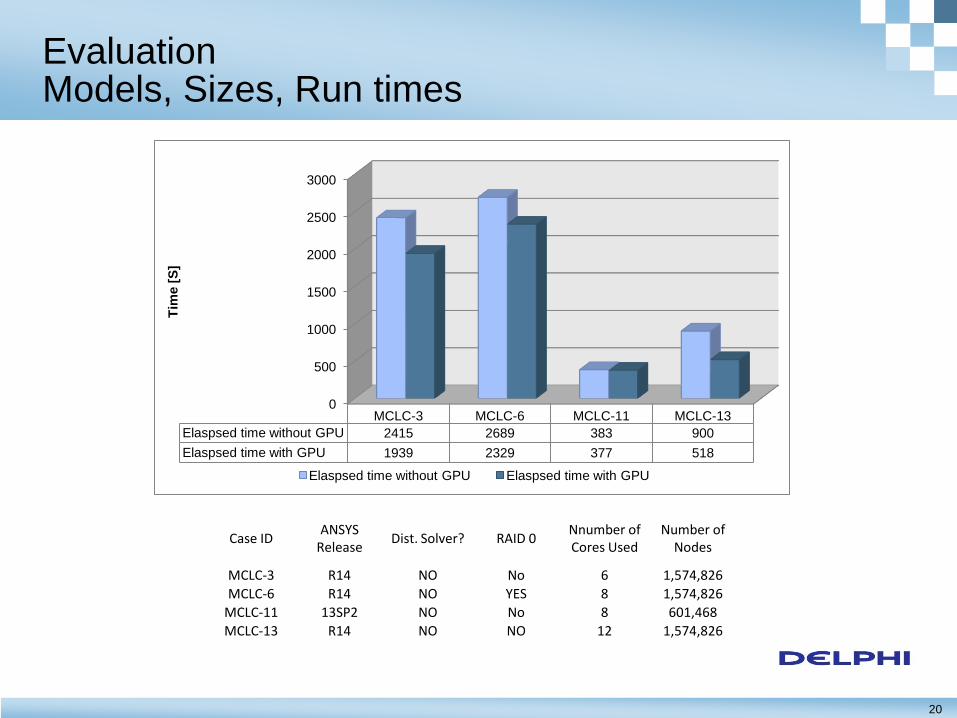
Evaluation Models, Sizes, Run times
0
500
1000
1500
2000
2500
3000
MCLC-3 MCLC-6 MCLC-11 MCLC-13
Elaspsed time without GPU 2415 2689 383 900
Elaspsed time with GPU 1939 2329 377 518
Tim
e [
S]
Elaspsed time without GPU Elaspsed time with GPU
Case ID ANSYS
Release Dist. Solver? RAID 0
Nnumber of Cores Used
Number of Nodes
MCLC-3 R14 NO No 6 1,574,826
MCLC-6 R14 NO YES 8 1,574,826
MCLC-11 13SP2 NO No 8 601,468
MCLC-13 R14 NO NO 12 1,574,826
21
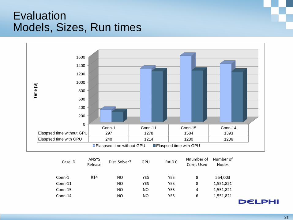
Evaluation Models, Sizes, Run times
Case ID ANSYS
Release Dist. Solver? GPU RAID 0
Nnumber of Cores Used
Number of Nodes
Conn-1 R14 NO YES YES 8 554,003
Conn-11 NO YES YES 8 1,551,821
Conn-15 NO NO YES 4 1,551,821
Conn-14 NO NO YES 6 1,551,821
0
200
400
600
800
1000
1200
1400
1600
Conn-1 Conn-11 Conn-15 Conn-14
Elaspsed time without GPU 297 1278 1584 1393
Elaspsed time with GPU 240 1214 1230 1206
Tim
e [
S]
Elaspsed time without GPU Elaspsed time with GPU
22
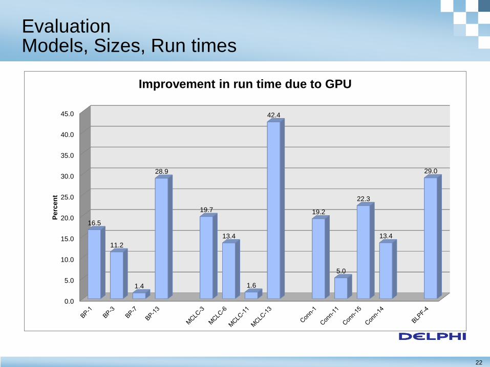
Evaluation Models, Sizes, Run times
0.0
5.0
10.0
15.0
20.0
25.0
30.0
35.0
40.0
45.0
16.5
11.2
1.4
28.9
19.7
13.4
1.6
42.4
19.2
5.0
22.3
13.4
29.0
Perc
en
t
Improvement in run time due to GPU
23
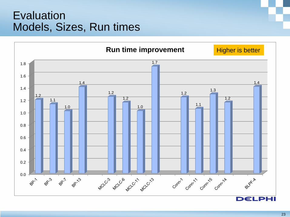
Evaluation Models, Sizes, Run times
0.0
0.2
0.4
0.6
0.8
1.0
1.2
1.4
1.6
1.8
1.2 1.1
1.0
1.4
1.2
1.2
1.0
1.7
1.2
1.1
1.3
1.2
1.4
Run time improvement Higher is better
24
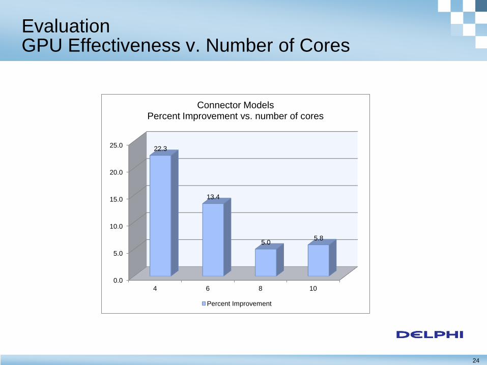
Evaluation GPU Effectiveness v. Number of Cores
0.0
5.0
10.0
15.0
20.0
25.0
4 6 8 10
22.3
13.4
5.0 5.8
Connector Models Percent Improvement vs. number of cores
Percent Improvement
25
Benefits
The Tesla C2075 GPU is capable of significantly improving FEA solution times
– Most of the test problems saw a 10% or more improvement in run time
– 6 out of 13 cases saw an improvement of 19% or better
– The maximum improvement was 42% (1.7 times faster)
Depending on the problem size, a GPU can be a relatively low-cost solution
The use of GPUs for computation is still evolving but major software vendors (ANSYS and Dassault among others) have embraced this technology
The trend is toward widespread use of GPUs
26
Benefits
On workstations with 8 or more CPU cores and dual display adapters, e.g., Quadro+Tesla, the GPU offloads enough of the work to allow the user to continue using the workstation
Alternatively, it may be possible to for load balancing software to submit jobs the workstation without affecting the main user of the workstation (Should be investigated before adopting)
Workstations in the same office area could be used as a cluster after hours maximizing the investment in the hardware
GPUs can also be added to compute servers to speed up processing
27
Pros and Cons
Advantages – Relatively inexpensive
– Easy to install and use
– No additional software or maintenance required
– Can be configured to be used as graphics processor or “compute server”
Disadvantages – Ineffective with very dense matrices
» PCG solver is more efficient when dealing with dense matrices
» GPU seems to help in some cases but not all
Distributed ANSYS+GPU resulted in 30% improvement