indesit wt 90 csi
DESCRIPTION
Service manualTRANSCRIPT

page 1
Model type:
WT90CSI
Commercial code:
26898
page 2
General notes
Technical Documentation guidelines
-------------------------------------------------------------------------------------------------------------------------------
You can find herewith some generic information to simplify cunsulting of technical documentation:
1. Models of same range share the same exploded views, which report the richest set of spare parts:generally, a model does not necessarly have a
related spare part for each particular shown on exploded views.
2. Some spare parts can not be represented directly on the exploded views (instruction booklets, specific kit, etc...). You can find those codes in the
spare parts list with the same reference of particular where spares are installed or with references 099, 999. Instruction booklets, once managed,
appear with 000 reference.
3. On the higher right site of each exploded view there is a serial number which indicates the beginning of the production of certain range:some
models might have more than an exploded view for a given category, each distinguished by a different serial no.and linked to another spare parts
list, In this case, serial no. is required to supply the right spare part code. Exploded view to be considered is the one with a more recent serial no.
but previous than the one of the model that needs assistance.
4.Exploded views might require further updates even after publishing. Addition of new spares will go on following the already existing numeration
references. Revision number of an exploded view is shown into last four digits of serial number into upper right hand corner.
5.The spare parts list associated to an exploded view shows related codes of spares managed for a certain model; for each spare part other
informations are available:
REF: reference no of spare into a table; SUBSTITUTE: list of spare(s) which can replace a code but that keeps same functional characteristics
INDUSTRIAL CODE: list of variables of a model (shown into model label) where such spare is used; NOTICE: code of information(s) to refer to
complete technical intervention, track for changes or to find correct spare part code.
6. Some notices, into a same section are generic therefore cannot be directly linked to a spare part. In order to assist a model in the best way as
possible, it is helpful to pay attention to all notices and constantly verify documentation updates
7.Technical documentation cover shows model name and its commercial codes
page 3
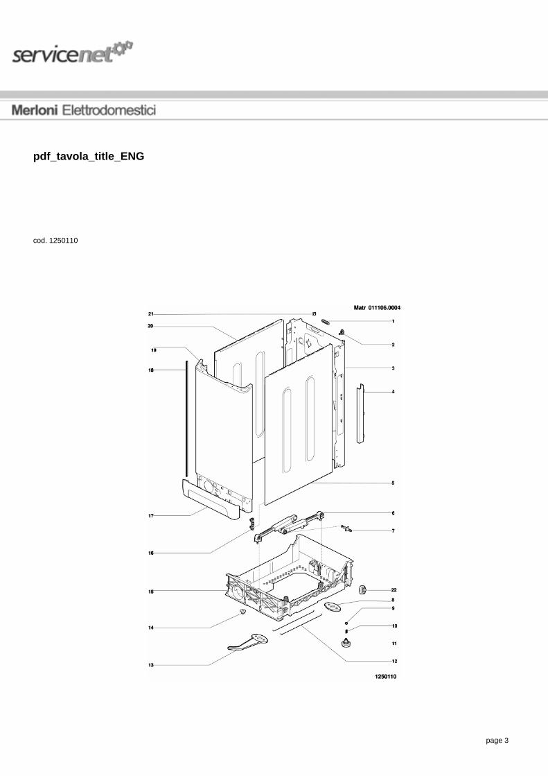
pdf_tavola_title_ENG
cod. 1250110

page 4
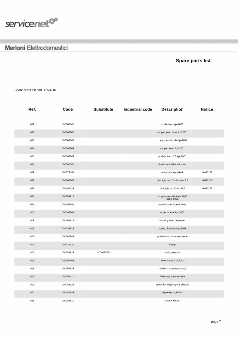
Spare parts list
Spare parts list cod. 1250110
Ref. Code Substitute Industrial code Description Notice
000 C00090087 user instructions bookletcrus-cz-h
001 C00083909 blanking plate-rear(test plug) tlph2001
002 C00064205 cord lead
003 C00083784 brezil back top ph2001 n1040278,n1040288,n1040309,n1040309
003 C00091893 brezil back top ph2002 n1040278,n1040288,n1040309,n1040309
003 C00094067 brezil back top ph2003 n1040278,n1040288,n1040309,n1040309
003 C00098566 brezil back top n1040278,n1040288,n1040309,n1040309
004 C00083901 wire protection
005 C00083774 1 C00084913 side panel right top ph2001
006 C00083787 shock absorber top ph2001
007 C00055037 plastic expansion rivet
008 C00083792 cam truck tl ph2001
009 C00083788 nut foot
010 C00059869 spring for foot d =11 mm h =21 mm
011 C00083789 foot top ph2001
012 C00083791 rod truck tl ph2001
013 C00083793 cam lever+truck
014 C00083786 nut ro-mob m6 d.28 1.5 topph2001
015 C00083785 1 C00093539 moving support top ph2001
016 C00083780 block side panel cabinet
017 C00083790 base ph2001 tl
018 C00065071 side panel trim (90701)
019 C00085462 front panel top ph2001

page 5
020 C00083776 1 C00084913 side panel left top ph2001
021 C00041575 adhesive hook
022 C00091071 rear wheel n1040271

page 6
pdf_tavola_title_ENG
cod. 1250210
page 7
Spare parts list
Spare parts list cod. 1250210
Ref. Code Substitute Industrial code Description Notice
001 C00083801 knob timer tl ph2001
002 C00083800 support knob timer tl ph2001
003 C00083802 components knob tl ph2001
004 C00083804 support knob tl ph2001
005 C00083803 push-button b27 tl ph2001
006 C00090081 dashboard wt90csi indesit
007 C00075456 red pilot lamp indesit n1040275
007 C00084763 pilot light red 12 v idc rast 2.5 n1040275
007 C00089024 pilot light red 230v ra2,5 n1040275
008 C00083916 programme select elbi 1665rast.2 8 pos.
009 C00084985 handle cover indesit white
010 C00085608 cover indesit tl ph2001
011 C00083918 blocking stem dispenser
012 C00083922 spring dispensertl ph2001
013 C00084983 push-button dispenser white
014 C00031331 clamp
015 C00083923 1 C00087073 spring support
016 C00085468 lower cover tl ph2001
017 C00057933 bellows clamp (tank front)
018 C00085611 faltenbalg / manschette
019 C00083924 protection diaphragm tl ph2001
020 C00084343 dispenser tl ph2001
021 C00085610 door interlock

page 8
022 C00084359 cover siphon tl ph2001
023 C00082331 radio interference suppressor
024 C00083893 screw4x12 tc-t15 tl ph2001
026 C00063971 push button switch s.sa na(on-off)
n1040275,n1040275
026 C00075445 push button switch na n1040275,n1040275
026 C00083904 1 C00058465 push button switch bip. na tlph2001
n1040275,n1040275
026 C00088394 push button switch na idc n1040275,n1040275
035 C00083905 1 C00085195 potentiometer 8 pos. idc

page 9
pdf_tavola_title_ENG
cod. 1250310

page 10
Spare parts list
Spare parts list cod. 1250310
Ref. Code Substitute Industrial code Description Notice
001 C00051504 face
001 C00051510 1 C00083894 face whit weight
002 C00085471 steam exhaust hose ass.
003 C00065320 anchorage pad - suspensionspring
004 C00083798 suspension spring - tank tlph2001
004 C00085463 front suspension spring - tanktl ph2001
005 C00083794 counterweight dx tl ph2001
006 C00041605 conic washer
007 C00083797 screw sw. 8x27 tc-t30
008 C00083910 belt pvel 1213h8 tl ph2001
009 C00065076 1 C00064786 torx bolt - drum pulley fixing(90701)
010 C00083912 drum pulley d280 tl ph2001
011 C00083898 tub-filter hose
012 C00074054 binding
013 C00055328 detergent recovery hose
014 C00083805 1 C00110148,1 C00110152 plastic tank 'tl 600/1000' n1040324,n1040324
014 C00110152 plastic tank 600/1000 tl2004 n1040324,n1040324
015 C00083896 counterweight sx tl ph2001
016 C00055303 insulation panel
017 C00055317 1 C00087966 support
018 C00080691 desc_ric_c00080691
018 C00083895 load orifice
019 C00055316 screw
page 11
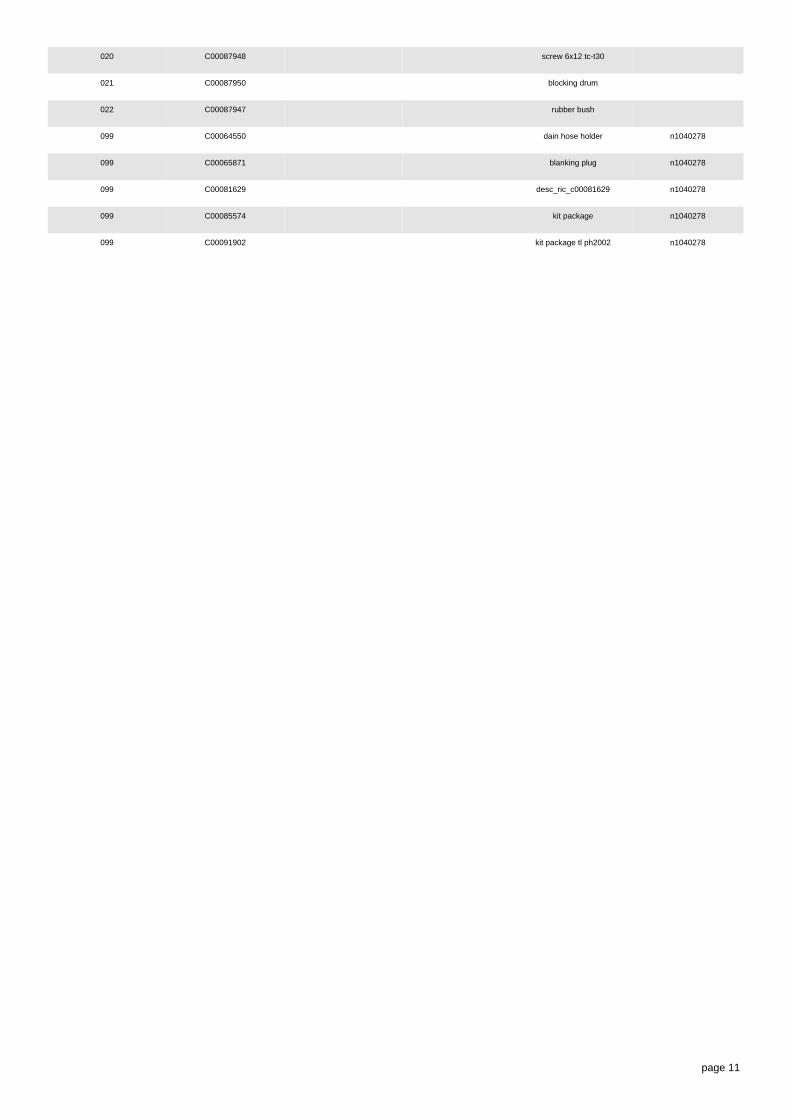
020 C00087948 screw 6x12 tc-t30
021 C00087950 blocking drum
022 C00087947 rubber bush
099 C00064550 dain hose holder n1040278
099 C00065871 blanking plug n1040278
099 C00081629 desc_ric_c00081629 n1040278
099 C00085574 kit package n1040278
099 C00091902 kit package tl ph2002 n1040278

page 12
pdf_tavola_title_ENG
cod. 1250410

page 13
Spare parts list
Spare parts list cod. 1250410
Ref. Code Substitute Industrial code Description Notice
001 C00083940 electrovalve 2 way 1e-2u elbi n1040301,n1040301,n1040309,n1040309,n1040321
001 C00096350 electrovalve 1e2u p.2.5 n1040301,n1040301,n1040309,n1040309,n1040321
002 C00061959 binding
003 C00083903 pressure switch 1+1 liv. tlph2001
004 C00083897 pipe pressostat
005 C00051555 air trap
006 C00065412 blank grommet - thermostat
007 C00083915 temperature sensor ntc elth tlph2001
008 C00036072 thermostat gasket
009 C00083906 heater 1750w-230v tl ph2001 n1040324,n1040324
009 C00110148 heater 1700w-230v tl n1040324,n1040324
010 C00055322 deflector n1040324
011 C00098677 motor collet.ceset p30 tl
012 C00083911 fixing nut
013 C00083914 motor rubber bush
014 C00084333 screw m8x35 tc-t30
015 C00045027 filter element kit
016 C00083942 self cleaning pump
017 C00036145 plastic support for drain hose
018 C00051563 drain hose - to sink
019 C00090926 1 C00091650 wiring 3m+4t n1040275,n1040288,n1040301,n1040301
019 C00091650 wiring 3m+4t n1040275,n1040288,n1040301,n1040301
019 C00096444 wiring 3m+4t tl n1040275,n1040288,n1040301,n1040301

page 14
020 C00083907 supply cable 3x1,0 l=1500 tlph2001
n1040288
020 C00091633 supply cable 3x1 schuko 1,5m + r.i.s.
n1040288
021 C00083944 grate steam exhaust hose
022 C00083939 tubing valve distributing n1040309,n1040309,n1040309
022 C00087068 tubing valve distributing n1040309,n1040309,n1040309
022 C00097841 tubing valve distributing l=145 n1040309,n1040309,n1040309
023 C00054734 binding
024 C00083941 distribution assembly
025 C00090079 eeprom wt90csi software28268980004
026 C00083908 1 C00084838 module (less eeprom) tlph2001
n1040321
027 C00066292 insulated tweezers
027 C00084566 1 C00095669 housing seriale lb2000-pc toploading
027 C00084943 1 C00099862 serial cable lb2000 - pc
028 C00078221 tubetto spugn.40x5x30
029 C00051556 1 C00003070,1 C00005572 mains inlet hose hot
030 C00051541 binding
031 C00061958 binding d=32,7
035 C00109798 protection electrovalve tl n1040321

page 15
Notices
n1040061
Trouble-shooting.
-------------------------------------------------------------------------------------------------------------------------------
Intervention procedure on 2000 washing machines
1. Reading the error code
The fault on the appliance is signalled via:
1. the continuous rotation of the selector knob
2. the action, for the first 4', of the electrovalve and the drain pump
3. the door becomes unlocked
4. the led flashes:
the number of flashes indicates the fault code; the code should be read as follows:
· each fast flash (2/3 flashes of the led very close together) represents one code value
· the fault code is evaluated by counting the number of flashes occurring at 3/4" intervals from one another
· stop counting when the washing machine waits the equivalent of approximately 8/9" between flashes
· the procedure is repeated by the appliance cyclically
E.g.: F03
(FIGURE NT 00)
2. Autotest

page 16
Should the washing machine not be signalling an error, you can check it using a serial key and using a particular autotest cycle, which is to be
activated as follows:
1. bring the washing machine to reset position (coloured ball) for at least 5" and wait until the led flashes on reset mode
2. insert the hardware key into the serial outlet
3. position the switch situated on the key in TEST position
4. wait for the door to lock and for the selector to start turning
5. position the switch situated on the key in PC position
the appliance will carry out the following cycle:
· selector moves on up to position 0 (12h if the appliance has a delay, programme 1 if it has no delay)
· loads the wash electrovalve for approx. 10"
· loads the pre-wash electrovalve for approx. 10"
· loads the wash electrovalve and pre-wash electrovalve at the same time until the pressure switch is on full
· heats up to 30° and moves the motor in both directions
· selector moves on for 9 notches
· drains and spins
· the selector knob stops on one of the reset positions
· STOP
The test cycle can be repeated as many times as you wish following the same procedures
The test cycle can be interrupted by positioning the selector knob on one of the reset positions.
3. Intervention in the event of a Fault
In the event of a fault, the procedure to go by is as follows:
F01: Triac Short circuit
Overhaul CNE
Replace Card

page 17
F02: Blocked Motor, Short-circuited/Open Tachometry
Overhaul CNE
Overhaul Motor connector
Control CNE Continuity/Motor Connector
Control Motor Windings
Control Tachometry Windings
Replace Card
F03: Open/Short-Circuited NTC Found
Overhaul CNA
Control NTC Wiring
Control CNA/NTC Wiring Continuity
Replace NTC
Replace Card
F04: Overflow and Pressure Switch Empty found at the same time (Pressure Switch stuck on Empty)
Overhaul CN1
Overhaul Pressure Switch Contacts
Control CN1/Pressure Switch Continuity
Replace Pressure Switch
Replace Card
F05: Blocked Pump or Pressure Switch stuck on Empty Found
Overhaul CNF (pump connector)
Overhaul Pump Connector
Control Pump Filter
Control Pump Windings
Change Pump
Replace Card

page 18
F06: Selector Error (a part no. cannot be found)
Overhaul CND (selector connector)
Overhaul Selector Connector
Control Selector/CND Continuity
Control Selector Motor
Replace Selector
Replace Card
F07: Resistance Relay Stuck
Overhaul CN1
Overhaul CN1
Overhaul Resistance Connection
Replace Card
Overhaul Resistance Connection
Replace Card
F08: Resistance Missing or Pressure Switch stuck on Full Found
Overhaul CN1
Overhaul Resistance Connection
Overhaul Pressure Switch Connection
Replace Resistance
Replace Pressure Switch
Replace Card
F09: Machine Setup Error Found
Control Microprocessor Version
Ask for EEPROM Spare Part indicating Microprocessor version
F10: Pressure Switch Empty and Full or neither Empty nor Full Pressure Switch Found
Overhaul CN1
Overhaul Pressure Switch Wiring

page 19
Control CN1/Pressure Switch Continuity
Replace Pressure Switch
Replace Card
F11: Pump Feedback Missing
Overhaul CN1
Overhaul CNF
Overhaul Pump Connector
Overhaul Pressure Switch Connector
Control Pump Windings
Replace Pump
Replace Card
F12 SPECIFIC FOR LVB2000 INDESIT EVOLUTION / DIALOGIC.
F12: Lack of Display card-Main Card Communication
1. Check the effectiveness of contacts on CNC Connector Card
2. Overhaul 8-way connector on Display card
3. Check continuity of CNC-CN 8 way connector
4. Replace Main Card
5. Replace Display Card
F13: NTC wiring harness disconnected from the dryer system
1. Check the efficiency of the terminals on the CNA connector board
2. Check NTC wiring harness
3. Check the wiring harness continuity of the CNA / NTC connectors
4. Replace NTC
5. Replace terminal board
F14: Dryer connector open or not connected
1. Check the efficiency of the terminals on the CNI connector board
2. Overhaul CN1

page 20
3. Overhaul connector connection
4. Replace the board.Merloni Elettrodomestici
F15: Dryer connector is always active
1. Check the efficiency of the terminals on the CNI connector board
2. Overhaul connector connection
3. Overhaul the pressure sensor connection
4. Replace the connector
5. Replace pressure sensor
6. Replace the board
F16: Non-functioning basket block
1. Go over connector card CNC
2. Go over connector basket block
3. Control Continuity of cabling CNC / basket block and basket block supply
4. Replace basket block
5. Replace card
N.B.From Fault F01 to fault F11
These are shown by LEDs in stand by/on in LVB2000 machines Ariston/Indesit.
From fault F01 to fault F12
These are shown in a display located on the instrument panel of LVB2000 ma-chines
Evolution Indesit.
From fault F01 to fault F15
Are those that are indicated according to the version via LED stand by/on or
display positioned on the Wash Dry machine Ariston/Indesit panel.
4. Replacing the card
Should you have to replace the card:
page 21
· retrieve the EEPROM from the old card
· reassemble the EEPROM onto the new replacement card (without EEPROM)
In the event, and only in this case:
· an F02 has been detected
· the above-mentioned checks have been carried out and no problems have been detected on the wiring or to the motor
· the card fitted onto the washing machine is a 12 or 20 version (the version is indicated by a label on the module-containing box with SW20 or
SW12)
you should:
· fit on a new card (version 32 or above)
· fit on an updated EEPROM to request from the assistance service centre, stating the code (e.g. 80xxxxx0000 or 46xxxxx0000), the serial number
and the washing machine model.
n1040078
WARNING: Remove the eeprom
-------------------------------------------------------------------------------------------------------------------------------
Remove the eeprom with pliers part no. 066292 from the faulty module and insert it on the new module / display module, otherwise the machine
will not function.
L'EPROM contains the software that characterizes the model, therefore each apparatus should have his own specific eprom(see the list spare
parts).
n1040211
Serial cable to connect the hardware key with the PC.
-------------------------------------------------------------------------------------------------------------------------------
To connect the hardware key: LB2000 with the personal computer,you must use
a serial cable, pin to pin 9 pin F/F, to garantee the availability, it was
decided to manage it as a spare part.

page 22
The SAT code of the cable (length 2m) is 084943.
n1040245
Brembate washing machine basket doors re
-------------------------------------------------------------------------------------------------------------------------------
For all washing machine models produced in the Brembate factory and relevant to this note, in replacing the loading mouth code 083895 proceed
as follows:
-remove the 18 rivets (9 on the right, 9 on the left) hooking the two doors to the loading mouth on the machine;
-take replacement part 083895 and carry out the same operation described in the previous point;
-hook the two new doors and the new loading mouth on the basket of the machine using the nut and bolts kit code 080691 (formed of 18 screws +
18 washers + 18 nuts);
-use silicone (SAT code 081629) for hooking the loading mouth on the basket.
n1040271
Introduction of wheel on Brembate TOP washing machines
-------------------------------------------------------------------------------------------------------------------------------
The central rear wheel on top-load washing machines, relevant to this note, produced in the Brembate factory has been eliminated with introduction
of the small wheel for movement.
This modification has introduced the rear wheel assembly Sat code 091071, eliminating the trolley bar Sat code 083791 and the trolley cam Sat
code 083792 (Sat codes 083791 and 083792 will continue to be regularly managed by the replacement parts warehouse).
Three feet are now used instead of four.
The mobile support still remains Sat code 083785.
The new mechanism can also be fitted to premodification machines.
The image n1040271.1 shows the situation with the new mechanism, and image n1040271.2 the situation with the premodification mechanism.
n1040275

page 23
Modification of lamp-switches on TOP washing machines
-------------------------------------------------------------------------------------------------------------------------------
From serial no. 20916.0001 the wiring assembly has been modified on top-load washing machines produced in the Brembate factory, due to
introduction of the following parts:
1)SINGLE-POLE 063971 in place of TWO-POLE 083904;
2)NA IDC 088394 in place of NA 075445;
3)INDICATOR LAMP IDC 089024 in place of INDICATOR LAMP 075456.
Wiring assemblies:
Old 083900 - new 091648
Old 085543 - new 091649
Old 090926 - new 091650
The machines fitted with the wiring assemblies listed below only have a switch modification because they are not fitted with the indicator lamp.
Wiring assemblies:
Old 084880 - new 091651
Old 087118 - new 091652
Old 087915 - new 091653
Old 088303 - new 091654
The modification also involved the wiring diagram and the wiring layout; the new layouts are differentiated from the old ones by means of the start
of validity date: 16/09/02.
The new wiring assemblies can also be fitted on premodification machines, therefore the old ones will be managed until stocks run out.

page 24
n1040278
New packing kit on Brembate TOP washing machines
-------------------------------------------------------------------------------------------------------------------------------
From serial no. 21022.0001, a new packing kit Sat code 091902 (in place of Sat code 085574) and a new rear panel Sat code 091893 (in place of
Sat code 083784) have been introduced on top-load washing machines produced in the Brembate factory.
This modification has introduced the packing hole cover Sat code 065871 and the drain tube support code 064550.
n1040288
Power supply cable + moulded filter on top-load Brembate WMs
-------------------------------------------------------------------------------------------------------------------------------
From serial number 30224.0001, all top-load washing machines produced in the Brembate factory have been equipped with a new power supply
cable with moulded filter and new rear panels with a specific opening for fixing the new cable.
The new power supply cables are:
Sat code 091632 Power supply cable 3x1 schuko 1.5m+capacitance filter;
Sat code 091633 Power supply cable 3x1 schuko 1.5m+inductive filter;
Sat code 091641 Power supply cable l=2550mm ag +capacitance filter;
Sat code 091635 Power supply cable uk 3x1 l=1950mm+capacitance filter;
Sat code 091634 Power supply cable uk 3x1 l= 1950mm + inductive filter;
Sat code 091689 Power supply cable l=2550mm ag +inductive filter.
The new rear panels are:
Sat code 094067 - premodification Sat code 091893 (used for few months in place of code 083784, see N1040278);
Sat code 094068 - premodification Sat code 093623 (specific for the Hotpoint WMTL80UK model, commercial code 28749).
To use premodified wirings on modified products perform the connection to the terminal block of the new cable as shown in fig. 1 - 1D.
The wiring diagrams indicated in the Documentation remain the same.

page 25
n1040301
Modification of solenoid valves and wiring on Brembate TOP LOAD washing machines
-------------------------------------------------------------------------------------------------------------------------------
From serial number 30609.0001, the top-load washing machines affected by this note have been equipped with the solenoid valve with coil rast 2.5
Sat code 096350 in place of 083940.
This modification does not affect model WMTL80UK commercial code 28749, which has been equipped with solenoid valves Sat code 096350
(1E2U) and 096349 (1E1U) in place of 083940 (1E2U) and 093546 (1E1U).
The wiring harnesses have been modified therefore both the premodification and new ones will be managed; the wiring diagrams are unchanged.
The Sat codes are given below:
Sat code new 096426 premodification 087487;
Sat code new 096427 premodification 087703;
Sat code new 096428 premodification 088098;
Sat code new 096429 premodification 088127;
Sat code new 096431 premodification 088292;
Sat code new 096432 premodification 090240;
Sat code new 096433 premodification 088027;
Sat code new 096434 premodification 091648;

page 26
Sat code new 096436 premodification 091651;
Sat code new 096437 premodification 091649;
Sat code new 096438 premodification 091652;
Sat code new 096440 premodification 091653;
Sat code new 096452 premodification 093540;
Sat code new 096441 premodification 090610;
Sat code new 096451 premodification 087928;
Sat code new 096444 premodification 091650;
Sat code new 096445 premodification 091654.
The models affected by this modification are:
26376 WT60FR
26867 WT62EX
26377 WT62TFR
26450 WT6IT
26454 WT5IT
26451 WT4IT
26894 WT52CSI
26865 WT40EX
26866 WT50EX
28672 WT124FR
28075 WT120EX
26868 WT82EXP
26379 WT82TFR
26452 WAT6IT
26453 WAT8IT
27872 W4608TLCSI
26899 WT100CSI
26869 WT102EXP
27728 WT102TFR
28670 WT92FR

page 27
28671 WT112FR
28314 WAT10IT
27873 W4610TLCSI
28669 WT80FR
26897 WT80CSI
26970 WT67EU
27143 AT82IT
28491 AT125FR
29395 AT110FR
27122 AT85FR
29388 AT95FR
29182 AT109FR
27142 AT62IT
28749 WMTL80UK
29393 ATD102FR
27148 ATD120EX
27125 ATD120FR
29394 ATD122FR
27636 ATD104EX
27145 ATD104IT
27144 ATD84IT
26898 WT90CSI
27635 AT84EX
28074 AT104EX
27726 AT84EO
27684 AT84AG
The wiring diagrams are unchanged.

page 28
n1040309
Modification of rear panels on TOP LOADING washing machines.
-------------------------------------------------------------------------------------------------------------------------------
From serial no. 30912.0001, the system used for fixing the loading solenoid valve (spare part code 096350) to the rear panel has been modified on
Top Loading washing machines, rotating its position by 90°.
The solenoid valve (spare part code 096350) has been modified with the 45° rotation of a coil; the Replacements Warehouse will continue to
manage this part with the same code. When replacing on premodification machines, fit the coils as shown in figure N1040309FIG3-1 and on
modified machines, as shown in figure N1040309FIG3-2; to rotate the coil, lift it using a screwdriver and then refit according to the inserts on the
plastic.
Replacement codes of the parts affected by this modification (see figure N1040309FIG1):
FIG1 A - PREMODIFICATION STRUCTURE
solenoid valve tube/distributor assembly: premodification 083939;
solenoid valve tube/distributor assembly: premodification 087068;
rear panel: premodification 094067.
FIG1 B - NEW STRUCTURE
solenoid valve tube/distributor assembly: new 097841;
solenoid valve tube/distributor assembly: new 097841;
rear panel: new 098566.
Replacement codes of the parts affected by the modification to WMTL80UK (see figure N1040309FIG2):
FIG2 A - PREMODIFICATION STRUCTURE
solenoid valve tube/distributor assembly: premodification 093620;
solenoid valve tube/distributor assembly: premodification 093621;
rear panel: premodification 094068.
FIG2 B - NEW STRUCTURE
solenoid valve tube/distributor assembly: new 097832;
solenoid valve tube/distributor assembly: new 097832;
rear panel: new 098567.
Premodification panels will be managed by the Replacements Warehouse while stocks last; when replacing with new ones on premodification
appliances the new tubes must also also be used.
When using the new panels on appliances before serial no. 30609.0001, fitted with solenoid valve code 083940, rotate the coil 45° and follow the
page 29
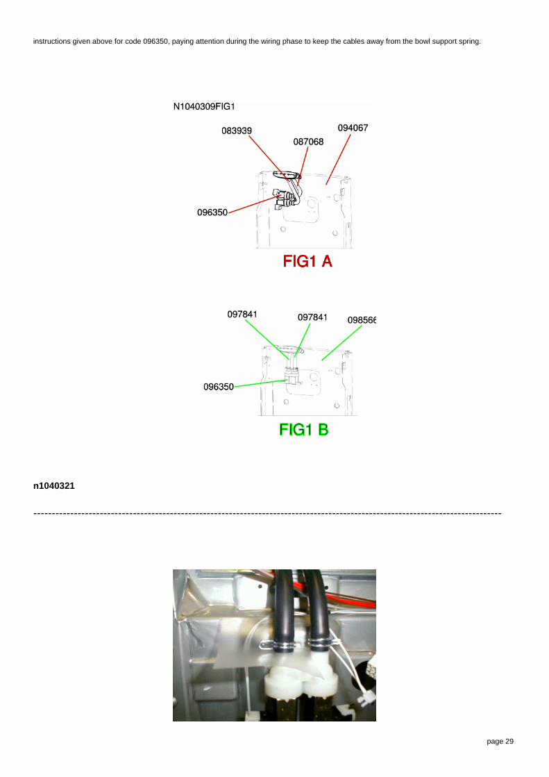
instructions given above for code 096350, paying attention during the wiring phase to keep the cables away from the bowl support spring.
n1040321
-------------------------------------------------------------------------------------------------------------------------------

page 30
n1040324
-------------------------------------------------------------------------------------------------------------------------------
n1040271
Introduction of wheel on Brembate TOP washing machines
-------------------------------------------------------------------------------------------------------------------------------
The central rear wheel on top-load washing machines, relevant to this note, produced in the Brembate factory has been eliminated with introduction
of the small wheel for movement.
This modification has introduced the rear wheel assembly Sat code 091071, eliminating the trolley bar Sat code 083791 and the trolley cam Sat
code 083792 (Sat codes 083791 and 083792 will continue to be regularly managed by the replacement parts warehouse).
Three feet are now used instead of four.
The mobile support still remains Sat code 083785.
The new mechanism can also be fitted to premodification machines.
The image n1040271.1 shows the situation with the new mechanism, and image n1040271.2 the situation with the premodification mechanism.
page 31
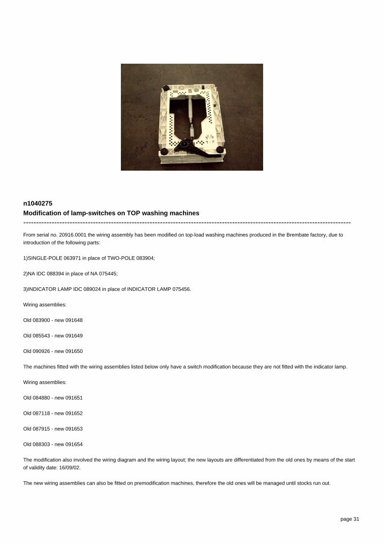
n1040275
Modification of lamp-switches on TOP washing machines
-------------------------------------------------------------------------------------------------------------------------------
From serial no. 20916.0001 the wiring assembly has been modified on top-load washing machines produced in the Brembate factory, due to
introduction of the following parts:
1)SINGLE-POLE 063971 in place of TWO-POLE 083904;
2)NA IDC 088394 in place of NA 075445;
3)INDICATOR LAMP IDC 089024 in place of INDICATOR LAMP 075456.
Wiring assemblies:
Old 083900 - new 091648
Old 085543 - new 091649
Old 090926 - new 091650
The machines fitted with the wiring assemblies listed below only have a switch modification because they are not fitted with the indicator lamp.
Wiring assemblies:
Old 084880 - new 091651
Old 087118 - new 091652
Old 087915 - new 091653
Old 088303 - new 091654
The modification also involved the wiring diagram and the wiring layout; the new layouts are differentiated from the old ones by means of the start
of validity date: 16/09/02.
The new wiring assemblies can also be fitted on premodification machines, therefore the old ones will be managed until stocks run out.

page 32
n1040278
New packing kit on Brembate TOP washing machines
-------------------------------------------------------------------------------------------------------------------------------
From serial no. 21022.0001, a new packing kit Sat code 091902 (in place of Sat code 085574) and a new rear panel Sat code 091893 (in place of
Sat code 083784) have been introduced on top-load washing machines produced in the Brembate factory.
This modification has introduced the packing hole cover Sat code 065871 and the drain tube support code 064550.
n1040288
Power supply cable + moulded filter on top-load Brembate WMs
-------------------------------------------------------------------------------------------------------------------------------
From serial number 30224.0001, all top-load washing machines produced in the Brembate factory have been equipped with a new power supply
cable with moulded filter and new rear panels with a specific opening for fixing the new cable.
The new power supply cables are:
Sat code 091632 Power supply cable 3x1 schuko 1.5m+capacitance filter;
Sat code 091633 Power supply cable 3x1 schuko 1.5m+inductive filter;
Sat code 091641 Power supply cable l=2550mm ag +capacitance filter;
Sat code 091635 Power supply cable uk 3x1 l=1950mm+capacitance filter;
Sat code 091634 Power supply cable uk 3x1 l= 1950mm + inductive filter;
Sat code 091689 Power supply cable l=2550mm ag +inductive filter.
The new rear panels are:
Sat code 094067 - premodification Sat code 091893 (used for few months in place of code 083784, see N1040278);

page 33
Sat code 094068 - premodification Sat code 093623 (specific for the Hotpoint WMTL80UK model, commercial code 28749).
To use premodified wirings on modified products perform the connection to the terminal block of the new cable as shown in fig. 1 - 1D.
The wiring diagrams indicated in the Documentation remain the same.
n1040301
Modification of solenoid valves and wiring on Brembate TOP LOAD washing machines
-------------------------------------------------------------------------------------------------------------------------------
From serial number 30609.0001, the top-load washing machines affected by this note have been equipped with the solenoid valve with coil rast 2.5
Sat code 096350 in place of 083940.
This modification does not affect model WMTL80UK commercial code 28749, which has been equipped with solenoid valves Sat code 096350
(1E2U) and 096349 (1E1U) in place of 083940 (1E2U) and 093546 (1E1U).
The wiring harnesses have been modified therefore both the premodification and new ones will be managed; the wiring diagrams are unchanged.
The Sat codes are given below:
Sat code new 096426 premodification 087487;
Sat code new 096427 premodification 087703;
Sat code new 096428 premodification 088098;

page 34
Sat code new 096429 premodification 088127;
Sat code new 096431 premodification 088292;
Sat code new 096432 premodification 090240;
Sat code new 096433 premodification 088027;
Sat code new 096434 premodification 091648;
Sat code new 096436 premodification 091651;
Sat code new 096437 premodification 091649;
Sat code new 096438 premodification 091652;
Sat code new 096440 premodification 091653;
Sat code new 096452 premodification 093540;
Sat code new 096441 premodification 090610;
Sat code new 096451 premodification 087928;
Sat code new 096444 premodification 091650;
Sat code new 096445 premodification 091654.
The models affected by this modification are:
26376 WT60FR
26867 WT62EX
26377 WT62TFR
26450 WT6IT
26454 WT5IT
26451 WT4IT
26894 WT52CSI
26865 WT40EX
26866 WT50EX
28672 WT124FR
28075 WT120EX
26868 WT82EXP
26379 WT82TFR
26452 WAT6IT
26453 WAT8IT

page 35
27872 W4608TLCSI
26899 WT100CSI
26869 WT102EXP
27728 WT102TFR
28670 WT92FR
28671 WT112FR
28314 WAT10IT
27873 W4610TLCSI
28669 WT80FR
26897 WT80CSI
26970 WT67EU
27143 AT82IT
28491 AT125FR
29395 AT110FR
27122 AT85FR
29388 AT95FR
29182 AT109FR
27142 AT62IT
28749 WMTL80UK
29393 ATD102FR
27148 ATD120EX
27125 ATD120FR
29394 ATD122FR
27636 ATD104EX
27145 ATD104IT
27144 ATD84IT
26898 WT90CSI
27635 AT84EX
28074 AT104EX
27726 AT84EO
27684 AT84AG

page 36
The wiring diagrams are unchanged.
n1040309
Modification of rear panels on TOP LOADING washing machines.
-------------------------------------------------------------------------------------------------------------------------------
From serial no. 30912.0001, the system used for fixing the loading solenoid valve (spare part code 096350) to the rear panel has been modified on
Top Loading washing machines, rotating its position by 90°.
The solenoid valve (spare part code 096350) has been modified with the 45° rotation of a coil; the Replacements Warehouse will continue to
manage this part with the same code. When replacing on premodification machines, fit the coils as shown in figure N1040309FIG3-1 and on
modified machines, as shown in figure N1040309FIG3-2; to rotate the coil, lift it using a screwdriver and then refit according to the inserts on the
plastic.
Replacement codes of the parts affected by this modification (see figure N1040309FIG1):
FIG1 A - PREMODIFICATION STRUCTURE
solenoid valve tube/distributor assembly: premodification 083939;
solenoid valve tube/distributor assembly: premodification 087068;
rear panel: premodification 094067.
FIG1 B - NEW STRUCTURE
solenoid valve tube/distributor assembly: new 097841;
solenoid valve tube/distributor assembly: new 097841;
rear panel: new 098566.
Replacement codes of the parts affected by the modification to WMTL80UK (see figure N1040309FIG2):
FIG2 A - PREMODIFICATION STRUCTURE
solenoid valve tube/distributor assembly: premodification 093620;
solenoid valve tube/distributor assembly: premodification 093621;
rear panel: premodification 094068.
FIG2 B - NEW STRUCTURE
solenoid valve tube/distributor assembly: new 097832;

page 37
solenoid valve tube/distributor assembly: new 097832;
rear panel: new 098567.
Premodification panels will be managed by the Replacements Warehouse while stocks last; when replacing with new ones on premodification
appliances the new tubes must also also be used.
When using the new panels on appliances before serial no. 30609.0001, fitted with solenoid valve code 083940, rotate the coil 45° and follow the
instructions given above for code 096350, paying attention during the wiring phase to keep the cables away from the bowl support spring.
n1040321
-------------------------------------------------------------------------------------------------------------------------------

page 38
n1040324
-------------------------------------------------------------------------------------------------------------------------------

page 39
Electric schemes and links
Cod. 160013210-0

page 40
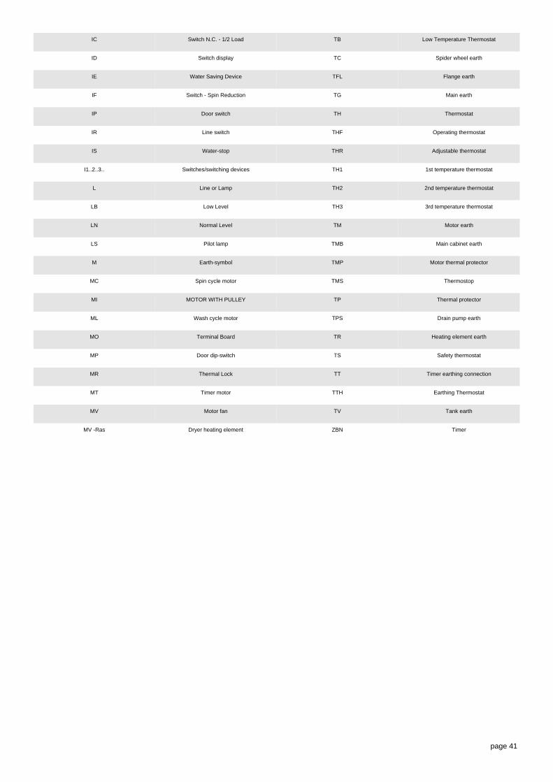
Legend
Legend: 160013210-0
AQS Aquastop electrovalve Mzbn/MTA zbn timer motor
B Buzzer N Neutral or Terminal Board
BC NC Spin cycle exclusion
BF Terminal board contact, motor fan and dryerheatin
P Pressure switch
BP Buzzer PA High speed potentiometer
C Condensator PB Low speed potentiometer
CA Condensator PL Pure Wool
DV Switching device PM Motor Thermoprotector
EF/CL Electro-Valve Cold Water / Bleach PR Timer programmer or Pressure switch
EF/L Electro-Valve Cold Water / Wash PS Drain pump
EF/P Electro-Valve Cold Water / Prewash P1 1st level pressure cut-off switch
ER Exclude Heating Element P2 2nd level pressure cut-off switch
ET Thermostat disactivation R Heating element
EV Electrovalve Ras/RA Dryer heating element
EVA Dryer electrovalve RE Relay
EVC Hot water electrovalve RR Heating element
EVF Elettrovalvola acqua fredda RV Speed regulator
EVL Wash electrovalve S LED
EVP Pre Wash electrovalve SL Line LED
FA Antijamming filter SO Door LED
FD Delicate drying cycle thermostat SR Heating LED
FE Strong drying cycle thermostat ST Temperature selector
FRT Thermofusible Heating Element SV Speed Selector for Spin
I Inverter T Timer contacts
IA Switch On/Off TA Drying timer contacts
page 41
IC Switch N.C. - 1/2 Load TB Low Temperature Thermostat
ID Switch display TC Spider wheel earth
IE Water Saving Device TFL Flange earth
IF Switch - Spin Reduction TG Main earth
IP Door switch TH Thermostat
IR Line switch THF Operating thermostat
IS Water-stop THR Adjustable thermostat
I1..2..3.. Switches/switching devices TH1 1st temperature thermostat
L Line or Lamp TH2 2nd temperature thermostat
LB Low Level TH3 3rd temperature thermostat
LN Normal Level TM Motor earth
LS Pilot lamp TMB Main cabinet earth
M Earth-symbol TMP Motor thermal protector
MC Spin cycle motor TMS Thermostop
MI MOTOR WITH PULLEY TP Thermal protector
ML Wash cycle motor TPS Drain pump earth
MO Terminal Board TR Heating element earth
MP Door dip-switch TS Safety thermostat
MR Thermal Lock TT Timer earthing connection
MT Timer motor TTH Earthing Thermostat
MV Motor fan TV Tank earth
MV -Ras Dryer heating element ZBN Timer

page 42
Electric schemes and links
Cod. 160013210-1

page 43
Legend
Legend: 160013210-1
AQS Aquastop electrovalve Mzbn/MTA zbn timer motor
B Buzzer N Neutral or Terminal Board
BC NC Spin cycle exclusion
BF Terminal board contact, motor fan and dryerheatin
P Pressure switch
BP Buzzer PA High speed potentiometer
C Condensator PB Low speed potentiometer
CA Condensator PL Pure Wool
DV Switching device PM Motor Thermoprotector
EF/CL Electro-Valve Cold Water / Bleach PR Timer programmer or Pressure switch
EF/L Electro-Valve Cold Water / Wash PS Drain pump
EF/P Electro-Valve Cold Water / Prewash P1 1st level pressure cut-off switch
ER Exclude Heating Element P2 2nd level pressure cut-off switch
ET Thermostat disactivation R Heating element
EV Electrovalve Ras/RA Dryer heating element
EVA Dryer electrovalve RE Relay
EVC Hot water electrovalve RR Heating element
EVF Elettrovalvola acqua fredda RV Speed regulator
EVL Wash electrovalve S LED
EVP Pre Wash electrovalve SL Line LED
FA Antijamming filter SO Door LED
FD Delicate drying cycle thermostat SR Heating LED
FE Strong drying cycle thermostat ST Temperature selector
FRT Thermofusible Heating Element SV Speed Selector for Spin
I Inverter T Timer contacts
IA Switch On/Off TA Drying timer contacts

page 44
IC Switch N.C. - 1/2 Load TB Low Temperature Thermostat
ID Switch display TC Spider wheel earth
IE Water Saving Device TFL Flange earth
IF Switch - Spin Reduction TG Main earth
IP Door switch TH Thermostat
IR Line switch THF Operating thermostat
IS Water-stop THR Adjustable thermostat
I1..2..3.. Switches/switching devices TH1 1st temperature thermostat
L Line or Lamp TH2 2nd temperature thermostat
LB Low Level TH3 3rd temperature thermostat
LN Normal Level TM Motor earth
LS Pilot lamp TMB Main cabinet earth
M Earth-symbol TMP Motor thermal protector
MC Spin cycle motor TMS Thermostop
MI MOTOR WITH PULLEY TP Thermal protector
ML Wash cycle motor TPS Drain pump earth
MO Terminal Board TR Heating element earth
MP Door dip-switch TS Safety thermostat
MR Thermal Lock TT Timer earthing connection
MT Timer motor TTH Earthing Thermostat
MV Motor fan TV Tank earth
MV -Ras Dryer heating element ZBN Timer

page 45
Electric schemes and links
Cod. 160013295-0
page 46
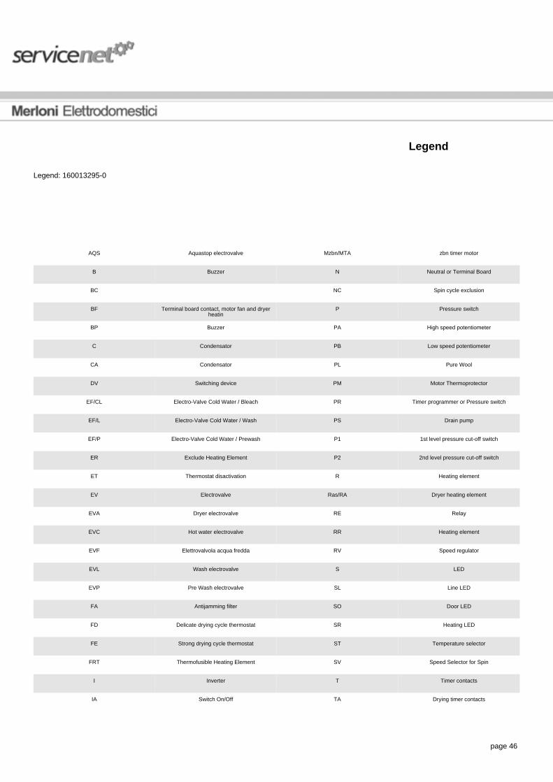
Legend
Legend: 160013295-0
AQS Aquastop electrovalve Mzbn/MTA zbn timer motor
B Buzzer N Neutral or Terminal Board
BC NC Spin cycle exclusion
BF Terminal board contact, motor fan and dryerheatin
P Pressure switch
BP Buzzer PA High speed potentiometer
C Condensator PB Low speed potentiometer
CA Condensator PL Pure Wool
DV Switching device PM Motor Thermoprotector
EF/CL Electro-Valve Cold Water / Bleach PR Timer programmer or Pressure switch
EF/L Electro-Valve Cold Water / Wash PS Drain pump
EF/P Electro-Valve Cold Water / Prewash P1 1st level pressure cut-off switch
ER Exclude Heating Element P2 2nd level pressure cut-off switch
ET Thermostat disactivation R Heating element
EV Electrovalve Ras/RA Dryer heating element
EVA Dryer electrovalve RE Relay
EVC Hot water electrovalve RR Heating element
EVF Elettrovalvola acqua fredda RV Speed regulator
EVL Wash electrovalve S LED
EVP Pre Wash electrovalve SL Line LED
FA Antijamming filter SO Door LED
FD Delicate drying cycle thermostat SR Heating LED
FE Strong drying cycle thermostat ST Temperature selector
FRT Thermofusible Heating Element SV Speed Selector for Spin
I Inverter T Timer contacts
IA Switch On/Off TA Drying timer contacts

page 47
IC Switch N.C. - 1/2 Load TB Low Temperature Thermostat
ID Switch display TC Spider wheel earth
IE Water Saving Device TFL Flange earth
IF Switch - Spin Reduction TG Main earth
IP Door switch TH Thermostat
IR Line switch THF Operating thermostat
IS Water-stop THR Adjustable thermostat
I1..2..3.. Switches/switching devices TH1 1st temperature thermostat
L Line or Lamp TH2 2nd temperature thermostat
LB Low Level TH3 3rd temperature thermostat
LN Normal Level TM Motor earth
LS Pilot lamp TMB Main cabinet earth
M Earth-symbol TMP Motor thermal protector
MC Spin cycle motor TMS Thermostop
MI MOTOR WITH PULLEY TP Thermal protector
ML Wash cycle motor TPS Drain pump earth
MO Terminal Board TR Heating element earth
MP Door dip-switch TS Safety thermostat
MR Thermal Lock TT Timer earthing connection
MT Timer motor TTH Earthing Thermostat
MV Motor fan TV Tank earth
MV -Ras Dryer heating element ZBN Timer
page 48
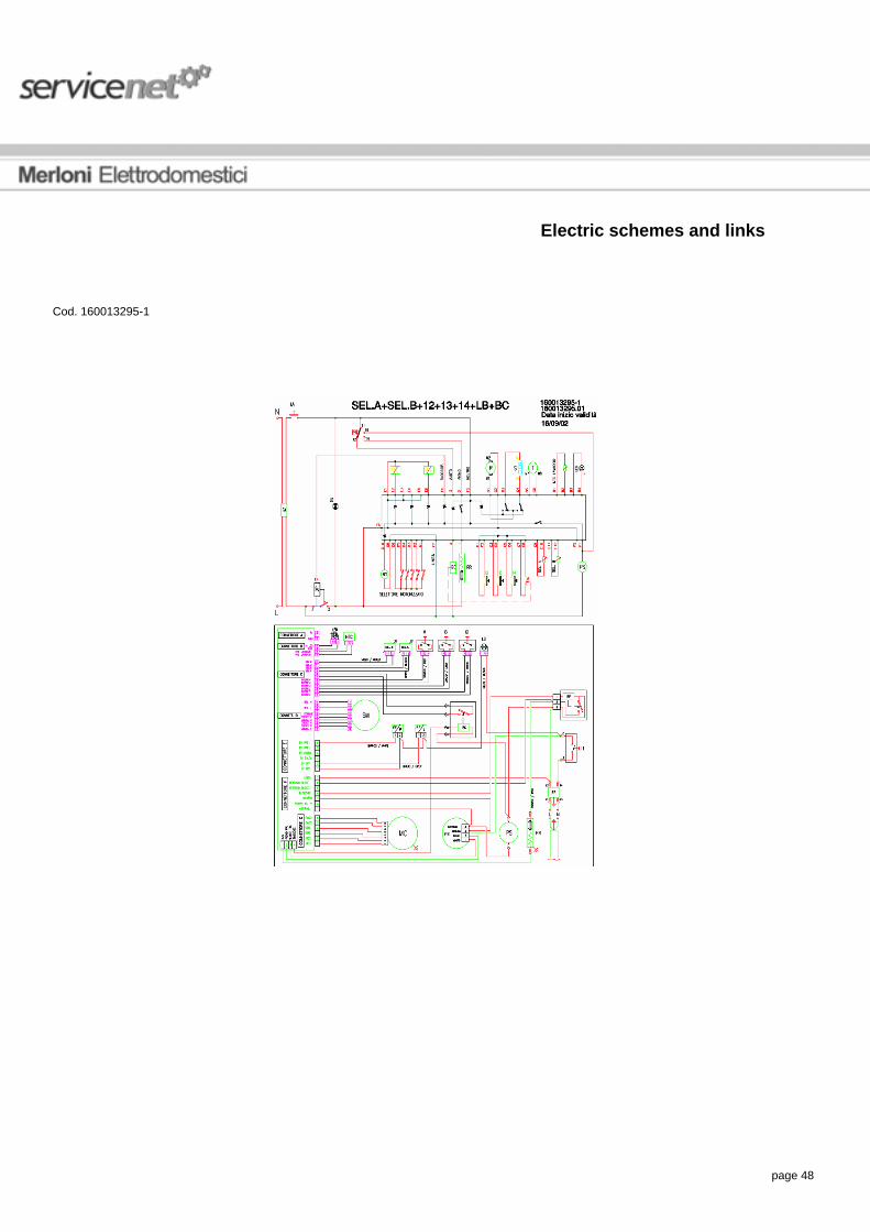
Electric schemes and links
Cod. 160013295-1

page 49
Legend
Legend: 160013295-1
AQS Aquastop electrovalve Mzbn/MTA zbn timer motor
B Buzzer N Neutral or Terminal Board
BC NC Spin cycle exclusion
BF Terminal board contact, motor fan and dryerheatin
P Pressure switch
BP Buzzer PA High speed potentiometer
C Condensator PB Low speed potentiometer
CA Condensator PL Pure Wool
DV Switching device PM Motor Thermoprotector
EF/CL Electro-Valve Cold Water / Bleach PR Timer programmer or Pressure switch
EF/L Electro-Valve Cold Water / Wash PS Drain pump
EF/P Electro-Valve Cold Water / Prewash P1 1st level pressure cut-off switch
ER Exclude Heating Element P2 2nd level pressure cut-off switch
ET Thermostat disactivation R Heating element
EV Electrovalve Ras/RA Dryer heating element
EVA Dryer electrovalve RE Relay
EVC Hot water electrovalve RR Heating element
EVF Elettrovalvola acqua fredda RV Speed regulator
EVL Wash electrovalve S LED
EVP Pre Wash electrovalve SL Line LED
FA Antijamming filter SO Door LED
FD Delicate drying cycle thermostat SR Heating LED
FE Strong drying cycle thermostat ST Temperature selector
FRT Thermofusible Heating Element SV Speed Selector for Spin
I Inverter T Timer contacts
IA Switch On/Off TA Drying timer contacts

page 50
IC Switch N.C. - 1/2 Load TB Low Temperature Thermostat
ID Switch display TC Spider wheel earth
IE Water Saving Device TFL Flange earth
IF Switch - Spin Reduction TG Main earth
IP Door switch TH Thermostat
IR Line switch THF Operating thermostat
IS Water-stop THR Adjustable thermostat
I1..2..3.. Switches/switching devices TH1 1st temperature thermostat
L Line or Lamp TH2 2nd temperature thermostat
LB Low Level TH3 3rd temperature thermostat
LN Normal Level TM Motor earth
LS Pilot lamp TMB Main cabinet earth
M Earth-symbol TMP Motor thermal protector
MC Spin cycle motor TMS Thermostop
MI MOTOR WITH PULLEY TP Thermal protector
ML Wash cycle motor TPS Drain pump earth
MO Terminal Board TR Heating element earth
MP Door dip-switch TS Safety thermostat
MR Thermal Lock TT Timer earthing connection
MT Timer motor TTH Earthing Thermostat
MV Motor fan TV Tank earth
MV -Ras Dryer heating element ZBN Timer

page 51
Electric schemes and links
Cod. 28268980001

page 52

page 53
Legend
Legend: 28268980001