industrial automation - isr
TRANSCRIPT
http://users.isr.ist.utl.pt/~jag/courses/api1213/api1213.html
Slides 2010/2011 Prof. Paulo Jorge OliveiraRev. 2011-2013 Prof. José Gaspar
PLC Programming languagesPLC Programming languagesLadder DiagramLadder Diagram
Industrial AutomationIndustrial Automation((AutomaAutomaççãoão de de ProcessosProcessos IndustriaisIndustriais))
IST / DEEC / API

Chap. 2 – Introduction to PLCs [2 weeks]...
Chap. 3 – PLC Programming languages [2 weeks]Standard languages (IEC-61131-3):Ladder Diagram; Instruction List, and Structured Text.Software development resources.
...Chap. 4 - GRAFCET (Sequential Function Chart) [1 week]
Syllabus:Syllabus:
IST / DEEC / API
Page 2
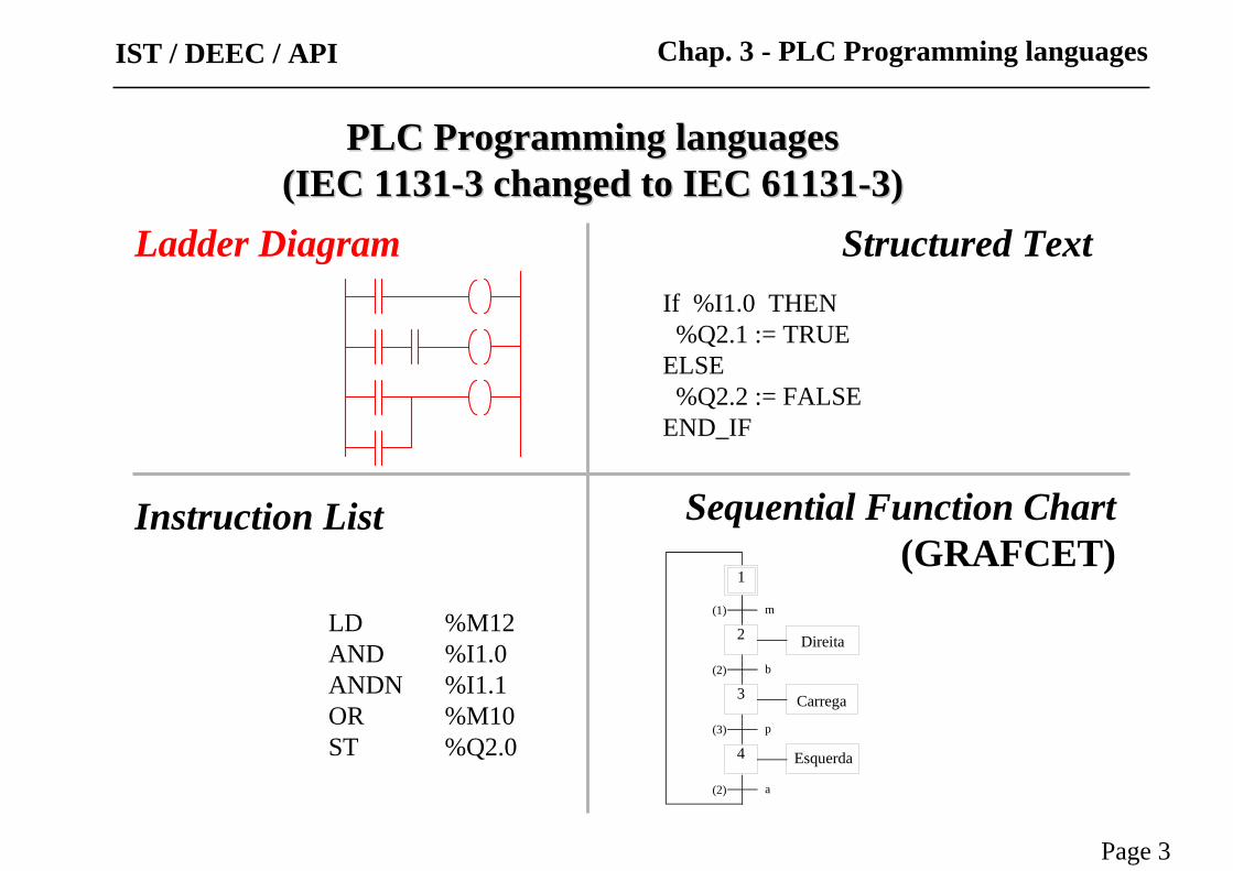
Ladder Diagram
Instruction List
Structured Text
Sequential Function Chart(GRAFCET)
LD %M12AND %I1.0ANDN %I1.1OR %M10ST %Q2.0
If %I1.0 THEN%Q2.1 := TRUE
ELSE%Q2.2 := FALSE
END_IF
1
Direita
(1) m
2
3(2) b
(3) p
4
(2) a
Carrega
Esquerda
Page 3
Chap. 3 - PLC Programming languagesIST / DEEC / API
PLC Programming languagesPLC Programming languages(IEC 1131(IEC 1131--3 changed to IEC 611313 changed to IEC 61131--3)3)

IST / DEEC / API
Page 4
Ladder diagramLadder diagram
A program is a series of instructions that directs the PLC to execute actions.
Relay ladder logic, the standard programming language, is based on electromagnetic relay control.
N S
InputInstructions
OutputInstructions
IST / DEEC / API
Page 5
Ladder diagramLadder diagram
Page 5
Chap. 3 - PLC Programming languagesIST / DEEC / API
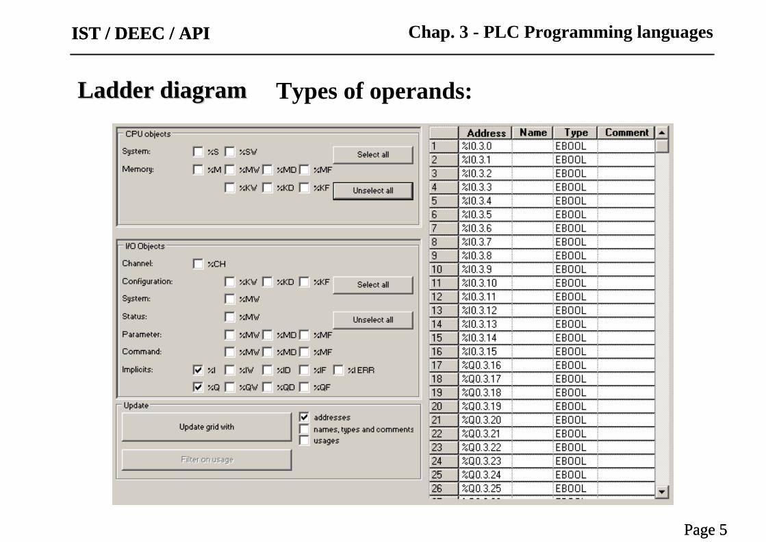
Types of operands:
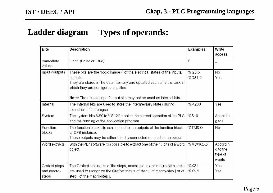
Ladder diagramLadder diagram Types of operands:
Page 6
Chap. 3 - PLC Programming languagesIST / DEEC / API
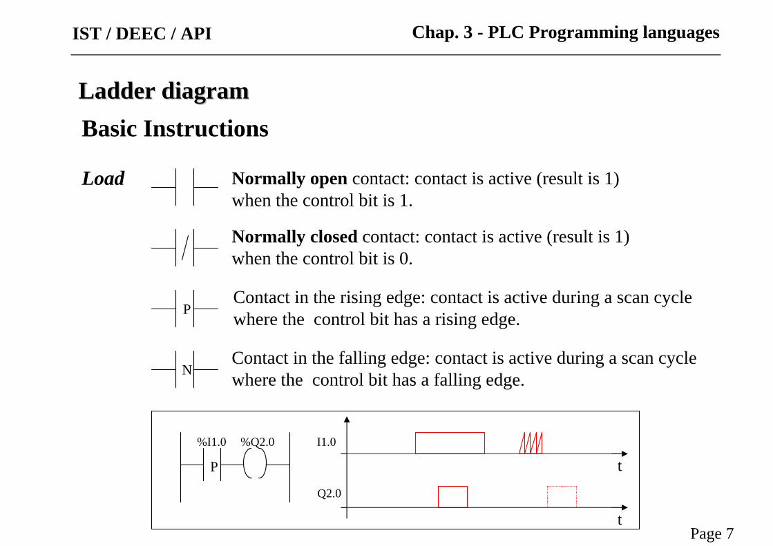
Basic Instructions
Load
P
N
Normally open contact: contact is active (result is 1)when the control bit is 1.
Normally closed contact: contact is active (result is 1)when the control bit is 0.
Contact in the rising edge: contact is active during a scan cycle where the control bit has a rising edge.
Contact in the falling edge: contact is active during a scan cycle where the control bit has a falling edge.
P
%I1.0 %Q2.0 I1.0
Q2.0
t
t
Ladder diagramLadder diagram
Page 7
Chap. 3 - PLC Programming languagesIST / DEEC / API

Ladder diagramLadder diagramBasic Instructions
Load operands
Page 8
Chap. 3 - PLC Programming languagesIST / DEEC / API
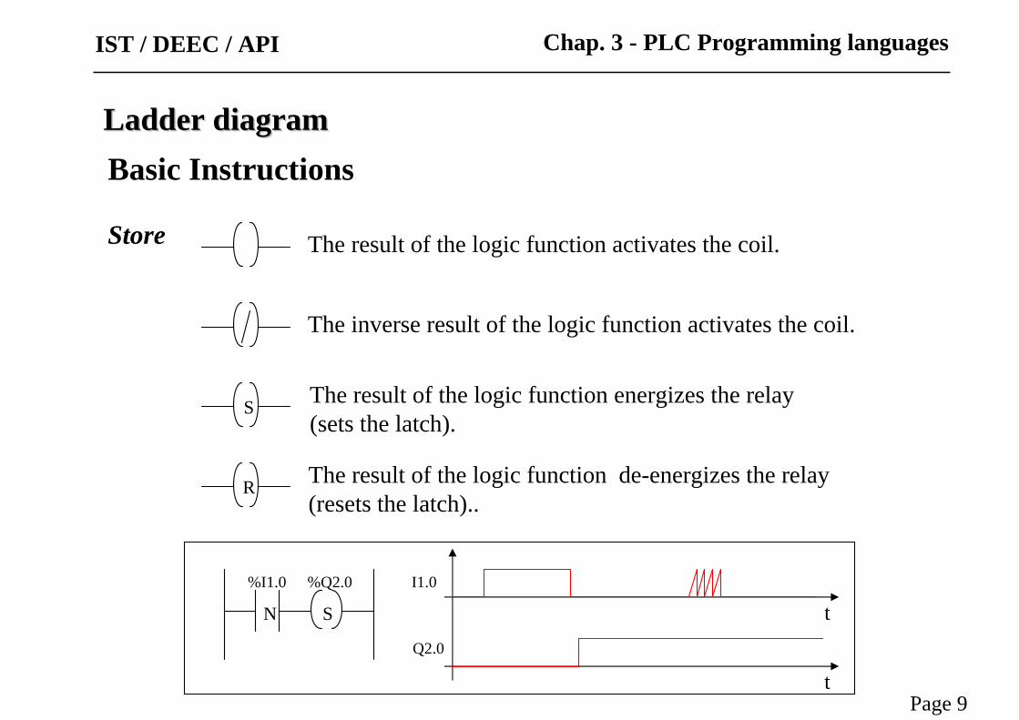
Store The result of the logic function activates the coil.
The inverse result of the logic function activates the coil.
The result of the logic function energizes the relay (sets the latch).
S
R The result of the logic function de-energizes the relay (resets the latch)..
N
%I1.0 %Q2.0 I1.0
Q2.0
t
t
S
Ladder diagramLadder diagram
Page 9
Chap. 3 - PLC Programming languages
Basic Instructions
IST / DEEC / API

Ladder diagramLadder diagram
Store operands
Page 10
Chap. 3 - PLC Programming languages
Basic Instructions
IST / DEEC / API
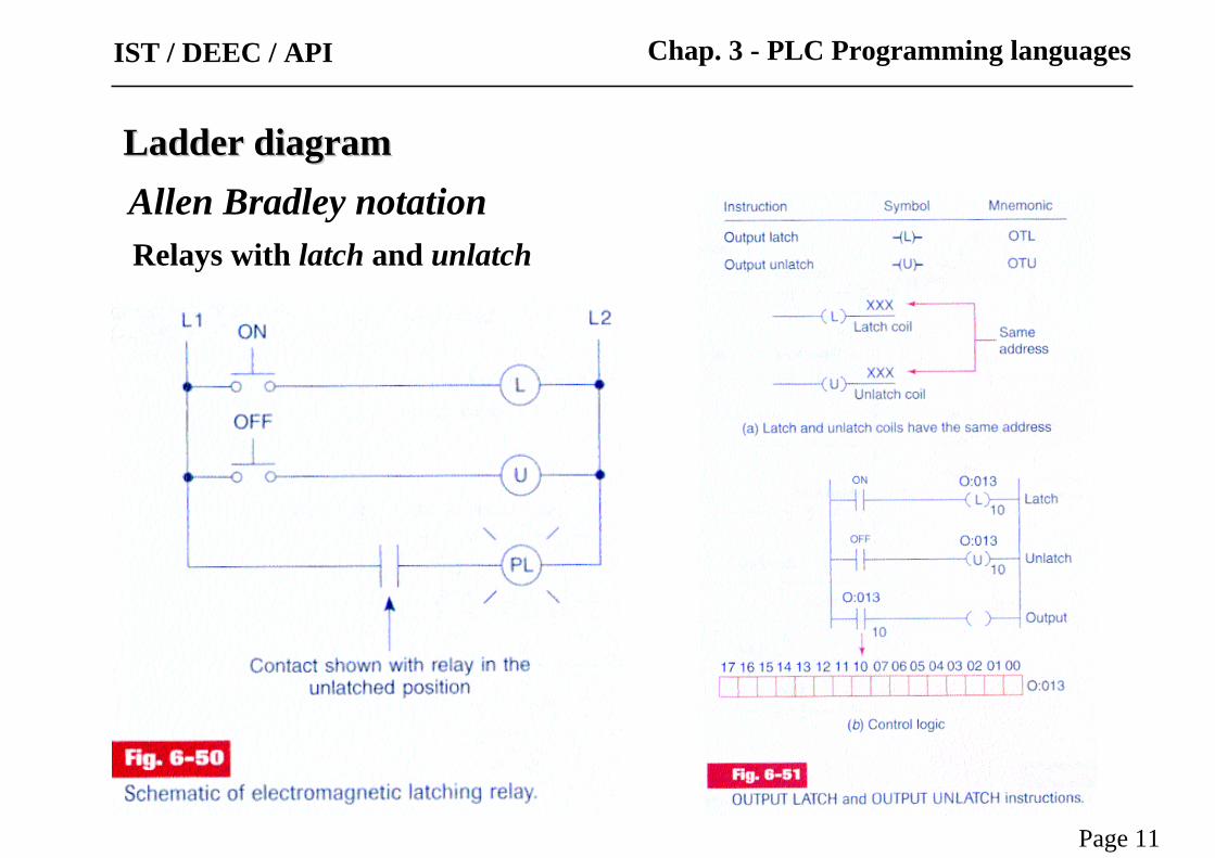
Relays with latch and unlatch
Ladder diagramLadder diagramAllen Bradley notation
Page 11
Chap. 3 - PLC Programming languagesIST / DEEC / API
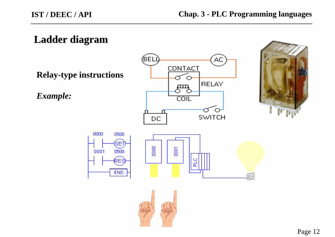
Relay-type instructions
Example:
Ladder diagramLadder diagram
Page 12
Chap. 3 - PLC Programming languagesIST / DEEC / API
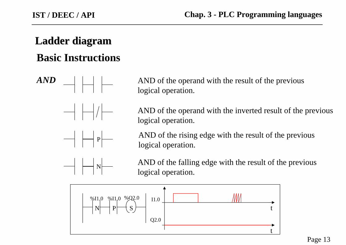
AND AND of the operand with the result of the previous logical operation.
AND of the operand with the inverted result of the previouslogical operation.
AND of the rising edge with the result of the previous logical operation.
AND of the falling edge with the result of the previous logical operation.
P
N
N
%Q2.0 I1.0
Q2.0
S t
t
P%I1.0%I1.0
Ladder diagramLadder diagram
Page 13
Chap. 3 - PLC Programming languages
Basic Instructions
IST / DEEC / API

OR
P
N
Ladder diagramLadder diagram
Page 14
Chap. 3 - PLC Programming languages
Basic Instructions
OR of the operand with the result of the previous logical operation.
OR of the operand with the inverted result of the previouslogical operation.
OR of the rising edge with the result of the previous logical operation.
OR of the falling edge with the result of the previous logical operation.
IST / DEEC / API

XOR
Ladder diagramLadder diagram
Page 15
Chap. 3 - PLC Programming languages
Basic Instructions
IST / DEEC / API

N S
InputInstructions
OutputInstructions
Ladder assembling
The outputs that have a TRUE logical function, evaluated from the left to right and from the top to the bottom, are energized (Schneider, Micro PLCs).
Ladder diagramLadder diagram
Page 16
Chap. 3 - PLC Programming languagesIST / DEEC / API
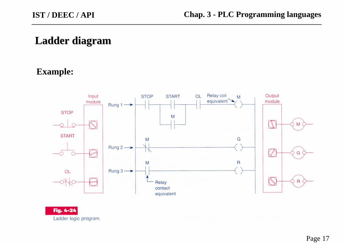
Ladder diagramLadder diagram
Example:
Page 17
Chap. 3 - PLC Programming languagesIST / DEEC / API

Ladder diagramLadder diagram
Example:
Page 18
Chap. 3 - PLC Programming languagesIST / DEEC / API
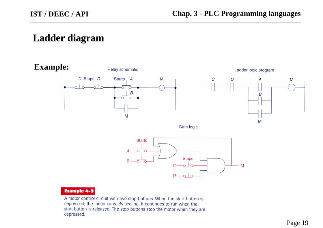
Ladder diagramLadder diagram
Example:
Page 19
Chap. 3 - PLC Programming languagesIST / DEEC / API
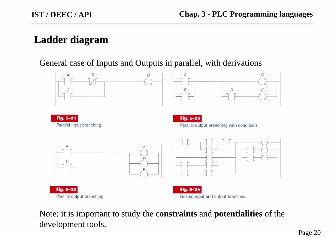
General case of Inputs and Outputs in parallel, with derivations
Ladder diagramLadder diagram
Note: it is important to study the constraints and potentialities of the development tools.
Page 20
Chap. 3 - PLC Programming languagesIST / DEEC / API

Imbricated (nested) contacts and alternative solution
Ladder diagramLadder diagram
Page 21
Chap. 3 - PLC Programming languagesIST / DEEC / API
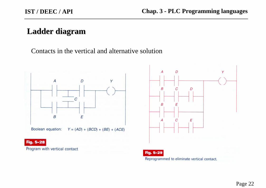
Contacts in the vertical and alternative solution
Ladder diagramLadder diagram
Page 22
Chap. 3 - PLC Programming languagesIST / DEEC / API
Ladder diagramLadder diagram
Page 23
Chap. 3 - PLC Programming languages
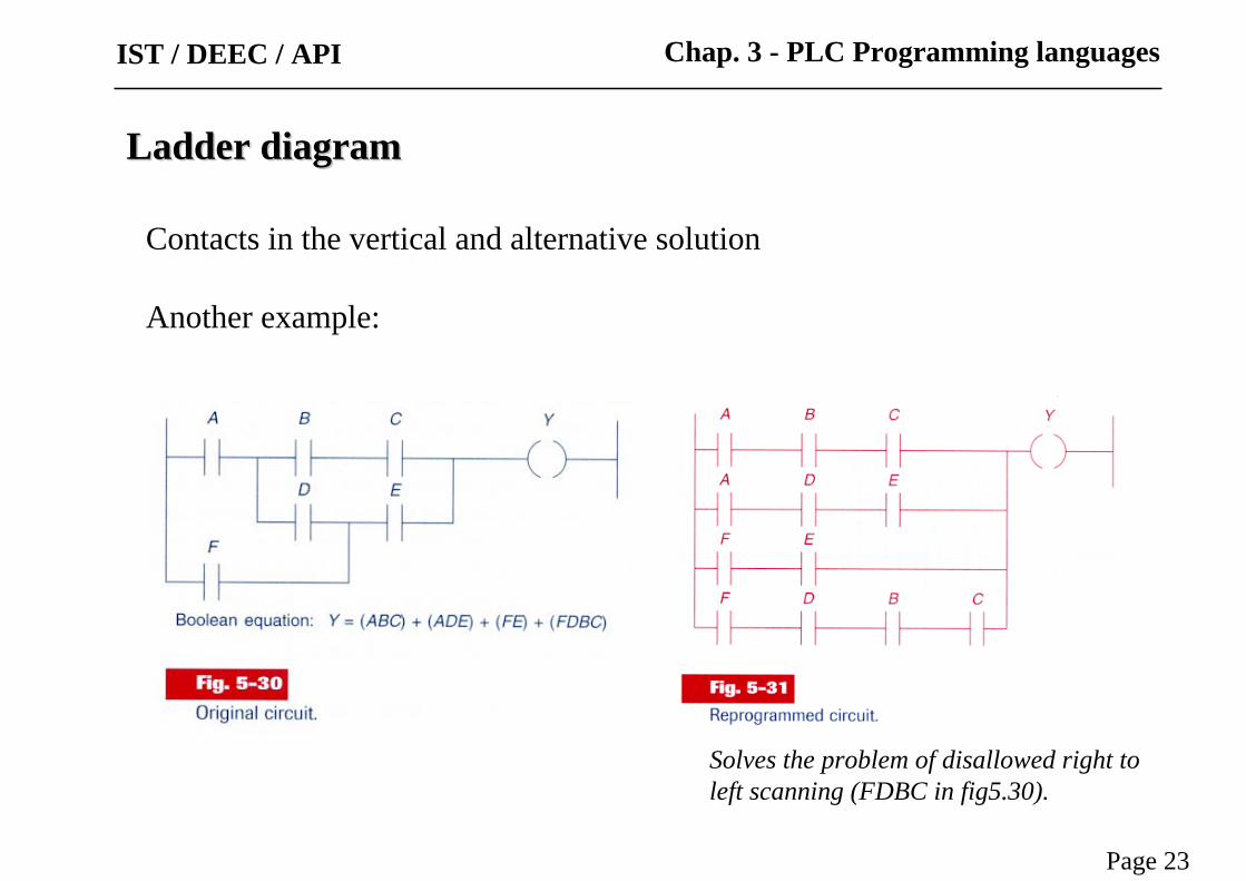
Contacts in the vertical and alternative solution
Another example:
IST / DEEC / API
Solves the problem of disallowed right to left scanning (FDBC in fig5.30).

IST / DEEC / API
Page 24
Ladder diagramLadder diagram
Page 24
Chap. 3 - PLC Programming languagesIST / DEEC / API
Temporized Relays or Timers

Ladder diagramLadder diagram
Page 25
Chap. 3 - PLC Programming languagesIST / DEEC / API
The instantaneous contacts change state as soon as the timer coil is powered.The delayed contacts change state at the end of the time delay.
Temporized Relays or Timers (pneumatic)

IST / DEEC / API
Page 26Tables: Relay symbols used for timed contacts.
On-delay, provides time delay when the relay coil is energized.
Off-delay, provides time delay when the relay coil is de-energized.
Ladder diagramLadder diagram
Chap. 3 - PLC Programming languages
Temporized Relays or Timers

Ladder diagramLadder diagram
Page 27
Chap. 3 - PLC Programming languagesIST / DEEC / API
Temporized Relays or Timers
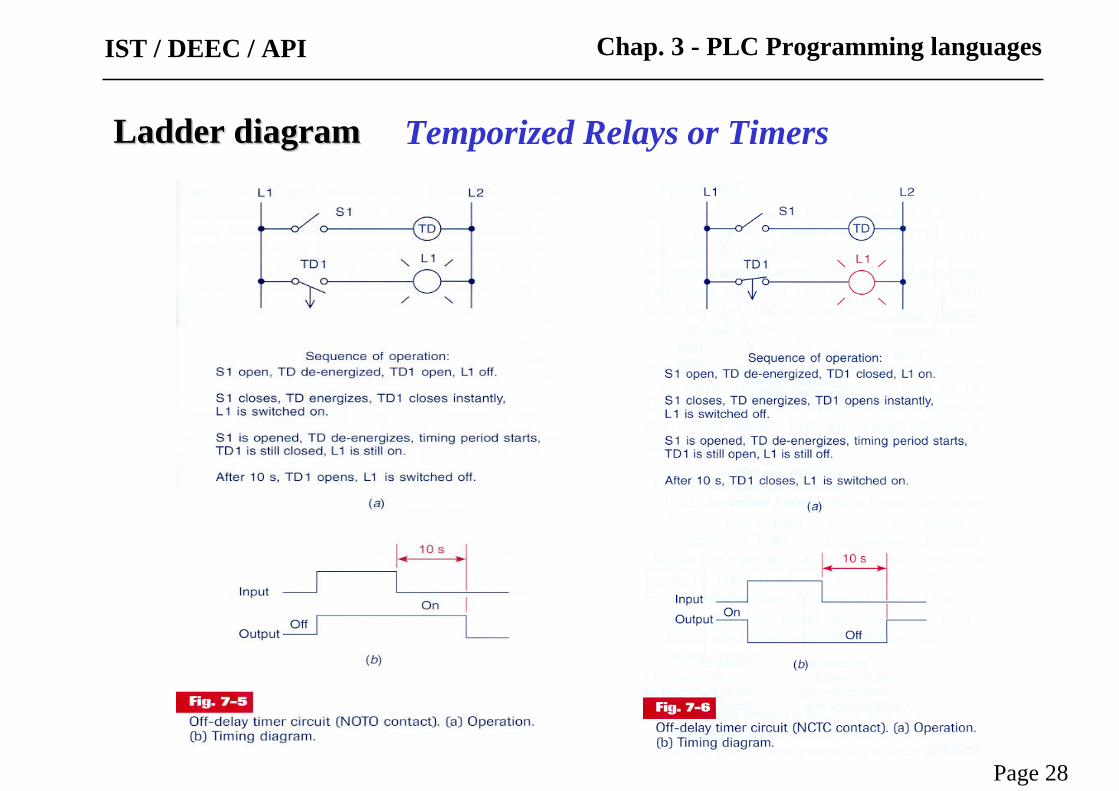
Ladder diagramLadder diagram
Page 28
Chap. 3 - PLC Programming languagesIST / DEEC / API
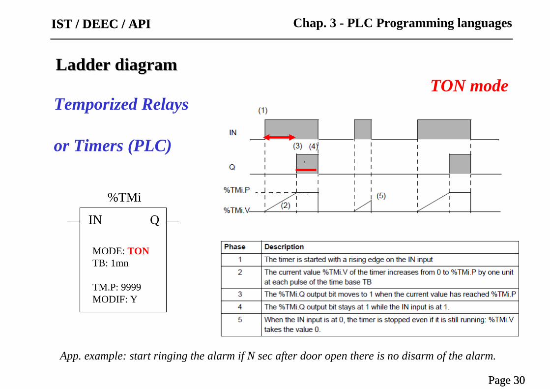
Temporized Relays or Timers
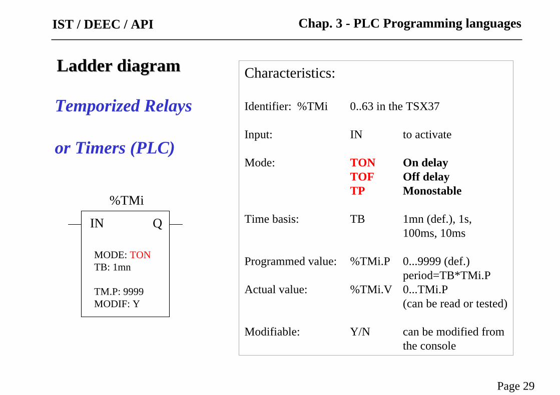
Characteristics:
Identifier: %TMi 0..63 in the TSX37
Input: IN to activate
Mode: TON On delayTOF Off delayTP Monostable
Time basis: TB 1mn (def.), 1s, 100ms, 10ms
Programmed value: %TMi.P 0...9999 (def.)period=TB*TMi.P
Actual value: %TMi.V 0...TMi.P(can be read or tested)
Modifiable: Y/N can be modified from the console
IN Q
%TMi
MODE: TONTB: 1mn
TM.P: 9999MODIF: Y
Ladder diagramLadder diagram
Page 29
Chap. 3 - PLC Programming languages
Temporized Relays
or Timers (PLC)
IST / DEEC / API
IST / DEEC / API
Page 30
IN Q
%TMi
MODE: TONTB: 1mn
TM.P: 9999MODIF: Y
Ladder diagramLadder diagram
Page 30
Chap. 3 - PLC Programming languages
Temporized Relays
or Timers (PLC)
IST / DEEC / API
TON mode
App. example: start ringing the alarm if N sec after door open there is no disarm of the alarm.

IST / DEEC / API
Page 31
IN Q
%TMi
MODE: TOFTB: 1mn
TM.P: 9999MODIF: Y
Ladder diagramLadder diagram
Page 31
Chap. 3 - PLC Programming languages
Temporized Relays
or Timers (PLC)
IST / DEEC / API
TOF mode
App. example: turn off stairways lights after N sec the lights’ button has been released.

IST / DEEC / API
Page 32
Works as a monostable or as a pulse generator (with pre-programmed period)
IN Q
%TMi
MODE: TPTB: 100msec
TM.P: 5MODIF: Y
Ladder diagramLadder diagram
Page 32
Chap. 3 - PLC Programming languagesIST / DEEC / API
Temporized Relays
or Timers (PLC)
TP mode
App. example: positive input edge give a controlled (fixed) duration pulse to start a motor.

Two alternative representations
Ladder diagramLadder diagram
Page 33
Chap. 3 - PLC Programming languagesIST / DEEC / API
Timers in the Allen-Bradley PLC-5

IST / DEEC / API
Page 34
Timers implementation in the Allen-Bradley PLC-5:
Ladder diagramLadder diagram
Page 34
Chap. 3 - PLC Programming languagesIST / DEEC / API

Timers operation in the Allen-Bradley PLC-5
Ladder diagramLadder diagram
Page 35
Chap. 3 - PLC Programming languagesIST / DEEC / API
EN = Enable BitTT = Timer-Timing BitDN = Done Bit
EN
TT
DN
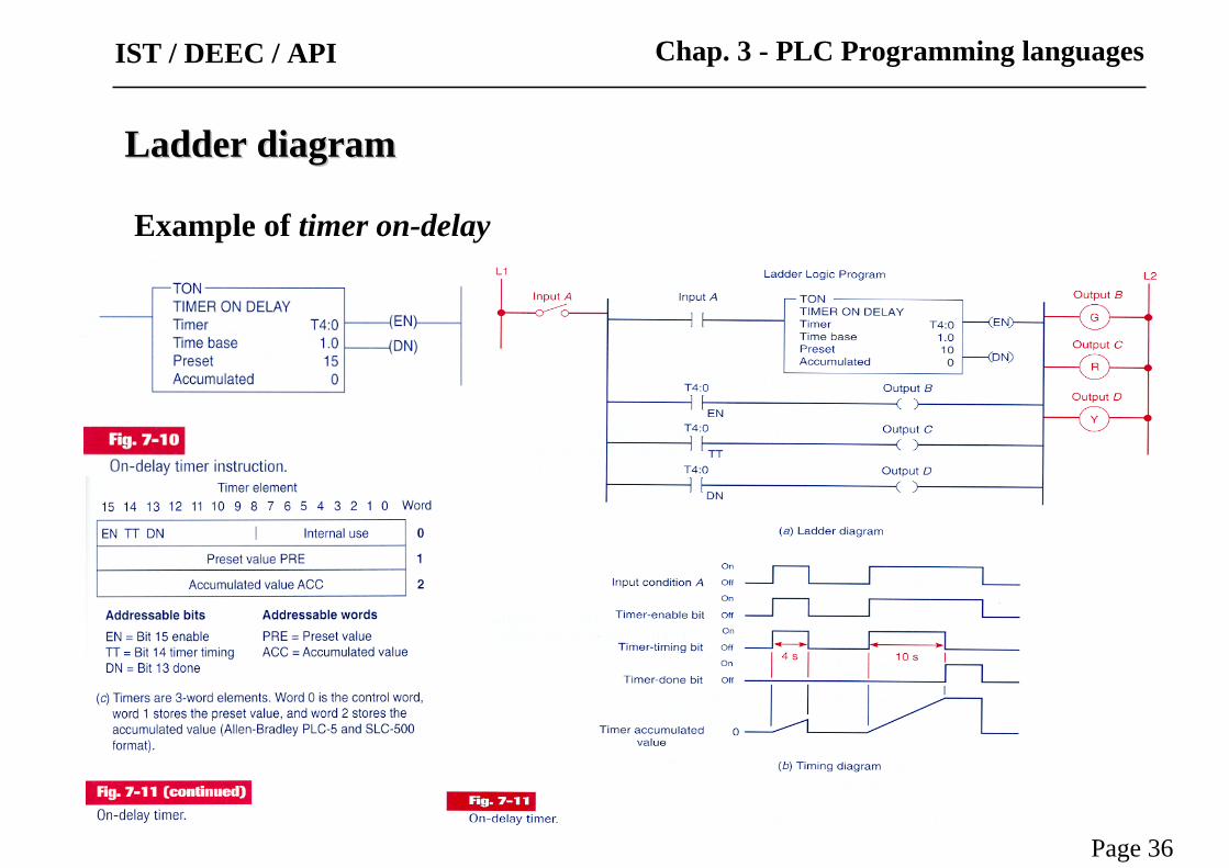
Example of timer on-delay
Ladder diagramLadder diagram
Page 36
Chap. 3 - PLC Programming languagesIST / DEEC / API

Example of a timer on-delay that sets an output after a count-down
Ladder diagramLadder diagram
Page 37
Chap. 3 - PLC Programming languagesIST / DEEC / API
Example of timer on-delay
Ladder diagramLadder diagram
Page 38
Chap. 3 - PLC Programming languagesIST / DEEC / API

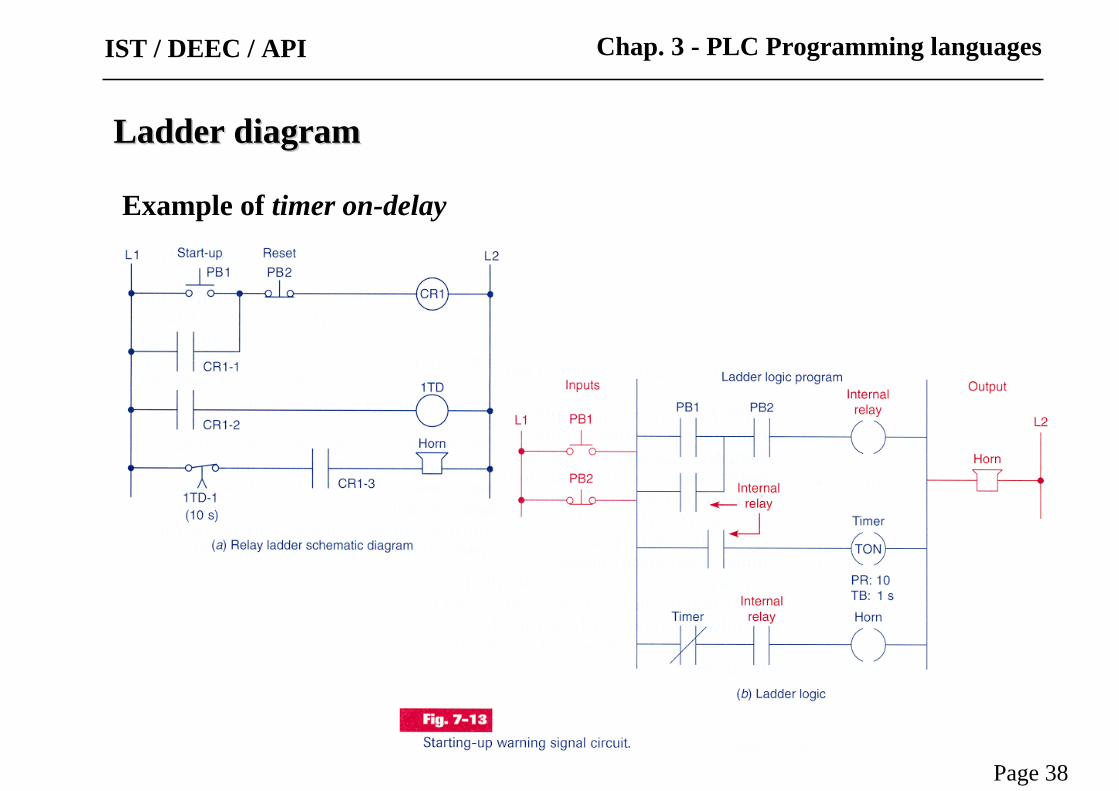
Example of timer on-delay
Coil is energized if the switch remains closed for 12 seconds
Ladder diagramLadder diagram
Page 39
Chap. 3 - PLC Programming languagesIST / DEEC / API
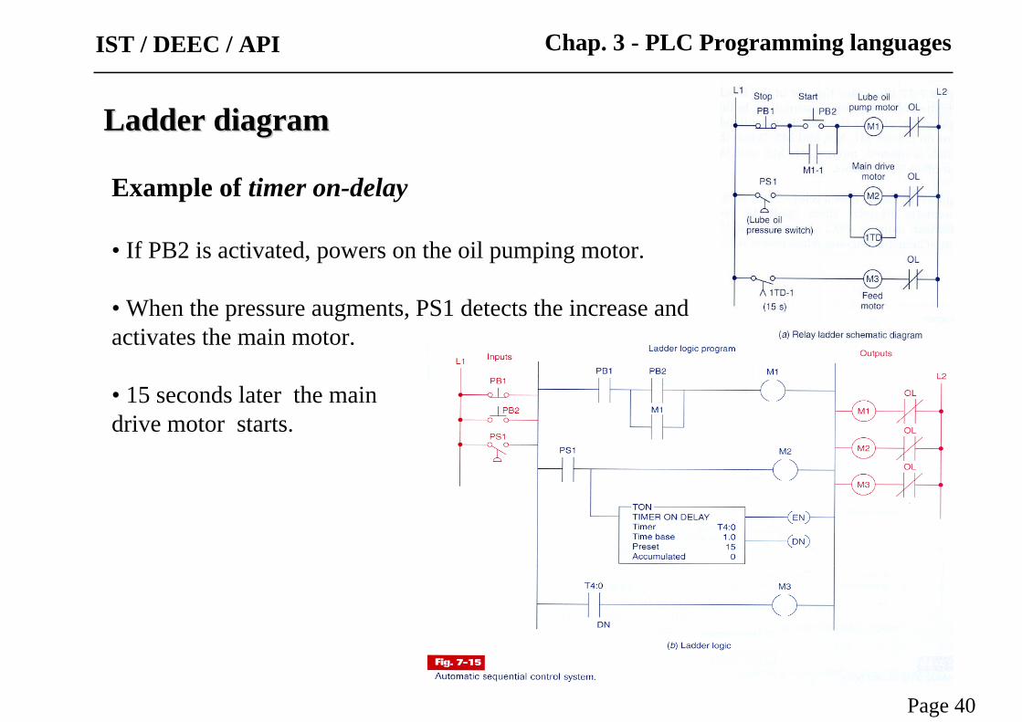
Example of timer on-delay
• If PB2 is activated, powers on the oil pumping motor.
• When the pressure augments, PS1 detects the increase andactivates the main motor.
• 15 seconds later the maindrive motor starts.
Ladder diagramLadder diagram
Page 40
Chap. 3 - PLC Programming languagesIST / DEEC / API

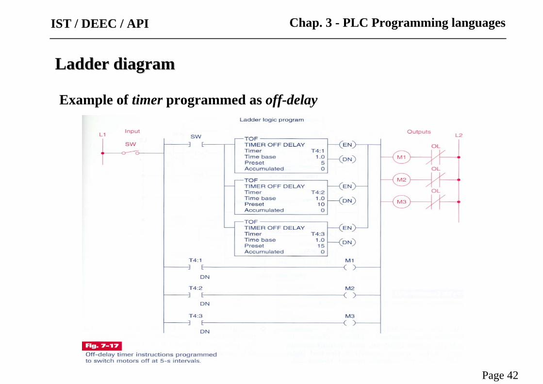
Example of timer programmed as off-delay
Ladder diagramLadder diagram
Page 41
Chap. 3 - PLC Programming languagesIST / DEEC / API
Ladder diagramLadder diagram
Page 42
Chap. 3 - PLC Programming languages
Example of timer programmed as off-delay
IST / DEEC / API

Ladder diagramLadder diagram
Page 43
Chap. 3 - PLC Programming languages
Example of timer programmed as off-delay
IST / DEEC / API

Ladder diagramLadder diagram
Page 44
Chap. 3 - PLC Programming languages
Example of timers programmed as off-delay and on-delay
IST / DEEC / API

Timers
Animated demonstration:
Ladder diagramLadder diagram
Page 45
Chap. 3 - PLC Programming languagesIST / DEEC / API

Retentive Timers
Ladder diagramLadder diagram
Page 46
Chap. 3 - PLC Programming languagesIST / DEEC / API
Switch-off region
Switch-on region
Motor accumulated motion (rotation) defines the on/off timing.

Example of retentive timers
Ladder diagramLadder diagram
Page 47
Chap. 3 - PLC Programming languagesIST / DEEC / API
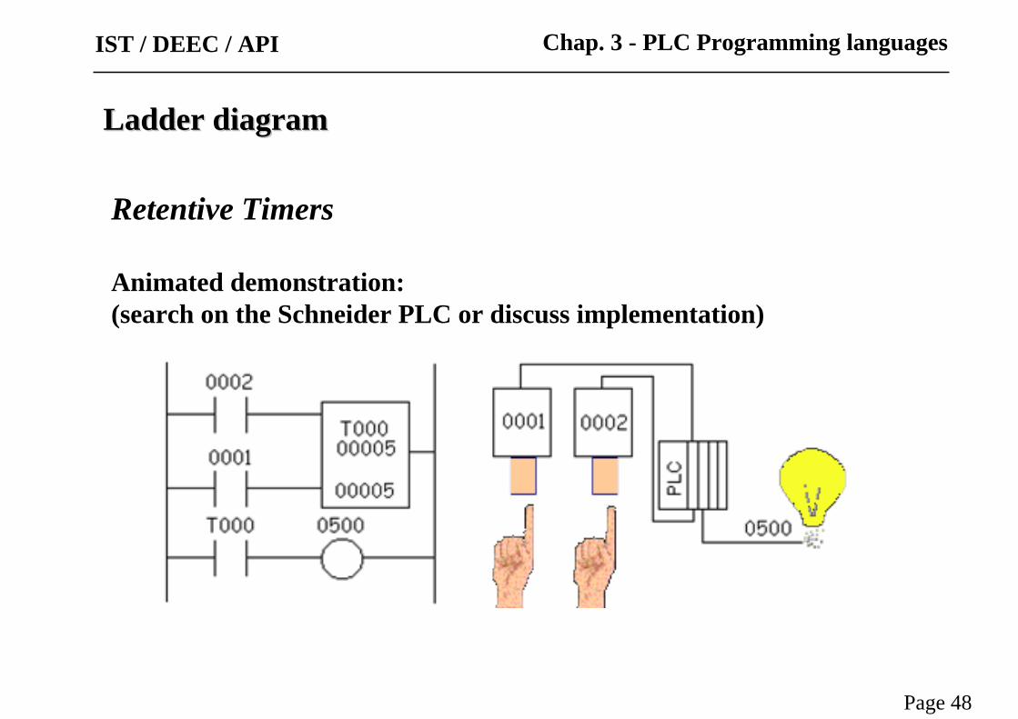
Retentive Timers
Animated demonstration: (search on the Schneider PLC or discuss implementation)
Ladder diagramLadder diagram
Page 48
Chap. 3 - PLC Programming languagesIST / DEEC / API

Example:
• SW ON to start operation
• Before motor starts, lubrificate 10 s with oil.
• SW OFF to stop. (lubrificate 15 s more).
• After 3 hours of pump operation, stop motor and signal with pilot light.
• Reset available after servicing.
Ladder diagramLadder diagram
Page 49
Chap. 3 - PLC Programming languagesIST / DEEC / API

Cascaded Timers
Ladder diagramLadder diagram
Page 50
Chap. 3 - PLC Programming languagesIST / DEEC / API
Ladder diagramLadder diagram
Page 51
Chap. 3 - PLC Programming languages
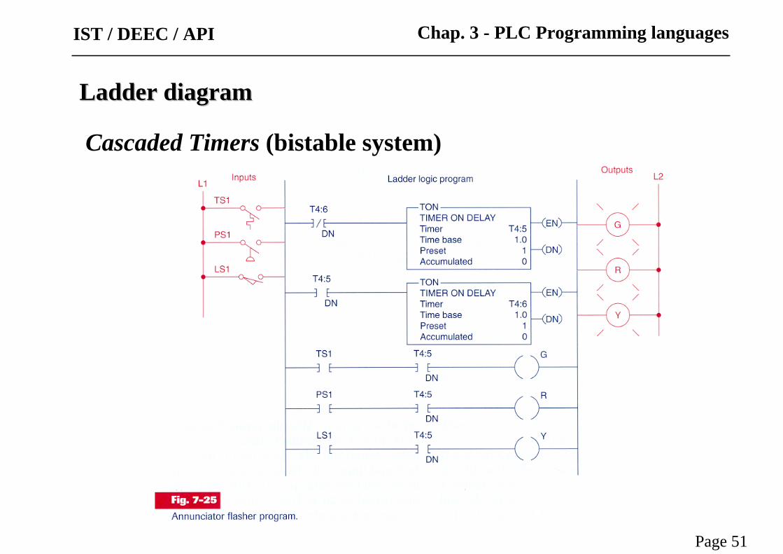
Cascaded Timers (bistable system)
IST / DEEC / API

Timers for very long time intervals
Ladder diagramLadder diagram
Page 52
Chap. 3 - PLC Programming languagesIST / DEEC / API
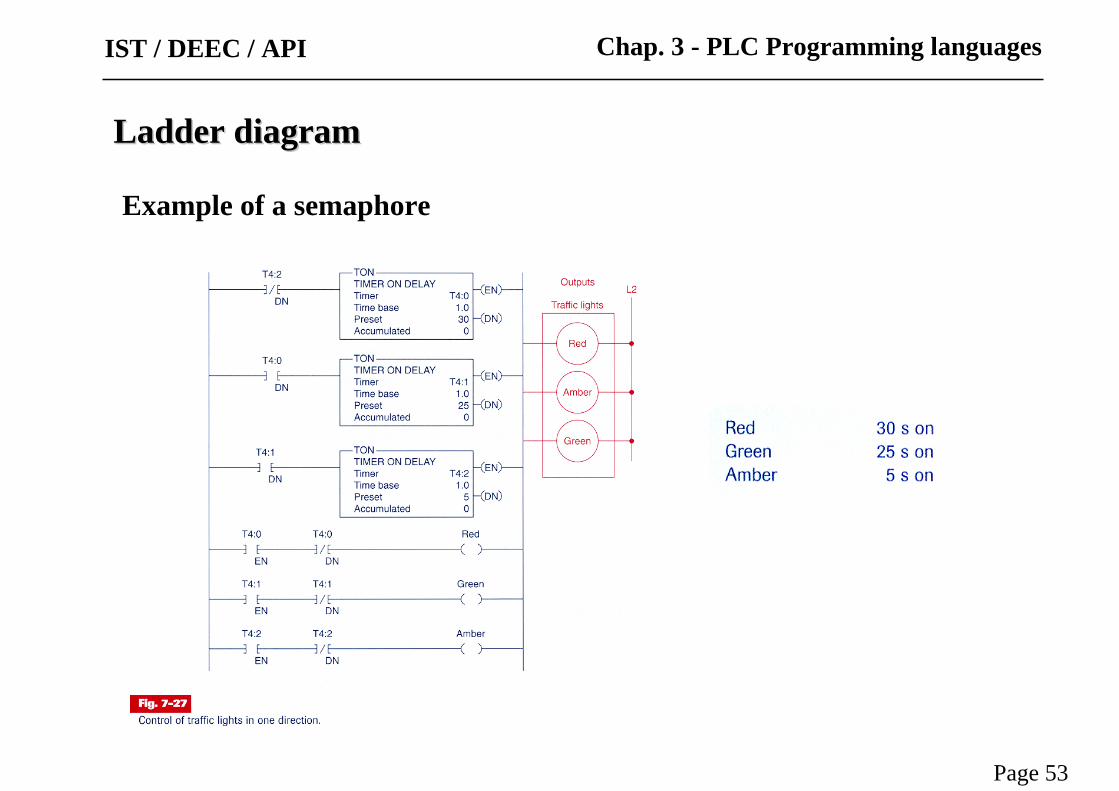
Example of a semaphore
Ladder diagramLadder diagram
Page 53
Chap. 3 - PLC Programming languagesIST / DEEC / API
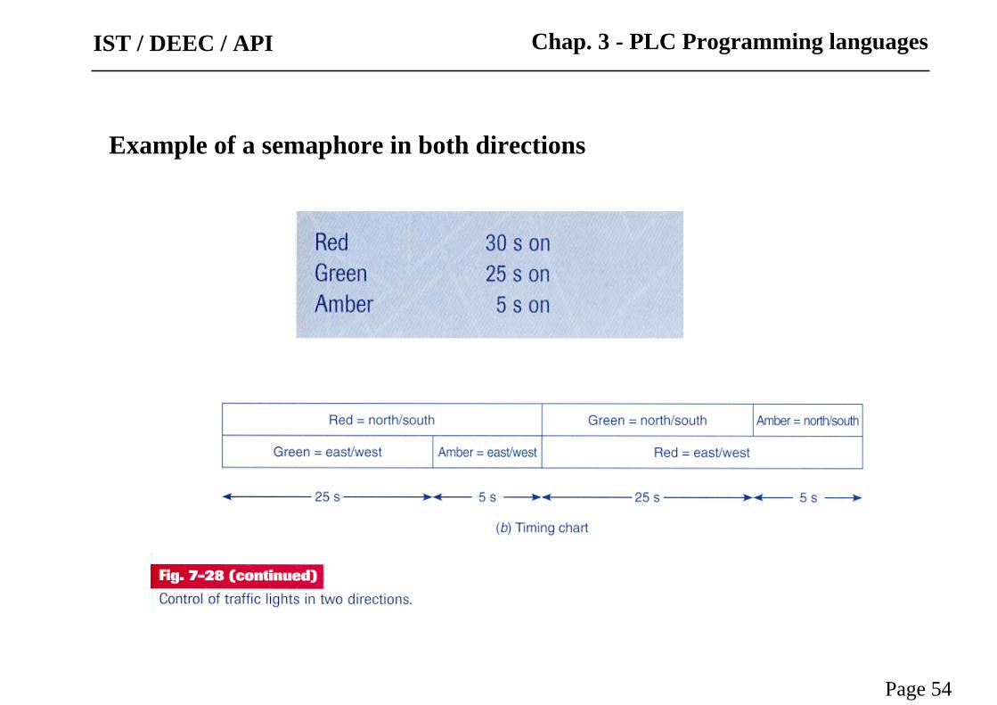
Example of a semaphore in both directions
Page 54
Chap. 3 - PLC Programming languagesIST / DEEC / API

Page 55
Chap. 3 - PLC Programming languages
Example
of a
semaphore
in both
directions
IST / DEEC / API
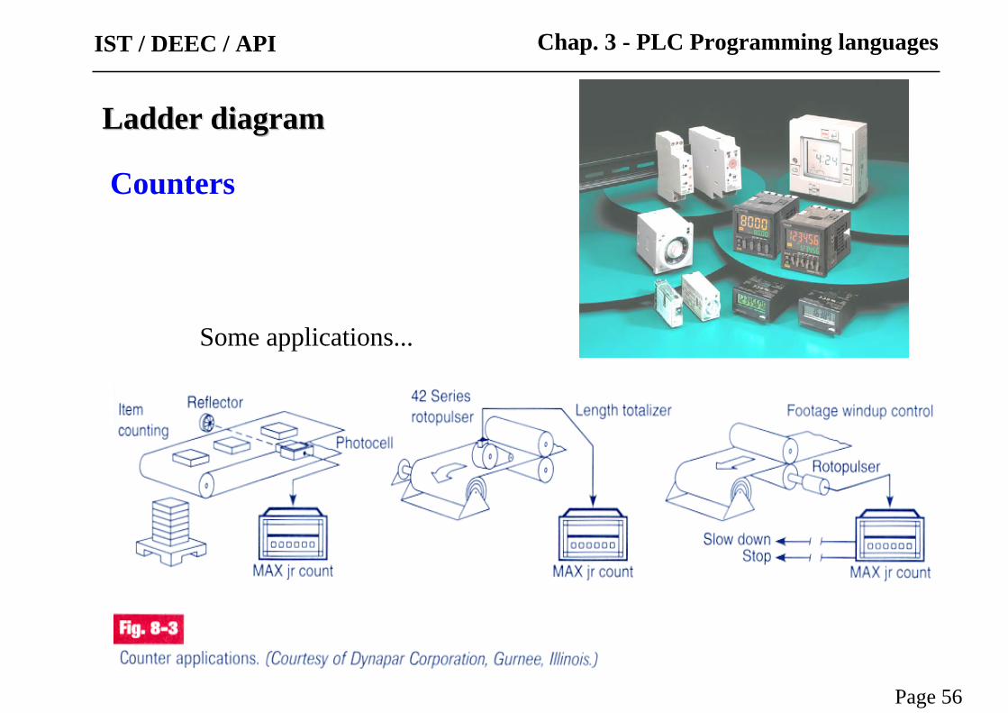
Counters
Ladder diagramLadder diagram
Page 56
Chap. 3 - PLC Programming languages
Some applications...
IST / DEEC / API

Implementation of Countersin the PLC-5 of Allen-Bradley:
Internal structure representation
Ladder diagramLadder diagram
Page 57
Chap. 3 - PLC Programming languagesIST / DEEC / API
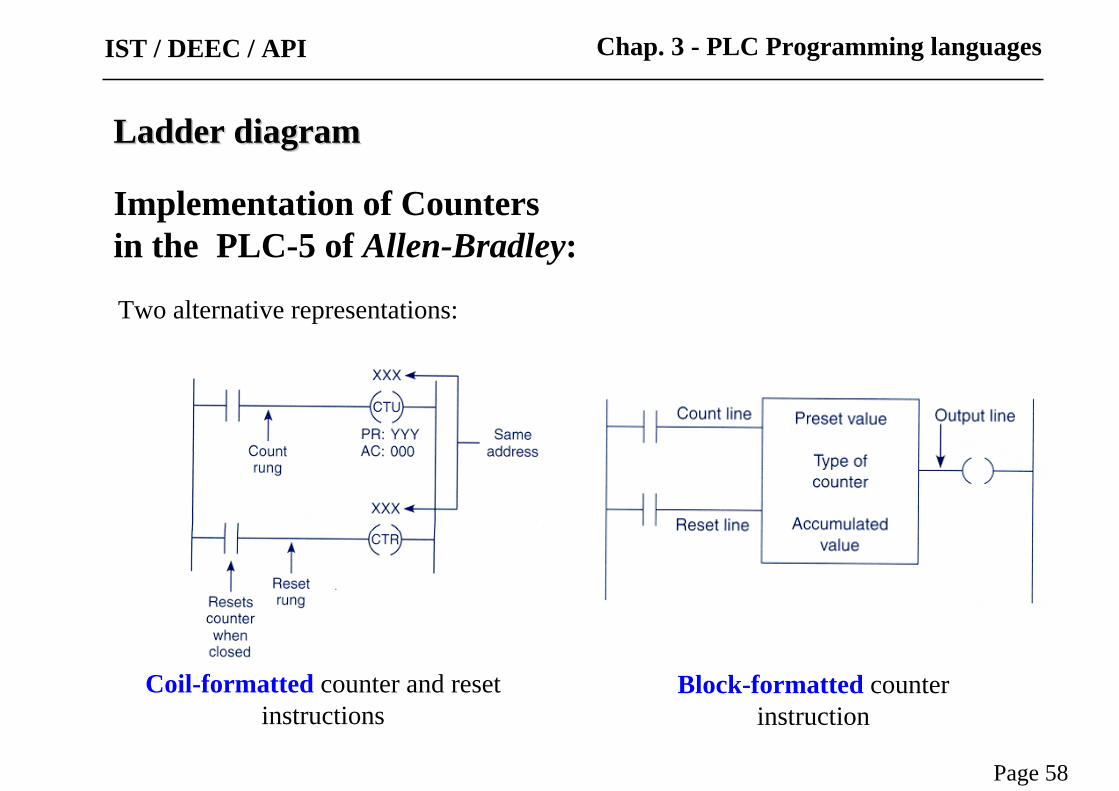
Two alternative representations:
Ladder diagramLadder diagram
Page 58
Chap. 3 - PLC Programming languages
Implementation of Countersin the PLC-5 of Allen-Bradley:
IST / DEEC / API
Coil-formatted counter and reset instructions
Block-formatted counter instruction

Up-counters
Usage of anincremental up-counterand the correspondingtemporal diagram:
PB1 increments countingPB2 resets the counting
Ladder diagramLadder diagram
Page 59
Chap. 3 - PLC Programming languagesIST / DEEC / API

Example: Counting parts
Ladder diagramLadder diagram
Page 60
Chap. 3 - PLC Programming languagesIST / DEEC / API

Example
Ladder diagramLadder diagram
Page 61
Chap. 3 - PLC Programming languagesIST / DEEC / API
1. Start conveyor motor2. Passing cases increment counter3. After 50 cases, stop motor

Up/down-counters
Ladder diagramLadder diagram
Page 62
Chap. 3 - PLC Programming languagesIST / DEEC / API
Usage of an incremental up-down-counterand the correspondingtemporal diagram:
PB1 increments countingPB2 decrements the countingPB3 resets the counter
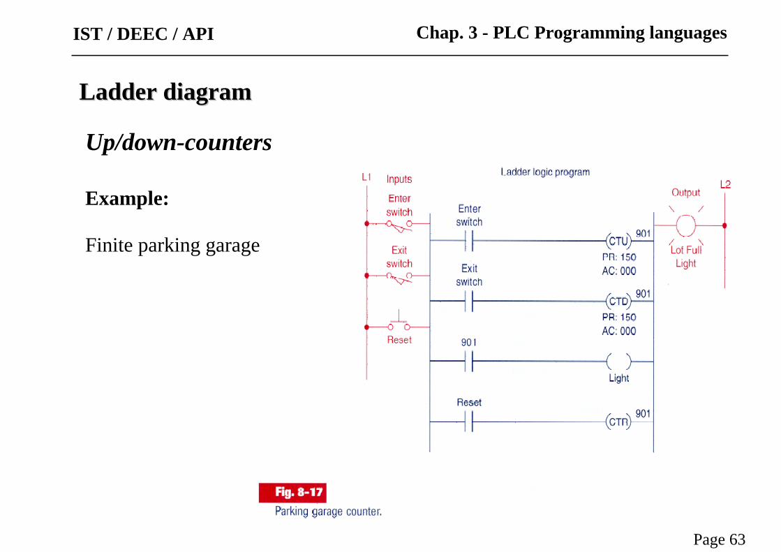
Up/down-counters
Example:
Finite parking garage
Ladder diagramLadder diagram
Page 63
Chap. 3 - PLC Programming languagesIST / DEEC / API
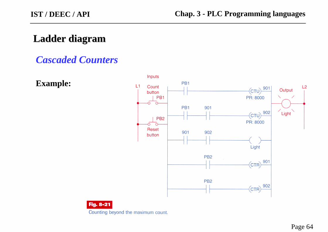
Cascaded Counters
Example:
Ladder diagramLadder diagram
Page 64
Chap. 3 - PLC Programming languagesIST / DEEC / API
Ladder diagramLadder diagram
Page 65
Chap. 3 - PLC Programming languages
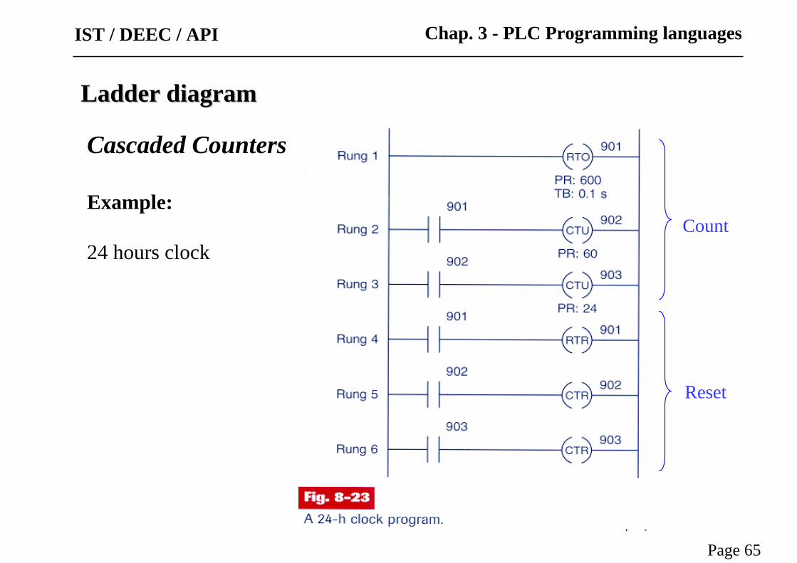
Cascaded Counters
Example:
24 hours clock
IST / DEEC / API
Count
Reset

Ladder diagramLadder diagram
Page 66
Chap. 3 - PLC Programming languages
Cascaded Counters
Example:
Memory time of eventInternal relay OFF stops clock
IST / DEEC / API

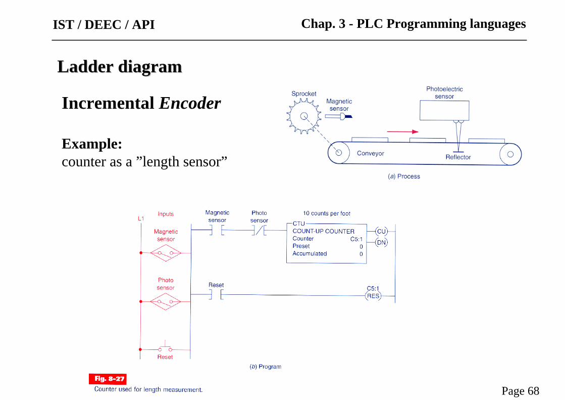
Incremental Encoder
counter measures rotation angle orrotation speed (if divided by time)
Ladder diagramLadder diagram
Page 67
Chap. 3 - PLC Programming languagesIST / DEEC / API
Ladder diagramLadder diagram
Page 68
Chap. 3 - PLC Programming languages
Incremental Encoder
Example: counter as a ”length sensor”
IST / DEEC / API

Example with counters and timers (cont.):
Specs:
• Starts M1 conveyorupon pushing button .
• After 15 plates stops M1and starts conveyor M2 .
• M2 operates for 5 seconds and then stops.
• Restart sequence.
Ladder diagramLadder diagram
Page 69
Chap. 3 - PLC Programming languagesIST / DEEC / API

Ladder diagramLadder diagram
Page 70
Chap. 3 - PLC Programming languages
Example with counters and timers (cont.):
Specs:
• Starts M1 conveyorupon pushing button .
• After 15 plates stops M1and starts conveyor M2 .
• M2 operates for 5 seconds and then stops.
• Restart sequence.
IST / DEEC / API

Ladder diagramLadder diagram
Page 71
Chap. 3 - PLC Programming languages
Example with counters and timers (cont.):
Specs:
• Starts M1 conveyorupon pushing button .
• After 15 plates stops M1and starts conveyor M2 .
• M2 operates for 5 seconds and then stops.
• Restart sequence.
IST / DEEC / API
Ladder diagramLadder diagram
Page 72
Chap. 3 - PLC Programming languages
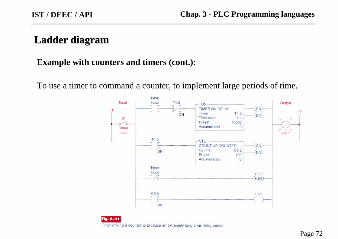
Example with counters and timers (cont.):
To use a timer to command a counter, to implement large periods of time.
IST / DEEC / API

Counters
Example:
Ladder diagramLadder diagram
Page 73
Chap. 3 - PLC Programming languagesIST / DEEC / API
E
%Ci
CP: 9999MODIF: Y
RS
CUCD
D
F
Ladder diagramLadder diagram
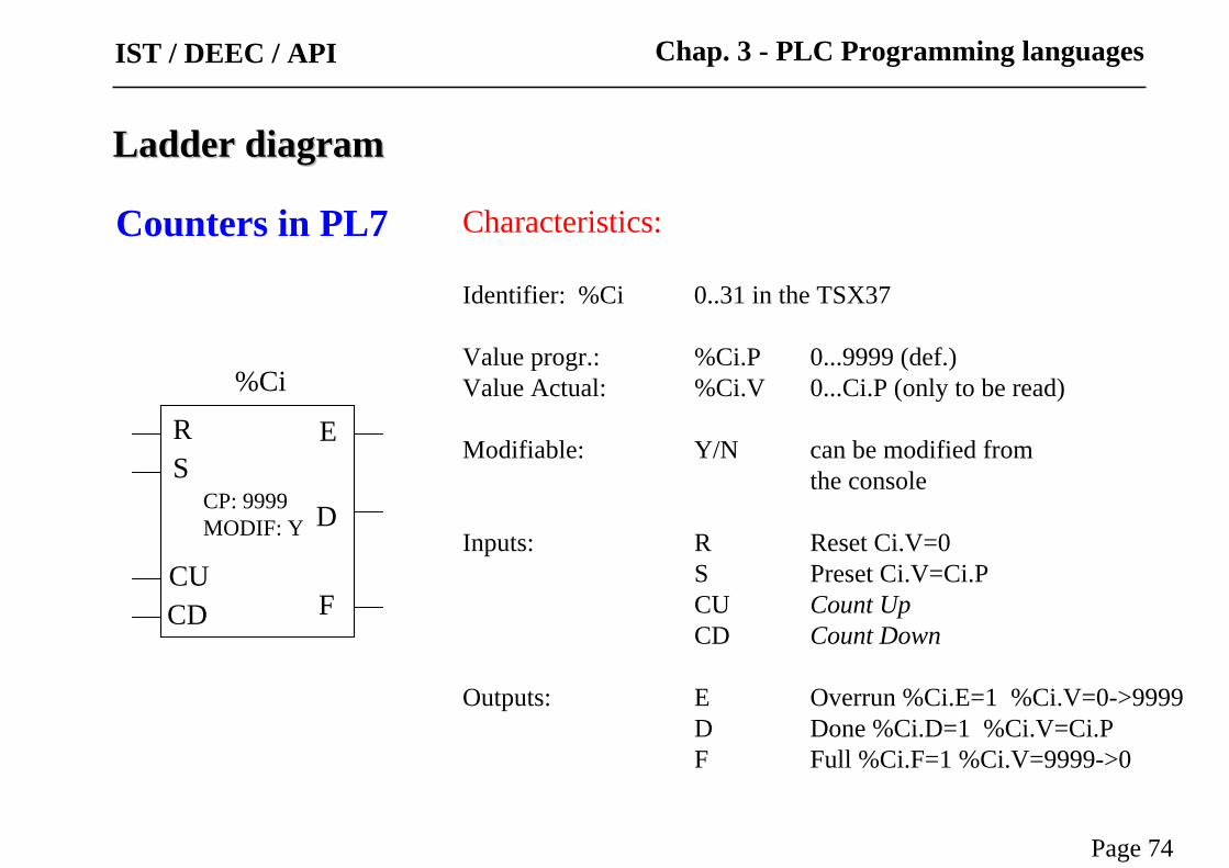
Counters in PL7
Page 74
Chap. 3 - PLC Programming languages
Characteristics:
Identifier: %Ci 0..31 in the TSX37
Value progr.: %Ci.P 0...9999 (def.)Value Actual: %Ci.V 0...Ci.P (only to be read)
Modifiable: Y/N can be modified from the console
Inputs: R Reset Ci.V=0S Preset Ci.V=Ci.PCU Count UpCD Count Down
Outputs: E Overrun %Ci.E=1 %Ci.V=0->9999D Done %Ci.D=1 %Ci.V=Ci.PF Full %Ci.F=1 %Ci.V=9999->0
IST / DEEC / API
IST / DEEC / API
Page 75
Chap. 3 - PLC Programming languages
Ladder diagramLadder diagram
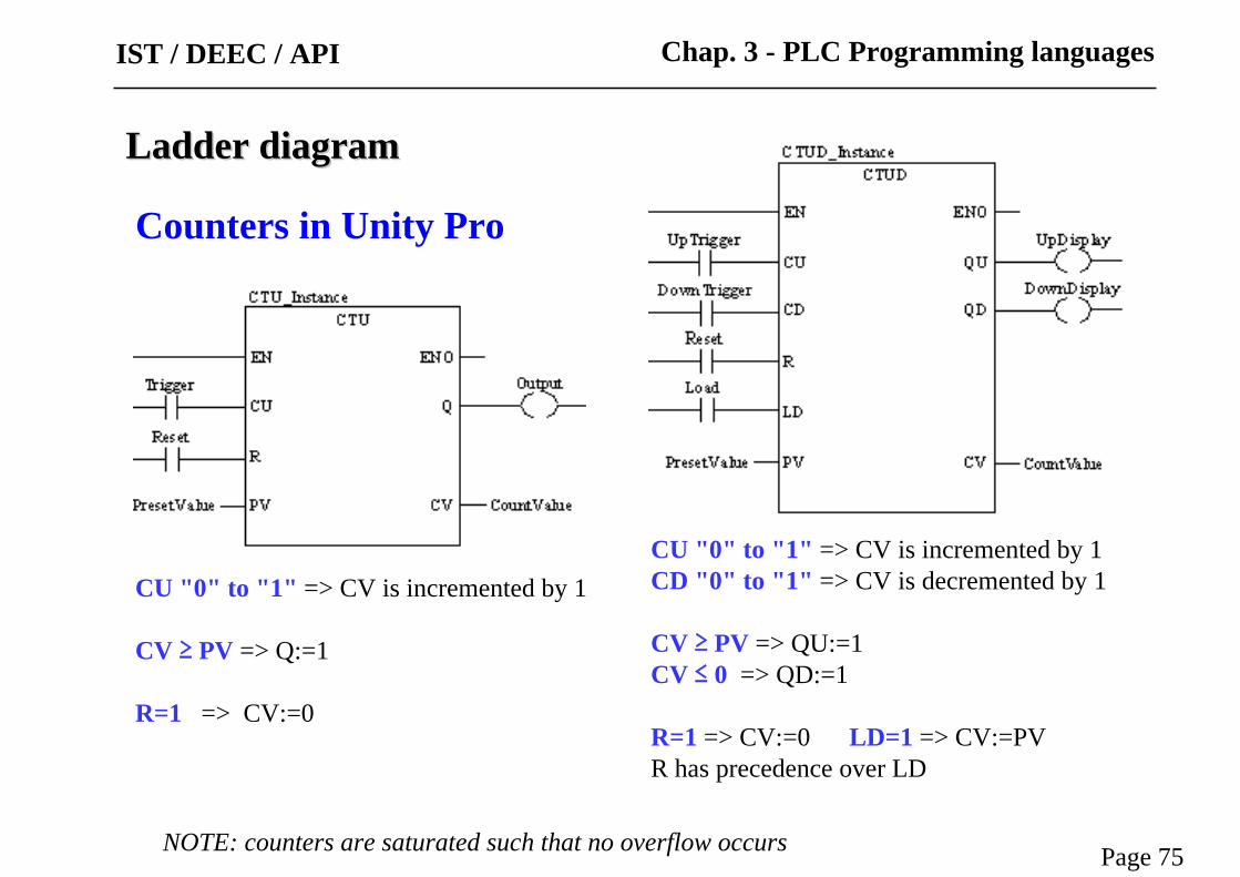
Counters in Unity Pro
CU "0" to "1" => CV is incremented by 1CD "0" to "1" => CV is decremented by 1
CV ≥ PV => QU:=1CV ≤ 0 => QD:=1
R=1 => CV:=0 LD=1 => CV:=PVR has precedence over LD
CU "0" to "1" => CV is incremented by 1
CV ≥ PV => Q:=1
R=1 => CV:=0
NOTE: counters are saturated such that no overflow occurs
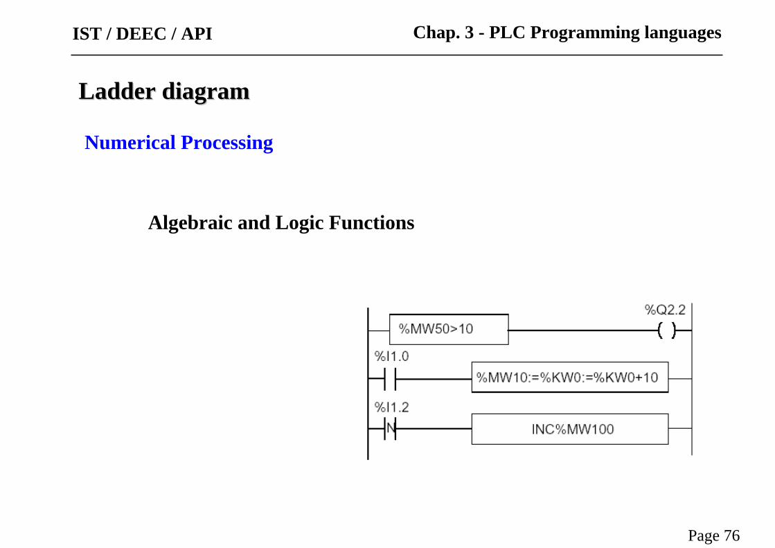
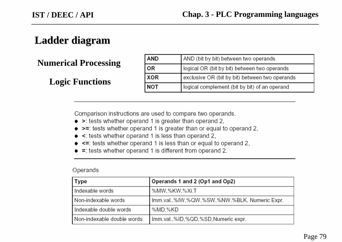
Numerical Processing
Ladder diagramLadder diagram
Algebraic and Logic Functions
Page 76
Chap. 3 - PLC Programming languagesIST / DEEC / API
Ladder diagramLadder diagram
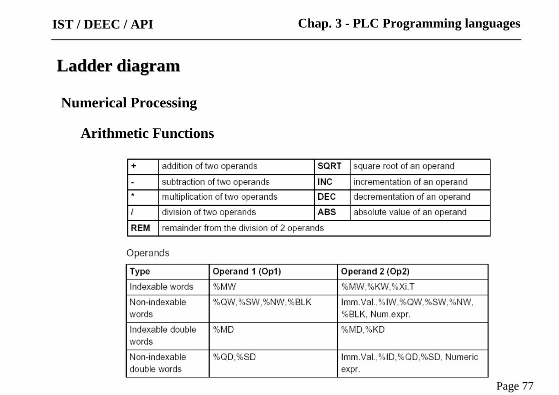
Arithmetic Functions
Page 77
Chap. 3 - PLC Programming languages
Numerical Processing
IST / DEEC / API

Ladder diagramLadder diagram
Example:
Arithmetic functions
Use of a system variable:
%S18 – flag de overflowPage 78
Chap. 3 - PLC Programming languages
Numerical Processing
IST / DEEC / API
Ladder diagramLadder diagram
Page 79
Chap. 3 - PLC Programming languages
Numerical Processing
Logic Functions
IST / DEEC / API
Ladder diagramLadder diagram
Page 80
Chap. 3 - PLC Programming languages
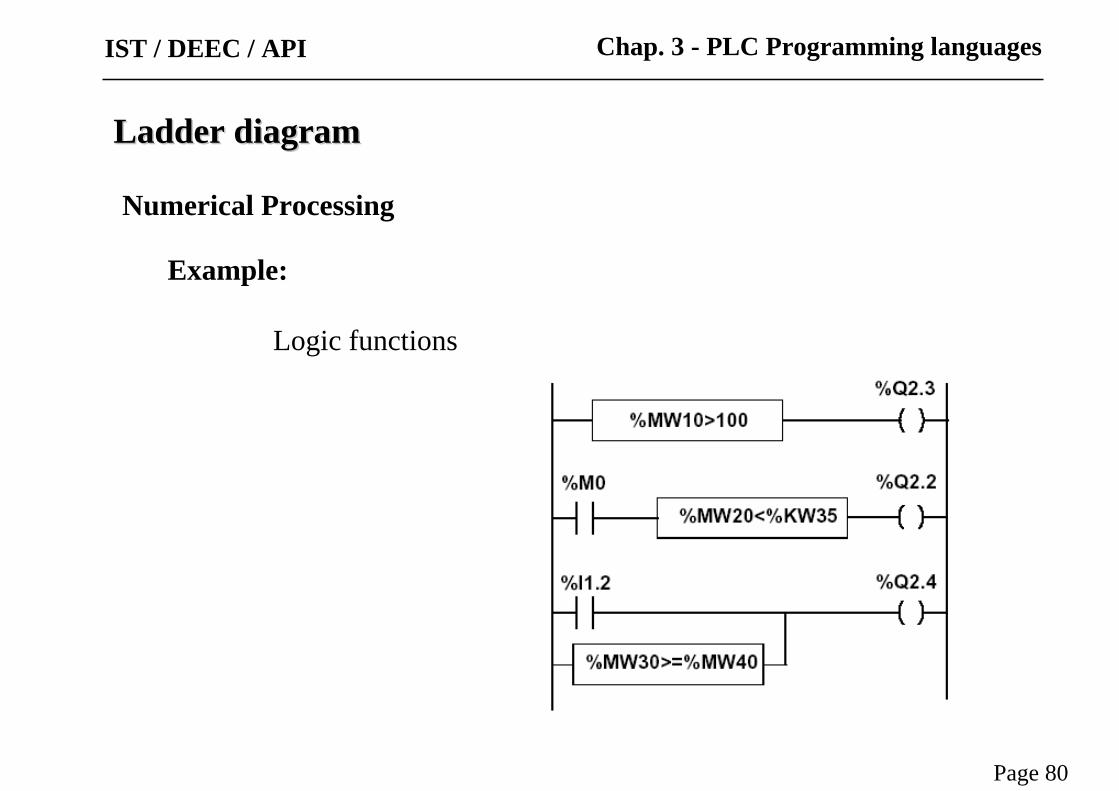
Example:
Logic functions
Numerical Processing
IST / DEEC / API
Ladder diagramLadder diagram
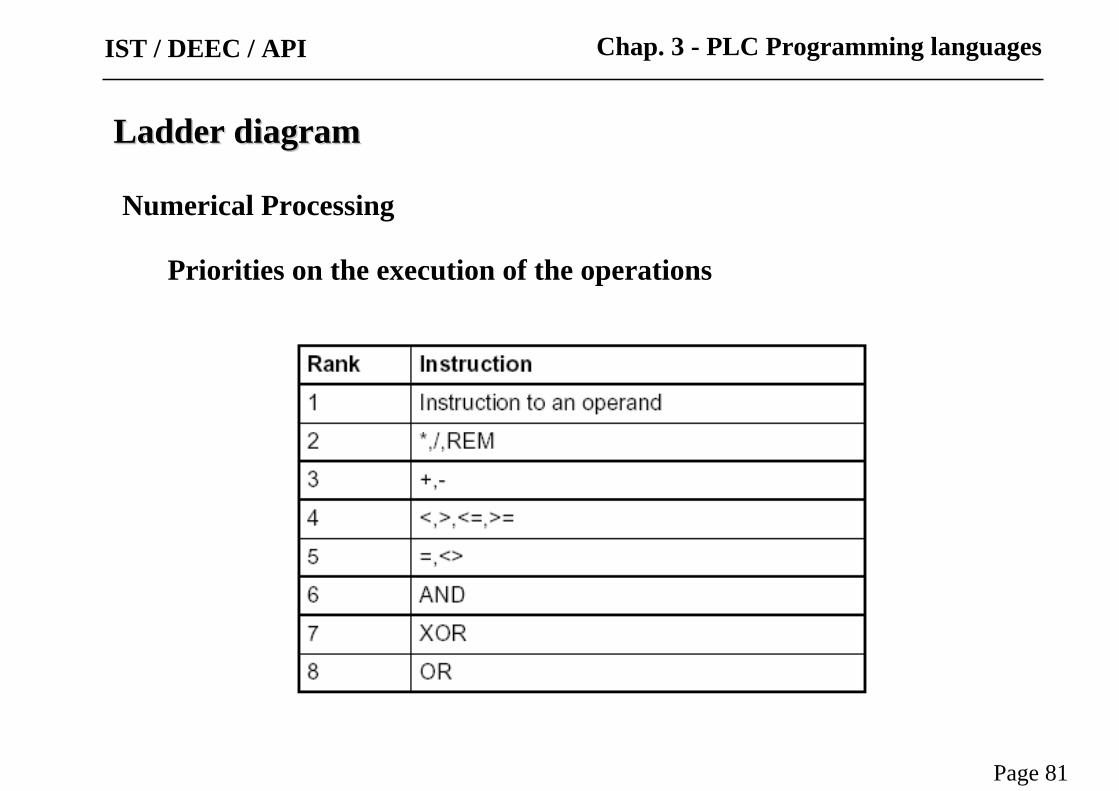
Priorities on the execution of the operations
Page 81
Chap. 3 - PLC Programming languages
Numerical Processing
IST / DEEC / API
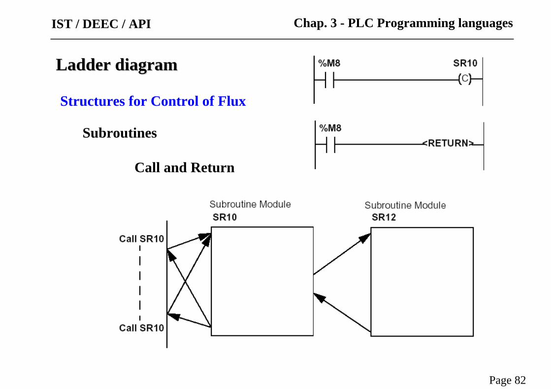
Structures for Control of Flux
Ladder diagramLadder diagram
Subroutines
Call and Return
Page 82
Chap. 3 - PLC Programming languagesIST / DEEC / API
Ladder diagramLadder diagram
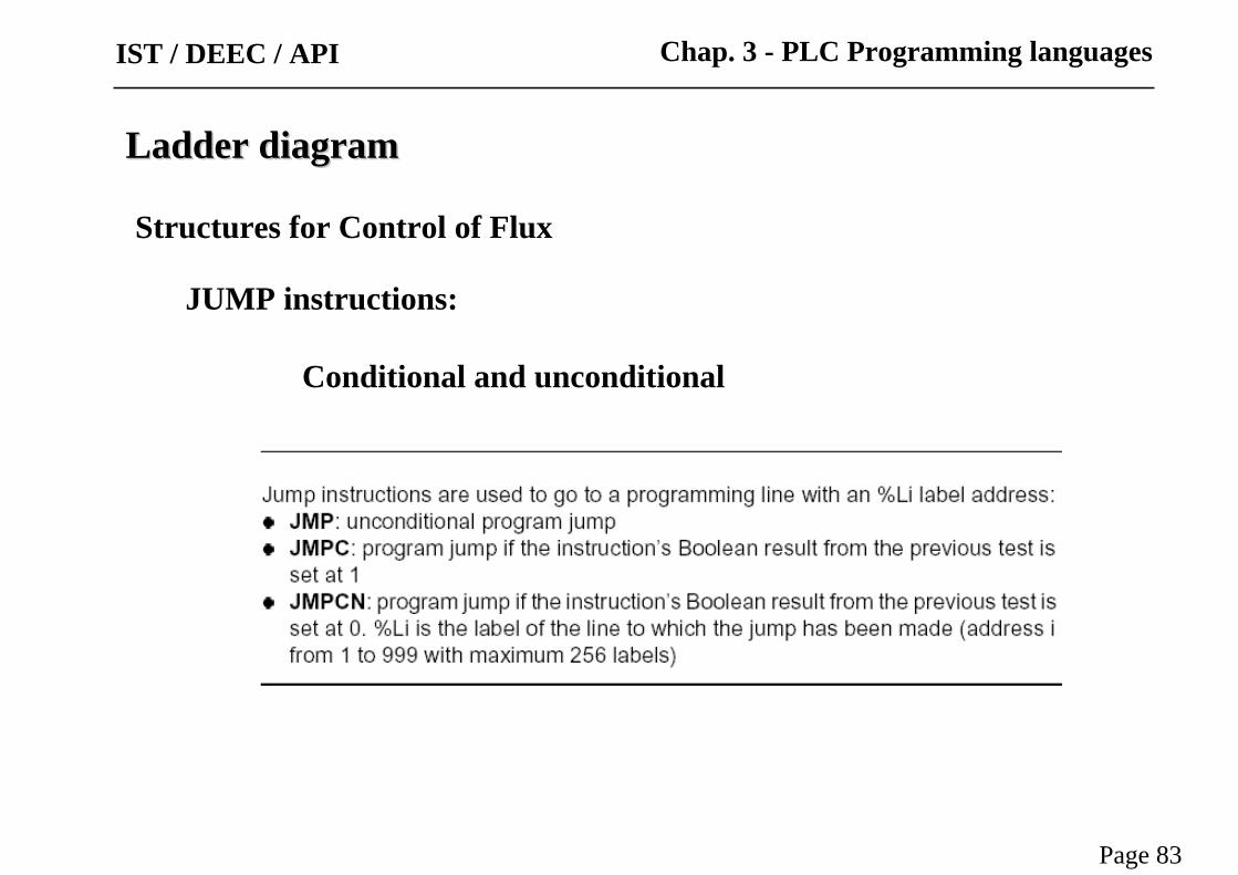
JUMP instructions:
Conditional and unconditional
Page 83
Chap. 3 - PLC Programming languages
Structures for Control of Flux
IST / DEEC / API

Ladder diagramLadder diagram
Example:
Use of jump instructions
Attention to:
• INFINITE LOOPS ...
• It is not a good style ofprogramming!...
• Does not improove the legibility of the proposed solution.
Page 84
Chap. 3 - PLC Programming languages
Structures for Control of Flux
IST / DEEC / API

Ladder diagramLadder diagram
Halt
Events masking
Page 85
Chap. 3 - PLC Programming languages
Structures for Control of Flux
Stops all processes!
IST / DEEC / API

There are other advanced instructions (see manual)
Ladder diagramLadder diagram
• Monostable
• Registers of 256 words (LIFO ou FIFO)
• DRUMs
• Comparators
• Shift-registers
...
• Functions to manipulate floats
• Functions to convert bases and typesPage 86
Chap. 3 - PLC Programming languagesIST / DEEC / API

Numerical Tables
Ladder diagramLadder diagram
Page 87
Chap. 3 - PLC Programming languagesIST / DEEC / API
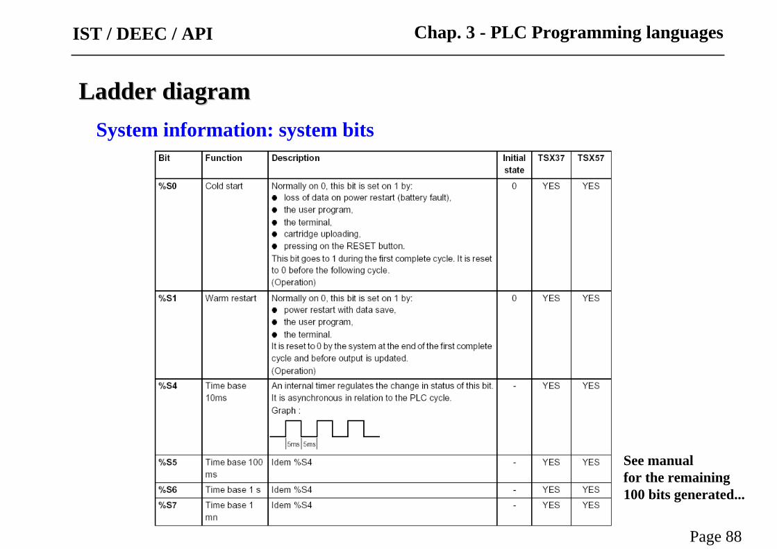
System information: system bits
Ladder diagramLadder diagram
See manual for the remaining 100 bits generated...
Page 88
Chap. 3 - PLC Programming languagesIST / DEEC / API

System information: system words
Ladder diagramLadder diagram
Page 89
Chap. 3 - PLC Programming languages
See manual for the remaining 140 words generated...
IST / DEEC / API
IST / DEEC / API
Page 90
Software OrganizationLadder diagramLadder diagram
Page 90
Chap. 3 - PLC Programming languagesIST / DEEC / API
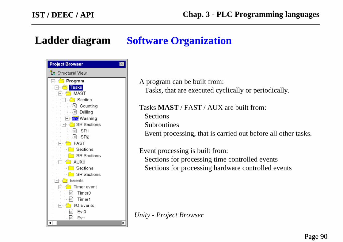
A program can be built from:Tasks, that are executed cyclically or periodically.
Tasks MAST / FAST / AUX are built from:SectionsSubroutinesEvent processing, that is carried out before all other tasks.
Event processing is built from:Sections for processing time controlled eventsSections for processing hardware controlled events
Unity - Project Browser
Ladder diagramLadder diagram
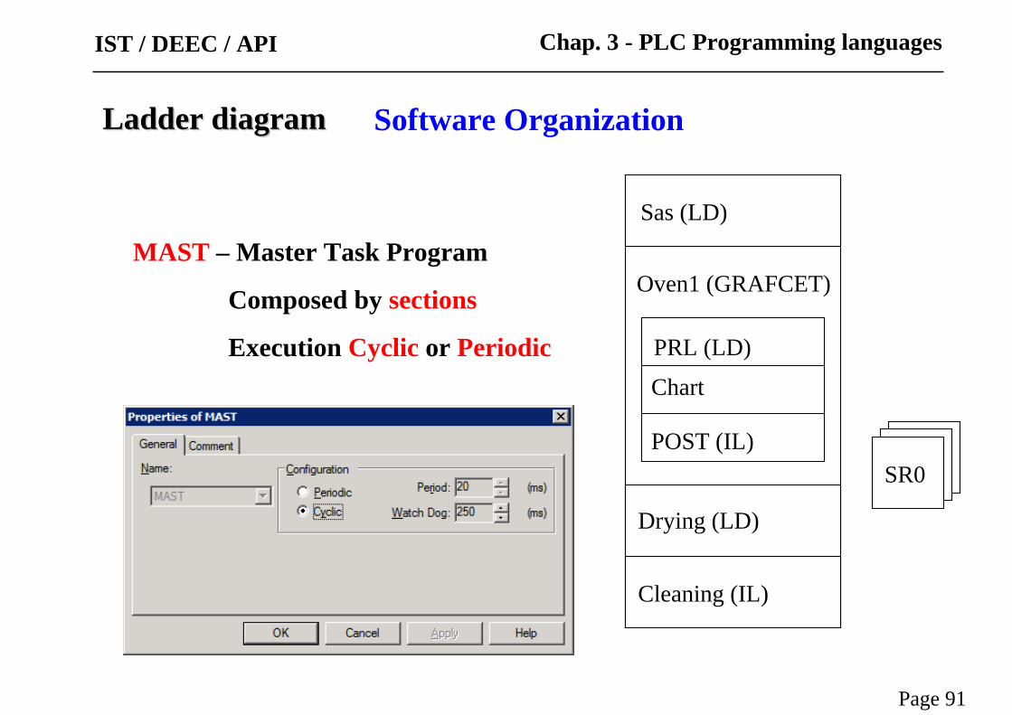
MAST – Master Task Program
Composed by sections
Execution Cyclic or Periodic
Oven1 (GRAFCET)
Sas (LD)
PRL (LD)
Chart
POST (IL)
Drying (LD)
Cleaning (IL)
SR0
Page 91
Chap. 3 - PLC Programming languagesIST / DEEC / API
Software Organization
Ladder diagramLadder diagram
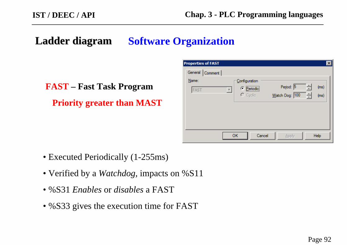
FAST – Fast Task Program
Priority greater than MAST
• Executed Periodically (1-255ms)
• Verified by a Watchdog, impacts on %S11
• %S31 Enables or disables a FAST
• %S33 gives the execution time for FAST
Page 92
Chap. 3 - PLC Programming languagesIST / DEEC / API
Software Organization

Ladder diagramLadder diagram
Event Processes – Processes that can react to external changes (16 in the Micro 3722 EV0 a EV15)
• Inputs 0 to 3 in module 1, given transitions
• Counters
• Upon telegrams reception
• %S38 Enables or disables event processes
(also with MASKEVT() or UNMASKEVT())
Event Generators
Priority greater than MAST and FAST!
Page 93
Chap. 3 - PLC Programming languagesIST / DEEC / API
Software Organization

IST / DEEC / API
Page 94
Each PLC has limitations in terms of connections
Ladder diagramLadder diagram
Example:
Page 94
Chap. 3 - PLC Programming languagesIST / DEEC / API
Development tools

IST / DEEC / API
Page 95
It is important to learn the potentialities and ...the limitations of the developing tools,
i.e. STUDYING the manuals is a MUST.
Ladder diagramLadder diagram
Page 95
Chap. 3 - PLC Programming languagesIST / DEEC / API
Development tools

IST / DEEC / API
Page 96
Last but not least, learn how to develop and debug programs(and how to do some fine tuning).
Ladder diagramLadder diagram
Page 96
Chap. 3 - PLC Programming languagesIST / DEEC / API
Development tools

IST / DEEC / API
Page 97
Last but not least, learn how to develop and debug programs(and how to do some fine tuning).
Ladder diagramLadder diagram
Page 97
Chap. 3 - PLC Programming languagesIST / DEEC / API
Development tools