installationsanvisning installation instructions
TRANSCRIPT
Dok. Nr: M6300V: 2.0
2020-10-20
WWW: Baselift 6300
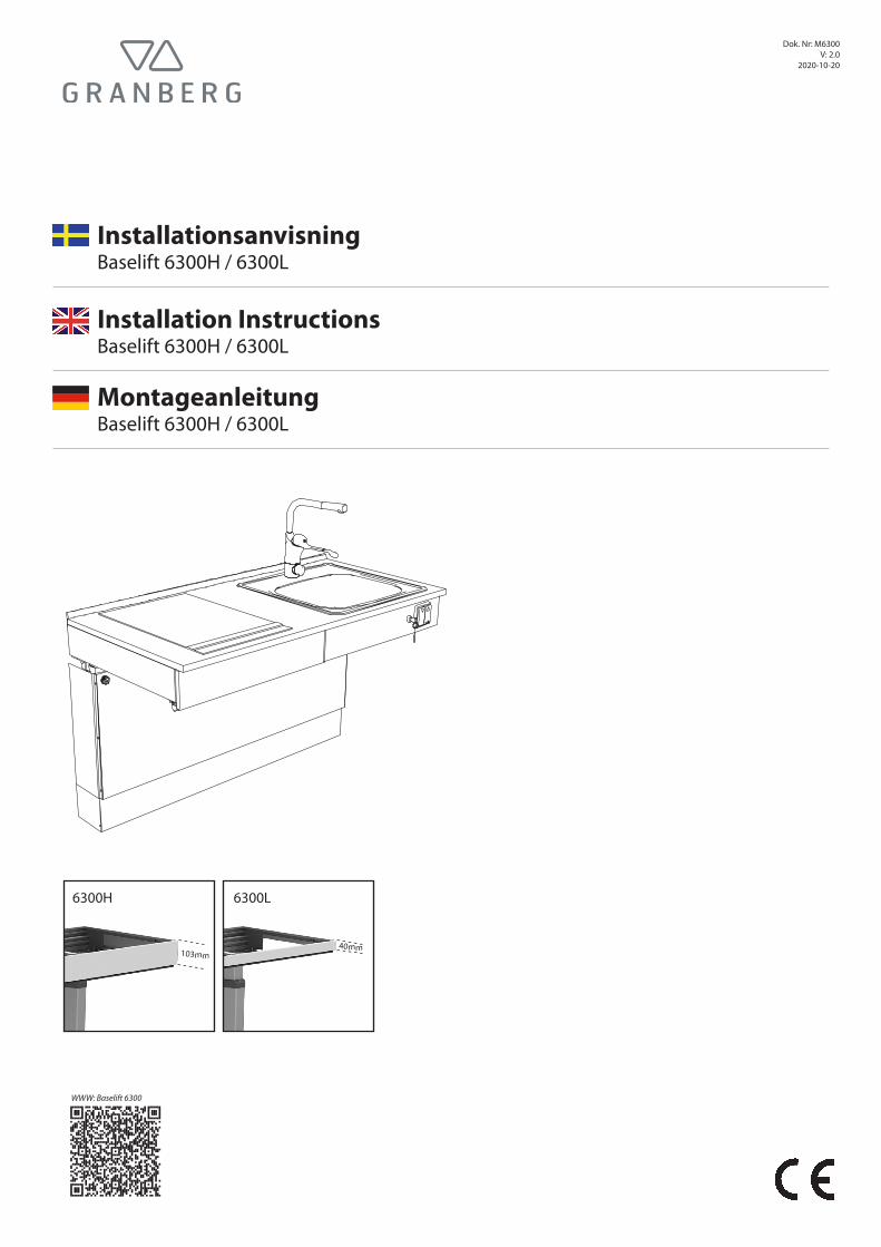
6300L
40mm
6300H
103mm
MontageanleitungBaselift 6300H / 6300L
Installation Instructions Baselift 6300H / 6300L
Installationsanvisning Baselift 6300H / 6300L

2
Förberedelser / Preparations / VorwortTack för att ni har valt att installera en produkt från Granberg!
För att produkten ska fungera säkert är det ytterst viktigt att installationsanvisningen följs.Installatör skall läsa och förstå hela installationsanvisningen innan installation påbörjas. Installatören ansvarar för att golv- och väggkonstruktioner uppfyller de krav som ställs och att fästelement klarar de krafter som kan uppstå.Installatör ansvarar även för att rätt behörighet och kompetens finns för el- och vattenarbete.
Efter utförd installation ska produkten funktionstestas enligt avsnitt på s. 24.
Thank you for choosing to install a product from Granberg!In order for the product to work safely and securely, it is extremely essential that the installation instructions be followed.The installer should read and understand all the installation instructions before installation begins.It is the installer who is responsible for floor and wall structures meeting the set requirements and that fasteners can withstand the forces that may occur.The installer is also responsible for the right authority and skills being available for electric and water works.
After completed installation, the product shall be functionally tested according to sections on p. 24.
Vielen Dank, dass Sie sich für ein Granberg-Produkt entschieden haben!
Für die Sicherheit ist es wichtig, den Anweisungen in der Montageanleitung folge zu leisten. Der Monteur muss vor der Montage die gesamte Anleitung gelesen und verstanden haben. Der Monteur trägt die Verantwortung für die Tragfähigkeit des Bodens und der Auswahl der richtigen Befestigungsmittel, unter Berücksichtigung der auftretenden Kräfte. Der Monteur ist auch für die Strom- u. Wasseranschlüsse verantwortlich und muss entsprechend dafür qualifiziert sein.
Nach der Montage muss eine Funktionsprüfung gemäß der Beschreibung aus Seite 24 stattfinden.
SE
EN
DE
3
(mm)
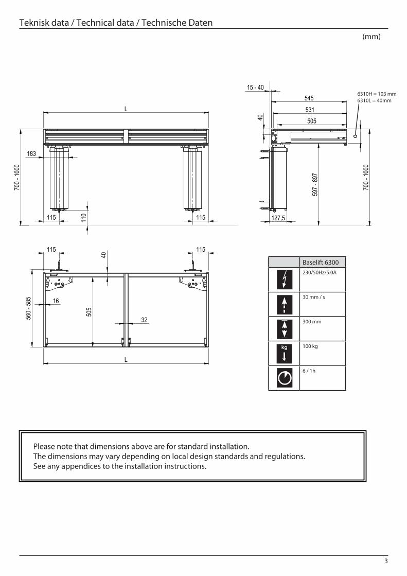
Teknisk data / Technical data / Technische Daten
L
115 115
183
700 -
1000
110
115 115
L
560 -
585
40
16
32 505
40
505 531
545
103
127,5
700 -
1000
15 - 40
597 -
897
Fäste Rev A.
Tekniska mått 6300
WEIGHT:
A3
SHEET 1 OF 1SCALE:1:10
DWG NO.
TITLE:
REVISION
DO NOT SCALE DRAWING
MATERIAL:
DEBUR AND BREAK SHARP EDGES
FINISH:
UNLESS OTHERWISE SPECIFIED:DIMENSIONS ARE IN MILLIMETERS TOLERANCES: LINEAR: SS-ISO 2768-m ANGULAR: SS-ISO 2768-m
DRAWN
CHECKED
Granberg Interior AB Tel. +46(0)[email protected] www.granberg.se
Baselift 6300230/50Hz/5.0A
30 mm / s
300 mm
100 kg
6 / 1h
kg
6310H = 103 mm6310L = 40mm
Please note that dimensions above are for standard installation. The dimensions may vary depending on local design standards and regulations. See any appendices to the installation instructions.
4
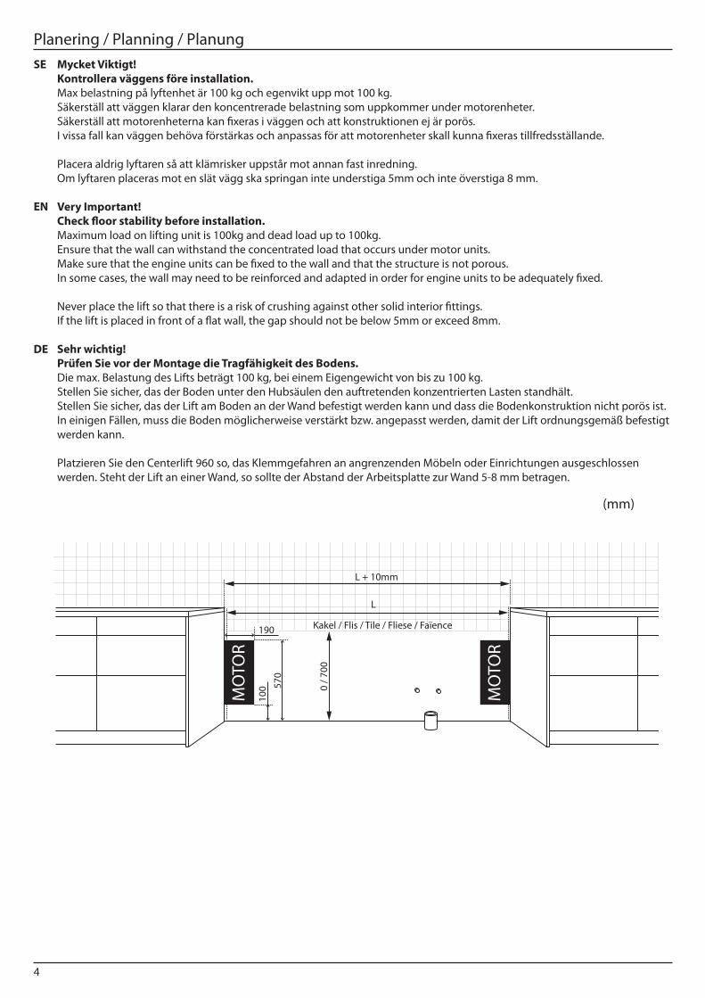
Planering / Planning / Planung
(mm)
Mycket Viktigt!Kontrollera väggens före installation. Max belastning på lyftenhet är 100 kg och egenvikt upp mot 100 kg.Säkerställ att väggen klarar den koncentrerade belastning som uppkommer under motorenheter.Säkerställ att motorenheterna kan fixeras i väggen och att konstruktionen ej är porös.I vissa fall kan väggen behöva förstärkas och anpassas för att motorenheter skall kunna fixeras tillfredsställande.
Placera aldrig lyftaren så att klämrisker uppstår mot annan fast inredning. Om lyftaren placeras mot en slät vägg ska springan inte understiga 5mm och inte överstiga 8 mm.
Very Important!Check floor stability before installation.Maximum load on lifting unit is 100kg and dead load up to 100kg.Ensure that the wall can withstand the concentrated load that occurs under motor units.Make sure that the engine units can be fixed to the wall and that the structure is not porous.In some cases, the wall may need to be reinforced and adapted in order for engine units to be adequately fixed.
Never place the lift so that there is a risk of crushing against other solid interior fittings.If the lift is placed in front of a flat wall, the gap should not be below 5mm or exceed 8mm.
Sehr wichtig!Prüfen Sie vor der Montage die Tragfähigkeit des Bodens. Die max. Belastung des Lifts beträgt 100 kg, bei einem Eigengewicht von bis zu 100 kg. Stellen Sie sicher, das der Boden unter den Hubsäulen den auftretenden konzentrierten Lasten standhält. Stellen Sie sicher, das der Lift am Boden an der Wand befestigt werden kann und dass die Bodenkonstruktion nicht porös ist. In einigen Fällen, muss die Boden möglicherweise verstärkt bzw. angepasst werden, damit der Lift ordnungsgemäß befestigt werden kann. Platzieren Sie den Centerlift 960 so, das Klemmgefahren an angrenzenden Möbeln oder Einrichtungen ausgeschlossen werden. Steht der Lift an einer Wand, so sollte der Abstand der Arbeitsplatte zur Wand 5-8 mm betragen.
SE
EN
DE
L
Förberedelser
0 / 7
00
MO
TOR
100
190
570
MO
TOR
Example:L = 1900mmW = 1900 + 10 = 1910mm
* = Greater than 300mm a�ects the �ow of wastewater
L + 10mm
Kakel / Flis / Tile / Fliese / Faïence
5
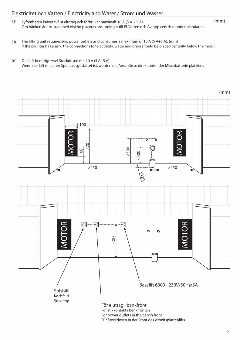
Elektricitet och Vatten / Electricity and Water / Strom und Wasser(mm)Lyftenheten kräver två st eluttag och förbrukar maximalt 10 A (5 A + 5 A).
Om bänken är utrustad med diskho placeras anslutningar till El, Vatten och Avlopp centriskt under blandaren.
The lifting unit requires two power outlets and consumes a maximum of 10 A (5 A+5 A). (mm)If the counter has a sink, the connections for electricity, water and drain should be placed centrally below the mixer.
Der Lift benötigt zwei Steckdosen mit 10 A (5 A+5 A) Wenn der Lift mit einer Spüle ausgestattet ist, werden die Anschlüsse direkt unter der Mischbatterie platziert.
SE
EN
DE
(mm)
Förberedelser
>250 >250
<300M
OTO
R10
0
190
570
MO
TOR
<500
<120
Vattensäkert
MO
TOR
MO
TOR
500
Baselift 6300 - 230V/50Hz/5A
För eluttag i bänkfrontFor stikkontakt i benkfronten For power outlets in the bench front Für Steckdosen in der Front des Arbeitsplattenlifts
SpishällKochfeldStovetop
6
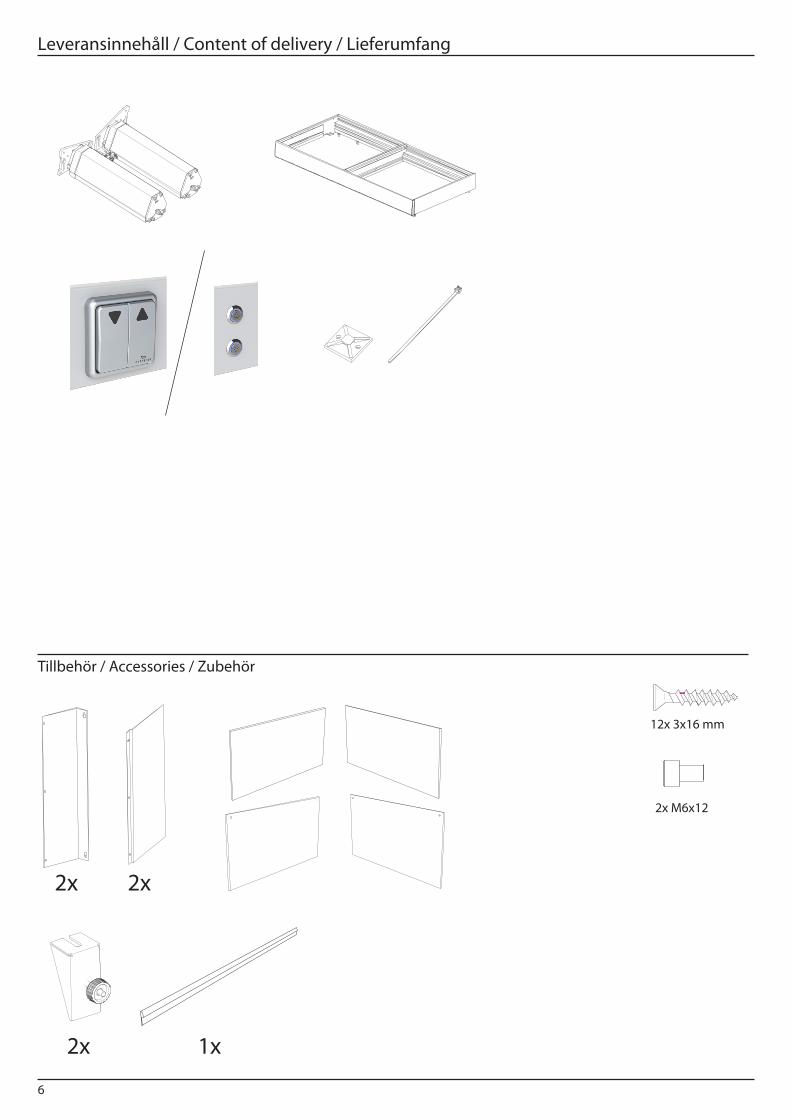
Leveransinnehåll / Content of delivery / Lieferumfang
Tillbehör / Accessories / Zubehör
2x M6x12
16 mm
12x 3x16 mm
2x 2x
2x 1x
7
113

8
2
L
115 115
700
700
125 17
5 49
0 540
L - 230
125 17
5 49
0 540
115 115
L
06714
WEIGHT:
A3
SHEET 1 OF 1SCALE:1:10
DWG NO.
TITLE:
REVISION
DO NOT SCALE DRAWING
MATERIAL:
DEBUR AND BREAK SHARP EDGES
FINISH:
UNLESS OTHERWISE SPECIFIED:DIMENSIONS ARE IN MILLIMETERS TOLERANCES: LINEAR: SS-ISO 2768-m ANGULAR: SS-ISO 2768-m
DRAWN
CHECKED
Granberg Interior AB Tel. +46(0)[email protected] www.granberg.se
L
9
3
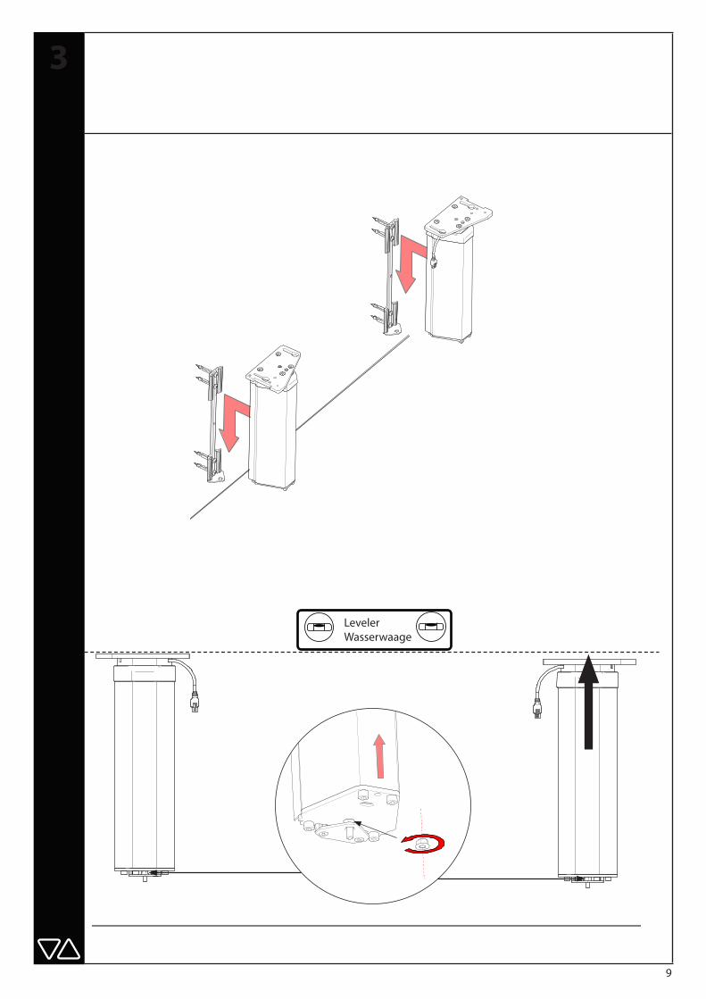
Leveler Wasserwaage

10
413
11
5
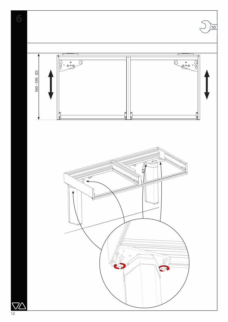
12
106
560
- 590
(D
)
13
7
14
8

15
9
0
15
30
45 5s
ON
”click click click”
B
19
32
22 36
25
32
103
60 20
> 100
> 60
B - 4mm
Front
10431
WEIGHT:
A3
SHEET 1 OF 1SCALE:1:5
DWG NO.
TITLE:
REVISION
DO NOT SCALE DRAWING
MATERIAL:
DEBUR AND BREAK SHARP EDGES
FINISH:
UNLESS OTHERWISE SPECIFIED:DIMENSIONS ARE IN MILLIMETERS TOLERANCES: LINEAR: SS-ISO 2768-m ANGULAR: SS-ISO 2768-m
DRAWN
CHECKED
Granberg Interior AB Tel. +46(0)[email protected] www.granberg.se
Frontfästen
10433
WEIGHT:
A3
SHEET 1 OF 1SCALE:2:1
DWG NO.
TITLE:
REVISION
DO NOT SCALE DRAWING
MATERIAL:
DEBUR AND BREAK SHARP EDGES
FINISH:
UNLESS OTHERWISE SPECIFIED:DIMENSIONS ARE IN MILLIMETERS TOLERANCES: LINEAR: SS-ISO 2768-m ANGULAR: SS-ISO 2768-m
DRAWN
CHECKED
Granberg Interior AB Tel. +46(0)[email protected] www.granberg.se
Frontfästen
10433
WEIGHT:
A3
SHEET 1 OF 1 SCALE:2:1
DWG NO.
TITLE:
REVISION
DO NOT SCALE DRAWING
MATERIAL:
DEBUR AND BREAK SHARP EDGES
FINISH:
UNLESS OTHERWISE SPECIFIED:DIMENSIONS ARE IN MILLIMETERS TOLERANCES: LINEAR: SS-ISO 2768-m ANGULAR: SS-ISO 2768-m
DRAWN
CHECKED
Granberg Interior AB Tel. +46(0)[email protected] www.granberg.se
Träfront / wooden front / Holzfront
För lådaFor drawer
Für schubkasten
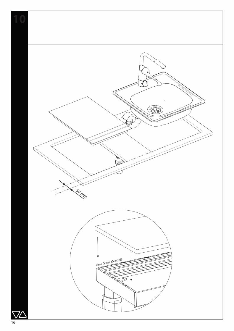
16
Lim / Glue / Klebstoff
10
50 mm

17
11
18
12
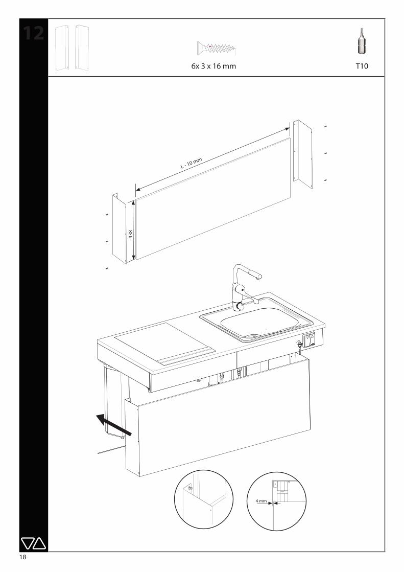
4 mm
T1016 mm
6x 3 x 16 mm
L - 10 mm
438

19
132x 2x M6x12 HEX 4
20
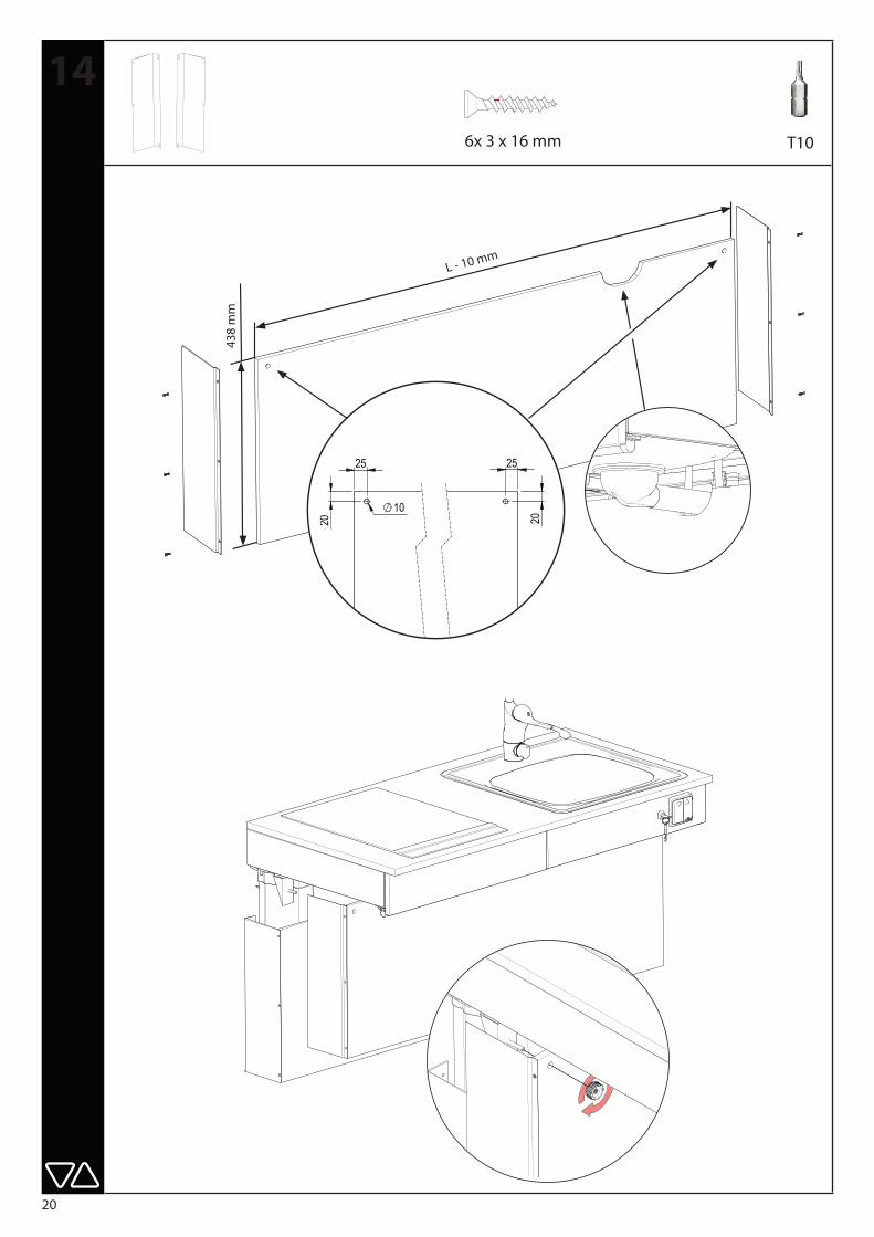
T10
1416 mm
6x 3 x 16 mm
L - 10 mm
438
mm
10
25
20
25
20
Täckskiva 120
04453
WEIGHT:
A3
SHEET 1 OF 1SCALE:1:5
DWG NO.
TITLE:
REVISION
DO NOT SCALE DRAWING
MATERIAL:
DEBUR AND BREAK SHARP EDGES
FINISH:
UNLESS OTHERWISE SPECIFIED:DIMENSIONS ARE IN MILLIMETERS TOLERANCES: LINEAR: SS-ISO 2768-m ANGULAR: SS-ISO 2768-m
DRAWN
CHECKED
Granberg Interior AB Tel. +46(0)[email protected] www.granberg.se
21
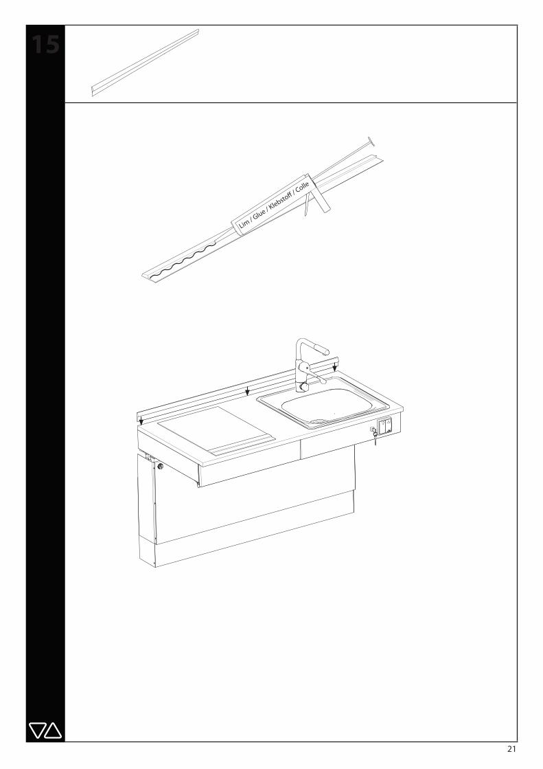
15
Lim / Glue / K
lebstoff / Colle
22
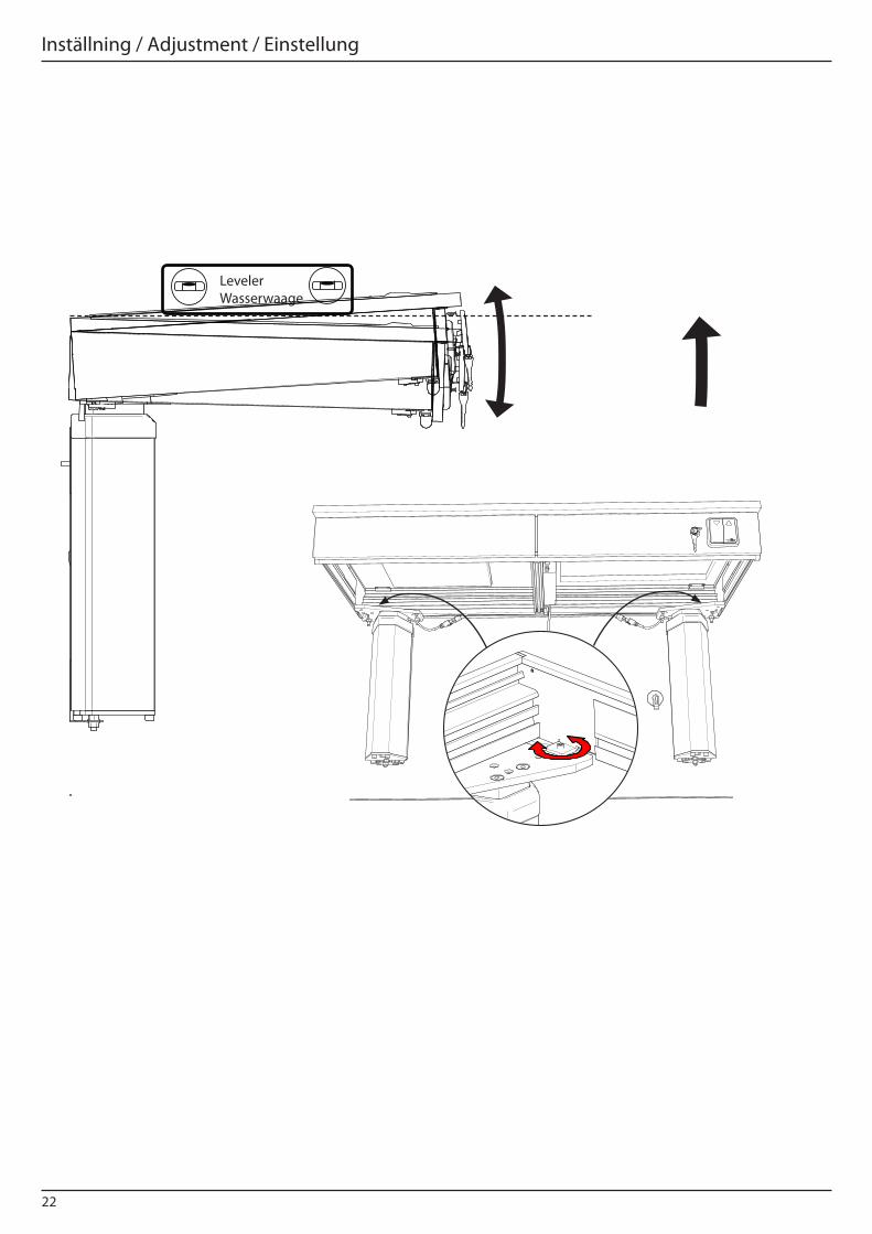
Leveler Wasserwaage
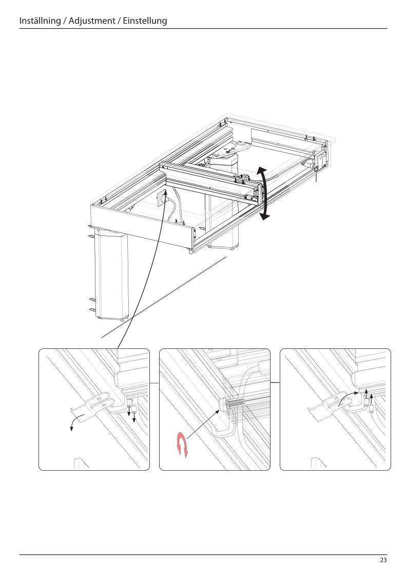
Inställning / Adjustment / Einstellung
23
Inställning / Adjustment / Einstellung
24
Funktionsprov
Efter installation ska komplett funktionsprov: * Provkör lyftenheten upp och ner hela vägen till respektive ändläge. Kontrollera att lyften löper fritt utan hinder, klämrisker och missljud. Kontrollera att den står kvar i nedre respektive övre läge.
* Kontrollera att inga kablar kommer i kläm och att de är fixerade.
* Kör lyftaren nedåt och funktionstesta klämlisten runt hela ramen . Tryck på den vid körning nedåt. Lyften ska stanna omedelbart och vända uppåt för att frige utrymme när ett klämskydd aktiveras.
Functional tests
Complete functional tests should be carried out after installation:
* Test run the lift unit up and down all the way to each end position. Make sure that the lift runs freely without obstacles, risk of pinching and noise. Make sure it remains at each end position.
* Make sure that no cables get pinched and that they are fixed.
* Lower the lift and test the function of the anti-pinch strip all around the frame. Press on it while lowering. The lift should stop immediately and rise to free up space when anti-pinch protection is activated.
Funktionstest
Nach der Montage muss eine vollständige Funktionsprüfung durchgeführt werden:
* Fahren Sie den Lift probeweise bis in die jeweilige Endposition auf und ab. Überprüfen Sie, das der Lift ohne Störgeräusche und ohne Klemmgefahren läuft. Der Lift muss in den jeweiligen Endpositionen stehen bleiben.
* Stellen Sie sicher, das keine Kabel oder Schläuche gequetscht werden und das diese sicher befestigt sind.
* Fahren Sie den Lift abwärts um die Funktion der Klemmschutzleiste zu testen. Üben Sie während der Fahrt druck auf die Klemmschutzleiste aus. Der Lift muss sofort stoppen und eine Gegenbewegung auslösen.
25
Innan driftsättning - Läs användarmanual
Endast behöriga personer får använda denna produkt!Behörighet innebär skyldighet att ta del av, samt följa instruktionerna.Det är mycket viktigt att ni läser och förstår användarmanualen innan driftsättning. Användarmanualen medföljer denna installationsanvisning som separat häfte.
Samtliga handlingar som medföljer produkten ska finnas tillgänglig för berörd personal, förvaras på skyddad plats och ska åtfölja produkten, om den övergår till annan installationsplats eller annan bostadsägare.Korrekt användning, manövrering, inspektioner och underhåll är avgörande för effektivt och säkert arbete. Om ni har frågor - kontakta er leverantör.
Before you use the device - Read the users manual
Only authorized persons may use the this product!Authorization means obligation to read and follow the instructions.It is very important that you read and understands the users manual before you use the device. The user manual is attached as a separate booklet.
All of the accompanying documents shall be available for all concerned persons, be kept in a protected place and shall follow the product, if it is moved to another installation site or another house or apartment owner.Correct use, operation, inspections and maintenance are decisive for efficient and safe work.
If you have any questions - contact your supplier.
Vor der Nutzung des Geräts lesen Sie bitte das Benutzerhandbuch
Dieses Produkt darf nur von autorisierten Personen bedient werden!Autorisiert bedeutet die Verpflichtung, die Anweisungen zu lesen und zu befolgen.Es ist sehr wichtig, dass Sie das Benutzerhandbuch gelesen und verstanden haben, bevor Sie das Gerät ver-wenden.Das Benutzerhandbuch ist als separate Broschüre beigefügt.
Sämtliche Begleitdokumente müssen für alle involvierten Personen verfügbar sein, an einem geschützten Ort aufbewahrt werden unddem Produkt folgen, wenn es an einen anderen Installationsort oder in eine andere Wohnung wechselt.Die ordnungsgemäße Verwendung, Bedienung, als auch die Wartungen und Inspektionen sind entschei-dend für ein sicheres und effizientes Arbeiten.
Bei Fragen wenden Sie sich bitte an Ihren Händler.

Granberg Interior ABBox 6112 600 06, Norrköping Tel: 011-19 77 50 E-mail: [email protected] Internet: www.granberg.se
Granberg Deutschland GmbHEggeweg 91, 33617 Bielefeld Tel: +49 521 1439983E-mail: [email protected] Internet: www.granberg.de