instruction manual & parts book - consew.com · parts manual 1. p2339rb arm ... they are widely...
TRANSCRIPT

PREMIER SERIES
BY
P2339RB
P1255RB
Parts Manual
1. P2339RB Arm parts…………………………………………………………………………………………………………….11~14
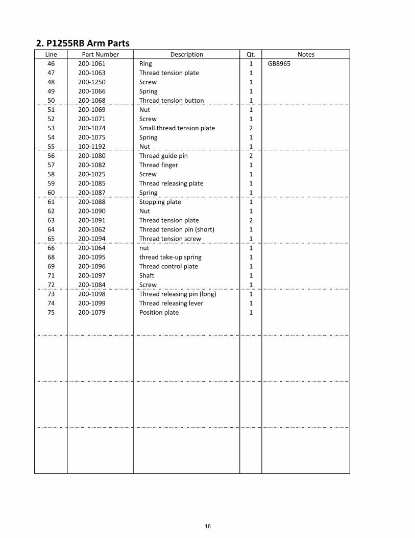
2. P1255RB Arm parts…………………………………………………………………………………………………………….15~18
3. Upper shaft and presser foot parts…………………………………………………………………………………….19~20
4. P2339RB Arm parts…………………………………………………………………………………………………………….21~24
5. P2339RB Arm parts…………………………………………………………………………………………………………….25~28
6. P2339RB Arm parts…………………………………………………………………………………………………………….29~32
7. P2339RB Arm parts…………………………………………………………………………………………………………….33~36
8. P2339RB Arm parts…………………………………………………………………………………………………………….37~38
9. P2339RB Arm parts…………………………………………………………………………………………………………….39~40
10. P2339RB Arm parts…………………………………………………………………………………………………………….41~42
11. P2339RB Arm parts…………………………………………………………………………………………………………….43~44
12. P2339RB Arm parts…………………………………………………………………………………………………………….45~46
1
2
small
big
B
A
B
A
oil felt
-1-
Both the models adopt straight twin-needle and two horizontal hooks with auto lubrication for threadlooping, sliding lever for thread take up to form two lines of lockstitch seam. The upper shaft and lowershaft is connected by ball bearing and driven by teeth-type synchronic belt; plunge oil pump lubricationsystem. They adopt the compound feed mechanics of feed dog, needle bar and presser foot, even if for longstitch length and long material, They can deal with them freely. They are widely used in factories of suitcase, tent, cushion, leather goods, apparel, mat, etc.. The difference between the two models: P2339RB adopts twin-needle, two large horizontal hooks with auto lubrication. With the parts it canform ten different needle gauges. P1255RB adopts single needle and form single line double lockstitch form.
1. Brief introduct oni
1 Application: medium and heavy duty materials2 Max. sewing speed: 2000 spm3 Max. Stitch length : 9 mm4 Needle bar stroke: 36 mm5 Presser foot lift height: 8mm(by hand); 16mm(by knee)6 Hook: large horizontal hook with auto lubrication7 Needle: DPX¡Á17 Nm125~1808 Lubrication: pump auto lubrication (partial of manually oiling)9 Needle gauge: (Twin-needle) 6.4, 3.2, 4, 4.8, 8, 9.5, 12.7, 16, 19, 25.410 Motor power: 0.37 kw (clutch motor)
2. Main Technical Specification
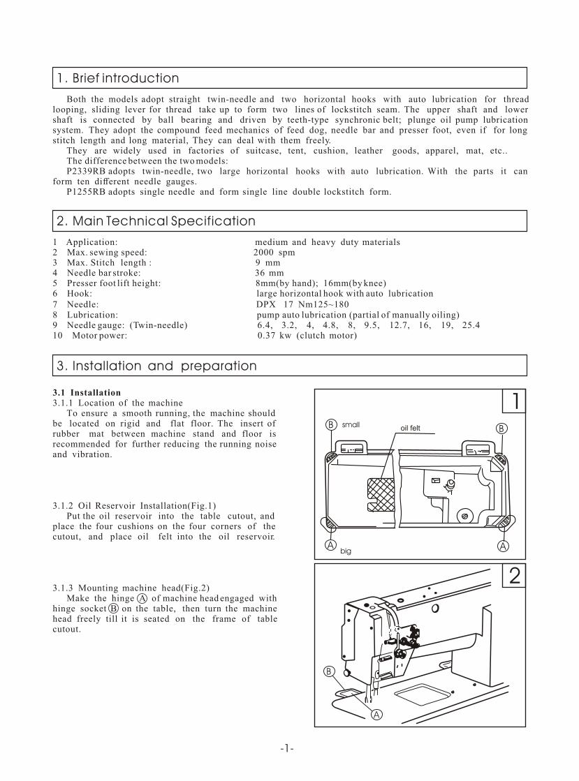
3.1 Installation3.1.1 Location of the machine To ensure a smooth running, the machine shouldbe located on rigid and flat floor. The insert of rubber mat between machine stand and floor isrecommended for further reducing the running noiseand vibration.
3.1.2 Oil Reservoir Installation(Fig.1) Put the oil reservoir into the table cutout, andplace the four cushions on the four corners of the cutout, and place oil felt into the oil reservoir.
3.1.3 Mounting machine head(Fig.2) Make the hinge A of machine head engaged withhinge socket B on the table, then turn the machinehead freely till it is seated on the frame of tablecutout.
( )
3. Installation and preparation
B
A
A
A
C
C
B
B
3
4
5
A
C
B
-2-
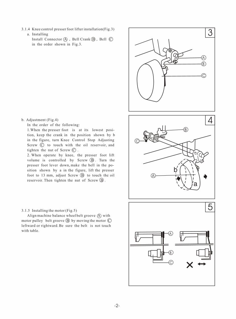
3.1.4 Knee control presser foot lifter installation(Fig.3)
a. Installing
Install Connector A , Bell Crank B , Bell C
in the order shown in Fig.3.
b. Adjustment (Fig.4)
In the order of the following:
1.When the presser foot is at its lowest posi-
tion, keep the crank in the position shown by b
in the figure, turn Knee Control Stop Adjusting
Screw C to touch with the oil reservoir, and
tighten the nut of Screw C .
2. When operate by knee, the presser foot lift
volume is controlled by Screw B . Turn the
presser foot lever down, make the bell in the po-
sition shown by a in the figure, lift the presser
foot to 13 mm, adjust Screw B to touch the oil
reservoir. Then tighten the nut of Screw B .
3.1.5 Installing the motor (Fig.5)
Align machine balance wheel belt groove A with
motor pulley belt groove B by moving the motor C
leftward or rightward. Be sure the belt is not touch
with table.
( ) ( ) ( )
( )
( )
( )
( )
( )
( )
( ) ( )
A
B
C
D
G
F
E
10 - 1
2 mm
D
C
B
A20¡«30
6
7
8
C
A B
-3-
D
E
A B A
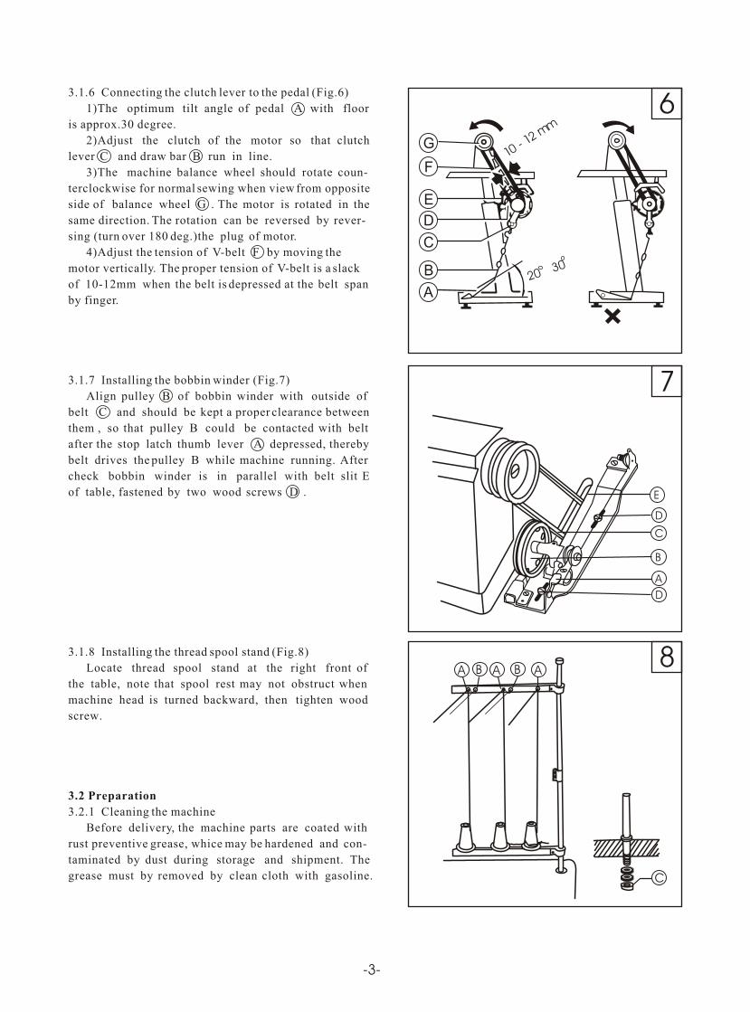
3.1.6 Connecting the clutch lever to the pedal (Fig.6)
1)The optimum tilt angle of pedal A with floor
is approx.30 degree.
2)Adjust the clutch of the motor so that clutch
lever C and draw bar B run in line.
3)The machine balance wheel should rotate coun-
terclockwise for normal sewing when view from opposite
side of balance wheel G . The motor is rotated in the
same direction. The rotation can be reversed by rever-
sing (turn over 180 deg.)the plug of motor.
4)Adjust the tension of V-belt F by moving the
motor vertically. The proper tension of V-belt is a slack
of 10-12mm when the belt is depressed at the belt span
by finger.
3.1.7 Installing the bobbin winder (Fig.7)
Align pulley B of bobbin winder with outside of
belt C and should be kept a proper clearance between
them , so that pulley B could be contacted with belt
after the stop latch thumb lever A depressed, thereby
belt drives the pulley B while machine running. After
check bobbin winder is in parallel with belt slit E
of table, fastened by two wood screws D .
3.1.8 Installing the thread spool stand (Fig.8)
Locate thread spool stand at the right front of
the table, note that spool rest may not obstruct when
machine head is turned backward, then tighten wood
screw.
3.2 Preparation
3.2.1 Cleaning the machine
Before delivery, the machine parts are coated with
rust preventive grease, whice may be hardened and con-
taminated by dust during storage and shipment. The
grease must by removed by clean cloth with gasoline.
( )
( ) ( )
( )
( )
( )
( )
( )
( )
9
10
11
12
oil mark
oi l screen
-4-
3.2.2 Examination
Though every machine is confirmed by strict inspec-
tion and test before delivery, the machine parts may be
loosed or deformed after long. distance transportation
with jolt. A thorough examination must be performed
after cleaning the machine . Turn the balance wheel to
see if there is running obstruction, parts collision,
uneven resistance or abnormal nosie. If these exist,
adjustment must be made accordingly before run.
3.2.3 Precaution before Start
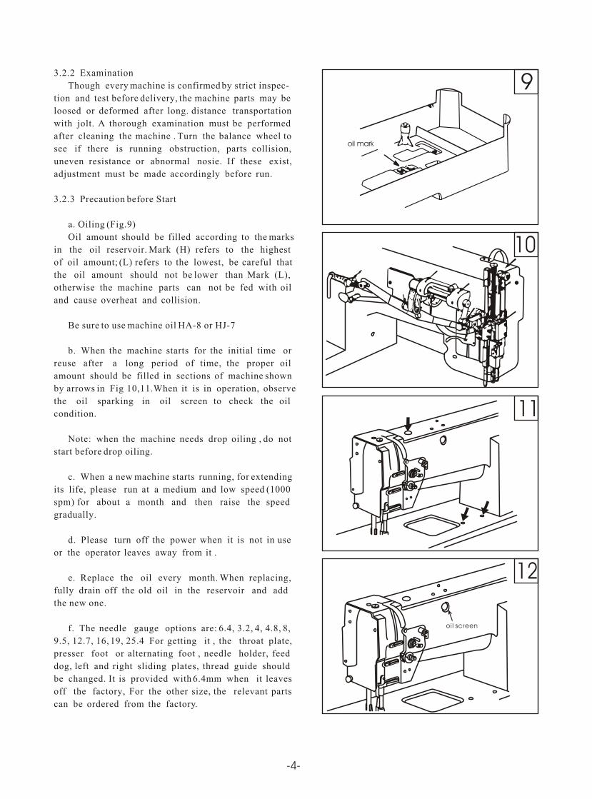
a. Oiling (Fig.9)
Oil amount should be filled according to the marks
in the oil reservoir. Mark (H) refers to the highest
of oil amount; (L) refers to the lowest, be careful that
the oil amount should not be lower than Mark (L),
otherwise the machine parts can not be fed with oil
and cause overheat and collision.
Be sure to use machine oil HA-8 or HJ-7
b. When the machine starts for the initial time or
reuse after a long period of time, the proper oil
amount should be filled in sections of machine shown
by arrows in Fig 10,11.When it is in operation, observe
the oil sparking in oil screen to check the oil
condition.
Note: when the machine needs drop oiling , do not
start before drop oiling.
c. When a new machine starts running, for extending
its life, please run at a medium and low speed (1000
spm) for about a month and then raise the speed
gradually.
d. Please turn off the power when it is not in use
or the operator leaves away from it .
e. Replace the oil every month. When replacing,
fully drain off the old oil in the reservoir and add
the new one.
f. The needle gauge options are: 6.4, 3.2, 4, 4.8, 8,
9.5, 12.7, 16, 19, 25.4 For getting it , the throat plate,
presser foot or alternating foot , needle holder, feed
dog, left and right sliding plates, thread guide should
be changed. It is provided with 6.4mm when it leaves
off the factory, For the other size, the relevant parts
can be ordered from the factory.
13
14
A
B
C
D
E
G
H
2
1F
-5-
long groove
long groove leftward
clearance
(a)
(d) (b)
(c)
A
4.1 Coordination between needle, thread and sewing
material
Please use needle DPX¡Á17,Nm125-180.The coarseness
of needle should be in accordance with the nature of
material. If stitch on heavy duty material with a slim
needle, the needle will be easily bent, skip or thread
breakage occurs, on the contrary, stitch on tightly woven
material with a very coarse needle, the material will
be destroyed with over-big needle. So the needle and
thread should be properly selected.
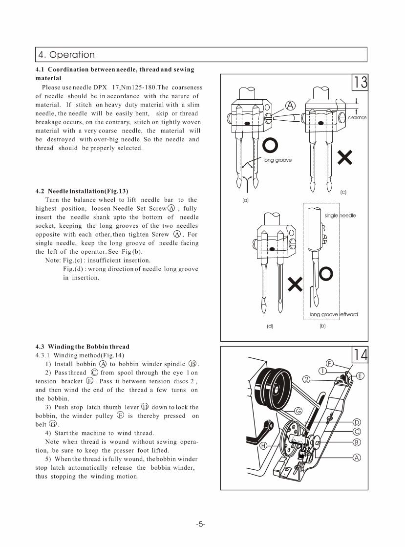
4.2 Needle installation(Fig.13)
Turn the balance wheel to lift needle bar to the
highest position, loosen Needle Set Screw A , fully
insert the needle shank upto the bottom of needle
socket, keeping the long grooves of the two needles
opposite with each other, then tighten Screw A , For
single needle, keep the long groove of needle facing
the left of the operator. See Fig (b).
Note: Fig.(c) : insufficient insertion.
Fig.(d) : wrong direction of needle long groove
in insertion.
4.3 Winding the Bobbin thread
4.3.1 Winding method(Fig.14)
1) Install bobbin A to bobbin winder spindle B .
2) Pass thread C from spool through the eye 1 on
tension bracket E . Pass ti between tension discs 2 ,
and then wind the end of the thread a few turns on
the bobbin.
3) Push stop latch thumb lever D down to lock the
bobbin, the winder pulley F is thereby pressed on
belt G .
4) Start the machine to wind thread.
Note when thread is wound without sewing opera-
tion, be sure to keep the presser foot lifted.
5) When the thread is fully wound, the bobbin winder
stop latch automatically release the bobbin winder,
thus stopping the winding motion.
( )
( ) ( )
( )
( )
( )
( )
( )
4. Operation
single needle
L7 L5 L4 L3' L3 L2' L2 LR7 R1
15
16
17
-6-
A
A
B
C
C
D
E
A A AB B
L11 R11
L8
L9
L10
L11
L12
L13
R8
R9
R10
from right to left from left to right
detail chart
thread
L6
R6
R11R12
R13
R5
R2R3
R4
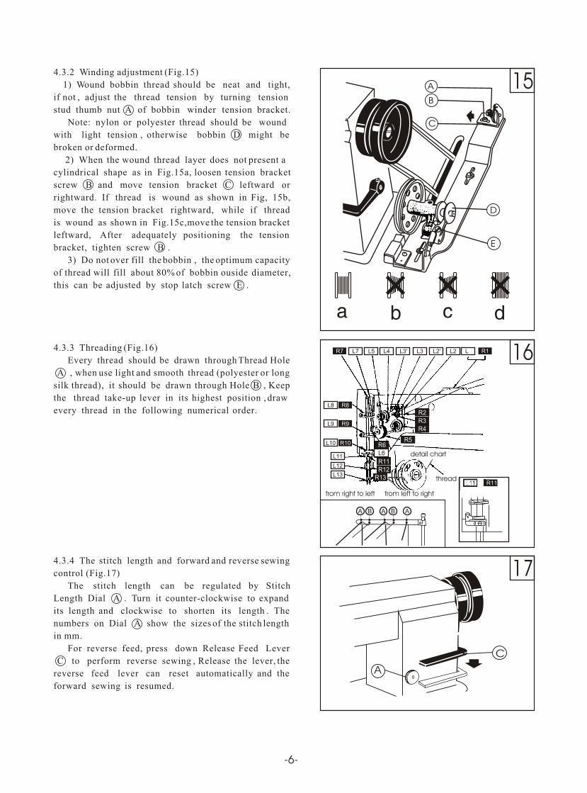
4.3.2 Winding adjustment (Fig.15)
1) Wound bobbin thread should be neat and tight,
if not , adjust the thread tension by turning tension
stud thumb nut A of bobbin winder tension bracket.
Note: nylon or polyester thread should be wound
with light tension , otherwise bobbin D might be
broken or deformed.
2) When the wound thread layer does not present a
cylindrical shape as in Fig.15a, loosen tension bracket
screw B and move tension bracket C leftward or
rightward. If thread is wound as shown in Fig, 15b,
move the tension bracket rightward, while if thread
is wound as shown in Fig.15c,move the tension bracket
leftward, After adequately positioning the tension
bracket, tighten screw B .
3) Do not over fill the bobbin , the optimum capacity
of thread will fill about 80% of bobbin ouside diameter,
this can be adjusted by stop latch screw E .
4.3.3 Threading (Fig.16)
Every thread should be drawn through Thread Hole
A , when use light and smooth thread (polyester or long
silk thread), it should be drawn through Hole B , Keep
the thread take-up lever in its highest position , draw
every thread in the following numerical order.
4.3.4 The stitch length and forward and reverse sewing
control (Fig.17)
The stitch length can be regulated by Stitch
Length Dial A . Turn it counter-clockwise to expand
its length and clockwise to shorten its length . The
numbers on Dial A show the sizes of the stitch length
in mm.
For reverse feed, press down Release Feed Lever
C to perform reverse sewing , Release the lever, the
reverse feed lever can reset automatically and the
forward sewing is resumed.
( )
( )
( ) ( )
( )
( )
( )
( )
( )
( )
( )
21
20
19
18
Normal
A
B
C
-7-
hook
thread
sliding plate
hook
sliding plate
tension adjusting screw
loosen
tighten
inner stop piece
1
12
thread
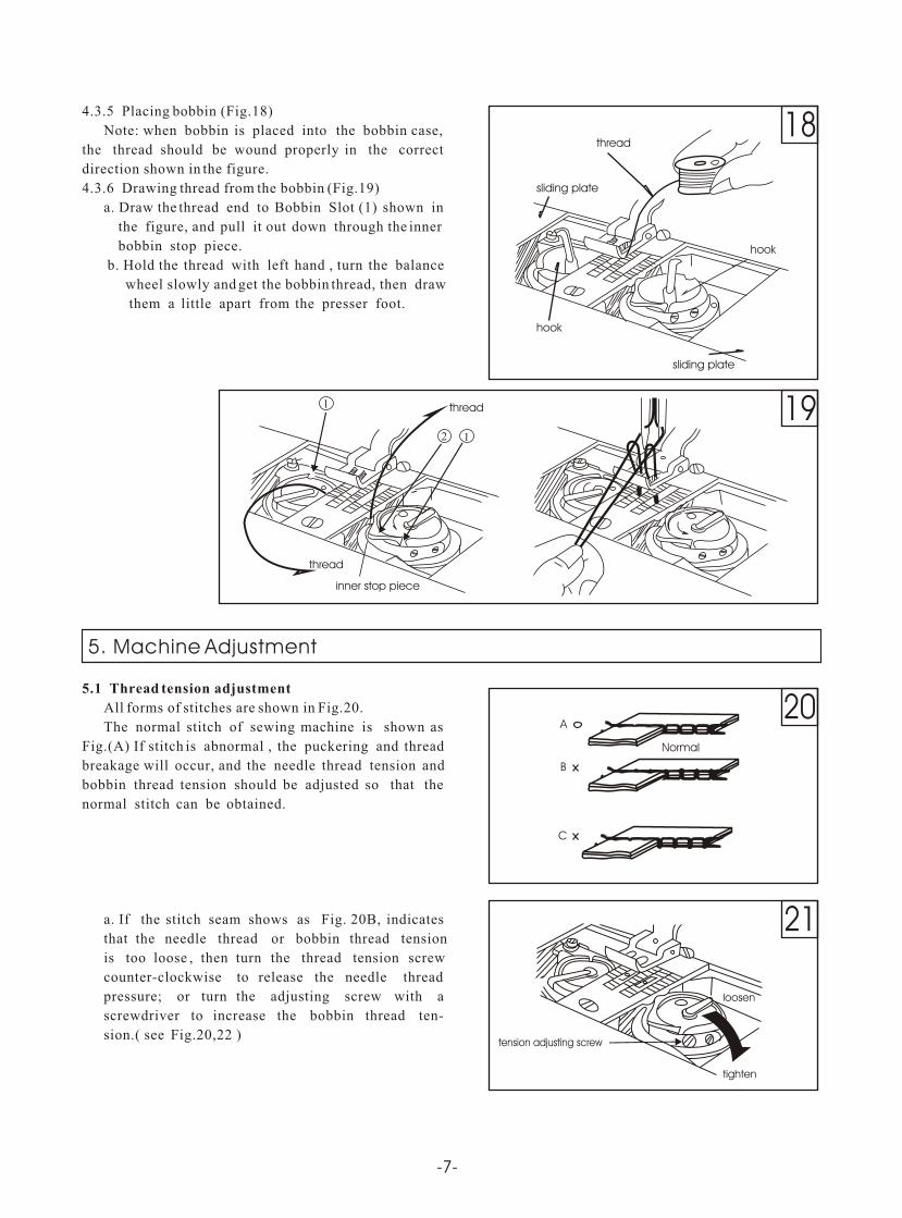
4.3.5 Placing bobbin (Fig.18)
Note: when bobbin is placed into the bobbin case,
the thread should be wound properly in the correct
direction shown in the figure.
4.3.6 Drawing thread from the bobbin (Fig.19)
a. Draw the thread end to Bobbin Slot (1) shown in
the figure, and pull it out down through the inner
bobbin stop piece.
b. Hold the thread with left hand , turn the balance
wheel slowly and get the bobbin thread, then draw
them a little apart from the presser foot.
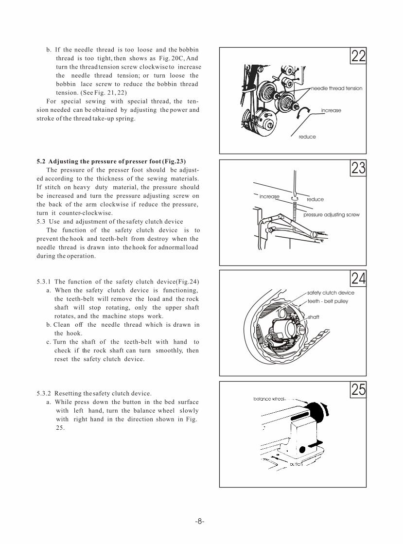
5.1 Thread tension adjustment
All forms of stitches are shown in Fig.20.
The normal stitch of sewing machine is shown as
Fig.(A) If stitch is abnormal , the puckering and thread
breakage will occur, and the needle thread tension and
bobbin thread tension should be adjusted so that the
normal stitch can be obtained.
a. If the stitch seam shows as Fig. 20B, indicates
that the needle thread or bobbin thread tension
is too loose , then turn the thread tension screw
counter-clockwise to release the needle thread
pressure; or turn the adjusting screw with a
screwdriver to increase the bobbin thread ten-
sion.( see Fig.20,22 )
5. Machine Adjustment
thread
25
24
23
22
button
balance wheel
pressure adjusting screw
reduceincrease
teeth - belt pulley
shaft
safety clutch device
-8-
needle thread tension
increase
reduce
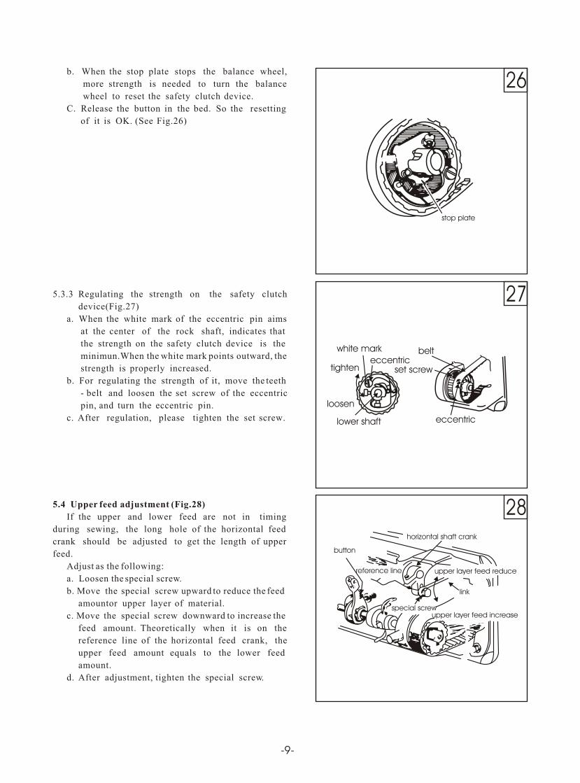
b. If the needle thread is too loose and the bobbin
thread is too tight, then shows as Fig. 20C, And
turn the thread tension screw clockwise to increase
the needle thread tension; or turn loose the
bobbin lace screw to reduce the bobbin thread
tension. (See Fig. 21, 22)
For special sewing with special thread, the ten-
sion needed can be obtained by adjusting the power and
stroke of the thread take-up spring.
5.2 Adjusting the pressure of presser foot (Fig.23)
The pressure of the presser foot should be adjust-
ed according to the thickness of the sewing materials.
If stitch on heavy duty material, the pressure should
be increased and turn the pressure adjusting screw on
the back of the arm clockwise if reduce the pressure,
turn it counter-clockwise.
5.3 Use and adjustment of the safety clutch device
The function of the safety clutch device is to
prevent the hook and teeth-belt from destroy when the
needle thread is drawn into the hook for adnormal load
during the operation.
5.3.1 The function of the safety clutch device(Fig.24)
a. When the safety clutch device is functioning,
the teeth-belt will remove the load and the rock
shaft will stop rotating, only the upper shaft
rotates, and the machine stops work.
b. Clean off the needle thread which is drawn in
the hook.
c. Turn the shaft of the teeth-belt with hand to
check if the rock shaft can turn smoothly, then
reset the safety clutch device.
5.3.2 Resetting the safety clutch device.
a. While press down the button in the bed surface
with left hand, turn the balance wheel slowly
with right hand in the direction shown in Fig.
25.
26
27
28
stop plate
white mark
eccentriclower shaft
loosen
tighten set screw
belteccentric
reference line
button
special screw
horizontal shaft crank
upper layer feed reduce
upper layer feed increase
link
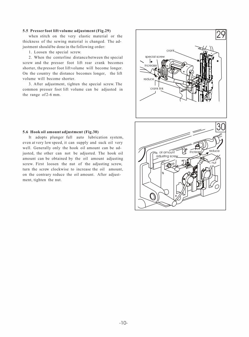
b. When the stop plate stops the balance wheel,
more strength is needed to turn the balance
wheel to reset the safety clutch device.
C. Release the button in the bed. So the resetting
of it is OK. (See Fig.26)
5.3.3 Regulating the strength on the safety clutch
device(Fig.27)
a. When the white mark of the eccentric pin aims
at the center of the rock shaft, indicates that
the strength on the safety clutch device is the
minimun.When the white mark points outward, the
strength is properly increased.
b. For regulating the strength of it, move the teeth
- belt and loosen the set screw of the eccentric
pin, and turn the eccentric pin.
c. After regulation, please tighten the set screw.
5.4 Upper feed adjustment (Fig.28)
If the upper and lower feed are not in timing
during sewing, the long hole of the horizontal feed
crank should be adjusted to get the length of upper
feed.
Adjust as the following:
a. Loosen the special screw.
b. Move the special screw upward to reduce the feed
amountor upper layer of material.
c. Move the special screw downward to increase the
feed amount. Theoretically when it is on the
reference line of the horizontal feed crank, the
upper feed amount equals to the lower feed
amount.
d. After adjustment, tighten the special screw.
-9-
30
29
oil amount adjusting screw
increase reduce
nut
special screw
crank
increase
reduce
crank link
-10-
5.5 Presser foot lift volume adjustment (Fig.29)
when stitch on the very elastic material or the
thickness of the sewing material is changed. The ad-
justment should be done in the following order:
1. Loosen the special screw.
2. When the centerline distance between the special
screw and the presser foot lift rear crank becomes
shorter, the presser foot lift volume will become longer.
On the country the distance becomes longer, the lift
volume will become shorter.
3. After adjustment, tighten the special screw. The
common presser foot lift volume can be adjusted in
the range of 2-6 mm.
5.6 Hook oil amount adjustment (Fig.30)
It adopts plunger full auto lubrication system,
even at very low speed, it can supply and suck oil very
well. Generally only the hook oil amount can be ad-
justed, the other can not be adjusted. The hook oil
amount can be obtained by the oil amount adjusting
screw. First loosen the nut of the adjusting screw,
turn the scre clockwise to increase the oil amount,
on the contrary reduce the oil amount. After adjust-
ment, tighten the nut.
w

Operation instruction
Parts Manual
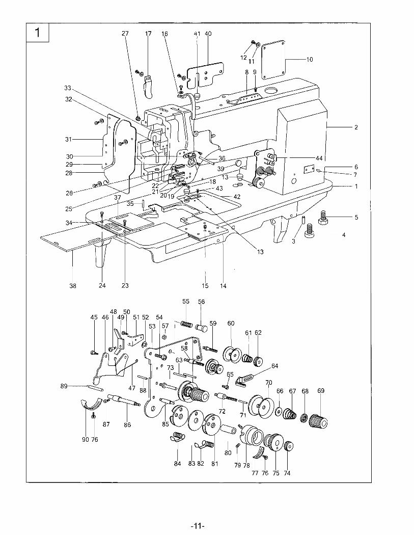
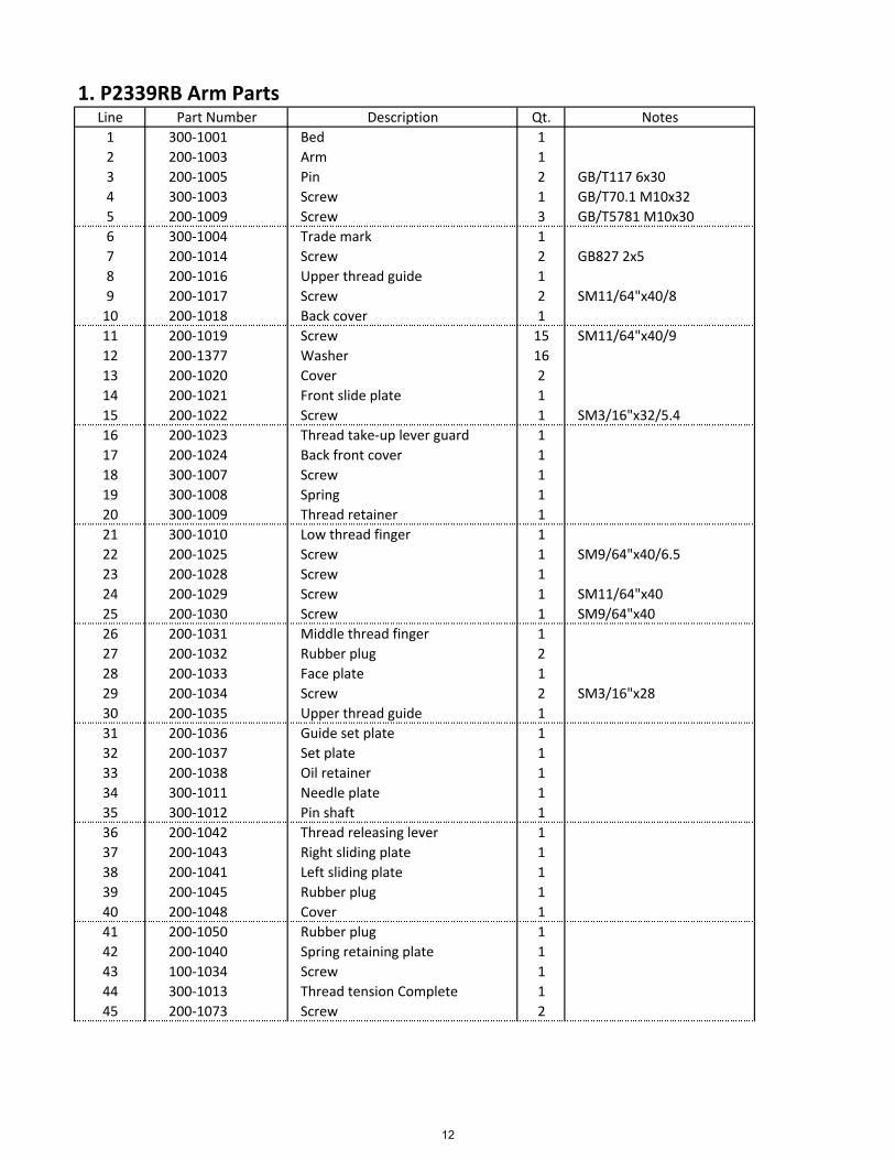
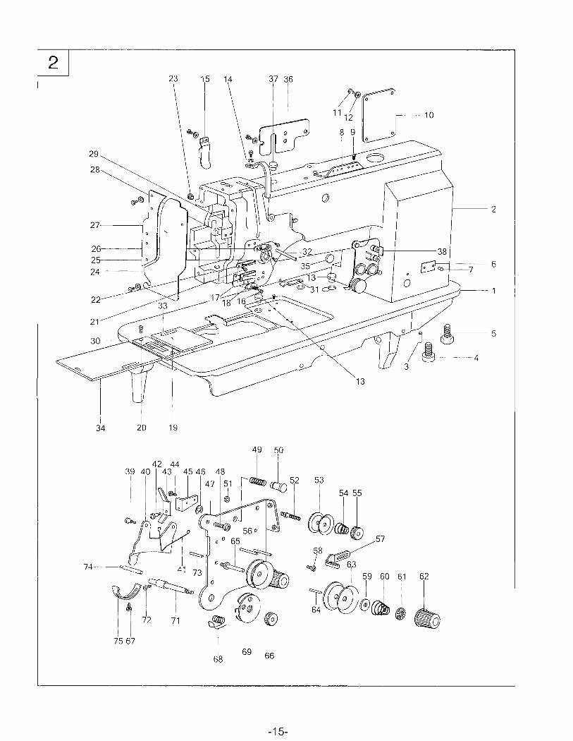
1. P2339RB Arm PartsLine Part Number Description Qt. Notes
1 300‐1001 Bed 1
2 200‐1003 Arm 1
3 200‐1005 Pin 2 GB/T117 6x30
4 300‐1003 Screw 1 GB/T70.1 M10x32
5 200‐1009 Screw 3 GB/T5781 M10x30
6 300‐1004 Trade mark 1
7 200‐1014 Screw 2 GB827 2x5
8 200‐1016 Upper thread guide 1
9 200‐1017 Screw 2 SM11/64"x40/8
10 200‐1018 Back cover 1
11 200‐1019 Screw 15 SM11/64"x40/9
12 200‐1377 Washer 16
13 200‐1020 Cover 2
14 200‐1021 Front slide plate 1
15 200‐1022 Screw 1 SM3/16"x32/5.4
16 200‐1023 Thread take‐up lever guard 1
17 200‐1024 Back front cover 1
18 300‐1007 Screw 1
19 300‐1008 Spring 1
20 300‐1009 Thread retainer 1
21 300‐1010 Low thread finger 1
22 200‐1025 Screw 1 SM9/64"x40/6.5
23 200‐1028 Screw 1
24 200‐1029 Screw 1 SM11/64"x40
25 200‐1030 Screw 1 SM9/64"x40
26 200‐1031 Middle thread finger 1
27 200‐1032 Rubber plug 2
28 200‐1033 Face plate 1
29 200‐1034 Screw 2 SM3/16"x28
30 200‐1035 Upper thread guide 1
31 200‐1036 Guide set plate 1
32 200‐1037 Set plate 1
33 200‐1038 Oil retainer 1
34 300‐1011 Needle plate 1
35 300‐1012 Pin shaft 1
36 200‐1042 Thread releasing lever 1
37 200‐1043 Right sliding plate 1
38 200‐1041 Left sliding plate 1
39 200‐1045 Rubber plug 1
40 200‐1048 Cover 1
41 200‐1050 Rubber plug 1
42 200‐1040 Spring retaining plate 1
43 100‐1034 Screw 1
44 300‐1013 Thread tension Complete 1
45 200‐1073 Screw 2
12
1. P2339RB Arm PartsLine Part Number Description Qt. Notes
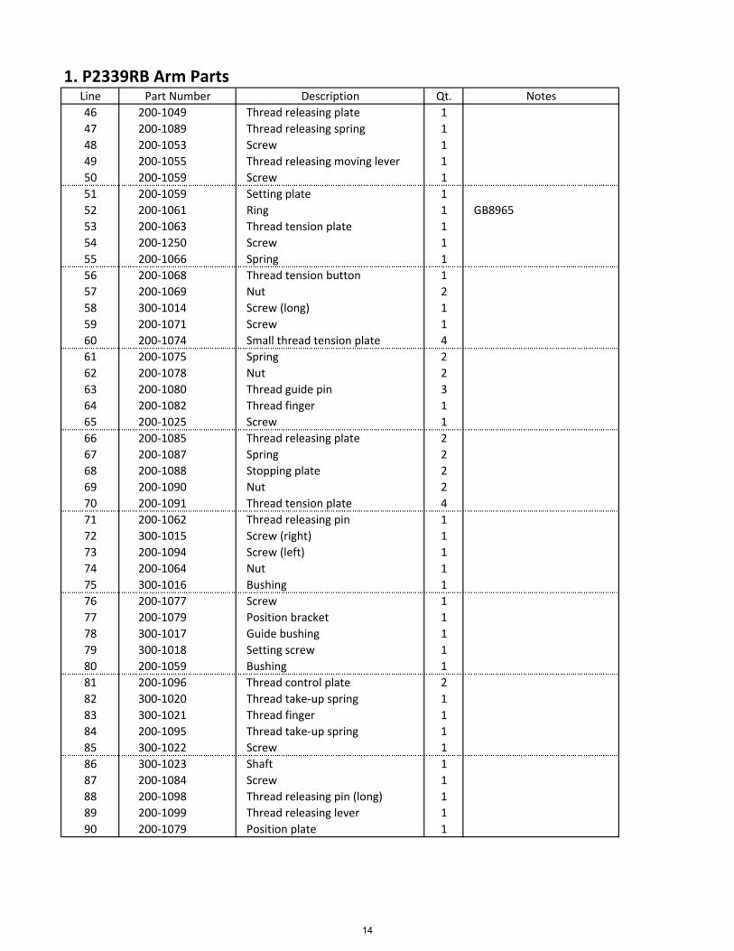
46 200‐1049 Thread releasing plate 1
47 200‐1089 Thread releasing spring 1
48 200‐1053 Screw 1
49 200‐1055 Thread releasing moving lever 1
50 200‐1059 Screw 1
51 200‐1059 Setting plate 1
52 200‐1061 Ring 1 GB8965
53 200‐1063 Thread tension plate 1
54 200‐1250 Screw 1
55 200‐1066 Spring 1
56 200‐1068 Thread tension button 1
57 200‐1069 Nut 2
58 300‐1014 Screw (long) 1
59 200‐1071 Screw 1
60 200‐1074 Small thread tension plate 4
61 200‐1075 Spring 2
62 200‐1078 Nut 2
63 200‐1080 Thread guide pin 3
64 200‐1082 Thread finger 1
65 200‐1025 Screw 1
66 200‐1085 Thread releasing plate 2
67 200‐1087 Spring 2
68 200‐1088 Stopping plate 2
69 200‐1090 Nut 2
70 200‐1091 Thread tension plate 4
71 200‐1062 Thread releasing pin 1
72 300‐1015 Screw (right) 1
73 200‐1094 Screw (left) 1
74 200‐1064 Nut 1
75 300‐1016 Bushing 1
76 200‐1077 Screw 1
77 200‐1079 Position bracket 1
78 300‐1017 Guide bushing 1
79 300‐1018 Setting screw 1
80 200‐1059 Bushing 1
81 200‐1096 Thread control plate 2
82 300‐1020 Thread take‐up spring 1
83 300‐1021 Thread finger 1
84 200‐1095 Thread take‐up spring 1
85 300‐1022 Screw 1
86 300‐1023 Shaft 1
87 200‐1084 Screw 1
88 200‐1098 Thread releasing pin (long) 1
89 200‐1099 Thread releasing lever 1
90 200‐1079 Position plate 1
14
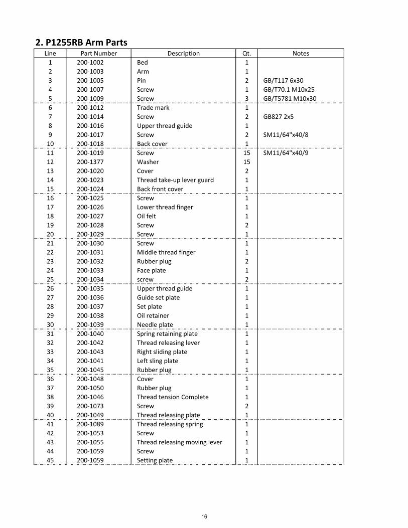
2. P1255RB Arm PartsLine Part Number Description Qt. Notes
1 200‐1002 Bed 1
2 200‐1003 Arm 1
3 200‐1005 Pin 2 GB/T117 6x30
4 200‐1007 Screw 1 GB/T70.1 M10x25
5 200‐1009 Screw 3 GB/T5781 M10x30
6 200‐1012 Trade mark 1
7 200‐1014 Screw 2 GB827 2x5
8 200‐1016 Upper thread guide 1
9 200‐1017 Screw 2 SM11/64"x40/8
10 200‐1018 Back cover 1
11 200‐1019 Screw 15 SM11/64"x40/9
12 200‐1377 Washer 15
13 200‐1020 Cover 2
14 200‐1023 Thread take‐up lever guard 1
15 200‐1024 Back front cover 1
16 200‐1025 Screw 1
17 200‐1026 Lower thread finger 1
18 200‐1027 Oil felt 1
19 200‐1028 Screw 2
20 200‐1029 Screw 1
21 200‐1030 Screw 1
22 200‐1031 Middle thread finger 1
23 200‐1032 Rubber plug 2
24 200‐1033 Face plate 1
25 200‐1034 screw 2
26 200‐1035 Upper thread guide 1
27 200‐1036 Guide set plate 1
28 200‐1037 Set plate 1
29 200‐1038 Oil retainer 1
30 200‐1039 Needle plate 1
31 200‐1040 Spring retaining plate 1
32 200‐1042 Thread releasing lever 1
33 200‐1043 Right sliding plate 1
34 200‐1041 Left sling plate 1
35 200‐1045 Rubber plug 1
36 200‐1048 Cover 1
37 200‐1050 Rubber plug 1
38 200‐1046 Thread tension Complete 1
39 200‐1073 Screw 2
40 200‐1049 Thread releasing plate 1
41 200‐1089 Thread releasing spring 1
42 200‐1053 Screw 1
43 200‐1055 Thread releasing moving lever 1
44 200‐1059 Screw 1
45 200‐1059 Setting plate 1
16
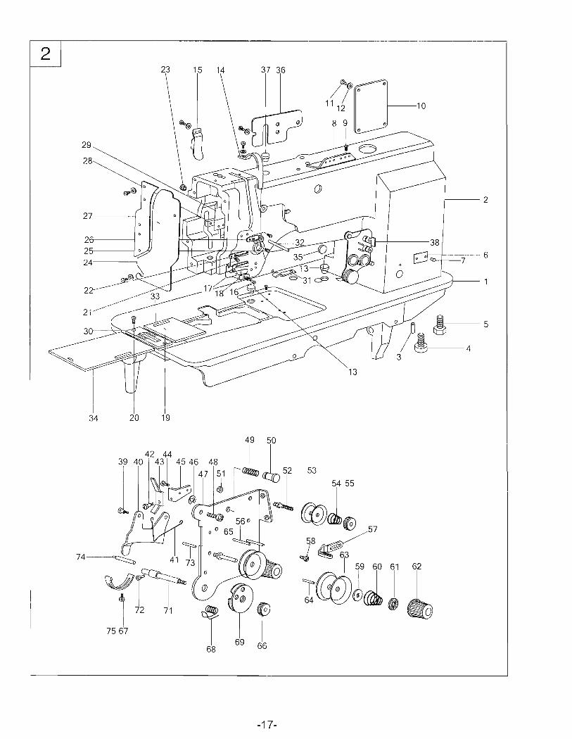
2. P1255RB Arm PartsLine Part Number Description Qt. Notes
46 200‐1061 Ring 1 GB8965
47 200‐1063 Thread tension plate 1
48 200‐1250 Screw 1
49 200‐1066 Spring 1
50 200‐1068 Thread tension button 1
51 200‐1069 Nut 1
52 200‐1071 Screw 1
53 200‐1074 Small thread tension plate 2
54 200‐1075 Spring 1
55 100‐1192 Nut 1
56 200‐1080 Thread guide pin 2
57 200‐1082 Thread finger 1
58 200‐1025 Screw 1
59 200‐1085 Thread releasing plate 1
60 200‐1087 Spring 1
61 200‐1088 Stopping plate 1
62 200‐1090 Nut 1
63 200‐1091 Thread tension plate 2
64 200‐1062 Thread tension pin (short) 1
65 200‐1094 Thread tension screw 1
66 200‐1064 nut 1
68 200‐1095 thread take‐up spring 1
69 200‐1096 Thread control plate 1
71 200‐1097 Shaft 1
72 200‐1084 Screw 1
73 200‐1098 Thread releasing pin (long) 1
74 200‐1099 Thread releasing lever 1
75 200‐1079 Position plate 1
18
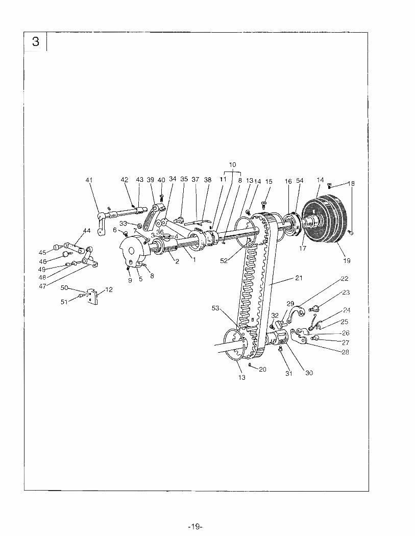
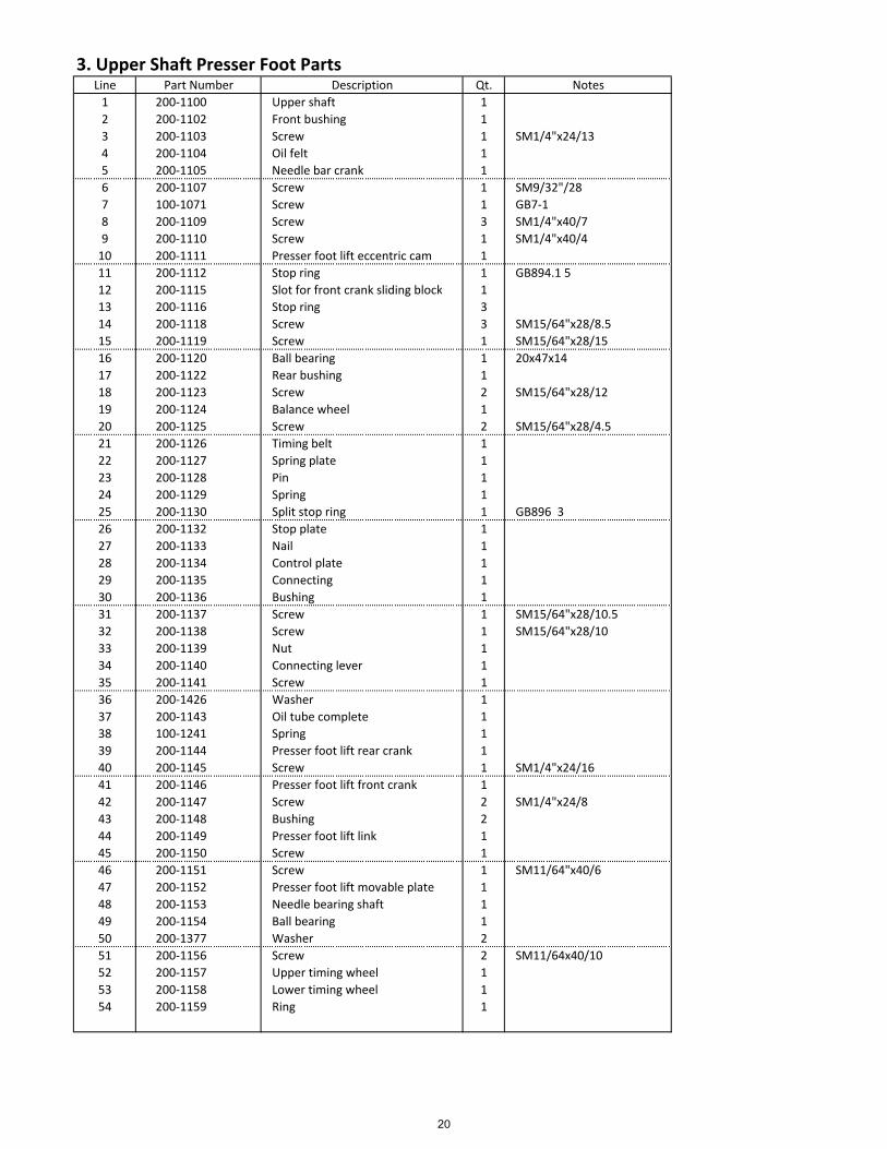
3. Upper Shaft Presser Foot PartsLine Part Number Description Qt. Notes
1 200‐1100 Upper shaft 1
2 200‐1102 Front bushing 1
3 200‐1103 Screw 1 SM1/4"x24/13
4 200‐1104 Oil felt 1
5 200‐1105 Needle bar crank 1
6 200‐1107 Screw 1 SM9/32"/28
7 100‐1071 Screw 1 GB7‐1
8 200‐1109 Screw 3 SM1/4"x40/7
9 200‐1110 Screw 1 SM1/4"x40/4
10 200‐1111 Presser foot lift eccentric cam 1
11 200‐1112 Stop ring 1 GB894.1 5
12 200‐1115 Slot for front crank sliding block 1
13 200‐1116 Stop ring 3
14 200‐1118 Screw 3 SM15/64"x28/8.5
15 200‐1119 Screw 1 SM15/64"x28/15
16 200‐1120 Ball bearing 1 20x47x14
17 200‐1122 Rear bushing 1
18 200‐1123 Screw 2 SM15/64"x28/12
19 200‐1124 Balance wheel 1
20 200‐1125 Screw 2 SM15/64"x28/4.5
21 200‐1126 Timing belt 1
22 200‐1127 Spring plate 1
23 200‐1128 Pin 1
24 200‐1129 Spring 1
25 200‐1130 Split stop ring 1 GB896 3
26 200‐1132 Stop plate 1
27 200‐1133 Nail 1
28 200‐1134 Control plate 1
29 200‐1135 Connecting 1
30 200‐1136 Bushing 1
31 200‐1137 Screw 1 SM15/64"x28/10.5
32 200‐1138 Screw 1 SM15/64"x28/10
33 200‐1139 Nut 1
34 200‐1140 Connecting lever 1
35 200‐1141 Screw 1
36 200‐1426 Washer 1
37 200‐1143 Oil tube complete 1
38 100‐1241 Spring 1
39 200‐1144 Presser foot lift rear crank 1
40 200‐1145 Screw 1 SM1/4"x24/16
41 200‐1146 Presser foot lift front crank 1
42 200‐1147 Screw 2 SM1/4"x24/8
43 200‐1148 Bushing 2
44 200‐1149 Presser foot lift link 1
45 200‐1150 Screw 1
46 200‐1151 Screw 1 SM11/64"x40/6
47 200‐1152 Presser foot lift movable plate 1
48 200‐1153 Needle bearing shaft 1
49 200‐1154 Ball bearing 1
50 200‐1377 Washer 2
51 200‐1156 Screw 2 SM11/64x40/10
52 200‐1157 Upper timing wheel 1
53 200‐1158 Lower timing wheel 1
54 200‐1159 Ring 1
20

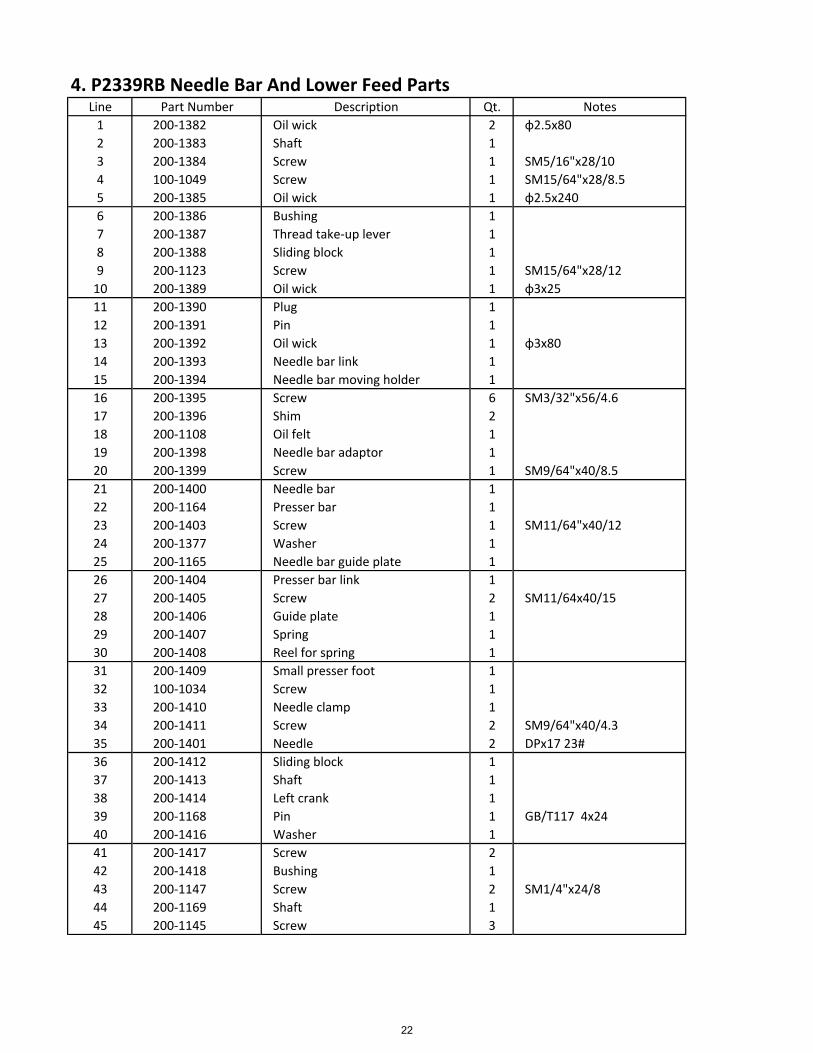
4. P2339RB Needle Bar And Lower Feed PartsLine Part Number Description Qt. Notes
1 200‐1382 Oil wick 2 ɸ2.5x80
2 200‐1383 Shaft 1
3 200‐1384 Screw 1 SM5/16"x28/10
4 100‐1049 Screw 1 SM15/64"x28/8.5
5 200‐1385 Oil wick 1 ɸ2.5x240
6 200‐1386 Bushing 1
7 200‐1387 Thread take‐up lever 1
8 200‐1388 Sliding block 1
9 200‐1123 Screw 1 SM15/64"x28/12
10 200‐1389 Oil wick 1 ɸ3x25
11 200‐1390 Plug 1
12 200‐1391 Pin 1
13 200‐1392 Oil wick 1 ɸ3x80
14 200‐1393 Needle bar link 1
15 200‐1394 Needle bar moving holder 1
16 200‐1395 Screw 6 SM3/32"x56/4.6
17 200‐1396 Shim 2
18 200‐1108 Oil felt 1
19 200‐1398 Needle bar adaptor 1
20 200‐1399 Screw 1 SM9/64"x40/8.5
21 200‐1400 Needle bar 1
22 200‐1164 Presser bar 1
23 200‐1403 Screw 1 SM11/64"x40/12
24 200‐1377 Washer 1
25 200‐1165 Needle bar guide plate 1
26 200‐1404 Presser bar link 1
27 200‐1405 Screw 2 SM11/64x40/15
28 200‐1406 Guide plate 1
29 200‐1407 Spring 1
30 200‐1408 Reel for spring 1
31 200‐1409 Small presser foot 1
32 100‐1034 Screw 1
33 200‐1410 Needle clamp 1
34 200‐1411 Screw 2 SM9/64"x40/4.3
35 200‐1401 Needle 2 DPx17 23#
36 200‐1412 Sliding block 1
37 200‐1413 Shaft 1
38 200‐1414 Left crank 1
39 200‐1168 Pin 1 GB/T117 4x24
40 200‐1416 Washer 1
41 200‐1417 Screw 2
42 200‐1418 Bushing 1
43 200‐1147 Screw 2 SM1/4"x24/8
44 200‐1169 Shaft 1
45 200‐1145 Screw 3
22
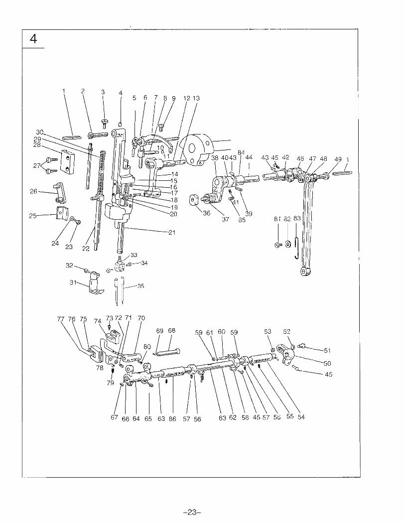
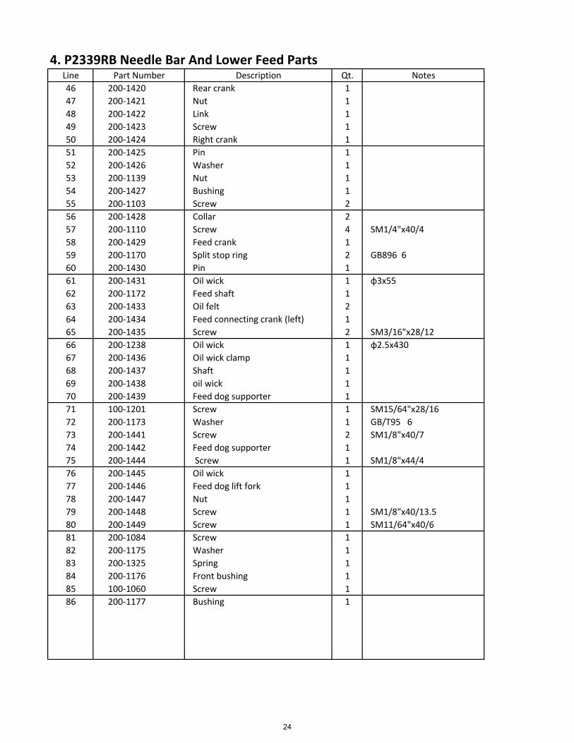
4. P2339RB Needle Bar And Lower Feed PartsLine Part Number Description Qt. Notes
46 200‐1420 Rear crank 1
47 200‐1421 Nut 1
48 200‐1422 Link 1
49 200‐1423 Screw 1
50 200‐1424 Right crank 1
51 200‐1425 Pin 1
52 200‐1426 Washer 1
53 200‐1139 Nut 1
54 200‐1427 Bushing 1
55 200‐1103 Screw 2
56 200‐1428 Collar 2
57 200‐1110 Screw 4 SM1/4"x40/4
58 200‐1429 Feed crank 1
59 200‐1170 Split stop ring 2 GB896 6
60 200‐1430 Pin 1
61 200‐1431 Oil wick 1 ɸ3x55
62 200‐1172 Feed shaft 1
63 200‐1433 Oil felt 2
64 200‐1434 Feed connecting crank (left) 1
65 200‐1435 Screw 2 SM3/16"x28/12
66 200‐1238 Oil wick 1 ɸ2.5x430
67 200‐1436 Oil wick clamp 1
68 200‐1437 Shaft 1
69 200‐1438 oil wick 1
70 200‐1439 Feed dog supporter 1
71 100‐1201 Screw 1 SM15/64"x28/16
72 200‐1173 Washer 1 GB/T95 6
73 200‐1441 Screw 2 SM1/8"x40/7
74 200‐1442 Feed dog supporter 1
75 200‐1444 Screw 1 SM1/8"x44/4
76 200‐1445 Oil wick 1
77 200‐1446 Feed dog lift fork 1
78 200‐1447 Nut 1
79 200‐1448 Screw 1 SM1/8"x40/13.5
80 200‐1449 Screw 1 SM11/64"x40/6
81 200‐1084 Screw 1
82 200‐1175 Washer 1
83 200‐1325 Spring 1
84 200‐1176 Front bushing 1
85 100‐1060 Screw 1
86 200‐1177 Bushing 1
24
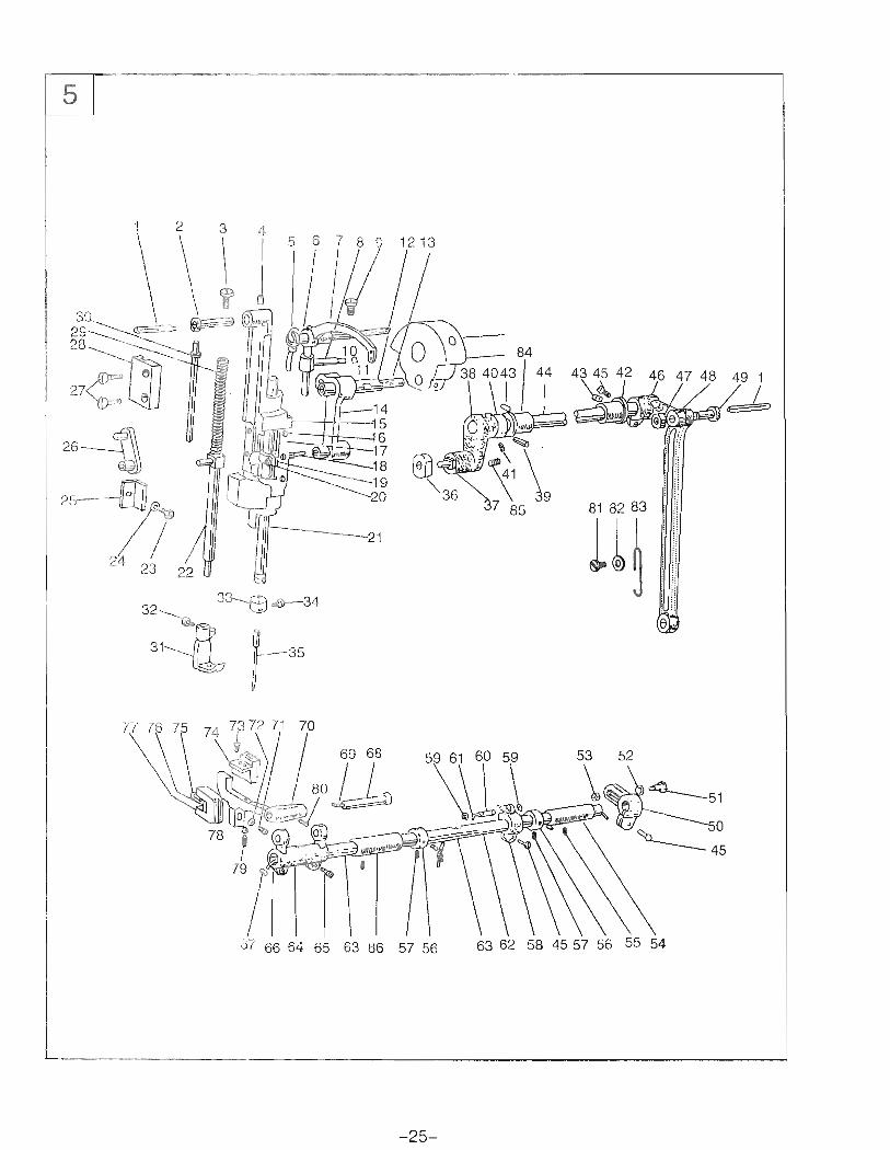
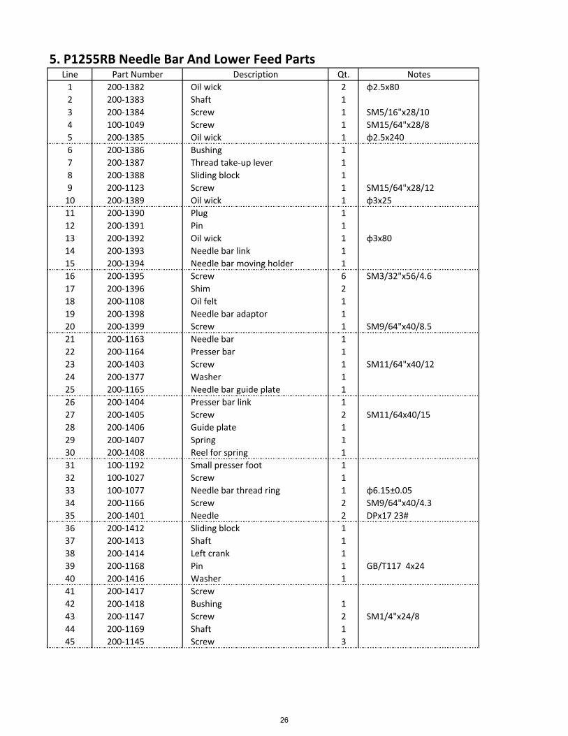
5. P1255RB Needle Bar And Lower Feed PartsLine Part Number Description Qt. Notes
1 200‐1382 Oil wick 2 ɸ2.5x80
2 200‐1383 Shaft 1
3 200‐1384 Screw 1 SM5/16"x28/10
4 100‐1049 Screw 1 SM15/64"x28/8
5 200‐1385 Oil wick 1 ɸ2.5x240
6 200‐1386 Bushing 1
7 200‐1387 Thread take‐up lever 1
8 200‐1388 Sliding block 1
9 200‐1123 Screw 1 SM15/64"x28/12
10 200‐1389 Oil wick 1 ɸ3x25
11 200‐1390 Plug 1
12 200‐1391 Pin 1
13 200‐1392 Oil wick 1 ɸ3x80
14 200‐1393 Needle bar link 1
15 200‐1394 Needle bar moving holder 1
16 200‐1395 Screw 6 SM3/32"x56/4.6
17 200‐1396 Shim 2
18 200‐1108 Oil felt 1
19 200‐1398 Needle bar adaptor 1
20 200‐1399 Screw 1 SM9/64"x40/8.5
21 200‐1163 Needle bar 1
22 200‐1164 Presser bar 1
23 200‐1403 Screw 1 SM11/64"x40/12
24 200‐1377 Washer 1
25 200‐1165 Needle bar guide plate 1
26 200‐1404 Presser bar link 1
27 200‐1405 Screw 2 SM11/64x40/15
28 200‐1406 Guide plate 1
29 200‐1407 Spring 1
30 200‐1408 Reel for spring 1
31 100‐1192 Small presser foot 1
32 100‐1027 Screw 1
33 100‐1077 Needle bar thread ring 1 ɸ6.15±0.05
34 200‐1166 Screw 2 SM9/64"x40/4.3
35 200‐1401 Needle 2 DPx17 23#
36 200‐1412 Sliding block 1
37 200‐1413 Shaft 1
38 200‐1414 Left crank 1
39 200‐1168 Pin 1 GB/T117 4x24
40 200‐1416 Washer 1
41 200‐1417 Screw
42 200‐1418 Bushing 1
43 200‐1147 Screw 2 SM1/4"x24/8
44 200‐1169 Shaft 1
45 200‐1145 Screw 3
26
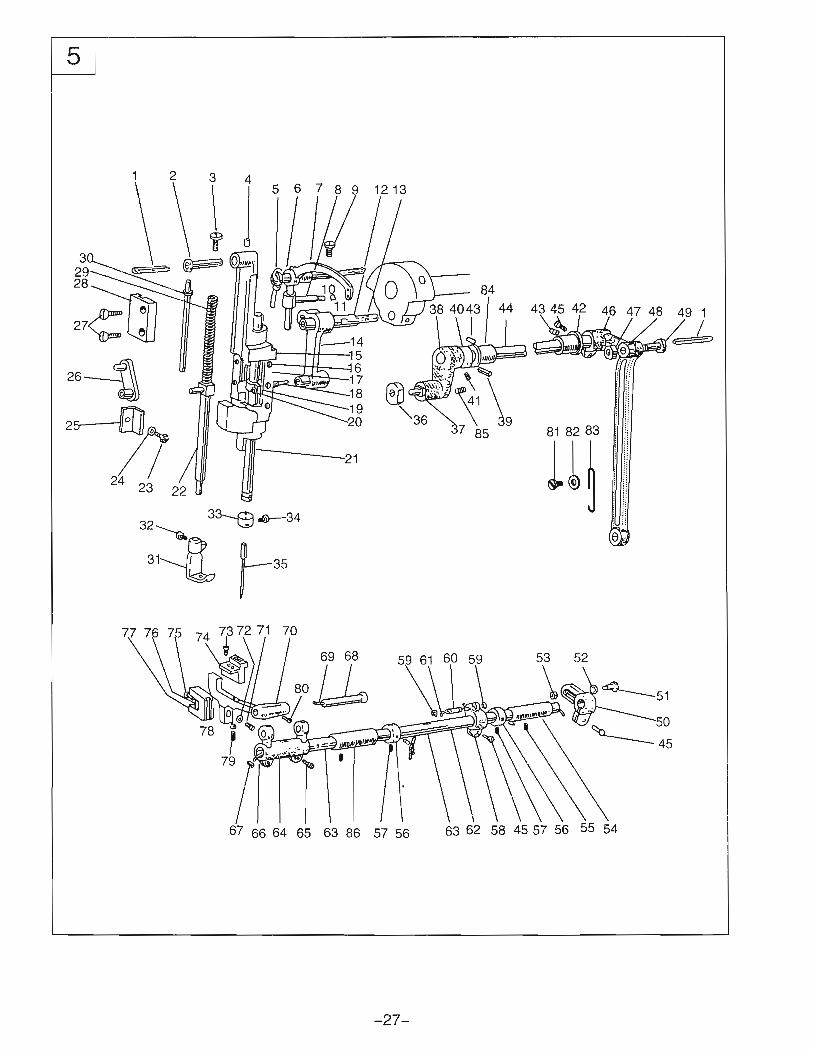
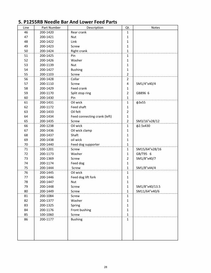
5. P1255RB Needle Bar And Lower Feed PartsLine Part Number Description Qt. Notes
46 200‐1420 Rear crank 1
47 200‐1421 Nut 1
48 200‐1422 Link 1
49 200‐1423 Screw 1
50 200‐1424 Right crank 1
51 200‐1425 Pin 1
52 200‐1426 Washer 1
53 200‐1139 Nut 1
54 200‐1427 Bushing 1
55 200‐1103 Screw 2
56 200‐1428 Collar 2
57 200‐1110 Screw 4 SM1/4"x40/4
58 200‐1429 Feed crank 1
59 200‐1170 Split stop ring 2 GB896 6
60 200‐1430 Pin 1
61 200‐1431 Oil wick 1 ɸ3x55
62 200‐1172 Feed shaft 1
63 200‐1433 Oil felt 2
64 200‐1434 Feed connecting crank (left) 1
65 200‐1435 Screw 2 SM3/16"x28/12
66 200‐1238 Oil wick 1 ɸ2.5x430
67 200‐1436 Oil wick clamp 1
68 200‐1437 Shaft 1
69 200‐1438 oil wick 1
70 200‐1440 Feed dog supporter 1
71 100‐1201 Screw 1 SM15/64"x28/16
72 200‐1173 Washer 1 GB/T95 6
73 200‐1369 Screw 2 SM1/8"x40/7
74 200‐1174 Feed dog 1
75 200‐1444 Screw 1 SM1/8"x44/4
76 200‐1445 Oil wick 1
77 200‐1446 Feed dog lift fork 1
78 200‐1447 Nut 1
79 200‐1448 Screw 1 SM1/8"x40/13.5
80 200‐1449 Screw 1 SM11/64"x40/6
81 200‐1084 Screw 1
82 200‐1377 Washer 1
83 200‐1325 Spring 1
84 200‐1176 Front bushing 1
85 100‐1060 Screw 1
86 200‐1177 Bushing 1
28
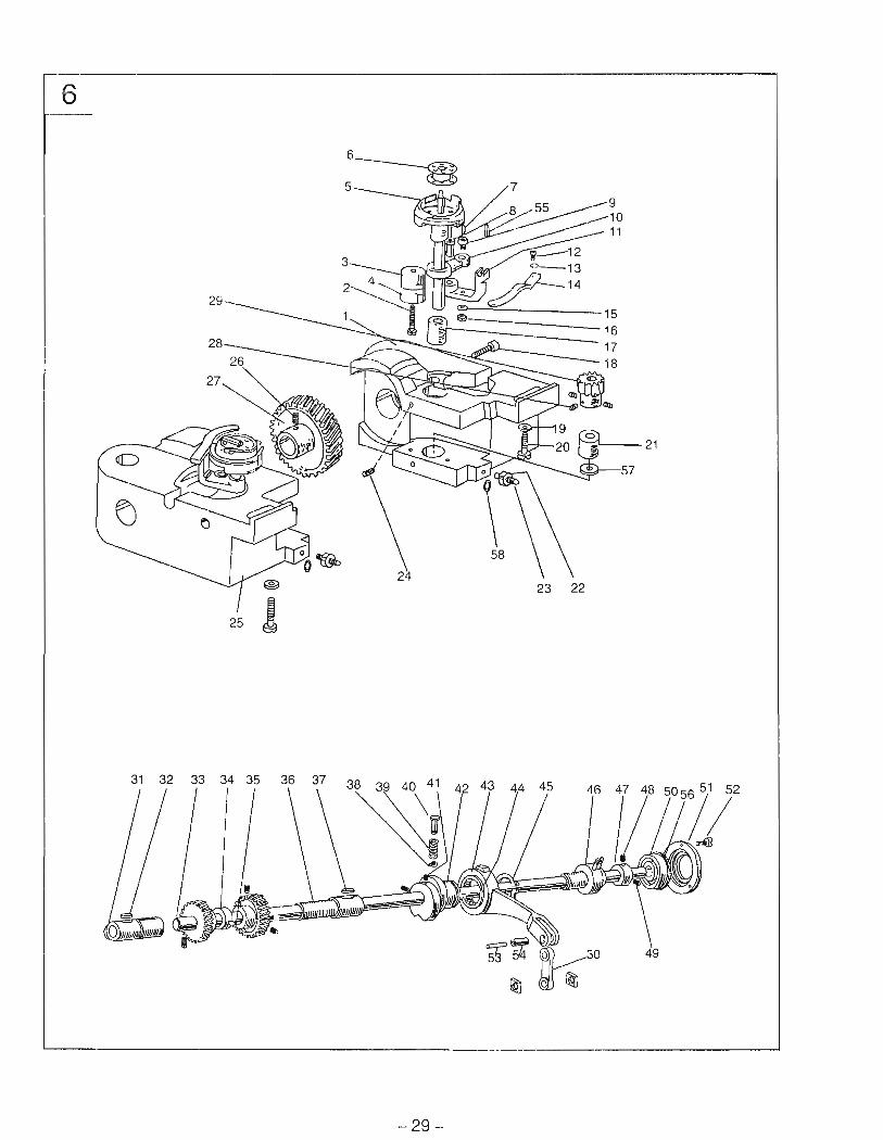

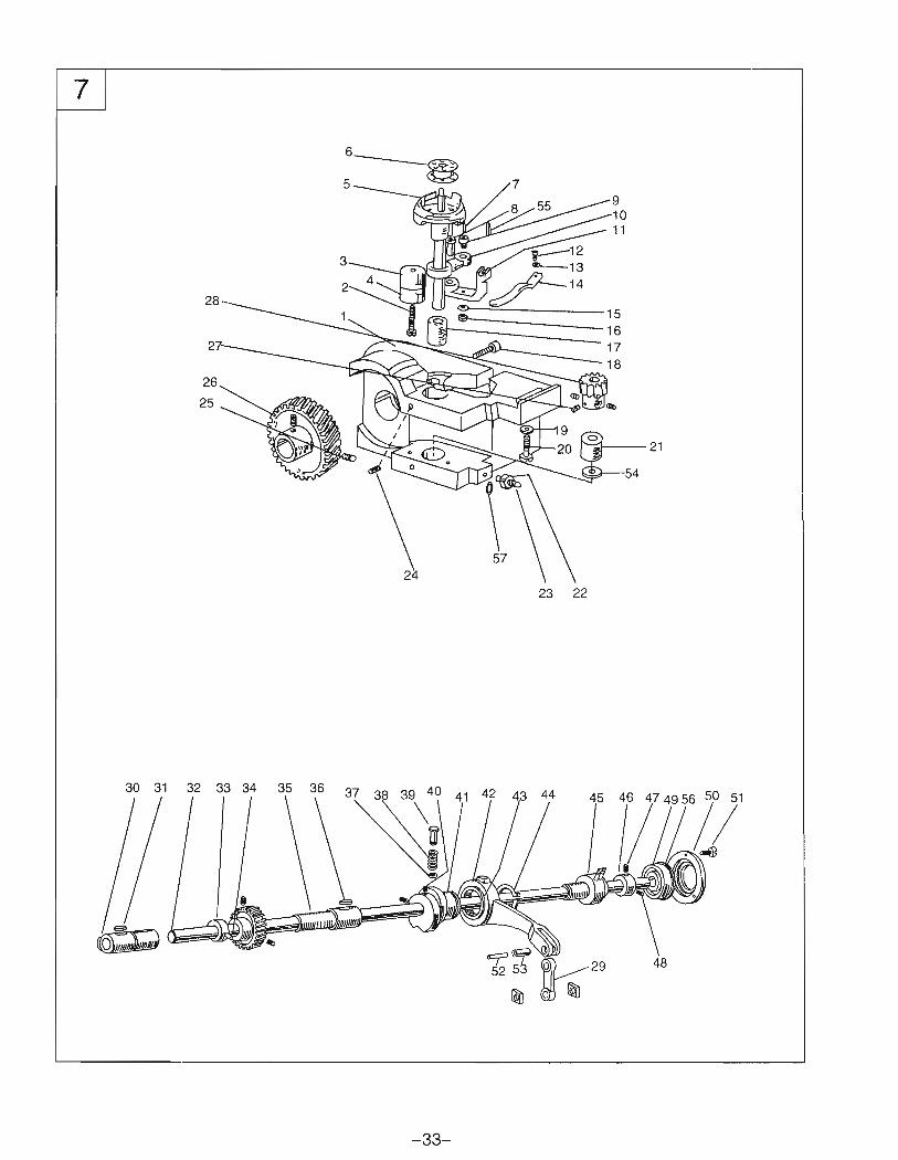
6. P2339RB Rock Shaft And Thread Looping PartsLine Part Number Description Qt. Notes
1 200‐1178 Right hook saddle 1
2 200‐1179 Screw 2 SM15/64"x28
3 200‐1180 Upper bushing 2
4 200‐1181 Lower bushing 2
5 200‐1182 Hook 2
6 200‐1183 Bobbin 2
7 200‐1184 Oil wick 2 ɸ2.5x14
8 200‐1185 Hinge shaft 2
9 200‐1186 Screw 2 SM3/16"32
10 200‐1187 Connecting lever 2
11 200‐1188 Thread finger bracket 2
12 200‐1077 Screw 2 SM9/64"x40/4.5
13 200‐1377 Washer 2 D=0.5
14 200‐1189 Thread finger 2
15 200‐1190 Spring washer 2 GB7246 5
16 200‐1191 Nut 2 SM3/16"x32
17 200‐1192 Bushing 2
18 200‐1193 Screw 2 SM3/16"x28/14.5
19 200‐1194 Washer 2 GB/T95 6
20 200‐1195 Screw 2 SM1/4"x24/20
21 200‐1196 Lower bushing 2
22 200‐1197 Nut 2
23 200‐1200 Screw 2
24 200‐1125 Screw 4 SM1/4"x40/5
25 200‐1201 left hook saddle 1
26 200‐1202 Screw 4 SM1/4"x40/4
27 200‐1203 Spiral gear 2
28 200‐1110 Screw 6
29 200‐1204 Spiral gear 2
30 200‐1205 Feed link 1
31 200‐1207 Left bushing 1
32 200‐1208 Oil wick 1 ɸ25x45
33 200‐1209 Rock shaft 1
34 200‐1210 Feed dog lift cam 1
35 200‐1212 Screw 1 SM15/64"x28/3.8
36 200‐1213 Right bushing 1
37 200‐1215 Oil wick 1 ɸ2.5x85
38 200‐1216 Split stop ring 1 GB896 5
39 200‐1217 Spring 1
40 200‐1218 Button 1
41 200‐1219 Screw 2 SM15/64"x28/13.5
42 200‐1220 Feed cam 1
43 200‐1221 Feed link 1
44 200‐1222 Needle bearing 1 HK263416
45 200‐1223 Spring stop ring 1 GB894.1 26
30
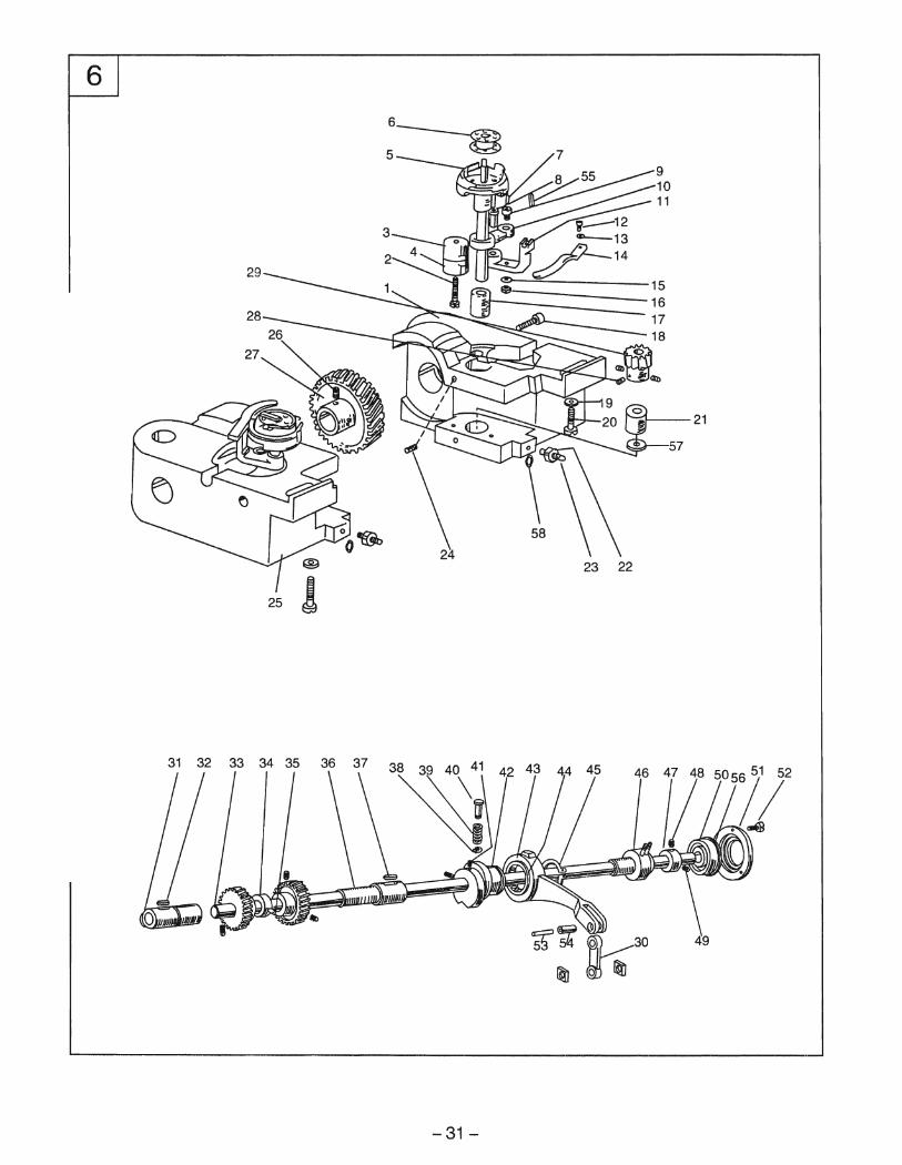
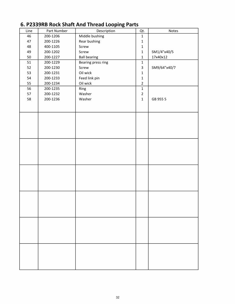
6. P2339RB Rock Shaft And Thread Looping PartsLine Part Number Description Qt. Notes
46 200‐1206 Middle bushing 1
47 200‐1226 Rear bushing 1
48 400‐1105 Screw 1
49 200‐1202 Screw 1 SM1/4"x40/5
50 200‐1227 Ball bearing 1 17x40x12
51 200‐1229 Bearing press ring 1
52 200‐1230 Screw 3 SM9/64"x40/7
53 200‐1231 Oil wick 1
54 200‐1233 Feed link pin 1
55 200‐1234 Oil wick 2
56 200‐1235 Ring 1
57 200‐1232 Washer 2
58 200‐1236 Washer 1 GB 955 5
32
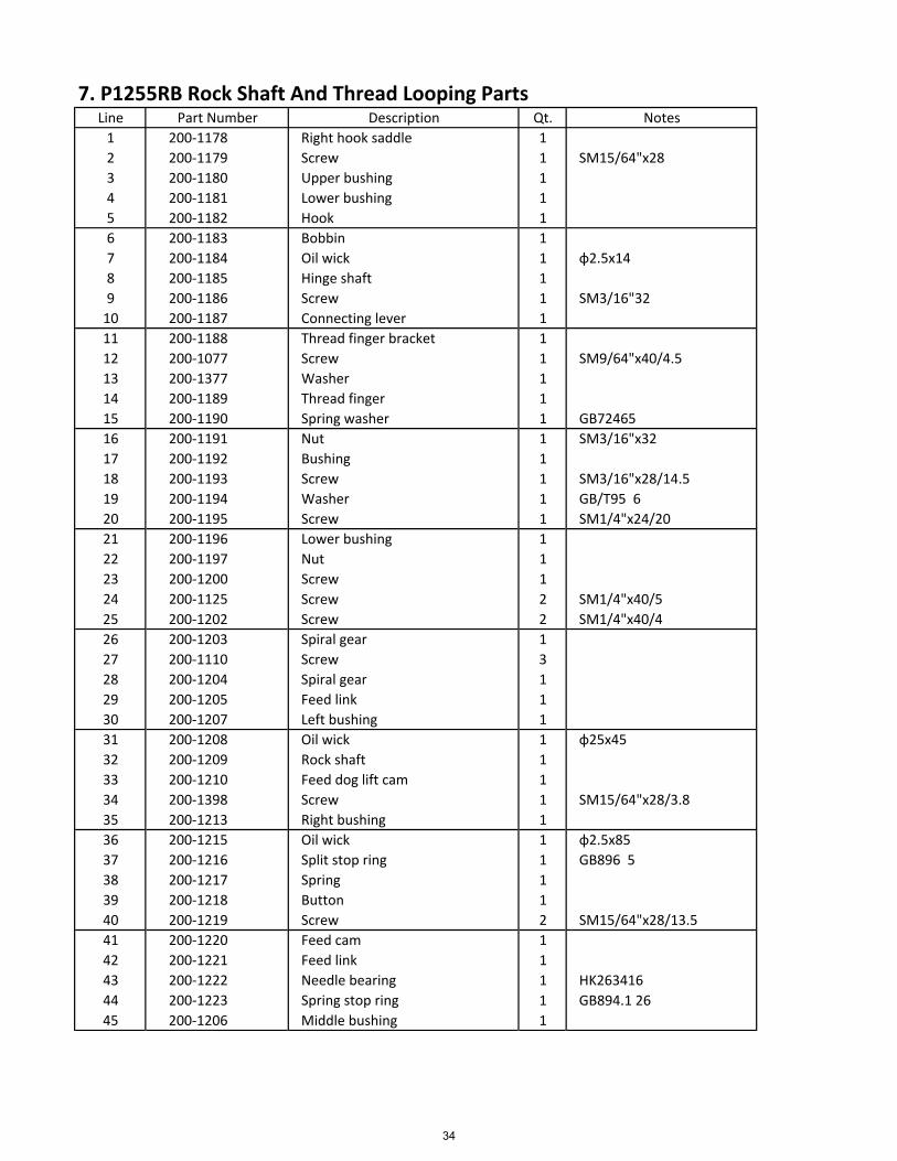
7. P1255RB Rock Shaft And Thread Looping PartsLine Part Number Description Qt. Notes
1 200‐1178 Right hook saddle 1
2 200‐1179 Screw 1 SM15/64"x28
3 200‐1180 Upper bushing 1
4 200‐1181 Lower bushing 1
5 200‐1182 Hook 1
6 200‐1183 Bobbin 1
7 200‐1184 Oil wick 1 ɸ2.5x14
8 200‐1185 Hinge shaft 1
9 200‐1186 Screw 1 SM3/16"32
10 200‐1187 Connecting lever 1
11 200‐1188 Thread finger bracket 1
12 200‐1077 Screw 1 SM9/64"x40/4.5
13 200‐1377 Washer 1
14 200‐1189 Thread finger 1
15 200‐1190 Spring washer 1 GB72465
16 200‐1191 Nut 1 SM3/16"x32
17 200‐1192 Bushing 1
18 200‐1193 Screw 1 SM3/16"x28/14.5
19 200‐1194 Washer 1 GB/T95 6
20 200‐1195 Screw 1 SM1/4"x24/20
21 200‐1196 Lower bushing 1
22 200‐1197 Nut 1
23 200‐1200 Screw 1
24 200‐1125 Screw 2 SM1/4"x40/5
25 200‐1202 Screw 2 SM1/4"x40/4
26 200‐1203 Spiral gear 1
27 200‐1110 Screw 3
28 200‐1204 Spiral gear 1
29 200‐1205 Feed link 1
30 200‐1207 Left bushing 1
31 200‐1208 Oil wick 1 ɸ25x45
32 200‐1209 Rock shaft 1
33 200‐1210 Feed dog lift cam 1
34 200‐1398 Screw 1 SM15/64"x28/3.8
35 200‐1213 Right bushing 1
36 200‐1215 Oil wick 1 ɸ2.5x85
37 200‐1216 Split stop ring 1 GB896 5
38 200‐1217 Spring 1
39 200‐1218 Button 1
40 200‐1219 Screw 2 SM15/64"x28/13.5
41 200‐1220 Feed cam 1
42 200‐1221 Feed link 1
43 200‐1222 Needle bearing 1 HK263416
44 200‐1223 Spring stop ring 1 GB894.1 26
45 200‐1206 Middle bushing 1
34
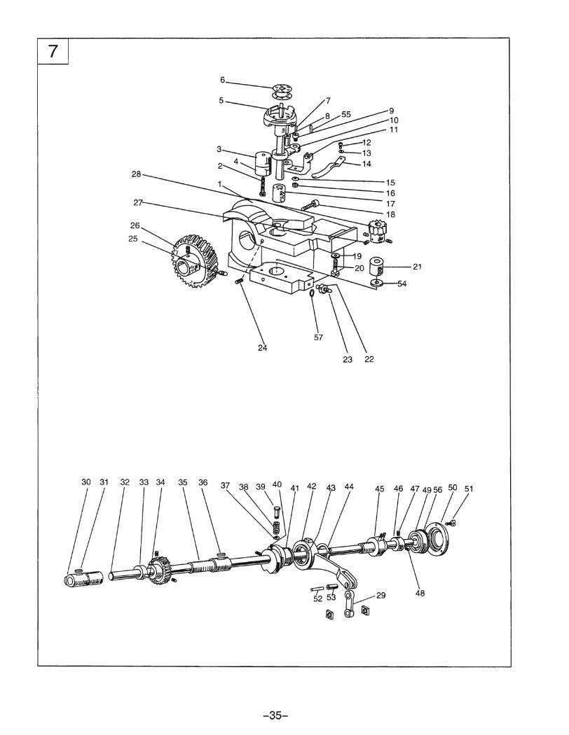
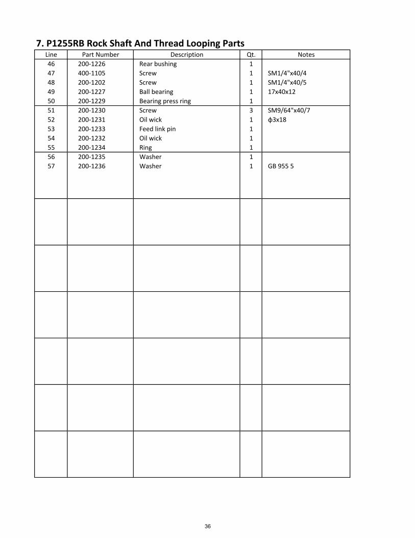
7. P1255RB Rock Shaft And Thread Looping PartsLine Part Number Description Qt. Notes
46 200‐1226 Rear bushing 1
47 400‐1105 Screw 1 SM1/4"x40/4
48 200‐1202 Screw 1 SM1/4"x40/5
49 200‐1227 Ball bearing 1 17x40x12
50 200‐1229 Bearing press ring 1
51 200‐1230 Screw 3 SM9/64"x40/7
52 200‐1231 Oil wick 1 ɸ3x18
53 200‐1233 Feed link pin 1
54 200‐1232 Oil wick 1
55 200‐1234 Ring 1
56 200‐1235 Washer 1
57 200‐1236 Washer 1 GB 955 5
36
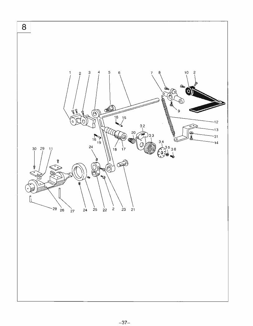
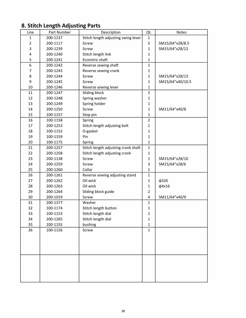
8. Stitch Length Adjusting PartsLine Part Number Description Qt. Notes
1 200‐1237 Stitch length adjusting swing lever 1
2 200‐1117 Screw 5 SM15/64"x28/8.5
3 200‐1239 Screw 1 SM15/64"x28/12
4 200‐1240 Stitch length link 1
5 200‐1241 Eccentric shaft 1
6 200‐1242 Reverse sewing shaft 1
7 200‐1243 Reverse sewing crank 1
8 200‐1244 Screw 1 SM15/64"x28/13
9 200‐1245 Screw 1 SM15/64"x40/10.5
10 200‐1246 Reverse sewing lever 1
11 200‐1247 Sliding block 2
12 200‐1248 Spring washer 1
13 200‐1249 Spring holder 1
14 200‐1250 Screw 1 SM11/64"x40/8
15 100‐1157 Stop pin 1
16 100‐1158 Spring 2
17 200‐1253 Stitch length adjusting bolt 1
18 100‐1152 O‐gasket 1
19 100‐1159 Pin 1
20 100‐1175 Spring 1
21 200‐1257 Stitch length adjusting crank shaft 1
22 200‐1258 Stitch length adjusting crank 1
23 200‐1138 Screw 1 SM15/64"x28/10
24 200‐1259 Screw 3 SM15/64"x28/6
25 200‐1260 Collar 1
26 200‐1261 Reverse sewing adjusting stand 1
27 200‐1262 Oil wick 1 ɸ326
28 200‐1263 Oil wick 1 ɸ4x16
29 200‐1264 Sliding block guide 2
30 200‐1019 Screw 4 SM11/64"x40/9
31 200‐1377 Washer 1
32 100‐1174 Stitch length button 1
33 100‐1153 Stitch length dial 1
34 200‐1265 Stitch length dial 1
35 100‐1155 bushing 1
36 100‐1156 Screw 1
38
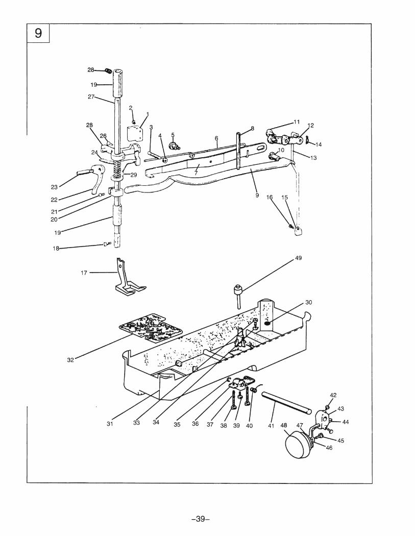
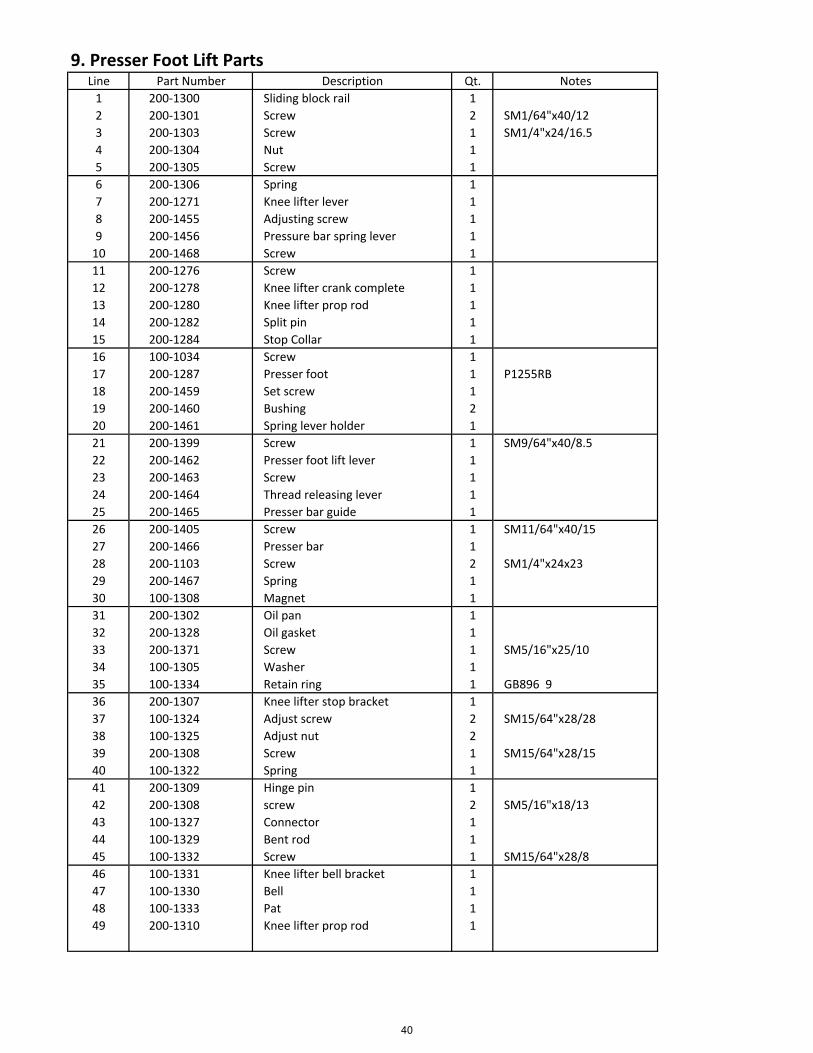
9. Presser Foot Lift PartsLine Part Number Description Qt. Notes
1 200‐1300 Sliding block rail 1
2 200‐1301 Screw 2 SM1/64"x40/12
3 200‐1303 Screw 1 SM1/4"x24/16.5
4 200‐1304 Nut 1
5 200‐1305 Screw 1
6 200‐1306 Spring 1
7 200‐1271 Knee lifter lever 1
8 200‐1455 Adjusting screw 1
9 200‐1456 Pressure bar spring lever 1
10 200‐1468 Screw 1
11 200‐1276 Screw 1
12 200‐1278 Knee lifter crank complete 1
13 200‐1280 Knee lifter prop rod 1
14 200‐1282 Split pin 1
15 200‐1284 Stop Collar 1
16 100‐1034 Screw 1
17 200‐1287 Presser foot 1 P1255RB
18 200‐1459 Set screw 1
19 200‐1460 Bushing 2
20 200‐1461 Spring lever holder 1
21 200‐1399 Screw 1 SM9/64"x40/8.5
22 200‐1462 Presser foot lift lever 1
23 200‐1463 Screw 1
24 200‐1464 Thread releasing lever 1
25 200‐1465 Presser bar guide 1
26 200‐1405 Screw 1 SM11/64"x40/15
27 200‐1466 Presser bar 1
28 200‐1103 Screw 2 SM1/4"x24x23
29 200‐1467 Spring 1
30 100‐1308 Magnet 1
31 200‐1302 Oil pan 1
32 200‐1328 Oil gasket 1
33 200‐1371 Screw 1 SM5/16"x25/10
34 100‐1305 Washer 1
35 100‐1334 Retain ring 1 GB896 9
36 200‐1307 Knee lifter stop bracket 1
37 100‐1324 Adjust screw 2 SM15/64"x28/28
38 100‐1325 Adjust nut 2
39 200‐1308 Screw 1 SM15/64"x28/15
40 100‐1322 Spring 1
41 200‐1309 Hinge pin 1
42 200‐1308 screw 2 SM5/16"x18/13
43 100‐1327 Connector 1
44 100‐1329 Bent rod 1
45 100‐1332 Screw 1 SM15/64"x28/8
46 100‐1331 Knee lifter bell bracket 1
47 100‐1330 Bell 1
48 100‐1333 Pat 1
49 200‐1310 Knee lifter prop rod 1
40
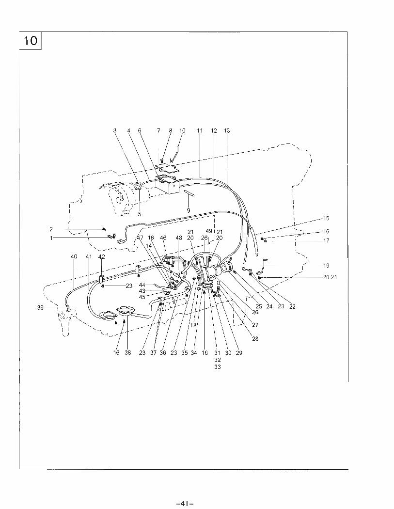
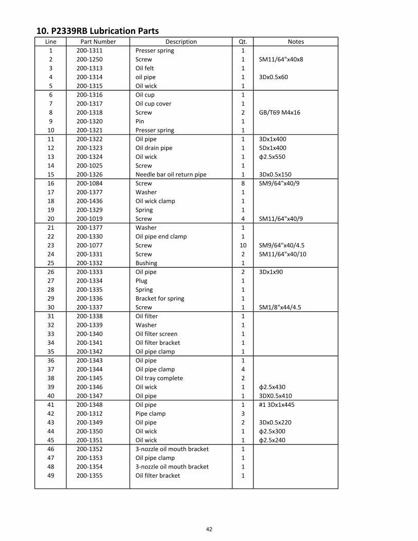
10. P2339RB Lubrication PartsLine Part Number Description Qt. Notes
1 200‐1311 Presser spring 1
2 200‐1250 Screw 1 SM11/64"x40x8
3 200‐1313 Oil felt 1
4 200‐1314 oil pipe 1 3Dx0.5x60
5 200‐1315 Oil wick 1
6 200‐1316 Oil cup 1
7 200‐1317 Oil cup cover 1
8 200‐1318 Screw 2 GB/T69 M4x16
9 200‐1320 Pin 1
10 200‐1321 Presser spring 1
11 200‐1322 Oil pipe 1 3Dx1x400
12 200‐1323 Oil drain pipe 1 5Dx1x400
13 200‐1324 Oil wick 1 ɸ2.5x550
14 200‐1025 Screw 1
15 200‐1326 Needle bar oil return pipe 1 3Dx0.5x150
16 200‐1084 Screw 8 SM9/64"x40/9
17 200‐1377 Washer 1
18 200‐1436 Oil wick clamp 1
19 200‐1329 Spring 1
20 200‐1019 Screw 4 SM11/64"x40/9
21 200‐1377 Washer 1
22 200‐1330 Oil pipe end clamp 1
23 200‐1077 Screw 10 SM9/64"x40/4.5
24 200‐1331 Screw 2 SM11/64"x40/10
25 200‐1332 Bushing 1
26 200‐1333 Oil pipe 2 3Dx1x90
27 200‐1334 Plug 1
28 200‐1335 Spring 1
29 200‐1336 Bracket for spring 1
30 200‐1337 Screw 1 SM1/8"x44/4.5
31 200‐1338 Oil filter 1
32 200‐1339 Washer 1
33 200‐1340 Oil filter screen 1
34 200‐1341 Oil filter bracket 1
35 200‐1342 Oil pipe clamp 1
36 200‐1343 Oil pipe 1
37 200‐1344 Oil pipe clamp 4
38 200‐1345 Oil tray complete 2
39 200‐1346 Oil wick 1 ɸ2.5x430
40 200‐1347 Oil pipe 1 3DX0.5x410
41 200‐1348 Oil pipe 1 #1 3Dx1x445
42 200‐1312 Pipe clamp 3
43 200‐1349 Oil pipe 2 3Dx0.5x220
44 200‐1350 Oil wick 1 ɸ2.5x300
45 200‐1351 Oil wick 1 ɸ2.5x240
46 200‐1352 3‐nozzle oil mouth bracket 1
47 200‐1353 Oil pipe clamp 1
48 200‐1354 3‐nozzle oil mouth bracket 1
49 200‐1355 Oil filter bracket 1
42
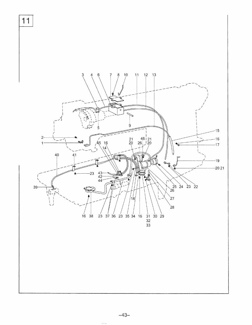
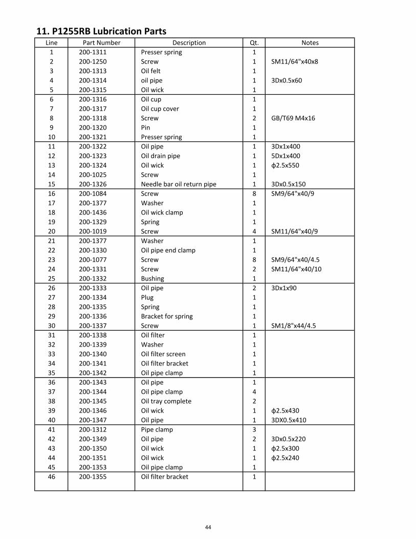
11. P1255RB Lubrication PartsLine Part Number Description Qt. Notes
1 200‐1311 Presser spring 1
2 200‐1250 Screw 1 SM11/64"x40x8
3 200‐1313 Oil felt 1
4 200‐1314 oil pipe 1 3Dx0.5x60
5 200‐1315 Oil wick 1
6 200‐1316 Oil cup 1
7 200‐1317 Oil cup cover 1
8 200‐1318 Screw 2 GB/T69 M4x16
9 200‐1320 Pin 1
10 200‐1321 Presser spring 1
11 200‐1322 Oil pipe 1 3Dx1x400
12 200‐1323 Oil drain pipe 1 5Dx1x400
13 200‐1324 Oil wick 1 ɸ2.5x550
14 200‐1025 Screw 1
15 200‐1326 Needle bar oil return pipe 1 3Dx0.5x150
16 200‐1084 Screw 8 SM9/64"x40/9
17 200‐1377 Washer 1
18 200‐1436 Oil wick clamp 1
19 200‐1329 Spring 1
20 200‐1019 Screw 4 SM11/64"x40/9
21 200‐1377 Washer 1
22 200‐1330 Oil pipe end clamp 1
23 200‐1077 Screw 8 SM9/64"x40/4.5
24 200‐1331 Screw 2 SM11/64"x40/10
25 200‐1332 Bushing 1
26 200‐1333 Oil pipe 2 3Dx1x90
27 200‐1334 Plug 1
28 200‐1335 Spring 1
29 200‐1336 Bracket for spring 1
30 200‐1337 Screw 1 SM1/8"x44/4.5
31 200‐1338 Oil filter 1
32 200‐1339 Washer 1
33 200‐1340 Oil filter screen 1
34 200‐1341 Oil filter bracket 1
35 200‐1342 Oil pipe clamp 1
36 200‐1343 Oil pipe 1
37 200‐1344 Oil pipe clamp 4
38 200‐1345 Oil tray complete 2
39 200‐1346 Oil wick 1 ɸ2.5x430
40 200‐1347 Oil pipe 1 3DX0.5x410
41 200‐1312 Pipe clamp 3
42 200‐1349 Oil pipe 2 3Dx0.5x220
43 200‐1350 Oil wick 1 ɸ2.5x300
44 200‐1351 Oil wick 1 ɸ2.5x240
45 200‐1353 Oil pipe clamp 1
46 200‐1355 Oil filter bracket 1
44
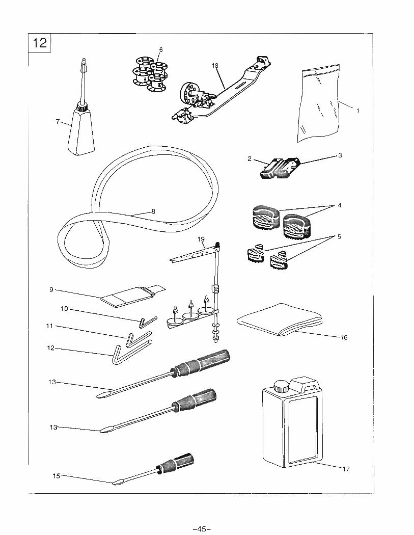
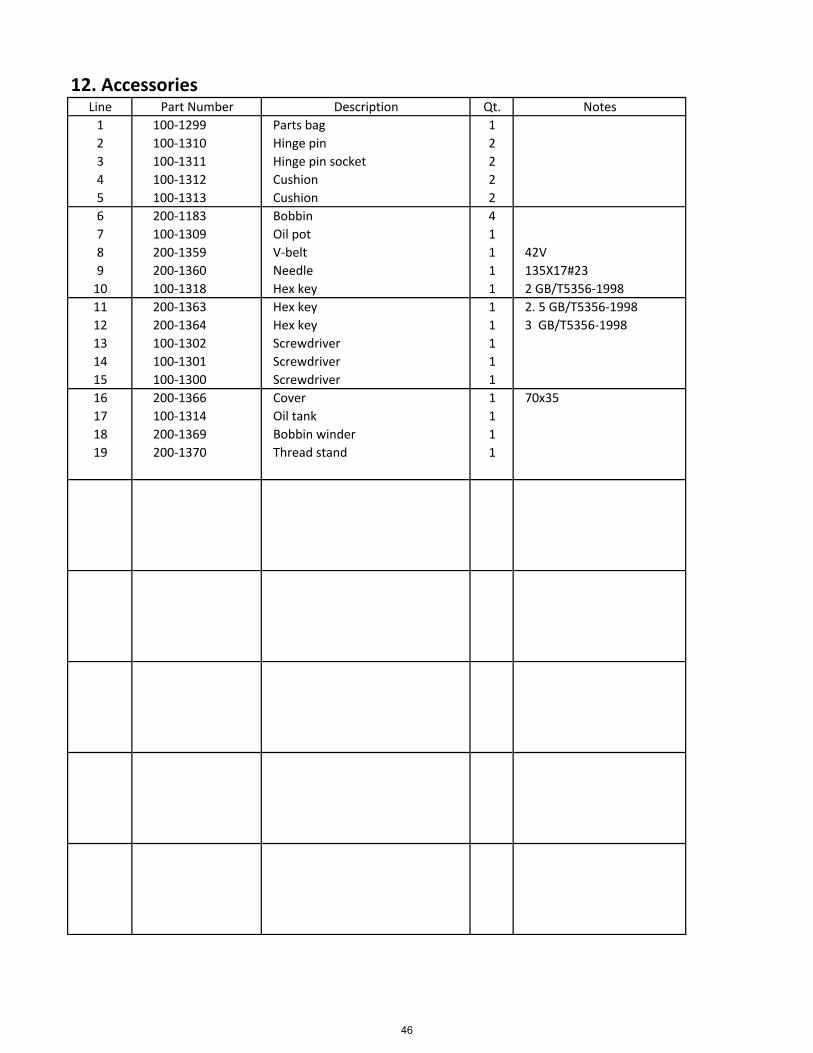
12. AccessoriesLine Part Number Description Qt. Notes
1 100‐1299 Parts bag 1
2 100‐1310 Hinge pin 2
3 100‐1311 Hinge pin socket 2
4 100‐1312 Cushion 2
5 100‐1313 Cushion 2
6 200‐1183 Bobbin 4
7 100‐1309 Oil pot 1
8 200‐1359 V‐belt 1 42V
9 200‐1360 Needle 1 135X17#23
10 100‐1318 Hex key 1 2 GB/T5356‐1998
11 200‐1363 Hex key 1 2. 5 GB/T5356‐1998
12 200‐1364 Hex key 1 3 GB/T5356‐1998
13 100‐1302 Screwdriver 1
14 100‐1301 Screwdriver 1
15 100‐1300 Screwdriver 1
16 200‐1366 Cover 1 70x35
17 100‐1314 Oil tank 1
18 200‐1369 Bobbin winder 1
19 200‐1370 Thread stand 1
46

Operation instruction

Operation instruction