inteliatsntÒ - Источники резервного ...220v.com.ua/files/ia-nt-std-2.4-reference...
TRANSCRIPT

May 2015 Copyright © 2015 ComAp a.s. Written by Jan Podlipný Prague, Czech Republic
ComAp a.s. Kundratka 2359/17, 180 00 Praha 8, Czech Republic Tel: +420 246 012 111, Fax: +420 266 316 647 E-mail: [email protected], www.comap.cz
Reference Guide
InteliATSNT Automatic Transfer Switch Controller
IA-NT STD unit
SW version 2.4, May 2015
InteliATSNT STD, SW version 2.4, ©ComAp – May 2015 2 IA-NT- STD-2.4-Reference Guide.pdf
Table of Contents Table of Contents ............................................................................................................................... 2 Document information ........................................................................................................................ 4
Clarification of notation ................................................................................................................... 4 Text ............................................................................................................................................... 4 Conformity Declaration ................................................................................................................... 4
General Guidelines ............................................................................................................................ 5 What is in this manual? .................................................................................................................. 5
Description ......................................................................................................................................... 7 Description of the controller system ................................................................................................ 7 Configurability .............................................................................................................................. 10 What is in the package? ............................................................................................................... 10 IL-NT RS232 Communication module .......................................................................................... 11 IL-NT RS232-485 Communication module ................................................................................... 14 IL-NT S-USB Service USB communication module ...................................................................... 15 IL-NT RD Remote display software .............................................................................................. 16 IB-Lite Communication module..................................................................................................... 16 IL-NT-GPRS GSM and GPRS plug-in modem .............................................................................. 20 IL-NT AOUT8 Gauge driver module ............................................................................................. 21 IL-NT BIO8 Hybrid binary input/output module .............................................................................. 22 Programming of IA-NT controller .................................................................................................. 23
User Interface .................................................................................................................................. 24 Terminals ......................................................................................................................................... 25
IA-NT STD terminals and face ...................................................................................................... 25 Installation ........................................................................................................................................ 26
Mounting ...................................................................................................................................... 26 Dimensions .................................................................................................................................. 27
Recommended Wiring ...................................................................................................................... 28 IA-NT STD – Wiring Diagram ....................................................................................................... 28
Applications ..................................................................................................................................... 29 AMF using two separate breakers (MCB and GCB) ...................................................................... 29 AMF using two-position ATS ........................................................................................................ 30 AMF using three-position ATS ...................................................................................................... 31 AMF + no battery operation .......................................................................................................... 33
Getting Started ................................................................................................................................. 34 How to install ............................................................................................................................... 34 Three phase applications ............................................................................................................. 36 Single phase applications ............................................................................................................. 36
Inputs and Outputs ........................................................................................................................... 38 Binary inputs IA-NT - default ........................................................................................................ 38 Binary inputs – list ........................................................................................................................ 39 Binary outputs IA-NT - default ...................................................................................................... 40 Binary outputs - list....................................................................................................................... 40
Setpoints .......................................................................................................................................... 42 Password ..................................................................................................................................... 42 Basic Settings .............................................................................................................................. 42 Comms Settings........................................................................................................................... 44 AMF Settings ............................................................................................................................... 46
Function Description......................................................................................................................... 50 Operating modes ......................................................................................................................... 50 Circuit breakers timing.................................................................................................................. 52
Alarm Management .......................................................................................................................... 53 Warning (WRN)............................................................................................................................ 53 Trip (TRP) .................................................................................................................................... 53 Mains failure (MF) ........................................................................................................................ 53 AMF time chart – genset OK ........................................................................................................ 54

InteliATSNT STD, SW version 2.4, ©ComAp – May 2015 3 IA-NT- STD-2.4-Reference Guide.pdf
AMF time chart – genset not started properly ............................................................................... 54 Voltage phase sequence detection ............................................................................................... 55
Gen-set Operation States ................................................................................................................. 56 List of possible events .................................................................................................................. 56
Init Screens ...................................................................................................................................... 58 Customer Logo screen ................................................................................................................. 58 Firmware Init screen ..................................................................................................................... 58 Language screen ......................................................................................................................... 58 User Interface screen ................................................................................................................... 58
Remote Control and Data Logging.................................................................................................... 59 PC software – LiteEdit .................................................................................................................. 59 Direct cable connection ................................................................................................................ 59 Modem connection ....................................................................................................................... 60 Internet connection....................................................................................................................... 61 IB-Lite .......................................................................................................................................... 62 IL-NT-GPRS ................................................................................................................................ 63 AirGate ........................................................................................................................................ 66 Locate .......................................................................................................................................... 67
IL-NT-RD Remote display software .................................................................................................. 68 General description ...................................................................................................................... 68 Warning ! ..................................................................................................................................... 68 IL-NT-RD Software installation ..................................................................................................... 68 IL-NT-RD Wiring .......................................................................................................................... 69 Function description ..................................................................................................................... 71 SW compatibility .......................................................................................................................... 71
Technical Data ................................................................................................................................. 72 Inputs/Outputs overview ............................................................................................................... 72 Power supply ............................................................................................................................... 72 Operating conditions .................................................................................................................... 72 Dimensions and weight ................................................................................................................ 72 Mains and generator .................................................................................................................... 73 Binary inputs and outputs ............................................................................................................. 73 IL-NT RS232 interface (optional card) .......................................................................................... 73 IL-NT RS232-485 interface (optional card) ................................................................................... 73 IL-NT S-USB interface (optional card) .......................................................................................... 74 IB-Lite interface (optional card)..................................................................................................... 74 IL-NT-GPRS interface (optional card) ........................................................................................... 74 IL-NT AOUT8 interface (optional card) ......................................................................................... 74 IL-NT BIO8 extension module (optional card) ............................................................................... 75

InteliATSNT STD, SW version 2.4, ©ComAp – May 2015 4 IA-NT- STD-2.4-Reference Guide.pdf
Document information INTELIATSNT STD® - REFERENCE GUIDE WRITTEN BY: JAN PODLIPNÝ ©2009-2015 COMAP LTD. KUNDRATKA 17, PRAHA 8, CZECH REPUBLIC PHONE: +420246012111, FAX: +420266316647 WEB: HTTP://WWW.COMAP.CZ, E-MAIL: [email protected] DOCUMENT HISTORY REVISION NUMBER RELATED SW. VERSION DATE
1 1.0 22.02.2009
2 1.0.1 24.03.2009
3 1.2 09.01.2010
4 2.0 09.06.2010
5 2.4 30.04.2015
Clarification of notation HINT: This type of paragraph points out details to help user installation/configuration. NOTE: This type of paragraph calls readers attention to a notice or related theme. CAUTION! This type of paragraph highlights a procedure, adjustment etc., which can cause a damage or improper function of the equipment if not performed correctly and may not be clear at first sight. WARNING! This type of paragraph indicates things, procedures, adjustments etc. which need high level of attention, otherwise can cause personal injury or death.
Text PAGE (Capital letters in the frame) buttons on the front panel Break Return (Italic) set points Generator protections (Bold) Set point group REMOTE START/STOP (Capital letters) binary inputs and outputs
Conformity Declaration
The following described machine complies with the appropriate basic safety and health requirement of the EC Low Voltage Directive No: 73/23 / EEC and EC Electromagnetic Compatibility Directive 89/336 / EEC based on its design and type, as brought into circulation by us.

InteliATSNT STD, SW version 2.4, ©ComAp – May 2015 5 IA-NT- STD-2.4-Reference Guide.pdf
General Guidelines
What is in this manual? This manual describes the InteliATSNT STD (IA-NT-STD) software, which is designed for automatic transfer switch applications and provides general information on how to install and operate the InteliATSNT controller. This manual is dedicated for
• Automatic transfer switch panel builders • Operators of remote gen-sets (started remotely from InteliATSNT) • For everybody who is concerned with installation, operation and maintenance of the gen-set
InteliATS controller SW and HW versions compatibility Software InteliATSNT is compatible with the InteliATSNT hardware v. 1.3 and higher. There are two modifications of the InteliATSNT HW - STD and PWR and two modifications of the InteliATSNT SW – STD and PWR which together with the appropriate archive file (IA-NT-STD-HW_1.3-X.X.AIL for STD HW 1.3, IA-NT-STD-X.X.AIL for STD HW > 1.3 and IA-NT-PWR-X.X.AIL) form the InteliATSNT PWR or STD controller. Beside that the InteliATSNT software is compatible with IL-NT AMF HW 1.3 and higher too, which is used when a low temperature ATS application is needed. In this case the InteliATSNT SW must be combined (purchased) with the IL-NT AMF 25 LT HW to obtain the low temperature ATS controller. NOTE: Because of large variety of InteliATSNT parameters settings, it is not possible to describe any combination. Some of InteliATSNT functions are subject of changes depend on SW version. The data in this manual only describes the product and are not warranty of performance or characteristic. CAUTION! SW and HW must be compatible (e.g. IA-NT firmware and IA-NT HW) otherwise the function will be disabled. If wrong software is downloaded, message HARDWARE INCOMPATIBLE appears on controller screen. In this case use Boot load (jumper) programming – close Boot jumper and follow instructions in LiteEdit, download correct software. NOTE: ComAp believes that all information provided herein is correct and reliable and reserves the right to update at any time. ComAp does not assume any responsibility for its use unless otherwise expressly undertaken. WARNING! Remote control - InteliATSNT controller can be remotely controlled. In case of the work on the controlled devices check, that nobody can perform remote operation. To be sure disconnect - remote control via RS232 line - input REM TRANSFER - input REMOTE AUT - input REMOTE TEST or disconnect output Rem START/STOP and outputs GCB CLOSE/OPEN and MCB CLOSE/OPEN
InteliATSNT STD, SW version 2.4, ©ComAp – May 2015 6 IA-NT- STD-2.4-Reference Guide.pdf
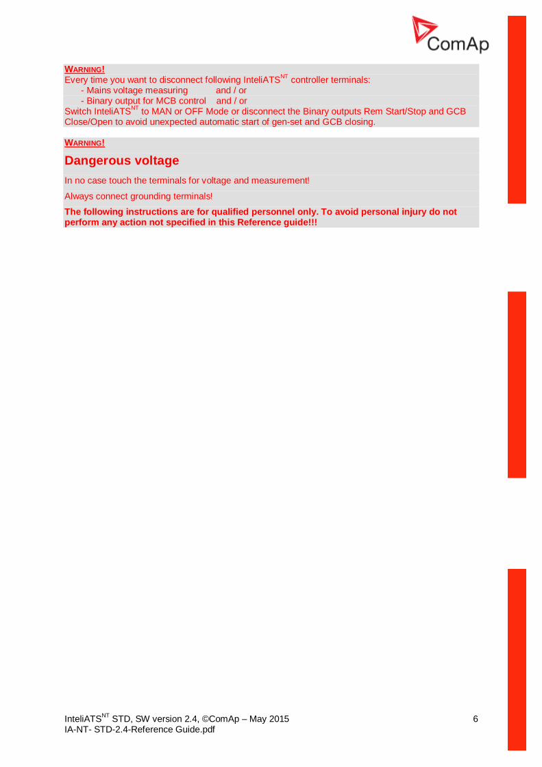
WARNING! Every time you want to disconnect following InteliATSNT controller terminals: - Mains voltage measuring and / or - Binary output for MCB control and / or Switch InteliATSNT to MAN or OFF Mode or disconnect the Binary outputs Rem Start/Stop and GCB Close/Open to avoid unexpected automatic start of gen-set and GCB closing. WARNING!
Dangerous voltage In no case touch the terminals for voltage and measurement!
Always connect grounding terminals!
The following instructions are for qualified personnel only. To avoid personal injury do not perform any action not specified in this Reference guide!!!
InteliATSNT STD, SW version 2.4, ©ComAp – May 2015 7 IA-NT- STD-2.4-Reference Guide.pdf
Description
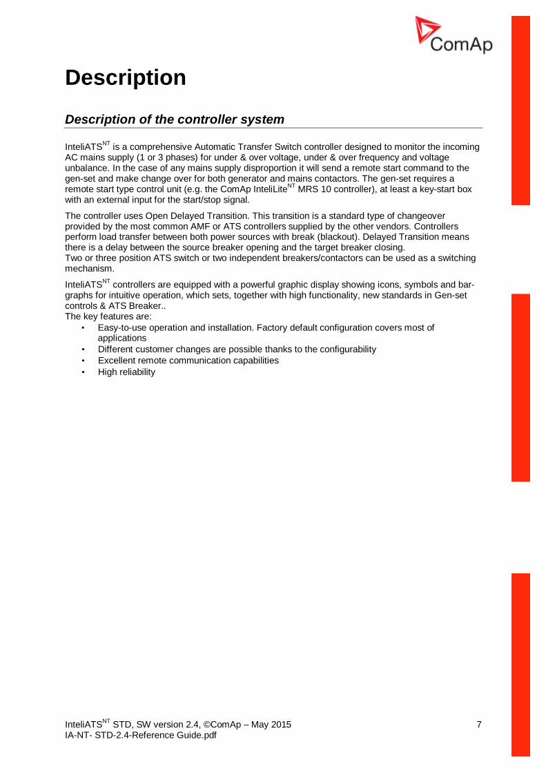
Description of the controller system InteliATSNT is a comprehensive Automatic Transfer Switch controller designed to monitor the incoming AC mains supply (1 or 3 phases) for under & over voltage, under & over frequency and voltage unbalance. In the case of any mains supply disproportion it will send a remote start command to the gen-set and make change over for both generator and mains contactors. The gen-set requires a remote start type control unit (e.g. the ComAp InteliLiteNT MRS 10 controller), at least a key-start box with an external input for the start/stop signal.
The controller uses Open Delayed Transition. This transition is a standard type of changeover provided by the most common AMF or ATS controllers supplied by the other vendors. Controllers perform load transfer between both power sources with break (blackout). Delayed Transition means there is a delay between the source breaker opening and the target breaker closing. Two or three position ATS switch or two independent breakers/contactors can be used as a switching mechanism.
InteliATSNT controllers are equipped with a powerful graphic display showing icons, symbols and bar-graphs for intuitive operation, which sets, together with high functionality, new standards in Gen-set controls & ATS Breaker.. The key features are:
• Easy-to-use operation and installation. Factory default configuration covers most of applications
• Different customer changes are possible thanks to the configurability • Excellent remote communication capabilities • High reliability
InteliATSNT STD, SW version 2.4, ©ComAp – May 2015 8 IA-NT- STD-2.4-Reference Guide.pdf
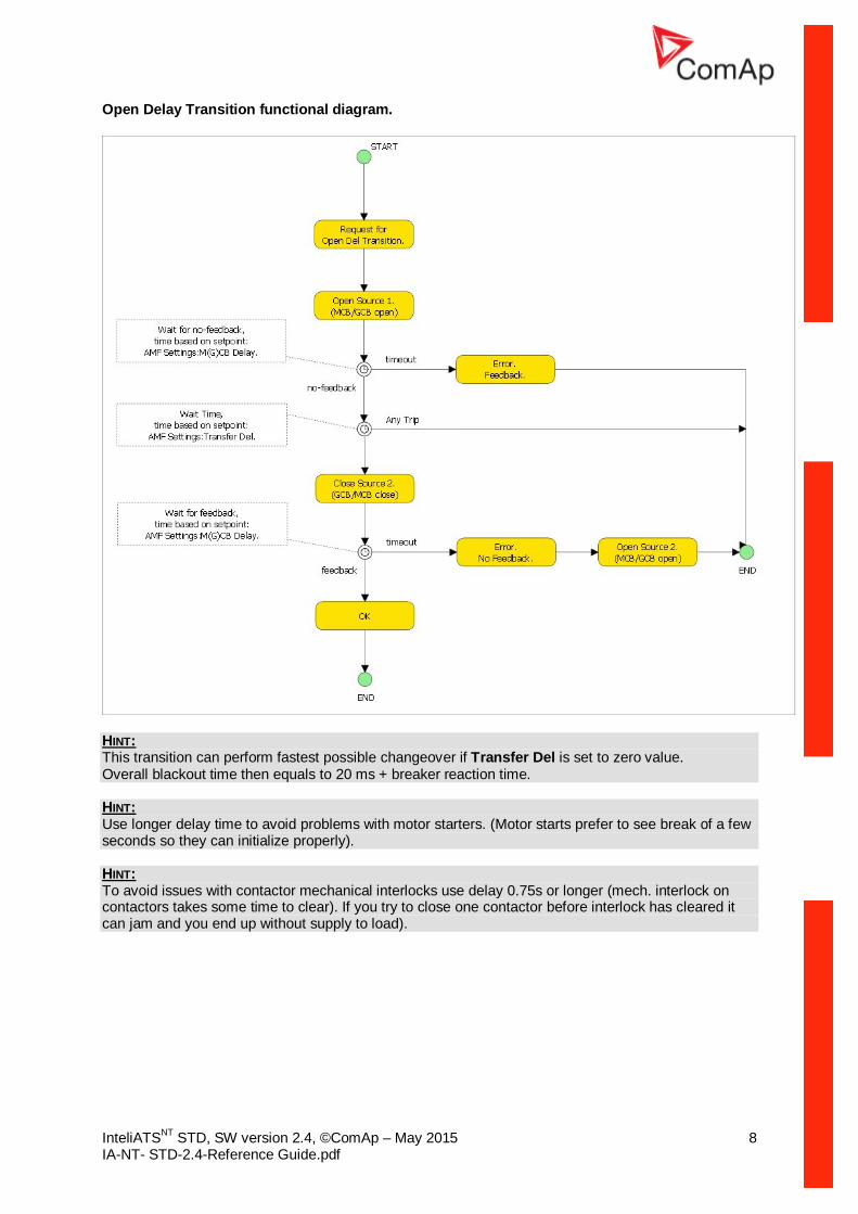
Open Delay Transition functional diagram.
HINT: This transition can perform fastest possible changeover if Transfer Del is set to zero value. Overall blackout time then equals to 20 ms + breaker reaction time. HINT: Use longer delay time to avoid problems with motor starters. (Motor starts prefer to see break of a few seconds so they can initialize properly). HINT: To avoid issues with contactor mechanical interlocks use delay 0.75s or longer (mech. interlock on contactors takes some time to clear). If you try to close one contactor before interlock has cleared it can jam and you end up without supply to load).
InteliATSNT STD, SW version 2.4, ©ComAp – May 2015 9 IA-NT- STD-2.4-Reference Guide.pdf
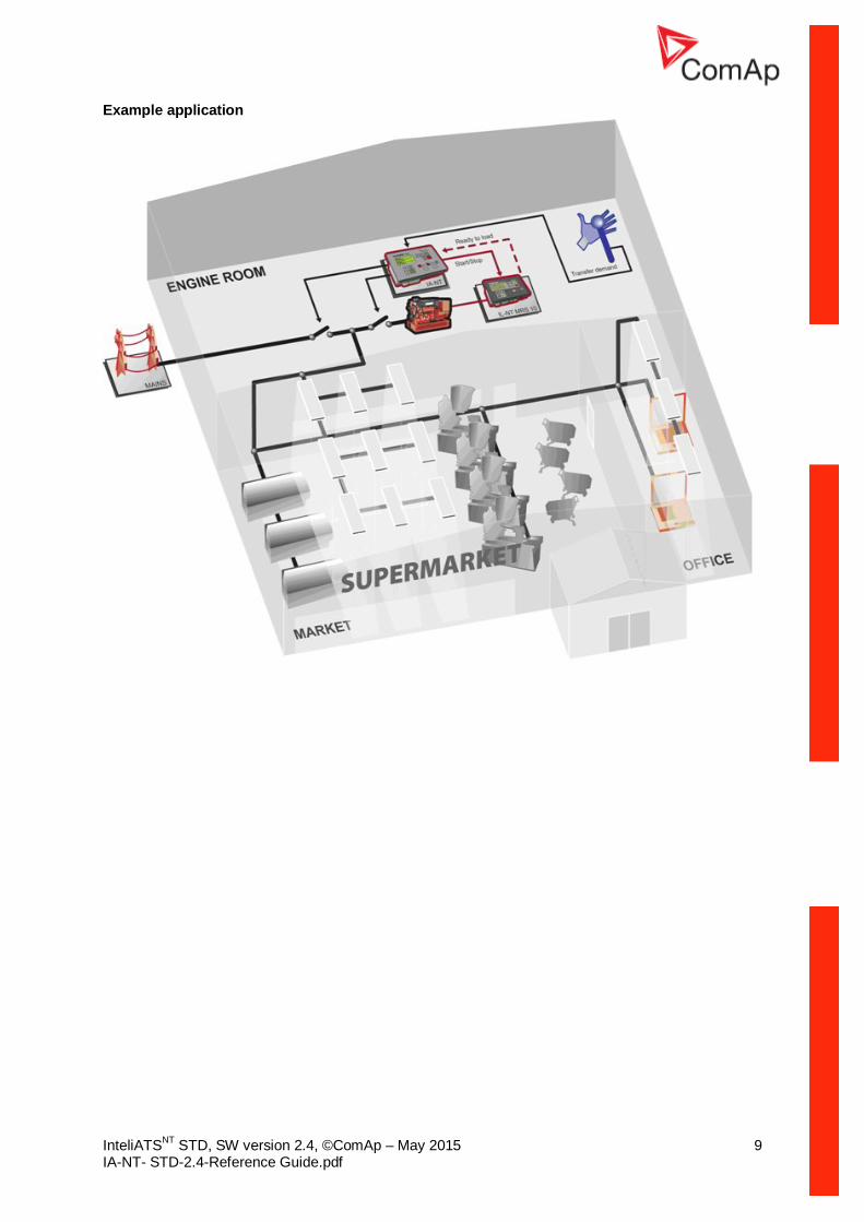
Example application
InteliATSNT STD, SW version 2.4, ©ComAp – May 2015 10 IA-NT- STD-2.4-Reference Guide.pdf
Configurability One of the key features of the controller is high level of adaptability of the system to the needs of every particular application. The way, how to achieve this, is the configuration.
NOTE: Use LiteEdit PC software to read configuration from the controller or disk, view it, modify it and write the configuration to controller or disk. The firmware contains a number of binary inputs and outputs needed for all necessary functions available in the firmware. But not all functions are required at the same time on different gen-sets and also the controller hardware does not have so many input and output terminals. One of the main tasks of the configuration is mapping of "logical" firmware inputs and outputs to the "physical" hardware inputs and outputs.
Configuration parts:
1. Mapping of logical binary inputs (functions) or assigning alarms to physical binary input terminals
2. Mapping of logical binary outputs (functions) to physical binary output terminals 3. Changing language of the controller texts
The controller is delivered with a default configuration, which should fit to most standard applications. This default configuration can be changed only using PC and LiteEdit software. See LiteEdit documentation for details.
NOTE: You need one of communication modules to connect the controller to a PC with LiteEdit. There is a special easy removable service module for cases, where there is no communication module permanently attached. Once the configuration is modified, it can be stored in a file for later usage with another controller or for backup purposes. The file is called archive and has file extension ".ail". An archive contains full image of the controller at the moment of saving (if the controller is online to the PC) except firmware, i.e. besides configuration there are also current adjustment of all setpoints, all measured values, a copy of history log and a copy of alarm list.
The archive can be simply used for cloning of controllers, which means preparing controllers with identical configuration and settings.
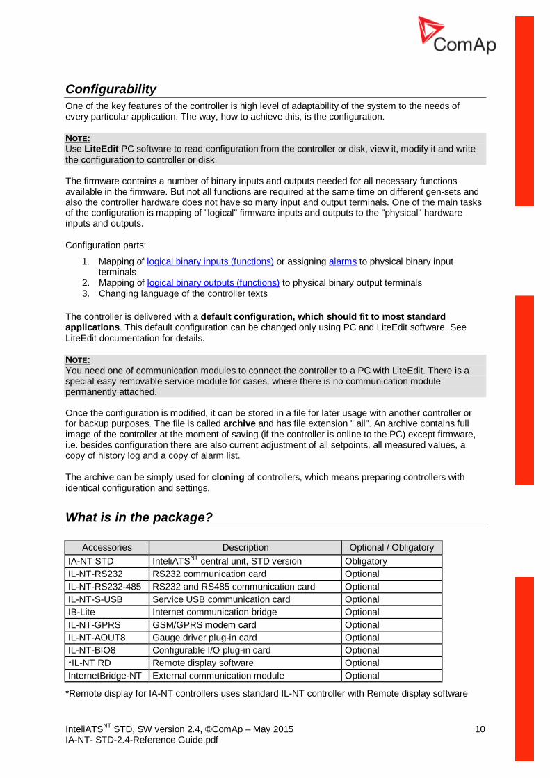
What is in the package?
Accessories Description Optional / Obligatory IA-NT STD InteliATSNT central unit, STD version Obligatory IL-NT-RS232 RS232 communication card Optional IL-NT-RS232-485 RS232 and RS485 communication card Optional IL-NT-S-USB Service USB communication card Optional IB-Lite Internet communication bridge Optional IL-NT-GPRS GSM/GPRS modem card Optional IL-NT-AOUT8 Gauge driver plug-in card Optional IL-NT-BIO8 Configurable I/O plug-in card Optional *IL-NT RD Remote display software Optional InternetBridge-NT External communication module Optional
*Remote display for IA-NT controllers uses standard IL-NT controller with Remote display software
InteliATSNT STD, SW version 2.4, ©ComAp – May 2015 11 IA-NT- STD-2.4-Reference Guide.pdf
NOTE: For detailed information about extension modules used with IA-NT controllers, please see the IL-NT, IC-NT, IA-NT, ID-Lite-Accessory Modules manual.
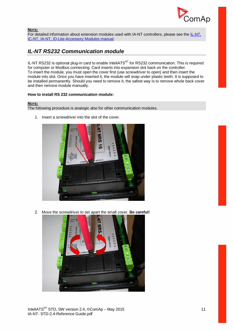
IL-NT RS232 Communication module IL-NT RS232 is optional plug-in card to enable InteliATSNT for RS232 communication. This is required for computer or Modbus connecting. Card inserts into expansion slot back on the controller. To insert the module, you must open the cover first (use screwdriver to open) and then insert the module into slot. Once you have inserted it, the module will snap under plastic teeth. It is supposed to be installed permanently. Should you need to remove it, the safest way is to remove whole back cover and then remove module manually. How to install RS 232 communication module: NOTE: The following procedure is analogic also for other communication modules.
1. Insert a screwdriver into the slot of the cover.
2. Move the screwdriver to set apart the small cover. Be careful!
InteliATSNT STD, SW version 2.4, ©ComAp – May 2015 12 IA-NT- STD-2.4-Reference Guide.pdf
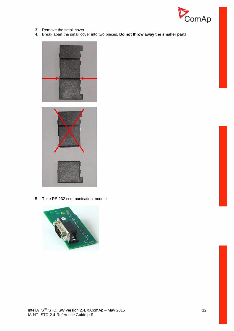
3. Remove the small cover. 4. Break apart the small cover into two pieces. Do not throw away the smaller part!
5. Take RS 232 communication module.
InteliATSNT STD, SW version 2.4, ©ComAp – May 2015 13 IA-NT- STD-2.4-Reference Guide.pdf
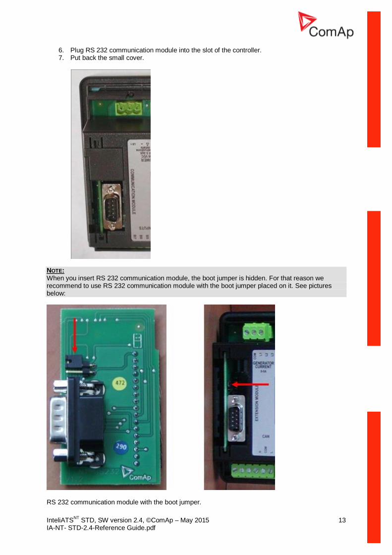
6. Plug RS 232 communication module into the slot of the controller. 7. Put back the small cover.
NOTE: When you insert RS 232 communication module, the boot jumper is hidden. For that reason we recommend to use RS 232 communication module with the boot jumper placed on it. See pictures below:
RS 232 communication module with the boot jumper.

InteliATSNT STD, SW version 2.4, ©ComAp – May 2015 14 IA-NT- STD-2.4-Reference Guide.pdf
NOTE: Boot jumper programming – In case of interrupted programming or other software failure is possible to use the boot jumper programing to restore controller to working order. Connect controller to PC, run LiteEdit and wait until connection bar at bottom turns red. Than run programming process via menu Controller -> Programming and cloning – Programming. Select correct firmware and confirm dialog. Than follow instructions in LiteEdit. Or follow video guide “Boot Jumper Programming“ at http://www.comap.cz/support/training/training-videos/.
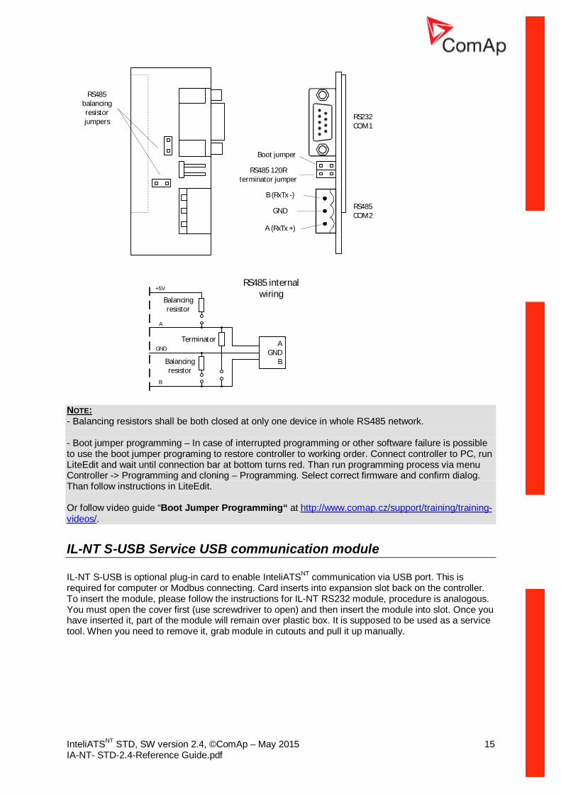
IL-NT RS232-485 Communication module IL-NT RS232-485 is optional plug-in card to enable InteliATSNT the RS232 and RS485 communication. This is required for computer or Modbus connection. Card inserts into expansion slot back on the controller. The IL-NT RS232-485 is a dual port module with RS232 and RS485 interfaces at independent COM channels. The RS232 is connected to COM1 and RS485 to COM2. To insert the module, please follow the instructions for IL-NT RS232 module, procedure is analogous. You must open the cover first (use screwdriver to open) and then insert the module into slot. Once you have inserted it, the module will snap under plastic teeth. It is supposed to be installed permanently. Should you need to remove it, the safest way is to remove whole back cover and then remove module manually.
RS485
Boot jumper RS485 Terminator jumper
RS232
InteliATSNT STD, SW version 2.4, ©ComAp – May 2015 15 IA-NT- STD-2.4-Reference Guide.pdf
RS232 COM1
RS485COM2
A (RxTx +)
B (RxTx -)
GND
RS485 120R terminator jumper
Boot jumper
RS485 balancing resistor jumpers
Terminator
Balancing resistor
AGND
BBalancing resistor
+5V
A
B
GND
RS485 internal wiring
NOTE: - Balancing resistors shall be both closed at only one device in whole RS485 network. - Boot jumper programming – In case of interrupted programming or other software failure is possible to use the boot jumper programing to restore controller to working order. Connect controller to PC, run LiteEdit and wait until connection bar at bottom turns red. Than run programming process via menu Controller -> Programming and cloning – Programming. Select correct firmware and confirm dialog. Than follow instructions in LiteEdit. Or follow video guide “Boot Jumper Programming“ at http://www.comap.cz/support/training/training-videos/.
IL-NT S-USB Service USB communication module IL-NT S-USB is optional plug-in card to enable InteliATSNT communication via USB port. This is required for computer or Modbus connecting. Card inserts into expansion slot back on the controller. To insert the module, please follow the instructions for IL-NT RS232 module, procedure is analogous. You must open the cover first (use screwdriver to open) and then insert the module into slot. Once you have inserted it, part of the module will remain over plastic box. It is supposed to be used as a service tool. When you need to remove it, grab module in cutouts and pull it up manually.

InteliATSNT STD, SW version 2.4, ©ComAp – May 2015 16 IA-NT- STD-2.4-Reference Guide.pdf
NOTE: Use the shielded USB A-B cable with this module! Recommended is ComAp cable – Order code: “USB-LINK CABLE 1.8M”. Boot jumper programming – In case of interrupted programming or other software failure is possible to use the boot jumper programing to restore controller to working order. Connect controller to PC, run LiteEdit and wait until connection bar at bottom turns red. Than run programming process via menu Controller -> Programming and cloning – Programming. Select correct firmware and confirm dialog. Than follow instructions in LiteEdit. Or follow video guide “Boot Jumper Programming“ at http://www.comap.cz/support/training/training-videos/.
IL-NT RD Remote display software IL-NT RD is remote display software for a controller. Remote display provides the same control and monitoring functions as controller itself. Remote display for IA-NT controllers uses standard IA-NT controller with IL-NT Remote display software. No further programming of the display is required – unit is self-configurable from the main controller. It is connected with the controller via IL-NT-RS232 communication modules using RS232 line. Longer distances (up to 1200m) are possible using IL-NT-RS232-485 communication module or when RS232/RS485 converters are used. The IL-NT RD hardware type should fit to the master IA-NT. NOTE: Please see the “IL-NT-RD Remote display software” chapter for more details.
IB-Lite Communication module IB-Lite is optional plug-in card to enable InteliATSNT communication via Ethernet/Internet. Card inserts into expansion slot back on the controller. To insert the module, please follow the instructions for IL-NT RS232 module, procedure is analogous. You must open the cover first (use screwdriver to open) and then insert the module into slot. Once you have inserted it, part of the module will remain over plastic box. It is supposed to be used as a service tool. When you need to remove it, grab module and pull it up manually. See IB-Lite-Reference Guide for further details.

InteliATSNT STD, SW version 2.4, ©ComAp – May 2015 17 IA-NT- STD-2.4-Reference Guide.pdf
Use Ethernet UTP cable with RJ45 connector for connection of the module into your ethernet network. The module can be also connected directly to a PC using cross-wired UTP cable.
12345678
12345678
CROSS-WIRED UTP 10/100Mbit CABLE
RJ45 RJ45
Web server for IB-Lite Is a new secured way of monitoring and controlling the gen-set from any point in world using your web browser. It offers clear overview and control of the state of engine, its settings and history. User friendly.
See IB-Lite-Reference Guide and pictures below for further details.

InteliATSNT STD, SW version 2.4, ©ComAp – May 2015 18 IA-NT- STD-2.4-Reference Guide.pdf
Scada window:
Measurement window:

InteliATSNT STD, SW version 2.4, ©ComAp – May 2015 19 IA-NT- STD-2.4-Reference Guide.pdf
Setpoints window:
History window:
HINT: This feature requires IB-Lite optional plug-in module and visible connection of controller to Ethernet/Internet.
InteliATSNT STD, SW version 2.4, ©ComAp – May 2015 20 IA-NT- STD-2.4-Reference Guide.pdf
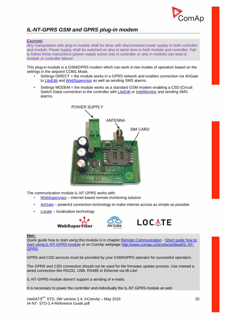
IL-NT-GPRS GSM and GPRS plug-in modem CAUTION! Any manipulation with plug-in module shall be done with disconnected power supply to both controller and module. Power supply shall be switched on also is same time to both module and controller. Fail to follow these instructions (power supply active only in controller or only in module) can lead to module or controller failure! This plug-in module is a GSM/GPRS modem which can work in two modes of operation based on the settings in the setpoint COM1 Mode.
• Settings DIRECT = the module works in a GPRS network and enables connection via AirGate to LiteEdit and WebSupervisor as well as sending SMS alarms.
• Settings MODEM = the module works as a standard GSM modem enabling a CSD (Circuit Switch Data) connection to the controller with LiteEdit or InteliMonitor and sending SMS alarms.
The communication module IL-NT GPRS works with:
• WebSupervisor – internet-based remote monitoring solution
• AirGate – powerful connection technology to make internet access as simple as possible
• Locate – localization technology
HINT: Quick guide how to start using this module is in chapter Remote Communication - Short guide how to start using IL-NT-GPRS module or on ComAp webpage http://www.comap.cz/products/detail/IL-NT-GPRS. GPRS and CSD services must be provided by your GSM/GPRS operator for successful operation. The GPRS and CSD connection should not be used for the firmware update process. Use instead a wired connection like RS232, USB, RS485 or Ethernet via IB-Lite! IL-NT-GPRS module doesn’t support a sending of e-mails. It is necessary to power the controller and individually the IL-NT GPRS module as well.

InteliATSNT STD, SW version 2.4, ©ComAp – May 2015 21 IA-NT- STD-2.4-Reference Guide.pdf
IL-NT AOUT8 Gauge driver module IL-NT AOUT8 is optional plug-in card. Through this card controller can drive up to 8 VDO style industrial/automotive gauges. Noncompensated gauges like 0-10V or 0-20mA are not supported. Gauge type and value are configured in LiteEdit software. Any analog value from controller may be shown in that way. To insert the module, you must open the cover first (use screwdriver to open) and then insert the module into slot. Once you have insert it, the module will snap under plastic teeth. It is supposed to be installed permanently. Should you need to remove it, the safest way is to remove whole back cover and then remove module manually. Installing IL-NT AOUT8 module is similar to installing RS 232 module. The difference is that module fits to “extension module” slot and after installing IL-NT AOUT8 you do not put back the small cover. PC Installation Suite consist a set of prepared converting curves for basic usage of PWM outputs with automotive gauges. IL-NT AOUT8 module:
InteliATSNT STD, SW version 2.4, ©ComAp – May 2015 22 IA-NT- STD-2.4-Reference Guide.pdf
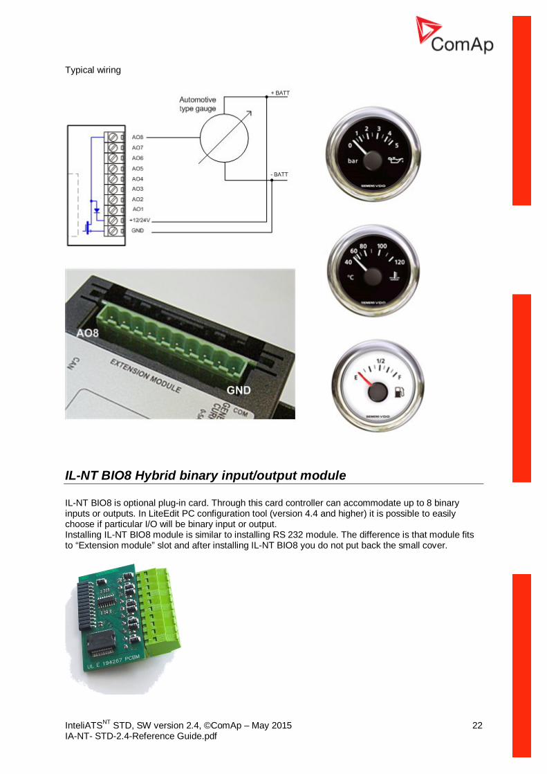
Typical wiring
IL-NT BIO8 Hybrid binary input/output module IL-NT BIO8 is optional plug-in card. Through this card controller can accommodate up to 8 binary inputs or outputs. In LiteEdit PC configuration tool (version 4.4 and higher) it is possible to easily choose if particular I/O will be binary input or output. Installing IL-NT BIO8 module is similar to installing RS 232 module. The difference is that module fits to “Extension module” slot and after installing IL-NT BIO8 you do not put back the small cover.

InteliATSNT STD, SW version 2.4, ©ComAp – May 2015 23 IA-NT- STD-2.4-Reference Guide.pdf
Programming of IA-NT controller Programming is possible only in OFF mode when the engine is not running. NOTE: For more information on programming, see LiteEdit Reference Guide. CAUTION! Check the statistic values after firmware upgrade. Readjust the values if necessary.
InteliATSNT STD, SW version 2.4, ©ComAp – May 2015 24 IA-NT- STD-2.4-Reference Guide.pdf
User Interface There is an interchangeable User Interface on controller. It allows two different modes of displaying controller menu. The first mode called USER is dedicated for users who prefer easy function and need only monitor actual values, see alarms or change language settings. Second mode is called ENGINEER and it is dedicated for advanced users, who desire to change the settings of controller, monitor all values and check the history of events. Changing the mode of User Interface is possible from default measuring screen of controller by simultaneous pressing the ENTER and PAGE button and then press again PAGE. On screen will be displayed the choice of two different User Interfaces. Please see latest IA-NT Operators Guide for detailed description.

InteliATSNT STD, SW version 2.4, ©ComAp – May 2015 25 IA-NT- STD-2.4-Reference Guide.pdf
Terminals
IA-NT STD terminals and face
InteliATSNT STD, SW version 2.4, ©ComAp – May 2015 26 IA-NT- STD-2.4-Reference Guide.pdf
Installation
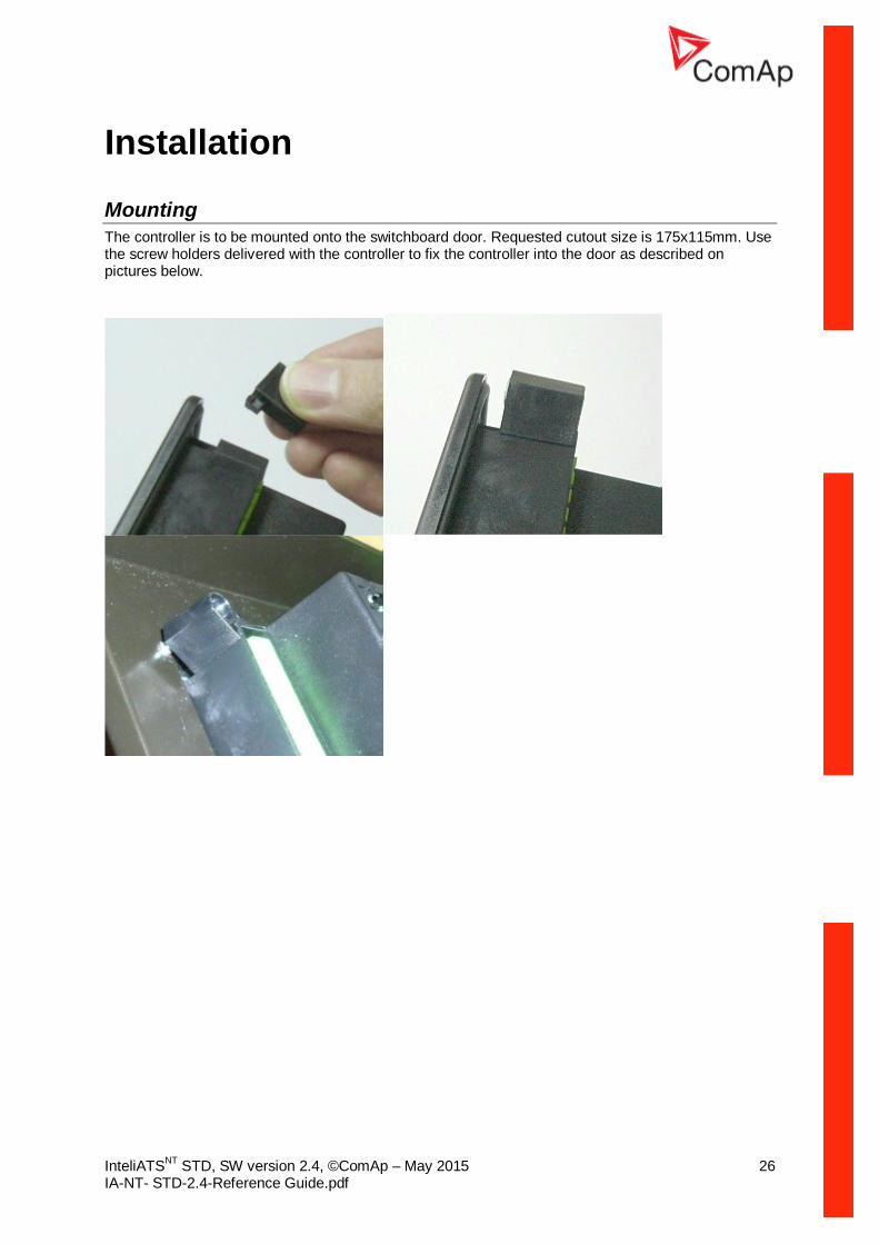
Mounting The controller is to be mounted onto the switchboard door. Requested cutout size is 175x115mm. Use the screw holders delivered with the controller to fix the controller into the door as described on pictures below.
InteliATSNT STD, SW version 2.4, ©ComAp – May 2015 27 IA-NT- STD-2.4-Reference Guide.pdf
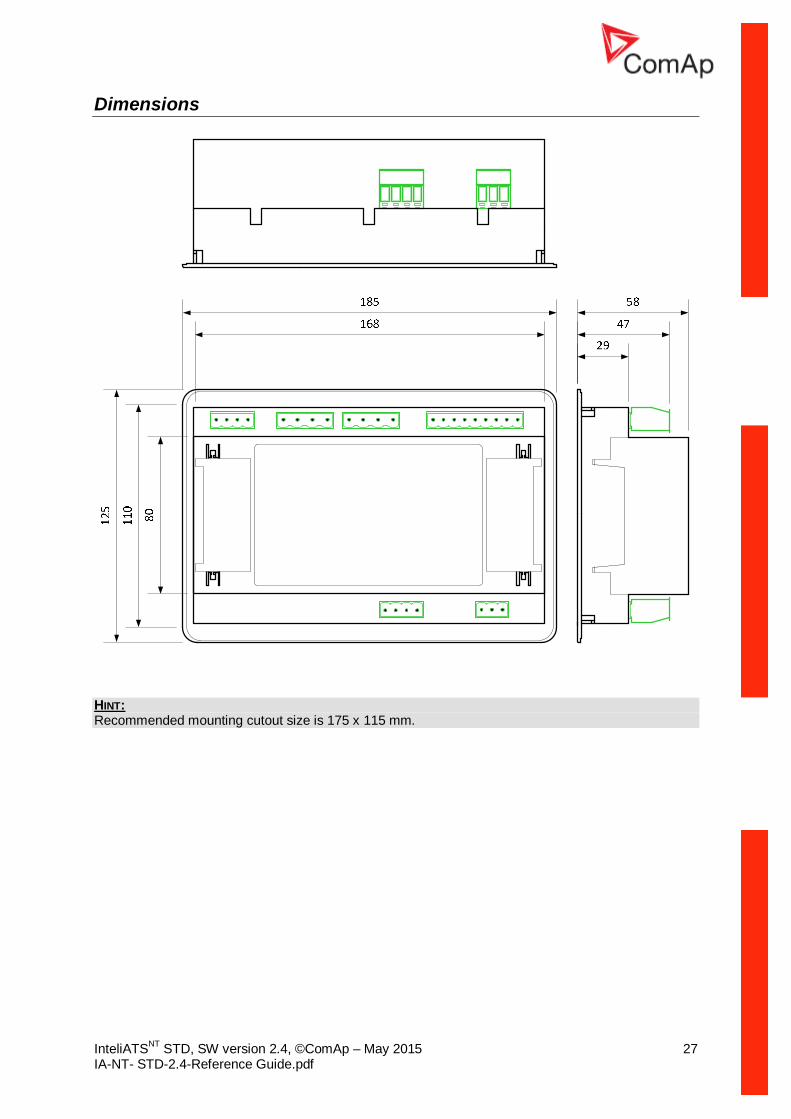
Dimensions
HINT: Recommended mounting cutout size is 175 x 115 mm.

InteliATSNT STD, SW version 2.4, ©ComAp – May 2015 28 IA-NT- STD-2.4-Reference Guide.pdf
Recommended Wiring
IA-NT STD – Wiring Diagram
InteliATSNT STD, SW version 2.4, ©ComAp – May 2015 29 IA-NT- STD-2.4-Reference Guide.pdf
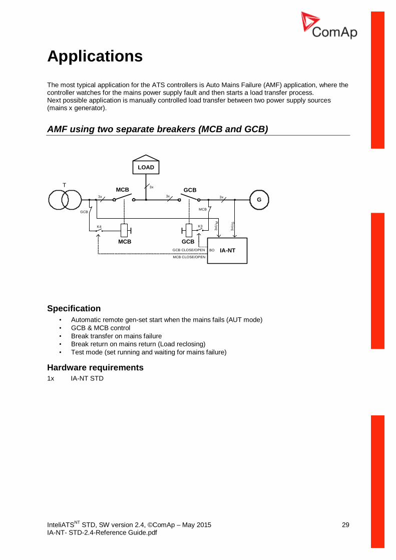
Applications The most typical application for the ATS controllers is Auto Mains Failure (AMF) application, where the controller watches for the mains power supply fault and then starts a load transfer process. Next possible application is manually controlled load transfer between two power supply sources (mains x generator).
AMF using two separate breakers (MCB and GCB)
G
IA-NT
GCB3x
LOAD
3xU
M
3xU
G
MCB3x
T 3x
K4
MCB GCB
3x
MCB CLOSE/OPEN
GCB CLOSE/OPEN BO
MCB
K3
GCB
Specification • Automatic remote gen-set start when the mains fails (AUT mode) • GCB & MCB control • Break transfer on mains failure • Break return on mains return (Load reclosing) • Test mode (set running and waiting for mains failure)
Hardware requirements 1x IA-NT STD

InteliATSNT STD, SW version 2.4, ©ComAp – May 2015 30 IA-NT- STD-2.4-Reference Guide.pdf
AMF using two-position ATS
G
IA-NT
3x
3xU
M
3xU
G
3x
T
3x
GCB CLOSE/OPENBO
K3
LOAD
ATS
3x
ATS
I II
Specification • Automatic remote gen-set start when the mains fails (AUT mode) • Two-position ATS • Break transfer on mains failure • Break return on mains return (Load reclosing) • Test mode (set running and waiting for mains failure)
Hardware requirements 1x IA-NT STD
InteliATSNT STD, SW version 2.4, ©ComAp – May 2015 31 IA-NT- STD-2.4-Reference Guide.pdf
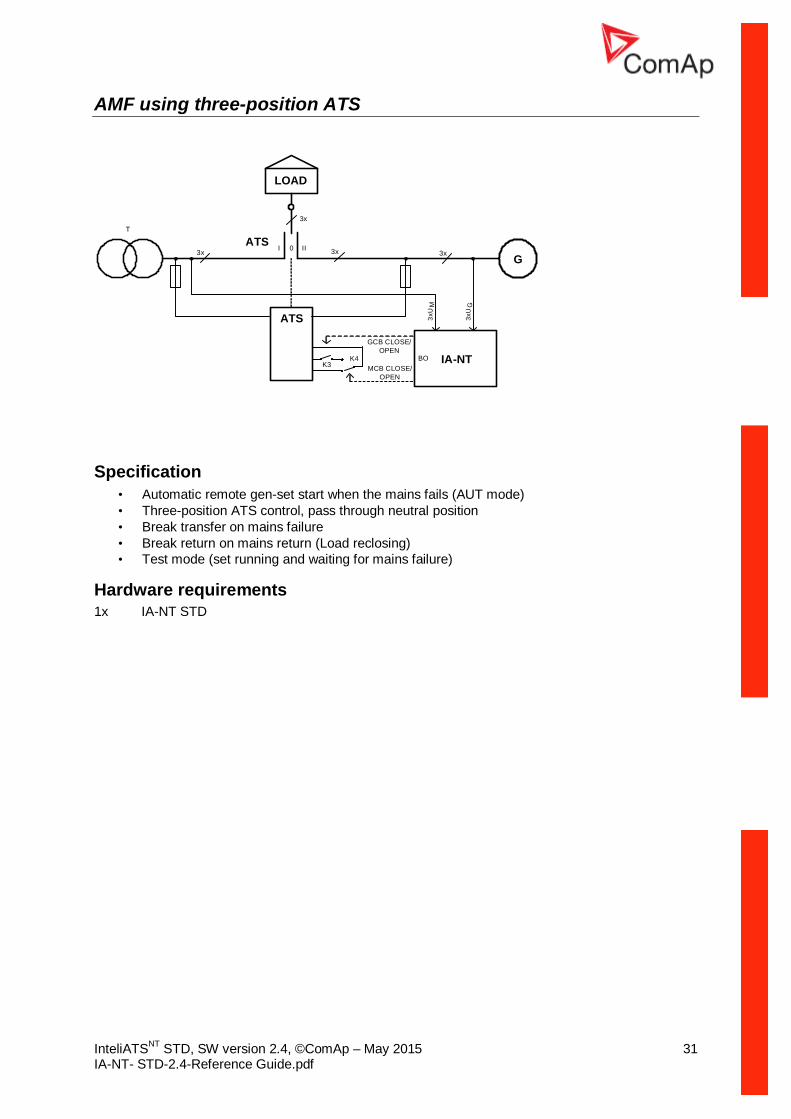
AMF using three-position ATS
G
IA-NT
3x
3xU
M
3xU
G
3x
T
3x
MCB CLOSE/OPEN
GCB CLOSE/OPEN
BO
LOAD
ATS
3x
ATS
I II0
K4K3
Specification • Automatic remote gen-set start when the mains fails (AUT mode) • Three-position ATS control, pass through neutral position • Break transfer on mains failure • Break return on mains return (Load reclosing) • Test mode (set running and waiting for mains failure)
Hardware requirements 1x IA-NT STD

InteliATSNT STD, SW version 2.4, ©ComAp – May 2015 32 IA-NT- STD-2.4-Reference Guide.pdf
AMF + manual transfer & neutral control using three-position ATS
G
IA-NT
3x
3xU
M
3xU
G
3x
T
REM TRANSFER
NEUTRAL POS
3x
MCB CLOSE/OPEN
GCB CLOSE/OPEN
BO
BI
Force Neutral Position
LOAD
ATS
3x
ATS
I II0
Manual Load Transfer
K3
K4
K5
NEUTRAL POS
Specification • Automatic remote gen-set start when the mains fails (AUT mode) • Three-position ATS control, pass through neutral position • Manual request for load transfer (AUT mode) • Request for switching to neutral position – the highest priority, overrides MCB & GCB state,
forces switch to neutral position. After deactivating return to previous state (MCB or GCB)
Hardware requirements 1x IA-NT STD

InteliATSNT STD, SW version 2.4, ©ComAp – May 2015 33 IA-NT- STD-2.4-Reference Guide.pdf
AMF + no battery operation
Specification It is possible to operate controller without a battery supplying the controller. For such operation the following conditions have to be fulfilled:
• Controller is supplied from 24V/2.5A AC/DC power supply whose source is switched between Mains and Gen-set via relay (another contacts of the relay for GCB switching) according to the Mains state (OK/Fault). See the schematic diagram for more details
• Normally closed relay contacts have to be used for the gen-set start command. Setpoint “GenStart Logic” has to be set to CLOSE-OFF
• Switching of the 24V AC/DC power supply is blocked when GCB is closed, so the power supply is not switched to Mains if voltage on the mains bus appears – protection against “Flip-flopping” of the power supply when voltage changes arise on Mains. It (power supply) will be switched to Mains when GCB is opened.
Then in the case of Mains failure:
• 24V AC/DC power supply source is switched to gen-set • Voltage supplying controller disappears • Gen Start relay is deenergized and contacts closed • Gen-set is started • Controller is supplied from running gen-set • Controller is initialized, waits for Gen OK conditions • MCB is opened, GCB closed and the 24V AC/DC power supply source is locked in gen-set
position.
If Mains returns:
• GCB is opened, 24V AC/DC power supply source is unlocked and switched to Mains • MCB is closed • Gen-set is stopped
Hardware requirements 1x IA-NT STD 1x 24V/2.5A AC/DC power supply

InteliATSNT STD, SW version 2.4, ©ComAp – May 2015 34 IA-NT- STD-2.4-Reference Guide.pdf
Getting Started
How to install
General To ensure proper function:
• Wiring for binary inputs and analog inputs must not be run with power cables. • Binary inputs should use shielded cables, especially when length >3m.
Power supply To ensure proper function:
• Use min. power supply cable of 1.5mm2 Maximum continuous DC power supply voltage is 36VDC. The InteliATSNT’s power supply terminals are protected against large pulse power disturbances. When there is a potential risk of the controller being subjected to conditions outside its capabilities, an outside protection devise should be used. NOTE: The InteliATSNT controller should be grounded properly in order to protect against lighting strikes!! The maximum allowable current through the controller’s negative terminal is 4A (this is dependent on binary output load). For the connections with 12VDC power supply, the InteliATSNT includes internal capacitors that allow the controller to continue operation if the battery voltage dips occurs. If the voltage before dip is 10V, after 100ms the voltage recovers to 7 V, the controller continues operating. During this voltage dip the controller screen backlight can turn off and on but the controller keeps operating. It is possible to further support the controller by connecting the external capacitor and separating diode or I-LBA module:
The capacitor size depends on required time. It shall be approximately thousands of microfarads. The capacitor size should be 5 000 microfarad to withstand 150ms voltage dip under following conditions: Voltage before dip is 12V, after 150ms the voltage recovers to min. allowed voltage, i.e. 8V NOTE: Before the battery is discharged the message "Low BackupBatt" appears.
InteliATSNT STD, SW version 2.4, ©ComAp – May 2015 35 IA-NT- STD-2.4-Reference Guide.pdf
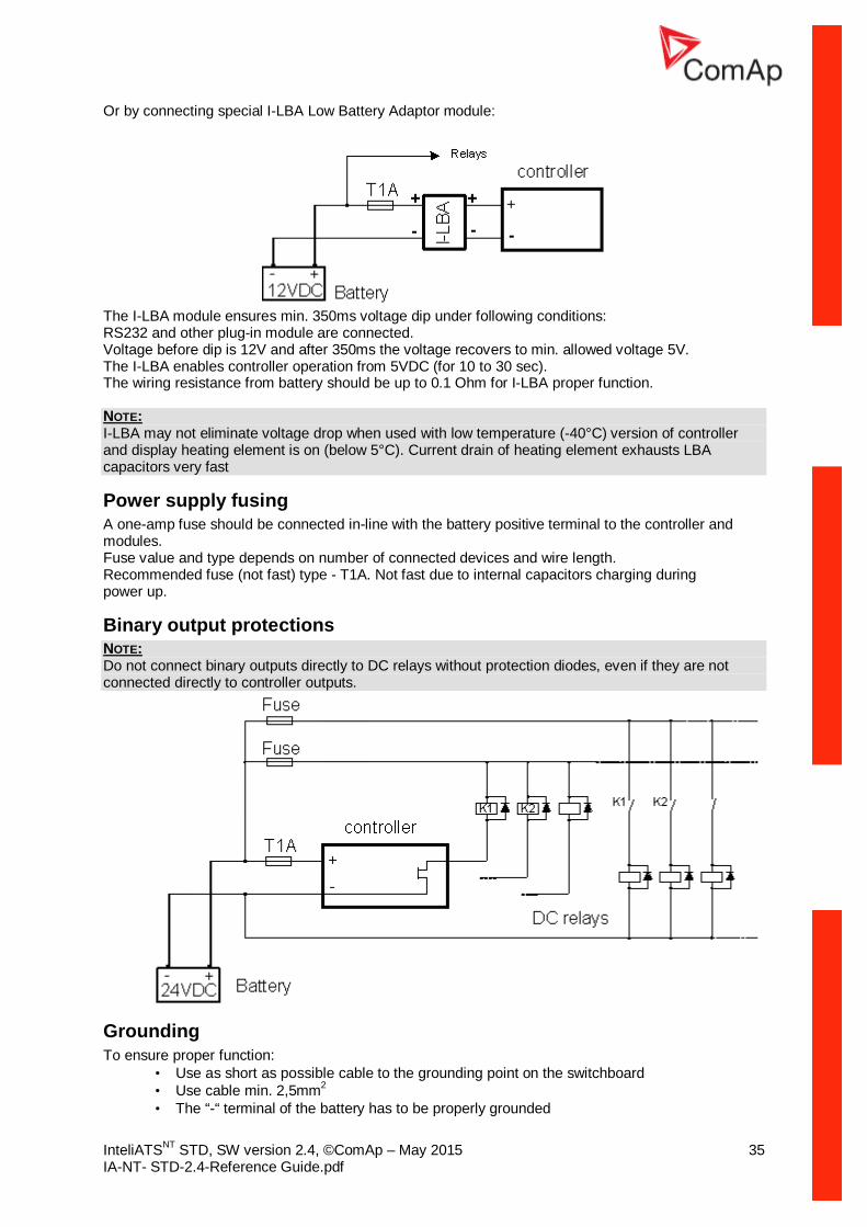
Or by connecting special I-LBA Low Battery Adaptor module:
The I-LBA module ensures min. 350ms voltage dip under following conditions: RS232 and other plug-in module are connected. Voltage before dip is 12V and after 350ms the voltage recovers to min. allowed voltage 5V. The I-LBA enables controller operation from 5VDC (for 10 to 30 sec). The wiring resistance from battery should be up to 0.1 Ohm for I-LBA proper function. NOTE: I-LBA may not eliminate voltage drop when used with low temperature (-40°C) version of controller and display heating element is on (below 5°C). Current drain of heating element exhausts LBA capacitors very fast
Power supply fusing A one-amp fuse should be connected in-line with the battery positive terminal to the controller and modules. Fuse value and type depends on number of connected devices and wire length. Recommended fuse (not fast) type - T1A. Not fast due to internal capacitors charging during power up.
Binary output protections NOTE: Do not connect binary outputs directly to DC relays without protection diodes, even if they are not connected directly to controller outputs.
Grounding To ensure proper function:
• Use as short as possible cable to the grounding point on the switchboard • Use cable min. 2,5mm2 • The “-“ terminal of the battery has to be properly grounded
InteliATSNT STD, SW version 2.4, ©ComAp – May 2015 36 IA-NT- STD-2.4-Reference Guide.pdf
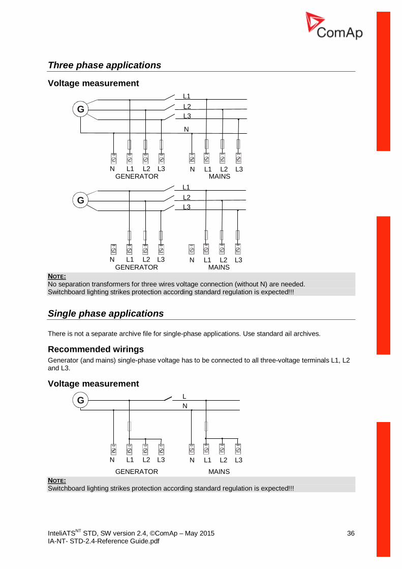
Three phase applications
Voltage measurement
G
GENERATOR MAINSL3L2L1N
L1L2L3
N
L3L2L1N
G
GENERATOR MAINSL3L2L1N
L1L2L3
L3L2L1N
NOTE: No separation transformers for three wires voltage connection (without N) are needed. Switchboard lighting strikes protection according standard regulation is expected!!!
Single phase applications There is not a separate archive file for single-phase applications. Use standard ail archives.
Recommended wirings Generator (and mains) single-phase voltage has to be connected to all three-voltage terminals L1, L2 and L3.
Voltage measurement
G
GENERATOR MAINS
L3L2L1N
LN
L3L2L1N
NOTE: Switchboard lighting strikes protection according standard regulation is expected!!!
InteliATSNT STD, SW version 2.4, ©ComAp – May 2015 37 IA-NT- STD-2.4-Reference Guide.pdf
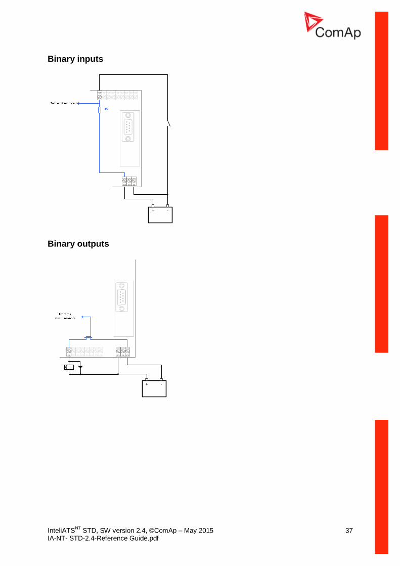
Binary inputs
Binary outputs

InteliATSNT STD, SW version 2.4, ©ComAp – May 2015 38 IA-NT- STD-2.4-Reference Guide.pdf
Inputs and Outputs For Inputs/Outputs overview table see chapter Technical Data. NOTE: Any Binary input or output can be configured to any IA-NT controller terminal or changed to different function by LiteEdit software. There is fix 1 sec delay when any binary input is configured as protection.
Not Used Binary input has no function. Use this configuration when Binary input is not connected.
Alarm If the input is closed (or opened) selected alarm is activated.
Binary Alarm configuration items
Name 14 characters ASCII string Contact type NC Normally closed
NO Normally opened Alarm type Warning
Trip
Control Use this setting to configure the desired function from the list below.
Binary inputs IA-NT - default
BI1 GCB Feedback
BI2 MCB Feedback
BI3 GenReadyToLoad
BI4 MainsFailBlock*
*InteliATS STD HW version 1.3 provides 3 binary inputs, higher versions provide 4 binary inputs
InteliATSNT STD, SW version 2.4, ©ComAp – May 2015 39 IA-NT- STD-2.4-Reference Guide.pdf
Binary inputs – list
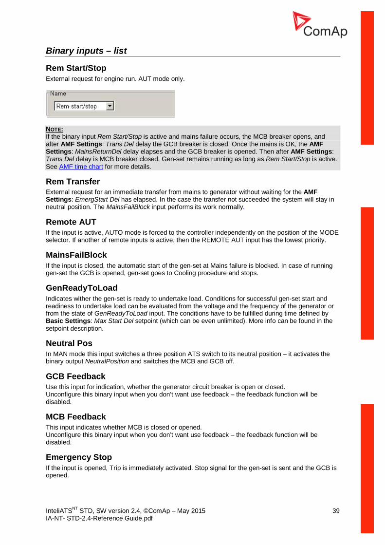
Rem Start/Stop External request for engine run. AUT mode only.
NOTE: If the binary input Rem Start/Stop is active and mains failure occurs, the MCB breaker opens, and after AMF Settings: Trans Del delay the GCB breaker is closed. Once the mains is OK, the AMF Settings: MainsReturnDel delay elapses and the GCB breaker is opened. Then after AMF Settings: Trans Del delay is MCB breaker closed. Gen-set remains running as long as Rem Start/Stop is active. See AMF time chart for more details.
Rem Transfer External request for an immediate transfer from mains to generator without waiting for the AMF Settings: EmergStart Del has elapsed. In the case the transfer not succeeded the system will stay in neutral position. The MainsFailBlock input performs its work normally.
Remote AUT If the input is active, AUTO mode is forced to the controller independently on the position of the MODE selector. If another of remote inputs is active, then the REMOTE AUT input has the lowest priority.
MainsFailBlock If the input is closed, the automatic start of the gen-set at Mains failure is blocked. In case of running gen-set the GCB is opened, gen-set goes to Cooling procedure and stops.
GenReadyToLoad Indicates wither the gen-set is ready to undertake load. Conditions for successful gen-set start and readiness to undertake load can be evaluated from the voltage and the frequency of the generator or from the state of GenReadyToLoad input. The conditions have to be fulfilled during time defined by Basic Settings: Max Start Del setpoint (which can be even unlimited). More info can be found in the setpoint description.
Neutral Pos In MAN mode this input switches a three position ATS switch to its neutral position – it activates the binary output NeutralPosition and switches the MCB and GCB off.
GCB Feedback Use this input for indication, whether the generator circuit breaker is open or closed. Unconfigure this binary input when you don’t want use feedback – the feedback function will be disabled.
MCB Feedback This input indicates whether MCB is closed or opened. Unconfigure this binary input when you don’t want use feedback – the feedback function will be disabled.
Emergency Stop If the input is opened, Trip is immediately activated. Stop signal for the gen-set is sent and the GCB is opened.

InteliATSNT STD, SW version 2.4, ©ComAp – May 2015 40 IA-NT- STD-2.4-Reference Guide.pdf
MainsHealthy This input was created mainly for cascading applications, where slave controllers do not have usually Mains and Gen-set voltage measuring inputs connected to the respective power sources. Then this binary input tells the controller if Mains is healthy to be able to respond to Mains failure.
Total Stop If the input is opened, Trip is immediately activated. Stop signal for gen-set is sent and the GCB and MCB are opened.
MCB Disable The input is used disable issuing the MCB closing command.
• If the input is active and the MCB is opened, the MCB will not be closed until the input is deactivated.
• If the input is active and the MCB is closed, the MCB will be opened. • If the input is active, MCB Disable alarm is activated.
GCB Disable The input is used disable issuing the MCB closing command.
• If the input is active and the MCB is opened, the MCB will not be closed until the input is deactivated.
• If the input is active and the MCB is closed, the MCB will be opened. • If the input is active, MCB Disable alarm is activated.
Binary outputs IA-NT - default
BO1 GenStart/Stop
BO2 Alarm
BO3 GCB Close/Open
BO4 MCB Close/Open
Binary outputs - list
Not Used Output has no function.
GenStart/Stop The closed relay sends remote start signal to the gen-set. Generator protections are blocked when the output is inactive and the GCB is blocked too. Output can be inverted (CLOSE-OFF) using Basic Settings: GenStart Logic setpoint.
Prestart The output closes when the gen-set start is requested and opens after the AMF Settings: Prestart Time has elapsed. Afterwards the GenStart/Stop output is activated as a start signal for the remote gen-set.
Pretransfer Is activated during the Prestart phase when the Mains Fail had occurred and the gen-set start is the result of this event. See the AMF Settings: Prestart Time setpoint for more info.

InteliATSNT STD, SW version 2.4, ©ComAp – May 2015 41 IA-NT- STD-2.4-Reference Guide.pdf
Alarm The output closes if :
• any alarm comes up or The output opens if
• FAULT RESET is pressed The output closes again if a new fault comes up.
GCB Close/Open The output controls the generator circuit breaker. NOTE: Supposed time to close (reaction time) of GCB is depend of breaker type and related to setpoint GCB Delay.
MCB Close/Open The output controls the mains circuit breaker. NOTE: Supposed time to close (reaction time) of MCB is depend of breaker type and related to setpoint GCB Delay.
Ready To AMF This output is activated when the controller is in AUT mode and no Trip alarm is active or unconfirmed. It remains active when the engine is running.
AL Mains Fail Output closes if the mains over/under voltage alarm, voltage asymmetry alarm or mains over/under frequency alarm activates. The output opens, if
• alarm is not active
Not In AUT Output activates when the controller is not in AUT mode.
Neutral Pos Switches ATS switch to its neutral position.
Falut Reset The output is a copy of Fault Reset button on controller and binary input FaultResButton.
Ctrl HeartBeat Output signalizes Watchdog Reset. In a healthy state it blinks at 500ms : 500ms rate. When Watchdog Reset occurs, it stops blinking.
InteliATSNT STD, SW version 2.4, ©ComAp – May 2015 42 IA-NT- STD-2.4-Reference Guide.pdf
Setpoints
Password
EnterPassword Password is a four-digit number. Password enables change of relevant protected setpoints. Use ↑ or ↓ keys to set and ENTER key to enter the password. NOTE: There is only 1 level of a password.
ChangePassword Use ↑ or ↓ keys to set and ENTER key to change the password. NOTE: At first the password has to be entered before the new password can be changed.
Basic Settings
ControllerName User defined name, used for InteliNT identification at remote phone or mobile connection. ControllerName is max 14 characters long and have to be entered using LiteEdit software.
Nominal Freq [Hz] Nominal generator frequency (usually 50 or 60 Hz) Step: 1 Hz Range: 45 – 65 Hz
Prestart Time [s] Time of closing of the Prestart and/or Pretransfer output prior to the engine start. Set to zero if you want to leave the output Prestart/Pretransfer open. Step: 1 s Range: 0 – 600 s
Cooling Time [s] Runtime of the unloaded gen-set to cool the engine before stop. Step: 1 s Range: 0 – 3600 s
MaxStartDel [s] This timeout starts after closing binary output GEN START/STOP. When generator does not reach defined limits Basic Settings: Nominal Freq) within MaxStartDel, Trp Start Fail alarm occurs and the gen-set will shut down. See the table below for a description of the engine start evaluation. If MaxStartDel is longer than 600 s it means there is NO TIMEOUT. Step: 1 s Range: 0 – 600 s, 601 s = NO TIMEOUT

InteliATSNT STD, SW version 2.4, ©ComAp – May 2015 43 IA-NT- STD-2.4-Reference Guide.pdf
Engine start evaluation diagram:
Min Stab Time [s] Minimum time interval between defined generator voltage is reached to GCB is closed. If BI: GenReadyToLoad is not configured, timer is not used. Step: 1 s Range: 0 – 300 s
Stop Time [s] Period given by the value of the Stop Time setpoint tells the controller how long should it wait for the engine to change to the stop state (stop state means GenReadyToLoad signal is deactivated or generator voltages disappeared). If the engine is still running after the stop time expires the Trp Stop Fail alarm is announced. Stop Fail starts counting always when the controller sends Stop command to the engine (Start/Stop output is deactivated). Step: 1 s Range: 0 – 3601 sec Value 3601 means the controller doesn’t care for the engine is
stopped (Trp Stop Fail is never announced).
GenStart Logic [CLOSE-ON/CLOSE-OFF] The set point influences the behavior of the output Gen Start/Stop. CLOSE-ON: Gen-set should start when the output Gen Start/Stop is closed. CLOSE-OFF: Gen-set should start when the output Gen Start/Stop is opened.

InteliATSNT STD, SW version 2.4, ©ComAp – May 2015 44 IA-NT- STD-2.4-Reference Guide.pdf
Batt Undervolt [V] Warning threshold for low battery voltage. Step: 0,1 V Range: 8V – 40 (Battery >Volts)
ConnectionType [3Ph4Wire / 3Ph3Wire / Split Ph / Mono Ph] Generator winding connection. 3Ph4Wire: STAR Connection, 3 phases and neutral - 4 wires,
Three phase “wye” measurement – 3PY 3Ph3Wire: DELTA Connection, 3 Phase without neutral - 3 Wires,
Three phase “delta” measurement – 3PD Split Phase: DOUBLE DELTA Connection, Split Phase,
Single-phase measurement – 1PH Mono Phase: MONOPHASE,
Single-phase measurement – 1PH
GCB Delay [s] By means of this setpoint system gets information about breaker/contactor switching time. This value is needed for exact sync moment/ time prediction. Step: 0.01 s Range: 0.01 – 60.00 s Default: 1 s
MCB Delay [s] By means of this setpoint system gets information about breaker/contactor switching time. This value is needed for exact sync moment/ time prediction. Step: 0.01 s Range: 0.01 – 60.00 s Default: 1 s
HINT: Value of breaker switching time MUST contain all the parts of breaker delay (i.e. breaker switching time plus switching time of relay used for breaker control). The more exact value is given, the more exact is the sync result.
Test Period [d] After the given value of Test Period setpoint expires, the engine is started and is running as long as the value of Test Duration setpoint. Test Period starts counting always when the engine is stopped. Range: 0 – 240 days
Test Duration [min] Time interval, when engine is running after expiring the Test Period setpoint. Range: 0 – 240 minutes NOTE: This function does not work till both setpoints (Test Period and Test Duration) are set to non-zero values.
Comms Settings
IBLite IP Addr [-] If DHCP is DISABLED this setpoint is used to adjust the IP address of the ethernet interface of the controller. Ask your IT specialist for help with this setting. If DHCP is ENABLED this setpoint is used to display the IP address, which has been assigned by the DHCP server.
InteliATSNT STD, SW version 2.4, ©ComAp – May 2015 45 IA-NT- STD-2.4-Reference Guide.pdf
IBLite NetMask [-] If DHCP is DISABLED this setpoint is used to adjust the IP address NetMask of the ethernet interface of the controller. Ask your IT specialist for help with this setting. If DHCP is ENABLED this setpoint is used to display the IP address, which has been assigned by the DHCP server.
IBLite GateIP [-] If DHCP is DISABLED this setpoint is used to adjust the IP address NetMask of the gateway of the network segment where the controller is connected. If DHCP is ENABLED this setpoint is used to display the gateway IP address which has been assigned by the DHCP server. A gateway is a device which connects the respective segment with the other segments and/or Internet.
IBLite DHCP [ENABLED/DISABLED] The setpoint is used to select the method how the ethernet connection is adjusted. DISABLED: The ethernet connection is adjusted manually according to the setpoints IP Addr, NetMask, GateIP, DNS IP Address. This method should be used for classic ethernet or Internet connection. When this type of connection is opening the controller is specified by its IP address. That means it would be inconvenient if the IP address were not fixed (static). ENABLED: The ethernet connection settings is obtained automatically from the DHCP server. The obtained settings is then copied to the related setpoints. If the process of obtaining the settings from DHCP server is not successful the value 000.000.000.000 is copied to the setpoint IP address and the module continues trying to obtain the settings.
ComAp Port [0 - 65535] This setpoint is used to adjust the port number, which is used for ethernet connection to a PC with any of ComAp PC program (i.e. InteliLite, InteliMonitor). This setpoint should be adjusted to 23, which is the default port used by all ComAp PC programs. A different value should be used only in special situations as e.g. sharing one public IP address among many controllers or to overcome a firewall restrictions.
APN Name [-] Name of APN access point for GPRS network provided by GSM/GPRS operator.
APN User Name [-] User name for APN access point provided by GSM/GPRS operator.
APN User Pass [-] User password for APN access point provided by GSM/GPRS operator.
AirGate [ENABLED/DISABLED] This setpoint selects the ethernet connection mode.
DISABLED: This is a standard mode, in which the controller listens to the incoming traffic and answers the TCP/IP queries addressed to him. This mode requires the controller to be accessible from the remote device (PC), i.e. it must be accessible at a public and static IP address if you want to connect to it from the Internet.
InteliATSNT STD, SW version 2.4, ©ComAp – May 2015 46 IA-NT- STD-2.4-Reference Guide.pdf
ENABLED: This mode uses the "AirGate" service, which hides all the issues with static/public address into a black box and you do not need to take care about it. You just need only a connection to the Internet. The AirGate server address is adjusted by the setpoint AirGate IP.
AirGate IP [-] This setpoint is used for entering the domain name or IP address of the AirGate server. Use the free AirGate server provided by ComAp at address airgate.comap.cz if your company does not operate its own AirGate server.
SMTP User Name [-] Use this setpoint to enter the user name for the SMTP server.
SMTP User Pass [-] Use this setpoint to enter the password for the SMTP server.
SMTP Server IP [-] This setpoint is used for entering the domain name (e.g. smtp.yourprovider.com) or IP address (e.g. 74.125.39.109) of the SMTP server. Please ask your internet provider or IT manager for this information.
HINT: You may also use one of free SMTP servers, e.g. smtp.gmail.com. However, please note that some free SMTP servers may cause delays (in hours..) when sending e-mails. If you do not want to send active e-mails, you may leave this setpoint blank, as well as other setpoints related to SMTP server and e-mail settings. Proper setting of SMTP-related setpoints as well as controller mailbox are essential for sending alerts via e-mails.
Contr Mail Box [-] Enter an existing e-mail address into this setpoint. This address will be used as sender address in active e-mails that will be sent from the controller.
Time Zone [-] This setpoint is used to select the time zone where the controller is located. See your computer time zone setting (click on the time indicator located in the rightmost position of the windows task bar) if you are not sure about your time zone.
HINT: If the time zone is not selected properly the active e-mails may contain incorrect information about sending time, which may result in confusion when the respective problem actually occurred.
DNS IP Address [-] If DHCP is DISABLED this setpoint is used to adjust the domain name server (DNS), which is needed to translate domain names in e-mail addresses and server names into correct IP addresses. If DHCP is ENABLED this setpoint is used to display DNS server, which has been assigned by the DHCP server.
AMF Settings EmergStart Del [s] Delay after the mains failure to the start of the gen-set Step: 1 s Range: 0 – 6000 s
InteliATSNT STD, SW version 2.4, ©ComAp – May 2015 47 IA-NT- STD-2.4-Reference Guide.pdf
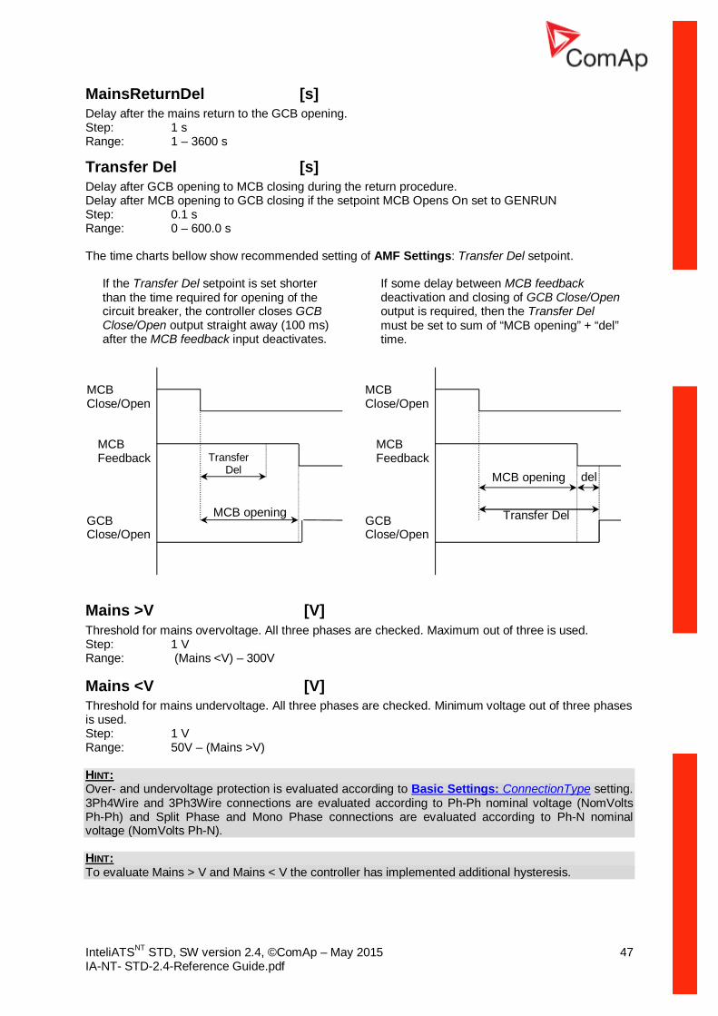
MainsReturnDel [s] Delay after the mains return to the GCB opening. Step: 1 s Range: 1 – 3600 s
Transfer Del [s] Delay after GCB opening to MCB closing during the return procedure. Delay after MCB opening to GCB closing if the setpoint MCB Opens On set to GENRUN Step: 0.1 s Range: 0 – 600.0 s The time charts bellow show recommended setting of AMF Settings: Transfer Del setpoint.
If the Transfer Del setpoint is set shorter than the time required for opening of the circuit breaker, the controller closes GCB Close/Open output straight away (100 ms) after the MCB feedback input deactivates.
If some delay between MCB feedback deactivation and closing of GCB Close/Open output is required, then the Transfer Del must be set to sum of “MCB opening” + “del” time.
Mains >V [V] Threshold for mains overvoltage. All three phases are checked. Maximum out of three is used. Step: 1 V Range: (Mains <V) – 300V
Mains <V [V] Threshold for mains undervoltage. All three phases are checked. Minimum voltage out of three phases is used. Step: 1 V Range: 50V – (Mains >V) HINT: Over- and undervoltage protection is evaluated according to Basic Settings: ConnectionType setting. 3Ph4Wire and 3Ph3Wire connections are evaluated according to Ph-Ph nominal voltage (NomVolts Ph-Ph) and Split Phase and Mono Phase connections are evaluated according to Ph-N nominal voltage (NomVolts Ph-N). HINT: To evaluate Mains > V and Mains < V the controller has implemented additional hysteresis.
MCB Close/Open
MCB Feedback
GCB Close/Open
MCB opening del
Transfer Del
MCB Close/Open
MCB Feedback
GCB Close/Open
Transfer Del
MCB opening

InteliATSNT STD, SW version 2.4, ©ComAp – May 2015 48 IA-NT- STD-2.4-Reference Guide.pdf
Mains >Freq [%] Threshold for mains overfrequency. All three phases are checked. Maximum out of three is used. Step: 0.1% of Nominal frequency Range: 50 (Mains <Freq) – 150.0%
Mains <Freq [%] Threshold for mains underfrequency. All three phases are checked. Minimum out of three is used. Step: 0.1% of Nominal frequency Range: 50% – 150.0(Mains >Freq)%
MCB Logic [CLOSE-ON / CLOSE-OFF] The set point affects the behavior of the output MCB CLOSE/OPEN CLOSE-ON: When the output MCB CLOSE/OPEN is closed – MCB should be closed. CLOSE-OFF: When the output MCB CLOSE/OPEN is closed – MCB should be opened.
NOTE: In the case MCB Logic = “CLOSE-OFF” it is necessary to change externally the polarity of the output signal.
IA “OFF”
MCB logic = ”CLOSE-ON”
IA “ON”
Mains O.K. Mains O.K.
Mains Failure
Signal after external inverted relay
MCB logic = ”CLOSE-OFF”

InteliATSNT STD, SW version 2.4, ©ComAp – May 2015 49 IA-NT- STD-2.4-Reference Guide.pdf
MCB Opens On [MAINSFAIL / GENRUN] MAINSFAIL The command to open the MCB is given immediately after mains fail condition evaluated. GENRUN The command to open the MCB is not given till the Gen-set starts (with respecting the setpoint EmergStart Del), reaches Running state, reaches proper voltage and frequency and Min Stab Time elapses. After that, the MCB is opened, Transfer Del timer is started and the GCB is closed after the timer elapses. NOTE: This option should be used for MCBs using 230V control and not equipped with the undervoltage coil.
InteliATSNT STD, SW version 2.4, ©ComAp – May 2015 50 IA-NT- STD-2.4-Reference Guide.pdf
Function Description
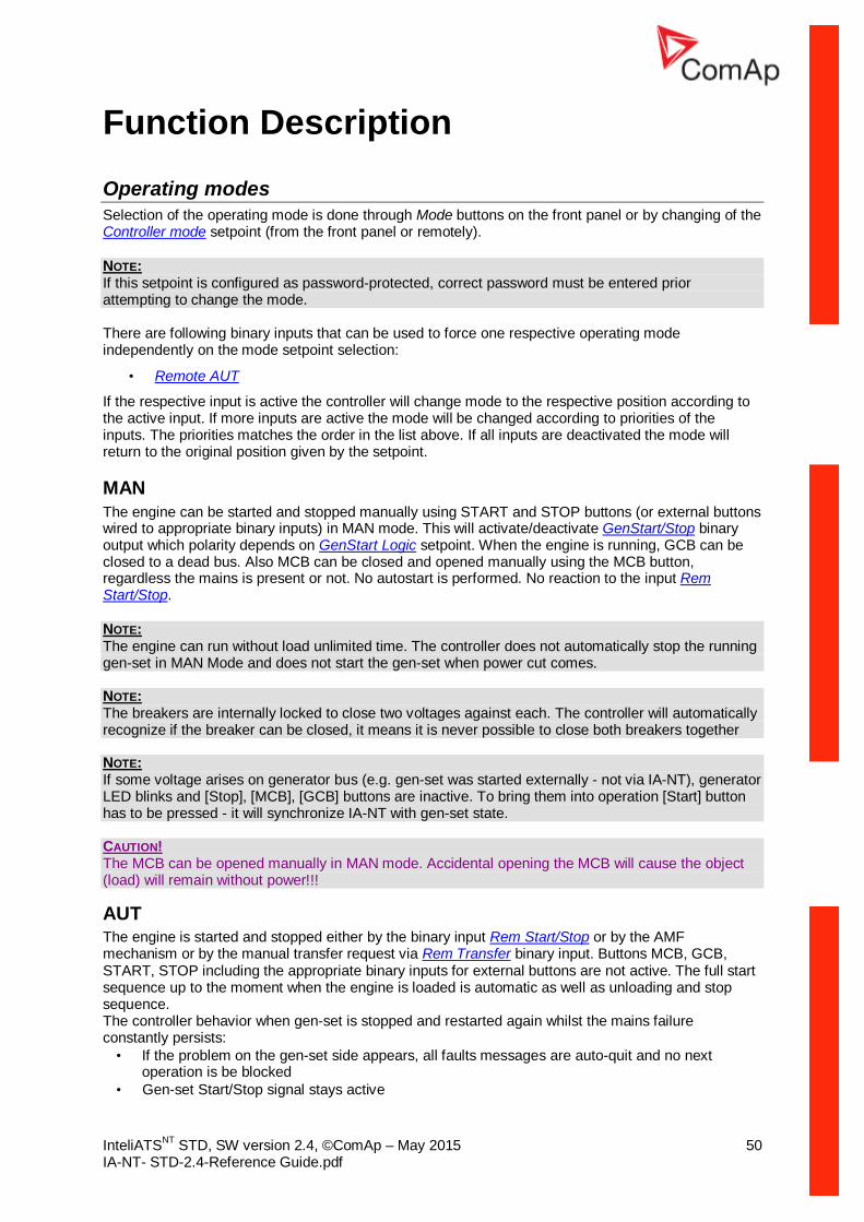
Operating modes Selection of the operating mode is done through Mode buttons on the front panel or by changing of the Controller mode setpoint (from the front panel or remotely).
NOTE: If this setpoint is configured as password-protected, correct password must be entered prior attempting to change the mode. There are following binary inputs that can be used to force one respective operating mode independently on the mode setpoint selection:
• Remote AUT
If the respective input is active the controller will change mode to the respective position according to the active input. If more inputs are active the mode will be changed according to priorities of the inputs. The priorities matches the order in the list above. If all inputs are deactivated the mode will return to the original position given by the setpoint.
MAN The engine can be started and stopped manually using START and STOP buttons (or external buttons wired to appropriate binary inputs) in MAN mode. This will activate/deactivate GenStart/Stop binary output which polarity depends on GenStart Logic setpoint. When the engine is running, GCB can be closed to a dead bus. Also MCB can be closed and opened manually using the MCB button, regardless the mains is present or not. No autostart is performed. No reaction to the input Rem Start/Stop.
NOTE: The engine can run without load unlimited time. The controller does not automatically stop the running gen-set in MAN Mode and does not start the gen-set when power cut comes. NOTE: The breakers are internally locked to close two voltages against each. The controller will automatically recognize if the breaker can be closed, it means it is never possible to close both breakers together NOTE: If some voltage arises on generator bus (e.g. gen-set was started externally - not via IA-NT), generator LED blinks and [Stop], [MCB], [GCB] buttons are inactive. To bring them into operation [Start] button has to be pressed - it will synchronize IA-NT with gen-set state. CAUTION! The MCB can be opened manually in MAN mode. Accidental opening the MCB will cause the object (load) will remain without power!!!
AUT The engine is started and stopped either by the binary input Rem Start/Stop or by the AMF mechanism or by the manual transfer request via Rem Transfer binary input. Buttons MCB, GCB, START, STOP including the appropriate binary inputs for external buttons are not active. The full start sequence up to the moment when the engine is loaded is automatic as well as unloading and stop sequence. The controller behavior when gen-set is stopped and restarted again whilst the mains failure constantly persists:
• If the problem on the gen-set side appears, all faults messages are auto-quit and no next operation is be blocked
• Gen-set Start/Stop signal stays active
InteliATSNT STD, SW version 2.4, ©ComAp – May 2015 51 IA-NT- STD-2.4-Reference Guide.pdf
• Controller waits for gen-set parameters are OK (means GenReadyToLoad signal is activated or generator voltages are in allowed limits) and then GCB is reclosed
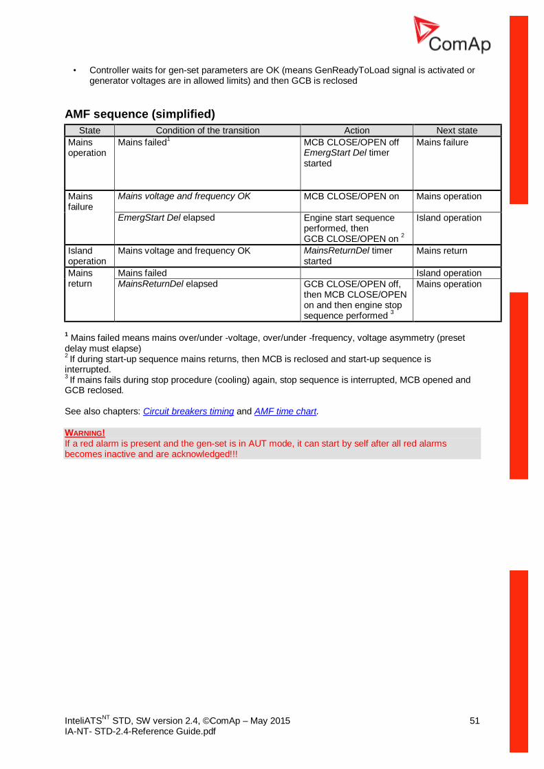
AMF sequence (simplified) State Condition of the transition Action Next state
Mains operation
Mains failed1 MCB CLOSE/OPEN off EmergStart Del timer started
Mains failure
Mains failure
Mains voltage and frequency OK MCB CLOSE/OPEN on
Mains operation
EmergStart Del elapsed
Engine start sequence performed, then GCB CLOSE/OPEN on 2
Island operation
Island operation
Mains voltage and frequency OK MainsReturnDel timer started
Mains return
Mains return
Mains failed Island operation MainsReturnDel elapsed GCB CLOSE/OPEN off,
then MCB CLOSE/OPEN on and then engine stop sequence performed 3
Mains operation
1 Mains failed means mains over/under -voltage, over/under -frequency, voltage asymmetry (preset delay must elapse) 2 If during start-up sequence mains returns, then MCB is reclosed and start-up sequence is interrupted. 3 If mains fails during stop procedure (cooling) again, stop sequence is interrupted, MCB opened and GCB reclosed.
See also chapters: Circuit breakers timing and AMF time chart.
WARNING! If a red alarm is present and the gen-set is in AUT mode, it can start by self after all red alarms becomes inactive and are acknowledged!!!

InteliATSNT STD, SW version 2.4, ©ComAp – May 2015 52 IA-NT- STD-2.4-Reference Guide.pdf
Circuit breakers timing
Relation between Mains fail and MCB and start of gen-set Mains fail is detected as Mains <V, Mains >V, Mains V Unbal, Mains <Freq, Mains >Freq. After detection MCB is opened. NOTE: When MCB drop-out and measured mains electrical limits (voltage, frequency) are still in limits, the controller switches MCB ON again.
EmergStart Del
Mains fail
MCB opened
Preset delay
genset start
Relation between Mains return and MCB MAN Mode, GCB and MCB are opened
Mains return
MCB closed (only when genset is not running and GCB is opened)
1 sec.
Relation between GCB and MCB Conditions: AUTO Mode, Mains =off, MCB = opened, GCB = closed, gen-set loaded. Mains returns: GCB opens (MainsReturnDel), MCB closes (1 sec)
GCB opened
MCB closed
1 sec.

InteliATSNT STD, SW version 2.4, ©ComAp – May 2015 53 IA-NT- STD-2.4-Reference Guide.pdf
Alarm Management Following alarms are available:
• Warning • Trip • Mains failure
Warning (WRN) When warning comes up, only alarm outputs and common warning output are closed.
Possible warnings: See List of possible events
Trip (TRP) When the trip alarm comes up, InteliATSNT opens outputs GCB CLOSE/OPEN, GENSTART/STOP and PRESTART to stop the engine immediately. Alarm outputs and common shutdown output are closed. Active or not reset protection disables start.
Possible shut-down alarms: See List of possible events
Mains failure (MF) Mains failure detection depends on Auto mains failure (AMF) setpoints (levels and delays) adjusting. When the mains failure comes up, mains circuit breaker is opened.
Possible mains failure reasons: See List of possible events NOTE: Mains failure is not written to alarm list!
InteliATSNT STD, SW version 2.4, ©ComAp – May 2015 54 IA-NT- STD-2.4-Reference Guide.pdf
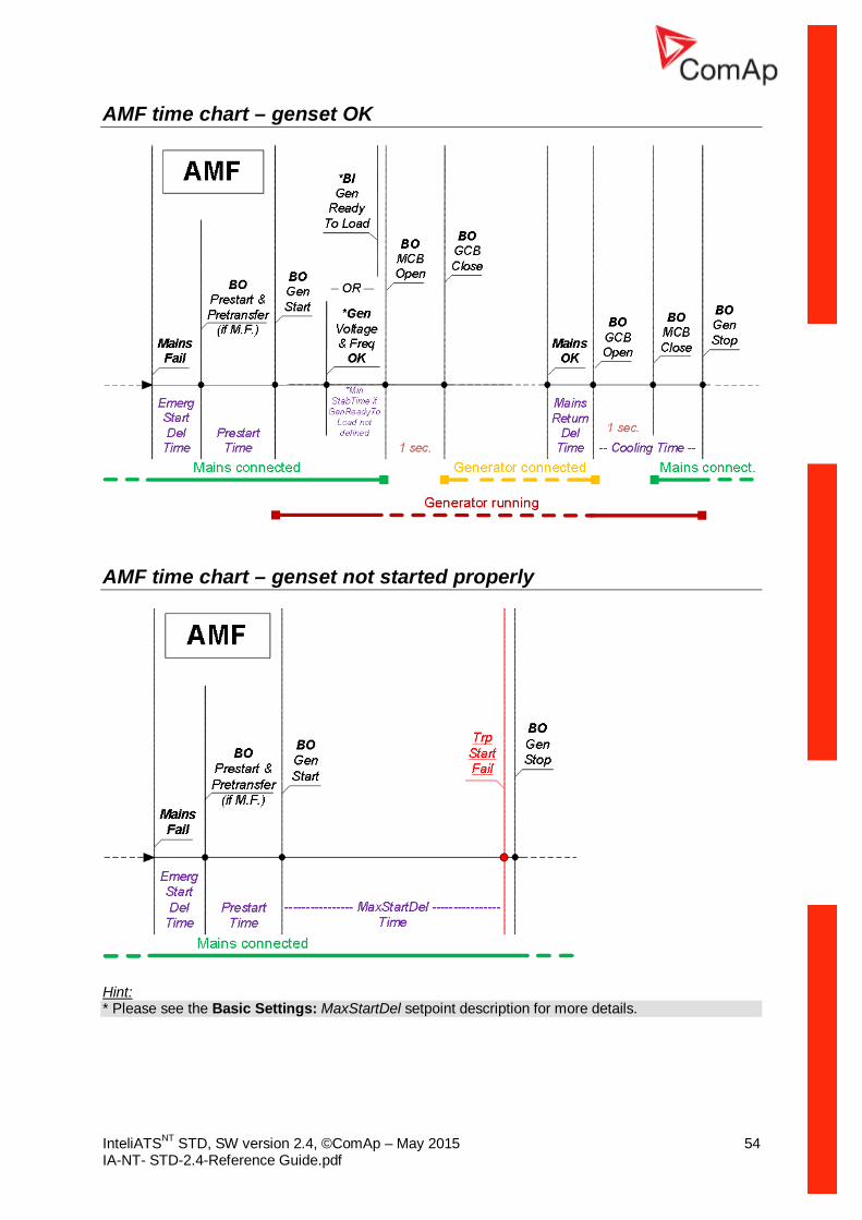
AMF time chart – genset OK
AMF time chart – genset not started properly
Hint: * Please see the Basic Settings: MaxStartDel setpoint description for more details.
InteliATSNT STD, SW version 2.4, ©ComAp – May 2015 55 IA-NT- STD-2.4-Reference Guide.pdf
Voltage phase sequence detection InteliATSNT controller detects phase sequence on both generator and mains/bus voltage terminals. These protections are important after controller installation to avoid wrong voltage phases connection. Following alarms can be detected:
Wrong phase sequence There is fix defined phase sequence in InteliATSNT controller L1, L2, L3. When the phases are connected in different order (e.g. L1, L3, L2 or L2, L1, L3) following alarms are detected:
Gen CCW Rot = wrong generator phase sequence Mains CCW Rot = wrong mains phase sequence
InteliATSNT STD, SW version 2.4, ©ComAp – May 2015 56 IA-NT- STD-2.4-Reference Guide.pdf
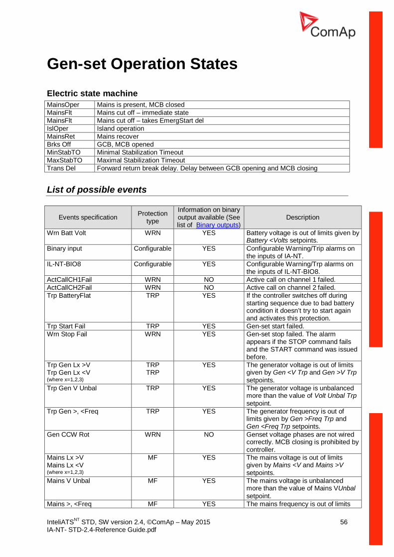
Gen-set Operation States Electric state machine MainsOper Mains is present, MCB closed MainsFlt Mains cut off – immediate state MainsFlt Mains cut off – takes EmergStart del IslOper Island operation MainsRet Mains recover Brks Off GCB, MCB opened MinStabTO Minimal Stabilization Timeout MaxStabTO Maximal Stabilization Timeout Trans Del Forward return break delay. Delay between GCB opening and MCB closing
List of possible events
Events specification Protection type
Information on binary output available (See list of Binary outputs)
Description
Wrn Batt Volt WRN YES Battery voltage is out of limits given by Battery <Volts setpoints.
Binary input Configurable YES Configurable Warning/Trip alarms on the inputs of IA-NT.
IL-NT-BIO8 Configurable YES Configurable Warning/Trp alarms on the inputs of IL-NT-BIO8.
ActCallCH1Fail WRN NO Active call on channel 1 failed. ActCallCH2Fail WRN NO Active call on channel 2 failed. Trp BatteryFlat TRP YES If the controller switches off during
starting sequence due to bad battery condition it doesn’t try to start again and activates this protection.
Trp Start Fail TRP YES Gen-set start failed. Wrn Stop Fail WRN YES Gen-set stop failed. The alarm
appears if the STOP command fails and the START command was issued before.
Trp Gen Lx >V Trp Gen Lx <V (where x=1,2,3)
TRP TRP
YES The generator voltage is out of limits given by Gen <V Trp and Gen >V Trp setpoints.
Trp Gen V Unbal TRP YES The generator voltage is unbalanced more than the value of Volt Unbal Trp setpoint.
Trp Gen >, <Freq TRP YES The generator frequency is out of limits given by Gen >Freq Trp and Gen <Freq Trp setpoints.
Gen CCW Rot WRN NO Genset voltage phases are not wired correctly. MCB closing is prohibited by controller.
Mains Lx >V Mains Lx <V (where x=1,2,3)
MF YES The mains voltage is out of limits given by Mains <V and Mains >V setpoints.
Mains V Unbal MF YES The mains voltage is unbalanced more than the value of Mains VUnbal setpoint.
Mains >, <Freq MF YES The mains frequency is out of limits

InteliATSNT STD, SW version 2.4, ©ComAp – May 2015 57 IA-NT- STD-2.4-Reference Guide.pdf
Events specification Protection type
Information on binary output available (See list of Binary outputs)
Description
given by Mains >Freq and Mains <Freq setpoints.
Mains CCW Rot WRN NO Mains voltage phases are not wired correctly. MCB closing is prohibited by controller.
EmergencyStop TRP NO If the input Emergency Stop is opened Trip is immediately activated.
Total Stop TRP NO If the input Total Stop is opened Trip is immediately activated.
Trp GeRd Fail TRP NO Signal BI GenReadyToLoad lost ParamFail NONE NO Wrong checksum of parameters.
Happens typically after downloading new firmware or changing of the parameter. The controller stays in INIT mode. Check all parameters and write at least one new parameter.
xCB Disabled WRN NO LBI MCB or GCB is activated. NOTE: Events Trp Gen Lx <V, Trp Gen <Freq, Trp Gen V Unbal are confirmed automatically. Fault Reset it’s not necessary to activate after the cause of the event disappeared.
InteliATSNT STD, SW version 2.4, ©ComAp – May 2015 58 IA-NT- STD-2.4-Reference Guide.pdf
Init Screens InteliATSNT controller holds information about serial number, uploaded firmware version and others. These information are displayed on so called “Init Screens”. It is possible to call this screen from any measurement screen by pressing ENTER and PAGE buttons concurrently and then only PAGE button separately. Init screens consist of:
Customer Logo screen This is a first screen which is dedicated for information provided by customers such as contact numbers, service technician contact and customer message for end users of gen-set. Configuration of this screen is only done by LiteEdit PC software.
Firmware Init screen This screen consists information about type of controller, controller manufacturer ComAp, uploaded firmware branch, used application and version of firmware.
Language screen InteliATSNT controller offers configurable language support. On this screen is possible to switch between languages configured in controller.
User Interface screen InteliATSNT controller enables to choose the user interface as customer prefers. There are two choices available: USER or ENGINEER interface. USER interface is meant for customers, who prefer simple and easy menu and don’t wish to list in complex menu or change the settings of controller. In USER interface controller displays measuring, alarm and init screens. ENGINEER interface is dedicated for engineers and allow changing the settings of controller, reviewing the history, measurement, alarms and grant the full access to all controllers screens which are available. This mode is default. This screen also consists information about controller’s Serial number and Password decode number which can be useful in case of lost password to controller. For this situations please contact your distributor for help and these two numbers will be needed to recover the password. Last value displayed on screen is DiagData, which is internal ComAp information is case of FW or unit problems, which helps ComAp to analyze the root cause and find a proper solution.

InteliATSNT STD, SW version 2.4, ©ComAp – May 2015 59 IA-NT- STD-2.4-Reference Guide.pdf
Remote Control and Data Logging
PC software – LiteEdit On the PC (for direct or modem connection) has to be installed the ComAp’s software package LiteEdit. (based on Windows 95 or newer platform) LiteEdit enables:
• read the quantities • adjust all set points • control the engine • configure the controller • select software configuration • modify alarm inputs and outputs • modify password, commands protections • direct, modem or Internet communication
Direct cable connection
An external communication module is necessary to enable direct cable connection to a PC. The module is plugged into the slot located on the rear side of the controller. Find more information about installation of the modules in a separate chapter. A RS232, USB or RS485 interface can be used for direct cable connection to a PC. The setpoint COM1 Mode or COM2 Mode (according to the interface used) must be set to DIRECT position for this kind of connection.
DIRECT CABLE CONNECTION TYPES The following modules are available for direct connection to a PC:
1. IL-NT RS232 2. IL-NT RS232-485 3. IL-NT S-USB (USB easily removable service module)

InteliATSNT STD, SW version 2.4, ©ComAp – May 2015 60 IA-NT- STD-2.4-Reference Guide.pdf
The RS232 or USB interface uses COM1 port of the controller. The RS485 uses COM2.
NOTE: Use a cross-wired serial communication cable with DB9 female connectors and signals Rx, Tx, GND for a RS232 connection.
HINT: Make sure the grounding system on controller and PC – COM port (negative of the PC DC supply) are identical – before the first direct connection. There must not be any voltage between these two points otherwise the internal reversible fuse in controller burns out. The simple solution is to assure, that the PC supply 240/20V is ground free (GND terminal is not connected).
5 - GND
2 - RxD3 - TxD
PC
5 - GND
2 - RxD3 - TxD
RS23
2
RS2
32
230 VAC
0 VD
C
CONTROLLER
+-Battery
Required the samevoltage potentialbetween GND‘s
RS 232
Modem connection
A PC can be connected to the controller also remotely via modems. Either an analog, GSM or ISDN modem must be connected to the RS232 interface and the setpoint COM1 Mode must be set to MODEM.
MODEM CONNECTION TYPES

InteliATSNT STD, SW version 2.4, ©ComAp – May 2015 61 IA-NT- STD-2.4-Reference Guide.pdf
The following modules can be used for a modem connection to a PC:
1. IL-NT RS232 2. IL-NT RS232-485
The RS232 interface uses COM1 port of the controller. If you have trouble with modem communication, an additional initialization string may be required. This may be due to, for example, a national telephone network-specific feature. Use the setpoint ModemIniString to add the necessary AT commands which will be sent to the modem during the initialization. See the documentation of the modem for details.
NOTE: Use the same kind of modem (e.g. analog, GSM or ISDN) as used on the controller also on the PC side.
Recommended GSM modems
• Siemens/Cinterion M20, TC35, TC35i, ES75, MC39 (baud rate 9600 bps) • Wavecom M1200/WMOD2 (baud rate 9600 bps) • Wavecom Maestro 20 • Wavecom Fastrack M1306B (Fastrack M1206B is not recommended) • Falcom A2D
Modem setup procedure Analog modems obviously do not require any setup. The only case in which setup could be necessary is if the modem has been bought in a country with a telephony system different than the target country where the modem will be used. GSM modems need to be set up prior to using them with the controller. Use the gm_setup program (installed together with LiteEdit) to perform initial setup of the modem. See the latest Inteli Communication Guide (available on the ComAp web site) for details. The setup must be done while a SIM card is inserted.
NOTE: It is always recommended to use modems bought in and approved for the target country.
Internet connection
A PC can be connected to the controller also remotely via Ethernet (internet, intranet). An appropriate Ethernet communication module must be used. Use a plug-in communication module IB-Lite or IL-NT-GPRS to connect to the IA-NT controller via the internet. The setpoint COM1 Mode must be set to the DIRECT position.
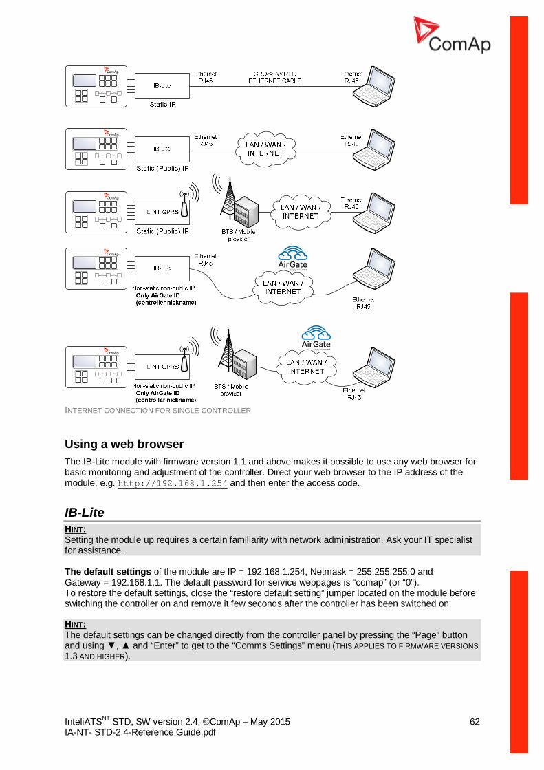
InteliATSNT STD, SW version 2.4, ©ComAp – May 2015 62 IA-NT- STD-2.4-Reference Guide.pdf
INTERNET CONNECTION FOR SINGLE CONTROLLER
Using a web browser The IB-Lite module with firmware version 1.1 and above makes it possible to use any web browser for basic monitoring and adjustment of the controller. Direct your web browser to the IP address of the module, e.g. http://192.168.1.254 and then enter the access code.
IB-Lite HINT: Setting the module up requires a certain familiarity with network administration. Ask your IT specialist for assistance.
The default settings of the module are IP = 192.168.1.254, Netmask = 255.255.255.0 and Gateway = 192.168.1.1. The default password for service webpages is “comap” (or “0”). To restore the default settings, close the “restore default setting” jumper located on the module before switching the controller on and remove it few seconds after the controller has been switched on. HINT: The default settings can be changed directly from the controller panel by pressing the “Page” button and using , and “Enter” to get to the “Comms Settings” menu (THIS APPLIES TO FIRMWARE VERSIONS 1.3 AND HIGHER).

InteliATSNT STD, SW version 2.4, ©ComAp – May 2015 63 IA-NT- STD-2.4-Reference Guide.pdf
Configuration
1. Plug the module into the controller and power the controller on. 2. Connect the module into your Ethernet network. If the default address does not match local
network parameters (i.e. the network segment does not use the IP range 192.168.1.xxx or the IP 192.168.1.254 is occupied), connect the module directly to your PC using a cross-wired cable. See details in the Installation chapter.
3. If you are connected directly, you have to change temporarily the IP address and subnet mask of your PC Ethernet connection. Use the following settings: DHCP disabled, IP from the range 192.168.1.1 – 192.168.1.253 and subnet mask 255.255.255.0. After the IB-Lite setup is finished, restore your PC setting back to the original values.
4. Start a web browser and direct it to http://192.168.1.254/sp_config.htm. 5. After a successful login the configuration page will be displayed. 6. It is recommended to change the user name and password and keep the new values
confidential. 7. Consult your IT specialist for proper IP settings. 8. Consult your e-mail provider for proper e-mail settings. Note that also most public SMTP
servers require authentication and e-mails must be sent from an existing address. 9. If you want to enable access only for clients with a specified IP address, tick the checkbox
“Trusted clients” and fill-in the allowed IP addresses.
HINT: See also the latest LiteEdit Reference Guide (available on the ComAp web site) for more information about IB-Lite setup.
Firmware upgrade
1. Follow steps 1–3 of the configuration procedure above. 2. Start a web browser and direct it to http://192.168.1.254/sp_fw_upld.htm. 3. After a successful login the configuration page will be displayed. 4. Press the button “Browse” and select the appropriate firmware file. 5. Press “Upload new firmware” button. After the firmware upload is finished, the module will
restart.
HINT: Interrupting the upload will NOT cause any damage. Just repeat the upload again.
IL-NT-GPRS CAUTION! Any manipulation with plug-in module shall be done with disconnected power supply to both controller and module. Power supply shall be switched on also is same time to both module and controller. Fail to follow these instructions (power supply active only in controller or only in module) can lead to module or controller failure!

InteliATSNT STD, SW version 2.4, ©ComAp – May 2015 64 IA-NT- STD-2.4-Reference Guide.pdf
1. You will need one of supported ComAp controllers (IL-NT/IC-NT/ID-Lite/IA-NT), IL-NT-GPRS, antenna, SIM card with GPRS service and optionally IL-NT-RS232 or IL-NT-S-USB module.
2. Contact SIM card operator for getting GPRS APN (APN = Access Point Name) name, username and password. Example: APN Name = internet.t-mobile.cz, UserName = [blank], Password = [blank].
3. Make sure SIM card does not require PIN code. If it does, it is possible to disable it in any common network unlocked mobile telephone.
4. Power up the ComAp controller. 5. Enter correct APN Name, APN UserName and APN UserPass in controller’s setpoint group
Comms Settings. Set COM1 Mode = DIRECT. Comms settings as every setpoint group are accessible by PAGE button from any measurement screen on controller. Setpoints can be set on controller’s front panel keyboard or by LiteEdit 4.5 and higher.
6. Switch off ComAp controller. 7. Place the SIM card into slot on IL-NT-GPRS card, plug in the IL-NT-GPRS card into
communication slot on back side of ComAp controller. 8. Connect the antenna to designated SMA connector. 9. Connect power supply to IL-NT-GPRS module. It supports 8-36V DC voltage. 10. Power up the system. 11. Wait for approx 2 - 4 minutes for first connection of the system to AirGate. AirGate will
generate automatically the AirGate ID value. Then navigate to last of measurement screens where you will find signal strength bar and AirGate ID identifier.
Once this AirGate ID is displayed, connection via AirGate was successful. This value will be needed for LiteEdit or WebSupervisor connection. Kindly make a note for future reference.
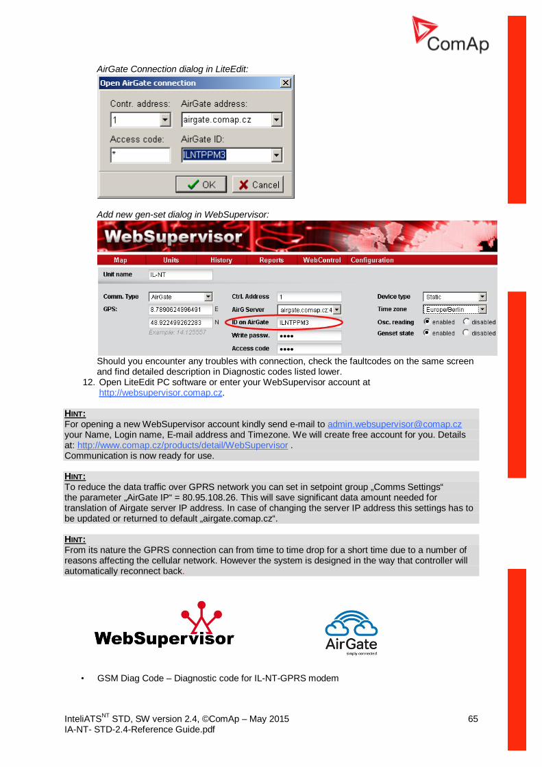
InteliATSNT STD, SW version 2.4, ©ComAp – May 2015 65 IA-NT- STD-2.4-Reference Guide.pdf
AirGate Connection dialog in LiteEdit:
Add new gen-set dialog in WebSupervisor:
Should you encounter any troubles with connection, check the faultcodes on the same screen and find detailed description in Diagnostic codes listed lower.
12. Open LiteEdit PC software or enter your WebSupervisor account at http://websupervisor.comap.cz.
HINT: For opening a new WebSupervisor account kindly send e-mail to [email protected] your Name, Login name, E-mail address and Timezone. We will create free account for you. Details at: http://www.comap.cz/products/detail/WebSupervisor . Communication is now ready for use.
HINT: To reduce the data traffic over GPRS network you can set in setpoint group „Comms Settings“ the parameter „AirGate IP“ = 80.95.108.26. This will save significant data amount needed for translation of Airgate server IP address. In case of changing the server IP address this settings has to be updated or returned to default „airgate.comap.cz“.
HINT: From its nature the GPRS connection can from time to time drop for a short time due to a number of reasons affecting the cellular network. However the system is designed in the way that controller will automatically reconnect back.
• GSM Diag Code – Diagnostic code for IL-NT-GPRS modem

InteliATSNT STD, SW version 2.4, ©ComAp – May 2015 66 IA-NT- STD-2.4-Reference Guide.pdf
Table of Diagnostic Codes: Code Description
0 OK. No error. 1 Not possible to hang up. 2 IL-NT-GPRS is switched off 3 IL-NT-GPRS is switched on 4 IL-NT-GPRS – error in initialization 5 IL-NT-GPRS – not possible to set the APN 6 IL-NT-GPRS – not possible to connect to GPRS network 7 IL-NT-GPRS – not possible to retrieve IP address 8 IL-NT-GPRS – not accepted DNS IP address 9 Error in modem detection
10 Error in initialization of analog modem
11 SIM card is locked (Possibly PIN code required, PIN needs to be deactivated) or unknown status of SIM locking
12 No GSM signal 13 Not possible to read the SIM card parameters
14 GSM modem did not accepted particular initialization command, possibly caused by locked SIM card
15 Unknown modem 16 Bad answer to complement initialization string 17 Not possible to read GSM signal strength 18 CDMA modem not detected 19 No CDMA network 20 Unsuccessful registration to CDMA network 23 Controller couldn´t detect IL-NT GPRS module communication speed.
255 Only running communication is needed to indicate • AirGate Diag – Diagnostic Code for AirGate connection
Table of Diagnostic Codes:
Code Description 0 Waiting for connection to AirGate Server 1 Controller registered, waiting for authorization 2 Not possible to register, controller blacklisted 3 Not possible to register, server has no more capacity 4 Not possible to register, other reason 5 Controller registered and authorized
AirGate
technology for easy plug-and-play wireless communication is incorporated into the product. An ordinary SIM card with GPRS service is suitable for this system. This overcomes problems with the necessity for a special SIM card (fixed and public IP), firewalls and difficult communication settings. http://www.comap.cz/news-room/news-and-events/detail/AirGate http://www.comap.cz/news-room/news-and-events/detail/The-Rainbow-rises-for-remotemonitoring-applications/

InteliATSNT STD, SW version 2.4, ©ComAp – May 2015 67 IA-NT- STD-2.4-Reference Guide.pdf
Locate The controller supports the technology for GSM localization using an IL-NT-GPRS communication module. It is possible to view the localization in WebSupervisor.

InteliATSNT STD, SW version 2.4, ©ComAp – May 2015 68 IA-NT- STD-2.4-Reference Guide.pdf
IL-NT-RD Remote display software This chapter describes Remote display software IL-NT-RD, which is designed as an remote signaling and control software for InteliATSNT, InteliLiteNT and InteliDrive Lite controllers. It is the optional software which is possible to upload into controller instead of standard controller’s firmware.
General description Remote display software works as “remote display and control” for the master InteliATSNT, InteliLiteNT or InteliDrive Lite controller. Genset/Engines can be controlled from remote display as well as from master controller. All remote display screens (Measure, Setpoints and History) displays the same data like master controller. Front panel buttons on both controllers work the same way. All remote display LED’s shows the same state as corresponding LED’s on master controller.
Warning ! It is highly recommended to use the same type and model of controller for master and remote display. Only in such case is assured the proper function of all buttons, LED diodes and display. Another combinations of HW types and models from Master controller and remote display are not supported nor tested!
IL-NT-RD Software installation The IL-NT-RD remote display firmware is installed in the same way as any other IA-NT firmware using LiteEdit software. Please see LiteEdit Reference guide for details about upgrading firmware. IL-NT-RD contains only firmware, not an archive. However when there is IL-NT-RD firmware installed in the controller the procedure to install back the original standard firmware is following:
• Open any type of online connection. • DDE server will try to open the connection, but it will fail and write red error message in the
status bar. • At this moment go to CONTROLLER -> PROGRAMMING AND CLONING -> PROGRAMMING and select
proper! firmware you want program to the controller. Choosing the wrong type of firmware may result in non-functional controller.
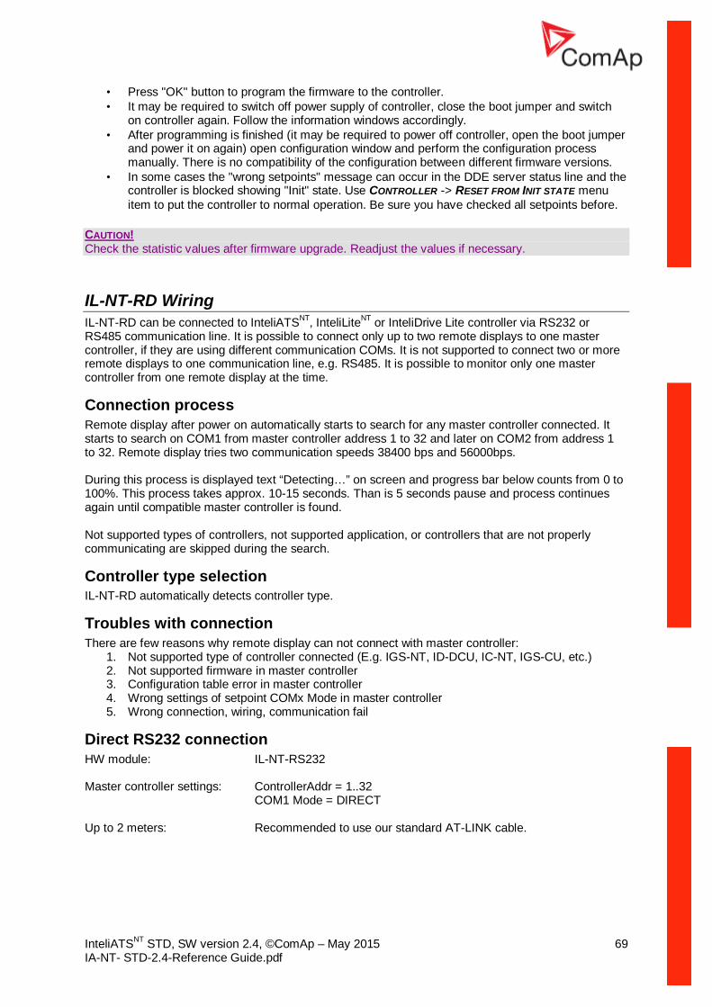
InteliATSNT STD, SW version 2.4, ©ComAp – May 2015 69 IA-NT- STD-2.4-Reference Guide.pdf
• Press "OK" button to program the firmware to the controller. • It may be required to switch off power supply of controller, close the boot jumper and switch
on controller again. Follow the information windows accordingly. • After programming is finished (it may be required to power off controller, open the boot jumper
and power it on again) open configuration window and perform the configuration process manually. There is no compatibility of the configuration between different firmware versions.
• In some cases the "wrong setpoints" message can occur in the DDE server status line and the controller is blocked showing "Init" state. Use CONTROLLER -> RESET FROM INIT STATE menu item to put the controller to normal operation. Be sure you have checked all setpoints before.
CAUTION! Check the statistic values after firmware upgrade. Readjust the values if necessary.
IL-NT-RD Wiring IL-NT-RD can be connected to InteliATSNT, InteliLiteNT or InteliDrive Lite controller via RS232 or RS485 communication line. It is possible to connect only up to two remote displays to one master controller, if they are using different communication COMs. It is not supported to connect two or more remote displays to one communication line, e.g. RS485. It is possible to monitor only one master controller from one remote display at the time.
Connection process Remote display after power on automatically starts to search for any master controller connected. It starts to search on COM1 from master controller address 1 to 32 and later on COM2 from address 1 to 32. Remote display tries two communication speeds 38400 bps and 56000bps. During this process is displayed text “Detecting…” on screen and progress bar below counts from 0 to 100%. This process takes approx. 10-15 seconds. Than is 5 seconds pause and process continues again until compatible master controller is found. Not supported types of controllers, not supported application, or controllers that are not properly communicating are skipped during the search.
Controller type selection IL-NT-RD automatically detects controller type.
Troubles with connection There are few reasons why remote display can not connect with master controller:
1. Not supported type of controller connected (E.g. IGS-NT, ID-DCU, IC-NT, IGS-CU, etc.) 2. Not supported firmware in master controller 3. Configuration table error in master controller 4. Wrong settings of setpoint COMx Mode in master controller 5. Wrong connection, wiring, communication fail
Direct RS232 connection HW module: IL-NT-RS232 Master controller settings: ControllerAddr = 1..32
COM1 Mode = DIRECT Up to 2 meters: Recommended to use our standard AT-LINK cable.
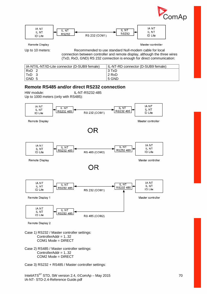
InteliATSNT STD, SW version 2.4, ©ComAp – May 2015 70 IA-NT- STD-2.4-Reference Guide.pdf
Up to 10 meters: Recommended to use standard Null-modem cable for local
connection between controller and remote display, although the three wires (TxD, RxD, GND) RS 232 connection is enough for direct communication:
IA-NT/IL-NT/ID-Lite connector (D-SUB9 female) IL-NT-RD connector (D-SUB9 female) RxD 2 3 TxD TxD 3 2 RxD GND 5 5 GND
Remote RS485 and/or direct RS232 connection HW module: IL-NT-RS232-485 Up to 1000 meters (only with RS485):
Case 1) RS232 / Master controller settings:
ControllerAddr = 1..32 COM1 Mode = DIRECT
Case 2) RS485 / Master controller settings:
ControllerAddr = 1..32 COM2 Mode = DIRECT
Case 3) RS232 + RS485 / Master controller settings:

InteliATSNT STD, SW version 2.4, ©ComAp – May 2015 71 IA-NT- STD-2.4-Reference Guide.pdf
ControllerAddr = 1..32 COM1 Mode = DIRECT COM2 Mode = DIRECT
It is possible to make a RS232 direct connection with IL-NT-RS232 module on one side and IL-NT-RS232-485 module on the other side.
Alternative connection using external RS232-RS422/485 converter: Recommend external converter: ADVANTECH – ADAM 4520: RS232 to RS422/485 converter, DIN rail, automatic RS485 bus supervision, no external data flow control signals, galvanic isolated, baud rate 38400 or 56000 bps. Any connected RS 232 to RS 422/485 converter has to be set to passive DSR signal (when DSR connected) after switch on.
Function description Remote display IL-NT-RD works as remote display and control of the master InteliATSNT, InteliLiteNT or InteliDrive Lite controller. It is supposed and highly recommended that both, remote display and master are using the same HW type and model of controller. Another types and models of master and remote display are not supported nor tested. All remote display’s LEDs show the same state as corresponding LEDs on master controller. Front panel buttons on both controllers work in the same way. Genset/Engine can be controlled from remote display as well as from master controller. User can switch screens, set password, change setpoints and view history records. All IL-NT-RD screens Init, Measure, Setpoints and History display the same data like in the master controller. Master device is always able to work without connected Remote display. Interruption of the serial line between master device and Remote display has no effect to the master controller. If the serial line between master device and remote display is interrupted, or communication cannot be established, remote display shows it’s Init screen and message “Trying” and all LED’s are off. Once remote display finds compatible master it shows “Preparing” and downloads configuration table from master controller. After the configuration from master is downloaded remote display jump to master controllers Init screen and all LEDs and blinking. It is possible to switch to remote displays Init screen to check it’s version and serial number of used controller and communication status by pressing PAGE button for 3 seconds.
SW compatibility IL-NT-RD sw. version 1.0 is compatible with masters SW: • All InteliATSNT standard software from ver. 1.0 • All InteliLiteNT standard software from ver. 1.1 • All ID-Lite standard software from ver. 1.0 • Chosen InteliATSNT, InteliLiteNT and ID-Lite customer branches Some of the future InteliATSNT, InteliLiteNT, ID-Lite versions may require upgrade of the IL-NT-RD software.

InteliATSNT STD, SW version 2.4, ©ComAp – May 2015 72 IA-NT- STD-2.4-Reference Guide.pdf
Technical Data
Inputs/Outputs overview
Model BIN BOUT COM1 COM2 Gen. Voltage
Mains Voltage
IA-NT STD 4 (3**) 4 Y* Y* Y Y NOTE: * With optional plug-in module ** Hardware version 1.3 provides 3 inputs only Y – Available Power supply Voltage supply 8–36V DC Consumption 40–430mA depend on supply voltage and temperature Consumption depends on supply voltage 0.104A at 8VDC 0.080A at 12VDC 0.051A at 24VDC 0.044A at 30VDC
0.040A at 36VDC Allowed supply voltage drop-out: 100ms from min. 10V, return to min. 8V Battery voltage measurement tolerance 2 % at 24V NOTE: For the supply voltage less than 7V the backlight of the display is switched off. Short-term voltage drops (e.g. during the engine cranking) do not affect the operation at all.
Operating conditions Operating temperature IA-NT -20..+70oC Storage temperature -30..+80oC Protection front panel IP65 Humidity 95% without condensation Standard conformity Low Voltage Directive EN 61010-1:95 +A1:97 Electromagnetic Compatibility EN 61000-6-3:2006, EN 61000-6-3:2006 EN 61000-6-1:2005, EN 61000-6-2:1999 Vibration 2 – 25 Hz, ±1.6 mm
25 – 100 Hz, a = 4 g Shocks a = 500 m/s2
Dimensions and weight Dimensions 180x120x55mm Weight 450g
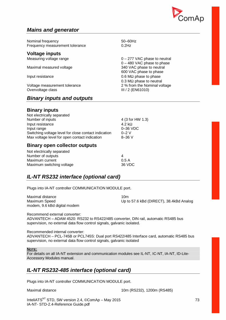
InteliATSNT STD, SW version 2.4, ©ComAp – May 2015 73 IA-NT- STD-2.4-Reference Guide.pdf
Mains and generator Nominal frequency 50–60Hz Frequency measurement tolerance 0.2Hz
Voltage inputs Measuring voltage range 0 – 277 VAC phase to neutral 0 – 480 VAC phase to phase Maximal measured voltage 340 VAC phase to neutral 600 VAC phase to phase Input resistance 0.6 MΩ phase to phase 0.3 MΩ phase to neutral Voltage measurement tolerance 2 % from the Nominal voltage Overvoltage class III / 2 (EN61010)
Binary inputs and outputs Binary inputs Not electrically separated Number of inputs 4 (3 for HW 1.3) Input resistance 4.2 kΩ Input range 0–36 VDC Switching voltage level for close contact indication 0–2 V Max voltage level for open contact indication 8–36 V
Binary open collector outputs Not electrically separated Number of outputs 4 Maximum current 0.5 A Maximum switching voltage 36 VDC
IL-NT RS232 interface (optional card) Plugs into IA-NT controller COMMUNICATION MODULE port. Maximal distance 10m Maximum Speed Up to 57.6 kBd (DIRECT), 38.4kBd Analog modem, 9.6 kBd digital modem Recommend external converter: ADVANTECH – ADAM 4520: RS232 to RS422/485 converter, DIN rail, automatic RS485 bus supervision, no external data flow control signals, galvanic isolated. Recommended internal converter: ADVANTECH – PCL-745B or PCL745S: Dual port RS422/485 Interface card, automatic RS485 bus supervision, no external data flow control signals, galvanic isolated NOTE: For details on all IA-NT extension and communication modules see IL-NT, IC-NT, IA-NT, ID-Lite-Accessory Modules manual.
IL-NT RS232-485 interface (optional card) Plugs into IA-NT controller COMMUNICATION MODULE port. Maximal distance 10m (RS232), 1200m (RS485)
InteliATSNT STD, SW version 2.4, ©ComAp – May 2015 74 IA-NT- STD-2.4-Reference Guide.pdf
Maximum speed Up to 57.6 kBd (DIRECT), 38.4kBd Analog modem, 9.6 kBd digital modem
IL-NT S-USB interface (optional card) Plugs into IA-NT controller COMMUNICATION MODULE port. Maximal distance 5m Maximum speed Up to 57.6 kBd (DIRECT), 38.4kBd Analog
modem, 9.6 kBd digital modem Use only shielded A-B USB cables up to 5m length. Recommend USB cable: USB-LINK CABLE 1.8M – ComAp A-B USB cable.
IB-Lite interface (optional card) Plugs into IA-NT controller COMMUNICATION MODULE port. Interface to Ethernet RJ45 (10baseT) Operating temperature -30..+70oC Storage temperature -30..+70oC
IL-NT-GPRS interface (optional card) Plugs into IA-NT controller COMMUNICATION MODULE port. SIM Card Type Standard size (1FF) Antenna Connector SMA Female
IL-NT AOUT8 interface (optional card) Plugs into IA-NT controller EXTENSION MODULE port. Number of PWM outputs 8 PWM frequency 250Hz Maximum current 0.5 A Maximum switching voltage 36 VDC Output resistance 1Ω Resolution 10 bits

InteliATSNT STD, SW version 2.4, ©ComAp – May 2015 75 IA-NT- STD-2.4-Reference Guide.pdf
IL-NT BIO8 extension module (optional card)
Technical details: IL-NT BIO8 plugs into the controller’s EXTENSION MODULE port. 8 dedicated pins of the plug-in card’s terminal can be configured as binary inputs or outputs.
Binary inputs Number of inputs 8 Input resistance 4.7 kΩ Input range 0–36 VDC Voltage level for close contact indication (Logical 1) < 0.8 VDC Voltage level for open contact indication (Logical 0) > 2 VDC Max voltage level for open contact indication 8–36 VDC
Binary open collector outputs Number of outputs 8 Maximum current per pin 0.5 A Maximum switching common current 2 A Maximum switching voltage 36 VDC
HINT: Binary inputs are not galvanically isolated.