introducing ti s integrated development environment code … · · 2016-11-01ccs is used to...
TRANSCRIPT
1SWRA526–November 2016Submit Documentation Feedback
Copyright © 2016, Texas Instruments Incorporated
Introducing TI’s Integrated Development Environment – Code ComposerStudio™ (CCS) to Expert Engineers
Application ReportSWRA526–November 2016
Introducing TI’s Integrated Development Environment –Code Composer Studio™ (CCS) to Expert Engineers
ABSTRACTCode Composer Studio™ (CCS) is Texas Instruments' Integrated Development Environment (IDE) usedto build, debug, and run DSP applications and other processor applications.
Contents1 Introduction ................................................................................................................... 2
1.1 Intended Audience – Expert DSP Engineer New to TI’s Code Composer Studio™ (CCS) .............. 21.2 CCS Online Training Resources.................................................................................. 21.3 Getting Started With CCS ......................................................................................... 31.4 CCS Edit and Debug Perspectives ............................................................................... 4
2 Import CCS Project From Release Examples ........................................................................... 52.1 Before Importing a Project......................................................................................... 52.2 Import the FFT Project ............................................................................................. 82.3 Define Target – Emulator ........................................................................................ 122.4 Connect to the Target and Run the Project.................................................................... 152.5 Code Execution and Measure Cycles .......................................................................... 18
3 Build a New CCS Project.................................................................................................. 203.1 Create a New Project ............................................................................................. 203.2 Building the New Project ......................................................................................... 343.3 Code Execution: Understanding the Results .................................................................. 40
4 Import Function From Library (Not Part of Processor SDK) ......................................................... 414.1 Import an Example From FFTLIB (C674x Version)........................................................... 41

Introduction www.ti.com
2 SWRA526–November 2016Submit Documentation Feedback
Copyright © 2016, Texas Instruments Incorporated
Introducing TI’s Integrated Development Environment – Code ComposerStudio™ (CCS) to Expert Engineers
Code Composer Studio is a trademark of Texas Instruments.ARM, Cortex are registered trademarks of ARM Limited.All other trademarks are the property of their respective owners.
1 Introduction
1.1 Intended Audience – Expert DSP Engineer New to TI’s Code Composer Studio™(CCS)CCS is Texas Instruments’ Integrated Development Environment (IDE), based on the open source Eclipsearchitecture. CCS is used to build, debug, and run DSP applications and other processor applications.
TI provides CCS training, documentation, and other help that covers all aspects of CCS. Section 1.2provides links for the training.
The intended audience of this document are DSP experts who have not yet worked with TI tools, yet areknowledgeable and have worked with tools from other vendors. They know what to expect from thesetools, understand the logic behind them, and only need to know the mechanics of the tools. They may nothave time for training. Their goal is to jump in and try to run a test application.
In addition to the CCS tool, TI provides software blocks to facilitate easy development of applications onTI’s devices, including a set of optimized libraries for standard mathematics (MATHLIB), signal processing(DSPLIB), and image processing (IMGLIB). A DSP expert can use these optimized functions inapplications. This document shows an expert DSP engineer how to develop applications that calloptimized library functions.
1.1.1 Steps to Take When Starting to Port a DSP Algorithm into TI EnvironmentsWhen porting an existing DSP algorithm, developed under a different environment, into TI’s IntegratedDevelopment Environment CCS, the expert engineer goes through the following steps:1. TI’s Processor Software Development Kit (SDK) is a comprehensive set of software and firmware
tools, utilities, and example modules that supports many TI processors. Each module has a unit testproject that demonstrates how to use the module. To understand how to use a library function, importthe unit test of the said function and run it on hardware such as an evaluation module (EVM). Section 2shows how to import a project from the release, build it, and run it on standard hardware.
2. Build a new application that utilizes the library function used in the previous step. Section 3 shows howto build a new non-trivial (that is, fairly complex) project, build it, and run it on standard hardware suchas an EVM.
3. The SDK is a uniform release of software blocks that ensures working together. Three standardlibraries are included in the SDK release: DSPLIB, MATHLIB, and IMGLIB. In addition, TI developed aset of optimized libraries that are not part of the Processor SDK release. These libraries includeIQMATH, FASTRTS, VICP, VLIB, FAXLIB, and VOLIB (seehttp://processors.wiki.ti.com/index.php/Software_libraries for more details). In addition, there aredevices that are not supported by the standard Processor SDK, but rather by their own SDK. Section 4shows how to build an example code (unit test) C674X that is not supported by the Processor SDK,using a library function from a dedicated FFTLIB library.
1.2 CCS Online Training Resources• CCS Training Page — contains training materials, including videos and documents.• TMS320C6000 Optimization Workshop — Section 2 discusses CCS (and provides an introduction to
C6000 architecture)• The Code Composer Studio (CCS) Integrated Development Environment (IDE) — The location to
download CCS, with links to other CCS information• Processor SDK RTOS Setup CCS — An introduction to using CCS with the Processor SDK. Some of
the materials referenced in this document are covered here• TI’s Code Composer e2e Forum — A public forum dedicated to questions and answers about
everything CCS. Almost any issue that you may encounter has probably been discussed previously inthis forum.

www.ti.com Introduction
3SWRA526–November 2016Submit Documentation Feedback
Copyright © 2016, Texas Instruments Incorporated
Introducing TI’s Integrated Development Environment – Code ComposerStudio™ (CCS) to Expert Engineers
1.3 Getting Started With CCSThe instructions and the screen shots in this document are taken from CCSv6 (6.1.3). Different versions ofCCS might have slightly different screen shots. This document assumes that the user has alreadyinstalled CCS.
CCS puts all the metadata that is associated with its operation in the workspace. There is a defaultworkspace (usually in c:/users/user_name/workspace_v6 or similar, where user_name is the user loginname) where multiple projects can reside. In addition, the user can define other locations as workspacefor a specific project.
The first time CCS is opened in a new workspace, the display window (see Figure 1) provides links tocollateral that provide training and other support documents.
Figure 1. CCS Getting Started Display

Introduction www.ti.com
4 SWRA526–November 2016Submit Documentation Feedback
Copyright © 2016, Texas Instruments Incorporated
Introducing TI’s Integrated Development Environment – Code ComposerStudio™ (CCS) to Expert Engineers
1.4 CCS Edit and Debug PerspectivesCCS has two default perspectives.• The CCS Edit perspective is used for creating projects and building code. To switch to the CCS Edit
perspective, click on Window → Perspective → Open Perspective → CCS Edit.• The CCS Debug perspective is used for execution and debugging of code on the customer EVM. To
switch to the CCS Debug perspective, click on Window → Perspective → Open Perspective → CCSDebug (see Figure 2).
Figure 2. Changing the CCS Perspective
The current perspective can be seen in the upper right corner of the CCS window, as shown in Figure 2.Upon starting CCS, the default perspective is the CCS Edit perspective.

www.ti.com Import CCS Project From Release Examples
5SWRA526–November 2016Submit Documentation Feedback
Copyright © 2016, Texas Instruments Incorporated
Introducing TI’s Integrated Development Environment – Code ComposerStudio™ (CCS) to Expert Engineers
2 Import CCS Project From Release Examples
2.1 Before Importing a ProjectThe Processor SDK has many examples and unit tests within a release that can be imported into aproject. Instructions on how to import a project from a release are provided in this chapter.
Most of the examples in the release are based on the real time software component (RTSC) scheme.RTSC enables the system to rebuild drivers and utilities for a user-defined platform from a configurationfile. To achieve that, the CCS environment must be aware of the location of the various building modulesin the Processor SDK release; in other words, the user must verify that CCS sees all the modules in therelease.
Assuming a new release was installed in directory C:\ti\Releases\Release_3_0_0_4\C667X, the followingsteps are required to add or verify that CCS sees the new release.1. Click the Window tab and select Preferences, as shown in Figure 3.
Figure 3. CCS Edit Perspective: Window Drop-Down Menu

Import CCS Project From Release Examples www.ti.com
6 SWRA526–November 2016Submit Documentation Feedback
Copyright © 2016, Texas Instruments Incorporated
Introducing TI’s Integrated Development Environment – Code ComposerStudio™ (CCS) to Expert Engineers
2. The Preferences dialog box opens. Navigate to Code Composer Studio → RTSC → Products, asshown in Figure 4.
Figure 4. RTSC Products

www.ti.com Import CCS Project From Release Examples
7SWRA526–November 2016Submit Documentation Feedback
Copyright © 2016, Texas Instruments Incorporated
Introducing TI’s Integrated Development Environment – Code ComposerStudio™ (CCS) to Expert Engineers
3. In the Product Discovery Path, specify the location of the new release. If the path is not there, click onthe Add tab, add the directory name or browse to the directory, and click OK, as shown in Figure 5.
Figure 5. Add to Discovery Path
4. CCS scans the new location and reports back any new modules found. Click Finish. CCS adds thenew module.
5. A dialogue box may ask if the user trusts the software. Answer Yes, then restart CCS.
NOTE: Some releases have issues with multiple NDK releases. If CCS reports an error when itloads NDK, un-checks NDK before clicking on Finish.

Import CCS Project From Release Examples www.ti.com
8 SWRA526–November 2016Submit Documentation Feedback
Copyright © 2016, Texas Instruments Incorporated
Introducing TI’s Integrated Development Environment – Code ComposerStudio™ (CCS) to Expert Engineers
2.2 Import the FFT ProjectThis next section uses an FFT project as an example. To get started, left-click on the Project tab in theCCS EDIT perspective, then select import CCS Projects as shown in Figure 6, and left-click.
Figure 6. Import CCS Projects
A dialog box is opened. For the Select search-directory, click on Browse and navigate to the locationwhere the DSPLIB directory was installed on the system → examples, and select OK. CCS searches forall the examples in this directory.
www.ti.com Import CCS Project From Release Examples
9SWRA526–November 2016Submit Documentation Feedback
Copyright © 2016, Texas Instruments Incorporated
Introducing TI’s Integrated Development Environment – Code ComposerStudio™ (CCS) to Expert Engineers
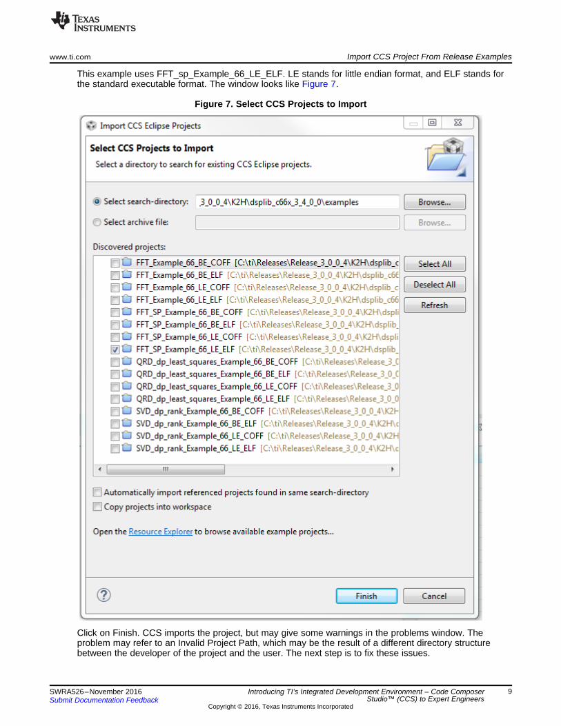
This example uses FFT_sp_Example_66_LE_ELF. LE stands for little endian format, and ELF stands forthe standard executable format. The window looks like Figure 7.
Figure 7. Select CCS Projects to Import
Click on Finish. CCS imports the project, but may give some warnings in the problems window. Theproblem may refer to an Invalid Project Path, which may be the result of a different directory structurebetween the developer of the project and the user. The next step is to fix these issues.
Import CCS Project From Release Examples www.ti.com
10 SWRA526–November 2016Submit Documentation Feedback
Copyright © 2016, Texas Instruments Incorporated
Introducing TI’s Integrated Development Environment – Code ComposerStudio™ (CCS) to Expert Engineers
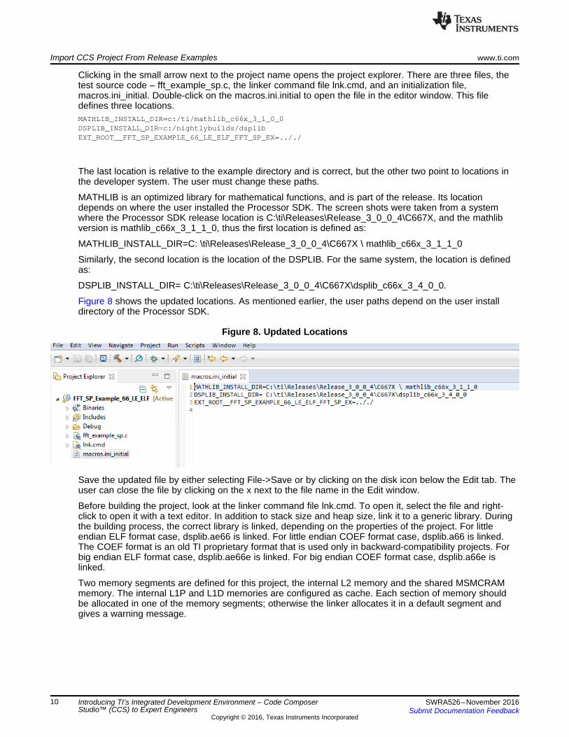
Clicking in the small arrow next to the project name opens the project explorer. There are three files, thetest source code – fft_example_sp.c, the linker command file lnk.cmd, and an initialization file,macros.ini_initial. Double-click on the macros.ini.initial to open the file in the editor window. This filedefines three locations.MATHLIB_INSTALL_DIR=c:/ti/mathlib_c66x_3_1_0_0DSPLIB_INSTALL_DIR=c:/nightlybuilds/dsplibEXT_ROOT__FFT_SP_EXAMPLE_66_LE_ELF_FFT_SP_EX=.././
The last location is relative to the example directory and is correct, but the other two point to locations inthe developer system. The user must change these paths.
MATHLIB is an optimized library for mathematical functions, and is part of the release. Its locationdepends on where the user installed the Processor SDK. The screen shots were taken from a systemwhere the Processor SDK release location is C:\ti\Releases\Release_3_0_0_4\C667X, and the mathlibversion is mathlib_c66x_3_1_1_0, thus the first location is defined as:
MATHLIB_INSTALL_DIR=C: \ti\Releases\Release_3_0_0_4\C667X \ mathlib_c66x_3_1_1_0
Similarly, the second location is the location of the DSPLIB. For the same system, the location is definedas:
DSPLIB_INSTALL_DIR= C:\ti\Releases\Release_3_0_0_4\C667X\dsplib_c66x_3_4_0_0.
Figure 8 shows the updated locations. As mentioned earlier, the user paths depend on the user installdirectory of the Processor SDK.
Figure 8. Updated Locations
Save the updated file by either selecting File->Save or by clicking on the disk icon below the Edit tab. Theuser can close the file by clicking on the x next to the file name in the Edit window.
Before building the project, look at the linker command file lnk.cmd. To open it, select the file and right-click to open it with a text editor. In addition to stack size and heap size, link it to a generic library. Duringthe building process, the correct library is linked, depending on the properties of the project. For littleendian ELF format case, dsplib.ae66 is linked. For little endian COEF format case, dsplib.a66 is linked.The COEF format is an old TI proprietary format that is used only in backward-compatibility projects. Forbig endian ELF format case, dsplib.ae66e is linked. For big endian COEF format case, dsplib.a66e islinked.
Two memory segments are defined for this project, the internal L2 memory and the shared MSMCRAMmemory. The internal L1P and L1D memories are configured as cache. Each section of memory shouldbe allocated in one of the memory segments; otherwise the linker allocates it in a default segment andgives a warning message.
www.ti.com Import CCS Project From Release Examples
11SWRA526–November 2016Submit Documentation Feedback
Copyright © 2016, Texas Instruments Incorporated
Introducing TI’s Integrated Development Environment – Code ComposerStudio™ (CCS) to Expert Engineers
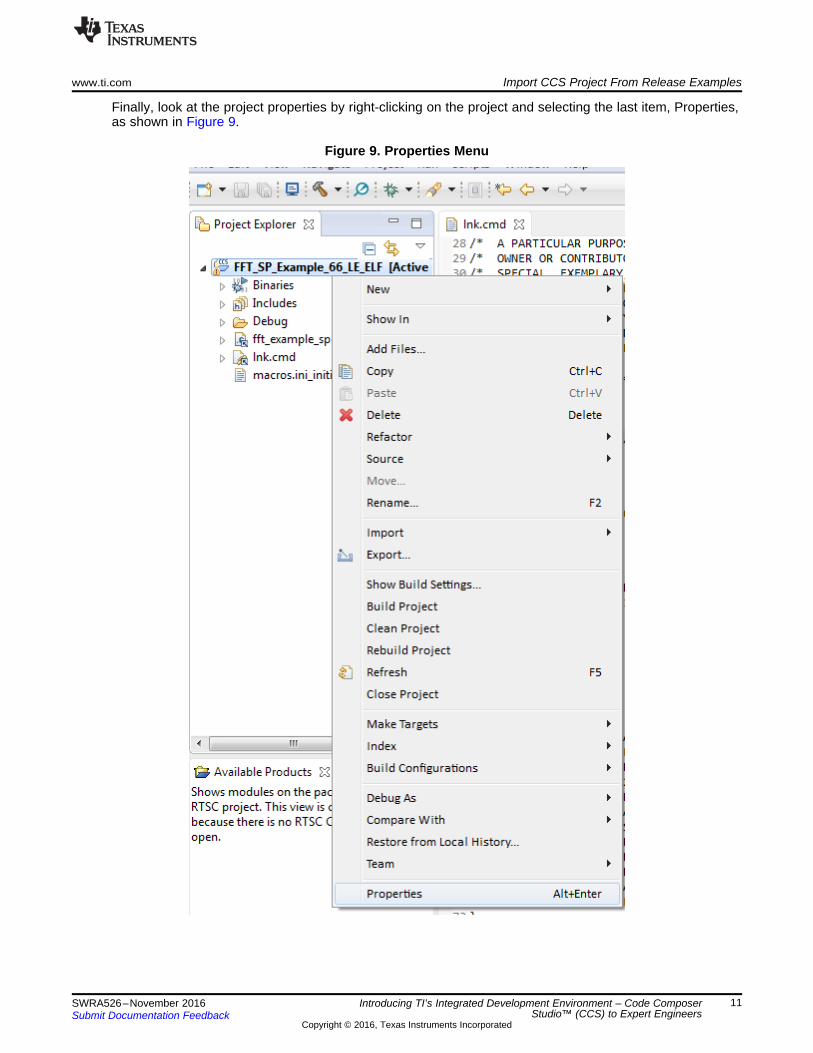
Finally, look at the project properties by right-clicking on the project and selecting the last item, Properties,as shown in Figure 9.
Figure 9. Properties Menu

Import CCS Project From Release Examples www.ti.com
12 SWRA526–November 2016Submit Documentation Feedback
Copyright © 2016, Texas Instruments Incorporated
Introducing TI’s Integrated Development Environment – Code ComposerStudio™ (CCS) to Expert Engineers
In the Properties dialog box, the optimization should be set to off, and the debug option to full symbolicdebug. Library routines that are called are optimized routines that were built with full optimization, and withno symbolic debug. The user is encouraged to explore the project properties, then close the Propertieswindow.
Rebuild the project by right-clicking the project name and selecting Rebuild Project. Figure 10 shows theresult of the build.
Figure 10. Build Result
2.3 Define Target – EmulatorCCS communicates with the board through an emulator. In this example, the EVM used is aTMS320C6678 Evaluation Module, with a Blackhawk XDS560v2-USB Mezzanine Emulator daughter card;the following instructions are for this emulator. If a different emulator or different EVM is used, theinstructions can be changed accordingly.

www.ti.com Import CCS Project From Release Examples
13SWRA526–November 2016Submit Documentation Feedback
Copyright © 2016, Texas Instruments Incorporated
Introducing TI’s Integrated Development Environment – Code ComposerStudio™ (CCS) to Expert Engineers
From the CCS Edit perspective, click on View → Target Configurations (see Figure 11) . A targetConfiguration window opens.
Figure 11. Target Configurations
In the User-Defined section, the user right-clicks and selects New Target Configuration. In the openedwindow, provide a name. For the purpose of this document, the example target name is emulator1. Afterclicking on Finish, the emulator definition is opened in the editor window.
Import CCS Project From Release Examples www.ti.com
14 SWRA526–November 2016Submit Documentation Feedback
Copyright © 2016, Texas Instruments Incorporated
Introducing TI’s Integrated Development Environment – Code ComposerStudio™ (CCS) to Expert Engineers
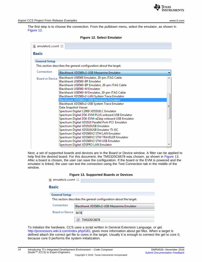
The first step is to choose the connection. From the pulldown menu, select the emulator, as shown inFigure 12.
Figure 12. Select Emulator
Next, a set of supported boards and devices are in the Board or Device window. A filter can be applied tohelp find the desired board. For this document, the TMS320C6678 was chosen, as shown in Figure 13.After a board is chosen, the user can save the configuration. If the board or the EVM is powered and theemulator is linked, the user can test the connection using the Test Connection tab in the middle of thewindow.
Figure 13. Supported Boards or Devices
To initialize the hardware, CCS uses a script written in General Extension Language, or gel.http://processors.wiki.ti.com/index.php/GEL gives more information about gel files. When a target isdefined attach the correct gel file to cores in the target. Usually it is enough to connect the gel to core 0,because core 0 performs the system initialization.

www.ti.com Import CCS Project From Release Examples
15SWRA526–November 2016Submit Documentation Feedback
Copyright © 2016, Texas Instruments Incorporated
Introducing TI’s Integrated Development Environment – Code ComposerStudio™ (CCS) to Expert Engineers
At the bottom of the emulator1.ccxml (or whichever name the user gave to the target) window, there is anAdvanced tab. Click on this tab to open a display of all the CPUs in the system, as shown in Figure 14.Select core 0, and browse for the correct gel file.
Figure 14. Advanced Tab
Gel files are located in the directory where CCS was installed in the subdirectory\ccsv6\ccs_base\emulation\boards\BOARDNAME\gel, where BOARDNAME is the board used. For thisexample, evmc6678l is used. After selecting the gel file and clicking the Open tab at the bottom of thedialog box, the gel location is in the target configuration, as seen in Figure 15.
Figure 15. CPU Properties
Finally, save the configuration by clicking on the Save tab. The user can then close the emulator1.ccxmlwindow.
2.4 Connect to the Target and Run the ProjectSelecting the target in the target configuration window and right click opens a menu. Set the target as adefault target and launch Selected Configuration, as shown in Figure 16.
Figure 16. Launch Selected Configuration
Import CCS Project From Release Examples www.ti.com
16 SWRA526–November 2016Submit Documentation Feedback
Copyright © 2016, Texas Instruments Incorporated
Introducing TI’s Integrated Development Environment – Code ComposerStudio™ (CCS) to Expert Engineers
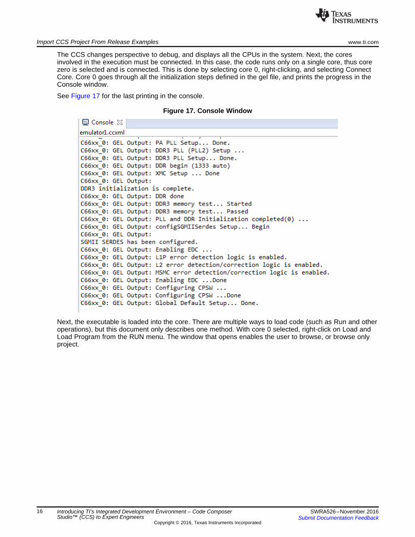
The CCS changes perspective to debug, and displays all the CPUs in the system. Next, the coresinvolved in the execution must be connected. In this case, the code runs only on a single core, thus corezero is selected and is connected. This is done by selecting core 0, right-clicking, and selecting ConnectCore. Core 0 goes through all the initialization steps defined in the gel file, and prints the progress in theConsole window.
See Figure 17 for the last printing in the console.
Figure 17. Console Window
Next, the executable is loaded into the core. There are multiple ways to load code (such as Run and otheroperations), but this document only describes one method. With core 0 selected, right-click on Load andLoad Program from the RUN menu. The window that opens enables the user to browse, or browse onlyproject.
www.ti.com Import CCS Project From Release Examples
17SWRA526–November 2016Submit Documentation Feedback
Copyright © 2016, Texas Instruments Incorporated
Introducing TI’s Integrated Development Environment – Code ComposerStudio™ (CCS) to Expert Engineers
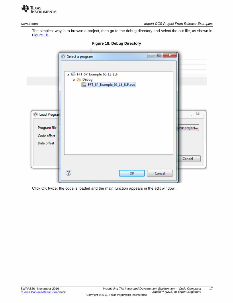
The simplest way is to browse a project, then go to the debug directory and select the out file, as shown inFigure 18.
Figure 18. Debug Directory
Click OK twice; the code is loaded and the main function appears in the edit window.

Import CCS Project From Release Examples www.ti.com
18 SWRA526–November 2016Submit Documentation Feedback
Copyright © 2016, Texas Instruments Incorporated
Introducing TI’s Integrated Development Environment – Code ComposerStudio™ (CCS) to Expert Engineers
2.5 Code Execution and Measure CyclesEnabling the CCS clock is done from the Run menu. Clicking on Clock Enable (see Figure 19) opens asmall clock window with a value of 0. Double-click on the Cycle count to set the clock to zero.
Figure 19. Clock Enable
The clock window appears as in Figure 20 (bottom-right corner of the CCS window)
Figure 20. Clock Window

www.ti.com Import CCS Project From Release Examples
19SWRA526–November 2016Submit Documentation Feedback
Copyright © 2016, Texas Instruments Incorporated
Introducing TI’s Integrated Development Environment – Code ComposerStudio™ (CCS) to Expert Engineers
Next, step through the code using the F6 key (or from the Run menu, click Step Over). After three steps,the execution executes the DSPF_sp_fftSPxSP routine. At this point, set the clock (double-click) to zero.
Before executing the DSPF_sp_fftSPxSP routine, look at the parameters for the function. TheTMS320C67x DSP Library Programmer’s Reference Guide (page 49) describes the function and theparameters used. The first parameter is the number of elements, and must be a power of two and up, to8K. The twiddle factors generated by the function gen_twiddle_fft should be called with the same value.Next are the pointers to the input data, the twiddle factors, and the output vector. Each of these vectorsare of 2 × N floating point size. The bit reversal vector brev is next. According to the above document, thebrev size is 64, regardless of the FFT size. The next three parameters are used to optimize the execution.n_min is 4 if N is a power of 4, and 2 otherwise. This value tells the program to use all Radix 4 butterflies,or that it must use Radix 2 butterflies, at least once. The last two parameters enable the program to breakthe FFT into multiple executions so the data fits into the L1D cache.
Click F6 once more; the code progress after the DSPF_sp_fftSPxSP routine, and the cycle counts (theclock) shows approximately 1513 cycles.

Build a New CCS Project www.ti.com
20 SWRA526–November 2016Submit Documentation Feedback
Copyright © 2016, Texas Instruments Incorporated
Introducing TI’s Integrated Development Environment – Code ComposerStudio™ (CCS) to Expert Engineers
3 Build a New CCS ProjectSection 2 shows how to import a project. Each module of Processor SDK, including all functions in theoptimized libraries, has a unit test that shows the user how to use the function. The next step is to build anew project using the same library function that was used in Section 2.
While different devices may or may not have different implementations of library functions, the interfaceand the parameter list of the function are the same across different platforms. Thus, this example uses theTI’s EVMK2H evaluation module with the 66AK2H12 processor.
This example builds a 66AK2H12 project, a single C66xx core that generates random numbers as input,calculates the energy in the sequence, executes an FFT function from a library, calculates the energy inthe frequency domain, and prints out the difference between the two energies. (Parseval's theorem impliesthat the two energies must be equal).
There are multiple ways to use library functions and other software modules that are part of ProcessorSDK. The first method is direct usage of libraries and other utilities. The other method is using RTSC.While many TI examples use RTSC to facilitate fast and accurate building of projects, the project in thischapter is created without RTSC support.
3.1 Create a New ProjectStart from the file menu (at the upper left corner):
File → New → CCS Project
A dialogue box opens. First, configure the target. There is a pulldown menu at the upper right corner ofthe dialogue window. The target can be a generic processor, a device, or a TI EVM. Each target has a setof processors.
www.ti.com Build a New CCS Project
21SWRA526–November 2016Submit Documentation Feedback
Copyright © 2016, Texas Instruments Incorporated
Introducing TI’s Integrated Development Environment – Code ComposerStudio™ (CCS) to Expert Engineers
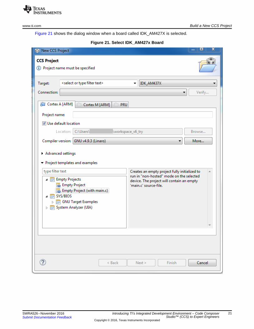
Figure 21 shows the dialog window when a board called IDK_AM427X is selected.
Figure 21. Select IDK_AM427x Board

Build a New CCS Project www.ti.com
22 SWRA526–November 2016Submit Documentation Feedback
Copyright © 2016, Texas Instruments Incorporated
Introducing TI’s Integrated Development Environment – Code ComposerStudio™ (CCS) to Expert Engineers
Figure 22 shows when the 66AK2H12 device is selected.
Figure 22. Select 66AK2H12 Device
The user selecting IDK_ AM437X can choose one of three programmable processors; ARM® Cortex®-A(AM437X has Cortex-A9), ARM Cortex-M4, or PRU. 66AK2H12 has two processors to choose from; eitherARM Cortex-A (A15) or C66xx DSP. Each processor has its own list of default project templates. Allprocessors have several Empty Projects templates, as well as a Basic Example (Hello World) template.

www.ti.com Build a New CCS Project
23SWRA526–November 2016Submit Documentation Feedback
Copyright © 2016, Texas Instruments Incorporated
Introducing TI’s Integrated Development Environment – Code ComposerStudio™ (CCS) to Expert Engineers
To start the project, choose Empty Project with main.c. Next, choose the project name. After a projectname (for example, exercise1) is written in the Project Name tab, the Finish tab at the bottom of the dialogwindow is highlighted.
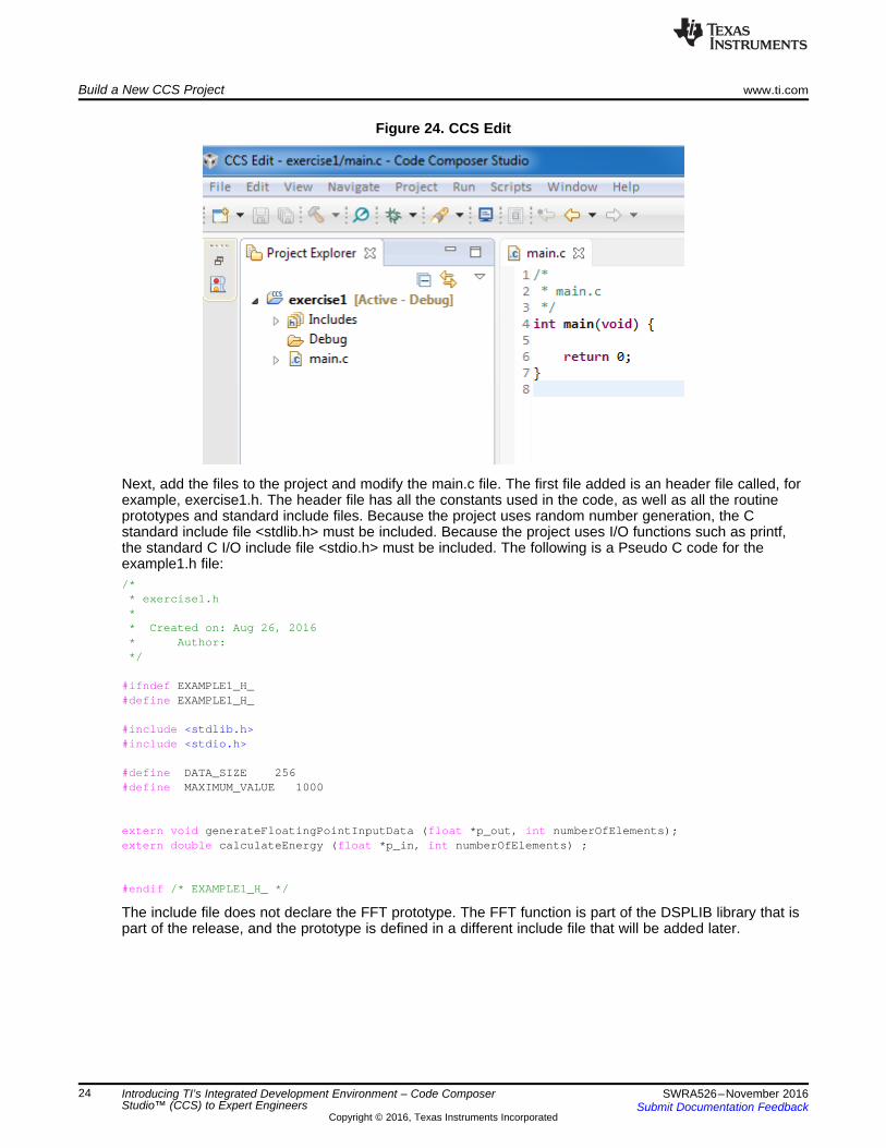
Left-click on the Finish tab, and the new project with main.c file is created. To open Project Explorer (if itwas not opened earlier), left-click on the View tab, select Project Explorer, then left-click. The following twowindows show how to enable Project Explorer and the Project Explorer display. Clicking on the smallarrow next to the Project Name opens the project structure, as shown in Figure 23 and Figure 24.
Figure 23. Project Explorer
Build a New CCS Project www.ti.com
24 SWRA526–November 2016Submit Documentation Feedback
Copyright © 2016, Texas Instruments Incorporated
Introducing TI’s Integrated Development Environment – Code ComposerStudio™ (CCS) to Expert Engineers
Figure 24. CCS Edit
Next, add the files to the project and modify the main.c file. The first file added is an header file called, forexample, exercise1.h. The header file has all the constants used in the code, as well as all the routineprototypes and standard include files. Because the project uses random number generation, the Cstandard include file <stdlib.h> must be included. Because the project uses I/O functions such as printf,the standard C I/O include file <stdio.h> must be included. The following is a Pseudo C code for theexample1.h file:/*
* exercise1.h** Created on: Aug 26, 2016* Author:*/
#ifndef EXAMPLE1_H_#define EXAMPLE1_H_
#include <stdlib.h>#include <stdio.h>
#define DATA_SIZE 256#define MAXIMUM_VALUE 1000
extern void generateFloatingPointInputData (float *p_out, int numberOfElements);extern double calculateEnergy (float *p_in, int numberOfElements) ;
#endif /* EXAMPLE1_H_ */
The include file does not declare the FFT prototype. The FFT function is part of the DSPLIB library that ispart of the release, and the prototype is defined in a different include file that will be added later.

www.ti.com Build a New CCS Project
25SWRA526–November 2016Submit Documentation Feedback
Copyright © 2016, Texas Instruments Incorporated
Introducing TI’s Integrated Development Environment – Code ComposerStudio™ (CCS) to Expert Engineers
The include file, just like any other source file, can be written using any text editor and then copied into theproject, or it can be written within CCS. To use the later, left-click on the File tab (File → New → Headerfile) and a dialog window opens. In the dialog box, write the include file name and click Finish as shown inFigure 25 and Figure 26.
Figure 25. New Header File

Build a New CCS Project www.ti.com
26 SWRA526–November 2016Submit Documentation Feedback
Copyright © 2016, Texas Instruments Incorporated
Introducing TI’s Integrated Development Environment – Code ComposerStudio™ (CCS) to Expert Engineers
Figure 26. Name Header File
www.ti.com Build a New CCS Project
27SWRA526–November 2016Submit Documentation Feedback
Copyright © 2016, Texas Instruments Incorporated
Introducing TI’s Integrated Development Environment – Code ComposerStudio™ (CCS) to Expert Engineers
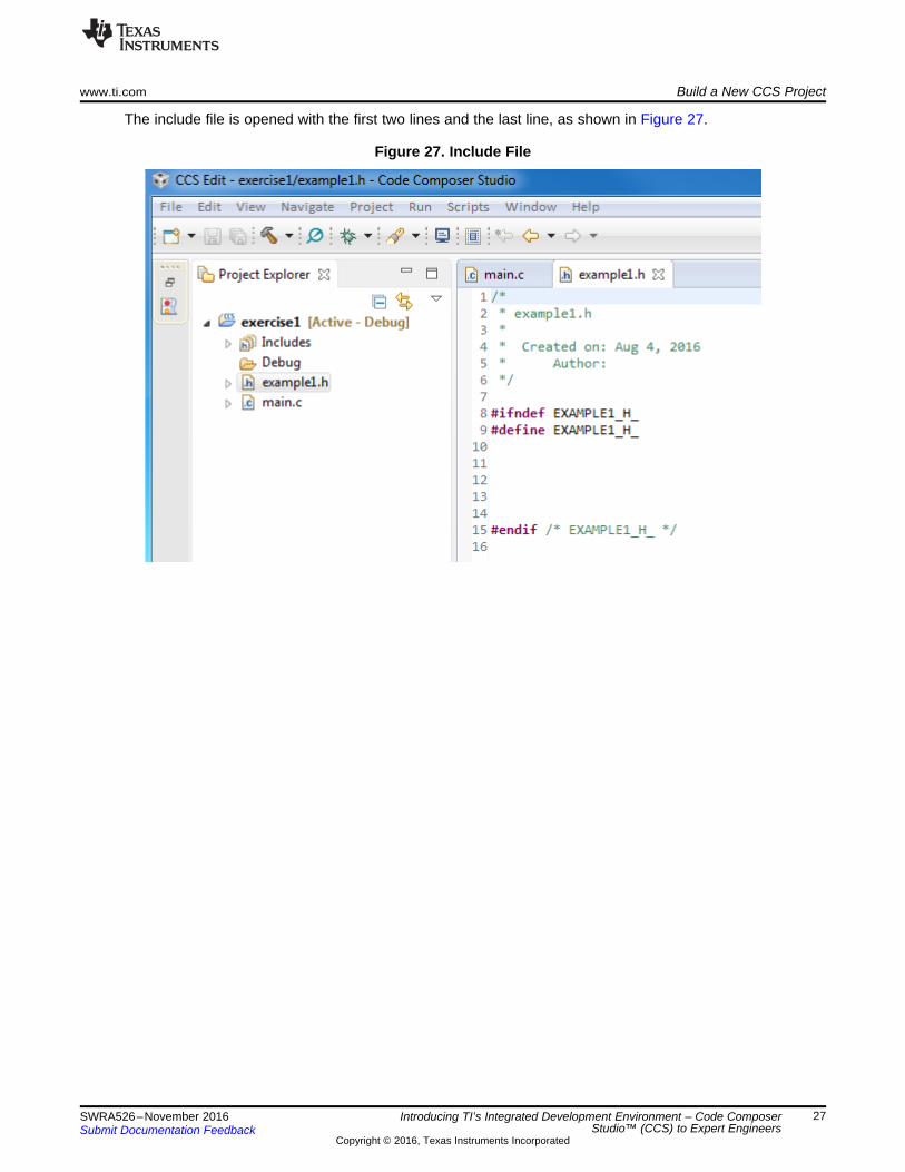
The include file is opened with the first two lines and the last line, as shown in Figure 27.
Figure 27. Include File
Build a New CCS Project www.ti.com
28 SWRA526–November 2016Submit Documentation Feedback
Copyright © 2016, Texas Instruments Incorporated
Introducing TI’s Integrated Development Environment – Code ComposerStudio™ (CCS) to Expert Engineers
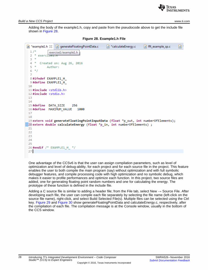
Adding the body of the example1.h, copy and paste from the pseudocode above to get the include fileshown in Figure 28.
Figure 28. Example1.h File
One advantage of the CCSv6 is that the user can assign compilation parameters, such as level ofoptimization and level of debug-ability, for each project and for each source file in the project. This featureenables the user to both compile the main program (say) without optimization and with full symbolicdebugger features, and compile processing code with high optimization and no symbolic debug, whichmakes it easier to profile performances and optimize each function. In this project, two source files areadded, one for generating floating point random numbers and one for calculating the energy. Theprototype of these function is defined in the include file.
Adding a C source file is similar to adding a header file; from the File tab, select New → Source File. Afterdeveloping each file, the user can compile each file separately by selecting the file name (left-click on thesource file name), right-click, and select Build Selected File(s). Multiple files can be selected using the Ctrlkey. Figure 29 and Figure 30 show generateFloatingPointData and calculateEnergy.c, respectively, afterthe compilation of each file. The compilation message is at the Console window, usually in the bottom ofthe CCS window.
www.ti.com Build a New CCS Project
29SWRA526–November 2016Submit Documentation Feedback
Copyright © 2016, Texas Instruments Incorporated
Introducing TI’s Integrated Development Environment – Code ComposerStudio™ (CCS) to Expert Engineers
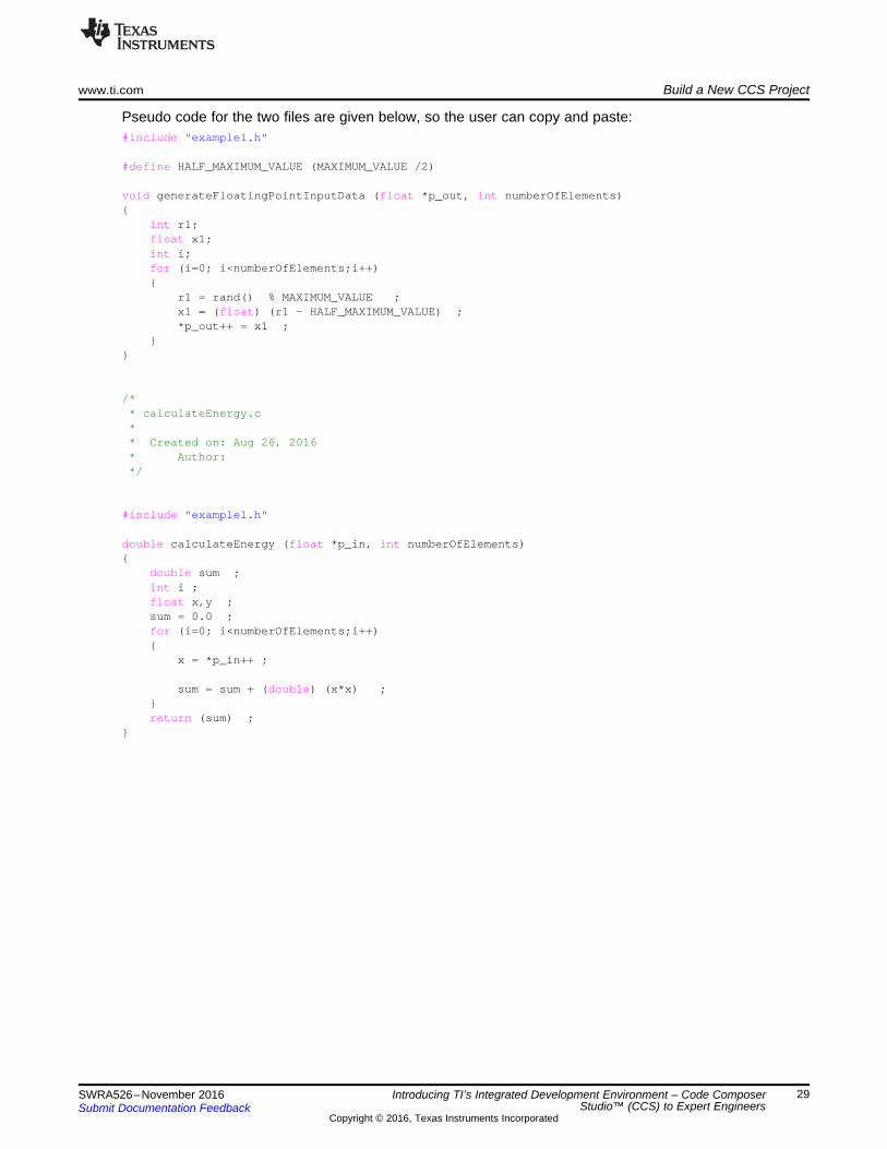
Pseudo code for the two files are given below, so the user can copy and paste:#include "example1.h"
#define HALF_MAXIMUM_VALUE (MAXIMUM_VALUE /2)
void generateFloatingPointInputData (float *p_out, int numberOfElements){
int r1;float x1;int i;for (i=0; i<numberOfElements;i++){
r1 = rand() % MAXIMUM_VALUE ;x1 = (float) (r1 - HALF_MAXIMUM_VALUE) ;*p_out++ = x1 ;
}}
/** calculateEnergy.c** Created on: Aug 26, 2016* Author:*/
#include "example1.h"
double calculateEnergy (float *p_in, int numberOfElements){
double sum ;int i ;float x,y ;sum = 0.0 ;for (i=0; i<numberOfElements;i++){
x = *p_in++ ;
sum = sum + (double) (x*x) ;}return (sum) ;
}

Build a New CCS Project www.ti.com
30 SWRA526–November 2016Submit Documentation Feedback
Copyright © 2016, Texas Instruments Incorporated
Introducing TI’s Integrated Development Environment – Code ComposerStudio™ (CCS) to Expert Engineers
Figure 29 shows the generateFloatingPointData.c file.
Figure 29. generateFloatingPointData
www.ti.com Build a New CCS Project
31SWRA526–November 2016Submit Documentation Feedback
Copyright © 2016, Texas Instruments Incorporated
Introducing TI’s Integrated Development Environment – Code ComposerStudio™ (CCS) to Expert Engineers
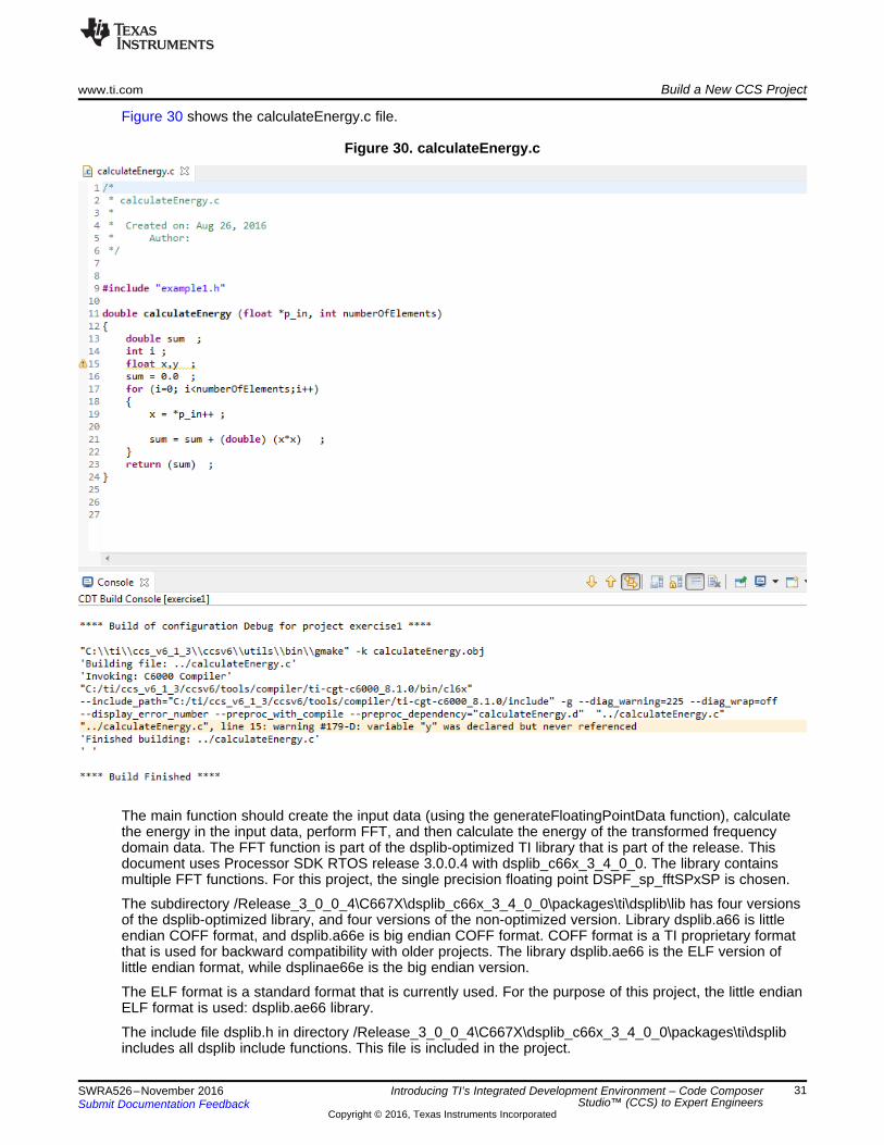
Figure 30 shows the calculateEnergy.c file.
Figure 30. calculateEnergy.c
The main function should create the input data (using the generateFloatingPointData function), calculatethe energy in the input data, perform FFT, and then calculate the energy of the transformed frequencydomain data. The FFT function is part of the dsplib-optimized TI library that is part of the release. Thisdocument uses Processor SDK RTOS release 3.0.0.4 with dsplib_c66x_3_4_0_0. The library containsmultiple FFT functions. For this project, the single precision floating point DSPF_sp_fftSPxSP is chosen.
The subdirectory /Release_3_0_0_4\C667X\dsplib_c66x_3_4_0_0\packages\ti\dsplib\lib has four versionsof the dsplib-optimized library, and four versions of the non-optimized version. Library dsplib.a66 is littleendian COFF format, and dsplib.a66e is big endian COFF format. COFF format is a TI proprietary formatthat is used for backward compatibility with older projects. The library dsplib.ae66 is the ELF version oflittle endian format, while dsplinae66e is the big endian version.
The ELF format is a standard format that is currently used. For the purpose of this project, the little endianELF format is used: dsplib.ae66 library.
The include file dsplib.h in directory /Release_3_0_0_4\C667X\dsplib_c66x_3_4_0_0\packages\ti\dsplibincludes all dsplib include functions. This file is included in the project.

Build a New CCS Project www.ti.com
32 SWRA526–November 2016Submit Documentation Feedback
Copyright © 2016, Texas Instruments Incorporated
Introducing TI’s Integrated Development Environment – Code ComposerStudio™ (CCS) to Expert Engineers
The documentation on how to use the library function is in directory\Release_3_0_0_4\C667X\dsplib_c66x_3_4_0_0\packages\ti\dsplib\docs\doxygen in a chm format, as wellas the TMS320C67x DSP Library Programmer’s Reference Guide (page 49).
Figure 31 shows how to use the function DSPF_sp_fftSPxSP.
Figure 31. DSPF_sp_fftSPxSP Function
Even with the documentation, it may not be clear how to use the function. To understand better how touse the function, use the unit test. The unit test main function is called DSPF_sp_fftSPxSP_d.c, and islocated in directory\Release_3_0_0_4\C667X\dsplib_c66x_3_4_0_0\packages\ti\dsplib\src\DSPF_sp_fftSPxSP\c66. While theprevious chapter test program is built for a different device, the method to use the library routines is thesame.
From the imported project of the previous chapter, the FFT routine needs two other vectors in addition tothe input: the 64-elements bit reversal vector (brev), and the twiddle factor. The DSPLIB has severaltwiddle factor generation functions, but they are all for fixed point arithmetic and not for floating point.Thus, this project uses the same Twiddle Factor generation used by the developer in the imported project.
www.ti.com Build a New CCS Project
33SWRA526–November 2016Submit Documentation Feedback
Copyright © 2016, Texas Instruments Incorporated
Introducing TI’s Integrated Development Environment – Code ComposerStudio™ (CCS) to Expert Engineers
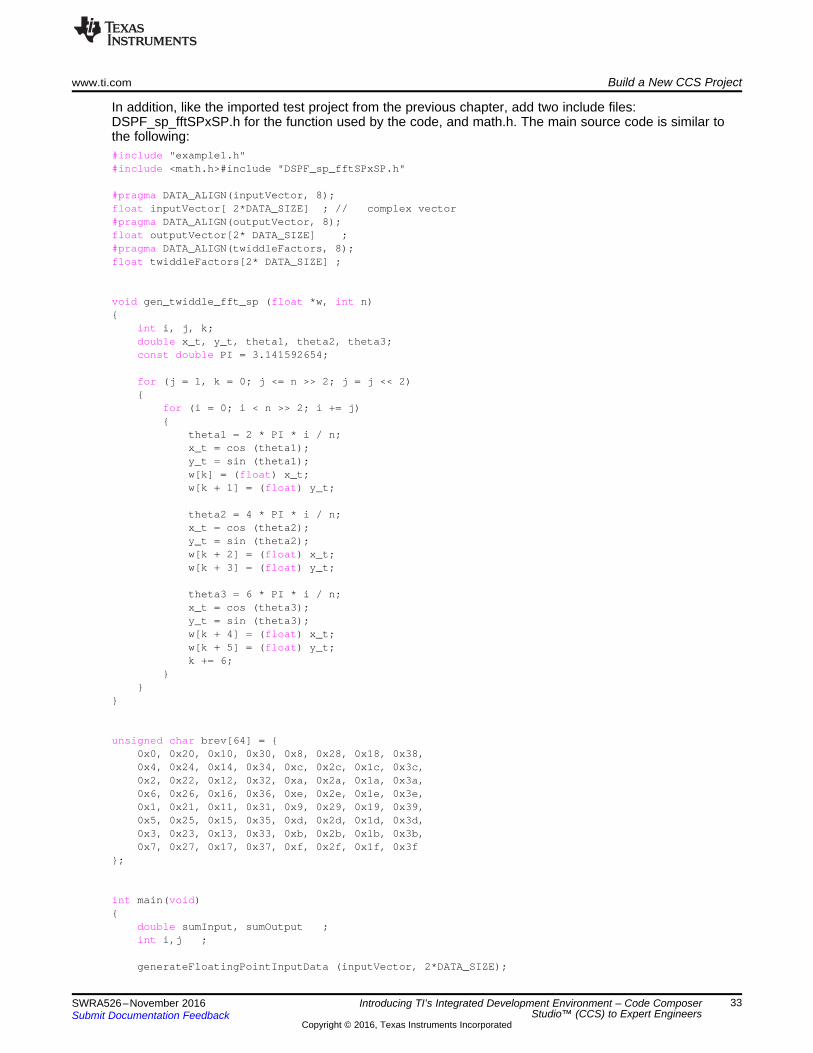
In addition, like the imported test project from the previous chapter, add two include files:DSPF_sp_fftSPxSP.h for the function used by the code, and math.h. The main source code is similar tothe following:#include "example1.h"#include <math.h>#include "DSPF_sp_fftSPxSP.h"
#pragma DATA_ALIGN(inputVector, 8);float inputVector[ 2*DATA_SIZE] ; // complex vector#pragma DATA_ALIGN(outputVector, 8);float outputVector[2* DATA_SIZE] ;#pragma DATA_ALIGN(twiddleFactors, 8);float twiddleFactors[2* DATA_SIZE] ;
void gen_twiddle_fft_sp (float *w, int n){
int i, j, k;double x_t, y_t, theta1, theta2, theta3;const double PI = 3.141592654;
for (j = 1, k = 0; j <= n >> 2; j = j << 2){
for (i = 0; i < n >> 2; i += j){
theta1 = 2 * PI * i / n;x_t = cos (theta1);y_t = sin (theta1);w[k] = (float) x_t;w[k + 1] = (float) y_t;
theta2 = 4 * PI * i / n;x_t = cos (theta2);y_t = sin (theta2);w[k + 2] = (float) x_t;w[k + 3] = (float) y_t;
theta3 = 6 * PI * i / n;x_t = cos (theta3);y_t = sin (theta3);w[k + 4] = (float) x_t;w[k + 5] = (float) y_t;k += 6;
}}
}
unsigned char brev[64] = {0x0, 0x20, 0x10, 0x30, 0x8, 0x28, 0x18, 0x38,0x4, 0x24, 0x14, 0x34, 0xc, 0x2c, 0x1c, 0x3c,0x2, 0x22, 0x12, 0x32, 0xa, 0x2a, 0x1a, 0x3a,0x6, 0x26, 0x16, 0x36, 0xe, 0x2e, 0x1e, 0x3e,0x1, 0x21, 0x11, 0x31, 0x9, 0x29, 0x19, 0x39,0x5, 0x25, 0x15, 0x35, 0xd, 0x2d, 0x1d, 0x3d,0x3, 0x23, 0x13, 0x33, 0xb, 0x2b, 0x1b, 0x3b,0x7, 0x27, 0x17, 0x37, 0xf, 0x2f, 0x1f, 0x3f
};
int main(void){
double sumInput, sumOutput ;int i,j ;
generateFloatingPointInputData (inputVector, 2*DATA_SIZE);

Build a New CCS Project www.ti.com
34 SWRA526–November 2016Submit Documentation Feedback
Copyright © 2016, Texas Instruments Incorporated
Introducing TI’s Integrated Development Environment – Code ComposerStudio™ (CCS) to Expert Engineers
sumInput = calculateEnergy (inputVector, 2* DATA_SIZE) ;
gen_twiddle_fft_sp (twiddleFactors, DATA_SIZE) ;
DSPF_sp_fftSPxSP(DATA_SIZE, inputVector, twiddleFactors, outputVector, brev, 4, 0, DATA_SIZE);sumOutput = calculateEnergy (outputVector, 2* DATA_SIZE) ;
printf(" input energy %e output energy %e difference %e \n", sumInput, sumOutput,sumInput-sumOutput) ;
return 0;}
NOTE: The include file in the imported project is ti\dsplib\dsplib.h. This is a generic include file thatincludes all the include files in the DSPLIB release. This include file is generic, so forfunctions optimized for a certain architecture, the user must provide the device name. For theC66 architecture, the device name is _TMS320C6600. Adding a device name to a project isdone from Properties -> Advanced Options -> Predefined Symbols, in the lower window(Pre-define NAME)
3.2 Building the New ProjectRight-click on the project name and select Rebuild Project. After the build, the error message in Figure 32is displayed in the Console window.
Figure 32. Error Message

www.ti.com Build a New CCS Project
35SWRA526–November 2016Submit Documentation Feedback
Copyright © 2016, Texas Instruments Incorporated
Introducing TI’s Integrated Development Environment – Code ComposerStudio™ (CCS) to Expert Engineers
The project does not find the include file DSPF_sp_fftSPxSP.h, thus, the user must add the path to it.Searching in the release, the file DSPF_sp_fftSPxSP.h is in directory INSTALL_DIR\dsplib_c66x_3_4_0_0\packages\ti\dsplib\src\DSPF_sp_fftSPxSP\c66, where INSTALL_DIR is the directoryname where the user installed the Processor SDK. Adding the path to ti\dsplib is done from the propertieswindows. Right-click on the Project name and select Properties (the last item in the list). In the Propertieswindow, select Include Options, as shown in Figure 33.
Figure 33. Include Options
The upper window enables the user to add a pre-include file. The lower window is used to add a path.Click on the green plus sign (+), and add the path to the ti\dsplib\dsplib.h.

Build a New CCS Project www.ti.com
36 SWRA526–November 2016Submit Documentation Feedback
Copyright © 2016, Texas Instruments Incorporated
Introducing TI’s Integrated Development Environment – Code ComposerStudio™ (CCS) to Expert Engineers
Figure 34 illustrates how the path appears in the system used here.
Figure 34. Add Directory Path
Click OK twice and try to rebuild the project again. In the example shown in Figure 35, the compilationwent through, but there are a few issues with linking the program.
Figure 35. Linking Issues
www.ti.com Build a New CCS Project
37SWRA526–November 2016Submit Documentation Feedback
Copyright © 2016, Texas Instruments Incorporated
Introducing TI’s Integrated Development Environment – Code ComposerStudio™ (CCS) to Expert Engineers
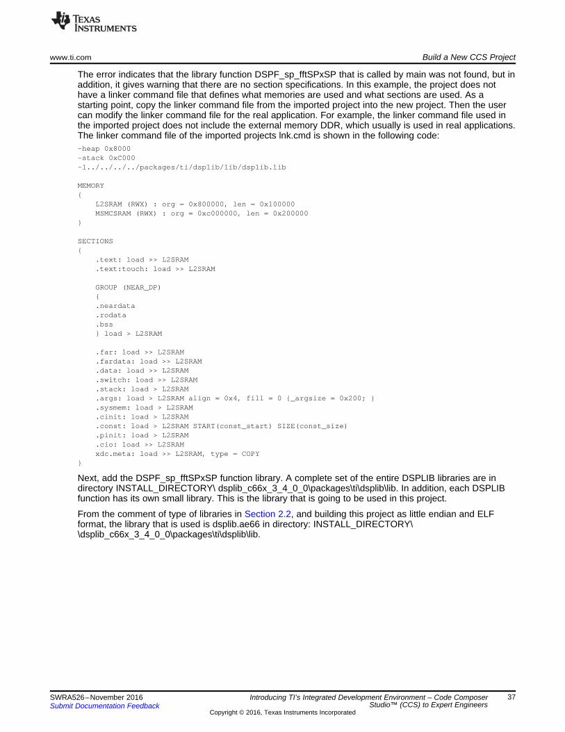
The error indicates that the library function DSPF_sp_fftSPxSP that is called by main was not found, but inaddition, it gives warning that there are no section specifications. In this example, the project does nothave a linker command file that defines what memories are used and what sections are used. As astarting point, copy the linker command file from the imported project into the new project. Then the usercan modify the linker command file for the real application. For example, the linker command file used inthe imported project does not include the external memory DDR, which usually is used in real applications.The linker command file of the imported projects lnk.cmd is shown in the following code:-heap 0x8000-stack 0xC000-l../../../../packages/ti/dsplib/lib/dsplib.lib
MEMORY{
L2SRAM (RWX) : org = 0x800000, len = 0x100000MSMCSRAM (RWX) : org = 0xc000000, len = 0x200000
}
SECTIONS{
.text: load >> L2SRAM
.text:touch: load >> L2SRAM
GROUP (NEAR_DP){.neardata.rodata.bss} load > L2SRAM
.far: load >> L2SRAM
.fardata: load >> L2SRAM
.data: load >> L2SRAM
.switch: load >> L2SRAM
.stack: load > L2SRAM
.args: load > L2SRAM align = 0x4, fill = 0 {_argsize = 0x200; }
.sysmem: load > L2SRAM
.cinit: load > L2SRAM
.const: load > L2SRAM START(const_start) SIZE(const_size)
.pinit: load > L2SRAM
.cio: load >> L2SRAMxdc.meta: load >> L2SRAM, type = COPY
}
Next, add the DSPF_sp_fftSPxSP function library. A complete set of the entire DSPLIB libraries are indirectory INSTALL_DIRECTORY\ dsplib_c66x_3_4_0_0\packages\ti\dsplib\lib. In addition, each DSPLIBfunction has its own small library. This is the library that is going to be used in this project.
From the comment of type of libraries in Section 2.2, and building this project as little endian and ELFformat, the library that is used is dsplib.ae66 in directory: INSTALL_DIRECTORY\\dsplib_c66x_3_4_0_0\packages\ti\dsplib\lib.
Build a New CCS Project www.ti.com
38 SWRA526–November 2016Submit Documentation Feedback
Copyright © 2016, Texas Instruments Incorporated
Introducing TI’s Integrated Development Environment – Code ComposerStudio™ (CCS) to Expert Engineers
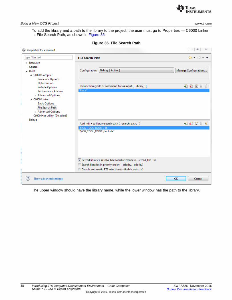
To add the library and a path to the library to the project, the user must go to Properties → C6000 Linker→ File Search Path, as shown in Figure 36.
Figure 36. File Search Path
The upper window should have the library name, while the lower window has the path to the library.
www.ti.com Build a New CCS Project
39SWRA526–November 2016Submit Documentation Feedback
Copyright © 2016, Texas Instruments Incorporated
Introducing TI’s Integrated Development Environment – Code ComposerStudio™ (CCS) to Expert Engineers
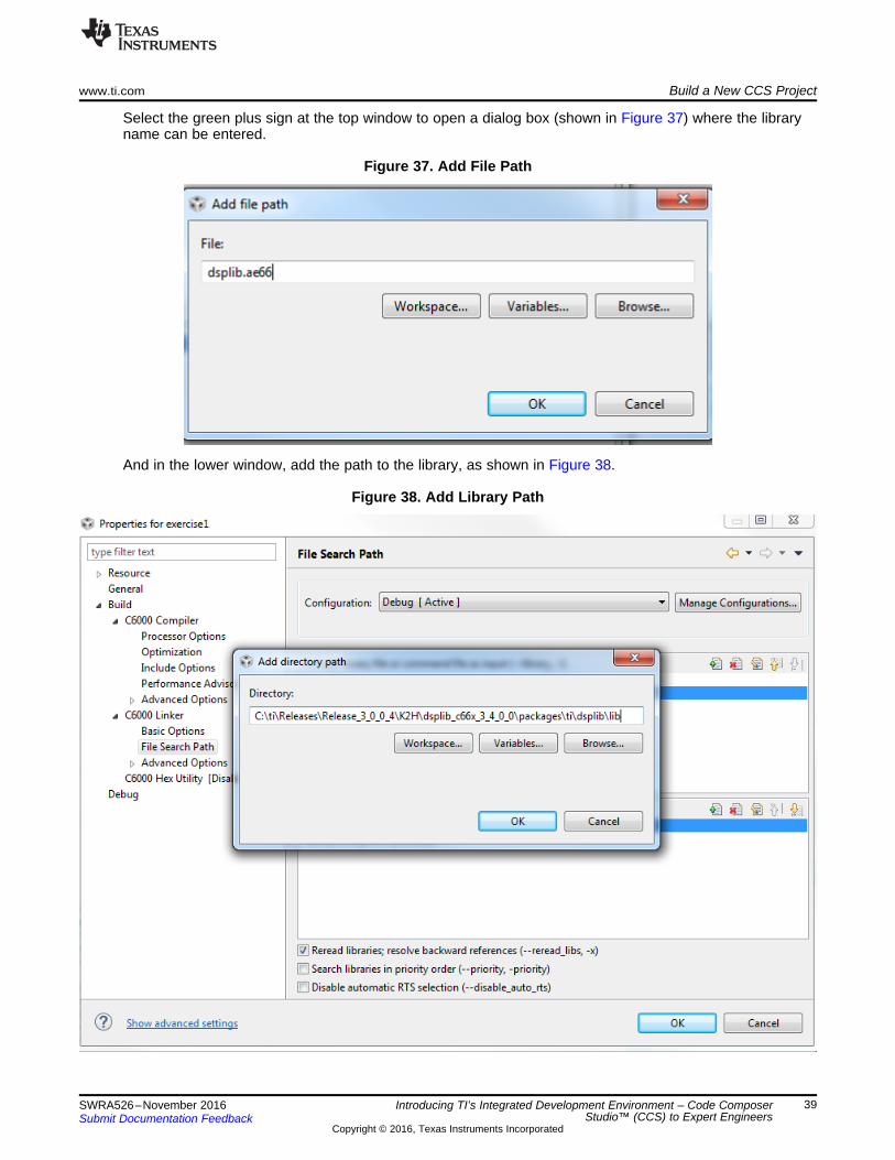
Select the green plus sign at the top window to open a dialog box (shown in Figure 37) where the libraryname can be entered.
Figure 37. Add File Path
And in the lower window, add the path to the library, as shown in Figure 38.
Figure 38. Add Library Path

Build a New CCS Project www.ti.com
40 SWRA526–November 2016Submit Documentation Feedback
Copyright © 2016, Texas Instruments Incorporated
Introducing TI’s Integrated Development Environment – Code ComposerStudio™ (CCS) to Expert Engineers
Click OK three times: once for the library, once for the path, and once for the Properties, then rebuild theproject. This time, the project is built and the console appears as it does in Figure 39.
Figure 39. Build Finished
There are some warnings that the user can easily eliminate, but the executable exercise1.out is built andis now in the Debug directory.
3.3 Code Execution: Understanding the ResultsRepeat the steps in Section 2.5 to launch the target, connect core 0, and load the code of exercise1 (Run->load _> Load Program). From the dialog box, choose Browse Project, then choose exercise1->Debug->Exercise1.out, and then OK and OK).
Step through the code. The last instruction prints the following on the Console:
input energy 4.216463e+07 output energy 1.079414e+10 difference -1.075198e+10
Thus, the input energy is not equal to the output energy. As a hint to the problem, if the following two linesare added to the code:sumInput = sumInput * (float) DATA_SIZE ;
printf(" input energy %e output energy %e difference %e \n", sumInput, sumOutput,sumInput-sumOutput) ;
Then the second printf gives the following results, (error of about e-8):input energy 1.079415e+10 output energy 1.079414e+10 difference 4.998233e+02
www.ti.com Import Function From Library (Not Part of Processor SDK)
41SWRA526–November 2016Submit Documentation Feedback
Copyright © 2016, Texas Instruments Incorporated
Introducing TI’s Integrated Development Environment – Code ComposerStudio™ (CCS) to Expert Engineers
4 Import Function From Library (Not Part of Processor SDK)
4.1 Import an Example From FFTLIB (C674x Version)Section 2 has instructions how to import a project. Section 3 has instructions how to build a new project. Inboth cases, the build process was relatively easy and simple.
Processor SDK supports many TI digital devices and covers many building blocks. However, there aresome devices that are not currently supported by the Processor SDK. There are TI libraries that are notpart of Processor SDK.
Importing and building examples in a library that is not part of Processor SDK requires moreconfigurations, because the example project is unaware of the software environment.
In addition, in the previous examples, the projects were not RTSC projects. RTSC requires someadditional considerations. Section 2.1 describes how to verify that RTSC system sees all the softwaremodules that it may require.
In this chapter, the user will import a project with some build issues, and see how to debug and fix theseissues. The techniques demonstrated here can be used for other projects with similar issues.
The software tools used are CCS V6.1.3, and the library used is a FFTLIB for floating point devices. Thelibrary can be loaded from http://software-dl.ti.com/libs/fftlib/2.0.0/2_0_0_2/index_FDS.html.
This library supports C674x devices, which are not supported by Processor SDK, but by a set of tools forthe C674x. The download page for the C674x set of software tools is http://software-dl.ti.com/dsps/dsps_public_sw/c6000/web/bios_c6sdk/latest/index_FDS.html.
Following the process, in directory INSTALL_DIRECTORY\fftlib_2_0_0_2\ packages\ti\fftlib\src, whereINSTALL_DIRECTORY is the directory where FFTLIB was installed, choose the second function in thefft_dp_1d_c2c_batch list. This function calculates the FFT of double precision values (and the calculationis double precision), and one dimension complex FFT on multiple vectors (thus the batch).

Import Function From Library (Not Part of Processor SDK) www.ti.com
42 SWRA526–November 2016Submit Documentation Feedback
Copyright © 2016, Texas Instruments Incorporated
Introducing TI’s Integrated Development Environment – Code ComposerStudio™ (CCS) to Expert Engineers
and show the location of the example.
Figure 40. Browse Folder Figure 41. Project Explorer

www.ti.com Import Function From Library (Not Part of Processor SDK)
43SWRA526–November 2016Submit Documentation Feedback
Copyright © 2016, Texas Instruments Incorporated
Introducing TI’s Integrated Development Environment – Code ComposerStudio™ (CCS) to Expert Engineers
First, notice the small exclamation mark next to the project name. This mark indicates that the projectmust adjust its properties before it can be built. Otherwise, if the user clicks on Rebuild Project, they getthe result shown in Figure 42.
Figure 42. Rebuild Project Error
When an include file is not recognized by the system, the project properties must be checked. For RTSCprojects, verifying that all the RTSC projects are well-defined is essential. To look at the RTSC definition,right-click on the project name and select Properties (the last item in the pulldown menu).

Import Function From Library (Not Part of Processor SDK) www.ti.com
44 SWRA526–November 2016Submit Documentation Feedback
Copyright © 2016, Texas Instruments Incorporated
Introducing TI’s Integrated Development Environment – Code ComposerStudio™ (CCS) to Expert Engineers
The RTSC definitions are in the General → RTSC tab, as shown in Figure 43.
Figure 43. RTSC Definitions
www.ti.com Import Function From Library (Not Part of Processor SDK)
45SWRA526–November 2016Submit Documentation Feedback
Copyright © 2016, Texas Instruments Incorporated
Introducing TI’s Integrated Development Environment – Code ComposerStudio™ (CCS) to Expert Engineers
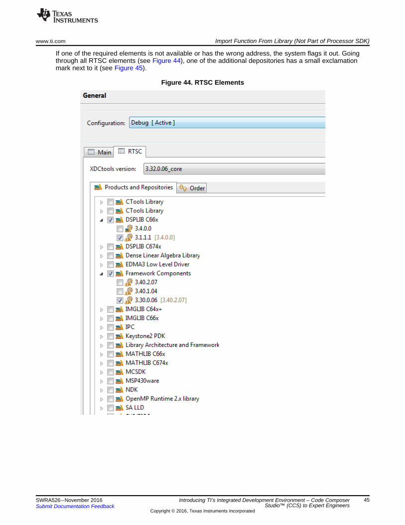
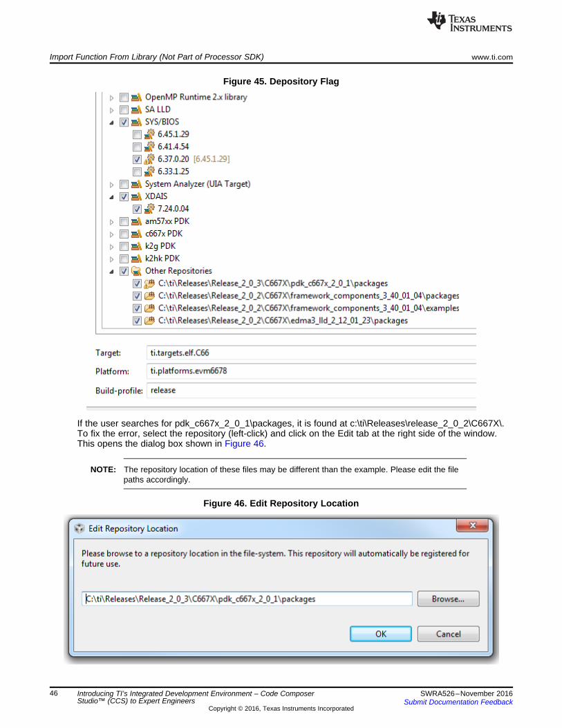
If one of the required elements is not available or has the wrong address, the system flags it out. Goingthrough all RTSC elements (see Figure 44), one of the additional depositories has a small exclamationmark next to it (see Figure 45).
Figure 44. RTSC Elements
Import Function From Library (Not Part of Processor SDK) www.ti.com
46 SWRA526–November 2016Submit Documentation Feedback
Copyright © 2016, Texas Instruments Incorporated
Introducing TI’s Integrated Development Environment – Code ComposerStudio™ (CCS) to Expert Engineers
Figure 45. Depository Flag
If the user searches for pdk_c667x_2_0_1\packages, it is found at c:\ti\Releases\release_2_0_2\C667X\.To fix the error, select the repository (left-click) and click on the Edit tab at the right side of the window.This opens the dialog box shown in Figure 46.
NOTE: The repository location of these files may be different than the example. Please edit the filepaths accordingly.
Figure 46. Edit Repository Location
www.ti.com Import Function From Library (Not Part of Processor SDK)
47SWRA526–November 2016Submit Documentation Feedback
Copyright © 2016, Texas Instruments Incorporated
Introducing TI’s Integrated Development Environment – Code ComposerStudio™ (CCS) to Expert Engineers
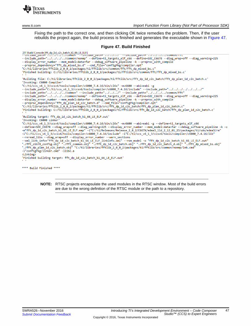
Fixing the path to the correct one, and then clicking OK twice remedies the problem. Then, if the userrebuilds the project again, the build process is finished and generates the executable shown in Figure 47.
Figure 47. Build Finished
NOTE: RTSC projects encapsulate the used modules in the RTSC window. Most of the build errorsare due to the wrong definition of the RTSC module or the path to a repository.
IMPORTANT NOTICE
Texas Instruments Incorporated and its subsidiaries (TI) reserve the right to make corrections, enhancements, improvements and otherchanges to its semiconductor products and services per JESD46, latest issue, and to discontinue any product or service per JESD48, latestissue. Buyers should obtain the latest relevant information before placing orders and should verify that such information is current andcomplete. All semiconductor products (also referred to herein as “components”) are sold subject to TI’s terms and conditions of salesupplied at the time of order acknowledgment.TI warrants performance of its components to the specifications applicable at the time of sale, in accordance with the warranty in TI’s termsand conditions of sale of semiconductor products. Testing and other quality control techniques are used to the extent TI deems necessaryto support this warranty. Except where mandated by applicable law, testing of all parameters of each component is not necessarilyperformed.TI assumes no liability for applications assistance or the design of Buyers’ products. Buyers are responsible for their products andapplications using TI components. To minimize the risks associated with Buyers’ products and applications, Buyers should provideadequate design and operating safeguards.TI does not warrant or represent that any license, either express or implied, is granted under any patent right, copyright, mask work right, orother intellectual property right relating to any combination, machine, or process in which TI components or services are used. Informationpublished by TI regarding third-party products or services does not constitute a license to use such products or services or a warranty orendorsement thereof. Use of such information may require a license from a third party under the patents or other intellectual property of thethird party, or a license from TI under the patents or other intellectual property of TI.Reproduction of significant portions of TI information in TI data books or data sheets is permissible only if reproduction is without alterationand is accompanied by all associated warranties, conditions, limitations, and notices. TI is not responsible or liable for such altereddocumentation. Information of third parties may be subject to additional restrictions.Resale of TI components or services with statements different from or beyond the parameters stated by TI for that component or servicevoids all express and any implied warranties for the associated TI component or service and is an unfair and deceptive business practice.TI is not responsible or liable for any such statements.Buyer acknowledges and agrees that it is solely responsible for compliance with all legal, regulatory and safety-related requirementsconcerning its products, and any use of TI components in its applications, notwithstanding any applications-related information or supportthat may be provided by TI. Buyer represents and agrees that it has all the necessary expertise to create and implement safeguards whichanticipate dangerous consequences of failures, monitor failures and their consequences, lessen the likelihood of failures that might causeharm and take appropriate remedial actions. Buyer will fully indemnify TI and its representatives against any damages arising out of the useof any TI components in safety-critical applications.In some cases, TI components may be promoted specifically to facilitate safety-related applications. With such components, TI’s goal is tohelp enable customers to design and create their own end-product solutions that meet applicable functional safety standards andrequirements. Nonetheless, such components are subject to these terms.No TI components are authorized for use in FDA Class III (or similar life-critical medical equipment) unless authorized officers of the partieshave executed a special agreement specifically governing such use.Only those TI components which TI has specifically designated as military grade or “enhanced plastic” are designed and intended for use inmilitary/aerospace applications or environments. Buyer acknowledges and agrees that any military or aerospace use of TI componentswhich have not been so designated is solely at the Buyer's risk, and that Buyer is solely responsible for compliance with all legal andregulatory requirements in connection with such use.TI has specifically designated certain components as meeting ISO/TS16949 requirements, mainly for automotive use. In any case of use ofnon-designated products, TI will not be responsible for any failure to meet ISO/TS16949.
Products ApplicationsAudio www.ti.com/audio Automotive and Transportation www.ti.com/automotiveAmplifiers amplifier.ti.com Communications and Telecom www.ti.com/communicationsData Converters dataconverter.ti.com Computers and Peripherals www.ti.com/computersDLP® Products www.dlp.com Consumer Electronics www.ti.com/consumer-appsDSP dsp.ti.com Energy and Lighting www.ti.com/energyClocks and Timers www.ti.com/clocks Industrial www.ti.com/industrialInterface interface.ti.com Medical www.ti.com/medicalLogic logic.ti.com Security www.ti.com/securityPower Mgmt power.ti.com Space, Avionics and Defense www.ti.com/space-avionics-defenseMicrocontrollers microcontroller.ti.com Video and Imaging www.ti.com/videoRFID www.ti-rfid.comOMAP Applications Processors www.ti.com/omap TI E2E Community e2e.ti.comWireless Connectivity www.ti.com/wirelessconnectivity
Mailing Address: Texas Instruments, Post Office Box 655303, Dallas, Texas 75265Copyright © 2016, Texas Instruments Incorporated