introduction of products - 日本ダイヤバルブ│高 … · · 2017-11-06introduction of...
TRANSCRIPT

468
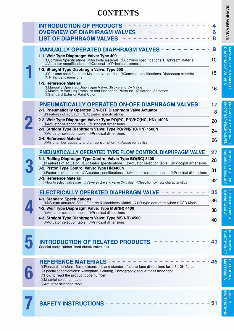
INTRODUCTION OF PRODUCTSOVERVIEW OF DIAPHRAGM VALVESLIST OF DIAPHRAGM VALVES
①Common Specifications: Main body material ②Common specifications: Diaphragm material③Actuator specifications ④Optional ⑤Principal dimensions
①Features of actuator ②Actuator specifications
①Features of actuator ②Actuator specifications ③Actuator selection table ④Principal dimensions
①Features of actuator ②Actuator specifications ③Actuator selection table ④Principal dimensions
MA
NU
ALLY
OP
ER
AT
ED
DIA
PH
RA
GM
VA
LVE
SELECTRICALLY OPERATEDDIAPHRAGM VALVE
RE
FER
EN
CE
MA
TE
RIA
LSPNEUM
ATICALLY OPERATEDON-OFF DIAPHRAGM
VALVESPNEUMATICALLY OPERATED TYPE FLOW CONTROL DIAPHRAGM VALVE
INTRODUCTION OF RELATED PRODUCTS
①Flange dimensions: Basic dimensions and standard face-to-face dimensions for JIS 10K flange②Special specifications: Nameplate, Painting, Photography and Witness inspection③How to read the product code number④Material selection table⑤Actuator selection table
SAFETY
IN
STRU
CTIO
NS
………………………………………………………………………………………………………………
………………………………………………………………
…………………………………
…………………………………
………………………………………
………………………………………………………………………
…………………………………………………………………………
9
17
27
35
43
45
51
10
18
20
24
26
15
16
28
31
32
36
38
40
DIA
PH
RA
GM
VA
LVE
CONTENTS
1-1. Weir Type Diaphragm Valve: Type 400
2-1. Pneumatically Operated ON-OFF Diaphragm Valve Actuator
①Actuator selection table ②Principal dimensions2-2. Weir Type Diaphragm Valve : Type PO(PC, PN)/HO(HC, HN) 1400N
①Actuator selection table ②Principal dimensions2-3. Straight Type Diaphragm Valve: Type PO(PN)/HO(HN) 1500N
①Air chamber capacity and air consumption ②Accessories list2-4. Reference Material
3-1. Rolling Diaphragm Type Control Valve: Type BO(BC) 3400
3-2. Piston Type Control Valve: Type HN3400N
①How to select valve size ②Valve stroke and valve Cv value ③Specific flow rate characteristics3-3. Reference Material
①Manually Operated Diaphragm Valve: Stroke and Cv Value ②Maximum Working Pressure and Inspection Pressure ③Material Selection ④Standard Exterior Paint Color
1-3. Reference Material
①Common specifications: Main body material ②Common specifications: Diaphragm material③ Principal dimensions
1-2. Straight Type Diaphragm Valve: Type 500
MANUALLY OPERATED DIAPHRAGM VALVES
PNEUMATICALLY OPERATED ON-OFF DIAPHRAGM VALVES
①MS type actuator: Seibu Electric & Machinery Model ②NR type actuator: Nihon KOSO Model4-1. Standard Specifications
①Actuator selection table ②Principal dimensions4-2. Weir Type Diaphragm Valve: Type MS(NR) 4400
①Actuator selection table ②Principal dimensions4-3. Straight Type Diaphragm Valve: Type MS(NR) 4500
ELECTRICALLY OPERATED DIAPHRAGM VALVE
Special body, rubber-lined check valve, etc.INTRODUCTION OF RELATED PRODUCTS
REFERENCE MATERIALS
SAFETY INSTRUCTIONS
PNEUMATICALLY OPERATED TYPE FLOW CONTROL DIAPHRAGM VALVE
1
2
3
4
5
6
7

Manually Operated Diaphragm Valve: Type 400
Pneumatically Operated ON-OFF Diaphragm Valve: Type PO(PC, PN) 1400N
Pneumatically Operated ON-OFF Diaphragm Valve: Type HO(HC, HN) 1400N
Pneumatically Operated Flow Control Diaphragm Valve (1): Type 3400 [Rolling diaphragm type]
Pneumatically Operated Flow Control DiaphragmValve (2): Type HN3400N [Cylinder type]
Electrically Operated Diaphragm Valve (1): Type MS4400
Electrically Operated Diaphragm Valve (2): Type NR4400
Nominal Size (DN):15‒150
PO…Reverse Acting(Air to Open)
PC…Direct Acting(Air to Close)
BO…Reverse Acting(Air to Open)
BC…Direct Acting(Air to Close)HN…Double Acting
HO…Reverse Acting(Air to Open)
HC…Direct Acting(Air to Close)
HN…Double Acting
Weir Type Diaphragm Valve (Basic type: Type 400)
PN…Double Acting
●Large and high output type ●Large and high output type
●Large and high output type
Nominal Size(DN) : 15 ‒ 300
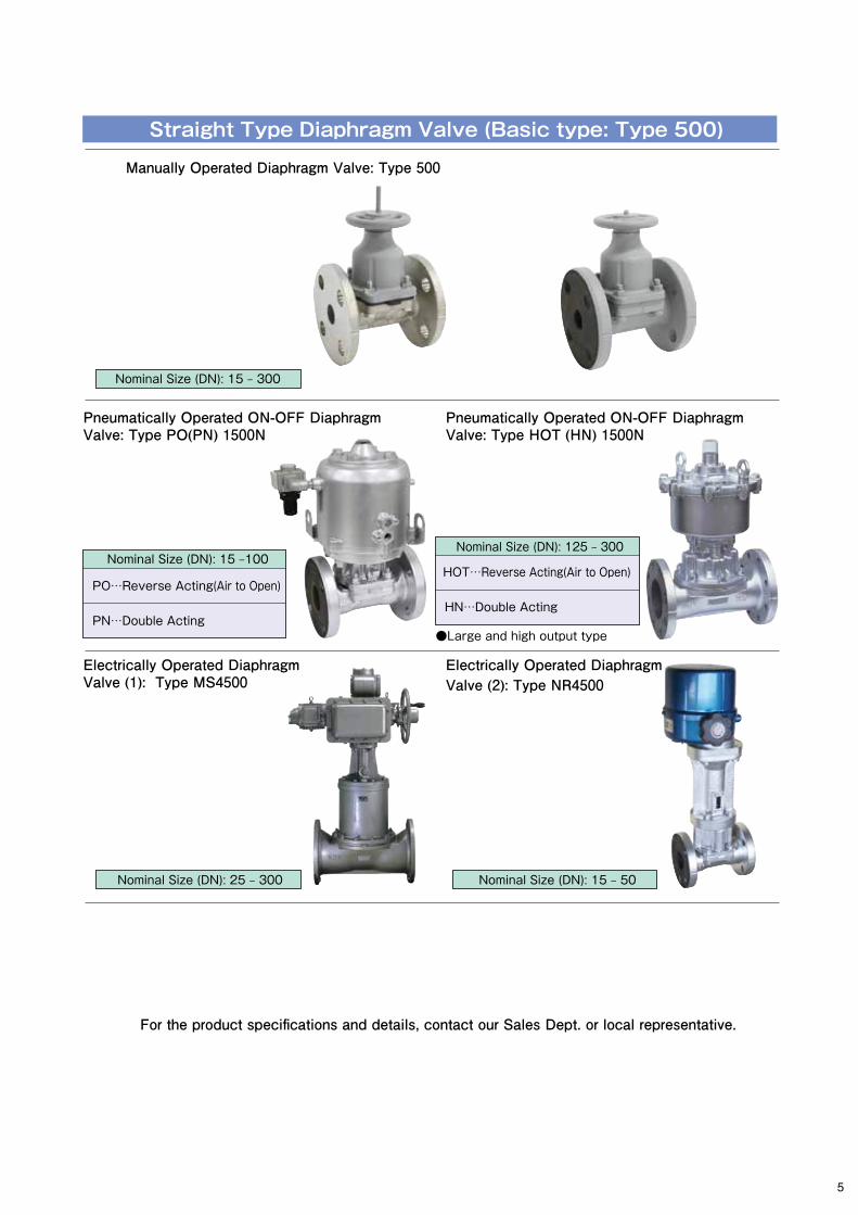
Manually Operated Diaphragm Valve: Type 500
Pneumatically Operated ON-OFF DiaphragmValve: Type PO(PN) 1500N
Pneumatically Operated ON-OFF Diaphragm Valve: Type HOT (HN) 1500N
Electrically Operated Diaphragm Valve (1): Type MS4500
For the product specifications and details, contact our Sales Dept. or local representative.
Electrically Operated DiaphragmValve (2): Type NR4500
Photos in this catalog represent images of valves. Actual appearance may differ by specifications.
INTRODUCTION OF PRODUCTS
Nominal Size (DN):15‒150
Nominal Size (DN): 25 ‒ 300 Nominal Size (DN): 15 ‒ 80
Nominal Size (DN): 15 ‒ 300
Nominal Size (DN): 25 ‒ 300 Nominal Size (DN): 15 ‒ 50
Nominal Size (DN):150 ‒300
Nominal Size (DN):100 ‒ 300
PO…Reverse Acting(Air to Open)
PN…Double Acting
Nominal Size (DN): 15 ‒100
HN…Double Acting
HOT…Reverse Acting(Air to Open)
Nominal Size (DN): 125 ‒ 300
Straight Type Diaphragm Valve (Basic type: Type 500)
4
Manually Operated Diaphragm Valve: Type 400
Pneumatically Operated ON-OFF Diaphragm Valve: Type PO(PC, PN) 1400N
Pneumatically Operated ON-OFF Diaphragm Valve: Type HO(HC, HN) 1400N
Pneumatically Operated Flow Control Diaphragm Valve (1): Type 3400 [Rolling diaphragm type]
Pneumatically Operated Flow Control DiaphragmValve (2): Type HN3400N [Cylinder type]
Electrically Operated Diaphragm Valve (1): Type MS4400
Electrically Operated Diaphragm Valve (2): Type NR4400
Nominal Size (DN):15‒150
PO…Reverse Acting(Air to Open)
PC…Direct Acting(Air to Close)
BO…Reverse Acting(Air to Open)
BC…Direct Acting(Air to Close)HN…Double Acting
HO…Reverse Acting(Air to Open)
HC…Direct Acting(Air to Close)
HN…Double Acting
Weir Type Diaphragm Valve (Basic type: Type 400)
PN…Double Acting
●Large and high output type ●Large and high output type
●Large and high output type
Nominal Size(DN) : 15 ‒ 300
Manually Operated Diaphragm Valve: Type 500
Pneumatically Operated ON-OFF DiaphragmValve: Type PO(PN) 1500N
Pneumatically Operated ON-OFF Diaphragm Valve: Type HOT (HN) 1500N
Electrically Operated Diaphragm Valve (1): Type MS4500
For the product specifications and details, contact our Sales Dept. or local representative.
Electrically Operated DiaphragmValve (2): Type NR4500
Photos in this catalog represent images of valves. Actual appearance may differ by specifications.
INTRODUCTION OF PRODUCTS
Nominal Size (DN):15‒150
Nominal Size (DN): 25 ‒ 300 Nominal Size (DN): 15 ‒ 80
Nominal Size (DN): 15 ‒ 300
Nominal Size (DN): 25 ‒ 300 Nominal Size (DN): 15 ‒ 50
Nominal Size (DN):150 ‒300
Nominal Size (DN):100 ‒ 300
PO…Reverse Acting(Air to Open)
PN…Double Acting
Nominal Size (DN): 15 ‒100
HN…Double Acting
HOT…Reverse Acting(Air to Open)
Nominal Size (DN): 125 ‒ 300
Straight Type Diaphragm Valve (Basic type: Type 500)
5

① ②
OVERVIEW OF DIAPHRAGM VALVES
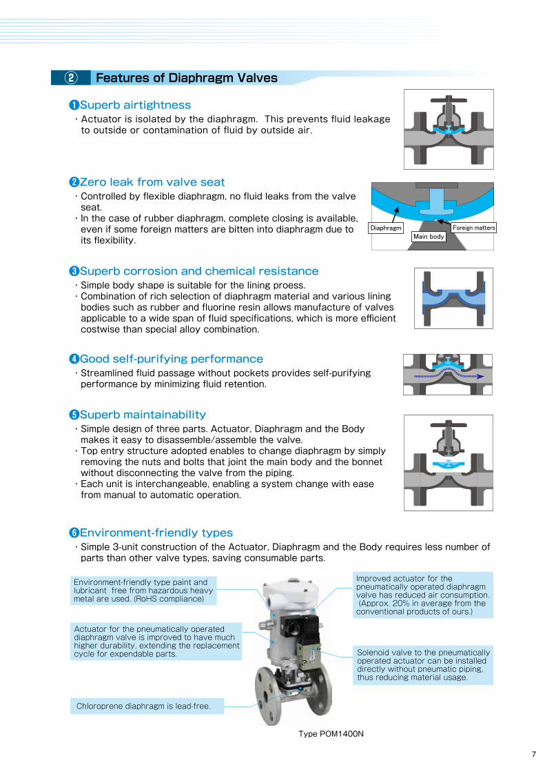
Basic Structure and Mechanism of Diaphragm Valves Features of Diaphragm Valves
Manually operated diaphragm valve (fluorine resin-lined)
Type POM1400N
Mainly categorized into the manually operated type, pneumatically operated type, flow control type(*) and electrically operated type.
Rubber, fluorine resin(*) and other material are available according to application(**).
Metal with or without lining is available in rich selection for a body. Connection method available includes weldedtype and screw type in addition to the flange type(**).(*) For weir type diaphragm valve only.(**) For details, see p.10 and p.15
●Diaphragm valve generally refers to a valve having a diaphragm of rubber or other flexible material that opens or closes the fluid passage.●The following diagram shows the basic structure of diaphragm valve that consists of three units, actuator, diaphragm and the body. The valve controls the liquid flow by pressing or depressing the diaphragm to or from the sealing surface on the inside of the body.●Diaphragm valves are roughly categorized to two types; Weir type (Type 400 ) and Straight type (Type 500), but both types share the same basic structure.
●Basic structure of diaphragm valve having a weir at the fluid passage. The diaphragm and weir of the body are tightly closed for airtightness to achieve high valve seat sealing performance.●Rich selection is available for the main body and diaphragm material to apply to a wide scope of fluid.●Used for : Chemical, environment and water treatment, iron and steel, shipbuilding, medical, food, semiconductor, power generation, etc.
●The fluid passage is straight, which minimizes pressure drop and/or fluid accumulation.●Applicable to viscose fluid, cellulose fluid, slurry, sledge and other fluids containing suspended solids.●Used for : Water purifying plants, terminal treatment plant, etc.
Actuator
Diaphragm
Body
Basic unit structure
Weir type diaphragm valve: Type 400
・Actuator is isolated by the diaphragm. This prevents fluid leakage to outside or contamination of fluid by outside air.
Environment-friendly type paint andlubricant free from hazardous heavy metal are used. (RoHS compliance)
Improved actuator for the pneumatically operated diaphragm valve has reduced air consumption. (Approx. 20% in average from the conventional products of ours.)
Solenoid valve to the pneumatically operated actuator can be installed directly without pneumatic piping, thus reducing material usage.
Chloroprene diaphragm is lead-free.
Actuator for the pneumatically operated diaphragm valve is improved to have much higher durability, extending the replacement cycle for expendable parts.
❶Superb airtightness
・Simple 3-unit construction of the Actuator, Diaphragm and the Body requires less number of parts than other valve types, saving consumable parts.
❻Environment-friendly types
・Controlled by flexible diaphragm, no fluid leaks from the valve seat.・In the case of rubber diaphragm, complete closing is available, even if some foreign matters are bitten into diaphragm due to its flexibility.
❷Zero leak from valve seat
・Simple design of three parts. Actuator, Diaphragm and the Body makes it easy to disassemble/assemble the valve.・Top entry structure adopted enables to change diaphragm by simply removing the nuts and bolts that joint the main body and the bonnet without disconnecting the valve from the piping.・Each unit is interchangeable, enabling a system change with ease from manual to automatic operation.
❺Superb maintainability
・Simple body shape is suitable for the lining proess.・Combination of rich selection of diaphragm material and various lining bodies such as rubber and fluorine resin allows manufacture of valves applicable to a wide span of fluid specifications, which is more efficient costwise than special alloy combination.
❸Superb corrosion and chemical resistance
・Streamlined fluid passage without pockets provides self-purifying performance by minimizing fluid retention.
❹Good self-purifying performance
Straight type diaphragm valve: Type 500
Diaphragm Foreign mattersMain body
6
① ②
OVERVIEW OF DIAPHRAGM VALVES
Basic Structure and Mechanism of Diaphragm Valves Features of Diaphragm Valves
Manually operated diaphragm valve (fluorine resin-lined)
Type POM1400N
Mainly categorized into the manually operated type, pneumatically operated type, flow control type(*) and electrically operated type.
Rubber, fluorine resin(*) and other material are available according to application(**).
Metal with or without lining is available in rich selection for a body. Connection method available includes weldedtype and screw type in addition to the flange type(**).(*) For weir type diaphragm valve only.(**) For details, see p.10 and p.15
●Diaphragm valve generally refers to a valve having a diaphragm of rubber or other flexible material that opens or closes the fluid passage.●The following diagram shows the basic structure of diaphragm valve that consists of three units, actuator, diaphragm and the body. The valve controls the liquid flow by pressing or depressing the diaphragm to or from the sealing surface on the inside of the body.●Diaphragm valves are roughly categorized to two types; Weir type (Type 400 ) and Straight type (Type 500), but both types share the same basic structure.
●Basic structure of diaphragm valve having a weir at the fluid passage. The diaphragm and weir of the body are tightly closed for airtightness to achieve high valve seat sealing performance.●Rich selection is available for the main body and diaphragm material to apply to a wide scope of fluid.●Used for : Chemical, environment and water treatment, iron and steel, shipbuilding, medical, food, semiconductor, power generation, etc.
●The fluid passage is straight, which minimizes pressure drop and/or fluid accumulation.●Applicable to viscose fluid, cellulose fluid, slurry, sledge and other fluids containing suspended solids.●Used for : Water purifying plants, terminal treatment plant, etc.
Actuator
Diaphragm
Body
Basic unit structure
Weir type diaphragm valve: Type 400
・Actuator is isolated by the diaphragm. This prevents fluid leakage to outside or contamination of fluid by outside air.
Environment-friendly type paint andlubricant free from hazardous heavy metal are used. (RoHS compliance)
Improved actuator for the pneumatically operated diaphragm valve has reduced air consumption. (Approx. 20% in average from the conventional products of ours.)
Solenoid valve to the pneumatically operated actuator can be installed directly without pneumatic piping, thus reducing material usage.
Chloroprene diaphragm is lead-free.
Actuator for the pneumatically operated diaphragm valve is improved to have much higher durability, extending the replacement cycle for expendable parts.
❶Superb airtightness
・Simple 3-unit construction of the Actuator, Diaphragm and the Body requires less number of parts than other valve types, saving consumable parts.
❻Environment-friendly types
・Controlled by flexible diaphragm, no fluid leaks from the valve seat.・In the case of rubber diaphragm, complete closing is available, even if some foreign matters are bitten into diaphragm due to its flexibility.
❷Zero leak from valve seat
・Simple design of three parts. Actuator, Diaphragm and the Body makes it easy to disassemble/assemble the valve.・Top entry structure adopted enables to change diaphragm by simply removing the nuts and bolts that joint the main body and the bonnet without disconnecting the valve from the piping.・Each unit is interchangeable, enabling a system change with ease from manual to automatic operation.
❺Superb maintainability
・Simple body shape is suitable for the lining proess.・Combination of rich selection of diaphragm material and various lining bodies such as rubber and fluorine resin allows manufacture of valves applicable to a wide span of fluid specifications, which is more efficient costwise than special alloy combination.
❸Superb corrosion and chemical resistance
・Streamlined fluid passage without pockets provides self-purifying performance by minimizing fluid retention.
❹Good self-purifying performance
Straight type diaphragm valve: Type 500
Diaphragm Foreign mattersMain body
7

1-1. Weir type Diaphragm Valve: Type 400① Common specifications: Body material
② Common specifications: Diaphragm material
③ Actuator specification
④ Optional
⑤ Principal dimension list
1-2. Straight type Diaphragm Valve: Type 500① Common specifications: Body material
② Common specifications: Diaphragm material
③ Principal dimension list
1-3. Reference materials① Manually operated diaphragm valve: Stroke and
Cv Value
② Maximum working pressure and inspection pressure
③ Selection of material
④ Standard exterior paint color
MANUALLY OPERATED DIAPHRAGM VALVE
1
●LI
ST
OF
DIA
PH
RA
GM
VA
LVES
Gray
cas
t iro
nDu
ctile
cas
t iro
n
Stai
nles
s st
eel
Diss
olved
zinc
plat
edHa
rd na
tural
rubbe
r line
dSo
ft natu
ral ru
bber
lined
Chlor
opren
e rub
ber li
ned
Buty
l rub
ber l
ined
Poly
ethy
lene
lined
PFA
lined
ETFE
line
dGl
ass
lined
Cera
mic
line
dNa
tura
l rub
ber
Chlor
opre
ne ru
bber
Buty
l rub
ber
Nitri
le ru
bber
EPDM
NEW
PTFE
/EPD
MNE
W PT
FE/E
PDM+
αPT
FE/E
PDM
PTFE
/EPD
M+α
FC20
0FC
D-S
SCS1
3SC
S14
SCS1
6HD
Z55(
FC20
0)(
FC20
0)(
FC20
0)(
FC20
0)(
FC20
0)(
FC20
0)(
FCD-
S)(
SCS1
3)(
FCD-
S)(
FCD-
S)(
FCD-
S)NR
+BR
CR IIR NBR
EPDM
NEW
PTFE
/EPD
MNE
W PT
FE/E
PDM+
αPT
FE/E
PDM
PTFE
/EPD
M+α
01 0407
(2)/
0712
(2)/
1213
(2)/
1371 30 33 35 36 50
59(
M)
59(2S
)/59(
S)60
40(
04)
80(
04)
NR
CR
BG
AB
EPTX
/CE
TX/C
XTF
/CE
TF/C
X
15-3
0015
-300
15-3
0015
-300
15-3
0015
-300
15-3
0015
-300
15-3
0015
-300
15-3
0015
-250
15-8
015
-100
15-2
0015
-80
15-3
0015
-300
15-3
0015
-300
15-3
0015
-100
15-1
0012
5-25
012
5-20
0
15-1
5015
-150
15-1
5015
-150
15-1
5015
-150
15-1
5015
-150
15-1
501-
150
20-1
5015
-150
15-8
015
-100
15-1
5015
-80
15-1
5015
-150
15-1
5015
-150
15-1
5015
-100
15-1
0012
5-15
012
5-15
0
15-1
5015
-150
15-1
5015
-150
15-1
5015
-150
15-1
5015
-150
15-1
5015
-150
20-1
5015
-150
15-8
015
-100
15-1
5015
-80
15-1
5015
-150
15-1
5015
-150
15-1
5015
-100
15-1
0012
5-15
012
5-15
0
150-
300
150-
300
150-
300
150-
300
150-
300
150-
300
150-
300
150-
300
150-
300
150-
300
150-
300
150-
250
- -15
0-20
0-
150-
300
150-
300
150-
300
150-
300
150-
300
- -15
0-25
015
0-20
0
15-3
0015
-300
15-3
0015
-300
15-3
0015
-300
15-3
0015
-300
15-3
0015
-300
15-3
0015
-250
15-8
015
-100
15-2
0015
-80
15-3
0015
-300
15-3
0015
-300
15-3
0015
-100
15-1
0012
5-25
012
5-20
0
15-3
0015
-300
15-3
0015
-300
15-3
0015
-300
15-3
0015
-300
15-3
0015
-300
- - - - - -15
-300
15-3
0015
-300
15-3
0015
-300
- - - -
15-3
0015
-300
15-3
0015
-300
15-3
0015
-300
15-3
0015
-300
15-3
0015
-300
- - - - - -15
-300
15-3
0015
-300
15-3
0015
-300
- - - -
125-
150
125-
150
125-
150
125-
150
125-
150
125-
150
125-
150
125-
150
125-
150
125-
150
- - - - - - - - - -
125-
300
125-
300
125-
300
125-
300
125-
300
125-
300
125-
300
125-
300
125-
300
125-
300
125-
150
125-
150
125-
150
125-
150
125-
150
125 -
300
125-
300
125-
300
125-
300
125-
300
15-1
0015
-100
15-1
0015
-100
15-1
0015
-100
15-1
0015
-100
15-1
0015
-100
- - - - - -15
-100
15-1
0015
-100
15-1
0015
-100
- - - -
100-
250
100-
250
100-
250
100-
250
100-
250
100-
200
100-
250
100-
250
100-
250
100-
250
100-
200
100-
250
- 100
125-
200
-10
0-25
010
0-25
010
0-25
010
0-25
010
0-25
010
010
012
5-25
012
5-25
0
125-
300
125-
300
125-
300
125-
300
125-
300
125-
300
125-
300
125-
300
125-
300
125-
300
125-
200
125-
250
- -12
5-20
0-
125-
300
125-
300
125-
300
125-
300
125-
300
- -12
5-25
012
5-20
0
150
150
150
150
150
150
150
150
150
150
150
150 - - 150 - 150
150
150
150
150 - - 150
150
Main body material and range of applicable nominal size (DN)
Diaphragm material and range of applicable nominal size (DN)
Mat
eria
l co
de
Val
ve
type
Type
400
Type
PO
1400
NTy
pe
HC14
00N
Type
HN
1400
NTy
pe
BO34
00Ty
pe
HO14
00N
Type
PN
1400
NTy
pe
PC14
00N
Rev
erse
Act
ing
Rev
erse
Act
ing
Rev
erse
Act
ing
Dou
ble
Act
ing
Dou
ble
Act
ing
Dou
ble
Act
ing
Dir
ect
Act
ing
Rev
erse
Act
ing
Dou
ble
Act
ing
Dir
ect
Act
ing
Rev
erse
Act
ing
Dou
ble
Act
ing
Dir
ect
Act
ing
①Ty
pe P
O(P
C, P
N) 1
400N
①[R
ollin
g di
aphr
agm
type
]①T
ype P
O(PN
) 150
0N②T
ype H
O(HN
) 150
0N②[
Cylin
der
type
]②
Type
HO
(HO
, HN
) 140
0N
Pneu
mat
ical
ly o
pera
ted
type
ON
-OFF
dia
phra
gm v
alve
Pne
umat
ical
ly o
pera
ted
ON
-OFF
di
aphr
agm
val
ve
Wei
r ty
pe d
iaph
ragm
val
ve (
Type
40
0)S
trai
ght
type
dia
phra
gm v
alve
(Ty
pe 5
00)
Pne
umat
ical
ly o
pera
ted
flow
co
ntro
l dia
phra
gm v
alve
Mat
eria
l (B
ase
mat
eria
l)
Spec
ifica
tions
Elect
ricall
y op
erat
ed
type
Elect
ricall
y op
erat
ed
type
Man
ually
op
erat
ed
type
Man
ually
op
erat
ed
type
Type
BC
3400
Type
HN
3400
NTy
pe 4
400
Type
500
Type
PO
1500
NTy
pe
PN15
00N
Type
HN
1500
NTy
pe 4
500
Type
HO
T150
0N
・Th
is t
able
out
lines
the
sta
ndar
d m
anuf
actu
ring
ran
ge o
f th
e fla
nged
typ
e bo
dy.
・Fo
r ot
her
mat
eria
l and
/or
nom
inal
siz
e, c
onta
ct o
ur S
ales
Dep
t. or
loca
l rep
rese
ntat
ive.
8

1-1. Weir type Diaphragm Valve: Type 400① Common specifications: Body material
② Common specifications: Diaphragm material
③ Actuator specification
④ Optional
⑤ Principal dimension list
1-2. Straight type Diaphragm Valve: Type 500① Common specifications: Body material
② Common specifications: Diaphragm material
③ Principal dimension list
1-3. Reference materials① Manually operated diaphragm valve: Stroke and
Cv Value
② Maximum working pressure and inspection pressure
③ Selection of material
④ Standard exterior paint color
MANUALLY OPERATED DIAPHRAGM VALVE
1
●LI
ST
OF
DIA
PH
RA
GM
VA
LVES
Gray
cas
t iro
nDu
ctile
cas
t iro
n
Stai
nles
s st
eel
Diss
olved
zinc
plat
edHa
rd na
tural
rubbe
r line
dSo
ft natu
ral ru
bber
lined
Chlor
opren
e rub
ber li
ned
Buty
l rub
ber l
ined
Poly
ethy
lene
lined
PFA
lined
ETFE
line
dGl
ass
lined
Cera
mic
line
dNa
tura
l rub
ber
Chlor
opre
ne ru
bber
Buty
l rub
ber
Nitri
le ru
bber
EPDM
NEW
PTFE
/EPD
MNE
W PT
FE/E
PDM+
αPT
FE/E
PDM
PTFE
/EPD
M+α
FC20
0FC
D-S
SCS1
3SC
S14
SCS1
6HD
Z55(
FC20
0)(
FC20
0)(
FC20
0)(
FC20
0)(
FC20
0)(
FC20
0)(
FCD-
S)(
SCS1
3)(
FCD-
S)(
FCD-
S)(
FCD-
S)NR
+BR
CR IIR NBR
EPDM
NEW
PTFE
/EPD
MNE
W PT
FE/E
PDM+
αPT
FE/E
PDM
PTFE
/EPD
M+α
01 0407
(2)/
0712
(2)/
1213
(2)/
1371 30 33 35 36 50
59(
M)
59(2S
)/59(
S)60
40(
04)
80(
04)
NR
CR
BG
AB
EPTX
/CE
TX/C
XTF
/CE
TF/C
X
15-3
0015
-300
15-3
0015
-300
15-3
0015
-300
15-3
0015
-300
15-3
0015
-300
15-3
0015
-250
15-8
015
-100
15-2
0015
-80
15-3
0015
-300
15-3
0015
-300
15-3
0015
-100
15-1
0012
5-25
012
5-20
0
15-1
5015
-150
15-1
5015
-150
15-1
5015
-150
15-1
5015
-150
15-1
501-
150
20-1
5015
-150
15-8
015
-100
15-1
5015
-80
15-1
5015
-150
15-1
5015
-150
15-1
5015
-100
15-1
0012
5-15
012
5-15
0
15-1
5015
-150
15-1
5015
-150
15-1
5015
-150
15-1
5015
-150
15-1
5015
-150
20-1
5015
-150
15-8
015
-100
15-1
5015
-80
15-1
5015
-150
15-1
5015
-150
15-1
5015
-100
15-1
0012
5-15
012
5-15
0
150-
300
150-
300
150-
300
150-
300
150-
300
150-
300
150-
300
150-
300
150-
300
150-
300
150-
300
150-
250
- -15
0-20
0-
150-
300
150-
300
150-
300
150-
300
150-
300
- -15
0-25
015
0-20
0
15-3
0015
-300
15-3
0015
-300
15-3
0015
-300
15-3
0015
-300
15-3
0015
-300
15-3
0015
-250
15-8
015
-100
15-2
0015
-80
15-3
0015
-300
15-3
0015
-300
15-3
0015
-100
15-1
0012
5-25
012
5-20
0
15-3
0015
-300
15-3
0015
-300
15-3
0015
-300
15-3
0015
-300
15-3
0015
-300
- - - - - -15
-300
15-3
0015
-300
15-3
0015
-300
- - - -
15-3
0015
-300
15-3
0015
-300
15-3
0015
-300
15-3
0015
-300
15-3
0015
-300
- - - - - -15
-300
15-3
0015
-300
15-3
0015
-300
- - - -
125-
150
125-
150
125-
150
125-
150
125-
150
125-
150
125-
150
125-
150
125-
150
125-
150
- - - - - - - - - -
125-
300
125-
300
125-
300
125-
300
125-
300
125-
300
125-
300
125-
300
125-
300
125-
300
125-
150
125-
150
125-
150
125-
150
125-
150
125 -
300
125-
300
125-
300
125-
300
125-
300
15-1
0015
-100
15-1
0015
-100
15-1
0015
-100
15-1
0015
-100
15-1
0015
-100
- - - - - -15
-100
15-1
0015
-100
15-1
0015
-100
- - - -
100-
250
100-
250
100-
250
100-
250
100-
250
100-
200
100-
250
100-
250
100-
250
100-
250
100-
200
100-
250
- 100
125-
200
-10
0-25
010
0-25
010
0-25
010
0-25
010
0-25
010
010
012
5-25
012
5-25
0
125-
300
125-
300
125-
300
125-
300
125-
300
125-
300
125-
300
125-
300
125-
300
125-
300
125-
200
125-
250
- -12
5-20
0-
125-
300
125-
300
125-
300
125-
300
125-
300
- -12
5-25
012
5-20
0
150
150
150
150
150
150
150
150
150
150
150
150 - - 150 - 150
150
150
150
150 - - 150
150
Main body material and range of applicable nominal size (DN)
Diaphragm material and range of applicable nominal size (DN)
Mat
eria
l co
de
Val
ve
type
Type
400
Type
PO
1400
NTy
pe
HC14
00N
Type
HN
1400
NTy
pe
BO34
00Ty
pe
HO14
00N
Type
PN
1400
NTy
pe
PC14
00N
Rev
erse
Act
ing
Rev
erse
Act
ing
Rev
erse
Act
ing
Dou
ble
Act
ing
Dou
ble
Act
ing
Dou
ble
Act
ing
Dir
ect
Act
ing
Rev
erse
Act
ing
Dou
ble
Act
ing
Dir
ect
Act
ing
Rev
erse
Act
ing
Dou
ble
Act
ing
Dir
ect
Act
ing
①Ty
pe P
O(P
C, P
N) 1
400N
①[R
ollin
g di
aphr
agm
type
]①T
ype P
O(PN
) 150
0N②T
ype H
O(HN
) 150
0N②[
Cylin
der
type
]②
Type
HO
(HO
, HN
) 140
0N
Pneu
mat
ical
ly o
pera
ted
type
ON
-OFF
dia
phra
gm v
alve
Pne
umat
ical
ly o
pera
ted
ON
-OFF
di
aphr
agm
val
ve
Wei
r ty
pe d
iaph
ragm
val
ve (
Type
40
0)S
trai
ght
type
dia
phra
gm v
alve
(Ty
pe 5
00)
Pne
umat
ical
ly o
pera
ted
flow
co
ntro
l dia
phra
gm v
alve
Mat
eria
l (B
ase
mat
eria
l)
Spec
ifica
tions
Elect
ricall
y op
erat
ed
type
Elect
ricall
y op
erat
ed
type
Man
ually
op
erat
ed
type
Man
ually
op
erat
ed
type
Type
BC
3400
Type
HN
3400
NTy
pe 4
400
Type
500
Type
PO
1500
NTy
pe
PN15
00N
Type
HN
1500
NTy
pe 4
500
Type
HO
T150
0N
・Th
is t
able
out
lines
the
sta
ndar
d m
anuf
actu
ring
ran
ge o
f th
e fla
nged
typ
e bo
dy.
・Fo
r ot
her
mat
eria
l and
/or
nom
inal
siz
e, c
onta
ct o
ur S
ales
Dep
t. or
loca
l rep
rese
ntat
ive.

MA
NU
ALLY
OP
ER
AT
ED
DIA
PH
RA
GM
VA
LVE
SELECTRICALLY OPERATEDDIAPHRAGM VALVE
RE
FER
EN
CE
MA
TE
RIA
LSPNEUM
ATICALLY OPERATEDON-OFF DIAPHRAGM
VALVESPNEUMATICALLY OPERATED TYPE FLOW CONTROL DIAPHRAGM VALVE
INTRODUCTION OF RELATED PRODUCTS
SAFETY
IN
STRU
CTIO
NS
DIA
PH
RA
GM
VA
LVE
MA
NU
ALL
Y O
PE
RA
TE
DD
IAP
HR
AG
M V
ALV
ES
ELEC
TRIC
ALLY
OPE
RATE
DDI
APHR
AGM
VALV
ER
EFE
RE
NC
EM
AT
ER
IALS
PNEU
MAT
ICAL
LY O
PERA
TED
ON-O
FF D
IAPH
RAGM
VAL
VES
PNEU
MATIC
ALLY
OPER
ATED
TYPE
FL
OW CO
NTRO
L DIAP
HRAG
M VAL
VEIN
TROD
UCTIO
N OF
RE
LATE
D PR
ODUC
TSSA
FETY
IN
STR
UC
TIO
NS
DIA
PH
RA
GM
VA
LVE
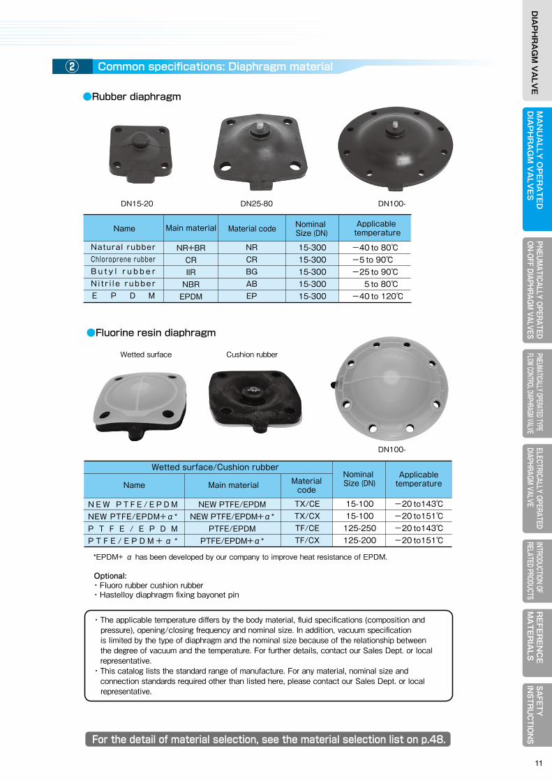
Common specifications: Body material
●Metal material (without lining)
Lined body with excellent corrosion, chemical and wear resistance
●Fluorine resin diaphragm
Type 400 (Flange type) Type 400L (Flange type) Tyoe 400Rc (Screwed type) Type 400SW (Welded type)
Wetted surface Cushion rubber
DN100-
DN100-DN25-80DN15-20
Name Main material
FC200FCD-SSCS13SCS14SCS16
HDZ55(FC200)
15-30015-30015-30015-30015-30015-300
15-10015-10015-10015-10015-10015-100
-15-2515-4015-40
--
--
15-5015-5015-50
-
Type 400 Type 400L
Nominal Size (DN)
Nominal Size (DN)
Nominal Size (DN)
Nominal Size (DN)
Nominal Size (DN)
Nominal Size (DN)
Nominal Size (DN)
Nominal Size (DN)
Nominal Size (DN)
Screwed typeType 400Rc
Welded type Type 400(SW/BW)Material
code
Flange type
① Common specifications: Diaphragm material②
Name Main material
Wetted surface/Cushion rubber
*EPDM+ α has been developed by our company to improve heat resistance of EPDM.
・The applicable temperature differs by the body material, fluid specifications (composition and pressure), opening/closing frequency and nominal size. In addition, vacuum specification is limited by the type of diaphragm and the nominal size because of the relationship between the degree of vacuum and the temperature. For further details, contact our Sales Dept. or local representative. ・This catalog lists the standard range of manufacture. For any material, nominal size and connection standards required other than listed here, please contact our Sales Dept. or local representative.
Optional:・Fluoro rubber cushion rubber・Hastelloy diaphragm fixing bayonet pin
TX/CETX/CXTF/CETF/CX
15-10015-100
125-250125-200
-20 to143℃-20 to151℃-20 to143℃-20 to151℃
Material code
Applicable temperature
N E W P T F E / E P D MNEW PTFE/EPDM+α*P T F E / E P D MP T F E / E P D M + α *
NEW PTFE/EPDMNEW PTFE/EPDM+α*
PTFE/EPDMPTFE/EPDM+α*
Name Base material
FC200/FCD-SFC200/FCD-SFC200/FCD-SFC200/FCD-S
30/30(04)33/33(04)35/35(04)36/36(04)
15-30015-30015-30015-300
15-20015-20015-20015-200
Material code
Name Base material Material code
Name Base material Material code
Hard natural rubber linedSoft natural rubber l inedChloroprene rubber linedButyl rubber lined
●Rubber lining
●Synthetic resin lining
FC200FCD-SSCS13FCD-S
5059(M)
59(2S)/59(S)60
15-30015-25015-80
15-100
15-100---
Type 400
Type 400
Type 400
Type 400L
Type 400L
Flange type
Flange type
Flange type
Polyethylene lined
P F A l i n e d *
E T F E l i n e d *
●Glass lining and Ceramic
*Those are dual use goods under export control by Japanese government. In case of export, export license stipulated in the Foreign Exchange and Foreign Trade Control Law of Japan and/or if necessary, export-related laws and regulations of the United States of America and other countries is required.
FCD-SFCD-S
40(04)80(04)
15-20015-80
G l a s s l i n e d *C e r a m i c l i n e d
Gray cas t i r onDuctile cast iron
Sta in less s tee l
Dissolved zinc plated
Name Main material
NR+BRCRIIR
NBREPDM
NRCRBGABEP
15-30015-30015-30015-30015-300
-40 to 80℃-5 to 90℃-25 to 90℃ 5 to 80℃-40 to 120℃
Nominal Size (DN)
Nominal Size (DN)
Material code Applicable temperature
Natural rubberChloroprene rubberB u t y l r u b b e rN i t r i l e rubberE P D M
●Rubber diaphragm
For the detail of material selection, see the material selection list on p.48.
0104
07(2)/0712(2)/1213(2)/13
71
1. Weir type Diaphragm Valve: Type 4001
10
MA
NU
ALLY
OP
ER
AT
ED
DIA
PH
RA
GM
VA
LVE
SELECTRICALLY OPERATEDDIAPHRAGM VALVE
RE
FER
EN
CE
MA
TE
RIA
LSPNEUM
ATICALLY OPERATEDON-OFF DIAPHRAGM
VALVESPNEUMATICALLY OPERATED TYPE FLOW CONTROL DIAPHRAGM VALVE
INTRODUCTION OF RELATED PRODUCTS
SAFETY
IN
STRU
CTIO
NS
DIA
PH
RA
GM
VA
LVE
MA
NU
ALL
Y O
PE
RA
TE
DD
IAP
HR
AG
M V
ALV
ES
ELEC
TRIC
ALLY
OPE
RATE
DDI
APHR
AGM
VALV
ER
EFE
RE
NC
EM
AT
ER
IALS
PNEU
MAT
ICAL
LY O
PERA
TED
ON-O
FF D
IAPH
RAGM
VAL
VES
PNEU
MATIC
ALLY
OPER
ATED
TYPE
FL
OW CO
NTRO
L DIAP
HRAG
M VAL
VEIN
TROD
UCTIO
N OF
RE
LATE
D PR
ODUC
TSSA
FETY
IN
STR
UC
TIO
NS
DIA
PH
RA
GM
VA
LVE
Common specifications: Body material
●Metal material (without lining)
Lined body with excellent corrosion, chemical and wear resistance
●Fluorine resin diaphragm
Type 400 (Flange type) Type 400L (Flange type) Tyoe 400Rc (Screwed type) Type 400SW (Welded type)
Wetted surface Cushion rubber
DN100-
DN100-DN25-80DN15-20
Name Main material
FC200FCD-SSCS13SCS14SCS16
HDZ55(FC200)
15-30015-30015-30015-30015-30015-300
15-10015-10015-10015-10015-10015-100
-15-2515-4015-40
--
--
15-5015-5015-50
-
Type 400 Type 400L
Nominal Size (DN)
Nominal Size (DN)
Nominal Size (DN)
Nominal Size (DN)
Nominal Size (DN)
Nominal Size (DN)
Nominal Size (DN)
Nominal Size (DN)
Nominal Size (DN)
Screwed typeType 400Rc
Welded type Type 400(SW/BW)Material
code
Flange type
① Common specifications: Diaphragm material②
Name Main material
Wetted surface/Cushion rubber
*EPDM+ α has been developed by our company to improve heat resistance of EPDM.
・The applicable temperature differs by the body material, fluid specifications (composition and pressure), opening/closing frequency and nominal size. In addition, vacuum specification is limited by the type of diaphragm and the nominal size because of the relationship between the degree of vacuum and the temperature. For further details, contact our Sales Dept. or local representative. ・This catalog lists the standard range of manufacture. For any material, nominal size and connection standards required other than listed here, please contact our Sales Dept. or local representative.
Optional:・Fluoro rubber cushion rubber・Hastelloy diaphragm fixing bayonet pin
TX/CETX/CXTF/CETF/CX
15-10015-100
125-250125-200
-20 to143℃-20 to151℃-20 to143℃-20 to151℃
Material code
Applicable temperature
N E W P T F E / E P D MNEW PTFE/EPDM+α*P T F E / E P D MP T F E / E P D M + α *
NEW PTFE/EPDMNEW PTFE/EPDM+α*
PTFE/EPDMPTFE/EPDM+α*
Name Base material
FC200/FCD-SFC200/FCD-SFC200/FCD-SFC200/FCD-S
30/30(04)33/33(04)35/35(04)36/36(04)
15-30015-30015-30015-300
15-20015-20015-20015-200
Material code
Name Base material Material code
Name Base material Material code
Hard natural rubber linedSoft natural rubber l inedChloroprene rubber linedButyl rubber lined
●Rubber lining
●Synthetic resin lining
FC200FCD-SSCS13FCD-S
5059(M)
59(2S)/59(S)60
15-30015-25015-80
15-100
15-100---
Type 400
Type 400
Type 400
Type 400L
Type 400L
Flange type
Flange type
Flange type
Polyethylene lined
P F A l i n e d *
E T F E l i n e d *
●Glass lining and Ceramic
*Those are dual use goods under export control by Japanese government. In case of export, export license stipulated in the Foreign Exchange and Foreign Trade Control Law of Japan and/or if necessary, export-related laws and regulations of the United States of America and other countries is required.
FCD-SFCD-S
40(04)80(04)
15-20015-80
G l a s s l i n e d *C e r a m i c l i n e d
Gray cas t i r onDuctile cast iron
Sta in less s tee l
Dissolved zinc plated
Name Main material
NR+BRCRIIR
NBREPDM
NRCRBGABEP
15-30015-30015-30015-30015-300
-40 to 80℃-5 to 90℃-25 to 90℃ 5 to 80℃-40 to 120℃
Nominal Size (DN)
Nominal Size (DN)
Material code Applicable temperature
Natural rubberChloroprene rubberB u t y l r u b b e rN i t r i l e rubberE P D M
●Rubber diaphragm
For the detail of material selection, see the material selection list on p.48.
0104
07(2)/0712(2)/1213(2)/13
71
1. Weir type Diaphragm Valve: Type 4001
11
MA
NU
ALLY
OP
ER
AT
ED
DIA
PH
RA
GM
VA
LVE
SELECTRICALLY OPERATEDDIAPHRAGM VALVE
RE
FER
EN
CE
MA
TE
RIA
LSPNEUM
ATICALLY OPERATEDON-OFF DIAPHRAGM
VALVESPNEUMATICALLY OPERATED TYPE FLOW CONTROL DIAPHRAGM VALVE
INTRODUCTION OF RELATED PRODUCTS
SAFETY
IN
STRU
CTIO
NS
DIA
PH
RA
GM
VA
LVE
MA
NU
ALL
Y O
PE
RA
TE
DD
IAP
HR
AG
M V
ALV
ES
ELEC
TRIC
ALLY
OPE
RATE
DDI
APHR
AGM
VALV
ER
EFE
RE
NC
EM
AT
ER
IALS
PNEU
MAT
ICAL
LY O
PERA
TED
ON-O
FF D
IAPH
RAGM
VAL
VES
PNEU
MATIC
ALLY
OPER
ATED
TYPE
FL
OW CO
NTRO
L DIAP
HRAG
M VAL
VEIN
TROD
UCTIO
N OF
RE
LATE
D PR
ODUC
TSSA
FETY
IN
STR
UC
TIO
NS
DIA
PH
RA
GM
VA
LVE
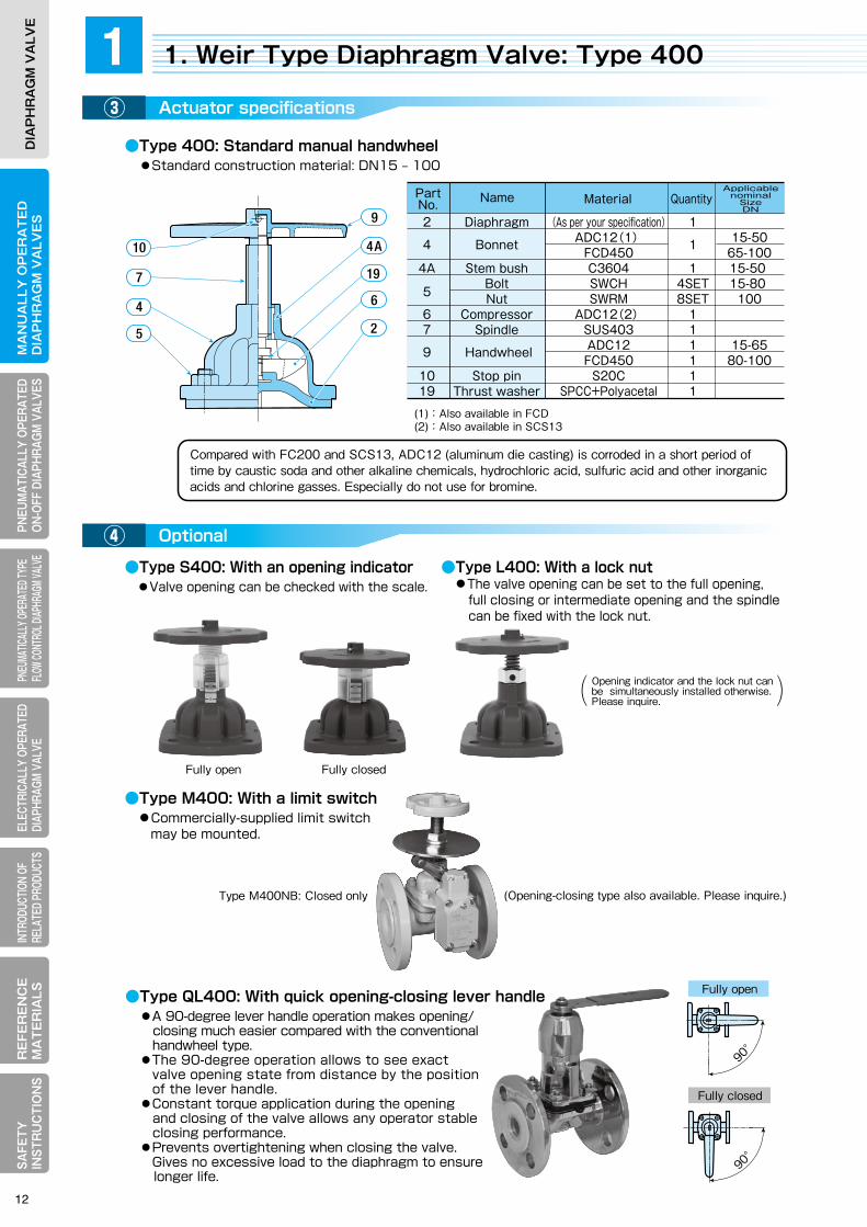
Actuator specifications
●Type 400: Standard manual handwheel ●Standard construction material: DN15 ‒ 100
●Type S400: With an opening indicator ●Valve opening can be checked with the scale.
●Type QL400: With quick opening-closing lever handle●A 90-degree lever handle operation makes opening/ closing much easier compared with the conventional handwheel type.●The 90-degree operation allows to see exact valve opening state from distance by the position of the lever handle.●Constant torque application during the opening and closing of the valve allows any operator stable closing performance.●Prevents overtightening when closing the valve. Gives no excessive load to the diaphragm to ensure longer life.
●Type M400: With a limit switch ●Commercially-supplied limit switch may be mounted.
●Type L400: With a lock nut ●The valve opening can be set to the full opening, full closing or intermediate opening and the spindle can be fixed with the lock nut.
③
Optional④
Principal dimension list⑤
Fully open Fully closed
Type M400NB: Closed only (Opening-closing type also available. Please inquire.)
Compared with FC200 and SCS13, ADC12 (aluminum die casting) is corroded in a short period oftime by caustic soda and other alkaline chemicals, hydrochloric acid, sulfuric acid and other inorganicacids and chlorine gasses. Especially do not use for bromine.
(1):Also available in FCD(2):Also available in SCS13
●Flange type①:Type 400
●Flange type②: Type 400L (Angle type)
NamePart No.
2 Diaphragm (As per your specification) 1 4 Bonnet ADC12(1) 1 15-50 FCD450 65-100 4A Stem bush C3604 1 15-50 Bolt SWCH 4SET 15-80 5 Nut SWRM 8SET 100 6 Compressor ADC12(2) 1 7 Spindle SUS403 1 9 Handwheel ADC12 1 15-65 FCD450 1 80-100 10 Stop pin S20C 1 19 Thrust washer SPCC+Polyacetal 1
Applicable nominal
SizeDN
Material Quantity
Opening indicator and the lock nut can be simultaneously installed otherwise. Please inquire.( (
Nominal Size (DN)
Nominal Size (DN)
Other thanrubber/
resin-lined
Other thanrubber/
resin-lined
Diameter d
Diameter d
Face-to-face length LHeight H, approx.
Height H, approx.
Lining rubber
thickness T
Mass approx.(kg)
Mass approx.(kg)
Rubber/resin-lined
Rubber/resin-lined
Other thanrubber/
resin-lined
Other thanrubber/
resin-linedRubber/
resin-linedRubber/
resin-lined
15202540506580
100125150200250300
13 15192538516476
102127152203254305
Unit :mm
Unit :mm
102118127159191216254305356406521635749
107123132165197222260313364414529645759
636380
100125125160224300350500600700
115125129155172209235297325365500585680
3333333444455
2.02.33.55.47.2
12.518.028.047.072.0
140.0226.0340.0
Remarks: 1.The mass is for the body of cast iron (JIS 10K.) 2.Height H represents the dimension when fully open. 3.Because of narrow space for the hexagon piping nut on the back of the flange of nominal size DN15 ‒ 80, use of continuous-thread stud and hexagonal nut of style 1(8-slit nut) is recommended. 4.Check the drawings for detailed dimensions of respective valve types.
Face-to-face AxBHandwheel diameter W
Handwheel diameter W
15202540506580
100125150200
Remarks : 1. The mass is for the body of cast iron (JIS 10K ). 2. Height H represents the dimension in fully open valve state.
13 15 19 25 38 51 64 76 102 94 - 119 - 144 - 195
67×64 69.5×66.5 63 115 2.0 73×67 75.5×69.5 63 125 2.3 83×80 85.5×82.5 80 129 3.5 105×80 108×83 100 155 5.6 130×98 133×101 125 172 8.4 149×123 152×126 125 209 13.0 178×140 181×143 160 235 19.5 216×152 220×156 224 297 36.0 - 258×284 300 325 - - 310×219 350 365 - - 402×258 500 500 -
90°
Fully open
90°
Fully closed
φW
B
A
φd
φW
φd
L
OPEN
SHUT
φW
φd
L
DN15 -100
Approx. H
Approx. H Approx. H
Approx. H
DN15 -100 DN125 - 200
DN125 - 300
φW
B
A
φd
OPEN
SHUT
1. Weir Type Diaphragm Valve: Type 4001
10
7
4
5
6
19
4A
9
2
12

MA
NU
ALLY
OP
ER
AT
ED
DIA
PH
RA
GM
VA
LVE
SELECTRICALLY OPERATEDDIAPHRAGM VALVE
RE
FER
EN
CE
MA
TE
RIA
LSPNEUM
ATICALLY OPERATEDON-OFF DIAPHRAGM
VALVESPNEUMATICALLY OPERATED TYPE FLOW CONTROL DIAPHRAGM VALVE
INTRODUCTION OF RELATED PRODUCTS
SAFETY
IN
STRU
CTIO
NS
DIA
PH
RA
GM
VA
LVE
MA
NU
ALL
Y O
PE
RA
TE
DD
IAP
HR
AG
M V
ALV
ES
ELEC
TRIC
ALLY
OPE
RATE
DDI
APHR
AGM
VALV
ER
EFE
RE
NC
EM
AT
ER
IALS
PNEU
MAT
ICAL
LY O
PERA
TED
ON-O
FF D
IAPH
RAGM
VAL
VES
PNEU
MATIC
ALLY
OPER
ATED
TYPE
FL
OW CO
NTRO
L DIAP
HRAG
M VAL
VEIN
TROD
UCTIO
N OF
RE
LATE
D PR
ODUC
TSSA
FETY
IN
STR
UC
TIO
NS
DIA
PH
RA
GM
VA
LVE
Actuator specifications
●Type 400: Standard manual handwheel ●Standard construction material: DN15 ‒ 100
●Type S400: With an opening indicator ●Valve opening can be checked with the scale.
●Type QL400: With quick opening-closing lever handle●A 90-degree lever handle operation makes opening/ closing much easier compared with the conventional handwheel type.●The 90-degree operation allows to see exact valve opening state from distance by the position of the lever handle.●Constant torque application during the opening and closing of the valve allows any operator stable closing performance.●Prevents overtightening when closing the valve. Gives no excessive load to the diaphragm to ensure longer life.
●Type M400: With a limit switch ●Commercially-supplied limit switch may be mounted.
●Type L400: With a lock nut ●The valve opening can be set to the full opening, full closing or intermediate opening and the spindle can be fixed with the lock nut.
③
Optional④
Principal dimension list⑤
Fully open Fully closed
Type M400NB: Closed only (Opening-closing type also available. Please inquire.)
Compared with FC200 and SCS13, ADC12 (aluminum die casting) is corroded in a short period oftime by caustic soda and other alkaline chemicals, hydrochloric acid, sulfuric acid and other inorganicacids and chlorine gasses. Especially do not use for bromine.
(1):Also available in FCD(2):Also available in SCS13
●Flange type①:Type 400
●Flange type②: Type 400L (Angle type)
NamePart No.
2 Diaphragm (As per your specification) 1 4 Bonnet ADC12(1) 1 15-50 FCD450 65-100 4A Stem bush C3604 1 15-50 Bolt SWCH 4SET 15-80 5 Nut SWRM 8SET 100 6 Compressor ADC12(2) 1 7 Spindle SUS403 1 9 Handwheel ADC12 1 15-65 FCD450 1 80-100 10 Stop pin S20C 1 19 Thrust washer SPCC+Polyacetal 1
Applicable nominal
SizeDN
Material Quantity
Opening indicator and the lock nut can be simultaneously installed otherwise. Please inquire.( (
Nominal Size (DN)
Nominal Size (DN)
Other thanrubber/
resin-lined
Other thanrubber/
resin-lined
Diameter d
Diameter d
Face-to-face length LHeight H, approx.
Height H, approx.
Lining rubber
thickness T
Mass approx.(kg)
Mass approx.(kg)
Rubber/resin-lined
Rubber/resin-lined
Other thanrubber/
resin-lined
Other thanrubber/
resin-linedRubber/
resin-linedRubber/
resin-lined
15202540506580
100125150200250300
13 15192538516476
102127152203254305
Unit :mm
Unit :mm
102118127159191216254305356406521635749
107123132165197222260313364414529645759
636380
100125125160224300350500600700
115125129155172209235297325365500585680
3333333444455
2.02.33.55.47.2
12.518.028.047.072.0
140.0226.0340.0
Remarks: 1.The mass is for the body of cast iron (JIS 10K.) 2.Height H represents the dimension when fully open. 3.Because of narrow space for the hexagon piping nut on the back of the flange of nominal size DN15 ‒ 80, use of continuous-thread stud and hexagonal nut of style 1(8-slit nut) is recommended. 4.Check the drawings for detailed dimensions of respective valve types.
Face-to-face AxBHandwheel diameter W
Handwheel diameter W
15202540506580
100125150200
Remarks : 1. The mass is for the body of cast iron (JIS 10K ). 2. Height H represents the dimension in fully open valve state.
13 15 19 25 38 51 64 76 102 94 - 119 - 144 - 195
67×64 69.5×66.5 63 115 2.0 73×67 75.5×69.5 63 125 2.3 83×80 85.5×82.5 80 129 3.5 105×80 108×83 100 155 5.6 130×98 133×101 125 172 8.4 149×123 152×126 125 209 13.0 178×140 181×143 160 235 19.5 216×152 220×156 224 297 36.0 - 258×284 300 325 - - 310×219 350 365 - - 402×258 500 500 -
90°
Fully open
90°
Fully closed
φW
B
A
φd
φW
φd
L
OPEN
SHUT
φW
φd
L
DN15 -100
Approx. H
Approx. H Approx. H
Approx. H
DN15 -100 DN125 - 200
DN125 - 300
φW
B
A
φd
OPEN
SHUT
1. Weir Type Diaphragm Valve: Type 4001
10
7
4
5
6
19
4A
9
2
13
MA
NU
ALLY
OP
ER
AT
ED
DIA
PH
RA
GM
VA
LVE
SELECTRICALLY OPERATEDDIAPHRAGM VALVE
RE
FER
EN
CE
MA
TE
RIA
LSPNEUM
ATICALLY OPERATEDON-OFF DIAPHRAGM
VALVESPNEUMATICALLY OPERATED TYPE FLOW CONTROL DIAPHRAGM VALVE
INTRODUCTION OF RELATED PRODUCTS
SAFETY
IN
STRU
CTIO
NS
DIA
PH
RA
GM
VA
LVE
MA
NU
ALL
Y O
PE
RA
TE
DD
IAP
HR
AG
M V
ALV
ES
ELEC
TRIC
ALLY
OPE
RATE
DDI
APHR
AGM
VALV
ER
EFE
RE
NC
EM
AT
ER
IALS
PNEU
MAT
ICAL
LY O
PERA
TED
ON-O
FF D
IAPH
RAGM
VAL
VES
PNEU
MATIC
ALLY
OPER
ATED
TYPE
FL
OW CO
NTRO
L DIAP
HRAG
M VAL
VEIN
TROD
UCTIO
N OF
RE
LATE
D PR
ODUC
TSSA
FETY
IN
STR
UC
TIO
NS
DIA
PH
RA
GM
VA
LVE
For the detail of material selection, see the material selection list on p.48.
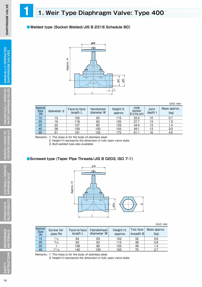
●Welded type (Socket Welded/JIS B 2316 Schedule 80)
●Screwed type (Taper Pipe Threads/JIS B 0203, ISO 7-1)
Remarks : 1. The mass is for the body of stainless steel. 2. Height H represents the dimension in fully open valve state. 3. Butt-welded type also available.
Remarks : 1. The mass is for the body of stainless steel. 2. Height H represents the dimension in fully open valve state.
NominalSize DN
diameter d Handwheeldiameter W
Height H, approx.
Joint depth t
Insidediameter
B of the jointFace-to-face
length L
1520254050
Unit: mm
Unit: mm
13 102 63 115 22.2 10 0.7 19 118 63 125 27.7 13 1.0 25 127 80 129 34.5 13 1.4 38 159 100 155 49.1 13 3.0 51 191 125 172 61.1 16 4.6
Nominal Size DN
Screw for pipe Rc
Two face breadth B
Mass approx. (kg)
Mass approx. (kg)
15202540
1/2 64 63 102 32 0.6 3/4 83 63 115 38 0.8 1 108 80 125 48 1.4 11/2 140 100 163 70 2.7
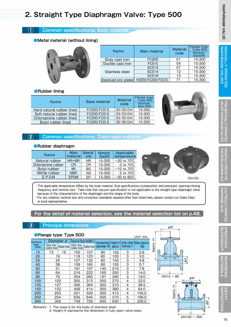
・The applicable temperature differs by the body material, fluid specifications (composition and pressure), opening-closing frequency and nominal size. Take note that vacuum specification is not applicable to the straight type diaphragm valve because of the characteristics of the diaphragm and the shape of the body. ・For any material, nominal size and connection standards required other than listed here, please contact our Sales Dept. or local representative.
φW
L
B
φRc
φW
Lt
φd φB
Principal dimensions
●Flange type: Type 500
③
Remarks : 1. The mass is for the body of stainless steel. 2. Height H represents the dimension in fully open valve state.
Unit: mm
15 20 19 118 123 80 105 3 3.0 25 25 127 132 80 155 3 4.8 40 38 159 165 80 155 3 5.7 50 51 191 197 140 210 3 7.8 65 64 216 222 165 250 3 14.0 80 76 254 260 197 295 3 19.0 100 102 305 313 250 270 4 23.5 125 127 356 364 300 310 4 38.5 150 152 406 414 300 380 4 64.0 200 203 521 529 350 415 4 105.0 250 254 635 645 500 570 5 166.0 300 305 749 759 600 630 5 330.0
Nominal size (DN)
Handwheeldiameter W
Height H, approx
Lining rubberthickness TOther than
rubber-linedOther than rubber-lined Rubber-linedRubber-lined
Diameter d Face-to-face length L
13 15 102 107 10580 3 2.6
Handwheeldiameter W
Height H, approx.
Face-to-facelength L
Mass approx. (kg)
App
rox.
HA
ppro
x. H
φW
1. Weir Type Diaphragm Valve: Type 400 2. Straight Type Diaphragm Valve: Type 5001Common specifications: Body material
●Metal material (without lining)
①
Common specifications: Diaphragm material
●Rubber diaphragm
②
DN100 -
DN15 ~ 80
DN100 ~ 300
Gray cast ironDuctile cast iron
Stainless steel
Dissolved zinc plated
Main material
FC200 01 15-300 FCD-S 04 15-300 SCS13 07 15-300 SCS14 12 15-300 SCS16 13 15-300 HDZ55(FC200/FCD-S) 71 15-300
Materialcode
Flange type, Type 500Nominal Size(DN)
●Rubber lining
Hard natural rubber lined Soft natural rubber linedChloroprene rubber lined
Butyl rubber lined
Base material
FC200/FCD-S 30/30(04) 15-300 FC200/FCD-S 33/33(04) 15-300 FC200/FCD-S 35/35(04) 15-300 FC200/FCD-S 36/36(04) 15-300
Natural rubberChloroprene rubber
Butyl rubberNitrile rubber
EPDM
Main material NR+BR NR 15-300 -20 to 70℃ CR CR 15-300 0 to 70℃ IIR BG 15-300 -10 to 70℃ NBR AB 15-300 5 to 70℃ EPDM EP 15-300 -20 to 90℃
Material code
Nominal Size(DN)
Applicable temperature
App
rox.
H
App
rox.
H
φW
L
φd
L
φd
φW
Flange type, Type 500Nominal Size (DN)
MaterialcodeName
Name
Name
14
MA
NU
ALLY
OP
ER
AT
ED
DIA
PH
RA
GM
VA
LVE
SELECTRICALLY OPERATEDDIAPHRAGM VALVE
RE
FER
EN
CE
MA
TE
RIA
LSPNEUM
ATICALLY OPERATEDON-OFF DIAPHRAGM
VALVESPNEUMATICALLY OPERATED TYPE FLOW CONTROL DIAPHRAGM VALVE
INTRODUCTION OF RELATED PRODUCTS
SAFETY
IN
STRU
CTIO
NS
DIA
PH
RA
GM
VA
LVE
MA
NU
ALL
Y O
PE
RA
TE
DD
IAP
HR
AG
M V
ALV
ES
ELEC
TRIC
ALLY
OPE
RATE
DDI
APHR
AGM
VALV
ER
EFE
RE
NC
EM
AT
ER
IALS
PNEU
MAT
ICAL
LY O
PERA
TED
ON-O
FF D
IAPH
RAGM
VAL
VES
PNEU
MATIC
ALLY
OPER
ATED
TYPE
FL
OW CO
NTRO
L DIAP
HRAG
M VAL
VEIN
TROD
UCTIO
N OF
RE
LATE
D PR
ODUC
TSSA
FETY
IN
STR
UC
TIO
NS
DIA
PH
RA
GM
VA
LVE
For the detail of material selection, see the material selection list on p.48.
●Welded type (Socket Welded/JIS B 2316 Schedule 80)
●Screwed type (Taper Pipe Threads/JIS B 0203, ISO 7-1)
Remarks : 1. The mass is for the body of stainless steel. 2. Height H represents the dimension in fully open valve state. 3. Butt-welded type also available.
Remarks : 1. The mass is for the body of stainless steel. 2. Height H represents the dimension in fully open valve state.
NominalSize DN
diameter d Handwheeldiameter W
Height H, approx.
Joint depth t
Insidediameter
B of the jointFace-to-face
length L
1520254050
Unit: mm
Unit: mm
13 102 63 115 22.2 10 0.7 19 118 63 125 27.7 13 1.0 25 127 80 129 34.5 13 1.4 38 159 100 155 49.1 13 3.0 51 191 125 172 61.1 16 4.6
Nominal Size DN
Screw for pipe Rc
Two face breadth B
Mass approx. (kg)
Mass approx. (kg)
15202540
1/2 64 63 102 32 0.6 3/4 83 63 115 38 0.8 1 108 80 125 48 1.4 11/2 140 100 163 70 2.7
・The applicable temperature differs by the body material, fluid specifications (composition and pressure), opening-closing frequency and nominal size. Take note that vacuum specification is not applicable to the straight type diaphragm valve because of the characteristics of the diaphragm and the shape of the body. ・For any material, nominal size and connection standards required other than listed here, please contact our Sales Dept. or local representative.
φW
L
B
φRc
φW
Lt
φd φB
Principal dimensions
●Flange type: Type 500
③
Remarks : 1. The mass is for the body of stainless steel. 2. Height H represents the dimension in fully open valve state.
Unit: mm
15 20 19 118 123 80 105 3 3.0 25 25 127 132 80 155 3 4.8 40 38 159 165 80 155 3 5.7 50 51 191 197 140 210 3 7.8 65 64 216 222 165 250 3 14.0 80 76 254 260 197 295 3 19.0 100 102 305 313 250 270 4 23.5 125 127 356 364 300 310 4 38.5 150 152 406 414 300 380 4 64.0 200 203 521 529 350 415 4 105.0 250 254 635 645 500 570 5 166.0 300 305 749 759 600 630 5 330.0
Nominal size (DN)
Handwheeldiameter W
Height H, approx
Lining rubberthickness TOther than
rubber-linedOther than rubber-lined Rubber-linedRubber-lined
Diameter d Face-to-face length L
13 15 102 107 10580 3 2.6
Handwheeldiameter W
Height H, approx.
Face-to-facelength L
Mass approx. (kg)
App
rox.
HA
ppro
x. H
φW
1. Weir Type Diaphragm Valve: Type 400 2. Straight Type Diaphragm Valve: Type 5001Common specifications: Body material
●Metal material (without lining)
①
Common specifications: Diaphragm material
●Rubber diaphragm
②
DN100 -
DN15 ~ 80
DN100 ~ 300
Gray cast ironDuctile cast iron
Stainless steel
Dissolved zinc plated
Main material
FC200 01 15-300 FCD-S 04 15-300 SCS13 07 15-300 SCS14 12 15-300 SCS16 13 15-300 HDZ55(FC200/FCD-S) 71 15-300
Materialcode
Flange type, Type 500Nominal Size(DN)
●Rubber lining
Hard natural rubber lined Soft natural rubber linedChloroprene rubber lined
Butyl rubber lined
Base material
FC200/FCD-S 30/30(04) 15-300 FC200/FCD-S 33/33(04) 15-300 FC200/FCD-S 35/35(04) 15-300 FC200/FCD-S 36/36(04) 15-300
Natural rubberChloroprene rubber
Butyl rubberNitrile rubber
EPDM
Main material NR+BR NR 15-300 -20 to 70℃ CR CR 15-300 0 to 70℃ IIR BG 15-300 -10 to 70℃ NBR AB 15-300 5 to 70℃ EPDM EP 15-300 -20 to 90℃
Material code
Nominal Size(DN)
Applicable temperature
App
rox.
H
App
rox.
H
φW
L
φd
L
φd
φW
Flange type, Type 500Nominal Size (DN)
MaterialcodeName
Name
Name
15
MA
NU
ALLY
OP
ER
AT
ED
DIA
PH
RA
GM
VA
LVE
SELECTRICALLY OPERATEDDIAPHRAGM VALVE
RE
FER
EN
CE
MA
TE
RIA
LSPNEUM
ATICALLY OPERATEDON-OFF DIAPHRAGM
VALVESPNEUMATICALLY OPERATED TYPE FLOW CONTROL DIAPHRAGM VALVE
INTRODUCTION OF RELATED PRODUCTS
SAFETY
IN
STRU
CTIO
NS
DIA
PH
RA
GM
VA
LVE
MA
NU
ALL
Y O
PE
RA
TE
DD
IAP
HR
AG
M V
ALV
ES
ELEC
TRIC
ALLY
OPE
RATE
DDI
APHR
AGM
VALV
ER
EFE
RE
NC
EM
AT
ER
IALS
PNEU
MAT
ICAL
LY O
PERA
TED
ON-O
FF D
IAPH
RAGM
VAL
VES
PNEU
MATIC
ALLY
OPER
ATED
TYPE
FL
OW CO
NTRO
L DIAP
HRAG
M VAL
VEIN
TROD
UCTIO
N OF
RE
LATE
D PR
ODUC
TSSA
FETY
IN
STR
UC
TIO
NS
DIA
PH
RA
GM
VA
LVE
For the detail of material selection, see the material selection list on p.48.
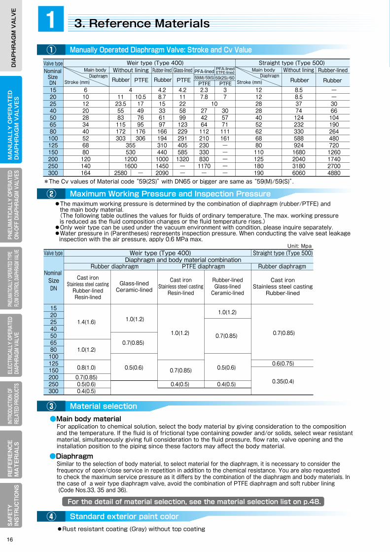
●The maximum working pressure is determined by the combination of diaphragm (rubber/PTFE) and the main body material. (The following table outlines the values for fluids of ordinary temperature. The max. working pressure is reduced as the fluid composition changes or the fluid temperature rises.)●Only weir type can be used under the vacuum environment with condition, please inquire separately.●Water pressure in (Parentheses) represents inspection pressure. When conducting the valve seat leakage inspection with the air pressure, apply 0.6 MPa max.
For application to chemical solution, select the body material by giving consideration to the composition and the temperature. If the fluid is of frictional type containing powder and/or solids, select wear resistant material, simultaneously giving full consideration to the fluid pressure, flow rate, valve opening and theinstallation position to the piping since these factors may affect the body material.
●Main body material
Similar to the selection of body material, to select material for the diaphragm, it is necessary to consider the frequency of open/close service in repetition in addition to the chemical resistance. You are also requestedto check the maximum service pressure as it differs by the combination of the diaphragm and body materials. Inthe case of a weir type diaphragm valve, avoid the combination of PTFE diaphragm and soft rubber lining (Code Nos.33, 35 and 36).
●Diaphragm
●Rust resistant coating (Gray) without top coating
2-1. Pneumatically Operated ON-OFF Diaphragm Valve Actuator ① Features of actuator
② Actuator specifications
2-2. Weir Type Diaphragm Valve: Type PO(PC, PN)/HO(HC, HN) 1400N ① Actuator selection table
② Principal dimensions
2-3. Straight Type Diaphragm Valve: Type PO(PN)/HO(HN) 1500N ① Actuator selection table
② Principal dimensions
2-4. Reference Material ① Air chamber capacity and air consumption
② Accessories
PNEUMATICALLY OPERATED TYPE ON-OFF DIAPHRAGM VALVE
2
3. Reference Materials1Manually Operated Diaphragm Valve: Stroke and Cv Value①
Maximum Working Pressure and Inspection Pressure②
Material selection③
Standard exterior paint color④
NominalSizeDN
Valve typeWithout lining Without liningRubber-lined Rubber-linedGlass-lined
15202540506580
100125150200250300
6 4 4.2 4.2 2.3 3 12 8.5 10 11 10.5 8.7 11 7.8 7 12 8.5 12 23.5 17 15 22 10 28 37 20 55 49 33 58 27 30 28 74 28 83 76 61 99 42 57 40 124 34 115 95 97 123 64 71 52 232 40 172 176 166 229 112 111 62 330 52 303 306 194 291 210 161 68 588 68 355 310 405 230 ― 80 924 80 530 440 585 330 ― 110 1680 120 1200 1000 1320 830 ― 125 2040 140 1600 1450 ― 1170 ― 180 3180 164 2580 ― 2090 ― ― ― 190 6060
Nominal Size DN
Valve type
Rubber diaphragmPTFE diaphragmRubber diaphragm
Weir type (Type 400) Straight type (Type 500)Diaphragm and body material combination
15202540506580
100125150200250300
1.4(1.6)
1.0(1.2)
0.8(1.0) 0.7(0.85)0.5(0.6)0.4(0.5)
1.0(1.2)
0.7(0.85)
0.4(0.5)
1.0(1.2)
0.7(0.85)
0.5(0.6)
0.4(0.5)
0.7(0.85)
0.6(0.75)
0.35(0.4)
1.0(1.2)
0.7(0.85)
0.5(0.6)
Unit: Mpa
Cast ironStainless steel casting
Rubber-linedResin-lined
Glass-lined Ceramic-lined
Cast ironStainless steel casting
Resin-lined
Rubber-linedGlass-lined
Ceramic-lined
Cast ironStainless steel casting
Rubber-lined
Rubber RubberRubberRubber
Main body
Stroke (mm) Stroke (mm)DiaphragmDiaphragm
Main bodyStraight type (Type 500) Weir type (Type 400)
PTFE PTFE
――3066
104190264480720
1260174027004880
PFA-lined PFA-linedETFE-lined59(2S)/6059(M)/59(S)
PTFE PTFE
*The Cv values of Material code “59(2S)” with DN65 or bigger are same as “59(M)/59(S)”.
16

For the detail of material selection, see the material selection list on p.48.
●The maximum working pressure is determined by the combination of diaphragm (rubber/PTFE) and the main body material. (The following table outlines the values for fluids of ordinary temperature. The max. working pressure is reduced as the fluid composition changes or the fluid temperature rises.)●Only weir type can be used under the vacuum environment with condition, please inquire separately.●Water pressure in (Parentheses) represents inspection pressure. When conducting the valve seat leakage inspection with the air pressure, apply 0.6 MPa max.
For application to chemical solution, select the body material by giving consideration to the composition and the temperature. If the fluid is of frictional type containing powder and/or solids, select wear resistant material, simultaneously giving full consideration to the fluid pressure, flow rate, valve opening and theinstallation position to the piping since these factors may affect the body material.
●Main body material
Similar to the selection of body material, to select material for the diaphragm, it is necessary to consider the frequency of open/close service in repetition in addition to the chemical resistance. You are also requestedto check the maximum service pressure as it differs by the combination of the diaphragm and body materials. Inthe case of a weir type diaphragm valve, avoid the combination of PTFE diaphragm and soft rubber lining (Code Nos.33, 35 and 36).
●Diaphragm
●Rust resistant coating (Gray) without top coating
2-1. Pneumatically Operated ON-OFF Diaphragm Valve Actuator ① Features of actuator
② Actuator specifications
2-2. Weir Type Diaphragm Valve: Type PO(PC, PN)/HO(HC, HN) 1400N ① Actuator selection table
② Principal dimensions
2-3. Straight Type Diaphragm Valve: Type PO(PN)/HO(HN) 1500N ① Actuator selection table
② Principal dimensions
2-4. Reference Material ① Air chamber capacity and air consumption
② Accessories
PNEUMATICALLY OPERATED TYPE ON-OFF DIAPHRAGM VALVE
2
3. Reference Materials1Manually Operated Diaphragm Valve: Stroke and Cv Value①
Maximum Working Pressure and Inspection Pressure②
Material selection③
Standard exterior paint color④
NominalSizeDN
Valve typeWithout lining Without liningRubber-lined Rubber-linedGlass-lined
15202540506580
100125150200250300
6 4 4.2 4.2 2.3 3 12 8.5 10 11 10.5 8.7 11 7.8 7 12 8.5 12 23.5 17 15 22 10 28 37 20 55 49 33 58 27 30 28 74 28 83 76 61 99 42 57 40 124 34 115 95 97 123 64 71 52 232 40 172 176 166 229 112 111 62 330 52 303 306 194 291 210 161 68 588 68 355 310 405 230 ― 80 924 80 530 440 585 330 ― 110 1680 120 1200 1000 1320 830 ― 125 2040 140 1600 1450 ― 1170 ― 180 3180 164 2580 ― 2090 ― ― ― 190 6060
Nominal Size DN
Valve type
Rubber diaphragmPTFE diaphragmRubber diaphragm
Weir type (Type 400) Straight type (Type 500)Diaphragm and body material combination
15202540506580
100125150200250300
1.4(1.6)
1.0(1.2)
0.8(1.0) 0.7(0.85)0.5(0.6)0.4(0.5)
1.0(1.2)
0.7(0.85)
0.4(0.5)
1.0(1.2)
0.7(0.85)
0.5(0.6)
0.4(0.5)
0.7(0.85)
0.6(0.75)
0.35(0.4)
1.0(1.2)
0.7(0.85)
0.5(0.6)
Unit: Mpa
Cast ironStainless steel casting
Rubber-linedResin-lined
Glass-lined Ceramic-lined
Cast ironStainless steel casting
Resin-lined
Rubber-linedGlass-lined
Ceramic-lined
Cast ironStainless steel casting
Rubber-lined
Rubber RubberRubberRubber
Main body
Stroke (mm) Stroke (mm)DiaphragmDiaphragm
Main bodyStraight type (Type 500) Weir type (Type 400)
PTFE PTFE
――3066
104190264480720
1260174027004880
PFA-lined PFA-linedETFE-lined59(2S)/6059(M)/59(S)
PTFE PTFE
*The Cv values of Material code “59(2S)” with DN65 or bigger are same as “59(M)/59(S)”.

MA
NU
ALLY
OP
ER
AT
ED
DIA
PH
RA
GM
VA
LVE
SELECTRICALLY OPERATEDDIAPHRAGM VALVE
RE
FER
EN
CE
MA
TE
RIA
LSPNEUM
ATICALLY OPERATEDON-OFF DIAPHRAGM
VALVESPNEUMATICALLY OPERATED TYPE FLOW CONTROL DIAPHRAGM VALVE
INTRODUCTION OF RELATED PRODUCTS
SAFETY
IN
STRU
CTIO
NS
DIA
PH
RA
GM
VA
LVE
MA
NU
ALL
Y O
PE
RA
TE
DD
IAP
HR
AG
M V
ALV
ES
ELEC
TRIC
ALLY
OPE
RATE
DDI
APHR
AGM
VALV
ER
EFE
RE
NC
EM
AT
ER
IALS
PNEU
MAT
ICAL
LY O
PERA
TED
ON-O
FF D
IAPH
RAGM
VAL
VES
PNEU
MATIC
ALLY
OPER
ATED
TYPE
FL
OW CO
NTRO
L DIAP
HRAG
M VAL
VEIN
TROD
UCTIO
N OF
RE
LATE
D PR
ODUC
TSSA
FETY
IN
STR
UC
TIO
NS
DIA
PH
RA
GM
VA
LVE
●Adoption of wear ring realizes smoother operation and improved durability.●Adoption of stopper nut prevents the shortening of product life due to an excessive load to the diaphragm when the valve is closed, simultaneously eliminating the need for adjusting the working pressure on the direct and double acting types.
●The actuator is more lightweight and compact compared with our conventional products (Type HO1400N series).
●Ancillary device includes manual operating device and opening limit device, etc.●Ancillary device can be installed without disassembling the actuator by simply removing the cap on the top.●Special compact limit switch box is expected to save space for the piping.
●Compact actuator saves on air consumption.●Environment-friendly paint is used.
●Two to three types of actuator can be selected per nominal size. Selection of an optimum actuator for the working fluid is available.
●Adoption of NAMUR dimensions to the solenoid valve mounting seat enables direct installation of the same standard solenoid valve without the mounting plate and pneumatic piping. (In the case of direct or double acting type, the pneumatic piping to the upper cylinder is required by using a spacer.) *VDI/VDE3845-2010
●Standard specifications
Cylinder size: 16 and over
❶Stopper nut
❶Wear ring
24A24B
72B70B
1
5
4
70C
70A
40B
40
1. Pneumatically Operated type ON-OFF Actuator2Features of actuator
❶Smooth operation and sharp improvement of durability:
❷Lightweight and compact:
❺Rich selection of ancillary device (see the following page) is easy to install:
❻Air saving and use of environment-friendly paint:
❸Economical in actuator selection:
❹Adoption of NAMUR connection standard*:
①
Actuator specifications②
Operation
Actuator typeOperating pressure
Bonnet material
Cylinder material
Nameplate
Reverse acting type (Air to Open/Spring to Close): Type PO1400N, Type PO1500NDirect acting type (Air to Close/Spring to Open):Type PC1400NDouble acting type (Air to Open/Air to Close):Type PN1400N, Type 1500NPiston Type (With wear ring)0.4 MPa, Optional: 0.3 MPaSCPH2…DN100 or under, Optional: SCS13FC200…DN125 or over, Optional: SCS13ADC12(Aluminum diecast), Optional: Cylinder base SCPH2
Seal nameplate reading “Product name/LP/OP/SER No./TAG No.” is attached on the exterior surface of the actuator.
+0.1 0
+0.1 0
・Spacer: Required for the explosion-proof type solenoid valve, direct and/or double acting type. Pneumatic piping is required to the upper cylinder in the case of the direct and/or double acting type.・Optional: Closing limit device, 2-stage open-close device.
●Ancillary Devices
●Standard Manufacturing Specification (Type PO1400N-TX)
Yoke
Spacer
Compact box type with two built-in open-close micro switches Yoke attached
General type
Explosion-proof type
Commercially-supplied limit switch: Can be mounted to the yoke.
Explosion-proof type
General type
M:Special limit switch
Basic type
S: Opening indicator
SH: Manual opening device
ST: Opening limit device
SL: Manual opening + opening limit device
NAMUR standard solenoid valve can be directly mounted
Filter Regulator
NamePart No.
Main bodyDiaphragmCushion rubberBonnetBoltNutCompressorSpindle
1234
5
67
Wear ringStemCoil springHexagonal boltSpring washerPlain washerHexagonal boltPlain washerHexagonal boltSpring washerPlain washer
42B5364
70A
70B
70C
95F23
11B
7
95A
95B
42A
42B
83B
83A
53
6495C
40C95E35
35B
41
2
3
6
11
95D
❺
❹
Standard exterior painting color Silver (environment-friendly type)
NamePart No.
WasherIndicatorCap A Cap BStopper nutPinCylinderBaseSpacerPistonO-ring
11B23
24A24B35
35B40
40B40C41
42A
WasherSeal washerO-ringO-ringO-ringO-ringO-ringO-ring
83A83B95A95B95C95D95E95F
11 Compressorsuspension
72BSlotted round head screw
Applicable nominal size range DN15-150
18

MA
NU
ALLY
OP
ER
AT
ED
DIA
PH
RA
GM
VA
LVE
SELECTRICALLY OPERATEDDIAPHRAGM VALVE
RE
FER
EN
CE
MA
TE
RIA
LSPNEUM
ATICALLY OPERATEDON-OFF DIAPHRAGM
VALVESPNEUMATICALLY OPERATED TYPE FLOW CONTROL DIAPHRAGM VALVE
INTRODUCTION OF RELATED PRODUCTS
SAFETY
IN
STRU
CTIO
NS
DIA
PH
RA
GM
VA
LVE
MA
NU
ALL
Y O
PE
RA
TE
DD
IAP
HR
AG
M V
ALV
ES
ELEC
TRIC
ALLY
OPE
RATE
DDI
APHR
AGM
VALV
ER
EFE
RE
NC
EM
AT
ER
IALS
PNEU
MAT
ICAL
LY O
PERA
TED
ON-O
FF D
IAPH
RAGM
VAL
VES
PNEU
MATIC
ALLY
OPER
ATED
TYPE
FL
OW CO
NTRO
L DIAP
HRAG
M VAL
VEIN
TROD
UCTIO
N OF
RE
LATE
D PR
ODUC
TSSA
FETY
IN
STR
UC
TIO
NS
DIA
PH
RA
GM
VA
LVE
●Adoption of wear ring realizes smoother operation and improved durability.●Adoption of stopper nut prevents the shortening of product life due to an excessive load to the diaphragm when the valve is closed, simultaneously eliminating the need for adjusting the working pressure on the direct and double acting types.
●The actuator is more lightweight and compact compared with our conventional products (Type HO1400N series).
●Ancillary device includes manual operating device and opening limit device, etc.●Ancillary device can be installed without disassembling the actuator by simply removing the cap on the top.●Special compact limit switch box is expected to save space for the piping.
●Compact actuator saves on air consumption.●Environment-friendly paint is used.
●Two to three types of actuator can be selected per nominal size. Selection of an optimum actuator for the working fluid is available.
●Adoption of NAMUR dimensions to the solenoid valve mounting seat enables direct installation of the same standard solenoid valve without the mounting plate and pneumatic piping. (In the case of direct or double acting type, the pneumatic piping to the upper cylinder is required by using a spacer.) *VDI/VDE3845-2010
●Standard specifications
Cylinder size: 16 and over
❶Stopper nut
❶Wear ring
24A24B
72B70B
1
5
4
70C
70A
40B
40
1. Pneumatically Operated type ON-OFF Actuator2Features of actuator
❶Smooth operation and sharp improvement of durability:
❷Lightweight and compact:
❺Rich selection of ancillary device (see the following page) is easy to install:
❻Air saving and use of environment-friendly paint:
❸Economical in actuator selection:
❹Adoption of NAMUR connection standard*:
①
Actuator specifications②
Operation
Actuator typeOperating pressure
Bonnet material
Cylinder material
Nameplate
Reverse acting type (Air to Open/Spring to Close): Type PO1400N, Type PO1500NDirect acting type (Air to Close/Spring to Open):Type PC1400NDouble acting type (Air to Open/Air to Close):Type PN1400N, Type 1500NPiston Type (With wear ring)0.4 MPa, Optional: 0.3 MPaSCPH2…DN100 or under, Optional: SCS13FC200…DN125 or over, Optional: SCS13ADC12(Aluminum diecast), Optional: Cylinder base SCPH2
Seal nameplate reading “Product name/LP/OP/SER No./TAG No.” is attached on the exterior surface of the actuator.
+0.1 0
+0.1 0
・Spacer: Required for the explosion-proof type solenoid valve, direct and/or double acting type. Pneumatic piping is required to the upper cylinder in the case of the direct and/or double acting type.・Optional: Closing limit device, 2-stage open-close device.
●Ancillary Devices
●Standard Manufacturing Specification (Type PO1400N-TX)
Yoke
Spacer
Compact box type with two built-in open-close micro switches Yoke attached
General type
Explosion-proof type
Commercially-supplied limit switch: Can be mounted to the yoke.
Explosion-proof type
General type
M:Special limit switch
Basic type
S: Opening indicator
SH: Manual opening device
ST: Opening limit device
SL: Manual opening + opening limit device
NAMUR standard solenoid valve can be directly mounted
Filter Regulator
NamePart No.
Main bodyDiaphragmCushion rubberBonnetBoltNutCompressorSpindle
1234
5
67
Wear ringStemCoil springHexagonal boltSpring washerPlain washerHexagonal boltPlain washerHexagonal boltSpring washerPlain washer
42B5364
70A
70B
70C
95F23
11B
7
95A
95B
42A
42B
83B
83A
53
6495C
40C95E35
35B
41
2
3
6
11
95D
❺
❹
Standard exterior painting color Silver (environment-friendly type)
NamePart No.
WasherIndicatorCap A Cap BStopper nutPinCylinderBaseSpacerPistonO-ring
11B23
24A24B35
35B40
40B40C41
42A
WasherSeal washerO-ringO-ringO-ringO-ringO-ringO-ring
83A83B95A95B95C95D95E95F
11 Compressorsuspension
72BSlotted round head screw
Applicable nominal size range DN15-150
19

MA
NU
ALLY
OP
ER
AT
ED
DIA
PH
RA
GM
VA
LVE
SELECTRICALLY OPERATEDDIAPHRAGM VALVE
RE
FER
EN
CE
MA
TE
RIA
LSPNEUM
ATICALLY OPERATEDON-OFF DIAPHRAGM
VALVESPNEUMATICALLY OPERATED TYPE FLOW CONTROL DIAPHRAGM VALVE
INTRODUCTION OF RELATED PRODUCTS
SAFETY
IN
STRU
CTIO
NS
DIA
PH
RA
GM
VA
LVE
MA
NU
ALL
Y O
PE
RA
TE
DD
IAP
HR
AG
M V
ALV
ES
ELEC
TRIC
ALLY
OPE
RATE
DDI
APHR
AGM
VALV
ER
EFE
RE
NC
EM
AT
ER
IALS
PNEU
MAT
ICAL
LY O
PERA
TED
ON-O
FF D
IAPH
RAGM
VAL
VES
PNEU
MATIC
ALLY
OPER
ATED
TYPE
FL
OW CO
NTRO
L DIAP
HRAG
M VAL
VEIN
TROD
UCTIO
N OF
RE
LATE
D PR
ODUC
TSSA
FETY
IN
STR
UC
TIO
NS
DIA
PH
RA
GM
VA
LVE
ActuatorCode
ActuatorCode
ActuatorCode
ActuatorCode
ActuatorCode
ActuatorCode
ActuatorCode
ActuatorCode
ActuatorCode
ActuatorCode
ActuatorCode
ActuatorCode
Fluid pressure(MPa)
Rubber diaphragm
0.1 0.2 0.3 0.4 0.5 0.6 0.7 0.8 0.9 1.0
3147ABC3147ABC3147ABC4048BC
3147ABC4048ABC4048ABC
3147AB3147ABC3147ABC4048ABC4048ABC
100125
150
200
250
125150
200
250
Fluid pressure(MPa)0.1 0.2 0.3 0.4 0.5 0.6 0.7 0.8 0.9 1.0
Max. allowable working pressure for other than the glass-lined and ceramic body
Max. allowable working pressure for other than the hard rubber-lined, glass-lined and ceramic body
Max. allowable working pressure for other than the hard rubber-lined, glass-lined and ceramic body
Max. allowable working pressure for the hard rubber-lied, glass-lined and ceramic body
Max. allowable working pressure for the hard rubber-lied, glass-lined and ceramic body
Max. allowable working pressure for the hard rubber-lied, glass-lined and ceramic body
Max. allowable working pressure for the hard rubber-lied, glass-lined and ceramic body
Max. allowable working pressure forthan the glass-lined and ceramic body
Max. allowable working pressure for the glass-lined and ceramic body
Max. allowable working pressure for other than the glass-lined and ceramic body
Max. allowable working pressure for the glass-lined and ceramic body
Max. allowable working pressure for theglass-lined and ceramic body
Fluid pressure(MPa)
PTFE diaphragm
0.1 0.2 0.3 0.4 0.5 0.6 0.7 0.8 0.9 1.0
3147ABC3147ABC3147ABC4048BC
3147ABC4048ABC4048ABC
3147ABC3147ABC3147ABC4048ABC4048ABC
100125
150
200
250
125150
200
250
Fluid pressure(MPa)0.1 0.2 0.3 0.4 0.5 0.6 0.7 0.8 0.9 1.0
Fluid pressure(MPa)
Fluid pressure(MPa) Fluid pressure(MPa)
Rubber diaphragm
0.1 0.2 0.3 0.4 0.5 0.6 0.7 0.8 0.9 1.0
3167
3167
150
1500.1 0.2 0.3 0.4 0.5 0.6 0.7 0.8 0.9 1.0
Working pressure: 0.4 MPa+0.10 Working pressure: 0.4 MPa+0.1
0
●Reverse acting type: Type HO1400N (For large bore and high output)
Fluid pressure(MPa)
PTFE diaphragm
0.1 0.2 0.3 0.4 0.5 0.6 0.7 0.8 0.9 1.0
3167
3167
150
1500.1 0.2 0.3 0.4 0.5 0.6 0.7 0.8 0.9 1.0
Fluid pressure(MPa)
PTFE diaphragm
0.1 0.2 0.3 0.4 0.5 0.6 0.7 0.8 0.9 1.0
313131403140
313131403140
125150
200
250
125150
200
250
Fluid pressure(MPa)
Actuator selection table in this catalog represents the data when the secondary pressure is atmospheric with the valve fully closed. See 6. Reference Material for more detail.
0.1 0.2 0.3 0.4 0.5 0.6 0.7 0.8 0.9 1.0
Fluid pressure(MPa)
Rubber diaphragm
0.1 0.2 0.3 0.4 0.5 0.6 0.7 0.8 0.9 1.0
3131314031403140
3131314031403140
125150
200
250
300
125150
200
250
300
Fluid pressure(MPa)0.1 0.2 0.3 0.4 0.5 0.6 0.7 0.8 0.9 1.0
Working pressure: See MPa in the table below Working pressure: See MPa in the table below
Working pressure: See MPa in the table below Working pressure: See MPa in the table below
●Direct acting type: Type HC1400 (For large bore and high output)
0.30.3
0.3
0.3
0.3
0.4
0.3
0.3
0.3
0.4
●Double acting type: Type HN1400N (For large bore and high output)
0.30.25
0.250.3
0.4
0.40.4
0.30.250.3
0.2
0.4
0.40.4
0.4
0.4
0.30.3
0.30.3
0.250.25
0.25
0.25
0.2
0.25 0.4
0.25 0.40.25 0.3 0.4
0.25 0.3
0.2
0.2
0.2
0.25
0.25
0.4
0.250.25
0.25
0.250.4
0.3
0.4
0.4
0.4
0.4
0.4
0.2
0.20.2
0.2
0.2
0.25
0.25
0.25
0.25
0.250.3
0.3
0.4
0.40.4
2. Weir Type Diaphragm Valve: Type PO(PC,PN)/HO(HC,HN) 1400N 2Actuator selection table①
●Reverse acting type: Type PO1400N
●Direct acting type: Type PC1400N
●Double acting type: Type PN1400N
1.3 1.3
Operating pressure: 0.4 MPa+0.10
Fluid pressure(MPa)Rubber diaphragm(*1)
0.1 0.2 0.3 0.4 0.5 0.6 0.7 0.8 0.9 1.0 1.1 1.2 1.4
15202540506580
100125150
Fluid pressure(MPa)0.1 0.2 0.3 0.4 0.5 0.6 0.7 0.8 0.9 1.0
15202540506580
100125150
Fluid pressure(MPa)Rubber diaphragm(*1)
0.1 0.2 0.3 0.4 0.5 0.6 0.7 0.8 0.9 1.0 1.1 1.2 1.4
15202540506580
100
Fluid pressure(MPa)0.1 0.2 0.3 0.4 0.5 0.6 0.7 0.8 0.9 1.0
15202540506580
100
1.3 1.3
Operating pressure: 0.4 MPa+0.10 Operating pressure: 0.3 MPa (Optional)+0.1
0
Operating pressure: 0.3 MPa (Optional)+0.10
Operating pressure: 0.3 MPa (Optional)+0.10
Remark:The stroke and Cv value are different between Type PO(PC,PN)1400N and Type HO(HC,HN)1400N, while choosing the same nominal size. For the details, contact our Sales Dept. or local representative.
Fluid pressure(MPa)Rubber diaphragm(*1)
0.1 0.2 0.3 0.4 0.5 0.6 0.7 0.8 0.9 1.0 1.1 1.2 1.4
15202540506580
100125150
Fluid pressure(MPa)PTFE diaphragm(*2)
0.1 0.2 0.3 0.4 0.5 0.6 0.7 0.8 0.9 1.0
15202540506580
100125150
Fluid pressure(MPa)Rubber diaphragm(*1)
0.1 0.2 0.3 0.4 0.5 0.6 0.7 0.8 0.9 1.0 1.1 1.2 1.4
15202540506580
100
Fluid pressure(MPa)PTFE diaphragm(*2)
PTFE diaphragm(*2)PTFE diaphragm(*2)
0.1 0.2 0.3 0.4 0.5 0.6 0.7 0.8 0.9 1.0
15202540506580
100
Operating pressure: 0.4 MPa+0.10
NominalSizeDN
NominalSizeDN
NominalSizeDN
NominalSizeDN
NominalSizeDN
NominalSizeDN
NominalSizeDN
NominalSizeDN
NominalSizeDN
NominalSizeDN
NominalSizeDN
NominalSizeDN
NominalSizeDN
NominalSizeDN
NominalSizeDN
NominalSizeDN
NominalSizeDN
NominalSizeDN
NominalSizeDN
NominalSizeDN
NominalSizeDN
NominalSizeDN
NominalSizeDN
NominalSizeDN
Fluid pressure(MPa)Rubber diaphragm(*1)
0.1 0.2 0.3 0.4 0.5 0.6 0.7 0.8 0.9 1.0 1.1 1.2 1.41.3 1.3
15202540506580
100125150
Fluid pressure(MPa)PTFE diaphragm(*2)
0.1 0.2 0.3 0.4 0.5 0.6 0.7 0.8 0.9 1.0
15202540506580
100125150
Fluid pressure(MPa)Rubber diaphragm(*1)
0.1 0.2 0.3 0.4 0.5 0.6 0.7 0.8 0.9 1.0 1.1 1.2 1.4
15202540506580
100
Fluid pressure(MPa)PTFE diaphragm(*2)
0.1 0.2 0.3 0.4 0.5 0.6 0.7 0.8 0.9 1.0
15202540506580
100
(*1): Max. allowable working pressure for other than the glass-lined and ceramic body Max. allowable working pressure for the glass-lined and ceramic body
(*2): Max. allowable working pressure for other than the hard rubber-lined, glass-lined and ceramic body Max. allowable working pressure for the hard rubber-lined, glass-lined and ceramic body
2525
2020
202016
25
0909
121612
070707
09
252020
202016
1209
2525
16
0909
12070707
2020
161209
07
0707
12
09
25
12
0909
16
25
2520
20
1612
0907
0707
25
1612
120909
16
252020
201616
161212
12
0909
09
25
2016
1209
0707
2025
2016
1209
07
12
0912
16
09
25
093093
123 163163
253203
203
253
163123
203
093 123
073
093123
203253
073093
123123
163163
203
093
253203
163
073
093
2525
2020
16
1212
07
0709
09
2525
2016
12
09
2525
2520
20201612
120907
0707
0909 12
16
07
2525
20
12
2016
07
0912
2520
16
0909
12
25
2525
2020
1612
25
070709
25
16
1212
0709
0916
20
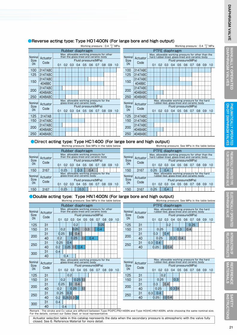
MA
NU
ALLY
OP
ER
AT
ED
DIA
PH
RA
GM
VA
LVE
SELECTRICALLY OPERATEDDIAPHRAGM VALVE
RE
FER
EN
CE
MA
TE
RIA
LSPNEUM
ATICALLY OPERATEDON-OFF DIAPHRAGM
VALVESPNEUMATICALLY OPERATED TYPE FLOW CONTROL DIAPHRAGM VALVE
INTRODUCTION OF RELATED PRODUCTS
SAFETY
IN
STRU
CTIO
NS
DIA
PH
RA
GM
VA
LVE
MA
NU
ALL
Y O
PE
RA
TE
DD
IAP
HR
AG
M V
ALV
ES
ELEC
TRIC
ALLY
OPE
RATE
DDI
APHR
AGM
VALV
ER
EFE
RE
NC
EM
AT
ER
IALS
PNEU
MAT
ICAL
LY O
PERA
TED
ON-O
FF D
IAPH
RAGM
VAL
VES
PNEU
MATIC
ALLY
OPER
ATED
TYPE
FL
OW CO
NTRO
L DIAP
HRAG
M VAL
VEIN
TROD
UCTIO
N OF
RE
LATE
D PR
ODUC
TSSA
FETY
IN
STR
UC
TIO
NS
DIA
PH
RA
GM
VA
LVE
ActuatorCode
ActuatorCode
ActuatorCode
ActuatorCode
ActuatorCode
ActuatorCode
ActuatorCode
ActuatorCode
ActuatorCode
ActuatorCode
ActuatorCode
ActuatorCode
Fluid pressure(MPa)
Rubber diaphragm
0.1 0.2 0.3 0.4 0.5 0.6 0.7 0.8 0.9 1.0
3147ABC3147ABC3147ABC4048BC
3147ABC4048ABC4048ABC
3147AB3147ABC3147ABC4048ABC4048ABC
100125
150
200
250
125150
200
250
Fluid pressure(MPa)0.1 0.2 0.3 0.4 0.5 0.6 0.7 0.8 0.9 1.0
Max. allowable working pressure for other than the glass-lined and ceramic body
Max. allowable working pressure for other than the hard rubber-lined, glass-lined and ceramic body
Max. allowable working pressure for other than the hard rubber-lined, glass-lined and ceramic body
Max. allowable working pressure for the hard rubber-lied, glass-lined and ceramic body
Max. allowable working pressure for the hard rubber-lied, glass-lined and ceramic body
Max. allowable working pressure for the hard rubber-lied, glass-lined and ceramic body
Max. allowable working pressure for the hard rubber-lied, glass-lined and ceramic body
Max. allowable working pressure forthan the glass-lined and ceramic body
Max. allowable working pressure for the glass-lined and ceramic body
Max. allowable working pressure for other than the glass-lined and ceramic body
Max. allowable working pressure for the glass-lined and ceramic body
Max. allowable working pressure for theglass-lined and ceramic body
Fluid pressure(MPa)
PTFE diaphragm
0.1 0.2 0.3 0.4 0.5 0.6 0.7 0.8 0.9 1.0
3147ABC3147ABC3147ABC4048BC
3147ABC4048ABC4048ABC
3147ABC3147ABC3147ABC4048ABC4048ABC
100125
150
200
250
125150
200
250
Fluid pressure(MPa)0.1 0.2 0.3 0.4 0.5 0.6 0.7 0.8 0.9 1.0
Fluid pressure(MPa)
Fluid pressure(MPa) Fluid pressure(MPa)
Rubber diaphragm
0.1 0.2 0.3 0.4 0.5 0.6 0.7 0.8 0.9 1.0
3167
3167
150
1500.1 0.2 0.3 0.4 0.5 0.6 0.7 0.8 0.9 1.0
Working pressure: 0.4 MPa+0.10 Working pressure: 0.4 MPa+0.1
0
●Reverse acting type: Type HO1400N (For large bore and high output)
Fluid pressure(MPa)
PTFE diaphragm
0.1 0.2 0.3 0.4 0.5 0.6 0.7 0.8 0.9 1.0
3167
3167
150
1500.1 0.2 0.3 0.4 0.5 0.6 0.7 0.8 0.9 1.0
Fluid pressure(MPa)
PTFE diaphragm
0.1 0.2 0.3 0.4 0.5 0.6 0.7 0.8 0.9 1.0
313131403140
313131403140
125150
200
250
125150
200
250
Fluid pressure(MPa)
Actuator selection table in this catalog represents the data when the secondary pressure is atmospheric with the valve fully closed. See 6. Reference Material for more detail.
0.1 0.2 0.3 0.4 0.5 0.6 0.7 0.8 0.9 1.0
Fluid pressure(MPa)
Rubber diaphragm
0.1 0.2 0.3 0.4 0.5 0.6 0.7 0.8 0.9 1.0
3131314031403140
3131314031403140
125150
200
250
300
125150
200
250
300
Fluid pressure(MPa)0.1 0.2 0.3 0.4 0.5 0.6 0.7 0.8 0.9 1.0
Working pressure: See MPa in the table below Working pressure: See MPa in the table below
Working pressure: See MPa in the table below Working pressure: See MPa in the table below
●Direct acting type: Type HC1400 (For large bore and high output)
0.30.3
0.3
0.3
0.3
0.4
0.3
0.3
0.3
0.4
●Double acting type: Type HN1400N (For large bore and high output)
0.30.25
0.250.3
0.4
0.40.4
0.30.250.3
0.2
0.4
0.40.4
0.4
0.4
0.30.3
0.30.3
0.250.25
0.25
0.25
0.2
0.25 0.4
0.25 0.40.25 0.3 0.4
0.25 0.3
0.2
0.2
0.2
0.25
0.25
0.4
0.250.25
0.25
0.250.4
0.3
0.4
0.4
0.4
0.4
0.4
0.2
0.20.2
0.2
0.2
0.25
0.25
0.25
0.25
0.250.3
0.3
0.4
0.40.4
2. Weir Type Diaphragm Valve: Type PO(PC,PN)/HO(HC,HN) 1400N 2Actuator selection table①
●Reverse acting type: Type PO1400N
●Direct acting type: Type PC1400N
●Double acting type: Type PN1400N
1.3 1.3
Operating pressure: 0.4 MPa+0.10
Fluid pressure(MPa)Rubber diaphragm(*1)
0.1 0.2 0.3 0.4 0.5 0.6 0.7 0.8 0.9 1.0 1.1 1.2 1.4
15202540506580
100125150
Fluid pressure(MPa)0.1 0.2 0.3 0.4 0.5 0.6 0.7 0.8 0.9 1.0
15202540506580
100125150
Fluid pressure(MPa)Rubber diaphragm(*1)
0.1 0.2 0.3 0.4 0.5 0.6 0.7 0.8 0.9 1.0 1.1 1.2 1.4
15202540506580
100
Fluid pressure(MPa)0.1 0.2 0.3 0.4 0.5 0.6 0.7 0.8 0.9 1.0
15202540506580
100
1.3 1.3
Operating pressure: 0.4 MPa+0.10 Operating pressure: 0.3 MPa (Optional)+0.1
0
Operating pressure: 0.3 MPa (Optional)+0.10
Operating pressure: 0.3 MPa (Optional)+0.10
Remark:The stroke and Cv value are different between Type PO(PC,PN)1400N and Type HO(HC,HN)1400N, while choosing the same nominal size. For the details, contact our Sales Dept. or local representative.
Fluid pressure(MPa)Rubber diaphragm(*1)
0.1 0.2 0.3 0.4 0.5 0.6 0.7 0.8 0.9 1.0 1.1 1.2 1.4
15202540506580
100125150
Fluid pressure(MPa)PTFE diaphragm(*2)
0.1 0.2 0.3 0.4 0.5 0.6 0.7 0.8 0.9 1.0
15202540506580
100125150
Fluid pressure(MPa)Rubber diaphragm(*1)
0.1 0.2 0.3 0.4 0.5 0.6 0.7 0.8 0.9 1.0 1.1 1.2 1.4
15202540506580
100
Fluid pressure(MPa)PTFE diaphragm(*2)
PTFE diaphragm(*2)PTFE diaphragm(*2)
0.1 0.2 0.3 0.4 0.5 0.6 0.7 0.8 0.9 1.0
15202540506580
100
Operating pressure: 0.4 MPa+0.10
NominalSizeDN
NominalSizeDN
NominalSizeDN
NominalSizeDN
NominalSizeDN
NominalSizeDN
NominalSizeDN
NominalSizeDN
NominalSizeDN
NominalSizeDN
NominalSizeDN
NominalSizeDN
NominalSizeDN
NominalSizeDN
NominalSizeDN
NominalSizeDN
NominalSizeDN
NominalSizeDN
NominalSizeDN
NominalSizeDN
NominalSizeDN
NominalSizeDN
NominalSizeDN
NominalSizeDN
Fluid pressure(MPa)Rubber diaphragm(*1)
0.1 0.2 0.3 0.4 0.5 0.6 0.7 0.8 0.9 1.0 1.1 1.2 1.41.3 1.3
15202540506580
100125150
Fluid pressure(MPa)PTFE diaphragm(*2)
0.1 0.2 0.3 0.4 0.5 0.6 0.7 0.8 0.9 1.0
15202540506580
100125150
Fluid pressure(MPa)Rubber diaphragm(*1)
0.1 0.2 0.3 0.4 0.5 0.6 0.7 0.8 0.9 1.0 1.1 1.2 1.4
15202540506580
100
Fluid pressure(MPa)PTFE diaphragm(*2)
0.1 0.2 0.3 0.4 0.5 0.6 0.7 0.8 0.9 1.0
15202540506580
100
(*1): Max. allowable working pressure for other than the glass-lined and ceramic body Max. allowable working pressure for the glass-lined and ceramic body
(*2): Max. allowable working pressure for other than the hard rubber-lined, glass-lined and ceramic body Max. allowable working pressure for the hard rubber-lined, glass-lined and ceramic body
2525
2020
202016
25
0909
121612
070707
09
252020
202016
1209
2525
16
0909
12070707
2020
161209
07
0707
12
09
25
12
0909
16
25
2520
20
1612
0907
0707
25
1612
120909
16
252020
201616
161212
12
0909
09
25
2016
1209
0707
2025
2016
1209
07
12
0912
16
09
25
093093
123 163163
253203
203
253
163123
203
093 123
073
093123
203253
073093
123123
163163
203
093
253203
163
073
093
2525
2020
16
1212
07
0709
09
2525
2016
12
09
2525
2520
20201612
120907
0707
0909 12
16
07
2525
20
12
2016
07
0912
2520
16
0909
12
25
2525
2020
1612
25
070709
25
16
1212
0709
0916
21
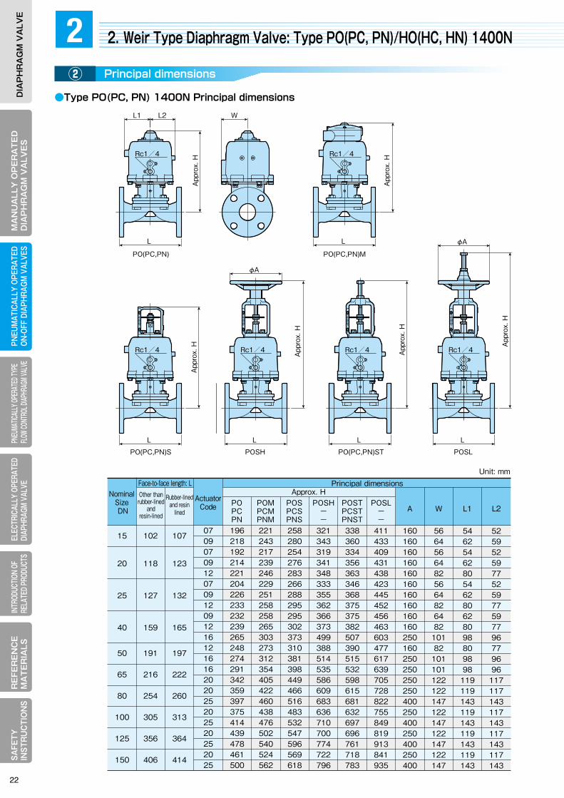
MA
NU
ALLY
OP
ER
AT
ED
DIA
PH
RA
GM
VA
LVE
SELECTRICALLY OPERATEDDIAPHRAGM VALVE
RE
FER
EN
CE
MA
TE
RIA
LSPNEUM
ATICALLY OPERATEDON-OFF DIAPHRAGM
VALVESPNEUMATICALLY OPERATED TYPE FLOW CONTROL DIAPHRAGM VALVE
INTRODUCTION OF RELATED PRODUCTS
SAFETY
IN
STRU
CTIO
NS
DIA
PH
RA
GM
VA
LVE
MA
NU
ALL
Y O
PE
RA
TE
DD
IAP
HR
AG
M V
ALV
ES
ELEC
TRIC
ALLY
OPE
RATE
DDI
APHR
AGM
VALV
ER
EFE
RE
NC
EM
AT
ER
IALS
PNEU
MAT
ICAL
LY O
PERA
TED
ON-O
FF D
IAPH
RAGM
VAL
VES
PNEU
MATIC
ALLY
OPER
ATED
TYPE
FL
OW CO
NTRO
L DIAP
HRAG
M VAL
VEIN
TROD
UCTIO
N OF
RE
LATE
D PR
ODUC
TSSA
FETY
IN
STR
UC
TIO
NS
DIA
PH
RA
GM
VA
LVE
●Type PO(PC, PN) 1400N Principal dimensions
●Type PO(PC, PN) 1400N Mass table
●Type HO(HC, HN) 1400N (for large bore and high output) principal dimensions
L
WL1 L2
App
rox.
H
App
rox.
H
App
rox.
H
App
rox.
H
App
rox.
H
App
rox.
H
App
rox.
H
App
rox.
H
App
rox.
H
App
rox.
H
L
Rc1/4 Rc1/4
HOTH
Air chamber capacity: lHOTHOWAHOT
HOTHHO
HNT Lower chamber
Upper chamberHNA
HNTHN
13.213.222.613.213.222.622.613.222.622.622.6
159173245176189261279261334357435
157171241174187257275259330353431
146159220162175236255248309332410
238238412238238412412238412412412
396396495396396495495396495495495
10621062122610841084125812581280137013701460
31314031403140
630720790790860826903
990110511451180122012131262
396396495396495396495
133211240290312365390
142220255299333375410
13.213.222.613.222.613.222.6
6.19.1
12.310.614.812.117.3
838838922860860944944952
103610361107
3147AB3147ABC4048 C3147AB
3147ABC4048 C4048 BC3147ABC4048 C4048ABC4048ABC
364
414
529
645
356
406
521
635
125
414406150
529521200
645635250
759749300
150
200
250
Remarks:1.The air intake ports are Rc1/4 for up to DN150 and Rc3/8 for over DN200. 2.Height of product represents cast iron body for other than rubber-lined and resin-lined, and hard rubber lining body for rubber-lined and resin-lined. 3.The mass of product is for cast iron body of 10K with flange.
Sin
gle
actin
g ty
pe (H
O)
Dou
ble
actin
g ty
pe (H
N)
S
O
A AA A
L LLL
HO HOTHN HNT
PO(PC,PN)
O
S
L
Rc1/4
PO(PC,PN)S
O
S
L
φA
Rc1/4
POSH
O
S
L
Rc1/4
PO(PC,PN)ST
O
S
L
φA
Rc1/4
POSL
PO(PC,PN)M
S
O
App
rox.
H
A
L
W
HOTH
S
O
Unit: mm
2. Weir Type Diaphragm Valve: Type PO(PC, PN)/HO(HC, HN) 1400N2Principal dimensions②
Face-to-face length: LFace-to-facelength; L
Face-to-facelength; L
L1 L2APOSL
--
POSH--
POSTPCSTPNST
POSPCSPNS
Nominal Size DN
POMPCMPNM
POPCPN
Other than rubber-lined
and resin-lined
Other than rubber-lined
and resin-lined
ActuatorCode Actuator
Code
ActuatorCode
Rubber-lined and resin
lined Rubber-lined and
resin-lined
Other than rubber-lined
and resin-lined
Rubber-lined and
resin-lined
Approx. H
W
Principal dimensions
5259525977525977597796779696117117143117143117143117143
5462546280546280628098809898119119143119143119143119143
5664566482566482648210182101101122122147122147122147122147
160160160160160160160160160160250160250250250250400250400250400250400
411433409431438423445452456463603477617639705728822755849819913841935
338360334356363346368375375382507390515532598615681632697696761718783
321343319341348333355362366373499388514535586609683636710700774722796
258280254276283266288295295302373310381398449466516483532547596569618
221243217239246229251258258265303273312354405422460438476502540524562
196218192214221204226233232239265248274291342359397375414439478461500
0709070912070912091216121616202025202520252025
15
20
25
40
50
65
80
100
125
150
102
118
127
159
191
216
254
305
356
406
107
123
132
165
197
222
260
313
364
414
0709070912070912091216121616202025202520252025
3.13.63.33.85.64.65.16.97.29
12.411.314.718.524.529.342.737.550.964778295
33.53.23.74.74.556
7.18.110.510.412.816.621.526.331
34.539.261667984
2.93.33.13.54.34.44.85.66.97.71010
12.316.120
24.829.533
37.759647882
POMPCMPNM
POSPCSPNS
POSTPCSTPNST
POSH--
POSL--
+1+0.5
+1
+1.3+1
+1.3+2+2+2+2
Operation PO PC PN
+0.5
+1.5+0.6
+1.5
+2.6+1.5+2.6+1.5+2.6+1.5+2.6
+0.6
+6.2+2
+6.2
+11.8+6.2+11.8+6.2+11.8+6.2+11.8
+2
+4.3+1.5
+4.3
+7.5+4.3+7.5+4.3+7.5+4.3+7.5
+1.5
+7.9+2.5
+7.9
+15+7.9+15+7.9+15+7.9+15
+2.5
15
20
25
40
50
65
80
100
125
150
Basic type Additional mass for ancillary deviceUnit: approx. kg
Unit: mm
Actuator Code
・The table represents data for our standard cast iron body of 10K with flange.
Principal dimensions
Principal dimensions
Approx. H
Approx. HAir chamber capacity: l
Mass: approx. kg
Mass: approx. kg
Nominal SizeDN
Nominal SizeDN
Nominal SizeDN
22
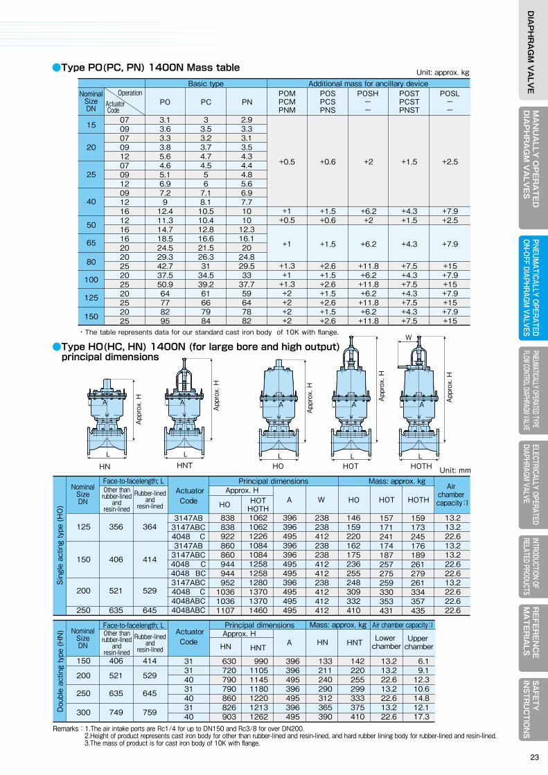
MA
NU
ALLY
OP
ER
AT
ED
DIA
PH
RA
GM
VA
LVE
SELECTRICALLY OPERATEDDIAPHRAGM VALVE
RE
FER
EN
CE
MA
TE
RIA
LSPNEUM
ATICALLY OPERATEDON-OFF DIAPHRAGM
VALVESPNEUMATICALLY OPERATED TYPE FLOW CONTROL DIAPHRAGM VALVE
INTRODUCTION OF RELATED PRODUCTS
SAFETY
IN
STRU
CTIO
NS
DIA
PH
RA
GM
VA
LVE
MA
NU
ALL
Y O
PE
RA
TE
DD
IAP
HR
AG
M V
ALV
ES
ELEC
TRIC
ALLY
OPE
RATE
DDI
APHR
AGM
VALV
ER
EFE
RE
NC
EM
AT
ER
IALS
PNEU
MAT
ICAL
LY O
PERA
TED
ON-O
FF D
IAPH
RAGM
VAL
VES
PNEU
MATIC
ALLY
OPER
ATED
TYPE
FL
OW CO
NTRO
L DIAP
HRAG
M VAL
VEIN
TROD
UCTIO
N OF
RE
LATE
D PR
ODUC
TSSA
FETY
IN
STR
UC
TIO
NS
DIA
PH
RA
GM
VA
LVE
●Type PO(PC, PN) 1400N Principal dimensions
●Type PO(PC, PN) 1400N Mass table
●Type HO(HC, HN) 1400N (for large bore and high output) principal dimensions
L
WL1 L2
App
rox.
H
App
rox.
H
App
rox.
H
App
rox.
H
App
rox.
H
App
rox.
H
App
rox.
H
App
rox.
H
App
rox.
H
App
rox.
H
L
Rc1/4 Rc1/4
HOTH
Air chamber capacity: lHOTHOWAHOT
HOTHHO
HNT Lower chamber
Upper chamberHNA
HNTHN
13.213.222.613.213.222.622.613.222.622.622.6
159173245176189261279261334357435
157171241174187257275259330353431
146159220162175236255248309332410
238238412238238412412238412412412
396396495396396495495396495495495
10621062122610841084125812581280137013701460
31314031403140
630720790790860826903
990110511451180122012131262
396396495396495396495
133211240290312365390
142220255299333375410
13.213.222.613.222.613.222.6
6.19.1
12.310.614.812.117.3
838838922860860944944952
103610361107
3147AB3147ABC4048 C3147AB
3147ABC4048 C4048 BC3147ABC4048 C4048ABC4048ABC
364
414
529
645
356
406
521
635
125
414406150
529521200
645635250
759749300
150
200
250
Remarks:1.The air intake ports are Rc1/4 for up to DN150 and Rc3/8 for over DN200. 2.Height of product represents cast iron body for other than rubber-lined and resin-lined, and hard rubber lining body for rubber-lined and resin-lined. 3.The mass of product is for cast iron body of 10K with flange.
Sin
gle
actin
g ty
pe (H
O)
Dou
ble
actin
g ty
pe (H
N)
S
O
A AA A
L LLL
HO HOTHN HNT
PO(PC,PN)
O
S
L
Rc1/4
PO(PC,PN)S
O
S
L
φA
Rc1/4
POSH
O
S
L
Rc1/4
PO(PC,PN)ST
O
S
L
φA
Rc1/4
POSL
PO(PC,PN)M
S
O
App
rox.
H
A
L
W
HOTH
S
O
Unit: mm
2. Weir Type Diaphragm Valve: Type PO(PC, PN)/HO(HC, HN) 1400N2Principal dimensions②
Face-to-face length: LFace-to-facelength; L
Face-to-facelength; L
L1 L2APOSL
--
POSH--
POSTPCSTPNST
POSPCSPNS
Nominal Size DN
POMPCMPNM
POPCPN
Other than rubber-lined
and resin-lined
Other than rubber-lined
and resin-lined
ActuatorCode Actuator
Code
ActuatorCode
Rubber-lined and resin
lined Rubber-lined and
resin-lined
Other than rubber-lined
and resin-lined
Rubber-lined and
resin-lined
Approx. H
W
Principal dimensions
5259525977525977597796779696117117143117143117143117143
5462546280546280628098809898119119143119143119143119143
5664566482566482648210182101101122122147122147122147122147
160160160160160160160160160160250160250250250250400250400250400250400
411433409431438423445452456463603477617639705728822755849819913841935
338360334356363346368375375382507390515532598615681632697696761718783
321343319341348333355362366373499388514535586609683636710700774722796
258280254276283266288295295302373310381398449466516483532547596569618
221243217239246229251258258265303273312354405422460438476502540524562
196218192214221204226233232239265248274291342359397375414439478461500
0709070912070912091216121616202025202520252025
15
20
25
40
50
65
80
100
125
150
102
118
127
159
191
216
254
305
356
406
107
123
132
165
197
222
260
313
364
414
0709070912070912091216121616202025202520252025
3.13.63.33.85.64.65.16.97.29
12.411.314.718.524.529.342.737.550.964778295
33.53.23.74.74.556
7.18.110.510.412.816.621.526.331
34.539.261667984
2.93.33.13.54.34.44.85.66.97.71010
12.316.120
24.829.533
37.759647882
POMPCMPNM
POSPCSPNS
POSTPCSTPNST
POSH--
POSL--
+1+0.5
+1
+1.3+1
+1.3+2+2+2+2
Operation PO PC PN
+0.5
+1.5+0.6
+1.5
+2.6+1.5+2.6+1.5+2.6+1.5+2.6
+0.6
+6.2+2
+6.2
+11.8+6.2+11.8+6.2+11.8+6.2+11.8
+2
+4.3+1.5
+4.3
+7.5+4.3+7.5+4.3+7.5+4.3+7.5
+1.5
+7.9+2.5
+7.9
+15+7.9+15+7.9+15+7.9+15
+2.5
15
20
25
40
50
65
80
100
125
150
Basic type Additional mass for ancillary deviceUnit: approx. kg
Unit: mm
Actuator Code
・The table represents data for our standard cast iron body of 10K with flange.
Principal dimensions
Principal dimensions
Approx. H
Approx. HAir chamber capacity: l
Mass: approx. kg
Mass: approx. kg
Nominal SizeDN
Nominal SizeDN
Nominal SizeDN
23
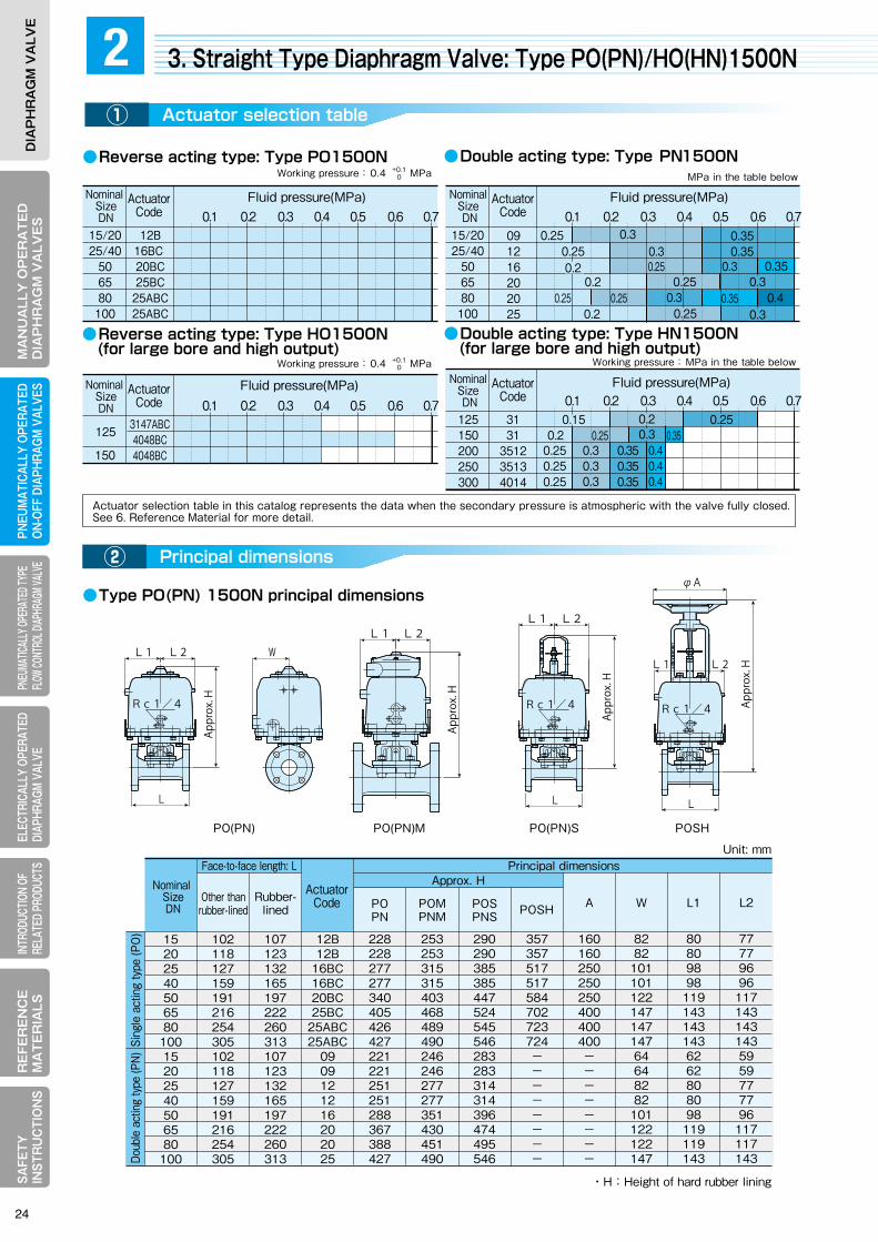
MA
NU
ALLY
OP
ER
AT
ED
DIA
PH
RA
GM
VA
LVE
SELECTRICALLY OPERATEDDIAPHRAGM VALVE
RE
FER
EN
CE
MA
TE
RIA
LSPNEUM
ATICALLY OPERATEDON-OFF DIAPHRAGM
VALVESPNEUMATICALLY OPERATED TYPE FLOW CONTROL DIAPHRAGM VALVE
INTRODUCTION OF RELATED PRODUCTS
SAFETY
IN
STRU
CTIO
NS
DIA
PH
RA
GM
VA
LVE
MA
NU
ALL
Y O
PE
RA
TE
DD
IAP
HR
AG
M V
ALV
ES
ELEC
TRIC
ALLY
OPE
RATE
DDI
APHR
AGM
VALV
ER
EFE
RE
NC
EM
AT
ER
IALS
PNEU
MAT
ICAL
LY O
PERA
TED
ON-O
FF D
IAPH
RAGM
VAL
VES
PNEU
MATIC
ALLY
OPER
ATED
TYPE
FL
OW CO
NTRO
L DIAP
HRAG
M VAL
VEIN
TROD
UCTIO
N OF
RE
LATE
D PR
ODUC
TSSA
FETY
IN
STR
UC
TIO
NS
DIA
PH
RA
GM
VA
LVE
●Reverse acting type: Type PO1500N ●Double acting type: Type PN1500N
●Reverse acting type: Type HO1500N (for large bore and high output)
●Double acting type: Type HN1500N (for large bore and high output)
● Type PO(PN) 1500N principal dimensions
●Type HO(HN) 1500N (for large bore and high output) principal dimensions
●Type PO(PN) 1500N table of mass
3. Straight Type Diaphragm Valve: Type PO(PN)/HO(HN)1500N2Actuator selection table①
Principal dimensions②
Nominal SizeDN
Nominal SizeDN
ActuatorCode
ActuatorCode
Nominal Size DN
ActuatorCode
Nominal Size DN
ActuatorCode
Fluid pressure(MPa)
Fluid pressure(MPa) Fluid pressure(MPa)
Fluid pressure(MPa)
12B16BC 20BC25BC
25ABC25ABC
0.1 0.2 0.3 0.4 0.5 0.6 0.715/2025/40
506580100
3147ABC4048BC 4048BC
0.1 0.2 0.3 0.4 0.5 0.6 0.7
150
0.1 0.2 0.3 0.4 0.5 0.6 0.715/2025/40
506580100
091216202025
0.250.40.40.4
MPa in the table below
3131
351235134014
125150200250300
Working pressure: MPa in the table below
Working pressure: 0.4 MPa+0.10
Working pressure: 0.4 MPa+0.10
Face-to-face length: L
L1 L2APOSHPOSPNS
POMPNM
POPN
Other than rubber-lined
Rubber-lined
Approx. H
W
Principal dimensions
1520254050658010015202540506580100
102118127159191216254305102118127159191216254305
107123132165197222260313107123132165197222260313
12B12B
16BC16BC20BC25BC
25ABC25ABC
0909121216202025
228 228 277 277 340 405 426 427 221 221 251 251 288 367 388 427
253 253 315 315 403 468 489 490 246 246 277 277 351 430 451 490
290 290 385 385 447 524 545 546 283 283 314 314 396 474 495 546
357 357 517 517 584 702 723 724 --------
160160250250250400400400--------
828210110112214714714764648282101122122147
808098981191431431436262808098119119143
777796961171431431435959777796117117143
Sing
le a
ctin
g ty
pe (P
O)Do
uble
act
ing
type
(PN)
・H:Height of hard rubber lining
Other than rubber-lined
Rubber-lined
Other than rubber-lined
Rubber-lined
Basic type
POSHPOMPNM
DN POSPNS
POPN
ActuatorCode
Added mass for ancillary device
1520254050658010015202540506580100
12BC12BC16BC16BC20BC25BC
25ABC25ABC
0909121216202025
6.2 6.6 12.0 13.9 24.7 43.3 48.2 54.2 4.1 4.5 7.0 8.9 16.3 25.1 30.0 41.0
+0.6+0.6+1.5+1.5+1.5+2.6+2.6+2.6+0.6+0.6+1.5+1.5+1.5+2.6+2.6+2.6
+0.5+0.5+1+1+1+1+1+1
+0.5+0.5+1+1+1+1+1+1
+2+2
+6.2+6.2+6.2+11.8+11.8+11.8
--------
Sing
le a
ctin
g ty
pe (P
O)
Doub
le a
ctin
g ty
pe (P
N)
・The mass is for our standard cast iron body of 10K with flange.
0.30.3
0.30.3
0.250.2
0.250.250.25
0.2
0.250.250.2
0.2
0.2
0.25
0.250.250.25
0.250.3
0.30.3 0.35
0.35
0.3
0.3
0.40.350.3
0.35
0.1 0.2 0.3 0.4 0.5 0.6 0.7
0.35125
0.350.350.35
Unit : approx . kg
Unit: mm
Face-to-face length: L
Face-to-face length: L
A HOT HOTHHOTHOTH
Air chamber capacity: l
Approx. H
W
Mass: approx. kgPrincipal dimensions
13.222.622.6
173245279
171241275
238412412
396495495
977 1133 1171
3147BC4048BC4048BC
364
414
356
406
125
150Sing
le a
ctin
g ty
pe (H
O)
Remarks :1.The air intake ports are Rc1/4 for up to DN150 and Rc3/8 for over DN200. 2.Height of product represents cast iron body for other than rubber-lined, and hard rubber lining body for rubber-lined. 3.DN200 to 300 are for the double acting Type HN1500. For further details. contact our Sales Dept. or local representative.
Unit:㎜
HNT HN HNTLower
chamberUpper
chamberHN
Approx. H
A
Mass: approx. kg Air chamber capacity: lPrincipal dimensions
8.3 9.1 20.0 21.0 30.0
12.4 13.2 16.0 20.0 29.0
126142
---
117133226250460
396396460460520
879 976
---
629 667 705 815 922
3131
351235134014
364414529645759
356406521635749
125150200250300D
oubl
e ac
ting
type
(HN
)
L1 L2
PO(PN)M
L1 L2 W
Rc1/4
PO(PN)
L
φA
L2L1
Rc1/4
POSH
L
Rc1/4
L2L1
Appr
ox. H
Appr
ox. H
Appr
ox. H
Appr
ox. H
PO(PN)S
L
φA
HN
φA
HNT
Appr
ox. H
Appr
ox. H
Appr
ox. H
Appr
ox. H
φA
HOT
φAW
HOTH
0.15
Actuator selection table in this catalog represents the data when the secondary pressure is atmospheric with the valve fully closed. See 6. Reference Material for more detail.
Nominal SizeDN Nominal
SizeDN
Nominal SizeDN
ActuatorCode Actuator
Code
ActuatorCode
24
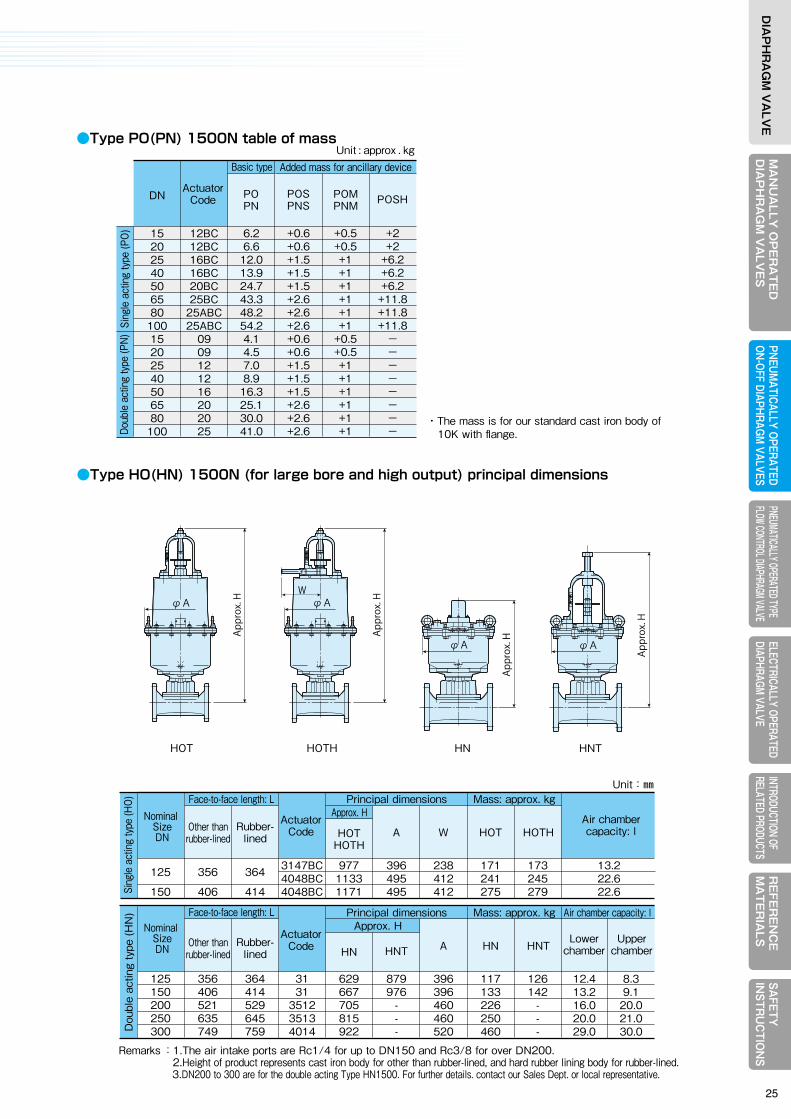
MA
NU
ALLY
OP
ER
AT
ED
DIA
PH
RA
GM
VA
LVE
SELECTRICALLY OPERATEDDIAPHRAGM VALVE
RE
FER
EN
CE
MA
TE
RIA
LSPNEUM
ATICALLY OPERATEDON-OFF DIAPHRAGM
VALVESPNEUMATICALLY OPERATED TYPE FLOW CONTROL DIAPHRAGM VALVE
INTRODUCTION OF RELATED PRODUCTS
SAFETY
IN
STRU
CTIO
NS
DIA
PH
RA
GM
VA
LVE
MA
NU
ALL
Y O
PE
RA
TE
DD
IAP
HR
AG
M V
ALV
ES
ELEC
TRIC
ALLY
OPE
RATE
DDI
APHR
AGM
VALV
ER
EFE
RE
NC
EM
AT
ER
IALS
PNEU
MAT
ICAL
LY O
PERA
TED
ON-O
FF D
IAPH
RAGM
VAL
VES
PNEU
MATIC
ALLY
OPER
ATED
TYPE
FL
OW CO
NTRO
L DIAP
HRAG
M VAL
VEIN
TROD
UCTIO
N OF
RE
LATE
D PR
ODUC
TSSA
FETY
IN
STR
UC
TIO
NS
DIA
PH
RA
GM
VA
LVE
●Reverse acting type: Type PO1500N ●Double acting type: Type PN1500N
●Reverse acting type: Type HO1500N (for large bore and high output)
●Double acting type: Type HN1500N (for large bore and high output)
● Type PO(PN) 1500N principal dimensions
●Type HO(HN) 1500N (for large bore and high output) principal dimensions
●Type PO(PN) 1500N table of mass
3. Straight Type Diaphragm Valve: Type PO(PN)/HO(HN)1500N2Actuator selection table①
Principal dimensions②
Nominal SizeDN
Nominal SizeDN
ActuatorCode
ActuatorCode
Nominal Size DN
ActuatorCode
Nominal Size DN
ActuatorCode
Fluid pressure(MPa)
Fluid pressure(MPa) Fluid pressure(MPa)
Fluid pressure(MPa)
12B16BC 20BC25BC
25ABC25ABC
0.1 0.2 0.3 0.4 0.5 0.6 0.715/2025/40
506580100
3147ABC4048BC 4048BC
0.1 0.2 0.3 0.4 0.5 0.6 0.7
150
0.1 0.2 0.3 0.4 0.5 0.6 0.715/2025/40
506580100
091216202025
0.250.40.40.4
MPa in the table below
3131
351235134014
125150200250300
Working pressure: MPa in the table below
Working pressure: 0.4 MPa+0.10
Working pressure: 0.4 MPa+0.10
Face-to-face length: L
L1 L2APOSHPOSPNS
POMPNM
POPN
Other than rubber-lined
Rubber-lined
Approx. H
W
Principal dimensions
1520254050658010015202540506580100
102118127159191216254305102118127159191216254305
107123132165197222260313107123132165197222260313
12B12B
16BC16BC20BC25BC
25ABC25ABC
0909121216202025
228 228 277 277 340 405 426 427 221 221 251 251 288 367 388 427
253 253 315 315 403 468 489 490 246 246 277 277 351 430 451 490
290 290 385 385 447 524 545 546 283 283 314 314 396 474 495 546
357 357 517 517 584 702 723 724 --------
160160250250250400400400--------
828210110112214714714764648282101122122147
808098981191431431436262808098119119143
777796961171431431435959777796117117143
Sing
le a
ctin
g ty
pe (P
O)Do
uble
act
ing
type
(PN)
・H:Height of hard rubber lining
Other than rubber-lined
Rubber-lined
Other than rubber-lined
Rubber-lined
Basic type
POSHPOMPNM
DN POSPNS
POPN
ActuatorCode
Added mass for ancillary device
1520254050658010015202540506580100
12BC12BC16BC16BC20BC25BC
25ABC25ABC
0909121216202025
6.2 6.6 12.0 13.9 24.7 43.3 48.2 54.2 4.1 4.5 7.0 8.9 16.3 25.1 30.0 41.0
+0.6+0.6+1.5+1.5+1.5+2.6+2.6+2.6+0.6+0.6+1.5+1.5+1.5+2.6+2.6+2.6
+0.5+0.5+1+1+1+1+1+1
+0.5+0.5+1+1+1+1+1+1
+2+2
+6.2+6.2+6.2+11.8+11.8+11.8
--------
Sing
le a
ctin
g ty
pe (P
O)
Doub
le a
ctin
g ty
pe (P
N)
・The mass is for our standard cast iron body of 10K with flange.
0.30.3
0.30.3
0.250.2
0.250.250.25
0.2
0.250.250.2
0.2
0.2
0.25
0.250.250.25
0.250.3
0.30.3 0.35
0.35
0.3
0.3
0.40.350.3
0.35
0.1 0.2 0.3 0.4 0.5 0.6 0.7
0.35125
0.350.350.35
Unit : approx . kg
Unit: mm
Face-to-face length: L
Face-to-face length: L
A HOT HOTHHOTHOTH
Air chamber capacity: l
Approx. H
W
Mass: approx. kgPrincipal dimensions
13.222.622.6
173245279
171241275
238412412
396495495
977 1133 1171
3147BC4048BC4048BC
364
414
356
406
125
150Sing
le a
ctin
g ty
pe (H
O)
Remarks :1.The air intake ports are Rc1/4 for up to DN150 and Rc3/8 for over DN200. 2.Height of product represents cast iron body for other than rubber-lined, and hard rubber lining body for rubber-lined. 3.DN200 to 300 are for the double acting Type HN1500. For further details. contact our Sales Dept. or local representative.
Unit:㎜
HNT HN HNTLower
chamberUpper
chamberHN
Approx. H
A
Mass: approx. kg Air chamber capacity: lPrincipal dimensions
8.3 9.1 20.0 21.0 30.0
12.4 13.2 16.0 20.0 29.0
126142
---
117133226250460
396396460460520
879 976
---
629 667 705 815 922
3131
351235134014
364414529645759
356406521635749
125150200250300D
oubl
e ac
ting
type
(HN
)
L1 L2
PO(PN)M
L1 L2 W
Rc1/4
PO(PN)
L
φA
L2L1
Rc1/4
POSH
L
Rc1/4
L2L1
Appr
ox. H
Appr
ox. H
Appr
ox. H
Appr
ox. H
PO(PN)S
L
φA
HN
φA
HNT
Appr
ox. H
Appr
ox. H
Appr
ox. H
Appr
ox. H
φA
HOT
φAW
HOTH
0.15
Actuator selection table in this catalog represents the data when the secondary pressure is atmospheric with the valve fully closed. See 6. Reference Material for more detail.
Nominal SizeDN Nominal
SizeDN
Nominal SizeDN
ActuatorCode Actuator
Code
ActuatorCode
25
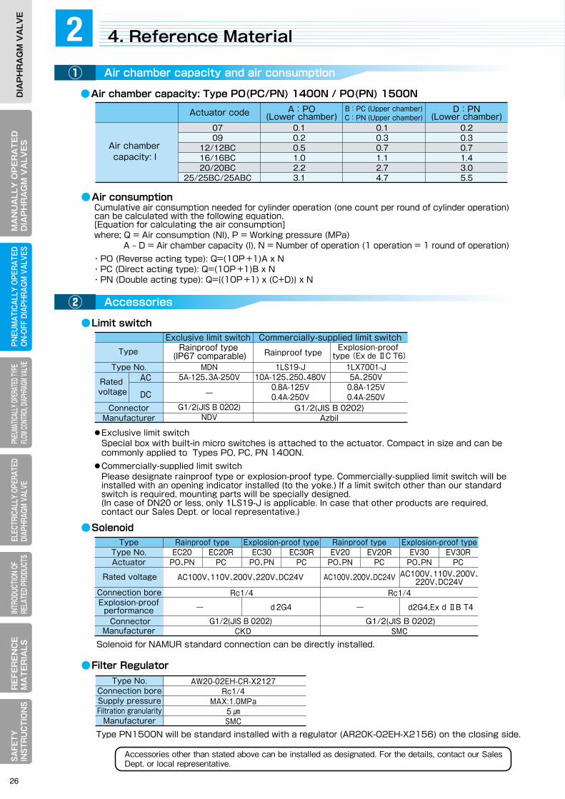
MA
NU
ALLY
OP
ER
AT
ED
DIA
PH
RA
GM
VA
LVE
SELECTRICALLY OPERATEDDIAPHRAGM VALVE
RE
FER
EN
CE
MA
TE
RIA
LSPNEUM
ATICALLY OPERATEDON-OFF DIAPHRAGM
VALVESPNEUMATICALLY OPERATED TYPE FLOW CONTROL DIAPHRAGM VALVE
INTRODUCTION OF RELATED PRODUCTS
SAFETY
IN
STRU
CTIO
NS
DIA
PH
RA
GM
VA
LVE
MA
NU
ALL
Y O
PE
RA
TE
DD
IAP
HR
AG
M V
ALV
ES
ELEC
TRIC
ALLY
OPE
RATE
DDI
APHR
AGM
VALV
ER
EFE
RE
NC
EM
AT
ER
IALS
PNEU
MAT
ICAL
LY O
PERA
TED
ON-O
FF D
IAPH
RAGM
VAL
VES
PNEU
MATIC
ALLY
OPER
ATED
TYPE
FL
OW CO
NTRO
L DIAP
HRAG
M VAL
VEIN
TROD
UCTIO
N OF
RE
LATE
D PR
ODUC
TSSA
FETY
IN
STR
UC
TIO
NS
DIA
PH
RA
GM
VA
LVE
Accessories other than stated above can be installed as designated. For the details, contact our SalesDept. or local representative.
●Air chamber capacity: Type PO(PC/PN) 1400N / PO(PN) 1500N
●Limit switch
●Filter Regulator
●Solenoid
0709
12/12BC16/16BC20/20BC
25/25BC/25ABC
0.10.20.51.02.23.1
0.10.30.71.12.74.7
0.20.30.71.43.05.5
Actuator code A:PO(Lower chamber)
B:PC (Upper chamber)C:PN (Upper chamber)
D:PN(Lower chamber)
Air chamber capacity: l
AC
DC
Type No.
Rated voltage
MDN5A-125、3A-250V
―
G1/2(JIS B 0202)NDV
1LS19-J10A-125、250、480V
0.8A-125V0.4A-250V
1LX7001-J5A、250V
0.8A-125V0.4A-250V
Commercially-supplied limit switchExclusive limit switchRainproof type
(IP67 comparable)
ConnectorManufacturer
Connector
G1/2(JIS B 0202)Azbil
TypeType No.Actuator
EC20PO、PN
EC20RPC
EC30PO、PN
EC30RPC
EV20PO、PN
EV20RPC
EV30PO、PN
EV30RPC
AC100V、110V、200V、220V、DC24V AC100V、110V、200V、220V、DC24VAC100V、200V、DC24V
Rainproof type Explosion-proof type Rainproof type
SMC
Rc1/4Rc1/4
CKD
― d2G4 ― d2G4,Ex d ⅡB T4
Explosion-proof type
Type No.Connection boreSupply pressureFiltration granularity
Manufacturer
AW20-02EH-CR-X2127Rc1/4
MAX:1.0MPa5 ㎛SMC
●Exclusive limit switch Special box with built-in micro switches is attached to the actuator. Compact in size and can be commonly applied to Types PO, PC, PN 1400N.●Commercially-supplied limit switch Please designate rainproof type or explosion-proof type. Commercially-supplied limit switch will be installed with an opening indicator installed (to the yoke.) If a limit switch other than our standard switch is required, mounting parts will be specially designed. (In case of DN20 or less, only 1LS19-J is applicable. In case that other products are required, contact our Sales Dept. or local representative.)
Cumulative air consumption needed for cylinder operation (one count per round of cylinder operation) can be calculated with the following equation.[Equation for calculating the air consumption]where; Q = Air consumption (Nl), P = Working pressure (MPa) A ‒ D = Air chamber capacity (l), N = Number of operation (1 operation = 1 round of operation)・PO (Reverse acting type): Q=(10P +1)A x N・PC (Direct acting type): Q=(10P +1)B x N・PN (Double acting type): Q={(10P +1) x (C+D)} x N
Solenoid for NAMUR standard connection can be directly installed.
Type PN1500N will be standard installed with a regulator (AR20K-02EH-X2156) on the closing side.
●Air consumption
Type Rainproof type Explosion-proof type (Ex de ⅡC T6)
Rated voltage
Connection boreExplosion-proof
performance
ManufacturerG1/2(JIS B 0202) G1/2(JIS B 0202)
4. Reference Material2Air chamber capacity and air consumption①
Accessories②
3-1. Rolling Diaphragm Type: Type BO(BC) 3400① Features of actuator
② Actuator specification
③ Actuator selection table
④ Principal dimensions
3-2. Piston Type: Type HN3400N① Features of actuator
② Actuator specifications
③ Actuator selection table
④ Principal dimensions
3-3. Reference Material① How to select valve size
② Valve stroke and Cv value
③ Specific flow rate characteristics
PNEUMATICALLY OPERATED TYPE FLOW CONTROL DIAPHRAGM VALVE
3
26

Accessories other than stated above can be installed as designated. For the details, contact our SalesDept. or local representative.
●Air chamber capacity: Type PO(PC/PN) 1400N / PO(PN) 1500N
●Limit switch
●Filter Regulator
●Solenoid
0709
12/12BC16/16BC20/20BC
25/25BC/25ABC
0.10.20.51.02.23.1
0.10.30.71.12.74.7
0.20.30.71.43.05.5
Actuator code A:PO(Lower chamber)
B:PC (Upper chamber)C:PN (Upper chamber)
D:PN(Lower chamber)
Air chamber capacity: l
AC
DC
Type No.
Rated voltage
MDN5A-125、3A-250V
―
G1/2(JIS B 0202)NDV
1LS19-J10A-125、250、480V
0.8A-125V0.4A-250V
1LX7001-J5A、250V
0.8A-125V0.4A-250V
Commercially-supplied limit switchExclusive limit switchRainproof type
(IP67 comparable)
ConnectorManufacturer
Connector
G1/2(JIS B 0202)Azbil
TypeType No.Actuator
EC20PO、PN
EC20RPC
EC30PO、PN
EC30RPC
EV20PO、PN
EV20RPC
EV30PO、PN
EV30RPC
AC100V、110V、200V、220V、DC24V AC100V、110V、200V、220V、DC24VAC100V、200V、DC24V
Rainproof type Explosion-proof type Rainproof type
SMC
Rc1/4Rc1/4
CKD
― d2G4 ― d2G4,Ex d ⅡB T4
Explosion-proof type
Type No.Connection boreSupply pressureFiltration granularity
Manufacturer
AW20-02EH-CR-X2127Rc1/4
MAX:1.0MPa5 ㎛SMC
●Exclusive limit switch Special box with built-in micro switches is attached to the actuator. Compact in size and can be commonly applied to Types PO, PC, PN 1400N.●Commercially-supplied limit switch Please designate rainproof type or explosion-proof type. Commercially-supplied limit switch will be installed with an opening indicator installed (to the yoke.) If a limit switch other than our standard switch is required, mounting parts will be specially designed. (In case of DN20 or less, only 1LS19-J is applicable. In case that other products are required, contact our Sales Dept. or local representative.)
Cumulative air consumption needed for cylinder operation (one count per round of cylinder operation) can be calculated with the following equation.[Equation for calculating the air consumption]where; Q = Air consumption (Nl), P = Working pressure (MPa) A ‒ D = Air chamber capacity (l), N = Number of operation (1 operation = 1 round of operation)・PO (Reverse acting type): Q=(10P +1)A x N・PC (Direct acting type): Q=(10P +1)B x N・PN (Double acting type): Q={(10P +1) x (C+D)} x N
Solenoid for NAMUR standard connection can be directly installed.
Type PN1500N will be standard installed with a regulator (AR20K-02EH-X2156) on the closing side.
●Air consumption
Type Rainproof type Explosion-proof type (Ex de ⅡC T6)
Rated voltage
Connection boreExplosion-proof
performance
ManufacturerG1/2(JIS B 0202) G1/2(JIS B 0202)
4. Reference Material2Air chamber capacity and air consumption①
Accessories②
3-1. Rolling Diaphragm Type: Type BO(BC) 3400① Features of actuator
② Actuator specification
③ Actuator selection table
④ Principal dimensions
3-2. Piston Type: Type HN3400N① Features of actuator
② Actuator specifications
③ Actuator selection table
④ Principal dimensions
3-3. Reference Material① How to select valve size
② Valve stroke and Cv value
③ Specific flow rate characteristics
PNEUMATICALLY OPERATED TYPE FLOW CONTROL DIAPHRAGM VALVE
3

MA
NU
ALLY
OP
ER
AT
ED
DIA
PH
RA
GM
VA
LVE
SELECTRICALLY OPERATEDDIAPHRAGM VALVE
RE
FER
EN
CE
MA
TE
RIA
LSPNEUM
ATICALLY OPERATEDON-OFF DIAPHRAGM
VALVESPNEUMATICALLY OPERATED TYPE FLOW CONTROL DIAPHRAGM VALVE
INTRODUCTION OF RELATED PRODUCTS
SAFETY
IN
STRU
CTIO
NS
DIA
PH
RA
GM
VA
LVE
MA
NU
ALL
Y O
PE
RA
TE
DD
IAP
HR
AG
M V
ALV
ES
ELEC
TRIC
ALLY
OPE
RATE
DDI
APHR
AGM
VALV
ER
EFE
RE
NC
EM
AT
ER
IALS
PNEU
MAT
ICAL
LY O
PERA
TED
ON-O
FF D
IAPH
RAGM
VAL
VES
PNEU
MATIC
ALLY
OPER
ATED
TYPE
FL
OW CO
NTRO
L DIAP
HRAG
M VAL
VEIN
TROD
UCTIO
N OF
RE
LATE
D PR
ODUC
TSSA
FETY
IN
STR
UC
TIO
NS
DIA
PH
RA
GM
VA
LVE
Accessories other than stated above can be installed as designated. For further details, contact our Sales Dept. or local representative.
●Reverse acting type: Type BO3400
●Direct acting type: Type BC3400●Standard specifications
●Filter Regulator
●Positioner
❶Smooth operation Due to its rolling operation (rolling movement), the rolling diaphragm restrains wear and friction loss.❷Stable output Compared with the piston type, the rolling diaphragm has larger compressed area, realizing excellent response and output precision.❸Compact and lightweight Adoption of multi-spring system realizes compact design and lightweight and high output (closing force). These help expand maximum working pressure.
+0.1 0
O
S 20
Rolling operation
1 . Rolling Diaphragm Type:Type BO(BC)34003Features of Actuator① Actuator selection table③
Actuator specifications②
Reverse acting type: Type BO3400 (Air to Open/Spring to Close)Direct acting type: Type BC3400 (Air to Close/Spring to Open)Rolling diaphragm typeDN15-1500.14 or 0.3 MPaFCD450SPHE or SS400PSilver (Environment-friendly type)Standard/High temperature: Idemitsu Kosan Daphne molybdenum grease No.2 Low temperature: Idemitsu Kosan Daphne Super Coronex No.1Linear characteristics (Relationship between signal pressure and valve opening)
*1:Double acting type is outside the manufacturing range.*2:For detail, see the actuator selection table.*3:For the machine with the positioner.
Operating systemType No.
Manufacturer
Pneumatic/PneumaticNPN11
Electric/PneumaticNE11
Our standard type
NDV
For NPN11For NE11
TypeXR108-S/M0J3XR108-S/M0R1
Lubricant
Machine characteristics*3
Minimum supply pressure*2
Bonnet materialCylinder material
Standard exterior painting color
Operation*1
Actuator systemApplicable nominal size
NominalSize DN
ActuatorCode
Supply pressure (MPa)
NominalSize DN
ActuatorCode
Supply pressure (MPa)
Rubber diaphragm(*1) PTFE diaphragm(*2)
152025
40
50
65
80
100
125
150
0.14
0.3
5221LA
5227LA5227LA5235LA5227LA5235LA5235LA524SLA524SLA524LLA526SLA524ELA526SLA524ELA526SLA
Fluid pressure (MPa) Fluid pressure (MPa)
Rubber diaphragm(*1) PTFE diaphragm(*2)Fluid pressure (MPa) Fluid pressure (MPa)
152025
40
50
65
80
100
125
150
0.14
0.3
5221LA
5227LA5227LA5235LA5227LA5235LA5235LA524SLA524SLA524LLA524ELA526SLA524ELA526SLA
0.2 0.3 0.5 0.7 0.90.1 0.4 0.6 0.8 1.0
0.2 0.3 0.5 0.7 0.90.1 0.4 0.6 0.8 1.0 0.2 0.3 0.5 0.7 0.90.1 0.4 0.6 0.8 1.0
0.2 0.3 0.5 0.7 0.90.1 0.4 0.6 0.8 1.0
Max. allowable working pressure for other than the hard rubber-lined, glass-lined and ceramic bodyMax. allowable working pressure for the hard rubber-lined, glass-lined and ceramic body
(*2):
Max. allowable working pressure for other than the glass-lined and ceramic bodyMax. allowable working pressure for the glass-lined and ceramic body
(*1):
Actuator selection table in this catalog represents the data when the secondary pressure is atmospheric with the valve fully closed. See 6. Reference Material for more detail.
28
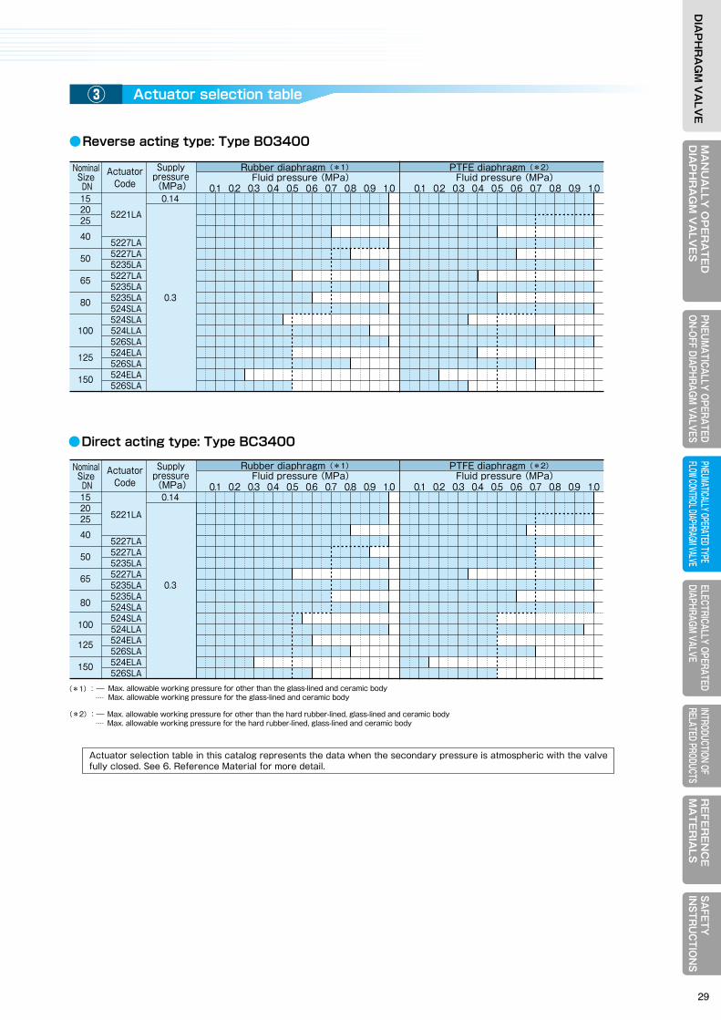
MA
NU
ALLY
OP
ER
AT
ED
DIA
PH
RA
GM
VA
LVE
SELECTRICALLY OPERATEDDIAPHRAGM VALVE
RE
FER
EN
CE
MA
TE
RIA
LSPNEUM
ATICALLY OPERATEDON-OFF DIAPHRAGM
VALVESPNEUMATICALLY OPERATED TYPE FLOW CONTROL DIAPHRAGM VALVE
INTRODUCTION OF RELATED PRODUCTS
SAFETY
IN
STRU
CTIO
NS
DIA
PH
RA
GM
VA
LVE
MA
NU
ALL
Y O
PE
RA
TE
DD
IAP
HR
AG
M V
ALV
ES
ELEC
TRIC
ALLY
OPE
RATE
DDI
APHR
AGM
VALV
ER
EFE
RE
NC
EM
AT
ER
IALS
PNEU
MAT
ICAL
LY O
PERA
TED
ON-O
FF D
IAPH
RAGM
VAL
VES
PNEU
MATIC
ALLY
OPER
ATED
TYPE
FL
OW CO
NTRO
L DIAP
HRAG
M VAL
VEIN
TROD
UCTIO
N OF
RE
LATE
D PR
ODUC
TSSA
FETY
IN
STR
UC
TIO
NS
DIA
PH
RA
GM
VA
LVE
Accessories other than stated above can be installed as designated. For further details, contact our Sales Dept. or local representative.
●Reverse acting type: Type BO3400
●Direct acting type: Type BC3400●Standard specifications
●Filter Regulator
●Positioner
❶Smooth operation Due to its rolling operation (rolling movement), the rolling diaphragm restrains wear and friction loss.❷Stable output Compared with the piston type, the rolling diaphragm has larger compressed area, realizing excellent response and output precision.❸Compact and lightweight Adoption of multi-spring system realizes compact design and lightweight and high output (closing force). These help expand maximum working pressure.
+0.1 0
O
S 20
Rolling operation
1 . Rolling Diaphragm Type:Type BO(BC)34003Features of Actuator① Actuator selection table③
Actuator specifications②
Reverse acting type: Type BO3400 (Air to Open/Spring to Close)Direct acting type: Type BC3400 (Air to Close/Spring to Open)Rolling diaphragm typeDN15-1500.14 or 0.3 MPaFCD450SPHE or SS400PSilver (Environment-friendly type)Standard/High temperature: Idemitsu Kosan Daphne molybdenum grease No.2 Low temperature: Idemitsu Kosan Daphne Super Coronex No.1Linear characteristics (Relationship between signal pressure and valve opening)
*1:Double acting type is outside the manufacturing range.*2:For detail, see the actuator selection table.*3:For the machine with the positioner.
Operating systemType No.
Manufacturer
Pneumatic/PneumaticNPN11
Electric/PneumaticNE11
Our standard type
NDV
For NPN11For NE11
TypeXR108-S/M0J3XR108-S/M0R1
Lubricant
Machine characteristics*3
Minimum supply pressure*2
Bonnet materialCylinder material
Standard exterior painting color
Operation*1
Actuator systemApplicable nominal size
NominalSize DN
ActuatorCode
Supply pressure (MPa)
NominalSize DN
ActuatorCode
Supply pressure (MPa)
Rubber diaphragm(*1) PTFE diaphragm(*2)
152025
40
50
65
80
100
125
150
0.14
0.3
5221LA
5227LA5227LA5235LA5227LA5235LA5235LA524SLA524SLA524LLA526SLA524ELA526SLA524ELA526SLA
Fluid pressure (MPa) Fluid pressure (MPa)
Rubber diaphragm(*1) PTFE diaphragm(*2)Fluid pressure (MPa) Fluid pressure (MPa)
152025
40
50
65
80
100
125
150
0.14
0.3
5221LA
5227LA5227LA5235LA5227LA5235LA5235LA524SLA524SLA524LLA524ELA526SLA524ELA526SLA
0.2 0.3 0.5 0.7 0.90.1 0.4 0.6 0.8 1.0
0.2 0.3 0.5 0.7 0.90.1 0.4 0.6 0.8 1.0 0.2 0.3 0.5 0.7 0.90.1 0.4 0.6 0.8 1.0
0.2 0.3 0.5 0.7 0.90.1 0.4 0.6 0.8 1.0
Max. allowable working pressure for other than the hard rubber-lined, glass-lined and ceramic bodyMax. allowable working pressure for the hard rubber-lined, glass-lined and ceramic body
(*2):
Max. allowable working pressure for other than the glass-lined and ceramic bodyMax. allowable working pressure for the glass-lined and ceramic body
(*1):
Actuator selection table in this catalog represents the data when the secondary pressure is atmospheric with the valve fully closed. See 6. Reference Material for more detail.
29

MA
NU
ALLY
OP
ER
AT
ED
DIA
PH
RA
GM
VA
LVE
SELECTRICALLY OPERATEDDIAPHRAGM VALVE
RE
FER
EN
CE
MA
TE
RIA
LSPNEUM
ATICALLY OPERATEDON-OFF DIAPHRAGM
VALVESPNEUMATICALLY OPERATED TYPE FLOW CONTROL DIAPHRAGM VALVE
INTRODUCTION OF RELATED PRODUCTS
SAFETY
IN
STRU
CTIO
NS
DIA
PH
RA
GM
VA
LVE
MA
NU
ALL
Y O
PE
RA
TE
DD
IAP
HR
AG
M V
ALV
ES
ELEC
TRIC
ALLY
OPE
RATE
DDI
APHR
AGM
VALV
ER
EFE
RE
NC
EM
AT
ER
IALS
PNEU
MAT
ICAL
LY O
PERA
TED
ON-O
FF D
IAPH
RAGM
VAL
VES
PNEU
MATIC
ALLY
OPER
ATED
TYPE
FL
OW CO
NTRO
L DIAP
HRAG
M VAL
VEIN
TROD
UCTIO
N OF
RE
LATE
D PR
ODUC
TSSA
FETY
IN
STR
UC
TIO
NS
DIA
PH
RA
GM
VA
LVE
●Standard specificationsAction Double acting type: HN3400N (Air to Open/Air to Close)Actuator system Piston typeApplicable range of nominal sizeDN150-300Supply air pressure 0.2 to 0.5MPaBonnet material FC200Cylinder material FC200Standard exterior painting color Silver (Environment-friendly type)Lubricant Shell Alvania EP2 grease
Actuator Code No.HN34N- L A Approx. H
31 406 396 738 40 521 495 945 40 635 495 1016 40 749 495 1057
150200250300
Unit: mm
Unit: mm
S
O
*
1. Rolling Diaphragm Type: Type BO(BC)3400 2. Piston Type:Type HN3400N3Principal Dimensions④ Features of Actuator①
Actuator specifications②
Actuator selection table③
Principal dimensions④Face-to-face length L
ActuatorCode
ActuatorCode
Other than rubber-lined
and resin-lined
Rubber-lined and
resin-lined
152025
40
50
65
80
100
125
150
Dimension H (parentheses) is for actuator code 526SLA with handle.
Mass: Approx.(kg) Mass: Approx.(kg)Type BO3400 Type BC3400
Without handle With handle Without handle With handleApprox.
HApprox.
HA E A E
107123132
165
197
222
260
313
364
414
102118127
159
191
216
254
305
356
406
5221LA
5227LA5227LA5235LA5227LA5235LA5235LA524SLA524SLA524LLA526SLA524ELA526SLA524ELA526SLA
404404404416514527562539574592702699839
918(1318)888
910(1310)920
942(1342)
231231231231283283283283367367472472472678472678472678
196196196196230230230230230230336336336265336265336265
16.016.517.519.531.534.556.538.060.066.596.5
107.0140.0262.0154.0276.0
302.0
12.012.513.515.521.524.546.528.050.056.584.594.5
117.0222.0131.0236.0148.0253.0
196196196196230230230230230230336336336―
336265336265
364364364375474487522499534552662659799―
848910(1310)
880942(1342)
231231231231283283367283367367472472472―
472678472678
12.012.513.515.521.524.546.528.050.056.584.594.5
117.0―
131.0236.0148.0253.0
16.016.517.519.531.534.556.538.060.066.596.5
107.0140.0
―154.0276.0
302.0
Control valve equipped with the piston type actuator (double acting type). Realizes high output by using high working pressure compared with the rolling diaphragm type.
●Rubber diaphragm ●PTFE diaphragm
Fluid pressure (MPa)
Rubber diaphragm
0.1 0.2 0.3 0.4 0.5 0.6 0.7 0.8
31404040
3140
150200250300
150200
0.1 0.2 0.3 0.4 0.5 0.6 0.7 0.8
Max. working pressure for other than glass-lined
Max. working pressure for glass-lined
Fluid pressure (MPa)
Fluid pressure (MPa) Fluid pressure (MPa)
PTFE diaphragm
0.1 0.2 0.3 0.4 0.5 0.6 0.7 0.8
31404040
3140
150200250300
150200
0.1 0.2 0.3 0.4 0.5 0.6 0.7 0.8
Max. working pressure for other than hard rubber-lined and glass-lined
Max. working pressure for hard rubber-lined and glass-lined
Working pressure: MPa in the table below Working pressure: MPa in the table below
0.350.30.250.2 0.25 0.3
0.2
0.50.40.30.2 0.3 0.35 0.45
0.4 0.450.30.250.20.2 0.25 0.3 0.4
0.2 0.25 0.30.2 0.25 0.3 0.35
0.450.4
0.3 0.350.3
0.40.35 0.4
0.30.25
0.20.2
0.30.4
0.350.25
0.25
0.35
: For the valve with positioner
E
L L
EE
AA
ppro
x. H
App
rox.
H
App
rox.
H
A
Front
Top handle for 526SLA only
Front
OPEN SHUT
S
O20
S
O20
OPEN SHUT
L
A
●With handle
●Reverse acting type: Type BO3400 ●Direct acting type: Type BC3400
Actuator selection table in this catalog represents the data when the secondary pressure is atmospheric with the valve fully closed. See 6. Reference Material for more detail.
NominalSize DN
NominalSize DN
ActuatorCode
NominalSize DN
ActuatorCode
NominalSize DN
NominalSize DN
ActuatorCode
NominalSize DN
30
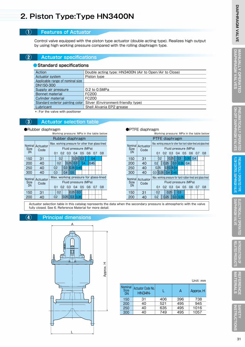
MA
NU
ALLY
OP
ER
AT
ED
DIA
PH
RA
GM
VA
LVE
SELECTRICALLY OPERATEDDIAPHRAGM VALVE
RE
FER
EN
CE
MA
TE
RIA
LSPNEUM
ATICALLY OPERATEDON-OFF DIAPHRAGM
VALVESPNEUMATICALLY OPERATED TYPE FLOW CONTROL DIAPHRAGM VALVE
INTRODUCTION OF RELATED PRODUCTS
SAFETY
IN
STRU
CTIO
NS
DIA
PH
RA
GM
VA
LVE
MA
NU
ALL
Y O
PE
RA
TE
DD
IAP
HR
AG
M V
ALV
ES
ELEC
TRIC
ALLY
OPE
RATE
DDI
APHR
AGM
VALV
ER
EFE
RE
NC
EM
AT
ER
IALS
PNEU
MAT
ICAL
LY O
PERA
TED
ON-O
FF D
IAPH
RAGM
VAL
VES
PNEU
MATIC
ALLY
OPER
ATED
TYPE
FL
OW CO
NTRO
L DIAP
HRAG
M VAL
VEIN
TROD
UCTIO
N OF
RE
LATE
D PR
ODUC
TSSA
FETY
IN
STR
UC
TIO
NS
DIA
PH
RA
GM
VA
LVE
●Standard specificationsAction Double acting type: HN3400N (Air to Open/Air to Close)Actuator system Piston typeApplicable range of nominal sizeDN150-300Supply air pressure 0.2 to 0.5MPaBonnet material FC200Cylinder material FC200Standard exterior painting color Silver (Environment-friendly type)Lubricant Shell Alvania EP2 grease
Actuator Code No.HN34N- L A Approx. H
31 406 396 738 40 521 495 945 40 635 495 1016 40 749 495 1057
150200250300
Unit: mm
Unit: mm
S
O
*
1. Rolling Diaphragm Type: Type BO(BC)3400 2. Piston Type:Type HN3400N3Principal Dimensions④ Features of Actuator①
Actuator specifications②
Actuator selection table③
Principal dimensions④Face-to-face length L
ActuatorCode
ActuatorCode
Other than rubber-lined
and resin-lined
Rubber-lined and
resin-lined
152025
40
50
65
80
100
125
150
Dimension H (parentheses) is for actuator code 526SLA with handle.
Mass: Approx.(kg) Mass: Approx.(kg)Type BO3400 Type BC3400
Without handle With handle Without handle With handleApprox.
HApprox.
HA E A E
107123132
165
197
222
260
313
364
414
102118127
159
191
216
254
305
356
406
5221LA
5227LA5227LA5235LA5227LA5235LA5235LA524SLA524SLA524LLA526SLA524ELA526SLA524ELA526SLA
404404404416514527562539574592702699839
918(1318)888
910(1310)920
942(1342)
231231231231283283283283367367472472472678472678472678
196196196196230230230230230230336336336265336265336265
16.016.517.519.531.534.556.538.060.066.596.5
107.0140.0262.0154.0276.0
302.0
12.012.513.515.521.524.546.528.050.056.584.594.5
117.0222.0131.0236.0148.0253.0
196196196196230230230230230230336336336―
336265336265
364364364375474487522499534552662659799―
848910(1310)
880942(1342)
231231231231283283367283367367472472472―
472678472678
12.012.513.515.521.524.546.528.050.056.584.594.5
117.0―
131.0236.0148.0253.0
16.016.517.519.531.534.556.538.060.066.596.5
107.0140.0
―154.0276.0
302.0
Control valve equipped with the piston type actuator (double acting type). Realizes high output by using high working pressure compared with the rolling diaphragm type.
●Rubber diaphragm ●PTFE diaphragm
Fluid pressure (MPa)
Rubber diaphragm
0.1 0.2 0.3 0.4 0.5 0.6 0.7 0.8
31404040
3140
150200250300
150200
0.1 0.2 0.3 0.4 0.5 0.6 0.7 0.8
Max. working pressure for other than glass-lined
Max. working pressure for glass-lined
Fluid pressure (MPa)
Fluid pressure (MPa) Fluid pressure (MPa)
PTFE diaphragm
0.1 0.2 0.3 0.4 0.5 0.6 0.7 0.8
31404040
3140
150200250300
150200
0.1 0.2 0.3 0.4 0.5 0.6 0.7 0.8
Max. working pressure for other than hard rubber-lined and glass-lined
Max. working pressure for hard rubber-lined and glass-lined
Working pressure: MPa in the table below Working pressure: MPa in the table below
0.350.30.250.2 0.25 0.3
0.2
0.50.40.30.2 0.3 0.35 0.45
0.4 0.450.30.250.20.2 0.25 0.3 0.4
0.2 0.25 0.30.2 0.25 0.3 0.35
0.450.4
0.3 0.350.3
0.40.35 0.4
0.30.25
0.20.2
0.30.4
0.350.25
0.25
0.35
: For the valve with positioner
E
L L
EE
A
App
rox.
H
App
rox.
H
App
rox.
H
A
Front
Top handle for 526SLA only
Front
OPEN SHUT
S
O20
S
O20
OPEN SHUT
L
A
●With handle
●Reverse acting type: Type BO3400 ●Direct acting type: Type BC3400
Actuator selection table in this catalog represents the data when the secondary pressure is atmospheric with the valve fully closed. See 6. Reference Material for more detail.
NominalSize DN
NominalSize DN
ActuatorCode
NominalSize DN
ActuatorCode
NominalSize DN
NominalSize DN
ActuatorCode
NominalSize DN
31

MA
NU
ALLY
OP
ER
AT
ED
DIA
PH
RA
GM
VA
LVE
SELECTRICALLY OPERATEDDIAPHRAGM VALVE
RE
FER
EN
CE
MA
TE
RIA
LSPNEUM
ATICALLY OPERATEDON-OFF DIAPHRAGM
VALVESPNEUMATICALLY OPERATED TYPE FLOW CONTROL DIAPHRAGM VALVE
INTRODUCTION OF RELATED PRODUCTS
SAFETY
IN
STRU
CTIO
NS
DIA
PH
RA
GM
VA
LVE
MA
NU
ALL
Y O
PE
RA
TE
DD
IAP
HR
AG
M V
ALV
ES
ELEC
TRIC
ALLY
OPE
RATE
DDI
APHR
AGM
VALV
ER
EFE
RE
NC
EM
AT
ER
IALS
PNEU
MAT
ICAL
LY O
PERA
TED
ON-O
FF D
IAPH
RAGM
VAL
VES
PNEU
MATIC
ALLY
OPER
ATED
TYPE
FL
OW CO
NTRO
L DIAP
HRAG
M VAL
VEIN
TROD
UCTIO
N OF
RE
LATE
D PR
ODUC
TSSA
FETY
IN
STR
UC
TIO
NS
DIA
PH
RA
GM
VA
LVE
●Rolling diaphragm type: Type BO(BC)3400
●Piston type: Type HN3400N
●Rolling Diaphragm Type: Type BO (BC) 3400
*The Cv values of Material code “59(2S)” with DN65 or bigger are same as “59(M)/59(S)”.*The above-mentioned Cv values need to be corrected when using the PTFE diaphragm and the pressure on the primary side is lower than 0.15 MPa. In such a case, please contact us.
・The charts show the specific flow rate characteristics actually observed by this company. In actual service, the flow rate characteristics may vary depending on the pressure, temperature, flow velocity, piping and other condition.・Piston type: Type HN3400N, contact our Sales Dept. or local representative for the details.
V : Flow rate of a fluid m3/hQ : Flow rate of a gas m3/h (at 15.6℃, 101.3 kPa・A)G :Specific gravity of fluid for liquid, water = 1 for gas, air: 1
P1: Absolute pressure on the primary side kPa・A*P2: Absolute pressure on the secondary side kPa・A* t: Temperature of the fluid ℃ W : Flow rate of vapor kg/h K : 1+(0.0013 x degree of superheat ℃)Degree of superheat: Difference between the saturation temperature to the absolute pressure on the primary side(P1) and the primary side temperature. In the case of saturation vapor, the degree of superheat reads 0 (zero).
Stroke(mm)
Main body without lining
Main bodywith rubber
lining
Main bodywith glass
lining
Main bodywith PFA
lining 55 520 435 570 325 75 1025 880 1120 800 95 1435 1295 1920 1160 110 2280 1840 2350 ―
150200250300
Without lining Rubber-lined Glass-lined
15202540506580
100125150
234678
106161303
15327178
166306
4.28.515305793
156194310440
4.21119408299
219291405585
4162
104210230330
5468
107161――
37
2.37.5
68
1014202430405060
PFA-lined PFA-linedETFE-lined59(2S)/6059(M)/59(S)
Ceramic Stroke
(mm)Diaphragm
Main body
Rubber PTFE Rubber PTFEPTFE PTFE
PTFE
5.91014285263
128―――
1025
410
355530
(*A:Absolute pressure = Gauge pressure + 101.3 kPa)
NominalSize DN
NominalSize DN
3. Reference Material3How to Select Valve Size①
Valve Stroke and Cv value②
駆動部の特長Specific Flow Rate Characteristics③Valve size is determined by calculating the valve coefficient of volume (Cv value) from the flow rate of a fluid, fluid pressure, differential pressure, specific gravity, etc. and comparing it with the Cv value in the table of the next section.Generally, the following Cv value calculation formulas are used except for the special correction items:
Liquid
Gas
Vapor
△ P
△P(P1+P2)
△P(P1+P2)
2
2.93
G
G(273+t)
Cv=11.56 V
Cv=
Cv= 0.1391
P1
(P1‒ P2)
< △ P2P1
≧
Q2.538P1
0.1205P1
G(273+t)Cv= Q
WKCv=
WK
Same as the left
:Main body without lining ‒ Rubber diaphragm
:Main body without lining ‒ PTFE diaphragm*1
:Rubber-lined main body ‒ Rubber (or PTFE) diaphragm
100
80
60
40
20
0
DN150
100
80
60
40
20
0
DN80100
80
60
40
20
0
DN100
100
80
60
40
20
0
DN125
100
80
60
40
20
0
DN40
100
80
60
40
20
0
DN15100
80
60
40
20
0
DN20
100
80
60
40
20
0
DN65100
80
60
40
20
0
DN50
100
80
60
40
20
0
DN25
:Glass-lined main body ‒ PTFE diaphragm
:PFA-lined main body ‒ PTFE diaphragm
:ETFE-lined main body ‒ PTFE diaphragm
100
80
60
40
20
0
DN150
100
80
60
40
20
0
DN80100
80
60
40
20
0
DN100
100
80
60
40
20
0
DN125
100
80
60
40
20
0
DN40
100
80
60
40
20
0
Flow
rat
e[%
]
Flow
rat
e[%
]
Flow
rat
e[%
]
Flow
rat
e[%
]
DN15100
80
60
40
20
0
Stroke[%] Stroke[%] Stroke[%] Stroke[%]
Stroke[%] Stroke[%] Stroke[%] Stroke[%]
Stroke[%] Stroke[%] Stroke[%] Stroke[%]
Stroke[%] Stroke[%] Stroke[%] Stroke[%]
Stroke[%] Stroke[%] Stroke[%] Stroke[%]
Flow
rat
e[%
]
Flow
rat
e[%
]
Flow
rat
e[%
]
Flow
rat
e[%
]
Flow
rat
e[%
]
Flow
rat
e[%
]
Flow
rat
e[%
]
Flow
rat
e[%
]
Flow
rat
e[%
]
Flow
rat
e[%
]
Flow
rat
e[%
]
Flow
rat
e[%
]
Flow
rat
e[%
]
Flow
rat
e[%
]
Flow
rat
e[%
]
Flow
rat
e[%
]
DN20
100
80
60
40
20
0
DN65100
80
60
40
20
00 20 40 60 80 100 0 20 40 60 80 100
0 20 40 60 80 100 0 20 40 60 80 100
0 20 40 60 80 100 0 20 40 60 80 100 0 20 40 60 80 100 0 20 40 60 80 100
0 20 40 60 80 100 0 20 40 60 80 100
0 20 40 60 80 100 0 20 40 60 80 100
0 20 40 60 80 100 0 20 40 60 80 100
0 20 40 60 80 100 0 20 40 60 80 100
0 20 40 60 80 100 0 20 40 60 80 100
0 20 40 60 80 100 0 20 40 60 80 100
DN50
100
80
60
40
20
0
DN25
*1.DN125 and 150 have characteristics approximately similar to rubber diaphragm.
32
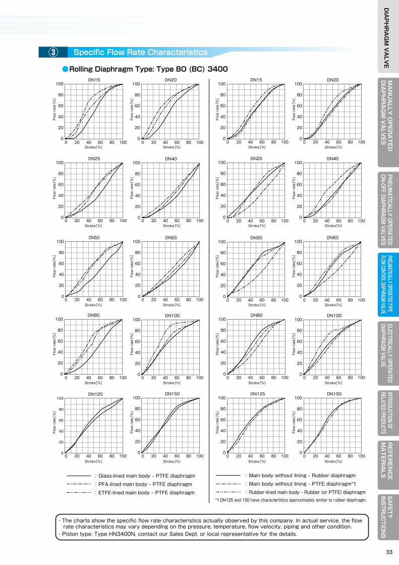
MA
NU
ALLY
OP
ER
AT
ED
DIA
PH
RA
GM
VA
LVE
SELECTRICALLY OPERATEDDIAPHRAGM VALVE
RE
FER
EN
CE
MA
TE
RIA
LSPNEUM
ATICALLY OPERATEDON-OFF DIAPHRAGM
VALVESPNEUMATICALLY OPERATED TYPE FLOW CONTROL DIAPHRAGM VALVE
INTRODUCTION OF RELATED PRODUCTS
SAFETY
IN
STRU
CTIO
NS
DIA
PH
RA
GM
VA
LVE
MA
NU
ALL
Y O
PE
RA
TE
DD
IAP
HR
AG
M V
ALV
ES
ELEC
TRIC
ALLY
OPE
RATE
DDI
APHR
AGM
VALV
ER
EFE
RE
NC
EM
AT
ER
IALS
PNEU
MAT
ICAL
LY O
PERA
TED
ON-O
FF D
IAPH
RAGM
VAL
VES
PNEU
MATIC
ALLY
OPER
ATED
TYPE
FL
OW CO
NTRO
L DIAP
HRAG
M VAL
VEIN
TROD
UCTIO
N OF
RE
LATE
D PR
ODUC
TSSA
FETY
IN
STR
UC
TIO
NS
DIA
PH
RA
GM
VA
LVE
●Rolling diaphragm type: Type BO(BC)3400
●Piston type: Type HN3400N
●Rolling Diaphragm Type: Type BO (BC) 3400
*The Cv values of Material code “59(2S)” with DN65 or bigger are same as “59(M)/59(S)”.*The above-mentioned Cv values need to be corrected when using the PTFE diaphragm and the pressure on the primary side is lower than 0.15 MPa. In such a case, please contact us.
・The charts show the specific flow rate characteristics actually observed by this company. In actual service, the flow rate characteristics may vary depending on the pressure, temperature, flow velocity, piping and other condition.・Piston type: Type HN3400N, contact our Sales Dept. or local representative for the details.
V : Flow rate of a fluid m3/hQ : Flow rate of a gas m3/h (at 15.6℃, 101.3 kPa・A)G :Specific gravity of fluid for liquid, water = 1 for gas, air: 1
P1: Absolute pressure on the primary side kPa・A*P2: Absolute pressure on the secondary side kPa・A* t: Temperature of the fluid ℃ W : Flow rate of vapor kg/h K : 1+(0.0013 x degree of superheat ℃)Degree of superheat: Difference between the saturation temperature to the absolute pressure on the primary side(P1) and the primary side temperature. In the case of saturation vapor, the degree of superheat reads 0 (zero).
Stroke(mm)
Main body without lining
Main bodywith rubber
lining
Main bodywith glass
lining
Main bodywith PFA
lining 55 520 435 570 325 75 1025 880 1120 800 95 1435 1295 1920 1160 110 2280 1840 2350 ―
150200250300
Without lining Rubber-lined Glass-lined
15202540506580
100125150
234678
106161303
15327178
166306
4.28.515305793
156194310440
4.21119408299
219291405585
4162
104210230330
5468
107161――
37
2.37.5
68
1014202430405060
PFA-lined PFA-linedETFE-lined59(2S)/6059(M)/59(S)
Ceramic Stroke
(mm)Diaphragm
Main body
Rubber PTFE Rubber PTFEPTFE PTFE
PTFE
5.91014285263
128―――
1025
410
355530
(*A:Absolute pressure = Gauge pressure + 101.3 kPa)
NominalSize DN
NominalSize DN
3. Reference Material3How to Select Valve Size①
Valve Stroke and Cv value②
駆動部の特長Specific Flow Rate Characteristics③Valve size is determined by calculating the valve coefficient of volume (Cv value) from the flow rate of a fluid, fluid pressure, differential pressure, specific gravity, etc. and comparing it with the Cv value in the table of the next section.Generally, the following Cv value calculation formulas are used except for the special correction items:
Liquid
Gas
Vapor
△ P
△P(P1+P2)
△P(P1+P2)
2
2.93
G
G(273+t)
Cv=11.56 V
Cv=
Cv= 0.1391
P1
(P1‒ P2)
< △ P2P1
≧
Q2.538P1
0.1205P1
G(273+t)Cv= Q
WKCv=
WK
Same as the left
:Main body without lining ‒ Rubber diaphragm
:Main body without lining ‒ PTFE diaphragm*1
:Rubber-lined main body ‒ Rubber (or PTFE) diaphragm
100
80
60
40
20
0
DN150
100
80
60
40
20
0
DN80100
80
60
40
20
0
DN100
100
80
60
40
20
0
DN125
100
80
60
40
20
0
DN40
100
80
60
40
20
0
DN15100
80
60
40
20
0
DN20
100
80
60
40
20
0
DN65100
80
60
40
20
0
DN50
100
80
60
40
20
0
DN25
:Glass-lined main body ‒ PTFE diaphragm
:PFA-lined main body ‒ PTFE diaphragm
:ETFE-lined main body ‒ PTFE diaphragm
100
80
60
40
20
0
DN150
100
80
60
40
20
0
DN80100
80
60
40
20
0
DN100
100
80
60
40
20
0
DN125
100
80
60
40
20
0
DN40
100
80
60
40
20
0
Flow
rat
e[%
]
Flow
rat
e[%
]
Flow
rat
e[%
]
Flow
rat
e[%
]
DN15100
80
60
40
20
0
Stroke[%] Stroke[%] Stroke[%] Stroke[%]
Stroke[%] Stroke[%] Stroke[%] Stroke[%]
Stroke[%] Stroke[%] Stroke[%] Stroke[%]
Stroke[%] Stroke[%] Stroke[%] Stroke[%]
Stroke[%] Stroke[%] Stroke[%] Stroke[%]
Flow
rat
e[%
]
Flow
rat
e[%
]
Flow
rat
e[%
]
Flow
rat
e[%
]
Flow
rat
e[%
]
Flow
rat
e[%
]
Flow
rat
e[%
]
Flow
rat
e[%
]
Flow
rat
e[%
]
Flow
rat
e[%
]
Flow
rat
e[%
]
Flow
rat
e[%
]
Flow
rat
e[%
]
Flow
rat
e[%
]
Flow
rat
e[%
]
Flow
rat
e[%
]
DN20
100
80
60
40
20
0
DN65100
80
60
40
20
00 20 40 60 80 100 0 20 40 60 80 100
0 20 40 60 80 100 0 20 40 60 80 100
0 20 40 60 80 100 0 20 40 60 80 100 0 20 40 60 80 100 0 20 40 60 80 100
0 20 40 60 80 100 0 20 40 60 80 100
0 20 40 60 80 100 0 20 40 60 80 100
0 20 40 60 80 100 0 20 40 60 80 100
0 20 40 60 80 100 0 20 40 60 80 100
0 20 40 60 80 100 0 20 40 60 80 100
0 20 40 60 80 100 0 20 40 60 80 100
DN50
100
80
60
40
20
0
DN25
*1.DN125 and 150 have characteristics approximately similar to rubber diaphragm.
33

4-1. Specifications of Electrically Operated Valve① MS type: Seibu Electric & Machinery Model
② NR type: Nihon KOSO Model
4-2. Weir Type Diaphragm Valve: Type MS(NR)4400① Actuator selection table
② Principal dimensions
4-3. Straight Type Diaphragm Valve: Type MS(NR)4500① Actuator selection table
② Principal dimensions
ELECTRICALLY OPERATEDDIAPHRAGM VALVE
4
MEMO
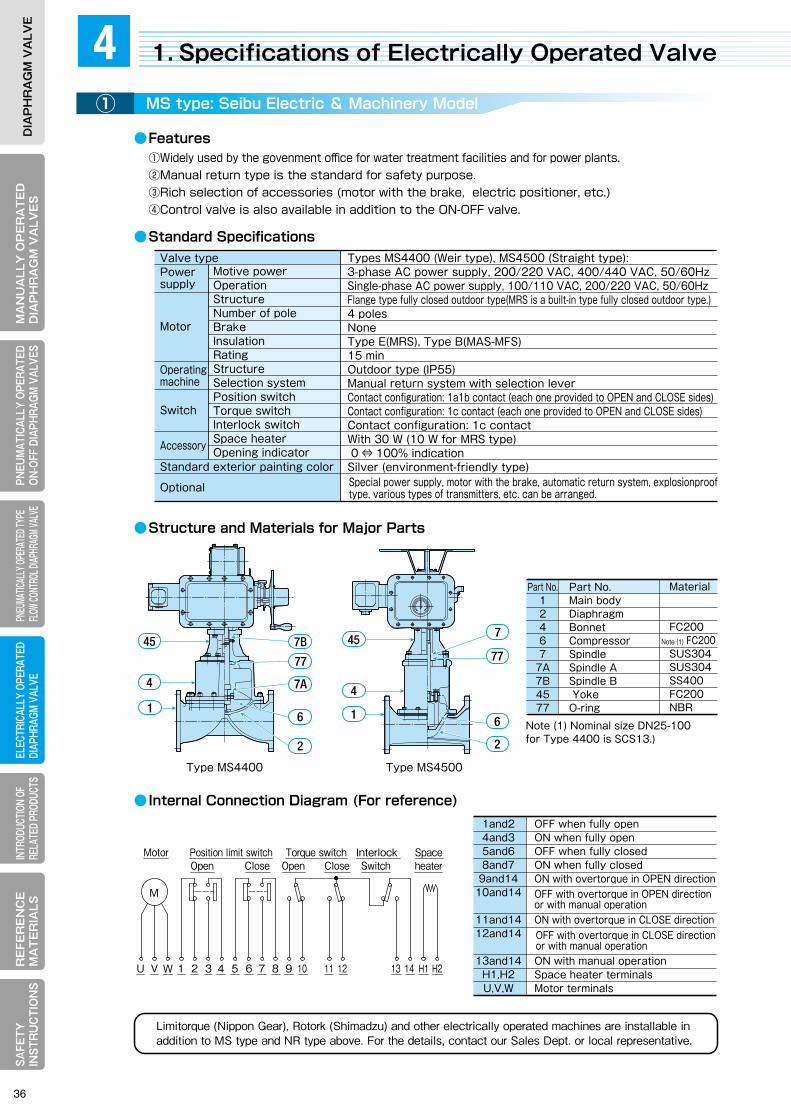
MA
NU
ALLY
OP
ER
AT
ED
DIA
PH
RA
GM
VA
LVE
SELECTRICALLY OPERATEDDIAPHRAGM VALVE
RE
FER
EN
CE
MA
TE
RIA
LSPNEUM
ATICALLY OPERATEDON-OFF DIAPHRAGM
VALVESPNEUMATICALLY OPERATED TYPE FLOW CONTROL DIAPHRAGM VALVE
INTRODUCTION OF RELATED PRODUCTS
SAFETY
IN
STRU
CTIO
NS
DIA
PH
RA
GM
VA
LVE
MA
NU
ALL
Y O
PE
RA
TE
DD
IAP
HR
AG
M V
ALV
ES
ELEC
TRIC
ALLY
OPE
RATE
DDI
APHR
AGM
VALV
ER
EFE
RE
NC
EM
AT
ER
IALS
PNEU
MAT
ICAL
LY O
PERA
TED
ON-O
FF D
IAPH
RAGM
VAL
VES
PNEU
MATIC
ALLY
OPER
ATED
TYPE
FL
OW CO
NTRO
L DIAP
HRAG
M VAL
VEIN
TROD
UCTIO
N OF
RE
LATE
D PR
ODUC
TSSA
FETY
IN
STR
UC
TIO
NS
DIA
PH
RA
GM
VA
LVE
●Features
●Standard Specifications●Standard Specifications
●Structure and Material for Major Parts
● Internal Connection Diagram
●Structure and Materials for Major Parts
● Internal Connection Diagram (For reference)
●Features
Type MS4500Type MS4400
Limitorque (Nippon Gear), Rotork (Shimadzu) and other electrically operated machines are installable in addition to MS type and NR type above. For the details, contact our Sales Dept. or local representative.
Valve typePower supply
Motor
Operating machine
Accessory
Optional
Types NR4400 (Weir type), NR4500 (Straight type) Single-phase AC power supply, 100/110 VAC, 200/220 VAC, 50/60HzStructure Reversible motor (with thermal protector)Number of pole 4 poles Brake With permanent brakeInsulation Type ERating 30 min Structure Outdoor type (IP55)Selection system Manual spindle pushing Position switch Contact configuration: 1b contact (each one provided to OPEN and CLOSE sides)Auxiliary switch Contact configuration: 1c contact (two provided)Torque switch None Interlock switch None Opening indicator O(OPEN) ⇔S (SHUT) indication Metallic blue Space heater, electric-electric positioner, separate terminal box
O
S
PUSH TO MANU
SO
PUSH TO MANU
SO
Power supply
Optional
Valve type
Motor
Motive powerOperationStructureNumber of poleBrakeInsulationRatingStructureSelection systemPosition switchTorque switchInterlock switchSpace heaterOpening indicator
Operating machine
Standard exterior painting color
Switch
Accessory
Standard exterior painting color
Switch
1. Specifications of Electrically Operated Valve4MS type: Seibu Electric & Machinery Model① 駆動部の特長NR type: Nihon KOSO Model②
①Widely used by the govenment office for water treatment facilities and for power plants.②Manual return type is the standard for safety purpose.③Rich selection of accessories (motor with the brake, electric positioner, etc.)④Control valve is also available in addition to the ON-OFF valve.
①Compact motor-operated machine for small bore valve.②Operable with a single-phase power supply③Economical as it consumes only little power compared with MS type.④Valve open-close operation with a single select switch.⑤Control valve is also available in addition to the ON-OFF valve.
Part No.12467
7A7B4577
Material
FC200 FC200SUS304SUS304SS400FC200NBR
Part No.Main bodyDiaphragmBonnetCompressorSpindleSpindle ASpindle B YokeO-ring
Note (1) Nominal size DN25-100for Type 4400 is SCS13.)
Note (1)
1and24and35and68and7
9and1410and14
11and1412and14
13and14H1,H2U,V,W
OFF when fully openON when fully openOFF when fully closedON when fully closedON with overtorque in OPEN direction
ON with overtorque in CLOSE direction
ON with manual operationSpace heater terminalsMotor terminals
Part No.12467
4595B
Material
FC200SCS13
SUS304FC200NBR
NameMain bodyDiaphragmBonnetCompressorSpindleYokeO-ring
Turn to CCW direction (OPEN direction)Turn to CW direction (CLOSE direction)ON at hinged end of CCW (fully open position)ON at hinged end of CW (fully closed position)Thermal protectorSpace heater (optional)Limit switch can be set for activation at an arbitrary position.
45
4
1
45
4
1
421
U-XV-X7-109-10TPSHLS3,LS4
7
77
6
22
7A
7B
77
6
45
6
795B
45
6
795B4
21
Special power supply, motor with the brake, automatic return system, explosionproof type, various types of transmitters, etc. can be arranged.
Types MS4400 (Weir type), MS4500 (Straight type): 3-phase AC power supply, 200/220 VAC, 400/440 VAC, 50/60HzSingle-phase AC power supply, 100/110 VAC, 200/220 VAC, 50/60HzFlange type fully closed outdoor type(MRS is a built-in type fully closed outdoor type.)4 polesNoneType E(MRS), Type B(MAS-MFS)15 minOutdoor type (IP55)Manual return system with selection leverContact configuration: 1a1b contact (each one provided to OPEN and CLOSE sides)Contact configuration: 1c contact (each one provided to OPEN and CLOSE sides)Contact configuration: 1c contactWith 30 W (10 W for MRS type) 0 ⇔ 100% indicationSilver (environment-friendly type)
OFF with overtorque in OPEN direction or with manual operation
OFF with overtorque in CLOSE direction or with manual operation
M
Motor Position limit switch Torque switch Spaceheater
Interlock SwitchOpen OpenClose Close
U V W 1 2 3 4 5 6 7 8 9 10 1112 13 14 H1H2
SH
E U V X 5 6 7 8 9 01 1 1 11 2 3
TPOpen Close
LS1
LS2
Ope
n
Clo
se LS3
LS4M
Power supply
Incorrect Correct
OPEN-OFF-CLOSE switch
NR type motor operating machine
NR type motor operating machine
Power supply
OPEN-OFF-CLOSE switch
If the 2 units of electric operating machines are simultaneously operated with the wiring as shown in thelower left-hand corner, a detour circuit is established through the capacitor leading to abnormal operation.Always arrange for the operating switches separately as shown to the right.
Turning direction is as viewed from the top of the operating machine. The diagram shows a hinged end at CW (fully closed position.)
36
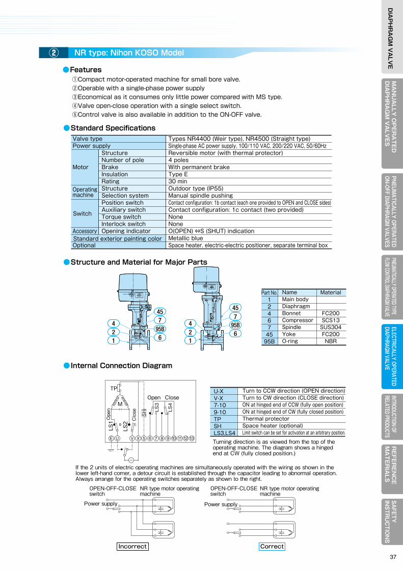
MA
NU
ALLY
OP
ER
AT
ED
DIA
PH
RA
GM
VA
LVE
SELECTRICALLY OPERATEDDIAPHRAGM VALVE
RE
FER
EN
CE
MA
TE
RIA
LSPNEUM
ATICALLY OPERATEDON-OFF DIAPHRAGM
VALVESPNEUMATICALLY OPERATED TYPE FLOW CONTROL DIAPHRAGM VALVE
INTRODUCTION OF RELATED PRODUCTS
SAFETY
IN
STRU
CTIO
NS
DIA
PH
RA
GM
VA
LVE
MA
NU
ALL
Y O
PE
RA
TE
DD
IAP
HR
AG
M V
ALV
ES
ELEC
TRIC
ALLY
OPE
RATE
DDI
APHR
AGM
VALV
ER
EFE
RE
NC
EM
AT
ER
IALS
PNEU
MAT
ICAL
LY O
PERA
TED
ON-O
FF D
IAPH
RAGM
VAL
VES
PNEU
MATIC
ALLY
OPER
ATED
TYPE
FL
OW CO
NTRO
L DIAP
HRAG
M VAL
VEIN
TROD
UCTIO
N OF
RE
LATE
D PR
ODUC
TSSA
FETY
IN
STR
UC
TIO
NS
DIA
PH
RA
GM
VA
LVE
●Features
●Standard Specifications●Standard Specifications
●Structure and Material for Major Parts
● Internal Connection Diagram
●Structure and Materials for Major Parts
● Internal Connection Diagram (For reference)
●Features
Type MS4500Type MS4400
Limitorque (Nippon Gear), Rotork (Shimadzu) and other electrically operated machines are installable in addition to MS type and NR type above. For the details, contact our Sales Dept. or local representative.
Valve typePower supply
Motor
Operating machine
Accessory
Optional
Types NR4400 (Weir type), NR4500 (Straight type) Single-phase AC power supply, 100/110 VAC, 200/220 VAC, 50/60HzStructure Reversible motor (with thermal protector)Number of pole 4 poles Brake With permanent brakeInsulation Type ERating 30 min Structure Outdoor type (IP55)Selection system Manual spindle pushing Position switch Contact configuration: 1b contact (each one provided to OPEN and CLOSE sides)Auxiliary switch Contact configuration: 1c contact (two provided)Torque switch None Interlock switch None Opening indicator O(OPEN) ⇔S (SHUT) indication Metallic blue Space heater, electric-electric positioner, separate terminal box
O
S
PUSH TO MANU
SO
PUSH TO MANU
SO
Power supply
Optional
Valve type
Motor
Motive powerOperationStructureNumber of poleBrakeInsulationRatingStructureSelection systemPosition switchTorque switchInterlock switchSpace heaterOpening indicator
Operating machine
Standard exterior painting color
Switch
Accessory
Standard exterior painting color
Switch
1. Specifications of Electrically Operated Valve4MS type: Seibu Electric & Machinery Model① 駆動部の特長NR type: Nihon KOSO Model②
①Widely used by the govenment office for water treatment facilities and for power plants.②Manual return type is the standard for safety purpose.③Rich selection of accessories (motor with the brake, electric positioner, etc.)④Control valve is also available in addition to the ON-OFF valve.
①Compact motor-operated machine for small bore valve.②Operable with a single-phase power supply③Economical as it consumes only little power compared with MS type.④Valve open-close operation with a single select switch.⑤Control valve is also available in addition to the ON-OFF valve.
Part No.12467
7A7B4577
Material
FC200 FC200SUS304SUS304SS400FC200NBR
Part No.Main bodyDiaphragmBonnetCompressorSpindleSpindle ASpindle B YokeO-ring
Note (1) Nominal size DN25-100for Type 4400 is SCS13.)
Note (1)
1and24and35and68and7
9and1410and14
11and1412and14
13and14H1,H2U,V,W
OFF when fully openON when fully openOFF when fully closedON when fully closedON with overtorque in OPEN direction
ON with overtorque in CLOSE direction
ON with manual operationSpace heater terminalsMotor terminals
Part No.12467
4595B
Material
FC200SCS13
SUS304FC200NBR
NameMain bodyDiaphragmBonnetCompressorSpindleYokeO-ring
Turn to CCW direction (OPEN direction)Turn to CW direction (CLOSE direction)ON at hinged end of CCW (fully open position)ON at hinged end of CW (fully closed position)Thermal protectorSpace heater (optional)Limit switch can be set for activation at an arbitrary position.
45
4
1
45
4
1
421
U-XV-X7-109-10TPSHLS3,LS4
7
77
6
22
7A
7B
77
6
45
6
795B
45
6
795B4
21
Special power supply, motor with the brake, automatic return system, explosionproof type, various types of transmitters, etc. can be arranged.
Types MS4400 (Weir type), MS4500 (Straight type): 3-phase AC power supply, 200/220 VAC, 400/440 VAC, 50/60HzSingle-phase AC power supply, 100/110 VAC, 200/220 VAC, 50/60HzFlange type fully closed outdoor type(MRS is a built-in type fully closed outdoor type.)4 polesNoneType E(MRS), Type B(MAS-MFS)15 minOutdoor type (IP55)Manual return system with selection leverContact configuration: 1a1b contact (each one provided to OPEN and CLOSE sides)Contact configuration: 1c contact (each one provided to OPEN and CLOSE sides)Contact configuration: 1c contactWith 30 W (10 W for MRS type) 0 ⇔ 100% indicationSilver (environment-friendly type)
OFF with overtorque in OPEN direction or with manual operation
OFF with overtorque in CLOSE direction or with manual operation
M
Motor Position limit switch Torque switch Spaceheater
Interlock SwitchOpen OpenClose Close
U V W 1 2 3 4 5 6 7 8 9 10 1112 13 14 H1H2
SH
E U V X 5 6 7 8 9 01 1 1 11 2 3
TPOpen Close
LS1
LS2
Ope
n
Clo
se LS3
LS4M
Power supply
Incorrect Correct
OPEN-OFF-CLOSE switch
NR type motor operating machine
NR type motor operating machine
Power supply
OPEN-OFF-CLOSE switch
If the 2 units of electric operating machines are simultaneously operated with the wiring as shown in thelower left-hand corner, a detour circuit is established through the capacitor leading to abnormal operation.Always arrange for the operating switches separately as shown to the right.
Turning direction is as viewed from the top of the operating machine. The diagram shows a hinged end at CW (fully closed position.)
37
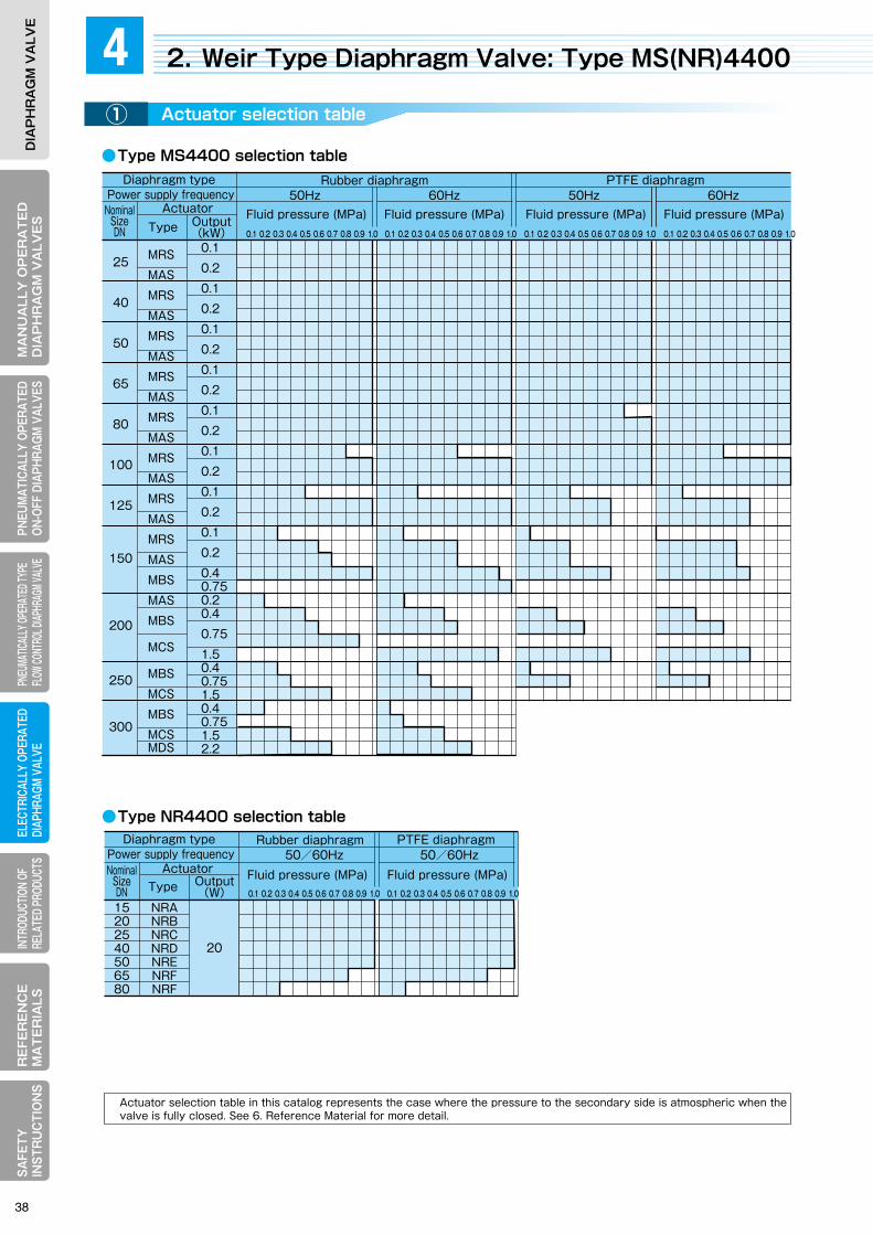
MA
NU
ALLY
OP
ER
AT
ED
DIA
PH
RA
GM
VA
LVE
SELECTRICALLY OPERATEDDIAPHRAGM VALVE
RE
FER
EN
CE
MA
TE
RIA
LSPNEUM
ATICALLY OPERATEDON-OFF DIAPHRAGM
VALVESPNEUMATICALLY OPERATED TYPE FLOW CONTROL DIAPHRAGM VALVE
INTRODUCTION OF RELATED PRODUCTS
SAFETY
IN
STRU
CTIO
NS
DIA
PH
RA
GM
VA
LVE
MA
NU
ALL
Y O
PE
RA
TE
DD
IAP
HR
AG
M V
ALV
ES
ELEC
TRIC
ALLY
OPE
RATE
DDI
APHR
AGM
VALV
ER
EFE
RE
NC
EM
AT
ER
IALS
PNEU
MAT
ICAL
LY O
PERA
TED
ON-O
FF D
IAPH
RAGM
VAL
VES
PNEU
MATIC
ALLY
OPER
ATED
TYPE
FL
OW CO
NTRO
L DIAP
HRAG
M VAL
VEIN
TROD
UCTIO
N OF
RE
LATE
D PR
ODUC
TSSA
FETY
IN
STR
UC
TIO
NS
DIA
PH
RA
GM
VA
LVE
●Type MS4400 selection table
●Type NR4400 selection table
●Type NR4400 principal dimensions
Principal dimensions (mm)
Principal dimensions (mm)
Stroke (mm) Operating time (sec)50Hz 60HzFace-to-face
AApprox.
H
Approx. H
Other than rubber-lined
ON-OFFvalve
ON-OFFvalve
ON-OFFvalve
ON-OFFvalve
ON-OFFvalve
Control valve
Control valve
ON-OFFvalve
Control valveRubber
lined
Face-to-faceOther than rubber-lined
Rubber lined
Mass approx.
(kg)
Mass approx.
(kg)
25
40
50
65
80
100
125
150
200
250
300
MRS
MAS
MRS
MAS
MRS
MAS
MRS
MAS
MRS
MAS
MRS
MAS
MRS
MAS
MRS
MAS
MBS
MAS
MBS
MCS
MBS
MCS
MBS
MCSMDS
0.1
0.2
0.1
0.2
0.1
0.2
0.1
0.2
0.1
0.2
0.1
0.2
0.1
0.2
0.1
0.2
0.40.750.20.4
0.75
1.50.4
0.751.50.4
0.751.52.2
127
159
191
216
254
305
356
406
521
635
749
430
587
430
587
430
587
430
587
430
587
430
587
430
587
430
587600625587600625800837600625837600625837950
10
18
25
30
35
50
65
70
110
130
160
132
165
197
222
260
313
364
414
529
645
759
390
475
400
485
435
520
455
540
465
550
500
605
540
645
595
700
740
870
905
955
985
1030
1140
11801250
12
22
21
21
20
25
24
24
23
34
32
44
42
47
4538-71595362-70634786-5765
-
14
20
24
30
40
50
60
85
95
115
9
17
16
18
17
21
20
20
19
28
27
36
35
39
383228595044-3359523972654755
-
-
26
-
28
-
34
-
34
-
45
-
57
-
6857-96815560-906145
110-5579
52
69
55
72
58
75
64
81
69
86
82
99
95
112
123
140170180210240250290295325335380440450495575
-
-
22
-
24
-
28
-
28
-
38
-
47
-
574832806746-3475513891624666
Stroke (mm)
Operating time (sec)50Hz 60Hz
15202540506580
NRANRBNRCNRDNRENRFNRF
20
102118127159191216254
68
1014202430
107123132165197222260
436440444457508531542
11151217394747
9121015323939
16161719232834
MRS
MAS
MRS
MAS
MRS
MAS
MRS
MAS
MRS
MAS
MRS
MAS
MRS
MAS
MRS
MAS
MBS
MAS
MBS
0.1
0.2
0.1
0.2
0.1
0.2
0.1
0.2
0.1
0.2
0.1
0.2
0.1
0.2
0.1
0.2
0.40.750.20.4
0.75
1.50.40.751.50.40.751.52.2
25
40
50
65
80
100
125
150
200
250
300
Diaphragm typePower supply frequency
Actuator
Actuator
Actuator
NominalSizeDN
NominalSizeDN
NominalSizeDN
Type
Type
Type
Output(kW)
Output(kW)
Output(W)
Rubber diaphragm PTFE diaphragm50Hz 60Hz
Fluid pressure (MPa) Fluid pressure (MPa)50Hz 60Hz
Fluid pressure (MPa) Fluid pressure (MPa)
MCS
MBS
MCS
MBS
MCSMDS
15202540506580
NRANRBNRCNRDNRENRFNRF
0.1 0.2 0.3 0.4 0.5 0.6 0.7 0.8 0.9 1.0 0.1 0.2 0.3 0.4 0.5 0.6 0.7 0.8 0.9 1.0
0.1 0.2 0.3 0.4 0.5 0.6 0.7 0.8 0.9 1.0 0.1 0.2 0.3 0.4 0.5 0.6 0.7 0.8 0.9 1.0 0.1 0.2 0.3 0.4 0.5 0.6 0.7 0.8 0.9 1.0 0.1 0.2 0.3 0.4 0.5 0.6 0.7 0.8 0.9 1.0
20Remarks: Dimension A and mass are for a motor without the brake.
O
S
App
rox.
H
A
2. Weir Type Diaphragm Valve: Type MS(NR)44004Actuator selection table① 駆動部の特長Principal dimensions②
●Type MS4400 principal dimensionsA
Type MRS Type MAS/MBS Type MCS/MFS
App
rox.
H
App
rox.
H
App
rox.
H
A
Actuator selection table in this catalog represents the case where the pressure to the secondary side is atmospheric when the valve is fully closed. See 6. Reference Material for more detail.
Diaphragm typePower supply frequency
ActuatorNominalSizeDN Type Output
(W)
Rubber diaphragm PTFE diaphragm
Fluid pressure (MPa) Fluid pressure (MPa)
50/60Hz 50/60Hz
38

MA
NU
ALLY
OP
ER
AT
ED
DIA
PH
RA
GM
VA
LVE
SELECTRICALLY OPERATEDDIAPHRAGM VALVE
RE
FER
EN
CE
MA
TE
RIA
LSPNEUM
ATICALLY OPERATEDON-OFF DIAPHRAGM
VALVESPNEUMATICALLY OPERATED TYPE FLOW CONTROL DIAPHRAGM VALVE
INTRODUCTION OF RELATED PRODUCTS
SAFETY
IN
STRU
CTIO
NS
DIA
PH
RA
GM
VA
LVE
MA
NU
ALL
Y O
PE
RA
TE
DD
IAP
HR
AG
M V
ALV
ES
ELEC
TRIC
ALLY
OPE
RATE
DDI
APHR
AGM
VALV
ER
EFE
RE
NC
EM
AT
ER
IALS
PNEU
MAT
ICAL
LY O
PERA
TED
ON-O
FF D
IAPH
RAGM
VAL
VES
PNEU
MATIC
ALLY
OPER
ATED
TYPE
FL
OW CO
NTRO
L DIAP
HRAG
M VAL
VEIN
TROD
UCTIO
N OF
RE
LATE
D PR
ODUC
TSSA
FETY
IN
STR
UC
TIO
NS
DIA
PH
RA
GM
VA
LVE
●Type MS4400 selection table
●Type NR4400 selection table
●Type NR4400 principal dimensions
Principal dimensions (mm)
Principal dimensions (mm)
Stroke (mm) Operating time (sec)50Hz 60HzFace-to-face
AApprox.
H
Approx. H
Other than rubber-lined
ON-OFFvalve
ON-OFFvalve
ON-OFFvalve
ON-OFFvalve
ON-OFFvalve
Control valve
Control valve
ON-OFFvalve
Control valveRubber
lined
Face-to-faceOther than rubber-lined
Rubber lined
Mass approx.
(kg)
Mass approx.
(kg)
25
40
50
65
80
100
125
150
200
250
300
MRS
MAS
MRS
MAS
MRS
MAS
MRS
MAS
MRS
MAS
MRS
MAS
MRS
MAS
MRS
MAS
MBS
MAS
MBS
MCS
MBS
MCS
MBS
MCSMDS
0.1
0.2
0.1
0.2
0.1
0.2
0.1
0.2
0.1
0.2
0.1
0.2
0.1
0.2
0.1
0.2
0.40.750.20.4
0.75
1.50.4
0.751.50.4
0.751.52.2
127
159
191
216
254
305
356
406
521
635
749
430
587
430
587
430
587
430
587
430
587
430
587
430
587
430
587600625587600625800837600625837600625837950
10
18
25
30
35
50
65
70
110
130
160
132
165
197
222
260
313
364
414
529
645
759
390
475
400
485
435
520
455
540
465
550
500
605
540
645
595
700
740
870
905
955
985
1030
1140
11801250
12
22
21
21
20
25
24
24
23
34
32
44
42
47
4538-71595362-70634786-5765
-
14
20
24
30
40
50
60
85
95
115
9
17
16
18
17
21
20
20
19
28
27
36
35
39
383228595044-3359523972654755
-
-
26
-
28
-
34
-
34
-
45
-
57
-
6857-96815560-906145
110-5579
52
69
55
72
58
75
64
81
69
86
82
99
95
112
123
140170180210240250290295325335380440450495575
-
-
22
-
24
-
28
-
28
-
38
-
47
-
574832806746-3475513891624666
Stroke (mm)
Operating time (sec)50Hz 60Hz
15202540506580
NRANRBNRCNRDNRENRFNRF
20
102118127159191216254
68
1014202430
107123132165197222260
436440444457508531542
11151217394747
9121015323939
16161719232834
MRS
MAS
MRS
MAS
MRS
MAS
MRS
MAS
MRS
MAS
MRS
MAS
MRS
MAS
MRS
MAS
MBS
MAS
MBS
0.1
0.2
0.1
0.2
0.1
0.2
0.1
0.2
0.1
0.2
0.1
0.2
0.1
0.2
0.1
0.2
0.40.750.20.4
0.75
1.50.40.751.50.40.751.52.2
25
40
50
65
80
100
125
150
200
250
300
Diaphragm typePower supply frequency
Actuator
Actuator
Actuator
NominalSizeDN
NominalSizeDN
NominalSizeDN
Type
Type
Type
Output(kW)
Output(kW)
Output(W)
Rubber diaphragm PTFE diaphragm50Hz 60Hz
Fluid pressure (MPa) Fluid pressure (MPa)50Hz 60Hz
Fluid pressure (MPa) Fluid pressure (MPa)
MCS
MBS
MCS
MBS
MCSMDS
15202540506580
NRANRBNRCNRDNRENRFNRF
0.1 0.2 0.3 0.4 0.5 0.6 0.7 0.8 0.9 1.0 0.1 0.2 0.3 0.4 0.5 0.6 0.7 0.8 0.9 1.0
0.1 0.2 0.3 0.4 0.5 0.6 0.7 0.8 0.9 1.0 0.1 0.2 0.3 0.4 0.5 0.6 0.7 0.8 0.9 1.0 0.1 0.2 0.3 0.4 0.5 0.6 0.7 0.8 0.9 1.0 0.1 0.2 0.3 0.4 0.5 0.6 0.7 0.8 0.9 1.0
20Remarks: Dimension A and mass are for a motor without the brake.
O
S
App
rox.
H
A
2. Weir Type Diaphragm Valve: Type MS(NR)44004Actuator selection table① 駆動部の特長Principal dimensions②
●Type MS4400 principal dimensionsA
Type MRS Type MAS/MBS Type MCS/MFS
App
rox.
H
App
rox.
H
App
rox.
H
A
Actuator selection table in this catalog represents the case where the pressure to the secondary side is atmospheric when the valve is fully closed. See 6. Reference Material for more detail.
Diaphragm typePower supply frequency
ActuatorNominalSizeDN Type Output
(W)
Rubber diaphragm PTFE diaphragm
Fluid pressure (MPa) Fluid pressure (MPa)
50/60Hz 50/60Hz
39
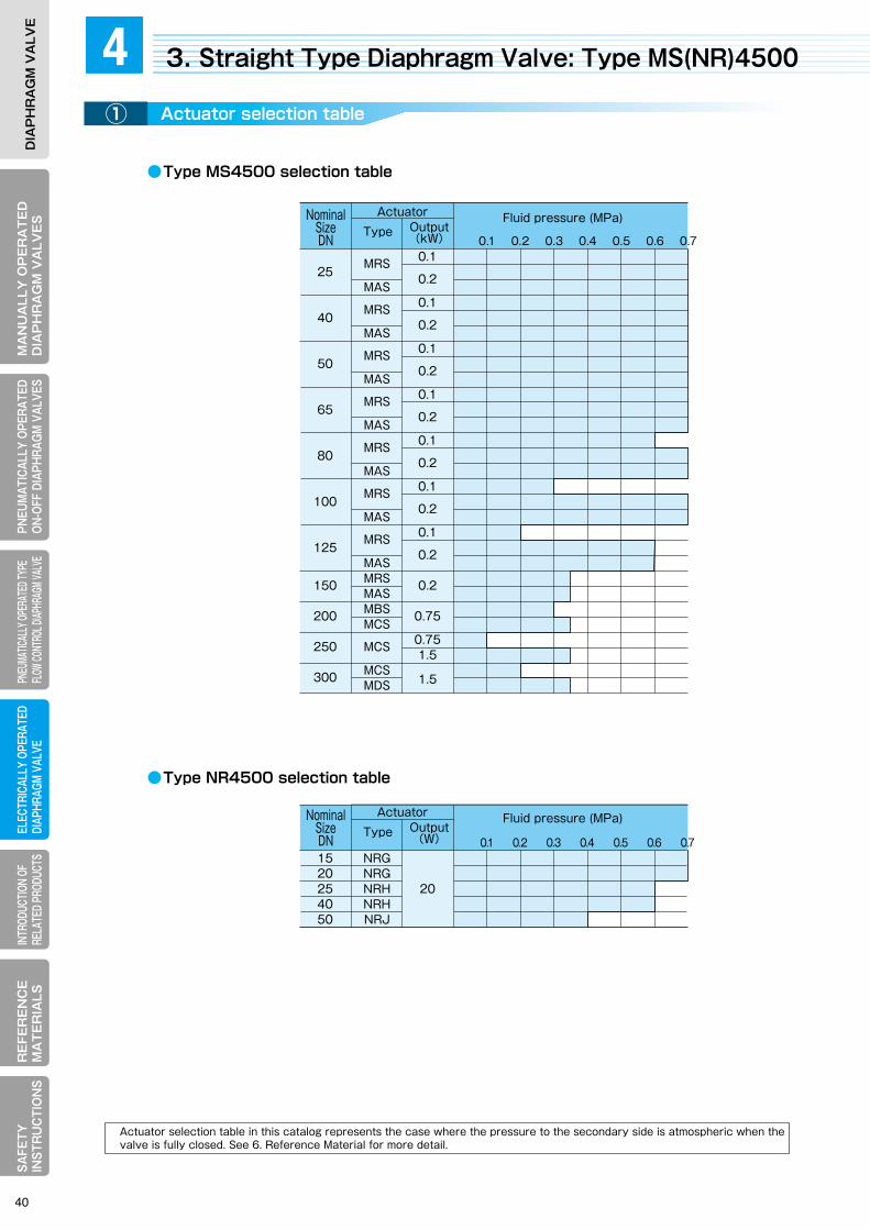
MA
NU
ALLY
OP
ER
AT
ED
DIA
PH
RA
GM
VA
LVE
SELECTRICALLY OPERATEDDIAPHRAGM VALVE
RE
FER
EN
CE
MA
TE
RIA
LSPNEUM
ATICALLY OPERATEDON-OFF DIAPHRAGM
VALVESPNEUMATICALLY OPERATED TYPE FLOW CONTROL DIAPHRAGM VALVE
INTRODUCTION OF RELATED PRODUCTS
SAFETY
IN
STRU
CTIO
NS
DIA
PH
RA
GM
VA
LVE
MA
NU
ALL
Y O
PE
RA
TE
DD
IAP
HR
AG
M V
ALV
ES
ELEC
TRIC
ALLY
OPE
RATE
DDI
APHR
AGM
VALV
ER
EFE
RE
NC
EM
AT
ER
IALS
PNEU
MAT
ICAL
LY O
PERA
TED
ON-O
FF D
IAPH
RAGM
VAL
VES
PNEU
MATIC
ALLY
OPER
ATED
TYPE
FL
OW CO
NTRO
L DIAP
HRAG
M VAL
VEIN
TROD
UCTIO
N OF
RE
LATE
D PR
ODUC
TSSA
FETY
IN
STR
UC
TIO
NS
DIA
PH
RA
GM
VA
LVE
●Type MS4500 selection table
●Type NR4500 selection table
●Type NR4500 principal dimensions
25
40
50
65
80
100
125
150
200
250
300
MRS
MAS
MRS
MAS
MRS
MAS
MRS
MAS
MRS
MAS
MRS
MAS
MRS
MASMRSMASMBSMCS
MCS
MCSMDS
0.1
0.2
0.1
0.2
0.1
0.2
0.1
0.2
0.1
0.2
0.1
0.2
0.1
0.2
0.2
0.75
0.751.5
1.5
0.1 0.2 0.3 0.4 0.5 0.6 0.7
1520254050
NRGNRGNRHNRHNRJ
20
0.1 0.2 0.3 0.4 0.5 0.6 0.7
50Hz 60HzA
25
40
50
65
80
100
125
150
200
250
300
MRS
MAS
MRS
MAS
MRS
MAS
MRS
MAS
MRS
MAS
MRS
MAS
MRS
MASMRSMASMBSMCS
MCS
MCSMDS
0.1
0.2
0.1
0.2
0.1
0.2
0.1
0.2
0.1
0.2
0.1
0.2
0.1
0.2
0.2
0.75
0.751.5
1.5
127
159
191
216
254
305
356
406
521
635
749
430
587
430
587
430
587
430
587
430
587
430
587
430
587430587625800800837837934
25
25
30
35
50
50
70
110
110
160
190
132
165
197
222
260
313
364
414
529
645
759
440
545
440
545
450
555
475
580
520
625
545
670
640
765730855860960
1160
11951260
23
22
23
22
21
20
25
24
28
27
28
274139386259446975485765
28
27
28
27
25
24
29
28
34
32
34
32
47
457471538390576878
53
70
55
72
59
76
64
81
73
90
83
100
98
115118135225270325330535575
50Hz 60Hz
1520254050
NRGNRGNRHNRHNRJ
20
102118127159191
1010252530
107123132165197
446446533533544
1919313158
1616252548
1616202227
Remarks: Dimension A and mass are for a motor without the brake.
ActuatorNominalSizeDN
Type Output(kW)
ActuatorNominal
SizeDN
Type Output(kW)
Fluid pressure (MPa)
ActuatorNominalSizeDN
Type Output(W)
Fluid pressure (MPa)
Principal dimensions (mm)
Approx. H ON-OFF
valveON-OFFvalve
ON-OFFvalve
Face-to-faceOther than rubber-lined
Rubber -lined
Mass approx.
(kg)
Stroke (mm)
Operating time (sec)
ActuatorNominal
SizeDN
Type Output(W)
Principal dimensions (mm)
Approx. H ON-OFF
valveON-OFFvalve
ON-OFFvalve
Face-to-faceOther than rubber-lined
Rubber -lined
Mass approx.
(kg)
Stroke (mm)
Operating time (sec)
3. Straight Type Diaphragm Valve: Type MS(NR)45004Actuator selection table① 駆動部の特長Principal dimensions②
A
Type MRS
A
Type MAS/MBS
A
Type MCS/MFS
App
rox.
H
App
rox.
H
App
rox.
H
App
rox.
H
●Type MS4500 principal dimensions
Actuator selection table in this catalog represents the case where the pressure to the secondary side is atmospheric when the valve is fully closed. See 6. Reference Material for more detail.
40
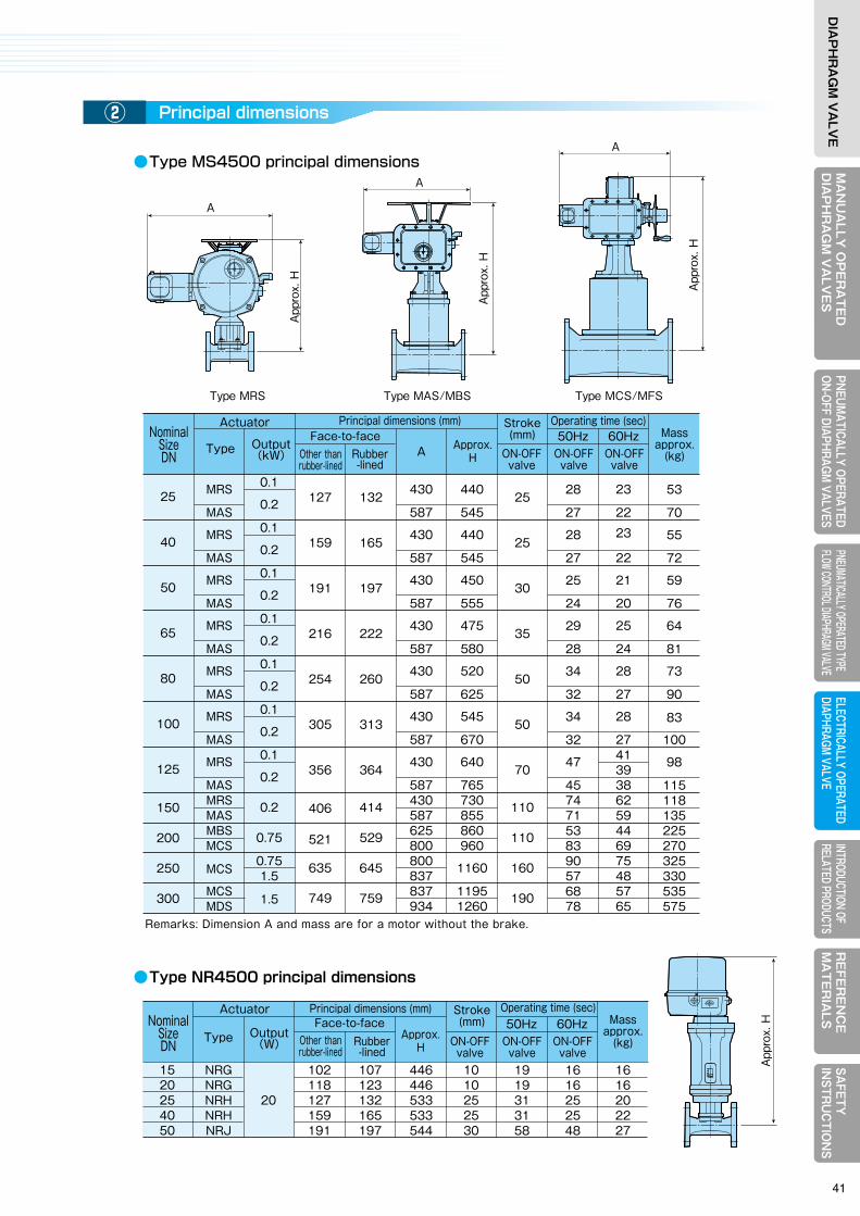
MA
NU
ALLY
OP
ER
AT
ED
DIA
PH
RA
GM
VA
LVE
SELECTRICALLY OPERATEDDIAPHRAGM VALVE
RE
FER
EN
CE
MA
TE
RIA
LSPNEUM
ATICALLY OPERATEDON-OFF DIAPHRAGM
VALVESPNEUMATICALLY OPERATED TYPE FLOW CONTROL DIAPHRAGM VALVE
INTRODUCTION OF RELATED PRODUCTS
SAFETY
IN
STRU
CTIO
NS
DIA
PH
RA
GM
VA
LVE
MA
NU
ALL
Y O
PE
RA
TE
DD
IAP
HR
AG
M V
ALV
ES
ELEC
TRIC
ALLY
OPE
RATE
DDI
APHR
AGM
VALV
ER
EFE
RE
NC
EM
AT
ER
IALS
PNEU
MAT
ICAL
LY O
PERA
TED
ON-O
FF D
IAPH
RAGM
VAL
VES
PNEU
MATIC
ALLY
OPER
ATED
TYPE
FL
OW CO
NTRO
L DIAP
HRAG
M VAL
VEIN
TROD
UCTIO
N OF
RE
LATE
D PR
ODUC
TSSA
FETY
IN
STR
UC
TIO
NS
DIA
PH
RA
GM
VA
LVE
●Type MS4500 selection table
●Type NR4500 selection table
●Type NR4500 principal dimensions
25
40
50
65
80
100
125
150
200
250
300
MRS
MAS
MRS
MAS
MRS
MAS
MRS
MAS
MRS
MAS
MRS
MAS
MRS
MASMRSMASMBSMCS
MCS
MCSMDS
0.1
0.2
0.1
0.2
0.1
0.2
0.1
0.2
0.1
0.2
0.1
0.2
0.1
0.2
0.2
0.75
0.751.5
1.5
0.1 0.2 0.3 0.4 0.5 0.6 0.7
1520254050
NRGNRGNRHNRHNRJ
20
0.1 0.2 0.3 0.4 0.5 0.6 0.7
50Hz 60HzA
25
40
50
65
80
100
125
150
200
250
300
MRS
MAS
MRS
MAS
MRS
MAS
MRS
MAS
MRS
MAS
MRS
MAS
MRS
MASMRSMASMBSMCS
MCS
MCSMDS
0.1
0.2
0.1
0.2
0.1
0.2
0.1
0.2
0.1
0.2
0.1
0.2
0.1
0.2
0.2
0.75
0.751.5
1.5
127
159
191
216
254
305
356
406
521
635
749
430
587
430
587
430
587
430
587
430
587
430
587
430
587430587625800800837837934
25
25
30
35
50
50
70
110
110
160
190
132
165
197
222
260
313
364
414
529
645
759
440
545
440
545
450
555
475
580
520
625
545
670
640
765730855860960
1160
11951260
23
22
23
22
21
20
25
24
28
27
28
274139386259446975485765
28
27
28
27
25
24
29
28
34
32
34
32
47
457471538390576878
53
70
55
72
59
76
64
81
73
90
83
100
98
115118135225270325330535575
50Hz 60Hz
1520254050
NRGNRGNRHNRHNRJ
20
102118127159191
1010252530
107123132165197
446446533533544
1919313158
1616252548
1616202227
Remarks: Dimension A and mass are for a motor without the brake.
ActuatorNominalSizeDN
Type Output(kW)
ActuatorNominal
SizeDN
Type Output(kW)
Fluid pressure (MPa)
ActuatorNominalSizeDN
Type Output(W)
Fluid pressure (MPa)
Principal dimensions (mm)
Approx. H ON-OFF
valveON-OFFvalve
ON-OFFvalve
Face-to-faceOther than rubber-lined
Rubber -lined
Mass approx.
(kg)
Stroke (mm)
Operating time (sec)
ActuatorNominal
SizeDN
Type Output(W)
Principal dimensions (mm)
Approx. H ON-OFF
valveON-OFFvalve
ON-OFFvalve
Face-to-faceOther than rubber-lined
Rubber -lined
Mass approx.
(kg)
Stroke (mm)
Operating time (sec)
3. Straight Type Diaphragm Valve: Type MS(NR)45004Actuator selection table① 駆動部の特長Principal dimensions②
A
Type MRS
A
Type MAS/MBS
A
Type MCS/MFS
App
rox.
H
App
rox.
H
App
rox.
H
App
rox.
H
●Type MS4500 principal dimensions
Actuator selection table in this catalog represents the case where the pressure to the secondary side is atmospheric when the valve is fully closed. See 6. Reference Material for more detail.
41

INTRODUCTION OF RELATED PRODUCTS
5
MEMO
INTRODUCTION OF RELATED PRODUCTS
5
MEMO
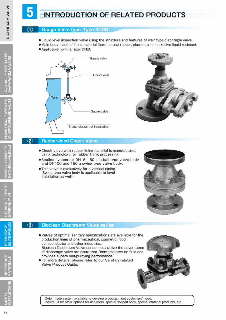
MA
NU
ALLY
OP
ER
AT
ED
DIA
PH
RA
GM
VA
LVE
SELECTRICALLY OPERATEDDIAPHRAGM VALVE
RE
FER
EN
CE
MA
TE
RIA
LSPNEUM
ATICALLY OPERATEDON-OFF DIAPHRAGM
VALVESPNEUMATICALLY OPERATED TYPE FLOW CONTROL DIAPHRAGM VALVE
INTRODUCTION OF RELATED PRODUCTS
SAFETY
IN
STRU
CTIO
NS
DIA
PH
RA
GM
VA
LVE
MA
NU
ALL
Y O
PE
RA
TE
DD
IAP
HR
AG
M V
ALV
ES
ELEC
TRIC
ALLY
OPE
RATE
DDI
APHR
AGM
VALV
ER
EFE
RE
NC
EM
AT
ER
IALS
PNEU
MAT
ICAL
LY O
PERA
TED
ON-O
FF D
IAPH
RAGM
VAL
VES
PNEU
MATIC
ALLY
OPER
ATED
TYPE
FL
OW CO
NTRO
L DIAP
HRAG
M VAL
VEIN
TROD
UCTIO
N OF
RE
LATE
D PR
ODUC
TSSA
FETY
IN
STR
UC
TIO
NS
DIA
PH
RA
GM
VA
LVE
●Liquid level inspection valve using the structure and features of weir type diaphragm valve.●Main body made of lining material (hard natural rubber, glass, etc.) is corrosive liquid resistant.●Applicable nominal size: DN20
●Check valve with rubber lining material is manufactured using technology for rubber lining processing.●Sealing system for DN15 ‒ 80 is a ball type valve body and DN100 and 150 a swing type valve body.●This valve is exclusively for a vertical piping. (Swing type valve body is applicable to level installation as well.)
INTRODUCTION OF RELATED PRODUCTS5Gauge Valve type: Type 400G
Rubber-lined Check Valve
Bioclean Diaphragm Valve series
●Valves of optimal sanitary specifications are available for the production lines of pharmaceutical, cosmetic, food, semiconductor and other industries. Bioclean Diaphragm Valve series most utilize the advantages of diaphragm valve structure that “contaminates no fluid and provides superb self-purifying performance.”●For more details, please refer to our Sanitary-related Valve Product Guide.
Order made system available to develop products meet customers' need;Inquire us for other options for actuators, special shaped body, special material products, etc.
REFERENCE MATERIALS
6
① Flange dimensions:Basic dimensions and standard face-to-face dimensions for JIS 10K flange
② Special specifications: Nameplate, Painting, Photography and Witness inspection
③ How to read the product code number
④ Material selection table
⑤ Actuator selection table
①
②
③
Liquid level
Gauge valve
Tank
Gauge valve
Image diagram of installation
44
MA
NU
ALLY
OP
ER
AT
ED
DIA
PH
RA
GM
VA
LVE
SELECTRICALLY OPERATEDDIAPHRAGM VALVE
RE
FER
EN
CE
MA
TE
RIA
LSPNEUM
ATICALLY OPERATEDON-OFF DIAPHRAGM
VALVESPNEUMATICALLY OPERATED TYPE FLOW CONTROL DIAPHRAGM VALVE
INTRODUCTION OF RELATED PRODUCTS
SAFETY
IN
STRU
CTIO
NS
DIA
PH
RA
GM
VA
LVE
MA
NU
ALL
Y O
PE
RA
TE
DD
IAP
HR
AG
M V
ALV
ES
ELEC
TRIC
ALLY
OPE
RATE
DDI
APHR
AGM
VALV
ER
EFE
RE
NC
EM
AT
ER
IALS
PNEU
MAT
ICAL
LY O
PERA
TED
ON-O
FF D
IAPH
RAGM
VAL
VES
PNEU
MATIC
ALLY
OPER
ATED
TYPE
FL
OW CO
NTRO
L DIAP
HRAG
M VAL
VEIN
TROD
UCTIO
N OF
RE
LATE
D PR
ODUC
TSSA
FETY
IN
STR
UC
TIO
NS
DIA
PH
RA
GM
VA
LVE
●Liquid level inspection valve using the structure and features of weir type diaphragm valve.●Main body made of lining material (hard natural rubber, glass, etc.) is corrosive liquid resistant.●Applicable nominal size: DN20
●Check valve with rubber lining material is manufactured using technology for rubber lining processing.●Sealing system for DN15 ‒ 80 is a ball type valve body and DN100 and 150 a swing type valve body.●This valve is exclusively for a vertical piping. (Swing type valve body is applicable to level installation as well.)
INTRODUCTION OF RELATED PRODUCTS5Gauge Valve type: Type 400G
Rubber-lined Check Valve
Bioclean Diaphragm Valve series
●Valves of optimal sanitary specifications are available for the production lines of pharmaceutical, cosmetic, food, semiconductor and other industries. Bioclean Diaphragm Valve series most utilize the advantages of diaphragm valve structure that “contaminates no fluid and provides superb self-purifying performance.”●For more details, please refer to our Sanitary-related Valve Product Guide.
Order made system available to develop products meet customers' need;Inquire us for other options for actuators, special shaped body, special material products, etc.
REFERENCE MATERIALS
6
① Flange dimensions:Basic dimensions and standard face-to-face dimensions for JIS 10K flange
② Special specifications: Nameplate, Painting, Photography and Witness inspection
③ How to read the product code number
④ Material selection table
⑤ Actuator selection table
①
②
③
Liquid level
Gauge valve
Tank
Gauge valve
Image diagram of installation
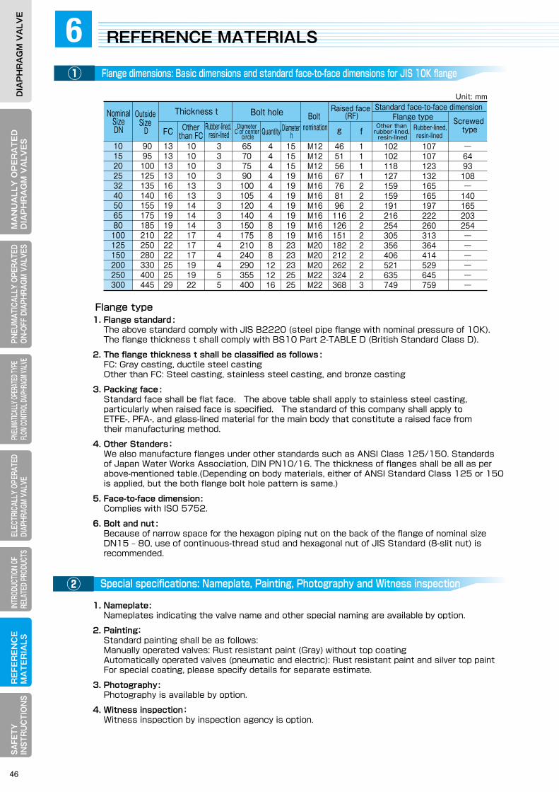
MA
NU
ALLY
OP
ER
AT
ED
DIA
PH
RA
GM
VA
LVE
SELECTRICALLY OPERATEDDIAPHRAGM VALVE
RE
FER
EN
CE
MA
TE
RIA
LSPNEUM
ATICALLY OPERATEDON-OFF DIAPHRAGM
VALVESPNEUMATICALLY OPERATED TYPE FLOW CONTROL DIAPHRAGM VALVE
INTRODUCTION OF RELATED PRODUCTS
SAFETY
IN
STRU
CTIO
NS
DIA
PH
RA
GM
VA
LVE
MA
NU
ALL
Y O
PE
RA
TE
DD
IAP
HR
AG
M V
ALV
ES
ELEC
TRIC
ALLY
OPE
RATE
DDI
APHR
AGM
VALV
ER
EFE
RE
NC
EM
AT
ER
IALS
PNEU
MAT
ICAL
LY O
PERA
TED
ON-O
FF D
IAPH
RAGM
VAL
VES
PNEU
MATIC
ALLY
OPER
ATED
TYPE
FL
OW CO
NTRO
L DIAP
HRAG
M VAL
VEIN
TROD
UCTIO
N OF
RE
LATE
D PR
ODUC
TSSA
FETY
IN
STR
UC
TIO
NS
DIA
PH
RA
GM
VA
LVE
1. Flange standard : The above standard comply with JIS B2220 (steel pipe flange with nominal pressure of 10K). The flange thickness t shall comply with BS10 Part 2-TABLE D (British Standard Class D).
2. The flange thickness t shall be classified as follows : FC: Gray casting, ductile steel casting Other than FC: Steel casting, stainless steel casting, and bronze casting
3. Packing face : Standard face shall be flat face. The above table shall apply to stainless steel casting, particularly when raised face is specified. The standard of this company shall apply to ETFE-, PFA-, and glass-lined material for the main body that constitute a raised face from their manufacturing method.
4. Other Standers: We also manufacture flanges under other standards such as ANSI Class 125/150. Standards of Japan Water Works Association, DIN PN10/16. The thickness of flanges shall be all as per above-mentioned table.(Depending on body materials, either of ANSI Standard Class 125 or 150 is applied, but the both flange bolt hole pattern is same.)
5. Face-to-face dimension: Complies with ISO 5752.
6. Bolt and nut : Because of narrow space for the hexagon piping nut on the back of the flange of nominal size DN15 ‒ 80, use of continuous-thread stud and hexagonal nut of JIS Standard (8-slit nut) is recommended.
1. Nameplate: Nameplates indicating the valve name and other special naming are available by option.
2. Painting: Standard painting shall be as follows: Manually operated valves: Rust resistant paint (Gray) without top coating Automatically operated valves (pneumatic and electric): Rust resistant paint and silver top paint For special coating, please specify details for separate estimate.
3. Photography: Photography is available by option.
4. Witness inspection: Witness inspection by inspection agency is option.
101520253240506580
100125150200250300
9095
100125135140155175185210250280330400445
131313131616191919222222252529
101010101313141414171717191922
333333333444455
65707590
100105120140150175210240290355400
151515191919191919192323232525
444444448888
121216
M12M12M12M16M16M16M16M16M16M16M20M20M20M22M22
46515667768196
116126151182212262324368
111122222222223
102102118127159159191216254305356406521635749
107107123132165165197222260313364414529645759
―6493
108―
140165203254――――――
Unit: mm
Screwed type
Standard face-to-face dimension Flange type
Other than rubber-lined,
resin-lined Rubber-lined,
resin-lined
Raised face (RF)
g f
Bolt nomination
Bolt hole Thickness t
FC Otherthan FC
Diameter C of center
circleRubber-lined, resin-lined Quantity Diameter
h
Outside Size
D
Flange type
●Basic system for product code numberNominal
SizeDN
REFERENCE MATERIALS6① ③
駆動部の特長②
[Notation example]
・Example for a manually operated valve
Standard handwheel type: None
①Operating
system
②Ancillary device
③Operating
section
④Valvetype
⑤Material of main
body①Operating system
Manually operated
valve
Electricallyoperated valve
Pneumatically operated
valve
NoneGQL
PO(HO)PC(HC)PN(HN)
BOBC
MRSM#SNR#
Standard handwheel typeGear operated typeQuick open-close typeON-OFF valve, reverse acting typeON-OFF valve, direct acting typeON-OFF valve, double acting typeRolling diaphragm type control valve, reverse acting type Rolling diaphragm type control valve, direct acting type
MS type actuator (Manufactured by Seibu Denki)
NR type actuator (Manufactured by Nihon Koso)
Standard actuatorWith the lock nutWith the opening indicatorWith a limit switch/exclusive limit switch boxWith the manual opening device: for Types PO1400N(1500N)With the opening limit device: for Types PO(PC, PN)1400N(1500N)With the manual opening + opening limit device: for Types PO1400N(1500N)With the opening limit device: for Types HO(HC, HN)1400N(1500N)With the manual opening + opening limit device: for Types HO1400N(1500N)With the manual operated device: for Types BO(BC)3400
Manually operated valvePneumatically operated type ON-OFF valvePneumatically operated type flow control valveElectrically operated valve
Weir type diaphragm valve: Type 400Straight type diaphragm valve: Type 400
None134
③Operating section
②Ancillary device
Diaphragm: Chloroprene
Nominal size:DN50Actuator code:16
JIS 10KRF
Diaphragm:NEW PTFE/EPDM
0 5 0 16 J10KRFTX/CE
Nominal size: DN25Actuator code : None
JIS 10KFF
0 2 5CR J10KFF⑩⑨⑧⑦
⑩⑨⑧⑦
*Improved product ID code (To be determined at the time of valve selection. Requires no selection by customer.)None
NNBNC
First timeFirst improvementSecond improvementThird improvement
⑨Actuator code : Compliant with respective selection tables. (In the case of an electrically operated valve, our 8-digit code number will be given according to requested valve specifications.)
⑩Connection standardJ10KFFJ10KRFA125FFA150RF
PTJTSW
(Other standard may be arranged as requested.)
⑦Diaphragm material… See p.11 and 15.
(Also depend on requested material and type.)
⑥Special body/lining base material
⑤Material of main body…See p10 and p15
⑧Nominal size: (DN or A) Compliant with ISO 6708 and JIS B 2001.
JIS 10KFFJIS 10KRFANSI CL125FFANSI CL150RFTapered screw for the pipingGeneral TIG welded joint Insert welded type
Standard two-face bodyAngle typeLining base material:⑤Dependent on a main body material code
NoneL
S,04 etc.
⑦Material of diaphragm
⑧Nominal
size
4 0 1S
-- - -
-- - -
NoneLSMSHSTSLT
THH
P O S T 1 4 3 0 (04)⑥
Special body/lining base material
⑨Actuator
code
⑩Connection standard
J10KFF2 01 0 0EP
The above-mentioned product codes represent the standard system. A separate code number may be given to a product manufactured according to requested specifications. For any question on the detail of product coding, contact our Sales Dept. or local representative.
Pneumatically operated ON-OFF diaphragm valve reverse acting typeWith manual opening + opening limit device
Pneumatically operated ON-OFF diaphragm valveWeir type diaphragm valve
Main body: PFA-linedBase material: FCD-S
・Example for a pneumatically operated ON-OFF valve
Weir type diaphragm valveMain body: FC200
Base material :None
NB*
*N(M)
④Valve type45
( )① ③ ④ ⑤ ⑥②
① ③ ④ ⑤ ⑥②
Manually operated valve: NoneWith the opening indicator
P O S L 1 4 5 9
-- - -N*
Flange dimensions: Basic dimensions and standard face-to-face dimensions for JIS 10K flange
Special specifications: Nameplate, Painting, Photography and Witness inspection
How to read the product code number
46

MA
NU
ALLY
OP
ER
AT
ED
DIA
PH
RA
GM
VA
LVE
SELECTRICALLY OPERATEDDIAPHRAGM VALVE
RE
FER
EN
CE
MA
TE
RIA
LSPNEUM
ATICALLY OPERATEDON-OFF DIAPHRAGM
VALVESPNEUMATICALLY OPERATED TYPE FLOW CONTROL DIAPHRAGM VALVE
INTRODUCTION OF RELATED PRODUCTS
SAFETY
IN
STRU
CTIO
NS
DIA
PH
RA
GM
VA
LVE
MA
NU
ALL
Y O
PE
RA
TE
DD
IAP
HR
AG
M V
ALV
ES
ELEC
TRIC
ALLY
OPE
RATE
DDI
APHR
AGM
VALV
ER
EFE
RE
NC
EM
AT
ER
IALS
PNEU
MAT
ICAL
LY O
PERA
TED
ON-O
FF D
IAPH
RAGM
VAL
VES
PNEU
MATIC
ALLY
OPER
ATED
TYPE
FL
OW CO
NTRO
L DIAP
HRAG
M VAL
VEIN
TROD
UCTIO
N OF
RE
LATE
D PR
ODUC
TSSA
FETY
IN
STR
UC
TIO
NS
DIA
PH
RA
GM
VA
LVE
1. Flange standard : The above standard comply with JIS B2220 (steel pipe flange with nominal pressure of 10K). The flange thickness t shall comply with BS10 Part 2-TABLE D (British Standard Class D).
2. The flange thickness t shall be classified as follows : FC: Gray casting, ductile steel casting Other than FC: Steel casting, stainless steel casting, and bronze casting
3. Packing face : Standard face shall be flat face. The above table shall apply to stainless steel casting, particularly when raised face is specified. The standard of this company shall apply to ETFE-, PFA-, and glass-lined material for the main body that constitute a raised face from their manufacturing method.
4. Other Standers: We also manufacture flanges under other standards such as ANSI Class 125/150. Standards of Japan Water Works Association, DIN PN10/16. The thickness of flanges shall be all as per above-mentioned table.(Depending on body materials, either of ANSI Standard Class 125 or 150 is applied, but the both flange bolt hole pattern is same.)
5. Face-to-face dimension: Complies with ISO 5752.
6. Bolt and nut : Because of narrow space for the hexagon piping nut on the back of the flange of nominal size DN15 ‒ 80, use of continuous-thread stud and hexagonal nut of JIS Standard (8-slit nut) is recommended.
1. Nameplate: Nameplates indicating the valve name and other special naming are available by option.
2. Painting: Standard painting shall be as follows: Manually operated valves: Rust resistant paint (Gray) without top coating Automatically operated valves (pneumatic and electric): Rust resistant paint and silver top paint For special coating, please specify details for separate estimate.
3. Photography: Photography is available by option.
4. Witness inspection: Witness inspection by inspection agency is option.
101520253240506580
100125150200250300
9095
100125135140155175185210250280330400445
131313131616191919222222252529
101010101313141414171717191922
333333333444455
65707590
100105120140150175210240290355400
151515191919191919192323232525
444444448888
121216
M12M12M12M16M16M16M16M16M16M16M20M20M20M22M22
46515667768196
116126151182212262324368
111122222222223
102102118127159159191216254305356406521635749
107107123132165165197222260313364414529645759
―6493
108―
140165203254――――――
Unit: mm
Screwed type
Standard face-to-face dimension Flange type
Other than rubber-lined,
resin-lined Rubber-lined,
resin-lined
Raised face (RF)
g f
Bolt nomination
Bolt hole Thickness t
FC Otherthan FC
Diameter C of center
circleRubber-lined, resin-lined Quantity Diameter
h
Outside Size
D
Flange type
●Basic system for product code numberNominal
SizeDN
REFERENCE MATERIALS6① ③
駆動部の特長②
[Notation example]
・Example for a manually operated valve
Standard handwheel type: None
①Operating
system
②Ancillary device
③Operating
section
④Valvetype
⑤Material of main
body①Operating system
Manually operated
valve
Electricallyoperated valve
Pneumatically operated
valve
NoneGQL
PO(HO)PC(HC)PN(HN)
BOBC
MRSM#SNR#
Standard handwheel typeGear operated typeQuick open-close typeON-OFF valve, reverse acting typeON-OFF valve, direct acting typeON-OFF valve, double acting typeRolling diaphragm type control valve, reverse acting type Rolling diaphragm type control valve, direct acting type
MS type actuator (Manufactured by Seibu Denki)
NR type actuator (Manufactured by Nihon Koso)
Standard actuatorWith the lock nutWith the opening indicatorWith a limit switch/exclusive limit switch boxWith the manual opening device: for Types PO1400N(1500N)With the opening limit device: for Types PO(PC, PN)1400N(1500N)With the manual opening + opening limit device: for Types PO1400N(1500N)With the opening limit device: for Types HO(HC, HN)1400N(1500N)With the manual opening + opening limit device: for Types HO1400N(1500N)With the manual operated device: for Types BO(BC)3400
Manually operated valvePneumatically operated type ON-OFF valvePneumatically operated type flow control valveElectrically operated valve
Weir type diaphragm valve: Type 400Straight type diaphragm valve: Type 400
None134
③Operating section
②Ancillary device
Diaphragm: Chloroprene
Nominal size:DN50Actuator code:16
JIS 10KRF
Diaphragm:NEW PTFE/EPDM
0 5 0 16 J10KRFTX/CE
Nominal size: DN25Actuator code : None
JIS 10KFF
0 2 5CR J10KFF⑩⑨⑧⑦
⑩⑨⑧⑦
*Improved product ID code (To be determined at the time of valve selection. Requires no selection by customer.)None
NNBNC
First timeFirst improvementSecond improvementThird improvement
⑨Actuator code : Compliant with respective selection tables. (In the case of an electrically operated valve, our 8-digit code number will be given according to requested valve specifications.)
⑩Connection standardJ10KFFJ10KRFA125FFA150RF
PTJTSW
(Other standard may be arranged as requested.)
⑦Diaphragm material… See p.11 and 15.
(Also depend on requested material and type.)
⑥Special body/lining base material
⑤Material of main body…See p10 and p15
⑧Nominal size: (DN or A) Compliant with ISO 6708 and JIS B 2001.
JIS 10KFFJIS 10KRFANSI CL125FFANSI CL150RFTapered screw for the pipingGeneral TIG welded joint Insert welded type
Standard two-face bodyAngle typeLining base material:⑤Dependent on a main body material code
NoneL
S,04 etc.
⑦Material of diaphragm
⑧Nominal
size
4 0 1S
-- - -
-- - -
NoneLSMSHSTSLT
THH
P O S T 1 4 3 0 (04)⑥
Special body/lining base material
⑨Actuator
code
⑩Connection standard
J10KFF2 01 0 0EP
The above-mentioned product codes represent the standard system. A separate code number may be given to a product manufactured according to requested specifications. For any question on the detail of product coding, contact our Sales Dept. or local representative.
Pneumatically operated ON-OFF diaphragm valve reverse acting typeWith manual opening + opening limit device
Pneumatically operated ON-OFF diaphragm valveWeir type diaphragm valve
Main body: PFA-linedBase material: FCD-S
・Example for a pneumatically operated ON-OFF valve
Weir type diaphragm valveMain body: FC200
Base material :None
NB*
*N(M)
④Valve type45
( )① ③ ④ ⑤ ⑥②
① ③ ④ ⑤ ⑥②
Manually operated valve: NoneWith the opening indicator
P O S L 1 4 5 9
-- - -N*
Flange dimensions: Basic dimensions and standard face-to-face dimensions for JIS 10K flange
Special specifications: Nameplate, Painting, Photography and Witness inspection
How to read the product code number
47

MA
NU
ALLY
OP
ER
AT
ED
DIA
PH
RA
GM
VA
LVE
SELECTRICALLY OPERATEDDIAPHRAGM VALVE
RE
FER
EN
CE
MA
TE
RIA
LSPNEUM
ATICALLY OPERATEDON-OFF DIAPHRAGM
VALVESPNEUMATICALLY OPERATED TYPE FLOW CONTROL DIAPHRAGM VALVE
INTRODUCTION OF RELATED PRODUCTS
SAFETY
IN
STRU
CTIO
NS
DIA
PH
RA
GM
VA
LVE
MA
NU
ALL
Y O
PE
RA
TE
DD
IAP
HR
AG
M V
ALV
ES
ELEC
TRIC
ALLY
OPE
RATE
DDI
APHR
AGM
VALV
ER
EFE
RE
NC
EM
AT
ER
IALS
PNEU
MAT
ICAL
LY O
PERA
TED
ON-O
FF D
IAPH
RAGM
VAL
VES
PNEU
MATIC
ALLY
OPER
ATED
TYPE
FL
OW CO
NTRO
L DIAP
HRAG
M VAL
VEIN
TROD
UCTIO
N OF
RE
LATE
D PR
ODUC
TSSA
FETY
IN
STR
UC
TIO
NS
DIA
PH
RA
GM
VA
LVE
Material Selection TableThis valve selection table outlines typical reference materials based on our tests and rich performance data.(The following table represents excerpts of reference materials. For application under other fluid, concentration, temperature and other conditions than stated in the table, please contact our Sales Dept. or local representative.)
④
[Note]・This table is applicable only for the diaphragm valve materials used by our company. The data is not applicable to composite chemical solution. For specific chemicals, contact our Sales Dept. or local representative.・Rubber-lined bodies are not applicable to by-product hydrochloric acid (hydrochloric acid obtained as a by-product in the manufacturing process of chloromethane, chloroform, vinyl chloride, trichloroethylene and chlorobenzene) . Bodies with ETFE or PFA lining are recommended.
Material evaluation symbol ◎:Comprehensively recommended ○:Applicable △:Conditionally applicable ×:Inapplicable -:Applicability unknown
Material evaluation symbol ◎:Comprehensively recommended ○:Applicable △:Conditionally applicable ×:Inapplicable -:Applicability unknown
Fluid name
Sodium nitrite
Sulfite solution
Sodium sulfite
Ammonia water
Ethylene glycol
Ammonium chloride
Hydrochloric acid
Fuming hydrochloric acid
Chlorine gas (wet)
Chlorine gas (dry)
Sodium chlorate
Chlorine water
Seawater
Acetic acid
Sodium hypochlorite
60
5
20 or under
28
100
35
5 or under
6 to 20
21 to 30
31 to 35
36
37.2 orover
20 orover
0.3 orunder
5 or under
0.1 or under
0.11 to 1.0
1.1 to 2.0
2.1 to 5.0
5.1 to 10
11 to 13
6 to 20
21 to 40
41 to 60
61 to 80
96 to 100
5577
20 to 6061 to 8020 to 6061 to 8020 to 6061 to 8020 to 5020 to 6061 to 80
81 or over20 to 50
6098
20 to 6061 to 80
81 to 10020 to 6061 to 80
81 to 10020 to 5051 to 7071 to 8081 to 9020 to 3536 to 6061 to 8020 to 3536 to 7020 to 3536 to 6020 to 35
36 or over20 to 35
36 or over20 to 50
51 or over20 to 35
36 or over20
20 to 5051 to 6061 to 8020 to 3536 to 5051 to 8020 to 3536 to 5051 to 8020 to 3536 to 5051 to 8020 to 3536 to 5051 to 8020 to 35
36 or over20 to 3536 to 5051 to 6020 to 3536 to 50
51 or over20 to 3536 to 50
51 or over20 to 3536 to 50
51 or over20 to 35
36 or over20 to 35
36 or over
Concentration% Temperature℃ Main body material code*1 Diaphragm material code*2
01 04 07 12 13 30 33 35 36 40 59 60 80 NR CR BG EP AB TX
Fluid name
Nitric acid
Sodium hydroxide (caustic soda)
Phthalic acid (alcoholic solution)
Hydrofluoric acid
Polyaluminum chloride
Sulfuric acid
Fuming sulfuric acid
Phosphoric acid
0.5 or under
10 or under
30 or under
20 or under
98 or over
40 or under
5 or under
1 or under
0.6 to10
11 to20
21 to70
6 to10
11 to20
21 to40
41 to50
51 to 60
2 to5
6 to 9
10 to 30
41 to 65
66 to 85
86 to100
21 to 50
51 to 80
81 to 97
20 to 3536 to 5051 to 80
81 or over20 to 3536 to 50
51 or over20 to 3536 to 50
51 or over20 to 60
61 or over20 to 5051 to 8081 to10020 to 5051 to 8081 to10020 to 5051 to 8081 to10020 to 5051 to 8081 to10020 to 5051 to 8081 to10020 to 5051 to 8081 to10020 to 6020 to 6061 to 8020 to 6061 to 8020 to 6061 to 8020 to 60
61 or over20~10020 to 8020 to 6061 to 7071 to 9020 to 6061 to 7071 to 9020 to 7071 to 9020 to 9020 to 35
36 or over20
20~4041~6061~8020~4041 to 6061 to 8020 to 4041 to 6061 to 8020 to 4041 to 6061 to 80
Concentration% Temperature℃ Main body material code*1 Diaphragm material code*2
01 04 07 12 13 30 33 35 36 40 59 60 80 NR CR BG EP AB TX × × ○ ○ ○ ◎ ○ ○ ○ ○ ○ ○ - ○ ○ ○ ◎ ○ ○ × × ○ ○ ○ ◎ △ △ ○ ○ ○ ○ - ○ ○ ○ ◎ △ ○ × × ◎ ○ ○ × × × × ○ ○ ○ - × × × ○ × ◎ × × ◎ ○ ○ × × × × ○ ○ ○ - × × × × × ◎ × × ○ ○ ○ ◎ × × △ ○ ○ ○ - △ △ △ ◎ × ○ × × ○ ○ ○ ○ × × × ○ ○ ○ - × × × ◎ × ◎ × × ◎ ○ ○ × × × × ○ ○ △ - × × × × × ◎ × × ◎ ○ ○ △ × × × ○ ○ ○ - × × × ○ × ◎ × × ◎ ○ ○ × × × × ○ ○ ○ - × × × ○ × ◎ × × ◎ ○ ○ × × × × ○ ○ ○ - × × × × × ◎ × × ◎ ○ ○ × × × × ○ ○ ○ - × × × × × ◎ × × △ △ △ × × × × ○ ◎ △ - × × × × × ◎ ○ ○ ○ ○ ○ ◎ ○ ○ ○ × ○ ○ × ◎ ○ ○ ○ ○ ○ ○ ○ ○ ○ ○ ◎ × ○ ○ × ○ ○ × ○ ○ △ ◎ △ ○ ○ ○ ○ ○ ○ × × × △ × ◎ ○ × × × × △ × ◎ ○ ○ ○ ○ ○ ◎ ○ ○ ○ × ○ ○ × ◎ ○ ○ ○ ○ ○ ○ ○ ○ ○ ○ ◎ × ○ ○ × ○ ○ × ○ ○ △ ◎ △ ○ ○ ○ ○ ○ ○ × × × △ × ◎ ○ × × × × △ × ◎ ○ ○ ○ ○ ○ ◎ ○ ○ ○ × ○ ○ × ◎ ○ ○ ○ ○ ○ ○ ○ ○ ○ ○ ◎ × ○ ○ × ○ ○ × ○ ○ △ ◎ △ ○ ○ ○ ○ ○ ○ × × × △ × ◎ ○ × × × × △ × ◎ ○ ○ ○ ○ ○ ◎ ○ ○ ○ × ○ ○ × ◎ ○ ○ ○ ○ ○ △ △ ○ ○ ○ ◎ × ○ ○ × ○ ○ × △ △ △ ◎ △ ○ △ △ △ △ △ × × × △ × ◎ ○ × × × × △ × ◎ △ △ ○ ○ ○ ◎ ○ ○ ○ × ○ ○ × ◎ ○ ○ ○ ○ ○ △ △ △ △ △ ◎ × ○ ○ × ○ ○ × △ △ △ ○ △ ◎ △ △ △ △ △ × × × △ × ◎ ○ × × × × △ × ◎ △ △ ○ ○ ○ ◎ ○ ○ ○ × ○ ○ × ◎ △ △ ○ × ○ × × △ △ △ ◎ × ○ ○ × ○ ○ × × × × ○ × ◎ × × × × × × × × × × ◎ ○ × × × × × × ◎ △ △ ○ ○ ○ △ × × × ○ ◎ ○ - × × × △ - ◎ × × × × × × × × × × ○ ◎ - × × × × × ◎ × × × × × × × × × × ○ ◎ - × × × × × ◎ × × × × × × × × × × ○ ◎ - × × × × × ◎ × × × × × × × × × × ○ ◎ - × × × × × ◎ × × × × × × × × × × ○ ◎ - × × × × × ◎ × × × × × × × × × × ○ ◎ - × × × × × ◎ × × × × × × × × × × ○ ◎ - × × × × × ◎ × × × × × × × × × × ◎ ○ - × × × × × ◎ × × × × × × × × × × ◎ ○ - × × × × × ◎ △ △ ○ ○ ○ ◎ ○ ○ ○ ○ ○ ○ - ◎ ○ ○ ○ - ○ × × × × × ◎ ○ ○ ○ ○ ○ ○ - ○ ◎ ○ ○ × ○ × × × × × ◎ △ △ △ ○ ○ ○ - ○ ○ △ ◎ × ○ × × × × × × × × × ○ ◎ ○ - × × × × × ◎ × × × × × ◎ ○ ○ ○ ○ ○ ○ - ○ ○ ○ ○ × ◎ × × × × × ○ × △ △ ○ ○ ◎ - △ ○ △ ○ × ◎ × × × × × × × × × ○ ◎ ○ - × × × × × ◎ × × × × × × × × × ○ ○ ◎ - × × × × × ◎ × × × × × × × × × ○ ◎ ○ - × × × × × ◎ × × × × × × × × × ○ ◎ ○ - × × × × × ◎ ◎ ○ ○ ○ ○ × × × × ○ ○ ○ - × × × × × ◎ △ △ △ △ △ × × × × ○ ◎ ○ - × × × × × ◎ ○ ○ ○ ○ ○ × × × × ○ ◎ ○ - × × × × ○ ◎ × × × × × ○ ◎ ○ ○ ○ ○ ○ - ◎ ○ ○ ○ ○ ○ × × × × × ◎ ○ ○ △ ○ ○ ○ - ◎ ○ ○ ○ △ ○ × × × × × ◎ × × × ○ ○ ◎ - △ △ △ ◎ △ ○ × × × × × ○ ◎ ○ ○ ○ ○ ○ - ◎ ○ ○ ○ △ ○ × × × × × ◎ ○ ○ △ ○ ○ ○ - ◎ ○ ○ ○ △ ○ × × × × × ○ × × × ○ ○ ◎ - △ △ △ ◎ △ ○ × × × × × ○ ◎ ○ ○ ○ ○ ○ - ◎ ○ ○ ○ △ ○ × × × × × ◎ ○ ○ △ ○ ○ ○ - ◎ ○ ○ ○ △ ○ × × × × × ○ × × × ○ ○ ◎ - △ △ △ ○ × ◎ × × × × × ◎ ○ △ ○ ○ ○ ○ - ◎ ○ ○ ○ △ ○ × × × × × ◎ △ △ △ ○ ○ ○ - ◎ △ ○ ○ △ ○ × × × × × ○ × × × ○ ◎ ○ - △ × × △ × ◎
6 REFERENCE MATERIALS
*1:See p.10 and 15. *2:See p.11 and 15.
△ △ ○ ○ ○ ◎ ○ ○ ○ ○ ○ ○ - ○ ○ ○ ◎ ○ ○ △ △ ○ ○ ○ ◎ △ △ △ ○ ○ ○ - ○ ○ △ ◎ × ○ × × ○ ○ ○ ◎ △ ○ △ ○ ○ ○ - ○ ◎ ○ ○ △ ○ × × ○ ○ ○ ◎ △ ○ △ ○ ○ ○ - × × × × × ◎ × × ○ ○ ○ ◎ △ ○ △ ○ ○ ○ - ○ ◎ ○ ○ △ ○ × × ○ ○ ○ ◎ △ ○ △ ○ ○ ○ - ○ ○ △ ◎ × ○ ○ ○ ○ ○ ○ ◎ ○ ○ ○ × ○ ○ - ○ ◎ ○ ○ - ○ ◎ ○ ○ ○ ○ ○ ○ ○ ○ ○ ○ ○ ○ ○ ◎ ○ ○ ○ ○ ◎ ○ ○ ○ ○ ○ △ △ △ ○ ○ ○ ○ ○ ○ △ ◎ △ ○ ○ ◎ ○ ○ ○ × × × × ○ ○ ○ ○ × × × △ × ◎ × × × × × ◎ ○ ○ ○ ○ ○ ○ - ○ ◎ ○ ○ ○ ○ × × × × × ◎ △ △ △ ○ ○ ○ - ○ ○ △ ◎ × ○ × × × × × × × × × ○ ○ ○ - × × × △ × ◎ × × × × × ◎ ○ ○ ○ ○ ○ ○ - ◎ ○ ○ ○ ○ ○ × × × × × ◎ × × △ ○ ○ ○ - ○ △ ○ ◎ △ ○ × × × × × × × × × ○ ○ ◎ - × × × △ × ◎ × × × × × ◎ △ × △ ○ ○ ○ - ◎ ○ ○ ○ ○ ○ × × × × × ◎ × × × ○ ○ ○ - △ △ △ ○ △ ◎ × × × × × × × × × ○ ◎ ○ - × × × △ × ◎ × × × × × ◎ × × △ ○ ○ ○ - ○ ○ ○ ◎ △ ○ × × × × × ◎ × × × ○ ○ ○ - △ △ △ ○ △ ◎ × × × × × ○ × × × ○ ◎ ○ - × × × × × ◎ × × × × × × × × × ○ ◎ ○ - × × × × × ◎ × × × × × ○ × × × ○ ◎ ○ - △ × ○ ○ × ◎ × × × × × ○ × × × ○ ◎ ○ - × × × ○ × ◎ × × × × × ○ × × × ○ ◎ ○ - × × × × × ◎ × × × × × ○ × × × ○ ○ ◎ - × × × ○ × ◎ × × × × × ○ × × × ○ ○ ◎ - × × × × × ◎ × × × × × ○ × × × ○ ◎ ○ - × × × × × ◎ × × × × × △ × × × ○ ◎ ○ - × × × × × ◎ × × × × × △ × × × ○ ◎ ○ ○ × × × △ × ◎ × × × × × × × × × ○ ◎ ○ ○ × × × × × ◎ × △ △ △ △ △ × × × ○ ○ ◎ - × × × △ × ◎ × △ △ △ △ × × × × ○ ○ ◎ - × × × × × ○ × × ○ ○ ○ ○ △ △ △ ○ ○ ◎ - △ △ △ ○ - ◎ × × ○ ○ ○ × × × × ○ ○ ◎ - × × × × - ◎ × × × × × ◎ × × × ○ ○ ○ ○ × × × ○ × ◎ × × × × × × × × × ○ ○ ◎ ○ × × × × × ◎ × × × × × ◎ ○ ○ ○ - ○ ○ - ○ ◎ ○ ○ - ○ × × ○ ○ ○ ◎ △ ○ ○ × ○ ○ - ○ ◎ ○ △ △ ○ × × ○ ○ ○ ◎ △ △ × × ○ ○ - ○ ○ ○ △ × ◎ × × ○ ○ ○ × × × × × ○ ◎ - × × △ × × ◎ × × ○ ○ ○ ◎ × ○ × × ○ ○ - × ○ ◎ × × ○ × × ○ ○ ○ ◎ × × × × ○ ○ - × △ ○ × × ○ × × ○ ○ ○ × × × × × ○ ◎ - × × × × × ○ × × ○ ○ ○ ◎ × × × × ○ ○ - × × ○ × × ◎ × × ○ ○ ○ ○ × × × × ○ ◎ - × × ○ × × ◎ × × ○ ○ ○ × × × × × ○ ◎ - × × × × × ○ × × ○ ○ ○ ○ × × × × ◎ ○ - × × ○ × × ◎ × × ○ ○ ○ △ × × × × ◎ ○ - × × × × × ◎ × × ○ ○ ○ × × × × × ◎ ○ - × × × × × ◎ × × ○ ○ ○ △ × × × × ◎ ○ - × × × × × ◎ × × ○ ○ ○ × × × × × ◎ ○ - × × × × × ◎ × × ○ ○ ○ × × × × × ◎ ○ - × × × × × ◎ × × ○ ○ ○ × × × × × ◎ ○ - × × × × × ◎ × × ○ ○ ○ × × × × × ◎ ○ - × × × × × ◎ × × × × × ◎ △ △ △ ○ ○ ○ - △ △ △ ◎ △ ○ × × × × × ◎ × × × ○ ○ ○ - × × △ ○ × ◎ × × × × × ◎ × × × ○ ○ ○ - × × × × × ◎ × × × × × ◎ △ △ △ ○ ○ ○ - △ △ △ ◎ × ○ × × × × × ○ × × × ○ ○ ◎ - × × × △ × ◎ × × × × × × × × × ○ ○ ◎ - × × × × × ◎ × × × × × ◎ × × △ ○ ○ ○ - × △ △ ◎ × ○ × × × × × ○ × × × ○ ○ ◎ - × × × △ × ◎ × × × × × × × × × ○ ○ ◎ - × × × × × ◎ × × × × × ◎ × × △ ○ ○ ○ - × × △ ◎ × ○ × × × × × ○ × × × ○ ○ ◎ - × × × △ × ◎ × × × × × × × × × ○ ○ ◎ - × × × × × ◎ × × × × × ○ × × × ○ ○ ◎ - × × × ○ × ◎ × × × × × × × × × ○ ○ ◎ - × × × × × ◎ × × × × × △ × × × ○ ○ ◎ - × × × △ × ◎ × × × × × × × × × ○ ◎ ○ - × × × × × ◎
48
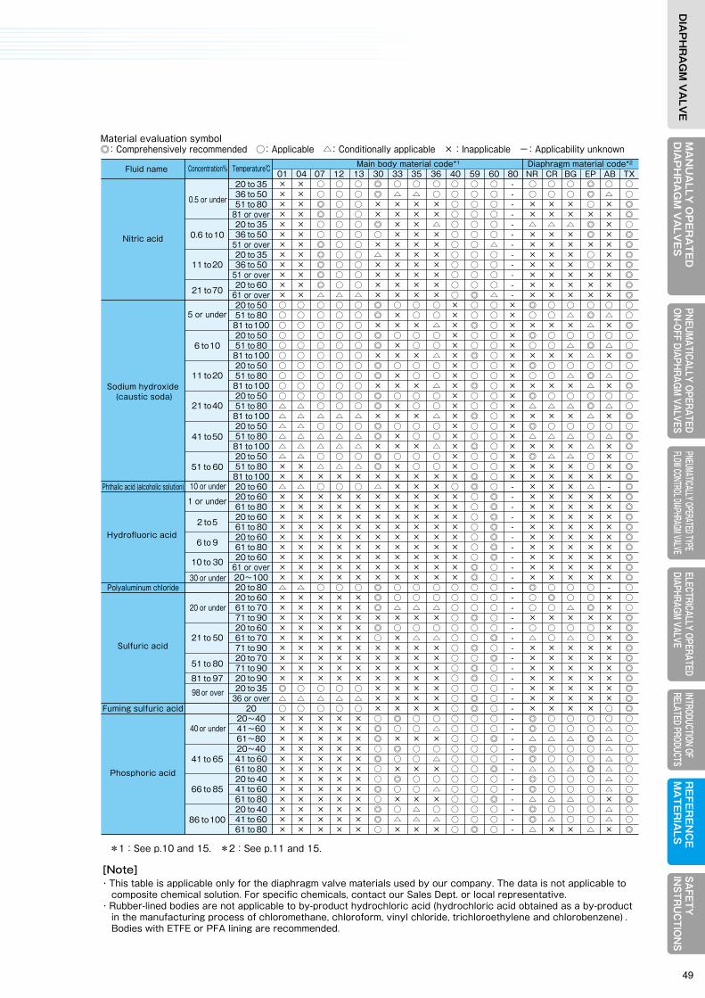
MA
NU
ALLY
OP
ER
AT
ED
DIA
PH
RA
GM
VA
LVE
SELECTRICALLY OPERATEDDIAPHRAGM VALVE
RE
FER
EN
CE
MA
TE
RIA
LSPNEUM
ATICALLY OPERATEDON-OFF DIAPHRAGM
VALVESPNEUMATICALLY OPERATED TYPE FLOW CONTROL DIAPHRAGM VALVE
INTRODUCTION OF RELATED PRODUCTS
SAFETY
IN
STRU
CTIO
NS
DIA
PH
RA
GM
VA
LVE
MA
NU
ALL
Y O
PE
RA
TE
DD
IAP
HR
AG
M V
ALV
ES
ELEC
TRIC
ALLY
OPE
RATE
DDI
APHR
AGM
VALV
ER
EFE
RE
NC
EM
AT
ER
IALS
PNEU
MAT
ICAL
LY O
PERA
TED
ON-O
FF D
IAPH
RAGM
VAL
VES
PNEU
MATIC
ALLY
OPER
ATED
TYPE
FL
OW CO
NTRO
L DIAP
HRAG
M VAL
VEIN
TROD
UCTIO
N OF
RE
LATE
D PR
ODUC
TSSA
FETY
IN
STR
UC
TIO
NS
DIA
PH
RA
GM
VA
LVE
Material Selection TableThis valve selection table outlines typical reference materials based on our tests and rich performance data.(The following table represents excerpts of reference materials. For application under other fluid, concentration, temperature and other conditions than stated in the table, please contact our Sales Dept. or local representative.)
④
[Note]・This table is applicable only for the diaphragm valve materials used by our company. The data is not applicable to composite chemical solution. For specific chemicals, contact our Sales Dept. or local representative.・Rubber-lined bodies are not applicable to by-product hydrochloric acid (hydrochloric acid obtained as a by-product in the manufacturing process of chloromethane, chloroform, vinyl chloride, trichloroethylene and chlorobenzene) . Bodies with ETFE or PFA lining are recommended.
Material evaluation symbol ◎:Comprehensively recommended ○:Applicable △:Conditionally applicable ×:Inapplicable -:Applicability unknown
Material evaluation symbol ◎:Comprehensively recommended ○:Applicable △:Conditionally applicable ×:Inapplicable -:Applicability unknown
Fluid name
Sodium nitrite
Sulfite solution
Sodium sulfite
Ammonia water
Ethylene glycol
Ammonium chloride
Hydrochloric acid
Fuming hydrochloric acid
Chlorine gas (wet)
Chlorine gas (dry)
Sodium chlorate
Chlorine water
Seawater
Acetic acid
Sodium hypochlorite
60
5
20 or under
28
100
35
5 or under
6 to 20
21 to 30
31 to 35
36
37.2 orover
20 orover
0.3 orunder
5 or under
0.1 or under
0.11 to 1.0
1.1 to 2.0
2.1 to 5.0
5.1 to 10
11 to 13
6 to 20
21 to 40
41 to 60
61 to 80
96 to 100
5577
20 to 6061 to 8020 to 6061 to 8020 to 6061 to 8020 to 5020 to 6061 to 80
81 or over20 to 50
6098
20 to 6061 to 80
81 to 10020 to 6061 to 80
81 to 10020 to 5051 to 7071 to 8081 to 9020 to 3536 to 6061 to 8020 to 3536 to 7020 to 3536 to 6020 to 35
36 or over20 to 35
36 or over20 to 50
51 or over20 to 35
36 or over20
20 to 5051 to 6061 to 8020 to 3536 to 5051 to 8020 to 3536 to 5051 to 8020 to 3536 to 5051 to 8020 to 3536 to 5051 to 8020 to 35
36 or over20 to 3536 to 5051 to 6020 to 3536 to 50
51 or over20 to 3536 to 50
51 or over20 to 3536 to 50
51 or over20 to 35
36 or over20 to 35
36 or over
Concentration% Temperature℃ Main body material code*1 Diaphragm material code*2
01 04 07 12 13 30 33 35 36 40 59 60 80 NR CR BG EP AB TX
Fluid name
Nitric acid
Sodium hydroxide (caustic soda)
Phthalic acid (alcoholic solution)
Hydrofluoric acid
Polyaluminum chloride
Sulfuric acid
Fuming sulfuric acid
Phosphoric acid
0.5 or under
10 or under
30 or under
20 or under
98 or over
40 or under
5 or under
1 or under
0.6 to10
11 to20
21 to70
6 to10
11 to20
21 to40
41 to50
51 to 60
2 to5
6 to 9
10 to 30
41 to 65
66 to 85
86 to100
21 to 50
51 to 80
81 to 97
20 to 3536 to 5051 to 80
81 or over20 to 3536 to 50
51 or over20 to 3536 to 50
51 or over20 to 60
61 or over20 to 5051 to 8081 to10020 to 5051 to 8081 to10020 to 5051 to 8081 to10020 to 5051 to 8081 to10020 to 5051 to 8081 to10020 to 5051 to 8081 to10020 to 6020 to 6061 to 8020 to 6061 to 8020 to 6061 to 8020 to 60
61 or over20~10020 to 8020 to 6061 to 7071 to 9020 to 6061 to 7071 to 9020 to 7071 to 9020 to 9020 to 35
36 or over20
20~4041~6061~8020~4041 to 6061 to 8020 to 4041 to 6061 to 8020 to 4041 to 6061 to 80
Concentration% Temperature℃ Main body material code*1 Diaphragm material code*2
01 04 07 12 13 30 33 35 36 40 59 60 80 NR CR BG EP AB TX × × ○ ○ ○ ◎ ○ ○ ○ ○ ○ ○ - ○ ○ ○ ◎ ○ ○ × × ○ ○ ○ ◎ △ △ ○ ○ ○ ○ - ○ ○ ○ ◎ △ ○ × × ◎ ○ ○ × × × × ○ ○ ○ - × × × ○ × ◎ × × ◎ ○ ○ × × × × ○ ○ ○ - × × × × × ◎ × × ○ ○ ○ ◎ × × △ ○ ○ ○ - △ △ △ ◎ × ○ × × ○ ○ ○ ○ × × × ○ ○ ○ - × × × ◎ × ◎ × × ◎ ○ ○ × × × × ○ ○ △ - × × × × × ◎ × × ◎ ○ ○ △ × × × ○ ○ ○ - × × × ○ × ◎ × × ◎ ○ ○ × × × × ○ ○ ○ - × × × ○ × ◎ × × ◎ ○ ○ × × × × ○ ○ ○ - × × × × × ◎ × × ◎ ○ ○ × × × × ○ ○ ○ - × × × × × ◎ × × △ △ △ × × × × ○ ◎ △ - × × × × × ◎ ○ ○ ○ ○ ○ ◎ ○ ○ ○ × ○ ○ × ◎ ○ ○ ○ ○ ○ ○ ○ ○ ○ ○ ◎ × ○ ○ × ○ ○ × ○ ○ △ ◎ △ ○ ○ ○ ○ ○ ○ × × × △ × ◎ ○ × × × × △ × ◎ ○ ○ ○ ○ ○ ◎ ○ ○ ○ × ○ ○ × ◎ ○ ○ ○ ○ ○ ○ ○ ○ ○ ○ ◎ × ○ ○ × ○ ○ × ○ ○ △ ◎ △ ○ ○ ○ ○ ○ ○ × × × △ × ◎ ○ × × × × △ × ◎ ○ ○ ○ ○ ○ ◎ ○ ○ ○ × ○ ○ × ◎ ○ ○ ○ ○ ○ ○ ○ ○ ○ ○ ◎ × ○ ○ × ○ ○ × ○ ○ △ ◎ △ ○ ○ ○ ○ ○ ○ × × × △ × ◎ ○ × × × × △ × ◎ ○ ○ ○ ○ ○ ◎ ○ ○ ○ × ○ ○ × ◎ ○ ○ ○ ○ ○ △ △ ○ ○ ○ ◎ × ○ ○ × ○ ○ × △ △ △ ◎ △ ○ △ △ △ △ △ × × × △ × ◎ ○ × × × × △ × ◎ △ △ ○ ○ ○ ◎ ○ ○ ○ × ○ ○ × ◎ ○ ○ ○ ○ ○ △ △ △ △ △ ◎ × ○ ○ × ○ ○ × △ △ △ ○ △ ◎ △ △ △ △ △ × × × △ × ◎ ○ × × × × △ × ◎ △ △ ○ ○ ○ ◎ ○ ○ ○ × ○ ○ × ◎ △ △ ○ × ○ × × △ △ △ ◎ × ○ ○ × ○ ○ × × × × ○ × ◎ × × × × × × × × × × ◎ ○ × × × × × × ◎ △ △ ○ ○ ○ △ × × × ○ ◎ ○ - × × × △ - ◎ × × × × × × × × × × ○ ◎ - × × × × × ◎ × × × × × × × × × × ○ ◎ - × × × × × ◎ × × × × × × × × × × ○ ◎ - × × × × × ◎ × × × × × × × × × × ○ ◎ - × × × × × ◎ × × × × × × × × × × ○ ◎ - × × × × × ◎ × × × × × × × × × × ○ ◎ - × × × × × ◎ × × × × × × × × × × ○ ◎ - × × × × × ◎ × × × × × × × × × × ◎ ○ - × × × × × ◎ × × × × × × × × × × ◎ ○ - × × × × × ◎ △ △ ○ ○ ○ ◎ ○ ○ ○ ○ ○ ○ - ◎ ○ ○ ○ - ○ × × × × × ◎ ○ ○ ○ ○ ○ ○ - ○ ◎ ○ ○ × ○ × × × × × ◎ △ △ △ ○ ○ ○ - ○ ○ △ ◎ × ○ × × × × × × × × × ○ ◎ ○ - × × × × × ◎ × × × × × ◎ ○ ○ ○ ○ ○ ○ - ○ ○ ○ ○ × ◎ × × × × × ○ × △ △ ○ ○ ◎ - △ ○ △ ○ × ◎ × × × × × × × × × ○ ◎ ○ - × × × × × ◎ × × × × × × × × × ○ ○ ◎ - × × × × × ◎ × × × × × × × × × ○ ◎ ○ - × × × × × ◎ × × × × × × × × × ○ ◎ ○ - × × × × × ◎ ◎ ○ ○ ○ ○ × × × × ○ ○ ○ - × × × × × ◎ △ △ △ △ △ × × × × ○ ◎ ○ - × × × × × ◎ ○ ○ ○ ○ ○ × × × × ○ ◎ ○ - × × × × ○ ◎ × × × × × ○ ◎ ○ ○ ○ ○ ○ - ◎ ○ ○ ○ ○ ○ × × × × × ◎ ○ ○ △ ○ ○ ○ - ◎ ○ ○ ○ △ ○ × × × × × ◎ × × × ○ ○ ◎ - △ △ △ ◎ △ ○ × × × × × ○ ◎ ○ ○ ○ ○ ○ - ◎ ○ ○ ○ △ ○ × × × × × ◎ ○ ○ △ ○ ○ ○ - ◎ ○ ○ ○ △ ○ × × × × × ○ × × × ○ ○ ◎ - △ △ △ ◎ △ ○ × × × × × ○ ◎ ○ ○ ○ ○ ○ - ◎ ○ ○ ○ △ ○ × × × × × ◎ ○ ○ △ ○ ○ ○ - ◎ ○ ○ ○ △ ○ × × × × × ○ × × × ○ ○ ◎ - △ △ △ ○ × ◎ × × × × × ◎ ○ △ ○ ○ ○ ○ - ◎ ○ ○ ○ △ ○ × × × × × ◎ △ △ △ ○ ○ ○ - ◎ △ ○ ○ △ ○ × × × × × ○ × × × ○ ◎ ○ - △ × × △ × ◎
6 REFERENCE MATERIALS
*1:See p.10 and 15. *2:See p.11 and 15.
△ △ ○ ○ ○ ◎ ○ ○ ○ ○ ○ ○ - ○ ○ ○ ◎ ○ ○ △ △ ○ ○ ○ ◎ △ △ △ ○ ○ ○ - ○ ○ △ ◎ × ○ × × ○ ○ ○ ◎ △ ○ △ ○ ○ ○ - ○ ◎ ○ ○ △ ○ × × ○ ○ ○ ◎ △ ○ △ ○ ○ ○ - × × × × × ◎ × × ○ ○ ○ ◎ △ ○ △ ○ ○ ○ - ○ ◎ ○ ○ △ ○ × × ○ ○ ○ ◎ △ ○ △ ○ ○ ○ - ○ ○ △ ◎ × ○ ○ ○ ○ ○ ○ ◎ ○ ○ ○ × ○ ○ - ○ ◎ ○ ○ - ○ ◎ ○ ○ ○ ○ ○ ○ ○ ○ ○ ○ ○ ○ ○ ◎ ○ ○ ○ ○ ◎ ○ ○ ○ ○ ○ △ △ △ ○ ○ ○ ○ ○ ○ △ ◎ △ ○ ○ ◎ ○ ○ ○ × × × × ○ ○ ○ ○ × × × △ × ◎ × × × × × ◎ ○ ○ ○ ○ ○ ○ - ○ ◎ ○ ○ ○ ○ × × × × × ◎ △ △ △ ○ ○ ○ - ○ ○ △ ◎ × ○ × × × × × × × × × ○ ○ ○ - × × × △ × ◎ × × × × × ◎ ○ ○ ○ ○ ○ ○ - ◎ ○ ○ ○ ○ ○ × × × × × ◎ × × △ ○ ○ ○ - ○ △ ○ ◎ △ ○ × × × × × × × × × ○ ○ ◎ - × × × △ × ◎ × × × × × ◎ △ × △ ○ ○ ○ - ◎ ○ ○ ○ ○ ○ × × × × × ◎ × × × ○ ○ ○ - △ △ △ ○ △ ◎ × × × × × × × × × ○ ◎ ○ - × × × △ × ◎ × × × × × ◎ × × △ ○ ○ ○ - ○ ○ ○ ◎ △ ○ × × × × × ◎ × × × ○ ○ ○ - △ △ △ ○ △ ◎ × × × × × ○ × × × ○ ◎ ○ - × × × × × ◎ × × × × × × × × × ○ ◎ ○ - × × × × × ◎ × × × × × ○ × × × ○ ◎ ○ - △ × ○ ○ × ◎ × × × × × ○ × × × ○ ◎ ○ - × × × ○ × ◎ × × × × × ○ × × × ○ ◎ ○ - × × × × × ◎ × × × × × ○ × × × ○ ○ ◎ - × × × ○ × ◎ × × × × × ○ × × × ○ ○ ◎ - × × × × × ◎ × × × × × ○ × × × ○ ◎ ○ - × × × × × ◎ × × × × × △ × × × ○ ◎ ○ - × × × × × ◎ × × × × × △ × × × ○ ◎ ○ ○ × × × △ × ◎ × × × × × × × × × ○ ◎ ○ ○ × × × × × ◎ × △ △ △ △ △ × × × ○ ○ ◎ - × × × △ × ◎ × △ △ △ △ × × × × ○ ○ ◎ - × × × × × ○ × × ○ ○ ○ ○ △ △ △ ○ ○ ◎ - △ △ △ ○ - ◎ × × ○ ○ ○ × × × × ○ ○ ◎ - × × × × - ◎ × × × × × ◎ × × × ○ ○ ○ ○ × × × ○ × ◎ × × × × × × × × × ○ ○ ◎ ○ × × × × × ◎ × × × × × ◎ ○ ○ ○ - ○ ○ - ○ ◎ ○ ○ - ○ × × ○ ○ ○ ◎ △ ○ ○ × ○ ○ - ○ ◎ ○ △ △ ○ × × ○ ○ ○ ◎ △ △ × × ○ ○ - ○ ○ ○ △ × ◎ × × ○ ○ ○ × × × × × ○ ◎ - × × △ × × ◎ × × ○ ○ ○ ◎ × ○ × × ○ ○ - × ○ ◎ × × ○ × × ○ ○ ○ ◎ × × × × ○ ○ - × △ ○ × × ○ × × ○ ○ ○ × × × × × ○ ◎ - × × × × × ○ × × ○ ○ ○ ◎ × × × × ○ ○ - × × ○ × × ◎ × × ○ ○ ○ ○ × × × × ○ ◎ - × × ○ × × ◎ × × ○ ○ ○ × × × × × ○ ◎ - × × × × × ○ × × ○ ○ ○ ○ × × × × ◎ ○ - × × ○ × × ◎ × × ○ ○ ○ △ × × × × ◎ ○ - × × × × × ◎ × × ○ ○ ○ × × × × × ◎ ○ - × × × × × ◎ × × ○ ○ ○ △ × × × × ◎ ○ - × × × × × ◎ × × ○ ○ ○ × × × × × ◎ ○ - × × × × × ◎ × × ○ ○ ○ × × × × × ◎ ○ - × × × × × ◎ × × ○ ○ ○ × × × × × ◎ ○ - × × × × × ◎ × × ○ ○ ○ × × × × × ◎ ○ - × × × × × ◎ × × × × × ◎ △ △ △ ○ ○ ○ - △ △ △ ◎ △ ○ × × × × × ◎ × × × ○ ○ ○ - × × △ ○ × ◎ × × × × × ◎ × × × ○ ○ ○ - × × × × × ◎ × × × × × ◎ △ △ △ ○ ○ ○ - △ △ △ ◎ × ○ × × × × × ○ × × × ○ ○ ◎ - × × × △ × ◎ × × × × × × × × × ○ ○ ◎ - × × × × × ◎ × × × × × ◎ × × △ ○ ○ ○ - × △ △ ◎ × ○ × × × × × ○ × × × ○ ○ ◎ - × × × △ × ◎ × × × × × × × × × ○ ○ ◎ - × × × × × ◎ × × × × × ◎ × × △ ○ ○ ○ - × × △ ◎ × ○ × × × × × ○ × × × ○ ○ ◎ - × × × △ × ◎ × × × × × × × × × ○ ○ ◎ - × × × × × ◎ × × × × × ○ × × × ○ ○ ◎ - × × × ○ × ◎ × × × × × × × × × ○ ○ ◎ - × × × × × ◎ × × × × × △ × × × ○ ○ ◎ - × × × △ × ◎ × × × × × × × × × ○ ◎ ○ - × × × × × ◎
49
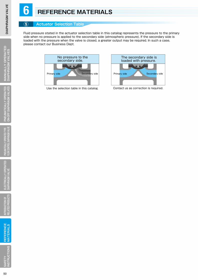
MA
NU
ALLY
OP
ER
AT
ED
DIA
PH
RA
GM
VA
LVE
SELECTRICALLY OPERATEDDIAPHRAGM VALVE
RE
FER
EN
CE
MA
TE
RIA
LSPNEUM
ATICALLY OPERATEDON-OFF DIAPHRAGM
VALVESPNEUMATICALLY OPERATED TYPE FLOW CONTROL DIAPHRAGM VALVE
INTRODUCTION OF RELATED PRODUCTS
SAFETY
IN
STRU
CTIO
NS
DIA
PH
RA
GM
VA
LVE
MA
NU
ALL
Y O
PE
RA
TE
DD
IAP
HR
AG
M V
ALV
ES
ELEC
TRIC
ALLY
OPE
RATE
DDI
APHR
AGM
VALV
ER
EFE
RE
NC
EM
AT
ER
IALS
PNEU
MAT
ICAL
LY O
PERA
TED
ON-O
FF D
IAPH
RAGM
VAL
VES
PNEU
MATIC
ALLY
OPER
ATED
TYPE
FL
OW CO
NTRO
L DIAP
HRAG
M VAL
VEIN
TROD
UCTIO
N OF
RE
LATE
D PR
ODUC
TSSA
FETY
IN
STR
UC
TIO
NS
DIA
PH
RA
GM
VA
LVE
Actuator Selection Table
Fluid pressure stated in the actuator selection table in this catalog represents the pressure to the primaryside when no pressure is applied to the secondary side (atmospheric pressure). If the secondary side isloaded with the pressure when the valve is closed, a greater output may be required. In such a case, please contact our Business Dept.
⑤
6 REFERENCE MATERIALS
Primary side Secondary side Primary side Secondary side
The secondary side is loaded with pressure.
No pressure to the secondary side.
Contact us as correction is required.Use the selection table in this catalog.
7SAFETY INSTRUCTIONS
50

Actuator Selection Table
Fluid pressure stated in the actuator selection table in this catalog represents the pressure to the primaryside when no pressure is applied to the secondary side (atmospheric pressure). If the secondary side isloaded with the pressure when the valve is closed, a greater output may be required. In such a case, please contact our Business Dept.
⑤
6 REFERENCE MATERIALS
Primary side Secondary side Primary side Secondary side
The secondary side is loaded with pressure.
No pressure to the secondary side.
Contact us as correction is required.Use the selection table in this catalog.
7SAFETY INSTRUCTIONS
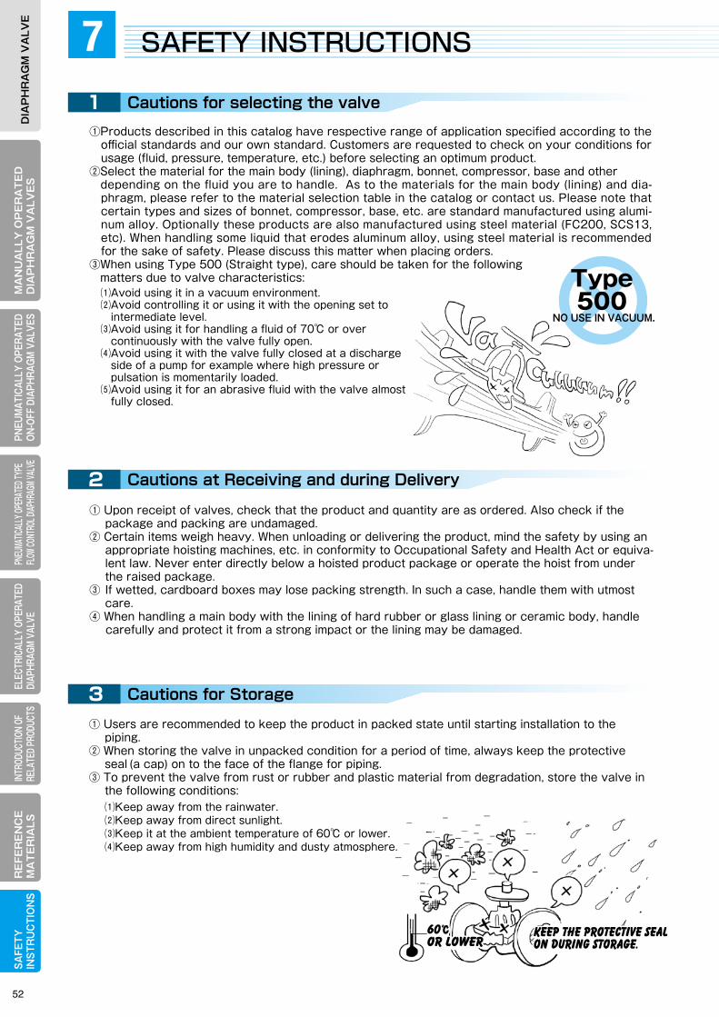
MA
NU
ALLY
OP
ER
AT
ED
DIA
PH
RA
GM
VA
LVE
SELECTRICALLY OPERATEDDIAPHRAGM VALVE
RE
FER
EN
CE
MA
TE
RIA
LSPNEUM
ATICALLY OPERATEDON-OFF DIAPHRAGM
VALVESPNEUMATICALLY OPERATED TYPE FLOW CONTROL DIAPHRAGM VALVE
INTRODUCTION OF RELATED PRODUCTS
SAFETY
IN
STRU
CTIO
NS
DIA
PH
RA
GM
VA
LVE
MA
NU
ALL
Y O
PE
RA
TE
DD
IAP
HR
AG
M V
ALV
ES
ELEC
TRIC
ALLY
OPE
RATE
DDI
APHR
AGM
VALV
ER
EFE
RE
NC
EM
AT
ER
IALS
PNEU
MAT
ICAL
LY O
PERA
TED
ON-O
FF D
IAPH
RAGM
VAL
VES
PNEU
MATIC
ALLY
OPER
ATED
TYPE
FL
OW CO
NTRO
L DIAP
HRAG
M VAL
VEIN
TROD
UCTIO
N OF
RE
LATE
D PR
ODUC
TSSA
FETY
IN
STR
UC
TIO
NS
DIA
PH
RA
GM
VA
LVE
1
2
3
4
KEEP the protective sealON during storage.KEEP the protective sealON during storage.
60℃ or lower60℃ or lower
Diagonally
Cautions for selecting the valve Cautions for Installation to the Piping
Cautions at Receiving and during Delivery
Cautions for Storage
⑴Avoid using it in a vacuum environment.⑵Avoid controlling it or using it with the opening set to intermediate level. ⑶Avoid using it for handling a fluid of 70℃ or over continuously with the valve fully open.⑷Avoid using it with the valve fully closed at a discharge side of a pump for example where high pressure or pulsation is momentarily loaded.⑸Avoid using it for an abrasive fluid with the valve almost fully closed.
⑴Keep away from the rainwater.⑵Keep away from direct sunlight.⑶Keep it at the ambient temperature of 60℃ or lower.⑷Keep away from high humidity and dusty atmosphere.
①Products described in this catalog have respective range of application specified according to the official standards and our own standard. Customers are requested to check on your conditions for usage (fluid, pressure, temperature, etc.) before selecting an optimum product.
②Select the material for the main body (lining), diaphragm, bonnet, compressor, base and other depending on the fluid you are to handle. As to the materials for the main body (lining) and dia-
phragm, please refer to the material selection table in the catalog or contact us. Please note that certain types and sizes of bonnet, compressor, base, etc. are standard manufactured using alumi-num alloy. Optionally these products are also manufactured using steel material (FC200, SCS13, etc). When handling some liquid that erodes aluminum alloy, using steel material is recommended for the sake of safety. Please discuss this matter when placing orders.
③When using Type 500 (Straight type), care should be taken for the following matters due to valve characteristics:
⑴Before closing the switch cover, make sure that the gasket is perfectly applied and the mating face is cleaned. Close the switch cover by tightening the mounting bolts steadily.⑵Outlet port for the outside lead wire should be made rainwater-proof.⑶Always keep the switch cover closed.⑷Positively never carry on outdoor wiring work in the rain.⑸After making wire connection, always check operation.
① Remove the protective seal (a cap) from the connecting flange face of the main body. Check the inside of the valve for any contamination or attachment of foreign matters. Also check the piping system to connect the valve to for cleanliness and any foreign matters. Apply a gas blowing or liquid flushing as may be needed. Foreign matters inside the valve if any may cause leakage when caught between the valve base of the main body and the diaphragm.
② Provide a space around the valve necessary for overhauling. Such a space should allow to replace the diaphragm with the main body remaining connected to the piping. Particularly, when hoisting the bonnet, necessary space must be provided for the hoisting operation.
③ When installing the valve to the piping, prevent it from receiving abnormal tension, compression or bending stress.
④ In the case of a flat face flange, use a gasket that fully covers the flange face. If a soft rubber-lined body is covered with a gasket that fails to cover the flange face completely, the lining may be dam-aged or leakage may occur.
⑤ Use rubber gasket to the rubber-lined main body.⑥ For connection to the piping, use the bolts of a length that makes no contact with the bonnet
flange or use continuous thread studs and adjust the length of the protruding head of the stud. Tightening the bolt in contact with the bonnet flange may cause external leakage or damage the bonnet, causing the valve failure.
Particular care is required to the contact of the bonnet flange with the piping bolt when installing a valve of DN15 to 80 to the piping.
Users are recommended to use a double-end stud for the piping bolt and the nut of Style 1 (JIS B 1181), Class 1 or 2 (JIS B 1181 Attachment 1). Make adjustment to prevent contact between the bonnet flange and the piping bolts.
Adjustment position should read a position where the end face of the bolt is flush with the end face of the nut. (Select a bolt so that the fit length of the thread will be definitely at least 80% or higher of the height of the nut.)
⑦ When installing the valve to the piping, tighten individual bolts alternately and diagonally under identical torque. Unevenly clamped bolts may cause leakage from the connecting flange face.
⑧ Products with the air vent port (manually operated valve of DN125 and over, pneumatically oper-ated valve and electrically operated valve) should be protected from the entry of rainwater, etc. through the port.
⑨ When connecting the valve with welded joint, always remove the bonnet including the diaphragm from the main body before welding. Reinstall the bonnet and all including the diaphragm after the temperature of the welded portions reaches the normal temperature.
⑩ Care should be given to the following points for wiring:
5 Cautions for Machine Operation
① Opening/closing the valve with part of an operator’s body or wear carelessly in contact with the moving parts inside or outside of the valve may lead to a serious injuries. Never touch the inside or moving parts of the valve.
② When opening/closing the valve, don’t operate the handwheel by hooking an auxiliary pipe or wrench on it. Or an excessive load will be applied to the valve component possibly to damage it.
③ When operating the handwheel to close the valve, stop the closing operation at maximum 15 to 20 degrees after sensing the valve resistance to the closing motion.
Excessive tightening may cause a shorter diaphragm life. Particular care is required when han-dling a fluid in high temperature.
④ If the handwheel operation is felt heavier in the middle of a valve closing operation, certain foreign matters might have been caught with the valve seat. In such a case, open the valve once, let the fluid flow through, and check if the foreign matters are washed away, then start the closing opera-tion again.
⑤ If ambient temperature or fluid temperature changes greatly while the fluid is sealed inside the piping, thermal expansion of the fluid causes the pressure to change, possibly leading to external leakage or damaged diaphragm.
① Upon receipt of valves, check that the product and quantity are as ordered. Also check if the package and packing are undamaged.
② Certain items weigh heavy. When unloading or delivering the product, mind the safety by using an appropriate hoisting machines, etc. in conformity to Occupational Safety and Health Act or equiva-lent law. Never enter directly below a hoisted product package or operate the hoist from under the raised package.
③ If wetted, cardboard boxes may lose packing strength. In such a case, handle them with utmost care.
④ When handling a main body with the lining of hard rubber or glass lining or ceramic body, handle carefully and protect it from a strong impact or the lining may be damaged.
① Users are recommended to keep the product in packed state until starting installation to the piping.
② When storing the valve in unpacked condition for a period of time, always keep the protective seal (a cap) on to the face of the flange for piping.
③ To prevent the valve from rust or rubber and plastic material from degradation, store the valve in the following conditions:
Type500
NO USE IN VACUUM.
7 SAFETY INSTRUCTIONS
52
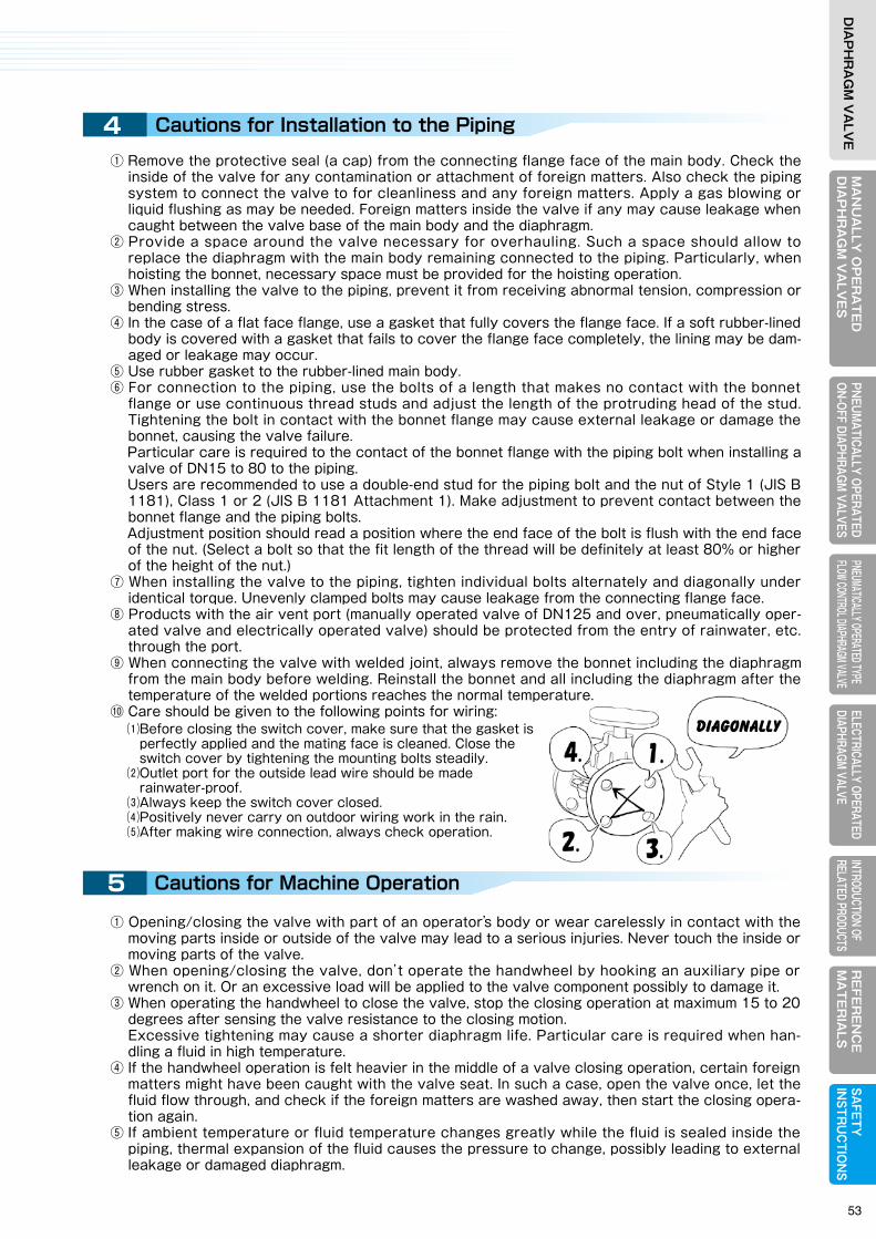
MA
NU
ALLY
OP
ER
AT
ED
DIA
PH
RA
GM
VA
LVE
SELECTRICALLY OPERATEDDIAPHRAGM VALVE
RE
FER
EN
CE
MA
TE
RIA
LSPNEUM
ATICALLY OPERATEDON-OFF DIAPHRAGM
VALVESPNEUMATICALLY OPERATED TYPE FLOW CONTROL DIAPHRAGM VALVE
INTRODUCTION OF RELATED PRODUCTS
SAFETY
IN
STRU
CTIO
NS
DIA
PH
RA
GM
VA
LVE
MA
NU
ALL
Y O
PE
RA
TE
DD
IAP
HR
AG
M V
ALV
ES
ELEC
TRIC
ALLY
OPE
RATE
DDI
APHR
AGM
VALV
ER
EFE
RE
NC
EM
AT
ER
IALS
PNEU
MAT
ICAL
LY O
PERA
TED
ON-O
FF D
IAPH
RAGM
VAL
VES
PNEU
MATIC
ALLY
OPER
ATED
TYPE
FL
OW CO
NTRO
L DIAP
HRAG
M VAL
VEIN
TROD
UCTIO
N OF
RE
LATE
D PR
ODUC
TSSA
FETY
IN
STR
UC
TIO
NS
DIA
PH
RA
GM
VA
LVE
1
2
3
4
KEEP the protective sealON during storage.KEEP the protective sealON during storage.
60℃ or lower60℃ or lower
Diagonally
Cautions for selecting the valve Cautions for Installation to the Piping
Cautions at Receiving and during Delivery
Cautions for Storage
⑴Avoid using it in a vacuum environment.⑵Avoid controlling it or using it with the opening set to intermediate level. ⑶Avoid using it for handling a fluid of 70℃ or over continuously with the valve fully open.⑷Avoid using it with the valve fully closed at a discharge side of a pump for example where high pressure or pulsation is momentarily loaded.⑸Avoid using it for an abrasive fluid with the valve almost fully closed.
⑴Keep away from the rainwater.⑵Keep away from direct sunlight.⑶Keep it at the ambient temperature of 60℃ or lower.⑷Keep away from high humidity and dusty atmosphere.
①Products described in this catalog have respective range of application specified according to the official standards and our own standard. Customers are requested to check on your conditions for usage (fluid, pressure, temperature, etc.) before selecting an optimum product.
②Select the material for the main body (lining), diaphragm, bonnet, compressor, base and other depending on the fluid you are to handle. As to the materials for the main body (lining) and dia-
phragm, please refer to the material selection table in the catalog or contact us. Please note that certain types and sizes of bonnet, compressor, base, etc. are standard manufactured using alumi-num alloy. Optionally these products are also manufactured using steel material (FC200, SCS13, etc). When handling some liquid that erodes aluminum alloy, using steel material is recommended for the sake of safety. Please discuss this matter when placing orders.
③When using Type 500 (Straight type), care should be taken for the following matters due to valve characteristics:
⑴Before closing the switch cover, make sure that the gasket is perfectly applied and the mating face is cleaned. Close the switch cover by tightening the mounting bolts steadily.⑵Outlet port for the outside lead wire should be made rainwater-proof.⑶Always keep the switch cover closed.⑷Positively never carry on outdoor wiring work in the rain.⑸After making wire connection, always check operation.
① Remove the protective seal (a cap) from the connecting flange face of the main body. Check the inside of the valve for any contamination or attachment of foreign matters. Also check the piping system to connect the valve to for cleanliness and any foreign matters. Apply a gas blowing or liquid flushing as may be needed. Foreign matters inside the valve if any may cause leakage when caught between the valve base of the main body and the diaphragm.
② Provide a space around the valve necessary for overhauling. Such a space should allow to replace the diaphragm with the main body remaining connected to the piping. Particularly, when hoisting the bonnet, necessary space must be provided for the hoisting operation.
③ When installing the valve to the piping, prevent it from receiving abnormal tension, compression or bending stress.
④ In the case of a flat face flange, use a gasket that fully covers the flange face. If a soft rubber-lined body is covered with a gasket that fails to cover the flange face completely, the lining may be dam-aged or leakage may occur.
⑤ Use rubber gasket to the rubber-lined main body.⑥ For connection to the piping, use the bolts of a length that makes no contact with the bonnet
flange or use continuous thread studs and adjust the length of the protruding head of the stud. Tightening the bolt in contact with the bonnet flange may cause external leakage or damage the bonnet, causing the valve failure.
Particular care is required to the contact of the bonnet flange with the piping bolt when installing a valve of DN15 to 80 to the piping.
Users are recommended to use a double-end stud for the piping bolt and the nut of Style 1 (JIS B 1181), Class 1 or 2 (JIS B 1181 Attachment 1). Make adjustment to prevent contact between the bonnet flange and the piping bolts.
Adjustment position should read a position where the end face of the bolt is flush with the end face of the nut. (Select a bolt so that the fit length of the thread will be definitely at least 80% or higher of the height of the nut.)
⑦ When installing the valve to the piping, tighten individual bolts alternately and diagonally under identical torque. Unevenly clamped bolts may cause leakage from the connecting flange face.
⑧ Products with the air vent port (manually operated valve of DN125 and over, pneumatically oper-ated valve and electrically operated valve) should be protected from the entry of rainwater, etc. through the port.
⑨ When connecting the valve with welded joint, always remove the bonnet including the diaphragm from the main body before welding. Reinstall the bonnet and all including the diaphragm after the temperature of the welded portions reaches the normal temperature.
⑩ Care should be given to the following points for wiring:
5 Cautions for Machine Operation
① Opening/closing the valve with part of an operator’s body or wear carelessly in contact with the moving parts inside or outside of the valve may lead to a serious injuries. Never touch the inside or moving parts of the valve.
② When opening/closing the valve, don’t operate the handwheel by hooking an auxiliary pipe or wrench on it. Or an excessive load will be applied to the valve component possibly to damage it.
③ When operating the handwheel to close the valve, stop the closing operation at maximum 15 to 20 degrees after sensing the valve resistance to the closing motion.
Excessive tightening may cause a shorter diaphragm life. Particular care is required when han-dling a fluid in high temperature.
④ If the handwheel operation is felt heavier in the middle of a valve closing operation, certain foreign matters might have been caught with the valve seat. In such a case, open the valve once, let the fluid flow through, and check if the foreign matters are washed away, then start the closing opera-tion again.
⑤ If ambient temperature or fluid temperature changes greatly while the fluid is sealed inside the piping, thermal expansion of the fluid causes the pressure to change, possibly leading to external leakage or damaged diaphragm.
① Upon receipt of valves, check that the product and quantity are as ordered. Also check if the package and packing are undamaged.
② Certain items weigh heavy. When unloading or delivering the product, mind the safety by using an appropriate hoisting machines, etc. in conformity to Occupational Safety and Health Act or equiva-lent law. Never enter directly below a hoisted product package or operate the hoist from under the raised package.
③ If wetted, cardboard boxes may lose packing strength. In such a case, handle them with utmost care.
④ When handling a main body with the lining of hard rubber or glass lining or ceramic body, handle carefully and protect it from a strong impact or the lining may be damaged.
① Users are recommended to keep the product in packed state until starting installation to the piping.
② When storing the valve in unpacked condition for a period of time, always keep the protective seal (a cap) on to the face of the flange for piping.
③ To prevent the valve from rust or rubber and plastic material from degradation, store the valve in the following conditions:
Type500
NO USE IN VACUUM.
7 SAFETY INSTRUCTIONS
53

MA
NU
ALLY
OP
ER
AT
ED
DIA
PH
RA
GM
VA
LVE
SELECTRICALLY OPERATEDDIAPHRAGM VALVE
RE
FER
EN
CE
MA
TE
RIA
LSPNEUM
ATICALLY OPERATEDON-OFF DIAPHRAGM
VALVESPNEUMATICALLY OPERATED TYPE FLOW CONTROL DIAPHRAGM VALVE
INTRODUCTION OF RELATED PRODUCTS
SAFETY
IN
STRU
CTIO
NS
DIA
PH
RA
GM
VA
LVE
MA
NU
ALL
Y O
PE
RA
TE
DD
IAP
HR
AG
M V
ALV
ES
ELEC
TRIC
ALLY
OPE
RATE
DDI
APHR
AGM
VALV
ER
EFE
RE
NC
EM
AT
ER
IALS
PNEU
MAT
ICAL
LY O
PERA
TED
ON-O
FF D
IAPH
RAGM
VAL
VES
PNEU
MATIC
ALLY
OPER
ATED
TYPE
FL
OW CO
NTRO
L DIAP
HRAG
M VAL
VEIN
TROD
UCTIO
N OF
RE
LATE
D PR
ODUC
TSSA
FETY
IN
STR
UC
TIO
NS
DIA
PH
RA
GM
VA
LVE
6
7
Pin
Cautions for the Actuators of Pneumatically, Electrically Operated Valve
Cautions for Disassembly and Assembly
⑴The object valve should have been separated from other piping.⑵The fluid pressure and temperature inside the piping and the valve should be atmospheric and normal.⑶There remains no residual fluid inside the piping, and no fluid leakage occurs when the mounting bolts and nuts are loosened.
This is general information. Do not disassemble before you read necessary manual in details.
① Protective sealing (cap) is provided to the air intake port and the electric wiring connection port. Don’t remove the sealing (cap) until the connection joint is installed.
② Actuators are shipped factory-adjusted. Don’t disassemble and reassemble them. If any adjustment is required, please contact us.
③ Dehumidify the air and filter it clean before leading to the valve for application.④ For the operating pressure and power supply, see the nameplate or the specifications of delivered
product.⑤ Protect the products with the air vent port against the entry of rainwater.
① When removing or disassembling the valve, ensure the following matters or you may be risking a serious hazard:
② Provide maintenance work for the diaphragm and actuator periodically.⑴Rubber diaphragm is screwed in. When mounting to the compressor, apply appropriate pressure to screw it in. Slightly bring it back from where it stopped to align the bolt hole positions.⑵PTFE diaphragm is of a bayonet type. To install to the compressor, push the center of a diaphragm firmly with fingertips. Ensure that the pin has fully entered the compressor before turning it 90 degrees clockwise or counterclockwise. In the case of a reverse seat type diaphragm, turn it over before installation. Turning the diaphragm before the pin fully enters the compressor may damage the pin.⑶When reassembling to the valve, run centering, and tighten the bolts and nuts evenly by applying prescribed torque.⑷For detailed maintenance instructions, see the instruction manual or contact our Sales Dept. or local
representative.
Fully insertthe pin
In addition, if the valve is operated to open/close while the valves before and after the diaphragm valve are closed and the inside fully filled with the fluid, the same phenomenon may occur, for which care should be taken.
⑥ If the fluid fully inside the valve is frozen, the valve may be freeze-fractured. For application in an environment where freezing may likely happen, take anti-freeze measures by providing the piping with thermal insulation or if the valve is not in use, to extract liquid from inside the valve, etc.
⑦ Rubber is used for the material of diaphragm. The nuts that clamp the diaphragm may be loosened due to vibration during transportation or stress relaxation after a long period of operation. In such a case, render the diaphragm unloaded by nullifying the fluid pressure, then apply prescribed torque to tighten the nuts to the required level.
7 SAFETY INSTRUCTIONS
54