本製品は審査登録(iso9001)された工場で製造さ...
TRANSCRIPT

本製品は審査登録(ISO9001)された工場で製造されたものです。本製品は審査登録(ISO9001)された工場で製造されたものです。
TEMPERATURE SENSORThermocouple, Resistance Temperature Sensor, Thermistor
TOHO ELECTRONICS INC.

BusinessPortfolioPlanning, designing, producing and marketing a variety of temperature con-trol equipment cored around temperature sensors, as well as marketing other peripheral equipment.
Control EquipmentGeneral purpose digital controllers TTM-200 Series TTM-000 SeriesHigh-performance digital controller TTM-509Program controller TTM-300 SeriesDual controller TTX-700Substrate type controllers TTM-00B TTM-10BS TTM-00BT TTM-10LDigital indicator TRM-006ATabletop temperature controllers BX-303 TRZ-303Wall-hung temperature controllers DT Series TP-673 Series
SensorsTemperature sensorsHumidity sensors
Other Peripheral EquipmentRecorders TRM10CSolid-state relay TRS SeriesPower regulator TRV1 SeriesHeaters Silicone rubber heater Cartridge heaterProgrammable display unit V Series
CONTENTS
1
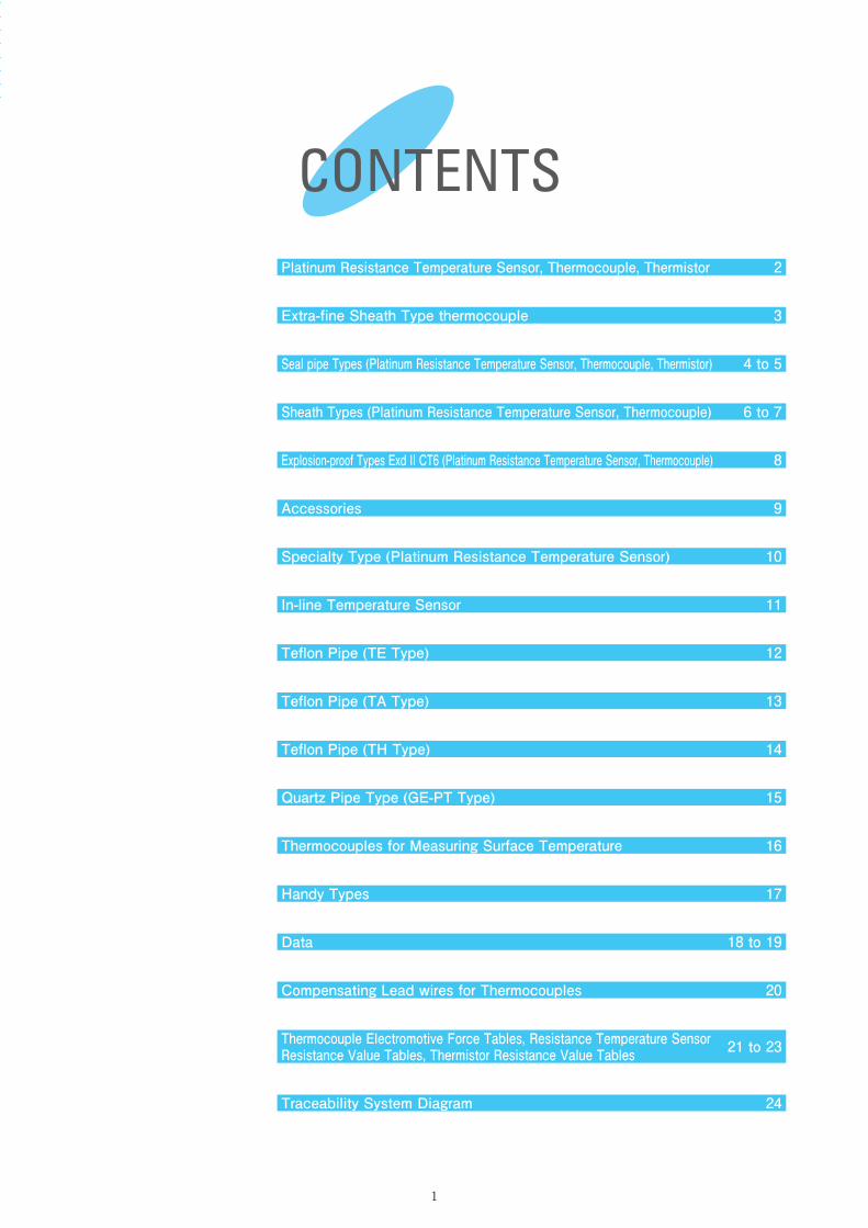
Platinum Resistance Temperature Sensor, Thermocouple, Thermistor 2
Extra-fine Sheath Type thermocouple 3
Seal pipe Types (Platinum Resistance Temperature Sensor, Thermocouple, Thermistor) 4 to 5
Sheath Types (Platinum Resistance Temperature Sensor, Thermocouple) 6 to 7
Explosion-proof Types Exd II CT6 (Platinum Resistance Temperature Sensor, Thermocouple) 8
Accessories 9
Specialty Type (Platinum Resistance Temperature Sensor) 10
In-line Temperature Sensor 11
Teflon Pipe (TE Type) 12
Teflon Pipe (TA Type) 13
Teflon Pipe (TH Type) 14
Quartz Pipe Type (GE-PT Type) 15
Data 18 to 19
Compensating Lead wires for Thermocouples 20
Thermocouple Electromotive Force Tables, Resistance Temperature Sensor Resistance Value Tables, Thermistor Resistance Value Tables 21 to 23
Thermocouples for Measuring Surface Temperature 16
Handy Types 17
Traceability System Diagram 24
Platinum Resistance Temperature Sensor, Thermocouple, Thermistor
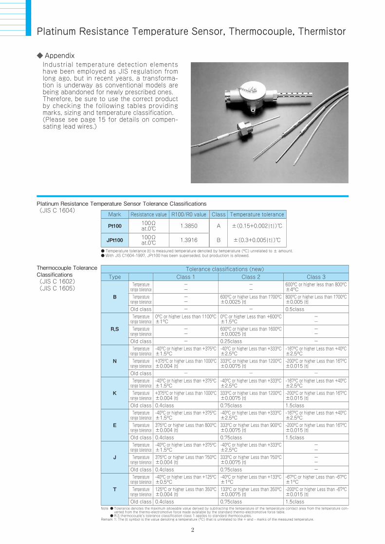
AppendixIndustrial temperature detection elements have been employed as JIS regulation from long ago, but in recent years, a transforma-tion is underway as conventional models are being abandoned for newly prescribed ones.Therefore, be sure to use the correct product by checking the following tables providing marks, sizing and temperature classification.(Please see page 15 for details on compen-sating lead wires.)
Platinum Resistance Temperature Sensor Tolerance Classifications(JIS C 1604)
Mark Resistance value R100/R0 value Class Temperature tolerance
Pt100 100Ωat.0 1.3850 A ±(0.15+0.002t)
JPt100 100Ωat.0 1.3916 B ±(0.3+0.005t)
Temperature tolerance ¦t¦ is measured temperature denoted by temperature (ºC) unrelated to ± amount. With JIS C1604-1997, JPt100 has been superseded, but production is allowed.
Tolerance classifications (new)Type Class 1 Class 2 Class 3
B
Temperaturerange tolerance
--
--
600ºC or higher less than 800ºC±4ºC
Temperaturerange tolerance
--
600ºC or higher Less than 1700ºC±0.0025 ¦t¦
800ºC or higher Less than 1700ºC±0.005 ¦t¦
Old class - - 0.5class
R,S
Temperaturerange tolerance
0ºC or higher Less than 1100ºC±1ºC
0ºC or higher Less than +600ºC±1.5ºC
--
Temperaturerange tolerance
--
600ºC or higher Less than 1600ºC±0.0025 ¦t¦
--
Old class - 0.25class -
N
Temperaturerange tolerance
-40ºC or higher Less than +375ºC±1.5ºC
-40ºC or higher Less than +333ºC±2.5ºC
-167ºC or higher Less than +40ºC±2.5ºC
Temperaturerange tolerance
+375ºC or higher Less than 1000ºC±0.004 ¦t¦
333ºC or higher Less than 1200ºC±0.0075 ¦t¦
-200ºC or higher Less than 167ºC±0.015 ¦t¦
Old class - - -
K
Temperaturerange tolerance
-40ºC or higher Less than +375ºC±1.5ºC
-40ºC or higher Less than +333ºC±2.5ºC
-167ºC or higher Less than +40ºC±2.5ºC
Temperaturerange tolerance
+375ºC or higher Less than 1000ºC±0.004 ¦t¦
333ºC or higher Less than 1200ºC±0.0075 ¦t¦
-200ºC or higher Less than 167ºC±0.015 ¦t¦
Old class 0.4class 0.75class 1.5class
E
Temperaturerange tolerance
-40ºC or higher Less than +375ºC±1.5ºC
-40ºC or higher Less than +333ºC±2.5ºC
-167ºC or higher Less than +40ºC±2.5ºC
Temperaturerange tolerance
375ºC or higher Less than 800ºC±0.004 ¦t¦
333ºC or higher Less than 900ºC±0.0075 ¦t¦
-200ºC or higher Less than 167ºC±0.015 ¦t¦
Old class 0.4class 0.75class 1.5class
J
Temperaturerange tolerance
-40ºC or higher Less than +375ºC±1.5ºC
-40ºC or higher Less than +333ºC±2.5ºC
--
Temperaturerange tolerance
375ºC or higher Less than 750ºC±0.004 ¦t¦
333ºC or higher Less than 750ºC±0.0075 ¦t¦
--
Old class 0.4class 0.75class -
T
Temperaturerange tolerance
-40ºC or higher Less than +125ºC±0.5ºC
-40ºC or higher Less than +133ºC±1ºC
-67ºC or higher Less than -67ºC±1ºC
Temperaturerange tolerance
125ºC or higher Less than 350ºC±0.004 ¦t¦
133ºC or higher Less than 350ºC±0.0075 ¦t¦
-200ºC or higher Less than -67ºC±0.015 ¦t¦
Old class 0.4class 0.75class 1.5classNote Tolerance denotes the maximum allowable value derived by subtracting the temperature of the temperature contact area from the temperature con-
verted from the thermo-electromotive force made available by the standard thermo-electromotive force table. R,S thermocouple’s tolerance classification class 1 applies to standard thermocouples.Remark 1: The ¦t¦ symbol is the value denoting a temperature (ºC) that is unrelated to the + and – marks of the measured temperature.
Thermocouple ToleranceClassifications(JIS C 1602)(JIS C 1605)
2
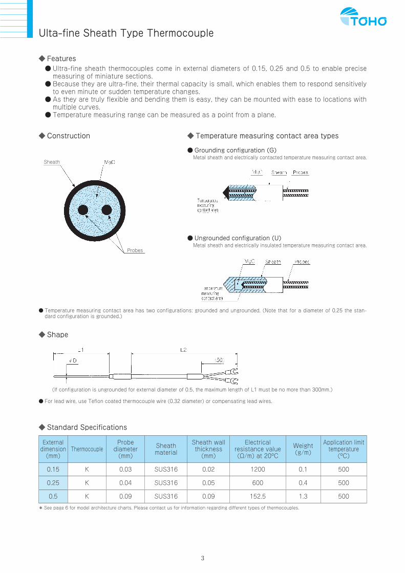
Ulta-fine Sheath Type Thermocouple
Features Ultra-fine sheath thermocouples come in external diameters of 0.15, 0.25 and 0.5 to enable precise
measuring of miniature sections. Because they are ultra-fine, their thermal capacity is small, which enables them to respond sensitively
to even minute or sudden temperature changes. As they are truly flexible and bending them is easy, they can be mounted with ease to locations with
multiple curves. Temperature measuring range can be measured as a point from a plane.
Construction Temperature measuring contact area types
Grounding configuration (G)Metal sheath and electrically contacted temperature measuring contact area.
Ungrounded configuration (U)Metal sheath and electrically insulated temperature measuring contact area.
Sheath
Probes
Temperature measuring contact area has two configurations: grounded and ungrounded. (Note that for a diameter of 0.25 the stan-dard configuration is grounded.)
Shape
(If configuration is ungrounded for external diameter of 0.5, the maximum length of L1 must be no more than 300mm.)
For lead wire, use Teflon coated thermocouple wire (0.32 diameter) or compensating lead wires.
Standard Specifications
Externaldimension
(mm)Thermocouple
Probediameter
(mm)
Sheathmaterial
Sheath wallthickness
(mm)
Electricalresistance value(Ω/m) at 20ºC
Weight(g/m)
Application limit temperature
(ºC)
0.15 K 0.03 SUS316 0.02 1200 0.1 500
0.25 K 0.04 SUS316 0.05 600 0.4 500
0.5 K 0.09 SUS316 0.09 152.5 1.3 500
* See page 6 for model architecture charts. Please contact us for information regarding different types of thermocouples.
3

Seal Pipe Types (Platinum Resistance Temperature Sensor, Thermocouple, Thermistor)
AppendixSeal tube type platinum resistance temperature sensors and thermistors have resistive elements inserted in metal protective pipes, so insulation is packed in between protective pip-ing and restive elements.(Depending on specifications, there are some pipes that cannot be filled with insulation material.)
Protective piping material and surface finishTeflon tube processingTeflon coatedElectro polishing (SUS304, SUS316, SUS316L)Titanium
Model architecture standard chart [K Model](Model display example)For fixing screw model, with small terminal box, element K, external diameter of 6.0mm for protective pipe, protective piping length (L1) of 350mm, protective piping length (L2) of 50mm, screw size of PT1/2
K3SK60×350×50R4
Model TerminalboxElementtypes
BRSNKEJT
SK1
K2
K3
small 30 3.032 3.240 4.048 4.850 5.0
150 150mm
250 250mm
0 0mm
50 50mm
350 350mm
60 6.064 6.4
Please designatelengths differentto above.
Please designatelengths differentto above.
80 8.0100 10.0
L large
S small Compression fitting
Movable flanges A, B
Double-layered protective tube
L largeJIS BJIS RJIS SJIS NJIS KJIS EJIS JJIS T
R(PT)R1R2R3R4R5R6
R 1/8R 1/4R 3/8R 1/2R 3/4R 1
G(PF)G1G2G3G4G5G6
G 1/8G 1/4G 3/8G 1/2G 3/4G 1
Protective pipeexternal diameter D
Protective pipelength L1
Protective pipelength L2 Screw Flange
(secure) Accessory
Thermocouple
PTJPT
Pt100JPt100
Platinum resistor
ABCDH
A typeB typeCD typeH type
Thermistor
K3 S K 60 350 50 R4× × -
Model architecture standard chart [M model](Model display example)For Platinum resistance temperature sensor with fixing screw, external diameter of 3.0mm for protective pipe, protective piping length 100mm, Teflon coated wire 1m, with M3.5 insulated open type terminal, and PT1/8
M4PT30×100-D1×2DR1
Sectional view
InsulationResistive elementProtective tube
M4 PT 30 100 D 1 2 D R1× - ×
Model Elementtypes
Protective pipeexternal diameter D
Protective pipelength L1
Lead wire type(heat resistance ºC of lead wire)
Lead wirelength L2 Treatment A Treatment B Screw Flange
(secure) Accessory
M1
B R S N K E J T
JIS B 16 1.6 45 R(PT)
R1 R1/8Compression fitting
Movable flanges A, B
Double-layered protective pipe
S small
L
A
B
C
D
E
F
G
largeR2 R1/4R3 R3/8R4 R1/2
R5 R3/4R6 R1
G(PF)
G1 G1/8
G2 G1/4G3 G3/8G4 G1/2
G5 G3/4G6 G1
M
M6 6
(mm)
M8 8 M10 10 M12 12
45mm 1 1000mm
2 2000mm
3 3000mm 100
A Vinyl coated (max 90ºC), diameter 3 or moreB Glass coated (max 180ºC), diameter 3 or moreC Teflon insulation, glass coated (max 300ºC), diameter 3 or more CS Teflon insulation, glass coated (max 300ºC), diameter 4.8 or moreT Teflon coated (max 200ºC), diameter 3 or more
E General vinyl cabtire (max 80ºC), diameter 5 or more
F Heat resistant vinyl cabtire (max 105ºC), diameter 5 or more
G Silicon coated cabtire (max 180ºC), diameter 6 or more
D Teflon strand (max 200ºC), diameter 3 or more
DT Teflon coated cabtire (max 200ºC), diameter 4.8 or more
K General vinyl cabtire (max 80ºC), diameter 5 or more
L Heat resistant vinyl cabtire (max 105ºC), diameter 5 or more
M Silicon coated cabtire (max 180ºC), diameter 6 or more
H Teflon coated (max 200ºC), diameter 3 or more
J Teflon insulated glass coated (max 300ºC), diameter 3 or more
1 Caulking A 7mm muki
B 7mm extra solder
C M3 Y type terminals with insulation
D M3.5 Y type terminals with insulation
F M3.5 bare terminals
E 178 type tab on terminals with insulation
5 Filler
6 Filler + double layered contraction tube
2 Caulking + double layered contraction tube
4 Caulking + Spring
8 Filler + spring
3 Caulking + silicon contraction tube
7 Filler + silicon contraction tube
100mm
150 150mm
250 250mm
350 350mm
20 2.0
23 2.3
30 3.0
32 3.2
40 4.0
48 4.8
50 5.0
60 6.0
64 6.4
80 8.0
100 10.0
PT Pt100
A A type
B B type
CD CD type
H H type
JPT JPt100
JIS R JIS S JIS N JIS K JIS E JIS J JIS T
M2
M3
M4
M5
M6
M7
Thermocouple Thermocouple
Temperature measuring resistor Thermistor
Platinum resistor
Thermistor
Please designatelengths differentto above.
Please designatelengths differentto above.
*C & CS are K thermocouples
Protective pipematerial:SUS.316
Please designate the class of platinum resistance temperature sensor or thermocouple required at time of order.See material columns on page 16 and 17 for details about dimensions of screws and flanges.For platinum resistance temperature sensors, production of protective pipes with external diameters starting from 1.6mm is possible, but these are limited to the M3 and M4 models.For double elements and double-couples, please designate after element type.
Models M1 andM2 cannot bemade withdiameters smallerthan 3.0mm.
D
4

55
Standard shapeM1 M6
M2 M7
M3 K1
M4 K2
M5 K3
Please see data paper for details of items marked with “※” symbol.

6
AppendixSheath type temperature sensors are constructed as a single unit with a mechanically processed mineral insulation material sand-wiched between the metal sheath and internal probe.
Features Bends easily Excellently durable Mechanically robust Not easily violated by external
ambient atmosphere Offers thorough heat resistance
Model architecture standard chart [KS & HS Models](Model display example)For fixing screw model, with small terminal box, element K, sheath external diameter of 6.4mm, sheath length (L1) of 350mm, sheath length (L2) of 50mm, screw size of PT1/2
KS3SK64×350×50R4
KS3 S K 64 350 50 R4× × - -
Model Terminalbox ConnectorScrewElementtypes
Sheath externaldiameter D
Sheathlength L1
Sheathlength L2
Flange(secure)
KS1
KS2
S
L
small 32 3.2 0 0mm
50 50mm
150mm
250mm
350mm
Pleasedesignatelengthsdifferent toabove.
Pleasedesignatelengthsdifferent toabove.
48 4.8
64 6.4
80 8.0
N JIS N R(PT) R1 R1/8R2 R1/4R3 R3/8R4 R1/2R5 R3/4R6 R1
G(PF) G1 G1/8G2 G1/4G3 G3/8G4 G1/2G5 G3/4G6 G1
PT Pt100 JPT JPt100
K JIS K E JIS E J JIS J T JIS T
large
S M Metal connector
Q Thermocouple designated connector
L
small
large
KS3
HS1
HS2
Thermocouple
Platinum resistor
Model architecture standard chart [S model](Model display example)For platinum resistance temperature sensor with fixing screw, sheath external diameter of 3.2mm, sheath length 100mm, Teflon coated wire 1m, with M3.5 insulated open type terminal, and PT1/8 S3PT32×100×0D1×2DR1
Sectional view
S3 PT 32 100 D 0 1 2 D R1× × - × ×
Model Elementtypes
Sheath externaldiameter D
Sheathlength L1
Sheathlength L2
Lead wire type(heat resistance ºC of lead wire)
Lead wirelength L3 Treatment A Treatment B Screw Flange
(secure)
S1
N JIS. SN 015 0.15 025 0.25 05 0.5
K JIS. SK
10 1.0
45 45mm
100 100mm
150 150mm
0
D Teflon coated cabtire (max 200ºC), 20 leads, 0.18mm
A Vinyl coated (max 90ºC), 7 leads, 0.3mm
B Glass coated (max 150ºC), 7 leads, 0.3mm
BS Glass coated external stainless steel shield (max 150ºC), 7 leads, 0.3mm
C Teflon insulation, glass coated (max 300ºC), 12 leads, 0.18mm
CS Teflon insulation, glass coated external stainless steel shield (max 300ºC), 12 leads, 0.18mm
E General vinyl cabtire (max 80ºC), 12 leads, 0.12mm
F Heat resistant vinyl cabtire (max 105ºC), 12 leads, 0.12mm
G Silicon coated cabtire (max 180ºC), 12 leads, 0.12mm
1 smallS
largeL
A
B
C
D
E
F
G
R(PT)
R1/8R1
R1/4R2
R3/8R3R1/2R4R3/4R5R1R6
G(PF)
G1/8G1
G1/4G2
G3/8G3G1/2G4G3/4G5
M
6mm M6
8mm M8
10mm M10 12mm M12
G1G6
7mm mukiA
7mm extra solderB
M3 Y typeterminals withinsulation
C
M3.5 Y typeterminals withinsulation
D
M3.5 bareterminals
F
178 type tabon terminalswith insulation
EFiller5
2
Filler +double layeredcontraction tube
6
3
Filler + siliconcontraction tube
7
4
Filler + spring8
0mm 1 1000mm
2 2000mm
3 3000mm50 50mm
100 100mm
250 250mm
350 350mm
15 *1.5
16 1.6
20 *2.0
23 2.3
32 3.2
48 4.8
64 6.4
80 8.0
E JIS. SE
J JIS. SJ
T JIS. ST
PT Pt100
JPT JPt100
S2
S3
S4
S5
Thermocouple Thermocouple
Resistance temperature sensor
Platinum resistor
Published separately
Pleasecontact usaboutavailabilityof productsmarked withstar “*”symbol.
Pleasedesignatelengthsdifferent toabove.
Pleasedesignatelengthsdifferent toabove.
Please designatelengths differentto above.
Sheathmaterial:SUS.316
Pleasecontact usaboutmaterialsdifferent tothose above.
Please designate the class of platinum resistance temperature sensor or thermocouple required at time of order.Epoxy resin that withstands heat up to 150ºC is used on the inside of the sleeve, so if temperature will be greater than 150ºC, please inform us at time of order.See material columns on page 16 and 17 for details about dimensions of screws and flanges.For platinum resistance temperature sensors, production of protective tubes with external diameters starting from 1.6mm is possible, but these are limited to the M3 and M4 models.For double elements and double-couples, please designate after element type.
*C & CS are Kthermocouples
D
T Teflon coated (max 200ºC), 7 leads, 0.3mm
Sheath Types (Platinum Resistance Temperature Sensor, Thermocouple)

7
Standard shapeS1 KS1
S2 KS2
S3 KS3
S4 HS1
S5 HS2

8
Explosion-proof Types Exd II CT6 (Platinum Resistance Temperature Sensor, Thermocouple)
Explosion-proof detectors are used in locations where there is a danger of explosion be-cause the atmosphere con-tains combust ible gas or combustible liquid. We have wide range of products avail-able for your use, including protective pipe shapes and materials to go with the plati-num resistance temperature sensors and thermocouples.
Explosion-proof construction classifications
Explosion-proof construction classifications
Class Mark
Explosion-proof constructionHydraulic explosion-proof constructionPressurized explosion-proof constructionIncreased safety explosion-proof constructionIntrinsically safe explosion-proof constructionSpecial explosion-proof construction
doPeis
Explosion rating classifications
Explosion rating
Class Mark
Group ⅡA
Group ⅡB
Group ⅡC
ⅡA
ⅡB
ⅡC
Ignition Temperature ClassificationsIgnition Temp. Mark
T 1T 2T 3T 4T 5T 6
Temp over 450ºCTemp over 300ºC but not exceeding 450ºCTemp over 200ºC but not exceeding 300ºCTemp over 135ºC but not exceeding 200ºCTemp over 100ºC but not exceeding 135ºCTemp over 85ºC but not exceeding 100ºC
Model architecture standard chart [S model](Model display example) For platinum resistance temperature sensor, sheath external diameter of 8.0mm, sheath length (L1) 300mm, sheath length (L2) 100mm, with slotted protective pipe 1B, protective pipe external diameter 1.5mm, protective pipe length of 300mm, and 304 material
D4PT80×300/100-EX×G615×300AS
D4 PT 80 300/100 EX G6 15 300 A S × - × ×
ConnectingModel Elementtypes
Sheathmaterials
Sheath externaldiameter D
Sheathlength L1
Sheathlength L2
Protectivepipe types
Protectivepipe externaldiameter
Protectivepipe
length L1Material Terminal boxwiring portScrews Flanges
JIS standardKg/cm2(FF, RF)
ANSI standardJPI standard(RF, RJ)
D1
N JIS.SN 16 1.6
20 *2.0
R(PT) R3 R3/8 A
S 304
B 304L C 316
Inconel
D
IN
Titan TI
Hastelloy-C HAS
316L
R4 R1/2
R5 R3/4
R6 R1
G(PF) G3 G3/8
G4 G1/2
G5 G3/4
G6 G1
PS Welded pipe type
EX Slotted type
23 2.3
32 3.2
48 4.8
64 6.4
50 50mm
100 100mm
150 150mm
0 Blank
50 50mm
5K RF
RJ
150LB
600LB
900LB
1500LB
300LB
10A 1B
8
10
12
15
18
20
50mm SUS.
100mm
150mm
200mm
250mm
300mm
21.7
(Single)
W (Double)
27.2
34
11/2B
2B
10K 15A
20K 20A
25A
32A
40A
100 100mm
200 200mm
250 250mm
300 300mm
80 8.0
K JIS.SK
E JIS.SE
J JIS.SJ
T JIS.ST
D2
D3
D4
D5
ThermocoupleA SUS (316)
Material B becomes KB mark.
SUS316 not displayed
Please contactus aboutavailability ofproductsmarked with star“*” symbol.
Please designatelengths differentto those above.
Pleasedesignateif double isrequired.
B B inconel(K type only)
Thermocouple
PT Pt100
JPT JPt100
Platinum resistor
Please contact us if the external diameter of the protective pipe required is different the SUS one.For double elements and double-couples, please designate after element type.D
D1 D2
9
D3
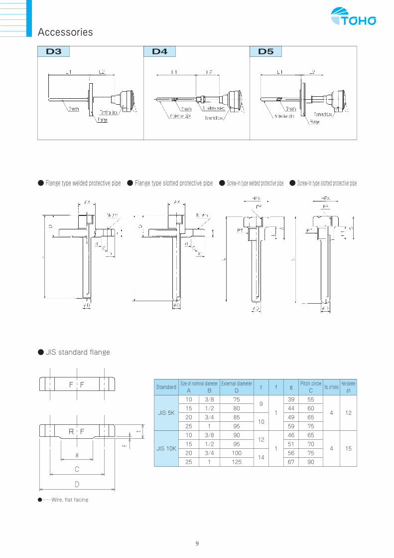
Accessories
D4 D5
Flange type welded protective pipe Flange type slotted protective pipe Screw-in type welded protective pipe Screw-in type slotted protective pipe
JIS standard flange
StandardSize of nominal diameter
A BExternal diameter
Dt f g
Pitch circleC
No. of holesHole diameter
φh
JIS 5K
10 3/8 759
1
39 55
4 1215 1/2 80 44 60
20 3/4 8510
49 65
25 1 95 59 75
JIS 10K
10 3/8 9012
1
46 65
4 1515 1/2 95 51 70
20 3/4 10014
56 75
25 1 125 67 90
……Wire, flat facing

10
Specialty Type (Platinum Resistance Temperature Sensor)
Wall-hung sealed terminal type (Model: HA-PT)
Specifications
Resistance value 100Ω(at 0)Specified current 2mAC l a s s BLead wire system 3-wire typeUsable temperature range -100 to 200
Class A units as well as thermocouples and thermistors also can be made, so please contact us if such items are required.
Heavy clamp and ferrule
* Dimensions differ depending on size of ferrule. * Small terminal boxes also can be made, so please contact us for details if required.
Model table
Model L dimension(mm)
Ferrule size
Specifications(platinum resistor)
HB-1 100
Types
Resistance value 100(at 0)
Specified current 2mA
C l a s s B
Lead wire system 3-wire type
Usable temperature range -100 to 200
HB-2 150
HB-3 200
HB-4 250
Designate ferrule size from table on right when placing order.
Heavy clamp dimension table
Type A B φC
1.5S 98 94 65
2S 113 93 75
2.5S 135 102 88
3S 148 112 106
4S 182 133 131
Ferrule dimension table
Size D E
1S 50.5 43.5
1.5S 50.5 43.5
2S 64.0 56.5
2.5S 77.5 70.5
3S 91.0 83.5
3.5S 106.0 97.0
4S 119.0 110.0

11
In-line Temperature Sensor
Features Usable on chemical lines such as washing, etching or
plating lines for semiconductors and printed circuit boards, etc.
Tube diameter can now accommodate down to a minimum of 1/4 inch (or external diameter of 6mm), so that now temperature settings can be made close to the use point of items such as application nozzles for chemicals, which has been impossible until now.
Both ends are jointed, which makes assembly and replacement easy.
There are three types of sensors to choose from: a Teflon type, a Teflon coated quartz pipe type, and a Teflon coated stainless steel type.
The S joint type can withstand conventionally unseen high-temperature fluids (max 180ºC).
Specifications
Usable fluids Acids, alkalis, pure water, etc.
JointsS type: Flowell’s 20 SeriesL type: Flowell’s 30 Series
Suitable tubesMaterials: PFA, PTFE fluoroethylene resin tubeSize: External diameters of 6, 8, 10mm, or 1/4, 3/8, 1/2 inch
Main unit materials
S type: PFAL type: PTFE
Nut materialsS type: PFAL type: ECTFE
Senor architecture
P type: PFA tube (for washing and etching)Q type: Quarts + PFA tube (with prolonged lifespan and for washing and etching)R type: SUS tube + PFA tube (for plating)
Sensor probePT type: Platinum resistance temperature sensor (100Ω)K type: JIS K thermocouple
Fluid temperatures
S joint type: Max. 180ºCL joint type: Max. 100ºC
Environmental temperature
Max:50
Note: Uses provided in table are only suggestions.
Construction
S type L type
d dimension L1 dimension L2 dimension
1 6mm 46mm 41mm
2 8mm 48mm 43mm
3 10mm 54mm 51mm
4 1/4 inch 46mm 41mm
5 3/8 inch 54mm 43mm
6 1/2 inch 64mm 51mm
d dimension L1 dimension L2 dimension
1 6mm 38mm 46mm
2 8mm 46mm 48mm
3 10mm 52mm 51mm
4 1/4 inch 38mm 46mm
5 3/8 inch 52mm 48mm
6 1/2 inch 60mm 51mm

12
Teflon pipe (TE type)
Features Fluoroethylene resin is used for the protective pipe. It offers superb chemical proof qualities beyond
that of stainless steel protective pipes, and is suitable for semiconductor washing devices, plating tank related tasks, and seawater control.
This pipe is flexible, so it can be used on devices with curved sections and inside pipes. It also has excellent heat resistance (heat resistance temperature: 150ºC).
External dimensions diagram
For M3.5Insulated Y type crimped terminal
2000
Contraction tubeSleeve
(120)
801000
FEPTeflon tube
±0.1φ4.2
Cord dimension
(50)
b Blue
A Red
White
RedWhite
BlueB
“TE-(J)PT” external dimensions diagram
SpecificationsResistance temperature sensor
Model name TE-PT TE-JPT
E l e m e n t Ceramic platinum resistance temperature sensor
M a r k Pt100 JPt100
C l a s s B
Prescribed current 2mA
Lead wire type 3-wire type
Temp. range -65 to +150
“Class A” products also can be made.
Thermocouple
Model name TE-K TE-J
Probe types K J
C l a s s 2 2
Temp. range -40 to +150 -40 to +150
Class 1 model also can be made. Please contact us for details about thermocouple types.
Thermistor
Model name TE-A TE-B
Nominal resistance 385Ω(100) 2.75kΩ(100)
B constant 3424K±3%(0/100) 3608K±3%(0/100)
Temp. range -30 to +100 +0 to +100
A resistance variable of ±5% is set as standard. Products can be produced to JIS standards. Probes are interchangeable.
Specifications
M a t e r i a l (temperature sensor) ※ FEP
External diameter(mm) ( 〃 ) Diameter 4.2mm (standard)
L e n g t h(mm) ( 〃 ) 1000mm (standard)
Heat resistance() ( 〃 ) 150ºC (continuous use Temp.)
Heat conductivity(J/s.cm.×10-3) 2.5
Acid No influence
Alkali 〃
Alcohol 〃
Solvents (trichlene, carbon tetrachloride) 〃
Aliphatic hydrocarbon (gasoline, kerosene) 〃
aromatic hydrocarbon (benzene, methylbenzene) 〃
* The standard product uses FEP, but PFA products also can be made.
Teflon is a chemically stable material, but like other plastics, gas and steam may penetrate it depending on temperature, pressure and chemical parameters.
13
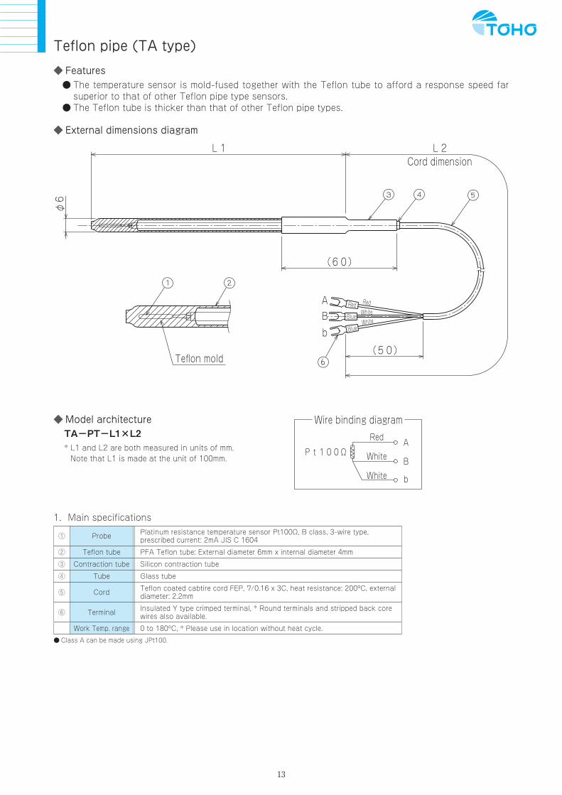
Features The temperature sensor is mold-fused together with the Teflon tube to afford a response speed far
superior to that of other Teflon pipe type sensors. The Teflon tube is thicker than that of other Teflon pipe types.
External dimensions diagram
Teflon pipe (TA type)
L1
φ6
Teflon mold
Cord dimension
(50)
b Blue
A Red
White
RedWhite
BlueB
L2
(60)
Model architectureTA-PT-L1×L2* L1 and L2 are both measured in units of mm.
Note that L1 is made at the unit of 100mm.
Wire binding diagram
White
White
Red
b
Pt100ΩB
A
1.Main specifications
① Probe Platinum resistance temperature sensor Pt100Ω, B class, 3-wire type, prescribed current: 2mA JIS C 1604
② Teflon tube PFA Teflon tube: External diameter 6mm x internal diameter 4mm
③ Contraction tube Silicon contraction tube
④ Tube Glass tube
⑤ Cord Teflon coated cabtire cord FEP, 7/0.16 x 3C, heat resistance: 200ºC, external diameter: 2.2mm
⑥ Terminal Insulated Y type crimped terminal, * Round terminals and stripped back core wires also available.
Work Temp. range 0 to 180ºC, * Please use in location without heat cycle.
Class A can be made using JPt100.

14
Features The internal cord of the Teflon tube is a cabtire cord. The sleeve unit on the TE type has been removed, reducing connection points to prevent corrosion to
connection points after chemical penetration.
External dimensions diagram
φ4.2
L1
Teflon mold
Cord dimension
(50)
b Blue
A Red
White
RedWhite
BlueB
L2
(60)
Model architectureTH-PT-L1×L2* L1 and L2 are both measured in units of mm.
Note that L1 is made at the unit of 100mm.
Wire binding diagram
White
White
Red
b
Pt100ΩB
A
1.Main specifications
① Probe Platinum resistance temperature sensor Pt100Ω, B class, 3-wire type, prescribed current: 2mA JIS C 1604
② Teflon tube FEP Teflon tube: External diameter 4.2mm x internal diameter 3.2mm
③ Contraction tube Silicon contraction tube
④ Tube Glass tube
⑤ Cord Teflon coated cabtire cord FEP, 7/0.16 x 3C, heat resistance: 200ºC, external diameter: 2.2mm
⑥ Terminal Insulated Y type crimped terminal, * Round terminals and stripped back core wires also available.
Work Temp. range 0 to 180ºC, * Please use in location without heat cycle.
Class A can be made using JPt100. Products also can be made using the PFA Teflon tube material.
Teflon pipe (TH type)
15
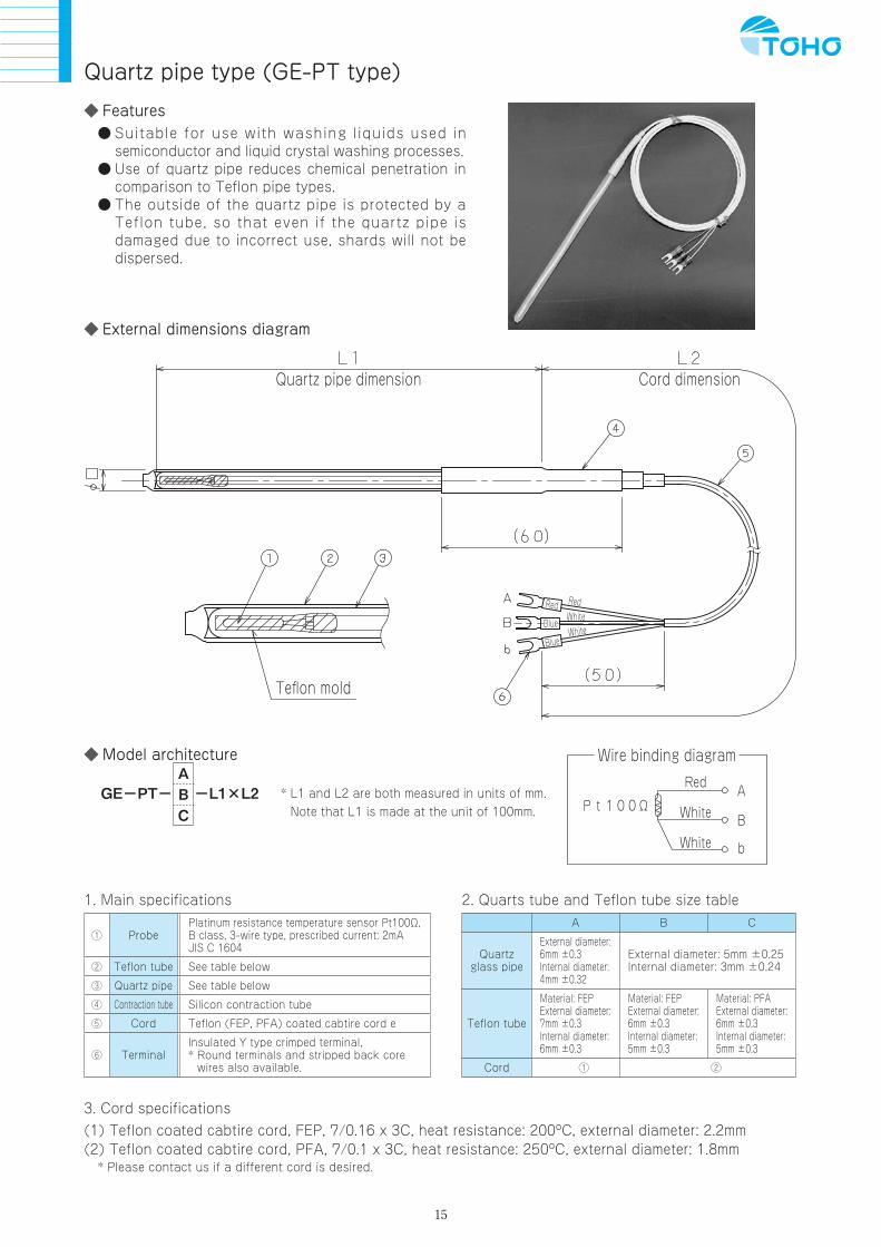
Features Suitable for use with washing liquids used in
semiconductor and liquid crystal washing processes. Use of quartz pipe reduces chemical penetration in
comparison to Teflon pipe types. The outside of the quartz pipe is protected by a
Teflon tube, so that even if the quartz pipe is damaged due to incorrect use, shards will not be dispersed.
External dimensions diagram
Quartz pipe dimension Cord dimension
Teflon mold
Red
Blue
Blue
RedWhiteWhite
Model architecture
GE-PT- -L1×L2 * L1 and L2 are both measured in units of mm. Note that L1 is made at the unit of 100mm.
Wire binding diagram
White
White
Red
b
Pt100ΩB
A
1. Main specifications
① ProbePlatinum resistance temperature sensor Pt100Ω, B class, 3-wire type, prescribed current: 2mA JIS C 1604
② Teflon tube See table below
③ Quartz pipe See table below
④ Contraction tube Silicon contraction tube
⑤ Cord Teflon (FEP, PFA) coated cabtire cord e
⑥ TerminalInsulated Y type crimped terminal, * Round terminals and stripped back core
wires also available.
3. Cord specifications(1) Teflon coated cabtire cord, FEP, 7/0.16 x 3C, heat resistance: 200ºC, external diameter: 2.2mm(2) Teflon coated cabtire cord, PFA, 7/0.1 x 3C, heat resistance: 250ºC, external diameter: 1.8mm * Please contact us if a different cord is desired.
Quartz pipe type (GE-PT type)
ABC
2. Quarts tube and Teflon tube size tableA B C
Quartz glass pipe
External diameter: 6mm ±0.3Internal diameter: 4mm ±0.32
External diameter: 5mm ±0.25Internal diameter: 3mm ±0.24
Teflon tube
Material: FEPExternal diameter: 7mm ±0.3Internal diameter: 6mm ±0.3
Material: FEPExternal diameter: 6mm ±0.3Internal diameter: 5mm ±0.3
Material: PFAExternal diameter: 6mm ±0.3Internal diameter: 5mm ±0.3
Cord ① ②

16
Specialty type (Thermocouple for measuring surface temperature)
Model
A1
Model
A2
Model
A3
Element K thermocouple JIS C 1602 0.75 class
Contact plate SUS304 t = 0.1mm, width: 2mm
Roller Teflon, diameter: 20mm
Lead wire TGK (K thermocouple, strand 0.18 x 30)
Treatment Silicon contraction tube, silicon tube, epoxy filler
End treatment Insulated crimped terminal CT1.25Y-3L
Work Temp. range Max. 250ºC (roller section)
Element K thermocouple JIS 0.75 class
Contact plate Stainless steel t = 0.1mm, width: 5mm
Sleeve ABS φ13×15L
Lead wire Compensating lead wire, vinyl coated (VX-G) 0.3/7
Work Temp. range Max. 200ºC (temperature measuring contact point section)
Element K thermocouple JIS 0.75 class
Sleeve Teflon, diameter 12 x 35L
Cover SUS303 φ8×9L
Contact plate SUS304 t = 0.1mm, width: 3.5mm
Lead wire Silicon coated K compensating lead wire 0.1/30
End treatment Insulated crimped terminal CT1.25Y-3L
Work Temp. range Max. 200ºC (temperature measuring contact point section)

17
Model
H1
Model architecture standard chart [H2 & H2 type Models](Model display example) For Platinum resistance temperature sensor, external diameter of 3.0mm for protective pipe,
protective piping length 100mm, general vinyl cabtire 1m, insulated Y terminal
H1-PT-30×100-E1-D
H1 PT 30 100 E 1 D - - × - -
Model Elementtypes
Protective pipeexternal diameter D
Protective pipelength L1
Lead wire types(lead wire heat resistance ºC)
Lead wirelength L2 Treatment B
H1 N JIS N
16 1.6
20 2.0
23 2.3
30 3.0
32 3.2
80 80mm 1 1000mm
2 2000mm
3 3000mm
100 100mm
150 150mm
250 250mm
350 350mm
48 4.8
50 5.0
60 6.0
K JIS K
E JIS E
J JIS J
T JIS T
H2
ThermocoupleA
B
C
CS
T
A
B
C
D
E
F
Thermocouple
D
DT
E
F
G
J
K
L
M
H
Temperature resistors Thermistor
A A type
B B type
CD CD type
H H type
Thermistor
PT Pt100
JPT JPt100
Platinum resistor
Protectivepipe materialSUS 316
Pleasedesignatelengths differentto above.
Please designatelengths differentto above.
Vinyl coated(max 90ºC)
Glass coated(max 180ºC)
Teflon insulation,glass coated(max 300ºC)
Teflon insulation,glass coated(max 300ºC)
Teflon coated(max 200ºC)
General vinylcabtire(max 80ºC)
Heat resistantvinyl cabtire(max 105ºC)
Silicon coatedcabtire(max 180ºC)
Teflon strand(max 200ºC)
Teflon coatedcabtire(max 200ºC)
General vinylcabtire(max 80ºC)
Heat resistantvinyl cabtire(max 105ºC)
Silicon coatedcabtire(max 180ºC)
Teflon coated(max 200ºC)
Teflon insulatedglass coated(max 300ºC)
7mm muki
7mm extra solder
M3 Y typeterminals withinsulation
M3.5 Y typeterminals withinsulation
M3.5 bareterminals
178 type tab onterminals withinsulation*C & CS are K
thermocouples
Handy Types
Model
H2

18
Data
R(PT) screw bolt G(PF) screw bolt
M screw bolt Compression fitting
Open type terminal box Closed type terminal box
Crimped terminals
C: M3 insulated open terminal D: M3.5 insulated open terminal E: 187 type insulated tab-on terminal F: M3.5 bare open terminal
R(PT) C E L A×B1/8 10 8 18 14×16.21/4 12 9 21 14×16.23/8 15 8 23 19×221/2 16 13 29 24×27.23/4 17 15 32 32×36.71 20 15 35 32×37
G(PF) C D E L A×B1/8 8 2 8 18 14×16.21/4 10 2 9 21 14×16.23/8 13 2 8 23 19×221/2 12 2.5 13 27.5 24×27.23/4 13 3 15 31 32×36.71 14.5 3.5 15 33 32×37
M C E L A×B6 7 5 12 12×13.58 12 6 18 13×1510 10 8 18 14×16.212 20 8 28 19×22
A B C D Suitable external diameterPT 1/8 12 14 5 Diameter 4.8mm or lessPT 1/4 12 17 8 Diameter 8.0mm or lessPT 1/2 17 15 8 Diameter 10.0mm or lessPT 3/4 25 25 8 Diameter 15.0mm or less
* Above dimensions may be changed ac-cording to circumstances.
Type A B C D φES (small) 58 44 14 G 1/4 19L (large) 77 70 63 G 1/2 30
Type φA B D E FS (small) 58 65 34 G 3/8 G 1/4L (large) 82 91 51 G 1/2 G 1/2
Insertion length can be adjusted to any length, but it will not be gastight.

19
Loose flanges
Securing flanges
The protective pipe comes with the flange secured already, so attach using screws.
Insert to desired length and secure from side with screw bolt. It will not be gastight, but can be used at normal pressure.
A
D
G
B
E
C
F
Type A B ThicknessS (small) 75 55 9L (large) 95 75 10
2-M4 tap
M4 tap

20
SummaryCompensating lead wire is used in conjunction with thermocouples and sheath thermocouples, and is comprised of a pair of wires with identical characteristics, insulated for conducting.
AppendixThere are two classes of compensating lead wire, class 1 (precision class) and class 2 (nor-mal class). Also, the following coatings are available: general type, heat resistant type and super heat resistant type.
Compensating lead wire for thermocouples
Surface coating
Core
Wires
Usage classifications for normal, heat resistant and super heat resistant compensating lead wiresJIS Standards (C 1610, 1995)
Type Mark Usable Temp. range (ºC)
Normal G -20 to 90
Heat resistant H 0 to 150
Super heat resistant S -25 to 200
Compensating lead wire specificationsThermocouple
typeCompensatinglead wire type
Toleranceclassification
Usageclassification
Wire nominalsectional area
Shield:Yes/No
Surfacecoating ID
Mark Mark Old mark(remarks)
1. Precision class2. Normal class
G: GeneralH: Heat resistantS: Super heat resistant
A.0.5mm2
B.0.75mm2
C.1.25mm2
Yes: S1No: [0]
Clas-sification
1
Clas-sification
2
B BC BX 2 G A S1. 0 Gray Gray
R RCARCB RX 2 G. H. A. B. S1. 0
Orange BlackS SCA
SCB SX 2 G. H. A. B. S1. 0
NNX
1. 2. G. H. S. A. B. C. S1. 0 Pink -NC
K
KX KX 1. 2.
G. H. S. A. B. C. S1. 0 Green BlueKCB WX 2
KCC VX 2
E EX EX 1. 2. G. H A. B. C. S1. 0 Violet Purple
J JX JX 1. 2. G. H A. B. C. S1. 0 Black Yellow
T TX TX 1. 2. G. H A. B. C. S1. 0 Brown Brown
* Classification 1 colors for surface coatings are available on a made-to-order basis.
Coated thermocouples
Thermocouple Coating material Wire diameter
K G 0.32 0.45 0.65
E H 0.32 - 0.65
J S 0.32 - 0.65
T 6F 0.32 - 0.65
Coating types
Mark Coatingmaterial
Heat resistance Temp. (ºC)
G Vinyl chloride 90
H Glass wool 150
S Silicon 180
6F Teflon 180
Nominal sectional area and wire architecture
Mark Sectionalarea (mm2)
Wiring architecture No.of wires/wire diameter
A 0.5 7/0.3 20/0.18
B 0.75 30/0.18
C 1.25 7/0.45 4/0.65
D 2.0 7/0.65
Model Indication*When ordering, please designate the compensating lead wire’s mark, tolerance classification, usage classification, wire architecture and shield: Yes/NO (do not indicate if not required).
KX - 1 - H - A - S1 N o t eFor external shield, include SOS after the wire nominal sectional area.
Example
Mark
Tolerance classification
Usage classification
Wire nominal sectional area
Shield: Y
es/No
Model indication for coated thermocouples*When order ing , p lease des ignate the thermocouple’s type mark, and wire diameter.
K - H - 0.32Example
Therm
ocouple type
Wire diam
eter
Coating m
ark
Polarity colors
Polarity Surface coating color
+ side Red
– side White
* Conforms to classification 2.

21
Thermocouple Electromotive Force Tables
R Standard Electromotive Force (JISC 1602-1995) Unit: μV
Temp. ºC 0 Temp. ºC 0 100 200 300 400 500 600 700 800 900 1000 1100 1200 1300 1400 1500 1600 1700
-100 0 0 647 1469 2401 3408 4471 5583 6743 7950 9205 10506 11850 13228 14629 16040 17451 18849 20222
-90 10 54 723 1558 2498 3512 4580 5697 6861 8073 9333 10638 11986 13367 14770 16181 17591 18988 20356
-80 20 111 800 1648 2597 3616 4690 5812 6980 8197 9461 10771 12123 13507 14911 16323 17732 19126 20488
-70 30 171 879 1739 2696 3721 4800 5926 7100 8321 9590 10905 12260 13646 15052 16464 17872 19264 20620
-60 40 232 959 1831 2796 3827 4910 6041 7220 8446 9720 11039 12397 13786 15193 16605 18012 19402 20749
-50 -226 50 296 1041 1923 2896 3933 5021 6157 7340 8571 9850 11173 12535 13926 15334 16746 18152 19540 20877
-40 -188 60 363 1124 2017 2997 4040 5133 6273 7461 8697 9980 11307 12673 14066 15475 16887 18292 19677 21003
-30 -145 70 431 1208 2112 3099 4147 5245 6390 7583 8823 10111 11442 12812 14207 15616 17028 18431 19814
-20 -100 80 501 1294 2207 3201 4255 5357 6507 7705 8950 10242 11578 12950 14347 15758 17169 18571 19951
-10 -51 90 573 1381 2304 3304 4363 5470 6625 7827 9077 10374 11714 13089 14488 15899 17310 18710 20087
0 0 100 647 1469 2401 3408 4471 5583 6743 7950 9205 10506 11850 13228 14629 16040 17451 18849 20222
K Standard Electromotive Force (JISC 1602-1995) Unit: μV
Temp. ºC -200 -100 0 Temp. ºC 0 100 200 300 400 500 600 700 800 900 1000 1100 1200 1300
-100 -5891 -3554 0 0 4096 8138 12209 16397 20644 24905 29129 33275 37326 41276 45119 48838 52410
-90 -5730 -3243 10 397 4509 8539 12624 16820 21071 25330 29548 33685 37725 41665 45497 49202 52759
-80 -5550 -2920 20 798 4920 8940 13040 17243 21497 25755 29965 34093 38124 42053 45873 49565 53106
-70 -6458 -5354 -2587 30 1203 5328 9343 13457 17667 21924 26179 30382 34501 38522 42440 46249 49926 53451
-60 -6441 -5141 -2243 40 1612 5735 9747 13874 18091 22350 26602 30798 34908 38918 42826 46623 50286 53795
-50 -6404 -4913 -1889 50 2023 6138 10153 14293 18516 22776 27025 31213 35313 39314 43211 46995 50644 54138
-40 -6344 -4669 -1527 60 2436 6540 10561 14713 18941 23203 27447 31628 35718 39708 43595 47367 51000 54479
-30 -6262 -4411 -1156 70 2851 6941 10971 15133 19366 23629 27869 32041 36121 40101 43978 47737 51355 54819
-20 -6158 -4138 -778 80 3267 7340 11382 15554 19792 24055 28289 32453 36524 40494 44359 48105 51708
-10 -6035 -3852 -392 90 3682 7739 11795 15975 20218 24480 28710 32865 36925 40885 44740 48473 52060
0 -5891 -3554 0 100 4096 8138 12209 16397 20644 24905 29129 33275 37326 41276 45119 48838 52410
J Standard Electromotive Force (JISC 1602-1995) Unit: μV
Temp. ºC -200 -100 0 Temp. ºC 0 100 200 300 400 500 600 700 800 900 1000 1100
-100 -7890 -4633 0 0 5269 10779 16327 21848 27393 33102 39132 45494 51877 57953 63792
-90 -7659 -4215 10 507 5814 11334 16881 22400 27953 33689 39755 46141 52500 58545 64370
-80 -7403 -3786 20 1019 6360 11889 17434 22952 28516 34279 40382 46786 53119 59134 64948
-70 -7123 -3344 30 1537 6909 12445 17986 23504 29080 34873 41012 47431 53735 59721 65525
-60 -6821 -2893 40 2059 7459 13000 18538 24057 29647 35470 41645 48074 54347 60307 66102
-50 -6500 -2431 50 2585 8010 13555 19090 24610 30216 36071 42281 48715 54956 60890 66679
-40 -6159 -1961 60 3116 8562 14110 19642 25164 30788 36675 42919 49353 55561 61473 67255
-30 -5801 -1482 70 3650 9115 14665 20194 25720 31362 37284 43559 49989 56164 62054 67831
-20 -5426 -995 80 4187 9669 15219 20745 26276 31939 37896 44203 50622 56763 62634 68406
-10 -8095 -5037 -501 90 4726 10224 15773 21297 26834 32519 38512 44848 51251 57360 63214 68980
0 -7890 -4633 0 100 5269 10779 16327 21848 27393 33102 39132 45494 51877 57953 63792 69553
T Standard Electromotive Force (JISC 1602-1995) Unit: μV
Temp. ºC -200 -100 0 Temp. ºC 0 100 200 300
-100 -5603 -3379 0 0 4279 9288 14862
-90 -5439 -3089 10 391 4750 9822 15445
-80 -5261 -2788 20 790 5228 10362 16032
-70 -6258 -5070 -2476 30 1196 5714 10907 16624
-60 -6232 -4865 -2153 40 1612 6206 11458 17219
-50 -6180 -4648 -1819 50 2036 6704 12013 17819
-40 -6105 -4419 -1475 60 2468 7209 12574 18422
-30 -6007 -4177 -1121 70 2909 7720 13139 19030
-20 -5888 -3923 -757 80 3358 8237 13709 19641
-10 -5753 -3657 -383 90 3814 8759 14283 20255
0 -5603 -3379 0 100 4279 9288 14862 20872

22
Resistance Temperature Sensor Resistance Value Tables
Pt100(JISC1604-1997) Unit: Ω
Temp. ºC -100 -0 Temp. ºC 0 100 200 300 400 500 600 700 800
-0 60.26 100.00 0 100.00 138.51 175.93 212.05 247.09 280.98 313.71 345.28 375.70
-10 56.19 96.09 10 103.90 142.29 179.53 215.61 250.53 284.30 316.92 348.38 378.68
-20 52.11 92.16 20 107.79 146.07 183.19 219.51 253.96 287.62 320.12 351.46 381.65
-30 48.00 88.22 30 111.67 149.83 186.84 222.68 257.38 290.92 323.30 354.53 384.60
-40 43.88 84.27 40 115.54 153.58 190.47 226.21 260.78 294.21 326.48 357.59 387.55
-50 39.72 80.31 50 119.40 157.33 194.10 229.72 264.18 297.49 329.64 360.64 390.48
-60 35.54 76.33 60 123.24 161.05 197.71 233.21 267.56 300.75 332.79 363.67
-70 31.34 72.33 70 127.08 164.77 201.31 236.70 270.93 304.01 335.93 366.70
-80 27.10 68.33 80 130.90 168.48 204.90 240.18 274.29 307.25 339.06 369.71
-90 22.85 64.30 90 134.71 172.17 208.48 243.64 277.64 310.49 342.18 372.71
-100 18.52 60.26 100 138.51 175.86 212.05 247.09 280.98 313.71 345.28 375.70
Usable temperature range for wire-wound model is -200 to 650ºC. Usable temperature range for thin-membrane model is -50 to 400ºC.
JPt100(JISC1604-1989) Unit: Ω
Temp. ºC -100 -0 Temp. ºC 0 100 200 300 400 500 600
-0 59.57 100.00 0 100.00 139.16 177.13 213.93 249.56 284.02 317.28
-10 55.44 96.02 10 103.97 143.01 180.86 217.54 253.06 287.40 320.54
-20 51.29 92.02 20 107.93 146.85 184.58 221.15 256.55 290.77 323.78
-30 47.11 88.01 30 111.88 150.67 188.29 224.74 260.02 294.12 327.02
-40 42.91 83.99 40 115.81 154.49 191.99 228.32 263.49 297.47
-50 38.68 79.96 50 119.73 158.29 195.67 231.89 266.94 300.80
-60 34.42 75.91 60 123.64 162.08 199.35 235.45 270.38 304.12
-70 30.12 71.85 70 127.54 165.86 203.01 238.99 273.80 307.43
-80 25.80 67.77 80 131.42 169.63 206.66 242.53 277.22 310.72
-90 21.46 63.68 90 135.30 173.38 210.30 246.05 280.63 314.01
-100 17.14 59.57 100 139.16 177.13 213.93 249.56 284.02 317.28
Normal limits according to thermocouple, sheath material and sheath diameter
Thermocouple typeSheath diameter (mm)
Sheath material1.0 1.6 3.2 4.8 6.4 8.0
KSUS316 650 650 750 800 800 900
Inconel 650 650 750 900 1000 1050
J SUS316 450 450 650 750 750 750
T SUS316 300 300 350 350 350 350
Normal limits and excessive heat usage limits for thermocouple probeThermocouple type Probe diameter (mm) Normal limit (ºC) Excessive heat usage limit (ºC)
R 0.50 1400 1600
K
0.65 650 850
1.00 750 950
1.60 850 1050
2.30 900 1100
3.20 1000 1200
J
0.65 400 500
1.00 450 550
1.60 500 650
2.30 550 750
3.20 600 750
T
0.32 200 250
0.65 200 250
1.00 250 300
1.60 300 350
Normal limit refers to the temperature limit at which the device can be used continually in air.Excessive heat usage limit refers to the temperature limit at which the device can be used for a short time if absolutely necessary.
23
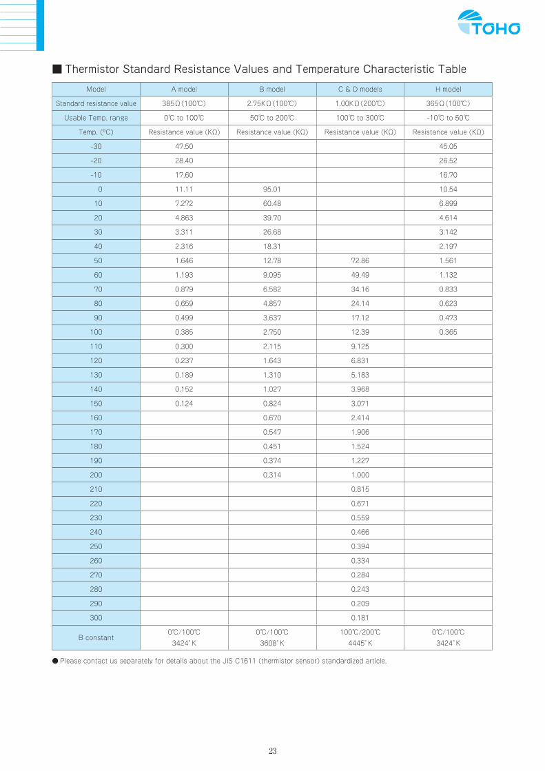
Thermistor Standard Resistance Values and Temperature Characteristic Table
Model A model B model C & D models H model
Standard resistance value 385Ω(100) 2.75KΩ(100) 1.00KΩ(200) 365Ω(100)
Usable Temp. range 0 to 100 50 to 200 100 to 300 -10 to 50
Temp. (ºC) Resistance value (KΩ) Resistance value (KΩ) Resistance value (KΩ) Resistance value (KΩ)
-30 47.50 45.05
-20 28.40 26.52
-10 17.60 16.70
0 11.11 95.01 10.54
10 7.272 60.48 6.899
20 4.863 39.70 4.614
30 3.311 26.68 3.142
40 2.316 18.31 2.197
50 1.646 12.78 72.86 1.561
60 1.193 9.095 49.49 1.132
70 0.879 6.582 34.16 0.833
80 0.659 4.857 24.14 0.623
90 0.499 3.637 17.12 0.473
100 0.385 2.750 12.39 0.365
110 0.300 2.115 9.125
120 0.237 1.643 6.831
130 0.189 1.310 5.183
140 0.152 1.027 3.968
150 0.124 0.824 3.071
160 0.670 2.414
170 0.547 1.906
180 0.451 1.524
190 0.374 1.227
200 0.314 1.000
210 0.815
220 0.671
230 0.559
240 0.466
250 0.394
260 0.334
270 0.284
280 0.243
290 0.209
300 0.181
B constant0/100
3424゚K
0/100
3608゚K
100/200
4445゚K
0/100
3424゚K
Please contact us separately for details about the JIS C1611 (thermistor sensor) standardized article.

Traceability System Diagram
Please inform us of the following when placing an order. 1.Utilization temperature range 2.Whether or not there is on-site pressure and/or vibration 3.Utilization atmosphere (conditions of use)
Please contact the Toho head office or sales office for details about specifications that do notappear in this catalog.We have many products available to meet the needs of our customers, and are ready always tofulfill tight delivery schedules.We also manufacture UL qualified products, so inquiries are welcome.
The appearance and specifications of products in this catalog are subject to change without prior notice.
Traceability System Diagram (for measuring instruments and temperature measuring)
Nationalstandard
National andpublic bodies
Civil correctingbodies
In-house measurem
entstandard
Toho Electronics Inc.
In-house standardIn-house w
ork
National Institute of Advanced IndustrialScience andTechnology (AIST)
National Research CenterCanada (NRC)
National Institute ofStandardsand Technology (NIST)
Japan Electric Meters InspectionCorporation (JEMIC)
Japan Quality AssuranceOrganization (JQA)
Yokogawa Manufacturing Corporation
Yokogawa Rental Lease Corporation
Precision digital multimetermeasurement standard
Model: 2001Serial number: 1167945Registration number: M-1043
Volt-ampere generationstandard
Model: 2553Registration number: V-1001V-1020
Digital multimeterstandard
Model: 7561-02756101-C-1/BRegistration number:M-1006, M-1038
6-dial resistancestandard
Model: 2786, 2793Registration number:R-1005, R-1008, R-1031
Platinum resistance temperaturesensor standard
Model: SPT-6300Registration number:S-2003, S-2015, S-2016, S-1027
Platinum resistance temperaturesensor measurement standard
Model: R800-9 Serial number: RS96Y-1Registration number: S-1027
Volt-ampere generationinstrument typesIn-house registration mark: V
Digital multimeter typesIn-house registration mark: M
6-dial resistance instrumentResistance instrument typeIn-house registration mark: R
Each type of temperature meterEach type of temperature sensorrelative measurementIn-house registration mark: S
Zero configuration
Model: ZC-114Registration number:S-1044, S-1045
Chino Corporation Yamari Industries,Limited
Coper ElectronicsCO., Ltd.
The system diagram is controlled in accordance with Toho in-house regulations and standards based on our quality system, and these are regularly traced by the National Standards.
24


46-7718-A EDUPRESS Printed in Japan 2008.3. 500
Head Office: 1-13-21, Tanashioda, Sagamihara Kanagawa 229-1125 Japan. Phone: +81-42-777-3311 FAX: +81-42-777-3751 E-Mail: [email protected] Web site: http://www.toho-inc.com
Specifications are subject to change without notice.Note: The color printed in this catalog may be different from actual color.